control of building vibrations with active/passive devices
TRANSCRIPT

EARTHQUAKE ENGINEERING AND STRUCTURAL DYNAMICS, VOL. 25, 1019-1039 (1996)
CONTROL OF BUILDING VIBRATIONS WITH ACTIVE/PASSIVE DEVICES
P. B. SHING*, M. E. DIXON*, N. KERMICHEt, R. SU' AND D. M. FRANGOPOL* * Department of Civil, Environmental and Architectural Engineering, CB 428 and 'Department of'Elecirica1 and Computer Engineering,
CB 425, University of Colorado, Boulder, CO 80309, U.S.A.
SUMMARY Two linear optimal control laws and a non-linear control strategy are critically evaluated. They are implemented in a ten-story frame structure. For the linear control laws, both an active bracing system and a hybrid mass damper are considered as control devices, while the non-linear control law can be implemented with either an active or semi-active bracing system. The active and semi-active systems are compared to a passive bracing system with linear viscous dampers and to a hybrid system consisting of a passive bracing and a hybrid mass damper. Dimensionless indices based on the reduction of the maximum story drift and on the maximum control force required are introduced to compare the efficiencies of different control strategies. While the linear optimal control laws exhibit an excellent performance, the non-linear control law, in addition to its simplicity and robustness, appears to be more efficient when the allowable control force is within a certain limit. Furthermore, one attractive feature of the latter is that it can be implemented with semi-active devices to minimize the power requirement.
KEY WORDS: active control; earthquake response; linear optimal control; non-linear control; semi-active dampers
INTRODUCTION
Passive and active vibration control mechanisms have found increasing applications in civil structures. Passive tuned mass dampers have been installed in buildings to mitigate wind-induced vibrations,' and base-isolation systems have been successfully used in bridges and in low- and mid-rise building^^.^ for protection against seismic forces. Recently, passive energy-dissipating devices using viscoelastic material^^-^ and frictional mechani~rns~~ ' have proven to be effective for the control of building vibrations induced by earthquake forces. In fact, viscoelastic dampers have been used in building structures to control wind- induced vibrations for a number of years.'
Active control has gained much attention in recent years. Its main advantage is that active devices are often structurally less invasive than passive devices.' For example, a single active device, such as an active mass damper, can be designed to influence a number of vibration modes. Hence, active control is most suited for tall and slender structures, where the response can be influenced by a number of natural modes. Active control systems have been implemented in a number of buildings in Japan.'op" However, all these systems were designed only for wind and moderate earthquake forces. The use of active control to counteract large earthquake forces has always been controversial for a number of reasons. First, large control forces can be difficult to realize. Secondly, large control forces could be as detrimental as earthquake forces if the stability of a control system were jeopardized. Furthermore, to maintain the reliability of an active control system over the lifetime of the structure can be a difficult task.
The main purpose of this study is to conduct a critical evaluation of the efficiency and practicality of different active control strategies as compared to a passive damping mechanism, and to develop viable control strategies based on hybrid and semi-active concepts that can eradicate some of the perceived drawbacks of active systems. To this end, different control laws and control mechanisms are first compared, the feasibility of a hybrid system that combines active and passive devices is explored, and a non-linear
CCC 0098-8847/96/101019-2 1 0 1996 by John Wiley & Sons, Ltd.
Received 16 March I995 Revise 20 February I996

1020 P. B. SHING ET AL.
control law which can be implemented in a semi-active environment is proposed. To compare these control strategies in a meaningful manner, design objectives are defined, performance indices that are relevant to building applications are proposed, and a ten-storey prototype frame is selected as a benchmark problem for case studies.
DESIGN OBJECTIVES
Regardless of the fact that the load-resistance mechanism of a structure is passive or active, to develop and design such a system, one must first define the design objectives. As in the design of conventional load-resisting structural systems, the design of an active or hybrid control system requires the consideration of cost-effectiveness and the ease of installation. Above and over, an active system has to be robust, reliable, and easy to maintain.
While the comfort of occupants and the prevention of damage to architectural elements are the main concerns for wind-induced vibrations, the mitigation of economic loss and human casualties has been the primary goal in earthquake-resistance design. In areas of high seismic risk, to attain an optimal balance between safety and economy, the following design objectives are usually adopted. For small earthquakes that may occur frequently during the lifetime of a structure, all structural and non-structural damage should be prevented. For moderate earthquakes that may occur occasionally, structural damage should be prevented, while mild non-structural damage is permitted. For severe earthquakes which have only a small probability of occurrence during the lifetime of a structure, structural damage is allowed but the collapse of the structure should be avoided.
While the above philosophy seems reasonable for the design of conventional structural systems, the basic premise can be challenged in light of the new developments in vibration control as well as the economic impact of several major earthquake^"-'^ which occurred recently. With the development of new vibration control systems, such as passive and active control devices, the prevention of structural damage in a severe earthquake may no longer be a costly alternative when compared to the repair or replacement cost of a building. For example, the excellent performance of base isolated structures in the 1994 Northridge e a r t h q ~ a k e ' ~ . ' ~ strongly alludes to the fact that a more stringent design philosophy can be adopted without a major impact on construction costs. The northridge earthquake has also demonstrated that the seismic risk of an area can be substantially underestimated because of the existence of hidden faults. Hence, with the current design philosophy, the seismic vulnerability of a structure or the likelihood of having a severe structural damage can be much higher than what has been initially anticipated.
Therefore, the primary objective of the control systems to be considered in this study is to prevent both structural and non-structural damage under a maximum credible earthquake. To facilitate the design of such a system, it is desirable to establish a damage index. In this regard, story drift appears to be a response parameter that is most relevant to structural or non-structural damage. While there is no unique correlation between damage and story drift, empirical evidence15 has indicated that a story drift in the range of 0-2-0-6 percent, with respect to the story height, may induce non-structural damage, a drift in the range of 0 . 6 1 percent may cause significant non-structural damage and/or mild structural damage, and a drift beyond 1 percent can induce severe structural damage. Based on these approximate guidelines, the objectives of the conventional design philosophy as well as those of the control strategies to be studied here are summarized in Table I. With these criteria at hand, different control systems can be designed and evaluated in a relevant manner.
CONTROL LAWS
A number of control laws have been proposed and studied for possible application to civil structures.' In spite of various pros and cons from the implementation standpoint, control laws based on the linear optimal control theory appear to be as competitive as, if not superior to, other linear control schemes. For this reason, two linear optimal control schemes, namely, the classical optimal feedback (LQR) control and the optimal feedforward-feedback control which utilizes a second-order filter to reconstruct the ground states, are

CONTROL OF BUILDING VIBRATIONS 1021
Table I. Design objectives
Storey drift limits (%)
< 0.4 0.4-0.8 > 0.8 (No damage or (non-structural (mild to severe
mild non- and/or mild structural Excitation structural damage) structural damage) damage)
Small E.Q. (0.1Og) x, xx Moderate E.Q. (0.259) xx X Strong E.Q. (0-409) xx X
X To be attained with conventional design XX: To be attained with control devices
considered in this study. Furthermore, a simple and robust non-linear control scheme, which can be implemented in a semi-active environment, is presented and evaluated.
To give a brief overview of the active control concept, the equations of motion for a multiple-degree-of- freedom structure subject to base acceleration and active control forces is expressed in a state space as follows.
z = Az + Bu + r l i o (1)
where 0 I ] B = [ 0 3 r l = [ 0 ] *=[
-M-'K -M- 'C - M - ' H - M-'r
in which z = {y' yT}', with y being the vector of structural displacements relative to the base, the superposed dot represents differentiation with respect to time, u is the vector of control forces, H the controller location matrix, xo the ground acceleration, r the excitation location vector, I an identity matrix, and M, C, and K are the mass, damping, and stiffness matrices of the structure. The control forces u are determined in accordance with the specific control law adopted.
Optimal feedback control Linear optimal control (LQR) involves the minimization of the following quadratic cost function:
J = j:'[z'Qz + uTRu] dt (3)
in which Q and R are the weighting matrices for the structural states and control forces, respectively, and t l is the duration over which the cost function is to be minimized. Minimizing J , under the constraint of equation (l), results in the following state-feedback control law:
u = - - R - 1 B P z T
2
in which P is obtained by solving the following matrix Riccati equation:
PA - - PBR-'BTP + ATP + 2Q = 0 1 2
(4)
(5 )
where P is assumed to be stationary.I6 The above control law is optimal with respect to the objective function defined in equation (3) under the
condition that the excitation, &, is a Gaussian white noise. However, since an earthquake ground motion is generally a coloured noise, the main criticism on this control law is that it might not be truly optimal. For this

1022 P. B. SHING ET AL.
reason, a feedforward-feedback control law that considers earthquake ground motions as filtered white noise is examined in the following.
Optimal feedforward-feedback control
noise as input, one can modify equation (1) to arrive at the following augmented state equations. Assuming that an earthquake ground motion can be generated by a second-order filter with Gausian white
i = x i + B u + i;'W (6) in which i = {z' z:}', with z, = {x, XglT being the vector of the ground states, w is the white noise excitation, and
A subscript g is used for the parameters of the ground model, which are defined as follows:
in which 0, and 5 , are the natural frequency and the ratio of critical damping of the ground model, respectively.
In this control law, the control forces are defined as functions of the ground states as well as those of the structural states. Minimizing the cost function in equation (3), under the constraint of equation (6), results in the following control law.
u = - R-' BTP,,z - R-'BT PSgzg
P,,A - P,,BR-'BT P,, + A'P,, + Q = 0
P,,rlC, + [A - BR-'BTPS,lT Psg + P,,A, = 0
(9)
(10)
(11)
in which P,, and P,,, assumed to be stationary, can be obtained from the following matrix equations:
This results in a feedforward-feedback control law that is truly optimal provided that the ground model selected accurately reflects the ground states.' This scheme has been considered for civil structures by Abdel-Rohman et al.," Iemura et ~ l . , ' ~ Suhardjo et ul.," and Yang et al.." To extract the ground states from the measured ground acceleration, the following stochastic observer can be used.'
4, = [A, - F&,]P, + FOX0 (12)
in which P, and %,, are the observed ground states and ground acceleration, respectively, and Fo is the observer gain. The higher the observer gain is, the faster is the convergence of the observed states to the actual states, but the more sensitive is the observer to the observation noise. Hence, for actual implementa- tion, an optimal observer gain has to be determined. To apply this control scheme, one has to replace zg in equation (9) by P,, which is evaluated by solving equation (12) numerically.
Non-linear control In spite of the optimality condition, linear control laws may not utilize the energy-dissipation capability of
a control device in a most effective manner. For example, with a constant velocity-feedback gain, the dissipative force vanishes at the same rate as the velocity. Furthermore, if one designs a control system for a severe but rare seismic event, large control forces may only be occasionally activated during a moderate earthquake, while most of the time, the control forces developed will fall far below the full capacities of the devices. Hence, this may not be a most efficient control strategy for wind and small earthquake forces. On the other hand, if a control system is designed for a moderate excitation force, the forces developed in the control devices will soon reach a saturation state when an exceptionally strong excitation is encountered, and,

CONTROL OF BUILDING VIBRATIONS 1023
thereby, the performance of the system may deteriorate. This is because the stability of a linear control law is no longer guaranteed when the control forces saturate.
In view of the above trade-off of the linear control laws, it is desirable to have a control system that is designed for the worst anticipated event and is yet able to mobilize its full capacity under small and moderate excitations that may occur frequently during the lifetime of the structure. For this purpose, the following non-linear control law is proposed.
Fui( j i - j i - J if luil < us
us sign (ui) if 1 uil 2 us
in which ui is an interstory control force developed at storey i, Fui is the velocity-feedback gain for the device, and us is the force limit at which saturation occurs. To achieve the aforementioned control objective, the control gain, Fui , has to be large enough so that it can activate the maximum control force even at low excitation levels, and the saturation point, us, has to be selected in accordance with the amount of response reduction that needs to be achieved under the worst anticipated event as well as with the mechanical constraint of the device. The force saturation can also be considered as a safety fuse that prevents the transmission of large control forces to other members of the structure.
The above non-linear control scheme has a number of desirable features. Since the saturation limit is part of the design consideration rather than a mere mechanical constraint, the performance of such a system is, thus, more predictable than that resulting from a linear control law. Since the non-linear control law is based on local velocity feedback, it is always stable and robust, which has been proven mathematically. The stability of a linear control law can be jeopardized by force saturation, and its performance may thus deteriorate once the saturation occurs. However, one major advantage of the non-linear control strategy is that it can be implemented with semi-active devices. Currently, a semi-active actuator which does not require any power consumption has been developed and successfully tested for this control strategy.” Finally, since each device can be controlled in a decentralized manner, the problem of time delay is minimized.
It must be pointed out that a constrained optimal control scheme has been studied by Indrawan and HigashiharaZ3 to achieve the same design objective delineated here. However, that scheme cannot be easily applied to multiple-degree-of-freedom structures and it requires the knowledge of the excitation time history a prior. The non-linear control law presented here is similar in certain respects to a bang-bang control. Nevertheless, its main distinction from a bang-bang control is that the control force developed in this scheme varies continuously.
EVALUATION OF CONTROL LAWS
Performance indices With the design objectives delineated earlier, a most effective control law is defined as one which can limit
the story drift to a target level with a minimum amount of control effort. Hence, to evaluate the effectiveness of different control laws, two dimensionless indices, which reflect the above performance measures, are introduced. They are the Drift Reduction Factor (DRF) and the Normalized Control Force (NCF) defined as follows:
urnax
in which AL,,and Ahaxare the absolute maxima of story drifts that occur in the uncontrolled and controlled structures, respectively, u,,, the absolute maximum of the control forces developed, z0. the peak ground acceleration, and (1) a unit row vector. With linear control laws, the normalization introduced in equation

1024 P. B. SHING ET AL.
(15) eliminates the influence of the level of ground motion and of the mass of the structure on the control effort required, and, thereby, allows an objective comparison of the efficiencies of various control strategies. Even though power requirement is an important consideration for active control, it is not an issue for passive and semi-active control devices. Therefore, since this study focuses on a wide spectrum of control strategies, the control effort in terms of power requirement will not be adopted as a general performance measure.
Linear control laws With the aforementioned performance indices, the efficiencies of the optimal feedback control and optimal
feedforward-feedback control laws are compared. It must be pointed out that the classical feedback control law is optimal only with respect to the quadratic cost function defined in equation (3) and with the condition of white-noise excitation. Hence, the true optimality of the classical feedback control with respect to the aforementioned performance indices and earthquake-type excitation has to be further examined. Among a number of possible choices for the weighting matrix Q, the following two forms are considered and compared:
'1 and Q = I O M in which I is an identity matrix. With the first Q matrix in equation (16), the first term in the cost function in equation (3) represents the total energy of the system, and it is, therefore, called the energy weighting in this study, while the second Q matrix is called the identity weighting. With the stiffness and mass quantities commonly encountered, the latter has more weight on the velocity state than the former. As to the weighting matrix R, the following form is assumed:
R = RI (17)
which is based on the consideration that the cost of the control effort does not depend on the location of the control force. The scalar factor R reflects the cost of the control effort with respect to that of the structural states. The larger the value of R is, the less costly is the control effort, and, therefore, the larger will be the resulting control gains.
Furthermore, it is understood that the performance of a control scheme also depends on the dynamic properties of the structure with respect to the frequency contents of the excitation force. Hence, in the following study, a variety of base motions are applied to a single-degree-of-freedom structure. These include a simulated earthquake ground motion, as well as several other acquired earthquake records, which provide a wide spectrum of frequency distributions. The structure considered here has a mass of 2.947 kN s2/m and a stiffness of 1.957 x lo3 kN/m, which lead to a natural frequency of 25.76 rad/s. The structure is assumed to have a damping coefficient equal to 2.26 percent of the critical.
Simulated earthquake. The main intention of using a simulated earthquake is to compare the performances of the optimal (LQR) feedback control and feedforward-feedback control under an ideal situation that the states of an earthquake ground motion can be perfectly reconstructed from the measured ground acceler- ation. This provides a most favourable condition for the feedforward-feedback control law. The earthquake ground motion is simulated with a second-order Kanai filter, with Gaussian white noise as input and with the following ground parameters: wg = 15 rad/s and tg = 0.40. The filtered output is modified by an envelope function to reflect the attenuation of the ground motion. For both control schemes, simulations are conducted with the two forms of the Q matrix shown in equation (16) and with the value of R varied gradually. The larger the value of R is, the smaller is the resulting control force. The values of the DRF obtained are plotted against the corresponding NCF in Figure 1. The resulting curves allow one to compare the values of the DRF obtained with different control schemes for a given NCF, and, thus, provide an efficiency measure. In general, it can be observed that the feedforward-feedback control is better than the feedback control. Nevertheless, in this example, the improvement obtained with the former is very marginal, except when the NCF lies between 0.40 and 0.70. When the NCF is around 0.55, the feedforward-feedback

CONTROL OF BUILDING VIBRATIONS 1025
Figure 1 . Comparison of linear control laws with simulated earthquake (DRF drift reduction factor; NCF normalized control force)
control results in a DRF about 30 percent higher than that obtained with the feedback control. This is the maximum difference that has been observed with a number of different stochastically simulated ground motions. In either case, the energy weighting results in a more efficient control law than the identity weighting.
Acquired earthquake records. Four earthquake ground motion records are selected here. They are the NS component of the 1940 El Centro record, the 1978 Miyagi-Ken-Oki record, and the EW components of the Sylmar and Santa Monica records obtained in the 1994 Northridge earthquake. Their acceleration time histories and Fourier spectra are shown in Figure 2. As it can be seen from the figure, the frequency characteristics of these four acceleration records are very different. The El Centro record has its predominant frequencies lying between 5 and 10 rad/s, while the Miyagi-Ken-Oki record has one distinct predominant frequency component around 6 5 rad/s. Hence, both have their predominant frequencies far away from the natural frequency of the structure. The latter is close to a simple harmonic motion. The Santa Monica record has fairly wide frequency band, with the major components lying between 25 and 30 rad/s. It has a large short-duration spike in the acceleration time history. This record probably has the most severe dynamic amplification effect on the structure. The Sylmar record has a number of predominant frequency components lying between 3 and 22 rad/s, with the highest component slightly below the natural frequency of the structure. Furthermore, as shown by its time history plot, the motion consists of several relatively long- duration pulses.
With the feedforward-feedback control law, a set of ground parameters are needed to reconstruct the ground states from each acceleration record. These parameters, listed in Table 11, are determined by trial and error to obtain a ‘best’ fit of the respective Fourier spectra. Only the energy weighting is considered as it has been shown in the previous example that it is more effective than the identity weighting. The performance curves obtained with the different earthquake records are shown in Figure 3. It can be observed that the efficiency of the feedforward-feedback control law is only marginally better than that of the feedback control in all cases. The performance of the optimal control laws is further compared with those of other linear control laws that are generated by a gain sweep, in which both the displacement- and velocity-feedback gains are varied systematically. The latter results are represented by circles in Figure 3. Each branch of circles in the figure corresponds to a single displacement gain, with the higher branches representing higher gains. It has been observed that the circles with a constant displacement gain approach the performance curves obtained

1026 P. B. SHING ET AL.
h
v 13

CONTROL OF BUILDING VIBRATIONS 1027
h I - U

1028 P. B. SHING ET AL.
ma - e
6 0 ' - t
0 -
0 0 0 0 0 - 0 oo 0" Q 0 0 0
0 n - o o o o o - I
h ma a v
I' s
0 0
3
I
" 0 0 0 0

CONTROL OF BUILDING VIBRATIONS 1029
Table 11. Ground parameters identified for feedforward- feedback control
Miyagi- Santa El Centro Ken-Oki Monica Sylma
with the optimal control laws as the velocity gain increases. They all eventually merge with the latter curves, and only in a few instances, the gain sweep results in a slightly higher efficiency than the optimal control laws.
The efficiencies of the control laws appear to vary from one earthquake to another. For example, with the NCF fixed at 0.2, the values of the DRF obtained with both control laws are about 030 for the El Centro record, 0.50 for the Miyagi-Ken-Oki record, and 017 and 025 for the Santa Monica and Sylmar records, respectively. Hence, the control laws are least effective when the predominant excitation frequencies cluster around the natural frequency of the structure. Furthermore, as shown by the circles generated by gain sweep, the velocity-feedback gain is most influential for the Santa Monica record in that its change results in a large shift in the efficiency plot, and least effective for the Miyagi-Ken-Oki record.
Non-linear control law To implement the non-linear control law in an effective manner, a high velocity-feedback gain, F, , of
5.3 x lo3 kN s/m is chosen. This is to maximize the energy dissipation by ensuring that the control force will readily approach the saturation state for the range of saturation limits considered here. By fixing the velocity-feedback gain and gradually raising the force saturation point, us, both the DRF and NCF will increase. This results in an efficiency curve for the non-linear control scheme. It should be noted that in the case of the non-linear control, the efficiency curve depends on the velocity gain as well. Nevertheless, if the velocity gain is high enough, as it is in this case, the efficiency curve will eventually approach an upper bound and become insensitive to the velocity gain. The results obtained with the linear and non-linear control laws are compared in Figure 3. It can be observed that the non-linear control law is superior to the linear control laws for all four earthquake records as long as the NCF is not too high. The non-linear control law is especially efficient for the El Centro and Santa Monica records. Nevertheless, for the Miyagi-Ken-Oki and Sylmar records, the efficiency of the non-linear control approaches and may sometimes go slightly below those of the linear control laws as the NCF goes beyond 0.2.
To obtain a better insight into the performance of the linear and non-linear control laws, the displacement time histories of the structure and the corresponding control forces are generated for selected cases. In these cases, the ground motions are scaled to have a peak acceleration of 0.4 g, the saturation limit for the non-linear control is set to 3 kN, and the control gains for the linear feedback control are chosen in such a way that a peak control force of 3 kN is generated. Hence, the resulting NCF is 0-25 in all these analyses. The peak displacement responses obtained in the above analyses are summarized in Table 111. The results for the El Centro record are shown in Figure 4, which indicate that the good performance of the non-linear control scheme is attributed to the continuous deployment of large control forces throughout the response time history; whereas, with the linear control law, the peak control forces are only occasionally activated by a few high-amplitude acceleration pulses that appear in the ground motion record (see Figure 2). A similar observation has been obtained with the Santa Monica record, which has a single high-amplitude acceleration pulse in the time history record. On the other hand, throughout the first 15 s of the Miyagi-Ken-Oki record and the first 8 s of the Slymar record, a number of large-amplitude acceleration pulses occur (see Figure 2). As a result, the time histories of control forces generated by the linear and non-linear control laws are very similar, and, therefore, the performances of the two are almost the same.

1030 P. B. SHING ET AL.
Table 111. Peak displacement response under 049 peak acceleration with NCF equal to 0.25
Miyagi- Santa El Centro Ken-Oki Monica Sylma
(cm) (cm) (cm) (cm)
No control 1.80 1.35 1.75 0.90 LQR FB control 1.10 0.60 1.40 0.63 Non-linear control 0.70 0.75 0.90 0.60
15
1 .o h 1 0.5 c)
8 E o 3 .3 %4.5 n
Q)
-1.0
-2.0' 1 2 3 4 5 6 0
Time (sec)
4 t I
pF/{ - Nonlinear
I 0 1 2 3 4 5 6
Time (sec)
(b)
Figure 4. Comparison of linear and non-linear control laws with El Centro record: (a) displacement time history; (b) control force time history

CONTROL OF BUILDING VIBRATIONS
CASE STUDIES WITH A TEN-STOREY BUILDING
("i 'ODE 1 Irod/secl
103 1
E i 1 % )
Prototype building To examine the practicality of the aforementioned control laws in terms of the design objectives delineated
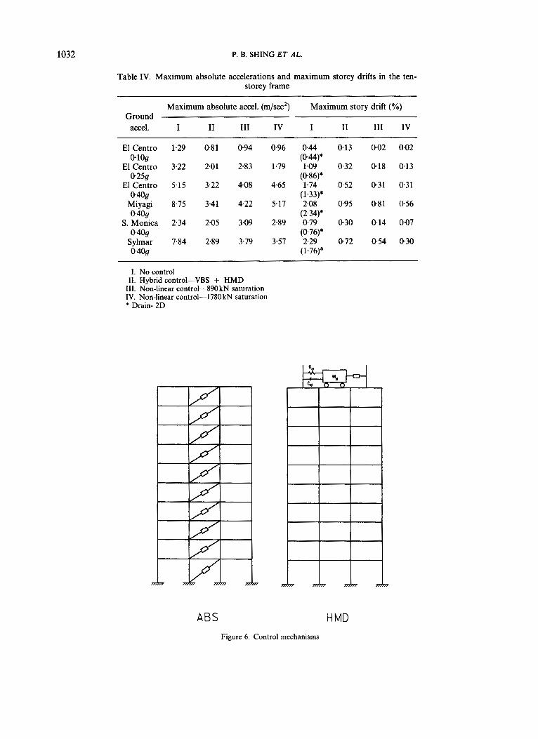
in an earlier section, a ten-storey moment-resisting steel frame designed by Anderson and NaeimZ4 is selected for case studies. The design of the frame and its dynamic properties are shown in Figure 5. The mass at each floor is 98 kN s'/m (05590 kip s'/in), with the roof mass being 81.6 kN s'/m (04658 kip s'/in). The frame has been analysed with DRAIN-2DZ5 under the NS component of the 1940 El Centro ground motion, with the peak ground acceleration scaled to 0.10 g , 0.25 g , and 0.40 g , respectively. Rayleigh damping is used, with the damping ratios for the first two modes set to 5 percent, as shown in Figure 5. This damping could be slightly higher than what is normally encountered in buildings. Nevertheless, a higher damping is expected to result in a more conservative assessment of a control system, whose efficiency is usually reduced by the inherent damping of a structure. The steel is assumed to be A36. As shown in Table IV, without control, the storey drifts developed at different ground acceleration levels more or less satisfy the conventional design criteria shown in Table I. Mild inelastic deformation initiated in the girders at the level of 0.25 g , and the columns in the seventh storey yielded at 0.40 g .
With the above frame model, the effectiveness of the control laws and different control mechanisms are compared. Two types of control mechanisms are considered, as shown in Figure 6. One is an Active Bracing System (ABS), and the other is a Hybrid Mass Damper (HMD). Since the main objective of the control is to
11.8 16.8 21.9 12
Figure 5. Ten-storey prototype frame (1 ft = 0.3048 m)
1032 P. B. SHING ET AL.
Table IV. Maximum absolute accelerations and maximum storey drifts in the ten- storey frame
Maximum absolute accel. (m/sec2) Maximum story drift (%) Ground
accel. I I1 I11 IV I i1 111 IV
El Centro 1.29 0.81 0.94 0.96 0.44 0.13 002 0.02
El Centro 3.22 2.01 2.83 1.79 1.09 0.32 0.18 0.13 0.259 (0.86)*
El Centro 5.15 3.22 4.08 4.65 1.74 0.52 0.31 0.31 0.409 (1.33)*
Miyagi 8.75 3.41 4.22 5.17 2.08 0.95 0.81 0.56 0.409 (2.34)*
S. Monica 2.34 2.05 3.09 2.89 0.79 030 0.14 0.07 0.409 (0.76)*
Sylmar 7.84 2.89 3.79 357 2.29 0.72 0.54 0.30 0.409 (1.76)*
I. No control 11. Hybrid control-VBS + HMD
111. Non-linear control-890 kN saturation IV. Non-linear control-1780kN saturation * Drain- 2D
0.109 (0.44)*
ABS H MD Figure 6. Control mechanisms
CONTROL OF BUILDING VIBRATIONS 1033
avoid structural and non-structural damage, all simulations with control forces are conducted with a linearly elastic frame model which is condensed to have ten lateral degrees of freedom.
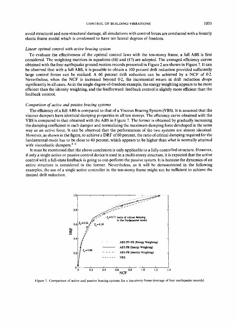
Linear optimal control with active bracing system To evaluate the effectiveness of the optimal control laws with the ten-storey frame, a full ABS is first
considered. The weighting matrices in equations (16) and (17) are adopted. The averaged efficiency curves obtained with the four earthquake ground motion records presented in Figure 2 are shown in Figure 7. It can be observed that with a full ABS, it is possible to obtain a 100 percent drift reduction provided sufficiently large control forces can be realized. A 60 percent drift reduction can be achieved by a NCF of 0-2. Nevertheless, when the NCF is increased beyond 0.2, the incremental return in drift reduction drops significantly in all cases. As in the single-degree-of-freedom example, the energy weighting appears to be more efficient than the identity weighting, and the feedforward-feedback control is slightly more efficient than the feedback control.
Comparison of active and passive bracing systems The efficiency of a full ABS is compared to that of a Viscous Bracing System (VBS). It is assumed that the
viscous dampers have identical damping properties in all ten storeys. The efficiency curve obtained with the VBS is compared to that obtained with the ABS in Figure 7. The former is obtained by gradually increasing the damping coefficient in each damper and normalizing the maximum damping force developed in the same way as an active force. It can be observed that the performances of the two systems are almost identical. However, as shown in the figure, to achieve a DRF of 60 percent, the ratio of critical damping required for the fundamental mode has to be close to 40 percent, which appears to be higher than what is normally attained with viscoelastic darn per^.^-^
It must be mentioned that the above conclusion is only applicable to a fully controlled structure. However, if only a single active or passive control device is used in a multi-storey structure, it is expected that the active control with a full-state feedback is going to out-perform the passive system. It is because the dynamics of an entire structure is considered in the former. Nevertheless, as it will be demonstrated in the following examples, the use of a single active controller in the ten-storey frame might not be sufficient to achieve the desired drift reduction.
1 .c
0.8
0.6
2 n 0.4
0.2
0
ABS FF-FB (Energy Weightmg)
A B S FB (Energy Weightmg)
- - - - ABS FB (Idenhty Weightmg)
VBS _ _ _ _ _ _
0.2 0.4 0.6 0.8 NCF
1 .o 1.2 1.4
Figure 7. Comparison of active and passive bracing systems for a ten-storey frame (average of four earthquake records)

1034 P. B. SHING ET AL.
I
/ ' /
Hybrid mass damper Active and hybrid tuned mass dampers constitute a majority of the active control systems that have been
actually installed in building structures." Hybrid mass dampers (HMD) are designed to take advantage of the passive mechanism to reduce the demand on the active force. It is interesting to compare the performance of such a system with that of an ABS. For this purpose, the properties of the passive damper mechanism are determined with Den Hartog's approach.26 It has a mass of 48 kN s2/m (02748 kip s2/in), which is equal to 5 percent of the total mass of the building, a natural frequency wd of 2.19 rad/s and a damping ratio t d of 24 percent. The feedback gains for the active component of the HMD are determined with the classical optimal control theory with various values of the force weighting factor R. A full-state feedback is adopted. Two types of ABS are compared to the HMD. One is a full bracing system and the other is a single active brace located at the bottom storey of the structure. It can be observed in Figure 8 that the maximum drift reduction that can be attained with the HMD based on the average of the four ground motion records is around 40 percent, while that obtained with the single brace is about 25 percent. It is interesting to note that the HMD is more effective than the full active bracing and far more effective than the single active brace as long as the NCF is less than 0.1, beyond which the effectiveness of the HMD drops rapidly. It should be noted that for the HMD, only the active force is used in the computation of the NCF.
Based on this result and the design criteria shown in Table I, one can conclude that while the HMD may be very effective when only a relatively small control force is needed, it may not be sufficient to prevent structural damage in the event of a strong earthquake excitation.
Hybrid system with H M D and VBS Based on the efficiency measure adopted here, full viscous and active bracing systems have almost the same
performances in the ten-storey frame. However, active systems are not only difficult to maintain, the deployment of large active forces may not be desirable as they could be potentially as detrimental as earthquake forces if the control system happened to malfunction. On the other hand, the damping capacity of a passive device can be severely limited by mechanical constraints. Therefore, a hybrid active-passive control system is considered as an alternative that can combine the best of the two strategies. The hybrid system considered here comprises a HMD and a VBS.
In this hybrid system, viscous dampers are introduced in all ten storeys. The damping coefficient for each damper is chosen to be 1927 kN s/m (1 1 kip s/in), which increases the damping in the fundamental mode of
ABS -All Stories
0.5
Figure 8. Comparison of Hybrid Mass Damper and active bracing systems for a ten-storey frame (average of four earthquake records)

CONTROL O F BUILDING VIBRATIONS 1035
the structure from 5 to 15 percent. This choice is conservative with respect to the performance of a typical viscoelastic damper operating under normal room t e m p e r a t ~ r e . ~ - ~ A tuned mass damper having the same mass, frequency, and damping properties as the one considered above is adopted. To determine the feedback gains, the optimal control theory is applied to the viscously damped structure. As shown in Figure 9, an averaged DRF-NCF curve is generated for the hybrid system with the four earthquake records and various values of the force weighting factor R. The displacement and velocity feedback gains that correspond to the peak of the DRF-NCF curve are selected. It can be noticed in Figure 9 that the incremental efficiency of the HMD is lowered by the presence of the viscous bracing system.
The performance of the hybrid control system under different earthquake ground motions is summarized in Tables IV and V. It can be seen that with the hybrid system, the drift criterion shown in Table I is almost satisfied for the El Centro record and well satisfied for the Santa Monica record, but not for the Miyagi-Ken- Oki and Sylmar records. The latter records have a number of high-amplitude acceleration pulses and have their predominant frequencies close to the first three natural frequencies of the structure. By comparing the resulting story drifts to those of the uncontrolled structure obtained with DRAIN-2D analysis, one can see
HMD + VBS
0' 0 0.05 0.10 0.15 0.20 0.25
NCF 30
Figure 9. Efficiency of hybrid control for a ten-storey frame (average of four earthquake records)
Table V. Maximum base shears and control forces in the ten-storey frame
Max. active Maximum Maximum column shear Maximum control force force damper
at base in brace in HMD drift (kW (kN) (kN) (m)
accel. I I1 I11 IV I1 I11 IV I1 I1 Ground
El Centro 1980 794 596 636 359 890 1780 149 0.67
Miyagi 2015 1382 1352 1035 399 890 1780 310 0.98
S. Monica 930 428 277 154 229 890 1780 79.3 0.45
Sylmar 2131 1018 911 575 358 890 1780 188 0.97
0,409
0.409
0.409
0.409

1036 P. B. SHING ET AL.
that the structure must have deformed slightly beyond its elastic limit under these two earthquakes. Except for the Santa Monica record, the hybrid system results in a significant reduction of the absolute acceleration of the structure. The maximum shears in the bottom-storey columns and the maximum passive and active control forces developed are shown in Table V. It can be observed that the base shears are significantly reduced in all cases. Table V also indicates that the drifts of the mass damper are within a reasonable range in all cases.
Nonlinear control law with active or semi-active bracing system The efficiency of the non-linear control law in the ten-storey frame is examined with a control device
installed in the diagonal brace of every storey. It should be mentioned that this control law can be
-0 0.2 0.4 0.6 0.8 1 .o 1.2 1.4 NCF
(4
0' I NCF
(b)
0 0.2 0.4 0.6 0.8 1 .o 1.2 1.4
Figure 10. Comparison of linear and non-linear control laws for a ten-storey frame: (a) El Centro; (b) Miyagi-Ken-Oki

CONTROL OF BUILDING VIBRATIONS 1037
implemented with a number of semi-active devices that are currently under d e v e l ~ p m e n t . ~ ~ * ~ ~ - ~ ~ H owever, it is not necessary to distinguish whether these devices are active or semi-active in the following simulations. A velocity gain of 149 kN s/mm (850 kip s/in) is selected for each device. This large control gain is intended to exploit the full capacity of the control devices over a range of the NCF chosen. A DRF-NCF curve is generated for each of the four earthquake records by increasing the force saturation limit. It is found that the non-linear control law is most effective for the El Centro record and least effective for the Miyagi-Ken-Oki record. The efficiency curves for these records are shown in Figure 10. In all the cases considered here, the non-linear control law is superior to the linear control laws or linear viscous damping devices as long as the NCF is around 0.2 or below. The linear and non-linear control laws have almost the same performance when the NCF exceeds 0.4.
To examine the magnitude of the maximum control force that is needed with the non-linear control law in order to satisfy the design objectives shown in Table I, different force saturation limits have been selected for case studies with the control gain kept at the same level as above. The results obtained with the saturation limits of 200 and 400 kips are shown in Tables IV and V. These correspond to a NCF of about 025 and 0.50, respectively. It can be observed that in either case, the performance is better than that attained with the hybrid system considered previously, but at the expense of larger control forces. When the saturation limit is set to 400 kips, the design criterion is satisfied in all cases, except that for the Miyagi-Ken-Oki record, the allowable drift limit of 0.4 percent is slightly exceeded. Nevertheless, as shown in Table IV, one distinct drawback of the non-linear control is that it increases the maximum absolute acceleration of the structure as the control forces increase beyond a certain level. In fact, the absolute accelerations of a structure will eventually approach that of the ground as the drift approaches zero. This is indeed the case with the Sylmar record, as shown in Table IV. However, in spite of this, the maximum absolute accelerations of the controlled structure are still less than that of the uncontrolled structure in most of the cases.
It should be noted that with a maximum allowable control force of 400 kips, the above performance can also be achieved by a linear optimal control law or by linear viscous dampers, as shown in Figure 10. Nevertheless, the main advantage of the non-linear control law is that it can be implemented with semi-active devices. Unlike active control, semi-active control does not have the stability problem and requires little power consumption. Furthermore, the non-linear control law provides a safety fuse that can prevent the transmission of detrimental forces to other members of the structure.
CONCLUSIONS
The performances of two optimal control strategies and a non-linear control law are critically evaluated and compared to that of linear viscous dampers. These control schemes are evaluated with a ten-storey steel frame implemented with active, passive, and semi-active bracing devices, respectively. A hybrid system consisting of a passive bracing system and a hybrid mass damper is also considered. To compare the efficiencies of different control strategies in an objective manner, dimensionless indices based on drift reduction and a normalized control force are introduced. The main conclusions derived from this study can be summarized as follows.
1. Even though earthquake ground motions are usually far from being Gaussian white noise, the performance of the classical optimal feedback control law is close to optimal with respect to the performance measures adopted here. This is, however, based on observations obtained with a SDOF system. In most of the examples considered, the improvement in performance introduced by the optimal feedforward-feedback control law over the classical feedback control is very marginal.
2. The non-linear control law introduced here is simple to implement and robust. In most of the examples considered, it has a performance at least equivalent to, if not better than, the linear optimal control laws. Furthermore, when only relatively small control forces are permitted, the non-linear control law appears to be far more efficient than the linear control laws.
3. In the ten-storey structure, a full active bracing system with a linear control has almost the same performance as a full passive bracing system. Both systems can achieve a 100 percent drift reduction as
1038 P. B. SHING ET AL.
4.
5.
long as sufficiently large control forces can be realized. However, the maximum drift reduction that can be achieved by a single hybrid mass damper located at the top of the structure is around 40 percent and that by a single active brace installed at the bottom storey is only 25 percent. On the other hand, when only relatively small control forces are allowed, a hybrid mass damper appears to be more effective than a full active bracing system. The performance of a control strategy varies from one earthquake ground motion to another. For the ten-storey structure, the Miyagi-Ken-Oki record seems to be most severe in terms of the maximum storey drift produced and the control effort required. When the maximum ground acceleration is scaled to 0.4 g, this record requires a maximum control force of more than 400 kips in a full bracing system to limit the maximum storey drift to 0.4 percent. For this ground motion, a single hybrid mass damper is not sufficient to attain the above drift limit. Results of this study allude to the fact that for a new structure, one should design the control system and the structure as a whole with the performance of the control system considered as part of the design constraints. For example, if the ten-storey structure was so designed that the drift reduction that needed to be attained by the control system was no more than 60 percent, either a semi-active bracing system implemented with the non-linear control law or a hybrid system consisting of a passive bracing and a hybrid mass damper could be a very effective solution.
Even though the conclusions of this study are based on specific numerical examples, it must be pointed out that a variety of earthquake ground motions are considered and the results encompass a number of scenarios. An efficient semi-active control mechanism to be used with the non-linear control law presented in this paper has been developed. This device does not require any power to operate. A study is currently underway to further improve and validate the performance of the device and that of the control strategy.
ACKNOWLEDGEMENTS
The study presented in this paper is supported by the National Science Foundation under Grant No. BCS- 9201962. However, opinions expressed in the paper are those of the writers and do not necessarily reflect those of the sponsor.
REFERENCES
1. N. R. Petersen, ‘Design of large scale tuned mass dampers’, in Proc. ASCE convention and exposition, Boston, 1979. 2. I. G. Buckle and R. L. Mayes, ‘Seismic isolation: history, application, and performance-a world review’, Earthquake spectra 6(2),
3. J. M. Kelly, ‘State-of-the-art and state-of-the-practice in base isolation’, in A T C 17-1, Seminar on seismic isolation, passive energy
4. I. D. Aiken, D. K. Nims, A. S. Whittaker and J. M. Kelly, ‘Testing of passive energy dissipation systems’, Earthquake spectra 9(3),
5. K. Kasai, J. A. Munshi, M. L. Lai and B. F. Maison, ‘Viscoelastic damper hysteretic model theory, experiment, and application’, in ATC 17-1, Seminar on seismic isolation, passive energy dissipation, and active control, Applied Technology Council, Redwood City,
6 . K. C. Chang, T. T. Soong, M. L. Lai and E. J. Nielsen, ‘Development of a design procedure for structures with added viscoelastic dampers’, in ATC 17-1, Seminar on seismic isolation, passive energy dissipation, and active control, Applied Technology Council, Redwood City, CA, 1993, pp. 473484.
7. C. E. Grigorian and E. P. Popov, ‘Slotted bolted connections for energy dissipation’, in ATC 17-1, Seminar on Seismic Isolation, Passive Energy Dissipation, and Active Control, Applied Technology Council, Redwood City, CA, 1993, pp. 545-556.
8. P. Mahmoodi, L. E. Robertson, M. Yontar, C. Moy and L. Feld, ‘Performance of viscoelastic dampers in world trade center towers’, in Proc. ASCE structures congress ’87, Dynamics of Structures, Orlando, FL, ASCE, N.Y., 1987.
9. T. T. Soong, ‘Active structural control in civil engineering’, Technical Report NCEER-87-0023, National Center for Earthquake Engineering Research, State University of New York at Buffalo, NY, 1987.
10. T. Kobori, N. Koshika, K. Yamada and Y. Ikeda, ‘Seismic-response-controlled structure with active mass driver system. Part 1: design’, Earthquake eng. struct. dyn. 20, 133-149 (1991).
11 . T. T. Soong and A. M. Reinhorn, ‘Case studies of active control and implementation issues’, in ATC 17-1, Seminar on seismic isolation, passive energy dissipation, and active control, Applied Technology Council, Redwood City, CA, 1993, pp. 701-713.
12. A. Astaneh, V. V. Bertero, B. A. Bolt, S. A. Mahin, J. P. Moehle and R. B. Seed, ‘Preliminary report on the seismological and engineering aspects of the October 17, 1989 Santa Cruz (Loma Prieta) earthquake’, UBC/EERC-89/14, Earthquake Engineering Research Center, University of California, Berkeley, CA, 1989.
161-201 (1990).
dissipation, and active control, Applied Technology Council, Redwood City, CA, 1993, pp. 9-28.
371-387 (1993).
CA, 1993, pp. 521-532.

CONTROL OF BUILDING VIBRATIONS 1039
13. J. P. Moehle (ed.), ‘Preliminary report on the seismological and engineering aspects of the January 17,1994 Northridge earthquake’,
14. J. F. Hall (ed.), ‘Northridge earthquake, January 17, 1994, Preliminary Reconnaissance Report, Earthquake Engineering Research
15. F. Naeim (ed.), The Seismic Design Handbook, Van Nostrand Reinhold, New York, 1989. 16. J. N. Yang, A. Akbarpour and P. Ghaemmaghami, ‘New optimal control algorithms for structural control’, J . eng. mech. div. ASCE
17. H. Kwakernaak and R. Sivan, Linear Optimal Control Systems, John Wiley, New York, 1972. 18. M. Abdel-Rohman and H. H. E. Leipholz, ‘Stochastic control of structures’, J . struct. din ASCE 107(ST7), 1313-1325 (1981). 19. H. Iemura, Y. Yamada, K. Izuno, Y. Iwasaki and S. Ohno, ‘Phase-adjusted activecontrol of structures with identification of random
earthquake ground motion’, in Proc. US national workshop on structural control research, University of Southern California, CA, 1990, pp. 116-124.
20. J. Suhardjo, B. F. Spencer and M. K. Sain, ‘Feedback-feedforward control of structures under seismic excitation’, Structural safety 8,
21. J. N. Yang, 2. Li and S. Vongchavalitkul, ‘Stochastic hybrid control of hysteretic structures’, Prob. eng. mech. 9, 125-133 (1994). 22. P. B. Shing, S. D. Kang, N. Kermiche, M. Dixon, B. Rose and D. M. Frangopol, ‘A non-linear control strategy for building
structures’, in Proc. 11th world con$ earthquake engineering, Acapulco, Mexico, June 1996. 23. B. Indrawan and H. Higashihara, ‘Active vibration control with explicit treatment of actuator’s limit’, in ATC 17-1, Seminar on
seismic isolation, passive energy dissipation, and active control, Applied Technology Council, Redwood City, CA, 1993, pp. 715-726. 24. J. C. Anderson and F. Naeim, ‘Design criteria and ground motion effects on the seismic response of multistorey buildings’, in
ATC-10-1, Critical aspects of earthquake ground motion and building damage potential, Applied Technology Council, Redwood City, CA, 1984.
25. A. Kanaan and G. H. Powell, ‘General purpose computer program for inelastic dynamic response of plane structures’, UCBIEERC 73/06, Earthquake Engineering Research Center, University of California, Berkeley, CA, 1973.
26. J. P. Den Hartog, Mechanical Vibrations, 4th edn, McGraw-Hill, New York, 1956. 27. H. P. Gavin and R. D. Hanson, ‘Electrorheological dampers for structural vibration suppression’, Report No . UMCEE 94-35,
28. R. L. Sack, C. C. Kuo, H. C. Wu, L. Liu and W. N. Patten, ‘Seismic motion control via semiactive hydraulic actuators’, Proc. 5th U.S.
29. M. D. Symans, M. C. Constantinou, D. P. Taylor and K. D. Garnjost, ‘Semi-active fluid viscous dampers for seismic response
UBC/EERC-94/01, Earthquake Engineering Research Center, University of California, Berkeley, CA, 1994.
Institute, Oakland, CA, 1994.
ll3(9), 1369-1386 (1987).
69-89 (1990).
Department of Civil and Environmental Engineering, University of Michigan, Ann Arbor, MI, 1994.
national con$ earthquake engineering, Chicago, IL, 1994, pp. 31 1-320.
control’, Proc. 1st world con$ structural control, Los Angeles, CA (1994).