control keyboard operating manual
TRANSCRIPT
1
Control Keyboard Operating Manual
2
Contents Welcome ...................................................................................................................................4 Important Safeguarding and Warnings ................................................................................5 1 Feature and Specification ...............................................................................................6
1.1 Feature ....................................................................................................................6 1.2 Specification ...........................................................................................................6
2 Keyboard Function ...........................................................................................................7 2.1 Keyboard Appearance ..........................................................................................7 2.2 Key Function List ...................................................................................................7 2.3 Keyboard Ports ....................................................................................................10 2.4 Port Features........................................................................................................10 2.5 Power.....................................................................................................................10
3 Menu Tree .....................................................................................................................11 3.1 Input Method.........................................................................................................12 3.2 Log in .....................................................................................................................12 3.3 Log out...................................................................................................................12
4 Menu Operation ..............................................................................................................13 4.1 Local Setup ...........................................................................................................13
4.1.1 Time Setup .................................................................................................13 4.1.2 Address Setup ...........................................................................................13
4.2 CTL Point ..............................................................................................................13 4.2.1 ID..................................................................................................................14 4.2.2 Device Name .............................................................................................14 4.2.3 Device Type ...............................................................................................14 4.2.4 Connection Type .......................................................................................14
4.3 Advance ................................................................................................................15 4.3.1 Password ....................................................................................................15 4.3.2 User Management.....................................................................................16 4.3.3 Set Local as Default..................................................................................17 4.3.4 Empty Control Point ..................................................................................17
4.4 Assistant Setup ....................................................................................................17 4.4.1 Backlight Setup..........................................................................................17 4.4.2 Alarm Setup................................................................................................17 4.4.3 Language....................................................................................................17 4.4.4 Auto Lock....................................................................................................17
4.5 System Information..............................................................................................17 4.5.1 Search Point...............................................................................................18
5 Keyboard Control DVR ..................................................................................................19 5.1 Serial Port Connection ........................................................................................19
5.1.1 RS232 Serial Port Connection ................................................................19 5.1.2 RS485 Connection ....................................................................................19 5.1.3 Multi-keyboard level-link via RS485 .......................................................20
5.2 DVR and Keyboard Setup ..................................................................................20 5.2.1 DVR Setup..................................................................................................21 5.2.2 Keyboard Setup after Serial Port Connection.......................................21

3
5.2.3 Keyboard Setup after Network Connection...........................................22 5.3 Operation ..............................................................................................................22
5.3.1 Login............................................................................................................22 5.3.2 Logout .........................................................................................................23 5.3.3 Record.........................................................................................................23 5.3.4 PTZ Control and Image Color .................................................................23 5.3.5 Tour and Single/Multiple Window Switch. .............................................23
6 Keyboard Control Dome................................................................................................24 6.1 Cable Connection ................................................................................................24 6.2 Keyboard Setup ...................................................................................................24 6.3 Operation ..............................................................................................................24
6.3.1 Direction Setup ..........................................................................................25 6.3.2 Preset ..........................................................................................................25 6.3.3 Scan ............................................................................................................25 6.3.4 Tour .............................................................................................................26 6.3.5 PATTERN ...................................................................................................27 6.3.6 Pan Rotation ..............................................................................................27
7 Control Keyboard Upgrade ...........................................................................................28 8 Make Serial Port .............................................................................................................29
8.1 RS232 Serial Port ................................................................................................29 8.2 RS485 Serial Port ................................................................................................29 8.3 25-pin Port and Switch Box Connection ..........................................................29

4
Welcome Thank you for purchasing our control keyboard! This operating manual is designed to be a reference tool for the operation of your keyboard. Here you can find information about this keyboard features and functions, as well as a detailed menu tree. Before operation please read the following safeguards and warnings carefully!

5
Important Safeguarding and Warnings All installation and operation should conform to your local electrical safety codes. We assume no liability or responsibility for all the fires or electrical shock caused by improper handling or installation All the examination and repair should be done by the qualified service engineers. We are not liable for any problems caused by unauthorized modifications or attempted repair.
6
1 Feature and Specification
1.1 Feature This series keyboard has the following features
One keyboard can control multiple DVRs, or you can use multiple keyboards to control one DVR.
Support dome operation. Support RS485 port and RS232 port. Support PTZ operation via joystick Support all operations you get from DVR front panel function keys Support keyboard lock function Support multiple-level operation rights Support level-link Support single or multiple DVRs’s menu setup On-screen menu, user-friendly procedure. It is very easy for you to operate
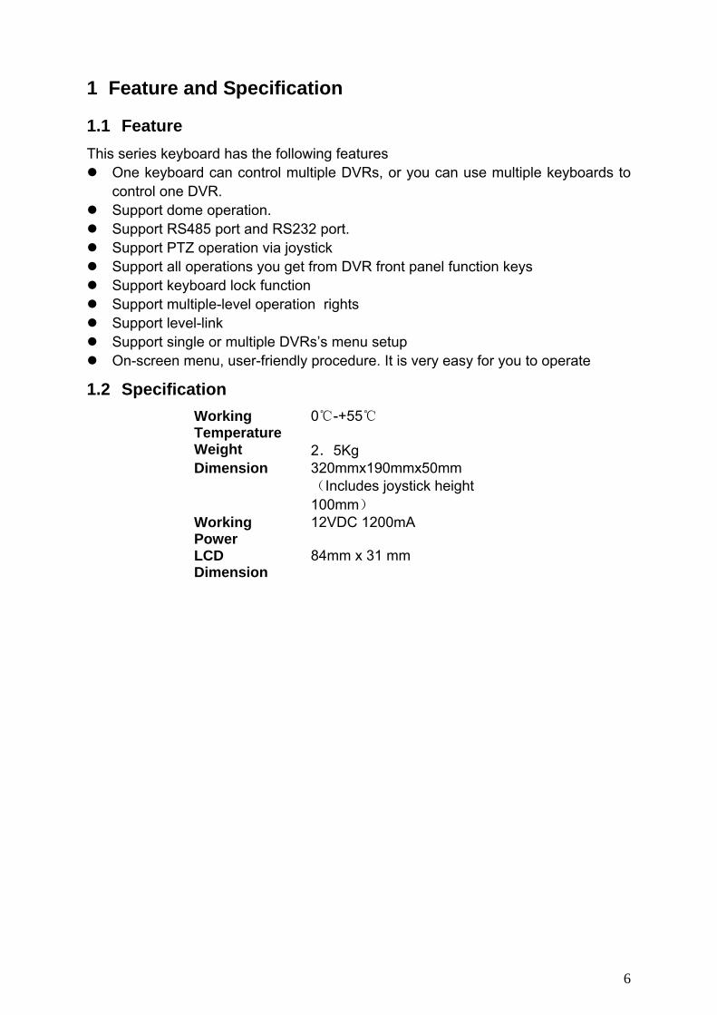
1.2 Specification Working Temperature
0℃-+55℃
Weight 2.5Kg Dimension 320mmx190mmx50mm
(Includes joystick height 100mm)
Working Power
12VDC 1200mA
LCD Dimension
84mm x 31 mm
7
2 Keyboard Function
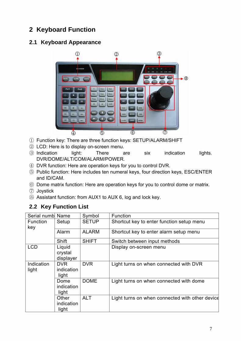
2.1 Keyboard Appearance
① Function key: There are three function keys: SETUP/ALARM/SHIFT ② LCD: Here is to display on-screen menu. ③ Indication light: There are six indication lights.
DVR/DOME/ALT/COM/ALARM/POWER. ④ DVR function: Here are operation keys for you to control DVR. ⑤ Public function: Here includes ten numeral keys, four direction keys, ESC/ENTER
and ID/CAM. ⑥ Dome matrix function: Here are operation keys for you to control dome or matrix. ⑦ Joystick ⑧ Assistant function: from AUX1 to AUX 6, log and lock key.
2.2 Key Function List Serial numb Name Symbol Function
Setup SETUP Shortcut key to enter function setup menu
Alarm ALARM Shortcut key to enter alarm setup menu
Function key
Shift SHIFT Switch between input methods LCD Liquid
crystal displayer
Display on-screen menu
DVR indication light
DVR Light turns on when connected with DVR
Dome indication light
DOME Light turns on when connected with dome
Indication light
Other indication light
ALT Light turns on when connected with other device

8
Serial port indication light
COM Light turns on when connected with serial port device
Alarm indication light
ALARM Light turns on when connected with alarm devices
Power indication light
POWER Light turns on when keyboard connected with power and works properly.
In single surveillance mode, click Fn1 to display PTZ and image color setup menu. In motion detection setup, working with other keys
Assistant function key
Fn1
When playback, click Fn1 to display or hide process bar.
DVR assistant function key 2
Fn2 In DVR menu, click Fn2 to select an input method.
Tour Activate tour function Single window display mode
Single window display mode
Four window display mode
⊞ Turn to four window display mode
Nine window display mode
▦ Turn to nine window display mode
Sixteen window display mode
▦ Turn to sixteen window display mode
Record Record/play Backward /Pause
/ Video backward play or pause
Play frameby frame
→ Play video frame by frame
Play/pause Play /Pause II When DVR is in real-time surveillance mode,
system goes to video search menu,. Fast backward Fast backward playback
Slow play ► Various slow play speeds
DVR function key
Fast forward Various fast play speeds
9
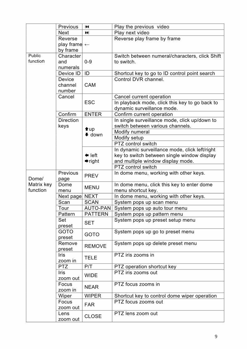
Previous Play the previous video Next Play next video Reverse play frameby frame
← Reverse play frame by frame
Character and numerals
0-9 Switch between numeral/characters, click Shift to switch.
Device ID ID Shortcut key to go to ID control point search Device channel number
CAM Control DVR channel.
Cancel current operation Cancel ESC In playback mode, click this key to go back to
dynamic surveillance mode. Confirm ENTER Confirm current operation
In single surveillance mode, click up/down to switch between various channels. Modify numeral Modify setup
up down
PTZ control switch In dynamic surveillance mode, click left/right key to switch between single window display and multiple window display mode.
Public function
Direction keys
left right
PTZ control switch Previous page PREV In dome menu, working with other keys.
Dome menu MENU In dome menu, click this key to enter dome
menu shortcut key. Next page NEXT In dome menu, working with other keys. Scan SCAN System pops up scan menu Tour AUTO-PAN System pops up auto tour menu Pattern PATTERN System pops up pattern menu Set preset SET System pops up preset setup menu
GOTO preset GOTO System pops up go to preset menu
Remove preset REMOVE System pops up delete preset menu
Iris zoom in TELE PTZ iris zooms in
PTZ P/T PTZ operation shortcut key Iris zoom out WIDE PTZ iris zooms out
Focus zoom in NEAR PTZ focus zooms in
Wiper WIPER Shortcut key to control dome wiper operation Focus zoom out FAR PTZ focus zooms out
Dome/ Matrix key function
Lens zoom out CLOSE PTZ lens zoom out

10
Lens zoom in OPEN PTZ lens zoom in
Light LIGHT Control dome light Joystick Assistant menu and function key operation.
AUX1----- AUX6 Assistant key
LOG LOG Shortcut key to search log files
Assistant function key
LOCK LOCK Shortcut key to lock keyboard
2.3 Keyboard Ports
1、RS485 2、RS232 3、Power
2.4 Port Features RS232 can directly connect with DVR. The distance should be within 10m. RS485 transmission distance is 1200 m(9600bps),max 3000 m. In level-link mode, one RS-485 port can connect with as many as 16 keyboards.
2.5 Power The keyboard use +12V DC, you can use +12V adapter included in the accessories package.

11
3 Menu Tree Key board menu tree is shown as below.
MEN
U
Time Setting
Address Setting Local
CTL Point
ID
Device Name
Device Type
Connection Type
Password
User Management
Default
Empty Point
Version
Date
Current Connection Type
Point Information
Menu Operation
Advance
Assistant
System Infor
Control Point Machine
ID
RS232
RS485
Alarm Setup
Language
Backlight
RS232
RS485
Auto Lock
12
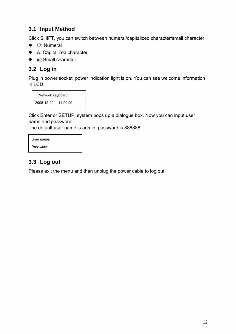
3.1 Input Method Click SHIFT, you can switch between numeral/capitalized character/small character.
: Numeral A: Capitalized character @ Small character.
3.2 Log in Plug in power socket, power indication light is on. You can see welcome information in LCD. Click Enter or SETUP, system pops up a dialogue box. Now you can input user name and password. The default user name is admin, password is 888888.
3.3 Log out Please exit the menu and then unplug the power cable to log out.
Network keyboard
2006-12-20 14.00.00
User name:
Password:
13
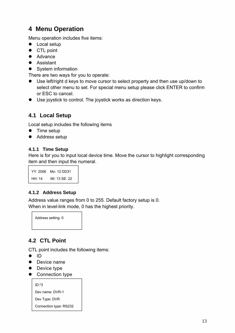
4 Menu Operation Menu operation includes five items:
Local setup CTL point Advance Assistant System information
There are two ways for you to operate: Use left/right d keys to move cursor to select property and then use up/down to
select other menu to set. For special menu setup please click ENTER to confirm or ESC to cancel.
Use joystick to control. The joystick works as direction keys.
4.1 Local Setup Local setup includes the following items
Time setup Address setup
4.1.1 Time Setup Here is for you to input local device time. Move the cursor to highlight corresponding item and then input the numeral. 4.1.2 Address Setup Address value ranges from 0 to 255. Default factory setup is 0. When in level-link mode, 0 has the highest priority.
4.2 CTL Point CTL point includes the following items:
ID Device name Device type Connection type
YY: 2006 Mo: 12 DD31
HH: 14 MI: 13 SE: 22
Address setting: 0
ID:*3
Dev name: DVR-1
Dev Type: DVR
Connection type: RS232

14
4.2.1 ID Here is for you to input front device ID. Move the cursor to highlight ID and then use input numeral. If there is a * before the ID number (such as *3), it means that front device has control point setup. You can view device *3 corresponding type and name. 4.2.2 Device Name Here is for you to input device name. You can use various input methods to give a name to the front device, 4.2.3 Device Type There are several options: DVR/dome/matrix/NVS. You can use left/right key to select. 4.2.4 Connection Type There are several options: RS232/RS485. You can use left/right key to select corresponding connection type. Please refer to the following figure for more information.
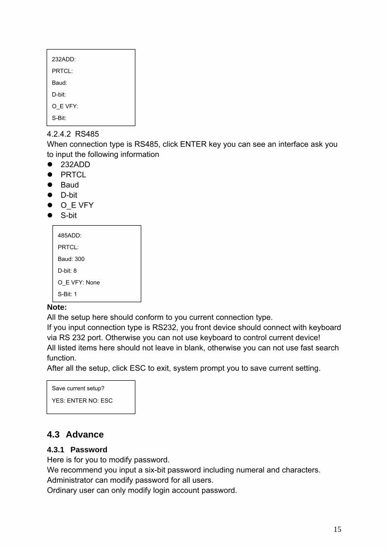
After you have selected connection type, please click ENTER to go on connection setup. 4.2.4.1 RS232 When connection type is RS232, click ENTER key you can see an interface ask you to input the following information
232ADD PRTCL Baud D-bit O_E VFY S-bit
15
4.2.4.2 RS485 When connection type is RS485, click ENTER key you can see an interface ask you to input the following information
232ADD PRTCL Baud D-bit O_E VFY S-bit
Note: All the setup here should conform to you current connection type. If you input connection type is RS232, you front device should connect with keyboard via RS 232 port. Otherwise you can not use keyboard to control current device! All listed items here should not leave in blank, otherwise you can not use fast search function. After all the setup, click ESC to exit, system prompt you to save current setting.
4.3 Advance 4.3.1 Password Here is for you to modify password. We recommend you input a six-bit password including numeral and characters. Administrator can modify password for all users. Ordinary user can only modify login account password.
232ADD:
PRTCL:
Baud:
D-bit:
O_E VFY:
S-Bit:
485ADD:
PRTCL:
Baud: 300
D-bit: 8
O_E VFY: None
S-Bit: 1
Save current setup?
YES: ENTER NO: ESC
16
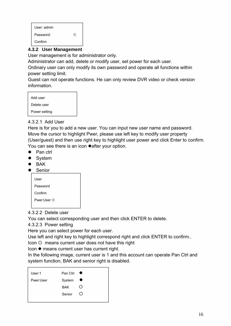
4.3.2 User Management User management is for administrator only. Administrator can add, delete or modify user, set power for each user. Ordinary user can only modify its own password and operate all functions within power setting limit. Guest can not operate functions. He can only review DVR video or check version information. 4.3.2.1 Add User Here is for you to add a new user. You can input new user name and password. Move the cursor to highlight Pwer, please use left key to modify user property (User/guest) and then use right key to highlight user power and click Enter to confirm. You can see there is an icon after your option.
Pan ctrl System BAK Senior
4.3.2.2 Delete user You can select corresponding user and then click ENTER to delete. 4.3.2.3 Power setting Here you can select power for each user. Use left and right key to highlight correspond right and click ENTER to confirm.. Icon means current user does not have this right Icon means current user has current right. In the following image, current user is 1 and this account can operate Pan Ctrl and system function, BAK and senior right is disabled.
User: admin
Password:
Confirm
Add user
Delete user
Power setting
User
Password
Confirm
Pwer:User
User:1 Pan Ctrl
Pwer:User System
BAK
Senior

17
4.3.3 Set Local as Default Here is for you to restore factory default setup. Note: when you operate this function, please be careful! 4.3.4 Empty Control Point Here is for you to delete all control point information. Click ENTER to clear all. 4.4 Assistant Setup Assistant setup includes the following items: 4.4.1 Backlight Setup You can open LCD backlight. It will last for ten minutes. When you log in the next time, backlight automatically turns on 4.4.2 Alarm Setup You can turn on alarm function. 4.4.3 Language There are three options: English/Simplified Chinese/Traditional Chinese. 4.4.4 Auto Lock Here is for you to set auto lock interval. There are four options:10/30/60/close(Unit: minute). When keyboard is inactive for specified interval, it becomes locked. You need to log in again to operate keyboard. Close means disable auto lock function, keyboard always maintain active. 4.5 System Information System information includes the following items.
Version: here is to display system version.(for reference only) Date: here is to display system released date(for reference only) Connection type: here is to display current connection type.
You can click ENTER to view type (serial port or network) Point information
Set Local as Default?
Yes: ENTER No: Esc
Clear ALL CTL Point?
Yes: ENTER No: Esc
Back light: ON
Alarm: ON
Language: English

18
Current Dev:Dome
RS232:3
ID:3
4.5.1 Search Point You can input either of the following information to search one device. System can automatically connect with that device and you can use keyboard to control it. For control keyboard:
You can click ENTER to go to the above menu and then input corresponding property to search. E.g.: If you want to search a device of ID3. Input ID as 3 and then click ENTER to confirm. System pops up the following interface, ID 3 is a dome and its RS232 address is 3. System automatically connects the dome. Now you can use keyboard to control current dome.
Note: when you use keyboard to control DVR, please click ID and then click ESC to go back to previous menu. When you use keyboard to control other device, click ESC to go back to previous menu.
Version: 1.10
Date: 2006-12-29
Connection type: Network
Point Info: 0
19
5 Keyboard Control DVR
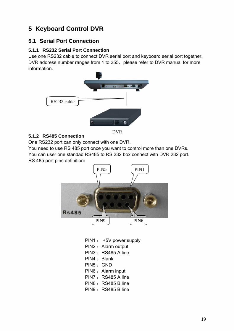
5.1 Serial Port Connection 5.1.1 RS232 Serial Port Connection Use one RS232 cable to connect DVR serial port and keyboard serial port together. DVR address number ranges from 1 to 255,please refer to DVR manual for more information.
5.1.2 RS485 Connection One RS232 port can only connect with one DVR. You need to use RS 485 port once you want to control more than one DVRs. You can user one standad RS485 to RS 232 box connect with DVR 232 port. RS 485 port pins definition:
PIN1 : +5V power supply PIN2 :Alarm output PIN3 :RS485 A line PIN4 :Blank PIN5 :GND PIN6 :Alarm input PIN7 :RS485 A line PIN8 :RS485 B line PIN9 :RS485 B line
DVR
RS232 cable
PIN1PIN5
PIN6PIN9

20
Rs485 connection via converter
……
One 485 bus can connect with thirty-two RS485->232 converters,one RS485->232 converter can connect with twelve DVRs. 5.1.3 Multi-keyboard level-link via RS485
…… Multi-converter connection: The last converter on RS 485 port must be short circuited. (E.g.: open converter). See the image below, you need to change [1-2] short circuit to [2-3] short circuit. Note: Menu serial setup should conform to the device you connected; otherwise keyboard can not control the device!
5.2 DVR and Keyboard Setup
Short circuit
1 2 3
A B
Other 485 devices
485->232 converter 485->232 converter
A B
485->232 converter
…

21
5.2.1 DVR Setup Before operation, please make sure cable connection is proper. In DVR menu, from “Setting” to RS232. The default setup is shown as below.
Function: Keyboard Baud rate: 9600 Data bit: 8 Stop bit: 1 Parity: none.
Please note keyboard setup should conform to DVR setup.
5.2.2 Keyboard Setup after Serial Port Connection In menu, go to control point setup. Here you need to input the following information.
ID If there is a * before the ID number (such as *3), it means this front device has control point setup. You can view device *3 corresponding type and name.
Device name Here is for you to give a name to the front device.
Device type There are several selections such as DVR/Dome/CMS/NVS. You can use left/right key to select device type and then click up/down to go on setup.
Connection type Please use up/down to highlight connection type and then use left/right to select type. Click “ENTER” to set the following items:
232 address Parity Protocol
ID: *3
Dev name: DVR-1
Dev type: DVR
Connection type: RS232

22
ID 485 Add
Dev name
IP ADD
232 ADD
Stop bit Baud rate Data bit
Note: 232 address and 485 address are corresponding DVR local number. DH2 is network keyboard/2nd generation control keyboard protocol, its corresponding DVR serial port protocol is network keyboard protocol. DH1 is the first generation keyboard protocol, its corresponding DVR serial port is control keyboard protocol or Dahua protocol. 5.2.3 Keyboard Setup after Network Connection Use up/down to highlight connection type and then use left/right to select connection type. Click “ENTER” to go to setup. After all the setup, click ESC to exit. System pops up the dialogue box to prompt you save setup
5.3 Operation 5.3.1 Login You can use the following ways to login: ID, device name, IP, 232 address, 485 address. Click ENTER to go to setup interface, input you information and click ENTER to begin search. System automatically begin login if search is OK. System pops up the alert information if there is no search result. Note: Before you login, please log off DVR local user menu, local user priority is higher than the keyboard user!
232 Add: 8 Parity: None
Protocol: DH2 Stop bit: 1
Baud rate: 9600
Data bit: 8
CTL point IP”192.168.090.111
CTL port: 3777
Protocol”DH-2
Save data?
YES: ENTER NO: ESC

23
5.3.2 Logout Click ID key and then click ESC, you can logout current control menu. 5.3.3 Record Click record button ( )to go to record interface. You can use direction keys to modify channel name and status. Click ENTER to save modification, click ESC to exit without saving modification you have done. 5.3.4 PTZ Control and Image Color In single window display mode, click Fn1, system pops up PTZ and image color menu. Or you can click P/T in the keyboard to go to DVR control menu. 5.3.5 Tour and Single/Multiple Window Switch. Note: before click tour key, please make sure your current series DVR supports tour function. You can click tour key ( ) to begin touring.
、⊞、▦、▦ are corresponding to :One/four/nine/sixteen window display modes.
You can click numeral key to go to corresponding channel. E.g. you can click numeral 1 to go to channel one. For channel number more than two-digit (such as numeral 11), you need work with CAM key. E.g., you want to go to channel 12 then you input CAM+12+CAM.
24
ID:0
Device name: qiuji ①
Device type: dome
Connection type: RS485
485 Add: 1 O_E VFY: None
PRTCL: DH-SD S-bit: 1
Baud: 9600
D-bit: 8
6 Keyboard Control Dome
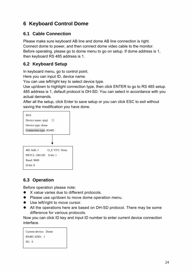
6.1 Cable Connection Please make sure keyboard AB line and dome AB line connection is right. Connect dome to power, and then connect dome video cable to the monitor. Before operating, please go to dome menu to go on setup. If dome address is 1, then keyboard RS 485 address is 1.
6.2 Keyboard Setup In keyboard menu, go to control point. Here you can input ID, device name. You can use left/right key to select device type. Use up/down to highlight connection type, then click ENTER to go to RS 485 setup. 485 address is 1, default protocol is DH-SD. You can select in accordance with you actual demands. After all the setup, click Enter to save setup or you can click ESC to exit without saving the modification you have done.
6.3 Operation Before operation please note:
X value varies due to different protocols. Please use up/down to move dome operation menu. Use left/right to move cursor. All the operations here are based on DH-SD protocol. There may be some
difference for various protocols. Now you can click ID key and input ID number to enter current device connection interface.
Current device:Dome
RS485 ADD:1
ID:0
25
Scan Value :1
Scan setup >Left limit
Versatile scan Right limit
Random scan Speed
Speed:5
〈Zoom〉
〈Direction〉 〈Focus〉
〈Iris〉
Preset setup >value:1
GOTO
Remove
Scan Value :1
Scan setup > Begin
Versatile scan Stop
Random scan
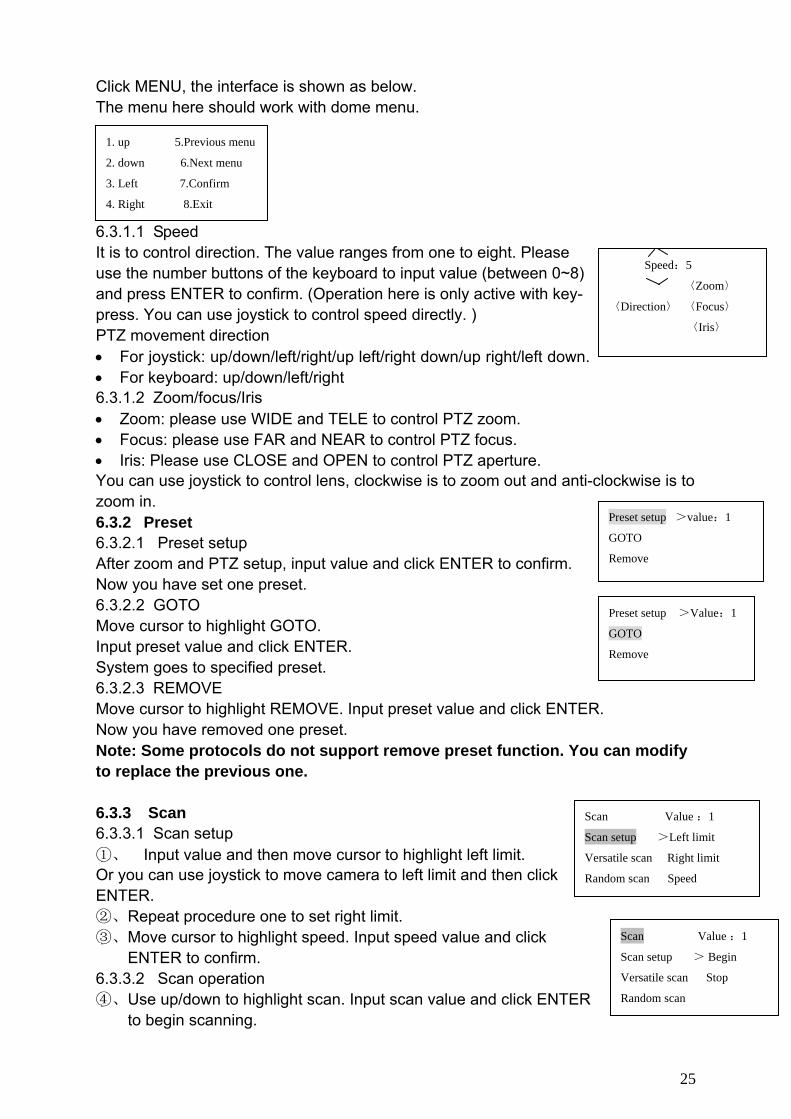
Click MENU, the interface is shown as below. The menu here should work with dome menu.
6.3.1 Direction Setup 6.3.1.1 Speed It is to control direction. The value ranges from one to eight. Please use the number buttons of the keyboard to input value (between 0~8) and press ENTER to confirm. (Operation here is only active with key-press. You can use joystick to control speed directly. ) PTZ movement direction • For joystick: up/down/left/right/up left/right down/up right/left down. • For keyboard: up/down/left/right 6.3.1.2 Zoom/focus/Iris • Zoom: please use WIDE and TELE to control PTZ zoom. • Focus: please use FAR and NEAR to control PTZ focus. • Iris: Please use CLOSE and OPEN to control PTZ aperture. You can use joystick to control lens, clockwise is to zoom out and anti-clockwise is to zoom in. 6.3.2 Preset 6.3.2.1 Preset setup After zoom and PTZ setup, input value and click ENTER to confirm. Now you have set one preset. 6.3.2.2 GOTO Move cursor to highlight GOTO. Input preset value and click ENTER. System goes to specified preset. 6.3.2.3 REMOVE Move cursor to highlight REMOVE. Input preset value and click ENTER. Now you have removed one preset. Note: Some protocols do not support remove preset function. You can modify to replace the previous one. 6.3.3 Scan 6.3.3.1 Scan setup ①、 Input value and then move cursor to highlight left limit. Or you can use joystick to move camera to left limit and then click ENTER. ②、Repeat procedure one to set right limit. ③、Move cursor to highlight speed. Input speed value and click
ENTER to confirm. 6.3.3.2 Scan operation ④、Use up/down to highlight scan. Input scan value and click ENTER
to begin scanning.
1. up 5.Previous menu
2. down 6.Next menu
3. Left 7.Confirm
4. Right 8.Exit
Preset setup >Value:1
GOTO
Remove
26
Scan Value :1
Scan setup > start
Versatile scan Stop
Random scan Speed
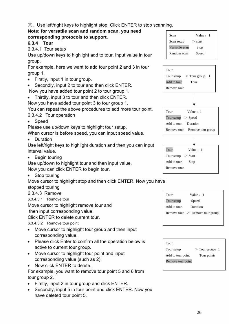
⑤、Use left/right keys to highlight stop. Click ENTER to stop scanning. Note: for versatile scan and random scan, you need corresponding protocols to support. 6.3.4 Tour 6.3.4.1 Tour setup Use up/down keys to highlight add to tour. Input value in tour group. For example, here we want to add tour point 2 and 3 in tour group 1. • Firstly, input 1 in tour group. • Secondly, input 2 to tour and then click ENTER. Now you have added tour point 2 to tour group 1. • Thirdly, input 3 to tour and then click ENTER. Now you have added tour point 3 to tour group 1. You can repeat the above procedures to add more tour point. 6.3.4.2 Tour operation • Speed Please use up/down keys to highlight tour setup. When cursor is before speed, you can input speed value. • Duration Use left/right keys to highlight duration and then you can input interval value. • Begin touring Use up/down to highlight tour and then input value. Now you can click ENTER to begin tour. • Stop touring Move cursor to highlight stop and then click ENTER. Now you have stopped touring 6.3.4.3 Remove 6.3.4.3.1 Remove tour Move cursor to highlight remove tour and then input corresponding value. Click ENTER to delete current tour. 6.3.4.3.2 Remove tour point
• Move cursor to highlight tour group and then input corresponding value.
• Please click Enter to confirm all the operation below is active to current tour group.
• Move cursor to highlight tour point and input corresponding value (such as 2).
• Now click ENTER to delete. For example, you want to remove tour point 5 and 6 from tour group 2. • Firstly, input 2 in tour group and click ENTER. • Secondly, input 5 in tour point and click ENTER. Now you
have deleted tour point 5.
Tour
Tour setup > Tour group:1
Add to tour Tour:
Remove tour
Tour Value :1
Tour setup > Start
Add to tour Stop
Remove tour
Tour Value :1
Tour setup > Speed
Add to tour Duration
Remove tour Remove tour group
Tour
Tour setup > Tour group:1
Add to tour point Tour point:
Remove tour point
Tour Value :1
Tour setup Speed
Add to tour Duration
Remove tour > Remove tour group

27
Pattern Value:1
Patter setup > Start
Rotation Stop
Pattern Value:1
Pattern setup Start
Pan rotation Stop
>Speed
• Thirdly, input 6 in tour point and click ENTER. You have deleted tour point 6.
6.3.5 PATTERN 6.3.5.1 Pattern setup • Move cursor to highlight pattern and then input pattern value.
Input value is the pattern path you want to set (Maximally support five paths). Click ENTER to confirm.
• Move cursor to highlight start and then input pattern value. Now click ENTER to confirm.
• Move cursor to highlight stop. Input pattern value and click ENTER to stop pattern. Dome will automatically memorize all the operations you have
done. 6.3.5.2 Pattern operation • Pleas use up/down keys to highlight pattern. When cursor is
before start, please input pattern value and then click ENTER to begin pattering.
• Move cursor to highlight stop and then click ENTER. System stop pattern.
6.3.6 Pan Rotation Move cursor to highlight speed. Input speed value (the speed you want) and click ENTER. Then move cursor to highlight start and then click ENTER. Dome begins pan rotation. Move cursor to highlight stop and then click ENTER. Dome stops rotation.
Pattern Value:1
Pattern setup >Start
Rotation Stop

28
7 Control Keyboard Upgrade Control keyboard does not support network upgrade. Please ship your control keyboard back to our factory to upgrade.
29
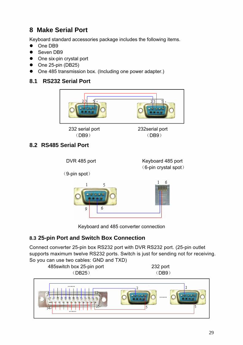
8 Make Serial Port Keyboard standard accessories package includes the following items.
One DB9 Seven DB9 One six-pin crystal port One 25-pin (DB25) One 485 transmission box. (Including one power adapter.)
8.1 RS232 Serial Port
232 serial port 232serial port
(DB9) (DB9)
8.2 RS485 Serial Port
DVR 485 port Keyboard 485 port (6-pin crystal spot)
(9-pin spot)
Keyboard and 485 converter connection
8.3 25-pin Port and Switch Box Connection Connect converter 25-pin box RS232 port with DVR RS232 port. (25-pin outlet supports maximum twelve RS232 ports. Switch is just for sending not for receiving. So you can use two cables: GND and TXD)
485switch box 25-pin port 232 port (DB25) (DB9)

30
485 switch box and DVR connection
Note: you can use standard RS232 port to connect keyboard with DVR. Slight difference may be found in user interface. All the designs and software here are subject to change without prior written notice. Please visit our website for more information.