control channel for smatv/matv distribution systems ... · etsi ts 101 964 v1.1.1 (2001-08)...
TRANSCRIPT

ETSI TS 101 964 V1.1.1 (2001-08)Technical Specification
Digital Video Broadcasting (DVB);Control Channel for SMATV/MATV distribution systems;
Baseline Specification
European Broadcasting Union Union Européenne de Radio-Télévision
EBU·UER
ETSI
ETSI TS 101 964 V1.1.1 (2001-08)2
ReferenceDTS/JTC-DVB-118
Keywordsbroadcasting, control, digital, DVB, SMATV, video
ETSI
650 Route des LuciolesF-06921 Sophia Antipolis Cedex - FRANCE
Tel.: +33 4 92 94 42 00 Fax: +33 4 93 65 47 16
Siret N° 348 623 562 00017 - NAF 742 CAssociation à but non lucratif enregistrée à laSous-Préfecture de Grasse (06) N° 7803/88
Important notice
Individual copies of the present document can be downloaded from:http://www.etsi.org
The present document may be made available in more than one electronic version or in print. In any case of existing orperceived difference in contents between such versions, the reference version is the Portable Document Format (PDF).
In case of dispute, the reference shall be the printing on ETSI printers of the PDF version kept on a specific network drivewithin ETSI Secretariat.
Users of the present document should be aware that the document may be subject to revision or change of status.Information on the current status of this and other ETSI documents is available at http://www.etsi.org/tb/status/
If you find errors in the present document, send your comment to:[email protected]
Copyright Notification
No part may be reproduced except as authorized by written permission.The copyright and the foregoing restriction extend to reproduction in all media.
© European Telecommunications Standards Institute 2001.© European Broadcasting Union 2001.
All rights reserved.

ETSI
ETSI TS 101 964 V1.1.1 (2001-08)3
Contents
Intellectual Property Rights ................................................................................................................................4
Foreword.............................................................................................................................................................4
Introduction ........................................................................................................................................................4
1 Scope ........................................................................................................................................................6
2 References ................................................................................................................................................6
3 Abbreviations ...........................................................................................................................................6
4 Message structure .....................................................................................................................................74.1 General ...............................................................................................................................................................74.2 Framing byte ......................................................................................................................................................74.3 Address byte .......................................................................................................................................................8
5 List of commands and coding ..................................................................................................................95.1 General ...............................................................................................................................................................95.1a Reset ...................................................................................................................................................................95.2 Stand-by ...........................................................................................................................................................105.3 Tuning ..............................................................................................................................................................105.3.1 delivery_system_descriptor ........................................................................................................................115.4 Installation Status Request ...............................................................................................................................135.5 Configuration ...................................................................................................................................................145.6 Maintenance .....................................................................................................................................................155.7 Resource Inquiry ..............................................................................................................................................155.8 Message Fragmentation....................................................................................................................................155.9 Command Reply (ACK)...................................................................................................................................165.10 Installation Status Reply...................................................................................................................................165.11 Configuration Reply .........................................................................................................................................175.12 Maintenance Reply...........................................................................................................................................175.13 Resource Reply ................................................................................................................................................17
Annex A (normative): Physical layers................................................................................................19
A.1 Physical layer based on a 22 kHz bus ....................................................................................................19A.1.1 Main characteristics..........................................................................................................................................19A.1.2 Multiaccess via the 22 kHz bus ........................................................................................................................20A.1.2.1 Timing ........................................................................................................................................................20
A.2 Physical layer based on a RF bus ...........................................................................................................21A.2.1 Main characteristics..........................................................................................................................................21A.2.2 Multiaccess via the RF bus...............................................................................................................................21A.2.3 Optional Frequency Extension .........................................................................................................................22
History ..............................................................................................................................................................23

ETSI
ETSI TS 101 964 V1.1.1 (2001-08)4
Intellectual Property RightsIPRs essential or potentially essential to the present document may have been declared to ETSI. The informationpertaining to these essential IPRs, if any, is publicly available for ETSI members and non-members, and can be foundin ETSI SR 000 314: "Intellectual Property Rights (IPRs); Essential, or potentially Essential, IPRs notified to ETSI inrespect of ETSI standards", which is available from the ETSI Secretariat. Latest updates are available on the ETSI Webserver (http://www.etsi.org/ipr).
Pursuant to the ETSI IPR Policy, no investigation, including IPR searches, has been carried out by ETSI. No guaranteecan be given as to the existence of other IPRs not referenced in ETSI SR 000 314 (or the updates on the ETSI Webserver) which are, or may be, or may become, essential to the present document.
ForewordThis Technical Specification (TS) has been produced by Joint Technical Committee (JTC) of the EuropeanBroadcasting Union (EBU), Comité Européen de Normalisation Electrotechnique (CENELEC) and the EuropeanTelecommunications Standards Institute (ETSI).
NOTE: The EBU/ETSI JTC Broadcast was established in 1990 to co-ordinate the drafting of standards in thespecific field of broadcasting and related fields. Since 1995 the JTC Broadcast became a tripartite bodyby including in the Memorandum of Understanding also CENELEC, which is responsible for thestandardization of radio and television receivers. The EBU is a professional association of broadcastingorganizations whose work includes the co-ordination of its members' activities in the technical, legal,programme-making and programme-exchange domains. The EBU has active members in about 60countries in the European broadcasting area; its headquarters is in Geneva.
European Broadcasting UnionCH-1218 GRAND SACONNEX (Geneva)SwitzerlandTel: +41 22 717 21 11Fax: +41 22 717 24 81
Founded in September 1993, the DVB Project is a market-led consortium of public and private sector organizations inthe television industry. Its aim is to establish the framework for the introduction of MPEG-2 based digital televisionservices. Now comprising over 200 organizations from more than 25 countries around the world, DVB fostersmarket-led systems, which meet the real needs, and economic circumstances, of the consumer electronics and thebroadcast industry.
IntroductionSMATV/MATV distribution systems, as described in EN 300 473 [1], represent a solution widely adopted forin-building delivery of DVB signals (both satellite and terrestrial) through collective installations. The adoption of theControl Channel specification, which has been defined in accordance with the commercial requirements given inDVB-TM 2342 [7], offers an alternative cost-effective solution to the current implementation of SMATV/MATVsystems, especially for the case of small and medium size installations, allowing the delivery of DVB TSs/multiplexeswithout the constraints of the limited bandwidth available in the installation.
These benefits are achieved by allocating to each user's terminal an individual RF channel on the in-building cablenetwork for the delivery of the DVB services which are remotely selected by the user's terminal controlling thehead-end device, installed in the building (e.g. QPSK/QAM transmodulator, QPSK/QPSK frequency converter), via asuitable set of commands. All the equipment which is operated via the Control Channel, i.e. the head-end devices andthe user's terminals, are connected through the same coaxial SMATV/MATV installation.
Furthermore, the Control Channel allows each single user of the building to autonomously decide on the possibility ofreceiving digital broadcasting services through the community installation, without the need of authorization from theother users.

ETSI
ETSI TS 101 964 V1.1.1 (2001-08)5
The system model representing this solution is based on two channels (see figure 1):
• Broadcast Channel: a unidirectional broadband delivery channel for video, audio and data services;
• Control Channel: a bi-directional narrow-band channel established between the head-end device and the user'sterminal for control and signalling purposes.
The present document describes the message structure and the set of commands and coding used by the ControlChannel for SMATV/MATV distribution systems. The specification covers both the approaches adopted for thedelivery of satellite signals as identified in EN 300 473 [1], i.e. transmodulation from QPSK to QAM (System A) anddirect distribution in QPSK after frequency conversion (System B), as well as the remote control of other head-enddevices for broadcast services.
The specification also takes into account the requirements from DVB-TM 2342 [7] in order to achieve the bestcommonality and ensure the minimum functionality required for operating via the SMATV systems the satelliteinteractive terminals.
Although primarily focused on SMATV systems for delivery of satellite DVB services, the Control Channel shall alsobe applicable to MATV systems currently used for terrestrial broadcasting services via VHF/UHF and microwave.
The Control Channel protocol is based on DiSEqC [2] to maintain compatibility with existing products and has thefurther advantage of being sufficiently flexible to allow for future extensions, if and when needed. The structure of theControl Channel message ensures a robust transmission mechanism.
The Physical layers, described in clauses A.1 and A.2, allow for a general use of the Control Channel in the whole rangeof SMATV/MATV distribution systems, having different topologies and characteristics. The transmission protocolproviding the communication link between the user's terminal and the head-end device makes use of the samecommands and coding (see clauses 4 and 5) for both physical layers.
The A.1 solution, which is based on the use of a 22 kHz bus, is suitable for the case of small SMATV/MATVinstallations using d.c. coupled elements. The A.2 solution, which is based on the use of an RF bus in a frequency rangeabove 10 MHz, provides the capability to pass through community installations using inductive components. So, thissecond solution potentially allows for a transparent introduction of the Control Channel in most existingSMATV/MATV systems.
Set-Top-Box
Module 1(e.g. QPSK to
QAM , IF to IF)
SMATV/MATVCable Network
Head-end device
Control Channel(Narrow-band carrier)
Control ChannelInterface
Module 2In-buildingHead-end unit
Module N…
Broadcast ChannelUser-allocated RF Channel(e.g. 8 MHz)
Figure 1: Simplified functional block diagram of the in-building SMATV/MATV Systemusing a Control Channel

ETSI
ETSI TS 101 964 V1.1.1 (2001-08)6
1 ScopeThe present document specifies the Control Channel for SMATV/MATV distribution systems based on EN 300 743.The present document is intended to provide remote control of the head-end device from the user's terminal through aset of commands in a closed in-building environment for the delivery of broadcast services. Provision for interactiveservices is out of the scope of the present document.
2 ReferencesThe following documents contain provisions which, through reference in this text, constitute provisions of the presentdocument.
• References are either specific (identified by date of publication and/or edition number or version number) ornon-specific.
• For a specific reference, subsequent revisions do not apply.
• For a non-specific reference, the latest version applies.
[1] ETSI EN 300 473: "Digital Video Broadcasting (DVB); Satellite Master Antenna Television(SMATV) distribution systems".
[2] ETSI EN 301 790: "Digital Video Broadcasting (DVB); Interaction channel for satellitedistribution systems".
[3] Eutelsat: "Digital Satellite Equipment Control (DiSEqC) Bus Functional Specification version 4.2,February 1998".
[4] ETSI EN 300 421: "Digital Video Broadcasting (DVB); Framing structure, channel coding andmodulation for 11/12 GHz satellite services".
[5] ETSI EN 300 429: "Digital Video Broadcasting (DVB); Framing structure, channel coding andmodulation for cable systems".
[6] ETSI EN 300 744: "Digital Video Broadcasting (DVB); Framing structure, channel coding andmodulation for digital terrestrial television".
[7] DVB-TM 2342: "Commercial Requirements for the addition of a Control Channel to theSMATV/MATV distribution systems".
3 AbbreviationsFor the purposes of the present document the following abbreviations apply:
ACK ACKnowledgeCRC Cyclic Redundancy CheckDiSEqC Digital Satellite Equipment ControlDVB-TS Digital Video Broadcasting-Transport StreamFDMA Frequency Division Multiple AccessFEC Forward Error CorrectionHE Head EndHED Head End DeviceHP High PriorityIDU InDoor UnitIF Intermediate FrequencyLP Low PriorityMATV Master Antenna TVMID Master IDentifierODU OutDoor UnitOFDM Orthogonal Frequency Division Multiplexing
ETSI
ETSI TS 101 964 V1.1.1 (2001-08)7
PIN Personal Identification NumberPWK Pulse Width KeyingQAM Quadrature Amplitude ModulationQPSK Quaternary Phase Shift KeyingRF Radio FrequencyRS Reed-SolomonSID Slave IDentifierSMATV Satellite Master Antenna TVSTB Set Top BoxTDMA Time Division Multiple AccessUHF Ultra High FrequencyVHF Very High Frequency
4 Message structure
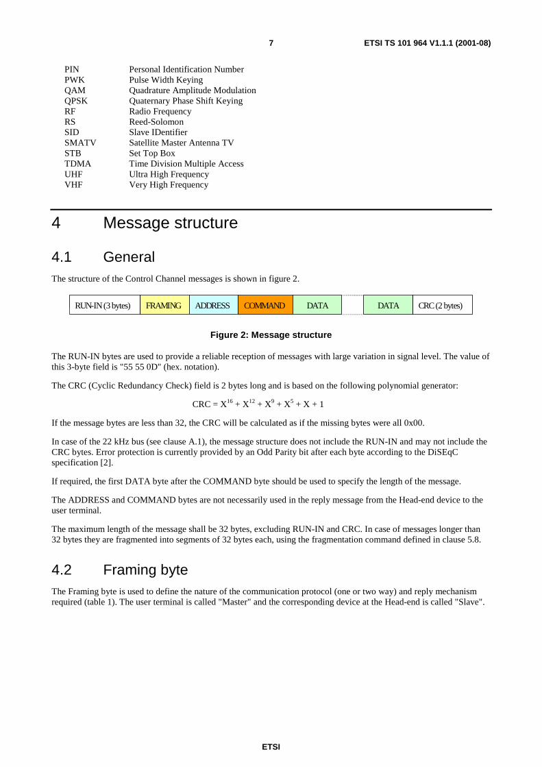
4.1 GeneralThe structure of the Control Channel messages is shown in figure 2.
FRAMING ADDRESS COMMAND DATADATA CRC(2 bytes)RUN-IN(3 bytes)
Figure 2: Message structure
The RUN-IN bytes are used to provide a reliable reception of messages with large variation in signal level. The value ofthis 3-byte field is "55 55 0D" (hex. notation).
The CRC (Cyclic Redundancy Check) field is 2 bytes long and is based on the following polynomial generator:
CRC = X16 + X12 + X9 + X5 + X + 1
If the message bytes are less than 32, the CRC will be calculated as if the missing bytes were all 0x00.
In case of the 22 kHz bus (see clause A.1), the message structure does not include the RUN-IN and may not include theCRC bytes. Error protection is currently provided by an Odd Parity bit after each byte according to the DiSEqCspecification [2].
If required, the first DATA byte after the COMMAND byte should be used to specify the length of the message.
The ADDRESS and COMMAND bytes are not necessarily used in the reply message from the Head-end device to theuser terminal.
The maximum length of the message shall be 32 bytes, excluding RUN-IN and CRC. In case of messages longer than32 bytes they are fragmented into segments of 32 bytes each, using the fragmentation command defined in clause 5.8.
4.2 Framing byteThe Framing byte is used to define the nature of the communication protocol (one or two way) and reply mechanismrequired (table 1). The user terminal is called "Master" and the corresponding device at the Head-end is called "Slave".

ETSI
ETSI TS 101 964 V1.1.1 (2001-08)8
Table 1: Values for the Framing byte
Framing byte Function ValueCommand from Master,No Reply required, First transmission.
0xE0
Command from Master,No Reply required, Repeated transmission.
0xE1
Command from Master,Reply required, First transmission.
0xE2
Command from Master,Reply required, Repeated transmission.
0xE3
"OK" Reply from Slave,No errors detected.
0xE4
Error Reply from Slave - Repeat of message is not required.Command not executable by Slave (e.g. not supported or power fail).
0xE5
Error Reply from Slave - Request repeat of message,Parity Error detected.
0xE6
Error Reply from Slave - Suggest repeat of message,Received message format not correct (e.g. wrong number of bits / bytes).
0xE7
Extended (multi-block) Command from Master,No Reply required (to this message block), First transmission.
0xE8
Extended Command from Master,No Reply required (to this message block), Repeated transmission.
0xE9
Extended Command from Master,Reply required (to this message block), First transmission.
0xEA
Extended Command from Master,Reply required (to this message block), Repeated transmission.
0xEB
"OK" Report from Slave, command understood,Not yet completed, but unknown time to execute.
0xEC 00
"OK" Report from Slave, command understood,Task completion expected within nn seconds (0 < nn < 128 decimal).
0xEC nn
Error Report from Slave, - Repeat of message is not required,EUI-64 of IDU not valid.
0xED E1
Error Report from Slave, Password in the command message not valid(1st to nth attempts - unidentified number of non-final attempts).
0xED F0
Error Report from Slave, Password in the command message not validnth attempt, (0 < n < 14 decimal).
0xED Fn
Error Report from Slave, Password in the command message not validPenultimate attempt before locking.
0xED FE
Error Report from Slave, ODU now Locked.Installer required (e.g. 6th to infinite use of wrong password).
0xED FF
Error Report from Slave - Request repeat of message,CRC not valid.
0xEE E2
Error Report from Slave - Suggest repeat of message,No Error codes yet defined.
0xEF nn
4.3 Address byteThe Address byte is used to identify the different device types for the Head-End unit (slave).
Table 2: Values for the Address byte
Address type ValueAll SMATV Head-end devices 0x70QPSK/QAM transmodulator 0x71QAM/QAM frequency converter 0x72QPSK/QPSK IF-IF converter 0x73OFDM/QAM transmodulator 0x74Reserved 0x75 to 0x7EReserved for future expansion 0x7F

ETSI
ETSI TS 101 964 V1.1.1 (2001-08)9
5 List of commands and coding
5.1 GeneralThe list of relevant commands for the Control Channel is based on DiSEqC and is given in table 3. The commands inthe range 0x01 and 0x03 to 0x6F, which are standard DiSEqC commands and are used in solutions adopting the 22 kHzbus (see clause A.1), are not reported in table 3 for sake of simplicity, and can be found in [2] and [6]. These commandsmay also be used with the RF bus (see clause A.2).
Note that the five Reply messages of table 3 from the Head-End to the user terminal do not have a specific Commandbyte (see clause 4.1), but are identified by the Framing byte as defined in table 1.
Table 3: List of the SMATV/MATV Control Channel Commands
Command Command Byte(hex)
DirectionSTB <-> Head-End device
Reset 0x00 -->Stand-by 0x02 -->
(reserved) 0x70 to 0x72Tuning 0x73 -->Installation Status Request 0x74 -->(reserved) 0x75 to 0x77Configuration 0x78 -->Maintenance 0x79 -->Resource Inquiry 0x7A -->(reserved) 0x7B to 0x7EMessage Fragmentation 0x7F
Command Reply (ACK) - <--Installation Status Reply - <--Configuration Reply - <--Maintenance Reply - <--Resource Reply - <--
5.1a ResetThis command is used to reset the Head-end devices.
Table 4: Reset
Syntax No. of bitsReset()
FramingAddress
reset_commandpin_code
888
16
Framing
As defined in clause 4.2.
Address
As defined in clause 4.3.
reset_command
As defined in table 3.
ETSI
ETSI TS 101 964 V1.1.1 (2001-08)10
pin_code
Code for the authentication of the user's device at the Head-end. It may also provide information for privacy protection.This pin_code is made of two bytes: an 8-bit Master Identifier (MID) and an 8-bit Slave Identifier (SID). Some of the16 bits can be used for privacy protection.
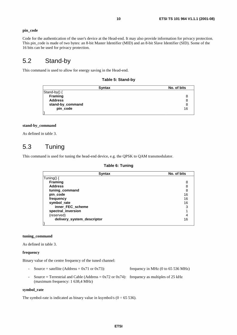
5.2 Stand-byThis command is used to allow for energy saving in the Head-end.
Table 5: Stand-by
Syntax No. of bitsStand-by()
FramingAddressstand-by_command
pin_code
888
16
stand-by_command
As defined in table 3.
5.3 TuningThis command is used for tuning the head-end device, e.g. the QPSK to QAM transmodulator.
Table 6: Tuning
Syntax No. of bitsTuning()
FramingAddresstuning_commandpin_codefrequencysymbol_rate
inner_FEC_schemespectral_inversion(reserved)
delivery_system_descriptor
888
161616
314
16
tuning_command
As defined in table 3.
frequency
Binary value of the centre frequency of the tuned channel:
- Source = satellite (Address = 0x71 or 0x73): frequency in MHz (0 to 65 536 MHz)
- Source = Terrestrial and Cable (Address = 0x72 or 0x74): frequency as multiples of 25 kHz(maximum frequency: 1 638,4 MHz)
symbol_rate
The symbol-rate is indicated as binary value in ksymbol/s (0 ÷ 65 536).
ETSI
ETSI TS 101 964 V1.1.1 (2001-08)11
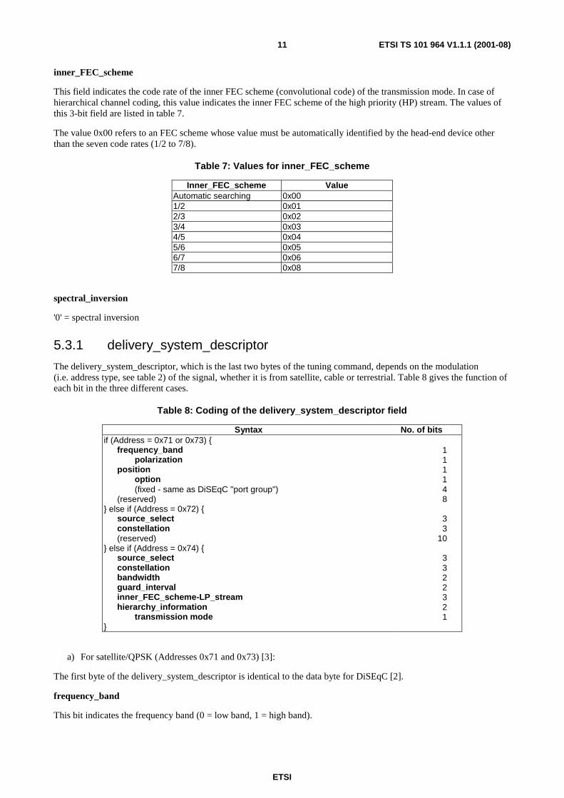
inner_FEC_scheme
This field indicates the code rate of the inner FEC scheme (convolutional code) of the transmission mode. In case ofhierarchical channel coding, this value indicates the inner FEC scheme of the high priority (HP) stream. The values ofthis 3-bit field are listed in table 7.
The value 0x00 refers to an FEC scheme whose value must be automatically identified by the head-end device otherthan the seven code rates (1/2 to 7/8).
Table 7: Values for inner_FEC_scheme
Inner_FEC_scheme ValueAutomatic searching 0x001/2 0x012/3 0x023/4 0x034/5 0x045/6 0x056/7 0x067/8 0x08
spectral_inversion
'0' = spectral inversion
5.3.1 delivery_system_descriptor
The delivery_system_descriptor, which is the last two bytes of the tuning command, depends on the modulation(i.e. address type, see table 2) of the signal, whether it is from satellite, cable or terrestrial. Table 8 gives the function ofeach bit in the three different cases.
Table 8: Coding of the delivery_system_descriptor field
Syntax No. of bitsif (Address = 0x71 or 0x73)
frequency_bandpolarization
positionoption(fixed - same as DiSEqC "port group")
(reserved) else if (Address = 0x72)
source_selectconstellation(reserved)
else if (Address = 0x74) source_selectconstellationbandwidthguard_intervalinner_FEC_scheme-LP_streamhierarchy_information
transmission mode
111148
33
10
3322321
a) For satellite/QPSK (Addresses 0x71 and 0x73) [3]:
The first byte of the delivery_system_descriptor is identical to the data byte for DiSEqC [2].
frequency_band
This bit indicates the frequency band (0 = low band, 1 = high band).

ETSI
ETSI TS 101 964 V1.1.1 (2001-08)12
polarization
This bit indicates the satellite polarization (0 = vertical/rhc, 1 = horizontal/lhc).
position
This bit indicates which satellite position is selected; in conjunction with the "option" bit up to 4 different orbitallocations or positions can be supported.
option
This bit can be used to select additional satellite positions (see above) or other functions as required.
b) For cable/QAM (Address 0x72) [4]:
source_select
This 3 bit field allows up to 8 different QAM sources to be selected.
constellation
This field indicates the constellation pattern used on a cable delivery system. The values of this 3-bit field are listed intable 9.
Table 9: Values for constellation
Constellation Value16-QAM 0x0164-QAM 0x02Reserved other values
c) For terrestrial/OFDM (Address 0x73) [5]:
source_select
This 3-bit field allows up to 8 different OFDM sources to be selected (e.g. different antennas).
constellation
This field indicates the constellation pattern used on a terrestrial delivery system. The values of this 3-bit field are listedin table 10.
Table 10:Values for constellation
Constellation ValueQPSK 0x0016-QAM 0x0164-QAM 0x02Reserved other values
bandwidth
This 2-bit field indicates the bandwidth of the terrestrial signal:
Table 11: Values for bandwidth
Bandwidth Value8 MHz 0x017 MHz 0x02reserved other values

ETSI
ETSI TS 101 964 V1.1.1 (2001-08)13
inner_FEC_scheme-LP_stream
In case of hierarchical channel coding, this field indicates the inner FEC scheme of the low priority (LP) stream,otherwise it is ignored. The values of this 3-bit field are listed in table 7.
hierarchy_information
This field indicates whether the OFDM transmission is hierarchical and, if so, what the α (constellation parameter)value is. The values of this 2-bit field are listed in table 12.
Table 12: Values for hierarchy_information
Hierarchy_information ValueNon-hierarchical 0x00α = 1 0x01α = 2 0x02α = 4 0x03
guard_interval
This field indicates the guard interval of the OFDM signal. The values of this 2-bit field are listed in table 13.
Table 13: Values for guard_interval
guard_interval Value1/32 0x001/16 0x011/8 0x021/4 0x03
transmission_mode
This field indicates the OFDM transmission mode (0 = 2k, 1 = 8k).
5.4 Installation Status RequestThe Installation Status Request command interrogates the Head-End device to detect new Head-End Modules, havingSID equal to 0, and to establish their type. This command is used during the installation phase by polling through alladdress categories to find all allocated SIDs/MIDs and RF channels that are already used in the network.
Table 14: Installation Status Request
Syntax No. of bitsInstallation_status_request()
FramingAddress
Installation_status_request_commandpin_code
888
16
installation_status_request_command
As defined in table 3.

ETSI
ETSI TS 101 964 V1.1.1 (2001-08)14
5.5 ConfigurationThis command communicates to the Head-End device all the technical parameters of the configuration to be adopted bythe new device (i.e. proposed pin_code, frequency, modulation, etc.). This command can be used also for changingsettings to the device after the installation procedure.
Table 15: Configuration
Syntax No. of bitsConfiguration()
FramingAddressConfiguration_commandpin_codeproposed_pin_codefrequency_usedmodulation_usedsymbol_rate_usedouterFEC_used(reserved)
888
161616
816
44
configuration_command
As defined in table 3.
proposed_pin_code
new values for MID and SID.
frequency_used
Binary value of the centre frequency of the RF channel (e.g. 8 MHz if address = 0x71, 0x72 or 0x74, 40 MHz ifaddress = 0x73) allocated to the delivery of the DVB signals from the Head-end to the specific user through thebuilding cable distribution network:
- Distribution in QPSK (Address = 0x73): frequency as multiples of 50 kHz(maximum frequency: 3 276,8 MHz)
- Distribution in QAM (Address = 0x71, 0x72 or 0x74): frequency as multiples of 25 kHz(maximum frequency: 1 638,4 MHz)
modulation_used
This 8-bit field specifies the modulation scheme used on the building cable network. The values are listed in table 16.
Table 16: Values for modulation_used
modulation_used ValueQPSK 0x0016-QAM 0x0132-QAM 0x0264-QAM 0x03128-QAM 0x04256-QAM 0x05reserved other values
symbol_rate_used
This 16-bit field specifies the symbol rate used on the building cable network. It is indicated as binary value inksymbol/s (0 to 65 536). The value 0x00 is used if a simple frequency conversion is performed.

ETSI
ETSI TS 101 964 V1.1.1 (2001-08)15
outer_FEC_used
This field indicates the outer Forward Error Correction (FEC) scheme (e.g. Reed-Solomon) used on the building cablenetwork. The values of this 4-bit field are listed in table 17.
Table 17: Values for outer_FEC_used
Cable_outer_FEC Valuenot applicable 0x00No outer FEC 0x01RS(188,204) 0x02reserved other values
5.6 MaintenanceVoid
5.7 Resource InquiryThe Resource Inquiry command asks the Head-End device to inform the STB about its identity and characteristics.
Table 18: Resource Inquiry
Syntax No. of bitsResource_inquiry()
FramingAddressResource_inquiry_command
pin_code
888
16
resource_inquiry_command
As defined in table 3.
5.8 Message FragmentationThis command is used for messages longer than 32 bytes. In this case the message is fragmented into segments ofexactly 32 bytes. The last segment will be stuffed by 0x00.
Table 19: Message Fragmentation
Syntax No. of bitsMessage_fragmentation()
FramingAddressMessage_fragmentation_command
pin_codetotal_number_of_segmentssegment_numberdata
888
1688
25x8
message_fragmentation_command
As defined in table 3.
total_number_of_segments
The total number of 32-byte segments that the message has been divided into.

ETSI
ETSI TS 101 964 V1.1.1 (2001-08)16
segment_number
Indicator of present segment. At the first segment this field is equal to the total number of segments and is decreasedevery message down to one.
data
Encapsulated segmented message.
5.9 Command Reply (ACK)This message is sent from the Head-End to the STB as a generic reply to those commands which do not need a specificreply. It carries an acknowledgement (e.g. 0xE4, see table 1) of the command on the basis of the CRC and on thevalidity of the received command and data.
Table 20: Command Reply
Syntax No. of bitsCommand_reply()
Framingpin_code
information
816
8
information
This byte gives information about the nature of the ACK (i.e. error codes, time to completion, etc.). It corresponds tothe second byte indicated in table 1.
5.10 Installation Status ReplyThe Installation Status Reply message is a response of the Head-end device to the Installation Status Request commandsent by the Set-Top-Box during the installation procedure. Through this message, the Head-end device informs the STBabout its characteristics (modulation, symbol rate, FEC, etc.) and the RF channel used.
Table 21: Installation Status Reply
Syntax No. of bitsInstallation_Status_reply()
Framing (= 0xE4: Ack)pin_codeaddressfrequency_usedmodulation_usedsymbol_rate_usedouterFEC_used(reserved)
816
816
816
44
Description for frequency_used, modulation_used, symbol_rate_used, outerFEC_used is given as in clause 5.5.

ETSI
ETSI TS 101 964 V1.1.1 (2001-08)17
5.11 Configuration ReplyThe Head-End device confirms back to the STB the configuration requested through the Configuration command ofclause 5.5, or indicates a new value of the parameters. Value 0x00 means no indication from the Head-End device.
Table 22: Configuration Reply
Syntax No. of bitsConfiguration_reply()
Framing (= 0xE4: Ack)pin_codeaddressfrequency_usedmodulation_usedsymbol_rate_usedouterFEC_used(reserved)
816
816
816
44
Description for frequency_used, modulation_used, symbol_rate_used, outerFEC_used is given as in clause 3.5.
5.12 Maintenance ReplyVoid
5.13 Resource ReplyThe Resource Reply message is a response of the Head-end device to the Resource Inquiry command. Through thismessage, the Head-end device informs the STB about its identity and characteristics.
Table 23: Resource Reply
Syntax No. of bitsResource_reply()
Framingpin_codemessage_lengthaddressfrequency_usedmodulation_usedsymbol_rate_usedouterFEC_used(reserved)manufacturer_codeavailability(reserved)for (i=0; i<message_length-13; i++)
additional data
816
88
168
1644
1635
8
message_length
This field indicates the length of the message.
manufacturer_code
This field is reserved to manufacturer. It is set to 0x00 if not used.
availability
This field indicates whether the device is available or not. The values of this 3-bits field are listed in table 24.
ETSI
ETSI TS 101 964 V1.1.1 (2001-08)18
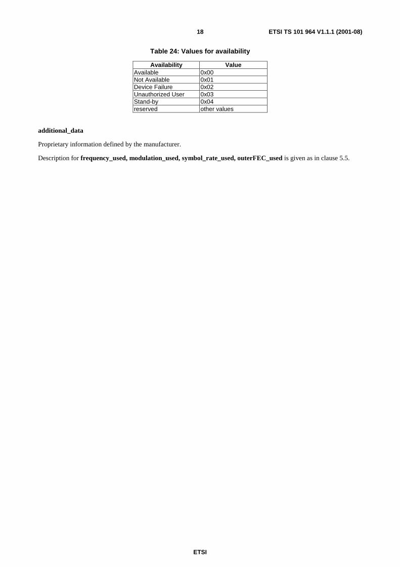
Table 24: Values for availability
Availability ValueAvailable 0x00Not Available 0x01Device Failure 0x02Unauthorized User 0x03Stand-by 0x04reserved other values
additional_data
Proprietary information defined by the manufacturer.
Description for frequency_used, modulation_used, symbol_rate_used, outerFEC_used is given as in clause 5.5.

ETSI
ETSI TS 101 964 V1.1.1 (2001-08)19
Annex A (normative):Physical layersThe Physical layers, described in clauses A.1 and A.2, allow for the use of the Control Channel in the whole range ofSMATV/MATV distribution systems, having different topologies and characteristics (i.e. available frequencybandwidth, type of network components, user taps, etc.).
The Control Channel is exclusively intended to provide remote control of the head-end device from the user's terminalthrough a set of commands in a closed in-building environment for the delivery of broadcasting services. All theequipment which is operated via the Control Channel, i.e. the head-end devices and the user's terminals, are connectedthrough the same coaxial SMATV/MATV installation.
The A.1 solution, based on the 22 kHz bus, is suitable for use in small SMATV/MATV installations adopting d.c.coupled elements. The A.2 solution, based on an RF Control Channel bus, is of general use in most SMATV/MATVinstallations which currently adopt inductively coupled components.
For both cases the transmission protocol providing the communication link between the user's terminal and thehead-end device is based on DiSEqC and makes use of the same commands and coding (see clauses 4 and 5).
In the communication between the user's terminal (STB) and the Head-End Device (HED) a master-slave approach isused where the STB is the master. For this reason an HED can transmit a message only after a request from STB.
A.1 Physical layer based on a 22 kHz busThis Control Channel between the user's terminal and the Head-End is based on a 22 kHz PWK (Pulse Width Keying)signal as used by DiSEqC [2]. The circuit implementation has to follow the description in the DiSEqC bus functionalspecification. In order to maintain backward compatibility with existing DiSEqC processors (typically 8 bitmicroprocessors) and to allow for the transmission of longer messages, these will be subdivided into blocks of 8 bytes.Details are reported in the Guidelines for Implementation document [6].
A.1.1 Main characteristicsCarrier frequency 22 kHz ± 20 %
Bus load impedance (R) 15 Ω ± 5 %
DC supply
Bus load inductance (LB) 270 µH ± 5 %
Bus load capacitance (CB) typically 470 nF
Current source
Current amplitude 43 mA ± 10 %
Source impedance > 10 kΩ
22 kHz carrier detection device resistance (Rr) typically between 5 kΩ and 10 kΩ
DC block capacitor (Cr) typically a few nF, but depends on the value Rr. It should be chosen so as to give a timeconstant of around 100 µs

ETSI
ETSI TS 101 964 V1.1.1 (2001-08)20
Bit definition
Timing base 0,5 ms ± 0,1 ms
Bit length 1,5 ms
"0" 1,0 ms burst + 0,5 ms pause
"1" 0,5 ms burst + 1,0 ms pause
A.1.2 Multiaccess via the 22 kHz busThis multiaccess specification provides a solution for small SMATV networks typically with QPSK/QPSK head-ends,as is often typical in IF distribution systems, where all elements (outlets, splitters, couplers, etc.) are d.c. coupled and allterminals are connected in parallel to the bus.
Due to the large bit-length, the communication capacity is limited so that the number of user's terminals should berestricted (about 12 on a single cable) to allow an acceptable "zapping" behaviour in practice. Furthermore, to avoidcollision problems, a suitable access control scheme is required, which is described below, capable to ensure amaximum access time of about 1,5 s, in the case all users are switching at the same time.
User terminal (master) message with anticollision header:
t0 t1 t2 t3 t4 t5
Reply from head-end:
t6 t7 t8
A.1.2.1 Timing
The description of the timing parameters and relevant values are reported in table A.1. Additional information is givenin [6].
Table A.1: Definition of anti-collision timing parameters
Time interval Meaning Valuet0 first watching time t2max + 4 mst1 bus test take-over time
(22 kHz burst)number of time intervals (4 ms)depends on number of STB's
t2 second watching time number of time intervals (4 ms)depends on number of STB's
t3, t5 guard interval 2 mst4 message to head-end depends on head-end typet6 guard interval
(minimum value)2 ms
t7 message from head-end depends on content/STBt8 guard interval
(minimum value)2 ms

ETSI
ETSI TS 101 964 V1.1.1 (2001-08)21
A.2 Physical layer based on a RF busThe RF Control Channel bus is based on 2-FSK modulation of a single RF carrier in a frequency range above 10 MHz,which is shared by all the Control Channel devices of the in-building cable network.
A.2.1 Main characteristicsFrequency: f0 = 10,7 MHz (see note 1)
or/and f0 = 18 MHzor/and f0 = 70 MHz
Modulation: 2-FSK; ∆f = 67 kHz
Bit length: 10 µs
Bit definition:
"0" f0 - ∆f
"1" f0 + ∆f
Tx. max power level
STB 98 dB(µV) (75 Ω)
Head-end unit 108 dB(µV) (75 Ω)
Rx. min. power level
STB 53 dB(µV) (75 Ω)
Head-end unit 43 dB(µV) (75 Ω)
Tx. spectral mask: ≤ -60 dB @ f0 - 2 MHz ≤ f ≤ f0 + 2 MHz (see note 2)
NOTE 1: The choice of the frequency will be made according to the different networks and national channelling.
NOTE 2: The Tx spectral mask is intended to avoid spectrum interference from the control channel onto theadjacent TV channels and/or other signals, if present.
A.2.2 Multiaccess via the RF busBecause of the directional characteristics of the inductive network components, the messages sent by one terminal to thehead-end are not detected by the other terminals. Therefore the approach described in clause A.1.2 cannot be adopted.The access system is then based on an Aloha scheme randomly exploiting the channel transmission resources in a time-division mode, i.e. whenever a terminal has an information to be sent, transmission is started without checking if thechannel is free or busy. This implies a non-null probability of message collision on the channel. However, the receivingdevice (Head-end and user's terminal) is able to detect the correctness of the message thanks to the CRC. An automaticmechanism of acknowledge and command repetition may be adopted.
The performance of the multiaccess system based on the Aloha scheme without acknowledge has been evaluated [6]under typical configurations of SMATV/MATV distribution systems in term of collision probability as function ofmessage duration and of number of user terminals. Given the maximum message length of 32 bytes, which correspondsto the maximum message duration around 2,5 ms, the results indicate an acceptable performance (about 97 %probability of success) in the case of 40 user's terminals connected to the distribution network.

ETSI
ETSI TS 101 964 V1.1.1 (2001-08)22
A.2.3 Optional Frequency ExtensionIn particular cases where fast response application is needed and/or a large number of devices are connected to the sameSMATV/MATV network, a "single channel" frequency (f0) may not be sufficient to meet the requirement of fasttuning/access to the user's selected DVB Transport Streams. In such a "multiple channel" mode, additional carriers, in amixed TDMA/FDMA configuration, can be used, where fa is the frequency separation between adjacent carriers. Thefrequency allocation of the additional carriers shall be as follows:
Frequency (Fc): f0 + n fa n = 1, 2, …; fa = 500 kHz
Tx. spectral mask: ≤ -30 dB @ Fc- fa ≤ f ≤ Fc + fa
All the parameters of the physical layer and transmission protocol are the same as for the case of the "single channel"mode.

ETSI
ETSI TS 101 964 V1.1.1 (2001-08)23
History
Document history
V1.1.1 August 2001 Publication