contractors' proposal form - template.net contractors' proposal form hospital bid due...
TRANSCRIPT

1
CONTRACTORS' PROPOSAL FORM Hospital Bid Due Date: Mr. Project Name: Street Building: City/State Project #: SUBMITTED BY (CONTRACTOR) Company Name Address Telephone Number ADDENDA/RECD
Having inspected the site and the conditions affecting or governing the construction and completion of said project, the undersigned being totally familiar with the location and scope of work described in the documents and specifications proposes to furnish all material, labor, equipment, supervision and insurance to complete the work for the following:
BASE BID:
Labor & Material $______________________________
Add Alternate (Replace Ductwork)
Labor & Material $______________________________
Allowances and Unit Prices Included in Base Bid
Description: $ < Lump Sum>
2
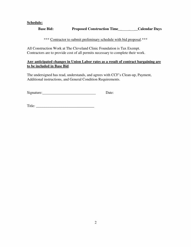
Schedule:
Base Bid: Proposed Construction Time__ _ __Calendar Days
*** Contractor to submit preliminary schedule with bid proposal.***
All Construction Work at The Cleveland Clinic Foundation is Tax Exempt. Contractors are to provide cost of all permits necessary to complete their work.
Any anticipated changes in Union Labor rates as a result of contract bargaining are to be included in Base Bid. The undersigned has read, understands, and agrees with CCF’s Clean-up, Payment, Additional instructions, and General Condition Requirements. Signature: Date: Title: _______________________________
3
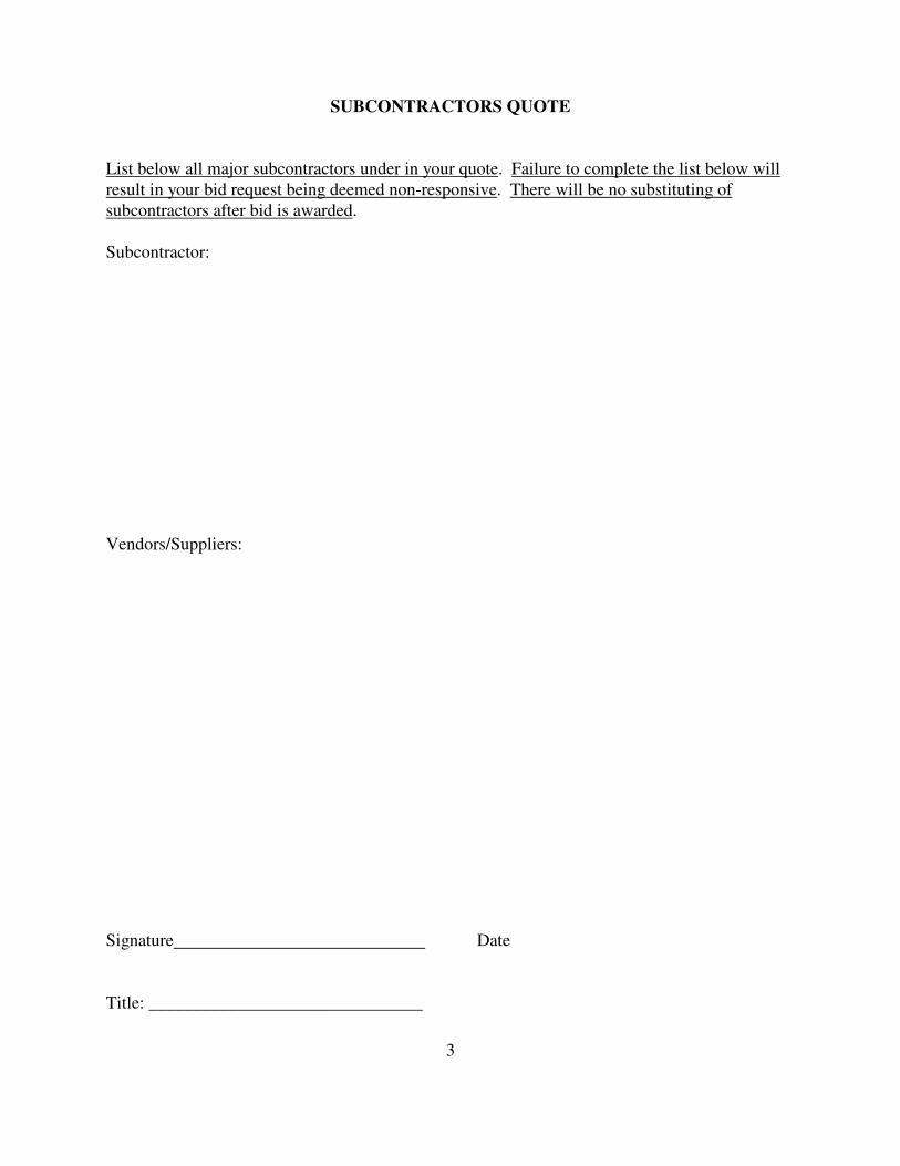
SUBCONTRACTORS QUOTE
List below all major subcontractors under in your quote. Failure to complete the list below will result in your bid request being deemed non-responsive. There will be no substituting of subcontractors after bid is awarded. Subcontractor: Vendors/Suppliers: Signature Date Title: _______________________________
4
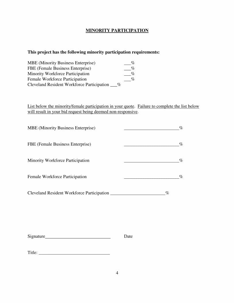
MINORITY PARTICIPATION
This project has the following minority participation requirements: MBE (Minority Business Enterprise) ___% FBE (Female Business Enterprise) ___% Minority Workforce Participation ___% Female Workforce Participation ___% Cleveland Resident Workforce Participation ___% List below the minority/female participation in your quote. Failure to complete the list below will result in your bid request being deemed non-responsive. MBE (Minority Business Enterprise) ________________________% FBE (Female Business Enterprise) ________________________% Minority Workforce Participation ________________________% Female Workforce Participation ________________________% Cleveland Resident Workforce Participation ________________________% Signature Date Title: _______________________________
5
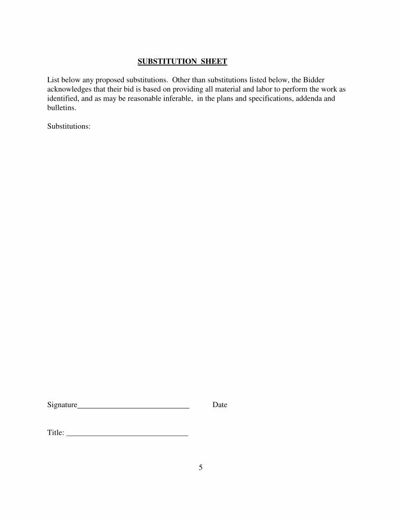
SUBSTITUTION SHEET List below any proposed substitutions. Other than substitutions listed below, the Bidder acknowledges that their bid is based on providing all material and labor to perform the work as identified, and as may be reasonable inferable, in the plans and specifications, addenda and bulletins. Substitutions: Signature Date Title: _______________________________

6
Clean-Up Requirements
1. All contractors holding direct contracts with The Cleveland Clinic Foundation shall be totally
responsible for the clean-up and removal of debris from the work area and site. This shall include the clean-up of debris generated by their subcontractors. Provide all required laborers and equipment required to provide daily cleaning for debris created by this bid package contractor and deposited in dumpsters at the ground level loading dock.
2. During the construction period, the entire project shall be kept as clean and free of debris as possible by all contractors. The owner shall have the right to demand additional clean up if in his opinion, the job site is unsightly. All contractors shall have access to an exterior trash container in an exterior location as directed by the owner. This container shall be utilized by all contractors for disposal of trash.
3. At the completion of the work, the General Trades Contractor shall remove all debris, "vacuum-
clean" the project and perform any special cleaning processes required. All glass, plastic, and finish flooring shall be cleaned and polished and all stains, marks, paint and dirt removed from finish materials. All temporary protections shall be removed. The General Trades Contractor shall be responsible for all final cleaning costs including but not limited to waxing floors, cleaning equipment, walls, hardware, mirrors, glass, cabinets etc. of entire construction site in a manner acceptable to The Cleveland Clinic’s Environmental Services inspection prior to turning project over to CCF. Broom cleaning will not be acceptable. Project cost of such cleaning etc. shall be borne by the General Trades Contractor.
4. If, in the opinion of the Owner, the work area requires clean-up, this clean-up will be
accomplished by the Owner without notification to the contractors. The cost and distribution of responsibility for the clean-up shall be determined by the Owner, and the Owner's decision shall be final without question. The costs for the above will be deducted from the monies due under the Contract.

7
Payment Schedule
1. Monthly Progress Payment Requests
1. Progress Payments to be submitted on AIA Documents G702. 2. Submit to the Office of Construction Management. 3. Include Waiver of Liens from contractors, subcontractors and suppliers.
(no Blanket Waiver of Liens accepted) 2. Final Progress Payment Request
In addition to items above, include Release of Claims for any employee benefits from all unions and subcontractors to this contract. These items are to be notarized and signed by legal representative of the organization.
8
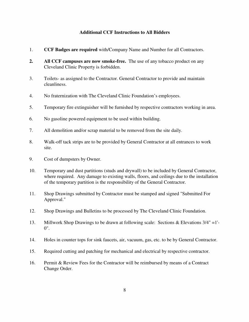
Additional CCF Instructions to All Bidders 1. CCF Badges are required with/Company Name and Number for all Contractors.
2. All CCF campuses are now smoke-free. The use of any tobacco product on any Cleveland Clinic Property is forbidden.
3. Toilets- as assigned to the Contractor. General Contractor to provide and maintain
cleanliness. 4. No fraternization with The Cleveland Clinic Foundation’s employees. 5. Temporary fire extinguisher will be furnished by respective contractors working in area. 6. No gasoline powered equipment to be used within building. 7. All demolition and/or scrap material to be removed from the site daily. 8. Walk-off tack strips are to be provided by General Contractor at all entrances to work
site. 9. Cost of dumpsters by Owner. 10. Temporary and dust partitions (studs and drywall) to be included by General Contractor,
where required. Any damage to existing walls, floors, and ceilings due to the installation of the temporary partition is the responsibility of the General Contractor.
11. Shop Drawings submitted by Contractor must be stamped and signed "Submitted For
Approval." 12. Shop Drawings and Bulletins to be processed by The Cleveland Clinic Foundation. 13. Millwork Shop Drawings to be drawn at following scale: Sections & Elevations 3/4" =1'-
0". 14. Holes in counter tops for sink faucets, air, vacuum, gas, etc. to be by General Contractor.
15. Required cutting and patching for mechanical and electrical by respective contractor. 16. Permit & Review Fees for the Contractor will be reimbursed by means of a Contract
Change Order.

9
17. General Contractor shall be responsible for all expenses incurred in applying for building permit (i.e. man hours, initial cost).
18. General Contractor/Project Manager shall generate and update monthly, material delivery
and progress schedule. Respective contractors to provide all necessary information in a timely manner.
19. Mechanical, and Electrical Contractors to be assigned to successful General Contractor. 20. General Contractor/Project Manager shall be sole coordinator of space requirements
above floor line, including ceiling on each floor. General Contractor/Project Manager shall coordinate with all other trades exact locations of mechanical, electrical, plumbing rough-ins and fixtures.
21. Mechanical Contractor shall be sole coordinator of space requirements above ceiling line
on each floor. Mechanical Contractor shall coordinate with all other trades to determine exact location of duct work, piping, conduits, lighting fixtures, etc. to insure clearances required. General and Electrical Contractor shall provide Mechanical Contractor all necessary information in a timely manner. Mechanical Contractor shall issue plans and section to Project Manager, Architect, General and Electrical for review and approval.
22. Mechanical Contractor and Electrical shall give The Cleveland Clinic Foundation one
week's (7 days) notice in advance of any shut-down or tie-in required. 23. Electrical Contractor to provide all necessary temporary lights and power outlets. 24. All Contractors to comply with all OSHA safety requirements. 25. All Contractors must comply with all ILSM (Interim Life Safety Measures). 26. All Contractors must pull a Burning Permit when any type of open flame work is done on
the job site.

10
General Conditions
1. The bidder for this contract shall include all the work generally defined by the following specification sections as shown on the plans and/or necessary to result in a complete functioning system: (Some specification sections may be divided between packages or may govern the work of more than one package…Include scope as described in this requisition.) Bids for this work shall include and be based upon the work required by the documents issued with this package.
• Bid Documents and specifications
• Contractor’s Form of Proposal
• Clean-up, Payment, and General Condition Requirements
2. The scope of work of this project includes, but is not limited to, all labor, materials, tools, equipment, plan, supplies, samples, shop drawings, layout, transportation, supervision, contributions, insurance, taxes, compliance with all agencies (City, County, State and Federal, as may be required), all other services and facilities and other things necessary for the performance of the work of this bid package as shown, detailed and/or implied by the following documents as defined herein.
3. Each bidder shall submit with its proposal a simplified “bar chart schedule” covering all
important activities showing how he intends to perform the work and that the work can be accomplished within the time specified in the proposal, and the manpower required, with the early start and late finish dates clearly shown.
Work is scheduled to begin immediately with the certification and signoff, and the General
Contractor is to provide a project schedule with the bid submission which indicates the date of substantial completion. This bidding contractor is to include all costs associated with the Commissioning Program, which is to include, but not limited to the following:
A. Operations & Maintenance Manual submittals no later than 14 days after date of
substantial completion.
B. As-built drawings no later than 28 days after date of substantial completion. 4. Commissioning Program:
A. Ensuring that at Substantial Completion all equipment has been inspected, tested, debugged and is in full operating condition.
B. Completely educate The Cleveland Clinic Foundation’s Facilities Engineering
personnel so that they full understand how to operate and maintain the equipment at time of Substantial Completion.
11
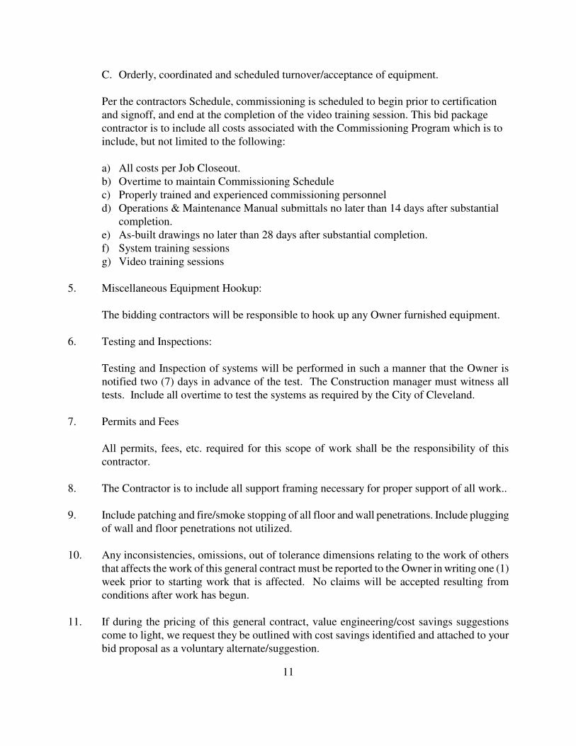
C. Orderly, coordinated and scheduled turnover/acceptance of equipment.
Per the contractors Schedule, commissioning is scheduled to begin prior to certification and signoff, and end at the completion of the video training session. This bid package contractor is to include all costs associated with the Commissioning Program which is to include, but not limited to the following:
a) All costs per Job Closeout. b) Overtime to maintain Commissioning Schedule c) Properly trained and experienced commissioning personnel d) Operations & Maintenance Manual submittals no later than 14 days after substantial
completion. e) As-built drawings no later than 28 days after substantial completion. f) System training sessions g) Video training sessions
5. Miscellaneous Equipment Hookup: The bidding contractors will be responsible to hook up any Owner furnished equipment. 6. Testing and Inspections:
Testing and Inspection of systems will be performed in such a manner that the Owner is notified two (7) days in advance of the test. The Construction manager must witness all tests. Include all overtime to test the systems as required by the City of Cleveland.
7. Permits and Fees
All permits, fees, etc. required for this scope of work shall be the responsibility of this contractor.
8. The Contractor is to include all support framing necessary for proper support of all work.. 9. Include patching and fire/smoke stopping of all floor and wall penetrations. Include plugging
of wall and floor penetrations not utilized. 10. Any inconsistencies, omissions, out of tolerance dimensions relating to the work of others
that affects the work of this general contract must be reported to the Owner in writing one (1) week prior to starting work that is affected. No claims will be accepted resulting from conditions after work has begun.
11. If during the pricing of this general contract, value engineering/cost savings suggestions
come to light, we request they be outlined with cost savings identified and attached to your bid proposal as a voluntary alternate/suggestion.
12
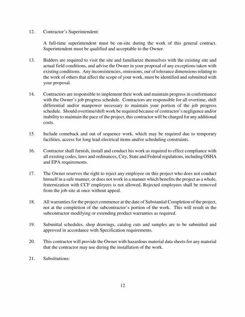
12. Contractor’s Superintendent:
A full-time superintendent must be on-site during the work of this general contract. Superintendent must be qualified and acceptable to the Owner.
13. Bidders are required to visit the site and familiarize themselves with the existing site and
actual field conditions, and advise the Owner in your proposal of any exceptions taken with existing conditions. Any inconsistencies, omissions, our of tolerance dimensions relating to the work of others that affect the scope of your work, must be identified and submitted with your proposal.
14. Contractors are responsible to implement their work and maintain progress in conformance
with the Owner’s job progress schedule. Contractors are responsible for all overtime, shift differential and/or manpower necessary to maintain your portion of the job progress schedule. Should overtime/shift work be required because of contractor’s negligence and/or inability to maintain the pace of the project, this contractor will be charged for any additional costs.
15. Include comeback and out of sequence work, which may be required due to temporary
facilities, access for long lead electrical items and/or scheduling constraints. 16. Contractor shall furnish, install and conduct his work as required to effect compliance with
all existing codes, laws and ordinances, City, State and Federal regulations, including OSHA and EPA requirements.
17. The Owner reserves the right to reject any employee on this project who does not conduct
himself in a safe manner, or does not work in a manner which benefits the project as a whole, fraternization with CCF employees is not allowed. Rejected employees shall be removed from the job-site at once without appeal.
18. All warranties for the project commence at the date of Substantial Completion of the project,
not at the completion of the subcontractor’s portion of the work. This will result in the subcontractor modifying or extending product warranties as required.
19. Submittal schedules, shop drawings, catalog cuts and samples are to be submitted and
approved in accordance with Specification requirements. 20. This contractor will provide the Owner with hazardous material data sheets for any material
that the contractor may use during the installation of the work. 21. Substitutions:
13
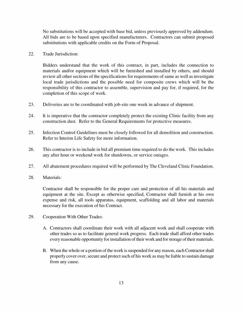
No substitutions will be accepted with base bid, unless previously approved by addendum. All bids are to be based upon specified manufacturers. Contractors can submit proposed substitutions with applicable credits on the Form of Proposal.
22. Trade Jurisdiction:
Bidders understand that the work of this contract, in part, includes the connection to materials and/or equipment which will be furnished and installed by others, and should review all other sections of the specifications for requirements of same as well as investigate local trade jurisdictions and the possible need for composite crews which will be the responsibility of this contractor to assemble, supervision and pay for, if required, for the completion of this scope of work.
23. Deliveries are to be coordinated with job-site one week in advance of shipment.
24. It is imperative that the contractor completely protect the existing Clinic facility from any
construction dust. Refer to the General Requirements for protective measures. 25. Infection Control Guidelines must be closely followed for all demolition and construction.
Refer to Interim Life Safety for more information. 26. This contractor is to include in bid all premium time required to do the work. This includes
any after hour or weekend work for shutdowns, or service outages. 27. All abatement procedures required will be performed by The Cleveland Clinic Foundation. 28. Materials:
Contractor shall be responsible for the proper care and protection of all his materials and
equipment at the site. Except as otherwise specified, Contractor shall furnish at his own expense and risk, all tools apparatus, equipment, scaffolding and all labor and materials necessary for the execution of his Contract.
29. Cooperation With Other Trades:
A. Contractors shall coordinate their work with all adjacent work and shall cooperate with other trades so as to facilitate general work progress. Each trade shall afford other trades every reasonable opportunity for installation of their work and for storage of their materials.
B. When the whole or a portion of the work is suspended for any reason, each Contractor shall
properly cover over, secure and protect such of his work as may be liable to sustain damage from any cause.

14
30. Shop Drawings:
A. Shop drawing approval is crucial to the schedule of this project. Shop drawing submittal is to start as soon as possible after award of the contract, especially submittals noted on Project Schedule.
B. Shop drawings of all fabricated work shall be submitted through the Contractor to the
Architect for approval and no work shall be fabricated by the Contractor except at his own risk, until approval has been given. One (1) blueline print and one (1) reproducible print of shop drawings will be required.
C. Subcontractors shall submit all shop drawings through the Contractor to enable the Owner
ample time for checking same, including time for correcting, resubmission’s and recheck if necessary, and no claim for delay will be granted the Contractor by reason of his failure in this respect.
D. All shop drawings submitted must bear the stamp of approval of the Contractor as evidence
that the drawings have been checked by the Contractor.
E. Where shop drawings submitted by the Contractor indicate a departure from the Contract which the Owner deems to be a minor adjustment not involving a change in contract price or extension of time, the owner may, at his discretion, approve the drawings.
F. All dimensions as shown in Shop Drawings shall be field verified by Contractor.
31. Construction Facilities Sanitary facilities in the area shall be used by workmen. Said facilities shall be protected and
maintained by the General Contractor in a manner acceptable to the Local Authorities, and the Owner.
32. Protection of Work and Property All Contractors shall use care and caution in the performance of their work to protect property
and personnel in the adjacent to the areas of construct operations. 33. Work in and Around Existing Property
A. The various Contractors shall carefully examine the drawings and site conditions relative to utilities and shall be responsible for repair or replacement thereto for damage caused by their work.

15
B. Any damage to existing curbs, walks, grades, grass, or related items caused by vehicles or equipment, shall be repaired with materials and workmanship equal to conditions found at the start of construction operation. Cost of such repair or restoration work shall be paid by the Contractor.
34. Cutting
A. Openings required in existing construction or in-place new construction shall be cut by the Contractor requiring the opening, with the supervisor’s approval of the General Contractor.
B. If sleeves, hangers, etc. are not placed in time or are improperly placed, each Contractor
shall be responsible for cutting, forming or drilling openings where required.
C. Cutting shall be done carefully so as not to damage any part of the structure. Cutting shall be done neatly, and as little material as possible shall be removed.
D. Holes in concrete or masonry construction shall be core drilled wherever possible.
E. In no case shall structural steel or known or presumable reinforcing steel be cut without the
permission of the Architect. If doubt exists as to the location of such steel, inquiry may be made to the Architect. If unknown reinforcing steel is inadvertently cut, the Architect shall be notified of the location and size of the reinforcing so that proper corrective measures may be determined, if required.
35. Patching
A. Patching work shall be performed by the proper trade for each material to be patched. B. Patch all materials, existing or new, cut or damaged in the performance of the work of the
project. C. Patch all materials in area as shown in the room finish schedule. D. Where patching is required, patching shall include closing or filling of openings, cracks
or holes, replacement of defective materials, and refinishing to achieve a uniformity of texture and finish between similar materials whether new or existing.
E. Where walls, partitions and ceilings have or are required to have a smoke or fire rating,
they must be continuous through concealed spaces and be sealed tightly against any pipes, ducts, conduits or other penetrations or building components. Any cracks, holes or defects, whether existing or resulting from the work of the Project, shall be patched to achieve or restore the required smoke or fire rating. Patching shall be performed to restore or maintain the integrity of floor/ceiling assemblies and roof/ceiling assemblies that have or are indicated to have a required fire rating.
16
36. Acceptance of Work
A. Certificates of Substantial Completion will be issued for each phase as the work reaches
that point. Once issued and executed by the Owner and Contractor the Owner may commence using the area and equipment.
B. The date of substantial completion will be the date for the commencement of the one
(1) year warranty period (or longer as allowed by law) for all items furnished under this Contract.
C. Upon completion, the Contractor shall supply (3) sets of Operation and Maintenance
Manuals, Appropriate Equipment Drawings, Schematics and Layout Information, as well as as-builts.
37. Working Hours
A. The normal job working hours shall be established by the General Contractor. B. During established working hours, it shall be the responsibility of all Contractors, and
their Subcontractor, to provide all necessary skilled craftsmen as to cause no delays to any phase of the construction work.
C. All Contractors shall provide sufficient and adequate labor, materials and equipment
necessary to properly correlate all phase of the work to the end that the approved Progress Schedule can be adhered to and the contract completion date met.
D. Work required in adjacent, occupied areas may be required to be performed at other than
normal working hours, as specified by the Cleveland Clinic. Any premium time for such work should be included in the contractor’s base bid; additional charges for such premium time will not be allowed after the bid is accepted.
38. Parking
A. Parking will be provided for contractor employees. All contractor employees shall abide by local parking regulations.
39. Job Progress Meetings
A. Generally, job progress meeting will be held once a week at the job site. They will be scheduled in advance by the General Contractor. All Prime Contractors and concerned Subcontractors shall have a representative in attendance. The representative shall be the project manager, job superintendent, or officer of the firm.

17
B. The purpose of the meeting is to review the status of the work and acquaint all parties with the anticipated work schedule.
C. Should Prime Contractor not have a representative in attendance at a meeting as
identified herein before, then such Contractor shall forfeit the sum of $50.00 per day every missed meeting from the amount due him by the Owner, unless the Owner specifically excused the Contractor in writing for that missed meeting.
D. Minutes of safety issues must be documented by the General Contractor and all safety
violation issues must documented. These minutes must be distributed in a timely fashion. Documentation of all safety violation corrective measures must also be included in these minutes.
ROOFING PROJECT MANUAL
&
SPECIFICATIONS
DATED
for
CLEVELAND CLINIC
Cleveland, OH
Roof Areas: Identify Date of Issue: Date Bid Due Date: Date

Heading Project #
SECTION 01100 INSTRUCTIONS TO BIDDERS Page 01100 - 1
SECTION 01100
INSTRUCTION TO BIDDERS
1 PART 1 - GENERAL
1.1 RELATED DOCUMENTS:
A Documents affecting work of this Section include, but are not necessarily limited to, Drawings and general provisions of the Contract, including General and Supplementary Conditions and other Division 1 Specification Sections.
1.2 SEALED BIDS
A Sealed bids will be received until: Date, for general construction on designated roof areas of Lutheran Hospital as indicated on the Drawings.
Address envelopes to: Address Phone: #
B Write in the lower left corner: Project ID
1.3 PLANS AND SPECIFICATIONS
A Additional copies of blank proposals, plans, specifications and any further information desired may be obtained from Adam Bradley Enterprises, Inc. at (440) 543-4971.
1.4 DEFINITION OF TERMS
A Whenever the term "Owner" occurs in the Specifications or other documents, it shall mean Cleveland Clinic Foundation.
B Whenever the term “Owners Representative” occurs in the specifications, it shall mean Adam Bradley Enterprises, Inc.
C Whenever the term "Contractor" occurs in the Specifications or other documents, it shall mean a person, firm or corporation contracting with the Owner to supply labor, equipment, and materials specified herein for the successful completion of this contract.
1.5 PRE-QUALIFICATION OF BIDDERS
A Bidders expecting to bid may be required to file, prior to the time of award of contract, a confidential financial statement and experience questionnaire, which may be a complete report of the financial resources and liabilities, equipment, past record, and personnel.
B Bidders must submit names of any subcontractors to be utilized on the bid form attached. All subcontractors must be approved by Cleveland Clinic.
1.6 BIDDER REQUIREMENTS:
A The Prime Bidder on this Project must be a Roofing Contractor with experience and qualifications specified in the Construction Documents.
B Requests for substitutions of specified materials or practices must be submitted by the prime bidder. Requests for substitutions from manufacturers, suppliers or sub contractors will not be considered.
1.7 ADDENDUM TO PROPOSAL
A The Owner reserves the right to modify the proposal to within 24 hours of the scheduled date for the opening of proposals. All addenda shall be in writing and sent to all bidders having attended the pre bid conference.

Heading Project #
SECTION 01100 INSTRUCTIONS TO BIDDERS Page 01100 - 2
1.8 AWARDING OF CONTRACT
A The Owner reserves the right to award the contract to the lowest and best, and not necessarily to the lowest bidder, or to reject any or all bids without formalities.
1.9 EXAMINATION OF PLANS, SPECIFICATIONS, SPECIAL PROVISIONS, AND SITE OF WORK
A The bidder is expected to examine carefully the site of the proposed work, the proposal, plans, specifications, supplemental specifications, special provisions and contract forms, before submitting a bid. The submission of a bid shall be considered evidence that the bidder has made such examination and is satisfied as to the conditions to be encountered in performing the work, and as to the requirements of the site conditions, plans, specifications, supplemental conditions, special provisions and contracts, and no allowance will be made for lack of knowledge concerning such conditions after the contract is signed.
1.10 PREPARATION OF BID PROPOSAL
A The bidder shall submit his bid upon the forms furnished by the Owner. All words and figures shall be in ink or typewritten.
B The bidder's bid must be signed with ink by the individual, by one or more members of the partnership, or by one or more officers of a corporation, or by an agent of the Contractor legally qualified and acceptable to the Owner. If the proposal is made by an individual, his name and business address must be shown; by a partnership, the name and business address of each partnership member must be shown; by a corporation, the name of the state under the laws of which the corporation is chartered and the name and title of the officer or officers having authority under the bylaws to sign contracts, the name of the corporation and the business address of its corporate official must be shown.
1.11 DELIVERY OF BIDS
A The bids shall be placed in a sealed envelope so marked as to indicate the identity of the project and the name and address of the bidder. Proposals will be received until the hour and date set for the opening thereof, and must be in the hands of the official indicated by such time. Bids received after the time for opening may be returned to the bidder unopened.
B Fax and/or E-mail transmittals of bids are not acceptable.
1.12 WITHDRAWAL OF BIDS
A A bidder may withdraw his bid, provided the request in writing is in the hands of the official indicated in the proposal by the time set for opening bid.
1.13 DISQUALIFICATION OF BIDDERS
A Any of the following reasons may be considered as being sufficient for the disqualification of a bidder and the rejection of his proposal or proposals:
1 If the bid is on a form other than that furnished by the Owner or if the form is altered or any part thereof is detached.
2 If there are unauthorized additions, conditional or substitute bids, or irregularities of any kind which may tend to make the bid incomplete, indefinite or ambiguous as to its meaning.
3 If the bidder adds any provisions reserving the right to accept or reject an award, or to enter into a contract pursuant to an award. This does not exclude a bid limiting the maximum gross amount of awards acceptable to any one bidder at any one bid letting, provided that any selection of awards will be made by the Owner.
4 More than one proposal for the same work from an individual firm or corporation under the same or different name.
5 Evidence of collusion among bidders. Participants in such collusion will receive no recognition as bidders for any future work of the Owner until any such participant shall have been reinstated as a qualified bidder.

Heading Project #
SECTION 01100 INSTRUCTIONS TO BIDDERS Page 01100 - 3
B Bid prices which obviously are unbalanced.
1.14 BID PROPOSAL FORM
A Each bidder shall submit an individual Bid Proposal Form. The Bid Proposal Form in these documents must be utilized; no alteration of the form shall be made.
1.15 INSURANCE
A The successful bidder shall provide The Cleveland Clinic Foundation with appropriate insurance coverage, including automobile liability, general liability, property insurance, etc. and name The Cleveland Clinic Foundation, an additional insured. Original sets of certificates shall be on file with The Cleveland Clinic Foundation before work commences. Each such certificate of insurance shall provide for payment of not less than the amount of $2,000,000.00 for injury or death of one person and $5,000,000.00 for any one accident, and $2,000,000.00 for property damage for any one accident, and a total aggregate property damage limit of $5,000,000.00. The successful bidder shall also agree to protect The Cleveland Clinic Foundation against all claims, demands, expenses, suits, or judgments arising because of, or resulting from the operations of the contractors, his agents, or his employees during the execution of this contract.
B The successful bidder shall present evidence of insurance coverage by presenting the following prior to signing of a contract:
1 Authenticated copies of all insurance coverage.
2 Authorization by the State of Ohio to do business in the State of Ohio, if the insurance company is not a corporation of the State of Ohio.
3 Workmen's Compensation Certificate of the State of Ohio.
C Insurance certificate shall be submitted with coverage as follows:
1 Claim under Workers' or Workmen's Compensation, disability benefit of other similar employee benefit acts;
2 Claims for damages because of bodily injury, occupational sickness or disease, or death of his employees;
3 Claims for damages because of bodily injury, sickness of disease, or death of any person other than his employees;
4 Claims for damages insured by usual personal injury liability coverage which are sustained by any person as a result of an offense directly or indirectly related to the employment of such person by the Contractor, or any other person;
5 Claims for damages, other than to the work itself, because of injury to or destruction of the tangible property, including loss of use resulting there from; and claims for damages because of bodily injury or death of any person, or property damage arising out of the ownership, maintenance, or use of any motor vehicle.
D Contractor shall provide Certificate of Insurance Coverage with coverage as noted in General Requirements.
1.16 TAXES
A The successful bidder shall be required to comply with all federal, state and local requirements with regard to any and all taxes owed and/or required.
1.17 WORK SCHEDULE AND PENALTIES
A The Contractor shall start the Work within ten (10) days of a notice to proceed and shall execute the Work with diligence and dispatch so as to maintain such schedules and milestones as established by the Owner.
B Contractor shall submit a preliminary construction schedule with his bid assuming a start date within three (3) weeks from the bid due date.

Heading Project #
SECTION 01100 INSTRUCTIONS TO BIDDERS Page 01100 - 4
C In the event that the Contractor should fail to maintain the progress schedule or the schedule as established above, the Owner reserves the right, after 48 hours formal notice, either by letter or telegram to the Contractor, to procure the materials, equipment, and labor necessary to proceed with, or to complete the Work, or any portion thereof from other sources and charge the cost thereof to the Contractor.
1.18 APPLICATION FOR PAYMENT
A An invoice for payment for materials may be submitted upon delivery of materials to job site. All suppliers and subcontractors must be paid in full and Waiver of Lien by major suppliers and subcontractors must be issued prior to any subsequent payments being made to the contractor.
B When all work has been completed, and a final inspection has been made, Contractor may invoice the Owner for 90% of the remaining labor and the materials which were provided by Contractor. Once any and all deficiencies have been corrected, the Owner will make payment of 90% of the balance of the total contract price, with adds and deducts, and will make payment of the remaining 10% once the warranty has been issued.
* * * END OF SECTION - INSTRUCTIONS TO BIDDERS * * *

Project ID Project #
SECTION 01110 SUMMARY OF WORK Page 01110 - 1
SECTION 01110
SUMMARY OF WORK
1 PART 1 - GENERAL
1.1 RELATED DOCUMENTS:
A Documents affecting work of this Section include, but are not necessarily limited to, Drawings and general provisions of the Contract, including General and Supplementary Conditions and other Division 1 Specification Sections.
1.2 SUMMARY OF WORK:
A The Prime Bidder shall provide all labor, materials, tools, equipment, services, etc. to provide complete, watertight roof systems, drainage and other related work as shown and/or specified in the Bidding Documents.
B Areas Included: Roof IDs
C Unit Prices:
1 Provide Unit Prices on Bid Form for the following items:
a Base Bid Unit Prices;
2 Include the following quantities and lump sum allowances in the base bid, additions to or subtractions from these indicated quantities to be adjusted by unit prices or lump sums quoted;
a Base Bid Allowances;
D Work includes:
1 Base Bid;
a Scope of work
2 Alternate Add Bid:
a Scope of work.
1.3 INTENT OF THE SPECIFICATIONS:
A The intent of these specifications is to describe the materials and methods of construction required for the performance of the work. In general, it is intended that the drawings shall delineate the detailed extent of the work. When there is a discrepancy between drawings, referenced specifications, and standards and this specification, this specification shall govern.
B Consultant designed the work conveyed in the Contract Documents for Owner’s benefit. These Contract Documents are between Owner and Consultant only. Nothing contained in these Contract Documents shall create a contractual relationship between the Contractor and the Consultant.
C Assumption of Responsibility: Throughout these specifications, unless specifically noted otherwise, all work shall be assumed to be the sole responsibility of the Contractor
1.4 SPECIFICATION FORMATS AND CONVENTIONS A. Specification Format: The Specifications are organized into Divisions and Sections using the 16-
division format and CSI/CSC “MasterFormat” numbering system.
Project ID Project #
SECTION 01110 SUMMARY OF WORK Page 01110 - 2
1. Section Identification: The Specifications use section numbers and titles to help cross-referencing in the Contract Documents. Sections in the Project Manual are in numeric sequence; however, the sequence is incomplete.
B. Specification Content: The Specifications use certain conventions for the style of language and
the intended meaning of certain terms, words, and phrases when used in particular situations. These conventions are as follows:
1. Abbreviated Language: Language used in the Specifications and other Contract
Documents is abbreviated. Words implied, but not stated, shall be inferred as the sense requires. Singular words shall be interpreted as plural and plural words shall be interpreted as singular where applicable as the context of the Contract Documents indicates.
2. Imperative mood and streamlined language are generally used in the Specifications. Requirements expressed in the imperative mood are to be performed by Contractor. Occasionally, the indicative or subjunctive mood may be used in the Section Text for clarity to describe responsibilities that must be fulfilled indirectly by Contractor or by others when so noted.
a. The words “shall,” “shall be,” or “shall comply with,” depending on the context, are
implied where a colon (:) is used within a sentence or phrase
1.5 WORK UNDER OTHER CONTRACTS
A Owner may award separate contracts for related or unrelated construction operations at this site. These operations may be conducted simultaneously with work under this contract.
B Cooperation with other Contractors and Trades that may be present on the site is expected so that work on those contracts may be carried out. Owner reserves the right to resolve conflicts if required.
1.6 EXISTING HVAC AND ELECTRICAL EQUIPMENT
A Existing HVAC and electrical equipment will require temporary disconnection, relocation, and reconnection. Such work shall be a part of this Contract and shall be performed by the appropriate licensed tradesmen. Cost of the work shall be included in Base Bid.
B Electrical conduit and electrical items will have to be permanently relocated to prevent re-attachment to new roofing, flashing, or sheet metal components. Such work shall be a part of this contract and shall be performed by the appropriate licensed tradesmen. Cost of the work shall be included in Base Bid.
1.7 REGULATORY REQUIREMENTS
A TAXES:
1 Contractor shall pay all sales, consumer, use and other similar taxes required by law.
2 Cleveland Clinic is Tax exempt.
B GOVERNING CODES AND STANDARDS:
1 Work performed under this specification shall be in compliance with applicable Industry Standards and all applicable codes, laws, and ordinances of the municipal, state, and federal departments concerned. Materials and workmanship required by such regulations shall be provided by the Contractor whether or not specifically noted herein or shown on the drawings.
2 Bidders are directed to immediately advise the Consultant if they discover any materials, products, or designs that conflict with or fail to satisfy any of the following Codes, Standards or Local Ordinances;
a Ohio Building Code (OBC)

Project ID Project #
SECTION 01110 SUMMARY OF WORK Page 01110 - 3
b Americans with Disabilities Act Architectural Guidelines (ADAAG)
c National Fire Protection Association (NFPA)
d Occupational Safety and Health Standards of Construction Industry (OSHA)
e Environmental Protection Agency (EPA)
f Factory Mutual Global (FMG)
g Underwriters Laboratories (UL)
3 Industry Standards: Minimum standards of construction shall comply with all applicable standards including but not limited to;
a NRCA
b SMACNA
C The above notwithstanding, Industry Standards and Codes are recognized as minimum requirements. In many cases these Contract Documents specify materials, quantities, thicknesses, details, assemblies, etc., that clearly exceed the Industry Standards and prevailing Codes. In all these cases the more stringent requirements in the Contract Documents shall be required.
1.8 NOTICES AND POSTINGS:
A The Contractor shall give all notices and comply with all laws, ordinances, rules, regulations and orders of any public authority bearing on the performance of the Work. If Contractor performs any Work knowing it to be contrary to such laws, ordinances, rules and regulations, without providing notice to building owner's representative, Contractor shall assume full responsibility and shall bear all costs.
B All permits shall be placed in a plastic tube and be kept in the location designated by the Fire Safety Officer for the entire duration of the work. The following shall be posted on site;
1 Copies of all permits
2 Copies of all MSDS sheets
3 A Job Board showing escape routes and the locations of fire alarms and smoke detectors and other information and documents as required by the fire safety officer.
4 A completed safety triangle listing hazardous substance ratings of products stored at or in use at the job site
1.9 PERMITS AND FEES:
A Obtain Hazardous substance permits from Owner. All containers five (5) gallons or larger must be labeled with the permit number.
B Obtain open burn permits and file pre and post burn inspection reports in writing on a daily basis as required by Owners Safety Office.
C The Contractor shall apply for and secure all incidental permits, governmental fees and licenses necessary for proper execution and completion of the Work.
1.10 PROTECTION:
A The Contractor shall use precautions necessary to provide for the safety of property owner, visitors to the site, and all connected with the work of this project.
B All existing facilities both above and below ground shall be protected and maintained free of damage. Existing facilities shall remain operating during the period of construction unless otherwise permitted. All access roadways must remain open to traffic unless otherwise permitted.
C Cranes and delivery vehicles may be placed only where approved by the Owner.

Project ID Project #
SECTION 01110 SUMMARY OF WORK Page 01110 - 4
1.11 SAFETY REQUIREMENTS
A All application, material handling, and associated equipment shall conform to and be operated in conformance with OSHA safety requirements.
B Comply with applicable Federal, State, Local and Owner health and safety requirements.
C Applicable asbestos-containing material removal procedures must be used where asbestos is detected.
D Notify the Owner in advance whenever work is expected to be potentially hazardous and/or harmful to persons and/or property on the site. Contractor is solely responsible for employing means and methods (acceptable to the Owner) deemed necessary to prevent harm to such persons and property.
E Maintain a construction crewmember as a Floor Area Guard whenever roof decking is being repaired or replaced.
F Maintain proper fire extinguishing equipment and trained personnel within close proximity and with unobstructed access to work areas whenever power tools, torches and/or other heat-producing equipment is being used on the project.
G ALL SAFETY REQUIREMENTS OF THE BUILDING OWNER INCLUDING OBTAINING OWNER ISSUED PERMITS AND EMPLOYEE SAFETY TRAINING MUST BE FOLLOWED. NO EXCEPTIONS WILL BE PERMITTED. SAFETY ORIENTATION MEETING REQUIRED PRIOR TO PERFORMING ANY WORK. ALL EMPLOYEES MUST WEAR OWNER ISSUED IDENTIFICATION BADGES.
1.12 CONTRACTOR REQUIREMENTS
A Roofing Contractor’s Qualifications to be submitted prior to award of the Contract:
1 Certification or letter from the Manufacturer that Contractor has been an approved applicator by the Manufacturer prior to the bidding period. Certification must be maintained throughout the installation.
2 Letter from Roofing Manufacturer confirming that all bidding documents have been approved, that the site has been inspected and meets the requirements for suitability, that these Specifications and the Drawing Details are acceptable to them for the deck and surfacing to which they are to be applied, and that the specified warranty shall be provided upon satisfactory completion of the project.
a If details for any manufacturer’s systems proposed in the Contract Documents are not acceptable to the manufacturer, submit corresponding details proposed for the particular application, together with the manufacturer’s reasons for not accepting the conditions depicted in the Specifications or Drawings. No alternate details will be considered without evidence of valid objections on the part of the manufacturer to the Contract requirements.
b No deviation is to be made from this Specification without prior written approval by the manufacturer; submit such approval to the Consultant.
B Shall appoint a Safety Coordinator who shall be a member of the roofing installation crew. The name of the appointee shall be submitted, including all qualifications for the appointment.
C Maintain a daily job log to be kept on site at all times from the pre-roofing conference until final close-out. The job log shall include:
1 Copies of all submittals.
2 Safety coordinator appointment with emergency telephone numbers; fall protection plan and material safety data sheets for all products.
3 A summary of each days work including any photographs or detail revisions.
4 A field sketch showing areas of work for the day.
5 Accident reports

Project ID Project #
SECTION 01110 SUMMARY OF WORK Page 01110 - 5
6 Material delivery records; and a visitor register.
7 Complaint log, listing complaints received from any party of any nature, and the actions taken and resolution, with dates and names of individuals involved.
D Contractor shall provide a foreman or superintendent to be present on the job site at all times to supervise all Work by all subcontractors utilized on the project. On site Foreman/Superintendent must have a cell phone on site at all times and provide number to Consultant and Owner.
* * * END OF SECTION 01110* * *

Project ID Project #
SECTION 01140 CONTRACTORS USE OF PREMISES Page 01140 - 1
SECTION 01140
CONTRACTOR'S USE OF PREMISES
1 PART 1 - GENERAL
1.1 RELATED DOCUMENTS:
A Documents affecting work of this Section include, but are not necessarily limited to, Drawings and general provisions of the Contract, including General and Supplementary Conditions and other Division 1 Specification Sections.
1.2 DESCRIPTION
A Work included: This Section applies to situations in which the Contractor or his representatives including, but not necessarily limited to, suppliers, subcontractors, employees, and field engineers, enter upon Owner's property.
1.3 QUALITY ASSURANCE
A Promptly upon award of the Contract, notify all pertinent personnel regarding requirements of this Section.
B Owner may require all personnel who will enter upon the Owner's property to certify their awareness of and familiarity with requirements of this Section.
1.4 BUILDING OCCUPANCY
A The facility will be occupied and in use during construction. Cooperate with Owner during construction process to minimize disruptions of Owner usage.
B Contractor is fully and solely responsible for the safety and protection of all occupants going into, leaving out of, or occupying the interior of the buildings. All costs associated with providing this service are to be included in the base bids.
C Maintain existing buildings in a weather tight condition throughout the construction process. Protect buildings and occupants during all construction operations and repair any damage caused by construction operations immediately
1.5 TRANSPORTATION FACILITIES
A Driveways and Entrances: Keep driveways and entrances clear. Do not park vehicles or store materials unless specifically authorized by the Owner.
1 Schedule deliveries to minimize the use of driveways and entrances.
2 Load, unload and store materials and equipment to minimize use of space and time requirements at loading, temporary storage and set up areas.
B Do not use handicapped parking area(s) at any time for any purpose.
C Provide adequate protection for curbs and sidewalks over which trucks and equipment pass to reach job site. If any damage occurs the contractor is responsible for repairs.
D Use of cranes, dumpsters or other impediments to traffic must be confined to hours and locations allowed by the Owner;
1 Cranes and delivery vehicles may be placed only where approved by the Owner.
2 Set up site has underground structures, tanks and utilities. Contractor is responsible, after the award of the bid, to determine locations of underground items and their load bearing capacities. Any equipment to be placed over these structures, tanks and utilities must not exceed their load bearing capacities.

Project ID Project #
SECTION 01140 CONTRACTORS USE OF PREMISES Page 01140 - 2
E Contractor's vehicles:
1 Require Contractor's vehicles, vehicles belonging to employees of Contractor, and all other vehicles entering upon Owner's property in performance of Work of Contract, to use only the access areas approved in advance by Owner.
2 Do not permit such vehicles to park on any street or other area of Owner's property except in the area approved by Owner as "Contractor's Parking Area." Contractor employees must obtain parking permits and park in contractor lots when required by the Owner.
1.6 LANDSCAPING
A Provide adequate protection for trees, grass, shrubs and all other landscaping during set-up or construction. If any damage occurs the contractor is responsible for repairs as designated by the Owner.
B Landscaping must be restored to original condition.
C Underground structures, tanks and utilities must be protected and must not be exposed to loads that exceed their load bearing capacity.
1.7 FACILITY USAGE
A Use of Site: Limit use of site to work in areas established during pre-bid and pre-construction meetings. Do not utilize or disturb areas of the site not previously identified beyond the work area without prior written approval.
1 Do not store materials inside building areas, including penthouses unless pre-approved by Owner.
B Safety: Do not block fire exits or doorways. Allow for egress of traffic at all times. Keep driveways and entrances serving the premises open and clear for use by the Owner, Owner’s employees and emergency vehicles at all times
C Provide adequate protection for all interior and exterior portions of the building during set-up and construction. If any damage occurs the contractor is responsible for repairs as designated by the Owner.
D Restrooms and other amenities of the building will only be used with permission of the Owner. If such authorization is given, the Contractor is responsible for maintaining cleanliness and repairs as designated by the Owner.
1.8 OWNER CONDITIONS
A The following Owner conditions shall apply throughout the course of the work. Violation of these conditions shall be grounds for immediate and permanent removal from the site of the offending personnel, or entire crew.
1 Audio Equipment: Playing of loud radios, tape players, CD players, televisions, or other audio devices is prohibited everywhere on site.
2 Appropriate Clothing: Construction personnel shall dress in appropriate clothing at all times, everywhere on site. Shirts and full length pants shall be worn at all times. No article of clothing or visible body parts may have obscene or profane language or graphics displayed on it in any manner.
3 Smoking: Smoking is prohibited at all times. There are no designated smoking areas on any of the Owners property.
4 Language: Loud or abusive language, particularly obscene or profane language is prohibited at all times.
5 Firearms, alcoholic beverages and illegal drugs are strictly prohibited at all times.
1.9 SECURITY
A Restrict access of all persons entering upon the Owner's property to the Access Route and to the actual site of the work.
Project ID Project #
SECTION 01140 CONTRACTORS USE OF PREMISES Page 01140 - 3
2 PART 2 – PRODUCTS (Not Used)
3 PART 3 – EXECUTION (Not Used)
* * * END OF SECTION 01140 * * *

Project ID Project #
SECTION 01150 REGULATORTY REQUIREMENTS Page 01150 - 1
SECTION 01150
REGULATORY REQUIREMENTS
1 PART 1 - GENERAL
1.1 RELATED DOCUMENTS:
A Documents affecting work of this Section include, but are not necessarily limited to, Drawings and general provisions of the Contract, including General and Supplementary Conditions and other Division 1 Specification Sections.
1.2 TAXES:
A Contractor shall pay all sales, consumer, use and other similar taxes required by law.
1.3 PERMITS AND FEES:
A The Contractor shall apply for and secure all incidental permits, governmental fees and licenses necessary for proper execution and completion of the Work.
B All permits shall be placed in a plastic tube and be kept in the location designated by the Fire Safety Officer for the entire duration of the work.
1.4 GOVERNING CODES:
A Work performed under this specification shall be in compliance with applicable codes, laws, and ordinances of the municipal, state, and federal departments concerned. Materials and workmanship required by such regulations shall be provided by the Contractor whether or not specifically noted herein or shown on the drawings.
1.5 NOTICES:
A The Contractor shall give all notices and comply with all laws, ordinances, rules, regulations and orders of any public authority bearing on the performance of the Work. If Contractor performs any Work knowing it to be contrary to such laws, ordinances, rules and regulations, without providing notice to building owner's representative, Contractor shall assume full responsibility and shall bear all costs.
1.6 REGULATORY REQUIREMENTS
A Federal, State and local building and fire codes.
B OSHA and EPA requirements
* * * END SECTION 01150 * * *
Project ID Project #
SECTION 01153 CHANGE ORDER PROCEDURE Page 01153 - 1
SECTION 01153
CHANGE ORDER PROCEDURE
1 PART 1 - GENERAL
1.1 RELATED DOCUMENTS:
A Documents affecting work of this Section include, but are not necessarily limited to, Drawings and general provisions of the Contract, including General and Supplementary Conditions and other Division 1 Specification Sections.
1.2 DESCRIPTION
A Work included:
1 Make such changes in the Work, in the Contract Sum, in the Contract Time of Completion, or any combination thereof, as are described in written Change Orders signed by the Owner and the Designated Owner’s representative and issued after execution of the Contract, in accordance with the provisions of this Section.
1.3 QUALITY ASSURANCE
A Include within the Contractor's quality assurance program such measures as are needed to assure familiarity of the Contractor's staff and employees with these procedures for processing Change Order data.
1.4 SUBMITTALS
A Make submittals directly to the Designated Owner’s representative at his normal place of business.
B Submit the number of copies called for under the various items listed in this Section.
1.5 PRODUCT HANDLING
A Maintain a "Register of Bulletins and Change Orders" at the job site, accurately reflecting current status of all pertinent data.
B Make the Register available to the Designated Owner’s representative for review at his request.
1.6 PROCESSING CHANGES INITIATED BY THE OWNER
A Should the Owner contemplate making a change in the Work or a change in the Contract Time of Completion, the Designated Owner’s representative will issue a "Bulletin" to the Contractor.
1 Bulletins will be dated and will be numbered in sequence.
2 The Bulletin will describe the contemplated change, and will carry one of the following instructions to the Contractor:
a Make the described change in the Work at no change in the Contract Sum and no change in the Contract Time of Completion;
b Promptly advise the Designated Owner’s representative as to credit or cost proposed for the described change. This is not an authorization to proceed with the change.
B If the Contractor has been directed by the Designated Owner’s representative to promptly advise him as to credit or cost proposed for the described change, the Contractor shall:
1 Analyze the described change and its impact on costs and time;
2 Secure the required information and forward it to the Designated Owner’s representative for review.
3 Meet with the Designated Owner’s representative as required to explain costs and, when appropriate, determine other acceptable ways to achieve the desired objective;
Project ID Project #
SECTION 01153 CHANGE ORDER PROCEDURE Page 01153 - 2
4 Alert pertinent personnel and subcontractors as to the impending change and, to the maximum extent possible, avoid such work as would increase the Owner's cost for making the change, advising the Designated Owner’s representative in writing when such avoidance no longer is practicable.
1.7 PROCESSING CHANGES INITIATED BY THE CONTRACTOR
A Should the Contractor discover a discrepancy among the Contract Documents or other cause for suggesting a change in the Work, a change in the Contract Sum, or a change in the Contract Time of Completion, he shall notify the Designated Owner’s representative as required by pertinent provisions of the Contract Documents.
B Upon agreement by the Designated Owner’s representative that there is reasonable cause to consider the Contractor's proposed change, the Designated Owner’s representative will issue a Bulletin in accordance with the provisions described in Article 1.6 above.
1.8 PROCESSING BULLETINS
A Make written reply to the Designated Owner’s representative in response to each Bulletin.
1 State proposed change in the Contract Sum, if any.
2 State proposed change in the Contract Time of Completion, if any.
3 Clearly describe other changes in the Work required by the proposed change or desirable therewith, if any.
4 Include full backup data such as subcontractor's letter of proposal or similar information.
5 Submit this response in single copy.
B When cost or credit for the change has been agreed upon by the Owner and the Contractor the Designated Owner’s representative will issue a "Change Order" to the Contractor.
1.9 PROCESSING CHANGE ORDERS
A Change Orders will be dated and will be numbered in sequence.
B The Change Order will describe the change or changes, will refer to the Bulletin or Bulletins involved, and will be signed by the Owner and the Designated Owner’s representative.
C The Designated Owner’s representative will issue three copies of each Change Order to the Contractor.
1 The Contractor promptly shall sign all three copies and return two copies to the Designated Owner’s representative.
2 The Designated Owner’s representative will retain one signed copy in his file and will forward one signed copy to the Owner.
D Should the Contractor disagree with the stipulated change in Contract Sum or change in Contract Time of Completion, or both:
1 The Contractor promptly shall return two copies of the Change Order, unsigned by him, to the Designated Owner’s representative with a letter signed by the Contractor and stating the reason or reasons for the Contractor's disagreement.
2 The Contractor's disagreement with the Change Order shall not in any way relieve the Contractor of his responsibility to proceed with the change as ordered and to seek settlement of the dispute under pertinent provisions of the Contract Documents.
* * * END OF SECTION 01153 * * *

Project ID Project #
SECTION 01300 ADMINISTRATIVE AND SPECIAL PROJECT REQUIREMENTS Page 01300 - 1
SECTION 01300
ADMINISTRATIVE AND SPECIAL PROJECT REQUIREMENTS
1 PART 1 - GENERAL REQUIREMENTS
1.10 RELATED DOCUMENTS:
A Documents affecting work of this Section include, but are not necessarily limited to, Drawings and general provisions of the Contract, including General and Supplementary Conditions and other Division 1 Specification Sections.
1.11 COORDINATION, SEQUENCING, AND SCHEDULING
A Work Hours:
1 Work day is limited to the local city ordinance and Owner requirements.
2 Work week is confined to hours permitted by local codes. Overtime hours can be worked during hours permitted by local codes. No additional compensation for premium time or over time will be allowed.
3 Deck replacement work on all buildings may be restricted to times when building is not occupied.
4 Duct work, electrical or mechanical equipment shutdowns will be done in off hours as approved by the Owner.
B Coordinate work with all installers and subcontractors to ensure proper sequencing of related trades and efficient and orderly installation of each part of the work in a manner that minimizes inconvenience to the Owner.
C Drainage: Coordinate all removal and replacement so that all roof areas have proper and unrestricted drainage at all times.
D Coordinate and schedule work within 30 feet of air intakes with the Owner. Work to be performed only when fans and intakes can be shut down.
1 Contractor responsible to coordinate shutdown of ductwork smoke detectors and maintain an hourly fire watch and keep a written fire watch log approved by the Owner while the detectors are down.
2 Install tarpaulins over intake vents after shut down occurs.
3 Remove tarpaulins daily after work is complete and inform Owner that intakes can be re-started.
1.12 ENVIRONMENTAL REQUIREMENTS
A Do not proceed with the Work under adverse weather conditions, immediately after rainfall (for weather sensitive products), or when climatic conditions are outside manufacturer’s recommended limitations for installation. Proceed with the work only when weather forecasts are favorable for proper development of the performance characteristics of the materials.
B Do not work in rain, snow or in presence of water, dew or frost.
C Weather delays may not extend the schedule, as defined in the terms of the Construction Documents, unless specifically approved by the Owner, at the Owner’s sole discretion

Project ID Project #
SECTION 01300 ADMINISTRATIVE AND SPECIAL PROJECT REQUIREMENTS Page 01300 - 2
1.13 HVAC AND RELATED WORK
A The Contractor must include all costs associated with raising rooftop units, gas lines, soil stacks, conduits, etc. or with repositioning same to ensure that proper flashing heights as designed and required by the manufacturer and by industry standards are achieved. This includes costs involved in evacuating and charging HVAC units, and gas lines. Work may need to be performed during off hours to accommodate the Owner. The Contractor must also use licensed, Owner approved and proper subcontractors for all of this type of work.
B Conduits, junction boxes, cabling, etc. that are mounted on walls or copings must be moved and remounted on masonry above the counter flashings or on proper blocking or supports on the roof. No such items may be mounted or remounted in a manner in which attachment penetrates flashing or metal roof components.
1.14 PROTECTION AND CLEANING
A Protect building, property, equipment, roads, approaches, parking areas, loading dock areas, sidewalks, vehicles, underground structures, tanks and utilities and landscaping from damage due to the Work, including but not limited to contamination, soiling, staining or defacing.
B Protect workers from radiation, including rooftop microwave antennas in accordance with OSHA regulations, ANSI standards and FCC regulations published in 47 CFR 1.1307(b).
1 Do not move or disturb roof top antennas with unqualified personnel. Use only appropriate tradesmen approved by the Owner to move or relocate antennas or dishes.
C Clean and protect construction in process and adjoining materials in place during handling and installation. Apply protective coverings where necessary to prevent damage or deterioration.
D Coordinate and sequence Work so that other trades do not damage completed installations.
E The Contractor is responsible for the protection of all vegetation, persons, and property on the site and the adjoining rights of way from the Work associated with this Project. Any damaged items will be replaced or repaired to the satisfaction of the Owner.
F The Contractor is responsible for daily clean-up of all debris and for protection of all persons and property in and around the work areas. Any soiling of or damage to vehicles, pedestrians, personal property or real property caused by Work from this Project will be the responsibility of the Contractor.
G The Contractor shall not discontinue the job once work has begun. A full crew must be on site performing appropriate Contract Work on any day in which work can be performed.
H Unapproved Subcontractors cannot be utilized on this Project. All Subcontractors are subject to the Owners approval.
1.15 EXAMINATION OF CONTRACT DOCUMENTS AND SITE
A Before submitting a bid, each Bidder will, at Bidders own expense make or obtain any additional examinations, investigations, exploration, tests, and studies and obtain any additional information and data which pertain to the physical conditions at or contiguous to the site or otherwise which may affect cost, progress performance or furnishing of the Work and which the Bidder deems necessary to determine that its Bid for performing and furnishing the Work is in accordance with the time, price and other terms and conditions of the Contract Documents.
B On request in advance, Owner will provide each Bidder access to the site to conduct such explorations and tests as each Bidder deems necessary for the submission of a Bid. Bidder shall fill all holes, clean up and restore the site to its former conditions upon completion of such exploration.

Project ID Project #
SECTION 01300 ADMINISTRATIVE AND SPECIAL PROJECT REQUIREMENTS Page 01300 - 3
C The submission of a Bid will constitute an incontrovertible representation by the Bidder that the Bidder has complied with every requirement of the Construction Documents and that without exception the Bid is premised upon performing and furnishing the Work required by the Contract Documents and such means, methods, techniques sequences or procedures of construction as may be indicated in or required by the Contract Documents, and that the Contract Documents are sufficient in scope and detail to indicate and convey understanding of all terms and conditions for performance and furnishing the Work.
2 PART 2 – PRODUCTS (Not Used)
3 PART 3 – EXECUTION
3.10 GENERAL
A Measurements: Independently verify dimensions shown on Drawings or in these specifications. Contractor is responsible for all measurements and dimensions including dimensional variations from place to place on the building, or variations between actual field dimensions and those that may be indicated in these specifications and drawings.
B Moisture: Contractor is responsible for the consequences of moisture in or on substrates that may interfere with the Work. Perform testing as necessary to determine if moisture that will interfere with the Work is present. Remove moisture or remove and replace moisture containing materials before completing installation of the Work.
END OF SECTION 01300 - ADMINISTRATIVE AND SPECIAL PROJECT REQUIREMENTS

Project ID Project #
SECTION 01310 - PROJECT MANAGEMENT AND COORDINATION Page 01310- 1
SECTION 01310
PROJECT MANAGEMENT AND COORDINATION
1 PART 1 - GENERAL
1.1 SUMMARY A. This section includes administrative provisions for coordinating construction operations
on Project including, but not limited to, the following: 1. General Project Coordination. 2. Conservation. 3. Cleaning and Protection. 1.2 GENERAL PROJECT COORDINATION A. Coordination: The Contractor shall coordinate the construction operations of all the
installers and Subcontractors to ensure the efficient and orderly installation of each part of the Work.
1. Schedule construction operations in sequence required to obtain the best results
where installation of one part of the Work depends on installation of other components, before or after its own installation.
2. Coordinate installation of different components with Subcontractors to ensure maximum accessibility for required maintenance, service, and repair.
3. Make adequate provisions to accommodate items scheduled for later installation. B. Administrative Procedures: The Contractor shall coordinate scheduling and timing of
required administrative procedures with all other construction activities and activities of other Subcontractors to avoid conflicts and to ensure orderly progress of the Work. Such administrative activities include, but are not limited to, the following:
1. Installation and removal of temporary facilities, roadways and controls. 2. Delivery and processing of submittals. 3. Progress meetings. 4. Pre-construction meetings. 5. Project closeout activities. C. Inspection of Conditions: Contractor shall inspect both the substrate and conditions under
which Work is to be performed. Installers shall not proceed until unsatisfactory conditions have been corrected in a manner acceptable to the Installer as well as the manufacturer of the product, material, or equipment. Proceeding with an installation shall be considered prima facie evidence that the substrates and conditions under which the Work is to be performed are completely satisfactory and acceptable to the installer, and that they will not adversely affect the installation in any way.
D. Contractor shall coordinate temporary enclosures with required inspections and tests to
minimize the necessity of uncovering completed construction for that purpose. E. Leaks: It is understood that this project will be weather tight and free from leaks of any
type. All leaks that occur during construction, or the Warranty period shall be immediately and properly repaired within twenty four (24) hours of its reported occurrence at no cost to the Owner unless as a result of specific warranty exclusions or if leak was a documented pre-existing condition in an area not yet worked on by the Contractor.
Project ID Project #
SECTION 01310 - PROJECT MANAGEMENT AND COORDINATION Page 01310- 2
F. Manufacturer’s Instructions: Where installations include manufactured products or
equipment, comply with manufacturer’s applicable instructions and recommendations for installation, only to the extent that these instructions or recommendations are more explicit or more stringent than other requirements shown in the Contract Documents.
G. Contractor shall install each unit of Work during weather conditions and Project status
which will assure the best possible results in coordination with the entire Work. Isolate each unit of Work from incompatible Work as necessary to prevent deterioration.
H. Understanding that the introduction of moisture into the building spaces during
construction can foster the growth of mold, mildew and fungi, Contractor shall be responsible for taking whatever steps necessary to prevent moisture infiltration into the building spaces during construction.
1.3 CONSERVATION
A. Conservation: Contractor shall coordinate construction activities to ensure that operations are carried out with consideration given to conservation of energy, water, and materials.
B. Salvage materials and equipment involved in performance of, but not actually incorporated into, the work.
1.4 CLEANING AND PROTECTING A. Contractor shall clean and protect construction in progress and adjoining materials in
place, during handling and installation. Apply protective covering where required to assure protection from damage or deterioration at Substantial Completion.
B. Contractor shall clean and provide maintenance on completed construction as frequently
as necessary though the remainder of the construction period. Adjust and lubricate operable components to assure operability without damaging effects.
C. Limiting Exposures: Contractor shall supervise construction operations to assure that no
part of the construction completed or in progress, is subject to harmful, dangerous, damaging, or otherwise deleterious exposure during the construction period. Where applicable, such exposures may include, but are not limited to, the following;
1. Excessive static or dynamic loading. 2. Excessive internal or external pressures. 3. Excessively high or low temperatures. 4. Thermal shock. 5. Excessively high or low humidity. 6. Air contamination or pollution. 7. Water or ice. 8. Solvents. 9. Chemicals. 10. Sunlight (UV) 11. Radiation. 12. Puncture. 13. Abrasion. 14. Heavy traffic. 15. Soiling, staining, and corrosion. 16. Bacteria.

Project ID Project #
SECTION 01310 - PROJECT MANAGEMENT AND COORDINATION Page 01310- 3
17. Rodent and insect infestation. 18. Combustion. 19. Electrical current. 20. High-speed operation. 21. Improper lubrication. 22. Unusual wear or other misuse. 23. Contact between incompatible materials. 24. Destructive testing. 25. Misalignment. 26. Excessive weathering. 27. Unprotected storage. 28. Improper shipping or handling. 29. Theft. 30. Vandalism.
2 PART 2 - PRODUCTS (Not Used)
3 PART 3 - EXECUTION (Not Used)
*** END OF SECTION 01310 - PROJECT MANAGEMENT AND COORDINATION ***

Project ID Project #
SECTION 01311 - PROJECT MEETINGS Page 01311- 1
SECTION 01311
PROJECT MEETINGS
1 PART 1 - GENERAL REQUIREMENTS
1.1 RELATED DOCUMENTS:
A Documents affecting work of this Section include, but are not necessarily limited to, Drawings and general provisions of the Contract, including General and Supplementary Conditions and other Division 1 Specification Sections.
B Related section: Section 01770 – Contract Close-Out.
1.2 SUMMARY A This section specifies requirements for meetings and administrative procedures that include but are not
limited to the following:
1 Preconstruction conference.
2 Progress meetings.
3 Substantial Completion inspection.
4 Final Completion inspection and Project Close-out
1.3 SUBMITALS A See Related Sections: Section 01100 – Summary, and Section 01330 – Submittals.
1.4 PRECONSTRUCTION CONFERENCE A The Preconstruction Conference will be scheduled within 5 working days after the Owner has issued the
Notice to Proceed, but prior to actual start of the Work. All submittals must be received prior to time of the Conference.
B Attendance: Consultant, roofing manufacturer/supplier, and Contractor’s Representative.
1 Minimum agenda: Data will be distributed and discussed on:
a Organizational arrangement of Contractor's forces and personnel, and those of Subcontractors, materials suppliers, and the Architect.
b Channels and procedures for communication.
c Review set-up area and storage areas.
d Review all required permits.
e Construction schedule, including sequence of critical work.
f Designation of responsible personnel.
g Contract Documents, including distribution of required copies of Drawings and revisions.
h Processing of Shop Drawings and other data submitted to the Architect for review.
i Processing of field decisions and Change Orders.
j Rules and regulations governing performance of the work including working hours, use of premises, Owner rules and requirements.
k Parking availability.
l Procedures for safety and first aid, security, quality control, housekeeping, and related matters.

Project ID Project #
SECTION 01311 - PROJECT MEETINGS Page 01311- 2
1.5 PROGRESS MEETINGS
A Will be scheduled by Consultant weekly or as described at the pre-construction meeting.
B Minimum Attendance: Owner, Contractor’s Representative, Job Superintendent, Consultant, and Sub-Contractors, as appropriate.
1 Minimum Agenda:
a Review and correct minutes of the previous progress meeting.
b Review of Work progress.
c Field observations, problems, and decisions.
d Identification of problems which impede planned progress.
e Maintenance of progress schedule.
f Corrective measures to regain projected schedules if construction is behind schedule.
g Planned progress during succeeding work period.
h Coordination of projected progress.
i Maintenance of quality and work standards.
j Effect of proposed changes on progress, schedule, and coordination.
k Interface requirements.
l Status of any incomplete submittals.
m Deliveries.
n Change orders.
o Documentation of information for payment requests.
p Other business relating to work.
C Reporting: Distribute minutes of meetings no later than three working days after each meeting to each party present and to parties who should have been present.
1.6 SUBSTANTIAL COMPLETION INSPECTION
A Related section: Section 01770 – Contract Close-Out.
1.7 FINAL INSPECTION
A Related section: Section 01770 – Contract Close-Out
2 PART 2 – PRODUCTS (Not Used)
3 PART 3 – EXECUTION (Not Used)
END OF SECTION 01311 - PROJECT MEETINGS

Project ID Project #
SECTION 01330 SUBMITTALS 01330- 1
SECTION 01330
SUBMITTALS
1 PART 1 - GENERAL
1.1 RELATED DOCUMENTS:
A Documents affecting work of this Section include, but are not necessarily limited to, Drawings and general provisions of the Contract, including General and Supplementary Conditions and other Division 1 Specification Sections.
1.2 SUMMARY
A The submittals specified in this section must be submitted at the times specified in this Section and as referenced in related sections of the Construction Documents.
B The requirements are in addition to any Submittals required in the Owner’s Bidding Requirements.
1.3 SUBMITTAL PROCEDURES
A Coordination of submittals:
1 Prior to each submittal, carefully review and coordinate all aspects of each item being submitted.
2 Verify that each item and the submittal for it conform in all respects with the specified requirements.
3 By affixing the Contractor's signature or approval stamp to each submittal, he/she certifies that this coordination has been performed.
1.4 SUBMITTAL DOCUMENTS
A All Bidders must submit the following documentation with their bids:
1 Construction Schedule.
2 Name of proposed roof membrane Manufacturer.
3 Submit List of Subcontractors and Suppliers
B All Bidders must submit the following documentation for this Project prior to the award of the bid;
1 Membrane manufacturers data as specified in Section 07500 if different from the manufacturer specified as the basis for the specification.
2 Copy of the roofing manufacturer’s warranty which meets all requirements of the specified warranty.
3 Individual product identification, including manufacturer’s literature and MSDS sheets for all products to be used.
4 Confirmation of Contractor requirements enumerated in Section 01100.
5 Letter from material manufacturer confirming that all bidding documents have been approved, that the site has been inspected and meets the requirements for suitability, that these Specifications and the Drawing Details are acceptable to them for the deck and surfacing to which they are to be applied, and that the specified warranty shall be provided upon satisfactory completion of the project
a If details for any manufacturer’s systems proposed in the Contract Documents are not acceptable to the manufacturer, submit corresponding details proposed for the particular application, together with the manufacturer’s reasons for not accepting the conditions depicted in the Specifications or Drawings. No alternate details will be considered without evidence of valid objections on the part of the manufacturer to the Contract requirements.

Project ID Project #
SECTION 01330 SUBMITTALS 01330- 2
b No deviation is to be made from this Specification without prior written approval by the manufacturer; submit such approval to the Consultant
C Contractor must submit the following documentation for this Project no later than 5 days before start of Work:
1 Shop Drawings:
a Metal Fascia and Copings: Show profiles, joining method, location of accessory items, anchorage and flashing details, adjacent construction interface, and dimensions.
b Shop drawings of each item specified that differ from the basis of design specified in the Construction Documents showing layout, profiles, methods of attachment, and joining methods.
c Shop drawings for new penthouse, doors, stairway, roof, flashings and closures.
d Color samples of metal finishes and sealants for approval by the Owner
e Shop drawing showing adhesive patterns for FMG 1-90 attachment. Show perimeter, corner and field densities of insulation fasteners and placement, type and spacing of perimeter nailer attachments, and adhesive patterns at perimeters, corners and field of the roof for insulation and base sheets.
f Tapered insulation layouts
2 Schedule of values.
3 Final Construction Schedule.
4 Completed Safety Triangle for all products that will be in use or stored at the job.
5 Asbestos monitoring, removal and abatement plans and procedures to be utilized if necessary;
a Copies of OSHA asbestos training certificates for all workers at the project
b Contractor must submit the following asbestos related documentation as required
c Results of air monitoring tests to be submitted daily, immediately after start of work if asbestos related procedures are required
d Credentials and declarations of the competent person. A written summary of safety procedures required based on the results of air monitoring shall be submitted before air monitoring activity is suspended
D The following submittals are required before final payment:
1 Close-out submittals as required in Section 01770 – Contract Close-Out.
2 Warrantees as required in Section 01783 – Warrantees.
2 PART 2 – PRODUCTS (Not Used)
3 PART 3 – EXECUTION (Not Used)
END OF SECTION 01300 - SUBMITTALS

Project ID Project #
SECTION 01420 REFERENCES page 01420- 1
SECTION 01420
REFERENCES
1 PART 1 - GENERAL
1.1 RELATED DOCUMENTS:
A Documents affecting work of this Section include, but are not necessarily limited to, Drawings and general provisions of the Contract, including General and Supplementary Conditions and other Division 1 Specification Sections.
1.2 GENERAL
A The abbreviations and acronyms defined in this section are provided as a convenience and may not be inclusive of all abbreviations and acronyms used in the specifications.
1.3 SUBMITTALS
A Shop drawing showing fastening and /or adhesive patterns for FMG 1-90 attachment and evidence of UL Class A rating for roof covering materials.
1.4 DEFINITIONS AND ABBREVIATIONS
A General: Basic Contract definitions are included in the Conditions of the Contract
B “Approved”: When used to convey Architect’s action on Contractors submittals, applications, and requests, “approved” is limited to Architect’s duties and responsibilities as stated in the Conditions of Contract.
C BMV: Brick masonry unit.
D Clean: Shall be construed to mean the level of cleanliness generally provided by skilled cleaners using commercial quality maintenance equipment and materials.
E CMU: Concrete masonry unit.
F “Directed”: A command or instruction by Architect. Other terms including “requested”, “authorized”, “selected”, “approved”, “required”, and “permitted” have the same meaning as “directed”.
G DL: Dead load.
H “Experienced”: When used with an entity, “experienced” means having successfully completed a minimum of five previous projects similar in size and scope to this Project.
I FCC: Federal Communications Commission.
J “Furnish”: Supply, deliver, or provide to the Project site, for assembly, installation, and similar operations.
K “Indicated”: Requirements expressed by graphic representations or in written form on Drawings, in Specifications, and in other Contract Documents. Other terms including "shown," "noted," "scheduled," and "specified" have the same meaning as "indicated”.
L “Install”: Operations and procedures to set materials, components and details referred to in the Contract Documents and Drawings into place for final use.
M “Installer”: Contractor or another entity engaged by the Contractor as an employee, Subcontractor, or Sub-subcontractor, to perform a particular construction operation, including installation, erection, application, and similar operations.
1 Using a term such as "carpentry" does not imply that certain construction activities must be performed by accredited or unionized individuals of a corresponding generic name, such as

Project ID Project #
SECTION 01420 REFERENCES page 01420- 2
"carpenter." It also does not imply that requirements specified apply exclusively to tradespeople of the corresponding generic name.
N LL: Live Load
O PLF: Pounds per linear foot.
P “Provide”: Furnish and install, complete and ready for intended use.
Q “Project Site”: Space available for performing construction activities. The extent of Project Site is shown on the drawings and may or may not be identical with the description of the land on which Project is to be built.
R PSF: Pounds per square foot.
S PSI: Pounds per square inch.
T “Regulations”: Laws, ordinances, statutes, and lawful orders issued by authorities having jurisdiction, and rules, conventions, and agreements within the construction industry that control performance of the Work.
U RFI: Requests for information.
V Roofing Terminology: Refer to the following publications for terms related to roofing work not otherwise defined in this section.
1 ASTM D 1079: Definitions of Terms Relating to Roofing, Waterproofing, and Bituminous Materials.
2 NRCA Roofing and Waterproofing Manual.
3 Roof Consultants Institute Glossary of Terms.
W SF: Square foot.
1.5 INDUSTRY STANDARDS
A Applicability of Standards: Unless the Contract Documents include more stringent requirements, applicable construction industry standards have the same force and effect as if bound or copied directly into the Contract Documents to the extent referenced. Such standards are made part of the Contract Documents by reference.
B Publication dates: Comply with standards in effect as of the date of the Contract Documents, unless otherwise indicated.
C Conflicting Requirements: If compliance with two or more standards is specified and the standards establish different or conflicting requirements for minimum quantities or quality levels, comply with the more stringent requirement. Refer uncertainties and requirements that are different, but apparently equal, to Architect for a decision before proceeding.
1 Minimum Quantity or Quality Levels: The quantity or quality level shown or specified shall be the minimum provided or performed. The actual installation may comply exactly with the minimum quantity or quality specified, or it may exceed the minimum within reasonable limits. To comply with these requirements, indicated numeric values are the minimum or maximum, as appropriate, for the context of requirements. Refer uncertainties to the Architect for a decision before proceeding.
D Copies of Standards: Each entity engaged in construction on Project must be familiar with industry standards applicable to its construction activity. Copies of applicable standards are not bound with the Contract Documents.
1 Where copies of standards are needed to perform a required construction activity, obtain copies directly from the publication source and make them available on request.
Project ID Project #
SECTION 01420 REFERENCES page 01420- 3
E Abbreviations and Acronyms for Standards and Regulations: Where abbreviations and acronyms are used in the Specifications or other Contract Documents, they shall mean the recognized name of the standards and regulations in the following list. Names, telephone numbers , and web site addresses are subject to change and are believed to be accurate and up to date as of the date of the Contract Documents.
ADAAG Americans with Disabilities Act (ADA)
Accessibility Guidelines for Buildings and Facilities Available from Access Board 800-872-2253 www.access-board.gov 202-272-5434
CFR Code of Federal Regulations 888-293-6498
Available from Government Printing Office 202-512-1530 www.access.gpo.gov/nara/cfr
FS Federal Specification Available from Defense Automated Printing Services //astimage.daps.dla.mil/online 215-697-6257 Available from General Services Administration www.fss.gsa.gov/pub/fed-specs.cfm 202-619-8925 Available from National Institute of Building Sciences www.nibs.org 202-289-7800
1.6 ABBREVIATIONS AND ACRONYMS
A Industry Organizations: Where abbreviations and acronyms are used in the Specifications or other Contract Documents, they shall mean the recognized name of the entities indicated in the Gale Research’s “Encyclopedia of Associations” or in the Columbia Books’ “National Trade and Professional Associations of the US”.
B Industry Organizations: Where abbreviations and acronyms are used in the Specifications or other Contract Documents, they shall mean the recognized name of the entities indicated in the following list. Names, telephone numbers , and web site addresses are subject to change and are believed to be accurate and up to date as of the date of the Contract Documents.
AAMA American Architectural Manufactures Association ACI American Concrete Institute/ACI International 248-848-3700 www.aci-int.org AIA American Institute of Architects (The) 202-626-7300
www.e-architect.com AISC American Institute of Steel Construction 800-644-2400 www.aisc.com 312-670-2400 ALSC American Lumber Standard Committee 301-972-1700 ANSI American National Standards Institute 202-293-8020 www.ansi.org APA APA- The Engineered Wood Association 253-565-6600 www.apawood.org ASHRAE American Society of Heating, Refrigerating and 800-527-4723 Air-conditioning Engineers 404-636-8400
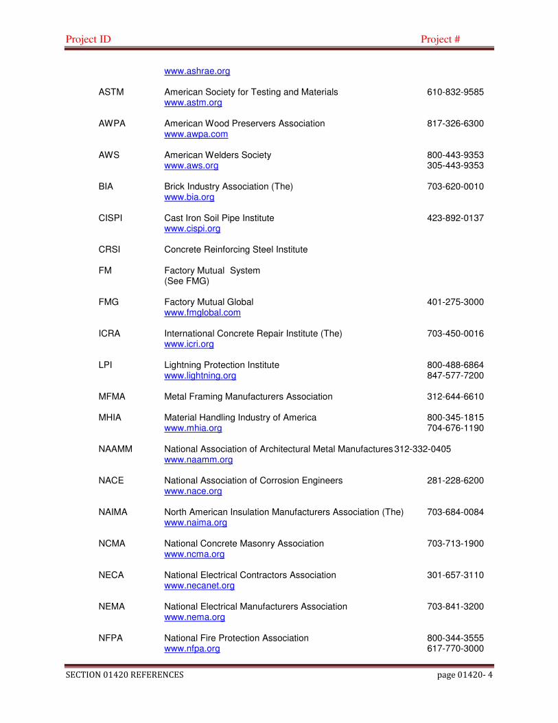
Project ID Project #
SECTION 01420 REFERENCES page 01420- 4
www.ashrae.org ASTM American Society for Testing and Materials 610-832-9585 www.astm.org AWPA American Wood Preservers Association 817-326-6300 www.awpa.com AWS American Welders Society 800-443-9353 www.aws.org 305-443-9353 BIA Brick Industry Association (The) 703-620-0010 www.bia.org CISPI Cast Iron Soil Pipe Institute 423-892-0137 www.cispi.org CRSI Concrete Reinforcing Steel Institute FM Factory Mutual System (See FMG) FMG Factory Mutual Global 401-275-3000 www.fmglobal.com ICRA International Concrete Repair Institute (The) 703-450-0016 www.icri.org LPI Lightning Protection Institute 800-488-6864 www.lightning.org 847-577-7200 MFMA Metal Framing Manufacturers Association 312-644-6610 MHIA Material Handling Industry of America 800-345-1815 www.mhia.org 704-676-1190 NAAMM National Association of Architectural Metal Manufactures 312-332-0405 www.naamm.org NACE National Association of Corrosion Engineers 281-228-6200 www.nace.org NAIMA North American Insulation Manufacturers Association (The) 703-684-0084 www.naima.org NCMA National Concrete Masonry Association 703-713-1900 www.ncma.org NECA National Electrical Contractors Association 301-657-3110 www.necanet.org NEMA National Electrical Manufacturers Association 703-841-3200 www.nema.org NFPA National Fire Protection Association 800-344-3555 www.nfpa.org 617-770-3000

Project ID Project #
SECTION 01420 REFERENCES page 01420- 5
NLGA National Lumber Grades Authority 604-524-2393 www.nlga.org NRCA National Roofing Contractors Association 800-323-9545 www.nrca.net 847-299-9070 NRMCA National Ready Mixed Concrete Association 888-846-7622 www.nrmca.org 301-587-1400 PCA Portland Cement Association PCI Precast Concrete Instititute PDI Plumbing and Drainage Institute 800-589-8956 www.pdionline.org 508-230-3516 SDI Steel Deck Institute 847-462-1030 www.sdi.org SJI Steel Joist Institute 843-626-1995 www.steeljoist.org SMACNA Sheet Metal and Air Conditioning Contractors National 703-803-2980 Association www.smacna.org SPIB Southern Pine Inspection Bureau 850-434-2611 www.spib.org SPRI SPRI 781-444-0242 (Single Ply Institute) www.spri.org SSPC Society for Protective Coatings 800-837-8303 www.sspc.org 412-281-2331 SWRI Sealant, Waterproofing, and Restoration Institute 816-472-7974 www.swronline.org UL Underwriters Laboratories 800-704-4050 www.ul.com 847-272-8800
C Code Agencies: Where abbreviations and acronyms are used in the Specifications or other Contract Documents, they shall mean the recognized name of the entities indicated in the following list. Names, telephone numbers , and web site addresses are subject to change and are believed to be accurate and up to date as of the date of the Contract Documents.
BOCA BOCA International, Inc. 708-799-2300 www.boca.org IAPMO International Association of Plumbing and Mechanical 909-595-8449 Officials (The) www.iapmo.org

Project ID Project #
SECTION 01420 REFERENCES page 01420- 6
ICBO International Conference of Building Officials 800-284-4406 www.icbo.org
D Federal Government Agencies
CPSC Consumer Protection Agency 800-638-2772 www.cpsc.gov 310-504-0990 EPA Environmental Protection Agency 202-260-2090 www.epa.gov FCC Federal Communications Commission GSA General Services Administration 202-708-5082 www.gsa.gov NIST National Institute of Science and Technology 301-975-6478 www.nist.gov OSHA Occupational Safety and Health Administration 202-693-1999
1.7 REFERENCE STANDARDS
A General: Standards listed by reference, including revisions by issuing authorities, form a part of this specification section to the extent indicated. Standards listed are identified by issuing authority, authority abbreviations, designation number, title or other designation established by issuing authority. Standards subsequently referenced herein are referenced to by authority abbreviation and standard designation
B American Society of Civil Engineers - Reference Document ASCE 7-95, Minimum Design Loads for Buildings and Other Structures.
C ACI 530 ACI 530-02/ASCE 5-02/TMS 402-02 “Specification for Masonry Structures”, published by the American Concrete Institute, American Society of Civil Engineers, and the Masonry Society.
D ACI 530.1 ACI 530.1-02/ASCE 6-02/TMS 602-02 “Specification for Masonry Structures”, published by the American Concrete Institute, American Society of Civil Engineers, and the Masonry Society
E American Society of Testing and Materials (ASTM).
1 ASTM A 366 - Standard specification for Commercial Steel (CS), Carbon (0.15 Maximum percent) Cold-rolled.
2 ASTM A 653 – Standard Specification for Sheet Steel, Zinc-Coated (Galvanized) or Zinc-Iron Alloy-Coated (Galannealed) by the hot dip process.
3 ASTM A 924 - Standard Specification for General Requirements for Steel Sheet, Metallic-Coated by the hot dip process.
4 ASTM C 90 – Hollow Load Bearing Concrete Masonry Units
5 ASTM C 144 – Standard Specification for Aggregate for Masonry Mortar
6 ASTM C150 – Standard Specification for Portland Cement
7 ASTM C 165 - Compressive strength
8 ASTM C 203 - Flexural strength
9 ASTM C 207 – Standard Specification for Hydrated Lime for Masonry Purposes
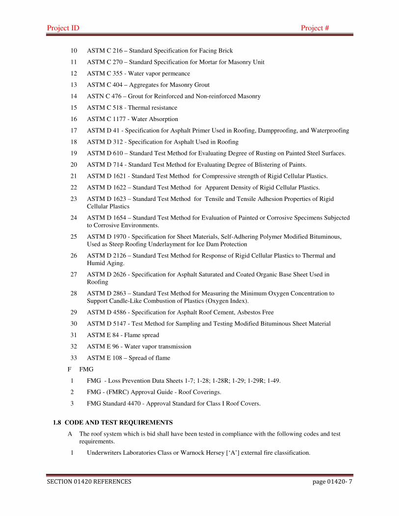
Project ID Project #
SECTION 01420 REFERENCES page 01420- 7
10 ASTM C 216 – Standard Specification for Facing Brick
11 ASTM C 270 – Standard Specification for Mortar for Masonry Unit
12 ASTM C 355 - Water vapor permeance
13 ASTM C 404 – Aggregates for Masonry Grout
14 ASTN C 476 – Grout for Reinforced and Non-reinforced Masonry
15 ASTM C 518 - Thermal resistance
16 ASTM C 1177 - Water Absorption
17 ASTM D 41 - Specification for Asphalt Primer Used in Roofing, Dampproofing, and Waterproofing
18 ASTM D 312 - Specification for Asphalt Used in Roofing
19 ASTM D 610 – Standard Test Method for Evaluating Degree of Rusting on Painted Steel Surfaces.
20 ASTM D 714 - Standard Test Method for Evaluating Degree of Blistering of Paints.
21 ASTM D 1621 - Standard Test Method for Compressive strength of Rigid Cellular Plastics.
22 ASTM D 1622 – Standard Test Method for Apparent Density of Rigid Cellular Plastics.
23 ASTM D 1623 – Standard Test Method for Tensile and Tensile Adhesion Properties of Rigid Cellular Plastics
24 ASTM D 1654 – Standard Test Method for Evaluation of Painted or Corrosive Specimens Subjected to Corrosive Environments.
25 ASTM D 1970 - Specification for Sheet Materials, Self-Adhering Polymer Modified Bituminous, Used as Steep Roofing Underlayment for Ice Dam Protection
26 ASTM D 2126 – Standard Test Method for Response of Rigid Cellular Plastics to Thermal and Humid Aging.
27 ASTM D 2626 - Specification for Asphalt Saturated and Coated Organic Base Sheet Used in Roofing
28 ASTM D 2863 – Standard Test Method for Measuring the Minimum Oxygen Concentration to Support Candle-Like Combustion of Plastics (Oxygen Index).
29 ASTM D 4586 - Specification for Asphalt Roof Cement, Asbestos Free
30 ASTM D 5147 - Test Method for Sampling and Testing Modified Bituminous Sheet Material
31 ASTM E 84 - Flame spread
32 ASTM E 96 - Water vapor transmission
33 ASTM E 108 – Spread of flame
F FMG
1 FMG - Loss Prevention Data Sheets 1-7; 1-28; 1-28R; 1-29; 1-29R; 1-49.
2 FMG - (FMRC) Approval Guide - Roof Coverings.
3 FMG Standard 4470 - Approval Standard for Class I Roof Covers.
1.8 CODE AND TEST REQUIREMENTS
A The roof system which is bid shall have been tested in compliance with the following codes and test requirements.
1 Underwriters Laboratories Class or Warnock Hersey [‘A’] external fire classification.

Project ID Project #
SECTION 01420 REFERENCES page 01420- 8
2 FMG Listing: Provide Roofing Membrane, Base Flashings, and component materials that comply with requirements in FMG 4450 and FMG 4470 as part of a membrane roofing system and that are listed in FMG’s “Approval Guide” for Class I construction.
a Fire/Winstorm Classification: Class 1A-90
b Hail Resistance: MH
2 PART 2 – PRODUCTS (Not Used)
3 PART 3 – EXECUTION (Not Used)
END OF SECTION 01420 - REFERENCES
Project ID Project #
SECTION 01430 QUALITY ASSURANCE page 01430- 1
SECTION 01430
QUALITY ASSURANCE
1 PART 1 - GENERAL
1.1 RELATED DOCUMENTS:
A Documents affecting work of this Section include, but are not necessarily limited to, Drawings and general provisions of the Contract, including General and Supplementary Conditions and other Division 1 Specification Sections.
1.2 COMMUNICATIONS
A Requests for information: Contractor shall issue requests for information (RFI’s) to Architect in a timely manner, in writing, preferably by e-mail.
1 Number each RFI.
2 Indicate the latest date by which a response is needed so as not to delay the Work. Allow at least two business days after receipt for a response (complex issues may require longer to research).
3 Maintain a log of RFI’s showing status of each.
4 If practicable, include a proposed solution to each issue raised in an RFI.
1.3 CONTRACTOR AND MANUFACTURER
A Contractor shall:
1 Be experienced in modified bitumen roofing as required in Section 01100.
2 Be acceptable by Owner and roofing material manufacturer.
3 Maintain an effective quality assurance program, independent of the activities by the Owner, Consultant, Observers, or manufacturers. Contractor may not rely on Consultants monitoring or on observation services provided by others as a substitute for performing Contractor’s own quality assurance program.
4 Accept sole responsibility for the quality of the work.
5 Notify Consultant orally, followed in writing, of conditions that the Contractor believes will yield unsatisfactory performance, or of items of non-conformity between these Contract Documents and manufacturers specifications or instructions, or of discovered errors and omissions. Failure of Contractor to submit written notification shall be construed as a representation by Contractor that the Contract Documents are acceptable to Contractor, that they are sufficient in scope and detail to indicate and convey understanding of the terms and conditions for performance and furnishing of the Work, and that Contractor reasonably believes the work will perform as intended.
6 Correct Work reported to be defective with no increase in cost to the Owner. Once defective Work is reported to the Contractor, that Work shall be considered to require correction until it is actually corrected, regardless of whether it is mentioned again. When a portion of the Work is reported as defective, the Contractor shall promptly investigate the extent to which similar Work has the same conditions. All similar Work shall be considered defective until the full extent of the defective conditions are documented to the Consultant’s satisfaction.
B Roofing manufacturer shall:
1 Be an Associate Member in good standing with National Roofing Contractor's Association (NRCA).

Project ID Project #
SECTION 01430 QUALITY ASSURANCE page 01430- 2
2 Notify Consultant of planned site visits in a timely manner so Consultant can coordinate his site visits to correspond.
3 Material manufacturer must supply a representative to perform periodic observations throughout the course of the Project. Written reports must be submitted to the Consultant and copies to the Contractor. Each site visit must be accompanied by a written report.
4 Provide written reports to Consultant summarizing any communication with Contractor regarding any aspect of the Work.
5 Provide a factory trained technician to attend site meetings and to perform final observations of the roofing system.
C Provide specified Warranty upon completion of satisfactory installation of the roofing system.
1.4 TESTING
A Each roof system and the ceilings under C08 must be tested for asbestos by a testing lab approved by the Owner, if asbestos is detected, it must be abated as required by current OSHA and EPA standards.
B Infra-red scan must be made prior to the request for final payment. Infra-red scanner must be approved by the manufacturer issuing the Warranty and the Consultant. Scan may not be made by Contractor who installed the work.
C Any deficiencies noted during observations, including results of the infrared scan must be corrected by the Contractor and approved in writing by the Consultant prior to scheduling inspection for Final Completion.
1.5 SUBMITTALS
A Submit certification by the manufacturer of the system materials used that these Specifications and the Drawing Details are acceptable to them for the deck and surfacing to which they are to be applied.
1 If details for any manufacturer’s systems proposed in the Contract Documents are not acceptable to the manufacturer, submit corresponding details proposed for the particular application, together with the manufacturer’s reasons for not accepting the conditions depicted in the Specifications or Drawings. No alternate details will be considered without evidence of valid objections on the part of the manufacturer to the Contract requirements.
2 No deviation is to be made from this Specification without prior written approval by the manufacturer; submit such approval to the Architect.
2 PART 2 - PRODUCTS
2.1 GENERAL
A Comply with Quality Control, References, Contract Documents, and Manufacturer's data. Where conflict may exist, more stringent requirements govern.
B Provide Primary Roofing Products for any system other than the specified standard, including each type of roofing sheet (felt), bitumen, adhesives, primers, base flashings, and miscellaneous flashing materials from a single manufacturer, which has produced that type of product successfully for not less than fifteen (15) years. Provide secondary products (insulation, mechanical fasteners, lumber, etc.) only as recommended and/or required by manufacturer of the roof membrane as required for the specified warranty and FMG Approval.
3 PART 3 – EXECUTION
3.1 JOB LOG
A Contractor to maintain a daily job log to be kept on site at all times from the pre-roofing conference through project close-out. The job log shall include:

Project ID Project #
SECTION 01430 QUALITY ASSURANCE page 01430- 3
1 Copies of all submittals.
2 Safety coordinator appointment with emergency telephone numbers; fall protection plan and material safety data sheets for all products.
3 A summary of each days work including any photographs or detail revisions.
4 A field sketch showing areas of work for the day.
5 Accident reports.
6 Complaint log, listing complaints received from any party of any nature, and the actions taken and resolution, with dates and names of individuals involved
END OF SECTION 01430 - QUALITY ASSURANCE

Project ID Project #
SECTION 0500 TEMPORARY FACILITIES AND CONTROLS page 01500- 1
SECTION 1500
CONSTRUCTION FACILITIES AND TEMPORARY CONTROLS
1 PART 1 – GENERAL
1.1 RELATED DOCUMENTS A Documents affecting work of this Section include, but are not necessarily limited to, Drawings and general
provisions of the Contract, including General and Supplementary Conditions and other Division 1 Specification Sections.
1.2 SUMMARY
A Work included: provide for construction facilities and temporary controls, including temporary utilities, support facilities, and security and protection. All temporary facilities shall be provided by the Contractor.
B Temporary utilities include, but are not limited to, the following:
1 Water: provided by Owner where available.
2 Electric power: 120 V power only will provided by Owner where available in sufficient amperage, to be distributed by the Contractor. If amperage is insufficient as distributed by the Contractor, the Contractor must re-distribute power or provide his own supplementary power to prevent disrupting power services due to tripped breakers.
3 Sanitary facilities: provided by the Contractor.
C Support Facilities include, but are not limited to, the following:
1 Waste disposal services to be provided by the Contractor.
2 Field office, document storage, and miscellaneous services and facilities to be provided by the Contractor, if needed.
D Security and Protection facilities include, but are not limited to, the following:
1 Temporary fire protection to be provided by the Contractor.
2 Barricades, warning lights and warning signs to be provided by the Contractor.
3 Environmental protection to be provided by the Contractor.
4 Temporary fences and gates to be provided by the Contractor.
5 Temporary pavements, walkways and ground protection to be provided by the Contractor.
6 Temporary scaffolding providing outside stairway access to roof to be provided by the Contractor.
1.3 SUBMITTALS
A Within five days prior to commencement of Work, submit schedule for delivery and set up of each temporary facility.
B If temporary utilities are used submit the following:
1 Reports of tests, inspections meter readings and similar procedures performed on temporary utilities.
2 Implementation and Termination Schedule: submit a schedule indicating implementation and termination of each temporary utility.

Project ID Project #
SECTION 0500 TEMPORARY FACILITIES AND CONTROLS page 01500- 2
1.4 QUALITY ASSURANCE
A Regulations: If temporary utilities are utilized, comply with industry standards and applicable laws and regulations of authorities having jurisdiction including, but not limited to, the following:
1 Building code requirements.
2 Health and safety regulations.
3 Utility company regulations.
4 Police, fire department, and rescue squad rules.
5 Environmental protection regulations
B Standards: Comply with NFPA 241 “standard for Safeguarding Construction, Alteration, and Demolition Operations,” ANSI A10 Series standards for “Safety Requirements for Construction and Demolition,” and NECA Electrical Design Library “Temporary Electrical Facilities”.
1 Electrical Service: Comply with NEMA, NECA, and UL standards and regulations for temporary electrical service. Install service in compliance with NFPA “National Electric Code”.
C Inspections: If temporary utilities are used, arrange for Authorities having jurisdiction to inspect and test each temporary utility before use. Obtain required certifications and permits.
1 Keep temporary services and facilities clean and neat in appearance. Operate in a safe and efficient manner. Take necessary fire prevention measures. Do not allow hazardous, dangerous or unsanitary conditions or public nuisances to develop or persist on site.
1.5 PROJECT CONDITIONS
A Temporary Utilities: Prepare a schedule indicating dates for implementation and termination of each temporary utility.
B Conditions of Use: Keep temporary services and facilities clean and neat in appearance. Operate in a safe and efficient manner. Relocate temporary services and facilities as necessary as the Work progresses. Do not overload facilities or permit them to interfere with progress. Take necessary fire-prevention measures. Do not allow hazardous, dangerous, or unsanitary conditions, or public nuisances to develop or persist on-site.
2 PART 2 – PRODUCTS
2.1 MATERIALS AND EQUIPMENT
A General: Provide new equipment. If acceptable to the Consultant, the Contractor may use undamaged, previously used equipment in serviceable condition. Provide equipment suitable for use intended
a Electrical Outlets: Provide properly configured, NEMA-polarized outlets to prevent insertion of 110- to 120-Volt plugs into higher voltage outlets. Provide receptacle outlets equipped with ground-fault circuit interrupters, reset button, and pilot light for connection of power tools and equipment.
B Electrical Power Cords: Provide grounded extension cords. Use hard-service cords where exposed to abrasion and traffic. Provide waterproof connectors to connect separate lengths of electric cords if single lengths will not reach areas where construction activities are in progress. Do not exceed safe length-voltage ratio.
C Fire Extinguishers: Provide hand-carried, portable, UL-rated, Class A fire extinguishers for temporary offices and similar spaces. In other locations, provide hand-carried, portable, UL-rated, Class ABC, dry-chemical extinguishers or a combination of extinguishers of NFPA-recommended classes for the exposures.
1 Comply with NFPA 10 and NFPA 241 for classification, extinguishing agent, and size required by location and class of fire exposure.
Project ID Project #
SECTION 0500 TEMPORARY FACILITIES AND CONTROLS page 01500- 3
3 PART 3 – EXECUTION
3.1 INSTALLATION
A Use qualified personnel for installation of temporary facilities and utilities. Locate facilities where they will serve the Project adequately and result in minimum interference with performance of the Work and the Owners use of the site.
B Provide each facility ready for use when needed to avoid delay. Maintain and modify as required. Do not remove until facilities are no longer needed or are replaced by authorized use of completed permanent facilities
3.2 TEMPORARY UTILITY INSTALLATION
A General: Engage the appropriate local utility company and a licensed electrician to install temporary service or connect to existing service. Where utility company provides only part of the service, provide the remainder with matching, compatible materials and equipment. Comply with utility company requirements.
1 Arrange with utility company and the Owner for a time when service can be interrupted, if necessary, to make connections for temporary services.
B Toilets: Provide temporary toilet facilities for use during construction. Use of Owner facilities is not permitted.
C Waste Collection and Disposal: Collect waste from construction and staging areas and elsewhere daily. Comply with requirements of NFPA 241 for removal of combustible waste material and debris. Enforce requirements strictly. Do not hold materials more than 7 days during normal weather or 3 days when the temperature is expected to rise above 80 deg F (27 deg C). Handle hazardous, dangerous, or unsanitary waste materials separately from other waste by containerizing properly. Dispose of material lawfully.
3.3 SECURITY AND PROTECTION FACILITIES INSTALLATION
A Except for use of permanent fire protection as soon as available, do not change over from use of temporary security and protection facilities to permanent facilities until Substantial Completion, or longer, as requested by the Consultant.
B Temporary Fire Protection: Unless fire-protection needs are supplied by permanent facilities, install and maintain temporary fire-protection facilities of the types needed to protect against reasonably predictable and controllable fire losses. Comply with NFPA 10 "Standard for Portable Fire Extinguishers" and NFPA 241 "Standard for Safeguarding Construction, Alterations, and Demolition Operations.”
1 Remove propane tanks from roof daily and place in secure cages. Cages to be located within secure barricades and fencing as approved by Owner.
2 Locate fire extinguishers at not less than one extinguisher on each roof at each point of access and near all convenient and effective points where torches are in use.
3 Store combustible materials in fire safe locations.
4 Do not obstruct access to fire hydrants, fire lanes or emergency vehicle access routes, temporary fire-protection facilities, stairways, fire exits, doorways or other emergency exit routes. Do not impede operation of smoke hatches or fire suppression systems. No smoking is allowed on site.
5 Provide supervision of welding operations, heat-producing electrical devices, combustion-type temporary heating units, and similar sources of fire ignition.
6 Provide fire watch whenever torches, welding devices or open flame are in use. Maintain fire watch for one hour after torches are extinguished. Fire watch to include interior and exterior inspection and use of hand held heat detection device to detect any hot spots. Perform pre and post burn inspections and provide written fire watch reports to Owner daily.

Project ID Project #
SECTION 0500 TEMPORARY FACILITIES AND CONTROLS page 01500- 4
C Barricades, Warning Signs, and Lights: Comply with standards and code requirements for erection of structurally adequate barricades. Paint with appropriate colors, graphics, and warning signs to inform personnel and the public of the hazard being protected against. Where appropriate and needed, provide lighting, including flashing red or amber lights.
D Environmental Protection: Provide protection, operate temporary facilities, and conduct construction in ways and by methods that comply with environmental regulations, and minimize the possibility that air, waterways, and subsoil might be contaminated or polluted or that other undesirable effects might result. Avoid use of tools and equipment that produce harmful noise. Restrict use of noise-making tools and equipment to hours that will minimize complaints from persons or firms near the site.
E Temporary Pavements: Provide temporary construction pavements, at unpaved staging areas, consisting of graded and compacted crushed stone materials of size and thickness capable of supporting loads of all construction vehicles, traffic without deforming and rutting. Maintain surface as required.
1 Wider construction vehicles must cross over a public sidewalk and/or curb, provide a temporary concrete ramp (sloped on three sides) from street pavement to top of curb across the width of the construction vehicle access, and replace a portion of the concrete sidewalk with 7” thick reinforced concrete (6.5 sack mix; 5,000 psi; 7% air content; finish to match existing sidewalk) across the width of the vehicle access.
F Temporary Signs: Provide temporary weatherproof signs to indicate construction vehicle access and the building it serves.
3.4 OPERATION, TERMINATION AND REMOVAL
A Supervision: Enforce strict discipline in use of temporary facilities. Limit availability of temporary facilities to essential and intended uses to minimize waste and abuse.
B Maintain facilities in a neat and orderly fashion and keep in good operating condition during the progress of the Work.
C Termination and Removal: Unless the Architect requests that it be maintained longer, remove each temporary facility when the need has ended, when replaced by authorized use of a permanent facility, or no later than Substantial Completion. Complete or, if necessary, restore permanent construction that may have been delayed because of interference with the temporary facility. Repair damaged Work, clean exposed surfaces, and replace construction that cannot be satisfactorily repaired
1 Materials and facilities that constitute temporary facilities are the Contractor's property. The Owner reserves the right to take possession of project identification signs.
END SECTION 01500 - CONSTRUCTION FACILITIES AND TEMPORARY CONTROLS
Project ID Project #
SECTION 01600 MATERIAL AND EQUIPMENT Page 01600-1
SECTION 01600
MATERIAL AND EQUIPMENT
1 PART 1 - GENERAL
1.1 RELATED DOCUMENTS:
A Documents affecting work of this Section include, but are not necessarily limited to, Drawings and general provisions of the Contract, including General and Supplementary Conditions and other Division 1 Specification Sections.
2 DELIVERY, STORAGE AND HANDLING
A Delivery of Materials
1 Deliver materials to job-site in new, dry, unopened and well-marked containers showing product and manufacturer's name.
2 Deliver materials in sufficient quantity to allow continuity of work.
B Storage of Materials
1 Store adhesives and ply sheets in dry area protected from water or extreme humidity.
2 Store ply sheets on ends where possible; on sloped roofs, store flat parallel to joists. Discard rolls which have been flattened, creased, or otherwise damaged.
3 Stack insulation on pallets.
4 Remove plastic packing shrouds. Cover all stored materials with tarpaulin top to bottom. Secure tarpaulin.
5 Rooftop storage: Disperse material on roof to avoid structure overloading.
C Material Handling
1 Handle all materials on site to avoid bending, tearing, or other damage during transportation and installation.
2 Material handling equipment shall be selected and operated so as not to damage existing construction or applied roofing. Do not operate or situate material handling equipment in locations that will hinder smooth flow of vehicular or pedestrian traffic.
D Environmental Requirements
1 Do not work in rain, snow or in presence of water.
* * * END OF SECTION 01600 * * *

Project ID Project #
SECTION 01731 CUTTING AND PATCHING Page 01731-1
SECTION 01731
CUTTING AND PATCHING
1 PART 1 – GENERAL
1.1 RELATED DOCUMENTS:
A Documents affecting work of this Section include, but are not necessarily limited to, Drawings and general provisions of the Contract, including General and Supplementary Conditions and other Division 1 Specification Sections.
1.2 SUMMARY
A Procedures for cutting and patching building surfaces necessary for installation or completion of the Work.
B Related Sections include the following:
1 All Divisions 1 through 16.
1.3 DEFINITIONS
A Cutting: Removal of existing construction necessary to permit installation or performance of other Work.
B Patching: Fitting and repair work required to restore surfaces to original conditions after installation of other Work
1.4 SUBMITTALS:
A Submit a proposal for prior approval, with shop drawings if necessary, describing the procedures for any cutting and patching that is to be performed according to requirements in Section 01330 - Submittals. Provide the following information as a minimum;
1 Extent: Describe cutting and patching, show how they will be performed, and indicate why they are necessary.
2 Changes to Existing Construction: Describe anticipated results. Include changes to structural elements and operating components as well as changes in building's appearance and other significant visual elements.
3 Products: List products to be used and firms or entities that will perform the Work.
4 Dates: Indicate when cutting and patching will be performed.
5 Utilities: List utilities that cutting and patching procedures will disturb or affect. List utilities that will be relocated and those that will be temporarily out of service. Indicate how long service will be disrupted.
6 Structural Elements: Where cutting and patching involve adding reinforcement to structural elements, submit details and engineering calculations showing integration of reinforcement with original structure.
7 Consultant’s and Owner’s Approval: Obtain approval of cutting and patching proposal before performing cutting and patching. Approval does not waive right to later require removal and replacement of unsatisfactory work.
1.5 QUALITY ASSURANCE
A Structural Elements: Do not cut and patch structural elements in a manner that could change their load-carrying capacity or load-deflection ratio.
1. Structural concrete.
Project ID Project #
SECTION 01731 CUTTING AND PATCHING Page 01731-2
2. Structural steel. 3. Lintels. 4. Structural decking. 5. Miscellaneous structural metals. 6. Exterior curtain-wall construction. 7. Equipment supports. 8. Piping, ductwork, vessels, and equipment. 9. Structural systems of special construction. B. Operational Elements: Do not cut and patch the following operating elements and related
components in a manner that results in reducing their capacity to perform as intended or that results in increased maintenance or decreased operational life or safety.
1. Primary operational systems and equipment. 2. Air or smoke barriers. 3. Fire-protection systems. 4. Control systems. 5. Communication systems. 6. Conveying systems. 7. Electrical wiring systems. 8. Operating systems of special construction. C. Miscellaneous Elements: Do not cut and patch the following elements or related
components in a manner that could change their load-carrying capacity, that results in reducing their capacity to perform as intended, or that results in increased maintenance or decreased operational life or safety.
1. Water, moisture, or vapor barriers. 2. Membranes and flashings. 3. Exterior curtain-wall construction. 4. Equipment supports. 5. Piping, ductwork, vessels, and equipment. 6. Noise- and vibration-control elements and systems. D. Visual Requirements: Do not cut and patch construction in a manner that results in visual
evidence that cutting and patching were performed. Do not cut and patch construction exposed on the exterior or in occupied spaces in a manner that would, in Architect's opinion, reduce the building's aesthetic qualities. Remove and replace construction that has been cut and patched in a visually unsatisfactory manner.
1. If possible, retain original Installer or fabricator to cut and patch exposed Work
listed below. If it is impossible to engage original Installer or fabricator, engage another recognized, experienced, and specialized firm.
a. Processed concrete finishes. b. Stonework and stone masonry. c. Ornamental metal. d. Matched-veneer woodwork. e. Preformed metal panels. f. Roofing. g. Firestopping. h. Window wall system. i. Stucco and ornamental plaster. j. Terrazzo. k. Aggregate wall coating. l. Wall covering. m. HVAC enclosures, cabinets, or covers.

Project ID Project #
SECTION 01731 CUTTING AND PATCHING Page 01731-3
B Cutting and Patching Conference: Before proceeding, meet at Project site with parties involved in
cutting and patching, including mechanical and electrical trades. Review areas of potential interference and conflict. Coordinate procedures and resolve potential conflicts before proceeding.
1.6 WARRANTEES
A Existing Warranties: Remove, replace, patch, and repair materials and surfaces cut or damaged during cutting and patching operations, by methods and with materials so as not to void existing warranties.
2 PART 2 – PRODUCTS
2.1 Materials
A General: Comply with requirements specified in other Sections of these Specifications.
B Existing Materials: Use materials identical to existing materials. For exposed surfaces, use materials that visually match existing adjacent surfaces to the fullest extent possible.
1 If identical materials are unavailable or cannot be used, use materials that, when installed, will match the visual and functional performance of existing materials.
3 PART 3 – EXECUTION
3.1 EXAMINATION
A Examine surfaces to be cut and patched; apply sample materials if necessary to confirm color and texture matching before proceeding.
1 Compatibility: Before patching, verify compatibility with and suitability of substrates, including compatibility with existing finishes or primers.
2 Proceed with installation only after unsafe or unsatisfactory conditions have been corrected.
3.2 PREPARATION
A Temporary Support: Provide temporary support of Work to be cut
B Protection: Protect existing construction during cutting and patching to prevent damage. Provide protection from adverse weather conditions for portions of Project that might be exposed during cutting and patching operations.
C Adjoining Areas: Avoid interference with use of adjoining areas or interruption of free passage to adjoining areas.
D Existing Services: Where existing services are required to be removed, relocated, or abandoned, bypass such services before cutting to avoid interruption of services to occupied areas.
3.3 PERFORMANCE
A General: Employ skilled workers to perform cutting and patching. Proceed with cutting and patching at the earliest feasible time, and complete without delay.
1 Cut existing construction to provide for installation of other components or performance of other construction, and subsequently patch as required to restore surfaces to their original condition.
B Cutting: Cut existing construction by sawing, drilling, breaking, chipping, grinding, and similar operations, including excavation, using methods least likely to damage elements retained or adjoining construction. If possible, review proposed procedures with original Installer; comply with original Installer's written recommendations.

Project ID Project #
SECTION 01731 CUTTING AND PATCHING Page 01731-4
1 In general, use hand or small power tools designed for sawing and grinding, not hammering and chopping. Cut holes and slots as small as possible, neatly to size required, and with minimum disturbance of adjacent surfaces. Temporarily cover openings when not in use.
2 Existing Finished Surfaces: Cut or drill from the exposed or finished side into concealed surfaces.
3 Concrete and Masonry: Cut using a cutting machine, such as an abrasive saw or a diamond-core drill.
4 Mechanical and Electrical Services: Cut off pipe or conduit in walls or partitions to be removed. Cap, valve, or plug and seal remaining portion of pipe or conduit to prevent entrance of moisture or other foreign matter after cutting.
5 Proceed with patching after construction operations requiring cutting are complete.
C Patching: Patch construction by filling, repairing, refinishing, closing up, and similar operations following performance of other Work. Patch with durable seams that are as invisible as possible. Provide materials and comply with installation requirements specified in other Sections of these Specifications
1 Inspection: Where feasible, test and inspect patched areas after completion to demonstrate integrity of installation.
2 Exposed Finishes: Restore exposed finishes of patched areas and extend finish restoration into retained adjoining construction in a manner that will eliminate evidence of patching and refinishing.
3 Exterior Building Enclosure: Patch components in a manner that restores enclosure to a weathertight condition.
D Cleaning: Clean areas and spaces where cutting and patching are performed. Completely remove paint, mortar, oils, putty, and similar items. Thoroughly clean piping, conduit, and similar features before applying paint or other finishing materials. Restore damaged pipe covering to its original condition.
END OF SECTION 01731 - CUTTING AND PATCHING
Project ID Project #
SECTION 01770 CONTRACT CLOSE-OUT Page01770-1
01770
CONTRACT CLOSE-OUT
1 PART 1 - GENERAL
1.1 RELATED DOCUMENTS:
A Documents affecting work of this Section include, but are not necessarily limited to, Drawings and general provisions of the Contract, including General and Supplementary Conditions and other Division 1 Specification Sections.
1.2 DESCRIPTION
A Work included:
1 Provide an orderly and efficient transfer of the completed Work to the Owner.
1.3 QUALITY ASSURANCE
A Prior to requesting inspection by the Owners Representative, use adequate means to assure that the Work is completed in accordance with the specified requirements and is ready for the requested inspection.
1.4 PROCEDURES
A Substantial Completion:
1 All roofing materials and components are in place and water tight according to specifications with alternates approved by Designated Owner’s representative and Building Owner.
2 Roofing Contractor will notify designated Owner’s representative of substantial completion. Within a reasonable time after receipt of notification, the designated Owner’s representative will inspect to determine status of completion.
3 Should the designated Owner’s representative determine that the Work is not substantially completed:
a The Designated Owner’s representative will promptly notify the Contractor, giving the reasons therefore.
b Roofing Contractor will remedy the deficiencies and notify the Designated Owner’s representative when ready for re-inspection.
c The Designated Owner’s representative will re-inspect the Work.
B Final Completion:
1 Designated Owner’s representative will prepare and submit a written statement at final completion.
2 Certify that:
a Contract Documents have been reviewed;
b Work has been inspected for compliance with the Contract Documents;
c Work has been completed in accordance with the Contract Documents;
d Equipment and systems have been tested as required, and are operational;
e Work is completed and ready for final inspection.
3 The Designated Owner’s representative will make an inspection to verify status of completion.
4 Should the Designated Owner’s representative determine that the Work is incomplete or defective:

Project ID Project #
SECTION 01770 CONTRACT CLOSE-OUT Page01770-2
a The Designated Owner’s representative will promptly notify the Contractor, in writing, listing the incomplete or defective work.
b Remedy the deficiencies promptly, and notify the Designated Owner’s representative when ready for re-inspection.
5 When the Designated Owner’s representative determines that the Work is acceptable under the Contract Documents, he will request the Contractor to make close-out submittals.
C Close-out submittals include, but are not necessarily limited to:
1 Project Record Documents described in Section 01720, if part of specification;
2 Operation and maintenance data for items so listed in pertinent other Sections of these Specifications, and for other items when so directed by the Owners Representative;
3 Warranties
4 Evidence of payment and release of liens;
5 List of subcontractors, service organizations, and principal vendors, including names, addresses, and telephone numbers where they can be reached for emergency service at all times including nights, weekends, and holidays.
D Final adjustment of accounts:
1 Submit a final statement of accounting to the Owners Representative, showing all adjustments to the Contract Sum.
2 If so required, the Designated Owner’s representative will prepare a final Change Order showing adjustments to the Contract Sum which were not made previously by Change Orders.
1.5 INSTRUCTION
A Instruct the Owner's personnel in proper operation and maintenance of systems, equipment, and similar items which were provided as part of the Work.
* * * END OF SECTION 01770 * * *

Project ID Project #
SECTION 01741 Warranty 1
SECTION 01741
WARRANTY
1 PART 1 - GENERAL
1.1 RELATED DOCUMENTS:
A Documents affecting work of this Section include, but are not necessarily limited to, Drawings and general provisions of the Contract, including General and Supplementary Conditions and other Division 1 Specification Sections.
1.2 GENERAL
A This portion of the specification sets forth the warranty requirements for the following roof area(s): All
1.3 WARRANTY
A Quotations for the base bid will include a 20 year NDL warranty as specified in section 07500.
1 The material supplier will issue the warranty to the owner upon material supplier acceptance of the project completion.
* * * END OF SECTION 01741 * * *

Cleveland Clinic Design Standards FACILITIES ARCHITECTURE DESIGN GUIDELINES GENERAL ROOFING DESIGN GUIDE
MAY 2011 Page - 1
PART 1 – GENERAL 1.1 GENERAL
A. NEW CONSTRUCTION
Roofing for new construction shall be either a Modified Bitumen Roof or Fluid Applied Protected Membrane roof, also referred to as a PMA, Protected Membrane Assembly. No exceptions shall be allowed unless approval is obtained in writing from Cleveland Clinic’s Facility Engineering Department in advance. These specification sections and their respective guidelines follow this section. General specifications, unrelated to specific materials (i.e. Quality Assurance, Pre-roofing Conference, Project Management, Job Conditions, etc.) shall apply to any roof utilized.
B. EXISTING CONSTRUCTION
For existing roofs, the two roof types listed above are preferred for low slope roofs. However, it is recognized that existing conditions may warrant consideration of alternative types of roofs. All alternatives must be approved in writing by the Facilities Engineering Department. The following are design criteria for both new roofing and re-roofing projects.
C. GENERAL DESIGN CRITERIA
1. Design low-slope roof systems in accordance with the recommendations of the National Roofing Contractors Association (NRCA) Roofing and Waterproofing Manual and this manual.
2. Low-slope roof systems are limited to the following roofing membranes with roof insulation:
a. Modified bituminous roofing systems
b. Fluid-applied roofing systems
c. Alternatives as approved by the Facilities Engineering Department
3. Re-roofed areas shall conform to this Article.
D. POLICY
No roofs shall be dead flat; design all roofs with slope to roof drains or gutters. Where the perimeter flashing height is limited, designer shall consider using a PMA.
The Cleveland Clinic supports and encourages solutions that are environmental responsible. Designers shall consider options to maximize LEED points. For example, the use of recycled material for overburden should be evaluated.

Cleveland Clinic Design Standards FACILITIES ARCHITECTURE DESIGN GUIDELINES GENERAL ROOFING DESIGN GUIDE
MAY 2011 Page - 2
E. DESIGN LAYOUT OF LOW-SLOPE ROOFS
1. Design low-slope roof systems with a positive slope: a minimum of 1:50 (0.25 in. per ft.) up to a maximum of 1:12 (1.0 in. per ft.) to drains:
a. Use tapered insulation or sloped structural systems to achieve the required slope. Sloped fill material shall not be allowed.
b. Do not use NRCA defined "One-way slope" (Sloping to a level valley). See NRCA – "Tapered Roof Insulation Systems."
c. Use NRCA defined "Two-Way slope" (actually sloping in four directions).
2. When existing slopes exceed 2” per foot, designer shall utilize insulation stops and back nail.
3. Locate drains at points of maximum deck deflection; generally at mid span of the deck between supports where possible. As an alternative, roofs may slope to a column.
3. Locate drains to the interior of the building. This is mandatory for buildings in northern climates.
4. All new roofs shall have an independent overflow drain system. Provide an overflow system compliant with all applicable Building and Plumbing Codes, with an overflow outlet no more than 2 inches above the main roof drain system.
5. For existing roofs that do not have an overflow drain system, designer shall evaluate options to comply with the code requirements for overflow drains and install an overflow system whenever possible. If it is not possible to add an interior overflow system, the designer may consider a solution utilizing scupper boxes.
6. External drainage systems are not allowed except where noted above. Gutters and downspouts shall not be used except where already present in existing buildings.
7. Designer shall address the requirements for both the building’s expansion joints and the roof’s expansion.
8. All roofs shall be completely dry within 24 hours of a rain fall.
F. ROOFING SELECTION
In selecting the right roofing system, there are a number of important factors to consider, including those listed below.
1. The size and shape of the building and roof
2. The location of the drains, whether exterior or interior
3. Aesthetic considerations, especially where the roof is visible from other portions of the building or from adjacent buildings.
4. Roof and insulation attachment methods that are dictated by the deck type
5. The insulating values desired for energy conservation and HVAC sizing. A minimum of R30 is required unless existing conditions prohibit achieving this value.
Cleveland Clinic Design Standards FACILITIES ARCHITECTURE DESIGN GUIDELINES GENERAL ROOFING DESIGN GUIDE
MAY 2011 Page - 3
6. The interior environment of the building and the operations contained within. For example, the water vapor generated from a swimming pool, or emissions from a boiler plant, may dictate the choice of roofing
7. The time of the year when the roofing work will occur.
8. Deck type, such as concrete or steel, and the existing slope.
9. For existing roofs, designer shall determine the cause of the failure of the existing roof, and the design shall address the cause(s) of the failure with the new roof.
10. For existing roofs, designer shall inspect the perimeter conditions to assess their integrity. This shall include curtain walls, existing flashing, counter flashing, weep holes, wall joints, copings, and window and door sills.
11. For existing roofs, designer shall inspect the condition of the roof and height available for flashing at all rooftop equipment and structures, including curbs for mechanical equipment and skylights. All roof penetrations shall be reviewed and assessed as well.
12. For existing roofs, designer shall conduct an underside inspection to include a thorough review of items attached to the roof deck. Items such as conduits, lights and ceilings may be impacted by a roof and deck replacement. The full scope of this work must be documented and an approach established to address these items prior to beginning any re-roofing project.
13. For existing roofs, designer shall inspect any duct work above the roof for leaks that may compromise the exterior envelope.
14. For existing roofs, designer shall conduct hazardous substance testing, including asbestos, lead paint, and asbestos fireproofing.
15. For existing roofs, designer shall evaluate the condition of the roof deck.
16. For existing roofs, designer shall determine roof construction, including materials and condition.
17. For existing roofs, designer shall inspect all roof appurtenances, such as skylights, to fully understand the flashing requirements.
18. In addition to the above, designer shall follow the Roof Education Guideline (REI) for assessment. Tools such as infrared testing may be necessary to fully understand the existing conditions.
19. Designer shall understand the site limitations and clarify with Owner where storage of materials and operations may occur on site.
G. ANCHORAGE OF INSULATION
Secure insulation to deck. Loose laid insulation is not permitted except for protective membrane roof insulation system.
H. OVERBURDEN
Show ballast types and weight(s) on roof plans and describe in detail in project specifications. Where applicable, indicate pavers and paver pattern, and green roof materials.

Cleveland Clinic Design Standards FACILITIES ARCHITECTURE DESIGN GUIDELINES GENERAL ROOFING DESIGN GUIDE
MAY 2011 Page - 4
I. BASE FLASHING AND PENETRATIONS
Use 200 mm (8 in.) minimum high base flashing at walls and penetrations. Do not use pitch pockets or similar penetration seals.
Do not cover existing through wall flashing and weep holes.
Do not surface mount counter flashing in masonry walls. Surface mounted flashing shall only be used on concrete walls where there is no reglet.
Do not flash or seal over weeps for skylights or weeps in masonry walls.
J. SCUPPERS
Locate overflow scuppers in parapet walls at top of membrane so that ponding does not exceed high point of slopes.
K. ROOF TIE OFF / DAVITS
All new roofs shall be provided with a means for window washers and maintenance personnel to tie off. There are no exceptions to this requirement, regardless of the size of the roof.
L. PARAPET WALLS, ROOF STRUCTURES, AND WALKWAYS
1. PARAPET WALLS
a. Parapet walls shall be provided on all new construction unless otherwise authorized by the Facilities Engineering Department.
b. Parapet walls shall be a minimum of 42 inches high, or as required to comply
with OSHA and all applicable building codes, whichever is higher.
c. Where parapet walls are non-bearing, utilize roof-to-wall expansion joints.
2. ROOF STRUCTURES
Make roof structures, such as penthouses and architectural screens enclosing or concealing roof-mounted mechanical equipment, compatible in appearance and with the material, texture, color, and shape of the building. Where it is necessary to expose roof-mounted mechanical equipment, minimize its appearance by location, low silhouette, and color.
3. ROOF WALKWAYS
Provide roof walkways with non-slip surfaces on access routes over roofs to mechanical equipment requiring recurrent maintenance. Provide a cage with all ladders when required by OSHA. Show their locations and provide details on architectural drawings.
Cleveland Clinic Design Standards FACILITIES ARCHITECTURE DESIGN GUIDELINES GENERAL ROOFING DESIGN GUIDE
MAY 2011 Page - 5
M. PERMANENT ROOF ACCESS
All roofs shall have permanent roof access. For larger roofs, access by a man door shall be provided. Smaller roofs, such as roofs over elevator penthouses, may be accessed by ladder if the ladder is permanent. When feasible in existing roofs, add a roof hatch if none exists.
N. PERMANENT FALL PROTECTION
Permanent fall protection shall be provided on all new and existing roofs. Acceptable means of providing fall protection include parapets, guardrails and davits.
Whenever mechanical equipment requiring periodic maintenance is installed on a roof more than 6 m (20 ft.) above the ground, as a minimum, provide guardrails or fences between the roof edge and any equipment or walkways less than 3 m (10 ft.) from the edge. Design the guardrails 1050 mm (42 in.) high and in accordance with OSHA requirements for standard guardrails.
O. ROOF DRAINS
1. All roof drains shall be cast iron. Stainless steel bolts shall be used to anchor drains. 2. On re-roofing projects, test all drains prior to starting work to confirm that they are free
flowing and in good condition. Repair all drains as needed prior to beginning work. 3. All drains shall be plugged during the day when work is in progress. Drains shall be
unplugged at the end of the working day. 4. On re-roofing projects, adjust roof drain height as needed for the new insulation thickness,
including lowering with PMA’s. 5. For all PMA’s, flood testing is required.
*****

Cleveland Clinic - Masterspec 11/11
STYRENE-BUTADIENE-STYRENE (SBS) MODIFIED BITUMINOUS MEMBRANE ROOFING
075216 - 1
SECTION 075216
STYRENE-BUTADIENE-STYRENE (SBS) MODIFIED BITUMINOUS MEMBRANE ROOFING
PART 1 - GENERAL
1.1 RELATED DOCUMENTS
A. Drawings and general provisions of the Contract, including General and Supplementary Conditions and Division 01 Specification Sections, apply to this Section.
1.2 SUMMARY
A. Section Includes:
1. Styrene-butadiene-styrene (SBS) modified bituminous membrane roofing. 2. Vapor retarder. 3. Roof insulation.
B. Section includes the installation of insulation strips in ribs of acoustical roof deck. Insulation strips are furnished under Division 05 Section "Steel Decking."
C. Related Sections:
1. Division 05 Section “Metal Fabrications” for steel ladders/stairs over obstructions.
2. Division 07 Section "Thermal Insulation" for insulation beneath the roof deck. 3. Division 07 Section "Manufactured Roof Expansion Joints" for proprietary manufactured
roof expansion-joint assemblies. 4. Division 07 Section "Joint Sealants" for joint sealants, joint fillers, and joint preparation. 5. Division 22 Section "Storm Drainage Piping Specialties" for roof drains.
1.3 DEFINITIONS
A. Roofing Terminology: See ASTM D 1079 and glossary of NRCA's "The NRCA Roofing and Waterproofing Manual" for definition of terms related to roofing work in this Section.
1.4 PERFORMANCE REQUIREMENTS
A. General Performance: Installed membrane roofing and base flashings shall withstand specified uplift pressures, thermally induced movement, and exposure to weather without failure due to defective manufacture, fabrication, installation, or other defects in construction. Membrane roofing and base flashings shall remain watertight.
Cleveland Clinic - Masterspec 11/11
STYRENE-BUTADIENE-STYRENE (SBS) MODIFIED BITUMINOUS MEMBRANE ROOFING
075216 - 2
B. Material Compatibility: Provide roofing materials that are compatible with one another under conditions of service and application required, as demonstrated by membrane roofing manufacturer based on testing and field experience.
C. Roofing System Design: Provide membrane roofing system that is identical to systems that have been successfully tested by a qualified testing and inspecting agency to resist uplift pressure calculated according to ASCE/SEI 7.
D. FM Approvals Listing: Provide membrane roofing, base flashings, and component materials that comply with requirements in FM Approvals 4450 and FM Approvals 4470 as part of a membrane roofing system, and that are listed in FM Approvals' "RoofNav" for Class 1 or noncombustible construction, as applicable. Identify materials with FM Approvals markings.
1. Fire/Windstorm Classification: Class 1A-90 2. Hail Resistance Rating: SH.
E. Energy Performance: Provide roofing system with initial Solar Reflectance Index not less than 78 when calculated according to ASTM E 1980 based on testing identical products by a qualified testing agency.
1.5 SUBMITTALS
A. Product Data: For each type of product indicated.
B. LEED Submittals:
1. Product Test Reports for Credit SS 7.2: For roof materials, indicating that roof materials comply with Solar Reflectance Index requirement.
2. Product Data for Credit EQ 4.1: For adhesives and sealants, including printed statement of VOC content.
C. Shop Drawings: For roofing system. Include plans, elevations, sections, details, and attachments to other work.
1. Base flashings and membrane terminations. 2. Tapered insulation, including slopes. 3. Crickets, saddles, and tapered edge strips, including slopes. 4. Insulation fastening patterns for corner, perimeter, and field-of-roof locations.
D. Samples for Verification: For the following products:
1. Sheet roofing materials, including base sheet, base-ply sheet, roofing membrane sheet, flashing backer sheet, membrane cap sheet and flashing sheet, of color specified.
2. Roof insulation. 3. 3 lb (1.5 kg) of aggregate surfacing material in gradation and color indicated. 4. Walkway pads or rolls. 5. Six insulation fasteners of each type, length, and finish.
E. Qualification Data: For qualified Installer and testing agency.

Cleveland Clinic - Masterspec 11/11
STYRENE-BUTADIENE-STYRENE (SBS) MODIFIED BITUMINOUS MEMBRANE ROOFING
075216 - 3
F. Manufacturer Certificates: Signed by roofing manufacturer certifying that roofing system complies with requirements specified in "Performance Requirements" Article.
1. Submit evidence of complying with performance requirements.
G. Product Test Reports: Based on evaluation of comprehensive tests performed by manufacturer and witnessed by a qualified testing agency, for components of membrane roofing system.
H. Research/Evaluation Reports: For components of membrane roofing system, from the ICC-ES .
I. Maintenance Data: For roofing system to include in maintenance manuals.
J. Warranties: Sample of special warranties.
1.6 QUALITY ASSURANCE
A. Manufacturer Qualifications: A qualified manufacturer that is UL listed and FM Approvals approved for membrane roofing system identical to that used for this Project.
B. Installer Qualifications: A qualified firm that is approved, authorized, or licensed by membrane roofing system manufacturer to install manufacturer's product and that is eligible to receive manufacturer's special warranty.
C. Source Limitations: Obtain components including roof insulation and for membrane roofing system from same manufacturer as membrane roofing or approved by membrane roofing manufacturer.
D. Exterior Fire-Test Exposure: ASTM E 108, Class A; for application and roof slopes indicated, as determined by testing identical membrane roofing materials by a qualified testing agency. Materials shall be identified with appropriate markings of applicable testing agency.
E. Fire-Resistance Ratings: Where indicated, provide fire-resistance-rated roof assemblies identical to those of assemblies tested for fire resistance per ASTM E 119 by a qualified testing agency. Identify products with appropriate markings of applicable testing agency.
F. Preinstallation Roofing Conference: Conduct conference at Project site.
1. Meet with Owner, Architect, Owner's insurer if applicable, testing and inspecting agency representative, roofing Installer, roofing system manufacturer's representative, deck Installer, and installers whose work interfaces with or affects roofing, including installers of roof accessories and roof-mounted equipment.
2. Review methods and procedures related to roofing installation, including manufacturer's written instructions.
3. Review and finalize construction schedule and verify availability of materials, Installer's personnel, equipment, and facilities needed to make progress and avoid delays.
4. Examine deck substrate conditions and finishes for compliance with requirements, including flatness and fastening.
5. Review structural loading limitations of roof deck during and after roofing. 6. Review base flashings, special roofing details, roof drainage, roof penetrations,
equipment curbs, and condition of other construction that will affect roofing system.

Cleveland Clinic - Masterspec 11/11
STYRENE-BUTADIENE-STYRENE (SBS) MODIFIED BITUMINOUS MEMBRANE ROOFING
075216 - 4
7. Review governing regulations and requirements for insurance and certificates if applicable.
8. Review temporary protection requirements for roofing system during and after installation.
9. Review roof observation and repair procedures after roofing installation.
1.7 DELIVERY, STORAGE, AND HANDLING
A. Deliver roofing materials to Project site in original containers with seals unbroken and labeled with manufacturer's name, product brand name and type, date of manufacture, approval or listing agency markings, and directions for storing and mixing with other components.
B. Store liquid materials in their original undamaged containers in a clean, dry, protected location and within the temperature range required by roofing system manufacturer. Protect stored liquid material from direct sunlight.
1. Discard and legally dispose of liquid material that cannot be applied within its stated shelf life.
C. Protect roof insulation materials from physical damage and from deterioration by sunlight, moisture, soiling, and other sources. Store in a dry location. Comply with insulation manufacturer's written instructions for handling, storing, and protecting during installation.
D. Handle and store roofing materials and place equipment in a manner to avoid permanent deflection of deck.
1.8 PROJECT CONDITIONS
A. Weather Limitations: Proceed with installation only when existing and forecasted weather conditions permit roofing system to be installed according to manufacturer's written instructions and warranty requirements.
1.9 WARRANTY
A. Special Warranty: Manufacturer's standard or customized form, without monetary limitation, in which manufacturer agrees to repair or replace components of membrane roofing system that fail in materials or workmanship within specified warranty period.
1. Special warranty includes membrane roofing, base flashings, roof insulation, fasteners, cover boards, substrate board, roofing accessories, and other components of membrane roofing system.
2. Warranty Period: 20 years from date of Substantial Completion.

Cleveland Clinic - Masterspec 11/11
STYRENE-BUTADIENE-STYRENE (SBS) MODIFIED BITUMINOUS MEMBRANE ROOFING
075216 - 5
PART 2 - PRODUCTS
2.1 SBS-MODIFIED ASPHALT-SHEET MATERIALS
A. SBS-Modified Bituminous Membrane Roofing:
1. Manufacturers: Subject to compliance with requirements, provide products by one of the following:
a. Firestone Building Products. b. Johns Manville. c. Soprema. d. Tremco Incorporated
B. Granule-Surface Roofing Membrane Cap Sheet: ASTM D 6164, Grade G, Type II, SBS-modified asphalt sheet (reinforced with polyester fabric); granular surfaced; suitable for application method specified, and as follows:
1. Granule Color: [White] [Gray]
2.2 BASE-SHEET MATERIALS
A. Base Sheet: ASTM D 4601, Type II, SBS-modified, asphalt-impregnated and -coated sheet, with polyester or compatible manufacturers standard, dusted with fine mineral surfacing on both sides.
1. Weight: 50 lb/100 sq. ft. (2.4 kg/sq. m) minimum.
2.3 BASE FLASHING SHEET MATERIALS
A. Granule-Surfaced Flashing Sheet: ASTM D 6164, Grade G, Type II, SBS-modified asphalt sheet (reinforced with polyester fabric); granular surfaced; suitable for application method specified, and as follows:
1. Granule Color: Match roof membrane granules color
2.4 AUXILIARY ROOFING MEMBRANE MATERIALS
A. General: Auxiliary materials recommended by roofing system manufacturer for intended use and compatible with roofing membrane.
1. Liquid-type auxiliary materials shall comply with VOC limits of authorities having jurisdiction.
2. Adhesives and sealants that are not on the exterior side of weather barrier shall comply with the following limits for VOC content when calculated according to 40 CFR 59, Subpart D (EPA Method 24):
a. Plastic Foam Adhesives: 50 g/L.

Cleveland Clinic - Masterspec 11/11
STYRENE-BUTADIENE-STYRENE (SBS) MODIFIED BITUMINOUS MEMBRANE ROOFING
075216 - 6
b. Gypsum Board and Panel Adhesives: 50 g/L. c. Multipurpose Construction Adhesives: 70 g/L. d. Fiberglass Adhesives: 80 g/L. e. Contact Adhesive: 80 g/L. f. Other Adhesives: 250 g/L. g. Nonmembrane Roof Sealants: 300 g/L. h. Sealant Primers for Nonporous Substrates: 250 g/L. i. Sealant Primers for Porous Substrates: 775 g/L.
B. Asphalt Primer: ASTM D 41.
C. Roofing Asphalt: ASTM D 6152, SEBS modified.
D. Asphalt Roofing Cement: ASTM D 4586, asbestos free, of consistency required by roofing system manufacturer for application.
E. Mastic Sealant: Polyisobutylene, plain or modified bitumen; nonhardening, nonmigrating, nonskinning, and nondrying.
F. Fasteners: Factory-coated steel fasteners and metal or plastic plates complying with corrosion-resistance provisions in FM Approvals 4470, designed for fastening roofing membrane components to substrate; tested by manufacturer for required pullout strength, and acceptable to roofing system manufacturer.
G. Metal Flashing Sheet: As specified in Division 07 Section "Sheet Metal Flashing and Trim."
H. Aggregate Surfacing: ASTM D 1863, No. 6 or No. 67, clean, dry, opaque, water-worn gravel or crushed stone, free of sharp edges, or crushed slag, free of sharp edges.
I. Miscellaneous Accessories: Provide those recommended by roofing system manufacturer.
2.5 SUBSTRATE BOARDS
A. Substrate Board: ASTM C 1396/C 1396M, Type X gypsum board, 5/8 inch (16 mm) thick.
B. Fasteners: Factory-coated steel fasteners and metal or plastic plates complying with corrosion-resistance provisions in FM Approvals 4470, designed for fastening substrate board to roof deck.
2.6 VAPOR RETARDER
A. Self-Adhering Sheet Vapor Retarder: ASTM D 1970, minimum of 40-mil- (1.0-mm-) thick, polyethylene film laminated to layer of rubberized asphalt adhesive; maximum permeance rating of 0.1 perm (6 ng/Pa x s x sq. m); cold applied, with slip-resisting surface and release paper backing. Provide primer when recommended by vapor-retarder manufacturer.
Cleveland Clinic - Masterspec 11/11
STYRENE-BUTADIENE-STYRENE (SBS) MODIFIED BITUMINOUS MEMBRANE ROOFING
075216 - 7
2.7 ROOF INSULATION
A. General: Preformed roof insulation boards manufactured or approved by roofing manufacturer, selected from manufacturer's standard sizes suitable for application, of thicknesses indicated and that produce FM Approvals-approved roof insulation.
B. Polyisocyanurate Board Insulation: ASTM C 1289, Type II, Class I, Grade 3, felt or glass-fiber mat facer on both major surfaces.
C. Tapered Insulation: Provide factory-tapered insulation boards fabricated to slope of 1/4 inch per 12 inches (1:48) unless otherwise indicated.
D. Provide preformed saddles, crickets, tapered edge strips, and other insulation shapes where indicated for sloping to drain. Fabricate to slopes indicated.
2.8 INSULATION ACCESSORIES
A. General: Furnish roof insulation accessories recommended by insulation manufacturer for intended use and compatibility with membrane roofing.
B. Fasteners: Factory-coated steel fasteners and metal or plastic plates meeting corrosion-resistance provisions in FM Approvals 4470, designed for fastening roof insulation to substrate, and acceptable to roofing system manufacturer.
C. Bead-Applied Insulation Adhesive: Insulation manufacturer's recommended bead-applied, low-rise, one-component or multicomponent urethane adhesive formulated to attach roof insulation to substrate or to another insulation layer.
D. Insulation Cant Strips: ASTM C 208, Type II, Grade 1, cellulosic-fiber insulation board.
E. Wood Nailer Strips: Comply with requirements in Division 06 Section "[Rough Carpentry] [Miscellaneous Rough Carpentry]."
F. Tapered Edge Strips: ASTM C 208, Type II, Grade 1, cellulosic-fiber insulation board.
G. Cover Board: ASTM C 1177/C 1177M, glass-mat, water-resistant gypsum substrate, 1/2 inch (13 mm) thick, factory primed.
1. Products: Subject to compliance with requirements, provide the following:
a. Georgia-Pacific Corporation; Dens Deck Prime.
H. Substrate Joint Tape: 6- or 8-inch- (150- or 200-mm-) wide, coated, glass-fiber joint tape.
2.9 WALKWAYS
A. Walkway Pads: Reinforced asphaltic composition pads with slip-resisting mineral-granule surface, or Polymer-modified, reconstituted rubber pads with slip-resisting textured surface, manufactured as a traffic pad for foot traffic and acceptable to roofing system manufacturer, 3/8 inch (10 mm) thick, minimum.

Cleveland Clinic - Masterspec 11/11
STYRENE-BUTADIENE-STYRENE (SBS) MODIFIED BITUMINOUS MEMBRANE ROOFING
075216 - 8
1. Pad Size: 24 inch x 24 inch (610 mm x 610 mm) minimum.
PART 3 - EXECUTION
3.1 EXAMINATION
A. Examine substrates, areas, and conditions, with Installer present, for compliance with the following requirements and other conditions affecting performance of roofing system:
1. Verify that roof openings and penetrations are in place and curbs are set and braced and that roof drain bodies are securely clamped in place.
2. Verify that wood cants, blocking, curbs, and nailers are securely anchored to roof deck at penetrations and terminations and that nailers match thicknesses of insulation.
3. Verify that surface plane flatness and fastening of steel roof deck complies with requirements in Division 05 Section "Steel Decking."
4. Verify that minimum concrete drying period recommended by roofing system manufacturer has passed.
5. Verify that concrete substrate is visibly dry and free of moisture. Test for capillary moisture by plastic sheet method according to ASTM D 4263.
6. Verify that concrete-curing compounds that will impair adhesion of roofing components to roof deck have been removed.
B. Proceed with installation only after unsatisfactory conditions have been corrected.
3.2 PREPARATION
A. Clean substrate of dust, debris, moisture, and other substances detrimental to roofing installation according to roofing system manufacturer's written instructions. Remove sharp projections.
B. Prevent materials from entering and clogging roof drains and conductors and from spilling or migrating onto surfaces of other construction. Remove roof-drain plugs when no work is taking place or when rain is forecast.
C. Install insulation strips in ribs of acoustical roof decks according to acoustical roof deck manufacturer's written instructions.
3.3 SUBSTRATE BOARD INSTALLATION
A. Install substrate board with long joints in continuous straight lines, perpendicular to roof slopes with end joints staggered between rows. Tightly butt substrate boards together.
1. Fasten substrate board to top flanges of steel deck according to recommendations in FM Approvals' "RoofNav" and FM Global Loss Prevention Data Sheet 1-29 for specified Windstorm Resistance Classification.
Cleveland Clinic - Masterspec 11/11
STYRENE-BUTADIENE-STYRENE (SBS) MODIFIED BITUMINOUS MEMBRANE ROOFING
075216 - 9
3.4 VAPOR-RETARDER INSTALLATION
A. Laminate Sheet: Install laminate-sheet vapor retarder in a single layer over area to receive vapor retarder, side and end lapping each sheet a minimum of 2 inches (50 mm) and 6 inches (150 mm), respectively. Bond vapor retarder to substrate as follows:
1. Apply adhesive at rate recommended by vapor-retarder manufacturer. Seal laps with adhesive.
B. Completely seal vapor retarder at terminations, obstructions, and penetrations to prevent air movement into membrane roofing system.
3.5 INSULATION INSTALLATION
A. Comply with roofing system manufacturer's written instructions for installing roof insulation.
B. Install one lapped base-sheet course and mechanically fasten to substrate according to roofing system manufacturer's written instructions.
C. Nailer Strips: Mechanically fasten 4-inch nominal- (89-mm actual-) width wood nailer strips of same thickness as insulation perpendicular to sloped roof deck at the following spacing:
1. [16 feet (4.88 m)] <Insert spacing> apart for roof slopes steeper than 1 inch per 12 inches (1:12) but less than 3 inches per 12 inches (3:12).
2. [48 inches (1220 mm)] <Insert spacing> apart for roof slopes steeper than 3 inches per 12 inches (3:12).
D. Insulation Cant Strips: Install and secure preformed 45-degree insulation cant strips at junctures of roofing membrane system with vertical surfaces or angle changes more than 45 degrees.
E. Install tapered insulation under area of roofing to conform to slopes indicated.
F. Install insulation with long joints of insulation in a continuous straight line with end joints staggered between rows, abutting edges and ends between boards. Fill gaps exceeding 1/4 inch (6 mm) with insulation.
1. Cut and fit insulation within 1/4 inch (6 mm) of nailers, projections, and penetrations.
G. Install insulation under area of roofing to achieve required thickness. Where overall insulation thickness is 2.7 inches (68 mm) or more, install two or more layers with joints of each succeeding layer staggered from joints of previous layer a minimum of 6 inches (150 mm) in each direction.
1. Where installing composite and noncomposite insulation in two or more layers, install noncomposite board insulation for bottom layer and intermediate layers, if applicable, and install composite board insulation for top layer.
H. Trim surface of insulation where necessary at roof drains so completed surface is flush and does not restrict flow of water.
I. Install tapered edge strips at perimeter edges of roof that do not terminate at vertical surfaces.

Cleveland Clinic - Masterspec 11/11
STYRENE-BUTADIENE-STYRENE (SBS) MODIFIED BITUMINOUS MEMBRANE ROOFING
075216 - 10
J. Adhered Insulation: Install each layer of insulation and adhere to substrate as follows: 1. Set each layer of insulation in ribbons of bead-applied insulation adhesive, firmly
pressing and maintaining insulation in place.
K. Mechanically Fastened Insulation: Install each layer of insulation and secure to deck using mechanical fasteners specifically designed and sized for fastening specified board-type roof insulation to deck type.
1. Fasten insulation according to requirements in FM Approvals' "RoofNav" for specified Windstorm Resistance Classification.
2. Fasten insulation to resist uplift pressure at corners, perimeter, and field of roof.
L. Mechanically Fastened and Adhered Insulation: Install first layer of insulation to deck using mechanical fasteners specifically designed and sized for fastening specified board-type roof insulation to deck type.
1. Fasten first layer of insulation according to requirements in FM Approvals' "RoofNav" for specified Windstorm Resistance Classification.
2. Fasten first layer of insulation to resist uplift pressure at corners, perimeter, and field of roof.
3. Set each subsequent layer of insulation in ribbons of bead-applied insulation adhesive, firmly pressing and maintaining insulation in place.
M. Install cover boards over insulation with long joints in continuous straight lines with end joints staggered between rows. Offset joints a minimum of 6 inches (150 mm) in each direction from joints of insulation below. Loosely butt cover boards together and fasten to roof deck. Tape joints if required by roofing system manufacturer.
1. Fasten cover boards according to requirements in FM Approvals' "RoofNav" for specified Windstorm Resistance Classification.
3.6 ROOFING MEMBRANE INSTALLATION, GENERAL
A. Install roofing membrane system according to roofing system manufacturer's written instructions and applicable recommendations in ARMA/NRCA's "Quality Control Guidelines for the Application of Polymer Modified Bitumen Roofing."
1. Install roofing system MBSH-3-I -T-A , according to roof assembly identification matrix and roof assembly layout illustrations in NRCA's "The NRCA Roofing and Waterproofing Manual" and to requirements in this Section.
B. Start installation of roofing membrane in presence of roofing system manufacturer's technical personnel.
C. Where roof slope exceeds 1/2 inch per 12 inches (1:24), install roofing membrane sheets parallel with slope.
1. Backnail roofing membrane sheets to nailer strips according to roofing system manufacturer's written instructions.

Cleveland Clinic - Masterspec 11/11
STYRENE-BUTADIENE-STYRENE (SBS) MODIFIED BITUMINOUS MEMBRANE ROOFING
075216 - 11
D. Cooperate with testing agencies engaged or required to perform services for installing roofing system.
E. Coordinate installation of roofing system so insulation and other components of the roofing membrane system not permanently exposed are not subjected to precipitation or left uncovered at the end of the workday or when rain is forecast.
1. At end of each day's work, provide tie-offs to cover exposed roofing membrane sheets and insulation with a course of coated felt set in roofing cement, with joints and edges sealed.
2. Complete terminations and base flashings and provide temporary seals to prevent water from entering completed sections of roofing system.
3. Utalize insulation deadman fillers to maintain insulation stagger each day. 4. Remove and discard temporary seals before beginning work on adjoining roofing.
F. Substrate-Joint Penetrations: Prevent roofing asphalt and adhesives from penetrating substrate joints, entering building, or damaging roofing system components or adjacent building construction.
G. Contractor shall maintain a fire watch using a hand-held thermal scanner.
3.7 BASE-SHEET INSTALLATION
A. Install lapped base-sheet course, extending sheet over and terminating beyond cants. Attach base sheet as follows:
1. Torch applied.
3.8 BASE-PLY SHEET INSTALLATION
A. Install glass-fiber base-ply sheets according to roofing system manufacturer's written instructions starting at low point of roofing system. Align glass-fiber base-ply sheets without stretching. Extend sheets over and terminate beyond cants.
1. Torch apply each glass-fiber base-ply sheet in a continuous void-free manner.
3.9 SBS-MODIFIED BITUMINOUS MEMBRANE INSTALLATION
A. Install modified bituminous roofing membrane sheet and cap sheet according to roofing manufacturer's written instructions, starting at low point of roofing system. Extend roofing membrane sheets over and terminate beyond cants, installing as follows:
1. Torch apply to substrate.
B. Laps: Accurately align roofing membrane sheets, without stretching, and maintain uniform side and end laps. Stagger end laps. Completely bond and seal laps, leaving no voids.
1. Repair tears and voids in laps and lapped seams not completely sealed. 2. Apply roofing granules to cover exuded bead at laps.
Cleveland Clinic - Masterspec 11/11
STYRENE-BUTADIENE-STYRENE (SBS) MODIFIED BITUMINOUS MEMBRANE ROOFING
075216 - 12
C. Install roofing membrane sheets so side and end laps shed water.
3.10 FLASHING AND STRIPPING INSTALLATION
A. Install base flashing over cant strips and other sloped and vertical surfaces, at roof edges, and at penetrations through roof; secure to substrates according to roofing system manufacturer's written instructions, and as follows:
1. Prime substrates with asphalt primer if required by roofing system manufacturer. 2. Backer Sheet Application: Adhere backer sheet to substrate in cold-applied adhesive at
rate required by roofing system manufacturer. 3. Flashing Sheet Application: Torch apply flashing sheet to substrate.
B. Extend base flashing up walls or parapets a minimum of 8 inches (200 mm) above roofing membrane and 4 inches (100 mm) onto field of roofing membrane.
C. Mechanically fasten top of base flashing securely at terminations and perimeter of roofing.
1. Seal top termination of base flashing with a strip of glass-fiber fabric set in asphalt roofing cement.
D. Install roofing membrane cap-sheet stripping where metal flanges and edgings are set on membrane roofing according to roofing system manufacturer's written instructions.
E. Roof Drains: Set 30-by-30-inch- (760-by-760-mm-) square metal flashing in bed of asphalt roofing cement on completed roofing membrane. Cover metal flashing with roofing membrane cap-sheet stripping and extend a minimum of 6 inches (150 mm) beyond edge of metal flashing onto field of roofing membrane. Clamp roofing membrane, metal flashing, and stripping into roof-drain clamping ring.
1. Install stripping according to roofing system manufacturer's written instructions.
3.11 WALKWAY INSTALLATION
A. Walkway Pads: Install walkway pads using units of size indicated or, if not indicated, of manufacturer's standard size according to walkway pad manufacturer's written instructions.
1. Set walkway pads in cold-applied adhesive.
3.12 FIELD QUALITY CONTROL
A. Testing Agency: Owner will engage a qualified testing agency to perform tests and inspections and to prepare test reports.
B. Test Cuts: Test specimens will be removed to evaluate problems observed during quality-assurance inspections of roofing membrane as follows:
1. Approximate quantities of components within roofing membrane will be determined according to ASTM D 3617.
Cleveland Clinic - Masterspec 11/11
STYRENE-BUTADIENE-STYRENE (SBS) MODIFIED BITUMINOUS MEMBRANE ROOFING
075216 - 13
2. Test specimens will be examined for interply voids according to ASTM D 3617 and to comply with criteria established in Appendix 3 in ARMA/NRCA's "Quality Control Guidelines for the Application of Polymer Modified Bitumen Roofing."
3. Repair areas where test cuts were made according to roofing system manufacturer's written instructions.
C. Final Roof Inspection: Arrange for roofing system manufacturer's technical personnel to inspect roofing installation on completion.
1. Notify Architect and Owner 48 hours in advance of date and time of inspection.
D. Roofing system will be considered defective if it does not pass tests and inspections.
1. Additional testing and inspecting, at Contractor's expense, will be performed to determine if replaced or additional work complies with specified requirements.
3.13 PROTECTING AND CLEANING
A. Protect roofing system from damage and wear during remainder of construction period. When remaining construction will not affect or endanger roofing, inspect roofing for deterioration and damage, describing its nature and extent in a written report, with copies to Architect and Owner.
B. Correct deficiencies in or remove roofing system that does not comply with requirements, repair substrates, and repair or reinstall roofing system to a condition free of damage and deterioration at time of Substantial Completion and according to warranty requirements.
END OF SECTION 075216
Cleveland Clinic Office of Construction Design Standards ARCHITECTURAL DESIGN GUIDELINES SBS MODIFIED BITUMINOUS MEMBRANE ROOFING
Page - 1
PART 1 - GENERAL
1.1 OVERVIEW
A. This Design Guideline is for new construction only and includes styrene-butadiene-styrene (SBS) modified bituminous membrane roofing system, including roof insulation, and accessories.
B. The roof system of any newly constructed Cleveland Clinic facility shall only be an SBS modified bituminous membrane roofing system or a hot fluid applied rubberized system. See Section 075556 for hot fluid applied rubberized system.
C. The materials referenced in this Design Guideline shall be used to construct a finished and warranted roof system. All roof system materials shall be of the same manufacturer. All other materials such as insulation, fasteners, wood, and coatings, shall be acceptable to the roofing material manufacturer and/or all parties providing a warranty.
D. Refer to Master Specification 075216 for detailed requirements.
PART 2 - DESIGN CRITERIA
2.1 INSURANCE REQUIREMENTS
A. The design and specification of a modified bituminous membrane roofing system should be made after carefully investigating applicable code requirements and limitations imposed by the Cleveland Clinic’s insurer. Fire performance and wind-uplift resistance should be examined and understood before selecting the roofing system. Cleveland Clinic’s insurer, especially in the case of FMG, may require the modified bituminous membrane roofing system to comply with specific requirements.
2.2 WARRANTY
A. The Cleveland Clinic and their Counsel should review warranty language because the responsibilities of the roofing system manufacturer may be limited and therefore detrimental to providing adequate protections.
B. Warranty duration varies with the choice of modified bituminous membrane roofing system proposed. Coordinate roofing membrane material selections, modified bituminous membrane roofing system ply numbers, surfacing, and base flashing types with warranty required.
C. Carefully review manufacturer’s warranty coverage exclusion for wind-speed limits. Many manufacturers’ standard roofing warranties limit wind speeds to velocities considerably less than wind speeds in ASCE 7 or the model building codes.
D. Most manufacturers charge extra for standard warranties beyond 10 or 15-year durations. When selecting roofing system manufacturers, the review of a manufacturer’s published warranty

Cleveland Clinic Office of Construction Design Standards ARCHITECTURAL DESIGN GUIDELINES SBS MODIFIED BITUMINOUS MEMBRANE ROOFING
Page - 2
obligations, remedies, limitations, and exclusions is an important consideration. Confirmation through the submittal process that a standard manufacturer’s roofing warranty complies with requirements is important and expected.
E. Manufacturer shall provide a minimum twenty (20) year No Dollar Limit labor and materials warranty, and the roofing contractor shall provide a minimum two (2) year installation warranty. The roofing contractor shall have a minimum ten (10) year verifiable installation record with the manufacturer as a certified installer. Cleveland Clinic will review and approve the installer’s qualifications. The installer’s performance on previous projects at Cleveland Clinic or other hospital or education and research projects will be considered before approval is granted to the proposed installer. Warranty shall begin upon substantial completion of project, as determined by Cleveland Clinic.
2.3 ROOFING MATERIALS
A. The decision to use a vapor retarder should be based on a detailed analysis of the vapor pressure drive through the building’s roof and the location of the dew point temperature in relation to the total roofing system. Use of a vapor retarder may be required by authorities having jurisdiction.
B. Air barriers prevent airflow into and also reduce uplift pressures on the modified bituminous membrane roofing system. Monolithic roof decks, such as cast-in-place concrete, are impermeable and perform as air barriers. Steel decks, because of their numerous laps, allow considerable air movement. Gaps at penetrations and terminations of the roof deck require sealing.
C. Roof insulation shall be selected for compatibility with other roofing system components, the substrate, desired thermal-barrier objectives, compressive strength, durability, moisture resistance, resistance to climatic conditions, stability, installed weight, method of attachment, fire and wind resistance properties, life-cycle cost, and warranties. 1. Metal decks: Roof insulation shall be double layer minimum with staggered joints.
Mechanically fasten first insulation layer with mechanical fastener type and pattern as required by wind-uplift criteria and manufacturer. Subsequent layers of insulation shall be adhered to the mechanically fastened first layer.
2. Concrete decks: Roof insulation shall be double layer minimum with staggered joints. Fully adhere and/or mechanically fasten first insulation layer according to project and manufacturer requirements and wind-uplift criteria. Subsequent layers of insulation shall be adhered to the mechanically fastened first layer.
D. Substrate boards may be used as thermal barriers, as support for vapor barriers, and as part of a fire-resistance-rated roofing system. As code-mandated thermal barriers over steel deck, substrate boards thermally isolate foam roof insulations from the interior of the building. When direct-to-deck application of foam insulation is considered, verify acceptability with authorities having jurisdiction.
E. Cover boards shall be used over foam insulation such as polyisocyanurate and extruded polystyrene before applying hot roofing asphalt. Cover board joints shall be taped to restrict migrating hot roofing asphalt from degrading the insulation.
F. Modified bituminous membrane shall be SBS-modified asphalt reinforced with polyester or glass fiber. SBS-modified asphalt has excellent elongation and recovery properties and remains
Cleveland Clinic Office of Construction Design Standards ARCHITECTURAL DESIGN GUIDELINES SBS MODIFIED BITUMINOUS MEMBRANE ROOFING
Page - 3
flexible at very low temperatures. Cap sheets shall be used with factory-applied protective mineral-granule-surfacing.
G. Base flashing shall be two-ply modified bitumen with the top ply being the same as the cap sheet and coated, in combination with 18 gage galvanized counter flashing with all seams welded. Stainless steel flashing may be used as an alternative counter flashing material.
H. Equipment curbs and supports, nailers, and other blocking shall be #2 grade or better, straight and without splits or cracks. Wood shall not be treated for moisture resistance due to fastener corrosion. Refer to governing codes for possible fire rating requirements for all lumber and wood products used on Cleveland Clinic roofs. All wood exposed to interior shall be fire-retardant treated.
I. Cants are preferred to be rigid insulation unless otherwise required by roofing system manufacturer or governing codes.
J. Where walk or traffic pads are specified, an extra layer of the granule cap sheet shall be applied and coated. Walk pad use and locations shall be approved by the Owner.
2.4 PERFORMANCE REQUIREMENTS
A. Roofing System Design: Design the roofing and insulation systems for applicable wind load and uplift criteria for the Project Site. Wind related design guidelines shall be governed by FM Global standards and the provisions of ASCE 7 for wind load design.
B. Solar Reflectance Index: Not less than 78.
C. Energy Performance: Provide roofing system that is listed on DOE’s ENERGY STAR “Roof Products Qualified Product List” for low-slope roof products.
D. Cool Roof Performance: LEED – low slope
E. FM Approvals Listing: Class 1-90 (for Cleveland Area)
F. Exterior Fire-Test Exposure: Class A
G. Roof U-values: Meet or exceed current requirements of ANSI/ASHRAE/IESNA 90.1. Meet envelope requirements for LEED “Optimize Energy Performance”.
2.5 ENVIRONMENTAL CONSIDERATIONS
A. The use of hot roofing asphalt in modified bituminous membrane roofing systems involves potential health, safety, and environmental risks associated with asphalt fumes. Restrictions have been placed on fume emissions and current threshold values of fume particulates for asphalt are expected to be reduced. While fume control and work practices are the responsibility of the roofing contractor, verify whether authorities having jurisdiction have additional restrictions on the use of hot roofing asphalt.
B. Refer to Cleveland Clinic’s General Conditions for additional information.

Cleveland Clinic Office of Construction Design Standards ARCHITECTURAL DESIGN GUIDELINES SBS MODIFIED BITUMINOUS MEMBRANE ROOFING
Page - 4
2.6 INSTALLATION CONSIDERATIONS
A. Require modified bituminous membrane roofing system installation according to roofing system manufacturer’s written instructions and applicable recommendations of NRCA/ARMA.
B. Require visible thermometer and thermostatic controls on all kettles and discard of any bitumen not heated in accordance with manufacturer’s recommendations.
C. Require coverage protection of adjacent surfaces and finishes against spilled bitumen.
D. Require an Owner engaged Testing Agency.
2.7 GENERAL DESIGN CONSIDERATIONS
A. Any modifications or deviations from this Design Guideline direction shall require written approval from the Owner.
B. For standard details, reference the following organizations and publications. Select applicable details and customize to site specific application(s): 1. NRCA’s The NRCA Roofing and Waterproofing Manual 2. SMACNA’s Architectural Sheet Metal Manual 3. Manufacturers’ publications including detail drawings and instructions.
C. Building Code, FMG, UL, or other performance or insurance agency requirements for a membrane roofing system in the Project’s geographic location shall be carefully reviewed and applied.
D. Roofing membrane shall not be used as a finish material on parapet walls. No roofing membrane flashing shall extend higher than 18 inches above the finished roof on any parapets. Sheet metal shall be provided above 18 inches, up and over parapet.
E. Two-piece continuous flashing shall be provided under stone or precast concrete sill, copings and similar conditions.
F. The design of the terminations and perimeter edges that must resist wind uplift and contraction. Exposed metal items should be free to expand and contract rather than be bonded to or embedded into the roofing membrane or flashing.
G. Termination bars, if used, shall be covered with counter-flashing.
H. For roofs without parapets, consider raising the perimeter edges of the membrane above the main roof plane, where feasible, using pressure-treated wood blocking and tapered insulation edge strips.
I. Expansion and contraction control within the roof deck. Modified bituminous membrane roofing systems have a limited ability to accommodate movement. Stresses from structural deck or parapet movement can seriously damage stiff membrane roofing systems. Area dividers may be needed to supplement roof structure expansion joints.

Cleveland Clinic Office of Construction Design Standards ARCHITECTURAL DESIGN GUIDELINES SBS MODIFIED BITUMINOUS MEMBRANE ROOFING
Page - 5
J. Roof slopes for positive drainage and whether the slope will be achieved by sloping the structure or using tapered insulation or a combination of both. A minimum of 1/4 inch per 12 inches (1:48) is required by code.
K. How much insulation and how many layers will be required. Review the building design with the mechanical engineer and determine the required insulation value for the roof-ceiling assembly. Determine the required thermal resistance for the roof insulation and the type of insulation that will be used.
L. Whether a vapor retarder will be required. Involve the mechanical engineer to determine the design temperatures for the building and the anticipated vapor pressure through the modified bituminous membrane roofing system. Consider the choice of material and the location of the vapor retarder and whether the function of the vapor retarder will be compromised by penetrating fasteners.
M. Roof-mounted HVAC and electrical equipment locations and maintenance. Consider the frequency of access and the maintenance loadings on the roof. Consider the design of equipment curbs and supports that provide a way of maintaining and replacing the membrane roofing systems. For sloped roofing membranes, require crickets on the high sides of curbs to prevent ponding.
N. Special in-service conditions that the membrane roofing system must endure, including chemicals, grease, oil, and other contaminants.
O. Number and type of base sheets (if applicable), base-ply sheets (if applicable), and modified bituminous membrane roofing plies required in the roofing system.
P. Metal decks shall be galvanized steel construction. Securement patterns for metal decks shall be based on current FM Global and ASCE 7-05 design loading requirements. On metal decks where light weight insulating concrete is used, the deck shall be vented.
Q. Ladders or stairs and roof hatches shall be provided to access all roof levels as required. OSHA required fall protection systems shall be provided to prevent falls. Roof hatch fall protection barriers shall have a self-closing hate style closer. Roof hatches within ten (10) feet of a roof edge shall not open facing the edge of the roof. There shall be no access to roofs via windows without the expressed approval in writing by Cleveland Clinic.
R. Permanent perimeter roof fall protection shall be provided as dictated by OSHA. This may be achieved through a physical barrier at roof edge with a minimum height of 42-inches above the highest adjacent point of the finished roof system. The height may be achieved by the combination of a parapet wall and guardrail, guardrail alone, or parapet wall alone. Alternatively, a lifeline cabling system may be provided so that a harnessed worker can safely move along each non-parapet protected roof top. Tiebacks shall be provided on all structures as and at all roof levels to ensure OSHA fall protection guidelines are met. Type and location of tieback systems shall be approved in writing by Owner.
S. Davits shall be provided on all structures exceeding six stories in height. Provide tiebacks to operate in conjunction with the davit systems, and for stand-alone use. Where both davits and tiebacks are provided, they shall be supported by separate and independent structural systems. Davits shall be designed with a 5,000 lb. maximum load capacity and shall be down-rated to a 2,500 lb. normal operating load.

Cleveland Clinic Office of Construction Design Standards ARCHITECTURAL DESIGN GUIDELINES SBS MODIFIED BITUMINOUS MEMBRANE ROOFING
Page - 6
T. Protecting workers from falls through skylight roof openings both during and after construction has become a major issue for skylight manufacturers, even though OSHA (Occupational Safety and Health Act) regulations do not lay the responsibility on product manufacturers. Establish and implement safety procedures for minimizing risk of falls from roofs and roof openings.
PART 3 - SPECIAL CONTRACT DOCUMENT REQUIREMENTS
3.1 To be completed as required for the Project and based upon advice from CC.
PART 4 - PRODUCTS
4.1 GENERAL
A. Roof systems shall be selected based on performance characteristics that meet or exceed this Design Guideline. Alternate roofing manufacturers and product lines that meet or exceed the performance requirements of this Design Guideline may be acceptable. Submit to Cleveland Clinic for consideration and approval. Use of an alternate manufacturer’s product is subject to compliance with the specific criteria stated herein.
4.2 MANUFACTURERS: Subject to compliance with final requirements of Design Team, acceptable manufacturers are:
A. CertainTeed Corp.
B. Firestone Building Products.
C. GAF Materials Corporation.
D. Johns Manville.
E. Suprema
F. Tremco Incorporated.
4.3 MATERIALS
A. Vapor Retarder: Subject to compliance with final requirements of Design Team, three ply laminate consisting of two layers of high density polyethylene and a high strength cord grid.
B. Roof Insulation: Composite Polyisocyanurate Board Insulation with factory-applied facing top and bottom. 1. Minimum compressive strength of 20 psi. 2. Tapered Insulation: Provide positive drainage 1/4 inch per 12 inches (1:48) minimum. 3. Cover insulation with ¾” thick Perlite board.
C. Base Sheet: Non-perforated, asphalt-impregnated and coated, glass-fiber sheet.

Cleveland Clinic Office of Construction Design Standards ARCHITECTURAL DESIGN GUIDELINES SBS MODIFIED BITUMINOUS MEMBRANE ROOFING
Page - 7
D. Base Flashing Sheet: Asphalt coated, glass-fiber sheet.
E. Substrate Board: FMG approved product, water-resistant gypsum roof board.
F. Cover Board: Perlite or cellulosic-fiber insulation board.
G. Roofing Membrane Sheet: SBS-modified asphalt sheet, reinforced with polyester/glass fibers.
H. Roofing Membrane Cap Sheet: SBS-modified asphalt sheet, reinforced with polyester/glass fibers, granular-surfaced.
I. Cool Roof Ballast: Shall have a minimum SRI value to achieve LEED Heat Island Effect: Roof requirements.
J. Walk or Traffic Pads: Where specified, an extra layer of the cap sheet shall be applied and coated. Walk pad use and locations shall be approved the Owner. 1. Pads: 32” x 32” x 3/8” thick preformed, skid resistant, fully adhered, consisting of
modified asphalt with granular surface.
K. Fasteners: Factory-coated steel fasteners and metal or plastic plates complying with corrosion resistance provisions in FM Approvals, designed for fastening roofing component to substrate; tested by manufacturer for required pullout strength, and acceptable to roofing system manufacturer.
L. Flashing shall be minimum 0.040 inch aluminum with Kynar finish and full cleat one (1) gage heavier.
*****

Cleveland Clinic - Masterspec 11/11
FLUID-APPLIED PROTECTED MEMBRANE ROOFING 075556 - 1
SECTION 075556
FLUID-APPLIED PROTECTED MEMBRANE ROOFING
PART 1 - GENERAL
1.1 RELATED DOCUMENTS
A. Drawings and general provisions of the Contract, including General and Supplementary Conditions and Division 01 Specification Sections, apply to this Section.
1.2 SUMMARY
A. Section Includes:
1. Protected, cold fluid-applied roofing membrane, reinforced. 2. Board insulation. 3. Aggregate ballast. 4. Roof pavers.
B. Related Sections:
1. Section 061053 "Miscellaneous Rough Carpentry" for wood blocking and curbs. 2. Section 071413 "Hot Fluid-Applied Rubberized Asphalt Waterproofing" for hot
rubberized-asphalt waterproofing. 3. Section 076200 "Sheet Metal Flashing and Trim" for flashing, counter flashing, and
metal roof penetration flashing. 4. Section 077100 "Roof Specialties." 5. Section 077129 "Manufactured Roof Expansion Joints." 6. Section 221423 "Storm Drainage Piping Specialties" for roof deck drains.
1.3 PERFORMANCE REQUIREMENTS
A. General Performance: Installed membrane roofing and base flashings shall withstand specified uplift pressures, thermally induced movement, and exposure to weather without failure due to defective manufacture, fabrication, installation, or other defects in construction. Membrane roofing and base flashings shall remain watertight.
B. Material Compatibility: Provide roofing materials that are compatible with one another under conditions of service and application required, as demonstrated by membrane roofing manufacturer based on testing and field experience.
C. Roofing System Design: Provide membrane roofing system that is identical to systems that have been successfully tested by a qualified testing and inspecting agency to resist uplift pressure calculated according to ASCE/SEI 7.

Cleveland Clinic - Masterspec 11/11
FLUID-APPLIED PROTECTED MEMBRANE ROOFING 075556 - 2
D. FM Approvals Listing: Provide membrane roofing, base flashings, and component materials that comply with requirements in FM Approvals 4450 and FM Approvals 4470 as part of a membrane roofing system, and that are listed in FM Approvals' "RoofNav" for Class 1 or noncombustible construction, as applicable. Identify materials with FM Approvals markings.
1. Fire/Windstorm Classification: Class 1A-90 2. Hail Resistance Rating: SH.
E. Energy Performance: Provide roofing system with initial Solar Reflectance Index not less than 78 when calculated according to ASTM E 1980 based on testing identical products by a qualified testing agency.
1.4 ACTION SUBMITTALS
A. Product Data: For each type of product indicated. Include manufacturer's written instructions for evaluating, preparing, and treating substrate, technical data, and tested physical and performance properties of roofing.
B. Shop Drawings: Show locations and extent of roofing. Include plans, sections, details, and attachments to other work, for substrate joints and cracks, flashing sheets, roof penetrations, vertical intersections, roof slope, expansion joints, and membrane terminations.
1. Show locations, extent, and details of roof pavers.
C. Samples for Verification: For each of the following products:
1. Flashing sheet. 2. Board insulation. 3. Aggregate ballast in gradation and color indicated. 4. Roof paver, full sized, in each color and texture required. 5. Paver pedestal assembly.
1.5 INFORMATIONAL SUBMITTALS
A. Qualification Data: For qualified Installer.
B. Product Test Reports: For each type of roofing product, based on evaluation of comprehensive tests performed by a qualified testing agency.
C. Field quality-control reports and manufacturer's final roof inspection report.
D. Warranties: Sample of special warranties.
1.6 CLOSEOUT SUBMITTALS
A. Maintenance Data: For roofing system to include in maintenance manuals.

Cleveland Clinic - Masterspec 11/11
FLUID-APPLIED PROTECTED MEMBRANE ROOFING 075556 - 3
1.7 QUALITY ASSURANCE
A. Installer Qualifications: Manufacturer's authorized representative who is trained and approved for installation of units required for this Project.
B. Source Limitations: Obtain roofing membrane materials sheet flashings, protection course, insulation, and pavers from single source from single manufacturer.
C. Fire-Test-Response Characteristics: Provide hot fluid-applied roofing identical to assemblies tested for fire-test-response characteristics indicated by a qualified testing agency. Identify products with appropriate markings of applicable testing agency.
1. Exterior Fire-Test Exposure: Class A; complying with ASTM E 108, for application and slopes indicated.
D. Mockups: Install roofing membrane to 100 sq. ft. (9.3 sq. m) of deck to demonstrate surface preparation, joint and crack treatment, thickness of roofing membrane, and execution quality. Install insulation, aggregate ballast and roof pavers over roofing membrane.
1. If Architect determines mockups do not comply with requirements, reapply roofing and overlaying construction until mockups are approved.
2. Mockups maintained in an undisturbed condition may be incorporated into the completed Work.
E. Preinstallation Conference: Conduct conference at Project site.
1. Review structural load limitations of roof deck during and after roofing. 2. Review flashing, special roofing details, roof drainage, roof penetrations, equipment
curbs, and condition of other construction that will affect roofing. 3. Review regulations and requirements of authorities having jurisdiction for insurance,
certifications, and inspection and testing if applicable. 4. Review temporary protection requirements for roofing system during and after
installation. 5. Review roof observation and repair procedures after roofing installation.
1.8 DELIVERY, STORAGE, AND HANDLING
A. Deliver materials to Project site in original containers with seals unbroken, labeled with manufacturer's name, product brand name and type, date of manufacture, and directions for storing and mixing with other components.
1. Handle and store roofing materials and place equipment in a manner to avoid significant or permanent damage to deck or structural supporting members.
B. Protect roofing insulation materials from damage and from deterioration by sunlight, moisture, soiling, and other sources. Store in a dry location.
Cleveland Clinic - Masterspec 11/11
FLUID-APPLIED PROTECTED MEMBRANE ROOFING 075556 - 4
1.9 PROJECT CONDITIONS
A. Environmental Limitations: Apply roofing within the range of ambient and substrate temperatures recommended by roofing system manufacturer. Do not apply roofing to a damp or wet substrate or when temperature is below 0 deg F (minus 18 deg C).
1. Do not apply roofing in snow, rain, fog, or mist.
1.10 WARRANTY
A. Special Warranty: Manufacturer's standard no dollar limit form in which manufacturer agrees to repair or replace roofing that does not remain watertight and base flashing that does not within specified warranty period.
1. Warranty also includes insulation and roof pavers. 2. Warranty Period: 20 years from date of Substantial Completion. 3. Warranty shall include removal and reinstallation of overburden, insulation, ballast, etc.
B. Roofing Installer's Warranty: Submit roofing installer's warranty, on warranty form at end of this Section, signed by Installer, covering Work of this Section, including roofing membrane, base flashing, board insulation, roof pavers and aggregate ballast for the following warranty period:
1. Warranty Period: Ten years from date of Substantial Completion.
PART 2 - PRODUCTS
2.1 ROOFING MEMBRANE
A. Fluid-Applied, Rubberized-Asphalt Roofing Membrane: Single component; 100 percent solids; cold fluid-applied, rubberized asphalt or two-componet, elastomeric fluid-applied.
1. Products: Subject to compliance with requirements, provide one of the following:
a. American Hydrotech, Inc.; Monolithic Membrane 6125.
b. Johns Manville; SeamFree Liquid Membrane c. Tremco Incorporated; Tremproof 150.
2.2 BASE FLASHING SHEET MATERIALS
A. Flashing Sheet: Manufacturers standard sheet with manufacturer's recommended contact adhesives as follows:

Cleveland Clinic - Masterspec 11/11
FLUID-APPLIED PROTECTED MEMBRANE ROOFING 075556 - 5
2.3 AUXILIARY MATERIALS
A. General: Furnish auxiliary materials recommended by roofing system manufacturer for intended use and compatible with roofing.
1. Furnish liquid-type auxiliary materials that meet VOC limits of authorities having jurisdiction.
B. Primer: ASTM D 41, asphaltic primer.
C. Elastomeric Sheet: 50-mil- (1.3-mm-) thick, minimum, uncured sheet neoprene with manufacturer's recommended contact adhesives as follows:
1. Tensile Strength: 1400 psi (9.6 MPa) minimum; ASTM D 412, Die C. 2. Elongation: 300 percent minimum; ASTM D 412. 3. Tear Resistance: 125 psi (860 kPa) minimum; ASTM D 624, Die C. 4. Brittleness: Does not break at minus 30 deg F (16 deg C); ASTM D 2137.
D. Metal Termination Bars: Manufacturer's standard, predrilled, stainless-steel or aluminum termination bars, approximately 1 by 1/8 inch (25 by 3 mm) thick; with anchors.
E. Reinforcing Fabric: Manufacturer's recommended, spun-bonded polyester fabric.
F. Protection Course: Manufacturer's standard, 80-to-90-mil- (2.0-to-2.3-mm-) thick, fiberglass-reinforced rubberized asphalt or modified bituminous sheet.
G. Drainage Mat: Manufacturers standard three-dimensional polyethylene drainage core with a non-woven filter fabric bonded to one side of the core, minimum 3/8” (10 mm) thickness.
H. Geotextile Fabric: Woven or nonwoven polyolefin; water permeable and resistant to UV-light degradation; of type and weight recommended by insulation manufacturer for application.
2.4 BOARD INSULATION
A. Extruded-Polystyrene Board Insulation: ASTM C 578, Type VII, 2.2 lb/cu. ft. (35 kg/cu. m) with two or four edges rabbeted.
2.5 AGGREGATE BALLAST
A. Aggregate Ballast: Washed, crushed stone or smooth stone that will withstand weather exposure without significant deterioration and will not contribute to membrane degradation; of the following size: 1. Size: ASTM D 448, Size 2, ranging in size from 1-1/2 to 2-1/2 inches (38 to 63 mm).
2.6 ROOF PAVERS
A. Roof Pavers: Heavyweight, hydraulically pressed, concrete units, with top edges beveled 3/16 inch (5 mm), factory cast for use as roof pavers; absorption not greater than 5 percent,

Cleveland Clinic - Masterspec 11/11
FLUID-APPLIED PROTECTED MEMBRANE ROOFING 075556 - 6
ASTM C 140; no breakage and maximum 1 percent mass loss when tested for freeze-thaw resistance, ASTM C 67; and as follows:
1. Manufacturers: Subject to compliance with requirements, provide products by one of the following:
a. Hanover Architectural Products, Inc. b. Hastings Pavement Company, LLC. c. Roofblok Limited. d. Sunny Brook Pressed Concrete. e. Wausau Tile, Inc.; Terra-Paving Division. f. Westile Roofing Products.
2. Size: 24 by 24 inches (600 by 600 mm). Manufacture pavers to dimensional tolerances of plus or minus 1/16 inch (1.6 mm) in length, height, and thickness.
3. Weight: 20 lb/sq. ft. (100 kg/sq. m) minimum. 4. Compressive Strength: 7500 psi (52 MPa), minimum; ASTM C 140. 5. Colors and Textures: [As indicated by manufacturer's designations] [Match
Architect's samples] [As selected by Architect from manufacturer's full range]. 6. Paver Supports: Paver manufacturer's standard SBR rubber, high-density polyethylene,
or polyurethane paver support assembly, including adjustable or stackable pedestals, shims, and spacer tabs for joint spacing of 3/16 inch (5 mm).
PART 3 - EXECUTION
3.1 EXAMINATION
A. Examine substrates, areas, and conditions under which roofing will be applied, with Installer present, for compliance with requirements and other conditions affecting performance of the Work.
1. Proceed with installation only after minimum concrete drying period recommended by roofing system manufacturer has passed.
2. Verify that concrete substrate is visibly dry and free of moisture. Test for capillary moisture by plastic sheet method according to ASTM D 4263.
B. Proceed with installation only after unsatisfactory conditions have been corrected.
3.2 PREPARATION
A. Clean and prepare substrate according to manufacturer's written recommendations. Provide clean, dust-free, and dry substrate for roofing application.
B. Mask off adjoining surfaces not receiving roofing to prevent spillage from affecting other construction.
C. Protect roof drains and other deck penetrations to prevent spillage and migration of roofing fluids.

Cleveland Clinic - Masterspec 11/11
FLUID-APPLIED PROTECTED MEMBRANE ROOFING 075556 - 7
D. Remove grease, oil, form-release agents, paints, curing compounds, and other penetrating contaminants or film-forming coatings from concrete.
E. Remove fins, ridges, and other projections and fill honeycomb, aggregate pockets, and other voids.
3.3 ROOFING MEMBRANE INSTALLATION, GENERAL
A. Coordinate installation of roofing system so insulation and other components of the roofing membrane system not permanently exposed are not subjected to precipitation or left uncovered at the end of the workday or when rain is forecast.
1. At end of each day's work, provide tie-offs to cover exposed roofing membrane sheets and insulation with a course of coated felt set in roofing cement, with joints and edges sealed.
B. Complete terminations and base flashings and provide temporary seals to prevent water from entering completed sections of roofing system.
C. Remove and discard temporary seals before beginning work on adjoining roofing.
3.4 JOINTS, CRACKS, AND TERMINATIONS
A. Prepare and treat substrates to receive roofing membrane, including joints and cracks, roof drains, and penetrations, according roofing system manufacturer's written instructions.
1. Rout and fill joints and cracks in substrate. Before filling, remove dust and dirt according to ASTM D 4258.
2. Adhere strip of elastomeric sheet to substrate in a layer of hot fluid-applied, rubberized asphalt. Extend elastomeric sheet a minimum of 6 inches (150 mm) on each side of moving joints and cracks or joints and cracks exceeding 1/8 inch (3 mm) thick, and beyond roof drains and penetrations. Apply second layer of hot fluid-applied, rubberized asphalt over elastomeric sheet.
3. Embed strip of reinforcing fabric into a layer of hot fluid-applied, rubberized asphalt. Extend reinforcing fabric a minimum of 6 inches (150 mm) on each side of nonmoving joints and cracks not exceeding 1/8 inch (3 mm) thick, and beyond roof drains and penetrations.
a. Apply second layer of hot fluid-applied, rubberized asphalt over reinforcing fabric.
B. At expansion joints and discontinuous deck-to-wall or deck-to-deck joints, bridge joints with elastomeric sheet extended a minimum of 6 inches (150 mm) on each side of joints and adhere to substrates in a layer of hot fluid-applied, rubberized asphalt. Apply second layer of hot fluid-applied, rubberized asphalt over elastomeric sheet.
3.5 BASE FLASHING INSTALLATION
A. Install base flashing at terminations of roofing membrane according to manufacturer's written instructions.
Cleveland Clinic - Masterspec 11/11
FLUID-APPLIED PROTECTED MEMBRANE ROOFING 075556 - 8
B. Prime substrate if required by manufacturer.
C. Extend flashing sheet up walls or parapets a minimum of 8 inches (200 mm) above insulation and 6 inches (150 mm) onto roof deck.
D. Install termination bars and mechanically fasten to top of flashing sheet at terminations and perimeter of roofing.
3.6 ROOFING MEMBRANE APPLICATION
A. Apply primer, at manufacturer's recommended rate, over prepared substrate and allow to dry.
B. Start application with manufacturer's authorized representative present.
C. Reinforced Membrane: Apply cold fluid-applied membrane to area to receive roofing. Spread to a thickness as required my the manufacturer.
D. Apply cold fluid-applied membrane over prepared joints and up wall terminations and vertical surfaces to heights indicated or required by manufacturer.
E. Cover waterproofing with protection course with overlapped joints before membrane is subject construction traffic.
3.7 INSULATION INSTALLATION
A. Loosely lay board insulation units over roofing membrane, with long joints of insulation in continuous straight lines and with end joints staggered between rows. Abut edges and ends between units.
B. Install one or more layers of insulation to achieve required thickness over roofing membrane. Cut and fit to within 3/4 inch (19 mm) of projections and penetrations.
1. Where overall insulation thickness is 2 inches (50 mm) or more, install required thickness in two or more layers with joints of each succeeding layer staggered over joints of previous layer a minimum of 6 inches (150 mm) in each direction.
3.8 BALLAST INSTALLATION
A. To roofed area, apply aggregate ballast uniformly over geotextile fabric at rate required by insulation manufacturer, but not less than the following, carefully spreading aggregate to not damage roofing membrane and base flashings. Install roof-paver ballast according to insulation manufacturer's written instructions. Apply ballast as insulation is installed, leaving roofing membrane insulated and ballasted at end of workday. 1. Ballast: 15 lb/sq. ft. (75 kg/sq. m), Size 2 aggregate within 102 inches (2600 mm) of
roof perimeter and 24 inches (600 mm) of roof penetrations; 13 lb/sq. ft. (65 kg/sq. m), Size 2 aggregate to field of roof; and install three rows of roof pavers at corners of roof according to insulation manufacturer's written instructions. Mechanically fasten securement strapping to center of first perimeter corner row of roof pavers.

Cleveland Clinic - Masterspec 11/11
FLUID-APPLIED PROTECTED MEMBRANE ROOFING 075556 - 9
2. Walkway Pavers: Install walkways formed from two rows of roof pavers, loosely laid and butted.
3.9 ROOF-PAVER INSTALLATION
A. Install roof pavers over roofed area according to insulation manufacturer's written instructions. Mechanically fasten roof-paver metal straps to center of first two perimeters and first two perimeter corner rows of roof pavers.
B. Install roof pavers on pedestals set according to pedestal manufacturer's written instructions.
3.10 FIELD QUALITY CONTROL
A. Contractor shall engage a full-time site representative qualified by roofing membrane manufacturer to inspect substrate conditions; surface preparation; and application of the membrane, base flashings, protection, insulation, and ballast; furnish daily reports.
B. Final Roof Inspection: Arrange for roofing system manufacturer's technical personnel to inspect roofing installation on completion of roofing membrane and flashing.
1. Notify Architect and Owner 48 hours in advance of date and time of final inspection.
C. Owner will engage a qualified testing agency to observe flood tests and to determine and report leaks.
D. Flood Testing: Flood test each roof deck area for leaks, according to recommendations in ASTM D 5957, after completing roofing and flashing, but before overlaying construction is placed. Install temporary containment assemblies, plug or dam drains, and flood with potable water.
1. Flood to an average depth of 2-1/2 inches (65 mm) with a minimum depth of 1 inch (25 mm) and not exceeding a depth of 4 inches (100 mm). Maintain 2 inches (50 mm) of clearance from top of base flashing.
2. Flood each area for 24 hours. 3. After flood testing, repair leaks, repeat flood tests, and make further repairs until roofing
and flashing installation is watertight.
E. Correct deficiencies in or remove roofing that does not comply with requirements, repair substrates, reapply roofing, and repair flashing.
1. After flood tests, repair leaks and make further repairs until roofing installation is watertight.
3.11 CLEANING AND PROTECTION
A. Protect roofing from damage and wear during remainder of construction period.

Cleveland Clinic - Masterspec 11/11
FLUID-APPLIED PROTECTED MEMBRANE ROOFING 075556 - 10
B. Protect installed insulation from damage due to UV light, physical abuse, and other causes. Provide temporary coverings where insulation will be subject to abuse and cannot be concealed and protected by permanent construction immediately after installation.
C. Clean spillage and soiling from adjacent construction using cleaning agents and procedures recommended by manufacturer of affected construction.
3.12 ROOFING INSTALLER'S WARRANTY
A. WHEREAS <Insert name> of <Insert address>, herein called the "Roofing Installer," has performed roofing and associated work ("work") on the following project:
1. Owner: <Insert name of Owner>. 2. Address: <Insert address>. 3. Building Name/Type: <Insert information>. 4. Address: <Insert address>. 5. Area of Work: <Insert information>. 6. Acceptance Date: <Insert date>. 7. Warranty Period: <Insert time>. 8. Expiration Date: <Insert date>.
B. AND WHEREAS Roofing Installer has contracted (either directly with Owner or indirectly as a subcontractor) to warrant said work against leaks and faulty or defective materials and workmanship for designated Warranty Period,
C. NOW THEREFORE Roofing Installer hereby warrants, subject to terms and conditions herein set forth, that during Warranty Period he will, at his own cost and expense, make or cause to be made such repairs to or replacements of said work as are necessary to correct faulty and defective work and as are necessary to maintain said work in a watertight condition.
D. This Warranty is made subject to the following terms and conditions:
1. Specifically excluded from this Warranty are damages to work and other parts of the building, and to building contents, caused by:
a. lightning; b. peak gust wind speed exceeding <Insert wind speed in mph (m/s)>; c. fire; d. failure of roofing system substrate, including settlement, excessive deflection,
deterioration, decomposition, and cracking wider than 1/8 inch (3 mm); e. faulty construction of parapet walls, copings, chimneys, skylights, vents,
equipment supports, and other edge conditions and penetrations of the work; f. vapor condensation on bottom of roofing; and g. activity on roofing by others, including construction contractors, maintenance
personnel, other persons, and animals, whether authorized or unauthorized by Owner.
2. When work has been damaged by any of foregoing causes, Warranty shall be null and void until such damage has been repaired by Roofing Installer and until cost and expense thereof have been paid by Owner or by another responsible party so designated.

Cleveland Clinic - Masterspec 11/11
FLUID-APPLIED PROTECTED MEMBRANE ROOFING 075556 - 11
3. Roofing Installer is responsible for damage to work covered by this Warranty but is not liable for consequential damages to building or building contents resulting from leaks or faults or defects of work.
4. During Warranty Period, if Owner allows alteration of work by anyone other than Roofing Installer, including cutting, patching, and maintenance in connection with penetrations, attachment of other work, and positioning of anything on roof, this Warranty shall become null and void on date of said alterations, but only to the extent said alterations affect work covered by this Warranty. If Owner engages Roofing Installer to perform said alterations, Warranty shall not become null and void, unless Roofing Installer, before starting said work, shall have notified Owner in writing, showing reasonable cause for claim, that said alterations would likely damage or deteriorate work, thereby reasonably justifying a limitation or termination of this Warranty.
5. During Warranty Period, if original use of roof is changed and it becomes used for, but was not originally specified for, a promenade, work deck, spray-cooled surface, flooded basin, or other use or service more severe than originally specified, this Warranty shall become null and void on date of said change, but only to the extent said change affects work covered by this Warranty.
6. Owner shall promptly notify Roofing Installer of observed, known, or suspected leaks, defects, or deterioration and shall afford reasonable opportunity for Roofing Installer to inspect work and to examine evidence of such leaks, defects, or deterioration.
7. This Warranty is recognized to be the only warranty of Roofing Installer on said work and shall not operate to restrict or cut off Owner from other remedies and resources lawfully available to Owner in cases of roofing failure. Specifically, this Warranty shall not operate to relieve Roofing Installer of responsibility for performance of original work according to requirements of the Contract Documents, regardless of whether Contract was a contract directly with Owner or a subcontract with Owner's General Contractor.
E. IN WITNESS THEREOF, this instrument has been duly executed this <Insert day> day of <Insert month>, <Insert year>.
1. Authorized Signature: <Insert signature>. 2. Name: <Insert name>. 3. Title: <Insert title>.
END OF SECTION 075556
Cleveland Clinic Office of Construction Design Standards ARCHITECTURAL DESIGN GUIDELINES FLUID-APPLIED PROTECTED MEMBRANE ROOFING
Page - 1
PART 1 - GENERAL
1.1 OVERVIEW
A. Coordinate this document with General Roofing Design Guide requirements.
B. This Design Guideline shall be used for roof replacement where flashing conditions occur that would not allow for the minimum flashing height required by Section 075216 Styrene-Butadiene-Styrene (SBS) Modified Bituminous Membrane Roofing System.
C. This system shall be used on clean decks only. Do not use on decks were insulation was adhered with asphalt moping to the deck.
D. This Design Guideline can also be used for GREEN roof systems on concrete decks. Green roofs shall not be installed over metal decks.
E. This Design Guideline includes fluid-applied protected membrane roofing systems, including insulation and accessories.
F. The materials referenced in this Design Guideline shall be used to construct a finished and warranted roof system. All roof system materials shall be of the same manufacturer. All other materials such as insulation, fasteners, wood, and coatings, shall be acceptable to the roofing material manufacturer and/or all parties providing a warranty.
G. Refer to Master Specification 075556 for detailed requirements.
H. Contract documents shall include requirements for contractor to supply as-built drawings to Cleveland Clinic when roof construction is complete.
I. This system shall not be installed over concrete-filled, unvented, steel deck construction unless approved by Cleveland Clinic.
PART 2 - DESIGN CRITERIA
2.1 INSURANCE REQUIREMENTS
A. The design and specification of a fluid-applied protected membrane roofing system should be made after carefully investigating applicable code requirements and limitations imposed by the Cleveland Clinic’s insurer. Fire performance and wind-uplift resistance should be examined and understood before selecting the roofing system. Cleveland Clinic’s insurer, especially in the case of FMG, may require the modified bituminous membrane roofing system to comply with specific requirements.

Cleveland Clinic Office of Construction Design Standards ARCHITECTURAL DESIGN GUIDELINES FLUID-APPLIED PROTECTED MEMBRANE ROOFING
Page - 2
2.2 WARRANTY
A. The Cleveland Clinic and their Counsel should review warranty language because the responsibilities of the roofing system manufacturer may be limited and therefore detrimental to providing adequate protections.
B. Warranty duration varies with the choice of modified bituminous membrane roofing system proposed. Coordinate roofing membrane material selections, modified bituminous membrane roofing system ply numbers, surfacing, and base flashing types with warranty required.
C. Carefully review manufacturer’s warranty coverage exclusion for wind-speed limits. Many manufacturers’ standard roofing warranties limit wind speeds to velocities considerably less than wind speeds in ASCE 7 or the model building codes.
D. Most manufacturers charge extra for standard warranties beyond 10 or 15-year durations. When selecting roofing system manufacturers, the review of a manufacturer’s published warranty obligations, remedies, limitations, and exclusions is an important consideration. Confirmation through the submittal process that a standard manufacturer’s roofing warranty complies with requirements is important and expected.
E. Manufacturer shall provide a minimum twenty (20) year No Dollar Limit total system labor and materials warranty, and the roofing contractor shall provide a minimum two (2) year installation warranty. The roofing contractor shall have a minimum ten (10) year verifiable installation record with the manufacturer as a certified installer. Cleveland Clinic will review and approve the installer’s qualifications. The installer’s performance on previous projects at Cleveland Clinic or other hospital or education and research projects will be considered before approval is granted to the proposed installer. Warranty shall begin upon substantial completion of project, as determined by Cleveland Clinic.
F. Warranty must include removal and replacement of overburden, ballast, insulation, etc.
2.3 ROOFING MATERIALS
A. Air barriers prevent airflow into and also reduce uplift pressures on the modified bituminous membrane roofing system. Monolithic roof decks, such as cast-in-place concrete, are impermeable and perform as air barriers. Steel decks, because of their numerous laps, allow considerable air movement. Gaps at penetrations and terminations of the roof deck require sealing.
B. Roof insulation shall be selected for compatibility with other roofing system components, the substrate, desired thermal-barrier objectives, compressive strength, durability, moisture resistance, resistance to climatic conditions, stability, installed weight, fire and wind resistance properties, life-cycle cost, and warranties. Extruded-polystyrene insulation shall be used. Insulation thickness shall be selected to provide a minimum R-30 of continuous insulation. 1. Concrete: Roof insulation shall be double layer minimum with staggered joints.
C. Fluid-applied protected membrane shall be cold fluid-applied, rubberized-asphalt.
D. Base flashing shall be elastomeric flashing sheet, SBS-modified bituminous flashing sheet or APP-modified bituminous flashing sheet, in combination with .040 prefinished aluminum
Cleveland Clinic Office of Construction Design Standards ARCHITECTURAL DESIGN GUIDELINES FLUID-APPLIED PROTECTED MEMBRANE ROOFING
Page - 3
counter flashing with all seams welded. Stainless steel flashing may be used as an alternative counter flashing material.
E. Equipment curbs and supports, nailers, and other blocking shall be #2 grade or better, straight and without splits or cracks. Wood shall not be treated for moisture resistance due to fastener corrosion. Refer to governing codes for possible fire rating requirements for all lumber and wood products used on Cleveland Clinic roofs. All wood exposed to interior shall be fire-retardant treated.
F. Cants are preferred to be rigid insulation unless otherwise required by roofing system manufacturer or governing codes.
2.4 PERFORMANCE REQUIREMENTS
A. Roofing System Design: Design the roofing and insulation systems for applicable wind load and uplift criteria for the Project Site. Wind related design guidelines shall be governed by FM Global standards and the provisions of ASCE 7 for wind load design.
B. Energy Performance: Provide roofing system that is listed on DOE’s ENERGY STAR “Roof Products Qualified Product List” for low-slope roof products.
C. FM Approvals Listing: Class 1-90 (for Cleveland Area)
D. Exterior Fire-Test Exposure: Class A
E. Roof U-values: Meet or exceed current requirements of ANSI/ASHRAE/IESNA 90.1. Meet envelope requirements for LEED “Optimize Energy Performance”.
F. Roofing contractor shall demonstrate a minimum ten (10) verifiable installation record with the manufacturer as a certified installer prior to award of contract. Contractor shall provide references with bid.
G. Manufacturer shall verify in writing that they can and will meet the warranty requirements prior to award of contract.
2.5 ENVIRONMENTAL CONSIDERATIONS
A. Refer to Cleveland Clinic’s General Conditions for additional information.
2.6 INSTALLATION CONSIDERATIONS
A. Require fluid-applied protected membrane roofing system installation according to roofing system manufacturer’s written instructions and applicable recommendations of NRCA/ARMA.
B. Require coverage protection of adjacent surfaces and finishes against spilled bitumen.
C. Require an Owner engaged Testing Agency.
D. Coordinate roofing work with Division 26 – Electrical, Lightning Protection Systems.

Cleveland Clinic Office of Construction Design Standards ARCHITECTURAL DESIGN GUIDELINES FLUID-APPLIED PROTECTED MEMBRANE ROOFING
Page - 4
2.7 GENERAL DESIGN CONSIDERATIONS
A. Any modifications or deviations from this Design Guideline direction shall require written approval from the Owner.
B. For standard details, reference the following organizations and publications. Select applicable details and customize to site specific application(s): 1. NRCA’s The NRCA Roofing and Waterproofing Manual 2. SMACNA’s Architectural Sheet Metal Manual 3. Manufacturers’ publications including detail drawings and instructions.
C. Building Code, FMG, UL, or other performance or insurance agency requirements for a membrane roofing system in the Project’s geographic location shall be carefully reviewed and applied.
D. Specifications shall include requirements for inspections by an independent testing agency and by Cleveland Clinic throughout construction.
E. GREEN roofs shall require a 100 sf. Ft. mock-up to demonstrate materials and execution quality.
F. Roofing membrane shall not be used as a finish material on parapet walls. No roofing membrane flashing shall extend higher than 18 inches above the finished roof on any parapets. Sheet metal shall be provided above 18 inches, up and over parapet.
G. Two-piece continuous flashing shall be provided under stone or precast concrete sill, copings and similar conditions.
H. The design of the terminations and perimeter edges that must resist wind uplift and contraction. Exposed metal items should be free to expand and contract rather than be bonded to or embedded into the roofing membrane or flashing.
I. Termination bars, if used, shall be covered with counter-flashing.
J. Roof slopes for positive drainage and whether the slope will be achieved by sloping the structure or using tapered insulation or a combination of both. A minimum of 1/4 inch per 12 inches (1:48) is required by code.
K. How much insulation and how many layers will be required. Review the building design with the mechanical engineer and determine the required insulation value for the roof-ceiling assembly. Determine the required thermal resistance for the roof insulation and the type of insulation that will be used.
L. Roof-mounted HVAC and electrical equipment locations and maintenance. Consider the frequency of access and the maintenance loadings on the roof. Consider the design of equipment curbs and supports that provide a way of maintaining and replacing the membrane roofing systems. For sloped roofing membranes, require crickets on the high sides of curbs to prevent ponding.
M. Special in-service conditions that the membrane roofing system must endure, including chemicals, grease, oil, and other contaminants.

Cleveland Clinic Office of Construction Design Standards ARCHITECTURAL DESIGN GUIDELINES FLUID-APPLIED PROTECTED MEMBRANE ROOFING
Page - 5
N. Ladders or stairs and roof hatches shall be provided to access all roof levels as required. OSHA required fall protection systems shall be provided to prevent falls. Roof hatch fall protection barriers shall have a self-closing hate style closer. Roof hatches within ten (10) feet of a roof edge shall not open facing the edge of the roof. There shall be no access to roofs via windows without the expressed approval in writing by Cleveland Clinic.
O. Permanent perimeter roof fall protection shall be provided as dictated by OSHA. This may be achieved through a physical barrier at roof edge with a minimum height of 42-inches above the highest adjacent point of the finished roof system. The height may be achieved by the combination of a parapet wall and guardrail, guardrail alone, or parapet wall alone. Alternatively, a lifeline cabling system may be provided so that a harnessed worker can safely move along each non-parapet protected roof top. Tiebacks shall be provided on all structures as and at all roof levels to ensure OSHA fall protection guidelines are met. Type and location of tieback systems shall be approved in writing by Owner.
P. Davits shall be provided on all structures exceeding six stories in height. Provide tiebacks to operate in conjunction with the davit systems, and for stand-alone use. Where both davits and tiebacks are provided, they shall be supported by separate and independent structural systems. Davits shall be designed with a 5,000 lb. maximum load capacity and shall be down-rated to a 2,500 lb. normal operating load.
Q. Provide fall protection barriers at skylights and other roof openings. Protecting workers from falls through skylight roof openings both during and after construction has become a major issue for skylight manufacturers, even though OSHA (Occupational Safety and Health Act) regulations do not lay the responsibility on product manufacturers. Establish and implement safety procedures for minimizing risk of falls from roofs and roof openings.
R. Provide roof walkways from roof entry point to and around all mechanical equipment. Where windows occur above a roof provide roof walkways at all areas frequented by window washing equipment.
S. Roof pavers can be used as ballast where aesthetics are a concern.
PART 3 - SPECIAL CONTRACT DOCUMENT REQUIREMENTS
3.1 Documents shall include an Extended Service Contract provision and be included as an line item on the Bid Proposal.
PART 4 - PRODUCTS
4.1 GENERAL
A. Roof systems shall be selected based on performance characteristics that meet or exceed this Design Guideline. Alternate roofing manufacturers and product lines that meet or exceed the performance requirements of this Design Guideline may be acceptable. Submit to Cleveland Clinic for consideration and approval. Use of an alternate manufacturer’s product is subject to compliance with the specific criteria stated herein.
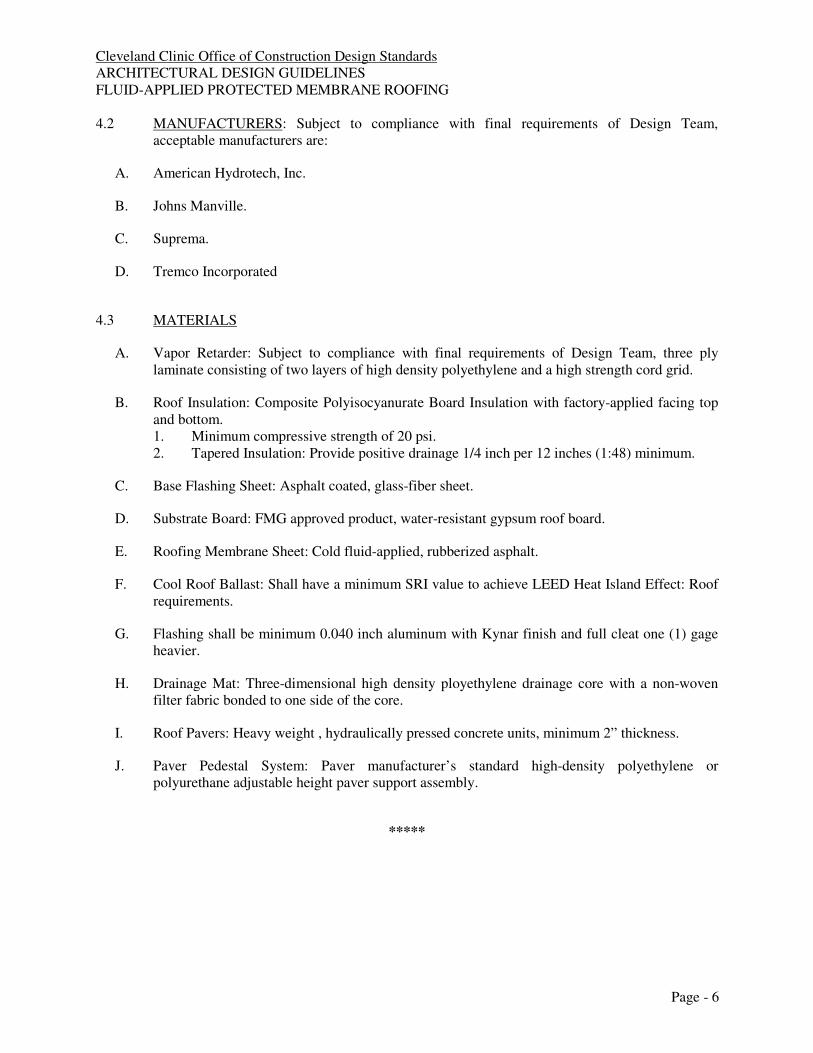
Cleveland Clinic Office of Construction Design Standards ARCHITECTURAL DESIGN GUIDELINES FLUID-APPLIED PROTECTED MEMBRANE ROOFING
Page - 6
4.2 MANUFACTURERS: Subject to compliance with final requirements of Design Team, acceptable manufacturers are:
A. American Hydrotech, Inc.
B. Johns Manville.
C. Suprema.
D. Tremco Incorporated
4.3 MATERIALS
A. Vapor Retarder: Subject to compliance with final requirements of Design Team, three ply laminate consisting of two layers of high density polyethylene and a high strength cord grid.
B. Roof Insulation: Composite Polyisocyanurate Board Insulation with factory-applied facing top and bottom. 1. Minimum compressive strength of 20 psi. 2. Tapered Insulation: Provide positive drainage 1/4 inch per 12 inches (1:48) minimum.
C. Base Flashing Sheet: Asphalt coated, glass-fiber sheet.
D. Substrate Board: FMG approved product, water-resistant gypsum roof board.
E. Roofing Membrane Sheet: Cold fluid-applied, rubberized asphalt.
F. Cool Roof Ballast: Shall have a minimum SRI value to achieve LEED Heat Island Effect: Roof requirements.
G. Flashing shall be minimum 0.040 inch aluminum with Kynar finish and full cleat one (1) gage heavier.
H. Drainage Mat: Three-dimensional high density ployethylene drainage core with a non-woven filter fabric bonded to one side of the core.
I. Roof Pavers: Heavy weight , hydraulically pressed concrete units, minimum 2” thickness.
J. Paver Pedestal System: Paver manufacturer’s standard high-density polyethylene or polyurethane adjustable height paver support assembly.
*****

Cleveland Clinic - Masterspec 11/11
APPLIED FIREPROOFING 078100 - 1
SECTION 078100
CEMENTITIOUS FIREPROOFING
PART 1 - GENERAL
1.1 RELATED DOCUMENTS
A. Drawings and general provisions of the Contract, including General and Supplementary Conditions and Division 01 Specification Sections, apply to this Section.
1.2 SUMMARY
A. This Section includes the following:
1. Concealed SFRM. 2. Exposed SFRM.
B. Related Sections include the following:
1. Division 05 Section "Structural Steel Framing" for surface conditions required for structural steel receiving SFRM.
2. Division 07 Section "Thermal Insulation" for fire-safing insulation. 3. Division 07 Section "Board Fireproofing" for mineral-fiber-board fire protection. 4. Division 07 Section "Penetration Firestopping" for fire-resistance-rated firestopping
systems. 5. Division 07 Section "Fire-Resistive Joint Systems" for fire-resistance-rated joint systems. 6. Division 09 Section "Intumescent Painting" for intumescent paints that are not fire
resistive.
1.3 DEFINITIONS
A. SFRM: Sprayed fire-resistive material.
B. Concealed: Fire-resistive materials applied to surfaces that are concealed from view behind other construction when the Work is completed.
C. Exposed: Fire-resistive materials applied to surfaces that are exposed to view when the Work is completed, that are in elevator shafts and machine rooms, that are in mechanical rooms, and that are identified as exposed on Drawings.
1.4 SUBMITTALS
A. Product Data: For each type of product indicated.
B. Shop Drawings: Structural framing plans indicating the following:
Cleveland Clinic - Masterspec 11/11
APPLIED FIREPROOFING 078100 - 2
1. Locations and types of surface preparations required before applying SFRM. 2. Extent of SFRM for each construction and fire-resistance rating, including the following:
a. Applicable fire-resistance design designations of a qualified testing and inspecting agency acceptable to authorities having jurisdiction.
1) For steel joist assemblies, include applicable fire-resistance design designations, with each steel joist tested with the same maximum tensile stress as each steel joist indicated on Drawings or in a schedule. Design designations with steel joists tested at lower maximum tensile stress than those indicated are not permitted.
b. Minimum thicknesses needed to achieve required fire-resistance ratings of structural components and assemblies.
3. Treatment of SFRM after application.
C. Product Certificates: For each type of SFRM, signed by product manufacturer.
D. Qualification Data: For Installer, manufacturer, professional engineer, and testing agency.
E. Compatibility and Adhesion Test Reports: From SFRM manufacturer indicating the following:
1. Materials have been tested for bond with substrates. 2. Materials have been verified by SFRM manufacturer to be compatible with substrate
primers and coatings. 3. Interpretation of test results and written recommendations for primers and substrate
preparation needed for adhesion.
F. Product Test Reports: Based on evaluation of comprehensive tests performed by a qualified testing agency, for proposed SFRM.
G. Field quality-control test reports.
H. Warranties: Special warranties specified in this Section.
1.5 QUALITY ASSURANCE
A. Installer Qualifications: A firm or individual certified, licensed, or otherwise qualified by SFRM manufacturer as experienced and with sufficient trained staff to install manufacturer's products according to specified requirements. A manufacturer's willingness to sell its SFRM to Contractor or to an installer engaged by Contractor does not in itself confer qualification on the buyer.
B. Source Limitations: Obtain SFRM through one source from a single manufacturer.
C. SFRM Testing: By a qualified testing and inspecting agency engaged by Contractor or manufacturer to test for compliance with specified requirements for performance and test methods.

Cleveland Clinic - Masterspec 11/11
APPLIED FIREPROOFING 078100 - 3
1. SFRMs are randomly selected for testing from bags bearing the applicable classification marking of UL or another testing and inspecting agency acceptable to authorities having jurisdiction.
2. Testing is performed on specimens of SFRMs that comply with laboratory testing requirements specified in Part 2 and are otherwise identical to installed fire-resistive materials, including application of accelerant, sealers, topcoats, tamping, troweling, rolling, and water overspray, if any of these are used in final application.
3. Testing is performed on specimens whose application the independent testing and inspecting agency witnessed during preparation and conditioning. Include in test reports a full description of preparation and conditioning of laboratory test specimens.
D. Compatibility and Adhesion Testing: Engage a qualified testing and inspecting agency to test for compliance with requirements for specified performance and test methods.
1. Test for bond per ASTM E 736 and requirements in UL's "Fire Resistance Directory" for coating materials. Provide bond strength indicated in referenced fire-resistance design, but not less than minimum specified in Part 2.
2. Verify that manufacturer, through its own laboratory testing or field experience, has not found primers or coatings to be incompatible with SFRM.
E. Fire-Test-Response Characteristics: Provide SFRM with the fire-test-response characteristics indicated, as determined by testing identical products per test method indicated below by UL or another testing and inspecting agency acceptable to authorities having jurisdiction. Identify bags containing SFRM with appropriate markings of applicable testing and inspecting agency.
1. Fire-Resistance Ratings: Indicated by design designations from UL's "Fire Resistance Directory" acceptable to authorities having jurisdiction, for SFRM serving as direct-applied protection tested per ASTM E 119.
F. Provide products containing no detectable asbestos as determined according to the method specified in 40 CFR 763, Subpart E, Appendix E, Section 1, "Polarized Light Microscopy."
G. Preinstallation Conference: Conduct conference at Project site to comply with requirements in Division 01 Section "Project Management and Coordination." Review methods and procedures related to SFRM including, but not limited to, the following:
1. Review products, exposure conditions, design ratings, restrained and unrestrained conditions, calculations, densities, thicknesses, bond strengths, and other performance requirements.
2. Review and finalize construction schedule and verify sequencing and coordination requirements.
3. Review weather predictions, ambient conditions, and proposed temporary protections for SFRM during and after installation.
4. Review surface conditions and preparations. 5. Review field quality-control testing procedures.
Cleveland Clinic - Masterspec 11/11
APPLIED FIREPROOFING 078100 - 4
1.6 DELIVERY, STORAGE, AND HANDLING
A. Deliver products to Project site in original, unopened packages with intact and legible manufacturers' labels identifying product and manufacturer, date of manufacture, shelf life if applicable, and fire-resistance ratings applicable to Project.
B. Use materials with limited shelf life within period indicated. Remove from Project site and discard materials whose shelf life has expired.
C. Store materials inside, under cover, and aboveground; keep dry until ready for use. Remove from Project site and discard wet or deteriorated materials.
1.7 PROJECT CONDITIONS
A. Environmental Limitations: Do not apply SFRM when ambient or substrate temperature is 40 deg F (4 deg C) or lower unless temporary protection and heat are provided to maintain temperature at or above this level for 24 hours before, during, and for 24 hours after product application.
B. Ventilation: Ventilate building spaces during and after application of SFRM. Use natural means or, if they are inadequate, forced-air circulation until fire-resistive material dries thoroughly.
1.8 COORDINATION
A. Sequence and coordinate application of SFRM with other related work specified in other Sections to comply with the following requirements:
1. Provide temporary enclosure as required to confine spraying operations and protect the environment.
2. Provide temporary enclosures for applications to prevent deterioration of fire-resistive material due to exposure to weather and to unfavorable ambient conditions for humidity, temperature, and ventilation.
3. Avoid unnecessary exposure of fire-resistive material to abrasion and other damage likely to occur during construction operations subsequent to its application.
4. Do not apply fire-resistive material to metal roof deck substrates until concrete topping, if any, has been completed. For metal roof decks without concrete topping, do not apply fire-resistive material to metal roof deck substrates until roofing has been completed and is watertight; prohibit roof traffic during application and drying of fire-resistive material. Do not apply fire-resistive material to metal floor deck substrates until concrete topping has been completed.
5. Do not begin applying fire-resistive material until clips, hangers, supports, sleeves, and other items penetrating fire protection are in place.
6. Defer installing ducts, piping, and other items that would interfere with applying fire-resistive material until application of fire protection is completed.
7. Do not install enclosing or concealing construction until after fire-resistive material has been applied, inspected, and tested and corrections have been made to defective applications.
Cleveland Clinic - Masterspec 11/11
APPLIED FIREPROOFING 078100 - 5
1.9 WARRANTY
A. Special Warranty: Manufacturer's standard form, signed by Contractor and by Installer, in which manufacturer agrees to repair or replace SFRMs that fail in materials or workmanship within specified warranty period.
1. Failures include, but are not limited to, the following:
a. Cracking, flaking, spalling, or eroding in excess of specified requirements; peeling; or delaminating of SFRM from substrates.
b. Not covered under the warranty are failures due to damage by occupants and Owner's maintenance personnel, exposure to environmental conditions other than those investigated and approved during fire-response testing, and other causes not reasonably foreseeable under conditions of normal use.
2. Warranty Period: Two years from date of Substantial Completion.
PART 2 - PRODUCTS
2.1 CONCEALED SFRM
A. Available Products: Subject to compliance with requirements, products that may be incorporated into the Work include, but are not limited to, the following:
B. Products: Subject to compliance with requirements, provide one of the following:
1. Concealed Cementitious SFRM:
a. Carboline Co., Fireproofing Products Div.; Pyrolite 22. b. Grace, W. R. & Co. - Conn., Construction Products Div.; Monokote Type Z106
and Z-106 G. c. Isolatek International Corp.; Cafco 400. d. Southwest Vermiculite Co., Inc.; Type 5 MD and 7 GP.
C. Material Composition: Manufacturer's standard product, as follows:
1. Concealed Cementitious SFRM: Factory-mixed, dry formulation of gypsum or portland cement binders, additives, and lightweight mineral or synthetic aggregates mixed with water at Project site to form a slurry or mortar for conveyance and application.
D. Physical Properties: Minimum values, unless otherwise indicated, or higher values required to attain designated fire-resistance ratings, measured per standard test methods referenced with each property as follows:
1. Dry Density: 22 lb/cu. ft. (352 kg/cu. m) for average and individual densities, or greater if required to attain fire-resistance ratings indicated, per ASTM E 605 or AWCI Technical Manual 12-A, Section 5.4.5, "Displacement Method."
2. Thickness: Minimum average thickness required for fire-resistance design indicated according to the following criteria, but not less than 0.375 inch (9 mm), per ASTM E 605:

Cleveland Clinic - Masterspec 11/11
APPLIED FIREPROOFING 078100 - 6
a. Where the referenced fire-resistance design lists a thickness of 1 inch (25 mm) or more, the minimum allowable individual thickness of SFRM is the design thickness minus 0.25 inch (6 mm).
b. Where the referenced fire-resistance design lists a thickness of less than 1 inch (25 mm) but more than 0.375 inch (9 mm), the minimum allowable individual thickness of SFRM is the greater of 0.375 inch (9 mm) or 75 percent of the design thickness.
c. No reduction in average thickness is permitted for those fire-resistance designs whose fire-resistance ratings were established at densities of less than 22 lb/cu. ft. (352 kg/cu. m).
3. Bond Strength: 434 lbs/sq. ft. (21 kPa) minimum per ASTM E 736 based on laboratory testing of 0.75-inch (19-mm) minimum thickness of SFRM.
4. Compressive Strength: 51 lbf/sq. in. (351 kPa) minimum per ASTM E 761. Minimum thickness of SFRM tested shall be 0.75 inch (19 mm) and minimum dry density shall be as specified but not less than 15 lb/cu. ft. (240 kg/cu. m).
5. Corrosion Resistance: No evidence of corrosion per ASTM E 937. 6. Deflection: No cracking, spalling, or delamination per ASTM E 759. 7. Effect of Impact on Bonding: No cracking, spalling, or delamination per ASTM E 760. 8. Air Erosion: Maximum weight loss of 0.025 g/sq. ft. (0.270 g/sq. m) in 24 hours per
ASTM E 859. For laboratory tests, minimum thickness of SFRM is 0.75 inch (19 mm), maximum dry density is 15 lb/cu. ft. (240 kg/cu. m), test specimens are not prepurged by mechanically induced air velocities, and tests are terminated after 24 hours.
9. Fire-Test-Response Characteristics: Provide SFRM with the following surface-burning characteristics as determined by testing identical products per ASTM E 84 by UL or another testing and inspecting agency acceptable to authorities having jurisdiction:
a. Flame-Spread Index: 10 or less. b. Smoke-Developed Index: 0.
10. Fungal Resistance: No observed growth on specimens per ASTM G 21.
2.2 EXPOSED SFRM
A. Available Products: Subject to compliance with requirements, products that may be incorporated into the Work include, but are not limited to, the following:
1. Exposed Cementitious SFRM:
a. Carboline Co., Fireproofing Products Div.; Pyrolite 22. b. Grace, W.R. & Co. - Conn., Construction Products Div.; Monokote Type Z-106
and Z-106 G. c. Isolatek International Corp.; Cafco 400. d. Southwest Vermiculite Co., Inc.; 5 MD and 7 GP.
B. Material Composition: Manufacturer's standard product, as follows:
1. Exposed Cementitious SFRM: Factory-mixed, dry, cement aggregate formulation; or chloride-free formulation of gypsum or portland cement binders, additives, and inorganic

Cleveland Clinic - Masterspec 11/11
APPLIED FIREPROOFING 078100 - 7
aggregates mixed with water at Project site to form a slurry or mortar for conveyance and application.
C. Physical Properties: Minimum values, unless otherwise indicated, or higher values required to attain designated fire-resistance ratings, measured per standard test methods referenced with each property as follows:
1. Dry Density: Values for average and individual densities as required for fire-resistance ratings indicated, per ASTM E 605 or AWCI Technical Manual 12-A, Section 5.4.5, "Displacement Method," but with an average density of not less than 22 lb/cu. ft. (352 kg/cu. m).
2. Bond Strength: 434 lbf/sq. ft. (21 kPa) minimum per ASTM E 736. 3. Compressive Strength: 51 lbf/sq. in. (351 kPa) minimum per ASTM E 761. 4. Corrosion Resistance: No evidence of corrosion per ASTM E 937. 5. Deflection: No cracking, spalling, or delamination per ASTM E 759. 6. Effect of Impact on Bonding: No cracking, spalling, or delamination per ASTM E 760. 7. Air Erosion: Maximum weight loss of 0.025 g/sq. ft. (0.270 g/sq. m) per ASTM E 859. 8. Combustion Characteristics: Passes ASTM E 136. 9. Fire-Test-Response Characteristics: Provide SFRM with the following surface-burning
characteristics as determined by testing identical products per ASTM E 84 by UL or another testing and inspecting agency acceptable to authorities having jurisdiction:
a. Flame-Spread Index: 10 or less. b. Smoke-Developed Index: 0.
10. Fungal Resistance: No observed growth on specimens per ASTM G 21.
2.3 AUXILIARY FIRE-RESISTIVE MATERIALS
A. General: Provide auxiliary fire-resistive materials that are compatible with SFRM and substrates and are approved by UL or another testing and inspecting agency acceptable to authorities having jurisdiction for use in fire-resistance designs indicated.
B. Substrate Primers: For use on each substrate and with each sprayed fire-resistive product, provide primer that complies with one or more of the following requirements:
1. Primer's bond strength complies with requirements specified in UL's "Fire Resistance Directory" for coating materials based on a series of bond tests per ASTM E 736.
2. Primer is identical to those used in assemblies tested for fire-test-response characteristics of SFRM per ASTM E 119 by UL or another testing and inspecting agency acceptable to authorities having jurisdiction.
C. Adhesive for Bonding Fire-Resistive Material: Product approved by manufacturer of SFRM.
D. Topcoat: Type recommended in writing by manufacturer of each SFRM for application over exposed SFRM.
Cleveland Clinic - Masterspec 11/11
APPLIED FIREPROOFING 078100 - 8
PART 3 - EXECUTION
3.1 EXAMINATION
A. Examine substrates, areas, and conditions, with Installer present, for compliance with requirements for substrates and other conditions affecting performance of work. A substrate is in satisfactory condition if it complies with the following:
1. Substrates comply with requirements in the Section where the substrate and related materials and construction are specified.
2. Substrates are free of dirt, oil, grease, release agents, rolling compounds, mill scale, loose scale, incompatible primers, incompatible paints, incompatible encapsulants, or other foreign substances capable of impairing bond of fire-resistive materials with substrates under conditions of normal use or fire exposure.
3. Objects penetrating fire-resistive material, including clips, hangers, support sleeves, and similar items, are securely attached to substrates.
4. Substrates are not obstructed by ducts, piping, equipment, and other suspended construction that will interfere with applying fire-resistive material.
B. Verify that concrete work on steel deck has been completed.
C. Verify that roof construction, installation of roof-top HVAC equipment, and other related work are completed.
D. Conduct tests according to fire-resistive material manufacturer's written recommendations to verify that substrates are free of substances capable of interfering with bond.
E. Proceed with installation only after unsatisfactory conditions have been corrected.
3.2 PREPARATION
A. Cover other work subject to damage from fallout or overspray of fire-resistive materials during application.
B. Clean substrates of substances that could impair bond of fire-resistive material, including dirt, oil, grease, release agents, rolling compounds, mill scale, loose scale, and incompatible primers, paints, and encapsulants.
C. Prime substrates where recommended in writing by SFRM manufacturer unless compatible shop primer has been applied and is in satisfactory condition to receive SFRM.
D. For exposed applications, repair substrates to remove surface imperfections that could affect uniformity of texture and thickness in finished surface of SFRM. Remove minor projections and fill voids that would telegraph through fire-resistive products after application.
3.3 APPLICATION, GENERAL
A. Comply with fire-resistive material manufacturer's written instructions for mixing materials, application procedures, and types of equipment used to mix, convey, and spray on fire-resistive

Cleveland Clinic - Masterspec 11/11
APPLIED FIREPROOFING 078100 - 9
material, as applicable to particular conditions of installation and as required to achieve fire-resistance ratings indicated.
B. Apply SFRM that is identical to products tested as specified in Part 1 "Quality Assurance" Article and substantiated by test reports, with respect to rate of application, accelerator use, sealers, topcoats, tamping, troweling, water overspray, or other materials and procedures affecting test results.
C. Coat substrates with bonding adhesive before applying fire-resistive material where required to achieve fire-resistance rating or as recommended in writing by SFRM manufacturer for material and application indicated.
D. Extend fire-resistive material in full thickness over entire area of each substrate to be protected. Unless otherwise recommended in writing by SFRM manufacturer, install body of fire-resistive covering in a single course.
E. Spray apply fire-resistive materials to maximum extent possible. Following the spraying operation in each area, complete the coverage by trowel application or other placement method recommended in writing by SFRM manufacturer.
3.4 APPLICATION, CONCEALED SFRM
A. Apply concealed SFRM in thicknesses and densities not less than those required to achieve fire-resistance ratings designated for each condition, but apply in greater thicknesses and densities if specified in Part 2 "Concealed SFRM" Article.
B. Cure concealed SFRM according to product manufacturer's written recommendations.
3.5 APPLICATION, EXPOSED SFRM
A. Apply exposed SFRM in thicknesses and densities not less than those required to achieve fire-resistance ratings designated for each condition, but apply in greater thicknesses and densities if indicated.
1. For steel beams and bracing, provide a thickness of not less than 1 inch (25 mm). 2. For metal floor or roof decks, provide a thickness of not less than 1/2 inch (13 mm).
B. Provide a uniform finish complying with description indicated for each type of material and matching Architect's sample or, if none, finish approved for field-erected mockup.
C. Apply exposed cementitious SFRM to produce the following finish:
1. Spray-textured finish with no further treatment for areas more than 10 ft. above floor. 2. Even, spray-textured finish, produced by rolling flat surfaces of fire-protected members
with a damp paint roller to remove drippings and excessive roughness for areas 10 ft. or less above floor.
D. Cure exposed SFRM according to product manufacturer's written recommendations.
Cleveland Clinic - Masterspec 11/11
APPLIED FIREPROOFING 078100 - 10
3.6 FIELD QUALITY CONTROL
A. Special Inspections: Owner will engage a qualified special inspector to perform the following special inspection and prepare reports:
1. SFRM.
B. Testing Agency: Owner will engage a qualified testing agency to perform tests and inspections and prepare test reports.
1. Testing and inspecting agency will interpret tests and state in each report whether tested work complies with or deviates from requirements.
C. Tests and Inspections: Testing and inspecting of completed applications of SFRM shall take place in successive stages, in areas of extent and using methods as follows. Do not proceed with application of SFRM for the next area until test results for previously completed applications of SFRM show compliance with requirements. Tested values must equal or exceed values indicated and required for approved fire-resistance design.
1. Thickness for Floor, Roof, and Wall Assemblies: For each 1000-sq. ft. (93-sq. m) area, or partial area, on each floor, from the average of 4 measurements from a 144-sq. in. (0.093-sq. m) sample area, with sample width of not less than 6 inches (152 mm) per ASTM E 605.
2. Thickness for Structural Frame Members: From a sample of 25 percent of structural members per floor, taking 9 measurements at a single cross section for structural frame beams or girders, 7 measurements of a single cross section for joists and trusses, and 12 measurements of a single cross section for columns per ASTM E 605.
3. Density for Floors, Roofs, Walls, and Structural Frame Members: At frequency and from sample size indicated for determining thickness of each type of construction and structural framing member, per ASTM E 605 or AWCI Technical Manual 12-A, Section 5.4.5, "Displacement Method."
4. Bond Strength for Floors, Roofs, Walls, and Structural Framing Members: For each 10,000-sq. ft. (929 sq. m) area, or partial area, on each floor, cohesion and adhesion from one sample of size indicated for determining thickness of each type of construction and structural framing member, per ASTM E 736.
a. Field test SFRM that is applied to flanges of wide-flange, structural-steel members on surfaces matching those that will exist for remainder of steel receiving fire-resistive material.
b. If surfaces of structural steel receiving SFRM are primed or otherwise painted for coating materials, perform series of bond tests specified in UL's "Fire Resistance Directory." Provide bond strength indicated in referenced UL fire-resistance criteria, but not less than 434 lbf/sq. ft. (21 kPa) minimum per ASTM E 736.
5. If testing finds applications of SFRM are not in compliance with requirements, testing and inspecting agency will perform additional random testing to determine extent of noncompliance.
D. Remove and replace applications of SFRM that do not pass tests and inspections for cohesion and adhesion, for density, or for both and retest as specified above.

Cleveland Clinic - Masterspec 11/11
APPLIED FIREPROOFING 078100 - 11
E. Apply additional SFRM, per manufacturer's written instructions, where test results indicate that thickness does not comply with specified requirements, and retest as specified above.
3.7 PROTECTING, CLEANING AND REPAIR
A. Cleaning: Immediately after completing spraying operations in each containable area of Project, remove material overspray and fallout from surfaces of other construction and clean exposed surfaces to remove evidence of soiling.
B. Protect SFRM, according to advice of product manufacturer and Installer, from damage resulting from construction operations or other causes so fire protection will be without damage or deterioration at time of Substantial Completion.
C. Coordinate application of SFRM with other construction to minimize need to cut or remove fire protection. As installation of other construction proceeds, inspect SFRM and patch any damaged or removed areas.
D. Repair or replace work that has not successfully protected steel.
3.8 PATCHING SMALL AREAS OF FIREPROOFING
A. Definition: hand patching is defined as the hand mixing and trowel application of spray-applied material to small areas (i.e. - a pump and mixer are not utilized).
B. Applicability: patching is limited solely to non-fibrous fireproofing material. Fibrous fireproofing shall not be patched by hand.
C. Hand patching is acceptable only under the following conditions: 1. The area of patching is limited to a maximum of 144 square inches.
2. The minimum in-place density of the material, as specified in the fire resistance design,
must be maintained.
3. The minimum thickness of the material, as specified in the fire resistance design, must be
maintained.
4. The in-place bond strength of the material meets the minimum value established by the
manufacturer.
5. The material is keyed into the material surrounding the patch. The integrity of the
surrounding material shall not be impaired.
6. Any clips or hangers being patched around are totally encased in material at the point of
attachment to the structural member at a thickness equal to that being applied to the
structural member.
END OF SECTION 078100

Cleveland Clinic Office of Construction Design Standards ARCHITECTURAL DESIGN GUIDELINES CEMENTIOUS FIREPROOFING
Page - 1
PART 1 - GENERAL
1.1 OVERVIEW
A. This Design Guideline includes concealed and exposed cementitious fireproofing systems for use on columns, beams, floor and roof assemblies.
B. This Design Guide does not cover the use fireproofing in exterior locations. It also does not cover the use of Intumescent Mastic Coatings.
C. Fireproofing for any newly constructed Cleveland Clinic facility shall be medium density cementitious type only. Use of fibrous type systems will not be allowed.
D. The materials referenced in this Design Guideline shall be used to construct a finished and warranted system. All materials shall be of the same manufacturer
E. Refer to Master Specification 078100 for detailed requirements.
PART 2 - DESIGN CRITERIA
2.1 INSURANCE REQUIREMENTS
A. The design and specification of fireproofing systems shall be made after carefully investigating applicable code and insurance requirements. Designer shall carefully select UL designs for column, beam, floor and roof assemblies that match the proposed construction details.
2.2 WARRANTY
A. Manufacturers shall provide a minimum two (2) year warranty from date of Substantial Completion in which the manufacturer agrees to replace SFRMs that fail in materials or workmanship within specified warranty period. Warranty shall include, but not be limited to, cracking, flaking, spalling, eroding, in excess of specified requirements, peeling or delamination from substrate.
2.3 MATERIALS
A. All fireproofing systems shall be cementious type, use of fibrous type systems will not be allowed.
2.4 ENVIRONMENTAL CONSIDERATIONS
A. Special requirement may be needed depending on project type, such as renovation work.
B. Refer to Cleveland Clinic’s General Conditions for additional information.

Cleveland Clinic Office of Construction Design Standards ARCHITECTURAL DESIGN GUIDELINES CEMENTIOUS FIREPROOFING
Page - 2
2.5 INSTALLATION CONSIDERATIONS
A. Where special inspections are required by the building code, specify the testing requirements and responsibilities of the owner, contractor and independent testing company.
B. Require an Owner engaged Testing Agency.
2.6 GENERAL DESIGN CONSIDERATIONS
A. Any modifications or deviations from this Design Guideline direction shall require written approval from the Owner.
B. Building Code, UL, or other performance or insurance agency requirements for fireproofing systems in the Project’s geographic location shall be carefully reviewed and applied.
C. Many UL floor system designs when used in a roof application require additional ½ hour rating when polyisocyanurate insulation is used. Verify requirements with selected UL designs and carry additional rating down through structure.
D. Extent of fireproofing application shall be clearly defined in the documents by either a schedule or symbols on the drawings.
E. Information indicating fire-resistance ratings with corresponding UL design numbers shall be placed on the drawings.
F. Drawings shall indicate ratings required for individual structural members supporting fire rated construction, ie. Walls, where the wall construction rating is higher than that required for the main structure. Example would be where building columns and floors are one hour rated but the stair enclosure is two hour rated. The structure members supporting the stair enclosure must be increased to match the wall rating.
PART 3 - SPECIAL CONTRACT DOCUMENT REQUIREMENTS
3.1 To be completed in conjunction with the Cleveland Clinic.
PART 4 - PRODUCTS
4.1 GENERAL
A. Fireproofing systems shall be selected based on performance characteristics that meet or exceed this Design Guideline. Alternate manufacturers and product lines that meet or exceed the performance requirements of this Design Guideline may be acceptable. Submit to Cleveland Clinic for consideration and approval. Use of an alternate manufacturer’s product is subject to compliance with the specific criteria stated herein and specified in Master Specification 078100.

Cleveland Clinic Office of Construction Design Standards ARCHITECTURAL DESIGN GUIDELINES CEMENTIOUS FIREPROOFING
Page - 3
4.2 MANUFACTURERS: Subject to compliance with final requirements of Design Team, acceptable manufacturers are:
A. Carboline Company; Fireproofing Products Div.
B. W. R. Grace & Co. – Conn.; Construction Products Div.
C. Isolatek International Corp.
D. Southwest Vermiculite Co., Inc
4.3 MATERIALS
A. Coordinate primer requirement with structural specifications. Primers typically cannot be provided on structural steel and steel decks subject to fireproofing installation.
*****

Cleveland Clinic - Masterspec 10/11
LOADING DOCK EQUIPMENT 111300 - 1
SECTION 111300 - LOADING DOCK EQUIPMENT
PART 1 - GENERAL
1.1 RELATED DOCUMENTS
A. Drawings and general provisions of the Contract, including General and Supplementary Conditions and Division 01 Specification Sections, apply to this Section.
1.2 SUMMARY
A. Section Includes:
1. Dock levelers. 2. Truck restraints. 3. Master control system. 4. Dock lights. 5. Dock bumpers. 6. Dock seals.
B. Related Sections:
1. Division 03 Section "Cast-in-Place Concrete" for concrete work for recessed loading dock equipment.
2. Division 08 Sections for coiling and other overhead doors electrically interlocked to dock levelers.
3. Division 26 Sections for electrical wiring for, and connections to, loading dock equipment.
1.3 DEFINITIONS
A. Operating Range: Maximum amount of travel above and below the loading dock level.
B. Working Range: Recommended amount of travel above and below the loading dock level for which loading and unloading operations can take place.
1.4 SUBMITTALS
A. Product Data: For each type of product indicated. Include construction details, material descriptions, dimensions of individual components and profiles, and finishes for loading dock equipment. Include rated capacities, operating characteristics, electrical characteristics, and furnished specialties and accessories.
B. Shop Drawings: For loading dock equipment. Include plans, elevations, sections, details, and attachments to other work.

Cleveland Clinic - Masterspec 10/11
LOADING DOCK EQUIPMENT 111300 - 2
1. Detail equipment assemblies and indicate dimensions, weights, loads, required clearances, method of field assembly, components, and location and size of each field connection.
2. Wiring Diagrams: For power, signal, and control wiring.
C. Product Test Reports: Based on evaluation of comprehensive tests performed by manufacturer and witnessed by a qualified testing agency; indicate compliance of dock levelers with requirements in MH 30.1 for determining rated capacity, which is based on comprehensive testing within last two years of current products.
1. Submittal Form: According to MH 30.1, Appendix A.
D. Operation and Maintenance Data: For loading dock equipment to include in operation and maintenance manuals.
E. Warranty: Sample of special warranty.
1.5 QUALITY ASSURANCE
A. Installer Qualifications: Manufacturer's authorized representative who is trained and approved for installation of units required for this Project.
B. Electrical Components, Devices, and Accessories: Listed and labeled as defined in NFPA 70, by a qualified testing agency, and marked for intended location and application.
1.6 DELIVERY, STORAGE, AND HANDLING
A. Store and handle dock seals in a manner to avoid significant or permanent damage to fabric or frame.
1. Comply with manufacturer's written instructions for minimum and maximum temperature requirements for storage.
1.7 PROJECT CONDITIONS
A. Field Measurements: Verify actual dimensions of construction contiguous with loading dock equipment, including recessed pit dimensions and heights of loading docks, by field measurements before fabrication.
1.8 WARRANTY
A. Warranty for Dock Equipment: Manufacturer's standard form in which manufacturer agrees to repair or replace dock-equipment components that fail in materials or workmanship within specified warranty period.
1. Failures include, but are not limited to, the following:

Cleveland Clinic - Masterspec 10/11
LOADING DOCK EQUIPMENT 111300 - 3
a. Structural failures including cracked or broken structural support members, load-bearing welds, and front and rear hinges.
b. Faulty operation of operators, control system, or hardware. c. Deck plate failures including cracked plate or permanent deformation in excess of
1/4 inch (6 mm) between deck supports. 2. Warranty Period shall be a minimum of one (1) year from date of Substantial
Completion. 3. Warranty shall be for unlimited usage of leveler for the specified rated capacity over the
term of the warranty.
PART 2 - PRODUCTS
2.1 MATERIALS
A. Steel Plates, Shapes, and Bars: ASTM 36/A 36M.
B. Rolled-Steel Floor Plate: ASTM A 786/A 786M, rolled from steel plate complying with ASTM A 572/A 572M, Grade 55 (380).
C. Steel Tubing: ASTM A 500, cold formed.
D. Welding Rods and Bare Electrodes: Select according to AWS specifications for metal alloy welded.
E. Wood: DOC PS 20 dimension lumber, select structural grade, kiln dried.
F. Pressure-Treated Wood: DOC PS 20 dimension lumber, select structural grade, kiln dried, and pressure treated with waterborne preservatives to comply with AWPA C2.
2.2 RECESSED DOCK LEVELERS
A. General: Recessed, hinged-lip-type dock levelers designed for permanent installation in concrete pits preformed in the edge of loading platform; of type, function, operation, capacity, size, and construction indicated; and complete with controls, safety devices, and accessories required.
1. Basis-of-Design Product: Subject to compliance with requirements, provide SPX Dock Products - Kelly; HP Hydraulic Dock Leveler or comparable product by one of the following:
a. Blue Giant Equipment Corporation. b. Chalfant Dock Equipment. c. McGuire, W. B. Co., Inc.; Division of Overhead Door Corporation. d. Pioneer Loading Dock Equipment. e. Rite-Hite Corporation. f. SPX Dock Products - Serco.
B. Standard: Comply with MH 30.1.
Cleveland Clinic - Masterspec 10/11
LOADING DOCK EQUIPMENT 111300 - 4
C. Rated Capacity: Capable of supporting total gross load of 40,000 lbs. minimum without permanent deflection or distortion.
D. Platform: Not less than 3/16-inch- (5-mm) thick, nonskid steel plate.
1. Platform Size: 6 feet wide by 8 feet long. 2. Frame: Manufacturer's standard. 3. Toe Guards: Equip open sides of dock leveler over range indicated with metal toe
guards.
a. Toe-Guard Range: Entire upper operating range.
E. Hinged Lip: Not less than 1/2-inch- (13-mm-) thick, nonskid steel plate.
1. Hinge: Full width, piano-type hinge with heavy-wall hinge tube and greased fittings, with gussets on lip and ramp for support.
2. Safety Barrier Lip: Designed to protect material-handling equipment from an accidental fall from loading platform edge of the dock leveler when the leveler is not in use.
F. Function: Dock levelers shall compensate for differences in height between truck bed and loading platform.
1. Vertical Travel: Operating range above platform level of sufficient height to enable lip to extend and clear truck bed before contact with the following minimum working range:
a. Above Adjoining Platform: 12 inches (305 mm). b. Below Adjoining Platform: 12 inches (305 mm).
2. Automatic Vertical Compensation: Floating travel of ramp with lip extended and resting on truck bed shall compensate automatically for upward or downward movement of truck bed during loading and unloading.
3. Automatic Lateral Compensation: Tilting of ramp with lip extended and resting on truck bed shall compensate automatically for canted truck beds of up to 4 inches (102 mm) over width of ramp.
4. Lip Operation: Manufacturer's standard mechanism that automatically extends and supports hinged lip on ramp edge with lip resting on truck bed over dock leveler's working range, allows lip to yield under impact of incoming truck, and automatically retracts lip when truck departs.
a. Length of Lip Extension: 18 inches (457 mm).
5. Automatic Ramp Return: Automatic return of unloaded ramp, from raised or lowered positions to stored position, level with platform, as truck departs.
6. Interlock: Leveler will not operate while overhead door is in closed position and truck restraint is not engaged.
G. Hydraulic Operating System: Electric control from a remote-control station; fully hydraulic operation. Electric-powered hydraulic raising and hydraulic lowering of ramp. Equip leveler with a packaged unit including a unitized, totally enclosed, nonventilated electric motor, pump, manifold reservoir, and valve assembly of proper size, type, and operation for capacity of leveler indicated. Include means for lowering ramp below platform level with lip retracted
Cleveland Clinic - Masterspec 10/11
LOADING DOCK EQUIPMENT 111300 - 5
behind dock bumpers. Provide a hydraulic velocity fuse connected to main hydraulic cylinder to limit loaded ramp's free fall to not more than 3 inches (76 mm).
1. Remote-Control Station with Emergency Stop: Multibutton control station with an UP button of the constant-pressure type and an emergency STOP button of the momentary-contact type, enclosed in NEMA ICS 6 box. Ramp raises by depressing and holding UP button; ramp lowers at a controlled rate by releasing UP button. All ramp movement stops, regardless of position of ramp or lip, by depressing STOP button. Normal operation resumes by engaging a manual reset button or by pulling out STOP button.
a. Master Panel: Control panel with integral fused disconnecting means for operating dock leveler, dock door, and truck restraints.
H. Accessories:
1. Curb Angles: 3-by-3-by-1/4-inch (76-by-76-by-6-mm) galvanized-steel curb angles for edge of recessed leveler pit, with 1/2-inch- (13-mm-) diameter by 6-inch- (152-mm-) long concrete anchors welded to angle at 6 inches (152 mm) o.c.
2. Night Locks: Manufacturer's standard means to prevent extending lip and lowering ramp when overhead doors are locked.
3. Side and rear weatherseals. 4. Abrasive skid-resistant surface.
I. Finish: Paint dock levelers after assembly.
1. Toe Guards: Paint yellow to comply with ANSI Z535.1.
2.3 TRUCK RESTRAINTS
A. General: Manufacturer's standard device designed to engage truck's rear-impact guard and hold truck at loading dock. Restraint shall consist of an iron or steel restraining arm that raises until contacting rear-impact guard. Arm shall move vertically, automatically adjusting to varying height of truck due to loading and unloading operations.
1. Basis-of-Design Product: Subject to compliance with requirements, provide SPX Dock Products - Kelly; STAR® 4 Vehicle Restraint or comparable product by one of the following:
a. Blue Giant Equipment Corporation. b. Chalfant Dock Equipment. c. McGuire, W. B. Co., Inc.; Division of Overhead Door Corporation. d. Pioneer Loading Dock Equipment. e. Rite-Hite Corporation. f. SPX Dock Products - Serco.
B. Standard: Comply with MH 30.3.
C. Rated Capacity: Capable of supporting total gross load of 30,000 lbs. minimum without permanent deflection or distortion.

Cleveland Clinic - Masterspec 10/11
LOADING DOCK EQUIPMENT 111300 - 6
D. Operating Range: Capable of restraining rear-impact guards within a range from:
1. Vertical: 30 inches (762 mm) above driveway. 2. Horizontal: 12 inches (305 mm) in front of dock bumpers.
E. Power Operating System: Manufacturer's standard electromechanical or hydraulic unit.
1. Remote-Control Station: Single-button station of the constant-pressure type, enclosed in NEMA ICS 6, Type 12 box. Restraint is engaged by depressing and holding button; restraint is released by releasing button.
2. Interlock: Leveler will not operate while truck restraint is not engaged.
F. Rear-Impact-Guard Sensor: Detects presence of rear-impact guard and automatically returns to stored position if rear-impact guard is not engaged.
G. Caution Signs: Exterior, surface mounted; designed to inform both dock attendant and truck driver; with sign copy as follows. Provide one sign at each truck-restraint location.
1. Sign Copy in Forward and Reverse Text: Manufacturer's standard text permitting truck movement with green light.
2. Interior Sign Copy: Manufacturer's standard text permitting truck movement with green light.
H. Light-Communication System: Red and green illuminated signal-light sets, with lens approximately 4 inches (102 mm) in diameter, designed to indicate status to both dock attendant and truck driver. Equip system with steel control panel located at interior of dock that includes illuminated lights indicating status of exterior signal lights. Provide signal-light set and control panel at each location indicated for light-communication system. Enclose exterior signal-light sets in steel or plastic housing with sunshade.
1. Automatic Operation: System is activated automatically by limit switch mounted on overhead door track. Provide on-off switch located on master control panel.
2. Mounting: Wall.
I. Alarm: Audible system indicating that rear-impact guard is not engaged, with manual reset.
J. Accessories: Interlock to dock leveler.
K. Truck-Restraint Finish: Hot-dip galvanized.
2.4 MASTER CONTROL SYSTEM
A. All dock equipment at each dock shall be controlled by a single master control system with interlocks to the truck restraint, overhead door and dock leveler.
1. Basis-of-Design Product: Subject to compliance with requirements, provide SPX Dock Products - Kelly; Master Control Panel or comparable product by one of the following:
a. Blue Giant Equipment Corporation. b. Chalfant Dock Equipment. c. McGuire, W. B. Co., Inc.; Division of Overhead Door Corporation.

Cleveland Clinic - Masterspec 10/11
LOADING DOCK EQUIPMENT 111300 - 7
d. Pioneer Loading Dock Equipment. e. Rite-Hite Corporation. f. SPX Dock Products – Serco.
2.5 DOCK LIGHTS
A. General: Provide dock lights for each location indicated.
1. Basis-of-Design Product: Subject to compliance with requirements, provide Rite Hite; Rite-Lite HD LED Dock Light or comparable product by one of the following:
a. Pioneer Loading Dock Equipment. b. APS Resource
2.6 DOCK BUMPERS
A. Manufacturers: Subject to compliance with requirements, provide products by one of the following:
1. Chalfant Dock Equipment. 2. Durable Corporation. 3. Hugger Dock Equipment Company; Division of Columbus Foam Products, Inc. 4. Pioneer Loading Dock Equipment. 5. Rite-Hite Corporation. 6. SPX Dock Products - Kelley. 7. SPX Dock Products - Serco.
B. Laminated-Tread Dock Bumper: Fabricated from multiple, uniformly thick plies cut from fabric-reinforced rubber tires. Laminate plies under pressure on not less than two 3/4-inch- (19-mm-) diameter, steel supporting rods that are welded at one end to 1/4-inch- (6-mm-) thick, structural-steel end angle and secured with a nut and angle at the other end. Fabricate angles with predrilled anchor holes and sized to provide not less than 1 inch (25 mm) of tread plies extending beyond the face of closure angles.
1. Thickness: 6 inches (152 mm). 2. Horizontal Style: 10 inches (250 mm) high by 18 inches (460 mm) long minimum.
C. Anchorage Devices: Hot-dip galvanized-steel anchor bolts, nuts, washers, bolts, sleeves, cast-in-place plates, and other anchorage devices as required to fasten bumpers securely in place and to suit installation type indicated.
2.7 FOAM-PAD DOCK SEALS
A. General: Dock seals consisting of fabric-covered foam pads designed to compress 4 to 5 inches (102 to 127 mm) under pressure of truck body to form an airtight seal at jambs and head of loading dock openings; of type, size, and construction indicated.
1. Basis-of-Design Product: Subject to compliance with requirements, provide Rite Hite; TP Platinum Dock Seal or comparable product by one of the following:

Cleveland Clinic - Masterspec 10/11
LOADING DOCK EQUIPMENT 111300 - 8
a. Blue Giant Equipment Corporation. b. Chalfant Dock Equipment. c. Fairborn U.S.A., Inc. d. Hugger Dock Equipment Company; Division of Columbus Foam Products, Inc. e. McGuire, W. B. Co., Inc.; Division of Overhead Door Corporation. f. Pioneer Loading Dock Equipment. g. SPX Dock Products - Kelley. h. SPX Dock Products - Serco.
B. Door Opening Size: As indicated on Drawings.
C. Stationary Head Pad: 18 inches (457 mm) high and same depth as jamb pads; sized for opening width.
D. Jamb Pads: Square.
1. Nominal Size: 12 inches (305 mm) wide and sized for opening height.
E. Construction: Consisting of single- or double-ply, coated, fabric-covered, urethane-foam core with supporting frame. Fabricate jamb and head pads of same depth and sized for opening width.
1. Pressure-Treated Wood Support Frame: Factory painted; with steel mounting hardware.
2. Cover Fabric: Hypalon-coated nylon with minimum total weight of 40 oz./sq. yd. (1356 g/sq. m).
a. Color: As selected by Architect from manufacturer's full range.
3. Guide Strips: 4-inch- (102-mm-) wide, coated, nylon guide strips on jamb pads. 4. Pleated Protectors: On face of jamb pads of overlapping layers of coated fabric attached
to base fabric; 8-inch (203-mm) wear exposure.
2.8 GENERAL FINISH REQUIREMENTS
A. Finish loading dock equipment after assembly and testing.
2.9 STEEL FINISHES
A. Galvanizing: Hot-dip galvanize components as indicated to comply with the following:
1. ASTM A 123/A 123M for iron and steel loading dock equipment. 2. ASTM A 153/A 153M or ASTM F 2329 for iron and steel hardware for loading dock
equipment.
B. Steel Finish: Immediately after cleaning and pretreating, apply manufacturer's standard two-coat, baked-on finish consisting of prime coat and thermosetting topcoat in manufacturer's standard color.

Cleveland Clinic - Masterspec 10/11
LOADING DOCK EQUIPMENT 111300 - 9
PART 3 - EXECUTION
3.1 EXAMINATION
A. Examine areas and conditions, with Installer present, for compliance with requirements for installation tolerances and other conditions affecting performance of loading dock equipment.
B. Examine roughing-in for electrical systems for loading dock equipment to verify actual locations of connections before equipment installation.
C. Examine walls and floors of pits for suitable conditions where recessed loading dock equipment is to be installed. Pits shall be plumb and square and properly sloped for drainage from back to front of loading dock.
D. Proceed with installation only after unsatisfactory conditions have been corrected.
3.2 PREPARATION
A. Coordinate size and location of loading dock equipment indicated to be attached to or recessed into concrete or masonry, and furnish anchoring devices with templates, diagrams, and instructions for their installation.
B. Set curb angles in concrete edges of dock-leveler recessed pits with tops flush with loading platform. Fit exposed connections together to form hairline joints.
C. Clean recessed pits of debris.
3.3 INSTALLATION
A. General: Install loading dock equipment, including control stations, wiring, safety devices, light-communication systems, and accessories as required for a complete installation.
1. Rough-in electrical connections according to requirements specified in Division 26 Sections.
B. Recessed Dock Levelers: Attach dock levelers securely to loading dock platform, flush with adjacent loading dock surfaces and square to recessed pit.
C. Truck Restraints: Attach truck restraints in a manner that complies with requirements for arrangement and height required for device to engage vehicle rear-impact guard. Interconnect control panel and signals with dock leveler.
1. Wall-Mounted Units: Weld truck restraints to steel mounting plate embedded in loading dock edge.
D. Dock Lights: Attach at each dock door jamb in accordance with manufacturers written instructions. Mount arm 80” above finished floor.
Cleveland Clinic - Masterspec 10/11
LOADING DOCK EQUIPMENT 111300 - 10
E. Dock Bumpers: Attach dock bumpers to face of loading dock in a manner that complies with requirements indicated for spacing, arrangement, and position relative to top of platform and anchorage.
1. Welded Attachment: Plug-weld anchor holes in contact with steel inserts and fillet weld at other locations.
F. Dock Seals: Attach dock-seal support frames securely to building structure in proper relation to openings, dock bumpers, and dock levelers to ensure compression of dock seals when trucks are positioned against dock bumpers.
3.4 ADJUSTING
A. Adjust loading dock equipment to function smoothly and safely, and lubricate as recommended by manufacturer.
B. Test dock levelers for vertical travel within operating range indicated.
C. After completing installation of exposed, factory-finished loading dock equipment, inspect exposed finishes and repair damaged finishes.
3.5 DEMONSTRATION
A. Engage a factory-authorized service representative to train Owner's maintenance personnel to adjust, operate, and maintain loading dock equipment.
END OF SECTION 111300

Cleveland Clinic Office of Construction Design Standards ARCHITECTURAL DESIGN GUIDELINES LOADING DOCK EQUIPMENT
Page - 1
PART 1 - GENERAL
1.1 OVERVIEW
A. Master Specification 111300 Loading Dock Equipment is based on a standard 48” high truck dock. Additional dock equipment maybe required for other dock heights.
B. Refer to Master Specification 111300 for detailed requirements.
PART 2 - DESIGN CRITERIA
2.1 WARRANTY
A. No special warranty requirement.
2.2 GENERAL DESIGN CONSIDERATIONS
A. Any modifications or deviations from this Design Guideline direction shall require written approval from the Owner.
B. Verify with Cleveland Clinic what types of delivery vehicles are anticipated prior to design of any truck dock. More than one dock height maybe required to accommodate a wide variety of delivery vehicles.
C. All docks shall be designed with an interlocked control system. System interlock shall include overhead door, dock leveler and truck restraint.
PART 3 - PRODUCTS
3.1 GENERAL
A. Any equipment required in addition to those included in the Master Specification shall be chosen based on required function, level of durability and Cleveland Clinic’s approval.
3.2 MANUFACTURERS: Subject to compliance with final requirements of Design Team, acceptable manufacturers are:
A. As listed in Master Specification 111300 Loading Dock Equipment.
*****

Cleveland Clinic - Masterspec 08/11
ELECTRIC TRACTION ELEVATORS 142100 - 1
SECTION 142100 - ELECTRIC TRACTION ELEVATORS
PART 1 - GENERAL
1.1 RELATED DOCUMENTS
A. Drawings and general provisions of the Contract, including General and Supplementary Conditions and Division 01 Specification Sections, apply to this Section.
1.2 SUMMARY
A. Section includes gearless traction passenger elevators with machine room-less application.
1. Work required under this section consists of all labor, materials and services required for the complete installation, including operational verification, of all equipment required for elevator(s) as herein specified.
B. Related Requirements: The following sections contain requirements that relate to this section and are performed by trades other than the elevator manufacturer/installer.
1. Section 015000 "Temporary Facilities and Controls" for temporary use of elevators for construction purposes.
2. Section 033000 "Cast-in-Place Concrete" for setting sleeves, inserts, and anchoring devices in concrete.
3. Section 042000 "Unit Masonry" for setting sleeves, inserts, and anchoring devices in masonry and for grouting elevator entrance frames installed in masonry walls.
4. Section 051200 "Structural Steel Framing" for the following:
a. Attachment plates, angle brackets, and other preparation of structural steel for fastening guide-rail brackets.
b. Divider beams. c. Hoist beams. d. Structural-steel shapes for subsills.
5. Section 055000 "Metal Fabrications" for the following:
a. Attachment plates and angle brackets for supporting guide-rail brackets. b. Divider beams. c. Hoist beams. d. Structural-steel shapes for subsills. e. Pit ladders. f. <Insert Section Number> <Insert Section Title> for waterproofing of elevator
pit.
6. Section 221429 "Sump Pumps" for sump pumps, sumps, and sump covers in elevator pits.
7. Division 23 – Heating, Ventilating, and Air Conditioning: ventilation and temperature control of elevator equipment areas.

Cleveland Clinic - Masterspec 08/11
ELECTRIC TRACTION ELEVATORS 142100 - 2
8. Division 26 – Electrical:
a. Main disconnects for each elevator. b. Electrical power for elevator installation and testing. c. Disconnecting device to elevator equipment prior to activation of sprinkler system. d. The installation of dedicated GFCI receptacles in the pit and overhead (with
machine room-less). e. Lighting in controller area, machine area and pit. f. Wiring for telephone service to controller.
9. Section 263213 “Engine Generators: to generate emergency power for elevator operation. 10. Section 271500 "Communications Horizontal Cabling" for telephone service for
elevators and for Internet connection to elevator controllers for remote monitoring of elevator performance.
11. Section 283111 "Digital, Addressable Fire-Alarm System" Fire-Alarm System" for smoke detectors in elevator lobbies to initiate emergency recall operation and heat detectors in shafts and controller rooms to disconnect power from elevator equipment before sprinkler activation and for connection to elevator controllers.
1.3 DEFINITIONS
A. Definitions in ASME A17.1/CSA B44 apply to work of this Section.
1.4 APPLICABLE CODES
A. Applicable Codes: Comply with applicable building codes and elevator codes at the project site, including but not limited to the following:
1. ANSI A117.1, Buildings and Facilities, Providing Accessibility and Usability for Physically Handicapped People.
2. ADAAG, Americans with Disabilities Act Accessibility Guidelines. 3. ANSI/NFPA 70, National Electrical Code. 4. ANSI/NFPA 80, Fire Doors and Windows. 5. ASME/ANSI A17.1, Safety Code for Elevators and Escalators. 6. ANSI/UL 10B, Fire Tests of Door Assemblies. 7. EN 12016 (May 1998): “EMC Product Family Standards for lifts, escalators, and
passenger conveyors Part 2 – immunity.” 8. All other local applicable codes.
1.5 SUBMITTALS
A. Product Data: Include capacities, sizes, performances, operations, safety features, finishes, and similar information. Include product data for car enclosures, hoistway entrances, and operation, control, and signal systems. Supplier must provide all material, computers, controls and equipment necessary to allow full functionality of Liftnet. Data for all Liftnet components shall be submitted.
B. Shop Drawings:

Cleveland Clinic - Masterspec 08/11
ELECTRIC TRACTION ELEVATORS 142100 - 3
1. Include plans, elevations, sections, and large-scale details indicating service at each landing, control room layout, coordination with building structure, relationships with other construction, and locations of equipment.
2. Include large-scale layout of car-control station and standby power operation control panel.
3. Indicate maximum dynamic and static loads imposed on building structure at points of support, and maximum and average power demands.
C. Qualification Data: For Installer.
D. Seismic Qualification Certificates: For elevator equipment, accessories, and components, from manufacturer.
1. Basis for Certification: Indicate whether withstand certification is based on actual test of assembled components or on calculation.
2. Dimensioned Outline Drawings of Equipment Unit: Identify center of gravity and locate and describe mounting and anchorage provisions.
3. Detailed description of equipment anchorage devices on which the certification is based and their installation requirements.
E. Manufacturer Certificates: Signed by elevator manufacturer certifying that hoistway, pit, and control closet layout and dimensions, as shown on Drawings, and electrical service including standby power generator, as shown and specified, are adequate for elevator system being provided.
F. Sample Warranty: For special warranty.
G. Operation and Maintenance Data: For elevators to include in emergency, operation, and maintenance manuals.
1. In addition to items specified in Section 017823 "Operation and Maintenance Data," include diagnostic and repair information available to manufacturer's and Installer's maintenance personnel.
H. Inspection and Acceptance Certificates and Operating Permits: As required by authorities having jurisdiction for normal, unrestricted elevator use.
I. Wiring Diagrams: Provide two (2) sets job specific wiring diagrams for each elevator.
1.6 QUALITY ASSURANCE
A. Installer Qualifications: Elevator manufacturer or an authorized representative who is trained and approved by manufacturer.
1.7 DELIVERY, STORAGE, AND HANDLING
A. Deliver, store, and handle materials, components, and equipment in manufacturer's protective packaging. Store materials, components, and equipment off of ground, under cover, and in a dry location.
Cleveland Clinic - Masterspec 08/11
ELECTRIC TRACTION ELEVATORS 142100 - 4
1.8 COORDINATION
A. Coordinate installation of sleeves, block outs, elevator equipment with integral anchors, and other items that are embedded in concrete or masonry for elevator equipment. Furnish templates, sleeves, elevator equipment with integral anchors, and installation instructions and deliver to Project site in time for installation.
B. Coordinate locations and dimensions of other work relating to electric traction elevators including pit ladders; sumps and floor drains in pits; entrance subsills; electrical service; and electrical outlets, lights, and switches in hoistways, pits, and control rooms.
1.9 WARRANTY
A. Manufacturer's Special Warranty: Manufacturer agrees to repair, restore, or replace elevator work that fails in materials or workmanship within specified warranty period.
1. Failures include, but are not limited to, operation or control system failure, including excessive malfunctions; performances below specified ratings; excessive wear; unusual deterioration or aging of materials or finishes; unsafe conditions; need for excessive maintenance; abnormal noise or vibration; and similar unusual, unexpected, and unsatisfactory conditions.
2. Warranty Period: One year from date of turnover of last elevator in a group. Interim maintenance for all elevators turned over prior to last elevator shall be provided at no additional cost to the Owner.
PART 2 - PRODUCTS
2.1 MANUFACTURERS
A. Basis-of-Design Product: Subject to compliance with requirements, provide Otis Elevator Co. Gen2 Gearless Traction Elevators or comparable product by one of the following:
1. KONE Inc. 2. Schindler Elevator Corp.
B. Source Limitations: Obtain elevators from single manufacturer.
2.2 PERFORMANCE REQUIREMENTS
A. Regulatory Requirements: Comply with ASME A17.1/CSA B44.
B. Accessibility Requirements: Comply with Section 407 in the U.S. Architectural & Transportation Barriers Compliance Board's ADA-ABA Accessibility Guidelines and with ICC A117.1.

Cleveland Clinic - Masterspec 08/11
ELECTRIC TRACTION ELEVATORS 142100 - 5
C. Seismic Performance: Elevator system shall withstand the effects of earthquake motions determined according to [ASCE/SEI 7] <Insert requirement> and shall comply with elevator safety requirements for seismic risk Zone 2 or greater in ASME A17.1/CSA B44.
1. The term "withstand" means "the system will remain in place without separation of any parts when subjected to the seismic forces specified [and the system will be fully operational after the seismic event]."
2. Affected peak velocity acceleration (Av) for Project's location is [less than 0.10 (seismic risk Zones 0 and 1)] [greater than or equal to 0.10, but less than 0.20 (seismic risk Zone 2)] [greater than or equal to 0.20 (seismic risk Zones 3 and 4)].
3. Provide earthquake equipment required by ASME A17.1/CSA B44. 4. Provide seismic switch required by ASCE/SEI 7. 5. Design earthquake spectral response acceleration short period (Sds) for Project is <Insert
value>. 6. Project Seismic Design Category: [A] [B] [C] [D] [E] [F]. 7. Elevator Component Importance Factor: [1.5] [1.0].
2.3 ELEVATORS
A. Elevator System, General: Manufacturer's standard elevator systems. Unless otherwise indicated, manufacturer's standard components shall be used, as included in standard elevator systems and as required for complete system.
B. Elevator Description:
1. Group Number: <Insert a different number for each group of elevators that share a group operation system>.
2. Elevator Number(s): <Insert elevator number(s) as shown on Drawings>. 3. Emergency Elevator Number(s): <Insert elevator number(s) as shown on Drawings>. 4. Machine Location: Hostway; no machine room is provided. 5. Rated Load: [3500 lb (1589 kg)] [4000 lb (1816 kg)] [5000 lb (2270 kg)]. 6. Rated Speed: [150 fpm (0.75 m/s)] [200 fpm (1.0 m/s)] [350 fpm (1.8 m/s)] [400 fpm
(2.0 m/s)]. 7. Operation System: Group automatic operation with demand-based dispatching. 8. Auxiliary Operations:
a. Standby power operation. b. Earthquake Emergency Operation: Comply with requirements in
ASME A17.1/CSA B44. c. Automatic dispatching of loaded car. d. Nuisance call cancel. e. [Emergency hospital] [Priority] service at [all] <Insert floor designations>
floors. f. Independent service for one car in group. g. Loaded-car bypass. h. Distributed parking.
9. Security Features: Card-reader operation. 10. Dual Car-Control Stations: Provide two car-control stations in each elevator with center
opening doors; equip only one with required key switches if any.
Cleveland Clinic - Masterspec 08/11
ELECTRIC TRACTION ELEVATORS 142100 - 6
11. Car Enclosures:
a. Inside Width: [68 inches (1727 mm)] [80 inches (2032 mm)] [92 inches (2337 mm)] <Insert dimension> from side wall to side wall.
b. Inside Depth: [51 inches (1295 mm)] [53 inches (1346 mm)] [57 inches (1448 mm)] [65 inches (1651 mm)] [87-1/2 inches (2222 mm)] [90 inches (2286 mm)] [93 inches (2362 mm)] [93-1/2 inches (2375 mm)] [96 inches (2438 mm)] [101 inches (2565 mm)] [102 inches (2591 mm)] <Insert dimension> from back wall to front wall (return panels).
c. Inside Height: [88 inches (2235 mm)] [92 inches (2337 mm)] [94 inches (2388 mm)] [100 inches (2540 mm)] [104 inches (2642 mm)] [108 inches (2743 mm)] [112 inches (2845 mm)] <Insert dimension> to underside of ceiling.
d. Front Walls (Return Panels): Refer to Materials Schedule. e. Side and Rear Wall Panels: Refer to Materials Schedule. f. Door Faces (Interior): Refer to Materials Schedule. g. Ceiling: Polished stainless steel, No. 8 finish h. Handrails: 1/2 by 2 inches (13 by 50 mm) rectangular] <Insert dimension>
[mirror-polished stainless steel, No. 8 finish] satin stainless steel, No. 4 finish, at sides and rear of car.
i. Floor prepared to receive Refer to Materials Schedule.
12. Hoistway Entrances:
a. Width: [42 inches (1067 mm)] [48 inches (1219 mm)] [54 inches (1372 mm)]. b. Height: 84 inches (2134 mm). c. Type: Single-speed center opening. d. Doors: Refer to Materials Schedule. e. Sills at First Floor: Nickel silver, polished. f. Sills at Other Floors: Aluminum, mill finish.
13. Hall Fixtures: Satin stainless steel, No. 4 finish. 14. Hall Fixtures at Other Floors: Satin stainless steel, No. 4 finish. 15. Additional Requirements:
a. Provide inspection certificate in each car, mounted under acrylic cover with frame made from satin stainless steel, No. 4 finish.
b. Provide hooks for protective pads in all cars and one complete set(s) of full-height protective pads.
2.4 TRACTION SYSTEMS
A. Elevator Machines: Variable-voltage, variable-frequency, ac-type hoisting machines and solid-state power converters.
1. Provide regenerative system. 2. Limit total harmonic distortion of regenerated power to 5 percent per IEEE 519. 3. Provide means for absorbing regenerated power when elevator system is operating on
standby power. 4. Provide line filters or chokes to prevent electrical peaks or spikes from feeding back into
building power system.

Cleveland Clinic - Masterspec 08/11
ELECTRIC TRACTION ELEVATORS 142100 - 7
B. Fluid for Hydraulic Buffers: If using hydraulic buffers, use only fire-resistant fluid.
C. Inserts: Furnish required concrete and masonry inserts and similar anchorage devices for installing guide rails, machinery, and other components of elevator work. Device installation is specified in another Section.
D. Machine Beams: Provide framing to support elevator hoisting machine and deflector sheaves from the building structure. Comply with Section 055000 "Metal Fabrications" for materials and fabrication.
E. Car Frame and Platform: Bolted- or welded-steel units.
F. Guides: Spring loaded roller guides. Provide guides at top and bottom of car and counterweight frames.
2.5 OPERATION SYSTEMS
A. General: 2.5.A: Provide manufacturer’s standard microprocessor operations systems as required to provide type of operation as indicated. It is the intent of the Owner to be provided with OEM, non-proprietary control systems. All components (microprocessor boards, etc.) shall be readily available for purchase by the owner or owner's agents, including all elevator maintenance companies.
B. Group Automatic Operation with Demand-Based Dispatching: Provide reprogrammable group automatic system that assigns cars to hall calls based on a dispatching program designed to minimize passenger waiting time. System automatically adjusts to demand changes for different traffic conditions including heavy incoming, heavy two-way, heavy outgoing, and light off-hours as variations of normal two-way traffic.
1. Products: Subject to compliance with requirements, provide one of the following:
a. OEM – no third party controllers b. KONE Inc.; KCM 831. c. Otis Elevator Co.; Gen2. d. Schindler Elevator Corp.; Miconic TX.
C. Auxiliary Operations: In addition to primary operation system features, provide the following operational features for elevators where indicated:
1. Single-Car Standby Power Operation: On activation of standby power, car is returned to a designated floor and parked with doors open. Car can be manually put in service on standby power, either for return operation or for regular operation, by switches in control panel located at main lobby. Manual operation causes automatic operation to cease.
2. Group Standby Power Operation: On activation of standby power, cars are returned to a designated floor and parked with doors open. One car is returned at a time, with priority given to loaded cars. If a car cannot be returned after two attempts, it is removed from the system. When all cars have been returned or removed from the system, one car is automatically placed in service. If car selected for service cannot operate within 60 seconds, the system removes car from service and places another car in service. Cars can be manually put in service on standby power, either for return operation or for regular

Cleveland Clinic - Masterspec 08/11
ELECTRIC TRACTION ELEVATORS 142100 - 8
operation, by switches in control panel located at main lobby. Manual operation causes automatic operation to cease.
3. Automatic Dispatching of Loaded Car: When car load exceeds 80 percent of rated capacity, doors begin closing.
4. Loaded-Car Bypass: When car load exceeds 80 percent of rated capacity, car responds only to car calls, not to hall calls.
5. Distributed Parking: When cars are not required for response to calls, they are parked with doors closed and distributed in predetermined zones throughout the building. One zone shall include the main floor and adjacent floors; remaining floors shall be divided into approximately equal zones.
6. Independent Service: Keyswitch in car-control station removes car from group operation and allows it to respond only to car calls. When in independent service, doors close only in response to door close button.
7. Emergency Hospital Service: Service is initiated by a keyswitch at designated floors. One elevator is removed from group operation and directed to the floor where service was initiated. On arriving at the floor, elevator opens its doors and parks and a lighted sign directs passengers to exit elevator. Car is placed in operation by selecting a floor and pressing door close button or by operating keyswitch to put car in independent service. After responding to floor selected or being removed from independent service, car is returned to group operation. If car is not placed in operation within a preset time after being called, it is returned to group operation.
8. Connect all elevator controllers to existing “Lift Net” system.
D. Security Features: Provide the following security features, where indicated. Security features shall not affect emergency firefighters' service. Except code blue shall not be cancled
1. Card-Reader Operation: System uses card readers at car-control stations to authorize calls. Security system determines which landings and at what times calls require authorization by card reader. Provide required conductors in traveling cable and panel in control room for interconnecting card readers, other security access system equipment, and elevator controllers. Allow space as indicated for card reader in car.
a. Security access system equipment is specified in Section 281300 "Access Control."
2.6 DOOR REOPENING DEVICES
A. Infrared Array: Provide door reopening device with uniform array of 36 or more microprocessor-controlled, infrared light beams projecting across car entrance. Interruption of one or more light beams shall cause doors to stop and reopen.
B. Nudging Feature: After car doors are prevented from closing for predetermined adjustable time, through activating door reopening device, a loud buzzer shall sound and doors shall begin to close at reduced kinetic energy.
2.7 CAR ENCLOSURES
A. General: Provide enameled-steel car enclosures to receive removable wall panels, with removable car roof, access doors, power door operators, and ventilation.

Cleveland Clinic - Masterspec 08/11
ELECTRIC TRACTION ELEVATORS 142100 - 9
1. Provide standard railings complying with ASME A17.1/CSA B44 on car tops where required by ASME A17.1/CSA B44.
B. Materials and Finishes: Manufacturer's standards, but not less than the following: 1. Subfloor: Exterior, Grade A plywood, not less than 7/8-inch (22.2-mm) nominal
thickness. 2. Floor Finish: Refer to Materials Schedule. 3. Stainless-Steel Wall Panels: Flush, hollow-metal construction; fabricated from stainless-
steel sheet. 4. Fabricate car with recesses and cutouts for signal equipment. 5. Fabricate car door frame integrally with front wall of car. 6. Stainless-Steel Doors: Flush, hollow-metal construction; fabricated from stainless-steel
sheet. 7. Sight Guards: Provide sight guards on car doors. 8. Sills: Extruded metal, with grooved surface, 1/4 inch (6.4 mm) thick. 9. Metal Ceiling: Flush panels, with LED downlights in the center of each panel. Align
ceiling panel joints with joints between wall panels. a. Lighting shall provide minimum of 5 foot candles at Medical Office and Parking
Garage elevators. b. Lighting shall provide minimum 20 foot candles at Hospital elevators.
10. Handrails: Manufacturer's standard handrails, of shape, metal, and finish indicated.
2.8 HOISTWAY ENTRANCES
A. Hoistway Entrance Assemblies: Manufacturer's standard horizontal-sliding, door-and-frame hoistway entrances complete with track systems, hardware, sills, and accessories. Frame size and profile shall accommodate hoistway wall construction.
1. Where gypsum board wall construction is indicated, frames shall be self-supporting with reinforced head sections.
B. Fire-Rated Hoistway Entrance Assemblies: Door and frame assemblies shall comply with NFPA 80 and be listed and labeled by a testing and inspecting agency acceptable to authorities having jurisdiction based on testing at as close-to-neutral pressure as possible according to NFPA 252 or UL 10B.
1. Fire-Protection Rating: 1-1/2 hours with 30-minute temperature rise of 450 deg F (250 deg C).
C. Materials and Fabrication: Manufacturer's standards, but not less than the following:
1. Stainless-Steel Frames: Formed from stainless-steel sheet. 2. Star of Life Symbol: Identify emergency elevators with star of life symbol, not less than
3 inches (76 mm) high, on both inside surfaces of hoistway door frames. 3. Stainless-Steel Doors: Flush, hollow-metal construction; fabricated from stainless-steel
sheet. 4. Sight Guards: Provide sight guards on doors matching door edges. 5. Sills: Extruded metal, with grooved surface, 1/4 inch (6.4 mm) thick. 6. Nonshrink, Nonmetallic Grout: Factory-packaged, nonstaining, noncorrosive,
nongaseous grout complying with ASTM C 1107/C 1107M.

Cleveland Clinic - Masterspec 08/11
ELECTRIC TRACTION ELEVATORS 142100 - 10
2.9 SIGNAL EQUIPMENT
A. General: Provide hall-call and car-call buttons that light when activated and remain lit until call has been fulfilled. Fabricate lighted elements with LEDs.
B. Car-Control Stations: Provide manufacturer's standard recessed car-control stations. Mount in return panel adjacent to car door unless otherwise indicated.
1. Mark buttons and switches for required use or function. Use both tactile symbols and Braille.
2. Provide "No Smoking" sign matching car-control station, either integral with car-control station or mounted adjacent to it, with text and graphics as required by authorities having jurisdiction.
C. Inset Car-Control Stations: Provide car-control stations mounted on rear of hinged return panel adjacent to car door and with buttons, switches, controls, and indicator lights projecting through return panel but substantially flush with face of return panel.
1. Mark buttons and switches for function. Use both tactile symbols and Braille. 2. Provide "No Smoking" sign matching car-control station, either integral with car-control
station or mounted adjacent to it, with text and graphics as required by authorities having jurisdiction.
D. Emergency Communication System: Two-way voice communication system, with visible signal, which dials preprogrammed number of monitoring station and does not require handset use. System is contained in flush-mounted cabinet, with identification, instructions for use, and battery backup power supply.
E. Firefighters' Two-Way Telephone Communication Service: Provide flush-mounted cabinet in each car and required conductors in traveling cable for firefighters' two-way telephone communication service specified in Section 283111 "Digital, Addressable Fire-Alarm System."
F. Car Position Indicator: Provide illuminated, digital-type car position indicator with characters a minimum of two inches in height, integral with car-control station. Also, provide audible signal to indicate to passengers that car is either stopping at or passing each of the floors served. Include travel direction arrows a minimum of 2 inches in height if not provided in car-control station.
1. Main Campus elevators shall have voice annunciation in lieu of audible signal in car-
control station. Annunciation type and message content must have prior approval by the Owner.
G. Hall Push-Button Stations: Provide one hall push-button station at each landing for each single or duplex elevator. With groups of three or more elevators, provide at least two hall stations at each landing.
1. Provide units with flat faceplate for mounting with body of unit recessed in wall.
H. Provide telephone jack in each unit for firefighters' two-way telephone communication service specified in Section 283111 "Digital, Addressable Fire-Alarm System."

Cleveland Clinic - Masterspec 08/11
ELECTRIC TRACTION ELEVATORS 142100 - 11
I. Hall Lanterns: At each landing, provide combination hall lanterns and position indicators with characters a minimum of two inches in height.
1. Main Campus hall lanterns shall be Model GTCV provided by C.E. Electronics. 2. For all other locations, manufacturer's standard wall-mounted units. Install per the
requirements of ADAAG and ANSI 17.1.
J. Hall Annunciator: With each hall lantern, provide audible signals indicating car arrival and direction of travel. Signals sound once for up and twice for down.
1. At manufacturer's option, audible signals may be placed on cars.
K. Hall Position Indicators: Integrated with hall lanterns. Provide units with faceplate for mounting and with body of unit recessed in wall.
1. Integrate ground-floor hall lanterns with hall position indicators.
L. Standby Power Elevator Selector Switches: Provide switches, as required by ASME A17.1/CSA B44, where indicated. Adjacent to switches, provide illuminated signal that indicates when normal power supply has failed. For each elevator, provide illuminated signals that indicate when they are operational and when they are at the designated emergency return level with doors open.
M. Fire-Command-Center Annunciator Panel: Provide panel containing illuminated position indicators for each elevator, clearly labeled with elevator designation; include illuminated signal that indicates when elevator is operational and when it is at the designated emergency return level with doors open. Provide standby power elevator selector switch(es), as required by ASME A17.1/CSA B44, adjacent to position indicators. Provide illuminated signal that indicates when normal power supply has failed.
N. Emergency Pictorial Signs: Fabricate from materials matching hall push-button stations, with text and graphics as required by authorities having jurisdiction, indicating that in case of fire, elevators are out of service and exits should be used instead. Provide one sign at each hall push-button station unless otherwise indicated.
2.10 FINISH MATERIALS
A. General: Provide the following materials for exposed parts of elevator car enclosures, car doors, hoistway entrance doors and frames, and signal equipment as indicated.
B. Cold-Rolled Steel Sheet: ASTM A 1008/A 1008M, commercial steel, Type B, exposed, matte finish.
C. Hot-Rolled Steel Sheet: ASTM A 1011/A 1011M, commercial steel, Type B, pickled.
D. Stainless-Steel Sheet: ASTM A 240/A 240M, Type 304.
E. Stainless-Steel Bars: ASTM A 276, Type 304.
F. Stainless-Steel Tubing: ASTM A 554, Grade MT 304.

Cleveland Clinic - Masterspec 08/11
ELECTRIC TRACTION ELEVATORS 142100 - 12
G. Aluminum Extrusions: ASTM B 221 (ASTM B 221M), Alloy 6063.
H. Nickel Silver Extrusions: ASTM B 151/B 151M, Alloy UNS No. C74500 or No. C77600.
2.11 LIFTNET COMPATIBILITY
A. General: For Liftnet capability, suppliers shall utilize the following, unless more current software is available.
1. For Otis, utilize ICSS box with the Lift-Net software. 2. For Schindler, utilize Lobby Vision for Lift-Net 3. For Kone, utilize Lift-Net re3ady KIC
PART 3 - EXECUTION
3.1 EXAMINATION
A. Examine elevator areas, with Installer present, for compliance with requirements for installation tolerances and other conditions affecting performance of the Work. Examine hoistways, hoistway openings, pits, and control rooms as constructed; verify critical dimensions; and examine supporting structure and other conditions under which elevator work is to be installed.
B. Prepare written report, endorsed by Installer, listing conditions detrimental to performance of the Work.
C. Proceed with installation only after unsatisfactory conditions have been corrected.
3.2 INSTALLATION
A. Comply with manufacturer's written instructions.
B. Any diagnostic tools, equipment, software, software components, hardware components, including but not limited to SD or SIM chips/cards, required for all maintenance, repairs, code required testing, troubleshooting, adjustments and setting parameters shall be provided to and remain the property of the Owner. No tools, equipment, software or hardware shall be timed stamped to expire. Any subsequent calibration of diagnostic tools shall be provided by the Contractor to the Owner at a nominal charge.
C. Welded Construction: Provide welded connections for installing elevator work where bolted connections are not required for subsequent removal or for normal operation, adjustment, inspection, maintenance, and replacement of worn parts. Comply with AWS standards for workmanship and for qualifications of welding operators.
D. Sound Isolation: Mount rotating and vibrating equipment on vibration-isolating mounts to minimize vibration transmission to structure and structure-borne noise due to elevator system.
E. Lubricate operating parts of systems, including ropes, as recommended by manufacturers.

Cleveland Clinic - Masterspec 08/11
ELECTRIC TRACTION ELEVATORS 142100 - 13
F. Alignment: Coordinate installation of hoistway entrances with installation of elevator guide rails for accurate alignment of entrances with car. Where possible, delay final adjustment of sills and doors until car is operable in shaft. Reduce clearances to minimum, safe, workable dimension at each landing.
G. Leveling Tolerance: 1/8 inch (3 mm), up or down, regardless of load and travel direction.
H. Set sills flush with finished floor surface at landing. Fill space under sill solidly with nonshrink, nonmetallic grout.
I. Locate hall signal equipment for elevators as follows unless otherwise indicated:
1. For groups of elevators, locate hall push-button stations between two elevators at center of group or at location most convenient for approaching passengers.
2. Place hall lanterns either above or beside each hoistway entrance. 3. Mount hall lanterns at a minimum of 72 inches (1829 mm) above finished floor.
3.3 FIELD QUALITY CONTROL
A. Acceptance Testing: On completion of elevator installation and before permitting elevator use (either temporary or permanent), perform acceptance tests as required and recommended by ASME A17.1/CSA B44 and by governing regulations and agencies.
B. Operating Test: Load each elevator to rated capacity and operate continuously for 30 minutes over full travel distance, stopping at each level and proceeding immediately to the next. Record temperature rise of elevator machine during 30-minute test period. Record failure to perform as required.
C. NEII performance standards shall be the basis to which ride quality be measured. Such performance requirements shall include but not be limited to:
1. Door time 2. Floor to floor flight time. 3. Acceleration / deceleration.
D. Advise Owner, Architect, and authorities having jurisdiction in advance of dates and times that tests are to be performed on elevators.
3.4 PROTECTION
A. Temporary Use: Limit temporary use for construction purposes to one elevator. Comply with the following requirements for each elevator used for construction purposes:
1. Provide car with temporary enclosure, either within finished car or in place of finished car, to protect finishes from damage.
2. Provide strippable protective film on entrance and car doors and frames. 3. Provide padded wood bumpers on entrance door frames covering jambs and frame faces. 4. Provide other protective coverings, barriers, devices, signs, and procedures as needed to
protect elevator and elevator equipment.

Cleveland Clinic - Masterspec 08/11
ELECTRIC TRACTION ELEVATORS 142100 - 14
5. Do not load elevators beyond their rated weight capacity. 6. Engage elevator Installer to provide full maintenance service. Include preventive
maintenance, repair or replacement of worn or defective components, lubrication, cleanup, and adjustment as necessary for proper elevator operation at rated speed and capacity. Provide parts and supplies same as those used in the manufacture and installation of original equipment.
7. Engage elevator Installer to restore damaged work, if any, so no evidence remains of correction. Return items that cannot be refinished in the field to the shop, make required repairs and refinish entire unit, or provide new units as required.
3.5 DEMONSTRATION
A. Engage a factory-authorized service representative to train Owner's maintenance personnel to operate elevator(s).
B. Check operation of each elevator with Owner's personnel present before date of Substantial Completion and again not more than one month before end of warranty period. Determine that operation systems and devices are functioning properly.
3.6 MAINTENANCE
A. Initial Maintenance Service: Beginning at Substantial Completion as defined in Division 1 of the contract documents , maintenance service shall include 12 months' full maintenance by skilled employees of elevator Installer. Include monthly preventive maintenance, repair or replacement of worn or defective components, lubrication, cleaning, and adjusting as required for proper elevator operation at rated speed and capacity. Parts and supplies shall be manufacturer's authorized replacement parts and supplies.
1. Perform maintenance during normal working hours. 2. Perform emergency callback service during normal working hours with response time of
one hour or less. 3. Include 24-hour-per-day, 7-day-per-week emergency callback service with response time
of one hour or less. END

Cleveland Clinic Office of Construction Design Standards ARCHITECTURAL DESIGN GUIDELINES ELEVATORS
Page - 1
PART 1 - GENERAL
1.1 OVERVIEW
A. This Design Guideline is for new construction only and includes machine room-less traction elevators. This Design Guide does not cover elevators over 5,000 lbs. capacity, ICU Car elevators or elevators manufactured specifically for freight use.
B. Refer to Master Specification 142100 for machine room-less traction elevator detailed requirements.
PART 2 - DESIGN CRITERIA
2.1 REQUIREMENTS
A. All new elevators shall be machine room-less type with regenerative drives.
B. Elevator size and capacity within hospitals shall be 5,000 lbs. 68 inches wide by 102 inches deep minimum clear inside dimensions.
C. Elevators size and capacity within Medical Office Buildings shall be 3,500 lbs. minimum, 80 inches wide by 51 inches deep minimum clear inside dimensions or larger as required to comply with the requirements of the local authority.
D. Elevators size and capacity within parking garages shall be 4,000 lbs. with center opening door. 80 inches wide by 51 inches deep minimum clear inside dimensions.
E. Helipad access elevators may need to be bigger to accommodate gurney and equipment.
F. Quantity and speed of elevators shall be determined an elevator performance study.
G. Heliports must be served by a minimum of two (2) elevators.
H. At least one elevator shall extend to the roof, terminating within a penthouse for service purposes.
I. Emergency power shall be provided to one elevator at each bank of elevators to maintain full operation. Emergency power shall be provided to all elevators to lower them to the main floor.
J. All elevator pits shall be provided with sump pumps and pits as required by ANSI A17.1.
K. Elevators shall be wired to accommodate security connections, cameras and card readers provided by others. All cables shall contain a minimum of two (2) coaxial and five (5) twisted shielded pair. Additionally, all cables shall contain a minimum of 10% spares.
L. Elevators serving Pediatric floors shall be connected to the Infant Security System to lock system closed.
Cleveland Clinic Office of Construction Design Standards ARCHITECTURAL DESIGN GUIDELINES ELEVATORS
Page - 2
M. Cab lighting shall be designed to provide the following minimum light levels: 1. Medical Office Buildings and Parking Garages; 5 foot candles. 2. Hospitals; 20 foot candles.
N. Lighting shall be provided at the top of the elevator shaft and at the elevator pit. Pit lighting shall be designed to provide a minimum of 15 foot candles.
O. Ceiling, call button, and signaling devices shall utilize LED lights.
P. Elevators shall be equipped with Fire Service keys meeting requirements of the local fire department.
Q. All Main Campus elevator controllers shall tie in to existing “Lift Net” system.
R. All elevators shall have an engraved sign in the car panel. Contact the Cleveland Clinic elevator administrator or service manager for elevator numbers and designations.
2.2 WARRANTY
A. All new elevators shall be specified with a one (1) year warranty.
B. All new elevators shall be specified to include a one (1) year new equipment service agreement with a maximum 1 hour response time.
2.3 MATERIALS
A. Cab finishes shall be per Cleveland Clinics standards and are specified in a separate document.
2.4 PERFORMANCE REQUIREMENTS
A. Banks of elevators shall be group automatic operation with demand-based dispatching. Each back shall also include a separate riser on one elevator for construction use and include hidden buttons within the jamb activated by a keyed switch.
B. All elevators within hospitals tied to patient care shall include a keyed priority (emergency/Code Blue) service in all call button stations. Areas include Heliports, ICU’s and Surgery. This is not required within parking garages.
C. Ride quality shall be required to meet NEII performance standards as a minimum.
2.5 ENVIRONMENTAL CONSIDERATIONS
A. Sump pumps shall discharge into an approved sanitary sewer and include an oil separator where required.
B. Refer to Cleveland Clinic’s General Conditions for additional information.

Cleveland Clinic Office of Construction Design Standards ARCHITECTURAL DESIGN GUIDELINES ELEVATORS
Page - 3
2.6 INSTALLATION CONSIDERATIONS
A. All elevator shafts and controller rooms shall be properly ventilated to meet the requirement of ANSI A17.1, local codes and the elevator manufacturer’s requirements.
B. Sprinkler heads shall be provided in all elevator shafts and controller rooms where required by NFPA 13 and local codes.
C. Shunt trips shall be installed at all elevators as required by the National Electrical Code, ANSI A17.1 and local codes. Provide heat detector where required by code.
2.7 GENERAL DESIGN CONSIDERATIONS
A. Any modifications or deviations from this Design Guideline direction shall require written approval from the Owner.
B. Walls within the lowest level of elevator shaft and pit shall be painted white.
PART 3 - SPECIAL CONTRACT DOCUMENT REQUIREMENTS
3.1 To be completed…as required…CC to advise on content.
PART 4 - PRODUCTS
4.1 MANUFACTURERS: Subject to compliance with final requirements of Design Team, acceptable manufacturers are:
A. Otis Elevator Co. (Basis of Design)
B. Kone Inc.
C. Schindler Elevator Corp.
*****