contractor · 2020-04-15 · field services manual 8 february 2016 city's requirements. the...
TRANSCRIPT
Field Services Manual
8 February 2016
City's requirements. The external service provider makes the reviews and makes recommendations to the City's project manager on a variety of items such as contractor payments, contract modifications, for example change directives, change orders, and so on and the City provides the final approvals.
The contract administrator and case manager must be active participants in all meetings and communications.
Other References:
For information related to the role of the contract administrator, see the Capital Works Projects Procurement and Administration Procedures Manual, Section 5.5.
For the definition of contract administrator, see General Conditions of Contract, clause GC 1.04.01.
For information related to the contract administrator’s authority, see General Conditions of Contract, clause GC 3.01.
For definitions of external service providers, see the Capital Works Projects Procurement and Administration Procedures Manual, Section 5.5.
Contractor
The contractor, when in a binding agreement with the City, is required to fulfill the obligations as outlined in the contract documents and specifications within a given schedule and price. The inspector must assure that the quality of materials and workmanship is not compromised during the contractor’s due process. Any deviation from the contract design or specifications must be approved by the contract administrator prior to being implemented.
It is the contractor’s responsibility to direct their staff and sub-contractors. An inspector should not direct the means and methods of the delivery of the project, but should assure that the contractor provides acceptable methods of good workmanship and quality of work according to the contract.

February 2016 9
Chapter 1 – Project Team
Other References:
For the definition of contractor, see General Conditions of Contract, clause GC 1.04.01.
For information related to the contractor’s responsibilities and control of work, see General Conditions of Contract, clauses GC 7.01–GC 7.19.
Engineering Surveys
The Engineering Surveys unit in the Engineering Support Services section provides full support to all internally delivered Capital Works Programme projects in coordination with Managers of the Design & Construction Transportation Infrastructure section. Engineering Surveys will:
• Attend construction meetings.
• Work with contract administrator and contractor to schedule survey requirements in order to effectively manage the survey and field layouts to avoid costly re-layouts.
• Perform and record the construction layout.
• Establish and keep a record of horizontal and vertical stations along the alignment at an appropriate offset and frequency to enable the accurate construction of the proposed feature.
• Prepare grade sheets and all other field notes to record and convey the work done.
• Provide assistance and input on issues that may arise requiring revision to completed surveys, and provide remedial work
• Record and make notes and sketches of relevant information that will be of value in the subsequent as-built drawings.
• Provide assistance for the tie-in of underground infrastructure, if required.
• Assist in final quantity measurements when a dispute arises.
• Perform audit check of private layout as required.

Field Services Manual
10 February 2016
Assistant Inspector
The role of the assistant inspector is to provide assistance to the inspector with daily tasks on a project site. The inspector and the assistant inspector should meet prior to project start up to designate tasks; however, the tasks can be assigned throughout the duration of the project. Strong communication between the assistant inspector and the inspector should occur to ensure all tasks are being completed.
Inspection Coordinator
The role of the inspection coordinator is to report to the construction supervisor and provide assistance to the inspector with coordination tasks. The team should meet prior to project start up to define roles; however, the tasks can be designated throughout the duration of the project. Strong communication between the team should occur to ensure all tasks are being completed.
The major responsibilities of the inspection coordinator can include:
• Assisting with assigning and monitoring and cover off for construction staff, for example the inspector and assistant inspector.
• Notifying contractors when not following City policies and procedures and follow-up as required.
• Assisting engineers with investigation of complaints and deficiencies from residents or councillors and prepares reports.
• Upon request, audit check work done by consultants
• Carrying out other duties as assigned by the construction supervisor
• Audit check work inspected by consultant inspectors.
Coordination
Assisting coordination of work between contractors and TTC forces.

February 2016 11
Chapter 1 – Project Team
Meetings
Meeting with key team members such as the contract administrator, inspector, design team and so on and so forth as required to discuss specifications and drawings.
Attending pre-construction, progress meetings and other meetings as required and assisting with taking meeting notes.
Health and Safety
Assisting the construction supervisor in compliance with contract specifications and requirements of the Occupational Health and Safety Act (OHSA) and Regulations for Construction Projects (Ontario Regulation 213/91).
Assisting in the scheduling of occupational health and safety training as required by inspectors and assistant inspectors.
Documentation
Assisting in the review of plans, specifications, special specifications and drawings.
Warranty
Assisting in the preparation of the 2-year warranty inspection list and updating the 2-year warranty deficiency list
Supervisor
Duties and Responsibilities
The supervisor is responsible for the day to day management of construction inpection staff. The supervisor provides daily functional direction to the construction inspection staff deals with site and contract issues. Duties can include but are not limited to:
• Reviewing documentation prepared by inspectors, inspection coordinators and assistant inspectors and provide comments in writing for the project file to show due dillegnce.
• Ensuring that the required documentation prepared by inspectors, inspection coordinators and assistant inspectors is prepared in

Field Services Manual
12 February 2016
compliance with the Field Services Manual and the most recent directives from the Engineering & Construction Services during the construction and upon completion of the contract.
• Ensuring all inspector submittals are saved electronically.
• Ensuring that all final calculations are checked for accuracy and payment for items are completed in accordance with audit requirements.
• Providing constructability review comments to the contract administrator prior to the tendering process.
• Visiting inspector work sites to monitor performance as required
• Ensuring inspectors' health and safety is protected as required by the Occupational Health and Safety Act (OHSA) and Regulations for Construction Projects (Ontario Regulation 213/91) and City Policies.
With External Service Provider
When an external service provider—that is the consultant—is involved in the project, they act as the owner’s contract administrator and shall complete all of the tasks listed above that the owner conducts.
Case Manager
The role of the case manager is specific to the Engineering Review section. The case manager provides support to Engineering review projects, working in conjunction with Engineering Review inspectors. Some of the activities undertaken by the case manager include:
• Review of drawing submissions against engineering design standards as they relate to Toronto Water and Transportation Services standard design requirements.
• Coordination of design comments from Toronto Water and Transportation Services operations and maintain with respect to the impact to their infrastructure.
• Provide single point office support for management of utility issues related to full stream cut permit and development applications.
February 2016 13
Chapter 1 – Project Team
• Review proposed design changes as proposed by permit holder or applicant and its contractors during construction as to resolve issues that may impact permit or approval conditions.
• Attend site meetings as required to support site staff in resolution of construction issues with respect to utility work.
• Review of applications for Ministry of the Environment and Climate Change approvals and signing-off on application on behalf of the municipality.
• Process the Drinking Water Applications and coordinate the review with City's Transfer Review unit.
• Attend internal coordination meetings with other City units such as City Planning, Solid Waste, Fire Services, and Transportation Services to ensure coordination of the review for the works proposed and submitted through the site plan process.
• Review important and non-standard issues with inspector prior to and during project phases.
City Project Manager
On internally-managed projects, the project manager provides functional project direction to the inspector and is responsible for all matters related to the project. This role includes managing the project's scope, budget, schedule, and reporting progress to the unit's manager as well as all project clients (or stakeholders). With internally-managed projects, the project manager is often also the contract administrator.
When an external service provider is involved on a project and is assigned the role of the contract administrator, the external service provider (typically a consultant) is managed by the City project manager. The City project manager provides support and oversight along with final authorization on items such as payments and contract changes, upon receipt of recommendations from the Consultant contract administrator. The City project manager also liaises with internal and external client (or stakeholders).
The City project manager must review and be familiar with the Request for Proposal (RFP) terms and conditions, RFP appendixes, as well as the technical and financial proposal from the external service provider. This is done to ensure that the consulting assignment can be managed in accordance with the scope and the terms and conditions of
Field Services Manual
14 February 2016
the consulting agreement. The consulting agreement includes the RFP, any addenda, cost proposal, and the legal agreement.
The City project manager must ensure that the consultant involves experienced staff as identified in their original proposal. If a staff change is proposed by the consultant, the approval process identified in the Capital Works Projects Procurement and Administration Procedures Manual must be followed.

February 2016 15
Chapter 2 – Project Control
Chapter 2 – Project Control
Meetings
Various types of meetings are necessary throughout the life of any project. Such meetings can include the following:
• pre-construction meetings• progress meetings• pre-concrete pour meetings• pre-pave meetings• joint health and safety meetings or tailgate meetings or both—
chaired by constructor
The schedules for meetings are dictated by the project complexity, contract progress, and the need to promptly address major issues. The meeting frequency is determined by the contract administrator and can be determined in conjunction with the inspector and the contractor. In the case where there is a consultant, the meeting frequency is pre-defined in the request for proposal (RFP). Items to be discussed in meetings can include the following:
• summary of contractual milestones• schedule• overview of work completed this period—provided by contractor• a review of construction issue decisions and rationale• recommended course of action• protocol for construction changes• health and safety• tree protection• new issues and others
The contract administrator chairs the meetings and minutes must be recorded with copies distributed to the all attendees, the project team and other key personnel. The inspector or inspection coordinator may assist—by taking meeting notes—with the meeting minutes at the discretion of the contract administrator. A copy of the meeting minutes should be circulated for comments to all attendees and changes or revisions noted. A copy of the final meeting minutes should always be included into the project files.

Field Services Manual
16 February 2016
Other References:
For information related to the requirements for the pre-construction meeting, see the Capital Works Projects Procurement and Administration Procedures Manual, Section 5.5.2.2.
For information related to the attendance and discussion items for site meetings, see the Capital Works Projects Procurement and Administration Procedures Manual, Section 5.5.3.
For requirements on joint health and safety meetings, see the Occupational Health and Safety Act and Regulations for Construction Projects (Ontario Regulation 213/91).
Pre-Construction Meetings
A pre-construction meeting is required to outline and discuss administrative procedures and define responsibilities of the City, contractor(s), subcontractor(s), and consultant(s) in order to complete the project in an efficient and satisfactory manner and in accordance with the contract documents. A sample outline of a progress meeting is attached in Appendix A, Forms.
Detailed discussions on method of construction, staging, schedule, and traffic control plan should take place. All relevant submittals are also part of the agenda for the pre-construction meeting. Submittals for mix designs are required for pre-pour or pre-pave meetings. The pre-construction meeting is typically held after the contract is awarded but before the commencement of any work on the contract.
The contract administrator arranges the time and location, prepares a list of invitees, and sends out meeting notices to all involved parties. Project drawings, documents, design information, environmental data, templates, horizontal and vertical control, construction notices, or any other site specific information as appropriate for the project should be made available to the meeting participants. The contract administrator also advises the contractor on the frequency of contractor performance evaluations during the pre-construction meeting.
The contract administrator chairs the meeting and is responsible for generating and distributing the minutes. The agenda can be revised as appropriate for the contract. At the beginning of the meeting, an introduction of all attendees should be conducted. This includes the name, company, role, and responsibility. In addition, business cards should be distributed to all and an emergency contact list prepared for

February 2016 17
Chapter 2 – Project Control
distribution. An example contact names sheet is provided on the next page. It is also important to identify key stakeholders during this meeting.
Table: Contact names sheet Name Company Work
Number Fax Cell
Phone Pager Emergency
Phone E-mail
Other References:
For information related to the requirements for the pre-construction meeting, see the Capital Works Projects Procurement and Administration Procedures Manual, Section 5.5.2.2.
Progress Meetings
Progress meetings are typically held continuously throughout the duration of the project. The frequency of the progress meetings vary depending upon the complexity and length of the project. The contract administrator, inspector, and the contractor should determine the frequency of the progress meetings for each project. In the case where we have an external service provider, the frequency of the meetings is specified in the RFP.
Progress meetings can address a number of topics and are typically held to encourage communication, resolve any issues, and plan activities before they occur. The following are some items that could be discussed:
• review of previous action items • contract administration issues such as progress payments and
contract changes • construction schedule: overall schedule and contractor’s weekly or
biweekly plan • safety issues • coordination between construction, plant and district operating
divisions in Transportation Services and Toronto Water, external service providers such as material testing companies and so on

Field Services Manual
18 February 2016
• construction submittals, change order document status • inspection and testing • status of permits, for example, RoDARS, cut permits, MOECC
permits, and so on • subcontractor status • deficiency items • third party or public complaints • engineering surveys • traffic and pedestrian access
Progress meetings are chaired by the contract administrator and are attended by the inspector and key contractor personnel. However, engineering surveys, transportation services, or plant operations staff and other key personnel may attend as requested. Meeting minutes with action items should be prepared and distributed for each meeting.
A final progress meeting should be held to wrap up the project and close out any issues.
Other References:
For information related to attendance and discussion items for site meetings, see the Capital Works Projects Procurement and Administration Procedures Manual, Section 5.5.3.
Joint Health and Safety Meetings
Joint health and safety committees are a requirement of the Occupational Health and Safety Act and Regulations for Construction Projects (Ontario Regulation 213/91), where there are more than 20 workers regularly employed, designated substances are present on site, or there is an order by the Ministry of Labour to have a committee. It is the responsibility of the constructor on the project to designate a joint health and safety committee and to hold regular joint health and safety meetings. Joint health and safety meetings can provide a forum for the following:
• identification of changes and hazards • exchange documentation • demonstration of a safety conscious work atmosphere • identification of expectations for safety on site • provides an opportunity to resolve outstanding issues

February 2016 19
Chapter 2 – Project Control
Significant issues in the field that require immediate attention should not be left until the next joint health and safety meeting to be discussed.
When the City is not the constructor, the inspector should attend joint health and safety meetings as an observer only. The inspector may participate in coordination efforts such as contacting Toronto Water for valve operations. Attending these meetings will also help the inspector to determine the level of safety culture from the contractor. The constructor chairs the meeting and prepares meeting minutes; however, the inspector and contract administrator should ensure that they receive agendas and meeting minutes from these meetings.
For Toronto Water facilities projects where the City is the constructor, the plant designates a competent staff person from Toronto Water to be the health and safety supervisor for that construction project to fulfill the requirements of the Occupational Health and Safety Act. In the case where the contractor is the constructor, the contractor will have a competent person on site to act as supervisor to fulfill the requirements of the Occupational Health and Safety Act and may be requested to attend the plant joint health and safety meetings as required to ensure safety of the facility.
Other References:
For requirements of the constructor with regard to joint health and safety meetings, see the latest revision of the Occupational Health and Safety Act and Regulations for Construction Projects (Ontario Regulation 213/91).
Schedule
In accordance with contract documents, the contractor develops a construction schedule for projects. Once an initial detailed schedule has been developed, it is submitted by the contractor, reviewed by the contract administrator, and modified by the contractor as necessary to ensure compliance with specifications. This forms the baseline project schedule. The schedule will change during the course of the project and the contractor is required to update the affected schedule activities as required for the project.

Field Services Manual
20 February 2016
The contract administrator, inspector, engineering surveys, and contractor use the schedule as a tool to:
• Evaluate impact of change requests with respect to schedule.
• Aid in coordination of scheduled events and specified milestones.
• Identify and coordinate plant operations with construction activities and with third parties, such as utilities, regulatory bodies and so on.
• Communicate project status to stakeholders.
• Identify potential delays, liquidated damages and so forth.
The inspector is responsible for monitoring and noting any considerable changes to the scheduled activities and should notify the contract administrator of any deviations based upon the agreed method of communication.
A list of some activities that could impact schedule is detailed below. These examples provide the inspector with activities that should be looked for and noted in the daily reports:
• changes in workforce • unforeseen conditions • inclement weather conditions • utility locates and mark-ups • change of subcontractor(s) • change in soil and groundwater conditions • insufficient workforce, equipment or materials • non-compliant or failed materials tests • changes in the work, for example extra work or additional work • equipment breakdown • failure of contractor and subcontractor to show up on time • lack of coordination from third parties, such as agencies, utilities,
regulators, testing companies • health and safety issues • regulatory approvals or orders • delivery of materials • design issues • public relations • labour disputes, strikes, lockouts or other forseen disruptions • archaeological finds

February 2016 21
Chapter 2 – Project Control
• for other examples, see GC 3.07 (Extension of Contract Time) and GC 3.08 (Delays) and specific conditions of contract, as amended
The contract administrator and the inspector should collectively review the schedule with the contractor on a regular basis—at least monthly—and at a minimum, review the contractor’s progress with key project milestones. The contract administrator and inspector should ensure that the schedule is included as an agenda item at each construction progress meeting.
Other References:
For specific requirements related to scheduling, see the Capital Works Projects Procurement and Administration Procedures Manual, Section 5.5.2.3.
For the contractor’s responsibilities and control of work related to scheduling, see the General Conditions of Contract, clause GC 7.01.11.
Conflict Resolution Procedures
During any project, differences of opinion regarding contract responsibilities, contract changes, budget, schedule, and contract interpretation can occur between the contractor and contract administrator or inspector or both. The initial level of conflict resolution is between the contractor and the inspector. The representatives should discuss any issues that arise during construction that they believe they are authorized to resolve. Any issue undertaken at this level must be resolved in a timely manner. If the resolution requires a higher degree of authority, such as if it affects design, cost, schedule, or scope of the work, or if the issue cannot be resolved quickly, the issue must be forwarded to the contract administrator for action.
It is important to document the issue and resolution in its entirety in the Inspector’s Daily Report (see Appendix A, Forms) regardless of how simple the issue may appear. This information must also be communicated to the contract administrator as soon as possible preferably through an email message.

Field Services Manual
22 February 2016
Some possible conflicts that could impact the work are:
Example 1: Conflicts the inspector deals with independently.
• Compliance of the work in accordance with the contract documents. This may include – defective or incomplete work or materials – work sequence or rate of production
• – access to work or public access • quantities—minor • property damage
– notification to contractor – direct public to city of Toronto claims process
Example 2: Conflicts where immediate notification to the contract administrator is required and the inspector may be requested to assist the contract administrator.
Conflicts can include any unresolved items as listed above or any of the following:
• scope • design changes • cost • schedule • quantities—major • quality—issues unresolved in the field • health and safety issues • contract interpretation
When there is a private property damage issue the inspector must inform the contractor to correct the problem. If the contractor does not believe they are at fault, the inspector should refer the dispute to the contract administrator. The inspector must document the issue and take any photographs as necessary. If the contract administrator determines that the claim may be legitimate, he or she will suggest to the private property owner to submit a claim.
For detailed information on how a member of the public can submit a claim, visit the following webpage:
http://www1.toronto.ca/wps/portal/contentonly?vgnextoid=ccd3285441f71410VgnVCM10000071d60f89RCRD

February 2016 23
Chapter 2 – Project Control
Other References:
For specific requirements related to the contractor claims procedures, see the Capital Works Projects Procurement and Administration Procedures Manual, Section 5.5.12.
For requirements related to the claims, negotiations, and mediation process, see General Conditions of Contract, clause GC 3.14.
For requirements related to arbitration process, see General Conditions of Contract, clause GC 3.15.

Insert Blank Page
This Text Will Not Print
February 2016 25
Chapter 3 – Communication
Chapter 3 – Communication
Communications
A strong communication link between all parties is critical to the success of any project. Inspectors should be attentive, professional, and fair when dealing with contractors. Instructions should be clear, concise, and should be limited to issues within the scope of the contract documents. Instructions should only be given to authorized contractor personnel such as the supervisor. Instructions should never be given to the contractor’s subcontractors. Important instructions should be given in writing, using the standard forms provided in Appendix A, Forms. Instructions for minor issues, such as those that do not impact schedule, budget, scope, or design, may be verbal after confirmation is obtained from the contract administrator. All verbal instructions must be recorded in the inspector’s daily report.
Any misunderstandings or differences of opinion between the inspector and the contractor should be resolved promptly, fairly, and within the scope of the contract documents. Issues or disagreements that cannot be resolved at the field level should be escalated to the contract administrator.
All correspondence, transmittals of drawings, and information from the contractors and vendors should be submitted directly to the contract administrator. Hard copies of all documents are maintained in the project files.
The inspector must notify the Toronto Water division directly for coordination of valve and hydrant operation. The contractor should not contact Toronto Water directly; rather he or she should be instructed to contact the inspector on the site for any valve opening/closing needs.

Field Services Manual
26 February 2016
Telephone Conversations
A record of third party telephone conversations of significant issues must be documented in the Inspector’s Daily Report. Significant issues can include those that address:
• cost • schedule • health and safety issues • scope • operation impact • contract interpretation • information • contractual matters • quality assurance results
Any issue that is related to a minor contract interpretation can be dealt with directly by the inspector. If the issue deals with matters beyond this, the contractor should be directed to the contract administrator or the inspector must contact the contract administrator for a resolution.
The inspector or the contract administrator should log all conversations in the inspector’s daily report. If other parties are relevant to the outcome of the telephone conversation, the contract administrator should distribute the information as appropriate.
Contract Administrator’s Site Visits
Contract administrator’s site visits are typically limited and are based on the project’s needs. The purpose of site visits can include:
• minimum monthly progress meetings • pre-pave meetings • monitoring schedule and project progress • conflict resolution • meet with public and other project stakeholders • technical review of and assistance with ongoing construction • observation or evaluation of field performance tests • assistance in problem resolution • assistance in project start-up or project closeout • participate in final inspection • others as required
February 2016 27
Chapter 3 – Communication
The contract administrator visiting the site should initially meet with the inspector to review procedures and goals of the visit. Before leaving the site, the contract administrator should debrief the inspector. The inspector will then log in the daily report the purpose of the site visit, any engineering issues or observations, requested actions, and any proposed solutions. For details on preparing reports, see section on daily and weekly reports on page 40.
Issue Management and Contract Modifications
This section summarizes the different approaches to be taken to manage project issues that can lead to potential contract modifications. Such project issues typically occur by various means, as described below:
Changes in the Work – The deletion, extension, increase, decrease or alteration of lines, grades, dimensions, quantities, methods, drawings, changes in the character of the Work to be done or materials of the Work or part thereof, including changes in geotechnical, subsurface, surface or other conditions.
The process flow for issues identified and the appropriate process to be taken is shown below.
There are several forms provided as part of the contract modification process that allow for managing changes. These forms include:
• Field Instruction (FI) • Change Directive (CD) • Request for Quotation (RFQ) • Change Order (CO)
Detailed descriptions and process flow diagrams are provided in this chapter. These figures are for information purposes only. For complete details, refer to the Capital Works Projects Procurement and Administration Procedures Manual.

Field Services Manual
28 February 2016
Design, cost, schedule, or
scope impact?
CA issues FI to contractor
Work on critical path?
NO
NO
Contractor impact?
YES
NO
YES
Contractor performs
work
NO
Issue Identified
City agreement?
CA – Contract Administrator CD – Change Directive RFQ – Request for Quotation CO – Change Order
CA issues instruction to proceed and reviews claim at end of project. Inspector tracks time and material for
possible claim.
Issue Identified
YES
City issues
RFQ
Contractor responds to RFQ
Contractor performs
work
City issues CD
Change in
work?
YES
Assess
impact to schedule
Is change related solely to
quantities of tender unit price items?
City issues CO
NO Payment as per the contract price item. No need to
issue CO.
YES
Figure: Issue identified

February 2016 29
Chapter 3 – Communication
Field Instruction (FI)
The Field Instruction form (see Appendix A, Forms) is used to provide information or requests to the contractor or to authorize minor variations to the contract documents that do not impact schedule, scope, cost, or design. Field instructions issued to the contractor can be prepared by either the inspector or the contract administrator.
Field instructions may be issued with an email message provided the same information as required on the form is captured and that the email message is printed off and attached to the daily report for the day it was sent.
If the contractor disagrees with the field instruction information, the inspector and the contract administrator must evaluate other options for having the work performed. This can include issuance of a change directive or request for quotation, having others perform the work, or revising the scope and re-issuing as the next field instruction.
Field instructions and responses should be numbered and logged for tracking purposes.
The field instruction process is shown in the figure on the next page.

Field Services Manual
30 February 2016
Field Instruction (FI) Process
Inspector or CA issues FI to the
contractor
Review by contractor
Contractor disputes and
responds to the inspector
CA issues a CD, RFQ or revises scope to reduce
impact and reissues the FI
Impact to cost, design,
scope, or schedule?
YES
NO
Contractor performs work
CA – Contract Administrator CD – Change Directive RFQ – Request for Quotation FI – Field Instruction
Figure: Field instruction process

February 2016 31
Chapter 3 – Communication
Change Directive (CD)
The change directive is used to order the contractor to make revisions to the contract, which are on the critical path or will impact time or cost or both. If the change in the work relates solely to quantities of unit price work items in the tender call, payment for the work shall be made according to the tender price items. If the change in the work does not relate solely to quantities of unit price work items in the tender call, the contract administrator shall issue a change order.
The contract administrator will finalize in written form and issue the change directive—as soon as possible. Third party agreement should be sought prior to the change in work starting, if required.
For unit price contracts, a change directive should be issued for each item that quantities exceeds the signing authority of the contract administrator. A change order must also be issued as soon as possible. The change directives are issued to monitor and track the unit price contract.
For works performed on a Time and Material basis, the inspector must document manpower, materials, and equipment—including hours worked—on a daily basis in the Report of Extra Work Completed form (see Appendix A, Forms) in order to verify progress and facilitate contractor progress payments. For works performed on a negotiated lump sum or negotiated unit price basis, the Inspector’s Daily Report form is to be completed for verification of progress payments.
The change directive process is shown in the figure on the next page.

Field Services Manual
32 February 2016
NO
Change Directive (CD) Process
CA issues CD to contractor
Contractor refuses to perform work; returns CD to CA
Terms and conditions
acceptable?
CA investigates alternate options for having work
performed
YES
Contractor performs work
CA – Contract Administrator CD – Change Directive
Figure: Change directive process
February 2016 33
Chapter 3 – Communication
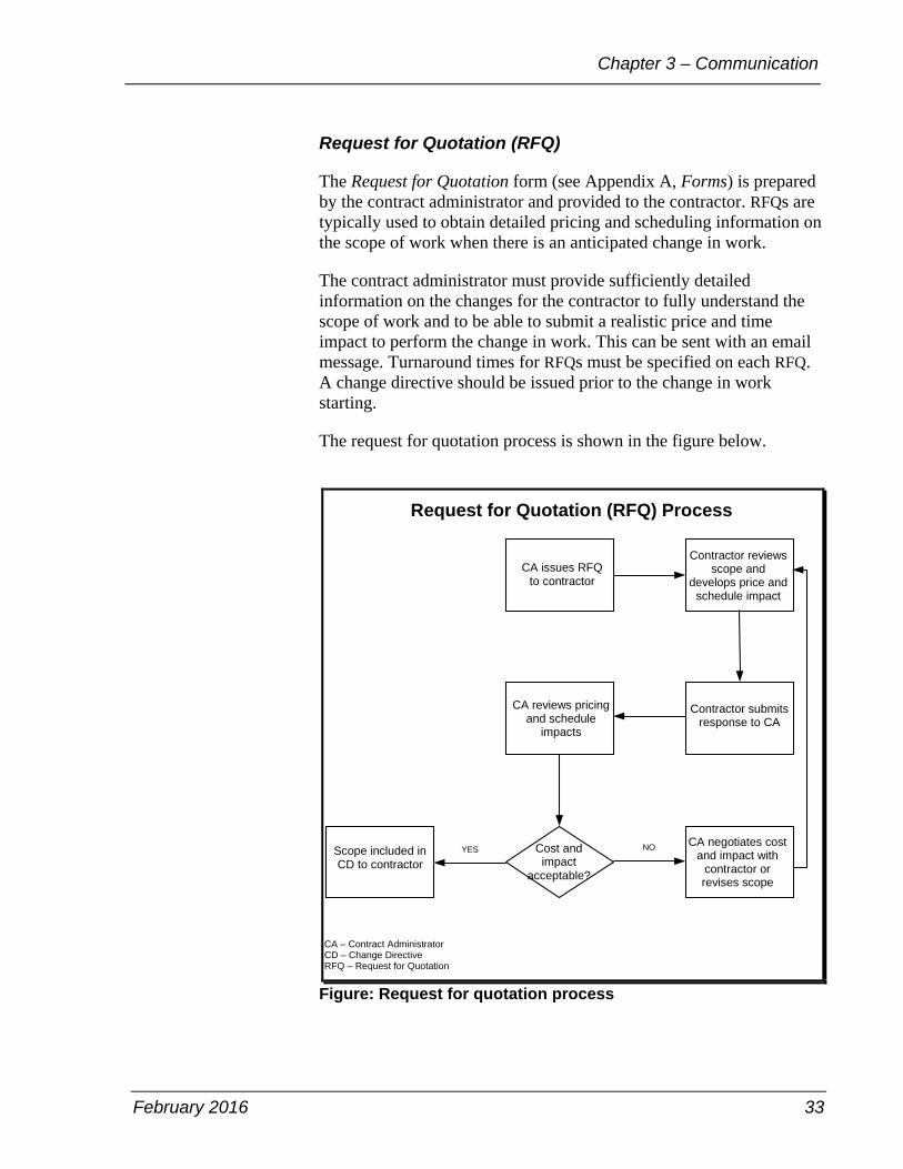
Request for Quotation (RFQ)
The Request for Quotation form (see Appendix A, Forms) is prepared by the contract administrator and provided to the contractor. RFQs are typically used to obtain detailed pricing and scheduling information on the scope of work when there is an anticipated change in work.
The contract administrator must provide sufficiently detailed information on the changes for the contractor to fully understand the scope of work and to be able to submit a realistic price and time impact to perform the change in work. This can be sent with an email message. Turnaround times for RFQs must be specified on each RFQ. A change directive should be issued prior to the change in work starting.
The request for quotation process is shown in the figure below.
Request for Quotation (RFQ) Process
CA issues RFQ to contractor
Scope included in CD to contractor
Cost and impact
acceptable?
CA negotiates costand impact with
contractor or revises scope
Contractor reviews scope and
develops price and schedule impact
Contractor submits response to CA
CA reviews pricing and schedule
impacts
YES NO
CA – Contract Administrator CD – Change Directive RFQ – Request for Quotation
Figure: Request for quotation process
Field Services Manual
34 February 2016
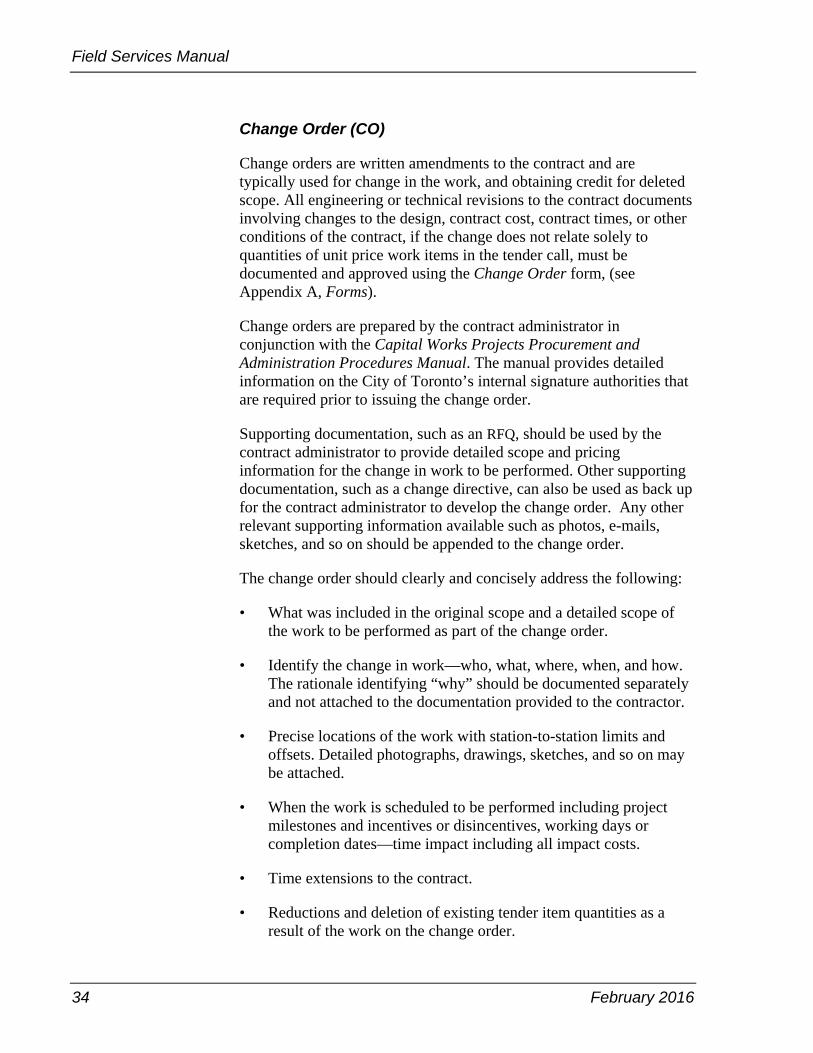
Change Order (CO)
Change orders are written amendments to the contract and are typically used for change in the work, and obtaining credit for deleted scope. All engineering or technical revisions to the contract documents involving changes to the design, contract cost, contract times, or other conditions of the contract, if the change does not relate solely to quantities of unit price work items in the tender call, must be documented and approved using the Change Order form, (see Appendix A, Forms).
Change orders are prepared by the contract administrator in conjunction with the Capital Works Projects Procurement and Administration Procedures Manual. The manual provides detailed information on the City of Toronto’s internal signature authorities that are required prior to issuing the change order.
Supporting documentation, such as an RFQ, should be used by the contract administrator to provide detailed scope and pricing information for the change in work to be performed. Other supporting documentation, such as a change directive, can also be used as back up for the contract administrator to develop the change order. Any other relevant supporting information available such as photos, e-mails, sketches, and so on should be appended to the change order.
The change order should clearly and concisely address the following:
• What was included in the original scope and a detailed scope of the work to be performed as part of the change order.
• Identify the change in work—who, what, where, when, and how. The rationale identifying “why” should be documented separately and not attached to the documentation provided to the contractor.
• Precise locations of the work with station-to-station limits and offsets. Detailed photographs, drawings, sketches, and so on may be attached.
• When the work is scheduled to be performed including project milestones and incentives or disincentives, working days or completion dates—time impact including all impact costs.
• Time extensions to the contract.
• Reductions and deletion of existing tender item quantities as a result of the work on the change order.
February 2016 35
Chapter 3 – Communication
• Change Order Summary sheet
A copy of the change directive and supporting documentation must be provided to the inspector. The inspector uses the information to inspect the change in work, completed by the contractor.
For works performed on a time and material basis, the inspector must document labour, materials, and equipment—including hours worked—on a daily basis in the Report of Changes in Work Completed form (see Appendix A, Forms) in order to verify progress and facilitate contractor progress payments. For works performed on a negotiated lump sum or negotiated unit price basis, the Inspector’s Daily Report form is to be completed for verification of progress payments.
For works performed on a negotiated lump sum or negotiated unit price basis, the Inspector’s Daily Report form is to be completed for verification of progress payments.
The measurement for change in work should also be reviewed for calculations, errors and omissions, and adequacy of supporting documentation.
For time and material work, the contract administrator must ensure that the contractor completes and submits the contractor payroll burden form and other applicable mark-ups, which should then be attached to all time and material change orders as back up. The payroll burden value is to be determined in accordance with the contract documents.
Costs associated with all change orders will need to be monitored to ensure that the originally approved costs are not exceeded. As the total costs associated with a change order or change directive may not always be known or accurate, a new change order must be prepared once the original estimate or quote is expected to be exceeded. The appropriate authority must be obtained based on the revised total cost of the change in work. Under no circumstances should a change order be issued after all the work is completed.
Contractors are required to submit invoices for work performed under a change order for payment based on unit quantities or time and material. If the invoice contains errors, requires corrections or if the final amount of work performed is different from the invoice provided then an updated invoice must be submitted by the contractor. The contract administrator must not make manual adjustments to invoices

Field Services Manual
36 February 2016
since it increases the risk of fraud and can potentially result in over payments.
Other References:
For specific requirements related to changes during construction, see the Capital Works Projects Procurement and Administration Procedures Manual, Section 5.5.10.
Public Relations
Inspectors are representatives of the City of Toronto. On a project, contractors may also be perceived by the public as representatives of the City—which they are not. As such, the public perception of the City is developed from the actions and attitudes of all people on a project. All on-site personnel should conduct themselves in a manner that earns the respect and confidence of the general public, as well as property owners, business owners, local citizens, tourists, and municipal officials. Courteous explanations and answers to questions raised by the public are essential in maintaining the good image of the City.
The inspector checks to ensure that notices for sewer, watermain, and road projects are posted and delivered and contain the appropriate contact information for the contract administrator. All media requests or questions should be directed to the contract administrator.
When a public complaint is made, the inspector should attempt to resolve the issue in the field with the contractor. There may be cases when the public is visibly upset and confrontational about a particular issue or the contractor may not be willing to resolve the issue. In these situations, the issue must be escalated to the contract administrator. All complaints made must be documented by the inspector in the daily report and photographs taken as supporting documentation.
The contractor typically takes a pre-construction video or photographs of the area prior to start of work. This could also be utilized to resolve issues, should a conflict occur.
The figure on the next page outlines a workflow for the complaint process.

February 2016 37
Chapter 3 – Communication
Inspector receives complaint
If the complaint is not resolved,
escalate to the contract
administrator
Complaint Process
Inspector contacts public immediately to determine the nature
of the complaint
If the complaint is related to the
construction project, contact the contractorto resolve the issue
Figure: Complaint process
Projects involving the Toronto Transit Commission (TTC), large scale, or contentious projects have access to the Public Consultation Unit. Under this scenario, assigned staff would attend meetings as required, prepare and distribute notices, and address concerns raised by the public.
If a complaint relating to a construction project cannot be resolved by the contract administrator, the resident can be directed to the Program Manager, Customer Service and Issues Management for further response and resolution. If a resident has a complaint regarding damages to their property or bodily injury resulting from construction, the resident or business owner can submit a claim to the City in accordance with the City's claim process.
For more information on how a member of the public can submit a claim, refer to the claims process on the City website.
http://www1.toronto.ca/wps/portal/contentonly?vgnextoid=ccd3285441f71410VgnVCM10000071d60f89RCRD&vgnextchannel=dafa285441f71410VgnVCM10000071d60f89RCRD
Other References:
For resident or property owner complaints or claims, see General Conditions of Contract, clause GC 7.17.
The Municipal Class EA applies to municipal infrastructure projects including roads, water and wastewater projects.

Field Services Manual
38 February 2016
Health and Safety
All individuals on site are responsible for becoming familiar with and fully complying with applicable regulations and codes, their company health and safety policies and procedures, and the health and safety requirements of the constructor. It is the inspector’s role to monitor the contractor to ensure compliance to the contract. For more information, see Appendix H, Health and Safety.
Other References:
For information related to the role and responsibilities of the constructor on construction projects, see the Occupational Health and Safety Act and Regulations for Construction Projects (Ontario Regulation 213/91).
Spills Response
All spills aside from regular collection of rainwater must be reported to the contract administrator immediately for follow up in accordance with the Toronto Water spills response plan and any other applicable legislation.
Spill requirements for the contractor are outlined in the contract documents. The inspector should monitor for compliance, should a spill occur.

February 2016 39
Chapter 4 – Field Construction Procedures
Chapter 4 – Field Construction Procedures
Filing System
A master project file is maintained by the contract administration
section including:
Contract administration file – folders on tender books, low bidder,
purchase requisitions, purchase orders, purchase order amendments,
permits, RFIs, RFQs, schedules, and so on.
Construction file – folders on quality assurance, pre-construction and
construction meeting minutes, final measurements, deficiency list,
photographs, copies of contractor submittals such as mix designs,
traffic control plans, utlity stakeouts, and so on.
Payment file – folders on payment certificates, change orders and so
on.
Inspector file – folders on complete contract documents, contract
price list, supporting documentation, field instructions log and so on.
Daily reports and tickets file – folders on inspector’s daily reports,
material tickets, and construction photographs and so on.
The inspector should also maintain a similar temporary file structure
for all documentation in the field. The inspector may collect and
manage a significant portion of the construction file and must ensure
that all documents are forwarded to the contract administrator. The
proper handling of documents by field staff determines the accuracy of
the files and records. Without the collective cooperation of every
member of the team, document management and control cannot be
effective.
At project close-out, all documents must be forwarded to the contract
administrator for incorporation in the project files as required by this
chapter of the Field Services Manual and the Request for Proposal.
The contract administrator will review and submit the materials to the
contract administration section for filing. External service providers
shall manage their filing system in accordance with the Request for
Proposal.

Field Services Manual
40 February 2016
Other References:
For information related to payment file, see the Capital Works Projects
Procurement and Administration Procedures Manual, Section 5.1.
Daily and Weekly Reports
Each inspector must prepare a daily report for each workday at the
project site so that the events of that day may be recreated by those not
on site, but who may need information to deal with the claims from the
contractor as well as claims or complaints from the public. This
requirement also applies to the contract administrator when they are
assigned site activities. The inspector must also complete a weekly
inspection summary report based on the daily reports.
The weekly report and supporting daily reports must be submitted to
the contract administrator through the construction supervisor. Each
daily report must be supported by weigh tickets for all material
delievered to site and calculator tape or on an Excel spreadsheet
showing the total quantities for the respective tender items where
applicable. The contract administrator must review and confirm the
quantities based on information received from the inspector and field
test reports. The Inspector’s Daily Report and Inspector’s Weekly
Report forms are provided in Appendix A, Forms.
Daily and weekly reports will be signed off by the inspector, contract
administrator and contractor. If the contractor declines to sign the daily
inspection report, the inspector will record in the report, and in their
daily log book, that the contractor has been shown the report or
advised of the contents of the report. The inspector shall complete
daily reports for changes in work done under time and material and the
inspector, contractor, and contract administrator shall sign-off the
same.
Note: Inspectors daily reports – field inspectors are required to sign
and submit the Inspector’s Daily Report form to the office for
processing. The contractor is also required to co-sign the front page of
the Inspector’s Daily Report form and to verify that the work recorded
on the form and only the work recorded on the form has indeed been
performed by the contractor. The contractor is not to view or sign the
page with the remarks.
Inspector’s daily report additional remarks – field inspectors can use
the Inspector’s Daily Report Additional Remarks form to record
various payments or non-payment related activities occurred and
Inspector’s Daily Report
can either mean
(a) Inspector’s Daily
Report for Storm Sewer /
Sanitary Sewer
/Watermain
(b) Inspector’s Daily
Report for Road /
Sidewalk
(c) Inspector’s Daily
Report for
Facilities/Vertical Works
February 2016 41
Chapter 4 – Field Construction Procedures
observed by the inspectors on site and to provide comments, if
necessary, to support and supplement the inspector’s daily report.
Inspectors are required to sign the Additional Remarks form as part of
their submission to the office. The contractor does not co-sign the
Additional Remarks form.
Daily report of extra work completed – both the inspector and the
contractor have to sign the Report of Extra Work Completed form to
confirm that the changes in the work have been performed and the
form can be used as a reference document for payment.
Note: For projects with an external service provider – if time and
materials work is being performed, both the site representative or the
owner’s representative on site, and the contractor are to sign the Daily
Report – Facilities form related to time and material work.
The inspector should notify the contract administrator on any
provisional work performed on site by noting it on the daily report. All
work done as a result of a change in the work must be approved by the
contract administrator prior to any work starting.
Daily reports should be accurate and thorough, addressing factual
information only and avoiding opinion, conjecture, or speculation. All
entries pertaining to a single contract must be maintained separately
from all other projects. If there is more than one location within the
contract then separate entries or daily reports or both shall be made
when work is done on each individual location. The daily report
should contain the following information:
• Report every workday and account for every calendar date. If no
work is done on a given date, the date should be entered and the
reason for not working should be recorded, for example, “No
activities scheduled for this date due to (reason), no onsite
inspection services provided”.
• Report when Report of Extra Work Completed form has been
used.
• Include references to on-site conversations and phone calls. For
more information on communications and telephone conversations,
see pages 23–24.
• Document site activities. References to specific scheduled
activities should be made in accordance with the specific areas of
Field Services Manual
42 February 2016
responsibility. Problems or abnormal occurrences should be
described clearly and photographed, including the reason for the
specific event.
The following are examples of observations, tasks, and site activities
that typical report entries for linear projects. Note that not all tasks are
applicable to facility or vertical projects:
• Document repairs to existing or contractor damaged utilities using
the Record of Damaged Utilities Form (see Appendix A, Forms).
• Report the number of construction employees, by trade, on the
contract. Note contractors and individual subcontractors. This
information should be obtained from the contractor; however, the
number of employees on site should be corroborated by visual
count.
• Report the work performed by the contractor and reference
scheduled activities when possible.
• Record all individual items worked on by the contractor on a daily
basis referring to survey chainages, where possible or
measurement ties and street addresses as well as showing
calculations for total quantities performed each day.
• Report on soil conditions and type of shoring used for all
underground construction work.
• Report the type, model number, and number of each piece of heavy
equipment on site. Note whether the equipment is owned or rented,
and if the equipment is working, on standby, or not in use.
• Report quantities installed for each tender item, for example: cubic
metres of concrete, linear metres of pipe noting each relevant
contract item number when applicable as well as indicating starting
and ending survey chainages wherever possible or measurement
ties and street address with calculations.
• Report and photograph work on provisional items performed
including the quantities, location, and time of the work, and the
reason for the work.
• Report extra work with the change directive reference number if
applicable.

February 2016 43
Chapter 4 – Field Construction Procedures
• Payment on third party invoices, for example paid duty officer
charges must be based on original invoices submitted by
contractor. Photocopies of invoices should not be processed for
payment.
• Contract administrator and inspector should review documentation
supporting progress payment, including documentation on third
party work.
• Refer to field tests as either pass or fail, if fail, identify course of
action. Collect and attach to daily reports all field test results where
the documents are provided by the material testing consultant.
• Potential out of scope work.
• Document and photograph areas that could not be constructed in
accordance with specifications due to unforeseen circumstances.
• Document and photograph sensitive areas that may result in
potential claims.
• Every time there is a significant change to the traffic control plan
and work zone location has changed.
• All visitors to the site, the reason for their attendance, time on site
and instructions, directions or comments provided.
• Complete all checkboxes noted in the daily report form or any
other form required to be completed and submitted.
Report use of testing services received in all field test reports. If
subcontracted, include name of company, the number of people, type,
and number of tests, and time spent on testing and on the site.
• When a specific scheduled activity or measured event is
completed, for example: a portion of a basic slab is cast, a length
of pipeline is laid, a specific piece of equipment is set, and the date
should be recorded.
• Note any questions on workmanship, to whom the question was
raised, and the context in which the question was asked, for
example, was it a complaint, a general comment, or a question
regarding scheduling.
• Record the content, date, and parties involved of all substantive
conversations held with the contractor.

Field Services Manual
44 February 2016
• Record all materials or equipment delivered and obtain delivery
tickets to be reviewed and attached to daily reports.
• Ensure that proper documentation is prepared and filed for the
manufacturer’s representative site visits in compliance with
contract documents for equipment checkout and testing.
• Label last daily report made of significant field activities "project
complete except for deficiencies". Afterwards, prepare daily
reports on the day when deficiencies were addressed.
Photographs should be taken on a daily basis for any unusual activities
observed or to demonstrate progress. This can include sub-
excavations, buried material or equipment, or anything that could lead
to a potential third party or contractor claim. Photographs should be
named accordingly and uploaded to the appropriate project folders on
the City’s server.
Photography Requirements
On the daily report, note the number of photographs taken each day
with the approximate time and a note as to what is in the photos.
On a daily basis, photographs are to be taken of the following:
• General site set-up where crew(s) are working showing general
progress of work.
• Any changed conditions.
• Any agreed upon extra work or situations where there is a possible
claim.
• Any site safety issues or other issues pertaining to negative
contractor performance appraisals.
• When trenching begins and any changes to the type of shoring,
tunnelling or sub-grade conditions.
• Any time traffic control that has changed from the previous day,
unless the contractor has done so and forwarded the information to
the inspector and the project mananger or contract administrator.
• Photographs are to be taken prior to working at any location back
of the sidewalk such as from lawns or driveways, and so on.

February 2016 45
Chapter 4 – Field Construction Procedures
• Any obvious recent damage adjacent to the work location.
In addition, during the early stages of the contract the inspector should
take photographs of the following:
• All key phases and new operations.
• Equipment used on site.
• Typical and representation parts of all underground work such as
buried bends, anodes compaction operations, and so forth.
Ministry of Labour Inspection Visits
The inspector will report all Ministry of Labour (MOL) visits to the
site during construction, irrespectively of whether the MOL inspector
has taken any action or not. The MOL inspection and the details of the
visits should be recorded in the inspector's daily report. The inspector
should report the visits along with the details to the contract
administrator who will then send a copy to the Program Manager,
Health & Safety & Emergency Planning in the division.
Other References:
For information related to daily work records, see General Conditions
of Contract, clause GC 8.02.04.02.
Equipment and Material Monitoring
The inspector should be active in the identification of deficient
materials or equipment received on site. The inspector should inform
the contractor of the deficiencies and record details and actions taken
in the Field Inspection of Materials and Equipment form (see
Appendix A, Forms) and on their daily report. The inspector must also
notify the contract administrator. In the event the contractor refuses to
comply with the inspector’s notification, the contract administrator
issues a field instruction. The Field Instruction form (see Appendix A,
Forms) should be filed and transmitted to all parties involved.
The inspector must follow up in the field to ensure that action has been
taken on any deficient equipment or material received.
Field Services Manual
46 February 2016
Materials Testing
The contract administrator and inspector must have a copy of and be
familiar with the Request for Proposal (RFP) for material testing
requirements.
The contract documents typically make reference to municipal,
provincial, or federal codes and standards. There may be exceptions
where the contract is tailored, specifying the type and frequency of
sampling and testing of construction materials for quality assurance. In
cases where batch or lot size of the material supplied and placed does
not coincide with those specified in contract documents, the contract
administrator may revise the frequency of sampling and testing;
however, the rationale for deviating from the contract documents must
be documented.
The contract administrator must verify that the minimum quality
requirements for materials are correct on the testing forms by initialing
the test result forms and that the appropriate commentary is provided
for test results when exceptions are noted. The contract administrator
must ensure that inspection staff are advised of these actions.
Contract administrators are required to verify that quality assurance of
construction materials, performed by third party consultants, are in
accordance with contract documents.
The City's project manager is responsible for ensuring that the contract
administrator for consultant-managed contracts adhere to the above
requirements.
The inspector is responsible for arranging material quality field
assurance tests, including having samples picked up for laboratory
testing. The contract administrator is responsible for review of all
laboratory test results.
Inspectors must be knowledgeable of the contractor’s work activities
and make the necessary arrangements for sampling and testing as per
the terms of the material testing RFP prior to the contractor conducting
the work. The inspector should inquire with the contractor in order to
make necessary arrangements for material tests.
The material testing company should be invited to the pre-construction
meeting by the contract administrator so that they may be informed
about the general testing requirements, and other pertinent information
as per the RFP and other contract protocols.
February 2016 47
Chapter 4 – Field Construction Procedures
When materials are delivered to site, the inspector or his or her
designate must collect the ticket from each truck prior to discharge for
weight based payment items (see Appendix G, Weight Verification
Protocol).
For all other items delivered to site, material tickets are to be collected
and attached to the daily reports. If tickets are not produced, the
contract administrator is to be notified. The missing tickets are to be
documented in the daily reports as well discussed at the progress
meetings.
All coordination, field test results and sample pick-ups must be
documented. For example, the request for sample collection including
type of samples to be taken, quantity of samples, time required and so
on, must be documented with a copy provided to the material testing
company. The material testing company must also submit a copy to the
contract administrator with the final invoice.
A record of the field testing, sample preparation, and sample pick-up
work should be recorded by the inspector in the daily report.
Information kept in the daily report should include time on the project,
name of technician, and tests or samples taken with locations
indicated. The testing technician should provide an immediate copy of
the field activity report to the inspector before their departure. This
field activity report should summarize activities conducted and allow
the inspector to verify that the correct information and locations have
been recorded. The inspector will then sign the field activity report and
attach it to the daily report.
Any delays with regard to the field testing arrival on site and delays to
the field testing representative after they arrived on site are to be
documented by the inspector as under the terms of the RFP payment
for standby time may be required.
The material testing company must report to the inspector all failed
field tests. The inspector should immediately follow up on all failed
field test with the contractor and document and advise the contract
administrator of issues and actions taken. The contract administrator is
to follow-up with all failed laboratory test results.
All defective work has to be replaced or rectified immediately to the
satisfaction of the contract administrator or inspector or both. No
payment should be recommended until all defective work has been
corrected and this is to be documented on the deficiency report.

Field Services Manual
48 February 2016
All laboratory test results for the contract submitted by the quality
assurance laboratory should be carefully reviewed by the contract
administrator. The contract administrator should follow-up on all
defective work with the contractor and put them on the deficiency list.
Payment of the defective work should be withheld until the work is
corrected.
All material testing results should be kept in a material testing quality
assurance (QA) folder for easy retrieval by the contract administrator.
The results should be tabulated and cross-referenced to the respective
contract.
The construction supervisor is to audit and document the results of
materials testing as arranged by the inspectors to ensure compliance
with Appendix C, Materials Testing Protocol, and discuss reasons for
non-compliance on each contract. Such audits are to be discussed with
the contract administrator and placed on the contract file. The contract
administrator is responsible for reviewing tests results of all laboratory
testing, which are sent to them by the materials testing company.
In general, material testing is required for the following:
• gradation analysis on fill materials
• sulphates testing of recycled concrete material
• subgrade evaluation—bearing capacity/penetrometer test asphalt
cores for Marshall density, gradation, compliance and so on
• field compaction and moisture tests on fill materials laboratory
extraction and gradation test and Marshall test on hot mix asphalt
• asphalt compaction testing for paving operations
• mold, cure, and break concrete cylinder specimens
• slump test for cast-in-place concrete
• air content for cast-in-place concrete
• concrete temperature for cast-in-place concrete
• sample testing of mortar, grout, crackfilling material
• other tests and samples requested by the contract administrator
Other References
For details on the outline the scope and procedures for the provision of
weight verification to construction materials, see Appendix G, Weight
Verification Protocol.
For details on material testing for the inspector and QA consultant, see
Appendix C, Material Testing Protocol.

February 2016 49
Chapter 4 – Field Construction Procedures
For details related to deficiencies with concrete materials testing, see
latest release of TS 1350, Amendment to OPSS.MUNI 1350 (Nov 2014)
Material Specification for Concrete – Materials and Production.
For the material inspection and materials testing guide, see the
General Conditions of Contract, clause GC 5.0.
Testing Required for Concrete and Asphalt Material
Contractor's Quality Control Plan
The contractor's quality control plan must be submitted and reviewed
if required as per the contract document. A copy of the reviewed and
accepted plan by the contract administrator and the material testing
consultant is to be provided to the inspector.
The inspector is to document instances of non-compliance with field
tests and discuss instances of non-compliance with the contract
administrator. Performance issues are to be reviewed with the
contractor and will be documented on contractor's performance
evaluation form.
The inspector is to ensure that material testing requirements in
Appendix C, Material Testing Protocol, are followed whether a
quality control plan is required or not.
Concrete
All mix designs are to be submitted and reviewed by the material
testing consultant.
Arrange for material testing as per the specifications and contract
requirements. Typically the first three loads per mix per day are tested
and cylinders cast, and until consistency is established, one for every
slump test, and one for every strength test.
Cast concrete cylinder samples for laboratory compressive strength
tests. Three cylinders on the first load of the day typically and every
50m3 with no fewer than one test for each class of concrete placed on
any one day.
Check the delivery time of the load – time when the concrete was
batched to the time the concrete was unloaded – if it falls within the
requirements as stipulated in TS 1350.
Field Services Manual
50 February 2016
Check if the load is produced from concrete plant(s) that was specified
in the contract, or the plants were agreed upon in the pre-construction
meeting or in pre-concrete placement meeting
Asphalt
Review contract requirements, Appendix B, Inspection Tasks and
Appendix C, Material Testing Protocol prior to work commencing.
Discuss pre-paving issues such as traffic control plan, night time
lighting, arrow boards, and so on at progress or pre-pave meeting prior
to work commencing.
Arrange for field testing according to the Field Services Manual and
ensure availability of an infrared thermometer temperature gun and
asphalt temperature gun for use when checking asphalt temperature.
Ensure proof rolling and compaction testing are done on granular
materials as required in Appendix C, Material Testing Protocol.
Ensure all other preliminary work is completed so that paving may
proceed including casting adjustment, gutter brick placement, delivery
of notifications, if required, and tack coat placement immediately prior
and placement of line markings immediately after.
For contracts where material is paid by weight discuss and arrange for
check weight to be done according to Appendix C, Material Testing
Protocol. Arrange for continuous ticket collection as a second
inspector may be required to assist with this requirement.
Review specifications and on day of paving, safely check the
temperature of asphalt mix at point of discharge—at least 120oC at
point of discharge and air temperature of pavement for hot mix asphalt
placing—for binder at least 2°C, for surface at least 7°C.
Ensure the material testing consultant performs compaction tests on
hot mix asphalt mat using nuclear density gauge as required under
contract documents.
Test Strip Method – Proof Rolling
• one test section per 300 metres of pass
• minimum two test sections per street
• five tests per test section
February 2016 51
Chapter 4 – Field Construction Procedures
Prepare plate samples of hot mix asphalt on site for extraction and
gradation tests and Marshall mix design tests for each type of mix—
reject samples prepared by shovels. Test the first production load from
the asphalt plant on each paving day, and every 250 Mg (tonne)
thereafter.
Other References
For a complete list of testing requirements for these and other
materials, see Appendix C, Material Testing Protocol.
Test Reports
Hydrostatic leak tests and disinfection tests are two types of tests that
can occur on a project. Prior to performing the tests, the contractor
must prepare and submit a plan to the contract administrator for
approval. Upon approval of the plan, the contractor and inspector
make the necessary arrangements to prepare for testing. For example,
the inspector will contact the Toronto Water division for valve
coordination, such as valve opening/closing.
Note: Toronto Water will not accept a valve opening/closing request
from the contractor; this request must come from the inspector with a
minimum of 48 hours' notice.
The Hydrostatic Leak Test Record and Disinfection Test forms (see
Appendix A, Forms) are filled out by the contractor during testing.
Information should be documented on the forms that indicate who
conducted the tests, when the tests were completed, the location of the
tests and so forth. The inspector is required to witness all tests and
record the observations in the daily report.

Field Services Manual
52 February 2016
Construction Submittals
Any submittals provided by the contractor should be submitted to the
contract administrator directly for review and as required. The contract
administrator must date and log all submittals and provide a copy of
the approved submittal to the inspector. The inspector should provide
information to the contract administrator, as requested, to aid in the
approval process.
On projects where an external service provider such as a consultant is
contracted, they may provide design, site inspection, and construction
administration roles. For more information on external service
providers, see Chapter 1, Project Team. In these cases, the contractor
is required to provide all submittals to the consultant directly.
All submittals must be submitted in the format prescribed in the
contract documents. Submittals can include drawings and other
information prepared by the contractor and vendors that provide
detailed information about equipment or materials to be supplied under
the contract. The information is reviewed by the contract administrator
and returned to the contractor with appropriate comments. No changes
to the contract are made during this process—it is a review for current
contract conformance and compliance.
For monthly schedule submittals accompanying the contractor’s
monthly payment application for Engineering & Construction Services
– Design & Construction Section contracts, hard copies of the
schedule shall be submitted as required per the contract documentation
or the specifications package or both.
Examples of submittals can include:
• shop drawings
• construction schedules
• operation and maintenance manuals for equipment
• equipment warranties
• certificates of proper installation—mechanical fitness
• as-built drawings
• utility locates
• Ministry of Labour reports
• traffic control plans
For projects that require the preparation and submission of shop
drawings by the contractor, the contract administrator must maintain a
log of all shop drawings with the date received, reviewed and when it

February 2016 53
Chapter 4 – Field Construction Procedures
was approved. The contract administrator shall adequately safeguard
approved copies of shop drawings and copies of the same are to be
provided to the City at the completion of the contract.
The goals of the submittal review process are thorough reviews
conforming to the intent of the design and not contract changes
through the submittal process.
The processes for submittals are shown in the figure below.
Submittals
NO
Contractor submits to contract
administrator
Contract administrator
/inspector review
Conform with specifications?
YES
Response to contractor “Revise and Resubmit”
Response to contractor with “No Exceptions Taken”, “Exceptions
Noted” or “Exceptions Noted Resubmit”
Figure: Submittals

Field Services Manual
54 February 2016
Conform with specifications?
YES
Consultant Review of Submittals
Return to consultant
Review by consultant
Contractor submits to consultant
Respond to contractor with “No Exceptions Taken”, “Exceptions
Noted” or “Exceptions Noted Resubmit”
NO
Return to contractor
“Exceptions Noted Resubmit”
Route to owner for review
YES
NO
Requires additional changes?
Figure: Consultant review of submittals

February 2016 55
Chapter 4 – Field Construction Procedures
Deficiency Lists
The inspector maintains a continuous list of deficient items for each
contract and submits to the contract administrator. The contract
administrator should review it as appropriate with the contractor at
regularly scheduled progress meetings. For more information on
progress meetings, see page 17.
Upon receipt of notification from the contractor signifying substantial
performance, acceptance and final completion, the inspector and the
operations group, along with the contractor, should perform a thorough
examination of the work to ensure deficient and incomplete work
items are resolved or completed. The contract administrator arranges
for design staff and specialty inspections, as necessary. The Deficiency
List form can be found in Appendix A, Forms.
The deficiency list should consist of an accumulation of one or more
items of the following:
• work-to-date inspection report
• checklist of deficient items, including defective works that need to
be reworked
• review of specification, submittals, and drawings related
information
• owner comments
• specialty inspection and testing reports
• value of deficient work to be performed—value should be
equivalent to the payment amount to an external party, if the
contractor decides not to rectify the deficiency as determined by
the contract administrator based on the deficiency list
The inspector prepares an initial comprehensive copy of the overall
deficiency list for review by the contract administrator. With approval
from the contract administrator, the list is provided to the contractor
for action. At a minimum, the deficiency list should be given to the
contractor monthly at progress meetings and documented in minutes of
meetings, at the end of a project phase, prior to substantial
performance or prior to completion. Further, warranty deficiencies
must be identified within two years of the end of warranty and
corrected.
Upon notification by the contractor that specific work items have been
completed, the inspector examines the completed work with the
contractor. If the item is correctly completed, the inspector initials and
dates the item on the confirmation copy of the deficiency list. The

Field Services Manual
56 February 2016
official confirmation copy of the deficiency list is maintained in the
project files. Any items disputed by the contractor are sent to the
contract administrator, who reviews them with the inspector and, if
necessary, the contractor.
Other References:
For information related to deficiencies and holdback, see the Capital
Works Projects Procurement and Administration Procedures Manual,
Sections 5.5 and 6.2.
As-Built Drawings
The requirement for as-built drawings is dependent upon the type of
project. Unless otherwise specified in a consultant RFP and contract
with the contractor the following is to be done:
For the Design & Construction Section, Major Infrastructure
contracts, the contractor is usually responsible for producing red line
mark-ups on his or her set of contract drawings; the inspector is
responsible for the subsequent inspection of the contractor's redline
mark ups. The inspector reviews with the contractor all revisions
marked on the contractor’s drawings to consolidate all changes before
transmitting the drawings to the contract administrator for updating the
computer aided design and drafting (CADD) files. As-built drawings
are not signed or stamped by a professional engineer, as the engineer is
not present on site during construction in a manner that all activities
could be overseen concurrently.
For all design and construction linear infrastructure projects and other
projects as required, the inspector is responsible for red lining as-built
information on the contract drawings. This requirement is for all types
of work and is required so that quantities and changes in the limits are
recorded for final payment purposes and these changes can be
identified on the redline plans. In cases whereby the contractor is
required to produce redline mark-ups the inspector is also required to
produce these drawings and compare them and reconcile them so that
there is agreement with all changes. If the inspector is unable to verify
and agree to the contractor's as built redline drawings then this is to be
reported to the contract administrator for action and listed as a
deficiency.
The office design staff generates the as-built drawings according to the
red lined drawings.

February 2016 57
Chapter 4 – Field Construction Procedures
If a third party consultant is involved, he or she is responsible for both
the inspector’s and contract administrator’s roles as described above.
Water and Sewer Service Cards
It is the inspector’s responsibility to complete the sewer and water
service cards, which are then submitted to the construction supervisor
for review and forwarded to the contract administrator. The contract
administrator will ensure that one copy be included in the project file,
and one copy sent to Toronto Water’s water infrastructure
management and the district operations and maintenance sections.
The sewer and water service cards are used to assist in the preparation
of the as-built drawings. Toronto Water will use the cards to update
their asset inventory database and work management system. The
sewer and water service cards can be found in Appendix A, Forms.
Other Requirements:
For information on as-built and record drawings, see Appendix D, As-
built Drawing Guidelines. This document should be given to the
contractor prior to project start-up and discussed in the pre-
construction meeting.
For minimum requirements and responsibilities, see Appendix E, As-
built Features Requirements.
Engineering Surveys
For in house design projects, lines and grades are typically set by the
engineering surveys unit. If there are any alterations to the design,
engineering surveys will amend the layout to reflect the revisions. All
engineering survey work is coordinated with the contract
administrator.
Substantial Performance
The contractor’s responsibilities for substantial performance are
defined in the general conditions with reference to the Construction
Lien Act. Work on any area, system, facility, or the like, must be to the
point where it is able to be fully operational in the mode for which it
was designed, unless specifications allow otherwise. The value of
deficient and uncompleted work must be accounted for determining if
Field Services Manual
58 February 2016
the contract is substantially performed. In addition, operations and
maintenance documentation and all warranty and guarantee
information must be properly filled out for all equipment and material
items and must be submitted to the contract administrator before
substantial performance is granted.
Substantial performance is granted by the issuance of a certificate of
substantial performance by the contract administrator. As stated in the
general conditions, the warranty period begins on the date of
substantial performance.
At the time of substantial performance, the on-going deficiency list
prepared by the inspector is provided to the contractor and an
inspection is conducted by the inspector. A new deficiency list is
generated after substantial performance to document any deficiencies
that may have occurred after substantial performance through to
completion of the contract. Prior to end of warranty, a deficiency list is
provided to the contractor to rectify the deficient items.
Other References:
For the requirements on the certificate of substantial performance, see
the General Conditions of Contract, clauses GC 8.02.03.04 and GC
8.02.03.05.
For information related to substantial performance, see the Capital
Works Projects Procurement and Administration Procedures Manual,
Section 5.5.15.
Completion
Completion is achieved when all items on the deficiency list have been
rectified, all required submittals have been completed, and all other
obligations of the contract have been satisfied. The contractor's
responsibilities for completion are defined in the general conditions
with reference to the Construction Lien Act.
To achieve completion, the contractor must satisfy the contract
requirements. As a final review, the inspector evaluates each item on
the deficiency list and submits an updated list verifying the
contractor’s completion of the work, or listing items not satisfactorily
corrected. The contractor must remedy any deficient or incomplete
work and notify the contract administrator that the work has been
completed.

February 2016 59
Chapter 4 – Field Construction Procedures
The inspector then examines the corrected work. When the inspector
finds the work acceptable and the required submittals are complete, the
contract administrator requests the contractor to make final application
for payment. Final payment to the contractor is made after completion
of all required work.
The following is a list of some examples of documentation that the
inspector shall collect or prepare prior to final completion:
• watermains – as-built drawings and drawing indicating pavement
and curb road cut locations and area, pressure tests, tracer wire
continuity reports
• road, curb, and sidewalk as-built drawings
• electrical work – ESA as-built drawings
• final operations and maintenance manual
• measurements and calculations of all work items and sketches or
marked-up plans to indicate where measurements were taken
• final review survey of work
• environmental compliance approval (ECA)
• quantity sheets
• water and sewer service cards
• deficiency lists
Other References:
For the requirements on the certificate of completion, see General
Conditions of Contract, clause GC 8.02.03.06.
Contract Payment
For Engineering Support Services section projects and lump sum
projects, the contractor must submit the proposed payment application
or a breakdown of prices documentation for approval by the contract
administrator prior to the first progress payment. Prior to each of the
contractor’s payment applications, the contractor must prepare an
updated progress schedule (see page 19) showing current progress on
all work activities. The progress schedule must show work activities,
planned start and finish dates, original duration, current percent
complete, and remaining duration.

Field Services Manual
60 February 2016
Upon receipt of the contractor’s schedule report and other required
payment application documentation, as defined by the contract
documents, the contract administrator proceeds with formal review of
the payment application in consultation with the inspector. Upon
verification of completion of the work, the inspector submits a final
weekly report to the contract administrator. The contract administrator
reviews and provides final approval on the payment request. Payment
application documents not recommended by the inspector are returned
to the contractor for re-submittal. Deficient work should also be
documented and a value assigned to the deficient work in order to
adjust contract payment. For more information on deficiency lists, see
page 55.
Deficient work should also be documented and a value assigned to the
deficient work in order to adjust contract payment. For more
information on deficiency lists, see page 55.
For all unit price contracts, progress payments shall be made based on
the compilation of quantities on the daily inspection reports for the
specific contract.
Other References:
For specific requirements related to progress payments, see the Capital
Works Projects Procurement and Administration Procedures Manual,
Section 5.5.6.
For the contractor’s responsibilities and control of work related to
measurement and payment, see the General Conditions of Contract,
clauses GC 8.01 and GC 8.02.
Contract Close-Out
The contract administrator along with the inspector, are responsible for
day-to-day construction observations and documentation of required
services for the contract close-out progress. The contract administrator
assists with the inspections, as required, and with input from the
inspector, coordinates with the contractor the closing documentation of
the project. This documentation can include:
• certificate of substantial performance
• certificate of completion
• as-built drawings
• water or sewer service cards
• completed deficiency list
February 2016 61
Chapter 4 – Field Construction Procedures
• pre-end of warranty inspection report
• engineering surveys
• warranty inspection reports and certification that they have been
completed
The contract administrator must ensure that all items on the current
deficiency list, prepared by the inspector, are addressed and resolved
prior to contract close-out.
It is important that all documentation is submitted to the contract
administrator at contract close-out. Some of this documentation may
be in duplicate, but it should be submitted regardless to ensure the
project files are complete.

Field Services Manual
62 February 2016
Other References:
For information related to final acceptance, see the Capital Works
Projects Procurement and Administration Procedures Manual, Section
6.4.
For the requirements on the certificate of substantial performance and
contract completion, see the General Conditions of Contract, clauses
GC 8.02.03.04 to GC 8.02.03.07
End of Construction Inspection
End of construction inspections may be required as part of project
close-out to ensure that all requirements of the contract have been met.
Client representatives shall be invited by the inspector to the end of
construction inspection.
Warranty Inspection
Three to six months prior to the warranty expiring, a joint inspection
between the inspector and the contractor is to be done with an
invitation sent to representatives from internal and external client
divisions.
The contract administrator will then issue a Notice of Defects to the
contractor a minimum of 60 days prior to expiration of the warranty.
The notice of defects requires approval from the City’s internal
signature authority.
Upon rectification of the deficient items, the inspector reviews to
ensure acceptance.
Other References:
For information related to warranty monitoring, see the Capital Works
Projects Procurement and Administration Procedures Manual,
Section 6.3.

February 2016 A-1
Appendix A – Forms
Appendix A – Forms
Table: Forms inventory Form number
Title Version(month/yr)
TS 100 Inspector’s Daily Report Storm Sewer / Sanitary Sewer / Watermain
12/15
TS 101 Inspector’s Daily Report Road / Sidewalk 12/15
TS 102 Report of Changes in Work Completed 12/15
TS 105 Inspector’s Weekly Report 11/15
TS 108 Field Instruction 12/15
TS 109 Request for Quotation 12/15
TS 110 Inspector’s Daily Report Additional Remarks 12/15
TS 111 Field Inspection of Materials and Equipment 12/15
TS 112 Deficiency List 12/15
TS 113 Underground Construction
TS 115 Disinfection Test 11/15
TS 116 Hydrostatic Leak Test Record 11/15
TS 117a Daily Observation Report – Major Infrastructure
01/16
TS 117b Daily Observation Report Checklist – Major Infrastructure Projects
12/15
TS 118 Request for Quotation – Form A 12/15
TS 119 Utility Construction Site Visit Report 12/15
TS 120 Utility Pre-Construction Meeting Summary 12/15
TS 121 Full Stream Line Change Process and Redline Submission Form
12/15

A-2 February 2016
Form number
Title Version (month/yr)
TS 122 Site Office Safety Audit 12/15
TS 123 Record of Damaged Services 12/15
TS 124 Change Order Checklist 12/15
TS 125 Contract Change Summary 12/15
A 37 Consultant Performance Evaluation Form 12/15
Contractor Performance Evaluation Form 12/15
Water/Sewer Service Card Template 12/15
Water/Sewer Service Card Reference Guide 12/15
Water/Sewer Service Card Examples 12/15
Contract Meeting Templates (See Capital Works Manual)

NOTE: Quantities subject to final confirmation
Copy to: Consultant, Contract Administrator, Contractor, Office File Form TS100 – 12/15 INSPECTOR’S DAILY REPORT STORM SEWER / SANITARY SEWER / WATERMAIN
INSPECTOR’S DAILY REPORT STORM SEWER / SANITARY SEWER / WATERMAIN
Engineering & Construction Services Page: of
Complete all boxes or indicate N/A – add remarks to second page One report for each street location. Indicate separate work forces for general and each sub-contractor
Report No: Inspector: Date: Contract No:
Location:
Weather: Project Engineer:
Contractor: Sub-Contractor: (check one only)
Working Days: Full None Inspector Time In:
Inspector Time Out:
LABOUR WORK VISITED BY
Number Duty Hours Total Hours Title Name Time In Time Out
Foreman
Labourer
Operator
Driver
EQUIPMENT SERVICE OR TEE LOCATION
OPSS 127 # Make/Model Hours Total Hours
Tee/ MH / VC
Location
Direction & Distance from
Centre House No. Size
MATERIAL DELIVERED TO JOB
Description Quantity Pay or
Non Pay Item
Description Quantity
Pay or Non Pay
Item

NOTE: Quantities subject to final confirmation
Copy to: Consultant, Contract Administrator, Contractor, Office File Form TS100 – 12/15 INSPECTOR’S DAILY REPORT STORM SEWER / SANITARY SEWER / WATERMAIN
CONTRACT ITEMS COMPLETED TODAY Item Description Location/Stations Day’s Total
Total To Date
REMARKS
In addition to the requirements in the latest version of the Field Services Manual, note the following on a daily basis: 1) Soil conditions 2) Traffic set up and any subsequent changes to traffic set up and work limit locations 3) Number of photos taken and general details of what they show 4) Indicate any changed conditions, utility conflict or where they are found not to be shown on plan 5) Field instructions or change directives issued 6) Material testing done and results 7) Reference documents attached to this report such as material tickets, test results and the outcome (i.e. pass/fail) 8) Note observations related to non-compliance with contract or specifications and deficiencies 9) Note observations of significant tasks For main line installation, record the following survey chainages:
Excavation Station Length
Excavation
Pipe Placement
Backfill
Asphalting
Time detour signs and barricades checked: __________ AM __________ PM Contractor's Time In: ____________ Time Out: __________ _________________________________ ________________________________ Contractor’s Signature Inspector’s Signature
REPORT CHECKED BY:
PROJECT ENGINEER/SUPERVISOR
NOTE: Quantities subject to final confirmation
Copy to: Consultant, Contract Administrator, Contractor, Office File Form TS101 – 12/15 INSPECTOR’S DAILY REPORT ROAD / SIDEWALK
Engineering & Construction Services INSPECTOR’S DAILY REPORT
ROAD / SIDEWALK Page: of
Complete all boxes or indicate N/A – add remarks to second page One report for each street location – indicate separate work forces for general and each sub-contractor
Report No: Inspector: Date: Contract No:
Location:
Weather: Project Engineer:
Contractor: Sub-Contractor: (check one only)
Working Days: Full None Inspector Time In:
Inspector Time Out:
LABOUR WORK VISITED BY
Number Duty Hours Total Hours Title Name Time In Time Out
Foreperson
Labourer
Operator
Driver
Formsetter
EQUIPMENT MATERIALS DELIVERED TO JOB – attach all tickets
OPSS 127# Make/Model Hours Total Hours
Description Quantity Pay or Non Pay item
TESTS TAKEN Material Type
Material Type – Indicate number of tests taken, attach field results and indicate pass or fail and remedial actions taken in remarks section
Concrete : Air Content Slump Cylinders Other
Asphalt: Temperature Extraction & Sieve Compaction Other
Granular : Sieve Analysis Compaction Proctor Other
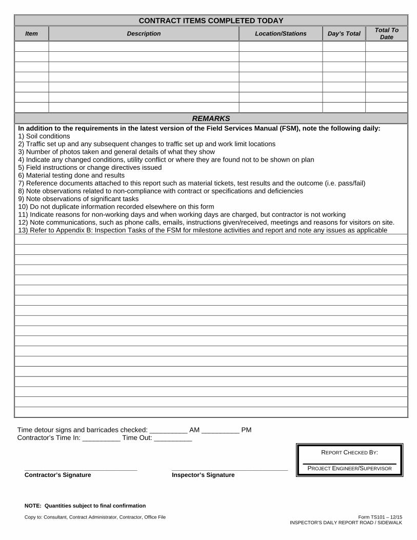
NOTE: Quantities subject to final confirmation
Copy to: Consultant, Contract Administrator, Contractor, Office File Form TS101 – 12/15 INSPECTOR’S DAILY REPORT ROAD / SIDEWALK
CONTRACT ITEMS COMPLETED TODAY Item Description Location/Stations Day’s Total
Total To Date
REMARKS In addition to the requirements in the latest version of the Field Services Manual (FSM), note the following daily: 1) Soil conditions 2) Traffic set up and any subsequent changes to traffic set up and work limit locations 3) Number of photos taken and general details of what they show 4) Indicate any changed conditions, utility conflict or where they are found not to be shown on plan 5) Field instructions or change directives issued 6) Material testing done and results 7) Reference documents attached to this report such as material tickets, test results and the outcome (i.e. pass/fail) 8) Note observations related to non-compliance with contract or specifications and deficiencies 9) Note observations of significant tasks 10) Do not duplicate information recorded elsewhere on this form 11) Indicate reasons for non-working days and when working days are charged, but contractor is not working 12) Note communications, such as phone calls, emails, instructions given/received, meetings and reasons for visitors on site. 13) Refer to Appendix B: Inspection Tasks of the FSM for milestone activities and report and note any issues as applicable
Time detour signs and barricades checked: __________ AM __________ PM Contractor’s Time In: __________ Time Out: __________
_________________________________ __________________________________ Contractor’s Signature Inspector’s Signature
REPORT CHECKED BY:
PROJECT ENGINEER/SUPERVISOR

Note: Quantities subject to final confirmation
Copy to: Consultant, Contract Administrator, Contractor, Office File Form TS102 – 12/15 REPORT OF CHANGES IN WORK COMPLETED
REPORT OF CHANGES IN WORK COMPLETED
Engineering & Construction Services
Change Order No:
Date: Contract No: Project Engineer: Report No.
Location:
Contractor: Sub-Contractor:
Description of Work :
LABOUR Number Duty Hours
Total Hours
Number Duty Hours Total Hours
Foreperson
Labourer
Operator
Driver
EQUIPMENT
OPSS 127 # Make/Model Hours / Days Owned or
Rented Total Time
Worked Standby
MATERIALS SUPPLIED BY CONTRACTOR Description Quantity Delivery
Slip Description Quantity Delivery Slip
REMARKS
_________________________________ __________________________________ Contractor’s Signature Inspector’s Signature
CHANGES IN WORK AUTHORIZED BY:
MANAGER/PROJECT ENGINEER

WEEKLY REPORT CONSTRUCTION SECTION
Engineering and Construction Services Week of:Contract No.: To:
Description: Report # To
Schedule: __ On __ Behind __ Ahead of
Project Engineer: Telephone: Cell Phone: Inspector:
Item # Description Qty. Unit Mon. Tue. Wed. Thurs. Fri. Sat. Sun.Week Total Prev. Total Total to Date
Chesapeake Avenue - Road Resurfacing - PART A
1 Field office for the Engineer 1lump
sum
2
Traffic control and Staging
including traffic control persons,
signs, flashers, delineators,
barricades, etc.
1Lump
Sum
3Clean out existing catchbasins and
sumps4 each
4 General excavation (Provisional) 80 m3
5Cold grind asphalt pavement up to
50mm deep (Provisional)400 m
2
6Cold grind asphalt pavement up to
100mm deep1,750 m
2
7Concrete/asphalt curbs, curbs &
gutters, all types390 m
8 Concrete sidewalk, all thicknesses 480 m2
9Temporary Asphalt sidewalk, all
thicknesses60 m
2
10 Asphalt driveways, all thicknesses 370 m2
11Major crack repair in asphalt using
HL8 - 300 mm wide, 75 mm deep100 m
12Rout and seal joints and minor
cracks100 m
13Hot mix asphalt HL-3 MOD with
PGAC 58-28220 t
14Hot mix asphalt HL-8 (20% RAP)
with PGAC 58-28300 t
15Hot mix asphalt HL-8 (20% RAP)
with PGAC 58-28 - hand laid60 t
16
Hot mix asphalt HL-3 FINE with
PGAC 58-28 - hand laid 50 mm
compacted thickness
370 m2
17
19 mm recycled concrete for
foundation, backfilling and other
applications
60 t
Page 1 of 18 TS105 11/15
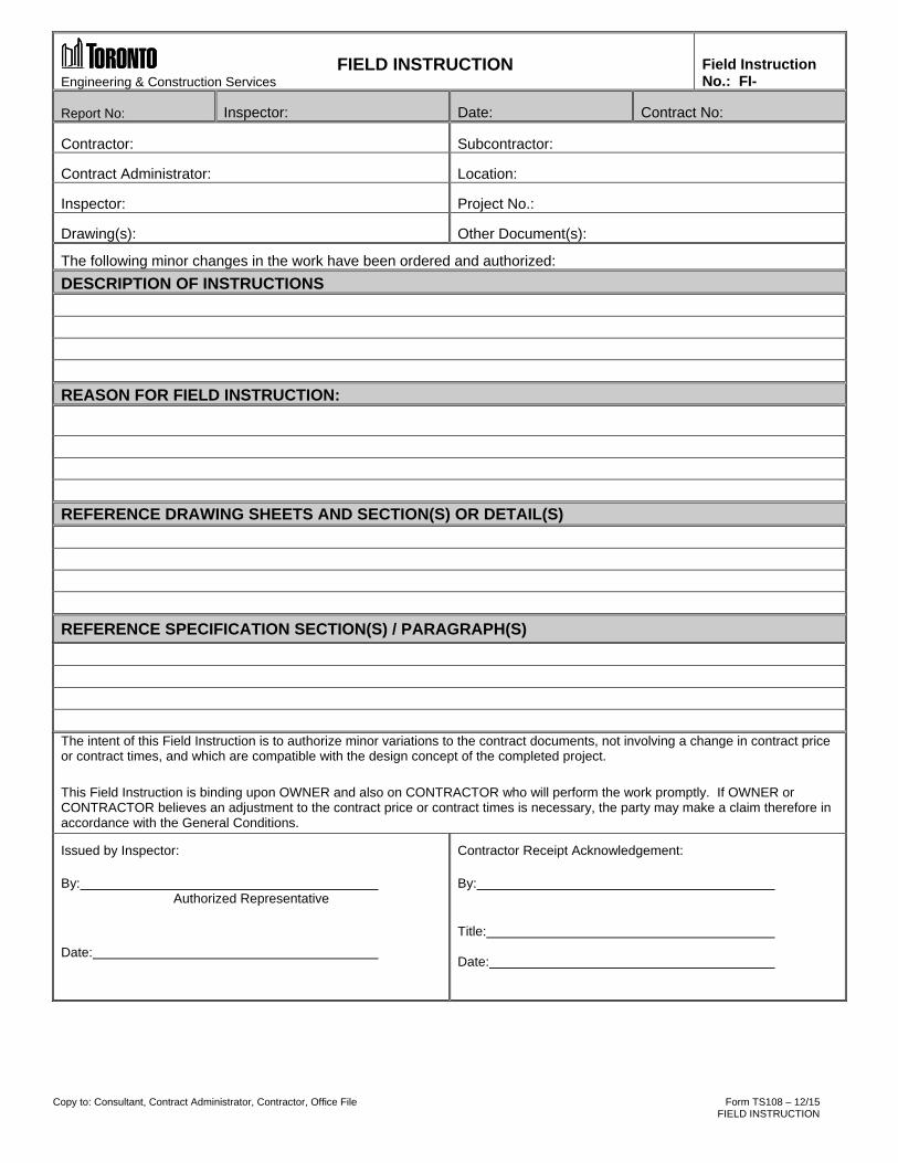
Copy to: Consultant, Contract Administrator, Contractor, Office File Form TS108 – 12/15 FIELD INSTRUCTION
FIELD INSTRUCTION
Engineering & Construction Services
Field Instruction No.: FI-
Report No: Inspector: Date: Contract No:
Contractor: Subcontractor:
Contract Administrator: Location:
Inspector: Project No.:
Drawing(s): Other Document(s):
The following minor changes in the work have been ordered and authorized:
DESCRIPTION OF INSTRUCTIONS
REASON FOR FIELD INSTRUCTION:
REFERENCE DRAWING SHEETS AND SECTION(S) OR DETAIL(S)
REFERENCE SPECIFICATION SECTION(S) / PARAGRAPH(S)
The intent of this Field Instruction is to authorize minor variations to the contract documents, not involving a change in contract price or contract times, and which are compatible with the design concept of the completed project.
This Field Instruction is binding upon OWNER and also on CONTRACTOR who will perform the work promptly. If OWNER or CONTRACTOR believes an adjustment to the contract price or contract times is necessary, the party may make a claim therefore in accordance with the General Conditions.
Issued by Inspector:
By: Authorized Representative
Date:
Contractor Receipt Acknowledgement:
By:
Title: Date:

Copy to: Consultant, Contract Administrator, Contractor, Office File Form TS109 – 12/15 REQUEST FOR QUOTATION
REQUEST FOR QUOTATION Engineering & Construction Services NO.: REQ-
Report No: Inspector: Date: Contract No:
TO: PROJECT:
FROM: SPEC. SECTION :
DESCRIPTION:: DATE QUOTATION IS REQUIRED:
To Be Completed By Initiator of Request: 1. Scope of work (Include List of Attachments):
2. Reason(s) for Modification: Owner Unforeseen Conditions (site, weather, etc.) Other
3. Approval of Request:
Contract Administrator: _____________________________________________________ Date: _________________________
To Be Completed by Contractor:
4. Total Cost of Modification (Attach detailed Breakdown): $ ______________________________________
5. Will a Modification to the Contract Time Be Requested: Yes No NOTE: If Yes, Form A Must be attached
6. Attachment Identification (List): _____________________________________________________________
_____________________________________________________________
_____________________________________________________________
7. Quotation In Effect Until (Date): _____________________________________________________________
Authorized Signature: _____________________________________________________________Contractor Date

NOTE: Quantities subject to final confirmation
Copy to: Consultant, Contract Administrator, Contractor, Office File Form TS110 – 12/15
INSPECTOR’S DAILY REPORT ADDITIONAL REMARKS
INSPECTOR’S DAILY REPORT ADDITIONAL REMARKS
Engineering & Construction Services Page: of
Report No: Inspector: Date: Contract No:
REMARKS
_____________________ Inspector’s Signature
REPORT CHECKED BY:
PROJECT ENGINEER/SUPERVISOR
Form TS111 – 12/15 Copy to: Consultant, Contract Administrator, Contractor, Office File FIELD INSPECTION OF MATERIALS AND EQUIPMENT
Engineering & Construction Services
FIELD INSPECTION OF MATERIALS AND EQUIPMENT
DATE:
ATTACHMENT TO DAILY LOG NO: SHEET: OF
DAY:
PROJECT NAME: CONTRACT NO.:
CONTRACTOR:
FURNISHED BY: CONTRACTOR OWNER
INSPECTED BY:
Specification Plan Sheet of
Material or Equipment Quantity
Manufacturer or Source Jobber or Dealer
Address Address
City State Zip Code City State Zip Code
Proposed Use Proposed Location
Dimensions and other physical characteristics determined by measurement, weight, visual inspection, and routine field tests:
Have required tests been run? Yes No
Are copies of material/equipment compliance certificates attached? Yes No List:
Materials complies with specifications Yes No
Specific location and explanation should be given if test results for inspections show non-compliance and the material is incorporated in the work.
Remarks:
Date Report Submitted:
Reviewed By: Date:

Copy to: Consultant, Contract Administrator, Contractor, Office File Form TS112 – 12/15 DEFICIENCY LIST
Engineering & Construction Services DEFICIENCY LIST
Page 1 of 1 Inspector: Date: Contract No.
Contractor:
Contract Administrator: Location:
AcceptedItem Location Description Cost By Date
Total $

Form TS113 – 05/07 UNDERGROUND CONSTRUCTION VER. 1
Technical Services
UNDERGROUND CONSTRUCTION (Reports and Assessment on Conditions of Pavements, etc.)
CONTRACT NUMBER
LOCATION
A. PAVEMENT SURFACE (Type and Condition)
B. PAVEMENT BASE (Thickness and Condition)
C. TYPE OF SOIL (Wet or Dry)
D. MEASUREMENT OF CUT REPAIRS (To be listed on back of report)
E.. MEASUREMENT OF OVER-BREAK (To be listed on back of report)
TEMPORARY SURFACE TREATMENT BY CONTRACTOR
A. SURFACE ___________________ mm
B. STONE BASE ___________________ mm
C. PERMANENT REPAIRS INCLUDED IN CONTRACT - SURFACE _____________ mm
- STONE BASE _____________ mm
REMARKS
DATE CONTRACT INSPECTOR
Submit in Duplicate

Copy to: Consultant, Contract Administrator, Contractor, Office File Form TS115 – 11/15 DISINFECTION TEST
Chain of Custody #
Engineering and Construction Services
Disinfection Test
Proposal Number: ___________________________ Contractor: _______________________________
Disinfection Criteria
Type of Installation: Watermain By-pass Rubber Service HosePipe Diameter : mm Length: m Pipe Material: PVC CI Disinfection Method: Continuous Feed Slug Concentration: mg/L Contact Time: 24 hrs 3 hrs 16 hrs Backflow Prevention: Live side monitoring: Pressure gauges install Disinfectant to be used:Discharge to:
Storm Sanitary Combined Other
Location of source water:
Source provided by: Watermain Hydrant By-pass
Disinfection Site Map:
Note: If this sketch area is not used with submission any attached sketch must include all pertinent information N
Identify the following: Line valves and status: (V-1,V-2,V-3, etc) indicate open/close example: (V1-O, V2-C). CL2 Application (A) Live side monitoring (LM) example: LM-1, LM-2 Flushing (F) example: F-1, F-2 Sampling (S) example: S-1, S-2 Pressure monitoring (P) example P-1,P-2 Discharge points (DP) example DP-1, DP-2
Contractor: Date:
Approved by Contract Administrator: Date:
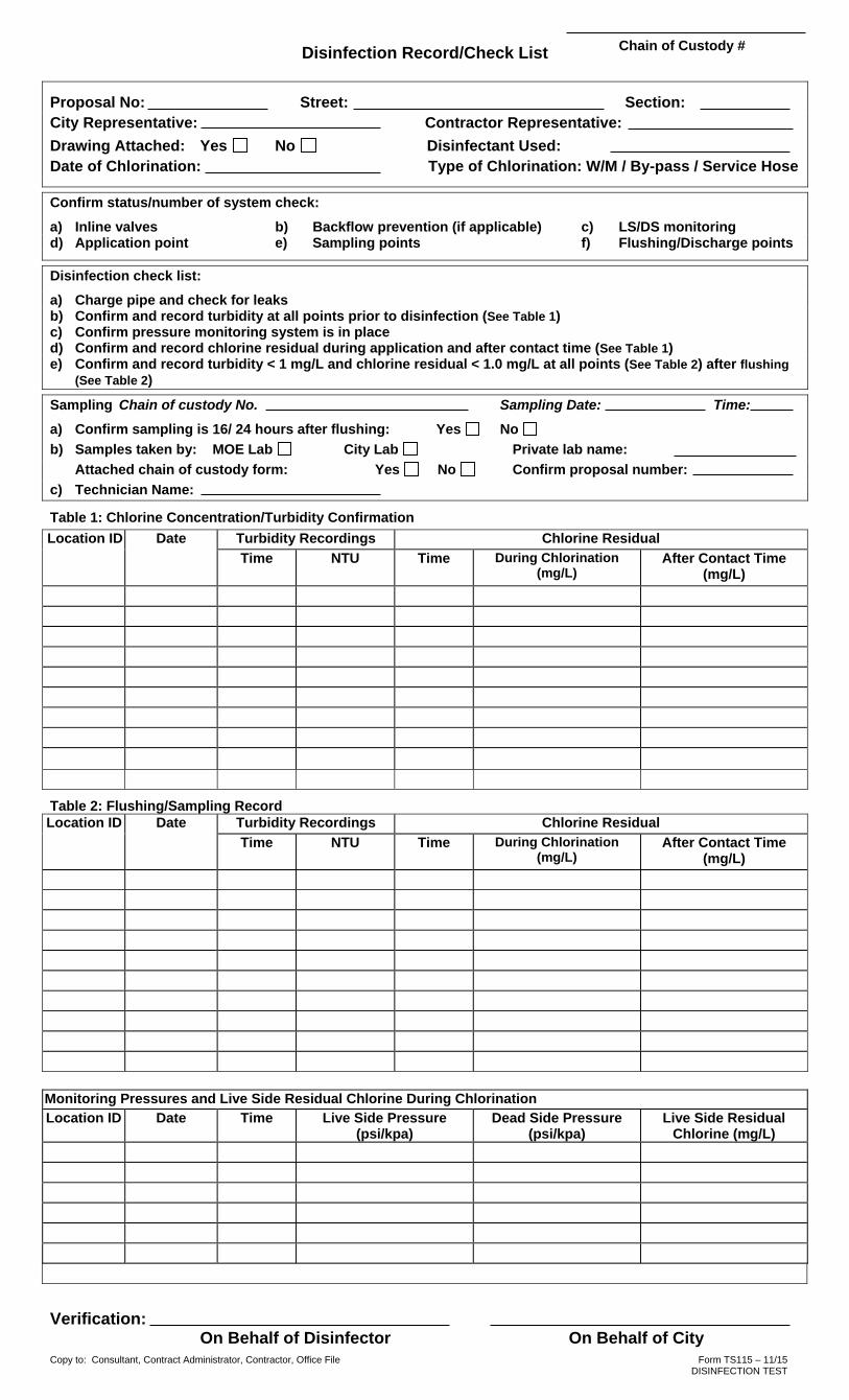
Copy to: Consultant, Contract Administrator, Contractor, Office File Form TS115 – 11/15 DISINFECTION TEST
Chain of Custody # Disinfection Record/Check List
Proposal No: Street: Section: City Representative: Contractor Representative: Drawing Attached: Yes No Disinfectant Used: Date of Chlorination: Type of Chlorination: W/M / By-pass / Service Hose
Confirm status/number of system check:
a) Inline valves b) Backflow prevention (if applicable) c) LS/DS monitoring d) Application point e) Sampling points f) Flushing/Discharge points
Disinfection check list: a) Charge pipe and check for leaks b) Confirm and record turbidity at all points prior to disinfection (See Table 1) c) Confirm pressure monitoring system is in place d) Confirm and record chlorine residual during application and after contact time (See Table 1) e) Confirm and record turbidity < 1 mg/L and chlorine residual < 1.0 mg/L at all points (See Table 2) after flushing
(See Table 2)
Sampling Chain of custody No. Sampling Date: Time: a) Confirm sampling is 16/ 24 hours after flushing: Yes No b) Samples taken by: MOE Lab City Lab Private lab name:
Attached chain of custody form: Yes No Confirm proposal number: c) Technician Name:
Table 1: Chlorine Concentration/Turbidity Confirmation Location ID Date Turbidity Recordings Chlorine Residual
Time NTU Time During Chlorination (mg/L)
After Contact Time (mg/L)
Table 2: Flushing/Sampling Record Location ID Date Turbidity Recordings Chlorine Residual
Time NTU Time During Chlorination (mg/L)
After Contact Time (mg/L)
Monitoring Pressures and Live Side Residual Chlorine During Chlorination
Location ID Date Time Live Side Pressure (psi/kpa)
Dead Side Pressure (psi/kpa)
Live Side Residual Chlorine (mg/L)
Verification: On Behalf of Disinfector On Behalf of City

Copy to: Consultant, Contract Administrator, Contractor, Office File Form TS115 – 11/15 DISINFECTION TEST
Chain of Custody #
Sample Results
a) Chain of custody No. b) Proposal No. c) Results submitted to: d) Results received by: Email Fax Phone e) Results: Pass Fail Action taken if failed f) Results attached: Yes No g) Date of watermain/by-pass put into service:
Retest
a) Chain of custody No. b) Proposal No. c) Results submitted to: d) Results received By: Email Fax Phone e) Results: Pass Fail f) Action taken if failed
g) Results attached: Yes No h) Date of watermain/by-pass put into service:

Copy to: Consultant, Contract Administrator, Contractor, Office File Form TS116 – 11/15 HYDROSTATIC LEAK TEST RECORD
Engineering & Construction Services
HYDROSTATIC LEAK TEST RECORD (FOR BURIED WATER & WASTEWATER PRESSURE PIPING)
Date of Test:
Test No.: Retest: Yes No
Project: Project No.:
Contractor: Inspector: (Print Name)
Pipeline Identification:
Location of Test:
Test From: To: Test Fluid: (Station) (Station)
Test Specification:
For ______________ metres, pipe diameter of ____________ makeup water = ____________________ litres
( length) (mm)
First Test: Subsequent Test: Allowable Leakage (L) Test Computation: Refer to OPSS 441.07.24.03 which states the allowable leakage of 0.082 litres per millimetre of pipe diameter per kilometre of pipe for a 2-hour test period. Remarks:
Contractor Certification: Inspector:
Signature Signature
Title Title

Engineering & Construction Services
Page 1 of 3 Form TS117a – rev. 01/16 DAILY OBSERVATION REPORT (cm kc)
DAILY OBSERVATION REPORT TEMPLATE - Major Infrastructure Projects
CONTRACT NAME: CONSULTANT:
CITY PROJECT: PROJECT NO.:
CONTRACTOR: COMPLETED BY:
DATE: TIME IN:
REPORT NO.: TIME OUT:
OBSERVATIONS Tailgate Safety Meeting (Contractor)
Health and Safety Issues: CONTRACTOR's SITE SUPERVISOR:
WORK AREA: (List here or below)
Topic: Time: Attendees: Weather: Clear Snow Overcast Foggy Rain Cold Temperature Range: Notes: Time Recorded:
Site Conditions: Clear Dusty Muddy Snow covered Soil Conditions: ___________ Changed Conditions? _______
Special Requirements YES NO Report Attached Surveys/Site Monitoring: ______________ Testing and Commissioning:
Working Days to-date: Inclement Weather Challenges Noted? YES NO
Work Observed /Activity/ Noted Concerns Spec/ Drawing
Reference Location
/Area Qty/Unit
1.
2.
3.
4.
5.
CONTRACTOR RESOURCES Personnel No. Hr Activity Equipment No. Hr Activity
LIST PERSONNEL OR APPEND DAILY SIGN-IN SHEET FROM CONTRACTOR OR FACILITY
Subcontractors
Material Quantity Activity Manufacturer Representatives
Engineering & Construction Services
Page 2 of 3 Form TS117a – rev. 01/16 DAILY OBSERVATION REPORT (cm kc)
COMMUNICATION Items/Concerns Discussed:
1.
2.
3.
Requested Revisions or Interpretations, Field Instructions, Change Directives, and Change Orders:
1.
2.
3.
Nonconforming Work Reported to Contractor today:
1.
2.
3.
Issues that may lead to Delays in project delivery:
1.
2.
3.
Visitors and Purpose of Visit:
1.
2.
Attachments and Other Inspection/Observation Reports :
1.
2.
3.
REMARKS: Acknowledgement Signatures:
INSPECTOR: (Print Name) Date:
REVIEWED BY:
(Title) (Print Name)
Date:
CITY PROJECT MANAGER:
(Optional) (Print Name)
Date:
Copies: CITY CONSULTANT FILE OTHER

Engineering & Construction Services
Page 3 of 3 Form TS117a – rev. 01/16 DAILY OBSERVATION REPORT (cm kc)
DAILY PHOTOGRAPHS (number to suit) PHOTOGRAPHS
Insert photograph and description of works.
Description:
Insert photograph and description of works.
Description:
Insert photograph and description of works.
Description:
Insert photograph and description of works.
Description:

Form TS 117b – 02/16 DAILY OBSERVATION CHECKLIST – MI PROJECTS
Engineering & Construction Services
Daily Observation Report Checklist – Major Infrastructure Projects The site inspector should maintain adequate data and records in a daily observation report related to the daily status and progress of the construction work. The report must include the following information in the table below as a minimum:
Items (see attached template): Please Check: Contract Name
Consultant Name
City Project Name
Project Number
Contractor Name
Completed By Name
Day and Date
Time In
Time Out
Report Number
Observations - Health and Safety Issues - Tailgate Safety Meeting (Contractor) - Weather/Temperature - Contractor Site Supervisor Name - Work Area - Site Conditions - Number of Working Days to-date - Inclement Weather Challenges Noted? - Work Observed/Activity/Noted Concerns - Surveys or any site monitoring, such as for
vibration being done - Changed conditions - Location of Work - Soil conditions - Testing or Commissioning - Progress of work and how it relates to the
schedule

Form TS 117b – 02/16 DAILY OBSERVATION CHECKLIST – MI PROJECTS
Items (see attached template): Please Check: List of Contractor Resources
- List Resources or Append Daily Sign-in Sheet from Contractor or Facility
- Personnel on-site including numbers - Activity/Purpose - Subcontractors and Equipment Manufacturer's on
site - Material delivered to site - Equipment on site and use
Communication - Items/Concerns Discussed - Requested Revisions or Interpretations, field
instructions, change directives or change orders issued or any other changed conditions
- Nonconforming Work Reported to Contractor (on this date)
- Issues that may lead to Delays in Project Delivery - Visitors and Purpose of Visit - Attachments and Other Inspections/Observation
Reports
Acknowledgement Signatures - Inspector - Reviewed By - City Project Manager (Optional) - Copies to City, Consultant and Project File
Daily Photographs - Insert photograph - Include description of photograph, date, time and
other details
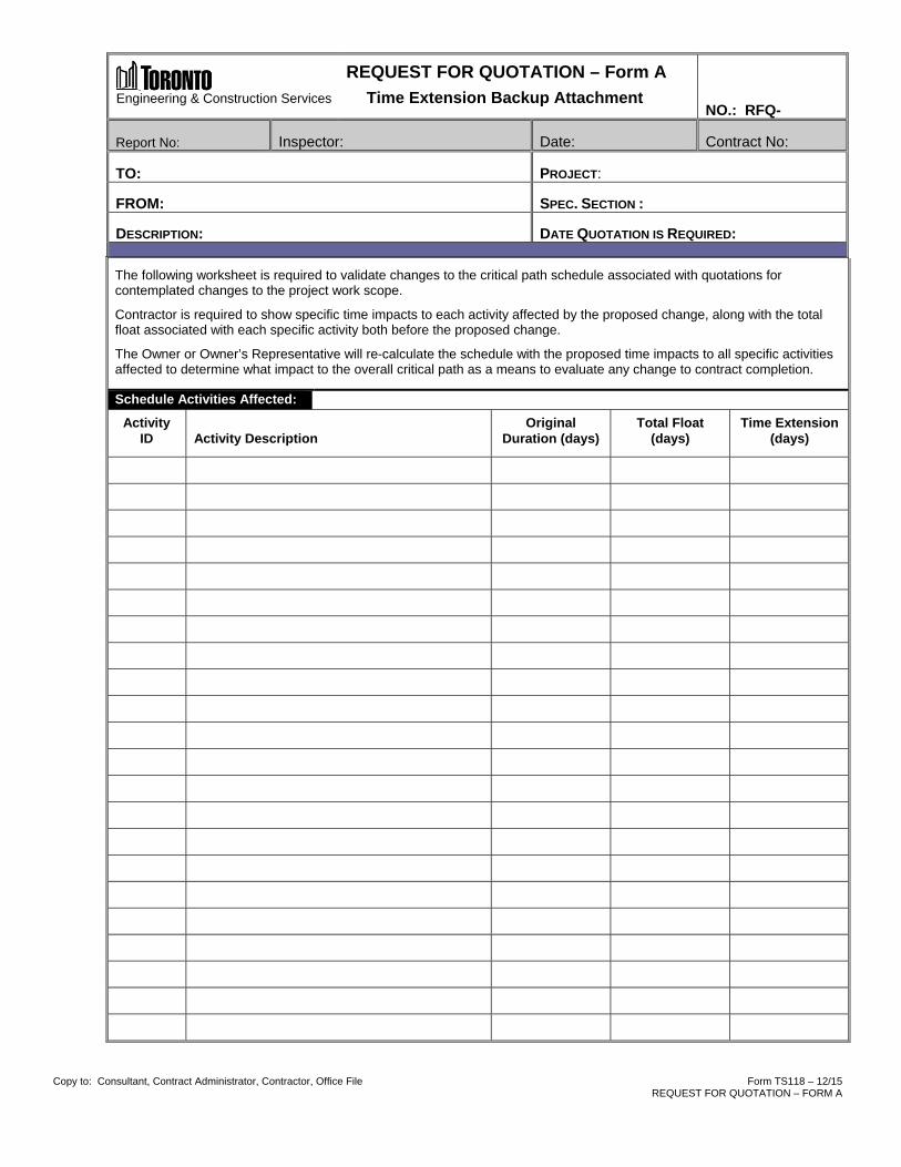
Copy to: Consultant, Contract Administrator, Contractor, Office File Form TS118 – 12/15 REQUEST FOR QUOTATION – FORM A
Engineering & Construction Services
REQUEST FOR QUOTATION – Form A Time Extension Backup Attachment
NO.: RFQ-
Report No: Inspector: Date: Contract No:
TO: PROJECT:
FROM: SPEC. SECTION :
DESCRIPTION: DATE QUOTATION IS REQUIRED:
The following worksheet is required to validate changes to the critical path schedule associated with quotations for contemplated changes to the project work scope.
Contractor is required to show specific time impacts to each activity affected by the proposed change, along with the total float associated with each specific activity both before the proposed change.
The Owner or Owner’s Representative will re-calculate the schedule with the proposed time impacts to all specific activities affected to determine what impact to the overall critical path as a means to evaluate any change to contract completion.
Schedule Activities Affected:
Activity ID
Activity Description
Original Duration (days)
Total Float (days)
Time Extension (days)

UTILITY CONSTRUCTION SITE VISIT REPORT Engineering & Construction Services
Copy to: Construction File Form TS 119 – 11/15 UTILITY CONSTRUCTION SITE VISIT REPORT
Date: Time Arrived: Time Departed:
RACS Permit #: Weather:
Location:
Utility Company: Inspector:
Contractor:
Checklist:
1. Permit on-site: Yes No 2. Drawings on-site: Yes No N/A 3. Information sign in place: Yes No 4. Alignment as per permit: Yes No
5. Pedestrian / vehicle access maintained: Yes No N/A 6. Traffic control in place: Yes No N/A 7. Pay-duty police on-site: Yes No N/A
8. Depth of cover as per permit: Yes No 9. Conformance with permit conditions: Yes No 10. Conformance with work restrictions: Yes No
11. Temporary restoration satisfactory Yes No N/A
12. Photographs taken Yes Qty:____ No
13. Work progress ____% Complete
Notes: (Include explanation for any boxes checked No or N/A above)

UTILITY PRE-CONSTRUCTION MEETING SUMMARY
Engineering & Construction Services
Copy to: Construction file Form TS 120 – 11/15 UTILITY PRE-CONSTRUCTION MEETING SUMMARY
Date: Time: Meeting Location: On-Site Other (specify):
RACS Permit #: Stream: Short Full District: TEY EY NY SC
Site Location and Type of Installation:
Start Date: Anticipated Completion Date:
Inspector: Number:
Utility Company: Contact Name: Number:
Contractor: Contact Name: Number: 24hr Emergency:
Attendees (name, company, number):
Notifications Distributed: RODARS: Y N N/A Residents: Y N N/A BIA: Y N N/A
Traffic Restrictions / Working Hours:
Pay-Duty Police Required: No Yes (specify details):
Staging of Work / Installation Method / Restoration:
Other Discussion (where applicable, discussion should include pedestrian access and safety, tree protection, equipment storage, materials stockpiling, protection of open excavations, etc.):
Additional Information: None On Reverse Attached (no. of pages):___

Engineering & Construction Services
Copy to: Consultant, Contract Administrator, Contractor, Office File Form TS121 – 12/15 FULL STREAM LINE CHANGE – RED LINE SUBMISSION FORM
Full-Stream Line Change Process
1. Contractor contacts utility company and City Inspector to attend the site.
2. Utility Company determines whether it is best to request a line change or to daylight thepotential conflict to see if there is truly a problem.
3. If a line change is required, Utility Company consults with the City Inspector in the fieldabout the best course of action then prepares redlined drawing. Drawing should showthe conflict that caused the change, basic offsets/clearances, and a note if the worklocation is moving from the boulevard to the roadway or vice versa.
4. Utility company emails the redlined drawing, along with the information indicated on theRedline Submission Form, to Third Party & Utility Review ([email protected] [email protected]) and copied to the Inspector.
o The subject line of the email shall be: Line Change - City Permit # - Street Name
o A picture of the redline may be taken in the field - as long as the quality is sufficientthat all information is legible.
o The information from the Redline Submission Form may be contained in the body ofthe email rather than attaching a separate form.
5. Utility Company proactively pursues email sign-off from other companies whoseinfrastructure may be encroached upon by the change and forwards them to theReviewer.
6. Reviewer begins review of line change without delay under the assumption that UtilityCompany is concurrently pursuing any required sign-offs.
7. Upon receipt of the required information, the Reviewer provides a response within 24hours, copying the Inspector and Transportation Services.
8. If the change is acceptable, the Reviewer stamps the PDF drawing electronically andemails it to the Utility Company, copying the Inspector, Transportation Services, andCity Mapping.
9. If the work location is moving from the boulevard to the roadway or vice versa, workcannot proceed until a revised permit is issued by Transportation Services. If the worklocation remains on the same area of the ROW, then work may proceed immediatelyupon receipt of the acceptance email from the Reviewer.

Engineering & Construction Services
Copy to: Consultant, Contract Administrator, Contractor, Office File Form TS121 – 12/15 FULL STREAM LINE CHANGE – RED LINE SUBMISSION FORM
Full Stream Line Change – Red Line Submission Form Project Information: Utility Company Name: Contractor Name: Utility Company Project Name: Utility Company Project Number: City Permit Number: City Inspector Name: Line Change Information: Specify and highlight if work is moving from the boulevard to the roadway or vice versa: Pages of permit drawing affected by line change: Description and rationale for line change:

SITE OFFICE AUDIT Engineering & Construction Services
Copy to: Consultant, Contract Administrator, Contractor, Office File Form TS122 – 12/15 SITE OFFICE AUDIT
Date: Time:
Inspector (print full name): Weather:
Location: Contract # (where applicable): Description of Work Performed:
Personal Protective Equipment
Appropriate PPE being used: Yes No
Site Office / Trailer
1. First-aid kit properly equipped and maintained: Yes No N/A 2. Eye-wash kit or station supplied and maintained: Yes No N/A 3. Copy of current OHS Act and Regs supplied: Yes No N/A 4. Adequate lighting: Yes No N/A 5. Adequate heating and air-conditioning: Yes No N/A 6. Supply of fresh drinking water: Yes No N/A 7. Sanitary system including toilet for sole use: Yes No N/A 8. Fire extinguisher supplied and maintained: Yes No N/A 9. Safe access / egress: Yes No N/A 10. Copies of MSDS sheets supplied: Yes No N/A 11. Smoke alarm supplied and working: Yes No N/A 12. Carbon monoxide detector supplied and working: Yes No N/A 13. Safety board that meets requirements in OHS Act: Yes No N/A 14. Burn Kit: Yes No N/A
Construction
Traffic control as per contract requirements: Yes No N/A
Notes:
Inspector’s Signature
Supervisor/Coordinator's Signature
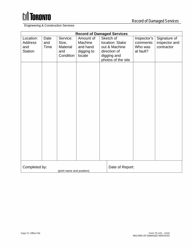
Record of Damaged Services Engineering & Construction Services
Copy To: Office File Form TS 123 – 12/15 RECORD OF DAMAGED SERVICES
Record of Damaged Services Location: Address and Station
Date and Time
Service: Size, Material and Condition
Amount of Machine and hand digging to locate
Sketch of location: Stake out & Machine direction of digging and photos of the site
Inspector’s comments: Who was at fault?
Signature of inspector and contractor
Completed by: (print name and position)
Date of Report:

Engineering & Construction Services
Form TS 124 – 12/15 CHANGE ORDER CHECKLIST
Change Order Checklist The following items form part of a complete change order package. Whenever possible, all items listed that are available must be part of the package provided for financial approvals. This checklist is to form page 2 of the package.
Contract Number: ####### – CO#
1 Change Order Cover Page (A54)
2 This Checklist
3 Briefing Note for all COs higher than Engineer's authority limit
4 Contract Change Summary
5 Signed Change Directive (A53)
Copy of Inspector's Daily Report for the dates that extra work started and was completed. (TS100 or TS101)
Report of Extra Work Completed (TS102)
Time and Material Summary Sheet, if applicable (A82)
Copy of Time and Material Payroll Burden Form, if applicable (A81)
Request for Quotation (TS118)
All correspondence relating to the negotiation of the final price (i.e. original proposals, emails, etc.)
Contractor's Invoice
Contractor's Documentation, including but not limited to:
Time and Material Summary Sheet, if applicable
Weigh Tickets
Material Tickets
Material Invoices (Highlight material used in EWO)
Dump Tickets
Pay Duty Officer Chits, if applicable
Submittal Drawings, if applicable
Drawings and/or Specifications Used
Photos of pre, during and post construction conditions
Arithmetic checks of Contractor's invoices
Copy of Local Union Rates, if T&M
Copy of Contractor's Equipment List, if T&M
Checklist Prepared By
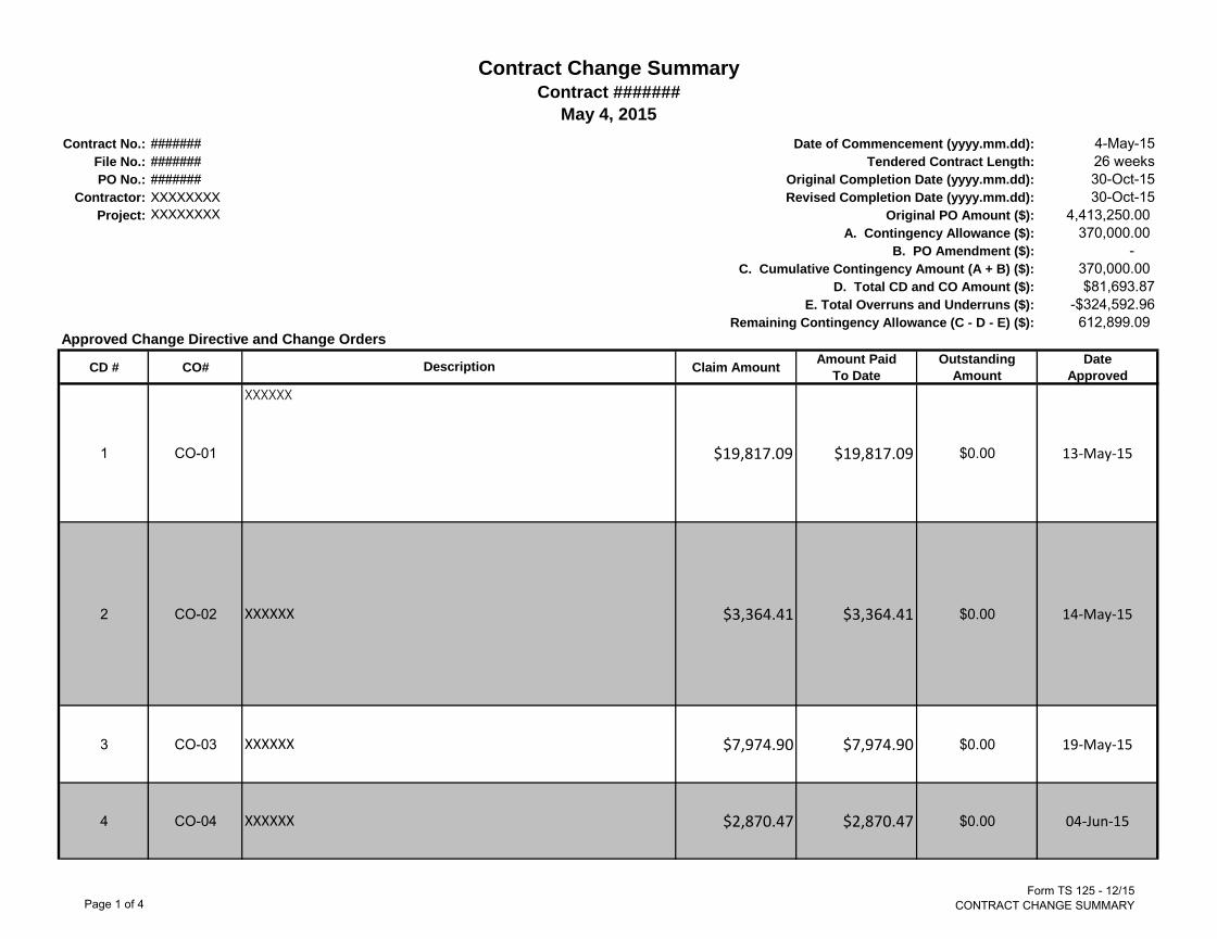
Contract No.: 4-May-15
File No.: 26 weeks
PO No.: 30-Oct-15
Contractor: 30-Oct-15
Project: 4,413,250.00
370,000.00
-
370,000.00
$81,693.87
-$324,592.96
612,899.09
Approved Change Directive and Change Orders
CD # CO# Claim AmountAmount Paid
To Date
Outstanding
Amount
Date
Approved
1 CO-01 $19,817.09 $19,817.09 $0.00 13-May-15
2 CO-02 $3,364.41 $3,364.41 $0.00 14-May-15
3 CO-03 $7,974.90 $7,974.90 $0.00 19-May-15
4 CO-04 $2,870.47 $2,870.47 $0.00 04-Jun-15
Contract Change Summary
May 4, 2015
Date of Commencement (yyyy.mm.dd):
Tendered Contract Length:
Original Completion Date (yyyy.mm.dd):
Contract #######
#######
#######
#######
XXXXXXXX
XXXXXXXX Original PO Amount ($):
A. Contingency Allowance ($):
B. PO Amendment ($):
E. Total Overruns and Underruns ($):
Revised Completion Date (yyyy.mm.dd):
C. Cumulative Contingency Amount (A + B) ($):
D. Total CD and CO Amount ($):
Remaining Contingency Allowance (C - D - E) ($):
Description
XXXXXX
XXXXXX
XXXXXX
XXXXXX
Page 1 of 4Form TS 125 - 12/15
CONTRACT CHANGE SUMMARY

Contract Change Summary
Contract 15ECS-TI-15SPApproved Change Directive and Change Orders
CD # CO# Claim AmountAmount Paid
To Date
Outstanding
Amount
Date
ApprovedDescription
XXXXXX5 CO-05 $3,043.00 $3,043.00 $0.00 04-Jun-15
6 CO-06 $12,489.00 $12,489.00 $0.00 16-Jun-15
7 CO-07 $5,250.00 $5,250.00 $0.00 12-Aug-15
8 CO-08 $2,200.00 $2,200.00 $0.00 20-Aug-15
9 CO-09 $24,685.00 $24,685.00 $0.00 21-Dec-15
$81,693.87 $81,693.87 $0.00
Contract Item Overruns and Underruns (Underrun items are shown as negative values to reflect unspent funding that is available)
Item# 16 101 $109,555.05 $109,555.05 $0.00
Item# 26 102 $118,000.00 $118,000.00 $0.00
Item# 17 - -$154,000.00 -$154,000.00 $0.00
Item#13 104 $28,812.90 $28,812.90 $0.00
Item# 43 - -$132,376.25 -$132,376.25 $0.00
Item#18 103 $51,863.22 $51,863.22 $0.00
Item#25 - -$41,428.40 -$41,428.40 $0.00
Item#28 - -$31,582.20 -$31,582.20 $0.00
XXXXXX
XXXXXX
Total Change Orders
XXXXXX
XXXXXX
XXXXXX
Page 2 of 4Form TS 125 - 12/15
CONTRACT CHANGE SUMMARY

Contract Change Summary
Contract 15ECS-TI-15SPApproved Change Directive and Change Orders
CD # CO# Claim AmountAmount Paid
To Date
Outstanding
Amount
Date
ApprovedDescription
XXXXXXItem#32 - -$35,000.00 -$35,000.00 $0.00
Item#33 - -$47,250.00 -$47,250.00 $0.00
Item#35 - -$25,665.50 -$25,665.50 $0.00
Item#36 - -$37,400.00 -$37,400.00 $0.00
Item#39 - -$33,951.00 -$33,951.00 $0.00
Item#45 - -$31,948.20 -$31,948.20 $0.00
Item#47 - -$28,500.00 -$28,500.00 $0.00
Item#55 105 $32,277.42 $32,277.42 $0.00
Item#63 - -$66,000.00 -$66,000.00 $0.00
-$324,592.96 -$324,592.96 $0.00
Contingency
AmountsPOAs
Total
Contingency
Amounts
Required
Amounts
Remaining
Total Change Orders and Overruns
Account PO Summaries
Page 3 of 4Form TS 125 - 12/15
CONTRACT CHANGE SUMMARY

Contract Change Summary
Contract 15ECS-TI-15SPApproved Change Directive and Change Orders
CD # CO# Claim AmountAmount Paid
To Date
Outstanding
Amount
Date
ApprovedDescription
XXXXXXTransportation $300,000.00 $300,000.00 -$184,306.82 $484,306.82
Toronto Water $20,000.00 $20,000.00 -$5,318.50 $25,318.50
Pedestrian Safety $30,000.00 $30,000.00 $3,043.00 $26,957.00
Traffic Signal $5,000.00 $5,000.00 -$66,000.00 $71,000.00
Neighbourhood Improvement $15,000.00 $15,000.00 $9,683.23 $5,316.77
$370,000.00 $370,000.00 -$242,899.09 $612,899.09
CPW####
CTP####
Total Contract Purchase Order Required
CTP####
CTP####
CTP####
Page 4 of 4Form TS 125 - 12/15
CONTRACT CHANGE SUMMARY

July 2010 Page 1 of 7
DATE:
CONSULTANT* PERFORMANCE EVALUATION FORM*Consultant refers to Contracted Professional Services or Consulting Services Provider
NAME OF CONSULTANT: PURCHASE ORDER # : PO value $ (Incl. all taxes): RFP/RFQ # : NAME OF CITY PROJECT MANAGER:
PROJECT NAME AND DESCRIPTION:
Check applicable type of Consulting Services Provided (one only):
STUDIES or ENVIRONMENTAL ASSESSMENT PRELIMINARY & DETAILED DESIGN SERVICES SERVICES DURING CONSTRUCTION / COMMISSIONING POST CONSTRUCTION SERVICES OTHER
PART 1 OVERALL QUALITY OF WORK PROVIDED ON THE PROJECT
(Assessment of the general performance on the project measured by the results or achievements of objectives, quality of end-products (documents) and general satisfaction of the process throughout the project)
RATING Poor (P)
Satisfactory (S)Excellent(E)
1 Objectives of the Terms of Reference in call document fulfilled at the end of the project (i.e. satisfactorily met the requirements as specified in the Terms of Reference)
2 Services delivered “on-time” (based on schedule as defined in the RFP and consultant’s Proposal, or agreed upon project schedule or agreed to revisions to project schedule)
2 Services delivered “on-budget” (based on consultant’s Cost of Services Proposal, or agreed to revisions to project budget for scope changes)
3 Quality and competency of technical assessments and evaluations (i.e. technical knowledge and application in a process, approvals / regulations, etc)
4 Key Deliverables Please indicate below key deliverables for this phase of the project:
Deliverable #1: Reports/Technical Memorandums Tender Documents Other (Specify):
Design Documents As Built Drawings
Overall quality of document(presentation, writing style, graphics, clarity, overall appearance, follows standards)
Document contents(completeness, technical accuracy, thoroughness, etc)
Document structure(flow of information, technical appendices, drawing groupings for technical disciplines)
QA completed prior to each submission or re submission
A37 7 pages Jul. 2010
July 2010 Page 2 of 7
Deliverable # 2: Reports/Technical Memorandums Tender Documents Other (Specify):
Design Documents As Built Drawings
Overall quality of document (presentation, writing style, graphics, clarity, overall appearance, follows standards)
Document contents (completeness, technical accuracy, thoroughness, etc)
Document structure (flow of information, technical appendices, drawing groupings for technical disciplines)
QA completed prior to each submission or re submission
Deliverable # 3: Reports/Technical Memorandums Tender Documents Other (Specify):
Design Documents As Built Drawings
Overall quality of document (presentation, writing style, graphics, clarity, overall appearance, follows standards)
Document contents (completeness, technical accuracy, thoroughness, etc)
Document structure (flow of information, technical appendices, drawing groupings for technical disciplines)
QA completed prior to each submission or re submission
Deliverable # 4: Reports/Technical Memorandums Tender Documents Other (Specify):
Design Documents As Built Drawings
Overall quality of document (presentation, writing style, graphics, clarity, overall appearance, follows standards)
Document contents (completeness, technical accuracy, thoroughness, etc)
Document structure (flow of information, technical appendices, drawing groupings for technical disciplines)
QA completed prior to each submission or re submission
Note: Determine overall rating for Part 1 based on all individual Part 1 ratings.
OVERALL RATING FOR PART 1:
Note: attach backup documentation if any of the above ratings is poor
Commentary on Ratings for PART 1 (including comments by consultant, if applicable). Additional comments attached? Y

July 2010 Page 3 of 7
PART 2
QUALITY OF SERVICE PERFORMED ON THE PROJECT (Assessment of the approach or “modus operandi” of the consultant measured by the manner in which services were provided)
RATING Poor (P)
Satisfactory (S)Excellent(E)
1 Communications (timely and sufficient information on status of work, budget and schedule)
2 Appropriate involvement of City Staff in technical decisions / issues (timely and sufficient information on technical issues providing opportunity for City input)
3 Project Management
(a) Overall Performance of Project Manager (Availability and level of support was sufficient. Demonstrated required leadership, and took action as required to meet project requirements.)
(b) Management of overall schedule and budget (managed project schedule and project budget appropriately. Appropriately addressed revisions to schedule and budget for services requested beyond the original scope of services and in a timely fashion)
(c) Management of project staff, sub-consultants & other team members, including 3rd party members (e.g. Geotechnical, DSL consultant, material testing firm)
(management of consultant team to satisfy project objectives & deliverables)
(d) Invoicing, project status reports, change management request and documentation, and related management reports submitted with sufficient detail and on timely basis
(in accordance with RFP requirements)
(e) Overall Performance of Key project staff (Availability and level of support was sufficient. Demonstrated required technical expertise)
If the appraisal is for Construction Services phase, then complete also (f) to (i) below.
(f) Overall Quality of Construction Management of Contractor (Overall level of communication with contractor, City staff, operating staff. Proactive in addressing contract issues)
(g) Overall quality of Office Service provided during construction (timeliness and quality of review and response to contractor i.e. shop drawings, RFI, RFQ, field QA by office staff)
(h) Overall quality of Site Services provided during construction (project control, site meetings and follow ups, contract payment recommendations, material testing, field reports, construction change management, timeliness of responding to contractor’s queries, followed Field Services Manual as a reference guide)
(i) Overall Quality of Testing and Commissioning Support (management and QA of contractor’s Training and Commissioning plan, appropriate level of technical staff support during commissioning, appropriate level of site witnesses start up and testing prior to requesting City attendance to Commissioning activities, quality and completeness of consultant’s operation manual)
4 Overall quality of Design as determined during the Construction phase (Appropriateness of Consultant design work and value of Change Orders as a result of design errors and omissions is reasonable)
5 Effectiveness in public / external consultation (Appropriate and timely communication with agencies and general public)
Note: Determine overall rating for Part 2 based on all individual Part 2 ratings.
OVERALL RATING FOR PART 2:
Note: Attach backup documentation if any of the above ratings is poor.

July 2010 Page 4 of 7
Commentary on Ratings for PART 2 (including comments by consultant, if applicable) Additional comments attached? Y
PART 3 CORPORATE PRACTICES AND SUPPORT FOR
PERFORMANCE ON THE PROJECT (Assessment of the corporate practices and the implementation of these practices measured by the performance of the project participants)
RATING Poor (P)
Satisfactory (S) Excellent(E)
1 Scope of services provided based on RFP and proposal submission (Understanding and anticipation of project requirements and circumstances affecting scope)
2 Corporate support to ensure success of project (Involvement of Principle-in-Charge, Quality Assurance practices, etc)
3
Availability of the assigned staff
4 Overall relationship maintained between City Staff and consultant (Understanding and responsive to reciprocal needs, mutual cooperation, etc)
Note: Determine overall rating for Part 3 based on all individual Part 3 ratings.
OVERALL RATING FOR PART 3:
Note: Attach backup documentation if any of the above ratings is poor
Commentary on Ratings for PART 3 (including comments by consultant, if applicable) Additional comments attached? Y
July 2010 Page 5 of 7
SUMMARY
RATING Poor (P)
Satisfactory (S) Excellent(E)
Overall Rating for PART 1
Overall quality of work provided on the project
Overall Rating for PART 2
Overall quality of service performed on the project
Overall Rating for PART 3
Corporate practices and support for performance on the project
OVERALL PERFORMANCE RATING:
NOTE: For assignments involving both design and contract administration, final design rating will depend on the performance and services delivered during the construction. The City reserves the right to revisit the overall evaluation if the facility does not operate as intended, due to design deficiencies.
Comments on Overall Performance Rating and Sign-off:
CITY COMMENTS: Additional comments attached? Y
Prepared by: (Name and Title)
Signature:
Date:
CONSULTANT COMMENTS: Additional comments attached? Y
Prepared by: (Name and Title)
Signature:
Date:

July 2010 Page 6 of 7
Consultant Comments on how the City Performed: (E.g. definition of work scope compared to what was actually requested/performed, City response time within timelines defined in RFP) Additional comments attached? Y
Prepared by: (Name and Title)
Signature:
Date:

July 2010 Page 7 of 7
QUESTION AND ANSWERS 1. WHAT IS THE PURPOSE OF PERFORMANCE EVALUATION?
Performance evaluation is a formal communication tool between the City and a consultant to manage performance on a project.
The performance evaluation data may be used to suspend poor performing consultants from bidding on City contracts for a specified period of time, with Council’s approval.
2. WHICH CONTRACTS REQUIRE PERFORMANCE EVALUATION?
Consultant performance evaluation shall be performed in all contracts where the cost of consulting services exceeds $50,000.00 (exclusive of all taxes), or in any other consulting contract where a Technical Services Manager determines that a performance evaluation would be appropriate. It has to be specified in the Terms of Reference of call document that the consultant’s performance will be evaluated.
3. WHO EVALUATES THE PERFORMANCE?
The performance evaluation shall be conducted by the Technical Services Project Manager in consultation with Toronto Water/Transportations representatives when applicable.
4. WHAT IS THE PURPOSE OF CONSULTANT APPRAISAL FORM?
The purpose of the form is to guide the evaluator through the performance evaluation and to provide a standard way of recording evaluation data. The form can be either filled out electronically, or printed and filled out manually (User Note: The form has been locked. Contact Marijana Bulatovic if modifications are required to suit non standard projects).
5. WHEN TO EVALUATE? There can be as many interim performance evaluations as a Technical Services Project Manager deems necessary over the course of a project to allow for improvement of performance. However, as a minimum, the Technical Services Project Managers must complete this form when performing a final evaluation at the completion of the consultant assignment (User Note: where an assignment is broken down into several Purchase Orders, one evaluation form is to be completed for each Purchase Order).
6. WHAT IS BACKUP DOCUMENTATION?
As part of good contract management practices, the Technical Services Project Managers should document consultant performance issues on an ongoing basis in the form of letters, minutes of meetings, telephone call confirmations, emails, etc. The backup documentation should be attached to the evaluation form if any of the ratings is poor.
7. HOW TO FILE EVALUATION DATA?
The final performance evaluation has to be properly recorded in the form. The final performance evaluation form must be signed by the City evaluator and forwarded to the consultant for comments and signature. The final form will be:
Stored in the contract file (along with backup documentation if any of the ratings is poor), and
Scanned (pdf format) and forwarded to SPQA ([email protected] ) The pdf files shall be stored in a directory accessible by Technical Services managers and directors.
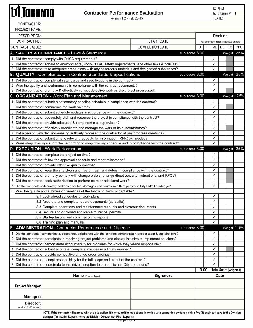
Contractor Performance Evaluation 1
START DATE:
COMPLETION DATE: U I ME EE EX N/A
A. sub-score 25%
1.
2.
3.
B. sub-score 25%
1.
2.
3.
C. sub-score 12.5%
1.
2.
3.
4.
5.
6.
7.
8.
9.
D. sub-score 25%
1.
2.
3.
4.
5.
6.
7.
8.
8.1
8.2
8.3
8.4
8.5
8.6
E. sub-score 12.5%
1.
2.
3.
4.
5.
6.
7.
Was the quality and submission timelines of the following items acceptable?
Did the contractor provide competitive change order pricing?
Did the contractor accept responsibility for the full scope and extent of the contract?
Did the contractor participate in resolving project problems and display initiative to implement solutions?
Did the contractor demonstrate accountability for problems for which they where responsible?
Complete operations and maintenance manuals and closeout documents
Did the contractor communicate, cooperate, collaborate with the contract administrator, project team & stakeholders?
Training plan and manuals
Startup testing and commissioning reports
ADMINISTRATION - Contractor Performance and Diligence
Total Score (weighted)
DATE:
Did the contractor submit timely, relevant requests for information (RFIs) as needed?
Were shop drawings submitted according to shop drawing schedule and in compliance with the contract?
EXECUTION - Work Performance
3.00
Did the contractor adequately address disputes, damages and claims with third parties to City PM's knowledge?
Look ahead schedules or work plans
Did the contractor seek authorization to perform extra or additional work?
3.00
3.00
Did the contractor follow the approved schedule and meet milestones?
Did the contractor provide effective quality control?
Did the contractor submit accurate, complete invoices in a timely manner?
Date
Project Manager:
SignatureName (Print or Type)
Director: (required for Final only)
Did the contractor coordinate to minimize disruption to the public and City operations?
Manager:
Weight
Weight
Weight
Weight
Weight
Did the contractor complete the project on time?
Accurate and complete record documents (as-builts)
Did the contractor effectively coordinate and manage the work of its subcontractors?
Secure and/or closed applicable municipal permits
Did the contractor comply with OHSA requirements?
Did the contractor submit schedule updates in accordance with the contract?
Did the contractor provide adequate & competent site supervision?
3.00
Did the contractor adequately staff and resource the project in compliance with the contract?
Did the contractor keep the site clean and free of trash and debris in compliance with the contract?
CONTRACT No.:
Did the contractor promptly comply with change orders, change directives, site instructions, and RFQs?
Was the quality and workmanship in compliance with the contract documents?
3.00
3.00
Did the contractor adhere to environmental, (non-OHSA) safety requirements, and other laws & policies?
For definitions refer to Backup sheets
Ranking
NOTE: If the contractor disagrees with this evaluation, it is to submit its objections in writing with supporting evidence within five (5) business days to the Division
Manager (for Interim Reports) or to the Division Director (for Final Reports)
version 1.2 - Feb 25-15
Did a person with decision-making authority represent the contractor at pay/progress meetings?
QUALITY - Compliance with Contract Standards & Specifications
Did the contractor commence the work on time?
Did the contractor promptly & effectively correct defective work as the project progressed?
Did the contractor submit a satisfactory baseline schedule in compliance with the contract?
Did the contractor comply with standards and specifications in the contract?
ORGANIZATION - Work Plan and Management
Did the contractor take adequate precautions with any hazardous materials and designated substances?
CONTRACTOR:
PROJECT NAME:
SAFETY & COMPLIANCE - Laws & Standards
CONTRACT VALUE:
DESCRIPTION:
Interim #
Final
Page 1 of 1
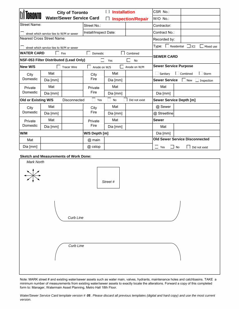
Installation
Inspection/Repair
Street Name:
Nearest Cross Street Name:
Sketch and Measurements of Work Done:
Note: MARK street # and existing water/sewer assets such as water main, valves, hydrants, maintenance holes and catchbasins. TAKE a
minimum number of measurements from existing water/sewer assets to exactly locate the alterations. Forward a copy of this completed
form to: Manager, Watermain Asset Planning, Metro Hall 18th Floor.
Water/Sewer Service Card template version # 05 . Please discard all previous templates (digital and hard copy) and use the most current
version.
Old or Existing W/S Disconnected
Sewer Service Purpose
Sewer Service Depth [m]
Sewer Service
Dia [mm]
W/S Depth [m]
Private
Domestic
City of Toronto
Water/Sewer Service Card
Dia [mm]
Mat
Dia [mm]
WATER CARD
City
Fire
City
Domestic
Private
Domestic Dia [mm]
City
Fire Dia [mm]
@ main
W/M
Mat
Dia [mm] @ cstop
Mat MatPrivate
Fire
Mat
Mat
Dia [mm]
MatMat
Dia [mm] Dia [mm]
City
Domestic Dia [mm]
Mat
CSR No.:
W/O No.:
Contractor:
Contract No.:
Recorded by:
New W/S
Private
Fire
Old Sewer Service Disconnected
Dia [mm]
@ Streetline
@ Sewer
Sewer
Mat
Install/Inspect Date:
Street No.:
Type:
Mat
NSF-053 Filter Distributed (Lead Only)SEWER CARD
Curb Line
Mark North
Street #
Curb Line
street which service ties to W/M or sewer
street which service ties to W/M or sewer ICIResidential Mixed use
Tracer Wire Anode on W/S
Yes No Did not exist
Yes No Did not exist
Combined StormSanitary
Anode on W/M
Fire Domestic Combined
Yes No
New Inspection

A filter MUST be
distributed if the service
is lead (on the City
and/or private side)
Material AND size to be
recorded ONLY if
replaced.
Material AND size of old
or existing water service
MUST be filled for both
inspection s and
installations.
Full name and company
of individual for follow up.
Material AND size to be
recorded ONLY if
replaced.
This section not required if INSPECTION only.
Material AND size of old
or existing fire service -
MUST be completed.
Quick Reference Guide for Water Service Cards
Exceptions:Info for domestic is not
required for
replacement of fire
service IF the domestic
is separate.
The installation checkbox
to be checked only if it is
replacement or new
installation. Otherwise
check the inspection box
Shaded areas
must be fully filled.
Shaded areas
must be filled for
installation only.

Full name and company
of individual for follow up.
Material, size, depth of
sewer service to be
recorded.
Material, size of the
associated sewer main
to be recorded.
Quick Reference Guide for Sewer Service Cards
The installation checkbox
MUST be checked.
Shaded areas
must be fully filled.
Location, date, and cross
street info to be fully
filled.
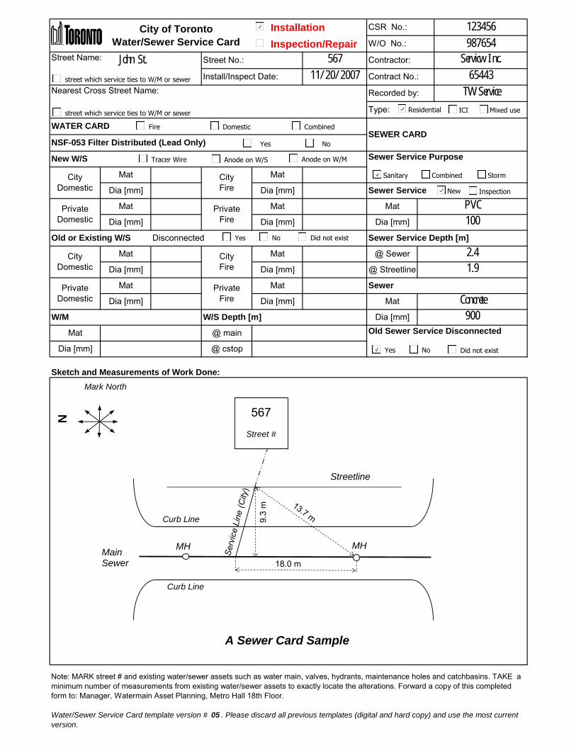
Installation
Inspection/Repair
Street Name:John St.
Nearest Cross Street Name:
Sketch and Measurements of Work Done:
Street No.: 567 Contractor: Servicw Inc.
City of Toronto
Water/Sewer Service Card
CSR No.: 123456
W/O No.: 987654
Install/Inspect Date: 11/20/2007 Contract No.: 65443
Recorded by: TW Service
Type:
WATER CARDSEWER CARD
NSF-053 Filter Distributed (Lead Only)
New W/S Sewer Service Purpose
City
Domestic
Mat City
Fire
Mat
Dia [mm] Dia [mm]
Old or Existing W/S Disconnected Sewer Service Depth [m]
Sewer Service
Private
Domestic
Mat Private
Fire
Mat Mat PVC
Dia [mm] Dia [mm] Dia [mm] 100
City
Domestic
Mat City
Fire
Mat @ Sewer 2.4
Dia [mm] Dia [mm] @ Streetline 1.9
Private
Domestic
Mat Private
Fire
Mat Sewer
Dia [mm] Dia [mm] Mat Concrete
@ cstop
Note: MARK street # and existing water/sewer assets such as water main, valves, hydrants, maintenance holes and catchbasins. TAKE a
minimum number of measurements from existing water/sewer assets to exactly locate the alterations. Forward a copy of this completed
form to: Manager, Watermain Asset Planning, Metro Hall 18th Floor.
Water/Sewer Service Card template version # 05 . Please discard all previous templates (digital and hard copy) and use the most current
version.
W/M W/S Depth [m] Dia [mm] 900
Mat @ main Old Sewer Service Disconnected
Dia [mm]
Curb Line
Mark North
567
Street #
MH MH
Streetline
18.0 m
9.3
m
Main Sewer
N
A Sewer Card Sample
Curb Line
street which service ties to W/M or sewer
street which service ties to W/M or sewer ICIResidential Mixed use
Tracer Wire Anode on W/S
Yes No Did not exist
Yes No Did not exist
Combined StormSanitary
Anode on W/M
Fire Domestic Combined
Yes No
New Inspection

Installation
Inspection/Repair
Street Name:John St.
Nearest Cross Street Name:
Sketch and Measurements of Work Done:
@ cstop
Note: MARK street # and existing water/sewer assets such as water main, valves, hydrants, maintenance holes and catchbasins. TAKE a
minimum number of measurements from existing water/sewer assets to exactly locate the alterations. Forward a copy of this completed
form to: Manager, Watermain Asset Planning, Metro Hall 18th Floor.
Water/Sewer Service Card template version # 05 . Please discard all previous templates (digital and hard copy) and use the most current
version.
W/M W/S Depth [m] Dia [mm] 900
Mat @ main Old Sewer Service Disconnected
Dia [mm]
Sewer
Dia [mm] Dia [mm] Mat Concrete
Private
Domestic
Mat Private
Fire
Mat
Dia [mm] 100
City
Domestic
Mat City
Fire
Mat @ Sewer 2.4
Dia [mm] Dia [mm] @ Streetline 1.9
Old or Existing W/S Disconnected Sewer Service Depth [m]
Sewer Service
Private
Domestic
Mat Private
Fire
Mat Mat PVC
Dia [mm] Dia [mm]
Type:
WATER CARDSEWER CARD
NSF-053 Filter Distributed (Lead Only)
New W/S Sewer Service Purpose
City
Domestic
Mat City
Fire
Mat
Dia [mm] Dia [mm]
Install/Inspect Date: 11/20/2007 Contract No.: 65443
Recorded by: TW Service
Street No.: 567 Contractor: Servicw Inc.
City of Toronto
Water/Sewer Service Card
CSR No.: 123456
W/O No.: 987654
Curb Line
Mark North
567
Street #
MH MH
Streetline
18.0 m
9.3
m
Main Sewer
N
A Sewer Card Sample
Curb Line
street which service ties to W/M or sewer
street which service ties to W/M or sewer ICIResidential Mixed use
Tracer Wire Anode on W/S
Yes No Did not exist
Yes No Did not exist
Combined StormSanitary
Anode on W/M
Fire Domestic Combined
Yes No
New Inspection

Installation
Inspection/Repair
Street Name: John St.
Nearest Cross Street Name: Wellington St.
Sketch and Measurements of Work Done:
Street No.: 123 Contractor: Acme Inc.
City of Toronto
Water/Sewer Service Card
CSR No.: 123456
W/O No.: 654321
Install/Inspect Date: Jan. 1/2013 Contract No.: 2013-1234
Recorded by: John Doe (Company)
Type:
WATER CARDSEWER CARD
NSF-053 Filter Distributed (Lead Only)
New W/S Sewer Service Purpose
City
Domestic
Mat Copper City
Fire
Mat
Dia [mm] 19 Dia [mm]
Old or Existing W/S Disconnected Sewer Service Depth [m]
Sewer Service
Private
Domestic
Mat Copper Private
Fire
Mat Mat
Dia [mm] 19 Dia [mm] Dia [mm]
City
Domestic
Mat Lead City
Fire
Mat @ Sewer
Dia [mm] 12.5 Dia [mm] @ Streetline
Private
Domestic
Mat Lead Private
Fire
Mat Sewer
Dia [mm] 12.5 Dia [mm] Mat
150 @ cstop 1.6
Note: MARK street # and existing water/sewer assets such as water main, valves, hydrants, maintenance holes and catchbasins. TAKE a
minimum number of measurements from existing water/sewer assets to exactly locate the alterations. Forward a copy of this completed
form to: Manager, Watermain Asset Planning, Metro Hall 18th Floor.
Water/Sewer Service Card template version # 05 . Please discard all previous templates (digital and hard copy) and use the most current
version.
W/M W/S Depth [m] Dia [mm]
Mat CI @ main 1.8 Old Sewer Service Disconnected
Dia [mm]
Curb Line
Mark North
Street #
John Street
We
llin
gto
n S
tre
et
123
Valve
Dom
estic
Curb Line 3.0
m
4.5
m
5.5 m
150 mm CI W/M Valve
N
csto
p
A Water Card Sample
street which service ties to W/M or sewer
street which service ties to W/M or sewer ICIResidential Mixed use
Tracer Wire Anode on W/S
Yes No Did not exist
Yes No Did not exist
Combined StormSanitary
Anode on W/M
Fire Domestic Combined
Yes No
New Inspection

Installation
Inspection/Repair
Street Name: John St.
Nearest Cross Street Name: Wellington St.
Sketch and Measurements of Work Done:
150 @ cstop 1.6
Note: MARK street # and existing water/sewer assets such as water main, valves, hydrants, maintenance holes and catchbasins. TAKE a
minimum number of measurements from existing water/sewer assets to exactly locate the alterations. Forward a copy of this completed
form to: Manager, Watermain Asset Planning, Metro Hall 18th Floor.
Water/Sewer Service Card template version # 05 . Please discard all previous templates (digital and hard copy) and use the most current
version.
W/M W/S Depth [m] Dia [mm]
Mat CI @ main 1.8 Old Sewer Service Disconnected
Dia [mm]
Sewer
Dia [mm] 50 Dia [mm] 150 Mat
DIPrivate
Domestic
Mat Copper Private
Fire
Mat
Dia [mm]
City
Domestic
Mat Copper City
Fire
Mat @ Sewer
Dia [mm] 50 Dia [mm] 150 @ Streetline
DI
Old or Existing W/S Disconnected Sewer Service Depth [m]
Sewer Service
Private
Domestic
Mat Private
Fire
Mat Mat
Dia [mm] Dia [mm]
Type:
WATER CARDSEWER CARD
NSF-053 Filter Distributed (Lead Only)
New W/S Sewer Service Purpose
City
Domestic
Mat DI City
Fire
Mat DI
Dia [mm] 100 Dia [mm] 200
Install/Inspect Date: 11/23/2007 Contract No.: 2007-1234
Recorded by: John Doe (Company)
Street No.: 5555 Contractor: JJ W/S Inc
City of Toronto
Water/Sewer Service Card
CSR No.: 123456
W/O No.: 654321
Curb Line
Mark North
5555
Street #
cstop
cstop
15.8 m
7.8 m C
urb
lin
e
15
0 m
m C
I W
/M
We
llin
gto
n S
tre
et
Valv
e
35.2
m
John Street
fire
N
1.2
m
A Water Card Sample
Curb Line
Va
lve
street which service ties to W/M or sewer
street which service ties to W/M or sewer ICIResidential Mixed use
Tracer Wire Anode on W/S
Yes No Did not exist
Yes No Did not exist
Combined StormSanitary
Anode on W/M
Fire Domestic Combined
Yes No
New Inspection

Installation
Inspection/Repair
Street Name: John St.
Nearest Cross Street Name: Wellington St.
Sketch and Measurements of Work Done:
Street No.: 5555 Contractor: JJ W/S Inc
City of Toronto
Water/Sewer Service Card
CSR No.: 123456
W/O No.: 654321
Install/Inspect Date: 11/23/2007 Contract No.: 2007-1234
Recorded by: John Doe (Company)
Type:
WATER CARDSEWER CARD
NSF-053 Filter Distributed (Lead Only)
New W/S Sewer Service Purpose
City
Domestic
Mat City
Fire
Mat
Dia [mm] Dia [mm]
Old or Existing W/S Disconnected Sewer Service Depth [m]
Sewer Service
Private
Domestic
Mat Private
Fire
Mat Mat
Dia [mm] Dia [mm] Dia [mm]
City
Domestic
Mat Copper City
Fire
Mat @ Sewer
Dia [mm] 50 Dia [mm] 150 @ Streetline
DI
Private
Domestic
Mat Copper Private
Fire
Mat Sewer
Dia [mm] 50 Dia [mm] 150 Mat
DI
150 @ cstop 1.6
Note: MARK street # and existing water/sewer assets such as water main, valves, hydrants, maintenance holes and catchbasins. TAKE a
minimum number of measurements from existing water/sewer assets to exactly locate the alterations. Forward a copy of this completed
form to: Manager, Watermain Asset Planning, Metro Hall 18th Floor.
Water/Sewer Service Card template version # 05 . Please discard all previous templates (digital and hard copy) and use the most current
version.
W/M W/S Depth [m] Dia [mm]
Mat CI @ main 1.8 Old Sewer Service Disconnected
Dia [mm]
Curb Line
Mark North
5555
Street #
cstop
cstop
15.8 m
7.8 m C
urb
lin
e
15
0 m
m C
I W
/M
We
llin
gto
n S
tre
et
Va
lve
35.2
m
John Street
fire
N
1.2
m
A Water Card Sample
Curb Line
Va
lve
street which service ties to W/M or sewer
street which service ties to W/M or sewer ICIResidential Mixed use
Tracer Wire Anode on W/S
Yes No Did not exist
Yes No Did not exist
Combined StormSanitary
Anode on W/M
Fire Domestic Combined
Yes No
New Inspection

February 2016 B-1
Appendix B – Inspection Tasks
Appendix B – Inspection Tasks
The inspection tasks listed under each activity are to be used as a basis for inspection. The contract administrator and inspector should work together at the start of a contract to determine critical inspection levels for construction activities and the need of adding tasks to this list.
Any inspection activity identified as a milestone requires a contract administrator or inspector on site to inspect the operation(s) at predetermined critical milestones. The inspector and contract administrator must pay particular attention by observing milestone tasks and reporting any problems with these tasks as soon as possible in writing regardless of the level of inspection specified. Milestones are indicated with an "M" beside the activity task number.
Any references to material testing and sampling should be done in accordance with Appendix C, Materials Testing Protocol, unless otherwise stated in the contract documents.
Table: Inspection tasks Category Task Name
highway guide rail HR 1 Guide Rail
highway guide rail HR 2 Crash/Cushion Attenuating Terminal Barrier
landscaping L 1 Topsoil
landscaping L 2 Sodding
landscaping L 3 Seeding and Mulching
resurfacing RF 1 Hot Mix Paving Operations
resurfacing RF 2 In-Place Full Depth Reclamation of Bituminous Pavement and Underlying Granular (Pulverizing)

Field Services Manual
B-2 February 2016
Table: Inspection tasks (continued) Category Task Name
resurfacing RF 3 Concrete Base and Pavement
resurfacing RF 4 Concrete Pavement – Full Depth Repair
road R 1 General Inspection
road R 2 Ditching
road R 3 Grade and Compaction
road R 4 Granular Base and Granular Sub-base
road R 5 Road Cut Permit Inspections
road R 6 Curb and Gutter
road R 7 Concrete Sidewalk
road R 8 Geotextile
road R 9 Tack Coat
road R 10 Hot Mix Paving Operations
road R 11 Pavement Marking
road R 12 General Environmental Compliance
road R 13 Control of Dust from the Work
road R 14 User of Waste Products/Materials in the Work
road R 15 Management and Disposal of Excess Materials
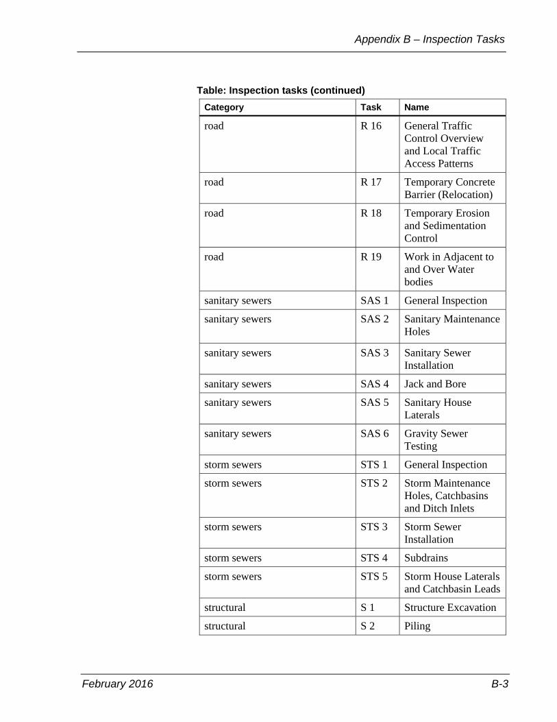
February 2016 B-3
Appendix B – Inspection Tasks
Table: Inspection tasks (continued) Category Task Name
road R 16 General Traffic Control Overview and Local Traffic Access Patterns
road R 17 Temporary Concrete Barrier (Relocation)
road R 18 Temporary Erosion and Sedimentation Control
road R 19 Work in Adjacent to and Over Water bodies
sanitary sewers SAS 1 General Inspection
sanitary sewers
SAS 2 Sanitary Maintenance Holes
sanitary sewers SAS 3 Sanitary Sewer Installation
sanitary sewers SAS 4 Jack and Bore
sanitary sewers SAS 5 Sanitary House Laterals
sanitary sewers SAS 6 Gravity Sewer Testing
storm sewers STS 1 General Inspection
storm sewers STS 2 Storm Maintenance Holes, Catchbasins and Ditch Inlets
storm sewers STS 3 Storm Sewer Installation
storm sewers STS 4 Subdrains
storm sewers STS 5 Storm House Laterals and Catchbasin Leads
structural S 1 Structure Excavation
structural S 2 Piling
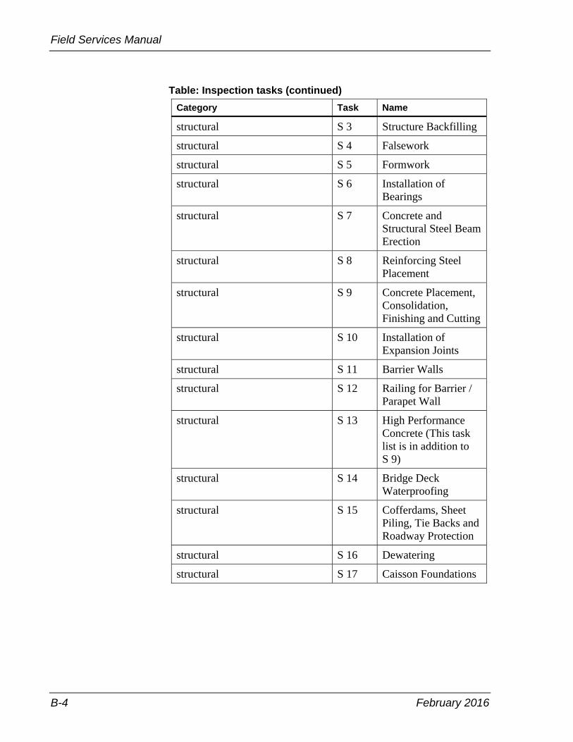
Field Services Manual
B-4 February 2016
Table: Inspection tasks (continued) Category Task Name
structural S 3 Structure Backfilling
structural S 4 Falsework
structural S 5 Formwork
structural S 6 Installation of Bearings
structural S 7 Concrete and Structural Steel Beam Erection
structural S 8 Reinforcing Steel Placement
structural S 9 Concrete Placement, Consolidation, Finishing and Cutting
structural S 10 Installation of Expansion Joints
structural S 11 Barrier Walls
structural S 12 Railing for Barrier / Parapet Wall
structural S 13 High Performance Concrete (This task list is in addition to S 9)
structural S 14 Bridge Deck Waterproofing
structural S 15 Cofferdams, Sheet Piling, Tie Backs and Roadway Protection
structural S 16 Dewatering
structural S 17 Caisson Foundations

February 2016 B-5
Appendix B – Inspection Tasks
Table: Inspection tasks (continued) Category Task Name
structural S 18 Tremie Concrete
structural S 19 Structure Rehabilitation–Removal of Waterproofing System From Deck Surfaces
structural S 20 Structure Rehabilitation–Concrete Removal and Surface Preparation
structural S 21 Structure Rehabilitation–Concrete Overlay
structural S 22 Structure Rehabilitation–Full Deck Removal
structural S 23 Structure Rehabilitation–Concrete Patches
structural S 24 Structure Rehabilitation–Silica Fume Concrete Overlay
structural S 25 Structure Rehabilitation–Concrete Refacing
structural S 26 Structural Steel Coating
traffic T 1 Underground Ducts and Bases
traffic T 2 Electrical Chambers
traffic T 3 Pole Foundations and Pole Erection

Field Services Manual
B-6 February 2016
Table: Inspection tasks (continued) Category Task Name
watermains WM 1 General Inspection
watermains WM 2 Watermain Installation
watermains WM 3 Water Valves Installation
watermains WM 4 Hydrant Installation
watermains WM 5 Water Service Installations
watermains WM 6 Installation of Temporary Services
watermains WM 7 Hydrostatic Testing
watermains WM 8 Chlorination / Disinfection Testing
watermains WM 9 Connections to Existing Watermains
watermains WM 10 Water Permit
trenchless sewer rehabilitation TRH 1 Full Length Cured-In-Place Pipe (CIPP)
trenchless replacement TRP 1 Horizontal Directional Drilling (HDD)
utilities UT 1 Utility Construction
third party and development TPD 1 General Inspection
TTC TTC 1 Track Allowance
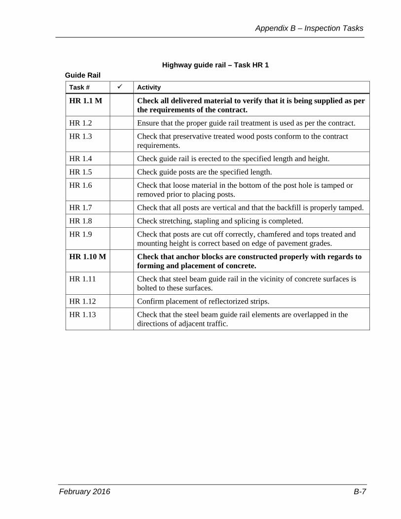
February 2016 B-7
Appendix B – Inspection Tasks
Highway guide rail – Task HR 1 Guide Rail
Task # Activity
HR 1.1 M Check all delivered material to verify that it is being supplied as per the requirements of the contract.
HR 1.2 Ensure that the proper guide rail treatment is used as per the contract.
HR 1.3 Check that preservative treated wood posts conform to the contract requirements.
HR 1.4 Check guide rail is erected to the specified length and height.
HR 1.5 Check guide posts are the specified length.
HR 1.6 Check that loose material in the bottom of the post hole is tamped or removed prior to placing posts.
HR 1.7 Check that all posts are vertical and that the backfill is properly tamped.
HR 1.8 Check stretching, stapling and splicing is completed.
HR 1.9 Check that posts are cut off correctly, chamfered and tops treated and mounting height is correct based on edge of pavement grades.
HR 1.10 M Check that anchor blocks are constructed properly with regards to forming and placement of concrete.
HR 1.11 Check that steel beam guide rail in the vicinity of concrete surfaces is bolted to these surfaces.
HR 1.12 Confirm placement of reflectorized strips.
HR 1.13 Check that the steel beam guide rail elements are overlapped in the directions of adjacent traffic.

Field Services Manual
B-8 February 2016
Highway guide rail – Task HR 2 Crash/Cushion Attenuating Terminal Barrier
Task # Activity
HR 2.1 M Check all the delivered material to verify that it is being supplied as per the requirements of the contract.
HR 2.2 Check that all preservative treated wood is identified with certification marks authorized by the Canadian Wood Preservation Association.
HR 2.3 Inspect the preservative treated wood to ensure the splits and checks are within specified limits.
HR 2.4 Check that guide rail is erected at the proper locations.
HR 2.5 Check that guide posts are the specified height.
HR 2.6 Check that steel posts are properly installed with regards to depth, alignment and spacing.
HR 2.7 Check that loose material in the bottom of the post hole is tamped or removed prior to placing the posts.
HR 2.8 Check that all posts are vertical and that the backfill is properly tamped.
HR 2.9 Check that channels are installed at proper locations, elevations and are terminated as specified in the contract.
HR 2.10 Check that spacer channel is installed properly and all connection details for posts 1 through 6 are adhered to.
HR 2.11 Check that anchor cable is installed at the correct height.
HR 2.12 Check that guide rail is properly attached as required.
HR 2.13 Check that all bolts, washers and nuts are placed and affixed to all plates, angles, posts and steel rail as required.

February 2016 B-9
Appendix B – Inspection Tasks
Landscaping – Task L 1 Topsoil
Task # Activity
L 1.1 M Ensure that imported topsoil conforms to the contract documents and is sampled as required.
L 1.2 Check that topsoil is not used for filling depressions or wasted.
L 1.3 M Check that topsoil is spread uniformly to the depth specified.
L 1.4 Accurately record quantities.
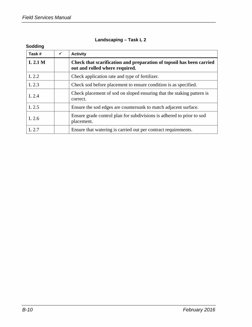
Field Services Manual
B-10 February 2016
Landscaping – Task L 2 Sodding
Task # Activity
L 2.1 M Check that scarification and preparation of topsoil has been carried out and rolled where required.
L 2.2 Check application rate and type of fertilizer.
L 2.3 Check sod before placement to ensure condition is as specified.
L 2.4 Check placement of sod on sloped ensuring that the staking pattern is correct.
L 2.5 Ensure the sod edges are countersunk to match adjacent surface.
L 2.6 Ensure grade control plan for subdivisions is adhered to prior to sod placement.
L 2.7 Ensure that watering is carried out per contract requirements.

February 2016 B-11
Appendix B – Inspection Tasks
Landscaping – Task L 3 Seeding and Mulching
Task # Activity
L 3.1 M Check all delivered material to verify that it is being supplied per requirements of the contract.
L 3.2 Check that material supplied by the contractor bears a label indicating that specified information.
L 3.3 M Check specified preparation of soil prior to seeding and mulching.
L 3.4 Ensure seeding and mulching operation is completed at temperatures or time of year allowed by specification or shown in the contract documents.
L 3.5 Check for growth of plant material or erosion of seeded areas or both.
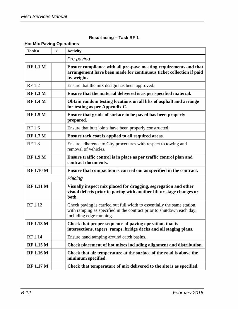
Field Services Manual
B-12 February 2016
Resurfacing – Task RF 1 Hot Mix Paving Operations
Task # Activity
Pre-paving
RF 1.1 M Ensure compliance with all pre-pave meeting requirements and that arrangement have been made for continuous ticket collection if paid by weight.
RF 1.2 Ensure that the mix design has been approved.
RF 1.3 M Ensure that the material delivered is as per specified material.
RF 1.4 M Obtain random testing locations on all lifts of asphalt and arrange for testing as per Appendix C.
RF 1.5 M Ensure that grade of surface to be paved has been properly prepared.
RF 1.6 Ensure that butt joints have been properly constructed.
RF 1.7 M Ensure tack coat is applied to all required areas.
RF 1.8 Ensure adherence to City procedures with respect to towing and removal of vehicles.
RF 1.9 M Ensure traffic control is in place as per traffic control plan and contract documents.
RF 1.10 M Ensure that compaction is carried out as specified in the contract.
Placing
RF 1.11 M Visually inspect mix placed for dragging, segregation and other visual defects prior to paving with another lift or stage changes or both.
RF 1.12 Check paving is carried out full width to essentially the same station, with ramping as specified in the contract prior to shutdown each day, including edge ramping.
RF 1.13 M Check that proper sequence of paving operation, that is intersections, tapers, ramps, bridge decks and all staging plans.
RF 1.14 Ensure hand tamping around catch basins.
RF 1.15 M Check placement of hot mixes including alignment and distribution.
RF 1.16 M Check that air temperature at the surface of the road is above the minimum specified.
RF 1.17 M Check that temperature of mix delivered to the site is as specified.

February 2016 B-13
Appendix B – Inspection Tasks
Resurfacing – Task RF 1 Hot Mix Paving Operations (continued)
Task # Activity
RF 1.18 Ensure specified distance between pavers is maintained when paving in echelon and proper rolling patterns are used.
RF 1.19 M Check that all required samples are taken and tested.
RF 1.20 Check equipment does not impact or damage areas beyond the road structure, such as curbs, adjustment chamber.
RF 1.21 Check for proper reinstatement of sample locations if required.
RF 1.22 Ensure that access ramps are in as required—one-half metre with paper if required.
RF 1.23 M Prior to placement of subsequent lifts, ensure that the temperature
of the previous mat is acceptable and compacted.

Field Services Manual
B-14 February 2016
Resurfacing – Task RF 2 In-place Full Depth Reclamation of Bituminous and Underlying Granular (Pulverizing)
Task # Activity
RF 2.1 Check that the in-place materials are processed to the depths, widths and gradation as specified in the contract.
RF 2.2 Check that the composition of the blended material is visually uniform and is as specified in the contract.
RF 2.3 Check that oversized or harmful material has been removed as specified in the contract.
RF 2.4 M Check that operational constraints are carried out as specified in
the contract.
RF 2.5 M Ensure that surface grading and compaction is as specified in the
contract.

February 2016 B-15
Appendix B – Inspection Tasks
Resurfacing – Task RF 3 Concrete Base and Pavement
Task # Activity
RF 3.1 M Check that all the delivered material is supplied from the approved list and properly stored.
RF 3.2 M Check for proper alignment, grade and base preparation.
RF 3.3 Check material supplied by the contractor is sampled as required as per the field services manual and the contract requirements.
RF 3.4 Check the concrete placement, consolidation, finishing and curing operations are in accordance with task S 9.
RF 3.5 Check that the spacer wires are cut on the load transfer devices prior to placing concrete.
RF 3.6 Check that the dowel bars and tie bars are placed and remain in the specified location. Check load transfer devices are placed on the proper skew, staked in place and are visibly marked for joint cutting. Load transfer devices should be checked following paving operations to ensure they have not moved.
RF 3.7 When fixed form pavers are used, check that hand held vibrators are used properly to supplement consolidation.
RF 3.8 M Check specified finishing and texturing procedures are adhered to.
RF 3.9 Check timing of form removal is as specified and any honeycombed areas are properly repaired.
RF 3.10 M Check that the joints are correct type and cut or formed at the proper location.
RF 3.11 Check that the initial saw cut is made to the full depth of the joint. Ensure this initial saw cut is done within the constraints specified in the contract, without damaging the concrete surface.
RF 3.12 Inspect hardened concrete surface for cracks outside of the joints.
RF 3.13 M Check that traffic is not permitted on the concrete pavement until the designed compressive strength is achieved.
RF 3.14 Check that quality assurance cores are obtained and delivered to the designated laboratory if required.
RF 3.15 Check profile traces and ensure high points are ground down and depressions are filled in.
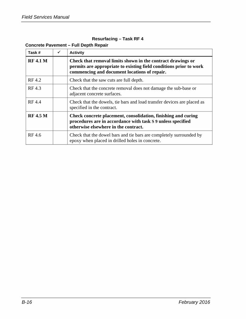
Field Services Manual
B-16 February 2016
Resurfacing – Task RF 4 Concrete Pavement – Full Depth Repair
Task # Activity
RF 4.1 M Check that removal limits shown in the contract drawings or permits are appropriate to existing field conditions prior to work commencing and document locations of repair.
RF 4.2 Check that the saw cuts are full depth.
RF 4.3 Check that the concrete removal does not damage the sub-base or adjacent concrete surfaces.
RF 4.4 Check that the dowels, tie bars and load transfer devices are placed as specified in the contract.
RF 4.5 M Check concrete placement, consolidation, finishing and curing procedures are in accordance with task S 9 unless specified otherwise elsewhere in the contract.
RF 4.6 Check that the dowel bars and tie bars are completely surrounded by epoxy when placed in drilled holes in concrete.
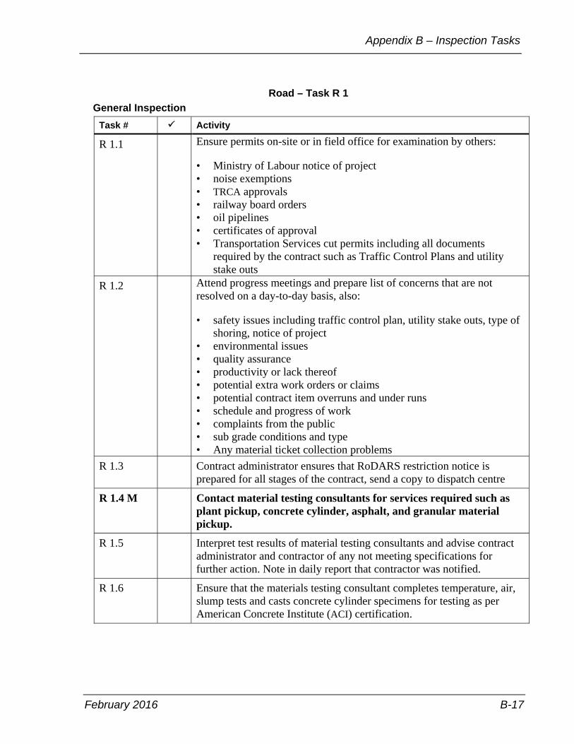
February 2016 B-17
Appendix B – Inspection Tasks
Road – Task R 1 General Inspection
Task # Activity
R 1.1 Ensure permits on-site or in field office for examination by others:
• Ministry of Labour notice of project • noise exemptions • TRCA approvals • railway board orders • oil pipelines • certificates of approval • Transportation Services cut permits including all documents
required by the contract such as Traffic Control Plans and utility stake outs
R 1.2 Attend progress meetings and prepare list of concerns that are not resolved on a day-to-day basis, also:
• safety issues including traffic control plan, utility stake outs, type of shoring, notice of project
• environmental issues • quality assurance • productivity or lack thereof • potential extra work orders or claims • potential contract item overruns and under runs • schedule and progress of work • complaints from the public • sub grade conditions and type • Any material ticket collection problems
R 1.3 Contract administrator ensures that RoDARS restriction notice is prepared for all stages of the contract, send a copy to dispatch centre
R 1.4 M Contact material testing consultants for services required such as plant pickup, concrete cylinder, asphalt, and granular material pickup.
R 1.5 Interpret test results of material testing consultants and advise contract administrator and contractor of any not meeting specifications for further action. Note in daily report that contractor was notified.
R 1.6 Ensure that the materials testing consultant completes temperature, air, slump tests and casts concrete cylinder specimens for testing as per American Concrete Institute (ACI) certification.
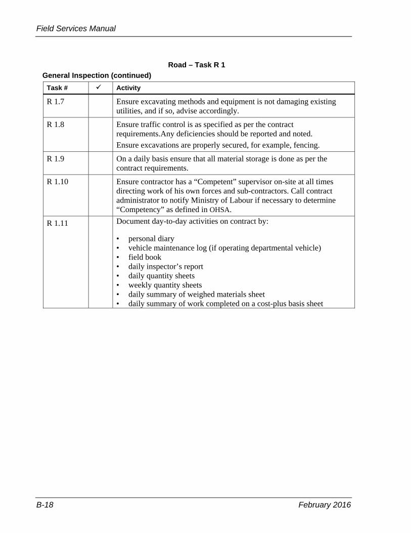
Field Services Manual
B-18 February 2016
Road – Task R 1 General Inspection (continued)
Task # Activity
R 1.7 Ensure excavating methods and equipment is not damaging existing utilities, and if so, advise accordingly.
R 1.8 Ensure traffic control is as specified as per the contract requirements.Any deficiencies should be reported and noted. Ensure excavations are properly secured, for example, fencing.
R 1.9 On a daily basis ensure that all material storage is done as per the contract requirements.
R 1.10 Ensure contractor has a “Competent” supervisor on-site at all times directing work of his own forces and sub-contractors. Call contract administrator to notify Ministry of Labour if necessary to determine “Competency” as defined in OHSA.
R 1.11 Document day-to-day activities on contract by:
• personal diary • vehicle maintenance log (if operating departmental vehicle) • field book • daily inspector’s report • daily quantity sheets • weekly quantity sheets • daily summary of weighed materials sheet • daily summary of work completed on a cost-plus basis sheet

February 2016 B-19
Appendix B – Inspection Tasks
Road – Task R 1 General Inspection (continued)
Task # Activity
R 1.12 M Document the following activities on a day-to-day basis:
Contractor, sub-contractor and supplier forces (including breakdown of classification), equipment (detail as per OPS 127) and material delivered on site.
• traffic control, that is what lanes are closed and for what distance, staging, presence of paid duty officer(s)
• weather conditions • general progress of work and quantities for each item completed • claims by contractor or complaints received by contractor or from
the public • verbal instructions given to contractor should in writing preferable
through a field instruction • any events that could adversely affect productivity • any changes to plans or adherence to specifications • spills that occur and any follow up notification • claims or potential claims such as traffic accidents or slip and falls
occurring in the work zone • sub-excavation quantities • dealings with adjacent property owners and public • concerns relayed by contract administrator and status • environmental controls are in-place and working, that is hay bales,
silt fence and so forth • material testing completed, field results and reasons why a required
test was not done • trench widths, shoring type used and sub grade conditions, such as
soil type and whether ground water is present. • location of utilities encountered that vary from plan location. • non-contract compliance issues and follow up action taken such as
discussion with contractor and contract administrator • all labour and equipment in the daily report forms are to be tracked,
including sizes model numbers and owned and leased equipment • visitors to site, reasons for the visit and any discusions. • any other items to be recorded as required in the standard daily
report and other report forms • working days, extension of time days • extra work to be tracked and reconciled on a daily basis using OPS
127 equipment rates and obtaining receipts of all material and rented equipment on site
• consultant testing services on-site
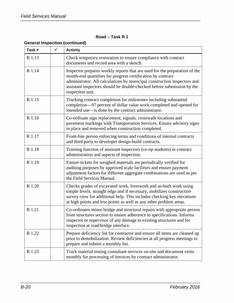
Field Services Manual
B-20 February 2016
Road – Task R 1 General Inspection (continued)
Task # Activity
R 1.13 Check temporary restoration to ensure compliance with contract documents and record area with a sketch.
R 1.14 Inspector prepares weekly reports that are used for the preparation of the month-end quantities for progress certification by contract administrator. All calculations by municipal construction inspectors and assistant inspectors should be double-checked before submission by the inspection unit.
R 1.15 Tracking contract completion for milestones including substantial completion—97 percent of dollar value work completed and opened for intended use—is done by the contract administrator.
R 1.16 Co-ordinate sign replacement, signals, crosswalk locations and pavement markings with Transportation Services. Ensure advisory signs in place and removed when construction completed.
R 1.17 Front-line person enforcing terms and conditions of internal contracts and third party to developer design-build contracts.
R 1.18 Training function of assistant inspectors (co-op students) in contract administration and aspects of inspection.
R 1.19 Ensure tickets for weighed materials are periodically verified for auditing purposes by approved scale facilities and ensure payment adjustment factors for different aggregate combinations are used as per the Field Services Manual.
R 1.20 Checks grades of excavated work, formwork and as-built work using simple levels, straight edge and if necessary, mobilizes construction survey crew for additional help. This includes checking key elevations at high points and low points as well as any other problem areas.
R 1.21 Co-ordinates minor bridge and structural repairs with appropriate person from structures section to ensure adherence to specifications. Informs inspector or supervisor of any damage to existing structures and for inspection at road/bridge interface.
R 1.22 Prepare deficiency list for contractor and ensure all items are cleaned up prior to demobilization. Review deficiencies at all progress meetings to prepare and submit a monthly list.
R 1.23 Track material testing consultant services on-site and document visits monthly for processing of invoices by contract administrator.
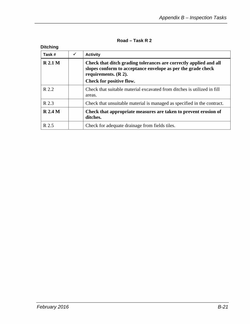
February 2016 B-21
Appendix B – Inspection Tasks
Road – Task R 2 Ditching
Task # Activity
R 2.1 M Check that ditch grading tolerances are correctly applied and all slopes conform to acceptance envelope as per the grade check requirements. (R 2).
Check for positive flow.
R 2.2 Check that suitable material excavated from ditches is utilized in fill areas.
R 2.3 Check that unsuitable material is managed as specified in the contract.
R 2.4 M Check that appropriate measures are taken to prevent erosion of ditches.
R 2.5 Check for adequate drainage from fields tiles.
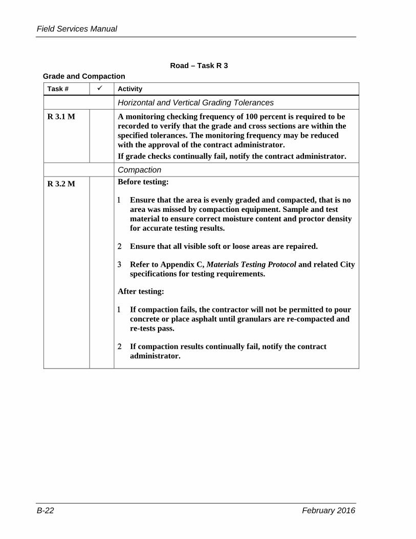
Field Services Manual
B-22 February 2016
Road – Task R 3 Grade and Compaction
Task # Activity
Horizontal and Vertical Grading Tolerances
R 3.1 M A monitoring checking frequency of 100 percent is required to be recorded to verify that the grade and cross sections are within the specified tolerances. The monitoring frequency may be reduced with the approval of the contract administrator.
If grade checks continually fail, notify the contract administrator.
Compaction
R 3.2 M Before testing:
Ensure that the area is evenly graded and compacted, that is no area was missed by compaction equipment. Sample and test material to ensure correct moisture content and proctor density for accurate testing results.
Ensure that all visible soft or loose areas are repaired.
Refer to Appendix C, Materials Testing Protocol and related City specifications for testing requirements.
After testing:
If compaction fails, the contractor will not be permitted to pour concrete or place asphalt until granulars are re-compacted and re-tests pass.
If compaction results continually fail, notify the contract administrator.

February 2016 B-23
Appendix B – Inspection Tasks
Road – Task R 4 Granular Base and Granular Sub-base
Task # Activity
R 4.1 Check that quality assurance samples are obtained for testing as specified in the contract documents. Conduct visual inspection of material for contamination, including clay balls, clay coated particles or foreign material. Where contamination is observed or suspected, take appropriate action.
R 4.2 Check that subbase and base materials comply as specified in the contract documents.
R 4.3 Check contractor's compaction density readings to see that all the work falls within the specified tolerances.
R 4.4 Verify and record horizontal and vertical grading tolernaces prior to the placement of the next type of amteiral or pavement.

Field Services Manual
B-24 February 2016
Road – Task R 5 Road Cut Permit Inspections
Task # Activity
R 5.1 M Ensure that the contractor has a road occupancy permit prior to commencing work on the right-of-way.
R 5.2 Ensure the permit has the correct address and clearly defines any special conditions.
R 5.3 Ensure the permit holder, contact name, and telephone number is accurate and clearly identified.

February 2016 B-25
Appendix B – Inspection Tasks
Road – Task R 6 Curb and Gutter
Task # Activity
R 6.1 M Check proper type of curb is constructed. Check for ledge.
R 6.2 M Check for proper alignment, grade and granular base preparation.
R 6.3 Check for proper positioning of construction joints.
R 6.4 M Check for proper positioning of drainage structures, frames and grates.
R 6.5 Inspect the concrete placement, consolidation, finishing and curing operations and saw cuts at catchbasins. All formed concrete is to be consolidated using a pencil vibrator.
R 6.6 Check that all required material samples are taken.
R 6.7 If extrusion method is being used, ensure proper percentage of air is being maintained behind slip form machine. Test for compressive strength, air entrainment, temperature and slump.
R 6.8 Check for proper treatments at entrances and handicap ramp locations.

Field Services Manual
B-26 February 2016
Road – Task R 7 Concrete Sidewalk
Task # Activity
R 7.1 M Check for proper alignment, grade, granular base preparation and extra thickness at commercial and industrial driveways.
R 7.2 M Check proper positioning of construction joints and expansion joints, including location and depth.
R 7.3 Check that all required material samples are taken.
R 7.4 M Check that the concrete placement, consolidation finishing and curing operations are conducted according to City standards and specifications.
R 7.5 M Check full depth expansion joints—contractor stamp tooled edges and construction joints:
• proper direction and spacing for installation of tactile walking surface indicator plates
• proper cross fall • grade to match driveways
R 7.6 M Ensure that entrances and pedestrian access ramp locations are constructed according to the latest contract drawings.

February 2016 B-27
Appendix B – Inspection Tasks
Road – Task R 8 Geotextile
Task # Activity
R 8.1 M Check all the delivered material to verify that it is being supplied from the approved list.
R 8.2 Check that material supplied by the contractor is sampled as required and forwarded for testing.
R 8.3 M Check installation area for removal of sharp objects that may puncture the geotextile and ensure that subgrade is rolled smooth.
R 8.4 Check that during installation the proper overlap has been maintained.
R 8.5 Check that the geotextile is not exposed to sunlight for more than three days.
R 8.6 Check that drop height for material placed onto geotextile is less than one metre to ensure geotextile is not damaged.
R 8.7 Check that all materials contaminated or damaged during installation are either replaced or repaired so that the geotextile will perform as intended.

Field Services Manual
B-28 February 2016
Road – Task R 9 Tack Coat
Task # Activity
R 9.1 M Check all the delivered material to verify that it is being supplied from the approved list.
R 9.2 Check that existing pavement is dry and clean before applying tack coat.
R 9.3 Check that proper rate of application and coverage is used.
R 9.4 M Check that tack coat has cured to the desired level before placing hot mix pavement tack.
R 9.5 M Check that traffic is not allowed on the tack coated area before paving.
R 9.6 Ensure that the contractor does not overspray beyond the pavement area.
R 9.7 Check that the tack coated area is cured before paving.
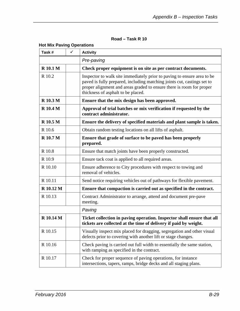
February 2016 B-29
Appendix B – Inspection Tasks
Road – Task R 10 Hot Mix Paving Operations
Task # Activity
Pre-paving
R 10.1 M Check proper equipment is on site as per contract documents.
R 10.2 Inspector to walk site immediately prior to paving to ensure area to be paved is fully prepared, including matching joints cut, castings set to proper alignment and areas graded to ensure there is room for proper thickness of asphalt to be placed.
R 10.3 M Ensure that the mix design has been approved.
R 10.4 M Approval of trial batches or mix verification if requested by the contract administrator.
R 10.5 M Ensure the delivery of specified materials and plant sample is taken.
R 10.6 Obtain random testing locations on all lifts of asphalt.
R 10.7 M Ensure that grade of surface to be paved has been properly prepared.
R 10.8 Ensure that match joints have been properly constructed.
R 10.9 Ensure tack coat is applied to all required areas.
R 10.10 Ensure adherence to City procedures with respect to towing and removal of vehicles.
R 10.11 Send notice requiring vehicles out of pathways for flexible pavement.
R 10.12 M Ensure that compaction is carried out as specified in the contract.
R 10.13 Contract Administrator to arrange, attend and document pre-pave meeting.
Paving
R 10.14 M Ticket collection in paving operation. Inspector shall ensure that all tickets are collected at the time of delivery if paid by weight.
R 10.15 Visually inspect mix placed for dragging, segregation and other visual defects prior to covering with another lift or stage changes.
R 10.16 Check paving is carried out full width to essentially the same station, with ramping as specified in the contract.
R 10.17 Check for proper sequence of paving operations, for instance intersections, tapers, ramps, bridge decks and all staging plans.

Field Services Manual
B-30 February 2016
Road – Task R 10 Hot Mix Paving Operations (continued)
Task # Activity
R 10.18 M Check placement of hot mix including alignment and distribution.
R 10.19 M Check that air temperature at the surface of the road is above the minimum specified.
R 10.20 M Check that the temperature of mix delivered to the site is as specified.
R 10.21 Check that vehicles are equipped with insulated tarpaulins.
R 10.22 Ensure specified distance between pavers is maintained when paving in echelon.
R 10.23 M Check that all required samples are taken.
R 10.24 Check equipment does not impact or damage areas beyond the road structure.
R 10.25 Check for proper reinstatement of sample locations if required.
R 10.26 Send notice requiring vehicles out of pathways for flexible pavement.
R 10.27 Ensure that access ramps are in as required.
R 10.28 Prior to placement of subsequent lift, ensure that the temperature of the previous mat is acceptable.
R 10.29 M Ensure compliance with all pre-pave meeting requirements and arrange for testing of materials and compaction for day of paving.
R 10.30 M Ensure that compaction is carried out as specified in the contract.
R 10.31 Check and ensure areas to be paved has been cleaned of all dirt, grime, loose broken and foreign material.
R 10.32 Ensure that areas to be paved have been checked prior to paving to ensure all required work such as joint filling, cut repairs, and casting adjustment, and so on, has been done.
R 10.33 Check that line marking sub-contractor and routing and sealing contractor has been scheduled.
R 10.34 Make arrangements of weight check with City facility.
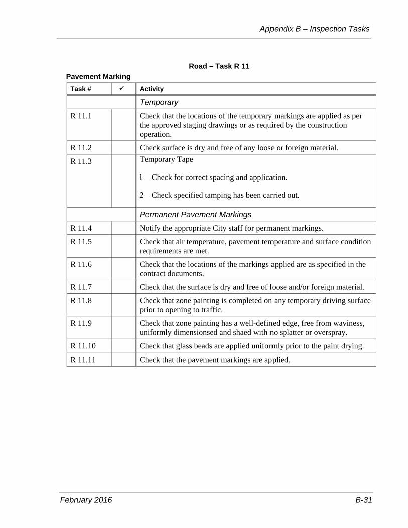
February 2016 B-31
Appendix B – Inspection Tasks
Road – Task R 11 Pavement Marking
Task # Activity
Temporary
R 11.1 Check that the locations of the temporary markings are applied as per the approved staging drawings or as required by the construction operation.
R 11.2 Check surface is dry and free of any loose or foreign material.
R 11.3 Temporary Tape
Check for correct spacing and application.
Check specified tamping has been carried out.
Permanent Pavement Markings
R 11.4 Notify the appropriate City staff for permanent markings.
R 11.5 Check that air temperature, pavement temperature and surface condition requirements are met.
R 11.6 Check that the locations of the markings applied are as specified in the contract documents.
R 11.7 Check that the surface is dry and free of loose and/or foreign material.
R 11.8 Check that zone painting is completed on any temporary driving surface prior to opening to traffic.
R 11.9 Check that zone painting has a well-defined edge, free from waviness, uniformly dimensionsed and shaed with no splatter or overspray.
R 11.10 Check that glass beads are applied uniformly prior to the paint drying.
R 11.11 Check that the pavement markings are applied.
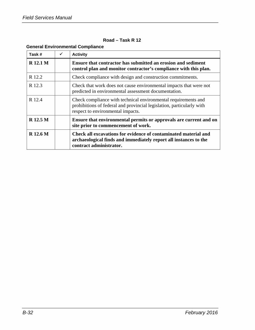
Field Services Manual
B-32 February 2016
Road – Task R 12 General Environmental Compliance
Task # Activity
R 12.1 M Ensure that contractor has submitted an erosion and sediment control plan and monitor contractor’s compliance with this plan.
R 12.2 Check compliance with design and construction commitments.
R 12.3 Check that work does not cause environmental impacts that were not predicted in environmental assessment documentation.
R 12.4 Check compliance with technical environmental requirements and prohibitions of federal and provincial legislation, particularly with respect to environmental impacts.
R 12.5 M Ensure that environmental permits or approvals are current and on site prior to commencement of work.
R 12.6 M Check all excavations for evidence of contaminated material and archaeological finds and immediately report all instances to the contract administrator.

February 2016 B-33
Appendix B – Inspection Tasks
Road – Task R 13 Control of Dust from the Work
Task # Activity
R 13.1 M Ensure that dust from construction operations such as grading, concrete cutting/grinding, abrasive blast cleaning of concrete and steel, hauling operations and road sweeping does not cause a nuisance to pedestrian and vehicular traffic, adjacent residential, commercial and institutional properties.
R 13.2 Check that contractor ensures that workers are trained in the hazards of asbestos, personal hygiene, the user of respirators, cleaning and disposal of protective clothing and the requirements of Type 1, 2 or 3 operations under the current Ontario Regulation 278 / 05.
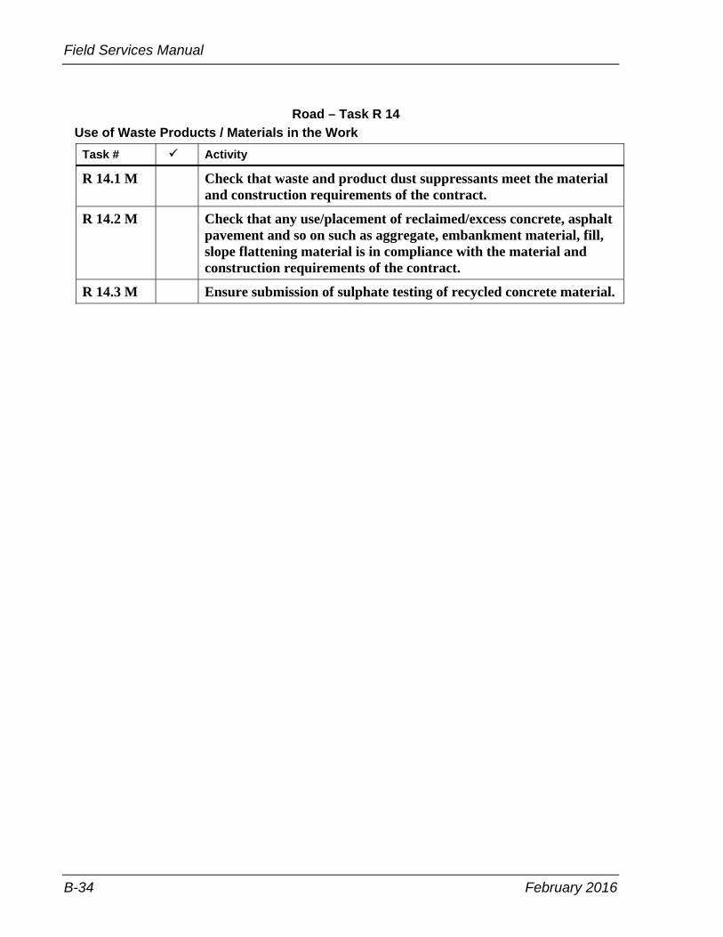
Field Services Manual
B-34 February 2016
Road – Task R 14 Use of Waste Products / Materials in the Work
Task # Activity
R 14.1 M Check that waste and product dust suppressants meet the material and construction requirements of the contract.
R 14.2 M Check that any use/placement of reclaimed/excess concrete, asphalt pavement and so on such as aggregate, embankment material, fill, slope flattening material is in compliance with the material and construction requirements of the contract.
R 14.3 M Ensure submission of sulphate testing of recycled concrete material.
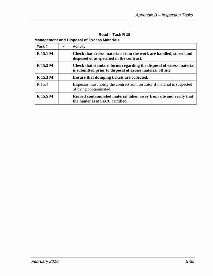
February 2016 B-35
Appendix B – Inspection Tasks
Road – Task R 15 Management and Disposal of Excess Materials
Task # Activity
R 15.1 M Check that excess materials from the work are handled, stored and disposed of as specified in the contract.
R 15.2 M Check that standard forms regarding the disposal of excess material is submitted prior to disposal of excess material off site.
R 15.3 M Ensure that dumping tickets are collected.
R 15.4 Inspector must notify the contract administrator if material is suspected of being contaminated.
R 15.5 M Record contaminated material taken away from site and verify that the hauler is MOECC certified.

Field Services Manual
B-36 February 2016
Road – Task R 16 General Traffic Control Overview and Local Traffic Access Patterns
Task # Activity
R 16.1 M Ensure that the contractor complies with the traffic management plan submitted by the contactor.
R 16.2 Record contractor’s contact person(s) responsible for traffic control.
R 16.3 Ensure that layout of signs is in accordance with the contract or as modified by the City.
R 16.4 Ensure that contractor’s initial sign placements—by station, offset and height above pavement— are placed according to Book 7 – Temporary Conditions and approved by the Transportation Services work zone coordinator, and that all revisions are clearly documented.
R 16.5 M Check daily that local traffic access to residential, commercial or institutional areas is not modified or redirected unless otherwise specified in the contract and that prior and approved notification has been delivered.
R 16.6 Ensure that sidewalks and driveways are ramped to provide access for pedestrians and vehicles and pedestrian use other sidewalk signs.
R 16.7 Ensure work areas are properly fenced and delineated to provide for safe traffic flow.
R 16.8 Check that any modification or redirection of local traffic access to residential, commercial or institutional areas complies with the time constraints specified in the contract.
R 16.9 Advise daily that all signs and traffic control devices are properly maintained, and in good working order, for example, flashers, and so on.
R 16.10 Check for the removal of temporary signs when they are no longer required.
R 16.11 Check that the contractor records each stage change or sign change.
R 16.12 M If an accident occurs, document all traffic control devices, signing, time of inspection and any other pertinent information including measurements, photos and police accident reports in the daily report.
R 16.13 Check that all lane closure protocol is adhered to as per the requirements of the contract documents.
R 16.14 Co-ordinate with right-of-way management unit for the inspection of the traffic control devices.

February 2016 B-37
Appendix B – Inspection Tasks
Road – Task R 17 Traffic Control – Temporary Concrete Barrier (Relocation)
Task # Activity
R 17.1 Check defects in barriers are verified before and after installation.
R 17.2 Ensure all units are connected properly.
R 17.3 Confirm placement, treatments and offsets are as shown on the contract drawings.
R 17.4 Ensure barriers are checked for misalignment or damage throughout the project. Ensure barriers are replaced or repaired as required.
R 17.5 Confirm removal or relocation is carried out as specified.
R 17.6 Check requirements for paid duty police officer(s) and ensure contractor adheres to requirements.
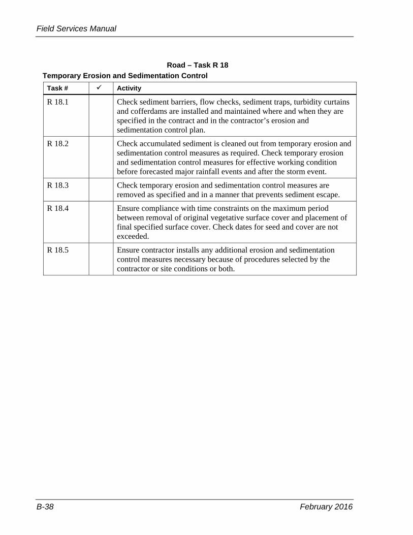
Field Services Manual
B-38 February 2016
Road – Task R 18 Temporary Erosion and Sedimentation Control
Task # Activity
R 18.1 Check sediment barriers, flow checks, sediment traps, turbidity curtains and cofferdams are installed and maintained where and when they are specified in the contract and in the contractor’s erosion and sedimentation control plan.
R 18.2 Check accumulated sediment is cleaned out from temporary erosion and sedimentation control measures as required. Check temporary erosion and sedimentation control measures for effective working condition before forecasted major rainfall events and after the storm event.
R 18.3 Check temporary erosion and sedimentation control measures are removed as specified and in a manner that prevents sediment escape.
R 18.4 Ensure compliance with time constraints on the maximum period between removal of original vegetative surface cover and placement of final specified surface cover. Check dates for seed and cover are not exceeded.
R 18.5 Ensure contractor installs any additional erosion and sedimentation control measures necessary because of procedures selected by the contractor or site conditions or both.

February 2016 B-39
Appendix B – Inspection Tasks
Road – Task R 19 Work in, Adjacent to, and Over Waterbodies
Task # Activity
R 19.1 M Ensure sedimentation and other harmful material is not permitted to enter into the watercourse or other water bodies.
R 19.2 Entry of equipment and construction materials into watercourses and water bodies and undertaking of any work is limited to that specified in the contract and environmental documentation, as may be authorized through environmental permits or approvals.
R 19.3 M Ensure work specified in the watercourses or water bodies and on the banks is in compliance with what is specified in the contract and environmental documentation, and as may be authorized through environmental permits or approvals.
R 19.4 Check temporary water passage systems, temporary water body crossings, cofferdams and turbidity curtains are installed, maintained and removed in compliance with the requirements of the contract.
R 19.5 Ensure disturbance or damage to watercourses or water body beds, banks and bank vegetation is limited to that specified in the contract and environment documentation, and as may be authorized through environmental permits or approvals.
R 19.6 M Check compliance with the time constraints specified in the contract relative to work in and adjacent to watercourses. The inspector to ensure that all other approvals have been obtained.

Field Services Manual
B-40 February 2016
Sanitary Sewers – Task SAS 1 General Inspection
Task # Activity
SAS 1.1 M Document existing site conditions and adjacent properties by taking pre-construction photos in preparation of subsequent claims. Ensure contractors have documented and submitted a copy to the contract administrator.
SAS 1.2 Ensure contractor has a “competent” supervisor on-site at all times directing work of his own forces and sub-contractors.
SAS 1.3 Pipe class checked and condition of pipe inspected, for example, maintenance holes, saddles, and so on. All connections core drilled or pre-manufactured.
SAS 1.4 Document day-to-day activities on contract by:
• personal diary • vehicle maintenance log—if operating departmental vehicle • field book • daily inspector’s report • daily quantity sheets • weekly quantity sheets • daily summary of weighed materials sheet • daily summary of work completed on a cost-plus basis sheet
SAS 1.5 Document the following activities on a day-to-day basis:
• contractor, sub-contractor and supplier forces including breakdown of classification, equipment detail as per OPS 127 and material delivered on site
• traffic control, that is what lanes are closed and for what distance, staging
• weather conditions • general progress of work • claims by contractor or complaints received by contractor • verbal instructions given to contractor • any events that could adversely affect productivity • any changes to plans or adherence to specifications • spills that occur and any follow-up notification • claims that occur and any follow-up notification • claims or potential claims such as traffic accidents or slip and falls
occurring in the work zone • sub-excavation quantities • change directives, change orders or field instructions • soil conditions

February 2016 B-41
Appendix B – Inspection Tasks
Sanitary Sewers – Task SAS 1 General Inspection (continued)
Task # Activity
SAS 1.5 continued
• trench widths • type of trench shoring used
SAS 1.6 • ensure OHSA compliance • ground conditions during excavation noted, that is areas of excessive
trench collapse, presence of water and so on • stations of water services and sanitary services recorded • type of shoring used noted • method of compaction noted • grade sheets mathematically checked • batter boards checked to ensure they have been set at the proper
elevation • bedding to spring line checked • dealings with adjacent property owners and public • concerns relayed by contract administrator and status • material testing completed, field results and reasons why a required
test was not done • trench widths, shoring type used and sub grade conditions, such as
soil type and whether ground water is present • location of utilities encountered that vary from plan location • non-contract compliance issues and follow up action taken such as
discussion with contractor and contract administrator • all labour and equipment in the daily report forms are to be tracked.
Including sizes model numbers and owned and leased equipment • visitors to site, reasons for the visit and any discusions • record any other items as required in the standard daily report and
other report forms SAS 1.7 Track material testing consultant services on-site and document visits
daily for processing of invoices by contract administrator.
SAS 1.8 M Prepare deficiency list for contractor and ensure all items are cleaned up prior to demobilization.
SAS 1.9 On a daily basis ensure that all material storage is done as per the contract requirements.
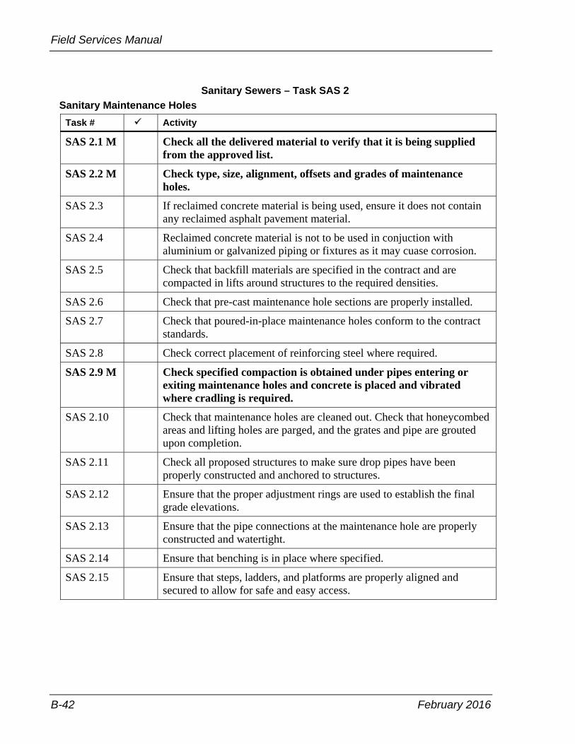
Field Services Manual
B-42 February 2016
Sanitary Sewers – Task SAS 2 Sanitary Maintenance Holes
Task # Activity
SAS 2.1 M Check all the delivered material to verify that it is being supplied from the approved list.
SAS 2.2 M Check type, size, alignment, offsets and grades of maintenance holes.
SAS 2.3 If reclaimed concrete material is being used, ensure it does not contain any reclaimed asphalt pavement material.
SAS 2.4 Reclaimed concrete material is not to be used in conjuction with aluminium or galvanized piping or fixtures as it may cuase corrosion.
SAS 2.5 Check that backfill materials are specified in the contract and are compacted in lifts around structures to the required densities.
SAS 2.6 Check that pre-cast maintenance hole sections are properly installed.
SAS 2.7 Check that poured-in-place maintenance holes conform to the contract standards.
SAS 2.8 Check correct placement of reinforcing steel where required.
SAS 2.9 M Check specified compaction is obtained under pipes entering or exiting maintenance holes and concrete is placed and vibrated where cradling is required.
SAS 2.10 Check that maintenance holes are cleaned out. Check that honeycombed areas and lifting holes are parged, and the grates and pipe are grouted upon completion.
SAS 2.11 Check all proposed structures to make sure drop pipes have been properly constructed and anchored to structures.
SAS 2.12 Ensure that the proper adjustment rings are used to establish the final grade elevations.
SAS 2.13 Ensure that the pipe connections at the maintenance hole are properly constructed and watertight.
SAS 2.14 Ensure that benching is in place where specified.
SAS 2.15 Ensure that steps, ladders, and platforms are properly aligned and secured to allow for safe and easy access.

February 2016 B-43
Appendix B – Inspection Tasks
Sanitary Sewers – Task SAS 3 Sanitary Sewer Installation
Task # Activity
SAS 3.1 M Check all the delivered material to verify that is it being supplied from the approved list that was submitted by the contractor at the commencement of the contract.
SAS 3.2 Check the trench alignment, grade and width are as specified.
SAS 3.3 M Check that the pipe is installed to proper alignment and grade.
SAS 3.4 If reclaimed concrete material is being used, ensure it does not contain any reclaimed asphalt pavement material.
SAS 3.5 Reclaimed concrete material is not to be used in conjuction with aluminium or galvanized piping or fixtures as it may cuase corrosion.
SAS 3.6 M Check that the specified bedding, cover and backfill materials are used, and compacted as per standard specifications.
SAS 3.7 Ensure excavations are free of water at all times and proper pumping procedures are followed.
SAS 3.8 M Check all pipes to ensure use of the correct class and size.
SAS 3.9 Inspect pipe for defects and reject those that are damaged or defective.
SAS 3.10 During progress of work, check that all pipes and connections are kept clean and free of foreign debris.
SAS 3.11 Where applicable, check that joints are lapped in directions of flow. SAS 3.12 M Record all rock excavations.
SAS 3.13 Check that all utilities have been properly supported during construction and prior to backfilling. Ensure that utility sizes and elevations are recorded. Advise utilities in the event of damage.
SAS 3.14 M Plastic sewer pipes will be tested for deflection as per OPSS 410.
SAS 3.15 Check if bypass pumps are working, if inclement weather is forcasted. Check that bypass is as per approved submitted plans.

Field Services Manual
B-44 February 2016
Sanitary Sewers – Task SAS 4 Jack and Bore
Task # Activity
SAS 4.1 Check that sufficient indicators are set up and maintained to detect and monitor any movements within and outside the tunnel.
SAS 4.2 Check that installation techniques employed meet the specification.
SAS 4.3 M Check that the alignment and grade are maintained.
SAS 4.4 M Check all the delivered material to verify that it is being supplied from the approved list.
SAS 4.5 Maintain detailed records and report all ground movements, failures, seepage zones and changes in soil conditions to the contract administrator.

February 2016 B-45
Appendix B – Inspection Tasks
Sanitary Sewers – Task SAS 5 Sanitary House Laterals
Task # Activity
SAS 5.1 M Check all the delivered material to verify that it is being supplied from the approved list.
SAS 5.2 M Check all connections at sewer mains for pipe and tee alignment, saddle stability and compaction.
SAS 5.3 If reclaimed concrete material is being used, ensure it does not contain any reclaimed asphalt pavement material.
SAS 5.4 Reclaimed concrete material is not to be used in conjuction with aluminium or galvanized piping or fixtures as it may cuase corrosion.
SAS 5.5 M Check that the granular bedding has been installed and compacted to the spring line of pipe. Check that granular cover and backfill are placed and compacted to specifications.
SAS 5.6 M Check for proper connections to existing service pipes.
SAS 5.7 Check that positive flow is maintained from the connection at streetline to the new sewer.
SAS 5.8 Check that the proper size of the pipe is used for all house connections.
SAS 5.9 Record chainages and lengths of pipes installed.
SAS 5.10 Record swing ties—three minimum—to established features at property line.
SAS 5.11 M Complete sewer service cards.
SAS 5.12 Record elevation at property line.
SAS 5.13 Check that lateral is connected to the proper sewer main, which is sanitary to sanitary.
SAS 5.14 Ensure that all permits are in place for the service laterals to vacant lots.
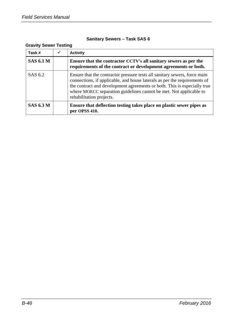
Field Services Manual
B-46 February 2016
Sanitary Sewers – Task SAS 6 Gravity Sewer Testing
Task # Activity
SAS 6.1 M Ensure that the contractor CCTV’s all sanitary sewers as per the requirements of the contract or development agreements or both.
SAS 6.2 Ensure that the contractor pressure tests all sanitary sewers, force main connections, if applicable, and house laterals as per the requirements of the contract and development agreements or both. This is especially true where MOECC separation guidelines cannot be met. Not applicable to rehabilitation projects.
SAS 6.3 M Ensure that deflection testing takes place on plastic sewer pipes as per OPSS 410.

February 2016 B-47
Appendix B – Inspection Tasks
Storm Sewers – Task STS 1 General Inspection
Task # Activity
STS 1.1 Follow-up with the contractor to ensure that they document the existing site conditions and adjacent properties by taking pre-construction photos in preparation of subsequent claims according to the contract documents.
STS 1.2 Ensure contractor has a “competent” supervisor on-site at all times directing work of his own forces and sub-contractors.
STS 1.3 Ensure contractor and sub-contractor’s forces have adequate safety equipment to satisfy the OHSA and the contract requirement.
STS 1.4 Pipe class checked and condition of pipe inspected, for example, manholes, saddles and so on. All connections core drilled or pre-manufactured.
STS 1.5 Document day-to-day activities on contract by:
• personal diary • vehicle maintenance log—if operating departmental vehicle • field book • daily inspector’s report • daily quantity sheets • weekly quantity sheets • daily summary of weighed materials sheet • daily summary of work completed on a cost-plus basis sheet
STS 1.6 Document the following activities on a day-to-day basis:
• contractor, sub-contractor and supplier forces including breakdown of classification, equipment detail as per OPS 127 and material delivered on site
• traffic control, that is what lanes are closed and for what distance, staging
• weather conditions • general progress of work • claims by contractor or complaints received by contractor • written instructions given to contractor • any events that could adversely affect productivity • any changes to plans or adherence to specifications • spills that occur and any follow-up notification • claims that occur and any follow-up notification • claims or potential claims such as traffic accidents or slip and falls
occurring in the work zone • sub-excavation quantities according to the contract docmuents

Field Services Manual
B-48 February 2016
Storm Sewers – Task STS 1 General Inspection (continued)
Task # Activity
STS 1.6 continued
• ground conditions during excavation noted, that is areas of excessive trench collapse, presence of water, and so on
• stations of water services and sanitary services recorded • type of shoring used noted • method of compaction noted batter boards checked to ensure they have been set at the proper
elevation • bedding to spring line checked • dealings with adjacent property owners and public • concerns relayed by contract administrator and status • material testing completed, field results and reasons why a required
test was not done • trench widths, shoring type used and sub grade conditions, such as
soil type and whether ground water is present • location of utilities encountered that vary from plan location • non-contract compliance issues and follow up action taken such as
discussion with contractor and contract administrator • all labour and equipment in the daily report forms are to be tracked.
Including sizes model numbers and owned and leased equipment • visitors to site, reasons for the visit and any discusions • record any other items as required in the standard daily report and
other report forms STS 1.7 M Track material testing consultant services on-site and document
visits daily for processing of invoices by contract administrator.
STS 1.8 M Prepare deficiency list for contractor and ensure all items are cleaned up prior to demobilization. This list should be prepared on a running basis and provided to the contract administrator and contractor at progress meetings or at least monthly.
STS 1.9 On a daily basis ensure that all material storage is done as per the contract requirements.

February 2016 B-49
Appendix B – Inspection Tasks
Storm Sewers – Task STS 2 Storm Maintenance Holes, Catchbasins and Ditch Inlets
Task # Activity
STS 2.1 M Check all the delivered material to verify that it is being supplied from the approved list.
STS 2.2 M Check type, size, alignment, offsets and grades of maintenance holes, catchbasins and ditch inlets.
STS 2.3 Check that backfill materials are specified in the contract and are compacted in lifts around structures to the required densities (R 2).
SAS 2.4 Recycled material concrete is not to be used in conjunction with aluminium or galvanized piping or fixures as it may cause corrosion.
STS 2.5 Check that pre-cast maintenance hole sections are properly installed.
STS 2.6 Check that poured in place maintenance holes, catchbasins and ditch inlets conform to the contract standards.
STS 2.7 Check correct placement of reinforcing steel where required.
STS 2.8 M Check specified compaction is obtained under pipes entering or exiting maintenance holes, catchbasins, and ditch inlets and concrete is placed and vibrated where cradling is required.
STS 2.9 Check that maintenance holes, catchbasins and ditch inlets are cleaned out. Check that honeycombed areas and lifting holes are parged, and the grates and pipe are grouted upon completion.
STS 2.10 Check all proposed structures to make sure drop pipes have been properly constructed and anchored to structures.
STS 2.11 When installing catchbasins to combined sewers, make sure odour traps are properly installed.
STS 2.12 Ensure that the proper adjustment rings are used to establish the final grade elevations.
STS 2.13 Ensure that the pipe connections at the maintenance hole are properly constructed and water tight.
STS 2.14 Ensure that benching is in place where specified.
STS 2.15 Ensure that steps, ladders, and platforms are properly aligned and secured to allow for proper access as per contract specification.
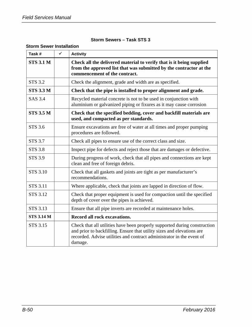
Field Services Manual
B-50 February 2016
Storm Sewers – Task STS 3 Storm Sewer Installation
Task # Activity
STS 3.1 M Check all the delivered material to verify that is it being supplied from the approved list that was submitted by the contractor at the commencement of the contract.
STS 3.2 Check the alignment, grade and width are as specified.
STS 3.3 M Check that the pipe is installed to proper alignment and grade.
SAS 3.4 Recycled material concrete is not to be used in conjunction with aluminium or galvanized piping or fixures as it may cause corrosion
STS 3.5 M Check that the specified bedding, cover and backfill materials are used, and compacted as per standards.
STS 3.6 Ensure excavations are free of water at all times and proper pumping procedures are followed.
STS 3.7 Check all pipes to ensure use of the correct class and size.
STS 3.8 Inspect pipe for defects and reject those that are damages or defective.
STS 3.9 During progress of work, check that all pipes and connections are kept clean and free of foreign debris.
STS 3.10 Check that all gaskets and joints are tight as per manufacturer’s recommendations.
STS 3.11 Where applicable, check that joints are lapped in direction of flow.
STS 3.12 Check that proper equipment is used for compaction until the specified depth of cover over the pipes is achieved.
STS 3.13 Ensure that all pipe inverts are recorded at maintenance holes. STS 3.14 M Record all rock excavations.
STS 3.15 Check that all utilities have been properly supported during construction and prior to backfilling. Ensure that utility sizes and elevations are recorded. Advise utilities and contract administrator in the event of damage.

February 2016 B-51
Appendix B – Inspection Tasks
Storm Sewers – Task STS 4 Subdrains
Task # Activity
STS 4.1 Check for specified size of pipe, including filter material. Check that all delivered material is stored properly and verify that it is being supplied from the approved list.
STS 4.2 M Check that pipe is installed to proper alignment and grade.
STS 4.3 Check that granular materials comply with the specifications and are compacted as per compaction requirements.
STS 4.4 Check that proper connections to maintenance holes, catchbasins, and ditch inlets are grouted and have sufficient grade.
STS 4.5 Check that outlet and collector pipes are not crushed during backfilling operations.
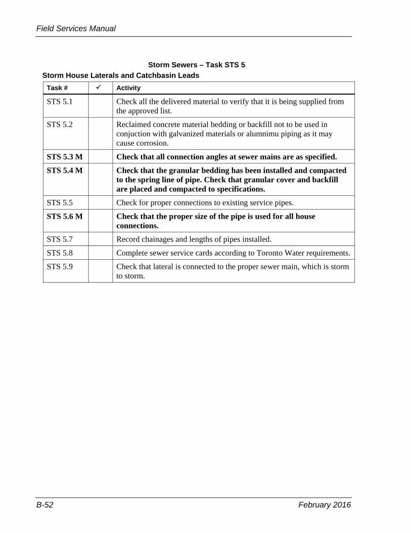
Field Services Manual
B-52 February 2016
Storm Sewers – Task STS 5 Storm House Laterals and Catchbasin Leads
Task # Activity
STS 5.1 Check all the delivered material to verify that it is being supplied from the approved list.
STS 5.2 Reclaimed concrete material bedding or backfill not to be used in conjuction with galvanized materials or alumnimu piping as it may cause corrosion.
STS 5.3 M Check that all connection angles at sewer mains are as specified.
STS 5.4 M Check that the granular bedding has been installed and compacted to the spring line of pipe. Check that granular cover and backfill are placed and compacted to specifications.
STS 5.5 Check for proper connections to existing service pipes.
STS 5.6 M Check that the proper size of the pipe is used for all house connections.
STS 5.7 Record chainages and lengths of pipes installed.
STS 5.8 Complete sewer service cards according to Toronto Water requirements.
STS 5.9 Check that lateral is connected to the proper sewer main, which is storm to storm.

February 2016 B-53
Appendix B – Inspection Tasks
Structural – Task S 1 Structure Excavation
Task # Activity
S 1.1 M Check that all footing excavations conform to size, shape, line, elevation, and grade as specified in the contract.
S 1.2 Check that the excavation is rendered stable and safe during footing excavation and construction.
S 1.3 Check that loosened material, soft material, boulders and other deleterious material at the foundation base are removed and replaced with suitable compacted material or mass concrete.
S 1.4 Record the depth, length, width, type of material used, and how it was placed, when a working slab is used by the contractor.
S 1.5 Check that any adjacent utility or structure is not affected or undermined by the footing excavation. Record location of utilities.
S 1.6 Check that the founding soil is protected and preserved.
S 1.7 Ensure that excavated materials are handled as per the requirements of the contract.
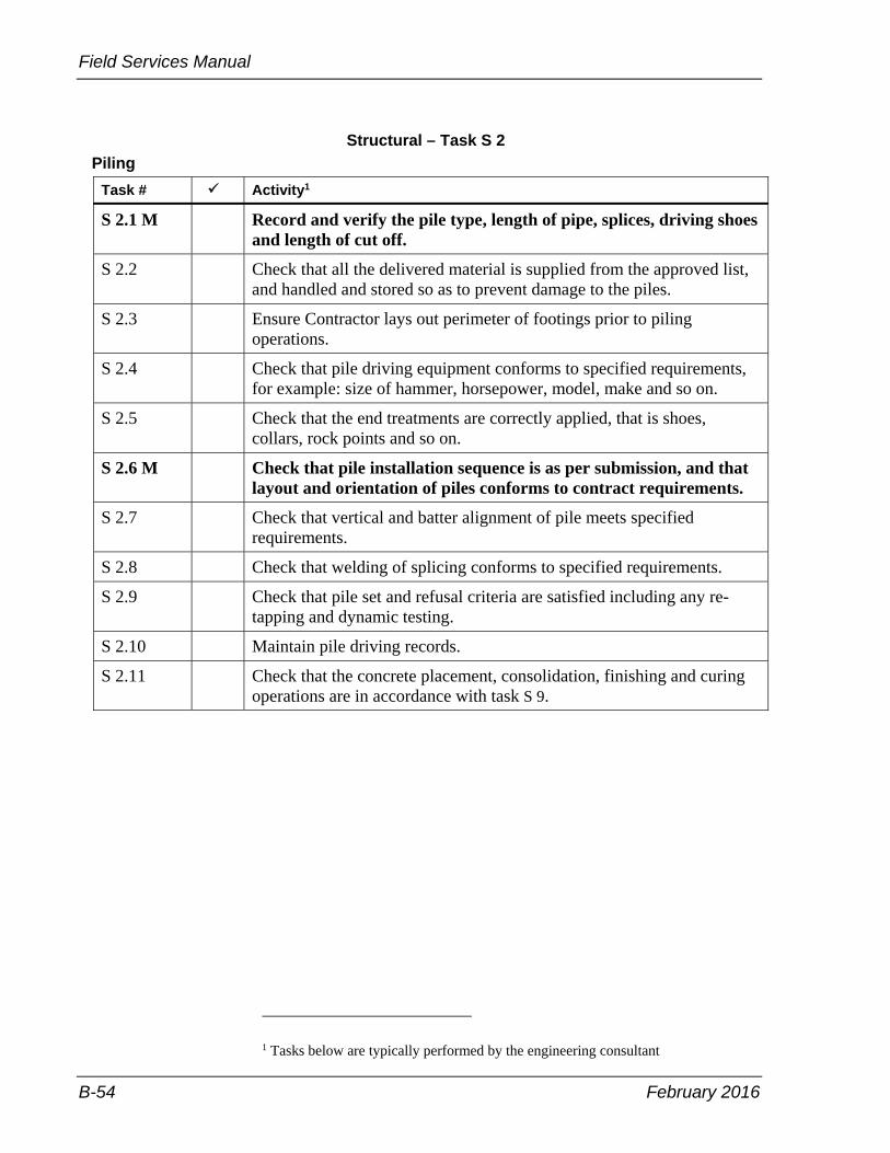
Field Services Manual
B-54 February 2016
Structural – Task S 2 Piling
Task # Activity1
S 2.1 M Record and verify the pile type, length of pipe, splices, driving shoes and length of cut off.
S 2.2 Check that all the delivered material is supplied from the approved list, and handled and stored so as to prevent damage to the piles.
S 2.3 Ensure Contractor lays out perimeter of footings prior to piling operations.
S 2.4 Check that pile driving equipment conforms to specified requirements, for example: size of hammer, horsepower, model, make and so on.
S 2.5 Check that the end treatments are correctly applied, that is shoes, collars, rock points and so on.
S 2.6 M Check that pile installation sequence is as per submission, and that layout and orientation of piles conforms to contract requirements.
S 2.7 Check that vertical and batter alignment of pile meets specified requirements.
S 2.8 Check that welding of splicing conforms to specified requirements.
S 2.9 Check that pile set and refusal criteria are satisfied including any re-tapping and dynamic testing.
S 2.10 Maintain pile driving records.
S 2.11 Check that the concrete placement, consolidation, finishing and curing operations are in accordance with task S 9.
1 Tasks below are typically performed by the engineering consultant

February 2016 B-55
Appendix B – Inspection Tasks
Structural – Task S 3 Structure Backfilling
Task # Activity
S 3.1 M Check that the area to be backfilled conforms to the contract documents.
S 3.2 M Check that the structure excavation limits are verified and recorded prior to commencement of backfilling operations.
S 3.3 M Check that the concrete has reached the required percentage of the design strength prior to backfilling.
S 3.4 Check subdrains are placed as specified in the contract.
S 3.5 Check proper procedures are used for weep holes and perforated pipe installation.
S 3.6 M Ensure use of proper material and backfill is placed as specified in contract.
S 3.7 Check that appropriate compaction procedures and sequence is used, and that appropriate compaction equipment is used in restricted areas.
S 3.8 Check that appropriate compaction testing is being conducted.

Field Services Manual
B-56 February 2016
Structural – Task S 4 Falsework
Task # Activity
S 4.1 M Check that stamped, approved falsework drawings are on site. Check installation of falsework against stamped working drawings prior to pour. Specifically ensure member sizes and spacing, mudsill locations and associate member sizes, longitudinal and transverse bracing, max extensions on screw heads of towers, type and location of hangers and location of screed rails.
S 4.2 Ensure that all required revisions are approved.
S 4.3 Ensure that falsework is erected on a stable base.
S 4.4 Ensure that required certifications are obtained prior to concrete placement.
S 4.5 Monitor falsework several times during concrete placement operation for deflection and settlement, that is tell tails.
S 4.6 M Check that the required concrete strength has been reached prior to removing falsework.
S 4.7 Ensure that the falsework is not removed prior to the grouting of the post tension ducts.

February 2016 B-57
Appendix B – Inspection Tasks
Structural – Task S 5 Formwork
Task # Activity
S 5.1 M Check all material, including hardware, for condition, quality, adjustment and fit.
S 5.2 Check dimensions of forms are as specified in the contract.
S 5.3 Check form release oil is applied to the forms before the installation of reinforcing steel.
S 5.4 Ensure proper cover to reinforcing steel is maintained during form installation.
S 5.5 Check forms and anchoring—several times—for alignment and possible deformation, during concrete placement.
S 5.6 Ensure that the mould is clean and free of all debris.
S 5.7 Ensure that any void box tie downs are installed as specified in the contract documents.
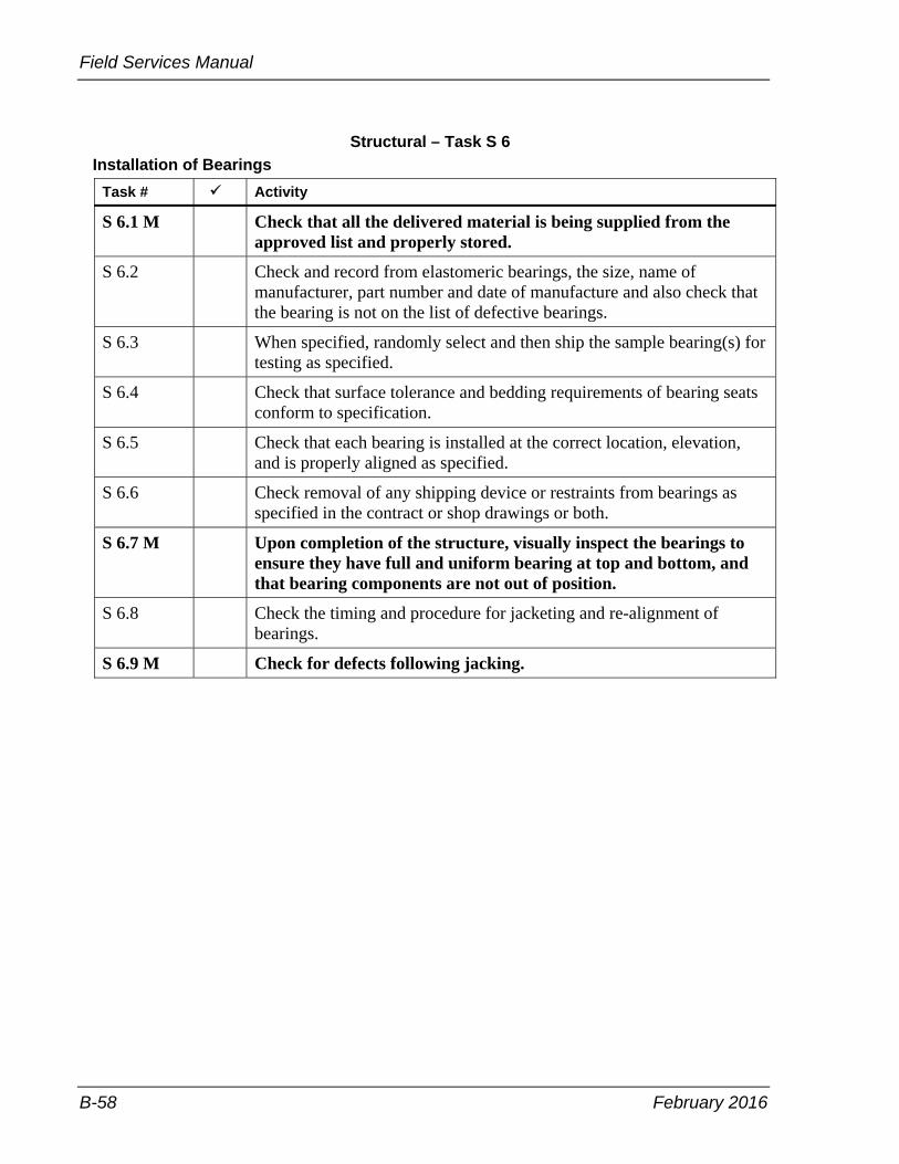
Field Services Manual
B-58 February 2016
Structural – Task S 6 Installation of Bearings
Task # Activity
S 6.1 M Check that all the delivered material is being supplied from the approved list and properly stored.
S 6.2 Check and record from elastomeric bearings, the size, name of manufacturer, part number and date of manufacture and also check that the bearing is not on the list of defective bearings.
S 6.3 When specified, randomly select and then ship the sample bearing(s) for testing as specified.
S 6.4 Check that surface tolerance and bedding requirements of bearing seats conform to specification.
S 6.5 Check that each bearing is installed at the correct location, elevation, and is properly aligned as specified.
S 6.6 Check removal of any shipping device or restraints from bearings as specified in the contract or shop drawings or both.
S 6.7 M Upon completion of the structure, visually inspect the bearings to ensure they have full and uniform bearing at top and bottom, and that bearing components are not out of position.
S 6.8 Check the timing and procedure for jacketing and re-alignment of bearings.
S 6.9 M Check for defects following jacking.

February 2016 B-59
Appendix B – Inspection Tasks
Structural – Task S 7 Concrete and Structural Steel Beam Erection
Task # Activity
S 7.1 M Check that the stamped approved erection drawings are on site.
S 7.2 Check that beams have not been damaged and are set to the specified alignment and seated properly.
S 7.3 M Ensure that the contractor complies with the approved drawings and procedures.
S 7.4 Ensure that lifting equipment has adequate capacity and is located on a stable foundation.
S 7.5 Ensure that lateral bracing is in place prior to lifting beams.

Field Services Manual
B-60 February 2016
Structural – Task S 8 Reinforcing Steel Placement
Task # Activity
S 8.1 Examine reinforcing steel schedule and drawings.
S 8.2 Check for proper site storage and handling.
S 8.3 M Check all the delivered material is being supplied from the approved list.
S 8.4 Check correct grade, bar mark, size, length, and bending dimensions and provision of mill certificates.
S 8.5 Check condition of all types of reinforcing steel and ensure damaged bars are repaired with approved materials or replaced as specified in the contract.
S 8.6 Check coated tie wire is used on epoxy coated steel and stainless steel ties are used on stainless steel.
S 8.7 Check splicing, spacing, cover, welding, supports and tying of bars is carried out as specified in the contract.
S 8.8 A sample of the stainless steel rebar must be obtained and forwarded for testing, as per the contract documents.
S 8.9 Check that the steel is in the proper place for cover as per the drawings, prior to concrete placement. Verify adequate cover before placement of concrete.
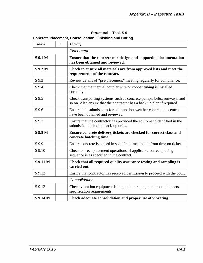
February 2016 B-61
Appendix B – Inspection Tasks
Structural – Task S 9 Concrete Placement, Consolidation, Finishing and Curing
Task # Activity
Placement
S 9.1 M Ensure that the concrete mix design and supporting documentation has been obtained and reviewed.
S 9.2 M Check to ensure all materials are from approved lists and meet the requirements of the contract.
S 9.3 Review details of “pre-placement” meeting regularly for compliance.
S 9.4 Check that the thermal coupler wire or copper tubing is installed correctly.
S 9.5 Check transporting systems such as concrete pumps, belts, runways, and so on. Also ensure that the contractor has a back up plan if required.
S 9.6 Ensure that submissions for cold and hot weather concrete placement have been obtained and reviewed.
S 9.7 Ensure that the contractor has provided the equipment identified in the submission including back-up units.
S 9.8 M Ensure concrete delivery tickets are checked for correct class and concrete batching time.
S 9.9 Ensure concrete is placed in specified time, that is from time on ticket.
S 9.10 Check correct placement operations, if applicable correct placing sequence is as specified in the contract.
S 9.11 M Check that all required quality assurance testing and sampling is carried out.
S 9.12 Ensure that contractor has received permission to proceed with the pour.
Consolidation
S 9.13 Check vibration equipment is in good operating condition and meets specification requirements.
S 9.14 M Check adequate consolidation and proper use of vibrating.

Field Services Manual
B-62 February 2016
Structural – Task S 9 Concrete Placement, Consolidation, Finishing and Curing (continued)
Task # Activity
Finishing
S 9.15 Check deck finishing equipment is as specified in the contract.
S 9.16 M Ensure deck finisher dry run is conducted and check clearances.
S 9.17 Check that finishing of plastic concrete is as specified in the contract.
S 9.18 Check tolerances of finishing concrete are as specified in the contract.
Curing
S 9.19 M Check that specified curing is carried out.
S 9.20 Check that hot and cold weather protection requirements are carried out as specified in the contract, including monitoring concrete temperatures where applicable.

February 2016 B-63
Appendix B – Inspection Tasks
Structural – Task S 10 Installation of Expansion Joints
Task # Activity
S 10.1 Check no damage occurs during handling.
S 10.2 Check all delivered material to verify that it is being supplied from the approved list.
S 10.3 M Check material supplied by the contractor is sampled as required.
S 10.4 Check for proper storage.
S 10.5 Check field splices in steel components are located and welded as per shop drawings and are performed by a certified welder and ensure that the weld is field painted.
S 10.6 Ensure that the dimensions of the block-out to receive the joint assembly are in accordance with the contract drawings and standard drawings.
S 10.7 Check that the block-out to receive the joint is abrasive blast cleaned, without damaging the epoxy coated steel.
S 10.8 Check that all debris in the block-out has been removed and the area coated with a cement paste prior to placing concrete.
S 10.9 M Check that the proper gap or “j” dimension of the unit has been established prior to placing concrete, and check that the constant gap is achieved throughout the total length.
S 10.10 M Ensure proper cover from expansion joint steel.
S 10.11 Check that the concrete placement, consolidation, finishing and curing operations are in accordance with task S 9.
S 10.12 Check that clamping angles or channels are removed as specified in the contract.
S 10.13 Check that holes left from removal of clamping angles or channels are cleaned and grouted with approved epoxy.
S 10.14 Check for concrete blockages in the expansion joint openings.
S 10.15 Check that seal is properly installed with no damage, wrinkles or splices.
S 10.16 Check that sliding plates on sidewalk, curbs, and median have been installed properly with regards to the direction of traffic.
S 10.17 Check that formwork including Styrofoam has been removed below expansion joint assembly between deck and ballast wall before the seal is installed.
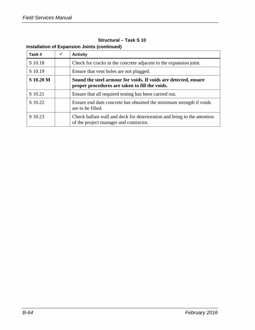
Field Services Manual
B-64 February 2016
Structural – Task S 10 Installation of Expansion Joints (continued)
Task # Activity
S 10.18 Check for cracks in the concrete adjacent to the expansion joint.
S 10.19 Ensure that vent holes are not plugged.
S 10.20 M Sound the steel armour for voids. If voids are detected, ensure proper procedures are taken to fill the voids.
S 10.21 Ensure that all required testing has been carried out.
S 10.22 Ensure end dam concrete has obtained the minimum strength if voids are to be filled.
S 10.23 Check ballast wall and deck for deterioration and bring to the attention of the project manager and contractor.

February 2016 B-65
Appendix B – Inspection Tasks
Structural – Task S 11 Barrier Walls
Task # Activity
S 11.1 Check method of construction is as specified in the contract.
S 11.2 Conventional wooden or steel form method. Check for correct alignment, grade and granular base preparation.
Check for correct joint detail and spacing.
Check cover on reinforcing steel.
Check that the concrete placement, consolidation and finishing operations are in accordance with task S 9.
Check that specified curing requirements are carried out.
Check for surface tolerances and cracking.
Check that railing mounts or anchorages are correctly installed, for example: location, elevation, flushness, and anchor bolt protrusion is adequate for tube rails.
Check that the inside faces of formwork is clean, oiled, and in good order, to produce a smooth cast face.
Check that the barrier wall forms are adequately restrained to prevent uplift and spreading.
Ensure anchorages for handrail are installed in correct locations.
S 11.3 Extruded method (Not allowed on bridge decks). Check for correct alignment, grade and granular base preparation.
Check location of reinforcing steel.
Check that the concrete placement, consolidation and finishing operations are in accordance with task S 9.
Check specified percentage of air is being maintained behind extruder.
Check that specified curing requirements are met.

Field Services Manual
B-66 February 2016
Check for surface tolerances and cracking.

February 2016 B-67
Appendix B – Inspection Tasks
Structural – Task S 12 Railing for Barrier or Parapet Wall
Task # Activity
S 12.1 Ensure that all rail and post material delivered to the site is that specified in the contract.
S 12.2 Ensure that material is stored properly.
S 12.3 Check material for damage or defects.
S 12.4 M Ensure that anchorages have been properly located.
S 12.5 Ensure all end caps are installed properly.
S 12.6 Check the gap on rail mating surfaces to ensure the joint will slide.
S 12.7 Ensure that slide joints are located as detailed in the contract.
S 12.8 Ensure that rail posts are perpendicular and rails are properly aligned.

Field Services Manual
B-68 February 2016
Structural – Task S 13 High Performance Concrete (This task list is in addition to S 9)
Task # Activity
S 13.1 M Ensure mix design is approved by the contract administrator.
S 13.2 Ensure that the number of thermocouples conform to the special provisions.
Placement of Curing
S 13.3 Check the thermocouples for temperature and temperature difference control are installed.
S 13.4 Check the concrete temperature, slump and air content are as per contract.
S 13.5 Check that the concrete does not segregate during placement and consolidation.
S 13.6 Check the moulds used for making test cylinders conform to requirements.
S 13.7 Check structure decks, approach slabs, curbs and sidewalks, to ensure that fog mist is applied continuously from the time of spreading until concrete is covered with burlap.
S 13.8 Review contractor’s temperature records daily. Calculate the thermal gradient by dividing the temperature difference between the centre of concrete and the surface of concrete by the distance between the centre and its nearest surface. If the thermal gradient is greater than 1.5° C/cm, alert the contract administrator.
S 13.9 Check protection is applied when temperature and/or temperature difference exceeds the limit.
Quality Assurance
S 13.10 Ensure that testing is carried out as per contract requirements.
S 13.11 Carry out crack inspection and review proposal for repairs.
S 13.12 M Check permission to waterproof is not issued until cracks are treated and the deck is cured for three (3) days.

February 2016 B-69
Appendix B – Inspection Tasks
Structural – Task S 14 Bridge Deck Waterproofing
Task # Activity
S 14.1 M Check that the deck meets requirements for surface tolerance and surface finish. Contractor to verify acceptability of deck surface with waterproofing subcontractor.
S 14.2 M Check that the air and concrete surface temperature are within specification requirements.
S 14.3 M Verify that the deck surface, face of the curbs and barriers walls have been completely treated by abrasive blast cleaning to expose sound, laitance-free concrete and provide permission to proceed.
S 14.4 Check that no traffic, other than the construction equipment directly associated with the waterproofing operation, is allowed on the abrasive blast cleaned deck.
S 14.5 M Check that all delivered materials are approved.
S 14.6 Check that tack coat is cured completely and free of any surface moisture and dirt before waterproofing membrane is applied.
S 14.7 Check specified temperature of waterproofing membrane at time of placing.
S 14.8 Check correct placement of membrane reinforcement.
S 14.9 Check correct placing of protection boards.
S 14.10 Check the deck drainage tubes are open.
S 14.11 Check tack coating of protection boards just prior to paving.
S 14.12 Ensure that the contractor takes adequate protective measures to mask concrete and prevent over-spray of tack coat materials onto adjacent concrete surfaces such as the curb face, barrier wall, abutments, columns, and so forth.
S 14.13 Measure and record waterproofing thickness.
S 14.14 Ensure that required samples are taken for testing.

Field Services Manual
B-70 February 2016
Structural – Task S 15 Cofferdams, Sheet Piling, Tie-backs and Roadway Protection
Task # Activity
S 15.1 M Ensure that stamped approved drawings are available on site.
S 15.2 Check length and condition of all material delivered to the site.
S 15.3 Check that the contractor’s scheme is as specified on the working drawings.
S 15.4 Check that the scheme is as specified in the contract for length.
S 15.5 Check that anchor testing is as specified in the specifications.
S 15.6 Check that the contractor monitors the completed scheme for movement.

February 2016 B-71
Appendix B – Inspection Tasks
Structural – Task S 16 Dewatering
Task # Activity
S 16.1 Check operation of dewatering system.
S 16.2 Check that the contractor is monitoring the system as specified in the contract.
S 16.3 Check that dewatering is not removed until the backfilling is brought up to grade.
S 16.4 Check that dewatering is not causing erosion of soil at the outlet and other environmental concerns, for example muddy water discharge. Check that the contractor has the standby equipment such as pumps, hoses, and so forth, on site as required in the environmental submission.
S 16.5 M Check environmental special provisions are adhered to.
S 16.6 M Check that discharge is being managed as per contract requirements.
S 16.7 Check that groundwater drawdown levels are as designed on the drawings.
S 16.8 Check that the contractor’s dewatering scheme is not causing loss of materials under adjacent founding elements or backfill.
S 16.9 Monitor pump inlet to ensure pump is not submerged in mud.

Field Services Manual
B-72 February 2016
Structural – Task S 17 Caisson Foundations
Task # Activity
S 17.1 Check type, length, and condition of caisson liners.
S 17.2 Check that installation equipment is as specified in the contract.
S 17.3 Check that penetration and cut off are in accordance with design data.
S 17.4 M Check that caissons are cleaned out prior to placing reinforcing steel and concrete.
S 17.5 Ensure that reinforcing cages are placed correctly.
S 17.6 Check that the concrete placement, consolidation, finishing, and curing operations are performed in accordance with task S 9.
S 17.7 Check that vertical and batter alignment of caisson are as specified in the contract.

February 2016 B-73
Appendix B – Inspection Tasks
Structural – Task S 18 Tremie Concrete
Task # Activity
S 18.1 Check placement operation is as specified.
S 18.2 Check the concrete placement, consolidation, finishing and curing operations are in accordance with contract.
S 18.3 Check elevation at which the placement is terminated.
S 18.4 Check that dewatering is not carried out prior to when it is specified in the contract.
S 18.5 M Check proper removals, cleaning and soundness of top surface prior to placing additional concrete.
S 18.6 Ensure that formed enclosure meets water tightness specified in the contractor’s submission, when placement is required next to a watercourse.

Field Services Manual
B-74 February 2016
Structural – Task S 19 Structure Rehabilitation – Removal of Waterproofing System from Deck Surface Note: For deck to be subsequently rehabilitated by patch or waterproofing and paving.
Task # Activity
S 19.1 Check that all old waterproofing membrane is completely removed from the concrete surface without any damage to the existing surface of the deck.
S 19.2 Identify all repairs and remedial works have been carried out prior to waterproofing.
S 19.3 Check that all repairs and remedial work to the concrete deck has been completed.
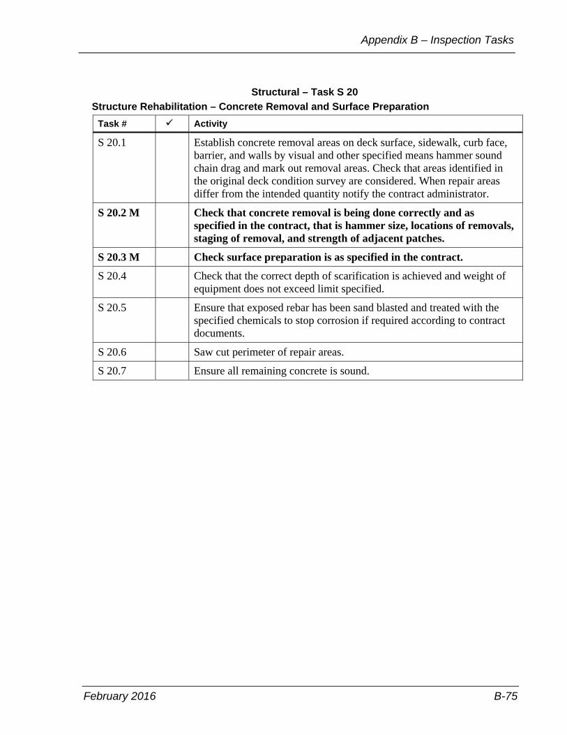
February 2016 B-75
Appendix B – Inspection Tasks
Structural – Task S 20 Structure Rehabilitation – Concrete Removal and Surface Preparation
Task # Activity
S 20.1 Establish concrete removal areas on deck surface, sidewalk, curb face, barrier, and walls by visual and other specified means hammer sound chain drag and mark out removal areas. Check that areas identified in the original deck condition survey are considered. When repair areas differ from the intended quantity notify the contract administrator.
S 20.2 M Check that concrete removal is being done correctly and as specified in the contract, that is hammer size, locations of removals, staging of removal, and strength of adjacent patches.
S 20.3 M Check surface preparation is as specified in the contract.
S 20.4 Check that the correct depth of scarification is achieved and weight of equipment does not exceed limit specified.
S 20.5 Ensure that exposed rebar has been sand blasted and treated with the specified chemicals to stop corrosion if required according to contract documents.
S 20.6 Saw cut perimeter of repair areas.
S 20.7 Ensure all remaining concrete is sound.

Field Services Manual
B-76 February 2016
Structural – Task S 21 Structure Rehabilitation – Concrete Overlay
Task # Activity
Submission
S 21.1 M Obtain contractor’s submission and verify that the concrete mix design meets the requirements of the special provision for air void system in the hardened concrete and minimum specified seven day compressive strength.
S 21.2 Obtain documentation certifying that the super plasticizer meets the following:
• conforms to ASTM C 494 standard specification for chemical admixtures for concrete and Committee C 17 on fibre reinforced cement products requirements
• no chlorides were added during the manufacturer of the super plasticizer
• it is compatible with the cementing materials and all other admixtures used in the concrete
S 21.3 Check that all supporting test data is not more then 12 months old from the data the concrete mix design was submitted.
Trial Run
S 21.4 Check that the screed rails have been installed outside the area to be waterproofed.
S 21.5 Check that the contractor’s trial run has been completed before each placing operation to ensure that the minimum thickness of the overlay can be achieved.
S 21.6 Check that the contractor has verified that the screed rails and finishing machine have been set to ensure that the thickness of the overlay meets the requirements of the contract documents before proceeding with the placement of the overlay.
Placement
S 21.7 Check that all full depth patches have been repaired prior to placing the overlay, unless otherwise specified in the contract documents.
S 21.8 Check that concrete for all partial depth removal areas in the deck are placed at the same time as the overlay.
S 21.9 Check that overlay is not placed adjacent to any new concrete less than 48 hours old. If the ambient air temperature falls below 10°C within the first 48 hours after placement of concrete, the 48 hour time requirement is extended to 96 hours.

February 2016 B-77
Appendix B – Inspection Tasks
Structural – Task S 21 Structure Rehabilitation – Concrete Overlay (continued)
Task # Activity
S 21.10 M Check the temperature of the air and existing concrete surface to receive the overlay, to ensure it meets contract requirements prior to and during concrete operations.
S 21.11 Check equipment and runways for the concrete transporting equipment to ensure they are not supported by reinforcing steel.
S 21.12 Check that only the finishing machine and buggies used to place concrete are allowed on the abrasive blast cleaned portions of the deck. No other vehicles or equipment, including concrete ready mix trucks shall be permitted.
S 21.13 Check that heavy vehicles such as concrete ready mix trucks or dump trucks are not permitted on the deck where concrete removal has taken place.
S 21.14 Check that removal of all dust and loose material is carried by oil-free compressed air.
S 21.15 Check that the prepared surface is maintained in a wet condition for six hours prior to placing concrete.
S 21.16 Check that excess water is removed by oil-free compressed air immediately prior to application of bonding grout.
S 21.17 Check that areas of reinforcing steel and prepared concrete surface are protected from oil leaks and dropping grout or concrete from placing equipment.
S 21.18 Check that all vertical and horizontal surfaces against which the overlay will be placed receive a thorough, even coating of bonding grout, with no excess left in place.
S 21.19 Check that the application of bonding grout is such that the brushed material does not become dry before it is covered with overlay concrete. Ensure that bonding grout, which is not used within 30 minutes after mixing, is discarded.
S 21.20 Check that concrete placement, consolidation, finishing and curing procedures are in accordance with the contract documents.
S 21.21 Check that the overlay is cured with burlap and water regardless of ambient temperature. Check that the burlap is maintained in a continuously wet condition throughout the curing period by means of a soaker hose. The soaker hoses shall be placed on the burlap prior to placing the moisture barrier.
S 21.22 Check that the burlap is prevented from freezing during cold weather.

Field Services Manual
B-78 February 2016
Structural – Task S 21 Structure Rehabilitation – Concrete Overlay (continued)
Task # Activity
S 21.23 Check that the construction joints are placed as specified in the contract documents.
S 21.24 Check that the tensile bond strength testing if carried out as per the contract requirements.
S 21.25 Check that the core holes have been filled according to the contract requirements.
Quality Assurance
S 21.26 Obtain and review tensile bond strength test results.
S 21.27 Check overlay for any areas of debonding, honeycombed areas or cracks.
S 21.28 Obtain and verify contractor’s crack inspection report and review Contractor’s crack treatment proposal is applicable.
S 21.29 Check that permission to waterproof is not issued until cracks are treated, if applicable, and the deck is air cured for three days.
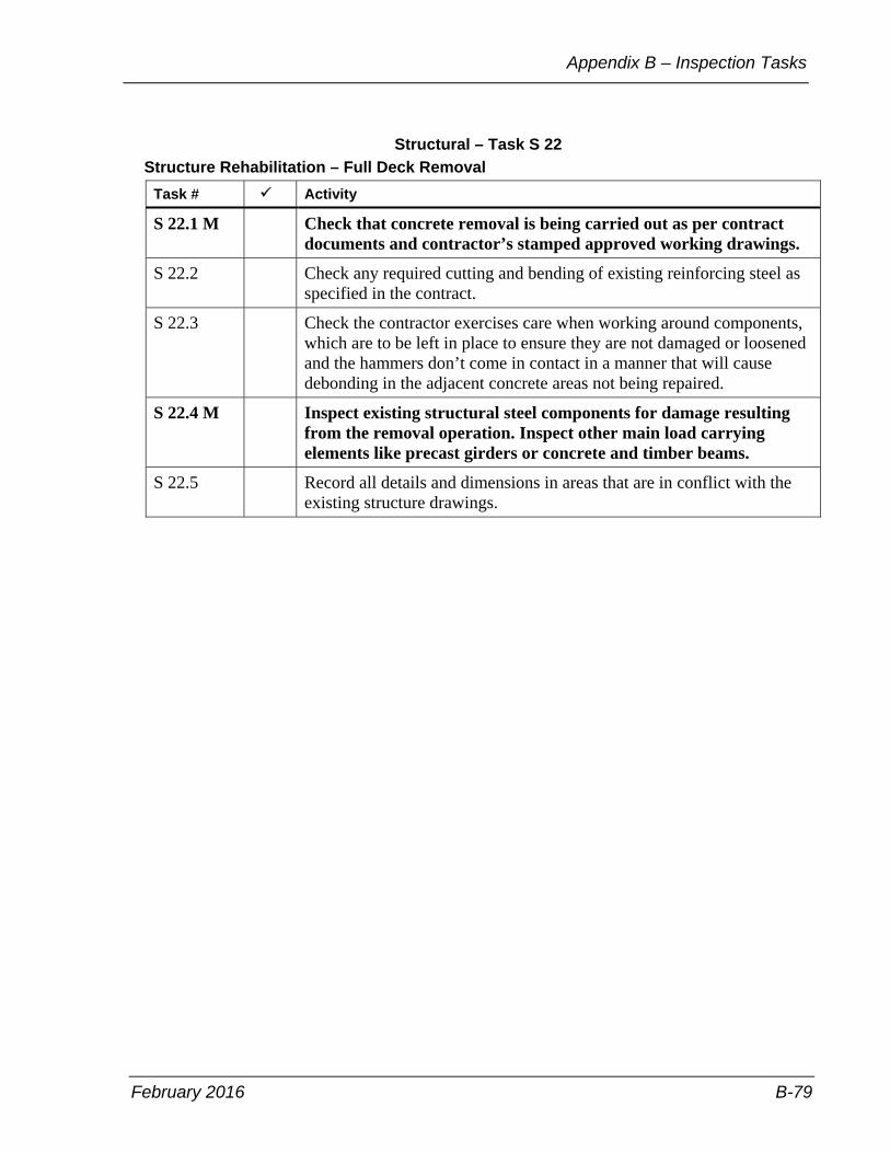
February 2016 B-79
Appendix B – Inspection Tasks
Structural – Task S 22 Structure Rehabilitation – Full Deck Removal
Task # Activity
S 22.1 M Check that concrete removal is being carried out as per contract documents and contractor’s stamped approved working drawings.
S 22.2 Check any required cutting and bending of existing reinforcing steel as specified in the contract.
S 22.3 Check the contractor exercises care when working around components, which are to be left in place to ensure they are not damaged or loosened and the hammers don’t come in contact in a manner that will cause debonding in the adjacent concrete areas not being repaired.
S 22.4 M Inspect existing structural steel components for damage resulting from the removal operation. Inspect other main load carrying elements like precast girders or concrete and timber beams.
S 22.5 Record all details and dimensions in areas that are in conflict with the existing structure drawings.
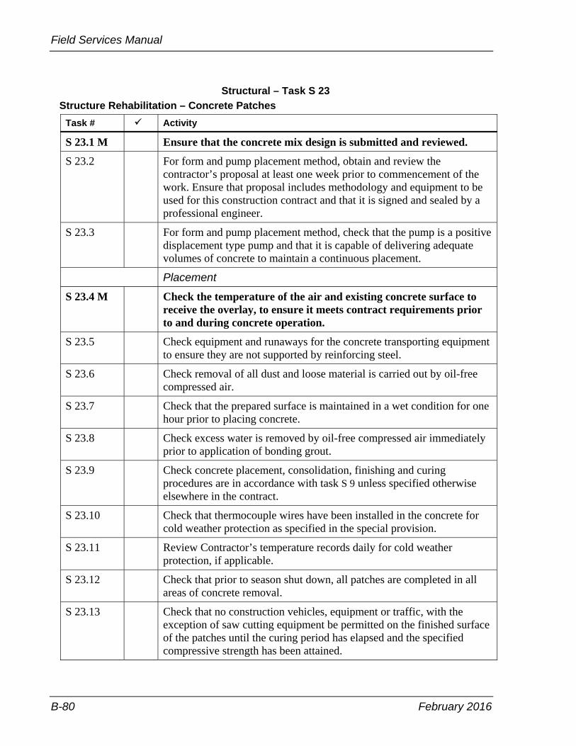
Field Services Manual
B-80 February 2016
Structural – Task S 23 Structure Rehabilitation – Concrete Patches
Task # Activity
S 23.1 M Ensure that the concrete mix design is submitted and reviewed.
S 23.2 For form and pump placement method, obtain and review the contractor’s proposal at least one week prior to commencement of the work. Ensure that proposal includes methodology and equipment to be used for this construction contract and that it is signed and sealed by a professional engineer.
S 23.3 For form and pump placement method, check that the pump is a positive displacement type pump and that it is capable of delivering adequate volumes of concrete to maintain a continuous placement.
Placement
S 23.4 M Check the temperature of the air and existing concrete surface to receive the overlay, to ensure it meets contract requirements prior to and during concrete operation.
S 23.5 Check equipment and runaways for the concrete transporting equipment to ensure they are not supported by reinforcing steel.
S 23.6 Check removal of all dust and loose material is carried out by oil-free compressed air.
S 23.7 Check that the prepared surface is maintained in a wet condition for one hour prior to placing concrete.
S 23.8 Check excess water is removed by oil-free compressed air immediately prior to application of bonding grout.
S 23.9 Check concrete placement, consolidation, finishing and curing procedures are in accordance with task S 9 unless specified otherwise elsewhere in the contract.
S 23.10 Check that thermocouple wires have been installed in the concrete for cold weather protection as specified in the special provision.
S 23.11 Review Contractor’s temperature records daily for cold weather protection, if applicable.
S 23.12 Check that prior to season shut down, all patches are completed in all areas of concrete removal.
S 23.13 Check that no construction vehicles, equipment or traffic, with the exception of saw cutting equipment be permitted on the finished surface of the patches until the curing period has elapsed and the specified compressive strength has been attained.

February 2016 B-81
Appendix B – Inspection Tasks
Structural – Task S 23 Structure Rehabilitation – Concrete Patches (continued)
Task # Activity
S 23.14 Define the lots and determine core locations for air void system and tensile bond strength test.
S 23.15 Check that the tensile bond strength testing is carried out as per the contract requirement.
S 23.16 Check that the core holes have been filled according to the contact requirements.
Quality Assurance
S 23.17 Obtain and review tensile bond strength test results.
S 23.18 Check patches for any areas of debonding, honeycombed areas or cracks.
S 23.19 Obtain and verify contractor’s crack inspection report, review Contractor’s crack treatment proposal if applicable.
S 23.20 Check permission to waterproof is not issued until the cracks are treated, if applicable, and the patches in the deck are cured for three (3) days.
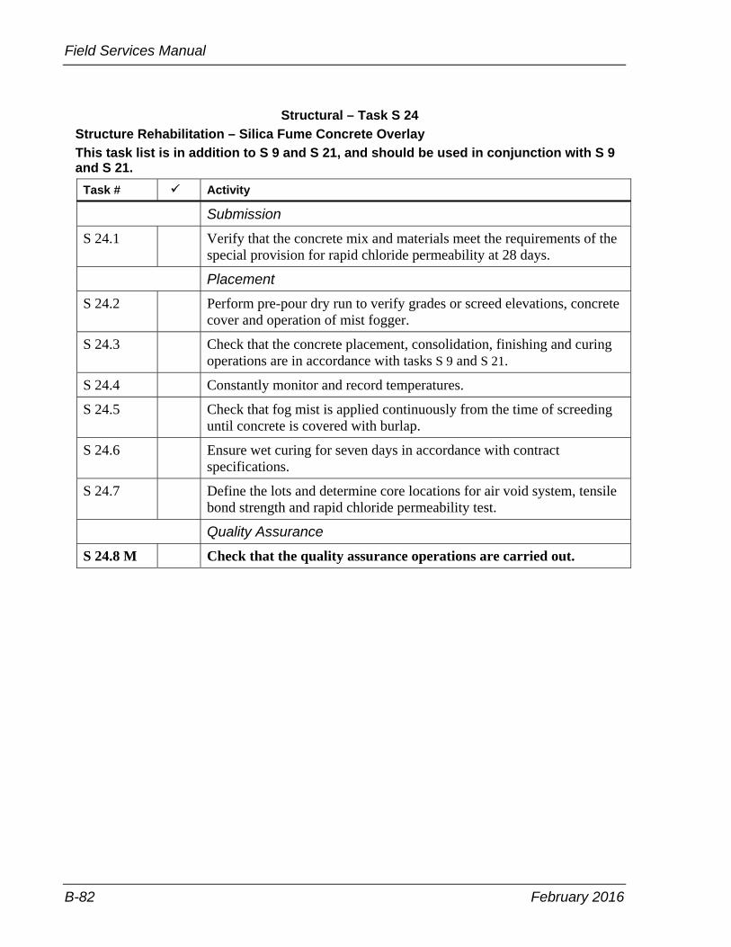
Field Services Manual
B-82 February 2016
Structural – Task S 24 Structure Rehabilitation – Silica Fume Concrete Overlay This task list is in addition to S 9 and S 21, and should be used in conjunction with S 9 and S 21.
Task # Activity
Submission
S 24.1 Verify that the concrete mix and materials meet the requirements of the special provision for rapid chloride permeability at 28 days.
Placement
S 24.2 Perform pre-pour dry run to verify grades or screed elevations, concrete cover and operation of mist fogger.
S 24.3 Check that the concrete placement, consolidation, finishing and curing operations are in accordance with tasks S 9 and S 21.
S 24.4 Constantly monitor and record temperatures.
S 24.5 Check that fog mist is applied continuously from the time of screeding until concrete is covered with burlap.
S 24.6 Ensure wet curing for seven days in accordance with contract specifications.
S 24.7 Define the lots and determine core locations for air void system, tensile bond strength and rapid chloride permeability test.
Quality Assurance
S 24.8 M Check that the quality assurance operations are carried out.
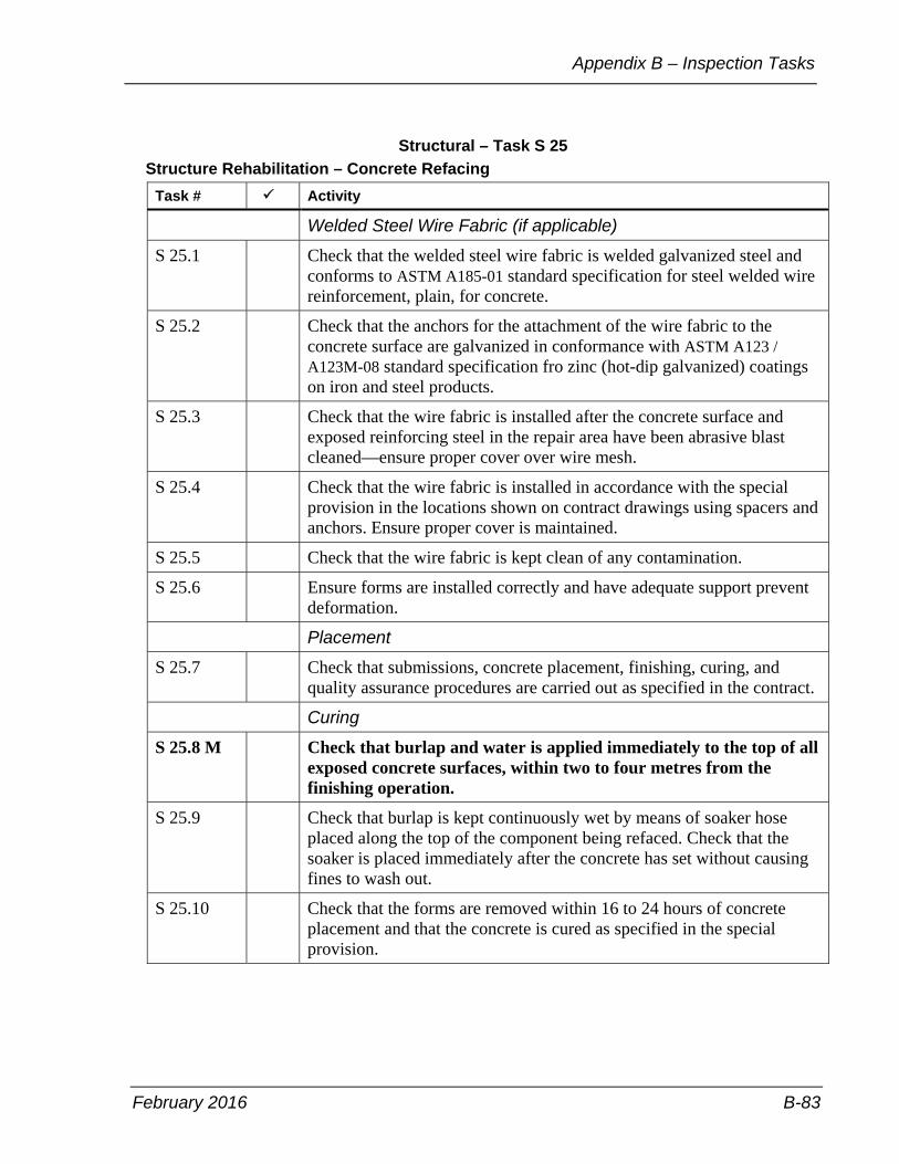
February 2016 B-83
Appendix B – Inspection Tasks
Structural – Task S 25 Structure Rehabilitation – Concrete Refacing
Task # Activity
Welded Steel Wire Fabric (if applicable)
S 25.1 Check that the welded steel wire fabric is welded galvanized steel and conforms to ASTM A185-01 standard specification for steel welded wire reinforcement, plain, for concrete.
S 25.2 Check that the anchors for the attachment of the wire fabric to the concrete surface are galvanized in conformance with ASTM A123 / A123M-08 standard specification fro zinc (hot-dip galvanized) coatings on iron and steel products.
S 25.3 Check that the wire fabric is installed after the concrete surface and exposed reinforcing steel in the repair area have been abrasive blast cleaned—ensure proper cover over wire mesh.
S 25.4 Check that the wire fabric is installed in accordance with the special provision in the locations shown on contract drawings using spacers and anchors. Ensure proper cover is maintained.
S 25.5 Check that the wire fabric is kept clean of any contamination.
S 25.6 Ensure forms are installed correctly and have adequate support prevent deformation.
Placement
S 25.7 Check that submissions, concrete placement, finishing, curing, and quality assurance procedures are carried out as specified in the contract.
Curing
S 25.8 M Check that burlap and water is applied immediately to the top of all exposed concrete surfaces, within two to four metres from the finishing operation.
S 25.9 Check that burlap is kept continuously wet by means of soaker hose placed along the top of the component being refaced. Check that the soaker is placed immediately after the concrete has set without causing fines to wash out.
S 25.10 Check that the forms are removed within 16 to 24 hours of concrete placement and that the concrete is cured as specified in the special provision.

Field Services Manual
B-84 February 2016
Structural – Task S 26 Structural Steel Coating
Task # Activity
S 26.1 M Check all the delivered material, for example, abrasives and coatings, to verify that it is being supplied as per the requirements and specifications.
S 26.2 Check material supplied by the contractor is sampled as required.
S 26.3 Check all requirements and manufacturers product data sheets are met.
S 26.4 Check individual coating products used in the coating system come from the same manufacturer and are compatible.
S 26.5 Check approvals for access, such as scaffolding and stain towers. Review shop drawings signed by a professional engineer.
S 26.6 Check environmental operations including enclosure systems, negative pressure, management and disposal of spent blast medium and removed coating material are as specified in contract or contractor’s approved proposal or both.
S 26.7 M Check that surface preparation is carried out as specified in the contract and meet the specified The Society for Protective Coatings (SSPC) standard.
S 26.8 Obtain sample of spent blast medium if specified in the contract. Delivery to contract administrator for laboratory testing.
S 26.9 M Check that coating of structural steel follows cleaning within the time as specified in the contract.
S 26.10 Check air temperature and dew point restrictions.
S 26.11 Check that the coat application is carried out as specified in the contract.
S 26.12 M Ensure that all applicable tests are performed, for example steel profile, paint thickness, temperature, dew point, and so forth.
S 26.13 Check that all blast abrasive, dust and other debris are removed from the steel surface and each coating surface prior to the application of the subsequent coat.
S 26.14 Ensure that the clean steel profile and paint thickness are recorded in diaries.
S 26.15 Check condition of galvanized components during installation. Ensure repairs as specified in the contract.
S 26.16 M Ensure that the consultant or sub-consultant inspecting the structural steel coating holds the appropriate certifications.

February 2016 B-85
Appendix B – Inspection Tasks
Traffic – Task T 1 Underground Ducts and Bases
Task # Activity
T 1.1 M Check all the delivered material to verify that it is being supplied from the approved list.
T 1.2 Check that excavation for the duct or duct banks conforms to the specified dimensions.
T 1.3 Check that wobble joints are installed as specified in the contract.
T 1.4 Check that the correct size and number of ducts are being installed.
T 1.5 M Check that backfill materials are as specified in the contract and is compacted as required.
T 1.6 Where Electrical Non-Metallic Tubing (EMT) is used, check that it has been installed in accordance with the contract documents.
T 1.7 Check that marker tape and cable bricks have been installed as specified in the contract.
T 1.8 Check that all unused ducts have fish wire installed, and are plugged.
T 1.9 M Check that ducts for underpass luminaries consist of non-metallic liquid tight conduit and connectors.

Field Services Manual
B-86 February 2016
Traffic – Task T 2 Electrical Chambers
Task # Activity
T 2.1 M Check all the delivered material to verify that it is being supplied from the approved list.
T 2.2 Check type, alignment, offsets and grade of maintenance holes and hand holes.
T 2.3 Check that the correct number of sleeves and openings are installed. Ensure correct positioning and installation of ladder rungs, pulling irons, duct sleeves, drainage pipe and frames and covers.
T 2.4 Check that drainage installation has been completed as specified in the contract.
T 2.5 M Check that backfill materials are as specified in the contract and are compacted as required.
T 2.6 Check that rigid and flexible ducts entering maintenance holes are installed with standard end bells places flush with the face of the inside wall of the unit.
T 2.7 M Check that frames and covers of electrical chambers are connected to the system ground or are intrinsically safe as per contract requirements.

February 2016 B-87
Appendix B – Inspection Tasks
Traffic – Task T 3 Electrical Chambers
Task # Activity
T 3.1 M Check all the delivered material to verify that it is being supplied from the approved list of shop drawings.
T 3.2 Check that the contractor augers that holes to the specified dimensions for footings.
T 3.3 At locations requiring excavation for bases, check excavation limits and ensure proper backfilling and compaction procedures.
T 3.4 Visually check all poles for dents, cracks, scratches and any other obvious imperfections.
T 3.5 Check that the contractor properly stores, erects and supports the poles in accordance with the manufacturer’s recommendations.
T 3.6 Check that pole orientation is as specified in the contract.
T 3.7 Check that the orientation and elevation of the frangible base is as specified in the contract.
T 3.8 M Check that pole foundations and poles are installed to the correct elevation, station and offset, as specified in the contract.
T 3.9 Check that the local grading around the pole foundations is completed as specified in the contract.

Field Services Manual
B-88 February 2016
Watermains – Task WM 1 General Inspection
Task # Activity
WM 1.1 Check that utility locates and mark-ups and traffic control plans are received.
WM 1.2 Check that hydrant “Out-of-Service” bags are used when a hydrant is temporaily out of service.
WM 1.3 Job inspected prior to saw cutting—ideally—to ensure no survey error or apparent conflicts with design.
WM 1.4 Check condition of road surface outside trench.
WM 1.5 Pipe class checked and condition of pipe inspected.
WM 1.6 Valves, fittings, saddles, and so on are checked.
WM 1.7 Construction proceeding as per standard drawings and specifications.
WM 1.8 Ground conditions during excavation noted, that is areas of excessive trench collapse, presence of water, undermining of asphalt and so on.
WM 1.9 Cover to top of pipe checked during construction.
WM 1.10 Stations of water services and sanitary services recorded.
WM 1.11 Trench width recorded.
WM 1.12 Type of shoring used noted.
WM 1.13 Site checked daily to ensure safety and ensure proper traffic control in place.
WM 1.14 Pictures taken of key tasks, unusual circumstances, extra work, typical anode and bend, tee, connection placements, changed conditions new operations, shoring, traffic control, and so forth.
WM 1.15 Deficiency inspection to be completed immediately as the work progresses and maintained on a running basis to be provided to the contract administrator and the contractor at least monthly and upon completion of construction.
WM 1.16 On a daily basis ensure that all material storage is done as per the contract requirements.
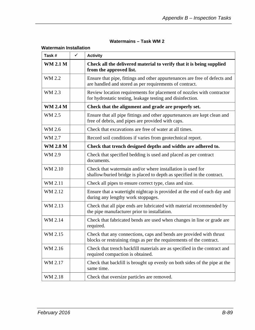
February 2016 B-89
Appendix B – Inspection Tasks
Watermains – Task WM 2 Watermain Installation
Task # Activity
WM 2.1 M Check all the delivered material to verify that it is being supplied from the approved list.
WM 2.2 Ensure that pipe, fittings and other appurtenances are free of defects and are handled and stored as per requirements of contract.
WM 2.3 Review location requirements for placement of nozzles with contractor for hydrostatic testing, leakage testing and disinfection.
WM 2.4 M Check that the alignment and grade are properly set.
WM 2.5 Ensure that all pipe fittings and other appurtenances are kept clean and free of debris, and pipes are provided with caps.
WM 2.6 Check that excavations are free of water at all times.
WM 2.7 Record soil conditions if varies from geotechnical report.
WM 2.8 M Check that trench designed depths and widths are adhered to.
WM 2.9 Check that specified bedding is used and placed as per contract documents.
WM 2.10 Check that watermain and/or where installation is used for shallow/buried bridge is placed to depth as specified in the contract.
WM 2.11 Check all pipes to ensure correct type, class and size.
WM 2.12 Ensure that a watertight nightcap is provided at the end of each day and during any lengthy work stoppages.
WM 2.13 Check that all pipe ends are lubricated with material recommended by the pipe manufacturer prior to installation.
WM 2.14 Check that fabricated bends are used when changes in line or grade are required.
WM 2.15 Check that any connections, caps and bends are provided with thrust blocks or restraining rings as per the requirements of the contract.
WM 2.16 Check that trench backfill materials are as specified in the contract and required compaction is obtained.
WM 2.17 Check that backfill is brought up evenly on both sides of the pipe at the same time.
WM 2.18 Check that oversize particles are removed.

Field Services Manual
B-90 February 2016
Watermains – Task WM 2 Watermain Installation (continued)
Task # Activity
WM 2.19 Check that appropriate equipment is used for compaction until the specified depth in the contract documents of cover over the pipe is achieved.
WM 2.20 M Check that hydrostatic and disinfection testing is completed and results are satisfactory before watermain is put back into service.
WM 2.21 Ensure that top of pipe elevations are obtained and recorded. WM 2.22 M Check that locations of bends, ties, connections and so on are
recorded.
WM 2.23 Ensure that the length of restrained pipe, on each side of the point of force, is as per contract.
WM 2.24 If applicable, check that the pipe installation sequence is as per the approved shop drawings.
WM 2.25 Ensure that the bituminous lined diaper and grout are installed on all joints of concrete watermain pipe as per contract.
WM 2.26 Ensure that anodes are installed on metallic pipe and appurtenances per the requirements of the contract and record size and location.
WM 2.27 Ensure that test stations are installed on all metallic watermain installations per contract.
WM 2.28 M Ensure that tracing wire is properly installed and tested for conductivity, continuity and traceability for non-metallic pipe.
WM 2.29 Document the work done in a manner similar to sanitary and storm sewer construction

February 2016 B-91
Appendix B – Inspection Tasks
Watermains – Task WM 3 Water Valves Installation
Task # Activity
WM 3.1 Check that all valves are supplied as specified from the approved list.
WM 3.2 Check that the bedding for valves is in accordance with pipe bedding specifications, unless otherwise specified.
WM 3.3 Ensure that damages to the factory applied protective coatings are corrected accordingly.
WM 3.4 Ensure that concrete supports are provided for valves when required.
WM 3.5 M Ensure that the direction of operation on all valves is clockwise, as specified (right hand opening) for transmission mains.
For distribution watermains direction to open valves is :
Open Clockwise
In districts Etobicoke/York (former City of York, east of the Humber River), North York, Toronto/East York all valves supplied to these areas of the City will open by operating in a clockwise direction and the operating nut supplied will be painted in red.
Open Counter Clockwise
In districts Etobicoke/York (former City of Etobicoke, west of the Humber River), and Scarborough all valves supplied to these areas of the City will open by operating in a counter clockwise direction and the operating nut supplied will be painted in black.
WM 3.6 Ensure that specified large valves have a hand wheel as well as the operating nut.
WM 3.7 Ensure that all valve boxes are installed plumb with well compacted backfill.
WM 3.8 Ensure that valve chambers are the type and size specified in the contract.
WM 3.9 Ensure that valve chambers with concrete floors have sumps as per the contract.
WM 3.10 Ensure that frames and covers for the valve chambers conform to the contract documents.
WM 3.11 Ensure that valve chamber frames and covers are centered over the valve nut with the cover adjusted to match grade. For large valve chambers with one or more valves, ensure that a sleeve is provided in the roof of the chamber immediately over the operating nut. Ensure that the valve box is installed over the centre of the sleeve.

Field Services Manual
B-92 February 2016
Watermains – Task WM 3 Water Valves Installation (continued)
Task # Activity
WM 3.12 Ensure that lifting hooks and lifting holes are provided, used and parged on pre-cast valve chamber sections.
WM 3.13 Ensure that pre-cast valve chamber sections are sealed as per the contract.
WM 3.14 Ensure that valve restraints are in place before pressure testing is conducted.
WM 3.15 Valve tied down before pressure testing. Make sure tracer wire is brought up to chamber.

February 2016 B-93
Appendix B – Inspection Tasks
Watermains – Task WM 4 Hydrant Installation
Task # Activity
WM 4.1 M Check all hydrants to verify that they are supplied from the approved list.
WM 4.2 Check that the bedding for the hydrants is in accordance with the contract documents.
WM 4.3 M Check that hydrants are placed to the depth and location specified in the contract.
WM 4.4 Check that hydrants are plumb. Ensure that the larger outlet nozzle is facing the roadway.
WM 4.5 M Check that the breakaway flange and coupling are at the proper elevation above the finished grade and that extensions are installed properly.
WM 4.6 Check that the restraining rings and the concrete thrust block are installed at the boot of the hydrant.
WM 4.7 Check that the restraining rings and concrete block is installed under the isolating valve and that the valve box over the valve is plumb and does not rest on the valve, but on the concrete block.
WM 4.8 Check that the operating nut on the hydrant opens counter clockwise.
WM 4.9 M Check that the upper barrel of the hydrant has a factory coat of yellow paint for City hydrants, and red for private hydrants.
WM 4.10 Check that anodes for cathodic protection and tracing wire are installed as per the contract.
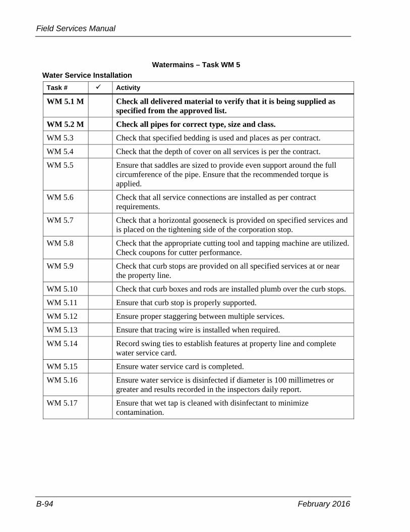
Field Services Manual
B-94 February 2016
Watermains – Task WM 5 Water Service Installation
Task # Activity
WM 5.1 M Check all delivered material to verify that it is being supplied as specified from the approved list.
WM 5.2 M Check all pipes for correct type, size and class.
WM 5.3 Check that specified bedding is used and places as per contract.
WM 5.4 Check that the depth of cover on all services is per the contract.
WM 5.5 Ensure that saddles are sized to provide even support around the full circumference of the pipe. Ensure that the recommended torque is applied.
WM 5.6 Check that all service connections are installed as per contract requirements.
WM 5.7 Check that a horizontal gooseneck is provided on specified services and is placed on the tightening side of the corporation stop.
WM 5.8 Check that the appropriate cutting tool and tapping machine are utilized. Check coupons for cutter performance.
WM 5.9 Check that curb stops are provided on all specified services at or near the property line.
WM 5.10 Check that curb boxes and rods are installed plumb over the curb stops.
WM 5.11 Ensure that curb stop is properly supported.
WM 5.12 Ensure proper staggering between multiple services.
WM 5.13 Ensure that tracing wire is installed when required.
WM 5.14 Record swing ties to establish features at property line and complete water service card.
WM 5.15 Ensure water service card is completed.
WM 5.16 Ensure water service is disinfected if diameter is 100 millimetres or greater and results recorded in the inspectors daily report.
WM 5.17 Ensure that wet tap is cleaned with disinfectant to minimize contamination.
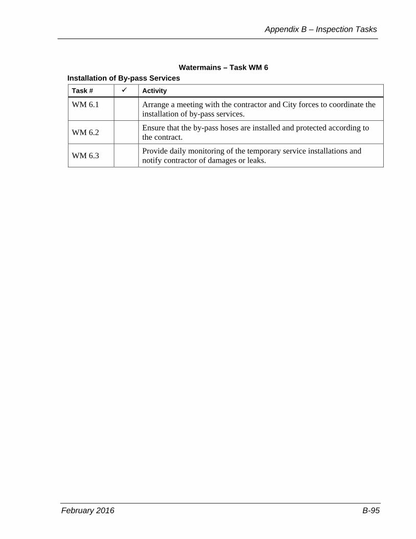
February 2016 B-95
Appendix B – Inspection Tasks
Watermains – Task WM 6 Installation of By-pass Services
Task # Activity
WM 6.1 Arrange a meeting with the contractor and City forces to coordinate the installation of by-pass services.
WM 6.2 Ensure that the by-pass hoses are installed and protected according to the contract.
WM 6.3 Provide daily monitoring of the temporary service installations and notify contractor of damages or leaks.

Field Services Manual
B-96 February 2016
Watermains – Task WM 7 Hydrostatic Testing
Task # Activity
WM 7.1 M Maintain presence on site for the duration of the test.
WM 7.2 M The watermain section to be tested shall be isolated by the contractor with the proper backflow prevention devices.
WM 7.3 Ensure adequate cover is provided over the watermain prior to testing.
WM 7.4 The watermain shall be filled by the contractor and flushed to remove any debris.
WM 7.5 Once the watermain has been properly flushed, check that the contractor increases the pressure to the testing level and air is expelled through hydrants and high points.
WM 7.6 Record the segment length and ensure that the testing pressure is maintained for the time, and within the specified pressure loss.
WM 7.7 Ensure that a leakage test is conducted during the first hour of the hydrostatic test, and that the volume of make-up water is within the tolerances specified in the contract.

February 2016 B-97
Appendix B – Inspection Tasks
Watermains – Task WM 8 Chlorination and Disinfection Testing
Task # Activity
WM 8.1 Once the watermain has been successfully tested for leakage, co-ordinate chlorination/disinfection test with the contractor.
WM 8.2 Ensure that the chlorination/disinfection plan has been prepared and submitted by the contractor and approved by the contract administrator. Inspector to receive a copy.
WM 8.3 M Ensure that no compressed air testing is permitted.
WM 8.4 M Ensure only Toronto Water operates the live system and not the contractor.
WM 8.5 M Ensure that disinfection tests are successfully performed by the contractor.
WM 8.6 Ensure that the contractor provides proper access to nozzles for disinfection.
WM 8.7 M Record disinfection test information in daily report.
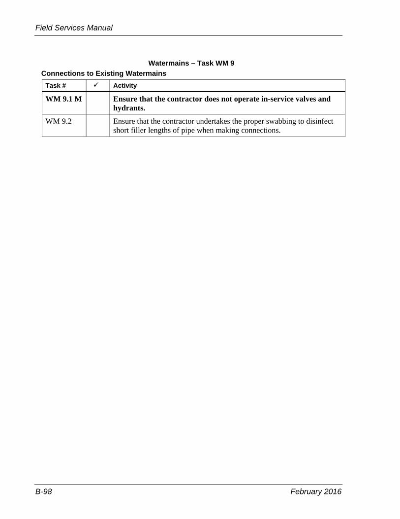
Field Services Manual
B-98 February 2016
Watermains – Task WM 9 Connections to Existing Watermains
Task # Activity
WM 9.1 M Ensure that the contractor does not operate in-service valves and hydrants.
WM 9.2 Ensure that the contractor undertakes the proper swabbing to disinfect short filler lengths of pipe when making connections.

February 2016 B-99
Appendix B – Inspection Tasks
Watermains – Task WM 10 Water Permit
Task # Activity
WM 10.1 Ensure that the contractor has a hydrant permit to take water for capital works projects such as for by-passes.

Field Services Manual
B-100 February 2016
Trenchless Rehabilitation – Task TRH 1 Full Length Cured-in-Place Pipe (CIPP)
Task # Activity
TRH 1.1 Check all delivered material is supplied as specified.
TRH 1.2 Ensure pre-cleaning, post-cleaning, and post-lining CCTV inspection are conducted as specified.
TRH 1.3 M Check liner material such as felt type, size and thickness are as specified.
TRH 1.4 Check resin and catalyst are as specified.
TRH 1.5 Check liner is free of debris such as cuts and tears.
TRH 1.6 Confirm specialized application equipment and processes are implemented as required.
TRH 1.7 Ensure wet out forms are completed by contractor.
TRH 1.8 Ensure inversion forms are completed by contractor.
TRH 1.9 Ensure installation is conducted as specified in contract documents.
TRH 1.10 Ensure curing forms are completed by contractor.
TRH 1.11 Ensure cooling down steps is observed.
TRH 1.12 Check lateral reinstatements are conducted.
TRH 1.13 Ensure lateral statement forms are completed by contractor. TRH 1.14 M Ensure liner testing for physical and chemical properties is
conducted.
TRH 1.15 Check damaged areas and defects are repaired.
TRH 1.16 Check liner sealing and finishing to face of maintenance holes is as specified.
TRH 1.17 Confirm active infiltration is stopped before lining begins. TRH 1.18 M Ensure post inspection of any defects in the liner if required.
TRH 1.19 Check liner is free of defects such as cuts and tears before installation.
TRH 1.20 Monitor by pass, as specified.
TRH 1.21 Ensure public is notified in advance.

February 2016 B-101
Appendix B – Inspection Tasks
Trenchless Replacement – Task TRP 1 Horizontal Directional Drilling (HDD)
Task # Activity
TRP 1.1 M Check all delivered material is supplied.
TRP 1.2 M Check pipe material, size and class.
TRP 1.3 Confirm rig classification and capabilities.
TRP 1.4 M Check all plans, sub-surface investigation and utility surveys, geotechnical reports and design calculations.
TRP 1.5 Ensure butt fusion and testing of pipe segments is conducted.
TRP 1.6 Ensure bore tracking equipment, walkover tracking systems, and non-walkover tracking systems are utilized.
TRP 1.7 Check drilling fluids and additives, delivery, recovery, containment systems, and storage.
TRP 1.8 M Check alignment and grade.
TRP 1.9 Confirm preparatory work for drilling pilot holes, reaming pilot holes, pulling to cleaning pipe ends, and handling and disposal of drilling mud and cuttings.
TRP 1.10 Check post inspection of pipe for any defects.
TRP 1.11 M Ensure testing and acceptance.
TRP 1.12 M Ensure all applicable forms and as-constructed drawings are provided by contractor to the City.

Field Services Manual
B-102 February 2016
Utilities – Task UT 1 Utility Construction
Task # Activity
UT 1.1 Check that a project information sign is placed at each end of the project. The sign should be visible to passing vehicular and pedestrian traffic, including the name of the utility company, the name of the contractor —where applicable—and a contact number.
UT 1.2 Ensure that pedestrian and vehicular access is being maintained in an efficient manner, unless restrictions have been approved by the Transportation Services division or the affected resident(s) or both.
UT 1.3 Check site for general cleanliness and housekeeping.
UT 1.4 Check that a copy of the permit is on-site. The expiry date on the permit should be checked to ensure that it is still valid and that the work is being carried out in the location noted on the permit.
UT 1.5 Check that a copy of the drawing is on-site, where applicable.
UT 1.6 Ensure that utility infrastructure is being installed in the correct alignment.The alignment should be as indicated on the drawing or sketch on the permit.
UT 1.7 Check that traffic control is in place and that traffic control plan is available on site.
UT 1.8 Check that pay-duty police are on-site, where applicable.
UT 1.9 Check that any adjacent utility or structure is not affected or undermined by the excavation.
UT 1.10 Ensure that utility infrastructure is being installed at the correct depth. The depth should be as indicated on the drawing or sketch on the permit. The inspector should measure the depth and note that depth of cover is as per the permit on the Utility Construction Site Visit Report (see Appendix A, Forms).
UT 1.11 Ensure that the work is being carried out in conformance with the conditions and work restrictions listed on the front or back of the permit.
UT 1.12 Check that any restoration being performed by the utility company meets City’s standards.
UT 1.13 Ensure that any photographs that are taken are noted on the Utility Construction Site Visit Report.
UT 1.14 M Complete the Utility Construction Site Visit Report and ensure that all major conditions noted on the permit are addressed on the report and inspections conducted according to the development and third party / utility inspection duration table.
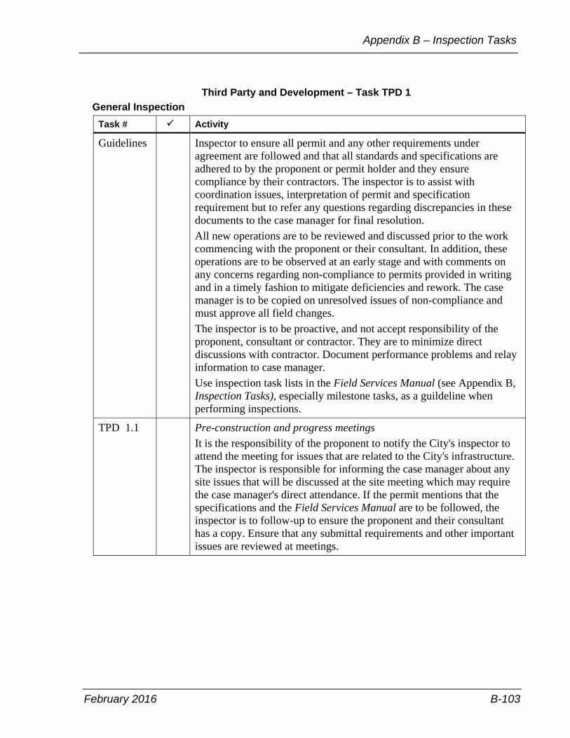
February 2016 B-103
Appendix B – Inspection Tasks
Third Party and Development – Task TPD 1 General Inspection
Task # Activity
Guidelines Inspector to ensure all permit and any other requirements under agreement are followed and that all standards and specifications are adhered to by the proponent or permit holder and they ensure compliance by their contractors. The inspector is to assist with coordination issues, interpretation of permit and specification requirement but to refer any questions regarding discrepancies in these documents to the case manager for final resolution. All new operations are to be reviewed and discussed prior to the work commencing with the proponent or their consultant. In addition, these operations are to be observed at an early stage and with comments on any concerns regarding non-compliance to permits provided in writing and in a timely fashion to mitigate deficiencies and rework. The case manager is to be copied on unresolved issues of non-compliance and must approve all field changes. The inspector is to be proactive, and not accept responsibility of the proponent, consultant or contractor. They are to minimize direct discussions with contractor. Document performance problems and relay information to case manager. Use inspection task lists in the Field Services Manual (see Appendix B, Inspection Tasks), especially milestone tasks, as a guildeline when performing inspections.
TPD 1.1 Pre-construction and progress meetings
It is the responsibility of the proponent to notify the City's inspector to attend the meeting for issues that are related to the City's infrastructure. The inspector is responsible for informing the case manager about any site issues that will be discussed at the site meeting which may require the case manager's direct attendance. If the permit mentions that the specifications and the Field Services Manual are to be followed, the inspector is to follow-up to ensure the proponent and their consultant has a copy. Ensure that any submittal requirements and other important issues are reviewed at meetings.

Field Services Manual
B-104 February 2016
Third Party and Development – Task TPD 1 General Inspection (continued)
Task # Activity
TPD 1.2 Field changes
Field changes due to any conflict on site are to be proposed by the proponent's consultant, and not the contractor. Contractors should be directed to contact the proponent and their consultants, and the not the City's site inspector and the case manager. However, the inspector is to investigate and report to the case manager on the validity of the proposed change.
TPD 1.3 Installation of sewers and watermains
Spot check for routine installation. Check that proponent or their consultant or both, are provding inspection, survey layout, material testing and documentation in accordance with the terms of the permit, specifications and any agreements. Sewers; inspection is required of the bedding of pressure pipes and sewers with water tight joints to ensure compliance with MOECC Procedure F-6-1 Procedures to Govern the Separation of Sewers and Watermains. Inspection also required to ensure backfilling is completed according to the specifications and agreement. Refer to and spot check other milestone inspection tasks in the Field Services Manual (see Appendix B, Inspection Tasks) pertaining to watermains and sewers.
TPD 1.4 Connection of new mains to existing mains
Near the end of the operation or before backfilling, ensure full-time attendance by the consultant and as-built information is recorded and submitted. Discuss connection work prior to the work being done with all parties involved. Ensure a photograph is taken and submitted of all connections.
TPD 1.5 Disinfection of watermain
Ensure proper documentation is completed and submitted, attendance by proponent or their consultant prior to work commencing, and that they are on site to ensure compliance with the disinfection procedure and chain of custody for sampling. Assist and provide guidance to proponent to help ensure that the procedure is followed correctly. Coordinate valve turn-on and turn-off. Report any unresolved problems to case manager.

February 2016 B-105
Appendix B – Inspection Tasks
Third Party and Development – Task TPD 1 General Inspection (continued)
Task # Activity
TPD 1.5 continued
Note: Toronto Water has requested Third Party Utility Review to be responsible to review and accept the forms prior to submission to Toronto Water. This has been added as a section to the General Information document in regards to Third Party Utility Review role in the Ministry of Environment and Climate Change (MOECC) watermain disinfection procedure under Section "6.5.2- Procedure for Disinfecting Watermains".
TPD 1.6 Spot check construction of above-ground works such as roads, curbs, sidewalks, hard boulevard works, tree pits, pavers, and any other streetscape features and construction of soft boulevard works such as street tree planting, sodding, and so forth for compliance with specifications, permits and agreements. Spot check formwork and other preparation work to ensure survey layout used. Check high, low points and cross fall for compliance with specifications and approved plans. Review testing requirements and areas of past problems or concerns with proponent and consultant prior to work commencing. Follow up with spot checks after observing and confirming compliance as early as possible in the operation. Ensure that proponent or their consultant has checked the pedestrian crossings ramps slopes to prior to pouring of concrete to ensure that they meet the City's standards and ensuring that sidewalk identification stamps and raised tactile plates are placed at ramps at all pedestrian crossings to meet the new Ontario Regulation 191/11 Integrated Accessibility Standards. Refer to Appendix B, Inspection Tasks of the Field Services Manual and spot check on any other milestone tasks with regards to road, curb and sidewalk construction, and so forth.
TPD 1.7 Connection of new roads to existing roads
Spot check during construction and review with proponent prior to final paving so that any deficiencies may be corrected prior to completion of the final paving.
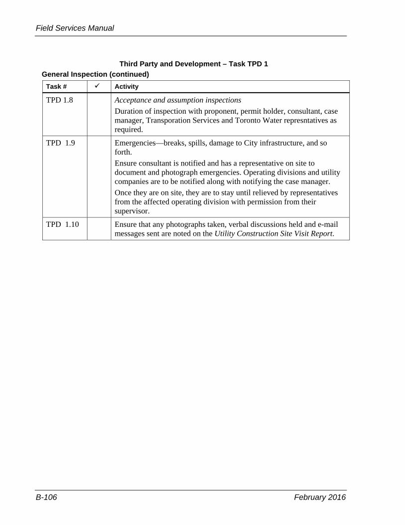
Field Services Manual
B-106 February 2016
Third Party and Development – Task TPD 1 General Inspection (continued)
Task # Activity
TPD 1.8 Acceptance and assumption inspections
Duration of inspection with proponent, permit holder, consultant, case manager, Transporation Services and Toronto Water represntatives as required.
TPD 1.9 Emergencies—breaks, spills, damage to City infrastructure, and so forth. Ensure consultant is notified and has a representative on site to document and photograph emergencies. Operating divisions and utility companies are to be notified along with notifying the case manager. Once they are on site, they are to stay until relieved by representatives from the affected operating division with permission from their supervisor.
TPD 1.10 Ensure that any photographs taken, verbal discussions held and e-mail messages sent are noted on the Utility Construction Site Visit Report.
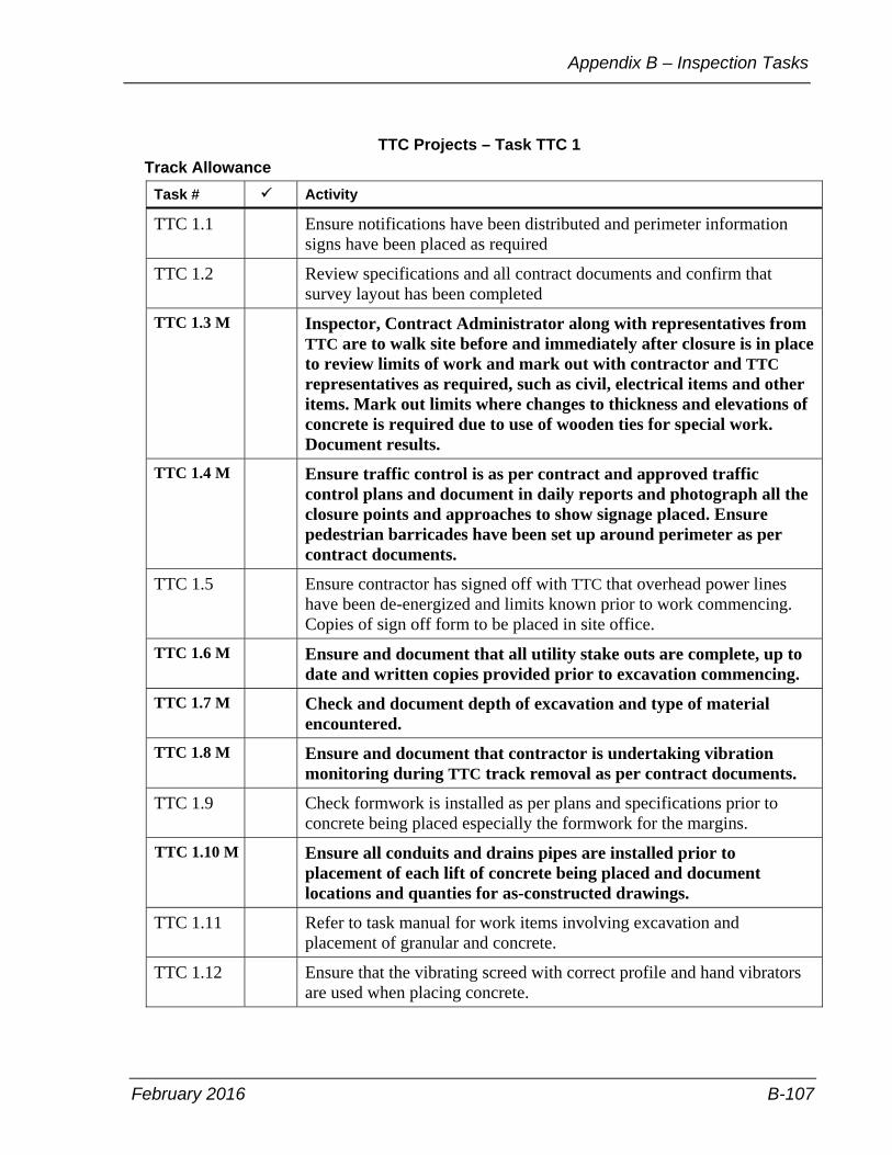
February 2016 B-107
Appendix B – Inspection Tasks
TTC Projects – Task TTC 1 Track Allowance
Task # Activity
TTC 1.1 Ensure notifications have been distributed and perimeter information signs have been placed as required
TTC 1.2 Review specifications and all contract documents and confirm that survey layout has been completed
TTC 1.3 M Inspector, Contract Administrator along with representatives from TTC are to walk site before and immediately after closure is in place to review limits of work and mark out with contractor and TTC representatives as required, such as civil, electrical items and other items. Mark out limits where changes to thickness and elevations of concrete is required due to use of wooden ties for special work. Document results.
TTC 1.4 M Ensure traffic control is as per contract and approved traffic control plans and document in daily reports and photograph all the closure points and approaches to show signage placed. Ensure pedestrian barricades have been set up around perimeter as per contract documents.
TTC 1.5 Ensure contractor has signed off with TTC that overhead power lines have been de-energized and limits known prior to work commencing. Copies of sign off form to be placed in site office.
TTC 1.6 M Ensure and document that all utility stake outs are complete, up to date and written copies provided prior to excavation commencing.
TTC 1.7 M Check and document depth of excavation and type of material encountered.
TTC 1.8 M Ensure and document that contractor is undertaking vibration monitoring during TTC track removal as per contract documents.
TTC 1.9 Check formwork is installed as per plans and specifications prior to concrete being placed especially the formwork for the margins.
TTC 1.10 M Ensure all conduits and drains pipes are installed prior to placement of each lift of concrete being placed and document locations and quanties for as-constructed drawings.
TTC 1.11 Refer to task manual for work items involving excavation and placement of granular and concrete.
TTC 1.12 Ensure that the vibrating screed with correct profile and hand vibrators are used when placing concrete.

Field Services Manual
B-108 February 2016
TTC Projects – Task TTC 1 Track Allowance (continued)
Task # Activity
TTC 1.13 Check template used for rail groove in concrete TTC track allowance meets specifications.
TTC 1.14 Check and ensure finished profile of surface concrete between rails meets specifications.
TTC 1.15 Ensure joints are placed in concrete and that bond breaker and curing compound is placed as per specifications.
TTC 1.16 M Compare the actual concrete used with the theoretical concrete required, document and adjust payment as per contract and specifications.
TTC 1.17 M Observe, document and ensure compliance with contract documents all material testing performed on site.
TTC 1.18 M Check to ensure that approved concrete mix design is used including fibre reinforced concrete.
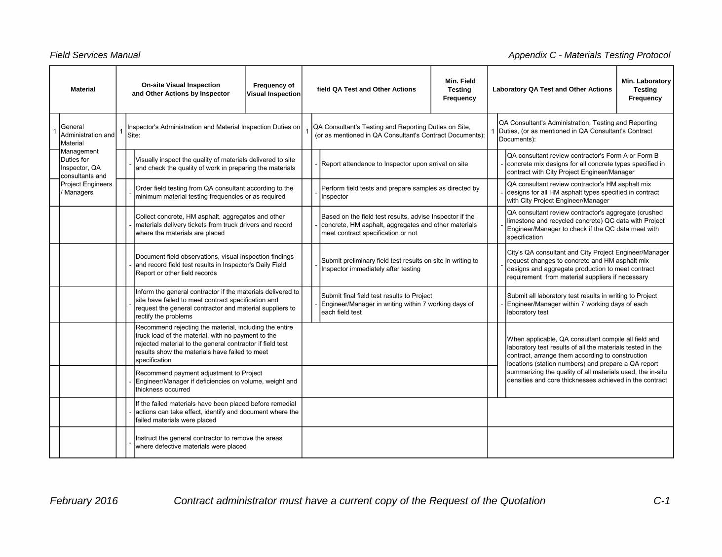
Field Services Manual Appendix C - Materials Testing Protocol
Frequency of
Visual Inspection
Min. Field
Testing
Frequency
Min. Laboratory
Testing
Frequency
1 1 1 1
- - -
- - -
- - -
- - -
- - -
-
-
-
field QA Test and Other Actions
Recommend rejecting the material, including the entire
truck load of the material, with no payment to the
rejected material to the general contractor if field test
results show the materials have failed to meet
specification
Inspector's Administration and Material Inspection Duties on
Site:
Visually inspect the quality of materials delivered to site
and check the quality of work in preparing the materials
Recommend payment adjustment to Project
Engineer/Manager if deficiencies on volume, weight and
thickness occurred
Instruct the general contractor to remove the areas
where defective materials were placed
Laboratory QA Test and Other Actions
Submit final field test results to Project
Engineer/Manager in writing within 7 working days of
each field test
MaterialOn-site Visual Inspection
and Other Actions by Inspector
QA consultant review contractor's aggregate (crushed
limestone and recycled concrete) QC data with Project
Engineer/Manager to check if the QC data meet with
specification
City's QA consultant and City Project Engineer/Manager
request changes to concrete and HM asphalt mix
designs and aggregate production to meet contract
requirement from material suppliers if necessary
Submit all laboratory test results in writing to Project
Engineer/Manager within 7 working days of each
laboratory test
General
Administration and
Material
Management
Duties for
Inspector, QA
consultants and
Project Engineers
/ Managers
Collect concrete, HM asphalt, aggregates and other
materials delivery tickets from truck drivers and record
where the materials are placed
If the failed materials have been placed before remedial
actions can take effect, identify and document where the
failed materials were placed
QA Consultant's Administration, Testing and Reporting
Duties, (or as mentioned in QA Consultant's Contract
Documents):
QA consultant review contractor's Form A or Form B
concrete mix designs for all concrete types specified in
contract with City Project Engineer/Manager
When applicable, QA consultant compile all field and
laboratory test results of all the materials tested in the
contract, arrange them according to construction
locations (station numbers) and prepare a QA report
summarizing the quality of all materials used, the in-situ
densities and core thicknesses achieved in the contract
QA consultant review contractor's HM asphalt mix
designs for all HM asphalt types specified in contract
with City Project Engineer/Manager
Based on the field test results, advise Inspector if the
concrete, HM asphalt, aggregates and other materials
meet contract specification or not
QA Consultant's Testing and Reporting Duties on Site,
(or as mentioned in QA Consultant's Contract Documents):
Report attendance to Inspector upon arrival on site
Submit preliminary field test results on site in writing to
Inspector immediately after testing
Perform field tests and prepare samples as directed by
Inspector
Order field testing from QA consultant according to the
minimum material testing frequencies or as required
Document field observations, visual inspection findings
and record field test results in Inspector's Daily Field
Report or other field records
Inform the general contractor if the materials delivered to
site have failed to meet contract specification and
request the general contractor and material suppliers to
rectify the problems
February 2016 Contract administrator must have a current copy of the Request of the Quotation C-1

Field Services Manual Appendix C - Materials Testing Protocol
Frequency of
Visual Inspection
Min. Field
Testing
Frequency
Min. Laboratory
Testing
Frequency
field QA Test and Other Actions Laboratory QA Test and Other Actions MaterialOn-site Visual Inspection
and Other Actions by Inspector
-
Record observation and report in writing to Project
Engineer/Manager on whether corrective actions to
defective materials had taken place or not
February 2016 Contract administrator must have a current copy of the Request of the Quotation C-2
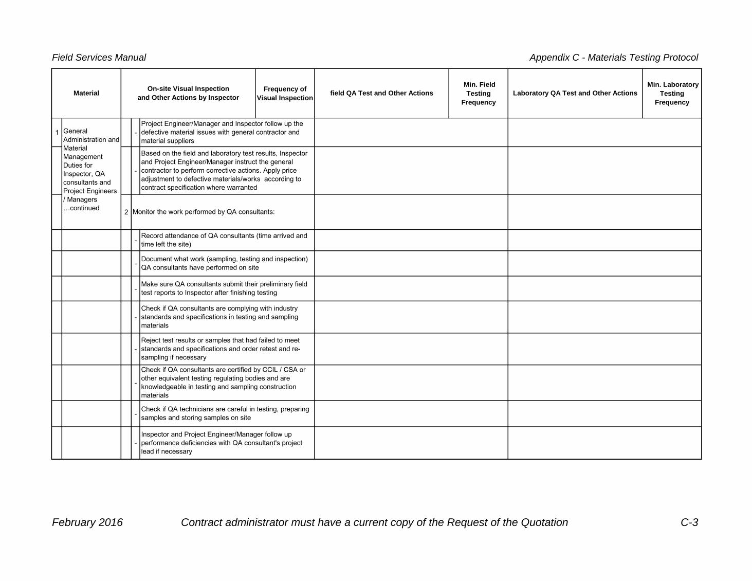
Field Services Manual Appendix C - Materials Testing Protocol
Frequency of
Visual Inspection
Min. Field
Testing
Frequency
Min. Laboratory
Testing
Frequency
field QA Test and Other Actions Laboratory QA Test and Other Actions MaterialOn-site Visual Inspection
and Other Actions by Inspector
1 -
-
2
-
-
-
-
-
-
-
-
Check if QA technicians are careful in testing, preparing
samples and storing samples on site
Check if QA consultants are certified by CCIL / CSA or
other equivalent testing regulating bodies and are
knowledgeable in testing and sampling construction
materials
Make sure QA consultants submit their preliminary field
test reports to Inspector after finishing testing
Inspector and Project Engineer/Manager follow up
performance deficiencies with QA consultant's project
lead if necessary
Project Engineer/Manager and Inspector follow up the
defective material issues with general contractor and
material suppliers
Based on the field and laboratory test results, Inspector
and Project Engineer/Manager instruct the general
contractor to perform corrective actions. Apply price
adjustment to defective materials/works according to
contract specification where warranted
Check if QA consultants are complying with industry
standards and specifications in testing and sampling
materials
Monitor the work performed by QA consultants:
Record attendance of QA consultants (time arrived and
time left the site)
Document what work (sampling, testing and inspection)
QA consultants have performed on site
General
Administration and
Material
Management
Duties for
Inspector, QA
consultants and
Project Engineers
/ Managers
…continued
Reject test results or samples that had failed to meet
standards and specifications and order retest and re-
sampling if necessary
February 2016 Contract administrator must have a current copy of the Request of the Quotation C-3

Field Services Manual Appendix C - Materials Testing Protocol
Frequency of
Visual Inspection
Min. Field
Testing
Frequency
Min. Laboratory
Testing
Frequency
field QA Test and Other Actions Laboratory QA Test and Other Actions MaterialOn-site Visual Inspection
and Other Actions by Inspector
2Ready Mixed
Concrete 1
Typically the first
load of the day
and every second
load until
consistency is
attained. Random
checking
thereafter
1
Refer to TS 1350
Table B:
Frequency of Field
Sampling and
Testing of
Concrete
1
One trial batch per
concrete mix
design per
contract, or as
required
2
Typically the first
load of the day
and every second
load until
consistency is
attained. Random
checking
thereafter
2
Refer to TS 1350
Table B:
Frequency of Field
Sampling and
Testing of
Concrete
2 All samples taken
4
Refer to QA
minimum testing
frequencies
3
Refer to TS 1350
Table B:
Frequency of Field
Sampling and
Testing of
Concrete
3
One test per mix
design per
contract
3 See below Every test
-
Check the delivery time of the load
(time when the concrete was batched
to the time the concrete was
unloaded) if it falls to meet the TS
1350
Typically the first
load of the day
and every second
load until
consistency is
attained. Random
checking
thereafter
Every air and
slump test and
every time
concrete cylinders
are casted
Document if concrete truck drivers are
adding water, superplasticizer or air
entrainment agent to the load on site
without prior authorization from the
general contractor and Project
Engineer/Manager
Order on-site slump tests, air tests and
concrete cylinder sampling from City's
QA consultant in accordance with the
minimum testing frequencies or as
required
Visually check the plasticity of fresh
concrete at point of discharge
Record temperature of plastic concrete
at point of discharge
Perform slump tests
Record in all test reports the air
temperature of the site during testing
Perform air entrainment tests
Cast concrete cylinder samples for
laboratory compressive strength tests
Collect concrete delivery tickets, review
and document details of tickets
Determine the unit weight of concrete
sample
Trial batching at concrete supply plant,
conduct air and slump tests on site,
perform 7-day and other strength
compressive strength tests according to
the mix types 30 working days prior to
placing concrete
Perform 24-hour, 7-day and 28-day
compressive strength tests, or other
strength tests for normal and early
strength concrete as specified in
contract
February 2016 Contract administrator must have a current copy of the Request of the Quotation C-4

Field Services Manual Appendix C - Materials Testing Protocol
Frequency of
Visual Inspection
Min. Field
Testing
Frequency
Min. Laboratory
Testing
Frequency
field QA Test and Other Actions Laboratory QA Test and Other Actions MaterialOn-site Visual Inspection
and Other Actions by Inspector
2
Ready Mixed
Concrete
…continued
-
Check if the load is produced from
concrete plant(s) that was specified
in the contract, or the plants were
agreed upon in the pre-construction
meeting or in any pre-concrete
placement meeting
Typically the first
load of the day
and every second
load until
consistency is
attained. Random
checking
thereafter
6Every 60 m lineal
length of structure
-
Verify and document the actual
volume of each pour and compare
with the theoretical volume if the
work is paid by volume
Random check all
areas where
concrete is placed
As directed by
Inspector and/or
Project Engineer /
Manager
Check and verify the thickness of
concrete structure if the concrete is
paid by area or length in contract
Random check all
areas where
concrete is placed
4 See below
-
- Check and document the state of
compaction of the granular base (if
any) and subgrade
- Recommend the general contractor
to recompact granular base /
subgrade where necessary
- Request QA consultant to perform
compaction test if necessary
Random check all
location where
fresh concrete is
discharged to
9
-
- Check and document the moisture
condition of the granular base (if any)
and subgrade
- Recommend wetting the granular
base / subgrade to the general
contractor if subgrade plastic
sheeting is not specified to be used
in contract
Random check all
location where
fresh concrete is
discharged to
Determine thickness of concrete road
bases, sidewalks or other structures by
coring if the slab/structure is paid by
area or length in contract
Check the conditions of the granular
base or subgrade before concrete is
discharged
Conduct concrete in-situ properties and
quality assurance check by coring
samples on site
February 2016 Contract administrator must have a current copy of the Request of the Quotation C-5
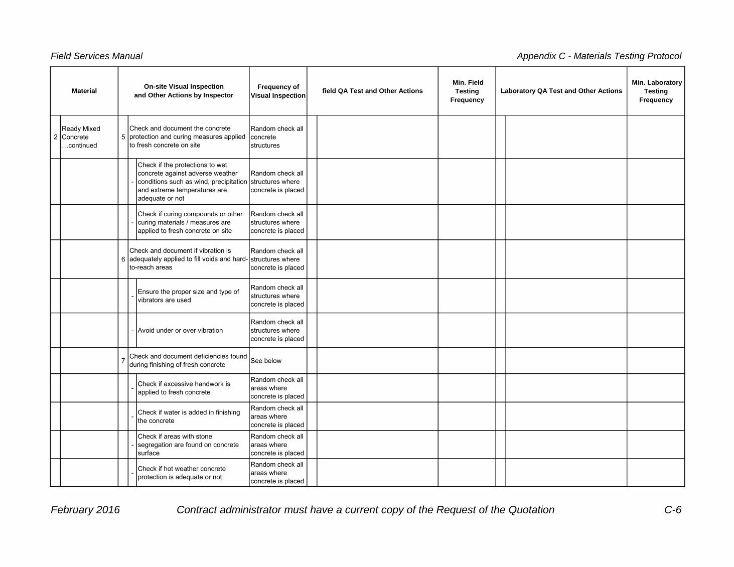
Field Services Manual Appendix C - Materials Testing Protocol
Frequency of
Visual Inspection
Min. Field
Testing
Frequency
Min. Laboratory
Testing
Frequency
field QA Test and Other Actions Laboratory QA Test and Other Actions MaterialOn-site Visual Inspection
and Other Actions by Inspector
2
Ready Mixed
Concrete
…continued
5
Random check all
concrete
structures
-
Check if the protections to wet
concrete against adverse weather
conditions such as wind, precipitation
and extreme temperatures are
adequate or not
Random check all
structures where
concrete is placed
-
Check if curing compounds or other
curing materials / measures are
applied to fresh concrete on site
Random check all
structures where
concrete is placed
6
Random check all
structures where
concrete is placed
-Ensure the proper size and type of
vibrators are used
Random check all
structures where
concrete is placed
- Avoid under or over vibration
Random check all
structures where
concrete is placed
7 See below
-Check if excessive handwork is
applied to fresh concrete
Random check all
areas where
concrete is placed
-Check if water is added in finishing
the concrete
Random check all
areas where
concrete is placed
-
Check if areas with stone
segregation are found on concrete
surface
Random check all
areas where
concrete is placed
-Check if hot weather concrete
protection is adequate or not
Random check all
areas where
concrete is placed
Check and document the concrete
protection and curing measures applied
to fresh concrete on site
Check and document deficiencies found
during finishing of fresh concrete
Check and document if vibration is
adequately applied to fill voids and hard-
to-reach areas
February 2016 Contract administrator must have a current copy of the Request of the Quotation C-6

Field Services Manual Appendix C - Materials Testing Protocol
Frequency of
Visual Inspection
Min. Field
Testing
Frequency
Min. Laboratory
Testing
Frequency
field QA Test and Other Actions Laboratory QA Test and Other Actions MaterialOn-site Visual Inspection
and Other Actions by Inspector
2
Ready Mixed
Concrete
…continued
-Check cold weather concrete
protection is adequate or not
Random check all
areas where
concrete is placed
-
Check if barricades are put in place
to protect wet concrete from
pedestrians and/or vehicular traffic
Random check all
areas where
concrete is placed
-Check if depressions and bumps are
found on concrete surface
Random check all
areas where
concrete is placed
-
Check if sidewalks or other
structures are constructed with the
proper gradients
Random check all
areas where
concrete is placed
-Check if spalling is found on concrete
surfaces and at expansion joint cuts
Random check all
areas where
concrete is placed
-
Check if honey combs are
developing on finished concrete
surface
Random check all
areas where
concrete is placed
-Check if cracks are developing on
finished concrete surface
Random check all
areas where
concrete is placed
8 All site visits
-
Check and document if cylinders are
stored in an acceptable curing box or
not
All samples taken
until consistency is
attained. Random
checking
thereafter.
-
Check and document if the curing
box is placed at a secured location or
not
All samples taken
until consistency is
attained. Random
checking
thereafter.
Monitor the work performed by field QA
testing technicians
February 2016 Contract administrator must have a current copy of the Request of the Quotation C-7

Field Services Manual Appendix C - Materials Testing Protocol
Frequency of
Visual Inspection
Min. Field
Testing
Frequency
Min. Laboratory
Testing
Frequency
field QA Test and Other Actions Laboratory QA Test and Other Actions MaterialOn-site Visual Inspection
and Other Actions by Inspector
-
Check if concrete cylinders are
delivered to testing laboratory in
accordance with the time limits or not
(within a maximum of 76 hours for 35
MPa or less concrete, or within 28
hours for 35 MPa or higher concrete)
All samples taken
until consistency is
attained. Random
checking
thereafter.
February 2016 Contract administrator must have a current copy of the Request of the Quotation C-8

Field Services Manual Appendix C - Materials Testing Protocol
Frequency of
Visual Inspection
Min. Field
Testing
Frequency
Min. Laboratory
Testing
Frequency
field QA Test and Other Actions Laboratory QA Test and Other Actions MaterialOn-site Visual Inspection
and Other Actions by Inspector
3 Hot Mixed Asphalt 1
Typically the first
load of the day
and every second
load until
consistency is
attained. Random
checking
thereafter.
1
Test strip method
(proof rolling):
- 1 test section per
300 m of pass
- Minimum 2 test
section per street
- 5 tests per test
section
1
One trial batch per
hot mix asphalt
mix design
2All deliveries to
site2 See below: 2
First production
load from the
asphalt plant on
each paving day.
3
As per City of
Toronto Weight
Verification
Protocol
-Large quantity paving job (for
example, arterial road paving)
First production
load from the
asphalt plant on
each paving day,
every 250 Mg
(tonne) thereafter
-
Conduct HM Asphalt Extraction and
Gradation (E&G) tests on the first
production load sample from asphalt
plant, report (fax or phone) the E&G
results to Project Engineer/Manager
and asphalt plant as soon as the test
results are ready. Advise changes to
production if necessary
Every 250 Mg
(tonne)
4 See below - Small quantity paving jobs
Typically the first
load of the day,
every 250 Mg
(tonne). Minimum
1 sample in the
morning and 1
sample in the
afternoon
3
-
Check if there are areas with stone
segregation on the mat and at
longitudinal joints
Random check all
locations where
HM asphalt is
placed
3All test samples
taken on site-
Conduct HM Asphalt Extraction and
Gradation (E&G) tests on the
samples taken from site
All samples from
site
-Check if all the stones in the mat are
adequately coated with asphalt or not
Random check all
locations where
HM asphalt is
placed
4All test samples
taken on site4
Every 500 Mg
(tonne) after the
first load
Conduct HM Asphalt full Marshall tests
(E&G, AC content and Marshall
properties tests)
Trial batching at hot mix asphalt plant
and conduct full Marshall test
(extraction and gradation (E&G), AC
content and Marshall properties tests)
on trial batch 7 working days before
asphalt placement
Perform compaction tests on HM
asphalt mat using nuclear density guage
E&G Testing and Fast Track Reporting
(for large quantity paving jobs like
arterial road paving):
Visually check the if type of aggregates
used in the mix are complying with
specification or not
Visually check the nominal size of the
aggregates used in the mix if they are
complying with specification or not
E&G Testing and Regular Reporting
(7- working-day reporting):
Check temperature of asphalt mix at
point of discharge (at least 120oC at
point of discharge) and air temperature
of pavement for HM asphalt placing (for
binder at least 2°C and for surface at
least 7°C )
Check and document the conditions of
the hot mixed asphalt mat
Verify the weight of the loads delivered
to site
Collect HM asphalt delivery tickets,
review and document details of tickets
Prepare plate samples of HM asphalt on
site for E&G tests and Marshall
properties tests for each type of mix
(reject samples prepared by shovels)
February 2016 Contract administrator must have a current copy of the Request of the Quotation C-9
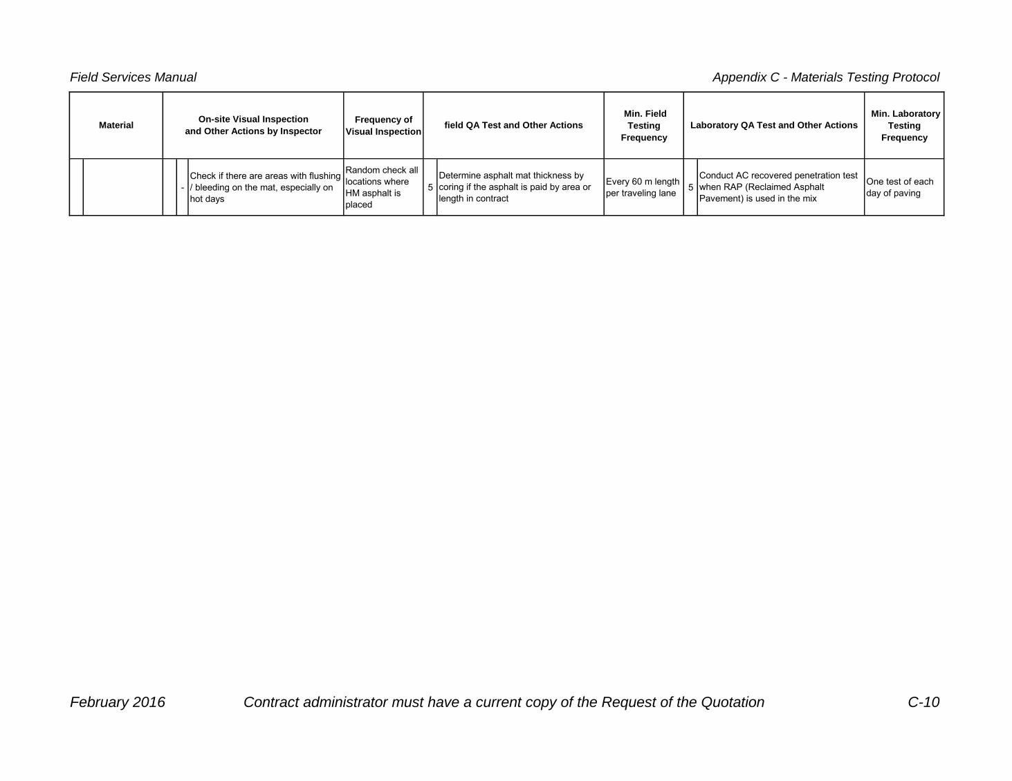
Field Services Manual Appendix C - Materials Testing Protocol
Frequency of
Visual Inspection
Min. Field
Testing
Frequency
Min. Laboratory
Testing
Frequency
field QA Test and Other Actions Laboratory QA Test and Other Actions MaterialOn-site Visual Inspection
and Other Actions by Inspector
-
Check if there are areas with flushing
/ bleeding on the mat, especially on
hot days
Random check all
locations where
HM asphalt is
placed
5Every 60 m length
per traveling lane5
One test of each
day of paving
Determine asphalt mat thickness by
coring if the asphalt is paid by area or
length in contract
Conduct AC recovered penetration test
when RAP (Reclaimed Asphalt
Pavement) is used in the mix
February 2016 Contract administrator must have a current copy of the Request of the Quotation C-10

Field Services Manual Appendix C - Materials Testing Protocol
Frequency of
Visual Inspection
Min. Field
Testing
Frequency
Min. Laboratory
Testing
Frequency
field QA Test and Other Actions Laboratory QA Test and Other Actions MaterialOn-site Visual Inspection
and Other Actions by Inspector
3Hot Mixed Asphalt
…continued-
Check and verify the thickness of
asphalt mat if the asphalt is paid by
area or length in contract
Every 50 m length
of asphalt mat6
As directed by
Inspector and/or
Project Engineer /
Manager
6One test for each
mix design
-Check if depressions and bumps are
found on the surface of the mat
Random check all
locations where
HM asphalt is
placed
7 Every test
-Check if roll marks and scratches are
found on the surface of the mat
Random check all
locations where
HM asphalt is
placed
8 Every test
-Check if oil spills are found on the
surface of the mat
Random check all
locations where
HM asphalt is
placed
-
Check if opened and uneven
construction joints are found on the
surface of the mat
Random check all
locations where
HM asphalt is
placed
-Check if contractor opens the mat to
traffic when the mat is still warm
Random check all
locations where
HM asphalt is
placed
5
Random check all
locations where
HM asphalt is
placed
6 All site visits
Record in test report the air temperature
of the site during testing
Record in test report the temperature of
HM asphalt during sampling
Conduct specification conformance
tests on Performance Graded Asphalt
Cement (PGAC) if required
Conduct HM asphalt in-situ properties
and quality assurance check by coring
samples on site
Monitor the work performed by field QA
testing technicians
Check if contractor applies tack coat to
old pavement, vertical face of curbs,
cold pavement joints and structures as
specified in contract and specification.
Also check the rate of application and
over-spraying
February 2016 Contract administrator must have a current copy of the Request of the Quotation C-11

Field Services Manual Appendix C - Materials Testing Protocol
Frequency of
Visual Inspection
Min. Field
Testing
Frequency
Min. Laboratory
Testing
Frequency
field QA Test and Other Actions Laboratory QA Test and Other Actions MaterialOn-site Visual Inspection
and Other Actions by Inspector
3
Granulars
(Crushed
Limestone and
Recycled
Concrete)
1
Every load until
consistency is
attained. Random
checking
thereafter.
1
All trench backfill,
granular bases
and subbases
1
As per TS 1010
and according to
the type of
material used, or
as required
2
Every load until
consistency is
attained. Random
checking
thereafter.
- Sewer and watermain trenches
Refer to TS
501.08
Construction
Specification for
Compaction
2All samples taken
from site
3
Every 250 Mg
(tonne) per type of
material
-Granular bases for roads, curbs,
sidewalks and other structures
Refer to TS
501.08
Construction
Specification for
Compaction
3All samples taken
from site
4
Recommend
minimum of 1 test
completed per
source of RCM
per project or as
per OPSS.MUNI
1010.07.03.01,
wihichever is
greater.
2
Refer to TS 1010
Material
Specification for
Aggregates –
Base, Subbase,
Select ubgrade,
and Backfill
Material
5All deliveries to
site3
One sample per
type of material
per contract
6
As per City of
Toronto Weight
Verification
Protocol
4Every 50 m length
of base
Take samples from stockpiles on site
for gradation tests
Determine granular base thickness by
coring or digging test pits
Conduct Standard/Modified Proctor
Density tests
Conduct gradation tests
Take samples from stockpiles on site
for Proctor density tests
Sampling at source (production plant)
and perform QA physical property test
and gradation tests to verify the physical
properties and gradation of materials if
necessary
Order QA gradation tests from QA
consultants
Order physical property test of
aggregates from QA consultants if
necessary
Visually check the percent crushed of
aggregate delivered and document
findings. If testing recycled concrete,
include sulphate testing of sampled
aggregrate.
Collect aggregate delivery tickets,
review and document details of tickets
Visually check for deleterious materials
(1% max) and document findings.
Determine if RAP is present if not
allowed (Granular A RCM, for instance)
For RCM material, review contractor's
supplied test data to confirm material
being delivered is under control.
Conduct compaction (including moisture
content) tests using nuclear density
guage
February 2016 Contract administrator must have a current copy of the Request of the Quotation C-12

Field Services Manual Appendix C - Materials Testing Protocol
Frequency of
Visual Inspection
Min. Field
Testing
Frequency
Min. Laboratory
Testing
Frequency
field QA Test and Other Actions Laboratory QA Test and Other Actions MaterialOn-site Visual Inspection
and Other Actions by Inspector
3
Granulars
(Crushed
Limestone and
Recycled
Concrete)
…continued
7
8 All site visits
4 Imported Earth 1
Every load until
consistency is
attained. Random
checking
thereafter.
1All trench backfill,
and subgrade1 All samples taken
2
As per City of
Toronto Weight
Verification
Protocol
2 - Sewer and watermain trenches
One test per 0.3 m
lift for each
increment or
fraction of 150
lineal metres of
backfill
2 All samples taken
All deliveries to
site- Road or sidewalk subgrade
One test per lift for
each increment or
fraction of 500
square metres on
each traveling
lane
3 All site visits 3
Every 250 Mg
(tonne) per type of
material, or as
required
5Crack Filling
Material1
Every 4 hours of
operation1
At commencement
of contract, every
20,000 m to
25,000 m
1 All samples taken
Take samples from stockpiles on site
for soil classification and engineering
properties tests
Conduct compaction (including moisture
content) tests using nuclear equipment Conduct soil classification test
Conduct Standard/Modified Proctor
Density test
Conduct AC penetration test Take samples on site for AC penetration
tests
Check the temperature of crack filling
material on site
Monitor the work performed by field QA
testing technicians
Collect earth delivery tickets, review and
document details of tickets
Verify the weight of the loads delivered
to site if the materials are paid by weight
Visually check for deleterious materials
and document findings
Monitor the work performed by field QA
testing technicians
Verify the weight of the loads delivered
to site if the materials are paid by weight
February 2016 Contract administrator must have a current copy of the Request of the Quotation C-13

Field Services Manual Appendix C - Materials Testing Protocol
Frequency of
Visual Inspection
Min. Field
Testing
Frequency
Min. Laboratory
Testing
Frequency
field QA Test and Other Actions Laboratory QA Test and Other Actions MaterialOn-site Visual Inspection
and Other Actions by Inspector
5
Crack Filling
Material
…continued
2 All site visits 2
Every day when
operation begins
Monitor the work performed by field QA
testing technicians
Inspect and verify all gauges on the
melting pot
February 2016 Contract administrator must have a current copy of the Request of the Quotation C-14

February 2016 D-1
Appendix D – As-built Drawing Guidelines
Appendix D – As-built Drawing Guidelines
The purpose of this section is to provide some background material if you are preparing record or as-built drawings. This section is intended for use on City capital improvement projects or on private developer related projects.
Purpose
A requirement for a full-stream application under the Municipal Consent Requirements (MCR) is for the applicant to provide as-constructed drawings or as-built drawings. As well, under the Safe Drinking Water Act (SDWA) 2000 Part V as-built drawings of constructed facilities must be made available upon demand, if requested by the Ministry of the Environment and Climate Change. The material in this appendix outlines the requirements for preparing record drawings or as-built drawings, which may need to be submitted by the contractor in accordance with the contract documents, or by the Contract Administrator if an external service provider is used. The as-built drawings can then be used by city staff, other government agencies, developers and engineers for planning, design, and maintenance purposes.
Distinction between Record and As-built Drawings
The Professional Engineers of Ontario (PEO) document "Use of the Professional Engineer’s Seal" has a section titled "As-built and Record Drawings" and reads as follows:
Professional engineers should use the following distinction between as-built and record drawings. Drawings referred to as "as-built" are prepared by a third party, or by the engineer using information furnished by the contractor or other field staff. Record drawings are those prepared by the reviewing engineer after verifying in detail the actual conditions of the completed project. For some projects, this verification may require frequent or continuous presence on site. The distinction between as-built and record drawings determines whether drawings representing the final state of the projects should be sealed.
Because professional engineers are responsible for the content of drawings bearing their seals, as-built drawings should not be sealed,

Field Services Manual
D-2 February 2016
since the engineer is not responsible for the content of these documents.
Some of the information provided on as-built drawings might be changes authorized by the engineer during construction. Other information might reflect changes initiated by other parties due to site conditions or other causes. Changes by the engineer will already have been documented by change orders, sealed sketches, or sealed reports, so there is no need to seal the as-builts. Where changes are by others, although the engineer will have a responsibility to advise the client whether the change was a result of a safety concern or a contravention of codes or standards, the engineer should not be forced to seal the documents, since to do so might imply that the changes were part of the engineer’s design. If as-builts are produced by making changes to the original construction drawings, the seal should not be applied, or should be removed if already in place, and the drawings marked "as-built drawing". In place of a seal, there should be a note referencing the original sealed drawings.
Sealed drawings with record information might imply to some parties that the engineer is providing some type of warranty or certification of the construction. This is never the case, since the contractor is always responsible for construction.
For any as-constructed drawing submitted to the City, the requirement will be as-built drawings, not record drawings.
Definitions
As-built drawing – is documentation created by or based solely on information provided by a third party that reflects the installed, constructed or commissioned conditions of a device, machine, equipment, apparatus, structure, system or other outcome of an engineering project. Since the engineer has not verified that the information is complete or accurate, as-built drawings must not be sealed.
Record drawing – is a document created to accurately reflect as-constructed, as-built or as-fabricated conditions and that has been sealed by a professional engineer after verifying that the document is accurate. They are usually retained to meet business or regulatory requirements.
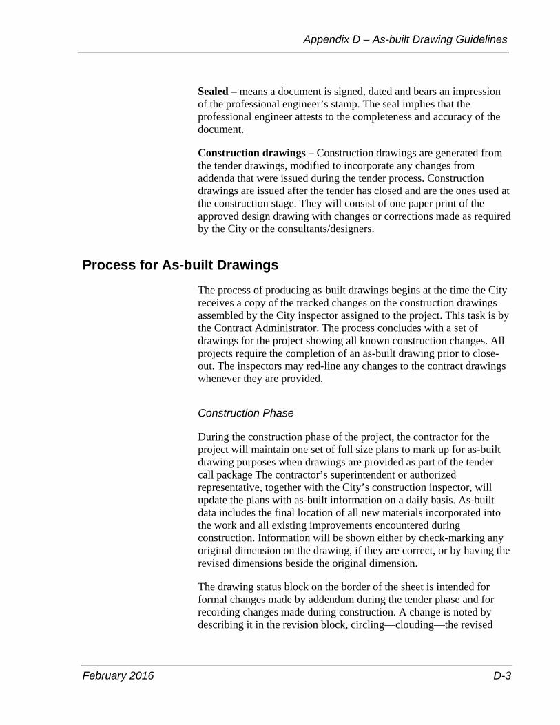
February 2016 D-3
Appendix D – As-built Drawing Guidelines
Sealed – means a document is signed, dated and bears an impression of the professional engineer’s stamp. The seal implies that the professional engineer attests to the completeness and accuracy of the document.
Construction drawings – Construction drawings are generated from the tender drawings, modified to incorporate any changes from addenda that were issued during the tender process. Construction drawings are issued after the tender has closed and are the ones used at the construction stage. They will consist of one paper print of the approved design drawing with changes or corrections made as required by the City or the consultants/designers.
Process for As-built Drawings
The process of producing as-built drawings begins at the time the City receives a copy of the tracked changes on the construction drawings assembled by the City inspector assigned to the project. This task is by the Contract Administrator. The process concludes with a set of drawings for the project showing all known construction changes. All projects require the completion of an as-built drawing prior to close-out. The inspectors may red-line any changes to the contract drawings whenever they are provided.
Construction Phase
During the construction phase of the project, the contractor for the project will maintain one set of full size plans to mark up for as-built drawing purposes when drawings are provided as part of the tender call package The contractor’s superintendent or authorized representative, together with the City’s construction inspector, will update the plans with as-built information on a daily basis. As-built data includes the final location of all new materials incorporated into the work and all existing improvements encountered during construction. Information will be shown either by check-marking any original dimension on the drawing, if they are correct, or by having the revised dimensions beside the original dimension.
The drawing status block on the border of the sheet is intended for formal changes made by addendum during the tender phase and for recording changes made during construction. A change is noted by describing it in the revision block, circling—clouding—the revised

Field Services Manual
D-4 February 2016
area on the drawing and placing the revision letter or number in a triangle inside the circled—clouded—area.
As-built Drawing Preparation
Upon completion of construction, the as-built notes will be provided to the engineer together with the engineering survey field data and notes of the as-built conditions. This information will be the basis for the as-built drawing submitted. Changes will be transferred to the permanent CADD drawing file and labelled as "As-Built Drawing".
Required Information
The following are examples of changes made to a project that are required to be included on the as-built drawings:
• Field changes noted by the developer’s engineer of work or engineer of record in the case of development related projects.
• Comments or remarks of field information that may have been provided by the design consultant in the case of capital improvement projects.
• Field information provided on the contractors construction drawings, assembled by the contractor hired to perform the work.
• Project change order drawings or change order details indicating changes made to the contract drawings in the case of capital improvement projects.
• Field information provided on the inspectors construction drawings, assembled by the city inspector assigned to the project.
• Survey notes provided by the survey crew, assembled by the City’s engineering survey unit only when the City has performed the layout.

February 2016 D-5
Appendix D – As-built Drawing Guidelines
Completion of As-built Drawings
Development Projects
The developer’s engineer typically performs work required for completion of the as-built drawing.
The developer’s engineer will be requested to submit to the City, one set of white prints redlined to clearly indicate all field changes brought to the attention of the developer or the developer’s engineer.
The developer’s engineer will incorporate all remarks provided by the City and submit two hardcopy prints made from the corrected originals. Mylars will not be produced or supplied to the City until all changes have been incorporated and accepted by the City.
After the City is satisfied that all remarks have been included, the City will request the mylars be submitted as follows:
Only mylars with matte finish with a thickness of 4-mil will be accepted. White prints must be made from the original mylars and signed by the engineer of work. Each sheet shall have a "As-Built" in the revisions box signed by the engineer of work.
Drawings will be 24 inch x 36 inch. Larger sheet sizes are unacceptable.
The submission will also include a revised CADD file in MicroStation format on CD. Each CD will be labelled with the project name, company name, engineer’s name and telephone number.
Capital Improvement Projects
City personnel typically perform the work required for completion of the as-built drawings. In some cases the City may have the design consultant or the contractor, who is contracted by the City, to perform the work required to complete the as-built drawings.
City personnel will proceed with the completion of the as-built drawings incorporating all field changes and information as required.
If the City proceeds with having the as-built drawings completed by the design consultant or the contractor, the City will supply the notes and survey data required to complete the as-built drawings, unless the
Field Services Manual
D-6 February 2016
consultant also acted as the contract administrator, in which case it would already have this information.
After the City is satisfied that all remarks have been included, the City will request that a set of as-built drawings to be provided as specified in Appendix A, As-Built Drawings of the Design Criteria for Sewers and Watermains manual.
As-built Drawing Requirements
For content requirements for water distribution systems, storm or sanitary sewer systems and stormwater management facilities, see the Design Criteria for Sewers and Watermains manual, Appendix A, As-Built Drawings.

February 2016 E-1
Appendix E – As-built Features Requirements
Appendix E – As-built Features Requirements
As-built drawings will show the accurate locations of construction features such as storm sewers, sanitary sewers, combined sewers, watermains and other water appurtenances, structures, conduits, power poles, light standards, vaults, width of streets, sidewalks, landscaping area, building footprints, channelization, pavement markings, property lines, equipments and processes and easements.
The following minimum information is required and indicates who is responsible to provide it.
Storm Drainage
Storm drainage features are intended to move rainwater and groundwater. As-built drawings will indicate all necessary information about the storm drainage system to evaluate whether the constructed features will be able to function as intended by the design. Information will be field verified or surveyed or both as outlined in the following table. The following table indicates what features are required and by whom should provide the information.

Field Services Manual
E-2 February 2016
Table: Storm drainage features Storm drainage features
Field verify
(inspector)
Survey (engineering surveys unit or consultants surveyors)
Indicate on as-built drawing (drawing preparer or engineer)
pipe size, material, class of pipe, bedding type, drop pipe size
inverts, drop pipe inverts, location of end of stub or bulkhead
Redraw pipe on drawing if pipe has moved more than 300 mm horizontally or 150 mm or more vertically.
Recalculate slope on record length and surveyed inverts.
Indicate new information on plans such as slope, length, and diameter and so on.
catchbasins, maintenance holes, outfalls, inlet structures
size, type, cover type, safety platforms, flow regulator, overflow, weir, grate type
rim elevation location of feature, overflow weir invert inlet /outlet inverts
Redraw structure on drawings if it moved 300 mm or more.
Indicate new information on plans such as size, type and so on.
culverts size, material, shape, seepage collars
location of ends of culverts and inverts
Redraw culvert on drawings if has moved more than 300 mm.
Recalculate slope based on recorded length and surveyed inverts.
Indicate new information on plans such as slope, length, and diameter and so on.
subdrains pipe locations, material, and size
Redraw subdrains on drawings if it moved 300 mm or more.
laterals size, material, class, bedding
Indicate locations on plan.
other drainage features
Redraw feature on drawings if it moved 300 mm or more.

February 2016 E-3
Appendix E – As-built Features Requirements
Stormwater Management
Stormwater management features are intended to control the rate and quality of the rainwater runoff. As-built drawings will indicate all necessary information about the stormwater management system to evaluate whether the constructed features will be able to function as intended by the design. Information will be field verified or surveyed or both as outlined in the following table. The following table indicates what features are required and by whom should provide the information.
Table: Stormwater management features Stormwater management features
Field Verify (inspector)
Survey (engineering surveys unit or consultants surveyors)
Indicate on as-built drawing (drawing preparer or engineer)
storage tanks material, type, size, control systems such as orifice size and weir dimensions
control structure location, control elevations such as orifice inverts, weir elevations bottom elevations and access locations
Redraw structure on drawing if moved more than 300 mm horizontally or 150 mm or more vertically.
Indicate new information on plans such as size, type and so on.
ponds size, shape control structure location, control elevations such as orifice inverts and weir elevations
overflow elevation
topographic survey including bottom elevations
final volumes
Redraw pond on drawing if moved more than 3.0 m or more.
Recalculate volume based on water surface shape and depth.
Indicate new information on plans such as size, type, volume and so on.
wetlands boundary of created or modified wetlands
Redraw wetland on drawings if moved more than 3.0 m or more.
Recalculate volume based on water surface shape and depth.
Indicate new information on plans such as size, type, volume and so on.

Field Services Manual
E-4 February 2016
Table: Stormwater management features (continued) Stormwater management features
Field Verify (inspector)
Survey (engineering surveys unit or consultants surveyors)
Indicate on as-built drawing (drawing preparer or engineer)
grease interceptor
oil/grit separation
size, material, vault, dimensions
horizontal location of four corners of vault where applicable
Indicate vault dimensions and size, inverts.
infiltration systems, French drains
material, size, pipe such as size, type and diameter
inlet invert
outlet invert
Redraw feature on drawings if it moved 300 mm or more.
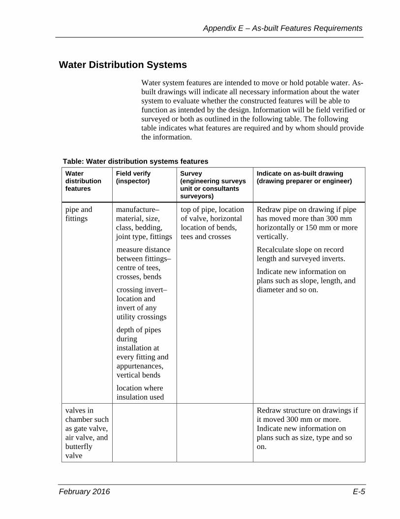
February 2016 E-5
Appendix E – As-built Features Requirements
Water Distribution Systems
Water system features are intended to move or hold potable water. As-built drawings will indicate all necessary information about the water system to evaluate whether the constructed features will be able to function as intended by the design. Information will be field verified or surveyed or both as outlined in the following table. The following table indicates what features are required and by whom should provide the information.
Table: Water distribution systems features Water distribution features
Field verify (inspector)
Survey (engineering surveys unit or consultants surveyors)
Indicate on as-built drawing (drawing preparer or engineer)
pipe and fittings
manufacture–material, size, class, bedding, joint type, fittings
measure distance between fittings–centre of tees, crosses, bends
crossing invert–location and invert of any utility crossings
depth of pipes during installation at every fitting and appurtenances, vertical bends
location where insulation used
top of pipe, location of valve, horizontal location of bends, tees and crosses
Redraw pipe on drawing if pipe has moved more than 300 mm horizontally or 150 mm or more vertically.
Recalculate slope on record length and surveyed inverts.
Indicate new information on plans such as slope, length, and diameter and so on.
valves in chamber such as gate valve, air valve, and butterfly valve
Redraw structure on drawings if it moved 300 mm or more. Indicate new information on plans such as size, type and so on.
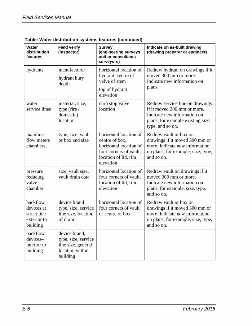
Field Services Manual
E-6 February 2016
Table: Water distribution systems features (continued) Water distribution features
Field verify (inspector)
Survey (engineering surveys unit or consultants surveyors)
Indicate on as-built drawing (drawing preparer or engineer)
hydrants manufacturer
hydrant bury depth
horizontal location of hydrant–centre of valve of stem
top of hydrant elevation
Redraw hydrant on drawings if it moved 300 mm or more. Indicate new information on plans.
water service lines
material, size, type (fire / domestic), location
curb stop valve location
Redraw service line on drawings if it moved 300 mm or more. Indicate new information on plans, for example existing size, type, and so on.
mainline flow meters chambers
type, size, vault or box and size
horizontal location of centre of box, horizontal location of four corners of vault, location of lid, rim elevation
Redraw vault or box on drawings if it moved 300 mm or more. Indicate new information on plans, for example, size, type, and so on.
pressure reducing valve chamber
size, vault size, vault drain data
horizontal location of four corners of vault, location of lid, rim elevation
Redraw vault on drawings if it moved 300 mm or more. Indicate new information on plans, for example, size, type, and so on.
backflow devices at street line–exterior to building
device brand type, size, service line size, location of drain
horizontal location of four corners of vault or centre of box
Redraw vault or box on drawings if it moved 300 mm or more. Indicate new information on plans, for example, size, type, and so on.
backflow devices–interior to building
device brand, type, size, service line size, general location within building
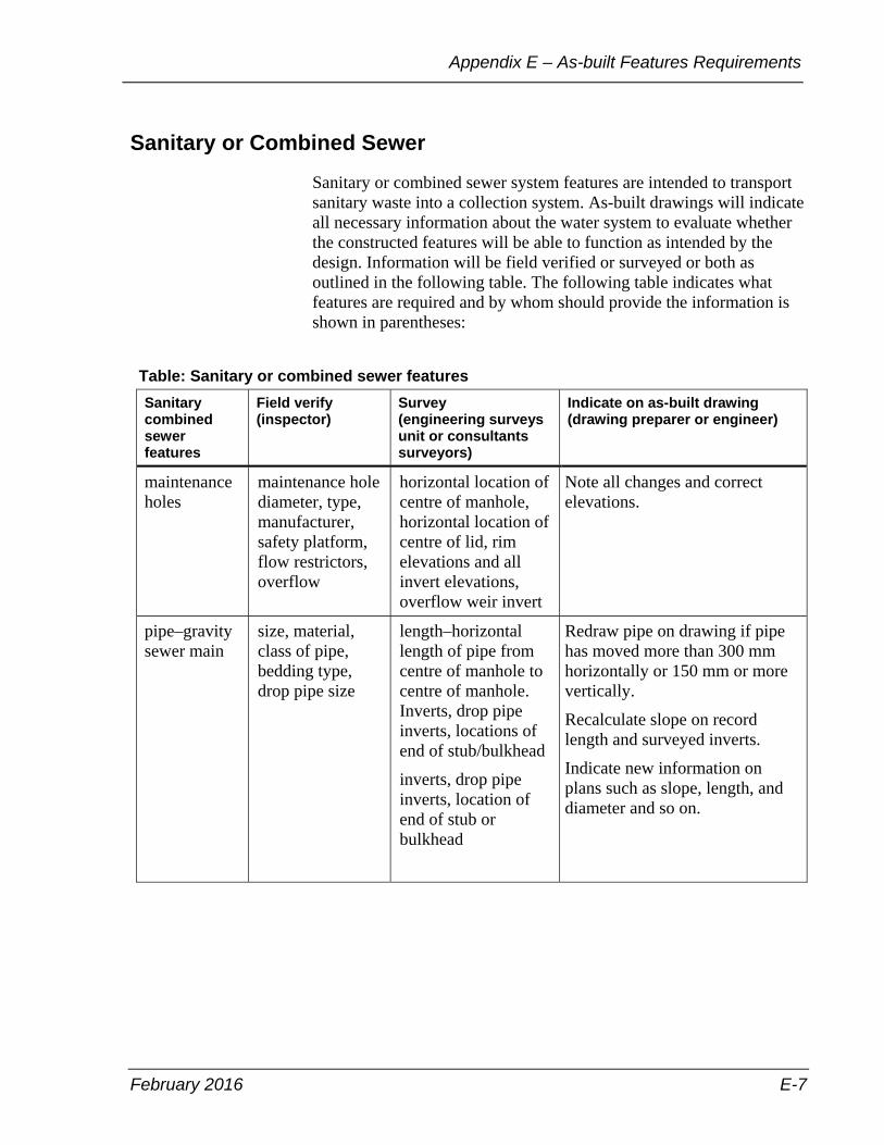
February 2016 E-7
Appendix E – As-built Features Requirements
Sanitary or Combined Sewer
Sanitary or combined sewer system features are intended to transport sanitary waste into a collection system. As-built drawings will indicate all necessary information about the water system to evaluate whether the constructed features will be able to function as intended by the design. Information will be field verified or surveyed or both as outlined in the following table. The following table indicates what features are required and by whom should provide the information is shown in parentheses:
Table: Sanitary or combined sewer features Sanitary combined sewer features
Field verify (inspector)
Survey (engineering surveys unit or consultants surveyors)
Indicate on as-built drawing (drawing preparer or engineer)
maintenance holes
maintenance hole diameter, type, manufacturer, safety platform, flow restrictors, overflow
horizontal location of centre of manhole, horizontal location of centre of lid, rim elevations and all invert elevations, overflow weir invert
Note all changes and correct elevations.
pipe–gravity sewer main
size, material, class of pipe, bedding type, drop pipe size
length–horizontal length of pipe from centre of manhole to centre of manhole. Inverts, drop pipe inverts, locations of end of stub/bulkhead
inverts, drop pipe inverts, location of end of stub or bulkhead
Redraw pipe on drawing if pipe has moved more than 300 mm horizontally or 150 mm or more vertically.
Recalculate slope on record length and surveyed inverts.
Indicate new information on plans such as slope, length, and diameter and so on.

Field Services Manual
E-8 February 2016
Table: Sanitary or combined sewer features (continued) Sanitary combined sewer features
Field verify (inspector)
Survey (engineering surveys unit or consultants surveyors)
Indicate on as-built drawing (drawing preparer or engineer)
pipe and fittings–force main
manufacturer–material, size, class, bedding, joint type, fittings
measure distance between fittings–centre of tees, crosses, bends
crossing invert–location and invert of any utility crossings
depth of pipes during installations at every fitting and appurtenance.
horizontal location of main:
Redraw pipe on drawings if it moved 300 mm or more. Indicate new information on plans, for example, slope, length, size, and so on.
laterals material, size, locations, backflow valve
Indicate location on plans.
cleanouts Size, material, location
rim elevations, centre of box, horizontal location of centre of box
Redraw structure on drawings if it moved 300 mm or more indicate new information on plans.
grease interceptor or oil grit separators
pipe materials, size, vault dimensions and size
horizontal location of four corners of the vault and inverts
Show vault dimensions and size. Show pipe elevations.

February 2016 E-9
Appendix E – As-built Features Requirements
Transportation
Transportation system features are intended to transport vehicle and pedestrian traffic. As-built drawings will indicate all necessary information about the transportation system to evaluate whether the constructed features will be able to function as intended by the design. Information will be field verified or surveyed or both as outlined in the following table. The following table indicates what features are required and by whom should provide the information.
Included but not limited to all surface features impacted by the construction.
Table: Transportation features Trans-portation features
Field verify (inspector)
Survey (engineering surveys or consultants surveyors)
Indicate on as-built drawing (drawing preparer or engineer)
Redraw on record drawing any and all transportation features listed if moved 300 mm or more.
pavement material, depth, width, type – rigid or flexbile
elevations Note all changes and correct locations indicated locations on plans
curb and gutter
location of face curb
driveways location, width, type – commercial or domestic
signage location, size, type of sign
sidewalk location, type - light or heavy, material, width
elevations
street lighting height, wattage, material
monument location, materials
conduit location, depth, materials, size, owner
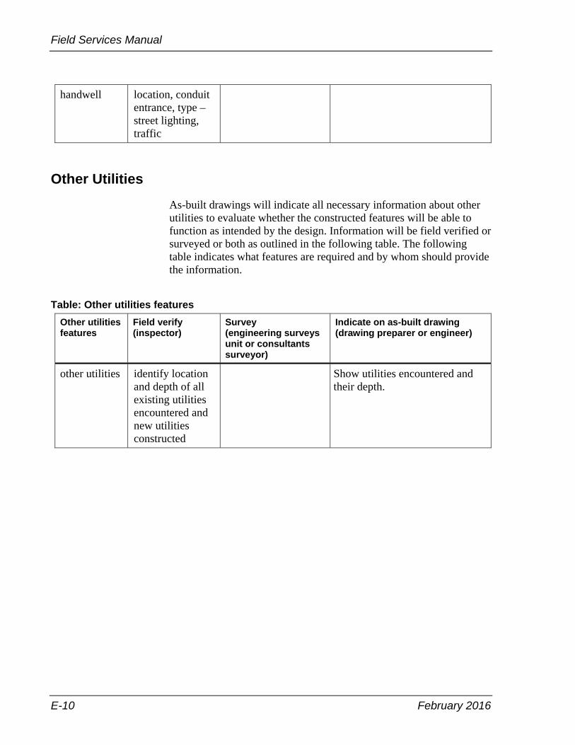
Field Services Manual
E-10 February 2016
handwell location, conduit entrance, type – street lighting, traffic
Other Utilities
As-built drawings will indicate all necessary information about other utilities to evaluate whether the constructed features will be able to function as intended by the design. Information will be field verified or surveyed or both as outlined in the following table. The following table indicates what features are required and by whom should provide the information.
Table: Other utilities features Other utilities features
Field verify (inspector)
Survey (engineering surveys unit or consultants surveyor)
Indicate on as-built drawing (drawing preparer or engineer)
other utilities identify location and depth of all existing utilities encountered and new utilities constructed
Show utilities encountered and their depth.
February 2016 F-1
Appendix F – Utility Inspections
Appendix F – Utility Inspections
The main duty of an inspector at a utility project is to protect the interests of the City and the city’s infrastructure while ensuring that the work is done in accordance with City standards and specifications, the permit conditions, permit drawings, and the Municipal Consent Requirements (MCR).
Some of the activities that the inspector is responsible for are as follows:
• Inspecting work for conformance with the permit and requirements.
• Preparing site visit inspection reports and meeting reports.
• Tracking progress of work.
• Prepare weekly or monthly reports
• Advising project lead such as the engineer, engineering technical coordinator or construction supervisor of the construction issues.
• Attending and documenting pre-construction and any necessary subsequent construction meetings.
• Responding to the public and directing them to the proper authority.
• Taking photographs where necessary to illustrate issues.
Pre-Construction Meeting
For all full-stream permits, and for short-stream work that will result in a major disruption to traffic or area residents or both, a pre-construction meeting is required. The meeting should outline and discuss the method of construction, staging, schedule and traffic control. Any specific requirements regarding the restoration to be done should also be discussed. The inspector shall fill in the Utility Pre-Construction Meeting Summary form after the conclusion of the meeting (see Appendix A, Forms).

Field Services Manual
F-2 February 2016
Changes in Work
Changes in work include, but are not limited to: the deletion, extension, increase or decrease in scope of work; the alteration of line alignment, grades, dimensions; or any alteration of the approved construction methods, backfilling, or staging.
When approached by the applicant utility company or their contractor to make any changes to the work described on the permit and associated drawings, the inspector shall immediately contact the engineering technical coordinator (case manager) for the respective district.
No changes shall be permitted without:
• Discussion between the inspector and the engineering technical coordinator (case manager) / supervisor to assess the impact of the requested change. Where necessary, a site meeting should be held.
• For any changes to the staging of the work, written approval must also be obtained from the Transportation Services division work-zone coordinator.
Public Relations
The inspector is a representative of the City of Toronto, not of the utility project owner. It is important that the inspector be mindful of this relationship at all times. Any concerns regarding the work should be forwarded first to the contractor on-site or the contact number printed on the project information sign for the respective utility company. The inspector should only get directly involved if the nature of the concern is a violation of the terms of the permit or the MCR.
If a public relations issue does arise on-site between the utility contractor and a resident, the inspector should notify the utility owner named on the permit and also contact the engineering technical coordinator (case manager) and the construction supervisor to let them know of the situation. The utility project owner is accountable for the actions of their contractor and must provide the necessary oversight. As the City’s representative on-site, the inspector is there only as a facilitator to ensure the resident concerns are taken seriously and the contractor and utility project owner are tactful in resolving any issues.

February 2016 G-1
Appendix G – Weight Verification Protocol
Appendix G – Weight Verification Protocol
Weight verification protocol is for construction materials which are priced based on unit weight.
The purpose of this protocol is to outline the scope and procedures for the provision of weight verification to construction materials that are priced based on unit weight in City construction contracts.
Scope
Contractor’s delivery trucks carrying construction materials including, but not limited to, aggregates, asphaltic concrete and soils that are paid by weight as identified in the form of tender in the City’s construction contracts are subject to weight verification at the discretion of the contract administrator or the site inspector.
It is the responsibility of the site inspector to verify randomly the weight of the materials delivered to construction sites. The site inspector will issue a Weight Verification Order to truck drivers and contractor’s field representative when they decide to verify the weight of the materials delivered to site.
The City will not compensate contractors for any cost associated with the weight verification process.
Application
This protocol applies to all City’s transportation, structures, sewer, and watermain construction contracts. The provisions included in this procedure shall form part of the contract between the City and the contractor.

Field Services Manual
G-2 February 2016
Material Delivery and Weight Verification Procedures
Prior to unloading materials that are priced based on unit weight, truck drivers shall submit the weigh tickets in-person to the site inspector. Material weigh tickets that are not accepted in-person by the site inspector prior to unloading will not be paid.
The City reserves the right to verify the weight of materials supplied in connection with the City’s construction contracts.
When directed by the site inspector, the truck carrying construction materials that are priced based on unit weight shall proceed immediately to a City solid waste management services transfer station specified by the site inspector, and the truck will be weighed at the facility.
The site inspector should minimize trucks waiting time at a transfer station and reduce trucks traveling time to and from a transfer station by:
• Contact the general supervisor, transfer operations at (416-392-3132) for west end sites and (416-392-3017) for east end sites one day in advance to get information about the best time to direct trucks for weight verification.
• Choosing a transfer station closest to the site, if possible.
• Avoiding weight verification in extreme weather conditions.
• Directing trucks to another transfer station to avoid roadways affected by traffic congestions and serious traffic accidents.
The site inspector will issue a Dump Authorization Slip (see sample on the next page) to the truck driver, who will show it to the transfer station staff upon arrival at the facility. The site inspector shall measure the temperature of hot mix asphalt at the site in a safe manner before and after the weight verification and record it in the Weight Verification Order.

February 2016 G-3
Appendix G – Weight Verification Protocol
Figure: Sample Dump Authorization Slip
If workload permits, site inspector should follow the truck in their vehicle to the transfer station. Otherwise, the site inspector should contact the transfer station staff to inform them about the incoming truck.
A weight scale receipt will be issued to the truck driver by the transfer station staff showing the verified gross weight of the truck and its content. The weigh scale receipt will also include information on the date of the operation, time of weighing, name of the facility performing the weighing, vehicle’s license plate number, name of inbound weigh scale operator and comments from the transfer station, if applicable. The truck driver should retain one copy of the weigh scale receipt for record and submit the other copy to the site inspectorfor verification purpose.
Should the weight verification show that the weight of the load is less than what is shown on the contractor’s weigh ticket by more than one percent, the site inspector shall direct the empty truck to return to the same facility on the same day to verify its tare weight.
The weighing facility will issue a new weigh scale receipt to the truck driver showing the verified tare weight of the truck. Both the truck driver and the site inspector should retain one copy of the receipt for record and verification purposes.
The transfer station will not charge the truck driver or the contractor for the weight verification operations.

Field Services Manual
G-4 February 2016
Quality Assurance
For each contract, a minimum of one truckload for each type of construction material paid by weight shall be weight verified at a City weighing facility. If more than one load of the same material is expected to be delivered on the same day, the weight of the first load delivered to the site should be verified, if possible.
Should the weight verification show that the verified net weight of the material is less than what is shown on the contractor’s weigh ticket by one percent or less, Site inspector may instruct the contractor to perform weight verification on other trucks at his or her discretion.
Should the weight verification show that the verified net weight of material is less than what is shown on the contractor’s weigh ticket by more than one percent, the site inspector shall notify the contractor of the weight discrepancy immediately and instruct the contractor to take steps to correct the problem without delay. At the same time, the site inspector shall immediately direct the next available truck(s) to a city weighing facility to verify the weight of the load(s) until the contractor has rectified the problem and the weight discrepancy is within the allowable limits.
Contractors must ensure that all weight verified materials delivered to work sites meet all contract specifications. Any weight verified material that has failed to meet contract specifications, for example: the asphalt temperature is below specification, shall not be used in the contract and shall be disposed of off site at contractor’s expense.
Price Adjustment
Should the weight verification show that the verified net weight of the material is less than what is shown on the contractor’s weigh ticket by more than one percent, the payment for the affected load shall be made based on the weight measured by the City’s weighing facility.
The contract administrator will also adjust the method of measurement for all following loads that are not weight verified but have been delivered to the site before a new weight verification process can prove the contractor had rectified the weight inconsistency. The net weight of the following loads will be adjusted using an adjustment factor "A" as determined by the following formula:

February 2016 G-5
Appendix G – Weight Verification Protocol
A = 1.0 ˗ (B ˗ C)/B; where A≤ 1.0; (B ˗ C)/B > 1.0 %
where
1.0 % = weight tolerance allowed A = adjustment factor B = net weight shown on delivery ticket C = net weight determined at the City transfer station
adjusted net weight = A x delivery ticket net weight
Example 1:
Net weight shown on delivery ticket = 20,000 kg (B) Net weight determined at the City transfer station = 19,920 kg (C) (B-C)/B = (20,000 – 19,920)/20,000 = 0.004 =0.4 % 0.4 % < 1.0 %, therefore the adjustment factor shall not be applied.
Example 2:
Net weight shown on delivery ticket = 20,000 kg (B) Net weight determined at the City transfer station = 19,000 kg (C) (B-C)/B = (20,000 – 19,000)/20,000 = 0.05= 5.0% 5.0 % > 1.0 %, therefore the adjustment factor shall be applied. A = 1.0 – (20,000 – 19,000)/20,000 = 1.0 – 0.05 = 0.95 adjusted net weight = 0.95 x delivery ticket net weight All following loads that are not weight verified will be paid at the adjusted net weight until a new weight verification process has proven otherwise.
Measurement of Payment
Not applicable.
Basis of Payment
The City will not pay the contractor any costs associated with the weight verification process.

February 2016 I-1
Appendix H – Health and Safety
Appendix H – Health and Safety The City of Toronto is committed to providing and maintaining safe and healthy working conditions for all members of the Toronto Public Service. It has committed to a continuous safety improvement program with a goal of Targeting ZERO Together – achieving a zero injuries workplace.
Making health and safety a top priority while Targeting ZERO Together, the Engineering & Construction Services (ECS) division has developed a comprehensive health and safety program committed to improving the safety of all staff, regardless of the type of work carrried out or where the work is completed.
The ECS Health & Safety & Emergency Planning webpage provides division-specific H&S strategies, policies, procedures, best practices, guidelines, forms and various tools to help support employees in performing their duties safely and effectively.
Purpose
The purpose of the health and safety section in this manual is to provide a quick summary and guideline to employees working in the field, on construction sites, facilities or areas of similar nature.
All employees are responsible for familiarizing themselves with and fully complying with applicable legislation, the City's and ECS's health and safety policies, procedures, guidelines or best practices, as well as the site specific health and safety requirements of the constructor.
For additional and more in depth information, ECS comprehensive Health and Safety Program is available on the City's intranet at http://insideto.toronto.ca/ecs/index.htm.
Field Services Manual
I-2 February 2016
Definitions
The following terms are defined in the Occupational Health and Safety Act as follows:
Competent Person means "a person who:
• Is qualified because of knowledge, training and experience to organize the work and its performance,.
• Is familiar with this Act and the regulations that apply to the work.
• Has knowledge of any potential or actual danger to health or safety in the workplace.
Construction "includes erection, alteration, repair, dismantling, demolition, structural maintenance, painting, land clearing, earth moving, grading, excavating, trenching, digging, boring, drilling, blasting, or concreting, the installation of any machinery or plant, and any work or undertaking in connection with a project but does not include any work or undertaking underground in a mine"
Constructor means "a person who undertakes a project for an owner and includes an owner who undertakes all or part of a project by himself or by more than one employer"
Owner "includes a trustee, receiver, mortgagee in possession, tenant, lessee, or occupier of any lands or premises used or to be used as a workplace, and a person who acts for or on behalf of an owner as an agent or delegate"
Project means "a construction project, whether public or private, including:
• the construction of a building, bridge, structure, industrial establishment, mining plant, shaft, tunnel, caisson, trench, excavation, highway, railway, street, runway, parking lot, cofferdam, conduit, sewer, watermain, service connection, telegraph, telephone or electrical cable, pipe line, duct or well, or any combination thereof
• the moving of a building or structure
• any work or undertaking, or any lands or appurtenances used in connection with construction.

February 2016 I-3
Appendix H – Health and Safety
Roles and Responsibilities
In addition to the Roles and Responsibilities described in the Operations Sector document (EHS-MAN-101-01) the following apply to inspectors and contract administrators under applicable circumstances:
• Use, wear and inspect any equipment, protective devices or clothing as required.
• Attend the contractor's safety orientation/meetings as per the contractor's health & safety program.
• Use and operate only the equipment and tools that they are competent and qualified to do so and in a safe manner.
• Do not remove or make ineffective any protective device required by the manufacturer or the employer.
• Do not remove or deface hazardous material identification. • Report any safety deficiencies such as defective equipment, tools
or personal protective equipment (PPE) to their supervisor immediately.
• Report any safety violation, contravention or act to their supervisor immediately, regardless of the parties involved.
General Safety Rules
Safety in the Trailer or Office
• Maintain good housekeeping. • Close filing cabinet drawers when not in use. • Use chairs in an appropriate manner. • Carry sharp items in an appropriate manner. • Do not stand in entrances or exits particularly behind closed doors. • Use handrails when using stairs. • Practice good ergonomics. • Ensure that Material Safety Data Sheets (MSDS's) are on site.
Safety in the Field
• Notify contractor when on site. • Be aware of the potential hazards on the site. • Use appropriate personal protective equipment. • Use only equipment that is in good condition such as ladders and
fall protection equipment. • Watch for damaged power cords, tripping hazards, unprotected
rebar and other poor housekeeping deficiencies. • Ensure appropriate controls are in place when dealing with
hazards.

Field Services Manual
I-4 February 2016
• Become familiar with emergency and rescue procedures. • Know the access and egress points. • Do not operate equipment and machinery without authorization. • Before accessing mobile equipment work zones, make eye contact
with the operator to ensure that they have seen and acknowledge you.
• Know the traffic plan of the site. • Remain aware of the environment and surroundings at all times,
for instance, do not take pictures, write notes, or use cell phone until you are away from hazardous areas.
Personal Protective Equipment (PPE)
Mandatory PPE
• Wear CSA approved footwear (Ω TYPE 1 Boot) • Wear CSA approved hardhat (TYPE 2 CLASS E) • Wear appropriate high-visibility vest or other appropriate hi-vis
clothing and if at night, wear reflective silver stripes encircling each arm and leg
• And other personal protection equipment as required
Note: Hoodies, loose clothing, long hair, and loose jewellery should be taken off or tucked or tied in tight to the body to avoid entanglements.
Conditional PPE—as required for specific hazards
• safety glasses, goggles, visors, face shields etc. • hearing protection • respirators • tyvek suits • fall Protection equipment • gloves, barrier creams • personal flotation devices • and any other PPE as determined through risk assessments

February 2016 I-5
Appendix H – Health and Safety
Rights of a worker
Right to know
• Workers have the right to know the potential hazards at their workplace as well as the potential hazards associated with their job or specific tasks.
• Workers have the right to protect themselves from theses hazards. • Workers have the right to additional training or instructions to
enable them to understand the hazards they may deal with.
Right to participate
• Workers have the right to participate in prevention such as hazard recognition and control measures, notifying supervisors and Joint Health and Safety (JHSC) members.
• Workers may participate in training. • Worker may participate on a JHSC committee or serve as a JHSC
representative.
Right to refuse
• Employees refusing work shall contact the immediate supervisor. • The supervisor shall follow the City of Toronto's work refusal
procedure.
Right to stop work
A JHSC Certified worker has this additional right which can be used under specific circumstances—refer to functions of the JHSC document.
Protection from reprisal
Workers are protected by legislation from reprisal if they have acted in compliance with the OHSA or regulations or sought enforcement of the OHSA or regulations.

Field Services Manual
I-6 February 2016
Expectations
City of Toronto's expectations of Contractors
For the purpose of this procedure, "contractor" includes but is not limited to contractors, sub-contractors and constructors.
• Ensure compliance with all applicable legislations and regulations. • In a timely fashion, provide the City of Toronto all of the
necessary health and safety documentation required and requested • Notify the City of Toronto via a complete written investigation of
all incidents, accidents, and near misses. • Ensure that any unsafe act or condition observed within their
respective site, are corrected in a timely fashion. • Report to the City of Toronto any unsafe acts and conditions
observed onsite regardless of the employer. • Be responsible for the health, safety and environmental conditions
of all persons present and activities conducted on their work site. • When applicable, cooperate in a professional manner with external
authorities or City of Toronto authorized personnel with regards to access, information, documentation and full disclosure as requested.
• Ensure that all Ministry of Labour visits are reported immediately to the City of Toronto.
• Ensure that all Ministry of Labour orders and notifications are complied with, within the inspector's set schedule.
• Cooperate with the City of Toronto and other subcontractors or trades on site in protecting the health and safety of everyone in the workplace.
City of Toronto's Expectations of Consultants
For the purpose of this procedure, "consultant" includes but is not limited to engineers, architects, and other specialized persons not performing construction activities.
• Ensure compliance with all applicable legislations and regulations. • In a timely fashion, provide the City of Toronto with all of the
necessary health and safety documentation required and requested. • Notify the City of Toronto via a complete written investigation of
all incidents, accidents and near misses. • When applicable, cooperate in a professional manner with external
authorities or City of Toronto authorized personnel with regards to access, information, documentation and full disclosure as requested.
February 2016 I-7
Appendix H – Health and Safety
• Advise the City of Toronto when contractor safety performance is negative or when a contractor's safety behaviour/record can negatively impact the City of Toronto.
Reporting Incidents, Accidents, and Near Misses
Events with City of Toronto Employees
• All incidents, accidents and near misses must be reported immediately to the supervisor.
• The supervisor must immediately report all incidents, accidents and near misses to the program manager of Health & Safety & Emergency Planning.
• Follow Incident Notification Guide ECS-MAN-112-01 at http://insideto.toronto.ca/ecs/index.htm.
Events with Contractors
• All incidents, accidents and near misses must be reported immediately to the project manager.
• The project manager must immediately report all incidents, accidents and near misses to the program manager of Health & Safety & Emergency Planning.
• Follow Incident Notification Guide ECS-MAN-112-01 at http://insideto.toronto.ca/ecs/index.htm.
• The project manager shall obtain a copy of the contractor's investigation and provide to the program manager of Health & Safety & Emergency Planning for review.
Safety Contraventions and Violations
When known contraventions of the Occupational Health and Safety Act/Regulations are witnessed, the actions taken by the inspector or contract administrator will depend on whether or not the contraventions pose an immediate danger to life or health. The actions are illustrated in the following two scenarios:
Scenario 1: there is immediate danger to life or health. In this scenario, the inspector or contract administrator may stop the activity or the worker in question.
• If possible and safe to do so, take a picture. • Verbally discuss the observation with the contractor's supervisor
immediately. • Follow up with an email summarizing the observation, the
subsequent conversation and the action/non action (positive and

Field Services Manual
I-8 February 2016
negative) taken by the contractor (cc: project manager and program manager, Health & Safety & Emergency Planning).
• The inspector or contract administrator always has the option and the right to call the Ministry of Labour (MOL) directly. As a measure of good faith and striving to continuously improve working relationships with contractors, it is advisable to attempt an internal resolution with the contractor before calling the MOL. However, the inspector or contract administrator should not hesitate to involve the MOL in dangerous circumstances, repeat offences or where the contractor refuses to comply with Occupational Health and Safety Act/Regulations.
Scenario 2: there is a known contravention but it does not constitute an immediate danger to life or health. In this scenario, the inspector or contract administrator is not to direct the contractor or their employee to comply.
• The inspector or contract administrator should contact their immediate supervisor and project manager or both if further direction is required, or verbally discuss the observation with the contractor's supervisor immediately.
• Follow up with an email summarizing the observation, the subsequent conversation and the action/non-action (positive and negative) taken by the contractor (cc: project manager and program manager, Health & Safety & Emergency Planning).
• The inspector or contract administrator always has the option and the right to call the MOL directly. As a measure of good faith and striving to continuously improve working relationships with contractors, it is advisable to attempt an internal resolution with the contractor before calling the MOL. However, the inspector or contract administrator should not hesitate to involve the MOL in dangerous circumstances, repeat offences or where the contractor refuses to comply with Occupational Health and Safety Act/Regulations.
Note: The City of Toronto or its representatives may not direct the contractor in health and safety related matters, unless contract language explicitly states otherwise.
Emergency Response Program
• Ensure that current emergency contact numbers are posted and available.
• Ensure there is a map and directions to nearest hospital.

February 2016 I-9
Appendix H – Health and Safety
• Become familiar with the Contractor's emergency response plan including:
• evacuation point (muster) location(s), • fire extinguisher locations, • eye wash station locations, • first aid kit locations, • first aiders available on site at all times, and • spill kit locations. • Follow the contractors' emergency response plan when on their
site.
Training
For details of training requirements, see the "Roles and Responsibilities in the Operations Sector – ECS-MAN-102-01" document.
References
• OHSA – Occupational Health & Safety Act • Regulation 213/91 – Construction Projects • Roles and responsibilities in the Operations Sector – ECS-MAN-
102-01 • Roles and responsibilities – Construction Sites & Facilities Sector,
ECS-MAN-102-01 • Infrastructure Health & Safety Association – Construction Health
& Safety manual • City of Toronto's Occupational health and safety intranet site
http://insideto.toronto.ca/health/staff/healthandsafety/

February 2016 I-1
Appendix I – Sidewalk Deficiency Protocol
Appendix I – Sidewalk Deficiency Protocol
Assessment Schedule
All types of cracks, spalling or other deficiencies shall be assessed at the following periods:
• Within 28 days after the placement of the concrete. This will allow the contractor to rectify the situation immediately and minimize any possible disruption to the public if the contractor is required to relocate his forces;
• Immediately after receiving low compressive strength results. This allows the referee testing to take place as close to the strength timeline as possible;
• At the time of substantial completion so that all deficiencies other than hairline cracks can be rectified; and
• At the time of warranty inspection. This will be the final deficiency report that will be provided to the contractor, so care has to be taken to identify all defects.
Types of Defects Expected
The types of defects that require the removal and replacement of all concrete are listed below:
• The concrete is honeycombed. Honeycombing is defined as voids left in concrete owing to failure of the mortar to fill effectively the spaces among coarse aggregate particles. Honeycombing results in a greatly increased susceptibility to freeze thaw damage and reduced life expectancy.

Field Services Manual
I-2 February 2016
Honeycombed concrete
• The concrete contains embedded debris. Embedded debris is defined as any material that is not part of the planned concrete mix design. Typical debris are pieces of wood from formwork or grade stakes left in place, rocks and garbage. The debris will cause voids in the concrete and may result in popouts and reduced life expectancy.
• The concrete has been damaged by freezing. Concrete that has experienced low temperatures prior to properly curing will result in a black appearance. If the black appearance fades after a week or so, then the assumption is that the damage was minor and the concrete has continued curing and may be acceptable if there are no other defects. If the black appearance is still evident after a month, then the assumption is that the damage caused by the freezing has ceased the curing process and therefore, the concrete is rejectable, regardless of the compressive strength achieved.
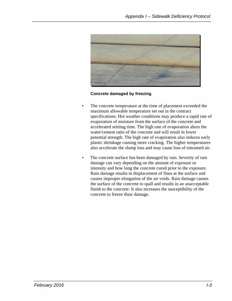
February 2016 I-3
Appendix I – Sidewalk Deficiency Protocol
Concrete damaged by freezing
• The concrete temperature at the time of placement exceeded the maximum allowable temperature set out in the contract specifications. Hot weather conditions may produce a rapid rate of evaporation of moisture from the surface of the concrete and accelerated settimg time. The high rate of evaporation alters the water/cement ratio of the concrete and will result in lower potential strength. The high rate of evaporation also induces early plastic shrinkage causing more cracking. The higher temperatures also accelerate the slump loss and may cause loss of entrained air.
• The concrete surface has been damaged by rain. Severity of rain damage can vary depending on the amount of exposure or intensity and how long the concrete cured prior to the exposure. Rain damage results in displacement of fines at the surface and causes improper elongation of the air voids. Rain damage causes the surface of the concrete to spall and results in an unacceptable finish to the concrete. It also increases the susceptibility of the concrete to freeze thaw damage.

Field Services Manual
I-4 February 2016
Concrete damaged by rain
Concrete damaged by rain

February 2016 I-5
Appendix I – Sidewalk Deficiency Protocol
• The concrete contains footprints or other undesirable impressions.
Concrete containing undesirable impressions
• The concrete has been subjected to traffic before it has achieved 75 percent of the specified 28 day compressive strength.
• The concrete has cracked or separated. Cracks in this section refer to unplanned separations in the concrete that are 2 mm or greater in width, separations that have shifted along the vertical alignment and are no longer flush, or both.

Field Services Manual
I-6 February 2016
Concrete that has cracked Hairline cracks are defined as fractures in which the fragments remain in alignment and do not separate because the line of break is so fine. Single hairline cracks that do not separate the concrete panel into a section less than 0.5 m wide do not require any further remedial action as the possible repairs available to use will typically result in a worse situation than leaving the hairline crack alone.
Hairline crack
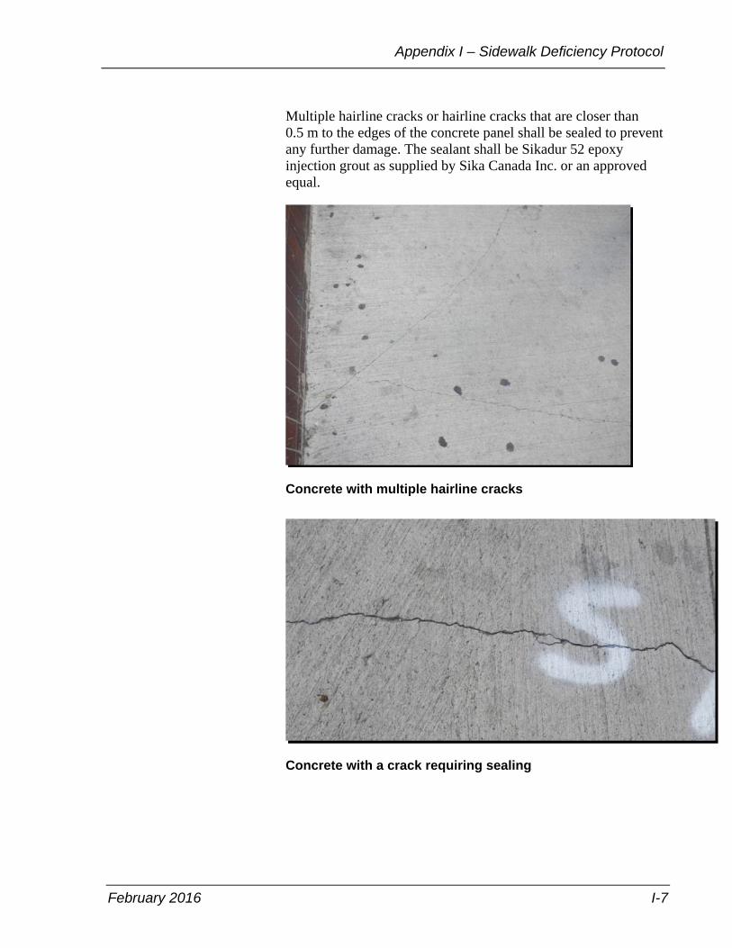
February 2016 I-7
Appendix I – Sidewalk Deficiency Protocol
Multiple hairline cracks or hairline cracks that are closer than 0.5 m to the edges of the concrete panel shall be sealed to prevent any further damage. The sealant shall be Sikadur 52 epoxy injection grout as supplied by Sika Canada Inc. or an approved equal.
Concrete with multiple hairline cracks
Concrete with a crack requiring sealing

Field Services Manual
I-8 February 2016
Single cracks that are less than 2 mm in width and do not show signs of shifting either at the time of inspection or the possibility of shifting at a future time can be sealed to prevent any further damage. The sealant shall be Sikadur 52 epoxy injection grout as supplied by Sika Canada Inc. or an approved equal.
Multiple cracks or cracks that are closer than 0.5 m to the edges of the concrete panel require the removal and replacement of the affected concrete between expansion joints—3 bays. Multiple cracks generally spider out and result in small pieces that can pop out or separate at future dates and reduce the life expectancy of the concrete.
• The concrete surface has spalled as defined in the General Conditions of Contract that the contract administrator will be the sole judge to the determination. Spalling is typically caused by rain or overworking the concrete surface during finishing. Concretes with higher supplementary cementing materials may be more susceptible to the effects of overworking the concrete finish (that is to say the way concrete was finished 15 years ago may not be acceptable on the new concrete mixes with higher supplementary cementing materials).
Concrete that has spalled

February 2016 I-9
Appendix I – Sidewalk Deficiency Protocol
• Expansion and isolation joints are not vertical.
• The concrete sections have heaved or sunk, from their original position.

February 2016 H-1
Appendix J – Bibliography
Appendix J – Bibliography
Field Services Manuals (Current City Divisions)
City of Toronto – Field Services Manual, Technical Services, Second Edition
Published by City of Toronto, 55 John Street, Toronto, Ontario, M5V 3C6, 2009.
Style Guides
City of Toronto – Corporate Writing and Style Guide (2009) By Strategic Communications, City Manager’s Office. Published by City of Toronto, 55 John Street, Toronto, Ontario, M5V 3C6.
Writing Revisable Manuals – Print and Online By Duncan A. Kent. Published by Carswell Thomson Professional Publishing, One Corporate Plaza, 2075 Kennedy Road, Scarborough, Ontario, M1T 3V4. ISBN 0-459-56346-7.
Directives
Frequency of Contractor Performance Evaluations By Engineering & Construction Services, City of Toronto, 5100 Yonge Street, Toronto, Ontario, M2N 5V7, 2014.
Change Order Protocol By Engineering & Construction Services, City of Toronto, 5100 Yonge Street, Toronto, Ontario, M2N 5V7, 2015.
Invoice and Unbudgeted Expenditure Documentation By Engineering & Construction Services, City of Toronto, 5100 Yonge Street, Toronto, Ontario, M2N 5V7, 2015.
Construction Material Testing and Quality Assurance By Engineering & Construction Services, City of Toronto, 5100 Yonge Street, Toronto, Ontario, M2N 5V7, 2015.
Compliance with Contract Terms and Conditions By Engineering & Construction Services, City of Toronto, 5100 Yonge Street, Toronto, Ontario, M2N 5V7, 2014.
Sign-off of Daily Inspection Reports By Engineering & Construction Services, City of Toronto, 5100 Yonge Street, Toronto, Ontario, M2N 5V7, 2014.

February 2016 Glossary-1
Glossary
Glossary
As-built drawing – is documentation created by or based solely on information provided by a third party that reflects the installed, constructed or commissioned conditions of a device, machine, equipment, apparatus, structure, system or other outcome of an engineering project. Since the engineer has not verified that the information is complete or accurate, as-built drawings must not be sealed.
ASTM – American Society for Testing Materials
Book 7 – MTO’s Ontario traffic manual Book 7 Temporary Conditions has been developed to show how to apply traffic control devices in temporary construction, maintenance, and utility work zones, to help ensure worker safety, motorist safety, and motorist mobility. It has been prepared to assist works in the field by illustrating the appropriate signing and the channelization required for the most common types of roadway work operations.
CADD – Computer Aided Design and Drafting
Canadian Standards Association (CSA) – is a non-profit organization that oversees the development of voluntary consensus standards for products, services, processes, systems and personnel in Canada.
CCTV – Closed Circuit Television
Change Directive (CD) – The change directive is used to order the contractor to make revisions to the contract, which are on the critical path or will impact time or cost or both. The change directive is utilized to keep the project moving forward and a subsequent change order with cost and schedule impacts is issued once the work has commenced.
City – The City of Toronto—the corporation—and will be referred to as the City for the purposes of this document.
Change Order (CO) – Change orders are written amendments to the contract and are typically used for contingencies, change in the work, extra work, additional work, and obtaining credit for deleted scope.
Construction drawings – Construction drawings are created from the tender drawings, modified to incorporate any changes from addenda that were issued during the tender process. Construction drawings are
Field Services Manual
Glossary-2 February 2016
issued after the tender has closed and are the ones used at the construction stage. They will consist of one paper print of the approved design drawing with changes or corrections made as required.
Consultant – Consulting engineering firm retained by, or on behalf of the City. This referenced may also include municipal staff depending on the context.
Contract Administrator – The individual or firm responsible for overseeing the construction of the works and representing the City’s interest. See also Project Manager, Project Lead.
CWPP – Capital Works Projects Procurement and Administration Procedures Manual, December 2007 edition.
Engineer – The licensed individual or firm responsible for the design of the works or their designate. Also may be referred to as the design engineer.
ESA – Electrical Safety Authority
Field Instruction (FI) – Instructions that provide information or requests to the contractor or to authorize minor variations to the contract documents that do not impact schedule, scope, cost, or design.
GC – General Conditions of Contract
MOE – Ministry of the Environment for the province of Ontario.
MTO – Ministry of Transportation for the province of Ontario.
Municipal Class EA – Municipal Class Environmental Assessments undertaken by municipalities which can vary in their environmental impact, such that the projects are classified in the Class EA in terms of schedules.
OHSA – Occupational Health and Safety Act for the province of Ontario.
OPSS – Ontario Provincial Standard Specifications
Quality Control (QC) – means a system or a series of activities performed by the contractor to ensure that materials supplied meet the specified requirements.
February 2016 Glossary-3
Glossary
Quality Assurance (QA) – means a system of activities carried out by the owner to ensure that the materials received meet the specified requirements.
Record drawings – is a document created to accurately reflect as-constructed, as-built or as-fabricated conditions and that has been sealed by a professional engineer after verifying that the document is accurate. They are usually retained to meet business or regulatory requirements.
Request for Quotation (RFQ) – RFQs are typically used to obtain detailed pricing and scheduling information on the scope of work when there is an anticipated change in work, extra work, or additional work. RFQs are prepared by the contract administrator and provided to the contractor.
RoDARS – Road Disruption Activity Reporting System is a report which notifies all emergency services such as police, fire, ambulance and so on, must also be submitted enabling these services to adequately plan alternate routes in the event of an emergency. The RODARS form is also sent to the city dispatch, traffic services and the TTC for their information.
Sealed – means a document is signed, dated and bears an impression of the professional engineer’s stamp. The seal implies that the professional engineer attests to the completeness and accuracy of the document.
Shop Drawings – A drawing or set of drawings produced by the contractor, supplier, manufacturer, subcontractor, or fabricator. Shop drawings are typically required for prefabricated components, and are an example of a construction submittal as prescribed in the contract documents.
TRCA – Toronto and Region Conservation Authority
TTC – Toronto Transit Commission
Total float – is the amount of time the selected activity can be delayed, without delaying the project’s finish date.
Water/Sewer Card – a form filled in by the inspector or assistant inspector showing the location and physical details of the water service or sewer service installed by the contractor.
WSIB – Workplace Safety & Insurance Board
1 of 1
Engineering and Construction ServicesNorth York Civic Center
5100 Yonge Street, 4th Floor Toronto, Ontario
M2N 5V7
www.toronto.ca
City of Toronto

Parks, Forestry & Recreation
Janie Romoff, General Manager
Urban Forestry
18 Dyas Road
Toronto, Ontario M3B 1V5
Brian Mercer
Acting Manager, Tree Protection and Plan Review
Tel: 416-392-0724
1
February 9, 2017 Revised March 1, 2017
Basement Flooding Protection Program: Complete Application and Arborist Report
Checklist
The submission of complete applications that are adequately detailed will enable a more efficient
and effective review of proposals by City staff. This will ultimately result in fewer delays in
responding to requests and processing of applications.
The following checklist is provided as a convenience to identify the information needed to
prepare a complete Application to Destroy and/or Injure trees protected under the City's Street
Tree Bylaw, the Private Tree Bylaw (MC Ch. 813, Article II and III), the Parks Bylaw (MC 608,
Article VII) and the Ravine and Natural Feature Protection Bylaw (MC Ch. 658). Further details
are provided on what information is required in the arborist report to be submitted as a part of a
complete application.
Timeline for Submissions
1. Tree Inventory
A Tree Inventory will need to be prepared by a certified Arborist and submitted to Engineering
& Construction Servicing's PFR Liaison during the Preliminary Design stage. This inventory
will be used by the PFR Liaison to identify any potential conflicts with healthy trees and to
identify opportunities to retain these trees early in the process. The inventory should include the
following information:
Tree Species (Common and Scientific Names)
Size (DBH) of all stems
Condition (TI/CS/CV) and also an overall rating of either Healthy or Poor
Dripline and minimum Tree Protection Zone
Address (Street Name and Number)
Tree Category (1 to 5; see details under Arborist Report Checklist)
2. Complete Application
The completed application, including the arborist report should be submitted to TPPR at the
50% Design stage of the design process. RNFP timelines are below. At this time Urban
Forestry will review the proposal to ensure that the project has been designed with tree
preservation in mind and will provide feedback on where additional tree preservation measures is
E18 - Application and Arborist Report Checklist
Parks, Forestry & Recreation
Janie Romoff, General Manager
Urban Forestry
18 Dyas Road
Toronto, Ontario M3B 1V5
Brian Mercer
Acting Manager, Tree Protection and Plan Review
Tel: 416-392-0724
2
required. Urban Forestry may require revisions to the project plans and Arborist report when
healthy trees are being impacted by the proposed work. If the project plans have changed
significantly post 50% design stage a completely new Arborist Report may be required to
address the impacts of these changes.
Designing with Tree Preservation in Mind
Urban Forestry's expectation is that the Project Consultant/Lead will hire a qualified Arborist to
work with them throughout the design phase to ensure that the project is designed with tree
preservation in mind. The Arborist should provide consultation to ensure that only necessary
tree injuries and removals are proposed as a result of the project.
Designing the project with tree preservation in mind means that the Arborist and Project
Consultant/Lead need to work together to ensure that the project is designed in a manner that will
have minimal impacts on bylaw protected trees and natural features on and near the construction
site.
Prior to the design of the project, the Consultant's Arborist needs to become very familiar with
the tree protection bylaws that impact the proposal - Street Tree Bylaw, the Private Tree Bylaw
(MC Ch. 813, Article II and III), the Parks Bylaw (MC 608, Article VII) and the Ravine and
Natural Feature Protection (RNFP) Bylaw (MC Ch. 658).
When projects involve work within RNFP protected areas, the RNFP office should be
contacted prior to any work planning/design being done. The RNFP Planner assigned to this
area will meet the Project Consultant/Lead on site to review the site conditions and to determine
potential tree/site impacts at the outset. RNFP can be reached at [email protected] or by calling
416-392-2513.
In order to guarantee that the project is designed with tree preservation in mind the following
guidelines should be followed:
i. The alignment of new or replacement sewer infrastructure should be designed so that it is
located outside of the tree protection zones (TPZs) of all bylaw protected trees.
ii. If it is not possible to avoid working within the TPZ of bylaw protected trees the project
should be designed to avoid working within the TPZ of healthy trees. If there is a
conflict between working in the TPZ of healthy trees vs poor condition trees the project
should be designed to avoid working within the TPZ of the healthy trees.
iii. If it is not possible to avoid working within the TPZ's, the Arborist and Project
Consultant/Lead should review the proposal to determine if tree preservation measures

Parks, Forestry & Recreation
Janie Romoff, General Manager
Urban Forestry
18 Dyas Road
Toronto, Ontario M3B 1V5
Brian Mercer
Acting Manager, Tree Protection and Plan Review
Tel: 416-392-0724
3
(see list below) and/or alternative construction methods (e.g. tunneling) can be adopted to
ensure the retention of the trees.
iv. After assessing options i. to iii. if it is determined that it is not possible to retain healthy
trees due to the proposed work, the Arborist and Project Consultant/Lead will need to
provide this information in the Arborist report to be submitted along with the complete
application. At the time when UF is reviewing the application a site visit may be
requested to review these specific trees. Based on outcome of the review UF may require
revisions to the project plans and the Arborist Report.
Complete Application Checklist
Additional information is provided for each of the following requirements under Appendix A.
The following should be submitted to ensure the submission of a complete tree removal and/or
injury application:
1. Completed Permit Application Form (and Authorization Form for Ravine and Natural
Feature Protection (RNFP) applications)
2. Permit Application Fee (not required for RNFP applications)
3. Site plan/Construction Plans
4. Arborist Report
5. Tree Protection Plan
6. Planting plan/Landscape plan/Naturalisation Plan
Additional requirements (if applicable):
7. Grading, Drainage and Stormwater plans
8. Sediment control plan
Note(s):
All plans must be drawn and dimensioned in appropriate metric scale.
The RNFP bylaw also regulates the placing or dumping of fill or refuse, and altering the
existing grade within ravine protected areas. Details are available at: http://www1.toronto.ca/wps/portal/contentonly?vgnextoid=40a137ae85f61410VgnVCM10000071d60f89R
CRD&vgnextchannel=4bb1927e1d3e9410VgnVCM10000071d60f89RCRD
If applicable, all site plan/construction drawings, must show the exact location of the
RNFP limit and contain the RNFP bylaw note to advise contractors of the regulated area
and the penalties associated with unauthorized activities.

Parks, Forestry & Recreation
Janie Romoff, General Manager
Urban Forestry
18 Dyas Road
Toronto, Ontario M3B 1V5
Brian Mercer
Acting Manager, Tree Protection and Plan Review
Tel: 416-392-0724
4
Arborist Report Checklist
Arborist Reports must be dated. The report needs to be less than 1 year old from the date of
submission of the tree permit application.
Arborist Reports must contain the following information:
1. Contact Information: Provide name, address, telephone number and email address of
the applicant/project lead.
2. Outline Construction Project: Provide details on the proposed construction project.
3. Methodology: Outline how information was collected.
4. Tree Identification: Tree species, diameter (dbh in cm), condition, category, location,
minimum tree protection zone (TPZ), bylaw jurisdiction, and other pertinent details must
be clearly identified (e.g. Species at Risk). Tree stem sizes and locations must be
accurately surveyed on the plans in order to correctly determine the impacts to the trees.
All trees, on-or off-site protected under the Private Tree and City Street tree bylaws and
within 6 m of the proposed construction impact zone of any proposed development
activity must be included in the arborist report inventory. For trees in the RNFP area, all
trees, on-or off-site protected under the RNFP bylaw and within 12 m of the proposed
construction impact zone of any proposed development activity must be included in the
arborist report inventory.
The minimum TPZ's need to be drawn on the plans in accordance with applicable
requirements as outlined in the City's Tree Protection Policy and Specifications for
Construction Near Trees document available at: https://www1.toronto.ca/city_of_toronto/parks_forestry__recreation/urban_forestry/files/pdf/TreeProtSpecs
.pdf (pg. 6, Table 1).
Tree Categories:
1 - Trees with diameters of 30 cm or more, situated on private property on the subject site.
2 - Trees with diameters of 30 cm or more, situated on private property, within 6 m of the subject site.
3 - Trees of all diameters situated on City owned parkland within 6 m of the subject site.
4 - Trees of all diameters situated within lands designated under City of Toronto Municipal Code, Chapter
658, Ravine and Natural Feature Protection.
5 - Trees of all diameters situated within the City road allowance adjacent to the subject site.
Note: If trees are located within the RNFP designated area but are located within the City road allowance,
the trees should be identified as both Category 4 and 5. The trees would be protected under the Street Tree
Bylaw.

Parks, Forestry & Recreation
Janie Romoff, General Manager
Urban Forestry
18 Dyas Road
Toronto, Ontario M3B 1V5
Brian Mercer
Acting Manager, Tree Protection and Plan Review
Tel: 416-392-0724
5
5. Tree Impacts: Identify whether the trees will be fully protected, removed or injured.
Tally number of trees to be removed, injured and fully protected.
6. Rationale and Details on the Tree Impacts: The reason for the removal or injury of
any trees must be clearly outlined. The arborist report needs to describe all work
proposed within the TPZ, including grade changes, construction of sidewalks, etc. The
report should outline the distance from the tree to the proposed work. E.g. Tree no. 1 –
Grade change at 2.4 m into the 4.8 m TPZ. The arborist should provide their professional
opinion on whether the injury is sustainable or if removal of the tree is required.
7. Tree Preservation Measures: Describe in detail recommended tree preservations
measures including, but not limited to, vertical hoarding, horizontal hoarding, tree-
sensitive demolition, root zone compaction protection, canopy pruning, root-sensitive
excavation, root pruning, and post construction care.
8. Recommendation for Mitigation: Provide recommendations and details on mitigating
tree negative impacts resulting from the proposed development. Mitigation should
include compensating for tree removal by planting replacement trees on the site; and, if
applicable, taking actions to restore and enhance the existing site. Details for
compensation can be found under Appendix A - Planting plan/Landscape
plan/Naturalisation Plan
Note: Urban Forestry strongly recommends that the Tree Identification, Tree Impacts and
Rationale and Details on the Tree Impacts as described above be provided to Urban
Forestry in an Excel Spreadsheet for ease of review.

Parks, Forestry & Recreation
Janie Romoff, General Manager
Urban Forestry
18 Dyas Road
Toronto, Ontario M3B 1V5
Brian Mercer
Acting Manager, Tree Protection and Plan Review
Tel: 416-392-0724
6
Appendix A
Details of Complete Application Requirements:
Permit Application Form - should be completed by the owner, or by the agent, if the
application is being made by an agent or consultant and the owner has completed the Owner’s
Authorization Form.
Private and Street Tree Bylaw Permit Application is available at: https://www1.toronto.ca/City%20Of%20Toronto/Parks%20Forestry%20&%20Recreation/03Trees%20and%20Ravi
nes/Files/pdf/A/Application_to_Injure_or_Destroy_Trees.pdf
Ravine and Natural Feature Protection Permit Application is available at: http://www1.toronto.ca/City%20Of%20Toronto/Parks%20Forestry%20&%20Recreation/03Trees%20and%20Ravin
es/Files/pdf/R/Ravine%20and%20Natural%20Feature%20Permit%20Application.pdf
Ravine and Natural Feature Protection Owner's Authorization is available at: https://wx.toronto.ca/intra/it/pubformrep.nsf/cf31a385c46c917b85257460004920a9/86285f41f75e53fb85257e8f006
9ea84/$FILE/01_0146_Owners_Authorization_to_Submit_an_Application.pdf
Permit Application Fee - $313.99/tree (subject to change) for tree protected under the Private
tree and Street Tree Bylaws. No permit fee required RNFP applications (subject to change).
Site Plan/Construction Plans – Plans of proposed works must be drawn and dimensioned in
appropriate metric scale on a base plan that corresponds to the legal plan, and shows intended
construction works, limits of construction, material storage, access requirements, servicing, etc.
If applicable all site plans and construction drawings must show the exact location of the RNFP
Limit, and the bylaw note must be shown on all site and construction drawings.
Ravine & Natural Feature Protection Bylaw Note:
The Ravine & Natural Feature Protection Bylaw, Chapter 658 of the City of Toronto Municipal Code regulates the
injury and destruction of trees, dumping of refuse and changes to grade within protected areas defined in Schedule A.
Under this bylaw protected trees may not be removed, injured or destroyed, and protected grades may not be altered,
without written authorisation from Urban Forestry Ravine & Natural Feature Protection, on behalf of the General
Manager of Parks, Forestry & Recreation.
Convictions of offences respecting the regulations in the Ravine & Natural Feature Protection Bylaw are subject to
fines, and the landowner may be ordered by the court to restore the area to the satisfaction of the City. A person
convicted of an offence under this Bylaw is liable to a minimum fine of $500 and a maximum fine of $100,000 for
each tree destroyed, a maximum fine of $100,000 for any other offence committed under this chapter, and/or a Special
fine of $100,000. A person convicted of a continuing offence, including failure to comply with ravine permit
conditions is liable to a maximum fine of not more than $10,000 for each day or part of a day that the offence continues.
(version June 2008)
Arborist Report – Details outlined above.

Parks, Forestry & Recreation
Janie Romoff, General Manager
Urban Forestry
18 Dyas Road
Toronto, Ontario M3B 1V5
Brian Mercer
Acting Manager, Tree Protection and Plan Review
Tel: 416-392-0724
7
Tree Protection Plan – All trees not approved for removal or injury must be protected to the
satisfaction of Urban Forestry. The applicant must submit a tree protection plan detailing how
trees proposed for preservation on the property and adjacent properties, if applicable, will be
protected during construction. The plan must comply with the City’s Tree Protection Policy and
Specifications for Construction near Trees. RNFP trees require larger TPZs than Private Tree
and City Street Tree bylaw protected trees.
The tree protection plan must detail pre- and post-construction tree maintenance that would be
required to ensure the survival, health, and vigour of trees to be retained on site.
Planting plan/Landscape plan/Naturalisation Plan - A legible planting plan with an
appropriate scale must be provided, detailing all proposed soft/hard landscaping surfaces plus
proposed improvements to the natural environment, including:
Proposed tree species, sizes, and locations must be provided for review and approval.
As a minimum, three trees are to be planted for each RNFP and private tree removed,
and one tree is required to be planted for each City owned tree removed.
For RNFP applications, replacement trees must be non-invasive, native and preferably
indigenous, grown from an acceptable local seed source, and appropriate species must
be matched to existing site conditions. In naturalised areas, use should be made of
species that are typically associated with specific indigenous forest ecosystems, as
detailed in the Ecological Land Classification Guide for Southern Ontario.
Compensatory planting may also take the form of a stewardship plan, naturalisation plan, or
forest management plan, if appropriate. Cash-in-lieu of replanting in the amount of $583/tree
may also be accepted.
Grading, Drainage and Stormwater Plans - A legible grading plan, at an appropriate scale,
must be provided, indicating existing and proposed grades, as well as details of site drainage and
storm water management. Grade changes are not permitted within established bylaw protected
tree's TPZs therefore the plan must confirm the limit of proposed grading does not extend into
the TPZs.
Sediment Control Plan (Erosion & Sediment Control Plan) - A sediment control plan must be
provided, at an appropriate scale, and indicating location and construction details of sediment
control measures to be erected prior to construction. Plans must show that protection is adequate
and located outside/above the TPZs of trees & natural areas in protected areas. The sediment
control fencing must be installed to Ontario Provincial Standards (OPSD-219.130, see Section 7,
Figure 5) and to the satisfaction of Urban Forestry.