contract proposal book for - city of rochester
TRANSCRIPT

January 23, 2020
City of Rochester, New York
Contract Proposal Book for
SAGER DRIVE IMPROVEMENT PROJECT
Project No. 16146
Department of Environmental Services Bureau of Architecture and Engineering Services
Holly E. Barrett, P.E., City Engineer
Issued: March 2, 2020
THIS CONTRACT CONTAINS AN INCENTIVE PROGRAM FOR EMPLOYING QUALIFIED CITY RESIDENTS,
APPRENTICESHIP TRAINING REQUIREMENTS; AND NEW MWBE AND WORKFORCE GOALS REQUIREMENTS EFFECTIVE JULY 1, 2018


PROJECT SUMMARY PROJECT TITLE Street Improvement Program Sager Drive Improvement Project (Culver Road to East Boulevard) Project No. 16146 PROJECT DESCRIPTION This Project includes new MWBE and Workforce Goals (reference Sections SLR 19 and SLR 20), and consists of the improvements to Sager Drive Improvement Project, between Culver Road and East Boulevard. The scope of the work consists of reconstruction of the existing pavement structure, milling and resurfacing the Sager Drive/East Boulevard intersection, driveway aprons, sidewalks and accessible curb ramps meeting ADA requirements, granite stone curbs, underdrain, catch basins, manhole frames and covers, abandonment of existing and installation of new water main and services, hydrant replacements, installation of fiber conduit, new street lighting system, tree removals, pavement markings, signage upgrades, and restoration of all disturbed lawn areas. This project will also convert Sager Drive from two-way travel to one-way travel in the eastbound direction (from Culver Road to East Boulevard) PROJECT DESIGN Dennis Kennelly, P.E. TYLin International Engineering & Architecture, P.C. 225 East Avenue Rochester, NY 14604 CONTRACT TYPE This is a UNIT PRICE contract. CONTRACT DOCUMENTS A. City of Rochester Standard Construction Contract Documents, November 1, 1991 Edition B. NYSDOT Standard Specifications (US Customary Units) latest edition – specifications as referenced C. Contract Proposal Book for Sager Drive Improvement Project D. Contract Proposal Forms for Sager Drive Improvement Project E. Contract Drawings 1 thru 36

WORK BY OTHERS The intent of the “WORK BY OTHERS” portion of the Project Summary section is to advise the prospective Bidder of any anticipated work to be done by others for informational and coordination purposes. The information is furnished solely for the convenience of the Contractor, without any warranty expressed or implied as to its accuracy or completeness. Rochester Gas & Electric - Gas – RG&E test pits determined the gas main at the curb intersections are between 37 inches and 40 inches deep and the gas services are 30 inches to 34 inches deep at the curb intersections. RG&E will be submitting a permit to lower their facilities a minimum of 42 inches below grade to be located below the proposed underdrain along the north side of the proposed travel lane. Work is expected to be completed prior to commencement of the street construction project. Rochester Gas & Electric - Electric – RG&E Electric has all overhead facilities with the exception of the west end of Sager Drive near Culver Road. Their permit application indicates the replacement and relocation of 10 poles including the installation of 1,000 feet of new 3ph primary and 1/0 triplex overhead electric wires; in addition, a new handhole will be installed in the lawn area on Sager Drive in front of 324 Culver Road and an new manhole will be installed in the parking area on Sager Drive in front of 1250 East Avenue along with 160 feet of underground conduit (between Stations S11:00 and S12+50). Pole relocations are expected to begin in March 2020 and be fully completed by end of August 2020. Coordination will be required with RG&E Electric’s contractor. Charter/Spectrum – Charter Communications has all overhead lines except at the west end of Sager Drive near Culver Road. Charter will transfer their service lines after RG&E Electric relocates their poles and lines. Frontier Telephone - all overhead except for the west end of Sager Drive near Culver Road and at the east end near East Blvd where there is underground conduit that will require replacement. Results from the test pits conclude the underground conduit on the east end near East Boulevard is 31 inches below existing grade and will be lowered to 42 inches at curb crossings; the underground conduit on the west end near Culver Road is 11 inches deep and will be lowered. Frontier will transfer their overhead service lines after RG&E Electric relocates their poles and lines. Proposed lowering of their underground facilities is expected to be completed prior to commencement of the street construction project. Street Lighting – Street Lighting’s contractor will be removing the existing lighting arms and LED cobra head fixtures from the existing utility poles and replace them with new lighting arms and Domia LED dark sky compliant light fixtures on the newly relocated RG&E wood poles. In addition, three (3) new residential post top fiberglass poles with dark sky compliant LED fixtures and all cabling will be installed along the south side of Sager. Work to be completed in coordination with RG&E Electric’s work and the street construction project. Monroe County Pure Waters (MCPW) – All sewer catch basin and manhole work will be performed as part of the street construction project. 46 Sager Drive Plumbing Contractor – Coordination with 46 Sager Drive’s Plumbing Contractor will be required prior to the installation of the cleanout and sewer lateral connection to the 20 inch sewer main in Sager Drive (approximate Station S13+10). The Plumbing Contractor’s information will be provided prior to start of construction. No other work is anticipated at this time.

TABLE OF CONTENTS
PAGE SUPPLEMENTARY INSTRUCTIONS TO BIDDERS .................................................... SIB-1 thru SIB-9 PROPOSAL ...................................................................................................................... P-1 thru P-15 AGREEMENT, BONDS AND INSURANCE FORMS ........................................................ A-1 thru A-11 SUPPLEMENTARY LAWS AND REGULATIONS ................................................... SLR-1 thru SLR-26 SUPPLEMENTARY TERMS AND CONDITIONS .................................................... STC-1 thru STC-72 SPECIAL NOTES .......................................................................................................... SN-1 thru SN-8 SUPPLEMENTARY SPECIFICATIONS...................................................................... SS-1 thru SS-236


SUPPLEMENTARY INSTRUCTIONS TO BIDDERS
PAGE A. RECENT CHANGES TO THE CONTRACT DOCUMENTS.................................................... SIB-1 B. PROJECT SPECIFIC INFORMATION
1. Pre-Bid Conference ........................................................................................................ SIB-2 2. Time and Location of Bid Opening .................................................................................. SIB-2 3. Apprenticeship and Subcontractor Data, MWBE Form P, Workforce Goals .................... SIB-2 4. Incentive Program for Employing Qualified City Residents ............................................. SIB-2 5. Start and Completion of the Work ................................................................................... SIB-2
C. MODIFICATIONS TO THE INSTRUCTIONS TO BIDDERS
SIB 1. Charge or Deposit Required ................................................................................... SIB-3 SIB 2. Qualifications of Bidders ......................................................................................... SIB-3 SIB 3. Inspections and Review of Contract Documents before Submitting Bid .................. SIB-4 SIB 5. Requirements for Bid Deposit ................................................................................. SIB-5 SIB 6. Subcontractors and Assignments ........................................................................... SIB-5 SIB 9. Requirements for Preparation and Submission of Bids ........................................... SIB-6 SIB 11. Owner’s Discretion to Accept, Reject, or Waive Bid ............................................... SIB-7 SIB 12. Basis of Award ....................................................................................................... SIB-7 SIB 14. Execution of the Agreement ................................................................................... SIB-8 SIB 15. Incentive Program for Public Works Contracts ....................................................... SIB-9 SIB 16. Iran Divestment Act ................................................................................................ SIB-9 SIB 17. NYS Freedom of Information Law (FOIL) ............................................................... SIB-9

Page SIB-1
SUPPLEMENTARY INSTRUCTIONS TO BIDDERS
These Supplementary Instructions to Bidders amend or supplement the Instructions to Bidders of the City of Rochester Standard Construction Contract Documents and other provisions of the City’s Contract Documents as are indicated below. All provisions which are not so amended remain in full force and effect. A. RECENT CHANGES TO THE CONTRACT DOCUMENTS The following is a brief recap of the major changes that have been made to the Contract Documents:
• Revised Bid Proposal Submissions Checklist of the Proposal Section to include a checkoff that
the Bidder certifies their understanding that they must perform a minimum of 20% of the contract work with their own organization (1/20/2020)
• Added a new Special Notes section after the Supplementary Terms and Conditions section to
supplement the City of Rochester and NYSDOT Standard and Supplementary Contract Documents (12/1/2019)
• Revised Subsection 6.4 Concerning Subcontractors and Suppliers Article 6 Contractor’s
Responsibilities of the General Terms and Conditions Section to require prime Contractor to provide the City with the names of all Subcontractors and Suppliers to be used on the project prior to the pre-construction meeting (5/13/2019)
• Revised Subsection 13.1 Applications for Progress Payment Article 6 Contractor’s
Responsibilities of the General Terms and Conditions Section to require the use of web based reporting systems (5/13/2019)
• Added definition CERTIFICATE OF ZONING COMPLIANCE (CZC) to Subsection 1.1
Definitions Article 1 Definitions and Abbreviations; Revised paragraph 5.1.2 of Subsection 5.1 Availability of Lands Article 5 Availability of Lands; Physical Conditions; Reference Points; and Revised paragraph 6.2.6 of Subsection 6.2 Labor, Products and Storage Article 6 Contractor's Responsibilities; all of the General Terms and Conditions Section to define requirements for Contractor to provide additional lands and access thereto that may be required for temporary construction facilities or storage of materials and equipment (2/1/2019)
An incomplete bid package that is missing the required forms will be declared informal and will not be considered for award. No required apprenticeship material will be accepted after Bids have been opened. The Bidder should familiarize themselves not only with these major changes, but also should thoroughly review all of the Contract Documents as other minor changes may also have been made that are not specifically noted herein. The Bidder is to comply not only with these new requirements, but with all of the other requirements that are listed within the Contract Documents.

Page SIB-2
B. PROJECT SPECIFIC INFORMATION 1. Pre-Bid Conference A pre-bid conference will be held on Tuesday, March 10, 2020 at 10:00 AM in Room 008-A, City Hall, 30 Church Street, Rochester, New York 14614. All Bidders are urged to attend so that their bid is not rejected due to lack of adequate documentation. Any statements made at the pre-bid meeting do not constitute changes in the Contract Documents. Amendments to the Contract Documents can only be accomplished by means of addenda issued by the City Engineer. 2. Time and Location of Bid Opening Sealed Proposals for the following improvement:
Sager Drive Improvement Project (Culver Road to East Boulevard) Project No. 16146
endorsed with the name of the Bidder and stating the Bidder’s address must be received by the Office of the Purchasing Agent, City Hall Room 105-A, 30 Church Street, Rochester, NY 14614 prior to the Bid opening. The Bid opening is scheduled at 2:00 PM local time on Tuesday, March 24, 2020, at City Hall, 30 Church Street, Rochester, NY, at which time and place all Bids will be publicly opened, read and recorded. When the Bidder submits their Bid, the Purchasing Office will inform the Bidder of the room location where the Bids will be opened. 3. Apprenticeship and Subcontractor Data, MWBE Form P, Certification of Workforce Goals
a. Submit Apprenticeship Agreements and Subcontractor Data as required by SIB-9 and SLR-17.
b. Submit MWBE Form P pages 1 and 2, and page 3 if required, with the bid as required by SIB-9 and SLR-19.
c. Verify intent to meet the Workforce Goals as required by SIB-9 and SLR-20 by checking the box on page P-5A.
d. Complete and sign the checklist on page P-5A of the proposal and submit all required documents.
The City will reject bids that lack any of the required documents. 4. Incentive Program for Employing Qualified City Residents Indicate on the form “Compliance with City of Rochester Specifications” of the Proposal if you expect to submit an application for the incentive program payment after the project is completed. Checking the box (indicating yes) on the form does not obligate the Bidder to submit an application for payment, but will be used by the City to budget for this additional cost. 5. Start and Completion of the Work The Contractor will start the work within ten (10) days of receipt of the written Notice to Proceed as issued by the City Engineer.

Page SIB-3
The Contractor shall complete the work within one-hundred fifty (150) calendar days from the date the Notice to Proceed was issued less the number of days by which one (1) or more of the following submittals are overdue: Completed MWBE forms and Workforce Goals forms required by Subsection SLR 19 and SLR 20 of the Supplementary Laws and Regulations; performance and payment bonds required by Article 4.1.2 of the General Terms and Conditions; and certificates of insurance required by Article 4.2 of the General Terms and Conditions, and Section 13.3 of the Supplementary Terms and Conditions. C. MODIFICATIONS TO THE INSTRUCTIONS TO BIDDERS SIB-1. Charge or Deposit Required Delete the first sentence of Subsection 1 Charge or Deposit Required in its entirety, and Replace with the following: A charge of sixty dollars ($60.00) shall be made to the Bidder for each hard copy set of the Drawings and the Contract Proposal Book obtained from the City for this Project. Copies of the Drawings and the Contract Proposal Book may also be obtained from BidNet at https://www.bidnetdirect.com/new-york/city-of-rochester/. No charge will be required for Bid documents that are downloaded through the City’s electronic bid service – BidNet - Empire State Purchasing Group – City of Rochester. SIB 2. Qualifications of Bidders Add the following at the end of Subsection 2 Qualifications of Bidders: Upon request by the City of Rochester (City Engineer or Purchasing Agent), Bidders will be required to fill out a Confidential Questionnaire - Statement of Bidder’s Qualifications. The Confidential Questionnaire is not attached to the Proposal as stated in Subsection 2. Qualifications of Bidders of the Instruction to Bidders in the City of Rochester Standard Construction Contract Documents, November 1, 1991, Edition. In the event that the City shall require certified supporting data regarding the qualifications of the Bidder in order to determine whether the Bidder is a responsible Bidder, the Bidder will be required to complete and furnish a Confidential Questionnaire within forty-eight (48) hours of the request by the City Engineer or Purchasing Agent. On the Confidential Questionnaire the Bidder will be required to list:
a. The Bidder’s performance record; b. The address and description of the Bidder’s plant and place of business, principals of the firm and detailed account of work committed; c. An itemized list of equipment in inventory. Such list shall include the age and condition of the equipment; d. Dollar value of the largest contract that the Bidder has been awarded and completed within the last 5 years; e. Description of other contract work the Bidder is engaged in at present time; f. Manner in which the Bidder inspected this Project; g. Names and experience of personnel responsible for field work on this Project; h. Description and dollar value of work to be performed on site with the Bidder’s forces;

Page SIB-4
i. Number of the Bidder’s workers to be assigned to this Project; j. Name of the Bidder’s bonding company; k. Description and dollar value of work to be sublet; l. A description of any similar projects which the Bidder has constructed in a satisfactory manner and other pertinent information; m. Type of equipment to be rented for this Project.
The City Engineer or Purchasing Agent may also request the Bidder to furnish within forty-eight (48) hours a certified or authenticated financial statement, dated within thirty (30) days prior to the opening of bids. The City may require that any items be further verified. The Bidder agrees to permit the City to verify the line of credit extended to the Bidder by banks or other financial institutions. The City may also use the services of a national mercantile agency such as Dunn & Bradstreet, Inc, in checking financial responsibility. The Bidder agrees further that the City will incur no liability as a result of this procedure. A copy of the Confidential Questionnaire is available in the City of Rochester Purchasing Office, City Hall. SIB 3. Inspections and Review of Contract Documents before Submitting Bid Add the following at the end of Subsection 3 Inspections and Review of Contract Documents Before Submitting Bid: The following Contract Documents shall be components of the Agreement between the City of Rochester and the Contractor:
a. The City of Rochester Standard Construction Contract Documents, November 1, 1991, Edition:
1. Instructions on the Use of the Standard Construction Contract Documents (pages IN-1
thru IN-3) 2. Instructions to Bidders (pages IB-1 thru IB-6) 3. Bonds and Insurance Forms (pages BI-1 thru BI-10) 4. Laws and Regulations (pages LR-1 thru LR-7) 5. General Terms and Conditions (pages GC-1 thru GC-55) 6. Specifications (pages S-1 thru S-266) 7. Details (No.R206-1 thru R917-3)
b. NYSDOT Standard Specifications (US Customary Units) latest edition, specifications as referenced.
c. Notice to Bidders (Advertisement)
d. The Contract Proposal Book:
1. Project Summary 2. Supplementary Instructions to Bidders (Page SIB-1 thru SIB-9) 3. Proposal (pages P-1 thru P-15) 4. Agreement, Bonds and Insurance Forms (pages A-1 thru A-11) 5. Supplementary Laws and Regulations (pages SLR-1 thru SLR-26) 6. Supplementary Terms and Conditions (pages STC-1 thru STC-72) 7. Special Notes (pages SN-1 thru SN-8) 8. Supplementary Specifications (pages SS-1 thru SS-236)

Page SIB-5
e. Additional Contract Documents:
1. Drawings (number 1 thru 36) 2. Addenda (as issued) 3. Any Change Orders Issued after execution of this Agreement
The City of Rochester Standard Construction Contract Documents, November 1, 1991, Edition is issued separately in a bound volume. Copies of this book can be purchased from the City of Rochester Purchasing Office, City Hall, for $25.00 or may be obtained from the City web site at http://www.cityofrochester.gov/Specifications/. Certain Supplementary Specifications may make reference to NYSDOT Standard Specifications (US Customary Units) latest edition. Copies of this book may be obtained by contacting NYSDOT Plan and Publication Sales, (518) 457-2124, or through the New York State website. The Water Bureau maintains a list of pre-approved materials for use on all construction projects. It is recommended that the Bidder obtain a copy of this list before preparing and submitting a bid. Copies of this list may be obtained either by calling the Water Bureau, at (585) 428-7569, or on the City of Rochester’s website at http://www.cityofrochester.gov/waterdocuments/. Any conflicts or questions between these documents are to be identified by the Bidder at the pre-bid meeting. SIB 5. Requirements for Bid Deposit Add the following after the first paragraph of Subsection 5 Requirements for Bid Deposit: A Bid Deposit will not be required for bids less than $100,000 unless specified in the bid documents. SIB 6. Subcontractors and Assignments Add the following after the first paragraph of Subsection 6 Subcontractors and Assignments: The Contractor shall perform with its own organization contract work amounting to not less than twenty percent (20%) of the original total contract bid price, except that any items designated by the City as “Specialty Items” may be performed by subcontract and the amount of any such “Specialty Items” so performed may be deducted from the original total contract bid price before computing the amount of work required to be performed by the Contractor with its own organization. The contract amount upon which the twenty percent (20%) requirement is computed includes the cost of materials and manufactured products which are to be purchased or produced by the Contractor under the contract provisions. “Its own organization” shall be construed to include only workers employed and paid directly by the Contractor and equipment owned or rented by it, with or without operators. Employee leasing and other similar arrangements under which workers are employed by a service organization are not considered part of the Contractor’s “own organization”. “Specialty Items” shall be construed to be limited to work that requires specialized knowledge, skill or equipment not ordinarily available in contracting organizations qualified to bid on the contract as a whole, and in general are to be limited to minor components of the overall contract.

Page SIB-6
SIB 9. Requirements for Preparation and Submission of Bids Delete the fourth paragraph of Subsection 9 Requirements for Preparation and Submission of Bids in its entirety, and Replace with the following: Bid proposals for this bid Project must be submitted in a marked sealed envelope, with the name and address of the Bidder, the Project name and number, and the opening date and time marked on the face of the envelope. The sealed envelope is to include a signed original hard copy of the complete Proposal, required bid bond, addenda, any support documentation required, and all other required forms as listed on the Bid Proposal Submissions Checklist. Bid proposals must be delivered to and received by the Purchasing Agent at the Bureau of Purchasing, Room 105-A, City Hall, Rochester, New York 14614 by the closing date and time specified in the Invitation to Bid, or as established by any addenda. Electronic bids submitted through BidNet or any other form of bid other than a hard copy of the City provided forms, will not be accepted. Add the following after the fifth paragraph of Subsection 9 Requirements for Preparation and Submission of Bids: Submit with the Proposal, copies of the appropriate apprenticeship agreements for the Bidder, Bidder’s Form AT-10 or if not self-sponsoring the apprenticeship program, Form AP3 and the associated Form AT-10, Form AP1 and appropriate Subcontractor apprenticeship agreements as required by the Rules and Regulations for the “Apprenticeship Training Program for Construction Projects”, if:
1. This contract involves work described in the Rules and Regulations for the “Apprenticeship Training Program for Construction Projects”; and
2. The amount of the contract to be awarded is in excess of $250,000. If any add/deduct alternates alone or in combination with the base bid could result in a contract amount award that exceeds $250,000, regardless of the base bid amount, submit the apprenticeship documentation.
A Contractor who submits a bid for such a City contract shall include with its bid package the following complete apprenticeship documents which meet the requirements of these Rules and Regulations:
1. Bidder’s Form AT-10 or, if not self-sponsoring the apprenticeship program, Form AP3 and the associated Form AT-10. 2. Bidder’s Form AP1.
Submit with the Proposal the complete Subcontractor apprenticeship documents:
1. Subcontractor’s Form AT-10 or, if not self-sponsoring the apprenticeship program, Form AP3 and the associated Form AT-10.
If no such subcontracts are proposed which exceed $100,000 in value, submit the completed City Form AP1 with the word “NONE” inserted under “Subcontract Scope of Work or Work Items” column for Subcontractors. An incomplete bid package that is missing the required forms will be declared informal and will not be considered for award. No required apprenticeship material will be accepted after Bids have been opened.

Page SIB-7
The apprenticeship agreement requirement also applies to subcontracts proposed following contract award; see the Rules and Regulations for the “Apprenticeship Training Program for Construction Projects” for details. The Rules and Regulations for the “Apprenticeship Training Program for Construction Projects” are included in the Supplementary Laws and Regulations section. An Excel spreadsheet version of City Form AP1 is available on the City’s website at http://www.cityofrochester.gov/mwbe. Submit with the Proposal, MWBE Form P pages 1 and 2, and page 3 if required. Check the box to verify acceptance of the Workforce Goals on Page P-5A. Add the following after the seventh paragraph of Subsection 9 Requirements for Preparation and Submission of Bids: No Bidder will be allowed to set a bid price in an increment of less than one hundredth of a dollar ($0.01). Bidders must assign a bid price to the nearest penny. Submission of a bid price in an increment of less than one hundredth of a dollar ($0.01) will result in that increment being dropped from the bid price and the total cost for that bid price recalculated, and the subtotal and total base bids adjusted accordingly. Figures will not be rounded up or down. For example, a bid price submission of $1.759 will be considered a bid price of $1.75. SIB 11. Owner’s Discretion to Accept, Reject, or Waive Bid Add the following under paragraph 3 of Subsection 11 Owner’s Discretion to Accept, Reject, or Waive Bid: J. Failure to submit Apprenticeship Agreements in accordance with the Rules and Regulations for the “Apprenticeship Training Program for Construction Projects”, per Subsection SLR 17 Apprenticeship Training Program for Construction Contracts of the Supplementary Laws and Regulations. K. Failure to submit MWBE Form P pages 1 and 2, and page 3 if required. L. Failure to check the box on Page P-5A to verify acceptance of the Workforce Goals. SIB 12. Basis of Award Delete Subsection 12 Basis of Award in its entirety, and Replace with the following: The contract will be awarded to the lowest responsible Bidder complying with all of the provisions of the Instructions to Bidders and the Supplementary Instructions to Bidders. The City of Rochester requires any Contractor, prior to entering into a construction contract with the City of Rochester, to have a MWBE Form A – MWBE Utilization Plan submitted to and approved by the City.
Page SIB-8
The City of Rochester requires any Contractor, prior to entering into a construction contract with the City of Rochester, to have apprenticeship agreements, appropriate for the type and scope of work to be performed, which have been registered with and approved by the New York State Commissioner of Labor in accordance with Article 23 of the New York State Labor Law. The Bidder must submit complete and appropriate apprenticeship documentation with the Bid proposal. For purposes of this article, Contractor shall mean an entity which directly employs labor under a construction contract. A construction contract shall mean a City of Rochester public works contract for an amount in excess of $250,000 for construction, reconstruction, or improvement of any building, facility or physical structure of any kind, or any subcontract thereto which exceeds $100,000 in value. The Rules and Regulations for the “Apprenticeship Utilization Requirement” are included under Subsection SLR 17 Apprenticeship Training Program for Construction Contracts of the Supplementary Laws and Regulations. The City may conduct such investigations as it may deem necessary to assist in the evaluation of any bid and to establish the responsibility, qualifications and financial ability of the Bidders, in accordance with the Contract Documents to the City’s satisfaction within the prescribed time. Add the following new subsections after Subsection 13 Notice of Award: SIB 14. Execution of the Agreement The successful Bidder shall be required to execute an agreement upon award of the contract. This agreement provides specific information and highlights contract requirements in the General Terms and Conditions of the City of Rochester Standard Construction Contract Documents, November 1, 1991, Edition. The following articles are included in this agreement:
• Article 1. Scope of Work • Article 2. City Engineer, Design Professional, Project Manager (responsibilities of in
accordance with Article 9) • Article 3. Contract Time • Article 4. Liquidated Damages (in accordance with Article 10.4) • Article 5. Contract Price • Article 6. Payment Procedures (in accordance with Article 13) • Article 7. Final Payment (in accordance with Article 14) • Article 8. Availability of Funds (in accordance with Article 15) • Article 9. Contractor’s Representations (in accordance with Article 9) • Article 10. Accounting Records (the Contractor shall maintain accounting records in
accordance with Article 6.10) • Article 11. Contract Documents (the Contract Documents that comprise the Agreement shall
be the same as those stated under SIB 3.d and SIB 3.e with addenda as issued) • Article 12. Miscellaneous (terms used in this agreement shall have the meaning as defined
in Article 1.1) A Performance Bond and Payment Bond shall be submitted in accordance with Article 4 Bonds and Insurance of the General Terms and Conditions, and as revised under the Supplementary Terms and Conditions section. Samples of the City forms are available in the City of Rochester Standard Construction Contract Documents, November 1, 1991, Edition. Performance and Payment bonds will not be required for contracts less than $100,000 unless specified in the bid documents.

Page SIB-9
A Certificate of Insurance shall be submitted in accordance with Article 4 Bonds and Insurance of the General Terms and Conditions, and as revised under the Supplementary Terms and Conditions section. A sample of the Certificate of Insurance Form is in the City of Rochester Standard Construction Contract Documents, November 1, 1991, Edition. The approved MWBE Utilization Plan, Workforce Staffing Plan and Apprenticeship agreements submitted and accepted by the City shall be incorporated into this agreement, along with any amendments to the MWBE Utilization Plan, Workforce Staffing Plan and Apprenticeship agreements approved during the period of this agreement. SIB 15. Incentive Program for Public Works Contracts The City of Rochester provides an Incentive Program for hiring qualified City residents for public works contracts for which the final contract price is for an amount of $50,000 or more. The Contractor may apply for a monetary incentive payment of twenty percent (20%) of the gross payroll paid to qualified City residents, provided that that ten percent (10%) or more of the gross payroll for the Project was paid to qualified City residents. Qualified City residents are those who live in certain ZIP codes. Prime Contractors and first tier Subcontractors may apply for the incentive payments. The Incentive Program is described in detail under Subsection SLR 18 Incentive Program for Public Works Contracts of the Supplementary Laws and Regulations. SIB 16. Iran Divestment Act The Iran Divestment Act of 2012 was signed into law on January 13, 2012 and is codified at State Finance Law (SFL) Section 165-a, and General Municipal Law (GML) Section 103-G. On July 17, 2012, Chapter 106 of the laws of 2012 was signed into law, extending the Iran Divestment Act to State and local public authorities. The Iran Divestment Act, with certain exceptions, prohibits the City from entering into contracts with persons or entities engaged in investment activities in the energy sector of Iran. To implement the law, each Bidder is required to certify at the time it submits its bid that it is not on the list of entities engaged in investment activities in Iran (Prohibited Entities List). The list of entities determined to be non-responsive Bidders is maintained by the Commissioner of the NYS Office of General Services pursuant to State Finance Law. If a Bidder is on the Prohibited Entities List, the City will be able to award the contract to that Bidder only in situations where the Bidder is taking steps to cease its investments in Iran or where the Bidder is a necessary sole source. SIB 17. NYS Freedom of Information Law (FOIL) Bids and all materials submitted with the bid shall become the property of the City and shall be subject to the NYS Freedom of Information Law. If any proprietary information is submitted with the bid, it must be clearly identified and a request to keep such information confidential and the justification for doing so must be submitted with the bid. The City reserves the right to determine whether or not to honor that request in whole or in part based upon requirements of the law.

THIS PAGE INTENTIONALLY LEFT BLANK

January 23, 2020
PROPOSAL
SAGER DRIVE IMPROVEMENT PROJECT
Project No. 16146
Issued: March 2, 2020
SUBMIT WITH THE BID PROPOSAL COPIES OF:
MWBE FORM P MWBE PARTICIPATION PLAN PAGES 1 AND 2, AND PAGE 3 IF NECESSARY, AS REQUIRED BY THE“MINORITY AND WOMEN BUSINESS ENTERPRISE (MWBE)
REQUIREMENTS”; AND
APPRENTICESHIP AGREEMENTS AND SUBCONTRACTOR DATA REQUIRED BY RULES; AND
REGULATIONS FOR THE “APPRENTICESHIP TRAINING PROGRAM FOR CONSTRUCTION PROJECTS”; AND
NO REQUIRED APPRENTICESHIP MATERIAL WILL BE ACCEPTED AFTER BIDS HAVE BEEN
OPENED

Page P-1
PROPOSAL TO THE CITY OF ROCHESTER
CITY HALL, 30 CHURCH STREET ROCHESTER, NEW YORK l4614
For Construction of: Sager Drive Improvement Project Project Number: 16146 To the Purchasing Agent of the City of Rochester: The Bidder affirms and declares: 1. The Bidder is the only one interested in this bid; and no person, firm, or corporation other than herein named has any interest in this bid, or in the Agreement proposed to be taken. 2. This bid is made without any connection with any other person, firm or corporation making a bid for the same work, and is in all respects fair, and without collusion or fraud. 3. No officer or employee or person whose salary is payable in whole or in part from the City of Rochester’s treasury is directly or indirectly interested in this bid, or in the supplies, materials, equipment, work or labor to which it relates, or in any of the profits thereof. 4. The Bidder is not in arrears to the City of Rochester, New York, or any other public agency upon any debt or contract, and is not defaulter, as Surety or otherwise, upon any obligation to the City of Rochester, New York, or any other public agency. 5. The Bidder has visited and examined the site of the work and has carefully examined the Contract Documents and is satisfied as to all the quantities and conditions and understands that in signing this Proposal the Bidder waives all rights to pleading any misunderstanding regarding the same. 6. The Bidder will provide, furnish and deliver all work, materials, supplies, tools, equipment, transportation necessary or required for this Project, all in strict conformity with the Contract Documents and in accordance with the prices entered by the Bidder on the attached Proposal form. 7. In a unit price Agreement, the Bidder will accept the unit bid prices in compensation for any additions or deductions caused by variations in quantities due to more accurate measurement or by any change or alterations in the Contract Documents. 8. The Bidder is aware that all interpretations of the Contract Documents are made by means of written addenda. Any objection arising out of an addendum subsequent to the opening of bids will not be considered. Failure of any Bidder to receive any addenda or to attend the reading of the bids will not relieve such Bidder from any obligation under the bid as submitted, including such addenda.
Page P-2
9. The Bidder will execute the Agreement and furnish the necessary bonds and insurance certificates within ten (10) days after written notice of the award of the contract, or forfeit the bid deposit in partial satisfaction of damages. 10. The Bidder will complete the work within the number of calendar days or by the date specified in the Supplementary Instructions to Bidders. 11. The Bidder will comply with all local, state or federal laws, ordinances, rules or regulations controlling or limiting in any way its actions during the submission of bids and performance of the work including the following:
CERTIFICATION OF COMPLIANCE WITH THE IRAN DIVESTMENT ACT A. The contract resulting from this bid shall be subject to the requirements of the Iran Divestment Act of 2012 (the “Act”), Chapter 1 of the 2012 Laws of New York, State Finance Law (SFL) Section 165-a and New York General Municipal Law Section 103-g both effective April 12, 2012. Under the Act, the Commissioner of the Office of General Services (OGS) is responsible for developing a list of “persons” who are engaged in “investment activities in Iran” (both are defined terms in the law) (the “Prohibited Entities List”). The Prohibited Entities List as required by SFL Section 165-a (3) (b) is found on the OGS web site at http://www.ogs.ny.gov/about/regs/docs/ListofEntities.pdf. B. CERTIFICATION. “By submission of this bid, each Bidder and each person signing on behalf of any Bidder certifies, and in the case of a joint bid each party thereto certifies as to its own organization, under penalty of perjury, that to the best of its knowledge and belief that each Bidder is not on the list created pursuant to paragraph (b) of Subdivision 3 of Section 165-a of the State Finance Law.” C. Any Bidder/Contractor seeking to renew or extend this contract or assume the responsibility of the contract awarded in response to this bid solicitation must certify at the time the contract is renewed, extended or assigned that it is not included on the Prohibited Entities List. D. During the term of the contract or any extension, should the City receive information that the Contractor is in violation of the above referenced certification, the City will offer the person or entity an opportunity to respond. If the person or entity fails to demonstrate that the person or entity has ceased engagement in the investment which is in violation of the Act within 90 days after the determination of such violation, then the City shall take such action as may be appropriate including, but not limited to, imposing sanctions, seeking compliance, recovering damages or declaring the Contractor in default. E. The City reserves the right to reject any bid or request for assignment for a Bidder/Contractor that appears on the Prohibited Entities List prior to the award of a contract and to pursue a responsibility review with respect to any Bidder/Contractor that is awarded a contract and subsequently appears on the Prohibited Entities List.

Page P-3
NON-COLLUSIVE BIDDING CERTIFICATION A. Every bid herein made to the City of Rochester, or official thereof, where competitive bidding is required by statute, rule or regulation, for work or services performed, or to be performed or goods sold or to be sold, shall contain the following statement subscribed by the Bidder and affirmed by such Bidder as true under the penalties or perjury: Non-collusive Bidding Certification.
(1) By submission of this bid, each Bidder and each person signing on behalf of the Bidder certifies, and in the case of a joint bid each party thereto certifies, as to its own organization, under penalty of perjury, that to the best of their knowledge and belief:
(i) The prices in this bid have been arrived at independently without collusion, consultation, communication, or agreement, for the purpose of restricting competition, as to any matter relating to such prices with any other Bidder or with any competitor;
(ii) Unless otherwise required by law, the prices which have been quoted in this bid have not been knowingly disclosed by the Bidder, and will not knowingly be disclosed by the Bidder prior to opening, directly or indirectly, to any other Bidder or to any competitor; and
(iii) No attempt has been made or will be made by the Bidder to induce any other person, partnership or corporation, to submit or not to submit a bid for the purpose of restricting competition.
(2) A bid shall not be considered for award nor shall any award be made where (1) (i) (ii) and (iii) above have not been complied with; provided however, that if in any case the Bidder cannot make the foregoing certification, the Bidder shall so state and shall furnish with the bid a signed statement which sets forth in detail the reasons therefore.
Where (1) (i) (ii) and (iii) above have not been complied with, the bid shall not be considered for award nor shall any award be made unless the head of the purchasing unit of the City of Rochester to which the bid is made, or the designee, determines that such disclosure was not made for the purpose of restricting competition. The fact that a Bidder: (a) has published price lists, rates, or tariffs covering items being procured; (b) has informed prospective customers of proposed or pending publication of new or revised price lists for such items; or (c) has sold the same items to other customers at the same prices being bid, does not constitute, without more, a disclosure within the meaning of subparagraph A (1). B. Any bid hereafter made to the City of Rochester, or official thereof, by a corporate Bidder for work or services performed or to be performed, or goods sold or to be sold, where competitive bidding is required by statute, rule or regulation, and where such bid contains the certification referred to herein, shall be deemed to have been authorized by the Board of Directors of the Bidder and such authorization shall be deemed to include the signing and submission of the bid, and the inclusion therein of the certificate as to non-collusion as the act and deed of the corporation.

THE UNDERSIGNED PROPOSES TO COMPLETE:ENG4810
LETTER/ITEM NO DESCRIPTION
ESTIMATEDQUANTITY
UNIT PRICE FIGURESUNIT
UNIT PRICE WRITTEN
ESTIMATED QUANTITY X UNIT PRICE
PROJECT # 16146 IN ACCORDANCE WITH THE CITY OF ROCHESTER'S STANDARD CONTRACT DOCUMENTS AND THEATTACHED CONSTRUCTION CONTRACT DOCUMENTS AT THE FOLLOWING PRICES:
SAGER DRIVE IMPROVEMENT PROJECT 2/25/2020 7:05:13 PM
Finance Plan Last Approved Date : 1/13/2020 10:27:52 AM
203.02 UNCLASSIFIED EXCAVATION AND DISPOSAL
2700 CY
DOLLARS AND
$
$CENTS
203.03 EMBANKMENT IN PLACE 25 CY
DOLLARS AND
$
$CENTS
S203.26 SAND 175 CY
DOLLARS AND
$
$CENTS
S203.29 SELECT GRANULAR BACKFILL (WATER)
259 CY
DOLLARS AND
$
$CENTS
S205.0101 PAVEMENT BASE REPAIR - CONCRETE BASE
4 SY
DOLLARS AND
$
$CENTS
R206.04 TRENCH AND CULVERT EXCAVATION 495 CY
DOLLARS AND
$
$CENTS
Page P4.1 of P4.16Pre-Approved Bid Proposal

THE UNDERSIGNED PROPOSES TO COMPLETE:ENG4810
LETTER/ITEM NO DESCRIPTION
ESTIMATEDQUANTITY
UNIT PRICE FIGURESUNIT
UNIT PRICE WRITTEN
ESTIMATED QUANTITY X
UNIT PRICE
PROJECT # 16146 IN ACCORDANCE WITH THE CITY OF ROCHESTER'S STANDARD CONTRACT DOCUMENTS AND THEATTACHED CONSTRUCTION CONTRACT DOCUMENTS AT THE FOLLOWING PRICES:
SAGER DRIVE IMPROVEMENT PROJECT 2/25/2020 7:05:13 PM
Finance Plan Last Approved Date : 1/13/2020 10:27:52 AM
R206.05 TRENCH AND CULVERT ROCK EXCAVATION
150 CY
DOLLARS AND
$
$CENTS
R206.06 CONDUIT EXCAVATION AND BACKFILL
160 LF
DOLLARS AND
$
$CENTS
304.11 SUBBASE COURSE, TYPE 1 535 CY
DOLLARS AND
$
$CENTS
304.12 SUBBASE COURSE, TYPE 2 645 CY
DOLLARS AND
$
$CENTS
402.000013 PLANT PRODUCTION QUALITY ADJUSTMENT TO HMA ITEMS
102 QU
DOLLARS AND
$
$CENTS
402.097203 9.5 F2 TOP COURSE HMA, 70 SERIES COMPACTION
380 TON
DOLLARS AND
$
$CENTS
Page P4.2 of P4.16Pre-Approved Bid Proposal
70.00 SEVENTY
NO 7,140.00

THE UNDERSIGNED PROPOSES TO COMPLETE:ENG4810
LETTER/ITEM NO DESCRIPTION
ESTIMATEDQUANTITY
UNIT PRICE FIGURESUNIT
UNIT PRICE WRITTEN
ESTIMATED QUANTITY X
UNIT PRICE
PROJECT # 16146 IN ACCORDANCE WITH THE CITY OF ROCHESTER'S STANDARD CONTRACT DOCUMENTS AND THEATTACHED CONSTRUCTION CONTRACT DOCUMENTS AT THE FOLLOWING PRICES:
SAGER DRIVE IMPROVEMENT PROJECT 2/25/2020 7:05:13 PM
Finance Plan Last Approved Date : 1/13/2020 10:27:52 AM
402.197903 19 F9 BINDER COURSE HMA, 70 SERIES COMPACTION
445 TON
DOLLARS AND
$
$CENTS
402.377903 37.5 F9 BASE COURSE HMA, 70 SERIES COMPACTION
1390 TON
DOLLARS AND
$
$CENTS
S407.0301 DILUTED TACK COAT 275 GAL
DOLLARS AND
$
$CENTS
S412.08 TEMPORARY PAVEMENT WITH SUBBASE COURSE
12000 SF
DOLLARS AND
$
$CENTS
418.7603 ASPHALT PAVEMENT JOINT ADHESIVE 3910 LF
DOLLARS AND
$
$CENTS
490.30 MISCELLANEOUS COLD MILLING OF BITUMINOUS CONCRETE
350 SY
DOLLARS AND
$
$CENTS
Page P4.3 of P4.16Pre-Approved Bid Proposal

THE UNDERSIGNED PROPOSES TO COMPLETE:ENG4810
LETTER/ITEM NO DESCRIPTION
ESTIMATEDQUANTITY
UNIT PRICE FIGURESUNIT
UNIT PRICE WRITTEN
ESTIMATED QUANTITY X
UNIT PRICE
PROJECT # 16146 IN ACCORDANCE WITH THE CITY OF ROCHESTER'S STANDARD CONTRACT DOCUMENTS AND THEATTACHED CONSTRUCTION CONTRACT DOCUMENTS AT THE FOLLOWING PRICES:
SAGER DRIVE IMPROVEMENT PROJECT 2/25/2020 7:05:13 PM
Finance Plan Last Approved Date : 1/13/2020 10:27:52 AM
555.0105 CONCRETE FOR STRUCTURES - CLASS A
5 SY
DOLLARS AND
$
$CENTS
S601.230106 6" INSERTA TEE CONNECTION TO EXISTING SEWER PIPE - INSTALLED (INCLUDING EXCAVATION, BACKFILL AND PAVEMENT BASE RESTORATION)
1 EACH
DOLLARS AND
$
$CENTS
S601.230108 8" INSERTA TEE CONNECTION TO EXISTING SEWER PIPE - INSTALLED (INCLUDING EXCAVATION, BACKFILL AND PAVEMENT BASE RESTORATION)
7 EACH
DOLLARS AND
$
$CENTS
S601.2806 6" POLYVINYL CHLORIDE LATERAL PIPE, SDR21 - INSTALLED (INCLUDING LATERAL CONNECTION) (INCLUDING EXCAVATION AND BACKFILL)
35 LF
DOLLARS AND
$
$CENTS
S601.2808 8" POLYVINYL CHLORIDE LATERAL PIPE, SDR21 - INSTALLED (INCLUDING LATERAL CONNECTION) (INCLUDING EXCAVATION AND BACKFILL)
120 LF
DOLLARS AND
$
$CENTS
S604.3705 NEW TYPE B CATCH BASIN - INSTALLED (INCLUDING CONCRETE COLLAR) (INCLUDING EXCAVATION, BACKFILL AND PAVEMENT BASE RESTORATION)
10 EACH
DOLLARS AND
$
$CENTS
Page P4.4 of P4.16Pre-Approved Bid Proposal

THE UNDERSIGNED PROPOSES TO COMPLETE:ENG4810
LETTER/ITEM NO DESCRIPTION
ESTIMATEDQUANTITY
UNIT PRICE FIGURESUNIT
UNIT PRICE WRITTEN
ESTIMATED QUANTITY X
UNIT PRICE
PROJECT # 16146 IN ACCORDANCE WITH THE CITY OF ROCHESTER'S STANDARD CONTRACT DOCUMENTS AND THEATTACHED CONSTRUCTION CONTRACT DOCUMENTS AT THE FOLLOWING PRICES:
SAGER DRIVE IMPROVEMENT PROJECT 2/25/2020 7:05:13 PM
Finance Plan Last Approved Date : 1/13/2020 10:27:52 AM
S604.5010 ALTER EXISTING TYPE A/B CATCH BASIN (INCLUDING CONCRETE COLLAR)
2 EACH
DOLLARS AND
$
$CENTS
S604.560201 ABANDON AND REMOVE EXISTING CATCH BASIN (INCLUDING EXCAVATION AND BACKFILL)
7 EACH
DOLLARS AND
$
$CENTS
S604.6024 ALTER EXISTING BRICK/STONE SEWER MANHOLE - EXISTING CASTINGS AT/OR BELOW FINISHED GRADE (INCLUDING CONCRETE COLLAR)
1 EACH
DOLLARS AND
$
$CENTS
S604.6026 ALTER EXISTING BRICK/STONE SEWER MANHOLE - EXISTING CASTINGS ABOVE FINISHED GRADE (INCLUDING CONCRETE COLLAR)
2 EACH
DOLLARS AND
$
$CENTS
S605.140106 6" PERFORATED CORRUGATED POLYETHYLENE UNDERDRAIN TUBING
125 LF
DOLLARS AND
$
$CENTS
S605.170106 6" HIGH DENSITY PERFORATED CORRUGATED POLYETHYLENE PIPE
755 LF
DOLLARS AND
$
$CENTS
Page P4.5 of P4.16Pre-Approved Bid Proposal

THE UNDERSIGNED PROPOSES TO COMPLETE:ENG4810
LETTER/ITEM NO DESCRIPTION
ESTIMATEDQUANTITY
UNIT PRICE FIGURESUNIT
UNIT PRICE WRITTEN
ESTIMATED QUANTITY X
UNIT PRICE
PROJECT # 16146 IN ACCORDANCE WITH THE CITY OF ROCHESTER'S STANDARD CONTRACT DOCUMENTS AND THEATTACHED CONSTRUCTION CONTRACT DOCUMENTS AT THE FOLLOWING PRICES:
SAGER DRIVE IMPROVEMENT PROJECT 2/25/2020 7:05:13 PM
Finance Plan Last Approved Date : 1/13/2020 10:27:52 AM
607.91000011 PIPE RAIL FENCE - 2 RAIL 43 LF
DOLLARS AND
$
$CENTS
S608.14 CONCRETE SIDEWALK AND DRIVEWAY (INCLUDING EXCAVATION AND SUBBASE COURSE)
163 CY
DOLLARS AND
$
$CENTS
S608.15 ASPHALT DRIVEWAY - LIGHT-DUTY 1305 SF
DOLLARS AND
$
$CENTS
S608.16 ASPHALT DRIVEWAY - MEDIUM-DUTY 1005 SF
DOLLARS AND
$
$CENTS
S608.17 ASPHALT DRIVEWAY - HEAVY-DUTY 2300 SF
DOLLARS AND
$
$CENTS
S608.37 EXPOSED AGGREGATE CONCRETE (INCLUDING EXCAVATION AND SUBBASE COURSE)
28 CY
DOLLARS AND
$
$CENTS
Page P4.6 of P4.16Pre-Approved Bid Proposal

THE UNDERSIGNED PROPOSES TO COMPLETE:ENG4810
LETTER/ITEM NO DESCRIPTION
ESTIMATEDQUANTITY
UNIT PRICE FIGURESUNIT
UNIT PRICE WRITTEN
ESTIMATED QUANTITY X
UNIT PRICE
PROJECT # 16146 IN ACCORDANCE WITH THE CITY OF ROCHESTER'S STANDARD CONTRACT DOCUMENTS AND THEATTACHED CONSTRUCTION CONTRACT DOCUMENTS AT THE FOLLOWING PRICES:
SAGER DRIVE IMPROVEMENT PROJECT 2/25/2020 7:05:13 PM
Finance Plan Last Approved Date : 1/13/2020 10:27:52 AM
S608.380602 EMBEDDED DETECTABLE WARNING SYSTEM
70 SF
DOLLARS AND
$
$CENTS
S609.2305 5" STONE CURB 1740 LF
DOLLARS AND
$
$CENTS
S609.2405 5" RADIUS STONE CURB 170 LF
DOLLARS AND
$
$CENTS
S609.250501 5" MOUNTABLE STONE CURB 50 LF
DOLLARS AND
$
$CENTS
S609.260501 5" MOUNTABLE RADIUS STONE CURB 65 LF
DOLLARS AND
$
$CENTS
S609.3005 5" STONE CURB (INCLUDING EXCAVATION, BACKFILL AND PAVEMENT BASE RESTORATION)
11 LF
DOLLARS AND
$
$CENTS
Page P4.7 of P4.16Pre-Approved Bid Proposal

THE UNDERSIGNED PROPOSES TO COMPLETE:ENG4810
LETTER/ITEM NO DESCRIPTION
ESTIMATEDQUANTITY
UNIT PRICE FIGURESUNIT
UNIT PRICE WRITTEN
ESTIMATED QUANTITY X
UNIT PRICE
PROJECT # 16146 IN ACCORDANCE WITH THE CITY OF ROCHESTER'S STANDARD CONTRACT DOCUMENTS AND THEATTACHED CONSTRUCTION CONTRACT DOCUMENTS AT THE FOLLOWING PRICES:
SAGER DRIVE IMPROVEMENT PROJECT 2/25/2020 7:05:13 PM
Finance Plan Last Approved Date : 1/13/2020 10:27:52 AM
S610.0502 HYDROSEEDING 4000 SF
DOLLARS AND
$
$CENTS
S613.03 TOPSOIL 50 CY
DOLLARS AND
$
$CENTS
S614.35 TREE REMOVAL - 6" TO 11" DBH 5 EACH
DOLLARS AND
$
$CENTS
S614.36 TREE REMOVAL - 12" TO 17" DBH 8 EACH
DOLLARS AND
$
$CENTS
S614.37 TREE REMOVAL - 18" TO 23" DBH 5 EACH
DOLLARS AND
$
$CENTS
S614.38 TREE REMOVAL - 24" TO 29" DBH 2 EACH
DOLLARS AND
$
$CENTS
Page P4.8 of P4.16Pre-Approved Bid Proposal

THE UNDERSIGNED PROPOSES TO COMPLETE:ENG4810
LETTER/ITEM NO DESCRIPTION
ESTIMATEDQUANTITY
UNIT PRICE FIGURESUNIT
UNIT PRICE WRITTEN
ESTIMATED QUANTITY X
UNIT PRICE
PROJECT # 16146 IN ACCORDANCE WITH THE CITY OF ROCHESTER'S STANDARD CONTRACT DOCUMENTS AND THEATTACHED CONSTRUCTION CONTRACT DOCUMENTS AT THE FOLLOWING PRICES:
SAGER DRIVE IMPROVEMENT PROJECT 2/25/2020 7:05:13 PM
Finance Plan Last Approved Date : 1/13/2020 10:27:52 AM
S617.01 FENCING FOR TREE PROTECTION 200 LF
DOLLARS AND
$
$CENTS
619.01 BASIC WORK ZONE TRAFFIC CONTROL 1 LS
DOLLARS AND
$
$CENTS
619.04 TYPE III CONSTRUCTION BARRICADES 8 EACH
DOLLARS AND
$
$CENTS
625.01 SURVEY OPERATIONS 1 LS
DOLLARS AND
$
$CENTS
S626.02 NEW HORIZONTAL CONTROL SURVEY MONUMENT (RCS)
2 EACH
DOLLARS AND
$
$CENTS
627.50140008 CUTTING PAVEMENT 200 LF
DOLLARS AND
$
$CENTS
Page P4.9 of P4.16Pre-Approved Bid Proposal

THE UNDERSIGNED PROPOSES TO COMPLETE:ENG4810
LETTER/ITEM NO DESCRIPTION
ESTIMATEDQUANTITY
UNIT PRICE FIGURESUNIT
UNIT PRICE WRITTEN
ESTIMATED QUANTITY X
UNIT PRICE
PROJECT # 16146 IN ACCORDANCE WITH THE CITY OF ROCHESTER'S STANDARD CONTRACT DOCUMENTS AND THEATTACHED CONSTRUCTION CONTRACT DOCUMENTS AT THE FOLLOWING PRICES:
SAGER DRIVE IMPROVEMENT PROJECT 2/25/2020 7:05:13 PM
Finance Plan Last Approved Date : 1/13/2020 10:27:52 AM
633.11 CLEANING EXISTING PAVEMENT AND/OR SHOULDER
350 SY
DOLLARS AND
$
$CENTS
633.12 CLEANING, SEALING AND/OR FILLING CRACKS
1 LS
DOLLARS AND
$
$CENTS
633.13 CLEANING, SEALING AND/OR FILLING JOINTS
150 LF
DOLLARS AND
$
$CENTS
S637.10 FIELD OFFICE - TYPE A 7 MONTH
DOLLARS AND
$
$CENTS
S643.0401 SIGN POST SLEEVE 13 EACH
DOLLARS AND
$
$CENTS
S671.030202 2" PVC CONDUIT - IN ROADWAY (INCLUDING EXCAVATION AND BACKFILL)
670 LF
DOLLARS AND
$
$CENTS
Page P4.10 of P4.16Pre-Approved Bid Proposal

THE UNDERSIGNED PROPOSES TO COMPLETE:ENG4810
LETTER/ITEM NO DESCRIPTION
ESTIMATEDQUANTITY
UNIT PRICE FIGURESUNIT
UNIT PRICE WRITTEN
ESTIMATED QUANTITY X
UNIT PRICE
PROJECT # 16146 IN ACCORDANCE WITH THE CITY OF ROCHESTER'S STANDARD CONTRACT DOCUMENTS AND THEATTACHED CONSTRUCTION CONTRACT DOCUMENTS AT THE FOLLOWING PRICES:
SAGER DRIVE IMPROVEMENT PROJECT 2/25/2020 7:05:13 PM
Finance Plan Last Approved Date : 1/13/2020 10:27:52 AM
S671.1030 CONCRETE PULLBOX (30") 2 EACH
DOLLARS AND
$
$CENTS
S671.1601 INSTALL FIBERGLASS HANDHOLE/PULLBOX (FURNISHED)
1 EACH
DOLLARS AND
$
$CENTS
S671.3201 FIBERGLASS LIGHT POLE FOUNDATION - PRECAST
3 EACH
DOLLARS AND
$
$CENTS
685.11 WHITE EPOXY REFLECTORIZED PAVEMENT STRIPES - 20 MILS
2200 LF
DOLLARS AND
$
$CENTS
686.05000011 MULTI-COLORED PREFORMED THERMOPLASTIC REFLECTORIZED PAVEMENT SYMBOLS
4 EA
DOLLARS AND
$
$CENTS
C686.520604 CONDUIT PVC SCHEDULE 80 - 4" DIA 750 LF
DOLLARS AND
$
$CENTS
Page P4.11 of P4.16Pre-Approved Bid Proposal

THE UNDERSIGNED PROPOSES TO COMPLETE:ENG4810
LETTER/ITEM NO DESCRIPTION
ESTIMATEDQUANTITY
UNIT PRICE FIGURESUNIT
UNIT PRICE WRITTEN
ESTIMATED QUANTITY X
UNIT PRICE
PROJECT # 16146 IN ACCORDANCE WITH THE CITY OF ROCHESTER'S STANDARD CONTRACT DOCUMENTS AND THEATTACHED CONSTRUCTION CONTRACT DOCUMENTS AT THE FOLLOWING PRICES:
SAGER DRIVE IMPROVEMENT PROJECT 2/25/2020 7:05:13 PM
Finance Plan Last Approved Date : 1/13/2020 10:27:52 AM
698.04 ASPHALT PRICE ADJUSTMENT 1 DC
DOLLARS AND
$
$CENTS
698.05 FUEL PRICE ADJUSTMENT 1 DC
DOLLARS AND
$
$CENTS
S901.130104 4" MOLECULARY ORIENTED POLYVINYL CHLORIDE PIPE WATER MAIN
46 LF
DOLLARS AND
$
$CENTS
S901.130106 6" MOLECULARY ORIENTED POLYVINYL CHLORIDE PIPE WATER MAIN
40 LF
DOLLARS AND
$
$CENTS
S901.130108 8" MOLECULARY ORIENTED POLYVINYL CHLORIDE PIPE WATER MAIN
740 LF
DOLLARS AND
$
$CENTS
S901.130206 6" MOLECULARY ORIENTED POLYVINYL CHLORIDE PIPE FOR HYDRANT BRANCH
30 LF
DOLLARS AND
$
$CENTS
Page P4.12 of P4.16Pre-Approved Bid Proposal
100.00 ONE HUNDRED
NO 100.00
100.00 ONE HUNDRED
NO 100.00

THE UNDERSIGNED PROPOSES TO COMPLETE:ENG4810
LETTER/ITEM NO DESCRIPTION
ESTIMATEDQUANTITY
UNIT PRICE FIGURESUNIT
UNIT PRICE WRITTEN
ESTIMATED QUANTITY X
UNIT PRICE
PROJECT # 16146 IN ACCORDANCE WITH THE CITY OF ROCHESTER'S STANDARD CONTRACT DOCUMENTS AND THEATTACHED CONSTRUCTION CONTRACT DOCUMENTS AT THE FOLLOWING PRICES:
SAGER DRIVE IMPROVEMENT PROJECT 2/25/2020 7:05:13 PM
Finance Plan Last Approved Date : 1/13/2020 10:27:52 AM
S903.0104 4" RESILIENT SEAT GATE VALVE WITH VALVE BOX - VERTICAL TYPE
2 EACH
DOLLARS AND
$
$CENTS
S903.0106 6" RESILIENT SEAT GATE VALVE WITH VALVE BOX - VERTICAL TYPE
4 EACH
DOLLARS AND
$
$CENTS
S904.030808 8" x 8" TAPPING SLEEVE WITH VALVE AND VALVE BOX
1 EACH
DOLLARS AND
$
$CENTS
S907.01 CONNECT NEW WATER MAIN TO EXISTING WATER MAIN
3 EACH
DOLLARS AND
$
$CENTS
S908.0106 CUT AND PLUG EXISTING 6" WATER MAIN
2 EACH
DOLLARS AND
$
$CENTS
S909.08 ADJUST EXISTING WATER VALVE BOX TO GRADE - EXTENSION ADJUSTMENT (INCLUDING EXCAVATION AND BACKFILL)
2 EACH
DOLLARS AND
$
$CENTS
Page P4.13 of P4.16Pre-Approved Bid Proposal

THE UNDERSIGNED PROPOSES TO COMPLETE:ENG4810
LETTER/ITEM NO DESCRIPTION
ESTIMATEDQUANTITY
UNIT PRICE FIGURESUNIT
UNIT PRICE WRITTEN
ESTIMATED QUANTITY X
UNIT PRICE
PROJECT # 16146 IN ACCORDANCE WITH THE CITY OF ROCHESTER'S STANDARD CONTRACT DOCUMENTS AND THEATTACHED CONSTRUCTION CONTRACT DOCUMENTS AT THE FOLLOWING PRICES:
SAGER DRIVE IMPROVEMENT PROJECT 2/25/2020 7:05:13 PM
Finance Plan Last Approved Date : 1/13/2020 10:27:52 AM
S912.020100 NEW 1" WATER SERVICE TAP AT WATER MAIN, CORPORATION STOP AND CONNECTION (INCLUDING EXCAVATION AND BACKFILL)
2 EACH
DOLLARS AND
$
$CENTS
S912.020150 NEW 1-1/2" WATER SERVICE TAP AT WATER MAIN, CORPORATION STOP AND CONNECTION (INCLUDING EXCAVATION AND BACKFILL)
1 EACH
DOLLARS AND
$
$CENTS
S913.120100 NEW 1" POLYETHYLENE WATER SERVICE (INCLUDING EXCAVATION AND BACKFILL)
67 LF
DOLLARS AND
$
$CENTS
S913.120150 NEW 1-1/2" POLYETHYLENE WATER SERVICE (INCLUDING EXCAVATION AND BACKFILL)
43 LF
DOLLARS AND
$
$CENTS
S914.020100 FURNISH AND INSTALL NEW 1" CURB STOP AND BOX AT NEW WATER SERVICE (INCLUDING EXCAVATION AND BACKFILL)
2 EACH
DOLLARS AND
$
$CENTS
S914.020150 FURNISH AND INSTALL NEW 1-1/2" CURB STOP AND BOX AT NEW WATER SERVICE (INCLUDING EXCAVATION AND BACKFILL)
1 EACH
DOLLARS AND
$
$CENTS
Page P4.14 of P4.16Pre-Approved Bid Proposal

THE UNDERSIGNED PROPOSES TO COMPLETE:ENG4810
LETTER/ITEM NO DESCRIPTION
ESTIMATEDQUANTITY
UNIT PRICE FIGURESUNIT
UNIT PRICE WRITTEN
ESTIMATED QUANTITY X
UNIT PRICE
PROJECT # 16146 IN ACCORDANCE WITH THE CITY OF ROCHESTER'S STANDARD CONTRACT DOCUMENTS AND THEATTACHED CONSTRUCTION CONTRACT DOCUMENTS AT THE FOLLOWING PRICES:
SAGER DRIVE IMPROVEMENT PROJECT 2/25/2020 7:05:13 PM
Finance Plan Last Approved Date : 1/13/2020 10:27:52 AM
S917.01 NEW HYDRANT 2 EACH
DOLLARS AND
$
$CENTS
S917.04 RELOCATE EXISTING HYDRANT 2 EACH
DOLLARS AND
$
$CENTS
S917.05 REMOVE EXISTING HYDRANT 2 EACH
DOLLARS AND
$
$CENTS
S966.0317 17 POUND MAGNESIUM ANODE 2 EACH
DOLLARS AND
$
$CENTS
S999.0101 PROJECT SIGN - 6' x 4' 2 EACH
DOLLARS AND
$
$CENTS
Page P4.15 of P4.16Pre-Approved Bid Proposal

THE UNDERSIGNED PROPOSES TO COMPLETE:ENG4810
LETTER/ITEM NO DESCRIPTION
ESTIMATEDQUANTITY
UNIT PRICE FIGURESUNIT
UNIT PRICE WRITTEN
ESTIMATED QUANTITY X
UNIT PRICE
PROJECT # 16146 IN ACCORDANCE WITH THE CITY OF ROCHESTER'S STANDARD CONTRACT DOCUMENTS AND THEATTACHED CONSTRUCTION CONTRACT DOCUMENTS AT THE FOLLOWING PRICES:
SAGER DRIVE IMPROVEMENT PROJECT 2/25/2020 7:05:13 PM
Finance Plan Last Approved Date : 1/13/2020 10:27:52 AM
Subtotal Base Bid $$
699.040001 MOBILIZATION 1 LS
DOLLARS AND
$
$CENTS
TOTAL BASE BID $$
Page P4.16 of P4.16Pre-Approved Bid Proposal

Page P-5A
BID PROPOSAL SUBMISSIONS CHECKLIST Complete and sign this checklist to verify that all required submissions are attached to the Bid.
An incomplete bid package that is missing the required forms will be declared informal and will not be considered for award.
No required apprenticeship material will be accepted after Bids have been opened. Included Item Notes
_____ Bid Proposal
_____ Addenda issued for the Bid Sign and date each addendum issued for this Bid
_____ Bid Bond See page P-7 (not required for bids less than $100,000)
_____ OR _____ _____ OR _____
Bidder’s Apprenticeship Agreement(s) Bid plus add alternates does not exceed $250,000 OR Bid plus add alternates exceeds $250,000 _____ AT-10 form(s) of Bidder attached _____ AP3 form(s) of Bidder attached, if needed _____ AP1 form _____ Subcontractor AT-10 and AP3, if needed, for Subcontractors proposed for each subcontract that exceeds $100,000 OR _____ Write “NONE” in Subcontractor data area if no subcontract greater than $100,000 is proposed; and Submit Form
Required if Bid is greater than $250,000 See Special Instructions for Bidders – SIB-9 and SLR-17 for details New York State Department of Labor Form AT-10 for program sponsor City of Rochester Form AP3 if Bidder is not the program sponsor New York State Department of Labor Form AT-10 for program sponsor and City of Rochester Form AP3 if Subcontractors are not the program sponsor Subcontractor AT-10 and AP3 Forms are only required with this proposal if the Bid plus add alternates exceeds $250,000
_____ MWBE Form P Submit MWBE PARTICIPATION PLAN, pages 1 and 2, and page 3 if required (see pages P-13 thru P-15)
_____ Workforce Goals Certification The Bidder certifies understanding of and commitment to meet the 20% M and 6.9% W workforce goals incorporated in this contract
_____ Incentive Program Payment The Bidder expects to apply for the Incentive Program Payments upon completion of the project (check if Yes)
_____ Contract Work Certification The Bidder certifies understanding of and commitment that a minimum of 20% of the contract work must be performed by the Bidder’s own organization as required by SIB 6 Subcontractors and Assignments
I am an authorized representative for the Bidder. The Bidder understands that its Bid may be deemed informal and not considered for contract award by the City if the information required above is not submitted with the Bid. Signature: _______________________________________________ Corporate Seal:
Signed By (print) __________________________________________
Title: ___________________________________ Date: __________

Page P-5B
The undersigned proposes to complete: PROJECT TITLE: Sager Drive Improvement Project PROJECT NO. 16146 in accordance with the City of Rochester Standard Construction Contract Documents, November 1, 1991 Edition and the Contract Proposal Book for this Project for the UNIT PRICES shown in this Proposal. WRITTEN FIGURES SUBTOTAL BASE BID (w/o ITEM 699.040001)
$
MOBILIZATION ITEM 699.040001 (Shall not exceed 4%
of Subtotal Base Bid) $
TOTAL BASE BID (w/ ITEM 699.040001)
$
I, the undersigned Bidder, acknowledge and accept that this contract contains MWBE and/or DBE Goals in the amounts specified in these Contract Documents. In particular I, the undersigned Bidder, affirm that I have read and understand the MWBE and/or DBE requirements contained in the Contract Documents, and agree to meet these requirements. I, the undersigned Bidder, further acknowledge and accept that this contract contains a requirement that a minimum of twenty percent (20%) of the contract work must be done by the Bidder’s own organization.
_______________________________________________________________ LEGAL NAME OF PERSON, FIRM OR CORPORATION SIGNED BY: _____________________________________________________ TITLE: __________________________________________________________ WITNESSED BY: _________________________________________________
P. O. ADDRESS OF BIDDER: CORPORATE SEAL ________________________________________ STREET ________________________________________ CITY AND STATE ________________________________________ TELEPHONE NUMBER ________________________________________ PROJECT MANAGER ________________________________________ E-MAIL ADDRESS

Page P-6A
CITY OF ROCHESTER, NEW YORK DEPARTMENT OF ENVIRONMENTAL SERVICES
CONTINGENT ITEMS
November 1, 2019 In the event that a Change Order becomes necessary, the Contractor hereby agrees to furnish and install the following items, complete, in place, and ready for use, in accordance with the specifications and directions of the Project Manager, for the prices stipulated, provided that a different unit price has not been bid for such item as a part of the Proposal. In the event that the Contractor has made a different bid price in the Proposal for any item listed, the bid price in the Proposal will prevail.
Item Number
Item Description
Pay Unit
Stipulated Unit Price
S203.35 Controlled Low Strength Fill Material Cubic Yard $130.00 S203.36 Controlled Low Strength Fill Material (no Fly Ash) Cubic Yard $200.00 S205.04 Pavement Replacement – Concrete Base Square Yard $130.00 S205.05 Pavement Replacement – Asphalt Base (3 inch) Square Yard $110.00 S205.06 Pavement Replacement – Asphalt Base (6 inch) Square Yard $130.00 S205.07 Pavement Replacement – Asphalt Base (8 inch) Square Yard $140.00 R206.07 Excavation for Test Pits Cubic Yard $60.00 R206.08 Rock Excavation for Test Pits Cubic Yard $220.00 S412.10 Temporary Pavement - Winter Season - 4” Concrete with
Subbase Course Square Foot $5.00
S412.12 Temporary Pavement - Winter Season - 3” Concrete with Subbase Course
Square Foot $4.50
S504.05 Class K Concrete Cubic Yard $700.00 R601.0208 8” Polyvinyl Chloride Pipe, SDR21 Linear Foot $110.00 R601.0212 12” Polyvinyl Chloride Pipe, SDR21 Linear Foot $120.00 R601.08 Lateral Connection to Existing Lateral Each $380.00 S604.31 New Type B Catch Basin Each $2,300.00 S604.3102 New Type B Catch Basin (Including Concrete Collar) Each $2,500.00 S604.41 Additional Depth New Type B Catch Basin Linear Foot $320.00 S604.5007 Alter Existing Type A/B Catch Basin Each $1,300.00 S604.5010 Alter Existing Type A/B Catch Basin (Including Concrete
Collar) Each $1,900.00
S604.5105 Alter Existing Capstone Catch Basin (Including Concrete Collar)
Each $2,400.00
S604.550301 Temporary Setting Catch Basin Castings Each $450.00

Page P-6B
CITY OF ROCHESTER, NEW YORK DEPARTMENT OF ENVIRONMENTAL SERVICES
CONTINGENT ITEMS (continued)
Item Number
Item Description
Pay Unit
Stipulated Unit Price
S604.560101 Abandon and Remove Existing Catch Basin Each $500.00 S604.5801 Existing Catch Basin Wall Repair Linear Foot $550.00 S604.6025 Alter Existing Brick/Stone Sewer Manhole – Existing
Casting at/or Below Finished Grade (Including Concrete Collar) (Including New Precast Flat Top Slab)
Each $2,600.00
S604.6027 Alter Existing Brick/Stone Sewer Manhole – Existing Casting Above Finished Grade (Including Concrete Collar) (Including New Precast Flat Top Slab)
Each $2,900.00
S604.6032 Alter Existing Precast Sewer Manhole – Existing Casting at/or Below Finished Grade (Including Concrete Collar)
Each $1,200.00
S604.6033 Alter Existing Precast Sewer Manhole – Existing Casting at/or Below Finished Grade (Including Concrete Collar) (Including New Precast Flat Top Slab)
Each $2,800.00
S604.6034 Alter Existing Precast Sewer Manhole – Existing Casting Above Finished Grade (Including Concrete Collar)
Each $1,400.00
S604.6035 Alter Existing Precast Sewer Manhole – Existing Casting Above Finished Grade (Including Concrete Collar) (Including New Precast Flat Top Slab)
Each $3,000.00
S604.6202 Temporary Setting Sewer Manhole Castings Each $500.00 S604.6601 Abandon and Remove Existing Sewer Manhole Each $1,200.00 S604.7048 Sewer Manhole Precast Concrete Flat Top Slab –
48” Diameter Each $340.00
S604.7160 Sewer Manhole Precast Concrete Flat Top Slab – 60” Diameter
Each $460.00
S604.724812 Sewer Manhole Precast Concrete Riser – 48” Diameter – 12” Thick
Each $150.00
S604.724824 Sewer Manhole Precast Concrete Riser – 48” Diameter – 24” Thick
Each $300.00
S604.736012 Sewer Manhole Precast Concrete Riser – 60” Diameter – 12” Thick
Each $200.00
S604.736024 Sewer Manhole Precast Concrete Riser – 60” Diameter – 24” Thick
Each $400.00

Page P-6C
CITY OF ROCHESTER, NEW YORK DEPARTMENT OF ENVIRONMENTAL SERVICES
CONTINGENT ITEMS (continued)
Item Number
Item Description
Pay Unit
Stipulated Unit Price
S608.180203 Brick (Including Excavation and Subbase Course) Square Foot $37.00 S608.180206 Brick with Concrete Foundation (Including Excavation and
Subbase Course) Square Foot $45.00
S608.180503 Reset Existing Brick (Including Excavation and Subbase Course)
Square Foot $32.00
S608.34 Concrete Entrance Walk (Including Excavation and Subbase Course)
Square Foot $13.00
S608.5803 Concrete Step (Including Excavation and Subbase Course)
Cubic Yard $650.00
S609.27 Reset Existing Stone Curb Linear Foot $40.00 S609.3501 Salvage Existing Curb Linear Foot $22.00 S609.36 Concrete Curb Linear Foot $30.00 S609.4001 Reshape Existing Stone Curb Linear Foot $28.00 S609.51 Steel Curb Linear Foot $75.00 S614.43 Stump Removal - 6” to 11” diameter Each $230.00 S614.44 Stump Removal - 12” to 17” diameter Each $260.00 S614.45 Stump Removal - 18” to 23” diameter Each $290.00 S614.46 Stump Removal - 24” to 29” diameter Each $320.00 S614.47 Stump Removal - 30” to 35” diameter Each $350.00 S614.48 Stump Removal - 36” to 41” diameter Each $380.00 S614.49 Stump Removal - 42” to 47” diameter Each $410.00 S614.50 Stump Removal - 48” diameter and over Each $440.00 S615.21 Handrail Linear Foot $32.00 S616.09 Landscape Timber Linear Foot $32.00 S616.10 Reset Existing Landscape Timber Planter Linear Foot $38.00 R624.05 Concrete Gutter Linear Foot $100.00 R624.07 Concrete Gutter - Gutter Replacement Linear Foot $130.00 S626.0401 Vertical Adjustment of Existing Horizontal Control
Monument (RCS) – without Maps and Survey Assistance Each $1,200.00
S645.41 Business Sign - Size A (0 to 10 square feet) Each $230.00 S645.42 Business Sign - Size B (11 to 20 square feet) Each $360.00 S645.43 Business Sign - Size C (21 to 40 square feet) Each $540.00 S645.44 Business Sign - Size D (41 to 100 square feet) Each $1,100.00 S645.45 Business Sign - Size E (over 100 square feet) Each $1,400.00

Page P-6D
CITY OF ROCHESTER, NEW YORK DEPARTMENT OF ENVIRONMENTAL SERVICES
CONTINGENT ITEMS (continued)
Item Number
Item Description
Pay Unit
Stipulated Unit Price
R655.06 Type A Catch Basin Frame and Grate – Fabricated Each $320.00 R655.07 Type B Catch Basin Frame and Grate – Fabricated Each $360.00 S655.09 Type D Catch Basin Access Frame and Cover Each $1,500.00 S671.050202 Replace Existing Conduit with 2” PVC Conduit (Including
Excavation and Backfill) Linear Foot $15.00
S671.060202 Replace Existing Conduit with 2” PVC Conduit – in Roadway (Including Excavation and Backfill)
Linear Foot $30.00
S671.1101 Adjust Existing Concrete Pullbox Each $260.00 S671.1402 Replace Existing Concrete Pullbox Frame and Cover
(Furnished) Each $200.00
S671.1701 Adjust Existing Fiberglass Handhole/Pullbox Each $260.00 S671.1901 Replace Existing Fiberglass Handhole/Pullbox (Furnished) Each $440.00 S671.3501 Extend Existing Light Pole Foundation Each $570.00 C686.05 Sign Sleeve Each $180.00 S901.040104 4” Ductile Iron Pipe Water Main Class 52 Linear Foot $75.00 S901.040106 6” Ductile Iron Pipe Water Main Class 52 Linear Foot $85.00 S901.040108 8” Ductile Iron Pipe Water Main Class 52 Linear Foot $100.00 S901.040110 10” Ductile Iron Pipe Water Main Class 52 Linear Foot $120.00 S901.040112 12” Ductile Iron Pipe Water Main Class 52 Linear Foot $140.00 S901.07 Additional Ductile Iron Pipe Fittings Pound $3.70 S901.09 Additional Polyvinyl Chloride Pipe Injection Molded
Fittings Pound $5.00
S901.12 Additional High Density Polyethylene Pipe Fittings Pound $5.00 S901.15 Additional Concrete Thrust Blocks Cubic Yard $200.00 S909.07 Adjust Existing Water Valve Box to Grade – Extension
Adjustment Each $220.00
S912.080075 New 3/4” Water Service Tap at Water Main, Corporation Stop and Connection (Including Abandonment of Existing Tap) (Including Excavation and Backfill)
Each $440.00
S912.080100 New 1” Water Service Tap at Water Main, Corporation Stop and Connection (Including Abandonment of Existing Tap) (Including Excavation and Backfill)
Each $550.00
S912.080200 New 2” Water Service Tap at Water Main, Corporation Stop and Connection (Including Abandonment of Existing Tap) (Including Excavation and Backfill)
Each $750.00
S913.020075 New 3/4” Copper Water Service (Including Excavation and Backfill)
Linear Foot $65.00

Page P-6E
CITY OF ROCHESTER, NEW YORK DEPARTMENT OF ENVIRONMENTAL SERVICES
CONTINGENT ITEMS (continued)
Item Number
Item Description
Pay Unit
Stipulated Unit Price
S913.120125 New 1-1/4” Polyethylene Water Service (Including
Excavation and Backfill) Linear Foot $85.00
S913.120200 New 2” Polyethylene Water Service (Including Excavation and Backfill)
Linear Foot $100.00
S914.1101 Replace Existing Curb Box Assembly (3/4” to 1-1/2”) (Including Excavation and Backfill)
Each $440.00
S914.14 Adjust Existing Curb Box (Including Excavation and Backfill)
Each $200.00
S914.23 Adjust Existing Water Meter Pit (Including Excavation and Backfill)
Each $380.00
S917.0601 Hydrant Marker (Furnished) Each $75.00 S917.07 6” Hydrant Extension Kit Each $700.00 S917.08 12” Hydrant Extension Kit Each $750.00 S917.09 18” Hydrant Extension Kit Each $800.00 S917.10 24” Hydrant Extension Kit Each $850.00 S962.01 Joint Bond Each $320.00 S966.0305 5 Pound Magnesium Anode Each $200.00 S966.0309 9 Pound Magnesium Anode Each $260.00 S966.0332 32 Pound Magnesium Anode Each $380.00 S966.0348 48 Pound Magnesium Anode Each $440.00

Page P-7
BID BOND
Bond Number ____________________ KNOW ALL PERSONS BY THESE PRESENTS: That ________________________________________ of ___________________________________ _________________________ as Principal, and __________________________________________ a corporation organized and existing under the laws of ______________________________________ and authorized to do business in the State of New York, as Surety, are held and firmly bound unto ________________________________________________________ as Obligee, in the full and just sum of _____________________________________________________________________ Dollars ( $ ______________________________ ), lawfully money of the United States, for the payment of which sum, well and truly to be made, we bind ourselves, our heirs, executors, administrators, successors and assigns, jointly and severally, firmly by these present. WHEREAS, the said Principal is herewith submitting its Proposal. THE CONDITION OF THIS OBLIGATION is such that if the aforesaid Principal shall be awarded the contract the said Principal will, within the time required, enter into a formal contract and give a good and sufficient bond to secure the performance of the terms and conditions of the contract, then this obligation to be void; otherwise the Principal and Surety will pay unto the Obligee the difference in money between the amount of the bid of the said Principal and the amount for which the Obligee legally contracts with another party to perform the work if the latter amount be in excess of the former, but in no event shall liability hereunder exceed the penal sum hereof.
Signed, sealed and delivered ________________________________________ Date
________________________________________
(Seal)
________________________________________ (Seal)
________________________________________
Attorney-in Fact

Adopted 4/7/2004 Page P-8 Revised 11/28/2012
Apprenticeship Training Program for Construction Contracts 1. Policy and Regulations.
By Ordinance 2003-347 of the City Council, as amended by Ordinance 2009-76, the City of Rochester established a policy to promote apprenticeship training programs, as authorized by Section 816-b of the New York State Labor Law. This policy applies to any City public works contract for an amount in excess of $250,000, or if any add/deduct alternates alone or in combination could result in a contract amount award that exceeds $250,000, regardless of the base bid amount, for construction, reconstruction, or improvement of any building, facility, or physical structure of any kind, and any subcontract thereto in excess of $100,000. Regulations for the implementation and enforcement of the apprenticeship policy follow.
2. Requirement for Contractors and Subcontractors.
For any bids subject to the apprenticeship requirements as defined in Section 1, the City of Rochester requires the Contractor, prior to entering into the construction contract, and any Subcontractor proposed to perform a subcontract thereto in excess of $100,000, to have apprenticeship agreements, appropriate for the type and scope of work to be performed and which have been registered with and approved by the New York State Commissioner of Labor in accordance with Article 23 of the New York Labor Law.
3. Submittals with Bid Proposal.
The Bidder shall submit for itself and for any Subcontractor(s) whom the Bidder proposes at the time of the bid to perform a subcontract in excess of $100,000 in value, copies of the following documents with the bid Proposal for each apprenticeship training program, approved by the New York State Department of Labor, which the Bidder or Subcontractor(s) will need to satisfy the requirements of the Apprenticeship Training Program requirement:
1. If the Bidder is sponsor of an apprenticeship training program, a copy of the Form AT-10, “New York State Department of Labor Apprenticeship Training Program Registration Agreement”, issued to the Bidder in approval of that apprenticeship training program.
2. If the Bidder does not self-sponsor an apprenticeship program but is party to an agreement with the sponsor of apprentices who are enrolled in an apprenticeship training program that is sponsored by a trade union, a joint apprenticeship committee, or other organization other than the Bidder,
a. An “Agreement to Utilize Apprentices for a City Construction Contract” form (City Form AP3) signed by the Bidder and the apprenticeship training program sponsor; and b. A copy of the current “New York State Department of Labor Apprenticeship Training Program Registration Agreement”, Form AT-10, issued to the sponsor in approval of that program.
3. The Bidder shall also submit with the bid package, the following:
a. City Form AP1, “Schedule of Subcontracts and Apprenticeship Agreements,” a listing of any Contractor proposed to hold a subcontract that exceeds $100,000 in value, including the name of the Subcontractor, the scope and value of work proposed to be performed, and the name of any apprenticeship trade for which an approved apprenticeship agreement will be submitted; and

Adopted 4/7/2004 Page P-9 Revised 11/28/2012
b. Copies of approved apprenticeship agreements as detailed in 2.a and 2.b above that are held by the proposed Subcontractors and intended to meet the requirements of the Apprenticeship Training Program. c. An Excel spreadsheet version of City Form AP1 is available on the City’s website at http://www.cityofrochester.gov/mwbe.
4. Any apprenticeship agreement submitted shall be:
a. Submitted completely with Bid; b. Current and valid; c. Represent an apprenticeship training program that is active and in good standing with the New York State Department of Labor; and d. Appropriate to the scope and nature of the work to be performed under the contract.
5. Submit complete apprenticeship documentation with Bid proposal. An incomplete package
will be declared informal and will not be considered for award. No required apprenticeship material will be accepted after Bids have been opened.
4. Enforcement.
If the Bidder fails to comply with the requirements of the “Apprenticeship Training Program for Construction Contracts”, the City will deem the Bidder non-responsive and disqualify the Bidder from consideration for the pending contract.

Adopted 4/7/2004 Page P-10 Revised 5/17/2013
Schedule of Subcontracts and Apprenticeship Agreements. A copy of this form may be downloaded from the City of Rochester’s website
at http://www.cityofrochester.gov/mwbe, or by calling (585) 428-6860.

Adopted 4/7/2004 Page P-11 Revised 11/28/2012
Form AP3 (11/12) Agreement to Utilize Apprentices
on a City of Rochester Construction Contract
To be used when a Bidder on a City of Rochester construction contract utilizes one or more apprentices supplied by an apprenticeship training program that the Bidder does not sponsor to satisfy the requirements of the City of Rochester Apprenticeship Training Program. Bidder: _____________________________________________________, “Bidder” Apprenticeship Training Program Sponsor: ____________________________________________________,
“Sponsor” ATTACH VALID NYSDOL AT-10 FORM City of Rochester Construction Contract: ____________________________________________________,
“Contract” The Bidder and sponsor agree as follows: 1. The sponsor will provide the Bidder with one or more apprentices for employment on the contract in the following occupation. Each apprentice is enrolled in an active apprentice training program that is registered with, approved by, and is in good standing with the New York State Department of Labor and has an apprenticeship agreement that has been registered with, and approved by, the New York State Commissioner of Labor in accordance with Article 23 of the New York State Labor Law:
Occupation _________________________________________________________________
2. The Bidder will employ the apprentice(s) to perform work on the contract under terms and conditions applicable to construction contract work in New York State. Attach a copy of the sponsor’s currently valid and signed New York State Department of Labor form AT-10, “Apprentice Training Program Registration Agreement”, for the occupation listed above. ss/ __________________________________ ss/ __________________________________ Bidder Representative Sponsor Representative ss/ __________________________________ __________________________________ Date Date
Page P-12
Minority and Women Business Enterprise (MWBE) Participation Plan
1. Requirements.
The City of Rochester requires any Contractor, prior to entering into a construction contract with the City of Rochester, to have an MWBE Utilization Plan submitted to and approved by the City.
2. Submittals with Bid Proposal.
Bidders must submit with their bid a completed MWBE Form P – the MWBE Participation Plan, pages 1 and 2, and page 3 if required. This Plan indicates the MWBE Subcontractors the Bidder intends to utilize if awarded this contract in order to fulfill the MWBE goals. Form P, Page 1, lists the names of each Subcontractor the Bidder intends to use, the MWBE classification, the type of work that the Subcontractor will do, the proposed dollar amount of the subcontract and the percentage of the base bid amount. On Form P, Page 2, the Bidder must indicate at what stage, or stages, each MWBE Subcontractor is expected to be utilized. The Bidder must complete and submit Form P, Page 3, if the Bidder is not meeting the 20% M and 10% W goals.
The City may reject the Bidder’s submittal as invalid or incomplete if the Bidder fails to submit a completed MWBE Form P pages 1 and 2, and page 3 if required.
3. Enforcement.
If the Bidder fails to comply with the requirements for the “Minority and Women Business Enterprise (MWBE) Participation Plan”, required by Subsection SLR 19 of the Supplementary Laws and Regulations, the City will deem the Bidder non-responsive and disqualify the Bidder from consideration for the pending contract.

Page P-13

Page P-14

Page P-15

AGREEMENT BONDS
AND INSURANCE FORMS


Page A-1
AGREEMENT THIS AGREEMENT is made this ______ day of ____________, 20______, by and between the City of Rochester, New York, a municipal corporation, hereinafter referred to as the “City”, and _____________ __________________ a corporation organized under the laws of the State of ____________________; a partnership; or an individual d/b/a/ ________________________________________ whose address is ________________________________________ hereafter referred to as the “Contractor”. WITNESSETH, that the City and the Contractor, for the consideration hereafter names, agree as follows: ARTICLE 1. SCOPE OF WORK The Contractor hereby agrees to perform all work in accordance with the City of Rochester Standard Construction Contract Documents, November 1, 1991, and Contract Documents issued March 2, 2020, and addenda thereto, all which are a part of this Agreement whether or not attached. The work is generally described as follows: PROJECT NUMBER 16146 PROJECT TITLE: Sager Drive Improvement Project CONTRACT NUMBER ____________________ ARTICLE 2. CITY ENGINEER, DESIGN PROFESSIONAL, PROJECT MANAGER The City Engineer is the agent of the City and has ultimate responsibility for the Project as provided in the Standard Construction Contract Documents. The Project was designed by T.Y. Lin International Engineering & Architecture, P.C., Project Manager, Dennis Kennelly, P.E. The Project Manager is the representative of the City Engineer, and will assume all duties and responsibilities and will have the rights and authority assigned to the Project Manager in the Standard Construction Contract Documents in connection with completion of the work in accordance with the Contract Documents. The City Engineer will appoint the Project Manager prior to the start of construction. ARTICLE 3. CONTRACT TIME The Contractor agrees that the work will be started within ten (10) days of the receipt of the written Notice to Proceed issued by the City Engineer. The Contractor agrees that the work will be completed within the number of calendar days or by the date specified in the Supplementary Instructions to Bidders.
Page A-2
ARTICLE 4. LIQUIDATED DAMAGES The City and the Contractor recognize that time is of the essence and that prompt completion of the work is a matter of public importance. Therefore, if the work is not completed in the number of days or by the date specified in the Supplementary Instructions to Bidders, plus any extension granted in accordance with Section 10.3 of the General Terms and Conditions, the Contractor agrees to pay liquidated damages to the City as specified in the table in Paragraph 10.4.1 of the General Terms and Conditions. ARTICLE 5. CONTRACT PRICE The City will pay the Contractor for the total number of each of the units of work in the attached schedule completed, at the UNIT PRICES stated in the Proposal, adjusted by any changes as provided in Section 10.2 of the General Terms and Conditions. ARTICLE 6. PAYMENT PROCEDURES The Contractor shall have the right to submit an application for progress payment each month as provided in Section 13.1 of the General Terms and Conditions. Applications for progress payments will be processed by the Project Manager as provided in Section 13.3 of the General Terms and Conditions, and Section 13.3 of the Supplementary Terms and Conditions. The City will retain five percent (5%) of the approved progress payment due the Contractor each month until the City Engineer certifies that the work is substantially complete. At such time, the City Engineer will authorize payment of the contract balance, including release of the five percent (5%) retainage, less any assessed liquidated damages and a withheld sum as provided in Section 14.2 of the General Terms and Conditions. All progress payments will be based on the actual units completed and the unit prices submitted in the Proposal. The Contractor may, from time to time, withdraw the whole or any portion of the amount retained from payments to the Contractor, upon depositing with the City Finance Director: (a) bonds or notes of the United States of America, or obligations, the payment of which is guaranteed by the United States of America; or (b) bonds or notes of the State of New York; or (c) bonds of any political subdivision in the State of New York, of a market value equal to the amount so withdrawn. The City Finance Director, from time to time, shall collect all interest and income on the obligations so deposited, and shall pay the same, when and as collected to the Contractor. However, the Contractor shall not be entitled to interest or income on any such obligations deposited if the proceeds of the obligations have been used or applied by the City pursuant to the terms of these Contract Documents. The City Finance Director may impose upon the Contractor such service charges for receiving, handling, and disbursing funds as may be allowed by law.

Page A-3
ARTICLE 7. FINAL PAYMENT Upon written notification by the Contractor and verification by the City Engineer that the remaining deficiencies of the work have been remedied, and all claims, liens, and judgments have been satisfied, the City Engineer will authorize payment of the final payment as provided in Section 14.4 of the General Terms and Conditions. ARTICLE 8. AVAILABILITY OF FUNDS The City shall be obligated to pay for goods and services received only to the extent that money has been appropriated and encumbered for such purpose. The Contractor in turn shall be obligated to perform only so long as money is available to pay for the goods and services it supplies. ARTICLE 9. CONTRACTOR'S REPRESENTATIONS In order to induce the City to enter into the Agreement, the Contractor makes the following representations:
The Contractor is familiar with the nature and extent of the Contract Documents, work, locality, and with all local conditions and federal, state and local laws, ordinances, rules and regulations that in any manner may affect cost, progress, or performance of the work.
The Contractor has studied carefully all reports of investigations and tests of the subsurface and latent physical conditions at the Site or otherwise affecting cost, progress or performance of the work, which were relied upon by the Project Designer in the preparation of the contract Documents; and, which have been identified in the Supplementary Terms and Conditions.
The Contractor has made or caused to be made examinations, investigations and test and studies of such report and related data in addition to those referred to in the above paragraph as is deemed necessary by the Contractor for the performance of the work at the contract price, within the contract time and in accordance with the other terms and conditions of the Contract Documents; and no additional examinations, investigations, tests, reports or similar data are or will be required by the Contractor for such purposes.
The Contractor has correlated the results of all such observations, examinations, investigations, tests, reports, and data with the terms and conditions of the Contract Documents.
The Contractor has given the City Engineer written notice of all conflicts, errors, or discrepancies that the Contractor has discovered in the Contract Documents and the written resolution thereof by the City Engineer is acceptable to the Contractor.
ARTICLE 10. ACCOUNTING RECORDS The Contractor shall check all products, equipment and labor entering into the work and shall keep such full and detailed accounts as may be necessary for proper financial management under this Agreement, and the accounting methods shall be satisfactory to the City. The City shall be afforded access to all of the Contractor’s records, books, correspondence, instructions, drawings, receipts, vouchers, memoranda and similar data relating to the cost of the work. The Contractor shall preserve all such documents for a period of three (3) years after the final payment by the City.

Page A-4
ARTICLE 11. CONTRACT DOCUMENTS The Contract Documents which comprise the Agreement between the City and the Contractor are made a part hereof and consist of the following:
A. The City of Rochester Standard Construction Contract Documents, November 1, 1991, Edition:
1. Instructions on the Use of the Standard Construction Contract Documents (pages IN-1
thru IN-3) 2. Instructions to Bidders (pages IB-1 thru IB-6) 3. Bonds and Insurance Forms (pages BI-1 thru BI-10) 4. Laws and Regulations (pages LR-1 thru LR-7) 5. General Terms and Conditions (pages GC-1 thru GC-55) 6. Specifications (pages S-1 thru S-266) 7. Details (No.R206-1 thru R917-3)
B. NYSDOT Standard Specifications (US Customary Units) latest edition, specifications as referenced.
C. Notice to Bidders (Advertisement) D. The Contract Proposal Book:
1. Project Summary 2. Supplementary Instructions to Bidders (pages SIB-1 thru SIB-9) 3. Proposal (pages P-1 thru P-15) 4. Agreement, Bonds and Insurance Forms (pages A-1 thru A-11) 5. Supplementary Laws and Regulations (pages SLR-1 thru SLR-26) 6. Supplementary Terms and Conditions (pages STC-1 thru STC-72) 7. Special Notes (pages SN-1 thru SN-8) 8. Supplementary Specifications (pages SS-1 thru SS-236)
E. Additional Contract Documents:
1. Drawings (number 1 thru 36) 2. Addenda (as issued) 3. Any Change Orders Issued after execution of this Agreement
There are no Contract Documents other than those above listed.

Page A-5
ARTICLE 12: MISCELLANEOUS Terms used in this Agreement, which are defined in Section 1.1 of the General Terms and Conditions, shall have the meanings indicated in the General Terms and Conditions. IN WITNESS WHEREOF, the parties hereto have executed this Agreement, the day and year first written above.
SEAL ________________________________________CONTRACTOR
BY_____________________________________________________ THE CITY OF ROCHESTER APPROVED FOR FUNDS By _____________________________________ By _____________________________________ Purchasing Agent Director of Finance STATE OF NEW YORK ) COUNTY OF MONROE ) ss: CITY OF ROCHESTER ) On this _______ day of ______________ in the year _______ before me, the undersigned, a Notary Public in and said State, personally appeared _______________________________________ personally known to me or proved to me on the basis of satisfactory evidence to be the individual(s) whose name(s) is(are) subscribed to the within instrument and acknowledged to me that he/she/they executed the same in his/her/their capacity(ies), and that by his/her/their signature(s) on the instrument, the individual(s) or the person upon behalf of which the individuals(s) acted, executed the instrument. _______________________________________ Notary Public Commission expires: ______ / ______ / ______
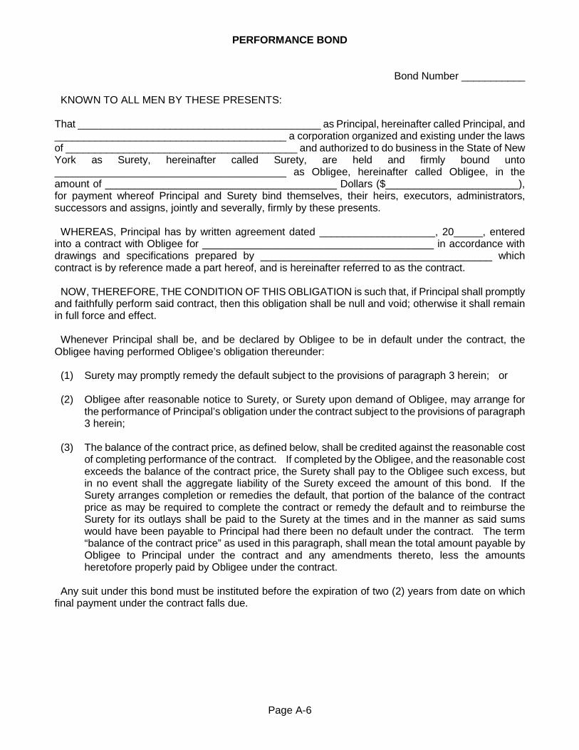
Page A-6
PERFORMANCE BOND
Bond Number ___________ KNOWN TO ALL MEN BY THESE PRESENTS: That __________________________________________ as Principal, hereinafter called Principal, and ________________________________________ a corporation organized and existing under the laws of ________________________________________ and authorized to do business in the State of New York as Surety, hereinafter called Surety, are held and firmly bound unto ________________________________________ as Obligee, hereinafter called Obligee, in the amount of ________________________________________ Dollars ($_______________________), for payment whereof Principal and Surety bind themselves, their heirs, executors, administrators, successors and assigns, jointly and severally, firmly by these presents. WHEREAS, Principal has by written agreement dated ____________________, 20_____, entered into a contract with Obligee for ________________________________________ in accordance with drawings and specifications prepared by ________________________________________ which contract is by reference made a part hereof, and is hereinafter referred to as the contract. NOW, THEREFORE, THE CONDITION OF THIS OBLIGATION is such that, if Principal shall promptly and faithfully perform said contract, then this obligation shall be null and void; otherwise it shall remain in full force and effect. Whenever Principal shall be, and be declared by Obligee to be in default under the contract, the Obligee having performed Obligee’s obligation thereunder: (1) Surety may promptly remedy the default subject to the provisions of paragraph 3 herein; or (2) Obligee after reasonable notice to Surety, or Surety upon demand of Obligee, may arrange for
the performance of Principal’s obligation under the contract subject to the provisions of paragraph 3 herein;
(3) The balance of the contract price, as defined below, shall be credited against the reasonable cost
of completing performance of the contract. If completed by the Obligee, and the reasonable cost exceeds the balance of the contract price, the Surety shall pay to the Obligee such excess, but in no event shall the aggregate liability of the Surety exceed the amount of this bond. If the Surety arranges completion or remedies the default, that portion of the balance of the contract price as may be required to complete the contract or remedy the default and to reimburse the Surety for its outlays shall be paid to the Surety at the times and in the manner as said sums would have been payable to Principal had there been no default under the contract. The term “balance of the contract price” as used in this paragraph, shall mean the total amount payable by Obligee to Principal under the contract and any amendments thereto, less the amounts heretofore properly paid by Obligee under the contract.
Any suit under this bond must be instituted before the expiration of two (2) years from date on which final payment under the contract falls due.
Page A-7
The Surety hereby waives any notice of a change in the contract price or contract time. No right of action shall accrue on this bond to or for the use of any person or corporation other than the Obligee named herein or the heirs, executors, administrators or successors of the Obligee. Signed and sealed this _______ day of ______________, 20_____ ________________________________________ BY ________________________________________ Principal BY ________________________________________ Surety STATE OF NEW YORK ) COUNTY OF MONROE ) ss: CITY OF ROCHESTER ) On this _______ day of ______________ in the year _______ before me, the undersigned, a Notary Public in and said State, personally appeared _______________________________________ personally known to me or proved to me on the basis of satisfactory evidence to be the individual(s) whose name(s) is(are) subscribed to the within instrument and acknowledged to me that he/she/they executed the same in his/her/their capacity(ies), and that by his/her/their signature(s) on the instrument, the individual(s) or the person upon behalf of which the individuals(s) acted, executed the instrument. _______________________________________ Notary Public Commission expires: ______ / ______ / ______

Page A-8
LABOR AND MATERIAL PAYMENT BOND
Bond Number ___________ KNOWN TO ALL MEN BY THESE PRESENTS: That __________________________________________ as Principal, hereinafter called Principal, and ________________________________________ a corporation organized and existing under the laws of ________________________________________ and authorized to do business in the State of New York as Surety, hereinafter called Surety, are held and firmly bound unto ________________________________________ as Obligee, hereinafter called Owner, for the use and benefit of Claimants as herein below defined, in the amount of ________________________________________ Dollars ($_______________________), for payment whereof Principal and Surety bind themselves, their heirs, executors, administrators, successors and assigns, jointly and severally, firmly by these presents. WHEREAS, Principal has by written agreement dated ____________________, 20_____, entered into a contract with Owner for ________________________________________ in accordance with drawings and specifications prepared by ________________________________________ which contract is by reference made a part hereof, and is hereinafter referred to as the contract. NOW, THEREFORE, THE CONDITION OF THIS OBLIGATION is such that if the Principal shall promptly make payment to all Claimants as hereinafter defined, for labor and material used or reasonably required for use in the performance of the contract, then this obligation shall be void; otherwise it shall remain in full force and effect, subject, however, to the following conditions: (1) A Claimant is defined as one having direct contract with the Principal or with the Subcontractor
of the Principal for labor, material or both, used or reasonably required for use in the performance of the contract, labor and material being construed to include that part of water, gas, power, light, heat, oil, gasoline, telephone service, or rental of equipment directly applicable to the contract.
(2) The above named Principal and Surety hereby jointly and severally agree with the Owner that
every Claimant as herein defined, who has not been paid in full before the expiration of a period of ninety (90) days after the date on which the last of such Claimant’s work or labor was done or performed, or materials were furnished by such Claimant, may sue on this bond for the use of such Claimant, prosecute the suit to final judgment for such sum or sums as may be justly due Claimant and have execution thereon. The Owner shall not be liable for payment of any costs or expenses of any such suit.
(3) No suit or action shall be commenced hereunder by any Claimant,
(a) Unless Claimant, other than one having a direct contract with the Principal, shall have given written notice to any two of the following: the Principal, the Owner, or the Surety above named, within ninety (90) days after such Claimant did or performed the last of the work or labor, or furnished the last of the materials for which said claim is made, stating with substantial accuracy the amount claimed and the name of the party to whom the materials were furnished, or for whom work or labor was done or performed. Such notice shall be served by mailing the same by registered mail or certified mail, postage prepaid, in an envelope addressed to the Principal, Owner or Surety, at any place where an office is regularly maintained for the transaction of business or served in any manner in which legal process may be served in the state in which the aforesaid Project is located, save that such service need not be made by a public officer.

Page A-9
(b) After the expiration of one (1) year following the date on which Principal ceased work on said contract, it being understood, however, that if any limitation embodied in this bond is prohibited by any law controlling the construction hereof such limitation shall be deemed to be amended so as to be equal to the minimum period of limitation permitted by such law.
(c) Other than in a State court of competent jurisdiction in and for the County or other political subdivision of the State in which the Project, or any part hereof, is situated, or in the United States District Court for the district in which the Project, or any part thereof, is situated, and not elsewhere.
(4) The amount of this bond shall be reduced by and to the extent of any payment or payments made
in good faith hereunder, inclusive of the payment by Surety of mechanics’ liens which may be filed of record against said improvement, whether or not claim for the amount of such lien be presented under and against this bond.
The Surety hereby waives any notice of a change in the contract price or contract time. Signed and sealed this _______ day of ______________, 20_____
________________________________________
________________________________________ Principal
(Seal)
________________________________________
Surety
(Seal) STATE OF NEW YORK ) COUNTY OF MONROE ) ss: CITY OF ROCHESTER ) On this _______ day of ______________ in the year _______ before me, the undersigned, a Notary Public in and said State, personally appeared _______________________________________ personally known to me or proved to me on the basis of satisfactory evidence to be the individual(s) whose name(s) is(are) subscribed to the within instrument and acknowledged to me that he/she/they executed the same in his/her/their capacity(ies), and that by his/her/their signature(s) on the instrument, the individual(s) or the person upon behalf of which the individuals(s) acted, executed the instrument. _______________________________________ Notary Public Commission expires: ______ / ______ / ______

Page A-10
CITY OF ROCHESTER CERTIFICATE OF INSURANCE
To the City of Rochester: The subscribing insurance company certifies that insurance of the kinds and types and for limits of liability not less than those herein stated, covering the work herein designated, has been procured by and furnished on behalf of the insured Contractor named in Item 1. 1. Name of Insured _____________________________________________________________ Address of Insured _____________________________________________________________ _____________________________________________________________ 2. Location and Description of Work: Sager Drive Improvement Project (Culver Road to East
Boulevard) 3. Kinds and Types of Insurance: Types of Insurance
Policy Number
Effective Date
Expiration Date
Limits of Liability
CONTRACTOR’S GENERAL LIABILITY -Comprehensive Form -Independent Contractors -Premises Operation -Completed Operations Hazard -Broad Form Property Damage -Underground Hazard -Explosion and Collapse Hazard -Contractual Insurance
WORKERS’ COMPENSATION INSURANCE
DISABILITY INSURANCE
COMMERCIAL AUTOMOBILE LIABILITY
UMBRELLA EXCESS LIABILITY
BUILDER’S ALL RISK INSURANCE
Such insurance as is herein certified applies to all operations of said insured in connection with the work herein described at the locations stated, and is written in accordance with the company’s regular policies

Page A-11
and endorsements, subject to the company’s applicable manuals of rules and rates in effect, except _________________________________________________________________________________ The insurance provided by the subscriber shall include the City of Rochester as an additional insured. The _____________________________________________________________________________, additional Funding Agencies, shall be named as an additional insured for liability arising under this agreement except for the Workers’ Compensation and Disability Insurance. No exclusion from coverage shall be made for any municipal operations performed as a term of the contract for which this insurance is issued. The subscribing company agrees that no policy referred to herein shall be changed or cancelled until ten (10) days written notice has been given to the City of Rochester. This certificate is furnished in accordance with and for the purpose of the specifications of the City of Rochester covering the operations herein described.
________________________________________ (Name of Company)
________________________________________
________________________________________ (Address of Company)
By ________________________________________ (Authorized Representative)
Dated ______________________________


SUPPLEMENTARY LAWS AND REGULATIONS
PAGE SLR 2. Compliance with Policies Prohibiting Discrimination
A. Anti-Apartheid ............................................................................................................... SLR-1 SLR 3. Compliance with Labor Laws ......................................................................................... SLR-1 SLR 9. Safety and Health Requirements
B. Drilling and Blasting ...................................................................................................... SLR-1 C. Explosives in Demolition ............................................................................................... SLR-2 F. OSHA Ten (10) Hour Construction Safety and Health Course Certification ................... SLR-2 G. Dig Safely New York Certified Excavator Program Certification .................................... SLR-2
SLR 17. Apprenticeship Training Program for Construction Contracts ....................................... SLR-3 SLR 18. Incentive Program for Public Works Contracts ........................................................... SLR-11 SLR 19. Minority and Women Business Enterprise (MWBE) Requirements ............................ SLR-15 SLR 20. Workforce Goals and Requirements .......................................................................... SLR-23 SLR 21. Prevailing Wage Schedule and List of Employers Ineligible to Bid on or be
Awarded any Public Work ....................................................................................... SLR-25


Page SLR-1
SUPPLEMENTARY LAWS AND REGULATIONS SLR 2. Compliance with Policies Prohibiting Discrimination The City of Rochester Standard Construction Contract Documents, November 1, 1991, Edition, is modified by City Council Ordinance 93-399 that repealed prior Ordinance 85-133 as follows: Delete the following Subsection A Anti-Apartheid in its entirety: A. Anti-Apartheid
The Council of the City of Rochester, New York has reaffirmed its commitment to racial equality and has established in Ordinance Number 85-133, a policy prohibiting any City agency or department from Contracting goods or services with any company or person who supports a policy of apartheid as defined herein except where competitive bidding is required by the General Municipal Law. The Contractor agrees to not support a policy of apartheid as defined herein.
SUPPORTS A POLICY OF APARTHEID shall mean providing loans directly to, underwriting securities of, advertising or otherwise promoting the sale of gold on behalf of, or otherwise providing financial services to the government of the Republic of South Africa or its agencies.
SLR 3. Compliance with Labor Laws Add the following after the second paragraph of Subsection 3 Compliance with Labor Laws: Effective April 27, 2008, in addition to the schedule of wage rates, the Contractor is required to post in a conspicuous location at the Project site the name and contact information of the individual who is responsible to collect certified payrolls and review for facial validity. SLR 9. Safety and Health Requirements Delete Subsection B Drilling and Blasting in its entirety, and Replace with the following: B. Drilling and Blasting
The Contractor shall employ only experienced supervisors and workers in the handling, loading and firing of explosives. The Contractor shall fulfill the requirements of the City of Rochester Fire Prevention Code Chapter 54 regarding explosives and blasting agents which, together with other conditions indicated herein shall provide for the possession, handling, storage, transportation, and use of all explosives used at the site. Overnight storage of explosives within the City limits is prohibited unless a specific authorization of such storage is granted in writing to the Contractor, by the City of Rochester Fire Marshal.

Page SLR-2
Delete Subsection C Explosives in Demolition in its entirety, and Replace with the following: C. Explosives in Demolition
Demolition work, subject to requirements of OSHA standards and New York Industrial Code Rule 39 and 53, shall not be performed by the use of explosives unless a specific variation of such use is granted in writing to the Contractor, by the City of Rochester Fire Marshal.
Add the following at the end of Subsection 9 Safety and Health Requirements: F. OSHA Ten (10) Hour Construction Safety and Health Course Certification
The Contractor shall be responsible for ensuring observance of all OSHA provisions and the State of New York Labor Law, including but not limited to Section 240, pertaining to safe performance of the work. Further, the Contractor shall ensure that the methods of performing the work do not involve undue danger to the personnel employed thereon, the public, and public and private property. Should charges of violation of any of the above be issued to the Contractor in the course of the work a copy of each charge shall be immediately forwarded to the Project Manager.
Where the total cost of all work to be performed under the contract is at least $250,000, all personnel employed in performance of the work on the Project site, either by the Contractor, Subcontractor, or other person or entity doing or Contracting to do the whole or any part of the work under the contract, shall be certified prior to performing any work on the Project site as having successfully completed a course in construction safety and health that is approved by the United States Department of Labor’s Occupational Safety and Health Administration (OSHA) that is at least ten (10) hours in duration.
If the Contractor or any Subcontractor performing work under the contract fails to submit its proof of certification, the City may retain five percent (5%) of payment due the prime Contractor on any progress payment until receipt of proper documentation of certification.
G. Dig Safely New York Certified Excavator Program Certification
The Contractor shall be responsible for ensuring observance of all provisions of the New York State educational amendment to 16 NYCRR Part 753 mandating excavator training which was signed into law November 5, 2018, with implementation on May 4, 2019. The amendment to the law requires that any local government which contracts for excavation shall require the excavator to have completed the training and education program provided by the one-call notification system, or any other provider authorized by the Public Service Commission to administer such training and education program. The Contractor shall ensure that any excavator performing work under the contract has successfully completed a Certified Excavator Program, and has been issued and is in possession of a Certified Excavator Card. The City reserves the right to require a copy of the excavator’s Certified Excavator Card as a condition for payment for such work.

Adopted 4/7/2004 Page SLR-3 Revised 11/28/2012
Add the following new subsections after Subsection 16 Content of Sub-Agreements: SLR 17. Apprenticeship Training Program for Construction Contracts 1. Policy and Regulations.
By Ordinance 2003-347 of the City Council, as amended by Ordinance 2009-76, the City of Rochester established a policy to promote apprenticeship training programs, as authorized by Section 816-b of the New York State Labor Law. This policy applies to any City public works contract for an amount in excess of $250,000, or if any add/deduct alternates alone or in combination could result in a contract amount award that exceeds $250,000, regardless of the base bid amount, for construction, reconstruction, or improvement of any building, facility, or physical structure of any kind, and any subcontract thereto in excess of $100,000. Regulations for the implementation and enforcement of the apprenticeship policy follow.
2. Requirement for Contractors and Subcontractors.
For any bids subject to the apprenticeship requirements as defined in Section 1, the City of Rochester requires the Contractor, prior to entering into the construction contract, and any Subcontractor proposed to perform a subcontract thereto in excess of $100,000, to have apprenticeship agreements, appropriate for the type and scope of work to be performed and which have been registered with and approved by the New York State Commissioner of Labor in accordance with Article 23 of the New York Labor Law.
3. Submittals with Bid Proposal.
The Bidder shall submit for itself and for any Subcontractor(s) whom the Bidder proposes at the time of the bid to perform a subcontract in excess of $100,000 in value, copies of the following documents with the bid Proposal for each apprenticeship training program, approved by the New York State Department of Labor, which the Bidder or Subcontractor(s) will need to satisfy the requirements of the Apprenticeship Training Program requirement:
1. If the Bidder is sponsor of an apprenticeship training program, a copy of the Form AT-10, “New York State Department of Labor Apprenticeship Training Program Registration Agreement”, issued to the Bidder in approval of that apprenticeship training program.
2. If the Bidder does not self-sponsor an apprenticeship program but is party to an agreement with the sponsor of apprentices who are enrolled in an apprenticeship training program that is sponsored by a trade union, a joint apprenticeship committee, or other organization other than the Bidder,
a. An “Agreement to Utilize Apprentices for a City Construction Contract” form (City Form AP3) signed by the Bidder and the apprenticeship training program sponsor; and b. A copy of the current “New York State Department of Labor Apprenticeship Training Program Registration Agreement”, Form AT-10, issued to the sponsor in approval of that program.
3. The Bidder shall also submit with the bid package, the following:
a. City Form AP1, “Schedule of Subcontracts and Apprenticeship Agreements,” a listing of any Contractor proposed to hold a subcontract that exceeds $100,000 in value, including the name of the Subcontractor, the scope and value of work proposed to be performed, and the name of any apprenticeship trade for which an approved apprenticeship agreement will be submitted; and

Adopted 4/7/2004 Page SLR-4 Revised 11/28/2012
b. Copies of approved apprenticeship agreements as detailed in 2.a and 2.b above that are held by the proposed Subcontractors and intended to meet the requirements of the Apprenticeship Training Program. c. An Excel spreadsheet version of City Form AP1 is available on the City’s website at http://www.cityofrochester.gov/mwbe.
4. Any apprenticeship agreement submitted shall be:
a. Submitted completely with Bid; b. Current and valid; c. Represent an apprenticeship training program that is active and in good standing with the New York State Department of Labor; and d. Appropriate to the scope and nature of the work to be performed under the contract.
5. Submit complete apprenticeship documentation with Bid proposal. An incomplete package will be declared informal and will not be considered for award. No required apprenticeship material will be accepted after Bids have been opened.
4. Enforcement.
If the Bidder fails to comply with the requirements of the “Apprenticeship Training Program for Construction Contracts”, the City will deem the Bidder non-responsive and disqualify the Bidder from consideration for the pending contract.
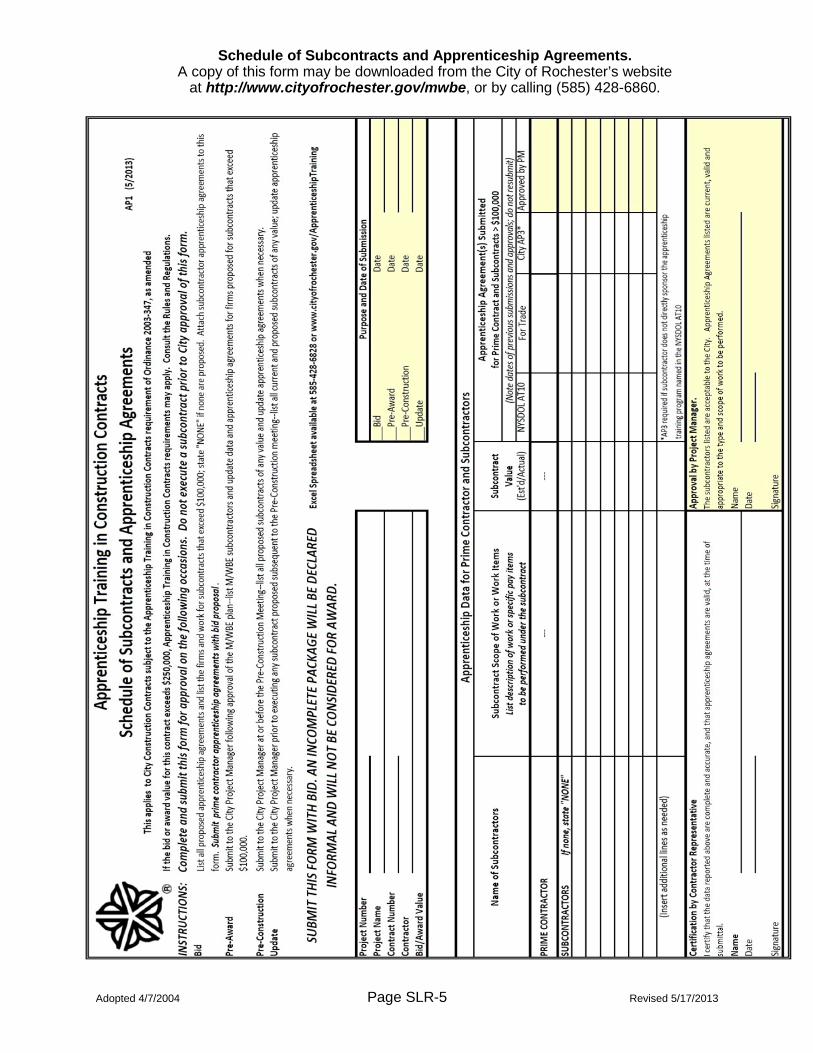
Adopted 4/7/2004 Page SLR-5 Revised 5/17/2013
Schedule of Subcontracts and Apprenticeship Agreements. A copy of this form may be downloaded from the City of Rochester’s website
at http://www.cityofrochester.gov/mwbe, or by calling (585) 428-6860.

Adopted 4/7/2004 Page SLR-6 Revised 11/28/2012
Form AP3 (11/12) Agreement to Utilize Apprentices
on a City of Rochester Construction Contract
To be used when a Bidder on a City of Rochester construction contract utilizes one or more apprentices supplied by an apprenticeship training program that the Bidder does not sponsor to satisfy the requirements of the City of Rochester Apprenticeship Training Program. Bidder: _____________________________________________________, “Bidder” Apprenticeship Training Program Sponsor: ____________________________________________________,
“Sponsor” ATTACH VALID NYSDOL AT-10 FORM City of Rochester Construction Contract: ____________________________________________________,
“Contract” The Bidder and sponsor agree as follows: 1. The sponsor will provide the Bidder with one or more apprentices for employment on the contract in the following occupation. Each apprentice is enrolled in an active apprentice training program that is registered with, approved by, and is in good standing with the New York State Department of Labor and has an apprenticeship agreement that has been registered with, and approved by, the New York State Commissioner of Labor in accordance with Article 23 of the New York State Labor Law:
Occupation _________________________________________________________________
2. The Bidder will employ the apprentice(s) to perform work on the contract under terms and conditions applicable to construction contract work in New York State. Attach a copy of the sponsor’s currently valid and signed New York State Department of Labor form AT-10, “Apprentice Training Program Registration Agreement”, for the occupation listed above. ss/ __________________________________ ss/ __________________________________ Bidder Representative Sponsor Representative ss/ __________________________________ __________________________________ Date Date

Adopted 4/7/2004 Page SLR-7 Revised 11/28/2012
Apprenticeship Training Program for Construction Contracts RULES AND REGULATIONS
Authorization These RULES AND REGULATIONS are promulgated under authority of City Ordinance 2003-347, which was adopted by the City Council on October 21, 2003, and amended by Ordinance 2009-76, which was adopted by City Council on March 18, 2009. These Ordinances were enacted under authority granted by Chapter 571 of the Laws of 2001, as codified in Section 816-b of the New York State Labor Law. Summary of City Ordinance 2003-347, as amended City Ordinance 2003-347, as amended, makes it the policy of the City of Rochester “to promote apprenticeship training programs.” The scope of the Ordinance includes any public works contracts, as defined in the Ordinance that are in excess of $250,000. The Ordinance further requires that the Contractors for such a contract and for any subcontract thereto in excess of $100,000, prior to entering into such public works contracts, “have apprenticeship agreements, appropriate to the type and scope of work to be performed, which have been registered with and approved by the New York State Commissioner of Labor.” The Ordinance authorizes the Commissioner of Environmental Services “to promulgate such rules and regulations necessary and appropriate for the implementation and enforcement of this ordinance.” The Ordinance also requires that the “City shall provide assistance to Contractors to its greatest extent possible in obtaining State approval of apprenticeship programs;” Such approval shall be obtained before a Contractor submits a bid for a construction contract or is awarded a subcontract. Definitions Appendix A contains definitions of terms used. Appendix A is an integral part of these RULES AND REGULATIONS. Effective Date and Administration The RULES and REGULATIONS shall be effective for contracts advertised for public bid after January 1, 2004, and, as revised, shall be effective for contracts advertised for public bid after March 19, 2009. They shall be administered by the Commissioner of Environmental Services. Direct inquiries to: Commissioner of Environmental Services City of Rochester 30 Church Street, Room 300B Rochester, NY 14614-1278 (585) 428-6855 office (585) 428-6010 fax

Adopted 4/7/2004 Page SLR-8 Revised 11/28/2012
Application 1. These RULES AND REGULATIONS shall apply to any construction contract in excess of $250,000, and that is subject to the Rules and Regulations, and to any subcontract thereto in excess of $100,000. The contract value for determination of application shall be the original contract price, including any items that are bid as alternates and accepted in the original contract or subcontract. Any field changes, made after contract award, made for any reason, shall not be counted in determining if a contract or subcontract exceeds the threshold value. 2. These RULES AND REGULATIONS shall only apply to public works contracts as defined in Appendix A. Accordingly, they shall not apply to any of the following types of contracts:
Contracts for the incidental or routine repair, operation or maintenance of any city building, street or street appurtenance, facility or structure and for major repair or maintenance where the City determines that the contract does not afford an opportunity for an apprentice to accumulate a significant amount of required on-the-job training; Contracts for the delivery of public services; Contracts for any professional service, whether associated with a public works construction contract or not; Contracts for the purchase of materials, supplies or equipment; Contracts for the purchase, delivery and/or installation of furnishings, furniture and/or equipment; and Any other contract that does not meet the definition of a construction contract as defined in Appendix A.
3. These RULES AND REGULATIONS shall not apply in the following situations: Any services procured through New York State Contracts as administered by the New York State Office of General Services; and, Any contracts utilizing federal, state, county or other funding assistance to the extent that the funding agency has indicated in writing that use of such funding precludes application of the Apprenticeship Training Program or the City determines that funding provisions make such application impractical. If the agency has an approved program available that provides for or encourages apprenticeship training, the City shall investigate applying that program to the contract and, if feasible, do so to the fullest practical extent.
Procedures 1. A Contractor who submits a bid for a City contract for which the contract amount exceeds $250,000 shall submit with the bid package a copy of the following for each apprentice agreement intended to meet the requirements of this regulation:
a. The current New York State Department of Labor Form AT-10, “Apprentice Training Program Registration Agreement,” issued to the Contractor or other sponsor of the apprentice training program; and b. If the apprentice training program is not sponsored by the Contractor, an executed copy of City Apprenticeship Training Program Form AP3, “Agreement to Utilize Apprentices on a City of Rochester Construction Contract.” c. The Contractor shall also submit with the bid package the following:
(1) A listing of any Contractor proposed to hold a subcontract that exceeds $100,000 in value, including the name of the Subcontractor, the scope and value of work proposed to be performed, and the name of any apprenticeship trade for which an approved apprenticeship agreement will be submitted, and (2) Copies of approved apprenticeship agreements intended to meet the requirements of this regulation as detailed in 1.a and 1.b above.

Adopted 4/7/2004 Page SLR-9 Revised 11/28/2012
2. A Contractor who, subsequent to contract award, proposes to enter subcontract that exceeds $100,000 in value, shall submit apprenticeship agreements as described in 1a or 1b above with the proposed subcontract documents to the City Project Manager for approval prior to entering the subcontract. 3. The City may verify that any apprenticeship agreement submitted by a Contractor is current and valid. 4. If a Contractor fails to timely submit valid apprenticeship agreements, the Contractor may be deemed to be non-responsive, and may be disqualified from further consideration for the pending contract or subcontract. Assistance The City shall provide assistance to Contractors to its greatest extent possible in obtaining State approval of apprenticeship programs by:
1. Referral to the New York State Department of Labor Rochester regional office and apprenticeship training representatives for apprenticeship training program sponsorship, referral to State-approved programs, recruitment of apprentices, assistance with program maintenance, and other technical assistance; 2. Supporting programs and activities that encourage or assist Contractors to develop or participate in apprenticeship training programs; 3. Other means which may be determined on a case by case basis.
Waivers 1. No waivers shall be provided to the general requirement that Contractors have current, valid apprenticeship agreements, appropriate to the scope and nature of the work to be performed under the contract, registered with the New York State Commissioner of Labor. Failure to document such agreements will result in a Contractor being deemed non-responsive, and such Contractor will be disqualified from consideration for the pending contract. 2. The Commissioner may grant a waiver for an apprenticeship agreement specific to a particular trade that is appropriate to the scope and nature of the work to be performed under the contract if:
a. The New York State Department of Labor certifies that no apprenticeship training is available or may be approved for that trade within the Rochester Labor Market by the time of contract award or of any subcontract proposed for approval subsequent to contract award; b. The application of the requirements of the apprenticeship program for City construction contracts would prevent the City or the Bidder from obtaining a Contractor or Subcontractor that is qualified to perform specific contract work, regardless of the price for that work.
Enforcement If the Contractor fails to comply with the requirements of the Apprenticeship Training Program for Construction Contracts, the City will deem the Contractor non-responsive and disqualify the Contractor from consideration for the pending contract.

Adopted 4/7/2004 Page SLR-10 Revised 11/28/2012
Appendix A Definitions
The following definitions apply to the RULES AND REGULATIONS promulgated herein to provide guidance on the implementation and enforcement of City of Rochester Ordinance 2003-347, as amended. The definitions provided here are an integral part of these RULES AND REGULATIONS. Alteration - the process of improving real property that adds value to its permanent value and prolongs its intended life appreciably; does not include repair, operation, or routine maintenance of existing real property. Apprenticeship Agreement - shall be:
a. The current New York State Department of Labor Form AT-10, “Apprentice Training Program Registration Agreement,” issued to the Contractor or other sponsor of the apprentice training program; and, b. If the apprentice training program is not sponsored by the Contractor, an executed copy of City Apprenticeship Utilization Program Form AP3, “Agreement to Utilize Apprentices on a City of Rochester Construction Contract.”
Construction contract - shall mean any City public works contract for an amount in excess of $250,000, or subcontract thereto in excess of $100,000, for construction, reconstruction or improvement of any building, facility or physical structure of any kind. Construction - the process of building, altering, or improving any public structure or building, demolition of existing real property, or other public improvement of any kind to any public real property; does not include the operation or routine maintenance and repair of existing real property. Contractor - shall mean a Contractor which directly employs labor under a construction contract or subcontract. Demolition - the process of taking down or removing a facility or physical structure from real property. Improvement - the process of alteration or renovation of real property that adds value to its permanent value and prolongs its intended life appreciably, and major maintenance and repair of real property that affords an opportunity for an apprentice to accumulate a significant amount of on-the-job training; does not include the incidental or routine repair, operation, or routine maintenance of existing real property. Installation - the process of installing material and
equipment in relation to a construction contract as defined above; does not include the operation or routine maintenance and repair of existing real property. Maintenance and Repair - shall mean the upkeep of real property that neither adds to its permanent value nor prolongs its intended life appreciably, but instead keeps it in an efficient operating condition. Real Property - is the land and its permanently affixed buildings and structures. Reconstruction - the process of rebuilding, altering, or improving any public structure or building, or other public improvement of any kind to any public real property; does not include the operation or routine maintenance and repair of existing real property. Rehabilitation - the process of reconstruction, improvement, alteration, installation, or renovation of real property that adds value to its permanent value and prolongs its intended life appreciably; does not include the operation, or routine maintenance and repair of existing real property. Renovation - the process of reconstruction, improvement, installation and alteration of real property that adds value to its permanent value and prolongs its intended life appreciably; does not include the operation or routine maintenance and repair of existing real property. Rochester Labor Market - shall mean those counties served by the Rochester Regional Office of the New York State Department of Labor. [Note: In January 2004 that area includes the following nine counties: Genesee; Livingston; Monroe; Ontario; Orleans; Seneca; Wayne; Wyoming; and Yates] Subcontractor - shall mean an individual, partnership, corporation or joint venture to whom the construction Contractor sublets any part of the project.
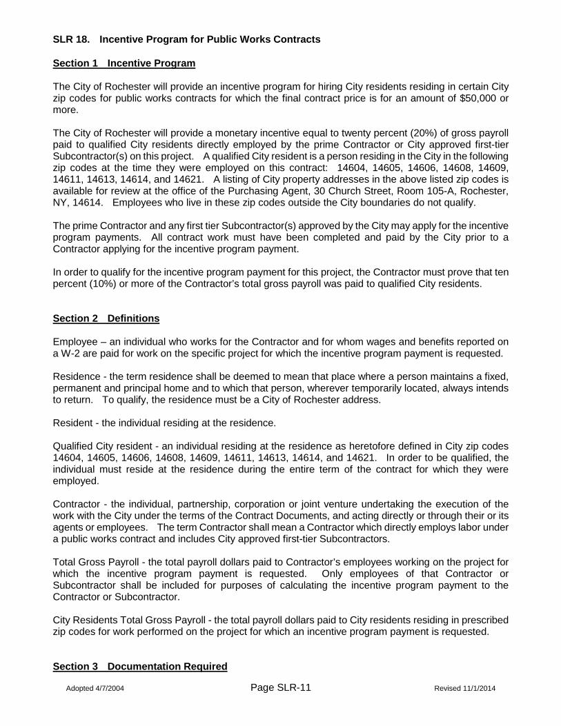
Adopted 4/7/2004 Page SLR-11 Revised 11/1/2014
SLR 18. Incentive Program for Public Works Contracts Section 1 Incentive Program The City of Rochester will provide an incentive program for hiring City residents residing in certain City zip codes for public works contracts for which the final contract price is for an amount of $50,000 or more. The City of Rochester will provide a monetary incentive equal to twenty percent (20%) of gross payroll paid to qualified City residents directly employed by the prime Contractor or City approved first-tier Subcontractor(s) on this project. A qualified City resident is a person residing in the City in the following zip codes at the time they were employed on this contract: 14604, 14605, 14606, 14608, 14609, 14611, 14613, 14614, and 14621. A listing of City property addresses in the above listed zip codes is available for review at the office of the Purchasing Agent, 30 Church Street, Room 105-A, Rochester, NY, 14614. Employees who live in these zip codes outside the City boundaries do not qualify. The prime Contractor and any first tier Subcontractor(s) approved by the City may apply for the incentive program payments. All contract work must have been completed and paid by the City prior to a Contractor applying for the incentive program payment. In order to qualify for the incentive program payment for this project, the Contractor must prove that ten percent (10%) or more of the Contractor’s total gross payroll was paid to qualified City residents. Section 2 Definitions Employee – an individual who works for the Contractor and for whom wages and benefits reported on a W-2 are paid for work on the specific project for which the incentive program payment is requested. Residence - the term residence shall be deemed to mean that place where a person maintains a fixed, permanent and principal home and to which that person, wherever temporarily located, always intends to return. To qualify, the residence must be a City of Rochester address. Resident - the individual residing at the residence. Qualified City resident - an individual residing at the residence as heretofore defined in City zip codes 14604, 14605, 14606, 14608, 14609, 14611, 14613, 14614, and 14621. In order to be qualified, the individual must reside at the residence during the entire term of the contract for which they were employed. Contractor - the individual, partnership, corporation or joint venture undertaking the execution of the work with the City under the terms of the Contract Documents, and acting directly or through their or its agents or employees. The term Contractor shall mean a Contractor which directly employs labor under a public works contract and includes City approved first-tier Subcontractors. Total Gross Payroll - the total payroll dollars paid to Contractor’s employees working on the project for which the incentive program payment is requested. Only employees of that Contractor or Subcontractor shall be included for purposes of calculating the incentive program payment to the Contractor or Subcontractor. City Residents Total Gross Payroll - the total payroll dollars paid to City residents residing in prescribed zip codes for work performed on the project for which an incentive program payment is requested. Section 3 Documentation Required

Adopted 4/7/2004 Page SLR-12 Revised 11/1/2014
To request an incentive program payment the Contractor must submit a request letter and Exhibits A and B as required to the City Director of Finance, 30 Church Street, Room 109-A, Rochester, NY, 14614. The request must be submitted no later than ninety (90) days after the Contractor obtains a certificate of substantial completion and final payment. Proof of wages paid to all employees and wages paid to City residents shall be in the format as per Exhibit A. Each qualified City resident employee must also sign a notarized attestation as per Exhibit B which certifies that the address represented is the permanent and principal place of residency, and that the employee resided at that address during the term of the contract for which the incentive program payment is requested. Any false information provided may lead to the Contractor being found a non-responsible Bidder on subsequent City bids. The Contractor shall retain payroll data and make available such records, for random audit by the City, for a period of three (3) years. Prime or first-tier Subcontractors on city public works projects may apply for the incentive program payment within ninety (90) days after the City has issued the check for the final payment application to the prime Contractor at the close-out of the project. Contractors on qualifying city term contracts must apply for the incentive program payment within ninety (90) days of the end of the contract period. The initial contract and each contract extension (if offered) will be considered a contract period for determining the incentive program payment amount for term contracts. The incentive program request will be paid upon submission, review, and approval of information required per this Section 3. Review by the City will include, but not be limited to, confirmation that employees submitted on the Contractor’s Exhibit A match the certified payrolls submitted during the contract. The City will issue payment directly to the Contractor and/or Subcontractor(s) upon approval of an incentive program request.

Adopted 4/7/2004 Page SLR-13 Revised 11/1/2014
EXHIBIT A SUMMARY OF TOTAL GROSS PAYROLL FOR PROJECT
Excel spreadsheet available from Director of Finance, City of Rochester, (585) 428-7151

Adopted 4/7/2004 Page SLR-14 Revised 11/1/2014
EXHIBIT B EMPLOYEE ATTESTATION OF ADDRESS
I, __________________________________________________, hereby attest that my residence and principal home from _______________________ to _______________________, while employed on Date Date _______________________________________ by _______________________________________ Contract number - Contract job description Name of Contractor was/is as listed below. Address ________________________________________________ City, town, village _________________________________________ State _____________________________, Zip Code _____________ ________________________________________ Signature of Employee STATE OF NEW YORK ) COUNTY OF MONROE ) ss: CITY OF ROCHESTER )
On this _______ day of ______________ in the year _______ before me, the undersigned, a Notary Public in and said State, personally appeared _______________________________________ personally known to me or proved to me on the basis of satisfactory evidence to be the individual whose name is subscribed above and acknowledged to me that they executed the same. _________________________________________________ Notary Public Commission expires: __________ / ________ / __________

Page SLR-15
SLR 19. Minority and Women Business Enterprise (MWBE) Requirements The City has a Minority and Women Business Enterprise (MWBE) policy that ensures participation of Minority and Women-owned businesses on City public works projects. Ordinance 2018-54 established a goal, effective July 1, 2018, that MWBE’s will receive 30% of the aggregate total annual contract awards for City public works contracts over $10,000, with the goal for minority owned businesses (M) being 20% and women owned businesses (W) being 10%. The requirements specified herein are established in order to accomplish these goals. Included within these bid documents are the following sections of SLR 19 that identify the policy requirements, participation requirements, utilization requirements and good faith effort requirements. Also provided is a table that identifies the types of work the City believes will need to be performed to complete this contract. This table is provided as an aid to bidders who are seeking certified MWBE’s available in the Rochester region to do this work. However, this table is provided for informational purposes only and does not relieve the bidder of making a good faith effort to meet the MWBE goals for this contract. All MWBE requirements, documents and forms are provided on the City’s website at http://www.cityofrochester.gov/mwbe/ and are hereby incorporated by reference. Information about MWBE goals may be obtained on an advisory basis by contacting the City of Rochester MWBE Officer at (585) 428-6190.

Page SLR-16
MINORITY AND WOMEN BUSINESS ENTERPRISE (MWBE) CONSTRUCTION UTILIZATION GOAL
[ Engineering (Streets/Water Public Works Projects) ]
1. Policy Goals City of Rochester Ordinance 2018-54 sets forth the following policy goals for all City public works construction contracts: 1.1 Goals for Public Works Construction Projects – 30% Aggregate Goal to Minority and Women Owned Enterprises (MWBE), which shall be split as a 20% goal for Minority (M) Owned businesses and a 10% goal for Women (W) owned businesses. 1.2 A contractor, vendor or consultant shall be eligible for meeting the MWBE goals if:
1.2.1 It is a state-certified MWBE at the time of the contract award. State certification requires that a business be at least 51% owned and controlled by minorities (M), women (W), or both. Minority shall be defined consistent with state and federal definitions, e.g. Black, Hispanic, American Indian or Alaskan Native, Asian – Indian Subcontinent, and Asian Pacific. 1.2.2 The contractor, vendor or consultant has bona fide offices and operations in the Empire State Development (ESD) Finger Lakes Region, which includes the following counties: Genesee, Livingston, Monroe, Ontario, Orleans, Seneca, Wayne, Wyoming and Yates. State-certified businesses from outside this region may be counted if there are insufficient businesses in the region to perform the specialized work or consulting services required.
2. Participation Plan Requirements Bidders are required to demonstrate how they intend to meet the City’s MWBE goals, both the 30% aggregate goal and the 20% M and 10% W goals in performing the work of this contract. 2.1 Bidders shall submit with their bid a completed MWBE Form P – the proposed MWBE Participation Plan (Form P pages 1 and 2, and page 3 if required). The amounts and percentages shown on Form P, page 1, should be based on the bidder’s Total Base Bid price. 2.2 The proposed MWBE Participation Plan indicates the MWBE subcontractors the bidder intends to utilize if awarded this contract in order to fulfill the MWBE goals listed in Section 1.1 above. Form P, Page 1, lists the names of each subcontractor the bidder intends to use, the MWBE classification, the type of work that the subcontractor will do, the proposed dollar amount of each subcontract and the percentage of the base bid amount. On Form P, Page 2, the bidder shall indicate at what stage, or stages, each MWBE subcontractor is expected to be utilized. Form P, Page 3 shall be completed and submitted with the bid if Form P, Page 1, shows that the amount of work to be subcontracted to MWBE’s does not equal at least thirty percent (30%) of the total base bid and/or the minority and women sub-goals are not met. On Page 3, the bidder must explain why the bidder is not meeting the 30% MWBE goal and/or the minority and women goals. 2.3 Only MWBE firms that are certified by the State of New York, and located within the Rochester region (defined as the nine-county Empire State Development Finger Lakes Region), or otherwise approved by the City's MWBE Officer should be entered on Form P (a list of approved certified MWBE’s in the region is available on the City website at http://www.cityofrochester.gov/mwbe/).

Page SLR-17
2.4 The proposed MWBE Participation Plan (Form P Plan) will be used by the City to determine whether or not the bidder has demonstrated the intent and ability to meet the overall 30% MWBE utilization goal, and 20% Minority and 10% Women MWBE sub-goals for this contract. 2.5 The bidder may propose the use of any MWBE companies who are certified to do any of the work required by the contract. However, for subcontracts requiring substantial materials and/or supply purchases, the following rules apply:
2.5.1 If the subcontractor is a manufacturer, or is certified/licensed as a manufacturer’s rep who performs the installation, and is classified as such in the State MWBE Directory, 100% of the supply and installation subcontract may be counted towards meeting the goal, 2.5.2 If the subcontractor is a supplier and is classified as such in the State MWBE Directory, 60% of the supply subcontract may be counted towards meeting the goal, 2.5.3 The City will not accept brokered services to count towards meeting the goal.
2.6 If the contract award is less than $50,000, only the aggregate MWBE goal shall apply. Any single MWBE or group of MWBE’s may be utilized. 2.7 If the City elects to choose Add or Delete Alternates in addition to the Base Bid, the Form P Plan shall be adjusted to ensure that the MWBE goals are met based upon the total value of the contract award. 2.8 The City reserves the right to request that the bidder modify the Form P Plan if: a) any proposed MWBE subcontractor is not qualified to do the work based on state certification categories and/or direct City experience with said subcontractor; b) if the Form P Plan does not demonstrate that the bidder will fully meet the MWBE utilization goals for this contract, either by category or percentage, c) if the City selects an add/delete alternate that will increase or decrease the award of the contract. The MWBE Officer will work with the bidder to develop an acceptable MWBE Form P plan based upon the work required by the contract, the availability of qualified MWBE companies to perform the work, current market conditions as reflected in bids for this and/or similar contracts in the region, any specialty work waivers, and the demonstration of a good faith effort to meet the MWBE utilization goals for this contract. 2.9 At the conclusion of the City’s review of the Form P Plan and upon notification by the City, the bidder must submit, within ten (10) calendar days, a completed MWBE Form A – MWBE Utilization Plan (Form A Utilization Plan), along with a completed MWBE Form B – Intent to Perform as a Subcontractor and MWBE Form C – MWBE Affidavit, for each MWBE subcontractor. Unless otherwise approved by the City, the subcontractors shown on the Form P Plan, along with any revisions per Sections 2.7 and 2.8 above, shall be used in the Form A Utilization Plan. The City shall accept and approve the submitted Form A Utilization Plan if it reflects utilization of MWBE’s developed in accordance with Sections 2.1 through 2.8 above. The Approved Form A Utilization Plan shall become an integral part of the performance agreement between the parties, along with corresponding Form B and Form C documents for each subcontractor. The City reserves the right to reject the submitted Form A Utilization Plan if it does not incorporate recommendations made by the MWBE Officer developed in accordance with Section 2.8 above. If a bidder does not provide an acceptable Form A Utilization Plan within ten (10) calendar days of request, the City reserves the right to declare the bid non-responsive. 3. Utilization Requirements

Page SLR-18
As a condition of this contract, the Contractor is required to provide the City with proof that the Contractor has utilized and paid MWBE subcontractors as shown on the Approved Form A Utilization Plan and consistent with the information provided on MWBE Form B – Intent to Perform as a Subcontractor and MWBE Form C – MWBE Affidavit for each MWBE subcontractor. 3.1 As stated in Section 2.9 above, a bidder must submit, within ten (10) calendar days, a completed Form A Utilization Plan, along with an MWBE Form B – Intent to Perform as a Subcontractor and MWBE Form C – MWBE Affidavit for each MWBE subcontractor. 3.2 Once approved by the City, the Approved Form A Utilization Plan and related Forms B and C shall become the contractual obligation of the Contractor for utilizing approved MWBE subcontractors to meet the MWBE goals for the project, along with any additions or subtractions per Section 3.3 below. The Contractor is required to utilize the approved MWBE subcontractors during the course of the project as shown in the Approved Form A Utilization Plan. 3.3 If any individual change order is 5% or more, or if any change order brings the total net cumulative amount of change orders to the initial contract award to 5% or more, the Contractor must submit a revised Form A Utilization Plan, and related Forms B and C (only if adding a new MWBE firm), and have these approved by the City. A Form A Utilization Plan revision must be submitted and approved each time a new change order occurs after the 5% threshold has been reached. Form A Utilization Plan revisions must be made where change orders increase the contract total, in order to ensure that MWBE goals are adjusted upward in proportion to the most recently Approved Form A Utilization Plan. 3.4 The last dated Approved Form A Utilization Plan (either the initial Approved Form A Utilization Plan or the last revised Approved Form A Utilization Plan to reflect change orders) shall be the Final Approved Form A Utilization Plan. The percentage goals and subcontract amount on the Final Approved Form A Utilization Plan shall be the contract requirements against which MWBE utilization will be determined. 3.5 The Contractor shall submit periodic MWBE utilization reports to the City, on forms or on a web based system provided by the City. A completed MWBE Form W - Subcontractor/Supplier Payment Certification Form (Form W) and MWBE Form F - Report of MWBE Utilization (Form F) shall be submitted with each application for payment until these forms are superseded by the web based system. The contractor is required to submit a payment application to the City at a minimum of once every ninety (90) days after the date of the Notice to Proceed. The City will use this information to determine if MWBE subcontractors are being utilized according to the Approved Form A Utilization Plan. In accordance with General Municipal Law Section 106-B payment on Public Works Projects, the Contractor shall pay the Subcontractor(s) and Supplier(s) for undisputed work performed by the Subcontractor(s) or deliveries made by the Supplier(s) within seven (7) days of receipt of payment by the City for which the work has been completed. To ensure that Contractors are adhering to this requirement the Contractor shall be required to submit an MWBE Form W - Subcontractor/Supplier Payment Certification Form (Form W) with each application for payment until the web based reporting system is utilized. If no payments were made to MWBE subcontractors during the time covered by the payment application, Form W is still required, but shall indicate “None”. Form W certifies that subcontractors and suppliers who performed work have been paid in full for all undisputed work and deliveries included in each prior payment application submitted to and paid for by the City of Rochester contract. The City reserves the right to withhold payment to the Contractor for failure to pay MWBE subcontractors for completed work per state law. Form F is required to be submitted with each payment application or at the project completion stages shown on the form, to ensure that MWBE subcontractors are being used according to the schedule

Page SLR-19
submitted at the bid on the Form P, Page 2 and incorporated in the Form A Utilization Plan. At or before the pre-construction meeting the City will provide Form F and Form W, or the City will provide access to the web based reporting system that will be used to report the required information. These forms and a complete description of the web based reporting system can be found on the City’s website at http://www.cityofrochester.gov/mwbe/. 3.6 The contractor is required to submit a payment application to the City at a minimum of once every ninety (90) days after the date of the Notice to Proceed and continuing during the term of the project/contract. The information in the payment application will be the basis for determining whether or not the MWBE goals and other contract requirements are being met during the course of the contract. 3.7 A Contractor’s failure to utilize MWBE subcontractors and to meet the goals on the Final Approved Form A Utilization Plan may be a basis for the City to declare the Contractor non-responsible on future bid submissions. 4. Good Faith Effort 4.1 In order to be considered for a waiver of any of the MWBE goals in this contract prior to or after award of the contract, bidders and the Contractor must demonstrate a good faith effort to obtain MWBE subcontractors. In deciding whether a bidder and/or the Contractor has made a good faith effort to meet the MWBE Goals of this contract, the City will consider the different kinds of effort used as well as the intensity of those efforts. 4.2 If a bidder submits a Form P Plan that does not meet the 30% MWBE aggregate goal and 20% M and 10% W goals, Form P, Page 3 must be completed and submitted with the bid. On Form P Page 3, the bidder must explain why the bidder is not meeting the required MWBE goals. 4.3 Demonstration of a good faith effort should include, but not be limited to, the following actions:
4.3.1 Should attend the pre-bid conference at which bidders are informed of the MWBE goals. 4.3.2 Should solicit MWBE’s listed in the City approved City’s MWBE directory available on the City’s website at http://www.cityofrochester.gov/mwbe/. Such solicitation must be for appropriate portions of the work which could be performed by MBE and WBE subcontractors, and shall clearly describe the plans and specifications of such work, including providing the opportunity to review plans and specifications. Solicitations should be made a reasonable period (at least one week) before bids or proposals are due. Use of subcontractors from the State MWBE Directory outside the ESD Finger Lakes Region may be utilized upon approval of the MWBE Officer. 4.3.3 Should advertise for quotes from MBE’s and WBE’s in general circulation media and minority and women focused media. Advertisements should appear for a reasonable period (at least one week) before bids or proposals are due. 4.3.4 Should notify appropriate minority and women subcontractor associations in writing within a reasonable period (at least one week) before bids or proposals are due. 4.3.5 Should utilize the services of and cooperate with those organizations providing technical assistance to MBE’s and WBE’s for running companies and obtaining business, such as the Minority Business Development Center and the SUNY Brockport SBA program. 4.3.6 Other reasonable actions that the MWBE Officer deems appropriate given current market

Page SLR-20
conditions and standard industry best practices to obtain MWBE subcontractors. 4.4 Bidders and the awarded Contractor must account for the following limitations on how MWBE subcontractors may be utilized to meet the MWBE goals for this contract:
4.4.1 MWBE subcontractors may only be counted towards the goals subject to the conditions of Section 2.5. 4.4.2 MWBE subcontractors who subcontract more than 30% of their work to non-MWBE companies shall be disqualified as an approved MWBE subcontractor and shall not be counted towards the goals of this contract. MWBE subcontractors certify to this requirement by signing Form C. However, the Contractor is not relieved of the responsibility of meeting the MWBE utilization requirements as shown in the Approved Form A Utilization Plan of this contract if an MWBE subcontractor is disqualified.
4.5 In the event that the specialized machinery and/or materials/products required to fulfill the contract represents a substantial portion of the cost of the contract, and where the specialized machinery/materials/products can only be supplied by a limited number of non-MWBE suppliers, the bidder must provide the City with the substantiation for such specialization and how this reduces the opportunity to utilize MWBE subcontractors for this contract. 4.6 Bidders and/or the Contractor shall submit all required documentation to the City within the time frames required in these contract documents, or as otherwise requested by the MWBE Officer, including all forms for proposed subcontractors and any other documentation requested by the City. 4.7 Any bidder requesting a waiver from fully meeting the MWBE goals for this contract must meet with the City’s MWBE Officer and/or the City Purchasing Agent if requested to review the good faith effort made by the bidder to meet the City’s MWBE goals for this contract. After the contract award, the Contractor shall be subject to the same requirements for any waiver requests to the Approved Form A Utilization Plan. 4.8 The City’s decision as to sufficiency of documentation and/or adequacy of a good faith effort shall be final.

Page SLR-21
TYPES OF WORK IN THIS CONTRACT The following table provides a list of types of work the City believes will need to be performed to complete this contract. Bidders can use the information in the table to identify MWBE companies who are on the list of approved certified MWBE’s in the region, which is available on the City website at http://www.cityofrochester.gov/mwbe/. However, this checklist is provided for informational purposes only and does not relieve the bidder of making a good faith effort to meet the MWBE goals for this contract. A check in the first column signifies that the project designer has identified a portion of work which falls into that category and might form the basis for an MWBE subcontract. However, no guarantee of completeness or accuracy can be made. Bidders should use their own judgment and expertise to determine what types of work are required to complete the contract.
TYPE/SCOPE OF WORK INCLUDED IN THIS PROJECT IS INDICATED BY A CHECK Type of Work in the Contract Type of Work in the Contract Acoustical Ceiling/Walls Masonry Asbestos Removal Metal Fabrication Building Alterations Metal Frame Structures Building Construction Nursery Bridge and Iron Work Painting Cabinetry X Paving Carpentry, Plastering X Pavement Marking Carpet Installation X Pipe Installation, Trenchless Caulking and Repointing Plumbing X Concrete Work Roofing X Construction Photos X Saw Cutting X Construction Stakeout Sealcoating, Asphalt Demolition X Sewer/Water Mains X Drainage Construction Skylights Drywall Work and Installation Steam Cleaning Duct Work Steel Erectors X Electrical Work X Street Construction Elevator Work X Surveying X Excavation/Site Development Tiling: Floor and Walls Fiber Optic Cabling X Tree Services Fire/Security Systems X Trucking and Services Gutters Waterproof and Sealing HVAC, Testing, Balance Welding, General Hazardous Waste Removal Window and Door Installation Horizontal Boring/Tunneling Window Treatment and Trim Insulation Window Blinds/Drapes X Landscape/Hydroseed Other (specify) Lead Abatement Other (specify)
Page SLR-22
THIS PAGE INTENTIONALLY LEFT BLANK

Page SLR-23
SLR 20. Workforce Goals and Requirements Ordinance 2018-54 established a goal that 20% of the workers on this project are minorities (M) and that 6.9% of the workers on this project are females (W). The requirements specified herein are established in order to accomplish these goals. Workforce requirement procedures and documents and forms are provided on the City’s website at http://www.cityofrochester.gov/mwbe/ and are hereby incorporated by reference. Additional Information about workforce goals may be obtained on an advisory basis by contacting the City of Rochester MWBE Officer at (585) 428-6190. 1. Commitment to Workforce Goals Bidders are required to affirm their understanding of and commitment to meet the 20% M and 6.9% W workforce goals by checking the box affirming their understanding and commitment found on the Bid Proposal Submissions Checklist (Proposal Page P-5A). 2. Workforce Staffing Plan 2.1 The Contractor shall submit a Workforce Staffing Plan on forms required by the City and distributed before or at the pre-construction meeting. The form may be paper or on a web based system provided by the City. 2.2 A workforce staffing plan must be provided for the Contractor and each subcontractor prior to the initiation of any work. A subcontractor shall mean a subcontractor of any tier. The workforce staffing plan shall identify the number of employees by ethnicity and gender who are expected to work on the project/contract. This should include all employees who will be reported on certified payrolls, as well as independent owner operators and on-site supervisory personnel who are not necessarily subject to prevailing wage reporting requirements. The City reserves the right to require that the Contractor and/or any subcontractor to submit the following information in support of the workforce staffing plan submitted:
2.2.1 Name, I.D. (last 4 digits of social security number), ethnicity, gender, and if required OSHA-10 certification, for each employee the Contractor expects to employ on the job; 2.2.2 Name of each subcontractor; 2.2.3 Name, I.D. (last 4 digits of social security number), ethnicity, gender, and if required OSHA-10 certification, for each employee the each subcontractor expects to employ on the job; 2.2.4 Should additional subcontractors be added during the term of the contract, the same information must be provided as required in Sections 2.2.2 and 2.2.3 above.
2.3 The workforce goals for this contract may be met by any combination of Contractor and subcontractor employees. The workforce staffing plans of the Contractor (i.e. the prime contractor) and all approved subcontractors shall be taken together to mean the Overall Workforce Staffing Plan. If the overall workforce staffing plan does not indicate that the workforce goals for this contract are likely to be met, the City reserves the right to request a revised overall workforce staffing plan from the Contractor. The workforce staffing plans of the Contractor (and all approved subcontractors) that have been reviewed and signed by the City, shall become part of the performance agreement between the parties.
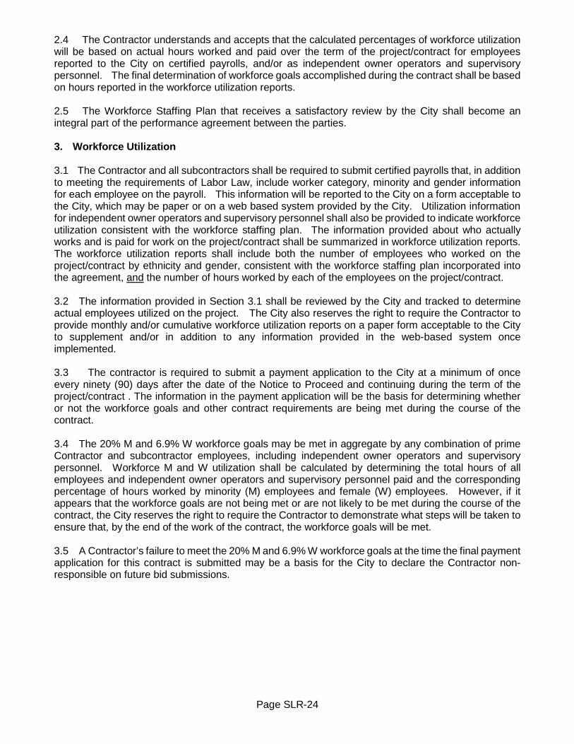
Page SLR-24
2.4 The Contractor understands and accepts that the calculated percentages of workforce utilization will be based on actual hours worked and paid over the term of the project/contract for employees reported to the City on certified payrolls, and/or as independent owner operators and supervisory personnel. The final determination of workforce goals accomplished during the contract shall be based on hours reported in the workforce utilization reports. 2.5 The Workforce Staffing Plan that receives a satisfactory review by the City shall become an integral part of the performance agreement between the parties. 3. Workforce Utilization 3.1 The Contractor and all subcontractors shall be required to submit certified payrolls that, in addition to meeting the requirements of Labor Law, include worker category, minority and gender information for each employee on the payroll. This information will be reported to the City on a form acceptable to the City, which may be paper or on a web based system provided by the City. Utilization information for independent owner operators and supervisory personnel shall also be provided to indicate workforce utilization consistent with the workforce staffing plan. The information provided about who actually works and is paid for work on the project/contract shall be summarized in workforce utilization reports. The workforce utilization reports shall include both the number of employees who worked on the project/contract by ethnicity and gender, consistent with the workforce staffing plan incorporated into the agreement, and the number of hours worked by each of the employees on the project/contract. 3.2 The information provided in Section 3.1 shall be reviewed by the City and tracked to determine actual employees utilized on the project. The City also reserves the right to require the Contractor to provide monthly and/or cumulative workforce utilization reports on a paper form acceptable to the City to supplement and/or in addition to any information provided in the web-based system once implemented. 3.3 The contractor is required to submit a payment application to the City at a minimum of once every ninety (90) days after the date of the Notice to Proceed and continuing during the term of the project/contract . The information in the payment application will be the basis for determining whether or not the workforce goals and other contract requirements are being met during the course of the contract. 3.4 The 20% M and 6.9% W workforce goals may be met in aggregate by any combination of prime Contractor and subcontractor employees, including independent owner operators and supervisory personnel. Workforce M and W utilization shall be calculated by determining the total hours of all employees and independent owner operators and supervisory personnel paid and the corresponding percentage of hours worked by minority (M) employees and female (W) employees. However, if it appears that the workforce goals are not being met or are not likely to be met during the course of the contract, the City reserves the right to require the Contractor to demonstrate what steps will be taken to ensure that, by the end of the work of the contract, the workforce goals will be met. 3.5 A Contractor’s failure to meet the 20% M and 6.9% W workforce goals at the time the final payment application for this contract is submitted may be a basis for the City to declare the Contractor non-responsible on future bid submissions.

Page SLR-25
SLR 21. Prevailing Wage Schedule and List of Employers Ineligible to Bid on or be Awarded any Public Work
Paper copies of the “Prevailing Wage Schedule” and “List of Employers Ineligible to Bid on or be Awarded any Public Work” will no longer be included with City of Rochester bid documents. A paper copy of the current documents will be provided to the successful Bidder(s) upon award of the contract. The “Prevailing Wage Schedule” and “List of Employers Ineligible to Bid on or be Awarded any Public Work” for this contract are available on the New York State Department of Labor’s website. They can be accessed by visiting the New York State Department of Labor’s website at http://wpp.labor.state.ny.us/wpp/doFindProject.do?method=showlt, and entering the assigned PRC# at the proper location on the website. The PRC# can be found on the PW 200 form which immediately follows this page. Contractors and Subcontractors must pay laborers, workers and mechanics employed in the performance of a public work contract not less than the most current prevailing rate of wage and supplements (fringe benefits). The City of Rochester will not be responsible for any of the Contractor’s increased labor costs which result from defects in the Prevailing Wage Schedule provided, or from amendments to the Prevailing Wage Schedule, whether that increase occurs before advertisement, before bid opening, before award of the contract, after the contract has been let, or during construction. No change in the contract price shall be allowed to the Contractor for any such increases. Information about current wage rates may be obtained on an advisory basis by contacting the City of Rochester Contract Administration office at (585) 428-7398.

PREVAILING WAGE SCHEDULE FOR ARTICLE 8 PUBLIC WORK PROJECT
Attached is the current schedule(s) of the prevailing wage rates and prevailing hourlysupplements for the project referenced above. A unique Prevailing Wage Case Number(PRC#) has been assigned to the schedule(s) for your project.
The schedule is effective from July 2019 through June 2020. All updates, corrections, postedon the 1st business day of each month, and future copies of the annual determination areavailable on the Department's website www.labor.ny.gov. Updated PDF copies of yourschedule can be accessed by entering your assigned PRC# at the proper location on thewebsite.
It is the responsibility of the contracting agency or its agent to annex and make part, theattached schedule, to the specifications for this project, when it is advertised for bids and /orto forward said schedules to the successful bidder(s), immediately upon receipt, in order toinsure the proper payment of wages.
Please refer to the "General Provisions of Laws Covering Workers on Public WorkContracts" provided with this schedule, for the specific details relating to otherresponsibilities of the Department of Jurisdiction.
Upon completion or cancellation of this project, enter the required information and mail ORfax this form to the office shown at the bottom of this notice, OR fill out the electronicversion via the NYSDOL website.
NOTICE OF COMPLETION / CANCELLATION OF PROJECT
Date Completed: Date Cancelled:
Name & Title of Representative:
Phone: (518) 457-5589 Fax: (518) 485-1870 W. Averell Harriman State Office Campus, Bldg. 12, Room 130, Albany, NY 12240
www.labor.ny.gov. PW 200 [email protected]
Andrew M. Cuomo, Governor Roberta Reardon, Commissioner
City of Rochester
Eric Kline, Contract AdministratorCity Hall30 Church St.Room 106-ARochester NY 14614-1282
Schedule Year 2019 through 2020Date Requested 02/25/2020PRC# 2020002463
Location VariousProject ID#Project Type Sager Drive Improvement Project
SLR-26

SUPPLEMENTARY TERMS AND CONDITIONS
PAGE STC 1.1 Definitions .................................................................................................................... STC-1 STC 3.3 Before Starting Construction ........................................................................................ STC-2 STC 4.1 Bonds .......................................................................................................................... STC-2 STC 4.2 Insurance..................................................................................................................... STC-3 STC 4.3 Contractual Liability Insurance ..................................................................................... STC-5 STC 5.1 Availability of Lands ..................................................................................................... STC-5 STC 5.2 Physical Conditions - Investigations and Reports ........................................................ STC-5 STC 6.2 Labor, Products and Storage ..................................................................................... STC-66 STC 6.4 Concerning Subcontractors and Suppliers ................................................................. STC-66 STC 6.21 Additional Pavement Restoration Requirements ...................................................... STC-66 STC 9.7 Resolution of Disputes ............................................................................................... STC-67 STC 10.2 Changes in the Contract Price ................................................................................. STC-67 STC 10.4 Liquidated Damages ................................................................................................ STC-70 STC 11.1 Warranty and Guarantee ......................................................................................... STC-71 STC 13.1 Applications for Progress Payments ........................................................................ STC-71 STC 13.3 Review of Applications for Progress Payments ........................................................ STC-71


Page STC-1
SUPPLEMENTARY TERMS AND CONDITIONS These Supplementary Terms and Conditions amend or supplement the General Terms and Conditions of the City of Rochester Standard Construction Contract Documents, November 1, 1991 Edition and other provisions of the City’s Contract Documents as are indicated below. All provisions which are not so amended or supplemented remain in full force and effect. The terms used in these Supplementary Terms and Conditions which are defined in the General Terms and Conditions of the City of Rochester Standard Construction Contract Documents, November 1, 1991 Edition have the meanings assigned to them in the General Terms and Conditions. STC 1.1 Definitions Under Article 1 Definitions and Abbreviations Subsection 1.1 Definitions, Delete the following definitions in their entirety, and Replace with the following: CITY ENGINEER – The City Engineer of the City of Rochester, New York. The City Engineer shall be responsible for the administration and management of all municipal design and engineering services and shall work under the general direction of the Commissioner of Environmental Services. The City Engineer shall be responsible for the preparation of plans and specifications for the design, construction, reconstruction and demolition of city streets, sidewalks, buildings, bridges, water system facilities and other municipal structures and facilities as deemed appropriate. SUBSTANTIAL COMPLETION - The Work (or a specified part thereof) that has progressed to the point where, in the opinion of the City Engineer as evidenced by the definitive Certificate of Substantial Completion, it is sufficiently complete, in accordance with the Contract Documents, so that the Work (or specified part) can be utilized for the purposes for which it was intended. When the Project consists of a Roadway or utility, Substantial Completion shall not be deemed to occur until the restoration work has been completed, a recommendation of Substantial Completion has been issued by the Project Manager to the City Engineer and the City Engineer has issued a written determination of Substantial Completion. Restoration work includes but is not limited to replacement of topsoil, and full establishment and City acceptance of all turf grasses planted under the contract, according to the requirements of the relevant contract specifications. Under Article 1 Definitions and Abbreviations Subsection 1.1 Definitions, Add the following definitions: CERTIFICATE OF ZONING COMPLIANCE (CZC) - This certificate is issued by the City Zoning office and authorizes the use of public or private properties within the City limits for construction related activities such as staging or material storage. Contractors or the respective property owners are required to obtain a CZC prior to use of a property for construction related purposes. The CZC will specify the terms and conditions to be followed for the use of the property. Use of such properties through the CZC shall be limited to the duration of the Project or as specified in the CZC.
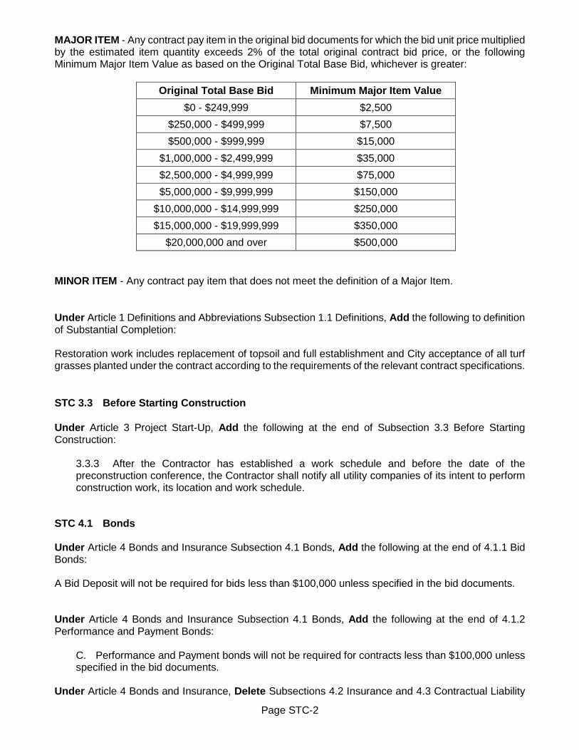
Page STC-2
MAJOR ITEM - Any contract pay item in the original bid documents for which the bid unit price multiplied by the estimated item quantity exceeds 2% of the total original contract bid price, or the following Minimum Major Item Value as based on the Original Total Base Bid, whichever is greater:
Original Total Base Bid Minimum Major Item Value $0 - $249,999 $2,500 $250,000 - $499,999 $7,500 $500,000 - $999,999 $15,000 $1,000,000 - $2,499,999 $35,000 $2,500,000 - $4,999,999 $75,000 $5,000,000 - $9,999,999 $150,000 $10,000,000 - $14,999,999 $250,000 $15,000,000 - $19,999,999 $350,000 $20,000,000 and over $500,000
MINOR ITEM - Any contract pay item that does not meet the definition of a Major Item. Under Article 1 Definitions and Abbreviations Subsection 1.1 Definitions, Add the following to definition of Substantial Completion: Restoration work includes replacement of topsoil and full establishment and City acceptance of all turf grasses planted under the contract according to the requirements of the relevant contract specifications. STC 3.3 Before Starting Construction Under Article 3 Project Start-Up, Add the following at the end of Subsection 3.3 Before Starting Construction:
3.3.3 After the Contractor has established a work schedule and before the date of the preconstruction conference, the Contractor shall notify all utility companies of its intent to perform construction work, its location and work schedule.
STC 4.1 Bonds Under Article 4 Bonds and Insurance Subsection 4.1 Bonds, Add the following at the end of 4.1.1 Bid Bonds: A Bid Deposit will not be required for bids less than $100,000 unless specified in the bid documents. Under Article 4 Bonds and Insurance Subsection 4.1 Bonds, Add the following at the end of 4.1.2 Performance and Payment Bonds:
C. Performance and Payment bonds will not be required for contracts less than $100,000 unless specified in the bid documents.
Under Article 4 Bonds and Insurance, Delete Subsections 4.2 Insurance and 4.3 Contractual Liability

Page STC-3
Insurance in their entirety, and Replace with the following: STC 4.2 Insurance: 4.2.1 The Contractor shall procure and maintain at its own expenses until final acceptance of the work covered by the Contract Documents, insurance for liability for damages imposed by law of the kinds and in the amounts hereinafter provided from insurance companies licensed to do such business in the State of New York and maintaining an A.M. Best rating of A- XV covering all operations under the Contract Documents whether performed by the Contractor or its Subcontractors. If the Contractor is comprised of more than one legal entity (excluding Subcontractors) each such entity will be jointly named. Within ten (10) days of Award of Contract, the Contractor shall furnish to the City Finance Director a certificate or certificates of insurance in form satisfactory to the City Purchasing Agent showing compliance with this Section. In each policy of insurance except insurance of Workers' Compensation and Disability Insurance, the City and other appropriate Funding Agencies shall be named as an additional insured as further stipulated below for liability arising under this Contract. The kinds and amounts of insurance are as follows:
A. WORKERS' COMPENSATION AND DISABILITY INSURANCE. The Contract shall be void and of no effect unless the person or corporation making or executing same shall secure Compensation and Disability coverage, covering all operations under the Contract - whether performed by the Contractor or its Subcontractors for the benefit of, and keep insured during the life of said Contract, employees in compliance with the provisions of the Workers' Compensation Law.
Workers' Compensation Insurance. A policy covering the operations of the Contractor in accordance with the provisions of Chapter 41 of the Laws of 1914, as amended, known as the Workers' Compensation Law. The policy shall be endorsed to provide 30 days prior written notice of cancellation or non-renewal and Waiver of Subrogation in favor of the City of Rochester. A copy of these endorsements shall be included with the Certificate of Insurance. Disability Insurance. A policy covering the operations of the Contractor in accordance with the provisions of Article 9 of the Workers' Compensation Law, known as the Disability Benefits Law (Chapter 600 of the Laws of 1949) and amendments thereto.
B. CASUALTY INSURANCE. The policy limits, unless otherwise indicated in the Supplementary Terms and Conditions shall be:
1) Commercial General Liability. Issued to the Contractor and covering the liability for damages imposed by law upon the Contractor with respect to all work performed by the Contractor under the within Contract. The coverage shall be written on an occurrence form utilizing ISO coverage form CG 00 01 12 07 or its equivalent. The policy shall furnish limits of not less than:
Bodily Injury and Property Damage Limit $1,000,000 each occurrence
Products/Completed Operations Limit $2,000,000 aggregate
Personal Injury and Advertising Injury Limit $1,000,000 each person or Organization
General Aggregate
$2,000,000 applicable on a per project basis

Page STC-4
The City of Rochester, their officers, employees and agents and all other appropriate Funding Agencies shall be named as an additional insured for liability arising under this Contract applicable to both ongoing and completed operations on a primary and non-contributory basis. There shall be no exclusions relating to NYS Labor Law or municipal operations. Coverage shall be maintained for a 3 year period following completion of the project. 2) Commercial Automobile Liability. Issued to the Contractor and covering all owned, non-owned and hired automobiles with limits not less than:
Combined Single Limit for Bodily Injury and Property Damage
$1,000,000 each accident
3) Umbrella Excess Liability. Issued to the Contractor providing follow form coverage over the General Liability and Automobile Liability requirements stipulated above with minimum limits of:
Bodily Injury and Property Damage Limit $5,000,000 each occurrence
Products/Completed Operations Limit $5,000,000 aggregate
General Aggregate $5,000,000 applicable on a per project basis
4) Contractors Pollution Liability. The Contractor must provide the following coverage when the work of the contract requires, or is reasonably anticipated to require one or more of the following items: asbestos abatement; hazardous material disposal; lead abatement; mold abatement; PCB abatement; emergency medical response work; environmental remediation work; medical waste disposal; tank installation, maintenance and/or removal; pipeline maintenance, installation and/ or removal involving underground drilling; work involving or affecting wetlands. Such insurance will be issued to the Contractor covering all operations with limits not less than:
$2,000,000 per loss $2,000,000 annual aggregate
This insurance shall cover losses caused by pollution conditions that arise from the operations of the Contractor with no exclusions relating to fungus, mold, microbial matter or asbestos. Coverage may be written on a claims-made basis.
All policies shall be endorsed to provide Waiver of Subrogation in favor of the City of Rochester. All policies shall be endorsed to provide 30 days prior written notice of cancellation or non-renewal. A copy of the Additional Insured and Waiver of Subrogation Endorsement(s) shall be included with the Certificate of Insurance.

Page STC-5
C. BUILDER'S RISK INSURANCE. Unless otherwise specified in the Contract Documents, the Contractor shall effect and maintain insurance against loss on an "All Risk" basis upon all work in place and all materials and equipment in connection therewith, whether or not furnished or delivered by any person or Contractor other than the Contractor or by the City, itself, and whether or not covered by partial payment made by the City. This insurance shall be in an amount equal to the full insurable value thereof at all times and shall be for the benefit of the City, the Contractor and each Subcontractor as their interest may respectively appear. This insurance shall be obtained on the "completed value" form. The City and other appropriate Funding Agencies shall be named as an additional named insured in this policy.
STC 4.3 Contractual Liability Insurance: 4.3.1 The Commercial General Liability insurance required by paragraph 4.2.1 B.1) shall include Contractual Liability Insurance applicable to the Contractor's obligations under Article 6 Contractor's Responsibilities Section 6.15 Indemnification. STC 5.1 Availability of Lands Under Article 5 Availability of Lands; Physical Conditions; Reference Points, Delete paragraph 5.1.2 of Subsection 5.1 Availability of Lands in its entirety, and Replace with the following: 5.1.2 The Contractor shall provide for all additional lands and access thereto that may be required for temporary construction facilities or storage of materials and equipment. Any Contractor use of such lands within the City limits shall require the Contractor or respective property owner to obtain a Certificate of Zoning Compliance (CZC) from the City. The CZC will stipulate the terms and conditions required for use of the property including: length of time; required fencing; sediment and erosion control; construction entrance details; final restoration; and contact information. The CZC and any other easements, permits, agreements, licenses, or leases of these lands shall be obtained and paid for by the Contractor. The Contractor’s use of these lands is subject to all Local, State, or Federal laws, ordinances, rules, or regulations controlling or limiting in any way their use of these lands. STC 5.2 Physical Conditions – Investigations and Reports Under Article 5 Availability of Lands; Physical Conditions; Reference Points, Add the following to the end of Subsection 5.2 Physical Conditions – Investigations and Reports: 5.2.2 In the preparation of the drawings and the specifications, the design professional has relied upon the following reports and tests of subsurface and latent physical conditions at the site, or otherwise affect cost, progress or performance of the work. Approximate locations of the boring(s)/coring(s) are shown on the drawings. These boring(s)/coring(s) are bound with, but are not part of the Contract Documents. The information is furnished solely for the convenience of the Contractor, without any warranty expressed or implied as to its accuracy or completeness. The Contractor shall make no claims against the City of Rochester with respect to the accuracy or completeness of such information, if it is erroneous or if the conditions found at the time of construction are different from those shown or indicated.

REPORT C OVER PAGE
Geotechnical Exploration Report Sager Drive Improvement Project, PC 16125
Rochester, NY December 24, 2019
Terracon Project No. BU195023A
Prepared for: City of Rochester
Department of Environmental Services/Street Design Division 30 Church Street
Rochester, New York
Prepared by: Terracon Consultants-NY, Inc.
Rochester, New York
STC-6

Terracon Consultants -NY, Inc. 15 Marway Circle, Suite 2B Rochester, New York 14624 P 585.247.3471 terracon.com
REPORT C OVER LETTER TO SIGN
December 24, 2019 Department of Environmental Services/Street Design Division 30 Church Street Rochester, New York 14608 Attn: Mr. Dominic Fekete, P.E.
Manager of Street Design Re: Geotechnical Exploration Report
Sager Drive Improvement Project, PC 16125 Rochester, NY Terracon Project No. BU195023A
Dear Mr. Fekete: We have completed the Geotechnical Exploration services for the above referenced project. This study was performed in general accordance with the request package dated October 31, 2019. This report presents the findings of the subsurface exploration for the proposed project. We appreciate the opportunity to be of service to you on this project. If you have any questions concerning this report, or if we may be of further service, please contact us. Sincerely, Terracon Consultants, NY Inc. Kyle P. Lemcke, E.I.T. Chuck Guzzetta Staff Engineer Office Manager
STC-7

Responsive ■ Resourceful ■ Reliable 1
INTRODUCTION
Geotechnical Exploration ReportSager Drive Improvement Project, PC 16125
Rochester, NYTerracon Project No. BU195023A
December 24, 2019
INTRODUCTION
This report presents the results of our subsurface exploration and geotechnical services performed for the street rehabilitation and utility improvements project along Sager Drive in the City of Rochester, NY. The purpose of these services is to provide information relative to:
■ Existing Pavement Section■ Volatile Organics Analysis■ Petroleum Hydrocarbon Analysis
■ Subsurface Soils Conditions■ TCL Analysis■ 10 Point DIPRA Test
The geotechnical exploration scope of services for this project included the advancement of eleven soil borings, nine of which included pavement cores. Soil borings were completed at a depth of approximately 6 feet below existing grade.
Maps showing the site and boring locations are shown in the Site Location and ExplorationPlan sections, respectively. Boring logs, Pavement Core Logs, 10 Point DIPRA Test, TCLAnalysis, Petroleum Hydrocarbon Analysis and Volatile Organics Analysis results are includedin the Exploration Results section of this report.
GENERAL COMMENTS
Our analysis and opinions are based upon our understanding of the project, the geotechnical conditions in the area, and the data obtained from our site exploration. Natural variations will occur between exploration point locations or due to the modifying effects of construction or weather. The nature and extent of such variations may not become evident until during or after construction.
Our scope of services does not include either specifically or by implication any environmental or biological (e.g., mold, fungi, bacteria) assessment of the site or identification or prevention of pollutants, hazardous materials or conditions. If the owner is concerned about the potential for such contamination or pollution, other studies should be undertaken.
Our services and any correspondence or collaboration through this system are intended for the sole benefit and exclusive use of our client for specific application to the project discussed and are accomplished in accordance with generally accepted geotechnical engineering practices with no third party beneficiaries intended. Any third party access to services or correspondence is solely for information purposes to support the services provided by Terracon to our client. Reliance
STC-8
Geotechnical Exploration Report Sager Drive Improvement Project, PC 16125 ■ Rochester, NY December 24, 2019 ■ Terracon Project No. BU195023A
Responsive ■ Resourceful ■ Reliable 2
upon the services and any work product is limited to our client, and is not intended for third parties. Any use or reliance of the provided information by third parties is done solely at their own risk. No warranties, either express or implied, are intended or made.
Site characteristics as provided are for design purposes and not to estimate excavation cost. Any use of our report in that regard is done at the sole risk of the excavating cost estimator as there may be variations on the site that are not apparent in the data that could significantly impact excavation cost. Any parties charged with estimating excavation costs should seek their own site characterization for specific purposes to obtain the specific level of detail necessary for costing. Site safety, and cost estimating including, excavation support, and dewatering requirements/design are the responsibility of others.
STC-9
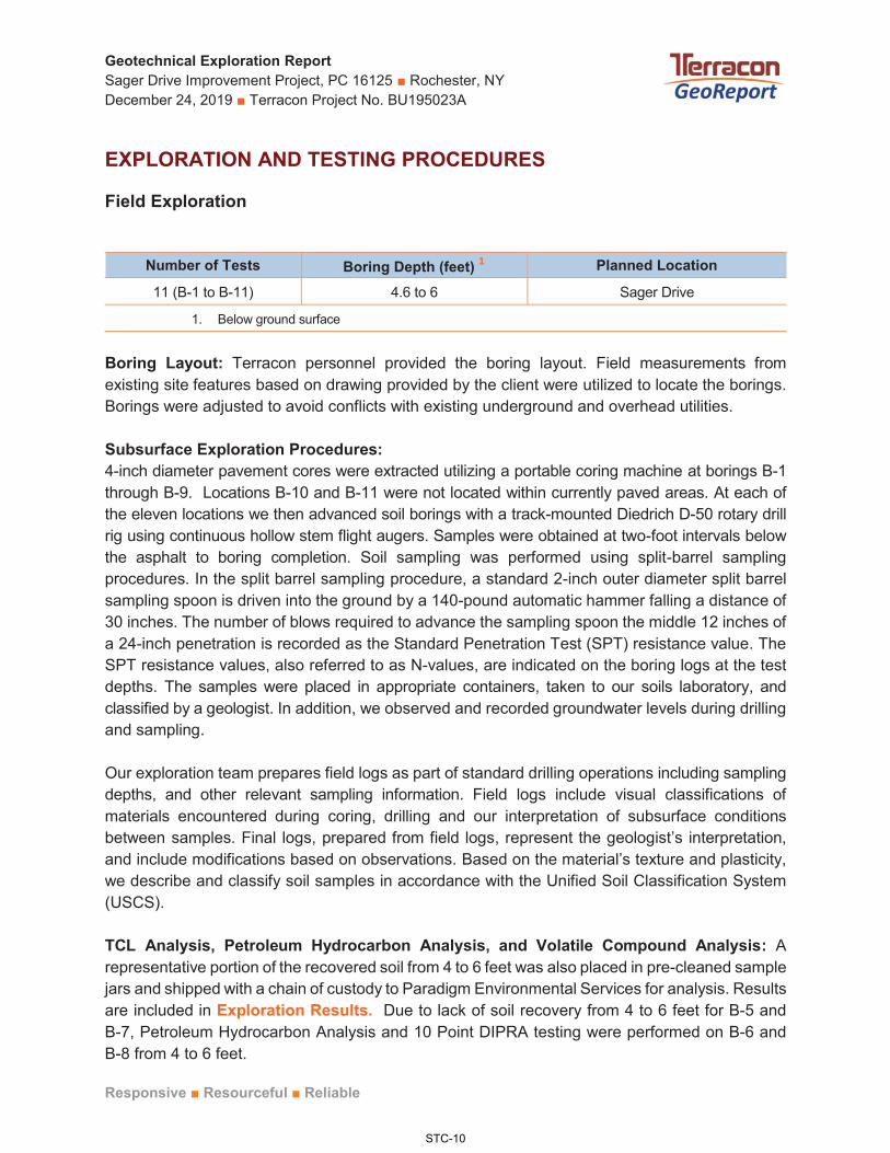
Geotechnical Exploration ReportSager Drive Improvement Project, PC 16125 ■ Rochester, NYDecember 24, 2019 ■ Terracon Project No. BU195023A
Responsive ■ Resourceful ■ Reliable
EXPLORATION AND TESTING PROCEDURES
Field Exploration
Number of Tests Boring Depth (feet) 1 Planned Location
11 (B-1 to B-11) 4.6 to 6 Sager Drive
1. Below ground surface
Boring Layout: Terracon personnel provided the boring layout. Field measurements from existing site features based on drawing provided by the client were utilized to locate the borings.Borings were adjusted to avoid conflicts with existing underground and overhead utilities.
Subsurface Exploration Procedures:4-inch diameter pavement cores were extracted utilizing a portable coring machine at borings B-1through B-9. Locations B-10 and B-11 were not located within currently paved areas. At each of the eleven locations we then advanced soil borings with a track-mounted Diedrich D-50 rotary drillrig using continuous hollow stem flight augers. Samples were obtained at two-foot intervals below the asphalt to boring completion. Soil sampling was performed using split-barrel sampling procedures. In the split barrel sampling procedure, a standard 2-inch outer diameter split barrel sampling spoon is driven into the ground by a 140-pound automatic hammer falling a distance of 30 inches. The number of blows required to advance the sampling spoon the middle 12 inches of a 24-inch penetration is recorded as the Standard Penetration Test (SPT) resistance value. The SPT resistance values, also referred to as N-values, are indicated on the boring logs at the test depths. The samples were placed in appropriate containers, taken to our soils laboratory, and classified by a geologist. In addition, we observed and recorded groundwater levels during drilling and sampling.
Our exploration team prepares field logs as part of standard drilling operations including sampling depths, and other relevant sampling information. Field logs include visual classifications of materials encountered during coring, drilling and our interpretation of subsurface conditions between samples. Final logs, prepared from field logs, represent the geologist’s interpretation,and include modifications based on observations. Based on the material’s texture and plasticity, we describe and classify soil samples in accordance with the Unified Soil Classification System (USCS).
TCL Analysis, Petroleum Hydrocarbon Analysis, and Volatile Compound Analysis: Arepresentative portion of the recovered soil from 4 to 6 feet was also placed in pre-cleaned samplejars and shipped with a chain of custody to Paradigm Environmental Services for analysis. Resultsare included in Exploration Results. Due to lack of soil recovery from 4 to 6 feet for B-5 andB-7, Petroleum Hydrocarbon Analysis and 10 Point DIPRA testing were performed on B-6 andB-8 from 4 to 6 feet.
STC-10

Geotechnical Exploration ReportSager Drive Improvement Project, PC 16125 ■ Rochester, NYDecember 24, 2019 ■ Terracon Project No. BU195023A
Responsive ■ Resourceful ■ Reliable
10 Point DIPRA Test: A 10 Point DIPRA soil evaluation test was performed in our soils laboratoryon soils recovered from 4 to 6 feet from select borings. Results are included in ExplorationResults.
Exploration Summary
Core LocationAsphalt thickness
(inches)Subbase thickness
(inches)Subbase Material Subgrade Material
B-1 3.5 21 Crushed stone Silty sand with gravel
B-2 3.5 3 Fill – Sand andgravel
Silty sand with gravel
B-3 2 6 Fill – Sand andgravel
Silty sand with gravel
B-4 7 18 Crushed stone with silt
Silty sand with gravel
B-5 6 12 Fill – Sand andgravel
Silty sand with gravel
B-6 6 18 Crushed stone with silt
Silty sand with gravel
B-7 6 18 Crushed stone with silt
Silty sand with gravel
B-8 6 18 Fill – Sand andgravel
Weathered dolostone
B-9 618 Fill – Sand and
gravelSilty sand with
gravel
B-10 N/A 4 Fill – Sand andgravel
Silty sand with gravel
B-11 N/A 4 Fill – Sand andgravel
Silty sand with gravel
ATTACHM ENTS
STC-11

Geotechnical Exploration Report Sager Drive Improvement Project, PC 16125 ■ Rochester, NY December 24, 2019 ■ Terracon Project No. BU195023A
Responsive ■ Resourceful ■ Reliable
ATTACHMENTS
STC-12

SITE LOC ATION AND EXPLOR ATION PLAN S
SITE LOCATION AND EXPLORATION PLANS
STC-13

SITE
LO
CAT
ION
Sage
r Driv
e Im
prov
emen
t Pro
ject■
Roc
hest
er, N
YD
ecem
ber 2
4, 2
019 ■
Terra
con
Proj
ect N
o. B
U19
5023
A
DIA
GR
AM IS
FO
R G
ENER
AL L
OC
ATIO
N O
NLY
, AN
D IS
NO
T IN
TEN
DED
FO
R C
ON
STR
UC
TIO
N P
UR
POSE
STO
POG
RAP
HIC
MAP
IMAG
E C
OU
RTE
SY O
F TH
E U
.S. G
EOLO
GIC
AL S
UR
VEY
QU
ADR
ANG
LES
INC
LUD
E: R
OC
HES
TER
EAS
T, N
Y (1
/1/1
978)
.
SITE
SITE
STC-14

EXPL
OR
ATIO
N P
LAN
Sage
r Driv
e Im
prov
emen
t Pro
ject■
Roc
hest
er, N
YD
ecem
ber 2
4, 2
019 ■
Terra
con
Proj
ect N
o. B
U19
5023
A
AER
IAL
PHO
TOG
RAP
HY
PRO
VID
ED B
Y M
ICR
OSO
FT B
ING
MAP
SD
IAG
RAM
IS F
OR
GEN
ERAL
LO
CAT
ION
ON
LY, A
ND
IS N
OT
INTE
ND
ED F
OR
CO
NST
RU
CTI
ON
PU
RPO
SES
STC-15

STC-16

EXPLOR ATION RESULTS
EXPLORATION RESULTS
STC-17
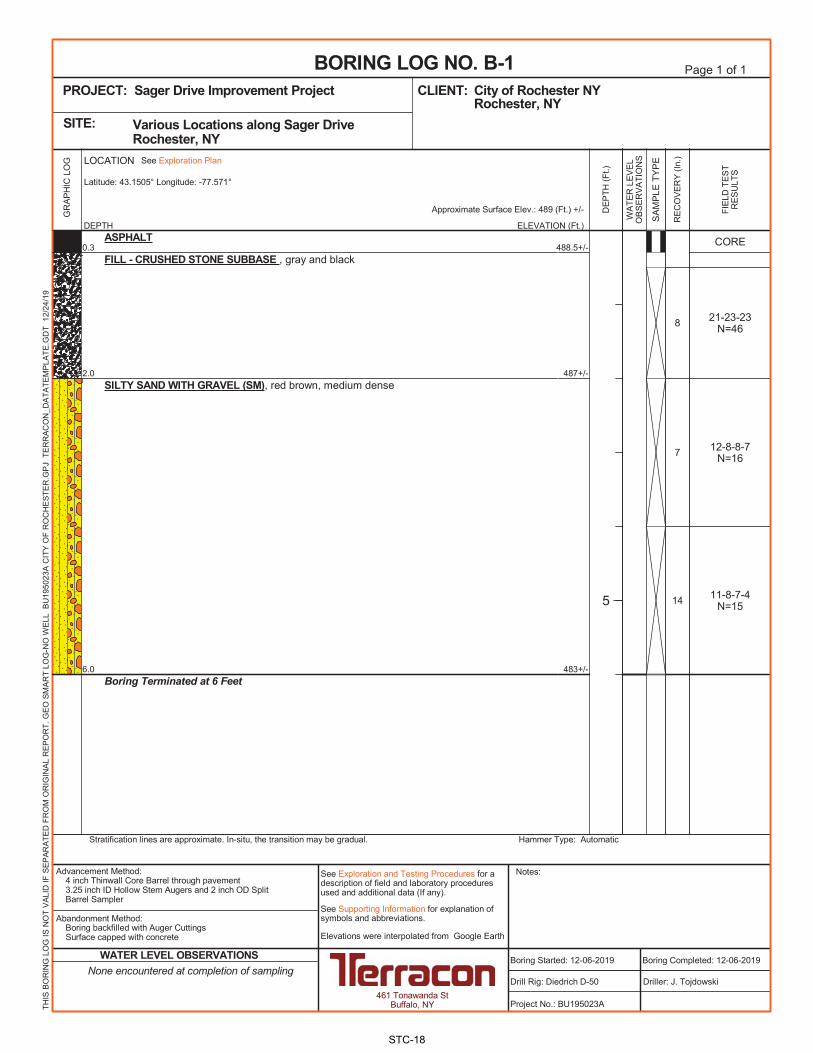
STC-18

STC-19

STC-20
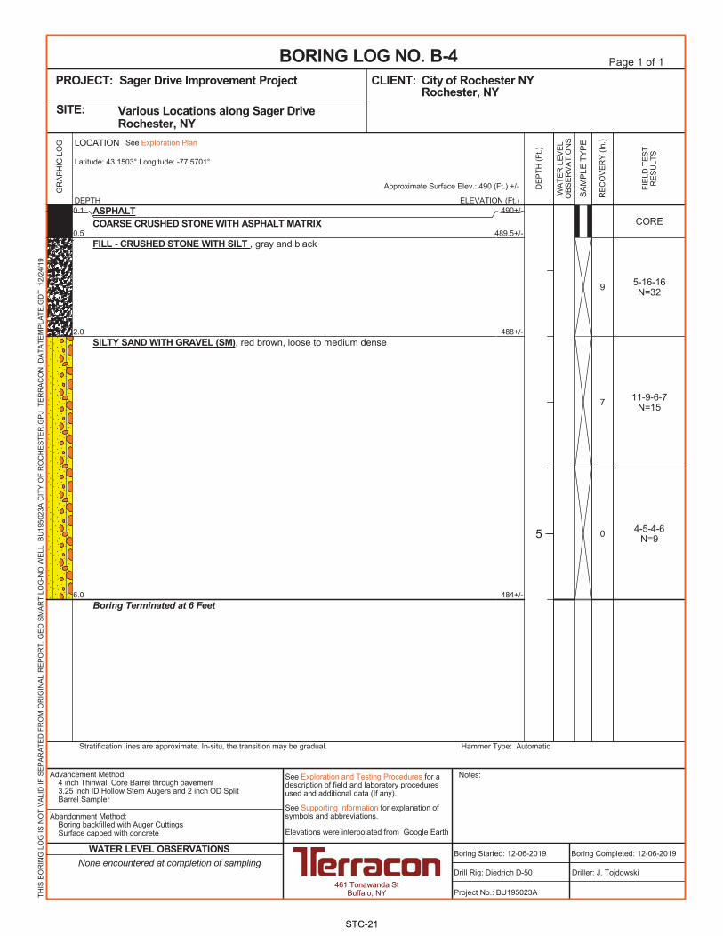
STC-21

STC-22

STC-23

STC-24

STC-25

STC-26

STC-27

STC-28

CORE LOG Sager Drive Improvement Project ■ Rochester, New York December 23, 2019 ■ Terracon Project No. BU195023A
Notes: The ruler presented in the photographs is intended to provide a reference scale only. Therefore, the dimensions of the cores may not be accurately reflected in the photographs.
Pavement core at boring B-1 .
Course Thickness (inches) Conditions Remarks
Top 1.75 Good
Binder 1.75 Good
TOTAL 3.5
STC-29

CORE LOG Sager Drive Improvement Project ■ Rochester, New York December 23, 2019 ■ Terracon Project No. BU195023A
Notes: The ruler presented in the photographs is intended to provide a reference scale only. Therefore, the dimensions of the cores may not be accurately reflected in the photographs.
Pavement core at boring B-2 .
Course Thickness (inches) Conditions Remarks
Top (2 layers) 1.75 Good
Binder 1.75 Good
TOTAL 3.5
STC-30

CORE LOG Sager Drive Improvement Project ■ Rochester, New York December 23, 2019 ■ Terracon Project No. BU195023A
Notes: The ruler presented in the photographs is intended to provide a reference scale only. Therefore, the dimensions of the cores may not be accurately reflected in the photographs.
Pavement core at boring B-3 .
Course Thickness (inches) Conditions Remarks
Top (2 layers) 2 Good
TOTAL 2
STC-31

CORE LOG Sager Drive Improvement Project ■ Rochester, New York December 23, 2019 ■ Terracon Project No. BU195023A
Notes: The ruler presented in the photographs is intended to provide a reference scale only. Therefore, the dimensions of the cores may not be accurately reflected in the photographs.
Pavement core at boring B-4 .
Course Thickness (inches) Conditions Remarks
Top (2 layers) 2 Good
Base 5 Satisfactory Coarse crushed stone with asphalt matrix
TOTAL 7
STC-32
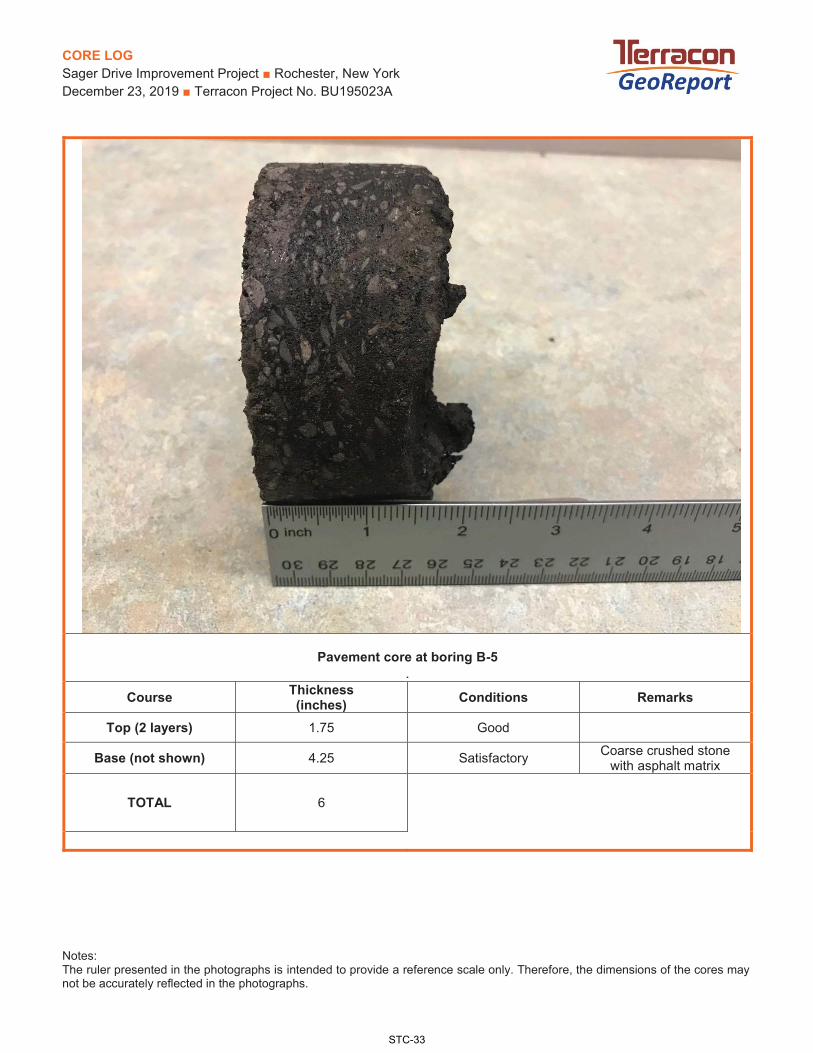
CORE LOG Sager Drive Improvement Project ■ Rochester, New York December 23, 2019 ■ Terracon Project No. BU195023A
Notes: The ruler presented in the photographs is intended to provide a reference scale only. Therefore, the dimensions of the cores may not be accurately reflected in the photographs.
Pavement core at boring B-5 .
Course Thickness (inches) Conditions Remarks
Top (2 layers) 1.75 Good
Base (not shown) 4.25 Satisfactory Coarse crushed stone with asphalt matrix
TOTAL 6
STC-33
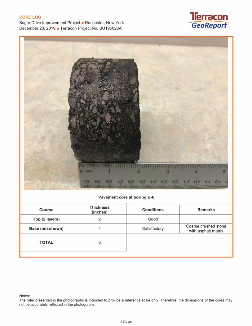
CORE LOG Sager Drive Improvement Project ■ Rochester, New York December 23, 2019 ■ Terracon Project No. BU195023A
Notes: The ruler presented in the photographs is intended to provide a reference scale only. Therefore, the dimensions of the cores may not be accurately reflected in the photographs.
Pavement core at boring B-6 .
Course Thickness (inches) Conditions Remarks
Top (2 layers) 2 Good
Base (not shown) 4 Satisfactory Coarse crushed stone with asphalt matrix
TOTAL 6
STC-34

CORE LOG Sager Drive Improvement Project ■ Rochester, New York December 23, 2019 ■ Terracon Project No. BU195023A
Notes: The ruler presented in the photographs is intended to provide a reference scale only. Therefore, the dimensions of the cores may not be accurately reflected in the photographs.
Pavement core at boring B-7 .
Course Thickness (inches) Conditions Remarks
Top (2 layers) 2 Good
Base (partially shown) 4 Satisfactory Coarse crushed stone with asphalt matrix
TOTAL 6
STC-35

CORE LOG Sager Drive Improvement Project ■ Rochester, New York December 23, 2019 ■ Terracon Project No. BU195023A
Notes: The ruler presented in the photographs is intended to provide a reference scale only. Therefore, the dimensions of the cores may not be accurately reflected in the photographs.
Pavement core at boring B-8 .
Course Thickness (inches) Conditions Remarks
Top (2 layers) 1.5 Good
Base (partially shown) 4.5 Satisfactory Coarse crushed stone with asphalt matrix
TOTAL 6
STC-36

CORE LOG Sager Drive Improvement Project ■ Rochester, New York December 23, 2019 ■ Terracon Project No. BU195023A
Notes: The ruler presented in the photographs is intended to provide a reference scale only. Therefore, the dimensions of the cores may not be accurately reflected in the photographs.
Pavement core at boring B-9 .
Course Thickness (inches) Conditions Remarks
Top (3 layers) 3.5 Good
Base (partially shown) 2.5 Satisfactory Coarse crushed stone with asphalt matrix
TOTAL 6
STC-37

D.I.
P.R
.A. 1
0-PO
INT
SOIL
EVA
LUA
TIO
N T
EST
RES
ULT
S
Proj
ect N
ame:
Sage
r Driv
e Im
prov
emen
t Pro
ject
BU19
5023
AC
lient
:Lo
catio
n:R
oche
ster
, NY
Dat
e:Ky
le L
emck
e
Bor
ing
IDR
esis
tivity
Red
oxPh
Sulfi
des
Moi
stur
eTo
tal P
oint
s(o
hm-c
m)
(mv)
(+,T
,-)(w
et, m
oist
, dry
)po
ints
poin
tspo
ints
poin
tspo
ints
5,61
0-1
058.
58ne
gativ
em
oist
05
30
1
11,3
00-1
248.
9ne
gativ
em
oist
05
30
1
3120
-150
9.61
nega
tive
moi
st
05
30
1
5430
-155
9.67
nega
tive
moi
st
05
30
1
Resis
tivity
(ohm
-cm
):Po
ints
pHPo
ints
Redo
x (m
v)Po
ints
Sulfi
des
Points
Moi
stur
ePo
ints
<150
010
0 - 2
5>
+ 10
00
Posit
ive
3.5
Wet
2≥1
500-
1800
82-
43
+50
to +
100
3.5
Trac
e2
Moi
st1
>180
0-21
005
4 - 6
.50
0 to
+50
4Ne
gativ
e0
Dry
0>2
100-
2500
26.
5 -
7.5
0*Ne
gativ
e5
>250
0-30
001
7.5
- 8
.50
> 30
000
> 8.
53
* = If
sul
fides
are
pre
sent
& lo
w
or n
egat
ive
RED
OX
valu
es a
re
pres
ent,
3 po
ints
sho
uld
be g
iven
fo
r thi
s ra
nge.
** ≥
10
poin
ts is
corr
osiv
e to
Du
ctile
Iron
Pip
e
POIN
T SY
STEM
**
City
of R
oche
ster
Proj
ect N
umbe
r:
B-3
4' to
6'
9
12/2
4/20
19
Dep
th
94'
to 6
'B-
1
Test
Per
form
ed b
y:
B-6
4' to
6'
9
B-8
4' to
6'
9
STC-38

STC-39

Lab Project ID:
Client:
Project Reference:
Terracon Consultants-NY, Inc.
Lab Sample ID:Sample Identifier:
Matrix:Date Sampled:Date Received:
Analyte Result Date AnalyzedQualifierUnits
Petroleum Hydrocarbons by GC
Method Reference(s):
ELAP does not offer this test for approval as part of their laboratory certification program.Preparation Date:
Analyte Result Date AnalyzedQualifierUnits
Volatile Organics
Report Prepared Tuesday, December 17, 2019 Page 2 of 29STC-40
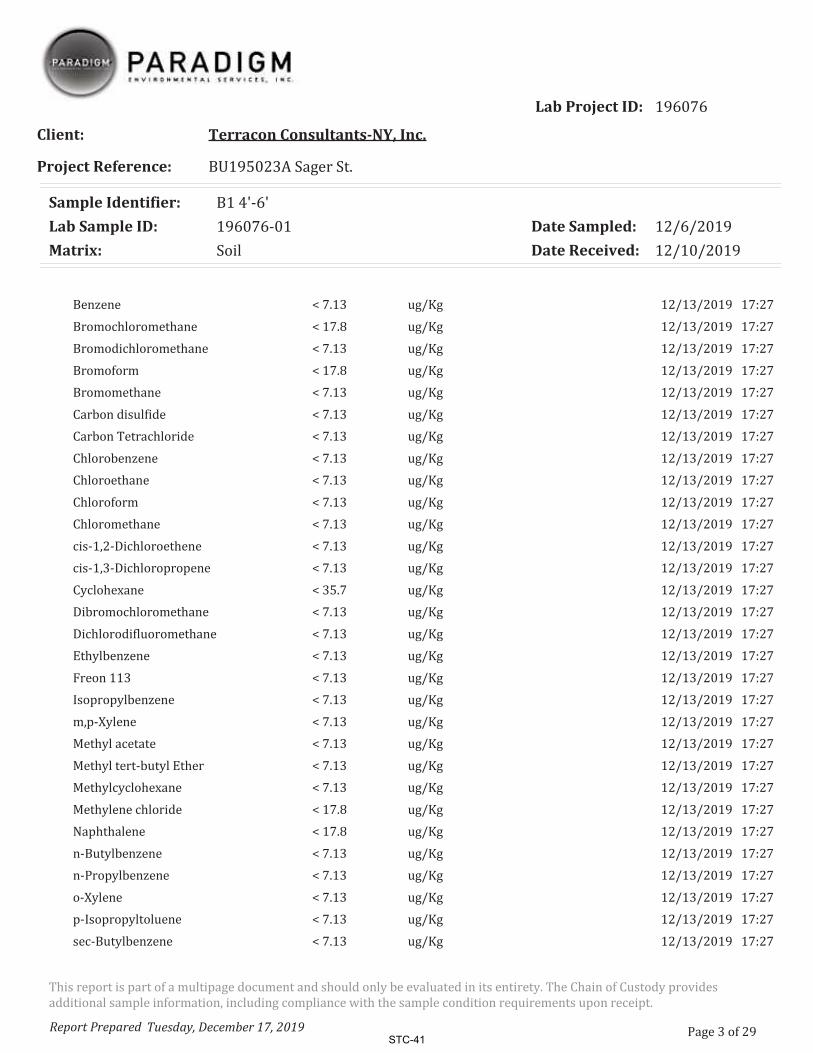
Lab Project ID:
Client:
Project Reference:
Terracon Consultants-NY, Inc.
Lab Sample ID:Sample Identifier:
Matrix:Date Sampled:Date Received:
Report Prepared Tuesday, December 17, 2019 Page 3 of 29STC-41
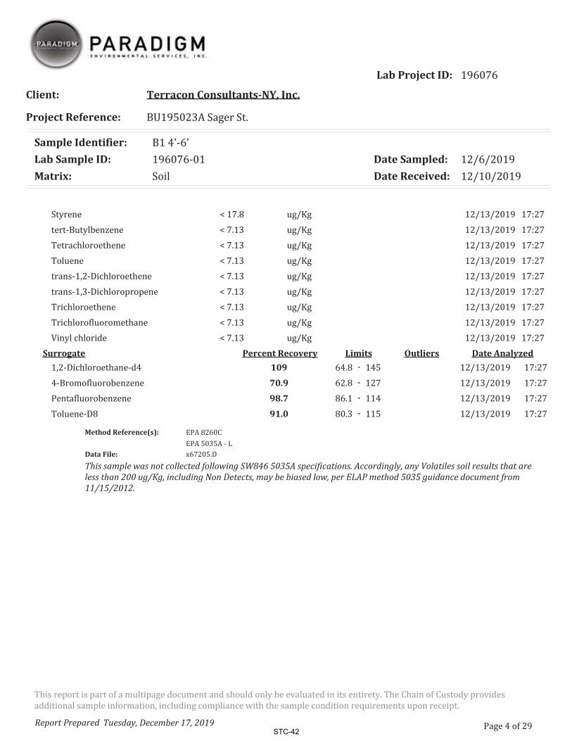
Lab Project ID:
Client:
Project Reference:
Terracon Consultants-NY, Inc.
Lab Sample ID:Sample Identifier:
Matrix:Date Sampled:Date Received:
Method Reference(s):
Data File:
This sample was not collected following SW846 5035A specifications. Accordingly, any Volatiles soil results that are less than 200 ug/Kg, including Non Detects, may be biased low, per ELAP method 5035 guidance document from 11/15/2012.
Surrogate Percent Recovery Limits Date AnalyzedOutliers109 -
70.9 -
98.7 -
91.0 -
Report Prepared Tuesday, December 17, 2019 Page 4 of 29STC-42
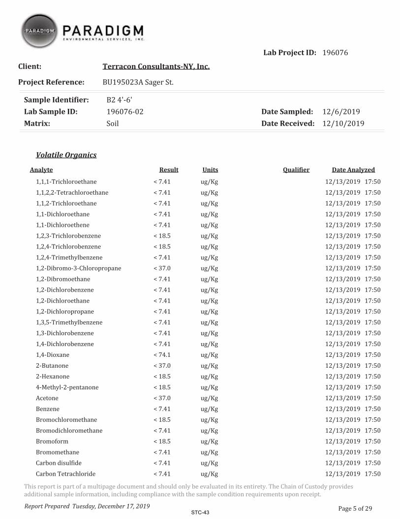
Lab Project ID:
Client:
Project Reference:
Terracon Consultants-NY, Inc.
Lab Sample ID:Sample Identifier:
Matrix:Date Sampled:Date Received:
Analyte Result Date AnalyzedQualifierUnits
Volatile Organics
Report Prepared Tuesday, December 17, 2019 Page 5 of 29STC-43

Lab Project ID:
Client:
Project Reference:
Terracon Consultants-NY, Inc.
Lab Sample ID:Sample Identifier:
Matrix:Date Sampled:Date Received:
Report Prepared Tuesday, December 17, 2019 Page 6 of 29STC-44

Lab Project ID:
Client:
Project Reference:
Terracon Consultants-NY, Inc.
Lab Sample ID:Sample Identifier:
Matrix:Date Sampled:Date Received:
Method Reference(s):
Data File:
This sample was not collected following SW846 5035A specifications. Accordingly, any Volatiles soil results that are less than 200 ug/Kg, including Non Detects, may be biased low, per ELAP method 5035 guidance document from 11/15/2012.
Surrogate Percent Recovery Limits Date AnalyzedOutliers112 -
82.0 -
98.3 -
94.8 -
Report Prepared Tuesday, December 17, 2019 Page 7 of 29STC-45

Lab Project ID:
Client:
Project Reference:
Terracon Consultants-NY, Inc.
Lab Sample ID:Sample Identifier:
Matrix:Date Sampled:Date Received:
Analyte Result Date AnalyzedQualifierUnits
Petroleum Hydrocarbons by GC
Method Reference(s):
ELAP does not offer this test for approval as part of their laboratory certification program.Preparation Date:
Analyte Result Date AnalyzedQualifierUnits
Volatile Organics
Report Prepared Tuesday, December 17, 2019 Page 8 of 29STC-46

Lab Project ID:
Client:
Project Reference:
Terracon Consultants-NY, Inc.
Lab Sample ID:Sample Identifier:
Matrix:Date Sampled:Date Received:
Report Prepared Tuesday, December 17, 2019 Page 9 of 29STC-47

Lab Project ID:
Client:
Project Reference:
Terracon Consultants-NY, Inc.
Lab Sample ID:Sample Identifier:
Matrix:Date Sampled:Date Received:
Method Reference(s):
Data File:
This sample was not collected following SW846 5035A specifications. Accordingly, any Volatiles soil results that are less than 200 ug/Kg, including Non Detects, may be biased low, per ELAP method 5035 guidance document from 11/15/2012.
Surrogate Percent Recovery Limits Date AnalyzedOutliers109 -
75.3 -
98.7 -
91.8 -
Report Prepared Tuesday, December 17, 2019 Page 10 of 29STC-48

Lab Project ID:
Client:
Project Reference:
Terracon Consultants-NY, Inc.
Lab Sample ID:Sample Identifier:
Matrix:Date Sampled:Date Received:
Analyte Result Date AnalyzedQualifierUnits
Volatile Organics
Report Prepared Tuesday, December 17, 2019 Page 11 of 29STC-49
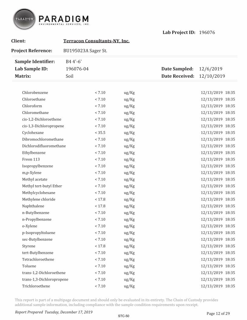
Lab Project ID:
Client:
Project Reference:
Terracon Consultants-NY, Inc.
Lab Sample ID:Sample Identifier:
Matrix:Date Sampled:Date Received:
Report Prepared Tuesday, December 17, 2019 Page 12 of 29STC-50

Lab Project ID:
Client:
Project Reference:
Terracon Consultants-NY, Inc.
Lab Sample ID:Sample Identifier:
Matrix:Date Sampled:Date Received:
Method Reference(s):
Data File:
This sample was not collected following SW846 5035A specifications. Accordingly, any Volatiles soil results that are less than 200 ug/Kg, including Non Detects, may be biased low, per ELAP method 5035 guidance document from 11/15/2012.
Surrogate Percent Recovery Limits Date AnalyzedOutliers114 -
75.8 -
99.9 -
91.4 -
Report Prepared Tuesday, December 17, 2019 Page 13 of 29STC-51

Lab Project ID:
Client:
Project Reference:
Terracon Consultants-NY, Inc.
Lab Sample ID:Sample Identifier:
Matrix:Date Sampled:Date Received:
Analyte Result Date AnalyzedQualifierUnits
Volatile Organics
Report Prepared Tuesday, December 17, 2019 Page 14 of 29STC-52

Lab Project ID:
Client:
Project Reference:
Terracon Consultants-NY, Inc.
Lab Sample ID:Sample Identifier:
Matrix:Date Sampled:Date Received:
Report Prepared Tuesday, December 17, 2019 Page 15 of 29STC-53
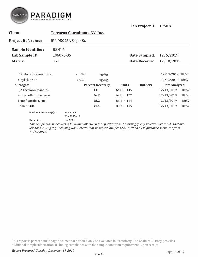
Lab Project ID:
Client:
Project Reference:
Terracon Consultants-NY, Inc.
Lab Sample ID:Sample Identifier:
Matrix:Date Sampled:Date Received:
Method Reference(s):
Data File:
This sample was not collected following SW846 5035A specifications. Accordingly, any Volatiles soil results that are less than 200 ug/Kg, including Non Detects, may be biased low, per ELAP method 5035 guidance document from 11/15/2012.
Surrogate Percent Recovery Limits Date AnalyzedOutliers113 -
76.2 -
98.2 -
91.4 -
Report Prepared Tuesday, December 17, 2019 Page 16 of 29STC-54

Lab Project ID:
Client:
Project Reference:
Terracon Consultants-NY, Inc.
Lab Sample ID:Sample Identifier:
Matrix:Date Sampled:Date Received:
Analyte Result Date AnalyzedQualifierUnits
Petroleum Hydrocarbons by GC
Method Reference(s):
ELAP does not offer this test for approval as part of their laboratory certification program.Preparation Date:
Analyte Result Date AnalyzedQualifierUnits
Volatile Organics
Report Prepared Tuesday, December 17, 2019 Page 17 of 29STC-55
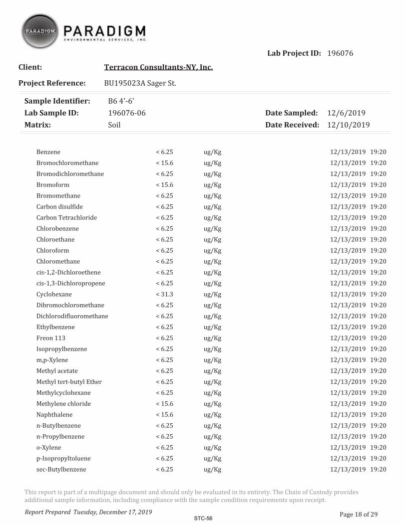
Lab Project ID:
Client:
Project Reference:
Terracon Consultants-NY, Inc.
Lab Sample ID:Sample Identifier:
Matrix:Date Sampled:Date Received:
Report Prepared Tuesday, December 17, 2019 Page 18 of 29STC-56

Lab Project ID:
Client:
Project Reference:
Terracon Consultants-NY, Inc.
Lab Sample ID:Sample Identifier:
Matrix:Date Sampled:Date Received:
Method Reference(s):
Data File:
This sample was not collected following SW846 5035A specifications. Accordingly, any Volatiles soil results that are less than 200 ug/Kg, including Non Detects, may be biased low, per ELAP method 5035 guidance document from 11/15/2012.
Surrogate Percent Recovery Limits Date AnalyzedOutliers113 -
74.4 -
97.8 -
89.2 -
Report Prepared Tuesday, December 17, 2019 Page 19 of 29STC-57

Lab Project ID:
Client:
Project Reference:
Terracon Consultants-NY, Inc.
Lab Sample ID:Sample Identifier:
Matrix:Date Sampled:Date Received:
Analyte Result Date AnalyzedQualifierUnits
Volatile Organics
Report Prepared Tuesday, December 17, 2019 Page 20 of 29STC-58

Lab Project ID:
Client:
Project Reference:
Terracon Consultants-NY, Inc.
Lab Sample ID:Sample Identifier:
Matrix:Date Sampled:Date Received:
Report Prepared Tuesday, December 17, 2019 Page 21 of 29STC-59

Lab Project ID:
Client:
Project Reference:
Terracon Consultants-NY, Inc.
Lab Sample ID:Sample Identifier:
Matrix:Date Sampled:Date Received:
Method Reference(s):
Data File:
This sample was not collected following SW846 5035A specifications. Accordingly, any Volatiles soil results that are less than 200 ug/Kg, including Non Detects, may be biased low, per ELAP method 5035 guidance document from 11/15/2012.
Surrogate Percent Recovery Limits Date AnalyzedOutliers113 -
73.9 -
98.5 -
92.6 -
Report Prepared Tuesday, December 17, 2019 Page 22 of 29STC-60

Lab Project ID:
Client:
Project Reference:
Terracon Consultants-NY, Inc.
Lab Sample ID:Sample Identifier:
Matrix:Date Sampled:Date Received:
Analyte Result Date AnalyzedQualifierUnits
Petroleum Hydrocarbons by GC
Method Reference(s):
ELAP does not offer this test for approval as part of their laboratory certification program.Preparation Date:
Analyte Result Date AnalyzedQualifierUnits
Volatile Organics
Report Prepared Tuesday, December 17, 2019 Page 23 of 29STC-61

Lab Project ID:
Client:
Project Reference:
Terracon Consultants-NY, Inc.
Lab Sample ID:Sample Identifier:
Matrix:Date Sampled:Date Received:
Report Prepared Tuesday, December 17, 2019 Page 24 of 29STC-62

Lab Project ID:
Client:
Project Reference:
Terracon Consultants-NY, Inc.
Lab Sample ID:Sample Identifier:
Matrix:Date Sampled:Date Received:
Method Reference(s):
Data File:
This sample was not collected following SW846 5035A specifications. Accordingly, any Volatiles soil results that are less than 200 ug/Kg, including Non Detects, may be biased low, per ELAP method 5035 guidance document from 11/15/2012.
Surrogate Percent Recovery Limits Date AnalyzedOutliers116 -
73.9 -
98.3 -
88.2 -
Report Prepared Tuesday, December 17, 2019 Page 25 of 29STC-63

SUPPORTING INFORM ATION
SUPPORTING INFORMATION
STC-64

UNIFIED SOIL CLASSIFICATION SYSTEM Sager Drive Improvement Project, PC 16125 ■ Rochester, NY December 24, 2019 ■ Terracon Project No. BU195023A UNIFIED SOIL C LASSIFIC AT ION SYSTEM
Criteria for Assigning Group Symbols and Group Names Using Laboratory Tests A Soil Classification
Group Symbol Group Name B
Coarse-Grained Soils: More than 50% retained on No. 200 sieve
Gravels: More than 50% of coarse fraction retained on No. 4 sieve
Clean Gravels: Less than 5% fines C
Cu 4 and 1 Cc 3 E GW Well-graded gravel F Cu 4 and/or 1 Cc 3 E GP Poorly graded gravel F
Gravels with Fines: More than 12% fines C
Fines classify as ML or MH GM Silty gravel F, G, H Fines classify as CL or CH GC Clayey gravel F, G, H
Sands: 50% or more of coarse fraction passes No. 4 sieve
Clean Sands: Less than 5% fines D
Cu 6 and 1 Cc 3 E SW Well-graded sand I Cu 6 and/or 1 Cc 3 E SP Poorly graded sand I
Sands with Fines: More than 12% fines D
Fines classify as ML or MH SM Silty sand G, H, I Fines classify as CL or CH SC Clayey sand G, H, I
Fine-Grained Soils: 50% or more passes the No. 200 sieve
Silts and Clays: Liquid limit less than 50
Inorganic: PI 7 and plots on or above “A”
JCL Lean clay K, L, M
PI 4 or plots below “A” line J ML Silt K, L, M
Organic: Liquid limit - oven dried
0.75 OL Organic clay K, L, M, N Liquid limit - not dried Organic silt K, L, M, O
Silts and Clays: Liquid limit 50 or more
Inorganic: PI plots on or above “A” line CH Fat clay K, L, M PI plots below “A” line MH Elastic Silt K, L, M
Organic: Liquid limit - oven dried
0.75 OH Organic clay K, L, M, P Liquid limit - not dried Organic silt K, L, M, Q
Highly organic soils: Primarily organic matter, dark in color, and organic odor PT Peat A Based on the material passing the 3-inch (75-mm) sieve B If field sample contained cobbles or boulders, or both, add “with cobbles
or boulders, or both” to group name. C Gravels with 5 to 12% fines require dual symbols: GW-GM well-graded
gravel with silt, GW-GC well-graded gravel with clay, GP-GM poorly graded gravel with silt, GP-GC poorly graded gravel with clay.
D Sands with 5 to 12% fines require dual symbols: SW-SM well-graded sand with silt, SW-SC well-graded sand with clay, SP-SM poorly graded sand with silt, SP-SC poorly graded sand with clay
E Cu = D60/D10 Cc = 6010
230
DxD
)(D
F If soil contains 15% sand, add “with sand” to group name. G If fines classify as CL-ML, use dual symbol GC-GM, or SC-SM.
H If fines are organic, add “with organic fines” to group name. I If soil contains 15% gravel, add “with gravel” to group name. J If Atterberg limits plot in shaded area, soil is a CL-ML, silty clay. K If soil contains 15 to 29% plus No. 200, add “with sand” or “with
gravel,” whichever is predominant. L If soil contains 30% plus No. 200 predominantly sand, add
“sandy” to group name. M If soil contains 30% plus No. 200, predominantly gravel, add
“gravelly” to group name. N PI 4 and plots on or above “A” line. O PI 4 or plots below “A” line. P PI plots on or above “A” line. Q PI plots below “A” line.
STC-65

Page STC-66
STC 6.2 Labor, Products and Storage Under Article 6 Contractor's Responsibilities Subsection 6.2 Labor, Products and Storage, Add the following to the end of 6.2.2: The Water Bureau maintains a list of pre-approved materials for use on all construction projects. The list contains various water system products that are pre-approved for use in conjunction with water work and that do not need to be approved for use by the Project Manager. The Contractor may substitute other equivalent products in the work, with prior approval of the Project Manager and the Water Bureau. The this list may be obtained either by calling the Water Bureau, at (585) 428-7569, or on the City of Rochester’s website, under Services – Contracts, Bids, RFPs – Public Works Construction Documents, Water System Useful Documents, Water Approved Products List. STC 6.4 Concerning Subcontractors and Suppliers Under Article 6 Contractor's Responsibilities Subsection 6.4 Concerning Contractors and Suppliers, Add the following to the end of 6.4.1: The prime Contractor must provide the City with the names of all its Subcontractors and Suppliers to be used on the Project a minimum of 5 days prior to the date of the pre-construction meeting. Subcontractors added to the project after the pre-construction meeting must be submitted to and approved by the City a minimum of 5 days prior to start of their work. All of the Subcontractors and Suppliers must be set up and properly trained in the use of the City’s web based reporting system software prior to the start of work. Under Article 6 Contractor's Responsibilities Subsection 6.2 Labor, Products and Storage, Delete paragraph 6.2.6 in its entirety, and Replace with the following: 6.2.6 The Contractor shall store all materials at approved locations meeting the requirements of paragraph 5.1.2 under Subsection 5.2 Physical Conditions – Investigations and Reports of Article 5 Availability of Lands; Physical Conditions; Reference Points. All materials shall be secure against being a public hazard or nuisance, subject to misuse, theft or damage; all package materials in original containers, clearly identified as to product, manufacturer, brand name, destination and Project number; and all materials under conditions specified or recommended by the manufacturer. Unless otherwise authorized, storage conditions shall exclude the entry of water. Products containing water shall be protected against freezing. Under Article 6 Contractor's Responsibilities, Add the following new subsection: STC 6.21 Additional Pavement Restoration Requirements The City requires that additional pavement restoration is required to be performed for any form of excavation that is done on streets that have been reconstructed within the past 15 years, and on streets that have been rehabilitated within the past 7 years. Additional pavement restoration will consist of the milling and resurfacing of the surrounding pavement area beyond the normal outer extents of an excavation. Additional pavement area is to be milled minimum of 1.5 inches, and resurfaced with the City’s standard asphalt top course mix. The excavation must be backfilled and the pavement base and asphalt binder course(s) restored prior to performing the additional milling and resurfacing operation.

Page STC-67
The overall area of the additional pavement restoration is to be as follows:
- Linear limits for the additional pavement restoration shall extend 10 feet beyond the outer extents of the excavation.
- An excavation that impacts only one side of the street will require a complete mill and
resurface of the impacted side of the street, from the center line to the pavement edge.
- An excavation which traverses across the center line of a street, thus impacting both sides of the street, will require a complete mill and resurface of the impacted street, from pavement edge to pavement edge.
- At locations which include multiple excavation areas that are within 100 linear feet of each
excavation, as measured from center to center of each excavation, the additional pavement restoration work must be extended to encompass all of the excavations into one overall restoration area.
Payment for the additional pavement restoration work will be made per the appropriate unit prices in the contract, or per Article 10.2 Changes in the Contract Price. No payment will be made for additional pavement restoration work that is done at excavations that are the result of the Contractor’s error, convenience, or corrections of previous contract work. STC 9.7 Resolution of Disputes Under Article 9 City Engineer's and Project Manager's Status During Construction Subsection 9.7 Resolutions of Disputes, Delete 9.7.3 in its entirety, and Replace with the following: 9.7.3 If the Contractor claims compensation for any damages sustained by reason of any act or omission of the City, its agents, or employees, or for any other reason whatsoever, it shall, within ten (10) days after such claim shall have arisen, file with the City Engineer written notice of its intention to make claim for such damages. If the Contractor believes its employees or those of its Subcontractors have not been treated fairly and with respect by any employees or agents of the City during this contract, the Contractor shall, within ten (10) days after such incident, file with the City Engineer written notice of the incident. Such notice shall state the nature and amount of the damages sustained or the nature of unfair or disrespectful treatment and the basis for the claim against the City or the nature of the events surrounding the incident. If the City Engineer shall deem it necessary for proper decision upon any notice filed hereunder, to require additional data, depositions or verified statements, the Contractor must furnish the same within ten (10) days after written demand therefore. STC 10.2 Changes in the Contract Price Under Article 10 Changes During the Project Subsection 10.2 Changes in the Contract Price, Delete Subsection 10.2.2 A. Unit Prices in its entirety, and Replace with the following: 10.2.2 A. Unit Price. The unit price may be:
• those submitted by the Contractor in the original bid documents; or
• as stipulated by the City in the contingent item list included with the Contract Documents; or
• as fixed by agreement between the City and the Contractor for extra work items not originally provided for in the Contract Documents; or

Page STC-68
• as adjusted by agreement between the City and the Contractor when the final quantity of a
major item is more than one-hundred and twenty-five percent (125%) or less than seventy-five percent (75%) of the original estimated item quantity provided for in the Contract Documents as delineated below.
When the final quantity of a major item is more than one-hundred and twenty-five percent (125%) or less than seventy-five percent (75%) of the original estimated item quantity, the Contractor or the City may request an adjustment of the bid unit price of the item, or time of performance, if they so desire such adjustment. The request by the Contractor or the City must be in the form of a written notice to the other party, and such written notice must be delivered to the other party within ten (10) work days of the time the party making the request had knowledge of conditions which result in such change in the estimated item quantity. Any allowance for a change in the bid unit price of an item will apply only to that portion of the work that is in excess of one-hundred and twenty-five percent (125%) of the original estimated item quantity, or to the actual amount of work performed if the quantity decreases to be below seventy-five percent (75%) of the original estimated item quantity. The total adjusted payment for all work on a major item that decreases to below seventy-five percent (75%) of the original estimated item quantity, is not to exceed the total payments which would have been made if the original estimated item quantity had been completed at the original bid unit price. No agreed upon change in the bid unit price of an item will constitute a basis for a claim for damages of anticipated profits on the item that was adjusted. Under Article 10 Changes During the Project Subsection 10.2 Changes in the Contract Price, Delete Subsection 10.2.6 Asphalt Price Adjustment, and Replace with the following: 10.2.6 Asphalt Price Adjustment A. The adjustment will provide for either an additional compensation to the Contractor for an increase, or a repayment to the City for a decrease, in the price of asphalt as based on the fixed index price. No adjustment will be made if the monthly average posted price is within fifteen dollars ($15.00) of the fixed index price for asphalt. No consideration will be given to the situation where an individual supplier’s price exceeds the monthly average posted price. Only those items that include asphalt, that are originally in the contract, and that are included in the general specification sections specified below, will be eligible for an asphalt price adjustment:
• R205 – Pavement Base Repair • S205 – Pavement Base Repair • 402 – Hot Mix Asphalt (HMA) Pavements (Superpave mixes) • 403 – Hot Mix Asphalt Concrete Pavement • 403 – Hot Mix Asphalt (HMA) Pavements for Municipalities • R404 – Recycled Asphalt Concrete Pavement • 18410 – Micro-Surfacing • S410 – Micro-Surfacing • S413 – Speed Hump • S608 – Sidewalk and Driveway • S609 – Curb

Page STC-69
B. The adjustment will be based solely on: the quantity of asphalt incorporated in the work, multiplied by the per cent (as expressed in decimals) of performance-graded binder or asphalt cement included in the mix, multiplied by the difference between the herein stipulated fixed index price plus fifteen dollars (+$15.00) when the average posted price increases, minus fifteen dollars (-$15.00) when the average posted price decreases, all as defined below. C. The percentage factor of performance-graded binder or asphalt cement incorporated in the asphalt course mix as expressed in decimals to the nearest thousandth for each asphalt course mix type shall be as follows:
Asphalt Course Mix (Q) Section(s) Factor (F) Type 1 R205-S205-S608-S609 0.060 Type 3 R205-S205-S608 0.065
Type 7F S413 0.080 Truing and Leveling 403 0.080
Recycled Base R404 0.041 Recycled Binder R404 0.046
Recycled Top R404 0.055 Recycled Truing and Leveling R404 0.055 9.5 F2 Top HMA, 80 Series 402 0.062
19 F9 Binder HMA, 80 Series 402 0.049 37.5 F9 Base HMA, 80 Series 402 0.040
HMA Type 1 Base 403 0.050 HMA Type 3 Binder 403 0.055 HMA Type 7F2 Top 403 0.0685
True & Leveling 402-403 based on mix formula at time of construction
Micro-Surfacing Type II 18410-S410 0.090 Micro-Surfacing Type III 18410-S410 0.075
Micro-Surfacing Type III Rut Filling 18410-S410 0.075
D. Fixed Index Price: A fixed index price per ton of performance-graded binder used solely as a basis from which to compute price adjustments. The fixed index price for original contract bid items and additional work at the original contract bid price, will be will be the monthly average posted price for the month of the bid letting. The index price for additional work not in the original contract and added by an agreed price, will be the monthly average posted price for the month the agreed price was approved by the City. E. Monthly Average Posted Price: The monthly average terminal price for unmodified PG 64-22 binder, without anti-stripping agent, will be determined by the State of New York Department of Transportation, as based on prices from approved primary sources of performance-graded binder, during the life of this Contract.

Page STC-70
F. A listing of the average posted prices for asphalt (performance-graded binder), is posted on or about the twenty-fifth (25th) of each month by the State of New York Department of Transportation in an Engineering Bulletin entitled Fuel, Asphalt and Steel price Adjustments. G. Also all discounts or allowances that reduce the asphalt price at the terminal will be deducted prior to calculating the price adjustment. H. Price adjustment will be based on the following formulas:
1). When average posted price increases:
Price Adjustment = [ (𝐴𝐴𝐴𝐴𝐴𝐴) − (𝐹𝐹𝐹𝐹𝐴𝐴 + $15.00) ] 𝑥𝑥 [ (𝑄𝑄) 𝑥𝑥 (𝐹𝐹) ]
2). When average posted price decreases:
Price Adjustment = [ (𝐴𝐴𝐴𝐴𝐴𝐴) − (𝐹𝐹𝐹𝐹𝐴𝐴 − $15.00) ] 𝑥𝑥 [ (𝑄𝑄) 𝑥𝑥 (𝐹𝐹) ] Where:
APP = Average posted price for the month within which the work is performed
FIP = Fixed index price for the month of the bid letting
Q = Asphalt course mix quantity incorporated in the work as expressed in tons
F = Percentage factor of performance-graded binder or asphalt cement incorporated in the asphalt course mix as expressed in decimals to the nearest thousandth
I. A price adjustment will be paid in addition to, or deducted from, the monthly estimate for material placed during the previous month. The average posted price is updated on or about the twenty-fifth (25th) of each month, with the price adjustment becoming effective on the first (1st) of the following month. All price changes received after the third (3rd) Wednesday of the month will be held in abeyance until the next scheduled price revision. J. This asphalt price adjustment is based solely on changes in the price of unmodified PG 64-22 binder, without anti-stripping agent. The fact that an individual asphalt supplier’s price exceeds the average posted price or that of a particular asphalt item such as emulsion base is more costly than unmodified PG 64-22 binder will have no bearing on the price adjustment. K. If asphalt items are placed after the completion date specified in this contract or after any extensions of that date with engineering charges and/or liquidated damages, the average posted price used to compute price adjustments shall not exceed the average posted price on the original scheduled contract completion date. If the contract completion date is extended without the assessment of engineering charges, price adjustments for material placed during such extensions shall be based on the latest updated average posted price. L. No price adjustment will be made unless the average posted price is either fifteen dollars ($15.00) greater than or fifteen dollars ($15.00) less than the fixed index price stated above. All price adjustments will be rounded to the nearest dollar. STC 10.4 Liquidated Damages Under Article 10 Changes During the Project, Delete Subsection 10.4 Liquidated Damages in its entirety, and Replace with the following:
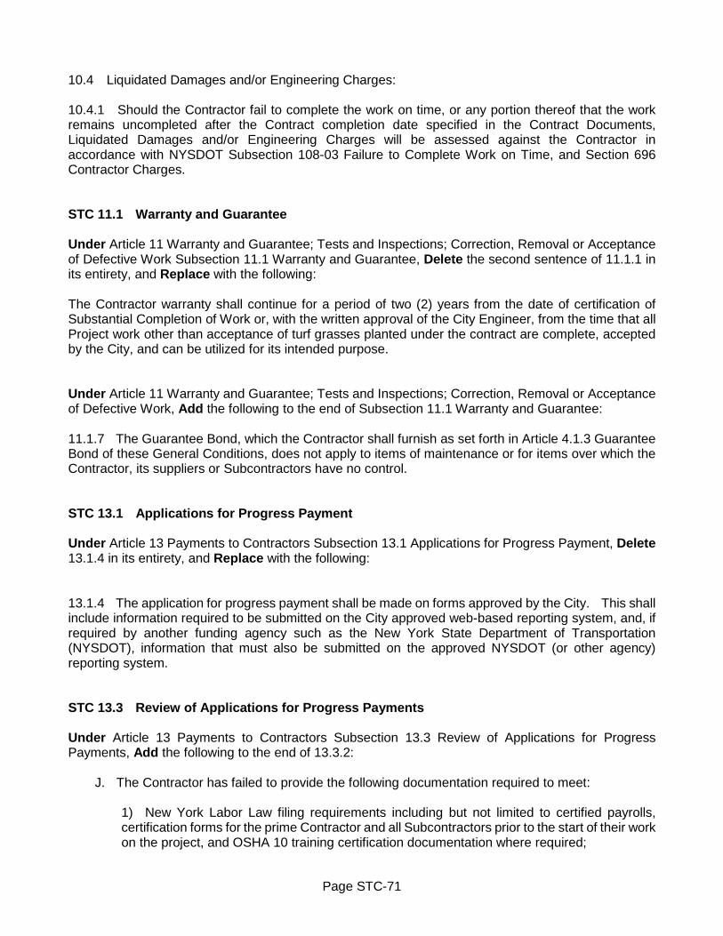
Page STC-71
10.4 Liquidated Damages and/or Engineering Charges: 10.4.1 Should the Contractor fail to complete the work on time, or any portion thereof that the work remains uncompleted after the Contract completion date specified in the Contract Documents, Liquidated Damages and/or Engineering Charges will be assessed against the Contractor in accordance with NYSDOT Subsection 108-03 Failure to Complete Work on Time, and Section 696 Contractor Charges. STC 11.1 Warranty and Guarantee Under Article 11 Warranty and Guarantee; Tests and Inspections; Correction, Removal or Acceptance of Defective Work Subsection 11.1 Warranty and Guarantee, Delete the second sentence of 11.1.1 in its entirety, and Replace with the following: The Contractor warranty shall continue for a period of two (2) years from the date of certification of Substantial Completion of Work or, with the written approval of the City Engineer, from the time that all Project work other than acceptance of turf grasses planted under the contract are complete, accepted by the City, and can be utilized for its intended purpose. Under Article 11 Warranty and Guarantee; Tests and Inspections; Correction, Removal or Acceptance of Defective Work, Add the following to the end of Subsection 11.1 Warranty and Guarantee: 11.1.7 The Guarantee Bond, which the Contractor shall furnish as set forth in Article 4.1.3 Guarantee Bond of these General Conditions, does not apply to items of maintenance or for items over which the Contractor, its suppliers or Subcontractors have no control. STC 13.1 Applications for Progress Payment Under Article 13 Payments to Contractors Subsection 13.1 Applications for Progress Payment, Delete 13.1.4 in its entirety, and Replace with the following: 13.1.4 The application for progress payment shall be made on forms approved by the City. This shall include information required to be submitted on the City approved web-based reporting system, and, if required by another funding agency such as the New York State Department of Transportation (NYSDOT), information that must also be submitted on the approved NYSDOT (or other agency) reporting system. STC 13.3 Review of Applications for Progress Payments Under Article 13 Payments to Contractors Subsection 13.3 Review of Applications for Progress Payments, Add the following to the end of 13.3.2:
J. The Contractor has failed to provide the following documentation required to meet:
1) New York Labor Law filing requirements including but not limited to certified payrolls, certification forms for the prime Contractor and all Subcontractors prior to the start of their work on the project, and OSHA 10 training certification documentation where required;

Page STC-72
2) M/W/DBE and/or workforce goal requirements of the Contract.
The City reserves the right to withhold five percent (5%) of the balance of the application for payment after deduction of the five percent (5%) completion retainage as provided in Section 13.4 Retainage until all such required documentation applicable to the payment application has been provided. Under Article 13 Payments to Contractors Subsection 13.3 Review of Applications for Progress Payments, Add the following: 13.3.4 In accordance with General Municipal Law Section 106-B Payment on Public Work Projects, the Contractor shall pay any Subcontractor(s) for undisputed work performed by the Subcontractor(s) within seven (7) days of receipt of payment by the City which includes such work.

SPECIAL NOTES
PAGE SN-1 Access for Persons with Disabilities ................................................................................... SN-1
SN-2 Special Events ................................................................................................................... SN-1
SN-3 Work Day ........................................................................................................................... SN-1
SN-4 Restoration Time Restrictions – Liquidated Damages ........................................................ SN-2
SN-5 Restoration of Areas Adjacent to Planned Work ................................................................. SN-2
SN-6 Restoration of Sidewalk, Sidewalk Access Ramps, Driveways and .................................... SN-3 Temporary Sidewalk Restoration
SN-7 Sidewalk Access Ramps and Detectable Warning Surface Installation .............................. SN-3
SN-8 Asphalt Top Course - Tapered Wedge Joint ...................................................................... SN-3
SN-9 Asphalt Pavement Joint Adhesive ...................................................................................... SN-4
SN-10 Catch Basins and Sewer Manholes Castings ..................................................................... SN-4
SN-11 Improper Casting Adjustment ............................................................................................. SN-4
SN-12 Loop Detectors ................................................................................................................... SN-5
SN-13 Pavement Markings ........................................................................................................... SN-5
SN-14 Preformed Thermoplastic Reflectorized Pavement Markings ............................................. SN-6
SN-15 Survey Work for Sidewalks and Curb Ramps ..................................................................... SN-6
SN-16 Utilities and Coordination with Utility Schedule ................................................................... SN-6
SN-17 Milling and Resurfacing Operations .................................................................................... SN-7
SN-18 Cleaning, Sealing and/or Filling all Joints and Cracks on Milled Pavement ........................ SN-8
SN-19 Driveway Apron Restoration for Milling and Resurfacing Projects ...................................... SN-8
SN-20 Spot Repair of Curb, Concrete Gutter and Sidewalk for Milling and ................................... SN-8 Resurfacing Projects
SN-21 Surface Drainage for Milling and Resurfacing Projects ....................................................... SN-8

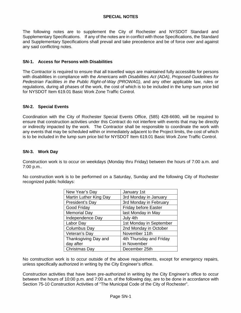
Page SN-1
SPECIAL NOTES
The following notes are to supplement the City of Rochester and NYSDOT Standard and Supplementary Specifications. If any of the notes are in conflict with those Specifications, the Standard and Supplementary Specifications shall prevail and take precedence and be of force over and against any said conflicting notes. SN-1. Access for Persons with Disabilities The Contractor is required to ensure that all travelled ways are maintained fully accessible for persons with disabilities in compliance with the Americans with Disabilities Act (ADA), Proposed Guidelines for Pedestrian Facilities in the Public Right-of-Way (PROWAG), and any other applicable law, rules or regulations, during all phases of the work, the cost of which is to be included in the lump sum price bid for NYSDOT Item 619.01 Basic Work Zone Traffic Control. SN-2. Special Events Coordination with the City of Rochester Special Events Office, (585) 428-6690, will be required to ensure that construction activities under this Contract do not interfere with events that may be directly or indirectly impacted by the work. The Contractor shall be responsible to coordinate the work with any events that may be scheduled within or immediately adjacent to the Project limits, the cost of which is to be included in the lump sum price bid for NYSDOT Item 619.01 Basic Work Zone Traffic Control. SN-3. Work Day Construction work is to occur on weekdays (Monday thru Friday) between the hours of 7:00 a.m. and 7:00 p.m.. No construction work is to be performed on a Saturday, Sunday and the following City of Rochester recognized public holidays:
New Year’s Day January 1st Martin Luther King Day 3rd Monday in January President’s Day 3rd Monday in February Good Friday Friday before Easter Memorial Day last Monday in May Independence Day July 4th Labor Day 1st Monday in September Columbus Day 2nd Monday in October Veteran’s Day November 11th Thanksgiving Day and day after
4th Thursday and Friday in November
Christmas Day December 25th No construction work is to occur outside of the above requirements, except for emergency repairs, unless specifically authorized in writing by the City Engineer’s office. Construction activities that have been pre-authorized in writing by the City Engineer’s office to occur between the hours of 10:00 p.m. and 7:00 a.m. of the following day, are to be done in accordance with Section 75-10 Construction Activities of “The Municipal Code of the City of Rochester”.

Page SN-2
SN-4. Restoration Time Restrictions – Liquidated Damages In addition to the liquidated damages that are assessed in accordance with Subsection 10.4 Liquidated Damages Article 10 Changes During the Project of the General Terms and Conditions Section of the Contract Documents, additional liquidated damages will be assessed for failure to complete restoration work that is not completed within the following specified time frames.
A. Restoration of Areas Adjacent to Planned Work: Areas adjacent to the planned work that are disturbed by the Contractor’s operations must be restored in-kind to pre-existing or better condition within twenty-one (21) calendar days of the original start of work at that area. Should the Contractor fail to complete the restoration work on time, or any portion thereof that the restoration work remains uncompleted, liquidated damages will be assessed in accordance with Subsection 10.4 Liquidated Damages Article 10 Changes During the Project of the General Terms and Conditions Section of the Contract Documents in an amount of $50.00 per calendar day per negligent location. The restoration work required at each repair site will be inspected within the above stated time frame. If a location requires a re-inspection of any non-compliant restoration work after the first inspection, additional liquidated damages will be assessed against the Contractor in an amount of $10.00 per location per re-inspection. Refer to Special Note SN-5 Restoration of Areas Adjacent to Planned Work for additional information. B. Sidewalk Restoration: Concrete placement for sidewalk areas and sidewalk access ramps must be poured within fourteen (14) calendar days of the area having been excavated. Should the Contractor fail to complete the sidewalk restoration work on time, or any portion thereof that the sidewalk restoration work remains uncompleted, liquidated damages will be assessed in accordance with Subsection 10.4 Liquidated Damages Article 10 Changes During the Project of the General Terms and Conditions Section of the Contract Documents in an amount of $150.00 per calendar day per negligent location. Refer to Special Note SN-6 Sidewalk, Sidewalk Access Ramps, Driveways and Temporary Sidewalk Restoration for additional information.
SN-5. Restoration of Areas Adjacent to Planned Work Restoration of existing areas that are adjacent to the planned work are subject to liquidated damages. Refer to Special Note SN-4 Restoration Time Restrictions – Liquidated Damages for additional information. Existing areas that are adjacent to the planned work and are disturbed by the Contractor’s construction activities must be restored in-kind to pre-existing or better condition as outlined below. Perimeter of paved areas that are disturbed are to be saw cut full depth, along straight lines, and with squared corners. Bricks/stone pavers are to be replaced in whole units only, with the replacement units matching as much as possible existing units in size, shape and color. The restoration work is to be done such that the pattern, grades and cross slope are consistent with the existing surrounding area. On-site borrow material may be used to backfill the disturbed and low lawn areas to within 4 inches of finished surface, topped with 4 inches of topsoil and seeded. On-site borrow material is to be thoroughly compacted and free of grass clumps, tree roots, stones larger than 1 inch in size, pieces of asphalt, concrete and any other extraneous material.

Page SN-3
The Contractor is hereby notified that the City will strictly enforce the above stated restoration requirements with respect to the prompt restoration of adjacent property that is disturbed by the Contractor’s construction activities. SN-6. Restoration of Sidewalk, Sidewalk Access Ramps, Driveways and Temporary Sidewalk Restoration Restoration of concrete sidewalk areas, including sidewalk access ramps, are subject to liquidated damages. Refer to Special Note SN-4 Restoration Time Restrictions – Liquidated Damages for additional information. No driveway, including the adjacent sidewalk area, is to be excavated on a Friday or the day before a legal holiday. Permanent driveway restoration must be completed within six (6) calendar days of the original excavation. Temporary sidewalk restoration must be provided when the pedestrian pathway is unavailable on the opposite side of the street, or when excavated sidewalk areas cannot be poured within fourteen (14) calendar days of original excavation. Temporary sidewalk section consists of a minimum 2 inch thick compacted hot mix asphalt material. The Contractor is to maintain the temporary sidewalk areas in a good non-hazardous condition at all times, including thru any winter shut-down period. The Contractor is to check all temporary sidewalk locations on a weekly basis, taking any measures necessary to correct any deficiencies by the end of the following day. No separate payment will be made for furnishing and installing temporary sidewalk. Payment for temporary sidewalk is included in the lump sum price bid for NYSDOT Item 619.01 Basic Work Zone Traffic Control. SN-7. Sidewalk Access Ramps and Detectable Warning Surface Installation All sidewalk access ramps are to be in compliance with Proposed Guidelines for Pedestrian Facilities in the Public Right-of-Way (PROWAG), and constructed in conformance with Section S608 Sidewalk and Driveway, and to the dimensional requirements and uniform pattern as shown on the detail drawings. Detectable warning surfaces are to be installed at all sidewalk access ramps within the Project limits. This will apply to both new sidewalk access ramp construction, and existing sidewalk access ramps without existing detectable warning system. SN-8. Asphalt Top Course - Tapered Wedge Joint The Contractor is required to use a tapered wedge joint (Michigan wedge joint) on all longitudinal joints with the placement of asphalt top course. The tapered wedge joint is to be constructed in accordance with NYSDOT Section 402-3.09B 2 Option B – Tapered Wedge Joint, with the use of an approved notched wedge joint apparatus.

Page SN-4
SN-9. Asphalt Pavement Joint Adhesive The Contractor is required to use asphalt pavement joint adhesive on vertical faces of new HMA top surface course for all longitudinal and transverse joints, and where it butts up against curb or other appurtenances. Asphalt pavement joint adhesive is also to be used on vertical faces of either new HMA base or binder course where it is anticipated it will be left open to traffic over winter layover or longer. SN-10. Catch Basins and Sewer Manholes Castings The Rochester Pure Waters District (RPWD) must have access to its sewer facilities at all times, including but not limited to catch basins and sewer manholes. If at any time the RPWD cannot access its sewer facilities, it will be the responsibility of the Contractor to provide access. The Contractor is to supply the MCPW Dispatch Center with an emergency contact phone list, which will be instructed to contact the Contractor in the event that such access is necessary. The Contractor shall adjust, or replace existing catch basin and sewer manhole castings as required in Contract Documents and as directed by the Project Manager. All new catch basin installations, and existing catch basin and sewer manhole castings that are adjusted or replaced, require the installation of a concrete collar in accordance with Section S604 Catch Basin and Sewer Manhole. Where the Contractor elects to cut pavement area for concrete collar installation and leave core in place for removal at later time, the void must be filled-in by end of that day. Voids are not to be left unfilled overnight. Use asphalt cold patch, millings or other asphalt material to fill-in the void, with material brought up to grade and flush with the surrounding surface, and with the top being level and smooth. SN-11. Improper Casting Adjustment The Contractor’s attention is drawn to NYSDOT Section 402-3.10 Surface Tolerance in the New York State Department of Transportation Standard Specifications, to which these Contract Documents are in reference to. These surface tolerances also apply to castings within the pavement area of newly paved streets. These castings include those adjusted by others, as it is the Contractor’s responsibility to supervise finish grade elevations. If the variation exceeds the tolerances as stated under NYSDOT Section 402-3.10 Surface Tolerance due to the Contractor’s operations, the Contractor will again adjust the castings to finish grade to the satisfaction of the Project Manager, at no additional cost to the City. If the corrective action results in a pavement cut, the Contractor will have $500.00 per pavement cut deducted from the progress payment for extended maintenance. Minimum size of corrective pavement cut shall extend 3 feet beyond and all around the casting. Pavement cut shall be a regular shape such as a square or rectangle. Restored pavement section shall be equal to that of the intended section.

Page SN-5
SN-12. Loop Detectors It will be the Contractor’s responsibility to contact the Monroe County Department of Transportation (MCDOT) and/or New York State Department of Transportation (NYSDOT) for assistance in determining the exact location of existing loop detectors in the field before any work is started on any street. This is imperative even though the loop detectors may be scheduled for removal as part of the work. All loop detectors located within the milling limits shall be removed via the milling operation. All loop detectors within areas that are to be overlaid or micro-paved only, shall be retained unless otherwise directed by the Project Manager. MCDOT will replace all loop detectors as necessary. Any damage to existing loop detectors outside of sketched Project limits as a result of the Contractor’s operations, shall be corrected by the Contractor to the satisfaction of MCDOT and/or NYSDOT, at no additional cost to the City. SN-13. Pavement Markings The Project includes the installation of temporary and permanent pavement markings. The locations and type of all pavement markings are shown on the Contract drawings. The Contractor shall not remove pavement markings and leave the street unmarked or un-delineated overnight. If temporary pavement delineation (in lieu of pavement markings) is not applied before the end of the work day, the Contractor will have $500.00 per calendar day deducted from the progress payment for each street not delineated.
A. Temporary Pavement Markings: All newly paved streets up to and including the binder course, must be delineated by the end of each work day with temporary pavement markings. Temporary pavement markings will include centerline and long line stripes along with symbols, in pattern similar to the existing pavement marking layout. Temporary pavement marking edge lines, crosswalks, stop bars, gores and letters are not required to be installed. No separate payment will be made for furnishing and installing temporary pavement markings. Payment for temporary pavement markings is included in the lump sum price bid for NYSDOT Item 619.01 Basic Work Zone Traffic Control. B. Interim Pavement Markings: Interim pavement marking stripes and symbols shall be installed immediately after asphalt top placement, and before the end of the work day. Interim pavement markings shall be installed consistent with the permanent pavement marking layout. Interim pavement marking of edge lines, crosswalks, stop bars, gores and letters are not required to be installed. Interim pavement markings will be paid for under unit price bid for NYSDOT Items 619.100101 Interim Pavement Markings, Stripes and Item 619.100201 Interim Pavement Markings, Symbols. C. Permanent Pavement Markings: The work involves furnishing and applying permanent pavement marking materials at the locations and in accordance with patterns as shown on the plans, and as required by MCDOT and as directed by the Project Manager.

Page SN-6
SN-14. Preformed Thermoplastic Reflectorized Pavement Markings The Contractor shall provide a material with a surface friction level equivalent to or better than the existing pavement, which may require the application of a non-skid treatment as recommended by the manufacturer, at no additional cost to the City. SN-15. Survey Work for Sidewalks and Curb Ramps The Contractor shall be responsible for field verifying all elevations and dimensions to ensure that the final layout of sidewalks, curb ramps and blended transitions meet the Proposed Guidelines for Pedestrian Facilities in the Public Right-of-Way (PROWAG) requirements prior to pouring concrete, or placing asphalt or pavers. The survey work necessary to meet these requirements shall be included in the cost of NYSDOT Item 625.01 Survey Operations, except where the appropriate pay item basis of payment includes the necessary survey work. SN-16. Utilities and Coordination with Utility Schedule It will be the Contractor's responsibility to contact Dig Safely NY by calling 811, and the owners of private and public utilities within the street for a stakeout of all utilities, including castings. The Contractor shall familiarize itself with the existence of all utility features on the Project Site and see that reasonable opportunity and cooperation is extended to the operators of such utility features in their work of protecting, reconstructing or altering them. The Contractor shall cooperate with the utility operators, and arrange or adjust its work schedule to coordinate the work with the utility operators. In the case of interference and/or lack of cooperation between the operations of the utilities and the Contractor, the City may adjust the schedule of the Contractor and the sequence of the work as necessary to expedite the completion of the work. All known public and private utility installations within the Contract limits and their disposition are shown in their approximate locations in the Contract Documents. The Contractor is, however, cautioned that these locations are not guaranteed, nor is there any guarantee that all such facilities within the Contract limits have been shown on the plans. In this regard, the Contractor's attention is called to Article 5 Subsection 5.6 Utilities of the General Terms and Conditions, and Subsection 9.D Excavation and Prohibition of Blasting near Public and Private Utility Pipes of the Laws and Regulations, of the Contract Documents. Utilities encountered during the work shall be maintained and protected in their existing locations until otherwise provided for. If unknown utility facilities are encountered, then excavation and grading shall be done with caution in order that these facilities are not disturbed until proper disposition of such is made by their owner. Damage by the Contractor to privately owned utilities shall be in all cases the responsibility of the Contractor. Relocation of public utilities and accessories is a responsibility of the Contractor as part of this Project. Every reasonable attempt will be made by the Project Manager not to unduly inconvenience or additionally cost the Contractor due to such locations relating to time and/or place; however, no extra compensation will be made to the Contractor by the City for extra work or loss of time due to such utilities or the removal or relocation of such utilities. The Contractor shall notify the Engineer, in writing, at least fourteen (14) days in advance of any work which may affect any utility or cause an interruption or disruption of utility service.

Page SN-7
It shall be the Contractor's duty to notify all utility companies or other parties affected within a time frame as not to affect the schedule prior to all necessary adjustment of the utility facilities within or adjacent to the limits of construction. The Contractor shall notify the Project Manager in writing describing the need for, and extent of, utility adjustments and the anticipated schedule. It will be the Contractor's responsibility to contact the Rochester Water Bureau to inspect existing water valves prior to the final paving of the street. Water valve castings in good condition that are removed or damaged by the Contractor’s operations, are to be replaced with new water valve casting provided and installed by and at the Contractor’s expense. In these instances, the Contractor will be paid only for a water valve adjustment at those locations. SN-17. Milling and Resurfacing Operations The Contractor shall resurface the milled pavement within a maximum of seven (7) calendar days of commencement of the milling operation, unless additional time is needed to complete pavement repairs. Any additional time shall be reviewed and approved by the Project Manager. If the Contractor fails to resurface all or any portion of the street within the required time frame, the Contractor will have $1.00 per linear foot per calendar day deducted from the progress payment for every linear foot of the street that has not been resurfaced. This stipulation may be waived by the Project Manager where the Contractor has to make extensive base repairs to the street before the street can be resurfaced. Projects with multiple streets, once started the milling operation on any single street must be completed in its entirety before the Contractor can start the milling operation on another street. For better control of and coordination of the milling operation with the resurfacing work, no street shall be milled without the express permission of the Project Manager. The milling operation shall not be considered complete nor the street considered fit for resurfacing until the Contractor has completed the milling work operation in its entirety, including all hand removal of existing pavement around utility appurtenances, cleaning of milled pavement surface; cleaning, sealing and/or filling all underlying joints and cracks; installation of pads around utility appurtenances; and installation of all required construction signs, barricades, flashers and other traffic maintenance and protection devices to maintain and protect pedestrians and vehicular traffic. Milled street may require a truing and leveling asphalt course in order to maintain the existing pavement structure. Placement of the truing and leveling course does not constitute a release to proceed with milling operations on another street, unless approved otherwise by the Project Manager. The edge at the limit of the milling operation and all other adjacent pavement surfaces shall not have a difference in elevation of greater than 1/2 inch at the end of each work day. At the end of each work day, the edge between the milled surface and all adjacent pavement surfaces must be padded with cold patch asphalt or fresh millings placed and compacted at a 1 on 12 slope, or the edge wedge milled at a 1 on 12 slope. All existing utility appurtenances with a difference in elevation of greater than 1/4 inch must be padded all around at the end of each work day with cold patch asphalt or fresh millings placed and compacted at a 1 on 12 slope. All pads shall be inspected on a daily basis, and maintained in good condition. Any pads that are deteriorated are to be immediately repaired before the end of the work day. All pads shall remain in place and shall not be removed until the day the street is to be resurfaced.

Page SN-8
SN-18. Cleaning, Sealing and/or Filling all Joints and Cracks on Milled Pavement Before repaving any milled pavement, all existing unsealed and/or inadequately sealed cracks and joints are to be cleaned of all extraneous materials, and thoroughly sealed in accordance with NYSDOT Items 633.12 Cleaning, Sealing and/or Filling Cracks and 633.13 Cleaning, Sealing and/or Filling Joints. SN-19. Driveway Apron Restoration for Milling and Resurfacing Projects Driveway aprons which are contiguous to the new pave pavement and do not have header curb, shall be adjusted and repaired as directed by the Project Manager. Driveway apron that is 4 feet and less in length between the edge of the pavement and the sidewalk will be replaced in its entirety. Driveway apron that is greater than 4 feet in length between the edge of the pavement and the sidewalk will be repaired as directed by the Project Manager. SN-20. Spot Repair of Curb, Concrete Gutter and Sidewalk for Milling and Resurfacing Projects On a street where the spot repair of the existing curb, concrete gutter and/or sidewalk is to be done, a field walk of the street is to be done between the Contactor, Project Manager and Project Representative, before starting any work on that street. The areas of the spot repair work is to be mutually agreed upon and clearly delineated by spray paint or other means at that time. SN-21. Surface Drainage for Milling and Resurfacing Projects The lump sum bid price for NYSDOT Item 625.01 Survey Operations is intended for survey related work which may be necessary to achieve proper drainage on a street. Before starting work on any street, a field walk of each street is to be held between the Contractor and Project Manager to evaluate existing surface drainage to determine if grading adjustments are necessary. It is the Contractor’s responsibility to adjust and pave longitudinal grades and pavement cross-slopes to ensure that each street has been graded and otherwise prepared to eliminate existing surface drainage issues and to provide positive surface drainage. In addition to adjustment of longitudinal grades and pavement cross-slope, other remediation actions may necessitate additional milling, installation of truing and leveling course, adjustment of existing catch basins, installation of new catch basins, and any other remediation work deemed necessary by mutual agreement. Any corrective measures necessary to correct surface drainage issues after completion of the paving operation, shall be undertaken by the Contractor at no additional cost to the City.

SUPPLEMENTARY SPECIFICATIONS
PAGE S203 EXCAVATION AND EMBANKMENT.................................................................................. SS-1 S205 PAVEMENT BASE REPAIR AND PAVEMENT REPLACEMENT ...................................... SS-6 304 SUBBASE COURSE ........................................................................................................ SS-10 402 HOT MIX ASPHALT (HMA) PAVEMENTS ....................................................................... SS-11 S407 TACK COAT .................................................................................................................... SS-12 S412 TEMPORARY PAVEMENT .............................................................................................. SS-14 418 ASPHALT PAVEMENT JOINT ADHESIVE ...................................................................... SS-17 490 COLD MILLING ................................................................................................................ SS-18 555 STRUCTURAL CONCRETE ............................................................................................ SS-19 S601 SEWER LATERAL AND CONNECTION .......................................................................... SS-20 S604 CATCH BASIN AND SEWER MANHOLE ........................................................................ SS-26 S605 UNDERDRAIN ................................................................................................................. SS-48 607 FENCES (607.91000011 PIPE RAIL FENCE – 2 RAIL) ................................................... SS-52 S608 SIDEWALK AND DRIVEWAY .......................................................................................... SS-55 S609 CURB............................................................................................................................... SS-92 S610 LANDSCAPE ................................................................................................................. SS-104 S613 TOPSOIL ....................................................................................................................... SS-113 S614 CARE OF PLANTS ........................................................................................................ SS-117 S617 TREE PROTECTION ..................................................................................................... SS-121 619 WORK ZONE TRAFFIC CONTROL ............................................................................... SS-124 625 SURVEY OPERATIONS ................................................................................................ SS-125 S626 SURVEY MONUMENT .................................................................................................. SS-126 627 CUTTING PAVEMENT .................................................................................................. SS-139 633 CONDITIONING EXISTING PAVEMENT PRIOR TO HOT MIX ASPHALT (HMA)
OVERLAY ...................................................................................................................... SS-140 S637 FIELD OFFICE ............................................................................................................... SS-141 S643 PARKING METER POST AND SIGN POST SLEEVE ................................................... SS-148 S671 STREET LIGHTING ....................................................................................................... SS-151 685 EPOXY REFLECTORIZED PAVEMENT MARKINGS .................................................... SS-170
686 WHITE PREFORMED THERMOPLASTIC REFLECTORIZED PAVEMENT STRIPES .. SS-171 C686 (C686.520604) CONDUIT PVC SCHEDULE 80 – 4” DIA ............................................... SS-173 698 PRICE ADJUSTMENTS ................................................................................................. SS-174
699 MOBILIZATION .............................................................................................................. SS-175 S900 GENERAL WATER PROVISIONS ................................................................................. SS-176 S901 WATER MAIN PIPE AND FITTINGS.............................................................................. SS-184 S903 RESILIENT SEAT GATE VALVE WITH VALVE BOX .................................................... SS-195 S904 TAPPING SLEEVE WITH VALVE AND VALVE BOX ..................................................... SS-198 S907 CONNECT NEW WATER MAIN TO EXISTING WATER MAIN ...................................... SS-201 S908 CUT AND PLUG EXISTING WATER MAIN ................................................................... SS-203 S909 WATER VALVE BOX ..................................................................................................... SS-205

S912 CORPORATION STOP AND CONNECTION; ABANDON EXISTING WATER SERVICE AT TAP (2 INCH AND SMALLER) ................................................................. SS-209 S913 WATER SERVICE (2 INCH AND SMALLER) ................................................................. SS-213 S914 CURB STOP AND BOX ................................................................................................. SS-220 S917 HYDRANT ..................................................................................................................... SS-225 S966 MAGNESIUM ANODE ................................................................................................... SS-230 S999 PROJECT SIGN ............................................................................................................ SS-234

Page SS-1
SECTION S203 - EXCAVATION AND EMBANKMENT S203 GENERAL References to NYSDOT specifications are to be in accordance with latest edition of NYSDOT Standard Specifications (US Customary Units). Work is to be in accordance with requirements of NYSDOT Sections 203 Excavation and Embankment and 204 Controlled Low Strength Material (CLSM), with following modifications: S203-1 DESCRIPTION Under NYSDOT Section 203-1.01 Definitions, DELETE Subsection 203-1.01A Unclassified Excavation in its entirety and REPLACE with following:
A. Unclassified Excavation. Estimated limits and descriptions of subsurface deposits, formations and facilities which may be shown on plans, are supplied in accordance with Paragraph 5.2.1, Article 5 Availability of Lands; Physical Conditions; Reference Points of General Terms and Conditions of City of Rochester Standard Construction Contract Documents.
Under NYSDOT Section 203-1.01 Definitions, ADD following:
Q. Rock Excavation. Rock excavation consists of boulders exceeding 1/2 cubic yard in volume; and ledge rock which cannot in opinion of Project Manager, be removed without blasting or use of pneumatic hammers. Concrete pavements and pavement foundations, and sewers and their appurtenances will not be considered rock. Rock excavation for trenches or test pits will be included in Section R206 Trench and Culvert Excavation.
R. Backfill - Recycled or Reclaimed Materials. Pulverized or recycled concrete aggregate and brick are unacceptable for use as backfill material.
S203-2 MATERIALS At end of NYSDOT Section 203-2 Materials, ADD following: S203-2.15 Backfill - General Recycled materials, pulverized or recycled portland cement concrete aggregate (RCA) and brick, reclaimed asphalt pavement (RAP), and Corian® are unacceptable for use as backfill or bedding materials, unless specifically authorized in writing by City Engineer. S203-2.16 Select Granular Backfill (Sewer/Water) - General Select granular backfill (sewer/water) materials are to consist of sand and gravel, approved blast furnace slag, or stone, and are to be well graded from coarse to fine, and free from organic or other deleterious material. Materials will be accepted on basis of Magnesium Sulfate Soundness Loss after 4 cycles of 20 percent or less. Plasticity index of material passing number 40 Screen is not to exceed 5.0. Not more than 30 percent by weight of particles retained on 1/2 inch screen are to consist of flat or elongated particles. Flat or elongated particles are defined as one which has as its greatest dimension more than three times its least dimension. Acceptance for this requirement will normally be based on

Page SS-2
visual inspection by Project Manager. When City elects to test for this requirement, material which has percentage greater than allowable 30 percent will be rejected. Materials are to meet specified gradation prior to placement, with processing completed at plant. S203-2.17 Stone Bedding Stone bedding material is to be crushed stone primary size type 1, or mixture of primary sizes type 1 and type 2, washed, in accordance with requirements of NYSDOT Material Section 703-02 Coarse Aggregate, material designation 703-0201. S203-2.18 Sand Sand material is to consist of clean, hard, durable, uncoated particles, free from lumps of clay and other deleterious substances. When dry, sand material is to be in accordance with following gradation requirements:
Screen Size Percent Passing by Weight 1/4 inch 100%
#50 5 to 35% #100 0 to 10%
Sand material is to have minimum resistivity of 15,000 Ohm-cm, and maximum chloride ion concentration of 50 parts per million (ppm). Sand material may be determined to be unacceptable if it contains loam or silt in excess of 10 percent of total volume. S203-2.19 Select Granular Backfill (Sewer) Select granular backfill (sewer) material is to be used for backfilling of trenches and excavations for catch basin, lateral pipe and other sewer related work. Select granular backfill (sewer) material is to be in accordance with following gradation requirements:
Screen Size Percent Passing by Weight 2 inch 100%
1/4 inch 30 to 65% #40 5 to 40%
#200 0 to 10% S203-2.20 Select Granular Backfill (Water) Select granular backfill (water) material is to be used for backfilling of trenches and excavations for water related work. Select granular backfill (water) material is to be in accordance with following gradation requirements:
Screen Size Percent Passing by Weight 3 inch 100% 2 inch 90 to 100%
1/4 inch 30 to 65% #40 5 to 40%
#200 0 to 10%

Page SS-3
S203-2.21 Controlled Low Strength Material (CLSM) Material and testing requirements for CLSM is to be in accordance with NYSDOT Section 204 Flowable Fill. CLSM provided for use in backfilling around Water facilities, is to have a compressive strength of 50 to 100 pounds per square inch, and must not contain fly ash or other pozzolan containing materials. S203-3 CONSTRUCTION DETAILS Under NYSDOT Subsection 203-3.01B Scheduling of Work to Minimize Soil Erosion and Water Pollution, ADD following:
Work is to be progressed in such manner that exposed, unprotected surface area of any earth material that is subject to erosion by wind or water, will not exceed total of 10,000 square feet at any given time. Work progression includes any special soil erosion, water and air pollution measures required in Supplementary Conditions.
Under NYSDOT Subsection 203-3.02B Disposal of Surplus Excavated Materials, ADD following:
Surplus excavated materials that are to be disposed of are not to be stockpiled on Project site. Surplus excavated materials are to be disposed of off-site within 24 hours.
At end of NYSDOT Section 203-3 Construction Details, ADD following: S203-3.15 Select Granular Backfill, Stone Bedding, and Sand Select granular backfill, stone bedding, and sand materials are to be placed as required in Contract Documents. Compaction is to be in accordance with requirements of NYSDOT Subsection 203-3 Construction Details. S203-3.16 Controlled Low Strength Material (CLSM) Construction details for CLSM is to be in accordance with NYSDOT Section 204 Flowable Fill. CLSM may only be used on case by case basis, and when specifically authorized in writing by City Engineer. Where water main pipe crosses sewer pipe and has less than minimum separation requirements either horizontally or vertically, all of joints of water main pipe located within 10 feet of sewer pipe are to be encased with CLSM. CLSM encasement is to be placed to minimum thickness of 6 inches around water main pipe for minimum length of 2 feet as centered on joint of water main pipe. S203-4 METHOD OF MEASUREMENT At end of NYSDOT Section 203-4 Method of Measurement, ADD following: S203-4.15 Rock Excavation Quantity to be measured for payment will be number of cubic yards of rock excavated, as computed in original position and to payment lines as specified in Contract Documents.

Page SS-4
S203-4.16 Stone Bedding, Sand and Select Granular Backfill (Sewer/Water) Quantity to be measured for payment will be number of cubic yards of material satisfactorily placed and compacted, as measured in completed work within payment lines specified in Contract Documents, less measured volume for pipes that exceed 12 inches in diameter as based on nominal diameter, and for all catch basin and manhole structures. No additional quantity will be measured for payment to make up losses due to foundation settlement, compaction, erosion or any other cause. S203-4.17 Controlled Low Strength Material (CLSM) Quantity to be measured for payment will be number of cubic yards of material satisfactorily placed, as measured in completed work within payment lines specified in Contract Documents or from payment lines established in writing by Project Manager, less measured volume for pipes that exceed 12 inches in diameter as based on nominal diameter, and for all other payment items when combined cross-sectional area exceeds 144 square inches, unless otherwise shown in Contract Documents. No deduction will be made for cross-sectional area of an existing facility. No additional quantity will be measured for payment to make up losses due to foundation settlement, compaction, erosion or any other cause. Cross sectioning, for purpose of determining quantities for payment, will be employed only where payment lines are not shown in Contract Documents, and cannot be reasonably established by Project Manager. S203-5 BASIS OF PAYMENT At end of NYSDOT Section 203-5 Basis of Payment, ADD following: S203-5.15 Rock Excavation Unit price bid includes cost of: excavation; disposal of excavated material; blasting; and furnishing all labor, material and equipment necessary to complete work. S203-5.16 Stone Bedding, Sand and Select Granular Backfill (Sewer/Water) Unit price bid includes cost of: furnishing, placing and compacting material; and furnishing all labor, material and equipment necessary to complete work. S203-5.17 Controlled Low Strength Material (CLSM) Unit price bid includes cost of: furnishing and placing material; and furnishing all labor, material and equipment necessary to complete work. Payment will be made under: ITEM NO. ITEM PAY UNIT S203.22 Rock Excavation and Disposal Cubic Yard S203.25 Stone Bedding Cubic Yard S203.26 Sand Cubic Yard

Page SS-5
ITEM NO. ITEM PAY UNIT S203.28 Select Granular Backfill (Sewer) Cubic Yard S203.29 Select Granular Backfill (Water) Cubic Yard S203.35 Controlled Low Strength Fill Material Cubic Yard S203.36 Controlled Low Strength Fill Material (no Fly Ash) Cubic Yard REVISED July 23, 2019

Page SS-6
SECTION S205 – PAVEMENT BASE REPAIR AND PAVEMENT REPLACEMENT S205-1 DESCRIPTION Work consists of repair of small sections of existing pavement base, or replacement of existing pavement section over utility trenches, as required in Contract Documents and as directed by Project Manager. References to NYSDOT specifications are to be in accordance with latest edition of NYSDOT Standard Specifications (US Customary Units). S205-2 MATERIALS S205-2.01 Select Granular Fill Select granular fill is to be in accordance with NYSDOT Section 203 Excavation and Embankment. S205-2.02 Subbase Course Subbase course material is to be Type 1 and Type 2 in accordance with NYSDOT Section 304 Subbase Course, with following modification: Recycled materials, pulverized or recycled portland cement concrete aggregate (RCA) and brick, reclaimed asphalt pavement (RAP), and Corian® are unacceptable for use as subbase course materials, unless specifically authorized in writing by City Engineer. S205-2.03 Asphalt Asphalt is to be 80 series compaction, 9.5 F2 top course HMA, 19 F9 binder course HMA, and 37.5 F9 base course HMA, in accordance with NYSDOT Section 402 Hot Mix Asphalt (HMA) Pavements. S205-2.04 Tack Coat Tack coat is to be diluted or straight tack coat mix in accordance with Section S407 Tack Coat. S205-2.05 Concrete Concrete is to be PCC foundation for pavement, class C or class F, in accordance with NYSDOT Section 503 Portland Cement Concrete Foundation for Pavement. S205-2.06 Pavement Saw Cut Pavement saw cut is to be full depth pavement saw cut in accordance with Section R622 Saw Cutting. S205-3 CONSTRUCTION DETAILS S205-3.01 General Outer limits of repair/replacement areas will be as required in Contract Documents, and as approved by Project Manager. Outer limits of existing pavement area to be repaired/replaced are to be saw cut along neat lines, and

Page SS-7
to full depth of pavement with power pavement saw with diamond or abrasive blade designed for such work Saw cut edge is to be clean, dry and shaped so that square shoulder is provided in direction of traffic. Existing pavement section is to be excavated to neat lines, removed and properly disposed of. Care is to be taken to prevent any undermining of adjacent pavement section, or damage from occurring to finished top course of adjacent pavement. Pavement section is to be constructed on sound thoroughly compacted subbase. Repair and thoroughly compact pavement subbase as necessary. For small areas, either hand operated vibrating tamper or power jumping jack may be used for compaction purposes. Tack coat is to be applied on top of concrete base, and between all courses of HMA lifts. S205-3.02 Pavement Base Repair Area to be repaired is to be excavated to depth that is sufficient to remove existing failed base materials, and any underlying unsuitable materials. Excavation is to be backfilled to bottom of pavement base material with select granular fill in 6 inch lifts compacted to no less than 95 per cent of Standard Proctor Maximum Density. For concrete base repair pavement section, use minimum 8 inches concrete and 2 inches HMA binder course. For asphalt base repair pavement section, use 8 or 6 inches HMA base course for commercial streets, and 3 inches HMA base course for residential streets and alleyways. HMA base course is to be topped with 2 inches HMA binder course. S205-3.03 Pavement Replacement Concrete pavement replacement section will be as noted in Contract Documents. For asphalt base repair pavement section, use 5 inches subbase course type 1; 6 inches subbase course type 2; 8 or 6 inches HMA base course for commercial streets, 3 inches HMA base course for residential streets and alleyways. HMA base course is to be topped with 2 inches HMA binder course and 1-1/2 inches HMA top course. S205-3.04 Work Zone Traffic Control (WZTC) For bid item description that include WZTC, basic WZTC devices and work is to be provided in accordance with Section S619 Work Zone Traffic Control and NYSDOT Section 619 Work Zone Traffic Control. For work on arterial streets and work zones that are more involved in scope and time, use of additional WZTC devices and work will be required. Additional WZTC plan and layout will be as required by City. S205-4 METHOD OF MEASUREMENT Quantity to be measured for payment will be number of square yards of pavement repaired/replaced. For pavement base repair, maximum depth of repair area to be included in pay item will be 24 inches. For items with measurement range, measurement range as noted is for total number of square yards

Page SS-8
repaired or restored for single area. Quantity to be measured for payment will be number of square yards of pavement repaired/replaced as measured to nearest tenth of foot (0.10’) S205-5 BASIS OF PAYMENT S205-5.01 Pavement Base Repair Unit price bid includes cost of: full depth pavement saw cut; excavation and disposal of excavated materials; furnishing, placing and compacting select granular fill; class C or F PCC foundation, or HMA base course; HMA binder course; furnishing and placing tack coat; and furnishing all labor, material and equipment necessary to complete work. For areas of pavement base repair that are more than 24 inches deep, additional excavation and select granular fill will be paid under separate bid items. HMA top course will be paid under separate bid item. S205-5.02 Pavement Replacement Unit price bid includes cost of: full depth pavement saw cut; excavation and disposal of excavated materials; furnishing, placing and compacting subbase course type 1 and type 2; class C or F PCC foundation, or HMA base course; HMA binder course; HMA top course; furnishing and placing tack coat; and furnishing all labor, material and equipment necessary to complete work. S205-5.03 Work Zone Traffic Control (WZTC) WZTC will be paid for under separate bid item or included in unit price bid for item as indicated in item description. WZTC that is included in bid item is for basic WZTC devices and work. For work on arterial streets and work zones that are more involved in scope and time, requiring more than basic WZTC, only direct costs of additional WZTC devices and work required for those situations will be paid for under separate bid item. Payment will be made under:
Note: XX in bid item number and X inch in item description represents thickness of asphalt base. i.e.: 8 inch asphalt base will be bid as S205.110809 Pavement Base Repair – Asphalt Base (8 inch) -
0 to 9 SY Area (Including WZTC). ITEM NO. ITEM PAY UNIT S205.0101 Pavement Base Repair – Concrete Base Square Yard S205.0201 Pavement Base Repair – Asphalt Base (8 inch) Square Yard S205.0202 Pavement Base Repair – Asphalt Base (6 inch) Square Yard S205.0301 Pavement Base Repair – Asphalt Base (3 inch) Square Yard S205.04 Pavement Replacement - Concrete Base Square Yard S205.05 Pavement Replacement - Asphalt Base (3 inch) Square Yard S205.06 Pavement Replacement - Asphalt Base (6 inch) Square Yard S205.07 Pavement Replacement - Asphalt Base (8 inch) Square Yard S205.100009 Pavement Base Repair – Concrete Base – 0 to 9 SY Area Square Yard (Including WZTC)
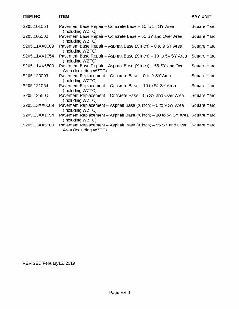
Page SS-9
ITEM NO. ITEM PAY UNIT S205.101054 Pavement Base Repair – Concrete Base – 10 to 54 SY Area Square Yard (Including WZTC) S205.105500 Pavement Base Repair – Concrete Base – 55 SY and Over Area Square Yard (Including WZTC) S205.11XX0009 Pavement Base Repair – Asphalt Base (X inch) – 0 to 9 SY Area Square Yard (Including WZTC) S205.11XX1054 Pavement Base Repair – Asphalt Base (X inch) – 10 to 54 SY Area Square Yard (Including WZTC) S205.11XX5500 Pavement Base Repair – Asphalt Base (X inch) – 55 SY and Over Square Yard Area (Including WZTC) S205.120009 Pavement Replacement – Concrete Base – 0 to 9 SY Area Square Yard (Including WZTC) S205.121054 Pavement Replacement – Concrete Base – 10 to 54 SY Area Square Yard (Including WZTC) S205.125500 Pavement Replacement – Concrete Base – 55 SY and Over Area Square Yard (Including WZTC) S205.13XX0009 Pavement Replacement – Asphalt Base (X inch) – 0 to 9 SY Area Square Yard (Including WZTC) S205.13XX1054 Pavement Replacement – Asphalt Base (X inch) – 10 to 54 SY Area Square Yard (Including WZTC) S205.13XX5500 Pavement Replacement – Asphalt Base (X inch) – 55 SY and Over Square Yard Area (Including WZTC) REVISED Febuary15, 2019

Page SS-10
SECTION 304 - SUBBASE COURSE 304 GENERAL Purpose of this directive is to designate certain NYSDOT bid items for use on all City projects. References to NYSDOT specifications are to be in accordance with latest edition of NYSDOT Standard Specifications (US Customary Units). Work is to be in accordance with requirements of NYSDOT Section 304 Subbase Course for following bid items, and with following modifications: 304-2 MATERIALS At end of NYSDOT Section 304-2 Materials, ADD following: Recycled materials, pulverized or recycled portland cement concrete aggregate (RCA) and brick, reclaimed asphalt pavement (RAP), and Corian® are unacceptable for use as subbase course materials, unless specifically authorized in writing by City Engineer. 304-5 BASIS OF PAYMENT Payment will be made under: ITEM NO. ITEM PAY UNIT 304.11 Subbase Course, Type 1 Cubic Yards 304.12 Subbase Course, Type 2 Cubic Yards 304.13 Subbase Course, Type 3 Cubic Yards 304.14 Subbase Course, Type 4 Cubic Yards 304.15 Subbase Course, Optional Type Cubic Yards REVISED July 1, 2017

Page SS-11
SECTION 402 - HOT MIX ASPHALT (HMA) PAVEMENTS 402 GENERAL Purpose of this directive is to designate certain NYSDOT bid items for use on all City projects. References to NYSDOT specifications are to be in accordance with latest edition of NYSDOT Standard Specifications (US Customary Units). Work is to be in accordance with requirements of NYSDOT Section 402 Hot Mix Asphalt (HMA) Pavements for following bid items, and with following modifications: 402-3 CONSTRUCTION DETAILS UNDER Subsection 402-3.09 Joints, at the end of 402-3.09B Longitudinal Joints DELETE fifth paragraph in its entirety and REPLACE with following: When paving top course Contractor is required to use tapered wedge joint (Michigan wedge joint) on all longitudinal joints. Butt joint may be used for top course in select situations only, and only with prior approval of Project Manager. Use butt joint for all other HMA courses. 402-5 BASIS OF PAYMENT Payment will be made under: ITEM NO. ITEM PAY UNIT 402.000013 Plant Production Quality Adjustment to HMA Items Quality Unit 402.000023 Pavement Density Quality Adjustment to HMA Items Quality Unit 402.000053 Test Section Adjustment to HMA Items Quality Unit 402.017903 True & Leveling F9, Superpave HMA, 70 Series Compaction Ton 402.018903 True & Leveling F9, Superpave HMA, 80 Series Compaction Ton 402.096203 9.5 F2 Top Course HMA, 60 Series Compaction Ton 402.097203 9.5 F2 Top Course HMA, 70 Series Compaction Ton 402.098203 9.5 F2 Top Course HMA, 80 Series Compaction Ton 402.196903 19 F9 Binder Course HMA, 60 Series Compaction Ton 402.197903 19 F9 Binder Course HMA, 70 Series Compaction Ton 402.198903 19 F9 Binder Course HMA, 80 Series Compaction Ton 402.376903 37.5 F9 Base Course HMA, 60 Series Compaction Ton 402.377903 37.5 F9 Base Course HMA, 70 Series Compaction Ton 402.378903 37.5 F9 Base Course HMA, 80 Series Compaction Ton 402.418903 9.5 F9 Temporary Top Course HMA, 80 Series Compaction Ton 402.438903 19 F9 Temporary Binder Course HMA, 80 Series Compaction Ton REVISED December 9, 2019

Page SS-12
SECTION S407 – TACK COAT S407-1 DESCRIPTION Work consists of preparing and treating portland cement concrete and hot mix asphalt (HMA) surfaces with tack coat as required in Contract Documents and as directed by Project Manager. References to NYSDOT specifications are to be in accordance with latest edition of NYSDOT Standard Specifications (US Customary Units). S407-2 MATERIALS Tack coat is to meet requirements of NYSDOT Section 702 Bituminous Materials for following emulsion grades:
Asphalt Emulsion – Diluted Tack Coat 702-3401 Asphalt Emulsion – Straight Tack Coat 702-3002
S407-3 CONSTRUCTION DETAILS S407-3.01 General Diluted tack coat is to be used for conventional hot mix asphalt (HMA) pavements, and is to be applied between all lifts of HMA courses. Diluted tack coat is to be applied on top of milled pavement surface, and on top of concrete base. Straight tack coat may be used for conventional hot mix asphalt (HMA) pavement overlay, only if existing pavement is not milled. Straight tack coat may also be used on steeper graded pavements, for nighttime paving operations, or for late season paving. S407-3.02 Equipment Distributor is to be designed, equipped, maintained and operated so that tack coat can be heated and applied uniformly at readily determined and controlled rates and with uniform pressure, on pavement surfaces of variable widths, up to 15 feet wide. Distributor equipment is to include quantity measuring system and thermometer for measuring temperature of tank contents. Prior to being used, equipment is to be calibrated in accordance with ASTM D 2995 Standard Practice for Estimating Application Rate of Bituminous Distributors, or any other equivalent calibration procedure acceptable to Project Manager. Project Manager will witness equipment calibration, or require Contractor to provide documentation certifying calibration. Distributor is to be equipped with power unit for pump, and circulation spray bars which are adjustable both laterally and vertically. Bristle broom that drags on pavement behind spray bars may be attached to distributor, and is adjustable both laterally and vertically so that full width of tack coat being applied is bristled uniformly onto pavement surface. Distributor is to be equipped with bituminous material sampling valve attached to distributor. When samples are taken through sampling valve, samples will be considered representative of all material in tank. Distributor tank is to be equipped with an agitator that is capable of ensuring tack coat remains homogeneous, and that tack coat stored in distributor tank is heated and maintained at temperature of between 85°F and 160°F. Hand operated spray units will be permitted only in areas where use of distributor is impractical.

Page SS-13
S407-3.03 Application Tack coat is to be uniformly applied across width of designated area by pressure distributor onto prepared clean pavement surface. Tack coat is to be applied to offer least inconvenience to traffic and to permit one-way traffic where practical, to prevent pickup or tracking of tack coat material. Tack coat is not to be applied on wet pavement surface, or when pavement surface temperature is below 40°F. Recommended application rate in gallons per square yard is:
Surface Type Application Rate
(gallons per square yards) Diluted Tack
Coat Straight Tack
Coat New Hot Mix Asphalt (HMA) 0.05 – 0.06 0.03 – 0.04
Milled Surface and Existing Hot Mix Asphalt (HMA) 0.08 – 0.10 0.05 – 0.06 Portland Cement Concrete 0.08 – 0.10 0.05 – 0.06
Vertical Surfaces (curbs, drainage structures, miscellaneous
appurtenances) 0.09 – 0.11 0.06 – 0.07
These are recommended application rates for tack coat on various surface types and may be modified as approved of by Project Manager. S407-4 METHOD OF MEASUREMENT Quantity to be measured for payment will be number of square yards of pavement surface treated, or number of gallons of tack coat applied. Number of gallons of tack coat will be as measured at 60ºF to nearest gallon. S407-5 BASIS OF PAYMENT Unit price bid includes cost of: preparation of pavement surface; furnishing and applying tack coat; and furnishing all labor, material and equipment necessary to complete work. Payment will be made under: ITEM NO. ITEM PAY UNIT S407.0201 Diluted Tack Coat Square Yard S407.0202 Straight Tack Coat Square Yard S407.0301 Diluted Tack Coat Gallon S407.0302 Straight Tack Coat Gallon REVISED May 1, 2013

Page SS-14
SECTION S412 - TEMPORARY PAVEMENT S412 GENERAL Work consists of construction of temporary pavement for maintenance of vehicular and pedestrian traffic as required in Contract Documents and as directed by Project Manager. References to NYSDOT specifications are to be in accordance with latest edition of NYSDOT Standard Specifications (US Customary Units). S412-2 MATERIALS S412-2.01 Temporary Pavement Following materials are acceptable for use:
• Asphalt pavement 19 F9 binder course HMA 80 series compaction in accordance with NYSDOT Section 402 Hot Mix Asphalt (HMA) Pavements
• Recycled asphalt top or binder course in accordance with Section R404 Recycled Asphalt Concrete Pavement
• Asphalt millings Asphalt millings are to be product of milling of existing asphalt concrete pavement. Asphalt millings are to be free of organic materials, gravel, crushed stone or any other material not direct product of milling process. S412-2.02 Temporary Pavement - Winter Season Temporary pavement section for winter season is to be unreinforced Class F concrete in accordance with NYSDOT Section 503 Portland Cement Concrete Foundation for Pavement. S412-2.03 Subbase Course Subbase course material is to be Type 1 and Type 2 in accordance with NYSDOT Section 304 Subbase Course, with following modification: Recycled materials, pulverized or recycled portland cement concrete aggregate (RCA) and brick, reclaimed asphalt pavement (RAP), and Corian® are unacceptable for use as subbase course materials, unless specifically authorized in writing by City Engineer. S412-2.04 Tack Coat Tack coat is to be diluted or straight tack coat mix in accordance with Section S407 Tack Coat. S412-3 CONSTRUCTION DETAILS S412-3.01 General Temporary pavement section is to be constructed over trenches and other excavated areas where directed by Project Manager to maintain vehicular or pedestrian traffic. Temporary pavement section is to be constructed within 24 hours after having received written notice from Project Manager.
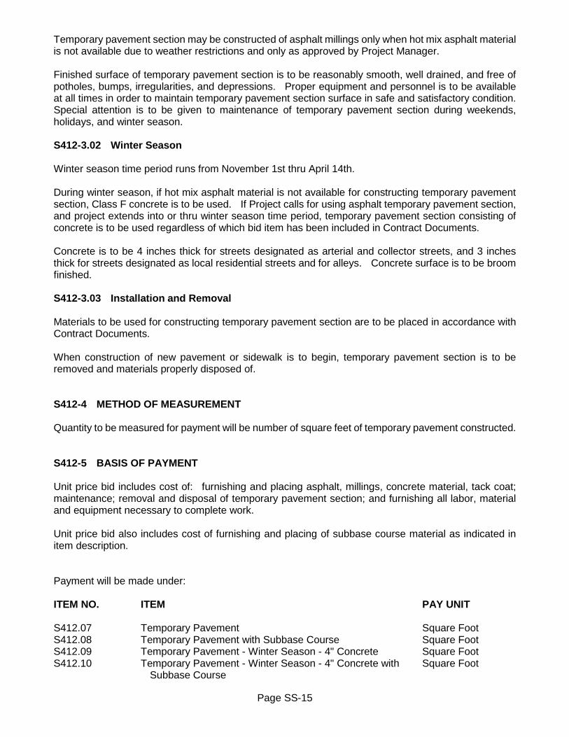
Page SS-15
Temporary pavement section may be constructed of asphalt millings only when hot mix asphalt material is not available due to weather restrictions and only as approved by Project Manager. Finished surface of temporary pavement section is to be reasonably smooth, well drained, and free of potholes, bumps, irregularities, and depressions. Proper equipment and personnel is to be available at all times in order to maintain temporary pavement section surface in safe and satisfactory condition. Special attention is to be given to maintenance of temporary pavement section during weekends, holidays, and winter season. S412-3.02 Winter Season Winter season time period runs from November 1st thru April 14th. During winter season, if hot mix asphalt material is not available for constructing temporary pavement section, Class F concrete is to be used. If Project calls for using asphalt temporary pavement section, and project extends into or thru winter season time period, temporary pavement section consisting of concrete is to be used regardless of which bid item has been included in Contract Documents. Concrete is to be 4 inches thick for streets designated as arterial and collector streets, and 3 inches thick for streets designated as local residential streets and for alleys. Concrete surface is to be broom finished. S412-3.03 Installation and Removal Materials to be used for constructing temporary pavement section are to be placed in accordance with Contract Documents. When construction of new pavement or sidewalk is to begin, temporary pavement section is to be removed and materials properly disposed of. S412-4 METHOD OF MEASUREMENT Quantity to be measured for payment will be number of square feet of temporary pavement constructed. S412-5 BASIS OF PAYMENT Unit price bid includes cost of: furnishing and placing asphalt, millings, concrete material, tack coat; maintenance; removal and disposal of temporary pavement section; and furnishing all labor, material and equipment necessary to complete work. Unit price bid also includes cost of furnishing and placing of subbase course material as indicated in item description. Payment will be made under: ITEM NO. ITEM PAY UNIT S412.07 Temporary Pavement Square Foot S412.08 Temporary Pavement with Subbase Course Square Foot S412.09 Temporary Pavement - Winter Season - 4" Concrete Square Foot S412.10 Temporary Pavement - Winter Season - 4" Concrete with Square Foot Subbase Course

Page SS-16
ITEM NO. ITEM PAY UNIT S412.11 Temporary Pavement - Winter Season - 3" Concrete Square Foot S412.12 Temporary Pavement - Winter Season - 3" Concrete with Square Foot Subbase Course REVISED July 1, 2017
Page SS-17
SECTION 418 – ASPHALT PAVEMENT JOINT ADHESIVE 418 GENERAL Purpose of this directive is to designate certain NYSDOT bid items for use on all City projects. References to NYSDOT specifications are to be in accordance with latest edition of NYSDOT Standard Specifications (US Customary Units). Asphalt pavement joint adhesive is to be used on vertical faces of new HMA top surface course for all longitudinal and transverse joints, and where it butts up against curb or other appurtenances. Asphalt pavement joint adhesive is also to be used on vertical faces of either new HMA base or binder course where it is anticipated it will be left open to traffic over winter layover or longer. Work is to be in accordance with requirements of NYSDOT Section 418 Asphalt Pavement Joint Adhesive for following bid item: 418-5 BASIS OF PAYMENT Payment will be made under: ITEM NO. ITEM PAY UNIT 418.7603 Asphalt Pavement Joint Adhesive Linear Foot ISSUED January 1, 2017

Page SS-18
SECTION 490 – COLD MILLING 490 GENERAL Purpose of this directive is to designate certain NYSDOT bid items for use on all City projects. References to NYSDOT specifications are to be in accordance with latest edition of NYSDOT Standard Specifications (US Customary Units). Work is to be in accordance with requirements of NYSDOT Section 490 – Cold Milling for following bid item: 490-5 BASIS OF PAYMENT Payment will be made under: ITEM NO. ITEM PAY UNIT 490.30 Miscellaneous Cold Milling of Bituminous Concrete Square Yard ISSUED February 25, 2020

Page SS-19
SECTION 555 – STRUCTURAL CONCRETE 555 GENERAL Purpose of this directive is to designate certain NYSDOT bid items for use on all City projects. References to NYSDOT specifications are to be in accordance with latest edition of NYSDOT Standard Specifications (US Customary Units). Work is to be in accordance with requirements of NYSDOT Section 555 – Structural Concrete for following bid item: 555-5 BASIS OF PAYMENT Payment will be made under: ITEM NO. ITEM PAY UNIT 555.0105 Concrete for Structures, Class A Cubic Yard ISSUED February 25, 2020
Page SS-20
SECTION S601 - SEWER LATERAL AND CONNECTION S601 GENERAL Work is to be in accordance with requirements of Section R601 Sewer Lateral and Connection, with following modifications: References to NYSDOT specifications are to be in accordance with latest edition of NYSDOT Standard Specifications (US Customary Units). S601-2 MATERIALS At end of Section R601-2 Materials, ADD following: S601-2.10 Polyvinyl Chloride Branch Polyvinyl chloride (PVC) wye and tee branches are to be SDR35 PVC gasketed fittings in accordance with requirements of ASTM D3034. S601-2.11 Inserta Tee Inserta tee is to be three piece compression fitted cored connection consisting of SDR35 PVC gasketed hub, rubber sleeve and stainless steel band, in accordance with requirements of ASTM D3034 and ASTM F477. S601-2.12 Cement Mortar Cement mortar for plugging abandoned lateral pipe is to be regular cement mortar, Type II cement. S601-3 CONSTRUCTION DETAILS At beginning of Section R601-3 Construction Details, ADD following: District must have access to its facilities at all times. If at any time District cannot access its facilities, it will be responsibility of Contractor to provide access. Contractor is to supply MCPW Dispatch Center with an emergency contact phone list, and will contact Contractor in event access is necessary. Construct all sewer appurtenances in accordance with these specifications and with the specifications of Rochester Pure Waters District (RPWD). Notify Monroe County Pure Waters (MCPW) minimum of 48 hours in advance when planning on working adjacent to existing Monroe County fiber optic utilities/facilities, by calling (585) 753-7600, option 5. Take appropriate measures to prevent dirt, debris and construction materials from entering sewer appurtenances during construction of project. Any such invasive materials are to be removed immediately and contaminated appurtenance thoroughly cleaned. RPWD must be notified immediately in event of any damage to existing sewer appurtenances, by calling (585) 753-7600, option 1. All repairs are to be performed in presence of representative of RPWD and are to be made in accordance with requirements of RPWD. RPWD will not mark private service laterals. Contractor will be responsible for repair of any laterals

Page SS-21
damaged during construction activities. If available, record maps indicating lateral wye locations or recorded wyes/taps may be obtained by contacting MCPW records room by calling (585) 753-7651 weekdays between hours of 8:00AM and 4:00PM. In event existing sewer main or lateral pipe is broken during construction, any and all repairs must be extended linearly. Introducing new bends in pipe will not be permitted. All 5 inch inside diameter lateral pipe is to be repaired using 5 inch service weight cast iron pipe and Fernco couplers. All other sizes of lateral pipe are to be repaired with SDR-21 PVC pipe and Fernco couplers. Contractor may be permitted to use oakum and epoxy mortar to connect new PVC pipe to an existing bell that is in good condition. Stone bedding material used for sewer main and lateral pipe repairs is to be Class B consisting of #1 and #2 washed stone at minimum depth of 6 inches. Any new catch basin lateral pipe installed within public right-of-way is to be SDR-21 PVC pipe in accordance with ASTM D-2241. Joints on horizontal lateral pipe and bends are to be push-on neoprene gaskets. Glued or chemically welded joints are unacceptable. Any dedicated mainline sewer pipe and associated fittings are to be SDR-35 PVC in accordance with ASTM D-3034. DELETE Subsection R601-3.05C Lateral Connection to Existing Lateral in its entirety, and REPLACE with following: C. Connect New Lateral Pipe to Existing Lateral Pipe
Remove sufficient length of existing lateral pipe to make proper connection, and any additional existing lateral pipe that is found to be unstable or otherwise damaged. Before connecting new lateral pipe, field cut new lateral pipe to obtain square plain ends at right angles to line of existing lateral pipe. Connect new lateral pipe to existing lateral pipe with new flexible rubber joint connector with stainless steel shear rings and bands.
DELETE Subsection R601-3.06C Branch Connection to Existing Sewer in its entirety, and REPLACE with following: C. Branch Connection to Existing Sewer
On existing sewer pipe, expose portion of existing sewer pipe to either install new branch fitting, or to core an opening in existing sewer pipe. 1. On existing sewer pipe that is less than 2 times size of new lateral pipe, remove sufficient length of existing sewer pipe necessary to properly install new branch. Open ends of remaining existing sewer pipe are to be field cut to square plain end that is at right angle to existing sewer pipe. Connection is to be made with new flexible rubber joint connector with stainless steel shear rings and bands. 2. On existing sewer pipe that is larger than 2 times size of new lateral pipe, and on all reinforced concrete sewer pipe, core hole in sewer pipe with rotary core drill equipped with diamond bit. No other method of coring an opening is acceptable. Cored hole is to be as small as practical to accommodate new saddle, and tight fit made with 100 percent solids epoxy mortar.
Face of existing sewer pipe to be cored is to be exposed from crown to invert for minimum length

Page SS-22
of 12 inches along existing sewer pipe. Take necessary precautions to prevent damage to existing sewer pipe, and to prevent debris from entering sewer pipe. Core is to be made minimum of 6 inches away from existing sewer pipe hubs. Before making connection, thoroughly clean opening and surface of sewer pipe of all foreign matter and loose particles.
At end of Subsection R601-3.06 Branch Connections, ADD following: D. Polyvinyl Chloride Branch at New Sewer Pipe
Polyvinyl chloride (PVC) branches are to be installed along with installation of new sewer pipe. New or existing lateral pipe is to be connected to branch.
E. Inserta Tee Connection to Existing Sewer Pipe
Core hole in existing sewer pipe with inserta tee hole saw, other hole saws, pneumatic devices or hammering knock-out methods are not acceptable for creating opening. Size of cored opening is limited to one-half nominal diameter of existing mainline sewer pipe. Face of existing sewer pipe to be cored is to be exposed from crown to invert for minimum length of 12 inches along existing sewer pipe. Take necessary precautions to prevent damage to existing sewer pipe, and to prevent debris from entering sewer pipe. Core is to be made minimum of 6 inches away from existing sewer pipe hubs. Before making connection, thoroughly clean opening and surface of sewer pipe of all foreign matter and loose particles.
At end of Section R601-3 Construction Details, ADD following: S601-3.07 Abandon Existing Lateral Pipe Existing lateral pipe is to be abandoned in place and open end plugged. Where existing lateral pipe is connected to structure, connection is to be abandoned by plugging lateral pipe at structure, and mortaring over opening in structure with cement mortar. Where existing lateral pipe is open ended, open end is to be abandoned by plugging lateral pipe. If necessary, remove short section of existing lateral pipe before abandoning lateral pipe. Where existing lateral pipe is 6 inch diameter and smaller, insert rubber gasketed mechanical type permanent plug into open end of lateral pipe. Where existing lateral pipe is over 6 inch diameter, fill open end with brick until opening is plugged as much as possible. Completely fill and seal any remaining void with cement mortar. S601-4 METHOD OF MEASUREMENT At end of Section R601-4 Method of Measurement, ADD following: S601-4.05 Polyvinyl Chloride Branch and Inserta Tee Quantity to be measured for payment will be number of wye or tee branches, or inserta tee connections installed.

Page SS-23
S601-4.06 Abandon Existing Lateral Pipe Quantity to be measured for payment will be number of lateral pipes abandoned. S601-5 BASIS OF PAYMENT At end of Subsection R601-5.05 Branch Connections, ADD following: D. Polyvinyl Chloride Branch at Existing Sewer Pipe - Installed
Unit price bid includes cost of: excavation; backfill; stone bedding; select granular backfill (sewer); full pavement or pavement base restoration; sheeting; shoring; maintenance of sewage flow; pumping; bailing; furnishing and installing polyvinyl chloride branch; preparing and cutting existing sewer pipe; connecting polyvinyl chloride branch to existing sewer pipe; flexible rubber joint connector with stainless steel shear rings and bands; replacing any portion of existing sewer pipe damaged during work; connecting lateral pipe to branch; and furnishing all labor, material and equipment necessary to complete work.
E. Polyvinyl Chloride Saddle Branch at Existing Sewer Pipe - Installed
Unit price bid includes cost of: excavation; backfill; stone bedding; select granular backfill (sewer); full pavement or pavement base restoration; sheeting; shoring; maintenance of sewage flow; pumping; bailing; furnishing, installing and sealing polyvinyl chloride saddle branch; preparing existing sewer pipe; coring hole in existing sewer pipe; connecting polyvinyl chloride saddle branch to existing sewer pipe; epoxy mortar; replacing any portion of existing sewer pipe damaged during work; connecting lateral pipe to branch; and furnishing all labor, material and equipment necessary to complete work.
F. Polyvinyl Chloride Branch at New Sewer Pipe
Unit price bid includes cost of: furnishing and installing polyvinyl chloride branch; connecting polyvinyl chloride branch to existing sewer pipe; connecting lateral pipe to branch; and furnishing all labor, material and equipment necessary to complete work.
G. Inserta Tee Connection to Existing Sewer Pipe
Unit price bid includes cost of: furnishing and installing inserta tee connection; preparing and coring existing sewer pipe; connecting inserta tee to existing sewer pipe; connecting lateral pipe to inserta tee; and furnishing all labor, material and equipment necessary to complete work.
H. Inserta Tee Connection to Existing Sewer Pipe - Installed
Unit price bid includes cost of: excavation; backfill; stone bedding; select granular backfill (sewer); full pavement or pavement base restoration; sheeting; shoring; maintenance of sewage flow; pumping; bailing; furnishing and installing inserta tee connection; preparing and coring existing sewer pipe; connecting inserta tee to existing sewer pipe; replacing any portion of existing sewer pipe damaged during work; connecting lateral pipe to inserta tee; and furnishing all labor, material and equipment necessary to complete work.
At end of Section R601-5 Basis of Payment, ADD following:

Page SS-24
S601-5.06 Polyvinyl Chloride Lateral Pipe – Installed (Including Lateral Connection) Unit price bid includes cost of: excavation; backfill; stone bedding; select granular backfill (sewer); full pavement or pavement base restoration; sheeting; shoring; maintenance of sewage flow; pumping; bailing; furnishing and installing lateral pipe; bends; fittings; connecting new lateral pipe to catch basin, existing lateral pipe, or existing/new branch stub; preparing and cutting existing lateral pipe for connection; flexible rubber joint connector with stainless steel shear rings and bands; making joint; and furnishing all labor, material and equipment necessary to complete work. S601-5.07 Abandon Existing Lateral Pipe Unit price bid includes cost of: plugging end of lateral pipe; rubber gasketed mechanical type permanent plug; brick; regular cement mortar Type II cement; filling and sealing void at plugged end; and furnishing all labor, material and equipment necessary to complete work. Where existing lateral pipe is connected to structure, unit price bid also includes cost of: mortaring over opening in structure; Where existing lateral pipe is open ended, unit price bid also includes cost of: removing short section of existing lateral pipe if necessary. S601-5.08 Excavation, Backfill, Pavement Base Restoration and Pavement Restoration Excavation including hand and tunnel excavation, furnishing and placing of stone bedding and select granular backfill (sewer), and either pavement base or full pavement restoration, will be paid for under separate bid items or included in unit price bid for item as indicated in item description. No separate payment will be made for placement of select backfill material excavated from trench. Excavation that is included in bid item does not include rock excavation. Rock excavation will be paid for under separate bid item. Where bid item includes cost of pavement base restoration, pavement base may consist of either concrete base or asphalt base course, as required in Contract Documents. Unit price bid will be same regardless of which type of pavement base is used, and bid items will include cost of: subbase courses type 1 and type 2; either Class C concrete foundation or asphalt base course; asphalt binder course; and asphalt tack coat. Where bid item includes cost of pavement restoration, pavement base may consist of either concrete base or asphalt base course, as required in Contract Documents. Unit price bid will be same regardless of which type of pavement base is used, and bid items will include cost of: subbase courses type 1 and type 2; either Class C concrete foundation or asphalt base course; asphalt binder course; asphalt top course; and asphalt tack coat.
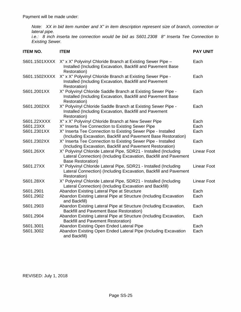
Page SS-25
Payment will be made under:
Note: XX in bid item number and X” in item description represent size of branch, connection or lateral pipe. i.e.: 8 inch inserta tee connection would be bid as S601.2308 8" Inserta Tee Connection to Existing Sewer.
ITEM NO. ITEM PAY UNIT S601.1501XXXX X" x X” Polyvinyl Chloride Branch at Existing Sewer Pipe – Each Installed (Including Excavation, Backfill and Pavement Base Restoration) S601.1502XXXX X" x X” Polyvinyl Chloride Branch at Existing Sewer Pipe - Each Installed (Including Excavation, Backfill and Pavement Restoration) S601.2001XX X" Polyvinyl Chloride Saddle Branch at Existing Sewer Pipe - Each Installed (Including Excavation, Backfill and Pavement Base Restoration) S601.2002XX X" Polyvinyl Chloride Saddle Branch at Existing Sewer Pipe - Each Installed (Including Excavation, Backfill and Pavement Restoration) S601.22XXXX X" x X” Polyvinyl Chloride Branch at New Sewer Pipe Each S601.23XX X" Inserta Tee Connection to Existing Sewer Pipe Each S601.2301XX X" Inserta Tee Connection to Existing Sewer Pipe - Installed Each (Including Excavation, Backfill and Pavement Base Restoration) S601.2302XX X" Inserta Tee Connection to Existing Sewer Pipe - Installed Each (Including Excavation, Backfill and Pavement Restoration) S601.26XX X” Polyvinyl Chloride Lateral Pipe, SDR21 - Installed (Including Linear Foot Lateral Connection) (Including Excavation, Backfill and Pavement Base Restoration) S601.27XX X” Polyvinyl Chloride Lateral Pipe, SDR21 - Installed (Including Linear Foot Lateral Connection) (Including Excavation, Backfill and Pavement Restoration) S601.28XX X” Polyvinyl Chloride Lateral Pipe, SDR21 - Installed (Including Linear Foot Lateral Connection) (Including Excavation and Backfill) S601.2901 Abandon Existing Lateral Pipe at Structure Each S601.2902 Abandon Existing Lateral Pipe at Structure (Including Excavation Each and Backfill) S601.2903 Abandon Existing Lateral Pipe at Structure (Including Excavation, Each Backfill and Pavement Base Restoration) S601.2904 Abandon Existing Lateral Pipe at Structure (Including Excavation, Each Backfill and Pavement Restoration) S601.3001 Abandon Existing Open Ended Lateral Pipe Each S601.3002 Abandon Existing Open Ended Lateral Pipe (Including Excavation Each and Backfill) REVISED: July 1, 2018

Page SS-26
SECTION S604 - CATCH BASIN AND SEWER MANHOLE S604-1 DESCRIPTION Work consists of construction of new catch basins and field inlets, or alteration of existing catch basins, field inlets and sewer manholes as required in Contract Documents, as required by Monroe County Pure Waters (MCPW) and Rochester Pure Waters District (RPWD), and as directed by Project Manager. References to NYSDOT specifications are to be in accordance with latest edition of NYSDOT Standard Specifications (US Customary Units). S604-2 MATERIALS S604-2.01 General Bar reinforcement is to be in accordance with NYSDOT Section 709-01 Bar Reinforcement, Grade 60. Brick is to be first quality, sound, hard-burned common sewer brick, culled of all irregular, unsound or damaged brick, in accordance with ASTM Designation C32 grade SS. Exterior damp proofing material is to be two coats of Hi-Build Bituminous Coating 35-J-10 as manufactured by Mobil Corporation, or Koppers Bitumastic Super Service Black as manufactured by Koppers Company, Inc, or approved equivalent. Interior damp proofing material is to be two coats of Tamms Duralkote 500 Epoxy as manufactured by Dural International Corporation, or approved equivalent. Grout is to be non-shrink type grout with minimum compressive strength of 4000 psi at 24 hours in accordance with NYSDOT Section 701-05 Concrete Grouting and Anchoring Material. Joint compound is to be Mainstay Joint Compound, Sikaflex-1A, Sonolastic NPII as manufactured by Sonneborn, or approved equivalent. Portland cement mortar is to be in accordance with ASTM Designation C270, Type M, Mortar for Unit Masonry. Cement mortar for plugging abandoned lateral pipe is to be regular cement mortar, Type II cement. Select granular backfill (sewer) material for backfilling around catch basin, field inlet and sewer manhole structures, is to be in accordance with Section S203 Excavation and Embankment. Stone bedding material for leveling course under catch basin and field inlet structures is to be in accordance with Section S203 Excavation and Embankment. Recycled materials, pulverized or recycled portland cement concrete aggregate (RCA) and brick, reclaimed asphalt pavement (RAP), and Corian® are unacceptable for use as backfill and bedding materials, unless specifically authorized in writing by City Engineer. Highway joint sealant is to be in accordance with NYSDOT 705-02 Joint Sealant. Asphalt pavement joint adhesive is to be in accordance with NYSDOT Section 418 Asphalt Pavement Joint Adhesive.

Page SS-27
S604-2.02 Castings Castings and assemblies are to be rated heavy-duty designed for AASHTO HS-20-44 highway loading plus 30 percent impact minimum, at discretion of City Engineer. S604-2.03 Catch Basin and Field Inlet A. General
Structures may be either precast or cast-in-place concrete units. Concrete is to have minimum 28 day compressive strength of 4000 psi in accordance with NYSDOT Sections 704-03 Precast Concrete – General and 706-04 Precast Concrete Drainage Units, reinforced with #4 rebar. Precast structures are to have recessed type lifting devices designed for use in precast concrete, and have an adequate capacity to safely handle structure. Recess is to be filled with approved concrete repair material after structure is installed. Castings are to be hot dip galvanized after fabrication, and are to be in accordance with ASTM A123, Section R655 Frame and Grate, and NYSDOT Section 655 Frames, Grates and Covers.
B. Type A/B Catch Basin Frame and Grate Frame, grate and appurtenant parts are to be fabricated galvanized steel per Syracuse Castings Model NYSDOT #1 for Type A, and #3 for Type B, or approved equivalent.
C. Type C Catch Basin Frame, grate and appurtenant parts are to be fabricated galvanized steel per Syracuse Castings Model NYSDOT #9, or approved equivalent. Type C catch basin is to have trap and underdrain check valve(s). Catch basin trap is to be cast iron hooded type per Neenah R-3701-8 as manufactured by Neenah Foundry Company, or approved equivalent; or tee wye with threaded clean-out plug on top side. Underdrain check valve is to be capable of preventing water from backing up into underdrain pipe.
D. Type D Catch Basin Type D catch basin is Type B catch basin structure, with access frame and cover. Access frame is to be welded steel; access cover 1/4 inch diamond plate hot rolled steel with 1/4 x 2 inch rib reinforcing @ 2-1/2 inch on center; in accordance with ASTM A36 and ASTM A48-83 Class 30B.
E. Field Inlet Field inlet is cast-in-place Type A catch basin structure, with concave shaped grate. Frame, grate and appurtenant parts are to be heavy duty cast iron type per Neenah R-3205 as manufactured by Neenah Foundry Company, or approved equivalent.
F. Concrete Collar Concrete collar is to be either 4000 psi or Class D concrete, reinforced with synthetic micro-fibers

Page SS-28
and #3 rebar. Concrete is to be in accordance with NYSDOT Section 501 Portland Cement Concrete – General. High early strength concrete may be used for placements required to satisfy open to traffic time requirements, as approved by Project Manager. Synthetic micro-fiber reinforcement is to be in accordance with NYSDOT Section 501 Portland Cement Concrete - General, and ASTM Designation C 1116 Classification 4.1.3 Type III Synthetic Fiber-Reinforced Concrete or Shotcrete. Fiber reinforcement is to be 100 percent virgin fibrillated polypropylene micro-fibers engineered and designed for use in concrete, 1/2 to 1-1/2 inches, without containing any reprocessed olefin material. Application rate is to be per manufacturer’s written instructions, but not less than 1.50 pounds per cubic yard.
S604-2.04 Sewer Manhole A. Sewer Manhole Frame and Cover
Frame, cover and appurtenant parts are to be cast iron, made of tough close-grained gray iron without admixture of any cinder iron or metal of inferior quality, in accordance with ASTM Designation A48, Class 30B or 35B, and NYSDOT Section 655 Frames, Grates and Covers. Frame is to be 9 inches tall in accordance with EJ 1310Z1 frame (9 inch tall) as manufactured by EJ Group, Inc., or approved equivalent. Cover is to be 24 inch diameter, 1-3/8 inch thick, with two pickholes in accordance with EJ 1310A2 cover as manufactured by EJ Group, Inc., or approved equivalent. Word “SEWER” and letters “MC-PW” at least 1-1/4 inches high are to be cast into cover and are to be plainly visible. Watertight frame and cover are to be heavy-duty with inner cover bolt and lock bar as required by MCPW.
B. Adjustment Rings, Flat Top Slab and Risers Adjustment rings are to be in accordance with NYSDOT Section 715-13 Prefabricated Adjustment Rings, Frames and Utility Valve Risers for Drainage Units, Manholes and Utilities. Top slab and risers are to be prefabricated concrete with minimum 28 day compressive strength of 4000 psi in accordance with ASTM C478 and NYSDOT Sections 704-03 Precast Concrete – General and 706-04 Precast Concrete Drainage Units. Where applicable, units are to have minimum of three lifting eyes or hooks designed for use in precast concrete, and have an adequate capacity to safely handle unit. Top slab is to be minimum of 8 inches thick, with 24 inch diameter hole located as required. Top slab is to be designed for AASHTO H-20 highway loading. Underside is to be pre-coated by manufacturer with cutback bitumen RC-30. Prior to ordering top slab, Contractor is to verify existing manhole size and proper location for hole in top slab.
C. Concrete Encasement and Collar Concrete for encasement and collar is to be Class D concrete, reinforced with synthetic micro-fibers. Concrete is to be in accordance with NYSDOT Section 501 Portland Cement Concrete – General.

Page SS-29
High early strength concrete may be used for placements required to satisfy open to traffic time requirements, as approved by Project Manager. Synthetic micro-fiber reinforcement is to be in accordance with NYSDOT Section 501 Portland Cement Concrete - General, and ASTM Designation C 1116 Classification 4.1.3 Type III Synthetic Fiber-Reinforced Concrete or Shotcrete. Fiber reinforcement is to be 100 percent virgin fibrillated polypropylene micro-fibers engineered and designed for use in concrete, 1/2 to 1-1/2 inches, without containing any reprocessed olefin material. Application rate is to be per manufacturer’s written instructions, but not less than 1.50 pounds per cubic yard.
S604-3 CONSTRUCTION DETAILS S604-3.01 General Manufacturer's shop drawings are to be submitted for approval as required in General Conditions Article 6, Section 6.13 Shop Drawings and Samples. Construct sewer appurtenances in accordance with these specifications and specifications of RPWD. RPWD requires all other utilities to cross perpendicular to or as close as possible to perpendicular to RPWD sewer facilities. Notify MCPW minimum of 48 hours in advance when planning on working adjacent to existing Monroe County fiber optic utilities/facilities, by calling (585) 753-7600, option 5. RPWD must have access to its sewer facilities at all times. If at any time RPWD cannot access its sewer facilities, it will be responsibility of Contractor to provide access. Contractor is to supply MCPW Dispatch Center with an emergency contact phone list, which will be instructed to contact Contractor in event such access is necessary. Take appropriate measures to prevent dirt, debris and construction materials from entering sewer facilities during construction of project. Any such invasive materials are to be removed immediately and contaminated sewer facilities thoroughly cleaned. RPWD will not mark private service laterals. If available, record maps indicating lateral wye locations of recorded wyes/taps may be obtained by contacting Dig Safely NY by calling 811, or online at digsafelynewyork.com, and requesting a design ticket. Contractor will be responsible for repair of any lateral pipe damaged during construction activities. RPWD must be notified immediately in event of any damage to sewer appurtenances, by calling (585) 753-7600, option 1. All repairs are to be performed in presence of representative of RPWD and are to be made in accordance with requirements of RPWD. In event sewer main or lateral pipes are damaged during construction activities, any and all repairs must be extended linearly, introducing new bends in pipe will not be permitted. All 5 inch inside diameter lateral pipe must be repaired using 5 inch service weight cast iron pipe and Fernco couplers. All other pipes are to be repaired with PVC SDR-21 pipe and Fernco couplers. Contractor may be permitted to use oakum and epoxy mortar to connect new PVC pipe to an existing bell that is in good condition. Stone bedding material used for sewer main and lateral pipe repairs is to be Class B consisting of #1 and #2 washed stone at minimum of 6 inch depth. In event that an existing catch basin is damaged during Contractor’s construction activities, any and all
Page SS-30
repairs must be done in accordance with these specifications and with the specifications of RPWD as follows:
• brick catch basins are to be repaired using red sewer brick in accordance with ASTM C32, Grade SS
• use Type S mortar • lateral pipe is to be repaired with PVC SDR-21 pipe and Fernco pipe couplers • damaged poured concrete riser section is to be completely removed and replaced with new poured
concrete riser • damaged precast concrete catch basin structure is to be completely removed and replaced with
new precast concrete catch basin structure Existing castings and capstones are property of RPWD. Castings and capstones that are to be replaced, or are no longer needed, and are in sound condition without any structural defects, are to be cleaned of all extraneous material and returned to MCPW Fleet Center, 145 Paul Road, Rochester, New York, Monday through Friday, between hours of 8:00AM and 3:00PM, inquire at main gate. Structurally damaged castings and capstones are not to be salvaged, but are to be properly disposed of. As-built drawings are to be furnished to RPWD, when applicable. In addition to paper hard copies, as-built drawings are also to be submitted electronically as georeferenced CAD drawings. As-built drawings are to indicate exact location of all sewers, wye branches, laterals, clean-outs and manholes. S604-3.02 Casting Installation and Tolerance A. Installation - General
Grade level castings are to be installed in same horizontal plane as surrounding elevation, true to line and grade and cross-slope of surrounding pavement, and on sound bearing. Top of cover/grate is to be level with top of corresponding frame. During construction, castings are to be protected from displacement caused by Contractor’s operations, equipment, and/or vehicular traffic that is being maintained on travelled way. Castings that are buried are to be uncovered, cleaned of all extraneous material, and set to grade, and surrounding area properly restored. Suitable measures are to be taken to ensure that cover/grate has full continuous and uniform bearing contact with corresponding frame, is stable, immovable and non-rocking when in place and when under influence of traffic or any other type of load. Suitable methods to achieve non-rocking fit between cover/grate and corresponding frame will include, but not be limited to following:
• ground mating surfaces • machined and milled mating surfaces (horizontal and vertical) • match marked elements • locking elements
If match marked elements are utilized, care is to be taken to retain identity of elements in order to correctly match them and assure proper fit. Field repairs may include grinding or proper welding techniques for material involved. Repairs that involve welding will be allowed only on steel castings and only with prior approval of Project

Page SS-31
Manager. Repairs are to result in complete unit whose individual parts have continuous, full and uniform bearing contact with each other, and that cover/grate does not rock or move under influence of traffic or other loads.
B. Basis of Acceptance
Acceptable installation of grade level casting is where casting is installed planar, true to line and grade, and cross-slope of surrounding pavement. Top of cover/grate must be level with top of corresponding frame. Wherever above conditions for basis of acceptance are not met, castings, including cover/grate, must be reset to acceptable installation.
S604-3.03 Catch Basin and Sewer Manhole - with Concrete Collar A. General
Concrete collar is required for grade level catch basin and sewer manhole castings that are located within asphalt, concrete, brick or other stone paver type pavement areas. Concrete collar will not be required where castings are located within concrete gutter section, lawn or landscaped area. Grade level castings and concrete collar are to be installed in same horizontal plane as surrounding elevation, true to line and grade and cross-slope of surrounding pavement, and on sound bearing. In lieu of 4000 psi or Class D concrete, high early strength concrete may be used for placements required to satisfy open to traffic time requirements, as approved by Project Manager. In asphalt pavement areas, final setting of castings and construction of concrete collar is to be done after final paving of top course has been completed, unless field conditions require otherwise, or as recommended by Contractor and as approved by Project Manager. In concrete, brick or other stone paver type pavement, final setting of casting and method of construction of concrete collar will be as approved by Project Manager. Care is to be taken not to damage any portion of adjacent pavement section. Any damage to adjacent pavement section caused by Contractor’s operations, is to be repaired by Contractor at their expense. For non-round shaped concrete collar, saw cut pavement full depth along neat lines around outer extents of concrete collar with power saw with diamond or abrasive blade designed for such work - do not overcut corners. Only remove pavement section to depth sufficient to construct concrete collar – do not over excavate. For round shaped concrete collar, cut pavement full depth along neat lines around outer extents of concrete collar with power hole cutter system that has heavy-duty auger driven cutter/excavator, and adjustable cutting diameter that is capable of cutting out and removing cut pavement section to required diameter and depth in one operation. Do not over cut or over excavate pavement section. After concrete has completely set, thoroughly seal all edges and joints, including around castings, with highway joint sealant.
Page SS-32
Apply asphalt pavement joint adhesive between top of concrete collar and adjacent asphalt pavement top course, thoroughly sealing joint. Where Contractor elects to cut pavement area for concrete collar installation and leave core in place for removal at later time, void must be filled-in by end of that day. Voids are not to be left unfilled overnight. Use asphalt cold patch, millings or other asphalt material to fill-in void, with material brought up to grade and flush with surrounding surface, and with top being level and smooth.
B. Concrete Collar for New Catch Basin
Concrete collar is to be parallel with outer edge of frame, and from minimum 8 inches to maximum 12 inches wide, as measured from outer edge of frame. Use same dimension for width of concrete collar on all sides of catch basin. Depth of concrete collar is to be minimum of 12 inches as measured from top of pavement down to top of structure, and tie into keyway. Exact depth will be based on actual field conditions, as recommended by Contractor and as approved by Project Manager. At minimum, provide scored and tooled joints from corners of frame out to corners of concrete collar.
C. Concrete Collar for Existing Catch Basin
Concrete collar is to be parallel with outer edge of frame, and from minimum 8 inches to maximum 12 inches wide, as measured from outer edge of frame. Use same dimension for width of concrete collar on all sides of catch basin. Depth of concrete collar is to be minimum of 12 inches as measured from top of pavement down to top of either existing construction joint, or sound concrete/brick. Exact depth will be based on actual field conditions, as recommended by Contractor and as approved by Project Manager. Scarify and/or remove top of existing walls to sufficient depth to accommodate concrete. Coat top surface of wall with NYSDOT 721-03 Epoxy Polysulfide Grout prior to pouring concrete. Concrete is to be tied into existing catch basin walls with minimum of six #5 dowels drilled and grouted into existing structure walls to form tight fit. At minimum, provide scored and tooled joints from corners of frame out to corners of concrete collar.
D. Concrete Collar for Existing Capstone Catch Basin
Concrete collar is to be parallel with outer edge of frame, and 12 inches wide as measured from outer edge of frame. Use same dimension for width of concrete collar on all sides of catch basin. Depth of concrete collar is to be minimum of 12 inches as measured from top of pavement down to top of either existing construction joint, or sound concrete/brick. Exact depth will be based on actual field conditions, as recommended by Contractor and as approved by Project Manager. Remove/add courses of brick, mortar or concrete to adjust top of existing walls to set castings to required finished grade, and on sound bearing. At minimum, provide scored and tooled joints from corners of frame out to corners of concrete

Page SS-33
collar. E. Sewer Manhole – Round Concrete Collar
Concrete collar is to be round, completely encompassing castings. Concrete collar is to be 12 inches wide as measured from outer edge of frame. Depth of concrete collar is to minimum of 12 inches as measured from top of pavement down to either top of structure, existing construction joint, or sound concrete/brick. Exact depth will be based on actual field conditions, as recommended by Contractor and as approved by Project Manager. Scored and tooled joints are to be located at and rotate out from frame ribs.
F. Sewer Manhole – Other Shaped Concrete Collar
Where existing physical conditions impede ability to construct round concrete collar, other shaped concrete collar may be allowed, but only at sole discretion of City Engineer. Concrete collar is to completely encompass castings. Concrete collar is to be 12 inches wide as measured from outer edge of frame along coordinate axes. Depth of concrete collar is to minimum of 12 inches as measured from top of pavement down to either top of structure, existing construction joint, or sound concrete/brick. Exact depth will be based on actual field conditions, as recommended by Contractor and as approved by Project Manager. Outer edge of concrete collar is to be parallel with and perpendicular to pavement edge. At minimum, provide scored and tooled joints from frame ribs out to outer edge of concrete collar.
S604-3.04 New Catch Basin and Field Inlet Prior to ordering precast portion of new structure, verify proposed invert elevation, and size and direction of all lateral and underdrain pipes. Before installation and backfilling of excavation, exterior surface of structure is to be thoroughly damp proofed with two coats of an approved bituminous coating material. Stone bedding leveling course and select granular backfill (sewer) materials are to be placed in accordance with requirements of Section S203 Excavation and Embankment. No structure is to be backfilled until mortar has completely set. Castings are to be set in accordance with Subsection S604-3.02 Casting Installation and Tolerance. Set back edge of frame parallel with and 1-1/2 inches from face of cub. Where catch basin is in radius area, mid-point of back edge of frame is to be set radial with radius curb, and 1-1/2 inches from face of curb. Fill gap between frame and curb down to top of concrete with 1:2 mortar. Castings are to be bolted down tight so individual parts have continuous, full and uniform bearing contact with each other, and that cover/grate does not rock or move under influence of traffic or any other type of load. After tightening, bolts are to be unable to be loosened by hand. Lateral pipe that is to be connected to structure is to be thoroughly cleaned of all extraneous material before and after making connection. New lateral pipe must be PVC SDR-21 in accordance with ASTM D-2241. Joints on horizontal pipe and bends are to be made with push-on neoprene gaskets. Glued or chemically welded joints are not acceptable.

Page SS-34
Lateral and underdrain pipe connections are to be made flush with inside face of structure and are to project outside of structure sufficient distance to allow for proper connection with adjoining lateral and underdrain pipe sections. Lateral and underdrain pipes are to fit neatly and tightly within structure wall. Connections are to be thoroughly sealed with 100 percent solids epoxy mortar, such as Sikadur 33 by Sika Corp., Flexolith Gel by Euclid Chemical, or approved equivalent. Upon completion of work structure is to be cleaned of all extraneous material, and interior surface of structure thoroughly damp proofed with two coats of an approved epoxy material. Structure is to be kept clean until final acceptance of work. Where required, construct concrete collar in accordance with Subsection S604-3.03 Catch Basin and Sewer Manhole - with Concrete Collar. S604-3.05 Alter Existing Catch Basin and Field Inlet Existing castings are to be removed, and are to be either reset or replaced with new frame and grate. Existing castings that are structurally sound are to be cleaned of all extraneous material, and either reset or returned to MCPW. Structurally damaged castings are to be properly disposed of. Existing concrete collar/riser is to be removed. All removed materials are to be properly disposed of. Portions of existing structure walls that are damaged are to be repaired consistent with original construction. Scarify and/or remove top portion of existing structure walls to sufficient depth to accommodate new concrete collar/riser. Coat top surface of wall with NYSDOT 721-03 Epoxy Polysulfide Grout material prior to pouring new concrete. If required, new concrete is to be tied into existing catch basin walls with minimum of six #5 vertical dowels drilled and grouted into existing catch basin walls to form tight fit. Precast structures with keyway do not require vertical dowels. Castings are to be set in accordance with Subsections S604-3.02 Casting Installation and Tolerance, and S604-3.04 New Catch Basin and Field Inlet. Exposed exterior surface of new concrete is to be thoroughly damp proofed with two coats of an approved bituminous coating material. Upon completion of work structure is to be cleaned of all extraneous material, and interior surface of structure thoroughly damp proofed with two coats of an approved epoxy material. Structure is to be kept clean until final acceptance of work. Where required, construct concrete collar in accordance with Subsection S604-3.03 Catch Basin and Sewer Manhole - with Concrete Collar. S604-3.06 Alter Existing Capstone Catch Basin Existing structure walls are generally constructed of brick and mortar, with portion of structure located under and behind curb line, and with or without an at-grade capstone. Existing capstone that is structurally sound and solid is to be carefully removed, cleaned of all extraneous material in such manner as to be non-deleterious to material and returned to MCPW. Capstones that are structurally damaged before or during excavation or salvage operations, or otherwise determined to be unacceptable for re-use by Project Manager, are to be properly disposed of.
Page SS-35
Existing castings are to be removed, and are to be either reset or replaced with new frame and grate. Existing castings that are structurally sound are to be cleaned of all extraneous material, and either reset or returned to MCPW. Structurally damaged castings are to be properly disposed of. Existing cast iron castings that are to be reset, to accommodate new curb installation long tines on back of frame are to be carefully removed so as not to damage remainder of frame. Existing concrete collar is to be removed. All removed materials are to be properly disposed of. Castings are to be set in accordance with Subsection S604-3.02 Casting Installation and Tolerance. Set back edge of frame parallel with and against face of curb. Portions of existing structure walls that are damaged are to be repaired consistent with original construction. Remove/add courses of brick, mortar or concrete to adjust top of existing walls to set castings to finished grade, and on sound baring. Mortar head and bed joints are to be maximum 1/2 inch thick. Portion of existing structure walls under and behind curb are to be dismantled by hand to depth sufficient to accommodate new concrete lintel on sound bearing. Coat top surface of wall with NYSDOT 721-03 Epoxy Polysulfide Grout prior to pouring concrete. Exposed exterior surface of new concrete is to be thoroughly damp proofed with two coats of an approved bituminous coating material. Upon completion of work structure is to be cleaned of all extraneous material, and interior surface of structure thoroughly damp proofed with two coats of an approved epoxy material. Structure is to be kept clean until final acceptance of work. Construct concrete collar in accordance with Subsection S604-3.03 Catch Basin and Sewer Manhole - with Concrete Collar. S604-3.07 Relocate Existing Catch Basin and Field Inlet Only precast structures are acceptable for relocation. Cast-in-place structures must be abandoned, completely removed and properly disposed of. Existing castings are to be removed, and are to be either reset or replaced with new frame and grate. Existing castings that are structurally sound are to be cleaned of all extraneous material, and either reset or returned to MCPW. Structurally damaged castings are to be properly disposed of. Existing concrete collar/riser is to be removed. All removed materials are to be properly disposed of. Portions of existing structure walls that are damaged are to be repaired consistent with original construction. Carefully excavate around existing structure in such manner as not to damage existing structure, completely exposing entire structure. Disconnect existing lateral and underdrain pipes. Carefully pick up, move and reinstall existing structure in its new location in such manner as not to damage existing structure. Existing structure that is damaged during excavation or salvage operations, or otherwise determined to be unacceptable for re-use by Project Manager is to be properly disposed of.

Page SS-36
Existing lateral and underdrain pipes are to be abandoned or reconnected in accordance with Subsection S604-3.11 Abandon and Remove Existing Catch Basin and Field Inlet. Install relocated structure and connect new/existing lateral and underdrain pipes in accordance with Subsection S604-3.04 New Catch Basin and Field Inlet. If necessary, scarify and/or remove top portion of existing catch basin walls to sufficient depth to accommodate new concrete collar/riser. Coat top surface of wall with NYSDOT 721-03 Epoxy Polysulfide Grout material prior to pouring new concrete. If required, new concrete is to be tied into existing catch basin walls with minimum of six #5 vertical dowels drilled and grouted into existing catch basin walls to form tight fit. Precast structures with keyway do not require vertical dowels. Unused openings in structure walls are to be blocked up with brick and mortar. Completely fill in all voids with 100 percent solids epoxy mortar, such as Sikadur 33 by Sika Corp., Flexolith Gel by Euclid Chemical, or approved equivalent. Finish off thoroughly sealing up both exterior and interior sides of opening with concrete. Surfaces of blocked up openings are to be smooth, blend in with surrounding surface, without any excess projections. Before backfilling excavation, exterior surface of new concrete is to be thoroughly damp proofed with two coats of an approved bituminous coating material. Upon completion of work structure is to be cleaned of all extraneous material, and interior surface of structure thoroughly damp proofed with two coats of an approved epoxy material. Structure is to be kept clean until final acceptance of work. Where required, construct concrete collar in accordance with Subsection S604-3.03 Catch Basin and Sewer Manhole - with Concrete Collar. S604-3.08 Temporary Setting Catch Basin and Field Inlet Castings Use and separate payment of this item will only be made at locations where Project Manager has pre-authorized such work. Temporarily fill existing keyway with sand, construct temporary riser section to proper height necessary to set castings to grade and on sound bearing. Mortar head and bed joints are to be maximum 1/2 inch thick. Apply one coat of damp proof material to exterior and interior surfaces of temporary riser section. Prior to final paving, remove temporary riser section and sand fill, and properly dispose of all materials. After removal of temporary riser section, construct permanent concrete collar/riser and set castings in accordance with Subsection S604-3.05 Alter Existing Catch Basin and Field Inlet. S604-3.09 Damp Proof Existing Catch Basin and Field Inlet Thoroughly clean entire interior surface area of structure by sand blasting or water pressure, removing all existing damp proofing and other extraneous materials so as to be in condition suitable for proper application of new damp proof material. Upon completion of work structure is to be cleaned of all extraneous material, and interior surface of structure thoroughly damp proofed with two coats of an approved epoxy material. Structure is to be kept clean until final acceptance of work.

Page SS-37
S604-3.10 Existing Catch Basin and Field Inlet Wall Repair Dismantle and remove damaged area of existing structure wall to point where wall is structurally sound. Work to repair damaged area is to be consistent with original construction, or better. All removed materials are to be properly disposed of. Upon completion of work structure is to be cleaned of all extraneous material, and interior surface of structure thoroughly damp proofed with two coats of an approved epoxy material. Structure is to be kept clean until final acceptance of work. S604-3.11 Abandon and Remove Existing Catch Basin and Field Inlet Existing castings and/or capstone, are to be removed. Structurally sound castings and/or capstone are to be cleaned of all extraneous material and returned to MCPW. Structurally damaged castings and/or capstone are to be properly disposed of. Existing lateral and underdrain pipes are to be disconnected, and entire structure and concrete collar are to be completely removed and properly disposed of. Where existing lateral and underdrain pipes are to be abandoned in place, disconnected end is to be thoroughly plugged and sealed. For lateral pipe 6 inch diameter and smaller insert rubber gasketed mechanical type permanent plug into open end of lateral pipe, completely filling and sealing end of lateral pipe with regular cement mortar, Type II Cement. For lateral pipe over 6 inch diameter fill open end of lateral pipe with sewer brick until opening is plugged as much as possible, completely filling and sealing end of lateral pipe with regular cement mortar, Type II Cement. Where existing lateral pipe is to remain active and reconnected, new lateral pipe is to be connected to open end of existing lateral pipe in accordance with Section S601 Sewer Lateral and Connection. Where existing underdrain pipe is to remain active, new underdrain pipe is to be installed to reconnect open ends in accordance with Section S605 Underdrain. S604-3.12 Alter Existing Sewer Manhole A. General Existing castings are to be removed, and are to be either reset or replaced with new frame and grate. Existing castings that are structurally sound are to be cleaned of all extraneous material, and either reset or returned to MCPW. Structurally damaged castings are to be properly disposed of. New frame and cover may be standard frame and cover, or watertight frame and cover, as required by RPWD. Existing concrete collar/encasement is to be removed. All removed materials are to be properly disposed of. Castings are to be set in accordance with Subsection S604-3.02 Casting Installation and Tolerance. New concrete top slab is to be in accordance with Subsection S604-3.15 New Sewer Manhole Precast Concrete Flat Top Slab. Surface of hole in concrete top slab is to be thoroughly damp proofed with two coats of an approved

Page SS-38
epoxy material. Exposed exterior surface of new concrete is to be thoroughly damp proofed with two coats of an approved bituminous coating material. Upon completion of work structure is to be cleaned of all extraneous material, and interior surface of structure thoroughly damp proofed with two coats of an approved epoxy material. Structure is to be kept clean until final acceptance of work. Where required, construct concrete collar/encasement in accordance with Subsection S604-3.03 Catch Basin and Sewer Manhole - with Concrete Collar. B. Existing Brick/Stone Sewer Manhole Structure
Remove/add additional courses brick/block, or install concrete adjustment ring as necessary as/if required to retrofit castings to finished grade, on sound bearing, and true to line and grade. For adjustment use either concrete adjustment ring or bricks/concrete blocks set in mortar leveling course. Concrete collar/encasement is to be at, or below, lowest portion of leveling course. Mortar head and bed joints are to be maximum 1/2 inch thick. Where new concrete top slab is required to be installed, remove additional courses brick/block to set top slab on sound bearing, and with bottom surface of top slab being minimum of 24 inches below grade. Top slab is to be set on mortar leveling course and is to overhang structure by minimum of 2 inches all around. Install either concrete adjustment ring or minimum two courses bricks/concrete blocks set in mortar leveling course as necessary to retrofit castings to finished grade, and true to line and grade. Concrete encasement for top slab is to be minimum 6 inches wide, extending down minimum of 6 inches below bottom of top slab.
C. Existing Precast Concrete Sewer Manhole Structure
Remove/add additional courses brick, or install concrete adjustment ring as necessary as/if required to retrofit castings to finished grade, on sound bearing, and true to line and grade. For adjustment use either concrete adjustment ring or minimum two courses bricks/concrete blocks set in mortar leveling course. Concrete collar/encasement is to extend down to top of existing precast structure. Mortar head and bed joints are to be maximum 1/2 inch thick. Where new concrete top slab is required to be installed, remove existing manhole top slab and saw cut top of riser section down minimum of 24 inches below finished grade. Saw cutting is to be done for full width of structure wall, and along neat, straight lines. Extreme irregularities of saw cut surface are to be milled or ground finished to relatively smooth level surface. Top slab is to be set on mortar leveling course, and is to be tied into existing structure walls with eight #5 vertical dowels drilled and grouted into existing structure walls to form tight fit. Install either concrete adjustment ring or minimum two courses bricks/concrete blocks set in mortar leveling course as necessary to retrofit castings to finished grade, and true to line and grade. Concrete collar/encasement is to extend down to top of concrete top slab.
S604-3.13 Temporary Setting Sewer Manhole Castings Use and separate payment of this item will only be made at locations where Project Manager has pre-authorized such work.
Page SS-39
Construct permanent alterations, including where necessary installation of concrete top slab, to within 12 inches of finished grade in accordance with Subsection S604-3.12 Altering Existing Sewer Manhole. Construct temporary riser section to proper height necessary to set castings to grade and on sound bearing. Mortar head and bed joints are to be maximum 1/2 inch thick. After setting frame, encase frame and temporary riser section all around with 12 inches of concrete. Top of concrete encasement is to be at least 2 inches below grade in paved areas and extend down to bottom of temporary riser section. Outside of paved areas, top of concrete encasement is to be 5 inches below grade and extend down to bottom of temporary riser section. Apply one coat of damp proof material to exterior and interior surfaces of temporary riser section. Prior to final paving, remove temporary riser section and concrete encasement, and properly dispose of all materials. After removal of temporary riser section, construct permanent concrete collar/encasement and set castings in accordance with Subsection S604-3.12 Alter Existing Sewer Manhole. S604-3.14 Abandon and Remove Existing Sewer Manhole Existing castings are to be removed. Existing castings that are structurally sound are to be cleaned of all extraneous material and returned to MCPW. Structurally damaged castings are to be properly disposed of. Existing sewer pipe(s) is to be disconnected, and entire sewer manhole structure and concrete collar are to be completely removed and properly disposed of. Where existing sewer pipe(s) is to be abandoned in place, open end(s) is to be plugged. For existing sewer pipe 6 inch diameter and smaller, insert rubber gasketed mechanical type permanent plug into open end(s) of sewer pipe. For existing sewer pipe over 6 inch diameter, fill open end(s) with brick until opening(s) is plugged as much as possible. Completely fill and seal any remaining void with regular cement mortar Type II cement. Where existing sewer pipe is to remain active and be reconnected, new sewer pipe is to be installed and connected to open ends of existing sewer pipe in accordance with requirements of RPWD. S604-3.15 New Sewer Manhole Precast Concrete Flat Top Slab Precast concrete flat top slab is to be installed in accordance with Subsection S604-3.12 Altering Existing Sewer Manhole. S604-3.16 New Sewer Manhole Precast Concrete Riser Manhole step(s) are to be provided with precast concrete riser. Use rubber ring gaskets with flexible joint sealer on outside of joints. Exterior surface is to be thoroughly damp proofed with two coats of an approved bituminous coating material. Interior surface is to be thoroughly damp proofed with two coats of an approved epoxy material.

Page SS-40
S604-4 METHOD OF MEASUREMENT S604-4.01 Concrete Collar No separate measurement and payment will be made for concrete collars. Concrete collars will be included in respective bid item as indicated in item description. S604-4.02 Catch Basin and Field Inlet Quantity to be measured for payment will be number of new structures constructed; or existing structures modified, relocated, or abandoned. Under this pay unit, maximum invert depth for new structure construction will be up to 4 feet 6 inches (4.50’), as measured between elevation of top of grate and elevation of interior floor of new structure. S604-4.03 Additional Depth of New Catch Basin and Field Inlet Quantity to be measured for payment will be number of linear feet of additional depth for new structure construction, where maximum invert depth exceeds 4 feet 6 inches (4.50’) as specified in Subsection S604-4.02 Catch Basin and Field Inlet, as measured to nearest tenth of foot (0.10’). S604-4.04 Alter Existing Catch Basin, Field Inlet and Sewer Manhole Castings Quantity to be measured for payment will be number of existing structures altered. Measurement for type D catch basin, will be made with frame and grate, including access frame and cover, counted as one complete unit. S604-4.05 Temporary Setting Catch Basin, Field Inlet and Sewer Manhole Castings Payment under this item will only be made at locations where Project Manager has pre-authorized separate payment. Quantity to be measured for payment will be number of structures topped with temporary brick riser section. Separate measurement and payment for existing structures will be made once under alteration item, and once under temporary setting item. S604-4.06 Damp Proof Existing Catch Basin and Field Inlet Quantity to be measured for payment will be number of existing structures where interior and/or exterior portion is required to be completely damp proofed. Measurement will be made separately for both interior and exterior damp proofing, it will not be counted as one complete unit. Separate measurement and payment for damp proofing will be limited only to those existing structures where existing damp proofing needs to be completely replaced, and no other type of work is being performed. No separate measurement and payment will be made under this item for damp proofing required in conjunction with new structure installation, and/or alteration or relocation of existing structures. S604-4.07 Existing Catch Basin and Field Inlet Wall Repair Quantity to be measured for payment will be number of square feet of existing structure wall repaired
Page SS-41
as measured to nearest tenth of foot (0.10’). Separate measurement and payment for repairing existing structure walls will be limited only to those existing structures where no other type of work is being performed. No separate measurement and payment will be made under this item for wall repair required in conjunction with alteration or relocation of existing structures. S604-4.08 New Sewer Manhole Precast Concrete Flat Top Slab and Precast Concrete Riser Quantity to be measured for payment will be number of units provided. S604-5 BASIS OF PAYMENT S604-5.01 General All Items Unit price bid includes cost of: providing access to RPWD to its sewer facilities at all times; taking appropriate measures to prevent dirt, debris and construction materials from entering sewer facilities during construction of project; removing and disposing any contaminant materials; cleaning contaminated sewer facilities; contacting Dig Safely NY and requesting a design ticket to obtain sewer record maps; locating and marking out recorded wyes/taps locations; and repairing any lateral pipe damaged during construction activities. Unit price bid also includes cost of: sheeting; shoring; verifying existing and proposed top of catch basin grate, manhole cover, and invert elevations; setting casting in accordance with basis of acceptable tolerance requirements; field repair of improperly fitting castings; furnishing and applying interior and exterior damp proofing material; cleaning out structure and lateral pipe of all construction related debris; disposing structurally damaged castings and capstones; disposing all extraneous material; furnishing and applying highway joint sealant; taking and furnishing all labor, material and equipment necessary to complete work. Existing structures that are being replaced and structure falls within general trench excavation limits for new structure and/or lateral pipe, removal of existing structure is considered to be part of general trench excavation for new structure and/or lateral pipe. Existing structures that are being replaced and structure falls outside of general trench excavation limits for new structure and/or lateral pipe, removal of existing structure will not be considered to be part of general trench excavation for new structure and/or lateral pipe, and will be paid for separately under Section R206 Trench and Culvert Excavation, or NYSDOT Section 203 Excavation and Embankment. Replaced and removed castings and capstones are property of RPWD. Any structurally sound castings and capstones are to be salvaged and returned to MCPW Fleet Center. No separate payment will be made for return of castings and capstones, cost is to be included in respective work item. Structurally damaged castings are to be properly disposed of. S604-5.02 Catch Basin and Sewer Manhole - with Concrete Collar Furnishing and installing concrete collar will be included in unit price bid for item as indicated in item description. Unit price bid also includes cost of: excavation; full depth pavement cutting and removal; repair and compaction pavement subbase; furnishing and installing concrete; fiber reinforcement; rebar; dowels; drilling holes; grout; scored and tooled joints; setting castings; and furnishing and applying highway joint sealant and asphalt pavement joint adhesive.
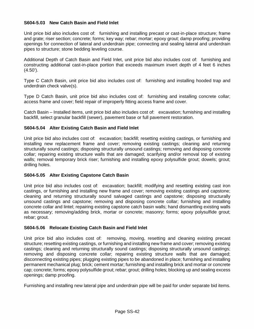
Page SS-42
S604-5.03 New Catch Basin and Field Inlet Unit price bid also includes cost of: furnishing and installing precast or cast-in-place structure; frame and grate; riser section; concrete; forms; key way; rebar; mortar; epoxy grout; damp proofing; providing openings for connection of lateral and underdrain pipe; connecting and sealing lateral and underdrain pipes to structure; stone bedding leveling course. Additional Depth of Catch Basin and Field Inlet, unit price bid also includes cost of: furnishing and constructing additional cast-in-place portion that exceeds maximum invert depth of 4 feet 6 inches (4.50’). Type C Catch Basin, unit price bid also includes cost of: furnishing and installing hooded trap and underdrain check valve(s). Type D Catch Basin, unit price bid also includes cost of: furnishing and installing concrete collar; access frame and cover; field repair of improperly fitting access frame and cover. Catch Basin – Installed items, unit price bid also includes cost of: excavation; furnishing and installing backfill, select granular backfill (sewer), pavement base or full pavement restoration. S604-5.04 Alter Existing Catch Basin and Field Inlet Unit price bid also includes cost of: excavation; backfill; resetting existing castings, or furnishing and installing new replacement frame and cover; removing existing castings; cleaning and returning structurally sound castings; disposing structurally unsound castings; removing and disposing concrete collar; repairing existing structure walls that are damaged; scarifying and/or removal top of existing walls; removal temporary brick riser; furnishing and installing epoxy polysulfide grout; dowels; grout; drilling holes. S604-5.05 Alter Existing Capstone Catch Basin Unit price bid also includes cost of: excavation; backfill; modifying and resetting existing cast iron castings, or furnishing and installing new frame and cover; removing existing castings and capstone; cleaning and returning structurally sound salvaged castings and capstone; disposing structurally unsound castings and capstone; removing and disposing concrete collar; furnishing and installing concrete collar and lintel; repairing existing capstone catch basin walls; hand dismantling existing walls as necessary; removing/adding brick, mortar or concrete; masonry; forms; epoxy polysulfide grout; rebar; grout. S604-5.06 Relocate Existing Catch Basin and Field Inlet Unit price bid also includes cost of: removing, moving, resetting and cleaning existing precast structure; resetting existing castings, or furnishing and installing new frame and cover; removing existing castings; cleaning and returning structurally sound castings; disposing structurally unsound castings; removing and disposing concrete collar; repairing existing structure walls that are damaged; disconnecting existing pipes; plugging existing pipes to be abandoned in place; furnishing and installing permanent mechanical plug; brick; cement mortar; furnishing and installing brick and mortar or concrete cap; concrete; forms; epoxy polysulfide grout; rebar; grout; drilling holes; blocking up and sealing excess openings; damp proofing. Furnishing and installing new lateral pipe and underdrain pipe will be paid for under separate bid items.
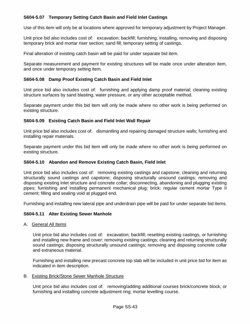
Page SS-43
S604-5.07 Temporary Setting Catch Basin and Field Inlet Castings Use of this item will only be at locations where approved for temporary adjustment by Project Manager. Unit price bid also includes cost of: excavation; backfill; furnishing, installing, removing and disposing temporary brick and mortar riser section; sand fill; temporary setting of castings. Final alteration of existing catch basin will be paid for under separate bid item. Separate measurement and payment for existing structures will be made once under alteration item, and once under temporary setting item. S604-5.08 Damp Proof Existing Catch Basin and Field Inlet Unit price bid also includes cost of: furnishing and applying damp proof material; cleaning existing structure surfaces by sand blasting, water pressure, or any other acceptable method. Separate payment under this bid item will only be made where no other work is being performed on existing structure. S604-5.09 Existing Catch Basin and Field Inlet Wall Repair Unit price bid also includes cost of: dismantling and repairing damaged structure walls; furnishing and installing repair materials. Separate payment under this bid item will only be made where no other work is being performed on existing structure. S604-5.10 Abandon and Remove Existing Catch Basin, Field Inlet Unit price bid also includes cost of: removing existing castings and capstone; cleaning and returning structurally sound castings and capstone; disposing structurally unsound castings; removing and disposing existing inlet structure and concrete collar; disconnecting, abandoning and plugging existing pipes; furnishing and installing permanent mechanical plug; brick; regular cement mortar Type II cement; filling and sealing void at plugged end. Furnishing and installing new lateral pipe and underdrain pipe will be paid for under separate bid items. S604-5.11 Alter Existing Sewer Manhole A. General All Items
Unit price bid also includes cost of: excavation; backfill; resetting existing castings, or furnishing and installing new frame and cover; removing existing castings; cleaning and returning structurally sound castings; disposing structurally unsound castings; removing and disposing concrete collar and extraneous material. Furnishing and installing new precast concrete top slab will be included in unit price bid for item as indicated in item description.
B. Existing Brick/Stone Sewer Manhole Structure
Unit price bid also includes cost of: removing/adding additional courses brick/concrete block, or furnishing and installing concrete adjustment ring; mortar levelling course.

Page SS-44
Bid item with installation of new concrete top slab, unit price bid also includes cost of: removing additional courses brick/concrete block; furnishing and installing precast concrete top slab; mortar leveling course; concrete encasement.
C. Existing Precast Concrete Sewer Manhole Structure
Unit price bid also includes cost of: removing/adding additional courses brick/concrete block, or furnishing and installing concrete adjustment ring; mortar levelling course. Bid item with installation of new concrete top slab, unit price bid also includes cost of: removing and disposing existing manhole top slab; saw cutting, removing and disposing portion of top of existing riser section; finishing cut section by milling or grinding; furnishing and installing precast concrete top slab; mortar leveling course; vertical dowels; drilling; grout.
S604-5.12 Temporary Setting Sewer Manhole Castings Use of this item will only be at locations where approved for temporary adjustment by Project Manager. Unit price bid also includes cost of: excavation; backfill; furnishing, installing, removing and disposing temporary brick and mortar riser section; temporary setting of castings. Final alteration of existing sewer manhole will be paid for under separate bid item. Separate measurement and payment for existing structures will be made once under alteration item, and once under temporary setting item. S604-5.13 Abandon and Remove Existing Sewer Manhole Unit price bid also includes cost of: removing existing castings; cleaning and returning structurally sound castings; disposing structurally unsound castings; removing and disposing existing sewer manhole structure and concrete collar; disconnecting, abandoning and plugging existing sewer pipe(s); furnishing and installing permanent mechanical plug; brick; regular cement mortar Type II cement; filling and sealing void at plugged end(s). Furnishing and installing new sewer pipe to reconnect open ends of existing pipe(s) will be paid for under separate bid item. S604-5.14 New Sewer Manhole Precast Concrete Flat Top Slab Unit price bid includes cost of: furnishing precast concrete flat top slab. Installation of precast concrete top slab will be paid for under separate bid item. S604-5.15 New Sewer Manhole Precast Concrete Riser Unit price bid includes cost of: furnishing precast concrete riser; manhole steps; rubber ring gaskets; flexible joint sealer. Installation of precast concrete riser will be paid for under separate bid item. S604-5.16 Excavation, Backfill, Pavement Base Restoration and Pavement Restoration Excavation including hand and tunnel excavation, and furnishing and placing of select granular backfill (sewer) will be paid for under separate bid items or included in unit price bid for item where indicated

Page SS-45
under Basis of Payment, or in item description. Bid items that include concrete collar as indicated in item description, will always include excavation and backfill. Pavement base or full pavement restoration, will be paid for under separate bid items or included in unit price bid for item as indicated in item description. No separate payment will be made for placement of select backfill material excavated from trench. Excavation that is included in bid item does not include rock excavation. Rock excavation will be paid for under separate bid item. Bid items that include cost of pavement base restoration, pavement base may consist of either concrete base or asphalt base course, as required in Contract Documents. Unit price bid will be same regardless of which type of pavement base is used, and bid items will include cost of: subbase courses type 1 and type 2; either Class C concrete foundation or asphalt base course; asphalt binder course; and asphalt tack coat. Bid items that include cost of full pavement restoration, pavement base may consist of either concrete base or asphalt base course, as required in Contract Documents. Unit price bid will be same regardless of which type of pavement base is used, and bid items will include cost of: subbase courses type 1 and type 2; either Class C concrete foundation or asphalt base course; asphalt binder course; asphalt top course; and asphalt tack coat. Payment will be made under: ITEM NO. ITEM PAY UNIT S604.30 New Type A Catch Basin Each S604.3002 New Type A Catch Basin (Including Concrete Collar) Each S604.31 New Type B Catch Basin Each S604.3102 New Type B Catch Basin (Including Concrete Collar) Each S604.32 New Type C Catch Basin Each S604.3202 New Type C Catch Basin (Including Concrete Collar) Each S604.33 New Type D Catch Basin (Including Concrete Collar) Each S604.34 New Field Inlet Each S604.3701 New Type B Catch Basin - Installed (Including Excavation, Backfill Each and Pavement Base Restoration) S604.3702 New Type B Catch Basin - Installed (Including Excavation, Backfill Each and Full Pavement Restoration) S604.3703 New Type D Catch Basin – Installed (Including Concrete Collar) Each (Including Excavation, Backfill and Pavement Base Restoration) S604.3704 New Type D Catch Basin - Installed (Including Concrete Collar) Each (Including Excavation, Backfill and Full Pavement Restoration) S604.3705 New Type B Catch Basin - Installed (Including Concrete Collar) Each (Including Excavation, Backfill and Pavement Base Restoration) S604.3706 New Type B Catch Basin - Installed (Including Concrete Collar) Each (Including Excavation, Backfill and Full Pavement Restoration) S604.40 Additional Depth New Type A Catch Basin Linear Foot S604.4002 Additional Depth New Type A Catch Basin (Including Excavation Linear Foot and Backfill) S604.41 Additional Depth New Type B Catch Basin Linear Foot

Page SS-46
ITEM NO. ITEM PAY UNIT S604.4102 Additional Depth New Type B Catch Basin (Including Excavation Linear Foot and Backfill) S604.42 Additional Depth New Type C Catch Basin Linear Foot S604.4202 Additional Depth New Type C Catch Basin (Including Excavation Linear Foot and Backfill) S604.43 Additional Depth New Type D Catch Basin Linear Foot S604.4302 Additional Depth New Type D Catch Basin (Including Excavation Linear Foot and Backfill) S604.44 Additional Depth New Field Inlet Linear Foot S604.4402 Additional Depth New Field Inlet (Including Excavation and Backfill) Linear Foot S604.5007 Alter Existing Type A/B Catch Basin Each S604.5008 Alter Existing Type A/B Catch Basin (Including Concrete Collar) Each (Including Pavement Base Restoration) S604.5009 Alter Existing Type A/B Catch Basin (Including Concrete Collar) Each (Including Full Pavement Restoration) S604.5010 Alter Existing Type A/B Catch Basin (Including Concrete Collar) Each S604.5019 Alter Existing Type C Catch Basin Each S604.5020 Alter Existing Type C Catch Basin (Including Concrete Collar) Each (Including Pavement Base Restoration) S604.5021 Alter Existing Type C Catch Basin (Including Concrete Collar) Each (Including Full Pavement Restoration) S604.5022 Alter Existing Type C Catch Basin (Including Concrete Collar) Each S604.5026 Alter Existing Type D Catch Basin (Including Concrete Collar) Each S604.5031 Alter Existing Field Inlet Each S604.5105 Alter Existing Capstone Catch Basin (Including Concrete Collar) Each S604.5105 Alter Existing Capstone Catch Basin (Including Concrete Collar) Each (Including Pavement Base Restoration) S604.5105 Alter Existing Capstone Catch Basin (Including Concrete Collar) Each (Including Full Pavement Restoration) S604.5202 Relocate Existing Type A/B Catch Basin Each S604.5203 Relocate Existing Type A/B Catch Basin (Including Concrete Collar) Each S604.5205 Relocate Existing Type C Catch Basin Each S604.5206 Relocate Existing Type C Catch Basin (Including Concrete Collar) Each S604.5207 Relocate Existing Type D Catch Basin (Including Concrete Collar) Each S604.5208 Relocate Existing Field Inlet Each S604.54 Damp Proof Existing Catch Basin Each S604.5402 Damp Proof Existing Field Inlet Each S604.550301 Temporary Setting Catch Basin Castings Each S604.5509 Temporary Setting Field Inlet Castings Each S604.560101 Abandon and Remove Existing Catch Basin Each S604.560201 Abandon and Remove Existing Catch Basin (Including Excavation Each and Backfill) S604.560301 Abandon and Remove Existing Catch Basin (Including Excavation, Each Backfill and Pavement Base Restoration) S604.560401 Abandon and Remove Existing Catch Basin (Including Excavation, Each Backfill and Full Pavement Restoration) S604.570101 Abandon and Remove Existing Field Inlet Each S604.570201 Abandon and Remove Existing Field Inlet (Including Excavation Each and Backfill S604.5801 Existing Catch Basin Wall Repair Square Foot S604.5901 Existing Field Inlet Wall Repair Square Foot S604.6020 Alter Existing Brick/Stone Sewer Manhole – Existing Castings Each at/or Below Finished Grade

Page SS-47
ITEM NO. ITEM PAY UNIT S604.6021 Alter Existing Brick/Stone Sewer Manhole – Existing Castings Each at/or Below Finished Grade (Including New Precast Flat Top Slab) S604.6022 Alter Existing Brick/Stone Sewer Manhole – Existing Castings Each Above Finished Grade S604.6023 Alter Existing Brick/Stone Sewer Manhole – Existing Castings Each Above Finished Grade (Including New Precast Flat Top Slab) S604.6024 Alter Existing Brick/Stone Sewer Manhole – Existing Castings Each at/or Below Finished Grade (Including Concrete Collar) S604.6025 Alter Existing Brick/Stone Sewer Manhole – Existing Castings Each at/or Below Finished Grade (Including Concrete Collar) (Including New Precast Flat Top Slab) S604.6026 Alter Existing Brick/Stone Sewer Manhole – Existing Castings Each Above Finished Grade (Including Concrete Collar) S604.6027 Alter Existing Brick/Stone Sewer Manhole – Existing Castings Each Above Finished Grade (Including Concrete Collar) (Including New Precast Flat Top Slab) S604.6028 Alter Existing Precast Sewer Manhole – Existing Castings at/or Each Below Finished Grade S604.6029 Alter Existing Precast Sewer Manhole - Existing Castings at/or Each Below Finished Grade (Including New Precast Flat Top Slab) S604.6030 Alter Existing Precast Sewer Manhole - Existing Castings Above Each Finished Grade S604.6031 Alter Existing Precast Sewer Manhole - Existing Castings Above Each Finished Grade (Including New Precast Flat Top Slab) S604.6032 Alter Existing Precast Sewer Manhole – Existing Castings at/or Each Below Finished Grade (Including Concrete Collar) S604.6033 Alter Existing Precast Sewer Manhole - Existing Castings at/or Each Below Finished Grade (Including Concrete Collar) (Including New Precast Flat Top Slab) S604.6034 Alter Existing Precast Sewer Manhole - Existing Castings Above Each Finished Grade (Including Concrete Collar) S604.6035 Alter Existing Precast Sewer Manhole - Existing Castings Above Each Finished Grade (Including Concrete Collar) (Including New Precast Flat Top Slab) S604.6202 Temporary Setting Sewer Manhole Castings Each S604.6601 Abandon and Remove Existing Sewer Manhole Each S604.6602 Abandon and Remove Existing Sewer Manhole (Including Each Excavation and Backfill) S604.6603 Abandon and Remove Existing Sewer Manhole (Including Each Excavation, Backfill and Pavement Base Restoration) S604.6604 Abandon and Remove Existing Sewer Manhole (Including Each Excavation, Backfill and Full Pavement Restoration) S604.7048 Sewer Manhole Precast Concrete Flat Top Slab – 48” Diameter Each S604.7160 Sewer Manhole Precast Concrete Flat Top Slab – 60” Diameter Each S604.724812 Sewer Manhole Precast Concrete Riser – 48” Diameter–12” Thick Each S604.724824 Sewer Manhole Precast Concrete Riser – 48” Diameter–24” Thick Each S604.736012 Sewer Manhole Precast Concrete Riser – 60” Diameter–12” Thick Each S604.736024 Sewer Manhole Precast Concrete Riser – 60” Diameter–24” Thick Each REVISED December 19, 2019
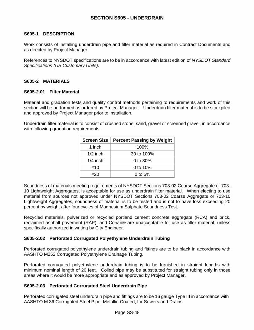
Page SS-48
SECTION S605 - UNDERDRAIN S605-1 DESCRIPTION Work consists of installing underdrain pipe and filter material as required in Contract Documents and as directed by Project Manager. References to NYSDOT specifications are to be in accordance with latest edition of NYSDOT Standard Specifications (US Customary Units). S605-2 MATERIALS S605-2.01 Filter Material Material and gradation tests and quality control methods pertaining to requirements and work of this section will be performed as ordered by Project Manager. Underdrain filter material is to be stockpiled and approved by Project Manager prior to installation. Underdrain filter material is to consist of crushed stone, sand, gravel or screened gravel, in accordance with following gradation requirements:
Screen Size Percent Passing by Weight 1 inch 100%
1/2 inch 30 to 100% 1/4 inch 0 to 30%
#10 0 to 10% #20 0 to 5%
Soundness of materials meeting requirements of NYSDOT Sections 703-02 Coarse Aggregate or 703-10 Lightweight Aggregates, is acceptable for use as underdrain filter material. When electing to use material from sources not approved under NYSDOT Sections 703-02 Coarse Aggregate or 703-10 Lightweight Aggregates, soundness of material is to be tested and is not to have loss exceeding 20 percent by weight after four cycles of Magnesium Sulphate Soundness Test. Recycled materials, pulverized or recycled portland cement concrete aggregate (RCA) and brick, reclaimed asphalt pavement (RAP), and Corian® are unacceptable for use as filter material, unless specifically authorized in writing by City Engineer. S605-2.02 Perforated Corrugated Polyethylene Underdrain Tubing Perforated corrugated polyethylene underdrain tubing and fittings are to be black in accordance with AASHTO M252 Corrugated Polyethylene Drainage Tubing. Perforated corrugated polyethylene underdrain tubing is to be furnished in straight lengths with minimum nominal length of 20 feet. Coiled pipe may be substituted for straight tubing only in those areas where it would be more appropriate and as approved by Project Manager. S605-2.03 Perforated Corrugated Steel Underdrain Pipe Perforated corrugated steel underdrain pipe and fittings are to be 16 gauge Type III in accordance with AASHTO M 36 Corrugated Steel Pipe, Metallic-Coated, for Sewers and Drains.

Page SS-49
Where bituminous coating is required, pipe and fittings are to be coated in accordance with AASHTO M 190 Bituminous-Coated Corrugated Metal Culvert Pipe and Pipe Arches - Type A Fully Bituminous Coated. S605-2.04 High-Density Perforated Corrugated Polyethylene Pipe High-density perforated corrugated polyethylene pipe and fittings is have smooth interior, and is to be in accordance with AASHTO M 252 Corrugated Polyethylene Drainage Pipe Type SP for 4 through 10 inch diameter pipe, and AASHTO M 294 Corrugated Polyethylene Pipe Type SP for 12 inch diameter and larger pipe. S605-3 CONSTRUCTION DETAILS S605-3.01 Underdrain Filter Material - General Where required, underdrain trench is to be encased with geotextile material in accordance with Section S207 Geotextiles. Underdrain filter material is to be loosely placed around and over underdrain pipe to such depth that, after compaction, underdrain filter material will extend to level 4 inches above underdrain pipe. For perforated corrugated polyethylene underdrain tubing and high-density perforated corrugated polyethylene pipe, underdrain filter material is to be compacted by three passes of vibrating pad or drum type compactor. For perforated corrugated steel underdrain pipe, underdrain filter material is to be compacted by two passes of vibrating pad or drum type compactor. In event underdrain pipe is not to be installed, underdrain filter material is to be placed in lifts not exceeding 6 inches in thickness prior to compaction. Each lift is to be compacted by two passes of vibrating pad or drum type compactor. Placement and compaction operations are to be conducted in manner so as to insure that top surface of each lift does not become contaminated by adjacent backfill materials. Contaminated underdrain filter material is to be replaced. S605-3.02 Underdrain Filter Material at Structures Underdrain filter material is to be placed in lifts not exceeding 6 inches in thickness, and is to precede placement of any adjacent backfill material. Temporary barrier may be used between underdrain filter material and adjacent backfill material. Temporary barrier is to be removed prior to compaction. Each lift of underdrain filter material and adjacent backfill material located within minimum distance of 3 feet from backwall plus footing heel projection of any structure, is to be compacted simultaneously. Each lift is to be compacted by two passes of vibratory compactor. Placement and compaction operations are to be conducted in manner so as to insure that top surface of each lift does not become contaminated by adjacent backfill materials. Contaminated underdrain filter material is to be replaced. S605-3.03 Underdrain Tubing/Pipe Storage and handling of underdrain tubing/pipe is to be in accordance with AASHTO M252 Corrugated Polyethylene Drainage Tubing, and AASHTO M 36 Corrugated Steel Pipe, Metallic-Coated, for Sewers and Drains, as appropriate.

Page SS-50
Underdrain tubing/pipe is to be installed in accordance with Section R601-3 Construction Details. Perforated underdrain tubing/pipe is to be placed on level and compacted bed of underdrain filter material. Where proper vertical alignment cannot be maintained, lengths of underdrain tubing/pipe are to be cut and secured with approved couplings. Sections of underdrain tubing/pipe are to be joined only with approved fittings, and are not to be split to make connection. Upgrade end of underdrain tubing/pipe is to be closed with appropriate plug or cap. Where existing underdrain pipe is being replaced with new underdrain tubing/pipe, remove sufficient length of existing underdrain pipe to accommodate proper installation of new underdrain tubing/pipe. Remaining portion of existing underdrain pipe is to be abandoned by plugging open ends with concrete to minimum depth of 12 inches. S605-3.04 High-Density Perforated Corrugated Polyethylene Pipe High-density perforated corrugated polyethylene pipe is to be used in applications where combination underdrain and lateral pipe is required. Storage and handling of pipe is to be in accordance with AASHTO M 252 Corrugated Polyethylene Drainage Pipe Type SP for 4 through 10 inch diameter pipe, and AASHTO M 294 Corrugated Polyethylene Pipe Type SP for 12 inch diameter and larger pipe. S605-3.05 Underdrain Tubing/Pipe Connection Underdrain tubing/pipe connections at catch basin or manhole structures are to be thoroughly sealed with concrete and 100 per cent epoxy grout material. Openings in concrete structures are to be made by coring. Openings in brick structures are to be made either by removing existing brick, or by coring. S605-4 METHOD OF MEASUREMENT S605-4.01 Underdrain Filter Material Quantity to be measured for payment will be number of cubic yards of filter material installed. Measurement for this item will be made only in those areas where filter material is installed without underdrain tubing/pipe. S605-4.02 Underdrain Tubing/Pipe Quantity to be measured for payment will be number of linear feet of underdrain tubing/pipe installed. S605-5 BASIS OF PAYMENT S605-5.01 General all Items Unit price bid for all items includes cost of: excavation; pavement saw cutting; and furnishing all labor, material and equipment necessary to complete work. No payment will be made for any losses of material which may result from compaction, foundation settlement, erosion, or any other causes. Cost of such losses is to be included in unit price bid for

Page SS-51
these items. Furnishing and installing geotextile material will be paid for under Section S207 Geotextiles. Excavation that is included in pay item does not include rock excavation. Rock excavation will be paid for under separate bid item. S605-5.02 Underdrain Filter Material Unit price bid also includes cost of: furnishing and placing underdrain filter material, without underdrain pipe. S605-5.03 Underdrain Tubing/Pipe Unit price bid also includes cost of: cutting, abandoning, plugging, removing existing underdrain pipe; furnishing and installing underdrain tubing/pipe; furnishing, placing and compacting underdrain filter material; making connection to catch basins, manholes and existing underdrain pipe; enlarging existing openings or making new openings in catch basin or manhole structures for connection of underdrain pipe; sealing connection with concrete and epoxy grout; plugging, capping unconnected ends of underdrain tubing/pipe. Payment will be made under:
Note: XX in bid item number and X” in item description represent size of underdrain tubing/pipe. i.e.: 6 inch underdrain tubing would be bid as S605.140106 X" Perforated Corrugated Polyethylene Underdrain Tubing.
ITEM NO. ITEM PAY UNIT S605.13 Underdrain Filter Material Cubic Yard S605.1401XX X" Perforated Corrugated Polyethylene Underdrain Tubing Linear Foot S605.15XX X" Perforated Corrugated Steel Underdrain Pipe - Uncoated Linear Foot S605.16XX X" Perforated Corrugated Steel Underdrain Pipe - Coated Linear Foot S605.1701XX X" High Density Perforated Corrugated Polyethylene Pipe Linear Foot REVISED July 1, 2017

Page SS-52
SECTION 607 – FENCES 607 GENERAL Purpose of this directive is to designate certain NYSDOT bid items for use on all City projects. References to NYSDOT specifications are to be in accordance with latest edition of NYSDOT Special Specifications (US Customary Units). Work is to be in accordance with requirements of NYSDOT Section 607 – Fences for following bid item: 607-5 BASIS OF PAYMENT Payment will be made under: ITEM NO. ITEM PAY UNIT 607.91000011 Pipe Rail Fence – 2 Rail Linear Foot ISSUED February 25, 2020
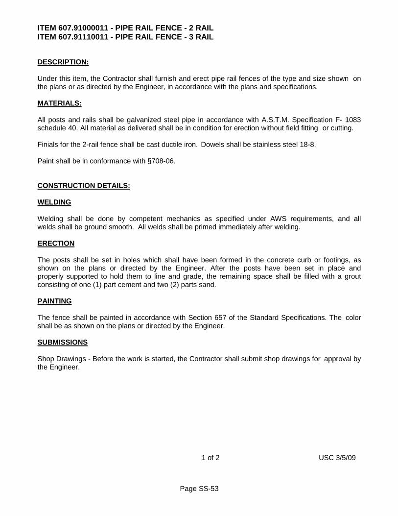
Page SS-53
ITEM 607.91000011 - PIPE RAIL FENCE - 2 RAIL ITEM 607.91110011 - PIPE RAIL FENCE - 3 RAIL DESCRIPTION: Under this item, the Contractor shall furnish and erect pipe rail fences of the type and size shown on the plans or as directed by the Engineer, in accordance with the plans and specifications. MATERIALS: All posts and rails shall be galvanized steel pipe in accordance with A.S.T.M. Specification F- 1083 schedule 40. All material as delivered shall be in condition for erection without field fitting or cutting. Finials for the 2-rail fence shall be cast ductile iron. Dowels shall be stainless steel 18-8. Paint shall be in conformance with §708-06. CONSTRUCTION DETAILS: WELDING Welding shall be done by competent mechanics as specified under AWS requirements, and all welds shall be ground smooth. All welds shall be primed immediately after welding. ERECTION The posts shall be set in holes which shall have been formed in the concrete curb or footings, as shown on the plans or directed by the Engineer. After the posts have been set in place and properly supported to hold them to line and grade, the remaining space shall be filled with a grout consisting of one (1) part cement and two (2) parts sand. PAINTING The fence shall be painted in accordance with Section 657 of the Standard Specifications. The color shall be as shown on the plans or directed by the Engineer. SUBMISSIONS Shop Drawings - Before the work is started, the Contractor shall submit shop drawings for approval by the Engineer. 1 of 2 USC 3/5/09
Page SS-54
METHOD OF MEASUREMENT: The quantity of pipe rail fence of type to be paid for under this item shall be the number of linear feet of fence measured along the top rail to the limit of new fence, furnished and erected complete in accordance with the plans and specifications and the directions of the Engineer. BASIS OF PAYMENT: The price bid shall include the cost of furnishing all labor, materials, and equipment necessary to erect the fence and shall include all necessary excavation and disposal, painting, concrete and reinforcing for the curb or footings and all incidental expenses necessary to complete the work in accordance with the plans and specifications to the satisfaction of the Engineer. 2 of 2 USC 3/5/09

Page SS-55
SECTION S608 - SIDEWALK AND DRIVEWAY S608-1 DESCRIPTION Work consists of construction of sidewalks, sidewalk access ramps, detectable warning surfaces, and driveways as required in Contract Documents and as directed by Project Manager. References to NYSDOT specifications are to be in accordance with latest edition of NYSDOT Standard Specifications (US Customary Units). S608-2 MATERIALS S608-2.01 General Materials are to be in accordance with NYSDOT Section 700 Materials Details:
Portland Cement 701-01 Bituminous Materials 702 Fine Aggregate 703-01 Coarse Aggregate 703-02 Mortar Sand 703-03 Cushion Sand 703-06 Concrete Sand 703-07 Mineral Filler 703-08 Premoulded Resilient Joint Filler 705-07 Masonry Mortar 705-21 Membrane Curing Compound 711-05 Form Insulating Materials for Cold Weather 711-07 Concreting Water 712-01
S608-2.02 Concrete Sidewalk and Driveway, Concrete Entrance Walk and Concrete Steps Concrete is to be Class K in accordance with Section S504 Portland Cement Concrete. Subbase course material is to be Type 1 in accordance with NYSDOT Section 304 Subbase Course. Recycled materials, pulverized or recycled portland cement concrete aggregate (RCA) and brick, reclaimed asphalt pavement (RAP), and Corian® are unacceptable for use as subbase course materials, unless specifically authorized in writing by City Engineer. S608-2.03 Color-Tinted Concrete Color-tinting of concrete is to be achieved by introducing color-conditioning, pigmented, normal or retarded-set additive directly into mixer drum at rate specified by color manufacturer. Color will be as specified in Contract Documents. Use of Type 6 cement (white) will be permitted to reduce quantity of color additive. Polyurethane caulking compound is to be color-matched to concrete.

Page SS-56
S608-2.04 Exposed Aggregate Concrete Aggregate is to consist of sound washed gravel which passes number 1 sieve, contains varying colors and is available from local run-of-bank gravels. Chemical horizontal surface retarder is to be water soluble spray applied organic chemical surface retarder that delays set of concrete to create exposed aggregate surface. Surface retarder is to be such that it will retard but not kill hydration of concrete, will allow aggregate to retain its natural appearance without effecting color or luster of aggregate, and is in compliance with Federal V.O.C. standards for concrete surface retarders. Sealer is to be single component transparent liquid designed to cure and seal exterior concrete surfaces, including exposed aggregate concrete. Sealer is to be such that it will bring out radiance and luster of natural aggregate, providing long lasting and durable finish, and is in compliance with Federal V.O.C. standards for concrete sealers. S608-2.05 Detectable Warning Surface Embedded detectable warning surface installation is preferred method for constructing detectable warning surface. Surface applied detectable warning surface installation for constructing detectable warning surface is generally unacceptable except in select locations, at discretion of Project Manager. Detectable warning surface is to be weather resistant, durable to high pedestrian traffic usage, and fabricated with non-slip texture. Detectable warning surface is to provide light-on-dark or dark-on-light contrast with surrounding surface. Detectable warning surface is to be uniform in color and texture, free of cracks or other defects, and have clean-cut well defined edges. Default color of detectable warning surface is #33538 traffic yellow. Other acceptable colors for use in concrete areas #20109 red brown and #36081 dark gunship gray; in asphalt and other similar dark surface areas #36495 light gray and #37925 insignia white; or approved equivalents. Colors are to be in accordance with Federal Standard 595C. Color is to be homogeneous throughout thickness of material, visually provide surface which is uniform in color over entire detectable warning surface area, and matches specified color designation. Basis of Acceptance: At least 30 days prior to beginning work, submit shop drawings and sample detectable warning surface unit to Project Manager for approval. A. Embedded Detectable Warning Surface Units
Pre-approved products and manufacturer of detectable warning surface units are those listed on NYSDOT Technical Services - Materials-and Equipment Approved List. Other equivalent products will need to be approved by Project Manager prior to installation. Embedded detectable warning surface units are to be single full sized solid units, either rectangular or radial in shape, and be capable of molding or fitting into contours, breaks and faults of paved surfaces. Precast brick detectable warning surface units may be provided in sizes as small as standard brick,

Page SS-57
be capable of being installed in either rectangular or radial shape, and be capable of fitting into contours, breaks and faults of paved surfaces. Detectable warning surface units are to be colorfast, UV stable, not showing any signs of appreciable fading, lifting, shrinkage, or other signs of poor adhesion. Where applicable, detectable warning surface units are to be capable of adhering to concrete surface at minimum air temperature of 60°F and minimum surface substrate temperature of 70°F. Manufacturer is to demonstrate in writing and provide references that embedded detectable warning surface material has been satisfactorily used for minimum period of 2 years in areas where weather conditions are similar to those experienced in Rochester, New York area. At least 30 days prior to installation, manufacturer is to submit certified test results from an independent testing laboratory to Project Manager indicating that type of material to be used is in compliance with following requirements:
Property Results Compressive Strength
(minimum after 28 days) 8000 psi minimum
Freeze-Thaw Loss (25 cycles, 1 cycle/day, 10% NaCi
solution in accordance with NYS Test Method 502-
3P)
1% maximum
B. Surface Applied Detectable Warning Surface Units
Pre-approved products and manufacturer of surface applied detectable warning surface units are those as listed on NYSDOT Technical Services – Materials and Equipment Approved List. Other equivalent products will need to be approved by Project Manager prior to installation. Surface applied detectable warning units are to be full sized single solid unit either rectangular or radial in shape, and be capable of molding or fitting into contours, breaks and faults of paved surfaces. Surface applied detectable warning units are not to show any signs of appreciable fading, lifting, shrinkage, tearing, rollback, or other signs of poor adhesion. Where applicable, surface applied detectable warning units are to be capable of adhering to concrete surface at minimum air temperature of 60°F and minimum surface substrate temperature of 70°F. Manufacturer is to demonstrate in writing and provide references that surface applied detectable warning surface material has been satisfactorily used for minimum period of 3 years in areas where weather conditions are similar to those experienced in Rochester, New York area. At least 30 days prior to installation, manufacturer is to submit certified test results from an independent testing laboratory to Project Manager indicating that type of material to be used is in compliance with following requirements:

Page SS-58
Standard Property Results
ASTM C501 Wear Resistance Wear Index: >15
ASTM C1028 Slip Resistance Dry Coefficient of Friction 0.8 minimum
ASTM E96 Water Vapor Transmission 10 grams/square foot/24 hours
S608-2.06 Heavy-Duty Commercial Concrete Driveway Concrete for heavy-duty commercial concrete driveway is to be Concrete for Structures Class A (Appurtenant Placements) in accordance with NYSDOT Section 555 Structural Concrete. Subbase course material is to be Type 4 in accordance with NYSDOT Section 304 Subbase Course. Recycled materials, pulverized or recycled portland cement concrete aggregate (RCA) and brick, reclaimed asphalt pavement (RAP), and Corian® are unacceptable for use as subbase course materials, unless specifically authorized in writing by City Engineer. Tie bar for construction joint is to be number 3 bar, 18 inches long, deformed billet steel bar in accordance with ASTM A615, Grade 60; or deformed rail steel bar in accordance with ASTM A616, Grade 60 including Supplementary Requirement S1. Welded wire fabric for reinforcement is to be 6x6 10 gauge uncoated steel reinforcement in accordance with ASTM A185 or ASTM A497. S608-2.07 Asphalt Driveway Asphalt top is to be asphalt mix that is dense graded and having gritty texture for single course resurfacing over stone base or asphalt binder. Asphalt mix is to be in accordance with NYSDOT Section 401 Plant Production, with following modifications:
Composition
Screen Size General Limits
Percent Passing
Job Mix Tolerance Percent
1/2 inch 100% - 1/4 inch 90 to 100% - 1/8 inch 45 to 70% +/- 7%
#20 15 to 40% +/- 7% #40 8 to 27% +/- 7% #80 4 to 16% +/- 4% #200 2 to 6% +/- 2%

Page SS-59
Other Properties
Asphalt Content Percentage 6 to 8% +/- 0.4%
Asphalt Cement Grade and Number AC-20 - 702.0500 -
Mixing and Placing Temperature Range 250°F to 325°F -
Aggregate is to be in accordance with NYSDOT Sections 703-01 Fine Aggregate and 703-02 Coarse Aggregate, meeting following blend percentages:
Aggregate Blend Percentage
Coarse Aggregate #1A 44% Fine Aggregate Manufactured 28%
Fine Aggregate Natural 28% Asphalt binder is to be 19 F9 Binder Course HMA, 80 Series Compaction in accordance with NYSDOT Sections 401 Plant Production and 402 Hot Mix Asphalt (HMA) Pavements. Asphalt base is to be 37.5 F9 Base Course HMA, 80 Series Compaction in accordance with NYSDOT Sections 401 Plant Production and 402 Hot Mix Asphalt (HMA) Pavements. Subbase course material is to be Type 2 in accordance with NYSDOT Section 304 Subbase Course. Recycled materials, pulverized or recycled portland cement concrete aggregate (RCA) and brick, reclaimed asphalt pavement (RAP), and Corian® are unacceptable for use as subbase course materials, unless specifically authorized in writing by City Engineer. S608-2.08 Temporary Sidewalk and Driveway Materials are to be in accordance with Section S412 Temporary Pavement. S608-2.09 Brick A. Brick
Brick is to be as required in Contract Documents. B. Brick – Cultural District
Color of brick for use within Cultural District is standardized on Endicott Dark Ironspot as manufactured by Endicott Clay Products Co., and any brick that is supplied must be an exact match in color. Brick is to be wire cut brick, 3-5/8 x 7-5/8 x 2-1/4, Endicott Dark Ironspot as manufactured by Endicott Clay Products Co., or approved equivalent.
S608-2.10 Slate Slate is to be sound and durable, reasonably uniform in quality and texture throughout, free from shale, excess mica, seams, scaling or evidence of disintegration.

Page SS-60
Slate pieces are to be 3 to 4 inches thick, generally 3 to 5 feet square in shape, with color as required in Contract Documents. Slate is to have one reasonable smooth split face with no projections or depressions over 1/4 inches, and dressed that it may be laid with maximum of 3/4 inch joints. Basis of Acceptance: Minimum 25 square foot sample of slate must be submitted to Project Manager for approval at least 30 days prior to beginning work. Slate will be inspected for accordance to dimensional and color requirements. Slate that is not in compliance with this specification will be rejected. S608-2.11 Stone Paver Stone paver can be either rock-face or small ashlar natural stone. Stone paver is to be sound and durable, reasonably uniform in quality and texture throughout, free from shale, excess mica, seams, scaling or evidence of disintegration. Stone paver is to have one reasonable smooth split face with no projections or depressions over 1/4 inches. Rock-face stone paver is to be so dressed that it may be laid with maximum of 3/4 inch joints. Size and color of stone paver will be as required in Contract Documents. Basis of Acceptance: Minimum 25 square foot sample of stone paver must be submitted to Project Manager for approval at least 30 days prior to beginning work. Stone paver will be inspected for accordance to dimensional and color requirements. Stone paver that is not in compliance with this specification will be rejected. S608-2.12 Paver Edge Restraint Paver Edge Restraint is to be composed of high density polyethylene (HDPE), PVC or other durable non-metallic material for rigid straight line installation, as manufactured by SnapEdge, E-Z Edge, PaveTech, or approved equivalent. S608-2.13 Coarse Sand Coarse sand is to be clean washed well graded angular sand with maximum particle size of 3/16 inch, without any fine limestone screenings, free of salts and other deleterious materials, and in accordance with ASTM C33 Concrete Aggregates. S608-2.14 Caulking Sealant Caulking sealant is to be one component polyurethane self-leveling sealant. Color of sealant is to be such as to be capable of blending in with surrounding elements. S608-2.15 Curing Compound Curing compound is to be single component transparent liquid designed to cure, seal and dustproof exterior concrete surfaces. S608-2.16 Fine Sand Fine sand is to be clean washed masons sand, free of salts and other deleterious materials, in accordance with ASTM C144 Aggregate for Masonry Mortar. S608-2.17 Polymeric Jointing Sand Polymeric jointing sand for filling joints is to be mix of graded sand and binder, especially formulated for

Page SS-61
filling of narrow or wide joints for brick, slate and stone paver construction. After setting-up, polymeric jointing sand material is to be flexible, allowing for movement without cracking. Polymeric jointing sand is to resistant to insect infestation, weed growth and erosion caused by rain, frost, wind and suction. Polymeric jointing sand is to be suitable for stabilizing horizontal or sloping installations such as for streets, driveways, sidewalks, parking lots and curb park areas. S608-2.18 Pervious Concrete Sidewalk Pervious concrete is to be in accordance with Section S507 Pervious Concrete. Porous subbase filter layer course is to be in accordance with Section S304 Subbase Course. S608-2.19 Subbase Course Subbase course material is to be Type 1, Type 2 and Type 4 in accordance with NYSDOT Section 304 Subbase Course, with following modification: Recycled materials, pulverized or recycled portland cement concrete aggregate (RCA) and brick, reclaimed asphalt pavement (RAP), and Corian® are unacceptable for use as subbase course materials, unless specifically authorized in writing by City Engineer. S608-3 CONSTRUCTION DETAILS S608-3.01 General All pedestrian facilities are to be designed, constructed, or altered, meeting or exceeding minimum requirements established in accordance with Americans with Disabilities Act (ADA), Americans with Disabilities Act Accessibility Guidelines (ADAAG), and Proposed Guidelines for Pedestrian Facilities in the Public Right-of-Way (PROWAG), and as reiterated and outlined under Subsection S608-3 Construction Details. Not all pedestrian facilities can be designed, constructed, or altered, in full compliance with current PROWAG design standards. If full compliance is structurally impractical and/or technically infeasible, accessibility must be provided to maximum extent possible. Features that do not meet PROWAG requirements must be approved by City and noted as non-standard features in Contract Documents. Structural impracticality and/or technical infeasibility should be identified as soon as possible. All structural impracticalness and/or technical infeasibility must be identified and documented during design. Designer must document that pedestrian facility or element cannot meet minimum requirements of accessibility guidelines due to specific structural impracticality and/or technical infeasibility. However, design must ensure that each affected element is made accessible to maximum extent feasible. For pedestrian access, sidewalks are to have minimum clear width of 5 feet. Width of sidewalk is measured from back edge of curb or concrete gutter. Sidewalk surface, grade and cross slope are to be maintained across driveways. Sidewalk surface is to be firm, stable and slip-resistant. Sidewalk cross slope is to be 1.50% maximum for design and field layout, 2% maximum per accessibility guidelines and for work acceptance. Sidewalk is to be sloped such that storm water runoff drains away from private property and towards street.

Page SS-62
At least 5 working days in advance of intent to do any work that directly affects access to any business or personal residence, provide written notification of such work to each principal occupant. Provide such notification again at least 2 working days in advance when actual work is to begin. For businesses an attempt is to be made to contact and provide written notification to principal occupant in person. For residences, notifications are to be placed in weatherproof plastic bag with handles that has capability of being hung on door knob. Coordinate with each business that is directly affected by work to schedule construction of work as to minimize as much as possible any disruption of business’s daily operations. Prior to commencing actual work which will directly impact driveway access, take all steps necessary to notify owner of any vehicle that may potentially be blocked-in by work. Allow owner reasonable amount of time to remove any vehicles from driveway. S608-3.02 Accessible Connections for Persons with Disabilities Access elements are to be constructed in accordance with Proposed Guidelines for Pedestrian Facilities in the Public Right-of-Way (PROWAG), and as outlined below. Accessible connections consist of access ramps and blended transitions, along with turning spaces and clear spaces. Sidewalk and pedestrian street crossings are to include minimum 4 feet wide reduced vibration zone, to minimize painful vibration that persons using wheeled mobility aids may experience when traversing rough and uneven surfaces. Reduced vibration zone is to free of rough and uneven surface features, i.e.: exposed aggregate, pavers with rounded edges, pavers with chamfered edges greater than 1/4 inch, cobblestones, decorative patterning materials and surface imprints wider and deeper than 1/4 inch, and any other type of rough, uneven or jointed surface. Acceptable reduced vibration surface materials include concrete, asphalt, squared edge pavers, pavers with chamfered edges less than 1/4 inch, decorative patterning materials and surface imprints less than 1/4 inch wide and deep. Design tolerances for dimensions, grades (running slopes) and cross slopes shown in Contract Documents are minimum and maximum limits for design and field layout of accessible elements, and maximum allowed per accessibility guidelines and for work acceptance.

Page SS-63
Element Tolerances
Element Design and Field layout
Accessibility Guidelines and
Work Acceptance
Sidewalk Cross Slope 1.50% maximum 2% maximum
Turning Space Cross Slope 1.50% maximum 2% maximum
Access Ramp Cross Slope 1.50% maximum 2% maximum
Blended Transition Cross Slope 1.50% maximum 2% maximum
Side Flare Cross Slope (Where Side Flare Encroaches into Paved
Area)
9.50% maximum 10% maximum
Side Flare Cross Slope (Where Side Flare Abuts Lawn Area) 20% maximum 20% maximum
Access Ramp Grade (Running Slope) 7.50% maximum 8.30% maximum
Blended Transition Grade (Running Slope) 4.50% maximum 5% maximum
Where sidewalk is less than 5 feet wide, passing spaces are to be provided at maximum intervals of 200 feet. Driveways that meet cross slope requirements are acceptable for use as passing space. Joints between sidewalk flags, access ramps, blended transitions, turning spaces and streets are to be flush and free from abrupt vertical separations greater than 1/4 inch. Vertical changes between 1/4 inch and 1/2 inch are to be beveled across entire joint with standard bevel slope of 1:3, but no steeper than 1:2. Pedestrian street crossing (crosswalk) and stop line pavement markings are to be located to stop vehicular traffic before accessible connection. Accessible connections and street pavement area immediately in front of accessible connection are to be free of any object which would prohibit or impede intended usage of accessible connection by persons with disabilities. Objects that tend to become slippery or icy during inclement weather; or which might have an exposed pattern are unsurmountable obstacles for persons with disabilities. Poles, utility handhole/manhole cover and valves, catch basin grate, et cetera are examples of such objects. Catch basins are not to be located directly in front of accessible connection or in clear space, but may be located within side flare areas. It is extremely important that all ponding of storm water runoff within area of accessible connection and clear space be eliminated as intended use of accessible connection will be negatively compromised by ponding storm water runoff. When establishing curb elevations and street pavement edge profile, they are to be adjusted so as to eliminate any low point and ponding of storm water runoff that would occur within area of accessible connection and clear space. Prior to excavation, street pavement area

Page SS-64
immediately adjacent to accessible connection and clear space is to be flooded with water to determine if adjustment to proposed grades is necessary. If further information, clarification or guidance is needed, refer to Proposed Guidelines for Pedestrian Facilities in the Public Right-of-Way (PROWAG) and NYSDOT Highway Design Manual – Chapter 18 Pedestrian Facility Design. A. Accessible Connections - Access Ramps and Blended Transitions
Accessible connections are access ramps and blended transitions, and are to be located so as to be totally accessible for persons with disabilities. Accessible connections are to be minimum of 4 feet wide, constructed of concrete in accordance with Subsection S608-3.06 Concrete Sidewalk and Driveway, except as modified herein. Access ramp is accessible connection between sidewalks and street that has grade (running slope) greater than 5%. Blended transition is accessible connection between sidewalks and street that has grade (running slope) less than 5%. Grade (running slope) of access ramp is to be 7.50% maximum for design and field layout, 8.30% maximum per accessibility guidelines and for work acceptance. Where existing conditions cannot be overcome to accommodate 8.30% maximum grade (running slope) of access ramp, length of access ramp can be extended up to maximum length of 15 feet. Grade (running slope) of accessible connection is to be uniform, free of bumps, sags or short abrupt grade changes. Cross slope of accessible connection is to be as flat as practical while still providing positive drainage. Cross slope is to be 1.50% maximum for design and field layout, 2% maximum per accessibility guidelines and for work acceptance. Where accessible connection encroaches into sidewalk, cross slope of side flares is to be 9.50% maximum for design and field layout, 10% maximum per accessibility guidelines and for work acceptance. At street corners with dual pedestrian street crossings, separate accessible connections are to be provided for each pedestrian street crossing oriented in direction of pedestrian travel. Where existing conditions cannot be overcome to accommodate separate accessible connections, single diagonal accessible connection may be permitted that is oriented to serve both pedestrian street crossings. At T-intersection, it is only necessary to provide single pedestrian crossing for through street from either corner of intersecting street. At signalized intersections, locate accessible connection such that wheelchair bound pedestrian can activate pedestrian signal without having to stop on accessible connection proper. Coarse broom surface of concrete transverse to grade (running slope) of accessible surface. Accessible connection construction is to be limited to one side of street at time. Only excavate an area that can be restored within 3 days. Concrete is to be placed and finished within 3 days of area having been excavated. Except for adverse weather conditions, under no other

Page SS-65
circumstances is an excavated area to remain open any longer than 3 days. If placement and finishing of concrete cannot occur within 3 days of excavation, provide temporary sidewalk in accordance with Subsection S608-3.07 Temporary Sidewalk. Accessible connection(s) on one side of street is to be finished and functional before commencing any work on other side of street.
B. Turning Spaces and Clear Spaces
Turning space is an area at top of access ramp or blended transition for changing direction from sidewalk into access ramp or blended transition. Clear space is an area beyond bottom grade break that is within width of pedestrian street crossing. Turning space is to be minimum of 4 feet by 4 feet where there are no vertical constraints at back of sidewalk, e.g. structures, fences, walls, curb, et cetera. Where there are vertical constraints, turning space is to be minimum of 4 feet by 5 feet, with 5 feet dimension being perpendicular to constraint. Cross slope of turning space is to be as flat as possible while still providing positive drainage. Cross slope is to be 1.50% maximum for design and field layout, 2% maximum per accessibility guidelines and for work acceptance. Clear space is to be minimum of 4 feet by 4 feet, and is to be kept clear of any impediment that may interfere with access for persons with disabilities.
C. Construction Performance Standards
Contractor is responsible for field verifying all elevations and dimensions to ensure that final layout of sidewalks, curb ramps and blended transitions meet Proposed Guidelines for Pedestrian Facilities in the Public Right-of-Way (PROWAG) requirements prior to pouring concrete, or placing asphalt or pavers. Dimensions, grades (running slopes) and cross slopes of all access elements including access ramps, blended transitions, side flares, turning spaces, clear spaces and curb reveal are to be measured to verify that elements have been constructed within required guidelines without exceeding allowable maximum limit for work acceptance. To check field layout and to verify work acceptance, all grades (running slopes) and cross slopes are to be measured with 4 foot long digital level using at least two readings. Where readings vary measurements are to be averaged. Dimensions, grades (running slopes) are to be measured in direction of pedestrian travel along centerline and on 12 inch and 18 inch offsets from centerline. Cross slopes are to be measured perpendicular to direction of pedestrian travel at 5 foot intervals. Take any steps necessary to correct any deficiencies that exceed maximum limit for work acceptance, including total replacement of deficient area if necessary. Written documentation including and noting all measurements taken to verify dimensions, grades (running slopes) and cross slopes is to be prepared and provided to City to format acceptable to Project Manager.

Page SS-66
S608-3.03 Survey Monument Contractor’s attention is hereby directed to extensive survey monumentation system within City of Rochester. Survey monuments are designated as RCS (Rochester City Survey), RTS (Rochester Topographic Survey), and USC&GS (United States Coastal and Geodetic Survey). Survey monuments are used to establish property and right-of-way lines, as well as elevations. RCS survey monuments are generally located at 4 feet offset from street intersection right-of-way corner, mid-block angle point in right-of-way line, and right-of-way radii pc/pt point(s). RCS survey monuments generally fall within concrete sidewalk area, but may also be found in street pavement or lawn area. RTS and USC&GS survey monuments are not located at any specific location, but may be found anywhere within public right-of-way. Location of each existing survey monument will be established by City with swing ties before any work begins at or near existing survey monument. Exercise extreme caution when working in vicinity of any existing survey monument so as not to disturb or otherwise damage existing survey monument. In event that existing survey monument has been disturbed or otherwise damaged by Contractor’s operations, existing survey monument must be restored or replaced in accordance with Section S626 Survey Monument, at Contractor’s expense. S608-3.04 Tree Protection Existing trees and tree roots within project limits are to be protected from damage by construction activities. Construction or excavated materials are not to be placed or stockpiled within limits of canopy of any existing tree, to prevent smothering of existing tree root system. Vehicles and other construction equipment are not to be parked on any tree root system, nor left running (idling) under limits of canopy of any existing tree. Where cutting of existing tree roots is necessary, it is to be done with sharp cutting tools. Exposed tree roots are to be re-buried as soon as possible. Until exposed tree roots can be re-buried, exposed tree roots are to be covered with wet burlap. Burlap is to be kept wet until exposed tree roots can be re-buried. Existing trees that are damaged by construction activities are to be repaired within 72 hours using current arboricultural standards. Those existing trees that are determined by City Forester to be damaged beyond repair, are to be removed and replaced by Contractor. S608-3.05 Grade Level Castings A. Installation - General
Grade level castings are to be planar with surrounding surface, true to line and grade and cross-slope, with top of cover/grate being level with top of corresponding frame. Cover must be no greater than 1/4 inch below/above top of frame. Suitable measures are to be taken to ensure that cover/grate has full continuous and uniform bearing contact with corresponding frame, and be non-rocking when in place and when under influence of load bearing stress. Castings that are covered or buried with construction of new paved surface material, are to be uncovered, cleaned and set to grade, and surrounding area restored. Suitable methods to achieve non-rocking fit between cover/grate and corresponding frame will include, but not be limited to following:
• ground mating surfaces

Page SS-67
• machined and milled mating surfaces (horizontal and vertical)
• match marked elements • locking elements
If match marked elements are utilized, care is to be taken to retain identity of elements in order to correctly match them and assure proper fit. Field repairs may include grinding or proper welding techniques for material involved. Repairs that involve welding will be allowed only on steel castings and only with prior approval of Project Manager. Repairs are to result in complete unit whose individual parts have continuous, full and uniform bearing contact with each other, and that cover/ grate does not rock or move under influence of traffic or other loads.
B. Basis of Acceptance
Acceptable installation of grade level casting is where casting is installed with maximum vertical difference between top of casting and surrounding surface of 1/4 inch. Deficient condition is where vertical difference is over 1/4 inch but does not exceed 1/2 inch. Deficient conditions are to be continually monitored for further deterioration and for possible future corrective action. In interim deficient condition is to be mitigated by transitioning surrounding surface with maximum 1V:3H slope. Unacceptable installation is where vertical difference is over 1/2 inch. Unacceptable installation must be corrected within 30 days of having been identified, with casting being reset to be within acceptable installation tolerance range. If cover is greater than 1/4 inch below/above top of frame, it is an unacceptable deficient condition that must be mitigated within 30 days of having been identified.
S608-3.06 Restoration Time Restrictions – Liquated Damages In addition to liquidated damages that are assessed in accordance with Subsection 10.4 Liquated Damages Article 10 Changes During the Project of General Terms and Conditions Section of Contract Documents, additional liquated damages will be assessed for failure to complete restoration work that is not completed within following specified time frames. A. Restoration of Areas Adjacent to Planned Work
Areas adjacent to planned work that are disturbed by Contractor’s operations must be restored in-kind to pre-existing or better condition within 21 calendar days of original start of work at that area. Should Contractor fail to complete restoration work on time, or any portion thereof that restoration work remains uncompleted, liquidated damages will be assessed in accordance with Subsection 10.4 Liquated Damages Article 10 Changes During the Project of General Terms and Conditions Section of Contract Documents in an amount of $50.00 per calendar day per negligent location. Restoration work required at each repair site will be inspected within above stated time frame. If location requires re-inspection of any non-compliant restoration work after first inspection, additional liquated damages will be assessed against Contractor in an amount of $10.00 per location per re-inspection. Refer to Subsection S608-3.07 Restoration of Areas Adjacent to Planned Work for additional information.

Page SS-68
B. Sidewalk Restoration
Concrete placement for sidewalk areas and sidewalk access ramps must be poured within 14 calendar days of area having been excavated. Should Contractor fail to complete sidewalk restoration work on time, or any portion thereof that sidewalk restoration work remains uncompleted, liquidated damages will be assessed in accordance with Subsection 10.4 Liquated Damages Article 10 Changes During the Project of General Terms and Conditions Section of Contract Documents in an amount of $150.00 per calendar day per negligent location. Refer to Subsection S608-3.09 Concrete Sidewalk and Driveway for additional information.
S608-3.07 Restoration of Areas Adjacent to Planned Work Restoration of existing areas that are adjacent to planned work are subject to liquidated damages. Refer to Subsection S608-3.06 Restoration Time Restrictions – Liquidated Damages for additional information. Existing areas that are adjacent to planned work and are disturbed by Contractor’s construction activities must be restored in-kind to pre-existing or better condition within 21 days of original start of work at that area. Perimeter of paved areas that are disturbed are to be saw cut full depth, along straight lines, and with squared corners. Bricks/stone pavers are to be replaced in whole units only, with replacement units matching as much as possible existing units in size, shape and color. Restoration work is to be done such that pattern, grades and cross slope are consistent with existing surrounding area. On-site borrow material may be used to backfill disturbed and low lawn areas to within 4 inches of finished surface, topped with 4 inches of topsoil and seeded. On-site borrow material is to be thoroughly compacted and free of grass clumps, tree roots, stones larger than 1 inch in size, pieces of asphalt, concrete and any other extraneous material. S608-3.08 Temporary Sidewalk Restoration Temporary sidewalk restoration must be provided when pedestrian pathway is unavailable on opposite side of street, or when excavated sidewalk areas cannot be poured within 14 calendar days of original excavation. Temporary sidewalk section is to consist of minimum 2 inch thick compacted hot mix asphalt material, constructed and maintained in accordance with NYSDOT Section 619 Work Zone Traffic Control. Maintain temporary sidewalk areas in good non-hazardous condition at all times, including thru any winter shut-down period. Inspect all temporary sidewalk locations on weekly basis, taking any measures necessary to correct any deficiencies by end of following day. S608-3.09 Concrete Sidewalk and Driveway A. General
General construction details for manufacturing, transporting, and placing concrete are to meet requirements of Section S504 Portland Cement Concrete, and NYSDOT Section 501 Portland Cement Concrete - General. Contractor is responsible for field verifying all elevations and dimensions to ensure that final layout of sidewalks, curb ramps and blended transitions meet Proposed Guidelines for Pedestrian Facilities in the Public Right-of-Way (PROWAG) requirements prior to pouring concrete, or placing
Page SS-69
asphalt or pavers. Restoration of concrete sidewalk areas, including sidewalk access ramps, are subject to liquidated damages. Refer to Subsection S608-3.06 Restoration Time Restrictions – Liquidated Damages for additional information. Freshly poured concrete is to be secured from vandalism or other mishap. Repair any damage as soon as possible. Concrete sidewalk section is to be minimum of 5 feet in width, and consists of 5 inches of Class K concrete, placed over thoroughly compacted subbase course Type 1 material with minimum thickness of 6 inches after compaction. Concrete sidewalk section in areas where concrete sidewalk crosses driveway, for concrete sidewalk access ramps including landing area, for concrete sidewalk located within area of intersection radius, and for concrete driveways, is to consist of 7 inches of Class K concrete, placed over thoroughly compacted subbase course Type 1 material with minimum thickness of 6 inches after compaction. Subbase course Type 1 material is to be placed in accordance with NYSDOT Section 304 Subbase Course. Concrete placement for sidewalk areas and sidewalk access ramps must be poured within 14 calendar days of area having been excavated. Only excavate areas where concrete can be poured within 14 calendar days at any one time. Except for adverse weather conditions, under no other circumstances are excavated areas to remain open for greater than 14 calendar days. No driveway, including sidewalk area, is to be excavated on Friday or day before legal holiday. Vehicular driveway access must be restored within 6 calendar days of original excavation. Carriage walks are considered to be an integral part of general concrete sidewalk, and are to be constructed in accordance with requirements for concrete sidewalk. Carriage walk is any concrete pathway that provides pedestrian access between main sidewalk and edge of pavement. If required by Project Manager, temporary driveway access is to be provided until permanent driveway restoration can be done.
B. Excavation and Backfill Area on which concrete is to be placed is to be excavated, and subgrade shaped and compacted with vibratory compactor to relatively smooth surface. Soft areas in subgrade are to be eliminated in order to provide uniform support of concrete. Finished subgrade is to be parallel to surface of proposed grade. Before compacting subgrade material, cull material of all large stones, tree roots, or any other foreign substances. Use subbase course Type 1 material to adjust subgrade elevations and to replace unsuitable subgrade material. Subbase course material is to be thoroughly compacted and wetted prior to placement of concrete. Excavation includes complete removal and disposal of existing materials, including paved areas, tree roots, dirt, and any other material encountered within area to be excavated. Stockpiling of excavated material at project site is not allowed. Excavated materials must be disposed of off project site by end of each work day. When excavating and removing an existing paved area, take any necessary precaution to prevent

Page SS-70
any damage from occurring to adjacent paved areas that are to remain. Perimeter of existing paved area to be excavated is to be saw cut full depth with concrete saw before starting excavation. Saw cut and excavate existing concrete areas at nearest joint.
C. Forms Forms are to be minimum of 5 inches high, free from warp and have sufficient strength to resist springing out of shape. Nominal thickness of wood forms is to be 2 inches, except for those in areas with curved construction lines. Before being used, forms are to be thoroughly cleaned of any mortar, concrete, dirt or any other extraneous materials. Forms are to be well staked or otherwise held to established construction lines, with upper edges conforming to established grade. Before placing concrete, wood forms are to be thoroughly wetted, and steel forms oiled. In areas where concrete placement crosses other paved areas, forms are to be carried through area to provide uniform width of concrete.
D. Joints 1. Edges. Edges, including joints, are to be finished smooth and plumb with an approved jointing tool which has minimum 5/8 inch radius, so made as to slightly round corners of edge or joint. 2. Construction Joint. Construction joints are joints where two successive placements of concrete meet. 3. Transverse Joint. Transverse joints are joints that are perpendicular to length of new sidewalk and are spaced at regular intervals. Transverse joints 12 feet long or shorter are to be saw cut or finished smooth with jointing tool. Transverse joints longer than 12 feet are to be saw cut, except when placed as construction joint. Transverse joints that are saw cut are to be saw cut minimum of 1/4 of thickness of concrete slab. Tooled transverse joints are to have maximum width of 1/2 inch, excluding rounded edges of jointing tool. 4. Longitudinal Joint. Longitudinal joints are joints that run length of new sidewalk. Longitudinal joints 12 feet long or shorter are to be saw cut or finished smooth with jointing tool. Longitudinal joints longer than 12 feet are to be saw cut, except when placed as construction joint. Longitudinal joints that are saw cut are to be saw cut minimum of 1/4 of thickness of concrete slab. Tooled longitudinal joints are to have maximum width of 1/2 inch, excluding rounded edges of jointing tool. 5. Scoring Pattern. Sidewalks with areas greater than 36 square feet are to be scored with joints. Transverse joints are to be scored at intervals of 5 feet on center so that finished sidewalk area will be marked in squares, unless otherwise indicated in Contract Documents, or as directed by Project Manager. Transverse joints are to be straight and perpendicular to longitudinal line of straight sidewalk at street side of sidewalk, and radial to line of curved sidewalk, or as directed by Project Manager. Longitudinal joints are to be parallel to longitudinal edge of sidewalk at street side of sidewalk, unless otherwise indicated in Contract Documents, or as directed by Project Manager. Scoring patterns at street corners and other large areas will be as indicated in Contract Documents. If Contract Documents do not indicate scoring pattern, Project Manager must approve proposed scoring pattern prior to construction of joints. Score joints minimum length of 2 feet diagonally off corners of structures, such as pole bases, handholes, manholes, et cetera, that are located in sidewalk area. Joints can be scored with either with jointing tool or saw cut.
Page SS-71
6. Construction and Expansion Joint. Construction and expansion joints are to be finished smooth with an approved jointing tool which has minimum 5/8 inch radius, so made as to slightly round corners of joint. Construction and expansion joints are to be filled with 1/2 inch thick premoulded expansion joint material. Premoulded expansion joint material is not to protrude above finished grade. Expansion joints are to be placed at least once every 30 feet of continuous sidewalk, and are to extend full thickness and width of sidewalk. When continuous length of sidewalk is at least 15 feet, but less than 30 feet, one piece of premoulded expansion joint material is to be placed. When continuous length of sidewalk is less than 15 feet, placement of premoulded expansion joint material is not necessary. 7. Joints at Structures. Premoulded expansion joint material, 1/2 inch in thickness, is to be placed between edges of concrete construction where it butts up against back edge of curb, concrete gutter, existing concrete areas, buildings, walls, around pole bases, and any other structure and appurtenance located within area of concrete construction. Top of premoulded expansion joint material is to be recessed 5/8 inch below top of concrete, with recessed area filled in with caulking sealant. 8. Saw Cutting. Saw cut joints within 24 hours of placement of concrete. Saw cuts are to be done with an abrasive diamond type blade. Saw cut edges are to be smooth and straight, with unbroken corners. Saw cut joint is to be 1/4 inch wide, and minimum of 1/4 of thickness of concrete slab. 9. Joint Tolerances and Quality. Outer edges, expansion joints, construction joints and scored joints constructed with either jointing tool or by saw cut, are to be straight and smooth. Joints and edges are to have uniform, fine broomed surface free of holes, tears, pock marks, broken corners and other defects. Joints are to be clear of excess concrete and mortar material resulting from brooming or finishing of adjacent concrete. Variations of edge of joint as measured from straight edge or string line set along that edge, that are greater than 1/8 inch from 5 feet straight line, or 1/4 inch from 10 feet straight line, or 1/2 inch from 20 feet straight line, will be cause for rejection of joint and adjacent sidewalk at that joint. Transverse joints are to be constructed to required spacing, perpendicular to longitudinal line of straight sidewalks, and radial to longitudinal line of curved sidewalks at street side of sidewalk. Transverse joints not perpendicular or radial by more than 1 inch per 5 feet of transverse joint, and transverse joints at spacing 2 inches greater or less than required spacing, will be cause for rejection of transverse joint and adjacent sidewalk at that transverse joint. Longitudinal joints and outer edges are to be constructed parallel to longitudinal line of sidewalk at street side of sidewalk. Longitudinal joints not parallel or differing in offset from longitudinal line of street side of sidewalk by more than 3 inches in 25 feet of longitudinal length of sidewalk, will be cause for rejection of longitudinal joint and adjacent sidewalk at that longitudinal joint. 10. Driveways. Joints and scoring pattern for driveways must be approved by Project Manager prior to construction of joints and scoring pattern. Joints and scoring pattern are to in accordance with Subsection S608-3.08D Joints.
E. Concrete Placement Upon placement of concrete, wet mix is to be struck off level with top of forms and bull floated to eliminate high and low spots and to force large particles back from surface in such manner as to

Page SS-72
prevent sealing of surface. After surface has been leveled and smoothed, edging and jointing is to be done. After waiting until normal bleeding has ceased, excess water is to be removed from surface of concrete before floating with an aluminum or magnesium float. Surface is then to be sealed by steel troweling and re-edged and re-jointed. Surface is to be lightly broomed transversely, with care taken to eliminate, or fill, joints left by edging tool. Curing procedures are to begin immediately upon final finishing of surface. Concrete surface is to be constructed level and smooth with lightly broomed surface. Variations in level of surface as measured from 5 foot straight edge that are greater than 1/8 inch, will be cause for rejection of concrete area located at unsatisfactory surface as bounded by joints surrounding such unsatisfactory surface.
F. Curing Concrete is to be cured immediately by application of chemical curing compound. Curing compound is to be applied in accordance with manufacturer's instructions and as approved by Project Manager.
G. Barricades Open excavations and freshly poured concrete areas are to be barricaded so as to prevent accidental intrusion into work area. Barricades in form of orange construction fencing or full saw horse type, are to be placed immediately after excavation, or after removal of any temporary access material. Barricades are to be placed so as to totally isolate construction area, and are to remain in place until concrete is finished and functional. In addition, post top mounted flashers or any other similar devices may be used along pavement edge.
H. Unsatisfactory Work Concrete is to be constructed with surface, edges and joints being level, smooth, straight, and of proper alignment and thickness. Areas of improperly constructed concrete will be rejected, with imperfections being corrected, or rejected concrete area removed and replaced. In lieu of correcting or removing and replacing rejected concrete areas due to an unsatisfactory surface, or improperly constructed joints or edges, Project Manager may choose to accept defective work. If Project Manager accepts any defective work, monetary reduction in amount owed Contractor will be made as outlined under General Terms and Conditions, Article 11 Warranty and Guarantee; Tests and Inspections; Correction, Removal or Acceptance of Defective Work, Section 11.7 Acceptance of Defective Work.
S608-3.10 Color-Tinted Concrete Color-tinted concrete areas and subbase course are to be constructed in accordance with Subsection S608-3.09 Concrete Sidewalk and Driveway, except as modified herein. Use same quality concrete mix design, water to cement ratio, and maintain consistent slump throughout project. Concrete surface is to be protected from rapid evaporation of bleed water. Use an evaporation reducer if recommended by color additive manufacturer. Do not use plastic sheeting or water to cure color-tinted concrete. Admixtures such as air-entraining agents, normal or retarded-set agents, or water-reducing agents may be used in concrete, but calcium chloride or admixtures containing calcium chloride are not to be used. Admixtures are to be added in same proportions to all loads of concrete.

Page SS-73
Color additive is to be introduced into mixer drum in manner recommended by color manufacturer, and mixer operated at charging speed which will ensure sufficient mixing of color with aggregate, cement and water. Quantity of concrete being mixed is to be no less than one-third of capacity of mixing drum, and is to be in full cubic yard increments. Prior to placing color-tinted concrete, all adjacent surfaces and structures are to be protected from spatters. If concrete is to be pumped, pump and hoses are to be primed with slurry that is colored to match desired concrete tint. Color-tinted concrete is to be placed in one course to required thickness. Once portion of batch has been placed, no water is to be added to remaining batch. Consistent finishing practices are to be used on all color-tinted concrete areas to insure uniformity of color. Water is not to be sprinkled or otherwise added to concrete surface during finishing process. Sample segment of color-tinted concrete measuring approximately 60 square feet is to be constructed in portion of flatwork area to determine suitability of color. If sample segment is satisfactory to Project Manager, it is to be incorporated into finished flatwork. If sample segment is unsatisfactory it is to be removed and new sample segment constructed. Repeat process until satisfactorily color-tinted concrete sample is achieved and approved. S608-3.11 Exposed Aggregate Concrete Exposed aggregate concrete areas and subbase course are to be constructed in accordance with Subsection S608-3.09 Concrete Sidewalk and Driveway, except as modified herein. Length of exposed aggregate concrete slab and contraction joints are to correspond to pattern of existing surface. Exposed aggregate concrete slab is to be constructed to grade and cross slope consistent with existing surface and surrounding area. Contractor may propose changes to this specification in order to provide an end result which will match above referenced areas. All proposed changes must be approved by Project Manager prior to use. Before construction of exposed aggregate concrete is to commence and for approval by Project Manager, construct sample area at least 25 square feet in size. Sample area is to be constructed within project limits at location acceptable to Project Manager. Construct or reconstruct as many sample areas as necessary until an acceptable end product has been achieved. Construction of overall exposed aggregate concrete areas cannot begin until approval of sample area has been obtained. If approved by Project Manager, sample area may be left in place and incorporated into overall work. Overall exposed aggregate concrete areas are to be constructed to match approved sample area. If sample area is not incorporated into overall work, sample area is to be removed and properly disposed of. As soon as water sheen is no longer visible on finished concrete surface area, generally within 1 hour after placement of concrete, retarder is to be sprayed onto finished concrete surface area in accordance with manufacturer’s instructions. Immediately after concrete area has been sprayed with retarder, concrete area is to be covered with polyethylene or curing blankets. After sufficient time has passed to insure that surface aggregate is securely imbedded within concrete, concrete surface is to be power washed and broomed to produce desired exposed aggregate finish. Within 24 hours after exposed aggregate concrete surface has been flushed, exposed aggregate concrete surface is to be covered with sealant placed in accordance with manufacturer’s instructions. S608-3.12 Detectable Warning Surface

Page SS-74
Embedded detectable warning surface installation is preferred method for constructing detectable warning surface. Surface applied detectable warning surface installation is generally unacceptable except in select locations, at discretion of Project Manager. At least 30 days prior to installation, submit copy of manufacturer’s documentation to Project Manager for approval which describes products to be used, recommended installation procedures and recommended routine maintenance. Follow manufacturer’s recommendations for environmental conditions, surface preparation, installation procedures, curing procedures, and materials compatibility. Detectable warning surface is to be minimum of 24 inches deep situated in predominant direction of pedestrian traffic, and extend across full width of accessible connection or flush surface, excluding side flares. Truncated dome rows are to be aligned perpendicular or radial to lower grade break on accessible connections with grade (running slope) of 5% or greater. Where truncated domes are arrayed radially truncated domes may differ in diameter and center-to-center spacing. Where grade (running slope) is less than 5%, orientation is less critical and truncated domes may differ from perpendicular or radial alignment to lower grade break. Detectable warning surface is to be provided at following locations:
• access ramps, blended transitions and flush surfaces at pedestrian street crossing • both sides of street medians and pedestrian refuge islands and where sidewalk is minimum of 6
feet long • both sides of street intersection style driveway opening
• both sides of driveway opening that is controlled by stop sign or traffic signal
Some detectable warning surface products require concrete border for proper installation. If required, width of border is not to exceed 2 inches, as measured between edge of detectable warning surface and back edge of curb or concrete gutter. A. Embedded Detectable Warning Surface - General
Embedded detectable warning surface units are not to be installed when ambient air temperature is under 40°F, or when ambient air temperature is expected to fall below 40°F within following 24 hour period. Cutting straight edges is to be done with water cooled radial cut-off type masonry saw for sharp, straight edge. Cutting circular edges is to be done with concrete hole saw which produces sharp circular edge. Foundation is to be concrete constructed in accordance with Subsection S608-3.09 Concrete Sidewalk and Driveway. Concrete is to be formed and poured integral with surrounding concrete sidewalk areas, and surface is to be level, without any indentations or projections. Embedded detectable warning surface unit(s) is to be installed in accordance with manufacturer’s recommendations.
B. Precast Brick Detectable Warning Surface

Page SS-75
Weep hole is to be provided at low point in concrete foundation. Weep hole is to be 2 inches in diameter, and extend thru concrete and into subbase course material. Weep hole can be installed by either coring hole after concrete has set up, or by installing 2 inch schedule 40 PVC drain pipe along with pouring concrete. PVC drain pipe is to extend above and thru concrete foundation and is to be thoroughly supported so it remains plumb until concrete has set. After concrete has set, top of PVC drain pipe is to be cut off flush with top of concrete. Weep hole is to be thoroughly cleaned out of all cuttings and fines, then flooded with water. After water has completely dissipated, weep hole is to be filled with coarse sand material. Coarse sand bedding material is to be placed on top of concrete foundation and thoroughly compacted to minimum thickness of 1 inch after compaction, moist but not saturated, with uniformly even surface. Precast brick detectable warning surface units are to be placed on bedding material in required pattern, with straight courses and hand tight joints. Precast brick detectable warning surface units are to be tamped down and leveled, and after compaction are to be true to surrounding cross slope and grade, and free of any movement. Joints are to be filled with polymeric jointing sand. Before applying polymeric jointing sand material, surface of precast brick detectable warning surface units must be completely dry as moisture will activate binder agent of polymeric jointing sand. Cover area with polymeric jointing sand, then sweep polymeric jointing sand over and into all joints until joints are overfilled. Sweep entire surface clean removing all excess polymeric jointing sand material. Compact overall area, repeating process until joints are filled solid with polymeric jointing sand. Lightly moisten polymeric jointing sand material with water several times at 5 to 10 minute intervals gradually moistening entire depth of joint.
C. Embedded Detectable Warning Surface at Existing Location Saw cut perimeter of existing area to dimensions necessary to install embedded detectable warning surface. Saw cuts are to be done with an abrasive diamond type blade, full depth of existing material. Saw cut edges are to be smooth and straight, with unbroken corners. Existing material is to be removed by any practical method, and removed material properly disposed of. Installation is to be in accordance with Subsection S608-3.12A Embedded Detectable Warning Surface - General and S608-3.12B Precast Brick Detectable Warning Surface.
D. Surface-Applied Detectable Warning Surface at New or Existing Location Surface-applied detectable warning surface is to be installed in accordance with manufacturer’s recommendations.
S608-3.13 Concrete Entrance Walk Concrete entrance walks are defined as those walks which are privately owned, and generally extend from public sidewalk back to house or building, providing means of pedestrian access. Concrete entrance walks are to be constructed in accordance with Subsection S608-3.09 Concrete Sidewalk and Driveway, except as modified herein. Concrete entrance walks are to be constructed with pattern, grades and cross slope consistent with existing walk and surrounding area. S608-3.14 Concrete Steps

Page SS-76
Concrete steps are to be constructed in accordance with Subsection S608-3.09 Concrete Sidewalk and Driveway, except as modified herein. Stairway and individual steps are to be constructed with pattern, grades and cross slope consistent with existing walk and surrounding area. Handrail is to be provided on both sides of stairway, with end extension not to protrude into main sidewalk area. Minimum clear space between inside of handrails is to be 3 feet for 1 and 2 family residences, 4 feet for buildings other than 1 and 2 family residences. Stairway is to have minimum of 3 steps, with risers and treads being of uniform size and shape. Adjust riser/tread dimensions to provide for stairway with minimum of 3 steps; or eliminate need for steps by adjusting elevation of surrounding area, or extending overall replacement limits. Tolerance between largest and smallest riser/tread is not to exceed 3/8 of an inch within any set of steps. All edges are to be rounded or chamfered with 1/2 inch radius. Top and bottom steps to have 2 inch wide non-slip visual contrast strip across leading edge of step. Strip is to be shaded to provide light-on-dark or dark-on-light contrast with underlying step. S608-3.15 Heavy-Duty Commercial Concrete Driveway Heavy-duty commercial concrete driveways are for businesses that generate significant amount of semi-tractor trailer truck traffic. Coordinate with individual businesses that are directly affected by work to schedule construction activities such as to minimize as much as possible any disruption of business’s daily operations. If required by Project Manager, temporary driveway access is to be provided until permanent driveway restoration can be done. Area on which concrete is to be placed is to be excavated, and subgrade shaped and compacted with vibratory compactor to relatively smooth surface. Soft areas in subgrade are to be eliminated in order to provide uniform support of concrete. Finished subgrade is to be parallel to surface of proposed grade. Before compacting subgrade material, cull material of all large stones, tree roots, or any other foreign substances. Use subbase course Type 4 material to adjust subgrade elevations and to replace unsuitable subgrade material. Subbase course material is to be thoroughly compacted and wetted prior to placement of concrete. When excavating and removing an existing paved area, take any necessary precaution to prevent any damage from occurring to adjacent paved areas that are to remain. Perimeter of existing paved area to be excavated is to be saw cut full depth with concrete saw before starting excavation. Saw cut and excavate existing concrete areas at nearest joint. Forms are to be minimum of 5 inches high, free from warp and have sufficient strength to resist springing out of shape. Nominal thickness of wood forms is to be 2 inches, except for those in areas with curved construction lines. Before being used, forms are to be thoroughly cleaned of any mortar, concrete, dirt or any other extraneous materials. Forms are to be well staked or otherwise held to established construction lines, with upper edges conforming to established grade. Before placing concrete, wood forms are to be thoroughly wetted, and steel forms oiled. In areas where concrete placement crosses other paved areas, forms are to be carried through area to provide uniform width of concrete. Scoring pattern and final location of joints must be approved by Project Manager prior to construction

Page SS-77
of such. Subbase course is to be constructed in accordance with requirements of NYSDOT Section 304 Subbase Course. Welded wire fabric is to be placed in accordance with requirements of NYSDOT Section 556 Reinforcing Steel for Concrete Structures. Concrete and construction joint is to be constructed in accordance with requirements of NYSDOT Section 555 Structural Concrete. S608-3.16 Asphalt Driveway Asphalt top is to be placed in accordance with NYSDOT Section 401 Plant Mix Pavements – General. Asphalt binder and base is to be placed in accordance with NYSDOT Sections 401 Plant Production and 402 Hot Mix Asphalt (HMA) Pavements. Subbase course Type 2 material is to be placed in accordance with NYSDOT Section 304 Subbase Course. Seams between existing and new asphalt surfaces is to be sealed with asphalt joint and crack filler material in accordance with NYSDOT Section 702 Bituminous Materials. S608-3.17 Temporary Driveway Temporary driveway is to blend in with adjacent slopes and grades, is to be constructed and operational before existing driveway access is closed, and is to be maintained to provide adequate access at all times until permanent driveway is operational. Excavate area to depth sufficient to construct temporary driveway, and if necessary remove existing curb. Remove any features such as fencing, guide rail, bollards, or any other miscellaneous features that are in way. Store removed features in safe location until they can be reinstalled. After permanent driveway has been constructed and is operational, temporary driveway is to be removed. Backfill excavation with select backfill material excavated from site, and restore surface as required. S608-3.18 Brick Brick is to be placed in pattern as required in Contract Documents, and to uniformly even surface. Brick is not to be installed when ambient air temperature is under 40°F, or is expected to fall below 40°F within following 24 hour period. Cutting straight edges of brick is to be done with water cooled radial cut-off type masonry saw for sharp, straight edge. Cutting circular edges of brick is to be done with concrete hole saw which produces sharp circular edge. Premoulded expansion joint material, 1/2 inch in thickness, is to be placed between edges of brick construction where it butts up against back edge of curb, concrete gutter, concrete areas, buildings, walls, around pole bases, and any other structure/appurtenance located within area of brick construction. Top of premoulded expansion joint material is to be recessed 5/8 inch below top of brick, with recessed area filled in with caulking sealant. Brick driveways, brick sidewalk crossing driveways, and other areas as required are to have concrete

Page SS-78
foundation constructed in accordance with Subsection S608-3.19 Brick with Concrete Foundation. Subbase material is be type 1, minimum of 6 inches thick. Bottom of subbase material is to be even with or below bottom of surrounding subbase material. Surface of underlying subbase material should be thoroughly clean and dry before installation of bedding material. Screed rails should be set on surface of subbase to proper line and level. Verify elevations of subbase to ensure that bedding material will be at consistent thickness after compaction, with isolated high and low spots being corrected before placement of bedding material. Bedding material should not be used to bring subbase to proper grade. An allowance should be made in overall thickness of setting bed material for compaction during brick installation. Overall placement thickness of setting bed material should be established so that after brick has been compacted, top surface of brick will be maximum of 1/8 inch above finished grade to allow for limited in-service settlement. To prevent disturbance, bedding material should not be spread too far ahead of brick laying face. Voids left after removing screed rails should be filled. Protect bedding material from wind or rain as well as by wayward construction operations. If bedding material is disturbed, it is to be loosened and re-screeded. Extensive areas of bedding material are not to be left exposed overnight unless they are properly protected from disturbance and moisture. Moisture content of bedding material should be kept as uniform as possible to minimize undulations in brick surface, and should be kept in damp condition conducive to packing. Water should not be applied except by very light misting. Stockpiled bedding material is to be covered to protect it from wind and rain. Install rigid paver edge restraint material along outer edge of brick driveways, and across entire opening of any adjacent open tree pit located within brick sidewalk area. Paver edge restraint is to be installed in accordance with Subsection S608-3.25 Paver Edge Restraint. Bricks are to be placed by hand on bedding material, in required pattern, with straight courses. Bricks should be tamped down and leveled with mechanical vibrator. After compaction, top of brick is to be maximum 1/8 inch above finished grade, true to surrounding cross slope and grade, and free of any movement. Joints between bricks are to be between 1/16 and 3/16 of an inch, with no joint width to exceed 3/16 of an inch. Joints are to be filled with polymeric jointing sand to within 1/8 inch of brick surface after compaction. Before applying polymeric jointing sand material, surface of brick must be completely dry as moisture will activate binder agent of polymeric jointing sand. Cover area with polymeric jointing sand, then sweep polymeric jointing sand over and into all joints until joints are overfilled. Sweep entire surface clean removing all excess polymeric jointing sand material as soon as possible so polymeric jointing sand does not get stuck in surface texture of brick. Compact overall area, repeating process until joints are filled solid with polymeric jointing sand. Lightly moisten polymeric jointing sand material with water several times at 5 to 10 minute intervals gradually moistening entire depth of joint. S608-3.19 Brick with Concrete Foundation Brick is to be constructed in accordance with Subsection S608-3.18 Brick, except as modified herein. Brick driveways, brick sidewalk crossing driveways, and other areas as required, are to be constructed with concrete foundation. Concrete foundation is to be concrete in accordance with Subsection S608-3.08 Concrete Sidewalk and Driveway. Surface of concrete is to be level, without any indentations or projections. Weep hole is to be provided for every 100 square feet of brick area, and at any low point in foundation. Weep hole is to be 2 inches in diameter, and extend thru concrete and into subbase course material.

Page SS-79
Weep hole can be installed by either coring hole after concrete has set up, or by installing 2 inch schedule 40 PVC drain pipe along with pouring concrete. PVC drain pipe is to extend above and thru concrete and is to be thoroughly supported so it remains plumb until concrete has set up. After concrete has set up, top of PVC drain pipe is to be cut off flush with top of concrete. Weep hole is to be thoroughly cleaned out of all cuttings and fines, then flooded with water. After water has completely dissipated, weep hole is to be filled with coarse sand material. Coarse sand bedding material is to be placed on top of concrete foundation and thoroughly compacted to minimum thickness of 1 inch after compaction, moist but not saturated, with uniformly even surface. S608-3.20 Reset Existing Brick Reset existing brick is to be constructed in accordance with Subsection S608-3.18 Brick, except as modified herein. Caution is to be taken in removing existing brick to minimize any breakage. Brick is to be cleaned of all foreign or extraneous matter. Removal and cleaning of brick is to be done such that overall structural integrity of brick is maintained. Brick is to be stored at location that is safe from damage, and is to be placed on level ground which will provide even bearing across brick surface. Work is to be phased so as to reduce to minimum amount of time brick is to be stored. Existing bedding material is to be removed and properly disposed of, and new coarse sand bedding course material installed. If required, existing foundation is to be removed and properly disposed of, and new concrete foundation complete with weep holes is to be constructed in accordance with Subsection S608-3.19 Brick with Concrete Foundation. S608-3.21 Salvage Existing Brick Use extra caution when removing and handling existing brick that is to be salvaged, and when working adjacent to brick areas that are to remain, so that there is to be no breakage caused by ongoing operations. Existing brick that is to be salvaged, and is damaged due to Contractor's operations, is to be replaced with new brick. Replacement brick is to match existing brick in general size, thickness, shape, form and color as much as possible. Project Manager will pre-determine which existing bricks are structurally acceptable to be salvaged. Carefully excavate around and remove existing brick such that overall structural integrity of brick is not compromised. Clean removed brick of all extraneous materials, including concrete, in such manner as to be non-deleterious to brick. Existing brick that is broken during excavation, salvage or cleaning operations, is to be disposed of. Salvaged brick is to be stored at location that is safe and secure from damage by Contractor's ongoing operations, and from vandalism, theft or other mishap. Brick is not to be stacked more than five high, with bottom row placed on level ground to provide even bearing across entire brick surface. Work is to be phased so as to reduce to minimum amount of time brick is to be stored. If required, salvaged brick that was installed by an adjacent property owner is to be placed and stacked on owner’s property, and off of public right-of-way. If required, after removing existing brick, existing setting bed material and/or foundation is to be removed and properly disposed of.

Page SS-80
S608-3.22 Slate/Stone Paver A. General
Use extra caution when handling and installing slate/stone paver, and when working adjacent to existing slate/stone paver areas that are to remain, so that there is to be no breakage caused by ongoing operations. Slate/stone paver is to be stored at location that is safe and secure from damage by Contractor's ongoing operations, and from vandalism, theft or other mishap. Slate/stone paver is not to be stacked more than five high, with bottom row placed on level ground to provide even bearing across entire slate/stone paver surface. Individual layers of stacked slate/stone paver are to be separated with 2x2 wooden sticker strips placed across entire surface of slate/stone paver. Work is to be phased so as to reduce to minimum amount of time slate/stone paver is to be stored. Slate/stone paver is to be placed in pattern as required in Contract Documents, and to uniformly even surface. Slate/stone paver is not to be installed when ambient air temperature is under 40°F, or is expected to fall below 40°F within following 24 hour period. Premoulded expansion joint material, 1/2 inch in thickness, is to be placed between edges of slate/stone construction where it butts up against back edge of curb, concrete gutter, concrete areas, buildings, walls, around pole bases, and any other structure and appurtenance located within area of slate/stone construction. Top of premoulded expansion joint material is to be recessed 5/8 inch below top of slate/stone, with recessed area filled in with caulking sealant. Install rigid paver edge restraint material along outer edge of slate/stone paver driveways, and across entire opening of any adjacent open tree pit located within slate/stone paver sidewalk area. Paver edge restraint is to be installed in accordance with Subsection S608-3.25 Paver Edge Restraint. Paver edge restraint is not required where concrete foundation is being installed as part of slate/stone paver construction, Cutting edges of slate/stone paver is to be done with stone or diamond cut-off type saw for sharp, straight edges. Cutting diagonal edges of slate/stone paver is to be done with angle grinder following pre-marked line on slate/stone paver. Slate/stone pavers are to be placed by hand on bedding material, in required pattern, with straight courses. Slate/stone pavers are to be tamped down and leveled with mechanical vibrator. After compaction, top of slate/stone paver is to be maximum 1/8 inch above finished grade, true to surrounding cross slope and grade, and free of any movement. Joints for slate and rock-face cut stone paver are to be between 3/8 and 3/4 of an inch, with no joint width to exceed 3/4 of an inch. Joints for small ashlar cut stone paver are to be between 1/16 and 3/16 of an inch, with no joint width to exceed 3/16 of an inch. Joints are to be filled with polymeric jointing sand. Before applying polymeric jointing sand material, surface of slate/stone paver must be completely dry as moisture will activate binder agent of polymeric jointing sand. Cover area with polymeric jointing sand, then sweep polymeric jointing sand over and into all joints until joints are overfilled. Sweep entire surface clean removing all excess polymeric jointing sand material. Compact overall area, repeating process until joints are filled solid with polymeric jointing sand. Lightly moisten polymeric jointing sand material with water several times at 5 to 10 minute intervals gradually moistening entire depth of joint.
B. Light-Duty Subbase material is be minimum of 6 inches thick, and is to be subbase course type 1 material. Bottom of subbase material is to be even with or below bottom of surrounding subbase material.

Page SS-81
Bedding is to be coarse sand bedding material. Surface of underlying subbase material should be thoroughly clean and dry before installation of bedding material. Verify elevations of subbase to ensure that bedding material will be at consistent thickness after compaction, with isolated high and low spots being corrected before placement of bedding material. Bedding material should not be used to bring subbase to proper grade. Screed rails should be set on surface of subbase to proper line and level. An allowance should be made in overall thickness of bedding material for compaction during slate/stone paver installation, and for additional in service settlement. Overall placement thickness of bedding material should be established so that after slate/stone pavers have been compacted, top surface of slate/stone pavers will be maximum of 1/8 inch above finished grade to allow for limited settling in place. To prevent disturbance, bedding material should not be spread too far ahead of slate/stone paver laying face. Voids left after removing screed rails should be filled. Protect bedding material from wind or rain as well as by wayward construction operations. If bedding material is disturbed, it is to be loosened and re-screeded. Extensive areas of bedding material are not to be left exposed overnight unless they are properly protected from disturbance and moisture. Moisture content of bedding material should be kept as uniform as possible to minimize undulations in slate/stone paver surface, and should be kept in damp condition conducive to packing. Water should not be applied except by very light misting. Stockpiled bedding material is to be covered to protect it from wind and rain.
C. Medium-Duty Foundation is to be concrete constructed in accordance with Subsection S608-3.09 Concrete Sidewalk and Driveway. Surface of concrete is to be level, without any indentations or projections. Weep hole is to be provided for every 100 square feet of slate/stone paver area, and at any low point in foundation. Weep hole is to be 2 inches in diameter, and extend thru concrete and into subbase course material. Weep hole can be installed by either coring hole after concrete has set up, or by installing 2 inch schedule 40 PVC drain pipe along with pouring concrete. PVC drain pipe is to extend above and thru concrete and is to be thoroughly supported so it remains plumb until concrete has set up. After concrete has set up, top of PVC drain pipe is to be cut off flush with top of concrete. Weep hole is to be thoroughly cleaned out of all cuttings and fines, then flooded with water. After water has completely dissipated, weep hole is to be filled with coarse sand material. Coarse sand bedding material is to be placed on top of foundation, with an allowance being made in overall thickness for compaction during slate/stone paver installation, and for additional in-service settlement. Overall placement thickness of bedding material should be established so that after slate/stone pavers have been compacted, top surface of slate/stone pavers will be maximum of 1/8 inch above finished grade to allow for limited settling in place. To prevent disturbance, bedding material should not be spread too far ahead of slate/stone paver laying face. Voids left after removing screed rails should be filled. Protect bedding material from wind or rain as well as by wayward construction operations. If bedding material is disturbed, it is to be loosened and re-screeded. Extensive areas of bedding material are not to be left exposed overnight unless they are properly protected from disturbance and moisture. Moisture content of bedding material should be kept as uniform as possible to minimize undulations in slate/stone paver surface, and should be kept in damp condition conducive to packing. Water

Page SS-82
should not be applied except by very light misting. Stockpiled bedding material is to be covered to protect it from wind and rain.
S608-3.23 Reset Existing Slate/Stone Paver Reset existing slate/stone pavers are to be constructed in accordance with Subsection S608-3.22 Slate/Stone Paver, except as modified herein. Use extra caution when removing and handling existing slate/stone paver that is to be reset, and when working adjacent to slate/stone paver areas that are to remain, so that there is to be no breakage caused by ongoing operations. Existing slate/stone paver that is to be reset, and is damaged due to Contractor's operations, is to be replaced with new slate/stone paver. Replacement slate/stone paver is to match existing slate/stone paver in general size, thickness, shape, form and color as much as possible. Project Manager will pre-determine which existing slate/stone pavers are structurally acceptable to be reset. Carefully excavate around and remove existing slate/stone paver such that overall structural integrity of slate/stone paver is not compromised. Clean removed slate/stone paver of all extraneous materials, including concrete, in such manner as to be non-deleterious to slate/stone paver. Existing slate/stone paver that is broken during excavation, salvage or cleaning operations, is to be disposed of. Slate/stone paver that is to be reset, is to be stored at location that is safe and secure from damage by Contractor's ongoing operations, and from vandalism, theft or other mishap. Slate/stone paver is not to be stacked more than five high, with bottom row placed on level ground to provide even bearing across entire slate/stone paver surface. Individual layers of stacked slate/stone paver are to be separated with 2x2 wooden sticker strips placed across entire surface of slate/stone paver. Work is to be phased so as to reduce to minimum amount of time slate/stone paver is to be stored. Existing bedding material is to be removed and properly disposed of, and new coarse sand bedding material installed. If required, existing foundation is to be removed and properly disposed of, and new concrete foundation with weep holes is to be constructed. S608-3.24 Salvage Existing Slate/Stone Paver Use extra caution when removing and handling existing slate/stone paver that is to be salvaged, and when working adjacent to slate/stone paver areas that are to remain, so that there is to be no breakage caused by ongoing operations. Existing slate/stone paver that is to be salvaged, and is damaged due to Contractor's operations, is to be replaced with new slate/stone paver. Replacement slate/stone paver is to match existing slate/stone paver in general size, thickness, shape, form and color as much as possible. Project Manager will pre-determine which existing slate/stone pavers are structurally acceptable to be salvaged. Carefully excavate around and remove existing slate/stone paver such that overall structural integrity of slate/stone paver is not compromised. Clean removed slate/stone paver of all extraneous materials, including concrete, in such manner as to be non-deleterious to slate/stone paver. Existing slate/stone paver that is broken during excavation, salvage or cleaning operations, is to be disposed of. Slate/stone paver that is to be salvaged, is to be stored at location that is safe and secure from damage by Contractor's ongoing operations, and from vandalism, theft or other mishap. Slate/stone paver is not to be stacked more than five high, with bottom row placed on level ground to provide even bearing across entire slate/stone paver surface. Individual layers of stacked slate/stone paver are to be

Page SS-83
separated with 2x2 wooden sticker strips placed across entire surface of slate/stone paver. Work is to be phased so as to reduce to minimum amount of time slate/stone paver is to be stored. On cleaned side surface, label width and running length of individual slate/stone paver with marking paint. Salvaged slate/stone paver is to be delivered to City’s Street Maintenance Division, 945 Mt. Read Boulevard, Rochester, New York, Monday through Friday, between hours of 8:00AM and 3:00PM, (585) 428-7479. Street Maintenance Division requires minimum of 2 working days advance notice to make arrangements for delivery of salvaged materials. Salvaged slate/stone paver is to be delivered to location as designated by Street Maintenance Division. Slate/stone paver is to be stacked no more than five high, with bottom row placed on level ground to provide even bearing across entire slate/stone paver surface. Individual layers of stacked slate/stone paver are to be separated with 2x2 wooden sticker strips placed across entire surface of slate/stone paver. If required, after removing existing slate/stone paver, existing setting bed material and/or foundation is to be removed and properly disposed of. S608-3.25 Paver Edge Restraint Install rigid paver edge restraint material along outer edge of brick/slate/stone paver driveways, and across entire opening of any adjacent open tree pit located within brick/slate/stone paver sidewalk area. Paver edge restraint material is to provide secure rigid edge restraint against which to install brick, slate or stone paver, and coarse sand bedding material. Paver edge restraint is to be installed on top of compacted subbase material, and anchored into subbase material with 10 to 12 inch long spikes or soil nails, or as recommended by manufacturer. After paver edge restraint has been properly installed, place and compact coarse sand bedding material, and brick, slate or stone paver. S608-3.26 Coarse Sand Bedding Material Surface of underlying subbase material should be thoroughly clean and dry before installation of bedding material. Verify elevations of subbase to ensure that bedding material will be at consistent thickness after compaction, with isolated high and low spots being corrected before placement of bedding material. Bedding material should not be used to bring subbase to proper grade. Screed rails should be set on surface of subbase to proper line and level. An allowance should be made in overall thickness of bedding material for compaction during pavement material installation, and for additional in service settlement. Overall placement thickness of bedding material should be established so that after pavement material has been compacted, top surface of pavement material will be maximum of 1/8 inch above finished grade to allow for limited settling in place. To prevent disturbance, bedding material should not be spread too far ahead of pavement material laying face. Voids left after removing screed rails should be filled. Protect bedding material from wind or rain as well as by wayward construction operations. If bedding material is disturbed, it is to be loosened and re-screeded. Extensive areas of bedding material are not to be left exposed overnight unless they are properly protected from disturbance and moisture. Moisture content of bedding material should be kept as uniform as possible to minimize undulations in pavement material surface, and should be kept in damp condition conducive to packing. Water should not be applied except by very light misting. Stockpiled bedding material is to be covered to protect it from wind and rain. S608-3.27 Replace Existing Coarse Sand Bedding Material

Page SS-84
Existing bedding material is to be removed and properly disposed of. Subgrade is to be prepared and new coarse sand bedding material placed in accordance with Subsection S608-3.26 Coarse Sand Bedding Material. S608-3.28 Pervious Concrete Sidewalk Pervious concrete is to be constructed in accordance with Section S507 Pervious Concrete and Subsection S608-3.09 Concrete Sidewalk and Driveway. Pervious concrete is not to be used for construction of sidewalk access ramps. Porous subbase filter layer course is to be installed in accordance with Section S304 Subbase Course. S608-4 METHOD OF MEASUREMENT Quantity to be measured for payment will be either number of cubic yards, square feet or linear feet of each item either constructed, reset or salvaged. Carriage walks are considered to be an integral part of general concrete sidewalk, and measurement for carriage walks will be included under concrete sidewalk bid items. S608-5 BASIS OF PAYMENT S608-5.01 General all Items Unit price bid for all items includes cost of: preserve, safeguard and maintain survey monument; coordinating work with adjacent businesses; furnishing and distributing written notification to residents of adjacent properties; plastic bags; protection of overall work from damage, vandalism or other mishap; furnishing, installing and maintaining barricades; flaggers; furnishing, placing, maintaining and removing temporary access; layout of proposed work to required grade and cross slope; quality control; saw cutting; cutting and disposal of tree roots; preparation of subgrade; furnishing and applying water; expansion joints; furnishing and installing premoulded expansion joint material; polyurethane caulking compound; cleaning finished work; equipment; site cleanup; correction or replacement of unsatisfactory work; and furnishing all labor, material and equipment necessary to complete work. Unit price bid for all items also includes cost of: survey work necessary to field verifying all elevations and dimensions to ensure that final layout of sidewalks, curb ramps and blended transitions meet Proposed Guidelines for Pedestrian Facilities in the Public Right-of-Way (PROWAG) requirements prior to pouring concrete, or placing asphalt or pavers. Unit price bid for all items also includes cost of: constructing all elements in accordance with Americans with Disabilities Act (ADA) and Proposed Guidelines for Pedestrian Facilities in the Public Right-of-Way (PROWAG), and in accordance with requirements of S608 Sidewalk and Driveway; and verifying dimensions, grades (running slopes) and cross slopes of all access elements including access ramps, blended transitions, side flares, turning spaces, clear spaces and curb reveal to ensure that elements have been constructed within required guidelines without exceeding allowable maximum limit for work acceptance. Furnishing and installing temporary sidewalk will be paid for under NYSDOT Item 619.01 Basic Work Zone Traffic Control. Adjustment of appurtenances such as monument frames and covers, utility valve box frames and covers, utility manhole/handhole/pullbox frames and covers, areaway/vault frames and covers, areaway/vault

Page SS-85
frames and hatchway doors, window well frames and grates, et cetera, will be paid for under separate bid items. Removal of unsatisfactory subgrade material and installation of additional subbase course material as replacement backfill for additional excavated area, will be paid for under separate bid items. Restoration of lawn areas including furnishing and installing topsoil, seed, hydroseed, sod, mulch and fertilizer, will be paid for under separate bid items. Restoration of adjacent paved areas done as part of overall work will be paid for under separate bid items. Restoration or replacement of existing features, including paved areas that are damaged by Contractor’s operations will be done at Contractor’s expense. S608-5.02 Excavation and Subbase Course Excavation and subbase course will be paid for under separate bid items or included in unit price bid for each item as indicated in item description. Excavation includes complete removal and disposal of existing materials, paved areas including concrete, asphalt or other pavement material types, tree roots, dirt, and any other material encountered within area to be excavated. Excavation that is included in pay item does not include rock excavation. Rock excavation will be paid for under separate bid item. Rock excavation consists of boulders exceeding 1/2 cubic yard in volume; and ledge rock which cannot in opinion of Project Manager, be removed without blasting or use of pneumatic hammers. Concrete pavements and pavement foundations, and utility appurtenances will not be considered rock. S608-5.03 Concrete Sidewalk and Driveway – all Related Bid Items Unit price bid also includes cost of: flooding pavement with water; layout of pavement/curb/sidewalk/sidewalk access ramp cross slope and grade; construction of sidewalk access ramp; furnishing, placing and finishing concrete; forms; edges; construction, transverse and longitudinal joints; scoring pattern; joints at appurtenances; curing compounds; brooming; polyethylene or curing blankets; conforming to joint tolerance and quality requirements. In addition, unit price bid for following individual work items will also include cost of: A. Concrete Sidewalk and Driveway
Unit price bid also includes cost of: all required work necessary to construct concrete sidewalk and driveways.
B. Color-Tinting Concrete Unit price bid also includes cost of: all required work necessary to construct color-tinted concrete; color additive; color-matched polyurethane caulking compound; evaporation reducer; furnishing and constructing satisfactory sample segment.
C. Exposed Aggregate Concrete Unit price bid also includes cost of: all required work necessary to construct exposed aggregate concrete slab; constructing and removing sample(s); surface retardant; power washing; additional

Page SS-86
brooming; sealer.
D. Concrete Entrance Walk Unit price bid also includes cost of: all required work necessary to construct concrete entrance walk.
E. Concrete Steps Unit price bid also includes cost of: all required work necessary to construct concrete steps; furnish and install visual contrast strip. Furnishing and installing handrails will be paid for under separate bid item.
F. Heavy-Duty Commercial Concrete Driveway Unit price bid also includes cost of: all required work necessary to construct heavy-duty commercial concrete driveway; contraction and construction joints; tie bars; uncoated steel reinforcement.
S608-5.04 Detectable Warning Surface – all Methods Unit price bid also includes cost of: furnishing sample(s); preparation of existing surface; furnishing, cutting, placing and finishing detectable warning surface; doing work in accordance with manufacturer’s recommendations. For precast brick detectable warning surface, unit price bid will also include cost of: furnishing, compacting and placing coarse sand bedding; polymeric jointing sand; furnishing and installing cored or PVC weep holes; cleaning, flooding and filling weep holes. Excavation, furnishing and installing concrete foundation and subbase course material will be paid for under appropriate concrete sidewalk bid item. S608-5.05 Detectable Warning Surface at Existing Location – all Methods Unit price bid also includes cost of: furnishing sample(s); preparation of existing surface; furnishing, cutting, placing and finishing detectable warning surface; doing work in accordance with manufacturer’s recommendations. For precast brick detectable warning surface, unit price bid will also include cost of: excavation; additional saw cutting; furnishing, compacting and placing coarse sand bedding; removing and disposing existing material; furnishing and installing new concrete foundation and subbase course; polymeric jointing sand; furnishing and installing cored or PVC weep holes; cleaning, flooding and filling weep holes. For embedded detectable warning surface, unit price bid will also include cost of: excavation; additional saw cutting; removing and disposing existing material; furnishing and installing new concrete foundation and subbase course; furnishing and installing cored or PVC weep holes; cleaning, flooding and filling weep holes.

Page SS-87
S608-5.06 Asphalt Driveway Unit price bid also includes cost of: excavation; furnishing and placing asphalt top; asphalt joint and crack filler; subbase course. For medium-duty driveway, unit price bid will also include cost of: furnishing and placing asphalt binder course. For heavy-duty driveway, unit price bid will also include cost of: furnishing and placing asphalt binder and asphalt base courses. S608-5.07 Temporary Driveway Unit price bid also includes cost of: excavation; furnishing, installing, maintaining, removing and disposing asphalt and subbase course; removing, cleaning, storing and reinstalling curb or other materials as specified. S608-5.08 Brick Unit price bid also includes cost of: furnishing and installing brick; coarse sand bedding; brooming; polymeric jointing sand; compaction; cutting brick; patterning. Furnishing and installing paver edge restraint will be paid for under separate bid item. S608-5.09 Brick with Concrete Foundation Unit price bid also includes cost of: furnishing and installing brick; concrete foundation; subbase course; coarse sand bedding; furnishing and installing cored or PVC weep holes for concrete foundation; cleaning, flooding and filling weep holes; brooming; polymeric jointing sand; compaction; cutting brick; patterning. Furnishing and installing paver edge restraint will be paid for under separate bid item. S608-5.10 Reset Existing Brick Unit price bid also includes cost of: removing, storing, cleaning, cutting and reinstalling existing brick; removing and disposing existing bedding material; furnishing and installing coarse sand bedding; brooming; polymeric jointing sand; compaction; patterning. Furnishing and installing paver edge restraint will be paid for under separate bid item. S608-5.11 Reset Existing Brick with Concrete Foundation Unit price bid also includes cost of: removing, storing, cleaning, cutting and reinstalling existing brick; removing and disposing existing bedding material; furnishing and installing concrete foundation; subbase course; and coarse sand bedding; furnishing and installing cored or PVC weep holes for concrete foundation; cleaning, flooding and filling weep holes; brooming; polymeric jointing sand; compaction; patterning. Furnishing and installing paver edge restraint will be paid for under separate bid item. S608-5.12 Salvage Existing Brick Unit price bid also includes cost of: excavation; removing, cleaning and storing brick; furnishing new brick as replacement for existing brick damaged by Contractor’s negligence; disposal of damaged brick;

Page SS-88
placing and stacking salvaged brick on adjacent private property; removing and disposing existing concrete foundation; backfill. S608-5.13 Slate/Stone Paver – Light Duty Unit price bid also includes cost of: furnishing, cutting and installing slate/stone paver; coarse sand bedding; polymeric jointing sand; compaction; patterning. Furnishing and installing paver edge restraint will be paid for under separate bid item. S608-5.14 Slate/Stone Paver – Medium-Duty Unit price bid also includes cost of: furnishing, cutting and installing slate/stone paver; furnishing and installing concrete foundation; subbase course; coarse sand bedding; furnishing and installing cored or PVC weep holes; cleaning, flooding and filling weep holes; brooming; polymeric jointing sand; compaction; patterning. Furnishing and installing paver edge restraint will be paid for under separate bid item. S608-5.15 Reset Existing Slate/Stone Paver Unit price bid also includes cost of: removing, storing, cleaning, cutting and reinstalling existing slate/stone paver; furnishing new slate/stone paver as replacement for existing slate/stone paver damaged by Contractor’s negligence; removing and disposing existing bedding material; furnishing and installing coarse sand bedding; brooming; polymeric jointing sand; compaction; patterning. Furnishing and installing paver edge restraint will be paid for under separate bid item. S608-5.16 Reset Existing Slate/Stone Paver with Concrete Foundation Unit price bid also includes cost of: removing, storing, cleaning, cutting and reinstalling existing slate/stone paver; furnishing new slate/stone paver as replacement for existing slate/stone paver damaged by Contractor’s negligence; removing and disposing existing bedding material; furnishing and installing concrete foundation; subbase course; coarse sand bedding; furnishing and installing cored or PVC weep holes; cleaning, flooding and filling weep holes; brooming; polymeric jointing sand; compaction; patterning. Furnishing and installing paver edge restraint will be paid for under separate bid item. S608-5.17 Salvage Existing Slate/Stone Paver Unit price bid also includes cost of: excavation; removing, cleaning, storing, delivering and stock piling slate/stone paver; furnishing new slate/stone paver as replacement for existing slate/stone paver damaged by Contractor’s negligence; labeling; sticker strips; disposal of damaged slate/stone paver; removing and disposing existing concrete foundation; backfill. S608-5.18 Paver Edge Restraint Unit price bid also includes cost of: furnishing and installing paver edge restraint. S608-5.19 Coarse Sand Bedding Material Unit price bid also includes cost of: furnishing, placing and compacting coarse sand bedding material.

Page SS-89
S608-5.20 Replace Existing Coarse Sand Bedding Material Unit price bid also includes cost of: excavation; removing and disposing existing bedding material; preparing existing subgrade; furnishing, placing and compacting new coarse sand bedding material. S608-5.21 Pervious Concrete Sidewalk Unit price bid also includes cost of: all required work necessary to layout and construct pervious concrete sidewalk; furnishing, placing and finishing pervious concrete; forms; edges; construction, transverse, longitudinal and expansion joints; scoring pattern; joints at appurtenances; curing compounds; polyethylene or curing blankets; conforming to joint tolerance and quality requirements; providing, maintaining, removing and disposing test sample. Payment will be made under: ITEM NO. ITEM PAY UNIT S608.12 Concrete Sidewalk and Driveway Cubic Yard S608.13 Concrete Sidewalk and Driveway (Including Excavation) Cubic Yard S608.14 Concrete Sidewalk and Driveway (Including Excavation and Cubic Yard Subbase Course) S608.15 Asphalt Driveway - Light-Duty Square Foot S608.16 Asphalt Driveway - Medium-Duty Square Foot S608.17 Asphalt Driveway - Heavy-Duty Square Foot S608.180201 Brick Square Foot S608.180202 Brick (Including Excavation) Square Foot S608.180203 Brick (Including Excavation and Subbase Course) Square Foot S608.180204 Brick with Concrete Foundation Square Foot S608.180205 Brick with Concrete Foundation (Including Excavation) Square Foot S608.180206 Brick with Concrete Foundation (Including Excavation and) Square Foot Subbase Course) S608.180301 Brick – Cultural District Square Foot S608.180302 Brick – Cultural District (Including Excavation) Square Foot S608.180303 Brick – Cultural District (Including Excavation and Subbase Square Foot Course) S608.180304 Brick with Concrete Foundation – Cultural District Square Foot S608.180305 Brick with Concrete Foundation – Cultural District (Including Square Foot Excavation) S608.180306 Brick with Concrete Foundation – Cultural District (Including Square Foot Excavation and Subbase Course) S608.180501 Reset Existing Brick Square Foot S608.180502 Reset Existing Brick (Including Excavation) Square Foot S608.180503 Reset Existing Brick (Including Excavation and Subbase Course) Square Foot S608.180504 Reset Existing Brick with Concrete Foundation Square Foot S608.180505 Reset Existing Brick with Concrete Foundation (Including Square Foot Excavation) S608.180601 Reset Existing Brick – Cultural District Square Foot S608.180602 Reset Existing Brick – Cultural District (Including Excavation) Square Foot S608.180603 Reset Existing Brick – Cultural District (Including Excavation Square Foot and Subbase Course) S608.180604 Reset Existing Brick with Concrete Foundation – Cultural District Square Foot S608.180605 Reset Existing Brick with Concrete Foundation – Cultural District Square Foot Including Excavation) S608.1902 Salvage Existing Brick Square Foot

Page SS-90
ITEM NO. ITEM PAY UNIT S608.200101 Slate - Light-Duty Square Foot S608.200102 Slate - Light-Duty (Including Excavation) Square Foot S608.200103 Slate - Light-Duty (Including Excavation and Subbase Course) Square Foot S608.200201 Slate - Medium-Duty with Concrete Foundation Square Foot S608.200202 Slate - Medium-Duty with Concrete Foundation (Including Square Foot Excavation) S608.200301 Reset Existing Slate Square Foot S608.200302 Reset Existing Slate (Including Excavation) Square Foot S608.200303 Reset Existing Slate (Including Excavation and Subbase Course) Square Foot S608.200401 Reset Existing Slate with Concrete Foundation Square Foot S608.200402 Reset Existing Slate with Concrete Foundation (Including Square Foot Excavation) S608.2103 Salvage Existing Slate Square Foot S608.220101 Stone Paver - Light-Duty Square Foot S608.220102 Stone Paver - Light-Duty (Including Excavation) Square Foot S608.220103 Stone Paver - Light-Duty (Including Excavation and Subbase Square Foot Course) S608.220201 Stone Paver - Medium-Duty with Concrete Foundation Square Foot S608.220202 Stone Paver - Medium-Duty with Concrete Foundation (Including Square Foot Excavation) S608.220301 Reset Existing Stone Paver Square Foot S608.220302 Reset Existing Stone Paver (Including Excavation) Square Foot S608.220303 Reset Existing Stone Paver (Including Excavation and Subbase Square Foot Course) S608.220401 Reset Existing Stone Paver with Concrete Foundation Square Foot S608.220402 Reset Existing Stone Paver with Concrete Foundation (Including Square Foot Excavation) S608.2303 Salvage Existing Stone Paver Square Foot S608.24 Temporary Driveway Square Foot S608.32 Concrete Entrance Walk Square Foot S608.33 Concrete Entrance Walk (Including Excavation) Square Foot S608.34 Concrete Entrance Walk (Including Excavation and Subbase Square Foot Course) S608.35 Exposed Aggregate Concrete Cubic Yard S608.36 Exposed Aggregate Concrete (Including Excavation) Cubic Yard S608.37 Exposed Aggregate Concrete (Including Excavation and Subbase Cubic Yard Course) S608.380601 Precast Brick Detectable Warning Surface Square Foot S608.380602 Embedded Detectable Warning Surface Square Foot S608.380603 Surface Applied Detectable Warning Surface Square Foot S608.380701 Precast Brick Detectable Warning Surface at Existing Location Square Foot S608.380702 Embedded Detectable Warning Surface at Existing Location Square Foot S608.380703 Surface Applied Detectable Warning Surface at Existing Location Square Foot S608.51 Coarse Sand Bedding Material Square Foot S608.52 Replace Existing Coarse Sand Bedding Material Square Foot S608.53 Heavy-Duty Commercial Concrete Driveway Cubic Yard S608.54 Heavy-Duty Commercial Concrete Driveway (Including Excavation) Cubic Yard

Page SS-91
ITEM NO. ITEM PAY UNIT S608.55 Heavy-Duty Commercial Concrete Driveway (Including Excavation Cubic Yard and Subbase Course) S608.5601XX Color-Tinted Concrete - Color Cubic Yard S608.5602XX Color-Tinted Concrete – Color (Including Excavation) Cubic Yard S608.5603XX Color-Tinted Concrete – Color (Including Excavation and Cubic Yard Subbase Course) S608.57 Paver Edge Restraint Linear Foot S608.5801 Concrete Step Cubic Yard S608.5802 Concrete Step (Including Excavation) Cubic Yard S608.5803 Concrete Step (Including Excavation and Subbase Course) Cubic Yard S608.5901 Pervious Concrete Sidewalk Cubic Yard S608.5902 Pervious Concrete Sidewalk (Including Excavation and Porous Cubic Yard Subbase Filter Layer Course) S608.5903 Pervious Concrete Sidewalk (Including Excavation, Porous Cubic Yard Subbase Filter Layer Course and Geotextile Separation) REVISED November 26, 2019

Page SS-92
SECTION S609 - CURB S609 GENERAL Curb items that do not include additional pavement work are generally used for reconstruction projects. Curb items that include pavement base restoration are generally used for rehabilitation and milling and resurfacing projects. CR curb items include full pavement restoration and are only used for projects where only curb is to be installed, and where project does not include any other form of extensive pavement restoration work. S609-1 DESCRIPTION Work consists of installation of new curb, and resetting, salvaging or modifying existing curb as required in Contract Documents and as directed by Project Manager. References to NYSDOT specifications are to be in accordance with latest edition of NYSDOT Standard Specifications (US Customary Units). CR curb items are for use on Projects where only curb is to be installed, without any other extensive pavement restoration work. S609-2 MATERIALS S609-2.01 General Materials are to be in accordance with NYSDOT Section 700 Materials Details:
Concrete Repair Material 701-04 Concrete Grouting and Anchoring Material 701-05 Anchoring Material – Chemically Curing 701-07 Premoulded Resilient Joint Filler 705-07 Masonry Mortar 705-21 Bar Reinforcement, Grade 60 709-01 Stone Curb Anchor Bars 709-07 Quilted Covers (for Curing) 711-02 Plastic Coated Fiber Blankets (for Curing) 711-03 Polyethylene Curing Cover (White Opaque) 711-04 Membrane Curing Compound 711-05 Stone Curb 714-01 Precast Concrete Curb 714-04 Structural Steel 715-01 Galvanized Coatings and Repair Methods 719-01 Epoxy Resin System 721-01

Page SS-93
S609-2.02 Stone Curb A. General
City is standardized on granite stone curb with top width of 5 inches. Granite stone curb is to be NYSDOT Type C curb in accordance with NYSDOT Sections 609 Curb and Curb & Gutter, and 714-01 Stone Curb, or approved equivalent. Dimensional requirements for other width stone curb will be as required in Contract Documents.
B. Dimensional Requirement Exceptions
1. Bridge Stone Curb. Depth of bridge curb is to be 12 inches, plus or minus 1 inch. Bridge curb is to have two 3/4 inch diameter anchor holes drilled into back of curb, pitched downward at 45° angle, 3 inches deep. Anchor holes are to be 12 inches from each end and 5 inches down from top of curb. Anchor bars are to be 12 inch long, 1/2 inch diameter galvanized bent steel bar. 2. Mountable Stone Curb. Overall top width of mountable curb is to match top width of curb being set on project. Depth of mountable curb is to be 14 inches, plus or minus 1 inch.
C. Mountable Stone Curb Exceptions to Finish Requirements
1. Arris Lines. Arris lines at joints are not to project beyond plane of split face, and are not to fall more than 1/4 inch under plane of split face. 2. Front Exposed Face. Front exposed face is to be smooth and quarry split to an approximately true plane, having no projection or depression greater than 1 inch as measured from 2 foot straightedge placed as closely as possible to plane of curb face. Top front edge is to be quarry cut at 45° angle, so as to have consistent 3 inch by 3 inch beveled edge. 3. Ends. Ends are to be approximately square with plane of exposed curb surface. Ends are to be finished so that when curb is set no space less than 1/8 inch or greater than 7/8 inch is to show in joints for full length of joint. 4. Drill Holes. Drill holes will be permitted along bottom edge of curb, and are not to be more than 3-1/2 inches long and 1/2 inch deep.
D. Driveway Transition and Header Stone Curb Finish Requirements
Top front edge of transition and header stone curb to be used for driveways is to be machine rounded with 1/2 inch radius. Radius is to present continuous smooth transition between top and front surface of curb without any evidence of lip, depressions, projections, or sharp edges. Only transition and header stone curb pieces that are to be used for driveways are to be provided with top front edge rounded. All other lengths of curb including transition and header stone curb to be used for sidewalk access ramps are not to be rounded.
S609-2.03 Concrete Cradle and Backing Concrete cradle and backing is to be Class L in accordance with Section S504 Portland Cement Concrete.

Page SS-94
S609-2.04 Concrete Curb Conventionally and machine formed concrete curb is to be in accordance with NYSDOT Sections 609 Curb and Curb & Gutter. S609-2.05 Steel Curb Steel plate and channel is to be in accordance with New York State Steel Construction Manual and NYSDOT Section 715-01 Structural Steel. Steel plate is to be 22 inches high, 3/8 inch thick, with width matching top width of adjacent curb. Steel plate is to be provided with 3/4 inch diameter hole, located 4 inches down from top, centered on plate. Steel channel is to be C9X15, with maximum length of 10 feet. Actual length of steel channel will be as required in Contract Documents. S609-2.06 Medina Stone Curb (Furnished) Medina stone curb will be as furnished by City. Contractor is to pick-up furnished curb from City’s Street Maintenance Division, 945 Mt. Read Bv., Rochester, New York, Monday through Friday, between hours of 8:00AM and 3:00PM, (585) 428-7479. Street Maintenance Division requires minimum of 2 working days advance notice to make arrangements for pick-up of furnished materials. S609-2.07 Saw Cutting Saw cutting for pavement is to be in accordance with Section R622 Saw Cutting. S609-2.08 Pavement Restoration Materials Materials to be used are:
• Subbase material Type 1 and Type 2 in accordance with NYSDOT Section 304 Subbase Course • Asphalt pavement courses in accordance with NYSDOT Section 402 Hot Mix Asphalt (HMA)
Pavements, for following mixes: 9.5 F2 top course HMA - compaction series as required 19 F9 binder course HMA - compaction series as required 37.5 F9 base course HMA - compaction series as required
• Tack coat is to be diluted or straight tack coat in accordance with Section S407 Tack Coat • Asphalt pavement joint adhesive in accordance with NYSDOT Section 418 Asphalt Pavement Joint
Adhesive • Concrete foundation for pavement, Class C in accordance with NYSDOT Section 503 Portland
Cement Concrete Foundation for Pavement Recycled materials, pulverized or recycled portland cement concrete aggregate (RCA) and brick, reclaimed asphalt pavement (RAP), and Corian® are unacceptable for use as subbase course materials, unless specifically authorized in writing by City Engineer. S609-3 CONSTRUCTION DETAILS S609-3.01 General Prior to excavation, existing pavement is to be saw cut full depth in accordance with Section R622 Saw Cutting.

Page SS-95
Trench for installation of curb is to be as narrow as possible to accomplish work and to minimize disruption to existing tree root systems. Where it is necessary to cut existing tree roots for installation of curb, tree roots are to be cut with sharp cutting tools, and according to current arboricultural standards. Cut tree roots are to be removed and disposed of off-site. Remaining tree roots that are exposed are to be re-buried as soon as possible. Until tree roots can be re-buried, exposed tree roots are to be covered with wet burlap to keep tree roots from drying out. Burlap is to be kept wet until tree roots can be re-buried. Curb is to be set true to line and grade within continuous concrete cradle, and kept clean and in its alignment, and protected from damage until completion of Contract. Use dry mix concrete for portion of concrete cradle located under bottom of curb, wet mix concrete for portion of concrete cradle located behind curb. Subbase materials beneath curb cradle are to be thoroughly compacted to provide firm and uniform bearing. Joints between individual pieces of curb are to be filled with cement mortar for minimum of 12 inches down from top of curb. Top and exposed front face of joint are to be neatly pointed, flush with curb surfaces, and cleaned of all excess mortar. After curb has been installed, remaining portion of excavation behind curb is to be backfilled with either embankment in place, or granular backfill material, and material thoroughly compacted. Embankment in place is to be locally excavated material determined by Project Manager to be suitable for use as backfill, and may consist of hard durable materials and soil, free of organic material, debris, clay, frozen material and stone having any dimension greater than 4 inches. Granular backfill material is to be in accordance with any subbase course material being utilized for pavement restoration. Care is to be taken so as not to disturb or damage any adjacent existing features that are to remain. Any adjacent existing features that are damaged by Contractor’s operations are to be repaired at no additional cost. S609-3.02 Stone Curb A. General
Where curb butts up to driveway transition curb that has top front edge rounded, top corner of curb is to be redressed by grinding to eliminate any sharp protuberance.
B. Sidewalk Access Ramps
When establishing curb elevations at sidewalk access ramp, elevations may be adjusted so as to eliminate any low point and to minimize as much as possible ponding of water within area of sidewalk access ramp, as ponding water within sidewalk access ramp area is detrimental to its intended usage.
C. Bridge Curb
Prior to placement of concrete backing, implant anchor bars into pre-drilled anchor holes. Protruding portion of anchor bars are to be encased within concrete backing.
D. Stone Curb at Mountable Curb
Where curb butts up to mountable curb, top front edge of single piece of curb is to be beveled to provide smooth transition between different shapes of curb and mountable curb. Beveled edge is to be minimum of 5 feet long, can be either quarry cut or field cut, and is to have smooth even finish

Page SS-96
without any cut marks or chips. E. Resetting Existing Curb
Existing curb that is in good condition and is approved by Project Manager as acceptable is to be salvaged and reset. Existing curb is to be solid, without being cracked, chipped, or show any other forms of deterioration. Carefully excavate and remove existing curb to avoid any unnecessary breakage. Extraneous materials, including concrete, are to be removed from curb in such manner as to be non-deleterious to curb. Removed curb is to be stored at location that is safe and secure from damage by Contractor's ongoing operations, and from vandalism, theft or other mishap. Curb is to be placed on level ground to provide even bearing across curb surface. Curb broken during excavation or salvage operations, or found to be unacceptable for reuse by Project Manager, is to be properly disposed of. If necessary, top and ends of curb are to be redressed to provide for good fit with adjacent curb pieces. Top front edge of transition and header curb to be used for driveways is to be machine rounded with 1/2 inch radius. Radius is to present continuous smooth transition between top and front surface of curb without any evidence of lip, depressions, projections, or sharp edges.
S609-3.03 Salvage Existing Stone Curb Existing stone curb that is in good condition and is approved by Project Manager as acceptable may be salvaged. Existing curb is to be solid, without being cracked, chipped, or show any other forms of deterioration. Existing curb to be salvaged may be sandstone, bluestone, granite or medina stone. Carefully excavate and remove existing curb to avoid any unnecessary breakage. Extraneous materials, including concrete, are to be removed from curb in such manner as to be non-deleterious to curb. Removed curb is to be stored at location that is safe and secure from damage by Contractor's ongoing operations, and from vandalism, theft or other mishap. Curb is to be placed on level ground to provide even bearing across curb surface. Curb that is broken during excavation or salvage operations, or found to be unacceptable for reuse by Project Manager, is to be properly disposed of. Each individual piece of salvaged curb is to be labeled on top surface with yellow marking paint, indicating top width and running length. Radius curb pieces are to be marked with radius size. Salvaged curb is to be delivered to City’s Street Maintenance Division, 945 Mt. Read Boulevard, Rochester, New York, Monday through Friday, between hours of 8:00AM and 3:00PM, (585) 428-7479. Street Maintenance Division requires minimum of 2 working days advance notice to make arrangements for delivery of salvaged materials. When delivered, curb is to be stacked neatly and orderly, according to width, type and style, at location designated by City's Street Maintenance Division. Stacked curb is to be separated into layers using 2x2 wooden sticker strips. S609-3.04 Reshape Existing Stone Curb Reshaping top of existing stone curb is generally done to cut driveway or sidewalk access ramp into

Page SS-97
existing curb, and is to be done using power saw. Power saw with diamond or abrasive blades are to be those designed for such work. Power saw is to be capable of saw cutting curb horizontally, and if necessary at varying degrees of pitch to match required slopes of driveway or sidewalk access ramp. After excavating area behind existing stone curb, saw cut top of curb horizontally to reshape top to required configuration. Saw cutting is to be done for full width of curb, and along neat, straight lines. Cut pieces are to be immediately removed and properly disposed of. Saw cut portion of curb is to be milled or ground finished to smooth level surface free from burrs, nicks, or other markings or damage from saw cutting operation. Existing joints are to be re-pointed with masonry mortar mix. Top front edge of transition and header curb to be used for driveways is to be machine rounded with 1/2 inch radius. Radius is to present continuous smooth transition between top and front surface of curb without any evidence of lip, depressions, projections, or sharp edges. Temporarily backfill and maintain excavated area with gravel until construction of driveway or sidewalk ramp begins. S609-3.05 Medina Stone Curb Medina stone curb will be used to replace existing medina stone curb that is in poor condition, or to fill-in areas where curb is missing. Medina stone curb may be as furnished by City, or as provided by Contractor. Medina stone curb that will be furnished by City is to be picked-up and delivered to Project site by Contractor. To make arrangement to pick-up medina stone curb, Contractor is to contact City’s Street Maintenance Division by calling (585) 428-7479, Monday through Friday, between hours of 8:00AM and 3:00PM. Street Maintenance Division requires minimum of 2 working days advance notice to make arrangements for pick-up of furnished materials. Curb that is to be provided by Contractor is to conform in size and color as much as possible to existing medina stone curb where it is to be installed. Contractor is to provide curb that has been salvaged from other areas of Project site, or that Contractor purchases from other outside sources. Salvaged curb is to be in accordance with requirements of Subsection S609-3.03 Salvage Existing Stone Curb. After curb is delivered to Project site, curb is to be stored at location that is safe and secure from damage by Contractor's ongoing operations, and from vandalism, theft or other mishap. Place curb on level ground that will provide an even bearing across entire curb surface. Stacked curb is to be separated into layers using 2x2 wooden sticker strips. Curb is to be installed and joints pointed in accordance with requirements of Subsection S609-3.01 General. S609-3.06 Concrete Curb Concrete curb is to be either conventionally formed or machine formed to required size and shape, and constructed in accordance with NYSDOT Subsection 609-3 Construction Details. Expansion Joint Exception. Expansion joints are to be 3/4 inch in width, provided at 20 feet intervals, and formed with premoulded resilient joint filler. Premoulded resilient joint filler material is to be cut to conform to cross section of concrete curb. Additional expansion joints are to be provided at all immovable objects, and at expansion joints in concrete pavement.
Page SS-98
S609-3.07 Steel Curb Steel curb is to be installed in front of selected trees to minimize disruption of tree root system. An opening is to be left in curb line large enough to accommodate installation of steel curb. Piece of steel curb is to be centered on tree as much as practical, making allowances and adjustments as necessary to accommodate any adjacent driveway. Maximum length of opening and steel curb section will be 10 feet. Steel plates are to be anchored to end of stone curb by use of rebar and epoxy resin system, installed thru steel plate and into end of stone curb. Adjacent pieces of stone curb are to be pre-drilled with 3/4 inch hole to align with hole drilled in steel plate. After installation, steel plate is to abut tightly with stone curb. Bottom of steel plate is to be encased minimum of 6 inches with same wet mix concrete cradle material used for stone curb backing. Wet mix concrete cradle is not to be placed adjacent to cut tree roots. Steel channel section is to be welded to steel plate, and is to be set true to line and grade. Galvanized areas damaged by welding operation are to be repaired. Additional granular backfill material is to be used to fill in spaces beneath and behind steel curb, and thoroughly compacted. S609-3.08 Reset Existing Steel Curb Existing steel curb that is in good condition and is approved by Project Manager as acceptable is to be salvaged and reset. Existing steel curb is to be solid, without being cracked, or show any other forms of deterioration. Steel curb is to be carefully excavated and removed. Extraneous materials including concrete, are to be removed from steel curb. Steel curb is to be stored at location that is safe and secure from damage by Contractor's ongoing operations, and from vandalism, theft or other mishap. Steel Curb is to be reset in accordance with Subsection S609-3.08 Steel Curb. S609-3.09 CR Curb A. General
This section covers work to install CR curb along an existing street to re-define pavement edge. Existing street pavement edge may already consist of curb or concrete gutters, or may be unimproved without any definition. CR curb items include all work necessary to layout and install curb, complete with full pavement restoration section. Overall pay limits of CR curb items and pavement restoration section will be as required in Contract Documents. CR stone curb and CR steel curb are to be installed in accordance with Subsection S609-3 Construction Details.
B. Layout
City will pre-set alignment points, such as PK nails/tacks, along centerline of existing pavement. Alignment points will be set approximately every 50 feet and at any critical break points. Alignment points will be used to establish center of proposed improvements, with new curb line generally being equidistant from centerline of pavement. Initial curb alignment will be based on offsets from

Page SS-99
alignment points, and existing pavement crown line. Stake curb alignment with iron pins and string line to initial offsets and existing pavement elevations, to establish preliminary grade and top of curb elevations. In establishing top of curb elevations, Contractor is to take into account that City is standardized on basic curb reveal of 0.60 feet (7-1/4 inches). Deviations from this standard may be made, but only to accommodate existing elevations and drainage, and only as approved of by Project Manager. Stakeout is to be done minimum of 24 hours prior to installation of curb, and may be done either before or after excavation for curb is done. Stakeout is to be done in accordance with NYSDOT Section 625 Survey Operations. Iron pins are to be set at maximum intervals of 25 feet and at any critical break points. After installation of iron pins and string line, Contractor is to work with Project Manager to make adjustments to basic curb grade line to fit existing conditions and elevations. Adjust string line as necessary and excavate or fill excavated curb subgrade to establish required curb grade. Maintain final curb grade line alignment and elevations until curb installation, if necessary re-stake curb alignment for actual installation. String line between iron pins should not be left in place overnight. Loss of alignment information will not be cause for claim or for delay to re-establish alignment during curb installation.
C. Pavement Restoration
Pavement restoration section may consist of either concrete or asphalt base, as required in Contract Documents. Pavement restoration section will be complete, including subbase courses; either class C concrete foundation or asphalt base course; asphalt binder course; asphalt top course; and asphalt tack coat.
S609-3.10 Pavement Restoration and Cleanup After completion of curb work, existing pavement areas removed and/or disturbed by work are to be restored. Use asphalt cement joint filler material to cap seam asphalt pavement joints. After completion of work, and as directed by Project Manager, clean street and all other areas disturbed by work. All debris, unused materials and equipment is to be removed and properly disposed. S609-4 METHOD OF MEASUREMENT Quantity to be measured for payment will be number of linear feet of curb installed, reset, salvaged or reshaped as measured along top front arris line of curb, to nearest tenth (0.10) of foot. Curb radii with radius of 100 feet or less will be measured and paid as radius curb. Curb radii with radius of more than 100 feet, will be measured and paid under straight curb items. S609-5 BASIS OF PAYMENT S609-5.01 General all Items Unit price bid for all items includes cost of: trimming and maintaining tree root systems; gravel necessary to adjust subgrade elevation; select backfill material; granular backfill material; cleanup
Page SS-100
including removing and disposing all debris and unused materials; and furnishing all labor, material and equipment necessary to complete work. Where bid item includes cost of excavation, unit price bid also includes cost of: pavement saw cutting. Overall pay limits will be as required in Contract Documents. Payment will be made only after all curb joints have been properly pointed. S609-5.02 Stone Curb Unit price bid also includes cost of: furnishing and installing stone curb; bridge curb; steel anchor rods for bridge curb; rounding top front edge of transition and header curb to be used for driveway; grinding corner of radius curb that butts up to rounded edge of driveway transition curb; concrete cradle; cement mortar; and pointing of joints. Unit price bid also includes cost of: beveling top front edge of stone curb to provide smooth transition between different shapes of curb and mountable curb. S609-5.03 Radius Stone Curb Unit price bid also includes cost of: furnishing and installing radius stone curb; bridge radius curb; steel anchor rods for bridge curb; rounding top front edge of any transition and header curb to be used for driveway; grinding corner of radius curb that butts up to rounded edge of driveway transition curb; concrete cradle; cement mortar; and pointing of joints. Unit price bid also includes cost of: beveling top front edge of radius stone curb to provide smooth transition between different shapes of curb and mountable curb. S609-5.04 Reset Existing Stone Curb Unit price bid also includes cost of: removing, cleaning, redressing, storing and reinstalling existing stone curb; steel anchor rods for bridge curb; rounding top front edge of any transition and header curb to be used for driveway; grinding corner of curb that butts up to rounded edge of driveway transition curb; concrete cradle; cement mortar; and pointing of joints. Unit price bid also includes cost of: beveling top front edge of radius stone curb to provide smooth transition between different shapes of curb and mountable curb. S609-5.05 Salvage Existing Stone Curb Unit price bid also includes cost of: removing, cleaning, redressing, storing, delivering, and stacking salvaged stone curb; disposing unsalvageable curb; handling; stockpiling; labeling; and wooden sticker strips. S609-5.06 Reshape Existing Stone Curb Unit price bid also includes cost of: horizontal saw cut; removal and disposal of curb cuttings; refinishing saw cut portion of curb; rounding top front edge of any transition and header curb to be used for driveway; cement mortar; repointing existing joints; and furnishing and placing temporary gravel backfill.

Page SS-101
S609-5.07 Install Medina Stone Curb (Furnished) Unit price bid also includes cost of: pavement saw cutting; excavation; removing and disposing existing materials; picking-up, cleaning, redressing, storing and setting furnished medina stone curb; concrete cradle; cement mortar; pointing of joints; and either pavement base or full pavement restoration. S609-5.08 Reset Existing Medina Stone Curb Unit price bid also includes cost of: removing, cleaning, redressing, storing and resetting existing medina stone curb; furnishing and installing medina stone curb from other outside sources; furnishing concrete cradle; cement mortar; and pointing of joints. S609-5.09 Concrete Curb Unit price bid also includes cost of: furnishing and installing new concrete curb; joint dowels; expansion joints; bituminous joint filler; forms; and finishing of concrete surface including rubbing and curing materials. S609-5.10 Steel Curb Unit price bid also includes cost of: furnishing and installing galvanized steel plate and channel; rebar; epoxy resin system; field galvanizing; welding; and concrete cradle. S609-5.11 Reset Existing Steel Curb Unit price bid also includes cost of: removing, cleaning, storing and resetting existing galvanized steel plate and channel; rebar; epoxy resin system; field galvanizing; welding; and concrete cradle. S609-5.12 General all CR Curb Items Unit price bid for all CR curb items also includes cost of: survey work necessary to establish, re-establish, adjust and maintain curb alignment and elevations; pavement saw cutting; excavation; backfill; removing and disposing existing material; rounding top front edge of any transition and header curb to be used for driveway; concrete cradle; embankment in place; asphalt cement joint filler; and pavement restoration. Unit price bid also includes cost of: beveling top front edge of radius stone curb to provide smooth transition between different shapes of curb and mountable curb. Overall pay limits will be as required in Contract Documents. Payment will be made only after curb installation and pavement restoration work have been satisfactorily completed, and all curb joints properly pointed. Underdrain will be paid for under separate bid item. S609-5.13 Excavation, Backfill, Pavement Base Restoration and Full Pavement Restoration – all Items Excavation, backfill and either pavement base or full pavement restoration, will be paid for under separate bid items or included in unit price bid for item as indicated in item description. Excavation that is included in bid item does not include rock excavation. Rock excavation will be paid for under separate bid item.
Page SS-102
Where bid item includes cost of pavement base restoration, pavement base may consist of either concrete base or asphalt base course, as required in Contract Documents. Unit price bid will be same regardless of which type of pavement base is used, and bid items will include cost of: subbase courses type 1 and type 2; either Class C concrete foundation or asphalt base course. Where bid item includes cost of full pavement restoration, pavement base may consist of either concrete base or asphalt base course, as required in Contract Documents. Unit price bid will be same regardless of which type of pavement base is used, and bid items will include cost of: subbase courses type 1 and type 2; either Class C concrete foundation or asphalt base course; asphalt binder course; asphalt top course; asphalt tack coat and asphalt pavement joint adhesive. Payment will be made under:
Note: XX in bid item number and X” in item description represents new curb top width. i.e.: 5 inch curb would be bid as S609.2305 5" Stone Curb.
ITEM NO. ITEM PAY UNIT S609.23XX X" Stone Curb Linear Foot S609.24XX X" Radius Stone Curb Linear Foot S609.25XXXX X” Mountable Stone Curb Linear Foot S609.26XXXX X” Mountable Radius Stone Curb Linear Foot S609.27 Reset Existing Stone Curb Linear Foot S609.30XX X" Stone Curb (Including Excavation, Backfill and Pavement Linear Foot Base Restoration) S609.31XX X" Radius Stone Curb (Including Excavation, Backfill and Linear Foot Pavement Base Restoration) S609.32XXXX X” Mountable Stone Curb (Including Excavation, Backfill and Linear Foot Pavement Base Restoration) S609.33XXXX X” Mountable Radius Stone Curb (Including Excavation, Backfill Linear Foot and Pavement Base Restoration) S609.340101 Reset Existing Stone Curb (Including Excavation, Backfill and Linear Foot Pavement Base Restoration) S609.3501 Salvage Existing Curb Linear Foot S609.3502 Salvage Existing Curb (Including Excavation, Backfill and Linear Foot Pavement Base Restoration) S609.36 Concrete Curb Linear Foot S609.37 Precast Concrete Curb Linear Foot S609.380101 Concrete Curb (Including Excavation, Backfill and Pavement Linear Foot Base Restoration) S609.4001 Reshape Existing Curb Linear Foot S609.410201 Reset Existing Medina Stone Curb Linear Foot S609.410301 Reset Existing Medina Stone Curb (Including Excavation, Backfill Linear Foot and Pavement Base Restoration) S609.42 Install Medina Stone Curb (Furnished) (Including Excavation, Linear Foot Backfill and Pavement Base Restoration) S609.43 Install Medina Stone Curb (Furnished) (Including Excavation, Linear Foot Backfill and Full Pavement Restoration) S609.51 Steel Curb Linear Foot S609.52 Reset Existing Steel Curb Linear Foot S609.5301 Steel Curb (Including Excavation, Backfill and Pavement Base Linear Foot Restoration) S609.5401 Reset Existing Steel Curb (Including Excavation, Backfill and Linear Foot Pavement Base Restoration)

Page SS-103
ITEM NO. ITEM PAY UNIT S609.60XXCR X" Stone Curb (CR Curb) (Including Excavation, Backfill and Linear Foot Full Pavement Restoration) S609.61XXCR X" Radius Stone Curb (CR Curb) (Including Excavation, Backfill Linear Foot and Full Pavement Restoration) S609.62XXXXCR X” Mountable Stone Curb (CR Curb) (Including Excavation, Backfill Linear Foot and Full Pavement Restoration) S609.63XXXXCR X” Mountable Radius Stone Curb (CR Curb) (Including Excavation, Linear Foot Backfill and Full Pavement Restoration) S609.6401CR Reset Existing Stone Curb (CR Curb) (Including Excavation, Linear Foot Backfill and Full Pavement Restoration) S609.7001CR Steel Curb (CR Curb) (Including Excavation, Backfill and Linear Foot Full Pavement Restoration) S609.7101CR Reset Existing Steel Curb (CR Curb) (Including Excavation, Linear Foot Excavation, Backfill and Full Pavement Restoration) REVISED December 9, 2019

Page SS-104
SECTION S610 - LANDSCAPE S610-1 DESCRIPTION Work consists of establishment and maintenance of turf in lawn areas, and miscellaneous treatment of planting areas as required in Contract Documents and as directed by Project Manager. References to NYSDOT specifications are to be in accordance with latest edition of NYSDOT Standard Specifications (US Customary Units). S610-2 MATERIALS S610-2.01 Turf Establishment Contractor must provide following certifications to Project Manager:
• Certification statement from grass seed mixture vendor stating botanical and common names, percentage by weight, and percentage of purity and germination for each type of grass seed provided in mixture
• Certification statement from material manufacturer for fertilizers, soil amendments, herbicides and pesticides, and any other chemicals that may be required, including instructions for proper application method
• Certification statement from material manufacturer for turf mulch and tackifier
Pesticide appliers must be licensed and fully trained in use and application of pesticides. In no case is Contractor to permit use or application of any pesticide material by non-approved, unlicensed and untrained personnel, or by any non-approved application method. S610-2.02 Topsoil Material Topsoil material is to be in accordance with requirements of Section S613 Topsoil. S610-2.03 Soil Amendments Soil amendments that are to be used for adjustment of soil chemistry are to be standard commercial type including but not limited to ground limestone, gypsum, products containing phosphorus, potassium, sulphur, et cetera. S610-2.04 Limestone Limestone is to be standard, pulverized commercial type having minimum total neutralizing value of 88 percent calcium carbonate equivalence, which is to be applied at rate sufficient to bring pH of topsoil material to range of 6.0 to 7.5, as determined by testing lab. S610-2.05 Grass Seed Mixture Grass seed is to be fresh, clean or new crop seed. Grass seed mixture is not to contain more than 0.10 percent poa annua, is to be free of bent grass and noxious weed seed, and is to be composed of varieties listed in Grass Seed Mixture table, or approved equivalent. Grass seed mixture is to be composed to specified species proportions by weight, and tested to minimum percentages of purity and germination. Equivalent grass seed varieties proposed for use are to be branded grass seed varieties that have been
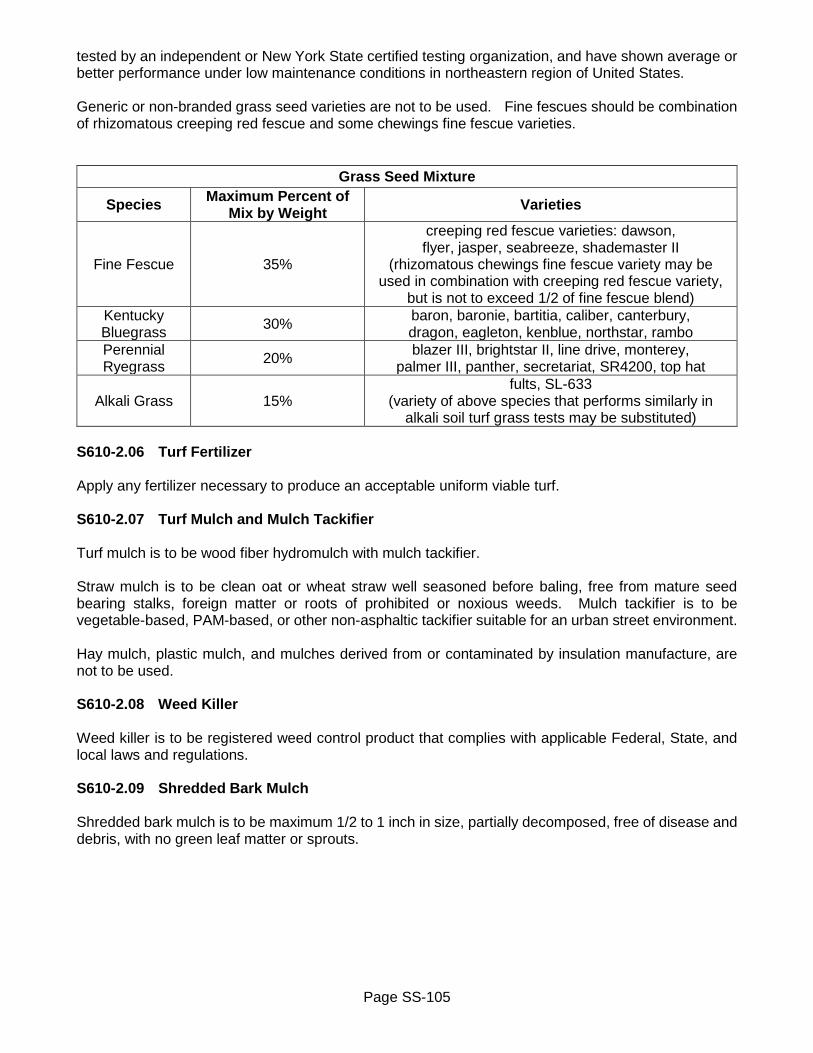
Page SS-105
tested by an independent or New York State certified testing organization, and have shown average or better performance under low maintenance conditions in northeastern region of United States. Generic or non-branded grass seed varieties are not to be used. Fine fescues should be combination of rhizomatous creeping red fescue and some chewings fine fescue varieties.
Grass Seed Mixture
Species Maximum Percent of Mix by Weight Varieties
Fine Fescue 35%
creeping red fescue varieties: dawson, flyer, jasper, seabreeze, shademaster II
(rhizomatous chewings fine fescue variety may be used in combination with creeping red fescue variety,
but is not to exceed 1/2 of fine fescue blend) Kentucky Bluegrass 30% baron, baronie, bartitia, caliber, canterbury,
dragon, eagleton, kenblue, northstar, rambo Perennial Ryegrass 20% blazer III, brightstar II, line drive, monterey,
palmer III, panther, secretariat, SR4200, top hat
Alkali Grass 15% fults, SL-633
(variety of above species that performs similarly in alkali soil turf grass tests may be substituted)
S610-2.06 Turf Fertilizer Apply any fertilizer necessary to produce an acceptable uniform viable turf. S610-2.07 Turf Mulch and Mulch Tackifier Turf mulch is to be wood fiber hydromulch with mulch tackifier. Straw mulch is to be clean oat or wheat straw well seasoned before baling, free from mature seed bearing stalks, foreign matter or roots of prohibited or noxious weeds. Mulch tackifier is to be vegetable-based, PAM-based, or other non-asphaltic tackifier suitable for an urban street environment. Hay mulch, plastic mulch, and mulches derived from or contaminated by insulation manufacture, are not to be used. S610-2.08 Weed Killer Weed killer is to be registered weed control product that complies with applicable Federal, State, and local laws and regulations. S610-2.09 Shredded Bark Mulch Shredded bark mulch is to be maximum 1/2 to 1 inch in size, partially decomposed, free of disease and debris, with no green leaf matter or sprouts.

Page SS-106
S610-2.10 Pea Stone Pea stone is to be washed, well graded, free from organic or other deleterious materials and is to meet following gradation requirements:
Screen Size Percent Passing by Weight 1/2 inch 100% 1/4 inch 85 to 100% 1/8 inch 0 to 15%
Material will be accepted on basis of Magnesium Sulfate Soundness Loss after 4 cycles of 20 percent or less. Not more than 30 percent, by weight, of particles retained on 1/2 inch sieve is to consist of flat or elongated particles. Flat or elongated particle is defined as one which has its greatest dimension more than 3 times its least dimension. Acceptance for this requirement will normally be based on visual inspection by Project Manager. When City elects to test for this requirement, material with percentage of flat or elongated particles that exceeds maximum 30 percent will be rejected. All material is to meet specified gradation requirements prior to placement. All processing of material is to be completed at originating source. Materials are to be stockpiled. Stockpile construction requirements, sampling, testing and acceptance or rejection procedures will be as stipulated in appropriate NYSDOT departmental publication. S610-2.11 Water Water is to have pH of between 6.0 and 8.0, and is to be free of oil and any other substance that may be harmful to plant growth. S610-3 CONSTRUCTION DETAILS S610-301 General Minimum of 14 days prior to commencing work, written schedule of planned operations for seeding/reseeding of lawn areas, application of fertilizers and weed killers is to submitted to Project Manager for approval. Such written schedule is also to include specific methods and materials to be used. At least 5 days prior to application, written notice is to be provided to Project Manager and residents of intent to apply grass seed, turf mulch and mulch tackifier, fertilizers and/or weed killers. Written notice to residents is to be in format as approved of by Project Manager. Do not apply weed killer at locations where resident objects to such application of weed killer. Existing surface areas are to be free of all undesirable material which is larger than 1 inch in its greatest dimension. Such undesirable materials are, but not limited to: refuse; paving materials such as concrete, asphalt, brick; materials which are toxic to plant growth and grass seed; subsoil; woody vegetation, stumps, roots, brush; clods, hard lumps, and rocks. Sod and herbaceous growth such as grass and weeds need not be removed from existing soil, but are to be thoroughly broken up and mixed into overall soil material. All embedded foreign objects are to be removed and resultant hole filled-in with topsoil material. Contractor is to remove and dispose of any undesirable materials prior to treating surface area.

Page SS-107
Existing surface is to be regraded as necessary to be uniform in contour and to meet required grades and cross-slopes without any irregularities. Finished grades and cross-slopes are to be uniformly sloping between tops of adjacent features such as sidewalks, driveways, curbs, or other existing lawn areas. Final surface contour is to be checked for accordance to required grades and cross-slopes by use of surveying instruments or other method as approved by Project Manager. Eliminate irregularities which form low areas and may tend to pond water when regrading, or by filling-in low area with either topsoil or embankment in place material. Excavation and disposal is to be in accordance with NYSDOT Section 203 Excavation and Embankment. Properly dispose of all excavated material off site within 24 hours. Stockpiling of excavated material at project site is not allowed. Buildings, paved areas, plantings and other non-seeded areas are to be protected from any excessive over-spray of any of materials that are being applied. S610-3.02 Tree Protection Existing trees and tree roots within project limits are to be protected from damage by construction activities. Construction or excavated materials are not to be placed or stockpiled within limits of canopy of any existing tree, to prevent smothering of existing tree root system. Vehicles and other construction equipment are not to be parked on any tree root system, nor left running (idling) under limits of canopy of any existing tree. Where cutting of existing tree roots is necessary, it is to be done with sharp cutting tools. Exposed tree roots are to be re-buried as soon as possible. Until exposed tree roots can be re-buried, exposed tree roots are to be covered with wet burlap. Burlap is to be kept wet until exposed tree roots can be re-buried. Existing trees that are damaged by construction activities are to be repaired within 72 hours using current arboricultural standards. Those existing trees that are determined by City Forester to be damaged beyond repair, are to be removed and replaced by Contractor. Topsoil that is placed around an existing tree is not to be placed any higher than 3 inches of original surface area at base of existing tree. S610-3.03 Soil Amendments Soil amendments are to be applied at rate sufficient to bring chemistry of existing soil to an pH acceptable range as determined by testing lab. Soil amendments are to be applied in accordance with manufacturer’s instructions for safe and effective application. S610-3.04 Topsoil and Compaction Topsoil material is to be placed and compacted in accordance with Section S613 Topsoil. S610-3.05 Surface Preparation for Turf Establishment Finished surface is to be flush with, or not greater than 1/4 inch above finished surface of adjacent surfaces. Prior to seeding, existing surface is to be prepared per Subsection S610-3.01 General. Finished surface is to be uniform and smooth, and in accordance with required grades and cross-slopes. Finished surface is not to have any irregularities greater than 1 inch as measured from 10 foot long straight edge laid on finished surface. In built-up and residential areas, this may require that existing surface be regraded and hand raked. Topsoil material is to be used to adjust existing surface to

Page SS-108
required degree of smoothness and uniformity. Finished surface is to be maintained to required grades and cross-slopes, placing any additional topsoil material that may be necessary to correct any irregularities that may have developed. If additional topsoil material is required, surface is to be properly prepared to ensure cohesiveness between materials. Tops and bottoms of all slopes are to be rounded to blend into each other and into existing adjacent surface areas so as not to leave any noticeable sharp breaks. Cuts and fills are to have maximum slope of 3 feet horizontally to 1 foot vertically. Surface preparation work is to in accordance with Method 1, unless Method 2 has been specifically required in Contract Documents. Regardless of which method is used, finished surface of any area that is to be seeded is not to be rougher, or more uneven, than any adjacent existing lawn areas. A. Method 1
Surface area to be seeded is to be scarified to depth of 1/2 inch to break-up surface crust immediately before seeding. undesirable materials are to be removed and properly disposed of off-site.
B. Method 2
Surface area to be seeded is to be harrowed, disced, or otherwise completely pulverized to state of tillage acceptable to Project Manager. Undesirable materials are to be removed and properly disposed of off-site.
S610-3.06 Turf Establishment A. General
Utilize all measures as may be necessary to produce finished product that provides continuous blanket of turf, that demonstrates relatively uniform height that is free of undesirable grasses, weeds, molds, mosses, algae, lichens, disease, and other undesirable characteristics. Within 2 days of having applied grass seed, Contractor is to provide written notice to residents on proper procedure for protecting and caring for seeded areas. Written notice to is to be in format as approved of by Project Manager. Areas disturbed by construction activities that are not to be paved or otherwise landscaped, are to be fine graded and seeded.
B. Hydroseeding (Two Step Method)
Use hydromulcher (sprayer) and apply materials in accordance with manufacturer’s recommendations. Apply materials at rate of application sufficient to meet required performance criteria, but not less than following:
• Grass seed - rate recommended by manufacturer • Wood fiber mulch - 1,500 pounds per acre • Mulch tackifier - rate recommended by manufacturer
C. Dry Seeding
Perform grass seeding operations when soil, wind, and other conditions are appropriate, at rate of

Page SS-109
application sufficient to meet required performance criteria, but not less than rate recommended by grass seed vendor.
D. Straw Mulch
Straw mulch may be used in lieu of hydromulch and only if approved for use by Project Manager. Straw mulch is to be placed uniformly in continuous blanket on seeded areas within 24 hours of having placed seed, and anchored with liquid tackifier. Apply materials at rate of application sufficient to meet required performance criteria, but not less than following:
• Straw mulch - 2-1/2 tons per acre, or two 50 pound bales per 1,000 square feet of area • Liquid tackifier - rate recommended by manufacturer
S610-3.07 Weed Killer Apply an approved weed killer as necessary to help produce relatively weed free turf. Weed killer may be used only after having received written approval from Project Manager. Weed killer is to be applied according to manufacturer’s safety and application recommendations, and in compliance with all applicable Federal, State and local ordinances, laws and regulations for public notice and methods of application. S610-3.08 Turf Maintenance Maintain all seeded areas until they have obtained continuous blanket of turf that is of relatively uniform height that is free of undesirable grasses, weeds, molds, mosses, algae, lichens, disease, and other undesirable characteristics, and has been accepted by City. Maintenance will include but is not limited to: soil amendment; fertilizing; watering; de-weeding; mowing; applications of herbicides, fungicides, insecticides; regrading and reapplication of topsoil; and reseeding. Areas of topsoil or seeded areas that become washed out, eroded, rutted, damaged, settled below required grades, or achieve unsatisfactory germination, are to be repaired. Water is to be applied to adequately maintain surface soil moisture for proper seed germination. After seed has germinated, continue to regularly water seeded area until initial growth of turf has been accepted by City. Until initial growth of turf has been accepted by City, turf areas are to be mowed as frequently as necessary to maintain maximum turf height of 4 inches and to minimize weed growth. No more than 1/3 of height of grass blade is to be mowed off during any one mowing operation. After reasonable period of time has elapsed, if Project Manager determines that any seeded area has failed to have satisfactorily produced thriving turf due to seeding operations and/or lack of proper maintenance, Contractor is to repeat all of work required by this specification to repair such failed area until satisfactory growth of turf has been established. Acceptance of established turf by City will be based on turf having achieved performance standards in accordance with Subsection S610-3.09 Performance Acceptance Measures. S610-3.09 Performance Acceptance Measures Only turf that demonstrates that it has achieved required growth and quality characteristics as outlined
Page SS-110
in this specification to satisfaction of Project manager, will be accepted by City. Factors for assessing turf will include, but not be limited to: topsoil pH; uniformity of turf color, texture, height and density of growth; overall coverage of areas designated for seeding; absence of undesirable grasses, weeds, molds, mosses, algae, lichens, disease, and other undesirable characteristics; and uniformity of slope and overall drainage of surface. S610-3.10 Shredded Bark Mulch/Pea Stone If required, weed fabric barrier is to be placed over area to be treated before shredded bark mulch/pea stone is placed. Shredded bark mulch/pea stone is to be uniformly spread to required thickness and lightly compacted. Shredded bark mulched/pea stone area is to be cared for until final acceptance of project. Such care is to consist of providing protection against pedestrian traffic by installing approved warning signs and barricades. Treated areas damaged by erosion, wind, fire or other causes are to be repaired as soon as possible to reestablish condition and grade of area prior to placing shredded bark mulch/pea stone, then retreated with new shredded bark mulch/pea stone. S610-3.11 Site Preparation Site is to shaped and graded to final lines and grades as required in Contract Documents, and as required by Project Manager. Clean topsoil material stripped during shaping and grading operation is to be stockpiled on-site. Each stockpile is to contain at least 200 cubic yards of topsoil material, is to be at least 4 feet high, and is to be trimmed, shaped and maintained to uniform surfaces and slopes. Straw bales are to be placed around entire bottom of stockpile and staked to ground for control erosion. Stockpile is to be either thoroughly covered with weatherproof material, or seeded. Until stockpile has been adequately covered, periodically water down stockpile to minimize dust erosion. Weatherproof material used to cover stockpile is to be staked, tied, or otherwise weighted down. Weatherproof material is to be maintained as necessary by reaffixing any areas that become loose, replacing any areas where weatherproof material becomes torn, damaged or otherwise missing. Stockpile that is to be seeded, is to be seeded and maintained in accordance with Subsection S610-3.10 Construction Details. After all other phases of work are completed, all ground areas that are to be seeded are to be prepared in accordance with Subsection S610-3.10 Construction Details. If there is an insufficient amount of stockpiled topsoil material available on-site, supply and spread new topsoil material in accordance with Section S613 Topsoil. Any excess stockpiled topsoil material is to removed. S610-3.12 Water Water may be brought to project site and applied via water truck, or may be applied through use of any existing hydrant. Before being allowed to use water from existing hydrants, obtain necessary permit(s), and install backflow prevention device and approved water meter. Water is to be applied in such manner that required volume of water being applied does not damage, cause any erosion or otherwise disrupt any existing vegetation, mulch, plant saucers, sod, or areas of stockpiled topsoil material. S610-3.13 Clean-up and Repair Within 72 hours of having completed any of miscellaneous landscape operations, or of having received written notification of any damage, clean and/or repair all adjacent surfaces to treated areas that have
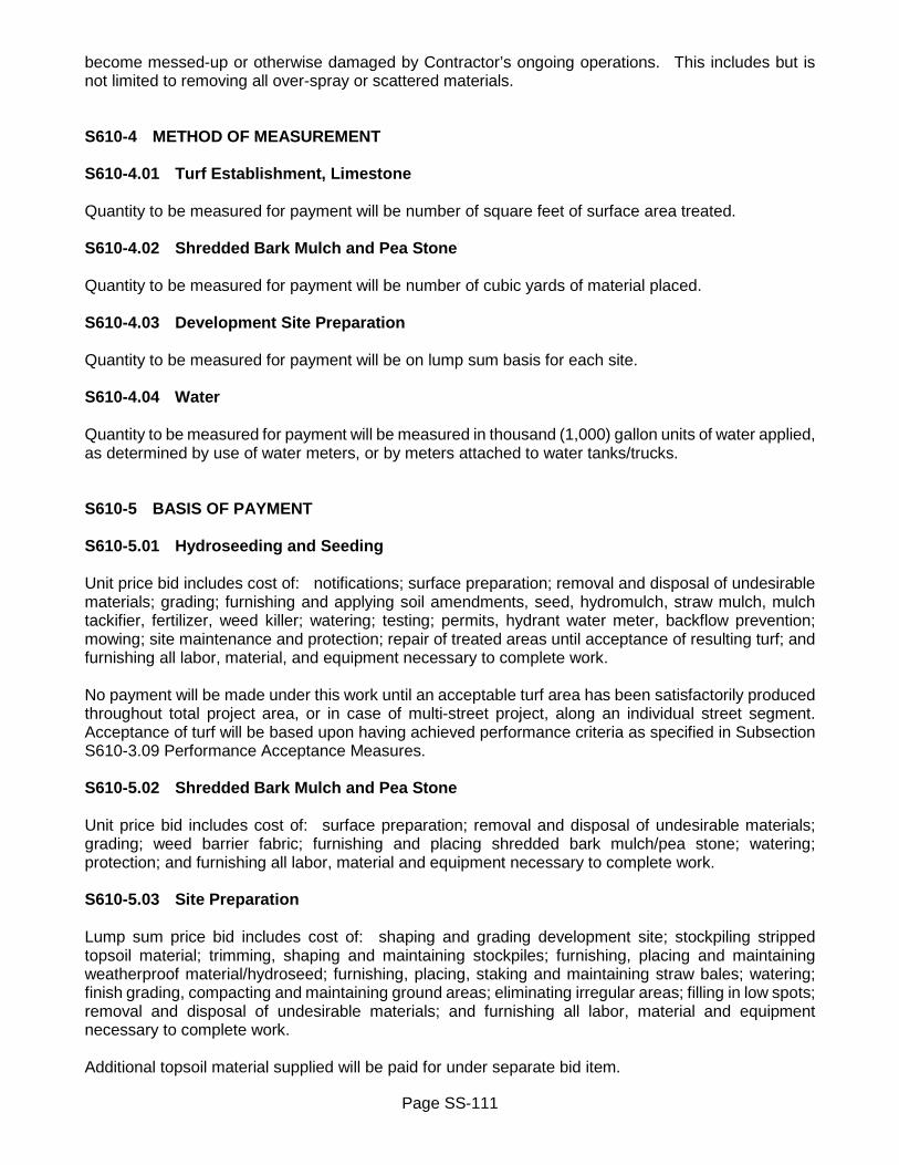
Page SS-111
become messed-up or otherwise damaged by Contractor’s ongoing operations. This includes but is not limited to removing all over-spray or scattered materials. S610-4 METHOD OF MEASUREMENT S610-4.01 Turf Establishment, Limestone Quantity to be measured for payment will be number of square feet of surface area treated. S610-4.02 Shredded Bark Mulch and Pea Stone Quantity to be measured for payment will be number of cubic yards of material placed. S610-4.03 Development Site Preparation Quantity to be measured for payment will be on lump sum basis for each site. S610-4.04 Water Quantity to be measured for payment will be measured in thousand (1,000) gallon units of water applied, as determined by use of water meters, or by meters attached to water tanks/trucks. S610-5 BASIS OF PAYMENT S610-5.01 Hydroseeding and Seeding Unit price bid includes cost of: notifications; surface preparation; removal and disposal of undesirable materials; grading; furnishing and applying soil amendments, seed, hydromulch, straw mulch, mulch tackifier, fertilizer, weed killer; watering; testing; permits, hydrant water meter, backflow prevention; mowing; site maintenance and protection; repair of treated areas until acceptance of resulting turf; and furnishing all labor, material, and equipment necessary to complete work. No payment will be made under this work until an acceptable turf area has been satisfactorily produced throughout total project area, or in case of multi-street project, along an individual street segment. Acceptance of turf will be based upon having achieved performance criteria as specified in Subsection S610-3.09 Performance Acceptance Measures. S610-5.02 Shredded Bark Mulch and Pea Stone Unit price bid includes cost of: surface preparation; removal and disposal of undesirable materials; grading; weed barrier fabric; furnishing and placing shredded bark mulch/pea stone; watering; protection; and furnishing all labor, material and equipment necessary to complete work. S610-5.03 Site Preparation Lump sum price bid includes cost of: shaping and grading development site; stockpiling stripped topsoil material; trimming, shaping and maintaining stockpiles; furnishing, placing and maintaining weatherproof material/hydroseed; furnishing, placing, staking and maintaining straw bales; watering; finish grading, compacting and maintaining ground areas; eliminating irregular areas; filling in low spots; removal and disposal of undesirable materials; and furnishing all labor, material and equipment necessary to complete work. Additional topsoil material supplied will be paid for under separate bid item.
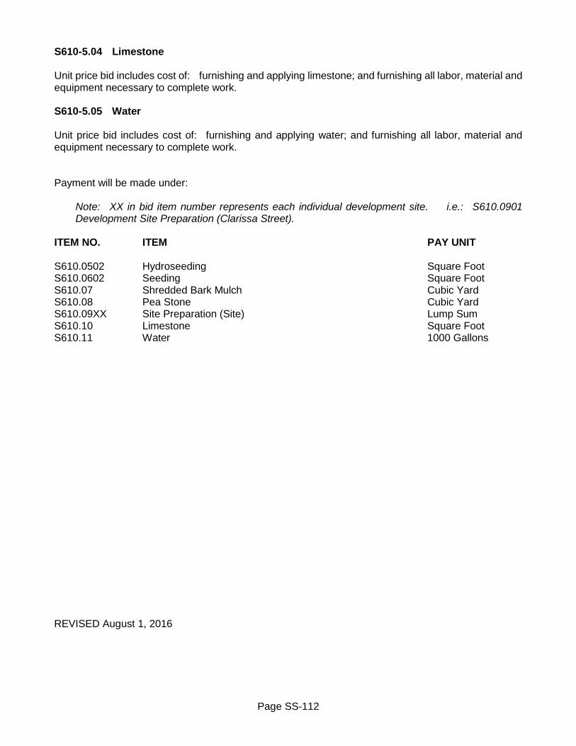
Page SS-112
S610-5.04 Limestone Unit price bid includes cost of: furnishing and applying limestone; and furnishing all labor, material and equipment necessary to complete work. S610-5.05 Water Unit price bid includes cost of: furnishing and applying water; and furnishing all labor, material and equipment necessary to complete work. Payment will be made under:
Note: XX in bid item number represents each individual development site. i.e.: S610.0901 Development Site Preparation (Clarissa Street).
ITEM NO. ITEM PAY UNIT S610.0502 Hydroseeding Square Foot S610.0602 Seeding Square Foot S610.07 Shredded Bark Mulch Cubic Yard S610.08 Pea Stone Cubic Yard S610.09XX Site Preparation (Site) Lump Sum S610.10 Limestone Square Foot S610.11 Water 1000 Gallons REVISED August 1, 2016

Page SS-113
SECTION S613 - TOPSOIL S613-1 DESCRIPTION Work consists of furnishing and placement of topsoil as required in Contract Documents and as directed by Project Manager. References to NYSDOT specifications are to be in accordance with latest edition of NYSDOT Standard Specifications (US Customary Units). S613-2 MATERIALS S613-2.01 Topsoil Topsoil material is to be natural, fertile, friable soil typical of local region. Topsoil material is to be surface layer of soil, and is to be free of all undesirable material which is larger than 1 inch in its greatest dimension. Sod and herbaceous growth such as grass and weeds need not be removed from topsoil material, but are to be thoroughly broken up and mixed into overall topsoil material. Undesirable materials are but not limited to refuse; paving materials such as concrete, asphalt, brick; materials which are toxic to plant growth and grass seed; subsoil, woody vegetation, stumps, roots, brush, clods, hard lumps, stones and rocks. Topsoil material is to have pH range of between 6.0 and 7.5, organic content of between 2 and 20 percent (dry weight basis), and is to meet following gradation requirements:
Screen Size Percent Passing by Weight 2 inch 100% 1 inch 85 to 100%
1/4 inch 65 to 100% #200 20 to 80%
Submit certification statement from topsoil supplier stating existing pH level, percentage of organic content and gradation. If necessary certification is to also state any recommendations on usage of amendments required to produce topsoil material conforming to required pH range. Topsoil material amendments that are to be used for adjustment of soil chemistry are to be standard commercial type including but not limited to ground limestone; gypsum; products containing phosphorus, potassium, sulphur, et cetera. Limestone is to be standard, pulverized commercial type having minimum total neutralizing value of 88 percent calcium carbonate equivalence, which is to be applied at rate sufficient to bring existing pH of topsoil material to required range of 6.0 to 7.5, as determined by testing. S613-2.02 Stockpiling and Testing Topsoil material may be acquired from previously approved site that is designated in Contract Documents. If no such previously approved site has been designated, Contractor is to notify Project Manager of intended source of topsoil material minimum of 21 days prior to scheduled use to allow for sampling and testing of topsoil material. Topsoil material is to come from stockpile that contains at least 200 cubic yards of topsoil material, is at least 4 feet high, and is trimmed, shaped and maintained to uniform surfaces and slopes.

Page SS-114
S613-2.03 Rejection/Acceptance of Topsoil Material Topsoil material which does not conform to material requirements, receives any unsatisfactory test result, contains any undesirable foreign material; has offensive or objectionable overpowering odor, or lacks certification statement from supplier, will be rejected. Acceptance of topsoil material will be based upon satisfactory test results, absence of any offensive or objectionable overpowering odor, and receipt of supplier’s certification statement. Project Manager will notify Contractor in writing that topsoil material has been rejected, or accepted for use. S613-3 CONSTRUCTION DETAILS S613-3.01 General Where Contractor is required to place topsoil material on existing surface that has been prepared by others, Contractor is to notify Project Manager in writing if existing surface is unsuitable for placement of topsoil material. Appropriate action is to be taken to rectify condition of existing surface before placing any topsoil material. S613-3.02 Tree Protection Contractor is to protect all existing trees and tree roots within project limits from damage by construction activities. Contractor is not to place or stockpile any construction or excavated materials within limits of canopy of any existing tree to prevent smothering of existing tree’s root system. Vehicles and other construction equipment are not to be parked on any tree root system, nor left running (idling) under limits of canopy of any existing tree. Where cutting of existing tree roots is necessary, it is to be done with sharp cutting tools. Exposed tree roots are to be re-buried as soon as possible. Until exposed tree roots can be re-buried, exposed tree roots are to be covered with wet burlap. Burlap is to be kept wet until exposed tree roots can be re-buried. Existing trees that are damaged by construction activities are to be repaired within 72 hours using current arboricultural standards. Those existing trees that are determined by City Forester to be damaged beyond repair, are to be removed and replaced by Contractor. Topsoil that is placed around an existing tree is not to be placed any higher than 3 inches of original surface area at base of existing tree. S613-3.03 Soil Amendments If required, soil amendments are to be applied according to manufacturer’s instructions for safe and effective application, and at rate sufficient to bring chemistry of topsoil material to required pH range. During turf establishment, City may have further tests done on topsoil material. Any topsoil material which is not in accordance is to be further treated with amendments or replaced with new topsoil material. S613-3.04 Surface Preparation Existing surface is to be re-graded as necessary to be uniform in contour, to meet required grades and cross-slopes, and to be free of irregularities. Finished grades and cross-slopes are to be uniformly
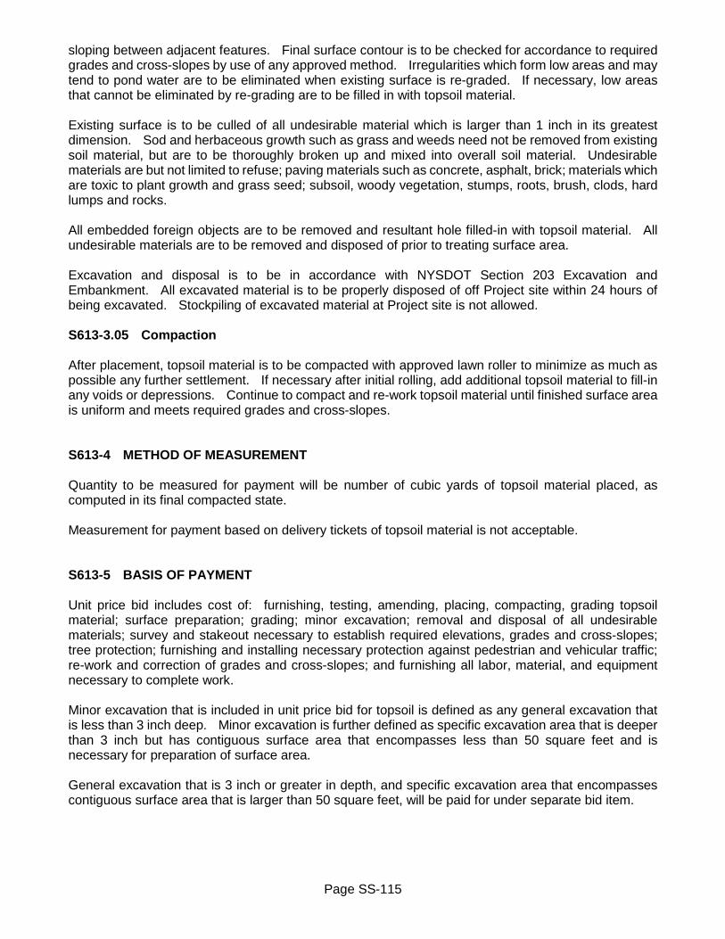
Page SS-115
sloping between adjacent features. Final surface contour is to be checked for accordance to required grades and cross-slopes by use of any approved method. Irregularities which form low areas and may tend to pond water are to be eliminated when existing surface is re-graded. If necessary, low areas that cannot be eliminated by re-grading are to be filled in with topsoil material. Existing surface is to be culled of all undesirable material which is larger than 1 inch in its greatest dimension. Sod and herbaceous growth such as grass and weeds need not be removed from existing soil material, but are to be thoroughly broken up and mixed into overall soil material. Undesirable materials are but not limited to refuse; paving materials such as concrete, asphalt, brick; materials which are toxic to plant growth and grass seed; subsoil, woody vegetation, stumps, roots, brush, clods, hard lumps and rocks. All embedded foreign objects are to be removed and resultant hole filled-in with topsoil material. All undesirable materials are to be removed and disposed of prior to treating surface area. Excavation and disposal is to be in accordance with NYSDOT Section 203 Excavation and Embankment. All excavated material is to be properly disposed of off Project site within 24 hours of being excavated. Stockpiling of excavated material at Project site is not allowed. S613-3.05 Compaction After placement, topsoil material is to be compacted with approved lawn roller to minimize as much as possible any further settlement. If necessary after initial rolling, add additional topsoil material to fill-in any voids or depressions. Continue to compact and re-work topsoil material until finished surface area is uniform and meets required grades and cross-slopes. S613-4 METHOD OF MEASUREMENT Quantity to be measured for payment will be number of cubic yards of topsoil material placed, as computed in its final compacted state. Measurement for payment based on delivery tickets of topsoil material is not acceptable. S613-5 BASIS OF PAYMENT Unit price bid includes cost of: furnishing, testing, amending, placing, compacting, grading topsoil material; surface preparation; grading; minor excavation; removal and disposal of all undesirable materials; survey and stakeout necessary to establish required elevations, grades and cross-slopes; tree protection; furnishing and installing necessary protection against pedestrian and vehicular traffic; re-work and correction of grades and cross-slopes; and furnishing all labor, material, and equipment necessary to complete work. Minor excavation that is included in unit price bid for topsoil is defined as any general excavation that is less than 3 inch deep. Minor excavation is further defined as specific excavation area that is deeper than 3 inch but has contiguous surface area that encompasses less than 50 square feet and is necessary for preparation of surface area. General excavation that is 3 inch or greater in depth, and specific excavation area that encompasses contiguous surface area that is larger than 50 square feet, will be paid for under separate bid item.
Page SS-116
Payment will be made under: ITEM NO. ITEM PAY UNIT S613.03 Topsoil Cubic Yard REVISED March 3, 2015

Page SS-117
SECTION S614 - CARE OF PLANTS S614-1 DESCRIPTION Work consists of pruning, transplanting, or removal of existing plants and stumps as required in Contract Documents and as directed by Project Manager. References to NYSDOT specifications are to be in accordance with latest edition of NYSDOT Standard Specifications (US Customary Units). S614-2 MATERIALS None specified. S614-3 CONSTRUCTION DETAILS S614-3.01 General Trunks, branches, rubbish and debris resulting from work is to be removed and disposed of in accordance with NYSDOT Section 201 Clearing and Grubbing. Existing features within public right-of-way and private property immediately adjacent to public right-of-way are to be protected to limit any possible damage from occurring due to Contractor’s operations. Any damage incurred while performing any work under this specification is to be immediately repaired. Workers are not permitted to climb trees with climbing spurs, but are to employ other acceptable tree climbing methods. Only tools and methods of work that are acceptable are to be used. Cutting surfaces of all tools, ladders, ropes, soles of workers shoes and other objects coming into contact with plant are to be washed with approved disinfectant at start of any work on plant to prevent spread of any plant born disease. If in opinion of Project Manager, unsafe tools, equipment or methods are being used, work will be stopped until such unsafe conditions have been corrected. S614-3.02 Pruning All work is to be performed in accordance with ANSI Z133.1, ISA Tree Pruning Guidelines and as required by City Forester. Existing plant is to be pruned of undesirable wood, and resulting crown re-shaped to natural habit of plant. Branches interfering with or hindering healthy growth of existing plant are to be removed. Diseased or dead branches are to be removed. Branches which may be partially dead, yet has healthy lateral branch at least 1/3 diameter of parent branch, are to be trimmed beyond healthy portion of branch, providing result does not prove to be unsightly in which case branch is to be completely removed. Stubs or improper cuts resulting from former pruning operations are to be removed. Branches on existing plants that interfere with vehicular or pedestrian sight distance, traffic signs or street lights, are to be removed. Overhanging branches that are less than 16 feet above any part of roadway, or 7 feet above any part of sidewalk, are to be removed. Existing plants are to be additionally pruned so as to allow minimum lateral clearance along sidewalk of 12 inches. Cuts are to be cleanly made with sharp tools as close to parent trunk or limb as possible, without disturbing callus collar. Large bark wounds are to be scar traced in accordance with good horticultural practice. Nails, spikes, wire or other foreign materials driven into or fastened to plant are to be either

Page SS-118
removed, or if approved cut flush in manner to permit complete healing over. S614-3.03 Transplanting Existing plants are to be transplanted in accordance with ANSI Z60.1 Transplanting. Transplanting is to be done by using tree spade of proper dimensions for size of plant which is to be transplanted. Transplanted plants are to be planted at same depth as plant originally grew. Transplanted plants are to be planted and maintained in accordance with Section S611 Planting. Pit at least twice size of root ball is to be dug, and plant set centered and plumb within pit. Burlap wrap and twine enclosing root ball is to be peeled back to expose top 1/2 of root ball, and all wraps and ropes removed. Prepared soil mix backfill material consisting of 2 parts native excavated material, 1 part saturated peat moss and 1 part topsoil is to be placed in 6 inch layers and thoroughly watered in to eliminate air pockets. Additional backfill material is to be placed and further watered in to compensate for any settlement. Backfill material is to be treated with slow release nitrogen thoroughly watered into backfill material. S614-3.04 Removal No cutting is to begin on any existing plant that is scheduled to be removed until approval has been received from Project Manager. Trees are to be topped and limbed before felling. Stumps are to be removed by grubbing, grinding or cutting. Stump holes are to be backfilled and compacted within 2 working days after removal of stump. S614-4 METHOD OF MEASUREMENT Quantity to be measured for payment will be number of existing plants pruned, transplanted or removed. Multiple plants growing out of same general excavation or pit will be measured as one plant. Measurement for payment of tree and stump removal under this section, will only be for those trees and stumps that are 6 inches in diameter and larger. Payment for removal of trees and stumps that are less than 6 inches in diameter will be included under Item 203.02 Unclassified Excavation and Disposal. Measurement range for tree and stump removal will be as noted, with measurement being rounded to nearest inch. For example, 11.4 inch will be made as 11 inch; 11.5 inch will be made as 12 inch. Diameter of existing tree is to be measured before beginning work, with measurement being made 4 feet 6 inches above ground, commonly referred to as DBH (Diameter at Breast Height). Separate payment for removal of existing stumps is limited only to existing stumps where tree was previously removed by others. Stumps that result from removal of respective existing tree by Contractor will be paid for under appropriate tree removal item. Diameter of existing stump is to be measured before beginning work, with measurement being made across top of stump.

Page SS-119
S614-5 BASIS OF PAYMENT S614-5.01 General All Items Unit price bid for all items includes cost of: removal and disposal of wood debris; protection of existing features; coordination with utilities; and furnishing all labor, material and equipment necessary to complete work. S614-5.02 Prune Existing Plant Unit price bid also includes cost of: cutting, removing and disposing undesirable growth and foreign materials; shaping plant crown; and repair of bark wounds. S614-5.03 Transplant Existing Plant Unit price bid also includes cost of: removing, balling, storing, trimming and re-planting existing plants; staking system; burlap; rope; prepared soil mix; hardwood mulch; water well; mulch retention pit; excavation and backfill. S614-5.04 Remove Existing Shrub Unit price bid also includes cost of: removing and disposing existing shrub and stump; excavation and backfill. Removal of existing shrubs will be paid for under either NYSDOT Section 201 Clearing and Grubbing, Section R203 Excavation and Embankment, or Section S614 Care of Plants, as indicated in Contract Documents. S614-5.05 Remove Existing Tree Unit price bid also includes cost of: removing and disposing existing tree and stump; excavation and backfill. S614-5.06 Remove Existing Stump Unit price bid also includes cost of: grubbing, grinding, cutting and disposing existing stump; excavation and backfill. Payment will be made under:
Note: XX in bid item number represents each individual size of tree to be transplanted. i.e.: 6” tree would be bid as S614.3306 Transplant Existing Tree – 6” DBH.
ITEM NO. ITEM PAY UNIT S614.30 Prune Existing Shrub Each S614.31 Prune Existing Tree Each S614.32 Transplant Existing Shrub Each S614.33XX Transplant Existing Tree - X" DBH Each S614.34 Remove Existing Shrub Each S614.35 Tree Removal - 6" to 11" DBH Each S614.36 Tree Removal - 12" to 17" DBH Each S614.37 Tree Removal - 18" to 23" DBH Each S614.38 Tree Removal - 24" to 29" DBH Each

Page SS-120
ITEM NO. ITEM PAY UNIT S614.39 Tree Removal - 30" to 35" DBH Each S614.40 Tree Removal - 36" to 41" DBH Each S614.41 Tree Removal - 42" to 47" DBH Each S614.42 Tree Removal - 48" DBH and over Each S614.43 Stump Removal - 6" to 11" diameter Each S614.44 Stump Removal - 12" to 17" diameter Each S614.45 Stump Removal - 18" to 23" diameter Each S614.46 Stump Removal - 24" to 29" diameter Each S614.47 Stump Removal - 30" to 35" diameter Each S614.48 Stump Removal - 36" to 41" diameter Each S614.49 Stump Removal - 42" to 47" diameter Each S614.50 Stump Removal - 48" diameter and over Each REVISED December 1, 2015

Page SS-121
SECTION S617 - TREE PROTECTION S617 GENERAL It is responsibility of Contractor to provide tree protection fencing for all existing trees and tree root systems that are located within and immediately adjacent to Project limits to minimize any possible damage due to construction activities. References to NYSDOT specifications are to be in accordance with latest edition of NYSDOT Standard Specifications (US Customary Units). S617-1 DESCRIPTION Work consists of protection and care of existing trees as required in Contract Documents and as directed by Project Manager. S617-2 MATERIALS Tree protection fence material may be either fluorescent orange construction safety fencing, or wood rail and post. Tree protection fence is to be at least 4 feet high. Water is to be in accordance with NYSDOT Section 712-01 Water. S617-3 CONSTRUCTION DETAILS S617-3.01 General Tree protection is to be provided to protect all existing trees within and immediately adjacent to project limits against any accidental cutting, breaking, skinning, or bruising of tree roots, tree bark and tree branches due to Contractor’s operations. Tree protection fencing is to be installed before any construction activities commence, and is to remain in place until Contractor is ready to perform final grading and seeding operations. Before commencing any work within any established tree protection zone, Contractor is to receive written authorization from representative of City Forester's office. Contractor is not to place or stockpile any construction or excavated materials within limits of canopy of any existing tree to prevent smothering of existing tree’s root system. Vehicles and other construction equipment are not to be parked on any tree root system, nor left running (idling) under limits of canopy of any existing tree. Cutting of existing sod and topsoil materials within 4 feet of existing tree trunk for removal to establish new finished grade must be done manually. Existing tree root system must remain adequate for existing tree to withstand heavy windstorms. If any existing tree roots that are 2 inches in diameter or larger are in conflict with any proposed work and need to be cut, before cutting those tree roots Contractor must notify City Forestry section by calling (585) 428-7581 to arrange for inspection of existing tree root system. S617-3.02 Fencing Existing tree is to be fenced in such manner that tree protection fencing encompasses entire limit of canopy of existing tree. In no case is tree protection fencing to be less than 2 feet from outer edge of

Page SS-122
existing tree trunk. In those areas where existing tree is bordered by paved surface, curb, wall or building, and minimum tree protection fence dimensions cannot be achieved, tree protection fence is to be installed to within 12 inches of nearest edge of such paved surface, curb, wall or building. Tree protection fencing is to be installed around existing tree according to following extents:
Tree Diameter (DBH) (inches)
Minimum Distance of Fence from Tree Trunk – each side
(feet) less than 10 6 10 thru 14 10 15 thru 19 12
20 and over 15 S617-3.03 Maintenance Tree protection fencing is to be maintained in good condition, and in an upright position. Tree protection fencing that has been damaged, collapsed or been knocked down, or otherwise damaged, is to be restored within 24 hours. Where cutting of existing tree roots is necessary, it is to be done with sharp cutting tools. Exposed tree roots are to be re-buried as soon as possible. Until exposed tree roots can be re-buried, exposed tree roots are to be covered with wet burlap. Burlap is to be kept wet until exposed tree roots can be re-buried. Where extensive cutting of existing tree root system has occurred, existing tree root system is to be watered to extent of limits of canopy of existing tree. Apply minimum 1/2 inch of water within 72 hours of when extensive cutting of existing tree root system has occurred. When weather conditions are consistently dry and when less than 1/2 inch of rain has fallen during any given week, water existing tree root system to extent of limits of canopy of existing tree with at least 1 inch of water. Existing trees that are damaged by construction activities are to be repaired within 72 hours using current arboricultural standards. Those existing trees that are determined by City Forester to be damaged beyond repair, are to be removed and replaced by Contractor. S617-3.04 Utility Installation Where underground installation of new utility is required to be done within outer limits of canopy of existing tree, tunneling operation is to be used for installation of new utility. Tunneling within outer limits of canopy of existing tree is to be done according to following:
Tree Diameter (DBH) (inches)
Distance of Tunnel From Tree Trunk – each side
(feet)
Minimum Recommended Depth
(feet) less than 10 6 2-1/2 10 thru 14 10 3 15 thru 19 12 3-1/2
20 and over 15 4
Page SS-123
S617-4 METHOD OF MEASUREMENT Quantity to be measured for payment will be number of linear feet of tree protection fence installed, as measured along top of tree protection fence, center to center of end posts. S617-5 BASIS OF PAYMENT Unit price bid includes cost of: furnishing, installing, maintaining and removing tree protection fence; hardware; watering; cutting, maintenance and repair of damaged tree roots; burlap; repair or replacement of damaged existing trees; and furnishing all labor, material and equipment necessary to complete the work. Payment will be made under: ITEM NO. ITEM PAY UNIT S617.01 Fencing for Tree Protection Linear Foot REVISED March 3, 2015

Page SS-124
SECTION 619 – WORK ZONE TRAFFIC CONTROL 619 GENERAL Purpose of this directive is to designate certain NYSDOT bid items for use on all City projects. References to NYSDOT specifications are to be in accordance with latest edition of NYSDOT Standard Specifications (US Customary Units). Work is to be in accordance with requirements of NYSDOT Section 619 Work Zone Traffic Control for following bid items, and with following modifications: 619-5 BASIS OF PAYMENT UNDER Subsection 619-5.01 General, A. Non-Payment, DELETE Table 619-7 in its entirety, and REPLACE with the following:
TABLE 619-7 BASIC WORK ZONE TRAFFIC CONTROL NON-PAYMENT Original Contract Amount Non-Payment
Amount From More Than To and Including $ 0 $ 100,000 $ 100 $ 100,000 $ 500,000 $ 200 $ 500,000 $ 1,000,000 $ 300 $ 1,000,000 $ 2,500,000 $ 400 $ 2,500,000 $ 5,000,000 $ 500 $ 5,000,000 $ 10,000,000 $ 750 $ 10,000,000 $ 20,000,000 $ 1,000 $ 20,000,000 over $ 3,000
Payment will be made under:
Note: nn in bid item number represents each individual location as defined in Contract Documents. ITEM NO. ITEM PAY UNIT 619.01 Basic Work Zone Traffic Control Lump Sum 619.04 Type III Construction Barricades Each 619.0901 Temporary Pavement Markings, Stripes Linear Foot 619.100101 Interim Pavement Markings, Stripes Linear Foot 619.100201 Interim Pavement Markings, Symbols Each 619.100301 Interim Pavement Markings, Letters Each 619.13nn Temporary Traffic Signals Each Location 619.1611 Maintain Traffic Signal Equipment (Requirement A) Intersection Month 619.1612 Maintain Traffic Signal Equipment (Requirement B) Intersection Month 619.1613 Maintain Traffic Signal Equipment (Requirement C) Intersection Month 619.1614nn Modify Existing Traffic Signal Equipment (Temporary) Each Location 619.27 Mailboxes Each REVISED March 1, 2017
Page SS-125
SECTION 625 – SURVEY OPERATIONS 625 GENERAL Purpose of this directive is to designate certain NYSDOT bid items for use on all City projects. References to NYSDOT specifications are to be in accordance with latest edition of NYSDOT Standard Specifications (US Customary Units). Work is to be in accordance with requirements of NYSDOT Section 625 Survey Operations for following bid item: 625-5 BASIS OF PAYMENT Payment will be made under: ITEM NO. ITEM PAY UNIT 625.01 Survey Operations Lump Sum ISSUED December 1, 2015

Page SS-126
SECTION S626 - SURVEY MONUMENT S626 GENERAL As of start work date as established by Notice to Proceed is issued, protection of all survey monuments within limits of project site is responsibility of General Contractor. If survey monument is found destroyed commencing on start work date, and party responsible for destroying survey monument is unclear or undeterminable, survey monument is to be replaced at Contractor’s expense. Prior to commencing construction, Contractor is responsible to contact City’s Maps and Surveys office to verify that necessary ties have been taken for all survey monuments. Survey monument issues that remain unresolved over 90 calendar days from date of discovery may result in declaration of contract default. In case of utility Contractor(s), permits for proposed utility work may be withheld until any outstanding survey monument issues have been resolved. New or replacement horizontal control survey monument is to have monument line intersection physically defined with mark appropriate to type of survey monument being installed. S626-1 DESCRIPTION Work consists of installation of new survey monument; adjustment, abandonment or removal of existing survey monument; installation of new and resetting of existing survey monument frame and cover; related survey work, preparation and submittal of survey data and survey monument certification; as required in Contract Documents, and as directed by City’s Maps and Surveys office and Project Manager. References to NYSDOT specifications are to be in accordance with latest edition of NYSDOT Standard Specifications (US Customary Units). S626-2 MATERIALS S626-2.01 Horizontal Control Survey Monument (RCS) Horizontal control survey monument is to be granite and come from approved quarries. Granite is to be light colored, sound and durable, free from seams which impair its structural integrity and of smooth splitting and machining character. Granite is to be rough quarried to required dimensions, with top having smooth finish. Quarrying holes are not permitted in top of granite. S626-2.02 Vertical Control Survey Monument (RTS) Vertical control survey monument is to be constructed of Class K concrete, with number 5 (5/8 inch) rebar set in center of and running for full length of concrete survey monument. Rebar is to be grade 60 in accordance with NYSDOT Section 709-01 Bar Reinforcement, Grade 60. If used, rebar cap is to be brass 2 inch diameter domed cap with plastic insert in accordance with SKB-

Page SS-127
108-2D as manufactured by Surv-Kap, or approved equivalent. S626-2.03 Survey Monument Frame and Cover Survey monument frame and cover castings are to be cast iron, with letters RCS cast into top of cover, per standard detail, or approved equivalent. Equivalent frame and cover castings may be used only with prior written approval by Maps and Surveys office. Upon request, dimensional requirements will be provided by Maps and Surveys office. Heavy-duty survey monument frame and cover castings to be in accordance with EJ #4178A and #4178Z as manufactured by EJ Group, or approved equivalent. S626-2.04 Brass Disc Survey Marker (RCS) - Furnished Brass disc survey marker will be as furnished by Maps and Surveys office. Contractor is to pick up and sign for brass disc survey marker during normal business hours from Maps and Surveys office, City Hall Room 225B, 30 Church Street, Rochester, New York, Monday through Friday, between hours of 8:00AM and 2:00PM, (585) 428-6873. Maps and Surveys office requires minimum of 2 working days advance notice to make arrangements for pickup of furnished materials. S626-2.05 Backfill Backfill is to be select granular fill is to be in accordance with NYSDOT Section 203 Excavation and Embankment. Recycled materials, pulverized or recycled portland cement concrete aggregate (RCA) and brick, reclaimed asphalt pavement (RAP), and Corian® are unacceptable for use as backfill material, unless specifically authorized in writing by City Engineer. S626-2.06 Concrete Concrete is to be Class K in accordance with Section S504 Portland Cement Concrete. S626-2.07 Grout Grout is to be non-shrink type grout with minimum compressive strength of 4000 psi at 24 hours in accordance with NYSDOT Section 701-05 Concrete Grouting and Anchoring Material. S626-3 CONSTRUCTION DETAILS S626-3.01 General New survey monument is to be set under direction of Land Surveyor licensed to practice in State of New York. Special attention is directed to Section 104-22 of Municipal Code of City of Rochester regarding requirements for permit when working in vicinity of survey monument, as reiterated herein:
Section 104-22. Interference with survey monuments.
No person shall interfere with, disturb or move any survey monument without having obtained a permit in writing from the City Engineer. Interference for the purpose of this section shall be defined as any excavation work within three feet of a survey monument or any extensive excavation work further than three feet from a survey monument that may affect the accuracy
Page SS-128
of the monument. Required data for survey monument certification submittal is to be prepared by NYS Licensed Land Surveyor and provided to Project Manager for delivery to, review and approval of Maps and Surveys office. Data for survey monument certification submittal and certification card is to be provided in accordance with Section S626-4 Survey Monument - Survey, Submittal and Certification Requirements. Submittal of either horizontal (RCS) or vertical (RTS) monument certification data to Maps and Surveys office does not constitute acceptance of survey monument. Written acceptance or rejection of each survey monument will be made by Maps and Surveys office after review of submitted data and certification card. New survey monument is to be installed complete with frame and cover. Top of survey monument is not to be less than 4 inches nor more than 6 inches below finished grade (except for brass disc survey markers). Rebar in vertical control survey monument structure is to be either topped with 2 inch diameter domed cap with plastic insert and tapered internal hole capable of accommodating ends of irregular shaped rebar; or rounded at top and extend 1/2 to 1 inch above top of concrete survey monument. Balance of excavation to be backfilled with select granular fill compacted in 6 inch layers. To make arrangements for pickup of salvaged materials, notify Maps and Surveys office between hours of 8:00AM and 2:00PM, Monday thru Friday, at (585) 428-6873. S626-3.02 Destroyed Survey Monument Survey monument that is found to be destroyed commencing on date to start work, and responsible party is unclear or cannot be determined, or in event that survey monument is destroyed due to construction operations, destroyed survey monument is to be replaced at Contractor’s expense with new survey monument of same type as one destroyed. Destroyed survey monument is one that has been:
• moved more than 0.02 of foot in any direction from its City tied position; or • broken; or • disturbed to point that survey monument’s position is no longer fixed or stable; or • excavated and removed from ground for any reason; or • vertically adjusted without prior written authorization of Maps and Surveys office
Horizontal control survey monument theoretical position of intersection of two monument lines is to be marked with drill hole on granite survey monument, or punch mark and cross on brass disc survey marker. Elevation of new vertical control survey monument is to be established. S626-3.03 New Survey Monument For purposes of this specification, new survey monument is defined as survey monument designated by Maps and Surveys office to be set, excluding those new survey monuments which are to be set to replace any destroyed survey monument. New survey monument is to be installed complete with frame and cover.

Page SS-129
New survey monument installations include:
• survey monument set to upgrade monument network density • survey monument set to replace existing survey monument in poor physical condition • survey monument set within new street to be accepted by City and dedicated as public right-of-
way Rochester City Survey Monument (RCS) - RCS survey monument is for horizontal control set to define limits of street right-of-way as shown on City of Rochester’s official mapping. RCS survey monument is typically set and marked at intersection of two monument lines, said monument lines being parallel to and 4.00 feet offset into right-of-way from street property (right-of-way) lines. Rochester Topographic Survey Monument (RTS) - RTS survey monument is for vertical control set as permanent benchmark referenced to elevations in City of Rochester “City Datum”. S626-3.04 Horizontal Control Survey Monument (RCS) - Theoretical Position Marking Horizontal control survey monument is to be placed and centered at theoretical position of intersection of two monument lines, said monument lines being parallel to and 4.00 feet offset into right-of-way from street property (right-of-way) lines, unless otherwise authorized in writing by Maps and Surveys office. Theoretical position is to be marked on top of granite survey monument with 1/8 to 1/4 inch diameter drill hole minimum of 3/8 inch deep, and minimum of 1/2 inch from outer edge of monument stone. Theoretical position is to be marked on top of brass disc survey marker with punch mark and cross. S626-3.05 Vertical Adjustment of Existing Horizontal Control Survey Monument (RCS) A. General
Vertical height adjustment of survey monument is to take place only at written direction of Maps and Surveys office. Vertical height adjustment that is performed without prior written authorization from Maps and Surveys office is to be considered destruction of survey monument, and require survey monument replacement and certification. Vertical adjustment of vertical survey control monument is not allowed. Top of existing survey monument is to be cut using power saw with diamond or abrasive blades designed for such work, and capable of saw cutting horizontally. Carefully excavate for and remove survey monument frame and cover. Further excavate to sufficient depth to expose top of survey monument stone, saw cut top of survey monument full width of stone to required elevation and along neat, straight lines. Cut pieces are to be immediately removed and properly disposed of. Saw cut top is to be milled or ground finished to smooth level surface that is free from burrs, nicks, or other markings or damage from saw cutting operation. After saw cutting, top of survey monument is not to be less than 4 inches nor more than 6 inches below finished grade. Survey monument frame and/or cover castings that are solid, undamaged and acceptable for reuse are to be cleaned of all extraneous materials and reset. Survey monument frame and/or cover castings that are damaged or otherwise found to be unacceptable for reuse are to be properly disposed of, and new replacement survey monument
Page SS-130
frame and cover installed. Survey monument that is structurally damaged by saw cutting operation, is to be replaced with new survey monument at Contractor’s expense.
B. Without Maps and Surveys Assistance
Theoretical position of survey monument is to be re-established with new drill hole, and new survey monument certification prepared.
C. With Maps and Surveys Assistance
Maps and Surveys Office will set position of survey monument with new drill hole, and prepare new survey monument certification.
S626-3.06 Abandon Existing Survey Monument Carefully excavate for and remove survey monument frame and cover. Survey monument frame and/or cover castings that are solid, undamaged and acceptable for reuse are to be salvaged, cleaned of all extraneous material in such manner as to be non-deleterious to material, and safely stored on site for pick up by Maps and Surveys office. Survey monument structure is to be abandoned in place. Excavate for and remove top portion of survey monument structure to minimum depth of 12 inches below finished grade. Excavation is to be backfilled with select granular backfill and disturbed surface area restored. Survey monument frame and/or cover castings that are damaged or otherwise found to be unacceptable for reuse are to be properly disposed of. S626-3.07 Survey Monument Frame and Cover Survey monument frame and cover is to be centered over survey monument, set flush with finished grade and be true to line and grade, make full and even bearing on underlying surface, with cover being non-rocking when in place. S626-3.08 Replacement Survey Monument Frame and Cover Replacement survey monument frame and cover are to be new castings, furnished and installed to replace missing or damaged survey monument frame and cover castings. S626-3.09 Reset Existing Survey Monument Frame and Cover Carefully excavate for and remove survey monument frame and cover. Survey monument frame and/or cover castings that are solid, undamaged and acceptable for reuse are to be cleaned of all extraneous materials and reset. Survey monument frame and/or cover castings that are damaged or otherwise found to be unacceptable for reuse are to be properly disposed of, and new replacement survey monument frame and cover installed.

Page SS-131
S626-3.10 New Brass Disc Survey Marker (RCS) A. General
Where physical conditions prohibit installation of granite survey monument, new brass disc survey marker may be installed, only with prior written approval of Maps and Surveys office. Representative of Maps and Surveys office will inspect proposed installation site, determine if conditions warrant brass disc survey marker installation, and if warranted provide written authorization and direction. Use of brass disc survey marker without prior written approval may result in replacement of brass disc survey marker with granite survey monument and recertification, at Contractor’s expense. Brass disc survey marker is to be embedded and recessed until only top of dome is above grade and fully exposed. Theoretical position of monument line intersection is to be set on top of brass disc with punch mark and cross in accordance with Subsection S626.04 Horizontal Control Survey Monument (RCS) - Theoretical Position Marking.
B. Installation in Paved Area
Brass disc survey marker located within new concrete or asphalt area is to be installed while material has not fully set-up and is still workable. Brass disc survey marker located within other new paved areas or within existing paved area, drill hole minimum 1/8 inch larger than brass disc survey marker. Brass disc survey marker is to be installed centered in hole and infixed in placed with non-shrink grout. Clean brass disc dome and surrounding area until all excess grout material has been removed.
C. Installation over Subsurface Obstruction
Brass disc survey marker is to be installed complete with survey monument frame and cover on top of and centered on 12 inch diameter Class K concrete base. Survey monument frame and cover are to be installed in accordance with Subsection S626-3.07 New Survey Monument Frame and Cover. Concrete base is to extend down to and rest on top of subsurface obstruction, with minimum of two 1/2 inch diameter PVC pipe weeps installed thru top of concrete base and into surrounding backfill material. Where necessary, top of subsurface obstruction is to be coated with bituminous waterproofing coating material, 12 inches all around concrete base.
S626-3.11 Replace Existing Survey Monument with New Survey Monument Existing survey monument and frame and cover are to be replaced with new survey monument and new frame and cover. Carefully excavate for and remove existing survey monument frame and cover. Existing survey monument frame and/or cover castings that are solid, undamaged and acceptable for reuse are to be salvaged, cleaned of all extraneous material in such manner as to be non-deleterious to material, and safely stored on site for pick up by Maps and Surveys office.
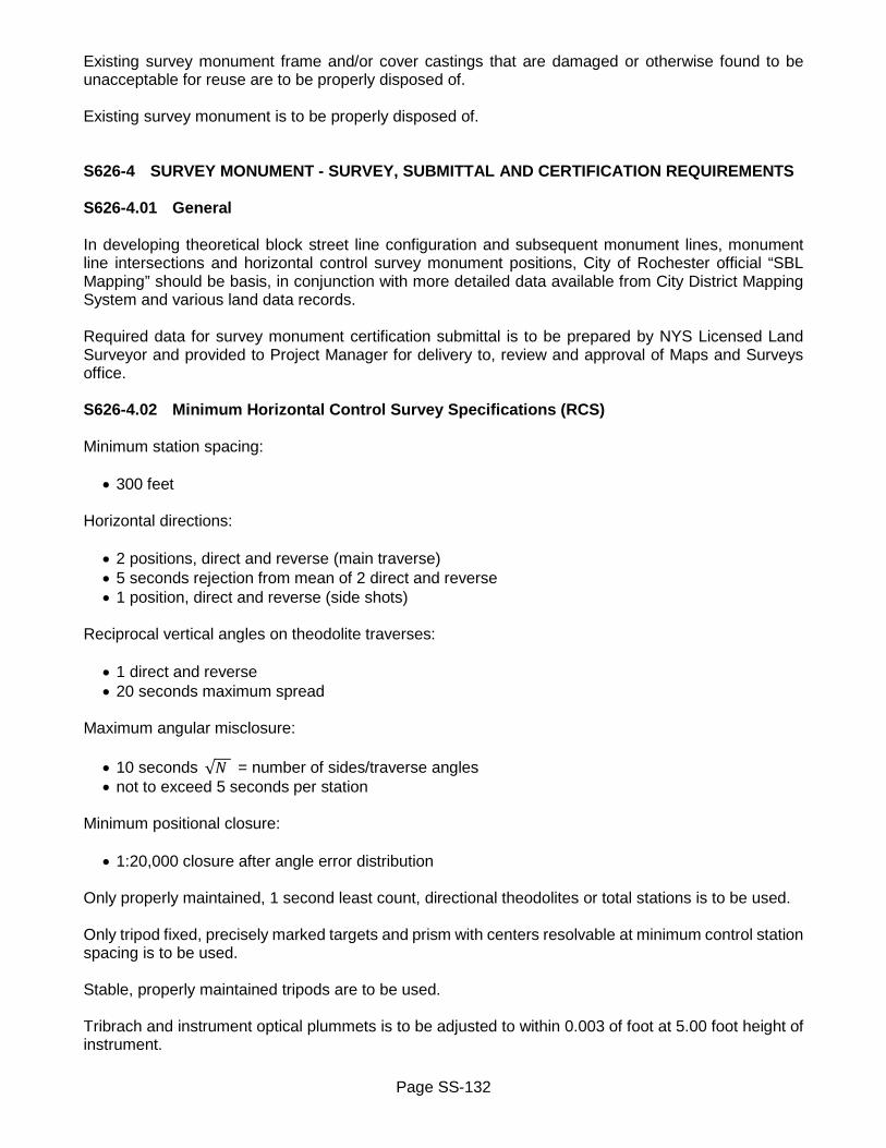
Page SS-132
Existing survey monument frame and/or cover castings that are damaged or otherwise found to be unacceptable for reuse are to be properly disposed of. Existing survey monument is to be properly disposed of. S626-4 SURVEY MONUMENT - SURVEY, SUBMITTAL AND CERTIFICATION REQUIREMENTS S626-4.01 General In developing theoretical block street line configuration and subsequent monument lines, monument line intersections and horizontal control survey monument positions, City of Rochester official “SBL Mapping” should be basis, in conjunction with more detailed data available from City District Mapping System and various land data records. Required data for survey monument certification submittal is to be prepared by NYS Licensed Land Surveyor and provided to Project Manager for delivery to, review and approval of Maps and Surveys office. S626-4.02 Minimum Horizontal Control Survey Specifications (RCS) Minimum station spacing:
• 300 feet Horizontal directions:
• 2 positions, direct and reverse (main traverse) • 5 seconds rejection from mean of 2 direct and reverse • 1 position, direct and reverse (side shots)
Reciprocal vertical angles on theodolite traverses:
• 1 direct and reverse • 20 seconds maximum spread
Maximum angular misclosure:
• 10 seconds √𝑁𝑁 = number of sides/traverse angles • not to exceed 5 seconds per station
Minimum positional closure:
• 1:20,000 closure after angle error distribution Only properly maintained, 1 second least count, directional theodolites or total stations is to be used. Only tripod fixed, precisely marked targets and prism with centers resolvable at minimum control station spacing is to be used. Stable, properly maintained tripods are to be used. Tribrach and instrument optical plummets is to be adjusted to within 0.003 of foot at 5.00 foot height of instrument.

Page SS-133
Deviation from minimum specifications may be granted in writing by Maps and Surveys office under certain circumstances. Electronic Distance Meters (EDM):
• must be capable of high degree of resolution and small inherent error, to maintain high relative accuracy on typically short traverse legs of City Survey lines - not to exceed Å (03MM + 2 PPM), verified by baseline results
• must have been calibrated on any NGS certified EDM baseline within last 6 months and data showing same provided with each Project submittal - include make, model and instrument serial number
• steel taping of short distances to be accomplished with calibrated invar tape or tape compared to standardized tape with applied temperature, sag, tension and slope corrections
• meteorological conditions is to be measured on site, recorded and corrections applied (temperature measured to 1°F, pressure measured to 0.10 inch mercury)
• EDM distances of traverse legs is to be mean of minimum of 5 measurements in each direction As minimum, block containing survey monument to be set is to be traversed and all existing survey monument stones on both sides of streets are to be located and used in analyzation. As minimum, field locations of three existing marked RCS survey monuments is to be analyzed in determination of each RCS survey monument to be set. Final scope of located RCS survey monument required to reliably fit developed theoretical figure to existing field locations of RCS survey monuments is professional judgement decision of NYS Licensed Land Surveyor. S626-4.03 Required Data for Horizontal Control Survey Monument (RCS) Certification Submittals Complete Land Surveyor sealed copies of EDM calibration performed within 6 months of monument work. Calibration is to be performed on any NGS certified EDM baseline. Provided data will include final reduced results, adjustment made and instrument make, model and serial number. Complete Land Surveyor sealed copies of field notes demonstrating adherence to minimum survey specifications (RCS) and noting:
• date and temperature • crew • instrument make, model and serial number
Traverse print out indicating:
• raw angular closure • closure after angular error distribution • final adjusted traverse configuration
Point number sheet for Project area with corresponding coordinate dumps presented in manner clearly delineating theoretical points from physical field measured points with complete description of field point. Reference to SBL maps, District maps and any other data sources used to develop theoretical block configurations. Outline of adjustments, both linear and angular, made to record block configurations to create closed figures. One 3 inch by 5 inch certification card for each survey monument.

Page SS-134
S626-4.04 Horizontal Control Survey Monument (RCS) Certification Card Submittal of one 3 inch by 5 inch certification card on standard card stock, in format shown in Contract Documents, is required for each survey monument to be certified. Provide minimum of five angle and distance ties to substantial, well defined and described, permanent points from RCS monument drill hole or punch mark and cross set. Ties to nails in trees are not acceptable. Top of RCS granite survey monument is to be marked with 1/8 to 1/4 inch diameter drill hole minimum of 3/8 inch deep, and minimum of 1/2 inch from outer edge of monument stone. Maps and Surveys office will furnish monument number to be shown on certification card. On back of each card print certification, and affix NYS Licensed Land Surveyor’s seal with signature and date. Certification:
“I (printed name) NYSPLS # hereby certify to the City of Rochester that the monument shown on the reverse side has been established on a 4.00 foot offset from the property lines (right of way) and that the monument line intersection has been marked with a drill hole or punch mark and cross. All in accordance with City of Rochester Specification S626.”
Where appropriate, certification is to be to real position if different requirements apply. Variation is to be approved of by Maps and Surveys office and correctly described. S626-4.05 Minimum Vertical Survey Specifications (RTS) Instrumentation, calibration procedures, field and office procedures is to be in accordance with Federal Geodetic Control Committee Standards and Specifications to attain Second Order Class II results. Peg test and rod calibration to be performed within 7 days prior to runs. Minimum acceptable closures to be:
• 0.033 of foot √𝑟𝑟𝑟𝑟𝑟𝑟 𝑖𝑖𝑟𝑟 𝑚𝑚𝑖𝑖𝑚𝑚𝑚𝑚𝑚𝑚 Level runs to begin at either an RTS monument or Geodetic Control Monument with published Rochester “City Datum” value, turn through new RTS monument set and close to second RTS or Geodetic Control Monument within specified tolerances. Published Rochester “City Datum” elevations is to be obtained from Maps and Surveys office. S626-4.06 Required Data for Vertical Control Survey Monument (RTS) Certification Submittal Copy of field level peg test and rod calibration performed within 7 days prior to level runs to include date, instrument and serial number.

Page SS-135
Complete original field notes or Land Surveyor sealed copies demonstrating adherence to specified Second Order Class II standards and noting:
• date • crew • instrument make, model and serial number • published elevations • measured elevations • closure
Summary of adjustments performed. One 3 inch by 5 inch certification card for each survey monument. S626-4.07 Vertical Control Survey Monument (RTS) Certification Card Submittal of one 3 inch by 5 inch certification card on standard card stock, in format shown in Contract Documents, is required for each survey monument to be certified. Provide minimum of 3 swing ties to substantial, well defined and described permanent points. Ties to nails in trees are not acceptable. Show measured “City Datum” elevation of new survey monument set and elevation of each reference benchmark used with corner description of each. Maps and Surveys office will furnish monument number to be shown on submitted certification cards. On back of each card print certification, and affix NYS Licensed Land Surveyor’s seal with signature and date. Certification:
“I (printed name) NYSPLS # hereby certify to the City of Rochester that the vertical control monument shown above has been established in the City of Rochester datum using proper methods to establish Second Order accuracy. (Class II) 0.033' �𝑚𝑚𝑙𝑙𝑙𝑙𝑙𝑙 𝑖𝑖𝑟𝑟 𝑚𝑚𝑖𝑖𝑚𝑚𝑚𝑚𝑚𝑚.”
S626-4.08 Monument Ties Suggested tie types to include but not be limited to:
• drill hole in concrete walk • drill hole in concrete walk as point on line to adjacent monument • drill hole in curbing • masonry building corner • drill hole in light pole base, sign base, signal box base, et cetera • masonry porch corner or step • chiseled cross in manhole rim, anchor bolt or metal pole • drill hole in water table • PK or Mag nail in wooden utility pole • set iron pin with cap (on sites void of potential tie objects) • for RCS angle and distance ties 0° origin can be adjacent monuments or long definable naturals
such as building corners, church steeples, tower apexes, atoll lights or intersection stations

Page SS-136
In general:
• attempt to spread ties through 360° for strength of resection • diversify tie types with no more than two ties to single type • if ties are taken on construction job avoid ties to manhole rims, curbing, et cetera, that will be
destroyed • per City Forestry no ties to points in City trees are acceptable • ties are to be taken to substantial, well defined and described, permanent points • angle ties shown are to be average of minimum of 1 direct and 1 reverse reading
S626-5 METHOD OF MEASUREMENT Quantity to be measured for payment will be number of units installed, reset, adjusted, replaced, abandoned or removed. No payment will be made for destroyed survey monuments and their re-survey as defined under Section S626-3 Construction Details. S626-6 BASIS OF PAYMENT S626-6.01 General all Items Unit price bid for all items includes cost of: coordination with and obtaining approval from Maps and Surveys office; related survey work; preparation and submittal of survey data and monument certification cards; excavation; furnishing and installing select granular fill; and furnishing all labor, material and equipment necessary to complete work. Excavation that is included in pay item does not include rock excavation. Rock excavation will be paid for under separate bid item. Payment for new survey monument installation will be made as follows: Fifty percent (50%) will be paid upon completion of installation and acceptance of new survey monument. Remaining fifty percent (50%) will be retained until all of required survey monument certification record information has been submitted to and approved of by Maps and Surveys office. Failure to correct any erroneous or incomplete survey monument certification record information, will result in forfeiture of retained fifty percent (50%). Within project limits, survey monuments found destroyed commencing on start work date, and responsible party is unclear or undeterminable, are to be replaced at Contractor’s expense. S626-6.02 New Horizontal Control Survey Monument (RCS) Unit price bid also includes cost of: furnishing and installing new granite survey monument including frame and cover; setting and marking theoretical position; drill hole. S626-6.03 New Vertical Control Survey Monument (RTS) Unit price bid also includes cost of: furnishing and installing new concrete survey monument including frame and cover; rebar; cap with plastic insert; establishing elevation.
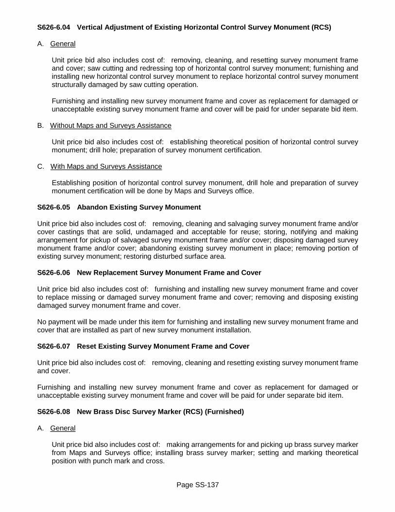
Page SS-137
S626-6.04 Vertical Adjustment of Existing Horizontal Control Survey Monument (RCS) A. General
Unit price bid also includes cost of: removing, cleaning, and resetting survey monument frame and cover; saw cutting and redressing top of horizontal control survey monument; furnishing and installing new horizontal control survey monument to replace horizontal control survey monument structurally damaged by saw cutting operation. Furnishing and installing new survey monument frame and cover as replacement for damaged or unacceptable existing survey monument frame and cover will be paid for under separate bid item.
B. Without Maps and Surveys Assistance
Unit price bid also includes cost of: establishing theoretical position of horizontal control survey monument; drill hole; preparation of survey monument certification.
C. With Maps and Surveys Assistance
Establishing position of horizontal control survey monument, drill hole and preparation of survey monument certification will be done by Maps and Surveys office.
S626-6.05 Abandon Existing Survey Monument Unit price bid also includes cost of: removing, cleaning and salvaging survey monument frame and/or cover castings that are solid, undamaged and acceptable for reuse; storing, notifying and making arrangement for pickup of salvaged survey monument frame and/or cover; disposing damaged survey monument frame and/or cover; abandoning existing survey monument in place; removing portion of existing survey monument; restoring disturbed surface area. S626-6.06 New Replacement Survey Monument Frame and Cover Unit price bid also includes cost of: furnishing and installing new survey monument frame and cover to replace missing or damaged survey monument frame and cover; removing and disposing existing damaged survey monument frame and cover. No payment will be made under this item for furnishing and installing new survey monument frame and cover that are installed as part of new survey monument installation. S626-6.07 Reset Existing Survey Monument Frame and Cover Unit price bid also includes cost of: removing, cleaning and resetting existing survey monument frame and cover. Furnishing and installing new survey monument frame and cover as replacement for damaged or unacceptable existing survey monument frame and cover will be paid for under separate bid item. S626-6.08 New Brass Disc Survey Marker (RCS) (Furnished) A. General
Unit price bid also includes cost of: making arrangements for and picking up brass survey marker from Maps and Surveys office; installing brass survey marker; setting and marking theoretical position with punch mark and cross.
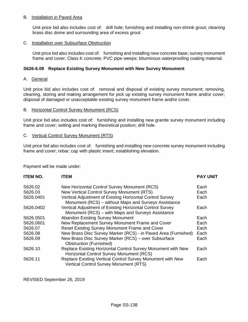
Page SS-138
B. Installation in Paved Area
Unit price bid also includes cost of: drill hole; furnishing and installing non-shrink grout; cleaning brass disc dome and surrounding area of excess grout.
C. Installation over Subsurface Obstruction
Unit price bid also includes cost of: furnishing and installing new concrete base; survey monument frame and cover; Class K concrete; PVC pipe weeps; bituminous waterproofing coating material.
S626-6.09 Replace Existing Survey Monument with New Survey Monument A. General Unit price bid also includes cost of: removal and disposal of existing survey monument; removing, cleaning, storing and making arrangement for pick up existing survey monument frame and/or cover; disposal of damaged or unacceptable existing survey monument frame and/or cover. B. Horizontal Control Survey Monument (RCS) Unit price bid also includes cost of: furnishing and installing new granite survey monument including frame and cover; setting and marking theoretical position; drill hole. C. Vertical Control Survey Monument (RTS) Unit price bid also includes cost of: furnishing and installing new concrete survey monument including frame and cover; rebar; cap with plastic insert; establishing elevation. Payment will be made under: ITEM NO. ITEM PAY UNIT S626.02 New Horizontal Control Survey Monument (RCS) Each S626.03 New Vertical Control Survey Monument (RTS) Each S626.0401 Vertical Adjustment of Existing Horizontal Control Survey Each Monument (RCS) – without Maps and Surveys Assistance S626.0402 Vertical Adjustment of Existing Horizontal Control Survey Each Monument (RCS) – with Maps and Surveys Assistance S626.0501 Abandon Existing Survey Monument Each S626.0601 New Replacement Survey Monument Frame and Cover Each S626.07 Reset Existing Survey Monument Frame and Cover Each S626.08 New Brass Disc Survey Marker (RCS) - in Paved Area (Furnished) Each S626.09 New Brass Disc Survey Marker (RCS) – over Subsurface Each Obstruction (Furnished) S626.10 Replace Existing Horizontal Control Survey Monument with New Each Horizontal Control Survey Monument (RCS) S626.11 Replace Existing Vertical Control Survey Monument with New Each Vertical Control Survey Monument (RTS) REVISED September 26, 2019

Page SS-139
SECTION 627 – CUTTING PAVEMENT 627 GENERAL Purpose of this directive is to designate certain NYSDOT bid items for use on all City projects. References to NYSDOT specifications are to be in accordance with latest edition of NYSDOT Standard Specifications (US Customary Units). Work is to be in accordance with requirements of NYSDOT Section 627 – Cutting Pavement for following bid item: 627-5 BASIS OF PAYMENT Payment will be made under: ITEM NO. ITEM PAY UNIT 627.50140008 Cutting Pavement Linear Foot ISSUED February 25, 2020

Page SS-140
SECTION 633 – CONDITIONING EXISTING PAVEMENT PRIOR TO HOT MIX ASPHALT (HMA) OVERLAY
633 GENERAL Purpose of this directive is to designate certain NYSDOT bid items for use on all City projects. References to NYSDOT specifications are to be in accordance with latest edition of NYSDOT Standard Specifications (US Customary Units). Work is to be in accordance with requirements of NYSDOT Section 633 – Conditioning Existing Pavement Prior to Hot Mix Asphalt (HMA) Overlay for following bid items: 633-5 BASIS OF PAYMENT Payment will be made under: ITEM NO. ITEM PAY UNIT 633.11 Cleaning Existing Pavement and/or Shoulder Square Yards 633.12 Cleaning, Sealing and/or Filling Cracks Lump Sum 633.13 Cleaning, Sealing and/or Filling Joints Linear Foot REVISED January 7, 2020

Page SS-141
SECTION S637 – FIELD OFFICE S637-1 DESCRIPTION Work consists of furnishing and installing field office as required in Contract Documents and as directed by Project Manager. References to NYSDOT specifications are to be in accordance with latest edition of NYSDOT Standard Specifications (US Customary Units). S637-2 MATERIALS S637-2.01 General Field office is to be for sole use of resident engineer, and is to be separate from any other building used by Contractor. Field office is to be within weatherproof building or mobile trailer that is habitable, in good condition, free of any health or safety hazards, readily accessible to public, and located within reasonable short distance of project site. Field office is to be in compliance with New York State Uniform Fire Prevention and Building Code, 19 NYCRR, and all applicable local building, safety and health regulations and laws. If requested, Project Manager is to be provided with copy of Certificate of Occupancy for field office. Signage is to be placed so as to readily identify and locate field office. Field office sign is to be conspicuously placed or mounted on field office. If necessary, other signage is to be posted that will be capable of directing public to location of field office. Freestanding sign supports are to be breakaway type. Field office sign board is to be 3 feet by 4 feet, constructed from 3/4 inch thick duraply or A-A exterior grade plywood, painted with two coats of white exterior enamel paint. Lettering is to be done with one color, pms 287C blue, and is to be done by either silk screen process, die cut vinyl letters (permanent adhesive), hand lettering, or stencil. Field office sign is to have following information denoted, all in capital letters, centered horizontally on sign board:
• FIELD OFFICE • NAME OF PROJECT • CONTRACTOR’S NAME • CITY AND RESIDENT ENGINEER CONTACT PHONE NUMBERS
FIELD OFFICE and NAME OF PROJECT are to be swiss 721 condensed bold 3 inch letters 1.50 inch line spacing. CONTRACTOR’S NAME and CITY AND RESIDENT ENGINEER CONTACT PHONE NUMBERS are to be swiss 721 condensed bold 1 inch letters 0.75 inch line spacing. Paved or other hard surfaced (crushed stone or gravel material) parking area is to be located immediately adjacent to field office. Each parking space is to be at least 9 feet wide by 18 feet deep, with minimum of two parking spaces provided immediately adjacent to field office. S637-2.02 Field Office – General Requirements Field office is to have minimum ceiling height of 7 feet. Doors and windows are to be weatherproofed,

Page SS-142
and each equipped with adequate and operational locking devices. Windows are to be minimum of 8 square feet, screened, and capable of being opened and closed to provide adequate ventilation. Restroom is to be separately enclosed room, lockable from inside, properly ventilated and in compliance with applicable sanitary codes. Restroom is to be provided with operational flush-type toilet, all lavatory amenities, necessary paper and soap products, and hot and cold running water. Potable water from local municipal water supply, or bottled with heating/refrigerator unit to provide hot and cold water. Electrical system capable of providing continuous service to operate all equipment and have adequate amount of receptacles. Dedicated 20 amp electrical service is to be provided for operation of computer equipment. Electric light is to be provided by non-glare type luminaries capable of providing minimum illumination level of 100 foot candles at desk-height level. Fire extinguishers, smoke and carbon monoxide detectors are to be located in each room and are to be fully operational and properly installed. Heating and cooling equipment that is operational and capable of maintaining constant ambient air temperature of 70°F, ±5°F. S637-2.03 Field Office – Equipment and Furnishing Computer Connection. Dedicated telephone line or high speed internet connection for computer access. Provide separate jack for internet connection in each room. Computer will be supplied by resident engineer. Digital Camera. Digital camera complete with all necessary hardware, cables, operating manuals, and other pertinent media required for operation of digital camera unit itself, including connecting digital camera to office computer system. Digital camera must be able to download images to computer without any proprietary software having to be installed on computer. Facsimile (Fax) Machine. Plain paper laser or inkjet fax machine with dedicated telephone line. Fax machine is to be capable of sending and printing maximum paper size of 8-1/2 inches x 14 inches, with minimum 20 page memory storage, 20-sheet document feeder, and 50-sheet paper capacity. Fax machine is to be able to transmit at least 6 pages per minute and have an autodial/redial with minimum of 50 phone number memory capability. Fax machine is to be capable of storing and printing outgoing message confirmation information and printing sender’s name, fax number and page number on incoming faxes. First Aid Kit. Type III first aid kit in accordance with ANSI Z308.1 Minimum Requirements for Workplace First Aid Kits. First aid kit is to be kept properly stocked at all times. Paper Supplies. Provide total of three packages of multi-purpose white paper (500 sheets, 20 pound, 92 brightness) as initial stock. Provide one package for each paper size required (8-1/2 inches x 11 inches, 8-1/2 inches x 14 inches, and 11 inches x 17 inches). Photocopy Machine. Heavy duty electric dry-process type photocopy machine, capable of copying paper sizes 8-1/2 inches x 11 inches, 8-1/2 inches x 14 inches, and 11 inches x 17 inches. Stove. Electric, propane or bottle gas type stove with minimum of two burners adequate for rapid drying of soil samples, including adequate supply of fuel or electrical supply. Stove is required only when Excavation and Embankment or Culverts and Storm Drains are included in project, and separate

Page SS-143
field laboratory is not included. Telephone with Answering Machine. Telephone with answering machine capable of recording outgoing message up to 60 seconds in duration, and receiving minimum of 40 incoming messages of 60 seconds in duration. Answering machine must include automated voice marking of time and day of each message received, and provide message mark so that new messages may be played back without erasing old messages. Answering machine is to include remote programming of playback, backspace, and outgoing message re-record and allow for retrieval of messages without remote control unit. Provide extension telephone for each separate room. Telephone Lines. Separate telephone lines are to be provided for telephone, fax machine and high speed internet connection for computer access. Provide separate jack for telephone and internet connection in each room. Thermometer. Minimum-maximum thermometer displaying in degrees fahrenheit and mounted with an external probe to give both indoors and outdoors temperature. Coat Rack. Metal or wood coat rack or closet capable of holding at least 4 coats. Drafting Stool. Fully assembled adjustable height type drafting stool with backrest. Drafting Table. Fully assembled adjustable height tilting top drafting table with brackets and legs and approximate dimensions of 3 feet x 6 feet. Filing Cabinet. Fire resistant, legal size 2-drawer or 4-drawer filing cabinet with locks and two keys each, meeting requirements of ANSI/UL Standard 72 for Insulated Filing Devices, Class 350-1 hour. Office Chair. Fully assembled adjustable type office chair with arms and 5 legs with casters, 2 office chairs per office desk. Office Desk. Fully assembled and freestanding office desk, minimum of 5 feet long, 2-1/2 feet wide, 2-1/2 feet high, with at least 2 lockable drawers. Pencil Sharpener. Manual or electric pencil sharpener, minimum one per room. Plan Filing Rack. Vertical plan filing rack constructed of metal, capable of hanging up to four sets of plan drawings up to 24 inches x 36 inches in size, with four hanging clamps included. Role File Unit. Eight compartment role file unit. Each compartment is to be approximately 6 inches x 6 inches capable of housing rolls of cross-sections that are minimum of 22 inches long. Storage Locker. Metal or wood storage locker with shelve(s), tumbler lock and two keys for storage of survey, GPS and testing equipment. Total locker space footprint is to be minimum of 2-1/2 square feet, and is to be minimum 6 feet high. Table. Commercial-grade rectangular table with weather/spill resistant top, minimum size of 6 feet long, 2-1/2 feet wide, and 2-1/2 feet high. Wastebasket. Wastebasket with minimum capacity of 6 gallons. Provide one wastebasket for each desk and table. S637-2.04 Field Office – Type A and Type B Field office Type A is to have minimum of 160 square feet of floor space with one outside door and at least four windows.

Page SS-144
Field office Type B is to have minimum of 330 square feet of floor space with two outside doors and at least six windows. Field office is to be partitioned to provide minimum of two rooms with an adjoining door. Smaller room is not to be less than 96 square feet in floor area and is to contain two windows. S637-2.06 Field Office - Minimum Requirements
Field Office Item Description Type A Type B Parking spaces 2 3 Area floor space 160 square feet 330 square feet Number of rooms
(not counting restroom) 1 2
Restroom 1 1 Doors – outside 1 2
Windows 4 6

Page SS-145
Field Office Equipment Item Description Type A Type B Fire extinguisher 1 2 Smoke detector 1 2
Carbon monoxide detector 1 2 Computer connection 1 2
Digital camera 1 1 Facsimile (Fax) machine 1 1
First aid kit 1 1
Paper supplies 3 reams (1 each paper size)
3 reams (1 each paper size)
Photocopy machine 1 1 Telephone w/answering machine 1 1
Telephone w/o answering machine - 1 Telephone lines 3 3 (5 connections) Thermometer 1 1
Coat rack 1 1 Drafting stool 1 2 Drafting table 1 2 Filing cabinet (1) 2 drawer (1) 4 drawer Office chair 2 4 Office desk 1 2
Pencil sharpener 1 2 Plan filing rack 1 1 Role file unit 1 1
Storage locker 1 1 Stove (if required) 1 1
Table 1 1 Wastebasket 3 5
S637-3 CONSTRUCTION DETAILS Field office is to be fully equipped and made available for use and occupancy by City’s project representative prior to start of any other work on project. Such use and occupancy is to be made available until City relinquishes its use. City will retain ownership of any data storage media, data storage containers and consumables. Contractor is responsible to maintain field office complete with furniture and equipment in safe and operable condition, and have adequate stock of supplies and materials on hand at all times. Equipment

Page SS-146
provided with field office is to be fully operational prior to resident engineer occupying field office. Contractor is to provide instruction to project engineer regarding proper use and operation of equipment provided with field office. Furniture and equipment is to be fully assembled, operational and clean. Field office is to be cleaned and rubbish removed as necessary, but not less than at least once per week. Field office is to be kept free of pests, both human and otherwise. Areas subject to pedestrian access, and vehicular circulation and parking, are to be maintained and kept clear of debris and accumulation of any weather related materials such as leaves and snow. Contractor is responsible, until use and occupancy of field office is relinquished by City, for any damage, direct or indirect, of whatever nature, occurring to property of City and property of resident engineer which is kept in field office. Such property will be limited to only those items used by resident engineer in performance of project related work activities. Such property is to be replaced within 30 days of reported damages and includes any loss caused by, but not limited to, fire, theft, vandalism or malicious mischief. Resident engineer is to provide Contractor with detailed list of project related items, with corresponding dollar values, belonging to City and resident engineer which are kept in field office. Resident engineer is to provide Contractor with updates when something on list changes. Contractor will not be responsible for any items kept in field office that are not on this list, or are not project related. After completion of project, field office is to be disassembled. If mobile trailer was used as field office, it is to be removed from location, and area cleaned and restored to original or better condition within 30 days of removal of mobile trailer. S637-4 METHOD OF MEASUREMENT Quantity to be measured for payment will be number of months to nearest quarter (0.25) of month for which field office has been properly provided. Measurement will not commence any sooner than date of start work order is effective, and will cease when City relinquishes its use. S637-5 BASIS OF PAYMENT Unit price bid includes cost of: providing and furnishing field office complete with all required fixtures, equipment, paper supplies, furniture, parking; signage; maintenance and repair of fixtures, equipment, furniture; weekly cleaning and upkeep; repair or replacement of City and resident engineer project related property that is damaged or lost due to fire, theft, vandalism or malicious mischief; removal mobile trailer and site restoration; and furnishing all labor, material and equipment necessary to complete work. Payment will be made for each month of availability for occupancy by resident engineer. No payment will be made under Field Office for each calendar day during which there are deficiencies in compliance with these requirements. First calendar day commences 24 hours after written notice has been delivered to Contractor of such deficiency. Amount of such calendar day nonpayment will be determined by dividing unit price bid per month by 30.

Page SS-147
Payment will be made under: ITEM NO. ITEM PAY UNIT S637.10 Field Office - Type A Month S637.11 Field Office - Type B Month REVISED March 3, 2015

Page SS-148
SECTION S643 – PARKING METER POST AND SIGN POST SLEEVE S643-1 DESCRIPTION Work consists of furnishing and installing parking meter posts and sign post sleeves as required in Contract Documents and as directed by Project Manager. References to NYSDOT specifications are to be in accordance with latest edition of NYSDOT Standard Specifications (US Customary Units). S643-2 MATERIALS S643-2.01 Parking Meter Post Parking meter post is to be standard 2 inch inside diameter galvanized steel pipe, 6 feet standard length, 3 feet long for installation over underground structure. Post is to be reinforced with 1/2 inch bar stock welded to post. For installation over underground structure, bottom of post is to be centered on and welded all around to 12 inch square 1/4 inch cast steel base plate. Post and base plate assembly is to be reinforced with four 1/4 inch 2 inch by 2 inch cast steel fillets cut on 45° angle welded all around to both post and base plate. Base plate is to be anchored to paved area with four 1/2 inch 3 inch long wedge anchor bolts. S643-2.02 Sign Post Sleeve Sign post sleeve for use in paved areas is to be standard 3-1/2 inch inside diameter galvanized steel pipe, 3 feet standard length, 12 inches for use with anchor plate. Anchor plate is to be 12 inch square 1/4 inch galvanized steel, with 2-1/4 inch square hole in center for installation of sleeve. Sleeve is to be inserted into hole flush with bottom of anchor plate, and welded all around to anchor plate. Anchor plate is to be anchored to paved area with four 1/2 inch 3 inch long wedge anchor bolts. S643-2.03 Concrete Concrete is to be Class K in accordance with Section S504 Portland Cement Concrete. S643-2.04 Subbase Course Subbase course material is to be Type 1 in accordance with NYSDOT Section 304 Subbase Course, with following modification: Recycled materials, pulverized or recycled portland cement concrete aggregate (RCA) and brick, reclaimed asphalt pavement (RAP), and Corian® are unacceptable for use as subbase course materials, unless specifically authorized in writing by City Engineer. S643-3 CONSTRUCTION DETAILS S643-3.01 Parking Meter Post Parking meter post is to be centered 2 feet off face of curb, with top of post 3 feet above finished grade. Where distance between back edge of sidewalk and face of curb is less than 7 feet, post is to be

Page SS-149
centered 18 inches off face of curb. Top end of post is to be reamed so that no burrs will hamper parking meter installation. Below grade portion of post is to be encased within 12 inch diameter concrete foundation, with foundation set on 6 inch bed of subbase course material. For installation over underground structure, post is to installed complete with base plate, and assembly anchored to paved area with wedge anchor bolts. For installation in lawn area, provide two 12 inch crossing pins installed thru bottom end of pole, and bore 3/8 inch diameter weep hole in post 3 inches above finished grade. S643-3.02 Sign Post Sleeve Sign post sleeve is to be centered 2 feet plus 1/2 width of sign off face of curb, with top of sleeve set flush with finished grade. Exact location of sleeve will be as directed by Monroe County Department of Transportation, call (585) 753-7750 if proposed location is questionable or if further assistance is required. Top end of sleeve is to be reamed so that no burrs will hamper sign post installation. Sleeve is to be installed prior to placement of new pavement. Below grade portion of sleeve is to be encased within 12 inch diameter concrete foundation, with foundation set on 6 inch bed of subbase course material. Where anchor plate is to be utilized, sleeve is to installed complete with anchor plate, and assembly anchored to paved area with wedge anchor bolts. S643-4 METHOD OF MEASUREMENT Quantity to be measured for payment will be number of each parking meter post or sign post sleeve installed. S643-5 BASIS OF PAYMENT S643-5.01 Parking Meter Post Unit price bid includes cost of: furnishing and installing parking meter post, bar stock, hardware; welding; cleaning, cutting, reaming post; painting; concrete foundation; subbase course material; excavation; backfill; and furnishing all labor, material and equipment necessary to complete work. S643-5.02 Parking Meter Post with Base Plate Unit price bid includes cost of: furnishing and installing parking meter post, bar stock, base plate, fillets, wedge anchor bolts, hardware; welding; cleaning, cutting, reaming post; painting; boring holes in paved area; and furnishing all labor, material and equipment necessary to complete work. S643-5.03 Sign Post Sleeve Unit price bid includes cost of: furnishing and installing sign post sleeve; cleaning, cutting, and reaming sleeve; concrete foundation; subbase course material; excavation; backfill; and furnishing all labor, material and equipment necessary to complete work.

Page SS-150
S643-5.04 Sign Post Sleeve with Anchor Plate Unit price bid includes cost of: furnishing and installing sign post sleeve, anchor plate, wedge anchor bolts, hardware; welding; cleaning, cutting, and reaming sleeve; boring holes in paved area; and furnishing all labor, material and equipment necessary to complete work. Payment will be made under: ITEM NO. ITEM PAY UNIT S643.0101 Parking Meter Post (Paved Area) Each S643.0201 Parking Meter Post with Base Plate Each S643.0301 Parking Meter Post (Lawn Area) Each S643.0401 Sign Post Sleeve Each S643.05 Sign Post Sleeve with Anchor Plate Each REVISED July 1, 2017

Page SS-151
SECTION S671 - STREET LIGHTING S671-1 DESCRIPTION Work consists of installing, adjusting, relocating or replacing street lighting appurtenances as required in Contract Documents and as directed by Project Manager. References to NYSDOT specifications are to be in accordance with latest edition of NYSDOT Standard Specifications (US Customary Units). S671-2 MATERIALS S671-2.01 Conduit and Cable A. Conduit
PVC conduit, couplings, condulets, adaptors and bends for installation outside of roadway are to be Schedule 40, rigid, extra-heavy wall polyvinyl chloride (PVC) as specified by and in accordance with Underwriters Laboratories Standard UL-651 and NEMA Standard Specification TC-2 for electrical plastic conduit EPC-40. PVC conduit, couplings, condulets, adaptors and bends for installation in roadway, wood pole riser connections, and for future fiber-optic installations, are to be Schedule 80, rigid, extra-heavy wall polyvinyl chloride (PVC) conduit as specified by and in accordance with Underwriters Laboratories Standard UL-651 and NEMA Standard Specification TC-2 for electrical plastic conduit EPC-80. Solvent cement for joining PVC conduit is to be in accordance with ASTM D2564, or as recommended by conduit manufacturer. HDPE conduit, couplings, condulets, adaptors and bends are to be in accordance with or exceed ASTM D3350, UV Black (minimum carbon black loading of 2 percent), as tested and listed by Intertek Laboratories (ETL) to assure compliance with and that conduit is in accordance with Underwriters Laboratories Standard UL-651A. Conduit sequential footage markings are to be permanent ink jet or indent print. Galvanized steel conduit, couplings, condulets, adaptors and bends are to be in accordance with NYSDOT Section 723-20 Metal Steel Conduit, Zinc Coated. In cases of conflicting test requirements, more stringent of test requirements will be required.
B. Cable in Conduit
Cable in conduit is to be single conductor No. 6 AWG stranded copper conductor, type THWN color coded, and continuously colored red/white/black/green. Cable is to be flame-retardant, moisture and heat resistant, with thermoplastic insulation and nylon jacket. Cable is to be approved for use in wet or dry locations, and up to temperature of 170°F.
C. Cable in Pole
Cable in pole is to be single conductor No. 10 AWG stranded copper conductor, type THWN color coded, and continuously colored white/black. Cables are to be flame-retardant, moisture and heat resistant, with thermoplastic insulation and nylon jacket. Cables are to be approved for use in wet or dry locations, and up to temperature of 170°F.
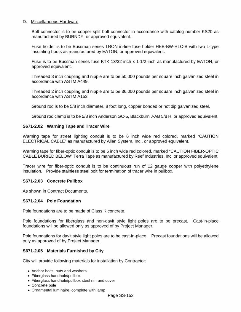
Page SS-152
D. Miscellaneous Hardware
Bolt connector is to be copper split bolt connector in accordance with catalog number KS20 as manufactured by BURNDY, or approved equivalent.
Fuse holder is to be Bussman series TRON in-line fuse holder HEB-BW-RLC-B with two L-type insulating boots as manufactured by EATON, or approved equivalent. Fuse is to be Bussman series fuse KTK 13/32 inch x 1-1/2 inch as manufactured by EATON, or approved equivalent. Threaded 3 inch coupling and nipple are to be 50,000 pounds per square inch galvanized steel in accordance with ASTM A449. Threaded 2 inch coupling and nipple are to be 36,000 pounds per square inch galvanized steel in accordance with ASTM A153. Ground rod is to be 5/8 inch diameter, 8 foot long, copper bonded or hot dip galvanized steel. Ground rod clamp is to be 5/8 inch Anderson GC-5, Blackburn J-AB 5/8 H, or approved equivalent.
S671-2.02 Warning Tape and Tracer Wire Warning tape for street lighting conduit is to be 6 inch wide red colored, marked “CAUTION ELECTRICAL CABLE” as manufactured by Allen System, Inc., or approved equivalent. Warning tape for fiber-optic conduit is to be 6 inch wide red colored, marked “CAUTION FIBER-OPTIC CABLE BURIED BELOW” Terra Tape as manufactured by Reef Industries, Inc. or approved equivalent. Tracer wire for fiber-optic conduit is to be continuous run of 12 gauge copper with polyethylene insulation. Provide stainless steel bolt for termination of tracer wire in pullbox. S671-2.03 Concrete Pullbox As shown in Contract Documents. S671-2.04 Pole Foundation Pole foundations are to be made of Class K concrete. Pole foundations for fiberglass and non-davit style light poles are to be precast. Cast-in-place foundations will be allowed only as approved of by Project Manager. Pole foundations for davit style light poles are to be cast-in-place. Precast foundations will be allowed only as approved of by Project Manager. S671-2.05 Materials Furnished by City City will provide following materials for installation by Contractor:
• Anchor bolts, nuts and washers • Fiberglass handhole/pullbox • Fiberglass handhole/pullbox steel rim and cover • Concrete pole • Ornamental luminaire, complete with lamp

Page SS-153
Furnished materials are to be picked up from Water Bureau Materials and Equipment Stockroom, 401 Dewey Avenue, Rochester, New York, Monday through Friday, between hours of 8:00AM and 2:00PM, exclusive of holidays. City Street Lighting Section requires minimum of 2 working days advance notice to make arrangements for pickup of furnished materials, (585) 428-1297. Inspect all furnished materials before accepting delivery to ensure that there are no obvious defectives. S671-2.06 Slurry Bond Coat Slurry bond coat is to be Acryl 60 as manufactured by Thoro System Products, or approved equivalent. S671-2.07 Grout Grout is to in accordance with NYSDOT Section 701-05 Concrete Grouting Material. S671-2.08 Concrete Concrete is to be Class K in accordance with Section S504 Portland Cement Concrete. S671-2.09 Subbase Course Material Subbase course material is to be Type 1 and Type 2 in accordance with NYSDOT Section 304 Subbase Course, with following modification: Recycled materials, pulverized or recycled portland cement concrete aggregate (RCA) and brick, reclaimed asphalt pavement (RAP), and Corian® are unacceptable for use as subbase course materials, unless specifically authorized in writing by City Engineer. S671-2.10 Sand Sand is to be clean washed well graded angular sand with maximum particle size of about 3/16 inch, without any fine limestone screenings, free of salts and other deleterious materials, and in accordance with requirements of ASTM C33 Concrete Aggregates. S671-2.11 Select Backfill Select backfill can be any locally excavated material that is free from stones, sod and foreign materials. If suitable or sufficient quantities of excavated materials are not available, provide select granular fill in accordance with Section R203 Excavation and Embankment. S671-2.12 Excavation, Backfill and Surface Restoration Excavation, backfill and surface restoration is to be in accordance with:
• Section S203 Excavation and Embankment • Section R206 Trench and Culvert Excavation • Section S608 Sidewalk and Driveway • Section S610 Landscape • NYSDOT Section 203 Excavation and Embankment • NYSDOT Section 304 Subbase Course • NYSDOT Section 610 Ground Vegetation – Preparation, Establishment and Management
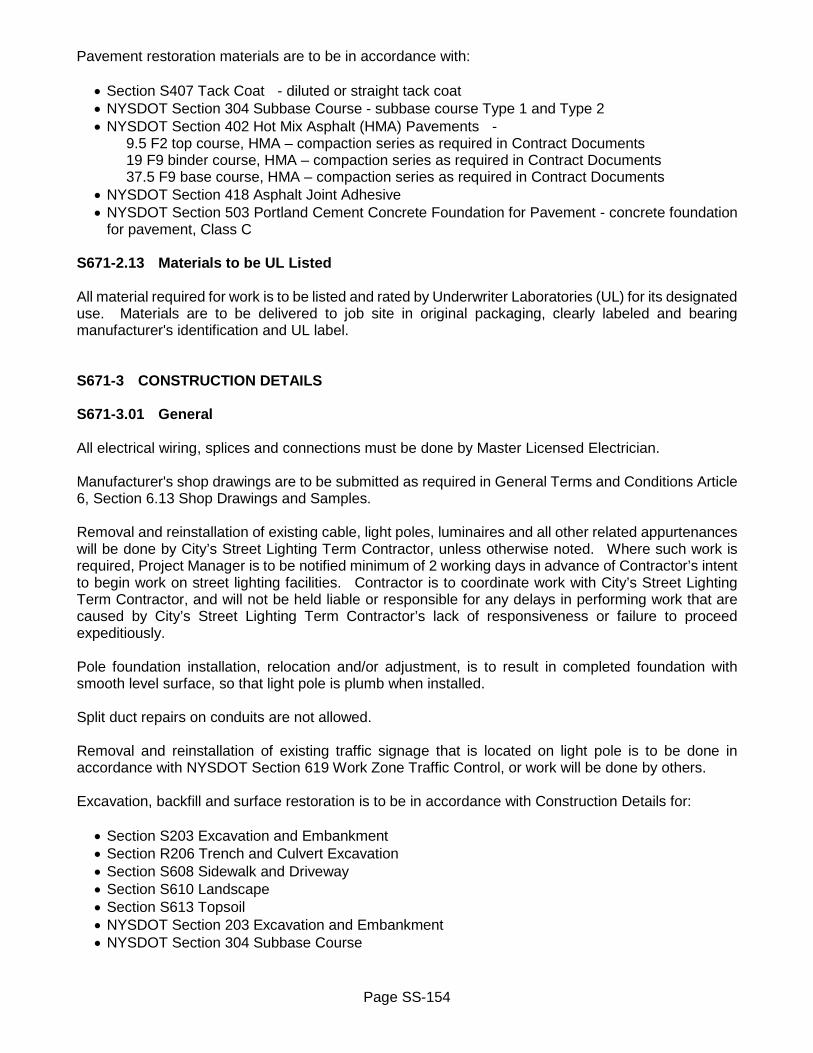
Page SS-154
Pavement restoration materials are to be in accordance with:
• Section S407 Tack Coat - diluted or straight tack coat • NYSDOT Section 304 Subbase Course - subbase course Type 1 and Type 2 • NYSDOT Section 402 Hot Mix Asphalt (HMA) Pavements -
9.5 F2 top course, HMA – compaction series as required in Contract Documents 19 F9 binder course, HMA – compaction series as required in Contract Documents 37.5 F9 base course, HMA – compaction series as required in Contract Documents
• NYSDOT Section 418 Asphalt Joint Adhesive • NYSDOT Section 503 Portland Cement Concrete Foundation for Pavement - concrete foundation
for pavement, Class C S671-2.13 Materials to be UL Listed All material required for work is to be listed and rated by Underwriter Laboratories (UL) for its designated use. Materials are to be delivered to job site in original packaging, clearly labeled and bearing manufacturer's identification and UL label. S671-3 CONSTRUCTION DETAILS S671-3.01 General All electrical wiring, splices and connections must be done by Master Licensed Electrician. Manufacturer's shop drawings are to be submitted as required in General Terms and Conditions Article 6, Section 6.13 Shop Drawings and Samples. Removal and reinstallation of existing cable, light poles, luminaires and all other related appurtenances will be done by City’s Street Lighting Term Contractor, unless otherwise noted. Where such work is required, Project Manager is to be notified minimum of 2 working days in advance of Contractor’s intent to begin work on street lighting facilities. Contractor is to coordinate work with City’s Street Lighting Term Contractor, and will not be held liable or responsible for any delays in performing work that are caused by City’s Street Lighting Term Contractor’s lack of responsiveness or failure to proceed expeditiously. Pole foundation installation, relocation and/or adjustment, is to result in completed foundation with smooth level surface, so that light pole is plumb when installed. Split duct repairs on conduits are not allowed. Removal and reinstallation of existing traffic signage that is located on light pole is to be done in accordance with NYSDOT Section 619 Work Zone Traffic Control, or work will be done by others. Excavation, backfill and surface restoration is to be in accordance with Construction Details for:
• Section S203 Excavation and Embankment • Section R206 Trench and Culvert Excavation • Section S608 Sidewalk and Driveway • Section S610 Landscape • Section S613 Topsoil • NYSDOT Section 203 Excavation and Embankment • NYSDOT Section 304 Subbase Course
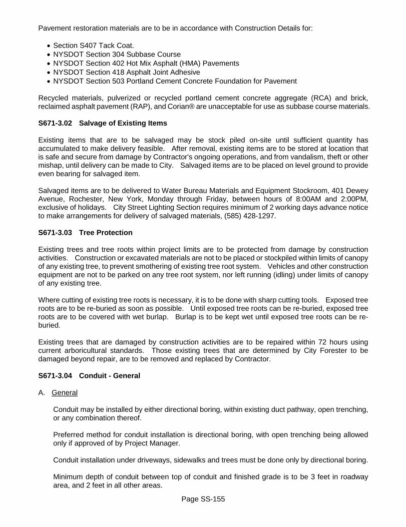
Page SS-155
Pavement restoration materials are to be in accordance with Construction Details for:
• Section S407 Tack Coat. • NYSDOT Section 304 Subbase Course • NYSDOT Section 402 Hot Mix Asphalt (HMA) Pavements • NYSDOT Section 418 Asphalt Joint Adhesive • NYSDOT Section 503 Portland Cement Concrete Foundation for Pavement
Recycled materials, pulverized or recycled portland cement concrete aggregate (RCA) and brick, reclaimed asphalt pavement (RAP), and Corian® are unacceptable for use as subbase course materials. S671-3.02 Salvage of Existing Items Existing items that are to be salvaged may be stock piled on-site until sufficient quantity has accumulated to make delivery feasible. After removal, existing items are to be stored at location that is safe and secure from damage by Contractor's ongoing operations, and from vandalism, theft or other mishap, until delivery can be made to City. Salvaged items are to be placed on level ground to provide even bearing for salvaged item. Salvaged items are to be delivered to Water Bureau Materials and Equipment Stockroom, 401 Dewey Avenue, Rochester, New York, Monday through Friday, between hours of 8:00AM and 2:00PM, exclusive of holidays. City Street Lighting Section requires minimum of 2 working days advance notice to make arrangements for delivery of salvaged materials, (585) 428-1297. S671-3.03 Tree Protection Existing trees and tree roots within project limits are to be protected from damage by construction activities. Construction or excavated materials are not to be placed or stockpiled within limits of canopy of any existing tree, to prevent smothering of existing tree root system. Vehicles and other construction equipment are not to be parked on any tree root system, nor left running (idling) under limits of canopy of any existing tree. Where cutting of existing tree roots is necessary, it is to be done with sharp cutting tools. Exposed tree roots are to be re-buried as soon as possible. Until exposed tree roots can be re-buried, exposed tree roots are to be covered with wet burlap. Burlap is to be kept wet until exposed tree roots can be re-buried. Existing trees that are damaged by construction activities are to be repaired within 72 hours using current arboricultural standards. Those existing trees that are determined by City Forester to be damaged beyond repair, are to be removed and replaced by Contractor. S671-3.04 Conduit - General A. General
Conduit may be installed by either directional boring, within existing duct pathway, open trenching, or any combination thereof. Preferred method for conduit installation is directional boring, with open trenching being allowed only if approved of by Project Manager. Conduit installation under driveways, sidewalks and trees must be done only by directional boring. Minimum depth of conduit between top of conduit and finished grade is to be 3 feet in roadway area, and 2 feet in all other areas.

Page SS-156
Conduit is to extend between all pole foundations, direct embedded poles, pullboxes, handholes and electrical service points. Conduit is to be connected to all pole foundations, direct burial poles, and City handholes/pullboxes, but not to private utility manhole/handhole. Conduit connected to concrete pullboxes is to be installed flush with inside wall, and minimum of 3 inches above floor of pullbox. Where open trenching is used, warning tape is to be placed in open trench approximately 6 inches above conduit. Individual conduit sections and fittings are to be assembled in accordance with manufacturer’s instructions to form continuous conduit run. After installation, conduit is to be tested for clear bore and correct installation by using mandrel, brush and snake, before installation will be accepted. Mandrel assembly is to include two short brushes. Mandrel is to be turned approximately 85 percent of internal diameter of conduit to be tested. Snaking of conduit is to be done in presence of Project Manager. Conduit which rejects mandrel is to be cleared at once, replace any defective conduit. After testing is complete and installation accepted, install 250 pound nylon pull cord in empty conduit, and cap or plug all openings. Provide tracer wire along top of fiber-optic conduit, connecting cut ends at all structures to provide single continuous run of tracer wire.
B. Roadway
Conduit sections installed under roadways are to extend to minimum of 1 foot behind face of curb, or back edge of concrete gutter, on both sides of roadway; or from exterior of pole foundation or direct embedded pole located on one side of roadway, to handhole, pullbox, manhole, or wood pole riser connection located on opposite side of roadway. PVC/HDPE conduit in open trench roadway crossings is to be encased within minimum of 3 inches of concrete, with backfilling of trench not being allowed until concrete has set.
C. Existing Duct Pathway
Conduit to be installed within existing duct pathway will be of size required in Contract Documents. Existing duct may consist of old pump log, larger size PVC/HDPE conduit, or metal conduit. If existing duct is still occupied with cable, existing cable is to be removed and properly disposed of. Where sections of existing duct pathway are blocked and cannot be cleared, area is to be bypassed, which may require open trenching.
D. Conduit Replacement
Section of existing conduit to be replaced is to be saw cut such that section of conduit which is to remain will have squared neat edges. After cutting, section of conduit is to be removed and disposed of, and new conduit installed.

Page SS-157
S671-3.05 Conduit Connection to Service Points Conduit is to be extended to designated point of service, and connected in accordance with following methods: A. Underground Supplied Fixture Fed from Underground Distribution Facilities
Conduit is to be extended from City's handhole/pullbox to private utility manhole/handhole, but not connected. Private utility company will provide necessary point of entry and will make actual conduit connection to manhole/handhole.
B. Underground Supplied Fixture Fed from Overhead Distribution Facilities - Wood Pole Riser Connection
Conduit is to be extended to wood pole. Riser section consisting of either grounded galvanized steel or PVC schedule 80 conduit is to be installed on wood pole of sufficient length to extend up wood pole to fuse point located on wood pole.
S671-3.06 Cable City Street Lighting Section will provide wiring schematics for all cable installation. Number and color of cables to be installed will be as shown on schematic drawings. A. Cable in Conduit
After conduit has been installed and assembly accepted, install required number of cables. Cable is to be extended from City's handhole/pullbox to private utility manhole/handhole, but not connected, connections will be done by others.
B. Underground Supplied Fixture Fed from Underground Conduit
Cable is to be extended from City's handhole/pullbox to private utility manhole/handhole, but not connected, connections will be done by others. Leave sufficient amount of cable coiled and protected at each connection point to reach center of handhole/pullbox/manhole with enough extra to make actual connection.
C. Underground Supplied Fixture Fed from Overhead Distribution Facilities - Wood Pole Riser Connection
Cable is to be extended from City's handhole/pullbox to and thru wood pole riser, but not connected, connections will be done by others. Provide additional 20 feet of cable at top of riser, coiled and secured.
D. Cable in Pole – Luminaire Connection
After pole has been installed and accepted, install required number of cables thru pole, leaving sufficient amount to make connection to luminaire.
E. Remove Existing Cable
Existing cable is to be removed from conduit and properly disposed of. When removing existing cable, caution is to be taken so as not to damage existing conduit.

Page SS-158
S671-3.07 Concrete Pullbox Installation Pullbox is to be set on 2 inch bed of compacted subbase course Type 2, with cable bracket supports, and frame and cover installed as required. Frame and cover are to be set in mortar, placed true to line and grade, make full and even bearing on underlying surface, and non-rocking when in place. Expansion joints are to be used for installation in paved areas. Where pullbox is being installed over an existing conduit run, section of existing conduit that is to be removed is to be saw cut such that section of conduit which is to remain will have squared neat edges. After cutting, cut section of conduit is to be removed and disposed of. After pullbox is installed, existing conduit is to be connected to pullbox. New conduit is to be installed to fill in any gaps in conduit in accordance with Subsection S671-3 Construction Details. S671-3.08 Concrete Pullbox Adjustment/Relocation/Replacement Before adjusting/relocating/replacing existing pullbox, existing conduit is to be disconnected. Excavate and remove existing pullbox in such manner that pullbox and any conduit contained therein are not damaged. Existing pullboxes that are being replaced, are to be removed and disposed of. Attach new cable bracket on inside of each in existing pullboxes that do not already have cable bracket supports. Pullbox work is to be done in accordance with Subsection S671-3.07 Concrete Pullbox Installation. S671-3.09 Concrete Pullbox Frame and Cover Replacement Existing pullbox frame and cover are to be removed and disposed of. Top of pullbox is to be cleaned of all debris, new pullbox frame and cover set in mortar, placed true to line and grade, make full and even bearing on underlying surface, and non-rocking when in place. Expansion joints are to be used for installation in paved areas. S671-3.10 Fiberglass Handhole/Pullbox Installation Handhole/pullbox is to be set on 3 to 6 inch thick bed of compacted sand or subbase course Type 1, true to line and grade, with rim and cover installed as required. Rim and cover are to make continuous full and uniform contact with corresponding box, are to be properly seated and secured, and non-rocking when in place. Expansion joints are to be used for installation in paved areas. Minimum of 6 inches of loose subbase course Type 1 is to be placed in bottom of handhole/pullbox. Where handhole/pullbox is being installed over an existing conduit run, section of existing conduit that is to be removed is to be saw cut such that section of conduit which is to remain will have squared neat edges. After cutting, cut section of conduit is to be removed and disposed of. After handhole/pullbox has been installed, existing conduit is to be connected to handhole/pullbox. Handhole/pullbox that is located within paved area will be supplied with steel rim and cover. New conduit is to be installed to fill in any gaps in conduit in accordance with Subsection S671-3 Construction Details.

Page SS-159
S671-3.11 Fiberglass Handhole/Pullbox Adjustment/Relocation/Replacement Before adjusting/relocating/replacing existing handhole/pullbox, existing conduit is to be disconnected. Excavate and remove existing handhole/pullbox in such manner that handhole/pullbox and any conduit contained therein are not damaged. Existing handholes/pullboxes that are being replaced, are to be removed and disposed of. Handhole/pullbox work is to be done in accordance with Subsection S671-3.10 Fiberglass Handhole/Pullbox Installation S671-3.12 Remove Existing Handhole/Pullbox Before removing existing handhole/pullbox, existing conduit is to be disconnected. Excavate, remove and dispose of existing handhole/pullbox. Backfill excavation with select backfill material. Existing metal frames and covers that are broken or otherwise structurally unsound are to be properly disposed of. Existing metal frames and covers that are in good condition are to be salvaged and delivered to City. Before delivery, existing frame and cover are to be cleaned of all extraneous materials, including concrete. New conduit is to be installed to fill in any gaps in conduit in accordance with Subsection S671-3 Construction Details. S671-3.13 Davit Light Pole – Pole Foundation Pole foundation is to be cast-in-place complete with anchor bolts, conduit, ground rod, and any necessary fittings. Pole foundation is to be cast against undisturbed earth, with anchor bolts, conduit, ground rod and all fittings held in place with template. Anchor bolts are to extend 3 inches above top of pole foundation, conduit minimum 9 inches. Ground rod is to be bent into and extend 4 inches above top of pole foundation. Earth anchors may be used for preparation of excavation for casting pole foundation. Use of sonotubes for forming pole foundations will not be allowed, unless specifically approved for use by Project Manager. Precast pole foundation may be used only with approval of Project Manager. Precast pole foundation is to be installed complete with required anchor bolts, conduit, ground rod, and any necessary fittings. Where pole foundation is being installed over an existing conduit run, section of existing conduit that is to be removed is to be saw cut such that section of conduit which is to remain will have squared neat edges. After cutting, cut section of conduit is to be removed and disposed of. After pole foundation has been installed, existing conduit is to be connected to connector opening in pole foundation. New conduit is to be installed to fill in any gaps in conduit in accordance with Subsection S671-3 Construction Details. S671-3.14 Other Metal Light Pole – Pole Foundation

Page SS-160
Pole foundation is to be precast and installed complete with required anchor bolts, conduit, ground rod, and any necessary fittings. Anchor bolts are to extend minimum of 2 inches above top of pole foundation, conduit minimum 6 inches. Ground rod is to extend 4 inches above top of pole foundation. Cast-in-place foundation may be used only with approval of Project Manager. Pole foundation is to be cast against undisturbed earth, with anchor bolts, conduit, ground rod and all fittings held in place with template. Anchor bolts are to extend 3 inches above top of pole foundation, conduit minimum 9 inches. Ground rod is to be bent into and extend 4 inches above top of pole foundation. Earth anchors may be used for preparation of excavation for casting pole foundation. Use of sonotubes for forming pole foundations will not be allowed, unless specifically approved for use by Project Manager. Where pole foundation is being installed over an existing conduit run, section of existing conduit that is to be removed is to be saw cut such that section of conduit which is to remain will have squared neat edges. After cutting, cut section of conduit is to be removed and disposed of. After pole foundation has been installed, existing conduit is to be connected to connector opening in pole foundation. New conduit is to be installed to fill in any gaps in conduit in accordance with Subsection S671-3 Construction Details. S671-3.15 Fiberglass Light Pole – Pole Foundation Pole foundation is to be precast and installed complete with required anchor bolts, conduit and any necessary fittings. Anchor bolts are to extend minimum of 2 inches above top of pole foundation, conduit minimum 6 inches. Cast-in-place foundation may be used only with approval of Project Manager. Pole foundation is to be cast against undisturbed earth, with anchor bolts, conduit and all fittings held in place with template. Anchor bolts are to extend 3 inches above top of pole foundation, conduit minimum 6 inches. Earth anchors may be used for preparation of excavation for casting pole foundation. Use of sonotubes for forming pole foundations will not be allowed, unless specifically approved for use by Project Manager. Where pole foundation is being installed over an existing conduit run, section of existing conduit that is to be removed is to be saw cut such that section of conduit which is to remain will have squared neat edges. After cutting, cut section of conduit is to be removed and disposed of. After pole foundation has been installed, existing conduit is to be connected to connector opening in pole foundation. New conduit is to be installed to fill in any gaps in conduit in accordance with Subsection S671-3 Construction Details. S671-3.16 Pole Foundation Adjustment/Relocation Before removing existing pole foundation, existing conduit is to be disconnected. Existing pole foundation is to be removed in such manner that pole foundation is not damaged. Pole foundation is to be re-installed in accordance Subsection S671-3 Construction Details, and conduit re-connected. Where pole foundation is being installed over an existing conduit run, section of existing conduit that is to be removed is to be saw cut such that section of conduit which is to remain will have squared neat edges. After cutting, cut section of conduit is to be removed and disposed of. After pole foundation has been installed, existing conduit is to be connected to connector opening in pole foundation.

Page SS-161
New conduit is to be installed to fill in any gaps in conduit in accordance with Subsection S671-3 Construction Details. S671-3.17 Pole Foundation Extension Top of existing pole foundation is to be scarified, or portion removed to accommodate new concrete cap. Use extra caution so that any exposed cable is not cut or otherwise damaged. Extend existing anchor bolts and conduit as required with appropriate nipples, extensions and couplings. Clean surface of pole foundation and coat with an approved slurry bond coat, form and pour new concrete cap. S671-3.18 Remove Existing Light Pole Existing light pole, with or without luminaire, is to be removed and properly disposed of. Existing luminaire that is to be salvaged, is to be removed in accordance with Subsection S671-3 Construction Details. S671-3.19 Remove Existing Pole Foundation Before removing existing foundation, existing conduit is to be disconnected from existing foundation. Existing foundation is to be removed and either salvaged or properly disposed of. Existing precast foundations that are in good condition are to be salvaged and delivered to City. New conduit is to be installed to fill in any gaps in conduit in accordance with Subsection S671-3 Construction Details. S671-3.20 Salvage Existing Luminaire Only existing luminaire that is in good condition and as approved of by Project Manager as acceptable, is to be salvaged. Existing luminaire to be salvaged may be on concrete, fiberglass or metal light pole. In any case, existing luminaire is to be carefully removed so as not to cause any damage to existing luminaire. S671-3.21 Salvage Existing Mast Arm Only existing mast arm that is in good condition and as approved of by Project Manager as acceptable, is to be salvaged. Existing mast arm is to be carefully removed so as not to cause any structural damage to existing mast arm. S671-3.22 Salvage Existing Light Pole Only existing light pole that is in good condition and as approved of by Project Manager as acceptable, is to be salvaged. Existing light pole to be salvaged may be fiberglass or metal light pole, with or without mast arm. Existing light pole is to be carefully removed so as not to cause any structural damage to existing light pole. Before removing existing foundation, existing conduit is to be disconnected from existing foundation. Existing foundation is to be removed and either salvaged or properly disposed of. Existing precast foundations that are in good condition are to be salvaged and delivered to City. New conduit is to be installed to fill in any gaps in conduit in accordance with Subsection S671-3 Construction Details. S671-3.23 Install Concrete Light Pole (Furnished)

Page SS-162
Light pole is direct embedded concrete pole, with embedded portion being approximately 4 feet deep. Excavate hole to proper depth, set light pole ensuring that it is vertical and plumb, with connector opening oriented for connection of conduit. Run required cable thru and out top of light pole, extending cable out top of light pole leaving sufficient length for connection of luminaire. S671-3.24 Install Ornamental Luminaire (Furnished) Connect cable to luminaire. Place, connect and orient luminaire on top of light pole, ensuring that luminaire is securely attached to light pole to form rigid assembly. S671-3.25 Replace Existing Concrete Light Pole (Furnished) Disconnect and remove existing luminaire, cable and concrete light pole. Install new concrete light pole, run existing or new cable thru light pole, and install existing or new luminaire, in accordance with Subsection S671-3 Construction Details. S671-3.26 Replace Existing Ornamental Luminaire (Furnished) Disconnect and remove existing luminaire and cable Connect cable to luminaire. Place, connect and orient luminaire on top of light pole, ensuring that luminaire is securely attached to light pole to form rigid assembly. S671-3.27 Daily Cleanup of Work Site Clean work site daily of all spoil and debris, including old pole base foundations. S671-4 METHOD OF MEASUREMENT S671-4.01 Conduit and Cable Quantity to be measured for payment will be number of linear feet of conduit, with or without cable, installed or replaced, as measured from exterior of pole foundation or embedded pole, to handhole, pullbox, manhole, or wood pole riser connection. Conduit that crosses driveway, sidewalk, or other hard surface areas outside of roadway, will be paid for under general bid items for conduit. Conduit that crosses roadway, will be measured and paid for under bid items for Conduit – in Roadway. Quantity to be measured for payment will be number of linear feet of conduit as measured from 1 foot behind face of curb, or back edge of concrete gutter, on both sides of roadway; or from exterior of pole foundation or embedded pole located on one side of roadway, across roadway to handhole, pullbox, manhole, or wood pole riser located on opposite side of roadway. No separate payment will be made for conduit located within pole foundation. No separate payment will be made for cable. Payment for cable will be included within respective bid items for conduit, pole foundation, handhole, pullbox, wood pole riser, light pole and luminaire. S671-4.02 All Other Items

Page SS-163
Quantity to be measured for payment will be number of units installed, adjusted, relocated, replaced or removed. S671-5 BASIS OF PAYMENT S671-5.01 General All Items Unit price bid for all items includes cost of: shop drawings; tree protection; coordination with City’s Street Lighting Contractor for installation of, or removal and reinstallation of cable, light poles, luminaires and all other related appurtenances; daily cleanup of work site; and furnishing all labor, material and equipment necessary to complete work. Installation of conduit, pole foundation, handhole, pullbox, wood pole riser, light pole and luminaire may or may not include cable, as noted in Contract Documents. Cost of picking up of furnished materials and delivery of salvaged items is included in unit price bid for those respective items. Cost of removal and reinstallation of existing traffic signage that is located on light pole will be paid for under NYSDOT Section 619 Work Zone Traffic Control, or work will be done by others. S671-5.02 Conduit Unit price bid also includes cost of: furnishing and installing new conduit; fittings, solvent cement; gluing; warning tape, tracer wire; pull cord, couplings and insulating bushings; testing for clear bore and correct installation; connecting conduit to handholes, pullboxes, existing conduit, pole foundations, direct embedded pole, wood pole riser connection, and other electrical facilities. For conduit in roadway, unit price bid also includes cost of: concrete encasement for open trenching. For conduit replacement, unit price bid also includes cost of: disconnecting, cutting, removing and disposing of existing conduit. S671-5.03 Wood Pole Riser Connection Unit price bid also includes cost of: furnishing and installing riser conduit; grounding; hardware. S671-5.04 Concrete Pullbox A. Concrete Pullbox Installation
Unit price bid also includes cost of: furnishing and installing new pullbox with frame and cover; cable support brackets; mortar; expansion joints; subbase course Type 2 bedding; cutting, removing and disposing section of existing conduit; connecting conduit to pullbox; excavation and backfill.
B. Concrete Pullbox Adjustment
Unit price bid also includes cost of: disconnecting existing conduit; removing and reinstalling existing pullbox, frame and cover; cable support brackets; mortar; expansion joints; subbase course Type 2 bedding; reconnecting existing conduit to pullbox; excavation and backfill.
C. Concrete Pullbox Relocation

Page SS-164
Unit price bid also includes cost of: disconnecting existing conduit; removing and reinstalling existing pullbox, frame and cover; cable support brackets; mortar; expansion joints; subbase course Type 2 bedding; cutting, removing and disposing section of existing conduit; connecting conduit to pullbox; in-fill conduit; excavation and backfill.
D. Concrete Pullbox Replacement
Unit price bid also includes cost of: disconnecting existing conduit; removing and disposing existing pullbox, frame and cover; furnishing and installing new pullbox with frame and cover; cable support brackets; mortar; expansion joints; subbase course Type 2 bedding; reconnecting existing conduit to pullbox; excavation and backfill.
E. Concrete Pullbox Frame and Cover Replacement
Unit price bid also includes cost of: removing and disposing existing frame and cover; providing and installing new frame and cover; or picking up and installing City furnished frame and cover; mortar; expansion joints; excavation and backfill.
S671-5.05 Fiberglass Handhole/Pullbox A. Fiberglass Handhole/Pullbox Installation
Unit price bid also includes cost of: picking up and installing City furnished handhole/pullbox with rim and cover; steel rim and cover in paved areas; expansion joints; sand; subbase course Type 1; cutting, removing and disposing section of existing conduit; connecting conduit to handhole/pullbox; excavation and backfill.
B. Fiberglass Handhole/Pullbox Adjustment
Unit price bid also includes cost of: disconnecting existing conduit; removing and reinstalling existing handhole/pullbox, rim and cover; expansion joints; sand; subbase course Type 1; reconnecting existing conduit to handhole/pullbox; excavation and backfill.
C. Fiberglass Handhole/Pullbox Relocation
Unit price bid also includes cost of: disconnecting existing conduit; removing and reinstalling existing handhole/pullbox, rim and cover; expansion joints; sand; subbase course Type 1; cutting, removing and disposing section of existing conduit; connecting conduit to handhole/pullbox; in-fill conduit; excavation and backfill.
D. Fiberglass Handhole/Pullbox Replacement
Unit price bid also includes cost of: disconnecting existing conduit; removing and disposing existing handhole/pullbox, rim and cover; picking up and installing City furnished handhole/pullbox rim and cover; steel rim and cover in paved areas; expansion joints; sand; subbase course Type 1; reconnecting existing conduit to handhole/pullbox; excavation and backfill.
E. Replace Fiberglass Handhole/Pullbox Rim and Cover with Steel Rim and Cover (Furnished)
Unit price bid also includes cost of: removing and disposing existing handhole/pullbox rim and cover; picking up and installing City furnished handhole/pullbox steel rim and cover.
S671-5.06 Remove Existing Handhole/Pullbox Unit price bid also includes cost of: disconnecting existing conduit; removing and disposing existing

Page SS-165
handhole/pullbox, frame and cover; in-fill conduit; excavation and backfill. Salvage of existing pullbox metal frame and cover will be paid for under separate bid item. S671-5.07 Pole Foundation – Precast or Cast-in-Place Unit price bid also includes cost of: furnishing and installing precast or cast-in-place pole foundation; ground rod; interior conduit and fittings, with or without cable; picking up and installing anchor bolts, nuts, washers and other necessary fittings; leveling shims; subbase course Type 2 bedding; cutting, removing and disposing section of existing conduit; connecting conduit to pole foundation; excavation and backfill. S671-5.08 Pole Foundation Adjustment Unit price bid also includes cost of: disconnecting existing conduit; removing and reinstalling existing pole foundation; ground rod; subbase course Type 2 bedding; reconnecting existing conduit to pole foundation; excavation and backfill. S671-5.09 Pole Foundation Relocation Unit price bid also includes cost of: disconnecting existing conduit; removing and reinstalling existing pole foundation; ground rod; subbase course Type 2 bedding; cutting, removing and disposing section of existing conduit; connecting conduit to pole foundation; in-fill conduit; excavation and backfill. S671-5.10 Pole Foundation Extension Unit price bid also includes cost of: scarifying, removing and preparation of top portion existing pole foundation; furnishing and installing concrete cap; cleaning; slurry bond coat; conduit and anchor bolt extensions, couplings, nipples; leveling shims; excavation and backfill. S671-5.11 Remove Existing Pole Foundation Unit price bid also includes cost of: disconnecting existing conduit; removing and disposing existing pole foundation; ground rod; salvaging and delivering precast foundation; in-fill conduit; excavation and backfill. S671-5.12 Remove Existing Light Pole Unit price bid also includes cost of: removing and disposing existing light pole, with or without luminaire; excavation and backfill. Removal of existing foundation and installation of new conduit will be paid for under separate bid items. S671-5.13 Conduit and Cable Unit price bid also includes cost of: furnishing and installing new conduit; cable; fittings, solvent cement; gluing; warning tape, pull cord, couplings and insulating bushings; testing for clear bore and correct installation; connecting conduit and cable to handholes, pullboxes, existing conduit, pole foundations, direct embedded pole, wood pole riser connection, and other electrical facilities. For conduit in roadway, unit price bid also includes cost of: concrete encasement. S671-5.14 Wood Pole Riser Connection (Including Cable) Unit price bid also includes cost of: furnishing and installing riser conduit; cable; grounding; hardware.

Page SS-166
S671-5.15 Salvage Existing Pullbox Metal Frame and Cover Unit price bid also includes cost of: removing, cleaning, salvaging and delivering to City existing pullbox metal frame and cover; excavation and backfill. Removal of existing pullbox will be paid for under separate bid item. S671-5.16 Salvage Existing Luminaire Unit price bid also includes cost of: removing, salvaging and delivering to City existing luminaire. S671-5.17 Salvage Existing Metal Mast Arm Unit price bid also includes cost of: removing, salvaging and delivering to City existing metal mast arm. Payment under this item will only be made where existing mast arm is being salvaged, and existing light pole is to remain, or removed and disposed of. S671-5.18 Salvage Existing Light Pole Unit price bid also includes cost of: removing, salvaging and delivering to City existing light pole, with or without mast arm; excavation and backfill. Removal of existing foundation and installation of new conduit will be paid for under separate bid items. S671-5.19 Install Concrete Light Pole (Furnished) Unit price bid also includes cost of: picking up and installing direct embedded concrete light pole; cable; wiring; excavation and backfill. S671-5.20 Replace Existing Concrete Light Pole (Furnished) Unit price bid also includes cost of: removing and reinstalling existing luminaire; removing and disposing existing concrete light pole; picking up and installing new direct embedded concrete light pole; cable; wiring; excavation and backfill. S671-5.21 Install Concrete Light Pole Ornamental Luminaire (Furnished) Unit price bid also includes cost of: picking up and installing concrete light pole ornamental luminaire; cable; wiring. S671-5.22 Replace Existing Concrete Light Pole Ornamental Luminaire (Furnished) Unit price bid also includes cost of: removing and dispose existing luminaire; picking up and installing new ornamental luminaire; cable; wiring. S671-5.23 Remove Existing Cable Unit price bid also includes cost of: removing and dispose existing cable; excavation and backfill. S671-5.24 Excavation, Backfill and Surface Restoration – all Items Excavation including trenching or boring, backfill and surface restoration, will be paid for under separate bid items or included in unit price bid for item as indicated in item description.

Page SS-167
Excavation that is included in bid item does not include rock excavation. Rock excavation will be paid for under separate bid item. Where bid item includes cost of pavement restoration, pavement base may consist of either concrete base or asphalt base course, as required in Contract Documents. Unit price bid will be same regardless of which type of pavement base is used, and bid items will include cost of: subbase courses type 1 and type 2; either Class C concrete foundation or asphalt base course; asphalt binder course; asphalt top course; and asphalt tack coat. Payment will be made under:
Note: XX in bid item number and X” in item description represents size of conduit. i.e.: 2 inch conduit would be bid as S671.020102 2" PVC Conduit.
ITEM NO. ITEM PAY UNIT S671.0201XX X" PVC Conduit Linear Foot S671.0202XX X" PVC Conduit (Including Excavation and Backfill) Linear Foot S671.0203XX X" PVC Conduit (Including Excavation, Backfill and Surface Linear Foot Restoration) S671.0301XX X" PVC Conduit - in Roadway Linear Foot S671.0302XX X" PVC Conduit - in Roadway (Including Excavation and Backfill) Linear Foot S671.0303XX X" PVC Conduit - in Roadway (Including Excavation, Backfill and Linear Foot Surface Restoration) S671.0401XX X" Galvanized Steel Conduit - in Roadway Linear Foot S671.0402XX X" Galvanized Steel Conduit - in Roadway (Including Excavation Linear Foot and Backfill) S671.0403XX X" Galvanized Steel Conduit - in Roadway (Including Excavation, Linear Foot Backfill and Surface Restoration) S671.0501XX Replace Existing Conduit with X" PVC Conduit Linear Foot S671.0502XX Replace Existing Conduit with X" PVC Conduit (Including Linear Foot Excavation and Backfill) S671.0503XX Replace Existing Conduit with X" PVC Conduit (Including Linear Foot Excavation, Backfill and Surface Restoration) S671.0601XX Replace Existing Conduit with X" PVC Conduit - in Roadway Linear Foot S671.0602XX Replace Existing Conduit with X" PVC Conduit - in Roadway Linear Foot (Including Excavation and Backfill) S671.0603XX Replace Existing Conduit with X" PVC Conduit - in Roadway Linear Foot (Including Excavation, Backfill and Surface Restoration) S671.0701XX Replace Existing Conduit with X" Galvanized Steel Conduit - in Linear Foot Roadway S671.0702XX Replace Existing Conduit with X" Galvanized Steel Conduit - in Linear Foot Roadway (Including Excavation and Backfill) S671.0703XX Replace Existing Conduit with X" Galvanized Steel Conduit - in Linear Foot Roadway (Including Excavation, Backfill and Surface Restoration) S671.0801 Wood Pole Riser Connection Each S671.1024 Concrete Pullbox (24") Each S671.1030 Concrete Pullbox (30") Each S671.1101 Adjust Existing Concrete Pullbox Each
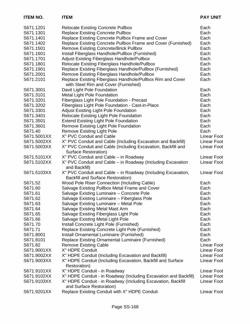
Page SS-168
ITEM NO. ITEM PAY UNIT S671.1201 Relocate Existing Concrete Pullbox Each S671.1301 Replace Existing Concrete Pullbox Each S671.1401 Replace Existing Concrete Pullbox Frame and Cover Each S671.1402 Replace Existing Concrete Pullbox Frame and Cover (Furnished) Each S671.1501 Remove Existing Concrete/Brick Pullbox Each S671.1601 Install Fiberglass Handhole/Pullbox (Furnished) Each S671.1701 Adjust Existing Fiberglass Handhole/Pullbox Each S671.1801 Relocate Existing Fiberglass Handhole/Pullbox Each S671.1901 Replace Existing Fiberglass Handhole/Pullbox (Furnished) Each S671.2001 Remove Existing Fiberglass Handhole/Pullbox Each S671.2101 Replace Existing Fiberglass Handhole/Pullbox Rim and Cover Each with Steel Rim and Cover (Furnished) S671.3001 Davit Light Pole Foundation Each S671.3101 Metal Light Pole Foundation Each S671.3201 Fiberglass Light Pole Foundation - Precast Each S671.3202 Fiberglass Light Pole Foundation - Cast-in-Place Each S671.3301 Adjust Existing Light Pole Foundation Each S671.3401 Relocate Existing Light Pole Foundation Each S671.3501 Extend Existing Light Pole Foundation Each S671.3601 Remove Existing Light Pole Foundation Each S671.40 Remove Existing Light Pole Each S671.5001XX X" PVC Conduit and Cable Linear Foot S671.5002XX X" PVC Conduit and Cable (Including Excavation and Backfill) Linear Foot S671.5003XX X" PVC Conduit and Cable (Including Excavation, Backfill and Linear Foot Surface Restoration) S671.5101XX X" PVC Conduit and Cable – in Roadway Linear Foot S671.5102XX X" PVC Conduit and Cable – in Roadway (Including Excavation Linear Foot and Backfill) S671.5103XX X" PVC Conduit and Cable – in Roadway (Including Excavation, Linear Foot Backfill and Surface Restoration) S671.52 Wood Pole Riser Connection (Including Cable) Each S671.60 Salvage Existing Pullbox Metal Frame and Cover Each S671.61 Salvage Existing Luminaire – Concrete Pole Each S671.62 Salvage Existing Luminaire – Fiberglass Pole Each S671.63 Salvage Existing Luminaire – Metal Pole Each S671.64 Salvage Existing Metal Mast Arm Each S671.65 Salvage Existing Fiberglass Light Pole Each S671.66 Salvage Existing Metal Light Pole Each S671.70 Install Concrete Light Pole (Furnished) Each S671.71 Replace Existing Concrete Light Pole (Furnished) Each S671.8001 Install Ornamental Luminaire (Furnished) Each S671.8101 Replace Existing Ornamental Luminaire (Furnished) Each S671.82 Remove Existing Cable Linear Foot S671.9001XX X" HDPE Conduit Linear Foot S671.9002XX X" HDPE Conduit (Including Excavation and Backfill) Linear Foot S671.9003XX X" HDPE Conduit (Including Excavation, Backfill and Surface Linear Foot Restoration) S671.9101XX X" HDPE Conduit - in Roadway Linear Foot S671.9102XX X" HDPE Conduit - in Roadway (Including Excavation and Backfill) Linear Foot S671.9103XX X" HDPE Conduit - in Roadway (Including Excavation, Backfill Linear Foot and Surface Restoration) S671.9201XX Replace Existing Conduit with X" HDPE Conduit Linear Foot

Page SS-169
ITEM NO. ITEM PAY UNIT S671.9202XX Replace Existing Conduit with X" HDPE Conduit (Including Linear Foot Excavation and Backfill) S671.9203XX Replace Existing Conduit with X" HDPE Conduit (Including Linear Foot Excavation, Backfill and Surface Restoration) S671.9301XX Replace Existing Conduit with X" HDPE Conduit - in Roadway Linear Foot S671.9302XX Replace Existing Conduit with X" HDPE Conduit - in Roadway Linear Foot (Including Excavation and Backfill) S671.9303XX Replace Existing Conduit with X" HDPE Conduit - in Roadway Linear Foot (Including Excavation, Backfill and Surface Restoration) S671.9401XX X" HDPE Conduit and Cable Linear Foot S671.9402XX X" HDPE Conduit and Cable (Including Excavation and Backfill) Linear Foot S671.9403XX X" HDPE Conduit and Cable (Including Excavation, Backfill and Linear Foot Surface Restoration) S671.9501XX X" HDPE Conduit and Cable – in Roadway Linear Foot S671.9502XX X" HDPE Conduit and Cable – in Roadway (Including Excavation Linear Foot and Backfill) S671.9503XX X HDPE Conduit and Cable – in Roadway (Including Excavation, Linear Foot Backfill and Surface Restoration) REVISED February 11, 2020

Page SS-170
SECTION 685 – EPOXY REFLECTORIZED PAVEMENT MARKINGS 685 GENERAL Purpose of this directive is to designate certain NYSDOT bid items for use on all City projects. References to NYSDOT specifications are to be in accordance with latest edition of NYSDOT Standard Specifications (US Customary Units). Work is to be in accordance with requirements of NYSDOT Section 685 – Epoxy Reflectorized Pavement Markings for following bid items: 685-5 BASIS OF PAYMENT Payment will be made under: ITEM NO. ITEM PAY UNIT 685.11 White Epoxy Reflectorized Pavement Stripes – 20 mils Linear Foot 685.12 Yellow Epoxy Reflectorized Pavement Stripes – 20 mils Linear Foot 685.13 White Epoxy Reflectorized Pavement Letters – 20 mils Each 685.14 White Epoxy Reflectorized Pavement Symbols – 20 mils Each ISSUED February 25, 2020

Page SS-171
SECTION 686 – PREFORMED THERMOPLASTIC REFLECTORIZED PAVEMENT MARKINGS
686 GENERAL Purpose of this directive is to designate certain NYSDOT bid items for use on all City projects. References to NYSDOT specifications are to be in accordance with latest edition of NYSDOT Standard Specifications (US Customary Units). Work is to be in accordance with requirements of NYSDOT US Customary Special Specification 686.01000011 for Preformed Thermoplastic Reflectorized Pavement Markings for following bid items: 686-5 BASIS OF PAYMENT Payment will be made under: ITEM NO. ITEM PAY UNIT 686.01000011 White Preformed Thermoplastic Reflectorized Pavement Stripes Linear Foot 686.02000011 Yellow Preformed Thermoplastic Reflectorized Pavement Stripes Linear Foot 686.03000011 White Preformed Thermoplastic Reflectorized Pavement Letters Each 686.04000011 White Preformed Thermoplastic Reflectorized Pavement Symbols Each 686.05000011 Multi-Color Preformed Thermoplastic Reflectorized Pavement Each Symbols ISSUED August 1, 2018
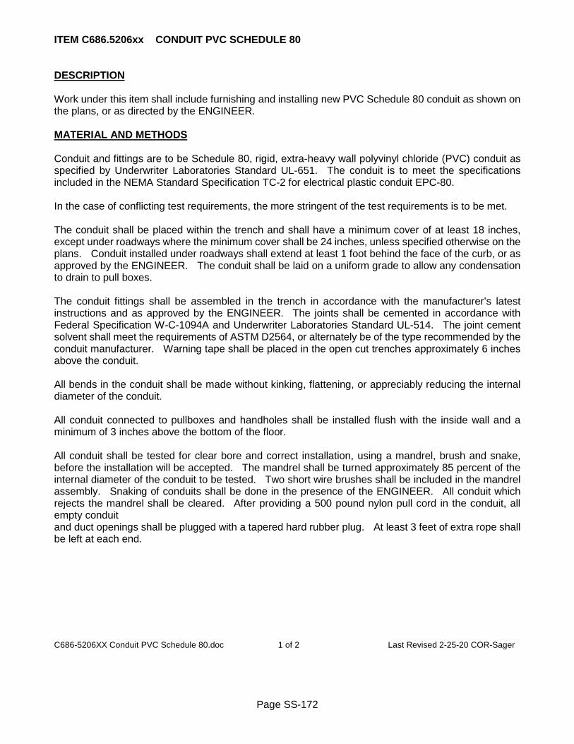
Page SS-172
ITEM C686.5206xx CONDUIT PVC SCHEDULE 80 DESCRIPTION Work under this item shall include furnishing and installing new PVC Schedule 80 conduit as shown on the plans, or as directed by the ENGINEER. MATERIAL AND METHODS Conduit and fittings are to be Schedule 80, rigid, extra-heavy wall polyvinyl chloride (PVC) conduit as specified by Underwriter Laboratories Standard UL-651. The conduit is to meet the specifications included in the NEMA Standard Specification TC-2 for electrical plastic conduit EPC-80. In the case of conflicting test requirements, the more stringent of the test requirements is to be met. The conduit shall be placed within the trench and shall have a minimum cover of at least 18 inches, except under roadways where the minimum cover shall be 24 inches, unless specified otherwise on the plans. Conduit installed under roadways shall extend at least 1 foot behind the face of the curb, or as approved by the ENGINEER. The conduit shall be laid on a uniform grade to allow any condensation to drain to pull boxes. The conduit fittings shall be assembled in the trench in accordance with the manufacturer’s latest instructions and as approved by the ENGINEER. The joints shall be cemented in accordance with Federal Specification W-C-1094A and Underwriter Laboratories Standard UL-514. The joint cement solvent shall meet the requirements of ASTM D2564, or alternately be of the type recommended by the conduit manufacturer. Warning tape shall be placed in the open cut trenches approximately 6 inches above the conduit. All bends in the conduit shall be made without kinking, flattening, or appreciably reducing the internal diameter of the conduit. All conduit connected to pullboxes and handholes shall be installed flush with the inside wall and a minimum of 3 inches above the bottom of the floor. All conduit shall be tested for clear bore and correct installation, using a mandrel, brush and snake, before the installation will be accepted. The mandrel shall be turned approximately 85 percent of the internal diameter of the conduit to be tested. Two short wire brushes shall be included in the mandrel assembly. Snaking of conduits shall be done in the presence of the ENGINEER. All conduit which rejects the mandrel shall be cleared. After providing a 500 pound nylon pull cord in the conduit, all empty conduit and duct openings shall be plugged with a tapered hard rubber plug. At least 3 feet of extra rope shall be left at each end. C686-5206XX Conduit PVC Schedule 80.doc 1 of 2 Last Revised 2-25-20 COR-Sager

Page SS-173
BASIS OF ACCEPTANCE The conduit shall be accepted upon the basis of the manufacturer’s certification that it meets the requirements of this specification, as well as being Underwriters Laboratory Listed. Fittings, couplings, and solvent cement shall be accepted upon the manufacturer’s certification that they meet the requirements of this specification. METHOD OF MEASUREMENT The quantity to be measured for payment shall be the number of lineal feet of conduit installed in accordance with the contract documents and as directed by the ENGINEER. BASIS OF PAYMENT The unit bid price for this item shall include the cost of furnishing and installing new conduit, fittings, warning tape, pull cord, couplings and insulating bushings; cementing of the joints and fittings; testing for clear bore and correct installation; connecting conduit to handholes, pullboxes, existing conduit, traffic signal pole foundations, and other electrical equipment. Payment for trenching, boring, and surface restoration shall be included under other items. Payment will be made under: Item No. Item Pay Unit C686.520601 Conduit PVC Schedule 80 - 1” Dia L.F. C686.520602 Conduit PVC Schedule 80 - 2” Dia L.F. C686.520603 Conduit PVC Schedule 80 - 3” Dia L.F. C686.520604 Conduit PVC Schedule 80 - 4” Dia L.F.
**Specification item numbers were modified specifically for the Sager Drive Improvement Project** C686-5206XX Conduit PVC Schedule 80.doc 2 of 2 Last Revised 2-25-20 COR-Sager

Page SS-174
SECTION 698 – PRICE ADJUSTMENTS 698 GENERAL Purpose of this directive is to designate certain NYSDOT bid items for use on all City projects. References to NYSDOT specifications are to be in accordance with latest edition of NYSDOT Standard Specifications (US Customary Units). Work is to be in accordance with requirements of NYSDOT Section 698 – Price Adjustments for following bid items: 698-5 BASIS OF PAYMENT Payment will be made under: ITEM NO. ITEM PAY UNIT 698.04 Asphalt Price Adjustment Dollar Cents 698.05 Fuel Price Adjustment Dollar Cents 698.06 Steel/Iron Price Adjustment Dollar Cents ISSUED February 25, 2020
Page SS-175
SECTION 699 – MOBILIZATION 699 GENERAL Purpose of this directive is to designate certain NYSDOT bid items for use on all City projects. References to NYSDOT specifications are to be in accordance with latest edition of NYSDOT Standard Specifications (US Customary Units). Work is to be in accordance with requirements of NYSDOT Section 699 Mobilization for following bid item: 699-5 BASIS OF PAYMENT Payment will be made under: ITEM NO. ITEM PAY UNIT 699.040001 Mobilization Lump Sum ISSUED January 1, 2017

Page SS-176
SECTION S900 - GENERAL WATER PROVISIONS S900 GENERAL These general water provisions apply to all specifications for work on water system, and by reference is part of each section of those specifications. S900-2 MATERIALS Materials and product manufacturer shall be in accordance with the current City of Rochester Water Bureau’s Approved Products List or approved equivalent. S900-2.01 Hardware Hardware is to be made of blue fluorocarbon coated, cold formed, high strength, low-alloy steel in accordance with ANSI/AWWA C111/A21.11. S900-2.02 Warning Tape Warning tape is to be 3-inch wide blue colored direct burial detectable metallic-lamination tape designed to locate and warn excavators of existing buried water pipes. Warning tape is to be marked in bold readable lettering “CAUTION WATER LINE BURIED BELOW”. S900-2.03 Material Certification Manufacturers and suppliers certifications are to be furnished to Project Manager stating that materials furnished have passed acceptance tests listed in appropriate specification. Water pipe, fittings and appurtenances that come into contact with drinking water are to be certified by an ANSI approved third-party North American certification program or laboratory for conformance with American National Standards Institute/National Sanitation Foundation (ANSI/NSF) Standard 61 for health effects and also ANSI/NSF Standard 61-Annex G or ANSI/NSF Standard 372 for “lead free” lead content requirements. S900-2.04 Thrust Restraint Concrete for thrust blocks is to be Class K in conformance with requirements of Section S504 Portland Cement Concrete, and can be either central, transit or truck mixed. With prior approval of Project Manager, an on-site mixed concrete can be used in lieu of Class K mix. Use of dry unmixed cement for constructing thrust blocks is prohibited. Push-on joints and mechanical joints may require restraint by utilizing restraining devices as described in the Materials Section of S901, Water Main Pipe and Fittings. Restraining device is to be installed according to manufacturer’s instructions. See Standard Detail for length of water pipe, including all pipe joints within the given length, required to be restrained. Tie rods and clamps may be used in lieu of restraining device and are subject to approval of Project Manager prior to their use in water work. Tie rods, clamps and hardware are to be in conformance with requirements of Section S900-2.01. Number and diameter of tie rods to be used for restrained joints shall be as shown in the following table:
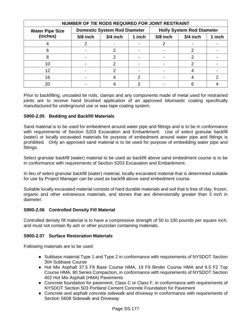
Page SS-177
NUMBER OF TIE RODS REQUIRED FOR JOINT RESTRAINT
Water Pipe Size (inches)
Domestic System Rod Diameter Holly System Rod Diameter 5/8 inch 3/4 inch 1 inch 5/8 inch 3/4 inch 1 inch
4 2 - - 2 - - 6 - 2 - - 2 - 8 - 2 - - 2 - 10 - 2 - - 2 - 12 - 2 - - 4 - 16 - 4 2 - 4 2 20 - 4 2 - 6 4
Prior to backfilling, uncoated tie rods, clamps and any components made of metal used for restrained joints are to receive hand brushed application of an approved bitumastic coating specifically manufactured for underground use or wax tape coating system. S900-2.05 Bedding and Backfill Materials Sand material is to be used for embedment around water pipe and fittings and is to be in conformance with requirements of Section S203 Excavation and Embankment. Use of select granular backfill (water) or locally excavated materials for purpose of embedment around water pipe and fittings is prohibited. Only an approved sand material is to be used for purpose of embedding water pipe and fittings. Select granular backfill (water) material to be used as backfill above sand embedment course is to be in conformance with requirements of Section S203 Excavation and Embankment. In lieu of select granular backfill (water) material, locally excavated material that is determined suitable for use by Project Manager can be used as backfill above sand embedment course. Suitable locally excavated material consists of hard durable materials and soil that is free of clay, frozen, organic and other extraneous materials, and stones that are dimensionally greater than 3 inch in diameter. S900-2.06 Controlled Density Fill Material Controlled density fill material is to have a compressive strength of 50 to 100 pounds per square inch, and must not contain fly ash or other pozzolan containing materials. S900-2.07 Surface Restoration Materials Following materials are to be used: ● Subbase material Type 1 and Type 2 in conformance with requirements of NYSDOT Section
304 Subbase Course ● Hot Mix Asphalt 37.5 F9 Base Course HMA, 19 F9 Binder Course HMA and 9.5 F2 Top
Course HMA, 80 Series Compaction, in conformance with requirements of NYSDOT Section 402 Hot Mix Asphalt (HMA) Pavements
● Concrete foundation for pavement, Class C or Class F, in conformance with requirements of NYSDOT Section 503 Portland Cement Concrete Foundation for Pavement
● Concrete and asphalt concrete sidewalk and driveway in conformance with requirements of Section S608 Sidewalk and Driveway

Page SS-178
● Curb in conformance with requirements of Section S609 Curb ● Seeding in conformance with requirements of Section S610 Landscape ● Topsoil in conformance with requirements of Section S613 Topsoil ● Concrete gutter in conformance with requirements of Section R624 Concrete Gutter S900-3 CONSTRUCTION DETAILS S900-3.01 General Work on water system is to be coordinated with Bureau of Water. Location and disposition of water services must be verified before beginning any water system related work. Where existing water system is required to be shut down as approved by the Project Manager, Bureau of Water will close existing water valves needed to isolate that section of existing water system. Bureau of Water is to be notified minimum of 10 working days in advance of intent to do work that requires section of existing water system to be shut down, and again minimum of 2 working days in advance of when actual work is to begin. Water valves and hydrants are to be operated only by authorized Bureau of Water personnel. Work is to be scheduled so as to maintain adequate level of water service, with interruptions being of minimum duration. Affected water service customer is to be notified by Contractor minimum of 24 hours in advance of any planned water service disruption. Temporary water service is to be provided to water service customer where water service is to be discontinued for more than 8 hours, or when indicated in Contract Documents. Method of providing temporary water service is to be in conformance with requirements of Section S916 Temporary Bypass. Businesses and sensitive water service customers that require continuous water service for their basic operation are to receive a written notification by Contractor minimum of 72 hours in advance of planned water service disruption and be provided with temporary water supply when water system is shut down, or water shut shall be coordinated such that it occurs outside normal business operating hours. Permit is required from Bureau of Water to use water from hydrants. Permit requires use of water meter and backflow preventer being supplied by Bureau of Water. Bureau of Water dispatcher and Project Manager must be immediately notified when existing hydrant is put out of service. Dispatcher will inform Fire Department of out of service hydrant, and Contractor is to red tag out of service hydrant. Dispatcher must be notified when hydrant is placed back in service. Contractor is to provide record information of all water service work to Bureau of Water Engineering Section. Record information is to be submitted in form of water service card. Blank water service card can be obtained from Bureau of Water Materials and Equipment Section. Water service card is to be submitted for approval to Bureau of Water Engineering Section with all required information completely filled in. Record information to be provided on each water service card includes street address, coordinate location of water service pipe and curb stop, sizes and type of material installed, and Contractor’s and inspector’s names. Excavation is to be in conformance with requirements of Section R206 Trench and Culvert Excavation. Excavation for new water construction is to be only to sufficient length, width and depth needed to perform work in safe manner, to expose existing water pipe, and for proper installation of new water pipe and fittings. Appropriate measures are to be taken to prevent extraneous material and ground water from contaminating water system. Ground water level is never to be less than 12 inches below invert of water pipe. To prevent contamination, open ends of water pipe that are left unattended are to be plugged with watertight plug, and wrapped in a double layer of polyethylene plastic and tightly taped or

Page SS-179
tied. Prior to installation, water valves and hydrants are to be inspected, cleaned, lubricated and tested to insure they are in proper working order and bolts and nuts are torqued to manufacturer’s specifications. Prior to installation of any new water pipe and fittings, open end of existing water pipe is to be cleaned, removing all external dirt, scale and rust for minimum distance of 12 inches beyond end of new water pipe and fittings. Extraneous material that ends up inside water pipe must be removed via scouring by manipulating respective water valve. Trenches located within existing pavement areas are to be surface finished with temporary pavement before end of work day. Temporary pavement is to be in conformance with requirements of Section S412 Temporary Pavement. Extra caution is to be taken when working in vicinity of existing water pipe which is to remain in service. No vibratory equipment is to be used within 5 feet horizontally of existing cast iron, steel, asbestos cement and prestressed concrete cylinder water pipe. Cut and open water pipe ends on abandoned water main and hydrant branch pipes are to be plugged with concrete. Concrete plug is to completely fill and seal end of abandoned water pipe to minimum depth of 12 inches. Abandoned water valves and curb stops are to be permanently closed and are to be left in shut position. New water service taps may be installed during installation of water pipe as approved by the Project Manager. S900-3.02 Installation Water pipe and fittings are to be installed to required alignment and depth as required in Contract Documents and as approved by Project Manager. Alignment and depth of water pipe and fittings specified in Contract Documents is approximate only. Actual alignment and depth may be adjusted to meet field conditions at time of installation as approved by Project Engineer. Control points are to be carefully preserved. Full depth pavement saw cutting is required for trenching in pavement areas that are located outside of full pavement reconstruction. All pavement saw cutting is to be done prior to commencing any water work, and is to be done in conformance with requirements of Section R622 Saw Cutting. Excavation limits for installation of water pipe and fittings are to be to required alignment and depth to provide for minimum cover over water pipe and fittings, as measured between finished grade and top of water pipe and fittings shall be (unless noted otherwise on plans): ● 4 feet 6 inches for domestic water pipe ● 5 feet for Holly system water pipe Trench is to be de-watered, and kept free of water at all times. Where trench bottom is determined to be unstable by Project Manager, unsuitable material is to be removed to width and depth as approved by Project Manager, and excavated area shall be backfilled with select granular backfill or subbase course material. Rock that is encountered within bounds of required excavation, embedment and backfill limits, is to be removed. Before installation interior of water pipe and fittings that cannot be normally disinfected shall be swabbed

Page SS-180
with 1- 5 percent minimum hypochlorite solution. Where it is required to cut or remove section of existing water pipe, cut is to be made straight, smooth and perpendicular to centerline of existing water pipe. Prior to cutting of water pipe, pipe cutting equipment and methods are to be as approved by Project Manager. S900-3.03 Bedding and Backfill Water pipe and fittings are to be completely embedded within sand material, as measured from exterior limit of water pipe and fitting to minimum extent of: ● 12 inches on each side ● 6 inches below bottom ● 12 inches above top Sand embedment material is to be installed and compacted in conformance with requirements of Section S203 Excavation and Embankment. Sand bedding is to provide solid bearing through entire length of water pipe and fittings. Timber blocking is not to be used without prior approval of Project Manager, and is to be removed prior to backfilling of trench. Warning tape is to be placed in open trench 12 inches above water pipe that is 4 inch and larger. Warning tape is to run continuously above and along centerline of water pipe, with wording facing up. Backfill under paved areas is to be select granular backfill (water), and is to be installed and compacted in conformance with requirements of Section S203 Excavation and Embankment, with following modifications: ● Lift thickness is not to exceed 12 inches ● Minimum density for all backfill materials is to be 95 percent of Standard Proctor Maximum
Density S900-3.04 Filling and Flushing Water pipe is to be slowly filled with water of potable quality at maximum velocity of 1 foot per second while all air is expelled from water pipe. Precautions are to be taken to prevent entrapping air in water pipe. After filling, water pipe is to be flushed at blow-offs and dead-ends at minimum velocity of 3 feet per second. Minimum of three changes of potable water are to be used in flushing operation. S900-3.05 Testing A. General
A hydrostatic pressure test is to be conducted on the water main after all required pipe and fittings have been installed including hydrant branches up to the hydrant and water services four (4) inches in diameter and larger. The length of water pipe to be pressure tested will be as approved by the Project Manager. The test shall be conducted using equipment that is capable of accurately measuring the pressure within the pipe and the amount of water added to the pipe during the test. The pressure test is to be witnessed by the Project Manager.
The section of water pipe to be pressure tested shall be filled with water of potable quality and all air expelled. Temporary taps on the water pipe are to be made at high points and other locations along the pipe, as needed, to release air from the pipe or for other testing purposes. All temporary taps shall be permanently plugged after successful completion of the hydrostatic test.

Page SS-181
The Contractor shall notify the Project Manager 24 hours in advance of beginning the hydrostatic pressure test. The Contractor shall furnish the pressure testing apparatus. The apparatus shall include a water pressure gauge and water meter that have been properly calibrated for the work. Calibration testing of the gauge and meter shall be performed by an ISO 17025-accredited laboratory. The pressure gauge shall have a maximum range of 0 to 300 pounds per square inch (p.s.i.), a 3-1/2 inch minimum diameter dial with a graduation of 2 p.s.i. or smaller, and a gauge accuracy of at least 0.50 per cent. The testing apparatus shall be equipped with a second port being a 1/4 inch NPT female quick-connect fitting to accommodate a second pressure gauge by the Water Bureau when ordered by the Project Manager. The ports shall be plumbed so that the gauges are installed in the upright position. The allowable difference between the Contractor’s pressure gauge and the Bureau’s pressure gauge shall not exceed 10 p.s.i. at the specified test pressure.
B. General - Ductile Iron, Polyvinyl Chloride (PVC), Molecularly Oriented Polyvinyl Chloride (PVCO)
Water Pipe
For the hydrostatic pressure test, water pressure is to be raised (based on elevation at lowest point of water pipe under test and corrected to gauge location) to minimum pressure of:
● 150 pounds per square inch gauge for domestic water main ● 250 pounds per square inch gauge for Holly water main
After all visible leaks have been stopped, full test-pressure is to be maintained for minimum of 1 continuous hour with zero (0) gallons allowable leakage for each section of water pipe being tested.
If section of water pipe should fail to pass pressure test, defective section of water pipe is to be uncovered and repaired. Continually repeat pressure test, making repairs as necessary, until entire length of water pipe passes required pressure test.
C. High Density Polyethylene Water Pipe
Pressure test is to be done in accordance with requirements of ASTM F 2164.
For initial expansion phase of pressure test, water pressure is to be raised gradually to minimum test pressure of 240 pounds per square inch (based on elevation at lowest point of water pipe in pressure test and corrected to gauge location) and maintain pressure for up to 4 hours. The test pressure shall not exceed that of lowest pressure rated component. Additional make-up water will be required to be added to maintain test pressure at hourly intervals for initial expansion phase.
Following initial expansion phase, actual test phase begins. For actual test, minimum test pressure shall be reduced 10 psi and monitored continuously for period of 1 hour without additional make-up water. There shall be no visible leakage and pressure loss during test phase shall not be more than 5 per cent different from test phase pressure for section of water pipe being tested.
Under no circumstances should total time water pipe is under continuous test pressure exceed 8 hours. If pressure test is not completed due to leakage, equipment failure or for any other reason within 8 hour time period, water pipe test section should be permitted to "relax" for continuous 8 hour period prior to performing any further pressure testing.

Page SS-182
S900-3.06 Disinfection Disinfection of water main/temporary bypass pipe is to be done in accordance with latest requirements of ANSI/AWWA C651. Disinfection is required for domestic and Holly water system mains. After section of water main/temporary bypass pipe has been successfully pressure tested, section of water main/temporary bypass pipe shall be thoroughly flushed. Method of flushing will be as approved by Project Manager. Minimum flushing velocity is to be 2.5 feet per second. Flows to produce minimum velocity of 2.5 feet per second shall be as shown in the following table:
FLOWS TO PRODUCE MINIMUM VELOCITY OF 2.5 FEET PER SECOND
Water Pipe Size (inches)
Flow in Gallons per Minute (gpm)
Hydrant Openings at 40 Pounds per Square Inch
(psi) Residual Pressure 4 100 one 2-1/2 inches 6 200 one 2-1/2 inches 8 400 one 2-1/2 inches
10 600 one 2-1/2 inches 12 900 two 2-1/2 inches 16 1,600 two 2-1/2 inches 20 2,500 one 4-1/2 inches
See Table 3 AWWA C651 for number and size of blow-off taps, if blow-off taps are required. Upon completion of flushing operations, water main/temporary bypass pipe is to be disinfected with chlorine solution using continuous feed method. Strength of chlorine solution is to be such that a residual of at least 25 milligrams per liter of chlorine is to be retained in water main/temporary bypass pipe after 24 hour period. For HDPE water pipe, chlorine solution is not to exceed 12 percent active chlorine due to chemical attack and degradation of polyethylene. Disinfection is to be in accordance with requirements of New York State Department of Health and of ANSI/AWWA C651, except that tablet method will not be allowed. Water pipe, fittings, valves, exterior pipe surfaces on existing water main (such as for tapping sleeves, cutting-in valves, insertion sleeves, connections to existing water main and service saddles) in addition to tools and equipment that are to be in contact with encapsulated system water which will be installed without standard 24 hour disinfection detention period are to be spray disinfected or swabbed with minimum 1 to 5 per cent solution of chlorine no more than 30 minutes prior to installation. Following disinfection, water main/temporary bypass pipe is to be flushed until chlorine concentration in water leaving water main/temporary bypass pipe is no more than that generally prevailing in existing water system. Samples of water will be collected from water main/temporary bypass pipe by Monroe County Department of Public Health. Monroe County Department of Public Health requires minimum of 2 working days advance notification requesting such sampling services. Contractor is to call (585) 753-5057 to arrange for sampling service. Monroe County Department of Public Health may refuse to collect samples of water if location of disinfection/sampling tap is determined to be improper. Hydrants are not acceptable sampling points. Monroe County Department of Health will not perform sampling until it is in receipt of certification from New York State licensed or registered design professional certifying that water improvements, testing and disinfection were completed in accordance with approved plans, reports, specifications and any

Page SS-183
amendments. Such design professional may be either an engineer, architect, or land surveyor with special exemption under Section 7208(n) of Education Law. Prior to collecting samples of water, sampling points must be decontaminated by flaming. Monroe County Department of Public Health will collect samples of water for free chlorine residual, total coliform, Escherichia coli (E. coli) and turbidity. Water main/temporary bypass pipe must not be placed in service until so authorized by Monroe County Department of Health. REVISED August 20, 2015

Page SS-184
SECTION S901 - WATER MAIN PIPE AND FITTINGS S901-1 DESCRIPTION Work consists of installation of water main pipe and fittings as required in Contract Documents and as directed by Project Manager. Work is to be in conformance with requirements of Section S900 General Water Provisions. S901-2 MATERIALS S901-2.01 Ductile Iron Pipe and Fittings Ductile iron pipe shall be Class 52 or Class 56, as indicated in Contract Documents, in conformance with requirements of ANSI/AWWA C151/A21.51 Fittings shall be ductile iron in conformance with requirements of ANSI/AWWA C110/A21.10 for full body fittings, and ANSI/AWWA C153/A21.53 for compact fittings. Fittings for ductile iron pipe that is 4 inches through 24 inches in diameter shall have rated working pressure of 350 pounds per square inch. Fittings for ductile iron pipe that is 30 inches through 48 inches in diameter shall have rated working pressure of 250 pounds per square inch. Ductile iron pipe and fittings shall be of good quality, strength, of even grain, and soft enough to permit drilling and cutting. Each section of ductile iron pipe shall be free from any defects which would make it unfit for intended use. Ductile iron pipe shall be straight, and true circle in section with concentric inner and outer surfaces. Ductile iron pipe section to be cut during installation shall be fully gauged for field cutting. Ductile iron pipe metal shall be made without any admixture of cinder iron or other inferior material. Interior of ductile iron pipe and fittings shall be cement mortar lined or epoxy coated. Cement mortar lined ductile iron pipe and fittings shall have interior lined with double thickness of cement mortar in conformance with requirements of ANSI/AWWA C104/A21.4, and have an asphalt coating on interior lining and exterior of pipe and fittings. Epoxy coated fittings shall have interior and exterior coated with 6 mil to 8 mil nominal thickness of fusion bonded epoxy in conformance with requirements of ANSI/AWWA C550 and C116/A21.16. Chips or breaks in the epoxy coating shall be repaired in the field by petrolatum wax tape coating system. Joints shall be rubber gasketed Tyton Joint® push-on, mechanical joint, or mechanical joint anchoring type. Gaskets shall be made of SBR rubber. For ductile iron water main and fittings located within petroleum hydrocarbon and/or chlorinated solvent contaminated soils, gaskets shall be made of oil resistant Buna-N (Nitrile) rubber. When contaminated soil is encountered unexpectedly in the field, Contractor shall immediately notify Project Manager. All joints shall be in conformance with requirements of ANSI/AWWA C111/A21.11. Joint restraint devices or anchor pipe shall be required in conjunction with concrete thrust blocking at points of change in direction of flow and at new hydrant branches. Restraining device is to be installed according to manufacturer’s instructions. Restraining device is to have epoxy coating or approved equivalent. Hardware shall be coated with blue fluorocarbon coating, 304 stainless steel or approved equivalent. Follower gland for mechanical joint ductile iron pipe shall be in conformance with requirements of ANSI/AWWA C151/A21.51.

Page SS-185
S901-2.02 Polyethylene Tube Encasement for Ductile Iron Pipe Polyethylene tube encasement for direct bury of ductile iron pipe 4 inches and larger in size shall consist of linear low-density polyethylene film 8 mil minimum thickness and polyethylene adhesive tape. Material and installation procedures shall be in conformance with requirements of ANSI/AWWA C105/A21.5.
S901-2.03 C900 Polyvinyl Chloride (PVC) Pipe and Fittings PVC pipe shall be designation DR 14 pressure class 305 pipe in sizes 4 inch through 12 inch in diameter, blue in color, and in conformance with requirements of AWWA C900 Standard for Polyvinyl Chloride (PVC) Pressure Pipe, 4 inch through 12 inch for Water Distribution. PVC pipe and fittings shall be of good quality and strength and be homogenous throughout, with inside and outside surfaces being free of sticky or tacky material. PVC pipe and fittings shall be free of blisters, cracks, cuts, foreign inclusions, holes, nicks, significant scratches, voids, and other defects that may affect overall integrity of PVC pipe and fittings. PVC pipe or fittings having any indication of cracking or crazing inside or outside shall be rejected. PVC pipe shall be straight and true circle in section with concentric inner and outer surfaces. Joining surfaces of PVC pipe spigots and integral-bell and sleeve-reinforced bell sockets shall be free of imperfections that might cause leakage at joints. PVC pipe shall be manufactured to cast iron pipe equivalent outside diameters to allow direct connection into cast iron and ductile iron pipe and fittings. Fittings for PVC pipe sizes 4 inches through 12 inches in diameter shall be PVC injection molded fittings in conformance with requirements ANSI/AWWA C907. Joints shall be SBR rubber gasket push-on type. For PVC water main and fittings located within petroleum hydrocarbon and/or chlorinated solvent contaminated soils, gaskets shall be made of oil resistant Buna-N (Nitrile) rubber. When contaminated soil is encountered unexpectedly in the field, Contractor shall immediately notify Project Manager. Mechanical joint restraint mechanism shall be required in conjunction with concrete thrust blocking at points of change in direction of flow and at new hydrant branches. Mechanical harness restraint shall be used for push-on joints.. Mechanical joint restraint mechanism shall have epoxy coating or approved equivalent. Hardware shall be coated with blue fluorocarbon coating, 304 stainless steel or approved equivalent. All mechanical joints on ductile iron fittings for PVC water main shall require mechanical restraint. Ductile iron or cast iron fittings may be substituted for PVC fittings upon approval by the City Water Bureau. When so approved, non-epoxy coated ductile and cast iron fittings on PVC or PVCO water mains are to be covered with protective wax tape coating and all non-epoxy coated ductile and cast iron fitting on PVC/PVCO pipe shall be cathodically protected with a 9 pound anode thermite welded to the fitting. S901-2.04 C906 High Density Polyethylene (HDPE) Pipe and Fittings HDPE pipe and fittings shall be designation DR 9 pressure class 200 pipe in sizes 4 inches through 20 inches in diameter, color striped blue, and in conformance with requirements of AWWA C906 Standard for Polyethylene (PE) Pressure Pipe and Fittings, 4 inch and larger for Water Distribution. HDPE pipe and fittings shall be made from resin meeting requirements of Plastic Pipe Institute (PPI) as PE3408. Resin material shall be in conformance with requirements of ASTM D3350 cell classification of 345464C. HDPE pipe and fittings shall be of good quality and strength and be homogenous throughout, with inside and outside surfaces being semi-matte to glossy in appearance and free of sticky or tacky material.

Page SS-186
HDPE pipe and fittings shall be free of blisters, cracks, cuts, foreign inclusions, holes, nicks, significant scratches, voids, and other defects that may affect overall integrity of HDPE pipe and fittings. HDPE pipe or fittings having any indication of cracking or crazing inside or outside shall be rejected. HDPE pipe shall be straight and true circle in section with concentric inner and outer surfaces. Joining surfaces of HDPE pipe spigots and integral-bell and sleeve-reinforced bell sockets shall be free of imperfections that might cause leakage at joints. HDPE pipe shall be manufactured to cast iron pipe equivalent outside diameters to allow direct connection into cast iron and ductile iron pipe and fittings when necessary. Fittings for HDPE pipe sizes 4 inches through 8 inches in diameter shall be thermal butt fusion molded fittings designation DR 11 with pressure rating of 160 pounds per square inch; except that 22½ degree bends may be fabricated fittings made of designation DR 9 HDPE pipe. Fittings for HDPE pipe 10 inches through 20 inches in diameter shall be thermal butt fusion fabricated fittings made of designation DR 9 HDPE pipe. Electro fusion couplings, adapters and fittings shall be designation DR 11 or better and shall be installed according to the manufacturer’s instructions. Mechanical joint adapters shall be required for installation of mechanical joint valves, hydrants and metallic fittings. Mechanical joint adapters shall have same rating, material designation and standards equivalent to HDPE pipe. Mechanical joint adapters shall be equipped with stainless steel pipe stiffener insert, ductile iron gland ring, gasket and attachment bolts and nuts. Mechanical joint adapters shall be installed according to manufacturer’s instructions. Mechanical joints shall require SBR rubber gaskets. Where joints cannot be made by thermal butt fusion or by mechanical joint adapter, mechanical joint restraint mechanism shall be required in conjunction with concrete thrust blocking at points of change in direction of flow. See Approved Products List for mechanical joint restraint mechanism 4 inch through 12 inch diameter pipe. Mechanical joint restraint mechanism shall have epoxy coating or approved equivalent. Hardware shall be coated with blue fluorocarbon coating, 304 stainless steel or approved equivalent. Mechanical joint restraint mechanism shall require pipe stiffener of sufficient length to support full bearing length of restrainer and prevent toe-in of pipe end. Pipe stiffener shall be made of T-304 stainless steel, 8 inches long, with reinforcing wedge. Pipe stiffener shall match DR designation of pipe on which it is to be used, and shall be installed according to manufacturer’s instructions. Small taps 3/4 inch through 3 inch in diameter on HDPE pipe shall be accomplished by Electro fusion transition tapping saddles equipped with internal AWWA brass threads. For connecting HDPE pipe to ductile iron pipe or PVC pipe, connection shall be made by an adapter kit which includes HDPE bell mechanical joint fitting with stainless steel reinforcing collar, C-110 heavy body ductile iron gland ring, gasket and extra length T-bolts. Installation shall be made with mechanical joint restraining mechanism for ductile iron or PVC pipe. Adapter kit shall be installed according to manufacturer’s instructions. Use of ductile iron and cast iron fittings may be substituted for HDPE fittings upon approval by the City Water Bureau. When so approved, non-epoxy coated ductile and cast iron fittings on HDPE water main are to be covered with protective wax tape coating and all ductile and cast iron fitting on HDPE pipe shall be cathodically protected with a 9 pound magnesium anode thermite welded to the fitting. S901-2.05 C909 Molecularly Oriented Polyvinyl Chloride (PVCO) Pipe and Fittings PVCO pipe shall be designation pressure class 235 CIOD pipe in sizes 4 inches through 12 inches in
Page SS-187
diameter, blue in color. PVCO pipe is to be in conformance with requirements of AWWA C909 Standard for Molecularly Oriented Polyvinyl Chloride (PVCO) Pressure Pipe, for Water Distribution. PVCO pipe shall be of good quality and strength and be homogenous throughout, with inside and outside surfaces being free of sticky or tacky material. PVCO pipe shall be free of blisters, cracks, cuts, foreign inclusions, holes, nicks, significant scratches, voids, and other defects that may affect overall integrity of PVCO pipe. PVCO pipe having any indication of cracking or crazing inside or outside shall be rejected. PVCO pipe shall be straight and true circle in section with concentric inner and outer surfaces. Joining surfaces of PVCO pipe spigots and integral-bell and sleeve-reinforced bell sockets shall be free of imperfections that might cause leakage at joints. PVCO pipe shall be manufactured to cast iron pipe equivalent outside diameters to allow direct connection into cast iron and ductile iron pipe and fittings. Fittings for PVCO pipe sizes 4 inches through 12 inches in diameter shall be PVC injection molded fittings in conformance with requirements ANSI/AWWA C907. Joints shall be SBR rubber gasket push-on type. When petroleum hydrocarbon or chlorinated solvent contaminated soils are encountered unexpectedly in the field, ductile iron pipe with nitrile gaskets or PVC pipe with nitrile gaskets shall be used in place of PVCO pipe. Mechanical joint restraint mechanism shall be required in conjunction with concrete thrust blocking at points of change in direction of flow and at new hydrant branches.. Mechanical harness restraint shall be for push-on joints. Mechanical joint restraint mechanism shall have epoxy coating or approved equivalent. Hardware shall be coated with blue fluorocarbon coating, 304 stainless steel or approved equivalent. All mechanical joints on ductile iron fittings for PVCO water main shall require mechanical restraint. Ductile iron or cast iron fittings may be substituted for PVC fittings upon approval by the City Water Bureau. When so approved, non=epoxy coated ductile and cast iron fittings on PVC/PVCO water main are to be covered with protective wax coating and all ductile and cast iron fittings on PVC/PVCO pipe shall be cathodically protected with a 9 pound magnesium anode thermite welded to the fitting. S901-2.06 Petrolatum Wax Tape Coating System for Metallic Fittings to be used with Polyvinyl Chloride (PVC) Pipe, Molecularly Oriented Polyvinyl Chloride (PVCO) Pipe and High Density Polyethylene (HDPE) Pipe The primer and wax tape coating shall be in accordance with ANSI/AWWA C217. Wax tape coating system shall be composed of synthetic fabric, saturated with blend of petroleum wax, plasticizers and corrosion inhibitors. Wax tape coating system shall consist of primer paste and petrolatum tape. S901-2.07 Tracer Wire for Polyvinyl Chloride (PVC) Pipe, Molecularly Oriented Polyvinyl Chloride (PVCO) Pipe and High Density Polyethylene ( HDPE) Pipe Tracer wire shall be designed specifically for detecting buried utilities. Tracer wire for open cut installation shall be minimum of one (1) - 12 AWG copper wire, solid, coated with a blue colored minimum 30 mil high molecular weight polyethylene insulation (HDPE or HMWPE). Tracer wire for trenchless water main shall consist of minimum two (2) wires or as shown on plans and shall be minimum 12 AWG copper clad steel core wire, solid, with a blue 45 mil HDPE insulation. S901-2.08 Tracer Wire Termination Box Termination box shall be cathode protection test box. Termination box shall be 4 feet long, have shaft size of 4 inches inside diameter, body made of ABS plastic flared at bottom, with cast iron rim and flush fit drop-turn locking lid with words "WATER TEST" cast on top of lid. Non-conductive terminal board designed for minimum of two stainless steel terminal connections shall be attached to inside of lid.

Page SS-188
If termination box is to be installed in paved area, termination box shall be installed within 7 inch diameter valve box. Valve box shall be minimum 4 feet long cast iron, screw type with arched base, with word "WATER" cast on top of lid. S901-2.09 Impervious Clay Trench Plug Impervious clay trench plug shall consist of a mixture of silt and clay soils free of rocks, stones and vegetation. All material shall pass through a 0.25 inch sieve and at least 95% by weight of the material shall pass through a #200 sieve. The hydraulic coefficient (coefficient of permeability) of the material shall be less than 1 x 10⁻⁶ cm/sec as measured using ASTM D5084. S901-3 CONSTRUCTION DETAILS S901-3.01 General Water main pipe shall be installed in straight line horizontally and vertically. Deflection of water main pipe shall be achieved at pipe joints within manufacturer’s allowable limits and with bend fittings. Water main pipe and fittings shall be handled in such manner that water main pipe and fittings, coatings and linings are not damaged. Nylon fabric choker sling capable of handling weight of water main pipe and fittings shall be used to lift, place and move water main pipe and fittings. Water main pipe and joints shall be uniformly supported and secured in place within required embedment material. Temporary support under water main pipe shall be removed upon securing water main pipe with permanent embedment material. Refer to Section S900-3.02 for minimum cover over water main pipe and fittings, as measured between finished grade and top of water main pipe and fittings. Minimum vertical separation between crossing water main and sewer pipe lines is to be 18 inches when water main pipe passes under sewer pipe, or 6 inches when water main pipe crosses over sewer pipe, as measured from outside of respective pipes at point of crossing. One full standard laying length of water main pipe is to be centered under or over sewer pipe so that both joints of water main pipe will be as far from sewer pipe as possible. In addition, when water main pipe passes under sewer pipe, adequate structural support in form of compacted crushed stone bedding or class K concrete is to be provided for sewer pipe to prevent excessive deflection of sewer pipe joints and any settling of sewer pipe onto water main pipe. Optimum minimum horizontal separation between parallel water main and sewer pipes, including manholes, vaults and junction chambers, is 10 feet as measured from outside of respective pipes, manholes, vaults and junction chambers. In no case is water main pipe to be installed less than 3 feet horizontally from parallel sewer pipe, including manholes, vaults and junction chambers. Where water main pipe has less than minimum separation requirements either horizontally or vertically, all of joints of water main pipe located within 10 feet of sewer pipe are to be encased with controlled density fill material. Controlled density fill encasement is to be placed to minimum thickness of 6 inches around water main pipe for minimum length of 2 feet as centered on joint of water main pipe. In all cases, where water main pipe crosses another utility, vertical separation shall not be less than 6 inches. Tees, bends, offsets, reducers, caps, plugs and hydrants on water pipe shall be mechanically restrained and solidly braced to prevent any movement due to thrust pressure. Bracing shall be accomplished with use of cast-in-place concrete between fittings/hydrant and undisturbed soil. Water valves shall be mechanically restrained at both ends.

Page SS-189
Disinfection/sampling taps are to be installed no more than 1,000 feet apart and at ends of all new water main installations. Contractor is responsible for making sure that inside of pipe is clean and free of foreign material before pipe installation. S901-3.02 Ductile Iron Pipe and Fittings Ductile iron pipe and fittings shall be installed in conformance with requirements of ANSI/AWWA C600, according to manufacturer’s latest instructions, and as approved by Project Manager. Polyethylene tube encasement shall be installed on all ductile iron water mains, water services and hydrant branch pipe in conformance with ANSI/AWWA C105/A21.5. Plugging, filing, burning-in or welding will not be allowed to repair any ductile iron pipe or fittings that have been damaged. For ductile iron pipe, sizes 4-inch through 24-inch in diameter, 75-90 ft/lbs is recommended torque on nuts and ‘T’ bolts used for mechanical joints. Install magnesium anodes as shown on drawings and as approved by Project Manager. The maximum allowable angular joint deflection for DIP pipe and DIP/Cast iron fittings shall not exceed the manufacturer’s published limits. Impervious clay trench plugs shall be installed around ductile iron pipe water mains and services where shown on the plans or as directed by the Project Manager to stop the flow of contaminated groundwater through porous water main bedding and backfill material. S901-3.03 Polyvinyl Chloride (PVC) and Molecularly Oriented Polyvinyl Chloride (PVCO) Pipe and Fittings PVC/PVCO pipe and fittings shall be installed in conformance with requirements of ANSI/AWWA C605, according to manufacturer’s instructions, and as approved by Project Manager. Field cutting of PVC/PVCO pipe shall be made with square ends. Cut spigot end shall be re-beveled at same angle provided by factory-finished PVC/PVCO pipe using a manufacturer’s approved beveling tool. On cut PVC/PVCO pipe an insertion line shall be marked on cut spigot end using factory marked spigot as guide. For connecting spigot end to shallow depth bell, such as mechanical joint valve and iron fitting, spigot end shall be cut so as to leave only slight bevel of 1/4 inch. Spigot end shall be inserted to full limit of shallow depth bell. For PVC (C900) pipe, sizes 4-inch through 24-inch in diameter, 75-90 ft/lbs is recommended torque on nuts and ‘T’ bolts used for mechanical joints. For PVCO (C909) pipe, 55 ft/lbs is recommended torque on nuts and ‘T’ bolts for mechanical joints. In assembling PVC/PVCO pipe, gaskets and pipe ends shall be wiped clean and spigot end lubricated from beveled end to approximately mid-way from insertion line. If recommended by manufacturer, lubricant shall be applied inside bell, using lubricant that is supplied by manufacturer. Joining is complete when spigot end is inserted to insertion line. Care shall be taken not to over-insert spigot end into bell end. It is recommended newly laid pipe be partially backfilled before adding more pipe to minimize over-insertion of pipe joints on previously laid lengths of pipe. Joining shall not be made by use of heavy machinery. The maximum allowable angular joint deflection for PVC/PVCO pipe and PVC fittings shall not exceed the manufacturer’s published limits, which may be 1 degree or less.

Page SS-190
Ductile iron or cast iron fittings shall be used when connecting PVC/PVCO pipe to existing ductile or cast iron pipe. Taps 2 inches in diameter and smaller on PVC/PVCO pipe shall require wide strap, all brass tapping saddles manufactured for C900 PVC pipe. Refer to Section S912, Corporation Stop and Connection, Taps larger than 2 inches in diameter on PVC/PVCO pipe shall require tapping sleeve. Taps shall be made using equipment designed specifically for making taps on PVC/PVCO pipe. Tap shall be no closer than 2 feet from back end of bell or spigot insertion line. Multiple taps shall be staggered at least 18 inches apart lengthwise. Asphalt coated metallic fittings installed on PVC/PVCO water main including tapping assemblies and hardware, shall be coated with petrolatum wax tape coating system applied in conformance with manufacturer instructions. One nine pound anode shall be attached to all ductile and cast iron fittings on PVC/PVCO water pipe. Precast concrete cement blocks or any hard objects shall not be used for thrust blocking or directly supporting PVC/PVCO water pipe. S901-3.04 High Density Polyethylene (HDPE) Pipe and Fittings HDPE pipe and fittings shall be installed in conformance with manufacturer’s instructions. Field cutting of HDPE pipe shall be made with square ends. Individual sections of HDPE water main pipe and fittings shall be joined together by thermal butt fusion method. Mechanical joining shall be used in locations where thermal butt fusion method cannot be used. Socket fusion, hot gas fusion, threading, solvent cements and adhesives such as epoxies shall not be used to join HDPE pipe. Electro fussed joining method may be used on fittings. Thermal butt fusion procedures shall be in conformance with manufacturer’s instructions and Plastic Pipe Institute (PPI). Fusion equipment operator shall be trained and certified in recommended procedure. Contractor shall be responsible to verify that fusion equipment is in good operating condition and that operator has been properly trained. Thermal butt fusion equipment shall be capable of meeting all conditions recommended by manufacturer, including, but not limited to, temperature requirements of 400°F, alignment and an interfacial fusion pressure of 75 pounds per square inch. Butt fusion joining shall produce joint weld strength equal to or greater than tensile strength of HDPE pipe itself. Welds shall be made using Data Logger to record temperature and fusion pressure with graphic representation of fusion cycle and shall be part of Quality Control records. Thermal butt fusion and Electro fusion joining methods shall be done in dry environment. Individual sections of HDPE pipe should be joined into continuous lengths on job site above ground. Fusion beads shall not be removed from HDPE pipe. For installation of mechanical joint adapters, bolts shall be tightened and torqued in conformance with manufacturer instructions. Asphalt coated metallic fittings installed on HDPE water main including tapping assemblies and hardware, shall be coated with petrolatum wax tape coating system applied in conformance with manufacturer instructions. Hardware for epoxy coated fittings not having blue fluorocarbon coating will require petrolatum wax tape coating system. Directional drilling method of pipe installation shall require the Contractor to record with survey grade accuracy and provide As Built map of the horizontal location and depth of pipe in reference to project stationing.

Page SS-191
Thermite weld 9 pound magnesium anode to each metallic fitting. S901-3.05 Tracer Wire Installation with Polyvinyl Chloride (PVC) Pipe, Molecularly Oriented Polyvinyl Chloride (PVCO) Pipe and High Density Polyethylene (HDPE) Pipe Tracer wire shall be installed along and above all PVC/PVCO/HDPE water pipe that is 4 inches in diameter and larger. Tracer wire shall be installed in such manner as to enable its detection with electronic locating equipment. Tracer wire shall be installed on top of PVC/PVCO/HDPE water pipe and shall be secured to water pipe with tape or plastic straps at 8 feet maximum intervals and at pipe bends. Tracer wire shall not be spiraled or otherwise wrapped around water pipe. At water service saddles, tracer wire shall be placed over and across water service saddle and water pipe. At valves, tracer wire shall be placed along the side of the water pipe so that the installation of a valve box will not damage the wire. Tracer wire shall begin and terminate at all connections to existing metallic water pipes wherever possible. Tracer wire connections to existing metallic pipes shall be made with thermite weld. Thermite weld shall be completely sealed with a brush applied coats of an approved bitumastic coating specifically manufactured for underground use. Route of tracer wire shall extend continuously along PVC/PVCO/HDPE water pipe, and shall be terminated at tracer wire termination box located near hydrant. Termination box shall be installed flush with finished grade and approximately 3 feet away from any given hydrant. Tracer wire shall extend up termination box and be connected to terminal board. Length of tracer wire extending up termination box shall be such that minimum of 3 feet of tracer wire can be coiled up and left tucked inside termination box. Number of splices made on tracer wire shall be kept to minimum. Splices shall be made using an approved waterproof connector. Where polyethylene (PE) water services are installed with PVC/PVCO/HDPE water pipe, tracer wire for PE water service shall be spliced to tracer wire for PVC/PVCO/HDPE water main pipe, using an approved splice connector that slips over the main tracer wire without cutting it. For directional drilling method of installing water main, Contractor shall attach tracer wires securely at beginning of pipe making sure wires will not become detached from pipe during drilling operation. After installation of tracer wire on mains and services has been completed, the Contractor shall test the tracer wire for electrical continuity. Upon successful completion of system test and submission of certification form to the City, tracer wire system shall be checked for functionality by a representative of the Bureau of Water. Deficiencies in the tracer wire system shall be repaired by Contractor at no additional cost to the City, and the tracer wire system shall be retested by Contractor. S901-3.06 Additional Fittings If required, additional fittings shall be installed on new water main pipe that are not already shown in Contract Documents. Petrolatum wax tape coating system and one (1) 9-pound anode shall be installed on ductile and cast iron fittings on PVC/PVCO water main pipe. S901-3.07 Additional Concrete Thrust Blocks If required, additional concrete thrust blocks shall be constructed that are not already shown to be constructed in Contract Documents.
Page SS-192
S901-4 METHOD OF MEASUREMENT S901-4.01 Water Main Pipe Quantity to be measured for payment shall be number of linear feet of water main pipe installed as measured along centerline of water main pipe, beginning with face of hub forming commencement of new work and extending to face of hub or spigot constituting end of that particular line of water main pipe. Hydrant branch water pipe and water service pipe 4 inches and larger will be measured and included for payment as water main pipe. Quantity to be measured for payment shall be number of linear feet of hydrant branch water pipe and water service pipe installed as measured from centerline of water main pipe to which hydrant branch water pipe and water service pipe is connected, along centerline of hydrant branch water pipe and water service pipe to face of hub or spigot constituting end of that particular hydrant branch water pipe and water service pipe line. S901-4.02 Additional Fittings Quantity to be measured for payment shall be number of pounds of additional fittings installed that were not originally required in Contract Documents. Weight of fittings shall be determined from listed weight in manufacturer catalogue. S901-4.03 Impervious Clay Trench Plug Quantity to be measured for payment shall be the actual number of imperious clay trench plugs installed and as shown on the plans or as ordered by the Project Manager. S901-5 BASIS OF PAYMENT S901-5.01 General all Items Unit price bid for all items shall include cost of: water pipe; water pipe fittings; water pipe specials; shop- drawings; hardware; warning tape; approved on site backfill; concrete thrust blocks; encasement; controlled density fill; joint materials; making water pipe joints; joint restraining devices; furnishing, installing and removing disinfection/sampling taps; blow-off taps; tapping saddles for disinfection/sampling taps and blow-off taps; pressure testing; disinfection, flushing and health sample testing and fees; pavement saw cutting; additional excavation and backfill required for testing and disinfection purposes; preparation and distribution of service interruption notices; preparation and submittal of water service information and cards; pipe installation records; and furnishing all labor, material and equipment necessary to complete work. Unless provided for under separate payment items in Contract Documents, cost of furnishing, installing, maintaining, and removing temporary water pipes, valves, plugs, taps, corporation stops, curb stops and boxes, blow-off water pipes, and other fittings necessary for construction of new water main, or for providing continuous water service, shall be included in unit price bid for water main pipe. Unless otherwise noted on plans or ordered by Project Manager, furnishing and installing magnesium anodes will be paid for under Section S966 Magnesium Anode. Partial payment of eighty (80) percent of unit price bid will be made for installed water main pipe that has not satisfactorily passed pressure and health tests. Remaining twenty (20) percent will not be paid until water main installation has passed both pressure and health tests and has been accepted by Monroe County Health Department and City of Rochester
Page SS-193
S901-5.02 Ductile Iron Pipe and Fittings Unit price bid shall also include cost of: furnishing and installing ductile iron pipe, anchor pipe and fittings, polyethylene tube encasement, including adhesive tape. S901-5.03 Polyvinyl Chloride (PVC), Molecularly Oriented Polyvinyl Chloride (PVCO) and High Density Polyethylene (HDPE) Pipe and Fittings Unit price bid shall also include cost of: furnishing and installing PVC/PVCO pipe and fittings; ductile iron and cast iron fittings; tracer wire; tracer wire termination box; splices and connections; tracer wire testing and certification. When substitution of a PVC fitting with a ductile or cast iron fitting is approved by the City Water Bureau no additional payment will be made for fitting, glands, hardware, joint restraint devices, petrolatum wax tape coating or 9-pound magnesium anode. S901-5.04 Additional Fittings Unit price bid shall also include cost of furnishing and installing additional pipe fittings, joint restraining devices and hardware. Unit price shall also include petrolatum wax tape coating and 9-pound anode on ductile or cast iron fittings installed on PVC/PVCO/HDPE water main pipe. Payment weight does not include weight of anode, mechanical joint glands, joint restraining devices, hardware, and tape coating. The unit price shall also include the cost to furnish and install the additional concrete thrust block. S901-5.05 Excavation, Backfill and Surface Restoration Excavation, rock excavation, furnishing and placing of bedding and select granular backfill (water), and surface restoration will be paid for under separate bid items. All hand or tunnel excavation in and around utility lines, tree roots, pipe joints and curbs shall be included in unit price bid for excavation. No separate payment shall be made for placement of approved on site backfill material excavated from trench. S901-5.06 Impervious Clay Trench Plug Unit price bid includes cost of excavation and furnishing and placement of clay material at locations shown on the plans or as ordered by the Project Manager. Payment will be made under: ITEM NO. ITEM PAY UNIT S901.0401XX X" Ductile Iron Pipe Water Main Class 52 Linear Foot S901.0503XX X" Ductile Iron Pipe Class 52 for Hydrant Branch Linear Foot S901.0601XX X" Ductile Iron Pipe Water Main Class 56 Linear Foot S901.0603XX X" Ductile Iron Pipe Class 56 for Hydrant Branch Linear Foot S901.07 Additional Ductile Iron Pipe Fittings Pound S901.0801XX X" Polyvinyl Chloride Pipe Water Main Linear Foot S901.0802XX X" Polyvinyl Chloride Pipe for Hydrant Branch Linear Foot S901.09 Additional Polyvinyl Chloride Pipe Injection Molded Fittings Pound S901.11XX X" High Density Polyethylene Pipe Water Main Linear Foot S901.12 Additional High Density Polyethylene Pipe Fittings Pound S901.1301XX X" Molecularly Oriented Polyvinyl Chloride Pipe Water Main Linear Foot

Page SS-194
ITEM NO. ITEM PAY UNIT S901.1302XX X" Molecularly Oriented Polyvinyl Chloride Pipe for Hydrant Branch Linear Foot S901.15 Impervious Clay Trench Plug Each REVISED February 5, 2018

Page SS-195
SECTION S903 - RESILIENT SEAT GATE VALVE WITH VALVE BOX S903-1 DESCRIPTION Work consists of installation of resilient seat gate valve with valve box, as required in Contract Documents and as directed by Project Manager. Work and materials are to be in conformance with requirements of Section S900 General Water Provisions and S901 Water Main Pipe and Fittings. S903-2 MATERIALS S903-2.01 Resilient Seat Gate Valve Resilient seat gate valve is to have non-rising stem (NRS), O-ring stem seals, standard 2 inch square AWWA operating nut, and open right (clockwise). Resilient seat gate valve 12 inch diameter and smaller is to meet or exceed all requirements of ANSI/AWWA C509. Resilient seat gate valve 16 inch through 24 inch in diameter is to meet or exceed all requirements of ANSI/AWWA C515. Resilient seat gate valve sizes 4 through 12 inch are to have design working pressure of 250 pounds per square inch and test pressure (gate open) of 500 pounds per square inch. Resilient seat gate valve sizes 16 through 24 inch are to have design working pressure of 200 pounds per square inch and test pressure of 500 pounds per square inch. Pressure rating is to be cast on outside of resilient seat gate valve body. Resilient seat gate valve body, bonnet and gate for valves 4 through12 inch are to be cast iron or ductile iron. Valve body and bonnet for valves 16 through 24 inch are to be ductile iron with either cast iron or ductile iron gate. Interior and exterior surface of resilient seat gate valve body and bonnet are to be coated with fusion bonded epoxy in conformance with requirements of ANSI/AWWA C550. Gate is to be completely encapsulated with rubber over all ferrous surfaces. Rubber is to be securely bonded to gate, including part which houses stem nut. Resilient seat gate valve stem is to be made of high strength bronze having minimum tensile strength of 70,000 pounds per square inch and minimum yield strength of 32,000 pounds per square inch. Stem sealing is to utilize "O" ring seals which can be replaced while resilient seat gate valve is under pressure in both fully open and fully closed position. Gate guides are to be provided to insure that gate is kept in proper alignment with body so that rubber sealing surfaces are evenly compressed when gate is closed to provide zero leakage at required design working pressure. Resilient seat gate valve is to be designed so that during operation, or cycling of resilient seat gate valve, there is no friction, abrasion or rubbing together of gate and body that can wear away any rubber and epoxy, thus exposing bare metal. Bolts and nuts for fastening bonnet to body of resilient seat gate valve are to be stainless steel. Resilient seat gate valves 4 through 12 inch are to be vertical type. Unless otherwise specified, all resilient seat gate valves 16 inch and larger shall be horizontal type.
Page SS-196
S903-2.02 Resilient Seat Gate Valve - Furnished Resilient seat gate valve complete with valve box will be as furnished by Bureau of Water Materials and Equipment Section. Contractor is to pick-up complete resilient seat gate valve unit from Bureau of Water Materials and Equipment Section, 401 Dewey Avenue, Rochester, New York, (585) 428-7514. Bureau of Water Materials and Equipment Section requires a minimum of 2 working days advance notice to make arrangements for pick-up of complete resilient seat gate valve unit. S903-2.03 Vertical Resilient Seat Gate Valve - Sizes 16 Inch to 24 Inch Vertical resilient seat gate valve sizes 20 and 24 inch are to have 2:1 ratio enclosed low-profile spur gearing for buried service with AWWA 2 inch square operating nut to allow above ground operation through valve box. Bolts and nuts on spur gear box are to be stainless steel. Vertical resilient seat gate valves 16 inch and larger may only be used in locations where water main cover depths exceed 6 feet. S903-2.04 Horizontal Resilient Seat Gate Valve Horizontal resilient seat gate valves 16 inch and larger are to have 2:1 ratio right angle enclosed bevel gearing with AWWA 2 inch square operating nut to allow above ground operation through valve box. Bolts and nuts on beveled gear box are to be stainless steel. S903-2.05 Valve Box Valve box is to be in conformance with material requirements of Section S909 Water Valve Box. S903-3 CONSTRUCTION DETAILS Resilient seat gate valve is to be installed with new water pipe in conformance with requirements of ANSI/AWWA C509 Appendix A, C515 Appendix A. Resilient seat gate valve is to be inspected, cleaned and bolts and nuts checked for tightness before installation to ensure that it is in proper working order. Vertical type resilient seat gate valve is to be installed with stem in vertical position. Horizontal type resilient seat gate valve is to be installed with valve stem in horizontal position and shaft of enclosed beveled gear box in vertical position. Joints are to be watertight. Valves, including mechanical joint glands, installed on metallic and non-metallic pipe shall be wrapped with polyethylene encasement and sealed with polyethylene tape. Special attention is to be paid to backfill material placed under resilient seat gate valve to ensure that it is well compacted for bedding resilient seat gate valve. Valve box is to be carefully set over stem or beveled gear shaft. Valve box is to be braced to ensure that it remains in proper vertical position and centered on valve stem during and after backfilling operation. Valve box top section is to be adjusted for elevation, and base centered over operating nut. Top of valve box is to be flush with finished surface. Backfilling of trench is to be done in manner so

Page SS-197
as to avoid damage to resilient seat gate valve and valve box. Proper alignment and height of valve box is to be maintained until completion of Project. S903-4 METHOD OF MEASUREMENT Quantity to be measured for payment will be number of resilient seat gate valves, with valve box, installed. S903-5 BASIS OF PAYMENT S903-5.01 General All Items Unit price bid includes cost of: enclosed beveled gear box; pressure testing; bracing; connection to water pipe; polyethylene wrap, maintaining proper alignment and height of valve box; pavement saw cutting; disinfection; and furnishing all labor, material and equipment necessary to complete work. Excavation, rock excavation, furnishing and placing of bedding and backfill materials, and surface restoration will be paid for under separate bid items. S903-5.02 Resilient Seat Gate Valve Unit price bid also includes cost of furnishing and installing resilient seat gate valve complete with valve box. S903-5.03 Resilient Seat Gate Valve - Furnished Unit price bid also includes cost of picking-up and installing resilient seat gate valve complete with valve box. Payment will be made under: ITEM NO. ITEM PAY UNIT S903.01XX X" Resilient Seat Gate Valve with Valve Box - Vertical Type Each S903.02XX X" Resilient Seat Gate Valve with Valve Box - Horizontal Type Each S903.03XX X" Resilient Seat Gate Valve with Valve Box - Vertical Type Each (Furnished) S903.04XX X" Resilient Seat Gate Valve with Valve Box - Horizontal Type Each (Furnished) REVISED September 23, 2010

Page SS-198
SECTION S904 - TAPPING SLEEVE WITH VALVE AND VALVE BOX S904-1 DESCRIPTION Work consists of installation of tapping sleeve with valve and valve box in existing water pipe, as required in Contract Documents and as directed by Project Manager. Work and materials are to be in conformance with requirements of Section S900 General Water Provisions and S901 Water Main Pipe and Fittings. S904-2 MATERIALS S904-2.01 Cast/Ductile Iron Tapping Sleeve Cast or ductile iron tapping sleeve is to be a split body tapping sleeve with mechanical joint ends and machined recess flanged outlet to accommodate tapping valve, capable of being installed on ductile iron, cast iron or PVC/PVCO water main pipe. It shall have a 3/4 inch tapped outlet with brass plug for testing and have a cement mortar lining or fusion bonded epoxy lining on the interior of the outlet branch. Sleeve is to be furnished with all glands, gaskets and fluorocarbon coated, cold formed, high strength, low-alloy steel bolts, washers and nuts. Cast/ductile iron tapping sleeve is to be designed for maximum working pressures of at least:
Water Main Pipe Size Pounds per Square Inch (psi)
4 through 12 inch 250 psi
16 through 24 inch 200 psi
larger than 24 inch 150 psi S904-2.02 Stainless Steel Tapping Sleeve Stainless steel tapping sleeves are not to be used on Holly water mains and may only be used in lieu of cast/ductile tapping sleeves on domestic water mains when the nominal diameter of the tapped outlet is at least one pipe size smaller than the nominal diameter of the existing water main pipe being tapped. When the nominal diameter of the tapped outlet is equal to the nominal diameter of the domestic water main pipe being tapped, a cast/ductile iron tapping sleeve must be used or a new tee cut into the existing water main. Stainless steel tapping sleeves shall be fabricated two piece shell Type 304 stainless steel with a gridded SBR or Nitrile (Buna-N) rubber shell gasket. Flange shall be Type 304 stainless steel with recess to accommodate tapping valve. Sleeve shall be capable of being installed on ductile iron, cast iron and PVC/PVCO water main pipe. It shall have a 3/4 inch tapped outlet with stainless steel plug for testing. Sleeve is to be furnished with stainless steel bolts, washers and nuts. Nuts shall have a fusion bonded or fluoropolymer coating to prevent seizing and galling. Stainless steel tapping sleeve is to be designed for maximum working pressures of at least:
Water Main Pipe Size Pounds per Square Inch (psi)
4 inch through 20 inch 200 psi
larger than 20 inch 150 psi

Page SS-199
S904-2.03 Tapping Valve Tapping valve is to be resilient seat tapping gate valve in conformance with requirements of Section S903 Resilient Seat Gate Valve with Valve Box. Valve shall be designed to connect directly to the flanged end of the tapping sleeve. Tapping valve is to be provided with full face gasket at the flanged end and fluorocarbon coated, cold formed, high strength, low-alloy steel nuts and bolts. S904-2.04 Valve Box Valve box is to be in conformance with requirements of Section S909 Water Valve Box. S904-2.05 Drilling/Tapping Machine and Tools Drilling/tapping machine is to be capable of attaching to and cutting through tapping valve, and is to be designed to operate with drilling/cutting tools required for the specific pipe material being drilled. When tapping PVC/PVCO water main pipe, cutting tool is to be toothed core cutter of shell-type design with minimum of two slots to allow the cut material to exit the hole and retains the coupon after penetration of water pipe. S904-3 CONSTRUCTION DETAILS Tap is to be made with drilling/tapping machine specially designed for intended work, and must be in good working condition. Hand-held drills are not to be used for making taps. Contractor is responsible to obtain actual outside diameter of existing water pipe to be tapped for proper sizing of tapping sleeve. Additional excavation is normally required to obtain actual outside diameter measurement of existing water pipe. Tapping sleeve and valve are to be installed in conformance with manufacturer's instructions and as approved by Project Manager. Before tapping the main - the pipe exterior, tapping saddle and valve and drilling/cutting tools are to be cleaned and disinfected using a chlorine solution; tapping sleeve and valve is to be inspected; and tapping sleeve and valve shall be hydrostatically pressure tested with water after installation at 150 p.s.i. for minimum 15 minutes to ensure that tapping sleeve and valve is not leaking. Valve is to be installed with stem in vertical position. Installation and joints are to be watertight, both prior to and after making connection. Tapping sleeve and valve, including mechanical joint glands, are to be wrapped with polyethylene encasement and sealed with polyethylene tape. Special attention is to be paid to backfill material placed under valve to ensure that it is well compacted for bedding valve. To prevent any deflection of tapping sleeve installation due to thrust pressure, cast-in-place concrete thrust block is to be constructed between tapping sleeve and undisturbed soil to solidly brace and support tapping sleeve independently of water pipe. Concrete thrust block is to be left in place after tapping sleeve installation is completed. Valve box is to be carefully set over valve stem or beveled gear shaft. Valve box top section is to be adjusted for elevation, and base centered over operating nut. Top of valve box is to be flush with finished surface.
Page SS-200
Valve box is to be carefully set and braced to ensure that it remains in proper vertical position and centered on valve stem during and after backfilling operation. Backfilling of trench is to be done in manner so as to avoid damage to valve and valve box. Proper alignment and height of valve box is to be maintained until completion of Project. S904-4 METHOD OF MEASUREMENT Quantity to be measured for payment will be number of tapping sleeves complete with valve and valve box installed. S904-5 BASIS OF PAYMENT Unit price bid includes cost of: furnishing and installing tapping sleeve complete with valve and valve box; making water main tap; polyethylene wrap; concrete thrust block; maintaining proper alignment and height of valve box; pavement saw cutting; pressure testing; bracing; additional excavation and backfill necessary to obtain outside diameter of existing water pipe; disinfectant to prevent contamination of existing water main; and furnishing all labor, material and equipment necessary to complete work. Excavation, rock excavation, furnishing and placing of bedding and select granular backfill, and surface restoration will be paid for under separate bid items. Payment will be made under: ITEM NO. ITEM PAY UNIT S904.03XXXX X" x X" Tapping Sleeve with Valve and Valve Box Each REVISED February 13, 2014

Page SS-201
SECTION S907 - CONNECT NEW WATER MAIN TO EXISTING WATER MAIN S907-1 DESCRIPTION Work consists of the connection of a new water main to an existing water main as required in the Contract Documents and as directed by the Project Manager. Work and materials are to be in conformance with requirements of Sections S900 General Water Provisions and S901 Water Main Pipe and Fittings. S907-2 MATERIALS All fittings and joint connection materials required to make the connection shall be as approved by the Project Manager prior to installation. Generally, the fittings and connection materials shall be the same material as the existing pipe: ductile iron fittings shall be required when connecting new ductile iron or PVC/PVCO pipe to existing cast or ductile iron pipe; and injection molded PVC fittings shall be required when connecting new PVC/PVCO pipe to existing PVC/PVCO pipe that is 12 inch diameter or less. S907-3 CONSTRUCTION DETAILS New water main shall be connected to the existing water main using approved and appropriate gaskets, materials and fittings. Fit between the new water main and the existing water main shall not exceed a gap of 1/8 inch. The interior of all water main pipe and fittings not receiving 24 hour chlorine disinfection contact time must be spray or swab disinfected with a 1 to 5 percent solution of chlorine no more than 30 minutes prior to installation. The interior and exterior of cut ends of existing pipe shall also be cleaned and disinfected. All fittings shall be solidly braced against the trench wall to prevent any deflection due to thrust pressure. Bracing shall be accomplished by the use of cast-in-place concrete thrust blocks and restrained joints. All water pipe joints shall be made watertight. Prior to backfilling, the water main shall be filled with potable water and installation tested for leaks under line pressure in the presence of the Project Manager. Prior to backfilling, uncoated tie rods, clamps and any components made of metal used for restrained joints are to receive hand brushed application of an approved bitumastic coating specifically manufactured for underground use or petrolatum wax tape coating system. Non epoxy coated ductile iron fittings installed on PVC/PVCO water main pipe shall be coated with petrolatum wax tape coating system applied in conformance with manufacturer’s instructions. One nine pound anode shall be attached to each ductile iron fitting. When connecting a new ductile iron or PVC/PVCO water main to an existing cast or ductile iron water main, one 32 pound anode shall be thermite welded to the existing water main. S907-4 METHOD OF MEASUREMENT The quantity to be measured for payment shall be the number of connections actually made.
Page SS-202
S907-5 BASIS OF PAYMENT The unit price bid shall include the cost of: cutting and removing a piece of the existing water main; removing the existing plug; dewatering and cleaning existing water main; furnishing and using all temporary plugs; disinfectant to prevent contamination of the existing water main; connecting the new water main to the existing water main; furnishing and placing all pipe, pipe specials, gaskets, fittings, joints, hardware and thrust blocks; protective coating; restrained joints; plugging the abandoned water main with concrete; pavement saw cutting; leak testing; and furnishing all labor, material and equipment necessary to complete the work. Excavation, rock excavation, furnishing and placing of magnesium anodes, bedding and select granular backfill, and surface restoration will be paid for under separate bid items. Payment for installation of a tee or cross into existing water main shall be considered as one connection. Payment will be made under: ITEM NO. ITEM PAY UNIT S907.01 Connect New Water Main to Existing Water Main Each REVISED February 13, 2014

Page SS-203
SECTION S908 - CUT AND PLUG EXISTING WATER MAIN S908-1 DESCRIPTION Work consists of cutting and plugging or capping existing water mains that are to remain in service, as required in the Contract Documents and as directed by the Project Manager. Work is to be in conformance with the requirements of Sections S900 General Water Provisions and S901 Water Main Pipe and Fittings. S908-2 MATERIALS Ductile iron plugs and caps shall be required on ductile iron, cast iron and PVC/PVCO pipe. PVC plugs and caps are not to be used. Plugs and caps are to be in conformance with the requirements of Section S901 Water Main Pipe and Fittings. Tapped plugs and caps, if used, shall have a 2 inch tap and brass plug. Plugs and caps installed on ductile iron and PVC/PVCO pipe shall be restrained to the pipe using mechanical joint or harness type joint restraint device in conformance with the requirements of S901 Water Main Pipe and Fittings. Tie rods, socket clamps and tie bars may be used on cast iron pipe, in lieu of mechanical joint or harness type joint restraint device, subject to the prior approval of the Project Manager. Number and size of tie rods shall be as specified in S900 General Water Provisions. Tie bars shall be 3 inch steel channels, 5 pounds per foot. S908-3 CONSTRUCTION DETAILS Whenever possible, plug shall be installed at a tee, cross or similar connection fitting. Where the water main is to be plugged at a water pipe joint, the plug shall be installed in the bell end of the water pipe. A section of water main pipe shall be cut and removed and the interior of all water main pipe and fittings not receiving 24 hour chlorine disinfection contact time must be spray or swab disinfected with a 1 to 5 percent solution of chlorine no more than 30 minutes prior to installation. The interior and exterior of existing fitting or pipe joint and cut end of existing pipe which will be plugged or capped shall also be cleaned and disinfected. On cast iron water pipe and fittings, where plugs cannot be bolted directly to the water pipe or fitting joint or otherwise restrained using a mechanical joint or harness type joint restraint device, the plug or cap shall be installed and held in place by a retaining bar extending across the center of the plug. A socket clamp shall be installed on the water pipe or fitting behind the bell, and the retaining bar secured to the socket clamp with steel rods, socket clamp washers, lock washers and nuts. Prior to backfilling, uncoated tie rods, clamps and any components made of metal used for restrained joints are to receive hand brushed application of an approved bitumastic coating specifically manufactured for underground use or petrolatum wax tape coating system. Non epoxy coated ductile iron fittings installed on PVC/PVCO water main pipe shall be coated with petrolatum wax tape coating system applied in conformance with manufacturer’s instructions. One nine pound anode shall be thermite welded to each ductile iron fitting. All joints shall be made watertight. Prior to backfilling, the water main shall be filled with potable water

Page SS-204
and installation tested for leaks under line pressure in the presence of the Project Manager. In conjunction with mechanical restraints, cast-in-place concrete thrust blocks shall be provided to transmit the thrust due to water pressure to undisturbed earth. Prior to placing the concrete, all wet and undesirable material shall be removed from the excavation. Timber blocking will not be allowed. S908-4 METHOD OF MEASUREMENT The quantity to be measured for payment shall be the number of plugs or caps installed. S908-5 BASIS OF PAYMENT The unit price bid shall include the cost of: cutting and removing a section of the existing water main; dewatering and cleaning existing water main; furnishing and using all temporary plugs and disinfection to prevent contamination of the existing water main and new fittings; furnishing and placing plug or cap, mechanical restraints and appurtenances; protective coating; constructing the concrete thrust block; plugging the abandoned water main with concrete; pavement saw cutting; pressure testing; and furnishing all labor, material and equipment necessary to complete the work. Excavation, rock excavation, furnishing and placing of magnesium anodes, bedding and select granular backfill, and surface restoration will be paid for under separate bid items. Payment will be made under: ITEM NO. ITEM PAY UNIT S908.01XX Cut and Plug Existing X" Water Main Ea REVISED February 13, 2014
Page SS-205
SECTION S909 - WATER VALVE BOX S909-1 DESCRIPTION The work shall consist of the installation of a new water valve box assembly, removal or adjustment of existing water valve box or installation of new water valve box top section and lid as required in the Contract Documents and as directed by the Project Manager. The work shall be in conformance with the requirements of Section S900 General Water Provisions. S909-2 MATERIALS S909-2.01 Water Valve Box Water valve box shall be two piece Buffalo Style, 5-1/4 inch shaft, cast iron boxes with a slip type extension with flange at top of upper section (2-3 inches from top). S909-2.02 Adjustment Ring Adjustment ring shall be cast iron and capable of fitting on Buffalo style water valve box, and be in 1 inch increments. S909-2.03 Water Valve Box Top Section Replacement water valve box top section and lid shall be cast iron with flange at top, Buffalo Style. S909-2.04 Water Valve Box (Pitometer) Water valve box for pitometer shall be three piece Buffalo Style screw type, 7 inch diameter, with cast iron shaft. S909-3 CONSTRUCTION DETAILS S909-3.01 General Prior to adjusting or installing water valve box on water valve which is to remain in service, water valve shall be operated by the Bureau of Water to insure that it is functioning properly. A water valve that does not function properly shall be replaced only as approved by the Project Manager. Water valves are to be operated only by authorized representatives of the Bureau of Water. S909-3.02 Installation An existing water valve box that is found damaged, not of sufficient length to be raised to the required finished grade, or determined by the Bureau of Water to be in need of replacement, shall be removed and replaced with a new water valve box assembly. Water valve box shall be carefully set over the stem. Top section shall be adjustable for elevation, and the base centered over the operating nut. Water valve box shall be carefully set and braced to insure that it remains in a vertical position centered on the stem during and after backfilling. Proper alignment and height of water valve box shall be maintained, until completion of the Project. Top of the water valve box shall be flush with the finished grade. Backfilling of the trench shall be done in a manner so as to avoid damage to the water valve and water valve box.

Page SS-206
Upon completion of the work, the excavation shall be backfilled and the surface area restored. S909-3.03 Removal of Existing Water Valve Box Assembly Existing water valve box on abandoned water valve shall be removed to a minimum of 18 inches below the finished grade. S909-3.04 Installation of New Water Valve Box Assembly Existing water valve box shall be removed and a new water valve box assembly installed. New water valve box shall be carefully set over the existing stem, the base centered over the operating nut and the top section adjusted for elevation. S909-3.05 Replacement of Water Valve Box Top Section A sufficient area shall be excavated to enable the upper section of the water valve box to be removed. No debris shall be allowed to fall into the existing water valve box. New top section shall be carefully set over the existing bottom section and adjusted to the proper elevation. S909-3.06 Water Valve Box Adjustment A. Water Valve Box Adjustment with Cast Iron Rings
Prior to resurfacing of a pavement surface, the top elevation of an existing water valve box shall be adjusted to finished grade by adding or removing cast iron adjustment rings. Cast iron rings required to raise water valve box other than the Buffalo Style shall be provided by the Bureau of Water. Bureau of Water shall be notified 2 working days in advance when adjustment rings are required for adjustment. Adjustment ring shall be secured into the existing water valve box with a fast setting adhesive. Adhesive shall be two-part epoxy, ET500 as manufactured by Permabond, or approved equivalent.
B. Water Valve Box Adjustment with Slip or Screw Type Extensions
Existing water valve box shall be raised or lowered to the finished grade. Prior to adjustment, the water valve box shall be checked for proper alignment. If a water valve box is found to be out of alignment, the Project Manager shall be notified immediately.
Flanges on existing water valve box sections are not to be broken to facilitate adjustment.
S909-4 METHOD OF MEASUREMENT The quantity to be measured for payment shall be the number of water valve boxes actually installed, removed, or adjusted. S909-5 BASIS OF PAYMENT S909-5.01 General all Items The unit price bid for all items shall include the cost of: furnishing and installing new water valve box assemblies or cast iron adjustment rings; having existing water valves checked; removal and disposal of existing water valve boxes; adjustment of new or existing water valve boxes to finished grade and alignment; pavement saw cutting; and furnishing all labor, material and equipment necessary to

Page SS-207
complete the work. S909-5.02 Remove Existing Water Valve Box Separate payment for removal of water valve box will be made only if water valve box is permanently removed and not replaced and only if water valve box is located outside of pavement reconstruction or trench and culvert excavation area, and only if removal of the water valve box is not being done in conjunction with salvaging of an existing valve or removal of an existing hydrant. Payment for those water valve boxes permanently removed that are located in pavement trench and culvert excavation area, or are removed in conjunction with salvaging of an existing water valve, or removal of an existing hydrant, will be included in unit price bid for Items 203.02 Unclassified Excavation and Disposal, R206.04 Trench and Culvert Excavation, S902.03XX Salvage Existing Water Valve, or S917.05 Remove Existing Hydrant. S909-5.03 Water Valve Box Adjustment with Cast Iron Rings The unit price bid shall also include the cost of furnishing and installing cast iron adjustment rings up to a total thickness of 6 inches and adhesive. S909-5.04 Water Valve Box Adjustment with Cast Iron Rings Furnished by Bureau of Water and Lighting The unit price bid shall also include the cost of installing cast iron adjustment rings up to a total thickness of 6 inches. Adjustment rings shall be obtained from the Bureau of Water Materials and Equipment Section. Adhesive shall be furnished by Contractor. S909-5.05 Replacement of Water Valve Box Top Section The unit price bid shall also include the cost of: removal of existing water valve top sections and lids; furnishing and installing new water valve box top sections and lids. S909-5.06 Excavation, Backfill and Surface Restoration Excavation, furnishing and placing of select granular backfill and surface restoration will be paid for under separate bid items or included in the price bid for the items as indicated in the payment item description. Excavation that is included in the pay item does not include rock excavation. Rock excavation will be paid for under separate bid item. Payment will be made under: ITEM NO. ITEM PAY UNIT S909.01 Furnish and Install New Water Valve Box Each S909.02 Furnish and Install New Water Valve Box (Including Excavation Each and Backfill) S909.03 Furnish and Install New Water Valve Box (Including Excavation, Each Backfill and Surface Restoration) S909.04 Remove Existing Water Valve Box Each S909.05 Remove Existing Water Valve Box (Including Excavation and Each Backfill)

Page SS-208
ITEM NO. ITEM PAY UNIT S909.06 Remove Existing Water Valve Box (Including Excavation, Backfill Each and Surface Restoration) S909.07 Adjust Existing Water Valve Box to Grade - Extension Adjustment Each S909.08 Adjust Existing Water Valve Box to Grade - Extension Adjustment Each (Including Excavation and Backfill) S909.09 Adjust Existing Water Valve Box to Grade - Extension Adjustment Each (Including Excavation, Backfill and Surface Restoration) S909.10 Adjust Existing Water Valve Box to Grade with Adjustment Rings Each S909.11 Adjust Existing Water Valve Box to Grade with Adjustment Rings Each (Furnished) S909.12 Replace Existing Water Valve Box Top Section Each S909.13 Replace Existing Water Valve Box Top Section (Including Each Excavation and Backfill) S909.14 Replace Existing Water Valve Box Top Section (Including Each Excavation, Backfill and Surface Restoration) S909.1501 Furnish and Install New Water Valve Box (Pitometer) Each S909.1502 Furnish and Install New Water Valve Box (Pitometer) (Including Each Excavation and Backfill) S909.1503 Furnish and Install New Water Valve Box (Pitometer) (Including Each Excavation, Backfill and Surface Restoration) S909.1601 Replace Existing Water Valve Box Top Section (Pitometer) Each S909.1602 Replace Existing Water Valve Box Top Section (Pitometer) Each (Including Excavation and Backfill) S909.1603 Replace Existing Water Valve Box Top Section (Pitometer) Each (Including Excavation, Backfill and Surface Restoration) REVISED February 13, 2014

Page SS-209
SECTION S912 - CORPORATION STOP AND CONNECTION; ABANDON EXISTING WATER SERVICE AT TAP (2 INCH AND SMALLER)
S912-1 DESCRIPTION Work consists of the installation of a new corporation stop or the abandonment of an existing water service as required in the Contract Documents and as directed by the Project Manager. Work is to be in conformance with the requirements of Section S900 General Water Provisions. S912-2 MATERIALS For new service taps: size of tap, corporation stop and service saddle for new water services shall be the same nominal size as the new water service tubing, unless otherwise noted. S912-2.01 Corporation Stop For copper water service tubing - corporation stop is to be cast brass ball valve type with inlet being AWWA taper threads and outlet fitted for flared couplings. For polyethylene water service tubing - corporation stop is to be cast brass ball valve type with inlet being AWWA taper threads and outlet fitted for quick joint compression couplings. S912-2.02 Water Service Saddle For water service connecting to iron water main, water service saddle is to be double strap all brass tapping saddle with Buna-N (Nitrile) or EPDM rubber gaskets and AWWA tapered threads. For water service connecting to PVC/PVCO water main, water service saddle is to be wide strap all brass tapping saddle with Buna-N (Nitrile) or EPDM rubber gaskets and AWWA tapered threads Taps for HDPE water main shall require the Contractor to submit proposed methods and materials to Bureau of Water for approval. S912-2.03 Drilling/Tapping Machine and Tools Tap is to be made with drilling/tapping machine specially designed for the intended work and must be in good working condition. Hand-held drills are not to be used for making taps. Tapping machine is to be capable of attaching to and cutting through corporation stop, and is to be designed to operate with drilling/cutting tools required for the specific pipe material being tapped. When tapping PVC/PVCO water main pipe, cutting tool is to be a core cutter with minimum of two exit slots, which retains coupon after penetration of water pipe, and also has sufficient throat depth to cut heavy walled water pipe. For PVC/PVCO mains, core cutter sizes shall be as follows:
Tap Size on PVC/PVCO Water Main Minimum Diameter of Core Cutter 1-inch 7/8-inch
1-1/2-inch 1-3/8-inch 2-inch 1-3/4-inch

Page SS-210
S912-3 CONSTRUCTION DETAILS S912-3.01 General Tap shall be made with a tapping machine and in accordance with the requirements of ANSI/AWWA C600 for ductile iron pipe and ANSI/AWWA C605 for polyvinyl pipe. Only equipment specially designed for this purpose and that is in good working condition shall be used. In no case shall a hand-held drill be used for making taps. Tap shall be made on the customer’s side of the water main at an angle between 5 and 15 degrees up from the horizontal centerline of the main. Tap shall be no closer than 2 feet from back end of bell or spigot insertion line. Multiple taps shall be staggered at least 18 inches apart lengthwise. Do not tap curved PVC/PVCO water pipe. When drilling, care shall be taken to completely cut through the water pipe wall. Thoroughly clean all tapped threads, making sure to remove any remnants of water pipe materials. Threaded end of corporation stop shall be wrapped with Teflon tape and corporation stop threaded into tapped hole and tightened so as to be watertight. For leaking corporation stops, repeat process as necessary until a successful installation is made. Backfilling of the trench shall be done in a manner so as to avoid damage to the corporation stop. For water main pipe that is wrapped in polyethylene, method of making direct tap shall consist of applying two or three wraps of polyethylene adhesive tape completely around the water main pipe to cover the area where the tapping machine and chain will be mounted to minimize possible damage to the polyethylene during the direct tapping procedure. After the tapping machine is mounted, install corporation stop directly through the tape and polyethylene. After direct tap is completed, entire circumferential area of the polyethylene should be closely inspected for damage, making any repairs as needed. Contractor is prohibited from tapping either the backside or top of the water main pipe. S912-3.02 Water Service Saddle On ductile or cast iron water main pipe, saddle shall be used in conjunction with a tap when the tap size exceeds the following:
Water Pipe Size Maximum Tap Size allowed without Service Saddle
4 to 6 inch all taps require saddle
8 to 10 inch 3/4 inch
12 inch 1 inch
16 inch or larger 1-1/2 inch

Page SS-211
All taps on PVC/PVCO water main shall require service saddles. Saddle tap and corporation stop sizes for PE services on PVC/PVCO water mains shall conform to the following:
PE Water Service Size Saddle Tap Size Corporation Stop Size 1 inch 1 inch 1 inch
1-1/2 inch 1-1/2 inch 1-1/2 inch 2 inch 2 inch 2 inch
S912-3.03 Abandon Existing Water Service at Tap Existing corporation stop shall be completely closed before the water service line is disconnected at the existing corporation stop. After removal of the service line from the corporation stop, a bronze cap or plug shall be installed on the outlet side of the corporation stop. If the water service line cannot be removed without damaging the existing corporation stop and/or creating a leak, the water service line shall be sawed off at the existing corporation stop. Nut on the bottom of the existing corporation stop, if present, shall be completely tightened. If the existing corporation stop leaks when fully closed or after being tightened, the existing corporation stop shall be completely plugged as approved by the Project Manager. The curb box shall be removed and properly disposed of with no additional payment. Existing curb boxes found on previously abandoned water services shall be removed and payment made under Section S914 Curb Stop and Box. S912-4 METHOD OF MEASUREMENT The quantity to be measured for payment shall be the number of water service taps and installations made or number of water services abandoned at tap. S912-5 BASIS OF PAYMENT S912-5.01 General all Items The unit price bid for all items shall include the cost of: preparation and submittal of service record information and cards; pavement saw cutting; and furnishing all labor, material and equipment necessary to complete the work. S912-5.02 Water Service Tap at Water Main The unit price bid shall also include the cost of: making the tap at the main; furnishing and installing the corporation stop; saddle; connection of the water service to the corporation stop; polyethylene adhesive tape; and repairing damaged polyethylene pipe wrap. S912-5.03 Abandon Existing Water Service at Tap The unit price bid shall also include the cost of: closing the corporation stop; disconnecting the water service tubing from the corporation stop; plugging the corporation stop; and removal and disposal of the curb box. No payment will be made for disconnecting water services on abandoned water mains, or for closing corporation stops and disconnecting water services that are to be extended to new or existing water mains, unless a separate excavation is required.

Page SS-212
S912-5.04 Water Service Tap at Water Main with Abandonment of Existing Water Service Tap The unit price bid shall also include the cost of: making new tap at the water main; furnishing and installing new corporation stop; saddle; connection of new water service pipe to new corporation stop; closing and plugging existing corporation stop; and disconnecting existing water service tubing from existing corporation stop. S912-5.05 Excavation, Backfill and Surface Restoration Excavation, furnishing and placing of bedding and select granular backfill, surface restoration will be paid for under separate bid items or included in the price bid for each item as indicated in the item description. Excavation that is included in the pay item does not include rock excavation. Rock excavation will be paid for under separate bid item. Payment will be made under: ITEM NO. ITEM PAY UNIT S912.01XXXX New X" Water Service Tap at Water Main, Corporation Stop and Each Connection S912.02XXXX New X" Water Service Tap at Water Main, Corporation Stop and Each Connection (Including Excavation and Backfill) S912.03XXXX New X" Water Service Tap at Water Main, Corporation Stop and Each Connection (Including Excavation, Backfill and Surface Restoration) S912.04 Abandon Existing Water Service at Tap Each S912.05 Abandon Existing Water Service at Tap (Including Excavation Each and Backfill) S912.06 Abandon Existing Water Service at Tap (Including, Excavation, Each Backfill and Surface Restoration) S912.07XXXX New X" Water Service Tap at Water Main, Corporation Stop and Each Connection (Including Abandonment of Existing Tap) S912.08XXXX New X" Water Service Tap at Water Main, Corporation Stop and Each Connection (Including Abandonment of Existing Tap) (Including Excavation and Backfill) S912.09XXXX New X" Water Service Tap at Water Main, Corporation Stop and Each Connection (Including Abandonment of Existing Tap) (Including Excavation, Backfill and Surface Restoration) REVISED March 5, 2015
Page SS-213
SECTION S913 - WATER SERVICE (2 INCH AND SMALLER) S913-1 DESCRIPTION Work consists of the installation of new water service tubing as required in the Contract Documents and as directed by the Project Manager. Work is to be in conformance with the requirements of Section S900 General Water Provisions. S913-2 MATERIALS S913-2.01 Copper Water Service Copper water service tubing is to be Type K in conformance with requirements of ASTM B88, in sizes 3/4 inch, 1 inch, 1-1/2 inch and 2 inch. Joints are to be of flared type. Couplings used for connecting copper water service tubing to corporation stop are to be of flared type. S913-2.02 Polyethylene (PE) and Cross-Linked Polyethylene (PEX) Water Service PE water service tubing shall be high density, copper tube size (CTS), SDR 9 (Standard Dimension Ratio), PE 4710 - pressure class 250 psi blue outer layer, in conformance with the requirements of ANSI/AWWA C901 and ASTM D2737 Standard Specification for Polyethylene (PE) Plastic Tubing, in sizes 1 inch, 1-1/2 inch and 2 inches. PEX water service tubing shall be copper tube size (CTS), SDR 9, PEXa, pressure class 200 psi/73.4°F @ 0.63 design factor, material designation 3306, with blue outer layer, in conformance with the requirements of ANSI/AWWA C904, in sizes 1 inch, 1-1/2 inch and 2 inches. PE and PEX water service tubing shall bear permanent identification markings that will remain legible during normal handling, storage, installation and service life and that will not reduce strength or otherwise damage tubing. Markings shall be applied at intervals not more than 5 feet and shall include: nominal size, standard material designation, (PE 4710 or PEX 3306), pressure class, AWWA designation number (C901 for PE or C904 for PEX), manufacturer’s name or trademark and production record code, seal or mark of testing agency that certified suitability of tubing material for potable water products. For PE pipe, include PE compound oxidative resistance classification per ASTM D3350 (i.e., CC2 or CC3). Joint couplings for PE and PEX tubing shall be Quick Joint compression type with solid stainless steel internal stiffeners inside ends of PE tubing. Where soils are contaminated with solvents or petroleum products, copper tubing shall be used instead of PE or PEX tubing. S913-2.03 Tracer Wire for Polyethylene (PE) and Cross-Linked Polyethylene (PEX) Water Service Tracer wire for PE and PEX water service tubing shall be in conformance with the requirements of Section S901 Water Main Pipe and Fittings for tracer wire.
Page SS-214
S913-3 CONSTRUCTION DETAILS S913-3.01 General Minimum cover over water service tubing and fittings, as measured between finished grade and top of exterior limit of water service tubing and fittings is to be 4 feet 6 inches, unless otherwise shown on plans or as ordered by Project Manager. Contractor shall have the option to install water service tubing by means of open trenching or tunneling, or a combination thereof, except for those water services where tunneling is required to be used as shown in the Contract Documents. Water service tubing shall be installed in a single piece without joints between corporation stop and curb stop. Water service tubing may be curved around obstructions in the trench. Water service tubing shall be laid at a right angle to the water main and in a straight path from the corporation stop to the curb stop. There shall be no kinks, joints, gouges or crimps in the water service tubing, and Contractor shall avoid any unnecessary flexing and bending of the water service tubing. Bending radius for PE and PEX tubing shall not be less than 30 times pipe diameter. PE and PEX tubing should be laid with moderate slack or snaking to accommodate any contraction. PE and PEX tubing should be allowed to cool in trench before cutting to required length between fittings to reduce stress from thermal contraction. Distance between bends and fittings in PE and PEX tubing should not be less than 10 pipe diameters to minimize bending stresses at connection point. Water service tubing shall be connected to corporation stop, curb stop and existing water service tubing by using approved and appropriate gaskets, joint and connection materials, or fittings required to make the connections. Extend installation of water service tubing to include removal of the existing curb stop and box. Water service connections and appurtenances shall be made watertight. Prior to flaring copper tubing, Contractor shall verify that the end of the tube is round and cut at a right angle to the axis of the tubing. For PE and PEX water service connection, internal stiffener shall be required at ends of PE and PEX tubing and stiffener shall not extend beyond end of connection fitting. For connecting PE and PEX water service to existing non-copper inside water service (service pipe on customer’s side of curb stop), PE and PEX water service shall extend minimum 1 foot beyond curb stop, eliminating need for dielectric insulator. Prior to connecting new water service to existing service, new service line shall be flushed with clean water making sure all debris is removed from the line. For connections of water service tubing to new or existing corporation stops, a horizontal expansion curve (goose neck) shall be formed into the water service tubing. Expansion curve shall start at the outlet end of the corporation stop and extend 3 feet along the water service tubing with a horizontal dimension of from 6 inches to 12 inches. Copper tubing connected to new or existing ductile iron or cast iron water main pipe shall be coated with bitumastic coating or petrolatum wax tape coating system (primer and tape) from tap, including corporation stop and portion of water main immediately surrounding tap, to minimum distance of 3 feet from tap. Service saddles are required for connecting all water service tubing to PVC/PVCO water main pipe. Service saddles shall be used as specified in Section S912 Corporation Stop and Connection; Abandon Existing Water Service Tap (2 Inch and Smaller) for connecting PE, PEX or copper water service tubing to ductile iron or cast iron water main pipe. Copper water services that are connected to PVC/PVCO water main shall require one-five pound magnesium anode be connected to copper tubing using copper tube nut (sizes 1 inch or less) or bronze ground clamp (sizes greater than 1 inch). Anode shall be located 2 feet away from water main and at least 6 inches below the bottom of the main and shall be surrounded with native backfill.

Page SS-215
Upon completion of the work and testing of the water service, the excavation shall be backfilled and the disturbed surface area restored. Backfilling of the trench shall be done in a manner so as to avoid damage to the water service. All hazardous waste, including lead water service materials, removed from the excavation shall be disposed of in accordance with all applicable New York State Department of Environmental Conservation (NYSDEC) and United States Environmental Protection Agency (USEPA) solid and/or hazardous waste management regulations. Solid hazardous waste must be disposed of at waste management or recycling facilities permitted to receive specific waste. Proposed disposal or recycling facilities must be approved by the City of Rochester prior to shipment by the Contractor. Disposal or recycling receipts must be provided to the City by the Contractor. S913-3.02 Water Service Tubing Sizing For sizing of new water service tubing, use the following:
Existing Water Service (nominal outside diameter)
Copper Water Service Tubing
(nominal outside diameter)
PE or PEX Water Service Tubing
(nominal outside diameter)
5/8 and 3/4 inch 3/4 inch 1 inch
1 inch 1 inch 1-1/2 inch
1-1/2 inch 1-1/2 inch 2 inch
2 inch 2 inch - S913-3.03 Tunneling Where the Contractor opts to install water service tubing by means of tunneling, approval shall be obtained from the Project Manager before commencing work. At locations where tunneling is to be performed, Contractor shall open cut and excavate both boring and receiving pits. Pit excavations shall be kept as small as practical, but large enough so as not to jeopardize safe tunneling operations. Excavations and tunneling operation shall be to a depth to ensure that the water service tubing will be installed at required minimum depth. Contractor has the option of tunneling-in the water service tubing by either boring, drilling or missiling. “Washing-in” of water service tubing is not allowed under any circumstances. Contractor shall open cut and excavate a sight pit at any location where an existing underground utility line is in the direct path of the tunneling operation. Sight pit shall be large enough and deep enough to be able to ensure that no damage occurs to the existing underground utility line during the tunneling operation. In most cases, the boring and receiving pits will generally be located at the water main or curb line, and at the curb stop. In some instances the pits may be located in other areas as shown in the Contract Documents or as directed by the Project Manager. S913-3.04 Installation of New Water Service Tubing at Existing Appurtenances For connection of new water service tubing to existing corporation stop that is to remain, existing corporation stop must not be leaking or damaged, and must be at least 5/8 inch diameter for connecting copper water service tubing or PE/PEX water service tubing. Water service shall be shut down at the existing corporation stop. Existing water service tubing is to be disconnected and removed, new water service tubing connected to the existing corporation stop.

Page SS-216
For connection of new water service tubing to existing curb stop that is to remain, existing curb stop must not be leaking or damaged and fully operational. Water service shall be shut down at the existing curb stop. Existing water service tubing is to be disconnected and removed, new water service tubing connected to the existing curb stop, and existing curb stop returned to full open position. For replacement of an existing water service, installation of the new water service tubing shall be extended to include removal of the existing curb stop and box. For existing corporation stop that is found to be broken, leaking, undersized, or otherwise determined unsatisfactory by the Project Manager, existing corporation stop shall be abandoned (closed and plugged) and a new corporation stop installed. Cost of abandoning an existing corporation stop under this work shall be included in the unit price bid for a new corporation stop under Section S912 Corporation Stop and Connection; Abandon Existing Water Service at Tap (2 inch and smaller). Tighten existing corporation stop that is found to be leaking at the threaded tap. If leak cannot be stopped by tightening and existing corporation stop made watertight, existing corporation stop shall be replaced by installing a new tapping saddle and corporation stop. S913-3.05 Tracer Wire Installation with Polyethylene (PE) and Cross-Linked Polyethylene (PEX) Water Service Tracer wire shall be installed with PE and PEX water service tubing and secured to the top of the tubing using nylon cable zip ties at intervals not to exceed 8 feet. Tracer wire should not be taped to or wrapped around the service tubing. Tracer wire shall be installed in such a manner as to enable its detection with electronic locating equipment. Tracer wire shall be from corporation stop extended continuously along PE and PEX water service tubing to the curb stop and up to top of curb stop box. Where PE and PEX water service is installed on ductile iron water mains, tracer wire shall be secured at the corporation stop. Where PE and PEX water service is installed on PVC water mains, tracer wire for PE and PEX water service tubing shall be spliced to the tracer wire for the PVC water main. Tracer wire shall travel up the inside of the curb box with enough extra tracer wire to extend a distance of 4 feet beyond the top of the curb box. The extra tracer wire shall be coiled and stored underside the curb box cover within the curb box. Number of splices made on the tracer wire shall be kept to a minimum. Splices shall be made using an approved connector and shall be water tight and corrosion resistant. Wire nuts shall not be used. The use of split bolt style connectors shall require the installation of three successive layers each of rubber splicing and vinyl tapes. After installation of tracer wire on mains and services has been completed, the Contractor shall test the tracer wire for electrical continuity. Upon successful completion of system test and submission of certification form to the City, tracer wire system shall be checked for functionality by a representative of the Bureau of Water. Deficiencies in the tracer wire system shall be repaired by the Contractor at no additional cost to the City and the tracer wire system shall be retested. S913-3.06 Flushing Water Service Lines and Restoration of Service After installation of the new water service the Contractor shall flush the new service line before reconnecting the new service and curb stop to the (private) inside service. If the existing service that is replaced with the new water service is composed of lead or galvanized steel the contractor shall perform the following procedure for a complete and final flushing of the entire water service. The final flush out of the service will be through the hose connection to the outside hose bib or through another plumbing fixture approved by the Project Manager. The Contractor must make arrangements to remove the water meter and install a splice pipe. The water service may not be flushed through the water meter. Each

Page SS-217
service shall be flushed for a period of at least 10 minutes, prior to reinstallation of the water meter. Flushing water shall travel from the charged water main through the new water service and the existing inside water service, through a portion of the internal plumbing and flushed out through an outside hose bib or laundry tub on the inside of the building. The water service curb stop must be left in the full open position for the duration of the flush. Precautions must be taken to ensure the flushing water is directed to the street and directed away from the building and lawn areas. Following the flush, the splice piece shall be removed and the meter reinstalled. The same procedure will apply in cases where the meter is located in an exterior meter crock. Multiple services may be flushed at the same time. Water meters shall be reinstalled on the same day that the service flush takes place. If a water meter cannot be installed on the same day, a re-flush of the service will be required. The contractor will record the size and material of the water service as it enters the premise up stream of the water meter on the Water Service Identification Cards provided by the City. These cards will be turned into the project engineer / inspector at the completion of work on each street in the project. Instructions for interior flushing of the premise plumbing shall be issued to each household following installation of the water meter. The City Water Bureau will provide the contractor with the appropriate pamphlets and/or door hangers for distribution. The contractor’s representative shall advise the resident not to drink water until the resident has completed the flushing of the internal premise plumbing S913-3.07 Testing Water Services Prior to backfilling the trench, water service work, including but not limited to connections, joints and unions, shall be tested for leaks under line pressure in the presence of the Project Manager. Any defective work shall be repaired and retested until installation is accepted. S913-4 METHOD OF MEASUREMENT S913-4.01 Water Service The quantity to be measured for payment shall be the number of linear feet of water service tubing installed. S913-5 BASIS OF PAYMENT S913-5.01 General all Items The unit price bid for all items shall include the cost of: furnishing and installing all water service tubing; pipe specials; flared connections; compression connections; gasket fittings; joint and connection materials; connection to new corporation stops and curb stops; initial and final flushing; connection to existing service; bitumastic or wax tape coating system for copper service; disposal of existing service pipe when removed; removal and disposal of existing curb stop and box where required; verifying location and disposition of water services; preparation and submittal of water service record information and identification cards; distribution of service interruption notices; removal and replacement of water meter; supplying and installing a water meter splice pipe; water service line flushing; distribution of premise plumbing flushing instructions; pavement saw cutting; pressure testing; placement of select backfill excavated from the trench; and furnishing all labor, material and equipment necessary to complete the work. In those cases where tunneling is used in lieu of, or in combination with open trenching, payment for

Page SS-218
the tunneled portion only is included in the unit price bid for water service. Excavation, backfill and surface restoration for boring, receiving and sight pits will be paid for as outlined under Subsection S913-5.04 Excavation, Backfill and Surface Restoration. Payment for furnishing and installing magnesium anode will be made under separate bid item. S913-5.02 Polyethylene (PE) and Cross-Linked Polyethylene (PEX) Water Service The unit price bid shall also include the cost of: furnishing and installing all tracer wire; splices and connections. Twenty five (25) percent of the unit price bid will be held in retainage until satisfactory completion of testing and certification of tracer wire continuity. S913-5.03 Connection to Existing Appurtenances The unit price bid shall also include the cost of: shutting down the existing water service; and connection to existing corporation stops, curb stops, or water service lines. S913-5.04 Excavation, Backfill, and Surface Restoration Excavation, furnishing and placing of sand embedment and select granular backfill, temporary pavement, and permanent surface restoration will be paid for under separate bid items or included in the price bid for the item as indicated in the item description. Excavation that is included in the pay item does not include rock excavation, except for water services installed by tunneling. Rock excavation will be paid for under separate bid item. For tunneling operation, excavation that is included in the pay item includes rock excavation. Where excavation, backfill and/or surface restoration is called for to be included in the pay item, it is meant to be inclusive of the tunnel operation, any open trench, and all boring, receiving and sight pits. Surface restoration that is included in the pay item shall include temporary pavement. Payment will be made under: ITEM NO. ITEM PAY UNIT S913.01XXXX New X" Copper Water Service Linear Foot S913.02XXXX New X" Copper Water Service (Including Excavation and Backfill) Linear Foot S913.03XXXX New X" Copper Water Service (Including Excavation, Backfill and Linear Foot Surface Restoration) S913.04XXXX New X" Copper Water Service at Existing Appurtenances Linear Foot S913.05XXXX New X" Copper Water Service at Existing Appurtenances Linear Foot (Including Excavation and Backfill) S913.06XXXX New X" Copper Water Service at Existing Appurtenances Linear Foot (Including Excavation, Backfill and Surface Restoration) S913.11XXXX New X" Polyethylene or Cross-Linked Polyethylene Water Service Linear Foot S913.12XXXX New X" Polyethylene or Cross-Linked Polyethylene Water Service Linear Foot (Including Excavation and Backfill) S913.13XXXX New X" Polyethylene or Cross-Linked Polyethylene Water Service Linear Foot (Including Excavation, Backfill and Surface Restoration) S913.14XXXX New X" Polyethylene or Cross-Linked Polyethylene Water Service Linear Foot at Existing Appurtenances S913.15XXXX New X" Polyethylene or Cross-Linked Polyethylene Water Service Linear Foot at Existing Appurtenances (Including Excavation and Backfill)

Page SS-219
ITEM NO. ITEM PAY UNIT S913.16XXXX New X" Polyethylene or Cross-Linked Polyethylene Water Service Linear Foot at Existing Appurtenances (Including Excavation, Backfill and Surface Restoration) REVISED February 21, 2018
Page SS-220
SECTION S914 - CURB STOP AND BOX S914-1 DESCRIPTION Work consists of the installation of new curb stops and curb boxes, adjusting existing curb boxes, removal of existing curb boxes, removal of existing water meter pits, or adjusting existing water meter pits as required in the Contract Documents and as directed by the Project Manager. Work is to be in conformance with requirements of Section S900 General Water Provisions. S914-2 MATERIALS S914-2.01 Curb Stop For copper water service tubing, curb stop is to be open left ball valve type with cast brass body, “O” ring seals fitted with flared couplings for copper water service tubing connections, and is to include water service line insulator which is to be located on customer’s (downstream) side of curb stop. For polyethylene water service tubing, curb stop is to be open left ball valve type with cast brass body, “O” ring seals fitted with quick joint compression couplings for polyethylene water service tubing connections. S914-2.02 Water Service Line Insulator Water service line insulator is to be installed for purpose of providing protection against electrical shock and water service line electrolysis by stray electric current, and is to be made and supplied by manufacturer of curb stop. Water service line insulator is to be made from nylon, with high dielectric, compressive and impact strength characteristics. Nylon is to be inert and recommended for water service applications. Water service line insulator is to be supplied with necessary fittings that permit connection between curb stop and existing water service tubing. Insulator will not be necessary if connecting to a non-metallic inside water service. Insulator is required only where new copper water services are installed. S914-2.03 Curb Box Curb box is to be two piece 2-1/2 inch new style screw extension type curb box capable of extending to at least 5 feet 4 inches. Service box screw extension may be required for greater depths. Curb box is to consist of cast or ductile iron screw top section and cast iron, ductile iron or white injection molded plastic screw bottom section, new style, heavy duty, cast or ductile iron flush fit cover, stationary rod, centering ring and pin. For 1-1/2 inch and 2 inch curb stop, curb box is to be supplied with enlarged base. All metallic components are to be heavily coated with asphalt base paint. Curb box cover is to be cast, with word "WATER" cast into top of cover. Curb box cover is to be supplied with brass pentagon shaped head bolt. S914-3 CONSTRUCTION DETAILS S914-3.01 General Existing curb box that is found to be defective shall be replaced as directed by the Project Manager Upon completion of the work, excavation shall be backfilled and disturbed surface area restored.

Page SS-221
S914-3.02 Installation New curb stop shall be placed in the trench on a precast solid concrete block support at an elevation to provide a minimum cover of 4 feet 6 inches. Curb stop shall be installed complete with water service pipe insulator positioned on customer’s (downstream) side of curb stop. Water service line insulator shall be installed in conformance with manufacturer’s and AWWA recommendations. Overall installation shall be tested for leaks under line pressure in the presence of the Project Manager prior to backfilling, and all connections made watertight and free from leakage. Curb box shall be carefully set and braced to insure that it remains in a vertical position centered on the curb stop during and after backfilling. Proper alignment and height of curb box shall be maintained, until completion of the Project. Top of curb box shall be flush with the finished grade. Backfilling of the trench shall be done in a manner so as to avoid damage to water service pipe and curb stop and box. S914-3.03 New Curb Stop and Box at New Water Service New curb stop and box shall be connected to the new water service pipe as required, and existing curb stop and box removed. Cost of removing existing curb stop and box shall be included in Section S913 Water Service Pipe (2 inch and Smaller). S914-3.04 New Curb Stop and Box at Existing Water Service Existing water service shall be shut off at corporation stop. Existing curb stop and box disconnected and removed, and new curb stop and box connected to the existing water service. S914-3.05 Replace Existing Curb Box Assembly Existing curb box assembly shall be replaced with a new curb box assembly. Prior to installation, curb stop shall be checked for proper operation. S914-3.06 Adjust Existing Curb Box/Water Meter Pit Assembly Existing curb box shall be adjusted to finished grade. Prior to adjusting existing curb box, Bureau of Water will check existing curb box to insure that it is functioning properly, and check existing curb stop that shut off rod is properly attached. S914-3.07 Remove Existing Curb Box/Water Meter Pit Assembly Existing curb box/water meter pit assembly on abandoned water service shall be removed and disposed of. S914-4 METHOD OF MEASUREMENT The quantity to be measured for payment shall be the number of curb stops and boxes, or water meter pits actually installed, adjusted, or removed.

Page SS-222
S914-5 BASIS OF PAYMENT S914-5.01 General all Items The unit price bid for all items shall include the cost of: verifying the location and disposition of water service; preparation and submittal of water service record information and card; pavement saw cutting; and furnishing all labor, material and equipment necessary to complete the work. Seventy-five (75) percent of the unit price bid will be paid upon completion of the installation and acceptance of the water service work. The remaining twenty-five (25) percent will not be paid until all water service record information and cards have been prepared, submitted and approved. Failure to correct any erroneous or incomplete information will result in holding twenty-five (25) percent of payment in retainage until work is satisfactorily completed. S914-5.02 New Curb Stop and Box at New Water Service The unit price bid shall also include the cost of: furnishing and installing curb stop with water service line insulator including all necessary fittings; curb box assembly; concrete block; connecting to water service pipe; pressure testing curb stop; final adjustment of curb box to finished grade and alignment; fittings and materials necessary to connect curb stop; removal of existing curb stop and box; and removal of water meter pit where required. S914-5.03 New Curb Stop and Box at Existing Water Service The unit price bid shall also include the cost of: furnishing and installing curb stop with water service line insulator including all necessary fittings; curb box assembly; concrete block; connecting to water service pipe; pressure testing curb stop; final adjustment of curb box to finished grade and alignment; fittings and materials necessary to connect curb stop; shut down water service at corporation stop; shut down water main; removal of existing curb stop and box; and removal of water meter pit where required. S914-5.04 Install New Curb Stop The unit price bid shall include the items in Subsection S914-5.02 New Curb Stop and Box at New Water Service, except that a new curb box assembly will not be included. S914-5.05 Replace Existing Curb Box Assembly The unit price bid shall also include the cost of: removing existing curb box assembly; furnishing and installing new curb box assembly; checking existing curb stop; final adjustment of curb box to finished grade and alignment. S914-5.06 Adjust Existing Curb Box The unit price bid shall also include the cost of: checking existing curb stop and box assembly for defects; final adjustment of curb box to finished grade and alignment. S914-5.07 Remove Existing Curb Box Assembly The unit price bid shall also include the cost of removal and disposal of existing curb box assembly. Existing curb box assembly removal in conjunction with other water service related work such as abandonment of existing water service at tap, installation of new curb stop and box, or replacement of existing curb box assembly, will be included in the unit price bid for those items as indicated in the Basis of Payment.

Page SS-223
Existing curb box assembly removal in areas of pavement reconstruction, sidewalk/driveway replacement, or trench and culvert excavation, will be considered as part of the general excavation, and cost of removal will be included in the unit price bid for those items under Sections 203 Excavation and Embankment, R206 Trench and Culvert Excavation and S608 Sidewalk and Driveway. S914-5.08 Adjust Existing Water Meter Pit The unit price bid shall also include the cost of final adjustment of water meter pit to finished grade and alignment. S914-5.09 Remove Existing Water Meter Pit The unit price bid shall also include the cost of removal and disposal of existing water meter pit. S914-5.10 Excavation, Backfill and Surface Restoration Excavation, furnishing and placing of bedding and select granular backfill, and surface restoration will be paid for under separate bid items or included in the unit price bid for the item as indicated in the item description. No separate payment shall be made for placement of select backfill excavated from the trench Excavation that is included in the pay item does not include rock excavation. Rock excavation will be paid for under separate bid item. Payment will be under: ITEM NO. ITEM PAY UNIT S914.01XXXX Furnish and Install New X" Curb Stop and Box at New Water Each Service S914.02XXXX Furnish and Install New X" Curb Stop and Box at New Water Each Service (Including Excavation and Backfill) S914.03XXXX Furnish and Install New X" Curb Stop and Box at New Water Each Service (Including Excavation, Backfill and Surface Restoration) S914.04XXXX Furnish and Install New X" Curb Stop and Box at Existing Water Each Service S914.05XXXX Furnish and Install New X" Curb Stop and Box at Existing Water Each Service (Including Excavation and Backfill) S914.06XXXX Furnish and Install New X" Curb Stop and Box at Existing Water Each Service (Including Excavation, Backfill and Surface Restoration) S914.07XXXX Furnish and Install New X" Curb Stop Each S914.08XXXX Furnish and Install New X" Curb Stop (Including Excavation and Each Backfill) S914.09XXXX Furnish and Install New X" Curb Stop (Including Excavation, Each Backfill and Surface Restoration) S914.1001 Replace Existing Curb Box Assembly (3/4" to 1-1/2") Each S914.1002 Replace Existing Curb Box Assembly (2") Each S914.1101 Replace Existing Curb Box Assembly (3/4" to 1-1/2") (Including Each Excavation and Backfill) S914.1102 Replace Existing Curb Box Assembly (2") (Including Excavation Each and Backfill) S914.1201 Replace Existing Curb Box Assembly (3/4" to 1-1/2") (Including Each Excavation, Backfill and Surface Restoration)
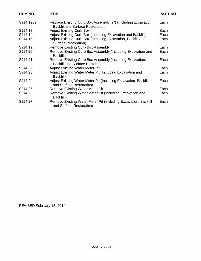
Page SS-224
ITEM NO. ITEM PAY UNIT S914.1202 Replace Existing Curb Box Assembly (2") (Including Excavation, Each Backfill and Surface Restoration) S914.13 Adjust Existing Curb Box Each S914.14 Adjust Existing Curb Box (Including Excavation and Backfill) Each S914.15 Adjust Existing Curb Box (Including Excavation, Backfill and Each Surface Restoration) S914.19 Remove Existing Curb Box Assembly Each S914.20 Remove Existing Curb Box Assembly (Including Excavation and Each Backfill) S914.21 Remove Existing Curb Box Assembly (Including Excavation, Each Backfill and Surface Restoration) S914.22 Adjust Existing Water Meter Pit Each S914.23 Adjust Existing Water Meter Pit (Including Excavation and Each Backfill) S914.24 Adjust Existing Water Meter Pit (Including Excavation, Backfill Each and Surface Restoration) S914.25 Remove Existing Water Meter Pit Each S914.26 Remove Existing Water Meter Pit (Including Excavation and Each Backfill) S914.27 Remove Existing Water Meter Pit (Including Excavation, Backfill Each and Surface Restoration) REVISED February 13, 2014

Page SS-225
SECTION S917 - HYDRANT S917-1 DESCRIPTION Work consists of installation of new hydrants, relocation or removal of existing hydrants as required in Contract Documents and as directed by Project Manager. Work is to be in conformance with requirements of Section S900 General Water Provisions. S917-2 MATERIALS S917-2.01 Hydrant Hydrant is to be in conformance with requirements of ANSI/AWWA C502, and as approved by City of Rochester. Hydrant is to be 5-1/4 inch, dry-barrel, break-away hydrant, manufactured for 5 feet 6 inches bury where hydrant branch pipe cover depth is 4 feet 6 inches, and 6 feet bury where hydrant branch pipe cover depth is 5 feet. Hydrant is to be open-left with one 1-1/2 inch pentagon operating nut, two 2-1/2 inch National Standard hose connections, and one 4-1/2 inch National Standard pumper connection. Inlet connection is to be 6 inch mechanical joint. External bolting on hydrant is to be manufactured of 304 stainless steel. Furnish with corrosion resistant steel nozzle cap chains. S917-2.02 Extension Kit Extension kit for height adjustment of hydrant is to be available in 6 inch increments with maximum of 24 inches allowed, and is to be manufactured by same company that manufactures hydrant. Extension kit is to include rod and barrel units, with non-breakable rod and barrel couplings complete with gaskets and fasteners. S917-2.03 Hydrant Marker - Furnished Hydrant marker is to be supplied by and obtained from the City’s Bureau of Water Materials and Equipment Section. S917-2.04 Miscellaneous Paint for hydrant is to be fusion bonded yellow epoxy or Insl-x Silathane Gloss Enamel Yellow No.520-35, or approved equivalent. Paint for dome on Holly hydrant is to be fusion bonded white epoxy or Insl-x Silathane Gloss Enamel White No.520-00, or approved equivalent. Interior coatings are to be in conformance with requirements of ANSI/AWWA C550. Hydrant drain material is to be No. 2 crushed stone in conformance with requirements of NYSDOT Section 703-02 Coarse Aggregate. Plastic barrier material is to be 6 mil polyethylene.

Page SS-226
S917-3 CONSTRUCTION DETAILS S917-3.01 General Existing hydrants are property of City of Rochester, and upon removal are to be delivered to Bureau of Water Materials and Equipment Section. Upon delivery, Contractor is to obtain written receipt from Bureau of Water stating number of hydrants returned and who received them. Contractor is to provide Project Manager with copy of receipt. S917-3.02 Installation Excavation is to be in conformance with requirements of Section R206 Trench and Culvert Excavation, and to appropriate depth to permit proper connection of hydrant to hydrant branch pipe. Minimum cover over hydrant branch pipe and fittings, as measured between finished grade and top of exterior limit of hydrant branch pipe and fittings, is to be, unless otherwise shown in plans or ordered by Project Manager:
o 4 feet 6 inches for domestic water pipe o 5 feet for Holly system water pipe
After installation of hydrant, there is to be resultant clearance of minimum of 2 inches and maximum of 6 inches between finished ground elevation and bottom of the breakaway flange coupling on hydrant. Adjustment for proper height of hydrant may be accomplished by use of mechanical joint offset or hydrant extension kit. Hydrant extension kit is to be installed in accordance with manufacturer's recommendation and Bureau of Water standards and specifications. The installation of more than one extension kit on a hydrant must be approved by the Project Manager and will require replacement of the lower stem with a longer one that reaches the breakaway flange. Generally, hydrant is to be located such that centerline of hydrant is at least:
o 2 feet behind face of curb o 2 feet behind back edge of concrete gutter o 10 feet away from point of curvature of radius at street intersection o 10 feet away from outer edge of driveway o 10 feet away from outer edge of pole o 15 feet away from outer edge of tree
Minimum distance of 4 feet is to be maintained between hydrant and hydrant branch valve, and if necessary, use horizontal bend to achieve required minimum distance. Hydrant is to be oriented with pumper connection nozzle at right angles to and facing pavement. Hydrant is to be installed in vertically plumbed position on solid concrete block support. Proper alignment of hydrant is to be maintained until completion of Project. For new hydrant installation, hydrant branch pipe material will be as required and with restrained joints. For hydrant being replaced or relocated on existing hydrant branch pipe that is ductile iron anchor pipe, any extension of existing hydrant branch pipe is to be done using ductile iron anchor pipe. For hydrant being replaced or relocated on existing hydrant branch pipe that is not ductile iron anchor pipe, solid concrete blocks are to be used for temporary thrust blocking to allow hydrant to be immediately pressurized. Temporary thrust blocking is to be incorporated in permanent poured
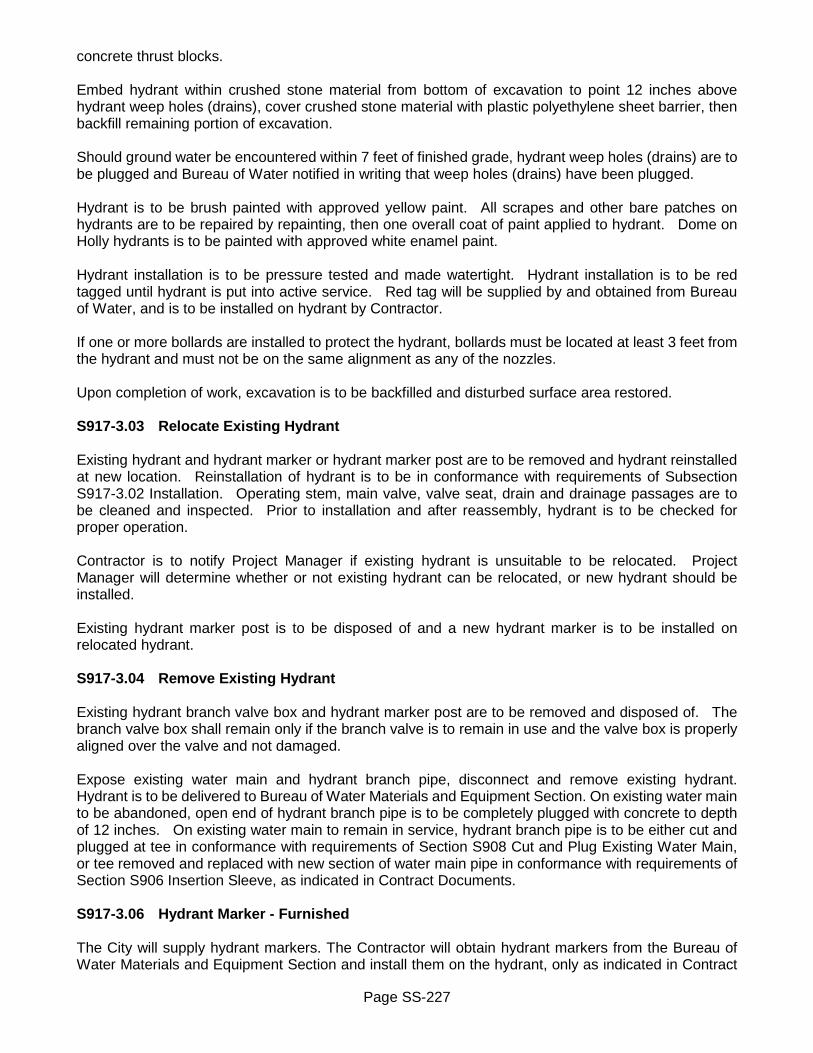
Page SS-227
concrete thrust blocks. Embed hydrant within crushed stone material from bottom of excavation to point 12 inches above hydrant weep holes (drains), cover crushed stone material with plastic polyethylene sheet barrier, then backfill remaining portion of excavation. Should ground water be encountered within 7 feet of finished grade, hydrant weep holes (drains) are to be plugged and Bureau of Water notified in writing that weep holes (drains) have been plugged. Hydrant is to be brush painted with approved yellow paint. All scrapes and other bare patches on hydrants are to be repaired by repainting, then one overall coat of paint applied to hydrant. Dome on Holly hydrants is to be painted with approved white enamel paint. Hydrant installation is to be pressure tested and made watertight. Hydrant installation is to be red tagged until hydrant is put into active service. Red tag will be supplied by and obtained from Bureau of Water, and is to be installed on hydrant by Contractor. If one or more bollards are installed to protect the hydrant, bollards must be located at least 3 feet from the hydrant and must not be on the same alignment as any of the nozzles. Upon completion of work, excavation is to be backfilled and disturbed surface area restored. S917-3.03 Relocate Existing Hydrant Existing hydrant and hydrant marker or hydrant marker post are to be removed and hydrant reinstalled at new location. Reinstallation of hydrant is to be in conformance with requirements of Subsection S917-3.02 Installation. Operating stem, main valve, valve seat, drain and drainage passages are to be cleaned and inspected. Prior to installation and after reassembly, hydrant is to be checked for proper operation. Contractor is to notify Project Manager if existing hydrant is unsuitable to be relocated. Project Manager will determine whether or not existing hydrant can be relocated, or new hydrant should be installed. Existing hydrant marker post is to be disposed of and a new hydrant marker is to be installed on relocated hydrant. S917-3.04 Remove Existing Hydrant Existing hydrant branch valve box and hydrant marker post are to be removed and disposed of. The branch valve box shall remain only if the branch valve is to remain in use and the valve box is properly aligned over the valve and not damaged. Expose existing water main and hydrant branch pipe, disconnect and remove existing hydrant. Hydrant is to be delivered to Bureau of Water Materials and Equipment Section. On existing water main to be abandoned, open end of hydrant branch pipe is to be completely plugged with concrete to depth of 12 inches. On existing water main to remain in service, hydrant branch pipe is to be either cut and plugged at tee in conformance with requirements of Section S908 Cut and Plug Existing Water Main, or tee removed and replaced with new section of water main pipe in conformance with requirements of Section S906 Insertion Sleeve, as indicated in Contract Documents. S917-3.06 Hydrant Marker - Furnished The City will supply hydrant markers. The Contractor will obtain hydrant markers from the Bureau of Water Materials and Equipment Section and install them on the hydrant, only as indicated in Contract

Page SS-228
Documents. Hydrant markers are not required to be installed within general limits of Central Business District. The color of the hydrant marker to be installed on each hydrant shall be determined by the Bureau of Water based on the anticipated maximum flow rate available at the hydrant. Blue markers are to be installed where available flows are 1,500 gallons per minute (gpm) or greater; green markers where flows are between 1,000 gpm and 1,500 gpm; orange or yellow markers where flows are between 500 gpm and 1,000 gpm and red markers where flows are less than 500 gpm. Hydrant marker is to be installed in accordance with manufacturer’s instructions. S917-4 METHOD OF MEASUREMENT Quantity to be measured for payment will be number of hydrants, hydrant markers, and hydrant extension kits installed, relocated, replaced, or removed. S917-5 BASIS OF PAYMENT S917-5.01 General all Items Unit price bid for all items includes cost of: furnishing all labor, material and equipment necessary to complete work. Excavation, rock excavation, furnishing and placing of bedding and select granular backfill, and surface restoration will be paid for under separate bid items. Extension kits used for height adjustment of hydrant will be paid for under respective pay item for extension kits. New hydrant branch pipe will be paid for under Section S901 Water Main Pipe and Fittings. New branch valve and valve box will be paid for under Section S903 Resilient Seat Gate Valve with Valve Box. S917-5.02 New Hydrant Unit price bid also includes cost of: furnishing and installing hydrant; concrete block support; concrete thrust block; crushed stone; plastic sheet barrier; plugging weep holes (drains) if required; painting hydrant; pressure testing; and connecting hydrant branch pipe to hydrant. S917-5.03 New Hydrant (Including Removal of Existing Hydrant) In addition to requirements of Subsection S917-5.02 New Hydrant, unit price bid also includes cost of: removing and delivering existing hydrant to Bureau of Water Materials and Equipment Section; and connecting new hydrant branch pipe to existing hydrant branch pipe. New hydrant (including removal of existing hydrant) item will only be paid where existing hydrant is being replaced by new hydrant on same hydrant branch pipe. S917-5.04 Relocate Existing Hydrant Unit price bid also includes cost of: removing, cleaning, inspecting, reinstalling and repainting hydrant; removing and disposing existing hydrant marker post; concrete block support; concrete thrust block; crushed stone; plastic sheet barrier; pressure testing; connecting hydrant branch pipe to hydrant; and

Page SS-229
connecting new hydrant branch pipe to existing hydrant branch pipe. S917-5.05 Remove Existing Hydrant Unit price bid also includes cost of: disconnecting and delivering existing hydrant to Bureau of Water Materials and Equipment Section; removing and disposing of existing branch valve box and hydrant marker post; and plugging open end of hydrant branch pipe with concrete. Remove existing hydrant item will only be paid when existing hydrant is removed and new hydrant is not set on same hydrant branch pipe. Plugging or removing existing tee and installation of insertion sleeve will be paid for under separate bid items. S917-5.06 Hydrant Marker - Furnished Unit price bid also includes cost of: obtaining hydrant marker from Bureau of Water Materials and Equipment Section and installing hydrant marker on hydrant. S917-5.07 Extension Kit Unit price bid also includes cost of: furnishing and installing extension kit; removing and reinstalling existing hydrant and replacing lower stem, where required. Payment will be made under: ITEM NO. ITEM PAY UNIT S917.01 New Hydrant Each S917.02 New Hydrant (Including Removal of Existing Hydrant) Each S917.04 Relocate Existing Hydrant Each S917.05 Remove Existing Hydrant Each S917.0601 Hydrant Marker (Furnished) Each S917.07 6" Hydrant Extension Kit Each S917.08 12" Hydrant Extension Kit Each S917.09 18" Hydrant Extension Kit Each S917.10 24" Hydrant Extension Kit Each REVISED December 26, 2013

Page SS-230
SECTION S966 - MAGNESIUM ANODE S966-1 DESCRIPTION Work consists of installing prepackaged magnesium anodes, to cathodically protect a portion of new or existing cast or ductile iron water main, service or hydrant branch pipe and new ductile iron fittings and copper water services on new or existing PVC, PVCO and HDPE water main pipe, as required in the Contract Documents and as directed by the Project Manager. Work is to be in conformance with the requirements of Section S900 General Water Provisions. S966-2 MATERIALS S966-2.01 Magnesium Anode Anodes shall be high potential magnesium anode ingots with packaged backfill. Anode ingot shall meet or exceed ASTM B843, GRADE M1C for high-potential magnesium anodes, with the following chemical composition:
ELEMENT PERCENT BY WEIGHT
Aluminum 0.01 maximum Manganese 0.5 – 1.3 Zinc 0.05 maximum Copper 0.02 maximum Silicon 0.05 maximum Iron 0.03 maximum Nickel 0.001 maximum Other metallic elements 0.05 maximum or 0.3 total Magnesium Remainder
Laboratory tests of magnesium anodes shall be conducted by a third party, in accordance to ASTM G97 (Laboratory Evaluation of Magnesium Anode Test Specimens for Underground Application) requirements. Test results shall demonstrate a minimum open circuit potential of -1.70 volts with respect to a saturated Calomel electrode (-1.774 volts with respect to a copper/copper sulfate electrode) and a minimum current efficiency of 50% or 500 amp-hours per pound. Anode shall come furnished with minimum 10 feet of coiled #12 AWG solid copper lead wire with TW, THHN or THWN insulation, firmly attached to the galvanized steel core of the anode. The core cavity shall be filled with electrical sealing compound to assure a fully insulated and protected connection. Magnesium anode and backfill shall be pre-packaged into a single unit in a permeable cloth bag.

Page SS-231
Each magnesium anode shall meet or exceed the nominal bare weight as shown in the following table (length, height and width dimensions and packaged weights may vary slightly by manufacturer):
Length Width Height Bare Weight
Packaged Weight
8 inch 3-1/2 inch 3-3/4 inch 5 pound 17 pound
13-3/4 inch 3-1/2 inch 3-3/4 inch 9 pound 24 pound
25-1/4 inch 3-1/2 inch 3-3/4 inch 17 pound 45 pound
19-7/8 inch 5-1/2 inch 5-3/4 inch 32 pound 70 pound
30-1/4 inch 5-1/2 inch 5-3/4 inch 48 pound 96 pound S966-2.02 Backfill Packaging Each anode shall be packaged in a permeable cloth bag containing backfill having the following composition, in percent by weight: ! 75 percent Hydrated Gypsum ! 20 percent Bentonite ! 5 percent Sodium Sulfate S966-2.03 Thermite Weld Equipment Connection of anode lead wire to cast iron or ductile iron pipe or fittings shall be made by the thermite weld method. Thermite weld materials shall consist of wire sleeves, weld mold and weld cartridges according to the weld manufacturer’s recommendations for the specific wire and pipe sizes and materials. Weld materials from different manufacturers shall not be interchanged. Weld molds shall be graphite molds. Ceramic "one -shot" molds will not be acceptable. S966-3 CONSTRUCTION DETAILS S966-3.01 General Spacing and size of magnesium anodes will be as specified in Contract Documents. Each anode shall be placed in a horizontal position parallel with the pipe, with centerline axis of the anode at least 6 inches below the bottom of the water pipe. The centerline axis of the anode shall also be placed at least 2 feet from the exterior wall of the water pipe. Care shall be taken to ensure that the cloth bag is not damaged and no backfill lost during installation. Each anode shall be centered in the cloth bag. It may be necessary to re-center the anode in the cloth bag by rolling it on the ground prior to installation. Each prepackaged anode shall be lowered into the trench using a sling or rope. The anode shall not be lowered, transported, handled or lifted by the lead wire. The anode lead wire shall be long enough to reach from the pipe to the anode without a splice. The anode lead wire shall be attached to the pipe using the thermite weld process. Anodes that are installed at cathodic protection test stations are not to be directly connected to the water pipe or fitting. When the anode lead wire is not long enough to reach the test station terminal board with sufficient slack, the lead wire may be lengthened by splicing on an additional length of lead wire. Splice shall be made using an approved splice connector suitable for buried applications. To connect anode lead wire to ductile iron pipes that are encased in a polyethylene tube, the Contractor

Page SS-232
shall first cut back the polyethylene tubing to expose the pipe. The Contractor shall make an “X” shaped cut in the polyethylene and temporarily fold back the polyethylene at the point where the anode lead wire will be connected to the pipe. Using a mechanical grinder, remove the minimum area of coating from pipe or fitting surface required for placement of weld mold, creating a bright, shiny surface. Prepare the anode lead wire and pipe surface for thermite welding by assuring that they are dry. Wire and pipe surface shall be free of dirt, grease and other foreign products. Remove insulation at end to be welded in a manner that will avoid damage to wire. Install adapter sleeves for anode lead wire as recommended by thermite weld manufacturer prior to welding. Hold wire at an approximate 30 degree angle to pipe surface when welding. When weld has cooled, remove weld slag and test weld for strength by striking a sharp blow to the weld with a hammer while pulling firmly on the wire. Re-weld unsound welds and retest weld. Thoroughly clean mold and mold covers after completion of each weld to remove all excess slag. After soundness of weld has been verified, thoroughly clean with a stiff wire brush and brush with an approved bitumastic coating over entire weld area. Lift wire away from pipe and apply bitumastic coating completely around and underneath the wire. Push wire back down on the pipe. Apply a protective bitumastic coating where any original pipe coatings have been disturbed. After the anode lead wire is connected to the pipe, the Contractor shall repair the polyethylene tubing using polyethylene compatible adhesive tape. The polyethylene tubing shall be folded back against the pipe and the repair tape shall be applied on anode lead wire. The repair tape shall completely cover the area of the polyethylene tubing that was cut and shall completely cover all exposed ductile iron pipe. Extra anode lead wire for each anode shall be coiled. The wire shall have sufficient slack to allow for pipe and anode movement and to protect against undue stress during backfilling. Prior to backfilling the anode, water shall be applied to the anode to moisten its pre-packed backfill. The area immediately surrounding the anode shall be backfilled with native soil. Cushion sand shall be backfilled around the water pipe or fitting so that the sand covers the pipe or fitting to a minimum depth of 12 inches on top, and along both sides of the pipe or fitting. The excavation shall be backfilled in stages using select granular backfill (water) material free from stone, rocks, roots, organic material, trash or other debris, and carefully tamped to ensure that no voids exist around the bag and that the bag and wire are not damaged. S966-3.02 Anodes on Copper Water Services on PVC, PVCO and HDPE Water Mains One 5 pound anode shall be connected to new copper water services on PVC, PVCO and HDPE water mains, For copper services 1 inch diameter and less, anode lead wire shall be attached to thaw wire type copper tube nut at outlet end of corporation stop. For copper services larger than 1 inch diameter, anode lead wire is to be attached to copper service using bronze ground clamp. S966-3.03 Anodes on Existing Ductile and Cast Iron Water Mains Magnesium anodes shall be installed at every pipe joint or every other pipe joint, as designated in the Contract Documents or directed by the Project Manager, on existing cast and ductile iron water main pipe to cathodically protect both pipes on either side of the joint. Two or more anodes will be installed at pipe joint locations, with one or more anodes connected to each pipe on either side of the joint. Pipe joints shall be located by the Contractor utilizing field notes from the original pipe installation records. These notes may be obtained from the Rochester Water Bureau Maps & Records office located at 10 Felix Street, Rochester, New York 14608. A test pit shall be excavated to verify the location of the first pipe joint. The Contractor shall layout the location of remaining joints to be excavated using the record field notes. At each excavated joint, an area shall be excavated that is large enough to expose top and

Page SS-233
one or both sides of existing water main pipe and safely install both anodes in one operation. Basic general size of the area to be excavated will be as noted in Contract Documents and will be dependent on the depth and location of the water main. Magnesium anodes are not required to be installed on existing water main fittings or valves encountered in an excavation, unless otherwise required in the Contract Documents or directed by the Project Manager. S966-3.04 Anodes on Existing Ductile and Cast Iron Hydrant Branches and Water Services Hydrant branches shall be excavated along the branch pipe with the branch gate valve centered in the trench. One 17 pound anode shall be attached to the branch pipe between the water main and the gate valve and one 17 pound anode on the branch pipe between the gate valve and the hydrant. Water services 4 inch diameter and larger shall be excavated along the service pipe with the curb shut off valve centered in the excavation. One anode shall be connected to the service pipe between the water main and the curb valve and a second anode shall be connected to the service pipe between the curb valve and the customer’s property. For services with no curb valve, one anode shall be connected to the service pipe in the vicinity of the curb. Anode sizes shall be based on the service diameter, with 17 pound anodes installed on 4 and 6 inch diameter services; 32 pound anodes installed on 8 and 10 inch diameter services and 48 pound anodes installed on services 12 inch diameter and larger. S966-4 METHOD OF MEASUREMENT The quantity to be measured for payment shall be by the number of prepackaged magnesium anodes installed. Size of magnesium anode is as described by bare weight. S966-5 BASIS OF PAYMENT The unit price bid shall include the cost of: furnishing and installing the prepackaged magnesium anode; all thermite weld equipment and materials; attaching the anode lead wire to the pipe or fitting; splicing the lead wire at test stations, bitumastic coating; repairing the polyethylene tubing; locating joints on existing pipe and furnishing all labor, material and equipment necessary to complete the work. Excavation, rock excavation, furnishing and placing of bedding and select granular backfill, temporary pavement, and final paving and surface restoration will be paid for under separate items. Payment will be made under: ITEM NO. ITEM PAY UNIT S966.0305 5 Pound Magnesium Anode Each S966.0309 9 Pound Magnesium Anode Each S966.0317 17 Pound Magnesium Anode Each S966.0332 32 Pound Magnesium Anode Each S966.0348 48 Pound Magnesium Anode Each REVISED December 9, 2010

Page SS-234
SECTION S999 - PROJECT SIGN S999 GENERAL It is responsibility of Contractor to provide project signs for duration of Project. Project signs are to be installed prior to any construction work being performed by Contractor on behalf of City of Rochester. S999-1 DESCRIPTION Work consists of furnishing and installing project signs as required in Contract Documents and as directed by Project Manager. Project signs must be installed at all main access points to project site. Project signs are not required to be installed at other minor access points, unless otherwise specifically required in Contract Documents. Actual number of signs to be installed on project will as indicated in Contract Documents. References to NYSDOT specifications are to be in accordance with latest edition of NYSDOT Standard Specifications (US Customary Units). S999-2 MATERIALS S999-2.01 Project Sign (6' x 4' and 3' x 2') Sign board is to be constructed from 3/4 inch thick duraply or A-A exterior grade plywood. Sign board is to be painted with two coats of white exterior enamel paint. Lettering and City mark are to be done with one color, pms 287C blue. Lettering and City mark are to be done by either silk screen process, die cut vinyl letters (permanent adhesive), hand lettering, or stencil. S999-2.02 Project Sign (11" x 17") Sign board is to be constructed of white poster board or other cardboard material suitable for minimum life span of 14 days. Lettering and City mark are to be done with one color, pms 287C blue. Lettering and City mark are to be done by either silk screen process, die cut vinyl letters (permanent adhesive), hand lettering, or stencil. S999-2.03 Project Sign - Inter-governmental Sign board is to be 6 feet by 1 foot 3 inches, and constructed from 3/4 inch thick duraply or A-A exterior grade plywood. Sign board is to be painted with two coats of white exterior enamel paint. Lettering and logos will be as required by appropriate governmental agency. Lettering and logos are to be done by either silk screen process, die cut vinyl letters (permanent adhesive), hand lettering, or stencil.

Page SS-235
S999-3 CONSTRUCTION DETAILS S999-3.01 Project Sign Information and Approval Prior to fabrication of actual project sign, mock-up of proposed project sign must be submitted to City for approval. Project Manager will supply Contractor with any updates to information that is required to be displayed on project sign for preparation of mock-up of proposed project sign. Mock-up of proposed project sign must be submitted to City’s Graphic Design Section for solicitation of comments, and any required revisions must be made before approval of proposed project sign layout will be given. Contractor is to contact City’s Graphic Design Section, Monday through Friday, between hours of 9:00AM and 5:00PM, (585) 428-6068. Contractor must obtain written confirmation from City’s Graphic Design Section that proposed project sign layout has been approved, and provide copy of such written approval to Project Manager, prior to fabrication and installation of project sign. S999-3.02 General Project signs must be in place minimum of 2 days before Contractor commences any form of work on project site, and are to remain in place for minimum of 5 days after completion of project. Contractor is to maintain project signs in good condition for duration of project. Under no circumstances are project signs from one project to be altered for re-use on another project. Project signs are property of City of Rochester, and after completion of project, project signs are to be removed and destroyed, or delivered to City storage facility, as directed Project Manager. On occasion, project signs may be required to be relocated from one area of project site, to another area of project site. When project sign is relocated, it is to be re-installed using installation requirements as outlined under this specification. For those projects that are spread out over several different streets and require generic project signs, number of actual project signs required may be less than total number of individual locations. Examples of such type of project would be: Water Main Cleaning and Lining Project, Milling and Resurfacing Project, or Sidewalk Curb Ramp Improvement Project. As work is completed and progresses from one location to another, project signs will be required to be relocated from original installation site to new work site. For project signs made out of plywood, two coats of white exterior enamel paint are to be applied evenly to both sides and on all edges of sign board. Fastening devices that appear on face of project sign are to be painted to match background color. No fastening devices are to enter into or cover any area of lettering or artwork. Project signs are to be soundly constructed and securely mounted on their own posts or barricades. Generally, project signs are not to be mounted on buildings, walls, fences, utility poles, traffic sign posts, or trees. Only 11 inch by 17 inch size project signs may be mounted on utility poles and trees. Project signs are to be located such as to be easily noticed, but are not to impair in any way or manner visual sight distance of both vehicular and pedestrian traffic. Where required to be installed, inter-governmental project sign is to be placed directly above City’s standard project sign. Bottom of sign board is to be posted minimum of 5 feet above grade.

Page SS-236
S999-3.03 Artwork Sample layout of project sign has been included in Contract Documents. Layout shows position of City mark and type of information that is to be on project sign, and how project sign is to look once it has been manufactured. If screen printing, Contractor is to supply all screens. If required by Contractor, City’s Graphic Design Section will provide camera-ready artwork for City mark only. Camera-ready artwork for City mark will be provided in high resolution digital file format which can be e-mailed to Contractor, or Contractor’s representative. No camera-ready artwork will be provided for any other information that is to be on project sign. For camera-ready artwork and for any additional information regarding City mark Contractor is to contact City’s Graphic Design Section, Monday through Friday, between hours of 9:00AM and 5:00PM, (585) 428-6068. S999-4 METHOD OF MEASUREMENT Quantity to be measured for payment will be number of project signs furnished and installed. S999-5 BASIS OF PAYMENT Unit price bid includes cost of: preparing mock-up; obtaining approvals; constructing, furnishing, installing, relocating, maintaining, and removing project signs and posts/barricades; destroying or delivering project signs to City storage facility after completion of work; and furnishing all labor, material and equipment necessary to complete work. Payment will be made under: ITEM NO. ITEM PAY UNIT S999.0101 Project Sign - 6' x 4' Each S999.0201 Project Sign - 3' x 2' Each S999.0301 Project Sign - 11" x 17" Each S999.04 Project Sign - Inter-governmental Each REVISED December 1, 2015