contract number delivery order rms ... number delivery order title and location section paragraph...
TRANSCRIPT
CONTRACT NUMBER DELIVERY ORDER
TITLE AND LOCATION
SECTION
PA
RA
GR
AP
H N
UM
BE
R
DESCRIPTION OF ITEM SUBMITTED
01
- PR
EC
ON
SU
BM
ITT
ALS
02
- SH
OP
DR
AW
ING
S
03
- PR
OD
UC
T D
AT
A
04
- SA
MP
LES
05
- DE
SIG
N D
AT
A
06
- TE
ST
RE
PO
RT
S
07
- CE
RT
IFIC
AT
ES
08
- MF
RS
INS
TR
UC
TIO
NS
09
- MF
RS
FIE
LD R
EP
OR
T
10
- O&
M D
AT
A
11
- CLO
SE
OU
T S
UB
MIT
TA
LS
FIO
- F
OR
INF
OR
MA
TIO
N O
NLY
GA
- G
OV
ER
NM
EN
T A
PP
RO
VE
D
DA
- D
ES
IGN
ER
OF
RE
CO
RD
AP
PR
OV
A
CR
- C
ON
FO
RM
AN
CE
RE
VIE
W
DA
/ C
R
DA
/ G
A
DO
- D
IST
RIC
T O
FF
ICE
AO
- A
RE
A O
FF
ICE
RO
- R
ES
IDE
NT
OF
FIC
E
PO
- P
RO
JEC
T O
FF
ICE
DR
- D
ES
IGN
ER
OF
RE
CO
RD
AE
- A
RC
HIT
EC
T /
EN
GIN
EE
R
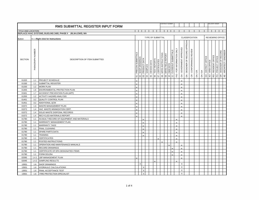
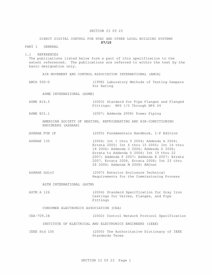
01320 1.1 PROJECT SCHEDULE X X
01330 1.1 SUBMITTAL REGISTER X X
01330 1.2 WORK PLAN X X
01355 1.6 ENVIRONMENTAL PROTECTION PLAN X X
01501 1.7 ACCIDENT PREVENTION PLAN (APP) X X
01355 1.2 ACTIVITY HAZARD ANALYSIS X X
01451 3.2 QUALITY CONTROL PLAN X X
01451 3.2 ADDITIONAL QCM X X
01572 1.3 WASTE MANAGEMENT PLAN X X
01572 1.4 HAZ. WASTE MINIMIZATION CERT. X X
01572 1.4 SOLID WASTE DISPOSAL RECORDS X X
01572 1.4 RECYCLED MATERIALS REPORT X X
01780 1.1 AS-BUILT RECORD OF EQUIPMENT AND MATERIALS X X
01780 1.1 WARRANTY MANAGEMENT PLAN X X
01780 1.1 WARRANTY TAGS X X
01780 1.1 FINAL CLEANING X X
01780 1.1 SPARE PARTS DATA X X
01780 1.1 TRAINING X X
01780 1.1 CERTIFICATES X X
01780 1.1 POSTED INSTRUCTIONS X X
01780 1.1 OPERATION AND MAINTENANCE MANUALS X X
01780 1.1 RECORD DRAWINGS X X
01780 1.1 CERTIFICATE OF EPA DESIGNATED ITEMS X X
01780 1.1 FORM DD1354 X X
02095 1.4.1 LBP MANAGEMENT PLAN X X
02095 1.4.2 SAMPLING RESULTS X X
13931 1.6 SHOP DRAWINGS X X
13931 1.6 HYDRAULIC CALCULATIONS X X
13931 1.6 FINAL ACCEPTANCE TEST X X
13931 1.6 FIRE PROTECTION SPECIALIST X X
REVIEWING OFFICEButton <-----Right click for Instructions
TYPE OF SUBMITTAL CLASSIFICATION
RMS SUBMITTAL REGISTER INPUT FORM
REPLACE HVAC SYSTEMS, BUIDLING 2400, PHASE II JBLM-LEWIS, WA
1 of 4
CONTRACT NUMBER DELIVERY ORDER
TITLE AND LOCATION
SECTION
PA
RA
GR
AP
H N
UM
BE
R
DESCRIPTION OF ITEM SUBMITTED
01
- PR
EC
ON
SU
BM
ITT
ALS
02
- SH
OP
DR
AW
ING
S
03
- PR
OD
UC
T D
AT
A
04
- SA
MP
LES
05
- DE
SIG
N D
AT
A
06
- TE
ST
RE
PO
RT
S
07
- CE
RT
IFIC
AT
ES
08
- MF
RS
INS
TR
UC
TIO
NS
09
- MF
RS
FIE
LD R
EP
OR
T
10
- O&
M D
AT
A
11
- CLO
SE
OU
T S
UB
MIT
TA
LS
FIO
- F
OR
INF
OR
MA
TIO
N O
NLY
GA
- G
OV
ER
NM
EN
T A
PP
RO
VE
D
DA
- D
ES
IGN
ER
OF
RE
CO
RD
AP
PR
OV
A
CR
- C
ON
FO
RM
AN
CE
RE
VIE
W
DA
/ C
R
DA
/ G
A
DO
- D
IST
RIC
T O
FF
ICE
AO
- A
RE
A O
FF
ICE
RO
- R
ES
IDE
NT
OF
FIC
E
PO
- P
RO
JEC
T O
FF
ICE
DR
- D
ES
IGN
ER
OF
RE
CO
RD
AE
- A
RC
HIT
EC
T /
EN
GIN
EE
R
REVIEWING OFFICEButton <-----Right click for Instructions
TYPE OF SUBMITTAL CLASSIFICATION
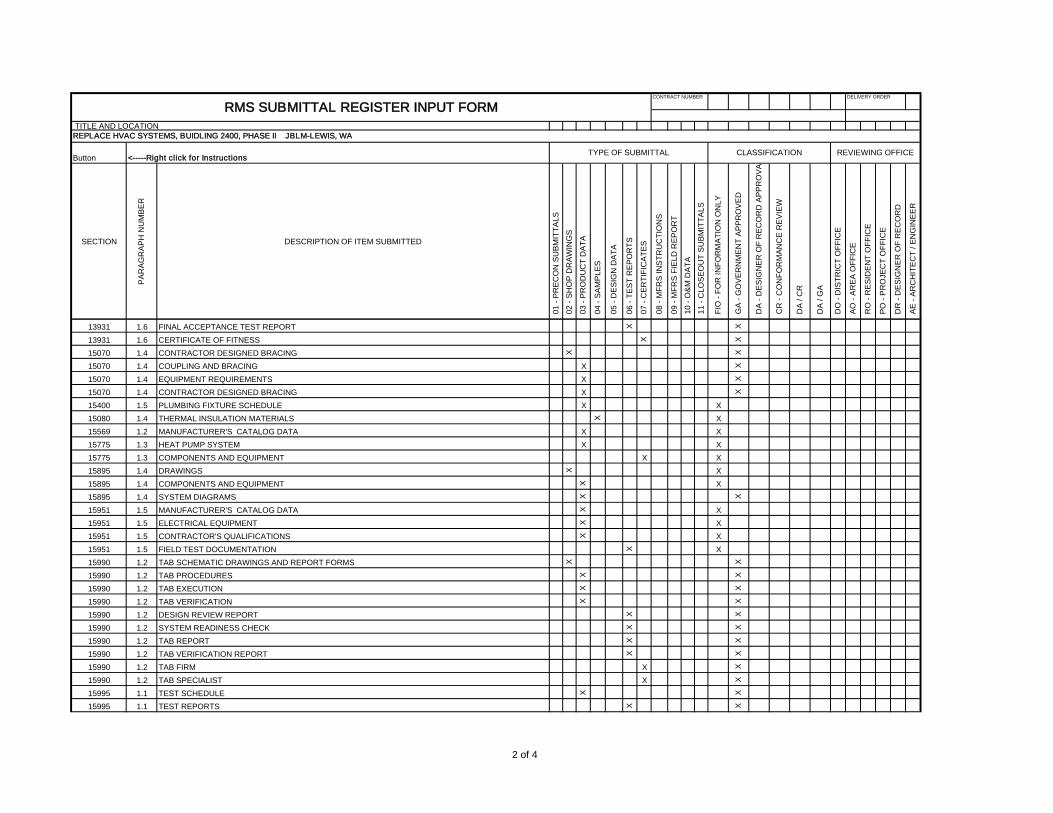
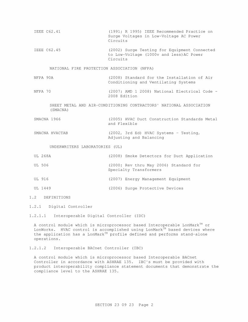
RMS SUBMITTAL REGISTER INPUT FORM
REPLACE HVAC SYSTEMS, BUIDLING 2400, PHASE II JBLM-LEWIS, WA
13931 1.6 FINAL ACCEPTANCE TEST REPORT X X
13931 1.6 CERTIFICATE OF FITNESS X X
15070 1.4 CONTRACTOR DESIGNED BRACING X X
15070 1.4 COUPLING AND BRACING X X
15070 1.4 EQUIPMENT REQUIREMENTS X X
15070 1.4 CONTRACTOR DESIGNED BRACING X X
15400 1.5 PLUMBING FIXTURE SCHEDULE X X
15080 1.4 THERMAL INSULATION MATERIALS X X
15569 1.2 MANUFACTURER'S CATALOG DATA X X
15775 1.3 HEAT PUMP SYSTEM X X
15775 1.3 COMPONENTS AND EQUIPMENT X X
15895 1.4 DRAWINGS X X
15895 1.4 COMPONENTS AND EQUIPMENT X X
15895 1.4 SYSTEM DIAGRAMS X X
15951 1.5 MANUFACTURER'S CATALOG DATA X X
15951 1.5 ELECTRICAL EQUIPMENT X X
15951 1.5 CONTRACTOR'S QUALIFICATIONS X X
15951 1.5 FIELD TEST DOCUMENTATION X X
15990 1.2 TAB SCHEMATIC DRAWINGS AND REPORT FORMS X X
15990 1.2 TAB PROCEDURES X X
15990 1.2 TAB EXECUTION X X
15990 1.2 TAB VERIFICATION X X
15990 1.2 DESIGN REVIEW REPORT X X
15990 1.2 SYSTEM READINESS CHECK X X
15990 1.2 TAB REPORT X X
15990 1.2 TAB VERIFICATION REPORT X X
15990 1.2 TAB FIRM X X
15990 1.2 TAB SPECIALIST X X
15995 1.1 TEST SCHEDULE X X
15995 1.1 TEST REPORTS X X
2 of 4
CONTRACT NUMBER DELIVERY ORDER
TITLE AND LOCATION
SECTION
PA
RA
GR
AP
H N
UM
BE
R
DESCRIPTION OF ITEM SUBMITTED
01
- PR
EC
ON
SU
BM
ITT
ALS
02
- SH
OP
DR
AW
ING
S
03
- PR
OD
UC
T D
AT
A
04
- SA
MP
LES
05
- DE
SIG
N D
AT
A
06
- TE
ST
RE
PO
RT
S
07
- CE
RT
IFIC
AT
ES
08
- MF
RS
INS
TR
UC
TIO
NS
09
- MF
RS
FIE
LD R
EP
OR
T
10
- O&
M D
AT
A
11
- CLO
SE
OU
T S
UB
MIT
TA
LS
FIO
- F
OR
INF
OR
MA
TIO
N O
NLY
GA
- G
OV
ER
NM
EN
T A
PP
RO
VE
D
DA
- D
ES
IGN
ER
OF
RE
CO
RD
AP
PR
OV
A
CR
- C
ON
FO
RM
AN
CE
RE
VIE
W
DA
/ C
R
DA
/ G
A
DO
- D
IST
RIC
T O
FF
ICE
AO
- A
RE
A O
FF
ICE
RO
- R
ES
IDE
NT
OF
FIC
E
PO
- P
RO
JEC
T O
FF
ICE
DR
- D
ES
IGN
ER
OF
RE
CO
RD
AE
- A
RC
HIT
EC
T /
EN
GIN
EE
R
REVIEWING OFFICEButton <-----Right click for Instructions
TYPE OF SUBMITTAL CLASSIFICATION
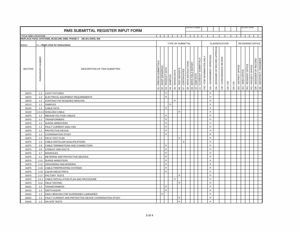
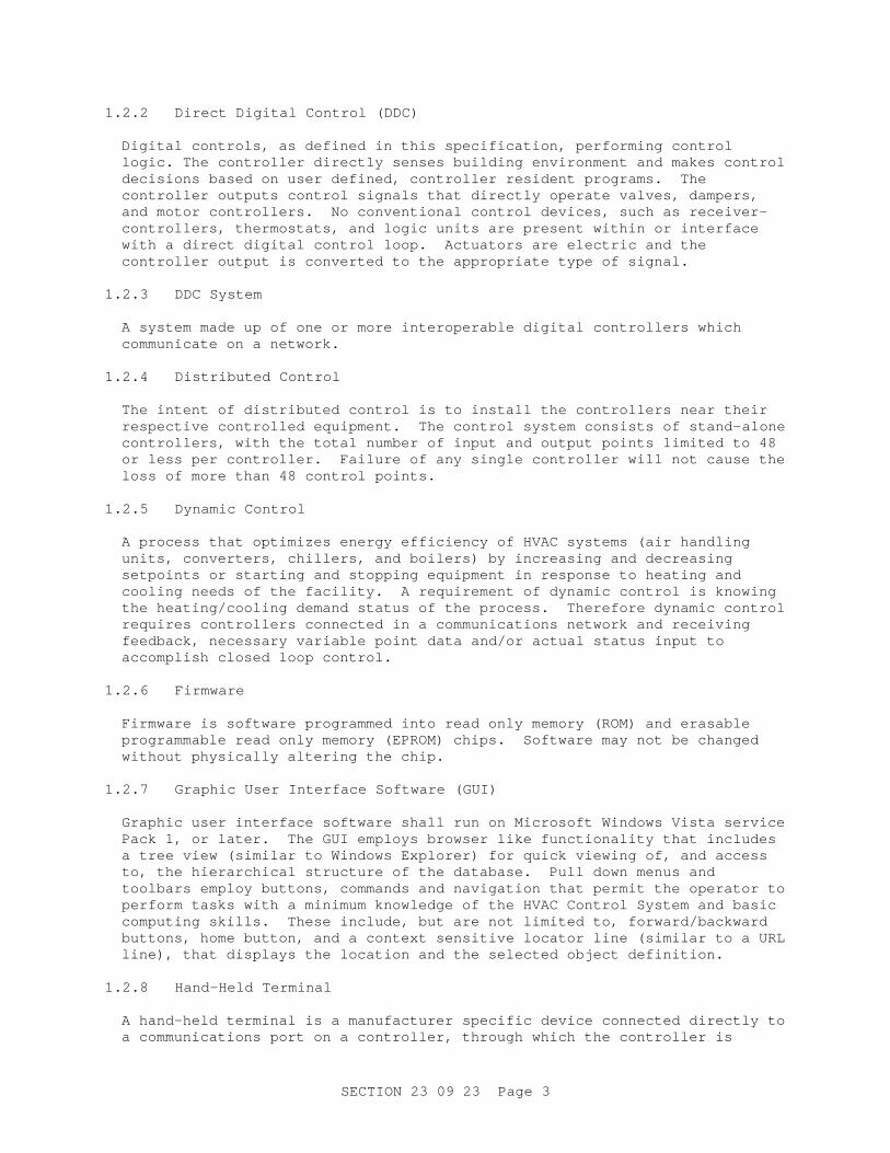
RMS SUBMITTAL REGISTER INPUT FORM
REPLACE HVAC SYSTEMS, BUIDLING 2400, PHASE II JBLM-LEWIS, WA
16070 1.2 LIGHT FIXTURES X X
16070 1.2 ELECTRICAL EQUIPMENT REQUIREMENTS X X
16070 1.2 CONTRACTOR DESIGNED BRACING X X
16113 1.2 SAMPLES X X
16120 1.2 CABLE DATA X X
16120 2.3.2.2 SHIELDED CABLE X X
16375 1.2 MEDIUM VOLTAGE CABLES X X
16375 1.2 TRANSFORMERS X X
16375 1.2 SURGE ARRESTERS X X
16375 1.2 FAULT CURRENT ANALYSIS X X
16375 1.2 PROTECTIVE DEVICE X X
16375 1.2 COORDINATION STUDY X X
16375 1.3 FIELD TEST PLAN X X
16375 1.3 CABLE INSTALLER QUALIFICATIONS X X
16375 2.5 CABLE TERMINATIONS AND CONNECTORS X X
16375 2.6 CONDUIT AND DUCTS X X
16375 2.7 MANHOLES X X
16375 2.1 METERING AND PROTECTIVE DEVICES X X
16375 2.11 SURGE ARRESTERS X X
16375 2.12 GROUNDING AND BONDING X X
16375 2.15 CABLE FIREPROOFING SYSTEMS X X
16375 2.16 LIQUID DIELECTRICS X X
16375 2.17 FACTORY TESTS X X
16375 3.2.1 CABLE INSTALLATION PLAN AND PROCEDURE X X
16375 3.11 FIELD TESTING X X
16415 1.3 TRANSFORMERS X X
16415 1.3 SWITCHGEAR X X
16415 1.3 SWAY BRACING FOR SUSPENDED LUMINARIES X X
16415 1.3 FAULT CURRENT AND PROTECTIVE DEVICE COORDINATION STUDY X X
16415 1.3 ON SITE TESTS X X
3 of 4
CONTRACT NUMBER DELIVERY ORDER
TITLE AND LOCATION
SECTION
PA
RA
GR
AP
H N
UM
BE
R
DESCRIPTION OF ITEM SUBMITTED
01
- PR
EC
ON
SU
BM
ITT
ALS
02
- SH
OP
DR
AW
ING
S
03
- PR
OD
UC
T D
AT
A
04
- SA
MP
LES
05
- DE
SIG
N D
AT
A
06
- TE
ST
RE
PO
RT
S
07
- CE
RT
IFIC
AT
ES
08
- MF
RS
INS
TR
UC
TIO
NS
09
- MF
RS
FIE
LD R
EP
OR
T
10
- O&
M D
AT
A
11
- CLO
SE
OU
T S
UB
MIT
TA
LS
FIO
- F
OR
INF
OR
MA
TIO
N O
NLY
GA
- G
OV
ER
NM
EN
T A
PP
RO
VE
D
DA
- D
ES
IGN
ER
OF
RE
CO
RD
AP
PR
OV
A
CR
- C
ON
FO
RM
AN
CE
RE
VIE
W
DA
/ C
R
DA
/ G
A
DO
- D
IST
RIC
T O
FF
ICE
AO
- A
RE
A O
FF
ICE
RO
- R
ES
IDE
NT
OF
FIC
E
PO
- P
RO
JEC
T O
FF
ICE
DR
- D
ES
IGN
ER
OF
RE
CO
RD
AE
- A
RC
HIT
EC
T /
EN
GIN
EE
R
REVIEWING OFFICEButton <-----Right click for Instructions
TYPE OF SUBMITTAL CLASSIFICATION
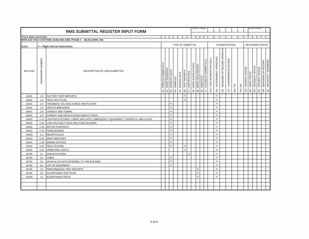
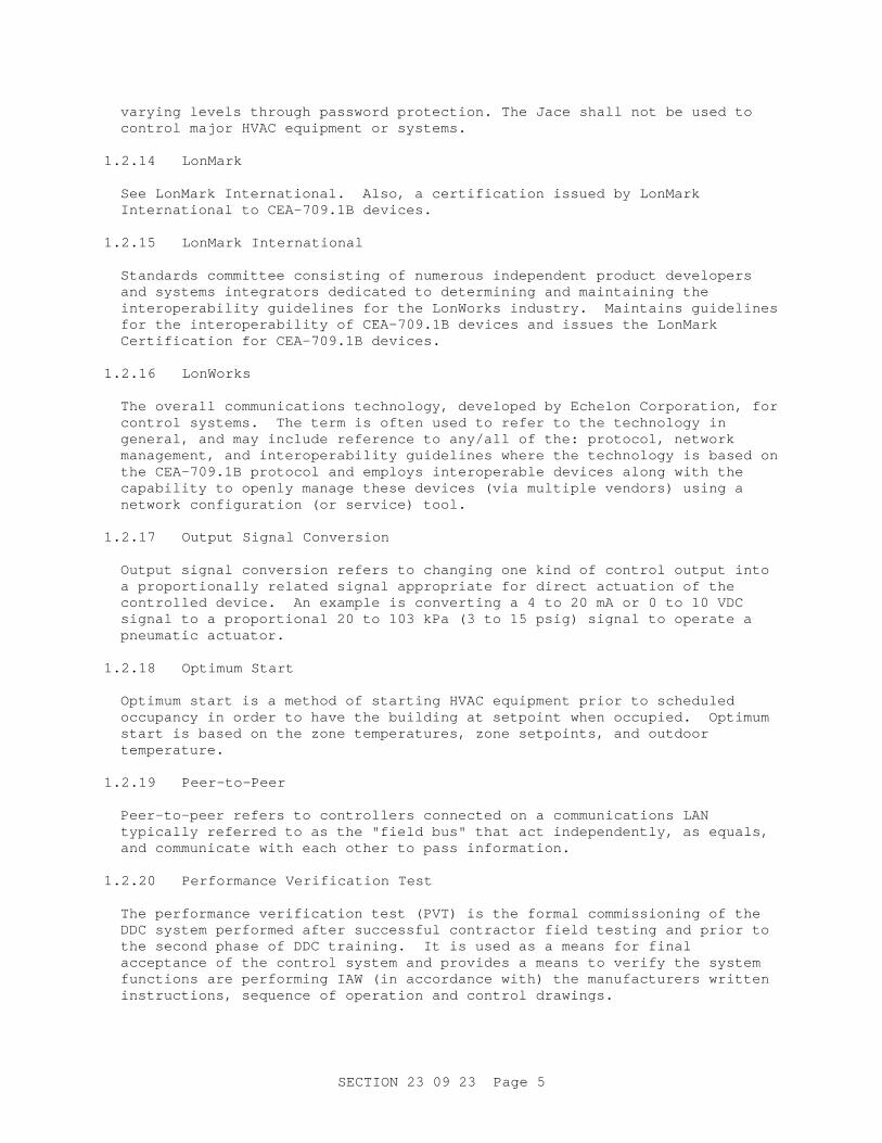
RMS SUBMITTAL REGISTER INPUT FORM
REPLACE HVAC SYSTEMS, BUIDLING 2400, PHASE II JBLM-LEWIS, WA
16415 1.3 FACTORY TEST REPORTS X X
16415 1.3 FIELD TEST PLAN X X
16415 2.4 TRANSIENT VOLTAGE SURGE PROTECTION X X
16415 2.6 CIRCUIT BREAKERS X X
16415 2.8 CONDUIT AND TUBING X X
16415 2.9 CONDUIT AND DEVICE BOXES AND FITTINGS X X
16415 2.14 LIGHTING FIXTURES, LAMPS, BALLASTS, EMERGENCY EQUIPMENT, CONTROLS, AND ACCES. X X
16415 2.15 LOW-VOLTAGE FUSES AND FUSE HOLDERS X X
16415 2.18 MOTOR CONTROLS X X
16415 2.19 PANELBOARDS X X
16415 2.2 RECEPTACLES X X
16415 2.23 SNAP SWITCHES X X
16415 2.29 WIRING DEVICES X X
16415 3.22 FIELD TESTING X X X
16415 3.23 OPERATING TESTS X X
16740 2.1 QUALIFICATIONS X X
16740 3.1 CABLE X X
16740 3.1 JACKS & OUTLETS INTERNAL TO THE BUILDING X X
16740 3.2 LIST OF EQUIPMENT X X
16740 3.3 PERFORMANCE TEST REPORTS X X
16740 3.5 ACCEPTANCE TEST PLAN X X
16740 11 ACCEPTANCE TESTS X X
4 of 4
SECTION 23 09 23 Page 1
SECTION 23 09 23
DIRECT DIGITAL CONTROL FOR HVAC AND OTHER LOCAL BUILDING SYSTEMS
07/10 PART 1 GENERAL 1.1 REFERENCES The publications listed below form a part of this specification to the extent referenced. The publications are referred to within the text by the basic designation only.
AIR MOVEMENT AND CONTROL ASSOCIATION INTERNATIONAL (AMCA)
AMCA 500-D (1998) Laboratory Methods of Testing Dampers
for Rating
ASME INTERNATIONAL (ASME) ASME B16.5 (2003) Standard for Pipe Flanges and Flanged
Fittings: NPS 1/2 Through NPS 24 ASME B31.1 (2007; Addenda 2008) Power Piping
AMERICAN SOCIETY OF HEATING, REFRIGERATING AND AIR-CONDITIONING ENGINEERS (ASHRAE)
ASHRAE FUN IP (2005) Fundamentals Handbook, I-P Edition
ASHRAE 135 (2004; Int 1 thru 5 2004; Addenda A 2004;
Errata 2005; Int 6 thru 15 2005; Int 16 thru 18 2006; Addenda C 2006; Addenda D 2006; Errata to Addenda D 2006; Int 19 thru 22 2007; Addenda F 2007; Addenda E 2007; Errata 2007, Errata 2008, Errata 2008; Int 23 thru 28 2008; Addenda M 2008) BACnet
ASHRAE Gdln3 (2007) Exterior Enclosure Technical
Requirements for the Commissioning Process
ASTM INTERNATIONAL (ASTM) ASTM A 126 (2004) Standard Specification for Gray Iron
Castings for Valves, Flanges, and Pipe Fittings
CONSUMER ELECTRONICS ASSOCIATION (CEA)
CEA-709.1B (2002) Control Network Protocol Specification
INSTITUTE OF ELECTRICAL AND ELECTRONICS ENGINEERS (IEEE)
IEEE Std 100 (2000) The Authoritative Dictionary of IEEE
Standards Terms
SECTION 23 09 23 Page 2
IEEE C62.41 (1991; R 1995) IEEE Recommended Practice on Surge Voltages in Low-Voltage AC Power Circuits
IEEE C62.45 (2002) Surge Testing for Equipment Connected
to Low-Voltage (1000v and less)AC Power Circuits
NATIONAL FIRE PROTECTION ASSOCIATION (NFPA)
NFPA 90A (2008) Standard for the Installation of Air
Conditioning and Ventilating Systems NFPA 70 (2007; AMD 1 2008) National Electrical Code -
2008 Edition
SHEET METAL AND AIR-CONDITIONING CONTRACTORS' NATIONAL ASSOCIATION (SMACNA)
SMACNA 1966 (2005) HVAC Duct Construction Standards Metal
and Flexible SMACNA HVACTAB (2002, 3rd Ed) HVAC Systems - Testing,
Adjusting and Balancing
UNDERWRITERS LABORATORIES (UL) UL 268A (2008) Smoke Detectors for Duct Application
UL 506 (2000; Rev thru May 2006) Standard for
Specialty Transformers UL 916 (2007) Energy Management Equipment
UL 1449 (2006) Surge Protective Devices
1.2 DEFINITIONS 1.2.1 Digital Controller 1.2.1.1 Interoperable Digital Controller (IDC) A control module which is microprocessor based Interoperable LonMarkTM or LonWorks. HVAC control is accomplished using LonMarkTM based devices where the application has a LonMarkTM profile defined and performs stand-alone operations.
1.2.1.2 Interoperable BACnet Controller (IBC) A control module which is microprocessor based Interoperable BACnet Controller in accordance with ASHRAE 135. IBC's must be provided with product interoperability compliance statement documents that demonstrate the compliance level to the ASHRAE 135.
SECTION 23 09 23 Page 3
1.2.2 Direct Digital Control (DDC) Digital controls, as defined in this specification, performing control logic. The controller directly senses building environment and makes control decisions based on user defined, controller resident programs. The controller outputs control signals that directly operate valves, dampers, and motor controllers. No conventional control devices, such as receiver-controllers, thermostats, and logic units are present within or interface with a direct digital control loop. Actuators are electric and the controller output is converted to the appropriate type of signal.
1.2.3 DDC System A system made up of one or more interoperable digital controllers which communicate on a network.
1.2.4 Distributed Control The intent of distributed control is to install the controllers near their respective controlled equipment. The control system consists of stand-alone controllers, with the total number of input and output points limited to 48 or less per controller. Failure of any single controller will not cause the loss of more than 48 control points.
1.2.5 Dynamic Control A process that optimizes energy efficiency of HVAC systems (air handling units, converters, chillers, and boilers) by increasing and decreasing setpoints or starting and stopping equipment in response to heating and cooling needs of the facility. A requirement of dynamic control is knowing the heating/cooling demand status of the process. Therefore dynamic control requires controllers connected in a communications network and receiving feedback, necessary variable point data and/or actual status input to accomplish closed loop control.
1.2.6 Firmware Firmware is software programmed into read only memory (ROM) and erasable programmable read only memory (EPROM) chips. Software may not be changed without physically altering the chip.
1.2.7 Graphic User Interface Software (GUI) Graphic user interface software shall run on Microsoft Windows Vista service Pack 1, or later. The GUI employs browser like functionality that includes a tree view (similar to Windows Explorer) for quick viewing of, and access to, the hierarchical structure of the database. Pull down menus and toolbars employ buttons, commands and navigation that permit the operator to perform tasks with a minimum knowledge of the HVAC Control System and basic computing skills. These include, but are not limited to, forward/backward buttons, home button, and a context sensitive locator line (similar to a URL line), that displays the location and the selected object definition.
1.2.8 Hand-Held Terminal A hand-held terminal is a manufacturer specific device connected directly to a communications port on a controller, through which the controller is

SECTION 23 09 23 Page 4
accessed and, in some cases, programmed. This style of interface is not an acceptable installation on Fort Lewis.
1.2.9 Input/Output (I/O) Points I/O points refer to analog inputs (AI), digital inputs (DI), analog outputs (AO), and digital outputs (DO) in a digital controller. Another term for digital inputs and outputs is binary inputs and outputs. Inputs are from analog sensors (temperature, pressure, humidity, flow) and digital sensors (motor status, flow switches, switch position, and pulse output devices). Outputs operate modulating and on/off control devices.
1.2.10 I/O Expansion Unit An I/O expansion unit provides additional point capacity to a digital controller and communicates with the stand-alone digital controller on a LAN. An I/O unit is not stand-alone because the control program does not reside in the I/O unit. An I/O expander which connects directly to a stand-alone controller through a multi-line microprocessor bus is restricted to reside within 3 feet of the stand alone controller and is considered part of the stand alone controller. The total point count of the I/O and all connected expansion units shall not exceed the 48 point limit.
1.2.11 Local Area Network (LAN)
a. A communications bus that interconnects digital controllers for peer-to-peer (see "peer-to-peer" below) communications. Different levels of LANs are possible within a single DDC system. In this case, a digital controller on a higher level LAN acts as a network controller to the controllers on the lower level LAN. The network controller, then, has at least two LAN communications ports. One port supports peer-to-peer communications with other digital controllers on the higher level LAN. The other port supports communications with the digital controllers on the lower level LAN.
b. LANs permit sharing global information. This allows building and
site wide control strategies such as peak demand limiting, dynamic control strategies, coordinated response to alarm conditions, and remote monitoring and programming of digital controllers.
c. The controllers peer-to-per communications bus is commonly referred
to as "the field bus."
d. The "LAN" typically refers to the communications bus using the ethernet protocols (Category 6) within a building.
1.2.12 Microprocessor A microprocessor refers to the central processing unit (CPU) that contains all registers and logic circuitry that allow digital controllers to function.
1.2.13 JACE (Java Application Control Engine) Network Area Controller (NAC) The Jace network area controller (NAC) provides the interface between a higher level LAN or WAN and the interoperable digital controllers, providing global supervisory control functions. NAC's provide multiple user access at
SECTION 23 09 23 Page 5
varying levels through password protection. The Jace shall not be used to control major HVAC equipment or systems.
1.2.14 LonMark See LonMark International. Also, a certification issued by LonMark International to CEA-709.1B devices.
1.2.15 LonMark International Standards committee consisting of numerous independent product developers and systems integrators dedicated to determining and maintaining the interoperability guidelines for the LonWorks industry. Maintains guidelines for the interoperability of CEA-709.1B devices and issues the LonMark Certification for CEA-709.1B devices.
1.2.16 LonWorks The overall communications technology, developed by Echelon Corporation, for control systems. The term is often used to refer to the technology in general, and may include reference to any/all of the: protocol, network management, and interoperability guidelines where the technology is based on the CEA-709.1B protocol and employs interoperable devices along with the capability to openly manage these devices (via multiple vendors) using a network configuration (or service) tool.
1.2.17 Output Signal Conversion Output signal conversion refers to changing one kind of control output into a proportionally related signal appropriate for direct actuation of the controlled device. An example is converting a 4 to 20 mA or 0 to 10 VDC signal to a proportional 20 to 103 kPa (3 to 15 psig) signal to operate a pneumatic actuator.
1.2.18 Optimum Start Optimum start is a method of starting HVAC equipment prior to scheduled occupancy in order to have the building at setpoint when occupied. Optimum start is based on the zone temperatures, zone setpoints, and outdoor temperature.
1.2.19 Peer-to-Peer Peer-to-peer refers to controllers connected on a communications LAN typically referred to as the "field bus" that act independently, as equals, and communicate with each other to pass information.
1.2.20 Performance Verification Test The performance verification test (PVT) is the formal commissioning of the DDC system performed after successful contractor field testing and prior to the second phase of DDC training. It is used as a means for final acceptance of the control system and provides a means to verify the system functions are performing IAW (in accordance with) the manufacturers written instructions, sequence of operation and control drawings.
SECTION 23 09 23 Page 6
1.2.21 PID PID refers to proportional, integral, and derivative control; the three types of action that is used in controlling modulating equipment.
1.2.22 Resolution Refers to the number of possible states an input value or output value can take and is a function of the digital controller I/O circuitry; the A/D converter for input and the D/A converter for output. Ten bit resolution has 1024 possible states.
1.2.23 Stand-Alone Control Refers to the digital controller performing required climate control, and energy management functions without connection to another digital controller or computer. Requirements for stand-alone control are a time clock, a microprocessor, resident control programs, PID control, and I/O. All stand-alone controllers have a communication port and firmware for direct connection and interrogation with a laptop computer. This interrogation includes parameter changes and program downloads.
1.2.24 Terminal Control Unit (TCU) An off-the-shelf, stand-alone digital controller equipped for communication on a lower level LAN. TCUs may deviate from stand-alone only in receiving energy management and time information from a stand-alone digital controller. A TCU is commonly application specific and is used for distributed control of specific HVAC subsystems. A TCU communicates with other digital controllers. Typically, a TCU communicates on a lower level LAN. Examples where TCUs are used include small air handling units (AHUs), variable air volume (VAV) boxes, fan coil units, and heat pumps. TCUs shall be LonMark/Lonworks or BACnet-based. All TCUs shall be remotely configurable via the Ft Lewis WAN (Wide Area Network).
1.3 TEMPERATURE CONTROL AND FACILITY MANAGEMENT AND CONTROL SYSTEM The building's Temperature Control System (TCS) shall be capable of being extended to the existing Fort Lewis Niagara Framework Utilities Management and Control System (UMCS), and comprised of a network of interoperable, stand-alone digital controllers communicating via LonMark/LonTalk and/or BACnet communication protocols to a Jace Controller Network Area Controller (NAC). The JACE Controller to be connected to the UMCS through the NEC switch. NEC switch not within the Scope of the contract. Cat-6 wiring to switch to be provided by Contractor. Access to the system shall be accomplished through standard Web browsers and/or local area network, and/or WAN.
The TCS shall be comprised of a network of interoperable, stand-alone digital controllers communicating to a host computer within one facility within the project using graphical user interface software. The UMCS shall communicate to third party systems such as chillers, boilers, air-handling systems, energy metering systems, other energy management systems, access control systems, fire-life safety systems and other building management related devices with open, interoperable communication capabilities.
SECTION 23 09 23 Page 7
Provide a TCS including associated equipment and accessories as specified. Manufacturer's products, including design, materials, fabrication, assembly, erection, examination, inspection, and testing shall be in accordance with ASME B31.1 and NFPA 70, except as modified herein or indicated otherwise. Routers and /or gateways between the JACE NAC or workstation computer to the Ft Lewis Wide Area Network (WAN)/ Local Area Network (LAN) shall not be utilized due to security restrictions.
The TCS systems shall maintain stable temperature control and all other conditions as indicated. The end-to-end accuracy of the system, including temperature sensor error, wiring error, A/D conversion, and display, shall be 0.5 degree C or less.
1.4 DESIGN REQUIREMENTS 1.4.1 Control System Schematic Provide control system schematic that includes the following:
a. Location of each input and output device
b. Flow diagram of each HVAC component, for instance flow through coils,
fans, dampers
c. Name or symbol for each component such as V-1, DM-2, and T-1 for a valve, damper motor, and temperature sensor, respectively
d. Setpoints
e. Sensor range
f. Actuator range
g. Valve and damper schedules and normal position
h. Switch points on input switches
i. Written sequence of operation for each schematic
j. Schedule identifying each sensor and controlled device with the
following information:
(1) LAN and Software point name with send and receive address if applicable
(2) Point type (AO, AI, DO, DI)
(3) Point range
(4) Digital controller number for each point
1.4.2 Electrical Equipment Ladder Diagrams Submit diagrams showing electrical equipment interlocks, including voltages and currents.

SECTION 23 09 23 Page 8
1.4.3 Component Wiring Diagrams Submit a wiring diagram for each type of input device and each type of output device. Diagram shall show how the device is wired and powered; showing typical connections at the digital controller and each power supply, as well as at the device itself. Show for all field connected devices, including, but not limited to, control relays, motor starters, electric or electronic actuators, and temperature, pressure, flow, proof, and humidity sensors and transmitters.
1.4.4 Terminal Strip Diagrams Submit a diagram of each terminal strip, including digital controller base terminal strips (digital controllers shall not be directly wired for ease of removal and replacement), terminal strip location, termination numbers and the associated point names.
1.4.5 Communication Architecture Schematic Submit a schematic showing communication networks used for all DDC system controllers, workstations, and field interface devices. Schematic shall show hierarchical topology. The supplied system must incorporate the ability to access all data using Java enabled browsers without requiring proprietary operator interface and configuration programs. An Open DataBase Connectivity (ODBC) or Structured Query Language (SQL) compliant server database is required for all system database parameter storage. This data shall reside on a supplier-installed server/computer using a Web Supervisor for all database access. Systems requiring proprietary database and user interface programs shall not be acceptable. All controllers shall be fully programmable and/or configurable from a remote workstation via the WAN using a Niagara Workbench application and/or a Web Supervisor. Configurable controls are only acceptable in application specific topology i.e. VAV controllers part of a distributed control network connected to a higher level controller such as an Air Handling Unit controller.
1.4.6 Symbols, Definition and Abbreviations Symbols, definitions, and engineering unit abbreviations used in information displays, submittals and reports shall be as shown in the contract drawings. Symbols, definitions and abbreviations not in the contract drawings shall conform at a minimum to IEEE Std 100 and the ASHRAE FUN IP.
1.4.7 System Units and Accuracy System print-outs and calculations shall be performed in English (inch-pound) units. Graphic User Interface (GUI) system displays shall be in English (inch-pound). Parameter modifications made through the GUI shall be displayed and accomplished in English units. Calculations shall have accuracy equal to or exceeding sensor accuracy. Displays and printouts shall have precision and resolution equal to or exceeding sensor accuracy.
1.5 SUBMITTALS Government approval is required for submittals with a "G" designation; submittals not having a "G" designation are for information only. When used, a designation following the "G" designation identifies the office that
SECTION 23 09 23 Page 9
will review the submittal for the Government. Submit the following in accordance with Section 01 33 00 SUBMITTAL PROCEDURES:
SD-01 Preconstruction Submittals
List of Drawings; G
List of abbreviations, symbols, nomenclature and identifiers used on the Drawings; G
List of I/O Points; G
List of Equipment Components; G
AC Power Table; G
SD-02 Shop Drawings
Shop Drawings; G
SD-03 Product Data
DDC hardware; G
DDC capabilities
Variable Frequency 3 Phase Motor Drives; G
Workstation software
Programming software
General purpose programmable controller operating programs
External interface files
Database
Input devices
Output devices
Surge and transient protection
Notebook computer
Workstation
PC Monitor
Smoke detectors
Submit documentation demonstrating that the product is EPEAT registered at the Bronze level or higher for PC Monitor, Notebook Computer, and Workstation.
SECTION 23 09 23 Page 10
SD-05 Design Data
Network Bandwidth Usage Calculations; In lieu of calculations provide a network bandwidth test to the communications contractor and COE generated from software such as Loytec Protocol Analyzer.
SD-06 Test Reports
Field tests
Pre-construction QC Checklist
Post-construction QC Checklist
Commissioning Report
Performance verification test
Training
Three copies of an outline for the HVAC control system training course with a proposed time schedule. Approval of the planned training schedule shall be obtained from the Government at least 60 days prior to the start of the training. Ten copies of the HVAC control system training course material 30 days prior to the scheduled start of the training course. The training course material shall include the operation manual, maintenance and repair manual, and paper copies of overheads used in the course.
SD-07 Certificates
Contractors' Qualifications
Training
SD-10 Operation and Maintenance Data
Controls and HVAC System Operators Manual
DDC Manufacturer's Hardware and Software Manuals
SD-11 Closeout Submittals
Provide administrative and closeout submittals:
Training course documentation
Service organizations
Contractor certification
Closeout QC Checklist
DDC Training DVD
SECTION 23 09 23 Page 11
1.6 OPERATING ENVIRONMENT Protect components from humidity and temperature variations, dust, and other contaminants, within limits published by the manufacturer.
1.7 QUALITY ASSURANCE 1.7.1 Standard Products
a. Material and equipment shall be standard products of manufacturer regularly engaged in the manufacturing of such product, using similar materials, design and workmanship. The standard products shall have been in commercial or industrial use for 2 years prior to bid opening. The 2-year use shall include applications of similarly sized equipment and materials used under similar circumstances and sold on the commercial market through advertisements, manufacturers' catalogs, or brochures.
b. Products are supported by a local service organization.
1.7.2 Nameplates and Tags
a. Nameplates and tags bearing device unique identifiers shall be engraved or stamped. Permanently attach nameplates to HVAC control panel doors and back plates.
b. For each field mounted piece of equipment attach a plastic or metal
tag with equipment name and point identifier. 1.7.3 Verification of Dimensions The Contractor shall verify all dimensions in the field, and shall advise the Contracting Officer of any discrepancy before performing work.
1.7.4 Drawings Because of the small scale of the drawings, it is not possible to indicate all offsets, fittings, and accessories that may be required. The Contractor shall carefully investigate the mechanical, electrical, and finish conditions that could affect the work, and shall furnish all work necessary to meet such conditions.
1.7.5 Contractors Qualifications The Contractor or subcontractor(s) performing the work shall have completed at least five DDC systems installations of a similar design and complexity and have successfully completed at least five Tridium integrations using both LonMark controllers and BACnet systems with the use of Niagara Workbench programming software running on the Niagara platform.
1.7.6 Training Course Documentation Training course documentation shall include a manual for each trainee plus one electronic (.pdf) version and 2 additional hard copies of manuals or audiovisual training aids. Documentation shall include an agenda, defined objectives for each lesson and detailed description of the subject matter of each lesson.
SECTION 23 09 23 Page 12
1.7.7 Service Organizations Qualified service organization list that shall include the names and telephone numbers of organizations qualified to service the HVAC control systems.
1.7.8 Contractor Certification Provide certification that the installation of the control system is complete and meets the technical requirements of this section.
1.7.9 Modification of References The advisory provision in ASME B31.1 and NFPA 70 are mandatory. Substitute the word "shall" for "should" wherever it appears and interpret all references to the "authority having jurisdiction" and "owner" to mean the Contracting Officer.
1.7.10 Performance Verification Test Three copies of the HVAC Control System Performance Verification Test Procedures, in booklet form and indexed, 60 days before the Contractor's scheduled test dates. The performance verification test procedures shall refer to the devices by their unique identifiers as shown, shall explain, step-by-step, the actions and expected results that will demonstrate that the HVAC control system performs in accordance with the sequences of operation, the requirements of paragraph "Field Quality Control Tests" and other contract documents. An HVAC control system performance verification test equipment list shall be included that lists the equipment to be used during performance verification testing. The list shall include manufacturer name, model number, equipment function, the date of the latest calibration, and the results of the latest calibration.
1.7.11 Commissioning Report Submit one electronic (.pdf) version and 2 hard copies of the HVAC control system commissioning procedures, in booklet form and indexed, 60 days prior to the scheduled start of commissioning. Commissioning procedures shall be provided for each HVAC control system, and for each type of terminal unit control system. The Commissioning procedures shall reflect the format and language of this specification, and refer to devices by their unique identifiers as provided by the Contractor, or if applicable, as shown. The Commissioning procedures shall be specific for each HVAC system, and shall give detailed step-by-step procedures for commissioning of the system per paragraph "Field Quality Control Tests." Contractor shall provide at least 2 weeks advance notice to the Contracting Office in order for the Government representative to be present at commissioning.
a. The Commissioning procedures shall include detailed, product
specific set-up procedures, configuration procedures, adjustment procedures, Lon network testing to include simulated failures proving controllers operate as stand-alone and calibration procedures for each device. Where the detailed product specific commissioning procedures are included in manufacturer supplied manuals, reference may be made in the HVAC control system commissioning procedures to the manuals.
SECTION 23 09 23 Page 13
b. An HVAC control system commissioning procedures equipment list shall be included that lists the equipment to be used to accomplish commissioning. The list shall include manufacturer name, model number, equipment function, the date of the latest calibration, and the results of the latest calibration.
1.7.12 DDC Manufacturer's Hardware and Software Manuals Provide one electronic (.pdf) version and 2 hard copies of the following manuals.
a. Installation and Technical Manuals for all digital controller
hardware.
b. Installation and Technical Manuals for workstation.
c. Operator Manuals for all digital controllers.
d. Operator Manuals for all workstation software.
e. Programming Manuals for all digital controllers.
f. Provide one electronic (.pdf) version and 2 hard copies of programming Manuals for workstation software.
1.7.13 Controls and HVAC System Operators Manual Submit one electronic (.pdf) version and 2 hard copies of the Control and HVAC Systems Operators Manual. Provide in hard copies in a 3 ring binder with a minimum of the following 7 sections. Use tabs to divide each section.
a. Description of HVAC Systems: Provide a description of the HVAC
system components and control system. Include sequence of operation and a complete List of I/O Points.
b. Controls Drawings: Provide drawings as specified in submittal
paragraph.
c. Control Program Listings: Provide listing of all control programs, including terminal equipment controller setup pages if used.
d. Current Operating Parameters: Provide printouts of input and
output setup information, (database setups). This section provides information such as point addresses, slopes and offsets for all points, database of points, etc.
e. Design Information: Provide tab, but leave this section blank.
f. Control Equipment Technical Data Sheets: Provide technical data
sheets for all controller hardware and accessories.
g. Backup of Control Program: Provide backup copies of the control program and ACAD control drawings on CD-ROM.
SECTION 23 09 23 Page 14
PART 2 PRODUCTS 2.1 DDC SYSTEM
a. Provide a DDC system as a distributed control system. The system shall have stand-alone Interoperable LonMarkTM or LonWorks, or BACnet digital controllers, a communications Network, and a separate workstation computer with Web Supervisor workstation software, Licensed to the Government as "GSA" in the License owner section. The installing controls contractor should be included in the owner section for system access during construction and warranty period. LonMark/LonWorks controllers and, or BACnet controllers shall be connected to a Tridium JACE Network Area Controller (provided by controls contractor) to be node licensed to the existing Fort Lewis UMCS Master Web Supervisor.
b. Provide an operator programmable system to perform closed-loop,
modulating control of building equipment. Connect all digital controllers through the communication network to share common data and report to workstation computers. Provide Web Supervisor software on the DDC workstation capable of programming and monitoring the digital controllers. The control system shall be capable of downloading programs between the workstation and digital controllers.
c. Provide the quantity of digital controllers as required to perform
the sequences of operation, or where shown, or as indicated on the drawings to perform required climate control, energy management, and alarm functions. The quantity of controllers shall be no less than that required to perform the sequences of operation within the parameters indicated in these specifications and contract drawings. All material used shall be currently in production.
2.1.1 Interoperable Direct Digital Controllers DDC hardware shall be UL 916 rated. Interoperable controllers (IDC's) shall be LonMarkTM or LonWorks bearing the applicable LonMarkTM interoperability logo and shall be compatible with the Niagara Framework (a Tridium partner). Where LonMarkTM devices are not available, devices based on LonWorks are acceptable providing that the controllers are programmable or configurable through the JACE controller. Interoperable BACnet Controllers (IBC's) shall be in accordance with ASHRAE 135 and shall be compatible with the Niagara Framework (a Tridium partner). IBC's must be provided with product interoperability compliance statement documents that demonstrate the compliance level to the ASHRAE 135.
2.1.1.1 Distributed Control Apply digital controllers in a distributed control manner.
2.1.1.2 I/O Point Limitation Total number of I/O hardware points, including those communicated over a LAN, used by a single stand-alone digital controller, including I/O expansion units shall not exceed 48.
SECTION 23 09 23 Page 15
2.1.1.3 Environmental Operating Limits Provide digital controllers that operate in environmental conditions between 32 and 120 degrees F.
2.1.1.4 Stand-Alone Control Provide stand-alone digital controllers.
2.1.1.5 Internal Clock Provide a clock with each stand-alone controller. Each controller shall have its clock backed up by a battery or capacitor with sufficient capacity to maintain clock operation for a minimum of 72 hours during power outage.
2.1.1.6 Memory
a. Provide sufficient memory for each controller to support required control, communication, trends, alarms, and messages.
b. Memory Protection: Programs residing in memory shall be protected
either by using EEPROM, flash memory, or by an uninterruptible power source (battery or uninterruptible power supply (UPS)). The backup power source shall have sufficient capacity to maintain volatile memory during an AC power failure. Where the uninterruptible power source is rechargeable (a rechargeable battery), provide sufficient back-up capacity for a minimum of seventy-two hours. The rechargeable power source shall be constantly charged while the controller is operating under normal line power. Where a non-rechargeable power source is used, provide sufficient capacity for a minimum of two years accumulated power failure. Batteries shall be replaceable without soldering.
2.1.1.7 Inputs Provide input function integral to the direct digital controller. Provide input type(s) as required by the DDC design. For each type of input used on high-level controllers, provide at least one similar spare input point per controller.
a. Analog Inputs: Allowable input types are 100 ohm (or higher)
platinum RTDs, thermistors, 4 to 20 mA, and 0-10 VDC. Thermistor and direct RTD inputs must have appropriate conversion curves stored in controller software or firmware. Analog to digital (A/D) conversion shall have 10-bit minimum resolution.
b. Digital Inputs: Digital inputs shall sense open/close, on/off, or
other two state indications. 2.1.1.8 Outputs Provide output function integral to the direct digital controller. Provide output type(s) as required by the DDC design. For each type of output used on high-level controllers, provide at least one similar spare output point per controller.
SECTION 23 09 23 Page 16
a. Analog Outputs: Provide controllers with a minimum output resolution of 10 bits. Output shall be 4 to 20 mA or 0 to 10 VDC.
b. Digital Outputs: Provide contact closure with contacts rated at a
minimum of 1 ampere at 24 volts. 2.1.1.9 PID Control Provide controllers with proportional integral, and derivative control capability. Terminal controllers are not required to have the derivative component.
2.1.1.10 Digital Controller Networking Capabilities The intent of this specification is to provide a peer-to-peer networked, stand-alone, distributed control system with the capability to integrate both the ASHRAE 135 BACnet and LonWorks technology communication protocols in one open, interoperable system. The upper level digital controllers shall be Tridium Jace controllers capable of networking with the existing Public Works network of Jace controllers at Ft Lewis. Upper level controllers shall also be capable of communicating over Fort Lewis Ethernet WAN and V-LAN network between buildings. The JACE Controller to be connected to the UMCS through the NEC switch. NEC switch not within the Scope of the contract. Cat-6 wiring to switch to be provided by Contractor.
2.1.1.11 Communications Ports
a. Controller-to-Controller LAN Communications Ports: Controllers in the building DDC system shall be connected in a communications network. Controllers shall have controller to controller communication ports to both peer controller (upper level controllers) and terminal controllers (lower level controllers). Network may consist of more than one level of local area network and one level may have multiple drops. Communications network shall permit sharing information between controllers, allowing execution of dynamic control strategies, and coordinated response to alarm conditions. Minimum baud rate for the lowest level LAN shall be 9600 Baud. Minimum baud rate for the highest level LAN shall be 9600 Baud. Minimum baud rate for a DDC system consisting of a single LAN shall be 9600 Baud.
b. On-Site Interface Ports: Provide a RS-232, RS-485, or RJ-11
communications port for each digital controller that allows direct connection of a computer or laptop and through which the controller may be fully accessed. Controller access shall not be limited to access through another controller. On-site interface communication ports shall be in addition to the communications port(s) supporting controller to controller communications. Communication rate shall be 9600-Baud minimum. Every controller on the highest level LAN shall have a communications port supporting direct connection of a computer; a hand held terminal port is not sufficient. The following operations shall be available: downloading and uploading control programs, modifying programs and program data base, and retrieving or accepting trend reports, status reports, messages, and alarms.
SECTION 23 09 23 Page 17
2.1.1.12 Digital Controller Cabinet Each indoor digital controller cabinet shall protect the controller from dust and shall be rated NEMA 1, unless specified otherwise. Each outdoor digital controller cabinet shall protect the controller from all outside conditions and shall be rated NEMA 4. Cabinets for high level controllers shall be hinged door, lockable, and have offset removable metal back plate.
2.1.1.13 Main Power Switch Each controller on the highest level LAN or each control cabinet shall have a main external power switch for isolation of the controller from AC power. The switch shall be located in the DDC cabinet and shall be labeled.
2.1.2 Terminal Control Units (TCUs)
a. TCUs shall automatically start-up on return of power after a failure, and previous operating parameters shall exist or shall be automatically downloaded from a digital controller on a higher level LAN.
b. TCUs do not require an internal clock, if they get time information
from a higher level digital controller. 2.1.3 DDC Software The Contracting Officer's representative shall sign a copy of the manufacturer's standard software and firmware licensing agreement as a condition of this contract. Such license shall grant use of all programs and application software to Ft. Lewis as defined by the manufacturer's license agreement, but shall protect manufacturer's rights to disclosure of trade secrets contained within such software. The supplied computer software shall employ object-oriented technology (OOT) for representation of all data and control devices within the system. In addition, adherence to industry standards including ASHRAE 135, BACnet and LonMark to assure interoperability between all system components is required. For each LonWorks device that does not have LonMark certification, the device supplier must provide an XIF file for the device. For each BACnet device, the device supplier must provide a PICS document showing the installed device's compliance level. Minimum compliance is Level 6; with the ability to support data read and write functionality. All integration and programming shall be via the Niagara Framework network engineering software tools, Niagara Workbench.
2.1.3.1 Sequence of Control Provide, in the digital controllers, software to execute the sequence of control. Provide one registered copy of all software used to program control sequences in direct digital controllers, LAN controllers and field configurable smart controllers on the stationary workstation. Provide any access keys which restrict programming language software functions or the ability to compile or prepare programming for download to controllers while editing parameters offline. Provide final copy of each program used in the system in both compiled and editable formats. Where specially programmed factory configured smart controllers are used in the system, provide the minimum factory programming tools and specialized controller programs ready for download to replacement controllers. At minimum, controllers must be
SECTION 23 09 23 Page 18
capable of performing programming functions outlined in the following "Parameter Modification" section. The units for graphic display, parameter modification and maintenance interface shall be English, even if the project is a metric design.
2.1.3.2 Parameter Modification Provide software capable of modifying all control parameters. Parameter modification shall be accomplished for all controllers (high level and low level application specific) through the main workstation computer and with laptop computer or keypad terminal directly at each controller. The supplied computer software shall employ object-oriented technology (OOT) for representation of all data and control devices within the system. Modifications shall be accomplished without having to make changes directly in line-by-line programming. Block programming languages shall provide for modification of these database parameters in fill-in-the-blank screens. Parameters of like type, including those in different high level and low level controllers, may be grouped together for a single, global change. For example, an operator may group all second floor space temperature setpoints into a group and raise the setpoint by two degrees with a single command. The following parameters shall be modifiable in this way:
a. Setpoints (English Units)
b. Dead band limits and spans
c. Reset schedules
d. Switch over points
e. PID gains and time between control output changes
f. Time
g. Timed local override time
h. Occupancy schedules
i. Holidays
j. Alarm points, alarm limits, and alarm messages
k. Point definition database
l. Point enable, disable, and override
m. Trend points, trend intervals, trend reports
n. Analog input default values
o. Passwords
p. Communications parameters including network and telephone
communications setups
q. User thermostat/sensor setpoint limitations
SECTION 23 09 23 Page 19
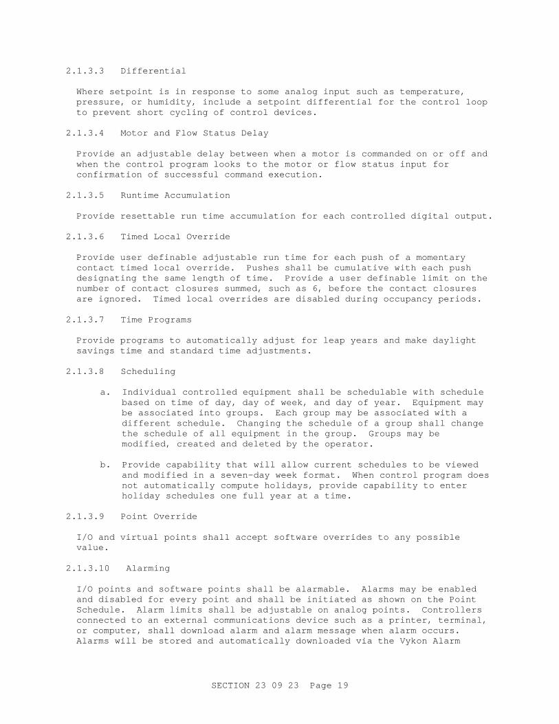
2.1.3.3 Differential Where setpoint is in response to some analog input such as temperature, pressure, or humidity, include a setpoint differential for the control loop to prevent short cycling of control devices.
2.1.3.4 Motor and Flow Status Delay Provide an adjustable delay between when a motor is commanded on or off and when the control program looks to the motor or flow status input for confirmation of successful command execution.
2.1.3.5 Runtime Accumulation Provide resettable run time accumulation for each controlled digital output.
2.1.3.6 Timed Local Override Provide user definable adjustable run time for each push of a momentary contact timed local override. Pushes shall be cumulative with each push designating the same length of time. Provide a user definable limit on the number of contact closures summed, such as 6, before the contact closures are ignored. Timed local overrides are disabled during occupancy periods.
2.1.3.7 Time Programs Provide programs to automatically adjust for leap years and make daylight savings time and standard time adjustments.
2.1.3.8 Scheduling
a. Individual controlled equipment shall be schedulable with schedule based on time of day, day of week, and day of year. Equipment may be associated into groups. Each group may be associated with a different schedule. Changing the schedule of a group shall change the schedule of all equipment in the group. Groups may be modified, created and deleted by the operator.
b. Provide capability that will allow current schedules to be viewed
and modified in a seven-day week format. When control program does not automatically compute holidays, provide capability to enter holiday schedules one full year at a time.
2.1.3.9 Point Override I/O and virtual points shall accept software overrides to any possible value.
2.1.3.10 Alarming I/O points and software points shall be alarmable. Alarms may be enabled and disabled for every point and shall be initiated as shown on the Point Schedule. Alarm limits shall be adjustable on analog points. Controllers connected to an external communications device such as a printer, terminal, or computer, shall download alarm and alarm message when alarm occurs. Alarms will be stored and automatically downloaded via the Vykon Alarm

SECTION 23 09 23 Page 20
Client. See Appendix B for Alarm Matrix. The following conditions shall generate alarms:
a. Motor is commanded on or off but the motor status input indicates
no change
b. Temperature, humidity, or pressure strays outside selectable limits
c. An analog input takes a value indicating sensor failure
d. A module is not communicating on the LAN
e. A power outage occurs 2.1.3.11 Messages Messages shall be operator defined and assigned to alarm or status conditions. Messages shall be displayed on the workstation or printer when these conditions occur.
2.1.3.12 Trending DDC system shall have the capability to trend all I/O and virtual points. Trend logs shall be initialed for the points identified in the Point Schedule. Points may be associated into groups. A trend report may be set up for each group. The period between logging consecutive trend values shall range from one minute to 60 minutes at a minimum. The minimum number of consecutive trend values stored at one time shall be 30 per variable. When trend memory is full, the most recent data shall overwrite the oldest data. Trend data shall be capable of being uploaded to computer. Trend data shall be available on a real time basis; trend data shall appear numerically and graphically on a connected computer's screen as the data is processed from the DDC system. Trend reports shall be capable of uploading to computer for storage.
2.1.3.13 Status Display Current status of I/O and virtual points shall be displayed on command. Points shall be associated into functional groups, such as all the I/O and virtual points associated with control of a single air handling unit, and displayed as a group, so the status of a single mechanical system can be readily checked. A group shall be selectable from a menu of groups having meaningful names; such as AHU-4, Second Floor, Chiller System, and other such names.
2.1.3.14 Diagnostics Each controller shall perform self-diagnostic routines and provide messages to an operator when errors are detected. The DDC system shall be capable of recognizing a non-responsive module on a LAN. The remaining, responsive modules on a LAN shall not operate in a degraded mode.
2.1.3.15 Power Loss During a power outage, each controller shall assume a disabled status and outputs shall go to a user definable state. Upon restoration of power, DDC system shall perform an orderly restart, with sequencing of outputs.

SECTION 23 09 23 Page 21
2.1.3.16 Program Transfer Provide software for download of control programs and database from a computer to controllers and upload of same to computer from controllers. Every digital controller in the DDC system shall be capable of being downloaded and uploaded to through a single controller on the highest level LAN.
2.1.3.17 Password Protection Provide at least three levels of password protection to the DDC system permitting different levels of access to the system. The lowest level allows monitoring only. The highest level allows full control of all functions, including setting new passwords. Password Protection matrix shall follow that shown in Appendix B.
2.1.4 Workstation
a. Provide a central workstation computer installed with Web Supervisor Niagara Workbench software to provide an interface for monitoring, troubleshooting, and making adjustments to the program or operating parameters of all DDC controllers, including TCUs. The workstation shall also be capable of programming all controllers, including TCUs.
b. DDC system shall operate continuously without connection to the
workstation. Information at the workstation is not required for day-to-day operations of the direct digital controllers.
c. Per Executive Order 13423, desktop computers, notebook computers,
and PC monitors shall be registered under the Electronic Product Environmental Assessment Tool (EPEAT) (IEEE 1680 standard for personal computer products) at a minimum Bronze level, but preferably at Silver or above (http://www.epeat.net/). These items shall also meet applicable FEMP recommended standby power requirements (http://www1.eere.energy.gov/femp/procurement/eep_standby_power.html).
2.1.5 Hardware The DDC system manufacturer shall assure compatibility of all workstation computer equipment and peripherals. The workstation shall be configured to operate according to the DDC system manufacturer's specifications. Workstation hardware shall be configured to allow operation of software, uploading and downloading of programs, and creation of graphics. At a minimum the workstation hardware shall consist of:
a. Computer; computer shall use Windows XP Professional with Service
Pack 2 or higher, and shall not have less than Intel Pentium IV processor, running at 3.2 Gigahertz speed, 160 gigabyte hard disc, 1 gigabyte RAM, 1 serial and 1 parallel port, one Ethernet port, one modem/telephone RJ-11 port, 4 USB 2.0 ports, one IEEE 1394 (firewire) connection, 17 inch Flat Panel monitor with 1280 x 1024 minimum resolution, 101 character keyboard, a 1.4 megabyte 3 1/2 inch floppy drive, 48X internal CD-RW/DVD Combo Drive, onboard or APG 8x graphics.
SECTION 23 09 23 Page 22
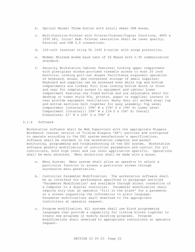
b. Optical Mouse: Three button with scroll wheel USB mouse.
c. Multifunction-Printer with Printer/Scanner/Copier functions, 4800 x
1200 DPI, Color/ B&W. Printer resolution shall be laser quality. Parallel and USB 2.0 connections.
d. 120-volt terminal strip UL 1449 6-outlet with surge protection.
e. Modem: Minimum modem baud rate of 56 Kbaud with v.90 communication
standard.
f. Security Workstation Cabinet features: Locking upper compartment with plexiglass window provided viewable access to most 20 inch monitors; Locking pull-out drawer facilitates ergonomic operation of keyboard, mouse, and convenient storage of small supplies; Keyboard and supplies can be accessed even while top and bottom compartments are locked; Full size locking bottom doors in front and rear for complete access to equipment and cables; Lower compartment features one fixed bottom and one adjustable shelf for desktop or tower style PCs, printer, paper or supplies; Louvers in rear provide equipment ventilation; Heavy duty all welded steel top and bottom sections bolt together for easy assembly; Top Level Compartment (internal): 20¾" W x 21¾" D x 19¼" H; Lower Level Compartment (internal): 20¾" W x 21¼ D x 23½" H; Overall Dimensions: 21" W x 22½" D x 59½" H
2.1.6 Software Workstation software shall be Web Supervisor with the appropriate Niagara Workbench (Latest version of Tridium Niagara "AX") services and configured to operate according to the DDC system manufacturer's specifications. Software shall be resident in the workstation computer and permit monitoring, programming and troubleshooting of the DDC system. Workstation software permits modification of controller parameters and control for all controllers, both high level and low level application specific. Operations shall be menu selected. Menu selections shall be made with a mouse.
a. Menu System: Menu system shall allow an operator to select a
particular function or access a particular screen through successive menu penetration.
b. Controller Parameter Modification: The workstation software shall
be an interface for performance specified in paragraph entitled "Parameter Modification" and available through direct connection of a computer to a digital controller. Parameter modification shall require only that an operator "fill in the blank" for a parameter on a screen requesting the information in plain language. Parameter modifications shall download to the appropriate controllers at operator request.
c. Program modification: All systems shall use block programming
languages that provide a capability for linking blocks together to create new programs or modify existing programs. Program modifications shall download to appropriate controllers at operator request.

SECTION 23 09 23 Page 23
d. Provide a current version of anti-virus software recommended by the manufacturer of the computer operating system. Program shall verify that the computer is virus free upon delivery to the quality assurance representative (QAR).
2.1.7 Graphic-Based Software The workstation shall use graphic-based software to provide a user-friendly interface to the DDC system. Graphic-based software shall provide graphical representation of the building, the buildings mechanical systems, and the DDC system. The current value and point name of every I/O point shall be shown on at least one graphic and in its appropriate physical location relative to building and mechanical systems.
a. Graphics shall follow the style of the screen shots in Appendix A in
representing mechanical systems, sensors, controlled devices, point names, colors, fonts, navigation buttons, and etc. Graphics shall utilize the standard library included in the Niagara Workbench/Web Supervisor software.
b. Graphic Title: Graphics shall have an identifying title visible when
the graphic is being viewed.
c. Dynamic Update: When the workstation is on-line with the control system, point data shall update dynamically on the graphic images.
d. Graphic Penetration: Provide graphic penetration when the capability
exists. For systems without graphic penetration, provide menu penetration for selection of individual graphics to give the same hierarchical affect provided by graphic penetration.
e. Graphic Types: Graphic-based software shall have graphics of the
building exterior, building section, floor plans, and mechanical systems. Provide the following graphics:
(1) Building Exterior Graphic: Show exterior architecture, major
landmarks, and building number.
(2) Building Section Graphic: Show floors in section graphic with appropriate floor name on each floor.
(3) Floor Plan Graphics: Provide a single graphic for each floor,
unless the graphic will contain more information than can reasonably be shown on a single graphic. Each heating or cooling zone within a floor plan shall have a zone name and its current temperature displayed within the zone outline. Show each controlled variable in the zone. Provide visual warning for each point in alarm.
(4) Mechanical System Graphics: Provide two-dimensional drawings to
symbolize mechanical equipment; do not use line drawings. Show controlled or sensed mechanical equipment. Each graphic shall consist of a single mechanical system; examples are a graphic for an air handling unit, a graphic for a VAV box, a graphic for a heating water system, and a graphic for a chiller system. Place sensors and controlled devices associated with mechanical equipment in their appropriate locations. Place point name and point value
SECTION 23 09 23 Page 24
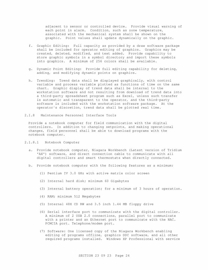
adjacent to sensor or controlled device. Provide visual warning of each point in alarm. Condition, such as zone temperature, associated with the mechanical system shall be shown on the graphic. Point values shall update dynamically on the graphic.
f. Graphic Editing: Full capacity as provided by a draw software package
shall be included for operator editing of graphics. Graphics may be created, deleted, modified, and text added. Provide capability to store graphic symbols in a symbol directory and import these symbols into graphics. A minimum of 256 colors shall be available.
g. Dynamic Point Editing: Provide full editing capability for deleting,
adding, and modifying dynamic points on graphics.
h. Trending: Trend data shall be displayed graphically, with control variable and process variable plotted as functions of time on the same chart. Graphic display of trend data shall be internal to the workstation software and not resulting from download of trend data into a third-party spreadsheet program such as Excel, unless such transfer is automatic and transparent to the operator, and the third-party software is included with the workstation software package. At the operator's discretion, trend data shall be plotted real time.
2.1.8 Maintenance Personnel Interface Tools Provide a notebook computer for field communication with the digital controllers. In addition to changing setpoints, and making operational changes, field personnel shall be able to download programs with the notebook computer.
2.1.8.1 Notebook Computer
a. Provide notebook computer, Niagara Workbench (Latest version of Tridium "AX") software, and direct connection cable to communicate with all digital controllers and smart thermostats when directly connected.
b. Provide notebook computer with the following features as a minimum:
(1) Pentium IV 3.0 GHz with active matrix color screen
(2) Internal hard disk; minimum 60 Gigabytes
(3) Internal battery operation; for a minimum of 3 hours of operation.
(4) RAM; minimum 512 Megabytes
(5) Internal 48X CD RW and 3.5 inch 1.44 MB floppy drive
(6) Serial interface port to communicate with the digital controller.
A minimum of 2 USB 2.0 connections, parallel port to communicate with a printer and an Ethernet port to communicate with the NAC. PCMCIA port. Telephone/modem port.
(7) Software: One licensed copy of the Niagara Workbench enabling
editing of programs offline, graphics DDC software, and all other required programs installed. Windows XP Professional with service
SECTION 23 09 23 Page 25
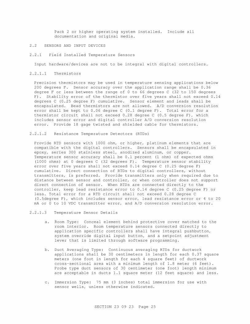
Pack 2 or higher operating system installed. Include all documentation and original media.
2.2 SENSORS AND INPUT DEVICES 2.2.1 Field Installed Temperature Sensors Input hardware/devices are not to be integral with digital controllers.
2.2.1.1 Thermistors Precision thermistors may be used in temperature sensing applications below 200 degrees F. Sensor accuracy over the application range shall be 0.36 degree F or less between the range of 0 to 66 degrees C (32 to 150 degrees F). Stability error of the thermistor over five years shall not exceed 0.14 degrees C (0.25 degree F) cumulative. Sensor element and leads shall be encapsulated. Bead thermistors are not allowed. A/D conversion resolution error shall be kept to 0.06 degree C (0.1 degree F). Total error for a thermistor circuit shall not exceed 0.28 degree C (0.5 degree F), which includes sensor error and digital controller A/D conversion resolution error. Provide 18 gage twisted and shielded cable for thermistors.
2.2.1.2 Resistance Temperature Detectors (RTDs) Provide RTD sensors with 1000 ohm, or higher, platinum elements that are compatible with the digital controllers. Sensors shall be encapsulated in epoxy, series 300 stainless steel, anodized aluminum, or copper. Temperature sensor accuracy shall be 0.1 percent (1 ohm) of expected ohms (1000 ohms) at 0 degrees C (32 degrees F). Temperature sensor stability error over five years shall not exceed 0.14 degree C (0.25 degree F) cumulative. Direct connection of RTDs to digital controllers, without transmitters, is preferred. Provide transmitters only when required due to distance between sensor and controller, or when controller does not support direct connection of sensor. When RTDs are connected directly to the controller, keep lead resistance error to 0.14 degree C (0.25 degree F) or less. Total error for a RTD circuit shall not exceed 0.28 degree C (0.5degree F), which includes sensor error, lead resistance error or 4 to 20 mA or 0 to 10 VDC transmitter error, and A/D conversion resolution error.
2.2.1.3 Temperature Sensor Details
a. Room Type: Conceal element behind protective cover matched to the room interior. Room temperature sensors connected directly to application specific controllers shall have integral pushbutton, system override digital input button, and a setpoint adjustment lever that is limited through software programming.
b. Duct Averaging Type: Continuous averaging RTDs for ductwork
applications shall be 30 centimeters in length for each 0.37 square meters (one foot in length for each 4 square feet) of ductwork cross-sectional area with a minimum length of 1.8 meter (6 feet). Probe type duct sensors of 30 centimeter (one foot) length minimum are acceptable in ducts 1.1 square meter (12 feet square) and less.
c. Immersion Type: 75 mm (3 inches) total immersion for use with
sensor wells, unless otherwise indicated.
SECTION 23 09 23 Page 26
d. Sensor Wells: Stainless steel material. Provide heat-sensitive transfer agent between exterior sensor surface and interior well surface.
e. Outside Air Type: Provide element on the building's north side
with sunshade to minimize solar effects. Mount element at least 75 mm (3 inches) from building outside wall. Sunshade shall not inhibit the flow of ambient air across the sensing element. Shade shall protect sensing element from snow, ice, and rain.
2.2.2 Transmitters Transmitters shall have 4 to 20 mA or 0 to 10 VDC output linearly scaled to the temperature, pressure, humidity, or flow range sensed. Transmitter shall be matched to the sensor, factory calibrated, and sealed. Total error shall not exceed 0.1 percent at any point across the measured span. Supply voltage shall be 24 volts ac or dc. Transmitters shall have non-interactive offset and span adjustments. For temperature sensing, transmitter stability shall not exceed 0.05 degrees C (0.09 degrees F) a year. Transmitters are not required unless warranted by signal travel distance.
2.2.2.1 Spans and Ranges Transmitter spans or ranges shall meet the following:
a. Temperature:
(1) 28 degrees C (50 degrees F) span: Room, chilled water, cooling
coil discharge air, return air sensors
(2) 56 degrees C (100 degrees F) span: Outside air, hot water, heating coil discharge air, mixed air sensors
(3) 111 degrees C (200 degrees F) span: High temperature hot water,
heating hot water, chilled/hot water system sensors.
b. Pressure:
(1) -125 to 125 pascals (-0.5 to 0.5 inches water) differential range: static pressure control of rooms
(2) 0 to 1250 pascals (0 to 5 inches water) differential range: Duct
static pressure
(3) 0 to 689 kPa (0 to 100 psig) differential: Water differential pressure
(4) 0 to 750 pascals (0 to 3 inches water) differential range: Static
pressure across filters
c. Relative Humidity:
(1) 10 to 90 percent minimum relative humidity range
SECTION 23 09 23 Page 27
2.2.3 Relative Humidity Transmitters Provide integral humidity transducer and transmitter. Output of relative humidity instrument shall be a 4 to 20 mA or 0 to 10 VDC signal proportional to full range of relative humidity input. Accuracy shall be 2 percent of full scale, long-term stability shall be less than one percent drift per year. Sensing element shall be polymer or thin film polymer type.
2.2.4 Pressure Transmitters Provide integral pressure transducer and transmitter. Output of pressure instrument shall be a 4 to 20 mA or 0 to 10 VDC signal proportional to the pressure span. Span shall be as specified. Accuracy shall be 1.0 percent. Linearity shall be 0.1 percent.
2.2.5 Current Transmitters Provide current transmitters to monitor amperage of motors. Select current transmitters for normal measured amperage to be near 50 percent of full-scale range. Current transmitters shall have an accuracy of one percent and 4 to 20 mA or 0 to 10 VDC output signal.
2.2.6 Air Quality Sensors 2.2.6.1 Carbon Dioxide (CO2) Sensor Provide CO2 sensors with integral transducers where shown or required by the sequence of operations. Output signal shall be 4 to 20 mA or 0 to 10 VDC. Accuracy shall be 5 percent of full scale.
2.2.7 Input Switches 2.2.7.1 Timed Local Override Provide momentary contact push button override with override time set in controller software. Provide to override DDC time of day program and activate occupancy program for assigned units. Upon expiration of override time, the control system shall return to time-of-day program. Time interval for the length of operation shall be software adjustable and shall expire unless reset.
2.2.7.2 Insertion Freeze Protection Switch Electric switch shall be capillary type. Provide special purpose insertion thermostats with flexible elements a minimum of 6 meters (20 feet) in length for coil face areas up to 3.7 square meters (40 square feet). Switch contacts shall be rated for motor starter circuit voltage being interrupted. Switch shall be equipped with auxiliary set of contacts for input of switch status to digital controller. Provide additional elements or longer elements for larger coils at the rate of 30 centimeters (1-foot) of element per .37 square meters (4 square feet) of coil. Serpentine capillaries perpendicular to the air flow to uniformly sense the entire airflow. A freezing condition at 18-inch increments along the sensing element shall activate the thermostatic switch. Switch shall require manual reset after activation.
SECTION 23 09 23 Page 28
2.2.7.3 Electronic Airflow Measurement Stations and Transmitters
a. Station - Each station shall contain an array of velocity sensing elements and straightening vanes inside a flanged sheet metal casing. The velocity sensing elements shall be of the RTD or thermistor type. The sensing elements shall be distributed across the duct cross section in the quantity and pattern set forth for measurements and instruments of ASHRAE Gdln3 and SMACNA HVACTAB for the traversing of ducted air flows. The resistance to airflow through the airflow measurement station shall not exceed 20 pascals (0.08 inch water gage) at an airflow of 10.16 meters per second (2,000 fpm). Station construction shall be suitable for operation at airflow of up to 25.4 meters per second (5,000 fpm) over a temperature range of 4 to 49 degrees C (20 to 120 degrees F), and accuracy shall be plus or minus 3 percent over a range of 0.635 to 12.7 meters per second (125 to 2,500 fpm) scaled to air volume.
b. Each transmitter shall produce a linear, temperature compensated 4
to 20 mA or 0 to 10 VDC output corresponding to the actual air flow. The transmitter shall be a 2-wire, loop powered device. The output error of the transmitter shall not exceed 0.5 percent of the calibrated measurement.
2.2.8 Energy Metering 2.2.8.1 Meters Provide LonMark/LonWorks compatible meters for each project building. All utilities shall be monitored. Provide DDC/EMCS monitoring/metering of utility usage for gas, water, and electricity. Meters listed in the water, gas, and electrical specifications are to be coordinated and integrated to function with the DDC system. DDC shall measure both instantaneous and accumulated utility usage.
a. Electrical meter shall be as specified in Section 26 20 00 INTERIOR
DISTRIBUTION SYSTEM.
b. Water meter shall be as specified in Section 22 00 00 PLUMBING, GENERAL PURPOSE.
c. Gas meter shall be as specified in Section 33 51 03.00 10 GAS
DISTRIBUTION SYSTEM. 2.3 OUTPUT DEVICES 2.3.1 Control Dampers Damper shall conform to SMACNA 1966 (2005) HVAC Duct Construction Standards Metal and Flexible.
a. A single damper section shall have blades no longer than 1220 mm
(48 inches) and shall be no higher than 1830 mm (72 inches). Maximum damper blade width shall be 203 mm (8 inches). Larger sized damper shall be made from a combination of sections.
b. Dampers shall be steel, or other materials where shown. Flat
blades shall be made rigid by folding the edges. Blades shall be
SECTION 23 09 23 Page 29
provided with compressible seals at points of contact. The channel frames of the dampers shall be provided with jamb seals to minimize air leakage. Dampers shall not leak in excess of 102 L/s per square meter (20 cfm per square foot) at 996 Pa (4 inches water) gage static pressure when closed. Seals shall be suitable for an operating temperature range of minus 40 degrees C to 93 degrees C (40 degrees F to 200 degrees F). Dampers shall be rated at not less than 10 m/s (2000 fpm) air velocity. All blade-operating linkages shall be within the frame so that blade-connecting devices within the same damper section will not be located directly in the air stream. Damper axles shall be 13 mm (0.5 inch) (minimum) plated steel rods supported in the damper frame by stainless steel or bronze bearings. Blades mounted vertically shall be supported by thrust bearings. Pressure drop through dampers shall not exceed 10 Pa gage at 5 m/s (0.04 inch water gage at 1000 fpm) in the wide-open position. Frames shall not be less than 50 mm (2 inches) in width. Dampers shall be tested in accordance with AMCA 500-D.
c. Operating links external to dampers (such as crankarms, connecting
rods, and line shafting for transmitting motion from damper actuators to dampers) shall withstand a load equal to twice the maximum required damper-operating force. Rod lengths shall be adjustable. Links shall be brass, bronze, zinc-coated steel, or stainless steel. Moving parts in contact with one another shall be of different materials. Working parts of joints and clevises shall be brass, bronze, or stainless steel. Adjustments of crankarms shall control the open and closed position of dampers.
2.3.2 Control Valves 2.3.2.1 Valve Assembly Valves shall have stainless steel stems. Valve bodies shall be designed for not less than 862 kPa (gage) (125 psig) working pressure or 150 percent of the system operating pressure, whichever is greater. Valve leakage rating shall be 0.01 percent of rated Cv. Class 125 copper alloy valve bodies and Class 150 steel or stainless steel valves shall conform to ASME B16.5 as a minimum. Cast iron valve components shall conform to ASTM A 126 Class B or C as a minimum. Valves for heating coils shall fail normally open.
2.3.2.2 Butterfly Valve Assembly Butterfly valves shall be threaded lug type suitable for dead-end service and for modulation to the fully closed position, with noncorrosive discs, stainless steel shafts supported by bearing, and EPDM seats suitable for temperatures from minus 29 degrees C to plus 121 degrees C (minus 20 degrees F to plus 250 degrees F). Valves shall have a manual means of operation independent of the actuator.
2.3.2.3 Two-Way Valves Two-way modulating valves shall have equal percentage characteristics.
2.3.2.4 Three-Way Valves Three-way valves shall have equal percentage characteristics.
SECTION 23 09 23 Page 30
2.3.2.5 Duct Coil and Terminal Unit Coil Valves Provide control valves with either flare-type or solder-type ends provided for duct or terminal-unit coils. Provide flare nuts for each flare-type end valve.
2.3.2.6 Valves for Hot Water Service Valves for hot water service below 121 degrees C (250 Degrees F):
a. Bodies for valves 40 mm(1 1/2 inches) and smaller shall be brass or
bronze with threaded or union ends. Bodies for valves larger than 50 mm (2 inches) shall have flanged-end connections. Water valves shall be sized for a 21 kPa (3 psi) differential through the valve at rated flow, except as indicated otherwise. Select valve flow coefficient (Cv) for an actual pressure drop not less than 50 percent or greater than 125 percent of the design pressure drop at design flow.
b. Internal trim, including seats, seat rings, modulation plugs, and
springs, of valves controlling water hotter than 99 degrees C (210 degrees F) shall be Type 316 stainless steel.
c. Internal trim for valves controlling water 99 degrees C (210
degrees F) or less shall be brass or bronze.
d. Non-metallic parts of hot water control valves shall be suitable for a minimum continuous operating temperature of 121 degrees C or 28 degrees C (250 degrees F or 50 degrees F) above the system design temperature, whichever is higher.
e. Valves 100 mm (4 inches) and larger shall be butterfly valves.
2.3.3 Actuator 2.3.3.1 Electric Actuators Provide direct drive electric actuators for all control applications. When operated at rated voltage, each actuator shall be capable of delivering torque required for continuous uniform motion and shall have end switch to limit travel, or shall withstand continuous stalling without damage. Actuators shall function properly with range of 85 to 110 percent of line voltage.
Provide gears of steel or copper alloy. Fiber or reinforced nylon gears may be used for torque less than 1.8 Newton meters (16 inch pounds). Provide hardened steel running shafts in sleeve bearing of copper alloy, hardened steel, nylon, or ball bearing. Provide two-position actuators of the single direction, spring return, or reversing type. Provide proportioning actuators capable of stopping at all points in the cycle and starting in either direction, from any point.
Provide reversing and proportioning actuators with limit switches to limit travel in either direction unless operator is stall type. Actuators shall have a simple switch for reversing direction, and a button to disengage clutch for manual adjustments. Provide reversible shaded pole, split capacitor, synchronous, or stepper type electric motors.
SECTION 23 09 23 Page 31
2.3.4 Output Switches 2.3.4.1 Control Relays Shall be double pole, double throw (DPDT), UL listed, with contacts rated to the application, indicator light, and dust proof enclosure. Light indicator is lit when coil is energized and is off when coil is not energized. Relays shall be socket type, plug into a fixed base, and replaceable without need of tools or removing wiring. Encapsulated "PAM" type relays are permissible for terminal control applications.
2.4 ELECTRICAL POWER AND DISTRIBUTION For control power provide a new, dedicated source 120 volts or less, 60 Hz, three wire (black, white, and green). Run green ground wire to panel ground; conduit grounds are not sufficient.
2.4.1 Transformers Transformers shall conform to UL 506. Power digital controllers and terminal control units (TCU's) from dedicated circuit breakers with surge protection specified. Transformers for digital controllers serving terminal equipment on lower level LANs may be grouped to have specified surge protection sized for the number of controllers on a single transformer. Provide a fuse on the secondary side of the transformer.
2.4.2 Surge Protection Surge and transient protection consist of devices installed externally to digital controllers.
2.4.2.1 Power Line Surge Protection Surge suppressors external to digital controller, shall be installed on all incoming AC power. Surge suppressor shall be rated by UL 1449, have a fault indicating light, and have clamping voltage ratings below the following levels:
a. Unit is a transient voltage surge suppressor 120 VAC/1 phase/2 wire
plus ground, hard wire individual equipment protector.
b. Unit must react within 5 nanoseconds and automatically reset.
c. Voltage protection threshold, line to neutral, starts at no more than 211 volts peak on the 120 VAC line.
d. The transient voltage surge suppressor must have an independent
secondary stage equal to or greater than the primary stage joule rating.
e. The primary suppression system components must be pure Silicon
Avalanche Diodes.
f. Silicon Avalanche Diodes or Metal Oxide Varistors are acceptable in the independent secondary suppression system.
SECTION 23 09 23 Page 32
g. The Transient Suppression System shall incorporate an indication light which denotes whether the primary and/or secondary transient protection components is/are functioning.
h. All system functions of the Transient Suppression System must be
individually fused and not short circuit the AC power line at any time.
i. The Transient Suppression System shall incorporate an EMI/RFI noise
filter with a minimum attenuation of 13 dB at 10 kHz to 300 MHz.
j. The system must comply with IEEE C62.41, Class "B" requirements and be tested according to IEEE C62.45.
k. The system shall operate at -20 to degrees C (-4 to 122 degrees F).
2.4.2.2 Telephone and Communication Line Surge Protection Provide transient surge protection to protect the DDC controllers and LAN related devices from surges that occur on the phone lines (modem or direct connect) and on inter-unit LAN communications. Devices shall be UL listed.
a. The surge protection shall be a rugged package with continuous,
non-interrupting protection and not use crowbar technology. Instant automatic reset after safely eliminating transient surges, induced lightning, and other forms of transient over voltages.
b. Unit must react within 5 nanoseconds using only solid-state
silicone avalanche technology.
c. Unit shall be installed at the proper distance as recommended by the manufacturer.
2.4.2.3 Controller Input/Output Protection Controller input/output points shall surge protection with optical isolation, metal oxide varistors (MOV), or silicon avalanche devices. Fuses are not permitted for surge protection.
2.4.3 Wiring Provide complete electric wiring for DDC System, including wiring to transformer primaries. Control circuit wiring shall not run in the same conduit as power wiring over 100 volts. Circuits operating at more than 100 Volts shall be in accordance with Section 26 20 00 INTERIOR DISTRIBUTION SYSTEM. Circuits operating at 100 Volts or less shall be defined as low voltage and shall be run in rigid or flexible conduit, metallic tubing, metal raceways or wire trays. Provide circuit and wiring protection as required by NFPA 70. Aluminum-sheathed cable or aluminum conduit may be used but shall not be buried in concrete. Use conduit in HVAC plenums. HVAC plenums include the space between a drop ceiling and the architectural ceiling, within walls, and within ductwork. Protect exposed wiring from abuse and damage.
SECTION 23 09 23 Page 33
2.4.3.1 AC Control Wiring
a. Control wiring for 24 V circuits shall be insulated copper 18 AWG minimum and rated for 300 VAC service.
b. Wiring for 120 V shall be 14 AWG minimum and rated for 600 V
service. 2.4.3.2 Analog Signal Wiring Analog signal wiring shall be 18 AWG single or multiple twisted pair. Each cable shall be 100 percent shielded, and have 20 AWG drain wire. Each wire shall have insulation rated to 300 V ac. Cables shall have an overall aluminum-polyester or tinned-copper (cable-shield tape). Install analog signal wiring in conduit separate from AC power circuits.
2.5 FIRE PROTECTION DEVICES Provide smoke detectors in return and supply air ducts on downstream side of filters in accordance with NFPA 90A, except as otherwise indicated. Provide UL listed or FM approved detectors for duct installation.
2.5.1 Smoke Detectors Provide in systems having air handling capacity over 944 l/s (2,000 cfm) in accordance with NFPA 90A. Design for detection of abnormal smoke densities by the ionization or photoelectric principle, responsive to both invisible and visible particles of combustion, and not susceptible to operation by changes to relative humidity. Provide UL listed or FM approved detectors for duct installation. Provide duct detectors with an approved duct housing, mounted exterior to duct, and with perforated sampling tubes extending across width of duct. Provide 115 V ac power supply unit integral with duct housing. Duct smoke detectors shall conform to the requirements of UL 268A. Duct smoke detectors shall have perforated sampling tubes extended into the air duct. Detector circuitry shall be mounted in a metallic enclosure exterior to the duct. Detectors shall have manual reset. Detectors shall be rated for air velocities that include air flows between 2.5 and 20 m/s. 500 and 4000 fpm. Detectors shall be powered from the HVAC control panel. Detectors shall have two sets of normally open alarm contacts and two sets of normally closed alarm contacts. Detectors shall be connected to the building fire alarm panel for alarm initiation. A remote annunciation lamp and accessible remote reset switch shall be provided for duct detectors that are mounted eight feet or more above the finished floor and for detectors that are not readily visible. Remote lamps and switches as well as the affected fan units shall be properly identified in etched rigid plastic placards. Detectors shall have test port or test switch. Provide each detector with a visible indicator lamp that lights when detector is activated. Activation of duct detector shall cause shutdown of associated air handling unit and closing of dampers and shall sound an alarm bell, minimum 6 inch diameter in a normally occupied area located as directed. Provide a separate bell for each air handling unit, with an engraved plastic or metal label indicating which unit each bell annunciates.
SECTION 23 09 23 Page 34
2.6 INDICATORS 2.6.1 Thermometers Provide fluid filled or bi-metal thermometers. Thermometers shall have either 9 inch scales or 3.5 inch dials. Provide with an adjustable angle suitable for the service. Provide thermometer and corrosion resistant separable socket well. Fluid filled thermometers (mercury is not acceptable) shall have a nominal scale diameter of 125mm. Construction shall be stainless steel case with molded glass cover, stainless steel stem and bulb. Stem shall be straight, length as required to fit well.
2.6.2 Pressure Gages
a. Gages for low differential pressure measurements shall be 4 1/2 inch (nominal) size with two sets of pressure taps, and shall have a diaphragm actuated pointer, white dial with black figures, and pointer zero adjustment. Gage shall have ranges and graduations as appropriate for the application, or as shown. Accuracy shall be plus or minus 2 percent of scale range.
2.7 VARIABLE FREQUENCY 3 PHASE MOTOR DRIVES The variable frequency drive (VFD) shall convert 208 or 460 volt (10 percent), three phase, 60 hertz (2Hz), utility grade power to adjustable voltage/frequency, three phase, AC power for stepless motor control from 5 percent to 105 percent of base speed.
2.7.1 Description The variable frequency drive (VFD) shall produce an adjustable AC voltage/ frequency output for complete motor speed control. The VFD must meet all of the following criteria.
a. The VFD shall use sinecoded PWM technology. The sinecoded PWM
calculations are performed by the VFD microprocessor.
b. The VFD shall use IGBT transistors for the inverter's three phase output.
c. The VFD shall use a three phase diode bridge converter to charge
the VFD constant voltage capacitor buss.
d. The VFD shall have the ability for control by either a remote 4-20 mA or 0 to 10 VDC control signal or from a local control panel located on the VFD itself.
e. The VFD shall use microprocessor technology for VFD control. The
VFD shall be programmable with a permanently mounted keypad included with each VFD.
f. The VFD shall be fully self diagnostic. No external programmers,
analyzers, interrogators, or diagnostic boards, shall be needed to annunciate VFD faults or drive internal status.
SECTION 23 09 23 Page 35
2.7.2 Code Standards VFD shall be UL listed as delivered to the end user. The VFD shall meet current National Electrical Code.
2.7.3 VFD Quality Assurance To ensure quality, each and every VFD shall be subject to a series of in-plant quality controlled inspections before approval for shipment from the manufacture's facilities.
a. All components shall be tested prior to assembly and the complete
unit shall be tested under full load conditions to ensure maximum product reliability.
b. The VFDs shall be the current standard production unit with at
least 10 identical units already in the field.
c. Engineering support shall be available from the factory of the VFD. Phone support shall be free of charge to the end user for the life of the equipment. Factory support shall be available in the English language.
2.7.4 VFD Service The VFD shall be supplied with:
a. 24 month parts and labor warranty. The warranty shall start when the
system is accepted by the end user or 30 months from date of shipment.
b. Installation, operation, and troubleshooting guide(s).
c. A district service support group shall provide the following additional services:
(1) Factory trained personal on-site for start-up for up to one
working day at no additional cost. Personnel shall be competent in operation and repair of the particular model of VFD that is installed.
(2) On-site training of customer personnel in basic installation,
troubleshooting, and operation of VFDs at no additional cost. This training shall be conducted for up to 6 personnel at the installation site for a minimum of 4 hours.
2.7.5 Basic VFD Features The VFD shall have the following basic features with no more than three separate internal electronic boards.
a. VFD mounted operator control keypad capable of:
(1) Remote/Local operator selection with password access.
(2) Run/Stop and manual speed commands.
(3) All programming functions.

SECTION 23 09 23 Page 36
(4) Scrolling through all display functions.
b. Digital display capable of indicating:
(1) VFD status.
(2) Frequency.
(3) RPM of motor.
(4) Phase current.
(5) Fault diagnostics in descriptive text.
(6) All programmed parameters.
c. Standard PI loop controller with input terminal for controlled variable and parameter settings made while inverter running.
d. User interface terminals for end-user remote control of VFD speed,
speed feedback, and isolated form C SPDT relay energized on drive fault condition.
e. An isolated form C SPDT auxiliary relay energized on run command.
f. The VFD shall have a metal NEMA 1 enclosure.
g. The VFD shall have an adjustable carrier frequency with 16 KHz minimum
upper limit.
h. The VFD shall have a built in or external line reactor with 3% minimum impedance to protect DC buss capacitors and rectifier section diodes.
2.7.6 Programmable Parameters The VFD shall include the following operator programmable parameters:
a. Upper limit frequency.
b. Lower limit frequency.
c. Acceleration rate.
d. Deceleration rate.
e. Variable torque volts per Hertz curve.
f. Starting voltage level.
g. Starting frequency level.
h. Display speed scaling.
i. Enable/disable auto-restart feature.
j. Enable/disable softstall feature.
SECTION 23 09 23 Page 37
k. Motor overload level.
l. Motor stall level.
m. Jump frequency and hysteresis band.
n. PWM carrier frequency. 2.7.7 Protective Circuits and Features
a. An electronic adjustable inverse time current limit with consideration for additional heating of the motor at frequencies below 45Hz, for the protection of the motor.
b. An electronic adjustable soft stall feature, allowing the VFD to lower
the frequency to a point were the motor will run at FLA when an overload condition exists at the requested frequency. The VFD will automatically return to the requested frequency when load condition permit.
c. The VFD will have a separate electronic stall at 110% VFD rated current
and a separate hardware trip at 190% current.
d. The VFD shall have ground fault protection that protects output cables and motor from grounds during both starting and continuous running conditions.
e. The VFD shall have the ability to restart after the following faults:
(1) Overcurrent (drive or motor).
(2) Power outage.
(3) Phase loss.
(4) Overvoltage/Undervoltage.
e. The VFD shall restart into a rotating load without tripping or damaging
the VFD or the motor.
f. The VFD shall keep a log of a minimum of four previous fault conditions, indicating type and time of occurrence in descriptive text.
g. The VFD shall be able to sustain 110% rated current for 60 sec.
h. The VFD shall respond to and record the following fault conditions:
(1) Over current (and have an indication if the over current was
during acceleration, deceleration, or running).
(2) Overcurrent internal to the drive.
(3) Motor overload at start-up.
(4) Over voltage from the utility power.
(5) Motor running overload.

SECTION 23 09 23 Page 38
(6) Overvoltage during deceleration.
(7) VFD over heat.
(8) Load end ground fault.
(9) Abnormal parameters or data in VFD EEPROM. 2.7.8 Operational Conditions The VFD shall be designed and constructed to operate within the following service conditions.
a. Ambient Temperature Range, -17.7 to 48.8 degrees C (0 to 120 deg.
F).
b. Non-condensing relative humidity to 90 percent. 2.7.9 Available Options Provide the following options:
a. RFI/EMI filters
b. LonWorks or BACnet interface card with application software which
can both control and monitor the VFD from a attached computer.
c. A manual bypass circuit and switch integral or external to the drive to allow drive bypass drive and operate at 100% speed. Overload fuses and other protective hardware shall remain in the circuit during bypass.
d. One set of spare parts per drive including: all replaceable
circuit cards, power diode assemble, DC Buss capacitor, power output transistor assembly, all fuses, and all lights. Package parts individually for long term storage and clearly label contents.
2.8 DRAWINGS 2.8.1 Shop Drawings Drawings shall be on A1 (841 mm by 594 mm) 34 by 22 inch sheets in the form and arrangement shown. The drawings shall use the same abbreviations, symbols, nomenclature and identifiers shown. Each control system element on a drawing shall have a unique identifier as shown. The HVAC Control System Drawings shall be delivered together as a complete submittal. Deviations must be approved by the Contracting Officer. List of Drawings shall be submitted along with Submittal SD-01, Preconstruction Submittals
2.8.2 List of Drawings HVAC Control System Drawings shall include the following:
Sheet One: Drawing Index, HVAC Control System Legend.
Sheet Two: Valve Schedule, Damper Schedule.
SECTION 23 09 23 Page 39
Sheet Three: (Not used.)
Sheet Four: Control System Schematic and Equipment Schedule.
Sheet Five: Sequence of Operation and Data Terminal Strip Layout.
Sheet Six: Control Loop Wiring Diagrams and Ladder Diagrams.
Sheet Seven: Motor Starter and Relay Wiring Diagram.
Sheet Eight: Communication Network Architecture and Block Diagram.
Sheet Nine: DDC Panel Installation and Block Diagram.
(Repeat Sheets Four through Seven for each AHU System.) 2.8.3 Drawing Index The HVAC Control System Drawing Index shall show the name and number of the building and military site. The Drawing Index shall list HVAC Control System Drawings, including the drawing number, sheet number, drawing title, and computer filename when used. The HVAC Control System Legend shall show generic symbols and the name of devices shown on the HVAC Control System Drawings.
2.8.4 Valve Schedule The valve schedule shall include each valve's unique identifier, size, flow coefficient Kv (Cv), pressure drop at specified flow rate, spring range, positive positioner range, actuator size, close-off pressure data, dimensions, and access and clearance requirements data. Valve schedules may be submitted in advance but shall be included in the complete submittal.
2.8.5 Damper Schedule The damper schedule shall contain each damper's and each actuator's identifier, nominal and actual sizes, orientation of axis and frame, direction of blade rotation, spring ranges, operation rate, positive positioner ranges, locations of actuators and damper end switches, arrangement of sections in multi-section dampers, and methods of connecting dampers, actuators, and linkages. The Damper Schedule shall include the maximum leakage rate at the operating static-pressure differential. The Damper Schedule shall contain actuator selection data supported by calculations of the torque required to move and seal the dampers, access and clearance requirements. Damper schedules may be submitted in advance but shall be included in the complete submittal.
2.8.6 Schematics The HVAC control system schematics shall show all control and mechanical devices associated with the HVAC system. A system schematic drawing shall be submitted for each HVAC system.
2.8.7 Equipment Schedule The HVAC control system equipment Schedule shall be developed. All devices shall have unique identifiers and shall be referenced in the equipment
SECTION 23 09 23 Page 40
schedule. Information to be included in the equipment schedule shall be the control loop, device unique identifier, device function, setpoint, input range, and additional important parameters (i.e., output range). An equipment schedule shall be submitted for each HVAC system.
2.8.8 Sequence of Operation The HVAC control system sequence of operation shall reflect the language and format of this specification, and shall refer to the devices by their unique identifiers as shown on the contract drawings. No operational deviations from specified sequences will be permitted without prior written approval of the Contracting Officer. Sequences of operation shall be submitted for each HVAC control system including each type of terminal unit control system.
2.8.9 Wiring Diagrams The HVAC control system wiring diagrams shall be functional wiring diagrams which show the interconnection of conductors and cables to HVAC control panel terminal blocks and to the identified terminals of devices, starters and package equipment. The wiring diagrams shall show necessary jumpers and ground connections. The wiring diagrams shall show the labels of all conductors. Sources of power required for HVAC control systems and for packaged equipment control systems shall be identified back to the panel board circuit breaker number, HVAC system control panel, magnetic starter, or packaged equipment control circuit. Each power supply and transformer not integral to a controller, starter, or packaged equipment shall be shown. The connected volt-ampere load and the power supply volt-ampere rating shall be shown. Wiring diagrams shall be submitted for each HVAC control system.
PART 3 EXECUTION 3.1 INSTALLATION Perform installation under supervision of competent technicians regularly employed in the installation of DDC systems.
3.1.1 Wiring Criteria
a. Input/output identification: Permanently label each field wire, cable, or pneumatic tube at each end with unique descriptive identification.
b. Rigid or flexible conduit shall be terminated at all sensors and
output devices.
c. Surge Protection: Install surge protection per manufacturer's specification.
d. Grounding: Ground controllers and cabinets to a good earth ground.
Ground controller to a ground in accordance with Section 26 20 00 INTERIOR DISTRIBUTION SYSTEM. Grounding of the green ac ground wire, at the breaker panel, alone is not adequate. Run metal conduit from controller panels to adequate building grounds. Ground sensor drain wire shields at controller end.
e. Contractor is responsible for correcting all associated ground loop
problems.
SECTION 23 09 23 Page 41
f. Wiring in panel enclosures shall be run in covered wire track. 3.1.2 Digital Controllers
a. Do not divide control of a single mechanical system such as an air handling unit, boiler, chiller, or terminal equipment between two or more controllers. A single controller shall manage control functions for a single mechanical system. It is permissible, however, to manage more than one mechanical system with a single controller.
b. Provide lockable digital control cabinets that protect digital
controller electronics from dust and moisture as required by the manufacturer.
c. Controllers shall not be installed in elevator equipment of
communication rooms. 3.1.3 Temperature Sensors Provide temperature sensors in locations to sense the appropriate condition. Provide sensor where they are easy to access and service without special tools. Calibrate sensors to accuracy specified. In no case will sensors designed for one application be installed for another application.
3.1.3.1 Room Temperature Sensors Provide on interior walls to sense average room temperature conditions. Avoid locations near heat sources or which may be covered by office furniture. Room temperature sensors shall not be mounted on exterior walls when other locations are available. Mount center of sensor at 5 feet above finished floor.
3.1.3.2 Duct Temperature Sensors
a. Provide sensors in ductwork in general locations as indicated. Select specific sensor location within duct to accurately sense appropriate air temperatures. Sensors shall not be located in dead air spaces or positions obstructed by ducts or equipment. Install gaskets between the sensor housing and duct wall. Seal duct and insulation penetrations.
b. String duct averaging sensors between two rigid supports in a
serpentine position to sense average conditions. Insulate temperature sensing elements from supports. Provide hinged duct access doors to install averaging sensors if needed.
c. Locate freeze protection sensors in appropriate locations to sense lowest temperatures, to avoid potential problems with air stratification.
3.1.3.3 Immersion Temperature Sensors Provide thermowells for sensors measuring temperatures in liquid applications or pressure vessels. Locate wells to sense continuous flow conditions. Do not install wells using extension couplings. Where piping diameters are smaller than the length of the wells, provide wells in piping
SECTION 23 09 23 Page 42
at elbows to sense flow across entire area of well. Wells shall not restrict flow area to less than 70 percent of pipe area. Increase piping size as required to avoid restriction. Provide thermowells with thermal transmission material within the well.
3.1.3.4 Outside Air Temperature Sensors Provide outside air temperature sensor in weatherproof enclosure on north side of the building, away from exhaust hoods, air intakes and other areas that may affect temperature readings. Provide sunshields to from direct sunlight.
3.1.4 Damper Actuators Actuators shall not be mounted in the air stream.
3.1.5 Thermometers Provide thermometers at locations indicated. Mount thermometers to allow reading when standing on the floor.
3.1.6 Pressure Sensors 3.1.6.1 Differential Pressure
a. Duct Static Pressure Sensing: Locate duct static pressure tip approximately two-thirds of distance from supply fan to end of duct with the greatest pressure drop.
b. Pumping Proof with Differential Pressure Switches: Install high
pressure side between pump discharge and check valve.
c. Steam Pressure Sensing: Install snubbers and isolation valves on steam pressure sensing applications.
d. Variable Speed Control: The cycle time and characteristics of the
input signal from the differential pressure sensors shall be fully compatible with the variable speed controller. Coordinate the requirements with the provided associated equipment.
e. Equipment filters are to be monitored by the DDC using an analog
point and displaying the loading of filters in inches wc on the graphics.
3.1.7 Current Transmitters Provide current transmitters on all HVAC motors for status.
3.1.8 Control Drawings
a. Post laminated copies of as-built control system drawings in each mechanical room.
b. Provide 3 sets of as-built control drawings to the Contracting
Officer.
SECTION 23 09 23 Page 43
3.2 TEST AND BALANCE SUPPORT The Contractors Field Tests shall be completed and the control system fully functional prior to balancing. Controls Contractor will coordinate with and provide full time on-site technical support to test and balance (TAB) personnel specified under Section 23 05 93 TESTING, ADJUSTING, AND BALANCING FOR HVAC or any other documents in the project specification. This support shall include:
a. On-site operation of control systems for proper operating modes
during all phases of balancing and testing.
b. Control setpoint adjustments for proper balancing of all relevant mechanical systems, including VAV boxes.
c. Setting all control loops with setpoints and adjustments determined
by TAB personnel. 3.3 FIELD QUALITY CONTROL TESTS 3.3.1 General
a. After loading software, and prior to connection to the WAN, the laptop and the workstation shall be tested and certified as virus free.
b. Demonstrate compliance of the heating, ventilating, and air-
conditioning control system with the contract documents. Furnish personnel, equipment, instrumentation, and supplies necessary to perform calibration and site testing. Ensure that test personnel are regularly employed in the testing and calibration of DDC systems.
c. Testing will include the field tests and the performance
verification tests. Field tests shall demonstrate proper calibration of input and output devices, and the operation of specific equipment. Performance verification test shall ensure proper execution of the sequence of operation and proper tuning of control loops, as well as system communication.
d. Obtain approval of the field test plan and performance verification
test play for each phase of testing before beginning that phase of testing. Give to the Contracting Officer written notification of planned testing at least 30 days prior to test. Notification shall be accompanied by the proposed test procedures. In no case will the Contractor be allowed to start testing without written Government approval of field test plan and performance verification test plan.
e. Before scheduling the performance verification test, furnish field
test documentation and written Certified Statement of Field Test Completion to the Contracting Officer for approval. The statement, certified by the DDC system provider, states that the installed system has been calibrated, tested, and is ready for the performance verification test. Do not start the performance verification test prior to receiving written permission from the Government.
SECTION 23 09 23 Page 44
f. Tests are subject to oversight and approval by the Contracting Officer. The testing shall not be run during scheduled seasonal off-periods of heating and cooling systems.
3.3.2 Test Reporting for Field Testing and Performance Verification Tests
a. During and after completion of the Field Tests, and again after the Performance Verification Tests, identify, determine causes, replace, repair or calibrate equipment that fails to meet the specification, and submit a written report to the Government.
b. Document all tests with detailed test results. Explain in detail
the nature of each failure and corrective action taken. Provide a written report containing test documentation after the Field Tests and again after the Performance Verification Tests. Convene a test review meeting at the job site to present the results to the Government. As part of this test review meeting, demonstrate by performing all portions of the field tests or performance verification test that each failure has been corrected. Based on the report and test review meeting, the Government will determine either the restart point or successful completion of testing. Do not retest until after receipt of written notification by the Government. At the conclusion of retest, assessment will be repeated.
3.3.3 Contractor's Field Tests Field tests shall include the following:
3.3.3.1 System Inspection Observe the HVAC system in its shutdown condition. Check dampers and valves for proper normal positions. Document each position for the test report.
3.3.3.2 Calibration Accuracy and Operation of Inputs Test Verify correct calibration and operation of input instruments. For each sensor and transmitter, including those for temperature, pressure, humidity, and air quality, record the reading at the sensor or transmitter location using calibrated test equipment. On the same table, record the corresponding reading at the digital controller for the test report. The test equipment shall have been calibrated within one year of use. Test equipment calibration shall be traceable to the measurement standards of the National Institute of Standards and Technology.
3.3.3.3 Actuator Range Adjustment Test With the digital controller, apply a control signal to each actuator and verify that the actuator operates properly from its normal position to full range of stroke position. Record actual spring ranges and normal positions for all modulating control valves and dampers. Include documentation in the test report.
3.3.3.4 Digital Controller Startup and Memory Test Demonstrate that programming is not lost after a power failure, and digital controllers automatically resume proper control after a power failure.
SECTION 23 09 23 Page 45
3.3.3.5 Surge Protection Test Show that surge protection, meeting the requirements of this specification, has been installed on incoming power to the digital controllers and on communications lines.
3.3.3.6 Application Software Operation Test Test compliance of the application software for:
a. Ability to communicate with the digital controllers, uploading and
downloading of control programs
b. Text editing program: Demonstrate the ability to edit the control program off line.
c. Reporting of alarm conditions: Force alarms conditions for each
alarm, and ensure that workstation receives alarms.
d. Reporting trend and status reports: Demonstrate ability of software to receive and save trend and status reports.
3.3.4 Performance Verification Tests 100 percent of Controls and Sequences shall be tested. Balancing shall be complete prior to commencing Performance Verification Tests. Conduct the performance verification tests to demonstrate control system maintains setpoints, control loops are tuned, and controllers are programmed for the correct sequence of operation. Conduct performance verification test during seven days of continuous HVAC and DDC systems operation and before final acceptance of work. Provide at least 14 days advance notice to the Contracting Officer in order for a Government representative to be present to witness the PVT. Specifically the performance verification test shall demonstrate the following:
3.3.4.1 Execution of Sequence of Operation Demonstrate the HVAC system operates properly through the complete sequence of operation, for example seasonal, occupied/unoccupied, and warm-up. Demonstrate proper control system response for abnormal conditions by simulating these conditions. Demonstrate hardware interlocks and safeties work. Demonstrate the control system performs the correct sequence of control after a loss of power.
3.3.4.2 Control Loop Stability and Accuracy Furnish the Government graphed trends of control loops to demonstrate the control loop is stable and that setpoint is maintained. Control loop response shall respond to setpoint changes and stabilize in 3 minutes. Control loop trend data shall be real time and the time between data points shall not be greater than one minute. The Contractor shall provide a printer, either the project printer or temporary, at the job site for printing graphed trends. The printer shall remain on the job site throughout Performance Verification Testing to allow printing trends.
SECTION 23 09 23 Page 46
3.3.4.3 Workstation Demonstrate the ability to monitor, command and revise the controlled systems, points, etc. Demonstrate capabilities specified in Paragraph, Workstation.
3.3.4.4 System Communication Demonstrate system communication by downloading program and configuration programs to controllers over the network from the workstation.
3.4 TRAINING Submit a training course schedule, syllabus, and training materials 14 days prior to the start of training. Furnish a qualified instructor to conduct training courses for designated personnel in the maintenance and operation of the HVAC and DDC system. Orient training to the specific system being installed under this contract. Use operation and maintenance manual as the primary instructional aid in Contractor provided activity personnel training. Base training on the Operations and Maintenance manuals and a DDC training manual. Manuals shall be delivered for each trainee with one electronic (.pdf) version and 2 hard copies of additional sets delivered for archiving at the project site. Training manuals shall include an agenda, defined objectives and a detailed description of the subject matter for each lesson. Furnish audio-visual equipment and all other training materials and supplies. A training day is defined as 8 hours of classroom or lab instruction, including two 15 minute breaks and excluding lunch time, Tuesday through Thursday, during the daytime shift in effect at the training facility. For guidance, the Contractor should assume the attendees will have a high school education and are familiar with HVAC systems. DDC Phase I and II training shall be videotaped by a qualified ideograph for future Government training. Submit five DVD copies at closeout.
3.4.1 DDC Training Phase I The first class shall be taught for a period of 1 training day at least 2 weeks prior to the scheduled Performance Verification Test. The first course shall be taught in a Government provided facility on base. Training shall be classroom, but have hands-on operation of similar digital controllers. A maximum of 8 personnel will attend this course. Upon completion of this course, each student, using appropriate documentation, should be able to perform elementary operations, with guidance, and describe the general hardware architecture and functionality of the system. This course shall include but not be limited to:
a. Theory of operation
b. Hardware architecture
c. Operation of the system
d. Operator commands
e. Control sequence programming
f. Data base entry
SECTION 23 09 23 Page 47
g. Reports and logs
h. Alarm reports
i. Diagnostics 3.4.2 DDC Training Phase II The second course shall be taught in the field, using the operating equipment at the project sites for a total of 1 day. A maximum of 8 personnel will attend the course. The course shall consist of hands-on training under the constant monitoring of the instructor. Course content shall duplicate DDC Training Phase I course as applied to the installed system. The instructor shall determine the level of the password to be issued to each student before each session. Upon completion of this course, students should be fully proficient in the operation of each system function.
-- End of Section -- Appendix A - to be inserted by Delivery or Task Order
APPENDIX B Life Group Group Group Group General HVAC Security Safety 4 5 6 7 Type of Point Setpoints (Zone Temp, Fixed DA, etc.) X Binary Override (Pumps) X Analog Overide (Temp & Dampers) X Schedule X Logs X Fire, Mass Notification (Future) X Card Key Access (Future) X Reset Points (Hard Code Points) X
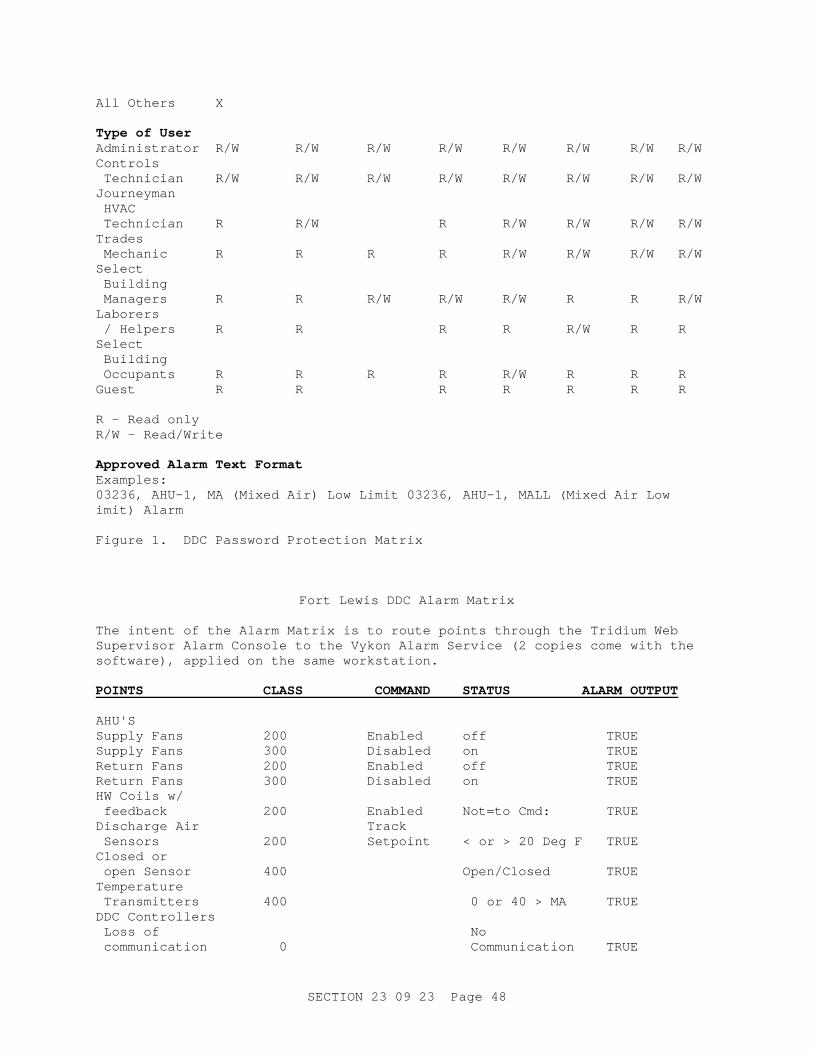
SECTION 23 09 23 Page 48
All Others X Type of User Administrator R/W R/W R/W R/W R/W R/W R/W R/W Controls Technician R/W R/W R/W R/W R/W R/W R/W R/W Journeyman HVAC Technician R R/W R R/W R/W R/W R/W Trades Mechanic R R R R R/W R/W R/W R/W Select Building Managers R R R/W R/W R/W R R R/W Laborers / Helpers R R R R R/W R R Select Building Occupants R R R R R/W R R R Guest R R R R R R R R - Read only R/W - Read/Write Approved Alarm Text Format Examples: 03236, AHU-1, MA (Mixed Air) Low Limit 03236, AHU-1, MALL (Mixed Air Low imit) Alarm Figure 1. DDC Password Protection Matrix
Fort Lewis DDC Alarm Matrix The intent of the Alarm Matrix is to route points through the Tridium Web Supervisor Alarm Console to the Vykon Alarm Service (2 copies come with the software), applied on the same workstation. POINTS CLASS COMMAND STATUS ALARM OUTPUT AHU'S Supply Fans 200 Enabled off TRUE Supply Fans 300 Disabled on TRUE Return Fans 200 Enabled off TRUE Return Fans 300 Disabled on TRUE HW Coils w/ feedback 200 Enabled Not=to Cmd: TRUE Discharge Air Track Sensors 200 Setpoint < or > 20 Deg F TRUE Closed or open Sensor 400 Open/Closed TRUE Temperature Transmitters 400 0 or 40 > MA TRUE DDC Controllers Loss of No communication 0 Communication TRUE
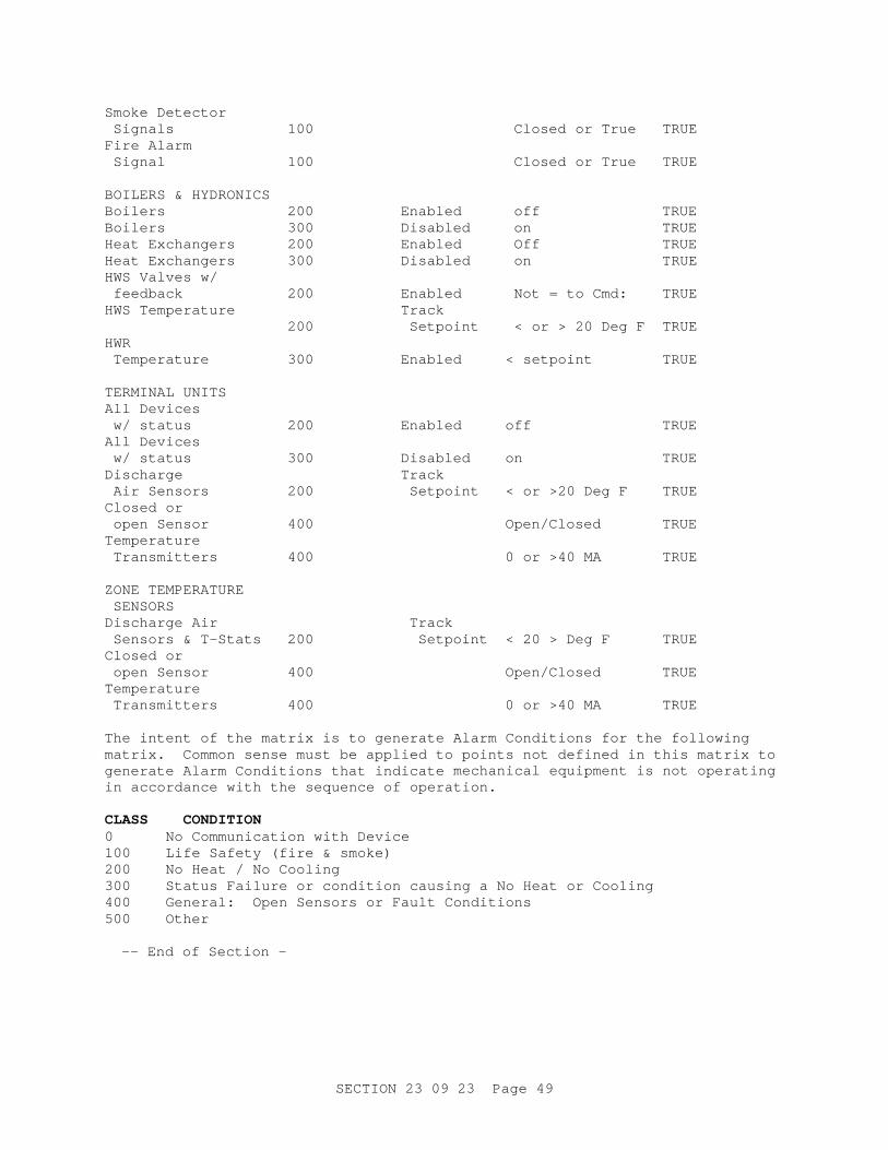
SECTION 23 09 23 Page 49
Smoke Detector Signals 100 Closed or True TRUE Fire Alarm Signal 100 Closed or True TRUE BOILERS & HYDRONICS Boilers 200 Enabled off TRUE Boilers 300 Disabled on TRUE Heat Exchangers 200 Enabled Off TRUE Heat Exchangers 300 Disabled on TRUE HWS Valves w/ feedback 200 Enabled Not = to Cmd: TRUE HWS Temperature Track 200 Setpoint < or > 20 Deg F TRUE HWR Temperature 300 Enabled < setpoint TRUE TERMINAL UNITS All Devices w/ status 200 Enabled off TRUE All Devices w/ status 300 Disabled on TRUE Discharge Track Air Sensors 200 Setpoint < or >20 Deg F TRUE Closed or open Sensor 400 Open/Closed TRUE Temperature Transmitters 400 0 or >40 MA TRUE ZONE TEMPERATURE SENSORS Discharge Air Track Sensors & T-Stats 200 Setpoint < 20 > Deg F TRUE Closed or open Sensor 400 Open/Closed TRUE Temperature Transmitters 400 0 or >40 MA TRUE The intent of the matrix is to generate Alarm Conditions for the following matrix. Common sense must be applied to points not defined in this matrix to generate Alarm Conditions that indicate mechanical equipment is not operating in accordance with the sequence of operation. CLASS CONDITION 0 No Communication with Device 100 Life Safety (fire & smoke) 200 No Heat / No Cooling 300 Status Failure or condition causing a No Heat or Cooling 400 General: Open Sensors or Fault Conditions 500 Other -- End of Section –

Page is intentionally blank
Section 23 81 45 Page 1
SECTION 23 81 45
VARIABLE REFRIGERANT ZONE SYSTEM 08/10
PART 1 GENERAL 1.1 SUMMARY a. The Variable Refrigerant Zone (VRFZ) system is a heat pump air conditioning system that shall have a variable capacity, heat pump heat recovery, and one outdoor unit shall support multiple indoor units. The system is to be capable of simultaneous heating and cooling between indoor units providing heat recovery operation.
1.2 QUALITY ASSURANCE a. The units shall be listed by ETL or UL and bear its label.
b. All wiring shall be in accordance with the National Electrical Code (N.E.C.).
c. The units shall be manufactured in a facility registered to ISO 9001 and ISO14001 which is a set of standards applying to environmental protection set by the International Standard Organization (ISO).
d. The VRFZ system shall be installed by a factory authorized/trained contractor/dealer. Contractor shall be required to submit training certification proof at the request of the Engineer. The mandatory contractor service and install training should be performed by the manufacturer.
1.3 DELIVERY, STORAGE, AND HANDLING Unit shall be stored and handled according to the manufacturer's recommendation.
1.4 WARRANTY The units shall have a manufacturer's warranty for a period of one (1) year from date of installation. The compressor shall have a warranty of six (6) years from date of installation. If, during this period, any part should fail to function properly due to defects in workmanship or material, it shall be replaced or repaired at the discretion of the manufacturer.
PART 2 PRODUCTS 2.1 WALL HUNG INDOOR UNIT 2.1.1 General The indoor unit shall be factory assembled, wired and run tested. Contained within the unit shall be all factory wiring, piping, control circuit board and fan motor. The unit shall have a self-diagnostic function, 3-minute time delay mechanism, an auto restart function, an emergency operation function and a test run switch. Indoor unit and refrigerant pipe will be charged with dry air instead of refrigerant before shipment from factory.
Section 23 81 45 Page 2
2.1.2 Unit Cabinet a. The casing shall have a white finish. b. Multi directional drain and refrigerant piping offering four (4) directions for refrigerant piping and two (2) directions for draining shall be standard. c. There shall be a separate back plate which secures the unit firmly to the wall.
2.1.3 Fan a. The indoor fan shall be an assembly with a line-flow fan direct driven by a single motor. b. The fan shall be statically and dynamically balanced and run on a motor with permanently lubricated bearings. c. A manual adjustable guide vane shall be provided with the ability to change the airflow from side to side (left to right). d. The indoor fan shall consist of two (2) speeds, High and Low. e. Fan motor shall be thermally protected. f. A motorized air sweep flow louver shall provide an automatic change in air flow by directing the air up and down to provide for uniform air distribution.
2.1.4 Filter Return air shall be filtered by means of an easily removable washable filter.
2.1.5 Coil a. The indoor coil shall be of nonferrous construction with smooth plate fins on copper tubing. b. The tubing shall have inner grooves for high efficiency heat exchange. c. All tube joints shall be brazed with phoscopper or silver alloy. d. The coils shall be pressure tested at the factory. e. A condensate pan and drain shall be provided under the coil.
2.1.6 Control a. This unit shall have a wireless controller to perform input functions necessary to operate the system. b. The controller shall consist of a Power On-Off switch, Mode Selector, Temperature Setting, Timer Control, Fan Speed Select and Auto Vane selector.
Section 23 81 45 Page 3
c. The indoor unit shall perform Self-diagnostic Function, Test Run switching and Check Mode switching. d. Temperature changes shall be by 2 °F increments with a range of 65-87 °F. e. The microprocessor located in the indoor unit shall have the capability of sensing return air temperature and indoor coil temperature, receiving and processing commands from the wireless controller, providing emergency operation and controlling the outdoor unit. f. The control voltage between the indoor unit and the outdoor unit shall be 12 to 16 volts, DC. g. The system shall be capable of automatic restart when power is restored after power interruption. h. Control system shall control the continued operation of the air sweeplouvers, as well as provide on/off and system/mode function switching.
2.2 FAN COIL INDOOR UNIT 2.2.1 General The indoor unit shall be factory assembled, wired and run tested. Contained within the unit shall be all factory wiring, piping, electronic modulating linear expansion device, control circuit board and fan motor. The unit shall have a self-diagnostic function, 3-minute time delay mechanism, and an auto restart function. Indoor unit and refrigerant pipes shall be charged with dehydrated air before shipment from the factory.
2.2.2 Unit Cabinet a. The cabinet shall be space saving, low profile, ceiling concealed, ducted. b. The cabinet panel shall have provisions for a field installed mixing box.
2.2.3 Fan a. The indoor unit fan shall be an assembly with one or two fan(s) direct driven by a single motor. b. The indoor fan shall be statically and dynamically balanced to run on a motor with permanently lubricated bearings. c. The indoor fan shall consist of two (2) speeds, High and Low, which are selectable on the room controller. d. The indoor unit shall have a ducted air outlet system and ducted return air system. e. The fan motor shall be thermally protected.
Section 23 81 45 Page 4
2.2.4 Coil a. he indoor coil shall be of nonferrous construction with smooth plate fins on copper tubing. b. The tubing shall have inner grooves for high efficiency heat exchange. c. All tube joints shall be brazed with phos-copper or silver alloy. d. The coils shall be pressure tested at the factory. e. A condensate pan and drain shall be provided under the coil. f. The condensate shall be gravity drained from the fan coil.
2.2.5 Controls This unit shall use controls provided by manufacturer to perform functions necessary to operate the system.
2.3 RECESSED CEILING - INDOOR UNIT 2.3.1 General The indoor unit shall be factory assembled, wired and run tested. Contained within the unit shall be all factory wiring, piping, electronic modulating linear expansion device, control circuit board and fan motor. The unit shall have a self-diagnostic function, 3-minute time delay mechanism, an auto restart function, an emergency operation function ceiling - recessed cassette, and a test run switch. Indoor unit and refrigerant pipes shall be charged with dehydrated air before shipment from the factory.
2.3.2 Unit Cabinet a. The cabinet shall be space saving. b. Grille shall be fixed to bottom of cabinet allowing one, two, three or four way blow, as indicated on plans.
2.3.3 Fan a. The indoor unit fan shall be an assembly with a turbo fan direct driven by a single motor. b. The indoor fan shall be statically and dynamically balanced to run on a motor with permanently lubricated bearings. c. The indoor fan shall consist of four (4) speeds, Low, Mid1, Mid2, and High, which are selectable on the room controller. d. The auto airswing vanes shall be capable of automatically swinging up and own for uniform air distribution.
2.3.4 Coil a. The indoor coil shall be of nonferrous construction with smooth plate fins on copper tubing.
Section 23 81 45 Page 5
b. The tubing shall have inner grooves for high efficiency heat exchange. c. All tube joints shall be brazed with phos-copper or silver alloy. d. The coils shall be pressure tested at the factory. e. A condensate pan and drain shall be provided under the coil. f. The condensate lift mechanism shall be able to raise drain water 33 inches above the condensate pan. g. Return air shall be filtered by means of a long-life washable permanent filter.
2.3.5 Controls This unit shall use controls provided by manufacturer to perform functions necessary to operate the system.
2.4 OUTDOOR UNIT 2.4.1 General The outdoor unit is designed specifically for use with the indoor units. These units are equipped with a circuit board that interfaces to the indoor unit and perform all functions necessary for operation. The unit must have a powder coated finish. The outdoor unit shall be completely factory assembled, piped and wired. Each unit must be run tested at the factory. Unit shall be capable of operating at 0ºF and above. The system will automatically restart operation after a power failure and will not cause any settings to be lost.
2.4.2 Unit Cabinet The casing shall be fabricated of galvanized steel, bonderized and finished with a powder coated baked enamel.
2.4.3 Fan a. The unit shall be furnished with direct drive, variable speed propeller type fans. b. The motor shall have inherent protection, be permanently lubricated bearings and be completely variable speed. c. The fan motor shall be mounted for quiet operation. d. The fan shall be provided with a raised guard to prevent contact with moving parts. e. The outdoor unit shall have vertical discharge airflow.
2.4.4 Coil a. The condenser coil shall be of nonferrous construction with lanced or corrugated plate fins on copper tubing.

Section 23 81 45 Page 6
b. The coil shall be protected with an integral metal guard. c. Refrigerant flow from the outdoor unit shall be controlled by means of an inverter driven compressor.
2.4.5 Compressor a. The compressor shall be one inverter driven, modulating capacity scroll compressor, and one scroll compressor. Variable capacity down to 16% of rated capacity. b. The outdoor unit shall have an accumulator. c. The compressor will be equipped with an internal thermal overload. d. The compressor shall be mounted to avoid the transmission of vibration. e. Provide crankcase heater.
2.4.6 Electrical a. The outdoor unit shall be controlled by the microprocessor located in the indoor unit and outdoor unit. b. The control voltage between the indoor unit and the outdoor unit shall be 12 to 16 volts, DC.
2.4.7 Refrigerant R410A shall be required for outdoor unit systems.
2.5 BRANCH SELECTOR (BS) BOX 2.5.1 General a. BS box shall be factory assembled, wired, and piped. b. BS box must be run tested at the factory. c. BS box must be mounted indoors.
2.5.2 Unit Cabinet a. Units shall have a galvanized steel plate casing. b. Each cabinet shall house multiple refrigeration control valves and a liquid gas separator. c. The cabinet shall contain a tube in tube heat exchanger. d. The unit shall have sound absorption thermal insulation material made of flame and heat resistant foamed polyethylene.
Section 23 81 45 Page 7
2.5.3 Refrigerant Valves a. The unit shall be furnished with 5 electronic expansion valves to control the direction of refrigerant flow. b. The refrigerant connections must be of the braze type.
2.5.4 Condensate Removal The unit shall not require provisions for condensate removal.
2.6 BRANCH CIRCUIT (BC) CONTROLLERS The BC (Branch Circuit) Controllers shall be equipped with a circuit board that interfaces to the manufacturer's controls system and shall perform all functions necessary for operation. The BC Controller shall completely factory assembled, piped and wired. Each unit shall be run tested at the factory.
2.6.1 BC Unit Cabinet a. The casing shall be fabricated of galvanized steel. b. Each cabinet shall house a liquid-gas separator and multiple refrigeration control valves. c. The unit shall house two tube-in-tube heat exchangers.
2.6.2 Refrigerant Valves a. The unit shall be furnished with multiple two position refrigerant valves. b. Each circuit shall have one (54,000 Btu/h or smaller indoor unit section) two-position liquid line valve and a two-position suction line valve. c. Linear electronic expansion valves shall be used to control the variable refrigerant flow.
2.6.3 Integral Drain Pan An integral condensate pan and drain shall be provided.
2.6.4 Electrical a. The BC Controller shall be controlled by integral microprocessors. b. The control circuit between the indoor units and the outdoor unit shall be 12 VDC completed using a 2-conductor, twisted pair shielded cable to provide total integration of the system.
2.7 CONTROLS a. VRFZ authorized dealer shall install VRFZ system controls and wiring. Authorized dealer shall provide and install complete LONWORKS interface
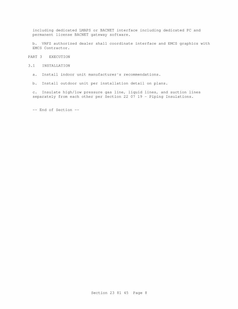
Section 23 81 45 Page 8
including dedicated LMAPS or BACNET interface including dedicated PC and permanent license BACNET gateway software. b. VRFZ authorized dealer shall coordinate interface and EMCS graphics with EMCS Contractor.
PART 3 EXECUTION 3.1 INSTALLATION a. Install indoor unit manufacturer's recommendations. b. Install outdoor unit per installation detail on plans. c. Insulate high/low pressure gas line, liquid lines, and suction lines separately from each other per Section 22 07 19 - Piping Insulations.
-- End of Section --
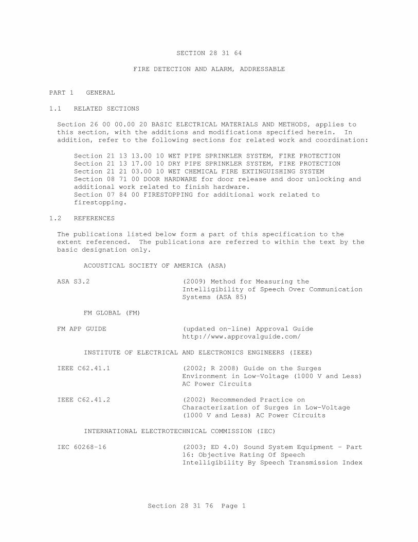
Section 28 31 76 Page 1
SECTION 28 31 64
FIRE DETECTION AND ALARM, ADDRESSABLE
PART 1 GENERAL 1.1 RELATED SECTIONS Section 26 00 00.00 20 BASIC ELECTRICAL MATERIALS AND METHODS, applies to this section, with the additions and modifications specified herein. In addition, refer to the following sections for related work and coordination:
Section 21 13 13.00 10 WET PIPE SPRINKLER SYSTEM, FIRE PROTECTION Section 21 13 17.00 10 DRY PIPE SPRINKLER SYSTEM, FIRE PROTECTION Section 21 21 03.00 10 WET CHEMICAL FIRE EXTINGUISHING SYSTEM Section 08 71 00 DOOR HARDWARE for door release and door unlocking and additional work related to finish hardware. Section 07 84 00 FIRESTOPPING for additional work related to firestopping.
1.2 REFERENCES The publications listed below form a part of this specification to the extent referenced. The publications are referred to within the text by the basic designation only.
ACOUSTICAL SOCIETY OF AMERICA (ASA)
ASA S3.2 (2009) Method for Measuring the
Intelligibility of Speech Over Communication Systems (ASA 85)
FM GLOBAL (FM)
FM APP GUIDE (updated on-line) Approval Guide
http://www.approvalguide.com/
INSTITUTE OF ELECTRICAL AND ELECTRONICS ENGINEERS (IEEE) IEEE C62.41.1 (2002; R 2008) Guide on the Surges
Environment in Low-Voltage (1000 V and Less) AC Power Circuits
IEEE C62.41.2 (2002) Recommended Practice on
Characterization of Surges in Low-Voltage (1000 V and Less) AC Power Circuits
INTERNATIONAL ELECTROTECHNICAL COMMISSION (IEC)
IEC 60268-16 (2003; ED 4.0) Sound System Equipment - Part
16: Objective Rating Of Speech Intelligibility By Speech Transmission Index
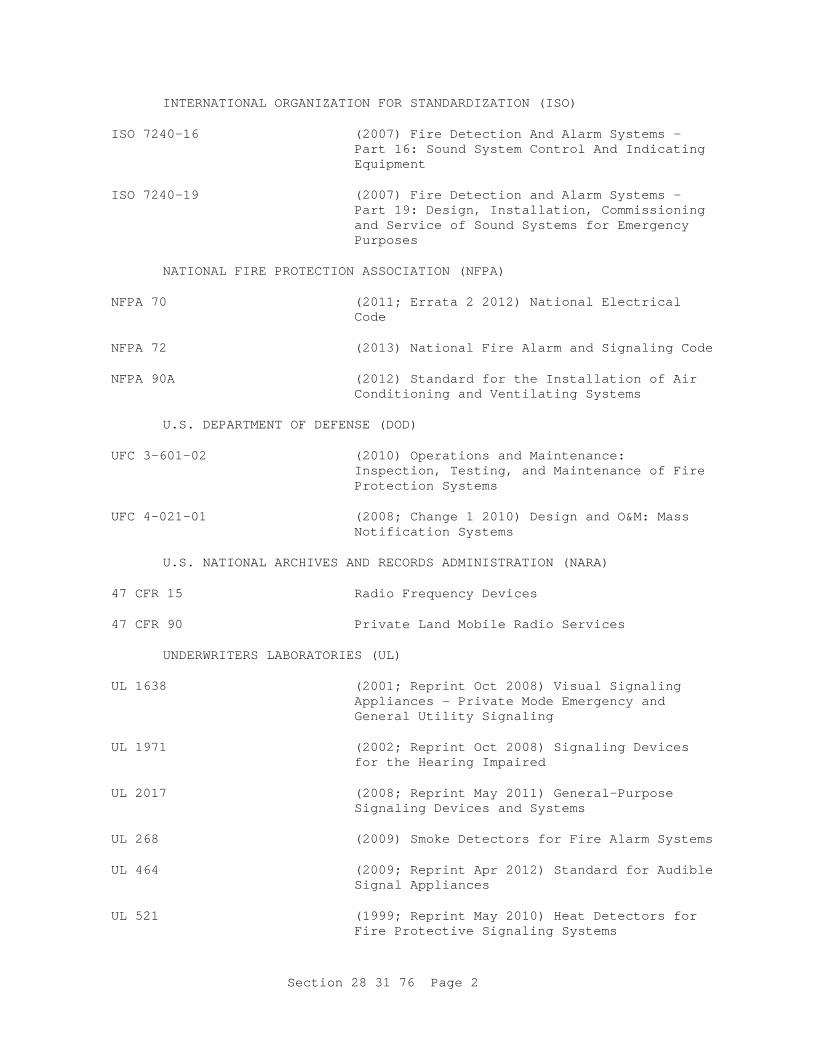
Section 28 31 76 Page 2
INTERNATIONAL ORGANIZATION FOR STANDARDIZATION (ISO) ISO 7240-16 (2007) Fire Detection And Alarm Systems —
Part 16: Sound System Control And Indicating Equipment
ISO 7240-19 (2007) Fire Detection and Alarm Systems —
Part 19: Design, Installation, Commissioning and Service of Sound Systems for Emergency Purposes
NATIONAL FIRE PROTECTION ASSOCIATION (NFPA)
NFPA 70 (2011; Errata 2 2012) National Electrical
Code NFPA 72 (2013) National Fire Alarm and Signaling Code
NFPA 90A (2012) Standard for the Installation of Air
Conditioning and Ventilating Systems
U.S. DEPARTMENT OF DEFENSE (DOD) UFC 3-601-02 (2010) Operations and Maintenance:
Inspection, Testing, and Maintenance of Fire Protection Systems
UFC 4-021-01 (2008; Change 1 2010) Design and O&M: Mass
Notification Systems
U.S. NATIONAL ARCHIVES AND RECORDS ADMINISTRATION (NARA) 47 CFR 15 Radio Frequency Devices
47 CFR 90 Private Land Mobile Radio Services
UNDERWRITERS LABORATORIES (UL)
UL 1638 (2001; Reprint Oct 2008) Visual Signaling
Appliances - Private Mode Emergency and General Utility Signaling
UL 1971 (2002; Reprint Oct 2008) Signaling Devices
for the Hearing Impaired UL 2017 (2008; Reprint May 2011) General-Purpose
Signaling Devices and Systems UL 268 (2009) Smoke Detectors for Fire Alarm Systems
UL 464 (2009; Reprint Apr 2012) Standard for Audible
Signal Appliances UL 521 (1999; Reprint May 2010) Heat Detectors for
Fire Protective Signaling Systems
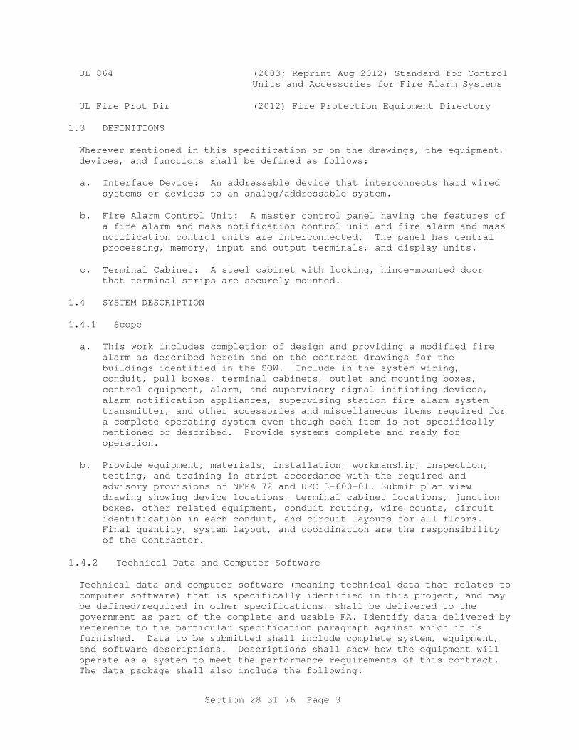
Section 28 31 76 Page 3
UL 864 (2003; Reprint Aug 2012) Standard for Control Units and Accessories for Fire Alarm Systems
UL Fire Prot Dir (2012) Fire Protection Equipment Directory
1.3 DEFINITIONS Wherever mentioned in this specification or on the drawings, the equipment, devices, and functions shall be defined as follows:
a. Interface Device: An addressable device that interconnects hard wired
systems or devices to an analog/addressable system.
b. Fire Alarm Control Unit: A master control panel having the features of a fire alarm and mass notification control unit and fire alarm and mass notification control units are interconnected. The panel has central processing, memory, input and output terminals, and display units.
c. Terminal Cabinet: A steel cabinet with locking, hinge-mounted door
that terminal strips are securely mounted. 1.4 SYSTEM DESCRIPTION 1.4.1 Scope
a. This work includes completion of design and providing a modified fire alarm as described herein and on the contract drawings for the buildings identified in the SOW. Include in the system wiring, conduit, pull boxes, terminal cabinets, outlet and mounting boxes, control equipment, alarm, and supervisory signal initiating devices, alarm notification appliances, supervising station fire alarm system transmitter, and other accessories and miscellaneous items required for a complete operating system even though each item is not specifically mentioned or described. Provide systems complete and ready for operation.
b. Provide equipment, materials, installation, workmanship, inspection,
testing, and training in strict accordance with the required and advisory provisions of NFPA 72 and UFC 3-600-01. Submit plan view drawing showing device locations, terminal cabinet locations, junction boxes, other related equipment, conduit routing, wire counts, circuit identification in each conduit, and circuit layouts for all floors. Final quantity, system layout, and coordination are the responsibility of the Contractor.
1.4.2 Technical Data and Computer Software Technical data and computer software (meaning technical data that relates to computer software) that is specifically identified in this project, and may be defined/required in other specifications, shall be delivered to the government as part of the complete and usable FA. Identify data delivered by reference to the particular specification paragraph against which it is furnished. Data to be submitted shall include complete system, equipment, and software descriptions. Descriptions shall show how the equipment will operate as a system to meet the performance requirements of this contract. The data package shall also include the following:
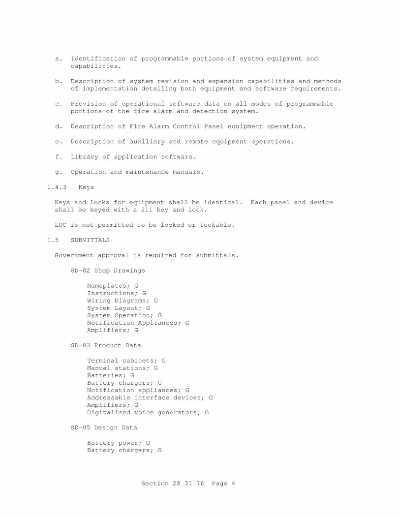
Section 28 31 76 Page 4
a. Identification of programmable portions of system equipment and
capabilities.
b. Description of system revision and expansion capabilities and methods of implementation detailing both equipment and software requirements.
c. Provision of operational software data on all modes of programmable
portions of the fire alarm and detection system.
d. Description of Fire Alarm Control Panel equipment operation.
e. Description of auxiliary and remote equipment operations.
f. Library of application software.
g. Operation and maintenance manuals. 1.4.3 Keys Keys and locks for equipment shall be identical. Each panel and device shall be keyed with a 211 key and lock.
LOC is not permitted to be locked or lockable.
1.5 SUBMITTALS Government approval is required for submittals.
SD-02 Shop Drawings
Nameplates; G Instructions; G Wiring Diagrams; G System Layout; G System Operation; G Notification Appliances; G Amplifiers; G
SD-03 Product Data
Terminal cabinets; G Manual stations; G Batteries; G Battery chargers; G Notification appliances; G Addressable interface devices; G Amplifiers; G Digitalized voice generators; G
SD-05 Design Data
Battery power; G Battery chargers; G
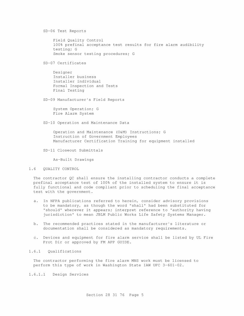
Section 28 31 76 Page 5
SD-06 Test Reports
Field Quality Control 100% prefinal acceptance test results for fire alarm audibility testing; G Smoke sensor testing procedures; G
SD-07 Certificates
Designer Installer business Installer individual Formal Inspection and Tests Final Testing
SD-09 Manufacturer's Field Reports
System Operation; G Fire Alarm System
SD-10 Operation and Maintenance Data
Operation and Maintenance (O&M) Instructions; G Instruction of Government Employees Manufacturer Certification Training for equipment installed
SD-11 Closeout Submittals
As-Built Drawings
1.6 QUALITY CONTROL The contractor QC shall ensure the installing contractor conducts a complete prefinal acceptance test of 100% of the installed system to ensure it is fully functional and code compliant prior to scheduling the final acceptance test with the government.
a. In NFPA publications referred to herein, consider advisory provisions
to be mandatory, as though the word "shall" had been substituted for "should" wherever it appears; interpret reference to "authority having jurisdiction" to mean JBLM Public Works Life Safety Systems Manager.
b. The recommended practices stated in the manufacturer's literature or
documentation shall be considered as mandatory requirements.
c. Devices and equipment for fire alarm service shall be listed by UL Fire Prot Dir or approved by FM APP GUIDE.
1.6.1 Qualifications The contractor performing the fire alarm MNS work must be licensed to perform this type of work in Washington State IAW UFC 3-601-02.
1.6.1.1 Design Services
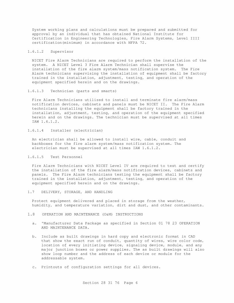
Section 28 31 76 Page 6
System working plans and calculations must be prepared and submitted for approval by an individual that has obtained National Institute for Certification in Engineering Technologies, Fire Alarm Systems, Level IIII certification(minimum) in accordance with NFPA 72.
1.6.1.2 Supervisor NICET Fire Alarm Technicians are required to perform the installation of the system. A NICET Level 3 Fire Alarm Technician shall supervise the installation of the fire alarm system/mass notification system. The Fire Alarm technicians supervising the installation of equipment shall be factory trained in the installation, adjustment, testing, and operation of the equipment specified herein and on the drawings.
1.6.1.3 Technician (parts and smarts) Fire Alarm Technicians utilized to install and terminate fire alarm/mass notification devices, cabinets and panels must be NICET II. The Fire Alarm technicians installing the equipment shall be factory trained in the installation, adjustment, testing, and operation of the equipment specified herein and on the drawings. The technician must be supervised at all times IAW 1.6.1.2.
1.6.1.4 Installer (electrician) An electrician shall be allowed to install wire, cable, conduit and backboxes for the fire alarm system/mass notification system. The electrician must be supervised at all times IAW 1.6.1.2.
1.6.1.5 Test Personnel Fire Alarm Technicians with NICET Level IV are required to test and certify the installation of the fire alarm/mass notification devices, cabinets and panels. The Fire Alarm technicians testing the equipment shall be factory trained in the installation, adjustment, testing, and operation of the equipment specified herein and on the drawings.
1.7 DELIVERY, STORAGE, AND HANDLING Protect equipment delivered and placed in storage from the weather, humidity, and temperature variation, dirt and dust, and other contaminants.
1.8 OPERATION AND MAINTENANCE (O&M) INSTRUCTIONS
a. "Manufacturer Data Package as specified in Section 01 78 23 OPERATION AND MAINTENANCE DATA.
b. Include as built drawings in hard copy and electronic format in CAD
that show the exact run of conduit, quantity of wires, wire color code, location of every initiating device, signaling device, module, and any major junction boxes or power supplies. The as built drawings will also show loop number and the address of each device or module for the addressable system.
c. Printouts of configuration settings for all devices.
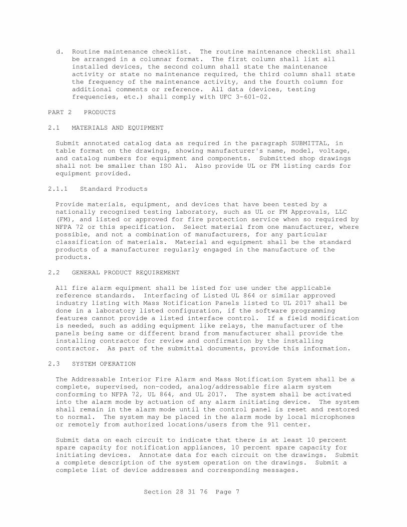
Section 28 31 76 Page 7
d. Routine maintenance checklist. The routine maintenance checklist shall be arranged in a columnar format. The first column shall list all installed devices, the second column shall state the maintenance activity or state no maintenance required, the third column shall state the frequency of the maintenance activity, and the fourth column for additional comments or reference. All data (devices, testing frequencies, etc.) shall comply with UFC 3-601-02.
PART 2 PRODUCTS 2.1 MATERIALS AND EQUIPMENT Submit annotated catalog data as required in the paragraph SUBMITTAL, in table format on the drawings, showing manufacturer's name, model, voltage, and catalog numbers for equipment and components. Submitted shop drawings shall not be smaller than ISO A1. Also provide UL or FM listing cards for equipment provided.
2.1.1 Standard Products Provide materials, equipment, and devices that have been tested by a nationally recognized testing laboratory, such as UL or FM Approvals, LLC (FM), and listed or approved for fire protection service when so required by NFPA 72 or this specification. Select material from one manufacturer, where possible, and not a combination of manufacturers, for any particular classification of materials. Material and equipment shall be the standard products of a manufacturer regularly engaged in the manufacture of the products.
2.2 GENERAL PRODUCT REQUIREMENT All fire alarm equipment shall be listed for use under the applicable reference standards. Interfacing of Listed UL 864 or similar approved industry listing with Mass Notification Panels listed to UL 2017 shall be done in a laboratory listed configuration, if the software programming features cannot provide a listed interface control. If a field modification is needed, such as adding equipment like relays, the manufacturer of the panels being same or different brand from manufacturer shall provide the installing contractor for review and confirmation by the installing contractor. As part of the submittal documents, provide this information.
2.3 SYSTEM OPERATION The Addressable Interior Fire Alarm and Mass Notification System shall be a complete, supervised, non-coded, analog/addressable fire alarm system conforming to NFPA 72, UL 864, and UL 2017. The system shall be activated into the alarm mode by actuation of any alarm initiating device. The system shall remain in the alarm mode until the control panel is reset and restored to normal. The system may be placed in the alarm mode by local microphones or remotely from authorized locations/users from the 911 center.
Submit data on each circuit to indicate that there is at least 10 percent spare capacity for notification appliances, 10 percent spare capacity for initiating devices. Annotate data for each circuit on the drawings. Submit a complete description of the system operation on the drawings. Submit a complete list of device addresses and corresponding messages.
Section 28 31 76 Page 8
2.3.1 Alarm Initiating Devices and Notification Appliances (Visual, Voice, Textural)
a. All wiring circuits including device and appliance wiring shall be class A in conduit.
b. The system shall operate in the alarm mode upon actuation of any alarm
initiating device or a mass notification signal. The system shall remain in the alarm mode until initiating device(s) is/are reset. Audible and visual appliances and systems shall comply with NFPA 72 and as specified herein. Fire alarm system system components requiring power, except for the control panel power supply, shall operate on 24 Volts dc.
2.3.2 Functions and Operating Features The system shall provide the following functions and operating features:
a. The FMCP shall provide power, annunciation, supervision, and control
for the system. Addressable systems shall be microcomputer (microprocessor or microcontroller) based with a minimum word size of eight bits with sufficient memory to perform as specified.
b. Provide signaling line circuits for each floor.
c. Provide signaling line circuits for the network.
d. Provide notification appliance circuits. The visual alarm notification
appliances shall have the flash rates synchronized as required by NFPA 72.
e. Provide electrical supervision of the primary power (AC) supply,
presence of the battery, battery voltage, and placement of system modules within the control panel.
f. Provide an audible and visual trouble signal to activate upon a single
break or open condition, or ground fault (or short circuit for Class "X"). The trouble signal shall also operate upon loss of primary power (AC) supply, absence of a battery supply, low battery voltage, or removal of alarm or supervisory panel modules. Provide a trouble alarm silence feature that shall silence the audible trouble signal, without affecting the visual indicator. After the system returns to normal operating conditions, the trouble signal shall again sound until the trouble is acknowledged. A smoke sensor in the process of being verified for the actual presence of smoke shall not initiate a trouble condition.
g. Alarm, supervisory, and/or trouble signals shall be automatically
transmitted to the D21 in the 911 center.
h. Alarm functions shall override trouble or supervisory functions. Supervisory functions shall override trouble functions.
i. Programmed information shall be stored in non-volatile memory.
Section 28 31 76 Page 9
j. The system shall be capable of operating, supervising, and/or monitoring both addressable and non-addressable alarm and supervisory devices.
k. There shall be no limit, other than maximum system capacity, as to the
number of addressable devices that may be in alarm simultaneously.
l. Where the fire alarm system is responsible for initiating an action in another emergency control device or system, such as an HVAC system, the addressable fire alarm relay shall be in the vicinity of the emergency control device.
m. An alarm signal shall automatically initiate the following functions:
(1) Transmission of an alarm signal to the D21 in the 911 center.
(2) Visual indication of the device operated on the control panel
(FACP). Indication on the FACP shall be by floor, zone or circuit, and type of device.
(3) Continuous actuation of all alarm notification appliances.
(4) Recording of the event via electronically in the history log of
the fire control system unit.
(5) Release of doors held open by electromagnetic devices.
(6) Operation of a duct smoke sensor shall shut down the appropriate air handler in accordance with NFPA 90A in addition to other requirements of this paragraph and as allowed by NFPA 72.
n. A supervisory signal shall automatically initiate the following
functions:
(1) Visual indication of the device operated on the FACP and sound the audible alarm at the respective panel.
(2) Transmission of a supervisory signal to the D21 in the 911
center.
(3) Recording of the event electronically in the history log of the control unit.
o. A trouble condition shall automatically initiate the following
functions:
(1) Visual indication of the system trouble on the FACP, and sound the audible alarm at the respective panel.
(2) Transmission of a trouble signal to the D21 in the 911 center.
(3) Recording of the event in the history log of the control unit.
p. The maximum permissible elapsed time between the actuation of an
initiating device and its indication at the FACP is 10 seconds.
Section 28 31 76 Page 10
q. The maximum elapsed time between the occurrence of the trouble condition and its indication at the FACP is 200 seconds.
2.5 MASS NOTIFICATION SYSTEM FUNCTIONS 2.5.2 Strobes Provide strobes to alert hearing-impaired occupants. Dual strobes are not required. Use a single clear strobe.
2.6 OVERVOLTAGE AND SURGE PROTECTION 2.6.1 Signaling Line Circuit Surge Protection For systems having circuits located outdoors, communications equipment shall be protected against surges induced on any signaling line circuit and shall comply with the applicable requirements of IEEE C62.41.1 and IEEE C62.41.2. Cables and conductors, that serve as communications links, shall have surge protection circuits installed at each end that meet the following waveform(s):
a. A 10 microsecond by 1000 microsecond waveform with a peak voltage of
1500 volts and a peak current of 60 amperes.
b. An 8 microsecond by 20 microsecond waveform with a peak voltage of 1000 volts and a peak current of 500 amperes. Protection shall be provided at the equipment. Additional triple electrode gas surge protectors, rated for the application, shall be installed on each wireline circuit within 3 feet of the building cable entrance. Fuses shall not be used for surge protection.
2.6.2 Sensor Wiring Surge Protection Digital and analog inputs and outputs shall be protected against surges induced by sensor wiring installed outdoors and as shown. The inputs and outputs shall be tested with the following waveforms:
a. A 10 by 1000 microsecond waveform with a peak voltage of 1500 volts and
a peak current of 60 amperes.
b. An 8 by 20 microsecond waveform with a peak voltage of 1000 volts and a peak current of 500 amperes. Fuses shall not be used for surge protection.
2.6.3 FACP The main control panel shall be surge protected from power surges in electrical power source by UL listed surge protection devices.
2.7 ADDRESSABLE INTERFACE DEVICES The system shall be capable of defining any module as an alarm module and report alarm trouble, loss of polling, or as a supervisory module, and reporting supervisory short, supervisory open or loss of polling such as waterflow switches, valve supervisory switches, fire pump monitoring, independent smoke detection systems, relays for output function actuation,
Section 28 31 76 Page 11
etc. The module shall be UL or FM listed as compatible with the control panel. The monitor module shall provide address setting means compatible with the control panel's SLC supervision and store an internal identifying code. Monitor module shall contain an integral LED that flashes each time the monitor module is polled and is visible through the device cover plate. Pull stations with a monitor module in a common backbox are not required to have an LED.
2.8 ADDRESSABLE CONTROL MODULE The control module shall be capable of operating as a relay (dry contact form C) for interfacing the control panel with other systems, and to control door holders or initiate elevator fire service. The module shall be UL or FM listed as compatible with the control panel. The system shall be capable of supervising, audible, visual and dry contact circuits. The control module shall have both an input and output address. The supervision shall detect a short on the supervised circuit and shall prevent power from being applied to the circuit. The control model shall provide address setting means compatible with the control panel's SLC supervision and store an internal identifying code. The control module shall contain an integral LED that flashes each time the control module is polled and is visible through the device cover plate. Control Modules shall be located in environmental areas that reflect the conditions to which they were listed.
2.9 ISOLATION MODULES Provide isolation modules to subdivide each signaling line circuit into groups of not more than 20 addressable devices between adjacent isolation modules. Indicate location of isolator modules clearly on as-built drawings.
2.10 SMOKE SENSORS 2.10.1 Photoelectric Smoke Sensors Provide addressable photoelectric smoke sensors as follows:
a. Provide analog/addressable photoelectric smoke sensors utilizing the
photoelectric light scattering principle for operation in accordance with UL 268. Smoke sensors shall be listed for use with the fire alarm control panel.
b. Provide self-restoring type sensors that do not require any
readjustment after actuation at the FACP to restore them to normal operation. Sensors shall be UL listed as smoke-automatic fire sensors.
c. Components shall be rust and corrosion resistant. Vibration shall have
no effect on the sensor's operation. Protect the detection chamber with a fine mesh metallic screen that prevents the entrance of insects or airborne materials. The screen shall not inhibit the movement of smoke particles into the chamber.
d. Provide twist lock bases with sounder that produces a minimum of 90 dBA
at 10 feet for the sensors. The sensors shall maintain contact with their bases without the use of springs. Provide companion mounting base with screw terminals for each conductor. Terminate field wiring

Section 28 31 76 Page 12
on the screw terminals. The sensor shall have a visual indicator to show actuation.
e. The sensor address shall identify the particular unit, its location
within the system, and its sensitivity setting. Sensors shall be of the low voltage type rated for use on a 24 VDC system.
f. An operator at the control panel shall have the capability to manually
access the following information for each initiating device.
(1) Primary status
(2) Device type
(3) Present average value
(4) Present sensitivity selected
(5) Sensor range (normal, dirty, etc.) 2.10.2 Duct Smoke Sensors Duct-mounted photoelectric smoke detectors shall be furnished and installed where indicated and in accordance with NFPA 90A. Units shall consist of a smoke detector as specified in paragraph Photoelectric Detectors, mounted in a special housing fitted with duct sampling tubes. Detector circuitry shall be mounted in a metallic enclosure exterior to the duct. (It is not permitted to cut the duct insulation to install the duct detector directly on the duct). Detectors shall automatically reset when the smoke condition clears. HVAC systems shall automatically restart when the duct detector no longer senses smoke. Detectors shall be powered from the fire alarm panel. Activation of a duct detector shall not cause a general alarm and shall shut down only the affected air handler.
a. Sampling tubes shall run the full width of the duct. The duct detector
package shall conform to the requirements of NFPA 90A, UL 268A, and shall be UL listed for use in air-handling systems. The control functions, operation, reset, and bypass shall be controlled from the fire alarm control panel.
b. Lights to indicate the operation and alarm condition; and the test and
reset buttons shall be visible and accessible with the unit installed and the cover in place. Remote indicators shall be provided where required by NFPA 72 and UFC 3-600-01 and these shall be provided with test and reset switches.
c. Remote lamps and switches as well as the affected fan units shall be
properly identified in etched plastic placards. Detectors shall provide for control of auxiliary contacts that provide control, interlock, and shutdown functions specified in Section 23 09 23 to LONWORKS DIRECT DIGITAL CONTROL FOR HVAC AND OTHER BUILDING CONTROL SYSTEMS. Auxiliary contacts provide for this function shall be located within 3 feet of the controlled circuit or appliance. The detectors shall be supplied by the fire alarm system manufacturer to ensure complete system compatibility.

Section 28 31 76 Page 13
Duct smoke detector shall not cause a global HVAC shut down on general alarm. Duct smoke detector activation signal a supervisory alarm at the FACP and transmit a supervisory signal to be transmitted to the 911 center. Activation of a duct smoke detector shall cause the shutdown of only the air handler it serves. Duct detectors shall be easily accessible for maintenance and testing.
2.10.3 SMOKE SENSOR TESTING Smoke sensors shall be tested in accordance with NFPA 72 and manufacturer's recommended calibrated test method. Submit smoke sensor testing procedures for approval. In addition to the NFPA 72 requirements, smoke detector sensitivity shall be tested during the preliminary tests.
2.11 HEAT DETECTORS 2.11.1 Heat Detectors The alarm condition shall be determined by comparing sensor valve with the stored values. Heat detector spacing shall be rated in accordance with UL 521. Detectors located in areas subject to moisture, exterior atmospheric conditions, or hazardous locations as defined by NFPA 70 shall be types approved for such locations.
2.11.1.1 Combination Fixed-Temperature and Rate-of-Rise Detectors Detectors shall be designed for outlet box mounting and supported independently of wiring connections. Contacts shall be self-resetting after response to rate-of-rise principle. Under fixed temperature actuation, the detector shall have a permanent external indication that is readily visible. Detector units located in boiler rooms, showers, or other areas subject to abnormal temperature changes shall operate on fixed temperature principle only. The UL 521 test rating for the Rate-of-Rise detectors shall be rated for 50 by 50 feet.
2.11.1.2 Rate Compensating Detectors Detectors shall be outlet box supported independently of wiring connections. Detectors shall be hermetically sealed and automatically resetting. Rate Compensated detectors shall be rated for 50 by 50 feet.
2.11.1.3 Fixed Temperature Detectors Detectors shall be designed for outlet box mounting and supported independently of wiring connections. Detectors shall be designed to detect high heat. The UL 521 test rating for the fixed temperature detectors shall be rated for 50 by 50 feet.
2.11.2 Self-Test Routines Automatic self-test routines shall be performed on each sensor that will functionally check sensor sensitivity electronics and ensure the accuracy of the value being transmitted. Any sensor that fails this test shall indicate a trouble condition with the sensor location at the control panel.
Section 28 31 76 Page 14
2.11.3 Operator Access An operator at the control panel shall have the capability to manually access the following information for each heat sensor:
a. Primary status
b. Device type
c. Present average value
d. Sensor range
2.11.4 Operator Control An operator at the control panel shall have the capability to manually control the following information for each heat sensor:
a. Alarm detection sensitivity values
b. Enable or disable the point/device
c. Control sensors relay driver output
2.13 SECONDARY POWER SUPPLY 2.13.1 Batteries Provide sealed, maintenance-free, sealed lead acid batteries as the source for emergency power to the FMCP. Batteries shall contain suspended electrolyte. The battery system shall be maintained in a fully charged condition by means of a solid state battery charger. Provide an automatic transfer switch to transfer the load to the batteries in the event of the failure of primary power. Battery boxes shall not be mounted more than 48” above finished floor. Batteries equal to or exceeding 50ah shall not be mounted more than 36” above finished floor.
2.13.1.1 Capacity Battery size shall be the greater of the following two capacities.
a. Sufficient capacity to operate the fire alarm system under supervisory
and trouble conditions, including audible trouble signal devices for 72 hours and audible and visual signal devices under alarm conditions for an additional 15 minutes.
b. Sufficient capacity to operate the mass notification for 60 minutes
after loss of AC power. 2.13.1.2 Battery Power Calculations
a. Verify that battery capacity exceeds supervisory and alarm power requirements.
(1) Substantiate the battery calculations for alarm, alert, and
supervisory power requirements. Include ampere-hour requirements

Section 28 31 76 Page 15
for each system component and each panel component, and compliance with UL 864.
(2) Provide complete battery calculations for both the alarm, alert,
and supervisory power requirements. Submit ampere-hour requirements for each system component with the calculations.
(3) A voltage drop calculation to indicate that sufficient voltage is
available for proper operation of the system and all components, at the minimum rated voltage of the system operating on batteries.
b. For battery calculations use the following assumptions: Assume a
starting voltage of 24 VDC for starting the calculations to size the batteries. Calculate the required Amp-Hours for the specified standby time, and then calculate the required Amp-Hours for the specified alarm time. Calculate the nominal battery voltage after operation on batteries for the specified time period. Using this voltage perform a voltage drop calculation for circuit containing device and/or appliances remote from the power sources.
2.13.2 Battery Chargers Provide a solid state, fully automatic, variable charging rate battery charger. The charger shall be capable of providing 120 percent of the connected system load and shall maintain the batteries at full charge. In the event the batteries are fully discharged (20.4 Volts dc), the charger shall recharge the batteries back to 95 percent of full charge within 48 hours after a single discharge cycle as described in paragraph CAPACITY above. Provide pilot light to indicate when batteries are manually placed on a high rate of charge as part of the unit assembly if a high rate switch is provided.
2.14 FIRE ALARM CONTROL UNIT AND MASS NOTIFICATION CONTROL UNIT (FMCP) 2.14.1 Audible Notification System The Audible Notification System shall comply with the requirements of NFPA 72 for Emergency Voice/Alarm Communications System requirements ISO 7240-16, IEC 60268-16, except as specified herein. The system shall be a one-way multi-channel voice notification system incorporating user selectability of a minimum eight distinct sounds for tone signaling, and the incorporation of a voice module for delivery of prerecorded messages. Audible appliances shall produce a temporal code 3 tone for three cycles followed by a voice message that is repeated until the control panel is reset or silenced. Automatic messages shall be broadcast through speakers throughout the building/facility but not in stairs or elevator cabs. A live voice message shall override the automatic audible output through use of a microphone input at the control panel.
a. When using the microphone, live messages shall be broadcast throughout
the facility. The system shall be capable of operating all speakers at the same time. The microprocessor shall actively interrogate circuitry, field wiring, and digital coding necessary for the immediate and accurate rebroadcasting of the stored voice data into the appropriate amplifier input. Loss of operating power, supervisory power, or any other malfunction that could render the digitalized voice
Section 28 31 76 Page 16
module inoperative shall automatically cause the code 3 temporal tone to take over all functions assigned to the failed unit in the event an alarm is activated.
2.14.1.1 Outputs and Operational Modules All outputs and operational modules shall be fully supervised with on-board diagnostics and trouble reporting circuits. Provide form "C" contacts for system alarm and trouble conditions. Provide circuits for operation of auxiliary appliance during trouble conditions.
2.14.2 Memory Provide each control unit with non-volatile memory and logic for all functions. The use of long life batteries, capacitors, or other age-dependent devices shall not be considered as equal to non-volatile processors, PROMS, or EPROMS.
2.14.3 Field Programmability Provide control units and control panels that are fully field programmable for control, initiation, notification, supervisory, and trouble functions of both input and output. The system program configuration shall be menu driven. System changes shall be password protected and shall be accomplished using personal computer based equipment. Any proprietary equipment and proprietary software needed by qualified technicians to implement future changes to the fire alarm system shall be provided as part of this contract to include factory training to use the software and access technical support provided by the factory.
2.14.4 Input/Output Modifications The FMCP shall contain features that allow the bypassing of input devices from the system or the modification of system outputs. These control features shall consist of a panel mounted keypad. Any bypass or modification to the system shall indicate a trouble condition on the FMCP.
2.14.5 Resetting Provide the necessary controls to prevent the resetting of any alarm, supervisory, or trouble signal while the alarm, supervisory or trouble condition on the system still exists.
2.14.6 Instructions Provide a typeset printed or typewritten instruction card mounted behind a Lexan plastic or glass cover in a stainless steel or aluminum frame. Install the frame in a conspicuous location observable from the FACP. The card shall show those steps to be taken by an operator when a signal is received as well as the functional operation of the system under all conditions, normal, alarm, supervisory, and trouble. The instructions shall be approved by the Contracting Officer before being posted.
Section 28 31 76 Page 17
2.14.7 History Logging The control panel shall have the ability to store a minimum of 400 events in a log. These events shall be stored in a battery-protected memory and shall remain in the memory until the memory is downloaded or cleared manually. Resetting of the control panel shall not clear the memory.
2.15 AMPLIFIERS, PREAMPLIFIERS, TONE GENERATORS Any amplifiers, preamplifiers, tone generators, digitalized voice generators, and other hardware necessary for a complete, operational, textual audible circuit conforming to NFPA 72 shall be housed in a remote FMCP, terminal cabinet, or in the FMCP. Submit data to indicate that the amplifiers have sufficient capacity to simultaneously drive all notification speakers at the maximum rating plus 50 percent spare capacity. Annotate data for each circuit on the drawings.
2.15.1 Operation The system shall automatically operate and control all building speakers except those installed in the stairs and within elevator cabs. The speakers in the stairs and elevator cabs shall operate only when the microphone is used to deliver live messages.
2.15.2 Construction Amplifiers shall utilize computer grade solid state components and shall be provided with output protection devices sufficient to protect the amplifier against any transient up to 10 times the highest rated voltage in the system.
2.15.3 Inputs Equip each system with separate inputs for the tone generator, digitalized voice driver and panel mounted microphone. Microphone inputs shall be of the low impedance, balanced line type. Both microphone and tone generator input shall be operational on any amplifier.
2.15.4 Tone Generator The tone generator shall be of the modular, plug-in type with securely attached labels to identify the component as a tone generator and to identify the specific tone it produces. The tone generator shall produce a code 3 temporal tone and shall be constantly repeated until interrupted by either the digitalized voice message, the microphone input, or the alarm silence mode as specified. The tone generator shall be single channel with an automatic backup generator per channel such that failure of the primary tone generator causes the backup generator to automatically take over the functions of the failed unit and also causes transfer of the common trouble relay.
2.15.5 Protection Circuits Each amplifier shall be constantly supervised for any condition that could render the amplifier inoperable at its maximum output. Failure of any component shall cause automatic transfer to a designated backup amplifier,
Section 28 31 76 Page 18
illumination of a visual "amplifier trouble" indicator on the control panel, appropriate logging of the condition on the system printer, and other actions for trouble conditions as specified.
2.16 Devices When any device is mounted externally on brick or exterior surface a rubber gasket shall be used to reduce electrolysis and grounds. Conduit penetrations in the top of exterior mounted devices will not be accepted (to prevent rain water intrusion).
2.17 MANUAL STATIONS Provide metal or plastic, semi-flush mounted, double action, addressable manual stations that are not subject to operation by jarring or vibration. Stations shall be equipped with screw terminals for each conductor. Stations that require the replacement of any portion of the device after activation are not permitted. Stations shall be finished in fire-engine red with molded raised lettering operating instructions of contrasting color. The use of a 211 key shall be required to reset the station. Stations shall have a separate screw terminal for each conductor.
2.18 NOTIFICATION APPLIANCES 2.18.1 Fire Alarm Speakers Audible appliances shall conform to the applicable requirements of UL 464. Appliances shall be connected into notification appliance circuits. Surface mounted audible appliances shall be white or red as required.
a. Speakers shall conform to the applicable requirements of UFC 4-021-01.
Where speakers and strobes are provided in the same location, they may be combined into a single unit. All inputs shall be polarized for compatibility with standard reverse polarity supervision of circuit wiring via the FMCP.
b. Speakers shall utilize screw terminals for termination of all field
wiring. 2.18.2 Visual Notification Appliances Visual notification appliances shall conform to the applicable requirements of UL 1971 and conform to the Architectural Barriers Act (ABA). Fire Alarm Appliances shall have clear high intensity optic lens, xenon flash tubes, and output white light and be marked "ALERT" in red letters. The light pattern shall be disbursed so that it is visible above and below the strobe and from a 90 degree angle on both sides of the strobe. Strobe flash rate shall be 1 flash per second. Where more than two appliances are located in the same room or corridor or field of view, provide synchronized operation. Devices shall use screw terminals for all field wiring.
2.21 WIRING Provide wiring materials under this section as specified in Section 26 20 00 INTERIOR DISTRIBUTION SYSTEM with the additions and modifications specified herein. All wiring shall be installed in conduit.
Section 28 31 76 Page 19
2.21.1 Alarm Wiring The SLC wiring shall be solid copper cable Class A in conduit in accordance with the manufacturer’s requirements. Copper signaling line circuits and initiating device circuit field wiring shall be twisted and shielded solid conductors at a minimum. Visual notification appliance circuit conductors, that contain audible alarm appliances, shall be solid copper No. 14 AWG size conductors class A in conduit at a minimum. Speaker circuits shall be copper twisted and shielded conductors at a minimum. Wire size shall be sufficient to prevent voltage drop problems. Circuits operating at 24 VDC shall not operate at less than the UL listed voltages for the sensors and/or appliances. Power wiring, operating at 120 VAC minimum, shall be a minimum No. 12 AWG solid copper having similar insulation. Power to room smoke detector sounder bases shall be solid copper Class A in conduit, minimum 14 AWG. Acceptable power-limited cables are FPL, FPLR or FPLP as appropriate with red colored covering. Nonpower-limited cables shall comply with NFPA 70.
PART 3 EXECUTION 3.1 INSTALLATION OF FIRE ALARM INITIATING DEVICES AND NOTIFICATION APPLIANCES 3.1.2 Manual Stations Locate manual stations as required by UFC 3-600-01 at each exit. Mount stations so that their operating handles are 4 feet above the finished floor. Mount stations so they are located no farther than feet from the exit door they serve, measured horizontally. Write the point address of the station on the outside of the station using a Sharpie marker. Stick-on labels are not permitted.
3.1.3 Notification Appliance Devices Locate notification appliance devices as required by NFPA 72. Mount assemblies on walls or ceilings as required by NFPA 72 and to meet the intelligibility requirements. If speaker device extends into back-box, the box shall be a minimum size of 4 11/16 x 2 1/8 to prevent wire pinching.
3.1.4 Smoke and Heat Sensors
Locate sensors as required by NFPA 72 and their listings on a 4 inch mounting box. Locate smoke and heat sensors on the ceiling. Install heat sensors not less than 4 inches from a side wall to the near edge. Heat sensors located on the wall shall have the top of the sensor at least 4 inches below the ceiling, but not more than 12 inches below the ceiling. Smoke sensors are permitted to be on the wall no lower than 12 inches from the ceiling with no minimum distance from the ceiling. In raised floor spaces, install the smoke sensors to protect 225 square feet per sensor. Install smoke sensors no closer than 5 feet from air handling supply outlets.
Section 28 31 76 Page 20
3.2 SYSTEM FIELD WIRING 3.2.1 Wiring within Cabinets, Enclosures, and Boxes Provide wiring installed in a neat and workmanlike manner and installed parallel with or at right angles to the sides and back of any box, enclosure, or cabinet. Conductors that are terminated, spliced, or otherwise interrupted in any enclosure, cabinet, mounting, or junction box shall be connected to screw-type terminal blocks. Mark each terminal in accordance with the wiring diagrams of the system. Conductor terminations shall be labeled using 3/16” Kroy brand or similar shrink wrap. The use of wire nuts or similar devices is prohibited. Conform wiring to NFPA 70.
Indicate the following in the wiring diagrams.
a. Point-to-point wiring diagrams showing the points of connection and
terminals used for electrical field connections in the system, including interconnections between the equipment or systems that are supervised or controlled by the system. Diagrams shall show connections from field devices to the FACP and remote fire alarm control units, initiating circuits, switches, relays and terminals.
b. Complete riser diagrams indicating the wiring sequence of devices and
their connections to the control equipment. Include a color code schedule for the wiring. Include floor plans showing the locations of devices and equipment.
3.2.2 Terminal Cabinets Provide a terminal cabinet at the base of any circuit riser, on each floor at each riser, and where indicated on the drawings. Terminal size shall be appropriate for the size of the wiring to be connected. Conductor terminations shall be labeled and a drawing containing conductors, their labels, their circuits, and their interconnection shall be permanently mounted in the terminal cabinet. Minimum size is 8 inches by 8 inches. Only screw-type terminals are permitted.
3.2.3 Alarm Wiring Voltages shall not be mixed in any junction box, housing, or device, except those containing power supplies and control relays. Provide all wiring in electrical metallic. Conceal conduit in finished areas of new construction and wherever practicable in existing construction. The use of flexible conduit not exceeding a 6 foot length shall be permitted in initiating device or notification appliance circuits. Run conduit or tubing (rigid, IMC, EMT, FMC, etc. as permitted by NFPA 72 and NFPA 70) concealed unless specifically indicated otherwise.
3.2.4 Conductor Terminations Labeling of conductors at terminal blocks in terminal cabinets shall be provided at each conductor connection. Each conductor or cable shall have a shrink-wrap label to provide a unique and specific designation. Label shall be computer printed, not hand written. Each terminal cabinet shall contain a laminated drawing that indicates each conductor, its label, circuit, and terminal. The laminated drawing shall be neat, using 12 point lettering
Section 28 31 76 Page 21
minimum size, and mounted within each cabinet, panel, or unit so that it does not interfere with the wiring or terminals. Maintain existing color code scheme where connecting to existing equipment.
3.3 DISCONNECTION AND REMOVAL OF EXISTING SYSTEM To the maximum extent practical and as much as possible maintain existing fire alarm equipment fully operational until the new equipment has been tested and accepted by the Contracting Officer. Once the new system is completed, tested, and accepted by the Government, it shall be placed in service and connected to the station fire alarm system.
a. After acceptance of the new system by the Contracting Officer, remove
existing equipment not connected to the new system, remove unused exposed conduit, and restore damaged surfaces. Remove the material from the site and dispose.
b. Disconnect and remove the existing fire alarm and smoke detection
systems.
c. The government shall be given the option of salvaging any components of the existing fire alarm system, and the contractor shall dispose of the remaining components.
d. Properly dispose of fire alarm outlet and junction boxes, wiring,
conduit, supports, and other such items. 3.4 CONNECTION OF NEW SYSTEM The following new system connections shall be made during the last phase of construction, at the beginning of the preliminary tests. New system connections shall include:
a. Connection of new control modules to existing magnetically held smoke
door (hold-open) devices. Once these connections are made, system shall be left energized and new audio/visual devices deactivated. Report immediately to the Contracting Officer, coordination and field problems resulting from the connection of the above components.
3.5 FIRESTOPPING Provide firestopping for holes at conduit penetrations through floor slabs, fire rated walls, partitions with fire rated doors, corridor walls, and vertical service shafts in accordance with Section 07 84 00 FIRESTOPPING.
3.6 PAINTING Paint exposed electrical, fire alarm conduit, and surface metal raceway to match adjacent finishes in exposed areas. Paint junction boxes red in unfinished areas and conduits and surface metal raceways shall be painted with a 1-inch wide red band every 10 feet in unfinished areas.. Painting shall comply with Section 09 90 00 PAINTS AND COATINGS.
Section 28 31 76 Page 22
3.7 FIELD QUALITY CONTROL 3.7.1 Testing Procedures Provide with the 100% prefinal test result submittal a detailed test procedures that lists all components of the installed system such as initiating devices and circuits, notification appliances and circuits, signaling line devices and circuits, control devices/equipment, batteries, transmitting and receiving equipment, power sources/supply, annunciators, special hazard equipment, emergency communication equipment, interface equipment, Guard's Tour equipment, and transient (surge) suppressors. Test procedures shall include sequence of testing, time estimate for each test, and sample test data forms. The test data forms shall be in a check-off format (pass/fail with space to add applicable test data; similar to the forma in NFPA 72) and shall be used for the preliminary testing and the acceptance testing. The test data forms shall record the test results and shall:
a. Identify the NFPA Class of all Initiating Device Circuits (IDC),
Notification Appliance Circuits (NAC), Voice Notification System Circuits (NAC Audio), and Signaling Line Circuits (SLC).
b. Identify each test required by NFPA 72 Test Methods and required test
herein to be performed on each component, and describe how this test shall be performed.
c. Identify each component and circuit as to type, location within the
facility, and unique identity within the installed system. Provide necessary floor plan sheets showing each component location, test location, and alphanumeric identity.
d. Identify all test equipment and personnel required to perform each test
(including equipment necessary for testing smoke detectors using real smoke).
e. Provide space to identify the date and time of each test. Provide
space to identify the names and signatures of the individuals conducting and witnessing each test.
3.7.2 Tests Stages 3.7.2.1 Preliminary Testing Conduct preliminary tests to ensure that devices and circuits are functioning properly. Tests shall meet the requirements of paragraph entitled "Minimum System Tests." After preliminary testing is complete, provide a letter certifying that the installation is complete and fully operable. The letter shall state that each initiating and indicating device was tested in place and functioned properly. The letter shall also state that panel functions were tested and operated properly. The letter shall include the names and titles of the witnesses to the preliminary tests. The Contractor and an authorized representative from each supplier of equipment shall be in attendance at the preliminary testing to make necessary adjustments.
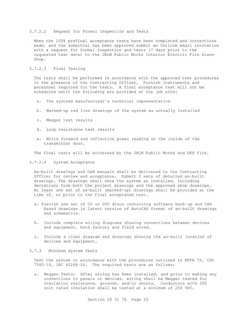
Section 28 31 76 Page 23
3.7.2.2 Request for Formal Inspection and Tests When the 100% prefinal acceptance tests have been completed and corrections made, and the submittal has been approved submit an Outlook email invitation with a request for formal inspection and tests (7 days prior to the requested test date) to the JBLM Public Works Interior Electric Fire Alarm Shop.
3.7.2.3 Final Testing The tests shall be performed in accordance with the approved test procedures in the presence of the Contracting Officer. Furnish instruments and personnel required for the tests. A final acceptance test will not be scheduled until the following are provided at the job site:
a. The systems manufacturer's technical representative
b. Marked-up red line drawings of the system as actually installed
c. Megger test results
d. Loop resistance test results
e. Write forward and reflective power reading on the inside of the
transmitter door. The final tests will be witnessed by the JBLM Public Works and DES fire.
3.7.2.4 System Acceptance As-built drawings and O&M manuals shall be delivered to the Contracting Officer for review and acceptance. Submit 3 sets of detailed as-built drawings. The drawings shall show the system as installed, including deviations from both the project drawings and the approved shop drawings. At least one set of as-built (marked-up) drawings shall be provided at the time of, or prior to the final acceptance test.
a. Furnish one set of CD or DVD discs containing software back-up and CAD
based drawings in latest version of AutoCAD format of as-built drawings and schematics.
b. Include complete wiring diagrams showing connections between devices
and equipment, both factory and field wired.
c. Include a riser diagram and drawings showing the as-built location of devices and equipment.
3.7.3 Minimum System Tests Test the system in accordance with the procedures outlined in NFPA 72, ISO 7240-16, IEC 60268-16. The required tests are as follows:
a. Megger Tests: After wiring has been installed, and prior to making any
connections to panels or devices, wiring shall be Megger tested for insulation resistance, grounds, and/or shorts. Conductors with 300 volt rated insulation shall be tested at a minimum of 250 VDC.
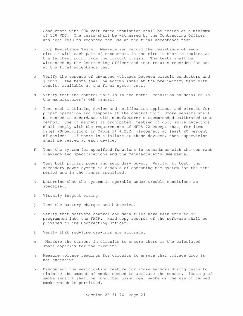
Section 28 31 76 Page 24
Conductors with 600 volt rated insulation shall be tested at a minimum of 500 VDC. The tests shall be witnessed by the Contracting Officer and test results recorded for use at the final acceptance test.
b. Loop Resistance Tests: Measure and record the resistance of each
circuit with each pair of conductors in the circuit short-circuited at the farthest point from the circuit origin. The tests shall be witnessed by the Contracting Officer and test results recorded for use at the final acceptance test.
c. Verify the absence of unwanted voltages between circuit conductors and
ground. The tests shall be accomplished at the preliminary test with results available at the final system test.
d. Verify that the control unit is in the normal condition as detailed in
the manufacturer's O&M manual.
e. Test each initiating device and notification appliance and circuit for proper operation and response at the control unit. Smoke sensors shall be tested in accordance with manufacturer's recommended calibrated test method. Use of magnets is prohibited. Testing of duct smoke detectors shall comply with the requirements of NFPA 72 except that, for item 12(e) (Supervision) in Table 14.4.2.2, disconnect at least 20 percent of devices. If there is a failure at these devices, then supervision shall be tested at each device.
f. Test the system for specified functions in accordance with the contract
drawings and specifications and the manufacturer's O&M manual.
g. Test both primary power and secondary power. Verify, by test, the secondary power system is capable of operating the system for the time period and in the manner specified.
h. Determine that the system is operable under trouble conditions as
specified.
i. Visually inspect wiring.
j. Test the battery charger and batteries.
k. Verify that software control and data files have been entered or programmed into the FACP. Hard copy records of the software shall be provided to the Contracting Officer.
l. Verify that red-line drawings are accurate.
m. Measure the current in circuits to ensure there is the calculated
spare capacity for the circuits.
n. Measure voltage readings for circuits to ensure that voltage drop is not excessive.
o. Disconnect the verification feature for smoke sensors during tests to
minimize the amount of smoke needed to activate the sensor. Testing of smoke sensors shall be conducted using real smoke or the use of canned smoke which is permitted.

Section 28 31 76 Page 25
p. Measure the voltage drop at the most remote appliance (based on wire
length) on each notification appliance circuit. 3.8 INSTRUCTION OF GOVERNMENT EMPLOYEES 3.8.1 Instructor Include in the project the services of an instructor, who has received specific training from the manufacturer for the training of other persons regarding the inspection, testing, and maintenance of the system provided. The instructor shall train the Government employees designated by the Contracting Officer, in the care, adjustment, maintenance, and operation of the fire alarm and fire detection system. Each instructor shall be thoroughly familiar with all parts of this installation. The instructor shall be trained in operating theory as well as in practical O&M work. Submit the instructor’s information and qualifications including the training history.
3.8.1.1 Technical Training Equipment manufacturer or a factory representative shall provide training that shall allow for classroom instruction as well as individual hands on programming, troubleshooting and diagnostics exercises at a location on JBLM. This factory training shall occur within 3 months of system acceptance. Training shall be made available to all available JBLM fire alarm technicians.
3.9 TECHNICAL DATA AND COMPUTER SOFTWARE Provide, in manual format, lesson plans, operating instructions, maintenance procedures, and training data for the training courses. The operations training shall familiarize designated government personnel with proper operation of the installed system. The maintenance training course shall provide the designated government personnel adequate knowledge, test equipment, dongles or software keys, passcodes and access to factory technical support required to diagnose, repair, maintain, and expand functions inherent to the system.
-- End of Section --