contract no. s-89 project no. 514n
TRANSCRIPT

16701 Melford Boulevard Suite 330
Bowie, Maryland 20715 Phone: (240) 206-6810
Fax: (240) 206-6811 GHD Project No. 11123560
Contract Documents North Branch Sewage Pumping Station Upgrade Allegany County Department of Public Works,
Maryland
Contract No. S-89 Project No. 514N
May 2019


North Branch Sewage Pumping Station Upgrade 11123560 TOC-1
TABLE OF CONTENTS PAGE ADVERTISEMENT FOR BIDS ......................................................................................00050-1 thru 00050-2 INSTRUCTIONS TO BIDDERS ..................................................................................00100-1 thru 00100-11 C-451 Qualifications Statement ........................................................................................................ 1 thru 12 BID FORM .....................................................................................................................00410-1 thru 00410-8
Attachments: 00410A - List of Proposed Subcontractors and Manufacturers ............................................. 1 thru 2 00410B - List of References ................................................................................................... 1 thru 1 00410C - Evidence of Authority to do Business in State of Maryland .................................... 1 thru 1 00410D - Contractor’s Maryland License No. ........................................................................ 1 thru 1
C-430 Bid Bond Penal Sum Form ....................................................................................................... 1 thru 2 C-510 Notice of Award ........................................................................................................................ 1 thru 1 00520 Agreement Between Owner and Contractor for Construction Contract (Stipulated Price)....... 1 thru 7
Exhibit A – Certificate of Insurance ............................................................................................... 1 thru 1 C-700 Standard General Conditions of the Construction Contract ................................................... 1 thru 72 00800 Supplementary Conditions ..................................................................................................... 1 thru 24 C-610 Performance Bond ................................................................................................................... 1 thru 4 C-615 Payment Bond .......................................................................................................................... 1 thru 4 C-620 Application for Payment ............................................................................................................ 1 thru 4 C-941 Change Order ........................................................................................................................... 1 thru 1 C-625 Certificate of Substantial Completion ....................................................................................... 1 thru 1 RD 400-6 Compliance Statement ....................................................................................................... 1 thru 2 AD-1048 Certification Regarding Debarment, Suspension, Ineligibility and Voluntary Exclusion – Lower Tier Covered Transactions ................................................................................................. 1 thru 2 RD 1940-Q, Exhibit A-1 Certification for Contracts, Grants, and Loans ............................................. 1 thru 1 Construction Project Sign .................................................................................................................... 1 thru 1 RUS 1780-26, Exhibit I Certificate of Owner’s Attorney and Agency Concurrence ............................ 1 thru 1 RUS 1780-26, Exhibit J Engineer’s Certification of Final Plans and Specifications ............................ 1 thru 1 RUS 1780-35, Exhibit C General (Prime) Contractor's Certification of Compliance with Provisions of the American Iron and Steel Requirements Section 746 Division A Title VII of the Consolidated Appropriations Act of 2017....................................................................... 1 thru 1 RUS 1780-35, Exhibit D Manufacturer's Certification Letter of Compliance with Provisions of the American Iron and Steel Requirements Section 746 Division A Title VII of the Consolidated Appropriations Act of 2017 ...................................................................................... 1 thru 1 DIVISION 1 - GENERAL REQUIREMENTS 01010 Summary of Work ............................................................................................................ 1 thru 8 01019 Contract Considerations .................................................................................................. 1 thru 5
Work Change Directive Field Order
01025 Unit Price Items - Bid Item Descriptions ........................................................................ 1 thru 29 01039 Coordination .................................................................................................................... 1 thru 4 01300 Submittals ........................................................................................................................ 1 thru 4 01310 Progress Schedule .......................................................................................................... 1 thru 7 01380 Construction Documentation ........................................................................................... 1 thru 2 01400 Quality Control ................................................................................................................. 1 thru 3 01420 Special Inspections ......................................................................................................... 1 thru10 01500 Temporary Facilities ........................................................................................................ 1 thru 5 01540 Temporary Pumping ........................................................................................................ 1 thru 4 01600 Materials and Equipment ................................................................................................. 1 thru 2 01640 Equipment - General ................................................................................................ …. 1 thru 09 01660 Testing and Startup ......................................................................................................... 1 thru 6

TABLE OF CONTENTS (continued)
TECHNICAL PROVISIONS (continued) SECTION TITLE PAGE
North Branch Sewage Pumping Station Upgrade 11123560 TOC-2
01700 Record Documents .......................................................................................................... 1 thru 2 DIVISION 2 – SITE WORK 02012 Test Pits ........................................................................................................................... 1 thru 2 02030 Demolition ........................................................................................................................ 1 thru 7 02110 Site Clearing .................................................................................................................... 1 thru 3 02141 Removal of Water ............................................................................................................ 1 thru 3 02161 Sheeting and Bracing ...................................................................................................... 1 thru 4 02205 Protection of Existing Facilities ........................................................................................ 1 thru 3 02222 Excavating ....................................................................................................................... 1 thru 3 02223 Backfilling ......................................................................................................................... 1 thru 8 02225 Trenching ......................................................................................................................... 1 thru 4 02228 Compaction ...................................................................................................................... 1 thru 4 02523 Concrete Walks ............................................................................................................... 1 thru 5 02741 Testing of Process Piping ................................................................................................ 1 thru 4 02831 Fences and Gates ........................................................................................................... 1 thru 4 02980 Site Rehabilitation ............................................................................................................ 1 thru 5 DIVISION 3 - CONCRETE 03001 Concrete……………………………………………………………………………………..1 thru 13 03481 Precast Concrete Vaults…………………………………………………………………….1 thru 6 03600 Grout………………………………………………………………………………………... 1 thru 3 03732 Concrete Coatings……………………………………………………………………………1 thru 5 DIVISION 4 – MASONRY – NOT USED DIVISION 5 - METALS 05500 Miscellaneous Fabrications ............................................................................................. 1 thru 5 05505 Concrete and Masonry Anchors……………………………………………………………....1 thru 4 DIVISION 7 - THERMAL AND MOISTURE PROTECTION 07631 Gutters and Downspouts ................................................................................................. 1 thru 3 07900 Joint Sealers…………………………………………………………………………………….1 thru 5 DIVISION 8 – DOORS – NOT USED DIVISION 9 - PAINTING 09900 Painting .......................................................................................................................... 1 thru 10 DIVISION 10 - SPECIALTIES 10426 Pipe Identification ............................................................................................................ 1 thru 2 10440 Identifying Devices……………………………………………………………………………...1 thru 2 10441 Signs ................................................................................................................................ 1 thru 4

TABLE OF CONTENTS (continued)
TECHNICAL PROVISIONS (continued) SECTION TITLE PAGE
North Branch Sewage Pumping Station Upgrade 11123560 TOC-3
DIVISION 11 - EQUIPMENT 11231 Odor Control Equipment .................................................................................................. 1 thru 3 11300 Pumping Equipment-General .......................................................................................... 1 thru 3 11307 Submersible Pumps ........................................................................................................ 1 thru 9 11330 Channel Grinders…………………………………………………....……………….…….. 1 thru 10 11605 Safety Equipment ............................................................................................................ 1 thru 1 11990 OEM Control Panels………………………………………………………….……………….1 thru 25 DIVISION 12 – FURNISHINGS – NOT USED DIVISION 13 - SPECIAL CONSTRUCTION 13340 Transportable Pre-Engineered Precast Concrete Structures .......................................... 1 thru 9 DIVISION 14 - CONVEYING SYSTEMS 14602 Davit Crane ...................................................................................................................... 1 thru 4 DIVISION 15 - MECHANICAL Section 15 Piping and Appurtenances ............................................................................................. 1 thru 38 15060 Process Piping ............................................................................................................... 1 thru 14 15100 Process Valves ................................................................................................................ 1 thru 7 15140 Supports and Anchors ..................................................................................................... 1 thru 5 15170 Motors .............................................................................................................................. 1 thru 8 15835 Terminal Heat Transfer Units .......................................................................................... 1 thru 3 15870 Power Ventilators ............................................................................................................. 1 thru 3 15890 Ductwork .......................................................................................................................... 1 thru 5 15910 Ductwork Accessories ..................................................................................................... 1 thru 4 15940 Air Outlets and Inlets ....................................................................................................... 1 thru 2 15985 HVAC Controls and Sequence of Operation ................................................................... 1 thru 4 15990 Testing, Adjusting and Balancing .................................................................................... 1 thru 8 DIVISION 16 - ELECTRICAL 16055 Electrical Work ............................................................................................................... 1 thru 25 16056 Electrical Demolition, Removals and Relocation ............................................................. 1 thru 4 16060 Power System Study and Testing .................................................................................... 1 thru 9 16100 Grounding ........................................................................................................................ 1 thru 5 16161 Control Panels and Enclosures ....................................................................................... 1 thru 7 16191 Electrical Supports, Anchors and Fasteners ................................................................... 1 thru 5 16421 Utility Service Entrance .................................................................................................... 1 thru 3 16460 Transformers ................................................................................................................... 1 thru 3 16470 Panelboards ..................................................................................................................... 1 thru 7 16475 Overcurrent Protective Devices ....................................................................................... 1 thru 5 16484 Contactors and Motor Starting Equipment....................................................................... 1 thru 7 16497 Transfer Switches ............................................................................................................ 1 thru 7 16500 Lighting ............................................................................................................................ 1 thru 5 16620 Packaged Engine Generator Systems........................................................................... 1 thru 15

TABLE OF CONTENTS (continued)
TECHNICAL PROVISIONS (continued) SECTION TITLE PAGE
North Branch Sewage Pumping Station Upgrade 11123560 TOC-4
16670 Surge Suppression .......................................................................................................... 1 thru 4 16900 Auxiliary Controls and Relays .......................................................................................... 1 thru 7 16950 Testing and Inspection ..................................................................................................... 1 thru 7 DIVISION 17 - INSTRUMENTATION 17010 Control Systems Integrator ............................................................................................ 1 thru 12 17100 Programmable Logic Controllers (PLC) ......................................................................... 1 thru 15 17101 I/O Table .......................................................................................................................... 1 thru 2 17111 SCADA Monitoring System………………………………………………………………….. 1 thru 5 17190 Control Panels ............................................................................................................... 1 thru 22 17200 Instrumentation-General ............................................................................................... 1 thru 14 17480 Variable Frequency Drives............................................................................................... 1 thru 9 17900 Pump Control Panel Description of Operation……………………………………………..1 thru 31

This document is a MODIFIED version of EJCDC® C-111, Copyright © 2013 by the National Society of Professional Engineers, American Society of Civil Engineers, and American Council of Engineering Companies, or is based in part on excerpts from
EJCDC documents. Those portions of the text that originated in published EJCDC documents remain subject to the copyright.
North Branch Sewage Pumping Station Upgrade 11123560 00050-1 ADVERTISEMENT FOR BIDS
SECTION 00050
ADVERTISEMENT FOR BIDS
Allegany County Department of Public Works Cumberland, Maryland
North Branch Sewage Pumping Station Upgrade
Sealed Bids for the construction of the North Branch Sewage Pumping Station Upgrade, Contract Number S-89, Project Number 541N will be received, by Allegany County, at the office of the County Administrator, Brandon Butler, at The County Office Complex, 701 Kelly Road, Suite 405, Cumberland, Maryland 21502, until 3:00 PM local time on August 20, 2019, at which time the Bids received will be publicly opened and read. The Project consists of constructing upgrades to an existing sewage pumping station including retrofit of an existing sewage wet well to add a grinder and davit crane, retrofit of an existing sewage wet well to add submersible sewage pumps, a davit crane, and a passive odor control system, replacement of an existing dry well with a new precast concrete valve vault, retrofit of an existing pre-engineered precast concrete building, and a new pre-engineered precast concrete building.
Bids will be received for a single prime Contract. Bids shall be on a lump sum and unit price basis as indicated in the Bid Form.
The Issuing Office for the Bidding Documents is: Allegany County Department of Public Works, 701 Kelly Road, Suite 300, Cumberland, Maryland 21502. Prospective Bidders may examine the Bidding Documents at the Issuing Office on Mondays through Fridays between the hours of 8:00 a.m. to 4:00 p.m., and may obtain copies of the Bidding Documents from the Issuing Office as described below.
Bidding Documents also may be examined at the office of the Engineer, GHD Inc., Melford Boulevard, Suite 330, Bowie, Maryland 20715, on Mondays through Fridays between the hours of 9:00 a.m. to 5:00 p.m. Additional plan room locations are available on the bidder’s list on our website – www.gov.allconet.org.
Printed copies of the Bidding Documents may be obtained from the Issuing Office, during the hours indicated above, upon payment of $250.00 for each set in the form of a check or money order payable to the Allegany County Commissioners. If mailing of documents is requested, a separate check or money order payable to the Allegany County Commissioners in the amount of $25.00 per set must be included to cover handling and postage fees. No refunds will be made for the return of Bidding Documents. The date that the Bidding Documents are transmitted by the Issuing Office will be considered the Bidder’s date of receipt of the Bidding Documents. Partial sets of Bidding Documents will not be available from the Issuing Office. Neither Owner nor Engineer will be responsible for full or partial sets of Bidding Documents, including Addenda if any, obtained from sources other than the Issuing Office.
A pre-bid conference will be held at 10:00 AM local time on July 16, 2019 at the County’s office at 701 Kelly Road, Suite 300, Cumberland, MD 21502, followed by a tour of the pumping station. Attendance at the pre-bid conference is mandatory. Bids will not be accepted from Bidders that do not attend the pre-bid conference.
Bid security shall be furnished in accordance with the Instructions to Bidders. Bidder qualifications are identified in the Instructions to Bidders. The Project will be in accordance with the requirements of the United States Department of Agriculture, Rural Utilities Service. Contract Times are identified in the Agreement.

This document is a MODIFIED version of EJCDC® C-111, Copyright © 2013 by the National Society of Professional Engineers, American Society of Civil Engineers, and American Council of Engineering Companies, or is based in part on excerpts from
EJCDC documents. Those portions of the text that originated in published EJCDC documents remain subject to the copyright.
North Branch Sewage Pumping Station Upgrade 11123560 00050-2 ADVERTISEMENT FOR BIDS
Section 746 of Title VII of the Consolidated Appropriations Act of2017 (Division A - Agriculture, Rural Development, Food and Drug Administration, and Related Agencies Appropriations Act, 2017) applies an American Iron and Steel requirement to this project. All iron and steel products used in this project must be produced in the United States. The term "iron and steel products" means the following products made primarily of iron or steel: lined or unlined pipes and fittings, manhole covers and other municipal castings, hydrants, tanks, flanges, pipe clamps and restraints, valves, structural steel, reinforced precast concrete, and construction materials.
Owner: Allegany County
By: Brandon Butler
Title: County Administrator
+ + END OF ADVERTISEMENT FOR BIDS + +

This document is a MODIFIED version of EJCDC® C-200 (Rev. 1), Copyright © 2013 National Society of Professional Engineers,
American Society of Civil Engineers, and American Council of Engineering Companies, or is based in part on excerpts from EJCDC documents. Those portions of the text that originated in published EJCDC documents remain subject to the copyright.
North Branch Sewage Pumping Station Upgrade 11123560 00100-1 INSTRUCTIONS TO BIDDERS
SECTION 00100
INSTRUCTIONS TO BIDDERS
ARTICLE 1 – DEFINED TERMS
1.01 Terms used in these Instructions to Bidders have the meanings indicated in the General Conditions and Supplementary Conditions. Additional terms used in these Instructions to Bidders have the meanings indicated below:
A. Issuing Office – The office from which the Bidding Documents are to be issued.
ARTICLE 2 – COPIES OF BIDDING DOCUMENTS
2.01 Complete sets of the Bidding Documents may be obtained from the Issuing Office in the number and format stated in the advertisement or invitation to bid.
2.02 Complete sets of Bidding Documents shall be used in preparing Bids; neither Owner nor Engineer assumes any responsibility for errors or misinterpretations resulting from the use of incomplete sets of Bidding Documents.
2.03 Owner and Engineer, in making copies of Bidding Documents available on the above terms, do so only for the purpose of obtaining Bids for the Work and do not authorize or confer a license for any other use.
ARTICLE 3 – QUALIFICATIONS OF BIDDERS
3.01 To demonstrate Bidder’s qualifications to perform the Work, Bidder shall submit with its Bid (a) written evidence establishing its qualifications such as financial data, previous experience, and present commitments, and (b) the following additional information:
A. Evidence of Bidder’s authority to do business in the state where the Project is located.
B. Bidder’s state or other contractor license number, if applicable.
3.02 A Bidder’s failure to submit required qualification information within the times indicated may disqualify Bidder from receiving an award of the Contract.
3.03 No requirement in this Article 3 to submit information will prejudice the right of Owner to seek additional pertinent information regarding Bidder’s qualifications.
3.04 Bidder is advised to carefully review those portions of the Bid Form requiring Bidder’s representations and certifications.
3.05 Bidder shall perform a minimum of 50% of the Work, excluding material and equipment purchases, with its own labor force.

This document is a MODIFIED version of EJCDC® C-200 (Rev. 1), Copyright © 2013 National Society of Professional Engineers,
American Society of Civil Engineers, and American Council of Engineering Companies, or is based in part on excerpts from EJCDC documents. Those portions of the text that originated in published EJCDC documents remain subject to the copyright.
North Branch Sewage Pumping Station Upgrade 11123560 00100-2 INSTRUCTIONS TO BIDDERS
ARTICLE 4 – SITE AND OTHER AREAS; EXISTING SITE CONDITIONS; EXAMINATION OF SITE; OWNER’S SAFETY PROGRAM; OTHER WORK AT THE SITE
4.01 Site and Other Areas
A. The Site is identified in the Bidding Documents. By definition, the Site includes rights-of-way, easements, and other lands furnished by Owner for the use of the Contractor. Any additional lands required for temporary construction facilities, construction equipment, or storage of materials and equipment, and any access needed for such additional lands, are to be obtained and paid for by Contractor.
4.02 Existing Site Conditions
A. Subsurface and Physical Conditions; Hazardous Environmental Conditions
1. The Supplementary Conditions identify:
a. those reports known to Owner of explorations and tests of subsurface conditions at or adjacent to the Site.
b. those drawings known to Owner of physical conditions relating to existing surface or subsurface structures at the Site (except Underground Facilities).
c. reports and drawings known to Owner relating to Hazardous Environmental Conditions that have been identified at or adjacent to the Site.
d. Technical Data contained in such reports and drawings.
2. Owner will make copies of reports and drawings referenced above available to any Bidder on request. These reports and drawings are not part of the Contract Documents, but the Technical Data contained therein upon whose accuracy Bidder is entitled to rely, as provided in the General Conditions, has been identified and established in the Supplementary Conditions. Bidder is responsible for any interpretation or conclusion Bidder draws from any Technical Data or any other data, interpretations, opinions, or information contained in such reports or shown or indicated in such drawings.
3. If the Supplementary Conditions do not identify Technical Data, the default definition of Technical Data set forth in Article 1 of the General Conditions will apply.
B. Underground Facilities: Information and data shown or indicated in the Bidding Documents with respect to existing Underground Facilities at or adjacent to the Site are set forth in the Contract Documents and are based upon information and data furnished to Owner and Engineer by owners of such Underground Facilities, including Owner, or others.
C. Adequacy of Data: Provisions concerning responsibilities for the adequacy of data furnished to prospective Bidders with respect to subsurface conditions, other physical conditions, and Underground Facilities, and possible changes in the Bidding Documents due to differing or unanticipated subsurface or physical conditions appear in Paragraphs 5.03, 5.04, and 5.05 of the General Conditions. Provisions concerning responsibilities for the adequacy of data furnished to prospective Bidders with respect to a Hazardous Environmental Condition at the Site, if any, and possible changes in the Contract Documents due to any Hazardous Environmental Condition uncovered or revealed at the Site which was not shown or

This document is a MODIFIED version of EJCDC® C-200 (Rev. 1), Copyright © 2013 National Society of Professional Engineers,
American Society of Civil Engineers, and American Council of Engineering Companies, or is based in part on excerpts from EJCDC documents. Those portions of the text that originated in published EJCDC documents remain subject to the copyright.
North Branch Sewage Pumping Station Upgrade 11123560 00100-3 INSTRUCTIONS TO BIDDERS
indicated in the Drawings or Specifications or identified in the Contract Documents to be within the scope of the Work, appear in Paragraph 5.06 of the General Conditions.
4.03 Site Visit and Testing by Bidders
A. Bidder shall conduct the required Site visit during normal working hours, and shall not disturb any ongoing operations at the Site.
B. Bidder is not required to conduct any subsurface testing, or exhaustive investigations of Site conditions.
C. On request, and to the extent Owner has control over the Site, and schedule permitting, the Owner will provide Bidder access to the Site to conduct such additional examinations, investigations, explorations, tests, and studies as Bidder deems necessary for preparing and submitting a successful Bid. Owner will not have any obligation to grant such access if doing so is not practical because of existing operations, security or safety concerns, or restraints on Owner’s authority regarding the Site.
D. Bidder shall comply with all applicable Laws and Regulations regarding excavation and location of utilities, obtain all permits, and comply with all terms and conditions established by Owner or by property owners or other entities controlling the Site with respect to schedule, access, existing operations, security, liability insurance, and applicable safety programs.
E. Bidder shall fill all holes and clean up and restore the Site to its former condition upon completion of such explorations, investigations, tests, and studies.
4.04 Owner’s Safety Program
A. Site visits and work at the Site may be governed by an Owner safety program. As the General Conditions indicate, if an Owner safety program exists, it will be noted in the Supplementary Conditions.
4.05 Other Work at the Site
A. Reference is made to Article 8 of the Supplementary Conditions for the identification of the general nature of other work of which Owner is aware (if any) that is to be performed at the Site by Owner or others (such as utilities and other prime contractors) and relates to the Work contemplated by these Bidding Documents. If Owner is party to a written contract for such other work, then on request, Owner will provide to each Bidder access to examine such contracts (other than portions thereof related to price and other confidential matters), if any.
ARTICLE 5 – BIDDER’S REPRESENTATIONS
5.01 It is the responsibility of each Bidder before submitting a Bid to:
A. examine and carefully study the Bidding Documents, and any data and reference items identified in the Bidding Documents;
B. visit the Site, conduct a thorough, alert visual examination of the Site and adjacent areas, and become familiar with and satisfy itself as to the general, local, and Site conditions that may affect cost, progress, and performance of the Work;

This document is a MODIFIED version of EJCDC® C-200 (Rev. 1), Copyright © 2013 National Society of Professional Engineers,
American Society of Civil Engineers, and American Council of Engineering Companies, or is based in part on excerpts from EJCDC documents. Those portions of the text that originated in published EJCDC documents remain subject to the copyright.
North Branch Sewage Pumping Station Upgrade 11123560 00100-4 INSTRUCTIONS TO BIDDERS
C. become familiar with and satisfy itself as to all Laws and Regulations that may affect cost, progress, and performance of the Work including but not limited to American Iron and Steel requirements as mandated by Section 746 Division A Title VII of the Consolidated Appropriations Act of2017 which apply to the following products made primarily of iron or steel: lined or unlined pipes and fittings, manhole covers and other municipal castings, hydrants, tanks, flanges, pipe clamps and restraints, valves, structural steel, reinforced precast concrete, and construction materials;
D. carefully study all: (1) reports of explorations and tests of subsurface conditions at or adjacent to the Site and all drawings of physical conditions relating to existing surface or subsurface structures at the Site that have been identified in the Supplementary Conditions, especially with respect to Technical Data in such reports and drawings, and (2) reports and drawings relating to Hazardous Environmental Conditions, if any, at or adjacent to the Site that have been identified in the Supplementary Conditions, especially with respect to Technical Data in such reports and drawings;
E. consider the information known to Bidder itself; information commonly known to contractors doing business in the locality of the Site; information and observations obtained from visits to the Site; the Bidding Documents; and the Site-related reports and drawings identified in the Bidding Documents, with respect to the effect of such information, observations, and documents on (1) the cost, progress, and performance of the Work; (2) the means, methods, techniques, sequences, and procedures of construction to be employed by Bidder; and (3) Bidder’s safety precautions and programs;
F. agree, based on the information and observations referred to in the preceding paragraph, that at the time of submitting its Bid no further examinations, investigations, explorations, tests, studies, or data are necessary for the determination of its Bid for performance of the Work at the price bid and within the times required, and in accordance with the other terms and conditions of the Bidding Documents;
G. become aware of the general nature of the work to be performed by Owner and others at the Site that relates to the Work as indicated in the Bidding Documents;
H. promptly give Engineer written notice of all conflicts, errors, ambiguities, or discrepancies that Bidder discovers in the Bidding Documents and confirm that the written resolution thereof by Engineer is acceptable to Bidder;
I. determine that the Bidding Documents are generally sufficient to indicate and convey understanding of all terms and conditions for the performance and furnishing of the Work; and
J. agree that the submission of a Bid will constitute an incontrovertible representation by Bidder that Bidder has complied with every requirement of this Article, that without exception the Bid and all prices in the Bid are premised upon performing and furnishing the Work required by the Bidding Documents.
ARTICLE 6 – PRE-BID CONFERENCE
6.01 A pre-Bid conference will be held at 10:00 a.m. local time on July 16, 2019, at County’s office at 701 Kelly Road, Suite 300, Cumberland, MD followed by a tour of the pumping station. Representatives of Owner and Engineer will be present to discuss the Project. Bidders are

This document is a MODIFIED version of EJCDC® C-200 (Rev. 1), Copyright © 2013 National Society of Professional Engineers,
American Society of Civil Engineers, and American Council of Engineering Companies, or is based in part on excerpts from EJCDC documents. Those portions of the text that originated in published EJCDC documents remain subject to the copyright.
North Branch Sewage Pumping Station Upgrade 11123560 00100-5 INSTRUCTIONS TO BIDDERS
required to attend and participate in the conference. Engineer will transmit to all prospective Bidders of record such Addenda as Engineer considers necessary in response to questions arising at the conference. Oral statements may not be relied upon and will not be binding or legally effective.
6.02 Bids received from Bidders not in attendance of the mandatory Pre-Bid Conference will remain unopened and be returned.
ARTICLE 7 – INTERPRETATIONS AND ADDENDA
7.01 All questions about the meaning or intent of the Bidding Documents are to be submitted to Robert Geist, P.E. via email at [email protected]. In the subject line, put ‘North Branch Sewage Pumping Station Upgrade Bid Questions’. Questions received by the close of business on August 2, 2019 will be answered via addendum. Interpretations or clarifications considered necessary by Engineer in response to such questions will be issued by Addenda delivered to all parties recorded as having received the Bidding Documents. Questions received less than seven days prior to the date for opening of Bids may not be answered. Only questions answered by Addenda will be binding. Oral and other interpretations or clarifications will be without legal effect.
7.02 Addenda may be issued to clarify, correct, supplement, or change the Bidding Documents.
ARTICLE 8 – BID SECURITY
8.01 A Bid must be accompanied by Bid security made payable to Owner in an amount of 5 percent of Bidder’s maximum Bid price (determined by adding the base bid and all alternates) and in the form of a certified check, bank money order, or a Bid bond (on the form included in the Bidding Documents) issued by a surety meeting the requirements of Paragraphs 6.01 and 6.02 of the General Conditions.
8.02 The Bid security of the apparent Successful Bidder will be retained until Owner awards the contract to such Bidder, and such Bidder has executed the Contract Documents, furnished the required contract security, and met the other conditions of the Notice of Award, whereupon the Bid security will be released. If the Successful Bidder fails to execute and deliver the Contract Documents and furnish the required contract security within 15 days after the Notice of Award, Owner may consider Bidder to be in default, annul the Notice of Award, and the Bid security of that Bidder will be forfeited. Such forfeiture shall be Owner’s exclusive remedy if Bidder defaults.
8.03 The Bid security of other Bidders that Owner believes to have a reasonable chance of receiving the award may be retained by Owner until the earlier of seven days after the Effective Date of the Contract or 61 days after the Bid opening, whereupon Bid security furnished by such Bidders will be released.
8.04 Bid security of other Bidders that Owner believes do not have a reasonable chance of receiving the award will be released within seven days after the Bid opening.

This document is a MODIFIED version of EJCDC® C-200 (Rev. 1), Copyright © 2013 National Society of Professional Engineers,
American Society of Civil Engineers, and American Council of Engineering Companies, or is based in part on excerpts from EJCDC documents. Those portions of the text that originated in published EJCDC documents remain subject to the copyright.
North Branch Sewage Pumping Station Upgrade 11123560 00100-6 INSTRUCTIONS TO BIDDERS
ARTICLE 9 – CONTRACT TIMES
9.01 The number of days within which, or the dates by which, the Work is to be substantially completed, and completed and ready for final payment, are set forth in the Agreement.
ARTICLE 10 – LIQUIDATED DAMAGES
10.01 Provisions for liquidated damages, if any, for failure to timely attain a Milestone, Substantial Completion, or completion of the Work in readiness for final payment, are set forth in the Agreement.
ARTICLE 11 – SUBSTITUTE AND “OR-EQUAL” ITEMS
11.01 The Contract for the Work, if awarded, will be on the basis of materials and equipment specified or described in the Bidding Documents, and those “or-equal” or substitute materials and equipment subsequently approved by Engineer prior to the submittal of Bids and identified by Addendum. No item of material or equipment will be considered by Engineer as an “or-equal” or substitute unless written request for approval has been submitted by Bidder and has been received by Engineer at least 15 days prior to the date for receipt of Bids in the case of a proposed substitute and 5 days prior in the case of a proposed “or-equal.” Each such request shall comply with the requirements of Paragraphs 7.04 and 7.05 of the General Conditions. Each such request shall comply with the requirements of Paragraphs 7.04 and 7.05 of the General Conditions. Each such request shall include Manufacturer's Certification letter for compliance with American Iron and Steel requirements, if applicable. Refer to Manufacturer's Certification Letter provided in these Contract Documents. The burden of proof of the merit of the proposed item is upon Bidder. Engineer’s decision of approval or disapproval of a proposed item will be final. If Engineer approves any such proposed item, such approval will be set forth in an Addendum issued to all prospective Bidders. Bidders shall not rely upon approvals made in any other manner. Substitutes and “or-equal” materials and equipment may be proposed by Contractor in accordance with Paragraphs 7.04 and 7.05 of the General Conditions after the Effective Date of the Contract.
11.02 All prices that Bidder sets forth in its Bid shall be based on the presumption that the Contractor will furnish the materials and equipment specified or described in the Bidding Documents, as supplemented by Addenda. Any assumptions regarding the possibility of post-Bid approvals of “or-equal” or substitution requests are made at Bidder’s sole risk.
11.03 If an award is made, Contractor shall be allowed to submit proposed substitutes and “or-equals” in accordance with the General Conditions.
ARTICLE 12 – SUBCONTRACTORS, SUPPLIERS, AND OTHERS
12.01 Not Used.
12.02 Not Used.
12.03 If required by the bid documents, the apparent Successful Bidder, and any other Bidder so requested, shall within five days after Bid opening, submit to Owner a list of the Subcontractors or Suppliers proposed for the following portions of the Work:

This document is a MODIFIED version of EJCDC® C-200 (Rev. 1), Copyright © 2013 National Society of Professional Engineers,
American Society of Civil Engineers, and American Council of Engineering Companies, or is based in part on excerpts from EJCDC documents. Those portions of the text that originated in published EJCDC documents remain subject to the copyright.
North Branch Sewage Pumping Station Upgrade 11123560 00100-7 INSTRUCTIONS TO BIDDERS
If requested by Owner, such list shall be accompanied by an experience statement with pertinent information regarding similar projects and other evidence of qualification for each such Subcontractor, Supplier, or other individual or entity. If Owner or Engineer, after due investigation, has reasonable objection to any proposed Subcontractor, Supplier, individual, or entity, Owner may, before the Notice of Award is given, request apparent Successful Bidder to submit an acceptable substitute, in which case apparent Successful Bidder shall submit a substitute, Bidder’s Bid price will be increased (or decreased) by the difference in cost occasioned by such substitution, and Owner may consider such price adjustment in evaluating Bids and making the Contract award.
12.04 If apparent Successful Bidder declines to make any such substitution, Owner may award the Contract to the next lowest Bidder that proposes to use acceptable Subcontractors, Suppliers, or other individuals or entities. Declining to make requested substitutions will constitute grounds for forfeiture of the Bid security of any Bidder. Any Subcontractor, Supplier, individual, or entity so listed and against which Owner or Engineer makes no written objection prior to the giving of the Notice of Award will be deemed acceptable to Owner and Engineer subject to subsequent revocation of such acceptance as provided in Paragraph 7.06 of the General Conditions.
12.05 Contractor shall not be required to employ any Subcontractor, Supplier, individual, or entity against whom Contractor has reasonable objection.
12.06 The Contractor shall not award work to Subcontractor(s) in excess of the limits stated in SC 7.06.A.
ARTICLE 13 – PREPARATION OF BID
13.01 The Bid Form is included with the Bidding Documents.
A. All blanks on the Bid Form shall be completed in ink and the Bid Form signed in ink. Erasures or alterations shall be initialed in ink by the person signing the Bid Form. A Bid price shall be indicated for each section, Bid item, alternate, adjustment unit price item, and unit price item listed therein.
B. If the Bid Form expressly indicates that submitting pricing on a specific alternate item is optional, and Bidder elects to not furnish pricing for such optional alternate item, then Bidder may enter the words “No Bid” or “Not Applicable.”
13.02 A Bid by a corporation shall be executed in the corporate name by a corporate officer (whose title must appear under the signature), accompanied by evidence of authority to sign. The corporate address and state of incorporation shall be shown.
13.03 A Bid by a partnership shall be executed in the partnership name and signed by a partner (whose title must appear under the signature), accompanied by evidence of authority to sign. The partnership’s address for receiving notices shall be shown.
13.04 A Bid by a limited liability company shall be executed in the name of the firm by a member or other authorized person and accompanied by evidence of authority to sign. The state of formation of the firm and the firm’s address for receiving notices shall be shown.
13.05 A Bid by an individual shall show the Bidder’s name and address for receiving notices.

This document is a MODIFIED version of EJCDC® C-200 (Rev. 1), Copyright © 2013 National Society of Professional Engineers,
American Society of Civil Engineers, and American Council of Engineering Companies, or is based in part on excerpts from EJCDC documents. Those portions of the text that originated in published EJCDC documents remain subject to the copyright.
North Branch Sewage Pumping Station Upgrade 11123560 00100-8 INSTRUCTIONS TO BIDDERS
13.06 A Bid by a joint venture shall be executed by an authorized representative of each joint venturer in the manner indicated on the Bid Form. The joint venture’s address for receiving notices shall be shown.
13.07 All names shall be printed in ink below the signatures.
13.08 The Bid shall contain an acknowledgment of receipt of all Addenda, the numbers of which shall be filled in on the Bid Form.
13.09 Postal and e-mail addresses and telephone number for communications regarding the Bid shall be shown.
13.10 The Bid shall contain evidence of Bidder’s authority and qualification to do business in the state where the Project is located, or Bidder shall covenant in writing to obtain such authority and qualification prior to award of the Contract and attach such covenant to the Bid. Bidder’s state contractor license number, if any, shall also be shown on the Bid Form.
ARTICLE 14 – BASIS OF BID
14.01 Total Bid Price
A. Bidders shall submit a Bid on a lump sum basis, unit price basis, contingent unit price basis, and allowances as set forth in the Bid Form.
14.02 Unit Price
A. Bidders shall submit a Bid on a unit price basis for each item of Work listed in the unit price section of the Bid Form.
B. The “Bid Price” (sometimes referred to as the extended price) for each unit price Bid item will be the product of the “Estimated Quantity” (which Owner or its representative has set forth in the Bid Form) for the item and the corresponding “Bid Unit Price” offered by the Bidder. The total of all unit price Bid items will be the sum of these “Bid Prices”; such total will be used by Owner for Bid comparison purposes. The final quantities and Contract Price will be determined in accordance with Paragraph 13.03 of the General Conditions.
C. Discrepancies between the multiplication of units of Work and unit prices will be resolved in favor of the unit prices. Discrepancies between the indicated sum of any column of figures and the correct sum thereof will be resolved in favor of the correct sum.
14.03 Allowances
A. For cash allowances the Bid price shall include such amounts as the Bidder deems proper for Contractor's overhead, costs, profit, and other expenses on account of cash allowances, if any, named in the Contract Documents, in accordance with Paragraph 13.02.B of the General Conditions.
ARTICLE 15 – SUBMITTAL OF BID
15.01 With each copy of the Bidding Documents, a Bidder is furnished one separate unbound copy of the Bid Form, and, if required, the Bid Bond Form. The unbound copy of the Bid Form is to be completed and submitted with the Bid security and the other documents required to be submitted under the terms of Article 7 of the Bid Form.

This document is a MODIFIED version of EJCDC® C-200 (Rev. 1), Copyright © 2013 National Society of Professional Engineers,
American Society of Civil Engineers, and American Council of Engineering Companies, or is based in part on excerpts from EJCDC documents. Those portions of the text that originated in published EJCDC documents remain subject to the copyright.
North Branch Sewage Pumping Station Upgrade 11123560 00100-9 INSTRUCTIONS TO BIDDERS
15.02 A Bid shall be received no later than the date and time prescribed and at the place indicated in the advertisement or invitation to bid and shall be enclosed in a plainly marked package with the Project title (and, if applicable, the designated portion of the Project for which the Bid is submitted), the name and address of Bidder, and shall be accompanied by the Bid security and other required documents. If a Bid is sent by mail or other delivery system, the sealed envelope containing the Bid shall be enclosed in a separate package plainly marked on the outside with the notation “BID ENCLOSED.” A mailed Bid shall be addressed to Owner at the address listed in Article 1.01 of the Bid Form.
15.03 Bids received after the date and time prescribed for the opening of bids, or not submitted at the correct location or in the designated manner, will not be accepted and will be returned to the Bidder unopened.
ARTICLE 16 – MODIFICATION AND WITHDRAWAL OF BID
16.01 A Bid may be withdrawn by an appropriate document duly executed in the same manner that a Bid must be executed and delivered to the place where Bids are to be submitted prior to the date and time for the opening of Bids. Upon receipt of such notice, the unopened Bid will be returned to the Bidder.
16.02 If a Bidder wishes to modify its Bid prior to Bid opening, Bidder must withdraw its initial Bid in the manner specified in Paragraph 16.01 and submit a new Bid prior to the date and time for the opening of Bids.
16.03 If within 24 hours after Bids are opened any Bidder files a duly signed written notice with Owner and promptly thereafter demonstrates to the reasonable satisfaction of Owner that there was a material and substantial mistake in the preparation of its Bid, that Bidder may withdraw its Bid, and the Bid security will be returned. Thereafter, if the Work is rebid, that Bidder will be disqualified from further bidding on the Work.
ARTICLE 17 – OPENING OF BIDS
17.01 Bids will be opened at the time and place indicated in the advertisement or invitation to bid and, unless obviously non-responsive, read aloud publicly. An abstract of the amounts of the base Bids and major alternates, if any, will be made available to Bidders after the opening of Bids.
ARTICLE 18 – BIDS TO REMAIN SUBJECT TO ACCEPTANCE
18.01 All Bids will remain subject to acceptance for the period of time stated in the Bid Form, but Owner may, in its sole discretion, release any Bid and return the Bid security prior to the end of this period.
ARTICLE 19 – EVALUATION OF BIDS AND AWARD OF CONTRACT
19.01 Owner reserves the right to reject any or all Bids, including without limitation, nonconforming, nonresponsive, unbalanced, or conditional Bids. Owner will reject the Bid of any Bidder that Owner finds, after reasonable inquiry and evaluation, to not be responsible. If Bidder purports to add terms or conditions to its Bid, takes exception to any provision of the Bidding Documents, or attempts to alter the contents of the Contract Documents for purposes of the Bid, then the

This document is a MODIFIED version of EJCDC® C-200 (Rev. 1), Copyright © 2013 National Society of Professional Engineers,
American Society of Civil Engineers, and American Council of Engineering Companies, or is based in part on excerpts from EJCDC documents. Those portions of the text that originated in published EJCDC documents remain subject to the copyright.
North Branch Sewage Pumping Station Upgrade 11123560 00100-10 INSTRUCTIONS TO BIDDERS
Owner will reject the Bid as nonresponsive; provided that Owner also reserves the right to waive all minor informalities not involving price, time, or changes in the Work.
19.02 If Owner awards the contract for the Work, such award shall be to the responsible Bidder submitting the lowest responsive Bid.
19.03 Evaluation of Bids
A. In evaluating Bids, Owner will consider whether or not the Bids comply with the prescribed requirements, and such alternates, unit prices, and other data, as may be requested in the Bid Form or prior to the Notice of Award.
B. For determination of the apparent low Bidder(s) when sectional bids are submitted, Bids will be compared on the basis of the Total Bid Price listed on the Bid Form.
19.04 In evaluating whether a Bidder is responsible, Owner will consider the qualifications of the Bidder and may consider the qualifications and experience of Subcontractors and Suppliers proposed for those portions of the Work for which the identity of Subcontractors and Suppliers must be submitted as provided in the Bidding Documents.
19.05 Owner may conduct such investigations as Owner deems necessary to establish the responsibility, qualifications, and financial ability of Bidders and any proposed Subcontractors or Suppliers.
ARTICLE 20 – BONDS AND INSURANCE
20.01 Article 6 of the General Conditions, as may be modified by the Supplementary Conditions, sets forth Owner’s requirements as to performance and payment bonds and insurance. When the Successful Bidder delivers the Agreement (executed by Successful Bidder) to Owner, it shall be accompanied by required bonds and insurance documentation.
ARTICLE 21 – SIGNING OF AGREEMENT
21.01 When Owner issues a Notice of Award to the Successful Bidder, it shall be accompanied by the unexecuted counterparts of the Agreement along with the other Contract Documents as identified in the Agreement. Within 15 days thereafter, Successful Bidder shall execute and deliver the required number of counterparts of the Agreement (and any bonds and insurance documentation required to be delivered by the Contract Documents) to Owner. Within ten days thereafter, Owner shall deliver one fully executed counterpart of the Agreement to Successful Bidder, together with printed and electronic copies of the Contract Documents as stated in Paragraph 2.02 of the General Conditions.
ARTICLE 22 – NOT USED
ARTICLE 23 – NOT USED
ARTICLE 24 – FEDERAL REQUIREMENTS
24.01 Federal requirements at Article 19 of the Supplementary Conditions apply to this Contract.

This document is a MODIFIED version of EJCDC® C-200 (Rev. 1), Copyright © 2013 National Society of Professional Engineers,
American Society of Civil Engineers, and American Council of Engineering Companies, or is based in part on excerpts from EJCDC documents. Those portions of the text that originated in published EJCDC documents remain subject to the copyright.
North Branch Sewage Pumping Station Upgrade 11123560 00100-11 INSTRUCTIONS TO BIDDERS
24.02 Section 746 of Title VII of the Consolidated Appropriations Act of2017 (Division A - Agriculture, Rural Development, Food and Drug Administration, and Relate Agencies Appropriations Act, 2017) applies an American Iron and Steel requirement to this project. All iron and steel products used in this project must be produced in the United States. The term "iron and steel products" means the following products made primarily of iron or steel: lined or unlined pipes and fittings, manhole covers and other municipal castings, hydrants, tanks, flanges, pipe clamps and restraints, valves, structural steel, reinforced precast concrete, and construction materials.


EJCDC® C-451, Qualifications Statement. Copyright © 2013 National Society of Professional Engineers, American Council of Engineering Companies,
and American Society of Civil Engineers. All rights reserved. Page 1 of 8
QUALIFICATIONS STATEMENT
THE INFORMATION SUPPLIED IN THIS DOCUMENT IS CONFIDENTIAL TO THE EXTENT PERMITTED BY LAWS AND REGULATIONS
1. SUBMITTED BY:
Official Name of Firm:
Address:
2. SUBMITTED TO:
3. SUBMITTED FOR:
Owner:
Project Name:
TYPE OF WORK:
4. CONTRACTOR'S CONTACT INFORMATION
Contact Person:
Title:
Phone:
Email:

EJCDC® C-451, Qualifications Statement. Copyright © 2013 National Society of Professional Engineers, American Council of Engineering Companies,
and American Society of Civil Engineers. All rights reserved. Page 2 of 8
5. AFFILIATED COMPANIES:
Name:
Address:
6. TYPE OF ORGANIZATION:
Top of Form
SOLE PROPRIETORSHIP
Bottom of Form
Name of Owner:
Doing Business As:
Date of Organization:
PARTNERSHIP
Date of Organization:
Type of Partnership:
Name of General Partner(s):
CORPORATION
State of Organization:
Date of Organization:
Executive Officers:
- President:
- Vice President(s):
- Treasurer:

EJCDC® C-451, Qualifications Statement. Copyright © 2013 National Society of Professional Engineers, American Council of Engineering Companies,
and American Society of Civil Engineers. All rights reserved. Page 3 of 8
- Secretary:
LIMITED LIABILITY COMPANY
State of Organization:
Date of Organization:
Members:
JOINT VENTURE
Sate of Organization:
Date of Organization:
Form of Organization:
Joint Venture Managing Partner
- Name:
- Address:
Joint Venture Managing Partner
- Name:
- Address:
Joint Venture Managing Partner
- Name:
- Address:

EJCDC® C-451, Qualifications Statement. Copyright © 2013 National Society of Professional Engineers, American Council of Engineering Companies,
and American Society of Civil Engineers. All rights reserved. Page 4 of 8
7. LICENSING
Jurisdiction:
Type of License:
License Number:
Jurisdiction:
Type of License:
License Number:
8. CERTIFICATIONS CERTIFIED BY:
Disadvantage Business Enterprise:
Minority Business Enterprise:
Woman Owned Enterprise:
Small Business Enterprise:
Other ( ):
9. BONDING INFORMATION
Bonding Company:
Address:
Bonding Agent:
Address:
Contact Name:
Phone:
Aggregate Bonding Capacity:

EJCDC® C-451, Qualifications Statement. Copyright © 2013 National Society of Professional Engineers, American Council of Engineering Companies,
and American Society of Civil Engineers. All rights reserved. Page 5 of 8
Available Bonding Capacity as of date of this submittal:
10. FINANCIAL INFORMATION
Financial Institution:
Address:
Account Manager:
Phone:
INCLUDE AS AN ATTACHMENT AN AUDITED BALANCE SHEET FOR EACH OF THE LAST 3 YEARS
11. CONSTRUCTION EXPERIENCE:
Current Experience:
List on Schedule A all uncompleted projects currently under contract (If Joint Venture list each participant's projects separately).
Previous Experience:
List on Schedule B all projects completed within the last 5 Years (If Joint Venture list each participant's projects separately).
Has firm listed in Section 1 ever failed to complete a construction contract awarded to it?
YES NO
If YES, attach as an Attachment details including Project Owner's contact information.
Has any Corporate Officer, Partner, Joint Venture participant or Proprietor ever failed to complete a construction contract awarded to them in their name or when acting as a principal of another entity?
YES NO
If YES, attach as an Attachment details including Project Owner's contact information.
Are there any judgments, claims, disputes or litigation pending or outstanding involving the firm listed in Section 1 or any of its officers (or any of its partners if a partnership or any of the individual entities if a joint venture)?
YES NO

EJCDC® C-451, Qualifications Statement. Copyright © 2013 National Society of Professional Engineers, American Council of Engineering Companies,
and American Society of Civil Engineers. All rights reserved. Page 6 of 8
If YES, attach as an Attachment details including Project Owner's contact information.
12. SAFETY PROGRAM:
Name of Contractor's Safety Officer:
Include the following as attachments:
Provide as an Attachment Contractor's (and Contractor's proposed Subcontractors and Suppliers furnishing or performing Work having a value in excess of 10 percent of the total amount of the Bid) OSHA No. 500- Log & Summary of Occupational Injuries & Illnesses for the past 5 years.
Provide as an Attachment Contractor's (and Contractor's proposed Subcontractors and Suppliers furnishing or performing Work having a value in excess of 10 percent of the total amount of the Bid) list of all OSHA Citations & Notifications of Penalty (monetary or other) received within the last 5 years (indicate disposition as applicable) - IF NONE SO STATE.
Provide as an Attachment Contractor's (and Contractor's proposed Subcontractors and Suppliers furnishing or performing Work having a value in excess of 10 percent of the total amount of the Bid) list of all safety citations or violations under any state all received within the last 5 years (indicate disposition as applicable) - IF NONE SO STATE.
Provide the following for the firm listed in Section V (and for each proposed Subcontractor furnishing or performing Work having a value in excess of 10 percent of the total amount of the Bid) the following (attach additional sheets as necessary):
Workers' compensation Experience Modification Rate (EMR) for the last 5 years:
YEAR EMR YEAR EMR YEAR EMR YEAR EMR YEAR EMR
Total Recordable Frequency Rate (TRFR) for the last 5 years:
YEAR TRFR YEAR TRFR YEAR TRFR YEAR TRFR YEAR TRFR

EJCDC® C-451, Qualifications Statement. Copyright © 2013 National Society of Professional Engineers, American Council of Engineering Companies,
and American Society of Civil Engineers. All rights reserved. Page 7 of 8
Total number of man-hours worked for the last 5 Years:
YEAR TOTAL NUMBER OF MAN-HOURS YEAR TOTAL NUMBER OF MAN-HOURS YEAR TOTAL NUMBER OF MAN-HOURS YEAR TOTAL NUMBER OF MAN-HOURS YEAR TOTAL NUMBER OF MAN-HOURS
Provide Contractor's (and Contractor's proposed Subcontractors and Suppliers furnishing or performing Work having a value in excess of 10 percent of the total amount of the Bid) Days Away From Work, Days of Restricted Work Activity or Job Transfer (DART) incidence rate for the particular industry or type of Work to be performed by Contractor and each of Contractor's proposed Subcontractors and Suppliers) for the last 5 years:
YEAR DART YEAR DART YEAR DART YEAR DART YEAR DART
13. EQUIPMENT:
MAJOR EQUIPMENT:
List on Schedule C all pieces of major equipment available for use on Owner's Project.

EJCDC® C-451, Qualifications Statement. Copyright © 2013 National Society of Professional Engineers, American Council of Engineering Companies,
and American Society of Civil Engineers. All rights reserved. Page 8 of 8
I HEREBY CERTIFY THAT THE INFORMATION SUBMITTED HEREWITH, INCLUDING ANY ATTACHMENTS, IS TRUE TO THE BEST OF MY KNOWLEDGE AND BELIEF.
NAME OF ORGANIZATION:
BY:
TITLE:
DATED:
NOTARY ATTEST:
SUBSCRIBED AND SWORN TO BEFORE ME
THIS DAY OF , 20___ NOTARY PUBLIC - STATE OF
MY COMMISSION EXPIRES: REQUIRED ATTACHMENTS
1. Schedule A (Current Experience).
2. Schedule B (Previous Experience).
3. Schedule C (Major Equipment).
4. Audited balance sheet for each of the last 3 years for firm named in Section 1.
5. Evidence of authority for individuals listed in Section 7 to bind organization to an agreement.
6. Resumes of officers and key individuals (including Safety Officer) of firm named in Section 1.
7. Required safety program submittals listed in Section 13.
8. Additional items as pertinent.

EJCDC® C-451, Qualifications Statement. Copyright © 2013 National Society of Professional Engineers, American Council of Engineering Companies,
and American Society of Civil Engineers. All rights reserved. Page 1 of 4
SCHEDULE A CURRENT EXPERIENCE Project Name Owner's Contact Person Design Engineer Contract Date Type of Work Status Cost of Work
Name:
Address:
Telephone:
Name:
Company:
Telephone:
Name:
Address:
Telephone:
Name:
Company:
Telephone:
Name:
Address:
Telephone:
Name:
Company:
Telephone:
Name:
Address:
Telephone:
Name:
Company:
Telephone:
Name:
Address:
Telephone:
Name:
Company:
Telephone:
Name:
Address:
Telephone:
Name:
Company:
Telephone:
Name:
Address:
Telephone:
Name:
Company:
Telephone:

EJCDC® C-451, Qualifications Statement. Copyright © 2013 National Society of Professional Engineers, American Council of Engineering Companies,
and American Society of Civil Engineers. All rights reserved. Page 2 of 4
SCHEDULE B PREVIOUS EXPERIENCE (Include ALL Projects Completed within last 5 years) Project Name Owner's Contact Person Design Engineer Contract Date Type of Work Status Cost of Work
Name:
Address:
Telephone:
Name:
Company:
Telephone:
Name:
Address:
Telephone:
Name:
Company:
Telephone:
Name:
Address:
Telephone:
Name:
Company:
Telephone:
Name:
Address:
Telephone:
Name:
Company:
Telephone:
Name:
Address:
Telephone:
Name:
Company:
Telephone:
Name:
Address:
Telephone:
Name:
Company:
Telephone:
Name:
Address:
Telephone:
Name:
Company:
Telephone:

EJCDC® C-451, Qualifications Statement. Copyright © 2013 National Society of Professional Engineers, American Council of Engineering Companies,
and American Society of Civil Engineers. All rights reserved. Page 3 of 4
SCHEDULE B PREVIOUS EXPERIENCE (Include ALL Projects Completed within last 5 years) Project Name Owner's Contact Person Design Engineer Contract Date Type of Work Status Cost of Work
Name:
Address:
Telephone:
Name:
Company:
Telephone:
Name:
Address:
Telephone:
Name:
Company:
Telephone:
Name:
Address:
Telephone:
Name:
Company:
Telephone:
Name:
Address:
Telephone:
Name:
Company:
Telephone:
Name:
Address:
Telephone:
Name:
Company:
Telephone:
Name:
Address:
Telephone:
Name:
Company:
Telephone:
Name:
Address:
Telephone:
Name:
Company:
Telephone:

EJCDC® C-451, Qualifications Statement. Copyright © 2013 National Society of Professional Engineers, American Council of Engineering Companies,
and American Society of Civil Engineers. All rights reserved. Page 4 of 4
SCHEDULE C - LIST OF MAJOR EQUIPMENT AVAILABLE
ITEM PURCHASE DATE CONDITION ACQUIRED VALUE

This document is a MODIFIED version of EJCDC® C-410, Copyright © 2013 by the National Society of Professional Engineers, American Society of Civil Engineers, and American Council of Engineering Companies, or is based in part on excerpts from
EJCDC documents. Those portions of the text that originated in published EJCDC documents remain subject to the copyright.
North Branch Sewage Pumping Station Upgrade 11123560 00410-1 BID FORM
BID FORM
Project Identification: North Branch Sewage Pumping Station Upgrade
Contract Identification: Allegany County Department of Public Works, Contract No. S-89, Project No. 541N
ARTICLE 1 – BID RECIPIENT
1.01 This Bid is submitted to:
BRANDON BUTLER, COUNTY ADMINISTRATOR ALLEGANY COUNTY SANITARY DISTRICT 701 KELLY ROAD, SUITE 405 CUMBERLAND, MD 21502
1.02 The undersigned Bidder proposes and agrees, if this Bid is accepted, to enter into an Agreement with Owner in the form included in the Bidding Documents to perform all Work as specified or indicated in the Bidding Documents for the prices and within the times indicated in this Bid and in accordance with the other terms and conditions of the Bidding Documents.
ARTICLE 2 – BIDDER’S ACKNOWLEDGEMENTS
2.01 Bidder accepts all of the terms and conditions of the Instructions to Bidders, including without limitation those dealing with the disposition of Bid security. This Bid will remain subject to acceptance for 60 days after the Bid opening, or for such longer period of time that Bidder may agree to in writing upon request of Owner.
ARTICLE 3 – BIDDER’S REPRESENTATIONS
3.01 In submitting this Bid, Bidder represents that:
A. Bidder has examined and carefully studied the Bidding Documents, and any data and reference items identified in the Bidding Documents, and hereby acknowledges receipt of the following Addenda:
Addendum No. Addendum, Date
B. Bidder has visited the Site, conducted a thorough, alert visual examination of the Site and adjacent areas, and become familiar with and satisfied itself as to the general, local, and Site conditions that may affect cost, progress, and performance of the Work.
C. Bidder is familiar with and has satisfied itself as to all Laws and Regulations that may affect cost, progress, and performance of the Work and including all AIS requirements.
D. Bidder has carefully studied all: (1) reports of explorations and tests of subsurface conditions at or adjacent to the Site and all drawings of physical conditions relating to existing surface or subsurface structures at the Site that have been identified in the Supplementary

This document is a MODIFIED version of EJCDC® C-410, Copyright © 2013 by the National Society of Professional Engineers, American Society of Civil Engineers, and American Council of Engineering Companies, or is based in part on excerpts from
EJCDC documents. Those portions of the text that originated in published EJCDC documents remain subject to the copyright.
North Branch Sewage Pumping Station Upgrade 11123560 00410-2 BID FORM
Conditions, especially with respect to Technical Data in such reports and drawings, and (2) reports and drawings relating to Hazardous Environmental Conditions, if any, at or adjacent to the Site that have been identified in the Supplementary Conditions, especially with respect to Technical Data in such reports and drawings.
E. Bidder has considered the information known to Bidder itself; information commonly known to contractors doing business in the locality of the Site; information and observations obtained from visits to the Site; the Bidding Documents; and any Site-related reports and drawings identified in the Bidding Documents, with respect to the effect of such information, observations, and documents on (1) the cost, progress, and performance of the Work; (2) the means, methods, techniques, sequences, and procedures of construction to be employed by Bidder; and (3) Bidder’s safety precautions and programs.
F. Bidder agrees, based on the information and observations referred to in the preceding paragraph, that no further examinations, investigations, explorations, tests, studies, or data are necessary for the determination of this Bid for performance of the Work at the price bid and within the times required, and in accordance with the other terms and conditions of the Bidding Documents.
G. Bidder is aware of the general nature of work to be performed by Owner and others at the Site that relates to the Work as indicated in the Bidding Documents.
H. Bidder has given Engineer written notice of all conflicts, errors, ambiguities, or discrepancies that Bidder has discovered in the Bidding Documents, and confirms that the written resolution thereof by Engineer is acceptable to Bidder.
I. The Bidding Documents are generally sufficient to indicate and convey understanding of all terms and conditions for the performance and furnishing of the Work.
J. The submission of this Bid constitutes an incontrovertible representation by Bidder that Bidder has complied with every requirement of this Article, and that without exception the Bid and all prices in the Bid are premised upon performing and furnishing the Work required by the Bidding Documents.
ARTICLE 4 – BIDDER’S CERTIFICATION
4.01 Bidder certifies that:
A. This Bid is genuine and not made in the interest of or on behalf of any undisclosed individual or entity and is not submitted in conformity with any collusive agreement or rules of any group, association, organization, or corporation;
B. Bidder has not directly or indirectly induced or solicited any other Bidder to submit a false or sham Bid;
C. Bidder has not solicited or induced any individual or entity to refrain from bidding; and
D. Bidder has not engaged in corrupt, fraudulent, collusive, or coercive practices in competing for the Contract. For the purposes of this Paragraph 4.01.D:
1. “corrupt practice” means the offering, giving, receiving, or soliciting of any thing of value likely to influence the action of a public official in the bidding process;
2. “fraudulent practice” means an intentional misrepresentation of facts made (a) to influence the bidding process to the detriment of Owner, (b) to establish bid prices at artificial non-competitive levels, or (c) to deprive Owner of the benefits of free and open competition;

This document is a MODIFIED version of EJCDC® C-410, Copyright © 2013 by the National Society of Professional Engineers, American Society of Civil Engineers, and American Council of Engineering Companies, or is based in part on excerpts from
EJCDC documents. Those portions of the text that originated in published EJCDC documents remain subject to the copyright.
North Branch Sewage Pumping Station Upgrade 11123560 00410-3 BID FORM
3. “collusive practice” means a scheme or arrangement between two or more Bidders, with or without the knowledge of Owner, a purpose of which is to establish bid prices at artificial, non-competitive levels; and
4. “coercive practice” means harming or threatening to harm, directly or indirectly, persons or their property to influence their participation in the bidding process or affect the e execution of the Contract.
ARTICLE 5 – BASIS OF BID
5.01 Bidder will complete the Work in accordance with the Contract Documents for the following prices:
5.02 Schedule A - Lump Sum Bid Items: Lump sum items included all Work in the Contract Documents except items specifically identified as Unit Price Work, Contingent Unit Price Work, and Allowances.
ITEM NO. DESCRIPTION TOTAL PRICE
A-1 All Work in the Contract Documents except items specifically identified as Unit Price Work and Allowances
$
SCHEDULE A SUBTOTAL (in words) ___________________________________________________________________________________
___________________________________________________________________________________
5.03 Schedule B - Unit Price Work: Measurement and payment of Unit Price Work is defined in Section 01025 (Unit Price Items – Bid Item Descriptions).
A. Unit Prices have been computed in accordance with General Conditions Article 13.03.B.
B. Bidders acknowledge that estimated quantities are not guaranteed, and are solely for the purposes of comparison of Bids, and final payment for all Unit Price Work will be based on actual quantities, determined as provided in the Contract Documents.
ITEM NO. DESCRIPTION UNIT ESTIMATED QUANTITY UNIT PRICE BID PRICE
B-1 2-inch Diameter PVC Water Main LF 30 $ $
B-2 6-inch Diameter PVC Water Main LF 300 $ $
B-3 8-inch Diameter PVC Water Main LF 2,369 $ $
B-4 2-inch Diameter Valves EA 1 $ $
B-5 6-inch Diameter Gate Valves EA 1 $ $
B-6 8-inch Diameter Gate Valves EA 6 $ $

This document is a MODIFIED version of EJCDC® C-410, Copyright © 2013 by the National Society of Professional Engineers, American Society of Civil Engineers, and American Council of Engineering Companies, or is based in part on excerpts from
EJCDC documents. Those portions of the text that originated in published EJCDC documents remain subject to the copyright.
North Branch Sewage Pumping Station Upgrade 11123560 00410-4 BID FORM
ITEM NO. DESCRIPTION UNIT ESTIMATED QUANTITY UNIT PRICE BID PRICE
B-7 Fire Hydrant Assembly EA 3 $ $
B-8 2-inch Diameter Frost Free Yard Hydrant
EA 1 $ $
B-9 2-inch Diameter Meter Assembly EA 1 $ $
B-10 Black Top Patch TON 5 $ $
B-11 Test Pits CY 1,000 $ $
Subtotal (Sum of Items B-1 through B-11) $
SCHEDULE B SUBTOTAL (in words) ___________________________________________________________________________________
___________________________________________________________________________________
5.04 Schedule C - Contingent Unit Price Work:
A. Bidder proposes to accept as full payment for the Contingent Unit Price Work proposed herein, the amounts computed under the conditions of the Bidding Documents and based on the following Contingent Unit Price Work amounts, it being expressly understood that the unit prices are independent of the exact quantities involved, and will be performed only at the express written authorization of Engineer.
B. Quantities for Contingent Unit Price Work represent quantities above and beyond that required by the Contract Documents.
C. Unit Prices have been computed in accordance with General Conditions Article 13.03.B.
ITEM NO. DESCRIPTION UNIT ALLOCATED QUANTITY UNIT PRICE BID PRICE
C-1 Test Pits in Paved Areas CY 10 $ $
C-2 Test Pits in Non-Paved Areas CY 10 $ $
C-3 Miscellaneous Excavation and Crusher-Run Aggregate Backfill Below Subgrade
CY 10 $ $
C-4 Miscellaneous Excavation and Select Backfill Below Subgrade
CY 10 $ $

This document is a MODIFIED version of EJCDC® C-410, Copyright © 2013 by the National Society of Professional Engineers, American Society of Civil Engineers, and American Council of Engineering Companies, or is based in part on excerpts from
EJCDC documents. Those portions of the text that originated in published EJCDC documents remain subject to the copyright.
North Branch Sewage Pumping Station Upgrade 11123560 00410-5 BID FORM
ITEM NO. DESCRIPTION UNIT ALLOCATED QUANTITY UNIT PRICE BID PRICE
C-5 Miscellaneous Excavation and Replacement of Topsoil
CY 5 $ $
C-6 Hot Mix Asphalt, 2.5 mm Tons 130 $ $
C-7 Miscellaneous Mix A Concrete CY 5 $ $
C-8 Below Grade 2” Ductbank LF 50 $ $
C-9 Below Grade 4” Ductbank LF 50 $ $
C-10 ¾” Type A-1 Conduit LF 100 $ $
C-11 ¾” Type E-1 Conduit LF 100 $ $
C-12 No. 12 AWG Type THWN Conductors
LF 250 $ $
C-13 No. 14 AWG Type THWN Conductors
LF 250 $ $
C-14 No. 16 TSP Instrumentation Cable LF 100 $ $
Subtotal (Sum of Items C-1 through C-14) $
SCHEDULE C SUBTOTAL (in words) ___________________________________________________________________________________
___________________________________________________________________________________
5.05 Schedule D - Allowances:
A. Bidder agrees to provide the following allowances as part of the Work in accordance with General Conditions Article 13.02.
B. Cash Allowances: Engineer will consult with Contractor for consideration and selection of products and select products in consultation with Owner and transmit decision to Contractor. On notification of selection by Engineer, Contractor shall execute purchase agreement with designated Supplier, arrange for and process Shop Drawings and Samples, arrange for delivery, and promptly inspect products upon delivery for completeness, damage, and defects.
ITEM NO. DESCRIPTION TOTAL PRICE
D-1 New Electrical Service $ 15,000
D-2 SCADA Monitoring System $ 20,000

This document is a MODIFIED version of EJCDC® C-410, Copyright © 2013 by the National Society of Professional Engineers, American Society of Civil Engineers, and American Council of Engineering Companies, or is based in part on excerpts from
EJCDC documents. Those portions of the text that originated in published EJCDC documents remain subject to the copyright.
North Branch Sewage Pumping Station Upgrade 11123560 00410-6 BID FORM
ITEM NO. DESCRIPTION TOTAL PRICE
D-3 Existing Generator Inspection and Repair $10,000
Subtotal (Sum of Items D-1 through D-3) $45,000 SCHEDULE D SUBTOTAL (in words) ___________________________________________________________________________________
___________________________________________________________________________________
5.06 Schedule E: Total Bid Price:
A. Determination of the apparent low Bidder shall be based on the Total Bid Price determined as follows.
B. All mathematical errors will be corrected. In case of a discrepancy between unit prices bid and extended totals, unit prices will govern. In case of discrepancy between the correct sum of individual bid items and the (incorrectly) calculated sum, the correct sum of individual bid items will govern.
ITEM NO. TOTAL PRICE
Schedule A Total (Lump Sum Bid Items) $
Schedule B Total (Unit Price Work) $
Schedule C Total (Contingent Unit Price Work) $
Schedule D Total (Allowances) $45,000.00
Total Bid Price $ TOTAL BID PRICE (in words) ___________________________________________________________________________________
___________________________________________________________________________________
ARTICLE 6 – TIME OF COMPLETION
6.01 Bidder agrees that the Work will be substantially complete and will be completed and ready for final payment in accordance with Paragraph 15.06 of the General Conditions on or before the dates or within the number of calendar days indicated in the Agreement.
6.02 Bidder accepts the provisions of the Agreement as to liquidated damages.
ARTICLE 7 – ATTACHMENTS TO THIS BID
7.01 The following documents are submitted with and made a condition of this Bid:
A. Required Bid security;
B. Statement of Surety’s Intent if check or money order provided for Bid security;
C. List of Proposed Subcontractors;
D. List of Proposed Manufacturers;

This document is a MODIFIED version of EJCDC® C-410, Copyright © 2013 by the National Society of Professional Engineers, American Society of Civil Engineers, and American Council of Engineering Companies, or is based in part on excerpts from
EJCDC documents. Those portions of the text that originated in published EJCDC documents remain subject to the copyright.
North Branch Sewage Pumping Station Upgrade 11123560 00410-7 BID FORM
1. Submersible pumps
2. Channel grinders
3. Pre-engineered buildings
4. Transfer switches
5. Packaged engine generator systems
6. Transfer switches
7. Variable frequency drives
E. List of Project References;
F. Evidence of authority to do business in the state of the Project; or a written covenant to obtain such license within the time for acceptance of Bids;
G. Contractor’s Maryland License Number or Evidence of Bidder’s ability to obtain a Maryland Contractor’s License and a covenant by Bidder to obtain said license within the time for acceptance of Bids;
H. Required Bidder Qualification Statement with supporting data on the form provided; and evidence demonstrating the following:
1. Minimum of three (3) completed wastewater pumping stations with a contract value of $1,500,000 each or greater within the past ten (10) years
I. If Bid amount exceeds $10,000, signed Compliance Statement (RD 400-6). Refer to specific equal opportunity requirements set forth in the Supplementary Conditions;
J. If Bid amount exceeds $25,000, signed Certification Regarding Debarment, Suspensions, Ineligibility and Voluntary Exclusion – Lower Tier Covered Transactions (AD-1048);
K. If Bid amount exceeds $100,000, signed RD Instruction 1940-Q, Exhibit A-1, Certification for Contracts, Grants, and Loans.
L. Manufacturer’s Certification letter of compliance with American Iron and Steel requirements for all proposed equals or substitutes for iron and steel products as provided in these Contract Documents.
ARTICLE 8 – DEFINED TERMS
8.01 The terms used in this Bid with initial capital letters have the meanings stated in the Instructions to Bidders, the General Conditions, and the Supplementary Conditions.

This document is a MODIFIED version of EJCDC® C-410, Copyright © 2013 by the National Society of Professional Engineers, American Society of Civil Engineers, and American Council of Engineering Companies, or is based in part on excerpts from
EJCDC documents. Those portions of the text that originated in published EJCDC documents remain subject to the copyright.
North Branch Sewage Pumping Station Upgrade 11123560 00410-8 BID FORM
ARTICLE 9 – BID SUBMITTAL
BIDDER: [Indicate correct name of bidding entity]
By: [Signature]
[Printed name] (If Bidder is a corporation, a limited liability company, a partnership, or a joint venture, attach evidence of authority to sign.)
Attest: [Signature]
[Printed name]
Title:
Submittal Date:
Address for giving notices:
Telephone Number:
Fax Number:
Contact Name and e-mail address:
Bidder’s License No.:
(where applicable)

North Branch Sewage Pumping Station Upgrade LIST OF PROPOSED SUBCONTRACTORS 11123560 00410A-1 AND MANUFACTURERS
LIST OF PROPOSED SUBCONTRACTORS
Each Bidder shall complete this “List of Proposed Subcontractors” in its entirety for the identified categories of work listed below and for any other subcontract valued at greater than 1% of the total contract amount. Attach additional sheets if necessary to list all subcontractors. Failure to complete this list may render the Bid Form non-responsive. If Bidder intends to self perform the type of work indicated, write “Self Perform” under Subcontractor Name and leave the other columns empty.
Type of Work Subcontractor Name &
Address
Certified Disadvantage
Business Enterprise?
Subcontract Amount
State Contractor
License Number
Mechanical
Electrical
Controls
Civil/Site
Painting
HVAC
Concrete Formwork and Placement
Concrete Reinforcing
Water Main
Paving
Total of other Subcontractors not specifically listed
Total Subcontracted Amount: $___________________
Percent of Total Contract: _________________%

North Branch Sewage Pumping Station Upgrade LIST OF PROPOSED SUBCONTRACTORS 11123560 00410A-2 AND MANUFACTURERS
LIST OF PROPOSED MANUFACTURERS
This document is an Attachment to the Bid Form and is a legally binding part thereof.
Each Bidder shall complete this “List of Proposed Manufacturers” in its entirety. Failure to do so shall render the Bid Form non-responsive and be grounds for its rejection by Owner. The “Supplier” shall be the local vendor representative if different from the Manufacturer. If there is no local vendor representative, the Supplier shall be the Manufacturer.
Name of Manufacturer Supplier Name & Address
Submersible Pumps
Channel Grinders
Transportable Pre-Engineered Precast Concrete Structures
Transfer Switches
Packaged Engine Generator Systems
Variable Frequency Drives

North Branch Sewage Pumping Station Upgrade 11123560 00410B-1 LIST OF REFERENCES
BID FORM ATTACHMENT B
LIST OF REFERENCES


EVIDENCE OF AUTHORITY TO DO BUSINESS IN THE STATE OF MARYLAND OR WRITTEN North Branch Sewage Pumping Station Upgrade COVENANT TO OBTAIN SUCH LICENSE WITHIN 11123560 00410C-1 THE TIMEFOR ACCEPTANCE OF BIDS
EVIDENCE OF AUTHORITY TO DO BUSINESS IN THE STATE OF MARYLAND
OR
WRITTEN COVENANT TO OBTAIN SUCH LICENSE WITHIN THE TIME FOR ACCEPTANCE OF BIDS


CONTRACTOR’S LICENSE NO. OR North Branch Sewage Pumping Station Upgrade EVIDENCE OF BIDDER’S ABILITY TO OBTAIN 11123560 00410D-1 STATE CONTRACTOR’S LICENSE
CONTRACTOR’S MARYLAND LICENSE NO.
OR
EVIDENCE OF BIDDER’S ABILITY TO
OBTAIN MARYLAND STATE CONTRACTOR’S LICENSE


PENAL SUM FORM
EJCDC® C-430, Bid Bond (Penal Sum Form). Published 2013. Prepared by the Engineers Joint Contract Documents Committee.
Page 1 of 2
BID BOND
Any singular reference to Bidder, Surety, Owner or other party shall be considered plural where applicable.
BIDDER (Name and Address): SURETY (Name, and Address of Principal Place of Business): OWNER (Name and Address): BID Bid Due Date: Description (Project Name— Include Location): BOND Bond Number: Date: Penal sum $ (Words) (Figures) Surety and Bidder, intending to be legally bound hereby, subject to the terms set forth below, do each cause this Bid Bond to be duly executed by an authorized officer, agent, or representative. BIDDER SURETY (Seal) (Seal) Bidder’s Name and Corporate Seal Surety’s Name and Corporate Seal By: By: Signature Signature (Attach Power of Attorney) Print Name Print Name Title Title Attest: Attest: Signature Signature Title Title Note: Addresses are to be used for giving any required notice. Provide execution by any additional parties, such as joint venturers, if necessary.

PENAL SUM FORM
EJCDC® C-430, Bid Bond (Penal Sum Form). Published 2013. Prepared by the Engineers Joint Contract Documents Committee.
Page 2 of 2
1. Bidder and Surety, jointly and severally, bind themselves, their heirs, executors, administrators, successors, and assigns to pay to Owner upon default of Bidder the penal sum set forth on the face of this Bond. Payment of the penal sum is the extent of Bidder’s and Surety’s liability. Recovery of such penal sum under the terms of this Bond shall be Owner’s sole and exclusive remedy upon default of Bidder.
2. Default of Bidder shall occur upon the failure of Bidder to deliver within the time required by the Bidding Documents (or any extension thereof agreed to in writing by Owner) the executed Agreement required by the Bidding Documents and any performance and payment bonds required by the Bidding Documents.
3. This obligation shall be null and void if:
3.1 Owner accepts Bidder’s Bid and Bidder delivers within the time required by the Bidding Documents (or any extension thereof agreed to in writing by Owner) the executed Agreement required by the Bidding Documents and any performance and payment bonds required by the Bidding Documents, or
3.2 All Bids are rejected by Owner, or
3.3 Owner fails to issue a Notice of Award to Bidder within the time specified in the Bidding Documents (or any extension thereof agreed to in writing by Bidder and, if applicable, consented to by Surety when required by Paragraph 5 hereof).
4. Payment under this Bond will be due and payable upon default of Bidder and within 30 calendar days after receipt by Bidder and Surety of written notice of default from Owner, which notice will be given with reasonable promptness, identifying this Bond and the Project and including a statement of the amount due.
5. Surety waives notice of any and all defenses based on or arising out of any time extension to issue Notice of Award agreed to in writing by Owner and Bidder, provided that the total time for issuing Notice of Award including extensions shall not in the aggregate exceed 120 days from the Bid due date without Surety’s written consent.
6. No suit or action shall be commenced under this Bond prior to 30 calendar days after the notice of default required in Paragraph 4 above is received by Bidder and Surety and in no case later than one year after the Bid due date.
7. Any suit or action under this Bond shall be commenced only in a court of competent jurisdiction located in the state in which the Project is located.
8. Notices required hereunder shall be in writing and sent to Bidder and Surety at their respective addresses shown on the face of this Bond. Such notices may be sent by personal delivery, commercial courier, or by United States Registered or Certified Mail, return receipt requested, postage pre-paid, and shall be deemed to be effective upon receipt by the party concerned.
9. Surety shall cause to be attached to this Bond a current and effective Power of Attorney evidencing the authority of the officer, agent, or representative who executed this Bond on behalf of Surety to execute, seal, and deliver such Bond and bind the Surety thereby.
10. This Bond is intended to conform to all applicable statutory requirements. Any applicable requirement of any applicable statute that has been omitted from this Bond shall be deemed to be included herein as if set forth at length. If any provision of this Bond conflicts with any applicable statute, then the provision of said statute shall govern and the remainder of this Bond that is not in conflict therewith shall continue in full force and effect.
11. The term “Bid” as used herein includes a Bid, offer, or proposal as applicable.

EJCDC® C-510 (Rev. 1), Notice of Award. Prepared and published 2013 by the Engineers Joint Contract Documents Committee.
Page 1 of 1
NOTICE OF AWARD
Date of Issuance:
Owner: Owner's Contract No.:
Engineer: Engineer's Project No.:
Project: Contract Name:
Bidder:
Bidder’s Address:
TO BIDDER:
You are notified that Owner has accepted your Bid dated [_________________________________] for the above Contract, and that you are the Successful Bidder and are awarded a Contract for:
_____________________________________________________________________________________ . [describe Work, alternates, or sections of Work awarded]
The Contract Price of the awarded Contract is: $ _______ [note if subject to unit prices, or cost-plus]
[ ] unexecuted counterparts of the Agreement accompany this Notice of Award, and one copy of the Contract Documents accompanies this Notice of Award, or has been transmitted or made available to Bidder electronically. [revise if multiple copies accompany the Notice of Award]
a set of the Drawings will be delivered separately from the other Contract Documents.
You must comply with the following conditions precedent within 15 days of the date of this Notice of Award:
1. Deliver to Owner [____]counterparts of the Agreement, fully executed by Bidder.
2. Deliver with the executed Agreement(s) the Contract security [e.g., performance and payment bonds] and insurance documentation as specified in the Instructions to Bidders and General Conditions, Articles 2 and 6.
3. Other conditions precedent (if any):
Failure to comply with these conditions within the time specified will entitle Owner to consider you in default, annul this Notice of Award, and declare your Bid security forfeited.
Within ten days after you comply with the above conditions, Owner will return to you one fully executed counterpart of the Agreement, together with any additional copies of the Contract Documents as indicated in Paragraph 2.02 of the General Conditions.
Owner:
Authorized Signature
By:
Title: Copy: Engineer


This document is a MODIFIED version of EJCDC® C-520 (Rev. 1), Agreement Between Owner and Contractor for Construction Contract (Stipulated Price), Copyright © 2013 National Society of Professional Engineers, American Society of Civil Engineers,
and American Council of Engineering Companies, , or is based in part on excerpts from EJCDC documents. Those portions of the text that originated in published EJCDC documents remain subject to the copyright Page 1 of 7
AGREEMENT BETWEEN OWNER AND CONTRACTOR
FOR CONSTRUCTION CONTRACT (STIPULATED PRICE)
THIS AGREEMENT is by and between (“Owner”) and
(“Contractor”).
Owner and Contractor hereby agree as follows:
ARTICLE 1 – WORK
1.01 Contractor shall complete all Work as specified or indicated in the Contract Documents. The Work is generally described as the items identified on the Bid Form in Schedule A (Lump Sum Bid Items), Schedule B (Unit Price Work), Schedule C (Contingent Unit Price Work) as authorized, and Schedule D (Allowances).
ARTICLE 2 – THE PROJECT
2.01 The Project, of which the Work under the Contract Documents is a part, is generally described as follows: North Branch Sewage Pumping Station Upgrade
ARTICLE 3 – ENGINEER
3.01 The part of the Project that pertains to the Work has been designed by GHD Inc.
3.02 The Owner will furnish and “Owner’s Site Representative (“Engineer”) to act as Owner’s representative, assume all duties and responsibilities, and have the rights and authority assigned to Engineer in the Contract Documents in connection with the completion of the Work in accordance with the Contract Documents.
ARTICLE 4 – CONTRACT TIMES
4.01 Time of the Essence
A. All time limits for Milestones, if any, Substantial Completion, and completion and readiness for final payment as stated in the Contract Documents are of the essence of the Contract.
4.02 Contract Times: Days
A. The Work will be substantially completed within 270 days after the date when the Contract Times commence to run as provided in Paragraph 4.01 of the General Conditions, and completed and ready for final payment in accordance with Paragraph 15.06 of the General Conditions within 300 days after the date when the Contract Times commence to run.
4.03 Liquidated Damages
A. Contractor and Owner recognize that time is of the essence as stated in Paragraph 4.01 above and that Owner will suffer financial and other losses if the Work is not completed within the times specified in Paragraph 4.02 above, plus any extensions thereof allowed in accordance with the Contract. The parties also recognize the delays, expense, and difficulties involved in proving in a legal or arbitration proceeding the actual loss suffered

This document is a MODIFIED version of EJCDC® C-520 (Rev. 1), Agreement Between Owner and Contractor for Construction Contract (Stipulated Price), Copyright © 2013 National Society of Professional Engineers, American Society of Civil Engineers,
and American Council of Engineering Companies, , or is based in part on excerpts from EJCDC documents. Those portions of the text that originated in published EJCDC documents remain subject to the copyright Page 2 of 7
by Owner if the Work is not completed on time. Accordingly, instead of requiring any such proof, Owner and Contractor agree that as liquidated damages for delay (but not as a penalty):
1. Substantial Completion: Contractor shall pay Owner $500 for each day that expires after the time (as duly adjusted pursuant to the Contract) specified in Paragraph 4.02.A above for Substantial Completion until the Work is substantially complete.
2. Completion of Remaining Work: After Substantial Completion, if Contractor shall neglect, refuse, or fail to complete the remaining Work within the Contract Times (as duly adjusted pursuant to the Contract) for completion and readiness for final payment, Contractor shall pay Owner $100 for each day that expires after such time until the Work is completed and ready for final payment.
3. Liquidated damages for failing to timely attain Substantial Completion and final completion are not additive and will not be imposed concurrently.
4.04 [Deleted]
ARTICLE 5 – CONTRACT PRICE
5.01 Owner shall pay Contractor for completion of the Work in accordance with the Contract Documents the amounts that follow, subject to adjustment under the Contract:
A. For all Work other than Unit Price Work, a lump sum of: $__________.
All specific cash allowances are included in the above price in accordance with Paragraph 13.02 of the General Conditions.
B. For all Unit Price Work, an amount equal to the sum of the extended prices (established for each separately identified item of Unit Price Work by multiplying the unit price times the actual quantity of that item):
Unit Price Work Item No. Description Unit Estimated
Quantity Unit Price
Extended Price
Total of all Extended Prices for Unit Price Work (subject to final adjustment based on actual quantities) $
The extended prices for Unit Price Work set forth as of the Effective Date of the Contract are based on estimated quantities. As provided in Paragraph 13.03 of the General Conditions, estimated quantities are not guaranteed, and determinations of actual quantities and classifications are to be made by Engineer.
C. Total of Lump Sum Amount and Unit Price Work (subject to final Unit Price adjustment) $__________.

This document is a MODIFIED version of EJCDC® C-520 (Rev. 1), Agreement Between Owner and Contractor for Construction Contract (Stipulated Price), Copyright © 2013 National Society of Professional Engineers, American Society of Civil Engineers,
and American Council of Engineering Companies, , or is based in part on excerpts from EJCDC documents. Those portions of the text that originated in published EJCDC documents remain subject to the copyright Page 3 of 7
ARTICLE 6 – PAYMENT PROCEDURES
6.01 Submittal and Processing of Payments
A. Contractor shall submit Applications for Payment in accordance with Article 15 of the General Conditions. Applications for Payment will be processed by Engineer as provided in the General Conditions.
6.02 Progress Payments; Retainage
A. Owner shall make progress payments on account of the Contract Price on the basis of Contractor’s Applications for Payment on or about the _____ day of each month during performance of the Work as provided in Paragraph 6.02.A.1 below, provided that such Applications for Payment have been submitted in a timely manner and otherwise meet the requirements of the Contract. All such payments will be measured by the Schedule of Values established as provided in the General Conditions (and in the case of Unit Price Work based on the number of units completed) or, in the event there is no Schedule of Values, as provided elsewhere in the Contract.
1. Prior to Substantial Completion, progress payments will be made in an amount equal to the percentage indicated below but, in each case, less the aggregate of payments previously made and less such amounts as Owner may withhold, including but not limited to liquidated damages, in accordance with the Contract
a. 95 percent of Work completed (with the balance being retainage); and
b. 95 percent of cost of materials and equipment not incorporated in the Work (with the balance being retainage).
B. Upon Substantial Completion of the entire construction to be provided under the Contract Documents, Owner shall pay an amount sufficient to increase total payments to Contractor to 100 percent of the Work completed, less such amounts set off by Owner pursuant to Paragraph 15.01.E of the General Conditions, and less 200 percent of Engineer’s estimate of the value of Work to be completed or corrected as shown on the punch list of items to be completed or corrected prior to final payment.
6.03 Final Payment
A. Upon final completion and acceptance of the Work in accordance with Paragraph 15.06 of the General Conditions, Owner shall pay the remainder of the Contract Price as recommended by Engineer as provided in said Paragraph 15.06.
ARTICLE 7 – INTEREST
7.01 All moneys not paid when due shall bear interest at the legally allowable rate determined by Owner.
ARTICLE 8 – CONTRACTOR’S REPRESENTATIONS
8.01 In order to induce Owner to enter into this Contract, Contractor makes the following representations:
A. Contractor has examined and carefully studied the Contract Documents, and any data and reference items identified in the Contract Documents.

This document is a MODIFIED version of EJCDC® C-520 (Rev. 1), Agreement Between Owner and Contractor for Construction Contract (Stipulated Price), Copyright © 2013 National Society of Professional Engineers, American Society of Civil Engineers,
and American Council of Engineering Companies, , or is based in part on excerpts from EJCDC documents. Those portions of the text that originated in published EJCDC documents remain subject to the copyright Page 4 of 7
B. Contractor has visited the Site, conducted a thorough, alert visual examination of the Site and adjacent areas, and become familiar with and is satisfied as to the general, local, and Site conditions that may affect cost, progress, and performance of the Work.
C. Contractor is familiar with and is satisfied as to all Laws and Regulations that may affect cost, progress, and performance of the Work.
D. Contractor has carefully studied all: (1) reports of explorations and tests of subsurface conditions at or adjacent to the Site and all drawings of physical conditions relating to existing surface or subsurface structures at the Site that have been identified in the Supplementary Conditions, especially with respect to Technical Data in such reports and drawings, and (2) reports and drawings relating to Hazardous Environmental Conditions, if any, at or adjacent to the Site that have been identified in the Supplementary Conditions, especially with respect to Technical Data in such reports and drawings.
E. Contractor has considered the information known to Contractor itself; information commonly known to contractors doing business in the locality of the Site; information and observations obtained from visits to the Site; the Contract Documents; and the Site-related reports and drawings identified in the Contract Documents, with respect to the effect of such information, observations, and documents on (1) the cost, progress, and performance of the Work; (2) the means, methods, techniques, sequences, and procedures of construction to be employed by Contractor; and (3) Contractor’s safety precautions and programs.
F. Based on the information and observations referred to in the preceding paragraph, Contractor agrees that no further examinations, investigations, explorations, tests, studies, or data are necessary for the performance of the Work at the Contract Price, within the Contract Times, and in accordance with the other terms and conditions of the Contract.
G. Contractor is aware of the general nature of work to be performed by Owner and others at the Site that relates to the Work as indicated in the Contract Documents.
H. Contractor has given Engineer written notice of all conflicts, errors, ambiguities, or discrepancies that Contractor has discovered in the Contract Documents, and the written resolution thereof by Engineer is acceptable to Contractor.
I. The Contract Documents are generally sufficient to indicate and convey understanding of all terms and conditions for performance and furnishing of the Work.
J. Contractor’s entry into this Contract constitutes an incontrovertible representation by Contractor that without exception all prices in the Agreement are premised upon performing and furnishing the Work required by the Contract Documents.
ARTICLE 9 – CONTRACT DOCUMENTS
9.01 Contents
A. The Contract Documents consist of the following:
1. This Agreement (pages 1 to ___, inclusive).
2. Performance bond (pages ___ to ___, inclusive).
3. Payment bond (pages ___ to ___, inclusive).
4. Other bonds.

This document is a MODIFIED version of EJCDC® C-520 (Rev. 1), Agreement Between Owner and Contractor for Construction Contract (Stipulated Price), Copyright © 2013 National Society of Professional Engineers, American Society of Civil Engineers,
and American Council of Engineering Companies, , or is based in part on excerpts from EJCDC documents. Those portions of the text that originated in published EJCDC documents remain subject to the copyright Page 5 of 7
a. ___ (pages ___ to ___, inclusive).
5. General Conditions (pages ___ to ___, inclusive).
6. Supplementary Conditions (pages ___ to ___, inclusive).
7. Specifications as listed in the table of contents of the Project Manual.
8. Drawings (not attached but incorporated by reference) consisting of ___ sheets with each sheet bearing the following general title: ___ [or] the Drawings listed on the attached sheet index.
9. Addenda (numbers ___ to ___, inclusive).
10. Exhibits to this Agreement (enumerated as follows):
a. Contractor’s Bid (pages ___ to ___, inclusive).
11. The following which may be delivered or issued on or after the Effective Date of the Contract and are not attached hereto:
a. Notice to Proceed.
b. Work Change Directives.
c. Change Orders.
d. Field Orders.
B. The documents listed in Paragraph 9.01.A are attached to this Agreement (except as expressly noted otherwise above).
C. There are no Contract Documents other than those listed above in this Article 9.
D. The Contract Documents may only be amended, modified, or supplemented as provided in the General Conditions.
ARTICLE 10 – MISCELLANEOUS
10.01 Terms
A. Terms used in this Agreement will have the meanings stated in the General Conditions and the Supplementary Conditions.
10.02 Assignment of Contract
A. Unless expressly agreed to elsewhere in the Contract, no assignment by a party hereto of any rights under or interests in the Contract will be binding on another party hereto without the written consent of the party sought to be bound; and, specifically but without limitation, money that may become due and money that is due may not be assigned without such consent (except to the extent that the effect of this restriction may be limited by law), and unless specifically stated to the contrary in any written consent to an assignment, no assignment will release or discharge the assignor from any duty or responsibility under the Contract Documents.
10.03 Successors and Assigns
A. Owner and Contractor each binds itself, its successors, assigns, and legal representatives to the other party hereto, its successors, assigns, and legal representatives in respect to all covenants, agreements, and obligations contained in the Contract Documents.

This document is a MODIFIED version of EJCDC® C-520 (Rev. 1), Agreement Between Owner and Contractor for Construction Contract (Stipulated Price), Copyright © 2013 National Society of Professional Engineers, American Society of Civil Engineers,
and American Council of Engineering Companies, , or is based in part on excerpts from EJCDC documents. Those portions of the text that originated in published EJCDC documents remain subject to the copyright Page 6 of 7
10.04 Severability
A. Any provision or part of the Contract Documents held to be void or unenforceable under any Law or Regulation shall be deemed stricken, and all remaining provisions shall continue to be valid and binding upon Owner and Contractor, who agree that the Contract Documents shall be reformed to replace such stricken provision or part thereof with a valid and enforceable provision that comes as close as possible to expressing the intention of the stricken provision.
10.05 Contractor’s Certifications
A. Contractor certifies that it has not engaged in corrupt, fraudulent, collusive, or coercive practices in competing for or in executing the Contract. For the purposes of this Paragraph 10.05:
1. “corrupt practice” means the offering, giving, receiving, or soliciting of any thing of value likely to influence the action of a public official in the bidding process or in the Contract execution;
2. “fraudulent practice” means an intentional misrepresentation of facts made (a) to influence the bidding process or the execution of the Contract to the detriment of Owner, (b) to establish Bid or Contract prices at artificial non-competitive levels, or (c) to deprive Owner of the benefits of free and open competition;
3. “collusive practice” means a scheme or arrangement between two or more Bidders, with or without the knowledge of Owner, a purpose of which is to establish Bid prices at artificial, non-competitive levels; and
4. “coercive practice” means harming or threatening to harm, directly or indirectly, persons or their property to influence their participation in the bidding process or affect the execution of the Contract.
10.06 Other Provisions
A. Owner stipulates that if the General Conditions that are made a part of this Contract are based on EJCDC® C-700, Standard General Conditions for the Construction Contract, published by the Engineers Joint Contract Documents Committee®, and if Owner is the party that has furnished said General Conditions, then Owner has plainly shown all modifications to the standard wording of such published document to the Contractor, through a process such as highlighting or “track changes” (redline/strikeout), or in the Supplementary Conditions.

This document is a MODIFIED version of EJCDC® C-520 (Rev. 1), Agreement Between Owner and Contractor for Construction Contract (Stipulated Price), Copyright © 2013 National Society of Professional Engineers, American Society of Civil Engineers,
and American Council of Engineering Companies, , or is based in part on excerpts from EJCDC documents. Those portions of the text that originated in published EJCDC documents remain subject to the copyright Page 7 of 7
IN WITNESS WHEREOF, Owner and Contractor have signed this Agreement.
This Agreement will be effective on __________ (which is the Effective Date of the Contract).
OWNER: CONTRACTOR:
By: By:
Title: Title:
(If Contractor is a corporation, a partnership, or a joint venture, attach evidence of authority to sign.)
Attest: Attest:
Title: Title:
Address for giving notices: Address for giving notices:
License No.:
(where applicable)


EXHIBIT A
CERTIFICATES OF INSURANCE


EJCDC® C-700 (Rev. 1), Standard General Conditions of the Construction Contract. Copyright © 2013 National Society of Professional Engineers, American Council of Engineering Companies,
and American Society of Civil Engineers. All rights reserved.
This document has important legal consequences; consultation with an attorney is encouraged with respect to its use or modification. This document should be adapted to the particular circumstances of the contemplated Project and the controlling Laws and Regulations.
STANDARD GENERAL CONDITIONS OF THE CONSTRUCTION CONTRACT

EJCDC® C-700 (Rev. 1), Standard General Conditions of the Construction Contract. Copyright © 2013 National Society of Professional Engineers, American Council of Engineering Companies,
and American Society of Civil Engineers. All rights reserved.
These General Conditions have been prepared for use with the Agreement Between Owner and Contractor for Construction Contract (EJCDC® C-520, Stipulated Sum, or C-525, Cost-Plus, 2013 Editions). Their provisions are interrelated and a change in one may necessitate a change in the other.
To prepare supplementary conditions that are coordinated with the General Conditions, use EJCDC’s Guide to the Preparation of Supplementary Conditions (EJCDC® C-800, 2013 Edition). The full EJCDC Construction series of documents is discussed in the Commentary on the 2013 EJCDC Construction Documents (EJCDC® C-001, 2013 Edition).
Copyright © 2013:
National Society of Professional Engineers
1420 King Street, Alexandria, VA 22314-2794
(703) 684-2882
www.nspe.org
American Council of Engineering Companies
1015 15th Street N.W., Washington, DC 20005
(202) 347-7474
www.acec.org
American Society of Civil Engineers
1801 Alexander Bell Drive, Reston, VA 20191-4400
(800) 548-2723
www.asce.org
The copyright for this document is owned jointly by the three sponsoring organizations listed above. The National Society of Professional Engineers is the Copyright Administrator for the EJCDC documents; please direct all inquiries regarding EJCDC copyrights to NSPE.
NOTE: EJCDC publications may be purchased at www.ejcdc.org, or from any of the sponsoring organizations above.

EJCDC® C-700 (Rev. 1), Standard General Conditions of the Construction Contract. Copyright © 2013 National Society of Professional Engineers, American Council of Engineering Companies,
and American Society of Civil Engineers. All rights reserved. Page i
STANDARD GENERAL CONDITIONS OF THE CONSTRUCTION CONTRACT
TABLE OF CONTENTS
Page Article 1 – Definitions and Terminology .......................................................................................1
1.01 Defined Terms ................................................................................................................... 1
1.02 Terminology ...................................................................................................................... 5
Article 2 – Preliminary Matters ....................................................................................................6
2.01 Delivery of Bonds and Evidence of Insurance ..................................................................... 6
2.02 Copies of Documents ......................................................................................................... 6
2.03 Before Starting Construction ............................................................................................. 6
2.04 Preconstruction Conference; Designation of Authorized Representatives .......................... 7
2.05 Initial Acceptance of Schedules .......................................................................................... 7
2.06 Electronic Transmittals ...................................................................................................... 7
Article 3 – Documents: Intent, Requirements, Reuse...................................................................8
3.01 Intent ................................................................................................................................ 8
3.02 Reference Standards ......................................................................................................... 8
3.03 Reporting and Resolving Discrepancies .............................................................................. 8
3.04 Requirements of the Contract Documents ......................................................................... 9
3.05 Reuse of Documents ........................................................................................................ 10
Article 4 – Commencement and Progress of the Work ..............................................................10
4.01 Commencement of Contract Times; Notice to Proceed .................................................... 10
4.02 Starting the Work ............................................................................................................ 10
4.03 Reference Points ............................................................................................................. 10
4.04 Progress Schedule ........................................................................................................... 10
4.05 Delays in Contractor’s Progress ....................................................................................... 11
Article 5 – Availability of Lands; Subsurface and Physical Conditions; Hazardous Environmental Conditions .................................................................................................................................12
5.01 Availability of Lands ......................................................................................................... 12
5.02 Use of Site and Other Areas ............................................................................................. 12
5.03 Subsurface and Physical Conditions ................................................................................. 13
5.04 Differing Subsurface or Physical Conditions ..................................................................... 14
5.05 Underground Facilities..................................................................................................... 15

EJCDC® C-700 (Rev. 1), Standard General Conditions of the Construction Contract. Copyright © 2013 National Society of Professional Engineers, American Council of Engineering Companies,
and American Society of Civil Engineers. All rights reserved. Page ii
5.06 Hazardous Environmental Conditions at Site ................................................................... 17
Article 6 – Bonds and Insurance ................................................................................................19
6.01 Performance, Payment, and Other Bonds ........................................................................ 19
6.02 Insurance—General Provisions ........................................................................................ 19
6.03 Contractor’s Insurance .................................................................................................... 20
6.04 Owner’s Liability Insurance .............................................................................................. 23
6.05 Property Insurance .......................................................................................................... 23
6.06 Waiver of Rights .............................................................................................................. 25
6.07 Receipt and Application of Property Insurance Proceeds ................................................. 25
Article 7 – Contractor’s Responsibilities ....................................................................................26
7.01 Supervision and Superintendence.................................................................................... 26
7.02 Labor; Working Hours ...................................................................................................... 26
7.03 Services, Materials, and Equipment ................................................................................. 26
7.04 “Or Equals” ...................................................................................................................... 27
7.05 Substitutes ...................................................................................................................... 28
7.06 Concerning Subcontractors, Suppliers, and Others .......................................................... 29
7.07 Patent Fees and Royalties ................................................................................................ 31
7.08 Permits ............................................................................................................................ 31
7.09 Taxes ............................................................................................................................... 32
7.10 Laws and Regulations ...................................................................................................... 32
7.11 Record Documents .......................................................................................................... 32
7.12 Safety and Protection ...................................................................................................... 32
7.13 Safety Representative ...................................................................................................... 33
7.14 Hazard Communication Programs.................................................................................... 33
7.15 Emergencies .................................................................................................................... 34
7.16 Shop Drawings, Samples, and Other Submittals ............................................................... 34
7.17 Contractor’s General Warranty and Guarantee ................................................................ 36
7.18 Indemnification ............................................................................................................... 37
7.19 Delegation of Professional Design Services ...................................................................... 37
Article 8 – Other Work at the Site..............................................................................................38
8.01 Other Work ..................................................................................................................... 38
8.02 Coordination ................................................................................................................... 39
8.03 Legal Relationships .......................................................................................................... 39

EJCDC® C-700 (Rev. 1), Standard General Conditions of the Construction Contract. Copyright © 2013 National Society of Professional Engineers, American Council of Engineering Companies,
and American Society of Civil Engineers. All rights reserved. Page iii
Article 9 – Owner’s Responsibilities ...........................................................................................40
9.01 Communications to Contractor ........................................................................................ 40
9.02 Replacement of Engineer ................................................................................................. 40
9.03 Furnish Data .................................................................................................................... 40
9.04 Pay When Due ................................................................................................................. 40
9.05 Lands and Easements; Reports, Tests, and Drawings........................................................ 40
9.06 Insurance ........................................................................................................................ 40
9.07 Change Orders ................................................................................................................. 40
9.08 Inspections, Tests, and Approvals .................................................................................... 41
9.09 Limitations on Owner’s Responsibilities ........................................................................... 41
9.10 Undisclosed Hazardous Environmental Condition ............................................................ 41
9.11 Evidence of Financial Arrangements ................................................................................ 41
9.12 Safety Programs .............................................................................................................. 41
Article 10 – Engineer’s Status During Construction ....................................................................41
10.01 Owner’s Representative .................................................................................................. 41
10.02 Visits to Site ..................................................................................................................... 41
10.03 Project Representative .................................................................................................... 42
10.04 Rejecting Defective Work ................................................................................................ 42
10.05 Shop Drawings, Change Orders and Payments ................................................................. 42
10.06 Determinations for Unit Price Work ................................................................................. 42
10.07 Decisions on Requirements of Contract Documents and Acceptability of Work................ 42
10.08 Limitations on Engineer’s Authority and Responsibilities ................................................. 42
10.09 Compliance with Safety Program ..................................................................................... 43
Article 11 – Amending the Contract Documents; Changes in the Work .....................................43
11.01 Amending and Supplementing Contract Documents ........................................................ 43
11.02 Owner-Authorized Changes in the Work .......................................................................... 44
11.03 Unauthorized Changes in the Work ................................................................................. 44
11.04 Change of Contract Price ................................................................................................. 44
11.05 Change of Contract Times ................................................................................................ 45
11.06 Change Proposals ............................................................................................................ 45
11.07 Execution of Change Orders ............................................................................................ 46
11.08 Notification to Surety ...................................................................................................... 47
Article 12 – Claims .....................................................................................................................47

EJCDC® C-700 (Rev. 1), Standard General Conditions of the Construction Contract. Copyright © 2013 National Society of Professional Engineers, American Council of Engineering Companies,
and American Society of Civil Engineers. All rights reserved. Page iv
12.01 Claims ............................................................................................................................. 47
Article 13 – Cost of the Work; Allowances; Unit Price Work ......................................................48
13.01 Cost of the Work ............................................................................................................. 48
13.02 Allowances ...................................................................................................................... 50
13.03 Unit Price Work ............................................................................................................... 51
Article 14 – Tests and Inspections; Correction, Removal or Acceptance of Defective Work .......52
14.01 Access to Work ................................................................................................................ 52
14.02 Tests, Inspections, and Approvals .................................................................................... 52
14.03 Defective Work................................................................................................................ 53
14.04 Acceptance of Defective Work ......................................................................................... 53
14.05 Uncovering Work............................................................................................................. 53
14.06 Owner May Stop the Work .............................................................................................. 54
14.07 Owner May Correct Defective Work ................................................................................ 54
Article 15 – Payments to Contractor; Set-Offs; Completion; Correction Period ..........................55
15.01 Progress Payments .......................................................................................................... 55
15.02 Contractor’s Warranty of Title ......................................................................................... 58
15.03 Substantial Completion ................................................................................................... 58
15.04 Partial Use or Occupancy ................................................................................................. 59
15.05 Final Inspection ............................................................................................................... 59
15.06 Final Payment .................................................................................................................. 59
15.07 Waiver of Claims ............................................................................................................. 61
15.08 Correction Period ............................................................................................................ 61
Article 16 – Suspension of Work and Termination .....................................................................62
16.01 Owner May Suspend Work .............................................................................................. 62
16.02 Owner May Terminate for Cause ..................................................................................... 62
16.03 Owner May Terminate For Convenience .......................................................................... 63
16.04 Contractor May Stop Work or Terminate ......................................................................... 63
Article 17 – Final Resolution of Disputes....................................................................................64
17.01 Methods and Procedures................................................................................................. 64
Article 18 – Miscellaneous.........................................................................................................64
18.01 Giving Notice ................................................................................................................... 64
18.02 Computation of Times ..................................................................................................... 64
18.03 Cumulative Remedies ...................................................................................................... 64

EJCDC® C-700 (Rev. 1), Standard General Conditions of the Construction Contract. Copyright © 2013 National Society of Professional Engineers, American Council of Engineering Companies,
and American Society of Civil Engineers. All rights reserved. Page v
18.04 Limitation of Damages ..................................................................................................... 65
18.05 No Waiver ....................................................................................................................... 65
18.06 Survival of Obligations ..................................................................................................... 65
18.07 Controlling Law ............................................................................................................... 65
18.08 Headings ......................................................................................................................... 65

EJCDC® C-700 (Rev. 1), Standard General Conditions of the Construction Contract. Copyright © 2013 National Society of Professional Engineers, American Council of Engineering Companies,
and American Society of Civil Engineers. All rights reserved. Page 1 of 65
ARTICLE 1 – DEFINITIONS AND TERMINOLOGY
1.01 Defined Terms
A. Wherever used in the Bidding Requirements or Contract Documents, a term printed with initial capital letters, including the term’s singular and plural forms, will have the meaning indicated in the definitions below. In addition to terms specifically defined, terms with initial capital letters in the Contract Documents include references to identified articles and paragraphs, and the titles of other documents or forms.
1. Addenda—Written or graphic instruments issued prior to the opening of Bids which clarify, correct, or change the Bidding Requirements or the proposed Contract Documents.
2. Agreement—The written instrument, executed by Owner and Contractor, that sets forth the Contract Price and Contract Times, identifies the parties and the Engineer, and designates the specific items that are Contract Documents.
3. Application for Payment—The form acceptable to Engineer which is to be used by Contractor during the course of the Work in requesting progress or final payments and which is to be accompanied by such supporting documentation as is required by the Contract Documents.
4. Bid—The offer of a Bidder submitted on the prescribed form setting forth the prices for the Work to be performed.
5. Bidder—An individual or entity that submits a Bid to Owner.
6. Bidding Documents—The Bidding Requirements, the proposed Contract Documents, and all Addenda.
7. Bidding Requirements—The advertisement or invitation to bid, Instructions to Bidders, Bid Bond or other Bid security, if any, the Bid Form, and the Bid with any attachments.
8. Change Order—A document which is signed by Contractor and Owner and authorizes an addition, deletion, or revision in the Work or an adjustment in the Contract Price or the Contract Times, or other revision to the Contract, issued on or after the Effective Date of the Contract.
9. Change Proposal—A written request by Contractor, duly submitted in compliance with the procedural requirements set forth herein, seeking an adjustment in Contract Price or Contract Times, or both; contesting an initial decision by Engineer concerning the requirements of the Contract Documents or the acceptability of Work under the Contract Documents; challenging a set-off against payments due; or seeking other relief with respect to the terms of the Contract.
10. Claim—(a) A demand or assertion by Owner directly to Contractor, duly submitted in compliance with the procedural requirements set forth herein: seeking an adjustment of Contract Price or Contract Times, or both; contesting an initial decision by Engineer concerning the requirements of the Contract Documents or the acceptability of Work under the Contract Documents; contesting Engineer’s decision regarding a Change Proposal; seeking resolution of a contractual issue that Engineer has declined to address; or seeking other relief with respect to the terms of the Contract; or (b) a demand or assertion by Contractor directly to Owner, duly submitted in compliance with the procedural requirements set forth herein, contesting Engineer’s decision regarding a Change Proposal; or seeking resolution of a contractual issue that Engineer

EJCDC® C-700 (Rev. 1), Standard General Conditions of the Construction Contract. Copyright © 2013 National Society of Professional Engineers, American Council of Engineering Companies,
and American Society of Civil Engineers. All rights reserved. Page 2 of 65
has declined to address. A demand for money or services by a third party is not a Claim.
11. Constituent of Concern—Asbestos, petroleum, radioactive materials, polychlorinated biphenyls (PCBs), hazardous waste, and any substance, product, waste, or other material of any nature whatsoever that is or becomes listed, regulated, or addressed pursuant to (a) the Comprehensive Environmental Response, Compensation and Liability Act, 42 U.S.C. §§9601 et seq. (“CERCLA”); (b) the Hazardous Materials Transportation Act, 49 U.S.C. §§5101 et seq.; (c) the Resource Conservation and Recovery Act, 42 U.S.C. §§6901 et seq. (“RCRA”); (d) the Toxic Substances Control Act, 15 U.S.C. §§2601 et seq.; (e) the Clean Water Act, 33 U.S.C. §§1251 et seq.; (f) the Clean Air Act, 42 U.S.C. §§7401 et seq.; or (g) any other federal, state, or local statute, law, rule, regulation, ordinance, resolution, code, order, or decree regulating, relating to, or imposing liability or standards of conduct concerning, any hazardous, toxic, or dangerous waste, substance, or material.
12. Contract—The entire and integrated written contract between the Owner and Contractor concerning the Work.
13. Contract Documents—Those items so designated in the Agreement, and which together comprise the Contract.
14. Contract Price—The money that Owner has agreed to pay Contractor for completion of the Work in accordance with the Contract Documents. .
15. Contract Times—The number of days or the dates by which Contractor shall: (a) achieve Milestones, if any; (b) achieve Substantial Completion; and (c) complete the Work.
16. Contractor—The individual or entity with which Owner has contracted for performance of the Work.
17. Cost of the Work—See Paragraph 13.01 for definition.
18. Drawings—The part of the Contract that graphically shows the scope, extent, and character of the Work to be performed by Contractor.
19. Effective Date of the Contract—The date, indicated in the Agreement, on which the Contract becomes effective.
20. Engineer—The individual or entity named as such in the Agreement.
21. Field Order—A written order issued by Engineer which requires minor changes in the Work but does not change the Contract Price or the Contract Times.
22. Hazardous Environmental Condition—The presence at the Site of Constituents of Concern in such quantities or circumstances that may present a danger to persons or property exposed thereto. The presence at the Site of materials that are necessary for the execution of the Work, or that are to be incorporated in the Work, and that are controlled and contained pursuant to industry practices, Laws and Regulations, and the requirements of the Contract, does not establish a Hazardous Environmental Condition.
23. Laws and Regulations; Laws or Regulations—Any and all applicable laws, statutes, rules, regulations, ordinances, codes, and orders of any and all governmental bodies, agencies, authorities, and courts having jurisdiction.

EJCDC® C-700 (Rev. 1), Standard General Conditions of the Construction Contract. Copyright © 2013 National Society of Professional Engineers, American Council of Engineering Companies,
and American Society of Civil Engineers. All rights reserved. Page 3 of 65
24. Liens—Charges, security interests, or encumbrances upon Contract-related funds, real property, or personal property.
25. Milestone—A principal event in the performance of the Work that the Contract requires Contractor to achieve by an intermediate completion date or by a time prior to Substantial Completion of all the Work.
26. Notice of Award—The written notice by Owner to a Bidder of Owner’s acceptance of the Bid.
27. Notice to Proceed—A written notice by Owner to Contractor fixing the date on which the Contract Times will commence to run and on which Contractor shall start to perform the Work.
28. Owner—The individual or entity with which Contractor has contracted regarding the Work, and which has agreed to pay Contractor for the performance of the Work, pursuant to the terms of the Contract.
29. Progress Schedule—A schedule, prepared and maintained by Contractor, describing the sequence and duration of the activities comprising the Contractor’s plan to accomplish the Work within the Contract Times.
30. Project—The total undertaking to be accomplished for Owner by engineers, contractors, and others, including planning, study, design, construction, testing, commissioning, and start-up, and of which the Work to be performed under the Contract Documents is a part.
31. Project Manual—The written documents prepared for, or made available for, procuring and constructing the Work, including but not limited to the Bidding Documents or other construction procurement documents, geotechnical and existing conditions information, the Agreement, bond forms, General Conditions, Supplementary Conditions, and Specifications. The contents of the Project Manual may be bound in one or more volumes.
32. Resident Project Representative—The authorized representative of Engineer assigned to assist Engineer at the Site. As used herein, the term Resident Project Representative or “RPR” includes any assistants or field staff of Resident Project Representative.
33. Samples—Physical examples of materials, equipment, or workmanship that are representative of some portion of the Work and that establish the standards by which such portion of the Work will be judged.
34. Schedule of Submittals—A schedule, prepared and maintained by Contractor, of required submittals and the time requirements for Engineer’s review of the submittals and the performance of related construction activities.
35. Schedule of Values—A schedule, prepared and maintained by Contractor, allocating portions of the Contract Price to various portions of the Work and used as the basis for reviewing Contractor’s Applications for Payment.
36. Shop Drawings—All drawings, diagrams, illustrations, schedules, and other data or information that are specifically prepared or assembled by or for Contractor and submitted by Contractor to illustrate some portion of the Work. Shop Drawings, whether approved or not, are not Drawings and are not Contract Documents.

EJCDC® C-700 (Rev. 1), Standard General Conditions of the Construction Contract. Copyright © 2013 National Society of Professional Engineers, American Council of Engineering Companies,
and American Society of Civil Engineers. All rights reserved. Page 4 of 65
37. Site—Lands or areas indicated in the Contract Documents as being furnished by Owner upon which the Work is to be performed, including rights-of-way and easements, and such other lands furnished by Owner which are designated for the use of Contractor.
38. Specifications—The part of the Contract that consists of written requirements for materials, equipment, systems, standards, and workmanship as applied to the Work, and certain administrative requirements and procedural matters applicable to the Work.
39. Subcontractor—An individual or entity having a direct contract with Contractor or with any other Subcontractor for the performance of a part of the Work.
40. Substantial Completion—The time at which the Work (or a specified part thereof) has progressed to the point where, in the opinion of Engineer, the Work (or a specified part thereof) is sufficiently complete, in accordance with the Contract Documents, so that the Work (or a specified part thereof) can be utilized for the purposes for which it is intended. The terms “substantially complete” and “substantially completed” as applied to all or part of the Work refer to Substantial Completion thereof.
41. Successful Bidder—The Bidder whose Bid the Owner accepts, and to which the Owner makes an award of contract, subject to stated conditions.
42. Supplementary Conditions—The part of the Contract that amends or supplements these General Conditions.
43. Supplier—A manufacturer, fabricator, supplier, distributor, materialman, or vendor having a direct contract with Contractor or with any Subcontractor to furnish materials or equipment to be incorporated in the Work by Contractor or a Subcontractor.
44. Technical Data—Those items expressly identified as Technical Data in the Supplementary Conditions, with respect to either (a) subsurface conditions at the Site, or physical conditions relating to existing surface or subsurface structures at the Site (except Underground Facilities) or (b) Hazardous Environmental Conditions at the Site. If no such express identifications of Technical Data have been made with respect to conditions at the Site, then the data contained in boring logs, recorded measurements of subsurface water levels, laboratory test results, and other factual, objective information regarding conditions at the Site that are set forth in any geotechnical or environmental report prepared for the Project and made available to Contractor are hereby defined as Technical Data with respect to conditions at the Site under Paragraphs 5.03, 5.04, and 5.06.
45. Underground Facilities—All underground pipelines, conduits, ducts, cables, wires, manholes, vaults, tanks, tunnels, or other such facilities or attachments, and any encasements containing such facilities, including but not limited to those that convey electricity, gases, steam, liquid petroleum products, telephone or other communications, fiber optic transmissions, cable television, water, wastewater, storm water, other liquids or chemicals, or traffic or other control systems.
46. Unit Price Work—Work to be paid for on the basis of unit prices.
47. Work—The entire construction or the various separately identifiable parts thereof required to be provided under the Contract Documents. Work includes and is the result of performing or providing all labor, services, and documentation necessary to produce such construction; furnishing, installing, and incorporating all materials and equipment into such construction; and may include related services such as testing, start-up, and commissioning, all as required by the Contract Documents.

EJCDC® C-700 (Rev. 1), Standard General Conditions of the Construction Contract. Copyright © 2013 National Society of Professional Engineers, American Council of Engineering Companies,
and American Society of Civil Engineers. All rights reserved. Page 5 of 65
48. Work Change Directive—A written directive to Contractor issued on or after the Effective Date of the Contract, signed by Owner and recommended by Engineer, ordering an addition, deletion, or revision in the Work.
1.02 Terminology
A. The words and terms discussed in the following paragraphs are not defined but, when used in the Bidding Requirements or Contract Documents, have the indicated meaning.
B. Intent of Certain Terms or Adjectives:
1. The Contract Documents include the terms “as allowed,” “as approved,” “as ordered,” “as directed” or terms of like effect or import to authorize an exercise of professional judgment by Engineer. In addition, the adjectives “reasonable,” “suitable,” “acceptable,” “proper,” “satisfactory,” or adjectives of like effect or import are used to describe an action or determination of Engineer as to the Work. It is intended that such exercise of professional judgment, action, or determination will be solely to evaluate, in general, the Work for compliance with the information in the Contract Documents and with the design concept of the Project as a functioning whole as shown or indicated in the Contract Documents (unless there is a specific statement indicating otherwise). The use of any such term or adjective is not intended to and shall not be effective to assign to Engineer any duty or authority to supervise or direct the performance of the Work, or any duty or authority to undertake responsibility contrary to the provisions of Article 10 or any other provision of the Contract Documents.
C. Day:
1. The word “day” means a calendar day of 24 hours measured from midnight to the next midnight.
D. Defective:
1. The word “defective,” when modifying the word “Work,” refers to Work that is unsatisfactory, faulty, or deficient in that it:
a. does not conform to the Contract Documents; or
b. does not meet the requirements of any applicable inspection, reference standard, test, or approval referred to in the Contract Documents; or
c. has been damaged prior to Engineer’s recommendation of final payment (unless responsibility for the protection thereof has been assumed by Owner at Substantial Completion in accordance with Paragraph 15.03 or 15.04).
E. Furnish, Install, Perform, Provide:
1. The word “furnish,” when used in connection with services, materials, or equipment, shall mean to supply and deliver said services, materials, or equipment to the Site (or some other specified location) ready for use or installation and in usable or operable condition.
2. The word “install,” when used in connection with services, materials, or equipment, shall mean to put into use or place in final position said services, materials, or equipment complete and ready for intended use.

EJCDC® C-700 (Rev. 1), Standard General Conditions of the Construction Contract. Copyright © 2013 National Society of Professional Engineers, American Council of Engineering Companies,
and American Society of Civil Engineers. All rights reserved. Page 6 of 65
3. The words “perform” or “provide,” when used in connection with services, materials, or equipment, shall mean to furnish and install said services, materials, or equipment complete and ready for intended use.
4. If the Contract Documents establish an obligation of Contractor with respect to specific services, materials, or equipment, but do not expressly use any of the four words “furnish,” “install,” “perform,” or “provide,” then Contractor shall furnish and install said services, materials, or equipment complete and ready for intended use.
F. Unless stated otherwise in the Contract Documents, words or phrases that have a well-known technical or construction industry or trade meaning are used in the Contract Documents in accordance with such recognized meaning.
ARTICLE 2 – PRELIMINARY MATTERS
2.01 Delivery of Bonds and Evidence of Insurance
A. Bonds: When Contractor delivers the executed counterparts of the Agreement to Owner, Contractor shall also deliver to Owner such bonds as Contractor may be required to furnish.
B. Evidence of Contractor’s Insurance: When Contractor delivers the executed counterparts of the Agreement to Owner, Contractor shall also deliver to Owner, with copies to each named insured and additional insured (as identified in the Supplementary Conditions or elsewhere in the Contract), the certificates and other evidence of insurance required to be provided by Contractor in accordance with Article 6.
C. Evidence of Owner’s Insurance: After receipt of the executed counterparts of the Agreement and all required bonds and insurance documentation, Owner shall promptly deliver to Contractor, with copies to each named insured and additional insured (as identified in the Supplementary Conditions or otherwise), the certificates and other evidence of insurance required to be provided by Owner under Article 6.
2.02 Copies of Documents
A. Owner shall furnish to Contractor four printed copies of the Contract (including one fully executed counterpart of the Agreement), and one copy in electronic portable document format (PDF). Additional printed copies will be furnished upon request at the cost of reproduction.
B. Owner shall maintain and safeguard at least one original printed record version of the Contract, including Drawings and Specifications signed and sealed by Engineer and other design professionals. Owner shall make such original printed record version of the Contract available to Contractor for review. Owner may delegate the responsibilities under this provision to Engineer.
2.03 Before Starting Construction
A. Preliminary Schedules: Within 10 days after the Effective Date of the Contract (or as otherwise specifically required by the Contract Documents), Contractor shall submit to Engineer for timely review:
1. a preliminary Progress Schedule indicating the times (numbers of days or dates) for starting and completing the various stages of the Work, including any Milestones specified in the Contract;
2. a preliminary Schedule of Submittals; and

EJCDC® C-700 (Rev. 1), Standard General Conditions of the Construction Contract. Copyright © 2013 National Society of Professional Engineers, American Council of Engineering Companies,
and American Society of Civil Engineers. All rights reserved. Page 7 of 65
3. a preliminary Schedule of Values for all of the Work which includes quantities and prices of items which when added together equal the Contract Price and subdivides the Work into component parts in sufficient detail to serve as the basis for progress payments during performance of the Work. Such prices will include an appropriate amount of overhead and profit applicable to each item of Work.
2.04 Preconstruction Conference; Designation of Authorized Representatives
A. Before any Work at the Site is started, a conference attended by Owner, Contractor, Engineer, and others as appropriate will be held to establish a working understanding among the parties as to the Work and to discuss the schedules referred to in Paragraph 2.03.A, procedures for handling Shop Drawings, Samples, and other submittals, processing Applications for Payment, electronic or digital transmittals, and maintaining required records.
B. At this conference Owner and Contractor each shall designate, in writing, a specific individual to act as its authorized representative with respect to the services and responsibilities under the Contract. Such individuals shall have the authority to transmit and receive information, render decisions relative to the Contract, and otherwise act on behalf of each respective party.
2.05 Initial Acceptance of Schedules
A. At least 10 days before submission of the first Application for Payment a conference, attended by Contractor, Engineer, and others as appropriate, will be held to review for acceptability to Engineer as provided below the schedules submitted in accordance with Paragraph 2.03.A. Contractor shall have an additional 10 days to make corrections and adjustments and to complete and resubmit the schedules. No progress payment shall be made to Contractor until acceptable schedules are submitted to Engineer.
1. The Progress Schedule will be acceptable to Engineer if it provides an orderly progression of the Work to completion within the Contract Times. Such acceptance will not impose on Engineer responsibility for the Progress Schedule, for sequencing, scheduling, or progress of the Work, nor interfere with or relieve Contractor from Contractor’s full responsibility therefor.
2. Contractor’s Schedule of Submittals will be acceptable to Engineer if it provides a workable arrangement for reviewing and processing the required submittals.
3. Contractor’s Schedule of Values will be acceptable to Engineer as to form and substance if it provides a reasonable allocation of the Contract Price to the component parts of the Work.
2.06 Electronic Transmittals
A. Except as otherwise stated elsewhere in the Contract, the Owner, Engineer, and Contractor may transmit, and shall accept, Project-related correspondence, text, data, documents, drawings, information, and graphics, including but not limited to Shop Drawings and other submittals, in electronic media or digital format, either directly, or through access to a secure Project website.
B. If the Contract does not establish protocols for electronic or digital transmittals, then Owner, Engineer, and Contractor shall jointly develop such protocols.
C. When transmitting items in electronic media or digital format, the transmitting party makes no representations as to long term compatibility, usability, or readability of the items resulting from the recipient’s use of software application packages, operating systems, or

EJCDC® C-700 (Rev. 1), Standard General Conditions of the Construction Contract. Copyright © 2013 National Society of Professional Engineers, American Council of Engineering Companies,
and American Society of Civil Engineers. All rights reserved. Page 8 of 65
computer hardware differing from those used in the drafting or transmittal of the items, or from those established in applicable transmittal protocols.
ARTICLE 3 – DOCUMENTS: INTENT, REQUIREMENTS, REUSE
3.01 Intent
A. The Contract Documents are complementary; what is required by one is as binding as if required by all.
B. It is the intent of the Contract Documents to describe a functionally complete project (or part thereof) to be constructed in accordance with the Contract Documents.
C. Unless otherwise stated in the Contract Documents, if there is a discrepancy between the electronic or digital versions of the Contract Documents (including any printed copies derived from such electronic or digital versions) and the printed record version, the printed record version shall govern.
D. The Contract supersedes prior negotiations, representations, and agreements, whether written or oral.
E. Engineer will issue clarifications and interpretations of the Contract Documents as provided herein.
3.02 Reference Standards
A. Standards Specifications, Codes, Laws and Regulations
1. Reference in the Contract Documents to standard specifications, manuals, reference standards, or codes of any technical society, organization, or association, or to Laws or Regulations, whether such reference be specific or by implication, shall mean the standard specification, manual, reference standard, code, or Laws or Regulations in effect at the time of opening of Bids (or on the Effective Date of the Contract if there were no Bids), except as may be otherwise specifically stated in the Contract Documents.
2. No provision of any such standard specification, manual, reference standard, or code, or any instruction of a Supplier, shall be effective to change the duties or responsibilities of Owner, Contractor, or Engineer, or any of their subcontractors, consultants, agents, or employees, from those set forth in the part of the Contract Documents prepared by or for Engineer. No such provision or instruction shall be effective to assign to Owner, Engineer, or any of their officers, directors, members, partners, employees, agents, consultants, or subcontractors, any duty or authority to supervise or direct the performance of the Work or any duty or authority to undertake responsibility inconsistent with the provisions of the part of the Contract Documents prepared by or for Engineer.
3.03 Reporting and Resolving Discrepancies
A. Reporting Discrepancies:
1. Contractor’s Verification of Figures and Field Measurements: Before undertaking each part of the Work, Contractor shall carefully study the Contract Documents, and check and verify pertinent figures and dimensions therein, particularly with respect to applicable field measurements. Contractor shall promptly report in writing to Engineer any conflict, error, ambiguity, or discrepancy that Contractor discovers, or has actual knowledge of, and shall not proceed with any Work affected thereby until the conflict,

EJCDC® C-700 (Rev. 1), Standard General Conditions of the Construction Contract. Copyright © 2013 National Society of Professional Engineers, American Council of Engineering Companies,
and American Society of Civil Engineers. All rights reserved. Page 9 of 65
error, ambiguity, or discrepancy is resolved, by a clarification or interpretation by Engineer, or by an amendment or supplement to the Contract Documents issued pursuant to Paragraph 11.01.
2. Contractor’s Review of Contract Documents: If, before or during the performance of the Work, Contractor discovers any conflict, error, ambiguity, or discrepancy within the Contract Documents, or between the Contract Documents and (a) any applicable Law or Regulation, (b) actual field conditions, (c) any standard specification, manual, reference standard, or code, or (d) any instruction of any Supplier, then Contractor shall promptly report it to Engineer in writing. Contractor shall not proceed with the Work affected thereby (except in an emergency as required by Paragraph 7.15) until the conflict, error, ambiguity, or discrepancy is resolved, by a clarification or interpretation by Engineer, or by an amendment or supplement to the Contract Documents issued pursuant to Paragraph 11.01.
3. Contractor shall not be liable to Owner or Engineer for failure to report any conflict, error, ambiguity, or discrepancy in the Contract Documents unless Contractor had actual knowledge thereof.
B. Resolving Discrepancies:
1. Except as may be otherwise specifically stated in the Contract Documents, the provisions of the part of the Contract Documents prepared by or for Engineer shall take precedence in resolving any conflict, error, ambiguity, or discrepancy between such provisions of the Contract Documents and:
a. the provisions of any standard specification, manual, reference standard, or code, or the instruction of any Supplier (whether or not specifically incorporated by reference as a Contract Document); or
b. the provisions of any Laws or Regulations applicable to the performance of the Work (unless such an interpretation of the provisions of the Contract Documents would result in violation of such Law or Regulation).
3.04 Requirements of the Contract Documents
A. During the performance of the Work and until final payment, Contractor and Owner shall submit to the Engineer all matters in question concerning the requirements of the Contract Documents (sometimes referred to as requests for information or interpretation—RFIs), or relating to the acceptability of the Work under the Contract Documents, as soon as possible after such matters arise. Engineer will be the initial interpreter of the requirements of the Contract Documents, and judge of the acceptability of the Work thereunder.
B. Engineer will, with reasonable promptness, render a written clarification, interpretation, or decision on the issue submitted, or initiate an amendment or supplement to the Contract Documents. Engineer’s written clarification, interpretation, or decision will be final and binding on Contractor, unless it appeals by submitting a Change Proposal, and on Owner, unless it appeals by filing a Claim.
C. If a submitted matter in question concerns terms and conditions of the Contract Documents that do not involve (1) the performance or acceptability of the Work under the Contract Documents, (2) the design (as set forth in the Drawings, Specifications, or otherwise), or (3) other engineering or technical matters, then Engineer will promptly give written notice to Owner and Contractor that Engineer is unable to provide a decision or interpretation. If Owner and Contractor are unable to agree on resolution of such a matter in question, either party may pursue resolution as provided in Article 12.

EJCDC® C-700 (Rev. 1), Standard General Conditions of the Construction Contract. Copyright © 2013 National Society of Professional Engineers, American Council of Engineering Companies,
and American Society of Civil Engineers. All rights reserved. Page 10 of 65
3.05 Reuse of Documents
A. Contractor and its Subcontractors and Suppliers shall not:
1. have or acquire any title to or ownership rights in any of the Drawings, Specifications, or other documents (or copies of any thereof) prepared by or bearing the seal of Engineer or its consultants, including electronic media editions, or reuse any such Drawings, Specifications, other documents, or copies thereof on extensions of the Project or any other project without written consent of Owner and Engineer and specific written verification or adaptation by Engineer; or
2. have or acquire any title or ownership rights in any other Contract Documents, reuse any such Contract Documents for any purpose without Owner’s express written consent, or violate any copyrights pertaining to such Contract Documents.
B. The prohibitions of this Paragraph 3.05 will survive final payment, or termination of the Contract. Nothing herein shall preclude Contractor from retaining copies of the Contract Documents for record purposes.
ARTICLE 4 – COMMENCEMENT AND PROGRESS OF THE WORK
4.01 Commencement of Contract Times; Notice to Proceed
A. The Contract Times will commence to run on the thirtieth day after the Effective Date of the Contract or, if a Notice to Proceed is given, on the day indicated in the Notice to Proceed. A Notice to Proceed may be given at any time within 30 days after the Effective Date of the Contract. In no event will the Contract Times commence to run later than the sixtieth day after the day of Bid opening or the thirtieth day after the Effective Date of the Contract, whichever date is earlier.
4.02 Starting the Work
A. Contractor shall start to perform the Work on the date when the Contract Times commence to run. No Work shall be done at the Site prior to such date.
4.03 Reference Points
A. Owner shall provide engineering surveys to establish reference points for construction which in Engineer’s judgment are necessary to enable Contractor to proceed with the Work. Contractor shall be responsible for laying out the Work, shall protect and preserve the established reference points and property monuments, and shall make no changes or relocations without the prior written approval of Owner. Contractor shall report to Engineer whenever any reference point or property monument is lost or destroyed or requires relocation because of necessary changes in grades or locations, and shall be responsible for the accurate replacement or relocation of such reference points or property monuments by professionally qualified personnel.
4.04 Progress Schedule
A. Contractor shall adhere to the Progress Schedule established in accordance with Paragraph 2.05 as it may be adjusted from time to time as provided below.
1. Contractor shall submit to Engineer for acceptance (to the extent indicated in Paragraph 2.05) proposed adjustments in the Progress Schedule that will not result in changing the Contract Times.

EJCDC® C-700 (Rev. 1), Standard General Conditions of the Construction Contract. Copyright © 2013 National Society of Professional Engineers, American Council of Engineering Companies,
and American Society of Civil Engineers. All rights reserved. Page 11 of 65
2. Proposed adjustments in the Progress Schedule that will change the Contract Times shall be submitted in accordance with the requirements of Article 11.
B. Contractor shall carry on the Work and adhere to the Progress Schedule during all disputes or disagreements with Owner. No Work shall be delayed or postponed pending resolution of any disputes or disagreements, or during any appeal process, except as permitted by Paragraph 16.04, or as Owner and Contractor may otherwise agree in writing.
4.05 Delays in Contractor’s Progress
A. If Owner, Engineer, or anyone for whom Owner is responsible, delays, disrupts, or interferes with the performance or progress of the Work, then Contractor shall be entitled to an equitable adjustment in the Contract Times and Contract Price. Contractor’s entitlement to an adjustment of the Contract Times is conditioned on such adjustment being essential to Contractor’s ability to complete the Work within the Contract Times.
B. Contractor shall not be entitled to an adjustment in Contract Price or Contract Times for delay, disruption, or interference caused by or within the control of Contractor. Delay, disruption, and interference attributable to and within the control of a Subcontractor or Supplier shall be deemed to be within the control of Contractor.
C. If Contractor’s performance or progress is delayed, disrupted, or interfered with by unanticipated causes not the fault of and beyond the control of Owner, Contractor, and those for which they are responsible, then Contractor shall be entitled to an equitable adjustment in Contract Times. Contractor’s entitlement to an adjustment of the Contract Times is conditioned on such adjustment being essential to Contractor’s ability to complete the Work within the Contract Times. Such an adjustment shall be Contractor’s sole and exclusive remedy for the delays, disruption, and interference described in this paragraph. Causes of delay, disruption, or interference that may give rise to an adjustment in Contract Times under this paragraph include but are not limited to the following:
1. severe and unavoidable natural catastrophes such as fires, floods, epidemics, and earthquakes;
2. abnormal weather conditions;
3. acts or failures to act of utility owners (other than those performing other work at or adjacent to the Site by arrangement with the Owner, as contemplated in Article 8); and
4. acts of war or terrorism.
D. Delays, disruption, and interference to the performance or progress of the Work resulting from the existence of a differing subsurface or physical condition, an Underground Facility that was not shown or indicated by the Contract Documents, or not shown or indicated with reasonable accuracy, and those resulting from Hazardous Environmental Conditions, are governed by Article 5.
E. Paragraph 8.03 governs delays, disruption, and interference to the performance or progress of the Work resulting from the performance of certain other work at or adjacent to the Site.
F. Contractor shall not be entitled to an adjustment in Contract Price or Contract Times for any delay, disruption, or interference if such delay is concurrent with a delay, disruption, or interference caused by or within the control of Contractor.

EJCDC® C-700 (Rev. 1), Standard General Conditions of the Construction Contract. Copyright © 2013 National Society of Professional Engineers, American Council of Engineering Companies,
and American Society of Civil Engineers. All rights reserved. Page 12 of 65
G. Contractor must submit any Change Proposal seeking an adjustment in Contract Price or Contract Times under this paragraph within 30 days of the commencement of the delaying, disrupting, or interfering event.
ARTICLE 5 – AVAILABILITY OF LANDS; SUBSURFACE AND PHYSICAL CONDITIONS; HAZARDOUS ENVIRONMENTAL CONDITIONS
5.01 Availability of Lands
A. Owner shall furnish the Site. Owner shall notify Contractor of any encumbrances or restrictions not of general application but specifically related to use of the Site with which Contractor must comply in performing the Work.
B. Upon reasonable written request, Owner shall furnish Contractor with a current statement of record legal title and legal description of the lands upon which permanent improvements are to be made and Owner’s interest therein as necessary for giving notice of or filing a mechanic’s or construction lien against such lands in accordance with applicable Laws and Regulations.
C. Contractor shall provide for all additional lands and access thereto that may be required for temporary construction facilities or storage of materials and equipment.
5.02 Use of Site and Other Areas
A. Limitation on Use of Site and Other Areas:
1. Contractor shall confine construction equipment, temporary construction facilities, the storage of materials and equipment, and the operations of workers to the Site, adjacent areas that Contractor has arranged to use through construction easements or otherwise, and other adjacent areas permitted by Laws and Regulations, and shall not unreasonably encumber the Site and such other adjacent areas with construction equipment or other materials or equipment. Contractor shall assume full responsibility for (a) damage to the Site; (b) damage to any such other adjacent areas used for Contractor’s operations; (c) damage to any other adjacent land or areas; and (d) for injuries and losses sustained by the owners or occupants of any such land or areas; provided that such damage or injuries result from the performance of the Work or from other actions or conduct of the Contractor or those for which Contractor is responsible.
2. If a damage or injury claim is made by the owner or occupant of any such land or area because of the performance of the Work, or because of other actions or conduct of the Contractor or those for which Contractor is responsible, Contractor shall (a) take immediate corrective or remedial action as required by Paragraph 7.12, or otherwise; (b) promptly attempt to settle the claim as to all parties through negotiations with such owner or occupant, or otherwise resolve the claim by arbitration or other dispute resolution proceeding, or at law; and (c) to the fullest extent permitted by Laws and Regulations, indemnify and hold harmless Owner and Engineer, and the officers, directors, members, partners, employees, agents, consultants and subcontractors of each and any of them from and against any such claim, and against all costs, losses, and damages (including but not limited to all fees and charges of engineers, architects, attorneys, and other professionals and all court or arbitration or other dispute resolution costs) arising out of or relating to any claim or action, legal or equitable, brought by any such owner or occupant against Owner, Engineer, or any other party indemnified hereunder to the extent caused directly or indirectly, in whole or in part

EJCDC® C-700 (Rev. 1), Standard General Conditions of the Construction Contract. Copyright © 2013 National Society of Professional Engineers, American Council of Engineering Companies,
and American Society of Civil Engineers. All rights reserved. Page 13 of 65
by, or based upon, Contractor’s performance of the Work, or because of other actions or conduct of the Contractor or those for which Contractor is responsible.
B. Removal of Debris During Performance of the Work: During the progress of the Work the Contractor shall keep the Site and other adjacent areas free from accumulations of waste materials, rubbish, and other debris. Removal and disposal of such waste materials, rubbish, and other debris shall conform to applicable Laws and Regulations.
C. Cleaning: Prior to Substantial Completion of the Work Contractor shall clean the Site and the Work and make it ready for utilization by Owner. At the completion of the Work Contractor shall remove from the Site and adjacent areas all tools, appliances, construction equipment and machinery, and surplus materials and shall restore to original condition all property not designated for alteration by the Contract Documents.
D. Loading of Structures: Contractor shall not load nor permit any part of any structure to be loaded in any manner that will endanger the structure, nor shall Contractor subject any part of the Work or adjacent structures or land to stresses or pressures that will endanger them.
5.03 Subsurface and Physical Conditions
A. Reports and Drawings: The Supplementary Conditions identify:
1. those reports known to Owner of explorations and tests of subsurface conditions at or adjacent to the Site;
2. those drawings known to Owner of physical conditions relating to existing surface or subsurface structures at the Site (except Underground Facilities); and
3. Technical Data contained in such reports and drawings.
B. Reliance by Contractor on Technical Data Authorized: Contractor may rely upon the accuracy of the Technical Data expressly identified in the Supplementary Conditions with respect to such reports and drawings, but such reports and drawings are not Contract Documents. If no such express identification has been made, then Contractor may rely upon the accuracy of the Technical Data (as defined in Article 1) contained in any geotechnical or environmental report prepared for the Project and made available to Contractor. Except for such reliance on Technical Data, Contractor may not rely upon or make any claim against Owner or Engineer, or any of their officers, directors, members, partners, employees, agents, consultants, or subcontractors, with respect to:
1. the completeness of such reports and drawings for Contractor’s purposes, including, but not limited to, any aspects of the means, methods, techniques, sequences, and procedures of construction to be employed by Contractor, and safety precautions and programs incident thereto; or
2. other data, interpretations, opinions, and information contained in such reports or shown or indicated in such drawings; or
3. any Contractor interpretation of or conclusion drawn from any Technical Data or any such other data, interpretations, opinions, or information.

EJCDC® C-700 (Rev. 1), Standard General Conditions of the Construction Contract. Copyright © 2013 National Society of Professional Engineers, American Council of Engineering Companies,
and American Society of Civil Engineers. All rights reserved. Page 14 of 65
5.04 Differing Subsurface or Physical Conditions
A. Notice by Contractor: If Contractor believes that any subsurface or physical condition that is uncovered or revealed at the Site either:
1. is of such a nature as to establish that any Technical Data on which Contractor is entitled to rely as provided in Paragraph 5.03 is materially inaccurate; or
2. is of such a nature as to require a change in the Drawings or Specifications; or
3. differs materially from that shown or indicated in the Contract Documents; or
4. is of an unusual nature, and differs materially from conditions ordinarily encountered and generally recognized as inherent in work of the character provided for in the Contract Documents;
then Contractor shall, promptly after becoming aware thereof and before further disturbing the subsurface or physical conditions or performing any Work in connection therewith (except in an emergency as required by Paragraph 7.15), notify Owner and Engineer in writing about such condition. Contractor shall not further disturb such condition or perform any Work in connection therewith (except with respect to an emergency) until receipt of a written statement permitting Contractor to do so.
B. Engineer’s Review: After receipt of written notice as required by the preceding paragraph, Engineer will promptly review the subsurface or physical condition in question; determine the necessity of Owner’s obtaining additional exploration or tests with respect to the condition; conclude whether the condition falls within any one or more of the differing site condition categories in Paragraph 5.04.A above; obtain any pertinent cost or schedule information from Contractor; prepare recommendations to Owner regarding the Contractor’s resumption of Work in connection with the subsurface or physical condition in question and the need for any change in the Drawings or Specifications; and advise Owner in writing of Engineer’s findings, conclusions, and recommendations.
C. Owner’s Statement to Contractor Regarding Site Condition: After receipt of Engineer’s written findings, conclusions, and recommendations, Owner shall issue a written statement to Contractor (with a copy to Engineer) regarding the subsurface or physical condition in question, addressing the resumption of Work in connection with such condition, indicating whether any change in the Drawings or Specifications will be made, and adopting or rejecting Engineer’s written findings, conclusions, and recommendations, in whole or in part.
D. Possible Price and Times Adjustments:
1. Contractor shall be entitled to an equitable adjustment in Contract Price or Contract Times, or both, to the extent that the existence of a differing subsurface or physical condition, or any related delay, disruption, or interference, causes an increase or decrease in Contractor’s cost of, or time required for, performance of the Work; subject, however, to the following:
a. such condition must fall within any one or more of the categories described in Paragraph 5.04.A;
b. with respect to Work that is paid for on a unit price basis, any adjustment in Contract Price will be subject to the provisions of Paragraph 13.03; and,

EJCDC® C-700 (Rev. 1), Standard General Conditions of the Construction Contract. Copyright © 2013 National Society of Professional Engineers, American Council of Engineering Companies,
and American Society of Civil Engineers. All rights reserved. Page 15 of 65
c. Contractor’s entitlement to an adjustment of the Contract Times is conditioned on such adjustment being essential to Contractor’s ability to complete the Work within the Contract Times.
2. Contractor shall not be entitled to any adjustment in the Contract Price or Contract Times with respect to a subsurface or physical condition if:
a. Contractor knew of the existence of such condition at the time Contractor made a commitment to Owner with respect to Contract Price and Contract Times by the submission of a Bid or becoming bound under a negotiated contract, or otherwise; or
b. the existence of such condition reasonably could have been discovered or revealed as a result of any examination, investigation, exploration, test, or study of the Site and contiguous areas expressly required by the Bidding Requirements or Contract Documents to be conducted by or for Contractor prior to Contractor’s making such commitment; or
c. Contractor failed to give the written notice as required by Paragraph 5.04.A.
3. If Owner and Contractor agree regarding Contractor’s entitlement to and the amount or extent of any adjustment in the Contract Price or Contract Times, or both, then any such adjustment shall be set forth in a Change Order.
4. Contractor may submit a Change Proposal regarding its entitlement to or the amount or extent of any adjustment in the Contract Price or Contract Times, or both, no later than 30 days after Owner’s issuance of the Owner’s written statement to Contractor regarding the subsurface or physical condition in question.
5.05 Underground Facilities
A. Contractor’s Responsibilities: The information and data shown or indicated in the Contract Documents with respect to existing Underground Facilities at or adjacent to the Site is based on information and data furnished to Owner or Engineer by the owners of such Underground Facilities, including Owner, or by others. Unless it is otherwise expressly provided in the Supplementary Conditions:
1. Owner and Engineer do not warrant or guarantee the accuracy or completeness of any such information or data provided by others; and
2. the cost of all of the following will be included in the Contract Price, and Contractor shall have full responsibility for:
a. reviewing and checking all information and data regarding existing Underground Facilities at the Site;
b. locating all Underground Facilities shown or indicated in the Contract Documents as being at the Site;
c. coordination of the Work with the owners (including Owner) of such Underground Facilities, during construction; and
d. the safety and protection of all existing Underground Facilities at the Site, and repairing any damage thereto resulting from the Work.
B. Notice by Contractor: If Contractor believes that an Underground Facility that is uncovered or revealed at the Site was not shown or indicated in the Contract Documents, or was not shown or indicated with reasonable accuracy, then Contractor shall, promptly after

EJCDC® C-700 (Rev. 1), Standard General Conditions of the Construction Contract. Copyright © 2013 National Society of Professional Engineers, American Council of Engineering Companies,
and American Society of Civil Engineers. All rights reserved. Page 16 of 65
becoming aware thereof and before further disturbing conditions affected thereby or performing any Work in connection therewith (except in an emergency as required by Paragraph 7.15), identify the owner of such Underground Facility and give written notice to that owner and to Owner and Engineer.
C. Engineer’s Review: Engineer will promptly review the Underground Facility and conclude whether such Underground Facility was not shown or indicated in the Contract Documents, or was not shown or indicated with reasonable accuracy; obtain any pertinent cost or schedule information from Contractor; prepare recommendations to Owner regarding the Contractor’s resumption of Work in connection with the Underground Facility in question; determine the extent, if any, to which a change is required in the Drawings or Specifications to reflect and document the consequences of the existence or location of the Underground Facility; and advise Owner in writing of Engineer’s findings, conclusions, and recommendations. During such time, Contractor shall be responsible for the safety and protection of such Underground Facility.
D. Owner’s Statement to Contractor Regarding Underground Facility: After receipt of Engineer’s written findings, conclusions, and recommendations, Owner shall issue a written statement to Contractor (with a copy to Engineer) regarding the Underground Facility in question, addressing the resumption of Work in connection with such Underground Facility, indicating whether any change in the Drawings or Specifications will be made, and adopting or rejecting Engineer’s written findings, conclusions, and recommendations in whole or in part.
E. Possible Price and Times Adjustments:
1. Contractor shall be entitled to an equitable adjustment in the Contract Price or Contract Times, or both, to the extent that any existing Underground Facility at the Site that was not shown or indicated in the Contract Documents, or was not shown or indicated with reasonable accuracy, or any related delay, disruption, or interference, causes an increase or decrease in Contractor’s cost of, or time required for, performance of the Work; subject, however, to the following:
a. Contractor did not know of and could not reasonably have been expected to be aware of or to have anticipated the existence or actual location of the Underground Facility in question;
b. With respect to Work that is paid for on a unit price basis, any adjustment in Contract Price will be subject to the provisions of Paragraph 13.03;
c. Contractor’s entitlement to an adjustment of the Contract Times is conditioned on such adjustment being essential to Contractor’s ability to complete the Work within the Contract Times; and
d. Contractor gave the notice required in Paragraph 5.05.B.
2. If Owner and Contractor agree regarding Contractor’s entitlement to and the amount or extent of any adjustment in the Contract Price or Contract Times, or both, then any such adjustment shall be set forth in a Change Order.
3. Contractor may submit a Change Proposal regarding its entitlement to or the amount or extent of any adjustment in the Contract Price or Contract Times, or both, no later than 30 days after Owner’s issuance of the Owner’s written statement to Contractor regarding the Underground Facility in question.

EJCDC® C-700 (Rev. 1), Standard General Conditions of the Construction Contract. Copyright © 2013 National Society of Professional Engineers, American Council of Engineering Companies,
and American Society of Civil Engineers. All rights reserved. Page 17 of 65
5.06 Hazardous Environmental Conditions at Site
A. Reports and Drawings: The Supplementary Conditions identify:
1. those reports and drawings known to Owner relating to Hazardous Environmental Conditions that have been identified at or adjacent to the Site; and
2. Technical Data contained in such reports and drawings.
B. Reliance by Contractor on Technical Data Authorized: Contractor may rely upon the accuracy of the Technical Data expressly identified in the Supplementary Conditions with respect to such reports and drawings, but such reports and drawings are not Contract Documents. If no such express identification has been made, then Contractor may rely on the accuracy of the Technical Data (as defined in Article 1) contained in any geotechnical or environmental report prepared for the Project and made available to Contractor. Except for such reliance on Technical Data, Contractor may not rely upon or make any claim against Owner or Engineer, or any of their officers, directors, members, partners, employees, agents, consultants, or subcontractors with respect to:
1. the completeness of such reports and drawings for Contractor’s purposes, including, but not limited to, any aspects of the means, methods, techniques, sequences and procedures of construction to be employed by Contractor and safety precautions and programs incident thereto; or
2. other data, interpretations, opinions and information contained in such reports or shown or indicated in such drawings; or
3. any Contractor interpretation of or conclusion drawn from any Technical Data or any such other data, interpretations, opinions or information.
C. Contractor shall not be responsible for removing or remediating any Hazardous Environmental Condition encountered, uncovered, or revealed at the Site unless such removal or remediation is expressly identified in the Contract Documents to be within the scope of the Work.
D. Contractor shall be responsible for controlling, containing, and duly removing all Constituents of Concern brought to the Site by Contractor, Subcontractors, Suppliers, or anyone else for whom Contractor is responsible, and for any associated costs; and for the costs of removing and remediating any Hazardous Environmental Condition created by the presence of any such Constituents of Concern.
E. If Contractor encounters, uncovers, or reveals a Hazardous Environmental Condition whose removal or remediation is not expressly identified in the Contract Documents as being within the scope of the Work, or if Contractor or anyone for whom Contractor is responsible creates a Hazardous Environmental Condition, then Contractor shall immediately: (1) secure or otherwise isolate such condition; (2) stop all Work in connection with such condition and in any area affected thereby (except in an emergency as required by Paragraph 7.15); and (3) notify Owner and Engineer (and promptly thereafter confirm such notice in writing). Owner shall promptly consult with Engineer concerning the necessity for Owner to retain a qualified expert to evaluate such condition or take corrective action, if any. Promptly after consulting with Engineer, Owner shall take such actions as are necessary to permit Owner to timely obtain required permits and provide Contractor the written notice required by Paragraph 5.06.F. If Contractor or anyone for whom Contractor is responsible created the Hazardous Environmental Condition in question, then Owner may remove and remediate the Hazardous Environmental Condition, and impose a set-off against payments to account for the associated costs.

EJCDC® C-700 (Rev. 1), Standard General Conditions of the Construction Contract. Copyright © 2013 National Society of Professional Engineers, American Council of Engineering Companies,
and American Society of Civil Engineers. All rights reserved. Page 18 of 65
F. Contractor shall not resume Work in connection with such Hazardous Environmental Condition or in any affected area until after Owner has obtained any required permits related thereto, and delivered written notice to Contractor either (1) specifying that such condition and any affected area is or has been rendered safe for the resumption of Work, or (2) specifying any special conditions under which such Work may be resumed safely.
G. If Owner and Contractor cannot agree as to entitlement to or on the amount or extent, if any, of any adjustment in Contract Price or Contract Times, or both, as a result of such Work stoppage or such special conditions under which Work is agreed to be resumed by Contractor, then within 30 days of Owner’s written notice regarding the resumption of Work, Contractor may submit a Change Proposal, or Owner may impose a set-off.
H. If after receipt of such written notice Contractor does not agree to resume such Work based on a reasonable belief it is unsafe, or does not agree to resume such Work under such special conditions, then Owner may order the portion of the Work that is in the area affected by such condition to be deleted from the Work, following the contractual change procedures in Article 11. Owner may have such deleted portion of the Work performed by Owner’s own forces or others in accordance with Article 8.
I. To the fullest extent permitted by Laws and Regulations, Owner shall indemnify and hold harmless Contractor, Subcontractors, and Engineer, and the officers, directors, members, partners, employees, agents, consultants, and subcontractors of each and any of them from and against all claims, costs, losses, and damages (including but not limited to all fees and charges of engineers, architects, attorneys, and other professionals and all court or arbitration or other dispute resolution costs) arising out of or relating to a Hazardous Environmental Condition, provided that such Hazardous Environmental Condition (1) was not shown or indicated in the Drawings, Specifications, or other Contract Documents, identified as Technical Data entitled to limited reliance pursuant to Paragraph 5.06.B, or identified in the Contract Documents to be included within the scope of the Work, and (2) was not created by Contractor or by anyone for whom Contractor is responsible. Nothing in this Paragraph 5.06.I shall obligate Owner to indemnify any individual or entity from and against the consequences of that individual’s or entity’s own negligence.
J. To the fullest extent permitted by Laws and Regulations, Contractor shall indemnify and hold harmless Owner and Engineer, and the officers, directors, members, partners, employees, agents, consultants, and subcontractors of each and any of them from and against all claims, costs, losses, and damages (including but not limited to all fees and charges of engineers, architects, attorneys, and other professionals and all court or arbitration or other dispute resolution costs) arising out of or relating to the failure to control, contain, or remove a Constituent of Concern brought to the Site by Contractor or by anyone for whom Contractor is responsible, or to a Hazardous Environmental Condition created by Contractor or by anyone for whom Contractor is responsible. Nothing in this Paragraph 5.06.J shall obligate Contractor to indemnify any individual or entity from and against the consequences of that individual’s or entity’s own negligence.
K. The provisions of Paragraphs 5.03, 5.04, and 5.05 do not apply to the presence of Constituents of Concern or to a Hazardous Environmental Condition uncovered or revealed at the Site.

EJCDC® C-700 (Rev. 1), Standard General Conditions of the Construction Contract. Copyright © 2013 National Society of Professional Engineers, American Council of Engineering Companies,
and American Society of Civil Engineers. All rights reserved. Page 19 of 65
ARTICLE 6 – BONDS AND INSURANCE
6.01 Performance, Payment, and Other Bonds
A. Contractor shall furnish a performance bond and a payment bond, each in an amount at least equal to the Contract Price, as security for the faithful performance and payment of all of Contractor’s obligations under the Contract. These bonds shall remain in effect until one year after the date when final payment becomes due or until completion of the correction period specified in Paragraph 15.08, whichever is later, except as provided otherwise by Laws or Regulations, the Supplementary Conditions, or other specific provisions of the Contract. Contractor shall also furnish such other bonds as are required by the Supplementary Conditions or other specific provisions of the Contract.
B. All bonds shall be in the form prescribed by the Contract except as provided otherwise by Laws or Regulations, and shall be executed by such sureties as are named in “Companies Holding Certificates of Authority as Acceptable Sureties on Federal Bonds and as Acceptable Reinsuring Companies” as published in Circular 570 (as amended and supplemented) by the Financial Management Service, Surety Bond Branch, U.S. Department of the Treasury. A bond signed by an agent or attorney-in-fact must be accompanied by a certified copy of that individual’s authority to bind the surety. The evidence of authority shall show that it is effective on the date the agent or attorney-in-fact signed the accompanying bond.
C. Contractor shall obtain the required bonds from surety companies that are duly licensed or authorized in the jurisdiction in which the Project is located to issue bonds in the required amounts.
D. If the surety on a bond furnished by Contractor is declared bankrupt or becomes insolvent, or its right to do business is terminated in any state or jurisdiction where any part of the Project is located, or the surety ceases to meet the requirements above, then Contractor shall promptly notify Owner and Engineer and shall, within 20 days after the event giving rise to such notification, provide another bond and surety, both of which shall comply with the bond and surety requirements above.
E. If Contractor has failed to obtain a required bond, Owner may exclude the Contractor from the Site and exercise Owner’s termination rights under Article 16.
F. Upon request, Owner shall provide a copy of the payment bond to any Subcontractor, Supplier, or other person or entity claiming to have furnished labor or materials used in the performance of the Work.
6.02 Insurance—General Provisions
A. Owner and Contractor shall obtain and maintain insurance as required in this Article and in the Supplementary Conditions.
B. All insurance required by the Contract to be purchased and maintained by Owner or Contractor shall be obtained from insurance companies that are duly licensed or authorized, in the state or jurisdiction in which the Project is located, to issue insurance policies for the required limits and coverages. Unless a different standard is indicated in the Supplementary Conditions, all companies that provide insurance policies required under this Contract shall have an A.M. Best rating of A-VII or better.
C. Contractor shall deliver to Owner, with copies to each named insured and additional insured (as identified in this Article, in the Supplementary Conditions, or elsewhere in the Contract), certificates of insurance establishing that Contractor has obtained and is

EJCDC® C-700 (Rev. 1), Standard General Conditions of the Construction Contract. Copyright © 2013 National Society of Professional Engineers, American Council of Engineering Companies,
and American Society of Civil Engineers. All rights reserved. Page 20 of 65
maintaining the policies, coverages, and endorsements required by the Contract. Upon request by Owner or any other insured, Contractor shall also furnish other evidence of such required insurance, including but not limited to copies of policies and endorsements, and documentation of applicable self-insured retentions and deductibles. Contractor may block out (redact) any confidential premium or pricing information contained in any policy or endorsement furnished under this provision.
D. Owner shall deliver to Contractor, with copies to each named insured and additional insured (as identified in this Article, the Supplementary Conditions, or elsewhere in the Contract), certificates of insurance establishing that Owner has obtained and is maintaining the policies, coverages, and endorsements required of Owner by the Contract (if any). Upon request by Contractor or any other insured, Owner shall also provide other evidence of such required insurance (if any), including but not limited to copies of policies and endorsements, and documentation of applicable self-insured retentions and deductibles. Owner may block out (redact) any confidential premium or pricing information contained in any policy or endorsement furnished under this provision.
E. Failure of Owner or Contractor to demand such certificates or other evidence of the other party’s full compliance with these insurance requirements, or failure of Owner or Contractor to identify a deficiency in compliance from the evidence provided, shall not be construed as a waiver of the other party’s obligation to obtain and maintain such insurance.
F. If either party does not purchase or maintain all of the insurance required of such party by the Contract, such party shall notify the other party in writing of such failure to purchase prior to the start of the Work, or of such failure to maintain prior to any change in the required coverage.
G. If Contractor has failed to obtain and maintain required insurance, Owner may exclude the Contractor from the Site, impose an appropriate set-off against payment, and exercise Owner’s termination rights under Article 16.
H. Without prejudice to any other right or remedy, if a party has failed to obtain required insurance, the other party may elect to obtain equivalent insurance to protect such other party’s interests at the expense of the party who was required to provide such coverage, and the Contract Price shall be adjusted accordingly.
I. Owner does not represent that insurance coverage and limits established in this Contract necessarily will be adequate to protect Contractor or Contractor’s interests.
J. The insurance and insurance limits required herein shall not be deemed as a limitation on Contractor’s liability under the indemnities granted to Owner and other individuals and entities in the Contract.
6.03 Contractor’s Insurance
A. Workers’ Compensation: Contractor shall purchase and maintain workers’ compensation and employer’s liability insurance for:
1. claims under workers’ compensation, disability benefits, and other similar employee benefit acts.
2. United States Longshoreman and Harbor Workers’ Compensation Act and Jones Act coverage (if applicable).
3. claims for damages because of bodily injury, occupational sickness or disease, or death of Contractor’s employees (by stop-gap endorsement in monopolist worker’s compensation states).

EJCDC® C-700 (Rev. 1), Standard General Conditions of the Construction Contract. Copyright © 2013 National Society of Professional Engineers, American Council of Engineering Companies,
and American Society of Civil Engineers. All rights reserved. Page 21 of 65
4. Foreign voluntary worker compensation (if applicable).
B. Commercial General Liability—Claims Covered: Contractor shall purchase and maintain commercial general liability insurance, covering all operations by or on behalf of Contractor, on an occurrence basis, against:
1. claims for damages because of bodily injury, sickness or disease, or death of any person other than Contractor’s employees.
2. claims for damages insured by reasonably available personal injury liability coverage.
3. claims for damages, other than to the Work itself, because of injury to or destruction of tangible property wherever located, including loss of use resulting therefrom.
C. Commercial General Liability—Form and Content: Contractor’s commercial liability policy shall be written on a 1996 (or later) ISO commercial general liability form (occurrence form) and include the following coverages and endorsements:
1. Products and completed operations coverage:
a. Such insurance shall be maintained for three years after final payment.
b. Contractor shall furnish Owner and each other additional insured (as identified in the Supplementary Conditions or elsewhere in the Contract) evidence of continuation of such insurance at final payment and three years thereafter.
2. Blanket contractual liability coverage, to the extent permitted by law, including but not limited to coverage of Contractor’s contractual indemnity obligations in Paragraph 7.18.
3. Broad form property damage coverage.
4. Severability of interest.
5. Underground, explosion, and collapse coverage.
6. Personal injury coverage.
7. Additional insured endorsements that include both ongoing operations and products and completed operations coverage through ISO Endorsements CG 20 10 10 01 and CG 20 37 10 01 (together); or CG 20 10 07 04 and CG 20 37 07 04 (together); or their equivalent.
8. For design professional additional insureds, ISO Endorsement CG 20 32 07 04, “Additional Insured—Engineers, Architects or Surveyors Not Engaged by the Named Insured” or its equivalent.
D. Automobile liability: Contractor shall purchase and maintain automobile liability insurance against claims for damages because of bodily injury or death of any person or property damage arising out of the ownership, maintenance, or use of any motor vehicle. The automobile liability policy shall be written on an occurrence basis.
E. Umbrella or excess liability: Contractor shall purchase and maintain umbrella or excess liability insurance written over the underlying employer’s liability, commercial general liability, and automobile liability insurance described in the paragraphs above. Subject to industry-standard exclusions, the coverage afforded shall follow form as to each and every one of the underlying policies.
F. Contractor’s pollution liability insurance: Contractor shall purchase and maintain a policy covering third-party injury and property damage claims, including clean-up costs, as a result

EJCDC® C-700 (Rev. 1), Standard General Conditions of the Construction Contract. Copyright © 2013 National Society of Professional Engineers, American Council of Engineering Companies,
and American Society of Civil Engineers. All rights reserved. Page 22 of 65
of pollution conditions arising from Contractor’s operations and completed operations. This insurance shall be maintained for no less than three years after final completion.
G. Additional insureds: The Contractor’s commercial general liability, automobile liability, umbrella or excess, and pollution liability policies shall include and list as additional insureds Owner and Engineer, and any individuals or entities identified in the Supplementary Conditions; include coverage for the respective officers, directors, members, partners, employees, agents, consultants, and subcontractors of each and any of all such additional insureds; and the insurance afforded to these additional insureds shall provide primary coverage for all claims covered thereby (including as applicable those arising from both ongoing and completed operations) on a non-contributory basis. Contractor shall obtain all necessary endorsements to support these requirements.
H. Contractor’s professional liability insurance: If Contractor will provide or furnish professional services under this Contract, through a delegation of professional design services or otherwise, then Contractor shall be responsible for purchasing and maintaining applicable professional liability insurance. This insurance shall provide protection against claims arising out of performance of professional design or related services, and caused by a negligent error, omission, or act for which the insured party is legally liable. It shall be maintained throughout the duration of the Contract and for a minimum of two years after Substantial Completion. If such professional design services are performed by a Subcontractor, and not by Contractor itself, then the requirements of this paragraph may be satisfied through the purchasing and maintenance of such insurance by such Subcontractor.
I. General provisions: The policies of insurance required by this Paragraph 6.03 shall:
1. include at least the specific coverages provided in this Article.
2. be written for not less than the limits of liability provided in this Article and in the Supplementary Conditions, or required by Laws or Regulations, whichever is greater.
3. contain a provision or endorsement that the coverage afforded will not be canceled, materially changed, or renewal refused until at least 10 days prior written notice has been given to Contractor. Within three days of receipt of any such written notice, Contractor shall provide a copy of the notice to Owner, Engineer, and each other insured under the policy.
4. remain in effect at least until final payment (and longer if expressly required in this Article) and at all times thereafter when Contractor may be correcting, removing, or replacing defective Work as a warranty or correction obligation, or otherwise, or returning to the Site to conduct other tasks arising from the Contract Documents.
5. be appropriate for the Work being performed and provide protection from claims that may arise out of or result from Contractor’s performance of the Work and Contractor’s other obligations under the Contract Documents, whether it is to be performed by Contractor, any Subcontractor or Supplier, or by anyone directly or indirectly employed by any of them to perform any of the Work, or by anyone for whose acts any of them may be liable.
J. The coverage requirements for specific policies of insurance must be met by such policies, and not by reference to excess or umbrella insurance provided in other policies.

EJCDC® C-700 (Rev. 1), Standard General Conditions of the Construction Contract. Copyright © 2013 National Society of Professional Engineers, American Council of Engineering Companies,
and American Society of Civil Engineers. All rights reserved. Page 23 of 65
6.04 Owner’s Liability Insurance
A. In addition to the insurance required to be provided by Contractor under Paragraph 6.03, Owner, at Owner’s option, may purchase and maintain at Owner’s expense Owner’s own liability insurance as will protect Owner against claims which may arise from operations under the Contract Documents.
B. Owner’s liability policies, if any, operate separately and independently from policies required to be provided by Contractor, and Contractor cannot rely upon Owner’s liability policies for any of Contractor’s obligations to the Owner, Engineer, or third parties.
6.05 Property Insurance
A. Builder’s Risk: Unless otherwise provided in the Supplementary Conditions, Contractor shall purchase and maintain builder’s risk insurance upon the Work on a completed value basis, in the amount of the full insurable replacement cost thereof (subject to such deductible amounts as may be provided in the Supplementary Conditions or required by Laws and Regulations). This insurance shall:
1. include the Owner and Contractor as named insureds, and all Subcontractors, and any individuals or entities required by the Supplementary Conditions to be insured under such builder’s risk policy, as insureds or named insureds. For purposes of the remainder of this Paragraph 6.05, Paragraphs 6.06 and 6.07, and any corresponding Supplementary Conditions, the parties required to be insured shall collectively be referred to as “insureds.”
2. be written on a builder’s risk “all risk” policy form that shall at least include insurance for physical loss or damage to the Work, temporary buildings, falsework, and materials and equipment in transit, and shall insure against at least the following perils or causes of loss: fire; lightning; windstorm; riot; civil commotion; terrorism; vehicle impact; aircraft; smoke; theft; vandalism and malicious mischief; mechanical breakdown, boiler explosion, and artificially generated electric current; earthquake; volcanic activity, and other earth movement; flood; collapse; explosion; debris removal; demolition occasioned by enforcement of Laws and Regulations; water damage (other than that caused by flood); and such other perils or causes of loss as may be specifically required by the Supplementary Conditions. If insurance against mechanical breakdown, boiler explosion, and artificially generated electric current; earthquake; volcanic activity, and other earth movement; or flood, are not commercially available under builder’s risk policies, by endorsement or otherwise, such insurance may be provided through other insurance policies acceptable to Owner and Contractor.
3. cover, as insured property, at least the following: (a) the Work and all materials, supplies, machinery, apparatus, equipment, fixtures, and other property of a similar nature that are to be incorporated into or used in the preparation, fabrication, construction, erection, or completion of the Work, including Owner-furnished or assigned property; (b) spare parts inventory required within the scope of the Contract; and (c) temporary works which are not intended to form part of the permanent constructed Work but which are intended to provide working access to the Site, or to the Work under construction, or which are intended to provide temporary support for the Work under construction, including scaffolding, form work, fences, shoring, falsework, and temporary structures.
4. cover expenses incurred in the repair or replacement of any insured property (including but not limited to fees and charges of engineers and architects).

EJCDC® C-700 (Rev. 1), Standard General Conditions of the Construction Contract. Copyright © 2013 National Society of Professional Engineers, American Council of Engineering Companies,
and American Society of Civil Engineers. All rights reserved. Page 24 of 65
5. extend to cover damage or loss to insured property while in temporary storage at the Site or in a storage location outside the Site (but not including property stored at the premises of a manufacturer or Supplier).
6. extend to cover damage or loss to insured property while in transit.
7. allow for partial occupation or use of the Work by Owner, such that those portions of the Work that are not yet occupied or used by Owner shall remain covered by the builder’s risk insurance.
8. allow for the waiver of the insurer’s subrogation rights, as set forth below.
9. provide primary coverage for all losses and damages caused by the perils or causes of loss covered.
10. not include a co-insurance clause.
11. include an exception for ensuing losses from physical damage or loss with respect to any defective workmanship, design, or materials exclusions.
12. include performance/hot testing and start-up.
13. be maintained in effect, subject to the provisions herein regarding Substantial Completion and partial occupancy or use of the Work by Owner, until the Work is complete.
B. Notice of Cancellation or Change: All the policies of insurance (and the certificates or other evidence thereof) required to be purchased and maintained in accordance with this Paragraph 6.05 will contain a provision or endorsement that the coverage afforded will not be canceled or materially changed or renewal refused until at least 10 days prior written notice has been given to the purchasing policyholder. Within three days of receipt of any such written notice, the purchasing policyholder shall provide a copy of the notice to each other insured.
C. Deductibles: The purchaser of any required builder’s risk or property insurance shall pay for costs not covered because of the application of a policy deductible.
D. Partial Occupancy or Use by Owner: If Owner will occupy or use a portion or portions of the Work prior to Substantial Completion of all the Work as provided in Paragraph 15.04, then Owner (directly, if it is the purchaser of the builder’s risk policy, or through Contractor) will provide notice of such occupancy or use to the builder’s risk insurer. The builder’s risk insurance shall not be canceled or permitted to lapse on account of any such partial use or occupancy; rather, those portions of the Work that are occupied or used by Owner may come off the builder’s risk policy, while those portions of the Work not yet occupied or used by Owner shall remain covered by the builder’s risk insurance.
E. Additional Insurance: If Contractor elects to obtain other special insurance to be included in or supplement the builder’s risk or property insurance policies provided under this Paragraph 6.05, it may do so at Contractor’s expense.
F. Insurance of Other Property: If the express insurance provisions of the Contract do not require or address the insurance of a property item or interest, such as tools, construction equipment, or other personal property owned by Contractor, a Subcontractor, or an employee of Contractor or a Subcontractor, then the entity or individual owning such property item will be responsible for deciding whether to insure it, and if so in what amount.

EJCDC® C-700 (Rev. 1), Standard General Conditions of the Construction Contract. Copyright © 2013 National Society of Professional Engineers, American Council of Engineering Companies,
and American Society of Civil Engineers. All rights reserved. Page 25 of 65
6.06 Waiver of Rights
A. All policies purchased in accordance with Paragraph 6.05, expressly including the builder’s risk policy, shall contain provisions to the effect that in the event of payment of any loss or damage the insurers will have no rights of recovery against any insureds thereunder, or against Engineer or its consultants, or their officers, directors, members, partners, employees, agents, consultants, or subcontractors. Owner and Contractor waive all rights against each other and the respective officers, directors, members, partners, employees, agents, consultants, and subcontractors of each and any of them, for all losses and damages caused by, arising out of, or resulting from any of the perils or causes of loss covered by such policies and any other property insurance applicable to the Work; and, in addition, waive all such rights against Engineer, its consultants, all Subcontractors, all individuals or entities identified in the Supplementary Conditions as insureds, and the officers, directors, members, partners, employees, agents, consultants, and subcontractors of each and any of them, under such policies for losses and damages so caused. None of the above waivers shall extend to the rights that any party making such waiver may have to the proceeds of insurance held by Owner or Contractor as trustee or fiduciary, or otherwise payable under any policy so issued.
B. Owner waives all rights against Contractor, Subcontractors, and Engineer, and the officers, directors, members, partners, employees, agents, consultants and subcontractors of each and any of them, for:
1. loss due to business interruption, loss of use, or other consequential loss extending beyond direct physical loss or damage to Owner’s property or the Work caused by, arising out of, or resulting from fire or other perils whether or not insured by Owner; and
2. loss or damage to the completed Project or part thereof caused by, arising out of, or resulting from fire or other insured peril or cause of loss covered by any property insurance maintained on the completed Project or part thereof by Owner during partial occupancy or use pursuant to Paragraph 15.04, after Substantial Completion pursuant to Paragraph 15.03, or after final payment pursuant to Paragraph 15.06.
C. Any insurance policy maintained by Owner covering any loss, damage or consequential loss referred to in Paragraph 6.06.B shall contain provisions to the effect that in the event of payment of any such loss, damage, or consequential loss, the insurers will have no rights of recovery against Contractor, Subcontractors, or Engineer, or the officers, directors, members, partners, employees, agents, consultants, or subcontractors of each and any of them.
D. Contractor shall be responsible for assuring that the agreement under which a Subcontractor performs a portion of the Work contains provisions whereby the Subcontractor waives all rights against Owner, Contractor, all individuals or entities identified in the Supplementary Conditions as insureds, the Engineer and its consultants, and the officers, directors, members, partners, employees, agents, consultants, and subcontractors of each and any of them, for all losses and damages caused by, arising out of, relating to, or resulting from any of the perils or causes of loss covered by builder’s risk insurance and any other property insurance applicable to the Work.
6.07 Receipt and Application of Property Insurance Proceeds
A. Any insured loss under the builder’s risk and other policies of insurance required by Paragraph 6.05 will be adjusted and settled with the named insured that purchased the

EJCDC® C-700 (Rev. 1), Standard General Conditions of the Construction Contract. Copyright © 2013 National Society of Professional Engineers, American Council of Engineering Companies,
and American Society of Civil Engineers. All rights reserved. Page 26 of 65
policy. Such named insured shall act as fiduciary for the other insureds, and give notice to such other insureds that adjustment and settlement of a claim is in progress. Any other insured may state its position regarding a claim for insured loss in writing within 15 days after notice of such claim.
B. Proceeds for such insured losses may be made payable by the insurer either jointly to multiple insureds, or to the named insured that purchased the policy in its own right and as fiduciary for other insureds, subject to the requirements of any applicable mortgage clause. A named insured receiving insurance proceeds under the builder’s risk and other policies of insurance required by Paragraph 6.05 shall distribute such proceeds in accordance with such agreement as the parties in interest may reach, or as otherwise required under the dispute resolution provisions of this Contract or applicable Laws and Regulations.
C. If no other special agreement is reached, the damaged Work shall be repaired or replaced, the money so received applied on account thereof, and the Work and the cost thereof covered by Change Order, if needed.
ARTICLE 7 – CONTRACTOR’S RESPONSIBILITIES
7.01 Supervision and Superintendence
A. Contractor shall supervise, inspect, and direct the Work competently and efficiently, devoting such attention thereto and applying such skills and expertise as may be necessary to perform the Work in accordance with the Contract Documents. Contractor shall be solely responsible for the means, methods, techniques, sequences, and procedures of construction.
B. At all times during the progress of the Work, Contractor shall assign a competent resident superintendent who shall not be replaced without written notice to Owner and Engineer except under extraordinary circumstances.
7.02 Labor; Working Hours
A. Contractor shall provide competent, suitably qualified personnel to survey and lay out the Work and perform construction as required by the Contract Documents. Contractor shall at all times maintain good discipline and order at the Site.
B. Except as otherwise required for the safety or protection of persons or the Work or property at the Site or adjacent thereto, and except as otherwise stated in the Contract Documents, all Work at the Site shall be performed during regular working hours, Monday through Friday. Contractor will not perform Work on a Saturday, Sunday, or any legal holiday. Contractor may perform Work outside regular working hours or on Saturdays, Sundays, or legal holidays only with Owner’s written consent, which will not be unreasonably withheld.
7.03 Services, Materials, and Equipment
A. Unless otherwise specified in the Contract Documents, Contractor shall provide and assume full responsibility for all services, materials, equipment, labor, transportation, construction equipment and machinery, tools, appliances, fuel, power, light, heat, telephone, water, sanitary facilities, temporary facilities, and all other facilities and incidentals necessary for the performance, testing, start up, and completion of the Work, whether or not such items are specifically called for in the Contract Documents.
B. All materials and equipment incorporated into the Work shall be of good quality and new, except as otherwise provided in the Contract Documents. All special warranties and

EJCDC® C-700 (Rev. 1), Standard General Conditions of the Construction Contract. Copyright © 2013 National Society of Professional Engineers, American Council of Engineering Companies,
and American Society of Civil Engineers. All rights reserved. Page 27 of 65
guarantees required by the Specifications shall expressly run to the benefit of Owner. If required by Engineer, Contractor shall furnish satisfactory evidence (including reports of required tests) as to the source, kind, and quality of materials and equipment.
C. All materials and equipment shall be stored, applied, installed, connected, erected, protected, used, cleaned, and conditioned in accordance with instructions of the applicable Supplier, except as otherwise may be provided in the Contract Documents.
7.04 “Or Equals”
A. Whenever an item of material or equipment is specified or described in the Contract Documents by using the name of a proprietary item or the name of a particular Supplier, the Contract Price has been based upon Contractor furnishing such item as specified. The specification or description of such an item is intended to establish the type, function, appearance, and quality required. Unless the specification or description contains or is followed by words reading that no like, equivalent, or “or equal” item is permitted, Contractor may request that Engineer authorize the use of other items of material or equipment, or items from other proposed suppliers under the circumstances described below.
1. If Engineer in its sole discretion determines that an item of material or equipment proposed by Contractor is functionally equal to that named and sufficiently similar so that no change in related Work will be required, Engineer shall deem it an “or equal” item. For the purposes of this paragraph, a proposed item of material or equipment will be considered functionally equal to an item so named if:
a. in the exercise of reasonable judgment Engineer determines that:
1) it is at least equal in materials of construction, quality, durability, appearance, strength, and design characteristics;
2) it will reliably perform at least equally well the function and achieve the results imposed by the design concept of the completed Project as a functioning whole;
3) it has a proven record of performance and availability of responsive service; and
4) it is not objectionable to Owner.
b. Contractor certifies that, if approved and incorporated into the Work:
1) there will be no increase in cost to the Owner or increase in Contract Times; and
2) it will conform substantially to the detailed requirements of the item named in the Contract Documents.
B. Contractor’s Expense: Contractor shall provide all data in support of any proposed “or equal” item at Contractor’s expense.
C. Engineer’s Evaluation and Determination: Engineer will be allowed a reasonable time to evaluate each “or-equal” request. Engineer may require Contractor to furnish additional data about the proposed “or-equal” item. Engineer will be the sole judge of acceptability. No “or-equal” item will be ordered, furnished, installed, or utilized until Engineer’s review is complete and Engineer determines that the proposed item is an “or-equal”, which will be evidenced by an approved Shop Drawing or other written communication. Engineer will advise Contractor in writing of any negative determination.

EJCDC® C-700 (Rev. 1), Standard General Conditions of the Construction Contract. Copyright © 2013 National Society of Professional Engineers, American Council of Engineering Companies,
and American Society of Civil Engineers. All rights reserved. Page 28 of 65
D. Effect of Engineer’s Determination: Neither approval nor denial of an “or-equal” request shall result in any change in Contract Price. The Engineer’s denial of an “or-equal” request shall be final and binding, and may not be reversed through an appeal under any provision of the Contract Documents.
E. Treatment as a Substitution Request: If Engineer determines that an item of material or equipment proposed by Contractor does not qualify as an “or-equal” item, Contractor may request that Engineer considered the proposed item as a substitute pursuant to Paragraph 7.05.
7.05 Substitutes
A. Unless the specification or description of an item of material or equipment required to be furnished under the Contract Documents contains or is followed by words reading that no substitution is permitted, Contractor may request that Engineer authorize the use of other items of material or equipment under the circumstances described below. To the extent possible such requests shall be made before commencement of related construction at the Site.
1. Contractor shall submit sufficient information as provided below to allow Engineer to determine if the item of material or equipment proposed is functionally equivalent to that named and an acceptable substitute therefor. Engineer will not accept requests for review of proposed substitute items of material or equipment from anyone other than Contractor.
2. The requirements for review by Engineer will be as set forth in Paragraph 7.05.B, as supplemented by the Specifications, and as Engineer may decide is appropriate under the circumstances.
3. Contractor shall make written application to Engineer for review of a proposed substitute item of material or equipment that Contractor seeks to furnish or use. The application:
a. shall certify that the proposed substitute item will:
1) perform adequately the functions and achieve the results called for by the general design,
2) be similar in substance to that specified, and
3) be suited to the same use as that specified.
b. will state:
1) the extent, if any, to which the use of the proposed substitute item will necessitate a change in Contract Times,
2) whether use of the proposed substitute item in the Work will require a change in any of the Contract Documents (or in the provisions of any other direct contract with Owner for other work on the Project) to adapt the design to the proposed substitute item, and
3) whether incorporation or use of the proposed substitute item in connection with the Work is subject to payment of any license fee or royalty.
c. will identify:
1) all variations of the proposed substitute item from that specified, and

EJCDC® C-700 (Rev. 1), Standard General Conditions of the Construction Contract. Copyright © 2013 National Society of Professional Engineers, American Council of Engineering Companies,
and American Society of Civil Engineers. All rights reserved. Page 29 of 65
2) available engineering, sales, maintenance, repair, and replacement services.
d. shall contain an itemized estimate of all costs or credits that will result directly or indirectly from use of such substitute item, including but not limited to changes in Contract Price, shared savings, costs of redesign, and claims of other contractors affected by any resulting change.
B. Engineer’s Evaluation and Determination: Engineer will be allowed a reasonable time to evaluate each substitute request, and to obtain comments and direction from Owner. Engineer may require Contractor to furnish additional data about the proposed substitute item. Engineer will be the sole judge of acceptability. No substitute will be ordered, furnished, installed, or utilized until Engineer’s review is complete and Engineer determines that the proposed item is an acceptable substitute. Engineer’s determination will be evidenced by a Field Order or a proposed Change Order accounting for the substitution itself and all related impacts, including changes in Contract Price or Contract Times. Engineer will advise Contractor in writing of any negative determination.
C. Special Guarantee: Owner may require Contractor to furnish at Contractor’s expense a special performance guarantee or other surety with respect to any substitute.
D. Reimbursement of Engineer’s Cost: Engineer will record Engineer’s costs in evaluating a substitute proposed or submitted by Contractor. Whether or not Engineer approves a substitute so proposed or submitted by Contractor, Contractor shall reimburse Owner for the reasonable charges of Engineer for evaluating each such proposed substitute. Contractor shall also reimburse Owner for the reasonable charges of Engineer for making changes in the Contract Documents (or in the provisions of any other direct contract with Owner) resulting from the acceptance of each proposed substitute.
E. Contractor’s Expense: Contractor shall provide all data in support of any proposed substitute at Contractor’s expense.
F. Effect of Engineer’s Determination: If Engineer approves the substitution request, Contractor shall execute the proposed Change Order and proceed with the substitution. The Engineer’s denial of a substitution request shall be final and binding, and may not be reversed through an appeal under any provision of the Contract Documents. Contractor may challenge the scope of reimbursement costs imposed under Paragraph 7.05.D, by timely submittal of a Change Proposal.
7.06 Concerning Subcontractors, Suppliers, and Others
A. Contractor may retain Subcontractors and Suppliers for the performance of parts of the Work. Such Subcontractors and Suppliers must be acceptable to Owner.
B. Contractor shall retain specific Subcontractors, Suppliers, or other individuals or entities for the performance of designated parts of the Work if required by the Contract to do so.
C. Subsequent to the submittal of Contractor’s Bid or final negotiation of the terms of the Contract, Owner may not require Contractor to retain any Subcontractor, Supplier, or other individual or entity to furnish or perform any of the Work against which Contractor has reasonable objection.
D. Prior to entry into any binding subcontract or purchase order, Contractor shall submit to Owner the identity of the proposed Subcontractor or Supplier (unless Owner has already deemed such proposed Subcontractor or Supplier acceptable, during the bidding process or otherwise). Such proposed Subcontractor or Supplier shall be deemed acceptable to Owner unless Owner raises a substantive, reasonable objection within five days.

EJCDC® C-700 (Rev. 1), Standard General Conditions of the Construction Contract. Copyright © 2013 National Society of Professional Engineers, American Council of Engineering Companies,
and American Society of Civil Engineers. All rights reserved. Page 30 of 65
E. Owner may require the replacement of any Subcontractor, Supplier, or other individual or entity retained by Contractor to perform any part of the Work. Owner also may require Contractor to retain specific replacements; provided, however, that Owner may not require a replacement to which Contractor has a reasonable objection. If Contractor has submitted the identity of certain Subcontractors, Suppliers, or other individuals or entities for acceptance by Owner, and Owner has accepted it (either in writing or by failing to make written objection thereto), then Owner may subsequently revoke the acceptance of any such Subcontractor, Supplier, or other individual or entity so identified solely on the basis of substantive, reasonable objection after due investigation. Contractor shall submit an acceptable replacement for the rejected Subcontractor, Supplier, or other individual or entity.
F. If Owner requires the replacement of any Subcontractor, Supplier, or other individual or entity retained by Contractor to perform any part of the Work, then Contractor shall be entitled to an adjustment in Contract Price or Contract Times, or both, with respect to the replacement; and Contractor shall initiate a Change Proposal for such adjustment within 30 days of Owner’s requirement of replacement.
G. No acceptance by Owner of any such Subcontractor, Supplier, or other individual or entity, whether initially or as a replacement, shall constitute a waiver of the right of Owner to the completion of the Work in accordance with the Contract Documents.
H. On a monthly basis Contractor shall submit to Engineer a complete list of all Subcontractors and Suppliers having a direct contract with Contractor, and of all other Subcontractors and Suppliers known to Contractor at the time of submittal.
I. Contractor shall be fully responsible to Owner and Engineer for all acts and omissions of the Subcontractors, Suppliers, and other individuals or entities performing or furnishing any of the Work just as Contractor is responsible for Contractor’s own acts and omissions.
J. Contractor shall be solely responsible for scheduling and coordinating the work of Subcontractors, Suppliers, and all other individuals or entities performing or furnishing any of the Work.
K. Contractor shall restrict all Subcontractors, Suppliers, and such other individuals or entities performing or furnishing any of the Work from communicating with Engineer or Owner, except through Contractor or in case of an emergency, or as otherwise expressly allowed herein.
L. The divisions and sections of the Specifications and the identifications of any Drawings shall not control Contractor in dividing the Work among Subcontractors or Suppliers or delineating the Work to be performed by any specific trade.
M. All Work performed for Contractor by a Subcontractor or Supplier shall be pursuant to an appropriate contractual agreement that specifically binds the Subcontractor or Supplier to the applicable terms and conditions of the Contract Documents for the benefit of Owner and Engineer.
N. Owner may furnish to any Subcontractor or Supplier, to the extent practicable, information about amounts paid to Contractor on account of Work performed for Contractor by the particular Subcontractor or Supplier.

EJCDC® C-700 (Rev. 1), Standard General Conditions of the Construction Contract. Copyright © 2013 National Society of Professional Engineers, American Council of Engineering Companies,
and American Society of Civil Engineers. All rights reserved. Page 31 of 65
O. Nothing in the Contract Documents:
1. shall create for the benefit of any such Subcontractor, Supplier, or other individual or entity any contractual relationship between Owner or Engineer and any such Subcontractor, Supplier, or other individual or entity; nor
2. shall create any obligation on the part of Owner or Engineer to pay or to see to the payment of any money due any such Subcontractor, Supplier, or other individual or entity except as may otherwise be required by Laws and Regulations.
7.07 Patent Fees and Royalties
A. Contractor shall pay all license fees and royalties and assume all costs incident to the use in the performance of the Work or the incorporation in the Work of any invention, design, process, product, or device which is the subject of patent rights or copyrights held by others. If a particular invention, design, process, product, or device is specified in the Contract Documents for use in the performance of the Work and if, to the actual knowledge of Owner or Engineer, its use is subject to patent rights or copyrights calling for the payment of any license fee or royalty to others, the existence of such rights shall be disclosed by Owner in the Contract Documents.
B. To the fullest extent permitted by Laws and Regulations, Owner shall indemnify and hold harmless Contractor, and its officers, directors, members, partners, employees, agents, consultants, and subcontractors from and against all claims, costs, losses, and damages (including but not limited to all fees and charges of engineers, architects, attorneys, and other professionals, and all court or arbitration or other dispute resolution costs) arising out of or relating to any infringement of patent rights or copyrights incident to the use in the performance of the Work or resulting from the incorporation in the Work of any invention, design, process, product, or device specified in the Contract Documents, but not identified as being subject to payment of any license fee or royalty to others required by patent rights or copyrights.
C. To the fullest extent permitted by Laws and Regulations, Contractor shall indemnify and hold harmless Owner and Engineer, and the officers, directors, members, partners, employees, agents, consultants and subcontractors of each and any of them from and against all claims, costs, losses, and damages (including but not limited to all fees and charges of engineers, architects, attorneys, and other professionals and all court or arbitration or other dispute resolution costs) arising out of or relating to any infringement of patent rights or copyrights incident to the use in the performance of the Work or resulting from the incorporation in the Work of any invention, design, process, product, or device not specified in the Contract Documents.
7.08 Permits
A. Unless otherwise provided in the Contract Documents, Contractor shall obtain and pay for all construction permits and licenses. Owner shall assist Contractor, when necessary, in obtaining such permits and licenses. Contractor shall pay all governmental charges and inspection fees necessary for the prosecution of the Work which are applicable at the time of the submission of Contractor’s Bid (or when Contractor became bound under a negotiated contract). Owner shall pay all charges of utility owners for connections for providing permanent service to the Work

EJCDC® C-700 (Rev. 1), Standard General Conditions of the Construction Contract. Copyright © 2013 National Society of Professional Engineers, American Council of Engineering Companies,
and American Society of Civil Engineers. All rights reserved. Page 32 of 65
7.09 Taxes
A. Contractor shall pay all sales, consumer, use, and other similar taxes required to be paid by Contractor in accordance with the Laws and Regulations of the place of the Project which are applicable during the performance of the Work.
7.10 Laws and Regulations
A. Contractor shall give all notices required by and shall comply with all Laws and Regulations applicable to the performance of the Work. Except where otherwise expressly required by applicable Laws and Regulations, neither Owner nor Engineer shall be responsible for monitoring Contractor’s compliance with any Laws or Regulations.
B. If Contractor performs any Work or takes any other action knowing or having reason to know that it is contrary to Laws or Regulations, Contractor shall bear all resulting costs and losses, and shall indemnify and hold harmless Owner and Engineer, and the officers, directors, members, partners, employees, agents, consultants, and subcontractors of each and any of them from and against all claims, costs, losses, and damages (including but not limited to all fees and charges of engineers, architects, attorneys, and other professionals and all court or arbitration or other dispute resolution costs) arising out of or relating to such Work or other action. It shall not be Contractor’s responsibility to make certain that the Work described in the Contract Documents is in accordance with Laws and Regulations, but this shall not relieve Contractor of Contractor’s obligations under Paragraph 3.03.
C. Owner or Contractor may give notice to the other party of any changes after the submission of Contractor’s Bid (or after the date when Contractor became bound under a negotiated contract) in Laws or Regulations having an effect on the cost or time of performance of the Work, including but not limited to changes in Laws or Regulations having an effect on procuring permits and on sales, use, value-added, consumption, and other similar taxes. If Owner and Contractor are unable to agree on entitlement to or on the amount or extent, if any, of any adjustment in Contract Price or Contract Times resulting from such changes, then within 30 days of such notice Contractor may submit a Change Proposal, or Owner may initiate a Claim.
7.11 Record Documents
A. Contractor shall maintain in a safe place at the Site one printed record copy of all Drawings, Specifications, Addenda, Change Orders, Work Change Directives, Field Orders, written interpretations and clarifications, and approved Shop Drawings. Contractor shall keep such record documents in good order and annotate them to show changes made during construction. These record documents, together with all approved Samples, will be available to Engineer for reference. Upon completion of the Work, Contractor shall deliver these record documents to Engineer.
7.12 Safety and Protection
A. Contractor shall be solely responsible for initiating, maintaining, and supervising all safety precautions and programs in connection with the Work. Such responsibility does not relieve Subcontractors of their responsibility for the safety of persons or property in the performance of their work, nor for compliance with applicable safety Laws and Regulations. Contractor shall take all necessary precautions for the safety of, and shall provide the necessary protection to prevent damage, injury, or loss to:
1. all persons on the Site or who may be affected by the Work;

EJCDC® C-700 (Rev. 1), Standard General Conditions of the Construction Contract. Copyright © 2013 National Society of Professional Engineers, American Council of Engineering Companies,
and American Society of Civil Engineers. All rights reserved. Page 33 of 65
2. all the Work and materials and equipment to be incorporated therein, whether in storage on or off the Site; and
3. other property at the Site or adjacent thereto, including trees, shrubs, lawns, walks, pavements, roadways, structures, other work in progress, utilities, and Underground Facilities not designated for removal, relocation, or replacement in the course of construction.
B. Contractor shall comply with all applicable Laws and Regulations relating to the safety of persons or property, or to the protection of persons or property from damage, injury, or loss; and shall erect and maintain all necessary safeguards for such safety and protection. Contractor shall notify Owner; the owners of adjacent property, Underground Facilities, and other utilities; and other contractors and utility owners performing work at or adjacent to the Site, when prosecution of the Work may affect them, and shall cooperate with them in the protection, removal, relocation, and replacement of their property or work in progress.
C. Contractor shall comply with the applicable requirements of Owner’s safety programs, if any. The Supplementary Conditions identify any Owner’s safety programs that are applicable to the Work.
D. Contractor shall inform Owner and Engineer of the specific requirements of Contractor’s safety program with which Owner’s and Engineer’s employees and representatives must comply while at the Site.
E. All damage, injury, or loss to any property referred to in Paragraph 7.12.A.2 or 7.12.A.3 caused, directly or indirectly, in whole or in part, by Contractor, any Subcontractor, Supplier, or any other individual or entity directly or indirectly employed by any of them to perform any of the Work, or anyone for whose acts any of them may be liable, shall be remedied by Contractor at its expense (except damage or loss attributable to the fault of Drawings or Specifications or to the acts or omissions of Owner or Engineer or anyone employed by any of them, or anyone for whose acts any of them may be liable, and not attributable, directly or indirectly, in whole or in part, to the fault or negligence of Contractor or any Subcontractor, Supplier, or other individual or entity directly or indirectly employed by any of them).
F. Contractor’s duties and responsibilities for safety and protection shall continue until such time as all the Work is completed and Engineer has issued a notice to Owner and Contractor in accordance with Paragraph 15.06.B that the Work is acceptable (except as otherwise expressly provided in connection with Substantial Completion).
G. Contractor’s duties and responsibilities for safety and protection shall resume whenever Contractor or any Subcontractor or Supplier returns to the Site to fulfill warranty or correction obligations, or to conduct other tasks arising from the Contract Documents.
7.13 Safety Representative
A. Contractor shall designate a qualified and experienced safety representative at the Site whose duties and responsibilities shall be the prevention of accidents and the maintaining and supervising of safety precautions and programs.
7.14 Hazard Communication Programs
A. Contractor shall be responsible for coordinating any exchange of material safety data sheets or other hazard communication information required to be made available to or

EJCDC® C-700 (Rev. 1), Standard General Conditions of the Construction Contract. Copyright © 2013 National Society of Professional Engineers, American Council of Engineering Companies,
and American Society of Civil Engineers. All rights reserved. Page 34 of 65
exchanged between or among employers at the Site in accordance with Laws or Regulations.
7.15 Emergencies
A. In emergencies affecting the safety or protection of persons or the Work or property at the Site or adjacent thereto, Contractor is obligated to act to prevent threatened damage, injury, or loss. Contractor shall give Engineer prompt written notice if Contractor believes that any significant changes in the Work or variations from the Contract Documents have been caused thereby or are required as a result thereof. If Engineer determines that a change in the Contract Documents is required because of the action taken by Contractor in response to such an emergency, a Work Change Directive or Change Order will be issued.
7.16 Shop Drawings, Samples, and Other Submittals
A. Shop Drawing and Sample Submittal Requirements:
1. Before submitting a Shop Drawing or Sample, Contractor shall have:
a. reviewed and coordinated the Shop Drawing or Sample with other Shop Drawings and Samples and with the requirements of the Work and the Contract Documents;
b. determined and verified all field measurements, quantities, dimensions, specified performance and design criteria, installation requirements, materials, catalog numbers, and similar information with respect thereto;
c. determined and verified the suitability of all materials and equipment offered with respect to the indicated application, fabrication, shipping, handling, storage, assembly, and installation pertaining to the performance of the Work; and
d. determined and verified all information relative to Contractor’s responsibilities for means, methods, techniques, sequences, and procedures of construction, and safety precautions and programs incident thereto.
2. Each submittal shall bear a stamp or specific written certification that Contractor has satisfied Contractor’s obligations under the Contract Documents with respect to Contractor’s review of that submittal, and that Contractor approves the submittal.
3. With each submittal, Contractor shall give Engineer specific written notice of any variations that the Shop Drawing or Sample may have from the requirements of the Contract Documents. This notice shall be set forth in a written communication separate from the Shop Drawings or Sample submittal; and, in addition, in the case of Shop Drawings by a specific notation made on each Shop Drawing submitted to Engineer for review and approval of each such variation.
B. Submittal Procedures for Shop Drawings and Samples: Contractor shall submit Shop Drawings and Samples to Engineer for review and approval in accordance with the accepted Schedule of Submittals. Each submittal will be identified as Engineer may require.
1. Shop Drawings:
a. Contractor shall submit the number of copies required in the Specifications.
b. Data shown on the Shop Drawings will be complete with respect to quantities, dimensions, specified performance and design criteria, materials, and similar data to show Engineer the services, materials, and equipment Contractor proposes to

EJCDC® C-700 (Rev. 1), Standard General Conditions of the Construction Contract. Copyright © 2013 National Society of Professional Engineers, American Council of Engineering Companies,
and American Society of Civil Engineers. All rights reserved. Page 35 of 65
provide and to enable Engineer to review the information for the limited purposes required by Paragraph 7.16.D.
2. Samples:
a. Contractor shall submit the number of Samples required in the Specifications.
b. Contractor shall clearly identify each Sample as to material, Supplier, pertinent data such as catalog numbers, the use for which intended and other data as Engineer may require to enable Engineer to review the submittal for the limited purposes required by Paragraph 7.16.D.
3. Where a Shop Drawing or Sample is required by the Contract Documents or the Schedule of Submittals, any related Work performed prior to Engineer’s review and approval of the pertinent submittal will be at the sole expense and responsibility of Contractor.
C. Other Submittals: Contractor shall submit other submittals to Engineer in accordance with the accepted Schedule of Submittals, and pursuant to the applicable terms of the Specifications.
D. Engineer’s Review:
1. Engineer will provide timely review of Shop Drawings and Samples in accordance with the Schedule of Submittals acceptable to Engineer. Engineer’s review and approval will be only to determine if the items covered by the submittals will, after installation or incorporation in the Work, conform to the information given in the Contract Documents and be compatible with the design concept of the completed Project as a functioning whole as indicated by the Contract Documents.
2. Engineer’s review and approval will not extend to means, methods, techniques, sequences, or procedures of construction or to safety precautions or programs incident thereto.
3. Engineer’s review and approval of a separate item as such will not indicate approval of the assembly in which the item functions.
4. Engineer’s review and approval of a Shop Drawing or Sample shall not relieve Contractor from responsibility for any variation from the requirements of the Contract Documents unless Contractor has complied with the requirements of Paragraph 7.16.A.3 and Engineer has given written approval of each such variation by specific written notation thereof incorporated in or accompanying the Shop Drawing or Sample. Engineer will document any such approved variation from the requirements of the Contract Documents in a Field Order.
5. Engineer’s review and approval of a Shop Drawing or Sample shall not relieve Contractor from responsibility for complying with the requirements of Paragraph 7.16.A and B.
6. Engineer’s review and approval of a Shop Drawing or Sample, or of a variation from the requirements of the Contract Documents, shall not, under any circumstances, change the Contract Times or Contract Price, unless such changes are included in a Change Order.
7. Neither Engineer’s receipt, review, acceptance or approval of a Shop Drawing, Sample, or other submittal shall result in such item becoming a Contract Document.

EJCDC® C-700 (Rev. 1), Standard General Conditions of the Construction Contract. Copyright © 2013 National Society of Professional Engineers, American Council of Engineering Companies,
and American Society of Civil Engineers. All rights reserved. Page 36 of 65
8. Contractor shall perform the Work in compliance with the requirements and commitments set forth in approved Shop Drawings and Samples, subject to the provisions of Paragraph 7.16.D.4.
E. Resubmittal Procedures:
1. Contractor shall make corrections required by Engineer and shall return the required number of corrected copies of Shop Drawings and submit, as required, new Samples for review and approval. Contractor shall direct specific attention in writing to revisions other than the corrections called for by Engineer on previous submittals.
2. Contractor shall furnish required submittals with sufficient information and accuracy to obtain required approval of an item with no more than three submittals. Engineer will record Engineer’s time for reviewing a fourth or subsequent submittal of a Shop Drawings, sample, or other item requiring approval, and Contractor shall be responsible for Engineer’s charges to Owner for such time. Owner may impose a set-off against payments due to Contractor to secure reimbursement for such charges.
3. If Contractor requests a change of a previously approved submittal item, Contractor shall be responsible for Engineer’s charges to Owner for its review time, and Owner may impose a set-off against payments due to Contractor to secure reimbursement for such charges, unless the need for such change is beyond the control of Contractor.
7.17 Contractor’s General Warranty and Guarantee
A. Contractor warrants and guarantees to Owner that all Work will be in accordance with the Contract Documents and will not be defective. Engineer and its officers, directors, members, partners, employees, agents, consultants, and subcontractors shall be entitled to rely on Contractor’s warranty and guarantee.
B. Contractor’s warranty and guarantee hereunder excludes defects or damage caused by:
1. abuse, modification, or improper maintenance or operation by persons other than Contractor, Subcontractors, Suppliers, or any other individual or entity for whom Contractor is responsible; or
2. normal wear and tear under normal usage.
C. Contractor’s obligation to perform and complete the Work in accordance with the Contract Documents shall be absolute. None of the following will constitute an acceptance of Work that is not in accordance with the Contract Documents or a release of Contractor’s obligation to perform the Work in accordance with the Contract Documents:
1. observations by Engineer;
2. recommendation by Engineer or payment by Owner of any progress or final payment;
3. the issuance of a certificate of Substantial Completion by Engineer or any payment related thereto by Owner;
4. use or occupancy of the Work or any part thereof by Owner;
5. any review and approval of a Shop Drawing or Sample submittal;
6. the issuance of a notice of acceptability by Engineer;
7. any inspection, test, or approval by others; or
8. any correction of defective Work by Owner.

EJCDC® C-700 (Rev. 1), Standard General Conditions of the Construction Contract. Copyright © 2013 National Society of Professional Engineers, American Council of Engineering Companies,
and American Society of Civil Engineers. All rights reserved. Page 37 of 65
D. If the Contract requires the Contractor to accept the assignment of a contract entered into by Owner, then the specific warranties, guarantees, and correction obligations contained in the assigned contract shall govern with respect to Contractor’s performance obligations to Owner for the Work described in the assigned contract.
7.18 Indemnification
A. To the fullest extent permitted by Laws and Regulations, and in addition to any other obligations of Contractor under the Contract or otherwise, Contractor shall indemnify and hold harmless Owner and Engineer, and the officers, directors, members, partners, employees, agents, consultants and subcontractors of each and any of them from and against all claims, costs, losses, and damages (including but not limited to all fees and charges of engineers, architects, attorneys, and other professionals and all court or arbitration or other dispute resolution costs) arising out of or relating to the performance of the Work, provided that any such claim, cost, loss, or damage is attributable to bodily injury, sickness, disease, or death, or to injury to or destruction of tangible property (other than the Work itself), including the loss of use resulting therefrom but only to the extent caused by any negligent act or omission of Contractor, any Subcontractor, any Supplier, or any individual or entity directly or indirectly employed by any of them to perform any of the Work or anyone for whose acts any of them may be liable.
B. In any and all claims against Owner or Engineer or any of their officers, directors, members, partners, employees, agents, consultants, or subcontractors by any employee (or the survivor or personal representative of such employee) of Contractor, any Subcontractor, any Supplier, or any individual or entity directly or indirectly employed by any of them to perform any of the Work, or anyone for whose acts any of them may be liable, the indemnification obligation under Paragraph 7.18.A shall not be limited in any way by any limitation on the amount or type of damages, compensation, or benefits payable by or for Contractor or any such Subcontractor, Supplier, or other individual or entity under workers’ compensation acts, disability benefit acts, or other employee benefit acts.
C. The indemnification obligations of Contractor under Paragraph 7.18.A shall not extend to the liability of Engineer and Engineer’s officers, directors, members, partners, employees, agents, consultants and subcontractors arising out of:
1. the preparation or approval of, or the failure to prepare or approve maps, Drawings, opinions, reports, surveys, Change Orders, designs, or Specifications; or
2. giving directions or instructions, or failing to give them, if that is the primary cause of the injury or damage.
7.19 Delegation of Professional Design Services
A. Contractor will not be required to provide professional design services unless such services are specifically required by the Contract Documents for a portion of the Work or unless such services are required to carry out Contractor’s responsibilities for construction means, methods, techniques, sequences and procedures. Contractor shall not be required to provide professional services in violation of applicable Laws and Regulations.
B. If professional design services or certifications by a design professional related to systems, materials, or equipment are specifically required of Contractor by the Contract Documents, Owner and Engineer will specify all performance and design criteria that such services must satisfy. Contractor shall cause such services or certifications to be provided by a properly licensed professional, whose signature and seal shall appear on all drawings, calculations, specifications, certifications, and other submittals prepared by such professional. Shop

EJCDC® C-700 (Rev. 1), Standard General Conditions of the Construction Contract. Copyright © 2013 National Society of Professional Engineers, American Council of Engineering Companies,
and American Society of Civil Engineers. All rights reserved. Page 38 of 65
Drawings and other submittals related to the Work designed or certified by such professional, if prepared by others, shall bear such professional’s written approval when submitted to Engineer.
C. Owner and Engineer shall be entitled to rely upon the adequacy, accuracy, and completeness of the services, certifications, or approvals performed by such design professionals, provided Owner and Engineer have specified to Contractor all performance and design criteria that such services must satisfy.
D. Pursuant to this paragraph, Engineer’s review and approval of design calculations and design drawings will be only for the limited purpose of checking for conformance with performance and design criteria given and the design concept expressed in the Contract Documents. Engineer’s review and approval of Shop Drawings and other submittals (except design calculations and design drawings) will be only for the purpose stated in Paragraph 7.16.D.1.
E. Contractor shall not be responsible for the adequacy of the performance or design criteria specified by Owner or Engineer.
ARTICLE 8 – OTHER WORK AT THE SITE
8.01 Other Work
A. In addition to and apart from the Work under the Contract Documents, the Owner may perform other work at or adjacent to the Site. Such other work may be performed by Owner’s employees, or through contracts between the Owner and third parties. Owner may also arrange to have third-party utility owners perform work on their utilities and facilities at or adjacent to the Site.
B. If Owner performs other work at or adjacent to the Site with Owner’s employees, or through contracts for such other work, then Owner shall give Contractor written notice thereof prior to starting any such other work. If Owner has advance information regarding the start of any utility work at or adjacent to the Site, Owner shall provide such information to Contractor.
C. Contractor shall afford each other contractor that performs such other work, each utility owner performing other work, and Owner, if Owner is performing other work with Owner’s employees, proper and safe access to the Site, and provide a reasonable opportunity for the introduction and storage of materials and equipment and the execution of such other work. Contractor shall do all cutting, fitting, and patching of the Work that may be required to properly connect or otherwise make its several parts come together and properly integrate with such other work. Contractor shall not endanger any work of others by cutting, excavating, or otherwise altering such work; provided, however, that Contractor may cut or alter others' work with the written consent of Engineer and the others whose work will be affected.
D. If the proper execution or results of any part of Contractor’s Work depends upon work performed by others under this Article 8, Contractor shall inspect such other work and promptly report to Engineer in writing any delays, defects, or deficiencies in such other work that render it unavailable or unsuitable for the proper execution and results of Contractor’s Work. Contractor’s failure to so report will constitute an acceptance of such other work as fit and proper for integration with Contractor’s Work except for latent defects and deficiencies in such other work.

EJCDC® C-700 (Rev. 1), Standard General Conditions of the Construction Contract. Copyright © 2013 National Society of Professional Engineers, American Council of Engineering Companies,
and American Society of Civil Engineers. All rights reserved. Page 39 of 65
8.02 Coordination
A. If Owner intends to contract with others for the performance of other work at or adjacent to the Site, to perform other work at or adjacent to the Site with Owner’s employees, or to arrange to have utility owners perform work at or adjacent to the Site, the following will be set forth in the Supplementary Conditions or provided to Contractor prior to the start of any such other work:
1. the identity of the individual or entity that will have authority and responsibility for coordination of the activities among the various contractors;
2. an itemization of the specific matters to be covered by such authority and responsibility; and
3. the extent of such authority and responsibilities.
B. Unless otherwise provided in the Supplementary Conditions, Owner shall have sole authority and responsibility for such coordination.
8.03 Legal Relationships
A. If, in the course of performing other work at or adjacent to the Site for Owner, the Owner’s employees, any other contractor working for Owner, or any utility owner for whom the Owner is responsible causes damage to the Work or to the property of Contractor or its Subcontractors, or delays, disrupts, interferes with, or increases the scope or cost of the performance of the Work, through actions or inaction, then Contractor shall be entitled to an equitable adjustment in the Contract Price or the Contract Times, or both. Contractor must submit any Change Proposal seeking an equitable adjustment in the Contract Price or the Contract Times under this paragraph within 30 days of the damaging, delaying, disrupting, or interfering event. The entitlement to, and extent of, any such equitable adjustment shall take into account information (if any) regarding such other work that was provided to Contractor in the Contract Documents prior to the submittal of the Bid or the final negotiation of the terms of the Contract. When applicable, any such equitable adjustment in Contract Price shall be conditioned on Contractor assigning to Owner all Contractor’s rights against such other contractor or utility owner with respect to the damage, delay, disruption, or interference that is the subject of the adjustment. Contractor’s entitlement to an adjustment of the Contract Times is conditioned on such adjustment being essential to Contractor’s ability to complete the Work within the Contract Times.
B. Contractor shall take reasonable and customary measures to avoid damaging, delaying, disrupting, or interfering with the work of Owner, any other contractor, or any utility owner performing other work at or adjacent to the Site. If Contractor fails to take such measures and as a result damages, delays, disrupts, or interferes with the work of any such other contractor or utility owner, then Owner may impose a set-off against payments due to Contractor, and assign to such other contractor or utility owner the Owner’s contractual rights against Contractor with respect to the breach of the obligations set forth in this paragraph.
C. When Owner is performing other work at or adjacent to the Site with Owner’s employees, Contractor shall be liable to Owner for damage to such other work, and for the reasonable direct delay, disruption, and interference costs incurred by Owner as a result of Contractor’s failure to take reasonable and customary measures with respect to Owner’s other work. In response to such damage, delay, disruption, or interference, Owner may impose a set-off against payments due to Contractor.

EJCDC® C-700 (Rev. 1), Standard General Conditions of the Construction Contract. Copyright © 2013 National Society of Professional Engineers, American Council of Engineering Companies,
and American Society of Civil Engineers. All rights reserved. Page 40 of 65
D. If Contractor damages, delays, disrupts, or interferes with the work of any other contractor, or any utility owner performing other work at or adjacent to the Site, through Contractor’s failure to take reasonable and customary measures to avoid such impacts, or if any claim arising out of Contractor’s actions, inactions, or negligence in performance of the Work at or adjacent to the Site is made by any such other contractor or utility owner against Contractor, Owner, or Engineer, then Contractor shall (1) promptly attempt to settle the claim as to all parties through negotiations with such other contractor or utility owner, or otherwise resolve the claim by arbitration or other dispute resolution proceeding or at law, and (2) indemnify and hold harmless Owner and Engineer, and the officers, directors, members, partners, employees, agents, consultants and subcontractors of each and any of them from and against any such claims, and against all costs, losses, and damages (including but not limited to all fees and charges of engineers, architects, attorneys, and other professionals and all court or arbitration or other dispute resolution costs) arising out of or relating to such damage, delay, disruption, or interference.
ARTICLE 9 – OWNER’S RESPONSIBILITIES
9.01 Communications to Contractor
A. Except as otherwise provided in these General Conditions, Owner shall issue all communications to Contractor through Engineer.
9.02 Replacement of Engineer
A. Owner may at its discretion appoint an engineer to replace Engineer, provided Contractor makes no reasonable objection to the replacement engineer. The replacement engineer’s status under the Contract Documents shall be that of the former Engineer.
9.03 Furnish Data
A. Owner shall promptly furnish the data required of Owner under the Contract Documents.
9.04 Pay When Due
A. Owner shall make payments to Contractor when they are due as provided in the Agreement.
9.05 Lands and Easements; Reports, Tests, and Drawings
A. Owner’s duties with respect to providing lands and easements are set forth in Paragraph 5.01.
B. Owner’s duties with respect to providing engineering surveys to establish reference points are set forth in Paragraph 4.03.
C. Article 5 refers to Owner’s identifying and making available to Contractor copies of reports of explorations and tests of conditions at the Site, and drawings of physical conditions relating to existing surface or subsurface structures at the Site.
9.06 Insurance
A. Owner’s responsibilities, if any, with respect to purchasing and maintaining liability and property insurance are set forth in Article 6.
9.07 Change Orders
A. Owner’s responsibilities with respect to Change Orders are set forth in Article 11.

EJCDC® C-700 (Rev. 1), Standard General Conditions of the Construction Contract. Copyright © 2013 National Society of Professional Engineers, American Council of Engineering Companies,
and American Society of Civil Engineers. All rights reserved. Page 41 of 65
9.08 Inspections, Tests, and Approvals
A. Owner’s responsibility with respect to certain inspections, tests, and approvals is set forth in Paragraph 14.02.B.
9.09 Limitations on Owner’s Responsibilities
A. The Owner shall not supervise, direct, or have control or authority over, nor be responsible for, Contractor’s means, methods, techniques, sequences, or procedures of construction, or the safety precautions and programs incident thereto, or for any failure of Contractor to comply with Laws and Regulations applicable to the performance of the Work. Owner will not be responsible for Contractor’s failure to perform the Work in accordance with the Contract Documents.
9.10 Undisclosed Hazardous Environmental Condition
A. Owner’s responsibility in respect to an undisclosed Hazardous Environmental Condition is set forth in Paragraph 5.06.
9.11 Evidence of Financial Arrangements
A. Upon request of Contractor, Owner shall furnish Contractor reasonable evidence that financial arrangements have been made to satisfy Owner’s obligations under the Contract Documents (including obligations under proposed changes in the Work).
9.12 Safety Programs
A. While at the Site, Owner’s employees and representatives shall comply with the specific applicable requirements of Contractor’s safety programs of which Owner has been informed.
B. Owner shall furnish copies of any applicable Owner safety programs to Contractor.
ARTICLE 10 – ENGINEER’S STATUS DURING CONSTRUCTION
10.01 Owner’s Representative
A. Engineer will be Owner’s representative during the construction period. The duties and responsibilities and the limitations of authority of Engineer as Owner’s representative during construction are set forth in the Contract.
10.02 Visits to Site
A. Engineer will make visits to the Site at intervals appropriate to the various stages of construction as Engineer deems necessary in order to observe as an experienced and qualified design professional the progress that has been made and the quality of the various aspects of Contractor’s executed Work. Based on information obtained during such visits and observations, Engineer, for the benefit of Owner, will determine, in general, if the Work is proceeding in accordance with the Contract Documents. Engineer will not be required to make exhaustive or continuous inspections on the Site to check the quality or quantity of the Work. Engineer’s efforts will be directed toward providing for Owner a greater degree of confidence that the completed Work will conform generally to the Contract Documents. On the basis of such visits and observations, Engineer will keep Owner informed of the progress of the Work and will endeavor to guard Owner against defective Work.
B. Engineer’s visits and observations are subject to all the limitations on Engineer’s authority and responsibility set forth in Paragraph 10.08. Particularly, but without limitation, during

EJCDC® C-700 (Rev. 1), Standard General Conditions of the Construction Contract. Copyright © 2013 National Society of Professional Engineers, American Council of Engineering Companies,
and American Society of Civil Engineers. All rights reserved. Page 42 of 65
or as a result of Engineer’s visits or observations of Contractor’s Work, Engineer will not supervise, direct, control, or have authority over or be responsible for Contractor’s means, methods, techniques, sequences, or procedures of construction, or the safety precautions and programs incident thereto, or for any failure of Contractor to comply with Laws and Regulations applicable to the performance of the Work.
10.03 Project Representative
A. If Owner and Engineer have agreed that Engineer will furnish a Resident Project Representative to represent Engineer at the Site and assist Engineer in observing the progress and quality of the Work, then the authority and responsibilities of any such Resident Project Representative will be as provided in the Supplementary Conditions, and limitations on the responsibilities thereof will be as provided in Paragraph 10.08. If Owner designates another representative or agent to represent Owner at the Site who is not Engineer’s consultant, agent, or employee, the responsibilities and authority and limitations thereon of such other individual or entity will be as provided in the Supplementary Conditions.
10.04 Rejecting Defective Work
A. Engineer has the authority to reject Work in accordance with Article 14.
10.05 Shop Drawings, Change Orders and Payments
A. Engineer’s authority, and limitations thereof, as to Shop Drawings and Samples, are set forth in Paragraph 7.16.
B. Engineer’s authority, and limitations thereof, as to design calculations and design drawings submitted in response to a delegation of professional design services, if any, are set forth in Paragraph 7.19.
C. Engineer’s authority as to Change Orders is set forth in Article 11.
D. Engineer’s authority as to Applications for Payment is set forth in Article 15.
10.06 Determinations for Unit Price Work
A. Engineer will determine the actual quantities and classifications of Unit Price Work performed by Contractor as set forth in Paragraph 13.03.
10.07 Decisions on Requirements of Contract Documents and Acceptability of Work
A. Engineer will render decisions regarding the requirements of the Contract Documents, and judge the acceptability of the Work, pursuant to the specific procedures set forth herein for initial interpretations, Change Proposals, and acceptance of the Work. In rendering such decisions and judgments, Engineer will not show partiality to Owner or Contractor, and will not be liable to Owner, Contractor, or others in connection with any proceedings, interpretations, decisions, or judgments conducted or rendered in good faith.
10.08 Limitations on Engineer’s Authority and Responsibilities
A. Neither Engineer’s authority or responsibility under this Article 10 or under any other provision of the Contract, nor any decision made by Engineer in good faith either to exercise or not exercise such authority or responsibility or the undertaking, exercise, or performance of any authority or responsibility by Engineer, shall create, impose, or give rise to any duty in contract, tort, or otherwise owed by Engineer to Contractor, any Subcontractor, any Supplier, any other individual or entity, or to any surety for or employee or agent of any of them.

EJCDC® C-700 (Rev. 1), Standard General Conditions of the Construction Contract. Copyright © 2013 National Society of Professional Engineers, American Council of Engineering Companies,
and American Society of Civil Engineers. All rights reserved. Page 43 of 65
B. Engineer will not supervise, direct, control, or have authority over or be responsible for Contractor’s means, methods, techniques, sequences, or procedures of construction, or the safety precautions and programs incident thereto, or for any failure of Contractor to comply with Laws and Regulations applicable to the performance of the Work. Engineer will not be responsible for Contractor’s failure to perform the Work in accordance with the Contract Documents.
C. Engineer will not be responsible for the acts or omissions of Contractor or of any Subcontractor, any Supplier, or of any other individual or entity performing any of the Work.
D. Engineer’s review of the final Application for Payment and accompanying documentation and all maintenance and operating instructions, schedules, guarantees, bonds, certificates of inspection, tests and approvals, and other documentation required to be delivered by Paragraph 15.06.A will only be to determine generally that their content complies with the requirements of, and in the case of certificates of inspections, tests, and approvals, that the results certified indicate compliance with the Contract Documents.
E. The limitations upon authority and responsibility set forth in this Paragraph 10.08 shall also apply to the Resident Project Representative, if any.
10.09 Compliance with Safety Program
A. While at the Site, Engineer’s employees and representatives will comply with the specific applicable requirements of Owner’s and Contractor’s safety programs (if any) of which Engineer has been informed.
ARTICLE 11 – AMENDING THE CONTRACT DOCUMENTS; CHANGES IN THE WORK
11.01 Amending and Supplementing Contract Documents
A. The Contract Documents may be amended or supplemented by a Change Order, a Work Change Directive, or a Field Order.
1. Change Orders:
a. If an amendment or supplement to the Contract Documents includes a change in the Contract Price or the Contract Times, such amendment or supplement must be set forth in a Change Order. A Change Order also may be used to establish amendments and supplements of the Contract Documents that do not affect the Contract Price or Contract Times.
b. Owner and Contractor may amend those terms and conditions of the Contract Documents that do not involve (1) the performance or acceptability of the Work, (2) the design (as set forth in the Drawings, Specifications, or otherwise), or (3) other engineering or technical matters, without the recommendation of the Engineer. Such an amendment shall be set forth in a Change Order.
2. Work Change Directives: A Work Change Directive will not change the Contract Price or the Contract Times but is evidence that the parties expect that the modification ordered or documented by a Work Change Directive will be incorporated in a subsequently issued Change Order, following negotiations by the parties as to the Work Change Directive’s effect, if any, on the Contract Price and Contract Times; or, if negotiations are unsuccessful, by a determination under the terms of the Contract Documents governing adjustments, expressly including Paragraph 11.04 regarding change of Contract Price. Contractor must submit any Change Proposal seeking an

EJCDC® C-700 (Rev. 1), Standard General Conditions of the Construction Contract. Copyright © 2013 National Society of Professional Engineers, American Council of Engineering Companies,
and American Society of Civil Engineers. All rights reserved. Page 44 of 65
adjustment of the Contract Price or the Contract Times, or both, no later than 30 days after the completion of the Work set out in the Work Change Directive. Owner must submit any Claim seeking an adjustment of the Contract Price or the Contract Times, or both, no later than 60 days after issuance of the Work Change Directive.
3. Field Orders: Engineer may authorize minor changes in the Work if the changes do not involve an adjustment in the Contract Price or the Contract Times and are compatible with the design concept of the completed Project as a functioning whole as indicated by the Contract Documents. Such changes will be accomplished by a Field Order and will be binding on Owner and also on Contractor, which shall perform the Work involved promptly. If Contractor believes that a Field Order justifies an adjustment in the Contract Price or Contract Times, or both, then before proceeding with the Work at issue, Contractor shall submit a Change Proposal as provided herein.
11.02 Owner-Authorized Changes in the Work
A. Without invalidating the Contract and without notice to any surety, Owner may, at any time or from time to time, order additions, deletions, or revisions in the Work. Such changes shall be supported by Engineer’s recommendation, to the extent the change involves the design (as set forth in the Drawings, Specifications, or otherwise), or other engineering or technical matters. Such changes may be accomplished by a Change Order, if Owner and Contractor have agreed as to the effect, if any, of the changes on Contract Times or Contract Price; or by a Work Change Directive. Upon receipt of any such document, Contractor shall promptly proceed with the Work involved; or, in the case of a deletion in the Work, promptly cease construction activities with respect to such deleted Work. Added or revised Work shall be performed under the applicable conditions of the Contract Documents. Nothing in this paragraph shall obligate Contractor to undertake work that Contractor reasonably concludes cannot be performed in a manner consistent with Contractor’s safety obligations under the Contract Documents or Laws and Regulations.
11.03 Unauthorized Changes in the Work
A. Contractor shall not be entitled to an increase in the Contract Price or an extension of the Contract Times with respect to any work performed that is not required by the Contract Documents, as amended, modified, or supplemented, except in the case of an emergency as provided in Paragraph 7.15 or in the case of uncovering Work as provided in Paragraph 14.05.
11.04 Change of Contract Price
A. The Contract Price may only be changed by a Change Order. Any Change Proposal for an adjustment in the Contract Price shall comply with the provisions of Paragraph 11.06. Any Claim for an adjustment of Contract Price shall comply with the provisions of Article 12.
B. An adjustment in the Contract Price will be determined as follows:
1. where the Work involved is covered by unit prices contained in the Contract Documents, then by application of such unit prices to the quantities of the items involved (subject to the provisions of Paragraph 13.03); or
2. where the Work involved is not covered by unit prices contained in the Contract Documents, then by a mutually agreed lump sum (which may include an allowance for overhead and profit not necessarily in accordance with Paragraph 11.04.C.2); or
3. where the Work involved is not covered by unit prices contained in the Contract Documents and the parties do not reach mutual agreement to a lump sum, then on

EJCDC® C-700 (Rev. 1), Standard General Conditions of the Construction Contract. Copyright © 2013 National Society of Professional Engineers, American Council of Engineering Companies,
and American Society of Civil Engineers. All rights reserved. Page 45 of 65
the basis of the Cost of the Work (determined as provided in Paragraph 13.01) plus a Contractor’s fee for overhead and profit (determined as provided in Paragraph 11.04.C).
C. Contractor’s Fee: When applicable, the Contractor’s fee for overhead and profit shall be determined as follows:
1. a mutually acceptable fixed fee; or
2. if a fixed fee is not agreed upon, then a fee based on the following percentages of the various portions of the Cost of the Work:
a. for costs incurred under Paragraphs 13.01.B.1 and 13.01.B.2, the Contractor’s fee shall be 15 percent;
b. for costs incurred under Paragraph 13.01.B.3, the Contractor’s fee shall be five percent;
c. where one or more tiers of subcontracts are on the basis of Cost of the Work plus a fee and no fixed fee is agreed upon, the intent of Paragraphs 11.04.C.2.a and 11.04.C.2.b is that the Contractor’s fee shall be based on: (1) a fee of 15 percent of the costs incurred under Paragraphs 13.01.A.1 and 13.01.A.2 by the Subcontractor that actually performs the Work, at whatever tier, and (2) with respect to Contractor itself and to any Subcontractors of a tier higher than that of the Subcontractor that actually performs the Work, a fee of five percent of the amount (fee plus underlying costs incurred) attributable to the next lower tier Subcontractor; provided, however, that for any such subcontracted work the maximum total fee to be paid by Owner shall be no greater than 27 percent of the costs incurred by the Subcontractor that actually performs the work;
d. no fee shall be payable on the basis of costs itemized under Paragraphs 13.01.B.4, 13.01.B.5, and 13.01.C;
e. the amount of credit to be allowed by Contractor to Owner for any change which results in a net decrease in cost will be the amount of the actual net decrease in cost plus a deduction in Contractor’s fee by an amount equal to five percent of such net decrease; and
f. when both additions and credits are involved in any one change, the adjustment in Contractor’s fee shall be computed on the basis of the net change in accordance with Paragraphs 11.04.C.2.a through 11.04.C.2.e, inclusive.
11.05 Change of Contract Times
A. The Contract Times may only be changed by a Change Order. Any Change Proposal for an adjustment in the Contract Times shall comply with the provisions of Paragraph 11.06. Any Claim for an adjustment in the Contract Times shall comply with the provisions of Article 12.
B. An adjustment of the Contract Times shall be subject to the limitations set forth in Paragraph 4.05, concerning delays in Contractor’s progress.
11.06 Change Proposals
A. Contractor shall submit a Change Proposal to Engineer to request an adjustment in the Contract Times or Contract Price; appeal an initial decision by Engineer concerning the requirements of the Contract Documents or relating to the acceptability of the Work under the Contract Documents; contest a set-off against payment due; or seek other relief under

EJCDC® C-700 (Rev. 1), Standard General Conditions of the Construction Contract. Copyright © 2013 National Society of Professional Engineers, American Council of Engineering Companies,
and American Society of Civil Engineers. All rights reserved. Page 46 of 65
the Contract. The Change Proposal shall specify any proposed change in Contract Times or Contract Price, or both, or other proposed relief, and explain the reason for the proposed change, with citations to any governing or applicable provisions of the Contract Documents.
1. Procedures: Contractor shall submit each Change Proposal to Engineer promptly (but in no event later than 30 days) after the start of the event giving rise thereto, or after such initial decision. The Contractor shall submit supporting data, including the proposed change in Contract Price or Contract Time (if any), to the Engineer and Owner within 15 days after the submittal of the Change Proposal. The supporting data shall be accompanied by a written statement that the supporting data are accurate and complete, and that any requested time or price adjustment is the entire adjustment to which Contractor believes it is entitled as a result of said event. Engineer will advise Owner regarding the Change Proposal, and consider any comments or response from Owner regarding the Change Proposal.
2. Engineer’s Action: Engineer will review each Change Proposal and, within 30 days after receipt of the Contractor’s supporting data, either deny the Change Proposal in whole, approve it in whole, or deny it in part and approve it in part. Such actions shall be in writing, with a copy provided to Owner and Contractor. If Engineer does not take action on the Change Proposal within 30 days, then either Owner or Contractor may at any time thereafter submit a letter to the other party indicating that as a result of Engineer’s inaction the Change Proposal is deemed denied, thereby commencing the time for appeal of the denial under Article 12.
3. Binding Decision: Engineer’s decision will be final and binding upon Owner and Contractor, unless Owner or Contractor appeals the decision by filing a Claim under Article 12.
B. Resolution of Certain Change Proposals: If the Change Proposal does not involve the design (as set forth in the Drawings, Specifications, or otherwise), the acceptability of the Work, or other engineering or technical matters, then Engineer will notify the parties that the Engineer is unable to resolve the Change Proposal. For purposes of further resolution of such a Change Proposal, such notice shall be deemed a denial, and Contractor may choose to seek resolution under the terms of Article 12.
11.07 Execution of Change Orders
A. Owner and Contractor shall execute appropriate Change Orders covering:
1. changes in the Contract Price or Contract Times which are agreed to by the parties, including any undisputed sum or amount of time for Work actually performed in accordance with a Work Change Directive;
2. changes in Contract Price resulting from an Owner set-off, unless Contractor has duly contested such set-off;
3. changes in the Work which are: (a) ordered by Owner pursuant to Paragraph 11.02, (b) required because of Owner’s acceptance of defective Work under Paragraph 14.04 or Owner’s correction of defective Work under Paragraph 14.07, or (c) agreed to by the parties, subject to the need for Engineer’s recommendation if the change in the Work involves the design (as set forth in the Drawings, Specifications, or otherwise), or other engineering or technical matters; and
4. changes in the Contract Price or Contract Times, or other changes, which embody the substance of any final and binding results under Paragraph 11.06, or Article 12.

EJCDC® C-700 (Rev. 1), Standard General Conditions of the Construction Contract. Copyright © 2013 National Society of Professional Engineers, American Council of Engineering Companies,
and American Society of Civil Engineers. All rights reserved. Page 47 of 65
B. If Owner or Contractor refuses to execute a Change Order that is required to be executed under the terms of this Paragraph 11.07, it shall be deemed to be of full force and effect, as if fully executed.
11.08 Notification to Surety
A. If the provisions of any bond require notice to be given to a surety of any change affecting the general scope of the Work or the provisions of the Contract Documents (including, but not limited to, Contract Price or Contract Times), the giving of any such notice will be Contractor’s responsibility. The amount of each applicable bond will be adjusted to reflect the effect of any such change.
ARTICLE 12 – CLAIMS
12.01 Claims
A. Claims Process: The following disputes between Owner and Contractor shall be submitted to the Claims process set forth in this Article:
1. Appeals by Owner or Contractor of Engineer’s decisions regarding Change Proposals;
2. Owner demands for adjustments in the Contract Price or Contract Times, or other relief under the Contract Documents; and
3. Disputes that Engineer has been unable to address because they do not involve the design (as set forth in the Drawings, Specifications, or otherwise), the acceptability of the Work, or other engineering or technical matters.
B. Submittal of Claim: The party submitting a Claim shall deliver it directly to the other party to the Contract promptly (but in no event later than 30 days) after the start of the event giving rise thereto; in the case of appeals regarding Change Proposals within 30 days of the decision under appeal. The party submitting the Claim shall also furnish a copy to the Engineer, for its information only. The responsibility to substantiate a Claim shall rest with the party making the Claim. In the case of a Claim by Contractor seeking an increase in the Contract Times or Contract Price, or both, Contractor shall certify that the Claim is made in good faith, that the supporting data are accurate and complete, and that to the best of Contractor’s knowledge and belief the amount of time or money requested accurately reflects the full amount to which Contractor is entitled.
C. Review and Resolution: The party receiving a Claim shall review it thoroughly, giving full consideration to its merits. The two parties shall seek to resolve the Claim through the exchange of information and direct negotiations. The parties may extend the time for resolving the Claim by mutual agreement. All actions taken on a Claim shall be stated in writing and submitted to the other party, with a copy to Engineer.
D. Mediation:
1. At any time after initiation of a Claim, Owner and Contractor may mutually agree to mediation of the underlying dispute. The agreement to mediate shall stay the Claim submittal and response process.
2. If Owner and Contractor agree to mediation, then after 60 days from such agreement, either Owner or Contractor may unilaterally terminate the mediation process, and the Claim submittal and decision process shall resume as of the date of the termination. If the mediation proceeds but is unsuccessful in resolving the dispute, the Claim

EJCDC® C-700 (Rev. 1), Standard General Conditions of the Construction Contract. Copyright © 2013 National Society of Professional Engineers, American Council of Engineering Companies,
and American Society of Civil Engineers. All rights reserved. Page 48 of 65
submittal and decision process shall resume as of the date of the conclusion of the mediation, as determined by the mediator.
3. Owner and Contractor shall each pay one-half of the mediator’s fees and costs.
E. Partial Approval: If the party receiving a Claim approves the Claim in part and denies it in part, such action shall be final and binding unless within 30 days of such action the other party invokes the procedure set forth in Article 17 for final resolution of disputes.
F. Denial of Claim: If efforts to resolve a Claim are not successful, the party receiving the Claim may deny it by giving written notice of denial to the other party. If the receiving party does not take action on the Claim within 90 days, then either Owner or Contractor may at any time thereafter submit a letter to the other party indicating that as a result of the inaction, the Claim is deemed denied, thereby commencing the time for appeal of the denial. A denial of the Claim shall be final and binding unless within 30 days of the denial the other party invokes the procedure set forth in Article 17 for the final resolution of disputes.
G. Final and Binding Results: If the parties reach a mutual agreement regarding a Claim, whether through approval of the Claim, direct negotiations, mediation, or otherwise; or if a Claim is approved in part and denied in part, or denied in full, and such actions become final and binding; then the results of the agreement or action on the Claim shall be incorporated in a Change Order to the extent they affect the Contract, including the Work, the Contract Times, or the Contract Price.
ARTICLE 13 – COST OF THE WORK; ALLOWANCES; UNIT PRICE WORK
13.01 Cost of the Work
A. Purposes for Determination of Cost of the Work: The term Cost of the Work means the sum of all costs necessary for the proper performance of the Work at issue, as further defined below. The provisions of this Paragraph 13.01 are used for two distinct purposes:
1. To determine Cost of the Work when Cost of the Work is a component of the Contract Price, under cost-plus-fee, time-and-materials, or other cost-based terms; or
2. To determine the value of a Change Order, Change Proposal, Claim, set-off, or other adjustment in Contract Price. When the value of any such adjustment is determined on the basis of Cost of the Work, Contractor is entitled only to those additional or incremental costs required because of the change in the Work or because of the event giving rise to the adjustment.
B. Costs Included: Except as otherwise may be agreed to in writing by Owner, costs included in the Cost of the Work shall be in amounts no higher than those prevailing in the locality of the Project, shall not include any of the costs itemized in Paragraph 13.01.C, and shall include only the following items:
1. Payroll costs for employees in the direct employ of Contractor in the performance of the Work under schedules of job classifications agreed upon by Owner and Contractor. Such employees shall include, without limitation, superintendents, foremen, and other personnel employed full time on the Work. Payroll costs for employees not employed full time on the Work shall be apportioned on the basis of their time spent on the Work. Payroll costs shall include, but not be limited to, salaries and wages plus the cost of fringe benefits, which shall include social security contributions, unemployment, excise, and payroll taxes, workers’ compensation, health and retirement benefits, bonuses, sick leave, and vacation and holiday pay applicable

EJCDC® C-700 (Rev. 1), Standard General Conditions of the Construction Contract. Copyright © 2013 National Society of Professional Engineers, American Council of Engineering Companies,
and American Society of Civil Engineers. All rights reserved. Page 49 of 65
thereto. The expenses of performing Work outside of regular working hours, on Saturday, Sunday, or legal holidays, shall be included in the above to the extent authorized by Owner.
2. Cost of all materials and equipment furnished and incorporated in the Work, including costs of transportation and storage thereof, and Suppliers’ field services required in connection therewith. All cash discounts shall accrue to Contractor unless Owner deposits funds with Contractor with which to make payments, in which case the cash discounts shall accrue to Owner. All trade discounts, rebates, and refunds and returns from sale of surplus materials and equipment shall accrue to Owner, and Contractor shall make provisions so that they may be obtained.
3. Payments made by Contractor to Subcontractors for Work performed by Subcontractors. If required by Owner, Contractor shall obtain competitive bids from subcontractors acceptable to Owner and Contractor and shall deliver such bids to Owner, who will then determine, with the advice of Engineer, which bids, if any, will be acceptable. If any subcontract provides that the Subcontractor is to be paid on the basis of Cost of the Work plus a fee, the Subcontractor’s Cost of the Work and fee shall be determined in the same manner as Contractor’s Cost of the Work and fee as provided in this Paragraph 13.01.
4. Costs of special consultants (including but not limited to engineers, architects, testing laboratories, surveyors, attorneys, and accountants) employed for services specifically related to the Work.
5. Supplemental costs including the following:
a. The proportion of necessary transportation, travel, and subsistence expenses of Contractor’s employees incurred in discharge of duties connected with the Work.
b. Cost, including transportation and maintenance, of all materials, supplies, equipment, machinery, appliances, office, and temporary facilities at the Site, and hand tools not owned by the workers, which are consumed in the performance of the Work, and cost, less market value, of such items used but not consumed which remain the property of Contractor.
c. Rentals of all construction equipment and machinery, and the parts thereof, whether rented from Contractor or others in accordance with rental agreements approved by Owner with the advice of Engineer, and the costs of transportation, loading, unloading, assembly, dismantling, and removal thereof. All such costs shall be in accordance with the terms of said rental agreements. The rental of any such equipment, machinery, or parts shall cease when the use thereof is no longer necessary for the Work.
d. Sales, consumer, use, and other similar taxes related to the Work, and for which Contractor is liable, as imposed by Laws and Regulations.
e. Deposits lost for causes other than negligence of Contractor, any Subcontractor, or anyone directly or indirectly employed by any of them or for whose acts any of them may be liable, and royalty payments and fees for permits and licenses.
f. Losses and damages (and related expenses) caused by damage to the Work, not compensated by insurance or otherwise, sustained by Contractor in connection with the performance of the Work (except losses and damages within the deductible amounts of property insurance established in accordance with Paragraph 6.05), provided such losses and damages have resulted from causes

EJCDC® C-700 (Rev. 1), Standard General Conditions of the Construction Contract. Copyright © 2013 National Society of Professional Engineers, American Council of Engineering Companies,
and American Society of Civil Engineers. All rights reserved. Page 50 of 65
other than the negligence of Contractor, any Subcontractor, or anyone directly or indirectly employed by any of them or for whose acts any of them may be liable. Such losses shall include settlements made with the written consent and approval of Owner. No such losses, damages, and expenses shall be included in the Cost of the Work for the purpose of determining Contractor’s fee.
g. The cost of utilities, fuel, and sanitary facilities at the Site.
h. Minor expenses such as communication service at the Site, express and courier services, and similar petty cash items in connection with the Work.
i. The costs of premiums for all bonds and insurance that Contractor is required by the Contract Documents to purchase and maintain.
C. Costs Excluded: The term Cost of the Work shall not include any of the following items:
1. Payroll costs and other compensation of Contractor’s officers, executives, principals (of partnerships and sole proprietorships), general managers, safety managers, engineers, architects, estimators, attorneys, auditors, accountants, purchasing and contracting agents, expediters, timekeepers, clerks, and other personnel employed by Contractor, whether at the Site or in Contractor’s principal or branch office for general administration of the Work and not specifically included in the agreed upon schedule of job classifications referred to in Paragraph 13.01.B.1 or specifically covered by Paragraph 13.01.B.4. The payroll costs and other compensation excluded here are to be considered administrative costs covered by the Contractor’s fee.
2. Expenses of Contractor’s principal and branch offices other than Contractor’s office at the Site.
3. Any part of Contractor’s capital expenses, including interest on Contractor’s capital employed for the Work and charges against Contractor for delinquent payments.
4. Costs due to the negligence of Contractor, any Subcontractor, or anyone directly or indirectly employed by any of them or for whose acts any of them may be liable, including but not limited to, the correction of defective Work, disposal of materials or equipment wrongly supplied, and making good any damage to property.
5. Other overhead or general expense costs of any kind and the costs of any item not specifically and expressly included in Paragraph 13.01.B.
D. Contractor’s Fee: When the Work as a whole is performed on the basis of cost-plus, Contractor’s fee shall be determined as set forth in the Agreement. When the value of any Work covered by a Change Order, Change Proposal, Claim, set-off, or other adjustment in Contract Price is determined on the basis of Cost of the Work, Contractor’s fee shall be determined as set forth in Paragraph 11.04.C.
E. Documentation: Whenever the Cost of the Work for any purpose is to be determined pursuant to this Article 13, Contractor will establish and maintain records thereof in accordance with generally accepted accounting practices and submit in a form acceptable to Engineer an itemized cost breakdown together with supporting data.
13.02 Allowances
A. It is understood that Contractor has included in the Contract Price all allowances so named in the Contract Documents and shall cause the Work so covered to be performed for such sums and by such persons or entities as may be acceptable to Owner and Engineer.

EJCDC® C-700 (Rev. 1), Standard General Conditions of the Construction Contract. Copyright © 2013 National Society of Professional Engineers, American Council of Engineering Companies,
and American Society of Civil Engineers. All rights reserved. Page 51 of 65
B. Cash Allowances: Contractor agrees that:
1. the cash allowances include the cost to Contractor (less any applicable trade discounts) of materials and equipment required by the allowances to be delivered at the Site, and all applicable taxes; and
2. Contractor’s costs for unloading and handling on the Site, labor, installation, overhead, profit, and other expenses contemplated for the cash allowances have been included in the Contract Price and not in the allowances, and no demand for additional payment on account of any of the foregoing will be valid.
C. Contingency Allowance: Contractor agrees that a contingency allowance, if any, is for the sole use of Owner to cover unanticipated costs.
D. Prior to final payment, an appropriate Change Order will be issued as recommended by Engineer to reflect actual amounts due Contractor on account of Work covered by allowances, and the Contract Price shall be correspondingly adjusted.
13.03 Unit Price Work
A. Where the Contract Documents provide that all or part of the Work is to be Unit Price Work, initially the Contract Price will be deemed to include for all Unit Price Work an amount equal to the sum of the unit price for each separately identified item of Unit Price Work times the estimated quantity of each item as indicated in the Agreement.
B. The estimated quantities of items of Unit Price Work are not guaranteed and are solely for the purpose of comparison of Bids and determining an initial Contract Price. Payments to Contractor for Unit Price Work will be based on actual quantities.
C. Each unit price will be deemed to include an amount considered by Contractor to be adequate to cover Contractor’s overhead and profit for each separately identified item.
D. Engineer will determine the actual quantities and classifications of Unit Price Work performed by Contractor. Engineer will review with Contractor the Engineer’s preliminary determinations on such matters before rendering a written decision thereon (by recommendation of an Application for Payment or otherwise). Engineer’s written decision thereon will be final and binding (except as modified by Engineer to reflect changed factual conditions or more accurate data) upon Owner and Contractor, subject to the provisions of the following paragraph.
E. Within 30 days of Engineer’s written decision under the preceding paragraph, Contractor may submit a Change Proposal, or Owner may file a Claim, seeking an adjustment in the Contract Price if:
1. the quantity of any item of Unit Price Work performed by Contractor differs materially and significantly from the estimated quantity of such item indicated in the Agreement;
2. there is no corresponding adjustment with respect to any other item of Work; and
3. Contractor believes that it is entitled to an increase in Contract Price as a result of having incurred additional expense or Owner believes that Owner is entitled to a decrease in Contract Price, and the parties are unable to agree as to the amount of any such increase or decrease.

EJCDC® C-700 (Rev. 1), Standard General Conditions of the Construction Contract. Copyright © 2013 National Society of Professional Engineers, American Council of Engineering Companies,
and American Society of Civil Engineers. All rights reserved. Page 52 of 65
ARTICLE 14 – TESTS AND INSPECTIONS; CORRECTION, REMOVAL OR ACCEPTANCE OF DEFECTIVE WORK
14.01 Access to Work
A. Owner, Engineer, their consultants and other representatives and personnel of Owner, independent testing laboratories, and authorities having jurisdiction will have access to the Site and the Work at reasonable times for their observation, inspection, and testing. Contractor shall provide them proper and safe conditions for such access and advise them of Contractor’s safety procedures and programs so that they may comply therewith as applicable.
14.02 Tests, Inspections, and Approvals
A. Contractor shall give Engineer timely notice of readiness of the Work (or specific parts thereof) for all required inspections and tests, and shall cooperate with inspection and testing personnel to facilitate required inspections and tests.
B. Owner shall retain and pay for the services of an independent inspector, testing laboratory, or other qualified individual or entity to perform all inspections and tests expressly required by the Contract Documents to be furnished and paid for by Owner, except that costs incurred in connection with tests or inspections of covered Work shall be governed by the provisions of Paragraph 14.05.
C. If Laws or Regulations of any public body having jurisdiction require any Work (or part thereof) specifically to be inspected, tested, or approved by an employee or other representative of such public body, Contractor shall assume full responsibility for arranging and obtaining such inspections, tests, or approvals, pay all costs in connection therewith, and furnish Engineer the required certificates of inspection or approval.
D. Contractor shall be responsible for arranging, obtaining, and paying for all inspections and tests required:
1. by the Contract Documents, unless the Contract Documents expressly allocate responsibility for a specific inspection or test to Owner;
2. to attain Owner’s and Engineer’s acceptance of materials or equipment to be incorporated in the Work;
3. by manufacturers of equipment furnished under the Contract Documents;
4. for testing, adjusting, and balancing of mechanical, electrical, and other equipment to be incorporated into the Work; and
5. for acceptance of materials, mix designs, or equipment submitted for approval prior to Contractor’s purchase thereof for incorporation in the Work.
Such inspections and tests shall be performed by independent inspectors, testing laboratories, or other qualified individuals or entities acceptable to Owner and Engineer.
E. If the Contract Documents require the Work (or part thereof) to be approved by Owner, Engineer, or another designated individual or entity, then Contractor shall assume full responsibility for arranging and obtaining such approvals.
F. If any Work (or the work of others) that is to be inspected, tested, or approved is covered by Contractor without written concurrence of Engineer, Contractor shall, if requested by Engineer, uncover such Work for observation. Such uncovering shall be at Contractor’s expense unless Contractor had given Engineer timely notice of Contractor’s intention to

EJCDC® C-700 (Rev. 1), Standard General Conditions of the Construction Contract. Copyright © 2013 National Society of Professional Engineers, American Council of Engineering Companies,
and American Society of Civil Engineers. All rights reserved. Page 53 of 65
cover the same and Engineer had not acted with reasonable promptness in response to such notice.
14.03 Defective Work
A. Contractor’s Obligation: It is Contractor’s obligation to assure that the Work is not defective.
B. Engineer’s Authority: Engineer has the authority to determine whether Work is defective, and to reject defective Work.
C. Notice of Defects: Prompt notice of all defective Work of which Owner or Engineer has actual knowledge will be given to Contractor.
D. Correction, or Removal and Replacement: Promptly after receipt of written notice of defective Work, Contractor shall correct all such defective Work, whether or not fabricated, installed, or completed, or, if Engineer has rejected the defective Work, remove it from the Project and replace it with Work that is not defective.
E. Preservation of Warranties: When correcting defective Work, Contractor shall take no action that would void or otherwise impair Owner’s special warranty and guarantee, if any, on said Work.
F. Costs and Damages: In addition to its correction, removal, and replacement obligations with respect to defective Work, Contractor shall pay all claims, costs, losses, and damages arising out of or relating to defective Work, including but not limited to the cost of the inspection, testing, correction, removal, replacement, or reconstruction of such defective Work, fines levied against Owner by governmental authorities because the Work is defective, and the costs of repair or replacement of work of others resulting from defective Work. Prior to final payment, if Owner and Contractor are unable to agree as to the measure of such claims, costs, losses, and damages resulting from defective Work, then Owner may impose a reasonable set-off against payments due under Article 15.
14.04 Acceptance of Defective Work
A. If, instead of requiring correction or removal and replacement of defective Work, Owner prefers to accept it, Owner may do so (subject, if such acceptance occurs prior to final payment, to Engineer’s confirmation that such acceptance is in general accord with the design intent and applicable engineering principles, and will not endanger public safety). Contractor shall pay all claims, costs, losses, and damages attributable to Owner’s evaluation of and determination to accept such defective Work (such costs to be approved by Engineer as to reasonableness), and for the diminished value of the Work to the extent not otherwise paid by Contractor. If any such acceptance occurs prior to final payment, the necessary revisions in the Contract Documents with respect to the Work shall be incorporated in a Change Order. If the parties are unable to agree as to the decrease in the Contract Price, reflecting the diminished value of Work so accepted, then Owner may impose a reasonable set-off against payments due under Article 15. If the acceptance of defective Work occurs after final payment, Contractor shall pay an appropriate amount to Owner.
14.05 Uncovering Work
A. Engineer has the authority to require additional inspection or testing of the Work, whether or not the Work is fabricated, installed, or completed.

EJCDC® C-700 (Rev. 1), Standard General Conditions of the Construction Contract. Copyright © 2013 National Society of Professional Engineers, American Council of Engineering Companies,
and American Society of Civil Engineers. All rights reserved. Page 54 of 65
B. If any Work is covered contrary to the written request of Engineer, then Contractor shall, if requested by Engineer, uncover such Work for Engineer’s observation, and then replace the covering, all at Contractor’s expense.
C. If Engineer considers it necessary or advisable that covered Work be observed by Engineer or inspected or tested by others, then Contractor, at Engineer’s request, shall uncover, expose, or otherwise make available for observation, inspection, or testing as Engineer may require, that portion of the Work in question, and provide all necessary labor, material, and equipment.
1. If it is found that the uncovered Work is defective, Contractor shall be responsible for all claims, costs, losses, and damages arising out of or relating to such uncovering, exposure, observation, inspection, and testing, and of satisfactory replacement or reconstruction (including but not limited to all costs of repair or replacement of work of others); and pending Contractor’s full discharge of this responsibility the Owner shall be entitled to impose a reasonable set-off against payments due under Article 15.
2. If the uncovered Work is not found to be defective, Contractor shall be allowed an increase in the Contract Price or an extension of the Contract Times, or both, directly attributable to such uncovering, exposure, observation, inspection, testing, replacement, and reconstruction. If the parties are unable to agree as to the amount or extent thereof, then Contractor may submit a Change Proposal within 30 days of the determination that the Work is not defective.
14.06 Owner May Stop the Work
A. If the Work is defective, or Contractor fails to supply sufficient skilled workers or suitable materials or equipment, or fails to perform the Work in such a way that the completed Work will conform to the Contract Documents, then Owner may order Contractor to stop the Work, or any portion thereof, until the cause for such order has been eliminated; however, this right of Owner to stop the Work shall not give rise to any duty on the part of Owner to exercise this right for the benefit of Contractor, any Subcontractor, any Supplier, any other individual or entity, or any surety for, or employee or agent of any of them.
14.07 Owner May Correct Defective Work
A. If Contractor fails within a reasonable time after written notice from Engineer to correct defective Work, or to remove and replace rejected Work as required by Engineer, or if Contractor fails to perform the Work in accordance with the Contract Documents, or if Contractor fails to comply with any other provision of the Contract Documents, then Owner may, after seven days written notice to Contractor, correct or remedy any such deficiency.
B. In exercising the rights and remedies under this Paragraph 14.07, Owner shall proceed expeditiously. In connection with such corrective or remedial action, Owner may exclude Contractor from all or part of the Site, take possession of all or part of the Work and suspend Contractor’s services related thereto, and incorporate in the Work all materials and equipment stored at the Site or for which Owner has paid Contractor but which are stored elsewhere. Contractor shall allow Owner, Owner’s representatives, agents and employees, Owner’s other contractors, and Engineer and Engineer’s consultants access to the Site to enable Owner to exercise the rights and remedies under this paragraph.
C. All claims, costs, losses, and damages incurred or sustained by Owner in exercising the rights and remedies under this Paragraph 14.07 will be charged against Contractor as set-offs against payments due under Article 15. Such claims, costs, losses and damages will

EJCDC® C-700 (Rev. 1), Standard General Conditions of the Construction Contract. Copyright © 2013 National Society of Professional Engineers, American Council of Engineering Companies,
and American Society of Civil Engineers. All rights reserved. Page 55 of 65
include but not be limited to all costs of repair, or replacement of work of others destroyed or damaged by correction, removal, or replacement of Contractor’s defective Work.
D. Contractor shall not be allowed an extension of the Contract Times because of any delay in the performance of the Work attributable to the exercise by Owner of Owner’s rights and remedies under this Paragraph 14.07.
ARTICLE 15 – PAYMENTS TO CONTRACTOR; SET-OFFS; COMPLETION; CORRECTION PERIOD
15.01 Progress Payments
A. Basis for Progress Payments: The Schedule of Values established as provided in Article 2 will serve as the basis for progress payments and will be incorporated into a form of Application for Payment acceptable to Engineer. Progress payments on account of Unit Price Work will be based on the number of units completed during the pay period, as determined under the provisions of Paragraph 13.03. Progress payments for cost-based Work will be based on Cost of the Work completed by Contractor during the pay period.
B. Applications for Payments:
1. At least 20 days before the date established in the Agreement for each progress payment (but not more often than once a month), Contractor shall submit to Engineer for review an Application for Payment filled out and signed by Contractor covering the Work completed as of the date of the Application and accompanied by such supporting documentation as is required by the Contract Documents. If payment is requested on the basis of materials and equipment not incorporated in the Work but delivered and suitably stored at the Site or at another location agreed to in writing, the Application for Payment shall also be accompanied by a bill of sale, invoice, or other documentation warranting that Owner has received the materials and equipment free and clear of all Liens, and evidence that the materials and equipment are covered by appropriate property insurance, a warehouse bond, or other arrangements to protect Owner’s interest therein, all of which must be satisfactory to Owner.
2. Beginning with the second Application for Payment, each Application shall include an affidavit of Contractor stating that all previous progress payments received on account of the Work have been applied on account to discharge Contractor’s legitimate obligations associated with prior Applications for Payment.
3. The amount of retainage with respect to progress payments will be as stipulated in the Agreement.
C. Review of Applications:
1. Engineer will, within 10 days after receipt of each Application for Payment, including each resubmittal, either indicate in writing a recommendation of payment and present the Application to Owner, or return the Application to Contractor indicating in writing Engineer’s reasons for refusing to recommend payment. In the latter case, Contractor may make the necessary corrections and resubmit the Application.
2. Engineer’s recommendation of any payment requested in an Application for Payment will constitute a representation by Engineer to Owner, based on Engineer’s observations of the executed Work as an experienced and qualified design professional, and on Engineer’s review of the Application for Payment and the accompanying data and schedules, that to the best of Engineer’s knowledge, information and belief:

EJCDC® C-700 (Rev. 1), Standard General Conditions of the Construction Contract. Copyright © 2013 National Society of Professional Engineers, American Council of Engineering Companies,
and American Society of Civil Engineers. All rights reserved. Page 56 of 65
a. the Work has progressed to the point indicated;
b. the quality of the Work is generally in accordance with the Contract Documents (subject to an evaluation of the Work as a functioning whole prior to or upon Substantial Completion, the results of any subsequent tests called for in the Contract Documents, a final determination of quantities and classifications for Unit Price Work under Paragraph 13.03, and any other qualifications stated in the recommendation); and
c. the conditions precedent to Contractor’s being entitled to such payment appear to have been fulfilled in so far as it is Engineer’s responsibility to observe the Work.
3. By recommending any such payment Engineer will not thereby be deemed to have represented that:
a. inspections made to check the quality or the quantity of the Work as it has been performed have been exhaustive, extended to every aspect of the Work in progress, or involved detailed inspections of the Work beyond the responsibilities specifically assigned to Engineer in the Contract; or
b. there may not be other matters or issues between the parties that might entitle Contractor to be paid additionally by Owner or entitle Owner to withhold payment to Contractor.
4. Neither Engineer’s review of Contractor’s Work for the purposes of recommending payments nor Engineer’s recommendation of any payment, including final payment, will impose responsibility on Engineer:
a. to supervise, direct, or control the Work, or
b. for the means, methods, techniques, sequences, or procedures of construction, or the safety precautions and programs incident thereto, or
c. for Contractor’s failure to comply with Laws and Regulations applicable to Contractor’s performance of the Work, or
d. to make any examination to ascertain how or for what purposes Contractor has used the money paid on account of the Contract Price, or
e. to determine that title to any of the Work, materials, or equipment has passed to Owner free and clear of any Liens.
5. Engineer may refuse to recommend the whole or any part of any payment if, in Engineer’s opinion, it would be incorrect to make the representations to Owner stated in Paragraph 15.01.C.2.
6. Engineer will recommend reductions in payment (set-offs) necessary in Engineer’s opinion to protect Owner from loss because:
a. the Work is defective, requiring correction or replacement;
b. the Contract Price has been reduced by Change Orders;
c. Owner has been required to correct defective Work in accordance with Paragraph 14.07, or has accepted defective Work pursuant to Paragraph 14.04;
d. Owner has been required to remove or remediate a Hazardous Environmental Condition for which Contractor is responsible; or

EJCDC® C-700 (Rev. 1), Standard General Conditions of the Construction Contract. Copyright © 2013 National Society of Professional Engineers, American Council of Engineering Companies,
and American Society of Civil Engineers. All rights reserved. Page 57 of 65
e. Engineer has actual knowledge of the occurrence of any of the events that would constitute a default by Contractor and therefore justify termination for cause under the Contract Documents.
D. Payment Becomes Due:
1. Ten days after presentation of the Application for Payment to Owner with Engineer’s recommendation, the amount recommended (subject to any Owner set-offs) will become due, and when due will be paid by Owner to Contractor.
E. Reductions in Payment by Owner:
1. In addition to any reductions in payment (set-offs) recommended by Engineer, Owner is entitled to impose a set-off against payment based on any of the following:
a. claims have been made against Owner on account of Contractor’s conduct in the performance or furnishing of the Work, or Owner has incurred costs, losses, or damages on account of Contractor’s conduct in the performance or furnishing of the Work, including but not limited to claims, costs, losses, or damages from workplace injuries, adjacent property damage, non-compliance with Laws and Regulations, and patent infringement;
b. Contractor has failed to take reasonable and customary measures to avoid damage, delay, disruption, and interference with other work at or adjacent to the Site;
c. Contractor has failed to provide and maintain required bonds or insurance;
d. Owner has been required to remove or remediate a Hazardous Environmental Condition for which Contractor is responsible;
e. Owner has incurred extra charges or engineering costs related to submittal reviews, evaluations of proposed substitutes, tests and inspections, or return visits to manufacturing or assembly facilities;
f. the Work is defective, requiring correction or replacement;
g. Owner has been required to correct defective Work in accordance with Paragraph 14.07, or has accepted defective Work pursuant to Paragraph 14.04;
h. the Contract Price has been reduced by Change Orders;
i. an event that would constitute a default by Contractor and therefore justify a termination for cause has occurred;
j. liquidated damages have accrued as a result of Contractor’s failure to achieve Milestones, Substantial Completion, or final completion of the Work;
k. Liens have been filed in connection with the Work, except where Contractor has delivered a specific bond satisfactory to Owner to secure the satisfaction and discharge of such Liens;
l. there are other items entitling Owner to a set off against the amount recommended.
2. If Owner imposes any set-off against payment, whether based on its own knowledge or on the written recommendations of Engineer, Owner will give Contractor immediate written notice (with a copy to Engineer) stating the reasons for such action and the specific amount of the reduction, and promptly pay Contractor any amount

EJCDC® C-700 (Rev. 1), Standard General Conditions of the Construction Contract. Copyright © 2013 National Society of Professional Engineers, American Council of Engineering Companies,
and American Society of Civil Engineers. All rights reserved. Page 58 of 65
remaining after deduction of the amount so withheld. Owner shall promptly pay Contractor the amount so withheld, or any adjustment thereto agreed to by Owner and Contractor, if Contractor remedies the reasons for such action. The reduction imposed shall be binding on Contractor unless it duly submits a Change Proposal contesting the reduction.
3. Upon a subsequent determination that Owner’s refusal of payment was not justified, the amount wrongfully withheld shall be treated as an amount due as determined by Paragraph 15.01.C.1 and subject to interest as provided in the Agreement.
15.02 Contractor’s Warranty of Title
A. Contractor warrants and guarantees that title to all Work, materials, and equipment furnished under the Contract will pass to Owner free and clear of (1) all Liens and other title defects, and (2) all patent, licensing, copyright, or royalty obligations, no later than seven days after the time of payment by Owner.
15.03 Substantial Completion
A. When Contractor considers the entire Work ready for its intended use Contractor shall notify Owner and Engineer in writing that the entire Work is substantially complete and request that Engineer issue a certificate of Substantial Completion. Contractor shall at the same time submit to Owner and Engineer an initial draft of punch list items to be completed or corrected before final payment.
B. Promptly after Contractor’s notification, Owner, Contractor, and Engineer shall make an inspection of the Work to determine the status of completion. If Engineer does not consider the Work substantially complete, Engineer will notify Contractor in writing giving the reasons therefor.
C. If Engineer considers the Work substantially complete, Engineer will deliver to Owner a preliminary certificate of Substantial Completion which shall fix the date of Substantial Completion. Engineer shall attach to the certificate a punch list of items to be completed or corrected before final payment. Owner shall have seven days after receipt of the preliminary certificate during which to make written objection to Engineer as to any provisions of the certificate or attached punch list. If, after considering the objections to the provisions of the preliminary certificate, Engineer concludes that the Work is not substantially complete, Engineer will, within 14 days after submission of the preliminary certificate to Owner, notify Contractor in writing that the Work is not substantially complete, stating the reasons therefor. If Owner does not object to the provisions of the certificate, or if despite consideration of Owner’s objections Engineer concludes that the Work is substantially complete, then Engineer will, within said 14 days, execute and deliver to Owner and Contractor a final certificate of Substantial Completion (with a revised punch list of items to be completed or corrected) reflecting such changes from the preliminary certificate as Engineer believes justified after consideration of any objections from Owner.
D. At the time of receipt of the preliminary certificate of Substantial Completion, Owner and Contractor will confer regarding Owner’s use or occupancy of the Work following Substantial Completion, review the builder’s risk insurance policy with respect to the end of the builder’s risk coverage, and confirm the transition to coverage of the Work under a permanent property insurance policy held by Owner. Unless Owner and Contractor agree otherwise in writing, Owner shall bear responsibility for security, operation, protection of the Work, property insurance, maintenance, heat, and utilities upon Owner’s use or occupancy of the Work.

EJCDC® C-700 (Rev. 1), Standard General Conditions of the Construction Contract. Copyright © 2013 National Society of Professional Engineers, American Council of Engineering Companies,
and American Society of Civil Engineers. All rights reserved. Page 59 of 65
E. After Substantial Completion the Contractor shall promptly begin work on the punch list of items to be completed or corrected prior to final payment. In appropriate cases Contractor may submit monthly Applications for Payment for completed punch list items, following the progress payment procedures set forth above.
F. Owner shall have the right to exclude Contractor from the Site after the date of Substantial Completion subject to allowing Contractor reasonable access to remove its property and complete or correct items on the punch list.
15.04 Partial Use or Occupancy
A. Prior to Substantial Completion of all the Work, Owner may use or occupy any substantially completed part of the Work which has specifically been identified in the Contract Documents, or which Owner, Engineer, and Contractor agree constitutes a separately functioning and usable part of the Work that can be used by Owner for its intended purpose without significant interference with Contractor’s performance of the remainder of the Work, subject to the following conditions:
1. At any time Owner may request in writing that Contractor permit Owner to use or occupy any such part of the Work that Owner believes to be substantially complete. If and when Contractor agrees that such part of the Work is substantially complete, Contractor, Owner, and Engineer will follow the procedures of Paragraph 15.03.A through E for that part of the Work.
2. At any time Contractor may notify Owner and Engineer in writing that Contractor considers any such part of the Work substantially complete and request Engineer to issue a certificate of Substantial Completion for that part of the Work.
3. Within a reasonable time after either such request, Owner, Contractor, and Engineer shall make an inspection of that part of the Work to determine its status of completion. If Engineer does not consider that part of the Work to be substantially complete, Engineer will notify Owner and Contractor in writing giving the reasons therefor. If Engineer considers that part of the Work to be substantially complete, the provisions of Paragraph 15.03 will apply with respect to certification of Substantial Completion of that part of the Work and the division of responsibility in respect thereof and access thereto.
4. No use or occupancy or separate operation of part of the Work may occur prior to compliance with the requirements of Paragraph 6.05 regarding builder’s risk or other property insurance.
15.05 Final Inspection
A. Upon written notice from Contractor that the entire Work or an agreed portion thereof is complete, Engineer will promptly make a final inspection with Owner and Contractor and will notify Contractor in writing of all particulars in which this inspection reveals that the Work, or agreed portion thereof, is incomplete or defective. Contractor shall immediately take such measures as are necessary to complete such Work or remedy such deficiencies.
15.06 Final Payment
A. Application for Payment:
1. After Contractor has, in the opinion of Engineer, satisfactorily completed all corrections identified during the final inspection and has delivered, in accordance with the Contract Documents, all maintenance and operating instructions, schedules, guarantees, bonds, certificates or other evidence of insurance, certificates of

EJCDC® C-700 (Rev. 1), Standard General Conditions of the Construction Contract. Copyright © 2013 National Society of Professional Engineers, American Council of Engineering Companies,
and American Society of Civil Engineers. All rights reserved. Page 60 of 65
inspection, annotated record documents (as provided in Paragraph 7.11), and other documents, Contractor may make application for final payment.
2. The final Application for Payment shall be accompanied (except as previously delivered) by:
a. all documentation called for in the Contract Documents;
b. consent of the surety, if any, to final payment;
c. satisfactory evidence that all title issues have been resolved such that title to all Work, materials, and equipment has passed to Owner free and clear of any Liens or other title defects, or will so pass upon final payment.
d. a list of all disputes that Contractor believes are unsettled; and
e. complete and legally effective releases or waivers (satisfactory to Owner) of all Lien rights arising out of the Work, and of Liens filed in connection with the Work.
3. In lieu of the releases or waivers of Liens specified in Paragraph 15.06.A.2 and as approved by Owner, Contractor may furnish receipts or releases in full and an affidavit of Contractor that: (a) the releases and receipts include all labor, services, material, and equipment for which a Lien could be filed; and (b) all payrolls, material and equipment bills, and other indebtedness connected with the Work for which Owner might in any way be responsible, or which might in any way result in liens or other burdens on Owner's property, have been paid or otherwise satisfied. If any Subcontractor or Supplier fails to furnish such a release or receipt in full, Contractor may furnish a bond or other collateral satisfactory to Owner to indemnify Owner against any Lien, or Owner at its option may issue joint checks payable to Contractor and specified Subcontractors and Suppliers.
B. Engineer’s Review of Application and Acceptance:
1. If, on the basis of Engineer’s observation of the Work during construction and final inspection, and Engineer’s review of the final Application for Payment and accompanying documentation as required by the Contract Documents, Engineer is satisfied that the Work has been completed and Contractor’s other obligations under the Contract have been fulfilled, Engineer will, within ten days after receipt of the final Application for Payment, indicate in writing Engineer’s recommendation of final payment and present the Application for Payment to Owner for payment. Such recommendation shall account for any set-offs against payment that are necessary in Engineer’s opinion to protect Owner from loss for the reasons stated above with respect to progress payments. At the same time Engineer will also give written notice to Owner and Contractor that the Work is acceptable, subject to the provisions of Paragraph 15.07. Otherwise, Engineer will return the Application for Payment to Contractor, indicating in writing the reasons for refusing to recommend final payment, in which case Contractor shall make the necessary corrections and resubmit the Application for Payment.
C. Completion of Work: The Work is complete (subject to surviving obligations) when it is ready for final payment as established by the Engineer’s written recommendation of final payment.
D. Payment Becomes Due: Thirty days after the presentation to Owner of the final Application for Payment and accompanying documentation, the amount recommended by Engineer (less any further sum Owner is entitled to set off against Engineer’s recommendation,

EJCDC® C-700 (Rev. 1), Standard General Conditions of the Construction Contract. Copyright © 2013 National Society of Professional Engineers, American Council of Engineering Companies,
and American Society of Civil Engineers. All rights reserved. Page 61 of 65
including but not limited to set-offs for liquidated damages and set-offs allowed under the provisions above with respect to progress payments) will become due and shall be paid by Owner to Contractor.
15.07 Waiver of Claims
A. The making of final payment will not constitute a waiver by Owner of claims or rights against Contractor. Owner expressly reserves claims and rights arising from unsettled Liens, from defective Work appearing after final inspection pursuant to Paragraph 15.05, from Contractor’s failure to comply with the Contract Documents or the terms of any special guarantees specified therein, from outstanding Claims by Owner, or from Contractor’s continuing obligations under the Contract Documents.
B. The acceptance of final payment by Contractor will constitute a waiver by Contractor of all claims and rights against Owner other than those pending matters that have been duly submitted or appealed under the provisions of Article 17.
15.08 Correction Period
A. If within one year after the date of Substantial Completion (or such longer period of time as may be prescribed by the terms of any applicable special guarantee required by the Contract Documents, or by any specific provision of the Contract Documents), any Work is found to be defective, or if the repair of any damages to the Site, adjacent areas that Contractor has arranged to use through construction easements or otherwise, and other adjacent areas used by Contractor as permitted by Laws and Regulations, is found to be defective, then Contractor shall promptly, without cost to Owner and in accordance with Owner’s written instructions:
1. correct the defective repairs to the Site or such other adjacent areas;
2. correct such defective Work;
3. if the defective Work has been rejected by Owner, remove it from the Project and replace it with Work that is not defective, and
4. satisfactorily correct or repair or remove and replace any damage to other Work, to the work of others, or to other land or areas resulting therefrom.
B. If Contractor does not promptly comply with the terms of Owner’s written instructions, or in an emergency where delay would cause serious risk of loss or damage, Owner may have the defective Work corrected or repaired or may have the rejected Work removed and replaced. Contractor shall pay all claims, costs, losses, and damages (including but not limited to all fees and charges of engineers, architects, attorneys, and other professionals and all court or arbitration or other dispute resolution costs) arising out of or relating to such correction or repair or such removal and replacement (including but not limited to all costs of repair or replacement of work of others).
C. In special circumstances where a particular item of equipment is placed in continuous service before Substantial Completion of all the Work, the correction period for that item may start to run from an earlier date if so provided in the Specifications.
D. Where defective Work (and damage to other Work resulting therefrom) has been corrected or removed and replaced under this paragraph, the correction period hereunder with respect to such Work will be extended for an additional period of one year after such correction or removal and replacement has been satisfactorily completed.

EJCDC® C-700 (Rev. 1), Standard General Conditions of the Construction Contract. Copyright © 2013 National Society of Professional Engineers, American Council of Engineering Companies,
and American Society of Civil Engineers. All rights reserved. Page 62 of 65
E. Contractor’s obligations under this paragraph are in addition to all other obligations and warranties. The provisions of this paragraph shall not be construed as a substitute for, or a waiver of, the provisions of any applicable statute of limitation or repose.
ARTICLE 16 – SUSPENSION OF WORK AND TERMINATION
16.01 Owner May Suspend Work
A. At any time and without cause, Owner may suspend the Work or any portion thereof for a period of not more than 90 consecutive days by written notice to Contractor and Engineer. Such notice will fix the date on which Work will be resumed. Contractor shall resume the Work on the date so fixed. Contractor shall be entitled to an adjustment in the Contract Price or an extension of the Contract Times, or both, directly attributable to any such suspension. Any Change Proposal seeking such adjustments shall be submitted no later than 30 days after the date fixed for resumption of Work.
16.02 Owner May Terminate for Cause
A. The occurrence of any one or more of the following events will constitute a default by Contractor and justify termination for cause:
1. Contractor’s persistent failure to perform the Work in accordance with the Contract Documents (including, but not limited to, failure to supply sufficient skilled workers or suitable materials or equipment or failure to adhere to the Progress Schedule);
2. Failure of Contractor to perform or otherwise to comply with a material term of the Contract Documents;
3. Contractor’s disregard of Laws or Regulations of any public body having jurisdiction; or
4. Contractor’s repeated disregard of the authority of Owner or Engineer.
B. If one or more of the events identified in Paragraph 16.02.A occurs, then after giving Contractor (and any surety) ten days written notice that Owner is considering a declaration that Contractor is in default and termination of the contract, Owner may proceed to:
1. declare Contractor to be in default, and give Contractor (and any surety) notice that the Contract is terminated; and
2. enforce the rights available to Owner under any applicable performance bond.
C. Subject to the terms and operation of any applicable performance bond, if Owner has terminated the Contract for cause, Owner may exclude Contractor from the Site, take possession of the Work, incorporate in the Work all materials and equipment stored at the Site or for which Owner has paid Contractor but which are stored elsewhere, and complete the Work as Owner may deem expedient.
D. Owner may not proceed with termination of the Contract under Paragraph 16.02.B if Contractor within seven days of receipt of notice of intent to terminate begins to correct its failure to perform and proceeds diligently to cure such failure.
E. If Owner proceeds as provided in Paragraph 16.02.B, Contractor shall not be entitled to receive any further payment until the Work is completed. If the unpaid balance of the Contract Price exceeds the cost to complete the Work, including all related claims, costs, losses, and damages (including but not limited to all fees and charges of engineers, architects, attorneys, and other professionals) sustained by Owner, such excess will be paid to Contractor. If the cost to complete the Work including such related claims, costs, losses,

EJCDC® C-700 (Rev. 1), Standard General Conditions of the Construction Contract. Copyright © 2013 National Society of Professional Engineers, American Council of Engineering Companies,
and American Society of Civil Engineers. All rights reserved. Page 63 of 65
and damages exceeds such unpaid balance, Contractor shall pay the difference to Owner. Such claims, costs, losses, and damages incurred by Owner will be reviewed by Engineer as to their reasonableness and, when so approved by Engineer, incorporated in a Change Order. When exercising any rights or remedies under this paragraph, Owner shall not be required to obtain the lowest price for the Work performed.
F. Where Contractor’s services have been so terminated by Owner, the termination will not affect any rights or remedies of Owner against Contractor then existing or which may thereafter accrue, or any rights or remedies of Owner against Contractor or any surety under any payment bond or performance bond. Any retention or payment of money due Contractor by Owner will not release Contractor from liability.
G. If and to the extent that Contractor has provided a performance bond under the provisions of Paragraph 6.01.A, the provisions of that bond shall govern over any inconsistent provisions of Paragraphs 16.02.B and 16.02.D.
16.03 Owner May Terminate For Convenience
A. Upon seven days written notice to Contractor and Engineer, Owner may, without cause and without prejudice to any other right or remedy of Owner, terminate the Contract. In such case, Contractor shall be paid for (without duplication of any items):
1. completed and acceptable Work executed in accordance with the Contract Documents prior to the effective date of termination, including fair and reasonable sums for overhead and profit on such Work;
2. expenses sustained prior to the effective date of termination in performing services and furnishing labor, materials, or equipment as required by the Contract Documents in connection with uncompleted Work, plus fair and reasonable sums for overhead and profit on such expenses; and
3. other reasonable expenses directly attributable to termination, including costs incurred to prepare a termination for convenience cost proposal.
B. Contractor shall not be paid on account of loss of anticipated overhead, profits, or revenue, or other economic loss arising out of or resulting from such termination.
16.04 Contractor May Stop Work or Terminate
A. If, through no act or fault of Contractor, (1) the Work is suspended for more than 90 consecutive days by Owner or under an order of court or other public authority, or (2) Engineer fails to act on any Application for Payment within 30 days after it is submitted, or (3) Owner fails for 30 days to pay Contractor any sum finally determined to be due, then Contractor may, upon seven days written notice to Owner and Engineer, and provided Owner or Engineer do not remedy such suspension or failure within that time, terminate the contract and recover from Owner payment on the same terms as provided in Paragraph 16.03.
B. In lieu of terminating the Contract and without prejudice to any other right or remedy, if Engineer has failed to act on an Application for Payment within 30 days after it is submitted, or Owner has failed for 30 days to pay Contractor any sum finally determined to be due, Contractor may, seven days after written notice to Owner and Engineer, stop the Work until payment is made of all such amounts due Contractor, including interest thereon. The provisions of this paragraph are not intended to preclude Contractor from submitting a Change Proposal for an adjustment in Contract Price or Contract Times or otherwise for

EJCDC® C-700 (Rev. 1), Standard General Conditions of the Construction Contract. Copyright © 2013 National Society of Professional Engineers, American Council of Engineering Companies,
and American Society of Civil Engineers. All rights reserved. Page 64 of 65
expenses or damage directly attributable to Contractor’s stopping the Work as permitted by this paragraph.
ARTICLE 17 – FINAL RESOLUTION OF DISPUTES
17.01 Methods and Procedures
A. Disputes Subject to Final Resolution: The following disputed matters are subject to final resolution under the provisions of this Article:
1. A timely appeal of an approval in part and denial in part of a Claim, or of a denial in full; and
2. Disputes between Owner and Contractor concerning the Work or obligations under the Contract Documents, and arising after final payment has been made.
B. Final Resolution of Disputes: For any dispute subject to resolution under this Article, Owner or Contractor may:
1. elect in writing to invoke the dispute resolution process provided for in the Supplementary Conditions; or
2. agree with the other party to submit the dispute to another dispute resolution process; or
3. if no dispute resolution process is provided for in the Supplementary Conditions or mutually agreed to, give written notice to the other party of the intent to submit the dispute to a court of competent jurisdiction.
ARTICLE 18 – MISCELLANEOUS
18.01 Giving Notice
A. Whenever any provision of the Contract Documents requires the giving of written notice, it will be deemed to have been validly given if:
1. delivered in person, by a commercial courier service or otherwise, to the individual or to a member of the firm or to an officer of the corporation for which it is intended; or
2. delivered at or sent by registered or certified mail, postage prepaid, to the last business address known to the sender of the notice.
18.02 Computation of Times
A. When any period of time is referred to in the Contract by days, it will be computed to exclude the first and include the last day of such period. If the last day of any such period falls on a Saturday or Sunday or on a day made a legal holiday by the law of the applicable jurisdiction, such day will be omitted from the computation.
18.03 Cumulative Remedies
A. The duties and obligations imposed by these General Conditions and the rights and remedies available hereunder to the parties hereto are in addition to, and are not to be construed in any way as a limitation of, any rights and remedies available to any or all of them which are otherwise imposed or available by Laws or Regulations, by special warranty or guarantee, or by other provisions of the Contract. The provisions of this paragraph will be as effective as if repeated specifically in the Contract Documents in connection with each particular duty, obligation, right, and remedy to which they apply.

EJCDC® C-700 (Rev. 1), Standard General Conditions of the Construction Contract. Copyright © 2013 National Society of Professional Engineers, American Council of Engineering Companies,
and American Society of Civil Engineers. All rights reserved. Page 65 of 65
18.04 Limitation of Damages
A. With respect to any and all Change Proposals, Claims, disputes subject to final resolution, and other matters at issue, neither Owner nor Engineer, nor any of their officers, directors, members, partners, employees, agents, consultants, or subcontractors, shall be liable to Contractor for any claims, costs, losses, or damages sustained by Contractor on or in connection with any other project or anticipated project.
18.05 No Waiver
A. A party’s non-enforcement of any provision shall not constitute a waiver of that provision, nor shall it affect the enforceability of that provision or of the remainder of this Contract.
18.06 Survival of Obligations
A. All representations, indemnifications, warranties, and guarantees made in, required by, or given in accordance with the Contract, as well as all continuing obligations indicated in the Contract, will survive final payment, completion, and acceptance of the Work or termination or completion of the Contract or termination of the services of Contractor.
18.07 Controlling Law
A. This Contract is to be governed by the law of the state in which the Project is located.
18.08 Headings
A. Article and paragraph headings are inserted for convenience only and do not constitute parts of these General Conditions.

This document is a MODIFIED version of EJCDC® C-800 (Rev. 1), Supplementary Conditions, Copyright © 2013 National Society of Professional Engineers, American Society of Civil Engineers, and American Council of Engineering
Companies, or is based in part on excerpts from EJCDC documents. Those portions of the text that originated in published EJCDC documents remain subject to the copyright.
Page 1 of 24
Supplementary Conditions
These Supplementary Conditions amend or supplement the Standard General Conditions of the Construction Contract, EJCDC® C-700 (Rev. 1) (2013 Edition). All provisions that are not so amended or supplemented remain in full force and effect.
The terms used in these Supplementary Conditions have the meanings stated in the General Conditions. Additional terms used in these Supplementary Conditions have the meanings stated below, which are applicable to both the singular and plural thereof.
The address system used in these Supplementary Conditions is the same as the address system used in the General Conditions, with the prefix "SC" added thereto.
ARTICLE 1 – DEFINITIONS AND TERMINOLOGY
SC-1.01 Defined Terms
SC-1.01.A.8 Add the following language at the end of last sentence of Paragraph 1.01.A.8:
The Change Order form to be used on the Project is EJCDC C-941. Agency approval is required before Change Orders are effective.
SC-1.01.A.48 Add the following language at the end of last sentence of Paragraph 1.01.A.48:
A Work Change Directive cannot change Contract Price or Contract Times without a subsequent Change Order.
SC-1.01.A.49 Add the following new Paragraph after Paragraph 1.01.A.48:
Abnormal Weather Conditions – Conditions of extreme or unusual weather for a given region, elevation, or season as determined by Engineer. Extreme or unusual weather that is typical for a given region, elevation, or season should not be considered Abnormal Weather Conditions.
SC-1.01.A.50 Add the following new Paragraph after Paragraph 1.01.A.49:
Agency – The Project is financed in whole or in part by USDA Rural Utilities Service pursuant to the Consolidated Farm and Rural Development Act (7 USC Section 1921 et seq.). The Rural Utilities Service programs are administered through the USDA Rural Development offices; therefore, the Agency for these documents is USDA Rural Development.
SC-1.01.A.51 Add the following new Paragraph after Paragraph 1.01.A.50:
Manufacturer's Certification letter is documentation provided by the manufacturer, supplier, distributor, vendor, fabricator, etc. to various entities stating that the iron and steel products to be used in the project are produced in the United States in accordance with American Iron and Steel requirements. Refer to Manufacturer's Certification Letter provided in these Contract Documents.

This document is a MODIFIED version of EJCDC® C-800 (Rev. 1), Supplementary Conditions, Copyright © 2013 National Society of Professional Engineers, American Society of Civil Engineers, and American Council of Engineering
Companies, or is based in part on excerpts from EJCDC documents. Those portions of the text that originated in published EJCDC documents remain subject to the copyright.
Page 2 of 24
SC-1.01.A.52 Add the following new Paragraph after Paragraph 1.01.A.51:
AIS - refers to requirements mandated by Section 746 Division A Title VII the Consolidated Appropriations Act of 2017 which apply to the following products made primarily of iron or steel: lined or unlined pipes and fittings, manhole covers and other municipal castings, hydrants, tanks, flanges, pipe clamps and restraints, valves, structural steel, reinforced precast concrete, and construction materials.
ARTICLE 2 – PRELIMINARY MATTERS
SC-2.02 Copies of Documents
SC-2.02.A. Amend the first sentence of Paragraph 2.02.A. to read as follows:
Owner shall furnish to Contractor five copies of the Contract Documents (including one fully executed counterpart of the Agreement), and one copy in electronic portable document format (PDF).
SC-2.03 Before Starting Construction
SC-2.03. Add the following language at the end of the second sentence of Paragraph 2.03.A.3:
The Schedule of Values shall be subdivided into categories matching each line item on the Bid Form. Additional requirements for the Schedule of Values are supplemented in Section 01019 (Contract Considerations).
ARTICLE 3 – DOCUMENTS: INTENT, REQUIREMENTS, REUSE
SC-3.01 Intent
SC-3.01.F Add the following new paragraph immediately after Paragraph 3.01.E:
F. Contract Documents are written in the imperative mood. When direction is given, it shall be understood that the direction is given to Contractor. For example, the phrase “Provide two pumps” shall be understood to mean “Contractor shall provide two pumps.”
ARTICLE 4 – COMMENCEMENT AND PROGRESS OF THE WORK
SC-4.01 Commencement of Contract Times; Notice to Proceed
SC-4.01.A Amend the last sentence of Paragraph 4.01.A by striking out the following words:
In no event will the Contract Times commence to run later than the sixtieth day after the day of Bid opening or the thirtieth day after Effective Date of the Contract, whichever data is earlier.
SC-4.05 Delays in Contractor’s Progress
SC-4.05.C.2 Amend Paragraph 4.05.C.2 by striking out the following text: “abnormal weather conditions;” and inserting the following text:
Abnormal Weather Conditions;

This document is a MODIFIED version of EJCDC® C-800 (Rev. 1), Supplementary Conditions, Copyright © 2013 National Society of Professional Engineers, American Society of Civil Engineers, and American Council of Engineering
Companies, or is based in part on excerpts from EJCDC documents. Those portions of the text that originated in published EJCDC documents remain subject to the copyright.
Page 3 of 24
ARTICLE 5 – AVAILABILITY OF LANDS; SUBSURFACE AND PHYSICAL CONDITIONS; HAZARDOUS ENVIRONMENTAL CONDITIONS
SC-5.03 Subsurface and Physical Conditions
SC-5.03 Add the following new paragraphs immediately after Paragraph 5.03.B:
C. The following reports of explorations and tests of subsurface conditions at or adjacent to the Site are known to Owner:
1. None.
D. The following drawings of physical conditions relating to existing surface or subsurface structures at or adjacent to the Site (except Underground Facilities) are known to Owner:
1. Drawings dated May 1991, prepared by Gannet Fleming, Inc., Baltimore, Maryland and Harrisburg, Pennsylvania, entitled: “Contract S-51 North Branch Sewage Pumping Station and Force Main”, consisting of 30 sheets numbered 1 to 30, inclusive.
a. None of the contents of such drawings is Technical Data on whose accuracy Contractor may rely.
E. Contractor may examine copies of reports and drawings identified in SC 5.03.C and SC 5.03.D that were not included with the Bidding Documents at the Allegany County Office Complex, 701 Kelly Road, Suite 300, Cumberland, MD 21502 during regular business hours, or may request copies from Engineer.
SC-5.06 Hazardous Environmental Conditions at Site
SC 5.06 Delete Paragraphs 5.06.A and 5.06.B in their entirety and insert the following:
A. No reports or drawings related to Hazardous Environmental Conditions at the Site are known to Owner.
B. Not Used.
ARTICLE 6 – BONDS AND INSURANCE
SC-6.02 Insurance—General Provisions
SC-6.02 Add the following paragraph immediately after Paragraph 6.02.B:
1. Contractor may obtain worker’s compensation insurance from an insurance company that has not been rated by A.M. Best, provided that such company (a) is domiciled in the state in which the project is located, (b) is certified or authorized as a worker’s compensation insurance provider by the appropriate state agency, and (c) has been accepted to provide worker’s compensation insurance for similar projects by the state within the last 12 months.

This document is a MODIFIED version of EJCDC® C-800 (Rev. 1), Supplementary Conditions, Copyright © 2013 National Society of Professional Engineers, American Society of Civil Engineers, and American Council of Engineering
Companies, or is based in part on excerpts from EJCDC documents. Those portions of the text that originated in published EJCDC documents remain subject to the copyright.
Page 4 of 24
SC-6.03 Contractor’s Insurance
SC 6.03 Add the following new Paragraph immediately after Paragraph 6.02.B:
6. The provisions or endorsements necessary to comply with Paragraph 6.03 of the General Conditions shall include the obligation to notify the Owner and Engineer when an aggregate limit of liability required or certified has been reduced by the payment of claim(s).
SC 6.03 Add the following new paragraph immediately after Paragraph 6.03.J:
K. The limits of liability for the insurance required by Paragraph 6.03 of the General Conditions shall provide coverage for not less than the following amounts or greater where required by Laws and Regulations:
1. Workers’ Compensation, and related coverages under Paragraphs 6.03.A.1 and A.2 of the General Conditions:
State: Statutory
Federal, if applicable (e.g., Longshoreman’s): Statutory
Jones Act coverage, if applicable:
Bodily injury by accident, each accident $ -
Bodily injury by disease, aggregate $ -
Employer’s Liability:
Bodily injury, each accident $ 100,00
Bodily injury by disease, each employee $ 100,000
Bodily injury/disease aggregate $ 500,000 For work performed in monopolistic states, stop-gap liability coverage shall be endorsed to either the worker’s compensation or commercial general liability policy with a minimum limit of: $ -
Foreign voluntary worker compensation Statutory
2. Contractor’s Commercial General Liability under Paragraphs 6.03.B and 6.03.C of the General Conditions:
General Aggregate $ 2,000,000
Products - Completed Operations Aggregate $ 1,000,000
Personal and Advertising Injury $ 1,000,000

This document is a MODIFIED version of EJCDC® C-800 (Rev. 1), Supplementary Conditions, Copyright © 2013 National Society of Professional Engineers, American Society of Civil Engineers, and American Council of Engineering
Companies, or is based in part on excerpts from EJCDC documents. Those portions of the text that originated in published EJCDC documents remain subject to the copyright.
Page 5 of 24
Each Occurrence (Bodily Injury and Property Damage) $ 1,000,000
3. Automobile Liability under Paragraph 6.03.D. of the General Conditions:
Bodily Injury:
Each person $ 1,000,000
Each accident $ 1,000,000
Property Damage:
$ 1,000,000
Combined Single Limit of $ 1,000,000
4. Excess or Umbrella Liability:
Per Occurrence $ 5,000,000
General Aggregate $ 5,000,000
5. Contractor’s Pollution Liability:
Each Occurrence $ 1,000,000
General Aggregate $ 2,000,000
If box is checked, Contractor is not required to provide Contractor’s Pollution Liability insurance under this Contract
6. Additional Insureds: In addition to Owner and Engineer, include as additional insureds the following:
Cumberland Analytical Laboratories 125 Frytown Road Carlisle, PA 17015
7. Contractor’s Professional Liability:
Each Claim $ -
Annual Aggregate $ -
8. Contractor and Subcontractors shall provide additional property insurance coverage in the form of an Installation Floater in the amount of $500,000.

This document is a MODIFIED version of EJCDC® C-800 (Rev. 1), Supplementary Conditions, Copyright © 2013 National Society of Professional Engineers, American Society of Civil Engineers, and American Council of Engineering
Companies, or is based in part on excerpts from EJCDC documents. Those portions of the text that originated in published EJCDC documents remain subject to the copyright.
Page 6 of 24
ARTICLE 7 – CONTRACTOR’S RESPONSIBILITIES
SC-7.02 Labor; Working Hours
SC-7.02.B. Add the following new subparagraphs immediately after Paragraph 7.02.B:
1. Regular working hours will be 7:00 a.m. to 5:00 p.m., Monday through Friday, excluding Holidays.
2. Owner's legal holidays are:
• New Year’s Day
• Martin Luther King Day
• Good Friday
• Memorial Day
• Independence Day
• Labor Day
• Columbus Day
• Veteran’s Day
• Thanksgiving
• Day after Thanksgiving
• Christmas Eve
• Christmas
• New Year’s Eve
SC-7.02.C. Add the following new paragraph immediately after Paragraph 7.02.B:
Contractor shall be responsible for the cost of any overtime pay or other expense incurred by the Owner for Engineer’s services (including those of the Resident Project Representative, if any), Owner's representative, and construction observation services, occasioned by the performance of Work on Saturday, Sunday, any legal holiday, or as overtime on any regular work day. If Contractor is responsible but does not pay, or if the parties are unable to agree as to the amount owed, then Owner may impose a reasonable set-off against payments due under Article 15.
SC-7.02.C. Add the following new subparagraph immediately after Paragraph 7.02.C:
1. For purposes of administering the foregoing requirement, additional overtime costs are defined as all work performed outside normal working hours.

This document is a MODIFIED version of EJCDC® C-800 (Rev. 1), Supplementary Conditions, Copyright © 2013 National Society of Professional Engineers, American Society of Civil Engineers, and American Council of Engineering
Companies, or is based in part on excerpts from EJCDC documents. Those portions of the text that originated in published EJCDC documents remain subject to the copyright.
Page 7 of 24
SC-7.03 Services, Materials, and Equipment
SC-7.03.C. Add the following new subparagraph immediately after Paragraph 7.03.C:
D. All iron and steel products must meet AIS requirements.
SC-7.04 “Or Equals”
SC-7.04.A. Amend the third sentence of Paragraph 7.04.A by striking out the following words:
Unless the specification or description contains or is followed by words reading that no like, equivalent, or ‘or-equal’ item is permitted.
SC-7.04.A.1 Amend the last sentence of Paragraph a.3 by striking out “and;” and adding a period at the end of Paragraph a.3.
SC-7.04.A.1 Delete Paragraph 7.04.A.1.a.4 in its entirety and insert the following in its place:
[Deleted]
SC-7.04.B Add the following new subparagraph immediately after Paragraph 7.04.B:
1. Contractor shall include Manufacturer's Certification letter for compliance with requirements in support data, if applicable. Refer to Manufacturer's Certification Letter provided in these Contract Documents.
SC-7.05 Substitutes
SC-7.05.A.3.a.4) Add the following new subparagraph immediately after Paragraph 7.05.A.3.a.3):
4) comply with AIS by providing Manufacturer's Certification letter of AIS compliance, if applicable. Refer to Manufacturer's Certification Letter provided in these Contract Documents.
SC-7.06 Concerning Subcontractors, Suppliers, and Others
SC-7.06.A Amend Paragraph 7.06.A by adding the following text to the end of the Paragraph:
The Contractor shall not award work valued at more than fifty percent of the Contract Price to Subcontractor(s), without prior written approval of the Owner.
SC-7.06.B Delete Paragraph 7.06.B in its entirety and insert the following in its place:
[Deleted]
SC-7.06.E Amend the second sentence of Paragraph 7.06.E by striking out “Owner may also require Contractor to retain specific replacements; provided, however, that”.
SC-7.09 Taxes
SC 7.09 Add a new paragraph immediately after Paragraph 7.09.A:
B. Water and wastewater facilities consist of both real and tangible personal property. As a general rule, all of the interconnected machinery and equipment for processing and treating water and wastewater at a treatment plant facility is considered tangible property. This would include, for example, all of the tanks, pumps, pipes, valves, electrical systems, and chemical handling equipment. Buildings and the systems serving the buildings, such as HVAC systems, plumbing,

This document is a MODIFIED version of EJCDC® C-800 (Rev. 1), Supplementary Conditions, Copyright © 2013 National Society of Professional Engineers, American Society of Civil Engineers, and American Council of Engineering
Companies, or is based in part on excerpts from EJCDC documents. Those portions of the text that originated in published EJCDC documents remain subject to the copyright.
Page 8 of 24
and electrical systems, as well as roadways, pavements, and fencing at treatment facilities, are improvements to the realty. The Owner, Allegany County, is exempt from sales and use tax on tangible personal property to be incorporated into the Work. Contractor shall afford Allegany County the benefit of any exemption. The Contractor shall refund to Allegany County any refund of sales or use tax received by Contractor as a result of County’s exemption.
SC-7.11 Record Documents
SC 7.11.A Modify Paragraph 7.11.A by inserting the following after "written interpretations and clarifications,":
Manufacturers' Certification letter is documentation provided by the manufacturer, supplier, distributor, vendor, fabricator, etc. to various entities stating that the iron and steel products to be used in the project are produced in the United States in accordance with AIS. Refer to the Manufacturers’ Certification Letter provided in these Contract Documents.
SC-7.15 Emergencies
SC 7.15.A. Add the following paragraph after Paragraph 7.15.A:
B. Contractor shall designate one person to respond to emergencies and act on the Contractor’s behalf during off-work hours at the Site. The person’s name, address, and telephone number shall be provided to Owner during the preconstruction conference and the designated person shall be on call during off-work hours. Response time shall not exceed one hour after notification is given by Owner and/or Engineer that emergency exists at the Site.
SC-7.16 Shop Drawings, Samples, and Other Submittals
SC 7.16.B. In Paragraph 7.16.B, replace “in accordance with the accepted Schedule of Submittals” with “in accordance with the Contract Documents”.
SC 7.16.A.1.e Add a new subparagraph immediately after subparagraph 7.16.A.1.d:
e. obtained Manufacturer's Certification letter for any item in the submittal subject to AIS requirements and include the Certificate provided in these Contract Documents.
SC 7.16.D.9 Add a new subparagraph immediately after subparagraph 7.16.D.8:
9. Engineer’s review and approval of Shop Drawing or Sample shall include review of compliance with AIS requirements as applicable.
SC 7.17.E Add a new paragraph immediately after paragraph 7.17.D:
E. Contractor shall certify upon Substantial Completion that all Work and Materials has complied with AIS requirements as mandated by Section 746 Division A Title VII of the 2017 Appropriations Act. Contractor shall provide said Certification to Owner. Refer to General Contractor's Certification Letter provided in these Contract Documents.

This document is a MODIFIED version of EJCDC® C-800 (Rev. 1), Supplementary Conditions, Copyright © 2013 National Society of Professional Engineers, American Society of Civil Engineers, and American Council of Engineering
Companies, or is based in part on excerpts from EJCDC documents. Those portions of the text that originated in published EJCDC documents remain subject to the copyright.
Page 9 of 24
ARTICLE 8 – OTHER WORK AT THE SITE
(No Amendments to the General Conditions)
ARTICLE 9 – OWNER’S RESPONSIBILITIES
SC-9.13 Owner’s Site Representative
SC 9.13 Add the following new paragraph immediately after Paragraph 9.12 of the General Conditions:
SC-9.13 Owner will furnish an “Owner’s Site Representative” to represent Owner at the Site and assist Owner in observing the progress and quality of the Work. The Owner’s Site Representative is not Engineer’s consultant, agent, or employee. Owner’s Site Representative will be a County employee. The authority and responsibilities of Owner’s Site Representative follow:
1. General: Owner’s Site Representative's dealings in matters pertaining
to the Work in general shall be with Owner and Contractor. Owner’s Site Representative's dealings with Subcontractors shall only be through or with the full knowledge and approval of Contractor.
2. Conferences and Meetings: Attend meetings with Contractor, such as preconstruction conferences, progress meetings, job conferences, and other Project-related meetings, and prepare and circulate copies of minutes thereof.
3. Liaison:
a. Serve as Engineer’s liaison with Contractor. Working principally through Contractor’s authorized representative or designee, assist in providing information regarding the provisions and intent of the Contract Documents.
b. Serve as Owner’s liaison with Contractor when Contractor’s operations affect Owner’s on-Site operations.
c. Assist in obtaining from Owner additional details or information, when required for proper execution of the Work.
4. Interpretation of Contract Documents: Report to Engineer when clarifications and interpretations of the Contract Documents are needed and transmit to Contractor clarifications and interpretations as issued by Engineer.
5. Shop Drawings and Samples:
a. Record date of receipt of Samples and Contractor-approved Shop Drawings.

This document is a MODIFIED version of EJCDC® C-800 (Rev. 1), Supplementary Conditions, Copyright © 2013 National Society of Professional Engineers, American Society of Civil Engineers, and American Council of Engineering
Companies, or is based in part on excerpts from EJCDC documents. Those portions of the text that originated in published EJCDC documents remain subject to the copyright.
Page 10 of 24
b. Receive Samples which are furnished at the Site by Contractor, and notify Engineer of availability of Samples for examination.
c. Advise Engineer and Contractor of the commencement of any portion of the Work requiring a Shop Drawing or Sample submittal for which RPR believes that the submittal has not been approved by Engineer.
6. Modifications: Consider and evaluate Contractor’s suggestions for modifications in Drawings or Specifications and report such suggestions, together with Owner’s Site Representative's recommendations, if any, to Engineer. Transmit to Contractor in writing decisions as issued by Engineer.
7. Review of Work and Rejection of Defective Work:
a. Conduct on-Site observations of Contractor’s work in progress to assist Engineer in determining if the Work is in general proceeding in accordance with the Contract Documents.
b. Report to Engineer whenever Owner’s Site Representative believes that any part of Contractor’s work in progress is defective, will not produce a completed Project that conforms generally to the Contract Documents, or will imperil the integrity of the design concept of the completed Project as a functioning whole as indicated in the Contract Documents, or has been damaged, or does not meet the requirements of any inspection, test or approval required to be made; and advise Engineer of that part of work in progress that Owner’s Site Representative believes should be corrected or rejected or should be uncovered for observation, or requires special testing, inspection or approval.
8. Inspections, Tests, and System Start-ups:
a. Verify that tests, equipment, and systems start-ups and operating and maintenance training are conducted in the presence of appropriate Owner’s personnel, and that Contractor maintains adequate records thereof.
b. Observe, record, and report to Engineer appropriate details relative to the test procedures and systems start-ups.
9. Records:
a. Prepare a daily report or keep a diary or log book, recording Contractor’s hours on the Site, Subcontractors present at the Site, weather conditions, data relative to questions of Change Orders, Field Orders, Work Change Directives, or changed

This document is a MODIFIED version of EJCDC® C-800 (Rev. 1), Supplementary Conditions, Copyright © 2013 National Society of Professional Engineers, American Society of Civil Engineers, and American Council of Engineering
Companies, or is based in part on excerpts from EJCDC documents. Those portions of the text that originated in published EJCDC documents remain subject to the copyright.
Page 11 of 24
conditions, Site visitors, deliveries of equipment or materials, daily activities, decisions, observations in general, and specific observations in more detail as in the case of observing test procedures; and send copies to Engineer.
b. Record names, addresses, fax numbers, e-mail addresses, web site locations, and telephone numbers of all Contractors, Subcontractors, and major Suppliers of materials and equipment.
c. Maintain records for use in preparing Project documentation.
10. Reports:
a. Furnish to Engineer periodic reports as required of progress of the Work and of Contractor’s compliance with the Progress Schedule and schedule of Shop Drawing and Sample submittals.
b. Draft and recommend to Engineer proposed Change Orders, Work Change Directives, and Field Orders. Obtain backup material from Contractor.
c. Immediately notify Engineer of the occurrence of any Site accidents, emergencies, acts of God endangering the Work, force majeure or delay events, damage to property by fire or other causes, or the discovery of any Constituent of Concern or Hazardous Environmental Condition.
11. Payment Requests: Review applications for payment with Contractor for compliance with the established procedure for their submission and forward with recommendations to Engineer, noting particularly the relationship of the payment requested to the Schedule of Values, Work completed, and materials and equipment delivered at the Site but not incorporated in the Work.
12. Certificates, Operation and Maintenance Manuals: During the course of the Work, verify that materials and equipment certificates, operation and maintenance manuals and other data required by the Contract Documents to be assembled and furnished by Contractor are applicable to the items actually installed and in accordance with the Contract Documents, and have these documents delivered to Engineer for review and forwarding to Owner prior to payment for that part of the Work.
13. Completion:
a. Participate in Engineer’s visits to the Site to determine Substantial Completion, assist in the determination of

This document is a MODIFIED version of EJCDC® C-800 (Rev. 1), Supplementary Conditions, Copyright © 2013 National Society of Professional Engineers, American Society of Civil Engineers, and American Council of Engineering
Companies, or is based in part on excerpts from EJCDC documents. Those portions of the text that originated in published EJCDC documents remain subject to the copyright.
Page 12 of 24
Substantial Completion and the preparation of a punch list of items to be completed or corrected.
b. Participate in Engineer’s final visit to the Site to determine completion of the Work, in the company of Owner and Contractor, and prepare a final punch list of items to be completed and deficiencies to be remedied.
c. Observe whether all items on the final list have been completed or corrected and make recommendations to Engineer concerning acceptance and issuance of the notice of acceptability of the work.
14. The Owner’s Site Representative shall not:
a. Authorize any deviation from the Contract Documents or substitution of materials or equipment (including “or-equal” items).
b. Undertake any of the responsibilities of Contractor, Subcontractors, or Suppliers.
c. Advise on, issue directions relative to, or assume control over any aspect of the means, methods, techniques, sequences or procedures of Contractor’s work.
d. Advise on, issue directions regarding, or assume control over security or safety practices, precautions, and programs in connection with the activities or operations of Owner or Contractor.
e. Participate in specialized field or laboratory tests or inspections conducted off-site by others except as specifically authorized by Engineer.
f. Accept Shop Drawing or Sample submittals from anyone other than Contractor.
g. Authorize Owner to occupy the Project in whole or in part.
ARTICLE 10 – ENGINEER’S STATUS DURING CONSTRUCTION
SC-10.03 Project Representative
SC-10.03 Add the following new paragraphs immediately after Paragraph 10.03.A:
B. On this Project, by agreement with the Owner, Engineer will not furnish a Resident Project Representative to represent Engineer at the Site or assist Engineer in observing the progress and quality of the Work.

This document is a MODIFIED version of EJCDC® C-800 (Rev. 1), Supplementary Conditions, Copyright © 2013 National Society of Professional Engineers, American Society of Civil Engineers, and American Council of Engineering
Companies, or is based in part on excerpts from EJCDC documents. Those portions of the text that originated in published EJCDC documents remain subject to the copyright.
Page 13 of 24
SC-10.10 AIS
SC-10.10 Add the following after Article 10.09.A with the title “AIS”:
A. Services required to determine and certify that to the best of the Engineer's knowledge and belief all iron and steel products referenced in engineering analysis, the Plans, Specifications, Bidding Documents, and associated Bid Addenda requiring design revisions are either produced in the United States or are the subject of an approved waiver and services required to determine to the best of the engineer's knowledge and belief that approved substitutes, equals, and all iron and steel products proposed in the shop drawings, Change Orders and Partial Payment Estimates are either produced in the United States or are the subject of an approved waiver under Section 746 of Title VII of the Consolidated Appropriations Act of2017 (Division A - Agriculture, Rural Development, Food and Drug Administration, and Related Agencies Appropriations Act, 2017). The term "iron and steel products" means the following products made primarily of iron or steel: lined or unlined pipes and fittings, manhole covers and other municipal castings, hydrants, tanks, flanges, pipe clamps and restraints, valves, structural steel, reinforced precast concrete, and construction materials.
ARTICLE 11 – AMENDING THE CONTRACT DOCUMENTS; CHANGES IN THE WORK
SC-11.06 Change Proposals
SC-11.06.A.1 Modify 11.06.A.1 by inserting the following sentence after “within 15 days after the submittal of the Change Proposal”.
Include in the supporting data the Manufacturer’s Certification Letter, as applicable.
SC-11.07 Execution of Change Orders
SC 11.07.C Add the following new Paragraph after Paragraph 11.07.B:
All Contract Change Orders must be concurred in by Agency before they are effective.
ARTICLE 12 – CLAIMS
(No Amendments to the General Conditions)
ARTICLE 13 – COST OF THE WORK; ALLOWANCES; UNIT PRICE WORK
SC-13.01 Cost of the Work
SC 13.01.B.5.c Delete Paragraph 13.01.B.5.c in its entirety and insert the following in its place:
c. Construction Equipment and Machinery:
1) Rentals of all construction equipment and machinery, and the parts thereof, in accordance with rental agreements approved by Owner with the advice of Engineer, and the costs of transportation, loading, unloading, assembly, dismantling, and removal thereof. All such costs shall be in accordance with

This document is a MODIFIED version of EJCDC® C-800 (Rev. 1), Supplementary Conditions, Copyright © 2013 National Society of Professional Engineers, American Society of Civil Engineers, and American Council of Engineering
Companies, or is based in part on excerpts from EJCDC documents. Those portions of the text that originated in published EJCDC documents remain subject to the copyright.
Page 14 of 24
the terms of said rental agreements. The rental of any such equipment, machinery, or parts shall cease when the use thereof is no longer necessary for the Work.
2) Costs for equipment and machinery owned by Contractor will be paid at a rate shown for such equipment in the Associated Equipment Distributor’s published monthly rate divided by 22 days to establish a daily rate. An hourly rate will be computed by dividing the monthly rates by 176. These computed rates will include all operating costs. Costs will include the time the equipment or machinery is in use on the changed Work and the costs of transportation, loading, unloading, assembly, dismantling, and removal when directly attributable to the changed Work. The cost of any such equipment or machinery, or parts thereof, shall cease to accrue when the use thereof is no longer necessary for the changed Work. Equipment or machinery with a value of less than $1,000 will be considered small tools.
SC-13.03 Unit Price Work
SC 13.03.E Delete Paragraph 13.03.E in its entirety and insert the following in its place:
E. The unit price of an item of Unit Price Work shall be subject to reevaluation and adjustment under the following conditions:
1. if the extended price of a particular item of Unit Price Work amounts to 15 percent or more of the Contract Price (based on estimated quantities at the time of Contract formation) and the variation in the quantity of that particular item of Unit Price Work actually furnished or performed by Contractor differs by more than 10 percent from the estimated quantity of such item indicated in the Agreement; and
2. if there is no corresponding adjustment with respect to any other item of Work; and
3. if Contractor believes that Contractor has incurred additional expense as a result thereof, Contractor may submit a Change Proposal, or if Owner believes that the quantity variation entitles Owner to an adjustment in the unit price, Owner may make a Claim, seeking an adjustment in the Contract Price.
ARTICLE 14 – TESTS AND INSPECTIONS; CORRECTION, REMOVAL OR ACCEPTANCE OF DEFECTIVE WORK
SC-14.03 Defective Work
SC 14.03.G Add the following new Paragraph after Paragraph 14.03.F:
G. Installation of Materials that are non-compliant with AIS requirements shall be considered defective work.

This document is a MODIFIED version of EJCDC® C-800 (Rev. 1), Supplementary Conditions, Copyright © 2013 National Society of Professional Engineers, American Society of Civil Engineers, and American Council of Engineering
Companies, or is based in part on excerpts from EJCDC documents. Those portions of the text that originated in published EJCDC documents remain subject to the copyright.
Page 15 of 24
ARTICLE 15 – PAYMENTS TO CONTRACTOR; SET-OFFS; COMPLETION; CORRECTION PERIOD
SC-15.01 Progress Payments
SC 15.01.B Amend the second sentence of Paragraph 15.01.B.1 by striking out the following text: “a bill of sale, invoice, or other.”
SC 15.01.B.3 Add the following language at the end of Paragraph 15.01.B.3:
No payments will be made that would deplete the retainage, place in escrow any funds that are required for retainage, or invest the retainage for the benefit of the Contractor.
SC 15.01.B.3 Add the following new Paragraph after Paragraph 15.01.B.3:
The Application for Payment form to be used on this Project is EJCDC C-620. The Agency must approve all Applications for Payment before payment is made.
SC-15.01.B.4 Add the following new paragraph immediately after Paragraph 15.03.B.3:
4. By submitting Materials for payment, Contractor is certifying that the submitted Materials are compliant with .AIS requirements. Manufacturer's Certification letter for Materials satisfy this certification. Refer to Manufacturer's Certification Letter provided in these Contract Documents.
SC-15.01.C.2.d Add the following new paragraph immediately after Paragraph 15.01.C.2.c:
d. The Materials presented for payment comply with AIS.
SC 15.01.D.1 Delete Paragraph 15.01.D.1 in its entirety and insert the following in its place:
The Application for Payment with Engineer’s recommendations will be presented to the Owner and Agency for consideration. If both the Owner and Agency find the Application for Payment acceptable, the recommended amount less any reduction under the provisions of Paragraph 15.01.E will become due twenty (20) days after the Application for Payment is presented to the Owner, and the Owner will make payment to the Contractor.
SC-15.02 Contractor’s Warranty of Title
SC 15.02.A Amend Paragraph 15.02.A by striking out the following text: “no later than seven days after the time of payment by Owner” and insert “no later than the time of payment by Owner.”
SC-15.03 Substantial Completion
SC-15.03.A Modify 15.03.A by adding the following after the last sentence: “Contractor shall submit Contractor’s Certification letter for compliance with AIS requirements to Engineer certifying that all materials installed in the project comply with AIS. [See Exhibit C of this Bulletin].”
SC 15.03.B Add the following new subparagraph to Paragraph 15.03.B:
1. If some or all of the Work has been determined not to be at a point of Substantial Completion and will require re-inspection or re-testing by Engineer, the cost of such re-inspection or re-testing, including the cost of time, travel and living

This document is a MODIFIED version of EJCDC® C-800 (Rev. 1), Supplementary Conditions, Copyright © 2013 National Society of Professional Engineers, American Society of Civil Engineers, and American Council of Engineering
Companies, or is based in part on excerpts from EJCDC documents. Those portions of the text that originated in published EJCDC documents remain subject to the copyright.
Page 16 of 24
expenses, shall be paid by Contractor to Owner. If Contractor does not pay, or the parties are unable to agree as to the amount owed, then Owner may impose a reasonable set-off against payments due under Article 15.
SC-15.06 Final Payment
SC-15.06. Add the following subparagraph immediately after Paragraph 15.06.A.3:
4. By signing the application and certificate for payment, Contractor certifies that the total cost of the Work and the amount due Contractor for payment is full compensation for all Work done under the terms of the Contract in its original form; that the payment is full compensation for all Work ordered to be done under Change Orders; and that the payment is full compensation for all other Work done by Contractor and for all damages, losses, and expense incurred by Contractor for doing and furnishing everything relating to or arising out of the Work, and that Contractor waives all right to claim or receive any further compensation in addition to that provided for in the final payment except as provided in paragraph 15.07.
ARTICLE 16 – SUSPENSION OF WORK AND TERMINATION
(No Amendments to the General Conditions)
ARTICLE 17 – FINAL RESOLUTION OF DISPUTES
(No Amendments to the General Conditions)
ARTICLE 18 – MISCELLANEOUS
(No Amendments to the General Conditions)
SC-19 Add Article 19 titled “FEDERAL REQUIREMENTS”
SC 19.01 Add the following language as Paragraph 19.01 with the title “Agency Not a Party”:
A. This Contract is expected to be funded in part with funds provided by Agency. Neither Agency, nor any of its departments, entities, or employees is a party to this Contract.
SC 19.02 Add the following sections after Article 19.01 with the title “Contract Approval”:
A. Owner and Contractor will furnish Owner’s attorney such evidence as required so that Owner’s attorney can complete and execute the following “Certificate of Owner’s Attorney” (Exhibit I of RUS Bulletin 1780-26) before Owner submits the executed Contract Documents to Agency for approval.
B. Concurrence by Agency in the award of the Contract is required before the Contract is effective.
SC 19.03 Add the following language after Article 19.02.B with the title “Conflict of Interest”:
A. Contractor may not knowingly contract with a supplier or manufacturer if the individual or entity who prepared the plans and specifications has a corporate or financial affiliation with the supplier or manufacturer. Owner’s officers,

This document is a MODIFIED version of EJCDC® C-800 (Rev. 1), Supplementary Conditions, Copyright © 2013 National Society of Professional Engineers, American Society of Civil Engineers, and American Council of Engineering
Companies, or is based in part on excerpts from EJCDC documents. Those portions of the text that originated in published EJCDC documents remain subject to the copyright.
Page 17 of 24
employees, or agents shall not engage in the award or administration of this Contract if a conflict of interest, real or apparent, would be involved. Such a conflict would arise when: (i) the employee, officer or agent; (ii) any member of their immediate family; (iii) their partner or (iv) an organization that employs, or is about to employ, any of the above, has a financial interest or other interest in or a tangible personal benefit from the Contractor. Owner’s officers, employees, or agents shall neither solicit nor accept gratuities, favors or anything of monetary value from Contractor or subcontractors.
SC 19.04 Add the following language after Article 19.03.A with the title “Gratuities”:
A. If Owner finds after a notice and hearing that Contractor, or any of Contractor’s agents or representatives, offered or gave gratuities (in the form of entertainment, gifts, or otherwise) to any official, employee, or agent of Owner or Agency in an attempt to secure this Contract or favorable treatment in awarding, amending, or making any determinations related to the performance of this Contract, Owner may, by written notice to Contractor, terminate this Contract. Owner may also pursue other rights and remedies that the law or this Contract provides. However, the existence of the facts on which Owner bases such findings shall be an issue and may be reviewed in proceedings under the dispute resolution provisions of this Contract.
B. In the event this Contract is terminated as provided in Paragraph 19.04.A, Owner may pursue the same remedies against Contractor as it could pursue in the event of a breach of this Contract by Contractor. As a penalty, in addition to any other damages to which it may be entitled by law, Owner may pursue exemplary damages in an amount (as determined by Owner) which shall not be less than three nor more than ten times the costs Contractor incurs in providing any such gratuities to any such officer or employee.
SC 19.05 Add the following language after Article 19.04.B with the title “Small, Minority and Women’s Business”:
A. Contracting with small and minority businesses, women’s business enterprises, and labor surplus area firms. If Contractor intends to let any subcontracts for a portion of the work, Contractor must take all necessary affirmative steps to assure that minority businesses, women’s business enterprises, and labor surplus are firms are used when possible. Affirmative steps must include:
(1) Placing qualified small and minority business and women’s business enterprises on solicitation lists;
(2) Assuring that small and minority business, and women’s business enterprises are solicited whenever they are potential sources;
(3) Dividing total requirements, when economically feasible, into smaller tasks or quantities to permit maximum participation by small and minority businesses, and women’s business enterprises;
(4) Establishing delivery schedules, where the requirement permits, which encourage participation by small and minority business, and women’s business enterprises;

This document is a MODIFIED version of EJCDC® C-800 (Rev. 1), Supplementary Conditions, Copyright © 2013 National Society of Professional Engineers, American Society of Civil Engineers, and American Council of Engineering
Companies, or is based in part on excerpts from EJCDC documents. Those portions of the text that originated in published EJCDC documents remain subject to the copyright.
Page 18 of 24
(5) Using the services and assistance, as appropriate, of such organizations as the Small Business Administration and the Minority Business Development Agency of the Department of Commerce; and.
SC 19.06 Add the following after Article 19.05.A.(5) with the title “Anti-Kickback”:
A. Contractor shall comply with the Copeland Anti-Kickback Act (40 U.S.C 3145) as supplemented by Department of Labor regulations (29 CFR Part 3, “Contractors and Subcontractors on Public Buildings or Public Work Financed in Whole or in Part by Loans or Grants from the United States”). The Act provides that Contractor or subcontractors must be prohibited from inducing, by any means, any person employed in the construction, completion, or repair of public work, to give up any part of the compensation to which he or she is otherwise entitled. Owner shall report all suspected or reported violations to Agency.
SC 19.07 Add the following after Article 19.065.A with the title “Clean Air Act (42 U.S.C. 7401-7671q.) and the Federal Water Pollution Control Act (33 U.S.C. 1251-1387), as amended”:
A. Contractor to agree to comply with all applicable standards, orders or regu8lations issued pursuant to the Clean Air Act (42 U.S.C. 7401-7671q) and the Federal Water Pollution Control Act as amended (33 U.S.C. 1251-1387). Violations must be reported to the Federal awarding agency and the Regional Office of the Environmental Protection Agency (EPA).
SC 19.08 Add the following after Article 19.07.A with the title ”Equal Employment Opportunity”:
A. The Contract is considered a federally assisted construction contract. Except as otherwise provided under 41 CFR Part 60, all contracts that meet the definition of “federally assisted construction contract” in 41 Part 60-1.3 must include the equal opportunity clause provided under 41 CFR 60-1.4(b), in accordance with Executive Order 11246, “Equal Employment Opportunity” (30 FR 12319, 12935, 3 CFR Part, 1964-1965 Comp., p. 339), as amended by Executive Order 11375, “Amending Executive Order 11246 Relating to Equal Employment Opportunity,” and implementing regulations at 41 CFR part 60, “Office of Federal Contract Compliance Programs, Equal Employment Opportunity, Department of Labor.”
SC 19.09 Add the following after Article 19.08.A with the title ”Byrd Anti-Lobbying Amendment (31 U.S.C. 1352)”:
A. Contractors that apply or bid for an award exceeding $100,000 must file the required certification (RD Instruction 1940-Q, Exhibit A-1). The Contractor certifies to the Owner and every subcontractor certifies to the Contractor that it will not and has not used Federal appropriated funds to pay an person or organization for influencing or attempting to influence an officer or employee of any agency, a member of Congress, officer or employee of Congress, or an employee of a member of Congress in connection with obtaining the Contract if it is covered by 31 U.S.C. 1352. The Contractor and every subcontractor must also disclose any lobbying with non-Federal funds that take place in connection with obtaining and Federal award. Such disclosures are forwarded from tier to tier up to the Owner. Necessary certification and disclosure forms shall be provided by Owner.

This document is a MODIFIED version of EJCDC® C-800 (Rev. 1), Supplementary Conditions, Copyright © 2013 National Society of Professional Engineers, American Society of Civil Engineers, and American Council of Engineering
Companies, or is based in part on excerpts from EJCDC documents. Those portions of the text that originated in published EJCDC documents remain subject to the copyright.
Page 19 of 24
SC 19.10 Add the following after Article 19.09.A with the title ”Environmental Requirements”:
When constructing a Project involving trenching and/or other related earth excavations, Contractor shall comply with the following environmental conditions:
A. Wetlands – When disposing of excess, spoil, or other construction materials on public or private property, Contractor shall not fill in or otherwise convert wetlands.
B. Floodplains – When disposing of excess, spoil, or other construction materials on public or private property, Contractor shall not fill in or otherwise convert 100-year floodplain areas (Standard Flood Hazard Area) delineated on the latest Federal Emergency Management Agency Floodplain Maps, or other appropriate maps, e.g., alluvial soils on NRCS Soil Survey Maps.
C. Historic Preservation – Any excavation by Contractor that uncovers an historical or archeological artifact or human remains shall be immediately reported to Owner and a representative of Agency. Construction shall be temporarily halted pending the notification process and further directions issued by Agency after consultation with the State Historic Preservation Officer (SHPO).
D. Endangered Species – Contractor shall comply with the Endangered Species Act, which provides for the protection of endangered and/or threatened species and critical habitat. Should any evidence of the presence of endangered and/or threatened species or their critical habitat be brought to the attention of Contactor, Contractor will immediately report this evidence to Owner and a representative of Agency. Construction shall be temporarily halted pending the notification process and further direction issued by Agency after consultation with the U.S. Fish and Wildlife Services.
SC 19.11 Add the following after Article 19.10.E with the title ”Contract Work Hours and Safety Standards Act (40 U.S.C. 3701-3708)”:
A. Where applicable, for contracts awarded by the Owner in excess of $100,000 that involve the employment of mechanics or laborers, the Contractor must comply with 40 U.S.C> 3702 and 3704, as supplemented by Department of Labor regulations (29 CFR Part 5). Under 40 U.S.C. 3702 fo the Act, the Contractor must compute the wages of every mechanic and laborer on the basis of a standard work week of 40 hours. Work in excess of the standard work week is permissible provided that the worker is compensated at a rate of not less than one and a half times the basic rate of pay for all hours worked in excess of 40 hours in the work week. The requirements of 40 U.S.C. 3704 are applicable to construction work and provide that no laborer or mechanic must be required to work in surroundings or under working conditions which are unsanitary, hazardous or dangerous. These requirements do not apply to the purchase of supplies or materials or articles ordinarily available on the open market, or contracts for transportation or transmission of intelligence.
SC 19.12 Add the following after Article 19.11.A with the title ”Debarment and Suspension (Executive Orders 12549 and 12689”:
A. A contact award (see 2 CFR 180.220) must not be made to parties listed on the governmentwide exclusions in the System for Award Management (SAM), in

This document is a MODIFIED version of EJCDC® C-800 (Rev. 1), Supplementary Conditions, Copyright © 2013 National Society of Professional Engineers, American Society of Civil Engineers, and American Council of Engineering
Companies, or is based in part on excerpts from EJCDC documents. Those portions of the text that originated in published EJCDC documents remain subject to the copyright.
Page 20 of 24
accordance with the OMB guidelines at 2 CFR 180 that implement Executive Orders 12549 (3 CFR part 1986 Comp., p. 189) and 12689 (3 CFR part 1989 Comp., p. 235), “Debarment and Suspensions.” SAM Exclusions contains the names of parties debarred, suspended, or otherwise excluded by agencies, as well as parties declared ineligible under statutory or regulatory authority other than Executive Order 12549..
SC 19.13 Add the following after Article 19.12.A with the title “Procurement of recovered materials”:
A. The Contractor must comply with 2 CFR Part 200.322, “Procurement of recovered materials.”
SC 19.14 Add the following after Article 19.13.A titled “AIS”:
A. Section 746 of Title VII of the Consolidated Appropriations Act of 2017 (Division A - Agriculture, Rural Development, Food and Drug Administration, and Related Agencies Appropriations Act, 2017) applies an American Iron and Steel requirement to this project. All iron and steel products used in this project must be produced in the United States. The term "iron and steel products" means the following products made primarily of iron or steel: lined or unlined pipes and fittings, manhole covers and other municipal castings, hydrants, tanks, flanges, pipe clamps and restraints, valves, structural steel, reinforced precast concrete, and construction materials.
SC 19.15 Add the following after Article 19.14.A titled “Definitions”:
“Certifications" means the following:
• Manufacturers ' certification is documentation provided by the manufacturer or fabricator to various entities stating that the iron and steel products to be used in the project are produced in the United States in accordance with American Iron and Steel Requirements. If items are purchased via a supplier, distributor, vendor, etc. vs. from the manufacturer or fabricator directly, then the supplier, distributor, vendor, etc. will be responsible for obtaining and providing these certification letters to the patties purchasing the products.
• Engineers' certification is documentation that plans, specifications, and bidding documents comply with AIS.
• Contractors' certification is documentation submitted upon substantial completion of the project that all iron and steel products installed were produced in the United States.
"Coating" means a covering that is applied to the surface of an object. If a coating is applied to the external surface of a domestic iron or steel component, and the application takes place outside of the United States, said product would be considered a compliant product under the AIS requirements. Any coating processes that are applied to the external surface of iron and steel components that would otherwise be AIS compliant would not disqualify the product from meeting the AIS requirements regardless of where the coating processes occur, provided that final assembly of the product occurs in the United States. This exemption only applies to coatings on the external surface of iron and steel components. It does not apply to coatings or linings on internal surfaces of iron and steel products, such as the lining of lined pipes. All

This document is a MODIFIED version of EJCDC® C-800 (Rev. 1), Supplementary Conditions, Copyright © 2013 National Society of Professional Engineers, American Society of Civil Engineers, and American Council of Engineering
Companies, or is based in part on excerpts from EJCDC documents. Those portions of the text that originated in published EJCDC documents remain subject to the copyright.
Page 21 of 24
manufacturing processes for lined pipes, including the application of pipe lining, must occur in the United States for the product to be compliant with AIS requirements.
"Construction materials" are those articles, materials, or supplies made primarily of iron and steel, that are permanently incorporated into the project, not including mechanical and/or electrical components, equipment and systems. Some of these products may overlap with what is also considered "structural steel". See-Exhibit F for examples. Note: Mechanical and electrical components, equipment and systems are not considered construction materials. See definition of mechanical and electrical equipment.
"Consulting engineer" is an individual or entity with which the owner has contracted to perform engineering/architectural services for water and waste projects funded by the programs subject to AIS requirements).
"De minimis incidental components" are various miscellaneous low-cost components that are essential for, but incidental to, the construction and are incorporated into the physical structure of the project. Examples of incidental components could include small washers, screws, fasteners (such as "off the shelf" nuts and bolts), miscellaneous wire, corner bead, ancillary tube, signage, trash bins, door hardware etc. Costs for such de minimis incidental components cumulatively may comprise no more than a total of five percent of the total cost of the materials used in and incorporated into a project; the cost of an individual item may not exceed one percent of the total cost of the materials used in and incorporated into a project.
"General contractor" is the individual or entity with which the applicant has contracted (or is expected to) to perform construction services (or for water and waste projects funded by the programs subject to AIS requirements). This includes bidders, contractors that have received an award from the applicant and any party having a direct contractual relationship with the owner/applicant. A general contractor is often referred to as the prime contractor.
"Iron and steel products" are defined as the following products made primarily of iron or steel: lined or unlined pipes and fittings, manhole covers and other municipal castings, hydrants, tanks, flanges, pipe clamps and restraints, valves, structural steel, reinforced precast concrete, and construction materials. Only items on the above list made primarily of iron or steel, permanently incorporated into the project must be produced in the United States. For example trench boxes, scaffolding or equipment, which are removed from the project site upon completion of the project, are not required to be made of U.S. Iron or Steel.
"Manufacturers" meaning a supplier, fabricator, distributor, materialman, or vendor is an entity with which the applicant, general contractor or with any subcontractor has contracted to furnish materials or equipment to be incorporated in the project by the applicant, contractor or a subcontractor.
"Manufacturing processes" are processes such as melting, refining, forming, rolling, drawing, finishing, fabricating and coating. Further, if a domestic iron and steel product is taken out of the United States for any part of the manufacturing process, it becomes foreign source material. However, raw materials such as iron ore, limestone and iron and steel scrap are not covered by the AIS requirement, and the material(s), if any,

This document is a MODIFIED version of EJCDC® C-800 (Rev. 1), Supplementary Conditions, Copyright © 2013 National Society of Professional Engineers, American Society of Civil Engineers, and American Council of Engineering
Companies, or is based in part on excerpts from EJCDC documents. Those portions of the text that originated in published EJCDC documents remain subject to the copyright.
Page 22 of 24
being applied as a coating are similarly not covered. Non-iron or steel components of an iron and steel product may come from non-US sources. For example, for products such as valves and hydrants, the individual non-iron and steel components do not have to be of domestic origin. Raw materials, such as iron ore, limestone, scrap iron, and scrap steel, can come from non-U.S. sources.
"Mechanical equipment" is typically that which has motorized parts and/or is powered by a motor. "Electrical equipment" is typically any machine powered by electricity and includes components that are part of the electrical distribution system.
"Minor components" are components within iron and/or steel product otherwise compliant with the American Iron and Steel requirements. This is different from the de minimis definition where de minimis pertains to the entire project and the minor component definition pe1iains to a single product. This waiver, would allow non-domestically produced miscellaneous minor components comprising up to five percent of the total material cost of an otherwise domestically produced iron and steel product to be used. However, unless a separate waiver for a product has been approved, all other iron and steel components in said product must still meet the AIS requirements. This waiver does not exempt the whole product from the AIS requirements only minor components within said product and the iron or steel components of the product must be produced domestically. Valves and hydrants are also subject to the cost ceiling requirements described here.
Examples of minor components could include items such pins and springs in valves/hydrants, bands/straps in couplings, etc.
"Municipal castings" are cast iron or steel infrastructure products that are melted and cast. They typically provide access, protection, or housing for components incorporated into utility owned drinking water, storm water, wastewater, and solid waste infrastructure. See Exhibit E for examples.
"National Office" refers to the office responsible for the oversight and administration of the program nationally. The National Office sets policy, develops program regulations, and provides training and technical assistance to help the state offices administer the program. The National Office is located in Washington, D.C.
"Owner" is the individual or entity with which the general contractor has contracted regarding the work, and which has agreed to pay the general contractor for the performance of the work, pursuant to the te1ms of the contract for water and waste projects funded by the programs subject to AIS requirements. For the purpose of this Bulletin, this term is synonymous with the term "applicant" as defined in 7 CFR 1780.7 (a) (1), (2) and (3) and is an entity receiving financial assistance from the programs subject to the AIS requirements.
"Pass through Entities" is an entity that provides a subaward to a loan and/or grant recipient to carry out part of a Federal program. Examples are grantees utilizing the Revolving Loan Program and Household Water Well Program and Alaska Native Tribal Health Consortium (ANTHC) or the State of Alaska from the RAVG Program.
"Primarily iron or steel" is defined as a product made of greater than 50 percent iron or steel, measured by cost. The cost should be based on the material costs. An exception to this definition is reinforced precast concrete (see Definitions). All technical specifications and applicable industry standards (e.g. NIST, NSF, AWWA) must be met. If

This document is a MODIFIED version of EJCDC® C-800 (Rev. 1), Supplementary Conditions, Copyright © 2013 National Society of Professional Engineers, American Society of Civil Engineers, and American Council of Engineering
Companies, or is based in part on excerpts from EJCDC documents. Those portions of the text that originated in published EJCDC documents remain subject to the copyright.
Page 23 of 24
a product is dete1mined to be less than 50 percent iron and steel, the AIS requirements do not apply.
For example, the cost of a fire hydrant includes:
(1) The cost of materials used for the iron p01tion of a fire hydrant (e.g. bonnet, body and shoe); and (2) The cost to pour and cast to create those components (e.g. labor and energy). Not included in the cost are: (1) The additional material costs for the non-iron and steel internal workings of the hydrant (e.g. stem, coupling, valve, seals, etc.); and (2) The cost to assemble the internal workings into the hydrant body.
"Produced in the United States" means that the production in the United States of the iron or steel products used in the project requires that all manufacturing processes, including application of coatings, must take place in the United States, with the exception of metallurgical processes involving refinement of steel additives.
"Project" is the total unde1taking to be accomplished for the applicant by consulting engineers, general contractors, and others, including the planning, study, design, construction, testing, commissioning, and start-up, and of which the work to be performed under the contract is a part. A project includes all activity that an applicant is unde1taking to be financed in whole or pa1t by programs subject to AIS requirements. The intentional splitting of projects into separate and smaller contracts or obligations to avoid AIS requirements is prohibited.
"Reinforced Precast Concrete" may not consist of at least 50 percent iron or steel, but the reinforcing bar and wire must be produced in the United States and meet the same standards as for any other iron or steel product.
Additionally, the casting of the concrete product must take place in the United States. The cement and other raw materials used in concrete production are not required to be of domestic origin. If the reinforced concrete is cast at the construction site, the reinforcing bar and wire are considered to be a construction material and must be produced in the United States.
"Steel" means an alloy that includes at least 50 percent iron, between 0.02 and 2 percent carbon, and may include other elements. Metallic elements such as chromium, nickel, molybdenum, manganese, and silicon may be added during the melting of steel for the purpose of enhancing prope1ties such as corrosion resistance, hardness, or strength. The definition of steel covers carbon steel, alloy steel, stainless steel, tool steel, and other specialty steels.
"Structural steel" is rolled flanged shapes, having at least one dimension of their cross-section three inches or greater, which are used in the construction of bridges, buildings, ships, railroad rolling stock, and for numerous other constructional purposes. Such shapes are designated as wide-flange shapes, standard I-beams, channels, angles, tees, and zees. Other shapes include but are not limited to, H-piles, sheet piling, tie plates, cross ties, and those for other special purposes.
"Ultimate recipient" is a loan or grant recipient receiving funds from a pass- through entity. Examples include: (1) a loan recipient from the Revolving Loan Fund; (2) a loan

This document is a MODIFIED version of EJCDC® C-800 (Rev. 1), Supplementary Conditions, Copyright © 2013 National Society of Professional Engineers, American Society of Civil Engineers, and American Council of Engineering
Companies, or is based in part on excerpts from EJCDC documents. Those portions of the text that originated in published EJCDC documents remain subject to the copyright.
Page 24 of 24
recipient from the Household Water Well Program; and a grant recipient from ANTHC or the State of Alaska from the RAVG Program.
"United States" means each of the several states, the District of Columbia, and each Federally Recognized Indian Tribe.

EJCDC® C-610, Performance Bond Copyright © 2013 National Society of Professional Engineers, American Council of Engineering Companies,
and American Society of Civil Engineers. All rights reserved. 1 of 3
PERFORMANCE BOND
CONTRACTOR (name and address):
SURETY (name and address of principal place of business):
OWNER (name and address): CONSTRUCTION CONTRACT
Effective Date of the Agreement: Amount: Description (name and location):
BOND Bond Number: Date (not earlier than the Effective Date of the Agreement of the Construction Contract): Amount: Modifications to this Bond Form: None See Paragraph 16
Surety and Contractor, intending to be legally bound hereby, subject to the terms set forth below, do each cause this Performance Bond to be duly executed by an authorized officer, agent, or representative.
CONTRACTOR AS PRINCIPAL SURETY
(seal) (seal) Contractor’s Name and Corporate Seal Surety’s Name and Corporate Seal By: By: Signature Signature (attach power of attorney) Print Name Print Name Title Title Attest: Attest: Signature Signature Title Title Notes: (1) Provide supplemental execution by any additional parties, such as joint venturers. (2) Any singular reference to Contractor, Surety, Owner, or other party shall be considered plural where applicable.

EJCDC® C-610, Performance Bond Copyright © 2013 National Society of Professional Engineers, American Council of Engineering Companies,
and American Society of Civil Engineers. All rights reserved. 2 of 3
1. The Contractor and Surety, jointly and severally, bind themselves, their heirs, executors, administrators, successors, and assigns to the Owner for the performance of the Construction Contract, which is incorporated herein by reference.
2. If the Contractor performs the Construction Contract, the Surety and the Contractor shall have no obligation under this Bond, except when applicable to participate in a conference as provided in Paragraph 3.
3. If there is no Owner Default under the Construction Contract, the Surety’s obligation under this Bond shall arise after:
3.1 The Owner first provides notice to the Contractor and the Surety that the Owner is considering declaring a Contractor Default. Such notice shall indicate whether the Owner is requesting a conference among the Owner, Contractor, and Surety to discuss the Contractor’s performance. If the Owner does not request a conference, the Surety may, within five (5) business days after receipt of the Owner’s notice, request such a conference. If the Surety timely requests a conference, the Owner shall attend. Unless the Owner agrees otherwise, any conference requested under this Paragraph 3.1 shall be held within ten (10) business days of the Surety’s receipt of the Owner’s notice. If the Owner, the Contractor, and the Surety agree, the Contractor shall be allowed a reasonable time to perform the Construction Contract, but such an agreement shall not waive the Owner’s right, if any, subsequently to declare a Contractor Default;
3.2 The Owner declares a Contractor Default, terminates the Construction Contract and notifies the Surety; and
3.3 The Owner has agreed to pay the Balance of the Contract Price in accordance with the terms of the Construction Contract to the Surety or to a contractor selected to perform the Construction Contract.
4. Failure on the part of the Owner to comply with the notice requirement in Paragraph 3.1 shall not constitute a failure to comply with a condition precedent to the Surety’s obligations, or release the Surety from its obligations, except to the extent the Surety demonstrates actual prejudice.
5. When the Owner has satisfied the conditions of Paragraph 3, the Surety shall promptly and at the Surety’s expense take one of the following actions:
5.1 Arrange for the Contractor, with the consent of the Owner, to perform and complete the Construction Contract;
5.2 Undertake to perform and complete the Construction Contract itself, through its agents or independent contractors;
5.3 Obtain bids or negotiated proposals from qualified contractors acceptable to the Owner for a contract for performance and completion of the Construction Contract, arrange for a contract to be prepared for execution by the
Owner and a contractor selected with the Owners concurrence, to be secured with performance and payment bonds executed by a qualified surety equivalent to the bonds issued on the Construction Contract, and pay to the Owner the amount of damages as described in Paragraph 7 in excess of the Balance of the Contract Price incurred by the Owner as a result of the Contractor Default; or
5.4 Waive its right to perform and complete, arrange for completion, or obtain a new contractor, and with reasonable promptness under the circumstances:
5.4.1 After investigation, determine the amount for which it may be liable to the Owner and, as soon as practicable after the amount is determined, make payment to the Owner; or
5.4.2 Deny liability in whole or in part and notify the Owner, citing the reasons for denial.
6. If the Surety does not proceed as provided in Paragraph 5 with reasonable promptness, the Surety shall be deemed to be in default on this Bond seven days after receipt of an additional written notice from the Owner to the Surety demanding that the Surety perform its obligations under this Bond, and the Owner shall be entitled to enforce any remedy available to the Owner. If the Surety proceeds as provided in Paragraph 5.4, and the Owner refuses the payment or the Surety has denied liability, in whole or in part, without further notice the Owner shall be entitled to enforce any remedy available to the Owner.
7. If the Surety elects to act under Paragraph 5.1, 5.2, or 5.3, then the responsibilities of the Surety to the Owner shall not be greater than those of the Contractor under the Construction Contract, and the responsibilities of the Owner to the Surety shall not be greater than those of the Owner under the Construction Contract. Subject to the commitment by the Owner to pay the Balance of the Contract Price, the Surety is obligated, without duplication for:
7.1 the responsibilities of the Contractor for correction of defective work and completion of the Construction Contract;
7.2 additional legal, design professional, and delay costs resulting from the Contractor’s Default, and resulting from the actions or failure to act of the Surety under Paragraph 5; and
7.3 liquidated damages, or if no liquidated damages are specified in the Construction Contract, actual damages caused by delayed performance or non-performance of the Contractor.
8. If the Surety elects to act under Paragraph 5.1, 5.3, or 5.4, the Surety’s liability is limited to the amount of this Bond.
9. The Surety shall not be liable to the Owner or others for obligations of the Contractor that are unrelated to the Construction Contract, and the Balance of the Contract Price shall not be reduced or set off on account of any such unrelated obligations. No right of action shall accrue on this Bond to any person or entity other than

EJCDC® C-610, Performance Bond Copyright © 2013 National Society of Professional Engineers, American Council of Engineering Companies,
and American Society of Civil Engineers. All rights reserved. 3 of 3
the Owner or its heirs, executors, administrators, successors, and assigns.
10. The Surety hereby waives notice of any change, including changes of time, to the Construction Contract or to related subcontracts, purchase orders, and other obligations.
11. Any proceeding, legal or equitable, under this Bond may be instituted in any court of competent jurisdiction in the location in which the work or part of the work is located and shall be instituted within two years after a declaration of Contractor Default or within two years after the Contractor ceased working or within two years after the Surety refuses or fails to perform its obligations under this Bond, whichever occurs first. If the provisions of this paragraph are void or prohibited by law, the minimum periods of limitations available to sureties as a defense in the jurisdiction of the suit shall be applicable.
12. Notice to the Surety, the Owner, or the Contractor shall be mailed or delivered to the address shown on the page on which their signature appears.
13. When this Bond has been furnished to comply with a statutory or other legal requirement in the location where the construction was to be performed, any provision in this Bond conflicting with said statutory or legal requirement shall be deemed deleted herefrom and provisions conforming to such statutory or other legal requirement shall be deemed incorporated herein. When so furnished, the intent is that this Bond shall be construed as a statutory bond and not as a common law bond.
14. Definitions
14.1 Balance of the Contract Price: The total amount payable by the Owner to the Contractor under the Construction Contract after all proper adjustments have been made including
allowance for the Contractor for any amounts received or to be received by the Owner in settlement of insurance or other claims for damages to which the Contractor is entitled, reduced by all valid and proper payments made to or on behalf of the Contractor under the Construction Contract.
14.2 Construction Contract: The agreement between the Owner and Contractor identified on the cover page, including all Contract Documents and changes made to the agreement and the Contract Documents.
14.3 Contractor Default: Failure of the Contractor, which has not been remedied or waived, to perform or otherwise to comply with a material term of the Construction Contract.
14.4 Owner Default: Failure of the Owner, which has not been remedied or waived, to pay the Contractor as required under the Construction Contract or to perform and complete or comply with the other material terms of the Construction Contract.
14.5 Contract Documents: All the documents that comprise the agreement between the Owner and Contractor.
15. If this Bond is issued for an agreement between a contractor and subcontractor, the term Contractor in this Bond shall be deemed to be Subcontractor and the term Owner shall be deemed to be Contractor.
16. Modifications to this Bond are as follows:


EJCDC® C-615, Payment Bond Copyright © 2013 National Society of Professional Engineers, American Council of Engineering Companies,
and American Society of Civil Engineers. All rights reserved. 1 of 3
PAYMENT BOND
CONTRACTOR (name and address):
SURETY (name and address of principal place of business):
OWNER (name and address):
CONSTRUCTION CONTRACT Effective Date of the Agreement: Amount: Description (name and location):
BOND Bond Number: Date (not earlier than the Effective Date of the Agreement of the Construction Contract): Amount: Modifications to this Bond Form: None See Paragraph 18
Surety and Contractor, intending to be legally bound hereby, subject to the terms set forth below, do each cause this Payment Bond to be duly executed by an authorized officer, agent, or representative.
CONTRACTOR AS PRINCIPAL SURETY
(seal) (seal) Contractor’s Name and Corporate Seal Surety’s Name and Corporate Seal By: By: Signature Signature (attach power of attorney) Print Name Print Name Title Title Attest: Attest: Signature Signature Title Title Notes: (1) Provide supplemental execution by any additional parties, such as joint venturers. (2) Any singular reference to Contractor, Surety, Owner, or other party shall be considered plural where applicable.

EJCDC® C-615, Payment Bond Copyright © 2013 National Society of Professional Engineers, American Council of Engineering Companies,
and American Society of Civil Engineers. All rights reserved. 2 of 3
1. The Contractor and Surety, jointly and severally, bind
themselves, their heirs, executors, administrators, successors, and assigns to the Owner to pay for labor, materials, and equipment furnished for use in the performance of the Construction Contract, which is incorporated herein by reference, subject to the following terms.
2. If the Contractor promptly makes payment of all sums due to Claimants, and defends, indemnifies, and holds harmless the Owner from claims, demands, liens, or suits by any person or entity seeking payment for labor, materials, or equipment furnished for use in the performance of the Construction Contract, then the Surety and the Contractor shall have no obligation under this Bond.
3. If there is no Owner Default under the Construction Contract, the Surety’s obligation to the Owner under this Bond shall arise after the Owner has promptly notified the Contractor and the Surety (at the address described in Paragraph 13) of claims, demands, liens, or suits against the Owner or the Owner’s property by any person or entity seeking payment for labor, materials, or equipment furnished for use in the performance of the Construction Contract, and tendered defense of such claims, demands, liens, or suits to the Contractor and the Surety.
4. When the Owner has satisfied the conditions in Paragraph 3, the Surety shall promptly and at the Surety’s expense defend, indemnify, and hold harmless the Owner against a duly tendered claim, demand, lien, or suit.
5. The Surety’s obligations to a Claimant under this Bond shall arise after the following:
5.1 Claimants who do not have a direct contract with the Contractor,
5.1.1 have furnished a written notice of non-
payment to the Contractor, stating with substantial accuracy the amount claimed and the name of the party to whom the materials were, or equipment was, furnished or supplied or for whom the labor was done or performed, within ninety (90) days after having last performed labor or last furnished materials or equipment included in the Claim; and
5.1.2 have sent a Claim to the Surety (at the
address described in Paragraph 13).
5.2 Claimants who are employed by or have a direct contract with the Contractor have sent a Claim to the Surety (at the address described in Paragraph 13).
6. If a notice of non-payment required by Paragraph 5.1.1 is given by the Owner to the Contractor, that is sufficient to satisfy a Claimant’s obligation to furnish a written notice of non-payment under Paragraph 5.1.1.
7. When a Claimant has satisfied the conditions of Paragraph 5.1 or 5.2, whichever is applicable, the Surety shall promptly and at the Surety’s expense take the following actions:
7.1 Send an answer to the Claimant, with a copy to the Owner, within sixty (60) days after receipt of the Claim, stating the amounts that are undisputed and the basis for challenging any amounts that are disputed; and
7.2 Pay or arrange for payment of any undisputed amounts.
7.3 The Surety’s failure to discharge its obligations under Paragraph 7.1 or 7.2 shall not be deemed to constitute a waiver of defenses the Surety or Contractor may have or acquire as to a Claim, except as to undisputed amounts for which the Surety and Claimant have reached agreement. If, however, the Surety fails to discharge its obligations under Paragraph 7.1 or 7.2, the Surety shall indemnify the Claimant for the reasonable attorney’s fees the Claimant incurs thereafter to recover any sums found to be due and owing to the Claimant.
8. The Surety’s total obligation shall not exceed the amount of this Bond, plus the amount of reasonable attorney’s fees provided under Paragraph 7.3, and the amount of this Bond shall be credited for any payments made in good faith by the Surety.
9. Amounts owed by the Owner to the Contractor under the Construction Contract shall be used for the performance of the Construction Contract and to satisfy claims, if any, under any construction performance bond. By the Contractor furnishing and the Owner accepting this Bond, they agree that all funds earned by the Contractor in the performance of the Construction Contract are dedicated to satisfy obligations of the Contractor and Surety under this Bond, subject to the Owner’s priority to use the funds for the completion of the work.
10. The Surety shall not be liable to the Owner, Claimants, or others for obligations of the Contractor that are unrelated to the Construction Contract. The Owner shall not be liable for the payment of any costs or expenses of any Claimant under this Bond, and shall have under this Bond no obligation to make payments to or give notice on behalf of Claimants, or otherwise have any obligations to Claimants under this Bond.
11. The Surety hereby waives notice of any change, including changes of time, to the Construction Contract or to related subcontracts, purchase orders, and other obligations.

EJCDC® C-615, Payment Bond Copyright © 2013 National Society of Professional Engineers, American Council of Engineering Companies,
and American Society of Civil Engineers. All rights reserved. 3 of 3
12. No suit or action shall be commenced by a Claimant under this Bond other than in a court of competent jurisdiction in the state in which the project that is the subject of the Construction Contract is located or after the expiration of one year from the date (1) on which the Claimant sent a Claim to the Surety pursuant to Paragraph 5.1.2 or 5.2, or (2) on which the last labor or service was performed by anyone or the last materials or equipment were furnished by anyone under the Construction Contract, whichever of (1) or (2) first occurs. If the provisions of this paragraph are void or prohibited by law, the minimum period of limitation available to sureties as a defense in the jurisdiction of the suit shall be applicable.
13. Notice and Claims to the Surety, the Owner, or the Contractor shall be mailed or delivered to the address shown on the page on which their signature appears. Actual receipt of notice or Claims, however accomplished, shall be sufficient compliance as of the date received.
14. When this Bond has been furnished to comply with a statutory or other legal requirement in the location where the construction was to be performed, any provision in this Bond conflicting with said statutory or legal requirement shall be deemed deleted herefrom and provisions conforming to such statutory or other legal requirement shall be deemed incorporated herein. When so furnished, the intent is that this Bond shall be construed as a statutory bond and not as a common law bond.
15. Upon requests by any person or entity appearing to be a potential beneficiary of this Bond, the Contractor and Owner shall promptly furnish a copy of this Bond or shall permit a copy to be made.
16. Definitions
16.1 Claim: A written statement by the Claimant including at a minimum:
1. The name of the Claimant; 2. The name of the person for whom the labor
was done, or materials or equipment furnished;
3. A copy of the agreement or purchase order pursuant to which labor, materials, or equipment was furnished for use in the performance of the Construction Contract;
4. A brief description of the labor, materials, or equipment furnished;
5. The date on which the Claimant last performed labor or last furnished materials or equipment for use in the performance of the Construction Contract;
6. The total amount earned by the Claimant for labor, materials, or equipment furnished as of the date of the Claim;
7. The total amount of previous payments received by the Claimant; and
8. The total amount due and unpaid to the Claimant for labor, materials, or equipment furnished as of the date of the Claim.
16.2 Claimant: An individual or entity having a direct contract with the Contractor or with a subcontractor of the Contractor to furnish labor, materials, or equipment for use in the performance of the Construction Contract. The term Claimant also includes any individual or entity that has rightfully asserted a claim under an applicable mechanic’s lien or similar statute against the real property upon which the Project is located. The intent of this Bond shall be to include without limitation in the terms of “labor, materials, or equipment” that part of the water, gas, power, light, heat, oil, gasoline, telephone service, or rental equipment used in the Construction Contract, architectural and engineering services required for performance of the work of the Contractor and the Contractor’s subcontractors, and all other items for which a mechanic’s lien may be asserted in the jurisdiction where the labor, materials, or equipment were furnished.
16.3 Construction Contract: The agreement between the Owner and Contractor identified on the cover page, including all Contract Documents and all changes made to the agreement and the Contract Documents.
16.4 Owner Default: Failure of the Owner, which has not been remedied or waived, to pay the Contractor as required under the Construction Contract or to perform and complete or comply with the other material terms of the Construction Contract.
16.5 Contract Documents: All the documents that comprise the agreement between the Owner and Contractor.
17. If this Bond is issued for an agreement between a contractor and subcontractor, the term Contractor in this Bond shall be deemed to be Subcontractor and the term Owner shall be deemed to be Contractor.
18. Modifications to this Bond are as follows:


Contractor's Application for Payment No.Application Application Date:
Period:
To From (Contractor): Via (Engineer):
(Owner):
Project: Contract:
Owner's Contract No.: Contractor's Project No.: Engineer's Project No.:
1. ORIGINAL CONTRACT PRICE...........................................................................$
2. Net change by Change Orders......................................................................................$
3. Current Contract Price (Line 1 ± 2)................................................................................................$
4. TOTAL COMPLETED AND STORED TO DATE
(Column F total on Progress Estimates).............................................................................................................$
5. RETAINAGE:
a. X Work Completed..............................................$
b. X Stored Material..............................................$
c. Total Retainage (Line 5.a + Line 5.b).........................................................................................................................................$
6. AMOUNT ELIGIBLE TO DATE (Line 4 - Line 5.c)....................................................................................................................$
7. LESS PREVIOUS PAYMENTS (Line 6 from prior Application).........................................................................................................$
8. AMOUNT DUE THIS APPLICATION....................................................................................................................................$
9. BALANCE TO FINISH, PLUS RETAINAGE
(Column G total on Progress Estimates + Line 5.c above).....................................................................................................$
Contractor's Certification
Payment of: $
is recommended by:
Payment of: $
is approved by:
Contractor Signature
By: Date: Approved by:
Additions
Approved Change Orders
NET CHANGE BY
TOTALS
(Line 8 or other - attach explanation of the other amount)
(Date)
Application For Payment
Funding or Financing Entity (if applicable)
(Line 8 or other - attach explanation of the other amount)
(Date)
(Date)
Change Order Summary
(Engineer)
(Owner)
Number Deductions
CHANGE ORDERS
The undersigned Contractor certifies, to the best of its knowledge, the following:(1) All previous progress payments received from Owner on account of Work done under the Contract have been applied on account to discharge Contractor's legitimate obligations incurred in connection with the Work covered by prior Applications for Payment;(2) Title to all Work, materials and equipment incorporated in said Work, or otherwise listed in or covered by this Application for Payment, will pass to Owner at time of payment free and clear of all Liens, security interests, and encumbrances (except such as are covered by a bond acceptable to Owner indemnifying Owner against any such Liens, security interest, or encumbrances); and(3) All the Work covered by this Application for Payment is in accordance with the Contract Documents and is not defective.
EJCDC® C-620 Contractor's Application for Payment© 2013 National Society of Professional Engineers for EJCDC. All rights reserved.
Page 1 of 1

Progress Estimate - Lump Sum Work
For (Contract): Application Number:
Application Period: Application Date:
B C D Materials Presently Total Completed Balance to FinishStored (not in C or D) and Stored to Date (B - F)
(C + D + E)Scheduled Value ($)
A
This Period
FWork Completed
From Previous Application (C+D)
Contractor's Application
Totals
% (F / B)
GE
Specification Section No. Description
EJCDC® C-620 Contractor's Application for Payment© 2013 National Society of Professional Engineers for EJCDC. All rights reserved.
Page 1 of 1

Progress Estimate - Unit Price Work Contractor's ApplicationFor (Contract): Application Number:
Application Period: Application Date:
A B C D E F
Item Estimated Quantity Installed
Value of Work Installed to
Date
Materials Presently Stored (not in C)
Total Completed and Stored to Date
(D + E)
% (F / B) Bid Item No. Description
Balance to Finish (B - F)
Contract Information
Item Quantity Units Unit Price Total Value
of Item ($)
Totals
EJCDC® C-620 Contractor's Application for Payment© 2013 National Society of Professional Engineers for EJCDC. All rights reserved.
Page 1 of 1

Stored Material Summary Contractor's ApplicationFor (Contract): Application Number:
Application Period: Application Date:
B E G
Supplier Invoice No.
Submittal No. (with
Specification Section No.)
A C
Bid Item No.
Storage Location Description of Materials or Equipment Stored
D FStored Previously Incorporated in Work
Date Placed into Storage
(Month/Year)
Amount ($)
Date (Month/ Year)
Amount ($)
Materials Remaining in Storage ($)
(D + E - F)
Amount Stored this Month ($)
Subtotal Amount Completed and Stored to Date
(D + E)
Totals
EJCDC® C-620 Contractor's Application for Payment© 2013 National Society of Professional Engineers for EJCDC. All rights reserved.
Page 1 of 1

EJCDC® C-941, Change Order. Prepared and published 2013 by the Engineers Joint Contract Documents Committee.
Page 1 of 1
Change Order No. Date of Issuance: Effective Date: Owner: Owner's Contract No.: Contractor: Contractor’s Project No.: Engineer: Engineer's Project No.: Project: Contract Name: The Contract is modified as follows upon execution of this Change Order:
Description:
Attachments: [List documents supporting change]
CHANGE IN CONTRACT PRICE CHANGE IN CONTRACT TIMES [note changes in Milestones if applicable]
Original Contract Price: Original Contract Times: Substantial Completion: $ Ready for Final Payment:
days or dates [Increase] [Decrease] from previously approved Change Orders No. to No. :
[Increase] [Decrease] from previously approved Change Orders No. to No. :
Substantial Completion: $ Ready for Final Payment:
days Contract Price prior to this Change Order: Contract Times prior to this Change Order: Substantial Completion: $ Ready for Final Payment:
days or dates [Increase] [Decrease] of this Change Order: [Increase] [Decrease] of this Change Order: Substantial Completion: $ Ready for Final Payment:
days or dates Contract Price incorporating this Change Order: Contract Times with all approved Change Orders: Substantial Completion: $ Ready for Final Payment:
days or dates RECOMMENDED: ACCEPTED: ACCEPTED:
By: By: By: Engineer (if required) Owner (Authorized Signature) Contractor (Authorized Signature) Title: Title
: Title
:
Date: Date:
Date:
Approved by Funding Agency (if applicable)
By: Date:
Title:


EJCDC® C-625, Certificate of Substantial Completion. Prepared and published 2013 by the Engineers Joint Contract Documents Committee.
Page 1 of 1
CERTIFICATE OF SUBSTANTIAL COMPLETION Owner: Owner's Contract No.: Contractor: Contractor’s Project No.: Engineer: Engineer's Project No.: Project: Contract Name: This [preliminary] [final] Certificate of Substantial Completion applies to:
All Work The following specified portions of the Work:
Date of Substantial Completion
The Work to which this Certificate applies has been inspected by authorized representatives of Owner, Contractor, and Engineer, and found to be substantially complete. The Date of Substantial Completion of the Work or portion thereof designated above is hereby established, subject to the provisions of the Contract pertaining to Substantial Completion. The date of Substantial Completion in the final Certificate of Substantial Completion marks the commencement of the contractual correction period and applicable warranties required by the Contract.
A punch list of items to be completed or corrected is attached to this Certificate. This list may not be all-inclusive, and the failure to include any items on such list does not alter the responsibility of the Contractor to complete all Work in accordance with the Contract.
The responsibilities between Owner and Contractor for security, operation, safety, maintenance, heat, utilities, insurance, and warranties upon Owner's use or occupancy of the Work shall be as provided in the Contract, except as amended as follows: [Note: Amendments of contractual responsibilities recorded in this Certificate should be the product of mutual agreement of Owner and Contractor; see Paragraph 15.03.D of the General Conditions.]
Amendments to Owner's responsibilities: None
As follows Amendments to Contractor's responsibilities: None As follows:
The following documents are attached to and made a part of this Certificate: [punch list; others] This Certificate does not constitute an acceptance of Work not in accordance with the Contract Documents, nor is it a release of Contractor's obligation to complete the Work in accordance with the Contract.
EXECUTED BY ENGINEER: RECEIVED: RECEIVED:
By: By: By: (Authorized signature) Owner (Authorized Signature) Contractor (Authorized Signature)
Title: Title: Title:
Date: Date: Date:


USDAForm RD 400-6
COMPLIANCE STATEMENT(Rev.12-09)
This statement relates to a proposed contract with
(Name of borrower or grantee)who expects to finance the contract with assistance from either the Rural Housing Service (RHS),Rural Business-Cooperative Service (RBS), or the Rural Utilities Service (RUS) or their successoragencies, United States Department of Agriculture (whether by a loan, grant, loan insurance,guarantee, or other form of financial assistance). I am the undersigned bidder or prospectivecontractor, I represent that:
have not, participated in a previous contract or subcontract subject to Executive1.Order 11246 (regarding equal employment opportunity) or a preceding similar Executive Order.
have not, filed all2. If I have participated in such a contract or subcontract, I have,compliance reports that have been required to file in connection with the contract or subcontract.
If the proposed contract is for $50,000 or more: or
3. have not previously had contracts subject to the written affirmative actionI have,programs requirements of the Secretary of Labor.
I have, have not developed and4. If I have participated in such a contract or subcontract,placed on file at each establishment affirmative action programs as required by the rules andregulations of the Secretary of Labor.
I understand that if I have failed to file any compliance reports that have been required of me, I am noteligible and will not be eligible to have my bid considered or to enter into the proposed contract unlessand until I make an arrangement regarding such reports that is satisfactory to either the RHS, RBS or RUS,or to the office where the reports are required to be filed.
I also certify that I do not maintain or provide for my employees any segregated facilities at any of myestablishments, and that I do not permit my employees to perform their services at any location, under mycontrol, where segregated facilities are maintained. I certify further that I will not maintain or provide formy employees any segregated facilities at any of my establishments, and that I will not permit my employeesto perform their services at any location, under my control, where segregated facilities are maintained. Iagree that a breach of this certification is a violation of the Equal Opportunity clause in my contract. Asused in this certification, the term ''segregated facilities'' means any waiting rooms, work areas, restroomsand wash rooms, restaurants and other eating areas time clocks, locker rooms and other storage or dressingareas, parking lots, drinking fountains, recreation or entertainment areas, transportation, and housing facilitiesprovided for employees which are segregated by explicit directive or are in fact segregated on the basis ofrace, creed, color, or national origin, because of habit, local custom, or otherwise. I further agree that(except where I have obtained identical certifications for proposed subcontractors for specific time periods)I will obtain identical certifications from proposed subcontractors prior to the award of subcontracts exceeding$10,000 which are not exempt from the provisions of the Equal Opportunity clause; that I will retain suchcertifications in my files; and that I will forward the following notice to such proposed subcontractors (exceptwhere the proposed subcontractors have submitted identical certifications for specific time periods):
Position 6 RD 400-6 (Rev. 12-09)
Form ApprovedOMB No. 0575-0018
According to the Paperwork Reduction Act of 1995, an agency may not conduct or sponsor, and a person is not required to respond to a collection of informationunless it displays the valid OMB control number. The valid OMB control number for this information collection is 0575-0018. The time required to complete thisinformation collection is estimated to average 10 minutes per response, including the time for reviewing instructions, searching existing data sources, gatheringand maintaining the data needed, and completing and reviewing the collection of information.
I have,
,
contract is for $50,000 or more and I have 50 or more employees, I also represent that:If the proposed nonconstruction

NOTICE TO PROSPECTIVE SUBCONTRACTORS OF REQUIREMENTS FORCERTIFICATIONS OF NON-SEGREGATED FACILITIES
A certification of Nonsegregated Facilities, as required by the May 9, 1967, order (32F.R. 7439, may 19, 1967) onElimination of Segregated Facilities, by the Secretary of Labor, must be submitted prior to the award of a subcontractexceeding $ 10,000 which is not exempt from the provisions of the Equal Opportunity clause. The certification may besubmitted either for each subcontract or for all subcontracts during a period (i.e., quarterly, semiannually, or annually).
NOTE: The penalty for making false statements in offers is prescribed in 18 U.S.C. 1001.
DATE(Signature of Bidder or Prospective Contractor)
Address (including Zip Code)

U.S. DEPARTMENT OF AGRICULTURE
Certification Regarding Debarment, Suspension, Ineligibilityand Voluntary Exclusion - Lower Tier Covered Transactions
This certification is required by the regulations implementing Executive Order 12549, Debarment and Suspension,7 CFR Part 3017, Section 3017.510, Participants' responsibilities. The regulations were published as Part IV of theJanuary 30, 1989, Federal Register (pages 4722-4733). Copies of the regulations may be obtained by contacting theDepartment of Agriculture agency with which this transaction originated.
(BEFORE COMPLETING CERTIFICATION, READ INSTRUCTIONS ON REVERSE)
The prospective lower tier participant certifies, by submission of this proposal, that neither it nor itsprincipals is presently debarred, suspended, proposed for debarment, declared ineligible, or voluntarilyexcluded from participation in this transaction by any Federal department or agency.
(1)
(2) Where the prospective lower tier participant is unable to certify to any of the statements in thiscertification, such prospective participant shall attach an explanation to this proposal.
Organization Name PR/Award Number or Project Name
Name(s) and Title(s) of Authorized Representative(s)
Signature(s) Date
Form AD-1048 (1/92)

Instructions for Certification
By signing and submitting this form, the prospective lower tier participant is providing the certification1.set out on the reverse side in accordance with these instructions.
The certification in this clause is a material representation of fact upon which reliance was placed when2.this transaction was entered into. If it is later determined that the prospective lower tier participant knowinglyrendered an erroneous certification, in addition to other remedies available to the Federal Government, thedepartment or agency with which this transaction originated may pursue available remedies, including suspensionand/or debarment.
The prospective lower tier participant shall provide immediate written notice to the person to which thisproposal is submitted if at any time the prospective lower tier participant learns that its certification was erroneouswhen submitted or has become erroneous by reason of changed circumstances.
4. The terms "covered transaction," "debarred," "suspended," "ineligible," '' lower tier covered transaction,''"participant," "person," "primary covered transaction,'' ''principal," "proposal," and "voluntarily excluded,'' as used in thisclause, have the meanings set out in the Definitions and Coverage sections of rules implementing Executive Order 12549.You may contact the person to which this proposal is submitted for assistance in obtaining a copy of those regulations.
5. The prospective lower tier participant agrees by submitting this form that, should the proposed coveredtransaction be entered into, it shall not knowingly enter into any lower tier covered transaction with a person who isdebarred, suspended, declared ineligible, or voluntarily excluded from participation in this covered transaction, unlessauthorized by the department or agency with which this transaction originated.
The prospective lower tier participant further agrees by submitting this form that it will include thisclause titled "Certification Regarding Debarment, Suspension, Ineligibility and Voluntary Exclusion - Lower TierCovered Transactions," without modification, in all lower tier covered transactions and in all solicitations for lowertier covered transactions.
A participant in a covered transaction may rely upon a certification of a prospective participant in alower tier covered transaction that it is not debarred, suspended, ineligible, or voluntarily excluded from the coveredtransaction, unless it knows that the certification is erroneous. A participant may decide the method and frequency bywhich it determines the eligibility of its principals. Each participant may, but is not required to, check theNonprocurement List.
Nothing contained in the foregoing shall be construed to require establishment of a system of recordsin order to render in good faith the certification required by this clause. The knowledge and information of aparticipant is not required to exceed that which is normally possessed by a prudent person in the ordinary course ofbusiness dealings.
9. Except for transactions authorized under paragraph 5 of these instructions, if a participant in a coveredtransaction knowingly enters into a lower tier covered transaction with a person who is suspended, debarred,ineligible, or voluntarily excluded from participation in this transaction, in addition to other remedies available to theFederal Government, the department or agency with which this transaction originated may pursue available remedies,including suspension and/or debarment.
2Form AD-1048 (1/92)
3.
6.
7.
8.
U.S. GPO: 1996-757-776/201 07

RD Instruction 1940-QExhibit A-1
CERTIFICATION FOR CONTRACTS, GRANTS AND LOANS
The undersigned certifies, to the best of his or her knowledge and belief,that:
1. No Federal appropriated funds have been paid or will be paid, by oron behalf of the undersigned, to any person for influencing or attempting toinfluence an officer or employee of any agency, a Member of Congress, anofficer or employee of Congress, or an employee of a Member of Congress inconnection with the awarding of any Federal contract, the making of anyFederal grant or Federal loan, and the extension, continuation, renewal,amendment, or modification of any Federal contract, grant or loan.
2. If any funds other than Federal appropriated funds have been paid orwill be paid to any person for influencing or attempting to influence anofficer or employee of any agency, a Member of Congress, an officer oremployee of Congress, or an employee of a Member of Congress in connectionwith this Federal contract, grant or loan, the undersigned shall complete andsubmit Standard Form - LLL, "Disclosure of Lobbying Activities," in accordancewith its instructions.
3. The undersigned shall require that the language of this certificationbe included in the award documents for all subawards at all tiers (includingcontracts, subcontracts, and subgrants under grants and loans) and that allsubrecipients shall certify and disclose accordingly.
This certification is a material representation of fact upon whichreliance was placed when this transaction was made or entered into.Submission of this certification is a prerequisite for making or entering intothis transaction imposed by section 1352, title 31, U.S. Code. Any person whofails to file the required certification shall be subject to a civil penaltyof not less than $10,000 and not more than $100,000 for each such failure.
______________________________________ _________________________________ (name) (date)
______________________________________ (title)
oOo
(08-21-91) PN 171


TEMPORARY CONSTRUCTION SIGN FOR RURAL DEVELOPMENT PROJECTS
Sponsor / Developer
Architect or Engineer
(second line)
(second line)
Contractor
Financed by United States Department of Agriculture (USDA) Rural Development
Project Title
USDA is an equal opportunity provider, employer, and lender.Donald J. Trump, President of the United StatesSonny Perdue, Secretary of Agriculture
SIGN DIMENSIONS : 1200 mm x 2400 mm x 19 mm (approx. 4’ x 8’ x ¾”)PLYWOOD PANEL (APA RATED A-B GRADE–EXTERIOR)
White Background
Black Lettering
Black Lettering Lettering
(Green, PMS 343)
Symbol Letters(Blue, PMS 288)
Symbol Fields(Green, PMS 343)
Signature Letters (Black)
Recommended Fonts: Helvetica, Arial, or Myriad Pro


RUS Bulletin 1780-26 Exhibit I
Page 1
CERTIFICATE OF OWNER’S ATTORNEY AND AGENCY CONCURRENCE CERTFICATE OF OWNER’S ATTORNEY PROJECT NAME: CONTRACTOR NAME: I, the undersigned, ___________________________________, the duly authorized and acting legal representative of __________________________________________________, do hereby certify as follows: I have examined the attached Contract(s) and performance and payment bond(s) and the manner of execution thereof, and I am of the opinion that each of the aforesaid agreements is adequate and has been duly executed by the proper parties thereto acting through their duly authorized representatives; that said representatives have full power and authority to execute said agreements on behalf of the respective parties named thereon; and that the foregoing agreements constitute valid and legally binding obligations upon the parties executing the same in accordance with the terms, conditions, and provisions thereof. Name Date AGENCY CONCURRENCE As lender or insurer of funds to defray the costs of this Contract, and without liability for any payments thereunder, the Agency hereby concurs in the form, content, and execution of this Agreement. Agency Representative Date Name


North Branch Sewage Pumping Station Upgrade
GHD Inc.
Thor Young, PE, Principal
May 2019


RUS Bulletin 1780-35 Exhibit C Page 1
GENERAL (PRIME) CONTRACTOR'S CERTIFICATION OF COMPLIANCE WITH PROVISIONS OF THE AMERICAN IRON AND STEEL REQUIREMENTS SECTION 746 DIVISION A TITLE VII OF THE CONSOLIDATED APPROPRIATIONS ACT OF 2017
DATE:
RE: PROJECT NAME
APPLICANT
CONTRACT NUMBER
I hereby certify that to the best of my knowledge and belief all iron and steel products installed for this project by my company and by any and all subcontractors and manufacturers my company has contracted with are produced in the United States as defined in Section 746 of the Consolidated Appropriations Act of 2017 or are the subject of a waiver approved by the Secretary of Agriculture or designee.
This certification is to be submitted upon completion of the project to the project engineer.
Name of Construction Company (PRINT)
By Authorized Representative (SIGNATURE)
Title


RUS Bulletin 1780-35 Exhibit D Page 1
EXHIBIT D: MANUFACTURER'S CERTIFICATION LETTER OF COMPLIANCE WITH PROVISIONS OF THE AMERICAN IRON AND STEEL REQUIREMENTS SECTION 746 DIVISION A TITLE VII OF THE CONSOLIDATED APPROPRIATIONS ACT OF 2017
Date:
Company Name:
Company Address:
Subject: American Iron and Steel Step Ce1iification for Project (X), Owner's Name, and Contract Number
I, (company representative), certify that the (melting, bending, galvanizing, cutting, etc.) processes for (manufacturing or fabricating) the following products and/or material shipped or provided for the subject project is in full compliance with the American Iron and Steel requirement as mandated by Section 746 Division A Title VII of the Consolidated Appropriations Act of 2017.
Item, Products and/or Materials:
1. 2. 3.
Such process took place at the following location:
This certification is to be submitted upon request to interested patties (e.g. municipalities, ·consulting engineers, general contractors, etc.)
If any of the above compliance statements change while providing materials to this project, please immediately notify the person(s) who is requesting to use your product(s).
Authorized Company Representative Signature
(Note: Authorized signature shall be Manufacturer's representative not the material distributor or supplier)


North Branch Sewage Pumping Station Upgrade 11123560 01010-1 SUMMARY OF WORK
SECTION 01010
SUMMARY OF WORK
PART 1 GENERAL
1.01. SECTION INCLUDES
A. Work covered by Contract Documents.
B. Work by others
C. Contractor’s use of Site
D. Owner Furnished Products
E. Limits of Work area
F. Construction permits and easements
G. Sequence of Work
H. Operation of existing facilities
I. Connections to existing facilities
J. Alteration project procedures
K. Cutting and patching
L. Facility outages
M. Continuity of service plans
N. Requests to work outside normal working hours
1.02. PROJECT – WORK COVERED BY CONTRACT DOCUMENTS
A. Work covered by the Contract Documents is described in the Agreement.
B. Work not specifically identified in the Bid Item Descriptions, but nevertheless required in the Contract Documents, shall be performed as shown and/or specified.
1.04. OWNER FURNISHED PRODUCTS
A. Owner will furnish water meter for Storage/Restroom building for installation by Contractor.
1.05. CONTRACTOR USE OF SITE
A. Limit use of Site to allow:
1. Owner operation and maintenance of pumping station
2. Owner occupancy and/or partial utilization

North Branch Sewage Pumping Station Upgrade 11123560 01010-2 SUMMARY OF WORK
1.06. LIMITS OF WORK AREA
A. Confine construction operations within the Contract Limits shown on the Drawings.
B. Storage of equipment and materials, or erection and use of sheds outside of the Contract Limits, if such areas are the property of Owner, shall be used only with Owner’s approval. Such storage or temporary structures, even within the Contract Limits, shall be confined to Owner’s property and shall not be placed on properties designated as easements or rights-of-way.
C. Where storage of equipment, materials, job trailers, etc. are proposed outside the approved limits of disturbance, obtain permits including erosion and sedimentation control plan approval for those areas at no additional cost to Owner.
1.07. EASEMENTS
A. Owner will obtain and pay for necessary construction permits from those authorities or agencies having jurisdiction over land areas, utilities or structures which are located within the Contract Limits and which will be occupied, encountered, used, or temporarily interrupted by Contractor’s operations.
B. When construction permits are accompanied by regulations or requirements issued by a particular authority or agency, it shall be Contractor’s responsibility to familiarize himself and comply with such regulations or requirements as they apply to his operations on this Project. All costs associated with additional field supervision or inspection by authorities or agencies having jurisdiction over land areas, utilities, or structures shall be Contractor’s responsibility.
C. Keep an approved set of permitted construction plans on site at all times.
D. Permanent and temporary easements or rights-of-way across private property, which are shown or defined as work areas within the Contract Limits, will be obtained by Owner. Where Contractor’s work requires his entry into easement areas to investigate, alter or replace existing water mains, water services, sewer mains, sewer laterals, and their associated structures, Owner will provide information on such easements and means of access thereto.
E. Easements and Rights-of-Way
1. Limit use of and access to easements and rights-of-way to personnel and equipment necessary to perform Work allowed by easement or rights-of-way documents.
2. Maintain existing protective barriers, such as fences, gates, shrubbery barriers, or other containment devices installed to protect people or private property, such as pets or livestock. Contractor shall be responsible to mitigate damages resulting from Contractor’s failure to maintain existing protective barriers.
3. Maintain adequate access to private property by public service entities, such as US mail, delivery services, utilities, police, fire, rescue, or other emergency services. Contractor shall be responsible to mitigate damages resulting from Contractor’s failure to maintain adequate access.
F. Occupying Private Land
1. If Contractor intends to occupy private land other than land owned by Owner, land owned by Contractor, or land covered by easements and rights-of-way obtained by the Owner for the performance of the Work by the Contractor, then Contractor shall obtain written consent from the owner of the land the Contractor intends to occupy.

North Branch Sewage Pumping Station Upgrade 11123560 01010-3 SUMMARY OF WORK
2. Written consent shall be obtained before Contractor enters or occupies the private land with equipment, tools, materials, or Contractor’s personnel.
3. Copies of written consent shall be provided to Owner, if requested by Owner.
1.08. OWNER OCCUPANCY
A. The Owner will occupy the Site during entire period of construction for the conduct of normal operations.
B. Cooperate with Owner to minimize conflict, and to facilitate Owner’s operations.
C. Schedule the Work to accommodate Owner occupancy.
1.09. SEQUENCE OF WORK
A. GENERAL
1. Provide an intended sequence of construction in accordance with Specification Section 01310 (Progress Schedule).
2. Contractor shall be solely responsible for the means, manpower, methods, techniques, sequences and procedures of construction unless specifically identified in the Contract Documents.
3. Contractor shall be responsible for sequencing and coordinating the Work in accordance with the Contract Documents.
4. Contractor shall provide temporary facilities to maintain continuous operation of all existing facilities and utilities unless scheduled facility shutdowns are identified in the Contract Documents.
5. Work shall be performed in a manner that minimizes impact to normal operation of existing facilities and utilities.
6. If Contractor’s operations cause Owner to receive a notice of violation for a sewage spill or erosion and sedimentation practices, all costs including fines, legal notices, mailings, administrative tasks, and engineering associated with resolving the notice shall be borne by Contractor.
B. Sequence Constraints
1. General
a. No buried plastic piping connections to new structures shall be allowed until a minimum of 45 days following completion of major structural and masonry components to allow initial settling to occur.
b. Temporary sewage pumping service shall not be removed until the new system has successfully completed Startup.
2. Process Constraints
a. Temporary pumping shall be scheduled such that the new Raw Sewage Pumps are not operated with sewage without the new Grinder being tested and fully operational. This will likely require a coordinated effort to move

North Branch Sewage Pumping Station Upgrade 11123560 01010-4 SUMMARY OF WORK
temporary pumping locations when working in Wet Well No. 2 and when testing the new Grinder in Wet Well No. 2.
C. Suggested Sequence of Construction:
1. Concurrent
a. Obtain submittal approvals, release new items for fabrication, and receive delivery of new items.
b. Develop detailed Continuity of Service Plan and temporary pumping plans.
2. Mobilize and establish erosion and sediment controls.
3. Install and test new 6-inch Water Main to Site.
4. Establish temporary pumping from Wet Well No. 2 to bypass existing plant.
5. Demolish existing facilities.
6. Concurrent
a. Retrofit Wet Well No. 1 and install associated new equipment.
b. Retrofit existing Control Building.
c. Install new generator.
d. Install new Storage/Restroom building.
e. Install all associated piping, electrical, plumbing and HVAC.
7. Perform Preliminary Field Testing and Functional Testing of new equipment associated with Wet Well No. 1.
8. Establish temporary pumping upstream of Wet Well No. 2.
9. Retrofit Wet Well No. 2 and install all associated new equipment.
10. Perform Preliminary Field Testing and Functional Testing of new equipment associated with Wet Well No. 2.
11. Perform System Demonstration Testing of all new systems.
12. Perform Startup of all new systems.
13. Perform final site restoration.
14. Demolish existing facilities between Wet Well No. 2 and the connection to the existing force main.
15. Establish temporary pumping from manholes upstream of Wet Well No. 2 for each influent pipeline entering Wet Well No. 2 to the exiting bypass pumping connection downstream of the exiting flow meter.
16. Retrofit Wet Well No. 2.

North Branch Sewage Pumping Station Upgrade 11123560 01010-5 SUMMARY OF WORK
17. Perform System Demonstration Testing by recirculating water to/from Wet Well No. 2 using the new facilities.
18. Perform Startup.
1.10. OPERATION OF EXISTING FACILITIES
A. Normal operations of the existing facilities will be performed by Owner. Only Owner’s staff is allowed to operate existing facilities including equipment, valves, gates, motor controls, etc.
1. Provide Owner and Engineer a minimum of five working days written notice of necessary operation of existing valves, pumps, or equipment to facilitate construction activities.
2. Contractor’s activities shall not disrupt Owner’s access to operate and maintain existing equipment and facilities. Contractor shall furnish any temporary access required, including ladders, platforms, grating, walkways, and awaits, which shall comply with OSHA laws and regulations, for necessary plant operations.
3. Contractor’s operations shall not disrupt truck access for the delivery or hauling of materials and suppliers to and from the Site.
1.11. CONNECTIONS TO EXISTING FACILITIES
A. Contractor shall provide all cutting and patching required for connection to existing facilities.
B. Temporary connections to existing facilities are covered in Section 01500 (Temporary Facilities).
1.12. ALTERATION PROJECT PROCEDURES
A. Materials: As specified in individual Specification sections; match existing products and work for patching and extending work.
B. Close openings in exterior surfaces to protect existing work from weather and extremes of temperature and humidity.
C. Remove, cut, and patch work in a manner to minimize damage and to provide a means of restoring products and finishes to original condition.
D. Refinish visible existing surfaces to remain in renovated rooms and spaces, to specified condition for each material, with a neat transition to adjacent finishes.
E. Where new work abuts or aligns with existing, perform a smooth and even transition. Patched work to match existing adjacent work in texture and appearance.
F. When finished surfaces are cut so that a smooth transition with new work is not possible, terminate existing surface along a straight line at a natural line of division and make recommendation to Engineer.
G. Where a change of plane of 1/4-inch or more occurs, submit recommendation for providing a smooth transition for Engineer review.
H. Patch or replace portions of existing surfaces which are damaged, lifted, discolored, or showing other imperfections.

North Branch Sewage Pumping Station Upgrade 11123560 01010-6 SUMMARY OF WORK
I. Finish surfaces as specified in individual Specification sections.
1.13. CUTTING AND PATCHING
A. Employ skilled and experienced installer to perform cutting and patching.
B. Submit written request in advance of cutting or altering elements which affects:
1. Structural integrity of element.
2. Integrity of weather-exposed or moisture-resistant elements.
3. Efficiency, maintenance, or safety of element.
4. Visual qualities of sight-exposed elements.
C. Execute cutting, fitting, and patching including excavation, backfill, and fill, to complete Work, and to:
1. Fit the several parts together, to integrate with other work.
2. Uncover work to install or correct ill-timed work.
3. Remove and replace defective and non-conforming work.
4. Remove samples of installed work for testing.
5. Provide openings in elements of work for penetrations of mechanical and electrical work.
D. Execute work by methods which will avoid damage to other work, and provide proper surfaces to receive patching and finishing.
E. Cut rigid materials using masonry saw or core drill.
F. Restore work with new products in accordance with requirements of Contract Documents.
G. Fit work tight to pipes, sleeves, ducts, conduit, and other penetrations through surfaces.
H. Maintain integrity of wall, ceiling, or floor construction; completely seal voids.
I. Refinish surfaces to match adjacent finishes. For continuous surfaces, refinish to nearest intersection; for an assembly, refinish entire unit.
J. Identify any hazardous substance or condition exposed during the Work to Engineer in writing for decision or remedy.
1.14. FACILITY OUTAGES
A. General:
1. Provide a minimum of 30 working days written notice to Owner and Engineer prior to actual date of scheduled outage.
2. All associated work that can be completed on a system without taking a unit or process out of service shall be completed prior to the outage to minimize down time.

North Branch Sewage Pumping Station Upgrade 11123560 01010-7 SUMMARY OF WORK
3. Have all required materials, labor, tools, and equipment on Site at the required locations and available for use prior to beginning an outage.
4. Provide all temporary facilities required for outages, including bypassing pumping, in accordance with Specification Section 01500 (Temporary Facilities) and Specification Section 01540 (Temporary Pumping).
5. Outages cannot be scheduled to begin on a Friday or day before a scheduled Holiday.
6. When temporary shutdowns are planned utilizing tankage with finite storage volumes and/or for limited timeframes, backup bypass pumping systems shall be on Site and immediately available for use during shutdowns in case facilities cannot be brought back on-line within the required time limits.
7. Begin work on temporarily isolated facilities immediately after isolation and expedite.
8. During scheduled outages, complete all associated work within time frames and constraints identified in Contract Documents and the approved Continuity of Service Plan, including testing and Startup.
9. Contractor shall be responsible for taking existing facilities off-line, draining and cleaning existing tanks, and removing liquid and solids from existing tanks, wet wells, and other water holding structures as required for new work Contractor is responsible for final wash down and cleaning of existing facilities to the degree required to perform associated work.
B. Scheduled Outages:
1. Contractor will be allowed to schedule facility outages identified herein.
2. One extended outage of the existing pumping station as required to provide the majority of Work included in this Project, excluding retrofit of Wet Well No. 2. Temporary pumping shall be required from Wet Well No. 2 during this outage in accordance with Section 01540 (Temporary Pumping).
3. One consecutive 14 day outage of Wet Well No. 2 to provide required retrofit and new work included under this Contract. Temporary Pumping shall be provided at the upstream manhole from each influent connection into Wet Well No. 2 in accordance with Section 01540 (Temporary Pumping).
4. One two hour outage will be allowed for each connection to the existing Water Main.
1.15. CONTINUITY OF SERVICE PLAN
A. Submit in accordance with the procedures described in Specification Section 01300 (Submittals).
B. Submit plans for the continuity of utility service and plant operations no later than 30 days prior to each planned interruption.
C. Plans shall include:
1. Approximate dates and times of scheduled interruption of service
2. Estimated period of outage

North Branch Sewage Pumping Station Upgrade 11123560 01010-8 SUMMARY OF WORK
3. List of existing equipment and facilities that will be affected by the outage
4. Proposed sequence of equipment and facility shutdown and startup
5. Contractor personnel responsible for overseeing operations
D. Plans must be approved by Owner and Engineer prior to proceeding with outage. Revisions to Continuity of Service Plans after initial approval shall be resubmitted to Owner and Engineer at least 14 days prior to scheduled outage and must be approved by Owner and Engineer prior to proceeding with outage.
1.16. REQUESTS TO WORK OUTSIDE OF NORMAL WORKING HOURS
A. Submit requests to work outside of normal working hours at least one week in advance. Requests to work outside normal working hours must be approved in advance by Owner.
PART 2 PRODUCTS
Not used
PART 3 EXECUTION
Not used
END OF SECTION

North Branch Sewage Pumping Station Upgrade 11123560 01019-1 CONTRACT CONSIDERATIONS
SECTION 01019
CONTRACT CONSIDERATIONS
PART 1 GENERAL
1.01. SECTION INCLUDES
A. Definitions
B. Cash allowances
C. Schedule of Values
D. Application for Payment
E. Change procedures
F. Standard forms
1.02. DEFINITIONS
A. Mobilization/Demobilization: Mobilization/Demobilization includes, but is not limited to, performance of preparatory construction operations, including the movement of personnel and equipment to the Project Site; application, fee payment, and acquisition of all required permits (e.g. erosion and sediment control plans, temporary and permanent building and trade permits, utility connections, etc.); and the establishment of Engineer’s and Contractor’s offices, buildings, and other facilities required at the Site in order to begin work on a substantial phase of the Contract and the cost of insurance and bonds, and removal of such temporary facilities upon completion of construction.
1.03. CASH ALLOWANCES
A. Engineer Responsibilities
1. Consult with Contractor for consideration and selection of products.
2. Select products in consultation with Owner and transmit decision to Contractor.
B. Contractor Responsibilities
1. Assist Owner and/or Engineer in selection of products.
2. Obtain proposals from Suppliers and offer recommendations.
3. On notification of selection by Owner, execute purchase agreement with designated Supplier.
4. Arrange for and process Shop Drawings and Samples. Arrange for delivery.
5. Promptly inspect products upon delivery for completeness, damage, and defects. Notify Owner immediately of missing components, damage, defects, and/or any other items relating to delivery that could impact Contractor’s obligations.
North Branch Sewage Pumping Station Upgrade 11123560 01019-2 CONTRACT CONSIDERATIONS
6. Submit receipts and documentation substantiating costs with Application for
Payment.
1.04. SCHEDULE OF VALUES
A. Submit three (3) hard copies of Schedule of Values and one (1) electronic copy in Microsoft Excel of Schedule of Values in accordance with the time frames identified in General and Supplementary Conditions.
B. Line items shall be subdivided into the Bid Items shown on the Bid Form.
C. The sum of all line items in the Schedule of Values shall equal the Total Bid Price included on the Bid Form.
D. Each line item shall include a directly proportional amount of the Contractor’s overhead and profit.
E. Schedule of Values shall serve as a breakdown Work used to establish progress payments. Progress payments for lump sum items will be made based on the percentages of completion of the work items included in the Schedule of Values for each lump sum item. Progress payments for Unit Price Work will be based on actual quantities of work performed. Progress payments for Contingent Unit Price work will only be made if work is authorized by Owner and/or Engineer. Progress payments for allowances will be made as described elsewhere in the Contract Documents.
F. For Lump Sum Bid Items, the following format shall be followed when developing the Schedule of Values.
1. Contractor shall include in the Schedule of Values three separate equally valued line items for Mobilization/Demobilization as part of a Lump Sum Bid Item.
a. Lump sum line items shall include all work described in the definition of mobilization/demobilization included herein.
b. Costs for bonds and insurance shall be included.
c. Provided Contractor has satisfied the requirements of General Condition Article GC-2.05, the first mobilization/demobilization payment will be made at with the first Application for Payment. The second payment will be made with the second Application for Payment. The third and final payment (demobilization) will be made with the final payment.
d. Mobilization/Demobilization cost shall not be greater than five percent of the Total Bid Price.
2. Sitework shall be subdivided into itemized quantities and unit costs for all individual construction components. Items shall be separated according to Specification section titles listed in the Table of Contents.
a. Sitework shall not include earthwork (such as excavation) or structural work (such as foundations) specific to a particular structure or process.
b. Include erosion and sediment control under sitework.

North Branch Sewage Pumping Station Upgrade 11123560 01019-3 CONTRACT CONSIDERATIONS
c. Include bypass pumping under sitework and include daily, weekly, or monthly unit costs for providing and operating the bypass pumping system(s).
d. Include dewatering under sitework and include daily costs for each structure.
e. Include off-site hauling of fill material under sitework.
f. Include site restoration.
g. Include yard piping and ductbanks.
1) Yard piping and ductbanks shall be subdivided into itemized quantities and unit costs for individual components.
2) Identify major yard piping by pipe diameter and material as individual line items (i.e. 12-inch ductile iron pipe) and by specific pipe segments where possible (i.e. 12-inch ductile iron pipe from pumping station to storage tank). Minor yard piping components not exceeding 5% of overall yard piping costs may be identified as lump sum items.
3) Identify major ductbanks by specific segments where possible (i.e. ductbank from control building to filters).
4) Piping and ductbank costs shall be stated as cost per unit length, based on the number of linear feet for each piping system estimated by Contractor.
5) Piping and ductbank installation costs may include labor, excavation, bedding, encasement, and/or backfill if desired.
h. Include valves and hydrants based on valve type and size.
3. Each major construction component such as a structure or building (i.e. pumping station, filter, control building, etc.) shall have its own subsection and shall be subdivided into line items for individual construction components itemized by unit costs and quantities. Include yard piping, earthwork, or foundations specific to the major construction component with that construction component (i.e. excavation for a pumping station). Items shall be separated according to Specification section titles listed in the Table of Contents. Contractor may provide further divisions within each Specification section if desired or needed for clarity.
a. Cast-in-place concrete work shall be broken out into the following categories:
1) Footings
2) Pipe encasement
3) Slab on grade (single mat rebar, 8-inches thick or less)
4) Slab on grade (double mat rebar, greater than 8-inches)
5) Walls, straight (16-inch thick or less)
6) Walls, straight (greater than 16-inch thick)

North Branch Sewage Pumping Station Upgrade 11123560 01019-4 CONTRACT CONSIDERATIONS
7) Walls, conical (16-inch thick or less)
8) Walls, conical (greater than 16-inch thick)
9) Elevated slabs
10) Columns
11) Beams
12) Bulk concrete fill (no reinforcing)
13) Bulk concrete fill (reinforced)
14) Concrete topping (3-inch thick or less, unreinforced)
15) Concrete topping (3-inch thick or less, fiber reinforcing)
b. For all mechanical equipment, each item shall be separated into the following two distinct payment items:
1) Furnish equipment
2) Install equipment
c. Separate line items shall be included for testing and Startup including:
1) Preliminary Field Testing
2) Functional Testing
3) System Demonstration Testing
4) Startup
5) Troubleshooting
6) Training
4. Electrical, instrumentation, and controls should be listed under the major construction component (structure or building) in which it is installed. Major electrical components not located in a specific structure or building, such as substations or emergency generators, may have their own line items under the category of “Major Power Distribution”.
5. Revise Schedule of Values to include executed Change Orders with each Application for Payment. List each Proposed Change Order (PCO) that is incorporated into executed Change Orders.
1.05. APPLICATIONS FOR PAYMENT
A. Submit three (3) original signature versions of each application on forms provided in the Contract Documents.

North Branch Sewage Pumping Station Upgrade 11123560 01019-5 CONTRACT CONSIDERATIONS
B. Contractor must have all record documents as identified in General Conditions Article 7.11 current and up to date prior to submitting Applications for Payment.
1.06. CHANGE PROCEDURES
A. Supplementing the General Conditions and Supplementary Conditions, Engineer may issue a Proposal Request or Notice of Change which includes a detailed description of a proposed change with supplementary or revised drawings and specifications, a change in Contract Time for executing the change and the period of time during which the requested price will be considered valid. Contractor shall prepare and submit a proposal to perform the indicated work indicating a proposed adjustment in Contract Price and Contract Times within 15 days.
B. Contractor may propose changes by submitting a request for change to Engineer, describing the proposed change and its full effect on the Work. Include a statement describing the reason for the change, and the effect on the Contract Price and Contract Time with full documentation.
C. Execution of Change Orders - Engineer will issue Change Orders for signatures of parties in the following order: Engineer, Contractor, Owner.
1.07. STANDARD FORMS
A. Use standard forms attached to this section.
PART 2 PRODUCTS Not used
PART 3 EXECUTION Not used
END OF SECTION


Section 01019, Contract Considerations
Attachments


EJCDC® C-940, Work Change Directive. Prepared and published 2013 by the Engineers Joint Contract Documents Committee.
Page 1 of 1
Work Change Directive No. Date of Issuance: Effective Date:
Owner: Owner’s Contract No.: Contractor: Contractor’s Project No.: Engineer: Engineer's Project No.: Project: Contract Name:
Contractor is directed to proceed promptly with the following change(s): Description:
Attachments: [List documents supporting change]
Purpose for Work Change Directive: Directive to proceed promptly with the Work described herein, prior to agreeing to changes on Contract Price and Contract Time, is issued due to: [check one or both of the following] Non-agreement on pricing of proposed change.
Necessity to proceed for schedule or other Project reasons. Estimated Change in Contract Price and Contract Times (non-binding, preliminary):
Contract Price $ [increase] [decrease]. Contract Time days [increase] [decrease]. Basis of estimated change in Contract Price:
Lump Sum Unit Price Cost of the Work Other
RECOMMENDED: AUTHORIZED BY: RECEIVED:
By: By: By:
Engineer (Authorized Signature) Owner (Authorized Signature) Contractor (Authorized
Signature) Title: Title: Title: Date: Date: Date:
Approved by Funding Agency (if applicable)
By: Date:
Title:


EJCDC® C-942, Field Order. Prepared and published 2013 by the Engineers Joint Contract Documents Committee.
Page 1 of 1
Field Order No. Date of Issuance: Effective Date:
Owner: Owner’s Contract No.:
Contractor: Contractor’s Project No.:
Engineer: Engineer's Project No.:
Project: Contract Name: Contractor is hereby directed to promptly execute this Field Order, issued in accordance with General Conditions Paragraph 11.01, for minor changes in the Work without changes in Contract Price or Contract Times. If Contractor considers that a change in Contract Price or Contract Times is required, submit a Change Proposal before proceeding with this Work. Reference:
Specification(s) Drawing(s) / Detail(s)
Description:
Attachments:
ISSUED: RECEIVED:
By: By: Engineer (Authorized Signature) Contractor (Authorized Signature)
Title: Title:
Date: Date:
Copy to: Owner


North Branch Sewage Pumping Station Upgrade 11123560 01025-1 BID ITEM DESCRIPTIONS
SECTION 01025
BID ITEM DESCRIPTIONS
PART 1 GENERAL
1.01. SECTION INCLUDES
A. Price make-up.
B. Elements of Bid Item Description page.
C. Bid Item Descriptions - Attached pages.
1.02. PRICE MAKE-UP
A. All prices bid by Contractor are deemed to be full compensation for all required labor, products, tools, equipment, plant, transportation, testing, inspection, services, incidentals, administrative, procedures, applicable taxes, permit fees, overhead, profit, and other miscellaneous expenses.
1.03. ELEMENTS OF BID ITEM DESCRIPTION PAGE
A. Identification of unit price item, as set forth in the Bid Form.
B. Brief statement of work involved in the item.
C. Listing of components of work which make-up the item including reference to the Specification section(s) covering each component.
D. Cross-references to associated work not included in the item.
E. Criteria to be applied in measuring number of completed units, for payment purposes.
F. Limitations, if any, imposed on the measurement of completed units, for payment purposes.
1.04. BID ITEM DESCRIPTIONS
A. Bid Item Description pages are attached at the end of this section.
PART 2 PRODUCTS
Not used.
PART 3 EXECUTION
Not used.

North Branch Sewage Pumping Station Upgrade 11123560 01025-2 BID ITEM DESCRIPTIONS
BID ITEM NUMBER A-1
BID ITEM DESCRIPTION All Work not included in Schedule B, Schedule C, and Schedule D
A. DESCRIPTION All Work included in the Contract Documents that is not specifically included in another Bid Item, including Mobilization/Demobilization.
B. WORK INCLUDED UNDER THIS ITEM
See Description
C. ASSOCIATED WORK NOT INCLUDED UNDER THIS ITEM
N/A
D. METHOD OF PAYMENT Payment for this item will be made on a lump sum basis in accordance with the approved Schedule of Values. Mobilization/Demobilization shall not exceed 5% of Total Bid Price and shall be paid for as described in Section 01019 (Contract Considerations).

North Branch Sewage Pumping Station Upgrade 11123560 01025-3 BID ITEM DESCRIPTIONS
BID ITEM NUMBER B-1
BID ITEM DESCRIPTION 2-Inch Diameter PVC Water Main
A. DESCRIPTION All costs including materials, labor, and markup for installing all 2-inch Diameter Water Main shown on the “W” Drawings. All 2-inch Diameter PVC piping shown on other Drawings will be paid for as part of the lump sum price.
B. WORK INCLUDED UNDER THIS ITEM
Excavation, trenching, installation of pipe, backfill, compaction, testing, disinfection, site restoration, and all other related work required by Contract Documents relating to the 2-Inch Diameter PVC Water Main covered by this Bid item.
C. ASSOCIATED WORK NOT INCLUDED UNDER THIS ITEM
N/A
D. METHOD OF PAYMENT Payment for this item will be made based on the linear feet of 2-inch Diameter PVC Water Main installed measured in the horizontal plane. No separate measurement will be made for any other associated components of work including excavation, pipe trench materials, hauling of excess materials, backfill, compaction, testing, disinfection, site restoration, or any other associated portion of the work.

North Branch Sewage Pumping Station Upgrade 11123560 01025-4 BID ITEM DESCRIPTIONS
BID ITEM NUMBER B-2
BID ITEM DESCRIPTION 6-Inch Diameter PVC Water Main
A. DESCRIPTION All costs including materials, labor, and markup for installing all 6-inch Diameter Water Main shown on Drawings except sections of 6-inch diameter piping covered under the Fire Hydrant Assemblies Bid item.
B. WORK INCLUDED UNDER THIS ITEM
Excavation, trenching, installation of pipe, backfill, compaction, testing, disinfection, site restoration, and all other related work required by Contract Documents relating to the 6-Inch Diameter PVC Water Main covered by this Bid item.
C. ASSOCIATED WORK NOT INCLUDED UNDER THIS ITEM
N/A
D. METHOD OF PAYMENT Payment for this item will be made based on the linear feet of 6-inch Diameter PVC Water Main installed measured in the horizontal plane. No separate measurement will be made for any other associated components of work including excavation, pipe trench materials, hauling of excess materials, backfill, compaction, testing, disinfection, site restoration, or any other associated portion of the work.

North Branch Sewage Pumping Station Upgrade 11123560 01025-5 BID ITEM DESCRIPTIONS
BID ITEM NUMBER B-3
BID ITEM DESCRIPTION 8-Inch Diameter PVC Water Main
A. DESCRIPTION All costs including materials, labor, and markup for installing all 8-inch Diameter Water Main shown on Drawings.
B. WORK INCLUDED UNDER THIS ITEM
Excavation, trenching, installation of pipe, backfill, compaction, testing, disinfection, site restoration, and all other related work required by Contract Documents relating to the 8-Inch Diameter PVC Water Main covered by this Bid item.
C. ASSOCIATED WORK NOT INCLUDED UNDER THIS ITEM
N/A
D. METHOD OF PAYMENT Payment for this item will be made based on the linear feet of 8-inch Diameter PVC Water Main installed measured in the horizontal plane. No separate measurement will be made for any other associated components of work including excavation, pipe trench materials, hauling of excess materials, backfill, compaction, testing, disinfection, site restoration, or any other associated portion of the work.

North Branch Sewage Pumping Station Upgrade 11123560 01025-6 BID ITEM DESCRIPTIONS
BID ITEM NUMBER B-4
BID ITEM DESCRIPTION 2-Inch Diameter Valves
A. DESCRIPTION All costs including materials, labor, and markup for installing all 2-inch Diameter Valves shown on the “W” Drawings. 2-inch diameter valves outside the limits of unit price piping are included in the lump sum Bid item.
B. WORK INCLUDED UNDER THIS ITEM
Excavation, trenching, installation of pipe, backfill, compaction, testing, disinfection, site restoration, and all other related work required by Contract Documents relating to the 2-Inch Diameter Valves covered by this Bid Item.
C. ASSOCIATED WORK NOT INCLUDED UNDER THIS ITEM
N/A
D. METHOD OF PAYMENT Payment for this item will be made based on the unit price for each valve. No separate measurement will be made for any other associated components of work including excavation, pipe trench materials, hauling of excess materials, backfill, compaction, testing, disinfection, site restoration, or any other associated portion of the work.

North Branch Sewage Pumping Station Upgrade 11123560 01025-7 BID ITEM DESCRIPTIONS
BID ITEM NUMBER B-5
BID ITEM DESCRIPTION 6-Inch Diameter Gate Valves
A. DESCRIPTION All costs including materials, labor, and markup for installing all 6-inch Diameter Gate Valves shown on the “W” Drawings except those included under the Fire Hydrant Assembly Bid item.
B. WORK INCLUDED UNDER THIS ITEM
Excavation, trenching, installation of pipe, backfill, compaction, testing, disinfection, site restoration, and all other related work required by Contract Documents relating to the 6-Inch Diameter Gate Valves covered by this Bid Item.
C. ASSOCIATED WORK NOT INCLUDED UNDER THIS ITEM
N/A
D. METHOD OF PAYMENT Payment for this item will be made based on the unit price for each valve. No separate measurement will be made for any other associated components of work including excavation, pipe trench materials, hauling of excess materials, backfill, compaction, testing, disinfection, site restoration, or any other associated portion of the work.

North Branch Sewage Pumping Station Upgrade 11123560 01025-8 BID ITEM DESCRIPTIONS
BID ITEM NUMBER B-6
BID ITEM DESCRIPTION 8-Inch Diameter Gate Valves
A. DESCRIPTION All costs including materials, labor, and markup installing all 8-inch Diameter Gate Valves shown on the “W” Drawings.
B. WORK INCLUDED UNDER THIS ITEM
Excavation, trenching, installation of pipe, backfill, compaction, testing, disinfection, site restoration, and all other related work required by Contract Documents relating to the 8-Inch Diameter Gate Valves covered by this Bid Item.
C. ASSOCIATED WORK NOT INCLUDED UNDER THIS ITEM
N/A
D. METHOD OF PAYMENT Payment for this item will be made based on the unit price for each valve. No separate measurement will be made for any other associated components of work including excavation, pipe trench materials, hauling of excess materials, backfill, compaction, testing, disinfection, site restoration, or any other associated portion of the work.

North Branch Sewage Pumping Station Upgrade 11123560 01025-9 BID ITEM DESCRIPTIONS
BID ITEM NUMBER B-7
BID ITEM DESCRIPTION Fire Hydrant Assembly
A. DESCRIPTION All costs including materials, labor, and markup installing all Fire Hydrant Assemblies shown on the “W” Drawings.
B. WORK INCLUDED UNDER THIS ITEM
Excavation, trenching, all 6-inch diameter piping extending from the water main to the fire hydrant including the 6-inch diameter isolation gate valve, backfill, compaction, testing, disinfection, site restoration, and all other related work required by Contract Documents relating to Fire Hydrant Assemblies covered by this Bid Item.
C. ASSOCIATED WORK NOT INCLUDED UNDER THIS ITEM
N/A
D. METHOD OF PAYMENT Payment for this item will be made based on the unit price for each Fire Hydrant Assembly. No separate measurement will be made for any other associated components of work including excavation, pipe trench materials, hauling of excess materials, backfill, compaction, testing, disinfection, site restoration, or any other associated portion of the work.

North Branch Sewage Pumping Station Upgrade 11123560 01025-10 BID ITEM DESCRIPTIONS
BID ITEM NUMBER B-8
BID ITEM DESCRIPTION 2-Inch Diameter Frost Free Yard Hydrant
A. DESCRIPTION All costs including materials, labor, and markup for installing all 2-inch Diameter Frost Free Yard Hydrants shown on the “W” Drawings. Yard hydrants shown on other Drawings will be paid for as part of the lump sum Bid item.
B. WORK INCLUDED UNDER THIS ITEM
Excavation, trenching, installation of yard hydrants, backfill, compaction, testing, disinfection, site restoration, and all other related work required by Contract Documents relating to 2-Inch Diameter Frost Free Yard Hydrants.
C. ASSOCIATED WORK NOT INCLUDED UNDER THIS ITEM
N/A
D. METHOD OF PAYMENT Payment for this item will be made based on the unit price for each 2-Inch Diameter Frost Free Yard Hydrant. No separate measurement will be made for any other associated components of work including excavation, pipe trench materials, hauling of excess materials, backfill, compaction, testing, disinfection, site restoration, or any other associated portion of the work.

North Branch Sewage Pumping Station Upgrade 11123560 01025-11 BID ITEM DESCRIPTIONS
BID ITEM NUMBER B-9
BID ITEM DESCRIPTION 2-Inch Diameter Meter Assembly
A. DESCRIPTION All costs including materials, labor, and markup for installing 2-inch Diameter Meter Assemblies shown on the “W” Drawings.
B. WORK INCLUDED UNDER THIS ITEM
Excavation, trenching, installation of meter assemblies including all components inside the meter box excluding 2-inch diameter PVC pipe paid for by linear foot, backfill, compaction, testing, disinfection, site restoration, and all other related work required by Contract Documents relating to 2-Inch Diameter Meter Assemblies.
C. ASSOCIATED WORK NOT INCLUDED UNDER THIS ITEM
N/A
D. METHOD OF PAYMENT Payment for this item will be made based on the unit price for each 2-Inch Diameter Meter Assembly. No separate measurement will be made for any other associated components of work including excavation, pipe trench materials, hauling of excess materials, backfill, compaction, testing, disinfection, site restoration, or any other associated portion of the work.

North Branch Sewage Pumping Station Upgrade 11123560 01025-12 BID ITEM DESCRIPTIONS
BID ITEM NUMBER B-10
BID ITEM DESCRIPTION Black Top Patch
A. DESCRIPTION All costs including materials, labor, and markup for saw cutting and restoring sections of pavement as required for installation of new piping and appurtenances within paved areas shown on the “W” Drawings. All other black top patching required by work on other Drawings will be paid for as part of the lump sum Bid item.
B. WORK INCLUDED UNDER THIS ITEM
Saw cutting, milling, subgrade preparation, subbase, asphalt paving including overlay, compaction, testing, site restoration, and all other related work required by Contract Documents relating to black top patching.
C. ASSOCIATED WORK NOT INCLUDED UNDER THIS ITEM
N/A
D. METHOD OF PAYMENT Payment for this item will be made based on the unit price per ton for asphalt patch. The width of black top patching to determine tons will be based on actual patch width installed where patch width complies with the widths shown on the Drawings. If black top patch widths exceed the widths shown on the Drawings, the calculated tons of back top patch will be based on the minimum black top patch limits allowed by the details on the Drawings. In accordance with the Details on the Drawings, the minimum allowable black top patch width shall be 4’-0” or the trench width plus 2’-0”, whichever is less. Black top patches exceeding these limits will not be paid unless specifically approved in writing by Owner in advance of performing the work. No separate measurement will be made for any other associated components of work including, hauling of excess materials, backfill, compaction, testing, site restoration, or any other associated portion of the work.

North Branch Sewage Pumping Station Upgrade 11123560 01025-13 BID ITEM DESCRIPTIONS
BID ITEM NUMBER B-11
BID ITEM DESCRIPTION Test Pits
A. DESCRIPTION All costs including materials, labor, and markup for test pits locations shown on the “W” Drawings including excavation, backfill, compaction, and site restoration excluding black top patching covered under a separate Bid item. All costs associated with test pitting at other locations will be paid for as part of the lump sum unit price unless specifically directed by the Owner, under which case the test pitting will be paid for as a Contingent Unit Price item.
B. WORK INCLUDED UNDER THIS ITEM
See Description
C. ASSOCIATED WORK NOT INCLUDED UNDER THIS ITEM
Test pits required to verify existing utilities and other underground items as required by the Contract Documents that are not specifically called out on the Drawings.
D. METHOD OF PAYMENT Payment for this item will be made on a unit price basis per cubic yard of compacted, excavated material based on the volume of the test pit excavation.

North Branch Sewage Pumping Station Upgrade 11123560 01025-14 BID ITEM DESCRIPTIONS
BID ITEM NUMBER C-1
BID ITEM DESCRIPTION Test Pits in Paved Areas
A. DESCRIPTION All costs including materials, labor, and markup for test pits in paved areas including excavation, backfill, compaction, paving replacement (including subgrade and pavement), and site restoration.
B. WORK INCLUDED UNDER THIS ITEM
See Description
C. ASSOCIATED WORK NOT INCLUDED UNDER THIS ITEM
Test pits required to verify existing utilities and other underground items as required by the Contract Documents.
D. METHOD OF PAYMENT Payment for this item will be made on a unit price basis per cubic yard of compacted, excavated material based on the volume of the test pit excavation.
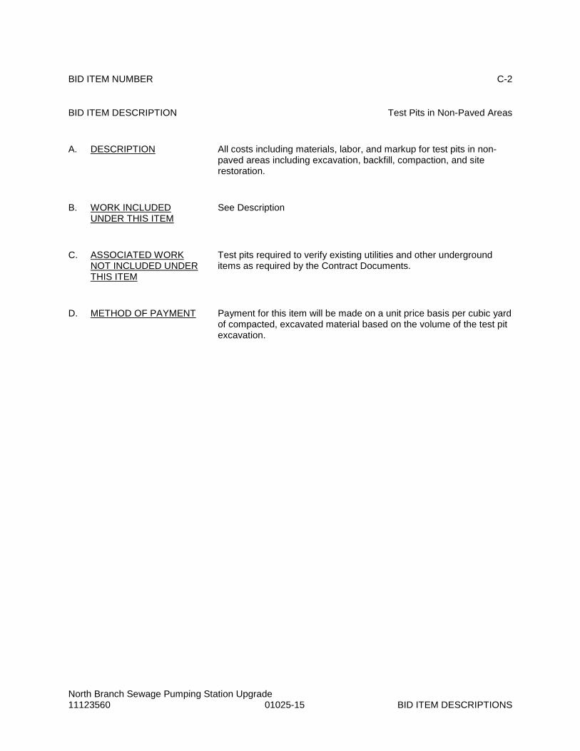
North Branch Sewage Pumping Station Upgrade 11123560 01025-15 BID ITEM DESCRIPTIONS
BID ITEM NUMBER C-2
BID ITEM DESCRIPTION Test Pits in Non-Paved Areas
A. DESCRIPTION All costs including materials, labor, and markup for test pits in non-paved areas including excavation, backfill, compaction, and site restoration.
B. WORK INCLUDED UNDER THIS ITEM
See Description
C. ASSOCIATED WORK NOT INCLUDED UNDER THIS ITEM
Test pits required to verify existing utilities and other underground items as required by the Contract Documents.
D. METHOD OF PAYMENT Payment for this item will be made on a unit price basis per cubic yard of compacted, excavated material based on the volume of the test pit excavation.

North Branch Sewage Pumping Station Upgrade 11123560 01025-16 BID ITEM DESCRIPTIONS
BID ITEM NUMBER C-3
BID ITEM DESCRIPTION Miscellaneous Excavation and Crusher Run Aggregate Backfill Below Subgrade
A. DESCRIPTION All costs including materials, labor, and markup for miscellaneous excavations and crusher run aggregate backfill below subgrade including excavation, removal of existing materials from the Site, installation of new materials, compaction, and geotextile fabric.
B. WORK INCLUDED UNDER THIS ITEM
See Description
C. ASSOCIATED WORK NOT INCLUDED UNDER THIS ITEM
N/A
D. METHOD OF PAYMENT Payment for this item will be made on a unit price basis per cubic yard of crusher run aggregate backfill.

North Branch Sewage Pumping Station Upgrade 11123560 01025-17 BID ITEM DESCRIPTIONS
BID ITEM NUMBER C-4
BID ITEM DESCRIPTION Miscellaneous Excavation and Select Backfill Below Subgrade
A. DESCRIPTION All costs including materials, labor, and markup for miscellaneous excavations and select backfill below subgrade including excavation, removal of existing materials from the Site, installation of new materials, compaction, and geotextile fabric.
B. WORK INCLUDED UNDER THIS ITEM
See Description
C. ASSOCIATED WORK NOT INCLUDED UNDER THIS ITEM
N/A
D. METHOD OF PAYMENT Payment for this item will be made on a unit price basis per cubic yard of compacted select backfill.

North Branch Sewage Pumping Station Upgrade 11123560 01025-18 BID ITEM DESCRIPTIONS
BID ITEM NUMBER C-5
BID ITEM DESCRIPTION Miscellaneous Excavation and Replacement of Topsoil
A. DESCRIPTION All costs including materials, labor, and markup for miscellaneous excavations and replacement of topsoil including excavation, removal of existing materials from the Site, installation of new materials, and compaction.
B. WORK INCLUDED UNDER THIS ITEM
See Description
C. ASSOCIATED WORK NOT INCLUDED UNDER THIS ITEM
N/A
D. METHOD OF PAYMENT Payment for this item will be made on a unit price basis per cubic yard of compacted topsoil.

North Branch Sewage Pumping Station Upgrade 11123560 01025-19 BID ITEM DESCRIPTIONS
BID ITEM NUMBER C-6
BID ITEM DESCRIPTION Hot Mix Asphalt, 2.5 mm
A. DESCRIPTION All costs including materials, labor, and markup for overlay of existing paving with 2.5 mm hot mix asphalt. This item does not include milling existing surfaces.
B. WORK INCLUDED UNDER THIS ITEM
See Description
C. ASSOCIATED WORK NOT INCLUDED UNDER THIS ITEM
N/A
D. METHOD OF PAYMENT Payment for this item will be made on a unit price basis per ton of installed hot mix asphalt.

North Branch Sewage Pumping Station Upgrade 11123560 01025-20 BID ITEM DESCRIPTIONS
BID ITEM NUMBER C-7
BID ITEM DESCRIPTION Miscellaneous Mix A Concrete
A. DESCRIPTION All costs including materials, labor, and markup for miscellaneous Mix D concrete including formwork and concrete.
B. WORK INCLUDED UNDER THIS ITEM
See Description
C. ASSOCIATED WORK NOT INCLUDED UNDER THIS ITEM
N/A
D. METHOD OF PAYMENT Payment for this item will be made on a unit price basis per cubic yard of installed concrete.

North Branch Sewage Pumping Station Upgrade 11123560 01025-21 BID ITEM DESCRIPTIONS
BID ITEM NUMBER C-8
BID ITEM DESCRIPTION Below Grade 2” Ductbank
A. DESCRIPTION All costs including materials, labor, and markup for 2ft x 2ft below grade concrete encased ductbanks (2” conduit sizes or less) including reinforced concrete, conduit, elbows, sweeps, fittings, couplings, saddle supports, rigid stub-ups, and all associated excavation, backfill, compaction, and site restoration.
B. WORK INCLUDED UNDER THIS ITEM
See Description
C. ASSOCIATED WORK NOT INCLUDED UNDER THIS ITEM
Conductors
D. METHOD OF PAYMENT Payment for this item will be made on a unit price basis per linear foot of installed ductbank.

North Branch Sewage Pumping Station Upgrade 11123560 01025-22 BID ITEM DESCRIPTIONS
BID ITEM NUMBER C-9
BID ITEM DESCRIPTION Below Grade 4” Ductbank
A. DESCRIPTION All costs including materials, labor, and markup for 2ft x 2ft below grade concrete encased ductbanks (conduit sizes between 2 ½” and 4”) including reinforced concrete, conduit, elbows, sweeps, fittings, couplings, saddle supports, rigid stub-ups, and all associated excavation, backfill, compaction, and site restoration.
B. WORK INCLUDED UNDER THIS ITEM
See Description
C. ASSOCIATED WORK NOT INCLUDED UNDER THIS ITEM
Conductors
D. METHOD OF PAYMENT Payment for this item will be made on a unit price basis per linear foot of installed ductbank.

North Branch Sewage Pumping Station Upgrade 11123560 01025-23 BID ITEM DESCRIPTIONS
BID ITEM NUMBER C-10
BID ITEM DESCRIPTION ¾” Type A-1 Conduit
A. DESCRIPTION All costs including materials, labor, and markup for conduit, fittings, outlet boxes, junction boxes, supports, hardware and fasteners
B. WORK INCLUDED UNDER THIS ITEM
See Description
C. ASSOCIATED WORK NOT INCLUDED UNDER THIS ITEM
Conductors
D. METHOD OF PAYMENT Payment for this item will be made on a unit price basis per linear foot of installed conduit.

North Branch Sewage Pumping Station Upgrade 11123560 01025-24 BID ITEM DESCRIPTIONS
BID ITEM NUMBER C-11
BID ITEM DESCRIPTION ¾” Type E-1 Conduit
A. DESCRIPTION All costs including materials, labor, and markup for conduit, fittings, outlet boxes, junction boxes, supports, hardware and fasteners
B. WORK INCLUDED UNDER THIS ITEM
See Description
C. ASSOCIATED WORK NOT INCLUDED UNDER THIS ITEM
Conductors
D. METHOD OF PAYMENT Payment for this item will be made on a unit price basis per linear foot of installed conduit.

North Branch Sewage Pumping Station Upgrade 11123560 01025-25 BID ITEM DESCRIPTIONS
BID ITEM NUMBER C-12
BID ITEM DESCRIPTION No. 12 AWG, Type THWN Conductors
A. DESCRIPTION All costs including materials, labor, and markup for No. 12 AWG, Type THWN conductors, terminations, labels, nuts, connectors, terminal blocks, splices, and other miscellaneous accessories
B. WORK INCLUDED UNDER THIS ITEM
See Description
C. ASSOCIATED WORK NOT INCLUDED UNDER THIS ITEM
N/A
D. METHOD OF PAYMENT Payment for this item will be made on a unit price basis per linear foot of installed conductors.

North Branch Sewage Pumping Station Upgrade 11123560 01025-26 BID ITEM DESCRIPTIONS
BID ITEM NUMBER C-13
BID ITEM DESCRIPTION No. 14 AWG, Type THWN Conductors
A. DESCRIPTION All costs including materials, labor, and markup for No. 14 AWG, Type THWN conductors, terminations, labels, nuts, connectors, terminal blocks, splices, and other miscellaneous accessories
B. WORK INCLUDED UNDER THIS ITEM
See Description
C. ASSOCIATED WORK NOT INCLUDED UNDER THIS ITEM
N/A
D. METHOD OF PAYMENT Payment for this item will be made on a unit price basis per linear foot of installed conductors.

North Branch Sewage Pumping Station Upgrade 11123560 01025-27 BID ITEM DESCRIPTIONS
BID ITEM NUMBER C-14
BID ITEM DESCRIPTION No. 16 TSP Instrumentation Cable
A. DESCRIPTION All cost including materials, labor, and markup for No. 16 TSP Instrumentation cable, terminations, labels, nuts, connectors, terminal blocks, splices, and other miscellaneous accessories.
B. WORK INCLUDED UNDER THIS ITEM
See Description
C. ASSOCIATED WORK NOT INCLUDED UNDER THIS ITEM
N/A
D. METHOD OF PAYMENT Payment for this item will be made on a unit price basis per linear foot of installed instrumentation cable.

North Branch Sewage Pumping Station Upgrade 11123560 01025-28 BID ITEM DESCRIPTIONS
BID ITEM NUMBER D-1
BID ITEM DESCRIPTION New Electrical Service
A. DESCRIPTION Allowance for payment to Potomac Edison for new electrical service to the Site.
B. WORK INCLUDED UNDER THIS ITEM
All work performed by Potomac Edison
C. ASSOCIATED WORK NOT INCLUDED UNDER THIS ITEM
Associated work performed by Contractor
D. METHOD OF PAYMENT Payment for this item will be made in accordance with General Condition Article 13.02.

North Branch Sewage Pumping Station Upgrade 11123560 01025-29 BID ITEM DESCRIPTIONS
BID ITEM NUMBER D-2
BID ITEM DESCRIPTION SCADA Monitoring System
A. DESCRIPTION Allowance for the cost of the SCADA Monitoring System (RTU).
B. WORK INCLUDED UNDER THIS ITEM
See Description
C. ASSOCIATED WORK NOT INCLUDED UNDER THIS ITEM
All other work other than the cost of the RTU itself
D. METHOD OF PAYMENT Payment for this item will be made in accordance with General Condition Article 13.02.

North Branch Sewage Pumping Station Upgrade 11123560 01025-30 BID ITEM DESCRIPTIONS
BID ITEM NUMBER D-3
BID ITEM DESCRIPTION Existing Generator Inspection and Repair
A. DESCRIPTION Allowance for payment Owner selected firm to inspect and repair existing generator scheduled for salvage
B. WORK INCLUDED UNDER THIS ITEM
All work performed by Owner selected firm
C. ASSOCIATED WORK NOT INCLUDED UNDER THIS ITEM
Associated work performed by Contractor
D. METHOD OF PAYMENT Payment for this item will be made in accordance with General Condition Article 13.02.
END OF SECTION

North Branch Sewage Pumping Station Upgrade 11123560 01039-1 COORDINATION
SECTION 01039
COORDINATION
PART 1 GENERAL
1.01. SECTION INCLUDES
A. Coordination
B. Field engineering
C. Preconstruction conference
D. Progress meetings
E. Pre-installation conferences
1.02. COORDINATION
A. Coordinate scheduled work sequences and related operations beforehand with appropriate local, county, or state officials and agencies including affected property owners, when Project is to be located in or adjacent to a public right-of-way.
B. Coordinate scheduling, submittals, and Work of the various Specification sections to assure efficient and orderly sequence of installation of interdependent construction elements, with provisions for accommodating items installed later.
C. Verify that utility requirement characteristics of operating equipment are compatible with building utilities. Coordinate work of various sections having interdependent responsibilities for installing, connecting to, and placing in service, such equipment.
D. Coordinate space requirements and installation of mechanical and electrical work which are indicated diagrammatically on Drawings. Follow routing shown for pipes, ducts, and conduit, as closely as practicable; place runs parallel with line of building. Utilize spaces efficiently to maximize accessibility for other installations, for maintenance, and for repairs.
E. In finished areas, except as otherwise indicated, conceal pipes, ducts, and wiring within the construction. Coordinate locations of fixtures and outlets with finish elements.
F. Coordinate completion and cleanup of work of separate sections in preparation for Substantial Completion.
G. After Owner use of facilities, coordinate access to Site for correction of defective Work and Work not in accordance with Contract Documents, to minimize disruption of Owner’s activities.
1.03. FIELD ENGINEERING
A. Control datum for survey work is that provided by Engineer as shown on the Drawings. Provide control loop to verify datum before beginning construction activities.
B. Engineer reserves right to inspect or check results of Contractor field engineering services specified herein for conformance with the Contract Documents.

North Branch Sewage Pumping Station Upgrade 11123560 01039-2 COORDINATION
C. Contractor shall provide field engineering services as follows:
1. Employ a land surveyor licensed in the State of Maryland.
2. Protect all control and reference points. Accurately replace any such point that is damaged or moved.
3. Provide correct lines, grades, locations and elevations for construction of all Project components.
4. Provide correct information for preparation of Project record documents.
1.04. PRECONSTRUCTION CONFERENCE
A. Engineer will schedule a conference after the Effective Date of Agreement.
B. Required Attendance: Owner, Engineer, funding agency, and Contractor.
C. Agenda
1. Distribution of extra sets of Contract Documents.
2. Submission of list of Subcontractors, list of products, Schedule of Submittals, Schedule of Values, and Progress Schedule.
3. Designation of personnel representing the parties in Contract, and Engineer.
4. Procedures and processing of field decisions, submittals, substitutions, Applications for Payments, proposal requests, Change Orders and Contract closeout procedures.
5. Scheduling.
6. Scheduling activities of testing laboratory.
7. Requirements of regulatory agencies.
8. Use of premises by Owner and Contractor.
9. Temporary facilities to be provided by Owner and Contractor.
10. Procedures for testing.
11. Procedures for maintaining record documents.
12. Maintenance of vehicular traffic detours, flagmen, etc.
13. Periodic cleanup of Site.
14. Notification of utilities’ owners.
15. Electronic communications.
16. Submittal and review of labeled progress photos.
17. Installation of Engineer’s trailer, including final location.

North Branch Sewage Pumping Station Upgrade 11123560 01039-3 COORDINATION
D. Engineer will record minutes and distribute copies to participants.
1.05. PROGRESS MEETINGS
A. Engineer or Owner will schedule and administer meetings throughout progress of the Work at maximum monthly intervals.
B. Engineer or Owner will make arrangements for meetings, prepare agenda with copies for participants, preside at meetings, record minutes, and distribute copies within five days to participants, and those affected by decisions made.
C. Required Attendance: Owner, Engineer, Job superintendent, major Subcontractors and Suppliers, as appropriate to agenda topics for each meeting.
D. Agenda
1. Review minutes of previous meetings.
2. Review of Work progress.
3. Field observations, problems, and decisions.
4. Identification of problems which impede planned progress.
5. Review of submittals schedule and status of submittals.
6. Review of off-site fabrication and delivery schedules.
7. Maintenance of Progress Schedule.
8. Corrective measures to regain projected schedules.
9. Planned progress during succeeding work period.
10. Coordination of projected progress.
11. Maintenance of quality and work standards.
12. Effect of proposed changes on Progress Schedule and coordination.
13. Other business relating to Work.
1.06. PRE-INSTALLATION CONFERENCES
A. When required in individual specification Section, Contractor shall convene a pre-installation conference at Site prior to commencing work of the section.
B. Require attendance of parties directly affecting, or affected by, work of the specific section.
C. Notify Engineer four days in advance of meeting date.
D. Prepare agenda, preside at conference, record minutes, and distribute copies within two days after conference to participants, with two copies to Engineer.

North Branch Sewage Pumping Station Upgrade 11123560 01039-4 COORDINATION
E. Review conditions of installation, preparation and installation procedures, and coordination with related work.
PART 2 PRODUCTS Not used.
PART 3 EXECUTION Not used.
END OF SECTION

North Branch Sewage Pumping Station Upgrade 11123560 01300-1 SUBMITTALS
SECTION 01300
SUBMITTALS
PART 1 GENERAL
1.01. SECTION INCLUDES
A. Submittal procedures
B. Review of submittals
C. Schedule of Submittals
D. Shop Drawings
E. Samples
F. Manufacturer’s instructions
1.02. SUBMITTAL PROCEDURES
A. Transmit each required submittal using Engineer furnished form.
B. Number the submittals as follows:
1. First: Specification Section number
2. Submittal number within the Specification Section
3. Review cycle number
4. Title of submittal
5. For example:
a. 15073-01-01 – Field lock gaskets for DIP (first review cycle)
b. 15073-01-02 - Field lock gaskets for DIP (second review cycle)
c. 15073-02-01 – Flange pipe and fittings (first review cycle)
d. 15073-02-02 – Flange pipe and fittings (second review cycle)
e. 15073-02-03 – Flange pipe and fittings (third review cycle)
C. Identify Project, Contractor, Subcontractor, and Supplier; pertinent Drawing number and detail number(s), and Specification Sections, as appropriate.
D. Apply stamp, signed or initialed providing certification required by General Condition Article 6.17.C.2. At a minimum, stamp shall include the following information:
1. Submittal Number 2. Deviations: None_________________; As Listed 3. Reference Specification Section

North Branch Sewage Pumping Station Upgrade 11123560 01300-2 SUBMITTALS
4. Reference Drawing Number 5. Space Requirement: As Designed____________ Different, As Listed 6. Representation is made to Owner and Engineer that Contractor has satisfied the
requirements of General Conditions Article 6.17.C.1.a through d, associated Supplementary Conditions, and that the Contractor hereby approves this submittal. Contractor Signature Date Date
E. Schedule submittals to expedite the Project, and deliver to parties in the quantities and at the locations identified during the Preconstruction Conference.
F. Identify deviations from Contract Documents in accordance with General Conditions Article 7.16.A.3.
G. Identify product and/or system limitations which may be detrimental to successful performance of the completed Work.
H. Identify space requirements which differ from those designed and/or shown on the Contract Documents.
I. Provide space for Contractor and Engineer review stamps.
J. Revise and resubmit in accordance with General Conditions Article 7.16.E. Provide written responses to previous review comments to clearly identify how each comment is being addressed. In addition, identify all other changes made since previous submittal at beginning of submittal prior to responses to review comments.
K. Distribute copies of reviewed submittals to concerned parties. Instruct parties to promptly report any inability to comply with provisions.
L. Submittals not required will not be recognized or processed.
M. Items shall not be fabricated or delivered without fully approved Shop Drawings.
N. Ensure no associated work begins until associated Shop Drawings are fully approved.
O. Fabrication prior to receiving an “Approved” or “Approved as Corrected – No Resubmittal Required” is at Contractor’s risk.
1.03. REVIEW OF SUBMITTALS
A. Review of submittals will be in accordance with General Conditions Article 7.16.D.
B. Review times:
1. No less than 28 days shall be allowed for Engineer’s review of submittals and resubmittals unless otherwise specified in the Contract Documents.
2. No less than 45 days shall be allowed for Engineer’s review of Division 17 submittals and all other items including PLC based control systems.
C. Review Codes:
1. Approved

North Branch Sewage Pumping Station Upgrade 11123560 01300-3 SUBMITTALS
2. Approved as Corrected – No Resubmittal Required
3. Approved as Corrected – Resubmit Written Responses and Requested Information
4. Revise and Resubmit
5. Not Approved
6. Informational Purposes Only
D. Payment will not be made for any items requiring submittals until no further submittals are required for the item.
1.04. SCHEDULE OF SUBMITTALS
A. Submit three copies of preliminary Schedule of Submittals in accordance with General Conditions Article 2.03.
B. Revise and resubmit until acceptable to Engineer.
1.05. SHOP DRAWINGS
A. Provide information in accordance with General Conditions Article 7.16 as supplemented herein and as required by individual Specification Sections.
B. Shop Drawing submittals shall include all descriptive data, performance characteristics, material specifications, spare parts list, drawings, piping diagrams, wiring schematics, and shall be complete and accurate to indicate item-by-item compliance with the Contract Documents.
C. Shop Drawings shall be drawn at scales matching those on the Drawings depicting the same items.
D. All catalog cuts, manufacturer’s specifications, drawings, and verbal descriptions shall be clearly marked to allow identification of the specific products used.
E. If the submittal deviates from the requirements of the Specifications in any way, it shall be clearly marked in the submittal with the justifying reason stated for evaluation by Engineer.
F. Electrical and control submittals shall include a verbal description of the functions, metering equipment, alarm points, alarm sequences, and any other specific features provided.
G. Electric motor submittals shall be in accordance with Section 15170 (Motors).
H. All electrical equipment submittals shall be in accordance with Division 16, Electrical Specifications.
I. Submit to Engineer in electronic Portable Document Format (Adobe PDF). Submittals shall be searchable and shall include a table of contents and have bookmarks for individual Sections when more than one item is included.
1.06. SAMPLES
A. Provide in accordance with General Conditions Article 7.16 as supplemented herein and as required by individual Specification Sections.

North Branch Sewage Pumping Station Upgrade 11123560 01300-4 SUBMITTALS
B. Submit Samples to illustrate functional and aesthetic characteristics of the product, with integral parts and attachment devices. Coordinate Sample submittals for interfacing work.
C. Submit Samples of finishes from the full range of manufacturers’ standard colors, textures, and patterns for Engineer’s selection.
D. Include identification on each Sample, with full Project information.
E. Submit the number or samples specified in individual Specification Sections, one of which will be retained by Engineer.
F. Reviewed Samples which may be used in the Work are indicated in individual Specification Sections.
1.07. MANUFACTURER’S INSTRUCTIONS
A. When specified in individual Specification Sections, submit manufacturers’ printed instructions for delivery, storage, assembly, installation, adjusting, and finishing, in quantities specified for Shop Drawings.
B. When specified in individual Specification Sections, submit manufacturer’s operation and maintenance instructions for equipment supplied under this Contract.
C. Identify conflicts between manufacturers’ instructions and Contract Documents.
PART 2 PRODUCTS Not used
PART 3 EXECUTION Not used
END OF SECTION

North Branch Sewage Pumping Station Upgrade 11123560 01310-1 PROGRESS SCHEDULE
SECTION 01310
PROGRESS SCHEDULE
PART 1 GENERAL
1.01. SUMMARY
A. This Specification Section covers the development and utilization of the Progress Schedule. In the event of conflicts or discrepancies with any other provisions of the Contract Documents relating to such, this Section shall govern.
1.02. DEFINITIONS
A. Terms used herein shall be in accordance with the definitions set forth in the Associated General Contractors of America (AGC) publication, “Construction Planning & Scheduling Manual”.
1.03. BASIC REQUIREMENTS
A. Schedule and monitor all Work using Critical Path Method (CPM) techniques. Scheduling software shall be Primavera P6, Microsoft Project, or equal.
B. Progress Schedule shall be maintained throughout entire Contract and shall be used by Contractor to schedule, plan, organize, and execute the Work.
C. Progress Schedule shall:
1. Comply with Contract Times identified in the Agreement.
2. Reflect all mandated sequencing identified in Contract Documents.
3. Include adequate time for Engineer’s review of submittals. Under no circumstances will the Progress Schedule be allowed to include Engineer review times shorter than those prescribed in Section 01300 (Submittals) and individual Specification Sections. The need for resubmittals based on Engineer’s review will not entitle Contractor to Contract Time extensions and the Progress Schedule must include adequate time for resubmittals.
4. Include time required by Contract Documents based on work days lost due to inclement weather.
5. Progress Schedule shall include adequate time for testing and Startup.
D. Each activity, except Notice to Proceed, shall have at least one predecessor. Each activity, except final completion, shall have at least one successor.
E. Construction activities shall have a maximum duration of 20 work days unless a longer duration is specifically called out in the Contract Documents (e.g. 45 calendar day submittal review time). All durations shall be developed based on definitive manpower and resource planning.
F. Float is not for the exclusive benefit of the Owner or Contractor and must be used in the best interest of the Project in order to maintain Contract Times. Contractor will not be allowed to

North Branch Sewage Pumping Station Upgrade 11123560 01310-2 PROGRESS SCHEDULE
sequester float through such strategies as extended activity durations, extensive crew/resource sequencing, etc.
1.04. QUALITY ASSURANCE
A. Utilize a qualified CPM scheduler to provide all scheduling services required for this Contract.
B. CPM scheduler shall be skilled in the time and cost application of CPM scheduling techniques for multi-disciplined construction projects.
C. CPM scheduler shall have a minimum of five years’ experience in preparing CPM schedules for projects of similar size and complexity.
D. Engineer reserves the right to reject proposed CPM scheduler if, in the Engineer’s opinion, the proposed CPM scheduler does not meet the qualifications specified herein. Engineer will notify Contractor in writing of decision concerning acceptability of proposed CPM scheduler within 14 days of receipt of proposed CPM scheduler qualifications submittal. If Engineer rejects proposed CPM scheduler, resubmit another proposed CPM scheduler within 7 days of receipt of Engineer’s rejection notice. Such rejection by Engineer does not release Contractor from its obligations under this Contract and will not entitle Contractor to an adjustment of Contract Price and/or Contract Times.
1.05. SUBMITTALS
A. Submit the following in accordance with the procedures identified in Section 01300 (Submittals):
1. CPM scheduler’s qualifications within ten days of Notice of Award including:
a. Name and address of proposed CPM scheduler.
b. Sufficient information showing proposed CPM scheduler’s qualifications including:
1) List of prior construction projects of similar size and complexity.
2) At least one sample network analysis demonstrating complete project planning similar to those required under this Contract, prepared by, or under the direction of, the proposed CPM scheduler.
3) Letter from proposed CPM scheduler indicated they have reviewed this Specification Section and understand the requirements specified herein.
2. Detailed Baseline Progress Schedule:
a. Submit one electronic version on compact disc and three 22” x 34” hard copies of bar chart within 30 days after acceptance of preliminary Progress Schedule.
b. Bar chart shall clearly identify the critical path and shall provide a tabulated listing of the following for each activity:

North Branch Sewage Pumping Station Upgrade 11123560 01310-3 PROGRESS SCHEDULE
1) Activity ID
2) Activity description
3) Original duration
4) Percent complete
5) Remaining duration
6) Early start
7) Early finish
8) Late start
9) Late finish
10) Total float
c. No progress payments will be made to Contractor for work completed more than 90 days after Notice to Proceed without an approved Baseline Progress Schedule.
3. Monthly Updates
a. After acceptance of the baseline Progress Schedule, submit monthly updates with each Application for Payment. The cutoff date for each monthly update shall be mutually agreed upon by Engineer and Contractor prior to submittal of first monthly update.
b. Submit one electronic version on compact disc and three22” x 34” hard copies of bar chart.
c. The monthly updates shall include, but not be limited to, three copies of a tabulated listing all activities showing the following:
1) Activity ID
2) Activity description
3) Original duration
4) Percent complete
5) Remaining duration
6) Early start or actual start
7) Early finish or actual finish
8) Late start or actual start

North Branch Sewage Pumping Station Upgrade 11123560 01310-4 PROGRESS SCHEDULE
9) Late finish or actual finish
10) Total float
d. Written report including the following:
1) Summary of Work accomplished during period
2) Summary of Work to be accomplished during next period
3) Milestone comparison chart
4) Critical path analysis
5) Analysis of work paths with less than 20 days total float
6) Analysis of time lost or gained during the period
7) Identification of problem areas
8) Identification of issues potentially having an adverse impact on the Progress Schedule
B. Engineer’s review of Progress Schedule submissions is solely to determine if Progress Schedule has been prepared in accordance with Contract Documents. Such acceptance will not impose on Engineer and/or Owner responsibility for the Progress Schedule, sequencing of Work, progress of Work, nor will it interfere with and/or relieve Contractor full responsibility for the Progress Schedule, means, methods, and sequence of construction when not specifically dictated by the Contract Documents.
C. Should Contractor fail to provide submittals, and/or revised submittals, within the time frames prescribed, Contractor will be in default and Owner is not obligated to provide progress payments to Contractor until such time as acceptability of submittals can be verified.
1.06. PROGRESS SCHEDULE ARCHITECTURE
A. Each activity in the Progress Schedule shall include:
1. A unique activity identification (ID) number
2. Activity description
3. Original Duration
4. Responsibility code assigning activities to Contractor, Subcontractors, Engineer, Owner, or other entity.
B. Calendars: At a minimum, establish the following calendars:
1. Work day calendar excluding all holidays identified in the Contract Documents
2. Calendar days for activities with durations based on calendar days

North Branch Sewage Pumping Station Upgrade 11123560 01310-5 PROGRESS SCHEDULE
1.07. DETAILED BASELINE PROGRESS SCHEDULE
A. Baseline Progress Schedule shall include no activity progress.
B. Provide sufficient detail to allow use for planning, scheduling, and control all Work included in Contract. The degree of detail shall be to the satisfaction of the Engineer, and shall account for the following Project specific items:
1. Structural breakdown of Project
2. Required phasing
3. Milestones
4. Trades involved
5. Maintaining operation of existing facilities
6. Subcontractor work plans
7. Crew flows and sizes
8. Access to Site and work areas
9. Identification of coordination between Contractor, Subcontractors, and Suppliers
10. Testing and Startup
11. Partial utilization by Owner
C. In addition to a breakdown of physical construction activities specified herein, include activities for the following:
1. Submittals
2. Engineer’s review of submittals
3. Fabrication and delivery of materials and equipment
4. Finish milestone activity for all Functional Tests associated with a given System (see Section 01660 (Testing and Startup) for definition).
5. Separate activities for loading/debugging application software for the Pumping Station PLC
D. Update to include any revisions to the System Delivery Plan identified in Section 01660 (Testing and Startup).
E. The accepted baseline Progress Schedule will form the basis of the first monthly update.

North Branch Sewage Pumping Station Upgrade 11123560 01310-6 PROGRESS SCHEDULE
1.08. REVISIONS
A. The Owner, Engineer, and Contractor shall have the right to propose revisions to the Progress Schedule if it is deemed to be in the best interest of the Project.
B. All Owner, Engineer, and Contractor proposed revisions must be submitted to each party no later than seven days prior to the date by which Contractor must submit monthly updates in order for proposed revisions to be considered for that update.
C. Objections to Proposed Revisions:
1. If Owner, Engineer, and/or Contractor object to proposed revisions made by any other party, the objecting party shall provide written notice to each other party within seven days of receipt of proposed revisions, stating objections.
2. Proposed revisions that are not mutually agreeable shall be discussed at the monthly scheduling meetings.
D. Engineer shall have final say on acceptance or rejection of all proposed Progress Schedule revisions based solely on requirements of the Contract Documents.
E. All Engineer accepted revisions will be incorporated into the next Progress Schedule update.
1.09. RECOVERY SCHEDULES
A. If Contractor fails to achieve planned progress, as indicated in the Progress Schedule, and lack of progress delays the critical path or an intermediate Milestone by more than 10 work days, submit a proposed recovery schedule to Engineer identifying how Contractor will recover lost time.
B. Failure to submit a recovery schedule and failure to cooperate with the Owner and/or Engineer in the recovery schedule process shall allow Owner the right to order Contractor to increase manpower to recover lost time, without adjustment to the Contract Price. Furthermore, Owner has the right to withhold progress payments until such time as Contractor’s progress is brought into compliance with Progress Schedule.
1.10. DELAYS AND EXTENSIONS OF CONTRACT TIMES
A. When Contractor believes that Contract Times will be delayed by circumstances outside if its control, Contractor shall include with its Change Proposal, a forward looking Time Impact Analysis (TIA) identifying the anticipated impact to Contract Times. Forward looking Time Impact Analysis shall include the following;
1. A fragnet prepared using the Progress Schedule submitted with the most recent Application for Payment.
2. A report identifying all new activities included with the fragnet and all proposed logic changes associated with the fragnet.
3. Summary of all requested extensions to Contract Times.
4. Cause of the delay, actions Contractor proposes to take to minimize delays, and actions Contractor proposes for Owner and/or Engineer to minimize delays.

North Branch Sewage Pumping Station Upgrade 11123560 01310-7 PROGRESS SCHEDULE
B. Engineer will review each forward looking TIA after submission. If acceptable to Engineer, Engineer will provide written notice to Owner within 14 days of submission, copying Contractor on correspondence, recommending that the fragnet should be incorporated into the Progress Schedule and a Change Order will be issued providing the requested extension of Contract Times. Owner will provide written notice to Contractor within 14 days of receipt of Engineer’s recommendation, either concurring or denying Engineer’s recommendation.
C. If a forward looking TIA submittal is not acceptable to Engineer, Engineer will provide written notice to Contractor identifying deficiencies with TIA. Contractor will have 7 days from receipt of Engineer’s written notice to submit a revised TIA addressing deficiencies.
D. Contract Time extensions will only be considered for events that impact Contract Times as demonstrated by acceptable forward looking TIAs.
PART 2 PRODUCTS
Not used
PART 3 EXECUTION
Not used
END OF SECTION

North Branch Sewage Pumping Station Upgrade 11123560 01380-1 CONSTRUCTION DOCUMENTATION
SECTION 01380
CONSTRUCTION DOCUMENTATION
PART 1 GENERAL
1.01. SECTION INCLUDES
A. Construction Photographs
1.02. DESCRIPTION
A. Take construction record photographs prior to mobilization and periodically during the course of the Work.
1.03. CONSTRUCTION PHOTOGRAPHS
A. Digital construction photographs shall be taken at each of the major stages on construction listed below and shall be furnished to Engineer and Owner with each Application for Payment.
1. Site before mobilization
2. Completion of Underground Facilities prior to backfilling
3. Completion of Site clearing for each structure
4. Completion of excavations for each structure
5. Completion of reinforcing and formwork prior to concrete pours
6. Completion of foundations of each structure
7. Completion of framing of each structure
8. Completion of enclosure for each structure
9. Interior of tanks prior to filling with liquid
10. Installation of all interior and exposed exterior piping, equipment, and electrical components
11. Testing of all piping, equipment, and systems
12. Completion of Site restoration and landscaping
B. Views and Quantities Required
1. Two views of each item
2. At least five views of overall Project Site monthly
3. Four prints of each view
C. Camera used for digital photography shall be a 2.0 megapixel or greater.

North Branch Sewage Pumping Station Upgrade 11123560 01380-2 CONSTRUCTION DOCUMENTATION
D. Electronic Copies
1. Maintain database of pictures for the entire length of the Project.
2. Each month, provide two electronic versions of all prints taken in the past month. Coordinate means of transmitting electronic versions with Owner in advance.
3. Provide two electronic versions of all prints taken in during the course of the Project (in .jpg format) with final Application for Payment. Coordinate means of transmitting electronic versions with Owner in advance.
4. All electronic copies of photos shall be in .jpg format. Each .jpg photo file name shall include the subject description and date.
1.04. REUSE OF CONSTRUCTION DOCUMENTATION
A. All construction documentation furnished to Owner shall become the property of the Owner and cannot be copyright or otherwise protected in a manner that prevents free reuse by either the Owner and/or Engineer.
PART 2 PRODUCTS
Not Used.
PART 3 EXECUTION
3.01. DELIVERY OF PRINTS
A. Preconstruction photos shall accompany the first Application for Payment. This Application for Payment will not be approved without receipt of such materials. Coordinate means of transmitting photos to Owner in advance.
B. Monthly construction photos shall accompany each monthly Application for Payment. Monthly Applications for Payment will not be approved without receipt of such materials. Coordinate means of transmitting photos to Owner in advance.
C. Final construction photos shall accompany the final Application for Payment. This Application for Payment will not be approved without receipt of such materials. Coordinate means of transmitting photos to Owner in advance.
END OF SECTION

North Branch Sewage Pumping Station Upgrade 11123560 01400-1 QUALITY CONTROL
SECTION 01400
QUALITY CONTROL
PART 1 GENERAL
1.01. SECTION INCLUDES
A. Quality assurance and control of installation
B. References and standards
C. Tolerances
D. Field samples
E. Mock-up
F. Inspection and testing services
G. Testing by Contractor
H. Manufacturers’ field services and reports
1.02. QUALITY ASSURANCE/CONTROL OF INSTALLATION
A. Monitor quality control over Suppliers, manufacturers, products, services, Site conditions, and workmanship, to produce Work of specified quality.
B. Comply fully with manufacturers’ instructions.
C. Verify that field measurements are as indicated on Shop Drawings and as instructed by the manufacturer.
D. If manufacturers’ instructions conflict with Contract Documents, request clarification from Engineer before proceeding.
E. Comply with specified standards as a minimum quality for the Work except when code requirements or equipment manufacturer requires more stringent standards.
F. Perform Work by persons qualified to produce workmanship of specified quality.
G. Secure products in place with positive anchorage devices designed and sized to withstand stresses, vibration, physical distortion and disfigurement.
1.03. REFERENCES AND STANDARDS
A. For products and workmanship specified by association, trade, or other consensus standards, comply with requirements of the standard, except when more rigid requirements are specified and/or are required by applicable codes.
B. Obtain copies of standards where required by individual Specification Sections.
C. If specified reference standards conflict with Contract Documents, request clarification from Engineer before proceeding.

North Branch Sewage Pumping Station Upgrade 11123560 01400-2 QUALITY CONTROL
1.04. TOLERANCES
A. Monitor fabrication and installation tolerance control to produce acceptable Work. Do not permit tolerances to accumulate.
B. Comply with manufacturers’ tolerances. If manufacturers’ tolerances conflict with Contract Documents, request clarification from Engineer before proceeding.
C. Adjust products to appropriate dimensions; position before securing products in place.
1.05. FIELD SAMPLES
A. Furnish field Samples at the Site as required by individual Specification Sections.
B. Acceptable Samples represent a quality level for the Work.
C. Where field Sample is specified in individual Specification Sections to be removed, clear area after field Sample has been accepted by Engineer.
1.06. MOCK-UP
A. Tests will be performed under provisions identified in this section and as identified in the individual Specification Sections.
B. Assemble and erect specified items, with specified attachment and anchorage devices, flashings, seals, and finishes.
C. Where mock-up is specified in individual Specification Sections to be removed, mock-up shall remain until Engineer provides notice to Contractor that it is acceptable to remove mock-up.
D. Accepted mock-ups shall be a comparison standard for quality required for the remaining Work.
1.07. TESTS AND INSPECTIONS
A. Owner shall employ and pay for the services of an independent testing laboratory to perform inspections, tests, and approvals indicated in General Conditions Article 14.02.B.
B. Independent testing laboratory will:
1. Perform inspections, tests, and other services specified in the individual Specification Sections and as required by Engineer and Owner.
2. Perform inspecting, testing, and source quality control which may occur on or off Site, as required by Engineer or Owner.
3. Prepare and submit reports to Engineer, in duplicate indicating observations and results of tests and indicating compliance or non-compliance with Contract Documents. Engineer will forward copy of report(s) to Contractor.
C. Contractor shall:
1. Cooperate with independent firm; furnish samples of materials; furnish design mix, equipment, tools, storage and assistance as requested.

North Branch Sewage Pumping Station Upgrade 11123560 01400-3 QUALITY CONTROL
2. Notify Engineer and independent firm 48 hours prior to expected time for operations requiring services.
3. Make arrangements with independent firm and pay for additional samples and tests required for Contractor’s own use.
D. Retesting required because of non-conformance to specified requirements shall be performed, on instructions by Engineer, by the same independent firm which performed the initial tests and inspections, whether employed by Owner or Contractor.
E. Costs for retesting and re-inspection will be deducted from progress payments to Contractor.
1.08. MANUFACTURERS’ FIELD SERVICES
A. Manufacturer field services for equipment are specified in Section 01640 (Equipment – General) and the individual Specification Sections.
B. When additional manufacturer services are specified in other individual Specification Sections, require material or product Suppliers or manufacturers to provide qualified personnel to observe Site conditions, conditions of surfaces and installation, quality of workmanship, testing and adjusting as applicable, and to initiate instructions when necessary.
C. Submit qualifications of observer to Engineer a minimum of 30 days in advance of required observations. Observers are subject to approval of Owner.
D. Report observations, Site conditions, or instructions given to applicators or installers, that are supplemental or contrary to manufacturers’ written instructions.
E. Submit report to Engineer in duplicate within 30 days of observation.
PART 2 PRODUCTS Not used
PART 3 EXECUTION Not used
END OF SECTION


North Branch Sewage Pumping Station Upgrade 11123560 01420-1 SPECIAL INSPECTIONS
SECTION 01420
SPECIAL INSPECTIONS
PART 1 GENERAL
1.01. SECTION INCLUDES
A. Special inspections and structural testing will be in accordance with Chapter 17 of the International Building Code.
B. The program of special inspection and testing is a quality assurance program intended to ensure that the Work is performed in accordance with the Contract Documents.
C. This Specification section is intended to inform the Contractor of the Owner’s quality assurance program and the extent of the Contractor’s responsibilities.
1.02. SCHEDULE OF INSPECTIONS AND TESTS
A. Required inspections and tests include, but are not limited to, those listed in the “Statement of Special Inspections” (attached for reference), and as stated in the individual Specification sections for the items to be inspected or tested.
1.03. QUALIFICATIONS
A. Special Inspector, testing laboratory, and individual technicians will be provided by the Owner.
1.04. PAYMENT
A. Owner will engage and pay for the services of the Special Inspectors and Testing Laboratory.
B. Contractor shall be responsible for the travel expenses of the Special Inspector or Testing Laboratory if any materials which require special inspections are fabricated in a plant which is not located within 100 miles of the project, the.
C. Contractor shall be responsible for the cost of any retesting or reinspection of Work which fails to comply with the requirements of the Contract Documents.
1.05. CONTRACTOR RESPONSIBILITIES
A. Cooperate with the Special Inspector, his agents, and the Testing Laboratory so that the special inspections and testing may be performed without hindrance.
B. Review the “Statement of Special Inspections” and coordinate scheduling of inspections and tests. Notify the Special Inspector or Testing Laboratory at least 48 hours in advance of a required inspection or test.
C. Uninspected work that required inspection may be rejected solely on that basis.
D. Provide incidental labor and facilities (ladders, scaffolding, lights, safety equipment, etc.) to provide access to the work to be inspected or tested, to obtain and handle samples at the site or at source of products to be tested, to facilitate tests and inspections, storage and curing of test samples.

North Branch Sewage Pumping Station Upgrade 11123560 01420-2 SPECIAL INSPECTIONS
E. Keep at the Site the latest set of Drawings, field sketches, approved Shop Drawings, and Specifications for use by the Special Inspector and Testing Laboratory.
F. The special inspection program shall in no way relieve the Contractor of his obligation to perform Work in accordance with the requirements of the Contract Documents and from implementing its own quality control program.
G. Work that is to be subjected to special inspections shall first be reviewed by Contractor’s quality control personnel.
H. Contractor shall be solely responsible for Site safety.
I. Contractor shall provide 7 days notice to Engineer prior to starting work that requires Special Inspections.
J. Contractor shall be responsible for costs associated with re-inspection due to non-conforming work.
1.06. LIMITS OF AUTHORITY
A. Special Inspector or Testing Laboratory may not release, revoke, alter, or enlarge on the requirements of the Contract Documents.
B. Special Inspector or Testing Laboratory will not have control over the Contractor’s means and methods of construction.
C. Special Inspector and/or Testing Laboratory have no authority to stop the Work.
1.07. STATEMENT OF SPECIAL INSPECTIONS
A. The “Statement of Special Inspections” is prepared by the Engineer and attached for reference at the end of this section.
1.08. RECORDS AND REPORTS
A. Daily reports are prepared by the Inspector for each inspection or test. Reports shall include:
1. Date of test or inspection.
2. Name of inspector or technician.
3. Location of specific areas tested or inspected.
4. Description of test or inspection and results.
5. Applicable standard(s).
6. Signature of inspector or technician.
B. Discrepancies from the Contract Documents will be reported to the Contractor. Reports will document discrepancies identified and any corrective action taken by the Contractor. If the discrepancies are not corrected within the same day as identified, the Special Inspector will notify the Engineer and Building Official and post a list of discrepancies at the Site.
C. At the completion of the Work requiring Special Inspections, each inspection agency and Testing Laboratory will provide a statement to the Special Inspector that Work was completed

North Branch Sewage Pumping Station Upgrade 11123560 01420-3 SPECIAL INSPECTIONS
in substantial conformance with the Contract Documents and that appropriate inspections and tests were performed. This statement will itemize discrepancies that were not corrected or resolved.
1.09. FINAL REPORT OF SPECIAL INSPECTIONS
A. The “Final Report of Special Inspections” will be completed by the Special Inspector and submitted to the Engineer and Building Official prior to the issuance of a Certificate of Use and Occupancy.
PART 2 PRODUCTS Not Used.
PART 3 EXECUTION
Not Used.
(CONTINUED)

North Branch Sewage Pumping Station Upgrade 11123560 01420-4 SPECIAL INSPECTIONS
Statement of Special Inspections Project: North Branch Sewage Pumping Station Upgrade Location: North Branch, Allegany County, Maryland Owner: Allegany County Department of Public Works
Engineer: Thor Young, PE, GHD Inc.
This Statement of Special Inspections is submitted as a condition for permit issuance in accordance with the Special Inspection and Structural Testing requirements of the Building Code. It includes a schedule of Special Inspection services applicable to this Project as well as the name of the Special Inspector and the identity of other approved agencies to be retained for conducting these inspections and tests. This Statement of Special Inspections encompass the following disciplines:
X Structural Mechanical/Electrical/Plumbing Architectural Other:
The Special Inspector will keep records of inspections and will furnish inspection reports to the Building Official and Engineer. Discovered discrepancies will be brought to the immediate attention of the Contractor for correction. If such discrepancies are not corrected, the discrepancies shall be brought to the attention of the Building Official and Engineer. The Special Inspection program does not relieve the Contractor of their responsibilities. Interim reports will be submitted to the Building Official and Engineer. A Final Report of Special Inspections documenting completion of required Special Inspections, testing, and correction of discrepancies noted in the inspections will be submitted prior to issuance of a Certificate of Use and Occupancy. Site safety and means and methods of construction are solely the responsibility of the Contractor.
Interim Report Frequency: To Be Determined or per attached schedule.
Prepared by:
Seal
Thor Young, PE (type or print name)
Signature Date
Owner’s Authorization:
Building Official’s Acceptance:
Signature Date Signature Date
5/3/19

North Branch Sewage Pumping Station Upgrade 11123560 01420-5 SPECIAL INSPECTIONS
Page 2 of 7
Inspection and Testing Agencies
This Statement of Special Inspections / Quality Assurance Plan includes the following building systems:
X Soils and Foundations Spray Fire Resistant Material X Cast-in-Place Concrete Wood Construction X Adhesive Anchors Exterior Insulation and Finish System Masonry Mechanical & Electrical Systems Structural Steel Architectural Systems Cold-Formed Steel Framing Special Cases
Special Inspection Agencies Firm Address, Telephone, e-mail 1. Special Inspection Coordinator To Be Determined
2. Inspector
3. Inspector
4. Testing Agency To Be Determined
5. Testing Agency
6. Other
Note: The inspectors and testing agencies shall be engaged by the Owner or the Owner’s Agent, and not by the
Contractor or Subcontractor whose work is to be inspected or tested.

North Branch Sewage Pumping Station Upgrade 11123560 01420-6 SPECIAL INSPECTIONS
Page 3 of 7
Quality Assurance Plan
Quality Assurance for Seismic Resistance Seismic Design Category B Quality Assurance Plan Required (Y/N) No Description of seismic force resisting system and designated seismic systems: Not Required.
Quality Assurance for Wind Requirements Basic Wind Speed (3 second gust) 90 mph Wind Exposure Category B Quality Assurance Plan Required (Y/N) No Description of wind force resisting system and designated wind resisting components: Not Required.
Statement of Responsibility Not Required.

North Branch Sewage Pumping Station Upgrade 11123560 01420-7 SPECIAL INSPECTIONS
Page 4 of 7
Schedule of Required Inspections Soils and Foundations: -Restroom Building Cast-in-Place Concrete: -Restroom Building Adhesive Anchors: -Restroom Building

North Branch Sewage Pumping Station Upgrade 11123560 01420-8 SPECIAL INSPECTIONS
Soils and Foundations Page 5 of 7
Item Agency #
(Qualif.)
Scope
1. Shallow Foundations PE/GE
Periodic Inspect soils below footings for adequate bearing capacity and consistency with geotechnical report. Verify removal of unsuitable material and preparation of subgrade prior to placement of controlled fill
2. Controlled Structural Fill PE/GE
Special Inspection is not required at fill areas 1’-0” or less. At fill areas greater than 1’-0”: Periodic inspection required for: -Sieve tests and Modified Proctor tests of each source of fill material. Continuous inspection required For: -Material placement, lift thickness, and compaction. -Test density at each lift of fill using nuclear methods. -Verify extent and slope of fill placement.

North Branch Sewage Pumping Station Upgrade 11123560 01420-9 SPECIAL INSPECTIONS
Cast-in-Place Concrete Page 6 of 7
Item Agency # (Qualif.)
Scope
1. Mix Design EIT
Periodic Review concrete batch tickets and verify compliance with approved mix design. Verify that water added at the site does not exceed that allowed by the mix design.
2. Reinforcement Installation EIT Periodic Verify size, spacing, cover, positioning and grade of reinforcing steel. Inspect bar laps and mechanical splices. Verify that bars are adequately tied and supported on chairs or bolsters
3. Formwork EIT Periodic Inspect formwork for shape, location, and dimensions.
4. Anchor Rods EIT Continuous Verify size, positioning and embedment of anchor rods. Inspect concrete placement and consolidation around anchors.
5. Sampling and Testing of Concrete
ACI-CFTT ACI-STT
Periodic Test concrete compressive strength, air content, and unit weight. Continuous Verify water/cement ratio, slump, and temperature.
6. Concrete Placement EIT
Continuous Verify correct design mix. Inspect placement of concrete. Verify that concrete conveyance and depositing avoids segregation or contamination. Verify that concrete is properly consolidated.
7. Curing and Protection EIT
Periodic Inspect curing, cold weather protection, and hot weather protection procedures.

North Branch Sewage Pumping Station Upgrade 11123560 01420-10 SPECIAL INSPECTIONS
Adhesive Anchors Page 7 of 7
Item Agency #
(Qualif.)
Scope
1. Material Verification EIT
Periodic (Initial) Review shop drawing submittal for compliance with specifications. Verify Manufacturer’s product installation instructions are
available on site and that Installer is trained.
2. Layout EIT
Periodic Verify location of installation with hidden reinforcing.
3. Equipment and Drill Size EIT
Periodic Verify use of hammer drill and drill bit diameter is as specified by product manufacturer to be compatible with anchor diameter being installed. Verify drilling of the correct hole depth as controlled by use of a depth stop attached to the drill equipment.
4. Hole Cleaning and Condition EIT
Periodic Verify that drilled hole is cleaned using either pumped or compressed air, followed by brushing with a new nylon or steel brush, followed again by blowing with air. Verify that hole is dry prior to installation of adhesive.
5. Material Storage and Installation Temperatures
EIT
Periodic Verify material storage meets Manufacturer’s instructions. Verify temperature of adhesive cartridge and base material during installation meets Manufacturer’s instructions.
6. Adhesive Installation EIT
Periodic Verify that initial adhesive mixture out of nozzle is discarded. Verify adhesive injection into the bottom of the hole with the nozzle being withdrawn as the adhesive is injected to avoid air pockets.
7. Anchor Installation EIT
Periodic Verify correct anchor material, diameter, and length (depth into hole and projection from drilled surface). Verify adequate adhesive fill by observation of excess adhesive squeezing out of hole after installation. Verify anchor is held in position (use wedges as required, particularly in overhead installations) for the entire cure time prior to subjecting anchor to any loading. Verify required cure time based on manufacturer’s instructions
and temperature.

North Branch Sewage Pumping Station Upgrade 11123560 01500-1 TEMPORARY FACILITIES
SECTION 01500
TEMPORARY FACILITIES
PART 1 GENERAL
1.01. SECTION INCLUDES
A. Continuity of Service
B. Temporary flow requirements
C. Temporary Utilities
D. Temporary Controls
E. Construction Facilities
1.02. CONTINUITY OF SERVICE
A. Provide temporary equipment including pumps, piping, valves, bulkheads, electrical equipment and all system components necessary to maintain the existing facilities in service during construction.
B. Provide temporary power, instrumentation, controls, and alarms necessary to assure continued facilities operation during the alterations of existing facilities components or installation of new equipment.
C. Construction may require the closing of various gates and valves to isolate tanks, channels, and equipment. Owner does not guarantee that the gates and valves will be completely water tight. It is Contractor’s responsibility to take whatever measures are necessary to proceed with construction in the event that valves or gates leak.
D. Provide temporary access required, including ladders, platforms, grating, walkways, and awaits which comply with OSHA laws, for necessary facilities operations.
E. Provide all line stops and temporary bypass piping and valves required to connect new piping to existing piping, unless otherwise specified.
F. No extra payment shall be made for labor, materials, tools, equipment, or temporary facilities required during construction. All costs therefore shall be considered to have been included in the Bid.
1.03. TEMPORARY FLOW REQUIREMENTS
A. The required temporary facilities will be dependent on Contractor’s means and methods within the limitations specified in the Contract Documents. In addition to temporary facilities included herein, Contractor shall provide temporary facilities that shall be capable of providing the entire flow range required for each unit process as shown in the table that follows if Contractor’s means and methods require disruptions to service.
1. Variable Flow Requirements

North Branch Sewage Pumping Station Upgrade 11123560 01500-2 TEMPORARY FACILITIES
UNIT PROCESS/FLOW PATH TOTAL REQUIRED FLOW RANGES
Variable Flow Requirements
Raw Sewage (at all sources) 1,250 – 2,100 gpm
1.04. TEMPORARY WATER SERVICE
A. Provide, and maintain suitable quality water service required for Contractor’s construction operations.
1.05. TEMPORARY SANITARY FACILITIES
A. Provide and maintain required sanitary facilities and enclosures for use by all persons employed at the Site. Provide at time of mobilization.
B. Remove facilities from Site at end of construction.
C. Facilities shall be maintained in conformance with applicable State Regulations and Local ordinances. Contents shall be removed and disposed of in satisfactory manner as occasion requires.
D. Enforce sanitary regulations amongst employees and take precautions against infectious diseases as deemed necessary. Isolate infected employee(s) and arrange for immediate removal of such person(s) from Site.
1.06. FENCING
A. Provide temporary chain link fence around construction Site; when portions of existing fence are removed as required in prosecution of the Work. Temporary fence shall match existing fence height and privacy slats.
1.07. WATER CONTROL
A. Grade Site to drain. Maintain excavations free of water. Provide, operate, and maintain pumping equipment.
B. Protect Site from puddling or running water.
1.08. EXTERIOR ENCLOSURES
A. Provide temporary weather-tight closure of exterior openings to accommodate acceptable working conditions and protection for products, to allow for temporary heating and maintenance of required ambient temperatures identified in individual Specification Sections, and to prevent entry of unauthorized persons. Provide access doors with self-closing hardware and locks.
1.09. PROTECTION OF INSTALLED WORK
A. Protect installed Work from damage and deterioration due to construction activities, traffic, birds, pests, vermin, wild-life, pets, pedestrians, visitors, vandals, dust, vapors, floods, precipitation, driving rain, wind, snow storms, melting temperatures, or freezing temperatures; provide special protection where specified in individual Specification Sections.
B. Provide temporary and removable protection for installed products. Control activity in immediate work area to minimize damage.

North Branch Sewage Pumping Station Upgrade 11123560 01500-3 TEMPORARY FACILITIES
C. Provide protective coverings at walls, projections, jambs, sills, and soffits of openings.
D. Protect finished floors, stairs, and other surfaces from traffic, dirt, wear, damage, or movement of heavy objects, by protecting with durable sheet materials.
E. Prohibit traffic or storage upon waterproofed or roofed surfaces. If traffic or activity is necessary, obtain recommendations for protection from waterproofing or roofing material manufacturer.
F. Prohibit traffic over landscaped areas. Provide adequate barriers, directional signs, and/or guards, if necessary to provide adequate protection of landscaped areas.
G. Owner reserves right to order that additional protective measures be taken beyond those proposed by Contractor, to safeguard the existing facilities and Work at no additional cost to Owner.
1.10. PARKING
A. Provide temporary gravel surface parking areas to accommodate all construction personnel involved with Project.
B. When Site space is not adequate, provide additional off-site parking.
1.11. MAINTENANCE OF TRAFFIC
A. Maintain and regulate traffic within Contract Limits in accordance with applicable state, county, and local regulations.
B. Conduct operations so as to maintain access for vehicular and pedestrian traffic to and from properties adjoining or adjacent to those streets and roads affected by construction activities, and to subject the public to a minimum of delay and inconvenience.
C. Erect suitable signs and barricades including warning lights at night, to alert traveling public. Provide watchmen and flagmen as necessary to maintain and regulate traffic.
D. Provide flagmen, to direct and regulate traffic on heavily traveled thoroughfares on which traffic will be subject to delays or detours caused by construction operations.
E. Plan operations so that access to any dwelling, building or hospital is assured in case of fire or other emergency. Review with and obtain approval from local fire and police departments regarding anticipated detours and obstructions to traffic flow which could hinder passage of fire apparatus, ambulance or otherwise.
F. When the normal route of vehicular access to any property must be temporarily obstructed, notify the affected property owner at least 24 hours in advance of intended operations at the location. The route shall subsequently be re-opened not later than one day following the start of construction at that location, unless special arrangements have been made with property owner. Vehicular access to hospitals, schools, fire and police departments must be provided at all times.
G. Comply with requirements of Department of Transportation agencies having jurisdiction:
1. Where the Work is in or encroaches upon a public Right-of-Way, such as a road, Contractor shall perform the Work in strict compliance with the rules, regulations, requirements, and staff decisions of all applicable Department of Transportation agencies having jurisdiction.

North Branch Sewage Pumping Station Upgrade 11123560 01500-4 TEMPORARY FACILITIES
2. Strict adherence to the latest edition of the Work Area Protection Manual and Land Use Permit Regulations (or equivalent documents in the Project area) is required.
3. Frequent inspections of Work conditions by staff of agencies having jurisdiction should be anticipated by Contractor.
4. Compliance with the requirements of the agencies having jurisdiction shall be the sole responsibility of the Contractor with the determination of compliance at the sole discretion of the staff of agencies having jurisdiction.
5. Failure to comply with the requirements of agencies having jurisdiction will result in full-time or part-time inspection by the staff of the agencies having jurisdiction.
6. Charges for these inspections will be based on the policies of the agencies having jurisdiction as determined solely by the agencies having jurisdiction.
7. Whenever charges are incurred, these charges will be invoiced to the Owner. The Owner will invoice the Contractor for these charges plus a 20% administrative fee. The Contractor shall pay these invoices no less frequently than monthly.
8. Contractor shall not be granted Substantial Completion until all of these invoices are paid by the Contractor to the Owner.
9. No additional claim for increased Cost or extension of time shall be allowed in the event these requirements are imposed by agencies having jurisdiction.
1.12. PROGRESS CLEANING
A. Maintain areas free of waste materials, debris, and rubbish. Maintain Site in a clean and orderly condition.
1.13. POLLUTION CONTROLS
A. Dust Control
1. Execute Work by methods to minimize raising dust from construction operations.
2. Provide positive means to prevent air-borne dust from dispersing into atmosphere.
3. Wash down disturbed areas daily.
4. Implement best management practices in accordance with requirements of agencies have jurisdiction over dust control.
B. Erosion and Sediment Control shall be provided in accordance with the Contract Documents and the requirements of governing regulatory agencies.
C. Noise Control
1. All construction equipment and tools exhibiting potential noise nuisance shall be provided with noise muffling devices.
2. Confine use of such equipment and tools during regular working hours.
3. Implement best management practices in accordance with requirements of agencies having jurisdiction over noise control.

North Branch Sewage Pumping Station Upgrade 11123560 01500-5 TEMPORARY FACILITIES
D. Pollutants Control: Provide methods, means and facilities to prevent contamination of soil, water and atmosphere from discharge of noxious, toxic substances, and pollutants produced by construction operations.
1.14. PROJECT IDENTIFICATION
A. Provide Project sign of exterior grade plywood and wood frame construction, painted with exhibit lettering by professional sign painter based upon the funding agency’s requirements.
B. Erect on Site at location established by Owner.
C. No other signs are allowed except those required by law or specified elsewhere in the Contract Documents.
1.15. REMOVAL OF UTILITIES, FACILITIES, AND CONTROLS
A. Remove temporary utilities, equipment, facilities, controls, materials, prior to Final Application for Payment.
B. Remove temporary barriers, enclosures, etc. in concert with completion of those segments of Work which no longer require such measures.
C. Remove temporary underground installations to a minimum depth of 2 feet. Grade Site as indicated.
D. Clean and repair damage caused by installation or use of temporary work.
E. Restore existing facilities used during construction to original condition. Restore permanent facilities used during construction to specified condition.
1.16. CONTRACTOR’S FIELD OFFICE
A. Provide weather tight field office with lighting, electrical outlets, heating, cooling and ventilating equipment, and equipped with sturdy furniture, drawing rack, drawing display table, and filing cabinets for Contractor’s use.
1.17. ENGINEER’S FIELD OFFICE
A. Owner will furnish a single-wide trailer approximately 30 ft long x 12 ft wide.
B. Contractor shall anchor trailer, construct steps into trailer as needed using pressure treatment lumber with guardrails meeting local Building Codes, and shall be responsible for providing water and sewer to the trailer and making final water and sewer connections.
PART 2 PRODUCTS
Not used.
PART 3 EXECUTION
Not used.
END OF SECTION


North Branch Sewage Pumping Station Upgrade 11123560 01540-1 TEMPORARY PUMPING
SECTION 01540
TEMPORARY PUMPING
PART 1 GENERAL
1.01. SECTION INCLUDES
A. Furnishing, installing, and testing temporary pumping systems.
1.02. GENERAL
A. Provide all materials, labor, equipment, power, maintenance, associated items, and superintendence to implement temporary pumping systems for diverting flow as required to maintain continuous operation of existing facilities prior to successful Startup of new facilities. Section 01010 (Summary of Work) identifies specified facility outages that may require temporary pumping. Provide all additional temporary pumping systems needed to meet Contractor’s means and methods at no additional cost to Owner.
1.03. SUBMITTALS
A. Submit Shop Drawings in accordance with Section 01300 (Submittals) as supplemented herein.
B. Submit a specific detailed description of each proposed temporary pumping system at least 30 days prior to intended use. The submittal shall include, but not be limited to, the following:
1. A written description of the plan.
2. Quantity, capacity, and location of all pumping equipment.
3. Pump performance curves and head capacity curves demonstrating the capability to meet all required flows.
4. The size, type and routing of all suction and discharge piping and the means of connecting the system.
5. Description of controls and emergency power source.
C. Engineer’s review will be limited to verification of compliance with performance requirements only. Owner will review temporary pumping system submittals with respect to maintenance of plant operations.
1.04. TEMPORARY PUMPING COORDINATION MEETING
A. After Owner and Engineer review and acceptance of temporary pumping system submittal(s), and at least 14 days prior to intended use, schedule a coordination meeting with the Owner, Engineer, Contractor, and Subcontractor or temporary pump Supplier, if applicable.
B. No temporary pumping shall take place until after satisfactory completion of the associated coordination meeting.

North Branch Sewage Pumping Station Upgrade 11123560 01540-2 TEMPORARY PUMPING
1.05. PERFORMANCE REQUIREMENTS
A. Design the installation and operation of temporary pumping systems in accordance with Laws and Regulations, including local noise and light ordinances.
B. Provide fuel supply for 48 hours of operation on Site and stored in accordance with Laws and Regulations based on a total pumping station output average daily flow rate of 1,460 gpm. Assume responsibility for all spills and regulatory fines due to failure of the temporary pumping system.
C. Design to pump peak required flow with largest unit out of service. Backup pump shall be stored on Site adjacent to installed pumps ready for installation and service as specified herein. At Contractor’s option, County can furnish one backup diesel pump for Contractor’s use if Contractor performs the following at no additional cost to Owner:
1. Provide a certified pre-inspection of the pump by the manufacturer’s authorized representative (Godwin) prior to establishing temporary pumping system(s) relying on this pump as the backup pump.
2. Provide a certified post-inspection of the pump by the manufacturer’s authorized representative when no longer required.
3. Provide all repairs needed to bring pump back to pre-inspection conditions prior to returning to Owner. Pump must be returned to Owner prior to any consideration of final payment.
D. Design to pump minimum required flow with smallest unit out of service.
E. Monitoring:
1. Install, test, and maintain remote telemetry to monitor operation of the temporary pumps and the wet well levels. Notify Contractor and Owner within 15 minutes of a pump and/or system failure.
2. For temporary pumping system with automatic backup pump operation, report to Site within 30 minutes of a pump failure to ensure the automatic backup system is operating properly.
F. Temporary pumping systems shall be equipped with noise reduction features that limit the noise output to 65 db[A] within 50 feet of the equipment or to 60 db[A] at the nearest residence property line, whichever is less.
G. Provide variable frequency drives where required to meet temporary pumping requirements.
H. See Section 01010 (Summary of Work) for facility outage requirements and sequencing constraints.
1.06. SPECIAL PRECAUTIONS
A. Contractor is responsible for fines levied on Owner by state, federal, and/or other agencies due to spills causes by failure of temporary pumping systems.
B. Provide Jersey barriers in all locations where temporary pumps, piping, and other accessories are located in roadways, driveways, and other vehicle-accessed areas.
C. Provide security fencing for all temporary pumps where not located within a secured area.

North Branch Sewage Pumping Station Upgrade 11123560 01540-3 TEMPORARY PUMPING
PART 2 PRODUCTS
2.01. PUMPS
A. The pumps and drives shall be rated for continuous duty and shall be capable of pumping the required flow ranges without surging, cavitation, or vibration. Where required pumping rates are not specified, coordinate with Engineer to determine required pumping range prior submitting associated Shop Drawings. Pumps shall not overload drivers at any point on the pump operating curve. Pumps shall be suitable for use with raw unscreened sewage and trash. Pumps shall be a self-contained units designed for temporary use.
B. Pumps shall either have fully automatic self-priming units that do not require the use of foot-valves or vacuum pumps in the priming system, or they shall be submersible.
C. The pumps shall be diesel powered or electric.
D. Provide the necessary start/stop and level controls for each pump. Flow shall not drop below 1,500 gpm in order to maintain appropriate velocities in the existing force main.
E. Manufacturers: Godwin or equal.
2.02. PIPING
A. In order to prevent accidental spillage, all temporary piping must be constructed of rigid or semi-rigid pipe with positive, leak proof connections. All pipe materials and joints for temporary piping systems must be accepted by Engineer prior to use.
B. Pipe 12 inches and larger shall be ductile iron or fused joint high density polyethylene pipe to provide a leak proof piping system. Flanged joints shall be used for exposed or submerged ductile iron pipe. Pipe joints shall be accepted by Engineer prior to use for temporary ductile iron pipe.
C. Provide heat tracing of temporary piping as required to prevent freezing.
2.03. TEMPORARY PLUGS
A. Provide temporary plugs, as required, for successful operation of the temporary pumping systems.
B. Plugs shall be inflatable and designed for the specific purpose of providing temporary plugging of active pipes.
C. All plugs shall be firmly attached to a stationary object at ground level by a steel cable in order to prevent loss of plugs in pipelines.
2.04. PIPE SUPPORTS
A. Pipe supports shall be provided by the temporary piping Supplier for all piping that is elevated above the ground.
B. Pipe support design shall be by the temporary pipe Supplier and spacing shall be in accordance with the requirements included in Contract Documents for permanent piping.
C. Pipe support type and location shall be indicated in the Shop Drawing submittals.

North Branch Sewage Pumping Station Upgrade 11123560 01540-4 TEMPORARY PUMPING
PART 3 EXECUTION
3.01. GENERAL REQUIREMENTS
A. Install, operate and maintain temporary pumping systems and appurtenances, including but not limited to, associated piping, valves, instrumentation, controls, and accessories, in accordance with the manufacturer’s instructions. Provide all oil, fuel, grease, lubricants, tools, and spare parts required for operation and maintenance of the temporary pumping systems for the duration of use. Remove all temporary pumping systems and appurtenances equipment following the completion of temporary pumping.
B. Contractor is responsible for proper operation of complete temporary pumping systems.
C. Adequate hoisting equipment for each pump and accessory shall be maintained on the Site.
D. Provide hay bales and tarping systems to enclose all exterior pumps and engines to further reduce noise levels.
E. Demonstrate all temporary pumping systems to Owner and/or Engineer for conformance with the Contract Documents prior to use. Measure the noise output during the demonstration phase and provide the results to Engineer.
F. Temporary pumping systems shall be placed in service a minimum of 72 hours before any work requiring use of the temporary pumping system may begin. Demonstrate continuous trouble-free operation for entire 72 hour period.
G. Temporary pumping systems shall remain operable until all components of new work requiring temporary pumping systems have successfully completed all required testing. Once activated, do not decommission without prior approval of the Owner and Engineer.
H. Once written permission is issued by Engineer, remove all components of the temporary pumping systems. After removal of temporary pumping systems, perform all restoration work to the satisfaction of the Owner.
I. Take precautions to prevent spills when cutting pipelines or decommissioning existing piping.
END OF SECTION

North Branch Sewage Pumping Station 11123560 01600-1 MATERIALS AND EQUIPMENT
SECTION 01600
MATERIALS AND EQUIPMENT
PART 1 GENERAL
1.01. SECTION INCLUDES
A. Products
B. Shipping and handling
C. Storage and protection
D. Substitutes
1.02. PRODUCTS
A. Do not use materials and equipment removed from existing premises, except as specifically permitted by the Contract Documents.
B. Provide interchangeable components of the same manufacturer, for components being replaced.
1.03. SHIPPING AND HANDLING
A. Arrange deliveries in accordance with the Progress Schedule.
B. Coordinate deliveries to avoid conflicts with Work, conditions at the Site, work of Owner, and availability of personnel and handling equipment.
C. Transport by methods to avoid damage.
D. Deliver in manufacturer’s unopened containers or packaging, dry, with identifying labels intact and legible.
E. Provide equipment and personnel for handling to prevent soiling and damage.
F. Protect sensitive equipment and finishes against impact, abrasion and other damage.
G. Promptly inspect shipments to assure compliance with requirements, correct quantities, and identify damage.
1.04. STORAGE AND PROTECTION
A. Store and protect in accordance with manufacturer’s instructions, with seals and labels intact and legible. Store sensitive items in weather-tight, climate controlled enclosures in an environment favorable to item.
B. For exterior storage of fabricated items, place on sloped supports, above ground.
C. Provide offsite storage and protection when storage and protection cannot be provided on Site.

North Branch Sewage Pumping Station 11123560 01600-2 MATERIALS AND EQUIPMENT
D. Cover items subject to deterioration with impervious sheet covering. Provide ventilation to prevent condensation and degradation.
E. Store loose granular materials on solid flat surfaces in a well-drained area. Prevent mixing with foreign matter.
F. Provide equipment and personnel to store items by methods that prevent soiling, disfigurement, and damage.
G. Arrange storage to permit access for inspection. Periodically inspect to assure items are undamaged and are maintained in acceptable conditions.
1.05. SUBSTITUTES
A. Submit three copies of requests for substitution to Engineer including all items required by General Conditions Article 7.05 and Supplementary Conditions Article 7.05. Each submittal shall be provided with a transmittal letter stating “REQUEST FOR SUBSTITUTION” and identifying the specific item for which the substitution is being requested.
B. Limit each request to one proposed substitute item.
PART 2 PRODUCTS Not used
PART 3 EXECUTION Not used
END OF SECTION

North Branch Sewage Pumping Station Upgrade 11123560 01640-1 EQUIPMENT - GENERAL
SECTION 01640
EQUIPMENT - GENERAL
PART 1 GENERAL
1.01. SECTION INCLUDES
A. Submittals
B. Performance affidavits
C. Equipment design
D. Spare parts
E. Equipment identification
F. Standardization of grease fittings
G. Shop tests
H. Installation of equipment
I. Services of manufacturer’s representative
J. Operation and maintenance manuals
K. Lubrication
L. Guarantees
1.02. SUBMITTALS
A. Submit Shop Drawings in accordance with Section 01300 (Submittals)
B. Submit performance affidavits prior to, or with Shop Drawings
C. Installation Certificates
D. Certification of Equipment Compliance
E. Operations and Maintenance Manuals
F. Training Plans:
1. Submit no less than 30 days prior to proposed date for training in accordance with procedures identified in Section 01300 (Submittals).
2. Training plan must be approved by Engineer prior to scheduling actual date for training.
3. Provide syllabus with sufficient detail to establish content of training, duration of each topic, and demonstrate adequate content to train Owner’s staff on proper operation and maintenance of equipment.

North Branch Sewage Pumping Station Upgrade 11123560 01640-2 EQUIPMENT - GENERAL
G. Hard drive with recordings of training sessions
H. Written training reports
I. Guarantees
1.03. PERFORMANCE AFFIDAVITS
A. Provide performance affidavits for items listed in the individual Specifications Sections.
B. Performance affidavits shall be developed by each manufacturer and shall certify to Contractor and Owner, jointly, that manufacturer has examined the Contract Documents and that the equipment, apparatus, process, or system will meet the performance requirements set forth in the Contract Documents in every way. Equipment design, manufacturing, and assembly specifications are an integral part of the performance requirements.
C. Shop Drawings will not be reviewed prior to receipt by Engineer of an acceptable performance affidavit.
D. The performance affidavit shall be signed by an officer (vice president or higher) of the basic corporation, partnership or company manufacturing the equipment, and witnessed by a notary public.
E. Performance affidavits shall be in the following format:
Addressed to: (Contractor) and (Owner) Reference: Contract No. (Project) Text “(manufacturer’s name) has examined the Contract Documents and
verified that the (product) meets in every way the performance and design requirements set forth in Specification Section(s) of the Contract Documents and related Drawings.”
Signature: Corporate officers shall be vice president or higher (unless statement authorizing signature is attached).
Notary: Signature(s) must be notarized.
1.04. EQUIPMENT DESIGN
A. Equipment and appurtenances shall be designed in conformity with ANSI, ASME, IEEE, NEMA and other generally accepted applicable standards.
B. Equipment and appurtenances shall be of rugged construction and of sufficient strength to withstand all stresses which may occur during fabrication, testing, shipping, handling, installation, all conditions of operation, and as required by the Contract Documents.
C. All bearings and moving parts shall be adequately protected by bushings or other approved means against wear, and provisions shall be made for adequate lubrication by readily accessible devices.
D. Details shall be designed for appearance as well as function. Protruding members, joints, corners, gear covers, etc., shall be finished in appearance. All exposed welds on machinery shall be ground smooth and the corners of structural shapes shall be rounded or chamfered.
E. Machinery parts shall conform within allowable tolerances to the dimensions shown on the Shop Drawings. The corresponding parts of identical machines shall be made interchangeable.

North Branch Sewage Pumping Station Upgrade 11123560 01640-3 EQUIPMENT - GENERAL
F. All machinery and equipment shall be safeguarded in accordance with the safety codes of the ANSI, OSHA, and local Laws and Regulations. All rotating shafts, couplings, and other moving parts of equipment shall be provided with suitable protective guards of sheet metal or wire mesh neatly and rigidly supported. Guards shall be removable to provide access for repairs.
G. Details promoting maintenance, ease of replacing parts, and lubrication shall be a prime consideration in design.
H. Products shall be designed for corrosion resistance and shall not be constructed of materials which may prohibit ease of maintenance due to corrosion. All fasteners on areas requiring access for maintenance and lubrication shall be Type 316 stainless steel unless otherwise specified. Zinc or cadmium plated fasteners for these areas shall not be used.
1.05. SPARE PARTS
A. Provide spare parts as required by individual Specification Sections.
B. Provide spare parts that are identical and interchangeable with original parts.
C. For each part (or group of small parts), provide a tag indicating the following:
1. Name and associated tag number(s) of equipment
2. Name of the part
3. Manufacturer’s name and the date of manufacture
4. Identification number of the part
D. Contractor shall provide a spare parts log that is maintained current listing the contents of each container and where the container is stored. Spare parts log shall be available for Owner inspection prior to submittal of each monthly Application for Payment.
1.06. EQUIPMENT IDENTIFICATION
A. Each piece of equipment shall be provided with a substantial stainless steel nameplate, securely fastened in a conspicuous place and clearly inscribed with the manufacturer’s name, year of manufacture, serial number, and principal rating data. Supplemental information required on the nameplates may be included in individual Specification Sections.
1.07. STANDARDIZATION OF GREASE FITTINGS
A. Provide grease fittings of the hydraulic type, Alemite #1600 Series or Lincoln.
B. Coordinate grease fittings on all mechanical equipment to be compatible with a single type of grease gun.
1.08. SHOP TESTS
A. Arrange shop tests of the equipment as required by the individual Specification Sections.
B. Arrange for the Engineer to witness shop tests in the manufacturer’s shop, if required by the individual Specification Sections.

North Branch Sewage Pumping Station Upgrade 11123560 01640-4 EQUIPMENT - GENERAL
C. Demonstrate equipment characteristics, including any specified pressure, duty, capacity, rating, efficiency, performance, function, and other special requirements, comply fully with the requirements of the Contract Documents and that the item will operate in the manner specified.
D. Submit certified copies of the manufacturer’s test data and interpreted results in accordance with the procedures identified in Section 01300 (Submittals).
1.09. INSTALLATION OF EQUIPMENT
A. Field modifications shall not be made without prior approval from Engineer.
B. Provide all necessary guides, bearing plates, anchors, and attachment bolts, working drawings for installation, templates, and all other appurtenances necessary for the installation of the equipment specified.
C. Anchor bolts shall be of size and strength suitable for purpose intended and shall be in accordance with Section 05500 (Miscellaneous Fabrications), and the individual Specification Sections.
D. Pipe sleeves or other means of adjusting anchor bolts shall be provided where indicated and where needed. Equipment shall be leveled by first using sitting nuts on the anchor bolts and then filling the space between the equipment base and concrete pedestal with grout. Where equipment bases (i.e., pumps) are installed with grout holes, those bases shall be totally filled with grout after successful completion of Functional Testing and prior to System Demonstration Testing.
E. Provide equipment and housekeeping pads for equipment in accordance with the Drawings.
1.10. SERVICES OF MANUFACTURER’S REPRESENTATIVE
A. Arrange for the equipment manufacturer to furnish the services of a qualified representative where specified in the individual Specification Sections and specified herein. The manufacturer’s representative shall visit the Site as many times as needed to fulfill its obligations required by the Contract Documents.
B. Contractor shall be responsible for any additional time required for the manufacturer’s representative to resolve equipment installation and/or operation problems due to a lack of coordination between the supplied equipment and the Contract Documents such as, but not limited to, dimensions, electrical problems or performance.
C. Arrange for the equipment representative to visit the Site on occasions after Startup and during the first year of operation if required by the individual Specification Sections. The purpose of these visits shall be to review equipment operation, assist the operators in correcting operational problems and basic inspection of the equipment.
D. Manufacturer’s representative shall assist and supervise Contractor during installation, testing, and operation of equipment where specified herein and in the individual Specification Sections.
E. Manufacturer’s representative shall provide all certificates specified herein and the individual Specification Sections.
1. Installation Certificate: Submit one copy to both Owner and Engineer of manufacturer representative’s Installation Certificate indicating that the manufacturer’s representative has inspected the installation and that the equipment provided by their

North Branch Sewage Pumping Station Upgrade 11123560 01640-5 EQUIPMENT - GENERAL
organization has been properly installed, aligned, lubricated, and is ready for operation.
2. Certification of Equipment Compliance: Submit one copy to both Owner and Engineer of manufacturer representative’s written Certification of Equipment Compliance indicating that the manufacturer’s representative has witnessed the Functional Test for the equipment provided by their organization, final adjustments to the equipment have been made, the equipment has been tested to their satisfaction, and the equipment meets all performance and testing requirements included in the Contract Documents, excluding testing to be performed either during or after Startup.
F. Testing Reports:
1. Functional Test Reports: Submit one copy to both Owner and Engineer of manufacturer representative’s written Functional Test reports including performance test results unless otherwise noted.
2. Performance Testing During or After Startup: When the Contract Documents require performance testing to be conducted during or after Startup, submit one copy of performance test results with an updated Certification of Equipment Compliance as previously specified.
G. Training:
1. Manufacturer shall provide services of qualified, factory trained, operations and maintenance personnel to instruct Owner personnel in proper care, operation, and maintenance of equipment specified in Divisions 11, 13, 14, 15, 16, and 17 and all other places specifically required by the Contract Documents. At a minimum, training shall include:
a. Theory of operation
b. Actual operation
c. Mechanical maintenance
d. Electrical maintenance
e. Instrumentation and alarms
f. Optimization of operation
g. Safe operating and working practices and operation of safety devices
h. Troubleshooting
i. Demonstration of equipment startup procedures, operation, and shutdown procedures using equipment installed under this Contract.
j. For pumps, training shall include instruction on pump curves including preferred operating range (POR) and acceptable operating range (AOR) and discuss consequences of recirculating and running off the curve including how to verify in the field that the pumps are operating within the POR and AOR.

North Branch Sewage Pumping Station Upgrade 11123560 01640-6 EQUIPMENT - GENERAL
2. Training sessions shall be conducted at the Site on weekdays between the hours of 7:00 a.m. and 3:00 p.m. Actual times, locations, and durations of training sessions shall be approved by Owner.
3. Trainer shall provide all materials and training manuals required for training in quantities required by Owner.
4. Contractor shall hire a professional video production firm to digitally record and produce video from all training sessions. All videos shall be clear in picture and sound quality and free from shake or vibration. Videos should be edited to include dates of training, subject matter, trainer’s name and affiliation, and length of video on the title credits and shall be edited to remove any gaps from the program. Unacceptable training videos should be rerecorded and reproduced.
5. Provide one portable hard drive that includes all training sessions prior to Substantial Completion. Each video file shall have a descriptive name easily identifying the subject matter of the training. Portable hard drives shall be provided with a transmittal sheet identifying Project name, and the following for each training session:
a. equipment description
b. date of training
c. trainer’s name and affiliation
6. Trainer shall develop a written report for each training session. At a minimum, reports shall summarize training sessions, indicate any problems that may have been encountered during operation of equipment, and include a sign-in sheet identifying all attendees. Contractor shall submit one copy of each training report to both Owner and Engineer.
1.11. OPERATION AND MAINTENANCE MANUALS
A. General:
1. Submit operation and maintenance manuals as required by the individual Specification Sections in accordance with the procedures identified in Section 01300 (Submittals).
2. Prior to completion of the Work, and at least 30 days prior to the 50 percent payment, submit for Engineer’s review one hard copy and electronic copy in PDF format of all preliminary draft operation and maintenance manuals. Preliminary draft operations and maintenance manuals may be submitted separately for individual items. Preliminary draft operation and maintenance manuals must be available prior to Functional Testing of associated items.
3. Prior to completion of the Work, and at least 60 days prior to the 85 percent payment, submit for Engineer’s one electronic copy in PDF format of all final draft operation and maintenance manuals. Final draft operations and maintenance manuals may be submitted separately for individual items.
a. All comments generated by Engineer during review of preliminary draft operation and maintenance manuals must be adequately addressed prior to submission of final draft operation and maintenance manuals. Final draft operation and maintenance manuals shall be complete in their entirety except for specific information related to testing and startup. Final draft

North Branch Sewage Pumping Station Upgrade 11123560 01640-7 EQUIPMENT - GENERAL
operations and maintenance manuals must be approved by Engineer prior to the following:
1) Training of associated items
2) System Demonstration Testing
4. Prior to final payment, provide two hard copies of the final operation and maintenance manual and one electronic copy in PDF format. The final operation and maintenance manual shall include all required operations and maintenance information consolidated into one manual with multiple volumes. The final operation and maintenance manual shall include testing and Startup results where applicable.
B. Manual Preparation: Manuals shall include operation and maintenance information on all systems and items of equipment. The data shall consist of catalogs, brochures, bulletins, charts, schedules, approved Shop Drawings corrected to as-built conditions and assembly drawings and wiring diagrams describing location, operation, maintenance, lubrication, operating weight, lubrication charts and schedules showing manufacturer’s recommended lubricants for each rotating or reciprocating unit, and other information necessary for Owner to establish effective operating and maintenance programs. The following shall also be included:
1. Title page giving name and location of facility, Drawing number where shown, and Specification Section where described.
2. Equipment cover sheet listing the supplied equipment manufacturer’s name, brand name, model numbers, serial numbers, equipment installer (provide contact name, address, phone and fax numbers, and e-mail address), equipment Supplier (provide contact name, address, phone and fax numbers, and e-mail address), and equipment manufacturer (provide contact name, address, phone and fax numbers, e-mail address, and website address).
3. Performance curves for all pumps and equipment.
4. Approved Shop Drawings of each piece of equipment.
5. Manufacturer’s cut sheets and dimensional drawings of each piece of equipment, and details of all replacement parts.
6. Manufacturer’s erection, operation, and maintenance instructions for all equipment and apparatus, and complete listing of nameplate data.
7. Complete electrical and control schematics with labeled terminations for all individual pieces of equipment and systems including one line diagrams, schematic or elementary diagrams, and interconnection and terminal board identification diagrams.
8. Complete piping and interconnecting drawings.
9. Complete parts list with parts assembly drawings (preferably by exploded view), names and addresses of spare parts suppliers, recommended list of spare parts to be kept “in stock” and sample order forms. Lead time requirements for ordering parts shall be estimated.
10. Instructions with easily understood schematics or diagrams for disassembling and assembling equipment for overhaul and repair.

North Branch Sewage Pumping Station Upgrade 11123560 01640-8 EQUIPMENT - GENERAL
11. Shop testing results where applicable.
12. Manufacturer’s Installation Certificate.
13. Manufacturer’s Certificate of Equipment Compliance.
14. Field testing/performance reports where applicable.
15. Manufacturer’s equipment warranty.
16. Information not applicable to a specific piece of equipment installed on this Project shall be removed from or crossed out on the submissions.
17. Illegible data due to any cause, including poor copy quality or reduction, will not be accepted. Manuals with illegible data will be rejected and returned for correction.
C. Organization: O&M Manuals shall be organized as follows:
1. All instructions shall be bound into a series of identical three or four inch, heavy-duty, three ring binders, all black covers with transparent exterior leaves for inserting cover pages. Where necessary, more than one binder may be used to assemble the data. When two or more binders are used, each book or volume shall be titled to indicate its particular book or volume number and the total number of volumes per set (e.g., Volume 2 of 12). Contractor shall plan manual content and shall “break” the data between volumes at reasonable locations so no loss in continuity of data presentation occurs.
2. Information shall be organized by Specification Section, each covering an individual equipment item.
3. Sections shall be listed in a Table of Contents at the front of each volume.
4. Binders shall be Vernon Line Royal No. R-6372 or R-372, Sparco Brand Slanted Ring Presentation Binder 68140, Universal D-Ring View Binder 20747, K&M Division VS11-40, or equal. Pages shall be linen reinforced on the binding edge.
5. Shop Drawings 24-inches by 36-inches in size shall be folded to approximately 12-inches by 9-inches with drawing title box exposed along either edge. Shop Drawings descriptive of a single item of equipment shall be grouped together. All Shop Drawings shall be placed in accordion-type folders similar to File Pocket No. 74CG (9-1/2 inches by 14-3/4 inches) as manufactured by the Cooke and Cobb Company, or equal, and fully indexed on the outside of the folders in a neat and uniform manner.
6. All Shop Drawings included in the binders and/or folders shall be those previously submitted for review and approval and shall bear Engineer’s review stamp and comments as originally noted thereon.
D. Electronic Operations and Maintenance Data
1. In addition to the specified printed operations and maintenance materials, furnish all specified operations and maintenance materials in electronic format as specified herein. Electronic manuals shall be submitted in Adobe Acrobat Reader (.PDF) format. Electronic submissions shall include a bookmarked table of contents and a bookmark for each section of the manual. The manuals shall be searchable PDF documents provided by the various equipment manufacturers.

North Branch Sewage Pumping Station Upgrade 11123560 01640-9 EQUIPMENT - GENERAL
2. Electronic files shall be submitted on a portable hard drive. Two copies shall be submitted, one for Owner and one for Engineer.
1.12. LUBRICATION
A. Retain the services of a qualified lubrication specialist, acceptable to Owner, to review the lubrication and maintenance instructions and schedules provided by the various equipment manufacturers. The lubrication specialist shall represent the County’s lubrication supplier.
B. Arrange for the lubrication specialist to prepare revised lubrication schedules for all equipment utilizing lubricants utilizing or-equal lubricants furnished by County’s lubrication supplier.
C. Include revised lubrication schedule(s) in final Operation and Maintenance Manuals.
1.13. GUARANTEES
A. Special Guarantees: Provide both Owner and Engineer one copy of special guarantees required in individual Specification Sections. Special guarantees shall be made out in the Owner’s name.
PART 2 PRODUCTS Not used
PART 3 EXECUTION Not used
END OF SECTION


North Branch Sewage Pumping Station Upgrade 11123560 01660-1 TESTING AND STARTUP
SECTION 01660
TESTING AND STARTUP
PART 1 GENERAL
1.01. SECTION INCLUDES
A. Definitions
B. Submittals
C. Preliminary Field Testing
D. Functional Testing
E. System Demonstration Testing
F. Startup
G. System Demonstration Testing and Startup Meetings
1.02. DEFINITIONS
A. System: The combination of Subsystems that will collectively undergo sequential System Demonstration Testing, Startup, and delivery to the Owner. Each System includes all components necessary for that System to function as intended, including structural/architectural components, HVAC, plumbing, process equipment, piping, power, automated controls, life safety, etc.
B. Subsystem: The multiple components of a System. Subsystems are generally defined as unit processes and support systems, including structural/architectural components, HVAC, plumbing, process equipment, piping, power, automated controls, life safety, etc.
C. System Delivery Plan: Contractor’s schedule for delivering Systems to the Owner.
D. Preliminary Field Test: Field test to demonstrate that equipment is properly installed and ready for operation.
E. Functional Test: Field test to demonstrate successful operation and performance of equipment in all intended modes of operation, including operation from remote devices.
F. System Demonstration Testing: Continuous successful operation of a System in its entirety utilizing a testing fluid prescribed by the Owner for seven consecutive days prior to Startup of that System.
G. Startup: Continuous successful online operation of a System in its entirety utilizing actual process fluid and at actual service conditions for seven consecutive days prior to delivery of that System to the Owner unless a different duration is identified elsewhere in the Contract Documents.
1.03. SUBMITTALS
A. Functional Testing Plans.

North Branch Sewage Pumping Station Upgrade 11123560 01660-2 TESTING AND STARTUP
1. Submit at least 30 days prior to proposed Functional Testing date in accordance with procedures identified in Section 01300 (Submittals).
2. Submit individual plans for each piece of equipment requiring a Functional Test.
3. Coordinate with Owner to determine testing fluid sources and include in Functional Testing Plans.
B. System Demonstration and Startup Plans
1. Submit a minimum of thirty days prior to the proposed System Demonstration Test date in accordance with procedures identified in Section 01300 (Submittals).
2. Identify all testing media sources and disposal locations including testing fluid, sludge, utility water, chemicals, process air, instrument air, etc. for both System Demonstration Testing, and Startup.
3. Identify all instrumentation and recording devices required to complete testing.
4. Identify days that the manufacturer’s representatives will be on Site.
1.04. GENERAL
A. Provide a minimum of fourteen days’ notice to the Owner and Engineer prior to all testing. The Owner and Engineer reserve the right to witness all testing.
B. Materials, Supplies, and Utilities:
1. Owner Furnished
a. Testing Fluid
2. Contractor Furnished
a. All required tools, materials, and spare parts.
b. All required instrumentation and monitoring devices, including temporary devices required for testing (i.e. flowmeters, pressure gauges, level sensors, etc.)
c. All required fuel, lubricants, energy, equipment, and instruments.
d. All required utilities not furnished by the Owner.
C. Connection to Existing Equipment and Facilities: Test all equipment and facilities to ensure that they are in operating condition before the final tie-ins are made which connect new equipment and facilities to existing equipment and facilities.
D. Contractor Operating Personnel:
1. System Demonstration Testing:
a. Provide the following on call personnel that are capable of arriving at the Site within two hours after request by Contractor furnished and monitored alarms:
1) mechanic

North Branch Sewage Pumping Station Upgrade 11123560 01660-3 TESTING AND STARTUP
2) electrician
2. Startup
a. Provide the following on call personnel that are capable of arriving at the Site within two hours after request by Contractor furnished and monitored alarms:
1) mechanic
2) electrician
1.05. PRELIMINARY FIELD TESTING
A. Demonstrate the following:
1. Equipment is permanently installed in the correct location and orientation.
2. Equipment is properly adjusted, aligned, and lubricated.
3. Equipment is prepared for operation in strict accordance with the Contract Documents and with manufacturer’s recommendations.
B. Make all changes, adjustments and replacements required to comply with the requirements of the Contract Documents.
C. Preliminary field testing shall be witnessed by the manufacturer’s representative where required by individual Specification sections.
D. Prerequisites:
1. Permanent power has been connected and unit is ready for operation.
1.06. FUNCTIONAL TESTING
A. At a minimum, Functional Tests shall include the following:
1. Verification that equipment meets the specified performance requirements in every detail and performs its intended function without any unusual vibration, noise or other signs of possible malfunction. Unless specifically identified otherwise in individual Specification sections, all performance testing shall be conducted during Functional Testing.
2. Motor testing where required.
3. Demonstration of successful operation in all control modes including from remote devices.
B. Prerequisites:
1. Accepted Functional Testing plan.
2. Preliminary Field Testing.
3. Manufacturer’s Installation Certificate.
4. Final Draft Operations and Maintenance Manual.

North Branch Sewage Pumping Station Upgrade 11123560 01660-4 TESTING AND STARTUP
5. Testing fluid shall be non-potable water unless otherwise required by Owner.
C. Final Point to Point Testing shall not begin until all associated Functional Testing is complete.
1.07. SYSTEM DEMONSTRATION TESTING
A. Operate System in simulated fashion as described in the accepted System Demonstration Testing and Startup Plan demonstrating all modes of operation. This shall include, when practical, simulation of extreme conditions so as to check the response of instrumentation and control devices, bypass functions, pumping cycles, etc. Contractor shall be responsible for the complete operation of the System, including the positioning of valves, gates, switches, proper equipment devices, controls and associated components furnished and/or installed under this Contract.
B. If any component of the System fails to operate in accordance with the Contract Documents during System Demonstration Testing, provide all necessary repairs, maintenance, replacement of parts, corrections, adjustments, and other actions necessary to restore proper operation of the System. Required adjustments to equipment shall be made by a qualified manufacturer’s representative. After the System is restored to proper operating conditions, restart the test. No credit will be given for operating time prior to System failures when calculating test durations.
C. Equipment shall be powered from the permanent power source prior to System Demonstration Testing.
D. Prerequisites:
1. Accepted System Demonstration Testing and Startup Plan.
2. Functional Testing of all System components.
3. Manufacturer’s Certification of Equipment Compliance for all associated equipment.
4. Associated System Demonstration Testing and Startup meeting.
5. Required training for all System components not specifically identified in individual Specifications sections as post Startup training.
6. Leakage testing of associated piping and tanks.
7. Permanent safety and protection devices installed and operational. Safety devices shall include, but not be limited to, fall protection, hand railing, grating and floor plates, leak detection, motor thermal and overload protection, emergency power generation, equipment lockouts, floatation devices, fire alarms and systems, ventilation systems, and lighting in operational areas in or directly related to the System being tested. All open excavations in or adjacent to the operational areas shall be covered.
8. Verification that all required lubrication equipment and materials are readily available to Contractor at the Site.
9. System piping, valves, instruments, control panels, and electrical equipment properly labeled in accordance with the Contract Documents.
10. Control System Testing as defined in Division 17.

North Branch Sewage Pumping Station Upgrade 11123560 01660-5 TESTING AND STARTUP
E. Testing fluid shall be non-potable water unless otherwise required by Owner.
1.08. STARTUP
A. Operate System under Owner’s direction demonstrating all modes of operations. This shall include, when practical, simulation of extreme conditions so as to check the response of instrumentation and control devices, bypass functions, pumping cycles, etc. Contractor shall be responsible for the complete operation of the System, including the positioning of valves, gates, switches, proper equipment devices, controls and associated components furnished and/or installed under this Contract. Owner will provide operation of all existing treatment plant components and provide all required sampling and laboratory testing required for operation of System during Startup unless otherwise specified.
B. If any component of the System fails to operate in accordance with the Contract Documents during Startup, provide all necessary all repairs, maintenance, replacement of parts, corrections, adjustments, and other actions necessary to restore proper operation of the System. Required adjustments to equipment shall be made by a qualified manufacturer’s representative. After the System is restored to proper operating conditions, restart the test. No credit will be given for operating time prior to System failures when calculating test durations. Examples of System failures include, but are not limited to the following:
1. Tank overflows.
2. Equipment failures and/or malfunctions.
3. Instrumentation failures and/or malfunctions.
4. Tank or piping failures and/or leakage.
5. Loss of power to equipment and/or devices.
6. Controls malfunctions.
C. Upon successful completion of Startup, the System shall be delivered to the Owner for partial utilization.
D. Prerequisites:
1. System Demonstration Testing.
2. Provide Owner with up-to-date record Drawings showing all components as they are installed. The record Drawings shall cover all major components of the System including power feed, control and alarm annunciation, and piping.
3. Seven days written notice prior to the proposed actual beginning of Startup. Startup cannot commence without Owner and Engineer acceptance of proposed actual beginning of Startup date.
1.09. SYSTEM DEMONSTRATION TESTING AND STARTUP MEETINGS
A. At least 14 days prior to the proposed start date for each System Demonstration Test, conduct a meeting with Owner and Engineer to review testing plans, finalize testing procedures, verify status of associated equipment and prerequisites, and coordinate all aspects of System Demonstration Testing and Startup. Representatives of the Owner, Engineer, and Contractor shall attend the conference.

North Branch Sewage Pumping Station Upgrade 11123560 01660-6 TESTING AND STARTUP
B. Prerequisites:
1. Accepted System Demonstration Testing and Startup Plan.
2. Completion of all associated Functional Testing.
PART 2 PRODUCTS
PART 3 EXECUTION
Not used.
END OF SECTION

North Branch Sewage Pumping Station Upgrade 11123560 01700-1 RECORD DOCUMENTS
SECTION 01700
RECORD DOCUMENTS
PART 1 GENERAL
1.01. SECTION INCLUDES
A. Closeout procedures
B. Record documents
1.02. CLOSEOUT PROCEDURES
A. Contract closeout procedures shall be in accordance with GC-15.06 and as supplemented in other portions of the Contract Documents.
1.03. RECORD DOCUMENTS
A. The following supplements the requirements of GC-7.11:
1. Record, keep, and monitor up to date record documents of work constructed in the field. Legibly mark in red ink or red pencil to show all changes in, or directly associated with, the Work of this Contract. Keep entire set or record documents current on a day to day basis. Record documents shall be kept on hand in the Contractor’s field office and shall be available for periodic examination by Engineer upon request.
2. Examples of annotations that could occur are as follows:
a. Change in location or elevation of structures
b. Change in dimensions of structures
c. Elimination of structures
d. Unforeseen modifications to existing structures
e. Relocation of equipment
f. Additions to or expansion of structures
g. Changes in mechanical trades components (electrical, heating, ventilating, plumbing)
h. Measured location of internal utilities or mechanical trade items, which are to be concealed from view, referenced to visible and accessible features of the structure
i. Change in location or elevations of Underground Facilities installed under this Contract
j. Change in materials, such as pipe materials
k. Relocation of existing Underground Facilities

North Branch Sewage Pumping Station Upgrade 11123560 01700-2 RECORD DOCUMENTS
l. Change in topographical contours of finished earth and paved surfaces
m. Change in elevations of finished surfaces along route of installed Underground Facilities
3. Show measurement of pipeline location from edge of pavement, at a minimum of 100 foot intervals.
B. At Substantial Completion, affix Contractor’s red identification stamp to front cover of each set of record documents and label them as “Record Documents”. One set of record documents shall be given to Engineer no later than 14 days after the date of Substantial Completion. Engineer will either approve record documents or return them to Contractor with comments. Contractor shall resubmit record documents until Engineer has no further comments. Affix Contractor’s identification stamp, together with the label “Record Documents,” as follows:
1. On each Drawing, just above the Engineer’s title block
2. On each Shop Drawing, just above the preparer’s title block
3. On the front cover or front page of all other documents
C. Final payment to Contractor will not be considered until acceptable record documents have been turned over to Owner.
PART 2 PRODUCTS Not used
PART 3 EXECUTION Not used
END OF SECTION

North Branch Sewage Pumping Station Upgrade 11123560 02012-1 TEST PITS
SECTION 02012
TEST PITS
PART 1 GENERAL
1.01. DESCRIPTION OF WORK
A. Test pits shall include, but not necessarily be limited to, excavation to determine the exact horizontal location and/or elevation of underground structures, utilities, and other obstructions; the backfill and compaction of the excavation; and the stabilization of the surface, in accordance with the Contract Documents.
B. Prior to construction it shall be the Contractor’s responsibility to establish the location and/or elevation of existing utilities and structures that may affect the proposed work. Contractor should consult design and record drawings for existing infrastructure, but verification of all information remains solely with Contractor.
1.02. QUALITY ASSURANCE
A. It is intended that all suitable materials removed from test pit excavations, exclusive of paving materials, be used for backfill. Owner reserves the right to inspect all material proposed for use as backfill to determine the material’s suitability for use as such.
PART 2 MATERIALS
2.01. USE OF EXCAVATED MATERIAL
A. All suitable material excavated from test pits shall be used, as far as practicable, for backfill. Contractor shall properly store or stockpile and protect all materials that are to be reused in the Work. Contractor shall replace, at his own expense, material that was suitable when excavated, which has subsequently become unsuitable because of careless, neglectful, wasteful, or unprotected storage. Contractor shall have no property right in any material taken from test pit excavations and no test pit excavated material shall be wasted or otherwise removed from the Project Site without permission of Owner. All unsuitable material shall be removed from test pit excavations and disposed of off-site in accordance with local, state and federal regulations by and at the expense of Contractor.
2.02. OFF-SITE MATERIALS
A. Off-Site material for test pit backfill shall meet the requirements of Section 02223 (Backfilling).
B. Graded aggregate subbase for test pit backfill shall meet the gradation requirements specified in Section 02231 (Aggregate Base Course).
PART 3 EXECUTION
3.01. GENERAL
A. It shall be Contractor’s responsibility to determine the location and/or elevation of underground structures and utilities by the use of test pit excavations prior to initiating excavation operations for the installation of the proposed facility. Test pits shall be of the size, depth and location as approved by Owner and/or Engineer. Should the location and/or elevation thus determined be different from that shown on the Drawings, Contractor shall

North Branch Sewage Pumping Station Upgrade 11123560 02012-2 TEST PITS
promptly furnish the correct information to Owner and Engineer so that the impact on the Project may be determined.
3.02. TEST PITS
A. Contractor shall provide all necessary traffic control in accordance with the applicable regulations.
B. Surface preparation, excavation, backfill, compaction, and maintenance of the backfilled excavation shall be as specified in Section 02222 (Excavating), Section 02223 (Backfilling), Section 02225 (Trenching), and Section 02228 (Compaction) except that the limits of the work shall be as approved by Owner.
C. Restoration shall be as specified in Section 02980 (Site Rehabilitation), unless otherwise specified or directed by Owner.
END OF SECTION

North Branch Sewage Pumping Station Upgrade 11123560 02030-1 DEMOLITION
SECTION 02030
DEMOLITION
PART 1 GENERAL
1.01. SECTION INCLUDES
A. Submittals
B. Salvage
C. Regulatory requirements
D. Hazardous environmental conditions
E. Demolition coordination meetings
F. Demolition of site, structural, architectural, mechanical, HVAC, and plumbing components
1.02. SUBMITTALS
A. Provide in accordance with Section 01300 (Submittals). Submittals shall include, but not be limited to, the following:
1. Shop Drawings
a. Submit a proposed demolition plan together with diagrams and/or drawings, taking into account Owner’s continuing occupancy and sequence of construction. Supplementing other requirements, at a minimum, Shop Drawings shall include:
1) Demolition, removal, and abandonment of items identified in the Contract Documents.
2) Temporary facilities needed to maintain structural integrity during demolition work.
3) Relocation of items to be salvaged under this Project, including temporary storage.
4) Items to be turned over to Owner for salvage.
5) Location of temporary barricades, fences, and signs.
6) Provisions for disposal of sludge, grit, debris, and hazardous materials (if any).
7) Proposed method for sealing abandoned piping penetrations at structures.
b. Coordinate with associated Continuity of Service Plans where demolition work must be sequenced to maintain operation of existing and/or new facilities.

North Branch Sewage Pumping Station Upgrade 11123560 02030-2 DEMOLITION
1.03. SALVAGE
A. The following items shall be carefully removed and turned over to the Owner in working condition:
1. Pumps and motors
2. Motor control centers
3. Emergency generator
4. Automatic transfer switch
5. Generator control panel
6. Mission RTU
7. Two packaged air compressors including receiver tanks
8. Flow meter
9. Unit heater
10. Odor control fan and controls
1.04. PROJECT RECORD DRAWINGS AND PHOTOGRAPHS
A. Submit under provisions of Section 01380 (Construction Documentation) and Section 01700 (Record Documents).
B. Accurately record actual locations of capped utilities and subsurface obstructions.
C. Provide construction photographs of those items designated by Owner, prior to their scheduled demolition, removal, or relocation.
1.05. REGULATORY REQUIREMENTS
A. Conform to applicable codes for demolition of structures, protection of adjacent structures, dust control, runoff control, and disposal of materials.
B. Obtain required permits from authorities.
C. Notify affected utility companies before starting demolition operations and comply with their requirements.
D. Do not close or obstruct roadways, sidewalks, hydrants, and parking areas without required permits.
E. Conform to applicable regulatory procedures if a hazardous environmental condition is encountered at site or if hazardous material disposal is required.
1.06. HAZARDOUS ENVIRONMENTAL CONDITIONS
A. If an unknown unforeseeable hazardous environmental condition is encountered at the Site, or if Contractor or anyone for whom Contractor is responsible creates a hazardous environmental condition, immediately:

North Branch Sewage Pumping Station Upgrade 11123560 02030-3 DEMOLITION
1. Secure or otherwise isolate such condition;
2. Stop all work in connection with such condition and in any area affected thereby; and
3. Notify Owner (and promptly thereafter confirm such notice in writing).
B. Resume work in connection with such condition or in an affected area only after Owner has obtained any required permits related thereto and delivered to Contractor a written notice specifying under what special conditions related work may be resumed safely.
PART 2 PRODUCTS
Not Used.
PART 3 EXECUTION
3.01. DEMOLITION COORDINATION MEETINGS AND AUTHORIZATION FOR DEMOLITION
A. Thirty days prior to performing demolition, coordinate a meeting with Owner to discuss the approved associated Demolition Plan and related procedures. Agenda shall include, but not be limited to, dust control, sequence of work, removal of material, protection of existing equipment, access and egress of material, reuse of removed items, salvage, etc. Demolition procedures must be coordinated with Owner requirements and revised accordingly, if necessary.
B. After Demolition Coordination Meetings and required revisions to associated demolition plans are made, obtain Owner’s written authorization to proceed with specific portions of demolition work.
C. Following written authorization from Owner to proceed, Contractor may proceed with authorized demolition work.
D. Notify Owner at least 48 hours in advance of intended start of demolition operations in each affected area, including erection of temporary barriers, signs, and security devices.
3.02. DEMOLITION
A. General Requirements
1. All new associated materials and equipment to be installed must be on Site and ready for installation prior to demolition of existing equipment.
2. Obtain written permission from adjacent property owners when demolition equipment will traverse, infringe upon or limit access to their property.
3. Provide all necessary appurtenances to adequately support remaining piping, conduits, and duct banks after required portions are removed.
4. Provide, erect, and maintain temporary barriers, signs, and security devices prior to commencing demolition work.
5. Provide all signs, lights, railings, barricades, and other items as necessary to meet safety regulations. Provide adequate protection of persons and property at all times.

North Branch Sewage Pumping Station Upgrade 11123560 02030-4 DEMOLITION
6. Conduct operations with minimum interference to public or private accesses. Maintain egress and access at all times.
7. Provide adequate ventilation in all areas of demolition work.
8. In areas with painted structures and facilities, paint all surfaces exposed by demolition to match surrounding painted structures and facilities.
9. Remove temporary barricades, partitions, signs, etc. upon completion of each area of demolition.
10. Disconnect, cap, and identify utilities within demolition areas.
11. Remove and dispose of demolished materials as Work progresses. Do not burn materials; do not bury materials unless otherwise specified herein.
12. Patch and refinish existing visible surfaces which are to remain and otherwise restore adjacent surfaces as required by the Contract Documents.
13. Paint designated metal surfaces and reinforcing steel exposed by demolition operations in accordance with the Division 9 specifications.
14. Remove temporary barricades, partitions, signs, etc.
15. Upon completion of demolition operations, leave areas in a clean condition.
B. Protection of Property
1. Demolish in an orderly, careful manner, protecting existing facilities, including supporting structural members, walls, equipment, and all other existing items.
2. Repair all damaged facilities at no additional cost to Owner.
3. Cease operations immediately if adjacent structures appear to be in danger. Notify Owner. Do not resume operations until directed.
4. Dust Control
a. Provide dust control for all new and existing equipment. Cover all electrical equipment, control panels, and appurtenances and protect from dust. Suspended dust shall be kept to a minimum, and Contractor shall clean up all dust at least once per day for the duration of all demolition and once after each demolition activity is complete.
C. Coordination with Owner
1. Conduct operations to minimize interference with adjacent and occupied building areas. Maintain protected egress and access at all times.
2. Coordinate demolition with Owner’s operating procedures. All demolition material shall be picked up and disposed of at the end of each day.
D. Salvage
1. Carefully disconnect support, protect, and remove designated items to be salvaged for Owner’s use in a manner that prevents damage.

North Branch Sewage Pumping Station Upgrade 11123560 02030-5 DEMOLITION
2. For items identified for salvage, Contractor shall remove items in working order and deliver to the Rolling Oaks Pumping Station in Cumberland, Maryland.
E. Removal from Site
1. All demolished materials, except those scheduled for reuse and/or salvage by Owner, shall be completely removed from the Site and properly disposed at Contractor’s expense. Neither storage of demolition materials nor sale of removed materials will be permitted at the Site.
2. Dispose of designated hazardous materials in accordance with the nature of the material, required handling and disposal procedures, regulatory requirements, and applicable permits.
3. Remove and dispose of debris, trash, and other scrap upon completion of each area of demolition.
4. No burning of debris will be allowed at the Site.
3.03. SCHEDULES
A. Demolish or abandon in place all items indicated in the Contract Documents and those items required to complete the Work.
B. Site and Structural Demolition
1. Demolish and remove all structures, portions of structures, pavement, fences, and other items as required by the Specifications, shown on the Drawings, or as required to accomplish the Work.
2. Major site and structural items scheduled for demolition include but are not limited to:
a. Facilities identified on the Drawings.
b. Buried piping and miscellaneous structures which are uncovered during excavation or demolition, and which will not be reused.
1. Remove foundation walls and footings to a minimum of two feet below finished grade if additional demolition is not required to construct new facilities.
2. Piping beneath slabs or encased in concrete can be abandoned in place unless it interferes with new construction.
3. All wall, floor, ceiling, roof, and tank openings shall be plugged in a watertight manner as specified herein.
4. Piping sleeves and penetrations through concrete which are abandoned in place must be plugged or sealed in a watertight manner as specified herein.
5. Yard piping abandoned in place shall be removed to within 2 feet of the subgrade walls and wall penetrations shall be plugged watertight as specified herein.
C. Architectural Demolition: Demolish and remove all items as required by the Contract Documents and/or as necessary to accomplish the Work.

North Branch Sewage Pumping Station Upgrade 11123560 02030-6 DEMOLITION
D. Mechanical Demolition
1. Mechanical demolition, in general, shall consist of the dismantling and removal of existing piping, valves, tanks, pumps, motors, controls, ductwork, equipment and other appurtenances as shown on the Drawings or as necessary to accomplish the Work. It shall also include, where necessary, the cutting of existing piping for the purpose of making connections.
2. Detach, dismantle, and remove metal components of process equipment from designated tanks, including miscellaneous metal work items associated with access to and operation of such equipment
3. Concrete bases, anchor bolts, conduit and other supports shall be removed to two inches below the surrounding finished area and the recesses shall be patched to match the adjacent areas with non-shrink grout in accordance with 03600 (Grout).
4. Items that are to remain, be reused, or salvaged intact but that are damaged by Contractor’s operations, shall be repaired or replaced at Contractor’s expense to a condition at least equal to that which existed prior to start of his work. Equipment to be salvaged for reuse or sale by Owner shall be protected from damage during this Contract.
5. All piping shall be rerouted, removed, plugged or cut as indicated on the Drawings. Piping not indicated to be removed, which may interfere with construction, shall be removed to the nearest solid support, capped, and left in place. Where piping that is to be removed passes through the wall of existing structures, it shall be cut off and properly capped on each side of the wall and all openings in the concrete shall be closed in a manner meeting the requirements of the appropriate sections of the Specifications, as shown on the Drawings, and as directed and approved by Owner.
6. All supports, pedestals, and anchors shall be removed with the equipment and piping unless otherwise specified or required.
7. Materials salvaged may not be incorporated in the new work unless otherwise specified or as shown on the Drawings.
8. Contractor shall coordinate demolition with the requirements for the new equipment.
9. Where mechanical equipment is demolished and controls, electrical wiring, and/or conduit to the removed equipment is not to be reused, then all controls, electrical wiring and exposed conduit for the equipment shall also be removed in accordance with Section 16056 (Electrical Demolition, Removals and Relocations).
10. Piping Demolition:
a. Disconnect and remove designated process piping systems, including pipe supports, valves, and fittings. Provide temporary capping of those segments of the system to be reused. Plug openings in walls and floors where utilities are removed.
b. All water, sewer, drain, vent, HVAC, and process piping that are to be terminated shall be done so as follows:
1) Piping penetrating walls in buildings, tunnels, and crawlspaces shall be cut at the inside face of the wall and sealed with concrete flush with wall; pipe outside of wall shall be removed to 12 inches from the

North Branch Sewage Pumping Station Upgrade 11123560 02030-7 DEMOLITION
face of the wall and capped watertight. Cast iron pipe shall be capped using a blind flange, restrained cap, or restrained plug. Copper and steel lines shall be sealed by soldering or welding a cap to the line. Plastic pipes shall be provided with a restrained seal acceptable to the Owner.
2) Piping penetrating floors shall be removed flush with floor and sealed with non-shrink grout in accordance with Section 03600 (Grout). Final floor surface shall match the adjacent areas.
E. HVAC Demolition: Demolish and remove all unit heaters, ductwork, exhaust fans, wall air conditioning units, control and powering wiring, brackets, supports and other items as required by the Contract Documents and/or as necessary to accomplish the Work.
F. Plumbing Demolition: Demolish and remove all utility water lines, drain lines, vent lines, hot water heaters, related piping and supports as required by the Contract Documents and/or as required to accomplish the Work.
END OF SECTION


North Branch Sewage Pumping Station Upgrade 11123560 02110-1 SITE CLEARING
SECTION 02110
SITE CLEARING
PART 1 GENERAL
1.01. SECTION INCLUDES
A. Removal of surface debris and rubbish.
B. Removal of paving, curbs, walks.
C. Removal of trees, shrubs, and other plant life.
D. Removal of stumps and root system of trees and shrubs.
E. Disposal of excess materials, trash, and debris.
F. Topsoil excavation and salvage.
1.02. REGULATORY AND DISPOSAL REQUIREMENTS
A. Coordinate clearing work with utility companies.
B. Conform to applicable local, state and county codes for environmental requirements.
C. Follow standard horticultural practice for cutting and/or pruning of trees, brush, and shrubs.
PART 2 PRODUCTS
Not Used
PART 3 EXECUTION
3.01. PREPARATION
A. Verify that existing plant life designated to remain is tagged or identified.
B. Mark limits of clearing by flagging, fencing, or other approved methods.
C. Vehicles used to haul soft or wet material over streets and pavements shall be sufficiently watertight to prevent deposits on the streets and pavements. In all cases where materials are dropped from vehicles of Contractor, clean up the same, and keep the crosswalks, streets, and pavement areas clean and free from debris.
D. Identify on Site waste or salvage areas for temporarily placing removed materials.
3.02. PROTECTION
A. Locate, identify, and protect existing utilities that are to remain, including notification and review of Site by Miss Utility

North Branch Sewage Pumping Station Upgrade 11123560 02110-2 SITE CLEARING
B. Install temporary fences (minimum 3 feet high) to protect trees, plant growth, and features designated to remain as final landscaping.
C. Protect benchmarks, survey control points, and existing structures from damage or displacement.
D. Where trees are to be protected or preserved, no excavation and grubbing, except as directly required for construction, shall be performed within the radius of spread of tree branches.
E. No storage of topsoil materials or construction equipment will be permitted within the radius of spread of such tree branches.
3.03. CLEARING
A. Clear areas required for access to the Site and execution of Work.
B. Partially remove paving, curbs, and other paved areas as needed to complete the Work. Neatly saw cut edges at right angle to surface.
C. Remove trees and shrubs within marked areas.
D. Clear undergrowth and deadwood without disturbing subsoil.
E. Remove debris, extracted rock, and plant life.
F. Prune branches and/or roots of trees to be preserved or where they interfere with or obstruct construction operations.
1. If exposed, bend and relocate main lateral roots and tap roots.
2. Engage a state-certified arborist or qualified tree surgeon to cut roots and/or branches. Use sharp pruning instruments without breaking or chopping roots and branches.
3. Qualified personnel shall paint all cuts with standard tree paint or equivalent which is waterproof, antiseptic, elastic, and free of kerosene, coal, tar, creosote, and other harmful substances.
4. Where required, extend pruning procedures to restore the natural shape of the entire tree or shrub.
G. Damaged Trees: Vegetation which has been damaged by clearing activities and deemed non-functional by Owner shall be replaced by Contractor with vegetation of the same genus and species at Contractor’s expense.
3.04. DISPOSAL OF MATERIAL
A. All material except topsoil shall be treated as surplus material and shall be disposed of off Site in a legal manner.
3.05. TOPSOIL EXCAVATION
A. Excavate topsoil from areas to be further excavated re-landscaped, or regradedwithout mixing with foreign materials.

North Branch Sewage Pumping Station Upgrade 11123560 02110-3 SITE CLEARING
B. All topsoil, loam, or other natural organic materials covering such areas shall be removed; and when suitable for reuse as topsoil shall be stockpiled. Stockpiles shall be established only at approved locations and shall be maintained to prevent erosion and contamination until reuse. To prevent intermixing, topsoil shall not be stockpiled immediately adjacent to other stockpiled materials. All excavated materials shall be stockpiled at locations which will not create public endangerment or inconvenience. Stockpiles shall be kept clear of Fire Department and police facilities and equipment and, where possible, clear of driveways, sidewalks, and crossings.
C. Stockpile in area designated on the Site to depth not exceeding 8 feet. Protect from erosion.
D. No topsoil shall be removed from the Site without Owner’s permission.
END OF SECTION


North Branch Sewage Pumping Station Upgrade 11123560 02141-1 REMOVAL OF WATER
SECTION 02141
REMOVAL OF WATER
PART 1 GENERAL
1.01. DESCRIPTION OF WORK
A. Providing equipment, materials and labor required to successfully complete the work included in this section.
B. Maintaining and operating pumps and related equipment, including standby equipment, of sufficient capacity to adequately perform dewatering as required by this section.
C. Lowering the groundwater table elevation.
D. Intercepting seepage from excavation slopes.
E. Controlling groundwater flow that may adversely affect excavation or construction activities.
F. Collecting, removing and disposing of all excess groundwater.
G. Collecting, removing, and disposing of all wastewater.
H. Removing and/or disposing of spoil, excess materials, equipment, trash and debris used for or resulting from the work included in this section.
1.02. REGULATORY REQUIREMENTS
A. Conform to applicable local, state and county codes for legal disposal of water.
B. Temporary water supplies shall meet requirements of local, state and federal regulatory agencies.
C. Conform to applicable OSHA standards.
1.03. SUBMITTALS
A. Provide in accordance with Section 01300 (Submittals) as supplemented herein. Submittals shall include, but not be limited to, the following when applicable to the Project:
1. Shop Drawings: Proposed wellpoint dewatering systems
2. Water sampling and analysis results
3. Temporary water system documentation
1.04. WELLPOINT DEWATERING SYSTEMS
A. If wellpoint dewatering methods are proposed, Contractor shall prepare a plan of dewatering system and coordinate a meeting with Owner and Engineer to discuss the plan prior to submitting Shop Drawings. Review or comments by Owner and Engineer concerning the proposed plan shall not relieve Contractor of its responsibilities for dewatering excavations in conformance with requirements specified herein.

North Branch Sewage Pumping Station Upgrade 11123560 02141-2 REMOVAL OF WATER
1.05. EROSION AND SEDIMENT
A. Coordinate removal of water with dewatering requirements required for Erosion and Sediment Control Drawings.
PART 2 PRODUCTS Not Used.
PART 3 EXECUTION
3.01. PREPARATION
A. Conduct appropriate investigations and become familiar with the groundwater conditions at the Site. Allocate sufficient time and use appropriate procedures based on these conditions for dewatering excavations.
B. Arrange for water sampling and analysis of each water supply source which may be affected by dewatering operations and submit a copy of the results to Engineer.
C. Examine adjacent structures and utilities, both existing and under construction, for possible settlement, movement or other adverse effects resulting from dewatering methods or water removal. Take necessary precautions to protect such structures and utilities.
D. Should the drawdown of groundwater levels by removal or dewatering systems critically reduce or disrupt public or private water supplies, Contractor shall be prepared to:
1. Provide adequate potable water to the owners or users of the affected water supplies until groundwater levels have recovered, so as to sufficiently restore those deficient water supplies.
2. Provide to Engineer documentation to confirm that temporary water supplies meet the requirements of Local, State and Federal Regulatory Agencies.
3.02. REMOVAL OF WATER
A. Assume responsibility for Site, surface and subsurface drainage. Maintain such drainage as specified herein during the life of the Contract.
B. Supply all supervision, labor, material, equipment, including standby equipment, necessary to maintain a dry excavation as may be necessary to construct the Project.
C. Maintain groundwater in or below the bearing strata at a safe level at all times by methods which prevent loss of fines, which preserves the undisturbed state of subgrade soils and which sufficiently lowers the groundwater level in permeable strata at or below excavation and fill levels such that blowing or unstable conditions do not develop in the bottom or sides of excavation or fill areas.
D. Protect all adjacent structures, existing and under construction, from settlement, flotation, damage or other adverse effects resulting from water removal or dewatering methods.
E. Install all drains, ditching, sluiceways, pumping and bailing equipment, wicking, sumps, wells, well points, cutoff trenches, curtains, sheeting and all other equipment and structures

North Branch Sewage Pumping Station Upgrade 11123560 02141-3 REMOVAL OF WATER
necessary to create and maintain a dry excavation and a groundwater level at a minimum of two feet below excavation subgrades.
F. As part of any dewatering system, observation wells or piezometers shall be provided and installed, as required, to effectively and efficiently monitor drawdown to required levels.
G. Discharge water removed from the Site to natural water courses, storm drains or channels.
1. Large quantities of water shall not be discharged as overland flow. Overland flow is not permitted onto private property.
2. No unpolluted water shall be discharged to sanitary sewers.
3. Wastewater shall be disposed of in a manner satisfactory to the local authority having jurisdiction.
H. Dewatering operations shall cease when all foundations, structures, pipe installations and other excavated areas have been properly backfilled and compacted, and are safe from damage, flotation, settlement and displacement.
3.03. MAINTENANCE
A. Operate and maintain dewatering and removal operations on a 24-hour basis for the time required to complete that portion of the work which requires dewatering prior to its construction and which requires protection from flotation or displacement of such work until proper backfilling and compaction is completed.
3.04. REMOVAL
A. After groundwater levels have returned to elevations appropriate for conditions and time of year, without causing damage to the Work, remove all dewatering equipment and related equipment from the Site and restore site to original conditions or rehabilitate Site to meet requirements of Contract Documents.
END OF SECTION


North Branch Sewage Pumping Station Upgrade 11123560 02161-1 SHEETING AND BRACING
SECTION 02161
SHEETING AND BRACING
PART 1 GENERAL
1.01. SECTION INCLUDES
A. Sheeting and bracing installation, removal, and left in place
B. Regulatory codes and requirements
C. Design requirements
D. Submittals
E. Materials
1.02. GENERAL REQUIREMENTS
A. Use sheeting at locations shown on the Drawings and where required to complete the Work. All sheeting, whether shown on the Drawings or not, shall be included in Contract Price.
1.03. REFERENCES
A. ASTM A6/A6M, Standard Specifications for General Requirements for Rolled Structural Steel Bars, Plates, Shapes, and Sheet Piling, latest edition
B. ASTM A36/A36M, Standard Specification for Carbon Structural Steel, latest edition
C. ASTM A328/A328M, Standard Specification for Steel Sheet Piling, latest edition
D. AWC, American Wood Council
1.04. REGULATORY REQUIREMENTS
A. All work shall comply with Title 29, Code of Federal Regulations, Part 26, Subpart P (and other applicable sections) of Occupational Safety and Health Regulations for Construction as supplemented by the Maryland Occupational Safety and Health (MOSH) – Division of Labor and Industry.
1.05. QUALITY CONTROL
A. All sheeting and bracing shall be designed and monitored by a professional engineer licensed in the State of Maryland.
1.06. DESIGN REQUIREMENTS
A. Design shall include all loading conditions to which the sheeting and bracing will be subjected during construction.

North Branch Sewage Pumping Station Upgrade 11123560 02161-2 SHEETING AND BRACING
B. Design sheeting and bracing systems against failure from the maximum loads that will occur during construction, including surcharge loads and additional loading due to construction equipment.
C. Design sheeting and bracing systems to enable safe construction of structures, utilities and appurtenances, and prevent excessive ground loss, displacement of adjacent foundations, and displacement of the bottom of the excavation.
D. Steel Sheet Piling: Continuous interlocking type, ASTM A328, Z-sheet piling, provided with at least one 2-1/2 inch diameter handling hole on the centerline of the web located at least 6 inches from each of the sheet piles.
1.07. SUBMITTALS
A. Submit in accordance with the requirements of Section 01300 (Submittals) as supplemented herein.
1. Certified design calculations signed and sealed by a licensed professional engineer as required herein.
2. Shop Drawings of sheeting proposed to be left in place as specified herein.
PART 2 PRODUCTS
2.01. MATERIALS
A. Wood: Tongue and groove, #3 Common Douglas Fir or Hemlock or Utility grade Southern Pine; AWC grading or equal, meeting the requirements of the AWC.
B. Steel:
1. ASTM A6
2. ASTM A36 as required by ASTM A328
C. Trench Boxes: Fabricated steel or aluminum
PART 3 EXECUTION
3.01. PROTECTION
A. When so designated on the Drawings or stated in the Specifications, or to comply with local, state (MOSH), or federal (OSHA) regulations, or when sloped excavations are not feasible, not possible or allowed or if excavations endanger adjacent facilities, sheeting and bracing shall be installed by Contractor.
3.02. INSTALLATION
A. Provide all materials, equipment and labor necessary to construct and maintain all required excavation support systems.
B. Sheeting and bracing support systems shall include, but shall not be limited to, wall support such as wood sheeting, ringwales, lagging, soldier piles, steel sheeting, trench boxes and

North Branch Sewage Pumping Station Upgrade 11123560 02161-3 SHEETING AND BRACING
bracing members such as stringers, wales, struts, rakers, shores, tieback anchors, etc. necessary to prevent damage to the Work and for the safety of workers, the general public or adjacent property.
C. No excavation shall be performed below a line drawn down and away at a slope of two horizontal and one vertical from the nearest footing or grade beam of the existing building or as shown on the Drawings without providing sheeting, shoring and bracing to provide lateral support for soils beneath the foundations of the building and to prevent damage to the building.
D. Design of bracing shall be such as to permit proper construction of the walls and footings and proper installation of the utilities as shown on the Drawings.
E. Sheeting shall not be driven while concrete is being placed, or within 24 hours after placement, nor during pile load testing.
F. Do not brace to concrete without written approval of Engineer.
G. Install sheeting and bracing systems in a logical sequence as excavation operations are performed.
H. If a prefabricated mobile shield is used, the bottom of the shield shall be maintained as high as possible (preferably above the spring line of the pipe, maximum 2 feet) to prevent disturbance of the bedding material and tension forces on pipe joints.
I. Openings or troughs created by the use of a shield shall be filled and compacted in accordance with Sections 02223 (Backfilling); 02225 (Trenching); and 02228 (Compaction).
3.03. MAINTENANCE
A. Maintain sheeting and bracing systems as functional on a 24-hour basis.
B. Provide a means of determining movement of excavation walls, and adjacent soil, buildings and structures and utilities.
1. If movement or damage occurs, immediately cease all construction activities, install temporary measures to prevent further movement or damage and notify Engineer.
2. Movement or damage due to failure of sheeting and bracing systems shall be permanently repaired as soon as possible, at no cost to Owner and no extension of Contract Times.
3.04. REMOVAL
A. Remove sheeting and bracing as the Work progresses in a manner which shall prevent damage to finished Work, adjacent structures and property.
B. All voids created by removal of sheeting and bracing shall be filled and compacted in accordance to the guidelines of Sections 02223 (Backfilling); 02225 (Trenching); and 02228 (Compaction).
C. Sheeting to be left in place shall be new and unused material. Where shown on the Drawings, specified or approved, sheeting shall be cut off as specified, or a minimum of 2-1/2-feet below proposed final grade.

North Branch Sewage Pumping Station Upgrade 11123560 02161-4 SHEETING AND BRACING
1. Contractor may elect to leave sheeting and bracing in place (cut off as previously described) if he elects to do so at his own expense and with Engineer’s approval.
2. Provide to Engineer a drawing of cut-off sheeting locations. Drawing should show Site plan with dimensioned locations of sheeting, type of material remaining, and depths or elevations to top and bottom of remaining sheet.
END OF SECTION

North Branch Sewage Pumping Station Upgrade 11123560 02205-1 PROTECTION OF EXISTING FACILITIES
SECTION 02205
PROTECTION OF EXISTING FACILITIES
PART 1 GENERAL
1.01. SECTION INCLUDES
A. Location of facilities
B. Notification of owners and authorities
C. Coordination and preparation
D. Protection of facilities
E. Relocation of facilities
F. Protection of sewers and storm drains
G. Protection of water mains near sewers
H. Restoration of property markers
1.02. SUBMITTALS
A. Restoration of Property Marker maps when required as specified herein.
PART 2 PRODUCTS
Not used.
PART 3 EXECUTION
3.01. LOCATION OF FACILITIES
A. Prior to construction, verify location of existing underground facilities near or adjacent to Project.
1. Consult with Miss Utility and arrange for field stake-out or other markings to show locations.
2. Perform exploratory excavation at key junctures and other critical points to aid in ascertaining locations.
B. Report field stake-out findings and results of exploratory excavations to Engineer if possible changes in project location or design are indicated because of suspected interferences with existing facilities. Allow Engineer sufficient time to determine magnitude of changes and to formulate instructions in that regard.
C. If location of an existing underground facility is uncertain, apply careful excavation and probing techniques during construction to locate and avoid damage to same.

North Branch Sewage Pumping Station Upgrade 11123560 02205-2 PROTECTION OF EXISTING FACILITIES
3.02. NOTIFICATIONS OF OWNERS AND AUTHORITIES
A. Prior to construction, notify owners of existing facilities, including local Police and Fire Departments, of general scope, nature and planned progress schedule of the Work.
B. When existing utilities, such as sewer, water, gas, telephone or electric power are damaged or disturbed during construction, immediately notify affected owner and Project Owner.
C. Notify Police and Fire Departments, including affected owners, immediately if hazardous conditions are created or have the potential for occurring, as a result of damage to an existing facility or as a result of other activities at the Site. Hazardous conditions could be created from: fire, explosion, escape of gas, escape of fuel oil, gasoline or industrial fluids, downed electrical wires, and disrupted underground electrical cables.
3.03. COORDINATION AND PREPARATION
A. Discuss anticipated work schedule with local authorities and owners of utilities at preconstruction meeting, including procedures to be followed if one or more utilities are damaged or disrupted. Develop contingency plans to address Contractor’s role in repair of damaged utilities.
B. Make preparations beforehand to repair and restore damaged utilities, including arrangements for standby materials and equipment to be promptly assembled at Site and utilized immediately.
C. Adjust work schedules and personnel assignments as necessary to conform with requirements of utility owner whose utility is to be temporarily interrupted during construction. Cooperate with utility owner in this regard to minimize the time of interruption.
3.04. PROTECTION OF FACILITIES
A. Plan and conduct construction operations so that operation of existing facilities near or adjacent to the Work, including electric, telephone, sewer, water, gas or drainage utilities, are sustained insofar as the requirements of the Project will permit.
B. Protect existing facilities from damage or movement through installation of adequate support systems and use of proper equipment, including application of careful excavation and backfilling techniques in sensitive areas.
C. Existing utilities and other facilities which are damaged by the Contractor’s construction operations shall be promptly repaired by Contractor to the satisfaction of the affected owner or, if he so elects, that owner will perform the repairs with his own forces. Under either arrangement, such repair work shall be done at Contractor's expense.
D. When aboveground visible facilities such as poles, wires, cables, fences, signs or structures constitute an unavoidable interference, notify Engineer and consult with affected owner regarding temporary removal and later restoration of the interfering item. Arrange with that owner to remove and later restore the interfering item to the satisfaction of the owner, subject to approval of the Project Owner; or, allow affected owner to perform such work with his own forces. Under either arrangement, such work shall be done at Contractor’s expense.
E. Take all necessary precautions to prevent fires at or adjacent to the work, buildings, and other facilities. No burning of trash or debris is permitted. If permanent fire extinguishers are used, they shall be recharged and in “new” condition when turned over to Owner.

North Branch Sewage Pumping Station Upgrade 11123560 02205-3 PROTECTION OF EXISTING FACILITIES
3.05. RELOCATION OF FACILITIES
A. If the location or position of an existing gas or water pipe, public or private sewer or drain, conduit or structure be such as, in the opinion of Engineer, to require its removal, realignment or change, such alteration shall be without cost to the Contractor for the work of removal, realignment or change only provided such work is not already required by the Contract Documents.
B. Uncovering, supporting and sustaining such facility before its removal or before and after its realignment or change, shall be the Contractor’s responsibility as part of the Work of its Contract.
3.06. PROTECTION OF SEWERS AND STORM DRAINS
A. Where existing sanitary sewers or storm drain systems are being replaced or interrupted, provide temporary bypass pumping or piping to maintain flow around that segment of the Work such that no back-ups occur in existing systems.
B. Maintain existing manholes, catch basins, and other utility structures in their pre-work condition. Any material or debris entering same due to the Contractor’s operation shall be promptly removed.
3.07. PROTECTION OF WATER MAINS NEAR SEWER
A. The following applies to gravity sanitary sewers, storm sewers, sanitary and storm sewer manholes, and sanitary force mains.
B. Where a minimum 10-foot horizontal separation or minimum 18-inch vertical separation (bottom of water pipe to top of sewer pipe) cannot be maintained between a water main and sewer line, one or more of the following remedies shall be incorporated in the work:
1. The sewer lines shall be encased in 4,000 psi mix concrete for a length of 10 feet on either side of the water main.
2. Both the water main and sewer line shall be constructed of pressure type joints of ductile iron pipe rated for an internal pressure of 100 psig or the existing working pressure (whichever is greater), and shall be pressure tested to 100psi to assure watertightness. TESTING PRESSURE MUST BE COORDINATED WITH OWNER IN ADVANCE.
3. One full length of water main shall be centered over the sewer line, so that both joints will be as far from the sewer as possible.
4. Relocate water main to obtain 18-inches minimum vertical separation.
3.08. RESTORATION OF PROPERTY MARKERS
A. Property corner markers, boundary monuments, etc., disturbed or moved by the Contractor’s operation shall be restored, in conformance with the property deed description, by a licensed land surveyor. Restoration of the property corner markers or boundary monuments shall be certified by said surveyor on a map prepared by him which shows the work accomplished. One copy of the map shall be given to the property owner and one copy given to the Project Owner.
END OF SECTION


North Branch Sewage Pumping Station Upgrade 11123560 02222-1 EXCAVATING
SECTION 02222
EXCAVATING
PART 1 GENERAL
1.01. DESCRIPTION OF WORK
A. This section covers all excavation. Section 02225 (Trenching) supplements the requirements specified herein as related to trenching.
1.02. FIELD MEASUREMENTS
A. Verify that survey benchmarks and intended elevations for the Work are as indicated.
1.03. REGULATORY REQUIREMENTS
A. Excavations shall be in accordance with details of applicable codes, rules, Laws and Regulations, including the Occupational Safety and Health Administration (OSHA) Title 29 Code of Federal Regulations (CFR) Part 1926, Subpart P – Excavations as amended by the Maryland Occupational Health and Safety (MOSH). Designate a “Competent Person” who shall be responsible for inspections of excavations on a daily basis and document and maintain daily trenching and excavation logs per OSHA 29 CFR 1926.
PART 2 PRODUCTS
Not Used.
PART 3 EXECUTION
3.01. PREPARATION
A. Review available Site information.
B. Identify required lines, levels, contours, and datum.
C. Prior to start of construction, notify Miss Utility and have all underground utilities staked or marked. Utilities include water, gas, electrical, telephone, cable, storm sewer, sanitary sewers, sanitary laterals, and water service connections. In the event such locations indicate a possible interference, or when needed to locate points of connection to existing facilities, perform exploratory excavations to determine the utilities’ location and elevation. Provide Engineer with the results of the exploratory excavations for review. Allow Engineer sufficient time to determine if any changes are required as a result of such exploratory excavations prior to start of related construction activities.
D. Identify known above ground, and aerial utilities. Stake and flag locations.
E. Notify utility owners to remove and relocate utilities when required by Work.
F. Protect above and below grade utilities which are to remain.
G. Protect plant life, lawns, and other features remaining as a portion of final landscaping.

North Branch Sewage Pumping Station Upgrade 11123560 02222-2 EXCAVATING
H. Protect control points, benchmarks, existing structures, fences, sidewalks, paving, and curbs from excavation equipment and vehicular traffic. Preserve the control points provided by the Engineer throughout the life of the Project, and accurately replace any such point, which is damaged or moved, at Contractor’s expense.
3.02. CLASSIFICATION OF EXCAVATED MATERIAL
A. Excavated material will not be classified under this section.
B. Contractor shall not be entitled to additional compensation for unauthorized excavations carried beyond or below the lines and subgrades prescribed in the Contract Documents. Contractor shall refill such unauthorized excavations at his own expense, with material specified in Section 02223 (Backfilling), or such other material as may be approved by Owner. All associated costs, including testing, shall be borne by Contractor.
C. Excavation below subgrade which is ordered by Owner because the normal subgrade has been disturbed by Contractor’s operations will be considered unauthorized excavation.
3.03. EXCAVATING
A. Underpin adjacent structures which may be damaged by excavation work, including utilities and pipe chases.
B. Excavate subsoil required to accommodate building foundations, slabs-on-grade, paving, site structures, and construction operations.
C. If unsuitable subgrade material is encountered at structural excavations, over excavate to remove unsuitable material from the Site
D. Excavation cut not to interfere with normal 45 degree bearing splay of foundation. Undercutting of excavation faces will not be permitted.
E. Grade top perimeter of excavation to prevent surface water from draining into excavation.
F. Hand trim excavation to required undisturbed subgrade. Remove loose material.
G. Remove lumped subsoil, boulders, and rock under 1 cubic yard, measured by volume. Refill voids with material specified in Section 02223 (Backfilling).
H. Notify Owner of unexpected subsurface conditions, or of questionable soils encountered at required subgrade elevations, and discontinue excavation work in area until notified to resume operations.
I. Should Contractor, through negligence or otherwise carry his excavation below the designated subgrade, material specified in Section 02223 (Backfilling), or other such materials as may be approved by Owner, shall be furnished and placed as backfill in sufficient quantities to re-establish the designated subgrade surface. All associated costs, including testing, shall be borne by Contractor at no additional cost to Owner.
J. Stockpile excavated material in areas designated on the Drawings and remove excess material not being reused.
3.04. MAINTENANCE OF EXCAVATIONS
A. All excavations shall be properly and legally maintained while they are open and exposed. Sufficient and suitable barricades, warning lights, flood lights, signs, etc., to protect life and property shall be installed and maintained at all times until the excavation has been backfilled

North Branch Sewage Pumping Station Upgrade 11123560 02222-3 EXCAVATING
and graded to a safe and satisfactory condition. All signs, markers, barricades shall conform to the requirements of the manual of Uniform Traffic Control Devices where located in public roadways. All barricades, signs and markers shall be reflectorized.
3.05. DISPOSAL OF MATERIAL
A. All excavated material except reusable topsoil and reusable material shall be classified as surplus material and disposed of off Site at no additional cost to Owner.
B. All unsuitable materials removed from excavations shall be removed from the Site; mixing with suitable soils will not be allowed.
C. Reuse of excavated material as on Site backfill shall conform with Section 02223 (Backfilling).
3.06. FIELD QUALITY CONTROL
A. Provide visual inspection of bearing surfaces.
B. Additional field inspection shall be performed under provisions of Section 01400 (Quality Control).
3.07. PROTECTION
A. Protect excavations by methods required to prevent cave-in or loose soil from falling into excavation.
B. Roll all cut areas to “seal” the exposed excavation at the end of each day.
C. Protect bottom of excavations and soil adjacent to and beneath foundation from freezing.
D. Exposed subgrade surfaces shall remain undisturbed, drained, and maintained as uniform, plane areas, shaped to receive the foundation components of the building or structure.
END OF SECTION


North Branch Sewage Pumping Station Upgrade 11123560 02223-1 BACKFILLING
SECTION 02223
BACKFILLING
PART 1 GENERAL
1.01. DESCRIPTION OF WORK
A. This section covers backfilling of general excavations and trenches. Supplemental requirements relating to embankments and fill areas are covered under Section 02224 (Embankments).
1.02. DEFINITIONS
A. Subgrade: As used in this section, subgrade shall mean the existing material at the bottom of excavations and backfill material extending to the bottom of granular material underneath structural foundations and precast concrete (or the bottom of the foundation or precast concrete if no granular material is required), backfill material extending to the subbase of a roadway or paved surface, and backfill material extending to topsoil in other areas.
1.03. TERMINOLOGY
A. The requirements of “backfill” specified in this section shall also apply to “fill” unless different requirements are specifically identified for “backfill” and “fill” materials.
1.04. REFERENCES
A. AASHTO – American Association of State Highway and Transportation Officials, Standard Specifications for Transportation Materials and Methods of Sampling and Testing, latest edition
B. ASTM D4533/D4533, Standard Test Method for Trapezoid Tearing Strength of Geotextiles, latest edition
C. ASTM D4595, Standard Test Method for Tensile Properties of Geotextiles by the Wide-Width Strip Method, latest edition
D. ASTM D4632/D4632M, Standard Test Method for Grab Breaking Load and Elongation of Geotextiles, latest edition
E. ASTM D4751, Standard Test Method for Determining Apparent Opening Size of a Geotextile, latest edition
F. ASTM D4833/D4833M, Standard Test Method for Index Puncture Resistance of Geomembranes and Related Products, latest edition
G. ASTM D5261, Standard Test Method for Measuring Mass per Unit Area of Geotextiles, latest edition
H. ASTM D1140, Standard Test Methods for Determining the Amount of Material Finer than 75-μm (No. 200) Sieve in Soils by Washing, latest edition
I. Maryland Department of Transportation (MDOT) State Highway Administration, Standard Specifications for Construction and Materials.

North Branch Sewage Pumping Station Upgrade 11123560 02223-2 BACKFILLING
1.05. QUALITY CONTROL
A. Owner reserves the right to inspect proposed source of off-site granular material and to order such tests of the materials as deemed necessary to ascertain its quality and gradation of particle size. Contractor shall, at his own expense, engage an approved testing laboratory to perform such test, and submit certified test results to Owner.
B. No granular materials shall be used on this Project for fill, backfill, sub-base, or other purpose until approval is obtained from Owner.
1.06. SUBMITTALS
A. Provide in accordance with Section 01300 (Submittals) as supplemented herein unless requirements are specifically amended herein. Submittals shall include, but not be limited to, the following:
1. Shop Drawings:
a. For each on Site and off-site material proposed, identify the proposed source of the material and material testing results demonstrating compliance with field testing requirements specified in Section 02228 (Compaction). Material testing results shall be provided at least 10 days prior to the date of anticipated use clearly stating intended use of material submitted.
b. Off Site Materials: Certified sieve analysis, proctor test, and moisture content (all completed within the last 6 months) for all off Site materials.
c. Geotextiles: Include manufacturer’s specifications of average roll characteristics for standard ASTM geotextile tests for each geotextile proposed.
2. Samples:
a. Geotextiles: Submit a one square foot sample of each geotextile to be used, clearly indicating where each product will be used.
1.07. QUALITY CONTROL
A. Owner reserves the right to inspect proposed source of off-site granular material and to order such tests of the materials as he deems necessary to ascertain its quality and graduation of particle size. Contractor shall, at his own expense, engage an approved testing laboratory to perform such test, and submit certified test results to Owner. If similar tests of the material from a particular source were performed previously, submit results of these tests to the Owner for consideration.
B. No granular materials shall be used on this Project for fill, backfill, subbase, or other purpose until approval is obtained from Owner, and only material from approved sources shall be used.
PART 2 PRODUCTS
2.01. CLASSIFICATION OF EXCAVATED MATERIALS FOR BACKFILLING
A. Type A Excavated Material: Material under this classification shall be derived solely from excavations necessary to construct the Project to the lines and grades specified. If the excavated material on Site is approved for reuse and is suitable, it shall be used for backfilling

North Branch Sewage Pumping Station Upgrade 11123560 02223-3 BACKFILLING
purposes where other materials are not required. Contractor may, at his own expense, substitute other types of material in place of Type A Excavated Material, provided such substitution is approved in advance by Owner.
1. Type A-1: Referred to as “excavated material” and from which all frozen material, boulders, trash, brush, logs, stumps, foreign debris, and other objectionable material greater than 3 inches in any dimension has been removed.
2. Type A-2: Referred to as “select excavated material” and from which all frozen material, humus, peat, roots, vegetation, ashes, trash, debris, and rocks and stones greater than 2 inches in any dimension have been removed.
B. Type E: Borrow Material:
1. “Borrow material” is defined as approved off site material required for backfill in excess of the quantity of available approved material designated as Type “A” material
2. Classification of Borrow Material:
a. Type E-1: Referred to as “common borrow material,” shall comply with the requirements of Type A-1 excavated material.
b. Type E-2: Referred to as “select borrow material” shall comply with the requirements of Type A-2 select excavated material.
2.02. OFF SITE MATERIALS
A. Acquire materials from a licensed commercial Supplier.
B. Within the following specifications, where grain size distribution requires a maximum of 10 percent or less material capable of passing the #200 mesh sieve, the percentage of material finer (than the #200 sieve) by weight shall be determined by wet screening in accordance with ASTM Standard D1140.
1. It is the intent to allow the use of granular materials from local suppliers.
2. No crusher run aggregate, bank run gravel, graded base aggregate, stone, or sand material shall be used on this Project until acceptance is obtained from Owner. Field quality control testing requirements are specified in Section 01400 (Quality Control) and Section 02228 (Compaction).
C. Crusher Run Aggregate
1. Type CR-6 in accordance with MDOT requirements.
2. Material shall be angular crusher run aggregate delivered unsorted from the crusher. Limestone material shall be used, and shall be well graded, durable and composed of rock pieces, chips and fines. The amount of fine material shall be sufficient to fill all voids between large stones when the material is compacted.
D. Bank Run Gravel
1. A mixture of hard, durable gravel and sand in accordance MDOT requirements.
2. Free from organic matter, trash, shale, debris, snow ice and other frozen or mechanically deleterious material.

North Branch Sewage Pumping Station Upgrade 11123560 02223-4 BACKFILLING
E. Sand:
1. Shall be a mixture of natural fine gravel and sand.
2. Shall be free from organic matter, trash, debris, snow, ice and other frozen or mechanically deleterious material.
3. Sand bedding shall meet the requirements of AASHTO M6.
2.03. REINFORCING GEOTEXTILE
A. Shall be composed of polyester and/or polypropylene polymers meeting the criteria listed in the table that follows.
B. Reinforcing Geotextile shall be a woven geotextile specifically designed for reinforcement applications.
MINIMUM ACCEPTANCE CRITERIA – GEOTEXTILES
Test Description Test Method (ASTM) Criteria Reinforcing Geotextile Mass per unit area D-5261 > 8 oz./SY Puncture resistance D-4833 > 150 lb. Grab tensile strength D-4632 > 400 lb. Tensile Strength (at 5% strain) D-4595 > 200 lb./in. Trapezoid Tearing Strength D-4533 > 120 psi Apparent Opening size (AOS) D-4751 <No. 30 sieve
C. Minimum acceptance criteria shall apply to both the machine direction (MD) and the cross machine direction (XMD).
D. Reinforcing Geotextile:
1. TenCate Mirafi FW403
2. Propex Geotex 4X4
3. Or equal
PART 3 EXECUTION
3.01. EXAMINATION
A. Examine spaces to be filled beforehand and remove all unsuitable materials and debris including sheeting, forms, trash, stumps, plant life, etc.
B. Inspect backfill and fill materials beforehand and confirm compliance with material specifications.
C. No backfill or fill material shall be placed on frozen ground nor shall the material itself be frozen or contain frozen soil fragments.
D. Spaces to be filled shall be free from standing water so that placement and compaction of materials can be accomplished in “dry” conditions.

North Branch Sewage Pumping Station Upgrade 11123560 02223-5 BACKFILLING
E. Verify backfill materials to be used are approved.
F. Verify that all subsurface installations for the Project have been inspected and are ready for backfilling.
G. Verify that foundation walls are properly shored and braced to withstand lateral soil pressures created when backfilled material is placed against such walls.
H. Verify that over excavation limits are at least 5 feet beyond the footprint of structures in all directions and subgrade has been verified by heavy proof rolling, inspection, testing, and is ready for backfilling.
3.02. PREPARATION
A. Inspect spaces to be backfilled and remove all unsuitable materials including sheeting, bracing, forms and debris prior to commencing backfilling operations.
B. Compact subgrade to density requirements for subsequent backfill materials.
C. Cut out soft areas of subgrade not capable of in situ compaction. Backfill with specified foundation and/or subgrade material compact in accordance with Section 02228 (Compaction) as required for subsequent backfill material.
D. Brace walls and slabs of structures to support surcharge loads and construction loads imposed by backfilling operations.
E. Areas to receive compacted fill shall be graded to prevent surface runoff and ponding in accordance with Section 02110 (Site Clearing).
3.03. GENERAL BACKFILLING REQUIREMENTS
A. Backfilling shall be started as soon as practicable and after structures or pipe installations have been completed and inspected, concrete has acquired a suitable degree of strength, and subgrade waterproofing materials have been in place for at least 48 hours. Backfilling shall be carried on expeditiously thereafter. Backfill shall be started at the lowest section of the area to be backfilled. Natural drainage shall not be obstructed at any time.
B. Backfill spaces shall be inspected prior to backfilling operations and all unsuitable materials, including sheeting, bracing forms and debris, shall be removed. No backfill shall be placed against foundation walls on structural members unless they are properly shored and braced or of sufficient strengths to withstand lateral soil pressures.
C. No backfill material shall be placed on frozen ground nor shall the material itself be frozen or contain frozen soil fragments when placed. Material incorporated in the backfilling operation which is not in satisfactory condition shall be subject to rejection and removal at the Contractor’s expense.
D. No calcium chloride or other chemicals shall be added to prevent freezing.
E. If Contractor fails to stockpile and protect on-site excavated material acceptable for backfill, then Contractor shall provide an equal quantity of acceptable off-site material at no expense to Owner.

North Branch Sewage Pumping Station Upgrade 11123560 02223-6 BACKFILLING
3.04. BACKFILLING
A. Backfill areas to required contours, grades, and elevations with approved unfrozen materials.
B. Systematically backfill to allow maximum time for natural settlement. Do not backfill over porous, wet, frozen or spongy subgrade surfaces.
C. Backfill material shall be inspected prior to placement for conformance with required material specifications. Stones shall not be allowed to form clusters with voids.
D. Backfill material shall not be placed when moisture content is more than two percent above optimum or is otherwise too high to allow proper compaction. When material is too dry for adequate compaction, water shall be added to the extent necessary.
E. Place and compact backfill materials in continuous layers, starting at the deepest portion of the excavation, to meet requirements of Section 02228 (Compaction).
F. As backfill progresses, the surface shall be graded so as to drain off during incidence of rain such that no ponding of water shall occur on the surface of the backfill.
G. Remove all water, snow, ice and debris from surfaces to accept backfill materials and from backfill materials. Do not place backfill on snow, ice, or soil that was permitted to freeze prior to compaction. Remove these unsatisfactory materials prior to backfill placement.
H. Do not disturb or damage adjacent walls, drainage systems, damp-proofing, waterproofing, protective coverings, utilities in trenches, underground conduits, or tanks.
I. Maintain optimum moisture content of backfill materials to attain required compaction density.
J. Do not backfill against unsupported foundation walls.
K. Slope grade away from buildings a minimum 6 inches in 10 feet unless noted otherwise or shown on the Drawings.
L. Rough grade all backfilled areas to meet subsequent topsoiling or paving requirements. Make gradual grade changes. Blend slopes into existing undisturbed surfaces.
M. Leave fill material stockpile areas completely free of excess backfill materials
N. Install metallic tape 12-inches above piping in trenches. Refer to Section 16196 (Electrical System Identification) for marking tape in electrical trenches.
3.05. TOLERANCES
A. Top Surface of Backfilling Under Pavement Subgrade: +1 inch from required elevations.
B. Top Surface of Backfilling Under Paved Areas: +1/2 inch from required elevations.
C. Top Surface of General Backfilling: +1 inch from required elevations.
3.06. FIELD QUALITY CONTROL
A. Field inspection and testing shall be performed under the provisions of Section 01400 (Quality Control) and Section 02228 (Compaction).

North Branch Sewage Pumping Station Upgrade 11123560 02223-7 BACKFILLING
B. Material Testing:
1. Owner reserves the right to order testing of materials at any time during the work.
2. Testing shall be done by a qualified, independent testing laboratory in accordance with this section and Section 01400 (Quality Control).
3. Contractor shall aid Owner in obtaining representative material samples to be used in testing.
4. For each material which does not meet specifications, the Contractor shall reimburse the Owner for the cost of the test and shall supply an equal quantity of acceptable material, at no additional compensation.
5. Contractor shall anticipate these tests and incorporate the time and effort into procedure.
C. Stockpiled material may be tested in accordance to with material testing specified herein.
D. No fill or backfill materials may be used without prior approval of Owner.
E. Crushed gravel stockpiles which have undergone excessive particle segregation shall be remixed and approved by the Owner prior to placement.
F. All crusher run aggregate shall undergo a minimum of handling from the source to installation in order to minimize segregation of particles by size. Stockpiles which have undergone excessive particle segregation shall be remixed and approved by the Owner prior to using.
3.07. PERIODIC CLEAN-UP AND BASIC RESTORATION
A. When work involves installation of sewers, drains, water mains, manholes, underground structures, or other disturbances of existing features in or across streets, rights-of-way, easements or private property, Contractor shall (as the work progresses) promptly backfill, compact, grade and otherwise restore the disturbed area to a basic condition which will permit resumption of pedestrian or vehicular traffic and any other critical activity or function consistent with the original use of the land. The requirements for temporary paving of streets, walks, and driveways are specified elsewhere. Unsightly mounds of earth, large stones, boulders and debris shall be removed so that the site presents a neat appearance.
B. Perform clean-up work on a regular basis and as frequently as required. Basic site restoration in a particular area shall be accomplished immediately following the installation or completion of the required facilities in that area. Furthermore, such work shall also be accomplished if partially completed facilities must remain incomplete for some time period due to unforeseen circumstances.
C. Upon failure of Contractor to perform periodic clean-up and basic restoration of the Site to Owner’s satisfaction, Owner may, upon five days prior written notice to Contractor, without prejudice to any other rights to remedies of Owner, cause such work for which Contractor is responsible to be accomplished to the extent deemed necessary by Owner, and all costs resulting therefrom shall be charged to Contractor and deducted from the amounts of money that may be due to Contractor.
3.08. PROTECTION OF FINISHED WORK
A. Protect finished Work in accordance with the Contract Documents.
B. Re-grade and re-compact disturbed backfill areas subjected to vehicular traffic.

North Branch Sewage Pumping Station Upgrade 11123560 02223-8 BACKFILLING
3.09. BACKFILLING SCHEDULE
A. Backfilling shall be as follows unless otherwise indicated:
1. Pipe and Buried Utility Foundations: Crusher Run Aggregate
2. Pipe Bedding:
a. Crusher Run Aggregate: All piping unless otherwise specified, extending 6-inches below the outside diameter of the pipe barrel
b. Sand: PVC pipe less than 6-inch diameter, extending 6-inches below the outside diameter of the pipe barrel
c. PVC Pipe 6-inch Diameter and Greater: In accordance with the detail shown on the Drawings
3. Haunching:
a. Crusher Run Aggregate: All piping unless otherwise specified
b. Sand: PVC pipe less than 6-inch diameter
c. PVC Pipe 6-inch Diameter and Greater: In accordance with the detail shown on the Drawings
4. Initial Backfill:
a. Crusher Run Aggregate: All piping unless otherwise specified
b. Sand: PVC pipe less than 6-inch diameter
c. PVC Pipe 6-inch Diameter and Greater: In accordance with the detail shown on the Drawings
5. Final Backfill:
a. Type A-2 select excavated material or Type E-2 borrow material.
6. Under Structures: Crusher Run Aggregate
7. Side Backfill Adjacent to Structures: Bank Run Gravel extending 5 feet horizontally from walls to subgrade
8. Over-Excavated Areas:
a. Underneath Structures: Type A-2 select excavated material or Type E-2 select borrow material.
b. Other Areas: Crusher Run Aggregate.
9. Underneath Concrete Encasement: Type A-2 select excavated material.
10. Other Areas: Type A-1 excavated material or Bank Run Gravel
END OF SECTION

North Branch Sewage Pumping Station Upgrade 11123560 02225-1 TRENCHING
SECTION 02225
TRENCHING
PART 1 GENERAL
1.01. DESCRIPTION OF WORK
A. This section supplements the requirements of Section 02222 (Excavating) as related to pipe and utility trenches.
1.02. SUBMITTALS
A. Provide in accordance with Section 01300 (Submittals) as supplemented herein unless requirements are specifically amended herein. Submittals shall include, but not be limited to, the following:
1. Shop Drawings: Metallic Tape
a. Product data
b. Schedule of utility names on tape corresponding to pipe designations on Drawings
2. Samples: One section metallic tape for each type of utility showing proposed utility names.
PART 2 PRODUCTS
2.01. METALLIC TAPE
A. Non-Electrical Service
1. Minimum Overall Thickness: 5.0 mils
2. Minimum Solid Aluminum Foil Core: 0.35 mils
3. Acid, alkali, chemical, and oil resistant
4. Direct burial rated
5. Minimum Tensile Strength: 5,000 psig
6. American Public Works Association (APWA) color-coding
7. Indicate use (e.g. STORM DRAIN, POTABLE WATER, SANITARY SEWER, etc.)
8. Manufacturer: Pro-Line Safety Products “Detectable Tape” or equal.
B. Electrical Service: In accordance with Section 16055 (Electrical Work)

North Branch Sewage Pumping Station Upgrade 11123560 02225-2 TRENCHING
PART 3 EXECUTION
3.01. EXAMINATION
A. Verify that all trench subgrades have been compacted, approved, and are ready for backfilling (including installation of geotextiles where required).
3.02. PREPARATION
A. Preparation shall be in accordance with Section 02222 (Excavating) as supplemented herein.
B. Abandoned pipes shall be plugged in with 12 inches of concrete or non-shrink grout.
C. Conduct the operations such that no interruptions to the existing utility system shall occur. Where existing sanitary sewers or storm drain systems are being replaced or interrupted, provide temporary bypass pumping or temporary piping to maintain flow around the work site such that no backups occur in these sewer systems.
D. Maintain existing manholes, catch basins, and other utility structures above and below grade which are to remain in their pre-work condition. All material and debris entering same due to construction activities shall be promptly removed.
E. Cut out soft areas of subgrade not capable of in-situ compaction.
3.03. EXCAVATION CLASSIFICATION
A. Classification of excavated material will be in accordance with Section 02222 (Excavating).
3.04. TRENCH EXCAVATION
A. Trenches for underground piping, ductwork, drains, and similar utilities shall be excavated and maintained as shown on the Drawings and specified herein. Trench widths shall be held within the minimum shown on the Drawings.
B. If a prefabricated, mobile shield is utilized in lieu of conventional sheeting and bracing in pipe trenches, the bottom of the shield shall be maintained as high as possible (preferably above the spring line of the pipe) so as to prevent disturbance of the pipe foundation material and to avoid forces which would tend to pull pipe joints apart when the shield is dragged forward. Gouged openings or troughs left by the shield shall be filled with additional material specified in Section 02223 (Backfilling) and shall be thoroughly compacted.
C. Excavation shall be such that a flat bottom trench of allowable width is established at the required subgrade elevation for subsequent installation of pipe bedding material.
D. Operations shall result in stable trench walls and a stable base free from standing water.
E. In general, trenches shall not be opened for more than 50 feet in advance of installed pipe. Excavation of the trench shall be fully completed at least 5 feet in advance of pipe laying operations. Trenches shall not be left opened overnight.
F. If indicated on the Drawings, or when directed by Owner as a result of unsuitable soil conditions, trench excavation shall be carried below the required subgrade and foundation material installed in conformance with the Contract Documents. Over excavate soft areas of subgrade not capable of in situ compaction down to suitable subgrade or a minimum of 2 feet

North Branch Sewage Pumping Station Upgrade 11123560 02225-3 TRENCHING
below the bottom of the trench, whichever is greater. Once suitable subgrade is reached, place single layer of reinforcing geotextile to cover the entire area of over excavation and backfill. If more than 100 cubic yards of over excavation is required to reach suitable subgrade, Contractor shall notify Owner immediately, and Contractor shall provide recommended corrective actions to Owner from a geotechnical engineer licensed in the State of Maryland for review prior to proceeding further with over excavation.
1. If after two feet of additional excavation, the material is still unsuitable, continue excavating an additional 8-inches if directed by Owner. Provide a minimum of 8-inches of pipe foundation material as specified in Section 02223 (Backfilling) at the bottom of the trench. Provide reinforcing geotextile fabric on top of the pipe foundation material extending up the trench walls to the top of the final backfill. Provide additional bedding material above the reinforcing geotextile fabric as required to install the pipe at the elevation shown on the Drawings.
3.05. PIPE TRENCHES
A. Unless otherwise shown on the Drawings, the minimum total finished cover over the top of the pipe barrel of all pressure pipe shall be 4 feet.
B. Bedrock, boulders and cobbles greater than six inches in diameter shall be trimmed back or removed on each side of the trench so that no rock protrudes within 6 inches of the installed pipe. Rock shall also be trimmed back across the bottom of the trench so that no rock, boulder or cobble protrudes within four inches of the installed pipe.
C. All pipes, fittings or specials which are to be installed in the open trench excavation shall be properly bedded in, and uniformly supported on pipe foundations of the types required by the Contract Documents. Flat-bottom trenches shall be excavated to the necessary depth as shown on the Drawings and/or as specified herein and maintained in accordance with the Contract Documents. Trenches shall be dewatered and all work performed in a dry trench.
D. Specified bedding, haunching, initial backfill, and final backfill material shall be furnished, placed, and compacted in the trench for its full width. Suitable holes shall be provided in the trench bottom to permit adequate bedding of bells, couplings, or similar projections. The minimum allowable width of pipe trenches shall be outside diameter of the pipe plus 1'-0" on each side of the pipe.
E. Install metallic tape 12-inches above piping in trenches. Refer to Section 16055 (Electrical Work) for marking tape in electrical trenches.
3.06. REINFORCING GEOTEXTILE FABRIC
A. When specifically called for on the Drawings, or when ordered by Owner, provide reinforcing geotextile fabric. Extend fabric upwards to the top of the initial backfill where it can then be placed flat with a minimum overlap of 6 inches. Longitudinal overlaps shall be a minimum of 2 feet. Fabrics shall be installed and stretched tight and have no wrinkles so that the fabric will be in tension when placing the pipe foundation material.
3.07. MAINTENANCE OF EXCAVATIONS
A. To maintain traffic and safety, temporary plating over trenches consisting of steel plates shall be used to temporarily bridge trench excavations. Plates shall be of size and positioned to provide adequate bearing at plate edges, shall be securely anchored, and shall be fitted in place in a manner to minimize noise when crossed by traffic. Plates shall be of sufficient thickness to safely carry heavy traffic without detrimental deflection. Unless otherwise specified, the minimum thickness of plates shall be 1-inch.

North Branch Sewage Pumping Station Upgrade 11123560 02225-4 TRENCHING
B. Plate edges exposed to traffic shall be feathered with asphalt mix as part of trench excavation work. Work includes surveillance and adjustment of plating over trenches which shall be provided by Contractor during non-working hours, weekends, and holidays.
C. Work shall be done in such a manner as to cause minimum traffic interruption, both pedestrian and vehicular. Utilities such as hydrants and valves, etc. shall be accessible at all times. Unless specifically waived by the authority having jurisdiction, provisions shall be made to maintain vehicular traffic on all streets in which work is in progress, and suitable walkways shall be maintained for pedestrian travel.
3.08. FIELD QUALITY CONTROL
A. Field inspection and testing will be performed under provisions of Section 01400 (Quality Control) and Section 02228 (Compaction).
END OF SECTION

North Branch Sewage Pumping Station Upgrade 11123560 02228-1 COMPACTION
SECTION 02228
COMPACTION
PART 1 GENERAL
1.01. DESCRIPTION OF WORK
A. Compaction requirements and test methods.
1.02. TERMINOLOGY
A. The requirements of “backfill” specified in this section shall also apply to “fill” unless different requirements are specifically identified for “backfill” and “fill” materials.
1.03. REFERENCES
A. ASTM D1557, Standard Test Methods for Laboratory Compaction Characteristics of Soil Using Modified Effort (56,000 ft-lbf/ft3 (2,700 kN-m/m3)), latest edition
B. ASTM D2216, Standard Test Methods for Laboratory Determination of Water (Moisture) Content of Soil and Rock by Mass, latest edition
C. ASTM D2922, Standard Test Methods for Density of Soil and Soil-Aggregate in Place by Nuclear Methods (Shallow Depth), latest edition
D. ASTM D6938, Standard Test Methods for In-Place Density and Water Content of Soil and Soil-Aggregate by Nuclear Methods (Shallow Depth), latest edition
1.04. SUBMITTALS
A. Provide in accordance with Section 01300 (Submittals) as supplemented herein unless requirements are specifically amended herein. Submittals shall include, but not be limited to, the following:
1. Shop Drawings: Written description of equipment and methods proposed for compaction.
1.05. QUALITY ASSURANCE
A. Contractor shall adopt compaction methods which will produce the degree of compaction specified herein, prevent subsequent settlement, and provide adequate support for the surface treatment, pavement, structure, and piping to be placed thereon, or therein, without damage to the new or existing facilities.
B. The natural subgrade for all footings, mats, slabs-on-grade for structures, and pipes shall consist of firm undisturbed natural soil, at the grades shown on the Drawings.
C. After excavation to subgrade is completed, the subgrade shall be compacted if it consists of loose granular soil or if its surface is disturbed by the teeth of excavating equipment.
1. This compaction shall be limited to that required to compact loose surface material and shall be terminated in the event that it causes disturbance to underlying fine-

North Branch Sewage Pumping Station Upgrade 11123560 02228-2 COMPACTION
grained soils, as revealed by weaving or deflection of the subgrade under the compaction equipment.
2. If the subgrade soils consist of saturated fine or silty sands, silts, clay or varved clays, no compaction shall be applied.
PART 2 PRODUCTS
Not Used.
PART 3 EXECUTION
3.01. PREPARATION
A. Brace walls and slabs of structures to support surcharge loads and construction loads imposed by compaction operations.
B. Proof-roll all subgrade surfaces to accept backfill and fill materials.
C. Install geotextile where needed.
3.02. COMPACTION
A. Each layer of fill shall be compacted to the specified density the same day it is placed.
B. The moisture content of the material shall be within three percentage points of the optimum moisture content and shall be adjusted within these limits, if necessary, to achieve the required degree of compaction.
C. Compact each lift in accordance with Table 1 (Compaction Requirements) included herein.
D. Match compaction equipment and methods to the material and location being compacted in order to obtain specified compaction, with consideration of the following guidelines:
1. Rubber-tired rollers are preferred for most areas to prevent bridging of softer materials.
2. Double smooth drum rollers may be used provided that careful inspection can prevent bridging.
3. Compaction roller should be lighter in weight than proof-rolling equipment, with a minimum compaction force of 350 pounds per linear inch (PLI).
4. Vibratory compaction is preferred for dry, granular materials.
5. Hand compaction equipment such as impact rammers, plate or small drum vibrators, or pneumatic buttonhead compactors should be used in confined areas.
6. Hydraulic compaction by ponding or jetting will not be permitted except in unusual conditions, and then only upon written approval by the Owner and after a demonstration of effectiveness.

North Branch Sewage Pumping Station Upgrade 11123560 02228-3 COMPACTION
7. Backhoe mounted hydraulic or vibratory tampers are preferred for compaction of backfill in trenches under pavements over 4 feet in depth. The upper 4 feet shall be compacted as detailed above or with hand-guided or self-propelled vibratory compactors or static roller.
E. Compaction shall be done systematically, and no consideration shall be given to incidental compaction due to construction vehicle traffic.
F. Contractor may employ alternate methods of compaction if the desired degree of compaction can be successfully demonstrated to Owner’s satisfaction.
G. Plastic Piping:
1. For plastic piping smaller than 4-inch in diameter, lightly compact backfill material from the springline to one foot above the top of the pipe.
2. For plastic piping 4-inch in diameter and greater, do not compact backfill material from the springline to one foot above the top of the pipe.
H. Backfill to a depth of 12 inches over top of concrete encasement before beginning compaction with mechanical equipment.
TABLE 1 COMPACTION REQUIREMENTS
CONSTRUCTION ELEMENT
MAXIMUM COMPACTION
LAYER THICKNESS (INCHES)
ASTM
MINIMUM COMPACTION
(MODIFIED PROCTER)
I. STRUCTURES* a. Backfill beneath foundation elements and under slabs-
on-grade - hand-guided compaction equipment 6 D1557 95%
Backfill beneath foundation elements and under slabs-on-grade - self-propelled compaction equipment
8 D1557 95%
b. Backfill around structures and above footings 8 D1557 95% II. TRENCHES**,*** a. Backfill under pipelines and pipe bedding 8 D1557 95% b. Pipe side fills and top 4 feet of pipe backfill under
pavements (see top 1’ below) 12 D1557 95%
c. Backfill below 4 feet under pavement 18 D1557 92% d. Backfill under lawns, gardens and cultivated fields 24 D1557 90% e. All other trenches 36 D1557 85% III. EMBANKMENTS AND FILLS a. Fill under streets, parking lots, and other paved areas 12 D1557 95% b. Embankments not supporting pavement or structures 18 D1557 90% c. Rough site grading 24 D1557 85% IV. PAVEMENT SUBGRADE

North Branch Sewage Pumping Station Upgrade 11123560 02228-4 COMPACTION
CONSTRUCTION ELEMENT
MAXIMUM COMPACTION
LAYER THICKNESS (INCHES)
ASTM
MINIMUM COMPACTION
(MODIFIED PROCTER)
a. Top 2’ below pavement Subbase (GABC) – hand-guided equipment
4 D1557 97%
b. Top 2’ below pavement Subbase (GABC) – self-propelled equipment
8 D1557 97%
c. Fill at depth greater than 1’ below pavement – see I above. ** Where structural loads are carried by piles, caissons or other deep foundations, minimum
compaction may be reduced to 92 percent. ** The first 1 foot above pipelines shall have a compacted thickness of 12 inches. *** For cross-country pipelines, lifts may be compacted with a backhoe bucket or other means, and
slightly mounded at the surface provided that regrading is performed within the guarantee period.
3.03. FIELD QUALITY CONTROL
A. Compaction Testing
1. Owner will hire and pay for the services of a qualified, independent testing laboratory in accordance with this section and Section 01400 (Quality Control).
2. Owner reserves the right to order the qualified independent testing laboratory to conduct in-place density tests of compacted lifts at any location during the Work.
3. Testing may be conducted for every 200 cubic yards of fill or backfill, or every 100 linear feet of trench backfill placed.
4. Contractor shall dig test holes and provide access to all fill and backfill areas at no additional compensation when requested by Owner.
5. For each test which does not meet the requirements of the Contract Documents, the cost of the test will be deducted from Contractor’s Application for Payment. At Contractor’s option, material not meeting requirements of the Contract Documents can be retested once or the material can be replaced and re-compacted material at no additional cost to Owner. If after retesting, material still does not meet the requirements of the Contract Documents, Contractor shall replace and re-compact material at no additional cost to Owner.
6. Anticipate these tests and incorporate the time and effort into procedures.
3.04. PROTECTION
A. Prior to terminating work for the day, the final layer of compacted backfill, after compaction, shall be rolled with a smooth-wheel roller if necessary to eliminate ridges of soil left by tractors or equipment used for compaction or installing the material.
END OF SECTION

North Branch Sewage Pumping Station Upgrade 11123560 02523-1 CONCRETE WALKS
SECTION 02523
CONCRETE WALKS
PART 1 GENERAL
1.01. DESCRIPTION OF WORK
A. Concrete sidewalks, reinforced.
B. Subbase preparation.
C. Placing, finishing, curing, and protection of concrete.
D. Tolerances and flatness test.
E. Correction period.
1.02. REFERENCES
A. ASTM D1751-04(2013)e1, Standard Specification for Preformed Expansion Joint Filler for Concrete Paving and Structural Construction (Nonextruding and Resilient Bituminous Types)
B. SHA – Maryland State Highway Administration
1.03. PERFORMANCE REQUIREMENTS
A. All sidewalk work shall be performed by a qualified sidewalk contractor or Subcontractor who specializes in sidewalk construction and can show at least 5 years’ experience.
B. Perform all work within the prescribed temperature, moisture and weather limitations imposed herein and by Division 3 Specifications.
1.04. SUBMITTALS
A. Submit in accordance with Section 01300 (Submittals):
1. Name and qualifications of the organization proposed for sidewalk work.
B. Reference Divisions 2 and 3 specification requirements. Provide only approved materials.
1.05. QUALITY ASSURANCE
A. Perform work in accordance with Divisions 2 and 3 specifications.
B. Obtain concrete from approved mix designs and from the same source throughout Project.
1.06. ENVIRONMENTAL REQUIREMENTS
A. Do not place concrete when base surface is less than 40 degrees F.
B. Protect surface of freshly placed concrete from adverse weather conditions, rain, freezing and damage or defacement from vandalism. Reference Section 03001 (Concrete).

North Branch Sewage Pumping Station Upgrade 11123560 02523-2 CONCRETE WALKS
1.07. CORRECTION PERIOD
A. During the one year correction period, promptly maintain, repair, and/or replace any sidewalk which has settled, cracked, or is damaged due to settlement or defective materials or workmanship.
B. If settlement or tilting of +1/4 inch or more has occurred, the sidewalk section shall be removed and the subbase restored and compacted before replacement of the concrete.
PART 2 PRODUCTS
2.01. AGGREGATE BASE
A. Aggregate base course shall be as indicated on the details on the Drawings.
2.02. FORM MATERIALS
A. Sidewalk forms shall be either steel or wood, and shall be equal in depth to the thickness of the sidewalk.
2.03. REINFORCING
A. Welded wire reinforcement shall be in accordance with the details on the Drawings.
B. Metal supports shall be used for welded wire fabric.
2.04. PREMOULDED JOINT FILLER
A. Expansion joint material shall be bituminous joint filler in accordance with ASTM D1751.
2.05. CONCRETE SIDEWALKS
A. Concrete shall be SHA “Mix 3” having a nominal 28-day strength of 3000 psi.
2.06. CURING AND PROTECTION
A. Curing shall be in accordance with Section 03001 (Concrete), either “Waterproof Paper Blankets;” “Quilted Covers;” “Polyethylene Coated Burlap Blankets;” or “Polyethylene Curing Covers.”
B. Provide winter protection: enclosures and heat as specified.
2.07. JOINT SEALANT
A. Joint sealant to be a grey polyurethane sealant. Use “Sikaflex - 1a” by Sika Corporation, “Sonolastic NP1” by BASF Construction Chemicals, or equal.
2.08. CONCRETE SEALANT
A. The concrete shall be sealed with a sealer membrane compound, “Type D” floor finish per Section 03001 (Concrete).

North Branch Sewage Pumping Station Upgrade 11123560 02523-3 CONCRETE WALKS
PART 3 EXECUTION
3.01. EXAMINATION
A. The finished grade and alignment of sidewalks to match existing grade with slopes as indicated on the Drawings. New sidewalks shall not impede existing site drainage or cause ponding.
3.02. PREPARATION
A. Prior to the start of each day’s concrete placement, the sidewalk forms shall be placed and graded to the proper alignment and grade.
B. Forms shall be held firmly in place using steel pins driven into the ground.
C. Subgrade
1. Overexcavate to install a minimum 6 inches compacted subgrade material.
2. The subgrade shall be graded, leveled and compacted to a smooth surface, parallel to the final surface.
3. The subgrade shall be free from all bumps, depressions, standing water, roots, organic material and deleterious material.
D. Tree roots which interrupt the proposed alignment and profile on the new sidewalk shall be removed to provide a 6-inch clearance between root and edge or bottom of sidewalk.
E. Any valve boxes, curb boxes, manhole covers, etc., encountered or to be located in the sidewalk area shall be adjusted so that the cover is flush with the top surface of the sidewalk.
1. All valve boxes, curb boxes, etc., shall be left in such a way that the covers are easily removed and the boxes shall function in the manner in which they were intended.
2. All covers shall be cleaned and restored to their original condition, free from concrete.
3.03. INSTALLATION
A. Concrete Sidewalks
1. Concrete thickness shall be 4 inches, except that it shall be 6 inches through driveways, parking areas, or any areas subject to vehicular traffic and at other locations indicated on the details on the Drawings.
2. At all locations where vehicular traffic crosses, install two layers of welded wire reinforcement.
3. The final surface shall be leveled, floated and allowed to “set” slightly prior to the final troweling.
4. All surfaces shall be carefully finished to slope-to-drain with no depressions that might allow any ponding.

North Branch Sewage Pumping Station Upgrade 11123560 02523-4 CONCRETE WALKS
5. After troweling, the surface shall be given a “Type C” Broom Finish in accordance with Section 03001 (Concrete), with all joints and edges tooled.
B. Expansion Joints
1. Sidewalks shall have transverse expansion joints consisting of pre-molded bituminous joint filler for full depth of concrete, of the width and spacing required by the details on Drawings.
2. Match adjacent expansion or contraction joints in curbs or pavements.
3. Pre-molded bituminous expansion joint filler shall also be placed between sidewalk and curbs, pavements, buildings, steps, changes in direction, manhole frames, valve boxes and other fixed items within the concrete sidewalk area including any construction joints.
a. The top of the pre-molded bituminous joint filler shall be set 1/4-inch below finished grade to allow room for joint sealant.
b. After completion of curing, joint sealant shall be installed at all expansion joints.
C. Contraction Joints - The top surface shall be scored with contraction joints at the depths and spacing required by the details on the Drawings so that the finished walk will be marked in squares both longitudinally and transversely.
1. Coordinate joint layout with expansion joints, intersections, and structures.
2. Contraction joints may be constructed using 1/4-inch by 2-inch steel plates inserted in the freshly screeded concrete prior to finishing. After finishing is complete and the initial set is started, remove plate and finish joints.
3.04. FINISH
A. Sidewalk top surface to be finish troweled with a steel trowel followed by a broom finish.
1. Where walk grades are more than 5 percent and at ramps the broom finish shall leave striations approximately 1/8-inch deep.
2. After brooming, all edges and joints shall be edged with an edging tool of 1/4-inch radius.
B. Vertical faces of concrete to remain exposed after final grading shall be smooth rubbed to remove all fins and fill any “bug holes” and defects.
3.05. CURING AND PROTECTION
A. Reference Section 03001 (Concrete).
B. The edges and faces of concrete exposed by the removal of forms shall be protected immediately to provide these surfaces with continuous curing treatment equal to the method selected for curing the walk surface.
C. The selection of materials and methods shall provide protection from freezing temperatures.

North Branch Sewage Pumping Station Upgrade 11123560 02523-5 CONCRETE WALKS
D. Concrete shall be kept cured and free of vehicles for at least seven days. Where necessary to provide vehicular access, provide suitable bridging or plates (not supported by the fresh concrete) during the curing process.
3.06. SURFACE SEALANT
A. After curing, the exposed concrete surfaces shall be allowed to dry and then be sealed with two coats of liquid-applied “Type D” Concrete Floor Sealant as specified in Section 03001 (Concrete).
3.07. TOLERANCES
A. Finished subgrade shall be +1/2 inch of its proposed grades.
B. Finished walking surfaces shall be +1/4 inch of proposed grade.
C. Joints shall be perpendicular to the run of the sidewalk with no more than 1/4-inch differential between one side to the other.
3.08. FLATNESS TEST
A. After the concrete has hardened sufficiently to avoid marking the surface, test the surface, longitudinally and transversely, with a straight edge or string line 6 to 10 feet long (two walk blocks long).
B. Areas with high spots of more than 1/4-inch in 6 to 10 feet or where surface is concaved and exceeds 1/2-inch in 6 to 10 feet, the sidewalk shall be removed to the nearest joints and replaced at Contractor’s expense.
3.09. PROTECTION
A. Any sidewalk constructed which is damaged due to negligence, activity of work, vandalism, or marked by vehicular or pedestrian traffic shall be removed and replaced by Contractor at no additional cost to Owner.
END OF SECTION


North Branch Sewage Pumping Station Upgrade 11123560 02741-1 TESTING OF PROCESS PIPING
SECTION 02741
TESTING OF PROCESS PIPING
PART 1 GENERAL
1.01. DESCRIPTION OF WORK
A. Pressure testing of force mains and pressure piping systems.
B. Exfiltration testing of new sanitary sewer piping.
C. Test requirements.
D. Required replacement or repair if test fails.
1.02. REFERENCES
A. AWWA C-600 - Installation of Ductile Iron Water Mains and Their Appurtenances
1.03. TEST REQUIREMENTS
A. All pressure process piping systems furnished under Section 15060 (Process Piping) shall be tested in accordance with AWWA Standard C-600 unless specified otherwise.
B. One of the following procedures shall be used, as required by Section 15060 (Process Piping):
1. Procedure A - Shall consist of a two-hour test at 100 psi.
2. Procedure B - Shall consist of a two-hour test at 150 psi.
3. Procedure C - Shall consist of a two-hour test at 50 psi.
4. Procedure D - Shall consist of an exfiltration test for new sanitary sewer piping. The new sanitary sewer shall be plugged in Wet Well No. 1 and the utility sink in the new Storage/Restroom shall be filled to within 1” of the top of basin. There shall be no measured leakage over a 4 hour test duration.
1.04. SUBMITTALS
A. For each test of pressure piping performed under the requirements of this section, submit completed FLUSHING AND TESTING OF FORCE MAINS TABULATION SHEET included herein in accordance with the procedures identified in Section 01300 (Submittals).
B. Submit test results from exfiltration tests performed in accordance with the requirements of this section.
1.05. REGULATORY REQUIREMENTS
A. Submit proof of testing as required by local, county or State agencies and this section of the Specifications.

North Branch Sewage Pumping Station Upgrade 11123560 02741-2 TESTING OF PROCESS PIPING
1.06. FIELD MEASUREMENTS
A. Measure length of test section.
B. Measure quantity of water used to maintain test pressure during test period.
C. Measurements required to complete the FLUSHING AND TESTING PRESSURE PIPING TABULATION SHEET included herein.
1.07. COORDINATION
A. Provide 48-hour notice to local authorities when water for flushing and testing is required.
B. Owner of existing water system to operate all valves and hydrants unless Contractor has been authorized by local authorities to operate water systems valves and hydrants.
PART 2 PRODUCTS
2.01. WATER SUPPLY
A. Water supplied for flushing and testing shall be clean, clear, and from sources acceptable to Owner and/or Engineer.
B. All water for flushing and testing shall be furnished and disposed of by Contractor at Contractor’s expense.
PART 3 EXECUTION
3.01. PREPARATION
A. Contractor shall supply all plugs, pumps, weirs, gauges, etc., necessary to conduct the tests, including means to accurately measure the quantity of water used to maintain test pressure during the test period.
B. Flush all piping systems with water prior to testing.
3.02. TESTING
A. Pressure and leakage tests shall be conducted on all pressure piping furnished under Section 15060 (Process Piping). Testing of piping furnished under Section 15 (Piping and Appurtenances) is included within that section.
B. Exfiltration testing shall be performed on the new sanitary sewer piping serving the Storage/Restroom in accordance with Procedure D specified herein.
C. Piping included in the shop assembled pre-engineered Storage/Restroom shall be tested with the adjoining piping furnished under Section 15 (Piping and Appurtenances).
D. Engineer reserves the right to witness all tests.
E. All test results for pressure piping tested under this section shall be recorded on FLUSHING AND TESTING OF PRESSURE PIPING TABULATION SHEET included herein.

North Branch Sewage Pumping Station Upgrade 11123560 02741-3 TESTING OF PROCESS PIPING
F. Pressurization - Each valved section of pipe shall be slowly filled with water. The specified test pressure, based on the elevation of the lowest point of the pipe section under test and corrected to the elevation of the test gauge, shall be applied by means of a pump connected to the pipe.
G. Air Removal - Before applying the specified test pressure, air shall be expelled completely from the pipe and valves.
H. Examination - Exposed pipe, fittings, valves, and joints shall be examined carefully during the test. Damaged or defective pipe, fittings, or valves that are discovered following the pressure test shall be repaired or replaced with sound material and the test shall be repeated.
I. All visible leaks, regardless of the amount, shall be repaired.
J. If the section being tested fails to pass the pressure or leakage test, Contractor shall determine, at his own expense, the source or sources of leakage, and shall permanently repair or replace all defective materials and/or workmanship.
1. The extent and type of repair as well as results shall be subject to the approval of Engineer.
2. The completed pipe installation shall then be retested and required to meet the pressure and leakage requirements specified herein.
K. Testing and retesting shall be completed prior to final paving.
L. The use of sealants, applied from outside or inside of pipe, is not acceptable.
M. Pressure gauges shall read in 1 psi increments for high pressure and 0.5 psi increments for low pressure tests.
N. Pumps or devices for makeup water to calculate the leakage shall be provided with calibration containers.

North Branch Sewage Pumping Station Upgrade 11123560 02741-4 TESTING OF PROCESS PIPING
FLUSHING AND TESTING OF PRESSURE PIPING TABULATION SHEET
Job No. ________ Location ______________________________________ Contract No. ___ Contractor ____________________________________ Project _________________________________________________________ Contractor’s Representative _______________ Observed by _________ FLUSHING Date __________ Weather ______________ Temperature _____________ Section Flushed __________________ ft. of ____-inch diameter pipe Line Flushed ______________ hrs. ________ min. @ _________gal/min Line Flushed Through _________________ Manhole # ________________ PRESSURE AND LEAKAGE TESTING Date __________ Weather ______________ Temperature _____________ Section Tested __________________________________________________ ___ ft. of ___-inch diameter _____ pipe in ___-ft. laying lengths Time Started ______ Time Finished _______ Elapsed Time __________ Test Pressure: Start _______ psi Finish _____ psi Water to Make up Initial Pressure _______________________ gallons Allowable leakage, as calculated _____ gallons
_____ gallons (allowable leakage from AWWA C600 or Technical Provisions)
Pass ____ Fail ____
L = SD*P0.5
133,200* L = Allowable leakage in gallons/hour S = Length of pipe tested (linear feet) D = Nominal diameter of pipe (inches) P = Average pressure during test, psi
*Refer to C600 for additional allowance leakage against closed metal-seated valves.
END OF SECTION

North Branch Sewage Pumping Station Upgrade 11123560 02831-1 CHAIN LINK FENCES AND GATES
SECTION 02831
CHAIN LINK FENCES AND GATES
PART 1 GENERAL
1.01. DESCRIPTION OF WORK
A. Furnish and install chain link gates and modifications to existing chain link fence to accommodate larger gates as specified herein and shown on the Drawings.
1.02. REFERENCES
A. ASTM A121-13, Standard Specification for Metallic-Coated Carbon Steel Barbed Wire
B. ASTM A392-11a, Standard Specification for Zinc-Coated Steel Chain-Link Fence Fabric
C. ASTM A780 / A780M - 09(2015), Standard Practice for Repair of Damaged and Uncoated Areas of Hot-Dip Galvanized Coatings
D. ASTM F567-14a, Standard Practice for Installation of Chain-Link Fence
E. ASTM F626-14, Standard Specification for Fence Fittings
F. ASTM F900 - 11(2017), Standard Specification for Industrial and Commercial Steel Swing Gates
G. ASTM F1043 – 18, Standard Specification for Strength and Protective Coatings on Steel Industrial Fence Framework
H. ASTM F1083-16, Standard Specification for Pipe, Steel, Hot-Dipped Zinc-Coated (Galvanized) Welded, for Fence Structures
1.03. SYSTEM DESCRIPTION
A. Fence Height – as indicated on the Drawings.
1.04. SUBMITTALS
A. Provide in accordance with Section 01300 (Submittals) and as supplemented herein. Submittals shall include, but not be limited to, the following:
1. Shop Drawings
a. Site plan showing layout of fence locations with dimensions, location of gates and opening sizes, typical fence elevation, elevations of all gates, details of attachments and footings.
b. Manufacturer material certifications in compliance with current ASTM specifications.
2. Samples:
a. Standard color chips for color selections.

North Branch Sewage Pumping Station Upgrade 11123560 02831-2 CHAIN LINK FENCES AND GATES
1.05. QUALITY ASSURANCE
A. Manufacturer: Company operating in the United States having U.S. manufacturing facility/facilities specializing in manufacturing chain link fence products with at least five years’ experience.
B. Fence Subcontractor: Company with demonstrated successful experience installing similar projects and products in accordance with ASTM F567 and have at least five years’ experience.
C. Tolerances: Current published edition of ASTM specifications tolerances apply. ASTM specification tolerances supersede any conflicting tolerance.
1.06. PROJECT RECORD DOCUMENTS
A. Accurately record actual locations of property perimeter posts relative to property lines
1.07. MATERIALS DELIVERY, STORAGE & HANDLING
A. Deliver materials to the Site in an undamaged condition. Store materials off the ground to provide protection against oxidation caused by ground contact.
PART 2 PRODUCTS
2.01. CHAIN LINK FABRIC
A. Steel Chain Link Fabric: 2 inch mesh, 9 gauge in accordance with the CLFMI Product Manual, top selvage twisted, bottom selvage knuckled.
1. Zinc-Coated Steel Fabric: ASTM A392 hot dipped galvanized before or after weaving.
a. Class 2 - 2.0 oz/ft²
2.02. BARBED WIRE
A. Metallic Coated Steel Barbed Wire: Comply with ASTM A121, Design Number 12-4-5-14R, double 12-½ gauge twisted strand wire, with 4 point 14 gauge round barbs spaced 5 inches on center. Match coating type to that of the chain link fabric specified herein.
2.03. FITTINGS
A. Tension and Brace Bands: Galvanized pressed steel complying with ASTM F626, minimum steel thickness of 12 gauge, minimum width of ¾ in.and minimum zinc coating of 1.20 oz/ft². Bands shall be supplied with 5/16 inch or 3/8 inch galvanized steel carriage bolts.
B. Terminal Post Caps, Line Post Loop Tops, Rail and Brace Ends, Boulevard Clamps, Rail Sleeves: In compliance to ASTM F626, pressed steel galvanized after fabrication having a minimum zinc coating of 1.20 oz/ft² .
C. Truss Rod Assembly: In compliance with ASTM F626, 3/8 in. diameter steel truss rod with a pressed steel tightener, minimum zinc coating of 1.2 oz/ft² , assembly capable of withstanding a tension of 2,000 lbs.
D. Tension Bars: In compliance with ASTM F626. Galvanized steel one-piece length 2 in. less than the fabric height. Minimum zinc coating 1.2 oz. /ft².

North Branch Sewage Pumping Station Upgrade 11123560 02831-3 CHAIN LINK FENCES AND GATES
1. Bars for 2 in. and 1 ¾ in. mesh shall have a minimum cross section of 3/16 in. by 3/4 in..
E. Barbed Wire Arms: In compliance with ASTM F626, pressed steel galvanized after fabrication, minimum zinc coating of 1.20 oz. /ft², capable of supporting a vertical 250 lb load. Type I – three strand 45 degree arm.
2.04. TIE WIRE AND HOG RINGS
A. Tie Wire and Hog Rings: Galvanized minimum zinc coating 1.20 oz/ft² Tie Wire and Hog Rings: Galvanized minimum zinc coating 1.20 oz/ft² 9 gauge steel wire in compliance with ASTM F626.f.
2.05. SWING GATES
A. Swing Gates: Double opening of the size shown on the Drawings. Galvanized steel welded fabrication in compliance with ASTM F900. Gate frame members 1.900 inch outside diameter, ASTM F1043 Group IA F1083 schedule 40 pipe. Frame members spaced no greater than 8 ft. apart vertically and horizontally. Welded joints protected by applying zinc-rich paint in accordance with ASTM Practice A780. Positive locking gate latch fabricated of 5/16 in. thick by 1 ¾” pressed steel galvanized after fabrication. Galvanized malleable iron or heavy gauge pressed steel post and frame hinges. Match gate fabric to that of the specified herein for fence systems. Gateposts sized in accordance with the Drawings, ASTM F1043 Group IA ASTM AF1083 schedule 40 pipe.
2.06. ACCESSORIES
A. Gate Hardware: Center plunger rod, catch, and semi-automatic outer catches to secure gates open in position; three 180 degree ball and socket gate hinges per leaf and hardware for padlock accessible from both sides of gate.
B. Privacy Slats: Vinyl-coated fabric strips, matching existing fence.
C. Padlocks: 2-inch size with 9-inch chain and stainless steel shackle as manufactured by Schlage #45-122.
PART 3 EXECUTION
3.01. FRAMEWORK INSTALLATION
A. Posts: Posts shall be set plumb in concrete footings in accordance with ASTM F567. Top of post concrete footing to be crowned to shed water away from the post.
B. Terminal posts: End, corner, pull and gate posts shall be braced and trussed for fence 6 ft. and higher. The horizontal brace rail and diagonal truss rod shall be installed in accordance with ASTM F567.
3.02. BARBED WIRE INSTALLATION
A. Barbed Wire: Stretched taut between terminal posts and secured in the slots provided on the line post barb arms. Attach each strand of barbed wire to the terminal post using a brace band.

North Branch Sewage Pumping Station Upgrade 11123560 02831-4 CHAIN LINK FENCES AND GATES
3.03. GATE INSTALLATION
A. Swing Gates: Installation of swing gates and gateposts in compliance with ASTM F567. Direction of swing shall be as shown on the Drawings. Gates shall be plumb in the closed position having a bottom clearance of 3 in. grade permitting. Hinge and latch offset opening space from the gate frame to the post shall be no greater than 3 in. in the closed position. Double gate drop bar receivers shall be set in a concrete footing minimum 6 in. diameter 24 in. deep. Gate leaf holdbacks shall be installed for all double gates.
3.04. NUTS AND BOLTS
A. Bolts: Carriage bolts used for fittings shall be installed with the head on the secure side of the fence. All bolts shall be peened over to prevent removal of the nut.
3.05. CLEAN UP
A. Clean Up: The area of the fence line shall be left neat and free of any debris caused by the installation of the fence.
END OF SECTION

North Branch Sewage Pumping Station Upgrade 11123560 02980-1 SITE REHABILITATION
SECTION 02980
SITE REHABILITATION
PART 1 GENERAL
1.01. DESCRIPTION OF WORK
A. Site rehabilitation of lawns, existing cultivated or landscape items such as trees, shrubs, hedges, saplings, vines, ground cover vegetation, gardens, etc.
B. Restoration of uncultivated lands.
C. Topsoil, fertilizer, seeding, mulching and planting.
D. Site rehabilitation of walls, terraces, fences, ditches, drains, culverts, drives, posts, patios, outdoor recreational equipment, garden decorations and appurtenances, small structures, and all other artificial features.
E. Site modifications and development to meet new conditions.
F. Removal and disposal of all excess materials, equipment, trash and debris used for, or resulting from, the work included in this Section.
1.02. REFERENCES
A. American Nursery & Landscape Association
B. ANSI Z60.1-2014, American Standard for Nursery Stock
C. Maryland Standards and Specifications for Soil Erosion and Sediment Control, latest edition as revised, amended, or updated
1.03. QUALITY ASSURANCE
A. Areas and Features to be Restored
1. All areas, including natural features occurring thereon, which are damaged or disturbed by the Contractor’s operations, shall be restored, repaired or replaced to the same or superior condition which existed prior to construction or as modified herein or as shown on the Drawings.
2. Artificial features shall be restored equal to a new condition or as modified herein or as shown on the Drawings.
1.04. SUBMITTALS
A. Provide in accordance with Section 01300 (Submittals). Submittals shall include, but not be limited to, the following:
1. Shop Drawings.
a. By property, generate a list of existing plants and trees that require removal as part of the water line construction, such that they can be replaced after installation of piping.

North Branch Sewage Pumping Station Upgrade 11123560 02980-2 SITE REHABILITATION
b. Source of nursery for all plantings
c. Sieve analysis and characteristics of topsoil
d. Seed mixture data
1.05. QUALIFICATIONS
A. All planting material to be furnished from a nursery which meets the requirements of the American Nursery and Landscape Association.
1.06. PACKING AND SHIPPING
A. All seed furnished for this Project shall be delivered in standard size unopened bags of the vendor, showing weight, mixture, vendor’s name and guaranteed analysis.
1.07. STORAGE
A. Seed shall be properly stored in dry conditions at the Site.
B. Seed damaged or spoiled during storage shall be replaced by Contractor at no additional cost to Owner.
1.08. ENVIRONMENTAL CONDITIONS
A. Topsoil shall not be delivered or placed in a frozen or muddy condition.
B. Seeding shall be done on dry or moderately dry soil.
C. Seeding shall not be performed when the wind velocity exceeds 5 miles per hour.
1.09. SCHEDULE
A. Seeding dates are included in the 2011 Maryland Standards and Specifications for Soil Erosion and Sediment Control.
B. Seeding may be conducted under unseasonable conditions without additional compensation, and at the option and full responsibility of Contractor.
PART 2 PRODUCTS
2.01. MATERIAL
A. Topsoil
1. Topsoil specifications are included in the 2011 Maryland Standards and Specifications for Soil Erosion and Sediment Control.
B. Soil Amendments
1. Fertilizer and lime specifications are included in the 2011 Maryland Standards and Specifications for Soil Erosion and Sediment Control.
2. Plant Fertilizer: As recommended by local Soil Conservation District for the types of soils and plants.

North Branch Sewage Pumping Station Upgrade 11123560 02980-3 SITE REHABILITATION
C. Seeding
D. Seeding specifications for lawns and cultivated (landscaped) areas are included in the 2011 Maryland Standards and Specifications for Soil Erosion and Sediment Control.
D. Mulching:
1. Mulching specifications are included in the 2011 Maryland Standards and Specifications for Soil Erosion and Sediment Control.
E. Plantings:
1. Trees, shrubs, vines, ground cover and other vegetation to be replaced or installed new as specified which meet the requirements of the American Nursery &Landscape Association.
2. Classifications of plants, dimensions, planting procedures, etc., shall conform to ANSI Z60.1-2014.
F. Peat Moss: As recommended by the supplier of nursery stock.
G. Metal Edging
1. Edging shall be 3/16-inch thick by 4-inches high steel in 16- and 20-foot lengths.
a. Secure edging with 16-inch long tapered steel stakes at 30 inches on center.
b. All steel materials shall be painted with one coat of epoxy primer and two coats of epoxy finish.
H. Weed Barrier: Weed barriers shall consist of non-woven geotextile.
I. Stones
1. All stones used for landscape surfacings shall be between 2 and 4 inches in maximum dimension and average to about 3 inches.
2. Stones shall be well-rounded.
3. All stones used for mowing strips shall be a washed crushed stone, size 1/2-inch to 1-inch size.
J. Tree Wrapping: Wrapping for trees shall be 8 ounce first quality burlap.
PART 3 EXECUTION
3.01. EXAMINATION
A. Determine that surface area is ready for fine grading and/or to receive topsoil and seeding or plantings.
1. Remove trash, debris, large stones and other foreign materials from surface areas to be restored or rehabilitated.

North Branch Sewage Pumping Station Upgrade 11123560 02980-4 SITE REHABILITATION
2. Topsoil shall be free of frozen fragments, debris, large stones, and other foreign materials.
3.02. PREPARATION
A. Refer to the Sediment and Erosion Control Notes on the Drawings for preparation.
3.03. INSTALLATION
A. Areas to be Developed
1. When the Site is to be modified and developed to meet new conditions, Contractor shall perform all required grading, topsoiling, fertilizing, seeding, planting, mulching and maintenance of areas, all in accordance with the Drawings and as specified herein.
2. Unless shown otherwise on the Drawings, the entire unpaved area within the grading limits and within the overall areas excavated and backfilled shall be so developed.
3. New landscaping work and artificial features, if any, are shown on the Drawings and specified elsewhere.
B. Contractor shall reestablish all existing cultivated or landscape items, trees, shrubs, vines and ground covers as practicable and shall provide additional or modify existing vegetation, as shown on the Drawings.
C. Existing trees, plants, shrubs, saplings, ground cover, vines, etc., which are disturbed or damaged by the Contractor’s operations shall be replaced with new plant materials.
3.04. TOPSOILING
A. Topsoil requirements are included in the 2011 Maryland Standards and Specifications for Soil Erosion and Sediment Control.
3.05. FERTILIZING
A. Fertilizing requirements are included in the 2011 Maryland Standards and Specifications for Soil Erosion and Sediment Control.
3.06. SEEDING
A. Seeding requirements are included in the 2011 Maryland Standards and Specifications for Soil Erosion and Sediment Control.
3.07. PLANTING
A. All new plant materials which are to replace existing plant materials shall be of the same genus and species as the original, and shall be placed in the same location as the item being replaced.
1. The size of the new plant materials shall, if practical, match that of the item being replaced, consistent with normally available sizes from nursery stock.
2. Depending on the size and type of material, and when ordered by Owner, guy wires, stakes, anchors and wrappings shall be furnished and installed in a proper manner to brace and protect the plant.

North Branch Sewage Pumping Station Upgrade 11123560 02980-5 SITE REHABILITATION
3. Contractor shall, as soon as practicable, water and maintain all reestablished, replaced or disturbed plant materials until final acceptance of total.
B. Plantings shall be set plumb and true. Shape area around saucer to form drainage grades as shown on the Drawings.
C. Install wooden posts, guy wires and hose section for protection as shown on the Drawings. Provide three guy wires per planted item.
D. For all trees of 2-inch caliper or larger, wrap with tree wrap.
1. Begin at base of tree and work upward to the first branches.
2. Tie the burlap wrap with cord (no synthetic cord nor wire) at 2-foot intervals and at the bottom and top.
E. Place weed barriers on prepared subgrade as recommended by the planting Supplier. Turn up weed barrier at all edges and corners.
F. Place washed stone over weed barriers to the as recommended by the planting Supplier. Rake stone to produce a smooth, uniform surface.
G. Install metal edging such that the top edge projects 1/4-inch above surrounding soil and stone.
3.08. MULCHING AND PROTECTION
A. Mulching and protection requirements are included with the Sediment and Erosion Control Notes on the Drawings.
3.09. MAINTENANCE
A. Any portion of seeded areas failing to produce a full uniform stand of grass from any cause, shall be reseeded at full rate and re-fertilized at one-half rate and protected and maintained until such a full stand has been obtained.
B. Plantings to be maintained for one year after Substantial Completion.
3.10. SPECIAL CONDITIONS
A. Vegetation which is damaged by Contractor activities and deemed non-functional by Owner, shall be replaced by Contractor with vegetation of the same caliper, genus, and species at no additional cost to Owner.
END OF SECTION


North Branch Sewage Pumping Station Upgrade11123560 03001-1 CONCRETE
SECTION 03001
CONCRETE
PART 1 GENERAL
1.01. SECTION INCLUDES
A. Cast-in-place concrete frost walls, footings, fill concrete and sidewalk.
B. Formwork.
C. Reinforcing steel bars and accessories.
D. Concrete mixes.
E. Concrete testing.
F. Concrete finishes.
G. Concrete curing and protection.
H. Bonding agent.
I. Repair to new and existing defective concrete.
J. Saw cutting concrete and repair to exposed steel reinforcement.
K. Non-shrink grout.
L. Joint filler and sealant.
1.02. RELATED SECTIONS
A. Section 05500 - MISCELLANEOUS FABRICATIONS
B. Section 05505 – CONCRETE AND MASONRY ANCHORS
1.03. REFERENCES
The publications listed below form a part of this specification to the extent referenced. Thepublications are referred to in the text by the basic designation only.
A. American Concrete Institute (ACI)
ACI 201.1 Guide for Conducting a Visual Inspection of Concrete in ServiceACI 211.1 Selecting Proportions for Normal, Heavyweight, and Mass ConcreteACI 301 Specifications for Structural ConcreteACI 302.1 Guide for Concrete Floor and Slab ConstructionACI 304 Measuring, Mixing, Transporting and Placing ConcreteACI 305 Hot Weather ConcretingACI 306 Cold Weather Concreting

North Branch Sewage Pumping Station Upgrade11123560 03001-2 CONCRETE
ACI 308 Guide to Curing ConcreteACI 309 Guide for Consolidation of ConcreteACI 315 Details and Detailing of Concrete ReinforcementACI 315R Manual of Engineering and Placing Drawings for Reinforced Concrete
StructuresACI 318 Building Code Requirements for Structural ConcreteACI 347 Recommended Practice for Concrete FormworkACI 350 Code Requirements for Environmental Engineering Concrete Structures
B. American Society for Testing and Materials (ASTM)
ASTM A185 Steel Welded Wire Reinforcement, Plain, for Concrete
ASTM A497 Steel Welded Wire Reinforcement, Deformed, for Concrete
ASTM A615 Deformed and Plain Billet Steel Bars for Concrete Reinforcement
ASTM C31 Making and Curing Concrete Test Specimens in the Field
ASTM C33 Concrete Aggregates
ASTM C39 Compressive Strength of Cylindrical Concrete Specimens
ASTM C88 Soundness of Aggregates
ASTM C94 Ready-Mixed Concrete
ASTM C136 Sieve Analysis of Fine and Coarse Aggregates
ASTM C143 Test Method for Slump of Hydraulic-Cement Concrete
ASTM C150 Portland Cement
ASTM C172 Sampling Freshly Mixed concrete
ASTM C231 Air Content of Freshly Mixed Concrete by the Pressure Method
ASTM C260 Air-Entraining Admixtures for Concrete
ASTM C309 Liquid Membrane Forming Compounds for Curing Concrete
ASTM C494 Chemical Admixtures for Concrete
ASTM C595 Specification for Blended Hydraulic Cements
ASTM C618 Fly Ash and Raw or Calcined Natural Pozzolan for Use in Concrete
ASTM C989 Ground Granulated Blast-Furnace Slag for Use in Concrete
1.04. SUBMITTALS
A. Submit Concrete Mix Designs - Concrete mixes used on this project shall be eitherestablished mixes verified by “Field Test Data” or new custom laboratory designed “TrialMixtures.” Requirements for either option are as follows.
All data shall be dated within the last 12 months. Partial submittal will not be reviewed.
1. List amount and sources of mix ingredients:
cement pozzolans (fly ash and slag) fine aggregate coarse aggregate

North Branch Sewage Pumping Station Upgrade11123560 03001-3 CONCRETE
water admixtures [(including fibers)]
2. Strength Test Reports - The average strengths shall be higher than the requiredaverage compressive strengths (f’cr) as per ACI 301, paragraph 4.2.3.3.
3. Typed letter signed by an official from concrete supplier stating that all ingredients forproposed mix(es) are identical and from the same source as ingredients used forconcrete in provided strength test reports.
4. Certified tests of fine and coarse aggregates meeting requirements in Part 2 of thisspecification.
5. Certified statement from source of fine and coarse aggregates pertaining to history ofalkali-aggregate reactivity (ASR) or State DOT confirmation that ASR issues are notevident at the aggregate source.
6. Certified mill test of cement and fly ash or slag.
7. Certified test for amount of water-soluble chloride ion (CL-) in concrete.
8. One-page admixture catalog cuts.
B. Submit one-page catalog cut for bonding agent.
C. Submit one-page catalog cut for retarding admixture.
D. Submit one-page catalog cut for surface-applied hot weather evaporation reducer.
E. Submit a written statement regarding Contractor’s anticipated curing procedures.
F. Reinforcing Steel - Submit shop drawings in accordance with ACI 301, ACI 315 and ACI315R, as modified below.
1. Drawings shall be clearly drawn and show enough details to locate every bar withoutthe need to refer to the Contract Drawings. All construction and control joints must beshown. Photocopies of Contract Drawings, in whole or in part, will not be acceptable.
2. No fabrication shall commence until shop drawings are approved. All bars shall beshop fabricated.
G. Submit catalog cuts for non-shrink grout.
H. Submit catalog cuts for joint filler and sealant.
I. Submit catalog cut for slab sealer.
J. Submit catalog cut for curing compound with fugitive dye specifically indicated.
K. Submit special requests for embedment of conduit, etc. Reference restrictions in Part 3 of thisspecification.

North Branch Sewage Pumping Station Upgrade11123560 03001-4 CONCRETE
1.05. COORDINATION
A. Coordinate all concrete placements with work (general, civil, architectural, structural,mechanical, electrical, plumbing, HVAC, etc.) indicated in all specifications and on allContract Drawings.
B. Coordinate the installation of all cast-in (embedded) items (i.e., grating frames, accesshatches, anchor rods, etc.) prior to start of concrete placement. Post-installation of cast-in(embedded) items will not be allowed.
C. Contractor shall receive approval on anticipated curing and protection procedures prior toplacement of all concrete.
D. Coordinate all concrete placements with testing and inspection requirements specified herein.
1.06. QUALITY ASSURANCE
A. The concrete batch plant providing concrete to this project shall be certified by the MarylandState DOT.
B. Bar Identification and Mill Test Reports - All reinforcing bars shall have the manufacturer’smill marking rolled into the bar which shall indicate the producer, size, type, and grade.
C. Concrete testing shall be performed prior to and during placement.
PART 2 PRODUCTS
2.01. FORMWORK
A. Form materials shall be new wood, new plywood, or steel. Worn, used forms will not beallowed on exposed work.
B. Chamfer forming strips for exposed edges of concrete.
1. Exposed edges and outside corners of concrete shall be formed with 3/4-inch by 3/4-inch chamfer forming strips, or as shown on the Drawings.
C. Forms shall be coated with a release agent which will not stain concrete or absorb moisture.
2.02. REINFORCING STEEL
A. Deformed Reinforcing Bars - ASTM A615, Grade 60.
B. Bar Supports and Bolsters
1. Bar supports and bolsters shall be a non-bleeding and non-staining material whereconcrete surfaces remain exposed. Plastic, plastic tipped, or stainless steel barsupports shall be used for this purpose.
2. Bar supports bearing on grade, insulation, or fill material shall be continuous runnertype supplied with continuous welded-on plates, or minimum 4000 psi precastconcrete blocks specifically cast for this intended use to assure proper support ofreinforcement. Individual high chair supports will not be considered adequate.

North Branch Sewage Pumping Station Upgrade11123560 03001-5 CONCRETE
The use of pavers, brick, or concrete masonry units (CMU) to support reinforcementshall not be permitted.
2.03. CONCRETE
A. Concrete Classes and Their Use
Mix A - All general uses
Mix
28-DayCompressiveStrength (psi)
CoarseAggregate
Size perASTM C33
MinimumTotal
CementitiousContent(lbs/CY)
MaximumWater/
CementRatio
(w/c)(1)
AirContent
%(2)(3)
MaximumWater-SolubleChlorideIon (CL-)
A 4,500 #57 575 0.42 6.0 0.30
(1) These maximum water/cement ratios shall be considered for selection of supplier’smix designs. The water/cement ratio specified in the approved mix designs shall bethe maximum used in production.
(2) Tolerance for air content is +1-1/2 percent.(3) Do not use air entrainment for interior slab placement.
2.04. MATERIALS
A. Cement shall be Portland cement Type I or Type II and shall conform to ASTM C150.
B. Pozzolans
1. Fly ash shall meet the requirements of ASTM C618 Class F, except as modifiedbelow:
a. Loss of Ignition, Maximum - 5.0 percent.
b. Maximum Retained on #325 Sieve - 30 percent.
A blend of Portland cement and fly ash shall be between 15 to 25 percent of totalcementitious content.
2. Blastfurnace slag shall meet the requirements of ASTM C989 and be specificallymanufactured to produce higher concrete strengths and provide greater resistance tochloride penetration and sulfate attack.
A blend of Portland cement and ground iron blastfurnace slag shall contain no morethan 50 percent slag. The resulting blend of cementitious material shall meet therequirements of ASTM C595.
C. Aggregates
1. Fine Aggregate (Sand)
a. Natural or manufactured siliceous sand.
b. Quantity of deleterious substances as approved by State DOT or as limitedby Table 1 of ASTM C33.
c. Graded within the limits of ASTM C33.

North Branch Sewage Pumping Station Upgrade11123560 03001-6 CONCRETE
2. Coarse Aggregate
a. Crushed stone or crushed gravel.
b. Quantity of deleterious substances as approved by State DOT.
c. Graded within the limits of ASTM C33.
3. Five cycle soundness tests for fine and coarse aggregates shall meet therequirements of ASTM C33.
PERCENT LOSS
MAGNESIUM SULFATE SODIUM SULFATE
Fine aggregate(1) 15 10Coarse aggregate(2) 18 12
(1) If provided results of soundness tests exceed these limits, it would be acceptableto provide a certified letter attesting to the favorable performance of the fineaggregates as outlined in ASTM C33, Article 8.
(2) Soundness tests for coarse aggregates do not need to be provided if they areapproved by State DOT for use with concrete. Submit verification of such.
4. Source of fine and coarse aggregates shall not have a history pertaining to alkali-aggregate reactivity. In the event that aggregate source with potential alkali-aggregate reactivity is unavoidable, at least two of the following measures shall betaken to minimize this reaction:
a. Provide low alkali cement (<0.60 percent alkalies).
b. Use lithium-based additives.
c. Test aggregates to show non-reactive.
d. Use fly ash (minimum 20 percent content) or slag.
D. Mixing Water - Clear and potable.
2.05. ADMIXTURES
A. General - Admixtures other than those specified may only be used after written approval bythe Engineer.
B. Admixtures shall be as manufactured by BASF Chemical Company; Sika Corporation; TheEuclid Chemical Company; W.R. Grace, Inc.; or equal.
C. Air Entrainment Admixture - All concrete shall contain an air entrainment admixture meetingthe requirements of ASTM C260.
D. Water Reducing Admixture - All concrete shall contain a water reducing admixture that meetsthe requirements of ASTM C494 Type A (water reducing) or Type F (superplasticizer). Thisadmixture shall not contain chlorides.

North Branch Sewage Pumping Station Upgrade11123560 03001-7 CONCRETE
E. Retarding Admixture - If air temperatures are expected to exceed 85 degrees F during theplacement and/or finishing of any flatwork, a retarding admixture shall be used that meets therequirements of ASTM C494 Type D.
F. Evaporation Reducer - For all concrete flatwork during hot and/or windy weather conditions,apply to freshly placed concrete prior to finishing. Use BASF Chemical Company “Confilm,”L&M Construction Chemicals “E-Con,” Conspec (by Dayton Superior) “Aquafilm,” or equal.
2.06. OTHER PRODUCTS
A. Bonding Agent – When placing freshly-mixed concrete against existing hardened concrete,use a corrosion inhibiting, non-vapor barrier, extended open time bonding compound.
Use Sika Corporation “Armatec 110 EpoCem,” The Euclid Chemical Company “DuralprepA.C.,” Larsen Products Corporation “Weld-Crete,” or equal.
B. Liquid curing compound shall only be used during cold weather conditions and curing offoundation wall strip footings. When allowed, use a dissipating, VOC-compliant, water-basedmembrane forming with fugitive dye, conforming to ASTM C309, Type 1-D. Curing compoundshall be applied at twice the manufacturer’s recommended application rate.
Use Euclid Chemical Company “Tammscure WB 30D,” SYMONS Corporation “Resi-ChemClear Cure 1D,” W.R. Meadows, Inc. “1100-Clear” (with optional fugitive dye), or equal.
C. Slab sealer shall be Sika Corporation “Sikagard 701W,” Euclid Chemical Company “Euco-Gard 100,” BASF Chemical Company “Enviroseal 20,” or equal.
D. Sealant for joints in concrete structures shall be a two-component polyurethane material.
Use Sika Corporation “Sikaflex-2c SL,” The Euclid Chemical Company “Eucolastic II,” orequal.
E. Non-Shrink Grout - Shall be a fluid or flowable non-gas liberating cement base product whichis manufactured premixed, requiring only the addition of water at the job site. All componentsshall be inorganic.
Non-shrink grout (mixed as a plastic state) shall have a minimum compressive strength of5000 psi in seven days and 7000 psi in 28 days.
F. After material sources have been established and approved, these sources shall not bechanged for the duration of the project.
G. Isolation Joint Filler Material
1. Isolation joint filler material shall be closed cell rigid foam, cork, or non-impregnatedfiberboard such as “Conflex LT” by Masonite Corporation Building Products or equal.
2. Joint filler shall be compatible as a back-up material, with regard to sealant notbonding to or being stained by the joint filler. If the joint filler is a material that willbond to or stain the sealant, a non-bonding polyethylene strip shall be used to coverthe joint filler material.
H. Saw-Cut Surface Corrosion Inhibitor – Where concrete is cut for pipe penetrations or otherreasons, exposed cut surface shall be coated with a clear, corrosion inhibiting aqueoussolution. Use “Ferrogard 903” by Sika Corporation, “MasterProtect800Cl” by BASF, or equal.

North Branch Sewage Pumping Station Upgrade11123560 03001-8 CONCRETE
PART 3 EXECUTION
3.01. FORMS
A. Earth cut forms shall not be used; all footings, base slabs, etc., shall be formed.
B. Contractor is responsible for design and bracing of all forms for strength, integrity, and toproduce the desired tolerances and finishes.
3.02. TOLERANCES FOR FORMED SURFACES
A. Tolerances apply to concrete dimensions only, not to positioning of reinforcing steel or cast-in/embedded items.
1. Variation from plumb:a. In the lines and surfaces of columns, piers, walls, and other vertical members: 1/4 inchb. For exposed corners of walls and columns, construction/ control joint
grooves, and other conspicuous vertical lines:1/4 inch
2. Variation from level or from grades specified:a. In slab soffits, ceilings and beam soffits, measured before removal of
supporting shores:1/4 inch
b. In exposed lintels, sills, parapets, grooves, tops of walls, slab edges, andother conspicuous horizontal lines:
1/4 inch
3. Variation of the linear lines of structure from position in plan and related positionof columns, walls, and partitions:
1/2 inch
4. Variation in the sizes and location of sleeves, floor openings, and wall openings: +1/4 inch
3.03. CONCRETE COVER
A. Clear concrete cover shall be as shown on Drawings, but in no case shall the clear cover beless than 1-1/2 inches.
3.04. CLEANING
A. Prior to concrete deposition, reinforcing steel shall be free from mortar, mud, loose mill andrust scale, grease, oil or any other coatings, including ice, that would destroy or reduce bondwith the concrete.
3.05. PREPARATION, MIXING, AND HANDLING OF CONCRETE
A. Batch Plant Requirements - Measurement of materials at the batch plant shall be inaccordance with ASTM C94.
B. Mixing Methods - All concrete shall be ready mixed to meet the requirements of ASTM C94.
A written delivery slip or ticket, prepared and signed by the plant operator shall be made outat the proportioning plant for each truck load batch. Each slip shall show the followinginformation:
Truck number Date and time truck is batched Ticket number Mix designation of concrete (per paragraph 2.03.A) Cubic yards of concrete Cement brand, type and weight in pounds

North Branch Sewage Pumping Station Upgrade11123560 03001-9 CONCRETE
Weight in pounds of each size and type of aggregate Admixtures, brand and weight in pounds and ounces Moisture content of fine and coarse aggregates Water added to the batch at the plant Water added to the batch during transport Water added to the batch at the job site
The driver shall record the number of gallons of water added during transport and at the jobsite. In no case shall the w/c ratio be exceeded.
Any truck delivering concrete to the job site without a delivery slip will be rejected and shallimmediately depart from the job site.
C. Heating and Cooling of Materials - The batch plant shall be equipped to heat aggregates andwater, or cool water with ice, and cool aggregates by shading and/or spraying with cool waterto obtain acceptable concrete delivery temperatures in the range of 55 to 85 degrees F.Aggregates shall not contain ice or have frozen lumps nor shall they be heated to atemperature over 120 degrees F.
3.06. EMBEDMENTS IN CONCRETE
A. Install and secure all cast-in components in accordance with manufacturer’srecommendations, prior to concrete placement.
B. Embed no pipes other than electrical conduit in structural concrete.
Obtain approval from Engineer for any variation from the following requirements unlessshown on the Drawings. Make request in writing accompanied by suitable sketch.
1. Do not cut or displace any reinforcement.
2. Do not place conduit between concrete surfaces and reinforcement.
3. Restrict O.D. of conduit to 1/4 of slab thickness. Keep within middle half of thatthickness.
4. Place parallel conduits apart at least six times O.D. of conduit being used.
5. Conduits that cross must be bent such that they cross between 45 and 90 degreesfrom each other.
6. Conduits that cross can touch each other, but no more than three conduits can crossat any given location.
3.07. CONCRETE PLACEMENT
A. The Contractor shall notify the Engineer a minimum of 48 hours in advance of placement toallow sufficient time for inspection and for any corrective measures which are subsequentlyrequired.
B. Concrete shall be placed in accordance with ACI 304 and ACI 318.
C. Curing and protection of the concrete shall begin immediately after completion of the finishingoperation.

North Branch Sewage Pumping Station Upgrade11123560 03001-10 CONCRETE
3.08. FORM REMOVAL
A. The Contractor shall assume full responsibility for the strength of all components from whichforms are removed.
B. Forms and supports shall remain undisturbed until the concrete has attained sufficientstrength to support its own weight in addition to any anticipated loads (temporary orpermanent) that may be placed upon it during subsequent work. In no event shall forms beloosened or removed prior to 24 hours’ wet cure time. Re-shore at midspan where necessary.
C. Vertical forms such as beam side forms, column forms, and wall forms may be removed atany time after 24 hours, provided that stripping does not damage surfaces and such actiondoes not endanger any part of the structure. Coordinate timing of form removal with rub finishrequirements.
D. No structural forms supporting suspended slabs or beams shall be removed prior to concreteattaining at least 80 percent of the required design strength and less than 14 days. Duringcold weather conditions, field cured cylinders shall also be made to determine in-placeconcrete strengths.
E. Residue of the form release agent shall be completely cleaned off the concrete surface.
3.09. FINISHING
A. The finish of slabs shall be as described below and in accordance with the schedules at theend of this Article. Slabs on this project shall receive a Type C & D finish.
B. Slab Finishes - The finish of all slabs shall be described below:
1. Type A - Floated Finish - After the concrete has been placed, consolidated, struck off,and leveled, the concrete shall not be worked further until ready for floating.Preferably a magnesium float will be used.
Floating shall begin when the water sheen has disappeared and when the surfacehas stiffened sufficiently to permit the operation. During or after the first floating,planeness of surface shall be checked with a 10-foot straightedge.
If water has been brought to the surface by the rough floating operation, additionalfloating shall not proceed until this water has evaporated.
The slab is further floated, with all high spots cut down and all low spots filled duringthis procedure. The slab shall be finish floated to a uniform sandy texture.
2. Type C - Broom Finish - First, finish the concrete with a Type A floated finish. Theconcrete shall be given a transverse scored texture by drawing a coarse broomacross the surface, perpendicular to the line of travel along the walking surface.
3. Type D - Concrete Floor Sealer - All concrete surfaces identified in the FinishSchedule, not scheduled to receive other coatings or coverings, shall be sealed asfollows:
a. Prior to applying floor sealer, thoroughly clean the concrete surface.
1) At new concrete floors, remove all dirt, oil, grease, and other foreignmatter with caustics and detergents.

North Branch Sewage Pumping Station Upgrade11123560 03001-11 CONCRETE
2) At existing concrete floors, the concrete shall first be cleaned usingan abrasive brush-off blast, followed by caustics and detergents asneeded.
b. Thoroughly rinse and apply two coats of sealer in accordance withmanufacturer’s recommendations.
1) At new concrete floors, the first coating shall be applied as soon aspossible after finishing and curing. The second coating shall beapplied near project completion after installation of all equipment andpiping and after completion of other related construction activities.
C. Exposed tops of foundation walls shall receive a “rubbed” finish. Within 7 days of castingconcrete, remove forms, knock/grind off “fins” and other imperfections. Create “rubbed” finishusing carborundum stone or similar using only water. Do not add paste or grout. Finalappearance to be smooth and uniform. Rubbed wall finish to extend at least 6-inches belowfinished grade.
3.10. CURING AND PROTECTION
A. All freshly placed concrete shall be protected from adverse weather elements, and fromdefacement. As soon as the concrete has been placed and horizontal top surfaces havereceived their required finish, provision shall be made for providing sufficient water forhydration and preventing loss of moisture from the concrete for at least a seven-day period.
B. For the first 24 hours after concrete finishing, no work shall commence nor shall any materialbe placed on the newly cast concrete. The exposed concrete surfaces shall be protectedfrom any potential damage with plywood or other means for the remaining six days of thecuring period.
C. Interruptions, not to exceed a total of four hours are permitted for the purpose of layout orother required construction needs as long as the surface is not allowed to completely dry. Beprepared to spray the exposed surface every 15 to 30 minutes.
D. Slabs and Other Flatwork
1. After finishing and immediately after the concrete surface has hardened enough toprevent dilution of the cement paste, spray the surface with water to providecontinuous moist curing for at least the first 24 hours.
2. After the initial 24-hour period, soak with water and cover for an additional six dayswith waterproof paper or white polyethylene blankets. Wet burlap coverings may beused if the burlap is kept wet by continuous sprinkling with water. Lap the covermaterial at least 12 inches, covering the top and sides of the concrete.
3. If cover material is not used, the concrete surfaces shall be kept continuously wet byspraying or other approved methods.
E. In hot weather conditions (defined in ACI 305), provide curing procedures as outlined abovealong with additional provisions required by ACI 305.
F. In cold weather conditions (defined in ACI 306) where heated enclosures are provided andwhen continuous moist curing of walls and slabs is not practical, use liquid membraneforming curing compounds with fugitive dye, applied at twice the manufacturer’s standard rateof application.

North Branch Sewage Pumping Station Upgrade11123560 03001-12 CONCRETE
G. For the first 24 hours after concrete finishing, no work shall commence nor shall any materialbe placed on newly cast concrete. The exposed concrete surfaces shall be protected fromany potential damage with plywood or other means for the remaining six days of the curingperiod.
3.11. SEALING OF CONCRETE
A. The concrete surfaces identified in the Finish Schedule shall be sealed as follows:
1. The first coating shall be applied as soon as possible after finishing and curing, andthe second coating shall be applied near project completion after installation of allequipment and piping and after completion of other related construction activities.
2. Apply sealer in accordance with manufacturer’s recommendations.
3.12. TESTING FOR QUALITY ASSURANCE
A. The Owner shall hire and pay for the services of an independent testing laboratory to performthe testing for quality assurance.
B. This testing shall consist of calculation of w/c ratio; measuring slump; air content; and testsfor the compressive strength. Four 6-inch diameter cylinders shall be made with 1 cylinder tobe tested at 7 days, 2 cylinders to be tested at 28 days, and 1 cylinder to be tested at 56 daysif the 28-day strengths are inadequate. These test results will be used by the Contractor toassist his control of quality.
C. The Contractor shall schedule and provide 48 hours’ notice to the independent testinglaboratory. The Contractor shall provide free access to work and cooperate with the testinglaboratory.
D. In general, testing shall be required for each placement in excess of 5 cubic yards.
E. Copies of all test reports shall be mailed directly to the Owner and Engineer by the testinglaboratory as soon as they become available.
F. The Contractor shall accept all test results reported by the testing laboratory. Any disputedresults shall be validated by an independent testing laboratory hired by the Contractor at theirexpense.
3.13. REPAIR OF NEWLY CAST AND/OR EXISTING CONCRETE
A. Areas of concrete in which cracking, spalling, or other signs of deterioration develop duringinitial curing or thereafter until the end of the guarantee period shall be removed andreplaced, or repaired in accordance with this Article.
The Contractor may propose to use a specific method most suitable to the situation and havethe method approved by the Engineer prior to repair. The Contractor shall submitmanufacturer’s product data sheets and recommended application procedures to theEngineer for approval prior to performing repairs.
B. Structural Cracks (as determined by Engineer) - Random shrinkage or structural cracks shallbe repaired utilizing a low viscosity, 100 percent solids, two-component epoxy resin system.
Crack or void must be dry at time of application. Remove all dust, debris or disintegratedmaterial from crack or void by use of oil-free compressed air or vacuuming or by otherapproved methods as may be required by manufacturer. After successful crack repair,

North Branch Sewage Pumping Station Upgrade11123560 03001-13 CONCRETE
remove temporary seal and excess adhesive. Clean surfaces adjacent to repair and blendfinish.
Surface preparation, mixing, and application shall be in conformance with manufacturer’srecommendations.
Prior to repair, Contractor shall submit a suitable remedial product and installation proceduresto the Engineer for approval.
C. Excessive surface cracking in concrete slabs as defined herein shall receive a penetratingepoxy resin sealer to seal the cracks.
Excessive cracking shall be defined as areas containing “craze cracking” or “map cracking”as defined by ACI 201.1. In the event that excessive cracking occurs in isolated areas of agiven concrete slab, sealer could only be required in the area of the cracks bounded byconstruction or control joints pending Engineer approval.
Surface preparations, priming, mixing, application and finishing shall be in accordance withthe manufacturer’s recommendations.
Epoxy resin penetrating sealer shall be “Sikadur 55 SLV” by Sika Corporation, or equal.Contractor shall submit a suitable remedial product and installation procedures to theEngineer for approval.
D. All spalled, weakened, damaged or disintegrated concrete and areas of honeycombing shallbe removed to sound concrete.
For spalled or honeycombing areas involving depths generally less than 3 inches, utilize apolymer-modified cementitious repair mortar, such as Sika Corporation “Sikatop 122 or 123,”Euclid Chemical Company “Verticoat,” BASF Construction Chemicals “HB2 Repair Mortar,” orequal.
Surface preparation, mixing, priming and application shall be in conformance withmanufacturer’s recommendations.
3.14. REPAIR AT SAW CUTS TO CONCRETE
A. After saw cutting concrete, repair exposed rebar as follows:
1. Chip back concrete around rebar end with maximum 20 pound chipping hammer.
2. Cut off exposed rebar minimum 1-1/2 inches past concrete surface.
3. Coat area with bonding agent and patch hole with non-shrink grout.
END OF SECTION


North Branch Sewage Pumping Station Upgrade 11123560 03481-1 PRECAST CONCRETE VAULTS
SECTION 03481
PRECAST CONCRETE VAULTS
PART 1 GENERAL
1.01. SECTION INCLUDES
A. Factory design and manufacture of precast concrete rectangular dry pit valve vault.
B. Factory design and manufacture of precast concrete circular wet well top slab sections and related accessories.
C. Quality assurance and control.
D. Over-excavation, subgrade preparation, and field installation.
E. Waterproofing and epoxy coatings.
F. Installation of frames, hatches, ladders and safety devices.
G. Vault schedule.
1.02. RELATED SECTIONS
A. Section 03001 - CONCRETE
B. Section 05500 - MISCELLANEOUS FABRICATIONS, access hatches, etc.
1.03. REFERENCES
A. American Concrete Institute
ACI 301 Specifications for Structural Concrete Buildings
ACI 315 Details and Detailing of Concrete Reinforcement
ACI 315R Manual of Engineering and Placing Drawings for Reinforced Concrete Structures
ACI 318 Building Code Requirements for Structural Concrete
ACI 350 Environmental Engineering Concrete Structures
B. American Society for Testing and Materials
ASTM C150 Portland Cement
ASTM C858 Underground Precast Concrete Utility Structures
ASTM C913 Precast Concrete, Water, and Wastewater Structures
1.04. DESIGN
A. All vaults and top slabs shall be designed by a licensed professional engineer registered in the State of Maryland, and engaged by the manufacturer. All dead loads, live loads, flotation, erection, temperature and anchorage stresses shall be considered.

North Branch Sewage Pumping Station Upgrade 11123560 03481-2 PRECAST CONCRETE VAULTS
B. The calculations and drawings shall be prepared in a neat and legible manner, sealed by the licensed Professional Engineer performing the calculations.
C. The sealed calculations shall include a summary page to list all design loads, material specifications, and design criterion used in the calculations. Groundwater shall be assumed at grade and the design shall provide for a 25 percent factor of safety against floatation.
D. All vaults with a top slab less than 1 foot above finished grade and that are not protected by bollards shall be designed for H-20 wheel load on top slab and hatches. When top slab is 1 foot or greater above finished grade, or when protective bollards are installed, the top slab and hatch can be designed with a reduced 300 PSF live load. Include live loads from davit cranes where shown.
E. An H-20 surcharge load, applied at grade around all sides, shall be considered at all vaults that are traffic-accessible.
1.05. SUBMITTALS
A. Submit evidence that shows current PCI, NPCA, and/or MDOT certification.
B. Submit shop drawings of wall sections and bases proposed for this project; include joint design and related details for field assembly as applicable.
C. Submit certification of conformance with Contract Documents and ASTM C858 or C913 as applicable.
D. Submit catalog cut and installation details for aluminum hatches with fall protection grates, and ladders with safety devices.
E. Submit catalog cut for waterproofing system used on exterior surfaces.
F. Submit catalog cut for epoxy coating used on the inside of the wet well walls and ceiling.
G. Under a separate submittal, provide two file copies of calculations for each vault indicating all loads and load combinations. Other than the summary page, calculations will not be reviewed; calculations will not be returned to Contractor.
1.06. QUALITY ASSURANCE
A. Manufacturer shall be a PCI, NPCA, and/or MDOT-certified plant for production of precast vaults as specified herein.
B. Aggregate used in producing concrete shall be from MDOT approved sources.
1.07 QUALITY CONTROL INSPECTION
A. The quality of all materials, the process of manufacture and the finished sections shall be subject to inspection by Engineer. Such inspection may be made at the place of manufacture and/or at the Site after delivery.
B. All sections shall be inspected for general appearance, dimensions, soundness, etc. The surface shall be dense, close-textured and free of honeycomb, cracks, roughness, exposure of reinforcement, damaged joints, or other irregularities.
C. All sections which have been damaged after delivery will be rejected, or if already installed, shall be repaired or removed and replaced entirely at Contractor’s expense.

North Branch Sewage Pumping Station Upgrade 11123560 03481-3 PRECAST CONCRETE VAULTS
PART 2 PRODUCTS
2.01. CONCRETE
A. Minimum 28-Day Compressive Strength - 4500 psi.
2.02. REINFORCEMENT
A. Reference Section 03001 (Concrete).
2.03. PRECAST OR CAST-IN-PLACE CONCRETE BASES
A. Design and manufacture of precast concrete bases shall conform to the requirements of this section and ASTM C858 or C913 as applicable. Cast-in-place concrete shall conform to Division 3 specifications.
B. Bases shall conform to the dimensions indicated on the Drawings or as required by design. The horizontal joint at the top of the base shall be compatible with that of the precast wall section.
C. Sumps shall be field constructed where shown on the Drawings.
D. Concrete topping walking surface shall be sloped to the sump, have a non-slip broom finish, and be sealed with a penetrating concrete sealer. Minimum concrete topping thickness at sumps shall be three inches or more as indicated.
2.04. PRECAST CONCRETE WALLS
A. Design and manufacture of precast concrete walls shall conform to the requirements of this section and ASTM C858 or C913 as applicable.
B. All tongue-and-groove joints in the precast wall, including the joint at the top of the base, shall be made up using gaskets.
C. The precast sections shall be provided with a special groove to receive and hold the gasket in position during joint assembly.
After joint assembly, the gap between sections shall be packed on the inside and outside with “Masterflow 713” by Master Builder; “Five Star Grout” by U.S. Grout Corp.; or equal, and shall be troweled smooth so that no projections remain on the inside. There shall be concrete to concrete bearing between the various sections. The gasket shall not support the weight of the section.
2.05. PRECAST CONCRETE SLAB TOPS
A. Precast reinforced concrete slab tops shall be manufactured in accordance with ASTM C858 or C913 as applicable. Openings and frames shall be provided for hatches where shown on the Drawings. Slab tops shall be set in a full bed of mortar.
B. Slab tops shall be crowned or sloped to drain, minimum 1/4 inch per foot.
C. Concrete slab tops shall receive a non-slip broom finish and a penetrating concrete sealer per Section 03001 (Concrete).

North Branch Sewage Pumping Station Upgrade 11123560 03481-4 PRECAST CONCRETE VAULTS
2.06. PIPE SEALS
A. Where polyethylene, plastic or PVC pipe is utilized, connections between vault and pipes shall be made with flexible rubber sleeves with stainless steel straps and bolts. Provide an elastomeric waterstop gasket where sleeve sizes are not commercially available.
B. The annular space around the pipe wall or sleeve shall be packed with “Masterflow 713” by Master Builders, “Five Star Grout” by U.S. Grout Corp.; or equal. Before the grout has set, Contractor shall recheck invert elevations of the pipe.
C. For steel or ductile iron pipe, provide a pipe sleeve sized to accept the pipe plus a modular mechanical rubber seal such as Link Seal or equal.
2.07. HATCHES
A. Hatches shall be of the size shown on the Drawings and as described in Section 05500 (Miscellaneous Fabrications).
B. A 1-inch drain coupling shall be provided in hatch frames. Contractor to extend drain to exterior of the vault; at vaults intended to remain dry.
2.08. LADDER
A. Provide manufacturer’s standard embedded ladder rungs below Valve Vault access hatch.
B. Rungs to be set at 12-inch on center maximum.
C. Rungs shall be polypropylene with steel core, 12-inch minimum width, slip-resistant per OSHA standards, and capable of withstanding 300-lb point load.
2.09. OPENINGS AND INSERTS
A. All openings required in the concrete shall be reinforced with additional diagonal bars tied to each layer of wall or slab reinforcement.
B. Any required pipe sleeves, inserts, and wall openings shall be coordinated with mechanical requirements prior to casting the units.
2.10. WATERPROOFING
A. Around the exterior of all wall joints, apply the “Bituthene System 4000” with conditioner primer and HDPE membrane waterproofing system by W.R. Grace Company, or equal.
B. Exterior wall surfaces shall next be waterproofed using manufacturer’s standard two-coat system, specifically designed to waterproof the exterior of concrete surfaces in a below-grade submerged condition.
C. For the top slab and above-grade exposed side walls, the concrete shall be sealed with two coats of a Type E finish per Section 03001 (Concrete).
2.11 SUMPS
A. All vaults shall have sumps where shown. These are formed by placing a concrete topping in the vault bottom.
B. Fit and install an aluminum grate over all sumps, reference standard details.

North Branch Sewage Pumping Station Upgrade 11123560 03481-5 PRECAST CONCRETE VAULTS
PART 3 EXECUTION
3.01. EXAMINATION
A. Verify that subgrade elevations for vault base is correct, excavation is dewatered, and subgrade is pre-compacted.
B. Verify that rejected units have been removed from Site.
C. For Wet Well No. 1 & 2 top slab replacement, field verify existing connection to wall so that new top slab matches existing keyway condition.
D. Contractor shall coordinate with pump and grinder vendors to properly locate hatch openings. Precast vault/slab submittals will not be approved until pump and grinder submittals are approved and coordinated.
3.02. PREPARATION
A. Provide foundation mat of run-of-crusher stone to support base. Mat shall be 6 inches minimum depth and shall bear on sound undisturbed earth; excavate and remove subgrade material as necessary to reach sound subgrade.
B. Stone foundation mat shall be a minimum of 1 foot greater than the footprint of the vault base, and shall be compacted to a uniform, level surface.
3.03. INSTALLATION
A. Vaults shall be accurately located and uniformly supported on the foundation mat in a level position.
B. Install wall sections in properly oriented position; follow manufacturer’s instructions for joining together each section using gaskets. Pack joints with grout.
C. Units shall be laid-up plumb and level.
D. Contractor is responsible for the integrity of all materials and protection against flotation during the installation and backfilling process.
3.04. COATINGS
A. All exterior below-grade wall joints shall be sealed using a membrane waterproofing system. Next, all below-grade wall surfaces shall be waterproofed per manufacturer’s instructions.
B. After installation is complete, the cover slab and interior walking surfaces shall be sealed.
C. After installation of mechanical equipment, provide touch-up painting of epoxy wall and ceiling finish in wet well.
3.05. BACKFILLING
A. Backfill in accordance with Section 02223 (Backfilling) being careful to not damage exterior waterproof coating while providing full support under connecting pipes using compacted bedding material.
B. During the one year warranty period, all visible leaks shall be sealed in an approved manner.

North Branch Sewage Pumping Station Upgrade 11123560 03481-6 PRECAST CONCRETE VAULTS
3.06. SCHEDULE OF VAULTS
VAULT IDENTIFICATION
REFERENCE DRAWING NOTES
Valve Vault M002 & M005 300 psf Live Load for Vault and Double-Leaf Hatch
Wet Wells No 1 & 2 M002 & M005 Replace top slab as shown: 300 psf Live Load on slab and hatches
END OF SECTION

North Branch Sewage Pumping Station Upgrade 11123560 03600-1 GROUT
SECTION 03600
GROUT
PART 1 GENERAL
1.01. SECTION INCLUDES
A. Non-shrink grout for setting of equipment, precast units, baseplates and floor armor.
1.02. RELATED SECTIONS
A. Section 03001 - CONCRETE
B. Section 05505 - CONCRETE AND MASONRY ANCHORS
1.03. REFERENCES
The publications listed below form a part of this specification.
A. American Concrete Institute
ACI 304 Recommended Practice for Measuring, Mixing, Transporting, and Placing Concrete
ACI 305R Hot Weather Concreting ACI 306R Cold Weather Concreting ACI 309 Practice for Consolidation of Concrete
B. American Society for Testing and Materials
ASTM C31 Method of Making and Curing Concrete Test Specimens in the Field ASTM C109 Test Method for Compressive Strength of Hydraulic Cement Mortars (Using
2-inch or 50-mm Cube Specimens) ASTM C143 Test Method for Slump of Portland Cement Concrete ASTM C150 Portland Cement ASTM C1019 Standard Method of Sampling and Testing Grout ASTM C1107 Packaged Dry, Hydraulic-Cement Grout (Non-shrink)
1.04. SUBMITTALS
A. Submit single-page catalog cuts for the following:
1. Non-shrink grout.
PART 2 PRODUCTS
2.01. GROUT
A. Non-Shrink Grout - Shall be a flowable, non-staining, cement-base product, manufactured premixed, requiring only the addition of water or latex mix solution as supplied by the grout manufacturer at the job site.

North Branch Sewage Pumping Station Upgrade 11123560 03600-2 GROUT
1. For supporting smaller equipment of 10 HP or less, use non-shrink grout with a minimum strength of 5000 psi at 28 days with a fluid consistency. Also use for setting of precast sills, etc.
2. For support of heavy equipment or other large loads, and when stresses from vibrations are involved or when equipment will be subject to thermal movement, use grout specifically manufactured for such applications.
Provide Engineer with manufacturer’s certification for the use intended, including 2-inch by 2-inch grout cube strength tests in accordance with ASTM C109. Grout tests shall achieve 5000 psi in 7 days and 7000 psi in 28 days with a fluid consistency.
3. Non-shrink grout shall be applicable for damp, corrosive environments.
B. Adhesive anchor systems used to install bolts into concrete and masonry and to install reinforcing dowels into concrete shall be as specified in Section 05505 (Concrete and Masonry Anchors).
PART 3 EXECUTION
3.01. INSTALLATION
A. Prepare surfaces, mix products, and install grout per manufacturer’s instructions.
3.02. GROUT MIXING
A. When a scheduled grout placement will consist of 3 cubic yards or more, the grout shall be produced at a batch plant, not site mixed.
3.03. TESTING FOR QUALITY ASSURANCE
A. Quality assurance testing shall be conducted by the Owner with samples tagged and sent to an independent laboratory.
B. In general, testing will be conducted for each day where more than 1 cubic yard of grout is placed.
C. Coordinate 48 hours in advance with the Engineer and testing laboratory to assure that testing can be accomplished. Provide free access to work and cooperate with the testing laboratory.
D. The following tests may be performed by the testing laboratory:
1. Slump Test - Made on each batch of grout produced, in accordance with ASTM C143. Grout which exceeds the manufacturer’s recommended slump shall not be used.
2. Compressive Strength Test
a. Samples of freshly mixed grout will be taken and tested by the testing laboratory for compressive strength in accordance with ASTM C1019 except as modified herein.
b. Each specimen will be identified by a tag, furnished by the Contractor, which will be attached to the side of the specimen.

North Branch Sewage Pumping Station Upgrade 11123560 03600-3 GROUT
c. It is the Contractor’s responsibility that specimens be stored in an approved storage box provided by the Contractor on the construction site for 48 hours after they have been molded at a temperature between 60 degrees F and 80 degrees F.
d. After 48 hours, the specimens will be transported to the testing laboratory and moist cured until testing in accordance with ASTM C39. One specimen will be tested at 7 days, and two at 28 days.
e. Should a 7-day or 28-day test strength from any specimen be lower than the specified compressive strengths, the Contractor shall immediately correct the mix for the next grout placement operation. Engineer will determine if installed grout must be replaced.
END OF SECTION


North Branch Sewage Pumping Station Upgrade 11123560 03732-1 CONCRETE COATINGS
SECTION 03732
CONCRETE COATINGS
PART 1 GENERAL
1.01. SECTION INCLUDES
A. Preparation of concrete and application of repair materials.
B. Protective coating.
1.02. COORDINATION
A. The Contractor shall send a copy of this specification to product manufacturers.
B. The Contractor shall coordinate with the repair materials manufacturer’s representative to visit the Site prior to submitting written recommendations and final product selection.
1.03. SUBMITTALS
A. Submit in accordance with Section 01300 (Submittals) as supplemented herein including the following:
1. Manufacturers’ custom written repair recommendations and outline procedures based on manufacturer’s representative’s site visit, verified and signed by the Contractor.
2. Product data sheets (to confirm product selection) and custom written outline installation instructions for proposed repair materials.
3. Certification from manufacturer attesting to approved Contractor status.
4. If the Contractor elects to propose a substitute repair material manufacturer for approval, all of the above items shall be submitted for approval along with at least two references from completed projects with similar repairs. These references shall include project and name with phone numbers of the owner’s representative able to judge quality of the repair project.
5. Submit manufacturer’s suggested method of surface preparation and repair of leaks or cracks.
1.04. QUALITY ASSURANCE
A. Materials Manufacturer - Company specializing in manufacturing the products specified in this section.
B. Applicator - Company specializing in concrete repair. The application contractor shall be an approved contractor of the manufacturer of the specified product, who has completed a program of instruction in the use of the specified repair material.
C. Contractor and product manufacturer shall make final product recommendations based on experience and project conditions.

North Branch Sewage Pumping Station Upgrade 11123560 03732-2 CONCRETE COATINGS
1.05. DELIVERY, STORAGE, AND HANDLING
A. Comply with instructions for storage, shelf life limitations, and handling of repair products.
PART 2 PRODUCTS
2.01. MANUFACTURERS
A. Sprayroq, Inc. – SprayWall – Type A
B. CCI Spectrum - SpectraShield – Type B
C. Or equal.
2.02. MATERIALS
A. Cementitious Compound (Quadex or equivalent product) for spalling repair
1. A quick setting cementitious material can be used to bring the substrate to profile by filling voids, cracks, missing mortar and other substrate defects. It should be mixed and applied according to the manufacturer's recommendations and should meet the following minimum requirements.
a. Compressive strength ASTM C 109 1000 psi @ 1 hr, 3500 psi @ 48 hrs, 5000 psi @ 28 days
b. Tensile strength ASTM C 307 200 psi @ 24 hrs, 300 psi @ 7 days
B. General Concrete Coating
1. Type A - Sprayroq, Inc. Products
a. Concrete and exposed reinforcement shall be coated with SprayWall.
b. Minimum application thickness – 250 mils
c. Minimum Technical Performance and Specifications
1) 50 year design life retaining 70% of Flex Modulus
2) 100 % solids - VOC Free
3) 735,000 psi Flex Modulus
4) Density – 87 lbs/cu.ft.
5) Hardness, Shore D – 85
6) Tensile Strength 7450 psi
7) Elongation 4% at break
8) Compressive strength, 18,000 psi

North Branch Sewage Pumping Station Upgrade 11123560 03732-3 CONCRETE COATINGS
2. Type B – CCI Spectrum
a. Liner
Moisture displacement barrier Primer Moisture barrier Modified Polymer Surfacer Polyurethane/Polymeric blend foam Final corrosion barrier Modified polymer
b. Primer shall be 100% solids. Modified polymer shall be sprayable, solvent free, two-component polymeric, moisture/chemical barrier specifically developed for the corrosive wastewater environment.
1) Component A Viscosity, 77° F, 450 cps. Physical State – Liquid Color - Clear to amber Hygroscopicity - Reacts with water
2) Component B Viscosity, 77° F 500 cps. Physical State - Liquid Color - Flamingo Pink Non-Volatile - 100%
3) Component Ratio 1:1
4) Tensile Strength, PSI >3600
5) Elongation, % >300
6) Tear Strength, PLI >500
7) Shore A Hardness 96
8) 100% Modulus, PSI >2400
c. Polyurethane Rigid Structure Foam, low viscosity two-component, containing flame retardants.
1) Component A Viscosity, 77° F, 200 cps. Physical State – Liquid Color – Dark Brown Hygroscopicity - Reacts with water
2) Component B Viscosity, 77° F 660 cps. Physical State - Liquid Color – Transparent Dark Hygroscopicity – Adsorbs water rapidly
3) Component Ratio 1:1
d. Minimum application thickness – 500 mils

North Branch Sewage Pumping Station Upgrade 11123560 03732-4 CONCRETE COATINGS
PART 3 EXECUTION
3.01. EXTENT OF COATING
A. Reference Drawings
3.02. EXAMINATION
A. Verify that surfaces are ready to receive work.
B. Beginning of installation means installer accepts existing conditions.
3.03. PREPARATION
A. Concrete Coating - Surface cleaning, existing coating removal, and surface profiles shall be achieved by water or abrasive blasting. Epoxy coating shall be applied to all surfaces specified.
1. Follow standards set by both the National Association of Corrosion Engineers (NACE) and Society for Protective Coatings (SSPC).
2. Water or abrasive blast all concrete areas to be repaired to obtain surface profile as recommended by product manufacturer and remove all oil, paint, greases, scale, deposits and other debris.
3. Allow concrete to dry prior to applying coating.
4. Saw cut as required to avoid feather edge of repair material and to provide a neat finished appearance.
5. At areas to be coated, use either a brush-off blast or water blast at 2,500 to 5,000 psi to remove all existing coatings and to prepare surface for coating.
3.04. APPLICATION
A. Concrete Coating
1. Prior to coating existing or new concrete areas, all repairs shall be fully cured and new concrete and grout shall be at least 28 days old.
2. Apply coating in accordance with manufacturer’s instructions. A factory trained representative shall review the existing surfaces prior to application and provide written documentation that they believe the existing walls are sufficiently prepared to accept the coating.
3. The end result will leave a uniform color and neat appearance.
4. If several coats are applied, no more than 15 minutes shall be allowed between coat applications. Clean surfaces thoroughly between coats.
5. There shall be no evidence of groundwater seepage or infiltration through the structure wall prior to application of liner material. All permeation must be stopped before application.

North Branch Sewage Pumping Station Upgrade 11123560 03732-5 CONCRETE COATINGS
6. After the defects in the structure are identified, repair all leaks with a chemical or hydraulic sealant designed for use in field sealing of ground water. Severe cracks shall be repaired with a urethane based chemical sealant. Product to be utilized shall be as approved by owner/engineer prior to installation. Repairs to exposed rebar, defective pipe penetrations or inverts, etc. shall be repaired utilizing non-shrink grout or approved alternative method.
B. Saw Cut Concrete - At all areas on the project, after saw cutting concrete, repair exposed reinforcement as follows:
1. Chip back concrete around rebar end.
2. Cut off exposed reinforcement minimum 1-1/2 inches past concrete surface.
3. Prepare surface to a saturated, surface-dry condition and patch hole with plug mortar.
C. Repair to Removed Anchor Bolts – Existing exposed anchor bolts that are no longer used shall be cut off and patched in the same manner as the repair of exposed reinforcement in saw cut concrete.
3.05. QUALITY CONTROL
A. The Contractor shall:
1. Coordinate to have the manufacturer’s representative on site during installation to offer inspection and technical guidance.
2. Maintain suitable temperature throughout application. The ambient air and coating temperature shall be 60 degrees F minimum and 120 degrees maximum.
3. Cure following manufacturer’s recommendations.
4. The final product shall be free of pinholes and voids.
5. Any subsequent repairs shall be performed based upon written instructions from the manufacturer.
END OF SECTION


North Branch Sewage Pumping Station Upgrade 11123560 05500-1 MISCELLANEOUS FABRICATIONS
SECTION 05500
MISCELLANEOUS FABRICATIONS
PART 1 GENERAL
1.01. SECTION INCLUDES
A. Shop-fabricated ferrous and non-ferrous metal and fiberglass items, including miscellaneous framing, custom fabrications, bollards, lintels, shelf angles, bearing plates, anchor bolts, overhead door frames, ladders, access hatches, checkered floor plate panels, wall brackets, custom pipe supports, etc.
1.02. RELATED SECTIONS
A. Section 05505 - CONCRETE AND MASONRY ANCHORS
B. Section 09900 - PAINTING
1.03. REFERENCES
ANSI A14.3 Ladders, Fixed, Safety Requirements ASTM A36 Structural Steel shapes (36 ksi) ASTM A53 Pipe, Steel, Black and Hot-Dip Galvanized ASTM A123 Zinc Coating (Hot-Dip Galvanized) on Steel Products ASTM A153 Zinc Coating (Hot-Dip Galvanized) on Steel Hardware ASTM A276 Stainless and Heat-Resisting Steel Bars and Shapes ASTM A307 Carbon Steel Bolts and Studs, 60 ksi Tensile Strength ASTM A325 Structural Bolts, Heat Treated, 120/105 ksi Tensile Strength ASTM A489 Carbon Steel Lifting Eyes ASTM A500 Cold-Formed Welded and Seamless Carbon Steel Structural Tubing in
Rounds and Shapes ASTM A992 Structural Steel Shapes (50 ksi) ASTM B209 Aluminum and Alloy Sheet and Plate ASTM B221 Aluminum and Alloy Extruded Bars, Rods, Wire, Profiles, and Tubes ASTM B308 Aluminum-Alloy 6061-T6 Standard Structural Shapes ASTM B632 Aluminum Tread Plate ASTM F593 Stainless Steel Bolts, Hex Cap Screws, and Studs AWS A2.0 Standard Welding Symbols AWS D1.1 Welding Code - Steel AWS D1.2 Welding Code - Aluminum AWS D1.6 Welding Code – Stainless Steel SSPC Society for Protective Coatings
1.04. SUBMITTALS
A. Shop Drawings:
1. Indicate profiles, sizes, connections, attachments, reinforcing, anchorage, size and type of welds, holes, fasteners, and accessories.

North Branch Sewage Pumping Station Upgrade 11123560 05500-2 MISCELLANEOUS FABRICATIONS
2. Shop drawings shall be submitted in sets of similar fabricated items. Large submittals, generally over 10 sheets, consisting of several different fabricated items will be returned to the Contractor unreviewed.
3. Resubmittals of shop drawings shall have all revisions/corrections clearly highlighted to the Engineer (e.g., labeled, clouded, etc.).
B. Include detailed fabrication drawings with erection drawings, bill of materials, finishes, and applicable details such that each piece is easily identifiable and located on the project for both review/approval and installation.
C. Submit manufacturer’s product data for floor hatches, safety posts, stair nosings, and other manufactured items to include details of manufactured product with installation instructions.
1.05. COORDINATION
A. Field verify all dimensions prior to submittal of shop drawings.
B. Coordinate work of this section where required to tie into the work of other sections.
1.06. QUALIFICATIONS
A. Weld procedures and welder personnel shall be AWS qualified. Keep procedures and certifications on file. Submit only when requested.
PART 2 PRODUCTS
2.01. MATERIALS
A. Steel Channels, Angles, and Plates: ASTM A36.
B. “W”-Shape Steel Beams: ASTM A992.
C. “S”-Shape Steel Beams: ASTM A36.
D. Rectangular and Square Hollow Structural Sections (HSS): ASTM A500, Grade B.
E. Aluminum Sections: ASTM B308 Alloy 6061-T6. Use Aluminum Association shapes.
F. Stainless Steel Structural Shapes: ASTM A276, Type 316.
G. Stainless Steel Angles and Plates: ASTM A276, Type 316.
H. Pipe: Steel ASTM A53 Grade B. Aluminum alloy 6061-T6.
I. Bolts: ASTM F593 stainless steel, Type 316; ASTM A325 carbon steel; galvanized bolts as a manufactured assembly to ASTM A153; ASTM A489 steel eyebolts.
All bolt accessories including nuts, washers, etc. shall be of the same material as the bolt.
J. Cast-In Anchor Rods (Bolts): ASTM F1554 anchor rods galvanized to ASTM A153. Use 3/4-inch diameter rods (L-bolts) bent 90 degrees with 3-inch hook. Anchor rods shall be 18 inches long or as shown on Drawings. Reference Section 05505 (Concrete and Masonry Anchors).
K. Welding Materials: AWS D1.1 and D1.2; type required for materials being welded.

North Branch Sewage Pumping Station Upgrade 11123560 05500-3 MISCELLANEOUS FABRICATIONS
L. Touch-Up Primer for Galvanized Surfaces: Zinc-rich paint.
M. Bollards: 6-inch steel pipe; concrete filled, crowned cap; prime and finish paint or cover with a PVC sleeve as indicated.
N. Lintels are required in masonry openings larger than 16 inches for concrete block and 8 inches for brick. Provide masonry lintels combined with hot dip galvanized steel brick lintels as shown on Drawings, at doors, windows, HVAC accessories, access panels, and pipes, extend 8 inches beyond opening (each side).
O. Bearing plates with minimum two 5/8-inch diameter by 4-inch long welded studs to be embedded in grout-filled masonry bond beams.
P. Anchorage for metal items cast in concrete shall have welded-on strap anchors 2 feet o.c., made from 1/4-inch thick x 1-inch wide x 6-inch long bar stock with each end bent 90 degrees.
Q. Floor Hatches
1. Exterior: Use 1/4-inch aluminum checkered plate hatch with watertight gasket seal, aluminum channel frame with drain coupling, backpainted, complete stainless steel hardware including slam lock with security cover plug. Extend drain to exterior or to sump.
a. For any hatch installation at 12 inches or less elevation above finished grade, provide for H-20 load capacity, use standard size (except at hatches above ladders use custom size 30-inch X 38-inch) single- or double-leaf Bilco Type J-AL H20 or JD-AL H20, Syracuse Castings Model DT-HD or DTD-HD, Halliday Products Series H1W or H2W, or equal.
b. For 300 psf load capacity, only at exterior hatches in surfaces located greater than 12 inches above finished grade or roadway, and not accessible to vehicles, are allowed to have a reduced 300 psf load capacity if not otherwise specified as an H20 hatch in the Contract Documents. Use standard size (except at hatches above ladders use 30-inch X 38-inch) single- or double-leaf Bilco Type J-AL or JD-AL; Syracuse Castings Model CH or CHD; Halliday Products Series W1R or W2R; or equal.
2.02. FINISHES
A. Prepare steel surfaces in accordance with SSPC SP-6.
B. Shop prime paint steel items, not galvanized, and top coat after installation. Do not prime surfaces where field welding is required.
C. Hot dip galvanize in accordance with ASTM A123 or A153. Provide minimum 2.0 oz/sq.ft. galvanize coating.
D. Unless noted otherwise, aluminum shall be mill finish.
E. Aluminum in contact with concrete or masonry shall be backpainted with bituminous paint.

North Branch Sewage Pumping Station Upgrade 11123560 05500-4 MISCELLANEOUS FABRICATIONS
PART 3 EXECUTION
3.01. EXAMINATION
A. Ensure that field conditions are acceptable and are ready to receive work. Measurements and dimensions to be field verified.
B. Beginning of installation means Contractor accepts existing conditions.
3.02. FABRICATION
A. Fit and shop assemble in largest practical sections, for delivery to site.
B. Fabricate items with joints tightly fitted and secured.
C. Welds shall be continuous unless noted otherwise.
D. Exposed Mechanical Fastenings: Unobtrusively located, consistent with design of component.
E. Supply components required for anchorage of fabrications. Aluminum and fiberglass fabrications require stainless steel fasteners.
F. Fiberglass Fabrications: All cuts and drilled holes shall be sealed with clear vinyl ester resin to provide maximum corrosion resistance.
3.03. FABRICATION TOLERANCES
A. Squareness: 1/8-inch maximum difference in diagonal measurements.
B. Maximum Offset Between Faces: 1/16-inch.
C. Maximum Misalignment of Adjacent Members: 1/16-inch.
D. Maximum Bow: 1/8-inch in 48 inches.
E. Maximum Deviation From Plane: 1/16-inch in 48 inches.
3.04. INSTALLATION
A. Install items plumb and level, accurately fitted, free from distortion or defects.
B. Allow for erection loads, and for sufficient temporary bracing to maintain true alignment until completion of erection and installation of permanent attachments.
C. Perform field welding in accordance with AWS.
D. Fasten aluminum and/or fiberglass fabrications using Type 316 stainless steel bolts.
E. Carbon steel bolts shall only be used for painted carbon steel framing connections.
F. Use galvanized or stainless steel bolts at galvanized fabrications.
G. Isolate dissimilar metals with dielectric and appropriate fasteners.
H. Obtain Engineer approval prior to site cutting or making adjustments not indicated.

North Branch Sewage Pumping Station Upgrade 11123560 05500-5 MISCELLANEOUS FABRICATIONS
I. Prior to installation, aluminum surfaces in contact with concrete and/or masonry require backpainting.
J. After erection, touch up paint welds, bolts, connection material, and abrasions.
K. Top paint all exposed steel that is not galvanized.
L. Fiberglass Fabrications: All field cuts and drilled holes shall be sealed with clear vinyl ester resin as supplied by the manufacturer to provide maximum corrosion protection.
3.05. INSTALLATION TOLERANCES
A. Maximum Variation From Plumb: 1/4-inch.
B. Maximum Offset From True Alignment: 1/4-inch.
C. Maximum Out-of-Position: 1/4-inch.
END OF SECTION


North Branch Sewage Pumping Station Upgrade 11123560 05505-1 CONCRETE AND MASONRY ANCHORS
SECTION 05505
CONCRETE AND MASONRY ANCHORS
PART 1 GENERAL
1.01. SECTION INCLUDES
A. Post-installed chemical adhesive anchor system for installing bolts and reinforcement dowels into concrete and masonry.
B. Limited use of post-installed mechanical anchors in concrete and masonry.
C. Cast-in anchors for attachment to concrete and masonry.
1.02. RELATED SECTIONS
A. Section 03001 - CONCRETE
B. Section 05500 - MISCELLANEOUS FABRICATIONS
1.03. REFERENCES
ACI 318 Building Code for Structural Concrete ACI 355.2 Qualifications of Post-Installed Mechanical Anchors in Concrete ACI 355.4 Qualifications of Post-Installed Adhesive Anchors in Concrete ASTM A153 Zinc Coating (Hot-Dip) on Iron and Steel Hardware ASTM A325 Structural Bolts, Heat Treated, 120/105 ksi Tensile Strength ASTM A449 Hex Cap Screws, Bolts and Studs, Steel, Heat Treated, 120/105/90 ksi
Minimum Tensile Strength, General Use ASTM A615 Deformed and Plain Carbon-Steel Bars for Concrete Reinforcement ASTM E488 Strength of Anchors in Concrete and Masonry Elements ASTM E1512 Testing Bond Performance of Bonded Anchors ASTM F593 Stainless Steel Bolts, Hex Cap Screws, and Studs ASTM F594 Stainless Steel Nuts ASTM F1554 Anchor Rods, Steel, 36, 55, and 105-ksi Yield Strength ASTM F2329 Zinc Coating, Hot-Dip ICC-ES AC58 Acceptance Criteria for Post-Installed Adhesive Anchors in Masonry ICC-ES AC106 Acceptance Criteria for Post-Installed Mechanical Anchors in Masonry ICC-ES AC193 Acceptance Criteria for Post-Installed Mechanical Anchors in Concrete ICC-ES AC308 Acceptance Criteria for Post-Installed Adhesive Anchors in Concrete
1.04. SUBMITTALS
A. Submit catalog cuts for post-installed anchor products to be used for anchoring bolts and dowels into concrete and masonry. Catalog cuts (do not submit whole catalogs) shall be clearly marked to include:
1. Manufacturer’s installation instructions.
2. Allowable temperature range for anchor installation and curing.
B. Submit the ICC-ES Evaluation Service Report (ESR) for proposed anchor system.

North Branch Sewage Pumping Station Upgrade 11123560 05505-2 CONCRETE AND MASONRY ANCHORS
C. Submit data on threaded rods to be used, including materials, sizes, lengths, etc.
D. Submit letter from anchor manufacturer which indicates successful completion of product installation training.
E. Submit catalog cuts on mechanical, expansion-type anchor bolts when use is previously approved.
F. Submit name of Contractor’s testing laboratory that will complete proof -load testing.
1.05. QUALITY ASSURANCE
A. Only post-installed anchor products listed in Part 2 are acceptable for use on this project. Substitutions will only be considered for products having an applicable ICC-ES Evaluation Service Report. Substitution requests shall include calculations, signed and sealed by a professional engineer registered in the state of Maryland, that demonstrate the substitute product is capable of achieving the performance values required by this specification.
B. Prior to installation of the approved anchor, contact the Manufacturer’s representative to provide product installation training and a letter indicating successful completion of product installation training.
C. A five percent sample of installed anchors shall be proof-loaded by an independent testing laboratory contracted by the Contractor. The quantity of samples and locations shall be determined by the Engineer. Test results shall be submitted to the Engineer.
1.06. COORDINATION
A. Coordinate the placement of anchor bolts with approved items and fabrications.
PART 2 PRODUCTS
2.01. MATERIALS
A. Anchor adhesive shall be a high-strength, premeasured, two-part, self-mixing, cartridge-type adhesive system.
B. Adhesive system used to install threaded rod anchors and reinforcing bars into concrete shall be “SET-XP (ESR-2508)” by Simpson; Strong-Tie Company, Inc., “HIT-HY 150 MAX (ESR-2262) or HIT-RE 500-SD (ESR-2322)” by Hilti, Inc., or equal.
C. Adhesive system used to install threaded rod anchors and reinforcing bars into grouted masonry shall be “SET (ESR-1772)” by Simpson; Strong-Tie Company, Inc., “HIT HY 150 MAX (ESR-1967)” by Hilti, Inc., or equal.
D. Adhesive system used to install threaded rod anchors into hollow core masonry using a mesh screen tube; shall be “SET (ESR-1772)” by Simpson; Strong-Tie Company, Inc. or equal.

North Branch Sewage Pumping Station Upgrade 11123560 05505-3 CONCRETE AND MASONRY ANCHORS
MINIMUM REQUIRED ULTIMATE LOAD CAPACITIES
ROD SIZE (DOWEL)
MINIMUM EMBEDMENT(1) (INCHES)
MINIMUM ULTIMATE TENSILE STRENGTH(2) (LBS.)
MINIMUM ULTIMATE SHEAR STRENGTH(2) (LBS.)
3/8” (#3) 3-1/2 6,000 5,000 1/2” (#4) 4-1/2 10,000 9,000 5/8” (#5) 5-1/2 14,000 15,000 3/4” (#6) 6-3/4 18,000 20,000 7/8” (#7) 7-3/4 30,000 30,000 1” (#8) 9 43,000 33,000
(1) Minimum embedment depths unless noted otherwise on the Drawings. (2) Ultimate strengths are based on bond strength to minimum 2,000 psi concrete.
E. Stainless Steel Threaded Rods – ASTM A593, Type 316.
F. Stainless Steel Nuts – ASTM A594, Type 316.
G. Reinforcing Steel Dowels – ASTM A615, Grade 60 deformed bar.
H. Cast-in Anchor Rods (Bolts) – ASTM F1554 anchor rods galvanized to ASTM A153 or F2329. Use 3/4-inch diameter rods (L-bolts) bent 90 degrees with 3-inch hook. Anchor rods shall be 18 inches long or as shown on the Drawings.
I. Threaded rods and anchor bolt accessories, including nuts, washers, etc. shall be of the same material as the rods/bolts.
J. Mechanical Anchors – (expansion-type) are not allowed unless specifically requested (for a special application) by the Contractor and approved by Engineer in writing. When approved, expansion-type anchors shall be stainless steel. Anchors shall be rated for a minimum of twice the required load capacity. Refer to limitations of use stated in Part 3.
PART 3 EXECUTION
3.01. INSTALLATION OF ADHESIVE ANCHOR SYSTEMS
A. All bolted connections to concrete and masonry shall utilize an adhesive anchor system as specified above.
B. Threaded stainless steel rods shall be used for all anchor bolt applications.
C. Provide templates or other means to accurately locate anchors.
D. Drilled holes shall be cleaned out and shall be free of dust and trapped water by using oil free compressed air and brushes.
E. Masonry wall (cores) shall be filled with masonry grout where anchors are to be installed. In existing construction where masonry cores are not (and cannot be) grout filled (hollow core masonry), manufacturer’s mesh screen tube shall be used with adhesive anchor installation.
F. Install adhesive anchors in accordance with manufacturer’s recommendations.
G. Bolts installed into concrete and masonry shall not be closer than 6 inches on centers.

North Branch Sewage Pumping Station Upgrade 11123560 05505-4 CONCRETE AND MASONRY ANCHORS
H. All structural members bolted to concrete and masonry shall be made with a minimum of two 5/8-inch diameter anchors at each end of member.
I. Anchor bolts and dowels shall be clean and free of coatings or other contaminants that would impair bonding to the chemical adhesive.
J. Threaded rods shall be long enough to project through the entire depth of nut and shall be cut off at 1/2 inch beyond the top of nut.
K. Anchor bolts shall not be installed in concrete less than seven days old, or older if recommended by the manufacturer.
L. Adhesive anchors shall be installed following all criteria as listed in the respective ESR. Adhesive shall be fully cured prior to applying load on anchor.
3.02. INSTALLATION OF CAST-IN ANCHORS
A. All cast-in anchors shall be hot-dip galvanized unless noted otherwise in the Contract Documents.
B. Provide templates or other means to accurately place anchors.
C. Anchors shall be secured in place to not allow displacement during placement of concrete or masonry grout.
D. Concrete or masonry grout shall be thoroughly vibrated around the anchors for proper bonding of the anchors.
E. Anchor rods shall be long enough to project through the entire depth of nut and shall be cut off at 1/2 inch beyond the top of nut.
F. Concrete or masonry grout shall be at full 28-day compressive strength prior to applying load on anchor.
3.03. INSTALLATION OF MECHANICAL ANCHORS
A. Mechanical (expansion-type) anchors will only be considered for overhead (ceiling) applications where thru-bolting cannot be performed. Mechanical anchors are not allowed for any other use unless specifically requested (for a special application) by the Contractor and approved by Engineer in writing.
B. Mechanical anchors shall support static tension loads not exceeding 200 lbs. per anchor.
C. Drilled holes shall be cleaned out and free of dust.
D. Anchors shall be fully seated prior to pretension. Pretension in accordance with manufacturer’s instructions.
E. Engineer may request any/all of these mechanical anchors to be proof-loaded.
END OF SECTION

North Branch Sewage Pumping Station Upgrade 11123560 07631-1 GUTTERS AND DOWNSPOUTS
SECTION 07631
GUTTERS AND DOWNSPOUTS
PART 1 GENERAL
1.01. DESCRIPTION OF WORK
A. Furnish and install precoated aluminum gutters and with all required accessories in accordance with the Contract Documents.
1.02. REFERENCES
A. ASTM B209 - Aluminum and Aluminum Alloy Sheet and Plate.
B. SMACNA - Architectural Sheet Metal Manual.
C. AAMA 2605 - Voluntary Specifications, Performance Requirements, and Test Procedures for Superior Performing Organic Coatings on Aluminum Extrusions and Panels.
1.03. SUBMITTALS
A. Shop Drawings: Submit in accordance with Section 01300 (Submittals) as supplemented herein. Include the following:
1. Material data on prefabricated components
2. Manufacturer’s extended color range charts
3. Indicate locations, configurations, jointing methods, fastening methods, and installation details.
1.04. DELIVERY, STORAGE AND HANDLING
A. Deliver, store, protect and handle products to site under provisions of Section 01600 (Materials and Equipment).
B. Stack preformed and prefinished material to prevent twisting, bending, or abrasion, and to provide ventilation. Slope to drain.
C. Prevent contact with materials during storage which may cause discoloration, staining, or damage.
1.05. COORDINATION
A. Coordinate the work with downspout discharge connection to splash blocks.
PART 2 PRODUCTS
2.01. MANUFACTURERS
A. OMG - Product: Commercial grade formed gutters (OGEE) and downspouts (DS66)

North Branch Sewage Pumping Station Upgrade 11123560 07631-2 GUTTERS AND DOWNSPOUTS
B. MM Systems - Product: Equal to OMG “OGEE” and DS66
C. Metal-ERA - Product: Equal to OMG “OGEE” and DS66
D. Or equal
2.02. MATERIALS
A. Aluminum Sheet - ASTM B209, aluminum alloy, .040-inch thick; plain finish, shop pre coated with Kynar 500 coating of color selected by architect.
2.03. COMPONENTS
A. Gutters - SMACNA square-style profile.
B. Downspouts - SMACNA square profile.
C. Accessories - Profiled to suit gutters and downspouts.
2.04. ACCESSORIES
A. Anchorage Devices - Type recommended by manufacturer.
B. Gutter Supports - Brackets and straps; type recommended by manufacturer.
C. Downspout Supports - Brackets and straps; type recommended by manufacturer.
D. Fasteners - Stainless steel with soft neoprene washers.
E. Protective Back Coating – High-build epoxy per Section 09900 (Painting) or bituminous coating.
F. Splash Blocks
1. Precast concrete
2. Nominal Size: 30” long by 12” wide
2.05. FABRICATION
A. Form gutters and downspouts of profiles and size indicated.
B. Fabricate with required connection pieces.
C. Form sections square, true, and accurate in size, in maximum possible lengths, free of distortion or defects detrimental to appearance or performance. Allow for expansion at joints.
D. Hem exposed edges of metal.
E. Fabricate gutter and downspout accessories; solder seal watertight.
F. Provide 45 elbow on downspouts at splash block discharge points

North Branch Sewage Pumping Station Upgrade 11123560 07631-3 GUTTERS AND DOWNSPOUTS
2.06. FINISHES
A. Superior Performance Organic Coatings
1. Comply with requirements of AAMA 2605.
2. Manufacturer’s standard colors.
B. Protect surfaces in contact with dissimilar materials by one of the following methods:
1. Paint - Solvent clean aluminum surfaces contacting masonry and coat with zinc-chromate primer and one coat of aluminum paint.
2. Non-absorptive tape or gasket - Non-absorptive tape or gasket shall be placed between the adjoining surfaces and shall be cemented to the aluminum surface using cement compatible with aluminum.
PART 3 EXECUTION
3.01. EXAMINATION
A. Verify that surfaces are ready to receive work.
3.02. INSTALLATION
A. Install gutters, downspouts, and accessories in accordance with manufacturer's instructions.
B. Join lengths with formed seams sealed watertight. Flash and seal gutters to downspouts and accessories.
C. Slope gutters 1/8 inch per foot minimum.
D. Seal metal joints watertight.
END OF SECTION


North Branch Sewage Pumping Station Upgrade 11123560 07900-1 JOINT SEALERS
SECTION 07900
JOINT SEALERS
PART 1 GENERAL
1.01. DESCRIPTION OF WORK
A. Furnish and install Joint Sealers and accessories in accordance with the Contract Documents including, but not limited to the following:
1. Sealants and caulking for non-submerged uses.
2. Backer rods and accessories.
1.02. REFERENCES
A. ASTM C834 - Standard Specifications for Latex Sealants.
B. ASTM C920 - Standard Specification for Elastomeric Joint Sealants.
C. ASTM C1330 - Standard Specification for Cylindrical Sealant Backing for Use with Cold Liquid Applied Sealants.
D. SWRI - Sealant, Waterproofing Restoration Institute. ANSI A117.1 – Specifications for Making Buildings and Facilities Accessible to and Usable by Physically Handicapped People
1.03. SUBMITTALS
A. Provide in accordance with Section 01300 (Submittals) and as supplemented herein. Submittals shall include, but not be limited to, the following:
1. Manufacturer’s Product Data – Manufacturer's literature describing performance characteristics validating product compliance with performance criteria specified and application procedures.
2. Samples – Submit samples illustrating manufacturer’s extended color range.
1.04. QUALITY ASSURANCE
A. Manufacturer Qualifications - Company regularly engaged in manufacturing and marketing of products specified in this section.
B. Installer Qualifications - Qualified to perform work specified by reason of experience or training provided by product manufacturer.
C. Installation per manufacturer’s instructions and SWRI.
1.05. DELIVERY, STORAGE AND HANDLING
A. Deliver products in original factory packaging bearing identification of product, manufacturer, and batch number. Provide Material Safety Data Sheets for each product.

North Branch Sewage Pumping Station Upgrade 11123560 07900-2 JOINT SEALERS
B. Store products in a location protected from freezing, damage, construction activity, precipitation, and direct sunlight in strict accordance with manufacturer's recommendations.
C. Condition products to approximately 60 to 70 degrees F for use in accordance with manufacturer's recommendations.
D. Handle all products with appropriate precautions and care as stated on Material Safety Data Sheet.
E. Do not use material that has exceeded manufacturer’s shelf life.
1.06. PROJECT CONDITIONS
A. Do not use products under conditions of precipitation or freezing weather. Use appropriate measures for protection and supplementary heating to ensure proper curing conditions in accordance with manufacturer's recommendations if application during inclement weather occurs.
B. Ensure substrate is dry.
C. Protect adjacent work from contamination due to mixing, handling, and application of flexible epoxy joint filler.
1.07. WARRANTY
A. Provide manufacturer's five-year standard material warranty.
B. Include coverage for replacement of sealant materials which fail to achieve watertight seal, exhibit loss of adhesion or cohesion, or do not cure.
1.08. COORDINATION
A. Coordinate the work of this section with all sections referencing this section or referenced by this section.
PART 2 PRODUCTS
2.01. MANUFACTURERS
A. Provide all joint sealers of the same type from a single manufacturer.
B. Provide USDA and NSF approved sealants when indicated.
2.02. MATERIALS AND MANUFACTURERS
A. Multi-Component, Non-Sag Polyurethane Sealant - Sika “Sikaflex 2cNS,” BASF "Sonolastic NP 2," or equal with +50 percent movement capability for vertical joints; ASTM C920, Type M, Grade NS, Class 25. USDA approved; SWRI validated; UL classified (fire resistance).
B. Two Component, Self-Leveling Polyurethane Sealant - Sika “Sikaflex 2cSL,” BASF "Sonolastic SL 2," or equal with +25 percent movement capability for horizontal joints; ASTM C920, Type M, Grade P, Class 25; USDA approved.

North Branch Sewage Pumping Station Upgrade 11123560 07900-3 JOINT SEALERS
C. Silicone Sealant - Sika “SikaSil C990 or 995,” BASF “OmniPlus or Omniseal,” Pecora “864,” or equal. ASTM C920, Type S, Grade NS, Class 25 or 50.
D. Single Component Non-Sag Acrylic Latex Sealant - USG “Sheetrock Acoustical Sealant,” Pecora “AC20 FTR,” or equal. ASTM C834; SWRI validated; UL classified (fire resistance).
E. Single Component pre-pressurized expanding polyurethane foam sealant equal to Sika “Sika Boom.”
2.03. ACCESSORIES
A. Low VOC Primer - As recommended by manufacturer for particular sealant and substrate.
B. Joint Cleaner - Non-corrosive and non-staining type recommended by sealant manufacturer and compatible with joint forming materials.
C. Soft Backer Rod - Industrial Thermo Polymers Limited “104 Soft-Type Backer Rod,” Backer Rod Mfg. Inc. “Denver Foam” or equal; non-gassing, reticulated closed-cell polyethylene rod designed for use with cold-applied joint sealants.
1. Comply with ASTM C1330.
2. Size required for joint design.
D. Closed-Cell Backer Rod - Industrial Thermo Polymers Limited “101 Standard Backer Rod,” Deck-o-Seal “Kool-Rod” or equal closed-cell polyethylene rod designed for use with cold-applied joint sealants for on-grade or below-grade applications.
1. Comply with ASTM C1330.
2. Size required for joint design.
E. Joint Filler - Canzac “Expansion Joint Filler,” Sonneborn(R)/ChemRex "Expansion Joint Filler," or equal closed-cell polyethylene joint filler designed for use in cold joints, construction joints, or isolation joints wider than 1/4 inch (6 mm).
1. Size required for joint design.
F. Bond Breaker - Pressure-sensitive tape recommended by sealant manufacturer to suit application.
2.04. COLOR
A. Sealant Colors – From manufacturer’s extended range of colors. Match to adjacent materials as directed by the Schedule of Joint Sealers at the end of this section.
PART 3 EXECUTION
3.01. EXAMINATION
A. Inspect all areas involved in work to establish extent of work, access, and need for protection of surrounding construction.
1. Verify that substrate surfaces and joint openings are ready to receive work.

North Branch Sewage Pumping Station Upgrade 11123560 07900-4 JOINT SEALERS
2. Verify that joint backing and release tapes are compatible with sealant.
3.02. PREPARATION
A. Remove loose materials and foreign matter which impair adhesion of joint filler.
B. Clean joints and saw cuts by grinding, sandblasting, or wire brushing to expose a sound surface free of contamination and laitance. Prime joints.
C. Ensure structurally sound surfaces, dry, clean, free of dirt, moisture, loose particles, oil, grease, asphalt, tar, paint, wax, rust, waterproofing, curing and parting compounds, membrane materials, and other foreign matter.
D. Where the possibility of joint filler staining of adjacent areas or materials exists, mask joints prior to application.
1. Do not remove masking tape before joints have been tooled and initial cure of joint filler has taken place.
2. Work stained due to failure of proper masking precautions will not be accepted.
3.03. INSTALLATION
A. Back-Up Material
1. Install appropriate size backer rod, larger than joint where necessary according to manufacturer's recommendations.
2. Install polyethylene joint filler in joints wider than 1/4 inch (6 mm) to back-up material per manufacturer's recommendations.
3. Do not install epoxy joint filler over backer rod
B. Bond Breaker - Install bond-breaker strip in joint to be sealed on top of back-up material to prevent adhesion of sealant to back-up material. Install per manufacturer's recommendations.
C. Sealant
1. Prepare sealants that require mixing. Follow manufacturer's recommended procedures, mixing thoroughly.
2. Mix only as much material as can be applied within manufacturer's recommended application time period.
3. Apply materials in accordance with manufacturer's recommendations. Take care to produce beads of proper width and depth, tool as recommended by manufacturer, and immediately remove surplus sealant.
4. Apply materials only within manufacturer's specified application life period. Discard sealant after application life is expired or if prescribed application period has elapsed.
D. Expansion Joint Systems - Install per manufacturer’s instruction for the system as shown on Drawings and as required by substrates and conditions encountered.

North Branch Sewage Pumping Station Upgrade 11123560 07900-5 JOINT SEALERS
3.04. CLEANING
A. Remove uncured sealant and joint filler with sealant manufacturer’s recommended solvent. Remove cured sealant and joint filler by razor, scraping, or mechanically.
B. Remove all debris related to application of sealants from job site in accordance with all applicable regulations for hazardous waste disposal.
3.05. SCHEDULE OF JOINT SEALANTS
SEALANT TYPE LOCATIONS FOR APPLICATION COLOR COMMENTS Two-component, non-sag polyurethane (UL classified)
Metal or FRP door, window, or louver frames at masonry openings
Match frame color
Prime frame as recommended by sealant manufacturer for particular factory finish
Two-component, self-leveling polyurethane sealant
Control, movement, or perimeter joints in horizontal concrete
Match finished concrete color
Silicone sealant Glass at metal Clear Silicone sealant Plumbing fixtures abutting other
materials Match color of plumbing fixture
Single-component acrylic latex
Intersections of non-structural interior finish materials
White Paint to match adjacent material
Polyurethane foam sealant
Gaps at windows, doors, louvers, and other openings
-- --
END OF SECTION


North Branch Sewage Pumping Station Upgrade 11123560 09900-1 PAINTING
SECTION 09900
PAINTING
PART 1 GENERAL
1.01. DESCRIPTION OF WORK
A. Field preparation and painting of:
1. Surfaces and materials indicated to receive paint on the Drawings.
2. Any equipment that is not furnished by its manufacturer with surface preparation, prime coat, and finish coats suitable to protect the equipment for its service life in the environment where it is to be installed.
3. Exposed process piping within Wet Well No. 1, the Valve Vault, and the Flow Meter Vault.
4. All miscellaneous steel fabrications and structural steel, excluding galvanized steel and stainless steel.
5. Any equipment or fabrications where field preparation or painting is called for in the specification for that equipment or fabrication.
B. Work not to be painted under this section includes:
1. Any surfaces not listed, specified, noted or scheduled to receive paint as specified herein.
2. Cast-in-place concrete surfaces scheduled, specified, or noted to receive other finishes specified in Section 03001 (Concrete).
3. Factory finished interior or exterior equipment, furnishings or materials except as specified herein.
4. Galvanized steel and stainless steel.
5. Safety labels, equipment tags, UL, or other standards compliance certification labels, or other features required to be visible to meet codes or regulations, or to facilitate equipment operation.
1.02. DESIGN INTENT
A. It is the intent of this Project that there will be no submerged ferrous metals. If submerged ferrous metals are identified as part of the Work, it shall be brought to the Engineer’s attention at the time of discovery and shall be included in the Shop Drawings as specified herein if resolution has not already been made.
1.03. REFERENCES
ASTM D16 Standard Terminology for Paint-Related Coatings, Materials, and Applications

North Branch Sewage Pumping Station Upgrade 11123560 09900-2 PAINTING
ASTM D522 Standard Test Methods for Mandrel Bend Test of Attached Organic Coatings (Method A, Conical Mandrel)
ASTM D870 Standard Practice for Testing Water Resistance of Coatings Using Water Immersion
ASTM D1014 Standard Practice for Conducting Exterior Exposure Tests of Paints and Coatings on Metal Substrates
ASTM D4541 Standard Test Method for Pull-Off Strength Coatings Using Portable Adhesion Testers (Type II Fixed Alignment Adhesion Tester)
ASTM D4585 Standard Practice for Testing Water Resistance of Coatings Using Controlled Condensation
ASTM D5894 Standard Practice for Cyclic Salt Fog/UV Exposure of Painted Metal, (Alternating Exposures in a Fog/Dry Cabinet and a UV/Condensation Cabinet)
ASTM D4060 Abrasion Resistance (CS-17 Wheel, 1000 Grams Load)
NACE NACE International (formerly “National Association of Corrosion Engineers”) – certification program
NSF International ANSI/NSF Standard 61
SSPC-Volumes 1 and II
Steel Structures Painting Council - Steel Structures Painting Manual
SSPC-SP6 Commercial Blast Cleaning
SSPC-SP10 Near-White Metal Blast Cleaning
SSPC-SP16 Brush-Off Blast Cleaning Non-Ferrous Metals
1.04. DEFINITIONS
A. Conform to ASTM D16 for interpretation of terms used in this section.
1.05. SUBMITTALS
A. Submit, for approval, painting experience record of proposed Subcontractor / Contractor for approval. The Subcontractor / Contractor shall have a minimum five years’ experience and list projects of three projects similar size and type that have been successfully completed within the past five years.
B. Submit a complete schedule of paint systems and surface preparations proposed.
1. List all interior and exterior surfaces and all major equipment to be painted.
2. The schedule is to reflect the approved manufacturer’s recommendations. Schedule shall include certification that a qualified manufacturer’s representative has reviewed and approved the schedule. The qualified manufacturer’s representative shall hold current NACE certification as a Coating Inspector, Protective Coatings Specialist, or Materials Selection/Design Specialist.
3. As a minimum, schedule shall itemize each painted item or surface and shall contain the following information in tabular format:
a. Type of surface preparation (note whether shop or field preparation).

North Branch Sewage Pumping Station Upgrade 11123560 09900-3 PAINTING
b. Paint system (generic name).
c. Prime coat (product, number of coats, dry mil thickness per coat, square feet coverage per gallon).
d. Intermediate coat, if required (product, number of coats, dry mil thickness per coat, square feet coverage per gallon).
e. Finish coat (product, number of coats, color, dry mil thickness per coat, square feet coverage per gallon).
f. Painting status at time of installation.
g. Remarks (any special treatment or application requirements, etc.)
4. The schedule shall follow the sample format attached to the end of this section. It shall also contain the name of the paint manufacturer and name, address, and telephone number of the manufacturer’s representative who will inspect the work. The schedule shall be in conformance with the criteria of Table A-1. Manufacturer’s recommended dry mil thickness shall be incorporated into the schedule. Schedule shall be submitted to the Engineer as soon as possible following the award of Contract so that the approved schedule may be used to identify colors and to specify shop paint systems for fabricated equipment.
5. The schedule shall specifically identify any submerged ferrous metals identified for evaluation by Engineer.
C. Submit color chips for selection. Color names and/or numbers shall be identified according to the appropriate color chart published by the manufacturer.
PART 2 PRODUCTS
2.01. MANUFACTURERS
A. Paint and paint products shall be as designated for the following uses and as manufactured by the following manufacturers or approved equal:
1. Industrial/Commercial - Materials shall be products listed in this Section or equivalent as submitted per Section 01300 (Submittals) and approved by Engineer.
B. Equivalent materials of other manufacturers may be substituted only by approval of Engineer. Requests for substitution shall include manufacturer’s literature for each product giving the name, generic type, descriptive information, solids by volume, recommended dry film thicknesses.
1. Requests for substitution shall also include a list of five projects where each product has been used and rendered satisfactory service; which list shall include the following information:
a. Name and location of the project.
b. A contact (name and telephone number) at the project who is in a position to be aware of the performance of the proposed coatings; typically the maintenance director or superintendent of buildings and grounds.

North Branch Sewage Pumping Station Upgrade 11123560 09900-4 PAINTING
c. Information about which coatings were used on which surfaces at the referenced project.
2. No request for substitution shall be considered that does not provide equal or better performance than the specified products. Provide manufacturer’s certified test reports of characteristics relevant to the proposed product installation, showing that substitute product(s) equal or exceed performance of specified products as tested according to the standards listed below, or tests of equal relevance and severity:
a. ASTM D5894 – Corrosion Weathering (cycle testing).
b. ASTM D522 - Standard Test Methods for Mandrel Bend Test of Attached Organic Coatings (Method A, Conical Mandrel).
c. ASTM D870 - Standard Practice for Testing Water Resistance of Coatings Using Water Immersion.
d. ASTM D1014 - Standard Practice for Conducting Exterior Exposure Tests of Paints and Coatings on Metal Substrates.
e. ASTM D4060 - Abrasion Resistance: CS17 wheel, 1000 cycles, 1 kg load.
f. ASTM D4541 - Abrasion Resistance.
g. ASTM D5894 – Adhesion.
h. ASTM D4585 – Humidity Resistance.
C. Products for each specified function and system shall be of a single manufacturer.
D. Where thinning is necessary, only the products of the particular manufacturer furnishing the paint shall be used, and all such thinning shall be done in strict accordance with the manufacturer’s instructions.
2.02. MATERIAL
A. Paint - Refer to Table A-1, Coating System Schedule.
B. All materials which will be in contact with potable water shall be approved by the National Sanitation Foundation and appropriate state and local health departments. Contractor shall submit evidence of approval for all applicable materials.
C. All materials used on this Project, whether shop applied by equipment manufacturer or field applied by Contractor, shall comply with all current federal, state and local Clean Air Act-related regulations. It shall be the responsibility of equipment manufacturers to comply with laws in effect at their painting facilities. Where Laws and Regulations prohibit field applications of any scheduled paint product, Contractor shall submit for Engineer’s approval, an alternate product of similar performance characteristics which complies with those laws. If approved, those products shall be provided at no additional cost to the Owner.
PART 3 EXECUTION
3.01. EXAMINATION

North Branch Sewage Pumping Station Upgrade 11123560 09900-5 PAINTING
A. Ensure that substrate conditions are ready to receive work as instructed by the product manufacturer.
B. Examine surfaces scheduled to be finished prior to commencement of work. Correct any condition that may potentially affect proper application.
3.02. SURFACE PREPARATION
A. Prepare surfaces in accordance with the direction and referenced standards show in Table A-1.
B. If, for any reason, Contractor deems the surface preparation shown in Table A-1 to be inappropriate for a specific surface or location, Contractor shall submit a proposed alternative preparation, in the form of a signed recommendation by the Manufacturer’s NACE-certified representative for Engineer’s approval.
3.03. APPLICATION
A. Contractor shall be responsible for cleanliness of all painting operations and use covers and masking tape to protect work. Contractor shall protect not only his own work, but also all adjacent work and materials by adequate covering with drop cloths.
B. Contractor shall maintain a daily epoxy coatings induction record (log) showing each epoxy paint mixing event in the format demonstrated at the end of this section. A signed copy of this log shall be turned over to the Engineer’s field representative before the end of each working day during which epoxy coatings are mixed or applied.
C. Any unwanted paint shall be carefully removed without damage to finished paint or surface. If damage does occur, the entire surface adjacent to and including damaged area shall be repainted without visible lap marks.
D. Do not use plumbing fixtures or waste piping for mixing of paint or disposal of any refuse material. All waste shall be disposed of properly into a suitable receptacle located outside of building.
E. All paint shall be applied without runs, sags, thin spots, or unacceptable marks. Paint shall be applied at the rate specified to achieve minimum dry mil thickness required. Additional coats of paint shall be applied, if necessary, to obtain dry film thickness specified.
F. Application shall be by spraying where recommended by manufacturer. If material has thickened or must be diluted for application by spray gun, each coat shall be built up to the same film thickness achieved with undiluted brushed-on material. Where thinning is necessary, such thinning shall be done in strict accordance with manufacturer’s instructions.
G. A minimum of 24 hours drying time shall elapse between application of any two coats of paint on a particular surface, unless otherwise recommended by coating manufacturer. Longer drying times may be required for abnormal conditions in concert with manufacturer’s recommendations.
H. No painting whatsoever shall be accomplished in rainy or excessively damp weather when the relative humidity exceeds 85 percent, or when the general air temperature cannot be maintained at 50 degrees F (10 degrees C) or above throughout entire drying period.
I. All painted force main piping shall be [brown]. Coordinate with requirements of Section 10426 (Pipe Identification) for labeling requirements.

North Branch Sewage Pumping Station Upgrade 11123560 09900-6 PAINTING
3.04. FINISHING SHOP PRIMED EQUIPMENT
A. All fabricated steel work and equipment scheduled to be delivered to job Site shop primed, and scheduled for field finish painting, shall receive at factory at least one shop coat of approved prime paint compatible to be applied in concert with paint system required by these Specifications. Surface preparation prior to shop painting shall be as scheduled in Table A-1. All shop primed items shall be properly packaged and stored until they are incorporated into the Work. Any primed surfaces that are damaged during handling, transportation, storage, or installation shall be cleaned, scraped, and patched before field painting begins so that work shall be equal to original painting at shop. Equipment or steel work that is to be assembled on the Site shall likewise receive a minimum of one shop coat of paint at factory. Paint and surface preparation used for shop coating shall be identified on equipment Shop Drawings submitted to Engineer.
B. Where exact identity of shop primer cannot be determined, or where primer differs from that specified, Contractor shall perform blast cleaning appropriate for service, followed by specified paint system. In lieu of above, Contractor has the option of shipping bare metal to job Site and performing appropriate blast cleaning, followed by field prime coat of specified material immediately thereafter.
3.05. FIELD QUALITY CONTROL
A. Prior to commencing Startup, Contractor shall arrange for manufacturer to inspect the application of his product and shall submit his report to Engineer identifying products used and verifying that said products were properly applied and that paint systems were proper for the exposure and service. The manufacturer’s representative shall also certify that all coats in each system are compatible with one another.
B. Each field coat of priming and finishing paint is subject to inspection by Engineer or his authorized representative before the succeeding coat is applied. The Contractor shall follow a system of tinting successive paint coats so that no two coats for a given surface are exactly the same color. Areas to receive black protective coatings shall be tick-marked with white or actually gaged as to thickness when finished.
3.06. SHOP PAINTING
A. Shop painting of manufactured items (such as lockers, furnishings, and electrical and mechanical equipment) is not included in the scope of this work, unless specifically scheduled; as in the case of fabricated steel items (structural and miscellaneous steel, steel doors and frames). Manufactured items shall be finished as noted in the specification section related to that item.
3.07. DESCRIPTION OF WORK
A. Coating System Schedule (Table A-1)
TABLE A-1 COATING SYSTEM SCHEDULE
Non-Submerged Ferrous Metal
SYSTEM M-1 SHERWIN-WILLIAMS PPG TNEMEC REMARKS Surface preparation
SSPC-SP6/NACE 3 Commercial Blast Cleaning Shop
Prime coat Pro Industrial Pitt Tech Plus Series V10 Shop

North Branch Sewage Pumping Station Upgrade 11123560 09900-7 PAINTING
SYSTEM M-1 SHERWIN-WILLIAMS PPG TNEMEC REMARKS ProCryl 1300 Series Tnemec Primer,
2.0-3.0 mils Intermediate coat
Sher-Cryl HPA-High Performance Acrylic B66W00350
Pitt Tech Plus 1300 Series
Series 1029-Color Enduratone, 2.0-3.0 mils
--
Finish coat Macropoxy 646 Fast Cure Epoxy B58W00610
Pitt Tech Plus 1300 Series
Series 1029-Color Enduratone, 2.0-3.0 mils
Total DFT – 7.5 mils minimum
General Ferrous Metal - Interior
SYSTEM M-2 SHERWIN-WILLIAMS PPG TNEMEC REMARKS Surface preparation
SSPC-SP6/NACE 3 Commercial Blast Cleaning Shop
Prime coat Macropoxy 646
Amerlock 2/400 Series 66HS 3.0-5.0 mils
Shop
Intermediate coat
Macropoxy 646
Amerlock 2/400 Series 66HS 3.0-5.0 mils
--
Finish coat Macropoxy 646
Amerlock 2/400 Series 66HS 3.0-5.0 mils
Total DFT – 12 mils minimum
General Ferrous Metal - Exterior
SYSTEM M-4 SHERWIN-WILLIAMS PPG TNEMEC REMARKS Surface preparation
SSPC-SP6/NACE 3 Commercial Blast Cleaning Shop
Prime coat Macropoxy 646
Amerlock 2/400 Series 66HS 3.0-5.0 mils
Shop
Intermediate coat
Macropoxy 646
Amerlock 2/400 Series 66HS 3.0-5.0 mils
--
Finish coat Hi-Solids Polyurethane 250 Polyurethane Semi-Gloss
Amercoat 450H Series 1075-Color Endura-Shield II 3.0-5.0 mils
Total DFT – 10.5 mils minimum
Ferrous Metal – Below Grade
SYSTEM M-5 SHERWIN-WILLIAMS PPG TNEMEC REMARKS Surface preparation
In accordance to SSPC-SP10/NACE 2 Near White Metal Blast Cleaning
--
Prime coat -- -- -- -- Intermediate coat
-- -- -- --
Finish coat TARGUARD Coal Tar Epoxy
Amercoat 78HB 46H-413 Hi-Build Tneme-Tar 16.0-20.0 mils
Total DFT – 16.0 mils minimum
Uncertain Base Coat
SYSTEM M-8 SHERWIN WILLIAMS PPG TNEMEC REMARKS Surface preparation
Wash with Great Lakes No-Rinse Pre-Paint Cleaner and water, rinse thoroughly with clean water and allow to dry.
Remove grease and oil. Scuff sand to dull gloss.

North Branch Sewage Pumping Station Upgrade 11123560 09900-8 PAINTING
SYSTEM M-8 SHERWIN WILLIAMS PPG TNEMEC REMARKS Prime coat Corothane 1
Galvapac One Pack Zinc B65G00011
Amercoat 68MCZ Series 394 2.5-3.5 mils
Follow with appropriate system for exposure.
Intermediate coat
-- -- -- Delete normal specified primer
Finish coat -- -- -- -- Aluminum Surfaces in Contact with Concrete
SYSTEM M-9 SHERWIN WILLIAMS PPG TNEMEC REMARKS Surface preparation
In accordance to SSPC-SP16 Brush-off Blast cleaning of coated and uncoated galvanized steel, stainless steel and non-ferrous metals.
--
Prime coat Macropoxy 646
Amerlock 2/400 Series N69-Color Hi-Build Epoxoline II 3.0-5.0 mils
--.
Intermediate coat
-- -- -- --
Finish coat -- -- -- Total DFT – 5.0 mils minimum

North Branch Sewage Pumping Station Upgrade 11123560 09900-9 PAINTING
PAINT SCHEDULE
Reviewed by Paint Mfg. Rep.
Interior or Exterior Surfaces to Be
Painted and Major Equipment
Surface Preparation
Paint System
Prime Coat
Product, No. of Coats, Dry Film Thickness, and
Coverage
Intermediate Coat
Finish Coat
Painting Status
Remarks (Any
Special Treatment or Application Requirements)
Shop
Field
Color
Color
Color

North Branch Sewage Pumping Station Upgrade 11123560 09900-10 PAINTING
DAILY EPOXY COATINGS INDUCTION RECORD
Date Product Location Ambient
Temperature (oF) Mix
Start Time Induction End
Time Total Induction Time
Before Use
END OF SECTION

North Branch Sewage Pumping Station Upgrade 11123560 10426-1 PIPE IDENTIFICATION
SECTION 10426
PIPE IDENTIFICATION
PART 1 GENERAL
1.01. DESCRIPTION OF WORK
A. Furnish and install piping markers and stenciled labeling and all other required accessories in accordance with the Contract Documents.
1.02. RELATED SECTIONS
A. Section 09900 – PAINTING
B. Section 10441 - SIGNS
1.03. SUBMITTALS
A. Provide in accordance with Section 01300 (Submittals), and as supplemented herein. Submittals shall include, but not be limited to, the following:
1. Manufacturer’s product data, including installation requirements and dimensions and sizes for each type of pipe marker required.
PART 2 PRODUCTS
2.01. MANUFACTURERS
A. Subject to compliance with requirements, manufacturers offering products that may be incorporated into the Work include, but are not limited to, the following:
1. Seton Name Plate Corporation, New Haven, CT
2. W.H. Brady Co.
3. Or equal.
2.02. PIPING MARKERS
A. All visible pipelines are to be color-coded. The exceptions are that flexible connectors, copper piping and tubing, PVC sanitary piping, and all piping furnished by the pre-engineered building Supplier shall not be painted. Supplemental information is provided in Section 09900 (Painting), concerning pipes that do not get painted.
B. Labels on pipelines are required and shall be the plastic wrap-around type, or self-sticking type, which are commercially available; or spray stenciled labels in the appropriate color. Arrows indicating the direction of flow shall be the same color as the lettering.
C. Label or stencil lettered legends on the piping at the horizontal or vertical centerlines. Place letterings below the horizontal centerline where pipelines are too close together or where located above normal line of vision (or above the centerline when pipeline is below the normal line of vision).

North Branch Sewage Pumping Station Upgrade 11123560 10426-2 PIPE IDENTIFICATION
D. Locate lettered legends and bands at the following locations:
1. Where pipes enter or leave the room space.
2. At junction points and points of distribution.
3. Adjacent to valves and equipment.
4. At changes in direction.
5. At 30 feet maximum intervals along the piping where necessary for identification.
E. Stencil same size arrows as letters, indicating direction of flow pointing away from the legend. Letter sizes and bandwidths are given in the schedule below:
Outside Diameter of Pipe Covering Width of Letter Color Band 3/4 to 1-1/4 inches 1/2 inch 8 inches 1-1/2 to 2 inches 3/4 inch 8 inches 2 1/2 to 6 inches 1-1/4 inches 12 inches 8 to 10 inches 2-1/2 inches 24 inches Over 10 inches 3-1/2 inches 32 inches
F. Cleanup and retouch as necessary all affected work. Leave all glass areas, unpainted fittings, plaster surfaces, floors and walks, hardware, and other surfaces clean and free from any paint, stain, smears, spattering or smudges.
G. Do not paint over equipment identification tags.
2.03. PIPE COLOR CODING
A. Pipe color coding shall be in accordance with Section 09900 (Painting).
PART 3 EXECUTION
3.01. INSTALLATION
A. Piping Markers - Apply piping markers in accordance with the manufacturer’s written instructions in locations herein specified.
3.02. CLEANING AND PROTECTION
A. At completion of the installation, clean soiled sign surfaces in accordance with the manufacturer’s instructions. Protect units form damage until acceptance by the Owner.
END OF SECTION

North Branch Sewage Pumping Station Upgrade 11123560 10440-1 IDENTIFYING DEVICES
SECTION 10440
IDENTIFYING DEVICES
PART 1 GENERAL
1.01. SECTION INCLUDES
A. Building plaques.
B. Building identification signs.
1.02. SUBMITTALS
A. Submit proposed layout in accordance with Section 01300 (Submittals).
PART 2 PRODUCTS
2.01. PLAQUE
A. Building plaque of bronze 12 inches wide by 10 inches high.
B. Borders, design lines and faces of raised letters of plaque to be satin finish aluminum. Background shall be gray leatherette design in aluminum. Border and design lines to be raised.
C. Finished plaque to be free from defects and sprayed with oxidation retardant. Mounting shall be concealed.
D. Plaque manufacturer shall develop plaque from design shown herein and submit a proposed layout to Engineer. Following approval, the manufacturer shall submit full sized rub-off for final approval, prior to plaque fabrication.
E. Plaque to be manufactured by International Bronze, Matthews International Corporation; Southwell Company; Nelson Harkins Company; or equal.
F. Design
NORTH BRANCH SEWAGE PUMPING STATION ALLEGANY COUNTY DEPARTMENT OF PUBLIC WORKS
NORTH BRANCH SEWAGE PUMPING STATION UPGRADE
COMPLETED _________, 20__
(INSERT COUNTY SEAL HERE)
PRESIDENT, BOARD OF COMMISSIONERS Jacob C. Shade COMMISSIONERS(1) DIRECTOR OF PUBLIC WORKS: Paul F. Kahl, P.E. UTILITIES DIVISION CHIEF: Mark W. Yoder, P.E. DESIGN ENGINEER: GHD INC., BOWIE, MD GENERAL CONTRACTOR:

North Branch Sewage Pumping Station Upgrade 11123560 10440-2 IDENTIFYING DEVICES
1. List Board of Commissioners members in addition to the Commission President.
G. Location - To be located on the pumping station building as directed by Owner.
PART 3 EXECUTION
3.01. INSTALLATION
A. Plaques to be mounted to wall in theft-proof manner using stainless steel threaded studs set with non-staining cement. Plaque locations to be designated by Owner.
END OF SECTION

North Branch Sewage Pumping Station Upgrade 11123560 10441-1 SIGNS
SECTION 10441
SIGNS
PART 1 GENERAL
1.01. SECTION INCLUDES
A. Interior and exterior wall-mounted fiberglass signs.
B. Exterior wall-mounted or post-mounted parking space designation aluminum signs.
C. Safety warning signs.
D. Instructional signs.
1.02. SUBMITTALS
A. Submit under provisions of Section 01300 (Submittals).
B. Shop Drawings:
1. Manufacturer’s Data - Submit descriptive literature and specifications, including color chart.
2. Submit Shop Drawings depicting sign styles, lettering font, foreground and background colors, locations above finished floor and adjacent to doors, a list of all signs to be provided indicating sign location and text, and overall dimension of each sign and method of attachment.
3. Submit manufacturer’s standard warranty information.
1.03. REGULATORY REQUIREMENTS
A. Wall-mounted signs shall conform to ICC/ANSI A 117.1 – 2003 - Accessible and Usable Buildings and Facilities.
1.04. DELIVERY, STORAGE, AND HANDLING
A. Deliver products to site in accordance with Section 01600 (Materials and Equipment).
B. Store and protect products in accordance with Section 01600 (Materials and Equipment).
C. Store adhesive or tape materials at temperatures within the manufacturer’s recommended installation temperature range.
1.05. ENVIRONMENTAL REQUIREMENTS
A. For mounting methods utilizing adhesive or tape materials: do not install signs when ambient temperature is below 70 degrees F. Maintain this minimum during and after installation of signs.

North Branch Sewage Pumping Station Upgrade 11123560 10441-2 SIGNS
PART 2 PRODUCTS
2.01. MANUFACTURERS
A. For Interior and Exterior Wall-Mounted Fiberglass Signs
1. Best Sign Systems, Inc., Montrose, CO. www.bestsigns.com (800) 235-2378
2. Apco Signs, Atlanta, GA. www.apcosigns.com (877)988-2726
3. Or equal.
B. Exterior Post-Mounted Signs
1. Emed Co. Inc., Chicago, IL. www.emedco.com (800) 442-3633
2. Brimar Industries, Inc, Garfield, NJ www.safetysign.com (800) 274-6271
3. Or equal.
C. Safety Warning Signs
1. Seton Identification Products, Branford, CT. www.seton.com (800) 571-2596
2. Emed Co. Inc., Chicago, IL. www.emedco.com (800) 442-3633
3. Or equal.
D. Instructional Signs
1. Interior and exterior wall-mounted fiberglass signs.
2. Best Sign Systems, Inc., Montrose, CO. www.bestsigns.com (800) 235-2378
3. Apco Signs, Atlanta, GA. www.apcosigns.com (877)988-2726
4. Or equal.
2.02. SIGNS
A. Mounting Posts for Exterior Signs
1. Hot-dipped G90 galvanized steel U-channel.
2. Stainless steel bolts for attaching the sign.

North Branch Sewage Pumping Station Upgrade 11123560 10441-3 SIGNS
3. Minimum Length - Size so that the bottom edge of the sign is 5 feet minimum above the adjacent pavement or walking surface.
4. Minimum Post Embedment - 3 feet.
B. Safety Warning Signs/Equipment Signs
1. Where self-adhesive application is possible: flexible vinyl with a clear polyester coating or high-performance polyester.
2. Where it is necessary to mount the sign on railings or other framework near the hazard: 0.063-inch aluminum secured with stainless steel U-bolts or other appropriate stainless steel fasteners.
3. Rectangular signs are to be a minimum size of 10 inches wide by 7 inches high.
C. Interior and Exterior Instructional Signs
1. Etched fiberglass with non-glare, UV-resistant painted surface.
2. Base material thickness to be 0.25 inch.
3. Minimum width 10 inches; minimum height 3 inches.
4. Room name lettering and Braille as required by ICC/ANSI A 117.1 – 2003.
5. Raised white letters on black background.
6. Mounting by countersunk stainless steel screws in pre-drilled holes with expansion sleeves. Plastic spacing sleeves behind signs as required to attain plum and true alignment.
7. Best Sign Systems HC300, equal product by Apco Signs, or equal.
PART 3 EXECUTION
3.01. EXAMINATION
A. Verify that surfaces are ready to receive work.
B. Beginning installation means installer accepts existing surfaces.
3.02. INSTALLATION
A. Install in accordance with manufacturer’s instructions.
B. Install signs after surfaces are finished.
C. Safety warning signs shall be mounted so as to be clearly visible to the person approaching the equipment or area referenced by the sign. Sign locations shall be in compliance with OSHA regulations. Where possible, signs are to be mounted directly on the tanks, cabinets, or equipment referenced by the safety message. Coordinate mounting locations with Engineer.

North Branch Sewage Pumping Station Upgrade 11123560 10441-4 SIGNS
D. Instructional signs shall be mounted:
1. So that the baseline of characters shall be no less than 48 inches above, and no more than 60 inches above, the adjacent floor or ground surface.
3.03. REQUIRED SIGNS
A. Provide red “NON-POTABLE WATER - DO NOT DRINK” safety signs at the following locations:
1. Hose bibbs.
2. Yard hydrants.
3. All other locations providing non-potable (plant water) or plant effluent water sources.
B. Vault Designation Signs - Provide name of each vault engraved in the access hatch to the vault.
C. Equipment Designation Signs:
1. Provide wall- -mounted equipment designation sign adjacent to each piece of equipment identified in the Contract Documents by proper name and/or tag number including, valve, and OEM furnished instruments.
2. Signs shall list both the full name of device and the full tag number (e.g. “Mudwell Pump No. 1” and “MWP-29-12-01”).
3. Device tag numbers shall be listed below device proper names.
4. Signs for OEM Control Panels are covered in Section 11990 (OEM Control Panels).
5. Signs for items furnished under Division 16 and Division 17 are specified within those divisions are not covered by this Section.
D. Provide “No Smoking” signs at the following locations:
1. All entrances to all new and retrofitted buildings included in this Contract.
E. Fire Extinguisher – Provide identifying sign at each unit.
F. Provide an additional 5 standard safety warning signs 10” high by 14” wide and 5 custom safety warning signs 10” high by 14” wide. Coordinate final sign selection with Owner. Final locations shall be as determined by Owner.
END OF SECTION

North Branch Sewage Pumping Station Upgrade 11123560 11231-1 PASSIVE ODOR CONTROL UNITS
SECTION 11231
PASSIVE ODOR CONTROL UNITS
PART 1 GENERAL
1.01. DESCRIPTION OF WORK
A. Furnish, install, and test passive odor control units complete with all required accessories in accordance with the Contract Documents.
1.02. PERFORMANCE REQUIREMENTS
A. Exhaust Capacity: 100 cfm
B. Hydrogen Sulfide Concentration: 20 ppm
C. Intake Capacity: 400 cfm
1.03. SUBMITTALS
A. Provide in accordance with Section 01300 (Submittals), Section 01640 (Equipment-General), and as supplemented herein. Submittals shall include, but not be limited to, the following:
1. Shop Drawings
2. Operation and Maintenance Manuals
1.04. SPARE PARTS
A. Furnish the following spare parts in accordance with the Section 01640 (Equipment –General) in clearly identified dust-proof containers:
1. 100 pounds of media
PART 2 PRODUCTS
2.01. MANUFACTURERS
A. Wager Company “2050FAPC-100”
B. Or equal
2.02. OR EQUAL AND SUBSTITUTION QUALIFICATIONS
A. In the case of an “or-equal” or a substitution, demonstrate in writing, to the satisfaction of Owner that the manufacturer has produced the specified type and size of equipment for raw sewage service that has been in successful operation for a minimum period of five years prior to the Bid date.
2.03. EQUIPMENT DESIGN
A. General

North Branch Sewage Pumping Station Upgrade 11123560 11231-2 PASSIVE ODOR CONTROL UNITS
1. Units shall be designed for passive odor control by vented air exhausted from the wet well through a media bed prior to releasing to the atmosphere.
2. The unit shall contain two air admittance valves that allow fresh air intake to the wet well without any restrictions from the units media.
3. Expended media shall be considered non-hazardous.
B. Enclosure
1. Fabricated aluminum plate
2. Powder coated in a grass green in color
3. Type 316 stainless steel Tamper-proof lockable hook and security latches
4. Two corrugated plastic canisters each designed for 50 lbs of media. Canisters shall be completely removable from the unit for media change-out.
5. 6” diameter flanged connection for wet well exhaust
C. Media
1. UL Certified
2. Designed for removal of hydrogen sulfide gas
3. Maximum Moisture Content: 35%
4. Maximum Crush Strength: 35% - 70%
5. Maximum Abrasion: 4.5%
6. Pellet Diameter: 1/16” – ¼”
2.04. FABRICATION REQUIREMENTS
A. Shop coat per manufacturer’s standard finish system and color.
B. All bolts, nuts, washers, and other fasteners shall be Type 316 stainless steel unless otherwise noted.
C. Welds shall be continuous unless noted otherwise.
D. Grind exposed joints flush and smooth with adjacent finish surface. Make exposed joints butt tight, flush, and hairline. Ease exposed edges to small uniform radius.
E. Furnish nameplates for each equipment.
1. Equipment nameplates of stainless steel shall be engraved or stamped and fastened to the equipment in an accessible location with No. 4 or larger oval head stainless steel screws or drive pins.
2. Nameplates shall contain the manufacturer's name, model, serial number, size, characteristics, and appropriate data describing the equipment performance ratings.

North Branch Sewage Pumping Station Upgrade 11123560 11231-3 PASSIVE ODOR CONTROL UNITS
PART 3 EXECUTION
3.01. EQUIPMENT INSTALLATION
A. Install in accordance with the Contract Documents and the manufacturer’s written instructions.
B. No modifications to equipment shall be made without the written consent of the manufacturer and approval of Engineer.
C. Field verify all dimensions and elevations. Notify Engineer of specific differences.
D. Furnish all necessary materials (including lubricants, chemicals, etc.) and equipment (including measuring devices, etc.) for testing and Startup.
E. Surface preparation and field painting shall be in accordance with Division 9 Specifications.
F. All bolts, nuts, washers, and other fasteners shall be Type 316 stainless steel unless otherwise noted.
G. Anchor rods (bolts) shall be Type 316 SS HILTI-style adhesive anchors.
H. Backpaint aluminum in contact with painted or galvanized steel or concrete with 5 mils of Tnemec Series N69-Gray Hi-Build Epoxyline II or DuPont 25P Epoxy.
I. Isolate dissimilar metals by backpainting or with dielectric using stainless steel fasteners.
3.02. TESTING AND STARTUP
A. Testing and startup shall be performed in accordance with Section 01660 (Testing and Startup) and as specified herein unless otherwise noted.
B. All testing shall be done in the presence of the Engineer and the equipment manufacturer or their approved representative.
3.03. SERVICES OF MANUFACTURER’S REPRESENTATIVE
A. Provide services of the equipment manufacturer or their approval representative in accordance with Section 01640 (Equipment-General) and as specified herein.
END OF SECTION


North Branch Sewage Pumping Station Upgrade 11123560 11300-1 PUMPING EQUIPMENT - GENERAL
SECTION 11300
PUMPING EQUIPMENT - GENERAL
PART 1 GENERAL
1.01. DESCRIPTION OF WORK
A. Furnish, install, and test pumping equipment complete with pressure gauges, pressure gauge accessories, and all other required accessories in accordance with the Contract Documents.
1.02. RELATED SECTIONS
A. Section 11307 - SUBMERSIBLE PUMPS
1.03. SUBMITTALS
A. Provide in accordance with Section 01300 (Submittals), Section 01640 (Equipment – General) and as supplemented herein. Submittals shall include, but not be limited to, the following:
1. Shop Drawings: Supplementing other requirements, include the following:
a. Shop testing procedures complete with list of instruments, description and sketch of process, and sample calculation form.
b. Proposed ranges and units for all pressure gauges and pressure indicating transmitters furnished under this Section.
2. Pressure gauge and pressure indicating transmitter calibration sheets.
3. Operations and maintenance manuals.
PART 2 PRODUCTS
2.01. PRESSURE ASSEMBLIES
A. Pressure assemblies shall include in-line annular seals, pressure gauges, and pressure indicating transmitters in accordance with the details shown on the Drawings.
B. All pressure assemblies furnished under this Section shall be from the same manufacturer.
C. In-Line Annular Seals
1. Furnished by pressure gauge Supplier.
2. Wafer-type construction preventing contact of dissimilar metals.
3. Type 316 stainless steel flange and body.
4. Liner material and fluid selected for specific application.
D. Pressure Gauges

North Branch Sewage Pumping Station Upgrade 11123560 11300-2 PUMPING EQUIPMENT - GENERAL
1. Pressure gauges shall be of the liquid-filled, bourdon tube type with 4-1/2-inch diameter.
2. Casing shall be Type 304 stainless steel with a Type 316 stainless steel bourdon tube and socket and window shall be glass unless otherwise specified.
3. Pressure gauges shall be calibrated to read zero at atmospheric pressure.
4. Discharge pressure gauges shall be calibrated to read from 0 feet to a minimum of 5 feet of water pressure above pump shutoff.
E. Pressure Indicating Transmitters
1. Each pressure indicating transmitter shall have an analog 4-20mA output proportional to PRESSURE and a discrete output for INSTRUMENT FAIL.
2. Rated for Class I, Group D, Division 1 hazardous locations.
F. Manufacturers
1. Ashcroft.
2. Or equal
2.02. SHOP TESTING
A. All pumps shall be tested in the manufacturer’s shop in accordance with the requirements of Section 01640 (Equipment – General) and as specified herein.
B. Conduct performance test of all pumps under simulated design conditions in factory prior to shipment.
1. Test conditions shall include:
a. Design point.
b. Secondary design points, if applicable. Secondary design points shall include any minimum or low flows which require motor speed reduction.
c. Shutoff head.
2. Pump shall be able to meet rated flow and head with no negative tolerance.
3. Develop pump curve for each pump type using at least 10 actual data points for each curve.
4. Develop at least 5 pump curves by testing the pumps at different speeds for units specified to be operated with a VFD. Use of affinity laws to develop curves at various speeds is not allowed.
5. Record motor amperage and brake horsepower and efficiency at each data point at the pump curve.

North Branch Sewage Pumping Station Upgrade 11123560 11300-3 PUMPING EQUIPMENT - GENERAL
C. Engineer and Owner reserve the right to witness pump shop tests at their own expense before the pumps are assembled for shipment. The pump manufacturer shall give Owner and Engineer ample notice of these tests so that Engineer can arrange to witness the tests.
D. The manufacturers shall submit certified copies of the test data to Engineer and receive approval of the test data before shipment of the pumps.
PART 3 EXECUTION
3.01. EQUIPMENT INSTALLATION
A. Install in accordance with the Contract Documents and the manufacturer’s written instructions.
B. No modifications to equipment shall be made without the written consent of the manufacturer and approval of Engineer.
C. Field verify all dimensions and elevations. Notify Engineer of specific differences.
D. Furnish all necessary materials (including lubricants, chemicals, etc.) and equipment (including measuring devices, etc.) for testing and Startup.
3.02. TESTING AND STARTUP
A. Testing and Startup shall be performed in accordance with Section 01660 (Testing and Startup) the individual pump Specification sections, and as specified herein unless otherwise noted.
B. Functional Testing: Supplementing other requirements, demonstrate the following:
1. Pumping units have been properly installed and are in proper alignment.
2. Pumping units operate without overheating or overloading of any parts and without objectionable vibration.
3. That there are no mechanical defects in any of the parts.
4. That the pumps can deliver the rated flows and pressures at the specified speeds.
5. Functional Testing of pumps shall be conducted with clean water unless otherwise identified in the Contract Documents.
6. Contractor shall provide all temporary flow measurement devices and other instrumentation as necessary to achieve accurate measurement of the pumped flow during the field tests.
7. If pumps are VFD-driven, tests should be performed using approved VFD’s.
8. Record all essential data observed during Functional Testing at a minimum of four operating points for each pump. At a minimum, recorded data shall include the following:
a. Wet Well level and discharge pressure
b. Flow

North Branch Sewage Pumping Station Upgrade 11123560 11300-4 PUMPING EQUIPMENT - GENERAL
c. Pump speed
d. Motor amperage
9. All field testing information shall be summarized in a report and submitted to Engineer for approval.
END OF SECTION

North Branch Sewage Pumping Station Upgrade 11123560 11307-1 SUBMERSIBLE PUMPS
SECTION 11307
SUBMERSIBLE PUMPS
PART 1 GENERAL
1.01. DESCRIPTION OF WORK
A. Furnish, install, and test submersible pumps complete with power cables, discharge elbows, guide rails, lifting cable suitable for operation of davit crane provide under separate section, and all other required accessories in accordance with the Contract Documents.
1.02. RELATED SECTIONS
A. Section 17480 – VARIABLE FREQUENCY DRIVES
B. Section 17900 – PUMP CONTROL PANEL DESCRIPTION OF OPERATION
1.03. REFERENCES
A. AISI, American Iron and Steel Institute
B. ASME B16.1-2015, Gray Iron Pipe Flanges and Flanged Fittings: Classes 25, 125, and 250
C. ASTM A48/A48M-03(2012), Standard Specification for Gray Iron Castings
D. FDA, Food and Drug Administration
PERFORMANCE REQUIREMENTS
A. Pumps shall be capable of continuous stable operation throughout the entire specified pumping range as follows:
Parameter Value
Equipment Name Raw Sewage Pump No. 1 [2]
Quantity 2
Tag Numbers P-00-11-01 P-00-11-02
Pumped Liquid Raw Sewage
Primary Design Point Rated Flow
Rated Total Dynamic Head
1,460 gpm
122 ft
Minimum Allowable Shutoff Head
200 ft
Minimum Allowable Operating Range (Full Speed)
105-150 ft TDH

North Branch Sewage Pumping Station Upgrade 11123560 11307-2 SUBMERSIBLE PUMPS
Parameter Value
Minimum Allowable Efficiency at Primary Rating Point
72 %
Minimum Sphere Passing Size
3 inches
Minimum Net Positive Suction Head Available (NPSHA) throughout Operating Range
35 ft
1.05. SUBMITTALS
A. Provide in accordance with Section 01300 (Submittals); Section 01640 (Equipment – General); and as supplemented herein. Submittals shall include, but not be limited to, the following:
1. Performance Affidavit
2. Shop Drawings: Supplementing other requirements, include the following:
a. Include manufacturer’s proposed method for storing additional cable slack.
b. Include or-equal selection of lubricants from lubrication specialist identified in Section 01640 (Equipment – General).
Shop testing results
4. Installation Certificate
5. Certification of Equipment Compliance
6. Field testing results
7. Special guarantees
8. Operations and maintenance manuals
1.06. SPARE PARTS
A. Furnish the following spare parts for each pump furnished in accordance with the Section 01640 (Equipment – General) in clearly identified dust-proof containers:
1. One complete pump
2. One complete motor temperature and seal monitoring unit
3. One set of bearings
4. One mechanical seal
5. One set of O-rings
6. One set of gaskets

North Branch Sewage Pumping Station Upgrade 11123560 11307-3 SUBMERSIBLE PUMPS
7. One spare motor temperature and seal monitoring unit
1.07. EQUIPMENT WARRANTIES AND SPECIAL GUARANTEES
A. The Supplier shall provide the following warranties and special guarantees in accordance with Section 01640 (Equipment – General):
1. Manufacturer’s standard pro-rated warranty
PART 2 PRODUCTS
2.01. MANUFACTURERS
A. Flygt
B. Or equal
2.02. OR EQUAL AND SUBSTITUTION QUALIFICATIONS
A. In the case of an “or-equal” or a substitution, demonstrate in writing, to the satisfaction of Owner that the manufacturer has produced the specified type and size of equipment for raw sewage service that has been in successful operation for a minimum period of five years prior to the Bid date.
2.03. EQUIPMENT DESIGN
A. General
1. Pumps shall be wet-pit mounted, submersible, non-clogging, centrifugal type with vertical mounted, direct-connected motors and bottom inlet.
2. All major components of the pumping unit (including volute casing and stator housing) shall be manufactured from grey cast iron, ASTM A48, Class 35B, except impeller shall be Hard-Iron™.
3. All metal surfaces coming into contact with the pumped liquid, except for stainless steel and brass materials, shall be protected by a factory applied spray coating of acrylic dispersion zinc phosphate primer with a polyester resin paint finish.
B. Pump Volute Casing
1. Casing shall be constructed of close-grained cast iron and shall be designed to withstand hydrostatic heads equal to 1.5 times the maximum shutoff head without leakage or undue distortion or deflection.
2. The discharge connection shall match the discharge base elbow for the pump assembly.
C. Impeller
1. The impeller vanes shall be back swept, screw shaped, non-clog design. Impellers shall be mechanically self-cleaning, dynamically balanced and capable of handling solids, fibrous materials, heavy sludge, and other matter normally found in wastewater.

North Branch Sewage Pumping Station Upgrade 11123560 11307-4 SUBMERSIBLE PUMPS
2. The impeller hub shall be locked to the pump shaft and secured by an impeller bolt, treated with an alkyd resin primer, and shall be easily removed for installation of impeller without the use of special tools.
D. Pump Shaft
1. The shaft shall be constructed of stainless steel, ASTM A479 S43100-T.
2. The pump shaft shall be an extension of the motor shaft. Shafts using mechanical couplings will not be acceptable.
E. Mechanical Seals
1. Pumps shall be provided with two pressure-compensating or spring activated mechanical seals. Seals shall be composed of tungsten carbide, silicon carbide or carbon.
2. The lower compression spring shall be protected against exposure to the pumped liquid.
3. Each pump shall be provided with a lubricant chamber for the shaft sealing system. The drain and inspection plug, with anti-leak seals, shall be easily accessible from the outside.
4. Seal lubricant shall be FDA approved and non-toxic.
F. Bearings
1. Each pump shall have two radial bearings independent of the casings. The upper bearing shall be single ball-type bearing, and the lower bearing shall be angular-type contact bearing.
2. Bearings shall be sized to carry the loads imposed under continuous service without undue heating.
3. Motor bearings shall be sealed and permanently grease lubricated.
4. Minimum L-10 life for bearings shall be 50,000 hours at maximum operating conditions.
G. Minimum Allowable Discharge Nozzle Sizes:
1. Raw Sewage Pumps: 6” diameter
2.04. ACCESSORIES
A. Power Cable
1. Power cable, moisture detection sensor cable, and motor thermal overload sensor cable shall be attached together and protected by common protective sheath. If separate instrumentation cables are required they shall be shielded.
2. Each pump shall be provided with a sufficient length of cable with the number and size of conductors required for the motor power leads and MWTS/seal level switch to reach the junction box or control panel as shown on the Drawings plus an additional

North Branch Sewage Pumping Station Upgrade 11123560 11307-5 SUBMERSIBLE PUMPS
10 feet of slack. Contractor shall field verify the required cable length prior to Shop Drawing submittal.
3. Cable entry shall be watertight, with strain relief at the junction chamber. Strain relief and water sealing shall function separately.
B. Discharge Assembly
1. Each pump shall be provided with a fixed base elbow discharge assembly.
2. Pumps shall be provided with a flat-faced discharge flange which shall connect to a permanently mounted discharge elbow by a simple downward motion, without rotation, guided by two non-load bearing guide rails.
a. The pump and discharge assembly shall be constructed so that when the pump is lowered to the discharge base/elbow, the knifing action of the vertical metal-to-metal seal provides a watertight contact.
b. The discharge base elbow shall be secured to the bottom of the tank and support the guide rails for the pump. The base shall be sufficiently rigid to firmly support the guide rails, discharge piping, and pumping unit under all operating conditions. The diameter and drilling of the elbow outlet flange shall conform to ASME B16.1, Class 125. The discharge base shall be coated with the manufacturer’s standard corrosion inhibiting primer and finish coat.
C. Pump Mounting
1. Pump mounting accessories shall be made of Type 304 stainless steel and shall include a safety hook assembly.
2. Pumps shall be easily removable from the tank in which they operate without requiring personnel to remove bolts, nuts or other fastenings. Pumps shall be able to be lifted from the tank without personnel entering or dewatering the tank.
3. The pump shall be compatible with the supplied crane assembly, lifting cable and hook. Lifting cable shall be stainless steel and coordinated with the davit crane to allow complete removal of pumps from wet well with davit crane.
4. Pumps shall be provided with guide rails to guide the pumps when being raised or lowered into the tank.
a. The guide rails shall be Type 304 stainless steel. Single rail or cable guide systems are not acceptable.
b. The guide rails shall mount on the discharge base elbow for the pump and shall align the pump with the discharge elbow as it is lowered into place.
c. A Type 304 stainless steel upper rail guide bracket shall be furnished to support and align the guide rails at the top of the sump. For rail lengths greater than 15 feet, a stainless steel intermediate rail guide bracket shall be included.
D. Motor Temperature and Seal Monitoring

North Branch Sewage Pumping Station Upgrade 11123560 11307-6 SUBMERSIBLE PUMPS
1. Pump Supplier shall furnish one pre-engineered module for monitoring motor temperature and seal leakage detectors for each pump for installation in motor controller.
2. The unit shall be capable of monitoring thermal switches embedded in the stator end coils and a float type switch water-in-stator-housing sensor.
3. The unit shall monitor the series connected thermal switches and leakage sensor by outputting 12 VDC on a single two wire circuit.
4. The float switch shall be wired in series with the thermal switches.
5. The unit shall operate on the current sensing principle whereby a change in temperature or leakage condition shall change the resistance of the associated sensor and thus alter the current in the sensing circuit.
6. The module shall contain two sets of form C dry contacts, one for over-temperature and one for leakage.
7. The over-temperature dry contacts shall be used to trip the pump in both HAND and AUTO.
8. The seal leak dry contacts shall be used to provide an alarm in both HAND and AUTO, but shall not trip the pump.
9. The module shall be designed to be plugged into a standard 11-pin circular socket.
10. Manufacturer: Flygt “MiniCAS” or equal.
2.05. MOTORS AND DRIVES
A. Provide in accordance with Section 15170 (Motors) unless otherwise specified herein.
B. Motors and drives shall be furnished by the equipment Supplier and shall be designed specifically for use with the equipment provided.
C. Motor Parameters:
ITEM NO. MOTOR PARAMETERS P-00-11-01 [02]
1. Maximum Allowable Motor Horsepower
70 hp
2. Motor Selection Type Submersible
Special Applications Inverter Duty
3. Maximum Motor Speed (Nominal)
1,800 rpm
4. Minimum Allowable Motor Efficiency at full speed
92.5

North Branch Sewage Pumping Station Upgrade 11123560 11307-7 SUBMERSIBLE PUMPS
ITEM NO. MOTOR PARAMETERS P-00-11-01 [02]
5. NEMA Design N/A
6. Duty Continuous
7. Insulation Class H
8. Voltage, Phase, and Hertz 460V, 3 Phase, 60 Hz
9. Service Factor 1.0 on VFD
10. Motor Enclosure Submersible, Class I, Group D, Division 1
11. Protection MWTS
Seal Leak
12. Maximum starts per hour 30, evenly spaced
Legend: MWTS – Motor Winding Temperature Switch N/A – Not Applicable
2.06. CONTROLS
A. The Raw Sewage Pumps will be controlled by the Pump Control Panel. Control descriptions are specified in Section 17900 (Pump Control Panel Description of Operation)
2.07. FABRICATION REQUIREMENTS
A. Shop coat per manufacturer’s standard finish system and color.
B. All bolts, nuts, washers, and other fasteners shall be Type 316 stainless steel unless otherwise noted.
C. Welds shall be continuous unless noted otherwise.
D. Grind exposed joints flush and smooth with adjacent finish surface. Make exposed joints butt tight, flush, and hairline. Ease exposed edges to small uniform radius.
E. Furnish nameplates for each pumping unit.
1. Equipment nameplates of stainless steel shall be engraved or stamped and fastened to the equipment in an accessible location with No. 4 or larger oval head stainless steel screws or drive pins.
2. Nameplates shall contain the manufacturer's name, model, serial number, size, characteristics, and appropriate data describing the equipment performance ratings.
2.08. SHOP TESTING

North Branch Sewage Pumping Station Upgrade 11123560 11307-8 SUBMERSIBLE PUMPS
A. All pumps specified herein shall be tested in the manufacturer’s shop in accordance with the requirements of Section 01640 (Equipment – General); Section 11300 (Pumping Equipment – General); and as specified herein.
PART 3 EXECUTION
3.01. EQUIPMENT INSTALLATION
A. Install in accordance with the Contract Documents and the manufacturer’s written instructions.
B. No modifications to equipment shall be made without the written consent of the manufacturer and approval of Engineer.
C. Field verify all dimensions and elevations. Notify Engineer of specific differences.
D. Furnish all necessary materials (including lubricants, chemicals, etc.) and equipment (including measuring devices, etc.) for testing and Startup.
E. Surface preparation and field painting shall be in accordance with Division 9 Specifications.
F. All bolts, nuts, washers, and other fasteners shall be Type 316 stainless steel unless otherwise noted.
G. Anchor rods (bolts) shall be Type 316 SS HILTI-style adhesive anchors.
H. Backpaint aluminum in contact with painted or galvanized steel or concrete with 5 mils of Tnemec Series 66-Gray, Hi-Build Epoxoline or DuPont 25P Epoxy.
I. Isolate dissimilar metals by backpainting or with dielectric using stainless steel fasteners.
J. Additional cable slack shall be neatly wound and fastened with wire ties adjacent to the junction box or control panel in a manner that protects the cable and prevents tripping hazards in accordance with the manufacturer’s recommendations.
3.02. TESTING AND STARTUP
A. Testing and Startup shall be performed in accordance with Section 01660 (Testing and Startup); Section 11300 (Pumping Equipment – General); and as specified herein unless otherwise noted.
B. All testing shall be done in the presence of the Engineer and the equipment manufacturer or their approved representative.
C. Perform the following additional tests:
1. Motor testing in accordance with Section 15170 (Motors).
2. Functional Testing: During Functional Testing, demonstrate smooth, steady operation of the pump mounting and lifting assembly without excessive effort.

North Branch Sewage Pumping Station Upgrade 11123560 11307-9 SUBMERSIBLE PUMPS
3.03. SERVICES OF MANUFACTURER’S REPRESENTATIVE
A. Provide services of the equipment manufacturer or their approval representative in accordance with Section 01640 (Equipment – General) and as specified herein.
END OF SECTION


North Branch Sewage Pumping Station Upgrade 11123560 11330-1 CHANNEL GRINDERS
SECTION 11330
CHANNEL GRINDERS
PART 1 GENERAL
1.01. DESCRIPTION OF WORK
A. Furnish, install, and test channel grinders complete with all required accessories in accordance with the Contract Documents.
1.02. RELATED SECTIONS
A. Section 11990 – OEM CONTROL PANELS
1.03. REFERENCES
A. ASTM A36 / A36M – 14, Standard Specification for Carbon Structural Steel
B. ASTM A536 - 84(2014), Standard Specification for Ductile Iron Castings
1.04. PERFORMANCE REQUIREMENTS
A. Minimum Capacity: 2.7 mgd
B. Seal Pressure Rating: 90 psig
1.05. SUBMITTALS
A. Provide in accordance with Section 01300 (Submittals), Section 01640 (Equipment - General), and as supplemented herein. Submittals shall include, but not be limited to, the following:
1. Performance Affidavit
2. Shop Drawings: Include or-equal selection of lubricants from lubrication specialist identified in Section 01640 (Equipment – General).
3. Shop testing results
4. Installation Certificate
5. Certification of Equipment Compliance
6. Field testing results
7. Operation and Maintenance Manuals 1.06. SPARE PARTS
A. Furnish the following spare parts in accordance with the Section 01640 (Equipment –General) in clearly identified dust-proof containers:
1. Three cutters

North Branch Sewage Pumping Station Upgrade 11123560 11330-2 CHANNEL GRINDERS
2. Three spacers
3. One gasket of each size and type
4. Three fuses of each size and type
PART 2 PRODUCTS
2.01. MANUFACTURERS
A. JWC Environmental
B. Or equal
2.02. OR EQUAL AND SUBSTITUTION QUALIFICATIONS
A. In the case of an “or-equal” or a substitution, demonstrate in writing, to the satisfaction of Owner that the manufacturer has produced the specified type and size of equipment for raw sewage service that has been in successful operation for a minimum period of five years prior to the Bid date.
2.03. EQUIPMENT DESIGN
A. Environmental Rating: Class I, Group D, Division 1 areas subject to flooding
B. Frame and Supports
1. General
a. Frame and/or supports shall provide a method for properly securing the grinder in an open channel or wet well.
b. The frame shall allow installation or removal without any disassembly of the frame or grinder.
2. Components
a. Wall frame and sliderail system shall be fabricated of Type 316 stainless steel.
b. Frame shall provide proper support and interface to prevent unwanted bypass.
c. Frame shall utilize guides that insert into the grinders side rail slots to properly position and locate the grinder.
C. Grinder
1. General
a. Grinder shall be of two-shafted design consisting of individual cutters and spacers driven by hexagonal shafts.
b. The cutters shall actively grab and pull material into the stack for shredding.

North Branch Sewage Pumping Station Upgrade 11123560 11330-3 CHANNEL GRINDERS
c. A rotating perforated drum shall maximize hydraulic capacity by screening the wastewater to capture solids larger than the perforation diameter and transfer the solids to the cutter stack for shredding.
d. Grinder shall have upper and lower end housings to retain shaft support bearings and seals.
e. Side rails shall provide structural rigidity while optimizing throughput and capture.
f. Grinder shall have a motor and speed reducer to drive the cutter shafts and rotating drum.
g. The equipment shall operate at low speed with a maximum cutter shaft speed of 60 rpm and shall be specifically designed for capturing and shredding wipes.
2. Components
a. Cutters and Spacers
1) Nominal cutting stack height shall be 18”
2) Cutters shall be serrated, shall have 17 teeth, and be 0.438” thick.
3) Spacers shall be 0.446” thick.
4) Cutters and spacers shall be individual disks constructed of heat treated alloy steel
5) Cutter tooth height shall be not greater than ½-inch above the root diameter of the cutter.
6) Cutter outside diameter shall not exceed a maximum 4.73".
7) Cutter thickness tolerance shall be +.000/-.001”. Spacer thickness tolerance shall be +.001/-.000”.
8) Cutters shall be heat treated to 45-53 HRc.
9) Spacers shall be heat treated to 34-53 HRc.
10) Spacers shall have a knurled outside diameter.
11) Cutter to cutter clearance shall be a maximum of 0.010”.
12) Clearance between any cutter tip and adjacent spacer shall be nominal 0.015”.
b. Shafts
1) Shafts shall be hexagonal, 2” across flats.
2) Shafts shall be of heat treated 4140 alloy steel with a minimum tensile strength of 149,000 psi

North Branch Sewage Pumping Station Upgrade 11123560 11330-4 CHANNEL GRINDERS
3) Shaft hardness shall be 38-42 Rockwell C.
4) Seals: Mechanical, tungsten carbide
c. Rotating Drum
1) Drum Diameter: 10”
2) Drum Perforation Size: 1/2” diameter holes
3) Drum shall be of Type 304 stainless steel.
4) Nominal clearance between the drum and adjacent cutters shall not exceed 0.100”.
d. Side Rails
1) Side rails shall be constructed of ASTM A536 ductile iron.
2) Cutter side rail shall have evenly-spaced Delta-P horizontal fingers to maximize flow and maximize capture of solids by cutter stack.
3) Clearance between cutter side rail and adjacent cutters shall not exceed 0.100”.
4) Drum side rail shall have an adjustable UHMWPE sealing strip creating an interface between the drum and side rail to minimize clearance.
5) Each side rail shall have an integral guide slot for installing into framework.
e. Shaft Bearings and Seals
1) Radial and axial loads shall be borne by sealed, oversized, deep-groove ball bearings.
2) Shaft seal type shall be mechanical.
3) Each bearing and seal arrangement shall be incorporated into a cartridge-style housing.
4) Cutter shafts shall be supported on both ends. Cantilever-style arrangements shall not be permitted.
5) Dynamic and rotating seal faces shall be Tungsten Carbide with 6% Nickel binder.
6) Seal cartridges shall be rated to a maximum pressure of 90 psi.
7) O-rings shall be of BUNA-N.
8) Seal cartridges shall not require flushing.
9) Seals shall be rated to operate wet or dry.

North Branch Sewage Pumping Station Upgrade 11123560 11330-5 CHANNEL GRINDERS
f. Housings and Covers
1) Housings and top cover shall be of ASTM A536 ductile iron. Bottom housing cover shall be of ASTM A36 carbon steel.
2) End housings shall have integral bushing deflectors to guide solids away from seal cartridges.
g. Transfer Gears
1) Transfer gears shall be of involute profile and fabricated from heat treated alloy steel.
2) Transfer gear tooth design, thickness and hardness shall be suitable to transfer torque between shafts up to the rated breakdown torque of the motor.
3) The interface between transfer gears shall be factory lubricated with grease to minimize wear.
h. Low Speed Coupling
1) Low speed coupling shall be of type and material as listed in Performance Requirements.
2) The interface between low speed coupling halves shall be factory lubricated with grease to minimize wear.
i. Speed Reducer
1) Speed reducer shall be manufactured by Sumitomo Machinery Corporation of America or equal.
2) Speed reducer shall be a cycloidal type.
3) Gear motor speed reduction ratio shall be cycloid 29:1.
4) Speed reducer shall be grease lubricated.
j. High Speed Coupling
1) High speed coupling shall be a 3-jaw type with elastomer spider.
2) The 3-jaw halves shall be of sintered iron.
3) The spider shall be of BUNA-N.
k. Hoist Rings
1) Grinder shall be fitted with four hoist rings for lifting.
2) Hoist rings shall be designed to pick the grinder above the center of gravity and ensure grinder remains suitably vertical in movement.
3) Hoist rings shall be suitable to bear the side loads associated with laying the grinder down in any direction.

North Branch Sewage Pumping Station Upgrade 11123560 11330-6 CHANNEL GRINDERS
2.04. MOTORS AND DRIVES
A. Provide in accordance with Section 15170 (Motors) unless otherwise specified herein.
B. Motors and drives shall be furnished by the equipment Supplier and shall be designed specifically for use with the equipment provided.
C. Motor Parameters:
ITEM NO.
MOTOR PARAMETERS
GR-00-27-01
1. Maximum Allowable Motor Horsepower
5 hp
2. Motor Selection Type Vertical
Special Applications Immersible rated for 40 ft of submergence for 40
days
3. Maximum Motor Speed (Nominal)
1,800 rpm
4. Minimum Allowable Motor Efficiency at full speed
90.3
5. NEMA Design B
6. Duty Continuous
7. Temperature Rise at 1.0 Service Factor
Class B
8. Insulation Class F
9. Voltage, Phase, and Frequency
460V, 3 Phase, 60 Hz
10. Service Factor 1.15
11. Motor Enclosure XPNV
12. Protection MWTS
13. Maximum starts per hour 10, evenly spaced
Legend: MWTS – Motor Winding Temperature Switch XPNV – Totally Enclosed Explosion-Proof Non-Ventilated

North Branch Sewage Pumping Station Upgrade 11123560 11330-7 CHANNEL GRINDERS
2.05. CONTROLS
A. General
1. Control Systems shall be provided in accordance with Section 11990 (OEM Control Panels) for OEM control panels.
2. The control panel and associated equipment shall be furnished as a coordinated assembly requiring only field connections of the power and control circuits for a complete and operating installation as specified and shown on the Contract Drawings.
B. Provide Grinder Control Panel in accordance with Specification 11990 (OEM Control Panels):
Control Panel
Nameplate Text: GRINDER CONTROL PANEL
Power Distribution:
Main Power Supply: 480VAC, 3Φ, 60Hz
Incoming Feed: Top Fed (Contractor shall coordinate as required for site conditions).
Overcurrent Protection: Main Circuit Breaker
Short Circuit Current Rating: 5kAIC minimum (Symmetrical)
Surge Protection: N/A
Control Power: 120VAC derived from internal CPT Provide 24Vdc power supplies for loop power for instrument circuits
Control Panel Listing: UL Listed 508A Industrial Control Panel
Enclosure:
Rating: NEMA 12 Painted Steel
Mounting: Wall Mounted
Door(s): Single
Dead-Front Swing-Out Panel: N/A
HVAC/Environmental: Ventilation Fan(s) as required
Enclosure Accessories:
Lighting: N/A
Window Kit: N/A
Door Stops: Yes
Print Pocket: Yes
Condensation Heater: N/A
Motor Control Components:
VFD: N/A
SSRV: N/A
FVNR: N/A
FVR: NEMA reversing motor starter for Grinder
Control Components:
PLC Micro Per Specification 11990.
HMI/OIT: N/A
Keypad: N/A
Digital Panel Indicators: NA
Pilot Devices:
E-Stop: N/A

North Branch Sewage Pumping Station Upgrade 11123560 11330-8 CHANNEL GRINDERS
Selector Switch: 2-Positon “On – Off/Reset”
VFD Speed Selection: NA
VFD Fault: N/A
Control Power On: White LED
Run Status: Red LED
Fault: Amber LED
Elapsed Time Meter: Yes
Equipment Protective Devices: N/A
Power/Phase Relay: N/A
Alarm Horn: N/A
Alarm Horn Silence: N/A
Alarm Reset: N/A
Communications:
Network: N/A
Hardwired: Per Contract Drawings and I/O List
Spare Parts: Per Section 11990 OEM Control Panels
CP Inputs/Outputs
Equipment/Signal Description To/From Signal Type GRINDER CP:
STATUS-RUN: Run signal – Grinder is in operation Grinder CP DO
ALARM - FAULT: Common Alarm – Unit Shutdown Grinder CP DO
Abbreviations:
DI Discrete Input
DO Discrete Output
AI: Analog Input (4-20mA)
AO: Analog Output (4-20mA)
NO/NC Normally Open / Normally Closed
C. Grinder Sequence of Operation
1. Selector switch “On” position shall energized grinder forward contactor, run relay, and run pilot light.
2. Selector switch “Off/Reset” position shall de-energize grinder contactor, run relay, and run pilot light as well as clear any alarm condition.
3. Control logic shall be performed by a PLC-based control system programmed to provide a complete, functional grinder system, including:
a. Overload protection system, operating on motor amperage, to reverse the grinder motor on preset (adjustable) rise in motor current.
4. Jam or Overload Protection – A current sensor shall detect a jam or overload condition and the controller shall stop the grinder and reverse its rotation for a period of time to clear the obstruction. If the jam is cleared, the controller shall return to normal operation. If the jam condition still exists, the controller shall go through two additional reversing cycles within 30 seconds (three times total within 30 seconds) before signaling a grinder overload condition. Upon a grinder overload condition, the controller shall shut off the grinder and activate an alarm circuit and pilot light.

North Branch Sewage Pumping Station Upgrade 11123560 11330-9 CHANNEL GRINDERS
Controller shall include a common fault relay that is energized during any alarm condition including, grinder jam, grinder motor overload, or grinder motor over-temperature.
2.06. FABRICATION REQUIREMENTS
A. Shop coat per manufacturer’s standard finish system and color.
B. All bolts, nuts, washers, and other fasteners shall be Type 316 stainless steel unless otherwise noted.
C. Welds shall be continuous unless noted otherwise.
D. Grind exposed joints flush and smooth with adjacent finish surface. Make exposed joints butt tight, flush, and hairline. Ease exposed edges to small uniform radius.
E. Furnish nameplates for each equipment.
1. Equipment nameplates of stainless steel shall be engraved or stamped and fastened to the equipment in an accessible location with No. 4 or larger oval head stainless steel screws or drive pins.
2. Nameplates shall contain the manufacturer's name, model, serial number, size, characteristics, and appropriate data describing the equipment performance ratings.
2.07. SHOP TESTING
A. The following equipment shall be tested in the manufacturer’s shop in accordance with the requirements of Section 01640 (Equipment – General) and as specified herein.
1. Channel grinders shall be factory tested to verify proper operation prior to shipment.
EXECUTION
3.01. EQUIPMENT INSTALLATION
A. Install in accordance with the Contract Documents and the manufacturer’s written instructions.
B. No modifications to equipment shall be made without the written consent of the manufacturer and approval of Engineer.
C. Field verify all dimensions and elevations. Notify Engineer of specific differences.
D. Furnish all necessary materials (including lubricants, chemicals, etc.) and equipment (including measuring devices, etc.) for testing and Startup.
E. Surface preparation and field painting shall be in accordance with Division 9 Specifications.
F. All bolts, nuts, washers, and other fasteners shall be Type 316 stainless steel unless otherwise noted.
G. Anchor rods (bolts) shall be Type 316 SS HILTI-style adhesive anchors.

North Branch Sewage Pumping Station Upgrade 11123560 11330-10 CHANNEL GRINDERS
H. Backpaint aluminum in contact with painted or galvanized steel or concrete with 5 mils of Tnemec Series N69-Gray Hi-Build Epoxyline II or DuPont 25P Epoxy.
I. Isolate dissimilar metals by backpainting or with dielectric using stainless steel fasteners.
3.02. TESTING AND STARTUP
A. Testing and startup shall be performed in accordance with Section 01660 (Testing and Startup) and as specified herein unless otherwise noted.
B. All testing shall be done in the presence of the Engineer and the equipment manufacturer or their approved representative.
C. Perform the following additional tests:
1. During Functional Testing, successfully demonstrate installation and removal of the grinder five times using the davit crane provided under this Contract.
2. Motor testing in accordance with Section 15170 (Motors)
3.03. SERVICES OF MANUFACTURER’S REPRESENTATIVE
A. Provide services of the equipment manufacturer or their approval representative in accordance with Section 01640 (Equipment – General) and as specified herein.
END OF SECTION

North Branch Sewage Pumping Station Upgrade 11123560 11605-1 SAFETY EQUIPMENT
SECTION 11605
SAFETY EQUIPMENT
PART 1 GENERAL
1.01. DESCRIPTION OF WORK
A. Furnish and install safety equipment complete with all required accessories in accordance with the Contract Documents.
1.02. SUBMITTALS
A. Provide in accordance with Section 01300 (Submittals), Section 01640 (Equipment – General), and as supplemented herein. Submittals shall include, but not be limited to, the following:
1. Shop Drawings: Include proposed wall-mounting location based on proposed electrical equipment layout
PART 2 PRODUCTS
2.01. FIRST AID CABINET
A. Wall mounted industrial type complying with ANSI Z308.1, Class A
2.02. FIRE EXTINGUISHERS
A. Provide one UL rated Class ABC fire extinguishers. Verify final mounting locations with Owner.
PART 3 EXECUTION
A. Mount fire extinguisher and first aid cabinet on wall. Verify final mounting location with Owner prior to installation and after installation of all other items within enc.
END OF SECTION


North Branch Sewage Pumping Station Upgrade 11123560 11990-1 OEM CONTROL PANELS
SECTION 11990
OEM CONTROL PANELS
PART 1 GENERAL
1.01. SECTION INCLUDES
A. This Section includes requirements for vendor-provided control panels and Original Equipment Manufacturer’s (OEM) control panels included as part of packaged systems.
B. This section shall set minimum quality standards that must be met or exceeded.
C. Equipment furnished under this Contract shall be installed in an industrial type environment and powered from an electrical source that may include harmonic distortion, surges, sags, and other electrical noise under normal operating conditions. The Contractor shall verify that all equipment furnished shall function correctly in an environment where electrical noise of the types referenced are common during normal operations. If the equipment is found to be unable to operate in this environment, the Contractor shall furnish additional and/or replacement equipment, surge protection, power line conditioners, UPS, or other equipment required to correct this problem at no additional cost to the Owner.
D. This Section includes power line surge protectors as shown on the Contract Drawings, specified herein, and otherwise required for appropriate equipment, including, but not limited to control panels, instrument cabinets, instruments, processors, and other equipment susceptible to damage from power surges in the electrical supply.
E. Control panels shall be furnished with related installation, calibration, configuration and manufacturer’s startup and training services as specified.
1.02. RELATED SECTIONS
A. Special Provisions
B. All Division 11 specifications
C. All Division 16 and 17 specifications
D. Section 17100 – PROGRAMMABLE LOGIC CONTROLLERS
E. Section 17480 – VARIABLE FREQUENCY DRIVES
1.03. REFERENCES
A. Material and installation shall be in accordance with the latest revisions of the following:
1. National Electric Code - NEC
2. National Electrical Manufacturers Association - NEMA
3. Underwriters Laboratories, Inc. – UL-508A

North Branch Sewage Pumping Station Upgrade 11123560 11990-2 OEM CONTROL PANELS
1.04. QUALITY ASSURANCE
A. Qualifications of Manufacturer - All equipment furnished under this Section shall be furnished by manufacturers who meet the quality, workmanship, and experience requirements as specified in the General Provisions Section of this Contract.
B. Control Panel Supplier
1. The Control Panel Supplier shall be responsible for providing control panels, systems, and motor control panels. The Control Panel Supplier shall regularly engaged in the business of industrial control panels and shall be responsible for the furnishing, coordination and the installation of the equipment and specified herein either in-house or through an outside industrial control panel shop.
2. The Control Panel Supplier shall be responsible for all resources associated with the control panel manufacture, fabrication, and integration to include but not be limited to engineering, drafting, analog and digital control systems and wiring design, construction, wiring, labeling, component configuration, test/demonstration configuration and operation of panel, project management, quality control, field engineering and training.
3. Control panels shall be furnished by a UL 508/508A listed fabrication shop.
1.05. SUBMITTALS
A. Submittals shall be in accordance with the Special Provisions and as described herein.
B. Prior to obtaining any material in connection with this Section, detailed shop drawings on all material shall be submitted.
C. Submittals for equipment and materials shall be clearly marked or noted with specific features, standard options, and wiring diagrams to indicate compliance with Contract Documents. Terminal board wiring diagrams including terminal numbers and conductor color codes shall be indicated.
D. Where deviations to Contract Documents are proposed, submit a list of deviations. Provide a detailed description and explanation for each deviation.
E. Shop drawings shall present complete and accurate information relative to all working dimensions, equipment weights, assembly, and section views, and all necessary details pertaining to coordinating the Work of the Contract. Shop drawings shall contain information such as special tools and other items of information that are required to demonstrate detailed compliance with the Contract Documents.
F. Submit shop drawings which shall include the following:
1. Submittals shall include verification that panels will be fabricated to UL 508A standards and labeled as such. Submit short circuit current ratings (SCCR) for each individual control panel assembly.
2. Submittals shall contain the NEMA-type designation and manufacturer data describing the enclosures and showing its compliance with specifications and associated standards.

North Branch Sewage Pumping Station Upgrade 11123560 11990-3 OEM CONTROL PANELS
3. Control panel assembly drawings detailing panel cut-out locations and sizes, back panel and device layout and locations.
4. Using AutoCAD 2014, or higher, provide these drawings for each control cabinet in the following order. Label all components with manufacturer and complete model numbers on the drawings. Typical drawings are not acceptable.
a. Scaled enclosure layout drawings in 11-inch by 17-inch format, detailing locations of all components on the subpanel, door, and all other enclosure faces. Label each view as “Enclosure Door”, “Enclosure Subpanel”, “Enclosure Side”, etc. Drawing shall display layout of completed assemblies, including, but not limited to, PLC backplane, PLC I/O modules, empty slots, radios, UPS, Ethernet switches, autodialers, terminal blocks, installed spare equipment, power supplies, power line isolators, surge suppression, grounding lugs, wireway, disconnect switches, fuses, control relays, acceptable regions for conduit penetrations of both AC and DC wiring separately, and external power. Illustrate handles, hasps, hinges, and dimensions of exterior mounted devices. Identify equipment manufacturer and model numbers by placing a number next to the piece of equipment on the drawing and cross-referencing with the Bill of Materials. In addition to the Bill of Materials cross-reference labeling, label PLC I/O modules on the drawing with the manufacturers complete model numbers.
b. Elementary diagram drawings in 11-inch by 17-inch format, detailing all enclosure electrical components including, but not limited to, power line isolators, surge suppression, UPS, power supplies, fuses, duplex receptacles, indicating lights, switches, and control relays. Diagrams shall include terminal point designations, line reference numbers, and wire numbers. All wires shall maintain the same wire number for the entire contiguous segment of wire. Diagrams shall illustrate all network cabling and DC and AC electrical distribution. Drawing shall illustrate all available instrument terminations, both used and unused, and be labeled with the manufacturer’s terminal point label as will be found on the installed instrument. Provide a legend on this sheet for all symbols and general notes used on this sheet and on the PLC I/O module detail drawings.
5. Provide PLC submittals, where applicable, including:
a. Memory map of data registers used in transferring data to the plant process control system (PCS). Coordinate each tag data type (BOOL, REAL, DINT, COUNTER, TIMER, CONTROL, STRING, INT, etc.) as well as any extended properties ( Min/Max, Units, State0, State1), byte size, scope and all information necessary for a complete and operable system with PCS System Programmer for all tag values.
b. Catalog cuts and user’s manuals for all PLC system components.
c. Screen captures of all HMI displays.
d. Operating description.
e. Comment PLC source listing.
f. Other materials, as required, to fully describe the control panel operation.

North Branch Sewage Pumping Station Upgrade 11123560 11990-4 OEM CONTROL PANELS
g. Updated hard and soft copies of all program files shall be submitted to the buyer for inclusion with record document submittals.
6. Bill of Materials for all equipment and accessories.
7. Manufacturer’s catalog information for all components and accessories.
8. Manufacturer’s standard wiring diagrams including all available terminal connections for each component.
9. Spare Parts List (including specified spare parts to be furnished by the Contractor and manufacturer’s recommended spare parts list for each type of unit).
10. Project specific installation instructions and mounting details for each component. Materials of construction for supports, brackets, and mounting hardware shall be provided with details for each type of equipment mounting rack.
11. A list of nameplate titles shall be submitted.
12. Identify spare control panel space for future equipment.
13. Submit field testing schedule and field testing reports.
14. Submit operation and maintenance manuals for control panel equipment and components.
a. Submit a detailed “sequence of operation” controls narrative which completely describes the operation of the control system. Written narrative shall be provided with sufficient detail to demonstrate complete operation of the system. Controls narrative shall be specific to this Project. (Generic descriptions from catalog and/or O&M data is not acceptable) Controls narrative shall include the following as a minimum:
1) System Manual Operation in including speed control adjustments (if applicable).
2) System Automatic Operation.
3) Control Sequencing, Lead/Lag Operation.
4) Alternation and Failover Sequencing.
5) System Alarm Monitoring.
6) System Alarm/Acknowledge/Reset Procedures.
7) Power Outage Shutdown and Power Restoration Sequencing.
8) System Diagnostics.
G. Owner Maintenance
1. All tools, information and equipment required to fully maintain or modify the provided OEM panels shall be provided. Tools and equipment shall include, but not be limited to:

North Branch Sewage Pumping Station Upgrade 11123560 11990-5 OEM CONTROL PANELS
a. Documented PLC/HMI source code and configuration files.
b. Licensed PLC/HMI development software.
c. Connecting cables.
d. Network interface devices.
e. One spare of each type PLC card provided.
2. Where the PLC source code contains verifiable copyrighted material, the Vendor may request that distribution of the source code be limited.
PART 2 PRODUCT
2.01. GENERAL
A. Control panels shall include display panels, relay panels, annunciator panels, termination boards, or any other assembly of electrical components shop assembled in enclosures.
B. The control panels and associated controls and instrumentation equipment shall be furnished as a coordinated assembly requiring only field connections of the power and control circuits for a complete and operating installation as specified and shown on the Contract Drawings.
C. Electrical equipment and controls shall be provided as required to perform the control function as shown on the Contract Drawings and specified herein. Controls shall include motor starters, control power transformers, circuit breakers and power disconnecting devices and hardware, control relays, timing relays, intrinsically safe relays, and miscellaneous controls as required, or as specified. Electrical equipment and controls shall be provided in accordance with the specifications contained herein and in Division 16.
D. The control panel enclosure, components, and controls shall be UL Listed and Labeled. Control panels shall conform to the requirements of UL 508.
2.02. CONTROL PANEL DESIGN CRITERIA
A. Control panels shall be designed to provide the functionality for each individual unit process as specified in other Division 11 Specifications. Where information is not specifically provided in other sections, the control panels shall include general characteristics as features as specified herein.
Power Distribution:
Main Power Supply: 480VAC, 3 Phase, 60 Hz.OR 120VAC. 1 Phase, 60Hz as specified Provide CPT for 480VAC CPs if required to power integral AC, ventilation equipment units, or control circuits and devices.
Auxiliary Control Power Supply: 120VAC, 1 Phase, 60 Hz. from Internal control power transformer.
Main Circuit Breaker: Main circuit breaker shall be sized to protect the equipment and related controls. All 480VAC Supplied CPs shall have Flange Mounted Disconnect. (Through Door Disconnect Mechanisms are not permitted)
Incoming Feed: Bottom or Top Fed, Contractor to Coordinate. SCCR: 35,000 Amperes Symmetrical
Surge Protection: Provide TVSS surge protection of incoming power supply. VFD Line Side: 5% Line Reactor
VFD Load Side: As required for each application

North Branch Sewage Pumping Station Upgrade 11123560 11990-6 OEM CONTROL PANELS
Enclosure: Rating: NEMA 12 or NEMA 4X as specified with all live components
mounted inside enclosure – dead front construction. Mounting: Concrete Equipment Pad or equipment rack mounting.
Provide Floor Stand Kit if required to elevated free standing enclosures.
Doors: Single Door with 3 Point Latch handle with keylock. Door Mounted Controls: As shown on Contract Drawings
Dead-Front Swing-out Panel Mounted Controls:
Not Applicable
Control Components: Keypad: Accessible on panel door.
Level Control System: Coordinate with Tank Instrumentation Cabinet Pilot Devices: Per Control Drawings Elementary
Elapsed Time Meter: Yes
Control Panel Protective Devices: Provide equipment protective devices and interface relays as
shown on the Contract Drawings. Coordinate with equipment/motor supplier.
Control Panel Surge Protection TVSS Enclosure Accessories: Print Pocket Interior LED Lights w/Door Activated Switches Door Stops for holding Door(s) in Open Position Ventilation Equipment. Window Kit where specified or required to maintain enclosure
rating Hinged Window Kit (Where required to maintain NEMA 4X
ratings of door mounted VFD & SSRV keypads).
2.03. ENCLOSURES
A. Enclosure Construction
1. General
a. Dimensions of enclosures shown on the Contract Drawings are minimum required dimensions. Contractor shall size each enclosure as required to house the electrical equipment shown or specified.
b. Control panels shall include an equipment support system for mounting internal wiring and control components, and for the proper support of long case instruments. This system shall ensure that equipment is adequately supported by the main structural frame members. Fixed support members shall not be attached to front panels or removable access panels.
c. Steel enclosures shall be constructed of a minimum of 14 gauge steel and shall be constructed in accordance with NEMA requirements. Seams shall be continuously welded and ground smooth, with no holes or knockouts. Exterior hardware, including mounting hardware shall be stainless steel unless otherwise noted.
d. Panel cutouts shall be provided for mounting components as arranged on the Contract Drawings and shall include cutouts and cover plates, and shall be capable of being removed for the addition of future components. Components shall either be door mounted unless otherwise noted. Control panels requiring rear access shall have the components mounted on side opposite the door.
2. NEMA 12 Steel Enclosures

North Branch Sewage Pumping Station Upgrade 11123560 11990-7 OEM CONTROL PANELS
a. NEMA 12 enclosures shall be dust-tight, drip-tight suitable for protecting enclosed equipment and components from fibers, flyings, lint, dust and dirt. NEMA 12 enclosures shall provide a degree of protection against light splashing, seepage, dripping and external condensation of non-corrosive liquids.
b. Manufacturers
1) Hoffman
2) Saginaw Control & Engineering (SCE)
3) Equal
3. NEMA 4X Stainless Steel Enclosures
a. NEMA 4X enclosures shall be watertight and dusttight suitable for outdoor installations. NEMA 4X enclosures shall protect enclosed equipment against splashing water, seepage of water, falling or hose-directed water, severe external condensation, and shall be corrosion resistant.
b. Enclosures shall be constructed of 14 gauge Type 304 stainless steel. Trim shall be Type 304 stainless steel. Exterior shall be unpainted.
c. Manufacturers
1) Hoffman
2) Saginaw Control & Engineering (SCE)
3) Equal
B. Enclosure Doors
1. Enclosures shall be provided with front access single or double overlapping doors as required for the enclosure size. Door(s) shall be provided with heavy duty three point spring-roller latches operated by a key locking handle. Latch rods shall have rollers to facilitate door closing. Provide a minimum of two keys for each lock. Locks shall be keyed the same. Door assemblies for NEMA 4X stainless steel enclosures shall be constructed to maintain the NEMA rating of the enclosure assembly without the use of external door clips or hasps.
2. Door(s) shall be mounted with continuous piano hinges. Contractor shall coordinate door swing (right hand or left hand) for each control panel to avoid interference with other equipment mounted adjacent to the control panels.
3. A rolled lip around minimum three sides of door shall be provided to prevent dirt and liquid from dropping into the panel when door is open.
4. Door(s) shall be fitted with a neoprene gasket applied with oil resistant adhesive and held in place with stainless steel retaining strips.
Enclosures mounted outdoors shall be provided with stainless steel door stops to hold the door(s) in the open position. The open position shall be field adjustable.

North Branch Sewage Pumping Station Upgrade 11123560 11990-8 OEM CONTROL PANELS
C. Interior Subpanels
1. Interior subpanels for component mounting shall be provided and assembled for each enclosure. Interior subpanels shall be constructed of 12 gauge steel finished in white enamel paint. Subpanels shall be provided with intermediate stiffeners where required to maintain surface flatness and panel rigidity. Fasteners, screws, and equipment mounting racks shall be stainless steel.
a. Backpanel shall be grounded.
2. In addition to interior subpanels, provide ‘swing-out’ type panels where shown on the Contract Drawings. Swing-out panels shall be of similar construction to subpanels specified above. Swing-out interior panels shall be provided with a continuous stainless steel piano hinge along the side of the panel. A stainless steel catch latch shall be provided to lock the swing-out panel in-place to prevent unwanted movement. Heavy duty hinges shall be provided as required to carry the load of the swingout panels as mounted equipment.
D. Enclosure Finish
1. NEMA 4X stainless steel enclosures shall not be finished.
2. NEMA 12 Enclosures - Sheet metal components shall be thoroughly cleaned, bonderized and finished with a prime coat and two topcoats of a two-component, catalyzed, polyurethane enamel. Texture semi-gloss finish shall be applied to provide a non-glare and abrasion resistant surface. Enclosures shall be provided with gray finish inside with a white enamel interior unless otherwise specified.
E. Enclosure Accessories
1. A large print pocket shall be provided on interior face of the enclosure door(s). Where this cannot be accommodated due to windows and other control devices mounted on the door, the print pockets shall be mounted on the interior side of the control panels.
2. Panel Window Kits (where shown or specified)
a. Panel windows shall be provided for control panels and enclosures where shown on the Contract Drawings. The window shall be sized to allow visual inspection of controls and components mounted on the interior swing-out panel as shown on the Contract Drawings.
b. Panel windows shall be factory installed. Installation of panel windows shall maintain the rating of the control panel or enclosure. The panel window frame shall be fabricated from heavy gauge steel and painted to match the enclosures finish. The window shall be fabricated from clear acrylic plastic with a minimum thickness of 1/4 inch. The window frame shall hold a neoprene gasket to provide a watertight seal around the entire window.
3. Floorstand Kits (where shown or specified) - Floorstand kits shall be provided where shown on the Contract Drawings or where required for free standing panels. Floorstand kits shall be constructed of the same materials as the enclosure with a reinforcing bottom plate. Floorstand kit dimensions shall be coordinated with the overall enclosure dimensions.

North Branch Sewage Pumping Station Upgrade 11123560 11990-9 OEM CONTROL PANELS
4. Rain hoods shall be provided for outdoor control panels and instrument enclosures as shown on the Contract Drawings.
5. Control Panel Shelf: PCS cabinet enclosures shall be provided with retractable shelf for temporary use of laptop programming terminals.
6. Circuit Breaker Operators
a. Where shown on the Contract Drawings and for all 480VAC supllied CPs, circuit breaker disconnect handle operators shall be provided. Handle operator shall be flange mounted type, accessible from the front flange of the panel, and shall be capable of being locked in either the On and Off position with a padlock.
b. Handle operators shall prevent opening of the control panel doors with the handle in the On position. Operators shall be provided with a defeater mechanism to allow authorized personnel to open the door with the handle in the On position.
7. Service Lights and Receptacles
a. A service light complete with lamp, safety shield, on-off switch and utility receptacle shall be furnished where shown on the Contract Drawings. Provide door activated switch where shown on the Contract Drawings.
b. Receptacles shall be as specified in Section 16055 (Electrical Work).
c. LED service lights shall be provided with a plastic cover to protect the bulb (bulb sleeves are not acceptable). Lights shall be controlled by a door activated light switch. Service lights shall be as manufactured by Hoffman or equal.
2.04. ENCLOSURE HVAC
A. General
1. Control panels enclosures shall be provided with louvers, forced ventilation, or air conditioners as required to prevent heat build-up within the enclosure. Except for enclosures mounted with the rear of the panel directly adjacent to a wall, place louvers in the rear of the enclosure, top and bottom. For enclosures mounted with the rear of the panel directly adjacent to a wall, place louvers on the side or front of the panel.
2. Thermostats shall be surface mount type with a temperature range of 40 to 100 degrees F (field adjustable over the entire range). Thermostats shall be provided with a stainless steel shell. Thermostat contacts shall be rated a minimum of 10 amperes at 120 VAC. Contacts shall close on temperature rise for cooling and open on temperature rise for heating equipment. Insulation bushings and mounting hardware shall be provided as required to mount the thermostats.
B. Louvers
1. Control panel louvers shall be constructed of the same material as the enclosure.

North Branch Sewage Pumping Station Upgrade 11123560 11990-10 OEM CONTROL PANELS
2. Intake louvers shall be provided with washable aluminum air filters used for ventilation. Provide 1 can of filter spray adhesive for every enclosure.
C. Ventilation Fans - Provide forced ventilation fans, with washable aluminum air filters and finger guards. Fans motors shall be operated on 115 VAC, 60 Hertz. power, and shall be provided with integral thermal protection. Motors shall be rated for 20,000 hours of continuous operation without lubrication or service. Fan noise shall not exceed 50 db at 5 feet.
D. Fan-Driven Heaters
1. Provide thermostatically controlled heaters that shall maintain the temperature inside the control panel above 40 degrees F. Heaters shall operate on 115 VAC, 1 phase power supply.
2. Freeze Protection - Heaters shall be provided for freeze protection of control panels and shall be sized per the panel volume by the control panel fabricator.
3. Condensation Protection - Provide thermostatically controlled, fan driven heaters for all outdoor enclosures for condensation control unless otherwise specified.
4. Mount heaters near the bottom of center of the enclosure. Do not mount the electronic components closer than 6 inches to the heater.
5. Heaters shall be DesignAire electric heaters as manufactured by Hoffman or equal.
E. PTC-Type Heaters
1. Provide thermostatically controlled heaters that shall maintain the temperature inside the control panel above 40 degrees F. Heaters shall operate on 115 VAC, 1 phase power supply.
2. Freeze Protection - Heaters shall be provided for freeze protection of control panels and shall be sized per the panel volume by the control panel fabricator.
3. Condensation Protection - Provide thermostatically controlled, heaters for outdoor enclosures for condensation control as shown on the contract drawings.
4. Mount heaters near the bottom of center of the enclosure. Do not mount the electronic components closer than 2 inches to the heater.
5. Heaters shall be Pentair electric heaters as manufactured by Hoffman or equal.
F. Corrosion Inhibitors
1. Furnish enclosures with vapor phase protective corrosion inhibiting devices, tape, or emitters sized for the individual panel volume.
2. Activate the inhibitor upon delivery to the site. Do not store panels with inhibitors inactive. If necessary, cover panels to reduce ventilation and prolong inhibitor life.
3. Provide Hoffman A-HCI-5E or -10E, or equal.
G. Air conditioners shall be sized by the manufacturer to remove the waste heat generated in each enclosure where shown on the Contract Drawings. Submit heat load design

North Branch Sewage Pumping Station Upgrade 11123560 11990-11 OEM CONTROL PANELS
calculations for each unit. Air conditioners shall be side mount, suitable for outdoor wet locations. Units shall be UL listed and shall maintain the NEMA 4X rating of the control panel or cabinet. Units shall operate on 120VAC, 1 phase power supply. Units shall be Type CR as manufactured by Hoffman Enclosures Inc.
2.05. ELECTRICAL SYSTEMS
A. Panels and enclosures including internal components shall be designed to operate on standard utility grade power systems +/- 10% nominal voltage. Equipment and systems shall be capable of sustaining temporary voltage dips of up to 15% as required to accommodate step starting and loading of emergency generator systems. Equipment shall be design to automatically restart after a power outage without latching into an alarm condition. Each system shall be provided with one shot times, relays, configuration programming and accessories to allow automatic restart after a power outage.
B. Power Distribution
1. Power Supplies – Unless otherwise noted, power is provided to the OEM control panels from a single source as listed in the specifications or shown on the Drawings.
2. Power and distribution devices including, control power transformers, power supplies, fuses, circuit breakers, power distribution blocks, terminations and other required components shall be provided to generate all required voltages used by the control panel.
3. Panels including VFDs or motor starters shall be provided with an externally accessible main disconnect.
4. Control panels shall include provisions for distributing power to all three phase and single phase equipment shown on the Contract Drawings. Control panels shall include a main circuit breaker which shall disconnect power to the entire system. Incoming terminals shall be oversized to accommodate wiring and cable sizes as shown on the Contract Drawings.
5. Motor control panels which include motor controllers, motor starters, variable frequency drives, solid state reduced voltage starters, etc., shall have flange mounted disconnects mounted on the enclosure. Through-door-type disconnecting handles are not acceptable.
6. Branch circuit breakers shall be provided on control power circuits and each individual circuit distributed from the panel. Circuit breakers shall be grouped on a single subpanel or DIN-rail. Place subpanel so that there is a clear view of and access to the breakers when the door is open. Use branch circuit breakers rated at no more than twice the load.
7. Provide toggle switches to disconnect the control power to inside the panel where as required to perform routine maintenance. The toggle switch shall be mounted on the interior sub-panel of the control panel unless otherwise shown or specified.
8. Provide control power transformers and power supplies as required to obtain an operable system. Control power transformers shall be provided with suitable fusing on the primary and secondary side of the transformers. Control power transformers shall be sized as required to power equipment as shown on the Contract Drawings.
a. Control power shall be 120VAC, 1 phase.

North Branch Sewage Pumping Station Upgrade 11123560 11990-12 OEM CONTROL PANELS
b. Control power transformer shall not be used for any loads other than the control panel circuits.
c. All control components on the load side of the transformer shall be protected by circuit breakers or fusing as require for the loads.
9. Place no more than 20 devices on any single circuit. Do not exceed 12 amperes on the branch circuit.
10. Where multiple units provide parallel operations, do not group devices on the same branch circuit.
11. Control panels which distribute power to motor operated valves shall be provided with circuit breakers mounted on an interior sub-panel and protected with a dead front grounded swingout panel. The circuit breaker handle operators shall be accessible without opening the swingout panel.
C. Circuit Protective Devices
1. Circuit Breakers
a. Circuit Breakers shall be of the thermal magnetic air type, and shall be as specified in the Section 16475 (Overcurrent Protective Devices). Circuit breakers shall be appropriately sized to protect the equipment served per the requirements of the National Electric Code.
b. Thermal magnetic air circuit breakers shall be provided for branch circuit disconnect service and short circuit protection of motor control and auxiliary circuits.
c. Main circuit breakers for motor control panels which include motor controllers, motor starters, variable frequency drives, solid state reduced voltage starters, etc., shall be rated a minimum of 35kAIC.
2. Fuses
a. Provide fuses as required and specified for protecting individual control circuits and systems. Fuse ratings shall be sized to protect the equipment served per the requirements of the National Electric Code.
b. Each PLC I/O Module shall be individually fused.
3. Surge Protection - Each control panel shall be provided with transient voltage surge arresters on the incoming power supply as required to protect the equipment from voltage surges. Control and Instrument circuits which enter/exit the building or structure shall be furnished with surge protective devices.
D. Terminal blocks
1. General
a. Terminal blocks shall be feed through, single level, and suitable for DIN rail mounting. Terminal blocks shall be fabricated complete with marking strip, covers, end plates, partitions, and screw type pressure connectors. Terminal blocks shall be screw connector type, tin-plated copper.

North Branch Sewage Pumping Station Upgrade 11123560 11990-13 OEM CONTROL PANELS
b. Terminal blocks shall be UL listed, rated for 600 VAC, 35 amperes unless otherwise noted.
c. Not less than 25 percent spare terminals shall be provided.
d. Terminal blocks for external connections shall be suitable for No. 12 AWG wire.
2. Terminal blocks for low voltage instrumentation circuits shall be rated for 300 VAC, 10 amperes.
3. Separate terminals shall be used for AC and DC voltages. These terminals shall be labeled AC and DC and shall be provided with two distinct colors. Separate wireways shall be installed for AC and DC voltages. AC and DC wiring shall be kept separate at all times.
4. Fuse terminal blocks shall be provided with LED blown fuse indicators and shall be capable of being disconnected without the use of any special tools.
5. Ground terminals shall be green.
6. Terminal blocks shall be located in the bottom of the panel, except where otherwise shown or noted. Terminal blocks shall be located near the doors or access panels of the enclosures to facilitate field wiring connections. Minimum spacing between terminal blocks shall be 5 inches and a minimum of 4 inches all around. Duplicate terminals shall be used to limit the number of wires at one terminal to two.
7. Terminals shall be labeled to agree with identification shown on supplier's submittal drawings. A terminal shall be provided for each conductor of external circuits, plus one ground for each shielded cable.
a. Wires shall be numbered using wire markers. Wire numbers shall agree with terminal numbers, submittals, and remote equipment wiring designations.
b. Terminal blocks shall be numbered with a high resolution, wipe resistant label. Phoenix Zack strip or equal.
8. Provide a screwdriver with blade suitable for operating each type of terminal screw provided.
9. Terminal blocks shall be as manufactured by:
a. Phoenix Contact.
b. Equal.
E. Internal Wiring
1. Internal instrument and component device wiring shall be as normally furnished by the manufacturer.
2. With the exception of low voltage instrumentation circuits (less than 30 V), interconnecting wiring and wiring to terminals for external connection shall be not less than No. 14 AWG copper, insulated for not less than 600 volts, with a moisture and heat resistant material and flame-retardant nonmetallic covering.

North Branch Sewage Pumping Station Upgrade 11123560 11990-14 OEM CONTROL PANELS
3. Wiring, except where noted, shall terminate on panel terminal blocks. Wiring shall be from terminal to terminal with no splices. Wiring from external devices shall terminate at the panel's field termination terminal blocks.
4. Instrumentation circuits shall be shielded.
5. Wiring shall be grouped or cabled and firmly supported to the panel. Not less than eight inches of clearance shall be provided between the terminal strips and the base of vertical panels for conduit and wiring space. Plastic wireway, Panduit or equal, shall be used to route wire within the panel. Wireways shall be provided with removable covers. Wireway shall be run in continuous length with snap on covers. AC and DC wiring shall be run in separate plastic wireways.
6. Tie-wraps used for bundling wire shall be cinched carefully to eliminate grooving the insulation.
7. Each control loop or system shall be individually fused, and fuses and circuit breakers shall be clearly labeled and located for easy maintenance.
8. Color code wiring as follows:
a. Line and Load Circuits (ac or dc power) Black b. Neutral White c. AC Control Circuits Red d. DC Control Circuits Blue e. Interlock Control Circuits on the panel energized from external
source. Yellow
f. Equipment Grounding Conductors Green
F. Circuit Identification
1. Devices mounted on or within the enclosures shall be permanently identified. The device and terminal identifications shall agree with those shown on the Contract Drawings.
2. Circuit identification shall be as specified in the Section 16055 (Electrical Work).
G. Controls and Instruments
1. Panel-mounted control relays, pushbuttons, indicating lights, selector switches, and instruments and components shall be as specified herein. Device, junction, pullboxes and other conduit system accessories shall be as specified in the Section 16055 (Electrical Work).
H. Grounding
1. Enclosures shall be provided with two grounding lugs located on opposite sides of the enclosure for connection to external grounding system.
2. Provide a ground bus in each cabinet or panel for the shield and signal grounding circuits.
3. Swing-out panels shall be grounded and provided with flexible grounding braids that allow the swing-out panels to be opened.

North Branch Sewage Pumping Station Upgrade 11123560 11990-15 OEM CONTROL PANELS
2.06. PROGRAMMABLE LOGIC CONTROLLERS (PLC)
A. OEM Control systems with a PLC shall be provided meeting the requirements of either a Large Control PLC System, Small Control PLC System, or Micro Control PLC System.
1. Small Control PLC Systems shall be provided for all OEM systems shown with a network connection to the Plant PCS.
2. A Micro Control PLC System shall be provided for all other OEM systems requiring a PLC but not communicating with the Plant PCS over a network connection. These systems may be hardwired with the PCS or not communicating with the PCS at all.
3. General
a. Large and Small PLCs shall be rack-mounted or chassis-mounted design within enclosure.
b. All PLCs shall be have individual I/O module points including spare points shall be terminated to terminal blocks for field wiring.
c. All PLCs shall be Programmable from a Windows based PC.
d. Provide all power supplies, cabling, surge protection, input/output (I/O) racks, extensions, network ethernet cards, and ladder logic program to accommodate required I/O and provide a complete operable system.
e. Provide SPD terminal blocks for all hardwired signals from/to equipment located outside or in a remote structure from where the PLC is located.
f. All PLCs shall have minimum 10% spare IO for each IO type used.
g. All PLCs shall utilize 120VAC field wiring for discrete signals and 4-20mA signals for analog I/O.
4. Large Control PLC Systems
a. Large PLC Control Systems platform shall be:
1) Allen-Bradley ControlLogix 1756
2) Schneider Electric Modicon Quantum Unity
3) Or Equal
5. Small Control PLC Systems
a. Small PLC Control Systems platform shall be
1) Allen-Bradley CompactLogix 1769
2) Schneider Electric Modicon M340
3) Or Equal
6. Micro Control PLC Systems

North Branch Sewage Pumping Station Upgrade 11123560 11990-16 OEM CONTROL PANELS
a. Micro PLC Control Systems platform shall be:
1) Allen-Bradley MicroLogix 1400
2) Or Equal
7. HMI Characteristics for Small and Micro Control PLC Systems excluding Belt Filter Press No. 1 CP and Belt Filter Press No. 2 CP
a. Manufacturer’s Standard color touchscreen at size appropriate to display all graphic screens and feasibly allow all finger input values.
2.07. CONTROL PANEL IDENTIFICATION
A. Control panels and enclosures shall be provided with nameplates on the exterior of each enclosure identifying the application function of the equipment enclosed such as "Fill Station Panel". Nameplates shall be mounted directly above equipment.
B. In addition, for selector switches and/or pushbuttons, a factory installed legend plate shall be provided to indicate the function each station performs, such as "On" or "Off."
C. Nameplates shall be engraved 1/4 inch high (1/2-inch high for enclosure titles) black capital letters on a 1/8-inch thick plastic black tag with white letters mechanically attached to enclosure. Lettering shall be in capitals except as shown. Nameplate text shall be as shown or scheduled on the Contract Drawings.
D. Legend plates shall be metal with black lettering mechanically attached to control panel.
E. Interior mounted components and equipment shall be provided with nameplates. Nameplates shall be located adjacent to, but not on, the given device and visibility shall not be obstructed by wire bundles or other equipment. Nameplates shall include device identification number as well as descriptive name.
F. Instrumentation Equipment shall be provided with brass identification tags as specified in the Section 17200 (Instrumentation).
G. Enclosures shall be provided with instruction plaques indicating any warnings or special instructions required by the component manufacturers. Warning plaques shall be red with white lettering.
H. Control panels that contain wiring fed from multiple external power sources shall be provided with a nameplate on the front of the enclosure indicating:
“WARNING - THIS PANEL IS FED BY MULTIPLE POWER SOURCES”
1. Nameplates shall be permanently secured to enclosures and backpanels.
2. Each panel shall be provided with short circuit current rating information included on the nameplate.
2.08. MISCELLANEOUS ITEMS
A. Wiring Diagrams - A glossy embossed elementary wiring diagram shall be provided, permanently attached to the inside door of each control panel. The wiring diagram shall include all shop drawing and field changes and revisions performed during construction.

North Branch Sewage Pumping Station Upgrade 11123560 11990-17 OEM CONTROL PANELS
B. Surge Suppressors - Surge suppressors shall be provided on all DC operated relay coils to minimize the high transient voltages generated when the circuit to the operating coil is opened.
C. Spare Parts - Each control panel shall be provided with the following spare parts:
1. One control relay of each type provided.
2. One timing relay of each type provided (where applicable).
3. Five fuses of each size and type provided.
4. One lighting fixture lamp (where applicable).
5. Two spare air filters.
2.09. CONTROL COMPONENTS
A. Relays
1. General Purpose Control Relay (CR)
a. 24 VDC units shall be blade plug-in type. 120 VAC units shall be pin plug-in type. All relays shall have LED indicators and mechanical test button.
b. Use - Shall be used in motor control centers where all relays are in separate sections and only for such things as indicating lights, alarm output, and motor starting coil seal in contact.
c. Number of poles and arrangement as shown or specified.
d. Contacts.
e. AC units shall be rated 10 amps at 240 volts AC.
f. DC units shall be rated 5 amps at 40 volts DC.
g. Material shall be silver cadmium oxide.
h. Coils shall be rated continuous duty.
i. Sockets.
j. Supply with relay retainer clip.
k. Terminal connections with captive screw to accept locking fork solderless connectors.
l. Single tier design.
m. Manufacturers - Square D Company Class 8501 Type K relay and Type NR socket; Potter-Brumfield; or equal.
2. Industrial Control Relay

North Branch Sewage Pumping Station Upgrade 11123560 11990-18 OEM CONTROL PANELS
a. Industrial machine tool type.
b. Use - Shall be used to control equipment with power requirements, such as solenoid valves.
c. Shall be used in MCC for all control relay applications.
d. Contacts (with LED indicators)
1) Double break field convertible.
2) Rated 10 amps at 600 volts AC.
3) Rated 5 amps at 250 volts DC.
e. Coil shall be encapsulated, continuously rated of the voltage rating indicated on the plans.
f. Number of poles as indicated on Contract Drawings, but not less than four.
g. Holding and Operating Mechanism
1) Electrically held, electrically operated, Square D Company Class 8501, Type X; or equal.
2) Mechanically held/electrically held relay with mechanically-held attachment.
3) Time Delay - Pneumatic timer attachment for electrically-held delay; ‘on delay’ or ‘off delay” as indicated on plans.
3. Time Delay Relays
a. Solid-state type with calibrated dial head or dip switch adjustment, encapsulated coil, snap-action switch assembly of number of poles indicated.
b. “On-Delay,” “Off-Delay,” or “On-Off Delay” dual head type as indicated; timing range intervals as shown or specified.
c. Bases shall have captive screws for locking fork solderless connectors, single tier design, with relay retainer clips.
d. Dust-tight construction.
e. Provide auxiliary contacts where indicated.
f. Contacts rated 10 amps resistive at 120 VAC.
g. Manufacturer - Diversified Electronics Series “TD;” Square D, Type JCK; Timemark 300 Series.
B. Wireway
1. Provide covers for all wireway.

North Branch Sewage Pumping Station Upgrade 11123560 11990-19 OEM CONTROL PANELS
2. For all stand-alone enclosures provide 3-inch width wireway, minimum.
3. Size width and depth based on 50 percent of area fill. Check the applicable codes to verify fill.
4. Manufacturer:
a. Panduit.
b. Or equal.
C. 24 VDC Power Supply
1. Provide a sufficient quantity of 24 VDC power supplies as necessary to power PLC equipment and instrumentation.
2. Power supplies shall be manufactured by Acme Electric Corporation, Model DR Series, LAMBDA Electronic, Acopian, or equal. Power supplies shall meet, or exceed, the following requirements.
3. UL 508 listed, CE approved.
4. DIN-rail mounted.
5. Removable, pluggable connections for input and output power.
6. Local output status indication light.
7. Overload Protection - Current limited to a preset value.
8. 86 percent efficient.
9. Output Voltage - 24 VDC +5 percent adjustable.
10. Temperature Range - -20 to 50 degrees C.
11. Mean lifetime of 500,000 hours.
12. Two-year warranty.
13. Ripple and Noise - 24 mV RMS, 200-mV peak to peak.
14. Accept input voltages of both 120 VAC and 240 VAC. Fully enclosed, touch-safe.
D. Control Power Transformer (CPT)
1. Standard industrial control type, VA size as required for the powered load, plus 100VA spare capacity.
2. Dual voltage primary, with 120V ac, single phase secondary. All primary connections fused; size as required for the transformer.
3. Secondary control fuse with capacity for the control circuit indicated.
4. DIN-rail mounted type in control panels.

North Branch Sewage Pumping Station Upgrade 11123560 11990-20 OEM CONTROL PANELS
5. Manufacturer - Square D or equal.
2.10. PILOT DEVICES
A. General
1. Pilot devices shall include indicating light, pushbuttons, and selector switches.
2. Heavy-duty, industrial type, construction.
3. Area Classification
a. Non-Classified Area Device Rating - NEMA 13 oil-tight.
b. Wet Area or Exterior Device Rating - NEMA 4 and NEMA 13 oil-tight and watertight.
4. Provide extra large nameplates in accordance with Section 16055 (Electrical Work), for all door or enclosure front-mounted devices.
5. Controls and relays shall be by one manufacturer wherever possible.
6. Provide enclosure for field mounted devices and individual controls in accordance with Section 16161 (Control Panels and Enclosures).
7. 30-millimeter diameter.
8. Retaining ring and boot type.
9. Terminal blocks shall have a safety cover or be finger safe to protect personnel.
B. Pushbuttons and Selector Switches (PB) and (SEL SW)
1. Lockout feature as indicated.
2. Color - Red for stop or terminate function; black for all others.
3. Operators
a. Provide “gloved hand” knobs for selector switches.
b. Provide “mushroom head” button on emergency stop pushbuttons.
4. Stackable contact blocks.
5. Devices shall be either momentary, maintained, spring return, push-pull, or other operational types as shown or otherwise specified.
6. Manufacturer NEMA 4 and 13 Oil and Watertight - Square D Type K.
7. Manufacturer NEMA 4X, Non-Metallic - Square D Type SK.
8. Or equal.
C. Indicating Pilot Lights (IL)

North Branch Sewage Pumping Station Upgrade 11123560 11990-21 OEM CONTROL PANELS
1. Glass or plastic lens.
2. 120-volt LED transformer type.
3. Push-to-test type heavy duty, 30 mm.
4. Color shall be as follows:
Function Color Motor Running Red
Motor Off (Ready) Green Failure / Fault Amber
Power On White
5. Manufacturers - Square D or equal.
D. Potentiometer
1. Heavy duty, NEMA 4, 30 mm, potentiometer with dial plate,
2. Range: 0-1000 ohms, 2 watts, single pot.
3. Square D – Type K
2.11. POWER LINE SURGE PROTECTORS
A. General - Power line surge protectors shall be provided to protect equipment from transients on the AC power line. Surge Protectors shall meet the requirements of ANSI/IEEE C62.41. They shall be of the type required to protect equipment installed in an industrial environment.
B. Electrical equipment shall be protected in accordance with U.L. 1449 Third Edition Listed SPD to suppress voltage surges on the incoming power supply.
C. SPD shall be connected to the line side of the incoming power source lugs and shall be properly grounded.
D. The device shall be rated according to IEEE C62.41.1-2002, C62,41,2-002 and C63.45-2002 to provide a surge capacity of no less than 50kW per phase.
E. Response time shall be not greater than 1 nanosecond.
F. SPD shall withstand no less than 5000 3kA impulses, 8x20microsecond, or 1000 10kA impules, 8x20 microseconds.
G. Manufacturer of SPD shall be ISO 9001:2000 certified and shall have an ISO 17025:2005 test lab.
H. Hardwired Type - Hardwired power line surge protectors shall be wired to the input terminals of the respective panel or equipment. Power line surge protectors shall be by Topaz, Best, Tycor, Control Concepts, or equal.

North Branch Sewage Pumping Station Upgrade 11123560 11990-22 OEM CONTROL PANELS
PART 3 EXECUTION
3.01. CONTROL PANEL FABRICATION
A. General
1. Fabricate control panels, install instruments and components plumb, and wire in the factory. Test wiring and check plumbing prior to shipment.
2. Use panel fabrication techniques that allow for removal and maintenance of all equipment after installation.
3. Cut, punch, or drill cutouts for panel-mounted instruments and smoothly finish with rounded edges.
4. Place knockouts for the wiring of freestanding panels either at top or bottom of the panel. Cover holes for future devices with a plastic plate.
5. Wiring - Panel wiring shall be installed by the panel manufacturer and shall be brought out to identified terminal blocks. Interwiring between panel sections shall be from terminal blocks to terminal blocks. Terminal blocks for panel wiring shall be correlated with those for the electrical equipment by the panel manufacturer.
B. Component Location
1. All indicating lights reset buttons, selector switches, VFD and SSRV keypad interfaces and other operator interface devices shall be mounted on the exterior enclosure door, unless specifically specified or shown to be mounted inside the control panel. User adjustable parameters and set points shall be capable of being performed from the front of the control panel without having to enter the panel.
2. Equipment shown or specified to be furnished with the panels shall be mounted by the panel manufacturer. Panel-mounted controls shall be located such that they are easily accessible. Panel-mounted controls and components (pilot lights, switches, pushbuttons, etc.) shall be mounted a minimum of 42 inches above grade or finished floor and a maximum of 72 inches above finished floor, The panels shall be furnished as completely assembled units, requiring only field connections of power and control wiring.
3. Panel mounted HMI’s, and other digital readouts shall be mounted at 54” above finished floor (taking into account the panel will be mounted on a 4” high concrete equipment pad for floor mounted, free standing control panel enclosures).
4. The location for intake and exhaust louvers shall be coordinated with the panel and adjacent panels and existing conditions to avoid short circuiting of air flow and to avoid putting louvers adjacent to walls.
3.02. INSTALLATION
A. General
1. Contractor shall verify placement of panel prior to fabrication and any and all shipping splits shall be provided.

North Branch Sewage Pumping Station Upgrade 11123560 11990-23 OEM CONTROL PANELS
2. Panels shall be grounded and all equipment and circuits included in the panels, as shown or required to be grounded, shall be connected to the grounding conductors.
3. The panels shall be installed as shown and directed. The final control panel locations shall be coordinated by the Contractor to avoid interference with standard operation and maintenance practices of the adjacent equipment. Wiring shall enter the panels as shown or specified.
4. Wall mounted control panels butting to masonry walls shall be provided with closure strips to seal the opening between the panel and the masonry.
B. PCS Programmer Coordination
1. Coordinate with PCS Programmer performing programming services for the plant wide Process Control System. Almost all OEM systems will be monitored by the plant PCS on this project. Each individual vendor providing a PLC panel must coordinate with PCS Programmer and go over supplied memory map of data registers used in transferring data to the plant process control system (PCS). Coordinate each tag data type (BOOL, REAL, DINT, COUNTER, TIMER, CONTROL, STRING, INT, etc.) as well as any extended properties ( Min/Max, Units, State0, State1), byte size, scope and all information necessary for a complete and operable system with PCS System Programmer for all tag values.
2. Where a control signal is required between the OEM System to or from the PCS system, the signal(s) shall be exchanged with direct PLC to PLC communication.
C. Wire Labeling
1. All wiring shall be labeled within 1.0-inch of stripped sheathing.
2. Wire label text shall be visible in its installed location without manual manipulation.
3. Wire shall carry the same wire number for an entire contiguous segment.
4. Wires shall be labeled via machine-generated print on polyester or polyvinyl film.
5. In the event that labels begin to fall off or text begins to smudge, or otherwise begin to become illegible, within one year of panel delivery to the site, the Contractor shall remove all labels within the panel with new labels at the Contractor’s own expense. In this case, the Engineer must approve replacement labels.
D. Device Labeling - All subpanel mounted devices shall be labeled.
1. Devices that do not require external power (24 VDC or 120 VAC) shall be labeled via machine-generated print on polyester or polyvinyl film. Print shall not be capable of being washed off, smudged, or erased. Labeled components include, but are not limited to, individual terminal blocks, control relays, individual fuses, individual I/O surge suppressors, and grounding bars.
2. Devices that require 24 VDC external power or 120 VAC shall be labeled via machine engraved plastic nameplates utilizing white text on black background. Nameplates shall be secured to the subpanel via permanent adhesives. Labeled components include, but are not limited to, disconnect switches, TVSS, power supplies, PLC backplanes, circuit breakers, DIN-rail strips, radios, Ethernet switches, UPSs, and convenience receptacles.

North Branch Sewage Pumping Station Upgrade 11123560 11990-24 OEM CONTROL PANELS
3. Exemptions – Individual PLC I/O modules only.
E. Supplier-Fabricated Cabling – All cabling fabricated by the panel fabricator.
F. Control Wiring - Contractor shall include time to install/replace/provide additional control and interlock components and wiring for each starter/VFD assembly as directed by the Engineer in the field. Modifications shall be performed as required to provide electrical interlocks and interface wiring to obtain a complete and operating control system.
3.03. POWER LINE SURGE PROTECTORS
A. Install power line surge protectors on the incoming power of all equipment susceptible to damage in an industrial or commercial environment due to line surges, lightning, transients, or other line disturbances.
B. All control panels containing electronic, microprocessor based, or other line powered equipment susceptible to damage be shall be provided with adequate line surge and transient protection.
3.04. FIELD QUALITY CONTROL
A. Field Testing and Demonstration - Control panels shall be tested for proper operation and operational sequencing. Proper operation of control panels shall be demonstrated to the Engineer. Testing and demonstration shall be performed by a qualified service representative of the control panel fabricator or manufacturer. Submit field test reports.
3.05. TESTING AND STARTUP
A. Testing and startup shall be performed in accordance with Sections 01660 (Testing and Startup), and 11300 (Pumping Equipment – General), and as specified herein unless otherwise noted.
B. All testing shall be done in the presence of the Engineer and the equipment manufacturer or their approved representative.
C. Motor testing in accordance with Section 15170 (Motors).
D. Control Panel Testing
1. Contractor shall demonstrate the successful operation of the following control panel features for each individual pump and/or system:
a. Control Panel Power Distribution
1) Energization Test
2) Circuit Breakers
3) Dc Power Supply
4) Fusing
b. Pilot Devices
1) Pilot Lights – PTT Feature

North Branch Sewage Pumping Station Upgrade 11123560 11990-25 OEM CONTROL PANELS
2) Elapsed Time Meter
3) Digital Indicator Operation
4) Alarm / Strobe Lights
2. The control panel shall be tested for proper operation and operational sequencing. Testing and demonstration shall be performed by a qualified service representative of the control panel fabricator or manufacturer.
a. Hand Operation
b. Automatic Operation
1) Float Controls
2) Equipment Sequencing
a) Lead-Standby Pump Operation
b) Pump Fail-over sequencing
c. Power Failure Cycle/Restoration
d. Alarm Sequencing
1) Alarm Annunciation – Visual
2) Alarm Annunciation – Audible
3) Alarm Annunciation – Remote Supervision
4) Alarm – Silencing
5) Alarm Acknowledgement
6) Alarm Reset
e. Equipment Fault Conditions
1) Motor Over-temp
2) Motor Seal-Fail
3) Motor Overload
f. System Interlocks
1) Maximum number of Pumps and/or Equipment in Operation
2) Wet Well Low Level Interlock
END OF SECTION


North Branch Sewage Pumping Station Upgrade TRANSPORTABLE PRE-ENGINEERED 11123560 13340-1 PRECAST STRUCTURES
SECTION 13340
TRANSPORTABLE PRE-ENGINEERED PRECAST CONCRETE STRUCTURES
PART 1 GENERAL
1.01. DESCRIPTION OF WORK
A. Furnish and install transportable pre-engineered precast concrete structures as shown on the Drawings complete with all listed accessories and all other required accessories in accordance with the Contract Documents.
B. Structures shall be shop fabricated and delivered to the Site assembled for installation on a Site-prepared foundation. Contractor shall only be required to make final plumbing and electrical connections as follows:
1. Power to a factory installed panelboard
2. Potable water to factory installed piping including backflow preventer and plumbing fixtures
3. Non-potable water connection to piping feeding outdoor yard hydrant
4. Sanitary waste piping
C. Structures shall be furnished will all necessary plumbing, HVAC, and electrical openings.
D. Structure shall comply with the current International Building Code, International Plumbing Code, and National Electric Code
E. Convection heaters and exhaust fans shall be furnished, factory installed, and wired by the pre-engineered precast concrete structure Supplier and shall meet the requirements specified in Division 15 and as scheduled on the Drawings.
1.02. REFERENCES
A. ACI 318-11, Building Code Requirements for Structural Concrete and Commentary
B. ANSI – American National Standards Institute
C. ANSI/BHMA A156.2, Bored & Preassembled Locks and Latches
D. ANSI/BHMA A156.16, Auxiliary Hardware
E. ANSI/BHMA A156.17, Self Closing Hinges & Pivots
F. ASCE 7-10, Minimum Design Loads for Buildings and Other Structures
G. ASME A112.19.3/CSA B45.4-2017, Stainless Steel Plumbing Fixtures
H. ASTM A304 – 16, Standard Specification for Carbon and Alloy Steel Bars Subject to End-Quench Hardenability Requirements
I. ASTM A416 / A416M - 17a, Standard Specification for Low-Relaxation, Seven-Wire Steel Strand for Prestressed Concrete

North Branch Sewage Pumping Station Upgrade TRANSPORTABLE PRE-ENGINEERED 11123560 13340-2 PRECAST STRUCTURES
J. ASTM A615 / A615M - 18e1, Standard Specification for Deformed and Plain Carbon-Steel Bars for Concrete Reinforcement
K. ASTM A653 / A653M – 17, Standard Specification for Steel Sheet, Zinc-Coated (Galvanized) or Zinc-Iron Alloy-Coated (Galvannealed) by the Hot-Dip Process
L. ASTM A924 / A924M - 17a, Standard Specification for General Requirements for Steel Sheet, Metallic-Coated by the Hot-Dip Process
M. ASTM A1064 / A1064M – 18, Standard Specification for Carbon-Steel Wire and Welded Wire Reinforcement, Plain and Deformed, for Concrete
N. ASTM C260 / C260M - 10a(2016), Standard Specification for Air-Entraining Admixtures for Concrete
O. BHMA – Builders Hardware Manufacturers Association
P. Concrete Reinforcing Institute, Manual of Standard Practice
Q. PCI Design Handbook, 7th Edition
R. UL-752 Ballistic Standards, (Test Method level 5) for bullet resistance certified by military approved laboratory
1.03. RELATED SECTIONS
A. Section 15835 – TERMINAL HEAT TRANSFER UNITS
B. Section 15870 – POWER VENTILATORS
1.04. SUBMITTALS
A. Provide in accordance with Section 01300 (Submittals) as supplemented herein. Submittals shall include, but not be limited to, the following:
1. Shop Drawings: Supplementing other requirements, also include the following:
a. Evidence demonstrating compliance with specified quality assurance requirements
b. Certified design calculations signed and sealed by a Professional Engineer registered in the State of Maryland
c. Layout demonstrating suitable access to electrical panelboard
d. Certification of compliance with governing building codes
e. Color charts for exterior coating color selection
1.05. QUALITY ASSURANCE
A. The precast producer shall be a plant-certified member of either the National Precast Concrete Association (NPCA) or the Precast/Prestressed Concrete Institute (PCI)

North Branch Sewage Pumping Station Upgrade TRANSPORTABLE PRE-ENGINEERED 11123560 13340-3 PRECAST STRUCTURES
B. The precast producer shall demonstrate product knowledge and shall have a minimum of five years of experience manufacturing and setting precast concrete
PART 2 PRODUCTS
2.01. SYSTEM DESCRIPTION
A. Basis of Design
1. Storage and Restroom:
a. Flush toilet with chase
b. Gabled roof
c. Utility sink to function as lavatory
d. 2-inch diameter water supply and backflow preventer with 2-inch diameter non-potable water effluent connection for downstream yard hydrants
e. Interior rigid foam insulation with FRP panels on interior walls and ceilings
f. 4-inch diameter sanitary waste connection with cleanout
g. One heater in each room in accordance with Section 15835 (Terminal Heat Transfer Units) as scheduled on the Drawings
h. One ceiling exhaust fan in accordance with Section 15870 (Power Ventilators) as scheduled on the Drawings
B. Dimensions as shown on the Drawings
C. Structural design criteria as indicted on the Drawings
D. Roof
1. Gable style as shown on the Drawings
2. Roof panels shall overhang on all sides to prevent water intrusion
3. Pitch shall be 3:12 vertical to horizontal
4. Finish: cedar shake
E. Panel Construction and Joints
1. Each roof panel, floor panel, and wall panel shall each be produced as single component monolithic panels. No floor or vertical wall joints are allowed except at perimeter interfaces, corners, and partitions. Wall panels shall be set on top of floor panels.
2. Wall-to-Floor interior surface joints along the perimeter of each partition shall be locked in place with a recessed cove finished with a 5,000 psi minimum non-shrink, non-metallic grout.

North Branch Sewage Pumping Station Upgrade TRANSPORTABLE PRE-ENGINEERED 11123560 13340-4 PRECAST STRUCTURES
2.02. FABARICATION
A. Concrete
1. Steel-reinforced
2. 5000 psi minimum 28-day compressive strength
3. Air entrained in accordance with ASTM C260
B. Reinforcing Steel: ASTM A615, grade 60 unless otherwise specified
C. Welded Wire Fabric: ASTM A1064, Grade 65
D. Post-Tensioning Strand
1. 41K Polystrand CP50,1/2” 270 KSI Seven-Wire strand, enclosed within a greased plastic sheath in accordance with ASTM A416
2. Each roof and floor shall be post-tensioned using a single, continuous tendon.
E. Sealant
1. Exterior: Dow Corning 790 silicone
2. Interior: Sikaflex-1A paintable elastic sealant
3. All joints between panels shall be caulked along the exterior and interior surface of the joints
4. Exterior caulk reveals shall be 3/8” x ¾” deep so that sides of the joints are parallel for proper caulk adhesion. Backs of joints to be taped with bond breaking tape to ensure adhesion of caulk to parallel sides of joints and not the backs.
F. Panel Connections
1. All panels shall be securely fastened together utilizing cast-in stainless steel embeds and welding
2. All welding shall be done in conformance with AWS, Structural Welding Code latest revision
3. Steel shall be of structural quality, hot-rolled carbon complying with ASTM A304
4. No floating–in of connection plates is allowed.
G. Wall and Ceiling Panel Insulation and FRP Panels
1. Rigid foam insulation and FRP wall panels shall be provided for all interior walls and ceilings
2. Insulation R Values:
a. Walls: R15

North Branch Sewage Pumping Station Upgrade TRANSPORTABLE PRE-ENGINEERED 11123560 13340-5 PRECAST STRUCTURES
b. Ceilings: R20
H. Stain and Paint
1. Interior Concrete Surfaces of Toilet Rooms
a. Interior floors shall be a two component, water based polyamide epoxy floor coating (gray, unless otherwise specified). Sherwin Williams Floor-Plex 7100, Amorpoxy, or equal.
b. Interior walls and ceilings shall be a pre-catalyzed water based epoxy. Sherwin Williams or equal.
2. Exterior Concrete Surfaces
a. Exterior slab top surfaces shall be a two component water based polyamide epoxy floor coating (gray, unless otherwise specified. Sherwin Williams Floor-Plex 7100, Amorpoxy, or equa].
b. Exterior walls and roof shall be a water–based acrylic, water-repellent penetrating stain. United Coatings (Canyon Tone Stain), Sherwin Williams (H&C Colortop), or equal.
c. Clear Acrylic anti-graffiti sealer
2.03. ACCESSORIES
A. Doors and Frames
1. Shall comply with Steel Door Institute “Recommended Specifications for Standard Steel Doors and Frames” (SDI-100) and as specified herein
2. Galvanizing in accordance with ASTM A924 and A653, minimum coating thickness shall be A60
3. Insulated, 18 gauge, metal doors with 16 gauge frames to meet wall thickness
4. Doors shall have flush top caps
5. Doors and frames shall be factory bonderized and painted with one coat of rust-inhibitive primer and one finish-coat of enamel paint. Color shall be Bolt Brown unless otherwise specified.
6. Doors and frames shall meet SDI standard Level 2, 1 ¾” heavy duty
7. Doors Schedule
a. Restroom Entry Door: 3’-0” x 6’-8” x 1 ¾” thick insulated
b. Chase Door: 2’-8” x 6’-8” x 1 ¾” thick insulated

North Branch Sewage Pumping Station Upgrade TRANSPORTABLE PRE-ENGINEERED 11123560 13340-6 PRECAST STRUCTURES
B. Door Hardware
1. Cylindrical Lock
a. Commercial grade, meeting the requirements of ANSI A156.2, series 4000, UL listed [and ADA approved]
b. Zinc dichromate chassis with cast solid zinc level to resist corrosion
c. Furnish locks with 6-pin solid brass keyway
d. Exterior shall lock and unlock by a key
e. Interior shall have a push button lock, released when lever is turned
2. Hinges
a. Self-closing (spring) hinges in compliance with ANSI A156.17 Grade 1 self-closing hinges
b. A minimum of three hinges per door
c. Stainless steel grade 304 (ASNI K81071F).
d. ANSI/BHMA 630 brushed satin finish.
e. Manufacturer: Design Hardware or equal
3. Door Sweep
a. Nylon brush door sweep, ANSI/BHMA certified
b. Shall include an integral drip edge to repel water from base of doors
c. UL 10C approved for positive pressure and suitable for use with fire doors up to three hours
d. Manufacturer: National Guard Products or equal
4. Drip Cap
a. Aluminum with minimum projection of 2 ½”
b. Manufacturers: National Guard Products or equal
5. Door Stop
a. ANSI 156.16 approved
b. Wall mounted with keeper
c. Corrosion resistant cast brass material
d. ANSI/BHMA 652 brushed chrome finish.
e. Manufacturer: Don-Jo, Rockwood or equal

North Branch Sewage Pumping Station Upgrade TRANSPORTABLE PRE-ENGINEERED 11123560 13340-7 PRECAST STRUCTURES
6. Wall Vent
a. Extruded aluminum, minimum thickness of 0.125”, 6063-T5 alloy
b. Furnished with aluminum mesh insect screen and 204-R1 clear anodized finish
c. Manufacturer: Sunvent Industries or equal
7. Windows
a. Frames shall be constructed from stainless steel
b. Widow glazing shall be ¼” translucent Lexan
8. Toilet Paper Dispenser
a. Constructed of 3/16” to ¼” thick 304 stainless steel
b. Capable of holding three standard rolls of toilet paper
c. Manufacturers: Aslin Industries, Bobrick, or equal
9. Paper Towel Dispenser: Georgia Pacific “Universal Push-Paddle Paper Towel Dispenser”, smoke colored.
a. Plumbing: All fixtures shall meet ASME A112.19.3
10. Waste and Vent Piping: ABS or PVC plastic
11. Water Piping
a. Copper tubing Type L, hard drawn
b. Provide a gate or ball valve at the inlet end of the water line
c. Size water lines as shown on the Drawings and to provide proper flushing action based on a nominal water pressure of 40 psi
d. Provide a backflow preventer as shown on the Drawings
12. A main shut-off valve and drain shall be provided with plumbing
13. Toilet
a. Type 304 stainless steel, wall hung, with siphon or blowout jet action
b. Back spud for concealed flush valve connection, unless otherwise specified.
14. Flush Valve
a. Concealed toilet flush valve with integral vacuum breaker and non-hold-open pushbutton or handle
b. Bronze or brass construction with water saver flow of 1.6 gallons per flush

North Branch Sewage Pumping Station Upgrade TRANSPORTABLE PRE-ENGINEERED 11123560 13340-8 PRECAST STRUCTURES
15. Utility Sink
a. Type 304 stainless steel bowl construction
b. Thickness of bowl shall be at least 16-gauge
c. Minimum Bowl Depth: 12-inches nominal
d. Brushed finish
e. Minimum Bowl Dimensions:
1) 18 inches x 23 inches
2) Depth: 12 inches nominal
16. 3/4” Hose bib to be provided in chase area downstream of backflow preventer
17. Hammer arrester shall be installed on water line
18. Provide a trap primer distribution unit
C. Electrical: All components shall be UL listed
1. A 100A, 120/208V, 3 phase panelboard shall be provided with 50A main circuit breaker.
a. Neutral and ground shall NOT be bonded in panelboard.
2. All electrical wiring shall be copper and routed in conduit
3. Light Fixtures:
a. Refer to Contract Drawings and Section 16500 (Lighting) for light fixture details and specifications.
b. Chase: 4-foot LED fixture, switch controlled
c. Toilet Room: 4 foot LED fixture, motion detector activated
d. Exterior: LED fixture
4. One GFCI outlet located next to the utility sink
5. One restroom area exhaust fan
6. Two heaters
D. Finishes
1. Interior of Building: Smooth form finish on all interior panel surfaces unless exterior finish is produced using a form liner, then smooth hand-troweled finish
2. Exterior raised aggregate finish matching existing adjacent pre-engineered precast concrete building

North Branch Sewage Pumping Station Upgrade TRANSPORTABLE PRE-ENGINEERED 11123560 13340-9 PRECAST STRUCTURES
PART 3 EXECUTION
3.01. INSTALLATION
A. Install in accordance with the Contract Documents and the manufacturer’s written instructions.
B. Precast Supplier shall deliver pre-assembled units to the Site and be responsible for setting the units on Contractor prepared foundations.
END OF SECTION


North Branch Sewage Pumping Station Upgrade 11123560 14602-1 DAVIT CRANES
SECTION 14602
DAVIT CRANES
PART 1 GENERAL
1.01. DESCRIPTION OF WORK
A. Furnish, install, and test davit cranes complete with crane boom, mast, ratchet-style screw-jack, base, lifting winch, electric motor control, wire rope and all other required accessories in accordance with the Contract Documents.
1.02. QUALITY CONTROL
A. Manufacturer shall have a minimum of five years’ experience producing substantially similar equipment.
B. Manufacturer shall be registered ISO 9001, year 2000 or later.
1.03. SUBMITTALS
A. Provide in accordance with Section 01300 (Submittals), Section 01640 (Equipment – General), and as supplemented herein. Submittals shall include, but not be limited to, the following:
1. Shop Drawings
a. Supplementing other requirements, include the following:
1) Indicate item by item compliance with Contract Documents.
2) Spare parts list.
3) Include or-equal selection of lubricants from lubrication specialist identified in Section 01640 (Equipment – General).
2. Operation and maintenance manuals
PART 2 PRODUCTS
2.01. MANUFACTURERS
A. Wet Well No. 1: Thern, Inc., Model 572E2 with 3WG4B-K-S power winch, ratchet style screw-jack for adjustable boom operation, and 10S2A79 single-speed electric motor control – 2,200 pound capacity.
B. Wet Well No. 2: Thern Inc, Model 571M series with manual winch and ratchet style screw-jack for adjustable boom operation, 1,500 pound capacity.
C. Or equal.
2.02. EQUIPMENT DESIGN
A. Davit Crane

North Branch Sewage Pumping Station Upgrade 11123560 14602-2 DAVIT CRANES
1. Provide davit cranes, complete and ready to operate, including crane boom, ratchet style screw-jack, mast, base, lifting winch, wire rope, hardware and accessories.
2. Davit cranes shall have an adjustable lifting capacities based on boom position as follows:
a. Wet Well No. 1:
1) Horizontal: 1,700 lbs
2) Fully Raised: 2,200 lbs
b. Wet Well No. 2:
1) Horizontal: 1,200 lbs
2) Fully Raised: 1,500 lbs
3. Design factor shall be 3:1 or greater for all davit crane components including the lifting winch, screw-jack, and base.
4. Boom shall be adjustable to a minimum of four positions. Minimum allowable hook heights shall be as follows:
a. Wet Well No. 1:
1) Horizontal: 60-inches
2) Fully Raised: 138-inches
b. Wet Well No. 2:
1) Horizontal: 54-inches
2) Fully Raised: 114-inches
5. Crane base shall be designed to allow the mast and boom to rotate 360 degrees.
6. Wire rope shall pass over a sheave at the end of the boom.
7. Davit crane shall break down into portable components with no single component weighing more than 100 pounds.
8. Lifting winch shall be located such that the center point of the drive shaft is behind the centerline of the mast.
9. Davit crane shall be labeled with a non-corrosive metal identification plate labeled or imprinted with the manufacturer’s name, model number, serial number, capacity rating, and other essential information.
10. Winch shall have machine cut gears, an adjustable handle that mounts securely to the drive shaft, bronze bearings, and a positive load holding Weston style brake designed to stop and hold the load automatically if the winch handle is released.
11. Winch shall include quick disconnect feature allowing quick attachment and detachment of wire rope equipped with a swaged ball anchor.

North Branch Sewage Pumping Station Upgrade 11123560 14602-3 DAVIT CRANES
12. Winch shall be fabricated from Type 304/17-4 stainless steel with electropolish finish.
13. Wire rope shall be 7 x 19 Type 304 stainless steel cable with heat-treated, drop forged Type 304 stainless steel latch type hook. Hook shall be non-rotating eye type or swivel type to allow 360-degree rotation under all load conditions.
a. Davit cranes shall be provided with a total of three sets of wire rope, one each for the pumps (Wet Well No. 1) and one for the grinder (Wet Well No. 2).
b. Provide stainless steel wire rope keeper brackets at the top of the wet well to hold the free end of the rope when it is detached from the crane.
c. Wire rope shall be marked with its load rating.
d. At a minimum, wire lengths shall be selected to allow the hook to reach the bottom of the structure being served (Wet Well No. 1 and Wet Well No. 2 finihsed floors).
B. Power Winch, Electric Controller, and Pendant
1. Provide for davit crane at Wet Well No. 1 as schedule herein.
2. Power Winch: 1.5 HP motor, 460-3-60 input voltage, worm gear reducer and internal load brake.
3. Motor Controller:
a. Rated for 1.5 HP and 460-3-60 line voltage
b. Magnetic reversing starter, thermal overload relay and a fused control circuit in a NEMA 4 enclosure
4. Pendant:
a. 50-foot intrinsically safe pendant
b. Two momentary contact pushbuttons in a NEMA 4X enclosure
c. Pushbuttons shall be labeled as “UP” and “DOWN”
PART 3 EXECUTION
3.01. EQUIPMENT INSTALLATION
A. Install in accordance with the Contract Documents and the manufacturer’s written instructions.
B. No modifications to equipment shall be made without the written consent of the manufacturer and approval of Engineer.
C. Field verify all dimensions and elevations. Notify Engineer of specific differences.
D. Furnish all necessary materials (including lubricants, chemicals, etc.) and equipment (including measuring devices, etc.) for testing and Startup.

North Branch Sewage Pumping Station Upgrade 11123560 14602-4 DAVIT CRANES
E. All bolts, nuts, washers, and other fasteners shall be Type 316 stainless steel unless otherwise noted.
F. Anchor rods (bolts) shall be Type 316 SS HILTI-style adhesive anchors.
3.02. TESTING AND STARTUP
A. Testing and Startup shall be performed in accordance with Section 01660 (Testing and Startup) and as specified herein unless otherwise noted.
B. All testing shall be done in the presence of the Engineer or Project Representative.
END OF SECTION

15-1
DIVISIONSECTION 15 PIPING AND APPURTENANCES SECTION 15A - PIPING 15A.01 GENERAL A. Scope This section includes the furnishing, installing, laying, jointing, testing and
sterilizing, as required, of all process and utility pipe, fittings, special castings and appurtenant materials and equipment, all as indicated on the drawings and as specified herein. Ductile iron pipe, PVC for sanitary sewer service, and above grade PVC for water service are specified in Section 15060 (Process Piping). Valves for the new force main are specified in Section 15100 (Process Valves). Gate valves for freeze-proof hydrants are specified in this section.
B. Unless otherwise modified by these Contract Documents, all Ductile Iron Pipe
shall be installed according to AWWA C600-87 Standard. C. Unless otherwise modified by these Contract Documents, all PVCO pipe shall
be installed according to AWWA C605-05 Standard. 15A.02 DUCTILE IRON PIPE AND DUCTILE OR CAST IRON FITTINGS A. Scope 1. Contractor shall furnish, install, lay, joint and test all underground
ductile iron pipe, Class 51 or greater, appropriate fittings, specials, appurtenant materials and equipment, all as shown on the Drawings and herein specified.
B. Standard Specifications 1. All pipe, fittings and accessories shall conform to requirements of the
following standard specifications, latest revision, as applicable: AMERICAN NATIONAL STANDARDS INSTITUTE STANDARDS A21.4 ANSI - Standard for Cement-Mortar Lining for Ductile Iron Pipe and
Fittings for Water A21.5 ANSI - Standard for Polyethylene Encasement for Ductile Iron Piping for
Water or Other Liquids

15-2
A21.11 ANSI - Standard for Rubber Gasket Joints for Ductile Iron Pressure Pipe and Fittings
A21.15 ANSI - Standard for Flanged Ductile Iron Pipe with Threaded Flanges A21.50 ANSI - Standard for the Thickness Design of Ductile Iron Pipe A21.51 ANSI - Standard for Ductile Iron Pipe, Centrifugally Cast for Water or
Other Liquids A21.53 ANSI - Standard for Ductile Iron Fittings 3" through 16", for Water and
Other Liquids DIPRA Standard Ductile Iron Pipe Research Association Standard 2. Each pipe and fitting shall have the weight and class designation
conspicuously painted on it as near as possible to the bell end of the pipe and these designations shall be clearly legible.
3. In addition, each pipe purchased on special order or contract for the
Owner, shall have distinctly cast, the month and date of manufacture, with suitable size raised numerals on the face of the bell. This may be indicated as follows: 9/25/55. Also, the initials or other brand mark indicating the name or identity of the manufacturer shall be cast on the face of the bell in suitable size raised letters.
C. Pipe 1. All ductile iron pipe, except as may be noted, shall be centrifugally cast
not less than 12 feet nor more than 20 feet in length. Ductile iron pipe shall be furnished in accordance with ANSI/ AWWA C151/A21.51, latest revision. The Contractor shall furnish end designs conforming to ANSI/AWWA C110/A21.10. The outside of all ductile iron pipe shall be bituminous coated and the inside shall be cement-lined double thickness.
2. Flanged pipe shall be furnished in accordance with ANSI/AWWA
C151/A21.51 with flanges in accordance with ANSI/AWWA C110/A21.10, cement-lined double thickness, and bituminous coated.
3. All ductile iron pipe shall be designed in accordance with
aforementioned ANSI A.21.51 and manufactured in accordance with ANSI A.21.51.
a. All underground piping shall be push-on joint or restrained joint
pipe. 4. Pipe for use with sleeve type couplings shall be as specified except that
ends shall be plain, without bells or beads.

15-3
D. Fittings 1. All ductile iron fittings and specials for pipe 24 inches in diameter and
less shall be furnished in accordance with ANSI/AWWA C110/A21.10. 2. All fittings and specials shall be provided with standardized mechanical
joints in accordance with ANSI/AWWA C110/A21.10 latest revision, or AWWA C153 compact ductile iron fittings except where otherwise shown on the drawings or required by the pipe, valves or other materials being placed or installed.
3. Fittings shall be provided with standard bases where so indicated. 4. Pipe and fittings shall be manufactured domestically by the same
manufacturing group.
5. The owner will accept the use of compact fittings with standardized mechanical or push-on joints in accordance with ANSI C153 and the latest revision thereof except where otherwise shown on the drawings or required by the pipe, valves, or other materials being placed or installed.
6. All fittings and specials shall be cement lined double thickness. E. Types of Joints 1. Joints for mechanical joint or push-on joint pipe shall conform to ANSI
A21.11. 2. Mechanical joint pipe and fittings shall be provided with sufficient
quantities of accessories conforming to ANSI A21.11. Bolts and nuts shall be tee head (low alloy steel).
3. Gaskets shall be of a composition suitable for exposure to the liquid
within the pipe, as per ANSI A21.11. 4. Where so indicated, pipe and fittings shall have restrained joints to keep
pipe from pulling apart under pressure. 5. Restrained Joints a. At Valves & Fittings Where indicated on the drawings, Contractor shall provide
restrained mechanical joints on underground valves, sleeves and fittings. Restrained mechanical joints shall consist of a follower

15-4
gland that includes a restraining mechanism that incorporates multiple wedging action against the pipe, increasing its resistance as the pressure increases. Flexibility of the joint shall be maintained after burial. Glands shall be manufactured of ductile iron conforming to ASTM A536. Dimensions of the gland shall be such that it can be used with standardized mechanical joint bell and tee-head bolts conforming to ANSI/AWWA A21.11 and ANSI/AWWA C153/A21.53, latest revision.
Restraining devices shall be of ductile iron, heat-treated to a
minimum hardness of 370 BHN. The design shall incorporate twist-off nuts to insure proper torque upon installation, leaving hex head nut for disassembly if required. The mechanical joint restraining device in sizes 3" through 16" shall have a working pressure of 350 psi, with a safety factor of two to one. In sizes 18" through 48" the working pressure shall be 250 psi with a two to one safety factor. Glands shall have U.L. listing through 24" in size, and factory mutual approval through 12". Restraining glands shall be as manufactured by EBAA Iron Mega Lugs, 1100 Series, Uni-Flange or equal.
b. Restrained Joint Pipe In all casings and where indicated on the Drawings, Contractor
shall provide restrained joints on the underground pressure piping.
F. Lining and Coating 1. All pipe and fittings shall be lined and coated as follows: a. Inside of all pipe and fittings shall be given a double thickness
cement lining and bituminous seal coat in accordance with ANSI A21.4/AWWA C104.
b. The curing shall be affected by the application of a bituminous
seal coating which shall continuously cover and seal the cement mortar. After drying for 48 hours, such bituminous seal coating shall have no deleterious effect upon the quality, color, taste or odor of potable water that has been standing for 48 hours in the pipe. The bituminous seal coating shall be applied to the lining as soon as it is sufficiently dry. No pipe or fittings shall be shipped in less than 12 hours after lining or until the lining is thoroughly set and hard.

15-5
c. Pipe and fittings to be installed under-ground shall be coated on
outside with standard bituminous coating specified under the appropriate ANSI Specification for pipe and fittings.
d. All pipe and fittings embedded or cast in concrete or exposed on
interior of buildings shall not be coated. e. Machined surfaces shall be cleaned and coated with suitable rust-
preventive coating at the shop immediately after being machined. G. Pipe Jointure 1. Push-on Pipe a. Thoroughly clean out the bell, remove all foreign matter, brush
coat gasket groove with lubricant. b. Insert gasket with solid face toward installer. c. Release gasket and press remaining loop into lubricated groove. d. Apply coating of lubricant to exposed gasket surface prior to
joint assembly. e. Clean plain end and grind or file any sharp edges. f. Guide plain end into bell. g. If deflection is required, it should be taken after joint is
assembled. 2. Mechanical-Joint Pipe a. Before any joint is made, the Contractor shall exercise particular
care to insure the outside of the spigot and inside of the bell are entirely free of oil, tar and greasy substance to insure a tight bond.
b. The mechanical joint shall consist of a rubber or composition
tapered gasket, a cast iron gland ring and cast iron T-head bolts. The joint shall be affected in the following manner:
1) Clean and wet inside of bell and spigot end of pipe with
soapy water.

15-6
2) Slip gland on spigot end of pipe with the lip extension of
the gland toward the joint. Slip gasket on pipe with thick edge toward the gland.
3) Wet gasket thoroughly with soapy water and push spigot
end to its seat in the bell. 4) Press the gasket into place within the bell. Be sure it is
evenly "set" all around entire joint. 5) Move gland in position for bolting, insert all bolts and
make up the nuts tightly with fingers. Special care shall be exercised to prevent the cast iron gland from riding the pipe at any point.
6) Bolts 180 degrees apart should be tightened alternately in
order to bring up gland evenly all around, i.e., first bolt to be tightened should be at bottom of joint, second should be at the top of joint, etc.
c. All bolts shall be tightened with a torque wrench set between a
minimum of 50 pounds and a maximum of 60 pounds. 3. Restrained - Joint Pipe a. Remove screws and slotted shipping plate from the segmented
ring ends inside the bell. b. Clean the socket and insert the gasket. Clean the outside of the
spigot end from the end of the pipe to the assembly stripe. Apply a thin film of joint lubricant to the outside pipe surface between the weld bead and the end of the pipe and also to the inside surface of the inserted gasket. With the pipes in reasonably straight alignment, insert the spigot completely into the socket per normal joint assembly procedure. The orientation of the spigot stripe relative to the bell face is an indication of pipe alignment. The spigot stripe will pass into the bell during correct joint assembly.
c. Remove the clip between the ring ends and away from the face
of the bell allowing the ring to close firmly onto the barrel of the pipe. Verify the correct positioning of the assembled ring by visual inspection (or by "feeler" gauge if installed in conditions of poor visibility). The ring will normally spring directly into the

15-7
correct assembled position. However, if the ring should not come down firmly onto the pipe at any location, deflect the pipe slightly in that direction, causing the ring to seat itself correctly. After joint assembly, deflect the joint, if required, within the range of allowable joint deflection for the size of pipe being assembled.
4. Laying Pipe a. Pipe, fittings and valves shall be carefully handled and lowered
into the trench. The ends of pipe shall abut against each other in such manner that there shall be no shoulder or unevenness on the inside of the main.
b. Special care shall be taken to insure that the pipes are bedded on
a solid foundation, and any defects due to settlement shall be made good by the Contractor at his own expense. Bell holes shall be dug sufficiently large to insure the making of proper joints. Special precautions shall be exercised to prevent any pipe from resting on rock.
c. Proper and suitable tools and appliances for the safe and
convenient handling and laying of pipes and fittings shall be used. Great care shall be taken to prevent the pipe lining and coating from being damaged, and any lining or coating damaged in any way shall be repaired to the satisfaction of the Engineer by the Contractor.
d. The pipes and fittings shall be thoroughly cleaned before they are
laid and shall be kept clean until the acceptance of the completed work. Each length of pipe or fitting in water mains shall, just before being lowered into the trench, be placed on blocks or other supports and the whole internal surface well swabbed out with a solution of chlorine in the concentration of 50 ppm by means of a mop mounted on a long handle. The solution shall be made up fresh daily and any left over at the end of the day shall be wasted. The pipe or fittings, after being thoroughly swabbed out, shall then be carefully lowered into the trench so as to exclude dirt and other foreign substances, and after it has been "homed", the end shall be kept closed with tight stopper until the next length is laid. At the close of work each day, the end of the pipe line shall be tightly closed with an expansion type stopper so that no dirt or other foreign substance may enter the line, and this stopper shall be kept in place until pipe laying is again resumed.

15-8
e. All water lines shall be installed with a minimum cover to the
crown of the pipe of four (4) feet, unless otherwise noted on the drawings.
5. Whenever a pipe or fitting requires cutting, to fit in the line or to bring it
to the required location, the work shall be done in a satisfactory manner so as to leave a smooth beveled end, and without extra compensation.
6. No springing of bell and spigot joints to effect a change in direction will
be allowed, except by permission or direction, or as shown on the Drawings.
7. All ductile iron pipe and fittings shall be constructed as shown or as
directed by the Engineer. 8. Fittings shall be placed along the water mains where shown on the
Drawings or where designated by the Engineer. D. Laying Pipe in Freezing Weather No pipe shall be laid upon a foundation into which frost has penetrated, nor at
any time when the Engineer shall deem there is danger of the formation of ice or the penetration of frost at the bottom of the excavation, unless all required precautions as to the minimum length of open trench and promptness of refilling are observed.
15A.03 COPPER PIPE AND FITTINGS A. Scope 1. Contractor shall furnish, install, lay, joint and test all copper pipe,
fittings, specials and appurtenant materials and equipment, all as indicated on the drawings and hereinafter specified.
B. Tubing 1. All copper tubing utilized for conducting liquids or air shall be Type L,
Hard Drawn for solder joints, conforming to ASTM Specification B-88. 2. Copper tubing for underground service shall be Type K, annealed and
conforming to ASTM B-88. 3. Copper tubing utilized for instrument air shall be either Type K, hard-
drawn for solder joints, conforming to ASTM B-88, or Type L, 1/4 hard-

15-9
temper, compression joint, conforming to ASTM B-68. C. Fittings 1. Solder type fittings shall be wrought copper, Type L or Type K to match
adjacent piping and conforming to ANSI B16.22. 2. Compression type fittings shall be brass Type L, conforming to ANSI
B16.26 or AWWA C800 85.5.5.5 Brass.
3. Flared fittings for underground cold water service shall be flared brass, conforming to ANSI A40.2 or AWWA C800 85.5.5.5 Brass.
15A.04 PVC Pipe 15A.04A SMALL DIAMETER PVC PIPE (4” and smaller) A. Pipe shall conform to all requirements of ASTM D2241 for PVC pipe. Pipe
shall be jointed by means of a rubber ring bell joint that shall be an integral and homogeneous part of the pipe barrel. Pipe shall bear the NSF seal. Pipe shall be rated for 315 psi (DR 13.5). All PVC pipe shall have a magnetic tape installed above the pipe.
B. Contractor shall furnish, install, lay, joint, and test all small diameter Polyvinyl
Chloride (PVC) pipe, appropriate fittings, specials and appurtenant materials and equipment, all as shown on the drawings, herein specified, and as recommended by the manufacturer.
C. Small diameter PVC piping shall be ASTM D-2241, 315 psi rating. Bedding
and backfill shall be as specified in Division 2F.
D. All fittings for 2” PVC shall be manufactured of ductile iron grade 65-45-12 in accordance with ASTM A-536. Fittings shall be pressure rated at 350 psi. Gaskets shall meet ASTM F-477. Fittings shall be iron pipe size deep bell push-on joints and shall not require transition gaskets.
15A.04B MOLECULARLY ORIENTED PVC PRESSURE PIPE (6” – 12”)
A. PVC Molecular Oriented Pipe shall be manufactured and tested to conform to the following standards: 1. AWWA C909-09 2. ASTM D1784 – Standard Specification for Rigid Polyvinyl Chloride
(PVC) Compounds Cell Class 12454 Material

15-10
3. ASTM D2241 – Performance Requirements Standard Specification for
Polyvinyl Chloride (PVC) Pressure Treated Pipe (SDR Series)
4. ASTM D3139 – Standard Specification for Joints for Plastic Pressure Pipe Using Flexible Elastometric Seals
5. ASTM F477 – Standard Specification Elastometric Seals (Gaskets) for
Joining Plastic Pipe
6. Testing per ASTM D1598, ASTM D1599, ASTM D2122, ASTM D2152, ASTM D2412, and ASTMD2837.
7. NSF Standard No. 61 – Drinking Water System Components – Health
Effects 8. PPI TR3 – Policies and Procedures for Developing Recommended
Hydrostatic Design Stresses for Thermoplastic Pipe Materials
9. PVCO shall have a minimum hydrostatic design basis (HDB) of 1700 psi.
10. Length – standard pipe lengths shall be provided in standard laying
lengths of 20 feet +/- one inch.
11. Markings:
a. Nominal size b. PVCO c. Pressure class (PC) d. AWWA C909 e. Manufacturer’s name f. Seal g. Do not use solvent cement
12. PVCO in sizes 6” through 16” shall have outside diameter of ductile iron
pipe, and shall require no special repair material, tapping material, other than what is currently being utilized.
13. PVCO 6” through 12” pressure pipe shall be pressure class 235 (235 psi)
with a safety factor of 2.0.
14. PVCO 16” pipe shall be pressure class 165 (165 psi) with a safety factor of 2.0.

15-11
15. Upon request, the manufacturer shall provide an affidavit of compliance with AWWA C909-09.
B. Contractor shall furnish, install, lay, joint, and test all PVCO pipe, appropriate
fittings, specials and appurtenant materials and equipment, all as shown on the drawings, herein specified, and as recommended by the manufacturer.
C. PVCO pipe shall be manufactured by JM Eagle, or equal.
D. Fittings for PVCO pipe shall be ductile iron conforming to AWWAC110 or
C153.
E. Restraint devices for PVCO pipe shall be intended for use with PVC/PVCO pipe.
15A.05 POLYETHYLENE PIPE AND TUBING
A. Polyethylene pipe and tubing shall conform to all applicable requirements in the latest revision of the following standards:
1. Polyethylene extrusion compound from which the tubing is extruded
shall comply with the applicable requirements for PE-34-06 high molecular weight polyethylene material as described in ASTM 02737.
2. Polyethylene tubing shall be rated for use with water at 73.4 degrees
Fahrenheit at a hydrostatic design stress of 800 psi and a maximum working pressure of 200 psi, copper tube size SDR 9 ASTM D2737.
3. The tubing shall be homogeneous throughout and free of visible cracks,
holes, foreign inclusions or other defects. It shall be uniform in color, opacity, density and other physical properties.
4. Each bidder must be able to furnish a certification from the manufacturer
of the tubing that the manufacturer is fully competent and capable of extruding PE tubing of uniform texture and strength that will fully comply with the properties specified herein.
5. Tubing shall be manufactured with consistent outside diameters to insure
the compatibility of AWWA C800 service line fittings.
6. Tubing intended for water service should be buried at least 12” below the maximum expected frost penetration.
7. Backfill materials with particle size recommended in ASTM-2774
should be used and compacted per that standard.

15-12
15A.06 DRAIN PIPE A. Pipe 1. The drain pipe shall be PVC ASTM 3034 SDR 35 sewer pipe. Joints
shall be either chemical solvent weld with a coupling, or O-ring type "or" mechanical seal joint. Pipe zone shall be compacted AASHTO M43 Size Number 67 to a minimum of 4" on all sides of pipe. All PVC pipe shall have a magnetic location tape installed above the pipe. Tape shall be 6” wide colored blue for water and green for sewer.
15A.07 HDPE Pipe (Directional Drilling)
A. Pipe.
1. Piping for directional drilling shall meet AWWA C906 and ASTM F714, NSF/ANSI 61and shall be DR 9 HDPE 4710 with a blue stripe.
B. Fittings. Fittings shall be as required to transition from HDPE directional drill
piping to C 909 PVC. 15A.08 Steel Casing
A. Pipe.
1. Piping for casing shall meet or exceed the yield and tensile strength of ASTM A139 Grade B with minimum yield strength of 36,000 psi. Minimum wall thickness shall be 0.5 inches.
15A.09 UNDERGROUND WATER LINE INSTALLATION IN THE VICINITY OF EXISTING OR PROPOSED SANITARY SEWERS AND STORM SEWERS
A. Requirements for water line installation as per the Department of the
Environment are as follows: 1. Horizontal Separation - Whenever possible, a water main shall be laid at
least 10' horizontally from any existing or proposed sewer line. Should local conditions prevent a lateral separation of 10', a water main may be laid closer than 10' to a sanitary sewer, provided that the main is laid in a separate trench, or on an undisturbed earth shelf located on one side of the sewer at such an elevation that bottom of water main is at least 18" above top of the sewer. When it is impossible to obtain proper horizontal and vertical separation as stipulated, both water main and

15-13
sewer shall be constructed of push-on or mechanical joint ductile iron pipe, and shall be pressure-tested to assure water tightness before backfilling.
2. Vertical Separation - Whenever water mains must cross house sewers or
sanitary sewers, the water main shall be laid at such an elevation that bottom of the water main is 18" above top of the sewer. This vertical separation should be maintained for that portion of the water main located within 10' horizontally of a sewer. The water main shall be protected with concrete encasement and should extend on each side of the crossing until the normal distance from the water main to sewer is at least 10'. In making such crossing, it is preferable to center a length of water main pipe over the sewer to be crossed, so that joints will be equi-distant from the sewer and as remote therefrom as possible. Where a water main must cross under a sewer, a vertical separation of 18" between bottom of the sewer and top of the water main shall be maintained, with adequate support for the larger-sized sewer lines to prevent them from settling on and breaking the water main.
3. Sewer Manholes- No water pipe shall pass through or come into contact
with any part of a sewer manhole. 15A.10 PIPELINE TESTING A. Completed water mains shall be tested for leakage. Test sections shall be as
directed or approved by the Engineer. The maximum allowable leakage shall not exceed that determined by the formula stipulated in AWWA Specification C-600 (ductile iron) or C605 (PVCO) for mechanical and push-on joints. The Engineer must be notified of all tests at least 24-hours ahead of time. Tests performed in the absence of the Engineer will not be accepted.
B. The length of water main under test shall be filled with water and brought to the
test gradient of 150% of the greatest working pressure but no less than 150 psi. All valve and fire hydrants in the test section shall be operated during this portion of the test. After valves and fire hydrants have been tested, and their deficiencies, if any, corrected, the length of the water main under test shall be carefully filled with water, with particular care being taken to eliminate all air from the pipeline. The pressure shall then be raised to test pressure by means of hydrostatic pump, and shall be maintained at test pressure for a period of not less than 6 hours. At the end of the period, the pipe shall again be carefully filled with water introduced from either a measured receptacle or an accurately calibrated meter and leakage determined. Any leak which the Engineer shall deem of importance and any section of the line in which the leakage exceeds the maximum allowable, shall be repaired by the Contractor at his expense to the complete satisfaction of the Engineer, whether or not the trench has been

15-14
refilled. Any pipe, fitting, valve, fire hydrant, etc. which gives evidence under test of being defective, shall be replaced by the Contractor at his own expense.
If the line shows leaks in any phase of the test, the Contractor shall, if so directed by the Engineer, retest the line after initial correction of defects and this testing and correcting of defects shall continue until all substantial leaks have been remedied and the allowable leakage requirement met.
C. Leaks and defects shall be immediately repaired or otherwise remedied by the
Contractor at no expense to the Owner, and to the complete satisfaction of the Engineer, at whatever time they become apparent prior to the final acceptance of the work under this contract.
D. Sterilization of Water Mains 1. Sterilization of water mains shall be done by the Contractor, as specified
and directed, without additional payment therefore. The Contractor shall provide all labor, materials and equipment for and shall perform the sterilizing operations complete. Contractor shall notify the Allegany County Environmental Health Division 48 hours prior to any sterilization (301-777-5650).
2. Sterilization of water mains shall be in accordance with AWWA
Standard C-651 and may be done by either of the following methods: a. By introducing a chlorine gas - water mixture by means of a
solution - feed chlorinating device. b. By introducing a mixture of the calcium hypochlorite
(comparable to commercial products known as HTH, Perchloron, or equal) and water.
3. Prior to the beginning of sterilizing operations, the Contractor shall
submit to the Engineer for approval a schedule listing details of sterilizing procedure.
4. Before beginning sterilization, dirt and foreign matter shall be removed
from the mains by a thorough flushing with clear water. 5. Water shall be introduced slowly and the sterilizing agent shall be
introduced through corporation cocks at the rate of one pound of chlorine gas to each 2,400 gallons of water, or at the rate of one pound of calcium hypochlorite (measured in a dry state prior to preparation of the slurry) to each 1,680 gallons of water.
6. After the sterilizing agent has been in contact with the pipeline for

15-15
twenty-four hours or longer, samples shall be taken and analyzed. If less than 50 ppm residual chlorine is indicated, the pipe shall be drained and the sterilizing treatment repeated. If more than 50 ppm residual is indicated, the lines shall be drained to waste and refilled with clear water. Caution must be exercised to prevent any section of pipe successfully sterilized from being contaminated.
7. Before any section of pipe is placed into service it must be tested and
certified acceptable by a representative of the Allegany County Environmental Health Division.
8. The Contractor shall not discharge superchlorinated water into the
waters of the state. The Contractor must have a plan, approved by the Engineer, for dechlorinating all superchlorinated water.
E. Hydrant Flow Testing 1. Flow testing of each fire hydrant installed shall be completed by the
Contractor and observed by the Owner.
2. Hydrant flow meters shall be provided by the Owner. 3. At each hydrant, the Contractor shall record the location, static pressure,
pitot tube reading on the meter, and the residual pressure at the upstream meter.
4. At hydrants where the tested flow is lower than the design flow, the
Contractor shall investigate the system for blockages or partially closed valves. After resolved, the testing shall be repeated as needed to document design flow.
5. The Contractor shall provide the Owner with an electronic spreadsheet
of all recorded data of flow rates after testing. 15A.11 MISCELLANEOUS A. Anchoring and Blocking 1. Thrust blocking or approved restrained joint system shall be used at all
bends in excess of 11-1/4o, plugs, caps, tees, blow-off hydrants, and wye branches to prevent the lines from pulling apart under pressure. Blocking shall conform to Details as shown on the Drawings. Concrete used for blocking and anchoring pipelines in trenches shall be Class B.

15-16
B. Flexible Connections 1. Flexible couplings shall be arranged for plain end ductile iron pipe
installation. 2. Flexible couplings on pressure lines shall be suitably harnessed in
accordance with recommendations of the manufacturer, or otherwise protected against separation from thrust.
C. Mechanical Joint Sleeves 1. Mechanical joint sleeves shall be long sleeves constructed of ductile iron
with a 350 psi pressure rating. 2. Sleeves shall have restraining mechanisms as specified in Section
15A.02.E.5a and installed according to manufacturer’s specifications. D. Manufacturing Facility Inspection and Testing 1. All pipe and fittings shall be inspected and tested at the manufacturing
facility as required by the standard specifications to which the material is manufactured. Contractor shall furnish in duplicate to Engineer sworn certificates of such tests. All inspection and testing at the manufacturing facility shall be accomplished at no additional expense to the Owner.
E. Adapter Flanges 1. Where ductile iron pipe or steel pipe is to be connected to plain end pipe,
adapter flanges may be used on a limited basis and only in areas with prior approval by the Engineer.
2. Adapter flange shall be manufactured from ductile iron ASTM A536
and drilling of ANSI B16.1 compatible with flanged end. Gasket shall be BUNA-S suitable for water and wastewater.
F. Stream Crossings 1. Contractor shall install waterline stream crossings at the locations shown
on the Contract Drawings. 2. Contractors attention is called to the Soil Erosion and Sedimentation
Control Plan included in the Contract Drawings which contains approved stream crossing techniques.

15-17
15A.12 PIPE SCHEDULE A. The Piping Schedule is to serve as a guide to the Contractor and is a
recommendation by the Engineer. Any alternate to the Schedule must first be approved by the Engineer.
PIPING SCHEDULE Description Size Material 1. Water Process 4"-20" Ductile Iron CL 51 or greater Piping Underground 2. Water Process Piping 4"-20" Ductile Iron CL 53 Within Structures or Exposed 3. Small Diameter Water ½” - 2" Copper Type L Piping Within Structures or Exposed 4. Small Diameter Water ½” - 1" Copper Type K Piping, Underground 5. Floor Drain Pipe 4" PVC D3034, SDR 35 (Underground) 6. Water Process Piping 2" PVC ASTM D2241, SDR 13.5 Underground
7. Water Process 6”-12” PVCO AWWA C909 PC 235 Piping Underground
8. Small Diameter Water ½”- 1” Polyethylene ASTM D2737, SDR 9 9. HDPE 6” HDPE AWWA C906,ASTM F714
(Directional Drilling) DR 9 10. Casing 20” Steel ASTM A139 Grade B Yield strength 36,000 psi

15-18
SECTION 15B - VALVES AND APPURTENANCES 15B.01 SCOPE
A. This section includes the furnishing, installing and testing, if required, of all valves and appurtenant materials and equipment.
B. Contractor shall submit in the number of copies required manufacturer's
shop drawings of each type of valve to be furnished. Such shop drawings shall be in sufficient detail to indicate compliance with the specifications both as to operation and material of construction of the valves and other accessory equipment.
C. As required, operators for all valves shall be accessible, and where valves
are located within a structure, they shall be provided with operating handwheels, levers, nuts, chain wheels and chain, extension stems and guides, floor stands. Stems shall be of sufficient diameter and strength to withstand all stresses induced by normal operating forces without buckling or permanent distortion. Handwheels shall be 18" diameter.
15B.02 GATE VALVES
A. Gate valves in sizes 2” through 30” shall be manufactured to meet, and or exceed, all the requirements of AWWA C515 for resilient seated ductile iron gate valves. Valves shall include the following specific design criteria:
1. Valve body shall be manufactured of ductile iron and have a working
pressure of 250 psi in all sizes.
2. All ferrous components shall be ductile iron, body, wrench nut, snuffing box, and valve wedge.
3. The words “DI” or “Ductile Iron” shall be cast into the valve body
along with “250 W” or “250 PSI”.
4. The valve wedge shall be ductile iron, encapsulated with nitrile rubber, in sizes 2” through 12”, SBR rubber sized 14” through 24”, and EDPM in 30”. The wedge shall be symmetrical and seal equally well with flow in either direction.
5. Valves shall have a fusion bonded epoxy coating inside and out for
maximum corrosion resistance, complying with ANSI/AWWA C550 applied electrostatically prior to assembly.
6. The valve shall have a smooth full diameter waterway with no

15-19
recesses to trap debris or obstruct flow.
7. Valve stem shall be high strength corrosion resistant bronze. Stem shall be sealed by three O-rings. The top two O-rings shall be replaceable with valve fully open and while subject to full rated working pressure. O-rings set in a cartridge shall not be allowed.
8. Sealing gaskets shall be pressure energized O-rings.
9. Torque minimizing thrust washers located with (1) above and (1)
below the thrust collar, assuring trouble free operation of the valve.
10. Gate valves in sizes 4” through 12” shall conform U.L. Underwriters Laboratories, and F.M. Factory Mutual Research Corporation.
11. Valves shall be NSF standard GI certified.
12. Bolting materials shall develop the physical strength requirements of
ASTM A307, and may have either regular square or hexagonal heads with dimensions conforming to ANSI B18.2.1. Metric size socket head cap screws therefore are not allowed. Bolts and nuts shall be 304 stainless steel.
13. Operating nut shall have four flats at stem connection to assure even
input torque to the stem.
14. Flanged valves in sizes 4” through 12” shall be O S & Y 125 lb flanges. Manufacturer shall be able to furnish 250 lb flanges if required.
15. Valves 16” and larger shall have an enclosed gear case. Design shall
be of the bevel or spur gear type, dependent upon the depth of bury and installation conditions of the valve.
16. Valves and hydrants shall be of the same manufacturer.
17. Valves 2”-3” in size shall be of a resilient wedge design. The valve
shall have a cold water rated working pressure of 250 psig. All cast ferrous components shall be ductile iron and shall be manufactured in compliance with the latest edition of AWWA/ANSI C515. The valve shall also be UL Listed and FM Approved in applicable configurations.
B. In addition to the above requirements, the pressure ratings and specifics of the above
conditions must be published in the manufacturer’s catalogs. The manufacturer

15-20
must have a ten (10) year warranty against defective material and workmanship. 15B.03 VALVE BOXES A. Each buried valve shall be equipped with a valve box which shall be made of
cast iron of 3-piece construction of the screw type with not less than 5-1/4" diameter shaft and a large oval base.
B. Size or depth of setting shall be adjustable over a range to accommodate a cover
over the pipe 4'-6" and the box length shall be variable to suit the installation. A deep socket type cover shall be furnished with each box on which shall be cast the word "WATER". Valve boxes shall be given two coats of coal tar varnish.
C. Each valve box shall center directly over valve nut and be held in position to
avoid displacement during backfilling. Top of cover shall be set to grade and box adequately supported on concrete block or brick as directed by Engineer. Valve boxes shall not touch or rest on the bonnet or any other part of the valve. In tamping and backfilling around them, special care shall be taken to keep boxes plumb and have them firmly supported. Any boxes found out of plumb, or which are not firmly supported, shall be dug up and reset.
D. Where required and as directed by the Inspector, the Contractor shall install an
18 inch diameter, 6 inch thick Class B concrete pad around valve boxes. Pads shall be constructed around all valve boxes located in grass ditch areas and gravel and dirt roads and any other areas the Inspector deems necessary.
E. The Contractor shall supply two (2) new valve keys to the Owner prior to
completion of the project. The cost of the keys shall be included in the unit price for valves.
F. Valve boxes shall also include adaptors to eliminate settling and shifting of boxes and to center the operating nut in the box. The assembly shall also include debris plugs.
15B.04 TAPPING VALVES A. All tapping valves shall be iron body, resilient seated conforming in all respects
to AWWA Standard C515, latest revision except as modified for passage and clearance of tapping machine cutters.
B. The opening through the valve shall be at least 1/4" larger than nominal valve
diameter. C. Tapping valve shall allow full size cutters to be used. Seating of the disc gate
shall not require any sliding or wedging to achieve a zero leakage.

15-21
D. All interior and exterior ferrous surfaces shall be protected against corrosion by
fusion-bonded epoxy coating, minimum 8 mils thick. E. Tapping valves shall be furnished by O-ring type of stem seal, with flanged,
mechanical joint, or plain ends, as required. Unless otherwise specified, all valves shall open by turning the wrench nut to the left or counterclockwise.
15B.05 TAPPING SLEEVES A. Tapping sleeve shell and flange shall be constructed of 304 stainless steel. B. The tapping sleeve shall have a 3/4" NPT test plug, constructed of 304 stainless
steel with a standard square head for pressure testing. C. Tapping sleeve bolts and nuts shall be made of 304 stainless steel. Bolt threads
shall be teflon coated to prevent galling. The washer shall be of the plastic lubricating type.
D. The interior gasket shall have a grid pattern with tapered ends. 15B.06 VALVE EXTENSION STEMS A. The extension stem shall be made of an extension pipe, a 2" square nut at the top
and a wrench nut coupling at the bottom. The wrench nut coupling fits over the 2" square nut of the valve stem being raised and is held to the nut by a set screw threaded in the wrench nut couplings. The wrench nut and wrench nut coupling are pinned to the extension pipe that is drilled to receive steel pins. Both castings are ductile iron, Grade 65-45-12.
B. Extension stems shall be adjusted so they are within 3 ft. of finished grade. 15B.07 LOOSE PIPE WRAP The loose polyethylene wrap, if and as required by the Engineer, shall be 8 mil thickness
and in accordance with ANSI/AWWA C105/A21.5. 15B.08 BLOW-OFF HYDRANT
A. Blow-off hydrants shall be non-freezing, self-draining type, with an overall length of 3’-6”. Set underground in a standard meter box (see Section 15E.02), these hydrants will be furnished with a 2” FIP inlet, a non-turning operating rod, and shall open to the left. All of the working parts shall be of bronze-to-bronze design, and be serviceable from above grade with no digging. The outlet shall be bronze and be 2-1/2” NST. Hydrants shall be lockable to prevent

15-22
unauthorized use. 15B.09 TRACER WIRE
A. Tracer wire shall be installed with all PVC pipe. Tracer wire shall be rated for direct burial, moisture, gasoline, and oil resistant. Coating shall be blue in color.
1. Open Trench: Wire shall be #12 AWG Copper Clad Steel, High
Strength with minimum 450 lb. break load, with minimum 30 mil HDPE insulation thickness.
2. Directional Drilling: Wire shall be #12 AWG Copper Clad Steel, Extra
High Strength with minimum 1,150 lb. break load, with minimum 30 mil HDPE insulation thickness.
B. All mainline trace wires must be interconnected in intersections, at mainline tees
and crosses. At tees, the three wires will be joined using a single 3-way lockable connector. At crosses, the four wires shall be joined using a 4-way connector. Use of two 3-way connectors with a short jumper wire between them is an acceptable alternative. Direct bury connectors shall include 3-way lockable connectors and mainline to lateral lug connectors specifically manufactured for use in underground trace wire installation. Connectors shall be dielectric silicon filled to seal out moisture and corrosion, and shall be installed in a manner so as to prevent any uninsulated wire exposure. Non locking friction fit, twist on or taped connectors are prohibited.
C. Trace wire shall be properly grounded at all deadends/stubs.
D. Tracer wire test stations/marking posts shall: be designed for outdoor use; have
two (2) terminals; be 66” in height; be blue in color; and be installed where shown on the drawings.
15B.10 DETECTABLE UNDERGROUND UTILITY MARKING TAPE A. Marking tape shall be installed with all pipe. Marking tape shall be 6” wide,
super stretch. The tape shall consist of a minimum 6 mil overall thickness, reverse printed and constructed for prolonged use underground. All must meet or exceed the industry standard including the American Public Works Association (APWA) color code.

15-23
SECTION 15C - FIRE HYDRANT INSTALLATION 15C.01 HYDRANTS A. Hydrants shall conform to the following: 1. 5-1/4 inch Main Valve Opening 2. Counterclockwise (left) Direction to Open Hydrant 3. Two (2) National Standard 2-1/2" Hose Nozzles, Thread 4. One (1) 4-1/2” National Standard Pumper Nozzle, thread 5. Mechanical Joint Inlet Connection 6. 6 inch Inlet Connection 7. 1-1/2” Pentagon, Point to Opposite Flat, Operating Nut
B. Fire hydrants shall meet or exceed AWWA C-502, latest revision at a rated working pressure of 250 psi with a test pressure of 500 psi.
C. Hydrant shall include the following design criteria:
1. The main valve closure shall be of the compression type, opening against the pressure and closing with the pressure.
2. Traffic feature to be designed so that the nozzle section of the hydrant can be
rotated (by degree) to full 360 degree circle. 3. The main valve opening shall not be less than 5-1/4" and be designed so that
removal of seat, drain valve mechanism, internal rod, and all working parts can be removed through top of hydrant, without disturbing the ground line joint or the nozzle section of the hydrant.
4. The bronze seat shall be threaded into mating threads of bronze.
5. The draining system of the hydrant shall be bronze, and activated by the main stem without the use of auxiliary rods, toggles, pins, etc. The drain mechanism shall be completely closed after no more than three turns of the operating nut in the operating direction, allowing throttling of hydrants as needed. A minimum of two inside ports and four drain port outlets to the exterior of the hydrant to be provided, insuring positive drain when closed. Drain shut-offs shall be by direct compression closure.
6. The operating nut, main stem, coupling, and main valve assembly shall be
capable of withstanding input torque of 200 ft.-lbs in opening or closing directions.
7. Dry Top: Shall be an internal top housing with anti-friction washer and triple O-

15-24
rings to seal operating threads from the waterway.
8. Nozzle section of hydrants shall be designed to permit field replacement of damaged threads without special tools, excavation, or disturbing the ground line joint. Bronze nozzles are to be locked into the hydrant barrel with locking lugs, and be sealed by heavy-duty O-rings. Threading of hose and pumper nozzles shall conform to National Standard Thread Specifications. Operating nut shall conform to Allegany County Specifications.
9. Hydrants shall comply with both Factory Mutual Research Corporation, and
Underwriters Laboratories U.L. 246 Standards.
10. Friction loss through hydrant shall not exceed 3.0 psi at 1,000 gpm through the pumper nozzle. Above flow test and certification of this feature shall be conducted at an independent testing laboratory and be in accordance with AWWA C-502, latest revision.
11. All below ground portions of hydrants (barrel and shoe) shall be manufactured
of ductile iron. Below ground flange nuts and bolts shall be 304 stainless steel. 12. Depth of bury of hydrant shall be minimum four (4) feet.
a. Ground line extensions shall be available in 6" increments through 36". Contractor shall be responsible for finished grade.
D. The Contractor shall supply two (2) new hydrant wrenches to the Owner prior to
completion of the project. The cost of the wrenches shall be included in the unit price for fire hydrants.
E. Each fire hydrant assembly shall include a spring steel hydrant marker. The cost of the
marker shall be included in the unit price for fire hydrants. 15C.02 HYDRANT INSTALLATION
A. Fire hydrants shall be located as shown or directed in a manner to provide complete accessibility and also to minimize possibility of damage from vehicles or injury to pedestrians.
B. When placed behind curb, hydrant barrel shall be set so that no portion of pumper or
hose nozzle cap is less than 6" nor more than 12" from the gutter face of the curb.
C. When set in the lawn space between curb and sidewalk, or between sidewalk and the property line, no portion of the hydrant or nozzle cap shall be within 6" of the sidewalk or the curb.

15-25
D. All hydrants shall stand plumb and have their nozzles parallel with or at right angles to the curb with the pumper nozzle facing the curb except hydrants having two hose nozzles 90o apart shall be set with each nozzle facing the curb at an angle of 45o. Hydrants shall be set to the established grade with nozzles at least 18" above ground. Hydrant safety flange shall not be more than 6" nor less than 2" above grade.
E. Each fire hydrant shall be connected to the main with a 6" lateral controlled by an
independent 6" gate valve unless otherwise directed. Each hydrant lateral valve shall be fastened to the main with a special adapter, hydrant tee, harness or tie rods.
F. Each fire hydrant shall be installed as follows:
1. Excavate to required depth.
2. Fill space around hydrant with clean crushed #57 aggregate, to a height of 18"
above hydrant base and extending around hydrant at least 18".
3. Cover granular fill with polyethylene film and backfill to grade.
4. Where hydrants are located in sloping terrain, provide a clear area of at least 2'-0" in back and along side of hydrants.
5. Where water lines are lower than normal depth, Contractor shall install
extensions on the hydrants so hydrants will be at specified elevation above grade.
6. Fire hydrants shall be delivered to the job site factory-primed with a rust
inhibitive primer, and shall be finish painted after complete installation with a base color of red. Below ground section shall have two coats of black asphaltum paint.
SECTION 15D - WATER SERVICE CONNECTIONS 15D.01 SCOPE
A. Water service connections shall be furnished and installed as shown on the drawings, and specified herein.
B. Typical connections shall include tap on new line, saddle, corporation stop, service line,
tracer wire, curb stop and box and connectors.
C. Locations for water service connections shall be as directed in the field by the Engineer or his representative.

15-26
15D.02 CURB STOPS A. Ball Curb Stops:
1. Curb stops in sizes 3/4" through 2" shall be the ball type manufactured from water works brass.
2. The ball shall be teflon-coated brass, seating against Buna-N-Rubber seats.
3. Valve shall be water tight against flow in either direction.
4. Stem shall be held in place by a bronze ring, and shall exert no other force on it,
except to open or close the ball valve. Stem seals shall consist of two (2) O-rings.
5. Each valve shall have a substantial T-head for the operation of opening and
closing with a 90 degree turn of a standard slotted tee handle curb wrench.
6. Stops or lugs for controlling the motion of the T-head shall be enclosed and properly positioned to line up the waterway through the ball with the water passage through the valve body.
7. 1-1/2" and 2" curb valves shall be capable of being fitted with a 2" operating nut
to accommodate standard tee handle valve keys. For curb valves in sizes 3/4" through 2" to end connections shall be F.I.P. or compression as required. When curb valves are used as blow-off valves, the end connections shall be F.I.P. Each curb stop shall be fully tested in both open and closed position with air pressure under water and shall be capable of withstanding a working pressure of 300 psi.
15D.03 CORPORATION STOPS FOR DUCTILE IRON PIPE
A. Corporation stops shall be of the ball valve type designed for installation in either a dry main or a main under pressure with a standard tapping machine. Inlet thread and material of manufacture shall conform to AWWA C-800. Outlet shall be adapted for compression connection. Each corporation stop shall be fully tested in both open and closed position with air pressure under water and shall be capable of withstanding a working pressure of 300 psi.
15D.04 TAPPING SADDLE FOR PVCO WATERMAIN
A. Direct tapping of PVCO pipe is not allowed. Brass service saddles for PVCO pipe shall be manufactured to comply with AWWA C800 Standard and shall have an inside diameter of designed for use with PVC/PVCO pipe.

15-27
B. Saddles shall provided full support around the circumference of the pipe and shall provide a bearing area width along the axis of the pipe of 2 inches minimum to ensure that the pipe will not be distorted when the saddle is tightened.
15D.05 TAPPING SADDLE FOR PVC WATER MAIN A. Brass service saddles for 2" PVC pipe shall be manufactured from AWWA C-800
Water Works machined to rigid specifications, and allow ample width to provide greater distribution of clamping pressure to avoid deforming of the pipe.
B. Bronze saddles in sizes 2" shall be designed as a single unit with the upper and lower
casting permanently hinged with a silicon bronze pin. The tightening device of the saddle shall be a slotted hex head silicon bronze bolt as to prevent over-torque with the lower casting being tapped.
C. Outlet taps shall be 3/4" through 1" having AWWA type threads.
15D.06 CURB BOXES
A. Curb boxes shall be 42” by 54” cast iron with a 27” extension stem. Shaft shall be 2-1/2" in size. Curb boxes shall be constructed of cast iron, box lid shall be furnished with the word "WATER" cast thereon, and lid screw shall be of red brass construction.
15D.07 TAPPING SADDLE FOR DIP WATER MAIN
A. Water mains 6” and 8” may be direct tapped for ¾” or 1” service. Should the Contractor elect to use a tapping saddle may be used at no additional cost to the owner.
15D.08 INSTALLATION
A. New service line shall be bedded with sand around the copper pipe. At locations where service lines must be extended to the main on the opposite side of a paved road, the new service line shall be installed by boring under the existing pavement.
B. Corporation stop shall be installed in accordance with watermain manufacturer's
recommendations. C. Connections shall conform to Owner's Regulations and Codes. D. Connections shall be scheduled to minimize inconvenience to water customers.
E. Connections shall be made so that no customer is without water for more than four (4) hours.
F. Contractor shall give each customer a minimum of one day's notice that the water will

15-28
be temporarily shut off. SECTION 15E - METER SETTING 15E.01 SCOPE
A. Water service meter pits shall be furnished and installed as shown on the drawings, and specified herein.
B. Locations for water service meter pits shall be as directed in the field by the Engineer or
his representative. 15E.02 METER PIT
A. Meter box cover shall be cast iron. Cover shall be 4" in depth with a 15" lid opening. Valve keys shall be cadmium plated cast steel 24" in length. Three (3) valve keys shall be supplied.
1. ¾” Meter – lid cover with 18” x 22” x 30” meter box.
2. 1” Meter – lid cover with 20” x 24” x 30” meter box.
3. Meter Box Covers – Meter box covers for 1-1/2” and 2” meter settings shall be
manufactured of cast iron.
a. Each cover shall consist of a flange casting to fit on the meter box, a ring which is centered in place on the flange by a circular bead, and a top lid with a lifter worm lock with a standard pentagon bolt.
b. Lid shall be installed in non-traffic settings only.
c. The clear opening of the lid shall be 20” and shall be provided with a
pro-read hole for electronic meters.
d. Meter box cover shall be 36” diameter.
e. Meter box shall be 36” diameter by 36” high.
f. Contractor shall install “Heavy Duty” meter box covers for meter boxes installed in vehicular traffic areas.
B. Coppersetters
1. 5/8” and ¾” and 1” Coppersetters

15-29
a. Setters shall be furnished with a saddle nut inlet ball valve with padlock wings. The outlet shall have a saddle nut dual cartridge check valve.
b. Optional features of bracing eye, seal holes, and padlock wings shall be
furnished on each setter.
c. The height of the setter shall be 15”.
d. Setters shall have a tubing sized to allow a full flow to and from the meter 13/16 O.D. with .058 wall and .6965 I.D. Type K.
e. Inlet connection shall be compression with an outlet connection of
double purpose with a 15” extension.
f. High pressure setters shall have provided with each setter a cross over S-bar of copper with saddle nits to facilitate installation of a pressure reducing regulator prior to the water meter. Six (6) additional high pressure setters are to be delivered to the owner, the cost of which shall be included in other bid items under the contract.
2. 1-1/2” and 2” Coppersetters
a. Setters shall be provided with a ball valve with padlock wings. The
outlet shall have a dual check valve.
b. Optional features of bracing eye, seal holes, padlock wings, and meter support brackets shall be furnished on each setter.
c. The height of the setter shall be 24”.
d. Setters shall have a tubing sized to allow a full flow to and from the
meter Type K.
e. The inlet connection shall be F.I.P. with an outlet connection of F.I.P.
f. Each setter shall have a built-in by-pass valve and piping located at the base of each setter. The valve shall be a ball valve equipped with padlock wings, and a dual check valve.
C. All meters furnished shall conform to the "Standard Specifications for Cold Water
Meters" - C700, latest revision issued by AWWA. The following requirements for specific details are made referring to the section numbers contained in the AWWA Specifications.
D. All meters shall consist of a bronze maincase with the serial number stamped on the

15-30
maincase.
E. Maincases shall be the removable frost-protected bottom cap type with the cast iron bottom cap secured by four (4) bolts.
F. Frost-protected meters shall have a cast iron bottom cap which shall break clean when
subjected to freezing pressure of 600-850 psi.
G. All maincase bolts shall be of 300 series stainless steel. Bottom cap bolt lugs shall be enclosed in the maincase and shall not have externally exposed, threaded through holes.
H. All meters shall contain removable polypropylene plastic strainer screens. The strainer
shall be located near the inlet maincase port, before the measuring chamber and control block assembly.
I. The register shall be an encoder register based remote metering system. The meter must
be capable of providing digitally encoded meter information.
J. INTEGRATED ENCODER AND METER INTERFACE UNIT (IMIU)
These specifications cover a fully integrated self-contained solid state absolute encoder register and a radio frequency meter interface unit metering system designed to obtain simultaneous water meter registration that is guaranteed to exactly match the registration on the register odometer. The metering information shall be obtained through a fully integrated radio frequency device using a compatible data capture system. The above system shall be configured as follows: 1. Solid state absolute encoder meter register – direct mounting, electro-
magnetically encoded measuring element into an electronic solid state odometer. Encoder shall provide value-added flow data including leak, tamper and reverse flow detection. Digital counters requiring batteries and volatile memory for consumption data are not allowed. Encoder register shall periodically display flow rate information at register.
2. Fully integrated radio frequency meter interface unit providing a
communication link for the transmission of information from the register. 3. Data acquisition equipment with which the above components can be
interrogated. Such equipment shall be configured in two types:
a. A device that captures information and displays it visually to confirm correct system installation.
b. A device that is pre-programmed with route information and is capable
of storing collected data in solid-state memory. This device shall also

15-31
electronically transfer the data for use by the utility billing computer.
3. INTEGRATED METER INTERFACE UNIT (IMIU) DESCRIPTION - GENERAL
The unit shall interrogate the solid state odometer of the absolute encoder register and transmit the meter reading and other information to a data collection reading device. The unit shall be capable of being read by a walk-by handheld computer equipped with an RF interface unit, a mobile system with a unit mounted in a vehicle, and/or a targeted fixed network data collection system. This shall allow an easy migration between the three systems without any change to devices or need to revisit the site. The absolute solid state encoder register with IMIU shall be attached to new meters, or they shall retrofit existing meters in the field via a bayonet mount on top of the meter maincase. The absolute solid state encoder register with IMIU shall be manufactured in both inside and pit models. The inside IMIU will be mounted inside without degradation of performance and the pit MIU shall have the ability to be mounted in a pit or an underground vault. The inside IMIU shall have a water resistant enclosure and a permanent antenna, while the pit IMIU enclosure shall be a roll-sealed copper can and glass lens design to ensure a water tight seal, and offer a short whip antenna or an optional through-the-pit-lid antenna to address various applications. The IMIU battery shall be field replaceable on both the inside set and pit set designs. The IMIU shall log 35 days of hourly consumption intervals.
4. ENCODER DESCRIPTION – GENERAL
The self-contained solid state absolute encoder register metering system shall be designed to obtain remote simultaneous water meter registration that is guaranteed to exactly match the registration on the register odometer. The solid state absolute encoder meter register shall be a direct mounting, electromagnetically encoded measuring element into an electronic solid state odometer. The encoder shall provide value-added flow data including leak, tamper and reverse flow detection and 35 days of data logging when communicating with a compatible RF AMR MIU. Batteries and digital counters using volatile memory are not allowed. Encoder register shall display flow rate information at register.
6. IMIU PHYSICAL/MECHANICAL REQUIREMENTS
a. Inside Unit i. The integrated meter interface unit (IMIU) housing shall be
constructed of a polycarbonate plastic compound and be capable of mounting indoors. The device must be water-resistant and capable

15-32
of exposure to spray and splash. The device must be able to withstand a 200-hour salt fog test as specified in NEMA 4 standard.
ii. The device shall provide a location for a tamper deterrent seal.
Tampering with the device functions or connections shall not be possible without causing visible damage to the device exterior or to the seal.
iii. The device shall be capable of operating at temperatures of -22°F
to 149°F (-30°C to +65°C) with a humidity factor of 0 to 95%.
iv. The circuit board will be coated for moisture protection.
v. The battery will be protected by encapsulation in a hard potting and will be easily field replaceable.
vi. The unit must retrofit to existing installations.
vii. The IMIU device must be protected against static discharge
without loss of data per IEC 801-2, issue 2.
b. Pit Unit
i. For pit or vault applications, the IMIU shall be designed with a whip-type antenna for below-the-pit-lid applications.
ii. The device shall be designed for an optional remote antenna
capable of being installed through the industry standard 1-3/4” hole in the pit lid for maximum transmission range. The meter interface unit will be capable of mounting to various thicknesses of pit lids from 1/2” to 2-1/2” and various distances from meters.
iii. The device shall be capable of operating at temperatures of -22°F
to 149°F (-30°C to +65°C) with a humidity factor of 0 to 95%.
iv. The battery will be protected by a hard potting material. The battery shall be easily field replaceable.
v. The through-the-pit-lid antenna option shall be rigid in design to
withstand traffic and shall have a dual seal connection to the IMIU housing.
vi. The IMIU device must be protected against static discharge
without loss of data per IEC 801-2, issue 2.

15-33
c. Encoder Register Unit
i. Registration.
1. The solid-state absolute encoder register shall provide at least a
9-digit visual registration at the meter.
2. The unit shall provide an 8 digit meter reading for transmission through the radio MIU.
3. The unit shall provide 35 days of hourly consumption data.
4. The register shall employ a visual LCD leak indicator as well
as provide remote leak indication through an ASCII format to the data collection device.
5. The register shall provide reverse flow detection, days of no
consumption and number of days of leak or reverse flow condition.
6. Internal batteries shall not be allowed. Battery must be external
to register and field replaceable.
7. The manufacturer will guarantee that the reading obtained electronically matches the LCD odometer reading on the register and that the manufacturer will pay the difference at the current rate whenever a discrepancy appears.
8. The register shall display flow rate information.
ii. Mechanical Construction
1. The basement set enclosure shall feature a hermetic sonic weld seal. The pit set enclosure shall be a roll-sealed glass and copper can design to protect the internal components against moisture intrusion.
2. The register and IMIU shall be attached to the meter case by a
bayonet attachment. Fastening screws or nuts shall not be required.
3. A tamper-proof seal pin shall be used to secure the register to
the maincase.

15-34
4. The register shall be removable from the meter without disassembling the meter body and shall permit field installation and/or removal without taking the meter out of service.
5. Provision shall be made in the register for the use of seal wires
to further secure the register.
iii . Electrical Construction.
1. The solid state absolute encoder register shall incorporate an Application Specific Integrated Circuit (ASIC) and firmware designed to verify accurate measurement, information transmission and data integrity.
iv. Meter Reading Information
1. The solid state absolute encoder register shall provide to the reading equipment an 8-digit meter reading.
2. The solid state absolute encoder register shall provide
additional value-added information remotely, such as detailed leak detection data, days of leak state, days of no consumption, and reverse flow indication. This information shall be communicated through the encoder protocol and RF IMIU to the route management software to allow the seamless integration of data into a CIS package.
d. OPERATION SPECIFICATIONS
i. For reliability and meter reading integrity, the vendor shall be the sole manufacturer of the different components of the system (water meters, RF transmitter, meter reading equipment, and route management software), and provide a turn-key system offering to the utility.
ii. The manufacturer will guarantee that the reading obtained
electronically matches the visual reading on the register when the register is interrogated by the IMIU and that the manufacturer will pay the difference at the current rates whenever a discrepancy appears. Synchronization of electronic reading and mechanical reading for any reason (battery change, register change, cut wire, register roll-over, etc.) is not acceptable.
iii. For the purpose of ease of implementation, the system shall not

15-35
require any special licensing, including licenses from the FCC. The system must, therefore, operate in the 902 MHz to 928 MHz unlicensed bandwidth.
iv. The system implementation shall not be delayed due to the
uncertainty of Federal licensing requirements.
v. The system must be expandable at any time without getting authorization from the FCC.
vi. No wake-up tone shall be necessary.
vii. To minimize the potential for RF interference from other devices, the IMIU shall transmit using the frequency-hopping, spread-spectrum technique comprised of alternating pseudo-random frequencies within the 902 MHz to 928 MHz unlicensed bandwidth.
viii. The IMIU shall operate within FCC Part 15 regulations for
devices operating in the 902 MHz to 928 MHz unlicensed bandwidth. The output power of the devices will be governed by their conformance with these relevant FCC standards.
ix. Output power shall meet FCC Part 15.247 requirements.
x. Power shall be supplied to the IMIU by a lithium battery. The Vendor shall warrant that any battery provided with the IMIUs by the Vendor shall be free of manufacture and design defects for a period of twenty years – the first ten (10) years from their date of shipment from factory without pro-rating, and the second ten (10) years with pro-rating, as long as the IMIU is working under the environmental and meter reading conditions specified.
xi. The battery life shall not be affected by ambient erroneous
wake-up tones (e.g., other water, electric, or gas utilities reading and therefore sending out a wake-up tone).
xii. The number of reads performed must not affect the battery life.
xiii. The unit shall be able to transmit 96 days of data logging information via the RF for collection by an HH upon activation.
xiv. The batteries shall be field replaceable (the replacement shall

15-36
be demonstrated) and be designed for a minimum of twenty (20) years’ life expectancy. The IMIU shall not require reprogramming if the battery discharges before it is replaced.
xv. No IMIU programming shall be necessary for installation.
xvi. The IMIU shall not send readings older than an hour. Sending a reading older than an hour is not acceptable, as it can lead to incorrect billing.
xvii. The IMIU shall transmit the meter reading continuously at a
predetermined transmission interval to maximize battery life.
xviii. Each device shall have a unique pre-programmed identification number of 10 characters. ID numbers will be permanent and shall not be altered. Each device shall be labeled with the ID number in numeric and bar code form. The label shall also display FCC approval information, manufacturer’s designation, and date of manufacture.
xix. The IMIU shall transmit the encoder meter reading and a
unique IMIU ID number.
xx. The handheld reading equipment shall provide a test mode to verify proper operation of the IMIU by displaying the IMIU ID number and meter reading.
xxi. The IMIU reading shall be capable of being received by either a
handheld receiver, mobile receiver, or fixed network receiver without special configuration or re-manufacture.
7. Connecting cable shall be of the two or three-wire conductor type in a sheath
that shall be abrasion and moisture resistant. Each conductor shall be color coded: red, green and black and provided in a minimum of six foot length for each pit receptacle.
8. INTEGRATED ENCODER AND METER INTERFACE UNIT (IMIU) shall
have an external antenna.
L. Pressure reducing valve shall be of all bronze construction with a stainless steel integral strainer. Valve shall be 3/4" size with an adjustable reduced pressure range of 25-75 psi, and a built-in thermal expansion bypass.

15-37
M. Meter Boxes - HDPE or Concrete 1. Heavy Wall Max Series Bullet Meter Boxes. Maximum space bullet style meter
boxes shall be manufactured to meet the following requirements: a. Manufactured of a one piece molded construction. b. Manufactured from a three layered polyethylene. c. Dimensionally tapered at its top with an expanded body with the
maximum inside dimension starting at approximately 6” down from the top of the box.
d. The nominal wall thickness shall not be less than .550 inches. e. Each box shall have molded in the wall an insulation layer having a
minimum thermal transfer value of 4.0 according to ASTM C171 to resist frost jump.
f. The vertical free standing load should be a minimum of 25,000 lbs. g. The minimum free standing horizontal deflection test shall be no less
than as follows: i. 18” x 22” x 30” – no more than 1” deflections at 418 lbs ii. 20” x 24” x 30” – no more than 1” deflections at 370 lbs h. Each box shall have a top flange for frame and cover seating and bottom
flange for anti-settling at its base. i. The box shall incorporate a top lip shelf to facilitate the use of an
additional insulating disc as need may arise. j. The interior shall be bright white in color for light reflection to ease
meter reading and provide light for maintenance work. k. The exterior shall be black in color to retard UV degradation. l. Material shall be modified polyethylene (Imdpe) with low temperature
brittleness exceeding -76 degrees Fahrenheit. m. The manufacturer shall be able to provide grade box adjustments in
heights of 3” to 12” with tapered risers to accommodate sloping installations.

15-38
2. Particular applications shall be as follows:
a. 18” x 22” x 30” 5/8” x ¾” meters b. 20” x 24” x 30” 1” meters c. 36” x 36” 1-1/2” & 2” meters
4. Meter boxes in traffic areas shall be precast concrete or reinforced polymer
concrete with H20 Load Rating. 5. See Section 15E.02.A for meter box cover specifications.

North Branch Sewage Pumping Station Upgrade 11123560 15060-1 PROCESS PIPING
SECTION 15060
PROCESS PIPING
PART 1 GENERAL
1.01. DESCRIPTION OF WORK
A. Furnish, install, and test process piping complete with all fittings and required accessories in accordance with the Contract Documents.
B. Process piping includes all piping except for the following items specified elsewhere:
1. Piping specified in Section 15 (Piping and Appurtenances).
2. Piping furnished by the pre-engineered building Supplier.
3. Electrical conduit.
1.02. REFERENCES
A. AISI (American Iron and Steel Institute)
B. ASME
1. ASME B16.5-2017, Pipe Flanges and Flanged Fittings: NPS 1/2 through NPS 24 Metric/Inch Standard
2. ASME B16.26-2013, Cast Copper Alloy Fittings for Flared Copper Tubes
C. ASTM
1. ASTM A36/A36M-14, Standard Specification for Carbon Structural Steel
2. ASTM A53/A53M-12 Standard Specification for Pipe, Steel, Black and Hot-Dipped, Zinc-Coated, Welded and Seamless
3. ASTM A283/A283M-13, Standard Specification for Low and Intermediate Tensile Strength Carbon Steel Plates
4. ASTM A307-14e1, Standard Specification for Carbon Steel Bolts, Studs, and Threaded Rod 60 000 PSI Tensile Strength
5. ASTM A512-17, Standard Specification for Cold-Drawn Buttweld Carbon Steel Mechanical Tubing
6. ASTM A536-84(2014), Standard Specification for Ductile Iron Castings
7. ASTM A576-17, Standard Specification for Steel Bars, Carbon, Hot-Wrought, Special Quality
8. ASTM B32-08(2014), Standard Specification for Solder Metal
9. ASTM B88-16, Standard Specification for Seamless Copper Water Tube

North Branch Sewage Pumping Station Upgrade 11123560 15060-2 PROCESS PIPING
D. AWWA
1. AWWA C104/A21.4-16, Cement Mortar Lining for Ductile-Iron Pipe and Fittings for Water
2. AWWA C110/A21.10-12, Ductile-Iron and Gray-Iron Fittings
3. AWWA C111/A21.11-17, Rubber-Gasket Joints for Ductile-Iron Pressure Pipe and Fittings
4. AWWA C115/A21.15-11, Flanged Ductile-Iron Pipe with Ductile–Iron or Gray-Iron Threaded Flanges
5. AWWA C151/A21.51-17, Ductile Iron Pipe, Centrifugally Cast, for Water
6. AWWA C207-13, Steel Pipe Flanges for Waterworks Service, Sizes 4 In. Through 144 In. (100 mm Through 3,600 mm)
7. AWWA C219-17, Bolted Sleeve-Type Couplings for Plain-End Pipe
8. AWWA C600, Installation of Ductile-Iron Water Mains and Their Appurtenances
E. Manufacturers Standardization Society of the Valve and Fitting Industry, Inc. (MSS)
1. MSS SP-60-2012 Connecting Flange Joints Between Tapping Sleeves and Tapping Valves
F. NSF
1. NSF 61-2012, Drinking Water System Components – Health Effects
1.03. SUBMITTALS
A. Provide in accordance with Section 01300 (Submittals) as supplemented herein. Submittals shall include, but not be limited to, the following:
1. Shop Drawings
a. Layout Drawings: Show complete piping layout, including materials, sizes, classes, locations, dimensions, adapters, couplings, expansion joints, and pipe support details. Include temperature and gap setting for all expansion couplings.
b. Solvent cement chemical compatibility with conveyed fluid.
c. Certification of gasket material compatibility with conveyed fluid.
d. Compatibility of shop coatings with specified field coatings.
2. Samples
a. Provide one two feet long sample of piping when requested by Engineer at no additional cost to Owner.
b. Engineer will keep Sample.
3. Field testing results including pressure and leakage testing specified in other sections.

North Branch Sewage Pumping Station Upgrade 11123560 15060-3 PROCESS PIPING
4. Swing Tie Data: Provide on full size yard piping drawings clearly identifying measurement points (e.g. “corner of foundation wall). Provide multiple drawings as needed to clearly and neatly convey required information.
1.04. PROJECT RECORD DOCUMENTS
A. Provide in accordance with Section 01700 (Record Documents) and as supplemented herein.
1. Include record location of pipe connections, valves, cleanouts, bends, tees, manholes, and rim and invert elevations.
2. Centerline elevations where pipe enter or exit structures.
3. Uncharted existing utilities and services discovered during construction.
1.05. FIELD MEASUREMENTS
A. Prior to the start of construction, field measure to verify existing conditions, piping, and equipment are as shown on the Drawings.
B. Notify Engineer of specific differences.
1.06. TEST PITS
A. Prior to the start of construction, verify by exploratory excavations that existing underground utility locations and elevations are as shown on the Drawings prior to installation of crossing pipes and confirm location and elevation of uncharted utilities.
B. Notify Engineer of location and elevation and allow Engineer sufficient time to determine if changes required as a result of such exploratory excavation prior to start of construction.
PART 2 PRODUCTS
2.01. GENERAL
A. Identification: Each pipe segment, fitting, and special shall be clearly marked with the following:
1. Manufacturer’s name and trademark
2. Nominal pipe size and class
3. Material designation
B. All pipes, fittings, and specials, and materials exposed to potable water shall comply with NSF Standard 61.
2.02. DUCTILE IRON PIPE (DIP)
A. General
1. Provide in compliance with AWWA C151/A21.51.
2. Pressure Class 150 for buried service.

North Branch Sewage Pumping Station Upgrade 11123560 15060-4 PROCESS PIPING
3. At a minimum, Special Thickness Class 53 shall be provided for all threaded flanged end pipe. Provide additional wall thickness if needed to meet specified pressure ratings.
4. Gaskets shall be in accordance with governing standards listed herein based on the specific joint type and service and shall be compatible with the conveyed fluid.
B. Interior Linings
1. Provide shop coated, double cement mortar lining with seal coat in accordance with AWWA C104/A.21.4 for pipe and fittings unless otherwise specified.
C. Exterior Coatings
1. Shop prime the exterior of all above ground ductile iron pipe, fittings, and specials with the manufacturer’s standard universal primer compatible with the specified field coatings.
D. Restrained Joints
1. Provide all buried ductile iron process piping with restrained joints.
2. Restrained joints shall comply with AWWA C111/A21.11.
3. Restrained joints shall not rely on bolting mechanisms and shall provide a flexible joint that allows deflection in all directions.
4. Maximum allowable joint deflection for installed pipe shall be 3 degrees or the manufacturer allowable maximum, whichever is less.
5. Manufacturers
a. American Cast Iron Pipe Company
1) Flex-Ring: 4-inch diameter through 48-inch diameter.
b. U.S. Pipe and Foundry:
1) TR Flex: 4-inch diameter through 36-inch diameter.
c. Or equal
E. Fittings
1. Fittings 4-inch diameter through 48-inch diameter shall comply with AWWA C110/A.21.10. Fittings shown on the Drawings that are not specifically covered by AWWA C110/A.21.10 shall comply with all applicable portions of this standard.
2. Pressure ratings for fittings shall match pressure ratings of adjoining pipe.
3. Fitting joints shall match adjoining piping except where mechanical joint fittings are allowed.
4. Provide double cement mortar lining with seal coat in accordance with AWWA C104/A.21.4.

North Branch Sewage Pumping Station Upgrade 11123560 15060-5 PROCESS PIPING
F. Outlets
1. Smaller than 3-Inch Diameter
a. Factory installed.
b. Bonney Forge “Weldolet” or equal for connections to welded pipe.
c. Bonney Forge “Thredolet” or equal for connections to threaded pipe.
2. Outlets 3-inch diameter and larger
a. Shop fabricated.
b. Provide adjacent reducer if outlet size is not available.
2.03. POLYVINYL CHLORIDE (PVC) PIPE
A. Rubber Gasketed Pressure Pipe: 2-inch diameter water service in accordance with Section 15 (Piping and Appurtenances)
B. Gravity Sewer Pipe
1. ASTM D3034
2. ASTM D1784 Cell Class 12454/12364
3. Gasket: ASTM F477
4. Integral Bell Joint: ASTM D3212
C. Schedule 40
1. ASTM D1784, Cell Classification 12454
2. Pipe: ASTM D1785, solvent welded
3. Fittings: ASTM D2466
4. Solvent Cement: ASTM D2564, compatible with the conveyed fluid
5. Comply with NSF 61
6. UV stabilizers designed for long-term outdoor exposure
D. Schedule 80
1. ASTM D1784, Cell Classification 12454
2. Pipe: ASTM D1785, solvent welded
3. Fittings
a. Solvent Welded: ASTM D2467
b. Threaded: ASTM D2464

North Branch Sewage Pumping Station Upgrade 11123560 15060-6 PROCESS PIPING
c. For 3” diameter and larger pipe shown on the Drawings with bends not available in Schedule 80 PVC, use restrained ductile iron fittings
4. Solvent Cement: ASTM D2564, compatible with the conveyed fluid
5. Comply with NSF 61
6. UV stabilizers designed for long-term outdoor exposure
2.04. COPPER PIPE
A. ASTM B88, Type K, soft annealed, for underground service and Type L for interior service.
B. Buried fittings shall be flare-type fittings in conformance with AWWA C800 and ASME B16.26.
C. Interior fittings shall be socket-type fittings in conformance with ASME B16.18.
D. Interior copper joints shall be soldered with a lead free solder conforming to ASTM B32.
2.05. COUPLINGS AND ADAPTERS
A. General
1. Where alternative couplings are not shown on the Drawings, flanged coupling adapters shall be used to join process piping to all equipment flanges.
2. Provide couplings and/or adapters for alignment of similar types of pipe and/or connecting dissimilar pipe materials.
3. All connection of new piping to existing piping shall be restrained.
4. Provide Type 316 stainless steel bolts and hardware on all ductile iron pipe adapters.
B. Flange Coupling Adapters
1. Flange coupling adapters shall be restrained with tie rods and lugs in accordance with the Harnessed Mechanical Coupling detail shown on the Drawings when joint restraint is required.
2. In accordance with all applicable portions of AWWA C219.
3. Body - Carbon steel, ASTM A512 or carbon steel having a minimum yield of 30,000 psi. Flanges
a. 3-Inch Diameter Through 5-Inch Diameter - ASME B16.5, Class 150, flat face
b. 6-Inch Diameter and Larger - 150 lb. drilling, per AWWA C207 Class D
4. Follower Flanges
a. 3-Inch Diameter Through 12-Inch Diameter - Ductile iron, ASTM A536
b. 14-Inch Diameter and Larger - Heavy rolled steel, ASME B16.5, Class 150

North Branch Sewage Pumping Station Upgrade 11123560 15060-7 PROCESS PIPING
5. Gaskets: Nitrile (Buna N) NSF61 listed, compounded to resist: water, oil acids, alkalis, most (aliphatic) hydrocarbon fluids and many other chemicals. The temperature range of the gasket shall be -20F to 180F.
6. Bolts and Nuts - High strength low alloy steel, AWWA C111.
7. Coating - Flexi-Coat fusion bonded epoxy or equal.
C. Dismantling Joints
1. Dismantling joints shall be restrained unless specifically called out as unrestrained on the Drawings.
2. Shall combine a flange coupling adapters and flanged spigot into a shop fabricated assembly.
3. Longitudinal adjustment shall be accomplished by the telescoping action of the spigot inside the flanged coupling adapter.
4. Body: Carbon steel per ASTM A53, ASTM A512, ASTM A283 GRC, ASTM A36 or having a minimum yield of 30,000 psi.
5. Flanges: Carbon steel per AWWA C207 Class D.
6. Spigot: Carbon steel per ASTM A53, ASTM A512, or carbon steel having a minimum of 30,000 psi.
7. Follower Flange: Ductile iron per ASTM A536, steel section per ASTM A576GR1020HR, or carbon steel having a minimum yield of 30,000 psi.
8. The finish shall be fusion-bonded epoxy to an average of 12-mil thickness.
9. Studs shall meet ASTM F325 or A307.
10. Tie rods shall meet ASTM A 193 GR B7.
11. The gaskets shall be Nitrile (Buna N) NSF 61 listed, compounded to resist water, oil acids, alkalis, most (aliphatic) hydrocarbon fluids and many other chemicals.
D. Mechanical Couplings
1. Plain wedge-style gaskets that are Nitrile (Buna N) NSF 61 listed.
2. Gasket material shall be compounded to resist: water, oil acids, alkalis, most (aliphatic) hydrocarbon fluids and many other chemicals. The gasket shall have a temperature range of -20 F to 180 F.
3. Coating - Flexi-Coat fusion bonded epoxy finish or equal.
4. 12-Inch Diameter and Smaller
a. Sleeve - Carbon steel, ASTM A53 or have a minimum yield of 30,000 psi
b. Flanges - Ductile iron, ASTM A536 or carbon steel with a minimum yield of 30,000 psi

North Branch Sewage Pumping Station Upgrade 11123560 15060-8 PROCESS PIPING
c. Bolts and Nuts - High-strength, low-alloy steel. The nuts shall be semi-finished hexagon type
5. 14-Inch Diameter and Larger
a. Sleeve - Carbon steel with a minimum yield of 30,000 psi
b. Flanges - AISI C1020 steel
c. Bolts and Nuts - High strength, low-alloy steel. The nuts shall be semi-finished hexagon type
2.06. SLEEVES AND CASTINGS
A. Sleeves and castings shall be provided at all pipe penetrations through walls and floors as indicated on the Drawings. Where sleeves or castings are not shown on the Drawings, consult Owner to confirm the following:
1. Wall castings shall be provided on all liquid holding structures below the high water level.
2. Wall sleeves with modular mechanical seals can be used for non-liquid holding structures where fixed supports are not required.
B. Sleeves passing through floors shall extend from the bottom of the floor to a point 3 inches above the finished floor as detailed on the Drawings unless shown otherwise indicated.
C. All wall and floor sleeve shall be provided with waterstops.
D. Sleeves shall be black steel pipe, or fabricated steel in accordance and shall be furnished by the modular mechanical seal Supplier.
E. Sleeves shall be shop coated with the manufacturer’s standard universal primer compatible with specified field coatings.
F. Modular Mechanical Seals
1. Provide at all wall sleeves and cored pipe penetrations and as shown on the Drawings.
2. Modular mechanical seals shall fill the annular space between the installed piping and sleeve and shall be completely sealed against a maximum hydrostatic (or gas) pressure of 20 psig with interlocking synthetic rubber links connected by stainless steel bolts and nuts with pressure plates under each end. Tightening the bolts shall compress the neoprene lines causing them to expand and form a continuous, airtight, watertight seal between pipe and sleeve.
3. GPT “Link-Seal” or equal.
G. All piping passing through walls and floors shall be installed in sleeves or castings accurately located before concrete is poured.
1. Sleeves passing through floors shall extend from the bottom of the floor to a point 3 inches above the finished floor, unless shown otherwise on the Drawings.
2. Water-stop flanges are required on all sleeves located in floors or walls which are continually wet or under hydrostatic pressure on one or both sides of the floor or wall,

North Branch Sewage Pumping Station Upgrade 11123560 15060-9 PROCESS PIPING
where shown on the Contract Drawings, and on all sleeves penetrating walls of areas designed on the Drawings as “gastight.”
3. Sleeves shall be black steel pipe, or fabricated steel in accordance with details shown on the Drawings.
4. If not shown on the Drawings, Contractor shall submit to the Engineer the details of the sleeves he proposes to install.
5. Steel sleeves shall be fabricated of structural steel plate in accordance with the standards and procedures of AISC and AWS.
6. All steel wall and floor sleeves shall receive a commercial sandblast cleaning, and all surfaces shall be painted in accordance with Section 09900 (Painting).
7. The annular space between the installed piping and sleeve shall be completely sealed against a maximum hydrostatic (or gas) pressure of 20 psig with a modular mechanical seal consisting of interlocking synthetic rubber links connected by stainless steel bolts and nuts with pressure plates under each end.
8. Tightening the bolts shall compress the neoprene lines causing them to expand and form a continuous, airtight, watertight seal between pipe and sleeve. The seal shall be “Link-Seal,” as manufactured by the GPT; or equal.
9. Seal type, size and installation thereof shall be in strict accordance with the manufacturer’s recommendations.
10. In general, sleeves installed in walls, floors or roofs against one side of which will develop a hydrostatic (or gas) pressure, or through which leakage of liquid will occur, shall be so sealed.
11. Refer to standard details as shown on the Drawings for wall, floor and deck sleeve details.
PART 3 EXECUTION
3.01. PIPING EXAMINATION
A. Verify that trench cut, excavated base and pipe bedding are ready to receive pipe and that excavations and pipe bedding dimensions and elevations are as shown on the Drawings.
B. Verify that structures are complete enough to receive pipe.
C. All pipe or fittings which have been damaged in transit or which are obviously unfit for installation in any way shall be rejected, marked, and removed from the Site.
1. Pipe, fittings, and specials that Owner suspects is improper for the Project shall be temporarily rejected, marked, and set aside for subsequent investigation to determine its conformity with the Contract Documents.
2. All pipe fittings and specials shall be carefully inspected in the field before lowering into the trench. Cracked, broken, warped, out-of-round, damaged pipe joints including damaged pipe lining or coatings or specials, as determined by Owner, shall be culled out and not installed.

North Branch Sewage Pumping Station Upgrade 11123560 15060-10 PROCESS PIPING
a. Such rejected pipe shall be clearly tagged in such manner as not to deface or damage it, and the pipe shall then be removed from the Site by Contractor at its own expense.
3.02. UNDERGROUND PIPING PREPARATION
A. Have on Site with each pipe laying crew, all the proper tools, gauges, pipe cutters, lubricants, etc. to handle, cut and join the pipe.
B. Excavate trenches to the required widths and depths and maintain in accordance with Section 02225 (Trenching).
C. Prior to installing the pipe foundation materials, remove water and perform all work dry trenches.
D. All pipes, fittings and specials which are to be installed in the open trench excavation shall be Properly bed and uniformly support all pipe, fittings, and specials installed in open trench excavations on the type of pipe foundations required by the Contract Documents.
E. Maintain line and grades during bedding operations.
3.03. UNDERGROUND PIPING LINES AND GRADES
A. Furnish all labor, materials, surveying instruments, and tools to establish and maintain all lines and grades. Have qualified personnel on duty or on standby call at all times to check line and grade of pipe as they are installed.
B. Provide Engineer, at his request, all reasonable and necessary materials, opportunities, and assistance for setting stakes and making measurements, including the furnishing of one or two rodmen or chainmen as needed at intermittent times.
C. Carefully preserve bench marks, reference points and stakes established by Engineer or Owner, In case of willful or careless destruction, Contractor will be charged with the resulting expenses to reestablish such destroyed control data and shall be responsible for any mistakes or delays that may be caused by the unnecessary loss or disturbance of such control data.
D. Contractor may use laser equipment to assist in setting the pipe provided Contractor can demonstrate satisfactory skill in its use.
E. The use of string levels, hand levels, carpenter's levels or other relatively crude devices for transferring grade or setting pipe are not allowed.
F. Install pipes at the lines and grades shown on the Drawings.
G. Minimum depth of cover shall be maintained as required by the Contract Documents.
3.04. UNDERGROUND PIPING INSTALLATION
A. Install pipe, fittings, and specials in conformance with the following except as modified herein, in referenced Specification sections, or as shown on the Drawings:
1. Ductile Iron Pipe - AWWA C600
2. Plastic Pipe - ASTM D2774
B. Furnish slings, straps and/or approved devices to provide satisfactory support of the pipe when it is lifted. Chains shall not be used on any prestressed pipes and steel fittings. Transportation

North Branch Sewage Pumping Station Upgrade 11123560 15060-11 PROCESS PIPING
from storage areas to the trench shall be restricted to operations which can cause no damage to pipe, linings, coatings, and castings.
C. Do not drop pipes from trucks onto the ground or into trenches.
D. Placed each pipe section into position in trenches on the pipe bedding in such manner and by such means to cause no injury to the pipe, persons, or property.
E. Install and join pipe in accordance with the manufacturer’s recommendations.
F. Align each pipe with that already in place, force home completely with horizontal axial movement, and hold securely in position.
G. Install pipe bells in the same direction the installation is proceeding.
H. Provide enough depth and width at joints to permit pipe installers required access around the entire pipe such that joints may be made in accordance with the manufacturer's recommendations.
3.05. RECORD DOCUMENTATION
A. Swing Ties
1. Provide for all below grade fittings 4-inch in diameter and larger.
2. Provide a minimum of two ties for each fitting.
3. The approximate angle between ties shall be between 60 and 90 degrees.
4. Swing tie data shall be in the horizontal plane and shall be corrected for vertical components used during measurement.
3.06. UNDERGROUND PIPING TEMPORARY PLUGGING
A. Temporarily plug open ends of pipes at all times when pipe laying is not in progress such that there is no possibility of any water or foreign material entering pipes.
B. Do not remove temporary plugs until water has been removed and work can proceed in dry, stable trenches.
3.07. UNDERGROUND PIPING CLEANING
A. Contractor shall clean the underground pipe as it is installed. Engineer will inspect pipe as it is installed to verify that debris is not left in the pipe.
B. At the conclusion of the work, Contractor shall thoroughly clean all new pipes by flushing with water (or air for air piping) or other means to remove all dirt, stones, pieces of wood, etc., which may have entered during the construction period.
1. If, after this cleaning, any obstructions remain, they shall be corrected to the satisfaction of the Engineer.
2. Pipes shall be flushed at a minimum rate of 2.5 feet per second for a suitable duration.
C. Where required, Contractor shall use mechanical methods to clean pipes when flushing does not remove all obstructions or material.

North Branch Sewage Pumping Station Upgrade 11123560 15060-12 PROCESS PIPING
D. All pipe and fittings connected to and forming part of a potable water supply system shall be sterilized in accordance with the requirements of Section 15 (Piping and Appurtenances).
3.08. INTERIOR AND ABOVEGROUND PIPING INSTALLATION
A. All piping shall be installed by skilled workmen and in accordance with the best standard practice for piping installation.
1. Proper tools and appliances for the safe and convenient handling and installing of the pipe and fittings shall be used.
2. Great care shall be taken to prevent pipe coatings from being damaged on the inside of the pipe and fittings.
a. All pieces shall be carefully examined for defects and no piece shall be installed which is known to be defective.
3. If any defective pieces should be discovered after having been installed, it shall be removed and replaced with a sound one in a satisfactory manner by Contractor and at its own expense.
4. Pipe and fittings shall be thoroughly cleaned before they are installed and shall be kept clean until they are accepted in the complete work.
5. All piping connections to equipment or tanks shall be provided with couplings located so that piping may be readily dismantled from the equipment or tank.
6. All piping shall be installed in such a manner that it will be free to expand and contract without injury to itself or surrounding structures or equipment.
7. All piping shall be erected to accurate lines and grades and shall be supported and braced against movement temporary or permanent.
B. Where process piping assemblies connect to equipment, valves or tanks, such piping shall be rendered compatible with the approved equipment, valve or tank installed and any necessary modifications to the original piping shall be shown in scaled layout on appropriate Shop Drawings submitted to Engineer.
C. Piping connections to equipment shall be in accordance with the following:
1. Mating piping/equipment flanges shall be concentric to within a tolerance of 1/8-inch unbolted.
2. Mating flange faces shall be parallel to within a tolerance of half the normal gasket thickness or 1/8-inch, whichever is less, unbolted.
3. Flange face separation shall be no more than 1/8-inch beyond the normal gasket thickness or relaxed expansion joint length unbolted, nor less than the relaxed expansion joint length by more than 1/16-inch.
D. Where practical, such piping shall be run in neat clusters, plumb and level along walls, and parallel to overhead beams.

North Branch Sewage Pumping Station Upgrade 11123560 15060-13 PROCESS PIPING
3.09. ADDITIONAL INSTALLATION REQUIREMENTS
A. Flanged Joints
1. Shall be brought to exact alignment and all gaskets and bolts or studs inserted in their proper places.
2. Bolts or studs shall be uniformly tightened around the joints.
3. Where stud bolts are used, the bolts shall be uniformly centered in the connections and equal pressure applied to each nut on the stud.
B. Threaded Joints
1. All threaded joints shall have threads conforming to ANSI B2.1, made with the appropriate paste of jointing compound, depending on the type of liquid to be processed through the pipe.
2. Pipe 1-1/2-inch diameter and smaller shall be reamed to remove burrs and stood on end and well pounded to remove scale and dirt.
3. Wrenches on valves and fittings shall be applied directly over the joint being tightened.
4. Pipe in all lines subject to temperature changes shall be cut short and cold sprung into place to compensate for expansion when hot.
5. Joints in plastic piping shall be made with compounds recommended by the manufacturer.
C. Solvent-Welded Joints
1. Perform in strict accordance with the pipe manufacturer’s recommendations, including necessary field cutting, sanding of pipe ends, joint support during setting period, etc.
2. Care shall be taken that no droppings or deposits of adhesive or solvent material remain inside the assembled piping.
3. Solvent material shall be compatible with the pipe itself, being a product approved by the pipe manufacturer.
D. Copper
1. Copper joints shall be thoroughly cleaned and the end of the pipe uniformly flared by a suitable tool to the bevel of the fittings used.
2. Wrenches shall be applied to the bodies of the fittings where the joint is being made, and in no case, to a joint previously made.
E. Sleeves and Couplings - All piping passing through walls and floors shall be installed in sleeves or wall castings accurately located before concrete is poured, or placed in position during construction.
3.10. ENCASEMENT
A. All buried process piping, 3 feet or less below structures, roadways, and when specifically shown on the Drawings, shall be encased in concrete in accordance with the details shown on the

North Branch Sewage Pumping Station Upgrade 11123560 15060-14 PROCESS PIPING
Drawings. When the top of the encasing is within 12 inches of the bottom of the slab, the encasement shall be tied into the base slab with reinforcing as shown on the Drawings.
B. If a new buried pipe is within 12 inches (vertical direction) of another buried pipe (new or existing), then both pipes shall be encased to 1 foot beyond the limits of the larger pipe at that particular point.
3.11. HANGERS AND SUPPORTS
A. All piping shall be adequately supported and braced by means of hangers, concrete piers, pipe supports, brackets, or otherwise as may be required by the location in accordance with Section 15140 (Supports and Anchors).
3.12. TESTING
A. All piping shall be tested in accordance with Section 15 (Piping and Appurtenances) or Section 02741 (Testing of Process Piping) as applicable.
B. All potable water piping shall be cleaned, disinfected, and tested in accordance with Section 15 (Piping and Appurtenances).
END OF SECTION

North Branch Sewage Pumping Station Upgrade 11123560 15100-1 PROCESS VALVES
SECTION 15100
PROCESS VALVES
PART 1 GENERAL
1.01. DESCRIPTION OF WORK
A. Furnish, install, and test process valves complete with actuators and all other required accessories in accordance with the Contract Documents.
B. Furnish, install, and test yard hydrants as specified herein.
1.02. REFERENCES
A. ASME – The American Society of Mechanical Engineers
1. ASME B16.1-2015, Gray Iron Pipe Flanges and Flanged Fittings: Classes 25, 125, and 250
2. ASME B16.5-2017, Pipe Flanges and Flanged Fittings: NPS ½ through NPS 24 Metric/Inch Standard
B. ASTM - ASTM International
1. ASTM A536-84(2014), Standard Specification for Ductile Iron Castings
2. ASTM B584-14, Standard Specification for Copper Alloy Sand Castings for General Applications
3. ASTM D573-04(2015), Standard Test Method for Rubber-Deterioration in an Air Oven
C. AWWA – American Water Works Association
1. AWWA C111/A21.11-17, Rubber-Gasket Joints for Ductile-Iron Pressure Pipe and Fittings
2. AWWA C508-17, Swing-Check Valves for Waterworks Service, 2-In. Through 48-In. (50-mm Through 1200 mm) NPS
3. AWWA C517-16, Resilient-Seated Cast-Iron Eccentric Plug Valves
1.03. SUBMITTALS
A. Provide in accordance with Section 01300 (Submittals), Section 01640 (Equipment – General), and as supplemented herein. Submittals shall include, but not be limited to, the following:
1. Shop Drawings
a. Certification that all valve components that will come in contact with liquid are fully compatible with the liquid conveyed inside the valve and liquids contacting the outside of valves.

North Branch Sewage Pumping Station Upgrade 11123560 15100-2 PROCESS VALVES
b. Certification of presence of UV inhibitors in plastic (CPVC, PVC, HDPE, etc.) valves that will be outdoors or submerged.
2. Operation and maintenance manuals
PART 2 PRODUCTS
2.01. GENERAL EQUIPMENT DESIGN
A. All valves shall be compatible with all the materials for which they will be exposed
2.02. PLUG VALVES
A. General
1. Plug valves shall be non-lubricated, eccentric type and shall close drop-tight at a rated working pressure of 150 psig.
2. Port areas shall be at least 80 percent of the full pipe area to provide clog-free operation, unless otherwise indicated in the Contract Documents
3. Valves shall be furnished with end connections shown on the Drawings.
a. Flange drilling shall conform to ASME B16.1, Class 125 or ASME B16.5, Class 150 to match adjoining flanges.
b. Mechanical joint ends shall be in accordance with the AWWA C111/A21.11
4. Internal components shall be chemically resistant to the conveyed liquid.
B. Construction
1. Body: Cast iron in accordance with AWWA C517.
2. Hardware: Exposed nuts, bolts, springs, and washers shall be stainless steel.
3. Capable of providing drop-tight shut-off to the full rating with pressure on either side of the plug.
4. Upon request of the Engineer, the manufacturers shall submit proof of design data as well as calculations showing rear sizing compared to break away torque under full pressure in both directions.
5. Welded-in-place nickel seats
6. Seats shall be raised 1/4-inch to prevent the plug from being in contact with the valve body when the plug is closed.
7. Plug
a. Monolithic cast iron with synthetic EPDM rubber facing, suitable for frequent open-close operation and flow throttling.
b. Capable of withstanding the full pressure rating of the valve in either direction without the use of structural ribs that extend beyond the profile of the plug.

North Branch Sewage Pumping Station Upgrade 11123560 15100-3 PROCESS VALVES
c. Bolt on sections to the plug are not allowed.
8. Bearings
a. Replaceable, sleeve-type journal bearings shall be provided at each end of the plug and shall be of the wetted type to prevent binding.
b. Bearings shall be designed not to exceed a stress 1/5 of the compressive strength of the material used, and the stress shall not exceed 2,000 psig.
c. Manufacturers shall provide copies of strength and stress calculations upon Engineer’s request.
d. Fabricated from sintered oil impregnated 316 stainless steel to allow the plug to operate freely after long periods of inactivity.
9. Shaft Seals
a. Utilize a stuffing box and chevron packing ring.
b. Seal shall be adjustable or completely replaceable without removing the operator, bonnet, or plug from the valve.
c. Capable of being allowed to drain away from the valve without any liquid entering the operator.
C. Actuators
1. Exposed valves smaller than 6-inch diameter shall have lever operators unless otherwise specified.
2. Exposed valves 6-Inch diameter and larger shall have gear actuators and ductile iron handwheels unless otherwise specified.
a. Handwheels: Ductile iron.
b. Gears: Bronze or mounted on bronze bearings.
3. Diameter of handwheels shall not exceed twice the diameter of the gear sector.
4. Actuators shall be designed to produce the required torque with a maximum pull of 40-pounds on the handwheel.
5. The maximum input on operating nuts shall be 150 ft-pounds.
6. All actuator components shall be designed to withstand a pull of 200 ft-pounds for handwheel and 300 ft-pounds for operating nuts without any damage.
7. Power actuators shall be designed and manufactured in accordance with all applicable requirements of AWWA C542.
8. Valves 8-inches or greater shall also be provided with worm gear operators.
a. Gears shall be made of bronze or be mounted on bronze bearings.

North Branch Sewage Pumping Station Upgrade 11123560 15100-4 PROCESS VALVES
9. Unless otherwise specified, valves shall be installed so that when closed, the plug is at the upstream end of the valve.
10. In horizontal piping with the plug shaft installed horizontally, the plug shall be in the upper part of the valve body when open.
D. Manufacturer: DeZurik or equal.
2.03. CHECK VALVES
A. General
1. Unless shown otherwise on the Drawings or specified herein, check valves shall be located in horizontal piping runs.
2. Check valves shown on the Drawings in vertical piping shall be manufactured and approved for vertical installations.
3. Unless otherwise indicated, check valves shall be horizontal, single disc, swing type in accordance with AWWA C508, designed to operate with a minimum loss of pressure.
B. Rubber Flapper Swing Check Valves
1. General:
a. Long pattern design with integrally cast-on end flanges
b. Full pipe size flow area for sizes greater than 4” diameter except oversized flow area for 4” diameter allowing a 3-inch sphere to pass
c. Flapper seating surface at 45 degree angle requiring flapper to travel only 35 degrees from closed to fully opened position
d. Flapper captured between body and cover in a manner to permit the flapper to flex from closed to fully opened position
e. Flapper shall be easily removable without the need to remove the valve from the adjoining pipe
f. Designed for non-slam operation
g. Pressure Rating: 175 psig
2. Body and Cover:
a. Ductile iron, ASTM A536, Grade 65-45-12
b. Lined with 1/8” thick natural rubber. The lining shall be autoclaved to the body and cover and cured to 55 durometer shore A +/- 5 and tested in accordance with ASTM D573.
3. Flapper:
a. Buna-N

North Branch Sewage Pumping Station Upgrade 11123560 15100-5 PROCESS VALVES
b. O-ring seating edge
c. Steel reinforced
4. Backflow Device:
a. Shall allow manual opening of the valve by use of an outside lever. Removable for service without taking the check valve out of service.
b. Bronze, ASTM B584.
5. Manufacturer’s standard universal primer compatible with specified field coatings in Division 9.
6. Manufacturers: DeZurik “Series 100” or equal]
C. In-Line Check Valves for Drain Service
1. Liquid and gas-tight
2. Downstream flanged arrangement
3. Tideflex Checkmate Valve, or equal
2.04. BALL VALVES
A. Stainless Steel
1. Rated Working Pressure: 150 psig
2. Provide flanged end stainless steel ball valves where ball valves are required on stainless steel piping and at all instrument connections, manual vents, and manual drains on process piping.
3. Lever-operated with stainless steel levers and lockout devices unless otherwise required for electric actuators.
4. Minimum Rated Working Pressure: 150 psig unless otherwise specified.
5. Manufacturers
a. Apollo
b. [Or equal]
B. Thermoplastic Ball Valves
1. Ball valves for thermoplastic piping 2-inch diameter and smaller shall be solvent welded, true union ball valves unless indicated otherwise in the Contract Documents
2. True Union Ball Valves
a. Full port with O-ring seal
b. Lever operated with snap on, snap off handles

North Branch Sewage Pumping Station Upgrade 11123560 15100-6 PROCESS VALVES
c. Water Service Rating: 150 psig at 73 F
d. Rated for full vacuum pressure
e. Suitable for installation in both horizontal and vertical piping
f. Temperature Rating: 140 F for PVC, 210 F for CPVC
g. Socket Welded Ends unless flanges shown on Drawings
h. Flanges: ASME B16.5, Class 150
i. UV inhibitors for outdoor and submerged installations
j. Materials:
1) Body: Schedule 80 PVC or CPVC in accordance with ASTM F1970 matching adjoining pipe material
2) Seats and Seals: EPDM, FKM, or PTFE, compatible with fluid conveyed
k. Manufacturers
1) ASAHI America
2) NIBCO
3) Hayward
4) [Or equal]
2.05. YARD HYDRANTS
A. Yard hydrants shall be non-freeze, exposed head, post-type hydrants with 1-1/2-inch hose connections.
B. Provide 2-inch quick disconnect male hose adapters for each hydrant.
C. Hydrants shall have galvanized steel casing and cast aluminum casing guard, all bronze interior parts, bronze seat and replaceable seat washer, and non-turning operating rod with free floating compression closure valve with 2” connection, and ¼” tapped drain port in valve housing.
D. Provide one T handle operating key for each hydrant.
E. Manufacturer: Zurn “1390” or equal.
2.06. HANDWHEEL OPERATOR
A. Valves specified with handwheel operator shall have the proper size handwheel to provide an effortless operation.
B. Handwheels shall be made of bronze or cast iron and shall be properly secured to the valve stem to prevent displacement during use.

North Branch Sewage Pumping Station Upgrade 11123560 15100-7 PROCESS VALVES
2.07. FABRICATION REQUIREMENTS
A. Shop coat per manufacturer’s standard finish system and color. Shop coatings shall be compatible with finish coatings specified in Division 9. Notify Engineer if proposed shop coating is not compatible with specified finish coating.
B. All bolts, nuts, washers, and other fasteners shall be Type 316 stainless steel unless otherwise noted.
C. Welds shall be continuous unless noted otherwise.
D. Grind exposed joints flush and smooth with adjacent finish surface. Make exposed joints butt tight, flush, and hairline. Ease exposed edges to small uniform radius.
E. Furnish nameplates for each actuator identified with a tag number on the Drawings
1. Equipment nameplates of stainless steel shall be engraved or stamped and fastened to the equipment in an accessible location with No. 4 or larger oval head stainless steel screws or drive pins.
2. Nameplates shall contain the manufacturer's name, model, serial number, size, characteristics, and appropriate data describing the equipment performance ratings.
PART 3 EXECUTION
3.01. GENERAL
A. All valves, hydrants and appurtenances shall be carefully inspected in the field before installation.
B. Cracked, broken, warped, out-of-round, damaged joints, including damaged linings or coatings, or otherwise defective valves, hydrants and stops, as determined by the Engineer, shall be culled out and not installed.
C. Rejected material shall be clearly tagged in such manner as not to deface or damage it, and the material shall then be removed from the Site by Contractor at his own expense.
D. Contractor shall have on the Site all the proper tools, gauges, pipe cutters, lubricants, etc., to properly install valves, hydrants, etc.
E. Contractor shall verify all valve positions and locations before installation.
F. Install in accordance with the Contract Documents and the manufacturer’s written instructions.
G. No modifications to equipment shall be made without the written consent of the manufacturer and approval of Engineer.
H. Field verify all dimensions and elevations. Notify Engineer of specific differences.
I. Furnish all necessary materials (including lubricants, chemicals, etc.) and equipment (including measuring devices, etc.) for testing and Startup.
J. Surface preparation and field painting shall be in accordance with the Division 9 Specifications.

North Branch Sewage Pumping Station Upgrade 11123560 15100-8 PROCESS VALVES
K. All bolts, nuts, washers, and other fasteners shall be Type 316 stainless steel unless otherwise noted.
L. Contractor shall furnish slings, straps, and/or approved devices to provide satisfactory support of the valves or hydrants when lifted.
M. Transportation from storage areas to the work area shall be restricted to operations which can cause no damage to the coating or lining or castings.
N. The valves or hydrants shall not be dropped from trucks onto the ground or into the trench.
O. All valves shall be installed in accordance with the specifications for the pipe to which they are to be connected and as previously described for individual types of valves.
P. Joints of valves shall be made up in accordance with the Drawings and/or as described under the appropriate pipe joint descriptions found in other sections of these Specifications.
Q. Valves shall be so located that they are accessible for operating purposes and shall bear no stresses due to loads from the adjacent pipe.
R. All valves shall be inspected before installation, and they shall be cleaned and well lubricated before being installed.
S. Hydrants shall be set at locations specified on the Drawings. Hydrants shall be set so that the barrel is truly vertical and shall be backfilled so that the barrel will remain vertical. They shall be placed with 2 cubic feet of crushed stone pocket to provide drainage for the hydrant as indicated on the Drawings.
3.02. TESTING AND STARTUP
A. Testing and Startup shall be performed in accordance with Section 01660 (Testing and Startup) and as specified herein unless otherwise noted.
B. All testing shall be done in the presence of the Engineer and the equipment manufacturer or their approved representative.
C. Perform the following additional tests:
1. All installed valves, hydrants, and appurtenances furnished under this Section shall be subjected to the pressure and leakage test as described under Section 02741 (Testing of Process Piping). Valves furnished under Section 15 (Piping and Appurtenances) shall be testing in accordance with the requirements included in that Section.
2. All installed water valves, yard and deck hydrants, and potable and non-potable water appurtenances shall be subjected to the flushing, sterilization, and disinfection in accordance with Section 15 (Piping and Appurtenances).
3.03. SERVICES OF MANUFACTURER’S REPRESENTATIVE
A. Provide services of the equipment manufacturer or their approval representative in accordance with Section 01640 (Equipment – General) and as specified herein.
END OF SECTION

North Branch Sewage Pumping Station Upgrade 11123560 15140-1 SUPPORTS AND ANCHORS
SECTION 15140
SUPPORTS AND ANCHORS
PART 1 GENERAL
1.01. DESCRIPTION OF WORK
A. Furnish and install supports and anchors complete with all required accessories to provide complete support systems that can adequately support loads under all operating conditions in accordance with the Contract Documents.
B. The location of all required supports, anchors, and accessories are not shown on the Drawings.
C. Where supports, anchors, and accessories are shown on the Drawings, they shall be considered to be the minimum allowable requirements. Provide additional supports, anchors, and accessories as required for complete support systems.
1.02. RELATED SECTIONS
A. Section 05500 – MISCELLANEOUS FABRICATIONS
1.03. REFERENCES
A. ASME B31.1 – Code for Pressure Piping
B. MSS SP58 – Pipe Hangers and Supports – Materials, Design and Manufacturer
C. Seismic Considerations – Refer to State Building Codes
1.04. SUBMITTALS
A. Provide in accordance with Section 01300 (Submittals); Section 01640 (Equipment – General); and as supplemented herein. Submittals shall include, but not be limited to, the following:
1. Shop Drawings
a. Design Data: Indicate load carrying capacity of supports and anchors.
b. Manufacturer’s Installation Instructions: Indicate special procedures and assembly of components.
c. Certification by the Professional Engineer registered in the State of Maryland stating that the pipe support systems comply with the requirements of the Contract Documents and are adequate to support the pipe within allowable stress limits under all operating conditions.
d. Seismic Restraints
1) Design calculations signed and sealed by a professional engineer licensed in the State of Maryland.

North Branch Sewage Pumping Station Upgrade 11123560 15140-2 SUPPORTS AND ANCHORS
2) Include dead loads, static seismic loads, capacity of materials, and other information deemed necessary by the designer.
3) Clearly identify design criteria used including, but not be limited to, the following:
a) Peak velocity-rated acceleration coefficient
b) Seismic hazard exposure group
c) Seismic Performance Category
d) Seismic Coefficient
e) Performance Criteria Factor
f) Component Amplification Factor
4) Identify all exceptions.
5) If seismic restraints are not required, provide a letter on letter head of Professional Engineer registered in the State of Maryland with justification. Letter shall contain a signed and sealed professional engineer’s stamp from the State of Maryland.
1.05. REGULATORY REQUIREMENTS
A. Conform to applicable codes for support of plumbing piping.
PART 2 PRODUCTS
2.01. GENERAL
A. All hangers and supports shall be manufactured or fabricated from materials specified herein.
2.02. SEISMIC RESTRAINTS
A. Provide seismic restraint for all piping, ductwork, equipment, and systems in accordance with the Building Code.
2.03. MATERIALS
A. Stainless steel
1. For the purpose of this section, all stainless steel shall be Type 316.
2. All supports and anchors shall be stainless steel except supports for aluminum shall be aluminum construction.
2.04. CORROSION RESISTANCE
A. All pipe supports in wet, corrosive, hazardous or exterior locations shall have stainless steel support rods, stainless steel mounting hardware, stainless steel fasteners, and stainless steel concrete inserts.

North Branch Sewage Pumping Station Upgrade 11123560 15140-3 SUPPORTS AND ANCHORS
2.05. HANGER AND SUPPORT SCHEDULE
A. The following schedules are provided to identify the type of hangers and supports acceptable under this Contract based on nomenclature from MSS SP-58. Provide the type of hangers and supports in these schedules where specific pipe supports are not called out on the Contract Drawings.
B. Process Piping
1. Clips
a. Type 24, U-bolts.
2. Bands
a. Type 1 clevis hangers and Type 2.
3. Pipe Clamps
a. Type 12 pipe clamps.
4. Stanchions
a. Pipe Saddle: Type 37.
b. Adjustable Pipe Saddle with U-bolt: Type 38.
5. Wall Brackets
a. For 4” diameter and larger piping, use only where indicated on the Contract Drawings.
b. Light Duty: Type 31.
c. Medium Duty: Type 32.
d. Heavy Duty: Type 33.
6. Strut Support Systems
a. Use Unistrut Corporation, B-Line Systems, Globe Division of United States Gypsum; or equal.
b. Stainless steel.
c. System shall permit rigid metal construction without welding or drilling.
d. All members shall be fully adjustable, demountable and reusable.
e. One manufacturer shall furnish system complete with all nuts, bolts, couplers, channels and all other required fittings and mechanical accessories.
f. All mounting hardware, fasteners and concrete inserts shall be Type 316 stainless steel.

North Branch Sewage Pumping Station Upgrade 11123560 15140-4 SUPPORTS AND ANCHORS
g. Verify that the load carrying capacity of the strut system is adequate for weight of pipes and contents and span utilized.
PART 3 EXECUTION
3.01. GENERAL
A. All piping to be supported from floors, concrete slabs, ceilings or walls shall have supports and parts required for the installation of the piping systems which conform to the requirements of Chapter 1, Section 6 of the ANSI Code for Pressure Piping (B31.1), except as modified and supplemented by the requirements set forth in these Specifications.
B. Provide inserts for suspending hangers from concrete slabs and sides of concrete beams.
3.02. EQUIPMENT INSTALLATION
A. Install in accordance with the Contract Documents and the manufacturer’s written instructions.
B. No modifications to equipment shall be made without the written consent of the manufacturer and approval of Engineer.
C. Field verify all dimensions and elevations. Notify Engineer of specific differences.
D. Verify that structures are complete and ready to receive work.
E. Furnish all necessary materials (including lubricants, chemicals, etc.) and equipment (including measuring devices, etc.) for installation and testing.
F. Surface preparation and field painting shall be in accordance with Division 9 Specifications.
G. All bolts, nuts, washers, and other fasteners shall be Type 316 stainless steel unless otherwise noted.
H. Anchor rods (bolts) shall be Type 316 SS HILTI-style adhesive anchors.
I. Backpaint aluminum in contact with painted or galvanized steel or concrete with 5 mils of Tnemec Series N69-Gray, Hi-Build Epoxoline or DuPont 25P Epoxy.
J. Isolate dissimilar metals by backpainting or with dielectric using stainless steel fasteners.
3.03. SUPPORT INTERVALS
A. At a minimum, additional supports or anchors will be required at:
1. All bends on pump discharge line to prevent vertical or horizontal movement resulting from pressure thrusts.
2. Each side of all couplings in the horizontal plane to eliminate vertical force on couplings.
3. All branch connections to eliminate vertical and horizontal movement.
4. Both side of expansion joints to prevent horizontal movement.

North Branch Sewage Pumping Station Upgrade 11123560 15140-5 SUPPORTS AND ANCHORS
5. All pipe joints subject to torque along centerline of pipe. Piping shall be supported so that pumps and other equipment may be removed without providing additional pipe support.
6. Where depicted on the Drawings, pipe supports shall be of the type indicated.
7. At the location of valves or other in-line elements.
B. Flanged Ductile Iron Pipe
1. Supports and hangers for flanged ductile iron and steel pipe 1-1/4 inches and larger shall not be more than 10 feet on center.
2. Additional supports and hangers will be required for grooved end ductile iron pipe and fittings at the Contractor’s expense.
C. Plastic Pipe
1. Supports and hangers and/or braces for plastic piping shall be used at all bends and at not more than 4 feet on center horizontally and vertically, except non-metallic electrical conduit spacing shall be 3 feet on centers.
2. Supports and hangers for plastic piping shall include saddles and bands to distribute load and thus avoid localized deformation of the pipe.
3. All necessary inserts or appurtenances shall be furnished and installed in the concrete or structures for adequately securing these supports to the structure.
3.04. HANGER AND SUPPORT APPLICATION SCHEDULE
A. Materials of construction for all hangers, supports, and restraint mechanisms shall be in as specified herein unless otherwise specified or shown on the Contract Documents.
END OF SECTION


North Branch Sewage Pumping Station Upgrade 11123560 15170-1 MOTORS
SECTION 15170
MOTORS
PART 1 GENERAL
1.01. DESCRIPTION OF WORK
A. Furnish, install, and test motors complete with all other required accessories in accordance with the Contract Documents.
1.02. REFERENCES
A. IEEE 112, IEEE Standard Test Procedure for Polyphase Induction Motors and Generators
B. NEMA MG 1: Motors and Generators, latest edition
C. NFPA 70, National Electric Code (NEC), Article 430
D. IEEE 841-2009, IEEE Standard for Petroleum and Chemical Industry--Premium-Efficiency, Severe-Duty, Totally Enclosed Fan-Cooled (TEFC) Squirrel Cage Induction Motors--Up to and Including 370 kW (500 hp)
1.03. GENERAL REQUIREMENTS
A. Unless otherwise specified, all electric motors supplied under these Contract Documents shall conform to this specification as minimum requirements. Where individual Specification sections contain different and/or additional requirements, the individual Specification sections shall govern.
B. The rating of the motors offered shall in no case be less than the horsepower required in the Contract Documents.
C. All electric motors shall conform to NEMA Standards MG 1 for Motors and to NEC, Article 430.
1.04. PERFORMANCE REQUIREMENTS
A. Motors shall operate without undue noise or vibration and shall show no signs of electrical unbalance.
1.05. SUBMITTALS
A. Provide in accordance with Section 01300 (Submittals), Section 01640 (Equipment – General), and as supplemented herein.
1. Shop Drawings for motors shall be submitted with the driven equipment submittal and, at a minimum, shall include the following:
a. Electrical characteristics
b. Design characteristics
c. Mechanical construction

North Branch Sewage Pumping Station Upgrade 11123560 15170-2 MOTORS
d. Manufacturer’s name
e. Manufacturer’s type
f. Pertinent specifications for the use intended
g. Name of the equipment to be driven
h. The following information for each motor in tabulated form:
Motor manufacturer Nameplate horsepower Model Motor rpm, full load nameplate Frame number Insulation class Type of enclosure Service factor Volts Maximum ambient temperature Hertz Maximum temperature rise Phase Shop painting NEMA design Nominal efficiency Code letter Guaranteed minimum efficiency at 50, 75 and 100% full
load Locked rotor amps Minimum power factor at 50, 75 and 100% load Locked rotor torque Resistance temperature device information (if applicable)
2. Guaranteed performance data
3. Field testing results
4. Operation and Maintenance Manuals shall be submitted with the driven equipment manuals.
1.06. SHOP TESTING
A. For motors 150 HP and less, provide guaranteed performance data based on previous testing of the motor design unless otherwise specified.
PART 2 PRODUCTS
2.01. RATINGS AND DESIGN
A. All motors located in areas identified in the Contract Documents as Hazardous Locations (as defined in the latest edition of the National Electrical Code) shall be of a type approved for the Hazardous Location.
B. Severe Duty and Mill and Chemical Duty motors shall be in accordance with IEEE 841.
C. Unless otherwise specified, all single-phase motors shall be NEMA design letter M or N, designed to withstand full voltage starting in accordance with NEMA MG 1.
D. Unless otherwise specified, all three phase motors shall be constant speed, squirrel cage induction type. Contractor shall provide multi-speed (multiple windings or consequent poles - single winding, wound rotor, etc.) where required as specified in individual equipment Specifications.

North Branch Sewage Pumping Station Upgrade 11123560 15170-3 MOTORS
E. Furnish with adequate ratings to accelerate and drive connected equipment under all normal operating conditions without exceeding nameplate ratings.
F. Provide with service factors in accordance with NEMA standards as follows unless otherwise noted in individual equipment specifications.
TYPE OF MACHINE MINIMUM SERVICE FACTOR (SF)
Totally enclosed fan cooled 1.15 Severe duty, Mill and Chemical duty
1.15
Submersible 1.15 Open drip-proof 1.15 Inverter duty 1.0 All others 1.0
G. Motors shall operate successfully under running conditions at rated load and frequency with a voltage variation up to 10 percent; at rated load and voltage with a frequency variation up to 5 percent; and at rated load with a combined variation in voltage and frequency not more than 10 percent above or below the rated voltage and frequency provided that the frequency variation does not exceed 5 percent.
H. Assume voltage unbalance to be 1 percent.
I. Assume ambient temperatures to be 40 degrees C for motors in air and 25 degrees C for submersible motors.
J. When not identified in individual Specification sections, insulation class shall be based on requirements identified in NEMA MG 1.
K. Motor Voltages
1. 3/4 HP and Larger: Squirrel cage induction type designed for 3 phase, 60 cycle, 230/460 volt operation.
2. Smaller than 3/4 HP: Capacitor type designed for single phase, 60 cycle, 120 volt operation.
3. Motors indicated in the Contract Documents as 208 volt shall be specially wound for voltage indicated.
4. Dual-rated motors (i.e., 208/230 volts) are not acceptable for operation on 208 volts.
L. Variable Speed Applications
1. Motors intended for inverter duty (those controlled through variable speed drives), shall be specifically manufactured for inverter duty in accordance with NEMA MG 1, Part 31.
2. Variable speed motors shall be certified to meet UL requirements for operation over the motors entire speed range in conjunction with the VFD used.
3. Inverter duty motors shall have enhanced rotor and stator designs.

North Branch Sewage Pumping Station Upgrade 11123560 15170-4 MOTORS
M. Motors used with belt drives shall have grease slingers on the sheave end and sliding bases to provide for belt take up.
N. Auxiliary components necessary to provide required starting characteristics including capacitors, resistors and automatic switching devices shall be furnished and mounted integrally.
2.02. MECHANICAL CONSTRUCTION
A. All motors shall be cast iron construction when available for the application.
B. Unless otherwise specified, electric motors shall be of the following types of construction according to the degree of mechanical protection:
1. Totally Enclosed, Fan Cooled (TEFC) Motors: Indoors in wet areas such as wash-down areas and outdoors and locations where enclosure type is not specified.
2. Totally Enclosed, Explosion Proof Motors: When located in areas designated as NEC Class I, Division 1 and/or Class I, Division 2 Hazardous Locations.
3. Submersible Motors: Submerged applications.
4. Open Drip Proof: Where specifically identified.
C. Provide motor winding temperature switches or other thermal protection devices in motors 1 HP and larger.
D. Bearings
1. Motors rated above 2 HP shall have grease lubricated, anti-friction ball type bearings with conveniently located grease fittings. Provide a means of preventing bearings from becoming over greased (such as double shields on bearings or pressure sensitive relief fittings).
2. Unless otherwise specified, bearings shall be rated at a minimum L-10 life of 20,000 hours under axial loads.
3. Bearings for submersible motors shall be rated at a minimum L-10 life of 30,000 hours.
4. For vertical shaft construction, the motors shall have adequate thrust bearings to carry all motor loads and any other operating equipment loads and shall be furnished with grease slingers.
5. For horizontal shaft construction coupled to fluid pumps, the motors shall either have adequate thrust bearings or they shall have the couplings end play and rotor float coordinated to prevent damage to rotor bearings.
E. Rotors
1. Rotors shall be statically and dynamically balanced.
a. 25 hp and smaller: manufacturer’s standard balance.
b. Greater than 25 hp: special precision balance to achieve no more than 0.08 inches per second peak vibration.

North Branch Sewage Pumping Station Upgrade 11123560 15170-5 MOTORS
2. Rotors shall have secondary bars of heavy copper silver brazed to one piece end rings or shall have rotor windings of one piece cast aluminum.
3. Where applicable, construct with integral fans.
a. operating range of motor and variable frequency drive.
F. Motor Terminal Housings
1. Sized in accordance with NEC Article 430 and of sufficient size to accommodate conduits and conductor sizes as required by the Contract Documents.
2. Furnish rubber gasketed terminal boxes.
3. Horizontal Motors: Locate on the left hand side, when viewing the motor from the drive shaft ends and design such that conduit entrance can be made from above, below or either side of the terminal box.
4. Include grounding lug in terminal box.
5. Oversize terminal boxes in the following applications:
a. Motors 7-1/2 HP and larger operating at 208 or 230 volts.
b. Motors 20 HP and larger operating at 460 volts.
6. Inverter duty motors shall have a minimum of two conduit penetrations. One penetration shall be used for the motor power feeder conductors, sized to accommodate VFD type cable and the other shall be used for auxiliary device wiring (i.e. motor winding thermostats, space heaters, etc.). Additional conduit penetrations shall be provided as required by the Contract Documents.
G. Provide vibration isolation as necessary to meet vibration requirements for each piece of equipment.
2.03. INSULATION
A. Minimum NEMA Class B insulation unless otherwise noted in the individual equipment Specifications.
B. Provide Class F insulation if required by the manufacturer to meet specified energy efficiency.
C. Use Class F or H insulation where ambient temperatures exceed 104 degrees F (40 degrees C) as identified in the Contract Documents.
D. Where motors are to be used with variable frequency drives (VFDs), insulation systems shall be “inverter duty” with Class F thermostats. Insulation system shall meet NEMA MG 1 standards.
2.04. MOTOR EFFICIENCY
A. All single speed, three phase, squirrel cage induction-type motors 1 HP or larger, 60 Hertz, shall have nominal efficiencies in accordance with Table 1 included herein:

North Branch Sewage Pumping Station Upgrade 11123560 15170-6 MOTORS
1. Determine efficiencies by using IEEE Test Procedure 112, Test Method B using segregated losses. Motors shall be listed by their manufacturers and be nameplated with words such as “High Efficiency,” “Premium Efficient,” and “Energy Saver.”
2. List guaranteed minimum efficiencies on motor nameplate.
2.05. TWO-SPEED MOTORS
A. Motors 1/2 HP and larger specified as two-speed motors shall be provided with two windings unless otherwise noted.
B. Motors less than 1/2 HP will be permitted with single windings.
C. Speeds of the motors shall be as specified in the individual Specification sections.
2.06. PROTECTIVE COATINGS
A. All motors shall have a manufacturer’s standard rust resisting shop priming coat.
B. Finish coatings, either shop or field applied, shall be in accordance with the Division 9 Specifications.
2.07. NAMEPLATES
A. Stainless steel furnished with all motors, with markings in accordance with NEMA MG 1.
PART 3 EXECUTION
3.01. FIELD TESTING
A. All three phase electric motors 1/2 HP and larger and all single phase electric motors 1 HP and larger shall be field tested by the Contractor at as near operating conditions as possible during field testing of the associated equipment. Complete and submit all of the information required by the attached “Motor Test Report” for all motors to be tested per the above.
B. Operate motor under load for a minimum of four hours after which the motor leads shall be disconnected, the motor meggar tested, and the motor leads permanently reconnected. Tabulate result in “Motor Test Report”.
C. Two-speed motors shall be tested at the higher speed
D. Owner and Engineer reserve the right to witness all testing.
E. Submit completed report in accordance with submittal requirements and include results in O&M manuals.
(continued)

North Branch Sewage Pumping Station Upgrade 11123560 15170-7 MOTORS
TABLE 1
NOMINAL EFFICIENCIES FOR “NEMA PREMIUM™” INDUCTION MOTORS
RATED 600 VOLTS OR LESS (RANDOM WOUND)
OPEN DRIP-PROOF* TOTALLY ENCLOSED FAN-COOLED* 0BHP 900 1200 1800 3600 900 1200 1800 3600
1 74.0 82.5 85.5 77.0 74.0 82.5 85.5 77.0 1.5 75.5 86.5 86.5 84.0 77.0 87.5 86.5 84.0 2 85.5 87.5 86.5 85.5 82.5 88.5 86.5 85.5 3 86.5 88.5 89.5 85.5 84.0 89.5 89.5 86.5 5 87.5 89.5 89.5 86.5 85.5 89.5 89.5 88.5
7.5 88.5 90.2 91.0 88.5 85.5 91.0 91.7 89.5 10 89.5 91.7 91.7 89.5 88.5 91.0 91.7 90.2 15 89.5 91.7 93.0 90.2 88.5 91.7 92.4 91.0 20 90.2 92.4 93.0 91.0 89.5 91.7 93.0 91.0 25 90.2 93.0 93.6 91.7 89.5 93.0 93.6 91.7 30 91.0 93.6 94.1 91.7 91.0 93.0 93.6 91.7 40 91.0 94.1 94.1 92.4 91.0 94.1 94.1 92.4 50 91.7 94.1 94.5 93.0 91.7 94.1 94.5 93.0 60 92.4 94.5 95.0 93.6 91.7 94.5 95.0 93.6 75 93.6 94.5 95.0 93.6 93.0 94.5 95.4 93.6 100 93.6 95.0 95.4 93.6 93.0 95.0 95.4 94.1 125 93.6 95.0 95.4 94.1 93.6 95.0 95.4 95.0 150 93.6 95.4 95.8 94.1 93.6 95.8 95.8 95.0 200 93.6 95.4 95.8 95.0 94.1 95.8 96.2 95.4 250 94.5 95.4 95.8 95.0 94.5 95.8 96.2 95.8 300 -- 95.4 95.8 95.4 -- 95.8 96.2 95.8 350 -- 95.4 95.8 95.4 -- 95.8 96.2 95.8 400 -- 95.8 95.8 95.8 -- 95.8 96.2 95.8 450 -- 96.2 96.2 95.8 -- 95.8 92.2 95.8 500 -- 96.2 96.2 95.8 -- 95.8 96.2 95.8
*Nominal speed; for two-speed motors, the efficiency applies to the highest speed. For submersible motors, other motor horsepowers, speeds, and for Design C and D motors, the efficiencies shall be in accordance with the applicable equipment specification sections.

North Branch Sewage Pumping Station Upgrade 11123560 15170-8 MOTORS
MOTOR TEST REPORT Equipment Description_____________________________ Equipment No.______________ Equipment Loc. ________________________________________________________________ Drawing Nos. and Rev. _________________________________________________________ MCC/Panel No._________________________________ Section/CKT. No._______________ Control CKT. No. ______________________________________________________________
NAMEPLATE DATA Motor Mfr.___________________________________ HP_______ Rpm_____ S.F._________ Volts________________ Phase________ F.L. Amp______ KVA Code_____ O Rise ______ Serial No.____________________ Other __________________________________________ Locked Rotor KVA __________________________ Efficiency ______________________ Prestart Checks Date Lubrication Checked (Motor and Driven Equipment) __________ Motor Rotates Freely __________ Overload Heater Size/Setting_______________ (located at starter) __________ Control Circuit Tested __________ Breaker Size (Frame Size/Trip Element Rating)_________________ __________ Motor Insulation Resistance (Megger) Test Volts________(500V for up to 250V motors and 1000V for up to 600V motors) Test Duration - 1 minute Phase A to Gnd_________ Phase B to Gnd_________ Phase C to Gnd_________ Phase A to B___________ Phase B to C___________ Phase C to A___________
UNCOUPLED DATA (Provide this only when motor is shipped, uncoupled.
Do not uncouple motor from drive to test.) Bus Voltage_______ Inrush Current_______Amps ________Sec Run in Time ________ Average Running Current________A ________B ________C Rotation * ______________ Rpm_____________ Performed by_____________________________________ Date_______________________ Approved by______________________________________ Date_______________________
Test Engineer COUPLED DATA
Bus Voltage_______ Inrush Current_______Amps ________Sec Run in Time ________ Average Running Current________A ________B ________C Rotation * ______________ Rpm_____________ System Lineup/Conditions _____________________________________ ______________________________________________________________________________ Test Equipment Control Nos. ___________________________________________________ Remarks: ______________________________________________________________________ Performed by_____________________________________ Date_______________________ Approved by______________________________________ Date_______________________
Test Engineer *As viewed from motor outboard end. EQUIPMENT NO._________________________
END OF SECTION

North Branch Sewage Pumping Station Upgrade SPLIT SYSTEM DUCTLESS 11123560 15786-1 HEAT PUMP UNITS
SECTION 15786
SPLIT SYSTEM DUCTLESS HEAT PUMP UNITS
PART 1 GENERAL
1.01. SECTION INCLUDES
A. Wall-mounted, ductless unit (indoor unit).
B. Split system heat pump unit (outdoor unit).
C. Refrigerant piping.
D. Refrigerant pipe insulation.
E. Refrigerant pipe jacketing.
F. Condensate piping.
1.02. RELATED SECTIONS
A. Section 15985 – HVAC CONTROLS AND SEQUENCE OF OPERATION
B. Section 16110 – RACEWAYS
C. Section 16120 – CONDUCTORS
D. Section 16130 – BOXES
E. Section 16442 – DISCONNECT AND SAFETY SWITCHES
1.03. REFERENCES
A. NFPA 70 – National Electrical Code.
B. ARI 210 – Unitary Air Conditioning Equipment
1.04. SUBMITTALS FOR REVIEW
A. Section 01300 (Submittals) - Procedures for submittals.
B. Product Data - Provide manufacturers' literature performance data and data indicating drain and electrical characteristics and connection requirements.
1.05. SUBMITTALS FOR INFORMATION
A. Section 01300 (Submittals) - Procedures for submittals.
B. Submit manufacturer's installation instructions. Indicate procedures required for rigging and making service connections.
C. Manufacturer's Field Reports - Indicate conditions at initial startup including date, and initial set points.

North Branch Sewage Pumping Station Upgrade SPLIT SYSTEM DUCTLESS 11123560 15786-2 HEAT PUMP UNITS
1.06. SUBMITTALS FOR CLOSEOUT
A. Section 01700 (Record Documents) - Procedure for submittals.
B. Operation and Maintenance Data - Include manufacturer's descriptive literature, operating instructions, installation instructions, maintenance and repair data.
1.07. QUALITY ASSURANCE
A. Manufacturer's Qualifications - Company specializing in manufacturing the products specified in this section with minimum three years' experience.
1.08. REGULATORY REQUIREMENTS
A. Products Requiring Electrical Connection - Listed and classified by Underwriters' Laboratories, Inc. as suitable for the purpose specified and indicated.
1.09. WARRANTY
A. Provide a five-year warranty to cover parts and a seven-year warranty for compressors.
1. Warranty period shall be from date of Substantial Completion.
1.10. EXTRA MATERIALS
A. See Section 01700 (Record Documents).
B. Provide two sets of filters.
PART 2 PRODUCTS
2.01. WALL-MOUNTED DUCTLESS UNITS (INDOOR UNIT)
A. Manufacturers
1. Mitsubishi, Model PKA.
2. Daikin, Model FTXS.
3. Or equal.
B. Description - Indoor, direct expansion, wall mounted fan coil. Unit shall be complete with cooling coil, fan, fan motor, piping connectors, and hanging brackets. Indoor unit shall be same manufacturer as outdoor (condenser) unit. The variable capacity, heat pump air conditioning system shall be an inverter driven (heat/cool model) split system. The outdoor unit shall be a horizontal discharge air variable speed condenser fan using a single phase power supply. The system shall have a self diagnostic function, 3-minute time delay mechanism and factory pre-charge of R-410A. The system shall have automatic restart capability after a power failure has occurred and a low voltage cut-off feature to prevent stalling during power supply issues.
C. Performance

North Branch Sewage Pumping Station Upgrade SPLIT SYSTEM DUCTLESS 11123560 15786-3 HEAT PUMP UNITS
1. As scheduled on Contract Drawings.
2. Cooling performance shall be based on 80 degrees F DB and 67 degrees F WB.
3. Heating performance shall be based on 70 degrees F and 60 degrees F WB.
D. General - The indoor unit shall be factory assembled and pre-wired with all necessary electronic and refrigerant controls. Both liquid and suction lines shall be individually insulated between the outdoor and indoor units.
E. Cabinet
1. The indoor unit shall have a white finish.
2. The drain and refrigerant piping shall be accessible from six (6) positions for flexible installation (right side, right back, and right bottom; and left side, left back, and left bottom).
3. The cabinet shall be supplied with a mounting plate to be installed onto a wall for securely mounting the cabinet.
F. Fan
1. The evaporator fan shall be an assembly consisting of a direct-driven fan by a single motor.
2. The fan shall be statically and dynamically balanced and operate on a motor with permanent lubricated bearings.
3. An auto-swing louver for adjustable air flow (both vertically and horizontally) shall be standard.
4. The indoor fan shall offer a choice of five speeds, plus quiet and auto settings.
G. Filter - The return air filter shall be provided with a mildew proof, removable and washable filter.
H. Coil
1. The evaporator coil shall be a nonferrous, aluminum fin on copper tube heat exchanger.
2. All tube joints shall be brazed with silver alloy or phos copper.
3. All coils shall be factory pressure tested.
4. A condensate pan shall be provided under the coil with a drain connection.
I. Controls - Controls shall consist of a microprocessor based control system which shall control space temperature, determine fan speed and run self-diagnostics. User interface with the unit shall be accomplished through a wired control station provided by the air conditioning unit manufacturer. The indoor unit microprocessor shall have the capability to receive and process commands via return air temperature and indoor coil temperature sensors. Requirements of the control station are described below and in the sequence of operation in Section 15985 (HVAC Controls and Sequence of Operation).

North Branch Sewage Pumping Station Upgrade SPLIT SYSTEM DUCTLESS 11123560 15786-4 HEAT PUMP UNITS
1. The controller shall consist of the following:
a. On/Off switch shall power the system on or off.
b. Mode selector shall operate the system in auto, cool, heat, fan or dry operation
c. Fan setting shall provide five fan speeds.
d. Swing mode shall adjust the airflow of the horizontal and vertical louver blades.
e. Seven-day programmable timer.
f. Temperature adjustment shall allow for the increase or decrease of the desired temperature.
J. Electrical Requirements - Unit shall require single point power.
2.02. SPLIT SYSTEM CONDENSING UNITS (OUTDOOR UNITS)
A. Manufacturers
1. Mitsubishi, Model PUZ
2. Daikin, Model RKS
3. Or equal.
B. General - Factory assembled, single piece, air-cooled outdoor unit. Contained within the unit enclosure shall be all factory wiring, piping, controls, and the compressor. Outdoor unit shall be same manufacturer as indoor unit. Unit shall be designed for wall or pad mounting.
C. Performance
1. As scheduled on Contract Drawings.
2. Cooling performance shall be based on 95 degrees F DB and 75 degrees F WB.
3. Heating performance shall be based on 47 degrees F and 43 degrees F WB.
D. Unit Cabinet - The outdoor unit shall be completely weatherproof and corrosion resistant. The unit shall be constructed from rust-proof steel panels coated with a baked enamel finish.
E. Fan
1. The fan shall be a direct drive, propeller type fan.
2. The motor shall be inverter driven, permanently lubricated type bearings.
3. The fan shall be capable of operating in “silent operation” which lowers the outdoor fan speed in either cool, heat or auto modes.
4. A fan guard shall be provided on the outdoor unit to prevent contact with fan operation.

North Branch Sewage Pumping Station Upgrade SPLIT SYSTEM DUCTLESS 11123560 15786-5 HEAT PUMP UNITS
5. Airflow shall be horizontal discharge.
F. Coil
1. The outdoor coil shall be nonferrous construction with corrugated fin tube.
2. Refrigerant flow from the condenser shall be controlled via a metering device.
G. Compressor
1. The compressor shall be a swing inverter driven compressor.
2. The outdoor unit shall have an accumulator and four-way reversing valve.
3. The compressor shall have an internal thermal overload.
4. The outdoor unit shall operate with a maximum vertical height difference of 66 feet and overall maximum length of 100 feet without any oil traps or additional components.
H. Refrigeration Components - Refrigerant circuit components shall include brass external liquid line service valve with service gage port connections, suction line service valve with service gage connection port, service gage port connections on compressor suction and discharge lines with Schrader-type fittings with brass caps and accumulator.
I. Controls and Safeties - Operating controls and safeties shall be factory selected, assembled, and tested. The minimum control functions shall include the following:
1. Controls
a. Time delay control sequence is provided standard through the fan coil board.
b. Automatic outdoor-fan motor protection.
c. Low ambient controls.
2. Safeties
a. Diagnostics provided by matched indoor unit.
b. Compressor motor current and temperature overload protection.
c. Outdoor fan failure protection (high pressure switch).
d. Low pressure protection.
e. Fusible plug to vent refrigerant safely in case of a fire.
J. Special Features (Field Installed)
1. Low Ambient Kit - Control shall regulate fan-motor cycles in response to saturated condensing temperature of the unit. The control shall be capable of maintaining a condensing temperature of 100 degrees F +10 degrees F (37.78 degrees C +5.5 degrees C) with outdoor temperatures to -20 degrees F (-28.9 degrees C). Installation of kit shall not require changing the outdoor fan motor.

North Branch Sewage Pumping Station Upgrade SPLIT SYSTEM DUCTLESS 11123560 15786-6 HEAT PUMP UNITS
2. Crankcase heater.
K. Electrical
1. Unit shall require single point power.
2. The outdoor unit shall be controlled by a microprocessor located in the outdoor and indoor units via commands from the wired control station.
2.03. ELECTRICAL CHARACTERISTICS AND COMPONENTS
A. Electrical Characteristics - As indicated on the Contract Drawings.
B. Disconnect Switch - Factory mount disconnect switch on equipment under provisions of Section 16442 (Disconnect and Safety Switches).
2.04. REFRIGERANT PIPING
A. Copper Tubing – ASTM B280, Type ACR hard drawn or annealed.
1. Fittings – ASME B16.22 wrought copper.
2. Joints – Braze, AWS A5.8 BCuP silver/phosphorous/ copper alloy with melting range 1190 to 1480 degrees F (640 to 805 degrees C).
B. Copper Tubing to 7/8-inch OD – ASTM B88, Type K, annealed.
1. Fittings – ASME B16.26 cast copper.
2. Joints – Flared.
C. Install in accordance with 2015 International Mechanical Code, air conditioning unit manufacturer’s requirements, and as shown on the Contract Drawings.
2.05. CELLULAR FOAM REFRIGERANT PIPING INSULATION
A. Manufacturers
1. Armacell - Model AP Armaflex Tube
2. Halstead, Model Insul-Tube
3. Or equal
B. Insulation - ASTM C534; flexible, cellular elastomeric, molded or sheet, 1-inch thick.
1. “K” (“ksi”) Value - ASTM C177 or C518; 0.27 at 75 degrees F.
2. Minimum Service Temperature - -40 degrees F.
3. Maximum Service Temperature - 220 degrees F.
4. Maximum Moisture Absorption - ASTM D1056; 1.0 percent (pipe) by volume, .2 percent (sheet) by volume.

North Branch Sewage Pumping Station Upgrade SPLIT SYSTEM DUCTLESS 11123560 15786-7 HEAT PUMP UNITS
5. Moisture Vapor Transmission - ASTM E96; 0.08 perm inches.
6. Maximum Flame Spread - ASTM E84; 25.
7. Maximum Smoke Developed - ASTM E84; 50.
8. Connection - Manufacturer’s recommended waterproof vapor barrier adhesive.
9. Paint System - As recommended by manufacturer.
10. Pipe insulation installation, thickness, and R-value shall be in accordance with the 2015 International Mechanical Code and 2015 Energy Conservation Code.
C. Elastomeric Foam Adhesive
1. Manufacturers
a. Halstead - Model 77-198
b. Armstrong - Model Armstrong 520
c. Or equal.
2. Air dried, contact adhesive, compatible with insulation.
2.06. REFRIGERANT PIPING JACKETS
A. PVC Plastic (for piping inside the building)
1. Manufacturers
a. Manville - Model Zeston
b. Knauf - Model Proto
c. Or equal
2. Jacket - ASTM C921, One-piece molded-type fitting covers and sheet material, off white color.
a. Minimum Service Temperature - -40 degrees F.
b. Maximum Service Temperature - 150 degrees F.
c. Moisture Vapor Transmission - ASTM E96; 0.002 perm inches.
d. Maximum Flame Spread - ASTM E84; 25.
e. Maximum Smoke Developed - ASTM E84; 50.
f. Thickness - 20 mil.
g. Connections – Brush-on welding adhesive or pressure sensitive color matching vinyl tape.

North Branch Sewage Pumping Station Upgrade SPLIT SYSTEM DUCTLESS 11123560 15786-8 HEAT PUMP UNITS
3. Covering Adhesive Mastic - Compatible with insulation.
4. Substitutions - Refer to Section 01600, Materials and Equipment.
B. Aluminum Jacket (For Piping on Exterior of Building) – ASTM B209.
1. Thickness – 0.020-inch sheet.
2. Finish – Corrugated.
3. Joining – Longitudinal slip joints and 2-inch laps.
4. Fittings – 0.020-inch thick die-shaped fitting covers with factory attached protective liner.
5. Metal Jacket Bands – 3/8-inch wide; 0.020-inch thick aluminum.
2.07. CONDENSATE PIPING
A. Condensate piping shall be 3/4-inch diameter Schedule 40 PVC.
B. Install in accordance with 2015 International Mechanical Code, air conditioning unit manufacturer’s requirements, and as shown on the Contract Drawings.
PART 3 EXECUTION
3.01. EXAMINATION
A. Verify that electric power is available and of the correct characteristics.
3.02. INSTALLATION
A. Install in accordance with manufacturer's instructions.
B. Install evaporator-fan (outdoor unit) components using manufacturer’s standard mounting devices securely fastened to building structure.
C. Provide wall mounting brackets for outdoor unit.
D. Provide concrete equipment pad for outdoor unit where indicated on Contract Drawings.
3.03. MANUFACTURER'S FIELD SERVICES
A. Prepare and start systems under provisions of Section 01400 (Quality Control).
B. Set initial temperature and humidity setpoints. Instruct operating personnel.
END OF SECTION

North Branch Sewage Pumping Station Upgrade 11123560 15835-1 TERMINAL HEAT TRANSFER UNITS
SECTION 15835
TERMINAL HEAT TRANSFER UNITS
PART 1 GENERAL
1.01. SECTION INCLUDES
A. Wall-mounted convection heaters.
1.02. RELATED SECTIONS
A. Section 15170 – MOTORS
B. Section 15985 - HVAC CONTROLS AND SEQUENCE OF OPERATION
1.03. REFERENCES
A. ANSI/NFPA 70 - National Electrical Code (NEC)
B. 2015 International Mechanical Code
1.04. SUBMITTALS
A. Submit shop drawings under provisions of Section 01300 (Submittals).
B. Submit shop drawings indicating cross section of cabinets, grille, bracing and reinforcing, and typical elevation.
C. Submit product data under provisions of Section 01300 (Submittals).
D. Submit product data including catalog information showing equipment arrangements and accessories as well as any NEC equipment ratings.
E. Indicate mechanical and electrical service locations and requirements, specifically indicating deviations from indicated products.
F. Submit information on corrosion-resistant finishes including a chemical resistance chart.
G. Submit manufacturer's installation instructions under provisions of Section 01640 (Equipment - General).
H. Submit manufacturer’s color chart for review for electric baseboard convectors and wall-mounted convection heaters.
1.05. PROJECT RECORD DOCUMENTS
A. Submit record documents under provisions of Section 01700 (Record Documents).
B. Accurately record actual locations of access doors in radiation cabinets required for access or valving.

North Branch Sewage Pumping Station Upgrade 11123560 15835-2 TERMINAL HEAT TRANSFER UNITS
1.06. OPERATION AND MAINTENANCE DATA
A. Submit operation and maintenance data under provisions of Section 01700 (Record Documents).
B. Include manufacturer’s descriptive literature, operating instructions, installation instructions, maintenance and repair data, and parts listings.
1.07. QUALIFICATIONS
A. Manufacturer - Company specializing in manufacturing the products specified in this section with minimum five years’ documented experience.
1.08. REGULATORY REQUIREMENTS
A. Conform to ANSI/NFPA 70 code for internal wiring of factory wired equipment.
B. Unit support requirements shall be in accordance with ANSI/AMACNA 001-2000.
1.09. DELIVERY, STORAGE AND HANDLING
A. Deliver products to site under provisions of Section 01600 (Materials and Equipment).
B. Store and protect products under provisions of Section 01600 (Materials and Equipment).
C. Protect units from physical damage by storing in protected areas and leaving factory covers in place.
1.10. SEQUENCING AND SCHEDULING
A. Sequence and schedule work under the provisions of Section 01010 (Summary of Work).
B. Install radiation and heaters (equipment exposed to finished areas) after walls and ceiling are finished and painted. Avoid damage.
1.11. WARRANTY
A. Provide three-year manufacturer's warranty under provisions of Section 01700 (Record Documents).
B. Warranty - Include coverage of unit heater motors.
PART 2 PRODUCTS
2.01. WALL-MOUNTED CONVECTION HEATERS
A. Manufacturers
1. Chromalox Model HCH.
2. Or equal.

North Branch Sewage Pumping Station Upgrade 11123560 15835-3 TERMINAL HEAT TRANSFER UNITS
B. Assembly – UL listed and labeled assembly with terminal block and cover and built in controls.
C. Heating Elements – Steel sheathe, enclosed, non-humming, fin tubes, with base of fins rippled and furnace brazed to sheathe.
D. Cabinet – Reinforced 18 gauge steel, finished with corrosion resistant polyester powder coat paint.
E. Controls – Provide all necessary control relays, transformers, integral thermostat, automatic reset over temperature cutout to turn heating elements off should overheating occur and manual reset cutout.
F. Heater Support – Mount and support heater in accordance with manufacturer’s recommendations.
PART 3 EXECUTION
3.01. EXAMINATION
A. Verify that surfaces are ready to receive work and opening dimensions are as indicated on shop drawings.
B. Verify that required utilities are available, in proper location, and ready for use.
C. Beginning of installation means installer accepts existing surfaces.
3.02. INSTALLATION
A. Install in accordance with manufacturer’s instructions.
B. Protect units with protective covers during balance of construction.
C. Install electric devices furnished by manufacturer but not factory mounted. Furnish copy of manufacturer’s wiring diagram submittal. Verify that electrical wiring installation is in accordance with manufacturer’s submittals and installation requirements of Division 16 sections.
3.03. CLEANING
A. Clean work under provisions of Section 01010 (Summary of Work).
B. After construction is completed, including painting, clean exposed surfaces of units. Vacuum clean coils and inside of cabinets.
C. Touch-up marred or scratched surfaces of factory-finished cabinets, using finish materials furnished by manufacturer.
END OF SECTION


North Branch Sewage Pumping Station Upgrade 11123560 15870-1 POWER VENTILATORS
SECTION 15870
POWER VENTILATORS
PART 1 GENERAL
1.01. DESCRIPTION OF WORK
A. Furnish, install, and test power ventilators complete with all required accessories in accordance with the Contract Documents.
1. Ceiling exhaust fans
1.02. RELATED SECTIONS
A. Section 15170 - MOTORS
B. Section 15990 - TESTING, ADJUSTING AND BALANCING
C. Section 16055 – ELECTRICAL WORK
1.03. REFERENCES
A. AMCA 99 - Standards Handbook
B. AMCA 210 - Laboratory Methods of Testing Fans for Rating Purposes
C. AMCA 261 - Directory of Products Licensed to Bear the AMCA Certified Ratings Seal
D. AMCA 300 - Test Code for Sound Rating Air Moving Devices
E. AMCA 301 - Method of Publishing Sound Ratings for Air Moving Devices
F. NEMA MG1 - Motors and Generators
G. NFPA 70 - National Electrical Code
H. UL 705 - Power Ventilators
1.04. SUBMITTALS
A. Provide in accordance with Sections 01300 (Submittals); 16055 (Electrical Work); and as supplemented herein. Submittals shall include, but not be limited to, the following:
1. Shop drawings.
2. Final test results.
B. Product Data - Provide data on fans and accessories including fan curves with specified operating point clearly plotted, sound power levels at rated capacity, and electrical characteristics and connection requirements. Submit fan bearing life information.
C. Manufacturer’s installation instructions.

North Branch Sewage Pumping Station Upgrade 11123560 15870-2 POWER VENTILATORS
D. Submit information on corrosion-resistant finishes, including applicable corrosion resistance charts. Units requiring corrosion-resistant construction are noted on the Contract Drawing equipment schedules.
E. Provide operation and maintenance manuals and data where scheduled in Section 16055 (Electrical Work).
1.05. QUALITY ASSURANCE
A. All fans shall be tested and licensed to bear the AMCA sound and air performance seals.
PART 2 PRODUCTS
2.01. CEILING EXHAUST FANS
A. Manufacturers
1. Greenheck - Model SP or CSP.
2. Penn Ventilator - Model Zephyr.
3. Cook - Model Gemini.
4. Or equal
B. Performance - As noted on the Contract Drawings.
C. Centrifugal Fan Unit – V-belt or direct driven with galvanized steel housing, resilient-mounted motor, aluminum wheel, gravity backdraft damper in side discharge.
D. Electrical Characteristics and Components
1. Electrical Characteristics - As noted on the Contract Drawings.
2. Electrical Components - In accordance with Division 16.
3. Motor - Refer to Section 15170 (Motors).
4. Wiring Terminations - Provide terminal lugs to match branch circuit conductor quantities, sizes, and materials indicated. Enclose terminal lugs in terminal box sized to NFPA 70.
E. Grille - Aluminum with baked white enamel finish.
PART 3 EXECUTION
3.01. INSTALLATION
A. Install in accordance with manufacturer’s instructions. Manufacturer shall provide services in accordance with Section 16055 (Electrical Work).
B. Provide sheaves and belts required for final air balance.

North Branch Sewage Pumping Station Upgrade 11123560 15870-3 POWER VENTILATORS
C. Provide backdraft dampers on outlet from ceiling exhauster fans and as indicated.
D. Do not operate fans for any purpose until ductwork is clean, filters in place, bearings lubricated, and fan has been test run under observation. Testing shall be conducted as specified in Section 15990 (Testing, Adjusting and Balancing).
E. Extend ducts to roof exhausters into roof curb. Counterflash duct to roof opening.
F. Install backdraft dampers on inlet to roof exhausters for unit not provided with motor-operated dampers.
G. Secure roof exhausters with stainless steel lag screws to roof curb.
3.02. SERVICES OF MANUFACTURER’S REPRESENTATIVE
A. Provide services of the equipment manufacturer’s or their approval of the equipment in accordance with Section 01640 (Equipment - General), and as specified herein.
END OF SECTION


North Branch Sewage Pumping Station Upgrade 11123560 15890-1 DUCTWORK
SECTION 15890
DUCTWORK
PART 1 GENERAL
1.01. DESCRIPTION OF WORK
A. Furnish, install, and test ductwork and all required accessories in accordance with the Contract Documents.
1. Low pressure sheet metal ductwork.
2. Medium and high pressure ductwork.
3. Spiral wound ductwork.
4. Duct cleaning.
5. Ductwork leakage classification and leak testing.
1.02. RELATED SECTIONS
A. Section 15910 - DUCTWORK ACCESSORIES
B. Section 15990 - TESTING, ADJUSTING AND BALANCING
1.03. REFERENCES
ASHRAE Handbook 1999 Fundamentals; Chapter 32 - Duct Design ASHRAE Handbook 1996 Equipment; Chapter 16 - Duct Construction ASTM A167 Stainless and Heat-Resisting Chromium-Nickel Steel Plate, Sheet, and Strip ASTM D2996 Standard for Filament-Wound, Reinforced Thermosetting Resin Pipe NFPA 90A Installation of Air Conditioning and Ventilating Systems NFPA 90B Installation of Warm Air Heating and Air Conditioning Systems NFPA 91 Blower and Exhaust Systems SMACNA Low Pressure Duct Construction Standards SMACNA Thermoset FRP Duct Construction Manual UL 181 Factory-Made Air Ducts and Connectors
1.04. DEFINITIONS
A. Duct Sizes - Inside clear dimensions. For lined ducts, maintain sizes inside lining.
B. Low Pressure - One pressure classification: 2-inch WG positive or negative static pressure and velocities less than 2,000 fpm.
C. Medium Pressure - Three pressure classifications: 3-inch WG positive or negative static pressure and velocities less than 4,000 fpm, 4-inch WG positive static pressure and velocities greater than 2,000 fpm, 6-inch WG positive static pressure and velocities greater than 2,000 fpm.

North Branch Sewage Pumping Station Upgrade 11123560 15890-2 DUCTWORK
D. High Pressure - 10-inch WG positive static pressure and velocities greater than 2,000 fpm.
1.05. REGULATORY REQUIREMENTS
A. Construct ductwork to NFPA 90A and SMACNA standards.
1.06. SUBMITTALS
A. Provide in accordance with Sections 01300 (Submittals); 01640 (Equipment - General); and as supplemented herein. Submittals shall include, but not be limited to, the following:
1. Shop Drawings.
2. Ductwork Layout Drawing - Layout drawing(s) shall include plans and elevations, particulars such as gages, material, sizes, welds, fittings, etc. Layout drawing shall include any required duct re-routings or changes in sizes and configurations if required to avoid interferences identified by the Contractor during his site visit, specifically for routing, verification prior to Owner’s authorized representative’s layout approval and Contractor’s fabrication of ductwork. Submit as one complete package.
3. Submit Shop Drawings and product data, including ductwork diameters, wall thicknesses, resin type, loading criteria, allowable span, fittings, flange bolt hole dimensions, ductwork weight per lineal foot, joint types, expansion compensators (including design deflection), support bearing material and method of fastening, and ductwork finish system.
4. For iron and steel products, submit certification of compliance with the American Iron and Steel requirements as applicable. Refer to the General Conditions and to Section 01300 (Submittals).
PART 2 PRODUCTS
2.01. SHEET METAL DUCTWORK
A. General - Non-combustible or conforming to requirements for Class 1 air duct materials, or UL 181.
B. Aluminum Ducts - ANSI/ASTM B209; aluminum sheet, alloy 3003 H14. Aluminum connectors and bar stock: Alloy 6061 T6 or of equivalent strength.
C. Stainless Steel Ducts
1. Comply with the requirements of ASTM A167, A176, A240/A240M, and ASTM A480.
2. Stainless Steel Sheet - Type 316.
3. Gauge shall comply with the requirements of SMACNA Manual.
4. Finish: No. 2 B (cold rolled, bright) finish.
D. Flexible Ducts - Interlocking spiral of aluminum construction; rated to 2 inches WG positive and 1.5 inches WG negative for low pressure ducts. Maximum length shall be 3 feet or less. Flexible ducts must be tested in accordance with Underwriters Laboratories’ Standard UL-181.

North Branch Sewage Pumping Station Upgrade 11123560 15890-3 DUCTWORK
E. Insulated Flexible Ducts - Flexible duct wrapped with flexible glass fiber insulation, enclosed by seamless aluminum pigmented plastic vapor barrier jacket; maximum 0.23 K value at 75 degrees F. Maximum length shall be 3 feet or less.
F. Fasteners - Rivets, bolts or sheet metal screws compatible with duct material.
G. Sealant - Non-hardening, water resistant, fire resistive, compatible with mating materials; liquid used alone or with tape, or heavy mastic.
H. Hanger Rod - Stainless steel threaded both ends, threaded one end, or continuously threaded.
2.02. LOW PRESSURE SHEET METAL DUCTWORK
A. Fabricate and support in accordance with SMACNA Low Pressure Duct Construction Standards and ASHRAE handbooks, except as indicated. Provide duct material, gages, reinforcing, and sealing for operating pressures indicated.
B. Size round ducts installed in place of rectangular ducts in accordance with ASHRAE table of equivalent rectangular and round ducts. No variation of duct configuration or sizes permitted except by written permission.
C. Construct tees, bends, and elbows with radius of not less than 1-1/2 times width of duct on centerline. Where not possible and where rectangular elbows are used, provide air foil turning vanes.
D. Increase duct sizes gradually, not exceeding 15 degrees divergence wherever possible. Divergence upstream of equipment shall not exceed 30 degrees; convergence downstream shall not exceed 45 degrees.
E. Provide easements where low pressure ductwork conflicts with piping and structure. Where easements exceed 10 percent duct area, split into two ducts maintaining original duct area.
F. Use crimp joints with or without bead for joining round duct sizes 8-inch and smaller with crimp in direction of air flow.
G. Use double nuts and lock washers on threaded rod supports. Use of hanger strap for support of exposed ductwork is not permitted.
2.03. MEDIUM AND HIGH PRESSURE DUCTS
A. Fabricate and support in accordance with SMACNA High Pressure Duct Construction Standards and ASHRAE handbooks, except as indicated. Provide duct material, gages, reinforcing, and sealing for operating pressures indicated.
B. Construct tees, bends, and elbows with radius of not less than 1-1/2 times width of duct on centerline. Where not possible and where rectangular elbows are used, provide air foil turning vanes. Where acoustical lining is required, provide turning vanes of perforated metal with glass fiber insulation. Weld in place.
C. Transform duct sizes gradually, not exceeding 15 degrees divergence and 30 degrees convergence.

North Branch Sewage Pumping Station Upgrade 11123560 15890-4 DUCTWORK
D. Fabricate continuously welded medium and high pressure round and oval duct fittings two gages heavier than duct gages indicated in SMACNA Standard. Joints shall be minimum 4-inch cemented slip joint, brazed or electric welded. Prime coat welded joints.
E. Provide standard 45-degree lateral wye takeoffs unless otherwise indicated where 90-degree conical tee connections may be used.
2.04. SPIRAL WOUND DUCTWORK
A. Manufacturers
1. United McGill
2. SEMCO
3. Or equal
B. Ductwork and fittings to be industrial grade aluminum or stainless steel construction. Ductwork thickness to be per SMACNA. See ductwork application schedule for material and requirements of specific areas.
C. Fittings and couplings to be male sized to slip inside duct. Elbows to be 5-gore type. Provide square to round, straight lateral and tapered body or reducing body lateral fittings as shown on the Contract Drawings. Prefabricated connectors and couplers shall be used.
D. Duct shall be supported by a one-piece band strap around duct with single suspension hanger or by two-piece clamp band with two suspension hangers. Hanger material shall match duct material. Screws may not be used to secure hangers to duct.
PART 3 EXECUTION
3.01. EQUIPMENT INSTALLATION
A. Install in accordance with the Contract Documents and the manufacturer’s written instructions.
B. Provide openings in ductwork where required to accommodate thermometers and controllers. Provide pitot tube openings where required for testing of systems, complete with metal can with spring device or screw to ensure against air leakage. Where openings are provided in insulated ductwork, install insulation material inside a metal ring.
C. Locate ducts with sufficient space around equipment to allow normal operating and maintenance activities.
D. Provide gas-tight duct penetrations for ductwork passing between chemical rooms or spaces which are rated as hazardous and adjacent spaces.
E. During construction provide temporary closures of metal or taped polyethylene on open ductwork to prevent construction dust from entering ductwork system.
F. Coordinate flange bolt drilling requirements with mating equipment.

North Branch Sewage Pumping Station Upgrade 11123560 15890-5 DUCTWORK
3.02. ADJUSTING AND CLEANING
A. Clean duct system and force air at high velocity through duct to remove accumulated dust. To obtain sufficient air, clean half the system at a time. Protect equipment which may be harmed by excessive dirt with temporary filters, or bypass during cleaning.
B. Clean duct systems with high power vacuum machines. Protect equipment which may be harmed by excessive dirt with filters, or bypass during cleaning. Provide adequate access into ductwork for cleaning purposes.
3.03. DUCTWORK APPLICATION SCHEDULE
Building Room Material Storage/Restroom Restroom Aluminum
END OF SECTION


North Branch Sewage Pumping Station Upgrade 11123560 15910-1 DUCTWORK ACCESSORIES
SECTION 15910
DUCTWORK ACCESSORIES
PART 1 GENERAL
1.01. DESCRIPTION OF WORK
A. Furnish, install, and test ductwork accessories in accordance with the Contract Documents.
1. Volume control dampers.
2. Backdraft dampers.
3. Air turning devices.
4. Flexible duct connections.
5. Duct access doors.
6. Duct test holes.
1.02. RELATED SECTIONS
A. Section 15890 - DUCTWORK
1.03. REFERENCES
A. NFPA 90A - Installation of Air Conditioning and Ventilating Systems
B. SMACNA - Low Pressure Duct Construction Standards
1.04. SUBMITTALS
A. Provide in accordance with Sections 01300 (Submittals); 01640 (Equipment - General); and as supplemented herein. Submittals shall include, but not be limited to, the following:
1. Shop drawings.
B. Provide product data for hardware used.
PART 2 PRODUCTS
2.01. VOLUME CONTROL DAMPERS
A. Fabricate in accordance with SMACNA Low Pressure Duct Construction Standards, and as indicated.
B. Provide dampers with same corrosion resistance as ductwork they are to be installed in. Refer to Section 15890 (Ductwork) for corrosion-resistant specifications.
C. Fabricate single blade dampers for duct sizes to 9-1/2 x 30 inch.

North Branch Sewage Pumping Station Upgrade 11123560 15910-2 DUCTWORK ACCESSORIES
D. Fabricate multi-blade damper of opposed blade pattern with maximum blade sizes 12 inch x 72 inch. Assemble center and edge crimped blades in prime coated or galvanized channel frame with suitable hardware. Provide corrosion-resistant frame and hardware as required.
E. Except in round ductwork 12 inches and smaller, provide end bearings. On multiple blade dampers, provide oil-impregnated nylon or sintered bronze bearings.
F. Provide locking, indicating quadrant regulators on single and multi-blade dampers.
G. On insulated ducts, mount quadrant regulators on stand-off mounting brackets, bases, or adapters.
2.02. BACKDRAFT DAMPERS
A. Acceptable Manufacturers
1. Vent Products.
2. Arrow United Industries.
3. Ruskin.
4. Or equal.
B. Gravity backdraft dampers, size 24 inches by 24 inches or smaller, furnished with air moving equipment, may be air moving equipment manufacturer’s standard construction.
C. Fabricate multi-blade, parallel action gravity balanced backdraft dampers of 16 gage extruded aluminum with center pivoted blades of maximum 6-inch width, with felt or flexible vinyl sealed edges, linked together in rattle-free manner with 90-degree stop, steel ball bearings, and plated steel pivot pin; adjustment device to permit setting for varying differential static pressure.
2.03. AIR TURNING DEVICES
A. Acceptable Manufacturers
1. Ductmate.
2. Anemosat.
3. Semco.
4. Or equal.
B. Multi-blade device with blades aligned in short dimension; steel or aluminum construction; with individually adjustable blades.
2.04. FLEXIBLE DUCT CONNECTIONS
A. Acceptable Manufacturers
1. Elgen.
2. Ductmate.

North Branch Sewage Pumping Station Upgrade 11123560 15910-3 DUCTWORK ACCESSORIES
3. Durodyne.
4. Or equal.
B. Fabricate in accordance with SMACNA Low Pressure Duct Construction Standards, and as indicated. Shall be suitable for pressures ranging from -10 to +10 inches wg.
C. UL listed fire-retardant neoprene coated woven glass fiber fabric to NFPA 90A, minimum density 30 oz. per sq.yd. approximately 3 inches wide, crimped into metal edging strip.
D. Materials for corrosive areas shall be Hypalon, Viton or EPDM fabric with Type 316 stainless steel metal edging strip.
2.05. DUCT ACCESS DOORS
A. Acceptable Manufacturers
1. Ruskin.
2. Vent Products.
3. Or equal.
B. Fabricate in accordance with SMACNA Low Pressure Duct Construction Standards and as indicated.
C. Review locations prior to fabrication.
D. Fabricate rigid and close-fitting doors of stainless steel with sealing gaskets and quick fastening locking devices. For insulated ductwork, install minimum 1-inch thick insulation with sheet metal cover.
E. Access doors smaller than 12 inches square may be secured with sash locks.
F. Provide two hinges and two sash locks for sizes up to 18 inches square, three hinges and two compression latches with outside and inside handles for sizes up to 24 x 48 inches. Provide an additional hinge for larger sizes.
G. Access doors with sheet metal screw fasteners are not acceptable.
2.06. DUCT TEST HOLES
A. Cut or drill temporary test holes in ducts as required. Cap with neat patches, neoprene plugs, threaded plugs, or threaded or twist-on metal caps.
B. Permanent test holes shall be factory fabricated, air tight flanged fittings with screw cap. Provide extended neck fittings to clear insulation.
PART 3 EXECUTION
3.01. EQUIPMENT INSTALLATION
A. Install in accordance with the Contract Documents and the manufacturer’s written instructions.

North Branch Sewage Pumping Station Upgrade 11123560 15910-4 DUCTWORK ACCESSORIES
B. Provide balancing dampers at points on low pressure supply, return, and exhaust systems where branches are taken from larger ducts as required for air balancing.
C. Provide backdraft dampers on exhaust fans or exhaust ducts nearest to outside where indicated unless noted otherwise
D. Provide flexible connections immediately adjacent to equipment in ducts associated with fans and motorized equipment.
E. Provide duct access doors for inspection and cleaning before and after filters, coils, fans, automatic dampers, at fire dampers, and elsewhere as indicated. Provide minimum 12-inch x 12-inch size for hand access, 18 x 18-inch size for shoulder access, and as indicated.
F. Provide duct test holes where required for testing and balancing purposes.
G. Provide fire dampers where shown and where ducts penetrate fire boundaries.
H. Ductwork accessories specified herein shall be constructed of the same material as the ductwork.
END OF SECTION

North Branch Sewage Pumping Station Upgrade 11123560 15940-1 AIR OUTLETS AND INLETS
SECTION 15940
AIR OUTLETS AND INLETS
PART 1 GENERAL
1.01. SECTION INCLUDES
A. Brick vents.
1.02. RELATED SECTIONS
A. Section 07900 - JOINT SEALERS
B. Section 09900 - PAINTING: Painting of ductwork visible behind outlets and inlets.
C. Section 15890 - DUCTWORK
D. Section 15910 - DUCTWORK ACCESSORIES: Flexible duct connections.
E. Section 15990 - TESTING, ADJUSTING AND BALANCING
1.03. REFERENCES
ADC 1062 Certification, Rating and Test Manual AMCA 500 Test Method for Louvers, Dampers and Shutters ANSI/NFPA 90A Installation of Air Conditioning and Ventilating Systems ARI 650 Air Outlets and Inlets ASHRAE 70 Method of Testing for Rating the Air Flow Performance of Outlets and Inlets SMACNA Low Pressure Duct Construction Standard
1.04. QUALITY ASSURANCE
A. Test and rate performance of air outlets and inlets in accordance with ADC Equipment Test Code 1062 and ASHRAE 70.
B. Test and rate performance of louvers in accordance with AMCA 500.
1.05. REGULATORY REQUIREMENTS
A. Conform to ANSI/NFPA 90A.
1.06. SUBMITTALS
A. Submit product data under provisions of Section 01600 (Materials and Equipment).
B. Provide product data for items required for this project.
C. Submit schedule of outlets and inlets indicating type, size, location, application, free area, and noise level.

North Branch Sewage Pumping Station Upgrade 11123560 15940-2 AIR OUTLETS AND INLETS
D. Review requirements of outlets and inlets as to size, finish, and type of mounting prior to submitting product data and schedules of outlets and inlets.
E. Submit manufacturer’s installation instructions under provisions of Section 01600 (Materials and Equipment).
F. Submit manufacturer’s color chart for color selection by Owner.
PART 2 PRODUCTS
2.01. BRICK VENTS
A. Manufacturers
1. Greenheck – Model BVE
2. Or equal
B. Fabricate of aluminum construction with built-in interior-mounted aluminum mesh insect screen.
C. Provide with factory kynar or equal 70 percent fluoropolymer factory finish. A custom color shall be provided as selected by the Owner.
D. Provide exterior mounted aluminum bird screen with 1/2-inch square mesh. Finish to match brick vent.
PART 3 EXECUTION
3.01. INSTALLATION
A. Install items in accordance with manufacturers’ instructions.
B. Check location of outlets and inlets and make necessary adjustments in position to conform with architectural features, symmetry, and lighting arrangement. Refer to Sections 07900 (Joint Sealers) and 09900 (Painting).
C. Install diffusers to ductwork with airtight connection.
D. Provide balancing dampers on duct takeoff to diffusers, and grilles and registers, regardless of whether dampers are specified as part of the diffuser, or grille and register assembly.
E. Paint ductwork visible behind air outlets and inlets matte black. Refer to Section 09900 (Painting).
END OF SECTION

North Branch Sewage Pumping Station Upgrade HVAC CONTROLS AND 11123560 15985-1 SEQUENCE OF OPERATION
SECTION 15985
HVAC CONTROLS AND SEQUENCE OF OPERATION
PART 1 GENERAL
1.01. DESCRIPTION OF WORK
A. Furnish, install, and test HVAC control systems and components and sequence of operation of HVAC equipment and all required accessories in accordance with the Contract Documents.
1.02. RELATED SECTIONS
A. Section 15786 – SPLIT SYSTEM DUCTLESS HEAT PUMP UNITS
B. Section 15835 - TERMINAL HEAT TRANSFER UNITS
C. Section 15890 - DUCTWORK
D. Section 15910 - DUCTWORK ACCESSORIES
E. Section 15940 - AIR OUTLETS AND INLETS
F. Section 16161 - CONTROL PANELS AND ENCLOSURES
1.03. SYSTEM DESCRIPTION
A. This section defines the manner and method by which controls for HVAC systems function. Requirements for each type of control system operation are specified. Equipment, devices, and system components required for control systems may not be specified in detail; however, the Contractor shall supply and install complete systems of control for all heating, ventilating and air conditioning equipment.
B. Control systems, where possible, shall be provided by one manufacturer: Honeywell, Invensys, Johnson Controls, or equal. All control panels shall meet all of the requirements of this section and related Division 16 Electrical specification sections.
C. All electrical equipment, including control panel components and devices specified herein shall be in accordance with the Division 16 electrical specification sections.
D. Control systems shall be industrial quality and shall be suitable for the environments in which they are to be installed.
1.04. SUBMITTALS
A. Provide in accordance with Sections 01300 (Submittals); 01600 (Materials and Equipment); and as supplemented herein. Submittals shall include, but not be limited to, the following:
1. Shop drawings.
B. Shop Drawings - Shop drawings shall include, but not be limited to the following:
1. Written description of control.

North Branch Sewage Pumping Station Upgrade HVAC CONTROLS AND 11123560 15985-2 SEQUENCE OF OPERATION
2. Control panels, including NEMA rating, dimensions, and panel face layout.
3. Damper motor operators and installation details showing damper motor operator location in relation to louver/damper and linkage arrangement.
4. Temperature controllers.
5. Thermostats.
6. Motor starters.
7. Indicator and pilot lights.
8. Conduit schedule, including conduit type and materials. Refer to electrical specifications for conduit requirements.
1.05. QUALIFICATIONS
A. Company specializing in performing the work of this section shall have minimum five years’ experience.
PART 2 PRODUCTS
2.01. CONTROL PANELS - GENERAL
A. General - Unless otherwise noted, control panels for the heating and ventilating systems shall be NEMA 12 enclosures, constructed as specified in Section 16161 (Control Panels and Enclosures). Refer to Electrical Contract Drawings for schematic description of wiring requirements.
B. Control panels shall be furnished factory-wired and tested with equipment and appurtenances mounted thereon. Each panel will be provided with one source of power as shown on the Contract Drawings unless otherwise indicated on the Contract Drawings. The control panels shall contain all necessary switches, control pushbuttons, relays, interlock switches, indicator lights, selector switches, motor starters (when specified), contactors, control transformers, alarm contacts, instruments, gauges, clearly numbered terminal strips, and associated circuitry to monitor and control the operation of the heating and ventilating system.
2.02. DAMPER AND VALVE MOTOR OPERATORS
A. Manufacturers
1. Belimo.
2. Barber Colman.
3. Honeywell.
4. Valvcon.
5. Or equal.
B. All damper operators shall be provided with a motor starting switch provided by the Contractor. The switch shall be of the single pole, single-throw toggle type mounted in a

North Branch Sewage Pumping Station Upgrade HVAC CONTROLS AND 11123560 15985-3 SEQUENCE OF OPERATION
single gang box. The box shall be connected to the operator with a close nipple and shall be of similar construction as the damper motor enclosure. The switch and box shall be installed and wired by the Contractor. Where required by damper size, multiple damper operators shall be provided or, high torque operators shall be provided to match the operating characteristics of the proposed damper/louver.
C. Where noted on the Contract Drawings, damper operators shall be enclosed in corrosion-resistant enclosures meeting the NEMA ratings noted in these specifications and as noted on the Contract Drawings.
D. Damper operators shall be as follows:
1. Standard, Two-Position, Power Open/Spring Return - NEMA 1 or 2 enclosure for inside use and out of airstream (not suitable for unducted dampers or operable louvers used for outside air inlets) Honeywell Model M4185A; Invensys Model MA Series; Belimo Model AF, NF; or equal.
E. Damper operators located in outside air intake ducts, mixing boxes or plenums or which could be exposed to outside air temperatures shall be suitable for operating in ambient temperatures as cold as -22 degrees F and shall be provided with a NEMA 3R weatherproof enclosure.
2.03. THERMOSTATS
A. All thermostats, except where otherwise indicated, shall be wall mounted and easily accessible for reading and adjusting purposes. Thermostats shall be provided as follows:
1. Type 1 - Standard, industrial quality; Markel Model TW, Honeywell Model T7079, or equal; line voltage 40 to 90 degrees F range.
2. Type 2 - Single-stage fan cooling; Honeywell T631B1005 or equal; for high limit temperature control of exhaust fans in areas with high ambient temperatures, nominal 50 to 100 degrees F range.
PART 3 EXECUTION
3.01. EQUIPMENT INSTALLATION
A. Install in accordance with the Contract Documents and the manufacturer’s written instructions.
B. Final acceptance of the control systems will be made after each system has met the stated performance requirements to the satisfaction of the Engineer.
C. Thermostats shall not be mounted behind cabinets, equipment, ducts, etc. or in direct airstream of supply or outside air.
3.02. SERVICES OF MANUFACTURER’S REPRESENTATIVE
A. Provide services of the equipment manufacturer or their approved representative in accordance with Sections 01600 (Materials and Equipment); 01640 (Equipment – General); 01660 (Testing and Startup), and as specified herein.

North Branch Sewage Pumping Station Upgrade HVAC CONTROLS AND 11123560 15985-4 SEQUENCE OF OPERATION
B. Provide the following additional services:
1. Controls representative shall provide startup and training of operators upon completion of installation.
3.03. DESCRIPTION OF AUTOMATIC CONTROL
A. Control Building
1. Electrical Room (CB-AC-1, CB-HP-1, CB-AC-1 CS, CB-CH-1)
a. Air conditioning unit CB-AC-1, located in the Electrical Room shall be controlled by a microprocessor-based wired control station (CB-AC-1 CS) with temperature sensor located in the Electrical Room. The room control station shall contain an override control that allows a user to temporarily increase or decrease the room temperature. The microprocessor-based control station shall be provided by the air conditioning unit manufacturer. The programmable control station shall allow the building owner to view access data points including operation mode, space temperature, space temperature setpoint, heat/cool modes, fan speed and fan run status (at a minimum). Air conditioning unit CB-AC-1, and heat pump unit CB-HP-1 cycles to maintain setpoint temperatures. All necessary control and power wiring between the air conditioning unit, heat pump unit, and the control station shall be provided by the Contractor.
b. Convection heater CB-CH-1 shall be controlled by an integral thermostat.
B. Storage/Restroom
1. Restroom (RR-F-1, RR-CH-1)
a. Exhaust fan RR-F-1 shall be controlled by an occupancy sensor.
b. Convection heater RR-CH-1 shall be controlled by an integral thermostat.
2. Storage Room (RR-CH-2)
a. Electric convection heater RR-CH-2 shall be controlled by an integral thermostat.
END OF SECTION

North Branch Sewage Pumping Station Upgrade 11123560 15990-1 TESTING, ADJUSTING AND BALANCING
SECTION 15990
TESTING, ADJUSTING AND BALANCING
PART 1 GENERAL
1.01. DESCRIPTION OF WORK
A. Provide testing, adjustment, and balancing of air systems and measurement of final operating condition of the HVAC systems in accordance with the Contract Documents.
1. Testing, adjustment, and balancing of air systems.
2. Measurement of final operating condition of HVAC systems.
1.02. RELATED SECTIONS
A. Section 15835 - TERMINAL HEAT TRANSFER UNITS
B. Section 15870 – POWER VENTILATORS
C. Section 15890 - DUCTWORK
D. Section 15910 - DUCTWORK ACCESSORIES
E. Section 15940 - AIR OUTLETS AND INLETS
1.03. REFERENCES
AABC National Standards for Total System Balance ADC Test Code for Grilles, Registers, and Diffusers ASHRAE 111 Practices for Measurement, Testing, Adjusting, and Balancing of Building
Heating, Ventilation, Air-conditioning, and Refrigeration Systems NEBB Procedural Standards for Testing, Adjusting, and Balancing of Environmental
Systems SMACNA HVAC Systems Testing, Adjusting, and Balancing
1.04. SUBMITTALS
A. Provide in accordance with Sections 01300 (Submittals); 01640 (Equipment - General); and as supplemented herein. Submittals shall include, but not be limited to, the following:
1. Shop drawings.
B. Submit name of adjusting and balancing agency for approval.
C. Field Reports - Submit under provisions of Section 01400 (Quality Control).
D. Field Reports - Indicate deficiencies in systems that would prevent proper testing, adjusting, and balancing of systems and equipment to achieve specified performance.

North Branch Sewage Pumping Station Upgrade 11123560 15990-2 TESTING, ADJUSTING AND BALANCING
E. Prior to commencing work, submit report forms or outlines indicating adjusting, balancing, and equipment data required.
F. Submit draft copies of report for review prior to final acceptance of the project. Provide final copies for Architect/Engineer and for inclusion in operating and maintenance manuals.
G. Provide reports in soft cover, letter size, three-ring binder manuals, complete with index page and indexing tabs, with cover identification at front and side. Include set of reduced drawings with air outlets and equipment identified to correspond with data sheets, and indicating thermostat locations.
H. Include detailed procedures, agenda, and sample report forms prior to commencing system balance.
I. Test Reports - Indicate data on one of the following:
1. AABC National Standards for Total System Balance forms.
2. Forms prepared following ASHRAE 111.
3. NEBB forms.
J. Air system schematic showing location of all manual balancing dampers and with all inlets and outlets shown with design and actual air flows.
1.05. PROJECT RECORD DOCUMENTS
A. Submit under provisions of Section 01700 (Record Documents).
1.06. QUALIFICATIONS
A. Agency - Company specializing in the testing, adjusting, and balancing of systems specified in this section with minimum five years’ documented experience.
B. Perform Work under supervision of one of the following:
1. AABC Certified Test and Balance Engineer.
2. NEBB Certified Testing, Balancing and Adjusting Supervisor.
3. Registered professional engineer experienced in performance of this work and licensed in the State of Massachusetts.
1.07. SEQUENCING
A. Sequence work under the provisions of Section 01010 (Summary of Work).
1.08. SCHEDULING
A. Schedule work under the provisions of Section 01310 (Progress Schedule).
PART 2 PRODUCTS Not used.

North Branch Sewage Pumping Station Upgrade 11123560 15990-3 TESTING, ADJUSTING AND BALANCING
PART 3 EXECUTION
3.01. EXAMINATION
A. Verify that systems are complete and operable before commencing work. Ensure the following conditions:
1. Systems are started and operating in a safe and normal condition.
2. Temperature control systems are installed complete and operable.
3. Proper thermal overload protection is in place for electrical equipment.
4. Final filters are clean and in place. If required, install temporary media in addition to final filters.
5. Duct systems are clean of debris.
6. Fans are rotating correctly.
7. Air coil fins are cleaned and combed.
8. Access doors are closed and duct end caps are in place.
9. Air outlets are installed and connected.
10. Duct system leakage is minimized.
11. All necessary dampers are in place to allow balancing to take place.
12. Service and balance valves are open
B. Submit field reports. Report defects and deficiencies noted during performance of services which prevent system balance.
C. Beginning of work means acceptance of existing conditions.
3.02. PREPARATION
A. Provide instruments required for testing, adjusting, and balancing operations. Make instruments available to Engineer to facilitate spot checks during testing.
B. Provide additional balancing devices as required.
3.03. INSTALLATION TOLERANCES
A. Air Handling Systems - Adjust to within +5 percent of design for supply systems and +5 percent of design for return and exhaust systems.
B. Air Outlets and Inlets - Adjust total to within +10 percent and -5 percent of design to space. Adjust outlets and inlets in space to within +10 percent of design.
3.04. ADJUSTING
A. Ensure recorded data represents actual measured or observed conditions.

North Branch Sewage Pumping Station Upgrade 11123560 15990-4 TESTING, ADJUSTING AND BALANCING
B. Permanently mark settings of valves, dampers, speed dials (ECM motors) and other adjustment devices allowing settings to be restored. Set and lock memory stops.
C. After adjustment, take measurements to verify balance has not been disrupted or that such disruption has been rectified.
D. Leave systems in proper working order, replacing belt guards, closing access doors, closing doors to electrical switch boxes, and restoring thermostats to specified settings.
E. At final inspection, recheck random selections of data recorded in report. Recheck points or areas as selected and witnessed by the Owner.
3.05. AIR SYSTEM PROCEDURE
A. Adjust air handling and distribution systems to provide required or design supply, return, and exhaust air quantities at site altitude.
B. Make air quantity measurements in ducts by Pitot tube traverse of entire cross sectional area of duct.
C. Measure air quantities at air inlets and outlets.
D. Adjust distribution system to obtain uniform space temperatures free from objectionable drafts and noise.
E. Use volume control devices to regulate air quantities only to extent that adjustments do not create objectionable air motion or sound levels. Effect volume control by duct internal devices such as dampers and splitters.
F. Vary total system air quantities by adjustment of fan speeds. Provide drive changes required. Vary branch air quantities by damper regulation.
G. For fan systems using ECM motors, utilize speed controlling for air volume adjustment. Balancing dampers shall not be used for balancing main branch air flows.
H. Provide system schematic with required and actual air quantities recorded at each outlet or inlet.
I. Measure static air pressure conditions on air supply units, including filter and coil pressure drops, and total pressure across the fan. Make allowances for 50 percent loading of filters.
J. Adjust outside air automatic dampers, outside air, return air, and exhaust dampers for design conditions.
K. Measure temperature conditions across outside air, return air, and exhaust dampers to check leakage.
L. Where modulating dampers are provided, take measurements and balance at extreme conditions.
3.06. SCHEDULES
A. Equipment Requiring Testing, Adjusting, and Balancing
1. Air coils.

North Branch Sewage Pumping Station Upgrade 11123560 15990-5 TESTING, ADJUSTING AND BALANCING
2. Fans.
3. Air inlets and outlets.
4. Ductwork systems.
B. Report Forms
1. Title Page
a. Name of testing, adjusting, and balancing agency
b. Address of testing, adjusting, and balancing agency
c. Telephone number of testing, adjusting, and balancing agency
d. Project name
e. Project location
f. Project Engineer
g. Project Contractor
h. Project altitude
i. Report date
2. Summary Comments
a. Design versus final performance
b. Notable characteristics of system
c. Description of systems operation sequence
d. Summary of outdoor and exhaust flows to indicate amount of building pressurization
e. Nomenclature used throughout report
f. Test conditions
3. Instrument List
a. Instrument
b. Manufacturer
c. Model number
d. Serial number
e. Range

North Branch Sewage Pumping Station Upgrade 11123560 15990-6 TESTING, ADJUSTING AND BALANCING
f. Calibration date
4. Electric Motors
a. Manufacturer
b. Model/Frame
c. HP/BHP
d. Phase, voltage, amperage; nameplate, actual, no load
e. RPM
f. Service factor
g. Starter size, rating, heater elements
h. Sheave make/size/bore
i. ECM motor control type and location
5. V-Belt Drive
a. Identification/location
b. Required driven RPM
c. Driven sheave, diameter and RPM
d. Belt, size and quantity
e. Motor sheave diameter and RPM
f. Center-to-center distance, maximum, minimum, and actual
6. Return Air/Outside Air Data
a. Identification/location
b. Design air flow
c. Actual air flow
d. Design return air flow
e. Actual return air flow
f. Design outside air flow
g. Actual outside air flow
h. Return air temperature
i. Outside air temperature

North Branch Sewage Pumping Station Upgrade 11123560 15990-7 TESTING, ADJUSTING AND BALANCING
j. Required mixed air temperature
k. Actual mixed air temperature
l. Design outside/return air ratio
m. Actual outside/return air ratio
7. Fan and Blower Data
a. Location
b. Manufacturer
c. Model number
d. Serial number
e. Air flow, specified and actual
f. Total static pressure (total external), specified and actual
g. Inlet pressure
h. Discharge pressure
i. Sheave make/size/bore
j. Number of belts/make/size
k. Fan RPM
8. Duct Traverse
a. System zone/branch
b. Duct size
c. Area
d. Design velocity
e. Design air flow
f. Test velocity
g. Test air flow
h. Duct static pressure
i. Air temperature
j. Air correction factor

North Branch Sewage Pumping Station Upgrade 11123560 15990-8 TESTING, ADJUSTING AND BALANCING
9. Air Distribution Test Sheet
a. Air terminal number
b. Room number/location
c. Terminal type
d. Terminal size
e. Area factor
f. Design velocity
g. Design air flow
h. Test (final) velocity
i. Test (final) air flow
j. Percent of design air flow
END OF SECTION

North Branch Sewage Pumping Station Upgrade 11123560 16055-1 ELECTRICAL WORK
SECTION 16055
ELECTRICAL WORK
PART 1 GENERAL
1.01. SECTION INCLUDES
A. General work description and requirements for electrical work included in this contract.
B. Raceways, fittings and boxes.
C. Conductors and accessories.
D. Wiring devices.
E. Disconnect and safety switches.
F. Nameplates and labels.
G. Spare devices.
1.02. GENERAL REQUIREMENTS
A. All work shall be subject to applicable Sections of these specifications, not necessarily the aforementioned related Sections.
B. Examination of Premises
1. Before submitting a proposal, the Contractor shall examine all drawings and specifications relating to work of all trades to determine scope and relation to other work.
2. Ascertain access to site, available storage, and delivery facilities.
3. Before commencing work, verify all governing dimensions and examine all adjacent work at site and/or buildings.
4. Some equipment or material items may be special order items having long order times and shall be ordered well in advance of installation. Unavailability due to long lead times or special orders is not an excuse for not providing the specified items.
1.03. SCOPE OF WORK
A. The principal items of electrical work include, but are not necessarily limited to, the following:
1. Provide all electrical power, site lighting, control, instrumentation, and ductbank systems, including exposed and concealed raceway systems, conductors, cables, fittings, wiring devices, distribution equipment, starters, overcurrent protection, terminations, connections, and interconnections, and all related appurtenances to provide a complete and operating electrical system.
2. Provide all system and equipment grounding in conformance with the requirements of these Specifications and the NEC.
3. Provide electrical labels, signs, and nameplates per this Section.

North Branch Sewage Pumping Station Upgrade 11123560 16055-2 ELECTRICAL WORK
4. Install all electrical equipment, conduit, wire, conductors, cable, connections, etc., required for complete and operating systems.
5. Coordinate work with the work of others for timely completion of the work of this Contract.
6. Repair, fill and/or patch surfaces of all building components including walls, floors, ceilings, and roofs damaged or left open or bare as a result of the electrical work.
7. Have an Owner-approved third-party inspecting agency inspect electrical installation. Submit a final certificate approving all work to the Engineer prior to final acceptance of the electrical work.
8. Provide all materials, equipment, and labor required for complete and operating electrical power and instrumentation wiring systems.
9. Perform all trenching, backfilling, compaction, restoration of surfaces, dewatering (as required), ductbank fabrication, and pole installation required for grounding system, electric services and distribution, and instrumentation.
1.04. CODES AND STANDARDS
A. Reference to various codes and standards are a minimum installation requirements standard. In case(s) of discrepancy between the Contract Documents and the NEC, the stricter requirement shall apply.
B. All work, equipment, and materials furnished shall conform with the existing rules, requirements, and specifications of the Insurance Rating Organization having jurisdiction; the National Electrical Code (NEC); the National Electric Manufacturer’s Association (NEMA); the Underwriters Laboratories (U.L.); and the respective utilities.
C. All material and equipment shall bear the inspection labels of Underwriters Laboratories, unless otherwise allowed by the Engineer in writing and if the material and equipment is of the class inspected by said laboratories. All labeling shall be for the intended usage.
D. The Contractor shall be held responsible for adherence to all rules, requirements, and specifications as set forth above. Any additional work or material necessary for adherence will not be allowed as an extra, but shall be included in the bid price. Ignorance of any rule, requirement, or specification shall not be allowed as an excuse for non-conformity. Acceptance by the Owner or Engineer does not relieve the Contractor from the expense involved for the correction of any errors which may exist in the drawings submitted or in the satisfactory operation of any equipment.
1.05. SUBMITTALS
A. The Engineer’s approval shall be obtained for all equipment and material for which shop drawings are required before delivery to the job site. Delivery, storage or installation of equipment or material which has not had prior approval will not be permitted at the job site.
B. Provide submittals for all conduit, wire, cable, boxes other than device boxes, enclosures, disconnect switches, lighting fixtures, ballasts, overcurrent devices, control and starter panels, sealoffs, and all other electrical equipment as listed in other Sections.

North Branch Sewage Pumping Station Upgrade 11123560 16055-3 ELECTRICAL WORK
1.06. RECORD DRAWINGS
A. Prepare and submit marked-up field record drawings, which shall include all addenda items and changes made during construction, to the Engineer prior to final acceptance. Additionally, submit record drawings consisting of the following three types of drawings:
1. Elementary or Schematic Diagrams - All control schematics and elementary diagrams. Those constructed as shown on Contract Drawings need only be verified on the marked-up field set. For those that changed, submit preliminary revised schematic and elementary diagrams for the Engineer’s review. Once reviewed and approved, these diagrams shall be drafted on 24-inch by 30-inch sheets and added as “__A” sheets.
2. Block Diagrams - Prepare and submit fully labeled block diagrams, showing all point-to-point connections giving conduit size and fill (each conductor number, size, and color listed) showing all junctions boxes, pullboxes, panels, etc., together with terminal numbers at all conductor terminations. Initially, hand sketches on 8-1/2-inch by 11-inch sheets can be submitted for review. Once reviewed and approved, these designs shall be drafted on 24-inch by 36-inch sheets with suitable title block data. Block diagrams are to be updated to reflect all final connections (connections labeled) or other changes. When there is more than one sheet of block diagrams, an index shall be included to indicate on which sheet the respective pieces of equipment can be found. Refer to sample attached to end of this Section.
3. Contractor’s As-built Drawings - Provide one 24-inch by 36-inch copies of electrical as-built drawings of the Contract Drawings with all field notes and comments to illustrate actual construction conditions. As-built drawings shall include all addenda items issued during bidding and all other changes to the documents that occurred during construction. Drawing to be titled “Contractor’s As-built Drawing, Prepared by: (name of Contractor , Date Issued: .”
Electronic copies of the as-bid set of Contract Drawings will be provided to the Contractor for use in record drawing preparation. Contractor shall modify the as-bid set of drawings for record drawings. All drawings shall be prepared using AutoCAD drafting; no paste-on information will be allowed.
B. Submit a final record drawing copy on 24-inch by 36-inch vellum for the Engineer’s review.
C. “A” drawings shall be prepared (24-inch by 36-inch) showing all concealed conduit including ductbanks that cannot be shown clearly on the marked-up field set. All underground conduit routings and ductbanks shall be dimensioned from aboveground structures. All manholes, handholes, pullboxes, and bends without structures shall have at least two ties.
D. Once final approval of the drawings with corrections is provided to the Contractor, all final drawings shall be provided on a compact disc and produced using the computer-aided drafting system, AutoCAD 2014, as a minimum. Later revisions shall be saved as this version.
1.07. EQUIPMENT PROTECTION
A. Equipment and material shall be delivered to the site in new, unused condition in original packaging. Contractor shall be responsible to store equipment and protect against damage, theft, dirt, moisture and temperature extremes.
B. All programmable logic controllers, variable frequency drive, and instrumentation to be transported under this contract shall be shipped to and from the site in enclosed,

North Branch Sewage Pumping Station Upgrade 11123560 16055-4 ELECTRICAL WORK
weathertight, sealed containers in a manner designed to protect the units against damaging stress caused by sudden acceleration or deceleration. An indicating meter, such as “Drop-N-Tell,” designed to indicate any sudden impacts that exceed the unit’s rating shall be shipped with and fixed to each assembly or its packing crate. Upon arrival of each shipment at the project site, the meter shall be examined in the presence of representatives of the Engineer, the Contractor, and the equipment manufacturer. If the acceleration indicates the package exceeded the limits of the meter, the assembly or subassembly shall be dismantled and completely inspected. All damage shall be corrected before the equipment is incorporated into the work. The Contractor shall bear all cost arising out of dismantling, inspection, repair, and reassembly, including engineering costs. The meters shall be sized for three times the weight of the packaged item.
C. During the installation of equipment, controls, controllers, circuit protective devices, etc., these items shall be protected against entry of foreign matter and be vacuum cleaned both inside and outside before testing and operation.
D. Damaged equipment, as determined by the Owner and/or the Engineer, shall either be repaired to new condition or replaced with new equipment.
E. Painted surfaces shall be protected with factory installed removable heavy craft paper, sheet vinyl or similar protective cover.
1.08. EQUIPMENT INSTALLATION AND REQUIREMENTS
A. The locations of equipment, fixtures, outlets and similar devices shown on the Contract Drawings are approximate only. Equipment shall be installed as close as practical to locations shown on the Drawings. Where Contractor supplied equipment sizes differ from that anticipated on the Drawings, the Contractor shall prepare and submit to the Engineer new “to scale” layouts showing new equipment locations for approval.
B. Equipment Provided Under Other Divisions
1. Reasonable effort has been made to show the actual locations and sizes of the equipment to be provided under other Sections of the specifications and installed by other trades for the project. These locations shall be considered approximate, but suitable for preparation of the Contractor’s bid. These locations are not necessarily final locations. Contractor shall verify equipment size and location with the installing trades before rough in and obtain the applicable shop drawing information to enable the electrical trade(s) to furnish and install electrical service to the equipment.
2. The Contractor and/or the electrical installer(s) shall coordinate the exact locations of all equipment, receptacles, box-outs, sleeves and similar items required for the completion of electrical work with the structural, architectural, mechanical or other work.
3. The wiring configuration of equipment provided by other divisions will vary, depending on the manufacturer used. Specific wire connections to equipment provided by other divisions are not shown in these documents. The electrical installer(s) shall coordinate the wire connections with the division supplying the equipment.
4. No additional compensation will be made for relocations, reconnections or additional work required as a result of the failure of the Contractor and/or the electrical installer(s) to fully coordinate the work of all trades.

North Branch Sewage Pumping Station Upgrade 11123560 16055-5 ELECTRICAL WORK
C. Inaccessible Equipment
1. Where the Engineer determines that the Contractor or his subcontractors has installed equipment that is not conveniently accessible for operation and maintenance, equipment shall be removed and reinstalled as required by the Engineer at the Contractor’s expense.
2. “Conveniently accessible” is defined as reachable without the use of ladders, without climbing over or crawling under obstacles such as equipment, structures, piping and ductwork. Equipment shall be installed at the heights as specified in other Sections of these Specifications, except any readout devices shall be installed so that the centerline of the readout is 5 feet 0 inches above finish floor.
D. Equipment and Material - Equipment and material shall be designed to assure satisfactory operation and operating life for environmental conditions where being installed. These specifications, the NEC and other code requirements shall apply to the installation in areas requiring special protection; i.e., hazardous, wet or corrosive area/location, and weatherproof construction.
E. Classified Areas
1. General - Enclosures for classified areas shall be as specified in Section 16161 (Control Panels and Enclosures).
2. Dry Locations
a. Dry Locations shall include the Control Building, and Restroom and Storage Building.
3. Hazardous Areas
a. In the areas designated as Hazardous and where explosion proof work is shown or specified, all work shall meet the requirements of the NEC for the classification of that location.
b. Equipment enclosures shall be approved for use in the atmosphere of the area in which they are installed, i.e., Class I, Division 1, Group D; Class I, Division 2, Group D atmospheres.
c. Hazardous Locations shall be as shown on the Contract Drawings.
4. Wet Locations - Where installed outdoors or in areas designated as wet locations, all work shall meet the requirements of these Specifications and of the NEC for wet locations. Wet Locations shall include Wet Well No.1, Wet Well No.2, Meter Vault, and Valve Vault.
5. Rigging and Moving Equipment - Contractor and his subcontractors shall exercise extreme care and caution in moving and installing equipment. Skilled riggers shall be employed to move any equipment over 300 lbs. or of sufficient bulk. Proper falsework, skids, blocking, runways, supports of new or existing work, or other devices shall be employed when moving or placing equipment.
F. Diagrammatic Drawings
1. Circuit diagrams shown are diagrammatic and functional only and are not intended to show exact circuit or wiring layouts, number of fittings or other installation details.

North Branch Sewage Pumping Station Upgrade 11123560 16055-6 ELECTRICAL WORK
The Contractor shall furnish all labor and materials necessary to install and place in satisfactory operation all power, lighting and other electrical systems shown.
2. Circuits beyond their pushbutton and control device and conduits containing lighting circuits beyond panelboards are not always shown or scheduled.
3. The number of conductors shown is not necessarily the correct number required. Contractor shall install as many conductors as are required for the complete and satisfactory operation of all systems.
G. Conductor Sizing - Conductor sizes are shown for equipment branch circuits extending less than 100 feet from power source. Refer to schedule in this Section for sizing conductors on circuits more than 100 feet long. Conduit sizes shall change accordingly.
PART 2 MATERIALS AND EXECUTION
2.01. RACEWAYS, FITTINGS AND BOXES
A. Raceways
1. Type A – Rigid Aluminum Conduit (RAC)
a. This conduit shall be used for all interior above-slab systems.
b. Description – Rigid Aluminum conduit made from 6063 aluminum alloy. T-1 temper designation. Shall conform to Federal Specification WW-C-581.
c. Manufacturers
1) Wheatland
2) Allied.
3) Republic.
4) Or equal.
2. Type E – Polyvinyl Chloride (PVC)-Coated Rigid Steel Conduit With an Interior Urethane Coating
a. Application - For ductbank and/or ground conductor protection. For all exterior conduit applications and conduit applications in Class I, Divisions 1 or 2, Group D hazardous areas and on valve vault and wet well.
b. Description – PVC-coated, rigid steel conduit. Shall conform to Federal Specification WWC-581d and be coated with a heat polymerizing adhesive prior to plastic coating. PVC coating shall be applied by plastisol method. The interior coating shall be a factory-applied two-part 2 mil thick chemically cured hot dipped urethane coating. The conduit shall conform to NEMA Standard No. RNI-1986.
c. Manufacturers
1) RobRoy Industries.
2) OCAL

North Branch Sewage Pumping Station Upgrade 11123560 16055-7 ELECTRICAL WORK
3) Or equal.
3. Type G-1 - Liquid-tight, Sunlight-Resistant Flexible Conduit
a. Application – For use in areas as final connection where those connections are exposed to sunlight.
b. b. Description – Liquid-tight, flexible galvanized steel case with type “UA” rating UL listed as sunlight-resistant extruded PVC jacket.
c. c. Manufacturers
1) RobRoy Industries.
2) Anamet Electrical – Anaconda.
3) Keystone.
4) Or equal.
4. Type H – Explosion proof, Flexible Conduit
a. Application - For use in hazardous areas as final connection to motors and other vibrating equipment.
b. Description - Explosionproof, flexible conduit shall be flexible core with bronze braid covering and steel end fittings.
c. Manufacturers
1) Crouse-Hinds.
2) Appleton.
3) Killark.
4) Or equal.
5. Type K - General Purpose Auxiliary Gutters
a. Application - For use as called for on the Contract Drawings inside and in a non-classified area only.
b. Description - General purpose auxiliary gutters or wireways shall be formed, heavy gage sheet steel, hinged cover with captive screw closure, steel covers, bonderized with baked enamel finish.
c. Manufacturers
1) Square D.
2) General Electric.
3) Or equal.

North Branch Sewage Pumping Station Upgrade 11123560 16055-8 ELECTRICAL WORK
B. Conduit Fittings
1. All Fittings – Cast-type material and coatings shall match conduit system it is to be used with.
2. Covers shall be of the same material as the fittings to which they are attached. Provide gaskets for exterior use and for interior wet areas.
C. Expansion Deflection Fittings
1. Material shall match conduit system it is to be used with, designed for 4-inch movement.
2. Coupling shall compensate for the following movements:
a. Axial expansion or contraction.
b. Angular misalignment.
c. Parallel misalignment.
D. Access Fitting and Pulling Fitting - Of the same construction as conduit fittings. Provide cover gasket for interior wet locations and exterior areas. For corrosive areas, use PVC or fiberglass boxes.
E. Boxes
1. Outlet and Device - Of the same construction as conduit fittings. Provide cover gasket in wet locations.
2. Junction and Pullboxes - Of the same construction as conduit fittings. Up to 100 cubic inches. Larger interior non-classified area boxes shall be galvanized with hinged covers. Exterior and interior wet, non-corrosive areas shall be stainless steel. Provide cover gasket in wet or corrosive locations. Provide terminal strips for joining conductors in boxes over 100 cubic inches.
F. Elbows - Factory made by same manufacturer as couplings or conduit. Material to match conduit system it is to be used with.
G. Miscellaneous
1. Nipples, Locknuts, and Bushings - Factory made; material to match conduit system it is to be used with.
H. Conduit and Core Hole Sealing - Mechanical link type with elastomeric links joined by stainless steel bolts which also serve to expand the seal. Manufacturer - Thunderline Corporation, Model “Linkseal.” Shall be fire rated when used in fire walls.
2.02. CONDUCTORS AND ACCESSORIES
A. Conductors: Application - Material - Manufacturers
1. Service - Entrance Cable (in conduit or direct burial in earth)

North Branch Sewage Pumping Station Upgrade 11123560 16055-9 ELECTRICAL WORK
a. Application - For use from the point of connection to the utility to the service disconnect then to the power distribution means. The power is distributed through an automatic transfer switch.
b. Description - Type RHW/USE.
1) Conductor - Copper.
2) Insulation Voltage Rating - 600 volts.
3) Insulation Material - XLP (cross-linked polyethylene) or EP.
c. Manufacturers
1) Anixter - Model 3B.
2) Okonite Company - Model 112-32-3.
3) Manhattan - Model M8628.
4) Or equal.
2. Multi-Conductor Power and Control Cable
a. Application - For use in place of building wire and cable when powering three-phase equipment or for consolidating the number of power and control cables between two locations.
b. Description - Multi-conductor, Type TC cable.
1) Conductor - Stranded copper.
2) Insulation Voltage Rating - 600 volts.
3) Insulation Material - PVC with phase indicators for individual conductors and nylon or PVC for overall jacket.
c. Manufacturers
1) Anixter - Model 3G.
2) Cablec - Model AP14321.
3) Belden – Tray cable.
4) Or equal.
3. Building Wire and Cable
a. Application - For general use for all conductor applications unless specifically called out otherwise. Not for use as instrumentation cable or in manufactured control panels, service entrance cable, power distribution cable, and submersible cable.
b. Description - Single conductor insulated wire type as indicated below.
1) Conductor - Stranded copper only.

North Branch Sewage Pumping Station Upgrade 11123560 16055-10 ELECTRICAL WORK
2) Insulation Voltage Rating - 600 volts.
3) Insulation Type - Type THHW/THWN for feeders and branch circuits.
4) Insulation Material - PVC or thermoplastic with nylon overall jacket.
c. Manufacturers
1) Triangle PWC, Inc. – Model TP-220TH, TP-230TN.
2) Anixter - Model 6G.
3) Okonite - Model 116-67.
4) Or equal.
4. Twisted Instrumentation Cable (Interior)
a. Application - For signal or instrumentation wiring and use where called for on Contract Drawings.
b. Description - Single or multi, twisted pair and twisted triad cable with overall shield.
1) Conductor - Stranded copper, Size 16 AWG.
2) Insulation Voltage Rating - 600 volts.
3) Insulation Material - Color coded PVC for individual conductors and nylon or overall jacket.
4) Shielding – 100 percent overall aluminum or aluminum/polyester foil.
5) Drain - Tinned copper wire.
c. Manufacturers
1) Alpha - Model 2471 (2421).
2) Belden - Model 8719 (8760).
3) Or equal.
5. Twisted Instrumentation Cable (Exterior And Ductbanks)
a. Description - Single and multi-twisted pair cable with overall shield.
b. Conductor - Stranded copper, size 16 AWG.
c. Insulation Voltage Rating - 600 volts.
d. Insulation - PVC.
e. Shielding, Single Pair - Aluminum/polyester tape.
f. Drain - Tinned copper drain wire.

North Branch Sewage Pumping Station Upgrade 11123560 16055-11 ELECTRICAL WORK
g. Overall Jacket - Nylon.
h. Manufacturers
1) Okonite Company - Type P-OS, Model 264.
2) Belden Model 9342.
3) General Cable BICC, No. 125986.
4) Or equal.
6. Modbus Cable
a. Description - Single twisted pair cable with overall shield and tinned copper braid.
b. Conductor - Stranded copper, size 22 AWG.
c. Insulation Voltage Rating - 300 volts.
d. Insulation - FHDPE.
e. Shielding, Single Pair - Aluminum/polyester tape.
f. Drain - Tinned copper braid.
g. Overall Jacket - PVC.
h. Manufacturers
1) Belden Model 3105A.
2) General Cable, Carol Brand Model C7112A.
3) Alpha Wire Model 6453
4) Or equal.
7. Variable Frequency Drive Motor Branch Circuit Cable
a. Description - Multi-conductor, VFD power cable designed for use with low voltage (600VAC) AC motors controlled by PWM type VFD inverters. Cable shall include three power cables with overall copper tape (5mil) shield.
b. Conductor – Class B, soft drawn, bare copper per ASTM-B3 and ASTM-B8.
c. Insulation Voltage Rating - 600 volts.
d. Individual Conductor Insulation – XLPE (UL44). Wet or Dry 90 degrees C.
e. Jacket – PVC (UL-1581).
f. Manufacturers
1) General Cable – CVTC (Spec #4580)

North Branch Sewage Pumping Station Upgrade 11123560 16055-12 ELECTRICAL WORK
2) Belden – VFD Cable
3) Or equal
8. Bonding and Grounding Conductors
a. Application - For use as needed to meet the requirements of this specification as shown on the Drawings and the NEC for bonding and grounding.
b. Description - Multi-conductor cable, insulated conductor is twisted into pairs.
1) Conductor – Tinned Coated Bare copper wire.
2) Stranding - Solid ASTM B-1 for Sizes No. 8 and smaller. Stranded ASTM B-8 for Sizes No. 6 and larger.
3) Grounding system conductor from inside equipment to grounding rods or plates and under ductbanks shall be tin-plated. Note: This is a special item; order well in advance of installation.
c. Manufacturers
1) Anixter - Model 1A or 1B.
2) Cablec - Molded “bare and coated copper conductors” listed under Section 7, “Special Purpose Cables.”
3) Or equal.
9. Control Panel Wire
a. Application - For use in all manufactured or custom built control panels.
b. Description - 90 degrees C machine tool wire.
1) Conductor - Minimum Size AWG #16, 19 strand.
2) Insulation - PVC, 2/64-inch for 600 V service.
c. Manufacturers
1) Carol - Catalog Series 7600.
2) Anixter - Catalog Series 6W.
3) Or equal.
B. Wire Terminations and Connectors
1. General
a. Connector material shall be compatible with the wire that it is to be used with.
b. Connectors made of aluminum shall not be used with copper conductors.
c. Connectors listed below are for use with copper wire.

North Branch Sewage Pumping Station Upgrade 11123560 16055-13 ELECTRICAL WORK
2. Terminal Block Manufacture
a. Control Wiring
1) Buchanan - Model 0241.
2) Connectron - Model NSS3.
3) Or equal.
b. Equipment Power Wiring
1) Buchanan - Model 416.
2) Connectron - Model NC3.
3) Or equal.
3. Two-Way Splices
a. Description - Tubular compression type for conductors 1/0 and larger. Rated 600 VAC and uninsulated.
b. Manufacturer
1) Burndy - Model YS-L “Hylink.”
2) Thomas & Betts - Model 545.
3) 3M Model 10000.
4) Or equal.
4. Crimp Connectors
a. Description - For branch circuit connections, other than lighting and receptacle circuits.
b. Manufacturer
1) Ideal - Series 30; Model 410, 411, 412 with Model 415 and 417 insulator.
2) Thomas & Betts - Model PT66M,
3) Or equal.
5. Bus or Lug Terminals, Manufacturer - 600 VAC, Crimp Type
a. Burndy - “HYLUG” Catalog, Series YA.
b. Ideal - Catalog Series CCL and CC.
c. Or equal.
6. Terminal Strip Connectors

North Branch Sewage Pumping Station Upgrade 11123560 16055-14 ELECTRICAL WORK
a. Description - For control and instrumentation connections to terminal strips. Locking fork, vinyl, self-insulated, crimp-type connectors or tubular clamp type.
b. Manufacturers
1) Burndy - “VINYLUG” Types TP-LF and BA-EL.
2) Thomas & Betts - Catalog Series 18RA, 14RB, and 10RC.
3) Ideal - Series 83-7.
4) Or equal.
7. Wire Nuts
a. For Unclassified Areas - Hexagonal-shaped for use with a nut driver, compact swept-wings, ribbed cap, UL-listed for 600V with temperature rating of 105 degrees C (221 degrees F).
1) Ideal - Models 341 and 342.
2) 3M - Models 212, 312, and 512.
3) Buchanan - Models B-1, B-2, and B-4.
4) Or equal.
b. For Wet and Hazardous Areas - Compact swept-wings, ribbed cap, filled with non-hardening sealant, UL listed for 600V with temperature rating of 105 degrees C (221 degrees F).
1) Ideal - Model DB Plus.
2) Buchanan - Model BTS2 and BTS4.
3) Or equal.
8. Bolted Wire Connectors - Mechanical connectors for all combination of copper conductors. Connectors shall be of a compact high-strength design, tin-plated copper alloy, two-piece connector, and shall utilize two hex head bolts.
a. Burndy - Model KVSU.
b. Ideal.
c. Ilsco Corp.
d. Or equal.
2.03. WIRING DEVICES
A. Wall Switches
1. Types, Manufacturers, and Catalog Numbers

North Branch Sewage Pumping Station Upgrade 11123560 16055-15 ELECTRICAL WORK
Contact P&S Leviton GE Hubbell 1-pole 20AC-1 1221-2 GE5951-1G 1221 2-pole 20AC-2 1222-2 GE5952-1G 1222 3-way 20AC-3 1223-2 GE5953-1G 1223 4-way 20AC-4 1224-2 GE5954-1G 1224 Locator, 1-pole PS20AC-1-CSL 1221-LHC SL122-2G 1221IL
Hazardous Area, Class I, Divisions 1 and 2, 1-pole factory sealed snap switch or manual motor starting switch - Crouse Hinds, Model EDS Series; or Appleton, Model EDS Series with selector switch covers.
B. Receptacles (Note: All receptacles shall be “side wired” style. “Push-in” styles are not acceptable.)
1. Single Convenience Receptacle
a. Pass & Seymour, Inc. - Model 5361.
b. Hubbell - Model 5361.
c. General Electric - Model 4102.
d. Leviton - Model 5361.
2. GFCI Receptacle
a. Pass & Seymour, Inc. - Model 2091-S.
b. Hubbell - Model GF-5362.
c. General Electric - Model GFR-5342.
d. Leviton - Model 6899.
3. Dust and Moisture-Resistant Receptacle, Gray Face, Exterior Use
a. Pass & Seymour, Inc. - Model CR6307.
b. Or equal.
4. Exterior - Weatherproof plate with receptacle in use cover.
5. Telephone Jack, four conductor, modular recessed wall outlet
a. Leviton - Model 41108-RW5
b. Or equal
6. Data Jack, eight conductor, modular recessed wall outlet
a. Leviton - Model 61110-RW6
b. Or equal

North Branch Sewage Pumping Station Upgrade 11123560 16055-16 ELECTRICAL WORK
2.04. DISCONNECT AND SAFETY SWITCHES
A. Definitions
1. Disconnect Switches - Non-fusible switches.
2. Safety Switches - Fusible switches.
B. Characteristics
1. Heavy-duty type construction.
2. Number of poles shall be equal to the number of current carrying conductors.
3. Lockable in “off” or “open” and in the “on” or “closed” position.
4. Quick-make, quick-break switch mechanism.
5. Dual cover interlock to prevent opening of the switch door when handle is in the “on” position, and to prevent closing of switch mechanism with the door open. Provide a defeat mechanism.
6. Visible blade construction.
7. Single throw unless noted otherwise.
8. All main service disconnects shall come with a AR Type” fuse rejection kit.
9. Ratings
10. 600 volts for 480V systems and 240 volts for 208V systems. Ampere or horsepower rating as shown or required.
11. RMS symmetrical interrupting rating shall be 100,000 amperes for main service, 10,000 amperes otherwise.
12. Lugs shall be rated and U.L. listed for 60 degrees C and 75 degrees C wires.
C. Enclosures
1. U.L. listed.
2. NEMA 4X stainless steel for exterior and wet locations; all others NEMA 12.
3. Provide with enclosure-mounted handle operator, operating through approximately 180-degree arc.
D. Fuses - Dual element RK1 current limiting type, time delay. Bussman Low-Peak LPN-RK or equal.
E. Manufacturers - Heavy-duty Square D Class 3110; General Electric Type TH; Westinghouse Type H-600; or equal.

North Branch Sewage Pumping Station Upgrade 11123560 16055-17 ELECTRICAL WORK
2.05. NAMEPLATES AND LABELS
A. Nameplates
1. Material - Rigid laminated plastic.
2. Lettering Height - 5/16-inch high.
3. Lettering Color - White.
4. Background Color - Black.
B. Labels
1. Self-debossing, aluminum foil type.
2. Typewritten or preprinted black legends on white background.
3. Permanent Pressure-Sensitive Adhesive - Provide high temperature adhesive for labels on heat producing devices.
4. Use preprinted sleeve type for conductors. Label at each termination or splice.
5. Manufacturers - Seton or equal.
C. Conduit Markers
1. Preprinted, flexible or semi-rigid, permanent, plastic sheet extending 360 degrees around conduit; designed for attachment to conduit by adhesive backing, matching adhesive plastic tape, cover with plastic laminate. Conduit Up to and including 2-Inch Diameter - Marker color field shall be 8 inches long. Conduit larger than 2-Inch Diamater – Marker color field shall be 12 inches long.
2. Letter Size
CONDUIT DIAMETER LETTER HEIGHT 1/2" through 1-3/8" 1/2" 1-1/2" through 2-3/8" 3/4" 2-1/2" and larger 1-1/4"
3. Color
a. Black Text on Orange background
1) 277/480 VAC power systems
2) 120/208 VAC power systems
3) 120 VAC Control circuits
4) 24 VDC Control circuits
5) Instrumentation Circuits

North Branch Sewage Pumping Station Upgrade 11123560 16055-18 ELECTRICAL WORK
b. White Text on Red background
1) Fire Alarm branch circuits and signaling circuits
c. Black Text on White background
1) Fiber Optic conduits
2) Data and Communication conduits.
D. Equipment and Control Identification
1. In addition to the requirements of the National Electrical Code, install an identification label which will clearly indicate information required for use and maintenance of items such as panelboards, cabinets, motor controllers (starters), safety switches, separately enclosed circuit breakers, individual breakers and controllers in switchgear and motor control assemblies, control devices and other significant equipment.
2. Provide nameplates for all electrical equipment and controls.
3. Attach nameplates with stainless steel or other non-corrosive metallic rivets or screws.
4. Provide a nameplate at each remote switch or control device when the controlled function is not readily identifiable.
5. All wiring except primary service conductors shall have each end of the conductor labeled. Label wires at each junction box.
2.06. SPARE DEVICES
A. Provide the following spare devices:
1. One each of all fuses.
PART 3 EXECUTION
3.01. CONDUIT INSTALLATION
A. Conduit System Fabrication
1. All interior conduit shall be installed exposed. No conduit shall be in or under slabs.
2. No conduits within walls where the walls are below grade, i.e., in basements or galleries.
3. No conduit shall be run on the exterior face of any structure unless specifically shown exposed or approved by the Engineer prior to installation.
4. Conduit Defects - All conduit runs, cuts in coatings, to be free of indentations, elliptical sections, blisters, and other defects. Repair or replace damaged conduit sections as instructed by the Engineer.
5. Conduit Cutting - Cut all conduit ends square and remove all burrs. Cut conduit ends exactly to avoid excessive penetration into boxes.

North Branch Sewage Pumping Station Upgrade 11123560 16055-19 ELECTRICAL WORK
6. Expansion Joints - Provide approved conduit expansion joints wherever conduit is attached between two separate structures.
7. Preparation for Conductor Installation - Prior to pulling cables in any conduit system, thoroughly clean the inside of each length of conduit by swabbing or the use of compressed air to remove all foreign matter. Then temporarily plug the ends of each conduit to prevent the entrance of dirt or foreign matter.
8. Couplings
a. Tightly butt ends of conduit into the couplings.
b. In exposed work only, where standard couplings cannot be used, only union-type couplings are permitted or as otherwise acceptable to the Owner.
9. Cutting of Structures - Keep the cutting of walls or floors for conduit to a minimum. Where such cutting is absolutely necessary, take care so as not to weaken the walls or floor involved. Do not cut beams or other structural supports under any condition.
10. Connection to Devices - Conduit attachment to all electrical equipment, such as sheet steel junction boxes, pullboxes, switches, etc., to be made with approved fittings with non-metallic bushings. All Type C conduits shall use compression fittings only. Set screw fittings are not acceptable.
11. Conduit Bends and Elbows
a. Rigid Metallic Conduit Systems (Types A and E)
1) Heating metal conduit to facilitate bending is strictly prohibited.
2) Field bending metal conduit is permitted as follows:
a) Types A and E - Up to and including 3/4-inch size.
3) For all rigid metal conduit larger than that above, use manufactured elbows or use hydraulic one-shot bender to fabricate bends.
4) Make all bends with radius no less than N.E.C. requirement.
12. Routing of Conduits - Keep the number of bends, offsets, and crossovers to a mini-mum; however, not more than three 90-degree elbows or equivalent bends up to 270 degrees is to be installed in any run between pulling or access fittings unless specifically shown otherwise, but no more than allowed by NEC.
13. Structural - Make holes around conduit or cables watertight or gas-tight via silicone or acrylic latex masonry sealant upon completion of conduit or cable system.
B. Conduit Size - Minimum conduit sizes shall be as follows unless specifically shown otherwise:
1. 3/4-inch for exposed locations.
2. 1-inch for any concealed conduit in walls or within or beneath slabs.
3. 2-inch for any conduit in ductbanks (unless specifically shown otherwise).

North Branch Sewage Pumping Station Upgrade 11123560 16055-20 ELECTRICAL WORK
C. Changes in Conduit Sizes - Made at pull or junction boxes except where specifically shown via a pull fitting.
D. Conduit and Sleeve Sealing
1. Seal inside of conduit (after installing and testing conductors) where passing through exterior walls or walls containing vapor seals or required to be gastight. Sealing may be accomplished by locating junction or approved sealing fitting at wall and filling with an approved waterproof electrical putty or sealing compound. Seal around all interior conduit passing through floor and wall boxouts.
2. Where driptight and watertight NEMA 4X and 12 installations are required, use only watertight hubs for top or side entry. Locknuts with gaskets are not acceptable. Conduits entering the top of electrical equipment are to either be sealed or located in such a manner as to prevent water from entering the equipment through the conduit system. Install conduit for ease of sealing.
E. Interior Walls
1. Non-Fire Rated Walls
a. Between Unclassified Areas - Use core drilled holes.
b. Between Classified or Classified/Unclassified Areas
1) Use core drilled hole. In masonry wall, seal with non-shrink grout to within 3/4-inch of wall face. Seal gastight and watertight with silicone acrylic latex masonry sealant. Fill hollow masonry voids with grout.
In concrete wall, seal around conduit with modular neoprene links and stainless steel compression bolts.
2. Fire Rated Wall Seals - Refer to Contract Drawings for location of fire rated walls.
F. Access Fittings
1. May be used as required to facilitate installation of conductors or where shown.
2. Provide access fittings or conductors, as manufacturer recommends so as not to damage conductor or insulation during conductor pulling operations.
G. Pull and Junction Boxes - All pull and junction boxes shall be installed where shown or specified. Additional boxes may be installed as required to facilitate installation of conduit system. Refer also paragraph 2.01.E.2
H. Stamped boxes are unacceptable.
3.02. CONDUCTOR INSTALLATION
A. Installation
1. Install products in accordance with manufacturers’ instructions.
2. Do not pull thermoplastic wire at temperatures below 35 degrees F.

North Branch Sewage Pumping Station Upgrade 11123560 16055-21 ELECTRICAL WORK
3. Protect exposed cable from damage.
4. Provide Kellem support grips when electrical cables hang in a vertical, sloping, or horizontal position.
5. Neatly train and lace wiring inside boxes, equipment, and panelboards.
6. Install electrical circuit loadings as designed on Contract Drawings unless approved otherwise by Engineer.
7. Where instrumentation cables are installed in panels, etc., the Contractor shall arrange wiring to provide maximum clearance between instrumentation cables and other conductors. Instrumentation cables shall not be installed in the same bundle with conductors of other circuits.
8. Intrinsically safe conductors shall be in separate conduits both inside and outside enclosure and shall be terminated on terminal strips with barriers. Barriers are to physically isolate intrinsically safe conductors from non-intrinsically safe conductors.
9. Wiring Diagrams
a. Any wiring diagrams shown on plans for hookup of equipment furnished by others are approximate and are for bidding purposes only.
b. Obtain wiring diagrams, certified correct for the job, from respective supplier for all equipment and systems furnished by them.
c. Install all work in accordance with certified wiring diagrams.
10. Electrical Trade to provide all power, control, and signal wiring and conduits between system components (including installation of any conductors supplied by other trades), including final connections to labeled terminal strips integral in equipment, as shown on Drawings, and in accordance with approved manufacturer’s wiring diagrams.
B. Color Coding
1. Provide color coding for all service, feeder, branch, control, and signaling circuit conductors.
2. Grounded Conductor Color Coding in New Installations
a. Ground – Green.
b. Neutrals – White for 120V systems; gray for 277V systems.* *Exception - Where neutrals of more than one system are installed in the same raceway or box, each neutral shall be white or gray with a different colored (not green) stripe.
3. In addition to existing facilities, ungrounded conductors in different voltage systems shall match the existing system and/or be as follows:
a. 120/208-volt, 3 phase: Phase A - Black Phase B - Red Phase C - Blue

North Branch Sewage Pumping Station Upgrade 11123560 16055-22 ELECTRICAL WORK
b. 277/480-volt, 3 phase: Phase A - Brown Phase B - Orange Phase C - Yellow
c. 120/208-volt, single phase: Red and black
d. DC Power - Positive Lead - Red. - Negative Lead - Black.
e. DC Control - All blue.
f. 120-volt Control Wiring - Single conductor AC control wire shall be red, except a wire entering a motor control center compartment or control panel which is an interlock shall be color coded yellow.
g. 24-volt Control Wiring - Orange.
h. Neutral (Grounded Conductor) - White or gray.
i. Grounding Conductor - Green.
C. Conductor Sizing
1. Conductor sizes that are shown for equipment branch circuits are the minimum sizes allowed. Refer to Schedule in paragraph 3.02.C.2.c. below for sizing conductors on circuits longer than the minimum length shown for the various voltages. Adjust conduit sizes accordingly.
2. Wiring shown without size to be sized by one of the following methods, whichever is larger. No additional payment will be made for oversized conduit or conductor.
a. Power and Lighting Circuits - Minimum size No. 12 AWG. Quantity as required for proper operation. Use 3/4-inch conduit types as required for the area where conduit is installed.
b. Control Circuits - Minimum size No. 14 AWG. Quantity as required for proper operation, use 3/4-inch conduit, type as required for the area where conduit is installed.
c. Increase minimum size conductors for 20 ampere single phase circuits where distance between power source and item served exceeds noted length in accordance with the following table. No more than 2 percent voltage drop of all branch circuits at equipment’s rated full load current is permitted.
120 volts 100’ to 150’ #10 151’ to 225’ #8 226’ up #6 208/240 volts 100’ to 175’ #10 175’ to 250’ #8 251’ up #6 265/277 volts 125’ to 200’ #10 201’ to 300’ #8 301’ up #6 460/480 volts 225’ to 350’ #10 351’ to 525’ #8 526’ up #6
d. Minimum size of branch circuits over 20 amps per requirements of NEC Tables 310.16 thru 310.31.
3. Neutral Wire - To be equal to ungrounded wires unless otherwise shown.
4. Ground Wire - Minimum size as required by the NEC Table 250-122.

North Branch Sewage Pumping Station Upgrade 11123560 16055-23 ELECTRICAL WORK
D. Spare Conductors - Wherever groups of control and instrumentation conductors are required, provide the following minimum numbers of spare conductors. As required, Contractor shall increase conduit sizes shown to accommodate spare conductors. Terminate at terminal strips on both ends and mark as spare and indicate the location of opposite end.
Conductors Spares Up to 10 4 11 to 18 6 19 and over 8
3.03. CONDUCTOR STRANDING A.
A. All conductors shall be stranded except for interior lighting and receptacle circuits #10 and smaller.
3.04. CONNECTORS AND TERMINATIONS
A. Use manufacturer’s standard lugs for connection of conductors to equipment panel or devices.
B. Use UL approved wire nuts for lighting and receptacle circuits and for other circuits, compression connectors for connection of conductors to other conductors.
C. Terminal Board Terminations - All interconnecting instrumentation wiring to terminal boards and strips to be made with insulated crimp type connectors (locking fork type). Stranded wire is not to be directly connected to terminals without the use of connectors unless the terminations are specifically made to accept bare stranded wire, i.e., tubular clamp type termination. No loose strands shall be permitted outside of the connector, whichever is utilized.
D. Motor Connections
1. Motors Less Than 1 HP - Use wire nut appropriate for the environment where the motor is located.
2. Motors From 1 to 20 HP - Use branch circuit crimp-type connectors.
3. Motors Above 20 HP - Use bolted wire connectors. Insulate the connector with insulating putty to at least 7/64 inch and tape the insulated connection with two layers half lapped of neoprene splicing tape.
E. Splicing - Make splices in accessible locations and in junction boxes. No splices will be permitted in pulling fittings or MCC wiring spaces.
3.05. EQUIPMENT AND DEVICE MOUNTING HEIGHTS
A. Mounting heights are as follows, unless otherwise noted:
1. Receptacles - 48 inches.
2. Switches - 45 inches to the center.
3. Enclosed Starters or Circuit Breakers

North Branch Sewage Pumping Station Upgrade 11123560 16055-24 ELECTRICAL WORK
a. Wall Mounted - 66 inches to top.
b. Interior Mounting Stand/Exterior Not on Tank – 36 inches to center of operating handle for equipment less than 60 inches high.
c. Exterior Mounting on Tanks – 36 inches to center.
4. Control or Starter Panels - See Section 16161 (Control Panels and Enclosures).
5. Disconnect Switches - See Section 16161 (Control Panels and Enclosures).
(continued)

North Branch Sewage Pumping Station Upgrade 11123560 16055-25 ELECTRICAL WORK
END OF SECTION


North Branch Sewage Pumping Station Upgrade ELECTRICAL DEMOLITION, REMOVALS 11123560 16056-1 AND RELOCATIONS
SECTION 16056
ELECTRICAL DEMOLITION, REMOVALS, AND RELOCATIONS
PART 1 GENERAL
1.01. SECTION INCLUDES
A. Demolition and removal of existing electrical equipment and components.
B. Relocation of existing equipment requiring electrical power and control circuitry.
C. Disconnection and removal of existing power distribution and control circuit raceways and conductors.
D. Removal of exterior concrete equipment pads for electrical devices.
E. Disconnect and removal of the existing Control/Equipment Building electrical service and emergency generators and equipment pads.
1.02. ELECTRICAL DEMOLITION, REMOVALS, AND RELOCATIONS
A. General
1. Ensure that all hardware items and replacement equipment are on hand prior to attempting any demolition, modification, or remedial work.
2. Equipment, conduits, cables and materials that are abandoned in place shall be provided with tags, labels and nameplates indicating “Spare Equipment” or similar text. Labels shall be provided as specified in Division 16 Specifications.
3. The Owner reserves the right to remove any equipment or materials scheduled for demolition or removal up to the date of demolition, or removals actually begin. The removal, or failure to remove, by the Owner, any equipment or material scheduled for demolition or removal shall not be cause for any additional charges by the Contractor. The Contractor shall notify the Owner in writing at least 30 days prior to beginning any demolition.
4. Contractor shall take necessary precautions to ensure against damage to existing materials or equipment to remain in place, to be reused or to remain the property of Owner. Repair or replace damaged materials and equipment at no additional cost to Owner.
B. Equipment Demolition and Removals
1. Equipment and Materials
a. Refer to the Contract Drawings for details and limits of equipment and materials demolition and removals.
b. Contractor shall furnish labor to disconnect and/or remove items shown on the Contract Drawings and as specified. Carefully dismantle and salvage electrical equipment, switches, fixtures, instruments, conduits, cables, wiring, control panels, etc. as necessary to perform the proposed changes.

North Branch Sewage Pumping Station Upgrade ELECTRICAL DEMOLITION, REMOVALS 11123560 16056-2 AND RELOCATIONS
2. Conduits, Conductors and Cables
a. Where electrical equipment is removed or relocated, also remove all wiring back to source panelboard, MCC, switch or to last remaining device on the same circuit. Associated conduits, hangers, supports, etc. shall be removed unless otherwise noted or required to maintain the support and operation of remaining equipment.
b. Remove all extraneous wires and exposed conduits for all mechanical, and electrical devices to be removed or abandoned.
c. Wires shown for removal which are in underground duct banks, or embedded conduit shall be removed unless otherwise noted.
e. Contractor shall disconnect and remove related equipment and conduit mounting hardware, equipment mounting racks, and equipment associated with materials to be removed unless otherwise required to maintain the support and operation of remaining equipment.
f. Any conduit abandoned in concrete slabs, walls, or other inaccessible locations shall be left empty except for a nylon pull wire. Ends shall be capped and labeled as spare for future use.
g. If cables cannot be removed due to a collapsed or deformed duct, etc. cut cable at duct entrance at each end and tag cable as “Abandoned Cable”, “collapsed duct” or similar text. Notify Owner of these conditions.
3. Deliver items scheduled for salvage to Owner in accordance with specifications.
a. Deliver on the premises to a location directed by the Owner, existing material and equipment which is removed and is desired by the Owner or is indicated to remain on the property of the Owner.
b. Equipment and materials not indicted for relocation, reuse, or salvage shall become the property of the Contractor and shall be removed by the Contractor from the premises and properly disposed of.
C. Equipment Relocations
1. Re-route conduits and lighting fixtures where shown on the Contract Drawings and as necessitated by architectural, mechanical, and HVAC changes and for new electrical work.
2. Provide materials, and hardware for patching, plugging, and refurbishing equipment intended for reuse. Provide new nameplates for reused electrical work.
3. Where the work specified herein or under other divisions necessitates relocation of existing equipment, foundations, conduits, wiring, etc. perform all work and make necessary modifications to existing work as required to leave the completed system in a finished and workmanlike condition.
4. Contractor shall include all necessary equipment and components as required to relocate equipment from the existing locations to the new proposed locations. Equipment shall be tested prior to being disconnected and relocated. Any deficiencies in the equipment operation shall be brought to the attention of Engineer.

North Branch Sewage Pumping Station Upgrade ELECTRICAL DEMOLITION, REMOVALS 11123560 16056-3 AND RELOCATIONS
Once the equipment has been fully tested, Contractor shall schedule the relocation of the unit(s). After the unit(s) has been relocated and reconnected. The Contractor shall perform testing as required to demonstrate the operation of the unit(s).
D. Structure Repairs and Refinishing
1. Rehabilitate and relocate items of equipment as required and as indicated on the Contract Drawings or specified.
2. Fill and patch penetrations, holes, damaged surfaces, etc. to restore a smooth finish to floors, ceilings, and walls in accordance with specifications.
1.03. SUBMITTALS
A. Submit demolition Shop Drawings in accordance with specifications. Include the following:
1. Detailed sequence of construction plan for performing the building feeder and individual branch circuit and control circuit relocations.
2. Detailed circuit wiring lists for motor control center, control panel, and control circuit disconnections, removals, and reconnections.
PART 2 PRODUCTS
2.01. GENERAL
A. Refer to Division 16 for electrical material requirements.
PART 3 EXECUTION
3.01. GENERAL
A. Contractor shall remove interior and exterior concrete equipment pads for equipment to be removed and/or demolished. Remove exposed conduits, rebar, and concrete. Refinish existing floors for interior finished areas to a level condition.
3.02. EQUIPMENT RELOCATIONS
A. Contractor shall develop a detailed wiring list prior to disconnecting any existing power and control circuits. The wiring list shall designate wiring termination locations at each end of the wire segment. The list shall include wire marker tags identification, wire color coding, terminal block identification to allow the Contractor to reconnect the existing wiring to the original terminations.
B. Where existing wire segments are not provided with wire tag references, Contractor shall provide new identification tags at each end of the wire segment.
C. Contractor shall perform a functionality test of each unit to be relocated. Contractor shall notify Engineer of any equipment deficiencies prior to relocation of the equipment. Contractor shall fully test the equipment to demonstrate the operation of the system after it has been relocated.

North Branch Sewage Pumping Station Upgrade ELECTRICAL DEMOLITION, REMOVALS 11123560 16056-4 AND RELOCATIONS
D. Provide updated panel directories for all existing equipment which has been modified. New directories / panelboard cards shall be provided to replace old directories. Directories shall be “typed” and identify both new and existing equipment. (Handwritten directories or updating existing directories is not acceptable).
END OF SECTION

North Branch Sewage Pumping Station Upgrade 11123560 16060-1 POWER SYSTEM STUDY AND TESTING
SECTION 16060
POWER SYSTEM STUDY AND TESTING
PART 1 GENERAL
1.01. SUMMARY
A. This section includes the requirements for performing comprehensive power system study for the new and existing portions of the power distribution system. The power system study shall include short circuit analysis, coordination study, and arc-flash study. The studies shall include all portions of the electrical distribution system from the incoming utility service and emergency generator(s) down to and including the smallest adjustable trip circuit breaker in the distribution system as shown on the Contract Drawings, throughout the wastewater plant.
B. The Contractor shall obtain the services of a single independent Power System Analysis Firm (PSA) who shall be responsible for preparing project specific studies and field testing for all components of the power study as specified herein. The PSA shall be regularly engaged in the business of performing short circuit analysis, coordination studies, and testing for medium voltage and low voltage power distribution systems.
1.02. QUALITY ASSURANCE
A. References - Materials and installation shall be in accordance with the latest revisions of the following codes, standards and specifications, except where more stringent requirements have been specified herein:
1. Local Building Codes
2. National Electrical Code – NEC
3. Underwriters Laboratories, Inc. – UL
4. Institute of Electrical and Electronic Engineers – IEEE
5. Insulated Cable Engineers Association – ICEA
6. American National Standard Institute – ANSI
B. Power System Analysis Firm (PSA)
1. The PSA shall demonstrate the requisite resources of in-house staff, facilities and test equipment to complete the project in the schedule specified. These resources shall include personnel who are direct payroll employees of the PSA to perform engineering and field testing of the related power distribution systems.
2. The PSA shall assign a specific person to serve as the Project Manager for this project. The Project Manager shall be a direct employee of the PSA. The Project Manager shall have a minimum of (5) years’ experience in power systems evaluations and shall be a registered professional engineer in the State of Maryland. Should it become necessary to replace him, the Contractor shall submit to the Engineer the credentials of the person assigned as a replacement.

North Branch Sewage Pumping Station Upgrade 11123560 16060-2 POWER SYSTEM STUDY AND TESTING
1.03. SUBMITTALS
A. Submit a qualifications package for the proposed PSA for this project. The qualifications package shall include the following information which shall be organized and formatted as follows:
1. Company Background - Provide a brief company overview detailing PSA’s experience, capabilities, and available resources. Description of available resources shall include labor categories, staffing, and testing equipment.
2. Experience in Power Distribution System Evaluations - Provide a list of recent (last 5 years from the bid opening date of this Contract) projects involving Short Circuit and Coordination Studies and Testing that the company has successfully performed.
3. Facilities and Equipment – List type and addition of power system analysis software and testing equipment to be used for this project.
B. Submittal Coordination with Equipment Manufacturers - The PSA shall obtain specific submittal information pertaining to proposed power distribution equipment from the Contractor for the proposed equipment manufacturers. This shall include manufacturer’s catalog information, equipment ratings, and circuit breaker curves. Reports submitted without the information on proposed power distribution equipment will be rejected. As a minimum, PSA shall obtain equipment information on the following equipment:
1. Utility service entrance information
2. General transformers
3. Panelboards and circuit protective devices
4. Uninterruptable power supplies
5. Variable frequency drives (VFDs)
6. Emergency generator equipment
7. Field-mounted control panels (UL 508A compliance)
C. Power System Study Reports
1. The PSA shall submit Power System Study Reports that shall include the coordination study, short circuit analysis, and final summary and recommendations. Three separate and distinct submittals as specified herein.
2. Preliminary Power System Study Report
a. The Preliminary Power System Study Report shall be based on the following information:
1) Preliminary submittal information for:
a) Cables and conductors
b) Transformers

North Branch Sewage Pumping Station Upgrade 11123560 16060-3 POWER SYSTEM STUDY AND TESTING
c) Panelboards
d) Overcurrent protective devices
e) Packaged engine generator systems
f) Surge suppression equipment
g) VFDs
h) Field-mounted 3 phase control panels and components.
2) Utility Information
3) Information from the Contract Drawings
4) Information from the equipment specifications.
b. The Preliminary Power System Study Report shall be submitted prior to, or with the individual equipment submittals as specified in the individual equipment specifications. The report information will be used by the Engineer to review the equipment submittals for overall approval of the shop drawings. Submission of individual equipment submittals without the preliminary report will not be reviewed and will be returned to the Contractor.
c. It is the responsibility of the Contractor to forward the proposed electrical equipment submittal information to the PSA prior to submission of the submittals to the engineer for review.
d. The preliminary report shall consist of the following:
1) List of proposed power distribution equipment to be provided, with corresponding technical information for equipment pertaining to the study.
2) Short circuit study evaluation for the proposed power distribution equipment. Provide recommendations for utilization of the proposed equipment based on the adequacy of the short circuit withstand ratings, bus bracing, and overcurrent protective device ratings. Provide recommendations for mitigating problems with such issues.
3) An Engineer’s review code of “ACCEPTED AS SPECIFIED” or “ACCEPTED AS NOTED” will allow the PSA to proceed with the next report submission. The power study shall be remodeled as required to address the Engineers and Owner’s comments to address inaccuracies in the study (ie, assumed and inaccurate data that should have been field verified or obtained prior to completing submittal.) The Engineer reserves the right to request modifications to relay and circuit breaker settings based on operational preferences. Such requests shall be incorporated into the next report submission.
3. Pre-Final Power System Study Report – Report shall consist of the following:

North Branch Sewage Pumping Station Upgrade 11123560 16060-4 POWER SYSTEM STUDY AND TESTING
a. All information contained in the preliminary report, with Engineer’s comments addressed and incorporated.
b. Address all Engineer’s/Owner’s comments from previous report. Any comments from the electrical utility on service equipment relay settings and circuit breaker settings shall also be addressed. Re-evaluate the model to address any comments and provide revised coordination settings for the Contractor to use to make final adjustments to the electrical equipment settings.
c. Provide Coordination Study with recommended relay settings, adjustable trip circuit breaker settings, and fuse ratings for the electrical distribution system.
d. An Engineer’s review code of “ACCEPTED AS SPECIFIED” or “ACCEPTED AS NOTED” will allow the Contractor to proceed with making the settings on the circuit protective devices.
4. Final Power System Study Report – Report shall consist of the following:
a. All information contained in the pre-final report, with Engineer’s comments addressed and incorporated.
b. Final summary and recommendations for power distribution system and VFDs.
c. Engineer’s comments on final report shall be addressed, and the final report resubmitted, until the final report is provided with an “ACCEPTED AS SPECIFIED” review code by the Engineer.
5. More detailed requirements for report content are described in Part 2 – Product of this specification.
D. Electronic Copies - Submit two copies of the electronic files for the final Power System Study for future updating and reference by the Owner. Files shall be submitted compact disc in MS Word format. Files shall become the property of the Owner with all rights and privileges for making changes to accommodate future growth.
E. Arc-Flash Hazard Labels - The PSA shall furnish and install warning labels for all electrical equipment associated with this project.
PART 2 PRODUCTS
2.01. GENERAL
A. The Power System Study shall be provided to evaluate the power distribution system for equipment interrupting capacity, system coordination, system protection, and proper operation within the system limits. The Power System Study shall include the following components:
1. Short circuit analysis
2. Coordination study
3. Arc flash hazard analysis

North Branch Sewage Pumping Station Upgrade 11123560 16060-5 POWER SYSTEM STUDY AND TESTING
4. Final summary and recommendations
B. The Power System Study shall be performed with the aid of a digital computer program specifically designed for that purpose. Computer programs shall follow the latest applicable IEEE and ANSI standards.
C. Power Distribution System Information and Data
1. The PSA shall obtain utility source information from the power utility referenced in the Section 16421 (Utility Service Entrance).
2. Motor contributions shall be based on motor loads indicated on the Contract Drawings and in the specifications.
3. Utilize the actual generator impedance value, time constants, and current boost data in the study.
4. Cable and conductor impedances may be obtained from standard libraries for equivalent conductors and cables.
2.02. SHORT CIRCUIT ANALYSIS AND COORDINATION STUDY
A. The short circuit analysis and coordination study shall analyze short circuit occurrence during normal conditions when the utility feeder is available, and when one utility feeder is out of service and the generator is operational. The Short Circuit Analysis and Coordination Studies shall be performed in accordance with ANSI/IEEE C37.10, ANSI/IEEE C37.13, IEEE Standard 141, IEEE Standard 242, and IEEE Standard 399.
B. Short Circuit Analysis Parameters
1. The short circuit analysis shall be performed to determine the available (worst case) fault level at critical buses on the distribution system. The basis for the analysis shall be that a “three-phase” bolted fault can occur anytime on any bus in the system.
2. Provide calculation methods and assumptions, base per unit quantities selected, one-line diagrams, source impedance data including power company system characteristics, typical calculations, tabulations of calculated quantities and results.
3. Calculate short-circuit interrupting and momentary (where applicable) duties for an assumed 3-phase bolted fault at each supply main breaker, power panelboard, general panelboard, and other significant overcurrent protective device locations throughout the system.
4. Provide a ground fault current study for the same system areas, including the associated zero sequence impedance data. Include in tabulations fault impedance, X to R ratios, asymmetry factors, motor fault contribution, short circuit kVA, and symmetrical and asymmetrical fault currents.
C. Coordination Study Parameters
1. Provide a complete short circuit and system protection coordination study of the electrical distribution system with manufacturer’s curves of each protective device indicated on common drawings, to verify proper selectivity and protection for all components of the system obtained. Include all calculations, selected equipment, devices, and recommended settings. The study shall encompass all existing and

North Branch Sewage Pumping Station Upgrade 11123560 16060-6 POWER SYSTEM STUDY AND TESTING
new devices from the utility connection and the on-site generators to all motor control centers, panelboards, and 480 V field mounted protective devices, including those located in free standing VFD, SSRV and control panels.
2. Provide time-current curves graphically indicating the coordination proposed for the system. Curves shall be provided on full size, log-log forms. Each curve sheet shall be provided with an appropriate title, one line diagram, and identified components or legend. The study shall include coordination curves showing the proposed settings of protective devices required to assure selective coordination. Specific time-current characteristics of each protective device shall be plotted in such a manner that all upstream devices, including utility protective devices, will be clearly depicted on a full-size single log paper sheet.
3. Provide a detailed description of each protective device identifying its type, function, manufacturer, and time-current characteristics. Provide recommended device tap, time dial, pick-up, instantaneous, and time delay settings in a table format.
4. The curve sheets shall include the utility company relay and fuse characteristics, low voltage equipment circuit breaker trip device characteristics, pertinent transformer characteristics, motor and generator characteristics. Devices shall be shown down to the largest branch and feeder circuit breaker in each motor control center and panelboard.
5. Provide adjustable settings for ground fault protective devices. Include manufacturing tolerance and damage bands in plotted fuse characteristics. Transformer full load currents, magnetizing inrush, ANSI transformer withstand ratings, and significant symmetrical fault currents shall be included on the curves. Terminate device characteristic curves at a point reflecting the maximum symmetrical fault current to which the device is exposed.
6. Provide phase and ground coordination for the generator protective devices. Show the generator decrement curve and damage curve along with the operating characteristic of the protective devices. The PSA shall utilize the actual generator impedance value, time constants, and current boost data in the study.
2.03. REPORT
A. A comprehensive report shall be prepared to document each component of the Power System Study. The report shall be clearly organized and provided with tab dividers to separate logical sections. The report shall include the following information as a minimum:
1. General Description: Provide a general description outlining the purpose of the report. The general description shall include a basis and scope for the limits of the study.
2. Short Circuit Analysis
a. Describe the parameters which have an impact on the analysis in explicit detail.
b. Compare the manufacturer’s published interrupting, withstand and bus bracing ratings with the calculated available fault levels.
c. Summarize any system deficiencies or shortcomings with the interrupting capability of the proposed distribution equipment.

North Branch Sewage Pumping Station Upgrade 11123560 16060-7 POWER SYSTEM STUDY AND TESTING
d. Provide recommendations and solutions for correcting any deficiencies.
3. Coordination Study
a. The study shall include performing time-current analysis of each protective device.
b. The PSA shall provide recommendations for setting and adjusting the protective relay and circuit breaker settings and parameters to assure proper equipment and personnel protection.
c. Provide conclusions based on the compiled information, and recommendations for modifications to equipment or systems to correct any deficiencies.
4. Arc Flash Hazard Analysis
a. The Report shall include an Incident Energy Study performed in accordance with the IEEE 1584-2004a, ”IEEE Guide for Performing Arc Flash Hazard Calculations” as referenced in NFPA 70, “Standard for Electrical Safety in the Workplace”, latest Revision, in order to quantify the hazard for selection of personal protective equipment (PPE). Tables that assume fault current levels and clearing time for proper PPE selection are not acceptable.
b. Report shall include incident energy level (calories/cm2) for each equipment location and recommended PPE.
c. The PSA shall optimize the results of the study as it relates to safety and reliable electrical system operation (e.g. overcurrent device settings, working distances, current limiting devices). This includes mitigation, where possible, of incident energy levels that exceed 40 calories/cm2.
5. Existing Equipment Information - The preliminary report shall contain information on existing electrical distribution equipment.
6. Final Summary and Recommendations - Provide a final summary of all findings, and final recommendations, based on field measurements taken, and analyses performed.
7. Appendices
a. Provide computer input and output databases used in the evaluations.
b. Provide one or more comprehensive one-line diagrams for the power distribution system. Components shall be specifically labeled with tags and values which correlate to referenced items noted in the studies.
c. Provide an equivalent impedance one-line diagram for the power distribution system. Components shall be specifically labeled with tags and impedance values which correlate to referenced items noted in the studies.
d. Provide field data for harmonic values obtained while conducting field measurement surveys.

North Branch Sewage Pumping Station Upgrade 11123560 16060-8 POWER SYSTEM STUDY AND TESTING
e. Provide field data for power measurement values obtained while conducting field measurement surveys.
2.04. ARC-FLASH HAZARD LABELS
A. Based on the results of the incident energy study, the supplier shall produce and install warning labels (orange <40 cal/cm2) or danger label (red > 40 cal/cm2) for each piece of equipment in accordance with ANSI Z535.4-2002. The label must be readable in both indoor and outdoor environments for at least 3 years and contain the following information:
1. Arc hazard boundary (inches)
2. Working distance (inches)
3. Arc flash incident energy at the working distance (calories/ cm2)
4. PPE category and description including the glove rating
5. Voltage rating of the equipment
6. Limited approach distance (inches)
7. Restricted approach distance (inches)
8. Prohibited approach distance (inches)
9. Equipment/bus name
10. Date prepared
11. PSA name and address
PART 3 EXECUTION
3.01. GENERAL
A. Power distribution equipment shall not be energized prior to adjusting and setting all of the relay protective devices in accordance with approval of the pre-final Power System Study Report.
3.02. DATA COLLECTION
A. Existing Equipment - Perform a site survey of the existing electrical distribution system in order to collect comprehensive data necessary for the power system study. Obtain field data and equipment nameplate information for the existing equipment which will remain as part of the power distribution system. Obtain type, length, and size information for existing feeders. Survey information shall be submitted as part of the preliminary power system study report.
B. Utility Information - Short-circuit currents or impedances available from the electric utility system supplying the new power distribution system, and time-current characteristics and the settings of the utility protective devices on the supply side of the feeders shall be requested from the electric utility by the PSA.

North Branch Sewage Pumping Station Upgrade 11123560 16060-9 POWER SYSTEM STUDY AND TESTING
C. Equipment Submittals and Technical Information - The PSA shall obtain equipment submittal information and technical information for the power distribution equipment and VFDs proposed for the project.
3.03. FIELD CALIBRATION
A. The PSA shall supervise the performance of the on-site field adjustments for the protective relays, devices, and adjustable circuit breaker settings. The settings shall be adjusted in accordance with the final Power System Study Report.
B. The on-site field adjustments shall be supervised by a power systems technician who shall be present, on-site, as required to set and calibrate each power distribution unit. This Contractor shall coordinate the number of site trips required for the PSA with the sequencing of the installation and startup of the associated equipment. The technician shall be present on-site for a minimum of 16 hours (excluding travel time) for installation assistance, inspection, and certification of the installation.
END OF SECTION


North Branch Sewage Pumping Station Upgrade 11123560 16100-1 GROUNDING
SECTION 16100
GROUNDING
PART 1 GENERAL
1.01. SECTION INCLUDES
A. Grounding
1. Items to be grounded include all new or modified work of this Contract, but not be limited to, equipment housings, metal raceways, grounding terminals of outlets, outdoor lighting fixtures, ductbanks, and pullboxes. In addition to the NEC requirements and the above, the following, where a part of this Project, shall be permanently and effectively grounded:
a. All structural metals.
b. All metallic panels and conduit.
c. AlI metallic equipment bases.
d. Concrete equipment pads (rebar).
e. Ductbank rebar.
f. Emergency generator systems.
g. Metallic potable water lines as required by the NEC. (do not ground larger underground process piping)
2. Take special precautions to ground all equipment in strict accordance with the NEC and as otherwise noted in these specifications.
1.02. REFERENCES
A. All materials and installations shall be in accordance with the latest revisions of the following:
1. National Electric Code
2. Underwriters Laboratories, Inc.
1.03. SUBMITTALS
A. Submitted for all materials used in connection with the grounding system.
B. Additional samples shall be submitted as requested by the Engineer.
C. Certified test reports of grounding system resistance (Section 16950 (Testing and Inspection)).

North Branch Sewage Pumping Station Upgrade 11123560 16100-2 GROUNDING
PART 2 MATERIALS
2.01. ELECTRODES
A. Electrolytic Ground Rods
1. Ground Rods shall be a self-contained system consisting of a 10-foot vertical copper tube with drilled holes, containing non-hazardous electrolytic salt compound. Systems shall be permanently capped at the top and bottom ends. All Electrical connections to the ground rods shall be made via exothermic welding. All cables shall be tinned copper. Backfill material shall be natural volcanic non-corrosive form of Bentonite, free of polymer sealants and bear the NSF mark. Backfill shall have maximum resistivity of 60 ohm-cm at 30 percent solids density.
2. System shall be UL listed.
3. System access from grade shall incorporate the use of a heavy duty concrete inspection box (test well) and cast iron cover load rated for 20,000 lbs. Box shall be installed flush with finish grade. Cover shall read “Ground”.
4. Manufacturers
a. Lyncole XIT Grounding System
b. Harger
c. Or equal.
B. Copper-Clad Ground Rods
1. 3/4-inch diameter x 10 feet long (minimum) steel core copper jacketed.
2. Manufacturers
a. Copperweld Steel Company
b. Thompson Lightning Protection, Inc.
c. Or equal.
2.02. CONDUCTOR
A. Ground Conductor (Above Grade) - Type THW insulated wire in conduit or other raceway. Color code insulation per NEC.
B. Ground System Conductor (Buried) - Soft drawn of soft annealed stranded copper, tinned coated bare conductor. Note: This item may have a long lead time.
C. Equipment Bonding Conductor - For sizes 8 AWG and smaller, solid ASTM B-1. For sizes 6 AWG and larger, stranded ASTM B-8.
2.03. CONNECTORS
A. Compression-Type Fittings

North Branch Sewage Pumping Station Upgrade 11123560 16100-3 GROUNDING
1. Construction - Two bolts and a minimum of 1-1/2 inches in length.
2. Manufacturers
a. Thomas & Betts
b. Burndy Corporation
c. Or equal.
B. Welded Connection
1. Construction – Molded fusion-welding process.
2. Manufacturers
a. Cadweld.
b. Thermoweld.
c. Or equal.
C. Mechanical Connection
1. Construction – Mechanical lugs securely fastened using silicon bronze hardware.
2. Manufacturers
a. Thomas & Betts.
b. Burndy Corporation.
c. Or equal.
PART 3 EXECUTION
3.01. GROUND SYSTEM DESCRIPTION
A. Install ground system or grid as shown on the Contract Drawings. Install such that tops of driven ground rods are a minimum of 12 inches below grade. Ground rods are to be driven at least 2 feet below the groundwater level. Depth of the conductor system is to be 30 inches minimum with a minimum length of .20 feet. Thermoweld rods to copper, rope-lay grounding conductor or use approved mechanical connections to rods where grounding conductor is No. 4 or smaller.
B. When rods are shown and cannot be driven due to boulders or rock formations, install grounding plates below groundwater level or a minimum of 6 feet below grade.
C. Final resistance to ground of completed ground system shall be a maximum of 5 ohms in accordance with Section 16055 (Electrical Work). If tests indicate higher than 5 ohms resistance, the Contractor shall install additional rods or plates at no additional cost to Owner to lower the resistance to below 5 ohms.

North Branch Sewage Pumping Station Upgrade 11123560 16100-4 GROUNDING
3.02. CONNECTIONS
A. Buried Connection - Made with either thermal welded or compression fitting specially made for grounding systems
B. Exposed Connection - Made with grounding system compression-type fittings.
C. Connection to Metal – Make all connections to water pipes, steel surfaces, etc., using mechanical connectors.
D. Thoroughly clean all surfaces to bright bare metal to accept ground connections.
3.03. GROUNDING ELECTRODE CONDUCTOR
A. Size per NEC 250-66 unless larger size is shown or specified below:
1. Services Up to 200 Amps - #4 cu.
3.04. MAIN SERVICE GROUNDS
A. Bond ground system securely to:
1. Connect grounding electrode conductor building water service. (If available and if metallic water pipe is used and is of sufficient conductive length to insure continuity, provide jumpers around meters or other removable devices as required.)
2. Connect two grounding electrode conductors in conduit to facility grounding grid or system.
3.05. BUILDING GROUND CONNECTION
A. Connection from main ground to building system shall be as specified herein and as required. Positively connect equipment housings and conduit system to main service ground, only at main service ground.
3.06. INDIVIDUAL GROUNDS
A. If individual equipment or individual building grounds are made, separate grounding conductors (in earth where possible) shall connect these grounds to main service ground. (This requirement applies only within each system of subsystem fed from a distribution transformer.) Intent is that main ground shall be at the main or incoming power source and not at utilization point unless positively connected to same.
3.07. INTERIOR CONDUIT AND RACEWAY SYSTEM
A. Electrical integrity of conduit system shall be maintained throughout. Provide bonding jumpers at fittings as required; jumpers shall be no longer than required. Provide separate ground wire for all conduit systems.
3.08. EXTERIOR CONDUIT AND RACEWAY SYSTEM
A. Provide separate ground wire for all conduit systems leaving the building interior. Size per NEC 250-122 in NEC.

North Branch Sewage Pumping Station Upgrade 11123560 16100-5 GROUNDING
3.09. FEEDERS
A. Include an insulated grounding conductor, sized per NEC 250-66, in each conduit. Bond all served equipment frames, enclosures, ground bars, etc., to this conductor. Make all conductor terminations and connections using compression lugs or fittings designed and UL labeled for the purposes.
3.10. SEPARATE GROUND
A. Basic intent of grounding specification is that grounding conductor be completely separate from system neutral and connect neutral to ground at the main service grounding point only. Run separate insulated (green) grounding conductors from all grounding points independently back to main service ground. Where ground passes through panels and disconnects, ground lugs shall be brazed or bolted to panel or disconnect housings with neutral bus or lug isolated from same. Ground all metallic conduits at each panel. Clean paint from metal to accept ground lugs.
3.11. METALLIC, NON-CURRENT CARRYING ENCLOSURE
A. Connect to ground bar at load center supplying same through conduit system using proper fittings at junction boxes, expansion joints, and between ground bushings on each conduit within all sheetmetal enclosures.
3.12. SHIELDED CABLE
A. Shielding to be continuous and grounded at one point only unless otherwise required by equipment manufacturer’s recommendations.
3.13. CONDUIT SEALS
A. Where non-metallic conduits protecting grounding conductors enter the building from the exterior, provide watertight wall seals on each conduit and a sealing bushing on the enclosed conductor. Sealing bushings on all conduits penetrating the floor. Make bonding jumper connection to metallic conduit, where equipped with sealing bushings, with water pipe ground connections of proper size. Seal watertight the inside of all conduits.
3.14. GROUND CONDUIT LABELS
A. Label all service, equipment frame or motor grounding conduits containing only grounding conductors “____________ ground.” Label to identify item being grounded.
3.15. PACKAGED ENGINE GENERATOR SYSTEM
A. Ground and neutral of the generator through a service entrance type ground link at the generator transfer switch, in accordance with the NEC.
B. Connect generator equipment frame to ground system at two points via No. 6 ground conductors. Install in 1-inch conduit where conductor is in or under support slab.
3.16. DUCTBANK GROUND CONDUCTOR
A. Bond ductbank ground conductor to the new building ground system, or when a new building ground system was not provided, install a new ground road and bond the ductbank ground conductor to it.
END OF SECTION


North Branch Sewage Pumping Station Upgrade 11123560 16161-1 CONTROL PANELS AND ENCLOSURES
SECTION 16161
CONTROL PANELS AND ENCLOSURES
PART 1 GENERAL
1.01. SECTION INCLUDES
A. Hinged cover enclosures.
B. Cabinets.
C. Terminal blocks.
D. Control stations.
E. Accessories.
1.02. REFERENCES
NEMA 250 Enclosures for Electrical Equipment (1000 Volts Maximum) NEMA ICS 4 Terminal Blocks for Industrial Control Equipment and Systems ANSI/NFPA 70 National Electrical Code UL Underwriters Laboratories, Inc.
1.03. SUBMITTALS
A. Submit shop drawings for all control panels. The submitted information shall be detailed specification information proving compliance to these Specifications. Submittals shall include, but not be limited to, the following:
1. Enclosure information including size and NEMA classification.
2. Subpanel layout.
3. Wiring diagrams and elementaries.
4. Bill of materials.
5. Internal components (Specification information, cut sheets).
6. List of nameplate titles.
7. Dimensions.
B. Shop drawings shall be submitted for all materials used as enclosures.
C. Submit equipment and material samples as requested by the Engineer.
D. Manufacturer’s Instructions - Indicate application conditions and limitations of use stipulated by product testing agency specified under Regulatory Requirements. Include instructions for storage, handling, protection, examination, preparation, installation, and starting of product.

North Branch Sewage Pumping Station Upgrade 11123560 16161-2 CONTROL PANELS AND ENCLOSURES
1.04. DEFINITIONS
A. Power Wiring - Shall mean conductors, conduit, wireway and connections, and related electrical work to supply electrical power to equipment, including electrical power to supply point for equipment control systems.
B. Control Wiring - Shall mean conductors, conduit, wireway, construction and related work to connect or interconnect relays, solenoids, contact devices, signal lights and audible signals, as well as any and all other electrical control devices indicated as related to the control functions.
C. Control Panel (CP) - Is an enclosure used to house logic or power devices such as CPT, starters, contactors, relays, timers, and may also contain pilot devices.
D. Control Station (CS) - Is an enclosure used to house pilot devices only, such as pushbuttons, indicating lights, and selector switches.
1.05. REGULATORY REQUIREMENTS
A. Conform to requirements of ANSI/NFPA 70.
B. Furnish products listed and classified by Underwriters Laboratories, Inc. or testing firm acceptable to authority having jurisdiction, as suitable for purpose specified and shown.
1.06. EXTRA MATERIALS
A. Provide two of each cabinet key.
B. Provide a box of each size and type of control circuit fuses.
C. Provide three of each size and type of 3 phase power fuse.
D. Provide one of each size and type of single phase power fuse.
PART 2 PRODUCTS
2.01. MANUFACTURERS - NEMA 4X STAINLESS STEEL
A. Hoffman - Model Series AAS wall or free standing.
B. Hammond – 1418 N4 SS Series wall mounted or 1422 NA SS floor mounted.
C. McKinstry.
D. Or equal.
2.02. MANUFACTURERS - NEMA 7
A. Killark - Model “Quantum” Series EXB
B. Appleton - Model EXB
C. Or equal.
North Branch Sewage Pumping Station Upgrade 11123560 16161-3 CONTROL PANELS AND ENCLOSURES
2.03. MANUFACTURERS - NEMA 12 SINGLE DOOR
A. Hoffman - Model Series A12.
B. Hammond – 1418 Series.
C. McKinstry.
D. Or equal.
2.04. MANUFACTURERS - NEMA 12, TWO-DOOR AND FREE STANDING
A. Hoffman - Model Series AR and A4L.
B. Hammond – Series 1422.
C. McKinstry.
D. Or equal.
2.05. SHEET METAL ENCLOSURE FABRICATION
A. After fabrication and assembly of all sheet metal enclosures, grind all welds smooth, and then thoroughly degrease and clean. Apply at least two coats of rust inhibiting primer or undercoat of the manufacturer’s standard quality followed by at least two coats of baked enamel or epoxy finish. For exterior enclosures utilizing an epoxy finish, the enclosure shall have a final overcoat of clear acrylic polyurethane. Finish Color of All Enclosures - ANSI 61 Light Gray.
B. Turn back edges and file all sharp corners smooth.
C. Enclosure Opening
1. Roll lips on all sides.
2. Provide neoprene gasket.
3. Provide drip shield kits for exterior enclosures.
D. Doors
1. Rolled lips on unhinged sides (three sides).
2. Full length piano type hinges.
3. Provide all front or rear panel doors with door holders sized appropriately for the weight of the equipment on the door.
4. NEMA 4X and 12 Door Latches - Quick release.
5. Hinged doors over 24 inches high shall have latching device at three points.

North Branch Sewage Pumping Station Upgrade 11123560 16161-4 CONTROL PANELS AND ENCLOSURES
6. Provide mechanical interlock between door and panel power disconnect mechanism. The interlock is to prevent the door from opening while the disconnect switch is closed. Provide an unlabeled defeater mechanism to permit qualified personnel access to panel while it is powered.
2.06. ACCESSORIES
A. Manufacturer - Cable Ties
1. Thomas & Betts - Model Nylon TY-WRAPS.
2. Burndy Products.
3. Or equal.
B. Manufacturer - Terminal Blocks
1. Buchanan - Model 0241.
2. Connectron - Model N553.
3. Or equal.
C. Manufacturer - Wire Duct
1. Stahlin Brothers - Model XT-Panel Channel.
2. Panduit Corporation - Model Type E-Dark Grey.
3. Or equal.
D. Manufacturer - Grounding Terminals
1. Burndy - Model OA4C-AB.
2. ILSCO Corp.
3. Or equal.
E. Provide one drawing pocket in the panel, minimum size 10 inches wide by 10 inches high by 1/2 inch deep, panel manufacturer’s standard material and finish.
F. Power Disconnect Switch - Built in to flange of enclosure with door interlock. Through-the-door types will not be acceptable.
PART 3 EXECUTION
3.01. ELECTRICAL CONTROLS
A. Shall be in accordance with Section 16900 (Auxiliary Controls and Relays).
3.02. POWER CIRCUIT PROTECTIVE DEVICES
A. Shall be in accordance with Section 16475 (Overcurrent Protective Devices).

North Branch Sewage Pumping Station Upgrade 11123560 16161-5 CONTROL PANELS AND ENCLOSURES
3.03. NAMEPLATES
A. Provide nameplates on the exterior of each enclosure identifying the application or function of the enclosed equipment.
3.04. EQUIPMENT HOUSING TYPES
A. Enclosure, Control Panel or Device Applications – When no type is shown or specified, provide stainless steel.
Exterior Locations NEMA 4X stainless steel Interior Wet Locations NEMA 4X stainless steel Hazardous Areas NEMA 7 All Other Areas NEMA 12 painted
3.05. CONTROL PANEL CONNECTIONS
A. Regardless of who furnishes or installs the various panels, all are connected electrically by the electrical trade unless specifically shown or specified otherwise.
3.06. FINISH REPAIR
A. Repair damage to the factory finish in accordance with Section 09900 (Painting). Depending on the extent of damage to the factory-finish and/or the closeness of the color match of any field-applied paint, a complete repainting may be ordered by the Owner at his discretion.
3.07. DOOR QUANTITY
A. Provide two doors if panel is larger than 36 inches wide.
3.08. CONTROLS AND ASSOCIATED CIRCUITRY
A. Each control panel shall contain all applicable disconnects, including a single main power disconnect (unless specifically shown otherwise on the drawings); motor circuit disconnect - one for each motor; necessary control pushbuttons; timers; relays; door interlock switches; indicator lights; selector switches; alarms; instruments and associated circuitry to monitor and control the associated equipment. Main power disconnect operating mechanisms shall be flange mounted not through the door.
3.09. CONTROL PANEL WIRING
A. Wire Type - See Section 16055 (Electrical Work).
B. Wire Duct - Used for wiring between devices that are mounted on the back panel of control panels.
C. Wire Bundling - Where it is not possible to run wire in wire duct, such as wire run from devices located in the back of a panel to devices mounted on the door of a panel, the wire is to be bundled. Wire lacing or twine is not acceptable. Bundles are to be wrapped by a spiral plastic protective sheath. Secure bundles to the panel structure for a stable support with a spacing of no less than every 8 inches. A wire bundle which must cross a hinge shall run along the hinge as far as possible or have a large loop in bundle and be secured at both ends so that the twisting is taken over the longest

North Branch Sewage Pumping Station Upgrade 11123560 16161-6 CONTROL PANELS AND ENCLOSURES
length of hinge possible. Wire shall not be split off from the bundle along this length.
D. Wiring and Termination Methods - Interior wiring to be point-to-point with no splices. All wiring from and to the control panel to be through terminals located in the panel. Solderless insulated crimp-type locking fork lugs shall be used for terminations to screw-type terminals. Where screw-type terminals are not used, terminals shall be of the tubular clamp type. Install lugs such that no uninsulated wire is visible at the wire entry point, and wire strands are visible but not protruding from the screw connections end. Use solderless connectors or tubular clamp connectors for all connections to terminals and equipment.
E. Shielded Wire - Separate from other wires and equipment with suitable barriers and with terminal blocks for continuous shield grounding to the connecting cables.
F. Separate intrinsically safe wiring from all other wiring with barriers.
G. Furnish panels factory-wired and tested with all equipment and appurtenances mounted thereon.
H. Wire Labeling - Mark wires at both ends with numbers from Engineer-approved elementaries.
Color coding per Section 16055 (Electrical Work).
I. Panel Wiring - All panel wiring shall be installed by the panel manufacturer.
J. Lamp Test Switch – For panels with more than five indicating lights. Provide a single lamp test switch in lieu of push-to-test type indicating light.
3.10. TERMINAL BLOCKS
A. Arrange terminals in alphabetic and numeric order in columns on removable subplates. Locate columns at least 4 inches from any edge of the subplate and space 6-inch on centers and at least 2 inches from a wiring duct.
B. Provide marked terminals with wire number from Engineer-approved elementaries. Locate terminals with the same wire number adjacent to each other and jumpered.
C. Make a maximum of two connections to each side of a terminal, including jumpers.
D. Provide an additional 20 percent spare terminals with the following as minimum requirements:
1. Power Terminals - Three spares.
2. Control Terminals - Ten spares.
E. At least one position on a terminal block must be reserved for termination of each incoming wire. Locate all such positions on the same side of the column of terminals. A wiring duct to feed the terminals must be sized to include wires for these positions.
F. Connect all ground terminals of power receptacles solidly to the frame of the panel. Provide the panel with one grounding terminal in the control panel. Mount grounding terminals to the frame of the panel or rack.

North Branch Sewage Pumping Station Upgrade 11123560 16161-7 CONTROL PANELS AND ENCLOSURES
3.11. WIRING DUCT
A. Size wiring duct at 60 percent fill according to the maximum number of wires at any cross section, including field wiring terminations and spares. Wiring duct must be plastic.
3.12. CONTROL PANEL INSTALLATION
A. Wall mount panel enclosures that are up to 48 inches in height; floor mount larger panel enclosures.
B. Furnish control panels, where shown, with power disconnect switches which will de-energize the power supply to the panel.
C. Ground Panels - Connect all equipment and circuits in the panels shown or required to be grounded to the grounding conductors.
D. Install panels where shown or required for the installation.
E. Upon completion of installation, the equipment manufacturer’s representative shall check panels and make necessary adjustments.
F. Panel manufacturer to mount all equipment shown or specified to be furnished with a panel. Furnish panels as completely assembled units.
G. For all wall-mounted panels, provide a minimum of four brackets designed for wall mounting.
3.13. MOUNTING HEIGHT Mount control panels such that:
A. No disconnect handle is higher than 6 feet 6 inches to the highest part of handle. Mount all separately enclosed circuit breaker or disconnect switch handles 4 feet 6 inches from floor or other working surface unless otherwise indicated (5 feet to the top of enclosure).
B. Top of wall-mounted enclosures shall not be higher than 6 feet.
C. No pilot device is higher than 5 feet 6 inches.
D. No operator interface device (i.e., graphic display screen, etc.) is higher than 5 feet 0 inches to the centerline of the device.
3.14. ENCLOSURE INSTALLATION METHODS
A. Support - Adequately support all enclosures from walls, structure, or on support panels or plates independently of the conduit system.
B. Support Material - Size fasteners utilizing a safety factor of 5.
C. Mounting Accessories - Section 16191 (Electrical Supports, Anchors and Fasteners).
D. All panels and enclosures shall be installed level and plumb.
END OF SECTION


North Branch Sewage Pumping Station Upgrade 11123560 16191-1 ELECTRICAL SUPPORTS, ANCHORS AND FASTENERS
SECTION 16191
ELECTRICAL SUPPORTS, ANCHORS AND FASTENERS
PART 1 GENERAL
1.01. SECTION INCLUDES
A. Conduit and equipment supports.
B. Anchors and fasteners.
1.02. REFERENCES
A. NECA - National Electrical Contractors Association.
B. ANSI/NFPA 70 - National Electrical Code.
1.03. RELATED SECTIONS
A. Section 01300 - SUBMITTALS
B. Section 05500 - MISCELLANEOUS FABRICATIONS
1.04. SUBMITTALS
A. Submit under provisions of Section 01300 (Submittals).
B. Product Data - Provide manufacturer’s catalog data for fastening systems.
C. Manufacturer’s Instructions - Indicate application conditions and limitations of use stipulated by Product testing agency specified under regulatory requirements. Include instructions for storage, handling, protection, examination, preparation, installation, and starting of Product.
1.05. REGULATORY REQUIREMENTS
A. Conform to requirements of ANSI/NFPA 70.
B. Furnish products listed and classified by Underwriters Laboratories, Inc. or other third-party testing firm acceptable to authority having jurisdiction as suitable for purpose specified and shown.
PART 2 PRODUCTS
2.01. PRODUCT REQUIREMENTS
A. Materials and Finishes - Provide products which incorporate corrosion resistance adequate for the conditions in which they are to be installed.
B. Provide materials, sizes, and types of anchors, fasteners and supports to carry the loads of equipment and conduit. Consider weight of wire in conduit when selecting products and designing system supports.

North Branch Sewage Pumping Station Upgrade 11123560 16191-2 ELECTRICAL SUPPORTS, ANCHORS AND FASTENERS
2.02. CHANNEL
A. Non-PVC Coated
1. Aluminum
a. Description – 6063 Aluminum alloy, spring backed washers and nuts.
2. Stainless Steel
a. Description - For the purpose of this Section, all stainless steel shall be Type 316.
b. All fasteners, fittings, clamps, saddles and accessories shall be stainless steel.
B. Polyvinyl Chloride (PVC)-Coated Materials
1. Hanger or support shall be hot dipped galvanized including the threads.
2. The zinc surface shall be treated with chromic acid prior to coating to enhance the bond between metal and plastic.
3. All surfaces shall be coated with an epoxy acrylic primer of approximately 0.0005-inch thickness.
4. The PVC coating shall be applied by the liquid fluidized bed method.
5. The coating material shall be compounded of pure materials and shall be free of any fillers or secondary plastisizers or gross, non-uniform characteristics.
6. A PVC coating shall be bonded to the galvanized outer surface of the product. The bond between the PVC coating and the product surface shall be greater than the tensile strength of the plastic. The thickness of the PVC coating shall be a minimum of 0.040-inch (40 mils) and a maximum thickness of 0.045-inch (45 mils).
7. Finished Color - Manufacturer’s standard.
2.03. TWO-PIECE CLAMPS
A. Aluminum strap clamp sized to match conduit with mating aluminum clamp backs (spacers). Clamp back shall be thick enough to provide 1/4-inch standoff from conduit to wall. Cadmium plated anchor and washer.
B. PVC-coated cast malleable iron strap clamp sized to match conduit with mating malleable iron clamp back (spacer). Clamp back shall be thick enough to provide 1/4-inch standoff from conduit to wall. Stainless steel anchor and washer.
2.04. SEISMIC REQUIREMENTS
A. Equipment Anchoring and Supports - All equipment shall be securely anchored to the building and properly supported to resist the seismic forces at the site. Anchorage for equipment subject to thermal expansion shall be in accordance with recommendations of the

North Branch Sewage Pumping Station Upgrade 11123560 16191-3 ELECTRICAL SUPPORTS, ANCHORS AND FASTENERS
manufacturer. Anchors and fasteners shall be of such size and number to resist the shear and overturning moments from the seismic forces.
B. Contractor shall consider the equipment weight, dimensions, center of gravity, standard connections, manufacturer’s recommendations and behavior problems (vibration, thermal expansion, etc.) associated with equipment or piping so that the supports are proper for the installation.
C. Seismic restraints shall be as detailed on the Contract Drawings.
PART 3 EXECUTION
3.01. INSTALLATION
A. General
1. Install products in accordance with manufacturer’s instructions.
2. Do not fasten supports to pipes, ducts, mechanical equipment, and conduit. Anchor conduits to or support from structural members only.
3. Fasteners used to wall mount any material or equipment weighing 75 lbs or more to concrete or masonry shall be adhesive grouted Type 316 stainless steel anchors. All floor-mounted equipment and other wall-mounted materials or equipment weighing less than 75 lbs. may be supported via drilled anchors.
4. Do not use spring steel clips and clamps.
5. Do not use powder-actuated anchors.
6. Do not drill or cut structural members.
7. Install supports in a manner that does not interfere with or weaken the bolts when attaching to structural steel. Obtain the Engineer’s written approval of any drilling or cutting on the structure.
8. Through spaces where surface mounting is not available, install multiple conduits on electrical channel rack, either hung or wall mounted. Provide space on each rack for 25 percent additional conduits.
9. All hung systems with conduits 3-inch or larger shall also have lateral seismic supports at each hanger.
10. Support conduit passing through above-grade floors so that sealing sleeves or mechanical link seals do not carry the weight of the conduit.
11. Install individual surface mounted conduit with two-piece cast malleable iron clamp assembly.
12. Install surface-mounted cabinets and panelboards with minimum of four or six anchors, depending upon the number of normal anchor points. See table at the end of this section.

North Branch Sewage Pumping Station Upgrade 11123560 16191-4 ELECTRICAL SUPPORTS, ANCHORS AND FASTENERS
13. In wet and damp locations, use PVC-coated steel channel supports to stand cabinets, panelboards and mounting panels 1/2-inch (12 mm) off wall.
14. Finish of all supports shall be compatible with the conduit system applicable for the area classification where installed.
15. After thorough investigation of architectural, structural and shop drawings related to work to determine how equipment, fixtures, conduit, panelboards, etc. are to be supported, mounted or suspended, provide:
a. Extra steel bolts, inserts, pipe stands, brackets, or any other items required for proper support.
b. Supporting accessories where required, whether or not shown on Drawings.
16. Refer to details on the Contract Drawings for free standing and railing mounted construction and for any other details of special conditions. For other situations, the Contractor shall, prior to installation, submit mounting details to the Engineer for approval.
17. Coat field cuts of PVC-coated support members with matching PVC material to thickness of system coating. File smooth all cuts prior to coating.
B. Support Applications
1. Unclassified Areas - Aluminum steel channel system or aluminum clamps.
2. Interior Wet Areas - Stainless steel channel system.
3. Hazardous Areas - PVC-coated galvanized steel channel system.
4. Exterior Areas - Stainless steel channel system.
C. Anchor and Fastener Application Schedule - See schedule at end of this Section.
D. Support Spacing
1. Metallic Conduit - Not more than 8 feet on center. Types A and E within 3 feet of each outlet box, junction box, cabinet or fitting.
2. Maximum Deflection
a. Metallic Conduit - 1/100th of span between supports.

North Branch Sewage Pumping Station Upgrade 11123560 16191-5 ELECTRICAL SUPPORTS, ANCHORS AND FASTENERS
ANCHOR AND FASTENER APPLICATION SCHEDULE
ITEM CATEGORY
MOUNTING SURFACES WOOD,
PLYWOOD WALLBOARD, GYPSUM,
FRP, COMPOSITION HOLLOW
MASONRY SOLID
MASONRY CAST
CONCRETE SHEET METAL
Individual conduit F G D A A E Steel/FRP channel F, I D D A A E Structures; i.e., conduit rack, cable tray F, I D D A A -- Devices and equipment less than 75 lbs. I Note 1 D A A Note 2 Devices and equipment 75 lbs. or more (Note 4) I Note 2 H B, H B, C, H Note 2 Mounting panels (Note 3) I Note 1 D B, H B, C, H Note 2
Key to Anchor Types: A - Drilled (lead insert in masonry, expansion bolt in concrete) B - Adhesive grouted anchor
C - Cast in place insert D - Toggle bolt, hollow wall fastener E - Sheet metal screw F - Wood screw G - Sheet rock screw H - Through bolt I- Lag screw
In wet, exterior, corrosive, or hazardous areas, all fasteners and anchors shall be Type 316 stainless steel. In all unclassified areas, cadmium-plated fasteners shall be used, except grouted anchors shall be Type 316 stainless steel. Notes: (1) Support via plywood mounting panel lagged to studs or via electrical channel lagged to studs. (2) Do not mount to these surfaces. (3) Panels mounted to masonry or concrete surfaces shall have 1/2-inch air space between surface and panel via stainless steel spacers. (4) Provide two additional support connections; minimum of four or six, depending on number of normal connection points. This
requirement may necessitate fabricating the additional connections. Maintain NEMA rating of enclosure.
END OF SECTION


North Branch Sewage Pumping Station Upgrade 11123560 16421-1 UTILITY SERVICE ENTRANCE
SECTION 16421
UTILITY SERVICE ENTRANCE
PART 1 GENERAL
1.01. SECTION INCLUDES
A. Removal of existing electrical service and providing new larger service from source to service meter and service entrance disconnect. Electrical service shall be new 277/480 volt, three phase service.
B. Underground service entrance.
C. Metering equipment.
D. Scheduling.
1.02. REFERENCES
A. ANSI/NFPA 70 - National Electrical Code.
B. Potomac Edison - Customer Guide For Electric Service (May, 2015).
1.03. SYSTEM DESCRIPTION
A. Utility Company, Power – Potomac Edison
1. New Electrical Service. Existing electrical service to be removed and new service provided to accommodate new equipment as shown on Contract Drawings.
2. System Characteristics - 277/480 volts, three phase, four wire, 60 Hertz.
3. Service Entrance - Underground.
1.04. SUBMITTALS
A. Submit to the Engineer and the utility company the following:
1. Primary conduits.
2. Final location of meter.
3. Utility metering compartment (socket).
4. Other equipment submittals as required by the Utility.
5. Final inspection certificate from a utility company recognized electrical inspection agency.
B. Submit copies of the letter(s) from the utility company indicating approval of the conduit, meter socket, and final installation locations.

North Branch Sewage Pumping Station Upgrade 11123560 16421-2 UTILITY SERVICE ENTRANCE
1.05. QUALITY ASSURANCE
A. Perform Work in accordance with utility company requirements.
B. Maintain one copy of the utility company and inspection agency documents on site.
1.06. REGULATORY REQUIREMENTS
A. Conform to requirements of ANSI/NFPA 70.
B. Furnish products listed and classified by Underwriters Laboratories, Inc. or other third-party testing firm acceptable to authority having jurisdiction as suitable for purpose specified and shown.
C. Conform to requirements of the utility.
1.07. UTILITY COORDINATION
A. Coordinate with the utility and arrange for a pre-installation conference to convene one week prior to commencing work of this section, under provisions of Section 01039 (Coordination). Conference shall be at the site of the work and include the Owner.
B. The Engineer has made initial contact with the utility on behalf of the Owner regarding service at this facility.
C. The Contractor is responsible for completing any applications including all required application or inspection fees relative to permanent equipment, cable or devices.
D. Allowance: The Contractor shall utilize the Bid Form Allowance to cover the Utility Company’s cost for upgrading the Pumping Station Electrical Service and any work associated with the extension of or modifications to the utility company services to or upon the site.
E. Coordinate with the Electric Utility for connection of electrical service. Abide by Utility requirements.
F. Contact Person - Electric Utility Name: Marty A. Dunnington, Distribution Tech IV, Design Services Company: Potomac Edison, Cumberland Region Telephone No.: (301) 759-5709 Fax No.: (234) 678-2311 Work Order No. 748987559
1.08. FIELD MEASUREMENTS
A. Verify that field measurements are as indicated in the Contract Documents as verified and staked by “Miss Utility.”
1.09. EXISTING SYSTEM
A. The Contractor shall schedule and coordinate his work so that at no time shall the permanent service to the existing equipment be interrupted, except when specifically approved by the Owner.

North Branch Sewage Pumping Station Upgrade 11123560 16421-3 UTILITY SERVICE ENTRANCE
PART 2 PRODUCTS
2.01. UTILITY METERS
A. Meters will be furnished by utility company.
2.02. UTILITY METER BASE AND CT CABINET
A. Manufacturers – Coordinate with Utility.
B. Description - Meter base and CT cabinet shall be provided as required by the Utility Company. Coordinate final mounted location (either at utility transformer or adjacent to CT Cabinet as directed by the utility.
PART 3 EXECUTION
3.01. EXAMINATION
A. Verify that service equipment is ready to be connected and energized.
B. Provide inspection certificates.
3.02. PREPARATION
A. Make arrangements with utility company to obtain permanent electric service to the Project.
B. Coordinate location of utility company’s facilities to ensure proper access is available.
3.03. INSTALLATION
A. Install service entrance conduits in ductbanks as shown on the Contract Drawings, from utility company’s terminal pole to transformer-mounted metering equipment. Utility company will provide and connect service lateral conductors to service and service metering equipment (line side). Load side connections shall be provided by the Contractor.
3.04. UTILITY METERING ACCOMMODATIONS
A. Utility shall provide all utility metering instruments. Mount all meter sockets as required by the utility.
B. Provide grounding, connections and miscellaneous materials required.
END OF SECTION


North Branch Sewage Pumping Station Upgrade 11123560 16460-1 TRANSFORMERS
SECTION 16460
TRANSFORMERS
PART 1 GENERAL
1.01. SECTION INCLUDES
A. Dry-type transformers and accessories.
1.02. REFERENCES
A. National Fire Protection Association (NFPA) No. 70.
B. National Electrical Code (NEC).
C. American National Standards Institute (ANSI).
D. American Society for Testing and Materials (ASTM).
E. National Electrical Manufacturer's Association (NEMA).
F. Underwriter’s Laboratories, Inc. (U.L.).
1.03. SUBMITTALS
A. Shop drawings shall be submitted on all items of equipment and accessories provided under this Section.
B. Submittals shall contain data describing the materials and showing its compliance with specification, associated standards and test requirements. Include the following as a minimum:
1. Transformer floor plans, elevations, dimensions, and weights.
2. Electrical performance, including voltage, taps, kVA, impedances, losses, sound ratings, temperature rise, and BIL.
3. Connection diagrams.
4. Special features.
C. Certified Test Report - Submit certified test report of electrically similar unit with shop drawing.
PART 2 MATERIALS
2.01 GENERAL
A. Transformer kVA shall be as stated on the Contract Drawings.
B. Transformers shall be of the two winding type.

North Branch Sewage Pumping Station Upgrade 11123560 16460-2 TRANSFORMERS
C. Exteriors shall painted use manufacturer’s standard system. Final color shall be light gray.
2.02 GENERAL PURPOSE DRY-TYPE TRANSFORMERS
A. General purpose dry-type transformers shall be used for lighting and power, 600 volts and below only.
B. Voltage - Three phase transformers shall be 480 delta primary and 208Y/120 unless otherwise noted on Contract Drawings. Transformers 15 kVA and larger shall have a minimum of four 2-1/2 percent full capacity primary taps.
C. Insulation and Temperature Rise
1. Transformers under 15 kVA shall have 185 degrees C insulation with 115 degrees C temperature rise.
2. Insulation materials for transformers 15 kVA and above shall be in accordance with NEMA ST20 standards for a 220 degrees C UL component recognized insulation system.
3. Transformers 15 kVA and above shall have insulation rated for 115 degrees C rise above 40 degrees C ambient. The transformer shall be U.L. listed for the specified temperature rise.
D. Construction
1. Transformer coils shall be copper and be of the continuous wound construction and shall be impregnated with nonhygroscopic, thermosetting varnish.
2. All cores to be constructed of high grade, non-aging, grain oriented silicon steel with high magnetic permeability, and low hysteresis and eddy current losses. The core laminations shall be fully clamped together with structural steel angles. Coils form spaced to provide positive air ducts and exteriors wrapped to protect wire. Terminate coil leads with solderless type lugs. Locate lugs on a rigid braced and insulated terminal board.
3. Mount the core and coil assembly on an effective vibration damping and isolating system within a sheet steel NE code gauge enclosure having fully screened and baffled ventilation openings. Enclosure size shall provide reasonable space for conduit entrance and cable termination. Compartment temperature rise shall be limited to 5 degrees C at full load and shall be suitable for 60 degrees C rated cable.
E. Grounding - The core of the transformer shall be visibly grounded to the enclosure by means of a flexible grounding conductor sized in accordance with applicable NEMA, IEEE, and ANSI standards.
F. Sound Levels - The transformers shall meet the following sound level requirements: Up to 50 kVA - 45 dB 51 o 150 kVA - 50 dB

North Branch Sewage Pumping Station Upgrade 11123560 16460-3 TRANSFORMERS
2.03 TRANSFORMER MANUFACTURERS
A. Transformer Manufacturers - Square D, Hevi-Duty, or equal.
PART 3 EXECUTION
3.01. FLOOR-MOUNTED
A. Install on equipment base at least 6 inches clear of walls or other obstructions. Provide rubber-in-shear vibration isolators between transformer and base. Secure transformer to base using anchor bolts. Provide rubber-in-base vibration isolators between flat washer under bolt head and transformer base. Provide a soft rubber sleeve to prevent bolt shank contacting transformer base. Make connections to transformer with liquid-tight flexible conduit installed slack.
END OF SECTION


North Branch Sewage Pumping Station Upgrade 11123560 16470-1 PANELBOARDS
SECTION 16470
PANELBOARDS
PART 1 GENERAL
1.01. SECTION INCLUDES
A. Power Panelboards (PP).
B. General Panelboards (GP).
C. Distribution Panelboards (DP)
D. Integral surge protection devices (SPD).
E. Digital Power Monitor (DPM).
1.02. REFERENCES
A. UL listed panelboards and panelboard enclosures shall meet or exceed NEMA Standard PB-1 and Federal Specifications W-P-115b, Type 1, Class 1, and be listed as service entrance equipment when used as such.
B. The following specifications and standards are incorporated by reference:
1. Underwriters Laboratories, Inc. (UL) Publications
No. 50 Cabinets and Boxes, Electrical No. 67 Panelboards No. 489 Molded Case Circuit Breakers and Circuit Breaker Enclosures
2. National Electrical Manufacturers Association (NEMA) Publications
No. PB1 Panelboards No. AB1 Molded Case Circuit Breakers
1.03. SUBMITTALS
A. Submit shop drawings for all panelboards in this Section.
B. Include all construction and device characteristics to show compliance with specifications. Submittal shall include, but not be limited to, the following:
1. Main bus ampacity.
2. Construction details.
3. UL listing.
4. Protective ratings and withstand ratings.
5. Circuit Breakers

North Branch Sewage Pumping Station Upgrade 11123560 16470-2 PANELBOARDS
a. Type
b. Ratings and withstand ratings
6. Enclosure NEMA type.
7. Integral SPD equipment.
1.04. PROJECT RECORD DOCUMENTS
A. Record actual locations of products; indicate actual branch circuit arrangement, and loadings for each panelboard.
B. Provide a directory for each panelboard giving the circuit breaker number and the name or description for the load on that circuit.
1.05. OPERATION AND MAINTENANCE DATA
A. Maintenance Data - Include spare parts data listing; source and current prices of replacement parts and supplies; and recommended maintenance procedures and schedules.
1.06. QUALITY ASSURANCE
A. Perform work in accordance with National Electrical Contractors Association Standard of Installation.
1.07. FIELD MEASUREMENTS
A. Verify that the panelboard will fit in the space allocated on the plans.
1.08. EXTRA MATERIALS
A. Provide the following spare circuit breakers for installation of each type of panelboard provided.
Breaker Rating 1 Pole 2 Pole 3 Pole
15A 2 1 2 15A GFEP type 1 20A 2 2 20A GFEP type 1 4 25A 1 30A 1 35A 40A 50A 1
B. Provide two of each panelboard key.

North Branch Sewage Pumping Station Upgrade 11123560 16470-3 PANELBOARDS
PART 2 PRODUCTS
2.01. PANELBOARDS - GENERAL
A. Interiors
1. Completely factory assembled.
2. Independent switching and protective devices.
3. Replaceable circuit breakers with machining, drilling, or tapping.
4. Double row construction.
5. Full-sized, insulated, copper, neutral bars.
6. In subfed panels, provide neutral isolated from ground.
7. Arrange bus bar taps for panels with single pole branches for “distributed phase” or “phase sequencing.”
8. Full-sized copper, ground bus.
B. Panelboard Boxes
1. NEMA rating in accordance with Section 16161 (Control Panels and Enclosures).
2. Minimum 20 inches wide.
3. Without knockouts.
4. At least minimum gutter space per NEC.
5. At least four interior mounting studs with adjustable nuts.
C. Trim conforming to the following:
1. Accessible switching device handles.
2. Barriers for completely dead-front construction.
3. Concealed door hinges.
4. Chrome plated, minimum projection latch.
5. Key lock on panelboards; all locks keyed alike.
6. Three-point closure on doors over 48 inches high.
7. Permanent directory with heavy plastic cover.
8. Flush panel trim with 3/4-inch overlap on all four sides.
9. Trim clamps inaccessible when door is closed.

North Branch Sewage Pumping Station Upgrade 11123560 16470-4 PANELBOARDS
D. Bus Bars
1. Main bus bars in tin plated copper.
2. Sized in accordance with UL Standards.
3. Limit of temperature rise on any current carrying part - 50 degrees above air ambient of 40 degrees C maximum.
E. Surge Protection Devices
1. Provide integral SPD where shown or scheduled on Contract Documents.
2.02. 208/120VAC AND 240/120VAC, 3 PHASE PANELBOARDS (GP)
A. Application - Provide panelboards as indicated in the Contract Documents.
B. Description
1. Operating Voltage - 208Y/120 volts or 240/120volts, 3 phase power as scheduled.
2. The panelboards may contain circuit breakers to power equipment other than lighting and receptacles.
C. Circuit breakers shall be:
1. Molded case, thermal magnetic trip, bolt-on connection.
2. Quick make, quick break, toggle handle.
3. Silver alloy contacts.
4. Two- and three-pole units shall have internal common trip.
5. Rating - 22,000 A.I.C. (or 65,000 A.I.C. where noted on the Contract Drawings)
D. For panelboards up to 240 volts, incorporate branch circuit breakers rated at 10k A.I.S. symmetrical at 240 volts.
E. Provide panelboards with circuit protective devices as scheduled on the Contract Drawings.
F. Design Basis – Square D – NQOD Panelboards.
2.03. 480/277 VAC, 3 PHASE PANELBOARDS (MDP)
A. General
1. Definition – Panelboards are to operate on 480Y/277 volt, 3 phase power.
2. Panelboard Breakers – Molded case, thermal magnetic trip, bolt on connection, quick-make, quick-break, toggle-handle circuit breakers. Two and three pole units to be internal common trip type with silver alloy contacts.
3. Main Circuit Breakers – Rated at 35,000 AIC

North Branch Sewage Pumping Station Upgrade 11123560 16470-5 PANELBOARDS
4. Panelboards for use at 480 or 600 volts AC maximum to incorporate branch circuit breakers as shown or scheduled rated at 35,000 AIC symmetrical at 480 volts unless otherwise noted on Contract Drawings.
5. Design Basis - Square D Company – Model I-Line
2.04. 480/277 VAC INTEGRATED SURGE PROTECTIVE DEVICES
A. General
1. The SPD shall be a modular parallel TVSS, consisting of multi-stage metal oxide varistor suppression circuits.
2. Minimum surge current capacity shall be 160kA per phase and 80kA per mode.
3. The UL 1449 clamping voltage ratings shall not exceed the following:
Voltage L-N L-G N-G L-L 480/277 VAC, 3 phase, 4 wire 1000 V 1200 V 1200 V 2000 V
4. SPD shall be designed to withstand a maximum continuous operating voltage (MCOV) of not less than 125 percent of nominal RMS voltage.
5. Pulse Life Test - Capable of protecting against and surviving 5000 ANSI/IEEE C62.41 Category C3 transients without failure or degradation of UL 1449 suppression voltage ratings by more than 10 percent.
6. Surge suppressor shall be provided with the following features:
a. Individually fused suppression modes.
b. Thermal cutout.
c. Solid-state bi-directional.
d. Front panel alarm with test/silence switch.
e. LED indicators to indicate loss of protection of fully operational circuit.
f. AC tracking filter with EMI/RFI filtering up to –50db from 100kHz to 100 MHz.
g. Surge counter.
h. Dry contacts for remote monitoring of alarm status.
B. Integrated Surge Protection Units
1. Integrated TVSS equipment shall be suitable for mounting in equipment manufacturer’s panelboards where shown on the Contract Drawings. The TVSS equipment shall be factory installed and connected.
2. Surge protection units shall be high energy parallel design for IEEE C62.41 Category C applications.

North Branch Sewage Pumping Station Upgrade 11123560 16470-6 PANELBOARDS
3. TVSS units shall be provided by the equipment manufacturer and factory installed and wired. Manufacturer shall custom mount each unit as required to achieve peak performance of the surge protective device. .
4. Surge protective units shall be provided with an integrated disconnect switch or circuit breaker
5. Where integrated SPD are not available from a particular panelboard, the Contractor shall provide close nipple connection to the device mounted in a separate NEMA 12 enclosure per the manufacturer’s instructions.
C. Manufacturers - Integral TVSS equipment shall be the product of the panelboard manufacturer.
2.05. DIGITAL POWER MONITOR (DPM)
A. Incoming line metering shall be provided as shown on the Contract Drawings. Digital power metering shall be solid state with LED indicating readout.
B. Digital power monitors shall be equipped with an integral, continuous duty, long-life display to provide local access to the following metering quantities as well as the minimum and maximum value of each instantaneous quantity since last reset of min./max. value.
1. Current, per phase and neutral.
2. Volts, phase-to-phase and phase-neutral.
3. Real power, per phase and three phase total.
4. Reactive power, per phase and three phase total.
5. Apparent power, per phase and three phase total.
6. Power factor, per phase and three phase total.
7. Frequency.
8. Current demand, per phase, neutral, present, peak.
9. Real power demand, three phase total, present, peak.
10. Apparent power demand, three phase total, present, and peak.
11. Real energy, three phase total.
12. Reactive energy, three phase total.
13. Apparent energy, three phase total.
14. Accumulated energy modes, signed absolute, energy in, and energy out.
15. KYZ output.
16. Total harmonic distortion (THD), voltage and current, per phase.
17. Date/time stamping.

North Branch Sewage Pumping Station Upgrade 11123560 16470-7 PANELBOARDS
18. All reset and setup functions shall have a means for protection against unauthorized access.
C. Provide one normally open and one normally closed alarm contact and one normally open and one normally closed trip contact.
D. Digital Power Monitor shall include Ethernet output.
E. Metering system shall be door mounted and fully accessible.
F. Digital Power Monitors shall be the panelboard manufacturer’s standard products with appropriate software/drivers for communication to the Pump Control Panel.
G. Where integral mounting is not available with panelboard, the DPM shall be mounted in a suitable NEMA 12 enclosure and field wired by the Contractor as recommended by the manufacturer.
PART 3 EXECUTION
3.01. PANELBOARDS
A. Incorporate panelboard within box. Increase box width as required for additional space for auxiliary equipment, subfeeds or controls. Minimum depth 5-3/4 inches; increase if required to maintain 2 inches between edge of knockouts and front edge of cabinet. Height of cabinet as required. Maximum mounting height to top of cabinet is 72 inches. Locate panels as shown on the Contract Drawings.
B. Contractor shall include field time to install/replace panelboard circuit breakers with the spare parts to accommodate coordination issues with the process, HVAC, or other equipment ratings for the project.
3.02. LOADING
A. Panelboards shall be loaded evenly on each phase. Maximum imbalance shall be limited between phases (i.e., 3-4-5 is not acceptable; 4-5-4 is acceptable). Contractor shall measure steady state load currents at each panelboard feeder and rearrange circuits in the panelboard to balance phase loads within 10 percent of each other.
3.03. MOUNTING
A. Top of panel not to exceed 66 inches.
B. Methods and Materials - Per Section 16191 (Electrical Supports, Anchors and Fasteners) and manufacturer’s requirements.
END OF SECTION


North Branch Sewage Pumping Station Upgrade 11123560 16475-1 OVERCURRENT PROTECTIVE DEVICES
SECTION 16475
OVERCURRENT PROTECTIVE DEVICES
PART 1 GENERAL
1.01. SECTION INCLUDES
A. New Service Entrance Main Circuit Breaker Disconnect Switch.
B. Circuit breakers below 600 volts.
C. Fuses below 600 volts.
1.02. REFERENCES
NECA (National Electrical Contractors Association) “Standard of Installation” NEMA AB 1 Molded Case Circuit Breakers NFPA 70 National Electrical Code NEMA FU 1 Low Voltage Cartridge Fuses
1.03. SUBMITTALS
A. Product Data - Provide catalog sheets showing ratings, trip units, time current curves, dimensions, and enclosure details.
B. Manufacturer’s Installation Instructions - Indicate application conditions and limitations of use stipulated by Product testing agency specified under Regulatory Requirements. Include instructions for storage, handling, protection, examination, preparation, installation, and starting of product.
C. Samples as requested by the Engineer.
1.04. REGULATORY REQUIREMENTS
A. Conform to requirements of NFPA 70.
B. Circuit Breakers - Conform to requirements of NEMA AB-1 and UL 489.
C. Furnish products listed and classified by UL or a testing firm acceptable to authority having jurisdiction as suitable for purpose specified and indicated.
1.05. EXTRA MATERIALS
A. Provide three of each size and type current limiter.
PART 2 PRODUCTS
2.01. MANUFACTURERS
A. Circuit Breakers

North Branch Sewage Pumping Station Upgrade 11123560 16475-2 OVERCURRENT PROTECTIVE DEVICES
1. Square D
2. Cutler Hammer
3. General Electric
4. Substitutions - Under provisions of Section 01600 (Materials and Equipment).
B. Main Fuses, Unless Otherwise Noted
1. Bussman.
2. Gould-Shawmut.
3. Or equal.
C. C. Motor and Device Fuses, Unless Otherwise Noted
1. Bussman.
2. Gould-Shawmut.
3. Or equal.
2.02. GENERAL REQUIREMENTS
A. Circuit breakers shall be of the molded case type.
B. Shall consist of the number of poles, ampere rating and interrupting rating as shown or specified.
C. Molded case circuit breakers shall have overcenter toggle type mechanism, providing quick-make, quick-break action. Mechanism shall be mechanically trip-free from the handle so the contacts cannot be held closed against short circuit currents.
D. Multiple pole breakers shall be common trip type.
E. ON and OFF positions shall be clearly marked and color coded.
F. All breakers in panels for switching duty shall be “SWD” or “T” rated, for switching duty.
G. All main service entrance breakers with frame sizes rated at 800 amperes or more shall have integral ground fault protection.
H. All main service breakers shall have 100 percent ampere rating and shall be service entrance rated.
I. Breakers over 100-ampere frame size shall have front adjustable magnetic trip elements to provide instantaneous tripping over a range of 400 percent to 1000 percent of the continuous ampere trip rating.
J. All breakers shall be of the bolt-on type.
K. Dimensions and Performance - NEMA FU 1, Class as specified or indicated.
L. Voltage - Provide fuses with voltage rating suitable for circuit phase-to-phase voltage.

North Branch Sewage Pumping Station Upgrade 11123560 16475-3 OVERCURRENT PROTECTIVE DEVICES
2.03. CONTACTS
A. Contacts shall be non-welding under rated operating conditions.
B. Silver-to-silver type.
C. Provide with suitable arc interrupting devices.
2.04. TERMINATIONS
A. Circuit breakers shall have lugs that accommodate wire sizes shown on the Contract Drawings, including additional lugs where shown or required.
B. Lugs shall be UL listed for copper conductors only.
C. Breakers shall be UL listed for mechanical-type lugs.
2.05. GROUND FAULT PROTECTION
A. 250-ampere frame circuit breakers or less.
1. Integral with circuit breaker.
2. Push to test.
3. Reset feature.
4. Trip indication.
5. 0.8-second maximum pickup time.
2.06. RATINGS
A. All circuit breakers shall meet or exceed the following unless otherwise noted on Contract Drawings or Specifications.
Frame Size Maximum Constant Current-Amps
NEMA* Interrupting Cap. Symmetrical-Amps
Poles
Maximum Voltage Rating
100 10,000 @ 120 volts 1 120 100 10,000 @ 240 volts 2,3 240 100 18,000 @ 480/277 volts 1 480 100 18,000 2,3 600 250 Branch 25,000 2,3 600 250 Main 35,000 2,3 600
*Interrupt ratings are at 480 volts unless noted otherwise.
2.07. BREAKER TRIP CHARACTERISTICS All breakers shall be Type A thermal magnetic type unless noted otherwise on the Contract Drawings or specified.
A. Thermal Magnetic Type (Type A)

North Branch Sewage Pumping Station Upgrade 11123560 16475-4 OVERCURRENT PROTECTIVE DEVICES
1. Long time, nonadjustable, thermal overload, trip.
2. Instantaneous, electromagnetic trip.
3. Ambient compensating.
4. “Push-to-trip” test button.
B. Motor Circuit Protectors (Type MCP)
1. Each pole shall provide instantaneous short circuit protection.
2. MCP shall have provisions for adjusting the instantaneous magnetic trip element.
3. All poles shall be constructed to open, close, and trip simultaneously.
4. The MCP mechanism shall be the transient inrush suppressor type appropriate for the protection of energy efficient motors.
2.08. FUSES
A. Main Service Switches - Class RK (time delay). J (time delay).
B. Other Feeder Switches - Class RK (time delay). J (non-time-delay). (time delay).
C. Lighting Branch Circuits - Glass G.
PART 3 EXECUTION
3.01. GENERAL
A. Circuit breaker trip ratings and fuse sizings shown on the Contract Drawings are maximum for the specific application.
B. Breakers shall be removable from the front of the panel or board without disturbing adjacent units.
C. All breakers and fuses shall be suitably mounted in an enclosure in accordance with Section 16161 (Control Panels and Enclosures) and supported in accordance with Section 16191 (Electrical Supports, Anchors and Fasteners).
D. Individual-mounted circuit breakers and fused switches shall be provided with NEMA enclosures and installed at locations shown on Drawings and as required by NE Code at approximately 60 inches from floor to top of enclosure.
E. Fuses shall be of the rejection type unless otherwise shown or specified.
3.02. HANDLE OPERATORS
A. All enclosures for individually-mounted circuit breakers or fuses shall have enclosure-mounted handle operators, operating through approximately 180-degree arc. Flush mounted circular rotating handle operators are unacceptable.

North Branch Sewage Pumping Station Upgrade 11123560 16475-5 OVERCURRENT PROTECTIVE DEVICES
3.03. DISCONNECTING MEANS - LOCKING
A. For separately-mounted exterior circuit breakers, safety and disconnect switches, provide locking-type handles to be locked in both the ON (closed) or OFF (open) positions.
3.04. IDENTIFICATION
A. Circuit breakers shall be provided with uniformly designed nameplates to clearly indicate the type, rating, listing/recognition/certification marks, and other information as defined in UL 489 in accordance with Section 16055 (Electrical Work).
3.05. TERMINALS
A. All terminals shall comply with UL 486A and B and CSA 1165 Standards. Torque markings shall be provided and followed per UL 489.
B. Terminals shall be amply sized, including adapters or special lugs to connect the conductor(s) as shown, specified or required.
3.06. RATINGS - FUSES
A. Main distribution fuses shall be sized as shown on the Contract Drawings.
B. Motor and device fuses shall be sized as per the manufacturer’s requirements in accordance with the NEC.
3.07. FIELD QUALITY CONTROL
A. Field inspection and testing will be performed under provisions of Sections 01400 (Quality Control) and 16950 (Testing and Inspection).
B. Inspect each circuit breaker visually, per NETA ATS-1995.
C. Perform several mechanical ON-OFF operations on each circuit breaker.
D. Verify circuit continuity on each pole in closed position.
E. Determine that circuit breaker will trip on overcurrent condition, with tripping time to NEMA AB 1 requirements.
F. Include description of testing and results in test report.
3.08. ADJUSTING
A. Adjust trip settings so that circuit breakers coordinate with other overcurrent protective devices in circuit.
B. Adjust trip settings to provide adequate protection from overcurrent and fault currents.
END OF SECTION


North Branch Sewage Pumping Station Upgrade CONTACTORS AND MOTOR 11123560 16484-1 STARTING EQUIPMENT
SECTION 16484
CONTACTORS AND MOTOR STARTING EQUIPMENT
PART 1 GENERAL
1.01. SECTION INCLUDES
A. Manual motor starters.
B. Motor starters.
C. Magnetic contactors.
1.02. REFERENCES
A. UL listing is required for all factory-fabricated assemblies. Individual component listing is also required.
B. Size equipment per NEMA and UL standards to match motor or equipment controlled.
C. The following specifications and standards, except as hereinafter modified, are incorporated herein by reference and form a part of this specification to the extent indicated by the references thereto. The issue in effect at time of construction shall be applicable. In text, such specifications and standards are referred to by basic designation only.
1. National Electric Code (NEC).
2. Underwriters Laboratories, Inc. (UL) - UL-508.
3. National Electrical Manufacturers Association (NEMA)
a. NEMA-1C-1
b. NEMA AB-1 - Molded Case Circuit Breakers
4. American National Standards Institute (ANSI).
5. J.I.C. Standards for Industrial Control.
1.03. SUBMITTALS
A. Shop drawings shall be submitted for all starters and contactors. The submittal shall contain all the information needed to prove conformance with these specifications.
B. Submit elementaries and block diagrams for systems of relays and/or contactors.
C. Samples shall be submitted if requested by the Engineer.
1.04. QUALITY ASSURANCE
A. Perform Work in accordance with NECA Standard of Installation.

North Branch Sewage Pumping Station Upgrade CONTACTORS AND MOTOR 11123560 16484-2 STARTING EQUIPMENT
1.05. QUALIFICATIONS
A. Manufacturer - Company specializing in manufacturing the products specified in this section with minimum three years’ experience.
1.06. REGULATORY REQUIREMENTS
A. Conform to requirements of NFPA 70.
B. Furnish products listed and classified by Underwriters Laboratories, Inc. as suitable for purpose specified and indicated.
PART 2 PRODUCTS
2.01. GENERAL
A. Manufacturers
1. Allen Bradley.
2. Cutler Hammer.
3. Square D Company.
4. Or equal. All equipment furnished shall be of one approved manufacturer where possible. Motor starters for installation in motor control centers shall be manufactured by the MCC manufacturer.
B. For control panels with motors less than 1/2 HP, starters may be IEC rated motor protective switches. All other starters shall be NEMA rated starters.
C. Construction
1. Parts easily removable when subject to wear, arcing damage, or electrical failure.
2. Enclosures - Cold rolled, formed seam-welded steel or cast aluminum with suitable legend plates and NEMA enclosures as per Section 16161 (Control Panels and Enclosures).
3. Auxiliary Contacts - Rated as required by interlocking and/or automatic control systems as indicated in these Specifications and/or on the Contract Drawings. Minimum 2 NO and 2 NC auxiliary contacts required.
2.02. MANUAL STARTERS
A. General
1. Contact Mechanism - Quick make, quick break toggle action.
2. Contactors - Silver alloy.

North Branch Sewage Pumping Station Upgrade CONTACTORS AND MOTOR 11123560 16484-3 STARTING EQUIPMENT
3. Enclosures - Adequately sized to contain the starter and all accessories and/or modification. NEMA classification to meet requirements of Section 16161 (Control Panels and Enclosures).
4. Overload Protection
a. Thermal overloads in each phase leg or one for each motor winding. Use Type A for fractional horsepower and Type B for integral horsepower applications.
B. Fractional HP Type
1. Two-pole (unless shown or specified otherwise).
2. Toggle operated (unless shown or specified otherwise).
3. Full voltage.
4. Shall be non-reversing, reversing or two-speed as shown or specified.
5. Thermal overload device for each phase or motor winding.
6. Lock-off provisions and neon pilot light.
7. Selector switch as required, labeled for function performed.
C. Integral HP Type
1. Two- or three-pole polyphase.
2. Thermal overload device for each phase.
3. Full voltage, non-reversing, reversing or two-speed as shown or specified.
4. Pushbutton operated with handle guard and lock-off.
5. Neon pilot light(s).
6. Auxiliary contacts as required.
7. Low voltage protection to trip unit on power outage when shown or specified.
D. Manufacturers:
1. Square D
2. Eaton-CH
3. Or Equal
2.03. MAGNETIC STARTERS
A. General
1. Size per NEMA and UL standard to match motor controlled. Exceptions: NEMA Size 1 minimum (except NEMA Size 0 may be used for ventilation equipment 2 HP and less and in a separate H&V control panel) or as shown otherwise.

North Branch Sewage Pumping Station Upgrade CONTACTORS AND MOTOR 11123560 16484-4 STARTING EQUIPMENT
2. Starter coil voltage shall be 120 VAC unless noted otherwise.
3. Provide auxiliary contacts as required.
4. Provide with melting alloy thermal overloads.
B. Full Voltage Non-Reversing Starting (FVNR)
1. Across-the-line type, rated 600 volts maximum.
2. Equipped with double break silver alloy contacts. (Single break shall be supplied on Size 8.)
3. Straight-through wiring.
4. Coils - Of molded construction through NEMA Size 7. Coils on Size 8 starters shall be form wound, taped, varnished and baked. Replaceable from the front without removing the starter from the panel.
5. Suitable for the addition of at least four auxiliary contacts.
C. Full Voltage Reversing Starting (FVR)
1. Across-the-line type, rated 600 volts maximum.
2. Contacts - Double break silver alloy.
3. Coils - Molded construction.
4. Suitable for the addition of at least four auxiliary contacts.
5. Mechanical interlock to prevent the operation of both devices at the same time.
D. Full Voltage Multi-Speed Starting (FVMS)
1. Furnish with overload relay and auxiliary relay for each speed.
2.04. REDUCED VOLTAGE STARTERS
A. Solid-State Reduced Voltage Starters
1. Microcomputer based solid state for use with three phase induction motors.
2. Amply sized for the connected motor horsepower at the full rated motor voltage.
3. Included in the motor control center lineups as shown and scheduled and include all of the required modifications as listed herein and as shown on the Drawings.
4. Features
a. Adjustable motor starting current limitations from 150 percent to 425 percent of motor full load current.
b. Linear voltage ramp up during acceleration adjustable from 3 to 30 seconds and decreasing motor voltage linearly from 50 percent to 0 percent adjustable from 3 to 30 seconds for a soft stop.

North Branch Sewage Pumping Station Upgrade CONTACTORS AND MOTOR 11123560 16484-5 STARTING EQUIPMENT
c. Solid state overload relay.
d. SCR firing sequence and phase angle controls.
e. Logic voltage and starting condition controls.
f. Voltage monitor controls to monitor phase unbalance, phase reversal and underload for protection of the starter.
g. Rack mounted all features plug-in modules, each with applicable LED diagnostic indicating lights.
h. Shorted SCR Switch - Which on a short will open the unit circuit breaker via shunt trip feature.
i. Bypass Contactor (BC) – Which shall bypass the SSRV once the motor is up to speed.
j. Isolation Contactor - A second contactor on the line side of the motor contactor, isolation contactor open when starter power is interrupted.
5. Contacts for remote alarm/indications as shown on the Drawings and for a common fault of any shutdowns of starter.
6. Spare parts.
7. Provide two (2) spare flush mounted keypads with interconnection cables.
8. Unit shall be SMC-3 as manufactured by Allen Bradley or equal.
2.05. COMBINATION MAGNETIC STARTERS
A. Factory assembled of UL-listed components within a single enclosure containing MCP, magnetic starter, CPT, solid state overloads, and pilot devices as called for.
B. Flange mounted handle mechanism permanently connected to switch (operating through approximately a 180-degree arc) and installed in body of enclosure with interlock to prevent unauthorized opening or closing of door with switch on.
C. Provision for padlocking disconnect handle in off position.
D. Disconnect handle having clear indication of switch(es) position.
E. Auxiliary switches where indicated on Contract Drawings.
F. Magnetic starter, solid state overload relay, auxiliary controls and motor circuit protector as specified.
2.06. MAGNETIC CONTACTORS
A. General
1. Power and lighting contactors of the voltage, current rating, and number of poles as indicated on the Contract Drawings.
2. Continuously rated for all types of ballast and tungsten lighting, resistive and motor loads.

North Branch Sewage Pumping Station Upgrade CONTACTORS AND MOTOR 11123560 16484-6 STARTING EQUIPMENT
3. Totally enclosed, double break, silver-cadmium-oxide power type.
4. Auxiliary arcing contacts are not acceptable.
5. Auxiliary contacts and control circuit fusing as indicated on the Contract Drawings.
6. Industrial duty rated for 600-volt operation.
B. Electrically-Held Contactor Coils - Continuously rated and encapsulated.
C. Mechanically-Held Contactors - Coil-clearing contacts supplied so that the contactor coil shall be energized only during the instance of operation. Both the latching and unlatching coils shall be encapsulated.
2.07. OVERLOAD PROTECTION
A. Solid State Overload Relays (SSOL)
1. SSOL relays shall be self powered, current sensing, phase unbalance and phase loss protection, NC standard trip contacts, visible trip indication, trip test function, power LED. Provide auxiliary NO contact (convertible to NC). Adjust solid state overload settings to match motor manufacturers nameplate motor data.
2. Reset feature shall be made available on front of MCC compartment door.
3. SSOL relays shall include current transformers, power supplies, discrete input and discrete output points as well as communication port.
4. Provide (2) remote programming units with interconnecting cables to connect to the SSOL relay.
5. Manufacturers
a. Square D
b. Or equal
2.08. RELAYS (0-25 AMPS)
A. See Section 16900 (Auxiliary Controls and Relays).
PART 3 EXECUTION
3.01. GENERAL
A. Install according to the requirements of the National Electric Code and as shown or noted on the Contact Documents.
B. Mount all contactors in an enclosure as individual units or in a control panel as part of a control system.
C. Enclosures and control panels to comply with Section 16161 (Control Panels and Enclosures).
D. Provide nameplates and tagging.

North Branch Sewage Pumping Station Upgrade CONTACTORS AND MOTOR 11123560 16484-7 STARTING EQUIPMENT
3.02. INDIVIDUAL RELAY OR CONTACTOR ENCLOSURES
A. Wall mount unless noted or shown otherwise.
B. Mounting Height - Approximately 60 inches to enclosure top from finished floor.
C. NEMA enclosure for area of mounting, per Section 16161 (Control Panels and Enclosures).
3.03. ENCLOSED STARTER MOUNTING
A. Height - Per Section 16161 (Control Panels and Enclosures).
B. Methods and Material - Per Section 16191 (Electrical Supports, Anchors and Fasteners) and manufacturer’s requirements.
END OF SECTION


North Branch Sewage Pumping Station Upgrade 11123560 16497-1 TRANSFER SWITCHES
SECTION 16497
TRANSFER SWITCHES
PART 1 GENERAL
1.01. SECTION INCLUDES
A. Automatic transfer switch.
1.02. REFERENCES
NFPA 70 National Electrical Code NEMA ICS 1 General Standards for Industrial Control and Systems NEMA ICS 2 Standards for Industrial Control Devices, Controllers, and Assemblies NEMA ICS 6 Enclosures for Industrial Controls and Systems UL 1008 Standard for Transfer Switch Equipment NFPA 110 Emergency and Standby Power Systems
1.03. SUBMITTALS
A. Shop drawings shall be submitted for all materials furnished under this Section.
B. The shop drawing shall include, as a minimum, the following equipment specification information. The information shall be highlighted and prove compliance with these specifications.
1. Electrical Ratings - voltage, switch ampere rating, and short circuit ratings.
2. Protective devices and ratings.
3. Performance functions.
4. Elevation drawings and estimated weights.
5. Outline drawing showing conduit entry areas and anchoring information.
6. AC and/or DC schematic drawings.
7. Sequence of operation.
8. Complete nameplate schedule.
9. Once approved by the Engineer, Contractor shall submit transfer switch to electric utility for their approval. Contractor shall abide by their requirements and send Engineer a copy of their approval comments.
C. Manufacturer’s Instruction - The Contractor shall furnish a minimum of three copies of a composite instruction book covering this equipment. Each instruction book shall not necessarily be limited to, but shall include as a minimum, the following:
1. Instructions covering overall equipment.

North Branch Sewage Pumping Station Upgrade 11123560 16497-2 TRANSFER SWITCHES
2. Instructions covering all major and serviceable components.
3. Instructions covering all accessories.
4. Recommended spare parts with current prices, applicable to foregoing 1, 2, and 3.
5. Complete renewal parts information.
6. Indicate application conditions and limitations of use stipulated by product testing agency specified under regulatory requirements.
7. Include instructions for storage, handling, protection, examination, preparation, installation, and starting of product.
8. Submit instructions prior to shipping switch.
1.04. OPERATION AND MAINTENANCE DATA
A. Contractor shall submit operation and maintenance data in both hard copy and electronic formats.
B. Operation Data - Include instructions for operating equipment. Include instructions for operating equipment under emergency conditions when engine generator is running.
C. Maintenance Data - Include routine preventative maintenance and lubrication schedule. List special tools, maintenance materials, and replacement parts.
D. Operation and maintenance documentation shall be submitted at the time equipment is shipped. Final approved copies shall be available on site prior to startup.
1.05. QUALIFICATIONS
A. The transfer switch manufacturer shall employ a nationwide factory direct field service organization, available on a 24-hour/day, 365 days/year call basis.
B. The manufacturer shall include a toll-free telephone number for field service contact, affixed to the ATS enclosure.
C. The manufacturer shall maintain records of each transfer switch, by serial number, for a minimum of 20 years.
1.06. REGULATORY REQUIREMENTS
A. Conform to requirements of NFPA 70.
B. Furnish products listed and classified by UL as suitable for purpose specified and indicated.
C. American National Standards Institute (ANSI).
D. American Society for Testing and Materials (ASTM).
E. National Electrical Manufacturer’s Association (NEMA), latest version.
1. ICS 1 - General Standards for Industrial Control and Systems

North Branch Sewage Pumping Station Upgrade 11123560 16497-3 TRANSFER SWITCHES
2. ICS 2 - Standards for Industrial Control Devices, Controllers and Assemblies
3. ICS 4 - Terminal Blocks for Industrial Control Equipment and Systems
4. ICS 6 - Enclosures for Industrial Controls and Systems
5. ICS 10 - AC Automatic Transfer Switches
1.07. DELIVERY, STORAGE, AND HANDLING
A. Deliver, store, protect and handle products to site under provisions of Section 01600 (Materials and Equipment).
B. Store in a clean, dry space. Maintain factory wrapping or provide an additional heavy canvas or heavy plastic cover to protect units from dirt, water, construction debris, and traffic.
C. Handle in accordance with manufacturer’s written instructions. Lift only with lugs provided for the purpose. Handle carefully to avoid damage to internal components, enclosure and finish.
1.08. FIELD MEASUREMENTS
A. Verify that field measurements are as indicated on shop drawings.
B. Verify unit fits into space as shown on Drawings. If larger than shown, provide a “to scale” layout showing how the larger units will fit and meet all Code-required clearances.
1.09. MAINTENANCE SERVICE
A. Furnish service and maintenance of transfer switch for one year from date of substantial completion. Manufacturer/ supplier shall provide a schedule of service and maintenance work suggested for each switch and when that work will be performed. At least one full day of service by a manufacturer’s service technician shall be provided. The one-day visit will cover both switches.
1.10. MAINTENANCE MATERIALS
A. Provide maintenance materials under provisions of Section 01700 (Record Documents).
B. Provide two of each special tool required for maintenance.
1.11. WARRANTY
A. Duration shall be five years (match generator warranty; see Section 16620 (Packaged Engine Generator Systems)) and have no deductibles.
PART 2 PRODUCTS
2.01. MANUFACTURERS
A. Transfer switches shall be manufactured/supplied by the same manufacturer of the generator units. Acceptable switches are from Cummins, ASCO, Caterpillar, Russelectric, or approved equal.

North Branch Sewage Pumping Station Upgrade 11123560 16497-4 TRANSFER SWITCHES
2.02. GENERAL
A. Transfer switches shall be fully rated to handle all types of loads, inductive and resistive without derating in the enclosure.
B. It shall not be possible for load circuits to be connected to normal and alternate sources simultaneously. Provide position indicator visible from the front to show the source to which the switch is connected.
C. Transfer switch shall be double throw, mechanically and electrically interlocked. Breaker-type transfer switches are not acceptable.
D. Operated by momentary energization of bi-directional linear induction motors or single solenoid mechanism with mechanical latching in both normal and emergency positions.
E. Control components and wiring shall be front or side accessible. All control wires for transfer switch shall be in a multi-conductor 18 gauge, 600 volt harness. All control wire terminations shall be identified with tubular sleeve-type markers or permanently printed markings. Harness shall include a disconnect plug to enable the controller to be disconnected from the transfer switch for routine maintenance.
F. Connection Lugs - Provide compression-type, long-barrel, two-hole cable lugs for each power cable, phase and neutral; size, number of conductors per phase, and conductor type cable as shown on the Contract Documents or required for the equipment. Manufacturer’s standard UL-listed solderless screw-type terminal lugs shall also be acceptable, providing they will accommodate the quantity, size, and type of conductors required. All terminals front or side connected and space shall be provided for all lugs as required.
G. Main Contacts
1. Long life, high pressure, silver alloy contacts resistant to burning and pitting.
2. Provide separate arcing surfaces to protect the main contacts.
3. Contacts shall be sized for maximum amperage rating of the standby and/or utility supply service as required.
H. Arc Interruption
1. Provide magnetic blowout coils and arc barriers on each pole.
2. Provide covers to prevent interphase flashover. Covers shall be transparent for visual inspection.
2.03. AUTOMATIC TRANSFER SWITCH
A. Description - NEMA ICS 2, automatic transfer switch.
B. Configuration - Electrically operated, mechanically held transfer switch.
2.04. RATINGS
A. Voltage - 480 volts, three phase, four wire, 60 Hertz.

North Branch Sewage Pumping Station Upgrade 11123560 16497-5 TRANSFER SWITCHES
B. Switched Poles - Three, solid neutral.
C. Continuous Rating - Ampere rating adequate to meet requirements of the engine-generator output and connected line service unless a larger size is stated on the Contract Drawings.
D. Interrupting Capacity - 600 percent of continuous rating.
E. Withstand and Closing Rating - 1000 rms symmetrical amperes, when used with molded case circuit breaker.
2.05. PRODUCT OPTIONS AND FEATURES
A. Solid state undervoltage sensors to simultaneously monitor all phases of the normal power source and emergency source and arrange system for automatic starting upon failure of or a drop below the adjustable percentage of the normal source voltage. Field adjustable from 85 percent to 100 percent of normal source voltage.
B. Provide a two-second timed start delay, field adjustable from 3 to 6 seconds. Delay time between normal source failure and engine starting. The transfer switch shall control the generator set to allow generator set to start and transfer load within 10 seconds after normal source power failure.
C. Provide contacts for engine starting.
D. Transfer loads from normal source power to emergency source when engine-generator reaches 90 percent of its rated voltage.
E. Retransfer emergency loads from emergency generator to normal source 10 minutes after normal source has reached 90 percent or more of normal voltage. Provide 0 to 30-minute field adjustable timer (retransfer delay).
F. Retransfer emergency loads from emergency generator to normal source instantaneously when normal source has reached 90 percent or more of normal voltage, if emergency generator has failed while supplying load.
G. Run engine for a period of 5 minutes after retransfer of emergency loads to normal source. Engine generator will then shut down, automatically resetting and leaving all controls ready for the next emergency start condition. (overrun delay)
H. Use time clock to automatically exercise engine once each 168 hours. Time clock contacts shall simulate loss of normal voltage, start engine, and shut engine down after a preset time of operation. Time shall be adjustable from 0 to 60 minutes. Initial setting shall be 25 minutes. A switch option shall be provided to exercise the plant with or without load.
I. Operating voltage for transfer shall be obtained from the source to which the load is to be transferred.
J. Provide one of the following: 0 to 60-second adjustable timer for “programmed transition,” causing the switch to pause in the neutral position during transfer and retransfer for the set period, once the two sources are in phase with each other.
K. Provide voltage supervisory relays on each phase, such that transfer and engine start is affected should any one of the three phase supplies fall below 70 percent on normal voltage.

North Branch Sewage Pumping Station Upgrade 11123560 16497-6 TRANSFER SWITCHES
L. Provide a minimum of four auxiliary contacts (two for when ATS is connected to normal source and two for when ATS is connected to generator) on shaft (field convertible). No common wires for contacts. Bring wires to terminal block, suitably labeled.
M. Provide indicating lights (door mounted) for the following:
1. Normal switch position.
2. Normal source available.
3. Emergency switch position.
N. Provide any other accessories as may be required to achieve operation as described in this specification.
2.06. ENCLOSURE
A. Enclosure - ICS 6, Type 12.
B. Finish - Manufacturer’s standard.
PART 3 EXECUTION
3.01. GENERAL
A. Standards and Tests - Equipment covered by these specifications shall be designed, manufactured, assembled, and tested in accordance with the latest revisions of all applicable published ANSI, NEMA, and IEEE standards, and the requirements of the NEC.
B. The Contractor shall submit shop and field test reports and conduct field tests.
C. Owner Acceptance - Final acceptance by the Owner or his duly authorized representative of this equipment shall be contingent upon the equipment satisfactorily meeting these specifications and tests stipulated herein.
D. Rigging - The Contractor shall with his own forces or shall engage a rigging subcontractor as required to unload, move, transport, set in place, erect, etc., the engine-generator set(s).
3.02. INSTALLATION
A. Install transfer switches in accordance with manufacturer’s instructions.
B. Provide engraved plastic nameplates.
C. Mounting Height - Per Section 16161 (Control Panels and Enclosures).
3.03. MANUFACTURER’S FIELD SERVICES
A. Prepare and start systems.
B. The transfer switch shall be tested for compliance with the specification following completion of all site work. Testing shall be conducted by representatives of the manufacturer during the Owner’s normal working hours, with required fuel supplied by Contractor. The Owner shall supply personnel to assist in the starting and stopping of the existing generator and loads.

North Branch Sewage Pumping Station Upgrade 11123560 16497-7 TRANSFER SWITCHES
The Engineer and Owner shall be notified one week in advance in writing and shall witness the tests. Tests to be conducted on-site shall include, but not be limited to, a “cold start” test, a two-hour full load test, and a one-step rated load pickup test in accordance with NFPA 110. Provide a resistive loadbank and make temporary connections for full load test, as required. Provide a written report of the test to the Engineer and Owner.
3.04. DEMONSTRATION
A. Demonstrate operation of transfer switch in normal and emergency modes.
B. Provide written tabulation of all adjustable settings to include parameter, setting range, and field settings.
END OF SECTION


North Branch Sewage Pumping Station Upgrade 11123560 16500-1 LIGHTING
SECTION 16500
LIGHTING
PART 1 GENERAL
1.01. SECTION INCLUDES
A. Interior lighting fixtures and accessories.
B. Exterior lighting fixtures.
C. Emergency lighting units.
D. Alarm lights.
E. Exit signs.
F. Luminaire accessories.
G. Luminaire disconnect plugs.
1.02. REFERENCES ANSI C78.50 Assigned LED Lamp Codes ANSI C78.377 Specifications for the Chromaticity of Solid State Lighting Products ANSI/NFPA 70 National Electrical Code ANSI/NFPA 101 Life Safety Code NEMA WD 6 Wiring Devices-Dimensional Requirements ANSI/IES RP-8 Recommended Practice for Roadway Lighting UL 8750 Light Emitting Diodes (LED) Equipment for Use in Lighting Products
1.03. SUBMITTALS
A. Submit shop drawings for all light fixtures and poles specified in this Section and as scheduled on the Contract Drawings. Provide complete descriptive information including fixture accessories, luminaire disconnect plugs and installation instructions.
B. Manufacturer’s Instructions - Indicate application conditions and limitations of use stipulated by product testing agency specified under regulatory requirements.
C. Manufacturer’s Instructions - Include instructions for storage, handling, protection, examination, preparation, and installation of product.
D. Submit list of fixture types and manufacturer to be used for each.
E. Contractor shall submit a summary table for each lighting branch circuit. Summary table shall include the following information and proposed branch circuit conductor sizing showing coordination with voltage drop table included in Section 16055 (Electrical Work). Summary table shall include the following information as a minimum:
1. Branch circuit designation (panelboard Ckt reference).

North Branch Sewage Pumping Station Upgrade 11123560 16500-2 LIGHTING
2. Building served.
3. Room/area served.
4. Connected load/
5. Overall circuit length between panelboard to last fixture on circuit including switch travelers.
6. Proposed conduit and wire size to accommodate for voltage drop.
F. Submit warranty information for fixtures, ballasts, and lamps.
1.04. PROJECT RECORD DOCUMENTS
A. Accurately record actual locations of each luminaire.
B. Record and submit to Engineer plan or diagram indicating wiring connections to fixtures and switches and panelboard circuit providing power.
C. For each type of fixture, provide name of manufacturer, fixture catalog number, operating voltage, lamp type, manufacturer catalog number, and wattage.
D. Provide copies of warranties for each type of fixture, ballast, and lamp.
1.05. OPERATION AND MAINTENANCE DATA
A. Maintenance Data - Include replacement parts list and maintenance instructions.
1.06. REGULATORY REQUIREMENTS
A. Conform to requirements of ANSI/NFPA 70.
B. Conform to requirements of NFPA 101.
C. Furnish products listed and classified by Underwriters Laboratories, Inc. as suitable for purpose specified and shown.
1.07. DELIVERY, STORAGE, AND HANDLING
A. Deliver, store, protect and handle products to site.
B. Accept products on site. Inspect for damage.
C. Protect poles from finish damage by handling carefully.
1.08. COORDINATION
A. Furnish bolt templates and pole mounting accessories to installer of pole foundations.
B. Furnish mounting templates for wall mounted fixtures to builder for necessary coordination.

North Branch Sewage Pumping Station Upgrade 11123560 16500-3 LIGHTING
1.09. EXTRA MATERIALS
A. Provide spare parts as listed below; new and in original packaging; prior to final completion of the work to be stored on site at the direction of the Owner. No spare parts shall be used to equip lighting fixtures for final acceptance.
B. Provide other spare equipment as follows:
1. LED Driver – One per each fixture type.
1.10. EQUIPMENT WARRANTIES AND SPECIAL GUARANTEES
A. The supplier shall provide the following warranties and special.
1. The equipment manufacturer shall guarantee for a period of three years starting at the time of equipment delivery to the job site or one year starting at the time of Substantial Completion (whichever is shorter), that the equipment supplied is free from defects in materials or workmanship and will meet the specified performance requirements when operated in accordance with the manufacturer’s recommendations. The manufacturer shall correct any breach in this warranty at their expense.
PART 2 PRODUCTS
2.01. LIGHTING FIXTURES
A. Refer to Lighting Fixture Schedules on the Contract Drawings for fixture requirements
2.02. ACCESSORIES
A. Site Lighting Fixture Pole
1. Provide steel fixture mounting poles as indicated on the Contract Drawings with the following features:
a. Minimum 11 gauge steel with 130 mph wind rating.
b. Bolted mounting plate with base cover.
c. Access cover for inspection of terminations.
d. Color: Black, or as otherwise chosen by the Owner.
e. 15 foot mounting height, 4 inches wide site lighting mounting pole.
2. Provide all mounting bolts and hardware for installation.
PART 3 EXECUTION
3.01. EXAMINATION
A. Examine substrate and supporting grids for luminaires.

North Branch Sewage Pumping Station Upgrade 11123560 16500-4 LIGHTING
B. Examine each luminaire to determine suitability for lamps specified.
3.02. INSTALLATION
A. Install in accordance with manufacturers’ instructions.
B. Install suspended luminaires and exit signs using pendants supported from swivel hangers. Provide pendant length required to suspend luminaire at indicated height.
C. Support luminaires larger than 2-foot by 4-foot (600 x 1200 mm) size independent of ceiling framing.
D. Locate recessed ceiling luminaires as indicated on reflected ceiling plan.
E. Install surface mounted luminaires and exit signs plumb and adjust to align with building lines and with each other. Secure to prohibit movement.
F. Exposed Grid Ceilings - Support surface mounted luminaires on grid ceiling directly from building structure.
G. Install recessed luminaires to permit removal from below.
H. Install recessed luminaires using accessories and firestopping materials to meet regulatory requirements for fire rating.
I. Install clips to secure recessed grid-supported luminaires in place.
J. Install wall mounted luminaires, emergency lighting units and exit signs at height as indicated on Drawings or scheduled.
K. Install accessories furnished with each luminaire.
L. Make wiring connections to branch circuit using building wire with insulation suitable for temperature conditions within luminaire.
M. Bond products and metal accessories to branch circuit equipment grounding conductor.
N. Install specified lamps in each luminaire, emergency lighting unit, and exit sign.
O. Fluorescent fixtures shall be provided with plug type disconnects. Contractor shall coordinate installation of switches with the luminaire supplier for factory or field mounting.
P. Contractor shall provide increased wire and conduit sizes as required to accommodate for voltage drop per schedule in Section 16055 (Electrical Work). Contractor shall consider overall conductor path from panelboard (power source) through last fixture, including switch travelers.
Q. Emergency lighting units, emergency ballasts, and EXIT lights shall be connected to the same branch circuits as the lighting fixtures serving a particular room or area. Emergency lighting units, emergency ballasts, and EXIT lights shall be wired upstream of any lighting switch(es) such that the unit is always energized under normal utility source power.

North Branch Sewage Pumping Station Upgrade 11123560 16500-5 LIGHTING
3.03. FIELD QUALITY CONTROL
A. Operate each luminaire after installation and connection. Inspect for improper connections and operation.
B. Measure illumination levels and report findings to Engineer.
C. After new lighting installation is complete, operate each luminaire and inspect for improper connections and operation. While the lights are on, conduct a load test on each 120-volt lighting circuit. Report the circuit number, circuit breaker size, wire size, description of load, and result of the load test for each circuit. Bring to the attention of the field engineer any results which are not in accordance with the NEC. Demonstrate that disconnect plugs are provided for fluorescent fixtures as specified.
3.04. ADJUSTING
A. Aim and adjust luminaires to provide illumination levels and distribution indicated on Drawings and as directed.
B. Adjust exit sign directional arrows as indicated.
C. Relamp luminaires that have failed lamps at Substantial Completion.
3.05. CLEANING
A. Clean electrical parts to remove conductive and deleterious materials.
B. Remove dirt and debris from enclosure.
C. Clean photometric control surfaces as recommended by manufacturer.
D. Clean finishes and touch up damage.
3.06. DEMONSTRATION
A. Provide minimum of two hours demonstration of luminaire operation and maintenance.
END OF SECTION


North Branch Sewage Pumping Station Upgrade 11123560 16620-1 PACKAGED ENGINE GENERATOR SYSTEMS
SECTION 16620
PACKAGED ENGINE GENERATOR SYSTEMS
PART 1 GENERAL
1.01. SECTION INCLUDES
A. Packaged engine generator set.
B. Exhaust silencer and fittings.
C. Battery and charger.
D. Subbase fuel tank.
E. Fuel piping and fittings.
F. Remote annunciator panel.
G. Weather-protective, non-walk-in sound attenuated enclosure.
H. All specific and required accessories.
1.02. REFERENCES
NEMA AB1 Molded Case Circuit Breakers NEMA MG1 Motors and Generators NEMA 250 Enclosures for Electrical Equipment (1000 Volts Maximum) NFPA 30 Flammable and Combustible Liquids Code NFPA 70 National Electrical Code NFPA 99 Health Care Facilities NFPA 101 Life Safety Code NFPA 110 Emergency and Standby Power Systems
1.03. SUBMITTALS
A. A new emergency generator system will be provided. The system will include the outdoor engine-generator, a non-walk-in sound-attenuated enclosure, a subbase double wall fuel tank, concrete pads, all associated piping, conduit, and wiring; and all required appurtenances for a complete emergency standby generating system as shown, specified, and required.
B. Shop Drawings - Indicate electrical characteristics and connection requirements. Show plan and elevation views with overall and interconnection point dimensions, fuel consumption rate curves at various loads, ventilation and combustion air requirements, electrical diagrams including schematic and interconnection diagrams. Indicate weights of all major components. Detailed piping and equipment layouts for the emergency generator system include, but are not limited to, details of hangers, exhaust supports, fittings, level and monitoring, annunciator and leak monitoring, and appurtenances. Indicate weights of all major components.

North Branch Sewage Pumping Station Upgrade 11123560 16620-2 PACKAGED ENGINE GENERATOR SYSTEMS
C. Product Data - Provide data showing dimensions, weights, ratings, interconnection points, and internal wiring diagrams for engine, generator, control panel, battery, battery rack, battery charger, exhaust silencer, vibration isolators, remote radiator, and subbase fuel tank
D. Test Reports - Indicate results of performance testing. To be submitted after unit is assembled but before shipment.
E. Manufacturer’s Installation Instructions - Indicate application conditions and limitations of use stipulated by Product testing agency. Include instructions for storage, handling, protection, examination, preparation, installation, and starting of Product. Submit prior to shipping unit.
F. Manufacturer’s Performance Affidavit - Certify that Products meet or exceed specified requirements.
G. Shop drawing will not be reviewed prior to receipt by the Engineer of an acceptable performance affidavit.
H. Manufacturer’s Field Reports.
I. Manufacturer’s Field Reports - Indicate procedures and findings.
1.04. OPERATION AND MAINTENANCE DATA
A. Contractor shall submit, prior to shipping unit, all operation and maintenance data in both hard copy and electronic formats. These shall include, but not be limited to, the generator installation; normal operation, control and parts manuals; as well as the ATS installation, operation, and parts manuals.
B. Interconnection diagrams for generator, ATS, battery charger, and loadbank.
C. Operation Data - Include instructions for normal operation.
D. If the manufacturer does not have an operation and maintenance manual, then the Contractor shall prepare and provide a complete detailed manual to enable the Owner to operate and maintain the generation system.
E. Maintenance Data - Include instructions for routine maintenance requirements, service manuals for engine, oil sampling and analysis for engine wear, subbase fuel tank, and emergency maintenance procedures.
1.05. QUALITY ASSURANCE
A. To provide proven reliability of the generator set, three series of tests shall be performed, no exceptions taken: Prototype model tests. Fully assembled factory production model tests. Field acceptance tests.
B. The manufacturer shall provide documentation demonstrating satisfactory prototype and production test results. Generator sets that have not been prototype tested and factory production tested as described herein shall not be acceptable.
C. Generator Set Prototype Tests - These tests and evaluations must have been performed on a prototype generator set representative of the model specified. A summary of the generator

North Branch Sewage Pumping Station Upgrade 11123560 16620-3 PACKAGED ENGINE GENERATOR SYSTEMS
set testing results shall be submittal for review. The manufacturer’s standard series of components development tests on the generator system, engine and other major components shall be performed and available for review, but shall not be acceptable as a substitute for a prototype testing on the complete representative generator set prototype.
D. Torsiograph Analysis and Test - The manufacturer of the generator set shall verify that the engine generator set, as configured, is free from harmful torsional stresses. The analysis shall include correlation of empirical data from tests on a representative prototype. The empirical data must include spectrum analysis of the torsional transducer output within the operating speed range of the engine generator set. Calculations based on engine and generator separately are not acceptable.
E. Temperature Rise Test - Complete thermal evaluation of a prototype generator rotor and starter must include actual measurement of internal generator and exciter temperatures by embedded detector method, and measurement of average temperature rise by resistance method. No position measured any place in the windings may exceed the temperature rise limits of NEMA for the particular type of insulation system used. Resistance method temperature rise data shall be confirmed by a full load test on the generator set prototype to include conducted and radiated heat from the engine.
F. Short Circuit Test - A test on a prototype generator set shall have demonstrated that the generator set is designed to withstand the mechanical forces associated with a short circuit condition. With the generator set operating at rated load and speed, the generator terminals must be short circuited on all three phases for a duration of 20 seconds. At the conclusion of this test, the generator set must be capable of full load operation.
G. Endurance Run Test - A minimum of 500 continuous hours of endurance testing with a representative generator set prototype operating as defined by the manufacturer’s standby rating shall have been performed. Endurance testing shall be used to verify structural soundness and durability.
H. Maximum Power Test - With the prototype generator set at normal operating temperature and with all power consuming auxiliaries in place, the maximum power available at rated speed shall be determined with the governor set at its fuel stop. The generator set shall maintain this power for a minimum of 2 minutes.
I. Linear Vibration Test - A test for in-line motion of components occurring along a repeatable path shall meet the manufacturer’s acceptable criteria.
J. Cooling System Test - A cooling system test shall demonstrate the ability of the generator set cooling system to maintain normal operating temperature while operating at full rated load and power factor at the highest ambient temperature (122 degrees F) of the system rating. Cooling air requirements, radiator air flow and maximum allowable restriction at radiator discharge shall be verified by this test.
K. Maximum Motor Starting KVA Test - Motor starting KVA shall be determined by test, based on a sustained RMS recovery voltage of at least 90 percent on no load voltage with the specified load KVA at near zero power factor applied to the generator set.
L. Transient Response, Steady State Speed Control and Voltage Regulation Test - Prototype generator set tests shall demonstrate consistent performance as follows; stable voltage and frequency at all loads from no load to full rated load, consistent frequency kp on load acceptance and rejection and restoration to steady state after sudden load changes. Transient response is a complete generator set (engine, generator, exciter, and regulator) performance criteria and cannot be established on generator data alone.

North Branch Sewage Pumping Station Upgrade 11123560 16620-4 PACKAGED ENGINE GENERATOR SYSTEMS
M. Generator Set Factory Production Tests - On the equipment to be shipped, an five-hour test shall be performed at rated load and 0.8 PF. These tests shall include certified data to document the following: run at full load, maximum power, voltage regulation, transient and steady state governing, single step load pickup and safety shutdowns. Provide a factory test record of the production testing prior to shipping unit.
N. Factory Test - The unit shall be completely assembled and all preliminary adjustments made before the test is initiated. Genset shall be tested with the complete radiator and fan assembly to be shipped. Outside radiator heat exchanger attachments shall not be acceptable.
O. Testing Procedure - Test diesel-alternator unit at 0.8 PF in the following sequence:
1. 1/2 hour at 1/4 load.
2. 1 hour at 1/2 load.
3. 1 hour at 3/4 load.
4. 2 hours at full load.
P. Above testing shall be strip chart recorded and certified. During this test, the following measurements shall be taken and recorded on a certified report format:
1. Barometric pressure.
2. Intake air pressure.
3. RPM.
4. Output voltage per phase.
5. Output amperes per phase.
6. Power factor.
7. KW.
8. Transient Response Testing Sequence
a. 0-25 percent, 25 percent-0.
b. 0-50 percent, 50 percent-0.
c. 0-75 percent, 75 percent-0.
d. 0-100 percent, 100 percent-0.
Q. The above testing shall be recorded on manufacturer’s forms. Provide necessary equipment and instruments to measure voltage dips and frequency dips. Comparison shall be made to the herein specified alternator performance characteristics prior to acceptance.
R. Field Acceptance Tests - Generator supplier shall provide and conduct a four-hour loadbank test at unity power factor for the generator set. Contractor must provide portable loadbank for testing generator set at 100 percent load. Loadbank test shall test generator at full nameplate

North Branch Sewage Pumping Station Upgrade 11123560 16620-5 PACKAGED ENGINE GENERATOR SYSTEMS
KW ratings. Generator manufacturer’s representative shall record test data, as described below. Test data shall be tabulated and typed for submission and approval by the Engineer for final acceptance. No handwritten field notes will be allowed.
S. Initial startup and field acceptance tests are to be conducted by the authorized representative of the system manufacturer who supplies the equipment. Contractor responsible for protection of testing equipment and any additional cable, etc., required if equipment cannot be located internally during testing.
T. Test data shall be collected and recorded on the following: Time of day, coolant temperature, operating oil pressure, battery charging rate, cranking time, crank-to-rated frequency time, voltage and frequency overshoot, load assumption-to-steady state voltage and frequency stabilization time, operating voltage, frequency, current, kilowatts and power factor. All data shall be taken every 15 minutes.
1.06. QUALIFICATIONS
A. Manufacturer - Company specializing in manufacturing the Products specified in this Section with minimum 10 years’ documented experience, and with local manufacturer’s representative within 100 miles of Project, with factory trained service personnel, technical assistance, and stock of replacement parts.
B. Supplier - Authorized distributor of specified manufacturer with minimum 10 years’ experience.
1.07. REGULATORY REQUIREMENTS
A. Conform to requirements of NFPA 70, NFPA 110, and NFPA 101.
B. Furnish Products listed and classified by Underwriters Laboratories or testing firm acceptable to authority having jurisdiction as suitable for purpose specified and indicated.
1.08. DELIVERY, STORAGE, AND HANDLING
A. Deliver, store, protect and handle products to site under provisions of Section 01600 (Materials and Equipment).
B. Accept unit on site on skids. Inspect for damage.
C. Protect equipment from dirt and moisture by securely wrapping in heavy plastic.
1.09. MAINTENANCE SERVICE
A. Furnish service and maintenance of engine generator for one year from Date of Substantial Completion at no cost to Owner. Submit a schedule to the Owner at the Substantial Completion point indicating when routine maintenance will occur during the first year.
1.10. WARRANTY
A. Warranty - The manufacturer of either the engine or the generator shall warrant the complete standby power system specified herein to be free from defects in materials and workmanship, whether functional or non-functional, and shall replace or repair without cost to the Owner any defects which, with normal usage, appear or otherwise manifest themselves within five years or 1,500 operating hours of service, commencing from the date of substantial completion. Coverage shall include parts, labor, travel expenses, and labor to

North Branch Sewage Pumping Station Upgrade 11123560 16620-6 PACKAGED ENGINE GENERATOR SYSTEMS
remove/reinstall any parts of equipment. There shall be no deductibles applied to this warranty.
1.11. MAINTENANCE MATERIALS
A. Provide maintenance materials under provisions of Section 01700 (Record Documents).
B. Furnish one set of tools required for preventative maintenance of the engine generator system.
1.12. EXTRA MATERIALS
A. Furnish under provisions of Section 01700 (Record Documents).
B. Provide two of each fuel, oil and air filter element under provisions of Section 01700 (Record Documents). These are not for use by the Contractor during the one-year service/maintenance period.
PART 2 PRODUCTS
2.01. MANUFACTURERS
A. Kohler (design basis).
B. Onan/Cummins.
C. Caterpillar.
D. Substitutions shall be in accordance with Section 01600 (Materials and Equipment).
2.02. PACKAGE ENGINE GENERATOR SYSTEM
A. Description - NFPA 110, engine generator system to provide source of power for Level 2 applications. Engine shall meet current emissions and Tier rating requirements for emission control.
B. System Capacity – The Engineer has initially sized the generator at a nominal 255 kW (90 percent sustained voltage) at 105 degrees C and 480 volts using commercially available manufacturer’s software. The one generator shall be capable of powering the load configuration included at the end of this section. This sizing is for the loads and installation presented in this specification and for a unit located at or below 2,000 feet above sea level, rated “standby duty” with an engine-mounted radiator for the loads, steps, and voltage dip shown at the end of this section. The supplier/manufacturer shall verify this sizing as being either proper for the installation or provide a unit that will meet the requirements of this specification.
In the event the unit size determined by the supplier/ manufacturer differs from the above, the supplier/ manufacturer shall submit his sizing calculations with his shop drawing submittal. No additional costs will be allowed for the supplier/manufacturer’s compliance with these Contract Documents.
If the size determined by the distributor/supplier is the same as specified, distributor/supplier shall submit a certification letter stating the specified size is proper for each installation.

North Branch Sewage Pumping Station Upgrade 11123560 16620-7 PACKAGED ENGINE GENERATOR SYSTEMS
C. The generator shall be capable of starting and powering the loads as they are stepped on in the sequence as listed in the table at the end of this section.
2.03. ENGINE
A. Type - Water-cooled inline or V-type, four-cycle compression ignition diesel internal combustion engine.
B. Rating - Sufficient to operate under 10 percent overload for one hour in an ambient of 90 degrees F (32 degrees C at elevation of 1,000 feet.
C. Fuel System - No. 2 fuel oil.
D. Engine speed - 1800 rpm (maximum).
E. Governor - Isochronous type to maintain engine speed within 0.5 percent, steady state, and 5 percent, no load to full load, with recovery to steady state within 2 seconds following sudden load changes. Equip governor with means for manual operation and adjustment.
F. Safety Devices - Engine shutdown on high water temperature, low oil pressure, overspeed, low coolant level, and engine overcrank. Limits as selected by manufacturer.
G. Engine Starting - DC starting system with positive engagement, number and voltage of starter motors in accordance with manufacturer's instructions. Include remote starting control circuit, with Manual-Off-Remote selector switch on engine-generator control panel.
H. Engine Jacket Heater - Thermal circulation-type water heater with integral thermostatic control, sized to maintain engine jacket water at 90 degrees F (32 degrees C), and suitable for operation on 208 volts AC.
I. Radiator - Unit-mounted radiator, selected and sized by engine generator manufacturer to match engine cooling capacity, and suitable for operation at elevation of 1,000 feet in an ambient air temperature of 90 degrees F.
J. Engine Accessories - Fuel filter, lube oil filter, intake air filter, lube oil cooler, fuel transfer pump, fuel priming pump, water pump. Include fuel pressure gauge, water temperature gauge, and lube oil pressure gauge on engine/generator control panel.
K. Mounting - Provide unit with suitable spring-type vibration isolators and mount on structural steel base.
2.04. ALTERNATOR
A. Generator - NEMA MG1, three phase, four pole, reconnectible brushless synchronous generator with brushless shunt exciter.
B. Rating - 255 running kW, at 0.8 power factor, 480Y/277 volts, 60 Hertz at 1800 rpm.
C. Insulation Class - H.
D. Temperature Rise - 105 degrees C.
E. Enclosure - NEMA MG1, open drip proof.

North Branch Sewage Pumping Station Upgrade 11123560 16620-8 PACKAGED ENGINE GENERATOR SYSTEMS
F. Voltage Regulation - Include generator-mounted volts per hertz exciter-regulator to match engine and generator characteristics, with voltage regulation +1 percent from no load to full load. Include manual controls to adjust voltage droop, voltage level (+5 percent) and voltage gain.
2.05. ACCESSORIES
A. Subbase Tank - Minimum of 500-gallon subbase fuel tank unit with rupture basin (with leak detection alarm) and with single integral pump and level control. Include flexible fuel line connections, fuel gauge, check valve, high fuel level and low fuel level alarm contacts, and indicating lights. Operate all pumps with motor rated 120 volts AC. Conform to NFPA 30.
Tank shall be sized to permit a minimum of 24 hours of operation at full load. Provide double wall steel tank with fill vent, leak detector, high level alarm set at 90 percent, overfill monitoring, overfill prevention valve to prevent overfill of tank (manufacturers Clay and Bailey, Morrison Bros. Co., or equal), lockable 2-inch fill cap, spill pan with minimum 5-gallon capacity, fuel level gauge, venting to UL 142 in both primary and secondary containments, UL listed, and meet all local and regional Code requirements for aboveground fuel tanks. Provide vent “whistle” for primary vent to stop whistling at 90 percent fuel level. Note tank shall be a specially fabricated unit to fit inside the generator skid footprint.
B. Exhaust Silencer (see paragraph 2.06.J for additional requirements) - Critical-type single silencer, with muffler companion flanges, enclosure thimble as required, tailpipe turned up 90 degrees with flapper, flexible sections or wye, stainless steel exhaust fitting, sized in accordance with engine manufacturer’s instructions. Silencers shall be of the “critical” type with an attenuation of 20 dB or more at frequencies above 500 Hertz and 15 dB or more at frequencies 500 Hertz and below.
Contractor shall provide complete exhaust piping system per manufacturer’s recommendations. Exhaust pipe shall be minimum 1,000 degrees F black iron Schedule 80 with welded or flanged joints. Size as recommended by manufacturer. Vibration insulators shall be provided between the enclosure and the exhaust silencer supports as required by the manufacturer. They shall be sized to prevent any vibrating stress on the enclosure.
C. Batteries - Heavy duty, diesel starting type lead-acid storage batteries, 170 ampere-hours minimum (700 cold cranking amps) capacity. Match battery voltage to starting system. Include necessary cables and clamps.
D. Battery Trays - Treated for electrolyte resistance, constructed to contain spillage. If manufacturer’s standard tray does not comply with the above, provide a non-metallic marine-type box of plastic, rubber, or equivalent. Plywood inserts shall not be acceptable.
E. Battery Charger - Current limiting type designed to float at 2.17 volts per cell and equalize at 2.33 volts per cell. Include overload protection, full wave rectifier, DC voltmeter and ammeter, and 120 volts AC fused input. Charger shall fully charge battery within 24 hours and shall include the following features. LaMarche or equal.
1. Voltage Regulation - +2 percent for +10 percent variation in line voltage.
2. Output - 10 amps for 24-volt DC system, isolated from AC line.
3. Float Voltage - Adjustable.

North Branch Sewage Pumping Station Upgrade 11123560 16620-9 PACKAGED ENGINE GENERATOR SYSTEMS
4. Equalize Voltage - Adjustable, with 12-hour timer.
5. DC Voltmeter - 3 percent accuracy.
6. DC Ammeter - 5 percent accuracy.
7. Protection - Output current limited and self protecting.
F. Line Circuit Breaker - NEMA AB 1, molded case circuit breaker on generator output with integral thermal and instantaneous magnetic trip in each pole, sized in accordance with NFPA 70. Include battery-voltage operated shunt trip, connected to open circuit breaker on engine failure. Unit mount in enclosure to meet NEMA 250, Type 1 requirements.
G. Engine-Generator Control Panel - NEMA 250, Type 1 generator-mounted control panel enclosure with engine and generator controls and indicators together with 120-volt single phase anti-condensation heater. Include provision for the following equipment and features:
1. Control Functions - The control system provided shall include a cycle cranking system which allows for user-selected crank time, rest time, and number of cycles. Initial settings shall be for three cranking periods of 15 seconds each, with 15-second rest period between cranking periods.
2. The control system shall include an idle mode control which allows the engine to run in idle mode in the run position only. In this mode, the alternator excitation system shall be disabled.
3. The control system shall include an engine governor control which functions to provide steady-state frequency regulation as noted elsewhere in this specification.
4. The control system shall include time delay start (adjustable 0 to 300 seconds) and time delay stop (adjustable 0 to 600 seconds) functions.
5. The control shall have automatic remote start capability from a panel-mounted three-position switch (Stop, Run, Remote). Provide cycle cranking of 15 seconds (On), 15 seconds (Off) for three attempts (75 seconds). If engine fails to start, lock out the engine and indicate overcrank on alarm status panel.
6. The control shall shut down and lock out upon failing to start (overcrank), overspeed, low lubricating oil pressure, high engine temperature, or operation of a remote manual stop station. A panel-mounted switch shall reset the engine monitor and test all the lamps.
7. Ground fault indication.
8. Digital Frequency Indication – 45 to 65 Hertz range, 3.5 inch (89 mm) dial.
9. AC Output Voltmeter – Digital readout or 3.5-inch (89 mm) dial, 2 percent accuracy, with phase selector switch.
10. AC Output Ammeter – Digital readout or 3.5-inch (89 mm) dial, 2 percent accuracy, with phase selector switch.
11. Output voltage adjustment.

North Branch Sewage Pumping Station Upgrade 11123560 16620-10 PACKAGED ENGINE GENERATOR SYSTEMS
12. Push-to-test indicator lamps, or lamp test switch, one each for low oil pressure, high water temperature, overspeed, and overcrank.
13. Engine start/stop/auto selector switch. Provide remote start capability.
14. Engine running time meter.
15. Oil pressure gauge.
16. Water temperature gauge.
17. Auxiliary Relay - 3 PDT, operates when engine runs, with contact terminals prewired to terminal strip.
18. Additional visual indicators and alarms as required by NFPA 110. Level 2 use.
19. Remote Status and Alarms/Alarm Contacts - Alarms are to be sent to the remote annunciator and to the local programmable logic control (PLC), all wired to terminal strips for remote indication. Provide interposing relays where required.
a. Alarms from generator control panel to the remote annunciator:
1) High battery voltage (alarm).
2) Low battery voltage.
3) Normal battery voltage.
4) Generator running.
5) Anticipatory - low oil pressure.
6) Low oil pressure (alarm).
7) Anticipatory-high coolant temperature.
8) High coolant temperature (alarm).
9) Low engine temperature.
10) Overspeed (alarm).
11) Overcrank (alarm).
12) Not in auto (alarm).
13) Generator fault-shutdown (alarm).
b. Alarms to remote annunciator from other systems:
1) Battery charger malfunction (from charger location).
2) Normal utility power (from ATS).
3) Generator supplying load (from ATS).

North Branch Sewage Pumping Station Upgrade 11123560 16620-11 PACKAGED ENGINE GENERATOR SYSTEMS
c. Alarms to RTU
1) Generator failure (from generator control panel).
2) Generator on (from generator control panel).
d. Both the generator control panel and the remote annunciator shall be provided with local horns and lamp test switch (or pushbutton) and horn silence switch (or pushbutton).
e. Provide manual remote “emergency generator shutdown” switch (break glass type). Locate as shown on the Drawings.
H. Generator control panel shall be capable of monitoring all three phases simultaneously for the following parameters:
1. Voltage.
2. Frequency.
3. Amperage.
4. Kilowatts.
5. kVA.
I. Remote Annunciator - Provide a generator manufacturer’s remote annunciator, 24-volt DC, for the alarm indications listed in paragraph G.19 above.
J. Weather-Protective/Sound Limiting Enclosure
1. Integrally mounted critical silencer mounted within the enclosure, with rain cap and rain shield.
2. Lockable access doors for control panel and service points.
3. Door over control panel is to have window for viewing the controls.
4. Provide skid sound barriers.
5. All door hardware, latches and hinges made of stainless steel.
6. Air Louvers - If motorized, the louver shall be temperature controlled to prevent unit from overheating after engine shutdown.
7. The enclosure shall keep the sound level output to 67 dB at 23 feet (7 m) from the radiator end while the unit is running under full load.
8. Suitable for mounting on generator with sub-base tank.
9. Unit-Mounted Control Panel - A NEMA 3R or 4 control panel for automatic operation shall be provided. The control panel shall include:
a. Control power on-off.

North Branch Sewage Pumping Station Upgrade 11123560 16620-12 PACKAGED ENGINE GENERATOR SYSTEMS
b. “Normal operation” indicator lamp.
c. Master load control switch.
d. Load step control switches.
e. Cooling failure” alarm indicator lamp.
f. Provide a fabricated lockable cover over all operating switches or devices.
K. Outdoor Weather-Protective Enclosure
1. The generator set shall be provided with a factory supplied aluminum outdoor enclosure. The package shall comply with the requirements of the National Electrical Code for all wiring materials and component spacing. The total assembly of generator set and enclosure shall be designed to be lifted into place using spreader bars. Housing shall provide ample airflow for generator set operation at rated load in an ambient temperature of 122 degrees F. The housing shall have stainless steel hinged access doors as required to maintain easy access for all operating and service functions. All doors shall be lockable and include retainers to hold the door open during service; all hardware shall be stainless steel. Enclosure roof shall be cambered to prevent rainwater accumulation. All roof or wall penetrations shall be sealed or otherwise protected to keep rain from entering enclosure. Openings shall be screened to limit access of rodents into the enclosure. All electrical power and control interconnections shall be made within the perimeter of the enclosure.
2. Painting system shall be the manufacturer’s standard, but of a type to be scratch and corrosion resistant.
3. Fasteners used shall be stainless steel and designed to minimize marring of the painted surface when removed for normal installation or service work.
4. Enclosure shall be constructed of minimum 12 gauge aluminum for framework and 14 gauge aluminum for panels. All hardware and hinges shall be stainless steel.
5. A factory-mounted critical exhaust silencer shall be installed inside the enclosure. The exhaust shall exit the enclosure and pass through the required three-way catalyst or catalytic converter, terminating in the required exhaust stack. Exhaust connections to the generator set shall be through seamless flexible connections.
6. The enclosure shall include the following maintenance provisions.
a. Flexible coolant and lubricating oil drain lines, that extend to the exterior of the enclosure, with internal drain valves
b. External radiator fill provision.
7. Provide an external break glass-type emergency stop switch that is protected from accidental actuation.
8. Inlet ducts shall include rain hoods.
9. The generator set shall be provided with a sound-attenuated non-walk-in housing which allows the generator set to operate at full rated load in an ambient temperature of up to 122 degrees F. The enclosure shall reduce the sound level of the generator

North Branch Sewage Pumping Station Upgrade 11123560 16620-13 PACKAGED ENGINE GENERATOR SYSTEMS
set while operating at full rated load to a maximum of 75 dbA at any location 7 meters from the generator set in a free field environment.
10. The enclosure shall be insulated with non-hydroscopic materials.
PART 3 EXECUTION
3.01. INSTALLATION
A. Install in accordance with manufacturer’s instructions.
B. Height - Per Section 16161 (Control Panels and Enclosures).
3.02. FIELD QUALITY CONTROL
A. Field inspection and testing will be performed under provisions of Section 01400 (Quality Control).
B. Provide full load (100 percent of genset rating) NFPA 110 utilizing portable resistive test for four hours minimum. Simulate power failure including operation of transfer switch, automatic starting cycle, and automatic shutdown and return to normal. Testing shall include a “cold start” pickup of loads (step loaded per this section), full load test, and shutdown/cooldown in accordance with NFPA 110.
C. Record in 15-minute intervals during four hour test:
1. Kilowatts.
2. Amperes.
3. Voltage.
4. Coolant temperature.
5. Room temperature.
6. Frequency.
7. Oil pressure.
D. Test all alarm and shutdown circuits by simulating conditions.
3.03. SERVICES OF MANUFACTURER’S REPRESENTATIVE
A. Prepare and start systems.
B. The Contractor will arrange for the supplier of the engine generator to furnish the services of qualified service technician(s) to perform the following:
Service Minimum Time at Plant Site Observe the installation and test and calibrate the system.(1) 1/2 day (four hours) Instruct Owner’s operators in the operation, maintenance, and repair of the entire system.
Two 1/2-day (four-hour) sessions(2)

North Branch Sewage Pumping Station Upgrade 11123560 16620-14 PACKAGED ENGINE GENERATOR SYSTEMS
1. If manufacturer’s representative determines that the installation is not acceptable or corrections to any part of the installation are required, the Contractor shall, at his expense, make all necessary modifications or corrections and reschedule the testing and calibration test. Cost of the rescheduled session is also at the Contractor’s expense. A written report of findings shall be delivered in duplicate to the Engineer.
2. The first session shall be scheduled two weeks in advance of the actual date of instruction. The actual day shall be scheduled with the Engineer and Owner; the best day is Owner selected. The second session will be as requested by the Owner at some time during the warranty period. The times of these training sessions shall be Owner selected.
C. The Owner’s initial instruction session for operation, maintenance, and repair of the entire system shall be recorded by the Contractor at his expense. Video shall be DVD and left with the Owner. If the DVD is not of good quality, as determined by the Owner, the Contractor shall have the service technicians redo the instructional session with an additional recording made for the Owner’s use. This second instructional session and recording are also at the Contractor’s expense.
D. All times are actual on-site times. All costs, including overtime, travel, and subsistence are the responsibility of the Contractor.
3.04. ADJUSTING
A. Adjust generator output voltage and engine speed.
3.05. CLEANING
A. Clean engine and generator surfaces. Replace oil and fuel filters after load test.
3.06. DEMONSTRATION
A. Describe loads connected to emergency system and restrictions for future load additions.
B. Simulate power outage by interrupting normal source, and demonstrate that system operates to provide emergency power.

North Branch Sewage Pumping Station Upgrade 11123560 16620-15 PACKAGED ENGINE GENERATOR SYSTEMS
LOAD AND STEP CONFIGURATION Maximum Volt Dip: 15%
STEP NO.
LOAD TYPE(1) LOAD DESCRIPTION HP/(KVA) STARTER TYPE(2)
OPERATION RPM CONTINUOUS ON/OFF VOLTS/Ø COMMENTS
1 Res Transformer GT-SPS1 (15 kVA) N/A N/A X 480/3 3
CP Sewage Pump P-00-11-01 70 HP VFD 1800 X 480/3 3
CP Sewage Pump P-00-11-02 70 HP VFD 1800 X 480/3 3
CP Grinder GR-00-27-01 5 HP FVR 1800 X 480/3 3
(1) Load Types: CF = Centrifugal fans CP = Centrifugal pump Res = Resistive load (2) Starter Types: FVNR = Full voltage non-reversing VFD = Variable frequency drive (3) The loads in this step are powered as soon as the transfer switch closes into the generator. (4) These devices can start in the step indicated, but due to their cycle control, they may operate on/off at a later time.
END OF SECTION


North Branch Sewage Pumping Station Upgrade 11123560 16670-1 SURGE SUPPRESSION
SECTION 16670
SURGE SUPPRESSION
PART 1 GENERAL
1.01. SUMMARY
A. This section describes the materials and installation requirements for surge protection devices (SPD) for the protection of AC electrical circuits from the effects of lightning induced currents, substation switching transients and internally generated transients resulting from inductive and/or capacitive load switching.
1.02. REFERENCES
A. The following standards and publications are referenced for use in various sections of this specification.
1. ANSI/IEEE C62.41.1-2002, Guide on the Surge Environment in Low-Voltage AC Power Circuits.
2. ANSI/IEEE C62.41.2-2002, Recommended Practice on Characterization of Surges in Low-Voltage AC Power Circuits.
3. ANSI/IEEE C62.45-2002, Recommended Practice on Surge Testing for Equipment Connected to Low-Voltage AC Power Circuits.
4. NEMA LS-1-Low Voltage Surge Protective Devices.
5. Underwriters Laboratories, UL 1449, Standard for Safety, Transient Voltage Surge Suppressors, Latest edition (2nd Edition Revision – Feb. 2007, 3rd Edition – Sept. 2009), UL 1283, Electromagnetic Interference Filters.
1.03. SUBMITTALS
A. Submittals for integral/integrated SPD shall be included with the submittal information for each piece of equipment (i.e. VFDs, motor control centers, panelboards, control panels). Submittals for external devices shall be submitted separately.
B. UL Standard 1449 Listing, Standard for Safety, Transient Voltage Surge Suppressors, documentation showing listing to the most recent edition verifiable on www.UL.com.
C. Filtering capacitors shall be UL1283 recognized components suitable for cross-the-line use. UL1283 Listed protectors also acceptable.
D. IEEE C62.41-1991 Category C3 (20kV-1.2/50, 10kA-8/20s waveform) let through voltage test results.
E. Spectrum analysis of transient voltage surge suppressor (TVSS) based on MIL-STD-220A test procedures between 50 kHz and 200 kHz verifying noise attenuation exceeds 50 dB at 100 kHz.
F. Conductor size, rating, and type for connection of surge protection.

North Branch Sewage Pumping Station Upgrade 11123560 16670-2 SURGE SUPPRESSION
G. Submit manufacturer’s installation instructions for each type of unit.
H. Submit operations and maintenance manuals for each type of unit.
PART 2 PRODUCT
2.01. GENERAL
A. SPD shall provide a surge suppression path for each mode, line-to-neutral (L-N), Line-to-Ground (L-G), and Neutral-to-Ground (N-G). Each mode shall be individually fused.
B. Integrated SPD shall be provided where shown on the Contract Drawings and where specified herein.
C. Hardwired SPD shall be designed for close nipple installation. The mounting position of the SPD shall permit a straight and short lead length connection between the SPD and the point of connection to the system being protected.
D. SPD shall be housed in an enclosure that is compatible with the system being protected.
E. Voltage class and type of unit shall be compatible with system voltage being protected.
F. UL 1449 suppression voltage ratings (SVR) shall be permanently affixed to the TVSS unit.
2.02. 480/277 VAC INTEGRATED SURGE PROTECTIVE DEVICES
A. General
1. The SPD shall be a modular parallel TVSS, consisting of multi-stage metal oxide varistor suppression circuits.
2. Minimum surge current capacity shall be 160kA per phase and 80kA per mode.
3. The UL 1449 clamping voltage ratings shall not exceed the following:
Voltage L-N L-G N-G L-L 480/277 VAC, 3 phase, 4 wire 1000 V 1200 V 1200 V 2000 V
4. SPD shall be designed to withstand a maximum continuous operating voltage (MCOV) of not less than 125 percent of nominal RMS voltage.
5. Pulse Life Test - Capable of protecting against and surviving 5000 ANSI/IEEE C62.41 Category C3 transients without failure or degradation of UL 1449 suppression voltage ratings by more than 10 percent.
6. Surge suppressor shall be provided with the following features:
a. Individually fused suppression modes.
b. Thermal cutout.
c. Solid-state bi-directional.

North Branch Sewage Pumping Station Upgrade 11123560 16670-3 SURGE SUPPRESSION
d. Front panel alarm with test/silence switch.
e. LED indicators to indicate loss of protection of fully operational circuit.
f. AC tracking filter with EMI/RFI filtering up to –50db from 100kHz to 100 MHz.
g. Surge counter.
h. Dry contacts for remote monitoring of alarm status.
B. Integrated Surge Protection Units
1. Integrated TVSS equipment shall be suitable for mounting in equipment manufacturer’s switchgear, switchboards, motor control centers, and panelboards where shown on the Contract Drawings. The TVSS equipment shall be factory installed and connected.
2. Surge protection units shall be high energy parallel design for IEEE C62.41 Category C applications.
3. TVSS units shall be provided by the equipment manufacturer and factory installed and wired. Manufacturer shall custom mount each unit as required to achieve peak performance of the surge protective device. Front panel alarm information shall be accessible without opening of any MCC, switchboard, switchgear doors. Panelboard TVSS equipment may be located behind the panelboard access door.
4. Surge protective units shall be provided with an integrated disconnect switch provided in the motor control center, switchgear, or MCC bucket.
5. Refer to individual equipment specifications for additional requirements.
C. Manufacturers - Integral TVSS equipment shall be the product of the switchgear, switchboard, MCC, and/or panelboard manufacturer.
PART 3 EXECUTION
3.01. INSTALLATION
A. Install SPD as indicated on the Drawings, as specified, and according to manufacturer’s recommendations.
B. Locate suppressor on load side of main disconnect device, as close as possible to the phase conductors and ground/neutral bar.
C. Hardwired suppressors shall be close-nippled to the device being protected. The mounting position of the suppressor shall permit a straight and short lead length connection between the suppressor and the point of connection.
D. Securely mount surge suppressor to wall, or panel with stainless steel hardware.
E. Conductors for connection of surge suppression shall be as recommended by the manufacturer for this application, and shall be wrapped together the full length of the conductors.

North Branch Sewage Pumping Station Upgrade 11123560 16670-4 SURGE SUPPRESSION
F. Neutral and ground shall not be bonded together at the panelboard locations.
END OF SECTION

North Branch Sewage Pumping Station Upgrade 11123560 16900-1 AUXILIARY CONTROLS AND RELAYS
SECTION 16900
AUXILIARY CONTROLS AND RELAYS
PART 1 GENERAL
1.01. SECTION INCLUDES
A. Pushbutton.
B. Selector switches.
C. Indicating pilot lights.
D. Contact blocks.
E. Control power transformers.
F. Fuse blocks.
G. Limit switches.
H. Time delay relays.
I. Relays.
J. Intrinsically safe barriers.
K. Uninterruptible power supplies.
L. Alarm horn.
1.02. REFERENCES
NEMA ICS 1 General Standards for Industrial Control Systems NEMA ICS 2 Standards for Industrial Control Devices, Controllers and Assemblies NEMA ICS 6 Enclosures for Industrial Controls and Systems NEMA ST 1 Standard for Specialty Transformers (Except General Purpose Type)
1.03. SUBMITTALS
A. Submit shop drawings to NEMA ICS 1 indicating control panel layouts, wiring connections and diagrams, dimensions, support points.
B. Submit product data.
C. Submit product data for each component specified. The submittal shall be included as part of the system in which the component is specified.
D. Submit manufacturer’s installation instructions.
E. Submit samples as requested by the Engineer.

North Branch Sewage Pumping Station Upgrade 11123560 16900-2 AUXILIARY CONTROLS AND RELAYS
1.04. PROJECT RECORD DOCUMENTS
A. Accurately record actual locations of control equipment. Revise diagrams included in Drawings to reflect actual control device connections.
1.05. OPERATION AND MAINTENANCE DATA
A. Submit operation data.
B. Include instructions for adjusting and resetting time delay relays, timers, and counters.
C. Submit maintenance data.
D. Include recommended preventive maintenance procedures and materials.
PART 2 PRODUCTS
2.01. PILOT DEVICES
A. General
1. Pilot devices shall include indicating light, pushbuttons, and selector switches.
2. Heavy-duty, industrial type, construction.
3. Area Classification
a. Non-Classified Area Device Rating - NEMA 13 oil-tight.
b. Wet Area or Exterior Device Rating - NEMA 4 and NEMA 13 oil-tight and watertight.
c. Hazardous Area Device Rating - NEMA 7, explosionproof.
4. Provide extra large nameplates in accordance with Section 16055 (Electrical Work) for all door or enclosure front-mounted devices.
5. Controls and relays shall be by one manufacturer wherever possible.
6. Provide enclosure for field mounted devices and individual controls in accordance with Section 16161 (Control Panels and Enclosures).
7. 30-millimeter diameter.
8. Retaining ring and boot type.
B. Pushbuttons and Selector Switches (PB) and (SEL SW)
1. Lockout feature as indicated.
2. Color - Red for stop or terminate function; black for all others.

North Branch Sewage Pumping Station Upgrade 11123560 16900-3 AUXILIARY CONTROLS AND RELAYS
3. Operators:
a. Provide “gloved hand” knobs for selector switches.
b. Provide “mushroom head” button on emergency stop pushbuttons.
4. Stackable contact blocks.
5. Devices shall be either momentary, maintained, spring return, push-pull, or other operational types as shown or otherwise specified.
6. Manufacturer NEMA 4 and 13 Oil and Watertight - Square D Type K, Cutler-Hammer, Allen-Bradley, or equal.
7. Manufacturer NEMA 4X, Non-Metallic - Allen Bradley Type 800H, Square D Type SK, Cutler-Hammer, or equal.
8. Manufacturer NEMA 7, Explosionproof - Allen Bradley Type 800H, Crouse-Hinds Type EFS and Type EMP for panel-mounted units.
C. Indicating Pilot Lights (IL)
1. Glass or plastic lens.
2. 120-volt LED transformer type.
3. Push-to-test type. When six or more pilot lights are used in control panels, a single lamp test switch can be used in lieu of all lamps being push-to-test.
4. Lens color shall be as follows:
Function Color Motor running Red Malfunction Amber Ready White or Green
5. Manufacturers - Square D, Cutler-Hammer, or Allen-Bradley.
2.02. CONTACT BLOCKS
A. Molded of an amorphous transparent polyamid material with high impact resistance and resistant to carbon tracking.
B. Contacts - Double break silver type rated at 10 amp at 120 VAC continuous.
2.03. CONTROL POWER TRANSFORMER (CPT)
A. Standard industrial control type, VA size as required for the powered load.
B. Dual voltage primary, with 120V ac, single phase secondary. All primary connections fused; size as required for the transformer.
C. Secondary control fuse with capacity for the control circuit indicated.

North Branch Sewage Pumping Station Upgrade 11123560 16900-4 AUXILIARY CONTROLS AND RELAYS
D. Manufacturer - Square D, General Electric, Acme, or equal.
2.04. FUSE BLOCKS
A. General purpose Class H, K, and R phenolic fuse block for dual-element cartridge fuses.
B. DIN-rail mounted in control panels.
C. Manufacturer - Buchanan, Allen-Bradley, or equal.
2.05. LIMIT SWITCHES (LS)
A. Contacts - Silver-to-silver snap-acting where practicable and in all cases where the motion is slow.
B. Switches - Operated by levers, plungers, or pushrods, depending on the application.
C. Rollers - Provided where excessive wear due to a sliding action would result.
D. Manufacturer - General Electric Class CR215G, Square D Class 9007 Type C, Allen-Bradley, or equal.
2.06. ELAPSED TIME METERS (ETM)
A. Minimum six digit, non-resettable hour meter panel mounted.
B. For operation on 120 volts.
C. Manufacturer - General Electric.
2.07. TIME DELAY RELAYS (TR)
A. Solid-state type with calibrated dial head or dip switch adjustment, encapsulated coil, snap-action switch assembly of number of poles indicated.
B. On-Delay,” “Off-Delay,” or “On-Off Delay” dual head type as indicated; timing range intervals as shown or specified.
C. Bases shall have captive screws for locking fork solderless connectors, single tier design, with relay retainer clips.
D. Dust-tight construction.
E. Provide auxiliary contacts where indicated.
F. Contacts rated 10 amps resistive at 120 VAC.
G. Manufacturer - Diversified Electronics Series “TD;” Square D, Type JCK; Timemark 300 Series, or equal.
2.08. GENERAL PURPOSE CONTROL RELAYS (CR)
A. Units shall be plug-in type.
B. Only for use in manufactured or custom-built control panels.

North Branch Sewage Pumping Station Upgrade 11123560 16900-5 AUXILIARY CONTROLS AND RELAYS
C. Number of poles and arrangement as shown or specified.
D. Contacts
1. Shall be rated 10 amps at 240 volts AC.
2. Material shall be silver cadmium oxide.
E. Coils shall be rated continuous duty.
F. Sockets
1. Supply with relay retainer clip.
2. Terminal connections with captive screw to accept locking fork solderless connectors.
3. Single tier design.
G. Manufacturers - Square D Company Class 8501 Type K relay and Type NR socket; Potter-Brumfield; Allen-Bradley; or equal.
2.09. INDUSTRIAL CONTROL RELAYS (CR)
A. Industrial machine tool type.
B. Use - Shall be used to control equipment with power requirements, such as solenoid valves.
C. Contacts
1. Double break field convertible.
2. Rated 10 amps at 600 volts AC.
3. Rated 5 amps at 250 volts DC.
D. Coil shall be encapsulated, continuously rated of the voltage rating indicated on the plans.
E. Number of poles as indicated on Contract Drawings, but not less than four.
F. Holding and Operating Mechanism
1. Electrically held, electrically operated, General Electric Company CR-120A; Square D Company Class 8501, Type X; or equal.
2. Mechanically held/electrically held relay with mechanically-held attachment.
3. Time Delay - Pneumatic timer attachment for electrically-held delay; “on delay” or “off delay” as indicated on plans.
2.10. INTRINSICALLY-SAFE BARRIERS
A. Power supply, bistable input amplifier, intrinsically-safe for connections to passive devices located in hazardous areas.
B. Relay Output Stage - LED indicator type.

North Branch Sewage Pumping Station Upgrade 11123560 16900-6 AUXILIARY CONTROLS AND RELAYS
C. FM approved. Manufacturers: Pepperl & Fuchs WE Series, Square D, Class 8501.
2.11. ALARM HORN
A. Lightweight, compact, wall-mounted, signal device with gain control. UL listed for indoor and outdoor use.
B. Operating on 120-volt, 60 Hertz, with a maximum current draw of 0.5 amps.
C. Signal Type - Horn, 110 dB at 10 feet.
D. Housing - Speaker cone and projector made of spun aluminum. Internal amplification circuitry including gain control contained in diecast aluminum housing.
E. Manufacturer - Federal Signal Corp. or equal.
1. Horn - Model No. 3006C-120
2. Tone Module - Model No. UTM
PART 3 EXECUTION
3.01. GENERAL
A. Mount all individual controls in a suitable enclosure as specified per Section 16161 (Control Panels and Enclosures).
B. Identify all auxiliary controls.
C. General purpose control relays shall be used in manufactured or custom-built control panels. The Contractor shall use control relays as described in Article 2.09 to control equipment with power requirements, such as solenoid valves.
3.02. CONTROL POWER TRANSFORMER
A. Provide individual control power transformers for each control circuit.
B. Size as required by control circuit.
3.03. FUSE BLOCKS
A. Size as indicated on Drawings or as required.
3.04. LIMIT SWITCHES
A. Limit switches shall be provided where specified and where it is required to convert a mechanical motion into the control of an electric circuit.
3.05. PUSHBUTTONS AND SELECTOR SWITCHES
A. Units shall be back-mounted wherever possible.

North Branch Sewage Pumping Station Upgrade 11123560 16900-7 AUXILIARY CONTROLS AND RELAYS
3.06. FLOATS
A. Mount floats per the installation notes or details as shown on the Drawings.
END OF SECTION


North Branch Sewage Pumping Station Upgrade 11123560 16950-1 TESTING AND INSPECTION
SECTION 16950
TESTING AND INSPECTION
PART 1 GENERAL
1.01. SECTION INCLUDES
A. Electrical power distribution and control circuit testing.
1.02. SUBMITTALS
A. Made in accordance with Sections 01300 (Submittals) and 16055 (Electrical Work) and as specified herein.
B. Submit test records and reports for all testing.
1.03. CERTIFICATION OF TESTING
A. Perform all tests in the presence of a duly authorized representative of the Owner unless waived in writing by the Engineer. When the presence of such representative is so waived, certified results of the tests made and the results thereof shall be furnished by the Contractor.
B. Perform all tests in the presence of the Engineer. Give the Engineer written notice of all tests at least two weeks in advance.
1.04. TEST EQUIPMENT
A. Furnish all instruments and a qualified engineer to properly perform all tests required.
1.05. FACTORY-TRAINED SUPERVISION
A. Provide necessary factory trained supervision to check over equipment for proper functioning before putting the equipment into operation as may be required by these specifications. This shall include establishing a simulated fault on checking out the coordination of the protective devices.
B. Make necessary adjustments and testing in cooperation with the respective manufacturers and other Contractors when necessary. Perform all tests in accordance with the latest standards of the ANSI, IPCEA, IEEE and NEMA.
1.06. COSTS
A. Costs of all tests shall be borne by the Contractor and shall be included in the contract price.
1.07. DAMAGES
A. If damage is indicated or observed during testing or from the review of tabulated data, replace defective or damaged materials and retest at no cost to the Owner.

North Branch Sewage Pumping Station Upgrade 11123560 16950-2 TESTING AND INSPECTION
PART 2 MATERIALS
2.01. TESTING EQUIPMENT
A. Furnish all test equipment required to correctly perform the system tests.
PART 3 PART 3 EXECUTION
3.01. GENERAL
A. After completion of the work, thoroughly test the entire electrical system, including electrical work required for instrumentation, control and power, and adjust electrical system as required.
B. Test all electrical circuits to insure circuit continuity, insulation resistance, proper splicing, and freedom from improper grounds.
C. System performance test runs are required. Coordinate test runs of electrical systems with test runs of equipment served thereby (i.e., mechanical, heating, air conditioning, process systems and plumbing).
3.02. GENERAL TESTING METHODS
A. Panels - Test each panel with mains disconnected from the feeder, branches connected, branch circuit breakers closed, all fixtures in place and permanently connected, lamps removed or omitted from the sockets, and all wall switches closed.
B. Feeders - Test with the feeders disconnected from the panels.
C. Individual Power Circuits - Test each individual power circuit at the panel or motor control center with the power equipment connected for proper operation.
D. Transformers (Low Voltage) - Megohmmeter test all transformers in accordance with the manufacturer’s recommendations.
E. Lighting and receptacle circuits do not need to be megger tested.
3.03. EQUIPMENT TESTING (600 VOLTS AND BELOW)
A. Megohmmeter Tests
1. Conduct megohmmeter tests of the insulation resistance of rotating machines and power distribution feeders down to panelboard feeders. The results will be accepted when the megger shows the insulation resistance to be not less than 50 megohms at 20 degrees C using either a 500-volt or 1,000-volt megger. Wait 1 minute between each test for all conductors in the same enclosure and each conductor and ground.
2. Perform megohmmeter testing (Insulation Resistance Test) of all motor power and control wiring after the cables are in place and just prior to final terminations. Record all data as per Exhibit A. Lighting and receptacle panelboard branch circuits are not megohmmeter tested.

North Branch Sewage Pumping Station Upgrade 11123560 16950-3 TESTING AND INSPECTION
B. Voltage and Amperage Testing
1. Check all single and three phase motor amperage while the unit is running at as close to operating load as possible. Record voltage on each line and the amp draw for each leg. Provide results in a typed report format and submit as part of the Contractor’s closeout package.
2. Check the load current in each phase of each distribution, lighting and receptacle panelboard feeder and make modifications to the circuit loading to correct load unbalance to within 1 kVA phase to phase for each panelboard.
3.04. GROUNDING SYSTEM
A. Test the grounding system to verify a resistance to ground of 5 ohms or less. If the resistance is greater than 5 ohms, modifications shall be made to the system by adding additional ground rods or plates to bring the resistance test value to 5 ohms or less. Perform test a minimum of 90 days after the installation of the ground rods. Submit a record/report to the Engineer. Include the following:
1. Time, date, temperature, frost information depth (if applicable), and weather conditions.
2. Location of ground grid under test.
3. Date of ground grid installation.
4. Driven depth of electrodes.
5. Moisture content of earth at time of measurement (wet, dry, etc.).
6. Ground test equipment, model numbers, and last date of calibration.
7. Detailed description of method used.
8. Plot of “distance from ground grid versus resistance.” Resistances shall range from 0-50 ohms with enough points to produce a smooth curve.
9. Maintenance information and recommendations (if applicable).
B. Test all grounding conductors and grounding systems for continuity. Where continuity does not exist, conditions will be corrected by an approved method and the system retested.
3.05. SYSTEM CHECKS
A. Preliminary
1. Connect all motors to protective devices and controls to give proper motor acceleration and correct motor rotation. Interconnect the control wiring to all the control devices associated with a machine, a group of machines, or other device to produce the correct operation, timing, and/or sequencing of the equipment.
2. Adjust overload elements in motor starters and check for coordination with the actual installed motor characteristics. Replace any overload element that is inadequate.

North Branch Sewage Pumping Station Upgrade 11123560 16950-4 TESTING AND INSPECTION
3. Check all motor nameplates for verification of proper voltage, horsepower, speed, phase, and power factor.
B. Operational
1. Give the equipment an operational test to determine that all components, motors, controls, protective and switching devices, and auxiliary associated equipment are in operable condition and can function as described and shown on specifications, operating instructions, and drawings.
2. Take motor current reading at full load or as close to full load as the driven machine will develop. If the ammeter reading is over the rated full load current or the proper current for the load at which the machine was operated, determine the reason for the discrepancy and take the necessary corrective action.
3. Remove the cause of any motor operating above full load rating instead of increasing the overload relay trip rating.
3.06. CLOSEOUT PROCEDURES
A. General - Sequence closeout procedures so that work will not be endangered or damaged, and so that every required performance will be fully tested and demonstrated. Closeout shall be in accordance with Section 01700 (Record Documents), and as required herein.
B. Final Operational Check - Make a check of each item in each system to determine that it is set for proper operation. With the Engineer present, operate each system in a test run of appropriate duration to demonstrate compliance with performance requirements. During the following test runs, make final corrections or adjustments of systems to refine and improve performances where possible, including noise and vibration reductions, elimination of hazards, better response of controls, signals and alarms, and similar system performance improvements. Provide testing or inspection devices to permit observation of actual system performances and shall demonstrate that controls and items requiring service or maintenance are accessible.
C. Cleaning and Lubrication - After final performance test run of each electrical system, clean system both externally and internally, comply with manufacturer’s instructions for lubrication of both power and hand operated equipment, and remove excess lubrication, touch up minor damage to factory-painted finishes and other painting specified as electrical work, and refinish work where damage is extensive.
D. Operating Instructions - General operating instructions are required. In addition to specific training of the Owner’s operating personnel specified in the individual sections, and in addition to preparation of written operating instructions and compiled maintenance manuals specified elsewhere in these specifications, provide general operating instructions for each operational system and equipment item of electrical work, and coordinate instructions with instructions for mechanical work, and other equipment where associated with electrical systems or equipment.
E. System Description and Operation
1. Perform in the presence of the Owner, the Owner’s operating personnel and the Engineer.
2. Describe each basic electrical system and explain identification system, displayed diagrams, signals, alarms and audio visual provisions.

North Branch Sewage Pumping Station Upgrade 11123560 16950-5 TESTING AND INSPECTION
3. Describe interfaces with mechanical equipment, including interlocks, sequencing, startup, shutdown, emergency, safety, system failure, security, and similar provisions.
4. In the presence of the Owner’s personnel, display and conduct a “thumb-through” explanation of maintenance manuals, record drawings, spare parts inventory, storage and extra materials, meter readings, and similar service items.
3.07. CONTINUED SYSTEM OPERATIONS SUPPORT
A. Coordinate the Owner’s takeover of electrical systems with takeover of mechanical systems, including the provision of skilled electrical operating and maintenance personnel until the time the Owner’s personnel take over operation of entire mechanical and electrical plant. Respond promptly with continued consultation and services (beyond takeover date) on electrical systems, matching required continued services on associated mechanical systems and equipment until the end of the warranty period.
3.08. DOCUMENTATION PROCEDURE
A. Signed commitments are required. The transfer of electrical systems to the Owner for operation will not proceed until guarantees, warranties, performance certifications, maintenance agreements and similar commitments to be signed by Contractor and other entities have been executed and transmitted to and accepted by the Engineer for placement in the Owner’s records.
3.09. THERMOGRAPH INSPECTIONS
A. Perform thermograph inspections on all service terminations, subfeed terminations, major power splices, switchgear terminations, and transformer terminations. Testing on major power distribution equipment will be performed with the plant running at a minimum of 70 percent capacity or the highest load that can be operated. Testing on individual pieces of equipment will be performed while the unit is operational at rated load and has operated for at least 30 minutes for continuously operated equipment or near the end of a cycle for equipment that operates on/off. Loads shall be minimum of 40 percent of full load. Readings at overcurrent devices and starters will be for line and load; motors will be connections in motor terminal boxes; and for transformers, primary and secondary terminations. Provide a report of test results to the Owner including indication of any actions taken to resolve abnormal readings. See Exhibit B at the end of this section. All thermographic tests shall be reported on this form.
(continued)

North Branch Sewage Pumping Station Upgrade 11123560 16950-6 TESTING AND INSPECTION
EXHIBIT A
TESTING AND INSPECTION
ELECTRICAL INSULATION TEST RECORD INSULATION RESISTANCE TEST
EQUIP. I.D.
CKT/MARK NO.
TEST VOLTAGE
PHASE TO GND. MEG OHMS
PHASE TO PHASE MEG OHMS
DATE TESTED
A
B
C
N
A-B
A-N
B-C
B-N
C-A
C-N
TEST EQUIPMENT CONTROL NO. __________________ __________________ __________________ REMARKS:___________________________________________________________________________________________________________ PERFORMED BY: _______________________________________________ DATE: APPROVED BY: ________________________________________________ DATE:
Test Engineer

North Branch Sewage Pumping Station Upgrade 11123560 16950-7 TESTING AND INSPECTION
EXHIBIT B
TESTING AND INSPECTION THERMOGRAPHIC TERMINATION TEST
LINE/PRIMARY LOAD/SECONDARY LOAD CONDITION
(% OF FULL)
EQUIPMENT AMBIENT(1) 1 2 3 1 2 3 COMMENTS(2,3)
Thermograph Model Date of Test ____________________ Conducted by Outdoor Temperature _____________ Room Temperature Owner/Engineer Witness (1) Ambient is the breaker case temperature, transformer winding temperature, or motor housing
temperature. For bus or cabling, it shall be the temperature of the bus or cable a minimum of 24 inches from the splice or termination.
(2) TEMPERATURE DIFFERENCE CONDITION ACTION 1°C to 3°C Possible
deficiency Investigate, i.e., clean terminations/retorque
4°C to 15°C Deficiency Determine problem and repair; retest 16°C and above Major deficiency Immediate shutdown; determine problem and
repair and retest (3) Indicate any discrepancies the cause of any temperature differences and indicate action to be
taken. Test Parameters: • Imaging equipment shall be capable of detecting a minimum temperature difference of 1 degree at 30
degrees C. • Equipment shall detect and convert emitted radiation to a visual signal. • Tests to be run during periods of maximum possible loading, but at least 40 percent of rated load.
END OF SECTION


North Branch Sewage Pumping Station Upgrade 11123560 17010-1 CONTROL SYSTEMS INTEGRATOR
SECTION 17010
CONTROL SYSTEMS INTEGRATOR
PART 1 GENERAL
1.01. SUMMARY
A. This section includes the requirements for the Contractor to obtain the services of an Instrumentation and Controls Subcontractor who shall be responsible for the coordination and integration of the instrumentation and control systems for this contract. This subcontractor shall be referred to as the Control Systems Integrator (CSI). The CSI shall have total responsibility for the design, fabrication, configuration, testing, start-up, and implementation of the process control system (PCS), control panels, instrumentation and electrical equipment included in Division 17 specifications and as specified herein.
B. The CSI shall provide programming services for the Pump Control Panel including PLC programming and HMI programming.
C. The CSI shall provide testing and startup services to assist the Contractor and with commissioning of the control systems and related instrumentation.
D. Although specification references are made herein, other specification Sections may be referenced from those Sections. It shall be the Contractor’s and the CSI’s responsibility to obtain and follow applicable specification Sections for this project.
E. CSI Responsibility Summary
1. Provide instrumentation equipment as specified in Division 17 specifications. Provide manufacturer’s for the installation, configuration, calibration, startup, installation, and testing of each instrument.
2. Provide PCS cabinets and related equipment as specified in Section 17100 (Programmable Logic Controllers).
3. Fabricate variable frequency drive (VFD) control panels, and other control and termination panels as specified herein. Establish network communications to digital power monitoring equipment, and vendor control panels as shown on the Contract Drawings. Coordinate IP addresses to for each of the devices provided by the CSI and various vendors.
4. Conduct shop test (factory acceptance testing) of equipment and systems.
5. Provide network configuration, configuration and testing for Ethernet network, and fiber optic communications for the PCS.
6. Provide manufacturer’s configuration and startup services for VFD, and switches, PLC, and related components.
7. Interface with Contractor to obtain requirements for process mechanical equipment and related systems.
8. Test all equipment as systems as specified and required for an operable system.

North Branch Sewage Pumping Station Upgrade 11123560 17010-2 CONTROL SYSTEMS INTEGRATOR
9. Provide manufacturer’s services for installation, configuration and testing of equipment where specified. Manufacturer’s representatives who are not under direct employment of the equipment manufacturer are permitted only where specified in the Contract Documents.
10. The CSI shall provide on-site field technician personnel as scheduled in Part 3 for the length of time necessary for system installation, start-up and commissioning of the new treatment plant including upgrades to the existing facilities.
11. The CSI shall assume ownership of all equipment being furnished through the CSI. The CSI shall coordinate efforts associated with manufacturer’s technicians and representatives for services required during installation, configuration, calibration, start-up and troubleshooting of equipment. Coordination shall occur in a timely fashion as to not delay the project schedule.
12. Conduct intermediate and final I/O wiring verification and associated personnel as specified.
13. Provide programming phase services and field technician services as specified and scheduled.
14. Provide field technician services for individual unit process and plant-wide system tests as specified in Section 01660 (Testing and Startup) including:
a. Preliminary field testing.
b. Functional testing.
c. System demonstration testing.
d. Start-up.
e. Post-startup performance test field technician services as specified and scheduled.
15. Provide training and manufacturers services for training of equipment and systems as specified.
16. Provide motor control and control system modifications to existing equipment and control panels where this work is specified and/or shown on the Contract Drawings.
17. Provide modifications to existing process control system PLC cabinets as required to retrofit and upgrade equipment hardware and wiring.
18. Provide wiring and control features for each VFD, motor starter and control panel as shown on the Contract Drawings. In addition to controls and wiring shown on the elementary wiring diagrams, provide wiring and control features as specified in the equipment specifications for each unit and additional control components as directed by the Engineer.
19. Provide field wiring modifications as required to interlock and integrate with external control panels and equipment as specified herein. This shall include wiring interlocks to existing control panels and motor starters.

North Branch Sewage Pumping Station Upgrade 11123560 17010-3 CONTROL SYSTEMS INTEGRATOR
20. Providing motor control centers with integral VFDs as shown on the Contract Drawings. Provide VFD control panels with project specific wiring as required to provide a complete and functioning system.
1.02. QUALITY ASSURANCE
A. References - Materials and installation shall be in accordance with the latest revisions of the following codes, standards and specifications, except where more stringent requirements have been specified herein:
1. ANSI - American National Standards Institute
2. ASME - The American Society of Mechanical Engineers
3. ASTM - The American Society for Testing Materials
4. NEMA - National Electric Manufacturers Association
5. UL - Underwriters Laboratories, Inc.
6. ISA - Instrument Society of America
7. IEEE - Institute of Electrical and Electronic Engineers
8. NEC - National Electrical Code
B. Quality Control
1. All components shall be new and of the most current and proven design. All components shall be suitable for the intended application and shall be installed and wired in strict accordance with the manufacturer’s requirements.
2. Electrical equipment, VFDs, and control panels and their components and materials shall be UL listed and labeled as a complete assembly.
C. Control Systems Integrator
1. The CSI shall be regularly engaged in the business of instrumentation and controls and shall be responsible for the furnishing, coordination and the installation of the equipment and specified herein.
2. The CSI shall demonstrate the requisite resources of in-house staff, facilities and finances to complete the project in the schedule specified. These resources shall include personnel who are direct payroll employees of the CSI to Engineer, design, implement, fabricate, stage, and test the entire integrated hardware and software system at the CSI’s facilities. In-house personnel shall include all disciplines associated with system manufacture, fabrication, and integration to include but not be limited to engineering, drafting, analog and digital control systems and wiring design, construction, wiring, labeling, software configuration, test/demonstration programming, project management, quality control, field engineering and training.
3. The CSI shall assign a specific person to be the CSI Project Manager for this project. The Project Manager shall be a direct employee of the CSI, shall be assigned to this specific project, and shall be skilled and experienced in project management, and in the type of work described herein. The Project Manager shall be assigned for the

North Branch Sewage Pumping Station Upgrade 11123560 17010-4 CONTROL SYSTEMS INTEGRATOR
period of the Contract. Should it become necessary to replace the CSI project manager, the Contractor shall submit to the Engineer the credentials of the person assigned as a replacement.
4. The CSI shall maintain a UL 508 listed fabrication shop located at the CSI facility for the assembly of the various control panels, cabinets, consoles, instrument racks, enclosures, and wiring required for this project. This shop shall be available for inspection by the Engineer to observe quality control and workmanship. The CSI facilities shall include hardware and software owned by the CSI Subcontractor for development and support of any system software, and any testing and demonstration equipment to be utilized on the project.
5. The CSI shall be:
a. Company: Micro-Tech Designs, Inc. Contact: Mark T. Duvall Telephone: 410-239-2885 b.
Company: Contact: Telephone:
MC Dean. Robert Link 540-442-6270
c. Company: Contact: Telephone:
Sherwood Logan & Associates, Inc. Robert W. Sherwood 301-970-2181
d. Or equal
1.03. SUBMITTALS
A. Submittals shall be submitted in accordance with the General Conditions, Section 01300 (Submittals), and individual Division 17 specification requirements.
B. Submittals shall include the following:
1. CSI Qualifications Package.
2. Detailed Work Plan including modifications to existing PLC and control panels.
3. Shop drawings with all provisions specified.
4. Equipment summary table.
5. Coordination drawings.
6. O&M manuals.
7. Shop test plan, schedule, and reports.
8. Equipment installation and calibration reports.
9. Field testing and demonstration plan, schedule, and reports.
10. Training syllabus.

North Branch Sewage Pumping Station Upgrade 11123560 17010-5 CONTROL SYSTEMS INTEGRATOR
11. Record drawings.
1.04. CSI QUALIFICATIONS PACKAGE
A. Submit a CSI qualifications package for the proposed CSI for this project. The qualifications package shall include the following information which shall be organized and formatted as follows:
1. Company Background - Provide a brief company overview detailing CSI’s experience, capabilities, and available resources. Description of available resources shall include labor categories, staffing, equipment, material availability, testing equipment, and training staff and aids and experience providing motor control centers and variable frequency drive equipment for similar projects.
2. Experience in Wastewater Applications - Provide a list of recent (last five years from the bid opening date of this contract) projects involving wastewater treatment facilities that the CSI has successfully performed. Each project shall be provided with the date of completion.
3. Project Plan - Provide a brief project task list detailing the personnel to be utilized for engineering and design, fabrication, installation, startup, demonstration, and training for this project. Include personnel resumes for all personnel which will be performing services for this project. Provide name and resume for the proposed project manager for this project.
a. Provide resumes for all key staff, including field technicians who are assigned to perform installation, testing and demonstration services. All resumes shall be approved by the Engineer and the Owner.
4. Quality Assurance Plan - Provide a brief summary of the CSI’s in-place quality assurance plans for performing work from engineering through startup and training.
5. Facilities and Equipment - Provide a detailed list of office and fabrication space, location where fabrication of panels will take place, and available meeting facilities. List numbers and types of computer-aided drafting software and workstations that are available for this project.
6. Training - Provide an overview of training programs and capabilities to be used for this project for both on-site training and off-site training.
7. Reference Letters - Provide a minimum of five reference letters summarizing the CSI’s performance on similar projects. Reference letters shall be from Contractors or owners that have had contractual relationships with the CSI on specific wastewater treatment-type projects.
1.05. SHOP DRAWINGS
A. General
1. Prior to obtaining any material in connection with this Section, detailed shop drawings on all material shall be submitted. Submittal requirements for equipment are listed in individual equipment specification Sections referenced in this specification Section. Requirements listed in this specification Section are in addition to requirements listed in other specification Sections.

North Branch Sewage Pumping Station Upgrade 11123560 17010-6 CONTROL SYSTEMS INTEGRATOR
2. If deviations to the Contract Documents are proposed, the CSI shall submit a detailed description and explanation for each proposed deviation to the Contract Documents.
3. Provide “value added integration” services to identify and highlight equipment alternatives which may benefit the project with explanations for proposed alternatives. (i.e., updated model or part numbers, better performance for given application, etc.)
4. Address and incorporate all submittal comments for each control panel and piece of equipment. All equipment shall be approved prior to delivery to the project site. The CSI shall return any incomplete panels or equipment that has arrived to the project site back to the shop for corrective measures regardless if the panels are installed and mounted at no additional cost to the contract.
B. Manufacturer’s Equipment Performance Affidavits - Submit manufacturer’s equipment performance affidavits where specified. Performance affidavits shall be provided in accordance with Section 01640 (Equipment – General) and related specifications. Submittals will be returned “Not Reviewed” if performance affidavits are not included and complete.
C. Submittal Coordination with Equipment Manufacturers
1. The CSI shall obtain certain specific submittal information pertaining to control equipment required to be furnished by equipment manufacturers. This information shall include catalog data, field specific wiring diagrams and shop drawings that shall be included in the CSI’s shop drawing submittals. Control panel shop drawings submitted by the CSI submitted without the information on the specific controls will be returned “Not Reviewed.” Therefore, it is the responsibility of the Contractor, the CSI and the specific manufacturers of equipment listed to coordinate the submittals for the equipment. Where specified, panels shall be fabricated by, furnished by and shall be the responsibility of the CSI.
2. Coordinate with Process Mechanical Equipment Manufacturer’s as specified. Submittals will be returned “Not Reviewed” unless sufficient coordination has been completed.
1.06. OPERATIONS AND MAINTENANCE MANUALS
A. The CSI shall provide operations and maintenance manuals as specified in each of the individual Division 17 equipment specifications.
1.07. RECORD DRAWINGS
A. Submit complete and accurate record drawings reflecting all changes and modifications made during installation and testing of the equipment and systems.
B. Record drawings shall be submitted on reproducible mylars, with the required number of sets of prints. Prints and reproducible mylars shall be full sized. Once the record drawings are reviewed by the Engineer, the CSI shall incorporate the Engineer’s comments, submit required number of sets, and shall submit two copies of the electronic files for each record drawing shall be submitted on compact disks. Files shall be formatted in AutoCAD (.dwg) format. A list of drawing files with corresponding drawing titles shall be provided with the disks. Record drawings shall be provided after conditional acceptance of the facility is approved and shall include all field changes and design modifications made during construction.

North Branch Sewage Pumping Station Upgrade 11123560 17010-7 CONTROL SYSTEMS INTEGRATOR
1.08. WARRANTY SERVICES
A. The CSI shall provide prompt warranty period services for repairing equipment malfunctions.
PART 2 PRODUCTS
Not used.
PART 3 EXECUTION
3.01. GENERAL
A. The CSI shall furnish equipment, materials and appurtenances in accordance with the requirements of technical specifications listed in Divisions 16 and 17.
B. The CSI shall coordinate with equipment manufacturers as required to obtain information, submittals, materials and equipment from manufacturers, and shall provide information, submittals, materials and equipment to equipment manufacturers as required to execute the Work in accordance with the Contract Documents.
3.02. INSTRUMENTATION
A. The CSI shall furnish instrumentation, including all equipment, materials, appurtenances, and equipment labeling.
3.03. PANELS AND CONTROL SYSTEMS
A. The CSI shall furnish or fabricate control panels, motor starter panels, motor control centers, VFD control panels, annunciator panels, relay panels, interface panels, termination panels and display panels. Panels to be furnished by the CSI shall include the following (list is not all inclusive and is not limited to the following):
1. Pump Control Panel
2. VFD control panels.
3. Motor starter and VFD control panels not provided with OEM packages.
4. Containment area sump pump motor starter control panels.
5. Relay panels, seal fail panels, intrinsically safe panels, and relay control panels.
6. Junction and termination boxes for mounting of intrinsically safe relay barriers and submersible motor protection relays.
B. Lighting control panels as specified in Section 16500 (Lighting) are not required to be provided by the CSI.
C. The specific requirements for each panel are indicated on the Contract Drawings, and in specific technical specification Sections referenced herein.

North Branch Sewage Pumping Station Upgrade 11123560 17010-8 CONTROL SYSTEMS INTEGRATOR
3.04. CSI COORDINATION AND MEETING REQUIREMENTS
A. The CSI shall perform the detailed integration and coordination of the control systems and instrumentation equipment furnished in accordance with this specification. Work shall be performed by the CSI’s own staff and related equipment manufacturer’s engineers where applicable, including submittal drawings, operations and maintenance manuals, record drawings, equipment testing, operational demonstrations, and other applicable documentation.
B. Coordination with Process Mechanical Equipment Manufacturers - The CSI shall be responsible for coordinating through the General Contractor work associated with process mechanical equipment manufacturer’s in order to obtain control system requirements and special control components. The CSI shall review and coordinate with the equipment manufacturer’s submittals.
C. Initial Coordination Meeting
1. The CSI shall work through the General Contractor to coordinate and be responsible for scheduling and holding an initial coordination meeting with the General Contractor, Owner, and Engineer to review the scope of the project, and the project schedule. The meeting shall be attended by the CSI project manager, and all other parties that are involved in the integration of the control system.
2. The CSI shall develop the meeting agenda and distribute them to the attendees three day prior to the meeting for review.
D. CSI Progress Meetings
1. The CSI shall be responsible for holding progress meetings during the course of the project to coordination integration requirements with the equipment manufacturers and Contractors. The CSI shall hold a minimum of three progress meetings at the project site. The progress meetings shall be held at an agreeable time for the Owner, General Contractor and the Engineer. Additional meetings shall take place as required to coordinate the Work.
2. The CSI shall develop the meeting agendas and distribute them to the attendees three day prior to the meeting for review.
3.05. INSTRUMENTATION
A. The CSI shall coordinate and supervise the installation of instrumentation equipment furnished by the CSI as specified. Instrumentation shall be installed in accordance with the requirements of Section 17200 (Instrumentation-General).
3.06. PANELS
A. Panels shall be installed in accordance with Section 17190 (Control Panels).
3.07. TEST PLANS
A. The CSI shall assist the Contractor in developing the detailed test plans for I/O testing and plant testing as described in Section 01660 (Testing and Startup).

North Branch Sewage Pumping Station Upgrade 11123560 17010-9 CONTROL SYSTEMS INTEGRATOR
3.08. FIELD QUALITY CONTROL
A. Installation
1. The CSI shall provide on site supervision and advice to the installing contractor to insure the equipment is installed in accordance with the specifications and the manufacturer’s requirements.
2. Control Wiring: Contractor shall include time to install/replace/provide additional control and interlock components and wiring for each starter/VFD assembly or control panel as directed by the Engineer in the field. Modifications shall be performed as required to provide electrical interlocks and interface wiring to obtain a complete and operating control system.
3. CSI shall have two field technicians made available during the testing of equipment to assist with performing wiring and control modifications as required to interface with other field mounted equipment and control panels as directed by the Engineer.
B. Inspections and Field Calibrations
1. Any and all testing equipment required for this project shall be owned by the CSI so as to be immediately available for this project.
2. The use of specific equipment manufacturer’s startup, calibration, and troubleshooting personnel to assist the CSI shall be provided.
3. Calibrate instrumentation and place each system into operation. The commissioning of each system shall include the overall calibration and tuning of all control loops and sequences to provide stable control of the process. The validity of all process inputs and outputs for each system shall be checked and corrected during the system commissioning. Final adjustment and calibration shall be performed for all equipment prior to initiation of final testing.
C. System Testing
1. Testing of each panel and/or system shall be scheduled, performed in an orderly sequence, and conducted in the presence of, and to the satisfaction of the Engineer. Testing shall be conducted for each component and system in accordance with the CSI’s submitted plan that has been reviewed by the Engineer.
2. Testing shall include the operation of all hardware, software, process control logic and custom control features. (Testing of process control logic shall only be required for panels and components which have been configured and programmed by the CSI.)
3. Testing requirements described herein shall be performed as specified in the following Sections:
a. Section 01660, Testing and Startup
b. Section 17100, Programmable Logic Controllers (PLC)
c. Section 17190, Control Panels

North Branch Sewage Pumping Station Upgrade 11123560 17010-10 CONTROL SYSTEMS INTEGRATOR
d. Section 17200, Instrumentation-General
4. The following field tests and demonstrations shall be performed for each of the panels:
a. Point-to-point wiring and transmission verification
b. Section 01660, Testing and Startup
D. Field Testing Requirements
1. Demonstrate the control features of each panel and associated field mounted instrumentation and control equipment, to verify that each panel performs the required control functions and logic as shown on the Contract Drawings or as specified. Control features shall include relay energization, initiation of alarm conditions, resets, interlocks, set point activation, and other functions of the control panels.
2. Equipment shall be field demonstrated to operate satisfactorily in the presence of the Owner, and shall be conducted in accordance with the CSI’s testing and demonstration plan that has been reviewed by the Engineer. Field demonstrations shall be performed after successful installation, calibration and testing of each control panel.
3. In addition to demonstrating the operation of standard control features, special control panel functions shall be demonstrated as specified for each panel as specified below.
4. The Contractor shall provide the necessary test equipment, process media, materials, supplies, and qualified test personnel to perform the field demonstrations as specified herein.
5. Field instrumentation control signals that are required to demonstrate the operation of associated control panels may be simulated upon approval of the Engineer.
6. In the event of failure of the field demonstration, the Contractor shall perform the necessary corrections and re-demonstrate, at his own cost and expense, the equipment as directed by the Engineer.
7. Demonstration requirements described herein shall be performed as specified in the following specification Sections:
a. Section 01660, Testing and Startup
b. Section 17100, Programmable Logic Controllers (PLC)
c. Section 17190, Control Panels
d. Section 17200, Instrumentation-General
e. Section 17480, Variable Frequency Drives
E. Sequence of Testing and Demonstration
1. The CSI shall perform testing and demonstration in the following sequence:

North Branch Sewage Pumping Station Upgrade 11123560 17010-11 CONTROL SYSTEMS INTEGRATOR
a. Instrumentation Calibration and Testing – Specified in Section 17200 (Instrumentation-General).
b. Instrumentation Demonstration - Specified in Section 17200 (Instrumentation-General).
c. Point to Point I/O Wiring Verification – Specified in Section 17100 (Programmable Logic Controllers) (PLC).
d. Section 01660 (Testing and Startup)
F. The CSI shall provide competent personnel to participate in the field testing as scheduled below.
G. The CSI shall provide competent personnel to participate in the testing and startup of the facility as scheduled below and as specified in Section 01660 (Testing and Startup).
H. The CSI shall provide competent personnel to participate in the I/O testing as scheduled below.
3.09. TRAINING
A. After the successful completion of the field tests, demonstrations and system testing, the CSI shall arrange for the instruction and training of qualified plant personnel at the plant site in the operational procedures each instrument, panel and control system. Training shall consist of the training requirements as specified in the following specification Sections:
1. Section 17100, Programmable Logic Controllers (PLC)
2. Section 17190, Control Panels
3. Section 17200, Instrumentation-General
4. Section 17480, Variable Frequency Drives
B. In addition, the CSI shall provide an additional two days of on-site training for the various equipment furnished by the CSI. This training shall be for a minimum of four people for a two-day period, at eight hours per day of actual on-site training. Training shall be scheduled with the Owner a minimum of 15 calendar days prior to the start of training. Specific training shall be coordinated with the Owner.
C. Training shall be provided by qualified service engineers directly employed by manufacturers, or certified by manufacturers as being competent to conduct training on equipment furnished.
3.10. CSI FIELD TECHNICIAN TABLE
Description Required Number of CSI Field Technicians Equipment installation 1
Instrumentation calibration and testing 1
Instrumentation demonstration 1
Network communications testing and verification 1
Point-to-point I/O verification testing 1

North Branch Sewage Pumping Station Upgrade 11123560 17010-12 CONTROL SYSTEMS INTEGRATOR
Description Required Number of CSI Field Technicians Preliminary field test 1
Functional test 1
System demonstration testing 1
Startup 1
Post-startup performance test 1
END OF SECTION

North Branch Sewage Pumping Station Upgrade PROGRAMMABLE LOGIC CONTROLLERS 11123560 17100-1 (PLC)
SECTION 17100
PROGRAMMABLE LOGIC CONTROLLERS (PLC)
PART 1 GENERAL
1.01. SECTION INCLUDES
A. The Control Systems Integrator shall furnish and install the following programmable logic controller (PLC), enclosures, complete with all necessary accessories and PLC programming software and programming, HMI software and programming, wired to accommodate all inputs and outputs listed in the I/O lists, ready to communicate via the specified medium(s), and ready to be programmed under Section 17900 (Pump Control Panel Description of Operation). In short, this section includes:
1. Programmable logic controllers.
2. PLC power equipment and accessories.
3. Uninterruptible power supplies (UPS).
4. Surge suppression.
5. DC power supplies.
6. PLC enclosures.
7. PLC communication architecture.
8. PLC I/O lists.
9. Human-Machine Interface Terminals (HMIs).
10. Programming PLCs and HMIs.
1.02. GENERAL REQUIREMENTS
A. It is a requirement of this specification that all Division 17 specifications be provided by a single supplier as defined in Section 17010 (Control Systems Integrator). This supplier shall have total responsibility for the entire system performance and compatibility of this Section, as well as all other Division 17 specifications.
B. For ease of identification, symbols for the various components of the metering system to be furnished and installed are given in Table 17100-1.
TABLE 17100-1
SCHEDULE OF PROGRAMMABLE LOGIC CONTROLLERS
0BPCS Cabinet Nameplate
Designation 1BPLC Nameplate
Designation Location Pump Control Panel PCP-NBPS Control Building

North Branch Sewage Pumping Station Upgrade PROGRAMMABLE LOGIC CONTROLLERS 11123560 17100-2 (PLC)
1.03. REFERENCES
A. NEMA ICS 1 - General Standards for Industrial Control and Systems.
B. NEMA ICS 3 - Industrial Systems.
C. NEMA ICS 6 - Enclosures for Industrial Controls and Systems.
D. NFPA 70 - National Electrical Code.
E. NFPA 79 - Labeling.
F. Instrumentation Society of America (ISA) - Standards 5.1 and 5.4.
G. Industry Electric Code (IEC) – Article 1131.3, Programming Standards.
H. Federal Communication Commission (FCC), Part 15.247.
I. Underwriters Laboratories (UL) 508.
1.04. DEFINITIONS
A. UPS – Uninterruptible power supply.
B. HMI – Human-Machine Interface. Device that consists of a keypad and display for the purpose of extracting and input data to a controller. Also known as an Operator Interface Unit (OIU) or a Man-Machine Interface (MMI).
C. SCADA Node – A computer with an operating system (OS) that facilitates user interaction with supervisory software as well as other software programs that enable the user to manipulate data and generate reports.
D. Client Node – The same as a SCADA node in every way except that client nodes do not have the supervisory software program databases stored on their local hard drives. Client nodes poll SCADA nodes for data and do not function when the SCADA nodes are down.
E. Industrial Workstation – An HMI with an OS that typically serves as a node on a network and is typically a client node. Industrial workstations are panel-mounted and specifically suited for an industrial environment, otherwise they are identical to “Personal Computers” (PCs).
1.05. SUBMITTALS
A. The following submittal material shall be submitted for the Engineer’s review and approval prior to fabrication of any PLC enclosures. PLCs that are fabricated prior to the approval of these shop drawings are subject to alteration to conform with the approved shop drawings by the supplier at the suppliers cost.
Control panel, elementary and Interconnect wiring diagrams.
1. Using AutoCAD 2014, or higher, provide these drawings for each PLC in the following order. Label all components with manufacturer and complete model numbers on the drawings. Typical drawings are not acceptable.
a. Scaled PLC I/O module detail drawings, in 11-inch by 17-inch format, for each card installed in the PLC backplane. Detail the wiring of all terminations

North Branch Sewage Pumping Station Upgrade PROGRAMMABLE LOGIC CONTROLLERS 11123560 17100-3 (PLC)
on the PLC I/O module including, wiring of all I/O points and power. Illustrate all terminations points for each signal including termination points for terminal blocks, relays, etc. Identify each wires color and wire number. Utilize NFPA 79 standards to illustrate termination points: to an MCC, to a device terminal, to a control panel terminal, to fused blocks, to surge suppressor blocks, etc. Label the each point on PLC I/O modules with the PLCs physical address. Utilize NFPA 79 standards for illustration of wiring: internal to the PLC enclosure, outside the PLC panel, and integral to a device. Progression of I/O modules detail drawings shall be in the order of the orientation of the I/O modules in the PLC backplane (e.g. Slots 1 and 2 on sheet 7, Slots 3 and 4 on sheet 8, etc.). Not more than two card details shall be shown on any one drawing. Each I/O module shall be labeled with the installed rack and slot number. Illustrate installed spare I/O modules, but it is not necessary to detail slot filler cards. Each drawing title shall have the following format:
Line 1: PLC Name (e.g. “Blower Building, PLC-3”)
Line 2: Module Type (e.g. “Discrete Inputs”, “Combo Module: AI, AO, DI, DO”, etc)
Line 3: Installed Rack and Slot (e.g. “Rack 1, Slots 3 and 4”)
Label all PLC I/O module termination points an I/O point description as shown on the PLC I/O lists. For I/O list points that lack certain information, create descriptions that are in accordance with ISA Standard 5.1. Each point description shall utilize the following format:
Line 1: Equipment Description (e.g. “RWP-1”, “NaOCl Pump No. 1”, “Clearwell Level Transmitter”, etc.)
Line 2: Signal Description (e.g. “Run Indication”, “Flow Indication”, etc.)
Line 3: Signal Functional Designation (e.g. “YI-XXXX”, “FI-XXXX”, where “XXXX” is the instrument loop number.)
b. Provide two copies of all the above specified AutoCAD *.dwg files on CD-ROM. Drawing files must be capable of being used by others and saved to the disk in *.dwg format.
2. Submit manufacturer information on all software.
3. Calculations to substantiate sizing of each UPS. For each UPS, itemize all equipment drawing from the UPS and compare the respective current and power draws and to the manufacturer’s rating of current draw for the specified amount of time.
4. Unless the manufacturer is specifically named in these specifications, the following must be provided along with the manufacturer information for the proposed “or equals”. Provide the following information for a minimum of 20 references for the Engineer to verify seven of these installations: name and address of the client and location of installation, if different; name of the person in direct responsible charge; consulting design engineer; system programmer; details of the equipment; installation date; startup date; and full performance details. It is the sole responsibility of the Contractor to provide this information. Include all travel costs for Engineer to visit two of the referenced installations.

North Branch Sewage Pumping Station Upgrade PROGRAMMABLE LOGIC CONTROLLERS 11123560 17100-4 (PLC)
B. Operation and Maintenance Manual. Substantial completion for this section will not be approved until the Engineer has approved Operation and Maintenance manuals.
1. Maintenance, troubleshooting, and replacement of PLC cards, racks, CPU, EEPROM, and all associated equipment.
2. All “as-built” AutoCAD *.dwg files on CD ROM and 11-inch by 17-inch printed hardcopies.
3. One manufacturer supplied programming manual for the supplied PLC(s).
C. Project Record Documents
1. Revise AutoCAD drawings of individual I/O cards to reflect all scaling. Coordinate with the PLC programmer for each points scaling.
2. Update the Operation and Maintenance Manual AutoCAD, or higher, drawing hardcopies and CD-ROM with the “as built” drawings.
3. Updated AutoCAD drawings to indicate any changes made during installation or startup of the equipment provided under this section.
4. Updated Bill of Materials reflecting any changes in manufacturers, models, or quantities.
5. Updated Bill of Materials for spare parts supplied.
1.06. QUALIFICATIONS
A. Work under this Section shall be performed by the Control Systems Integrator as defined in Section 17010 (Control Systems Integrator).
1.07. PROGRAMMING SERVICES
A. CSI shall provide PLC and HMI programing services for the control the Pump Control Panel System and related auxiliary systems and I/O.
1.08. COORDINATION
A. Coordinate the compatibility of the power supplies and PLC cards with the new instrumentation, existing systems, and equipment. Coordination shall include, but not be limited to:
1. Power supplies provide powered equipment with adequate voltage and amperage according to the connecting equipment manufacturer’s recommendations.
B. Refer to Contract Drawings for designations and verify with Owner.
1.09. EXTRA MATERIALS
A. Provide five fuses of each type used for each PLC enclosure. Provide fuses in labeled containers and mount in each PLC enclosure
B. One licensed copy of professional level Windows-based on-line and off-line programming software (development) for programming the PLCs contained within this contract. PLC

North Branch Sewage Pumping Station Upgrade PROGRAMMABLE LOGIC CONTROLLERS 11123560 17100-5 (PLC)
programming software provided to the Owner shall be the latest version at the time of system Substantial Completion. Software shall be IEC 1131-3 compliant and include both ladder logic and Function Block Diagram editors. One year technical support contract with the software manufacturer. Software shall be supplied to the Engineer with the first revision of the PLC shop drawings.
C. Cable, software drivers, network cards, and other devices as required by PLC manufacturer to communicate from the PCI slots of each computer with the communication ports of PLCs provided by the system integrator.
D. Cable, software drivers, and other devices as required by setpoint station manufacturer to communicate from the serial port of a PC-compatible computer with the programming ports of setpoint stations provided by the system integrator of this project.
1.10. SPARE PARTS
A. Provide the following uninstalled spare parts that are identical to and interchangeable with the original parts. Spare parts shall be furnished in clearly identified containers, protected in accordance with the manufacturer’s requirements.
1. One (1) spare memory battery for each PLC.
2. One (1) EEPROM with final, debugged program stored on it for each PLC.
3. Two (1) of each type cable used to connect PLC I/O racks.
4. Two (1) spare 24 VDC power supply of each type used.
1.11. EQUIPMENT WARRANTIES AND SPECIAL GUARANTEES
A. The supplier shall provide the following warranties and special guarantees.
1. The equipment manufacturer shall guarantee for a period of three years starting at the time of equipment delivery to the job site or one year starting at the time of Substantial Completion (whichever is shorter), that the equipment supplied is free from defects in materials or workmanship and will meet the specified performance requirements when operated in accordance with the manufacturer’s recommendations. The manufacturer shall correct any breach in this warranty at their expense.
PART 2 PRODUCTS
2.01. PLC MANUFACTURERS
A. For PLCs listed in Table 17100-1, provide the following type PLCs or equal:
1. Rockwell: Allen-Bradley, Model CompactLogix 5370, or higher.
2. Or Equal
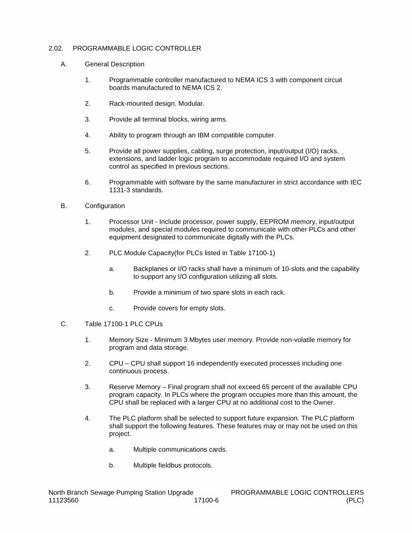
North Branch Sewage Pumping Station Upgrade PROGRAMMABLE LOGIC CONTROLLERS 11123560 17100-6 (PLC)
2.02. PROGRAMMABLE LOGIC CONTROLLER
A. General Description
1. Programmable controller manufactured to NEMA ICS 3 with component circuit boards manufactured to NEMA ICS 2.
2. Rack-mounted design. Modular.
3. Provide all terminal blocks, wiring arms.
4. Ability to program through an IBM compatible computer.
5. Provide all power supplies, cabling, surge protection, input/output (I/O) racks, extensions, and ladder logic program to accommodate required I/O and system control as specified in previous sections.
6. Programmable with software by the same manufacturer in strict accordance with IEC 1131-3 standards.
B. Configuration
1. Processor Unit - Include processor, power supply, EEPROM memory, input/output modules, and special modules required to communicate with other PLCs and other equipment designated to communicate digitally with the PLCs.
2. PLC Module Capacity(for PLCs listed in Table 17100-1)
a. Backplanes or I/O racks shall have a minimum of 10-slots and the capability to support any I/O configuration utilizing all slots.
b. Provide a minimum of two spare slots in each rack.
c. Provide covers for empty slots.
C. Table 17100-1 PLC CPUs
1. Memory Size - Minimum 3 Mbytes user memory. Provide non-volatile memory for program and data storage.
2. CPU – CPU shall support 16 independently executed processes including one continuous process.
3. Reserve Memory – Final program shall not exceed 65 percent of the available CPU program capacity. In PLCs where the program occupies more than this amount, the CPU shall be replaced with a larger CPU at no additional cost to the Owner.
4. The PLC platform shall be selected to support future expansion. The PLC platform shall support the following features. These features may or may not be used on this project.
a. Multiple communications cards.
b. Multiple fieldbus protocols.

North Branch Sewage Pumping Station Upgrade PROGRAMMABLE LOGIC CONTROLLERS 11123560 17100-7 (PLC)
c. Ethernet communications.
d. Available with NEC Class 1 rating.
e. Available to meet Safety applications.
f. Available with programmable ASCII interface cards.
g. RTD and thermocouple interface cards.
5. As a minimum, each CPU shall be able to address a minimum of 30 I/O cards in any combination of the types specified.
6. CPU shall have a minimum of one communication port for 10Base T Ethernet and one serial communication ports for programming. Minimum speed of the serial communication ports shall be 19,200 BPS. Ethernet port shall provide 10 MBS data transfer to the network, hence intermediary communication adapters that reduce this data transfer rate are not acceptable.
D. Input/Output Units
1. PLC
a. All I/O modules for PLCs shall be of the same form-factor as the PLC CPU and shall plug into the PLC backplane (rack).
b. I/O Cards – General Requirements
1) Removable terminal block on card edge.
2) Screw down connections.
3) Watchdog diagnostics.
c. Provide digital input as listed below unless otherwise shown or specified.
1) 120 Vac Inputs.
2) 16 isolated points per card.
3) 1500 V(rms) dielectric strength.
4) Digital Point input impedence: > 10kOhms.
5) On-card LED I/O diagnostics.
d. Provide digital outputs as listed below unless otherwise shown or specified.
1) Dry contact outputs.
2) 16 points per card
3) Contact Rating (Minimum) - 2 A @ 120 VAC.
4) Output Configuration - Form A.

North Branch Sewage Pumping Station Upgrade PROGRAMMABLE LOGIC CONTROLLERS 11123560 17100-8 (PLC)
e. Provide analog input as listed below unless otherwise shown or specified.
1) Isolated 4-20 mA inputs.
2) 8 channels per card.
3) 16 bit resolution.
4) Input filtering.
5) Overload protection.
f. Provide analog output as listed below unless otherwise shown or specified.
1) Isolated 4-20 mA outputs.
2) 4 channels per card.
3) Minimum 12 bit resolution.
4) Short circuit protection.
g. Combination I/O modules are not acceptable.
2. Installed Spare I/O - Provide the following installed spare I/O:
a. Provide a minimum of eight discrete inputs at each PLC.
b. Provide a minimum of eight discrete outputs at each PLC.
c. Provide a minimum of four analog inputs at each PLC.
d. Provide a minimum of four analog outputs at each PLC.
e. Wire all installed spare points to terminal strips. These terminal blocks do not count toward installed spare terminal blocks.
f. Discrete outputs shall be isolated using an interposing relay. Provide relays for used and installed spare discrete outputs.
g. In PLC enclosures where signal isolators are used to isolate analog inputs or analog outputs, provide signal isolators for each installed spare analog I/O point.
3. Refer to I/O list for I/O points for each PLC enclosure.
a. All I/O shall be wired to terminal strips. Where relays, intrinsically safe barriers and/or surge protection for I/O are required, wiring shall be from the I/O module to the relay, barrier, or surge protector to the terminal strip.
b. Provide intrinsically safe barriers for I/O originating in hazardous areas as indicated on the Contract Drawings. Installation and separation of wiring shall be in full accordance with the latest revision of the NEC.

North Branch Sewage Pumping Station Upgrade PROGRAMMABLE LOGIC CONTROLLERS 11123560 17100-9 (PLC)
c. Provide surge protection in for I/O that enters/leaves the building. Surge protection shall be located on a separate DIN rail from the terminal strips.
d. Provide loop and external power supplies for all field devices that require such power.
e. Provide 120 VAC power for all 120 VAC discrete outputs.
2.03. ENCLOSURE (CABINETS)
A. All PLC enclosures shall be appropriately sized to accommodate all I/O modules, power supplies, communication equipment, etc. as specified within this Section and as necessary to perform the required functions.
B. Maximum footprint for PLC enclosures shall be 24 inches by 60 inches or as otherwise shown on the Contract Drawings.
C. Refer to Electrical Contract Drawings for locations and space available for PLCs.
D. Each enclosure shall have two ground busses, one for instrumentation cable shields and enclosure grounding and one for signal grounding.
E. Provide grounding lugs for connection to the external grounding system.
F. Provide a Ground Fault Circuit Interruptor (GFCI), 15-amp duplex receptacle in each PLC enclosure. To be used as a service outlet with both outlets available.
G. Provide three-point latching, gasketed, keyed locking handles. All PLC enclosures shall utilize the same cylinder lock and keys. Provide two keys per enclosure.
H. Provide a fluorescent light package in each enclosure. Florescent light shall utilize a manual light switch, terminal block, and non-yellowing PVC lens. Light shall not energize automatically when door is opened. Light shall be Hoffman, Model A-LF16M24, or equal.
I. Provide a temperature transmitter designed to measure the PCS cabinet internal temperature for each PCS cabinet. The transmitter shall be provided with a 4-20mA analog output wired to a PLC AI input.
J. Terminal Blocks
1. Provide terminal blocks as described in Section 17190 (Control Panels).
2. Provide installed spare terminal blocks to accommodate wiring of PLC I/O modules provided in empty slots. Of the remaining empty slots, estimate half will be 4-point analog cards and half will be 16-point discrete cards. Mount installed spare terminal blocks in a contiguous strip next to the utilized discrete input, output, analog input, or output strips.
K. Fuse Blocks
1. Fuse blocks shall utilize slow blow glass fuses.
2. Fuse block shall have an LED that illuminates when the fuse has blown.

North Branch Sewage Pumping Station Upgrade PROGRAMMABLE LOGIC CONTROLLERS 11123560 17100-10 (PLC)
3. Label via machine printed zack strips as supplied by the fuse block manufacturer. Zack strips shall be plastic labels specifically designed for the supplied fuse block. Zack strips shall be capable of being separated to label stand-alone fuse block, if necessary
4. Provide installed spare fuse blocks to accommodate wiring of additional PLC I/O modules. Estimate as is done for terminal blocks.
5. Fuse block manufacturer shall be Phoenix Contact, model UK5-HESI, or equal.
L. Install a laminated plastic card in the enclosure of each PLC provided under this contract detailing all procedures for restarting the PLC upon lockup, including reloading the PLC program when necessary.
M. Install pertinent final I/O lists, elementary diagrams, and PLC card wiring diagrams in the enclosure of each PLC provided under this Contract. Drawings shall be laminated and bound via a plastic zip strip through a metallic grommet in the upper left-hand corner of each drawing.
2.04. PLC ACCESSORIES
A. A. I/O Signal Surge Suppressors
1. Provide I/O surge suppression for all discrete and analog signals terminating or originating out of doors or in other buildings and as specified in Section 17010 (Control Systems Integrator).
2. PLC Surge Protective Devices – Metal Oxide Varistor (MOV) based surge suppression with an active tracking filter.
a. Provide one power protection device for each PLC enclosure.
b. Manufacturer – Control Concept (Liebert), Model Islatrol Plus; or equal.
c. Minimum of 160 Joules protection between line-neutral, line-ground, and neutral-ground for a total of 480 Joules protection.
d. Response Time – Less than 1 nanosecond (in Normal mode).
e. 40kOhm surge capability on a 8x20 microsecond waveform.
f. UL1449 listed for safety and performance.
g. Manufactured by an ISO 9001 company.
h. Load side sine wave tracking circuitry.
i. Arrays of MOVs shall be located directly on the load side terminals and line side terminals to minimize response time.
j. Enclosure – Sand packed or epoxy filled.

North Branch Sewage Pumping Station Upgrade PROGRAMMABLE LOGIC CONTROLLERS 11123560 17100-11 (PLC)
2.05. UNINTERRUPTIBLE POWER SUPPLY (UPS)
A. Characteristics
1. Provide one online UPS for each PLC.
2. Minimum Watt Capacity - See paragraph 2.06.C.
3. Minimum Volt-ampere Capacity - See paragraph 2.06.C.
4. Four 120 volt, 5-15R, output receptacles, minimum.
5. Alarms - Battery backup operation, low run time remaining, and overload.
6. Automatic current and over-voltage output protection.
7. Operating Input Voltage - 99 VAC - 138 VAC.
8. No interruption (no transfer time for normal power to battery backup) of power to the PLC system.
9. Efficiency - 95 percent.
10. Brownout protection for input voltages of 88 VAC without the use of the batteries.
11. Lightning and Surge Protection - ANSI/IEEE C62.41 Categories A and B with 0.3 percent to 0.7 percent.
12. Radio Frequency Noise Isolation - 38 dB common mode, 47 dB normal mode.
13. Power Reserve Time at Full Power Draw - One hour, minimum. See paragraph 2.06.C for power draw requirements. SCADA system supplier shall submit calculations to substantiate sizing.
B. PLC power supply shall be backed up by the UPS. The required capacity of the UPS shall be determined by the load requirements of the PLC and its peripherals. As a minimum, the UPS shall maintain power to the entire panel, all communication devices and modules, all relays, all loop power supplies, all indicators, the PLC, and all PLC I/O that is powered from the panel, setpoint station, but not the heating/cooling system for the panel.
C. It is preferred that the UPS be located in the same enclosure as the PLC, unless panel size or cooling requirements make it impractical. In that case, it shall be located on a wall shelf located above the PLC enclosure. Shelf shall be provided by the Contractor.
2.06. HUMAN-MACHINE INTERFACE TERMINALS
A. General
1. The HMI shall be an industrial LCD computer panel that provides graphic displays on a color screen. The HMI shall allow bi-directional communication between itself and the PLC.
2. The HMI shall be provided with Touchscreen capabilities. The screen shall be a color LCD.

North Branch Sewage Pumping Station Upgrade PROGRAMMABLE LOGIC CONTROLLERS 11123560 17100-12 (PLC)
3. The HMI shall be provided with the ability to communicate to the PLC over the plant Ethernet network, including protocol (IP). The HMI shall be completely compatible with the process control system specified and as shown on the Contract Drawings.
4. The HMI shall be provided with a CompactFlash card (minimum 1GB), which shall allow the transfer of application files between the development software and the HMI.
5. HMI Characteristics
a. Display Type - TFT Active Matrix Color LCD.
b. Display Size - 17 inch.
c. Resolution: XGA - 1920 x 1080.
d. User Input Type - Resistive touchscreen.
e. Real-time Clock - Synchronizable battery-backed clock.
f. Electrical - 120 VAC.
g. Operating System - Microsoft Windows 7 Pro.
h. Processor - 1.83 GHz Core 2 Duo Mobile.
i. Memory/RAM (minimum) - 4 GB.
j. Hard Drive - 500GB SATA.
k. I/O Ports
1) Three USB
2) Two RS-232.
3) One RS-485.
4) One RJ-45 Ethernet LAN.
l. Removable Storage -
1) One PC card.
2) One compact flash card reader
3) DVD burner.
m. Housing Rating - Provide installed panel-mount NEMA rating to match enclosure rating
6. The HMI shall be flush mounted in an enclosure as specified herein. The power supply and related accessories shall be mounted in the enclosure. Refer to the Contract Drawings for additional information.

North Branch Sewage Pumping Station Upgrade PROGRAMMABLE LOGIC CONTROLLERS 11123560 17100-13 (PLC)
7. The HMI shall be provided with operating as required for connection to network as shown on Contract Drawings and programming cables for connection to a laptop computer.
8. Manufacturers
a. Total Controls Solutions
b. Nematron
c. Or equal
PART 3 EXECUTION
3.01. EXAMINATION
A. Verify that surfaces are ready to receive work.
B. Verify field measurements are as shown on Drawings.
C. Verify that required utilities are available, in proper location, and ready for use.
D. Beginning of installation means installer accepts conditions.
E. Verify grounding of system.
3.02. PANEL FABRICATION
A. Install in accordance with manufacturer's instructions.
3.03. INSTALLATION
A. Install in accordance with manufacturer's instructions.
B. All electrical work performed in fabrication and installation of PLC systems shall be in full accordance with the requirements of the Division 16 (Electrical) Specifications.
3.04. FIELD QUALITY CONTROL
A. The following field tests and demonstrations shall be performed for the process control system components:
1. Point-to-Point Wiring and Transmission Verification.
2. System Demonstration Testing.
3. Startup Testing.
4. All testing required herein shall be supervised by the CSI.
B. Sequencing
1. Notification of Testing and Demonstration: The Contractor shall notify the Engineer in writing a minimum of three (3) calendar days prior to beginning a particular test.

North Branch Sewage Pumping Station Upgrade PROGRAMMABLE LOGIC CONTROLLERS 11123560 17100-14 (PLC)
2. The CSI shall provide all equipment, labor and materials required to conduct testing. The CSI shall coordinate to have supportive personnel from the general contractor and/or subcontractors on site as required to perform tests with applicable field devices.
C. Final Point-to-Point I/O Wiring Verification and Transmission
1. After installation of the PLC equipment and connection of all I/O points, the CSI shall prepare an I/O checklist for I/O and wiring verification. Checklist shall include each input and output point connected to the control system, including point origination, point type, and point termination. Analog I/O shall include range of engineering units, and type of analog signal. Checklist format may also be used for final I/O wiring verification. Checklist shall have columns for signoff by a representative of the Contractor and a column for date of check.
2. The Contractor shall prepare a system test procedure to verify the proper transmission of all input and output signals from the field (to and from) the local HMIs. The field-testing procedure shall be approved by the Engineer and shall demonstrate conformance of the total system to these specifications and project requirements. The Contractor shall correct any deficiencies found and the tests shall be repeated. This process shall continue until all tests have been successfully completed. The Contractor shall develop a checklist for all I/O, including all of the information contained on the point-to-point I/O Verification checklist, and shall include a column for the graphics display program and HMI where applicable.
3. Each I/O shall be verified by the CSI to ensure that the interconnecting wiring is complete and correct, and connected to the proper terminals at the points of termination. Discrete points shall be checked from point of origin (the field device external to the PCS Cabinet) such as float switches, motor starters, switch status points, control panel alarm signals, and control points. Control points originating from PCS cabinets can be checked either by forcing the corresponding PLC register, or providing a temporary jumper at the I/O terminals. Analog points may be checked by using analog signal generators, and shall be checked at 0, 25, 50, 75, 100, and 101 percent of their values.
4. All required test programs shall be completed such that transmission of I/O from point of origin to destination can be demonstrated to be wired properly and transmitted properly between the field point and the HMI, and vice versa.
5. Engineer shall witness all testing, and shall sign off on each individual point along with a representative of the Contractor. All I/O shall be demonstrated to be wired and terminated properly, and resulting signals shall be demonstrated to activate the correct displays on the graphic display screens as well as on the applicable HMI screens. Analog display values shall be checked on the HMI.
6. Signal generators may be used for field generated analog input signals where analog input signals are not yet available in a real-time status. Analog output signals shall be generated at the programming terminal.
3.05. CERTIFICATION OF TESTING
A. Unless waived in writing by the Engineer, all tests shall be made in the presence of a duly authorized representative of the Owner. When the presence of such representative is so waived, certified results of the tests made and the results thereof shall be furnished by the Contractor.

North Branch Sewage Pumping Station Upgrade PROGRAMMABLE LOGIC CONTROLLERS 11123560 17100-15 (PLC)
B. All tests shall be performed in the presence of the Owner. Written notice of all tests shall be given the Owner at least two weeks in advance.
3.06. TEST EQUIPMENT
A. The Contractor shall furnish all instruments and a qualified engineer to properly perform all tests required.
3.07. FACTORY-TRAINED SUPERVISION
A. The Contractor shall include in his work the providing of necessary factory trained supervision to check over equipment for proper functioning before putting the equipment into operation as may be required by these specifications. This shall include establishing a simulated fault on checking out the coordination of the protective devices.
B. Point-to-point test of all wiring.
C. Functional test of all equipment, modes, alarms, controls.
END OF SECTION


North Branch Sewage Pumping Station Upgrade11123560 17101-1 PCS INPUT/OUTPUT DATA TABLES
SECTION 17101
PROCESS CONTROL SYSTEMINPUT / OUTPUT DATA TABLES
PART 1 GENERAL
1.01. SECTION INCLUDES
A. This section includes the input/output data tables for the Process Control System (PCS) forconfiguring the control system database.
1.02. INPUT/OUTPUT DATA TABLE FIELDS
A. The I/O point data table includes information required to organize layout discrete and analoginputs and outputs. Information is also included for the programmer to configure theinput/output modules and to establish data fields and range conversions.
B. Equipment Tag Nos.
C. Equipment description.
D. PCS point ID.
E. PCS point description.
F. I/O type.
G. Signal type.
H. Scaling/units.
1.03. INPUT/OUTPUT DATA TABLE
A. Slot designations are provided for general information for distribution of similar I/O points. I/Opoints shall be arranged such that similar equipment is separated onto individual I/O modulessuch that a common mode failure of a single I/O module will not disrupt operation of similarprocess units.
B. Discrete signal requirements shall be coordinated for 120VAC and 24VDC module counts.
C. Provide 20 percent additional (spare) I/O points per point type, including voltage types, inaddition to the I/O scheduled.
1. I/O Subtotals included at the end of each PCS Cabinet Data Table do not include the20 percent spare I/O.
2. The “# of Cards Required” count at the end of each PCS Cabinet Data Table includesthe 20 percent spare I/O; however, it is the Contractor’s responsibility to verify andprovide a minimum of 20 percent spare points.
3. All spare I/O points shall be wired to filed wiring terminal blocks with allappurtenances (i.e., interposing control relays for spare DO points, dc power supplyconnection for analog inputs).

North Branch Sewage Pumping Station Upgrade11123560 17101-2 PCS INPUT/OUTPUT DATA TABLES
D. The I/O data tables include digital communication I/O points/registers (Ethernet), but not allpossible digital communication points/registers have been identified for each device. Finaldigital communication I/O points/registers shall be determined during shop drawing reviewand the programming phase during construction based on the final equipment/componentselection.
Continued on next sheet.

PROJECT: NORTH BRANCH SEWAGE PUMPING STATION UPGRADECLIENT: ALLEGANY COUNTY, MD
CABINET: PCPNBPSLOCATION: Control Building
DATE:
Equipment Description Signal Scaling / Units I/O Type Signal
Type Slot
PS - AC1 PCP Cabinet Primary Power Supply PCPNBPS - JF AC1 Alarm - Power Outage Alarm/Normal DI 120VAC A4PS - AC2 PCP Cabinet Secondary Power Supply PCPNBPS - JF AC2 Alarm - Power Outage Alarm/Normal DI 120VAC A4PS - DC1 PCP Cabinet Primary DC Supply PCPNBPS - JF DC1 Alarm - PCP DC Power Fail Alarm/Normal DI 120VAC A4PS - DC2 PCP Cabinet Secondary DC Supply PCPNBPS - JF DC2 Alarm - PCP DC Power Fail Alarm/Normal DI 120VAC A4PS - UPS PCP Cabinet UPS PCPNBPS - UB UPS UPS Status - Normal/Bypass -40 to 140ᵒF DI 120VAC A4PS - UPS PCP Cabinet UPS PCPNBPS - US UPS UPS Status - Line/Batt Power 5-95% DI 120VAC A4PS - UPS PCP Cabinet UPS PCPNBPS - UF UPS UPS Alarm - General Alarm/Normal DI 120VAC A4PS - UPS PCP Cabinet UPS PCPNBPS - UF UPS UPS Alarm - Low Battery Alarm/Normal DI 120VAC A4PT - TEMP PCP Cabinet Temperature PCPNBPS - TI TEMP Cabinet Temperature -40 to 140ᵒF AI 4-20mA A9PH - HUM PCP Cabinet Humidity PCPNBPS - HI HUM Cabinet Humidity 40-90%RH AI 4-20mA A9AR - PB1 PCP Cabinet Alarm Reset/Silence PCPNBPS - AR PB1 Control - Silence Off/On DI 120VAC A4AH - AH1 PCP Cabinet Alarm Horn PCPNBPS - AH AH1 Alarm - Horn Off/On DO 120VAC A7
SPD - SPS Surge Protection Device Fail PCPNBPS - SPD SPS Normal/Alarm Off/On DI 120VAC A4DPM - MDP Digital Power Monitor PCPNBPS - DPM MDP MULTIPLE PARAMETERS - ENETATS - 901101 ATS in Normal PCPNBPS - ZSN 901101 Status - Position -/Normal DI 120VAC A4ATS - 901101 ATS in Emergency PCPNBPS - ZSE 901101 Status - Position -/Emergency DI 120VAC A4GEN - 901201 Generator Running PCPNBPS - MN 901201 Status - Running Off/On DI 120VAC A4GEN - 901201 Generator Fail PCPNBPS - PF 901201 Alarm - Fail Normal/Alarm DI 120VAC A4
P - 011101 Sewage Pump No. 1 VFD CP PCPNBPS - AH 011101 MULTIPLE PARAMETERS - ENET #N/AP - 011101 Sewage Pump No. 1 VFD CP PCPNBPS - MN 011101 Status - Run Off/On DI 120VAC A4P - 011101 Sewage Pump No. 1 VFD CP PCPNBPS - YN 011101 Mode - Auto -/Auto DI 120VAC A4P - 011101 Sewage Pump No. 1 VFD CP PCPNBPS - MC 011101 Control - Auto Stop/Start DO 120VAC A7P - 011101 Sewage Pump No. 1 VFD CP PCPNBPS - MF 011101 Alarm - Common Alarm/Normal DI 120VAC A5P - 011101 Sewage Pump No. 1 VFD CP PCPNBPS - SC 011101 Control - Speed 0-60Hz AO 4-20mA A11P - 011101 Sewage Pump No. 1 VFD CP PCPNBPS - SI 011101 Feedback - Speed 0-60Hz AI 4-20mA A9P - 011101 Sewage Pump No. 1 VFD CP PCPNBPS - XF 011101 Alarm - Seal Fail Alarm/Normal DI 120VAC A5P - 011102 Sewage Pump No. 2 VFD CP PCPNBPS - AH 011102 MULTIPLE PARAMETERS - ENET #N/AP - 011102 Sewage Pump No. 2 VFD CP PCPNBPS - MN 011102 Status - Run Off/On DI 120VAC A5P - 011102 Sewage Pump No. 2 VFD CP PCPNBPS - YN 011102 Mode - Auto -/Auto DI 120VAC A5P - 011102 Sewage Pump No. 2 VFD CP PCPNBPS - MC 011102 Control - Auto Stop/Start DO 120VAC A7P - 011102 Sewage Pump No. 2 VFD CP PCPNBPS - MF 011102 Alarm - Fault Alarm/Normal DI 120VAC A5P - 011102 Sewage Pump No. 2 VFD CP PCPNBPS - SC 011102 Control - Speed 0-60Hz AO 4-20mA A11P - 011102 Sewage Pump No. 2 VFD CP PCPNBPS - SI 011102 Feedback - Speed 0-60Hz AI 4-20mA A9P - 011102 Sewage Pump No. 2 VFD CP PCPNBPS - XF 011102 Alarm - Seal Fail Alarm/Normal DI 120VAC A5
GR - 002701 Grinder OEM CP PCPNBPS MN 002701 Status - Run Off/On DI 120VAC A5GR - 002701 Grinder OEM CP PCPNBPS MF 002701 Alarm - Fault Alarm/Normal DI 120VAC A5LT - 007301 Wet Well No.1 Submersible Pressure Transducer No.1 PCPNBPS - LT 007301 Indication - Level 0-100% AI 4-20mA A12LT - 007302 Wet Well No.1 Submersible Pressure Transducer No.2 PCPNBPS - LT 007302 Indication - Level 0-100% AI 4-20mA A12
LSHH - 007101 Wet Well No.1 High High Level Float PCPNBPS - LSHH 007101 Status - High Level Alarm/Normal DI 120VAC A6LSLL - 007102 Wet Well No.1 Low Low Level Float PCPNBPS - LSLL 007102 Status - Low Level Alarm/Normal DI 120VAC A6
FE/FIT - 378301 Pumping Station Effluent Flow Meter PCPNBPS - FIT 378301 Indication - Flow MGD AI 4-20mA A12PE/PIT - 017701 Pump Discharge No.1 Pressure Transmitter PCPNBPS - PIT 017701 Indication - Pressure PSI AI 4-20mA A12PE/PIT - 017702 Pump Discharge No.2 Pressure Transmitter PCPNBPS - PIT 017702 Indication - Pressure PSI AI 4-20mA A12
P - 011101 Sewage Pump No. 1 (To RTU) PCPNBPS - MN 011101 Status - Run Off/On DO 120VAC A7P - 011101 Sewage Pump No. 1 (To RTU) PCPNBPS - MF 011101 Alarm - Fault Alarm/Normal DO 120VAC A7P - 011101 Sewage Pump No. 1 (To RTU) PCPNBPS - XF 011101 Alarm - Seal Fail Alarm/Normal DO 120VAC A7P - 011102 Sewage Pump No. 2 (To RTU) PCPNBPS - MN 011102 Status - Run Off/On DO 120VAC A7P - 011102 Sewage Pump No. 2 (To RTU) PCPNBPS - MF 011102 Alarm - Fault Alarm/Normal DO 120VAC A7P - 011102 Sewage Pump No. 2 (To RTU) PCPNBPS - XF 011102 Alarm - Seal Fail Alarm/Normal DO 120VAC A7
GR - 002701 Grinder (To RTU) PCPNBPS MN 002701 Status - Run Off/On DO 120VAC A7GR - 002701 Grinder (To RTU) PCPNBPS MF 002701 Alarm - Fault Alarm/Normal DO 120VAC A7
GEN - 901201 Generator Running (To RTU) PCPNBPS - MN 901201 Status - Running Off/On DO 120VAC A7GEN - 901201 Generator Fail (To RTU) PCPNBPS - PF 901201 Alarm - Fail Normal/Alarm DO 120VAC A7
FE/FIT - 378301 Pumping Station Effluent Flow (To RTU) PCPNBPS - FIT 378301 Indication - Flow MGD AO 4-20mA A12LT - 007301 Wet Well Level (To RTU) PCPNBPS - LT 007301 Indication - Level 0-100% AO 4-20mA A12
LSHH - 007101 Wet Well High High Level (To RTU) PCPNBPS - LSHH 007101 Status - High Level Alarm/Normal DO 120VAC A6PS - DC1 PCP Primary DC Power Supply Fail (To RTU) PCPNBPS - PS DC1 Alarm - PCP DC Power Fail Alarm/Normal DO 120VAC A6PS - DC2 PCP Secondary DC Power Supply Fail (To RTU) PCPNBPS - PS DC2 Alarm - PCP DC Power Fail Alarm/Normal DO 120VAC A6PS - UPS PCP UPS General Alarm (To RTU) PCPNBPS - PS UPS UPS Alarm - General Alarm/Normal DO 120VAC A6
SPD - SPS Surge Protection Device Fail (To RTU) PCPNBPS - SPD SPS Normal/Alarm Off/On DO 120VAC A6
Hardwire I/O Subtotal Points # of Cards Required*
24VDC Discrete Input (DI): 0 0
24VDC Discrete Output (DO): 0 0
120VAC Discrete Input (DI): 26 3
120VAC Discrete Output (DO): 18 2
Analog Input (AI): 9 2
Analog Output (AO): 4 1
*Card count includes 20% spare
PROCESS CONTROL SYSTEM INPUT/OUTPUT DATA TABLES
5/17/2019
Equipment Tag No. PCS Point ID
North Branch Sewage Pumping Station Upgrade11123560 17111-3 17111 INPUT/OUTPUT DATA TABLE


North Branch Sewage Pumping Station Upgrade 11123560 17111-1 SCADA MONITORING SYSTEM
SECTION 17111
SCADA MONITORING SYSTEM
PART 1 GENERAL
1.01. SECTION INCLUDES
A. The North Branch Sewage Pumping Station is currently provided with a SCADA monitoring unit. The existing unit is a MISSION 800 Series provided by Whel-Tech, Inc.
B. Provide a new updated Mission MyDro 850 Series remote terminal SCADA unit to provide monitoring of I/O points derived from a new Pump Control Panel. The SCADA monitoring unit shall be programmed to communicate with the existing SCADA topology servicing Allegany County Utilities Division. Programming and any modifications required to the RTUs shall be performed by Whel-Tech, Inc or equal.
1.02. GENERAL REQUIREMENTS
A. It is a requirement of this specification that the elements of the system be provided by a single supplier.
1.03. REFERENCES
A. NEMA ICS 1 - General Standards for Industrial Control and Systems.
B. NEMA ICS 3 - Industrial Systems.
C. NEMA ICS 6 - Enclosures for Industrial Controls and Systems.
D. NFPA 70 - National Electrical Code.
E. ISO 9001
F. National Institute of Science and Technology (NIST) – Calibration method.
1.04. SUBMITTALS
A. Submittals shall include, but not be limited to, the following:
1. Shop Drawings – Data sheets and catalog information including:
a. Bill of Material
b. Wiring and interconnection schematics
c. Detailed system description
d. Mounting details
e. Physical size, outline and dimension drawings, materials of construction, enclosure details.

North Branch Sewage Pumping Station Upgrade 11123560 17111-2 SCADA MONITORING SYSTEM
1.05. OPERATION AND MAINTENANCE DATA
A. Contractor shall submit operation and maintenance data in both hard copy and electronic formats. Submit under provisions of Section 01700 (Record Documents). Contractor shall provide manufacturer/supplier with a copy of Section 01700 (Record Documents).
B. Operation Data - Include instructions for operating equipment. Include instructions for operating equipment under emergency conditions when engine generator is running.
C. Maintenance Data - Include routine preventative maintenance and lubrication schedule. List special tools, maintenance materials, and replacement parts.
D. Operation and maintenance documentation shall be submitted at the time equipment is shipped. Final approved copies shall be available on site prior to startup.
1.06. DELIVERY, STORAGE, AND HANDLING
A. Deliver, store, protect and handle products to site.
B. Store in a clean, dry space. Maintain factory wrapping or provide an additional heavy canvas or heavy plastic cover to protect units from dirt, water, construction debris, and traffic.
C. Handle in accordance with manufacturer’s written instructions. Lift only with lugs provided for the purpose. Handle carefully to avoid damage to internal components, enclosure and finish
1.07. EQUIPMENT WARRANTIES AND SPECIAL GUARANTEES
A. The Supplier shall provide the following warranties and special guarantees.
1. The equipment manufacturer shall guarantee for a period of two years starting at the time of equipment delivery to the job site or one-year starting at the time of Substantial Completion (whichever is shorter), that the equipment supplied is free from defects in materials or workmanship and will meet the specified performance requirements when operated in accordance with the manufacturer’s recommendations. The manufacturer shall correct any breach in this warranty at their expense.
1.08. COORDINATION
A. Coordinate mounting locations with the Owner.
PART 2 PRODUCTS
2.01. SCADA MONITORING SYSTEM
A. The SCADA monitoring RTU shall be enclosed in a NEMA 1 enclosure. The RTU shall transmit all data and alarms via a public wireless data network. The RTU shall be powered by 12 volts AC and have a built in battery backup capable of keeping the RTU powered for 24 hours in case of primary AC failure. All terminations inside the RTU enclosure shall be low voltage AC or DC (28 volts or less). The RTU shall be supplied with a UL recognized 120 VAC to 12 VAC step down transformer. The RTU shall have two (2) analog, 10-bit resolution, 4-20ma or 0-5 vdc inputs, with four (4) alarm thresholds per input. The analog input values shall be transmitted by the RTU to the central monitoring software at least every 1 minute. The RTU shall have built in AC failure and low battery detection. The RTU shall have eight (8) digital
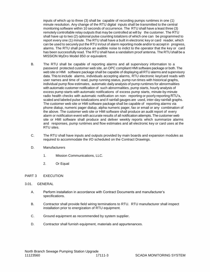
North Branch Sewage Pumping Station Upgrade 11123560 17111-3 SCADA MONITORING SYSTEM
inputs of which up to three (3) shall be capable of recording pumps runtimes in one (1) minute resolution. Any change of the RTU digital inputs shall be transmitted to the central monitoring software within 10 seconds of occurrence. The RTU shall have a least three (3) remotely controllable relay outputs that may be controlled at will by the customer. The RTU shall have up to two (2) optional pulse counting totalizers of which one can be programmed to report every one (1) minute. The RTU shall have a built in electronic key or card reader, which can be used to securely put the RTU in/out of alarm reporting mode and/or to accept in progress, alarms. The RTU shall produce an audible noise to indict to the operator that the key or card has been successfully read. The RTU shall have a vandalism proof antenna. The RTU shall be a MISSION MyDro Model 850 or equivalent.
B. The RTU shall be capable of reporting alarms and all supervisory information to a password protected customer web site, an OPC compliant HMI software package or both. The web site or HMI software package shall be capable of displaying all RTU alarms and supervisory data. This to include alarms, individuals accepting alarms, RTU electronic key/card reads with user names and time of read, pump running status, pump run times with historical graphs, individual pump flow estimates, automatic daily analysis of pump runtimes for abnormalities with automatic customer notification of such abnormalities, pump starts, hourly analysis of excess pump starts with automatic notifications of excess pump starts, minute-by-minute radio health checks with automatic notification on non- reporting or poorly reporting RTU’s, scaled and labeled pulse totalizations and if rainfall gauges are used, inter-day rainfall graphs. The customer web site or HMI software package shall be capable of reporting alarms via phone dialup, numeric pager dialup, alpha numeric pager, fax or email or any combination of the above. The customer web site or HMI software shall produce an audit report of every alarm or notification event with accurate results of all notification attempts. The customer web site or HMI software shall produce and deliver weekly reports which summarize alarms and responses, pump runtimes and flow estimates and all electronic key or card uses at the RTU sites.
C. The RTU shall have inputs and outputs provided by main boards and expansion modules as required to accommodate the I/O scheduled on the Contract Drawings.
D. Manufacturers
1. Mission Communications, LLC.
2. Or Equal
PART 3 EXECUTION
3.01. GENERAL
A. Perform installation in accordance with Contract Documents and manufacturer’s specifications.
B. Contractor shall provide field wiring terminations to RTU. RTU manufacturer shall inspect installation prior to energization of RTU equipment.
C. Ground equipment as recommended by system supplier.
D. Contractor shall furnish equipment, materials and appurtenances.

North Branch Sewage Pumping Station Upgrade 11123560 17111-4 SCADA MONITORING SYSTEM
3.02. FIELD QUALITY CONTROL
A. Installation
1. The RTU manufacturer shall provide on-site supervision and advice to the installing contractor to insure the equipment is installed in accordance with the specifications and the manufacturer’s requirements.
2. Contractor shall provide field wiring terminations to RTU.
3. All connections to the SCADA unit shall be coordinated with the unit supplier, and the CSI providing equipment to be interfaced to the RTU(s). All interfaces, in the form of discreet and analog inputs will be determined by the engineer, and owner, described herein, and outlined on the plan documents. All digital signals coming to the SCADA unit are to be provided by voltage free, dry contacts, and shall be run in shielded conductors, of 18 gauge minimum with shield and ground.
4. An analog inputs shall be powered at the source, and shall be individually isolated.
5. All digital inputs shall emanate from single pole double throw (SPDT) contacts, be voltage free, and accessible for the use of END of Line Termination Resistors.
B. Inspections and Field
1. RTU manufacturer shall inspect installation prior to energization of RTU equipment.
2. Any and all testing equipment required for this project shall be owned by the CSI so as to be immediately available for this project.
3. The use of specific equipment manufacturer’s startup, calibration, and troubleshooting personnel to assist the CSI shall be provided.
C. Field Testing Requirements
1. Demonstrate the control features of each panel and associated field mounted instrumentation and control equipment, to verify that each panel performs the required control functions and logic as shown on the Contract Drawings or as specified. Control features shall include relay energization, initiation of alarm conditions, resets, interlocks, set point activation, and other functions of the control panels.
2. Equipment shall be field demonstrated to operate satisfactorily in the presence of the Owner, and shall be conducted in accordance with the CSI’s testing and demonstration plan that has been reviewed by the Engineer. Field demonstrations shall be performed after successful installation, calibration and testing of each control panel.
3. In addition to demonstrating the operation of standard control features, special control panel functions shall be demonstrated as specified for each panel as specified below.
4. The Contractor shall provide the necessary test equipment, process media, materials, supplies, and qualified test personnel to perform the field demonstrations as specified herein.

North Branch Sewage Pumping Station Upgrade 11123560 17111-5 SCADA MONITORING SYSTEM
5. Field instrumentation control signals that are required to demonstrate the operation of associated control panels may be simulated upon approval of the Engineer.
6. In the event of failure of the field demonstration, the Contractor shall perform the necessary corrections and re-demonstrate, at his own cost and expense, the equipment as directed by the Engineer.
3.03. TRAINING
A. Provide services of the equipment manufacturer or their approval representative.
B. Training shall be a minimum of four (4) hours for the RTU and Web Page.
C. Instructional material shall be provided for (4) trainees.
END OF SECTION


North Branch Sewage Pumping Station Upgrade 11123560 17190-1 CONTROL PANELS
SECTION 17190
CONTROL PANELS
PART 1 GENERAL
1.01. SECTION INCLUDES
A. This section includes requirements for new control panels and modifications to existing control panels as shown on the Contract Drawings, specified herein, and otherwise indicated or referenced including:
1. Pump Control Panel
2. VFD Control Panels
3. Intrinsically Safe Relay Panels
B. Equipment furnished under this Contract shall be installed in an industrial type environment and powered from an electrical source that may include harmonic distortion, surges, sags, and other electrical noise under normal operating conditions. The Contractor shall verify that all equipment furnished shall function correctly in an environment where electrical noise of the types referenced are common during normal operations. If the equipment is found to be unable to operate in this environment, the Contractor shall furnish additional and/or replacement equipment, surge protection, power line conditioners, uninterruptible power supply (UPS), or other equipment required to correct this problem at no additional cost to the Owner.
C. This section includes power line surge protectors as shown on the Contract Drawings, specified herein, and otherwise required for appropriate equipment, including, but not limited to control panels, instrument cabinets, instruments, processors, and other equipment susceptible to damage from power surges in the electrical supply.
1.02. REFERENCES
A. Material and installation shall be in accordance with the latest revisions of the following:
1. National Electrical Code - NEC
2. National Electrical Manufacturers Association - NEMA
3. Underwriters Laboratories, Inc. - UL
4. JIC Standard EGP-1
1.03. QUALITY ASSURANCE
A. Qualifications of Manufacturer - All equipment furnished under this section shall be furnished by manufacturers who meet the quality, workmanship, and experience requirements as specified in the General Conditions section of this contract.
1.04. SUBMITTALS
A. Submittals shall be in accordance with the General Conditions and as described herein.

North Branch Sewage Pumping Station Upgrade 11123560 17190-2 CONTROL PANELS
B. Prior to obtaining any material in connection with this section, detailed shop drawings on all material shall be submitted.
C. Submittals for equipment and materials shall be clearly marked or noted with specific features, standard options, and wiring diagrams to indicate compliance with Contract Documents. Terminal board wiring diagrams including terminal numbers and conductor color codes shall be indicated.
D. Where deviations to Contract Documents are proposed, submit a list of deviations. Provide a detailed description and explanation for each deviation.
E. Shop drawings shall present complete and accurate information relative to all working dimensions, equipment weights, assembly, and section views, and all necessary details pertaining to coordinating the Work of the Contract. Shop drawings shall contain information such as special tools and other items of information that are required to demonstrate detailed compliance with the Contract Documents.
F. Submit shop drawings which shall include the following:
1. Submittals shall include verification that panels will be fabricated to UL 508A standards and labeled as such. Submit short circuit current ratings (SCCR) for each individual control panel assembly.
2. Submittals shall contain the NEMA type designation and manufacturer data describing the enclosures and showing its compliance with specifications and associated standards.
3. Control panel assembly drawings detailing panel cut-out locations and sizes, back panel and device layout and locations.
4. Using AutoCAD 2013, or higher, provide these drawings for each control cabinet in the following order. Label all components with manufacturer and complete model numbers on the drawings. Typical drawings are not acceptable.
a. Scaled enclosure layout drawings in 11-inch by 17-inch format, detailing locations of all components on the subpanel, door, and all other enclosure faces. Label each view as “Enclosure Door”, “Enclosure Subpanel”, “Enclosure Side”, etc. Drawing shall display layout of completed assemblies, including, but not limited to, PLC backplane, PLC I/O modules, empty slots, radios, UPS, Ethernet switches, autodialers, terminal blocks, installed spare equipment, power supplies, power line isolators, surge suppression, grounding lugs, wireway, disconnect switches, fuses, control relays, acceptable regions for conduit penetrations of both AC and DC wiring separately, and external power. Illustrate handles, hasps, hinges, and dimensions of exterior mounted devices. Identify equipment manufacturer and model numbers by placing a number next to the piece of equipment on the drawing and cross-referencing with the Bill of Materials. In addition to the Bill of Materials cross-reference labeling, label PLC I/O modules on the drawing with the manufacturers complete model numbers.
b. Elementary diagram drawings in 11-inch by 17-inch format, detailing all enclosure electrical components including, but not limited to, power line isolators, surge suppression, UPS, power supplies, fuses, duplex receptacles, indicating lights, switches, and control relays. Diagrams shall include terminal point designations, line reference numbers, and wire numbers. All wires shall maintain the same wire number for the entire

North Branch Sewage Pumping Station Upgrade 11123560 17190-3 CONTROL PANELS
contiguous segment of wire. Diagrams shall illustrate all network cabling and DC and AC electrical distribution. Drawing shall illustrate all available instrument terminations, both used and unused, and be labeled with the manufacturer’s terminal point label as will be found on the installed instrument. Provide a legend on this sheet for all symbols and general notes used on this sheet and on the PLC I/O module detail drawings.
5. Provide PLC submittals, where applicable, per Section 17100 (Programmable Logic Controllers) including:
a. Memory map of data registers used in transferring data to the plant PCS.
b. Catalog cuts and user’s manuals for all PLC system components.
c. Screen captures of all HMI displays.
d. Operating description.
e. Comment PLC source listing.
f. Other materials, as required, to fully describe the control panel operation.
g. Updated hard and soft copies of all program files shall be submitted to the buyer for inclusion with record document submittals.
6. Bill of Materials for all equipment and accessories.
7. Manufacturer’s catalog information for all components and accessories.
8. Manufacturer’s standard wiring diagrams including all available terminal connections for each component.
9. Spare parts list (including specified spare parts to be furnished by the Contractor and manufacturer’s recommended spare parts list for each type of unit).
10. Project specific installation instructions and mounting details for each component. Materials of construction for supports, brackets, and mounting hardware shall be provided with details for each type of equipment mounting rack.
11. A list of nameplate titles shall be submitted.
12. Identify spare control panel space for future equipment.
13. Submit factory testing schedule and factory test reports.
14. Submit field testing schedule and field testing reports.
15. Submit operation and maintenance manuals for control panel equipment and components.
1.05. REQUIREMENTS FOR OEM PANELS
A. This section has been included by reference for vendor provided control panels included as part of packaged systems. It is not the intent of this specification that standard or stock control panels be redesigned per the workmanship and material sections defined in this

North Branch Sewage Pumping Station Upgrade 11123560 17190-4 CONTROL PANELS
Section. This section does, however, set minimum quality standards that must be met or exceeded. The control panel submittals shall identify exceptions to these specifications.
B. Power Supplies – Unless otherwise noted, power is provided to the OEM control panels from a single source as listed in the specifications or shown on the Drawings.
1. Power and distribution devices including, control power transformers, power supplies, fuses, circuit breakers, power distribution blocks, terminations and other required components shall be provided to generate all required voltages used by the control panel.
2. Panels including VFDs or motor starters shall be provided with an externally accessible main disconnect.
C. Large and Networked PLCs
1. Where OEM panels are provided with PLC components tied to the Plant PCS over a control network, the components shall match the equipment provided by the CSI for the units provided as part of Division 17.
2. Coordinate with the CSI to verify that the equipment has been properly selected and that network addresses, data types and register addresses are properly identified.
D. Small PLCs - Standard or stock OEM panels that are not networked and have I/O requirements totaling less than one full I/O rack, shall be provided with the vendor standard PLC.
E. Owner Maintenance
1. All tools, information and equipment required to fully maintain or modify the provided OEM panels shall be provided. Tools and equipment shall include, but not be limited to:
a. Documented PLC/HMI source code and configuration files.
b. Licensed PLC/HMI development software.
c. Connecting cables.
d. Network interface devices.
e. One spare of each type PLC card provided.
2. Where the PLC source code contains verifiable copyrighted material, the Vendor may request that distribution of the source code be limited.
PART 2 PRODUCT
2.01. GENERAL
A. Control panels shall include display panels, relay panels, annunciator panels, termination boards, or any other assembly of electrical components shop assembled in enclosures.
B. The control panels and associated controls and instrumentation equipment shall be furnished as a coordinated assembly requiring only field connections of the power and control circuits for a complete and operating installation as specified and shown on the Contract Drawings.

North Branch Sewage Pumping Station Upgrade 11123560 17190-5 CONTROL PANELS
C. Electrical equipment and controls shall be provided as required to perform the control function as shown on the Contract Drawings and specified herein. Controls shall include motor starters, control power transformers, circuit breakers and power disconnecting devices and hardware, control relays, timing relays, intrinsically safe relays, and miscellaneous controls as required, or as specified. Electrical equipment and controls shall be provided in accordance with the specifications contained herein and in Division 16.
D. The control panel enclosure, components, and controls shall be UL Listed and Labeled. Control panels shall conform to the requirements of UL 508.
2.02. ENCLOSURES
A. Enclosure Construction
1. General
a. Dimensions of enclosures shown on the Contract Drawings are minimum required dimensions. Contractor shall size each enclosure as required to house the electrical equipment shown or specified. Each enclosure shall be sized such that a minimum of 20 percent spare open space is provided on the interior subpanel and/or swingout panel for mounting of future equipment. Spare space shall be located in one clear and open, contiguous area of the subpanel.
b. Control panels shall include an equipment support system for mounting internal wiring and control components, and for the proper support of long case instruments. This system shall ensure that equipment is adequately supported by the main structural frame members. Fixed support members shall not be attached to front panels or removable access panels.
c. Steel enclosures shall be constructed of a minimum of 14 gauge steel and shall be constructed in accordance with NEMA requirements. Seams shall be continuously welded and ground smooth, with no holes or knockouts. Exterior hardware, including mounting hardware shall be stainless steel unless otherwise noted.
d. Panel cutouts shall be provided for mounting components as arranged on the Contract Drawings and shall include cutouts and cover plates and be capable of being removed for the addition of future components. Components shall either be door mounted unless otherwise noted. Control panels requiring rear access shall have the components mounted on side opposite the door.
e. All panels shall be designed for deadfront construction.
2. NEMA 12 Steel Enclosures
a. NEMA 12 enclosures shall be dust-tight, drip-tight suitable for protecting enclosed equipment and components from fibers, flyings, lint, dust and dirt. NEMA 12 enclosures shall provide a degree of protection against light splashing, seepage, dripping and external condensation of non-corrosive liquids.
b. Manufacturers
1) Hoffman

North Branch Sewage Pumping Station Upgrade 11123560 17190-6 CONTROL PANELS
2) Saginaw Control & Engineering (SCE)
3) Equal
3. NEMA 4X Stainless Steel Enclosures
a. NEMA 4X enclosures shall be water-tight and dust-tight suitable for outdoor installations. NEMA 4X enclosures shall protect enclosed equipment against splashing water, seepage of water, falling or hose-directed water, severe external condensation, and shall be corrosion resistant.
b. Enclosures shall be constructed of 14 gauge Type 304 stainless steel. Trim shall be Type 304 stainless steel. Exterior shall be unpainted.
c. Manufacturers
1) Hoffman
2) Saginaw Control & Engineering (SCE)
3) Equal
4. NEMA 7 Enclosures
a. NEMA 7 enclosures shall be suitable for installation in Class I, Group D, Division 1 Hazardous Locations.
B. Enclosure Doors
1. Enclosures shall be provided with front access single or double overlapping doors as required for the enclosure size. Door(s) shall be provided with heavy duty three point spring-roller latches operated by a key locking handle. Latch rods shall have rollers to facilitate door closing. Provide a minimum of two keys for each lock. Locks shall be keyed the same. Door assemblies for NEMA 4X stainless steel enclosures shall be constructed to maintain the NEMA rating of the enclosure assembly without the use of external door clips or hasps.
2. Door(s) shall be mounted with continuous piano hinges. Contractor shall coordinate door swing (right hand or left hand) for each control panel to avoid interference with other equipment mounted adjacent to the control panels.
3. A rolled lip around minimum three sides of door shall be provided to prevent dirt and liquid from dropping into the panel when door is open.
4. Door(s) shall be fitted with a neoprene gasket applied with oil resistant adhesive and held in place with stainless steel retaining strips.
5. Enclosures mounted outdoors shall be provided with stainless steel door stops to hold the door(s) in the open position. The open position shall be field adjustable.
C. Interior Subpanels
1. Interior subpanels for component mounting shall be provided and assembled for each enclosure. Interior subpanels shall be constructed of 14 gauge steel finished in white enamel paint. Subpanels shall be provided with intermediate stiffeners where

North Branch Sewage Pumping Station Upgrade 11123560 17190-7 CONTROL PANELS
required to maintain surface flatness and panel rigidity. Fasteners, screws, and equipment mounting racks shall be stainless steel.
2. In addition to interior subpanels, provide ‘swing-out’ type panels where shown on the Contract Drawings. Swing-out panels shall be of similar construction to subpanels specified above. Swing-out interior panels shall be provided with a continuous stainless steel piano hinge along the side of the panel. A stainless steel catch latch shall be provided to lock the swing-out panel in-place to prevent unwanted movement. Heavy duty hinges shall be provided as required to carry the load of the swing-out panels as mounted equipment.
D. Enclosure Finish
1. NEMA 4X stainless steel enclosures shall not be finished.
2. NEMA 12 enclosures: Sheet metal components shall be thoroughly cleaned, bonderized and finished with a prime coat and two topcoats of a two-component, catalyzed, polyurethane enamel. Texture semi-gloss finish shall be applied to provide a non-glare and abrasion resistant surface. Enclosures shall be provided with gray finish inside with a white enamel interior unless otherwise specified.
E. Enclosure Accessories
1. A large print pocket shall be provided on interior face of the enclosure door(s). Where this cannot be accommodated due to windows and other control devices mounted on the door, the print pockets shall be mounted on the interior side of the control panels.
2. Panel Window Kits (where shown or specified)
a. Panel windows shall be provided for control panels and enclosures where shown on the Contract Drawings. The window shall be sized to allow visual inspection of controls and components mounted on the interior swing-out panel as shown on the Contract Drawings.
b. Panel windows shall be factory installed. Installation of panel windows shall maintain the rating of the control panel or enclosure. The panel window frame shall be fabricated from heavy gauge steel and painted to match the enclosures finish. The window shall be fabricated from clear acrylic plastic with a minimum thickness of 1/4 inch. The window frame shall hold a neoprene gasket to provide a watertight seal around the entire window.
3. Floor Stand Kits (Where Shown or Specified) - Floor stand kits shall be provided where shown on the Contract Drawings or where required for free standing panels. Floor stand kits shall be constructed of the same materials as the enclosure with a reinforcing bottom plate. Floor stand kit dimensions shall be coordinated with the overall enclosure dimensions.
4. Rain hoods shall be provided for outdoor control panels and instrument enclosures as shown on the Contract Drawings.
5. Control Panel Shelf - PCS cabinet enclosures shall be provided with retractable shelf for temporary use of laptop programming terminals.

North Branch Sewage Pumping Station Upgrade 11123560 17190-8 CONTROL PANELS
6. Circuit Breaker Operators
a. Where shown on the Contract Drawings, circuit breaker disconnect handle operators shall be provided. Handle operator shall be flange mounted type, accessible from the front flange of the panel, and shall be capable of being locked in either the On and Off position with a padlock.
b. Handle operators shall prevent opening of the control panel doors with the handle in the On position. Operators shall be provided with a defeater mechanism to allow authorized personnel to open the door with the handle in the On position.
7. Service Lights and Receptacles
a. A service light complete with lamp, safety shield, on-off switch and utility receptacle shall be furnished where shown on the Contract Drawings. Provide door activated switch where shown on the Contract Drawings.
b. Receptacles shall be as specified in the Section 16055 (Electrical Work).
c. Fluorescent service lights shall be provided with a plastic cover to protect the bulb. (Bulb sleeves are not acceptable). Lights shall be controlled by a door activated light switch. Service lights shall be as manufactured by Hoffman or equal.
2.03. ENCLOSURE HVAC
A. General
1. Control panels enclosures shall be provided with louvers, forced ventilation, or air conditioners as required to prevent heat build-up within the enclosure. Except for enclosures mounted with the rear of the panel directly adjacent to a wall, place louvers in the rear of the enclosure, top and bottom. For enclosures mounted with the rear of the panel directly adjacent to a wall, place louvers on the side or front of the panel.
2. Thermostats shall be surface mount type with a temperature range of 40 to 100 degrees F (field adjustable over the entire range). Thermostats shall be provided with a stainless steel shell. Thermostat contacts shall be rated a minimum of 10 amperes at 120 VAC. Contacts shall close on temperature rise for cooling and open on temperature rise for heating equipment. Insulation bushings and mounting hardware shall be provided as required to mount the thermostats.
B. Louvers
1. Control panel louvers shall be constructed of the same material as the enclosure.
2. Intake louvers shall be provided with washable aluminum air filters used for ventilation. Provide one can of filter spray adhesive for every enclosure.
C. Ventilation Fans - Provide forced ventilation fans, with washable aluminum air filters and finger guards. Fans motors shall be operated on 115 VAC, 60 Hz. power, and shall be provided with integral thermal protection. Motors shall be rated for 20,000 hours of continuous operation without lubrication or service. Fan noise shall not exceed 50 db at 5 feet.

North Branch Sewage Pumping Station Upgrade 11123560 17190-9 CONTROL PANELS
D. Fan Driven Heaters
1. Provide thermostatically controlled heaters that shall maintain the temperature inside the control panel above 40 degrees F. Heaters shall operate on 115 VAC, 1 phase power supply.
2. Freeze Protection - Heaters shall be provided for freeze protection of control panels and shall be sized per the panel volume by the control panel fabricator.
3. Condensation Protection - Provide thermostatically controlled, fan driven heaters for all outdoor enclosures for condensation control unless otherwise specified.
4. Mount heaters near the bottom of center of the enclosure. Do not mount the electronic components closer than 6 inches to the heater.
5. Heaters shall be DesignAire electric heaters as manufactured by Hoffman or equal.
E. PTC-Type Heaters
1. Provide thermostatically controlled heaters that shall maintain the temperature inside the control panel above 40 degrees F. Heaters shall operate on 115 VAC, 1 phase power supply.
2. Freeze Protection - Heaters shall be provided for freeze protection of control panels and shall be sized per the panel volume by the control panel fabricator.
3. Condensation Protection - Provide thermostatically controlled, heaters for outdoor enclosures for condensation control as shown on the contract drawings.
4. Mount heaters near the bottom of center of the enclosure. Do not mount the electronic components closer than 2 inches to the heater.
5. Heaters shall be Pentair electric heaters as manufactured by Hoffman or equal.
F. Corrosion Inhibitors
1. Furnish enclosures with vapor phase protective corrosion inhibiting devices, tape, or emitters sized for the individual panel volume.
2. Activate the inhibitor upon delivery to the site. Do not store panels with inhibitors inactive. If necessary, cover panels to reduce ventilation and prolong inhibitor life.
3. Provide Hoffman A-HCI-5E or -10E, or equal.
G. Air conditioners shall be sized by the manufacturer to remove the waste heat generated in each enclosure where shown on the Contract Drawings. Submit heat load design calculations for each unit. Air conditioners shall be side mount, suitable for outdoor wet locations. Units shall be UL listed and shall maintain the NEMA 4X rating of the control panel or cabinet. Units shall operate on 120VAC, 1 phase power supply. Units shall be Type CR as manufactured by Hoffman Enclosures Inc.

North Branch Sewage Pumping Station Upgrade 11123560 17190-10 CONTROL PANELS
2.04. ELECTRICAL SYSTEMS
A. Power Distribution
1. Control panels shall include provisions for distributing power to all three phase and single phase equipment shown on the Contract Drawings. Control panels shall include a main circuit breaker which shall disconnect power to the entire system. Incoming terminals shall be oversized to accommodate wiring and cable sizes as shown on the Contract Drawings.
2. Motor control panels which include motor controllers, motor starters, variable frequency drives, solid state reduced voltage starters, etc. shall have flange mounted disconnects mounted on the enclosure. “Through door” type disconnecting handles are not acceptable.
3. Branch circuit breakers shall be provided on control power circuits and each individual circuit distributed from the panel. Circuit breakers shall be grouped on a single subpanel or DIN-rail. Place subpanel so that there is a clear view of and access to the breakers when the door is open. Use branch circuit breakers rated at no more than twice the load.
4. Provide toggle switches to disconnect the control power to inside the panel where shown on the Contract Drawings. The toggle switch shall be mounted on the interior sub-panel of the control panel unless otherwise shown or specified.
5. Provide control power transformers and power supplies as required to obtain an operable system. Control power transformers shall be provided with suitable fusing on the primary and secondary side of the transformers. Control power transformers shall be sized as required to power equipment as shown on the Contract Drawings.
6. Place no more than 20 devices on any single circuit. Do not exceed 12 amperes on the branch circuit.
7. Where multiple units provide parallel operations, do not group devices on the same branch circuit.
8. Control panels which distribute power to motor operated valves shall be provided with circuit breakers mounted on an interior sub-panel and protected with a dead front grounded swing-out panel. The circuit breaker handle operators shall be accessible without opening the swing-out panel.
B. Circuit Protective Devices
1. Circuit Breakers
a. Circuit Breakers shall be of the thermal magnetic air type, and shall be as specified in the Section 16475 (Overcurrent Protective Devices). Circuit breakers shall be appropriately sized to protect the equipment served per the requirements of the NEC.
b. Thermal magnetic air circuit breakers shall be provided for branch circuit disconnect service and short circuit protection of motor control and auxiliary circuits.

North Branch Sewage Pumping Station Upgrade 11123560 17190-11 CONTROL PANELS
c. Main circuit breakers for motor control panels which include motor controllers, motor starters, variable frequency drives, solid state reduced voltage starters, etc., shall be rated a minimum of 35kAIC.
2. Fuses
a. Provide fuses as required and specified for protecting individual control circuits and systems. Fuse ratings shall be sized to protect the equipment served per the requirements of the National Electric Code.
b. Each PLC I/O Module shall be individually fused.
3. Surge Protection - Each control panel shall be provided with transient voltage surge arresters on the incoming power supply as required to protect the equipment from voltage surges. Control and Instrument circuits which enter/exit the building or structure shall be furnished with surge protective devices.
C. Terminal Blocks
1. General
a. Terminal blocks shall be feed through, single level, and suitable for DIN rail mounting. Terminal blocks shall be fabricated complete with marking strip, covers, end plates, partitions, and screw type pressure connectors. Terminal blocks shall be screw connector type, tin-plated copper.
b. Terminal blocks shall be UL listed, rated for 600 VAC, 35 amperes unless otherwise noted.
c. Not less than 25 percent spare terminals shall be provided.
d. Terminal blocks for external connections shall be suitable for No. 12 AWG wire.
2. Terminal blocks for low voltage instrumentation circuits shall be rated for 300 VAC, 10 amperes.
3. Separate terminals shall be used for AC and DC voltages. These terminals shall be labeled AC and DC and shall be provided with two distinct colors. Separate wireways shall be installed for AC and DC voltages. AC and DC wiring shall be kept separate at all times.
4. Fuse terminal blocks shall be provided with LED blown fuse indicators and shall be capable of being disconnected without the use of any special tools.
5. Ground terminals shall be green.
6. Terminal blocks shall be located in the bottom of the panel, except where otherwise shown or noted. Terminal blocks shall be located near the doors or access panels of the enclosures to facilitate field wiring connections. Minimum spacing between terminal blocks shall be 5 inches and a minimum of 4 inches all around. Duplicate terminals shall be used to limit the number of wires at one terminal to two.
7. Terminals shall be labeled to agree with identification shown on supplier's submittal drawings. A terminal shall be provided for each conductor of external circuits, plus one ground for each shielded cable.

North Branch Sewage Pumping Station Upgrade 11123560 17190-12 CONTROL PANELS
a. Wires shall be numbered using wire markers. Wire numbers shall agree with terminal numbers, submittals, and remote equipment wiring designations.
b. Terminal blocks shall be numbered with a high resolution, wipe-resistant label. Phoenix Zack strip or equal.
8. Provide a screwdriver with blade suitable for operating each type of terminal screw provided.
9. Terminal blocks shall be as manufactured by:
a. Phoenix Contact
b. Equal
D. Internal Wiring
1. Internal instrument and component device wiring shall be as normally furnished by the manufacturer.
2. With the exception of low voltage instrumentation circuits (less than 30 V), interconnecting wiring and wiring to terminals for external connection shall be not less than No. 14 AWG copper, insulated for not less than 600 volts, with a moisture and heat resistant material and flame-retardant nonmetallic covering.
3. Wiring, except where noted, shall terminate on panel terminal blocks. Wiring shall be from terminal to terminal with no splices. Wiring from external devices shall terminate at the panel's field termination terminal blocks.
4. Instrumentation circuits shall be shielded.
5. Wiring shall be grouped or cabled and firmly supported to the panel. Not less than eight inches of clearance shall be provided between the terminal strips and the base of vertical panels for conduit and wiring space. Plastic wireway, Panduit or equal, shall be used to route wire within the panel. Wireways shall be provided with removable covers. Wireway shall be run in continuous length with snap on covers. AC and DC wiring shall be run in separate plastic wireways.
6. Tie-wraps used for bundling wire shall be cinched carefully to eliminate grooving the insulation.
7. Each control loop or system shall be individually fused, and fuses and circuit breakers shall be clearly labeled and located for easy maintenance.
8. Color code wiring as follows:
a. Line and Load Circuits (ac or dc power) - Black.
b. Neutral - White.
c. AC Control Circuits - Red.
d. DC Control Circuits - Blue.
e. Interlock Control Circuits on the Panel Energized From External Source - Yellow.

North Branch Sewage Pumping Station Upgrade 11123560 17190-13 CONTROL PANELS
f. Equipment Grounding Conductors - Green
E. Circuit Identification
1. Devices mounted on or within the enclosures shall be permanently identified. The device and terminal identifications shall agree with those shown on the Contract Drawings.
F. Controls and Instruments
1. Panel-mounted control relays, pushbuttons, indicating lights, selector switches, and instruments and components shall be as specified in Article 2.07.
2. Device, junction, pull boxes, and other conduit system accessories shall be as specified in the Section 16055 (Electrical Work).
G. Grounding
1. Enclosures shall be provided with two grounding lugs located on opposite sides of the enclosure for connection to external grounding system.
2. Provide a ground bus in each cabinet or panel for the shield and signal grounding circuits.
3. Swing-out panels shall be grounded and provided with flexible grounding braids that allow the swing-out panels to be opened.
2.05. CONTROL PANEL IDENTIFICATION
A. General
1. Control panels and enclosures shall be provided with nameplates on the exterior of each enclosure identifying the application function of the equipment enclosed such as "Fill Station Panel". Nameplates shall be mounted directly above equipment.
2. In addition, for selector switches and/or pushbuttons, a factory installed legend plate shall be provided to indicate the function each station performs, such as "On" or "Off."
3. Nameplates shall be engraved 1/4-inch high (1/2-inch high for enclosure titles) black capital letters on a 1/8-inch thick plastic black tag with white letters mechanically attached to enclosure. Lettering shall be in capitals except as shown. Nameplate text shall be as shown or scheduled on the Contract Drawings.
4. Legend plates shall be metal with black lettering mechanically attached to control panel.
5. Interior mounted components and equipment shall be provided with nameplates. Nameplates shall be located adjacent to, but not on, the given device and visibility shall not be obstructed by wire bundles or other equipment. Nameplates shall include device identification number as well as descriptive name.
6. Instrumentation Equipment shall be provided with brass identification tags as specified in the Section 17200 (Instrumentation-General).

North Branch Sewage Pumping Station Upgrade 11123560 17190-14 CONTROL PANELS
7. Enclosures shall be provided with instruction plaques indicating any warnings or special instructions required by the component manufacturers. Warning plaques shall be red with white lettering.
8. Control panels that contain wiring fed from multiple external power sources shall be provided with a nameplate on the front of the enclosure indicating: “WARNING - THIS PANEL IS FED BY MULTIPLE POWER SOURCES.”
9. Nameplates shall be permanently secured to enclosures and backpanels.
10. Each panel shall be provided with short circuit current rating information included on the nameplate.
2.06. MISCELLANEOUS ITEMS
A. Wiring Diagrams - A glossy embossed elementary wiring diagram shall be provided, permanently attached to the inside door of each control panel. The wiring diagram shall include all shop drawing and field changes and revisions performed during construction.
B. Surge Suppressors - Surge suppressors shall be provided on all DC operated relay coils to minimize the high transient voltages generated when the circuit to the operating coil is opened.
C. Spare Parts - Each control panel shall be provided with the following spare parts:
1. One control relay of each type provided.
2. One timing relay of each type provided (where applicable).
3. Five fuses of each size and type provided.
4. One lighting fixture lamp (where applicable).
5. One indicating light (lamp) of each type provided.
6. Two spare air filters.
D. Additional Control Components
1. The CSI shall coordinate provide additional control and interlock components and wiring and connections for each control panel as required to interface with the field wiring and controls. The CSI shall include time and services to provide connection of relays as directed by the Engineer during project submittal review period and during field wiring of the equipment. All components shall be wired to terminal blocks and each relay shall include wiring of relay coil and two normally open and two normally closed contacts.
a. Two 120 VAC control relays.
b. One timing relay.
c. Two control interlocks.
d. One LED indicating light.
e. One pushbutton.

North Branch Sewage Pumping Station Upgrade 11123560 17190-15 CONTROL PANELS
f. Eight nameplates.
2. Components which are not installed shall be turned over to the Owner as additional spare parts.
2.07. CONTROL COMPONENTS
A. Relays
1. General Purpose Control Relay (CR)
a. 24 VDC units shall be blade plug-in type. 120 VAC units shall be pin plug-in type. All relays shall have LED indicators and mechanical test button.
b. Use - Shall be used in motor control centers where all relays are in separate sections and only for such things as indicating lights, alarm output, and motor starting coil seal in contact.
c. Number of poles and arrangement as shown or specified.
d. Contacts.
e. AC units shall be rated 10 amps at 240 volts AC.
f. DC units shall be rated 5 amps at 40 volts DC.
g. Material shall be silver cadmium oxide.
h. Coils shall be rated continuous duty.
i. Sockets.
j. Supply with relay retainer clip.
k. Terminal connections with captive screw to accept locking fork solderless connectors.
l. Single tier design.
m. Manufacturers - Square D Company Class 8501 Type K relay and Type NR socket; Potter-Brumfield; or equal.
2. Industrial Control relay
a. Industrial machine tool type.
b. Use - Shall be used to control equipment with power requirements, such as solenoid valves.
c. Shall be used in MCC for all control relay applications.
d. Contacts (with LED indicators)
1) Double break field convertible.
2) Rated 10 amps at 600 volts AC.

North Branch Sewage Pumping Station Upgrade 11123560 17190-16 CONTROL PANELS
3) Rated 5 amps at 250 volts DC.
e. Coil shall be encapsulated, continuously rated of the voltage rating indicated on the plans.
f. Number of poles as indicated on Contract Drawings, but not less than four.
g. Holding and Operating Mechanism
1) Electrically held, electrically operated, Square D Company Class 8501, Type X; or equal.
2) Mechanically held/electrically held relay with mechanically-held attachment.
3) Time Delay - Pneumatic timer attachment for electrically-held delay; “On Delay” or “Off Delay” as indicated on plans.
3. Time Delay Relays
a. Solid-state type with calibrated dial head or dip switch adjustment, encapsulated coil, snap-action switch assembly of number of poles indicated.
b. “On Delay,” “Off-Delay,” or “On-Off Delay” dual head type as indicated; timing range intervals as shown or specified.
c. Bases shall have captive screws for locking fork solderless connectors, single tier design, with relay retainer clips.
d. Dust-tight construction.
e. Provide auxiliary contacts where indicated.
f. Contacts rated 10 amps resistive at 120 VAC.
g. Manufacturer - Diversified Electronics Series “TD;” Square D, Type JCK; Timemark 300 Series, or equal.
B. Wireway
1. Provide covers for all wireway.
2. For all stand-alone enclosures, provide 3-inch width wireway, minimum.
3. Size width and depth based on 50 percent of area fill. Check the applicable codes to verify fill.
4. Manufacturer
a. Panduit.
b. Or equal.

North Branch Sewage Pumping Station Upgrade 11123560 17190-17 CONTROL PANELS
C. 24 VDC Power Supply
1. Provide a sufficient quantity of 24 VDC power supplies as necessary to power PLC equipment and instrumentation.
2. Power supplies shall be manufactured by Acme Electric Corporation, Model DR Series, LAMBDA Electronic, Acopian, or equal. Power supplies shall meet, or exceed, the following requirements.
3. UL 508 listed, CE approved.
4. DIN-rail mounted.
5. Removable, plugable connections for input and output power.
6. Local output status indication light.
7. Overload Protection - Current limited to a preset value.
8. 86 percent efficient.
9. Output Voltage - 24 VDC +5 percent adjustable.
10. Temperature Range - -20 to 50 degrees C.
11. Mean lifetime of 500,000 hours.
12. Two-year warranty.
13. Ripple and Noise - 24 mV RMS, 200-mV peak to peak.
14. Accept input voltages of both 120 VAC and 240 VAC. Fully enclosed, touch-safe.
D. Control Power Transformer (CPT)
1. Standard industrial control type, VA size as required for the powered load, plus 100VA spare capacity.
2. Dual voltage primary, with 120V ac, single phase secondary. All primary connections fused; size as required for the transformer.
3. Secondary control fuse with capacity for the control circuit indicated.
4. DIN-rail mounted type in control panels.
5. Manufacturer - Square D or equal.
2.08. PILOT DEVICES
A. General
1. Pilot devices shall include indicating light, pushbuttons, and selector switches.
2. Heavy-duty, industrial type, construction.

North Branch Sewage Pumping Station Upgrade 11123560 17190-18 CONTROL PANELS
3. Area Classification
a. Non-Classified Area Device Rating - NEMA 13 oil-tight.
b. Wet Area or Exterior Device Rating - NEMA 4 and NEMA 13 oil-tight and watertight.
4. Controls and relays shall be by one manufacturer wherever possible.
5. Provide enclosure for field mounted devices and individual controls in accordance with Section 16161 (Control Panels and Enclosures).
6. 30-millimeter diameter.
7. Retaining ring and boot type.
8. Terminal blocks shall have a safety cover or be finger safe to protect personnel.
B. Pushbuttons and Selector Switches (PB) and (SEL SW)
1. Lockout feature as indicated.
2. Color - Red for stop or terminate function; black for all others.
3. Operators
a. Provide “gloved hand” knobs for selector switches.
b. Provide “mushroom head” button on emergency stop pushbuttons.
4. Stackable contact blocks.
5. Devices shall be either momentary, maintained, spring return, push-pull, or other operational types as shown or otherwise specified.
6. Manufacturer NEMA 4 and 13 Oil and Watertight - Square D Type K.
7. Manufacturer NEMA 4X, Non-Metallic - Square D Type SK.
8. Or equal.
C. Indicating Pilot Lights (IL)
1. Glass or plastic lens.
2. 120-volt LED transformer type.
3. Push-to-test type heavy duty, 30 mm.
4. Lens color shall be as follows:
Function Color Motor Running Red Motor Off *(ready) Green

North Branch Sewage Pumping Station Upgrade 11123560 17190-19 CONTROL PANELS
Function Color Failure/Fault Amber Power On White
5. Manufacturers - Square D or equal.
2.09. EXISTING CONTROL PANEL AND MCC MODIFICATIONS
A. The control system integrator (CSI) shall perform modifications to existing field mounted control panels and MCCs as shown on the Contract Drawings and as specified.
B. The CSI shall furnish and install interior wiring and components and provide terminal blocks for connections.
C. Work performed on existing control panels shall be similar to the existing layout and equipment configuration.
D. New components and equipment shall be provided as specified herein.
2.10. POWER LINE SURGE PROTECTORS
A. General - Power line surge protectors shall be provided to protect equipment from transients on the AC power line. Surge Protectors shall meet the requirements of ANSI/IEEE C62.41. They shall be of the type required to protect equipment installed in an industrial environment.
B. Hardwired Type - Hardwired power line surge protectors shall be wired to the input terminals of the respective panel or equipment. Power line surge protectors shall be by Topaz, Best, Tycor, Control Concepts, or equal.
C. Powerstrip Type - Integral surge protector/powerstrip shall be wired ahead of cord connected equipment that is being protected. The devices shall include NEMA 5-15R outlets and “Power On” indicator. Powerstrip shall be installed ahead of all cord connected equipment susceptible to damage due to incoming power line surge. Powerstrip-type surge protector shall be by Best, Topaz, Tycor, Wm. Shape Co., or equal.
PART 3 EXECUTION
3.01. MOTOR CONTROL PANEL DESIGN CRITERIA
A. Design Criteria Typical for:
1. Sewage Pump VFD Control Panels (Typ for 3).
B. The following table outlines the general characteristics of the Control Panel. Some components may not be applicable to all panels:
Power Distribution:
Main Power Supply: 480VAC, 3 Phase, 60 Hz. Provide CPT if required to power integral AC or ventilation equipment units.
Auxiliary Control Power Supply: 120VAC, 1 Phase, 60 Hz. from Internal control power transformer.
Main Circuit Breaker: Main circuit breaker shall be sized to protect the equipment and related controls. Flange Mounted Disconnect. (Through Door Disconnect Mechanisms are not permitted)
Incoming Feed: Top Fed, Contractor to Coordinate.

North Branch Sewage Pumping Station Upgrade 11123560 17190-20 CONTROL PANELS
SCCR: 65,000 Amperes Symmetrical Surge Protection: Provide TVSS surge protection of incoming power supply.
VFD Line Side: 5% Line Reactor VFD Load Side: Not Applicable
Enclosure: Rating: NEMA 12 with all live components mounted inside enclosure –
dead front construction. Mounting: Concrete Equipment Pad or equipment rack mounting.
Provide Floor Stand Kit if required to elevated free standing enclosures.
Doors: Multiple Doors with 3 Point Latch handle with keylock. Door Mounted Controls: As shown on Contract Drawings
Dead-Front Swing-out Panel Mounted Controls:
Not Applicable
Control Components: Keypad: Accessible on panel door.
Level Control System: Coordinate with Pump Control Panel Pilot Devices: Per Control Drawings Elementary
Elapsed Time Meter: Yes Control Panel Protective Devices: Provide equipment protective devices and interface relays as
shown on the Contract Drawings. Coordinate with equipment/motor supplier.
Control Panel Surge Protection TVSS Enclosure Accessories: Print Pocket Interior LED Lights w/Door Activated Switches Door Stops for holding Door(s) in Open Position Ventilation Equipment.
3.02. CONTROL PANEL FABRICATION
A. General
1. Fabricate control panels, install instruments and components plumb, and wire in the factory. Test wiring and check plumbing prior to shipment.
2. Use panel fabrication techniques that allow for removal and maintenance of all equipment after installation.
3. Cut, punch, or drill cutouts for panel mounted instruments and smoothly finish with rounded edges.
4. Place knockouts for the wiring of freestanding panels either at top or bottom of the panel. Cover holes for future devices with a plastic plate.
B. Wiring - Panel wiring shall be installed by the panel manufacturer and shall be brought out to identified terminal blocks. Interwiring between panel sections shall be from terminal blocks to terminal blocks. Terminal blocks for panel wiring shall be correlated with those for the electrical equipment by the panel manufacturer.
C. Component Location
1. Equipment shown or specified to be furnished with the panels shall be mounted by the panel manufacturer. Panel-mounted controls shall be located such that they are easily accessible. Panel-mounted controls and components shall be mounted a minimum of 30 inches above grade or finished floor and a maximum of 72 inches above finished floor, The panels shall be furnished as completely assembled units, requiring only field connections of power and control wiring.

North Branch Sewage Pumping Station Upgrade 11123560 17190-21 CONTROL PANELS
2. The location for intake and exhaust louvers shall be coordinated with the panel and adjacent panels and existing conditions to avoid short circuiting of air flow and to avoid putting louvers adjacent to walls.
3.03. FACTORY TESTING
A. Factory Testing and Demonstration - Control panels shall be tested for proper operation and operational sequencing. Proper operation of control panels shall be demonstrated to the Engineer. Testing and demonstration shall be performed by a qualified service representative of the control panel fabricator or manufacturer. Provide power supply and field wiring to remote devices to simulate factory test of each control panel. Submit factory test report.
3.04. INSTALLATION
A. General
1. Contractor shall verify placement of panel prior to fabrication and any and all shipping splits shall be provided.
2. Panels shall be grounded and all equipment and circuits included in the panels, as shown or required to be grounded, shall be connected to the grounding conductors.
3. The panels shall be installed as shown and directed. The final control panel locations shall be coordinated by the Contractor to avoid interference with standard operation and maintenance practices of the adjacent equipment. Wiring shall enter the panels as shown or specified.
4. Wall mounted control panels butting to masonry walls shall be provided with closure strips to seal the opening between the panel and the masonry.
B. Wire Labeling
1. All wiring shall be labeled within 1.0 inch of stripped sheathing.
2. Wire label text shall be visible in its installed location without manual manipulation.
3. Wire shall carry the same wire number for an entire contiguous segment.
4. Wires shall be labeled via machine-generated print on polyester or polyvinyl film.
5. In the event that labels begin to fall off or text begins to smudge, or otherwise begin to become illegible within one year of panel delivery to the site, the Contractor shall remove all labels within the panel with new labels at the Contractor’s own expense. In this case, the Engineer must approve replacement labels.
C. Device Labeling - All subpanel mounted devices shall be labeled.
1. Devices that do not require external power (24 VDC or 120 VAC) shall be labeled via machine-generated print on polyester or polyvinyl film. Print shall not be capable of being washed off, smudged, or erased. Labeled components include, but are not limited to, individual terminal blocks, control relays, individual fuses, individual I/O surge suppressors, and grounding bars.
2. Devices that require 24 VDC external power or 120 VAC shall be labeled via machine engraved plastic nameplates utilizing white text on black background. Nameplates shall be secured to the subpanel via permanent adhesives. Labeled components

North Branch Sewage Pumping Station Upgrade 11123560 17190-22 CONTROL PANELS
include, but are not limited to, disconnect switches, SPD, power supplies, PLC backplanes, circuit breakers, DIN-rail strips, radios, Ethernet switches, UPSs, and convenience receptacles.
3. Exemptions – Individual PLC I/O modules only.
D. Supplier Fabricated Cabling – All cabling fabricated by the panel fabricator.
E. Control Wiring - Contractor shall include time to install/replace/provide additional control and interlock components and wiring for each starter/VFD assembly as directed by the Engineer in the field. Modifications shall be performed as required to provide electrical interlocks and interface wiring to obtain a complete and operating control system.
3.05. POWER LINE SURGE PROTECTORS
A. Install power line surge protectors on the incoming power of all equipment susceptible to damage in an industrial or commercial environment due to line surges, lightning, transients, or other line disturbances.
B. All control panels containing electronic, microprocessor based, or other line powered equipment susceptible to damage be shall be provided with adequate line surge and transient protection.
3.06. FIELD QUALITY CONTROL
A. Field Testing and Demonstration - Control panels shall be tested for proper operation and operational sequencing. Proper operation of control panels shall be demonstrated to the Engineer. Testing and demonstration shall be performed by a qualified service representative of the control panel fabricator or manufacturer. Submit field test reports.
END OF SECTION

North Branch Sewage Pumping Station Upgrade 11123560 17200-1 INSTRUMENTATION - GENERAL
SECTION 17200
INSTRUMENTATION - GENERAL
PART 1 GENERAL
1.01. DESCRIPTION OF WORK
A. Furnish, install, and test field instrumentation equipment complete with all other required components and accessories in accordance with the Contract Documents. Instrumentation equipment shall be furnished, installed, tested and coordinated by the Control Systems Integrator (CSI).
B. This Section includes requirements for the complete instrumentation system for this project as shown, specified and as scheduled. Detailed specifications for instrumentation equipment are included herein, on the Contract Drawings, and where specifically referenced elsewhere in the specifications.
C. This Section shall apply to the installation of all instrumentation furnished under this project regardless of whether it is specifically identified in this Section unless otherwise specified.
D. This Section includes re-programming and re-calibration of existing instrumentation equipment where shown and specified.
1.02. REFERENCES
A. Materials and installation shall be in accordance with the latest revisions of the following codes, standards and specifications, except where more stringent requirements have been specified herein:
1. ANSI - American National Standards Institution
2. ASME - The American Society of Mechanical Engineers
3. ASTM - The American Society for Testing Materials
4. NEMA - National Electric Manufacturers Association
5. UL - Underwriters Laboratories, Inc.
6. ISA - Instrument Society of America
7. NFPA 70 (NEC) - National Electrical Code
8. NEMA ICS 1 – General Standards for Industrial Control and Systems
9. NEMA ICS 3 – Industrial Systems
10. NEMA ICS 6 – Enclosures for Industrial Controls and Systems

North Branch Sewage Pumping Station Upgrade 11123560 17200-2 INSTRUMENTATION - GENERAL
1.03. SUBMITTALS
A. Submittals for equipment and materials shall be clearly marked or noted with specific features, standard options, and wiring diagrams to indicate compliance with Contract Documents.
B. Where there are deviations to Contract Documents are proposed, submit a list of deviations. Provide a detailed description and explanation for each deviation.
C. Submit shop drawings which shall include the following:
1. Bill of Materials for all instrumentation and accessories.
2. Manufacturer’s catalog information for all instrumentation and accessories.
3. Manufacturer’s wiring diagram including field termination points and project specific requirements.
4. Spare Parts List (including specified spare parts to be furnished by the Contractor and manufacturer’s recommended spare parts list for each instrument).
5. Instrumentation Tag List.
6. Project specific installation and mounting details for each instrument type. Materials of construction for supports, brackets, and mounting hardware shall be provided with details. Mounting details shall include specific details of interfacing with other equipment such as tanks, handrails, and other equipment required.
D. The Contractor shall prepare and submit a set of system coordination drawings which shall show all instrument connections and interconnections as well as the functional and connection relationship of the instrumentation equipment to the related equipment and devices.
E. Submit calibration report for each piece of instrumentation, including spares. Report shall include as a minimum the following:
1. Project name.
2. Device location.
3. References.
4. Tag.
5. Manufacturer/model.
6. Manufacturer serial number.
7. Test Equipment Type and ID Number
8. Date and time calibrated.
9. Calibrated by.

North Branch Sewage Pumping Station Upgrade 11123560 17200-3 INSTRUMENTATION - GENERAL
10. Calibration data showing the input value, output value and deviation percentage at 0, 25, 50, 75, and 100 percent of full capacity unless otherwise noted.
11. Ambient temperature conditions.
12. Other relevant data where applicable, including temperature, pressure and type of process fluid or media.
F. Submit manufacturer’s certificate that final acceptance test has been successfully completed.
G. Submit operation and maintenance manuals and data. Each shall include:
1. Index and tabbed section dividers.
2. Reviewed submittals
3. Wiring diagrams.
4. System coordination drawings.
5. Field adjustable settings (e.g. set points, ranges, spans current alarm trips)
6. Manufacturer's instructions on care and operation of equipment.
7. Warranty certificates.
8. Spare parts list.
9. Complete typewritten operating instructions, covering all systems descriptions and operation, emergency operating instructions and precautions.
10. Name, address and telephone number of supplier and representative of manufacturer for each item of equipment in Contract.
11. Bind above items (all unused, clean, and legible) in three ring binders and submit to Engineer for review. Provide before request for final acceptance.
H. Submit Project Record Documents in accordance with the General Conditions.
1.04. SPARE PARTS
A. Furnish the following spare parts in accordance with the Section 01640 (Equipment – General) in clearly identified dust-proof containers:
1.05. QUALITY ASSURANCE
A. Uniformity: Unless otherwise specified, equipment or material of same type or classification, shall be products of same manufacturer. All material shall be new and of the latest design of manufacturer providing equipment or material.
B. Design: Equipment and accessories not specifically described or identified by manufacturer's catalog numbers shall be designed in conformity with ISA, ANSI, ASME, ASTM, and other applicable technical standards and shall have neat and finished appearance.

North Branch Sewage Pumping Station Upgrade 11123560 17200-4 INSTRUMENTATION - GENERAL
1.06. CSI COORDINATION
A. The Control Systems Integrator shall coordinate with equipment suppliers to verify the proposed instrumentation equipment will function as designed for each instrument application. Contractor shall verify field conditions and equipment submittals to verify mounting configurations and arrangements. Any deviations from that which is specified shall be brought to the Engineer’s attention during shop drawing submittal reviews.
1.07. EQUIPMENT WARRANTIES AND SPECIAL GUARANTEES
A. The supplier shall provide the following warranties and special guarantees.
1. The equipment manufacturer shall guarantee for a period of three years starting at the time of equipment delivery to the job site or one year starting at the time of Substantial Completion (whichever is shorter), that the equipment supplied is free from defects in materials or workmanship and will meet the specified performance requirements when operated in accordance with the manufacturer’s recommendations. The manufacturer shall correct any breach in this warranty at their expense.
PART 2 PRODUCTS
2.01. GENERAL
A. Unless otherwise specified, each measurement system shall be accurate within one percent of full scale reading over the specified range. This accuracy requirement shall apply to each overall system including any transmitters, re-transmitters, receivers, etc. that are shown or required.
B. Instrumentation equipment and components shall be supplied by the Contractor, who shall coordinate the equipment and its arrangements in the shop drawing, installation and start up stages of the work.
C. Relay contacts shall be rated a minimum of 5 amperes at 120 VAC, unless otherwise noted.
2.02. SIGNAL CARRIERS
A. Signal carriers for instrumentation shall include the electric wires, cables and conduits as shown, specified and required for a complete transmission of signals between transmitters and receivers.
B. Electronic instrument signals (4-20mA) shall be carried over shielded twisted pairs of wires.
C. Shielded, coaxial, or special cables, where specified or required by the manufacturer, shall be supplied by the Contractor regardless of whether they are specifically scheduled or shown.
D. Current isolators shall be provided and installed where required for proper operation of the equipment and signals.
2.03. LIGHTNING/SURGE PROTECTION
A. General - Lightning/surge protection shall be provided to protect the electronic instrumentation equipment from induced surges propagating along the signal a power supply

North Branch Sewage Pumping Station Upgrade 11123560 17200-5 INSTRUMENTATION - GENERAL
lines. The protection systems shall be such that the protective level shall not interfere with normal operation, but shall be lower than the instrument surge withstand level, shall be maintenance free, and self-restoring. Instruments shall be housed in a suitable metallic case, properly grounded. Ground wires for surge protectors shall be connected to an earth ground and where practical, each ground wire shall be installed individually and insulated from each other. The protection systems shall be mounted within the instrument enclosure or a separate NEMA 4X junction box connected via a PVC-coated RGS conduit nipple to the enclosure. The units shall be as manufactured by Joslyn, Phoenix Contact, or equal.
B. Power Supply - Protection shall be provided for all 120 VAC instrument power supply lines. Cabinets, control panel enclosures and groups of field instruments shall be protected by isolation transformers and surge suppressors. Individual field instruments shall be protected by individual gas tube surge suppressors.
C. Signal Lines - All 4-20 mA analog signal loops containing field-mounted (i.e., remote from control panel) transmitters shall include surge/lightning transient protectors at both ends of the loop (at instrument and in control panel enclosure). Transient protectors shall be Joslyn Model 1669-02, Phoenix Contact Pipe Trab, or equal.
2.04. GENERAL EQUIPMENT
A. Instrument housings or enclosures shall be suitable for installation in the location where the instrument is mounted as specified herein and as shown on the Contract Drawings.
B. General Equipment Parameters
1. Provide one transmitter assembly for each transducer unless otherwise noted.
2. All memory shall be non-volatile EEPROM. Configuration parameters and alarm set-points shall not be lost upon power loss.
3. Instruments shall be configured to energize up after a power outage.
4. All terminal strips shall be labeled for external electrical connections.
C. Signal Conditioners
1. Isolators - Current-to-current (I/I) or current-to-voltage (I/E) isolators shall be one of the following:
a. 4 wire type - Rochester Instrument System (RIS) Series 1300 AC, AGM Series PTA 4000, or equal with options as required for application.
b. 4 wire type - M-System Co., LTD Model KWVS, or equal with options as required for application.
c. 2 wire type - Rochester Instrument System (RIS) Series 2300, AGM series HPM, or equal with options as required for application.
d. Rack-mounted type - Rochester Instrument System (RIS) Series SC-8300, AGM Series REA 4000, or equal with options as required for application.
D. Power Supplies - DC power supplies shall be of sufficient size to power all connected equipment with an additional 50 percent reserve. Provide individual dedicated power supplies where shown on the drawings. Provide common power supplies for powering

North Branch Sewage Pumping Station Upgrade 11123560 17200-6 INSTRUMENTATION - GENERAL
multiple circuits where shown on the Drawings. DC power supplies shall be one of the following:
1. Phoenix Contact.
2. Or equal.
E. Power Disconnection and Overcurrent Protection
1. Panel-mounted instruments shall have integral or external fuse protection.
2. Panel-mounted large case instruments shall be cord and plug connected or shall have toggle switch for power disconnection.
F. Digital Display Indicators
1. General: The digital display indicator shall be LED type, numeric display suitable for panel mounting.
2. Electrical
a. Display Type - 7-segment, 3-1/2-digit LED direct readout.
b. Input Signal - 4-20mA into a 250 ohm load (maximum), isolated.
c. Accuracy - +0.5 percent of span.
d. Power Supply - 120VAC.
3. Mounting - Provide mounting hardware for panel mounting on front of enclosure doors, backpan mounting, or swing-out panel mounting as required for each individual application.
4. Manufacturers
a. Red Lion Control – Apollo Series
b. Durant – Eclipse Series
c. Or Equal
G. Accessories
1. Mounting Hardware – Provide stainless steel mounting hardware in accordance with manufacturer’s suggestions to mount equipment in locations as specified and shown on the Contract Drawings. Provide additional mounting brackets and hardware as detailed on the Contract Drawings. All bolts shall be epoxy grouted in concrete.
2. Conduit Connections – Transducer wiring shall be installed in PVC-coated rigid steel conduit from the transmitter to the mounting surface of the mounting bracket. Final connections to the transducer shall be made with liquid tight flexible metal conduit with PVC-coated couplings and fittings. Provide conduit reducers as required to accommodate conduit fittings less than 3/4 inch.
(continued)

North Branch Sewage Pumping Station Upgrade 11123560 17200-7 INSTRUMENTATION - GENERAL
2.05. FLOAT SWITCHES
A. General
• Float switches shall be provided for level control and level monitoring where shown on the Contract Drawings and scheduled herein.
• Float (Ball) shall be direct acting, leak-proof, shock-proof, and constructed of polypropylene or other corrosion resistant material. Switch shall be electromechanical microswitch or snap-action switch (mercury type float switches are not acceptable).
B. Switch: • Switch assembly shall be a hermetically sealed micro-switch that is activated by a moving counterweight as the switch assembly changes position in the fluid.
• Switch contacts shall be rated a minimum of 16 amperes at 250 VAC. Switch shall be provided with one normally open (NO) and one normally closed (NC) contact.
C. Cable: • Float switch cable shall be provided with sensor as an integral assembly. Cable shall be PVC insulated, oil resistant, and suitable for use in sewage and wastewater applications. Cable shall be sealed at the float utilizing a flexible boot and compression type lock seal.
• Cables shall be 3 wire cables, provided with a minimum size conductor of No. 17 AWG.
• Cables shall be provided in sufficient length to mount the float switches in the locations shown on the Contract Drawings plus an additional 10 feet (minimum) of cable. Cables shall be provided in continuous lengths between the float and the associated junction box or control panel.
• Excess cable shall be coiled and tie-wrapped to the cable mounting supports. D. Mounting: • Float switches shall be provided with support masts and mounting brackets. Float
switch masts shall be Model 874862W-BR as manufactured by J.M. Gillin Corp. or equal. Coordinate type of mast and bracket for each individual application with the Contract Drawings.
• Provided wire mesh grips to support cables. E. Manuf.: • Consolidated Electric Model 9G-EF (Non-Mercury)
• MJK Automation – Model 7030 (Mercury Free) • Or Equal
F. Schedule
Instrument
Tag: Service Actuation Level Reference
Notes LSHH-00-71-01 Wet Well High Level Float EL. 601.00 2,4 LSLL-00-71-02 Wet Well Low Level Float EL. 595.00 2,4 LSHH-01-71-01 Meter Vault High Level Float EL. XXX.XX 2,5 Spares Provide 1 Spare Float Switch Not Installed Reference Notes: 1. Provide control circuit lightning protection at PCS Cabinet. 2. Actuation Level shall be set by CSI in the field. Coordinate final levels with Engineer. 3. Mount float switch below grating. Set final elevation in field with Engineer. 4. Provide intrinsically safe circuit wiring suitable for Class I, Group D, Division 1, Hazardous locations. 5. Equipment shall be suitable for installation in Class I, Group D, Div. 2, Hazardous Locations.
Space below is intentionally left blank

North Branch Sewage Pumping Station Upgrade 11123560 17200-8 INSTRUMENTATION - GENERAL
2.06. SUBMERSIBLE LEVEL TRANSDUCER
A. General
Submersible type level transducer shall be designed to translate pressure from a pressure element to a 4-20mA signal proportional to level. Sensor shall have a polyurethane vent tube incorporated into the cable assembly and a termination panel.
B. Performance Requirements: Accuracy: +/- 0.5% of calibrated range. Repeatability: +/- 0.2% of calibrated range. Drift: Less than 0.1% of span for a six-month period. C. Mechanical / Process: Sensing
Element: Piezoresistive Sensing Technology
Material: Sensing Diaphragm components shall be 316 stainless steel Enclosure: Submersible Rating – Continuous Mounting: Mount sensor in a guide well (stilling well) as shown on the Contract Drawings Process
Connections: Signal Cable Assembly with integral polyurethane vent tube.
D. Electrical: Output: 4-20mA output Indicator: Not Applicable Power Supply: 12 Vdc (2 wire) as shown on Contract Drawings. Sensor Cable: Provided with integral sensor cable (no splices between sensor and termination panel).
Provide sufficient length of cable to coil and wrap 10’ length of spare cable for maintenance.
Surge Protection:
As scheduled below.
E. Options and Accessories Accessories: Provide stainless steel cable grip/support. Sensor/Transducer shall include a nose cap. Anti-snag cone to protect cable Provide aneroid bellows or gore tex filter to prevent moisture from entering the vent tube. Provide manufacturer’s termination panel. Panel shall be explosion proof rated for the
location of installation. F. Manufacturers: • Endress & Hauser, FMX 21
• KPSI – Series 700 • Or Equal
G. Schedule:
Instrument
Tag: Service Instrument
Range Calibrated
Range Reference
Notes LT-00-73-01 Wet Well Level Sensor 1 0-20’ 0-20’ 1 LT-00-73-02 Wet Well Level Sensor 2 (Backup) 0-20’ 0-20’ 1 Spares Provide 1 Spare Submersible level
transducer with cable, accessories, and termination panel to match installed units.
0-20’ -- 2
Reference Notes: 1. Provide intrinsically safe relay barrier for signal wiring. 2. Spare transmitter shall be provided with integral cable, accessories and termination panel. Cable
length shall match other installed units. H. Manufacturer’s Services (Authorized Service Representative) Installation: Installation, Oversight, Calibration, Pre-Final Testing – 2 hours per instrument

North Branch Sewage Pumping Station Upgrade 11123560 17200-9 INSTRUMENTATION - GENERAL
2.07. FLOW METER - MAGNETIC
A. General
Magnetic flow meters shall provide continuous flow measurement of municipal wastewater and waste activated sludge. The flow meter shall measure the average velocity of the media and produce a 4-20mA signal proportional to the flow rate. The flow tube and converter/transmitter assembly shall be by the same manufacturer. The magnetic flow meter shall use Faraday’s Law of Electromagnetic Induction to induce a voltage in a conductor (conductive liquid) moving through a magnetic field, the magnetic field, the magnitude of induced voltage being proportional to the velocity of the conductor.
B. Process Application Parameters: Media: Municipal Wastewater/Sludge <5% solids. Fluid Velocity
Range: Less than 30 fps.
Pipe Size/Material:
(See schedule below for pipe size)/Ductile Iron
Pipe Orientation:
Horizontal or Vertical
C. Performance Requirements: Accuracy: +/- 0.2% of rate in 10 to 100% of flow range. Not affected by changes in percent solids,
fluid density, temperature, or viscosity. Repeatability: +/- 0.1% of rate in 10 to 100% of flow range. Drift: Include zero stability as an inherent characteristic of the metering system electronics. Minimum Liquid
Conductivity: 5 micro-siemens per centimeter.
D. Flow Element: Flow Tube: Metering tube shall be constructed of non-magnetic type 304 stainless steel. Liner: Neoprene or Urethane Coil Excitation
Sensing Element:
Pulsed DC Electrodes shall be constructed of type 316 stainless steel. Unit shall be provided with high impedance amplifiers in the electrode sensing circuit to minimize the need for periodic electrode maintenance.
Mounting: Carbon Steel flange connections drilled to the 150lb. ANSI Standard. Cable
Connections: For Remote Transmitter Assemblies: Provide sensor manufacturer’s cable assembly(s) for interconnection between the flow tube and remote transmitter assembly. Flow tube shall be provided with a NEMA 6P terminal box and watertight cable entrance seals. Cable shall be provided in sufficient length to connect the equipment for the locations shown on the Contract Drawings.
E. Transmitter: Design: The transmitter shall consist of a magnet driver to power the magnet coil and a signal
converter. The converter shall be of integrated solid state circuitry and shall convert the transmitter output signal to a 4-20 mA signal which is linearly proportional to the flow measured. Incorporate automatic zero stability without flow interruption.
Electronic Convertor:
Transmitter electronics shall be based on the principle of pulsed dc coil excitation to eliminate the need to periodically reset zero signal at zero flow.
Low Flow Cutoff:
Drive the output signal to zero when the measured flow rate is 0-10% (adjustable) of full scale and when fully developed flow no longer exists.
Input Span: Continuously adjustable between 0-1 fps and 0-31 fps via a calibrated range dial. Range adjustment shall be direct reading. Converter shall not be affected by quadrature noise nor shall it require zero adjustment or special tools for startup.
Enclosure: Corrosion Resistant, Suitable for installation in Class I, Group D, Division 2 Hazardous Locations. Remote or integral mounting from flow tube as scheduled.
Display: Integral LCD, scaled in gpm. Interface: Alphanumeric Keypad. Power Supply: 120 VAC, 1 Phase, 60Hz. Output Signal: 4-20mA signal isolated, into 600 ohms. Signal shall be linear and directly proportional to
flow.

North Branch Sewage Pumping Station Upgrade 11123560 17200-10 INSTRUMENTATION - GENERAL
1 Pulse output signal for remote flow totalization Relay Outputs: Two (2) 0.5 amp, SPDT Field Adjustable Set Points (Alarm Signal) Conduit
Connections: Two (2) – 1/2" (1 Power, 1 signal)
Surge Protection:
As scheduled
F. Options/ Accessories:
Integral Totalizer Stainless Steel, Corrosion resistant ground rings. Meters shall be hydraulically calibrated, traceable to the National Bureau of Standards.
G. Manufacturer: Endress & Hauser Promag L 400 Rosemount Model 8705 Or Equal
H. Schedule:
Instrument
Tag: Service Flow Meter
Size Calibrated
Range Reference
Notes FE/FIT-37-83-
01 Pumping Station Effluent Flow Meter 10” 0-4,000
gpm 1,4
Spares Provide 1 Spare transmitter assembly at
with cable, accessories, and termination panel to match installed units.
-- -- 4,
I. Reference Notes: 1. Transmitter 4-20mA signal circuit and power supply shall be provided with surge protection equipment
at the equipment as specified. 2. Transmitters located outside shall be provided with NEMA 4X stainless steel instrument enclosure.
Instrument enclosures shall be provided with accessories and components as shown on the Contract Drawings.
3. Integral Mounted Transmitter 4. Ductile Iron Pipe Manufacturer’s Services (Authorized Service Representative) Installation: Installation, Oversight, Calibration, Pre-Final Testing – 2 hours per instrument Configuration: Program one of the configurable relay outputs for “Instrument Fail” output alarm to the
Plant PCS to indicate a common alarm condition and general diagnostic health of the flow meter.
Space below is intentionally left blank

North Branch Sewage Pumping Station Upgrade 11123560 17200-11 INSTRUMENTATION - GENERAL
2.08. PRESSURE INDICATING TRANSMITTERS (PIT)
A. General
Pressure indicating transmitters shall be designed to translate pressure to a 4-20 mA signal proportional to pressure. Differential Flow Meters shall be capable of converting the differential pressure reading to a 4-20mA signal proportional to flow.
B. Performance Requirements: Accuracy: ± 0.5 % of calibrated range. Repeatability: ± 0.2 % of calibrated range. Drift: Less than 0.1 % of span for a six month period. Temp. Effect: Less than .01 % per one degree F of span from 0 to 150 degrees F. C. Mechanical/Process: Sensing Element: Diaphragm Type, Sensing Capacitance Technology Material: Sensing element components shall be 316 stainless steel. Provide vent and
drain valve on each sensing port. Enclosure: NEMA 4X Mounting: Provide equipment mounting racks (EMR) or wall brackets as shown on the
Contract Drawings. Where no specific detail is provided or referenced on the Contract Drawings provide a EMR per typical detail shown on the Contract Drawings.
Process Connections: 1/2" NPT. Provide 2-Valve manifold D. Electrical: Output: 4-20 mA output Indicator: Integral (LCD), scaled in engineering units. Power Supply: 24 Vdc (2 wire) as shown on the Contract Drawings. Conduit Connection: 1/2" Rigid Conduit with screw terminals Lightning Protection: As scheduled
Zero Suppression: Field Adjustable - 150% of calibrated range Range Elevation: Field Adjustable - 150% of calibrated range Span: Field Adjustable - 100% of instrument range E. Options/Accessories: • Provide (1) Handheld programming units and interface cables. F. Manufacturers: • Endress & Hauser PMP55
• Rosemount Model 2051 • Or Equal
G. Schedule: Tag Service Instrument
Range Calibrated Range
Reference Notes
PIT-01-77-01 Pressure Transmitter 0-100 psi 0-100 psi 2,3,4 PIT-01-77-02 Pressure Transmitter 0-100 psi 0-100 psi 2,3,4 Reference Notes: 1. Transmitters located outside shall be provided with sun shields. Sun shields shall be fabricated as
shown on the Contract Drawings. 2. Transmitter 4-20mA signal circuit and power supply circuit (4-wire units only) shall be provided with
surge protection equipment at the transmitter.
3. Transmitter shall be rated for Class I, Group D, Division 1 hazardous locations. 4. Transmitter shall be connected to diaphragm seal (by others). H. Manufacturer’s Services (Authorized Service Representative) Installation: Installation Oversight, Calibration, Pre-Final Testing – 1 hour(s) per instrument Final Acceptance: Equipment Demonstration – 1 hour(s) per instrument type. Training: 2 hours of instruction Calibration: 5 Point Calibration Method

North Branch Sewage Pumping Station Upgrade 11123560 17200-12 INSTRUMENTATION - GENERAL
PART 3 EXECUTION
3.01. EQUIPMENT INSTALLATION
A. Install in accordance with the Contract Documents and the manufacturer’s written instructions.
B. No modifications to equipment shall be made without the written consent of the manufacturer and approval of Engineer.
C. Field verify all dimensions and elevations. Notify Engineer of specific differences.
D. Furnish all necessary materials (including lubricants, chemicals, etc.) and equipment (including measuring devices, etc.) for testing and startup.
E. Surface preparation and field painting shall be in accordance with Division 9 Specifications.
F. All bolts, nuts, washers, and other fasteners shall be Type 316 stainless steel unless otherwise noted.
G. Anchor rods (bolts) shall be Type 316 SS HILTI-style adhesive anchors.
H. Back-paint aluminum in contact with painted or galvanized steel or concrete with 5 mils of Tnemec Series 66-Gray, Hi-Build Epoxoline or DuPont 25P Epoxy.
I. Isolate dissimilar metals by backpainting or with dielectric using stainless steel fasteners.
J. Electronic instruments and systems shall operate on a universal 4-20mA signal system unless otherwise noted. Instruments shall be installed in the instrument loop so that the failure or removal of any instrument from the loop, other than primary element or power supply, will not affect the remaining instruments on the loop or the overall integrity of the loop. This shall be accomplished through the use of bias resistors at each receiver.
K. All instruments shall be installed as shown, specified, directed and recommended by the manufacturers.
L. Instruments shall be factory calibrated to minimize field adjustments and insure proper operation.
M. Installation: Erect equipment in neat and workmanlike manner; align, level and adjust for satisfactory operation; install so that parts are easily accessible for inspection, operation, maintenance and repair. Minor deviations from indicated arrangements may be made, but only after obtaining approval from Engineer. All power and signal (4-20 mA / 1-5 VDC / other) cables shall be kept isolated and installed in separate conduit systems.
N. Instrument panels complete with all accessories and appurtenances as shown, specified and scheduled.
O. Furnish and install all mounting stands, supports structures, brackets and accessories as required or detailed for the installation of the instruments furnished. Unless otherwise specified or required, supports shall be aluminum. All mounting hardware shall be stainless steel. Equipment mounted on walls in contact with ground or water shall be mounted offset from the wall a minimum of 1 inch.

North Branch Sewage Pumping Station Upgrade 11123560 17200-13 INSTRUMENTATION - GENERAL
P. Temporary storage of all instrumentation equipment shall be in a humidity controlled environment heated to a minimum of 55 degrees F, maximum of 85 degrees F.
Q. Isolation of each device on 4-20 mA loops as required to prevent ground loops, with current to current isolators.
R. Current-to-current isolators as required to provide rated outputs into total impedance of each loop.
S. Cutting and drilling of existing panels for new instrumentation as shown, specified, or required, including repair and touch up painting of panel after installation.
T. Configuration parameters and alarm set-points shall not be lost upon power loss.
U. Instruments shall be configured to energize up after a power outage.
V. Transmitters shall be configured to overdrive the output signals upon transmitter or sensor fault conditions.
3.02. FIELD QUALITY CONTROL
A. General
1. Contractor shall furnish the services of a competent factory trained representative of the manufacturer who shall supervise the installation for proper assembly, start and operate the equipment, conduct field tests and make adjustments if required. Factory representative shall be certified by the manufacturer as being factory trained and competent to perform field calibration and adjustments, startup and demonstrations.
2. Factory trained representative shall verify proper mounting of the equipment, including hardware, mounting surface, and functional location.
3. Unless specifically waived in writing by the Engineer, all tests and demonstrations shall be made in the presence of a duly authorized representative of the Owner.
B. Pre-Final Field Tests
1. After installation, instrumentation equipment shall be checked and the required adjustments shall be made by the manufacturer’s authorized representatives.
2. Equipment shall be field tested in the presence of the Engineer and shall be demonstrated to operate satisfactorily over the specified ranges.
3. The Contractor shall provide the necessary test equipment and qualified test personnel.
4. In the event of failure of the field test, the Contractor shall perform the necessary corrections and retest, at his own cost and expense, the equipment as directed by the Engineer.
5. Submit manufacturer’s field calibration report for each individual instrument.
C. Final Acceptance Test (Instrument Demonstration) - Each piece of instrumentation shall be tested to demonstrated that the equipment has been properly installed, calibrated, and is functioning as specified including:

North Branch Sewage Pumping Station Upgrade 11123560 17200-14 INSTRUMENTATION - GENERAL
1. Demonstrate that configuration setpoints are not lost upon power loss. This shall be tested by disconnecting the transmitter from power for 30 minutes.
2. Final acceptance shall be performed by a factory trained service engineer or representative.
3. Contractor shall notify the Engineer and Owner in writing a minimum of two weeks in advance of Final Acceptance Test.
4. Submit manufacturer’s certificate that final acceptance test has been successfully completed.
3.03. TRAINING
A. Training shall be provided for each piece of instrumentation provided for this project. Training shall be conducted on site, and shall be conducted by a factory trained service engineer or representative. Training shall include calibration, troubleshooting, and maintenance of each piece of instrumentation.
B. Manufacturer’s services for training time shall be performed separate from Installation and Final Acceptance services.
C. Contractor shall notify the Engineer and Owner in writing a minimum of two weeks in advance.
END OF SECTION

North Branch Sewage Pumping Station Upgrade 11123560 17480-1 VARIABLE FREQUENCY DRIVES
SECTION 17480
VARIABLE FREQUENCY DRIVES
PART 1 GENERAL
1.01. DESCRIPTION
A. This Section covers the requirements for variable frequency drives (VFDs).
B. Provide the hereinafter specified equipment as part of the systems called for in the Specifications and the Contract Drawings.
1.02. REFERENCES
A. The latest revisions of the following standards and specifications are incorporated herein by reference and form a part of this Specification to the extent that sections or portions of section are applicable hereto.
1. National Electric Code (N.E.C.)
2. Underwriter’s Laboratories, Inc. (U.L.) - U.L. 508.
3. National Electrical Manufacturers Association (NEMA)
a. NEMA - 1C - 1
b. NEMA ICS 3.1
c. NEMA 250
4. American National Standards Institute (ANSI)
5. Standards for Industrial Control (J.I.C.)
6. Institute for Electronic and Electrical Engineering (IEEE) - IEEE 519.
1.03. SYSTEM DESCRIPTION
A. Performance Requirements – Drive shall start, vary the speed of the pumps as called for by the pump controls, and shut the motors down. They shall have sufficient torque and ampacity to drive the pump and mixer motors through their entire operating range in accordance with these Contract Documents.
B. Harmonic Reduction Equipment
1. For drives powering motors 30 HP and less, provide either 3 or 5 percent input line reactors as recommended by the VFD manufacturer, unless harmonic filters are required to meet IEEE 519.
2. Submit design calculations with the VFD shop drawing submittal proving compliance with IEEE Std. 519.

North Branch Sewage Pumping Station Upgrade 11123560 17480-2 VARIABLE FREQUENCY DRIVES
3. The point of common coupling shall be at the VFD enclosure main disconnecting means.
4. Coordinate (with the Engineer, Owner, and Electrical Contractor) the location and installation of harmonic filters, if required to meet IEEE 519, which may be external to the VFD enclosure.
5. Harmonic reduction equipment required for the pump VFDs shall be mounted within the VFD enclosure. Provide line reactors in the VFD enclosure, even if an oversized enclosure is required.
C. Distance, Drive to Motor - See Table 17480-1 at the end of this section.
1.04. SUBMITTALS
A. Submit written description of sequence of operation for each set of VFDs.
B. Submit dimensional data for each VFD. Include as a minimum: height, width, depth, distance from bottom of enclosure to center line of disconnect handle, conduit openings, size and location of cooling vents.
C. Submit drawings showing interior enclosure layout and panel door layout.
D. Submit elementary diagrams and block diagrams for each VFD system. Indicate how/where remote equipment is wired to each VFD system.
E. Submit manufacturer’s literature containing information needed to prove conformance with these Specifications.
F. Provide a “reconciliation tabulation” at the beginning of the submittal identifying where in the submittal each specification item can be found. Submittals not containing this tabulation will be returned “Revise and Resubmit.”
1.05. QUALIFICATIONS
A. Manufacturer - Company specializing in manufacturing the products specified in this Section with minimum three years’ documented experience.
B. The VFD manufacturer shall have service facilities within 100 miles of the site.DELIVERY, STORAGE, AND HANDLING
C. Deliver, store, protect, and handle equipment to site under provisions of Section 01600 (Materials and Equipment).
D. Store in a clean dry space. Maintain factory wrapping or provide a heavy canvas or heavy plastic to protect units from dirt, water, debris, and traffic. The Electrical Contractor shall replace any equipment damaged during shipping, handling, or storage.
1.06. SPARE PARTS
A. The following spare parts shall be furnished for each size VFD provided. Either:
1. Two of each type of control fuse used.

North Branch Sewage Pumping Station Upgrade 11123560 17480-3 VARIABLE FREQUENCY DRIVES
2. Three of each type of power fuse used.
3. One spare of each type of PC card.
4. All other spare parts normally recommended.
1.07. WARRANTY
A. The VFD and all equipment provided by the VFD supplier shall be provided with a two-year warranty. The warranty period shall begin upon delivery to the site. The warranty shall cover all parts and labor necessary to repair equipment which is inoperable due to defects in material or workmanship.
PART 2 PRODUCTS
2.01. MANUFACTURERS
A. Whenever possible, all VFDs provided shall be by the same manufacturer.
1. Allen Bradley - PowerFlex 7 Series.
2. Square ‘D’ - Altivar Process ATV Series.
3. ABB - ACS 880 Series.
4. Or equal
B. All materials and equipment furnished shall be current products of manufacturers regularly engaged in the manufacturer of VFD and for which replacement parts are available.
2.02. PULSE-WIDTH MODULATED VARIABLE FREQUENCY DRIVE
A. General
1. The Electrical Contractor shall furnish and install the complete variable frequency drive (VFD) system(s) described in this Specification and as shown on the Contract Drawings.
2. Drives shall be microprocessor controlled with digital display and programming/status keypad.
3. VFDs shall have ample starting and operating torque to operate the specified equipment over its complete speed range. Oversized drives may be required for some applications.
4. Motor Service Factors - Minimum 1.0, unless otherwise specified in respective equipment sections.
5. Provide VFDs specifically designed to provide continuous speed adjustment of three phase, inverter duty, NEMA design ‘B’ squirrel cage motors. The VFD applications shall be for the systems listed in Table 17480-1 at the end of this Section.
6. Complete configured VFD system shall be U.L. listed per U.L. 508.

North Branch Sewage Pumping Station Upgrade 11123560 17480-4 VARIABLE FREQUENCY DRIVES
7. Minimum efficiency shall be 97 percent at motor full load.
8. Unit service factor shall be minimum 1.0.
9. Input line reactors, either 3 or 5 percent, as recommended by the VFD manufacturer shall be provided for all drives 30 HP and less. All drives larger than 30 HP shall have harmonic filters.
10. Drives are operated via electrical systems connected to standby emergency generators. As such, all drives shall be capable of full operation both starting and running with a maximum of a 15 percent voltage dip based on a 480-volt system.
B. Construction
1. Control Panels shall be provided in accordance with Section 17190 (Control Panels).
2. The VFDs shall be housed in NEMA 12 enclosures. Provide replaceable, cleanable filters in enclosure cooling fan/vent openings. Each VFD enclosure shall also house other components such as relays, circuit breakers, and other devices when such are necessary to achieve conformance to the specified system.
3. An input circuit breaker or fusible disconnect switch shall be supplied for the VFD. The circuit breaker or fusible disconnect switch shall have an external flange mounted operator. Interlocking provisions shall prevent unauthorized opening of the enclosure door while the handle is in the “on” position. A defeater shall be provided.
4. The VFD shall be capable of converting 480 volt, 3 phase, 60 Hertz power to a fixed potential DC bus level. The DC voltage shall be inverted to an adjustable frequency pulse width modulated (PWM) sine coded output waveform. The drive shall utilize solid state full wave diodes and IGBT power transistors.
5. The VFD shall be insensitive to the phase rotation of the AC line and shall not cause displacement power factor of less than 0.95 lagging under any speed or load condition.
6. The VFD shall have the following ratings:
a. Minimum efficiency of 95 percent at rated load.
b. Overload Rating
1) Constant Torque - 150 percent rated current for 1 minute.
2) Variable Torque - 110 percent rated current for 1 minute.
c. Ambient operating temperature of 0 degrees C to 40 degrees C continuously, without derating.
d. Operating humidity of 5 to 90 percent, non-condensing.
7. The following basic control features shall be provided standard on each VFD:
a. Manual-Off-Auto Switch - When this switch is in the “Manual” position, the VFD shall start and stop using pushbuttons located on the VFD enclosure. When this switch is in the “Off” position, the VFD shall be off. When this

North Branch Sewage Pumping Station Upgrade 11123560 17480-5 VARIABLE FREQUENCY DRIVES
switch is in the “Auto” position, the VFD shall start and stop via remote contacts. VFDs shall be capable of both 3 and 4 wire control for remote starting and stopping.
b. Unidirectional operation, programmable acceleration and deceleration, restart into spinning loads. Implementation of the programmable acceleration and deceleration ramping shall be achieved without the programming of devices external to the VFD.
c. Full time torque limit, adjustable. Reduces speed to shed load when over current conditions exists.
d. Programmable torque performance from 4 to 60 Hertz. Electrical Contractor shall coordinate with manufacturer of each motor controlled by a VFD. Program minimum VFD speed per motor manufacturer’s recommendations to avoid overheating the motor.
e. Integral or remote AC power line reactors or isolation transformers. See paragraph 1.04.B.
f. Status indication for the following:
1) Power on
2) Run
3) Motor direction
4) Overcurrent
5) Overtemperature
6) High and low phase loss
7) Current limit
8) Ground fault
g. Minimum one cycle logic power carry-over during loss of power.
h. Programmable automatic restart upon the return of power following a power outage.
i. Automatic restart after fault, minimum three attempts and shutdown with manual reset.
j. Critical frequency rejection or lockout.
k. Programmable preset speeds, minimum of three.
l. Local speed potentiometer and speed indication, configurable in either rpm, percent of full speed, or hertz.
m. Fault log for minimum of last three faults.

North Branch Sewage Pumping Station Upgrade 11123560 17480-6 VARIABLE FREQUENCY DRIVES
n. Isolated process instrument follower input signal of 4-20mA DC, grounded or ungrounded.
o. 4-20mA DC output proportional to 0 to 100 percent speed.
p. Provide auxiliary run output contacts for remote run indication. Run output contacts shall be wired to an interposing relay. The interposing relay shall be provided with a minimum of two normally open and two normally closed contacts, located in pump control panel.
q. All wiring connections to the VFD shall be made on labeled terminal strips in accordance with Section 16161 (Control Panels and Enclosures).
8. The following protective features shall be provided standard on each VFD:
a. AC input line current limiting fuses for short circuit fault protection of AC to DC converter sections.
b. Electronic over current trip for instantaneous or timed overload protection
c. Under voltage and phase loss protection.
d. Overfrequency protection.
e. Overtemperature protection.
f. Electrical isolation between power and logic circuits.
g. Ground fault protection.
h. Provide a minimum of three sets of programmable output contacts for remote alarm indication. Programmable VFD output contacts shall be wired to interposing relays. The interposing relays shall be provided with a minimum of two normally open and two normally closed contacts, located in pump control panel.
i. LCD or LED diagnostic display.
j. Password protection for VFD programming.
9. The following VFD operating parameters shall be capable of being independently adjusted on the VFD:
a. Minimum Speed - 4 to 40 hertz (see paragraph 2.02.B.6.d).
b. Maximum speed - 40 to 90 hertz.
c. Acceleration time - 2 to 300 seconds.
d. Deceleration time - 2 to 300 seconds.
e. Low frequency boost - up to 46 volts.
f. Volts per hertz.

North Branch Sewage Pumping Station Upgrade 11123560 17480-7 VARIABLE FREQUENCY DRIVES
g. Current limits up to 110 percent for variable torque VFDs, up to 150 percent for constant torque VFDs.
h. Starting torque up to 150 percent.
i. Programmable Constant Torque - Variable torque switching. Drives which require physical modifications to accomplish this are not acceptable.
2.03. SYSTEM-SPECIFIC CONTROLS AND ALARMS
A. Field-mounted equipment (remote from the VFD) such as start/stop pushbuttons, potentiometers, auxiliary contacts on disconnect switches, etc., are shown on the Contract Drawings.
B. Provide run and failure for connection to the local RTU.
PART 3 EXECUTION
3.01. GENERAL
A. Supply the VFD(s) with the controls specified herein and shown on the Contract Drawings.
B. The Electrical Contractor shall arrange for the VFD manufacturer or supplier to furnish the services of a qualified representative to check and supervise the installation and the preliminary testing for not less than one day, to supervise final testing for not less than one day, and to instruct the owner’s operator(s) in proper operation at the time of final acceptance for not less than one day. A day is defined as eight hours. All days are actual on-site time. Travel and subsistence is the responsibility of the manufacturer’s/supplier’s representative.
Contractor shall provide the Engineer with a written certification that the installations (list all systems), including conduit and wiring, meet in every way the requirements of the VFD manufacturer. Times shown will be to cover all drives during each visit, unless additional time is required, which shall be at the Contractor’s cost.
C. Record the Owner’s training (on DVD) and leave a copy with the Owner. A full complete session may be made for one system that is typical for all systems. The video shall separately cover all adjustments, parameter changes, troubleshooting and diagnostic testing for each drive, and any specifics which may vary for individual systems. If the video is not of good quality, as determined by the Owner, the Contractor shall redo recording at their cost.
D. Three copies of a complete operations and maintenance manual shall be submitted to the engineer per Section 01640 (Equipment – General).
E. Field wiring shall be per manufacturers’ recommendations.
3.02. FIELD TESTING
A. Field testing shall be in accordance with Section 01640 (Equipment – General) and as specified herein.
B. The Electrical Contractor shall coordinate VFD testing such that both the Owner and the Engineer are available to witness the testing. The Electrical Contractor shall contact both the

North Branch Sewage Pumping Station Upgrade 11123560 17480-8 VARIABLE FREQUENCY DRIVES
Engineer and the Owner two weeks prior to the proposed test date. The representative of the equipment run by the VFD (pumps) shall be present during VFD testing.
C. Shop drawing shall be available during testing.
D. A copy of the operations and maintenance manual shall be available during testing.
E. The Electrical Contractor shall verify that all systems have been electrically connected and that equipment is ready for operation.
F. Testing/Verification/Documentation
1. General explanation of each system shall be made.
2. Electrical Contractor/manufacturer/supplier shall have a written tabulation of all adjustable/settable parameters as set from the factory. In a separate column, all of the actual field adjusted/set values shall be shown.
3. Demonstrate the following and show how each is set/changed.
a. Manual operation.
b. Minimum or default speed to be set for specific equipment operation.
c. Maximum set speed.
d. Adjust acceleration/deceleration times for proper equipment operation.
e. Restart after power outage.
f. Demonstrate starting into rotating motor (shut off circuit breaker and turn right back on).
g. Overcurrent/overvoltage (simulate with test equipment).
h. Over temperature/low voltage (simulate with test equipment).
i. Phase Loss - Remove on fuse on supply voltage.
j. Auto operation (from input current or voltage signal).
k. Output contacts for alarm/run, etc., operate as required.
G. Unit(s) shall operate without unusual or undue noises or vibrations.

North Branch Sewage Pumping Station Upgrade 11123560 17480-9 VARIABLE FREQUENCY DRIVES
TABLE 17480-1
VARIABLE FREQUENCY DRIVE APPLICATIONS
Units HP (each)
FLA (each) Type*
NEMA enclosure Bypass
Input voltage
Distance from drive to motor
Sewage Pumps P-00-11-01, P-00-11-02,
70 79 Variable torque pumping application
12 No 480 30 feet
END OF SECTION
