contract item - nasa · the voltage between dynode 91 and mode i10 was initially adjusted to an...
TRANSCRIPT

Contract No. 950054
(Phase 9 Item 3)
GPO PRICE s
CFSTI PRICE(S) $ a D ITnRUl
Hard copy (HC)
(ACCESSION NUMBER) z 2
(NASA CR OR TMX OR AD NUM ER) (CATEGORY1 q Microfiche (MF) / 4 (CODE)
ff 653 July 65
FINAL REPORT
ONE Y E A R LIFE TEST O F 1-1/2 INCH IMAGE DISSECTOR
Project No.: 5186
Date: December 13, 1965
Prepared For: Jet Propulsion Laboratory Cal i fornia I n s t i t u t e of Technology Pasadena, Cal i fornia
Prepared By: 3, l<-b& t
3? Zf/Karpin&
Approved By: C.E.F. Misso, Section Head Electron Tube Department CBS Laboratories A Division of Columbia Broadcasting System, Inc. Stamford, Connecticut
https://ntrs.nasa.gov/search.jsp?R=19660007819 2018-11-08T10:19:42+00:00Z
Contract No . 950054
"This work was performed for the Jet Propuls-on Laboratory, California Institute of Technology, pursuant to a sub- contract issued under Prime Contract MAST-100 between the California Institute of Technology and the United States of America represented by the National Aeronautics and Space Administration. "

T i t l e
1.
2.
3.
-
4.
5 .
6 .
a
Introduction
T e s t Conditions
T e s t Data Evaluation
3 .1 Tube d o 8 3 3.2 Tube m 0 8 9
Conclusion
Table I
5.1 Recorded Data
Table I1 Tube No. UO83
Table I11 Tube Bo. Ml089
Page No.
1
1
2
2 3
3
4
5-6
7-8
LIST OF ILLUSTRATIOHS
Figures
1
2
3
Description
Life Test Circuit Magram
L i f e Test Tube 1pM1083 (Output Currents YS. T-)
Life Test Tube #MlO& (Output Currents ys. Time)

Introduction
Two image d issec tors , of t h e type used i n t h e Mariner I V Mars probe
were continuously operated i n laboratory l i f e tes t equipment f o r a period
of one year.
which occur w i t h t h e tube i n an operational mode.
cha rac t e r i s t i c s , which occurred during t h e tes t were s m a l l and w e l l within
t h e permitted operational range.
The test w a s devised t o simulate t h e loading conditions
The changes i n tube
T e s t Conditions -
The tubes, each with i t s own current control , as shown i n Figure 1,
were mounted i n the t e s t equipment. The photocathodes were i l luminated
uniformly at a l e v e l of 0.02 foot-candles and t h e voltage between t h e
second and t h e t en th electron multiplying dynodes w a s i n i t i a l l y adjusted
t o give an anode s igna l output current of 0.1 microampere.
s e t up conditions were maintained throughout t h e t e s t .
conditions were checked and t h e anode s igna l and dark currents were
recorded a t weekly in t e rva l s , throughout t h e t e s t .
The i n i t i a l
The operational
General conditions of t e s t were as follows:
L i g h t source color temperature 2870'K
Photocathode i l lumination 0.02 f t . -candles
Area of photocathode 0.01667 square feet.
The tube poten t ia l s were adjusted as follows:
Photocathode - 700 vol ts*
Focus electrode - 630 vol t s
w i t h respect t o aperture (Dynode #1)
3c
1

The voltage between Dynode 91 and m o d e I10 was i n i t i a l l y adjusted t o
an mode current of 0.1microamperes and thereafter f ixed at tha t value.
The voltages between D10 and D11, D11 and D12 and anode were set at
125 Volts.
The measurements listed i n Table I were made before and after the
year 's l i fe test.
e lectron mul t ip l ie r voltages were TOO and 1500 vol t s respectively.
For these measurements the overal l image sect ion and
T e s t Data Evaluation -- Figures 2 and 3 show t h e variations i n anode s igna l and dark currents
which occurred dUi.ing the test.
The curves of Tube ryML083 i n Figure 2 show that t h e overa l l s e n s i t i v i t y
and t h e dark current of the tube increased by a f ac to r of
the year ' s operation.
substant ia te t h i s s ince these indicate t h a t the t o t a l change which occurred
during t h e test w a s i n t h e order of 20%.
2.5 during
However, t h e test figures i n Table I do not
A thorough invest igat ion of the latest tes t measurements and a l i fe
test equipment check did not reveal any anomalous conditions.
ution of t he electron mul t ip l ie r interdynode poten t ia l s between Dynode #I
and Dynode #10 w a s considered.
secondary emission curves generated from tube data could not account f o r the
170% increase.
A redistrib-
However, calculat ions made with the aid of
Since both tubes were operated together i n the same box
the increase cannot be a t t r ibu ted t o the l i g h t source var ia t ion. Thus a 2
.
we are l e d t o t h e belief t h a t a malfunction occurred during the test
p r i o r t o the one year operational cycle.
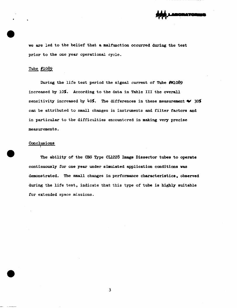
Tube #lo89 -- During t h e l i f e test period the s igna l current of Tube #Ml089
increased by 10%.
s e n s i t i v i t y increased by 40%. The differences i n these measurementY 30%
can be a t t r ibu ted t o small changes in instruments and f i l ter factors and
in par t i cu la r t o the d i f f i c u l t i e s encountered i n making very precise
measurements.
According t o the data i n Table I11 t h e overa l l
Conclusions T
a The a b i l i t y of t he CBS Type CLl.228 Image Dissector tubes t o operate
continuously f o r one year under simulated application conditions vas
demonstrated.
during the l i f e tes t , indicate that t h i s type of tube is highly suitable
f o r extended space missions.
The small changes i n performance charac te r i s t ics , observed
3

TABLE I
TUBE NO.
Before L i f e T e s t
PC Sens i t i v i ty 32 p/Lumen
P C uniformity 88.5%
Dynode Uniformity 85% 6
Anode Dark Current .OO5 pA
Gain 4 x 10
Anode Sens i t i v i ty 128 A/Lumen a
Ml083
A f t e r L i f e T e s t
42 pA/Lumen
88%
79%
3.7 x 10 6
.01 p 156 A/Lumen
Ml089
Before After L i f e T e s t L i f e T e s t
34.5 @/Lumen 42 p/Lumen
90% 90%
85% 79% 6 6 26 x i o 23.4 x 10
.03 u A .03 uA
785 A h m e n 1090 A/Lumen
4
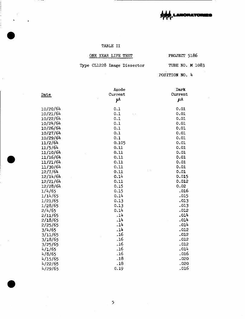
10 /20/ 64 10 /21/64 10/22/64
10/26/64 10/27/64 i0/29/64 11/2/64 11 15 164 ii/io/64 11 /16/64 11 /21 164 11 130164 12/7/64 12/14/64 12/21/64 12/28/64 1/4/65 1/14/65 1/21/65 1/28/65 2/4/65 2 /ill65 2/18/65
3/4/65
3/18/65
4/1/65 4/8/65 4/15/65 4/22/65 4/29/65
10/24/64
2/25/65
3/11/65
3/25;j 65
TABLE I1
ONE YEAR LIFE TEST
Type CL1228 Image Dissector
Anode Current P 0.1 0.1 0.1 0.1 0.1 0.1 0.1 0.105 0.11 0.11 0.11 0.11 0.11 0.11 0.14 0.11 0.15
0.14 0.13 0.13 0.14 .14 .14 .14 .14
0.15
.16
.16
.16
.16
.16
.18
.18 0.19
PROJECT 5186
TUBE NO. M 1083
POSITION NO. 4
Dark Current
P 0.01 0.01 0.01 0.01 0.01 0.01 0.01 0.01 0.01 0.01 0.01 0.01 0.01 0.01 0.015 0.012 0.02 .016 .015 .013 .013 .012 .014 .014 .014 .012 .012 .012 .012 .014 .016 .020 ,020 .016
5
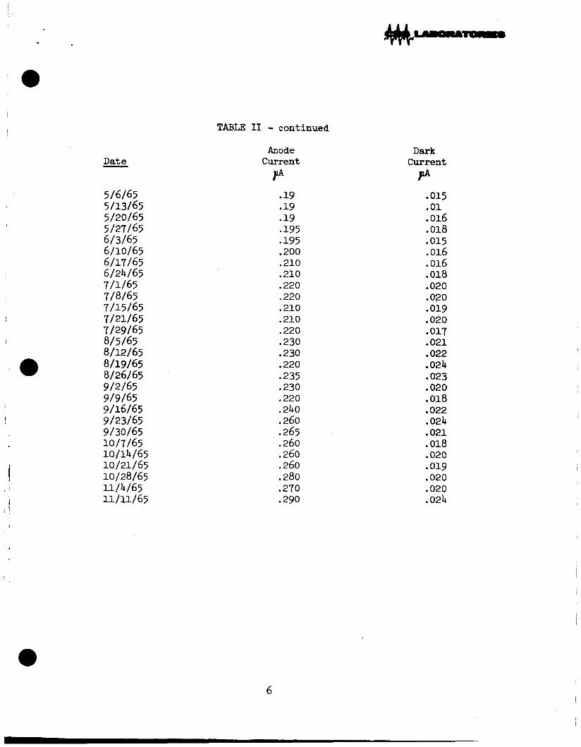
TABL;E 11 - continued
5/6/65 5/13/65 5/20/65
6/3/65 6/10/65 6/17/65
I 6/24/65
5/27/65
7/1/65 7/8/65 7/15/65
7/29/65 8/5/65 8/12/65 8/19/65 8/26/65 9/2/65 9/9/65 9/16/65
I 9/23/65
9/30/65 10/7/65 10/14/65 10 / 21 / 65 10/28/65 11/4 /65 11 / 11 / 65
7/21/65
f i
Anode Current P
19 19
.19
.195 - 195 200
,210 .210 .220 s 220 .210 .210 .220 .230 .230 .220 .235 .230 .220 .240 ,260 ,265 .260 .260 .260 .280
.290
.270
Dark Current P
.015
.01
.016
.018
.015
.016
.016
.018
.020
.020
.01g
.020
.017
.021
.022
.024
.023
.020
.018
.022
.024
.021
.018
.020
.01g
.020
.020
.024
6

TABLE 111
Date -
10/26/64 10/27/64 10/29/64 11/2/64 11/5/64 11/10/64 11/16/64 11 /21/64 11/30/64 12/7/64 12 /14/64 12 /21/64 12/28/64 1/4/65 1/14/65 1/21/65 1/28/65 2/4/65
2/18/65
3/4/65
3/18/65
4/1/65
4/15/65 4/22/65 4/29/65 5/6/65
5/20/65
2/11/65
2/25/65
3/11/65
3/25/65
4/8/65
5/13/65
5/27/65
ONE YEAR LIFE TEST
Type cu228 Imege Dissector
Anode Current
PA
0.1 0.1 0.1 0.11 0.11 0.11 0.12 0.12 0*12 0.12 0.11 0.12 0.12 0.12 0.11 0.13 0.13 0.11 13 .12 .12 .11 .11 .11 .ll .10 .10 .096 095 .11 .11 .10 .lo5 .10
7
PROJECT 5186
TUBE NO. m089
POSITION NO. 2
Dark Current P .01 .01 .01 .01 .01 .01 .01 .01 .01 .01 .02 .012 .014 . 011 .0076 .0068 .0072 .005 .0088 .0087 0077 .0072 .007 .0073 .0066 .0081 . 009 .0011 .0011
.003
.0044
.0076
.0027
.0085
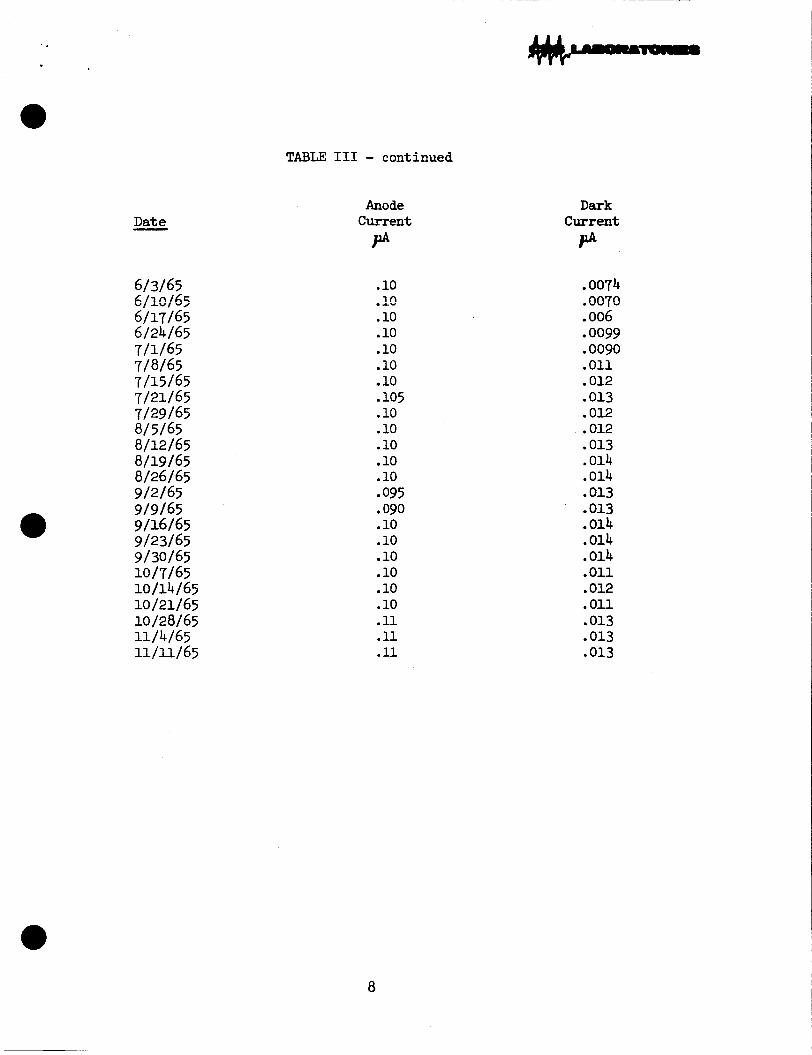
TABLE I11 - continued
D a t e - Anode
C u r r e n t P
.10 i n
.10
.10
.10
.10 10
.10
.10
.10
.10
.10 095 . 090 .10 .10 .10 .10 .10 .10 .ll . 11 . 11
.A"
.io5
Daxk C u r r e n t PA
.0074 . nn7g " 1 ,
.006 0099 . 0090 .011 .012 .013 .012 .012 ,013 .014 .014 .013 .013 .014 .014 .014 .011 .012 .011 .013 .013 ,013
8

-1700 Volts-
t#$ LABORATORIES
FIG. 1
LIFE TEST CIRCUIT DIAGRAM

LL i
v) L S 0 I I
C 0 .- CI
2 a 3
.c. v) Q) c

a
v) L 3 0 I I
t 0 .- i.r
zf a 3
.cI v) a, +-
* . . .

c .
Contract No. 950054
(Phase 9 Item 3)
A3DEND'JM TO FINAL REPORT
OKE YEA3 LIFE TEST OF 1-1/2 1Y'TC"T IYASE DISSECTOR
Ecrepared For: Jet Propnls ion La"sra-k 3
California Ins t i t { , r r Te c h n o l o a
Electron Tube 3ei,a.r+ IY r - C3S Iaboratories A Division of Go1 ,mrIt Broadcasting Sysiex. ~
Stamford, ConTe :: i r +

Contract No. 950054
“Tkis work was performed for the J e t Propulsion Laboratory, Cal i fornia I n s t i t u t e of Tezhnology, pursGant t o a sub-
California I n s t i t u t e of Technology and the United S ta tes af AmeriTa represented by t h e Nationai Aeronautics and Space Admini s t ra t ion. ’’
:oztract ~~;~~~~ ~ ~ y d c r C=ctrsct ?zAS7-1oc) between

M--
Measwements of t he overal l s e n s i t i v i t y of both tubes a t t h e i r l i f e
t e s t operaling poten t ia l s were made t o fur ther investigate the r i s e
i n s e n s i t i v i t y of tube #~i083 during the l i f e t e s t and the disagree-
ment of the l i f e t e s t data with the data obtained i n t e s t s before and
after the l i f e test .
3Le c v e r s l l s e n ~ i t p ~ ~ i t y =f ~ 2 5 2 #FJ&~ n f t c r thz lift test, ~t
i t s l i f e t e s t operation conditions, was found t o be 106$ greater
than t h a t of Tube #m089.
The overal l s e n s i t i v i t y of pi11083 increased by 190 percent during
the l i f e t e s t and t h a t of m089 by 10 percent.
Measurements made p r i o r t o and after the l i f e tes t indicated t h a t
the increase i n overal l s ens i t i v i ty of ~ 1 0 8 3 wits 18% and t h a t of
~ 1 0 8 9 3 8 .
A t t h i s stage it i s worthwhile considering both tubes independently
as fo~ l3ws :
Zt the o v e r a l l s e n s i t i v i t y a? the beginning of t he l i f e t e s t be 100 wii t s ,
The increase 27xing the l i f e t e s t w a s 16 i,e., t he overa l l s e n s i t i v i t y
increased t o 110 units.
* The overa l l s e n s i t i v i t y measured under standard t e s t conditions increased
by 3 9 o r from 100 t o 139 units.
Therefore the discrepancy a t the end of the tes t was
39-110 x 100 = 2 6 iio
*(Interdynode poten t ia l s 125 vo l t s per stage.)
i
!&is variance can be a t t r ibu ted t o var ia t ions i n op t i ca l a t tenuators
used i n the gain measurements made p r io r t o and after the l i f e t e s t
and t o s m a l l var ia t ions of inters tage poten t ia l s i n the l i f e t e s t
equlipment and the standard tes t set.
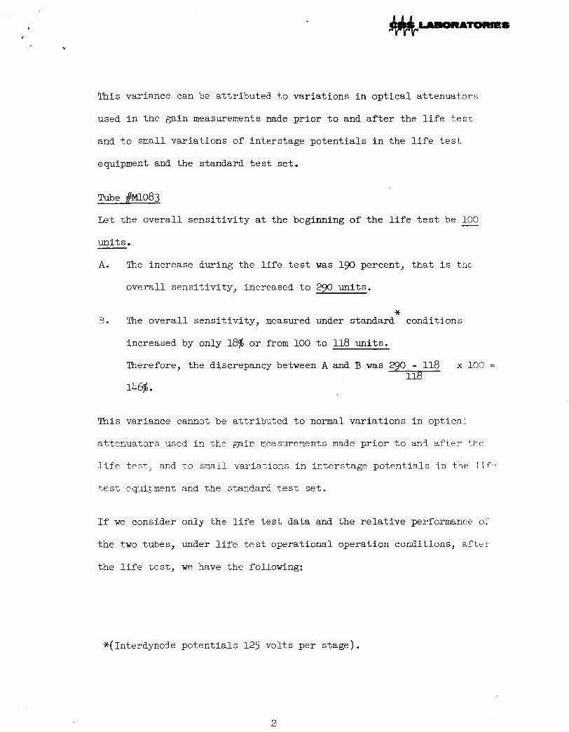
Tube m O 8 3
Let t he overa l l s e n s i t i v i t y at the beginning of the l i f e t e s t be - 100
units.
A. The increase during the l i f e tes t w a s 190 percent, t h a t i s the
overa l l s ens i t i v i ty , increased t o 290 units.
* 73. The overa l l sens i t iv i ty , measured under standard conditions
increased by on ly 18% o r from 100 t o 118 uni t s .
Therefore, the discrepancy between A and B w a s -0 - 118 x 100 = 118
This variance cannot be a t t r ibu ted t o normal var ia t ions i n opt ica l
atteriuators used i n the galn measurements made p r io r t o and a f r e r :hc
l i f e test_, and t o small variazions i n inters tage poten t ia l s i n t h e i i T c
tes t equigment ar,d the s t a n d a r d tes t se t .
If we consider only the l i f e t e s t data and the r e l a t i v e performance of
t he two tubes, under l i f e tes t operational operation conditions, a f t e r
the l i f e test, we have the following:
*(Interdymde po ten t i a l s 125 vol t s per s tage) .
2

c
~ 1 0 8 3
Overall s e n s i t i v i t y a t start of l i f e t es t 100
Overall s ens i t i v i ty a t end of l i f e t e s t 290
S e n s i t i v i t i e s 227
H Post l i f e t e s t evaluation Relative
n o 8 9
100 uni t ,s
110 uni t s
110
jcjc
The ove ra l l s e n s i t i v i t y of m083 as measured i n the post l i f e t es t would
therefore be 227 units.
I n approaching it t h i s way the
This f igure compares favorably
reasons can be given f o r the d
discrepancy i s 290 - 227 x 100 = 28%. 227
with the 2 6 of tube m 0 8 9 and the same
screpancy. This leads us t o believe tha t
our or ig ina l conclusions t h a t there w a s a malfunction i n the t e s t apparatus
used before the start of the l i f e t es t and t h a t t he before t e s t overa l l
s e n s i t i v i t y of ~ 1 0 8 3 was i n error.
obtained i n the t e s t i n g of other devices a f t e r the s t a r t of the l i f e
tes t .
one o f the op t i ca l a t tenuators ms loose ~ l ? d 13 ,ii.ject t o movemect i n its
mount. It i s qui te possible tha t thi? same clmdition w a s present when t r r
image d issec tor were t e s t ed pr ior to being l i f e tes ted .
Confirmation of t h i s poss ib i l i t y was
Anomalous readings were obtained and an invest igat ion revealed t h a t
** Under l i f e t es t operating conditions.
3