contour crafting process plan optimization part i: single-nozzle … · 2020-05-23 · journal of...
TRANSCRIPT
Journal of Industrial and Systems Engineering Vol. 4, No. 1, pp 33-46 Spring 2010
Contour Crafting Process Plan Optimization Part I: Single-Nozzle Case
Jing Zhang1, Behrokh Khoshnevis2∗
1,2Department of Industrial & Systems Engineering, University of Sothern California, USA
[email protected], [email protected]
ABSTRACT
Contour Crafting is an emerging technology that uses robotics to construct free form building structures by repeatedly laying down layers of material such as concrete. The Contour Crafting technology scales up automated additive fabrication from building small industrial parts to constructing buildings. Tool path planning and optimization for Contour Crafting benefit the technology by increasing the efficiency of construction especially for complicated structures. The research reported here has aimed at providing a systematic solution for improving the overall system efficiency and realizing the Contour Crafting technology for building custom-designed houses. In Part-I of this paper, an approach is presented to find the optimal tool path for the single nozzle Contour Crafting system. The model developed incorporates the physical constraints of the technology as well as some practical construction issues. In Part-II several algorithms are presented to find the collision-free tool paths for the multiple-nozzle system based on the algorithm developed for the single nozzle approach.
Keywords: Contour Crafting, tool path planning, optimization
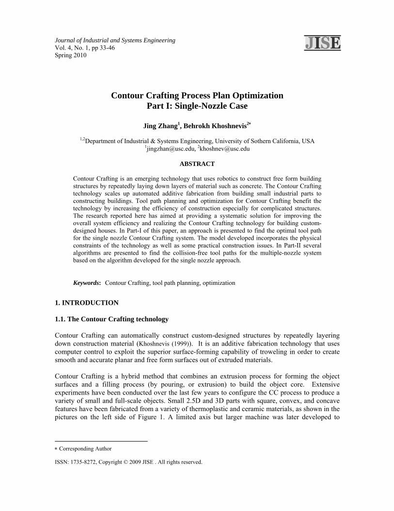
1. INTRODUCTION 1.1. The Contour Crafting technology Contour Crafting can automatically construct custom-designed structures by repeatedly layering down construction material (Khoshnevis (1999)). It is an additive fabrication technology that uses computer control to exploit the superior surface-forming capability of troweling in order to create smooth and accurate planar and free form surfaces out of extruded materials. Contour Crafting is a hybrid method that combines an extrusion process for forming the object surfaces and a filling process (by pouring, or extrusion) to build the object core. Extensive experiments have been conducted over the last few years to configure the CC process to produce a variety of small and full-scale objects. Small 2.5D and 3D parts with square, convex, and concave features have been fabricated from a variety of thermoplastic and ceramic materials, as shown in the pictures on the left side of Figure 1. A limited axis but larger machine was later developed to
∗ Corresponding Author ISSN: 1735-8272, Copyright © 2009 JISE . All rights reserved.
34 Zhang and Khoshnevis
demonstrate the possibility of fabricating full scale concrete structures, as shown on the right side of Figure 1.
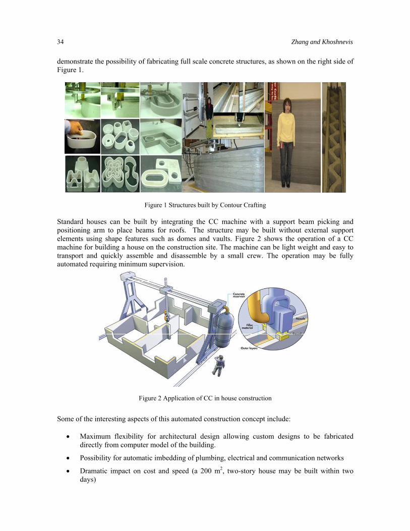
Figure 1 Structures built by Contour Crafting Standard houses can be built by integrating the CC machine with a support beam picking and positioning arm to place beams for roofs. The structure may be built without external support elements using shape features such as domes and vaults. Figure 2 shows the operation of a CC machine for building a house on the construction site. The machine can be light weight and easy to transport and quickly assemble and disassemble by a small crew. The operation may be fully automated requiring minimum supervision.
Figure 2 Application of CC in house construction
Some of the interesting aspects of this automated construction concept include:
• Maximum flexibility for architectural design allowing custom designs to be fabricated directly from computer model of the building.
• Possibility for automatic imbedding of plumbing, electrical and communication networks
• Dramatic impact on cost and speed (a 200 m2, two-story house may be built within two days)
Contour Crafting Process Plan Optimization 35
• Simplicity of construction logistics and management
• Friendliness to the environment due to low emissions and wasteless operation
• Significantly reduced energy usage compared to manual construction
1.2. Integrated Contour Crafting System An integrated CC system includes a control module, a geometry analysis module, a planning and optimization module and a presentation module. The control module is in charge of digital control of the Contour Crafting machine. The geometry analysis module includes structure feasibility analysis and support structure generation to annotate the original geometry. Tool path planning, multi-nozzle coordination, and other operational issues belong to the planning and optimization module. 3D Presentation and real time simulation functions are implemented inside the presentation module to provide an interface for visualization. A free flow of information such as virtual model, tool paths, construction schedule and machine tasks can be generated once the original architectural model is input into the integrated Contour Crafting system. The machine task sequences are fed to the Contour Crafting machine for construction execution after process planning, optimization and simulation. 1.3. Process planning and optimization in Contour Crafting Process planning and optimization play important roles in realizing the automation of the technology and improving the overall system efficiency by generating optimal nozzle/trowel paths for the given structure designs. A systematic methodology for process planning and optimization to handle complicated large-scale structures by Contour Crafting is presented in this paper. 2. OBJECTIVES This research presents a systematic methodology for process planning and optimization to handle complicated large-scale structures for Contour Crafting systems with single or multiple machines through the following steps:
1. Describe system characteristics and define tool path elements of Contour Crafting
2. Develop practical tool path planning and an optimization method for the single nozzle CC system
3. Develop practical tool path planning and optimization methods for multi-nozzle system based on the optimization method for single nozzle
4. Define performance factors and critical design parameters for the multi-machine system to improve efficiency.
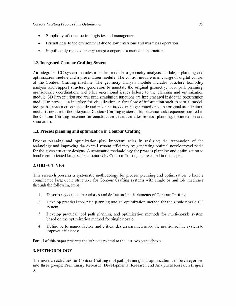
Part-II of this paper presents the subjects related to the last two steps above. 3. METHODOLOGY The research activities for Contour Crafting tool path planning and optimization can be categorized into three groups: Preliminary Research, Developmental Research and Analytical Research (Figure 3).
36 Zhang and Khoshnevis
Figure 3 Research Methodology
Under preliminary research the specific characteristics of the Contour Crafting process are identifies and proper assumptions are made to simplify the problem so that the Contour Crafting tool path model can be constructed. Once these assumptions are stated the Contour Crafting tool path elements can be defined systematically. Physical constraints and utility functions are then structured according to these assumptions. Approaches for tool path planning and optimization for the single nozzle Contour Crafting system are proposed in the development research. Three approaches that follow the two-step procedure are developed and illustrated in detail. A machine behavior model is incorporated into one of the approaches to make the system more robust. Based on the optimization method for the single nozzle system, a two-step procedure is developed and described in part-II of the paper in order to generate collision-free tool paths for the multi-machine Contour Crafting system. Under analytical research experimental and numerical investigations are performed to analyze the feasibility and efficiency of tool path planning and optimization for both single and multiple nozzle systems. A simulation test bed is implemented for the purpose of simulation. 4. CONTOUR CRAFTING SYSTEM CHARACTERISTIC AND TOOL PATH ELEMENTS 4.1. Description of system characteristics The scale of the optimization problem can become too large when all aspects of the technology are considered. Some practical assumptions are necessary regarding the limitations and special features
Contour Crafting Process Plan Optimization 37
of the system in order to reduce the complexity of the problem. These are the considerations which have been taken into account:
1. Structures are assumed to be 2.5 dimensional, meaning that each layer is similar to all other layers except where windows or doors are located. It is also assumed that the nozzle starts and ends at the same X-Y location for each layer.
2. In the construction process a nozzle (or nozzles in case of multiple nozzles or multiple machines) have to complete fabricating a layer before moving on to the next layer.
3. The building model is sliced into layers before tool path optimization is performed. Then the layout of each layer is converted into an Edge and Vertex model. Edges represent the wall, and the Vertices represent the intersection, corner or the end point of the wall segments.
4. The construction time is related to the machine deposition time and air time (time spent traveling without depositing material). Minimizing the machine idle time (air time) could save a certain amount of building time in this layered fabrication process.
5. Within each layer the nozzle of the system has to finish depositing one wall segment completely before starting a new wall segment so that it travels only between end points of the wall segments.
6. In order to avoid collision between the nozzle and previously deposited walls, the nozzle will be lifted up (one layer) once fabrication of a layer is completed.
7. The nozzle will be idle (i.e., encounter airtime) when traversing between walls or where windows or doors are located.
8. This research is focused on developing a practical optimization method to generate tool paths for general structures. The vertex number in a structure layout would normally be less than 10,000.
9. This research assumes that the deposition flow rate can be controlled perfectly (can start and stop) at anytime. The tool path optimization does not consider flow control issues.
10. Acceleration and deceleration times of the system are considered as fixed delays.
11. If multi-nozzle is applied, the nozzles are always working on the same layer at any point in time. It is assumed that allowing the nozzles to work on different layers at the same time will not increase the system efficiency.
4.2. Definition of tool path One of the advantages of utilizing the Contour Crafting technology instead of the traditional way of construction is that CC can save considerable time and cost. The cost of construction is related to time and energies consumed by the machine and the amount of materials used. These costs can be evaluated once a tool path has been defined. A tool path of Contour Crafting for a specific structure must describe the position, orientation, velocity, and deposition rate of the nozzle during the entire construction period. (See Figure 4 for a sample of a Contour Crafting tool path of a small structure).This information is then converted into a sequence of machine tasks and then fed to the Contour Crafting machine. If the time or energy spent on each machine task (such as deposition, nozzle traveling or nozzle rotation) is converted into the equivalent cost, then the goal of optimization would be finding a path with the minimum
38 Zhang and Khoshnevis
total cost associated with all machine tasks. Therefore, the cost of deposition, traveling and rotation needs to be defined for calculating the overall cost for the tool path.
Figure 4 A structure and its CC tool path
Cost of deposition depends on the flow rate of deposition and the velocity of the machine. For a given deposition rate and machine speed, since the nozzle has to traverse along all the deposition edges once and only once, the overall deposition time is fixed for a structure. Therefore, the cost of deposition will not affect the result of tool path optimization. Once the machine parameters have been defined, cost of deposition for each wall segment can be calculated according to its geometrical information. Cost of traveling between edges is related to the cost of moving between vertices and the cost of rotation along the edges. This cost can be estimated according to the relevant position of edges. Since the nozzle of the Contour Crafting machine has to orient itself to be perpendicular to the tangent of the wall segment, the nozzle may need to be re-oriented when traveling between edges. In order to determine the Cost of traveling, Euclidian distance and the re-orientation cost of the nozzle between the end points of edges must be calculated. Cost of moving between end points can be determined once the distance between two points and the velocity of the machine are known. Sometimes the nozzle has to be lifted up and lowered down to avoid obstacles, such as previously deposited segments of the same layer. In this case, the cost of lifting up and lowering down also need to be included in the cost of moving. Cost of rotation between edges can be evaluated according to the relative orientation of the two edges. However, the nozzle is limited in the degrees of rotation due to the electrical wires that are attached to it. For this reason a mechanical stop is installed at the nozzle rotation shaft to prevent the nozzle from rotating more than 360 degrees in each direction. At each extreme end of rotation the mechanical stop hits the mating part i=which is installed on the nozzle mounting bracket. Nozzle rotation direction and degree of rotation need to be controlled if the mechanical stop impedes the re-orientation transition of the nozzle in a given direction. Therefore, the cost of rotation depends on not only the degrees of rotation but also on position of the nozzle mechanical stop with respect to its mating part on the nozzle mounting platform. Once the Euclidian distance and orientation of two edges are known, traveling cost between two points can be estimated by calculating the time spent on moving and rotating. If the nozzle is allowed to rotate while moving from point to point then cost of traveling between two edges is equal to the maximum of movement or rotation times, otherwise it will be the sum of the two costs.
Contour Crafting Process Plan Optimization 39
Finally, the nozzle idle time cost is equal to the cost of traveling between two wall segments without depositing material. 4.3. Constraint definitions The following physical constraints also need to be observed during the construction process:
1. Nozzle idle time cannot be too long otherwise concrete will solidify and clog the pipeline.
2. Nozzle should not collide with the previously deposited layer when traveling. Nozzle can be lifted up one layer once it reaches a segment of the current layer that is already built and is standing in its travel path. In such a circumstance the nozzle will be lowered down before it starts to deposit material for a new wall segment. The cost of lifting up and lowering down the nozzle will be considered in tool path planning.
3. The lower layer must be able to support the upper layer, therefore, the time interval between depositing subsequent layers cannot be shorter than the critical limit. At the same time, subsequent layers must be able to adhere and this happens when the lower layer upon which the new layer is deposited is wet enough. Therefore, the interval between depositing subsequent layers should not exceed the critical limit for inter-layer adhesion. Both constraints are related to the time interval between depositing subsequent layers. This interval is equal to the overall time of constructing a layer.
4. When layers accumulate, the layer underneath must be solidified enough to support the overall weight of multiple layers above it. The overall weight on a layer is proportional to the number of layers above it. Hence this weight is proportional to the overall time of constructing a layer. Once the construction time of each layer is calculated a chart that shows the relationship between the weight of upper layers and construction time can be used to configure this constraint.
5. OPTIMAL TOOL PATH FOR THE SINGLE-NOZZLE CC SYSTEM Once the costs of different machine tasks and physical constraints have been defined, optimization can be performed to find the most efficient tool path for the single nozzle system. Tool path optimization is the critical issue for several other fabrication technologies such as other layered fabrication methods as well as CNC and laser cutting. For example, Wah et al. (2002) introduced ATSP-IP (asymmetric traveling salesman problem and integer programming) to improve the efficiency of Laminated Object Manufacturing. Tang and Pang (2003) also introduced a greedy algorithm to deal with the application of path optimization in layered manufacturing. Their general strategy is to start with a path that connects all the contours with a single line, removing points that touch a contour for the second time. Trager (1998) presents three different simple solutions to address nesting and (partial) tour optimization problems. The main problem addressed in his work is to reduce the cutting distance by combining the edges of as many shapes as possible. His methods are also able to address the problem of cutting paths crossing each other. In this research, the approach to find the optimal tool path is to convert the CC path model to a standard TSP (traveling salesman problem), (Concorde, 2005). This approach considers all the possible alternatives of construction and provides optimal solution if the TSP model is solved exactly. Heuristic TSP solvers can be used to solve large scale problem (e.g., the structure has more than 10,000 wall segments).
40 Zhang and Khoshnevis
TSP attempts to find the shortest route to visit a collection of cities at least once and return to the starting city. In the standard TSP problem vertices represent cities, while arcs are the paths between cities. A solution to the TSP must return the cheapest Hamiltonian cycle of the graph which represents the cities and paths. A Hamilton cycle is a simple path in the graph that contains each vertex. An asymmetric TSP problem can be formulated as follows: Define Xij = 1 (when i,j are the index of the vertices), if edge (i,j) is in the optimal tour; otherwise Xij = 0, and Dij = d(i,j), when d is the traveling cost between vertices i and j. Thus we have Minimize Σ Σ Dij Xij
Subject to:
Σ Xij = 1 for all j
ΣXij = 1 for all i
ΣΣ Xij ≥ 1 for every S ⊆ X (when i S∈ ; j X S∈ − ). The graph of a building layout cannot be directly formulated as a standard TSP problem. In the CC construction process, some edges in the graph have to be traversed by the nozzle in order to deposit concrete for building walls, which means that the CC tool path has to contain some specific edges. However, any edge can be included in the optimal path in TSP since any edge represents a path between two cities. Also, a vertex in a structure layout may have several edges incident to it, which means during the construction process, the nozzle of the CC machine will visit the same vertex more than once. However, in TSP, each vertex can be visited only once. For Contour Crafting, the overall construction time of a specific structure is the sum of the overall time of concrete deposition and the overall nozzle airtime, in which the nozzle stops depositing material and travels between two deposition edges. No matter how the optimal path is generated, the nozzle should traverse all the deposition edges once and only once. The overall deposition time is determined once the structure is given. The overall nozzle idle time is the factor that determines the overall construction time for different tool paths. The optimal tool path is a path that has the minimum overall nozzle airtime. Since the nozzle of the machine can move freely in 3-dimensions, it can go straight between any vertices. The problem of finding the optimal tool path can hence be stated as follows: Given a set of edges on a layout, find the optimum sequence and direction in which: (1) each edge is traversed exactly once and (2) the traveling airtime (motion between two end points of two edges) is a straight line. The optimal solution minimizes the overall airtime. A method to formulate the problem is to ignore the deposition edges (walls) while only considering the traveling paths between edges (the airtime of the nozzle). In this case, walls shrink to vertices (entities), when the paths between vertices represent the cost of traveling between walls. Figure 5 shows the concept behind this approach.
A
BC
DE
A
BC
DE
Figure 5 Concept of shrinking edges
A structure layout Compact edge to vertex (letters represent edges)
Contour Crafting Process Plan Optimization 41
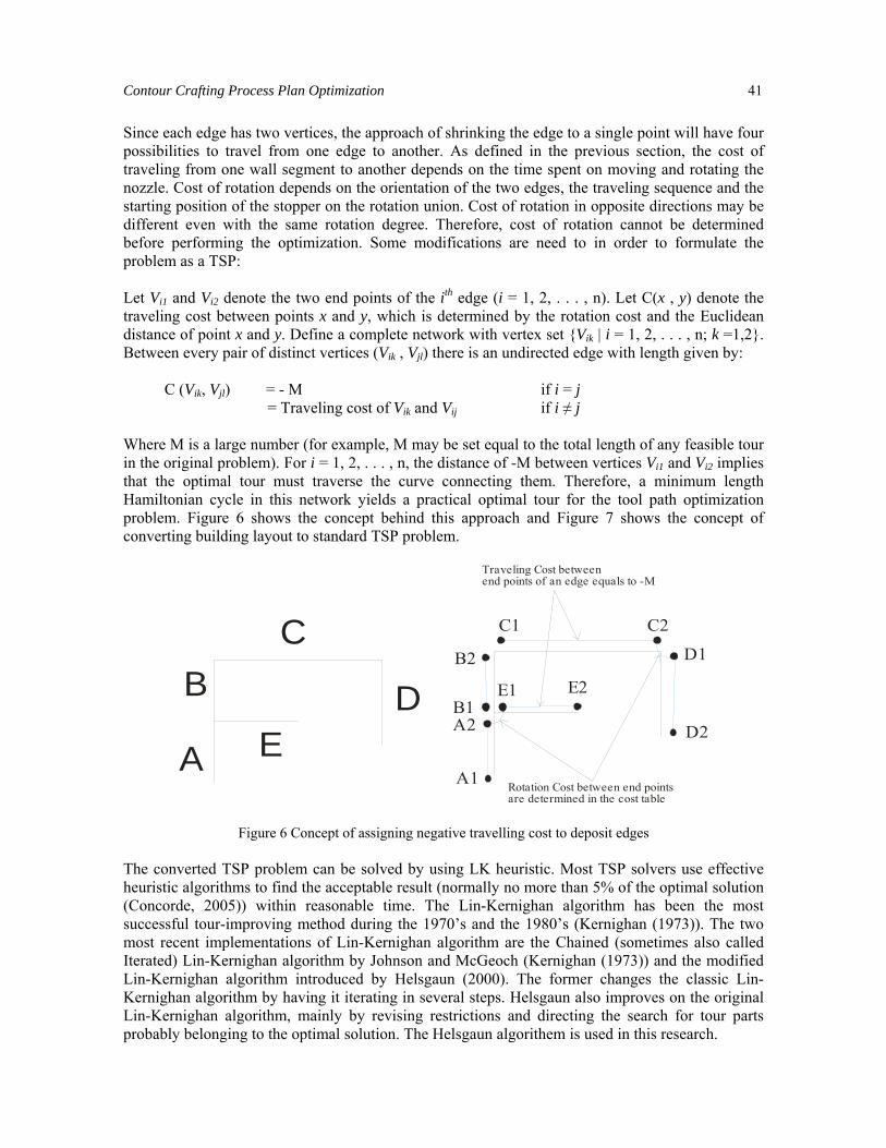
Since each edge has two vertices, the approach of shrinking the edge to a single point will have four possibilities to travel from one edge to another. As defined in the previous section, the cost of traveling from one wall segment to another depends on the time spent on moving and rotating the nozzle. Cost of rotation depends on the orientation of the two edges, the traveling sequence and the starting position of the stopper on the rotation union. Cost of rotation in opposite directions may be different even with the same rotation degree. Therefore, cost of rotation cannot be determined before performing the optimization. Some modifications are need to in order to formulate the problem as a TSP: Let Vi1 and Vi2 denote the two end points of the ith edge (i = 1, 2, . . . , n). Let C(x , y) denote the traveling cost between points x and y, which is determined by the rotation cost and the Euclidean distance of point x and y. Define a complete network with vertex set {Vik | i = 1, 2, . . . , n; k =1,2}. Between every pair of distinct vertices (Vik , Vjl) there is an undirected edge with length given by: C (Vik, Vjl) = - M if i = j = Traveling cost of Vik and Vij if i ≠ j Where M is a large number (for example, M may be set equal to the total length of any feasible tour in the original problem). For i = 1, 2, . . . , n, the distance of -M between vertices Vi1 and Vi2 implies that the optimal tour must traverse the curve connecting them. Therefore, a minimum length Hamiltonian cycle in this network yields a practical optimal tour for the tool path optimization problem. Figure 6 shows the concept behind this approach and Figure 7 shows the concept of converting building layout to standard TSP problem.
A2B1
B2
C2
E2
D2
E1
D1
C1
A1
Traveling Cost between end points of an edge equals to -M
Rotation Cost between end points are determined in the cost table
A
BC
DE
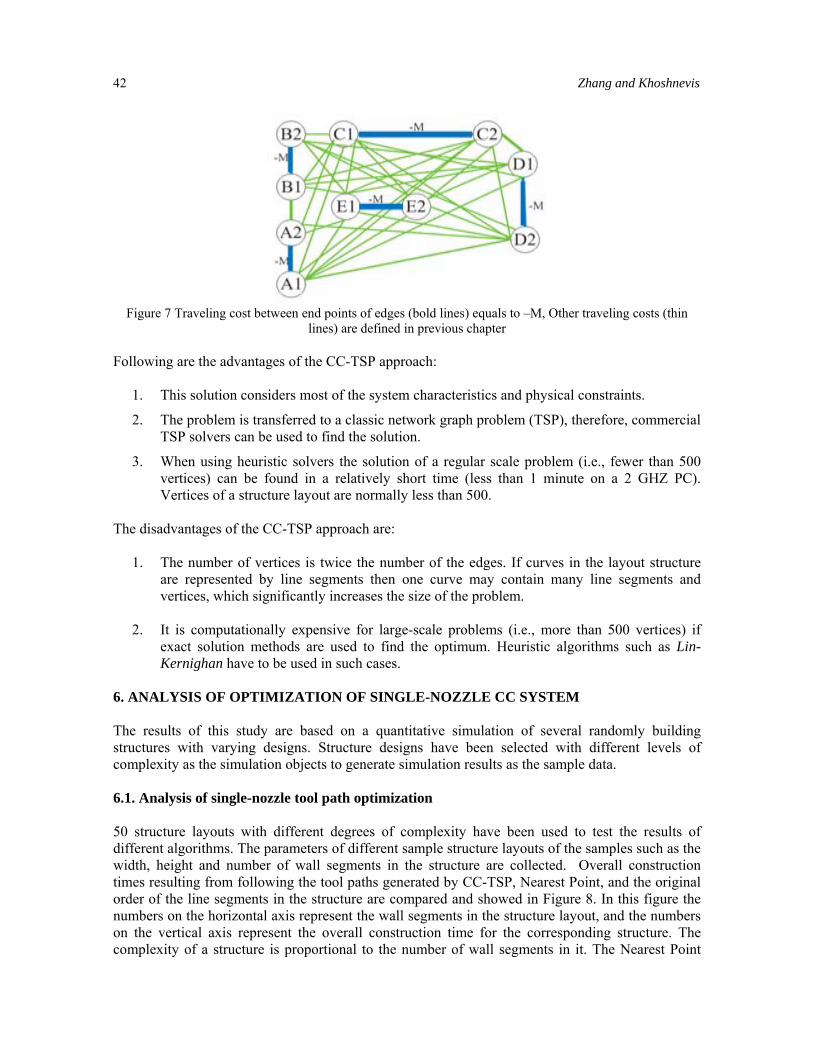
Figure 6 Concept of assigning negative travelling cost to deposit edges The converted TSP problem can be solved by using LK heuristic. Most TSP solvers use effective heuristic algorithms to find the acceptable result (normally no more than 5% of the optimal solution (Concorde, 2005)) within reasonable time. The Lin-Kernighan algorithm has been the most successful tour-improving method during the 1970’s and the 1980’s (Kernighan (1973)). The two most recent implementations of Lin-Kernighan algorithm are the Chained (sometimes also called Iterated) Lin-Kernighan algorithm by Johnson and McGeoch (Kernighan (1973)) and the modified Lin-Kernighan algorithm introduced by Helsgaun (2000). The former changes the classic Lin-Kernighan algorithm by having it iterating in several steps. Helsgaun also improves on the original Lin-Kernighan algorithm, mainly by revising restrictions and directing the search for tour parts probably belonging to the optimal solution. The Helsgaun algorithem is used in this research.
42 Zhang and Khoshnevis
Figure 7 Traveling cost between end points of edges (bold lines) equals to –M, Other traveling costs (thin
lines) are defined in previous chapter Following are the advantages of the CC-TSP approach:
1. This solution considers most of the system characteristics and physical constraints.
2. The problem is transferred to a classic network graph problem (TSP), therefore, commercial TSP solvers can be used to find the solution.
3. When using heuristic solvers the solution of a regular scale problem (i.e., fewer than 500 vertices) can be found in a relatively short time (less than 1 minute on a 2 GHZ PC). Vertices of a structure layout are normally less than 500.
The disadvantages of the CC-TSP approach are:
1. The number of vertices is twice the number of the edges. If curves in the layout structure are represented by line segments then one curve may contain many line segments and vertices, which significantly increases the size of the problem.
2. It is computationally expensive for large-scale problems (i.e., more than 500 vertices) if
exact solution methods are used to find the optimum. Heuristic algorithms such as Lin-Kernighan have to be used in such cases.
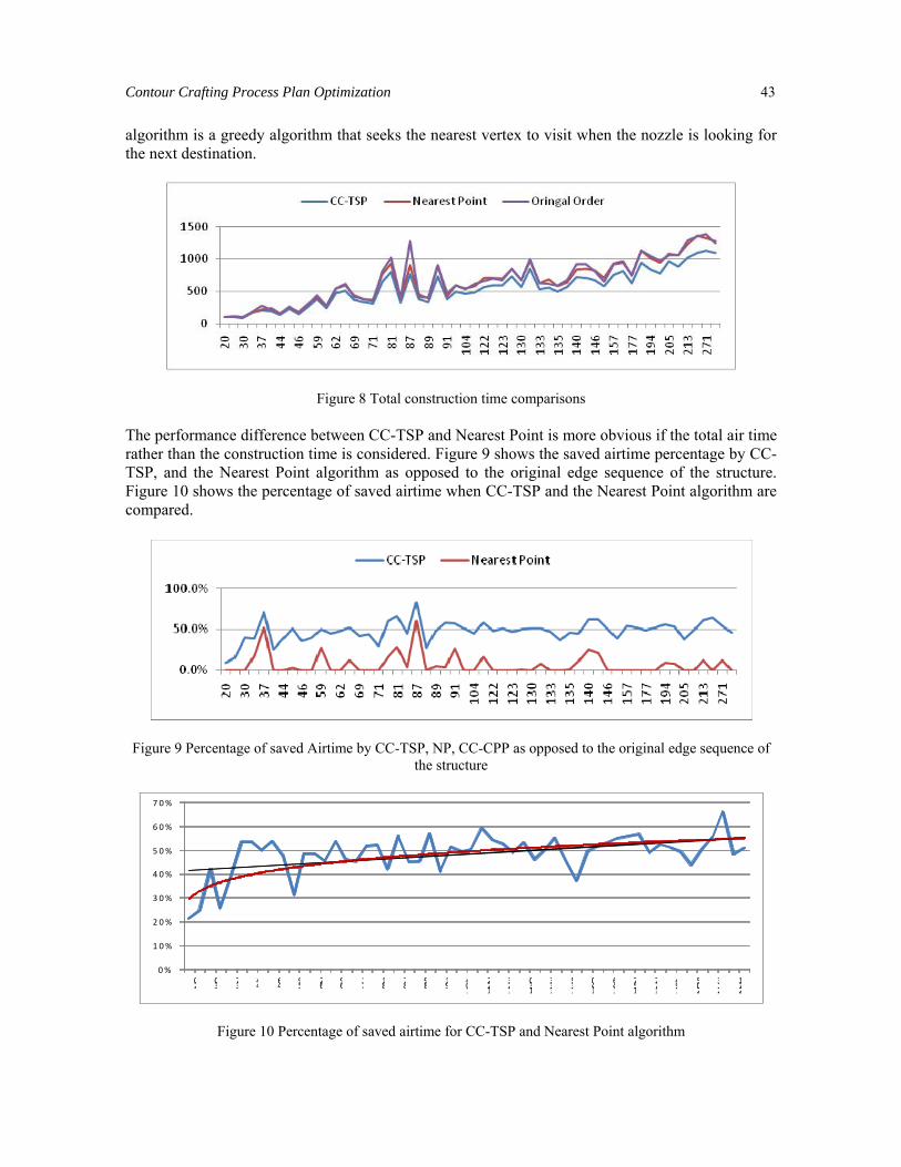
6. ANALYSIS OF OPTIMIZATION OF SINGLE-NOZZLE CC SYSTEM The results of this study are based on a quantitative simulation of several randomly building structures with varying designs. Structure designs have been selected with different levels of complexity as the simulation objects to generate simulation results as the sample data. 6.1. Analysis of single-nozzle tool path optimization 50 structure layouts with different degrees of complexity have been used to test the results of different algorithms. The parameters of different sample structure layouts of the samples such as the width, height and number of wall segments in the structure are collected. Overall construction times resulting from following the tool paths generated by CC-TSP, Nearest Point, and the original order of the line segments in the structure are compared and showed in Figure 8. In this figure the numbers on the horizontal axis represent the wall segments in the structure layout, and the numbers on the vertical axis represent the overall construction time for the corresponding structure. The complexity of a structure is proportional to the number of wall segments in it. The Nearest Point
Contour Crafting Process Plan Optimization 43
algorithm is a greedy algorithm that seeks the nearest vertex to visit when the nozzle is looking for the next destination.
Figure 8 Total construction time comparisons The performance difference between CC-TSP and Nearest Point is more obvious if the total air time rather than the construction time is considered. Figure 9 shows the saved airtime percentage by CC-TSP, and the Nearest Point algorithm as opposed to the original edge sequence of the structure. Figure 10 shows the percentage of saved airtime when CC-TSP and the Nearest Point algorithm are compared.
Figure 9 Percentage of saved Airtime by CC-TSP, NP, CC-CPP as opposed to the original edge sequence of
the structure
0%
1 0%
2 0%
3 0%
4 0%
5 0%
6 0%
7 0%
20 30 37 44 46 59 62 69 71 81 87 89 91 104
122
123
130
133
135
140
146
157
177
194
205
213
271
Figure 10 Percentage of saved airtime for CC-TSP and Nearest Point algorithm
44 Zhang and Khoshnevis
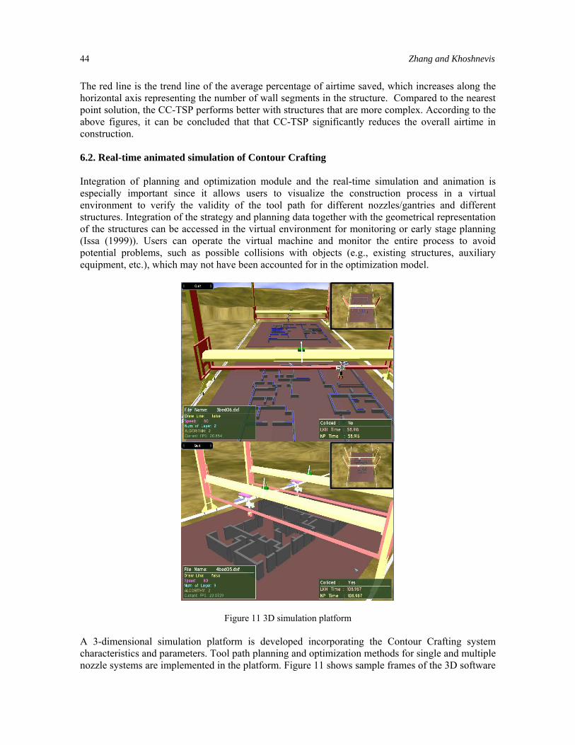
The red line is the trend line of the average percentage of airtime saved, which increases along the horizontal axis representing the number of wall segments in the structure. Compared to the nearest point solution, the CC-TSP performs better with structures that are more complex. According to the above figures, it can be concluded that that CC-TSP significantly reduces the overall airtime in construction. 6.2. Real-time animated simulation of Contour Crafting Integration of planning and optimization module and the real-time simulation and animation is especially important since it allows users to visualize the construction process in a virtual environment to verify the validity of the tool path for different nozzles/gantries and different structures. Integration of the strategy and planning data together with the geometrical representation of the structures can be accessed in the virtual environment for monitoring or early stage planning (Issa (1999)). Users can operate the virtual machine and monitor the entire process to avoid potential problems, such as possible collisions with objects (e.g., existing structures, auxiliary equipment, etc.), which may not have been accounted for in the optimization model.
Figure 11 3D simulation platform A 3-dimensional simulation platform is developed incorporating the Contour Crafting system characteristics and parameters. Tool path planning and optimization methods for single and multiple nozzle systems are implemented in the platform. Figure 11 shows sample frames of the 3D software
Contour Crafting Process Plan Optimization 45
module. In simulation of the single nozzle system two virtual machines are placed side by side. Simulations show that for all sample structure layouts the virtual machine which is using CC-TSP to generate optimal tool paths completes the construction much faster than the other machine which uses the nearest point algorithm. In the simulation of multiple nozzle system two virtual machines are placed in the scene to construct structures collaboratively. The tool path planning and optimization approaches for multiple nozzle system are in Part II of the paper. 7. CONCLUSION This research has aimed at providing a systematic methodology for process planning and optimization in order to efficiently construct complicated large-scale structures by Contour Crafting systems using different hardware configurations. The methodologies developed find optimal tool paths for 2.5 D structures. Structure models are first horizontally sliced into multiple layers, then tool path planning and optimization are performed on the layout of each layer of the structure. Nozzles of the Contour Crafting system are required to complete the construction of an entire layer before moving to the next one. Under these premises edges and vertices are defined as the basic elements of the Contour Crafting tool path when edges represent the wall segments and vertices represent the intersections, corners or end points of the wall segments. Physical constraints of the technology are incorporated with construction considerations to define other tool path elements such as cost of deposition, cost of travelling, cost of moving the nozzle and cost of nozzle rotation. By defining tool path elements the problem of tool path planning is converted into typical graph problems. The approach is to transfer the problem to a TSP (travelling salesman problem) structure by introducing a negative value to every two end points of each edge to obligate the optimal tool path to include every edge of the original structure in the entire path. The Lin-Kernighan heuristic algorithm is used to find the TSP solution in this research. The heuristic TSP solver is used because at reasonable speed it can find a solution within 5% of the exact solution even for large-scale TSP problems with up to 10000 vertices. In general, the solution found by the CC-TSP algorithm saved 45% of nozzle air time compared to the Nearest Point algorithm. More time is saved when the level of complexity of a structure is increased. In Part II of the paper multiple-nozzle Contour Crafting system is introduced for which the solution model is based on the single-nozzle solution models presented in this part. REFERENCES [1] Han Y.-K, Jang C.-D (1999), An Approach to Efficient Nesting and Cutting Path Optimization of
Irregular Shapes; Journal of ShipProduction 15(3); 129-135. [2] Helsgaun K. (2000), An effective implementation of the Lin-Kernighan traveling salesman heuristic;
European Journal of Operational Research 126(1); 106-130. [3] Israni S., Manber U. (1984), Pierce Point Minimization and Optimal Torch Path Determination in
Flame Cutting; Journal of Manufacturing Systems 3(1); 81-89. [4] Issa, Raja R.A. (1999), State of the Art Report: Virtual Reality in Construction; International Council
for Research and Innovation in Building and Construction (CIB). [5] Khoshnevis B. (1999), Contour Crafting - State of Development; Solid Freeform Fabrication
Proceedings 1999; 743-750.
46 Zhang and Khoshnevis
[6] Khoshnevis B. (2004), Automated construction by Contour Crafting - Related robotics and information technologies; Automation in Construction 12; 5-19
[7] Lawler E. L., Jan Karel Lenstra, Rinnooy Khan A.H.G., Shmoys D.B. (1985), The Traveling Salesman
Problem; A Guided Tour of Combinatorial Optimization. [8] Lin S., Kernighan B. (1973), An Effective Heuristic Algorithm for the Traveling Salesman Problem;
Operations Research 21; 498-516. [9] Pease III, L.F. (1998), Rapid Prototyping Methods; ASM Handbook Volume 7:Powder Metal
Technologies and Applications. [10] Tang K., Pang A. (2003), Optimal connection of loops in laminated object manufacturing; CAD
Computer Aided Design 35(11); 1011–1022. [11] Thomas H. Cormen, Charles E. Leiserson, Ronald L. Rivest (1990), Introduction to Algorithms; The
MIT Press; 465-467. [12] Trager M. (1998), Optimizing Laser Cutting; Industrial Laser Review. [13] Wah P.K., Murty K.G., Joneja A., Chiu L.C. (2002), Tool path optimization in layered manufacturing;
IIE Transactions 34(4); 335-347. [14] Yeh Z. (2003), Trowel-Path Planning For Contour Crafting; Ph.D. Dissertation, University of Southern
California. [15] Concorde TSP Solver, http://www.tsp.gatech.edu/concorde.html, January 2005.