continuous use - unt digital library
TRANSCRIPT

Pags 1 of I 1 . m ~ 161 4 6 8 JUN ' 1gg7@NGINEERING DATA TRANSMllTAL
3 q
I n t e r i m S t a b i l i z a t i o n
2. To: (Receiving Organization)
D i s t r i b u t i o n
Engr.:
J. R. K r i s k o v i c h
(Or ig ina t ing Organization)
FDNW TWRS E n g i n e e r i n g
I A l IC1 101 Itern If31 DocurnentlDrawing No. Sheet Rev. NO NO. NO.
5. P,,j./Prog./Dept./Div.: I 6. Design Authority/ Design Agent/Cog.
IEI Title or Description of Data Tianrmittsd
1
Acceptance T e s t P l a n f o r 500 CFM P o r t a b l e Exhauster POR-005, S k i d C .
HNF-SD-WM-ATP-199 0 ATP f o r t h e p o r t a b l e 500 CFM Exhauster POR-005 SKID C
11. Receiver Remarks: 11A. Design Baseline Document? [ X I Yes [ ] No
Approval Designator IF) Reason for Transmittal IGI
E. S. 0, 0 or NIA 1 Approval 4 Review [see WHC-CM-35. 2 Release 5. Port-Review Sec 12.71 3 Information 6 Diit. (Receipt Acknow. Required)
Disposition IHI 5 111 1 . Approved 4. Reviewed nolcomment 2 . Approved wlcomment 5. Reviewad wlcomment 3. Disapproved wlcomment 6. Receipt acknowledged
4 . Related EDT Yo.:
N/A
7. Purchase Order NO.:
N/A 9 . Equip./Component No.:
POR-005 10. system/Bldg./Facil i ty:
N/A 12. Major Assm. Dug. No.: A*l9?
H-14-100Z3Z 867 13. Permit/Permit Application No.:
N/A 1 4 . Required Response Date:
N/A
ED-7400-172-1 (07/91)

3 HNF-SD-WM-ATP-199, Rev. 0
ATP FOR THE PORTABLE 500 CFM EXHAUSTER POR-005 SKID C
C r a i g M. K e l l e r F luor -Dan ie l Northwest, Richland, WA 99352 U.S. Department o f Energy Cont rac t DE-AC06-96RL13200
EDT/ECN: 161468 UC: 2030 Org Code: 04E00 Charge Code: C13697 B&R Code: EW3120072 T o t a l Pages: 9 6
Key Words: P o r t a b l e Exhauster, S a l t w e l l Pumping, Waste Tank V e n t i l a t i o n , Flammable Gas M i t i g a t i o n
Abs t rac t : POR-005 t o be used f o r s a l t w e l l pumping. w i l l be u t i l i z e d t o e l i m i n a t e p o t e n t i a l flammable gases t h a t may e x i s t w i t h i n t h e dome space o f t h e tank . T h i s Acceptance Plan w i l l t e s t and v e r i f y t h a t t h e exhauster meets t h e s p e c i f i e d des ign c r i t e r i a , s a f e t y requirements, opera t ions requirements, and w i l l p r o v i d e a r e c o r d o f t h e f u n c t i o n a l t e s t r e s u l t s .
<PJ
T h i s Acceptance Test Plan i s f o r a 500 CFM P o r t a b l e Exhauster The P o r t a b l e Exhauster System
TRADEMARK DISCLAIMER. Reference here in t o any s p e c i f i c cMmerc ia l product, process, o r serv ice by t rade name, trademark, manufacturer, o r otheruise, does no t necessar i l y c o n s t i t u t e o r imply i t s endorsement, r e c m n d a t i o n , o r favor ing by the Un i ted States Coverlment o r any agency thereof or i t s con t rac tors o r subcontractors.
P r i n t e d in the Un i ted Sts tes o f America. To o b t a i n copies o f t h i s docunent, contact : DocMent Control Services, P.O. Box 950, Mai ls top H6-08, Richland UA 99352, Phone (509) 372-2420; Fax (509) 376-4989.
Reldase Approval Date
Approved for Public Release
A-6400-073 (01/97) GEF321

INTERIM STABILIZATION
I ATP FOR THE PORTABLE 500 CFM EXHAUSTER, POR-005, SKID C I CONTINUOUS USE

TANK FARM ACCEPTANCE TEST PROCEDURE
TEST EXECUTION SHEET
Date: Document Number: HNF-SD-WM-ATP-199 REV. 0 EXHAUSTER U n i t Number: POR-005
COGNIZANT DESIGN ENGINEER: Owen Nelson TEST DIRECTOR: T e r r y K a i s e r ALT TEST DIRECTOR: Owen Nelson
Test D i r e c t o r Date
TEST APPROVAL AND ACCEPTANCE
Without With With ~ Except ion - Exception/Resolved - Except ion/Outstanding
Test D i r e c t o r Date Qual i t y Assurance Date
Safe ty Date Cognizant Design Engineer Date

TANK FARM ACCEPTANCE TEST PROCEDURE
Jsage Type
CONTINOUS USE
TABLE OF CONTENTS
D o c m n t Lo . R W / M o d Page
HNF-SD-WM-ATP-199 0 3
1.0 PURPOSE . . . . . . . . . . . . . . . . . . . . . . . . . . . . . . 4
2.0 INFORMATION . . . . . . . . . . . . . . . . . . . . . . . . . . . . 4 2.1 SCOPE . . . . . . . . . . . . . . . . . . . . . . . . . . . . . 4 2.2 TERMS AND DEFINITIONS . . . . . . . . . . . . . . . . . . . . . 5 2.3 RESPONSIBILITIES . . . . . . . . . . . . . . . . . . . . . . . 6 2.4 REFERENCES . . . . . . . . . . . . . . . . . . . . . . . . . . 8 2.5 SAFETY . . . . . . . . . . . . . . . . . . . . . . . . . . . . 9 2.6 QUALITY ASSURANCE . . . . . . . . . . . . . . . . . . . . . . . 9 2.7 GENERAL INFORMATION . . . . . . . . . . . . . . . . . . . . . . 10
3.0 RECORDS . . . . . . . . . . . . . . . . . . . . . . . . . . . . . . 11
4.0 PREREQUISITES . . . . . . . . . . . . . . . . . . . . . . . . . . . 11
5.0 PROCEDURE . . . . . . . . . . . . . . . . . . . . . . . . . . . . . 14 5.1 CONDENSATE DRAIN TEST . . . . . . . . . . . . . . . . . . . . . 14 5.2 POWER SYSTEM CHECK . . . . . . . . . . . . . . . . . . . . . . 17 5.3 PRESSURE DECAY TEST . . . . . . . . . . . . . . . . . . . . . . 32 5.4 EXHAUSTER FAN CHECK . . . . . . . . . . . . . . . . . . . . . . 38 5.5 HEAT TRACE CHECK . . . . . . . . . . . . . . . . . . . . . . 43 5.6 FILTER # I DP INTERLOCK~ALARM CHECK . . . . . . . . . . . . . . 45 5.7 FILTER #2 DP INTERLOCK~ALARM CHECK . . . . . . . . . . . . . . 52 5.8 FILTER # 1 & #2 DP INTERLOCK/ALARM CHECK . . . . . . . . . . . . 59 5.9 PREFILTER DP INTERLOCK/ALARM CHECK . . . . . . . . . . . . . . 66 5.10 STACK FLOW INTERLOCK/ALARM CHECK . . . . . . . . . . . . . . . 69 5.11 SEAL POT INTERLOCK/ALARM CHECK . . . . . . . . . . . . . . . . 73 5.12 GLYCOL INTERLOCK/ALARM CHECK . . . . . . . . . . . . . . . . . 77 5.13 GLYCOL SYSTEM LEAK CHECK . . . . . . . . . . . . . . . . . . . 83 5.14 THERMOCOUPLE INTERLOCK/ALARM CHECK . . . . . . . . . . . . . . 86 5.15 GLYCOL HEATER TEST . . . . . . . . . . . . . . . . . . . . . . 89
DATA SHEET 1 . LEAKAGE RATE CALCULATION . . . . . . . . . . . . . . . . . 92
DATA SHEET 2 . LEAKAGE RATE CALCULATION . . . . . . . . . . . . . . . . . 93
ATP EXCEPTION LOG . . . . . . . . . . . . . . . . . . . . . . . . . . . . 94
ATP EXCEPTION RECORD . . . . . . . . . . . . . . . . . . . . . . . . . . 95

1.0 PURPOSE
"sage Type
CONTINOUS USE
1.1 The purpose o f t h i s Acceptance Test Procedure i s t o t e s t and v e r i f y t h a t t h e p o r t a b l e 500 CFM Exhauster meets t h e s p e c i f i e d Design C r i t e r i a , Safe ty requirements, Engineer ing requirements, and t o assure adequacy o f f a b r i c a t i o n . It w i l l a l s o p r o v i d e a r e c o r d o f t h e f u n c t i o n a l t e s t r e s u l t s .
There i s a concern t h a t flammable gases may exceed t h e Lower F lammabi l i t y L i m i t d u r i n g i n t e r i m s t a b i l i z a t i o n o f i d e n t i f i e d waste s to rage tanks. P o r t a b l e Exhauster System w i l l be u t i l i z e d t o reduce p o t e n t i a l flammable gases t h a t e x i s t w i t h i n t h e dome vapor space o f t h e tank .
1.2 The
Docunent No. Rev/Wod Page
HN F-SD- WM-ATP- 1 99 0 4
2.0 INFORMATION
2.1 SCOPE
The systems/funct ions t h a t w i l l be t e s t e d are t h e f o l l o w i n g :
2.1.1 CONDENSATE DRAIN TEST
T h i s check w i l l v e r i f y t h a t t h e condensate d r a i n l i n e s i n t h e f i l t e r t r a i n are f r e e of o b s t r u c t i o n p e r m i t t i n g l i q u i d s t o d r a i n t o t h e seal p o t .
2.1.2 POWER SYSTEM CHECK
T h i s check w i l l v e r i f y t h a t t h e r e i s power t o t h e Exhauster systems.
2.1.3 PRESSURE DECAY TEST
T h i s w i l l check i n t e g r i t y o f t h e Exhauster t r a i n assembly a i r boundary, i n c l u d i n g t h e Seal Pot.
2.1.4 EXHAUSTER FAN CHECK
T h i s check w i l l v e r i f y t h a t t h e Exhauster Fan r o t a t e s i n t h e c o r r e c t d i r e c t i o n .
2 . 1 . 5 HEAT TRACE CHECK
T h i s check w i l l v e r i f y t h a t t h e Heat Trace f u n c t i o n s p r o p e r l y .
FILTER # 1 INTERLOCK/ALARM CHECK
T h i s check w i l l v e r i f y t h a t 1 s t HEPA f i l t e r i n t e r l o c k s per fo rm as r e q u i r e d t o s p e c i f i c a larm c o n d i t i o n s f o r r u p t u r e o r p lugg ing of t h e HEPA.
2.1.6

TANK FARM ACCEPTANCE TEST PROCEDURE 1 2.1 SCOPE (con t inued)
2.1.7
2.1.8
2.1.9
2.1.10
2.1.11
2.1.12
2.1.13
2.1.14
FILTER # 2 INTERLOCK/ALARM CHECK
T h i s check w i l l v e r i f y t h a t 2nd HEPA f i l t e r i n t e r l o c k s oer fo rm as r e q u i r e d t o s p e c i f i c a l a r m c o n d i t i o n s f o r r u p t u r e o r p l h g g i n g o f t h e HEPA.
FILTER #l & #2 INTERLOCK/ALARM CHECK
T h i s check w i l l v e r i f y t h a t 1 s t & 2nd HEPA f i l t e r i n t e r l o c k s per fo rm as r e q u i r e d t o s p e c i f i c a la rm c o n d i t i o n s f o r r u p t u r e o r p l u g g i n g o f t h e HEPA.
PRE-FILTER ALARM CHECK
T h i s check w i l l v e r i f y t h a t P r e f i l t e r a larm per fo rm as r e q u i r e d t o s p e c i f i c a larm c o n d i t i o n s i f t h e p r e - f i l t e r s t a r t s p lugg ing .
STACK FLOW INTERLOCK/ALARM CHECK
T h i s check w i l l v e r i f y t h a t Stack Flow i n t e r l o c k s per fo rm as r e q u i r e d t o s p e c i f i c a larm c o n d i t i o n s t o shutdown t h e exhauster.
SEAL POT INTERLOCK/ALARM CHECK
T h i s check w i l l v e r i f y t h a t Seal Pot i n t e r l o c k s per fo rm as r e q u i r e d t o s p e c i f i c a larm c o n d i t i o n s t o shutdown t h e exhauster.
GLYCOL SYSTEM LEAK TEST
This w i l l check i n t e g r i t y o f t h e Glyco l System assembly.
THERMOCOUPLE INTERLOCK/ALARM CHECK
T h i s check w i l l v e r i f y t h a t 1 s t HEPA f i l t e r i n t e r l o c k s per fo rm as r e q u i r e d t o s p e c i f i c a larm c o n d i t i o n s t o shutdown t h e g l y c o l h e a t i n g system.
GLYCOL HEATER CHECK
T h i s check w i l l v e r i f y t h a t t h e Heater and Glyco l C i r c u l a t i o n Pump f u n c t i o n p r o p e r l y .
2.2 TERMS AND DEFINITIONS
2.2.1 ATP - Acceptance Test Procedure
2.2.2 DMM - D i g i t a l M u l t i m e t e r

TANK FARM ACCEPTANCE TEST PROCEDURE
2.2 TERMS AND DEFINITIONS (Continued)
2.2.3
2.2.4
2.2.5
2.2.6
2.2.1
2.2.8
2.2.9
2.2.10
2.2.11
DPT - D i f f e r e n t i a l Pressure T r a n s m i t t e r
DS - Disconnect Switch
HEPA - High E f f i c i e n c y P a r t i c u l a t e A i r
MPZ - M i n i Power Zone
MSDS - M a t e r i a l Sa fe ty Data Sheet
NO - Normal ly Open
SLC - Small Log ic C o n t r o l l e r
QC - Q u a l i t y Cont ro l
I N W.C.- inches Water Column
2.3 RESPONSIBILITIES
2.3.1 The Maintenance c r a f t personnel a re r e s p o n s i b l e f o r t h e f o l l o w i n g :
Design Cognizant Engineer i s r e s p o n s i b l e f o r t h e f o l l o w i n g :
Designate a Test D i r e c t o r .
Schedule t h e t e s t as r e q u i r e d .
Provide t h e t e s t s u p p l i e s found i n s t e p 4.1.
Prov ide ass is tance d u r i n g t h e t e s t .
2.3.2
Coordinate t e s t i n g w i t h f a c i l i t y management.
Ensure f i e l d t e s t i n g and i n s p e c t i o n has been completed
Schedule a pre-ATP meet ing w i t h t e s t p a r t i c i p a n t s p r i o r t o s t a r t o f t e s t i n g .
S ign Test Execut ion Sheet as cogn izant engineer when t h e ATP i s approved and accepted.
Take necessary a c t i o n t o c l e a r except ions t o t h e ATP.
S ign Except ion Sheet when except ion has been reso lved.
Prov ide a d i s t r i b u t i o n l i s t f o r t h e approved and accepted ATP.

TANK FARM ACCEPTANCE TEST PROCEDURE
&age Type
CONTINOUS USE
2.3 RESPONSIBILITIES (Continued)
D o c w n t No. R W / W o d Page
HNF-SD-WM-ATP-199 0 7
Reta in t h e working copy and a copy o f t h e master i n t h e f i e l d p r o j e c t f i l e s .
Compile i n f o r m a t i o n and i s s u e Acceptance Test Report .
Test D i r e c t o r i s r e s p o n s i b l e f o r t h e f o l l o w i n g :
9 Coordinate a l l acceptance t e s t i n g .
N o t i f y a l l concerned p a r t i e s when a change i s made i n t h e t e s t i n g schedule.
2 . 3 . 3
Conduct p r e - j o b s a f e t y meet ing.
Conduct p r e - j o b system walkdown.
Conf i rm t h a t f i e l d t e s t i n g and i n s p e c t i o n o f t h e system o r p o r t i o n o f t h e system t o be t e s t e d has been completed.
Obta in f rom t h e Design Cognizant Engineer, any i n f o r m a t i o n o r changes necessary t o c l e a r o r r e s o l v e o b j e c t i o n s .
Stop any t e s t which may cause damage t o t h e system u n t i l t h e t e s t procedure has been r e v i s e d .
Observe t e s t s , r e c o r d t e s t da ta and m a i n t a i n t e s t l o g .
Eva lua te recorded data, d isc repanc ies , and except ions .
Approve and r e c o r d au thor ized f i e l d changes t o t h e ATP us ing t h e r e d l i n e method.
S ign and d a t e every procedure s e c t i o n on t h e work ing copy as i t i s completed.
Sign Tes t Execut ion Sheet when ATP has been performed.
Sign Test Except ion Sheet when r e t e s t has been executed and accepted.
Record except ions and t e s t steps t h a t a re n o t performed on t h e ATP EXCEPTION RECORD. Add a d d i t i o n a l ATP EXCEPTION RECORD sheets as needed.
T r a n s f e r t h e f i n a l t e s t r e s u l t s w i t h Q u a l i t y C o n t r o l ’ s s ignatures and dates f o r each a p p l i c a b l e s e c t i o n t o t h e master i n i n k o r type .
2 . 3 . 4 Q u a l i t y Assurance i s r e s p o n s i b l e f o r t h e f o l l o w i n g :

TANK FARM ACCEPTANCE TEST PROCEDURE
-sage Type
CONTINOUS USE
2.3 RESPONSIBILITIES (Continued)
D o c m n t ha. Pev/Yod Page
HNF-SD-WM-ATP-199 0 8
Approval o f t e s t i n g by s i g n i n g Tes t Execut ion sheet.
Approval o f Acceptance Test Report .
2.3.5 Q u a l i t y Cont ro l i s r e s p o n s i b l e f o r t h e f o l l o w i n g :
Ver i fy ing /Wi tness ing r e s u l t s o f t e s t i n g t o e s t a b l i s h e d c r i t e r i a as i d e n t i f i e d i n t h e Test Procedure.
S ign ing and v e r i f y i n g complet ion o f s e c t i o n s 5.3 Pressure Decay Test and 5.13 Glyco l System Leak Check.
S ign ing Tes t Data Sheets.
Approval o f t e s t except ions by s i g n i n g ATP Except ion Records
2.3.6 Safe ty i s r e s p o n s i b l e f o r t h e f o l l o w i n g :
S ign ing Test Execut ion sheet.
2.4 REFERENCES
2.4.1 The f o l l o w i n g documents were used t o w r i t e o r a re re fe renced i n t h i s procedure: . HNF-PRO-079, PRE-JOB SAFETY PLANNING and HNF-PRO-088,
ELECTRICAL WORK SAFETY.
WHC-CM-6-1 EP 4.2., STANDARD ENGINEERING PRACTICE, "TESTING REQUIREMENTS"
WHC-IP-1026 APP M, ENGINEERING PRACTICE GUIDELINES "ACCEPTANCE TEST PROCEDURES AND REPORTS"
H-14-100867, 500 CFM PORTABLE EXHAUSTER'S B, C, &D (Mechanical drawings)
H-14-100868, EXHAUSTER B, C, &D CONNECTION DIAGRAM ( E l e c t r i c a l drawings)
PLAN drawings H-14-100869, ELECTRICAL EXHAUSTER B, C, & D S K I D ELEVATIONS AND
H-14-100807, ELECTRICAL EXHAUSTER B, C , & D SKID DETAILS drawings
H-14-100916, ELECTRICAL SAMPLE CABINET, (GEMS drawings)

2.4 REFERENCES (Continued)
H-14-020160, EXHAUSTER P I P I N G & INSTRUMENT DIAGRAM
ASME, 1989a, Nuclear Power P l a n t A i r - C l e a n i n g U n i t s and Components, ASME N509-1989, American S o c i e t y o f Mechanical Engineers (ASME), New York.
ASME N510-1989, ASME, New York. ASME, 1989b, T e s t i n g o f Nuclear A i r Treatment Systems,
VENDOR INFORMATION
2.5 SAFETY
Warning - Energized c i r c u i t s and leads are conta ined i n s i d e t h e cab ine ts . Observe a p p r o p r i a t e e l e c t r i c a l p recaut ions . Comply w i t h HNF-
Do n o t apply Megger v o l t a g e t o t h e V a r i a b l e Frequency D r i v e VTP-VFD-001. Damage t o t h e d r i v e may r e s u l t .
PRO-088, ELECTRICAL WORK SAFETY.
Caut ion -
2.5.1 The f o l l o w i n g a d m i n i s t r a t i v e procedures c o n t r o l work performed i n t h i s procedure:
I n d u s t r i a l Hygiene Manual, WHC-CM-4-40 Safe ty Manual, WHC-CM-1-10
277W B o i l e r Shop Emergency Preparedness Plan
2.6 QUALITY ASSURANCE
A Q u a l i t y Assurance Engineer w i l l be p rov ided by Lockheed M a r t i n Hanford Company. Q u a l i t y Assurance w i l l approve t h e Acceptance Test Plan document, Test Execut ion sheet, and t h e Acceptance Test Report .
A Q u a l i t y Cont ro l r e p r e s e n t a t i v e w i l l p r o v i d e w i t n e s s i n g and v e r i f i c a t i o n o f t e s t i n g a c t i v i t i e s as d e f i n e d i n Sec t ion 2.3.5 o f t h i s document. I t i s a n t i c i p a t e d t h a t Dyncorp F a b r i c a t i o n Serv ices w i l l p r o v i d e Q u a l i t y Cont ro l personnel t o support t e s t i n g a c t i v i t i e s . S u b s t i t u t e Q u a l i t y Cont ro l personnel may be used a t t h e d i s c r e t i o n o f t h e Test D i r e c t o r and t h e Q u a l i t y Assurance Engineer.
2.7 GENERAL INFORMATION
2.7.1
2.7.2
2.7.3
2.7.4
2.7.5
2.7.6
2.7.7
2.7.8
2.7.9
2.7.10
Complete each procedure step in the given order, unless otherwise noted, or as directed by the Test Director.
All entries recorded in this procedure shall be made in black ink except for those noted using the redline method.
Editorial changes required to this ATP may be made per the red line method by the Test Director as long as they do not impact operational facility safety function or performance, and will not compromise or influence the test data. Any changes affecting the above stated criteria shall be made in accordance with WHC-CM-6-1, Standard Engineering Practices, EP-2.2, Engineering Document Change Control Requirements.
Any non-conformance of the instrumentation, unexpected results, or exceptions during testing shall be sequentially numbered and recorded in the ATP EXCEPTION LOG. Thus, case-by-case resolution, recording, approval, and distribution of each exception will be achieved.
Do not perform any part of this procedure on faulty equipment. faulty equipment is discovered, STOP the execution of this procedure and resolve the problem (i.e. repair equipment or write up faulty equipment as an exception and continue).
At the completion of daily ATP testing, or if testing is suspended for any reason, ensure that the 500 CFM Portable Exhauster is shutdown and in a safe de-energized state.
The intent of this ATP is to provide a method for documenting the condition and capabilities of the as-built Exhauster unit. attached ATP Exception Log and Exception Record provides the means of documenting Acceptance Testing results and equipment conditions. Additional sheets are to be used as necessary to delineate the progress of the ATP.
The performance of this test may take several days. each day the power to all circuits must be turned off. The Test Director will ensure proper power is restored as needed.
There are no special training requirements beyond Hanford General Employee Training for testing personnel.
During operation of the alarm interlock checks the message view may display "Fan Shutdown" before the initial alarm. This is NOT an exception and may be cleared any time it is displayed.
If
The
At the end of

TANK FARM ACCEPTANCE TEST PROCEDURE
3.0 RECORDS
3.1 The completed working copy of this procedure and all exception logs and exception records generated by this procedure will be kept as permanent records.
4.0 PREREQUISITES
4.1 The following supplies will be needed to perform this procedure:
Yokogawa hand held transmitter configurer BT-200.
Digital Multi-Meter: Portable, 0-600 volts AC, 2% accuracy.
. Propylene Glycol (An amount that will fi l l system to 60% of volume with
- Pressure measurement device, accurate to 0.1 in. wg, approximate range
a 50/50 mixture of propylene glycol and deionized water).
of 0 to 12 in. wg.
Calibration No. Expiration Date
range from 0 to minimum 15 and maximum 40 psig with maximum 1 psi graduation.
Calibration No. Expiration Date
Pressure measurement device, suitable for water or water/glycol mixture,
Pressure source: water or water/glycol mixture, 0 - 10 psig
Barometer, accurate to k 0.01 in. Hg, or use Hanford weather station data (373-2716)
Reading :
Compressed air source (or blower), pressure reducer (or damper), isolation valve, and safety relief mechanism
Vacuum source (Capable of producing -12.0 I N W.C) and isolation valve.
Vibration Instrument, SKF CMVAlO (or as specified by Project Engineer)
Calibration No. Expiration Date
Desktop/Laptop computer to interface with the Exhauster SLC Logic program.
480V, 3 phase power source.

TANK FARM ACCEPTANCE TEST PROCEDURE
VTP-V-203 (G lyco l Heater o u t l e t )
VTP-V-204 (G lyco l Tank D r a i n )
4.0
4.2
4.3
VTP-V-158 (Exhaust Fan D r a i n )
VTP-V-136 (Exhaust Fan I n l e t )
PREREQUISITES (Continued)
l O O O V and 500V megohmeter.
P o r t a b l e C a l i b r a t i o n System (C-Box) Model 401-18-20 by DrexelBrook.
Clamp on AC ammeter f o r i n d i c a t i o n o n l y
The f o l l o w i n g documents a re r e q u i r e d t o per fo rm t h i s procedure:
Eng ineer ing drawings and a p p r o p r i a t e vendor i n f o r m a t i o n l i s t e d i n s e c t i o n 2 . 4 .
Propylene Glyco l MSDS (#01552)
The f o l l o w i n g c o n d i t i o n s must be met b e f o r e t h i s t e s t may commence:
4.3.1 HOLD a p r e - j o b s a f e t y meet ing has been h e l d i n accordance w i t h
HEALTH PROGRAM MANUAL. IS#, PRE-JOB SAFETY PLANNING, ICF KH ENVIRONMENTAL, SAFETY, AND
0
0 4.3.2 VERIFY t h a t t h e Exhauster i s ready f o r t e s t i n g by w a l k i n g down the
t e s t area t o i d e n t i f y and c l e a r a l l hazardous c o n d i t i o n s .
4.3.3 ENSURE a l l Exhauster va lves are c losed.
4.3.4 ENSURE/CLOSE a l l Exhauster DPT va lves are c losed, except f o r t h e s t a c k p i t o t va lves .

TANK FARM ACCEPTANCE TEST PROCEDURE I
“sage Type
CONTINOUS USE
4.0 PREREQUISITES (Continued)
Docunent Lo. PevIWcd Page
HNF-SD-WM-ATP-199 0 1 3
4.3.5 VERIFY the Exhauster has been electrically grounded.
0 4.3.6 Test Director SHALL VERIFY that section 4.0 is COMPLETE by SIGNING
bel ow.
Test Director Signature Date

TANK FARM ACCEPTANCE TEST PROCEDURE
5.0 PROCEDURE
5.1 CONDENSATE DRAIN TEST
This section of the procedure will verify that the condensate drains are free of obstructions and capable of draining liquids to the seal pot. Depending on the system configuration, some of the condensate drains may not be accessible for testing.
5.1.1
5.1.2
5.1.3
5.1.4
5.1.5
5.1.6
5.1.7
5.1.8
REMOVE the Is' & 2"d stage HEPA filter and Pre-filter access doors
cl REMOVE blind flange from Seal Pot Drain Valve VTP-V-160.
OPEN Seal Pot Overflow Valve VTP-V-161.
0
0 OPEN Seal Pot Drain Valve VTP-V-160 AND DRAIN any liquids.
POUR water into the Pre-Filter Condensate Drain until it exits the Seal Pot Drain Valve VTP-V-160, or until about 1 gallon of water has been added.
0 VERIFY the Pre-Filter Condensate Drain is functional by observing water exiting the seal pot drain.
POUR water into the First Test Section Condensate Drain unit it exits the Seal Pot Drain Valve VTP-V-160, or until about 1 gallon of water has been added.
0
0 VERIFY the First Test Section Condensate Drain is functional by observing water exiting the seal pot drain.

TANK FARM ACCEPTANCE TEST PROCEDURE
5.1 CONDENSATE DRAIN TEST (Continued)
5.1.9
5.1.10
5.1.11
5.1.12
5.1.13
5.1.14
5.1.15
5.1.16
5.1.17
POUR water into the First Hepa Section Condensate Drain until it exits the Seal Pot Drain Valve VTP-V-160, or until about 1 gallon o f water has been added.
0 VERIFY the First Hepa Section Condensate Drain is functional by observing water exiting the seal pot drain.
0 POUR water into the Second Test Section Condensate Drain until it exits the Seal Pot Drain Valve VTP-V-160, or until about 1 gallon o f water has been added.
0
0
0
VERIFY the Second Test Section Condensate Drain is functional by observing water exiting the seal pot drain.
POUR water into the Second Hepa Section Condensate Drain until it exits the Seal Pot Drain Valve VTP-V-160, or until about 1 gallon of water has been added.
VERIFY the Second Hepa Section Condensate Drain is functional by observing water exiting the seal pot drain.
OPEN the Fan Condensate Drain Valve VTP-V-158.
POUR water into the Fan Condensate Drain until it exits the Seal Pot Drain Valve VTP-V-160, or until about 1 gallon of water has been added.
VERIFY the Fan Condensate Drain is functional by observing water exiting the seal pot drain.
0

TANK FARM ACCEPTANCE TEST PROCEDURE
5.1 CONDENSATE DRAIN TEST (Cont inued)
5.1.18 POUR water i n t o t h e Heater Sec t ion Condensate D r a i n u n t i l i t e x i t s t h e Seal Pot D r a i n Valve VTP-V-160, o r u n t i l 1 g a l l o n o f water has been added.
0
0
0
5.1.19 VERIFY t h e Heater Sec t ion Condensate D r a i n i s f u n c t i o n a l by observ ing water e x i t i n g t h e seal p o t d r a i n .
5.1.20 VERIFY t h e Seal Pot Overf low i s f u n c t i o n a l by observ ing water e x i t i n g t h e Seal Pot Overf low Valve VTP-V-161.
5.1.21 CLOSE t h e Seal Pot Overf low va lve VTP-V-161.
5.1.22 CLOSE t h e Seal Pot D r a i n Valve VTP-V-160.
0
0 5.1.23 INSTALL t h e lSt & Z M stage HEPA f i l t e r and P r e - f i l t e r access doors
UNLESS acceptance t e s t i n g , i n c l u d i n g s e c t i o n 5.3, w i l l con t inue
0 5.1.24 Test D i r e c t o r SHALL VERIFY t h a t s e c t i o n 5.1 i s COMPLETE by S I G N I N G
below.
Test D i r e c t o r S ignature Date

5.2 POWER SYSTEM CHECK
5.2.1 VERIFY Main 480V Disconnect Swi tch VTP-DS-101 i s i n t h e OFF p o s i t i o n .
asage Type
CONTINOUS USE
5.1.3 VERIFY Exhauster Fan VTP-EF-001 Motor 480V Disconnect Swi tch VTP-DS-102 i s i n t h e OFF p o s i t i o n .
0
Doc-nc No. Revlncd Page
HNF-SD-WM-ATP-199 0 17
5.2.2 VERIFY Glyco l Heater 480V Disconnect Swi tch VTP-DS-201 i s i n t h e OFF p o s i t i o n .
5.2.3 VERIFY t h a t M i n i Power Zone 480V "pr imary" C i r c u i t Breaker VTP- BRK-101 ( l o c a t e d a t M i n i Power Zone Cabinet VTP-PNL-101) i s OFF
5.2.4 VERIFY t h a t M i n i Power Zone 12OV "secondary" C i r c u i t Breaker VTP- BRK-102 ( l o c a t e d a t MPZ Cabinet) i s OFF.
0

TANK FARM ACCEPTANCE TEST PROCEDURE
5.2 POWER SYSTEM CHECK (Continued)
5.2.5
5.2.6
5.2.7
VERIFY t h e f o l l o w i n g 120V c i r c u i t breakers ( l o c a t e d a t MPZ Cabinet) a re OFF:
0 C i r c u i t Breaker # 1 (Enclosure Heaters & Fans, A c t i o n Paks,
Sample Enclosure Heater & Fan)
- C i r c u i t Breaker # 2 (Fu ture Flammable Gas M o n i t o r ) SPARE
0 C i r c u i t Breaker # 3 (SLC Power & Message Views, Sampler Flow
Cont ro l Power Supply)
0 C i r c u i t Breaker # 4 (Heat Trace/Flammable Gas M o n i t o r Cab Heat
Trace/Sampler Heat Trace)
0 C i r c u i t Breaker # 5 (Convenience Receptacle)
0 C i r c u i t Breaker # 6 (SLC Cont ro l C i r c u i t , Module 8/VF0-001)
C i r c u i t Breaker # 7 (SLC Cont ro l C i r c u i t , (MOD 9 ) )
Fan) SPARE C i r c u i t Breaker # 8 ( A i r M o n i t o r Vac Pumps / Cabinet Heater &
0 VERIFY Fan/Off/Enable Cont ro l S e l e c t o r Swi tch VTP-HS-103 ( l o c a t e d on door o f Exhauster Cont ro l Cabinet VTP-CP-105) i s i n t h e OFF p o s i t i o n .
VERIFY Glyco l Pump C o n t r o l Swi tch VTP-HS-102 ( l o c a t e d on door o f Cont ro l Cabinet VTP-CP-105) i s i n t h e OFF p o s i t i o n .
0

TANK FARM ACCEPTANCE TEST PROCEDURE
5.2 POWER SYSTEM CHECK (Continued)
5.2.8
5.2.9
5.2.10
5.2.11
5.2.12
VERIFY Seal Pot Pump Cont ro l S e l e c t o r Swi tch VTP-HS-101 ( l o c a t e d on door o f Exhauster Cont ro l Cabinet VTP-CP-105) i s i n t h e AUTO p o s i t i o n .
VERIFY CAB HEAT/COOL S e l e c t o r Swi tch VTP-HS-105 (Located on door o f Cont ro l Cabinet VTP-CP-105) i s i n OFF p o s i t i o n .
0
VERIFY CAB HEAT/COOL S e l e c t o r Swi tch VTP-HS-104 (Located on door o f Heat Trace Cabinet VTP-ENCL-104) i s i n OFF p o s i t i o n .
INSTALL Personal Locking Device on Main 480V Disconnect Switch VTP-DS-101.
n
DISCONNECT Exhauster f a n motor c i r c u i t f rom t h e V a r i a b l e Frequency D r i v e (VTP-VFO-001) t e r m i n a l s T1, T2 and T3.
0
CAUTION Do n o t app ly Megger v o l t a g e t o t h e V a r i a b l e Frequency D r i v e VTP-VFD-001. Damage t o t h e d r i v e may r e s u l t .
5.2.13
5.2.14
U
USING A l O O O V Megger, megger between T1, T2 and T3 leads t o ground t o ENSURE t h e r e i s NOT a s h o r t between t h e exhauster f a n motor windings and ground. n
U READING : Megohm
RECONNECT Exhauster f a n motor c i r c u i t t o t h e V a r i a b l e Frequency D r i v e (VTP-VFD-001) t e r m i n a l s T1, T2 and T3.

5.2 POWER SYSTEM CHECK (Cont inued)
5.2.15
5.2.16
5.2.17
5.2.18
5.2.19
5.2.20
5.2.21
5.2.22
USING a l O O O V Megger, megger t e s t a t t h e Heater Contac tor VTP-CON- 206 l o a d s i d e ( l o c a t e d a t Heat Trace Cabinet VTP-ENCL-104), ENSURE t h e r e i s NOT a s h o r t between Heater c i r c u i t s and t h e Heater housing.
READING: Megohm 0
0
0
DISCONNECT n e u t r a l l e a d o f t h e heat t r a c e .
USING a 500V Megger, VERIFY t h a t Heat Trace h e a t i n g leads i n s u l a t i o n r e s i s t a n c e t o ground i s g r e a t e r than 100 Megohms.
READING (H): Megohm
READING (N): Megohm
USING a DMM, VERIFY t h a t Heat Trace h e a t i n g leads r e s i s t a n c e i s l e s s then 1000 ohms between leads.
0
0
0
RE-CONNECT n e u t r a l l e a d o f t h e heat t r a c e .
CONNECT t h e Exhauster t o a 480V 3 phase power source.
REMOVE Personal Locking Device on Main 480V Disconnect Switch VTP- DS-101.
POSITION Main 480V Disconnect Switch VTP-DS-IO1 t o ON p o s i t i o n .

TANK FARM ACCEPTANCE TEST PROCEDURE 1 5.2 POWER SYSTEM CHECK (Cont inued)
WARNING Energized c i r c u i t s and leads are conta ined i n s i d e t h e c a b i n e t . Observe a p p r o p r i a t e e l e c t r i c a l p recaut ions . ELECTRICAL WORK SAFETY.
Comply w i t h HNF-PRO-088,
5.2.23 CLOSE M i n i Power Zone 480V "pr imary" C i r c u i t Breaker VTP-BRK-101 ( l o c a t e d a t M i n i Power Zone Cabinet VTP-PNL-101).
0 5.2.24 CLOSE M i n i Power Zone 12OV "secondary" C i r c u i t Breaker VTP-BRK-102
( l o c a t e d a t MPZ Cab ine t ) . n U

TANK FARM ACCEPTANCE TEST PROCEDURE
5.2 POWER SYSTEM CHECK (Continued)
5.2.25
5.2.26
POSITION t h e f o l l o w i n g 12OV c i r c u i t breakers ( l o c a t e d a t MPZ Cabinet) t o ON:
0 C i r c u i t Breaker # 1 (Enclosure Heaters & Fans, A c t i o n Paks,
Sample Enclosure Heater & Fan)
0 C i r c u i t Breaker # 2 (Fu ture Flammable Gas M o n i t o r ) SPARE
0
0 C i r c u i t Breaker # 3 (SLC Power & Message Views, Sampler Flow
Cont ro l Power Supply)
C i r c u i t Breaker # 4 (Heat Trace/Flammable Gas M o n i t o r Cab Heat Trace/Sampl e r Heat Trace)
0 C i r c u i t Breaker # 5 (Convenience Receptacle)
0 C i r c u i t Breaker # ( 6 SLC Cont ro l C i r c u i t , Module 8/VFD-001)
0 C i r c u i t Breaker # 7 (SLC Cont ro l C i r c u i t , (MOD 9 ) )
0 Fan) SPARE
C i r c u i t Breaker # 8 ( A i r Mon i to r Vac Pumps / Cabinet Heater &
0 PRESS r e d EMERGENCY STOP b u t t o n VTP-PB-103 ( l o c a t e d on door o f Main 480V Disconnect Switch VTP-DS-101).
0 5.2.27 VERIFY t h e Main 480V Disconnect Swi tch C i r c u i t Breaker VTP-DS-101
has t r i p p e d .
0

TANK FARM ACCEPTANCE TEST PROCEDURE
5.2 POWER SYSTEM CHECK (Continued)
5.2.28 RESET t h e Main 480V Disconnect Swi tch C i r c u i t Breaker VTP-DS-101 t o ON p o s i t i o n .
0 5.2.29
5.2.30
5.2.31
5.2.32
5.2.33
5.2.34
5.2.35
VERIFY Green FAN OFF l i g h t ( l o c a t e d on door o f exhauster Contro l Cabinet ) i s NOT ILLUMINATED.
0 VERIFY Red FAN RUNNING l i g h t ( l o c a t e d on door o f exhauster Contro l Cabinet ) i s NOT ILLUMINATED.
0
0
0
0
0
VERIFY Glycol Heater i s OFF by OBSERVING t h a t t h e G lyco l Heater Contactor VTP-CON-206 c o n t a c t o r ( l o c a t e d i n Heat Trace Cabinet VTP-ENCL-104) i s OFF.
VERIFY t h e G lyco l C i r c u l a t i o n Pump i s OFF by LISTENING t o and/or FEELING t h e pump.
VERIFY t h e "HEAT TRACE ON" I n d i c a t i n g L i g h t ( l o c a t e d on door o f Heat Trace Cabinet VTP-ENCL-104) i s NOT ILLUMINATED.
VERIFY Exhauster Con t ro l Cabinet Heater VTP-HTR-105 i s OFF.
VERIFY Exhauster Con t ro l Cabinet Fan VTP-F-105 i s OFF.
5.2.36
0
0
0
VERIFY Cabinet Heater VTP-HTR-106 i n I n t r i n s i c B a r r i e r Cabinet i s OFF.
5.2.37 VERIFY Cabinet Fan VTP-F-106 i n I n t r i n s i c B a r r i e r Cabinet i s OFF
5.2.38 VERIFY Cabinet Heater VTP-HTR-104 i n Heat Trace Cabinet i s OFF.

5.2 POWER SYSTEM CHECK (Continued)
5.2.39
5.2.40
5.2.41
5.2.42
5.2.43
5.2.44
VERIFY Alarm Cabinet Heater VTP-HTR-107 i s OFF.
VERIFY Alarm Cabinet Fan VTP-F-107 i s OFF
VERIFY Cabinet Fan VTP-F-104 i n Heat Trace Cabinet i s OFF.
0
0
0 POSITION Main 480V Disconnect Swi tch C i r c u i t Breaker VTP-DS-IO1 t o OFF p o s i t i o n .
0 REMOVE e l e c t r i c a l panel cover a t MPZ cab ine t .
0 POSITION Main 480V Disconnect Swi tch C i r c u i t Breaker VTP-DS-101 t o ON p o s i t i o n .
0

TANK FARM ACCEPTANCE TEST PROCEDURE
5.2 POWER SYSTEM CHECK (Cont inued)
WARNING Energized c i r c u i t s and leads are conta ined i n s i d e t h e c a b i n e t . Observe a p p r o p r i a t e e l e c t r i c a l p recaut ions . Comply w i t h HNF-PRO-088, ELECTRICAL WORK SAFETY.
5.2.45 USING a DMM, VERIFY 1 2 O V a t t h e f o l l o w i n g c i r c u i t breakers ( l o c a t e d a t MPZ c a b i n e t ) :
C i r c u i t Breaker # 1 (Enclosure Heaters & Fans, A c t i o n Paks, Sample Enclosure Heater & Fan)
0
0
5.2.46
C i r c u i t Breaker # 2 (Fu ture Flammable Gas Mon i to r ) SPARE n U
C i r c u i t Breaker # 3 (SLC Power & Message Views, Sampler Flow Cont ro l Power Supply)
0 C i r c u i t Breaker # 4 (Heat Trace/Flammable Gas M o n i t o r Cab Heat
Trace/Sampler Heat Trace)
0 C i r c u i t Breaker # 5 (Convenience Receptacle)
. C i r c u i t Breaker # 6 SLC Cont ro l C i r c u i t , Module 8/VFD-001
0 C i r c u i t Breaker # 7 (SLC Cont ro l C i r c u i t , (MOD 9 ) )
0 Fan) SPARE
C i r c u i t Breaker # 8 ( A i r M o n i t o r Vac Pumps / Cabinet Heater &
0 PRESS Ground F a u l t C i r c u i t I n t e r r u p t e r b u t t o n a t C i r c u i t Breaker #5 ( l o c a t e d a t MPZ Cab ine t ) .
0

TANK FARM ACCEPTANCE TEST PROCEDURE
5.2 POWER SYSTEM CHECK (Continued)
5.2.47 VERIFY c i r c u i t breaker #5 has t r i p p e d .
5.2.48
5.2.49
5.2.50
5.2.51
5.2.52
5.2.53
5.2.54
RESET c i r c u i t Breaker #5.
0 PRESS t h e b u t t o n o f Ground F a u l t P r o t e c t i o n f o r Equipment ( l o c a t e d a t MPZ Cabinet C i r c u i t Breaker #4) .
VERIFY c i r c u i t Breaker #4 ( l o c a t e d a t MPZ Cabinet) has t r i p p e d
0 RESET c i r c u i t Breaker #4.
0 POSITION Main 480V Disconnect Swi tch C i r c u i t Breaker VTP-DS-101 t o OFF p o s i t i o n .
0 RE-INSTALL e l e c t r i c a l panel cover a t MPZ c a b i n e t .
0 POSITION Main 480V Disconnect Swi tch C i r c u i t Breaker VTP-DS-IO1 t o ON p o s i t i o n .
0 NOTE: The f o l l o w i n g s teps v e r i f y p roper o p e r a t i o n o f t h e Cabinet Coo l ing Fans and Cabinet
Heaters.
5.2.55
5.2.56
5.2.57
SET t h e Alarm Cabinet Heater VTP-HTR-107 thermosta t t e m w r a t u r e t o above t h e ambient temperature.
0 SET t h e Cont ro l Cabinet Heater VTP-HTR-105 thermosta t temperature t o above t h e ambient temperature.
0 POSITION t h e Cont ro l Cabinet S e l e c t o r s w i t c h "CAB HEAT/COOL S e l e c t o r " VTP-HS-105 t o "SUMMER".
5.2 POWER SYSTEM CHECK (Continued)
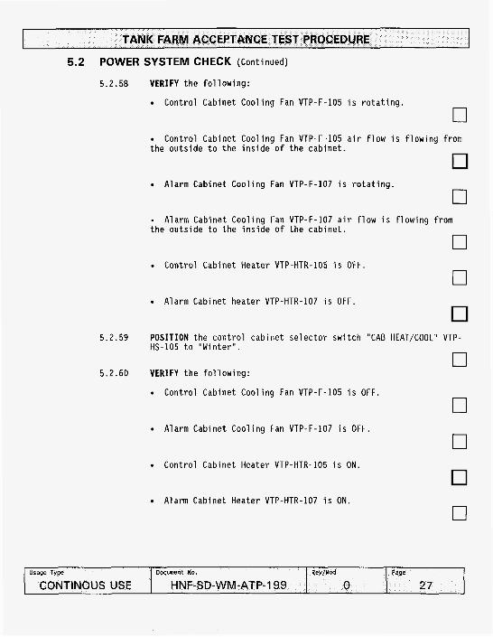
5.2.58 VERIFY t h e f o l l o w i n g :
Cont ro l Cabinet Coo l ing Fan VTP-F-105 i s r o t a t i n g .
0
0
0
0
t h e o u t s i d e t o t h e i n s i d e o f t h e cab ine t . Cont ro l Cabinet Coo l ing Fan VTP-F-105 a i r f l o w i s f l o w i n g from
Alarm Cabinet Coo l ing Fan VTP-F-107 i s r o t a t i n g .
- t h e o u t s i d e t o t h e i n s i d e o f t h e c a b i n e t .
Alarm Cabinet Coo l ing Fan VTP-F-107 a i r f l o w i s f l o w i n g from
Cont ro l Cabinet Heater VTP-HTR-105 i s OFF.
Alarm Cabinet heater VTP-HTR-107 i s OFF.
5.2.59 POSITION t h e c o n t r o l c a b i n e t s e l e c t o r s w i t c h "CAB HEAT/COOL" VTP- HS-105 t o "Win ter " .
n U
5.2.60 VERIFY t h e f o l l o w i n g :
Cont ro l Cabinet Coo l ing Fan VTP-F-105 i s OFF.
0 Alarm Cabinet Coo l ing Fan VTP-F-107 i s OFF.
0 Cont ro l Cabinet Heater VTP-HTR-105 i s ON.
0 Alarm Cabinet Heater VTP-HTR-107 i s ON.

TANK FARM ACCEPTANCE TEST PROCEDURE
5.2 POWER SYSTEM CHECK (Continued)
5.2.61
5.2.62
5.2.63
5.2.64
5.2.65
5.2.66
5.2.67
SET t h e C o n t r o l Cabinet Heater VTP-HTR-105 thermosta t temperature t o below t h e ambient temperature.
0 VERIFY Cont ro l Cabinet Heater element VTP-HTR-105 i s OFF and Heater f a n i s ON.
0 SET t h e Alarm Cabinet Heater VTP-HTR-107 thermosta t temperature t o below t h e ambient temperature.
0
0 VERIFY Alarm Cabinet Heater element VTP-HTR-107 i s OFF and Heater f a n i s ON.
POSITION t h e Cont ro l Cabinet S e l e c t o r Swi tch "CAB HEAT/COOL" VTP- HS-105 t o OFF. n
U
POSITION t h e Heat Trace Cabinet S e l e c t o r s w i t c h "CAB HEAT/COOL S e l e c t o r " VTP-HS-104 t o "SUMMER". n VERIFY t h e f o l l o w i n g :
U
Heat Trace Cabinet Coo l ing Fan VTP-F-104 i s r o t a t i n g .
0 Heat Trace Cabinet Coo l ing Fan VTP-F-104 a i r f l o w i s f l o w i n g
from t h e o u t s i d e t o t h e i n s i d e o f t h e c a b i n e t .
I n t r i n s i c B a r r i e r Coo l ing Fan VTP-F-106 i s r o t a t i n g .
Heat Trace Cabinet Heater VTP-HTR-104 i s OFF.
I n t r i n s i c B a r r i e r Cabinet heater VTP-HTR-106 i s OFF.
0
0
TANK FARM ACCEPTANCE TEST PROCEDURE
5.2 POWER SYSTEM CHECK (Cont inued)
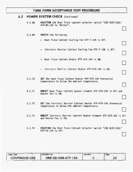
5.2.68 POSITION t h e Heat Trace c a b i n e t s e l e c t o r s w i t c h "CAB HEAT/COOL" VTP - HS - 104 t o I' W i n t e r " .
0 5.2.69 VERIFY t h e f o l l o w i n g :
Heat Trace Cabinet Coo l ing Fan VTP-F-104 i s OFF.
0
0 I n t r i n s i c B a r r i e r Cabinet Coo l ing Fan VTP-F-106 i s OFF.
Heat Trace Cabinet Heater VTP-HTR-104 i s ON.
. I n t r i n s i c B a r r i e r Cabinet Heater VTP-HTR-106 i s ON.
0
0
0
5.2.70 SET t h e Heat Trace Cabinet Heater VTP-HTR-104 thermosta t temperature t o below t h e ambient temperature.
5.2.71 VERIFY Heat Trace Cabinet Heater element VTP-HTR-104 i s OFF and Heater f a n i s ON.
5.2.72 SET t h e I n t r i n s i c B a r r i e r Cabinet Heater VTP-HTR-106 thermosta t temperature t o below t h e ambient temperature.
0 5.2.73 VERIFY I n t r i n s i c B a r r i e r Cabinet Heater element VTP-HTR-106 i s OFF
and Heater f a n i s ON.
0 5.2.74 POSITION t h e Heat Trace Cabinet S e l e c t o r Swi tch "CAB HEATKOOL"
VTP-HS-104 t o OFF

TANK FARM ACCEPTANCE TEST PROCEDURE
5.2 POWER SYSTEM CHECK (Cont inued)
WARNING
Energized c i r c u i t s and l e a d are conta ined i n s i d e t h e c a b i n e t . Observe A p p r o p r i a t e e l e c t r i c a l p recaut ions . 88, ELECTRICAL WORK SAFETY.
Comply w i t h HNF-PRO-
5.2.75
5.2.76
USING a DMM, VERIFY 120V a t t h e M i n i Power Zone Cabinet (VTP-PNL- 101) Receptacle.
0 USING a DMM, VERIFY 12OV a t t h e Alarm Cabinet (VTP-ENCL-107) Receptacle.
5.2.77 VERIFY t h e Wi lkerson i n d i c a t o r s a re i l l u m i n a t e d by v i s u a l i n s p e c t i o n . F i l l i n t h e f o l l o w i n g t a b l e .
5.2.78 VERIFY t h e Green FAN OFF i n d i c a t i n g l i g h t ( l o c a t e d on t h e door o f t h e Exhauster Cont ro l Cabinet VTP-CP-105) i s ILLUMINATED:
0
5.2 POWER SYSTEM CHECK (Continued)
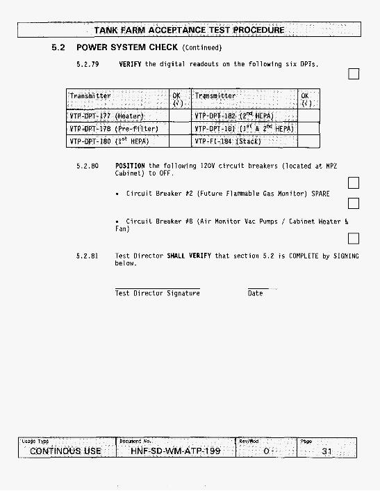
5 .2 .79 VERIFY the digital readouts on the following six DPTs.
5.2.80
5.2.81
POSITION the following 12OV circuit breakers (located at MPZ Cabinet) to OFF.
o
n U
Circuit Breaker #2 (Future Flammable Gas Monitor) SPARE n Circuit Breaker #8 (Air
Fan)
Test Director SHALL VERIFY below.
Test Director Signature
U
Monitor Qac Pumps / Cabinet Heater &
0 that section 5.2 is COMPLETE by SIGNING
Date

TANK FARM ACCEPTANCE TEST PROCEDURE
5.3 PRESSURE DECAY TEST
5.3.1 PERFORM t h e f o l l o w i n g i n s p e c t i o n s .
5.3.1.1 REMOVE f i l t e r housing doors. n U
5.3.1.2 REPAIR components as noted on t h e Except ion Reso lu t ion n U
5.3.1.3 TIGHTEN f i l t e r housing door l a t c h e s i n a gradual , equal sequence t o ensure an even door gasket sea l .
0 5.3.2
5.3.3
5.3.4
5.3.5
5.3.6
5.3.7
5.3.8
5.3.9
CLOSE F i l t e r t r a i n I n l e t va lve VTP-V-135.
CLOSE F i l t e r t r a i n O u t l e t v a l v e VTP-V-136.
0 VERIFY Seal Pot VTP-SP-001 i s empty by opening t h e seal p o t d r a i n v a l v e VTP-V-160.
VERIFY Seal Pot F i l l Valve VTP-V-159 i s CLOSED. 0
VERIFY Seal Pot Overf low D r a i n L i n e Valve VTP-V-161 i s CLOSED. - CLOSE Seal Pot D r a i n Valve VTP-V-160.
U
0 VERIFY Fan D r a i n L ine Valve VTP-V-158 i s CLOSED.
0 UNSCREW cap on t h e f i r s t stage HEPA F i l t e r Aerosol I n j e c t i o n Por t VTP-FTP-002 on t h e t e s t s e c t i o n n e x t t o t h e P r e f i l t e r .
0

5.3 PRESSURE DECAY TEST (Continued)
5.3.10
5.3.11
INSTALL AND SEAL the pressure measuring device into the first stage HEPA Filter Aerosol Injection Port VTP-FTP-002.
0 INSTALL the air supply line (with safety relief mechanism, isolation valve, and pressure reducer) into the second stage HEPA Filter Aerosol Test Port VTP-FTP-003.
NOTE: Next step starts checking positive pressure decay.
5.3.12
5.3.13
5.3.14
5.3.15
PRESSURIZE housing/duct assembly to t11.5 0.5 in wg.
MAINTAIN constant pressure until temperature remains constant within 2 0.5 "F as indicated by VTP-TIL179 for a minimum of 10 minutes.
0 ISOLATE the air supply from the filter housing while STARTING the clock. n
U
RECORD the initial time, barometric pressure, housing pressure, and temperature on Data Sheet 1 (Weather Station 373-2716).
TANK FARM ACCEPTANCE TEST PROCEDURE
Minute
5.3 PRESSURE DECAY TEST (Continued)
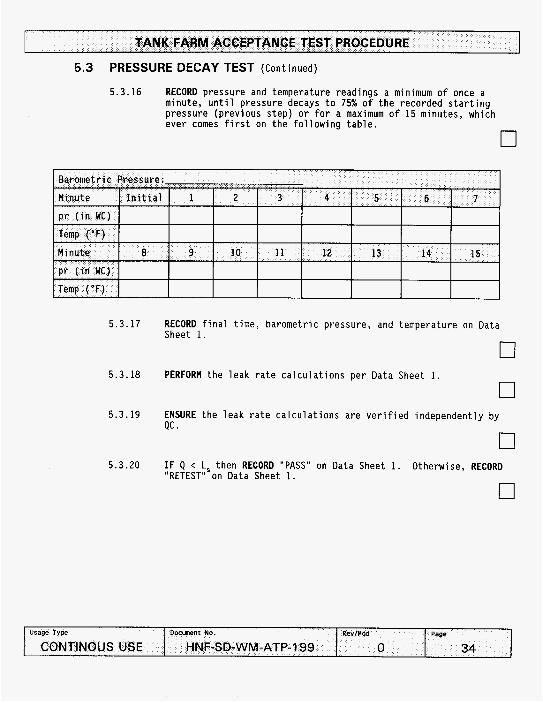
5.3.16 RECORD pressure and temperature readings a minimum of once a minute, until pressure decays to 75% of the recorded starting pressure (previous step) or for a maximum of 15 minutes, which ever comes first on the following table.
0
Initial 1 2 3 4 5 6 7
I I I I I I I I
5.3.17
5.3.18
5.3.19
5.3.20
RECORD final time, barometric pressure, and temperature on Data Sheet 1.
0
0
0
0
PERFORM the leak rate calculations per Data Sheet 1.
ENSURE the leak rate calculations are verified independently by QC .
I F Q < L, then RECORD "PASS" on Data Sheet 1. "RETEST" on Data Sheet 1.
Otherwise, RECORD

TANK FARM ACCEPTANCE TEST PROCEDURE
5.3 PRESSURE DECAY TEST (Continued)
5.3.21 IF a retest is needed, then PERFORM the following: n U
5.3.21.1 REPEAT steps 5.2.14 through 5.2.24 using new data sheets
0 5.3.22 DISCONNECT the air supply.
5.3.23 SLOWLY RELIEVE pressure from Filter Train housing through valve manifold assembly.
0 5.3.24 CONNECT a vacuum source to the Pressure Test Assembly at Aerosol
Injection Port VTP-FTP-003. n U
NOTE: Next step starts checking negative pressure decay.
5.3.25 DECREASE Filter Train housing internal pressure to -11.5 0.5 IN W.C. as INDICATED by the Pressure measuring device.
0
0
17
5.3.26 MAINTAIN constant pressure until temperature remains constant within & 0.5 "F for a minimum of 10 minutes.
5.3.27 ISOLATE the vacuum source from the filter housing while starting the clock.
5.3.28 RECORD the initial time, barometric pressure, pressure, and temperature on Data Sheet 2 (Weather Station 373-2716).
0

TANK FARM ACCEPTANCE TEST PROCEDURE
5.3 PRESSURE DECAY TEST (Continued)
5.3.29 RECORD pressure and temperature readings a minimum of once a minute, UNTIL pressure decays to 75% of the recorded starting pressure (previous step) or for a maximum of 15 minutes, which ever comes first on the following table.
0
5.3.30 RECORD final time, barometric pressure, and temperature on Data Sheet 2.
0 5 . 3 . 3 1 PERFORM the leak rate calculations per Data Sheet 2.
0 5.3.32 ENSURE the leak rate calculations are verified independently by
QC . 0
5.3.33 I F Q < L then RECORD "PASS" on Data Sheet 2 AND GO TO step 5.2.36. 'Otherwise. RECORD "RETEST" on Data Sheet 2.

TANK FARM ACCEPTANCE TEST PROCEDURE
.sage Type
CONTINOUS USE
5.3 PRESSURE DECAY TEST (Cont inued)
5.3.34 I F a r e t e s t i s needed, then PERFORM t h e f o l l o w i n g :
Docunnt No. Rev/nod Page
HNF-SD-WM-ATP-199 0 37
5.3.34.1 DETERMINE t h e l e a k pa th(s ) and REPAIR l e a k s as noted on t h e Except ion Reso lu t ion .
5.3.34.2 REPEAT steps 5.2.28 through 5.2.37 u s i n g new data sheets.
0 5.3.35 DISCONNECT t h e t e s t equipment.
5.3.36 SLOWLY e q u a l i z e F i l t e r T r a i n housing pressure t o atmospheric th rough t h e va lve m a n i f o l d assembly.
5.3.37 REINSTALL t h e t e s t p o r t p lugs .
5.3.38 OPEN F i l t e r T r a i n I n l e t va lve VTP-V-135.
5.3.39 OPEN F i l t e r T r a i n o u t l e t va lve VTP-V-136.
5.3.40 OPEN Fan D r a i n L i n e Valve VTP-V-158.
0 5.3.41 Test D i r e c t o r SHALL VERIFY t h a t s e c t i o n 5.3 i s COMPLETE by S I G N I N G
below.
Test D i r e c t o r S ignature Date
5.3.42 QC I n s p e c t o r SHALL VERIFY t h a t s e c t i o n 5.3 i s COMPLETE by S I G N I N G b e l ow.
QC I n s p e c t o r S ignature Date
TANK FARM ACCEPTANCE TEST PROCEDURE I 5.4 EXHAUSTER FAN CHECK
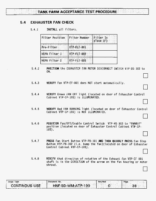
5.4.1 INSTALL a l l f i l t e r s .
5.4.2
5.4.3
5.4.4
5.4.5
5.4.6
5.4.7
5.4.8
POSITION t h e EXHAUSTER FAN MOTOR DISCONNECT SWITCH VTP-DS-102 t o ON.
0 VERIFY Fan VTP-EF-001 does NOT s t a r t a u t o m a t i c a l l y .
0 VERIFY Green FAN OFF l i g h t ( l o c a t e d on door o f Exhauster Contro l Cabinet VTP-CP-105) i s ILLUMINATED.
0 VERIFY Red FAN RUNNING l i g h t ( l oca ted on door o f Exhauster Contro l Cabinet VTP-CP-105) i s NOT ILLUMINATED.
0 POSITION Fan/Off/Enable Con t ro l Swi tch VTP-HS-103 t o "ENABLE" p o s i t i o n ( l oca ted on door o f Exhauster Con t ro l Cabinet VTP-CP- 105). n
U
PRESS Fan S t a r t Bu t ton VTP-PB-101 AND THEN QUICKLY PRESS Fan Stop Bu t ton VTP-PB-I02 ( i . e . bump t h e fan ) ( l oca ted on door o f Exhauster Con t ro l Cabinet VTP-CP-105).
0
n
VERIFY t h a t d i r e c t i o n o f r o t a t i o n o f t h e Exhaust f a n VTP-EF-001 s h a f t i s i n t h e DIRECTION o f t h e arrow on t h e f a n housing o r motor shroud.
U
TANK FARM ACCEPTANCE TEST PROCEDURE
5.4 EXHAUSTER FAN CHECK (Cont inued)
5.4.9 I F Exhauster Fan VTP-EF-001 r o t a t i o n d i r e c t i o n i s c o r r e c t , GO TO s tep 5.4.11
0 5.4.10 IF d i r e c t i o n o f r o t a t i o n o f t h e Exhauster Fan VTP-EF-001 i s i n the
i n c o r r e c t d i r e c t i o n , then PERFORM t h e f o l l o w i n g :
5.4.10.1 DO NOT EXECUTE any f u r t h e r p a r t o f 5.3 i n t h i s ATP UNTIL n e x t s tep through 5.4.10.5 a re COMPLETED.
0
0 5.4.10.2 POSITION Fan Motor Disconnect Swi tch VTP-DS-lO2A t o
OFF.
5.4.10.3 INSTALL Personal Locking Device on Fan Motor Disconnect Switch VTP-DS-102. n
U
5.4.10.4 CORRECT t h e Exhauster Fan VTP-EF-001 r o t a t i o n d i r e c t i o n by CORRECTING t h e leads a t t h e Fan Motor Disconnect Swi tch VTP-DS-101.
0
0
0
0
5.4.10.5 INSTALL Personal Locking Device on Fan Motor Disconnect Switch VTP-DS-102.
5.4.10.6 POSITION Fan Motor Disconnect Swi tch VTP-DS-102 t o ON
5.4.10.7 REPEAT steps 5.4.2 through 5.4.8.

TANK FARM ACCEPTANCE TEST PROCEDURE
.sage Type
CONTINOUS USE
5.4 EXHAUSTER FAN CHECK (Continued)
Docment ko. PevIMcd Page
HNF-SD-WM-ATP-199 0 40
5.4.11 OPEN t h e High and Low va lves AND CLOSE E q u a l i z i n g v a l v e on each t h r e e v a l v e m a n i f o l d f o r t h e f o l l o w i n g DPTs:
0
5.4.12
5.4.13
POSITION Fan Motor Disconnect Swi tch VTP-DS-102 t o OFF. r J REMOVE Fan VTP-EF-001 s h a f t guard as r e q u i r e d t o a l l o w access t o s h a f t bear ings.
0 5.4.14 POSITION Fan Motor Disconnect Swi tch VTP-DS-101 t o ON.
5.4.15
5.4.16
0
0 CONNECT o p e r a t i o n c o n t r o l console (computer) t o t h e SLC 500 CPU.
FORCE t h e exhaust SLC Program t o r u n t h e exhaust f a n a t 3450 rpm.
0 5.4.17 POSITION Fan/Off/Enable Cont ro l Swi tch VTP-HS-103 t o "ENABLE"
p o s i t i o n ( l o c a t e d on door o f Exhauster Cont ro l Cabinet VTP-CP- 105).
0
TANK FARM ACCEPTANCE TEST PROCEDURE
. .. CONTINOUS USE
5.4 EXHAUSTER FAN CHECK (Continued)
HNF-SD-WM-ATP-199 0 41
5.4.18
5.4.19
5.4.20
5.4.21
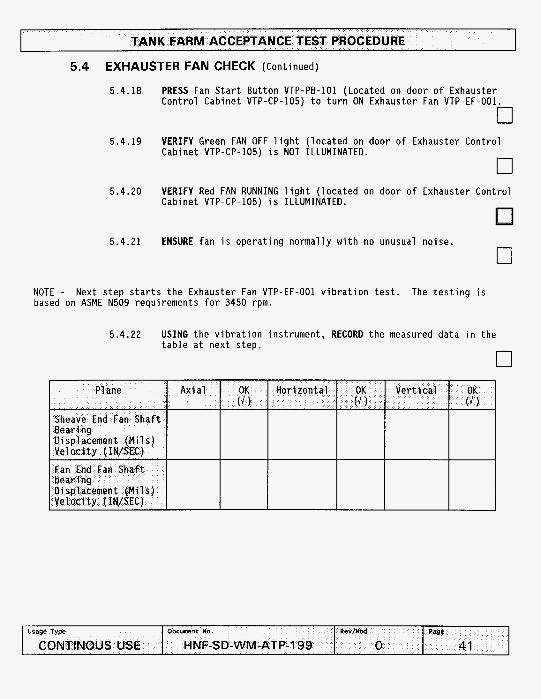
PRESS Fan S t a r t But ton VTP-PB-101 (Located on door o f Exhauster Cont ro l Cabinet VTP-CP-105) t o t u r n ON Exhauster Fan VTP-EF-001
0 VERIFY Green FAN OFF l i g h t ( l o c a t e d on door o f Exhauster Cont ro l Cabinet VTP-CP-105) i s NOT ILLUMINATED. n VERIFY Red FAN RUNNING l i g h t ( l o c a t e d on door o f Exhauster Cont ro l Cabinet VTP-CP-105) i s ILLUMINATED.
ENSURE f a n i s o p e r a t i n g normal ly w i t h no unusual n o i s e .
NOTE - Next s t e p s t a r t s t h e Exhauster Fan VTP-EF-001 v i b r a t i o n t e s t . based on ASME N509 requirements f o r 3450 rpm.
The t e s t i n g i s
5.4.22 USING t h e v i b r a t i o n ins t rument , RECORD t h e measured da ta i n t h e t a b l e a t nex t step.
0

TANK FARM ACCEPTANCE TEST PROCEDURE
5.4 EXHAUSTER FAN CHECK (Continued)
5.4.23 VERIFY t h a t t h e F i l t e r e d Bear ing V i b r a t i o n Levels on the fan s h a f t bear ings should meet t h e f o l l o w i n g c r i t e r i a :
0 Displacement <.6 MILS (PK-TO-PK) a t one t imes the f a n
speed.
- OR -
V e l o c i t y c .ll IN/SEC (PK) a t one t imes the fan speed.
5.4.24 PRESS Fan Stop Bu t ton VTP-PB-102 ( l oca ted on door o f Exhauster Con t ro l Cabinet VTP-CP-105) t o t u r n OFF Exhauster Fan.
0
0
0 0
0
5.4.25 VERIFY Exhauster f a n has SHUTDOWN.
5.4.26 REMOVE f o r c e f rom t h e exhauster SLC Program.
5.4.27 POSITION Fan Motor Disconnect Swi tch VTP-DS-102 t o OFF.
5.4.28 REPLACE Fan VTP-EF-001 s h a f t guard.
5.4.29 POSITION Fan Motor Disconnect Swi tch VTP-DS-I02 t o ON.
5.4.30 Test D i r e c t o r SHALL VERIFY t h a t s e c t i o n 5.4 i s COMPLETE by SIGNING below.
Test D i r e c t o r S igna tu re Date

I TANK FARM ACCEPTANCE TEST PROCEDURE
5.5 HEAT TRACE CHECK
5.5.1 ENSURE Heat Trace 120V c i r c u i t breaker #4 ( l o c a t e d a t MPZ Cabinet VTP-PNL-101) i s ON.
0 5.5.2 USING a DMM, VERIFY 0 V a t t e r m i n a l s TBlHTC-I1 and TBEHTC-I1
( l o c a t e d a t Heat Trace Cabinet VTP-ENCL-104).
0 5.5.3 IMMERSE Heat t r a c e thermostat probe i n i c e .
5.5.4 WAIT 2-5 minutes.
5.5.5 USING a DMM, VERIFY 120V a t t e r m i n a l s TBlHTC-11 and TBEHTC-11 ( l o c a t e d a t Heat Trace Cabinet VTP-ENCL-104),
0
o n
5.5.6 VERIFY Heat Trace ON amber l i g h t ( l o c a t e d a t door o f Heat Trace Cabinet VTP-ENCL-104) i s ILLUMINATED. n
U
5.5.7 REMOVE i c e f rom t h e heat t r a c e thermostat probe.
0 5.5.8 VERIFY Heat Trace ON amber l i g h t ( l o c a t e d a t door o f Heat Trace
Cabinet VTP-ENCL-104) i s NOT ILLUMINATED a f t e r probe heats up.
5.5.9 USING a DMM, VERIFY 0 V a t t e r m i n a l s TBlHTC-I1 and TBEHTC-11 ( l oca ted a t Heat Trace Cabinet VTP-ENCL-104).
0 5.5.10 POSITION Heat Trace 120V c i r c u i t breaker #4 ( l o c a t e d a t MPZ
Cabinet VTP-PNL-101) t o OFF.

TANK FARM ACCEPTANCE TEST PROCEDURE
5.5 HEAT TRACE CHECK (Continued)
5.5.11 Test D i r e c t o r SHALL VERIFY t h a t s e c t i o n 5.5 i s COMPLETE by SIGNING below.
Test D i r e c t o r S ignature Date

TANK FARM ACCEPTANCE TEST PROCEDURE
5.6 FILTER # I DP INTERLOCK/ALARM CHECK ( T r a n s m i t t e r Range 0-10" )
5.6.1 ENSURE t h e High, Low and E q u a l i z i n g v a l v e on VTP-DPT-180's t h r e e v a l v e m a n i f o l d a re CLOSED o r OPEN as i n d i c a t e d below:
5.6.2
5.6.3
5.6.4
5.6.5
5.6.6
5.6.7
REMOVE back cover f rom VTP-PDT-180.
0
0
0
0
CONNECT a BT-200 t o t h e t r a n s m i t t e r VTP-PDT-180.
ENSURE Fan/Off/Enable Cont ro l S e l e c t o r Swi tch VTP-HS-103 ( l o c a t e d on door o f Exhauster Cont ro l Cabinet VTP-CP-105) i s i n t h e Enable p o s i t i o n .
PRESS Fan S t a r t But ton VTP-PB-IO1 ( l o c a t e d on door o f Exhauster Cont ro l Cabinet VTP-CP-105).
WAIT f o r t h e Exhauster f a n t o come up t o speed
0 SET t h e BT-200 t o t e s t a t 045.0%. T h i s i s equal t o 4.5 I N W.C.
0

TANK FARM ACCEPTANCE TEST PROCEDURE
Usage Type
CONTINOUS USE
5.6 FILTER #I DP INTERLOCK/ALARM CHECK (Cont inued)
5.6.8 VERIFY t h e f o l l o w i n g :
17 0
Clear R o t a t i n g Beacon VTP-XA-101 i s ILLUMINATED.
DOcunent No. RevInca Page
HNF-SD-WM-ATP-199 0 46
Red FAN RUNNING l i g h t i s ILLUMINATED.
Green FAN O F F l i g h t i s NOT ILLUMINATED.
0
0 Alarm Cabinet Swing Out Panel) DISPLAY "FILTER 1 DP H I " .
Message View Disp lays VTP-MV-IO1 and VTP-MV-102 ( l o c a t e d a t
0 5.6.9 RECORD t h e pressure i n d i c a t e d by t h e Wi lkerson i n d i c a t o r VTP-PDI-
180 ( l o c a t e d on door o f Exhauster Cont ro l Cabinet VTP-CP-105).
I n d i c a t e d Pressure:
0 5.6.10 ACKNOWLEDGE t h e alarm by PRESSING t h e 1 but ton , then p r e s s i n g the
"r" b u t t o n on t h e Message View D i s p l a y VTP-MV-101 ( l o c a t e d a t Alarm Cabinet VTP-ENCL-107 Swing Out Panel) t h r e e t imes. For any secondary alarms repeat t h i s s tep u n t i l a l l alarms are c leared .
0
0
0
5.6.11 VERIFY Clear R o t a t i n g Beacon VTP-XA-101 i s NOT ILLUMINATED.
5.6.12 VERIFY Message View D i s p l a y VTP-MV-IO2 ( l o c a t e d a t Alarm Cabinet Any secondary Swing Out Panel) STILL DISPLAYS "FILTER 1 DP H I " .
alarms t h a t are s t i l l i n alarm c o n d i t i o n w i l l a l s o be i n d i c a t e d
5.6.13 SET t h e BT-200 t o t e s t a t 054.0%. T h i s i s e q u i v a l e n t t o 5.4 I N W.C.

TANK FARM ACCEPTANCE TEST PROCEDURE
5.6 FILTER # I DP INTERLOCKlALARM CHECK (Cont inued)
5.6.14
5.6.15
5.6.16
5.6.17
VERIFY t h e f o l l o w i n g :
Exhauster Fan VTP-EF-001 has SHUTDOWN.
Red FAN RUNNING l i g h t i s NOT ILLUMINATED.
Green FAN OFF l i g h t i s ILLUMINATED.
0
0
0
0 Clear R o t a t i n g Beacon VTP-XA-101 ( l o c a t e d on s t a c k suppor t ing
f raming) i s ILLUMINATED.
0 Message View D i s p l a y VTP-MV-IO1 ( l o c a t e d a t Alarm Cabinet Swing
Out Panel) DISPLAYS ''FILTER 1 DP HIHI " and "FAN SHUTDOWN". Any secondary alarms t h a t a re s t i l l i n alarm c o n d i t i o n w i l l a l s o be i n d i c a t e d .
El RECORD t h e pressure i n d i c a t e d by t h e Wi lkerson i n d i c a t o r VTP-PDI- 180 ( l o c a t e d on door o f Exhauster Cont ro l Cabinet VTP-CP-105).
I n d i c a t e d Pressure:
0 ACKNOWLEDGE t h e alarm by PRESSING t h e "1" bu t ton , then p r e s s i n g t h e "-" b u t t o n on the Message View D i s p l a y VTP-MV-IO1 ( l o c a t e d a t Alarm Cabinet VTP-ENCL-107 Swing Out Panel) t h r e e t imes. For any secondary alarms repeat t h i s s tep u n t i l a l l alarms are c l e a r e d
0 VERIFY Clear R o t a t i n g Beacon VTP-XA-101 i s NOT ILLUMINATED.
0

TANK FARM ACCEPTANCE TEST PROCEDURE
5.6 FILTER # I DP INTERLOCK/ALARM CHECK (Cont inued)
5.6.18
5.6.19
5.6.20
5.6.21
5.6.22
5.6.23
VERIFY Message View D i s p l a y VTP-MV-102 ( l o c a t e d a t Alarm Cabinet Swing Out Panel) STILL DISPLAYS "FILTER 1 DP HIHI". secondary alarms t h a t a re s t i l l i n alarm c o n d i t i o n w i l l a l s o be
Note: Any
i n d i c a t e b .
CLEAR t h e BT-200 t e s t s e t t i n g .
FORCE t h e r a t e o f change l o g i c
PRESS Fan S t a r t But ton PB-101 ( l o c a t e d on door o f Exhauster Cont ro l Cabinet VTP-CP-105).
WAIT f o r t h e Exhauster f a n t o come up t o speed.
SET t h e BT-200 t o t e s t a t 000.1%. approx imate ly 0.1 I N W . G .
T h i s i s e q u i v a l e n t t o
0
0
0
0
0

TANK FARM ACCEPTANCE TEST PROCEDURE
5.6 FILTER # I DP INTERLOCK/ALARM CHECK (Cont inued)
5.6.24
5.6.25
5.6.26
5.6.27
VERIFY t h e f o l l o w i n g : n U
Exhauster Fan VTP-EF-001 has SHUTDOWN a f t e r 10 seconds. n U
Red FAN RUNNING l i g h t i s NOT ILLUMINATED.
0 Green FAN OFF l i g h t i s ILLUMINATED.
0
0 Clear R o t a t i n g Beacon VTP-XA-IO1 ( l o c a t e d on s t a c k suppor t ing
f raming) i s ILLUMINATED.
Message View D i s p l a y VTP-MV-101 and VTP-MV-102 (1o:at;ed a t Alarm Cabinet Swing Out Panel) DISPLAYS " F i l t e r 1 ROC , FILTER 1 DP LO" and "FAN SHUTDOWN". Any secondary alarms t h a t are s t i l l i n a la rm c o n d i t i o n w i l l a l s o be i n d i c a t e d .
0 ACKNOWLEDGE t h e alarm by PRESSING t h e "1" bu t ton , then press ing t h e '*+" b u t t o n on t h e Message View D i s p l a y VTP-MV-101 ( l o c a t e d a t Alarm Cabinet VTP-ENCL-107 Swing Out Panel) t h r e e t imes. For any secondary alarms repeat t h i s s tep u n t i l a l l alarms are c l e a r e d
0
0
0
VERIFY Clear R o t a t i n g Beacon VTP-XA-101 i s NOT ILLUMINATED.
CLEAR t h e BT-200 t e s t s e t t i n g .

5.6 FILTER # I DP INTERLOCK/ALARM CHECK (Continued)
5.6.28 REMOVE force on the rate of change logic.
5.6.29 PRESS the Fan Start Button PB-101 (located on the door of Exhauster Control Cabinet VTP-CP-105).
5.6.30 WAIT 2 minutes for the fan to come up to speed.
0
0
0 5.6.31 RECORD VTP-PDT-180 reading.
Reading : 0
0 5.6.32 SET the BT-200 to test at 0.5 I N W.C. less then the value recorded
in the previous step from transmitter VTP-PDT-180.
5.6.33 RECORD the BT-200 setting.
Setting : 0

TANK FARM ACCEPTANCE TEST PROCEDURE
5.6 FILTER # I DP INTERLOCK/ALARM CHECK (Cont inued)
5.6.34
5.6.35
5.6.36
5.6.37
5.6.38
5.6.39
VERIFY t h e f o l l o w i n g :
C lear r o t a t i n g beacon VTP-XA-101 i s ILLUMINATED.
0 Red f a n runn ing l i g h t i s NOT ILLUMINATED.
0
0
0
Green f a n o f f l i g h t i s ILLUMINATED.
Exhauster f a n VTP-EF-001 has shutdown.
Message view d i s p l a y VTP-MV-101 ( l o c a t e d a t a la rm c a b i n e t swing o u t pane l ) DISPLAYS " F i l t e r 1 DP ROC" . alarms t h a t a re s t i l l i n a la rm c o n d i t i o n w i l l a l s o be i n d i c a t e d .
Any secondary
0 ACKNOWLEDGE t h e alarm by PRESSING t h e t h e "-*' b u t t o n on t h e Message View D i s p l a y VTP-MV-101 ( l o c a t e d a t Alarm Cabinet VTP-ENCL-107 Swing Out Panel) t h r e e t imes. For any secondary alarms repeat t h i s s tep u n t i l a l l alarms are c l e a r e d
"1" bu t ton , then press ing
0
0
0
0
VERIFY Clear R o t a t i n g Beacon VTP-XA-101 i s NOT ILLUMINATED.
DISCONNECT BT-200 from t r a n s m i t t e r VTP-PDT-180.
REPLACE back cover on t r a n s m i t t e r VTP-PDT-180.
Test D i r e c t o r SHALL VERIFY t h a t s e c t i o n 5.6 i s COMPLETE by S I G N I N G be l ow.
Tes t D i r e c t o r S ignature Date

TANK FARM ACCEPTANCE TEST PROCEDURE
5.7 FILTER #2 DP INTERLOCK/ALARM CHECK ( T r a n s m i t t e r Range 0-6" )
5.7.1 ENSURE t h e High, Low and E q u a l i z i n g va lves on VTP-DPT-182 t h r e e v a l v e m a n i f o l d a re CLOSED o r OPEN as i n d i c a t e d below:
5.7.2
5.7.3
5.7.4
5.7.5
5.7.6
5.7.7
REMOVE back cover f rom t h e t r a n s m i t t e r VTP-PDT-182.
17
0
17
17
CONNECT a ET-200 t o t h e t r a n s m i t t e r VTP-PDT-182.
ENSURE Fan/Off/Enable Cont ro l S e l e c t o r Swi tch VTP-HS-103 ( l o c a t e d on door o f Exhauster Cont ro l Cabinet VTP-CP-105) i s i n t h e Enable p o s i t i o n .
PRESS Fan S t a r t But ton PB-101 ( l o c a t e d on door o f Exhauster Cont ro l Cabinet VTP-CP-105).
WAIT f o r t h e Exhauster f a n t o come up t o speed.
SET BT-200 t o t e s t a t 053.4%. T h i s i s e q u i v a l e n t t o 3 . 2 I N W.C

5.7 FILTER #2 DP INTERLOCK/ALARM CHECK (Cont inued)
5.7.8
5.7.9
5.7.10
5.7.11
5.7.12
5.7.13
VERIFY t h e f o l l o w i n g :
C l e a r R o t a t i n g Beacon VTP-XA-101 i s ILLUMINATED.
0 Red FAN RUNNING l i g h t i s ILLUMINATED.
Green FAN OFF l i g h t i s NOT ILLUMINATED
cl
0 Message View Disp lays VTP-MV-101 and VTP-MV-102 ( l o c a t e d a t
Alarm Cabinet Swing Out Panel) DISPLAY "FILTER 2 DP H I " .
0 RECORD va lue from W i l kerson i n d i c a t o r VTP-PDI-182 ( l o c a t e d on door o f Exhauster Cont ro l Cabinet VTP-CP-105).
READ I NG : IN W.C. 0 ACKNOWLEDGE t h e a la rm by PRESSING t h e "1" b u t t o n , then p r e s s i n g t h e "r" b u t t o n on t h e Message View D i s p l a y VTP-MV-101 ( l o c a t e d a t Alarm Cabinet VTP-ENCL-107 Swing Out Panel ) t h r e e t imes. For any secondary alarms repeat t h i s s t e p u n t i l a l l alarms a r e c leared .
0
0 VERIFY C l e a r R o t a t i n g Beacon VTP-XA-101 i s NOT ILLUMINATED.
VERIFY Message View D i s p l a y VTP-MV-102 ( located, ,a t Alarm Cabinet Swing Out Panel) STILL DISPLAYS "FILTER 2 DP H I .
0 SET t h e BT-200 t o t e s t a t 061.7%. W.C.
T h i s i s e q u i v a l e n t t o 3.7 I N
0

TANK FARM ACCEPTANCE TEST PROCEDURE
5.7 FILTER #2 DP INTERLOCK/ALARM CHECK (Continued)
5.7.14 VERIFY the f o l l o w i n g :
5.7.15
5.7.16
5.7.17
5.7.18
Exhauster Fan VTP-EF-001 has SHUTDOWN.
Red FAN RUNNING l i g h t i s NOT ILLUMINATED.
Green FAN OFF l i g h t i s ILLUMINATED.
0
0
0
0 - C lea r R o t a t i n g Beacon VTP-XA-101 ( l o c a t e d on s tack suppor t i ng f raming) i s ILLUMINATED.
0 Message View D isp lay VTP-MV-IO1 ( l o c a t e d a t Alarm Cabinet Swing
Out Panel) DISPLAYS "FILTER 2 DP HIHI" and "FAN SHUTDOWN". Any secondary alarms t h a t a re s t i l l i n a larm c o n d i t i o n w i l l a l s o be i n d i c a t e d .
0 RECORD value f rom Wi lkerson i n d i c a t o r VTP-PDI-182 ( l o c a t e d on door o f Exhauster Contro l Cabinet VTP-CP-105).
READING : I N W.C.
ACKNOWLEDGE t h e a larm by PRESSING t h e "1" bu t ton , t hen p ress ing t h e "1-"' b u t t o n on t h e Message View D i s p l a y VTP-MV-101 ( l oca ted a t Alarm Cabinet VTP-ENCL-107 Swing Out Panel) t h r e e t imes . For any secondary alarms repea t t h i s s tep u n t i l a l l alarms a re c lea red .
0 VERIFY Clear Ro ta t i ng Beacon VTP-XA-101 i s NOT ILLUMINATED.
0 VERIFY Message View D i s p l a y VTP-MV-102 ( l o c a t e d a t A larm Cabinet Swing Out Panel) STILL DISPLAYS "FILTER 2 DP HIHI" . alarms t h a t are s t i l l i n a larm c o n d i t i o n w i l l a l s o be i n d i c a t e d
Any secondary

TANK FARM ACCEPTANCE TEST PROCEDURE
5.7 FILTER #2 DP INTERLOCK/ALARM CHECK (Cont inued)
5.7.19 CLEAR t h e BT-200 t e s t s e t t i n g .
5.7.20 FORCE t h e r a t e o f change l o g i c .
0
0 5.7.21 PRESS Fan S t a r t But ton VTP-PB-101 ( l o c a t e d on door o f Exhauster
Cont ro l Cabinet VTP-CP-105).
0 5.7.22 WAIT f o r t h e Exhauster f a n t o come up t o speed.
5.7.23 SET t h e BT-200 t o t e s t a t 001.6%. T h i s i s e q u i v a l e n t t o 0.1 I N W.C.
0 5.7.24 VERIFY t h e f o l l o w i n g :
0 Exhauster Fan VTP-EF-001 has SHUTDOWN a f t e r 10 seconds.
0 Red FAN RUNNING l i g h t i s NOT ILLUMINATED.
0 Green FAN OFF l i g h t i s ILLUMINATED.
0 Clear R o t a t i n g Beacon VTP-XA-IO1 ( l o c a t e d on s t a c k suppor t ing
f raming) i s ILLUMINATED.
0 Message View D i s p l a y VTP-MV-101 and VTP-MV-102 ( l o c a t e d a t
Alarm Cabinet Swing Out Panel) DISPLAYS " F i l t e r 2 ROC", "FILTER 1 DP LO" and "FAN SHUTDOWN". Any secondary alarms t h a t are s t i l l i n a la rm c o n d i t i o n w i l l a l s o be i n d i c a t e d .
0

TANK FARM ACCEPTANCE TEST PROCEDURE
FILTER #2 DP INTERLOCK/ALARM CHECK (Cont inued) 5.7
5.7.25
5.7.26
5.7.27
5.7.28
5.7.29
5.7.30
5.7.31
5.7.32
5.7.33
ACKNOWLEDGE t h e alarm by PRESSING t h e "1" bu t ton , then PRESSING t h e "e" b u t t o n on t h e Message View D i s p l a y VTP-MV-101 ( l o c a t e d a t Alarm Cabinet VTP-ENCL-107 Swing Out Panel) t h r e e t imes. For any secondary alarms repeat t h i s s tep u n t i l a l l alarms are c leared .
0 VERIFY Clear R o t a t i n g Beacon VTP-XA-101 i s NOT ILLUMINATED.
CLEAR t h e ET-200 t e s t s e t t i n g .
0 REMOVE f o r c e on t h e r a t e o f change l o g i c . n
Y
PRESS t h e Fan S t a r t But ton PB-101 ( l o c a t e d on t h e door o f Exhauster Cont ro l Cabinet VTP-CP-105).
WAIT 2 minutes f o r t h e f a n t o come up t o speed.
0
Reading :
RECORD VTP-POT-182 read ing .
SET t h e BT-200 t o t e s t a t 0.5 I N W.C. l e s s then t h e va lue recorded i n t h e prev ious s tep from t r a n s m i t t e r VTP-PDT-162.
RECORD t h e BT-200 s e t t i n g .
S e t t i n g :

TANK FARM ACCEPTANCE TEST PROCEDURE 1 5.7 FILTER #2 DP INTERLOCK/ALARM CHECK (Cont inued)
5.7.34 VERIFY t h e f o l l o w i n g :
C lear r o t a t i n g beacon VTP-XA-101 i s ILLUMINATED.
Red f a n runn ing l i g h t i s NOT ILLUMINATED.
Green f a n o f f l i g h t i s ILLUMINATED.
Exhauster f a n VTP-EF-001 has shutdown.
0
0 0
0 Message view d i s p l a y VTP-MV-101 ( l o c a t e d a t a larm c a b i n e t swing o u t pane l ) DISPLAYS " F i l t e r 2 DP ROC". alarms t h a t are s t i l l i n alarm c o n d i t i o n w i l l a l s o be i n d i c a t e d .
Any secondary
0 5.7.35 ACKNOWLEDGE t h e alarm by PRESSING t h e "1" b u t t o n , then p r e s s i n g
t h e "+" b u t t o n on t h e Message View D i s p l a y VTP-MV-101 ( l o c a t e d a t Alarm Cabinet VTP-ENCL-107 Swing Out Panel) t h r e e t imes. For any secondary alarms repeat t h i s s tep u n t i l a l l alarms are c l e a r e d
0 5.7.36 VERIFY Clear R o t a t i n g Beacon VTP-XA-101 i s NOT ILLUMINATED. n
U
5.7.37 RESET BT-200.
5.7.38 DISCONNECT BT-200 f rom t r a n s m i t t e r VTP-PDT-182.

TANK FARM ACCEPTANCE TEST PROCEDURE
5.7 FILTER #2 DP INTERLOCK/ALARM CHECK (Cont inued)
5.7.39 REPLACE back cover on t r a n s m i t t e r VTP-PDT-182.
5.7.40 Tes t D i r e c t o r SHALL VERIFY t h a t s e c t i o n 5.7 i s COMPLETE by SIGNING b e l ow.
Test D i r e c t o r S ignature Date

TANK FARM ACCEPTANCE TEST PROCEDURE
5.8 FILTER # I & #2 DP INTERLOCK/ALARM CHECK ( T r a n s m i t t e r Range 0 - 6 " )
5.8.1 ENSURE t h e High, Low and E q u a l i z i n g va lves on VTP-DPT-181 t h r e e v a l v e m a n i f o l d a re CLOSED o r OPEN as i n d i c a t e d below:
5.8.2
5.8.3
5.8.4
5.8.5
5.8.6
5.8.7
REMOVE back cover on t h e t r a n s m i t t e r VTP-PDT-181.
0
0
0
CONNECT a BT-200 t o t h e t r a n s m i t t e r VTP-PDT-181.
ENSURE Fan/Off/Enable Cont ro l S e l e c t o r Swi tch VTP-HS-103 ( l o c a t e d on door o f Exhauster Cont ro l Cabinet VTP-CP-105) i s i n t h e Enable p o s i t i o n .
PRESS Fan S t a r t But ton VTP-PB-101 ( l o c a t e d on door o f Exhauster Cont ro l Cabinet VTP-CP-105).
0 WAIT f o r t h e Exhauster f a n t o come up t o speed.
0 SET t h e BT-200 t o t e s t a t 090.1%. T h i s i s e p u i v a l e n t t o 5.4 I N W . C .
0

TANK FARM ACCEPTANCE TEST PROCEDURE
5.8 FILTER #I & #2 DP INTERLOCK/ALARM CHECK (Cont inued)
5.8.8 VERIFY t h e f o l l o w i n g :
Exhauster Fan VTP-EF-001 has SHUTDOWN.
Red FAN RUNNING l i g h t i s NOT ILLUMINATED.
Green FAN OFF l i g h t i s ILLUMINATED.
0
0 Clear R o t a t i n g Beacon VTP-XA-101 ( l o c a t e d on s t a c k suppor t ing
f raming) i s ILLUMINATED. n U
Message View D i s p l a y VTP-MV-IO1 ( l o c a t e d a t Alarm Cabinet,,Swing Out Panel) DISPLAYS "FILTER 1 & 2 DP HIHI " and "FAN SHUTDOWN . Any secondary alarms t h a t are s t i l l i n a la rm c o n d i t i o n w i l l a l s o be i n d i c a t e d . n
U - Message View D i s p l a y VTP-MV-102 ( l o c a t e d a t Alarm Cabinet Swing Out Panel) DISPLAYS "FILTER 1 & 2 DP H I H I " secondary alarms t h a t a re s t i l l i n alarm c o n d i t i o n w i l l a l s o be i n d i c a t e d .
5.8.9 RECORD va lue from Wilkerson i n d i c a t o r VTP-PDI-182 ( l o c a t e d on door o f Exhauster Cont ro l Cabinet VTP-CP-105).
READING : I N W.C. 0 5.8.10 ACKNOWLEDGE t h e alarm by PRESSING t h e "1" but ton , then p r e s s i n g
t h e "+" b u t t o n on t h e Message View D i s p l a y VTP-MV-101 ( l o c a t e d a t Alarm Cabinet VTP-ENCL-107 Swing Out Panel) t h r e e t imes. For any secondary alarms repeat t h i s s t e p u n t i l a l l alarms are c leared .
0 5.8.11 VERIFY Clear R o t a t i n g Beacon VTP-XA-101 i s NOT ILLUMINATED.
0

TANK FARM ACCEPTANCE TEST PROCEDURE
5.8 FILTER # I & #2 DP INTERLOCK/ALARM CHECK (Cont inued)
5.8.12
5.8.13
5.8.14
5.8.15
VERIFY Message View D i s p l a y VTP-MV-102 ( l o c a t e d a t Alarm Cabinet Swing Out Panel) STILL DISPLAYS "FILTER 1&2 DP H I H I " . Any secondary alarms t h a t are s t i l l i n a la rm c o n d i t i o n w i l l a l s o be i n d i c a t e d .
0
0 CLEAR t h e BT-200 t e s t s e t t i n g .
FORCE t h e r a t e o f change l o g i c .
0 PRESS Fan S t a r t But ton VTP-PB-101 ( l o c a t e d on door o f Exhauster Cont ro l Cabinet VTP-CP-105).
0 5.8.16 WAIT f o r t h e Exhauster f a n t o come up t o speed.
0 5.8.17 SET t h e BT-200 t o t e s t a t 001.6%.
approx imate ly 0 . 1 I N W.C. T h i s i s e q u i v a l e n t t o
TANK FARM ACCEPTANCE TEST PROCEDURE
5.8 FILTER # I & #2 DP INTERLOCK/ALARM CHECK (Cont inued)
5.8.18
5.8.19
5.8.20
5.8.21
5.8.22
VERIFY t h e f o l l o w i n g :
0 Exhauster Fan VTP-EF-001 has SHUTDOWN a f t e r 10 seconds.
0 Red FAN RUNNING l i g h t i s NOT ILLUMINATED.
0 Green FAN OFF l i g h t i s ILLUMINATED.
0
0 Clear R o t a t i n g Beacon VTP-XA-101 ( l o c a t e d on s t a c k suppor t ing
f raming) i s ILLUMINATED.
Message View D i s p l a y VTP-MV-101 ( l o c a t e d a t Out Panel) DISPLAYS " F i l t e r 1&2 ROC", "FILTER SHUTDOWN". Any secondary alarms t h a t a re s t i l w i l l a l s o be i n d i c a t e d .
Alarm Cabinet Swing &2 DP LO" and "FAN
i n a la rm c o n d i t i o n
0 Out Panel) DISPLAYS "FILTER 1&2 DP LO". a re s t i l l i n alarm c o n d i t i o n w i l l a l s o be i n d i c a t e d .
Message View D i s p l a y VTP-MV-102 ( l o c a t e d a t Alarm Cabinet Swing Any secondary alarms t h a t
0 ACKNOWLEDGE t h e alarm by PRESSING t h e "1" bu t ton , then t h r e e t imes "+" b u t t o n on t h e Message View D i s p l a y VTP-MV-IO1 ( l o c a t e d a t Alarm Cabinet VTP-ENCL-107 Swing Out Panel) . alarms repeat t h i s s tep u n t i l a l l alarms are c l e a r e d .
For any secondary
0
0 VERIFY Clear R o t a t i n g Beacon VTP-XA-IO1 i s NOT ILLUMINATED.
CLEAR t h e BT-200 t e s t s e t t i n g .
REMOVE f o r c e on t h e r a t e o f change l o g i c .
0

TANK FARM ACCEPTANCE TEST PROCEDURE
5.8 FILTER # I & #2 DP INTERLOCK/ALARM CHECK (Cont inued)
5.8.23
5.8.24
5.8.25
5.8.26
5.8.27
PRESS t h e Fan S t a r t But ton PB-101 ( l o c a t e d on t h e door o f Exhauster Cont ro l Cabinet VTP-CP-105).
0 WAIT approx imate ly 2 minutes f o r t h e f a n t o come up t o speed.
0
Reading : 0
0
S e t t i n g :
RECORD VTP-PDT-181 read ing .
SET t h e 6T-200 t o t e s t a t t 0 . 5 IN W.G. o f VTP-PDT-161 read ing .
RECORD t h e BT-200 s e t t i n g .
5.8 FILTER # I & #2 DP INTERLOCK/ALARM CHECK (Cont inued)
5.8.28 VERIFY t h e f o l l o w i n g :
- C lear r o t a t i n g beacon VTP-XA-IO1 i s ILLUMINATED.
Red f a n runn ing l i g h t i s NOT ILLUMINATED.
Green f a n o f f l i g h t i s ILLUMINATED.
Exhauster f a n VTP-EF-001 has shutdown.
0
0 - Message view d i s p l a y VTP-MV-101 ( l o c a t e d a t a la rm c a b i n e t
swing o u t panel) DISPLAYS " F i l t e r 1 & 2 DP ROC". secondary alarms t h a t a re s t i l l i n a la rm c o n d i t i o n w i l l a l s o be i n d i c a t e d .
Any
5.8.29 ACKNOWLEDGE t h e alarm by PRESSING t h e "1" but ton , then p r e s s i n g t h e "-" b u t t o n on t h e Message View D i s p l a y VTP-MV-IO1 ( l o c a t e d a t Alarm Cabinet VTP-ENCL-107 Swing Out Panel) t h r e e t imes. F o r any secondary alarms repeat t h i s s tep u n t i l a l l alarms are c l e a r e d
0 n 5.8.30 VERIFY Clear R o t a t i n g Beacon VTP-XA-101 i s NOT ILLUMINATED.
U
5.8.31
5.8.32
DISCONNECT BT-200 from t r a n s m i t t e r VTP-PDT-181
REPLACE back cover on t r a n s m i t t e r VTP-PDT-181.

5.8 FILTER # I & #2 DP INTERLOCK/ALARM CHECK (Cont inued)
5.8.33 Tes t D i r e c t o r SHALL VERIFY t h a t s e c t i o n 5.8 i s COMPLETE by SIGNING below.
Tes t D i r e c t o r S ignature Date

TANK FARM ACCEPTANCE TEST PROCEDURE 1 5.9 PREFILTER DP INTERLOCK/ALARM CHECK ( T r a n s m i t t e r Range 0 - 2 " )
5.9.1 ENSURE t h e High, Low and E q u a l i z i n g v a l v e on VTP-DPT-178 t h r e e v a l v e m a n i f o l d are CLOSED o r OPEN as i n d i c a t e d below:
5.9.2
5.9.3
5.9.4
5.9.5
5.9.6
5.9.7
REMOVE back cover on t r a n s m i t t e r VTP-PDT-178.
0
0
0
CONNECT a BT-200 t o t h e t r a n s m i t t e r VTP-PDT-178.
ENSURE Fan/Off/Enable Cont ro l S e l e c t o r Swi tch VTP-HS-103 ( l o c a t e d on door o f Exhauster Cont ro l Cabinet VTP-CP-105) i s i n t h e Enable p o s i t i o n .
PRESS Fan S t a r t But ton VTP-PB-101 ( l o c a t e d on door o f Exhauster Cont ro l Cabinet VTP-CP-105).
0 WAIT f o r t h e Exhauster f a n t o come up t o speed,
0 SET t h e BT-200 t o t e s t a t 050.5%. W.C.
T h i s i s e q u i v a l e n t t o 1.0 I N
n U

TANK FARM ACCEPTANCE TEST PROCEDURE 1 5.9 PREFILTER DP INTERLOCK/ALARM CHECK (Cont inued)
5.9.8 VERIFY t h e f o l l o w i n g :
C lear R o t a t i n g Beacon VTP-XA-IO1 i s ILLUMINATED.
Red FAN RUNNING l i g h t i s ILLUMINATED.
. Green FAN OFF l i g h t i s NOT ILLUMINATED.
0
0
0
Out Panel) DISPLAYS "PRE-FILTER DP H I . Message View D i s p l a y VTP-MV-101 ( l f c a t e d a t Alarm Cabinet Swing
0 5.9.9 RECORD va lue from Wilkerson i n d i c a t o r VTP-PDI-178 ( l o c a t e d on door
o f Exhauster Cont ro l Cabinet VTP-CP-105).
READING: I N W.C. 0 5.9.10 ACKNOWLEDGE t h e alarm by PRESSING t h e "1" bu t ton , then p r e s s i n g
t h e "+" b u t t o n on t h e Message View D i s p l a y VTP-MV-IO1 ( l o c a t e d a t Alarm Cabinet VTP-ENCL-107 Swing Out Panel) t h r e e t imes. For any secondary alarms repeat t h i s s tep u n t i l a l l alarms are c leared .
0 5.9.11 VERIFY Clear R o t a t i n g Beacon VTP-XA-101 i s NOT ILLUMINATED.
5.9.12 VERIFY Message View D i s p l a y VTP-MV-I02 ( l o c a t e d a t Alarm Cabinet Swing Out Panel) STILL DISPLAYS "PRE-FILTER DP H I " .
0 5.9.13 DISCONNECT BT-200.
5.9.14 REPLACE back cover on t r a n s m i t t e r VTP-PDT-178.

5.9 PREFILTER DP INTERLOCK/ALARM CHECK (Cont inued)
5.9.15 Test D i r e c t o r SHALL VERIFY t h a t s e c t i o n 5.9 i s COMPLETE by SIGNING below.
Test D i r e c t o r S ignature Date
5.10 STACK FLOW INTERLOCK/ALARM CHECK
5.10.1
5.10.2
5.10.3
5.10.4
5.10.5
5.10.6
5.10.7
PRESS Fan S t a r t But ton VTP-PB-101 ( l o c a t e d on door o f Exhauster Cont ro l Cabinet VTP-CP-105).
0 WAIT f o r t h e Exhauster f a n t o come up t o speed.
FORCE f a n i n p u t t o 500 CFM.
VERIFY f a n o p e r a t i o n cont inues .
0
0
0 RECORD va lue i n d i c a t e d by W i l kerson i n d i c a t o r VTP-FT-184 ( l o c a t e d on door o f Exhauster Cont ro l Cabinet VTP-CP-105).
READ I NG : 0
0
VERIFY Wilkerson i n d i c a t o r VTP-FT-184 ( l o c a t e d on door o f Exhauster Cont ro l Cabinet VTP-CP-105) i s READING w i t h i n a range o f 495 CFM and 505 CFM.
FORCE f a n i n p u t t o 530 CFM.

TANK FARM ACCEPTANCE TEST PROCEDURE
5.10 STACK FLOW INTERLOCK/ALARM CHECK (Cont inued)
5.10.8 PERFORM t h e f o l l o w i n g :
RECORD va lue i n d i c a t e d on Wilkerson i n d i c a t o r VTP-FI-184 ( l o c a t e d on door o f Exhauster Cont ro l Cabinet VTP-CP-105), corresponding t o t r a n s m i t t e r FT-184.
READ I NG : 0
0 VERIFY Clear R o t a t i n g Beacon VTP-XA-101 ( l o c a t e d on s tack
suppor t ing f raming) i s ILLUMINATED.
RECORD va lue i n d i c a t e d on Wilkerson i n d i c a t o r VTP-FI-184 ( l o c a t e d on door o f Exhauster Cont ro l Cabinet VTP-CP-105), corresponding t o t r a n s m i t t e r FT-184.
READING : 0 VERIFY Wilkerson i n d i c a t o r VTP-FI-184 ( l o c a t e d on door o f
Exhauster Cont ro l Cabinet VTP-CP-105), corresponding t o t r a n s m i t t e r FT-184, i s READING a f l o w r a t e w i t h i n a range o f 525 CFM and 535 CFM.
0
5.10.9
5.10.10
5.10.11
5.10.12
- VERIFY Message View D i s p l a y MV-101 and MV-102 ( l o c a t e d a t Alarm Cabinet Swing Out Panel) DISPLAYS "STACK FLOW H I " .
0 ACKNOWLEDGE t h e alarm by PRESSING t h e "1" bu t ton , then press ing t h e "+" b u t t o n on the Message View D i s p l a y VTP-MV-101 ( l o c a t e d a t Alarm Cabinet VTP-ENCL-107 Swing Out Panel) t h r e e t imes. For any secondary alarms repeat t h i s s tep u n t i l a l l alarms are c leared .
0 VERIFY Clear R o t a t i n g Beacon VTP-XA-101 i s NOT ILLUMINATED. n
U
VERIFY Message View D i s p l a y VTP-MV-101 ( l o c a t e d a t Alarm Cabinet Swing Out Panel) CLEARS alarm message. n CLEAR f o r c e .
U
n

I TANK FARM ACCEPTANCE TEST PROCEDURE
5.10 STACK FLOW INTERLOCK/ALARM CHECK (Cont inued)
5.10.13
5.10.14
5.10.15
5.10.16
5.10.17
5.10.18
5.10.19
PRESS Fan S t a r t But ton VTP-PB-101 ( l o c a t e d on door o f Exhauster Cont ro l Cabinet VTP-CP-105).
0 WAIT f o r t h e Exhauster f a n t o come up t o speed.
FORCE f a n i n p u t t o 230 CFM.
0
RECORD t h e va lue i n d i c a t e d on t h e Wi lkerson i n d i c a t o r VTP-FI-184 ( l o c a t e d on door o f Exhauster Cont ro l Cabinet VTP-CP-105), corresponding t o t r a n s m i t t e r FT-184.
READING : 0 VERIFY t h e Wi lkerson i n d i c a t o r VTP-FI-184 ( l o c a t e d on door o f Exhauster Cont ro l Cabinet VTP-CP-105), corresponding t o t r a n s m i t t e r FT-184, i s READING a f l o w r a t e w i t h i n a range o f 225 CFM and 235 CFM.
0 VERIFY a f t e r 10 second t h e C lear R o t a t i n g Beacon VTP-XA-101 ( l o c a t e d on s tack suppor t ing f raming) i s ILLUMINATED.
0 VERIFY t h e f o l l o w i n g a f t e r 30 seconds:
Red f a n runn ing l i g h t i s NOT ILLUMINATED.
0
0 Green fan o f f l i g h t is ILLUMINATED. n Exhauster f a n VTP-EF-001 has shutdown. n
U
Message View D i s p l a y VTP-MV-101 and VTP-MV-102 ( l o c a t e d a t Alarm Cabinet Swing Out Panel) DISPLAYS "STACK FLOW LO".
0
TANK FARM ACCEPTANCE TEST PROCEDURE
5.10 STACK FLOW INTERLOCK/ALARM CHECK (Cont inued)
5.10.20 ACKNOWLEDGE t h e alarm by PRESSING t h e "1" b u t t o n , then PRESSING t h e "+" b u t t o n on t h e Message View D i s p l a y VTP-MV-101 ( l o c a t e d a t Alarm Cabinet VTP-ENCL-107 Swing Out Panel) t h r e e t imes. For any secondary alarms repeat t h i s s t e p u n t i l a l l alarms are c leared .
0
0 5.10.21 VERIFY Clear R o t a t i n g Beacon VTP-XA-101 i s NOT ILLUMINATED.
5.10.22 VERIFY Message View D i s p l a y VTP-MV-IO1 ( l o c a t e d a t Alarm Cabinet Swing Out Panel) CLEARS alarm message.
0 5.10.23 REMOVE a l l f a n i n p u t fo rces .
5.10.24 Tes t D i r e c t o r SHALL VERIFY t h a t s e c t i o n 5.10 i s COMPLETE by SIGNING b e l ow.
Test D i r e c t o r S ignature Date
CI

TANK FARM ACCEPTANCE TEST PROCEDURE J 5.1 1 SEAL POT INTERLOCK/ALARM CHECK
5.11.1
5.11.2
5.11.3
5.11.4
5.11.5
5.11.6
5.11.7
5.11.8
5.11.9
5.11.10
5.11.11
ENSURE Seal Pot D r a i n Valve VTP-V-160 i s i n t h e CLOSED p o s i t i o n
ENSURE Seal Pot Overf low D r a i n L i n e O u t l e t Valve VTP-V-161 i s i n t h e 25+10% OPEN p o s i t i o n .
n REMOVE Seal Pot f i l l cap a t VTP-V-159.
OPEN Seal Pot f i l l i n l e t v a l v e VTP-V-159.
U
0 Add water t o Seal Pot r e s e r v o i r UNTIL t h e seal p o t r e s e r v o i r i s 50+5% f u l l . n
U
RECORD t h e Seal Pot Level f rom t h e Wilkerson I n d i c a t o r VTP-LI-185.
READING: 0
0
0
0
ENSURE Fan/Off/Enable Cont ro l S e l e c t o r Swi tch VTP-HS-103 ( l o c a t e d on door o f Exhauster Cont ro l Cabinet VTP-CP-105) i s i n t h e Enable p o s i t i o n .
PRESS Fan S t a r t But ton VTP-PB-101 ( l o c a t e d on door o f Exhauster Cont ro l Cabinet VTP-CP-105).
WAIT f o r t h e Exhauster fan t o come up t o speed.
ADD water t o t h e Seal Pot UNTIL t h e r o t a t i n g beacon i s ILLUMINATED, OR UNTIL a seal p o t l e v e l o f 65% i s i n d i c a t e d on L I - 105.
0 VERIFY t h a t t h e Seal Pot Level Wi lkerson I n d i c a t o r VTP-LI-185 i s INDICATING a l i q u i d l e v e l corresponding t o 65% FULL.

5.1 1 SEAL POT INTERLOCK/ALARM CHECK (Cont inued)
0 5.11.12 VERIFY t h e f o l l o w i n g :
Message View D i s p l a y VTP-MV-101 and VTP-MV-102 ( l o c a t e d a t Alarm Cabinet Swing Out Panel) DISPLAYS "SEAL POT LEVEL H I " and "FAN SHUTDOWN".
0 n The exhaust Fan VTP-EF-001 has shutdown.
U
Red f a n runn ing l i g h t i s NOT ILLUMINATED
Green f a n o f f l i g h t i s ILLUMINATED.
0 n U
Clear R o t a t i n g Beacon VTP-XA-101 i s ILLUMINATED.
0 5.11.13 ACKNOWLEDGE t h e alarm by PRESSING t h e "1" bu t ton , then PRESSING
t h e 'v' b u t t o n on t h e Message View D i s p l a y VTP-MV-101 ( l o c a t e d a t Alarm Cabinet VTP-ENCL-107 Swing Out Panel) t h r e e t imes. For any secondary alarms repeat t h i s s t e p u n t i l a l l alarms are c leared .
0
0 5.11.14 VERIFY Clear R o t a t i n g Beacon VTP-XA-101 i s NOT ILLUMINATED.
5.11.15 OPEN t h e Seal Pot d r a i n v a l v e VTP-V-160.
5.11.16 SLOWLY DRAIN t h e Seal Pot u n t i l t h e a la rm message c l e a r s .
0 n 5.11.17 CLOSE t h e Seal Pot d r a i n v a l v e VTP-V-160.
U

5.1 1 SEAL POT INTERLOCKlALARM CHECK (Cont inued)
5.11.18 VERIFY Message View D i s p l a y VTP-MV-102 ( l o c a t e d a t Alarm Cabinet Swing Out Panel) CLEARS alarm message a t an approximate l i q u i d l e v e l t h a t i s LESS THAN 60% FULL, as i n d i c a t e d by t h e SEAL POT LEVEL Wilkerson i n d i c a t o r VTP-LI-185.
0
0 5.11.19 PRESS Fan S t a r t But ton VTP-PB-101 ( l o c a t e d on door o f Exhauster
Cont ro l Cabinet VTP-CP-105).
5.11.20 WAIT f o r t h e Exhauster f a n t o come up t o speed.
0
0
0
0
0
0
READ I NG : 0
5.11.21 CONTINUALLY DRAIN t h e Seal Pot u n t i l r o t a t i n g beacon ILLUMINATES again, QUICKLY CLOSE t h e Seal Pot d r a i n v a l v e VTP-V-160.
5.11.22 VERIFY t h e f o l l o w i n g :
C lear r o t a t i n g beacon VTP-XA-101 i s ILLUMINATED.
Red f a n runn ing l i g h t i s NOT ILLUMINATED.
Green f a n o f f l i g h t i s ILLUMINATED.
Exhauster f a n VTP-EF-001 has shutdown.
5.11.23 RECORD t h e Seal Pot Level i n d i c a t e d by Wi lkerson I n d i c a t o r VTP-LI- 185.
5.11.24 VERIFY t h e Seal Pot Level Wi lkerson I n d i c a t o r VTP-LI-185 INDICATES a l i q u i d l e v e l o f 30+5% FULL.
0
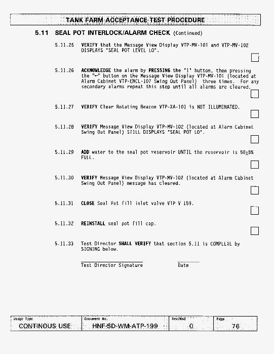
5.1 1 SEAL POT INTERLOCK/ALARM CHECK (Continued)
5.11.25 VERIFY t h a t t h e Message View D i s p l a y VTP-MV-101 and VTP-MV-102 DISPLAYS "SEAL POT LEVEL LO".
0 5.11.26 ACKNOWLEDGE t h e a larm by PRESSING t h e "1" bu t ton , then p ress ing
t h e "c'' b u t t o n on t h e Message View D i s p l a y VTP-MV-101 ( l o c a t e d a t Alarm Cabinet VTP-ENCL-107 Swing Out Panel) t h r e e t imes. For any secondary alarms repea t t h i s s t e p u n t i l a l l alarms are c leared.
0
0 5.11.27 VERIFY Clear Ro ta t i ng Beacon VTP-XA-101 i s NOT ILLUMINATED.
5.11.28 VERIFY Message View D i s p l a y VTP-MV-102 ( l o c a t e d a t A larm Cabinet Swing Out Panel) STILL DISPLAYS "SEAL POT LO".
0 5.11.29 ADD water t o t h e seal p o t r e s e r v o i r UNTIL t h e r e s e r v o i r i s 50+5%
FULL.
0 5.11.30 VERIFY Message View D isp lay VTP-MV-102 ( l o c a t e d a t Alarm Cabinet
Swing Out Panel) message has c lea red .
0 5.11.31 CLOSE Seal Pot f i l l i n l e t v a l v e VTP-V-159.
5.11.32 REINSTALL seal p o t f i l l cap.
5.11.33 Tes t D i r e c t o r SHALL VERIFY t h a t s e c t i o n 5.11 i s COMPLETE by SIGNING below.
Test D i r e c t o r S igna tu re Date

TANK FARM ACCEPTANCE TEST PROCEDURE
5.12 GLYCOL INTERLOCKlALARM CHECK
5.12.1 ENSURE Glyco l Reservoi r Tank VTP-TK-001 d r a i n v a l v e VTP-V-204 i s c losed.
0 5.12.2 ENSURE Glyco l Heater P i p i n g i s o l a t i o n va l ves a re open.
5.12.3 POSITION C i r c u i t Breaker #3 ( l o c a t e d a t MPZ Cabinet ) t o OFF.
5.12.4 DISCONNECT probe leads f rom t r a n s m i t t e r VTP-LT-205.
0
0 5.12.5 CONNECT Drexelbrook C-Box t o t r a n s m i t t e r probe s i d e o f
t r a n s m i t t e r VTP-LT-205.
5.12.6 CONNECT 3- te rm ina l w i r e t o capaci tance u n i t .
0 5.12.7 SET range sw i t ch t o NORMAL.
0 5.12.8 CONNECT Drexelbrook C-Box meter l eads i n s e r i e s w i t h VTP-LT-205 -
OUTPUT.
0
0
5.12.9 CONNECT t e rm ina l w i r e t o meter.
5.12.10 SET meter range t o 4-20 mA.

TANK FARM ACCEPTANCE TEST PROCEDURE
5.12 GLYCOL INTERLOCK/ALARM CHECK (Cont inued)
5.12.11 PRESS meter ONLY b u t t o n ON (down).
0 0
0
0
0
0
5.12.12 POSITION C i r c u i t Breaker #3 ( l o c a t e d a t MPZ Cab ine t ) t o ON.
5.12.13 SET V e r n i e r D i a l t o 14.5 P ico farads ( p f ) . T h i s i s e q u i v a l e n t t o 4 mA .
5.12.14 INCREASE V e r n i e r D i a l t o 60 p f . T h i s i s equal t o approx imate ly 60% volume (13.6 mA).
5.12.15 ENSURE c i r c u i t breaker #6 (SLC Cont ro l C i r c u i t , Module 8 / VFD- 001) i s ON ( l o c a t e d i n t h e MPZ c a b i n e t VTP-DP-101).
5.12.16 POSITION Glyco l C i r c u l a t i o n Pump Cont ro l Swi tch VTP-HS-102 t o ON ( l o c a t e d on door o f Exhauster Cont ro l Cabinet VTP-CP-105).
5.12.17 VERIFY/RECORD t h e f o l 1 owing :
Glyco l Level Wi lkerson I n d i c a t o r VTP-LI-205 d i s p l a y s a readout corresponding t o a 60% l e v e l .
READING : 0
0
0
0
Glyco l C i r c u l a t i o n Pump i s OPERATING by LISTENING t o and/or FEELING t h e pump.
Glyco l System has no leaks .
5.12.18 POSITION Glyco l Pump Cont ro l Swi tch VTP-HS-102 t o OFF ( l o c a t e d on door o f Exhauster Cont ro l Cabinet VTP-CP-105).

TANK FARM ACCEPTANCE TEST PROCEDURE
5.12 GLYCOL INTERLOCKlALARM CHECK (Cont inued)
5. I12 .19 ACKNOWLEDGE t h e PUMP OFF alarm by PRESSING t h e "1" but ton , then PRESSING t h e ''e" b u t t o n on t h e Message View D i s p l a y VTP-MV-101 ( l o c a t e d a t Alarm Cabinet VTP-ENCL-107 Swing Out Panel) t h r e e t imes. For any secondary alarms r e p e a t t h i s s tep u n t i l a l l alarms are c leared .
0 5.12.19.1 POSITION t h e Glyco l Heater Disconnect Swi tch VTP-DS-102
t o OFF n U
5.12.20 REMOVE t h e thermosta t cover on t o p o f G lyco l Heater VTP-HTR-001
0
0
0 n
5.12.21 ENSURE t h e Heater Thermostat i s s e t t o 19O'F.
5.12.22 REPLACE t h e thermosta t cover o f G lyco l Heater VTP-HTR-001.
5.12.23 POSITION t h e Glyco l Heater Disconnect Swi tch VTP-DS-201 t o ON.
U
5.12.24 POSITION Glyco l C i r c u l a t i o n Pump Cont ro l Swi tch VTP-HS-102 t o ON ( l o c a t e d on door o f Exhauster Cont ro l Cabinet VTP-CP-105).
0

TANK FARM ACCEPTANCE TEST PROCEDURE
5.12 GLYCOL INTERLOCK/ALARM CHECK (Continued)
II WARNING II Energ ized c i r c u i t s and l e a d a re conta ined i n s i d e t h e cab ine t . Observe Approp r ia te e l e c t r i c a l precaut ions. Comply w i t h HNF-PRO- 88, ELECTRICAL WORK SAFETY.
5.12.25 VERIFY t h e G lyco l Heater has STARTED by USING t h e DMM a t t h e G lyco l Heater Contactor VTP-CON-206 ( l o c a t e d a t Heat Trace Cabinet VTP-ENCL-104) and PERFORMING t h e f o l l o w i n g :
5.12.25.1 RECORD vo l tage between Terminal T I and Terminal T2.
READING : 0
Terminal T2. 0
READING : 0
Terminal T3. 0
READING: 0
0
5.12.25.2 VERIFY t h e r e i s a v o l t a g e between Terminal T1 and
5.12.25.3 RECORD vo l tage between Terminal T1 and Terminal T3.
5.12.25.4 VERIFY t h e r e i s a vo l tage between Terminal T1 and
5.12.25.5 RECORD vo l tage between Terminal T2 and Terminal T3.
5.12.25.6 VERIFY t h e r e i s a vo l tage between Terminal T2 and Terminal T3.
5.12.26 REDUCE t h e impedance t o s imu la te 50% Volume 52 p f (12 mA) on the G lyco l L i q u i d Level T ransmi t te r VTP-LT-205.
0 5.12.27 VERIFY t h e f o l l o w i n g :
C lea r r o t a t i n g beacon VTP-XA-101 i s ILLUMINATED.

5.12 GLYCOL INTERLOCK/ALARM CHECK (Cont inued)
G lyco l Heater has SHUTDOWN by OBSERVING t h a t t h e Glyco l Heater Contac tor VTP-CON-206 ( l o c a t e d a t Cont ro l Cabinet VTP-CP-105) i s OPEN.
0 Glyco l C i r c u l a t i o n Pump VTP-P-001 has SHUTDOWN by LISTENING t o
and/or FEELING t h e pump.
0 Message D i s p l a y VTP-MV-IO1 and VTP-MV-102 DISPLAYS "GLYCOL
LEVEL LO".
5.12.28
5.12.29
5.12.30
5.12.31
5.12.32
5.12.33
5.12.34
RECORD t h e l i q u i d l e v e l i n d i c a t i o n on t h e Wi lkerson l i q u i d l e v e l i n d i c a t o r VTP-LI-205.
READING: 0 ACKNOWLEDGE t h e alarm by PRESSING t h e "1" bu t ton , then PRESSING t h e "c" b u t t o n on t h e Message View D i s p l a y VTP-MV-101 ( l o c a t e d a t Alarm Cabinet VTP-ENCL-107 Swing Out Panel) t h r e e t imes. For any secondary alarms repeat t h i s s tep u n t i l a l l alarms are c leared .
0 VERIFY Clear R o t a t i n g Beacon VTP-XA-IO1 i s NOT ILLUMINATED.
0 VERIFY Message View D i s p l a y VTP-MV-101 ( l o c a t e d a t Alarm Cabinet Swing Out Panel) CLEARS a la rm message.
0 POSITION C i r c u i t Breaker #3 ( l o c a t e d a t MPZ Cabinet) t o OFF. n DISCONNECT t h e DrexelBrook C a l i b r a t o r f rom t h e Glyco l L i q u i d Level T r a n s m i t t e r VTP-LT-205.
0 RECONNECT probe leads t o t r a n s m i t t e r VTP-LT-205.

5.1 2 GLYCOL INTERLOCK/ALARM CHECK (Cont inued)
0 5 . 1 2 . 3 5 Test D i r e c t o r SHALL VERIFY t h a t s e c t i o n 5 . 1 2 i s COMPLETE by
SIGNING be l ow.
Tes t D i r e c t o r S ignature Date
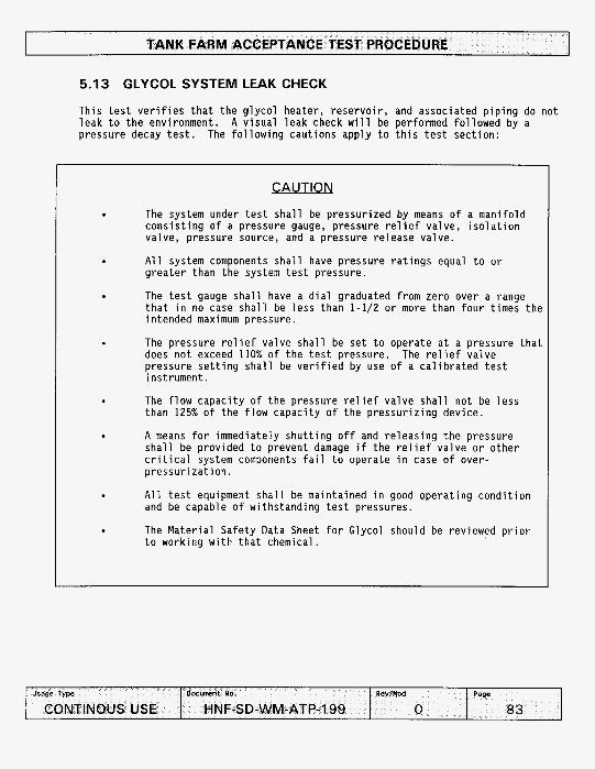
TANK FARM ACCEPTANCE TEST PROCEDURE
5.13 GLYCOL SYSTEM LEAK CHECK
This test verifies that the glycol heater, reservoir, and associated piping do not leak to the environment. A visual leak check will be performed followed by a pressure decay test. The following cautions apply to this test section:
CAUTION
The system under test shall be pressurized by means of a manifold consisting of a pressure gauge, pressure relief valve, isolation valve, pressure source, and a pressure release valve.
All system components shall have pressure ratings equal to or greater than the system test pressure.
The test gauge shall have a dial graduated from zero over a range that in no case shall be less than 1-1/2 or more than four times the intended maximum pressure.
The pressure relief valve shall be set to operate at a pressure that does not exceed 110% of the test pressure. pressure setting shall be verified by use of a calibrated test instrument.
The flow capacity of the pressure relief valve shall not be less than 125% of the flow capacity of the pressurizing device.
A means for immediately shutting off and releasing the pressure shall be provided to prevent damage if the relief valve or other critical system components fail to operate in case of over- pressurization.
All test equipment shall be maintained in good operating condition and be capable of withstanding test pressures.
The Material Safety Data Sheet for Glycol should be reviewed prior to working with that chemical.
The relief valve
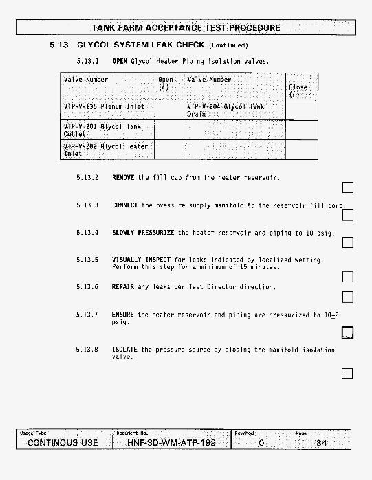
TANK FARM ACCEPTANCE TEST PROCEDURE
&age Type
CONTINOUS USE
5.13 GLYCOL SYSTEM LEAK CHECK (Continued)
5.13.1 OPEN Glycol Heater Piping isolation valves.
Docunent No. Rev/Mod Page
HN F-SD-WM -ATP- 1 99 0 84 I
5.13.2
5.13.3
5.13.4
5.13.5
5.13.6
5.13.7
REMOVE the fill cap from the heater reservoir.
0
0
0
CONNECT the pressure supply manifold to the reservoir fill port
SLOWLY PRESSURIZE the heater reservoir and piping to 10 psig.
VISUALLY INSPECT for leaks indicated by localized wetting. Perform this step for a minimum o f 15 minutes.
REPAIR any leaks per Test Director direction. 0 0
ENSURE the heater reservoir and piping are pressurized to 10+2 psig.
5.13.8 ISOLATE the pressure source by closing the manifold isolation valve.

5.13 GLYCOL SYSTEM LEAK CHECK (Cont inued)
5.13.9 RECORD t h e i n i t i a l pressure and t i m e
.-age Type
CONTINOUS USE
INITIAL:
D x M e n t No. R W / * d Page
HNF-SD-WM-ATP-199 0 85
FINAL:
5.13.10 WAIT 10 minutes.
0 5.13.11 RECORD t h e f i n a l p ressure and t ime.
5.13.12 VERIFY t h e r e was no pressure drop d u r i n g t h e 10 minute t i m e p e r i o d .
Q u a l i t y Cont ro l S ignature Date
5.13.13
5.13.14
5.13.15
5.13.16
RELIEVE pressure f rom t h e system by s l o w l y opening t h e m a n i f o l d re1 ease Val ve.
0
0 DISCONNECT and REMOVE t h e pressure supp ly and m a n i f o l d .
Test D i r e c t o r SHALL VERIFY t h a t s e c t i o n 5.13 i s COMPLETE by S I G N I N G be l ow.
Test D i r e c t o r S ignature Date
QC I n s p e c t o r SHALL VERIFY t h a t s e c t i o n 5.13 i s COMPLETE by S I G N I N G b e l ow.
QC I n s p e c t o r S ignature Date

5.14 THERMOCOUPLE INTERLOCK/ALARM CHECK
5.14.1 REMOVE thermocouple TE-179 from t h e thermowel l .
5.14.2
5.14.3
5.14.4
5.14.5
5.14.6
n POSITION t h e Glyco l Heater Disconnect Swi tch VTP-DS-201 t o ON.
0
0
n
ENSURE c i r c u i t breaker #6 (SLC Cont ro l C i r c u i t , Module 8 / VFD- 001) i s ON ( l o c a t e d i n t h e MPZ c a b i n e t VTP-DP-101).
POSITION Glyco l C i r c u l a t i o n Pump Cont ro l Swi tch VTP-HS-102 t o ON ( l o c a t e d on door o f Exhauster Cont ro l Cabinet VTP-CP-105).
VERIFY Glyco l Heater has STARTED by OBSERVING t h a t t h e Glyco l Heater Contac tor VTP-CON-206 ( l o c a t e d a t Cont ro l Cabinet VTP-CP- 105) i s CLOSED. n
U
HEAT thermocouple TE-179 w i t h a Hot A i r Gun UNTIL t h e Wi lkerson I n d i c a t o r VTP-TI-179 i s i n d i c a t i n g > Z O O O F .
5.14.7 VERIFY t h e f o l l o w i n g :
C lear R o t a t i n g Beacon VTP-XA-101 ( l o c a t e d on s t a c k support f raming) i s ILLUMINATED.
0 Message View D i s p l a y VTP-MV-101 and VTP-MV-102 ( l o c a t e d a t
Alarm Cabinet Swing Out Panel) DISPLAYS "HEATER A I R TEMP H I " .
G lyco l Heater has SHUTDOWN by OBSERVING t h a t t h e Glyco l Heater Contac tor VTP-CON-206 ( l o c a t e d a t t h e Cont ro l Cabinet VTP-CP-105) i s OPEN.
0

TANK FARM ACCEPTANCE TEST PROCEDURE
5.14 THERMOCOUPLE INTERLOCK/ALARM CHECK (Cont inued)
5.14.8
5.14.9
5.14.10
5.14.11
5.14.12
5.14.13
5.14.14
ACKNOWLEDGE t h e a la rm by PRESSING t h e "1" b u t t o n , then PRESSING t h e "-" b u t t o n on t h e Message View D i s p l a y VTP-MV-101 ( l o c a t e d a t Alarm Cabinet VTP-ENCL-107 Swing Out Panel) t h r e e t imes. For any secondary alarms repeat t h i s s tep u n t i l a l l alarms are c leared .
0
0
0
0
0
0
VERIFY Clear R o t a t i n g Beacon VTP-XA-IO1 i s NOT ILLUMINATED.
VERIFY Message View D i s p l a y VTP-MV-101 ( l o c a t e d a t Alarm Cabinet Swing Out Panel) CLEARS alarm message.
ALLOW thermocouple TE-179 t o coo l t o <lOO°F.
PLACE thermocouple TE-179 i n a cup o f i c e .
VERIFY t h e f o l l o w i n g AFTER t h e thermocouple i n d i c a t e s <40°F on Wilkerson I n d i c a t o r VTP-TI-179:
C lear R o t a t i n g Beacon VTP-XA-101 ( l o c a t e d on s t a c k suppor t ing f raming) i s ILLUMINATED.
RECORD i n d i c a t i o n on Wilkerson i n d i c a t o r TI-179 ( l o c a t e d on door o f Exhauster Cont ro l Cabinet VTP-CP-105) corresponding t o VTP-TE-176.
READ1 NG : 0
0 Message View D i s p l a y VTP-MV-IO1 and VTP-MV-102 ( l o c a t e d a t
Alarm Cabinet Swing Out Panel) DISPLAYS "HEATER TEMP LO".
ACKNOWLEDGE t h e alarm by PRESSING t h e "1" but ton , then PRESSING t h e "+" b u t t o n on t h e Message View D i s p l a y VTP-MV-101 ( l o c a t e d a t Alarm Cabinet VTP-ENCL-107 Swing Out Panel) t h r e e t imes. For any secondary alarms repeat t h i s s t e p u n t i l a l l alarms are c leared .
0

5.14 THERMOCOUPLE INTERLOCK/ALARM CHECK (Continued)
5.14.15 VERIFY Clear Ro ta t i ng Beacon VTP-XA-101 i s NOT ILLUMINATED.
0
0 0
5.14.16 VERIFY Message View D i s p l a y VTP-MV-102 ( l o c a t e d a t Alarm Cabinet Swing Out Panel) DISPLAYS alarm message.
5.14.17 POSITION C i r c u i t Breaker #3 ( l o c a t e d a t MPZ Cabinet ) t o OFF.
5.14.18 REPLACE Thermocouple TE-179 i n t o t h e thermowell
5.14.19 Tes t D i r e c t o r SHALL VERIFY t h a t s e c t i o n 5.14 i s COMPLETE by SIGNING below.
Test D i r e c t o r S igna tu re Date
0

5.15 GLYCOL HEATER TEST
5.15.1 VERIFY Glyco l Reservo i r Tank VTP-TK-001 i s approx imate ly 6025% f u l l by observ ing l e v e l s i g h t g l a s s VTP-LG-201.
n U
5.15.2 ENSURE t h e Glyco l Heater P i p i n g i s o l a t i o n va lves are OPEN o r CLOSED as i n d i c a t e d below:
0
5.15.3 POSITION c i r c u i t breaker #6 ( l o c a t e d i n t h e MPZ c a b i n e t VTP-DP- 101) t o OFF. n
5.15.4 REMOVE t h e thermosta t cover on t o p o f G lyco l Heater VTP-HTR-001
5.15.5 ENSURE t h e heater thermosta t i s s e t t o 190°F. n U
5.15.6 REPLACE t h e thermosta t cover on t o p o f G lyco l Heater VTP-HTR-001
0 5.15.7 POSITION c i r c u i t breaker #6 ( l o c a t e d i n t h e MPZ c a b i n e t VTP-DP-
101) t o ON.
0 5.15.8 POSITION t h e EXHAUSTER FAN MOTOR DISCONNECT SWITCH VTP-DS-102 t o
ON
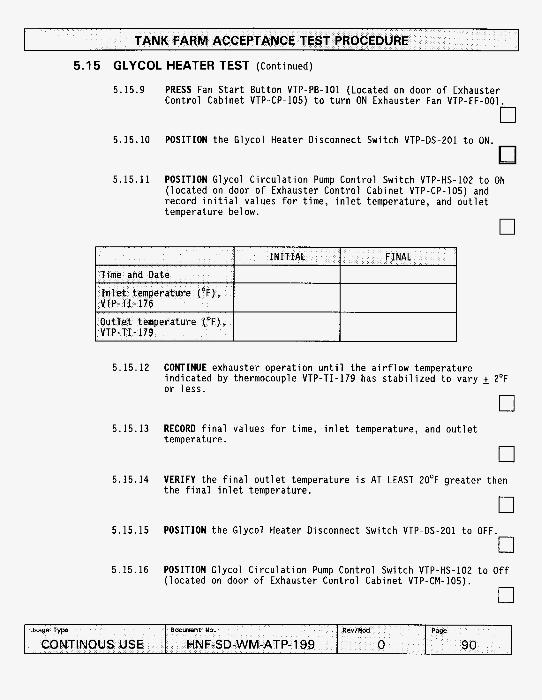
TANK FARM ACCEPTANCE TEST PROCEDURE
5.15 GLYCOL HEATER TEST (Cont inued)
5.15.9 PRESS Fan S t a r t But ton VTP-PB-101 (Located on door o f Exhauster Cont ro l Cabinet VTP-CP-105) t o t u r n ON Exhauster Fan VTP-EF-001
5.15.10 POSITION t h e Glyco l Heater Disconnect Swi tch VTP-OS-201 t o ON.
5.15.11 POSITION Glyco l C i r c u l a t i o n Pump Cont ro l Swi tch VTP-HS-102 t o ON ( l o c a t e d on door o f Exhauster Cont ro l Cabinet VTP-CP-105) and r e c o r d i n i t i a l values f o r t ime, i n l e t temperature, and o u t l e t temperature be l ow.
0
5.15.12
5.15.13
5.15.14
5.15.15
5.15.16
CONTINUE exhauster o p e r a t i o n u n t i l t h e a i r f l o w temperature i n d i c a t e d by thermocouple VTP-TI-179 has s t a b i l i z e d t o vary 2 2°F o r l e s s .
0 RECORD f i n a l values f o r t ime, i n l e t temperature, and o u t l e t temperature
0 VERIFY t h e f i n a l o u t l e t temperature i s AT LEAST 20°F g r e a t e r then t h e f i n a l i n l e t temperature. n
U
POSITION t h e Glyco l Heater Disconnect Swi tch VTP-OS-201 t o OFF.
0 POSITION Glyco l C i r c u l a t i o n Pump Cont ro l Swi tch VTP-HS-102 t o O f f ( l o c a t e d on door o f Exhauster Cont ro l Cabinet VTP-CM-105).
0

5.15 GLYCOL HEATER TEST (Cont inued)
5 . 1 5 . 1 7 POSITION t h e EXHAUSTER FAN MOTOR DISCONNECT SWITCH VTP-DS-IO2 t o OFF.
0 5 . 1 5 . 1 8 T e s t D i r e c t o r SHALL VERIFY t h a t s e c t i o n 5 . 1 5 i s COMPLETE by
SIGNING below.
.sage Type
CONTINOUS USE
T e s t D i r e c t o r S i g n a t u r e
Doc-nt No. R W l M o d Page
HNF-SD-WM-ATP-199 0 91
D a t e

TANK FARM ACCEPTANCE TEST PROCEDURE
Time
Pressure ( p s i g )
DATA SHEET 1 - LEAKAGE RATE CALCULATION
DATE: TEST I:
(Th is page may be reproduced as necessary)
I N I T IAL
t i =
P i = I N W.C./ 27.7
- -
Barometr ic p r ( I N Hg)
Duct p r ( p s f a )
Temperature (OR)
_______
Bpi= I N Hg x 0.491
- -
D P i = ( P i t Bpi ) (144)
- -
T i = OF t 460
- -
FINAL I +I I N W . C . / 27.7
B P f = IN Hg x 0.491
D P f = ( P f t Bpf ) (144) -1 T f = " F t 460
- -
Gas cons tan t : R = 53.35 f t lb/( lb*degR)
Test Dura t ion : a t = ( t f - t i ) = minutes
Q = (DPi/Ti - DPf/Tf)V /(R X A t X 0.075) = SCFM
Q i s t h e Averaye t o t a l l e a k r a t e p e r ASME N510-1989, Sec t ion 6.5.3.9, i n standard ft /min (SCFM).
L, = A l lowab le Leak Rate = 0.3 SCFM
Test D i r e c t o r S ignature Date Q C S ignature Date
Checker S ignature Date

TANK FARM ACCEPTANCE TEST PROCEDURE
Pressure ( p s i g )
DATA SHEET 2 - LEAKAGE RATE CALCULATION
DATE: TEST Y:
( T h i s page may be reproduced as necessary)
P i = I N W.C./ 27.7
- -
I INITIAL
Barometr ic p r ( I N Hg)
Time
Bp i= I N Hg x 0.491
- -
I t i =
Temperature (OR) T i = "F t 460
- -
Duct p r ( p s f a ) D P i = ( P i t Bpi ) (144)
- -
FINAL
tf =
P f = I N W.C. / 27.7
- -
BPf= I N Hg x 0.491
- -
D P f = ( P f + Bpf ) (144)
- -
T f = OF t 460
- -
Test Volume: V = c u b i c f e e t
Gas cons tan t : R = 53.35 f t lb/( lb*degR)
Test Dura t ion : A t = ( t f - t i ) = minutes
Q = (DPi/Ti - DPf/Tf)V / ( R X A t X 0.075) = SCFM
Q i s t h e Average t o t a l l e a k r a t e p e r ASME N510-1989, Sec t ion 6.5.3.9, i n standard f t3 /min (SCFM).
L, = A l lowab le Leak Rate = 0.3 SCFM
Tes t D i r e c t o r S ignature Date QC S ignature Date
Checker S ignature Date

ATP EXCEPTION LOG
T h i s page may be reproduced as necessary PAGE o f

ATP EXCEPTION RECORD
T h i s page may be reproduced as necessary.
ATP step number: ATP Exception Log Number:
Resolution o f Exception:
Date o f Resolution:
I Test Director signature:
Cognizant Engineer signature:
Quality Control signature: