continuous slot and linear louvre diffusers - esi.info · a wide range of paint finishes are also...
TRANSCRIPT

Publication
DIFFUSERSsection 2 SEPT 2005
PART B
R
Air Diffuserssupply and exhaust ventilation systems
continuous slot and linear louvre diffusers
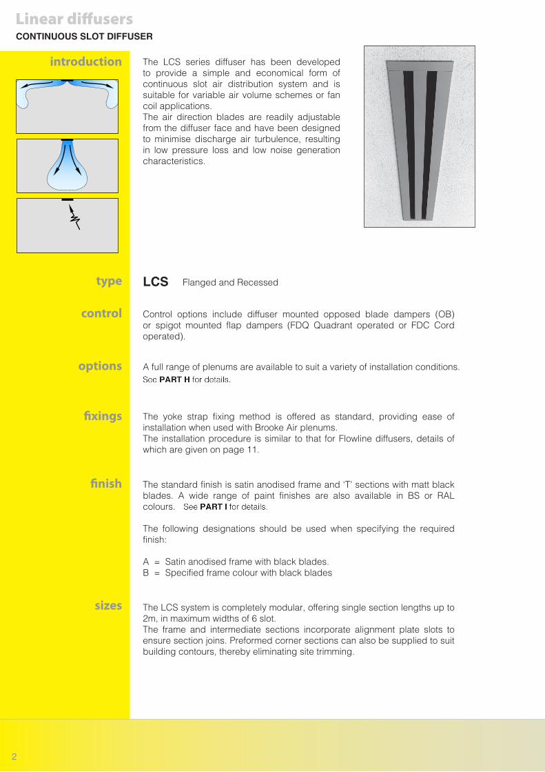
introduction The LCS series diffuser has been developed to provide a simple and economical form of continuous slot air distribution system and is suitable for variable air volume schemes or fan coil applications.The air direction blades are readily adjustable from the diffuser face and have been designed to minimise discharge air turbulence, resulting in low pressure loss and low noise generation characteristics.
The LCS system is completely modular, offering single section lengths up to 2m, in maximum widths of 6 slot.The frame and intermediate sections incorporate alignment plate slots to ensure section joins. Preformed corner sections can also be supplied to suit building contours, thereby eliminating site trimming.
The standard finish is satin anodised frame and ‘T’ sections with matt black blades. A wide range of paint finishes are also available in BS or RAL colours.
The following designations should be used when specifying the required finish:
A = Satin anodised frame with black blades.B = Specified frame colour with black blades
Control options include diffuser mounted opposed blade dampers (OB) or spigot mounted flap dampers (FDQ Quadrant operated or FDC Cord operated).
The yoke strap fixing method is offered as standard, providing ease of installation when used with Brooke Air plenums.The installation procedure is similar to that for Flowline diffusers, details of which are given on page 11.
A full range of plenums are available to suit a variety of installation conditions.
Flanged and Recessed
Linear diffusersCONTINUOUS SLOT DIFFUSER
control
sizes
finish
options
type
fixings
LCS
2

Yoke Strap Fixing
Plenum
AlignmentPlate Slots
Blade Access Tab
Standard Flanged unit shown
Radius to be specified.
Radius to be specified eitherconvex or concave.
Linear diffusersCONTINUOUS SLOT DIFFUSER
design features
TYPE - LCS
CURVED CEILING - CILL (CC)
CURVED SIDE WALL (CSW)
curved options
R
3

LCS1 LCS2 LCS3 LCS4 LCS5 LCS6
NUMBER OF SLOTS
‘N’ o/a NECK 54 101 148 195 242 289
‘P’ I/S PLENUM 68 115 162 209 256 303
‘F’ o/a FLANGE 80 127 174 221 268 315
Ceiling opening = P + 3
‘P’ I/S
‘N’
‘N’ - 5
30 20
‘F’ O/A
27 27
Section Length
821.
5
type finishend option
LCS3 / ENDS / A / 1500 / 6
length quantity
Examples :
When ordering linear sections, state the number of slots required, the section length and the finish designation code.
Section length ‘L’
(Maximum Single Section Length 2m)
O/A Length with End Caps = ‘L’ + 54
Maximum Blade
Length 600
When ordering corner sections, state the number of slots required, the inside lengths A and B, the angle and the finish designation code.Note: dimensions A and B should be based on the reflected ceiling plan.
Corners are normally supplied as non active sections.
type finishangle
LCS3 / 90o / A / 300 x 300 / 6
length (A x B) quantity
(Minimum 300)
A
(Min
imum
300
)
B
4.2
(Flanged)
Note: inside Plenum length add 14mm when using end caps.
dimensions
DIMENSIONS AND ORDERING DESIGNATIONS
ordering designations
Linear diffusers
TYPE - LCS
4

Ceiling opening = F + 6
‘P’ I/S
‘F’ - 5
16.7520
‘F’ O/A
27
19 x 19 angle
82
15
R/LCS1 R/LCS2 R/LCS3 R/LCS4 R/LCS5 R/LCS6
NUMBER OF SLOTS
‘F’ o/a NECK 54 101 148 195 242 289
‘P’ I/S PLENUM 68 115 162 209 256 303
(Recessed)
Note: inside Plenum length add 14mm when using end caps.
DIMENSIONSLinear diffusers
dimensions
TYPE - R/LCS
R
5

AIR FLOW RATE (l/s/m)
20 40 60 80 100 120 140 160 180 200
LCS1
LCS2
THROW MIN (m) MAX
PROJECTION (m)
Ps (Pa)
NR LEVEL
THROW MIN (m) MAX
PROJECTION (m)
Ps (Pa)
NR LEVEL
AIR FLOW RATE (l/s/m)
100 125 150 175 200 225 250 275 300 325
LCS3
LCS4
THROW MIN (m) MAX
PROJECTION (m)
Ps (Pa)
NR LEVEL
THROW MIN (m) MAX
PROJECTION (m)
Ps (Pa)
NR LEVEL
2.7 4.3 5.7 7.0 7.8
0.7 1.8 3.0 4.5 6.0
6 15 28 45
14 26 35 42
0.7 1.4 2.1 2.7 3.4
1.2 1.6 2.0 2.5 3.0 3.4 3.8 4.2 4.7
2.1 2.5 3.0 3.5 4.0 4.4 4.8
3.5 5.0 6.0 7.0 7.7 8.4 9.0 9.8 10.4
1.7 2.5 3.3 4.2 5.2 6.2 7.3 8.5
3 6 10 14 21 28 35 45
17 24 29 33 38 41 45
6.0 7.2 8.2 9.1 9.8 10.5 10.9
2.3 3.2 4.0 5.0 6.0 7.0 8.0
5 8 12 16 22 28 35
20 26 31 35 38 42
1.8 2.2 2.7 3.1 3.5 3.8 4.2 4.6 5.0 5.5
5.6 6.7 7.7 8.7 9.5 9.8 10.5 11.0 11.4 12.0
2.4 3.1 3.8 4.5 5.3 6.0 7.0 8.0 10.0
4 5 8 10 13 16 20 24 28
17 22 27 30 34 37 40 42
PERFORMANCE DATALinear diffusers
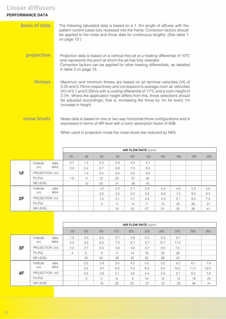
The following tabulated data is based on a 1.2m length of diffuser. Correction factors should be applied to the noise and throw data for continuous lengths. See table 1 on page 7.
Maximum and minimum throws are based on jet terminal velocities (Vt) of 0.25 and 0.75m/s respectively and correspond to average room air velocities (Vr) of 0.1 and 0.25m/s with a cooling differential of 11oC and a room height of 2.7m. Where the application height differs from this, throw selections should be adjusted accordingly; that is, increasing the throw by 1m for every 1m increase in height.
Projection data is based on a vertical free jet at a heating differential of 10oC and represents the point at which the jet has fully retarded. Correction factors can be applied for other heating differentials, as detailed in table 2 on page 7.
Noise data is based on one or two way horizontal throw configurations and is expressed in terms of NR level with a room absorption factor of 8db.
When used in projection mode the noise levels are reduced by NR 10.
basis of data
projection
throws
noise levels
6

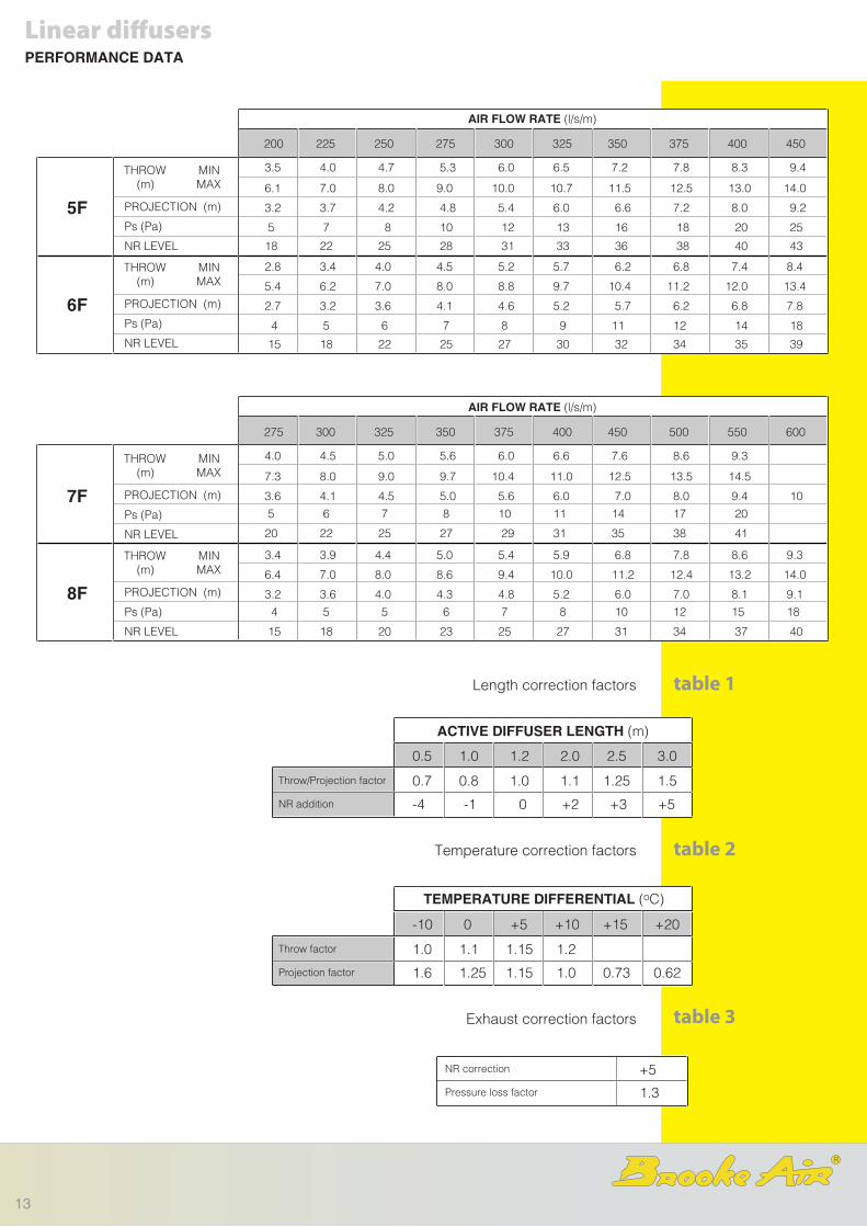
ACTIVE DIFFUSER LENGTH (m)
TEMPERATURE DIFFERENTIAL (oC)
0.5 1.0 1.2 2.0 2.5 3.0
Throw/Projection factor
NR addition
0.7 0.8 1.0 1.1 1.25 1.5
-4 -1 0 +2 +3 +5
Throw factor
Projection factor
-10 0 +5 +10 +15 +20
1.0 1.1 1.15 1.2
1.6 1.25 1.15 1.0 0.73 0.62
NR correction
Pressure loss factor
-10
0.8
Linear diffusers
AIR FLOW RATE (l/s/m)
200 225 250 275 300 325 350 375 400 450
LCS5
LCS6
THROW MIN (m) MAX
PROJECTION (m)
Ps (Pa)
NR LEVEL
THROW MIN (m) MAX
PROJECTION (m)
Ps (Pa)
NR LEVEL
8.4 9.0 9.8 10.4 11.0 11.5 12.0 12.3
3.8 4.4 5.0 5.7 6.5 7.2 8.0 9.0
3.2 3.5 4.0 4.2 4.5 5.0 5.2 5.6
2.9 3.2 3.5 3.8 4.2 4.5 4.8 5.0 5.4 6.0
7 9 11 14 17 20 23 27
21 25 28 32 34 36 38 41
8.0 8.6 9.3 10.0 10.5 11.0 11.5 11.9 12.2 13.0
3.2 3.7 4.3 5.0 5.6 6.2 6.8 7.5 8.2 10.0
5 6 8 9 11 13 16 18 21 27
16 19 23 26 29 31 34 36 38 42
table 3
table 2
table 1Length correction factors
Temperature correction factors
Exhaust correction factors
PERFORMANCE DATA
R
7

The Flowline diffuser has been specifically developed to meet requirements for an aerodynamically efficient continuous slot air distribution system. The unique design of the deflection tube produces both low noise and low pressure losses, making it suitable for use with variable air volume, fan coil or induction systems.Adjustment of the tubes can be easily carried out from the diffuser face to give control of the air direction and also the discharge velocity. This latter feature is particularly useful with variable air volume systems, allowing an optimum jet velocity to be set to maintain air movement at low air flow rates.
The Flowline system is completely modular, offering single section lengths up to 3m, in maximum widths of 8 slot.
The use of alignment plates and pins assist installation, whilst pre formed corner sections can be specified to any angle, eliminating the need for site trimming.
Dummy lengths are available where non active sections are required to maintain architectural continuity.
The standard finish is satin anodised frame and ‘T’ sections with matt black tubes. A wide range of paint finishes are also available in BS or RAL colours, as detailed in PART I. The following designations should be used when specifying the required finish:
A = Satin anodised frame with black tubes. B = Specified frame colour with black tubes. C = Specified frame colour including tubes.
The yoke strap fixing method is offered as standard, providing ease of installation when used with Brooke Air plenums.
A full range of plenums are available to suit a variety of installation conditions.
Control options include plenum mounted opposed blade dampers (OB) or spigot mounted flap dampers (FDQ Quadrant operated or FDC Cord operated).
Flanged and Recessed
introduction
Linear diffusersCONTINUOUS SLOT DIFFUSER
options
fixings
finish
control
type FLOWLINE
8

Supply / Extract Diffuser (3F illustrated) Dummy Diffuser (2F illustrated)
Yoke Strap Fixing
Spine Clutch
Air Deflector Roller
Support Studs
Hanging Brackets
Frame Alignment Plate Slots
Access Hole with plug‘T’ Alignment Pin Slot
Plenum
Hanging Brackets
Standard Flanged unit shown
Lateral and vertical adjustment of the deflection tubes provides full directional jet control and discharge velocity regulation. The aerodynamic profile of the tube also gives the Flowline diffuser a wide dynamic flow range, making it particularly suitable for variable air volume application.
Typically, ceiling attachment can be maintained under cooling conditions with air flow rates as low as 10 l/s/m per slot.
design features
Linear diffusersCONTINUOUS SLOT DIFFUSER
Radius to be specified.
Radius to be specified eitherconvex or concave.
CURVED CEILING - CILL (CC)
CURVED SIDE WALL (CSW)
curved options
R
9

Ceiling opening = P + 3
‘P’ I/S‘N’
*28 25
‘F’ O/A
20 17.5
Section Length
855
End Cap
NUMBER OF SLOTS
‘N’ o/a NECK
‘P’ i/s PLENUM
‘F’ o/a FLANGE
1F 2F 3F 4F 5F 6F 7F 8F
55.5 101.5 147.5 194 240 286 331 378
* Optional flange widths of 22mm and 33mm are also available. Subtract 12mm or Add 10mm from the overall flange dimension respectively
70 116 162 208 254 300 346 392
83 129 175 221 267 313 359 406
Ceiling opening = F + 6
‘P’ I/S
‘N’
925
‘F’ O/A
20
19 x 19 angle 85
NUMBER OF SLOTS
‘N’ o/a NECK
‘P’ i/s PLENUM
‘F’ o/a FLANGE
R/1F R/2F R/3F R/4F R/5F R/6F R/7F R/8F
55.5 101.5 147.5 194 240 286 331 378
70 116 162 208 254 300 346 392
48 94 140 186 232 278 324 370
To s
uit c
eilin
g d
epth
(Flanged)
TYPE - 3F
(Recessed)
TYPE - R/3F
Note: inside Plenum length add 6mm when using end caps.
Note: inside Plenum length add 10mm when using end caps.
Linear diffusersDIMENSIONS
dimensions
10

Yoke Straps
Plenum
Access Hole
type finishend option
3F / ENDS / A / 1500 / 6
length quantity
Examples :
When ordering linear sections, state the number of slots required, the section length and the finish designation code. Diffusers are supplied as standard with 28mm flanges. Requirements for the optional flange widths of 22mm and 33mm should be specified seperately.
Section length ‘L’
(Maximum Single Section Length up to 3m depending on No. of slots)
O/A Length with End Caps = ‘L’ + 35
Maximum Tube
Length 1200m
When ordering corner sections, state the number of slots required, the inside lengths A and B, the angle and the finish designation code.Note: dimensions A and B should be based on the reflected ceiling plan.
Corners are normally supplied as non active sections.
type finishangle
3F / 90o / A / 300 x 300 / 6
length (A x B) quantity
(Minimum 300)
A
(Min
imum
300
)
B
ordering designations
For dummy sections, add the specification D to the type, ie 3FD.
installation
Alignment Plates and Pins
When using the yoke strap fixing technique, the plenum is normally installed as a first fix item, with the hem edge levelled to the ceiling grid system. From there, the diffuser yoke straps can be inserted into the plenum, working from one end and butting the section lengths together.Once the yoke straps are secured, the screws can be tightened to level the diffuser to the ceiling.
Full installation instructions are provided with the diffusers.
ORDERING DESIGNATIONS
R
Linear diffusers
11
AIR FLOW RATE (l/s/m)
20 40 60 80 100 120 140 160 180 200
1F
2F
THROW MIN (m) MAX
PROJECTION (m)
Ps (Pa)
NR LEVEL
THROW MIN (m) MAX
PROJECTION (m)
Ps (Pa)
NR LEVEL
AIR FLOW RATE (l/s/m)
100 125 150 175 200 225 250 275 300 350
3F
4F
THROW MIN (m) MAX
PROJECTION (m)
Ps (Pa)
NR LEVEL
THROW MIN (m) MAX
PROJECTION (m)
Ps (Pa)
NR LEVEL
2.0 3.4 4.7 5.8 7.0 8.0
1.5 2.5 3.5 5.0 6.5
1.5 5 12 20 31 45
12 23 31 38 43
0.7 1.5 2.3 3.0 4.0 4.7
1.6 2.2 2.7 3.3 4.0 4.5 5.2 5.6
1.5 2.5 3.4 3.7 4.8 5.4 6.2 6.7
3.0 4.0 5.0 5.8 6.8 7.5 8.6 9.4
1.5 2.1 2.7 3.4 4.3 5.1 6.0 7.0
3 5 8 11 15 20 26 31
15 22 27 31 35 38 41
3.2 4.5 6.0 7.5 8.7 9.7 10.7 11.5
2.0 2.7 3.3 4.0 4.8 5.7 6.5 7.5
4 6 8 11 14 18 22 26
18 24 28 32 35 39 42
2.0 2.8 3.5 4.2 5.0 5.5 6.2 6.7 7.8
3.5 4.7 6.0 7.2 8.3 9.5 10.5 11.4 13.0
2.0 2.6 3.1 3.8 4.4 5.0 5.7 6.5 7.8
3 5 6 8 10 12 15 18 24
15 20 23 27 31 33 36 41
PERFORMANCE DATA
Linear diffusers
The following tabulated data is based on a 1 .2m length of diffuser with the pattern control tubes fully recessed into the frame. Correction factors should be applied to the noise and throw data for continuous lengths. (See table 1 on page 13.)
Maximum and minimum throws are based on jet terminal velocities (Vt) of 0.25 and 0.75m/s respectively and correspond to average room air velocities (Vr) of 0.1 and 0.25m/s with a cooling differential of 11oC and a room height of 2.7m. Where the application height differs from this, throw selections should be adjusted accordingly; that is, increasing the throw by 1m for every 1m increase in height.
Projection data is based on a vertical free jet at a heating differential of 10oC and represents the point at which the jet has fully retarded. Correction factors can be applied for other heating differentials, as detailed in table 2 on page 13.
Noise data is based on one or two way horizontal throw configurations and is expressed in terms of NR level with a room absorption factor of 8dB.
When used in projection mode the noise levels are reduced by NR3.
basis of data
projection
throws
noise levels
12
ACTIVE DIFFUSER LENGTH (m)
TEMPERATURE DIFFERENTIAL (oC)
0.5 1.0 1.2 2.0 2.5 3.0
Throw/Projection factor
NR addition
0.7 0.8 1.0 1.1 1.25 1.5
-4 -1 0 +2 +3 +5
Throw factor
Projection factor
-10 0 +5 +10 +15 +20
1.0 1.1 1.15 1.2
1.6 1.25 1.15 1.0 0.73 0.62
NR correction
Pressure loss factor
+5
1.3
Linear diffusers
AIR FLOW RATE (l/s/m)
200 225 250 275 300 325 350 375 400 450
5F
6F
THROW MIN (m) MAX
PROJECTION (m)
Ps (Pa)
NR LEVEL
THROW MIN (m) MAX
PROJECTION (m)
Ps (Pa)
NR LEVEL
6.1 7.0 8.0 9.0 10.0 10.7 11.5 12.5 13.0 14.0
3.2 3.7 4.2 4.8 5.4 6.0 6.6 7.2 8.0 9.2
3.5 4.0 4.7 5.3 6.0 6.5 7.2 7.8 8.3 9.4
2.8 3.4 4.0 4.5 5.2 5.7 6.2 6.8 7.4 8.4
5 7 8 10 12 13 16 18 20 25
18 22 25 28 31 33 36 38 40 43
5.4 6.2 7.0 8.0 8.8 9.7 10.4 11.2 12.0 13.4
2.7 3.2 3.6 4.1 4.6 5.2 5.7 6.2 6.8 7.8
4 5 6 7 8 9 11 12 14 18
15 18 22 25 27 30 32 34 35 39
table 3
table 2
table 1Length correction factors
Temperature correction factors
Exhaust correction factors
AIR FLOW RATE (l/s/m)
275 300 325 350 375 400 450 500 550 600
7F
8F
THROW MIN (m) MAX
PROJECTION (m)
Ps (Pa)
NR LEVEL
THROW MIN (m) MAX
PROJECTION (m)
Ps (Pa)
NR LEVEL
7.3 8.0 9.0 9.7 10.4 11.0 12.5 13.5 14.5
3.6 4.1 4.5 5.0 5.6 6.0 7.0 8.0 9.4 10
4.0 4.5 5.0 5.6 6.0 6.6 7.6 8.6 9.3
3.4 3.9 4.4 5.0 5.4 5.9 6.8 7.8 8.6 9.3
5 6 7 8 10 11 14 17 20
20 22 25 27 29 31 35 38 41
6.4 7.0 8.0 8.6 9.4 10.0 11.2 12.4 13.2 14.0
3.2 3.6 4.0 4.3 4.8 5.2 6.0 7.0 8.1 9.1
4 5 5 6 7 8 10 12 15 18
15 18 20 23 25 27 31 34 37 40
PERFORMANCE DATA
R
13

type finishend option
F45L/2 / ENDS / SAA / 1500 / 3
length quantity
EXAMPLE :
The F45L louvre style ceiling diffuser offers an alternative form of continuous air distribution system for variable air volume or fan coil applications.The diffuser can be supplied with one or two way cores in either single lengths or in sections, with frame alignment pins for continuous applications. Removable cores are offered as standard, allowing both ease of installation and service access to air filters or controls. The cores are retained with spring clips and are supplied complete with detachable safety cords.
introduction
Linear diffusersLINEAR LOUVRE DIFFUSER
The F45L diffuser is manufactured in standard width increments ranging from 150mm to 400mm and can be supplied in single lengths upto 1200mm long.
For continuous applications, the core section lengths are limited to 1200mm, although frames can be manufactured upto 3m long.
When ordering, state the diffuser type (F45L/1 or F45L/2), the required width, the section length and the finish.
ordering details
options
fixings
finish
control
type F45L
The standard finish is satin anodised aluminium, but a wide range of paint finishes are also available in either BS or RAL colours.See Part I for details
A full range of plenums are available to suit a variety of installation conditions. See Part H for details.
Control options include diffuser mounted opposed blade dampers (OB) or spigot mounted flap dampers (FDQ Quadrant operated or FDC Cord operated).
The yoke strap fixing method is offered as standard, providing ease of installation when used with Brooke Air plenums.The installation procedure is similar to that for Flowline diffusers, details of which are given on page 11.
/1 = 1 way blow/2 = 2 way blow
14

NONMINAL DIFFUSER WIDTH (mm)
‘N’ o/a NECK
‘P’ i/s PLENUM
‘F’ o/a FLANGE
150 200 250 300 350 400
134 185 236 287 337 388
144 195 246 297 347 398
191 242 293 344 394 445
Ceiling Opening = ‘P’ + 3
‘P’ i/s
‘N’
32
12.5‘F’ o/a
Frame alignmentpin slot.
1 or 2 way Core(secured with safety cord)
Yoke Strapfixing.
Plenum Core.
Retaining Clip.
Section Length ‘L’
o/a Length = ‘L’ + 64
‘F’ o
/a
Note: inside Plenum length add 6mm when using end caps.
Linear diffusersLINEAR LOUVRE DIFFUSER
dimensions
R
15

AIR FLOW RATE (l/s/m)
70 80 90 100 110 120 140 160 180 200
150
200
1 WAY THROW (m)
Ps (Pa)
NR LEVEL
Ps (Pa)
NR LEVEL
2.5 2.9 3.2 3.6 4.0 4.3 5.1 5.9
2 2 3 3 4 4 6 7
3.0 3.5 4.0 4.4 4.8 5.2 6.1 7.1
15 19 23 27 30 35 40
3.6 4.0 4.4 5.0 5.8 6.5 7.3
2 WAY THROW (m)
1 WAY THROW (m)
2 WAY THROW (m) 2.8 3.0 3.3 4.0 4.5 5.0 5.7
18 21 26 31 35 38
2 2 2 3 4 5 6
PARAMETERNOMINAL
WIDTH
AIR FLOW RATE (l/s/m)
120 140 160 180 200 220 240 260 280 300
250
300
1 WAY THROW (m)
Ps (Pa)
NR LEVEL
Ps (Pa)
NR LEVEL
2.8 3.3 3.7 4.2 4.7 5.2 5.7 6.1
2 2 3 3 4 5 6 7
3.7 4.3 4.9 5.6 6.1 6.8 7.5 8.0
19 23 27 31 35 38 41
4.5 5.0 5.7 6.2 6.7 7.3 7.9 8.5
2 WAY THROW (m)
1 WAY THROW (m)
2 WAY THROW (m) 3.3 3.7 4.0 4.5 5.0 5.3 5.8 6.2
18 22 25 29 32 35 38 40
2 2 3 4 4 5 6 6
PARAMETERNOMINAL
WIDTH
AIR FLOW RATE (l/s/m)
180 200 220 240 260 280 300 320 340 360
350
400
1 WAY THROW (m)
Ps (Pa)
NR LEVEL
Ps (Pa)
NR LEVEL
3.4 3.7 4.2 4.5 4.9 5.2 5.7 6.1 6.4
2 2 3 3 4 4 5 6 6
4.6 5.0 5.6 6.1 6.6 7.1 7.6 8.1 8.7
17 21 24 27 30 33 35 37 40
4.3 4.7 5.1 5.7 6.1 6.6 7.1 7.6 8.0 8.6
2 WAY THROW (m)
1 WAY THROW (m)
2 WAY THROW (m) 3.0 3.3 3.6 4.0 4.4 4.7 5.0 5.3 5.7 6.1
17 20 23 26 29 31 33 36 38
2 2 3 3 4 4 5 6 6 7
PARAMETERNOMINAL
WIDTH
Linear diffusersPERFORMANCE DATA
16
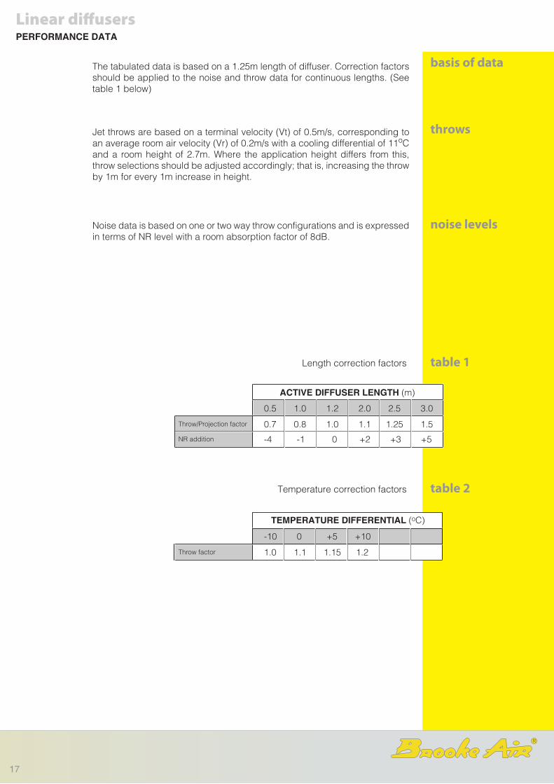
The tabulated data is based on a 1.25m length of diffuser. Correction factors should be applied to the noise and throw data for continuous lengths. (See table 1 below)
Jet throws are based on a terminal velocity (Vt) of 0.5m/s, corresponding to an average room air velocity (Vr) of 0.2m/s with a cooling differential of 11oC and a room height of 2.7m. Where the application height differs from this, throw selections should be adjusted accordingly; that is, increasing the throw by 1m for every 1m increase in height.
Noise data is based on one or two way throw configurations and is expressed in terms of NR level with a room absorption factor of 8dB.
ACTIVE DIFFUSER LENGTH (m)
TEMPERATURE DIFFERENTIAL (oC)
0.5 1.0 1.2 2.0 2.5 3.0
Throw/Projection factor
NR addition
0.7 0.8 1.0 1.1 1.25 1.5
-4 -1 0 +2 +3 +5
Throw factor
-10 0 +5 +10
1.0 1.1 1.15 1.2
table 2
table 1Length correction factors
Temperature correction factors
Linear diffusersPERFORMANCE DATA
basis of data
throws
noise levels
R
17

The general range of PB plenum boxes are manufactured with a return edge hem in the neck to suit the yoke strap fixings supplied with LCS, Flowline and F45L dif-fusers.The boxes can be manufactured to suit ei-ther top or side entry duct arrangements and are available with square rectangular or circular spigots.
Optional spigot mounted flap dampers are available with either cord or quadrant operators.Plenums can also be supplied with a non fibrous fire resistant acoustic liner for applications with critical noise limits.
The plenum selection nomogram on page 20 is designed to optimise the cross sectional area of the box to ensure an even distribution of air along the length of the diffuser.
To select an appropriate plenum size, firstly establish the static pressure loss of the diffuser at the required design duty from the appropriate performance table.
Then, using the selection nomogram, project a line between the flow rate and pressure loss scales to the pivot line of the plenum dimension scale. From there, project a line from the appropriate diffuser slot width through the pivot point and read off the plenum height. Note, an allowance should be added to the height to allow for the depth of the diffuser frame refer to note on the plenum height scale.
If the ceiling void height is limited, then any combination of width and height can be selected about the pivot point providing the plenum height can accommodate a suitable spigot size.
To determine the spigot size, project a line from the flow rate scale through the required spigot air velocity to the diameter line. Square or rectangular spigots of equivalent area can also be selected using the spigot diameter as a pivot point.
Linear diffusersPLENUM BOXES
introduction
options
plenum selection
type PB
18
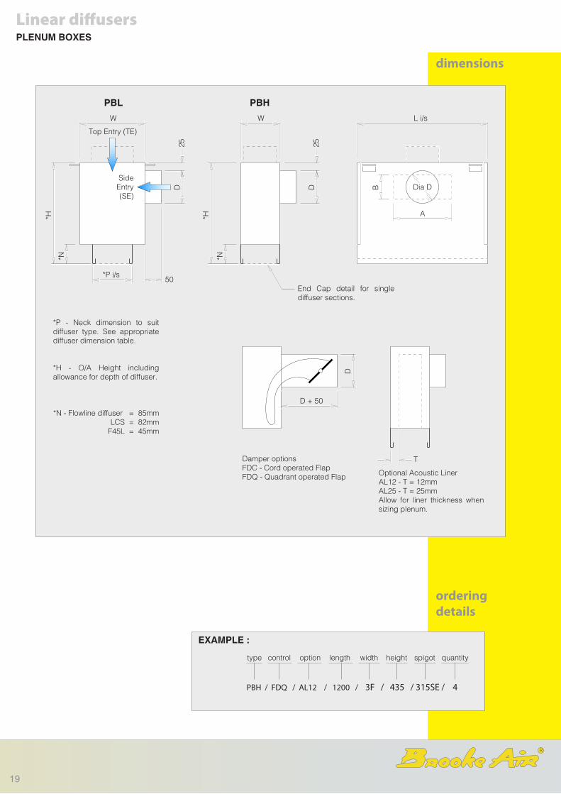
dimensions
orderingdetails
type heightoption
PBH / FDQ / AL12 / 1200 / 3F / 435 / 315SE / 4
length quantity
EXAMPLE :
control width spigot
*P - Neck dimension to suit diffuser type. See appropriate diffuser dimension table.
*H - O/A Height including allowance for depth of diffuser.
*N - Flowline diffuser = 85mm LCS = 82mm F45L = 45mm
PBL PBHW
Top Entry (TE)
*H
*N
*P i/s
D25
50
SideEntry (SE)
W
D25
*H
*N
L i/s
Dia D
A
B
End Cap detail for single diffuser sections.
Damper optionsFDC - Cord operated FlapFDQ - Quadrant operated Flap Optional Acoustic Liner
AL12 - T = 12mmAL25 - T = 25mmAllow for liner thickness when sizing plenum.
T
D + 50
D
Linear diffusersPLENUM BOXES
R
19

Linear diffusers
WIDTH (mm)
HEIGHT (mm)PIVOT
LINE
GRILLE PRESSURELOSS (Pa)
SPIGOT AIRVELOCITY
(m/s)
APPROXIMATENR LEVEL
(OPEN DAMPER)
50
40
30
20
75
100
150
50
200
300
400
500
50
100
300
200
75
600
100
150
200
250
400
500
600
800
1000
300
125
150
200
250
300
500
600
500
600
5
4
3
2
125
400
100
1
50
20
10
5
125
200
250
315
600
400
160
PLENUM DIMENSIONS
WIDTH (mm)
HEIGHT (mm)
PIVOTLINE
RECTANGULAROR SQUARE SPIGOT
AIR FLOW RATE
l/s m3/hr
1000900
800
600
500
400
300
250
200
700
100
3000
2000
1500
1000
900
800
700
600
500
400
50
300
200
150
400
SPIGOTDIAMETER
(mm)
SELECTION NOMOGRAM
1FLCS1
2FLCS2
3FLCS3
4FLCS4
5FLCS5
6FLCS6
7F
8F
20

example
note
Select a suitable plenum size for a 1.2m long 3F diffuser supplying 270 l/s. Air flow rate (l/s/m) = 270/1.2 = 225l/s/m, which from the chart on page 11 gives pressure loss of 18Pa.
From the nomogram, an active plenum height of 300mm would be satisfactory with a 400mm x 200mm spigot, but to accommodate an equivalent size circular spigot the plenum height would need to be increased to 350mm. The overall plenum height with a circular spigot would therefore be 350 + 85 = 435mm.
NOTE - to allow for the depth of the diffuser neck, add 85mm to the selected plenum height for Flowline and LCS slot diffusers, and 50mm for F45L louvre diffusers.
Linear diffusersPLENUM BOXES
R
21

Introduction, Technical Overview and Selection Guide.part A
Tel: +44 (0)1268 572266Fax: +44 (0)1268 560606
email: [email protected]: www.brookeair.co.uk
JC House,Hurricane Way,Wickford Business Park,Wickford,Essex SS11 8YB,UK.
Diffuser programme literature
R
Continuous Slot and Linear Louvre Diffusers.part B
Multicore Square and Rectangular Diffusers.part C
Laminar Flow Panels.part D
Circular Diffusers.part E
Drum Jet Diffusers.part F
Supply and Extract Valves.part G
Plenum Boxespart H
Finshes and Conversion factorspart I