continuous gas analyzer el6010 - abb group · pdf filecall for service 49 chapter 9 gas...
TRANSCRIPT

Continuous Gas Analyzers EL6010 Operator’s Manual 42/2430 EN Rev. 2


Continuous Gas Analyzers EL6010 Operator’s Manual Publication No. 42/2430 EN Rev. 2 Edition 04.05

2 EL6010 Gas Analyzer in Category 2G Operator’s Manual 42/24-30 EN Rev. 2
Contents
Page
Preface 4 Guideline for Installation and Operation 5 General Safety Precautions 6 Special Safety Instructions for Operating the EL6010 Gas Analyzer 7
Chapter 1 Preparation for Installation Installation Location Requirements 8 Gas Inlet and Outlet Conditions 9 Items Delivered 10 Analyzer Data Sheet 10 Control Unit: Dimensional Diagram 11 Analyzer Unit: Dimensional Diagram 12
Chapter 2 Install the Gas Analyzer Unpack and Install the Gas Analyzer 13 Connect the Gas Lines 15 Connect Electrical Lines – Safety Precautions 16 Control Unit: Electrical Connections 17 Connection Analyzer Unit – Control Unit 18 Electrical Connections 19 Power Supply Connection 20
Chapter 3 Gas Analyzer Operation Readout 21 Operation 22 Menu 23
Chapter 4 Start the Gas Analyzer Check the Installation 24 Start the Gas Analyzer 26
Chapter 5 Set Parameters Fundamentals 27 Test Gas Concentration 28 Filter 28 EL6010-Uras14: Measuring Range 29 EL6010-Magnos106: Measuring Range 30 EL6010-Caldos17: Measuring Range 31 Limit Parameters 32 Modbus Parameters 33 Factory and User Settings 34

42/24-30 EN Rev. 2 EL6010 Gas Analyzer in Category 2G Operator’s Manual 3
Contents
Page
Chapter 6 Calibrate the Gas Analyzer Calibration Verification 35 Test Gases 35 EL6010-Uras14: Notes for Calibration 35 EL6010-Caldos17: Notes for Calibration 36 EL6010-Magnos106: Notes for Calibration 36 Calibrate Sample Component 37 Perform Calibration Reset 39 EL6010-Uras14: Measure Calibration Cell 40 Pressure Correction 41 Drift Reading 42
Chapter 7 Inspection and Maintenance Inspection 43 Check Gas Path Seal Integrity 44
Chapter 8 Status Messages, Troubleshooting Blinking Screen 45 Status Messages 46 Troubleshooting 48 Call for Service 49
Chapter 9 Gas Analyzer Shutdown and Packing Gas Analyzer Shutdown 50 Gas Analyzer Packing 51
Appendix Application and Design 52 Analyzer Units 53 Control Unit 54 EL6010-Uras14: Metrological Data 55 EL6010-Magnos106: Metrological Data 56 EL6010-Caldos17: Metrological Data 57 Declaration of Conformity 58 Control Unit EC Type Examination Certificate 63 Junction Box EC Type Examination Certificate 67 Analyzer Unit EC Type Examination Certificate 70 Electrical Equipment in Explosion Hazard Zones: Legal Principles 75 Electrical Equipment in Explosion Hazard Zones: Installation Instructions 76 Electrical Equipment in Explosion Hazard Zones: Maintenance and Repair Instructions 77 Index 78

4 EL6010 Gas Analyzer in Category 2G Operator’s Manual 42/24-30 EN Rev. 2
Preface
Content of the Operator’s Manual
This operator’s manual contains all the information you will need to safely and efficiently install, start-up, operate and maintain the EL6010 gas analyzer. Note the information on the “Analyzer Data Sheet” shipped with every EL6010 gas analyzer.
Identifies safety information to be heeded during gas analyzer operation in order to avoid risks to the user.
Identifies specific information on operation of the gas analyzer as well as on the use of this manual.
Analyzer
Indicates specific information for individual gas analyzers EL6010-Uras14, EL6010-Magnos106 and EL6010-Caldos17.
1, 2, 3, ... Identifies reference numbers in figures.
Display Identifies a display on the screen.
Display Identifies a blinking display on the screen.
Symbols and Fonts Used in the Manual
Enter Back
Identifies function keys.
Additional Informa-tion on the Internet
Additional information on ABB Analytical products and services is available on the Internet at http://www.abb.com/analytical.
This operator’s manual is protected by copyright. The right is reserved to pursue civil or criminal penalties if this publication is translated, reproduced (electronic, mechanical, photocopying, recording, etc.), storedin information retrieval systems or networks or transmitted in any form without the permission of the copyright holder.

42/24-30 EN Rev. 2 EL6010 Gas Analyzer in Category 2G Operator’s Manual 5
Guideline for Installation and Operation
Basic Steps The following basic steps should be followed when installing and operating the
EL6010 gas analyzer.
Step Action See Page
Follow safety precautions 6, 71 Prepare the installation 82 Unpack the gas analyzer 133 Check gas path seal integrity 134 Install the gas analyzer 145 Connect the gas lines 156 Connect the electrical leads 167 Check the installation 248 Purge the gas path 269 Start the gas analyzer 26
10 Set the parameters 27
11 Calibrate the gas analyzer 35
6 EL6010 Gas Analyzer in Category 2G Operator’s Manual 42/24-30 EN Rev. 2
General Safety Precautions
Requirements for Safe Operation
In order to operate in a safe and efficient manner, the EL6010 gas analyzer should be properly handled and stored, correctly installed and set-up, properly operated and carefully maintained.
Personnel Qualifications
Only persons familiar with the installation, set-up, operation and maintenance of comparable equipment and certified as being capable of such work should work on the EL6010 gas analyzer.
Special Information and Precautions
These include • The content of this operator’s manual. • The safety information affixed to the EL6010 gas analyzer. • Safety precautions for the installation and operation of electrical devices. • Safety precautions for working with gases, acids, condensates, etc. • Regulations, standards and guidelines for explosion protection.
National Regulations The regulations, standards and guidelines cited in this operator’s manual are
applicable in the Federal Republic of Germany. The applicable national regulations should be followed when the EL6010 gas analyzer is used in other countries.
EL6010 Gas Analyzer Safety and Safe Operation
The EL6010 gas analyzer is designed and tested in accordance with EN 60950: 1992/A11:1997, “Safety of Information Technology Equipment” and has been shipped ready for safe operation. To maintain this condition and to assure safe operation, read and follow the safety information identified with the symbol in this operator’s manual. Failure to do so can put persons at risk and can lead to EL6010 gas analyzer damage as well as damage to other systems and instruments.
Additional Information
If the information in this operator’s manual does not cover a particular situation, ABB Service is prepared to supply additional information as needed. Contact your local ABB service representative or ABB Service, Telephone: +49-1 80-5-12 35 80, Fax: +49-6 21-3 81-51 35, E-mail: [email protected]

42/24-30 EN Rev. 2 EL6010 Gas Analyzer in Category 2G Operator’s Manual 7
Special Safety Instructions for Operating the EL6010 Gas Analyzer
Observe Safety Precautions
Before starting any work on the EL6010 gas analyzer, observe all explosion-protection safety precautions.
Do Not Work Where There is a Risk of Explosion
While there is a risk of explosion, do not work on current-bearing components, except intrinsically safe circuits, and do not work with equipment that poses an ignition hazard.
Potential Compen-sation Connection
The connection to the local potential compensation point must be made before all other connections.
Risks of a Disconnected Protective Lead
The EL6010 gas analyzer can be hazardous if potential compensation is inter-rupted inside or outside the gas analyzer or if the potential compensation connec-tion is interrupted.
Risks Involved in Opening the Covers
Current-bearing components can be exposed when covers or parts are removed, even if this can be done without tools. Current can be present at some connection points.
Risks Involved in Working with an Open EL6010 Gas Analyzer
The EL6010 gas analyzer must be disconnected from all power sources before being opened for any work. All work on an gas analyzer that is open and con-nected to power should only be performed by trained personnel who are familiar with the risks involved. While connected to power, the EL6010 gas analyzer housing should only be opened when the surrounding environment does not pose an explosion threat.
Charged Capacitors The EL6010-... analyzer unit capacitors require 10 minutes to discharge after the
system is disconnected from all power sources. Observe the safety precautions indicated on the housing. In the capacitors of the EL6010-CU control unit dangerous energies can be stored even after separation from the voltage source. The control unit housing must not be opened if the surrounding atmosphere is an explosion risk. Observe the warning advice on the housing cover on this subject.
Sample Gas Supply Cutoff
When working with flammable and toxic sample gases, shut off the sample gas supply and purge the sample gas path with nitrogen before opening the EL6010-... analyzer unit housing.
When Safe Operation Can no Longer be Assured
If it can be assumed that safe operation is no longer possible, the EL6010 gas analyzer should be taken out of service and protected against inadvertent use. The possibility of safe operation is excluded: • If the gas analyzer is visibly damaged • If the gas analyzer no longer operates • After prolonged storage under adverse conditions • After severe transport stresses

8 EL6010 Gas Analyzer in Category 2G Operator’s Manual 42/24-30 EN Rev. 2
Chapter 1 Preparation for Installation
Installation Location Requirements
Installation Location The gas analyzer should not be mounted outdoors.
Short Gas Paths Install the gas analyzer as close as possible to the sampling location.
Locate the gas conditioning and calibration assemblies as close as possible to the gas analyzer.
Adequate Air Circulation
Provide for adequate natural air circulation around the gas analyzer. Avoid heat buildup.
Protection from Adverse Conditions
Protect the gas analyzer from: • Cold • Direct sunlight and heat • Large temperature variations • Strong air currents • Accumulations of dust and dust infiltration • Corrosive atmospheres • Vibration
Air pressure range 600 to 1250 hPaRelative humidity max. 75 %
during storage and shipping –25 to +65 °C EL6010-Caldos17 +5 to +50 °C EL6010-Magnos106 +5 to +50 °C
Environmental Conditions
Ambient temperature in operation
EL6010-Uras14 +5 to +45 °C Note: The explosion protection is not impaired if the gas analyzer is operated at
temperatures less than +5 °C and down to –20 °C. However in this temperature range the compliance with the metrological data cannot be guaranteed.

42/24-30 EN Rev. 2 EL6010 Gas Analyzer in Category 2G Operator’s Manual 9
Gas Inlet and Outlet Conditions
Sample Gas Inlet Conditions
The gas analyzer is capable of measuring non-flammable and flammable gases under atmospheric conditions which occasionally can form an explosive environ-ment. Inlet Pressure pe ≤ 100 hPa (= 0.1 bar) or pabs ≤ 1,100 hPa (= 1.1 bar) Temperature EL6010-Uras14 +5 to +45 °C
EL6010-Magnos106 +5 to +50 °C EL6010-Caldos17 +5 to +50 °C
Flow EL6010-Uras14 20 to 100 l/h
EL6010-Magnos106 20 to 60 l/h EL6010-Caldos17 normally 10 to 90 l/h, min. 1 l/h
The maximum oxygen content of the sample gas mixture should be 21 Vol.-%, corresponding to atmospheric conditions. If the sample gas is a mixture only of oxygen and flammable gases and vapors, it must not be explosive under any conditions. As a rule this can be achieved by limiting the oxygen content to a maximum of 2 Vol.-%. Flammable gases that are explosive under the conditions encountered in analysis even when oxygen is excluded should be present in the mixture only in concentra-tions that are not critical to safety.
Definition pe = pabs – pamb where
pe = positive pressure, pabs = absolute pressure, pamb = atmospheric pressure
Sample Gas Dew Point
The sample gas dew point should be at least 5 °C below the lowest ambient temperature throughout the sample gas path. Otherwise a sample gas cooler or condensate trap is required. Water vapor content variations cause volume errors.
Corrosive Gases The EL6010 gas analyzers must not be used for the measurement of corrosive
gases. Gases like chlorine (Cl2) and hydrogen chloride (e.g. wet HCl) as well as gases or aerosols containing chlorine must be cooled or undergo prior absorption.
Gas Outlet Conditions The outlet pressure must not exceed the inlet pressure by more than the pressure
loss across the analyzer.

10 EL6010 Gas Analyzer in Category 2G Operator’s Manual 42/24-30 EN Rev. 2
Items Delivered
Quantity Description
1 EL6010-CU Control Unit 1 EL6010-... Analyzer Unit with attached connection cables for
24 VDC power supply and data transmission 1 Analyzer Data Sheet 1 Operator’s Manual 42/24-30 EN 1 2.5 mm Hex Wrench
Items Delivered
1 220 mm diam. x 3 mm O-Ring
Analyzer Data Sheet
Contents of the Analyzer Data Sheet
The analyzer data sheet contains the following information: • Order number (A-No.) • Part number (P-No.) • Serial number (F-No.) • Production date • Power supply (voltage, frequency, consumption) • Software version • Sample components and measuring ranges • Serial numbers of installed components
Keep the Analyzer Data Sheet Safely
The analyzer data sheet must be kept on the gas analyzer so that it is always ready-to-hand.
42/24-30 EN Rev. 2 EL6010 Gas Analyzer in Category 2G Operator’s Manual 11
Control Unit: Dimensional Diagram
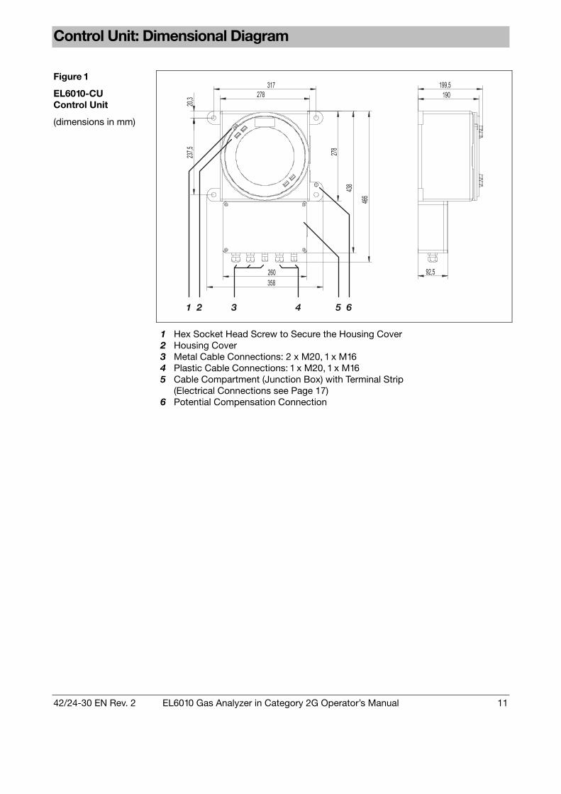
Figure 1 EL6010-CU Control Unit (dimensions in mm)
1 2 3 4 65
1 Hex Socket Head Screw to Secure the Housing Cover
2 Housing Cover 3 Metal Cable Connections: 2 x M20, 1 x M16 4 Plastic Cable Connections: 1 x M20, 1 x M16 5 Cable Compartment (Junction Box) with Terminal Strip
(Electrical Connections see Page 17) 6 Potential Compensation Connection

12 EL6010 Gas Analyzer in Category 2G Operator’s Manual 42/24-30 EN Rev. 2
Analyzer Unit: Dimensional Diagram
Figure 2 EL6010-... Analyzer Unit (dimensions in mm)
250
250
406
30
136
35
70
20030
3,5
26,5
50
50
ø 240
5
50
ø 9
40
20
56
4
50
775
(cle
aran
ce fo
r op
enin
g)
65
1
2
3
4
89
7 10
EL6010-Caldos17, EL6010-Magnos106
1 Sample Gas Inlet 2 Sample Gas Outlet 3 not used 4 not used 5 Purge Gas Inlet 1) 6 Purge Gas Outlet 1) 7 Pressure Sensor 2) 8 24 VDC Connection Cable Opening 9 Data Transmission Cable Opening 10 Potential Compensation Connection
EL6010-Uras14
1 ) 2 ) See 3 ) Analyzer Data Sheet 4 ) 5 Purge Gas Inlet 1) 6 Purge Gas Outlet 1) 7 Pressure Sensor 2) 8 Data Transmission Cable Opening 9 24 VDC Connection Cable Opening 10 Potential Compensation Connection
1) Option
2) Standard for EL6010-Caldos17, EL6010-Uras14; Option for EL6010-Magnos106. When measuring flammable and corrosive gases the pressure sensor connec-tion should not be joined with the sample gas path.
Note the additional space requirements • Beneath the analyzer unit for connection lines (approx. 10 cm) and • Above the analyzer unit for opening the housing (approx. 40 cm).
42/24-30 EN Rev. 2 EL6010 Gas Analyzer in Category 2G Operator’s Manual 13
Chapter 2 Install the Gas Analyzer
Unpack and Install the Gas Analyzer
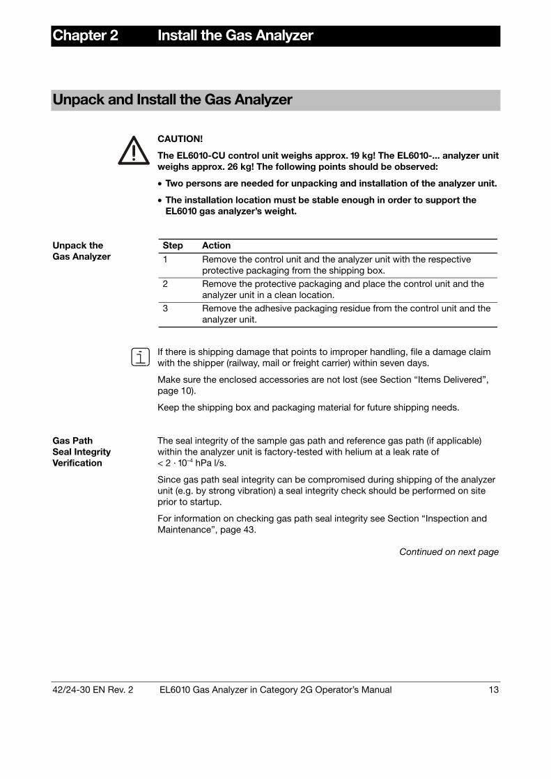
CAUTION!
The EL6010-CU control unit weighs approx. 19 kg! The EL6010-... analyzer unit weighs approx. 26 kg! The following points should be observed:
• Two persons are needed for unpacking and installation of the analyzer unit.
• The installation location must be stable enough in order to support the EL6010 gas analyzer’s weight.
Step Action
1 Remove the control unit and the analyzer unit with the respective protective packaging from the shipping box.
2 Remove the protective packaging and place the control unit and the analyzer unit in a clean location.
Unpack the Gas Analyzer
3 Remove the adhesive packaging residue from the control unit and the analyzer unit.
If there is shipping damage that points to improper handling, file a damage claim with the shipper (railway, mail or freight carrier) within seven days.
Make sure the enclosed accessories are not lost (see Section “Items Delivered”,
page 10).
Keep the shipping box and packaging material for future shipping needs.
Gas Path Seal Integrity Verification
The seal integrity of the sample gas path and reference gas path (if applicable) within the analyzer unit is factory-tested with helium at a leak rate of < 2 · 10–4 hPa l/s. Since gas path seal integrity can be compromised during shipping of the analyzer unit (e.g. by strong vibration) a seal integrity check should be performed on site prior to startup.
For information on checking gas path seal integrity see Section “Inspection and
Maintenance”, page 43.
Continued on next page
14 EL6010 Gas Analyzer in Category 2G Operator’s Manual 42/24-30 EN Rev. 2
Unpack and Install the Gas Analyzer, continued
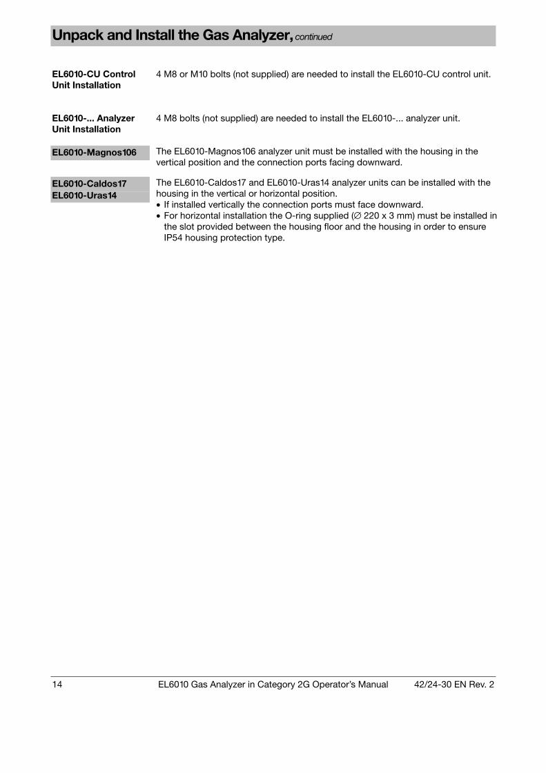
EL6010-CU Control Unit Installation
4 M8 or M10 bolts (not supplied) are needed to install the EL6010-CU control unit.
EL6010-... Analyzer Unit Installation
4 M8 bolts (not supplied) are needed to install the EL6010-... analyzer unit.
EL6010-Magnos106 The EL6010-Magnos106 analyzer unit must be installed with the housing in the
vertical position and the connection ports facing downward.
EL6010-Caldos17 EL6010-Uras14
The EL6010-Caldos17 and EL6010-Uras14 analyzer units can be installed with the housing in the vertical or horizontal position. • If installed vertically the connection ports must face downward. • For horizontal installation the O-ring supplied (∅ 220 x 3 mm) must be installed in
the slot provided between the housing floor and the housing in order to ensure IP54 housing protection type.

42/24-30 EN Rev. 2 EL6010 Gas Analyzer in Category 2G Operator’s Manual 15
Connect the Gas Lines
Gas Connection Design
All gas connections – with 1/8-NPT female threads – are routed via flame barriers: • Sample gas inlets and outlets • Housing purge (option) • Flowing reference gas for the EL6010-Uras14 (option) • Pressure sensor for EL6010-Uras 14, -Magnos106 (option) and -Caldos17 The actual gas connection layout of a delivered EL6010-... analyzer unit is shown in the applicable analyzer data sheet.
Pressure Sensor Connection
• If the pressure sensor connection is routed to the outside, the plug must be removed from the associated flame barrier (see Figure 2, Page 12) before starting operation.
• The pressure sensor connection should not be joined with the sample gas path
when measuring flammable and corrosive gases.
Housing Purge Housing purge is used to avoid corrosion in corrosive environment or with
corrosive sample or associated gases. To preserve atmospheric conditions in the pressure-tight housing, two types of purge operation are possible: • Limiting purge gas inlet and outlet pressure to a maximum positive pressure
pe ≤ 100 hPa (pabs ≤ 1,100 hPa). • The purge gas is supplied without pressure at the inlet and is extracted from the
outlet (pe ≥ –100 hPa). The purge gas flow must be limited to 10 l/h in normal operation. Clean instrument air from non-explosive areas or an inert gas must be used as purge gas. The purge gas should not contain any sample gas components. The pressure-tight housing is sealed in such a manner that purge gas loss during housing purge is minimized. Purge gas loss can be further reduced by installation of the O-ring supplied (∅ 220 x 3 mm) in the slot provided between the housing floor and the housing.

16 EL6010 Gas Analyzer in Category 2G Operator’s Manual 42/24-30 EN Rev. 2
Connect Electrical Lines – Safety Precautions
CAUTION! Follow all applicable national safety regulations for the preparation and operation of electrical devices as well as the following safety precautions!
Potential Compensation
The external potential compensation connections of the control unit and the analyzer unit must be connected to the local potential compensation point. The connection to the local potential compensation point must be made before all other connections. Minimum conductor section = 4 mm2. The gas analyzer can be hazardous if the protective lead is interrupted inside or outside the gas analyzer or if the protective lead is disconnected.
Securing Electrical Lines
All electrical wiring, including the connections between the analyzer unit and the control unit, must be firmly secured.
Shielded Lines Shielded lines must be routed through the metal wiring connectors. The
shield braid must be placed on the cable connectors.
Unused Cable Connections
Unused cable connectors must be closed off with plugs. Securely tighten the cap nuts on the unused cable connectors.
Before the Power Supply is Connected
Before the power supply is connected, make sure the power line voltage is in the permissible range 85 to 250 VAC for operation of the gas analyzer.

42/24-30 EN Rev. 2 EL6010 Gas Analyzer in Category 2G Operator’s Manual 17
Control Unit: Electrical Connections
1 1 LDA 2 2 LCL 3 3 TINT 4 4 RX_B 5 5 RX_A 6 6 TX_B 7 7 TX_A 8 8 485EN_B 9 9 485EN_A
10 10 RESET 11 11 S_DOWN 12 12 GND
Data Transmission to/ from Analyzer Unit (see page 18)
13 PE 14 24 VDC + 15 GND
Analyzer Unit Power Supply (see page 18)
16 RxD 17 TxD 18 GND
RS232
19 RTxD– 20 RTxD+ 21 GND
RS485
Serial Interfaces Transfers measured values and status signals to host systems, e.g. to standard Windows applications via Modbus DDEServer. Modbus slave protocol in RTU (remote terminal unit) mode. Either the RS232 or the RS485 interface can be used (configurable). Interface galvanically isolated from ground.
22 23 24
Collective Status
25 26 27
Limit Value 1
28 29 30
Limit Value 2
Digital Outputs Floating doublethrow contacts, max. contact load rating 30 VDC/1 A. Relays are shown in the unpowered state. The unpowered state is the failure mode (“fail safe“).
31 + 32 –
Sample Component 1
33 + 34 –
Sample Component 2
Analog Outputs 4–20 mA, common negative pole, galvanically isolated from ground, freely connectable to ground, max. gain relative to protective ground potential 25 V, max. working resistance 750 Ω. The output signal cannot be lower than 0 mA.
N L
PE
Power Supply (see page 20) 85–250 VAC, 48–63 Hz, max. 6 A breaker
At the factory two jumpers are inserted in the analog output terminals 31–32 and 33–34. If no signal leads are installed, these jumpers close the output current circuits and prevent the display of status message 30 “Broken analog output line” (see page 47). The respective jumper must be removed prior to connecting the electrical lines to the analog output terminals.

18 EL6010 Gas Analyzer in Category 2G Operator’s Manual 42/24-30 EN Rev. 2
Connection Analyzer Unit – Control Unit
Data Transmission Cable and 24-VDC Connection Cable
At the factory • a 3-meter long data transmission cable (12 x 0.5 mm2) and • a 3-meter long 24-VDC connection cable (3 x 2.5 mm2) are attached to the EL6010-... analyzer unit. Both cables pass through pressure-tight cable openings.
CAUTION! The data transmission cable and the 24-VDC connection cable must be firmly secured! The cables are integral components of the analyzer unit’s pressurized enclo-sure system. They should not be shortened to less than 1 meter in length and should not be damaged!
Figure 3 Connection of the Data Transmission Cable and the 24-VDC Connection Cable to the Control Unit
1 2 3 4 5 6 7 8 9 10 11 12 13 14 15
DatenübertragungskabelData Transmission Cable
24-V-DC-Anschlusskabel24-VDC Connection Cable
1 2 3 4 5 6 7 8 9 10 11 12 13 14 15
LDA
LCL
TIN
T
RX
_B
RX
_A
TX_B
TX_A
485E
N_B
485E
N_A
RE
SE
T
S_D
OW
N
GN
D
PE
24 V
DC
+
GN
Drot/red

42/24-30 EN Rev. 2 EL6010 Gas Analyzer in Category 2G Operator’s Manual 19
Electrical Connections
Material and Size of the Cable Connectors Cable Outer Diameter
M16 3 to 7 mm Metal M20 7 to 12 mm M16 4 to 8 mm
Allowed Cable Outer Diameters
Plastic M20 6,5 to 12 mm
Step Action
1 Uncover the shield braid of the cable on an length of approx. 10 mm. 2 Loosen the cap nut from the metallic cable connector and remove the
clamp insert. 3 Slide the cap nut and the clamp insert over the cable.
Fold the shield braid back over the clamp insert. 4
The shield braid must cover the O-ring by approx. 2 mm.
Cable Connection to a Metal Cable Connector on the Control Unit (e.g. Analyzer Unit Data Transmission Cable)
5 Push the clamp insert with the cable into the intermediate opening and securely tighten the cap nut.
Step Action
1 Loosen the cap nut from the plastic cable connector and remove the seal ring.
2 Slide the cap nut and the seal ring over the cable.
Cable Connection to a Plastic Cable Connec-tor on the Control Unit (e.g. Analyzer Unit 24-VDC Connection Cable)
3 Push the cable with the seal ring into the intermediate opening and securely tighten the cap nut.

20 EL6010 Gas Analyzer in Category 2G Operator’s Manual 42/24-30 EN Rev. 2
Power Supply Connection
Step Action
1
Make sure that the power line voltage is in the permissible range 85 to 250 VAC.
Make sure the power supply leads have an adequately dimensioned protective device (max. 6 A breaker).
2
Power consumption: EL6010-CU + EL6010-Uras14 approx. 100 VA EL6010-CU + EL6010-Magnos106 approx. 90 VA EL6010-CU + EL6010-Caldos17 approx. 40 VA
3 Install a breaker in the power supply line or a switched receptacle near the control unit to make sure the control unit can be completely sepa-rated from the power source. Mark the breaker so that its relationship to the protected device is clear.
Connecting the Power Supply to the Control Unit
4 Connect the power supply leads (conductor cross-section = 1.5 to 2.5 mm2) to the terminals N, L and PE (see connection diagram, page 17).
Analyzer Unit Power Supply
The analyzer unit is supplied with 24 VDC ± 5 % from the control unit’s power supply.

42/24-30 EN Rev. 2 EL6010 Gas Analyzer in Category 2G Operator’s Manual 21
Chapter 3 Gas Analyzer Operation
Readout
Screen The lighted LCD screen consists of two lines of 20 characters each.
CO 105.2 ppm
In measuring mode the screen displays the sample component name(s), the measured value in digits and the physical unit for the measured value.
Display in Measuring Mode
CO 21.14 %Span
Press the key to display the measured value as a percentage of the measuring range (span).
All screen displays shown in this operator’s manual are examples. As a rule, actual displays on the device will differ.
Number of Places after the Decimal Point
When the screen displays the measured value in physical units (e.g. ppm) the number of places after the decimal point depends on the size of the measuring span:
Span (in physical units) < 5 ≥ 5...< 50 ≥ 50...< 500 ≥ 500
Places 3 2 1 0 For the display of the measured value as a percentage of the whole measuring
range (%Span) two places are always shown after the decimal point. The number of decimal places when setting the parameters is the same as in the display in measuring mode.
Blinking Screen Blinking of part of the screen in measuring mode indicates that the gas analyzer or
process system has experienced a fault. See Chapter “Status Messages, Troubleshooting”, page 45, for details on faults, causes and corrective actions.

22 EL6010 Gas Analyzer in Category 2G Operator’s Manual 42/24-30 EN Rev. 2
Operation
Operation Four touch screen fields accessible through the control unit viewing glass allow
safe operation of the gas analyzer without opening the housing. The menu-driven control system is uniform for all three gas analyzers.
Important advice for actuating the keys: The keys can only be operated if the finger approaches the sensor field briskly from the front. The sensor fields do not react if the finger is slid across from the side. The pressure on the screen has no influence on the operation.
Keys The and keys are used to
• select a menu item • change a value.
The Enter key is used to
• activate a menu item • accept an edited value • activate a function.
The Back key is used to
• Return to the first item in a menu or to a previous menu • cancel the editing of a value.
Time-Out If the user does not use a key during a period longer than one minute during cali-
bration or parameter setup, the gas analyzer will automatically revert to displaying measured values (time-out). The time-out function is deactivated if the user changes the value of a parameter or activates calibration.

42/24-30 EN Rev. 2 EL6010 Gas Analyzer in Category 2G Operator’s Manual 23
Menu
Menu The EL6010 gas analyzer menu structure is summarized below.
Menu Structure (Overview)
Measured value display
Calibrate
Calibrate component
Zero calibration
Span calibration
Span with cal. cell
Calibration reset
Pressure adjustment
Measure cal. cell
Setting parameters
Parameters component
Zero setpoint
Span setpoint
Filter
Measuring range
Active TC component
Parameters limit
Limit 1
Limit 2
Limit 1 hysteresis
Limit 2 hysteresis
Parameters modbus
Modbus baudrate
Modbus address
Modbus type
Information
Drift
Delta drift
Software version
Error list
EL6010-Uras14 only
EL6010-Uras14 only
EL6010-Caldos17 only

24 EL6010 Gas Analyzer in Category 2G Operator’s Manual 42/24-30 EN Rev. 2
Chapter 4 Start the Gas Analyzer
CAUTION! If the EL6010-... analyzer unit must be opened for operation or maintenance, the instructions on the following warning label (affixed to the housing) must be observed: “Before opening, disconnect power and wait 10 minutes!” For operation of the EL6010-CU control unit the following warning instruction must be observed: “Do not open when an explosive atmosphere may be present!”
Check the Installation
Check the Installation Make sure the EL6010 gas analyzer is correctly installed before carrying out any start-up procedures. Use the following check list:
Check
Installation site • Do the conditions at the installation site (zone rating, explosion group,
temperature class) match the information on the identification plate? • Are the control unit and the analyzer unit not installed outdoors? • Are the control unit and the analyzer unit securely fastened? Connection of gas lines • Are all gas lines correctly connected? • Is the pressure sensor connection not joined with the sample gas path? Potential compensation connection • Is the external potential compensation connection of the analyzer unit
connected to the local potential compensation point? • Is the external potential compensation connection of the control unit
connected to the local potential compensation point?
Continued on next page

42/24-30 EN Rev. 2 EL6010 Gas Analyzer in Category 2G Operator’s Manual 25
Check the Installation, continued
Check
Connection of electrical lines • Does the power line voltage agree overall with the permitted operating
voltage (85 to 250 VAC, see rating plate)? • Are all the electrical lines installed permanently according to the specifi-
cations and correctly connected to the terminal strip in the cable com-partment?
• Are no loose core ends present? Are all unused core ends insulated and mechanically secured?
• Are the correct cable types being used for the lines which are led to the control unit through cable connectors?
• Are the lines firmly seated in the cable glands? • Are the shielded lines led through the metallic cable connectors? Is the
shield braid correctly installed at the cable connector? • Are the 24-VDC connecting cable and the data transmission cable,
which are non-detachably attached to the analyzer unit, not shortened to a length of less than 1 meter and not damaged?
Housing integrity • Is the analyzer unit housing intact? • Are all flame barriers and screw plugs present? • If the analyzer units EL6010-Uras14 and -Caldos17 are mounted horizon-
tally, are the O-rings, which are placed between the housing floor and the housing as well as between the housing and the housing lid in the slots provided, cleanly laid and not pinched?
• Are all the parts of the housing screwed together fully to the respective stops and secured from turning with the hex socket head screws?
• Is the control unit housing intact? • Is the control unit housing firmly closed? • Is the housing cover screwed on fully to the stop and secured from
turning with the hex socket head screw? • Is the seal in the cover of the cable compartment intact? Is the cover of
the cable compartment firmly closed? • Are all cable connectors present and firmly screwed in? • Are all the openings in unused cable connectors sealed tightly with
sealing plugs? Connection of peripheral devices • Are all devices needed for gas conditioning, calibration and exhaust
processing correctly connected and ready for use?

26 EL6010 Gas Analyzer in Category 2G Operator’s Manual 42/24-30 EN Rev. 2
Start the Gas Analyzer
Gas Path Purge On initial use, purge the gas paths prior to connecting the 24 VDC power supply.
This should remove any explosive gas/air mixture in the gas paths.
Purge gas for a non-flammable sample gas Clean instrument air from areas free of
any explosion risk for a flammable sample gas Inert gas
Purge gas quantity 5 times the volume of the gas paths Purge gas flow Approx. 30 liters/hour
Purge duration At least 3 minutes
During operation, purge gas flow should be limited to 10 liters/hour. The purge gas should not contain any sample gas components.
Step Action
1 Activate the gas analyzer power supply. EL Series IR 2.0.4 22-04-2003
2 The screen initially displays the gas analyzer name and the software version.
CO 105.2 ppm
After a brief time the screen switches displaying measured values.
3
Blinking of part of the screen indicates that the gas analyzer or the process system has experienced a fault. (see Section “Blinking Screen”, page 45).
4 Check the parameters and adjust as needed (see page 27). 5 After the warm-up phase (approx. 30 to 60 minutes) the gas analyzer
is ready to operate. 6 Calibrate the gas analyzer (see page 35).
Start the Gas Analyzer
7 Start the sample gas flow.

42/24-30 EN Rev. 2 EL6010 Gas Analyzer in Category 2G Operator’s Manual 27
Chapter 5 Set Parameters
Fundamentals
General Procedure The normal procedure for setting parameters is:
1. Press Enter to access the menu.
2. Select the Parameters menu item with the or key.
3. Activate the Parameters menu item with the Enter key.
4. Change the parameters with the or key.
5. Confirm the change with the Enter key or cancel the change with the Back key.
6. Use the Back key to return to the previous menu. Only parameters that blink in the display can be edited. The following example should clarify the details of this general procedure.
Step Action Key Display Key
CO 105.2 ppm
1 Enter Calibrate
Access the menu.
2 Setting parameters
Enter
Select the “Setting parameters” menu.
3 Parameters component
CO Enter
Select the submenu.
4 Span setpoint
505.0 ppm CO Enter
Select the parameter to be changed.
5 Span setpoint
505.0 ppm CO Enter
Edit the parameter value and confirm the change.
6 Span setpoint
500.0 ppm CO Back
Return to the previous menu.
7 Parameters component
CO Back
Return to the previous menu.
8 Setting parameters
Back
Return to the measured value display.
CO 105.2 ppm

28 EL6010 Gas Analyzer in Category 2G Operator’s Manual 42/24-30 EN Rev. 2
Test Gas Concentration
Zero setpoint 0.0 ppm CO
Test gas concentration set point for zero calibration
Zero setpoint 0.0 ppm CO
Zero Set Point
Value range: Reference measuring range 1) start minus 25 % of span to reference measuring range end
Span setpoint 500.0 ppm CO
Test gas concentration set point for span calibration
Span setpoint 500.0 ppm CO
Span Set Point
Value range: Reference measuring range 1) start to reference measuring range end plus 30 % of span
Step Interval The set point adjustment step interval is 0.2 % of the span of the range in use.
1) For an explanation of the term “Reference Measuring Range” see pages
29 to 31.
Filter
Filter 5 sec 1 sec 0.05 %
Non-linear filter with two low pass time constants and switching threshold
Filter 5 sec 1 sec 0.05 %
Time constant for constant measured value. Value range: 0 to 60 sec.
Filter 5 sec 1 sec 0.05 %
Time constant for measured value changes. Value range 0 to 60 sec.
Filter 5 sec 1 sec 0.05 %
Filter (T90 Time)
Switching threshold as % of span of reference measuring range 1). On exceeding this value the time constant for measured value changes is effective. Value range: 0 to 9.99 %
Recommendation The ratio of the time constant for constant measured values to the time constant
for measured value changes should be 5:1.
1) For an explanation of the term “Reference Measuring Range” see pages
29 to 31.
42/24-30 EN Rev. 2 EL6010 Gas Analyzer in Category 2G Operator’s Manual 29
EL6010-Uras14: Measuring Range
Measuring range 0.0 – 500.0 ppm
Measuring range The measuring range start value cannot be changed
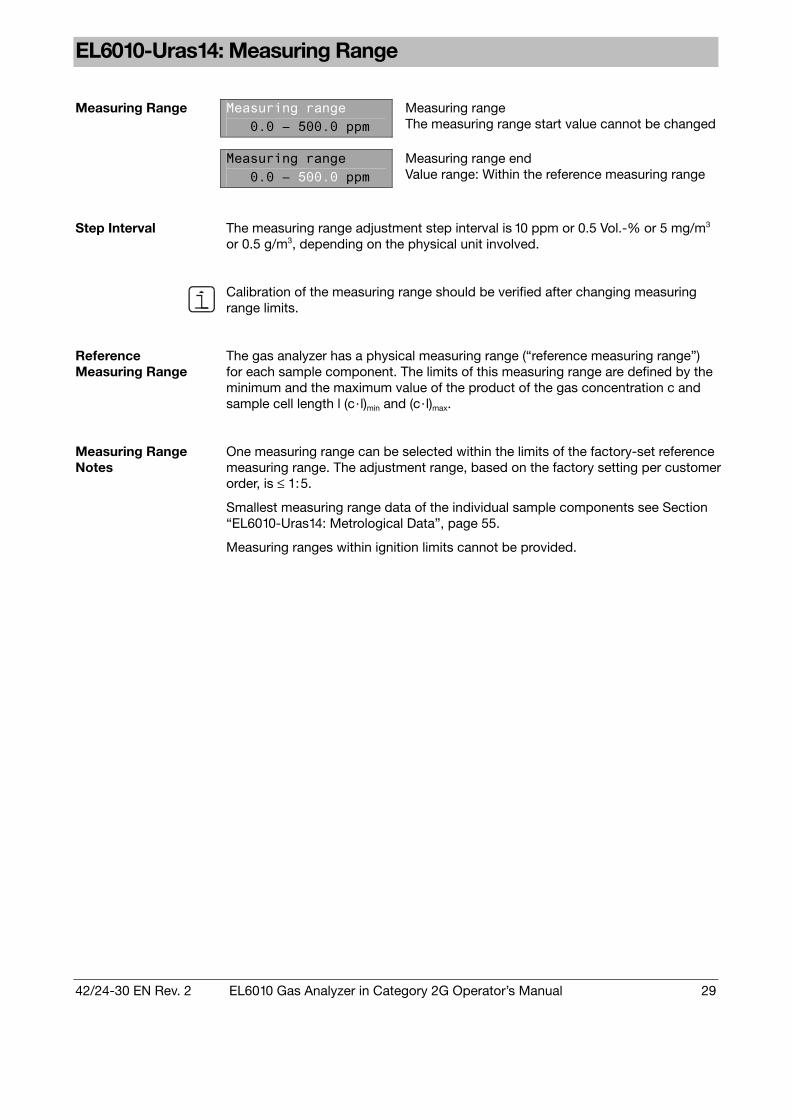
Measuring Range
Measuring range 0.0 – 500.0 ppm
Measuring range end Value range: Within the reference measuring range
Step Interval The measuring range adjustment step interval is 10 ppm or 0.5 Vol.-% or 5 mg/m3
or 0.5 g/m3, depending on the physical unit involved.
Calibration of the measuring range should be verified after changing measuring range limits.
Reference Measuring Range
The gas analyzer has a physical measuring range (“reference measuring range”) for each sample component. The limits of this measuring range are defined by the minimum and the maximum value of the product of the gas concentration c and sample cell length l (c · l)min and (c · l)max.
Measuring Range Notes
One measuring range can be selected within the limits of the factory-set reference measuring range. The adjustment range, based on the factory setting per customer order, is ≤ 1:5. Smallest measuring range data of the individual sample components see Section “EL6010-Uras14: Metrological Data”, page 55. Measuring ranges within ignition limits cannot be provided.
30 EL6010 Gas Analyzer in Category 2G Operator’s Manual 42/24-30 EN Rev. 2
EL6010-Magnos106: Measuring Range
Measuring range 0.00 - 25.00 Vol%
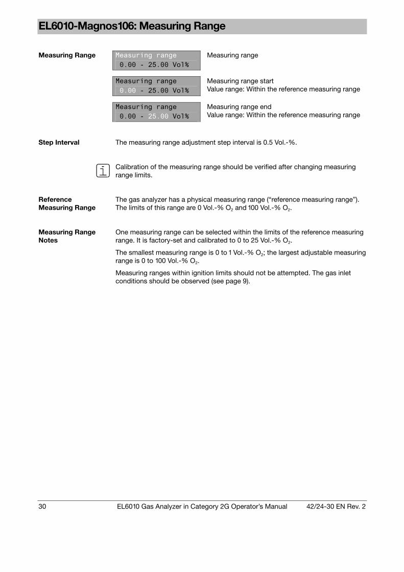
Measuring range
Measuring range 0.00 - 25.00 Vol%
Measuring range start Value range: Within the reference measuring range
Measuring Range
Measuring range 0.00 - 25.00 Vol%
Measuring range end Value range: Within the reference measuring range
Step Interval The measuring range adjustment step interval is 0.5 Vol.-%.
Calibration of the measuring range should be verified after changing measuring range limits.
Reference Measuring Range
The gas analyzer has a physical measuring range (“reference measuring range”). The limits of this range are 0 Vol.-% O2 and 100 Vol.-% O2.
Measuring Range Notes
One measuring range can be selected within the limits of the reference measuring range. It is factory-set and calibrated to 0 to 25 Vol.-% O2. The smallest measuring range is 0 to 1 Vol.-% O2; the largest adjustable measuring range is 0 to 100 Vol.-% O2. Measuring ranges within ignition limits should not be attempted. The gas inlet conditions should be observed (see page 9).

42/24-30 EN Rev. 2 EL6010 Gas Analyzer in Category 2G Operator’s Manual 31
EL6010-Caldos17: Measuring Range
Measuring range 0.0 - 100.0 Vol%
Measuring range
Measuring range 0.0 - 100.0 Vol%
Measuring range start Value range: Within the reference measuring range
Measuring Range
Measuring range 0.0 - 100.0 Vol%
Measuring range start Value range: Within the reference measuring range
Step Interval The measuring range adjustment step interval is 0.5 Vol.-%.
Calibration of the measuring range should be verified after changing measuring range limits.
Reference Measuring Range
The gas analyzer has a physical measuring range (“reference measuring range”) for each sample component. The limits of this range are 0 Vol.-% and 100 Vol.-%.
Measuring Range Notes
The measuring range can be adjusted within the limits valid for the sample components (see Section “EL6010-Caldos17: Metrological Data”, page 57). For the factory-set component “relative thermal conductivity” it is rTC = 0 to 60,000. The largest measuring range is 0 to 100 Vol.-% or 0 Vol.-% to saturation, depending on the measuring task. Measuring ranges within ignition limits cannot be provided.
Active TC component CO2:H2
Active sample component
Active TC component CO2:H2
Active Sample Component
All the sample components listed in the Section “EL6010-Caldos17: Metrological Data” are available (see page 57).
All sample components are precalibrated at the factory. After activating a sample component, check the zero and span points and recalibrate as necessary (see Chapter “Calibrate the Gas Analyzer”, page 35).
When a different sample component is activated, the gas analyzer reverts to the factory precalibrated state. This means that calibration values are lost and set point and measuring range limit settings are reset to the reference measuring range limits.

32 EL6010 Gas Analyzer in Category 2G Operator’s Manual 42/24-30 EN Rev. 2
Limit Parameters
Limit Parameters If only one sample component is present in the gas analyzer, two limits can be set
for this component. If there are two sample components in the gas analyzer, one limit can be set per sample component. Switching hysteresis can be set for each of the limits.
Limit 1 COOFF > 400.0 ppm
Limit of the sample component displayed
Limit 1 COOFF > 400.0 ppm
Activation. Value range: ON or OFF
Limit 1 COOFF > 400.0 ppm
Direction of effect. Value range: < or > = Alarm on underflow or overflow of limit
Limit
Limit 1 COOFF > 400.0 ppm
Limit. Value range: Within the reference measuring range 1)
Step Interval The limit adjustment step interval is 0.1 % of the span of the reference measuring
range 1).
Limit 1 hysteresis 10.0 ppm
Switching Hysteresis Switching Hysteresis
Limit 1 hysteresis 10.0 ppm
Extent of switching hysteresis. Value range: Within the reference measuring range 1)
Step Interval The hysteresis adjustment step interval is 0.01 % of the span of the reference
measuring range 1).
1) For an explanation of the term “Reference Measuring Range” see pages
29 to 31.

42/24-30 EN Rev. 2 EL6010 Gas Analyzer in Category 2G Operator’s Manual 33
Modbus Parameters
Modbus Parameters Modbus parameters are set prior to connecting the gas analyzer to a PC or
process control system via a Modbus link.
Modbus baudrate 19200
Baud Rate Baud Rate
Modbus baudrate 19200
Value range: 9600 or 19200
Modbus address 1
Address Address
Modbus address 1
Value range: 1 to 255
Modbus type RS232
Interface Type Interface Type
Modbus type RS232
Value range: RS232 or RS485
For detailed Modbus information see the “EasyLine Modbus and M-DDE Server” technical information sheet (Publication No. 30/27-100 EN).

34 EL6010 Gas Analyzer in Category 2G Operator’s Manual 42/24-30 EN Rev. 2
Factory and User Settings
Factory and User Settings
The following table lists the parameter settings made at the factory. The operator can enter any on-site or application-specific parameter changes in the column at the right.
Parameter Factory Setting User Setting
Zero setpoint
Span setpoint
Filter
Measuring range
Active TC component
Depending on the analyzer unit type
Limit 1 OFF < 0
Limit 2 OFF < 0
Limit 1 hysteresis 0
Limit 2 hysteresis 0
Modbus baudrate 19200
Modbus address 1
Modbus type RS232

42/24-30 EN Rev. 2 EL6010 Gas Analyzer in Category 2G Operator’s Manual 35
Chapter 6 Calibrate the Gas Analyzer
Calibration Verification
Calibration Verification
The gas analyzer has been calibrated in the factory. Transport stresses as well as pressure and temperature conditions at the installation location may however influence the calibration. Thus it is recommended to verify the gas analyzer calibration at the installation location prior to start-up.
Test Gases
Test Gas Dew Point The test gas dew point must be nearly identical to the sample gas dew point.
Test Gas Supply Test gases should be connected to the sample gas inlet (e.g. using a multiple-path
valve).
EL6010-Uras14: Notes for Calibration
For zero-point calibration: Inert gas, e.g. nitrogen (N2) or sample component-free
ambient air Test Gases
For end-point calibration: Calibration cell (optional) or test gas mixture (Concen-tration: 70% of the span value of the measuring range selected is recommended; the maximum value is the span value of the reference measuring range)
Calibration Cell (Option)
Use of a calibration cell allows the EL6010-Uras14 gas analyzer to be calibrated without using test gas containers. The calibration cell is filled with a test gas matched to the sample components and measuring ranges for which the gas analyzer is set up. It is routed to the beam path during span calibration. The calibration cell set point should be checked at long intervals (recommenda-tion: once a year, see page 40 for instructions).

36 EL6010 Gas Analyzer in Category 2G Operator’s Manual 42/24-30 EN Rev. 2
EL6010-Caldos17: Notes for Calibration
For zero-point calibration: Test gas or sample component-free process gas Test Gases
For end-point calibration: Test gas or process gas having a known sample component concentration
Measuring Ranges with Suppressed Zero-Point
Zero-point and end-point should only be calibrated with test gases with concen-trations in the selected measuring range.
EL6010-Magnos106: Notes for Calibration
For zero-point calibration: Oxygen-free process gas or nitrogen (N2) Test Gases
For end-point calibration: Process gas with a known oxygen concentration or dried air or test gas with concentration in the measur-ing range
Carrier Gas Offset Correction
The influence of carrier gases is seen in the form of a displacement of the zero point (see Section “EL6010-Magnos106: Metrological Data”, page 56). If it is expected that, due to a particular carrier gas specified by the customer with the order, this zero point displacement is greater than 1 % of the smallest selected measuring range, then the gas analyzer will be calibrated in the factory with an average process gas, and the deviation with respect to the carrier gas N2 will be corrected with the software function “Carrier gas offset correction”. This correction function has the effect that the influence of the carrier gas is minimized in the measuring operation. It is also active in the course of calibration while the concentration of the test gases is being measured. As a result, during zero-point and end-point calibration measured values are displayed which differ from the “true” measured value by the amount of the offset correction value. During calculation of the calibration however this correction function is switched off so that the offset correction value is not taken into account in the calibration results.

42/24-30 EN Rev. 2 EL6010 Gas Analyzer in Category 2G Operator’s Manual 37
Calibrate Sample Component
Wait until End of Warm-up Phase
The gas analyzer should only be calibrated after the end of the warm-up phase (that takes approx. 30 to 60 minutes).
Current Output During Calibration
Signals at the analog outputs (current outputs) track measured value changes during calibration.
Limits During Calibration
If limits are activated, they are also active during calibration.
Status Signal During Calibration
During calibration, the status signal “Maintenance Mode” is output on “overall status” digital output and via Modbus.
Calibration via Modbus
For information about calibration via Modbus see the “EasyLine Modbus and M-DDE Server” technical information sheet (Publication No. 30/27-100 EN).
A zero calibration must always be performed before a span calibration. A zero calibration can also be performed separately.
Step Action Key Display Key
1 Enter Calibrate
Enter
Select the Calibrate menu.
2 Calibrate component
CO Enter
Select the sample component.
3 Zero calibration
CO Enter
Select Zero calibration.
4 Zero setpoint
0.00 Vol% CO Enter
Check the zero set point and adjust as needed.
5 Connect zero gas!
Enter
Turn on the zero gas supply.
6 Meas. value stable?
0.53 Vol% CO Enter
Start calibration if the measured value reading is stable.
7 Wait cal. is running
Calibration in progress.
8 Accept calibration
or Meas. value ok?
0.00 Vol% CO Enter
Calibrate Sample Component
reject calibration. Back
Continued on next page

38 EL6010 Gas Analyzer in Category 2G Operator’s Manual 42/24-30 EN Rev. 2
Calibrate Sample Component, continued
Step Action Key Display Key
9 Span calibration CO
Enter
Select Span calibration with test gas.
10 Span setpoint
10.00 Vol% CO Enter
Check the span set point and adjust as needed.
11 Connect span gas!
Enter
Turn on the span gas supply.
12 Meas. value stable?
9.91 Vol% CO Enter
Start calibration if the measured value reading is stable.
13 Wait cal. is running
Calibration in progress.
14 Accept calibration
or Meas. value ok?
10.00 Vol% CO Enter
reject calibration. Back
9 Span with cal. cell CO
Enter
Select Span calibration with calibration cell.
10 Setpoint cal. cell
8.52 Vol% CO Enter
The calibration cell set point is displayed.
11 Connect zero gas!
Enter
Connect the zero gas (if this has not already been done).
12 Meas. value stable? 8.49 Vol% CO
Enter
Start calibration if the measured value reading is stable.
13 Wait cal. is running
Calibration in progress.
14 Accept calibration
or Meas. value ok?
8.52 Vol% CO Enter
Option for EL6010-Uras14
reject calibration. Back
Amplification error 0.00 Vol% CO
This display shows that an error occurred during calibration and that calibration was unsuccessful. In this case, press Enter to return to the start of zero or span calibration, check the test gas concentration, correct as needed and repeat the calibration process.

42/24-30 EN Rev. 2 EL6010 Gas Analyzer in Category 2G Operator’s Manual 39
Perform Calibration Reset
When should a calibration reset be performed?
Perform a calibration reset when the gas analyzer can no longer be calibrated with normal means. A possible cause of this is calibration with the wrong test gases.
What does the calibration reset do?
A calibration reset returns the gas analyzer’s calibration to factory default values. Additionally, the offset drift and amplification drift are electronically returned to initial calibration values (see Section “Drift Reading”, page 42).
Step Action Key Display Key
1 Enter Calibrate
Enter
Select the Calibrate menu.
2 Calibrate component
CO Enter
Select the sample component.
3 Calibration reset
CO Enter
Select Calibration reset.
4 Calibration reset
Start cal. reset! Enter
Start the calibration reset.
5 Wait cal. is running
Calibration reset in progress.
6 Calibration reset
CO
Calibration reset has ended.
Perform Calibration Reset
7 Press the Back key to return to displaying measured values.

40 EL6010 Gas Analyzer in Category 2G Operator’s Manual 42/24-30 EN Rev. 2
EL6010-Uras14: Measure Calibration Cell
Definition Measuring the calibration cell determines what calibration cell “deflection” is
equivalent to the test gas calibration reading. This “deflection” is stored as the calibration cell “set point”.
When should the calibration cell be measured?
We recommend measuring the calibration cell once a year. Measurement of the calibration cell is also recommended after a user-set measuring range (see page 29) is calibrated for the first time with test gases and subsequently whenever the test gas is changed.
Before Measuring the Calibration Cell
Prior to measuring the calibration cell, the zero and span point of the applicable sample components must be calibrated with test gases.
Zero Gas Supply During calibration cell measurement the zero gas supply must be turned on.
Step Action Key Display Key
1 Enter Calibrate
Enter
Select the Calibrate menu.
2 Measure cal. cell 1
CO Enter
Select Measure calibration cell.
3 Connect zero gas!
Enter
Turn on the zero gas supply.
4 Meas. value stable?
8.51 Vol% CO Enter
Start measurement if the measured value reading is stable.
5 Wait cal. is running
Measurement in progress.
6 Meas. value ok?
8.51 Vol% CO Enter
Accept the set point.
Measure Calibration Cell
7 Press the Back key to return to displaying measured values.

42/24-30 EN Rev. 2 EL6010 Gas Analyzer in Category 2G Operator’s Manual 41
Pressure Correction
Air Pressure Effect A change in atmospheric pressure by a certain amount will affect measured value
readings.
Pressure Sensor Installed
A pressure sensor is installed in the gas analyzer unit (in EL6010-Magnos106 as an option). The effects of air pressure changes on the measured value are minimized by automatic internal pressure correction.
Pressure Sensor Calibration
If the indication of the internal pressure sensor differs from the current air pressure, the pressure sensor can be recalibrated.
When measuring non-flammable sample gases, the pressure sensor can be con-nected to the sample gas outlet line via an external tee. In this case, the sample gas flow should be stopped when calibrating the pressure sensor in order to prevent the sample gas pressure from causing a false pressure reading.
After calibrating the pressure sensor the zero and span points must be checked and recalibrated as needed.
Notes for EL6010-Magnos106
The EL6010-Magnos106 analyzer unit with no pressure sensor installed is cali-brated at the factory for an air pressure of 1013 hPa. If the air pressure at the instal-lation site differs from 1013 hPa, the actual pressure can be corrected by manually entering a value (see instructions “Calibrate Pressure Sensor”, steps 1 to 3).
Step Action Key Display Key
1 Enter Calibrate
Enter
Select the Calibrate menu.
2 Pressure adjustment
Enter
Select Pressure adjustment.
3 Pressure setpoint
1021 hPa Enter
Set the pressure set point.
4 Meas. value stable?
997 hPa Enter
Start adjustment if the measured value reading is stable.
5 Wait cal. is running
Adjustment in progress.
6 Meas. value ok?
1021 hPa Enter
Accept the measured value.
Calibrate Pressure Sensor
7 Press the Back key to return to displaying measured values.

42 EL6010 Gas Analyzer in Category 2G Operator’s Manual 42/24-30 EN Rev. 2
Drift Reading
Drift CO offs 0% ampl 0%
Drift
Offset and amplification drift values are determined cumulative and based on the last initial calibration performed.
Delta drift CO offs 0% ampl 0%
Delta Drift
Offset and amplification delta drift values are deter-mined based on the last and next-to-last calibration performed via the Modbus.
Drifts are displayed as a percentage of the user-set measuring range.

42/24-30 EN Rev. 2 EL6010 Gas Analyzer in Category 2G Operator’s Manual 43
Chapter 7 Inspection and Maintenance
Inspection
Regular Inspection Perform regular inspections using the “Check the Installation” list on page 24.
Check Gas Path Seal Integrity
Sample and reference gas path seal integrity should be examined during operation at least once annually. A sample gas path leak is the probable cause if erratic measurement readings (e.g. after starting the test gas supply) or implausible measured readings occur. A simple procedure for checking gas path seal integrity is described in the “Check Gas Path Seal Integrity” section (see page 44).
Measures taken after opening the gas paths inside the analyzer unit
• All parts of the housing are fully tightened and secured with set screws? • If the sample or reference gas path inside an EL6010-... analyzer unit has been
opened, the seal integrity should be tested with helium at a leak rate of < 2 · 10-4 hPa l/s. The pressure drop method, described in the “Check Gas Path Seal Integrity” section can be used as an alternative to the helium test. To accomplish this, increase the test pressure to a pe of approx. 400 hPa (= 400 mbar) and increase the test period to 15 minutes. The maximum excess pressure pe = 500 hPa (= 500 mbar).
• Any time the gas paths are opened they must then be purged prior to connecting
the power supply. This should remove any explosive gas/air mixture in the gas paths.
Purge gas
for a non-flammable sample gas Clean instrument air from areas free of any explosion risk
for a flammable sample gas Inert gas Purge gas quantity 5 times the volume of the gas paths Purge gas flow Approx. 30 liters/hour
Purge duration At least 3 minutes The purge gas should not contain any sample gas components.
Reseal the Wiring Passages After Opening
If the pressure-tight wiring passages through which the data transmission and 24-VDC connecting cables are routed into the analyzer unit’s pressure-tight cylinder have been opened, reseal the nuts using a 20-mm torque wrench; tightening torque = 17 Nm.

44 EL6010 Gas Analyzer in Category 2G Operator’s Manual 42/24-30 EN Rev. 2
Check Gas Path Seal Integrity
Quantity Description
1 Pressure gauge 1 Tubing, approx. 1 meter in length 1 Tee with shutoff valve
Material Required
Air or nitrogen
CAUTION! If the seal test is to be carried out with air and there is the possibility of a combustible gas being present in the gas paths or if a flammable gas is to be introduced later, the gas paths should first be purged with nitrogen. Other-wise the seal integrity test can be performed with nitrogen.
Step Action
1 Plug the outlet of the gas path to be tested. 2 Connect a hose with a tee fitted with a shutoff valve to the inlet of the
gas path to be tested. 3 Connect the free end of the tee to the pressure gauge.
Blow air or nitrogen through the shutoff valve until the sample gas path is pressurized to a pe of approx. 50 hPa (= 50 mbar). Close the shutoff valve. Maximum excess pressure pe = 150 hPa (= 150 mbar).
4
After opening the gas paths inside the analyzer unit: Test pressure pe approx. 400 hPa, maximum excess pressure pe = 500 hPa.
The pressure should not change measurably in 3 minutes. A sharp pressure drop is a sign of a leak in the gas path being tested.
5
After opening the gas paths inside the analyzer unit: Test period 15 minutes.
Gas Path Seal Integrity Verification
6 Repeat steps 1 to 5 for all gas paths in the analyzer unit.

42/24-30 EN Rev. 2 EL6010 Gas Analyzer in Category 2G Operator’s Manual 45
Chapter 8 Status Messages, Troubleshooting
Blinking Screen
Blinking Screen Blinking of part of the screen in measuring mode indicates that the gas analyzer or
process system has experienced a fault.
CO 753.2 ppm
Measured value exceeds/is below measuring range span
The measured value reading blinks if the measured value of the sample component is < –100 % or > 130 % of measuring range span.
CO 105.2 ppm
Maintenance Request
The sample component name display blinks if a maintenance request condition has occurred.
The gas analyzer is in a state that will soon require user intervention. The measured value is valid.
CO 105.2 ppm
Failure
The sample component name and measured value displays blink if a failure condition has occurred.
The gas analyzer is in a state that immediately requires user intervention. The measured value is invalid.
Error list CO30
Error List
In the event of faults, the status message numbers are displayed in the Error List menu item for each sample component (see page 46). To select the menu item, press the key twice.
Error list CO
no errors This display indicates there are no errors present.

46 EL6010 Gas Analyzer in Category 2G Operator’s Manual 42/24-30 EN Rev. 2
Status Messages
Nr. Status Problem Reaction/Solution
1 M F No new measured values from analog/digital converter.
Call for service.
2 M F Measured value exceeds the analog/digital converter value range.
Check cable connections in the gas analyzer. Call for service.
3 M Offset drift exceeds half the permissible range.
Observe the drift value. If the drift value is under the value shown in the specifications, the measured value is correct. If drift exceeds this value, call for service.
4 M F Offset drift exceeds permissible range.
Call for service. Perform initial calibration (only possible with test and calibration software TCT).
Permissible offset drift range: EL6010-Uras14: 250 % of measuring range, EL6010-Magnos106: 150 % of measuring range, EL6010-Caldos17: 150 % of measuring range. Drift reading see page 42.
5 M Amplification drift exceeds half the permissible range.
Observe the drift value. If the drift value is under the value shown in the specifications, the measured value is correct. The detector involved will need to be changed soon. If drift exceeds this value, call for service.
6 M F Amplification drift exceeds permissible range.
Change the associated detector. Call for service. Perform initial calibration (only possible with test and calibration software TCT).
Permissible amplification drift range: 50 % of sensitivity. Drift reading see page 42.
7 M Delta offset drift exceeds permissible range.
8 M Delta amplification drift exceeds permissible range.
Only generated during calibration via Modbus. Check calibration plausibility.
Delta drift reading see page 42. 9 M F An error occurred during calcula-
tion of the measured value. Switch power supply off and on again. Call for service.
10 Measured value < –100 % of measuring range span.
Activate the zero and span point test gases to check measurement indication plausibility. If the measured value indication is OK, call for service. Otherwise perform a calibration reset (see page 39) and then perform a calibration (see page 37).
11 Measured value > 130 % of measuring range span.
Continued on next page
42/24-30 EN Rev. 2 EL6010 Gas Analyzer in Category 2G Operator’s Manual 47
Status Messages, continued
Nr. Status Problem Reaction/Solution
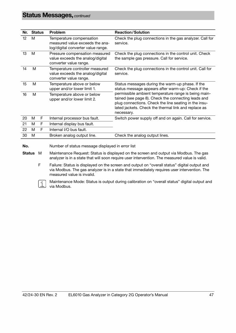
12 M Temperature compensation measured value exceeds the ana-log/digital converter value range.
Check the plug connections in the gas analyzer. Call for service.
13 M Pressure compensation measured value exceeds the analog/digital converter value range.
Check the plug connections in the control unit. Check the sample gas pressure. Call for service.
14 M Temperature controller measured value exceeds the analog/digital converter value range.
Check the plug connections in the control unit. Call for service.
15 M Temperature above or below upper and/or lower limit 1.
16 M Temperature above or below upper and/or lower limit 2.
Status messages during the warm-up phase. If the status message appears after warm-up: Check if the permissible ambient temperature range is being main-tained (see page 8). Check the connecting leads and plug connections. Check the line seating in the insu-lated jackets. Check the thermal link and replace as necessary.
20 M F Internal processor bus fault. 21 M F Internal display bus fault. 22 M F Internal I/O bus fault.
Switch power supply off and on again. Call for service.
30 M Broken analog output line. Check the analog output lines.
No. Number of status message displayed in error list
Status M Maintenance Request: Status is displayed on the screen and output via Modbus. The gas analyzer is in a state that will soon require user intervention. The measured value is valid.
F Failure: Status is displayed on the screen and output on “overall status” digital output and via Modbus. The gas analyzer is in a state that immediately requires user intervention. The measured value is invalid.
Maintenance Mode: Status is output during calibration on “overall status” digital output and via Modbus.
48 EL6010 Gas Analyzer in Category 2G Operator’s Manual 42/24-30 EN Rev. 2
Troubleshooting
Flow Fault
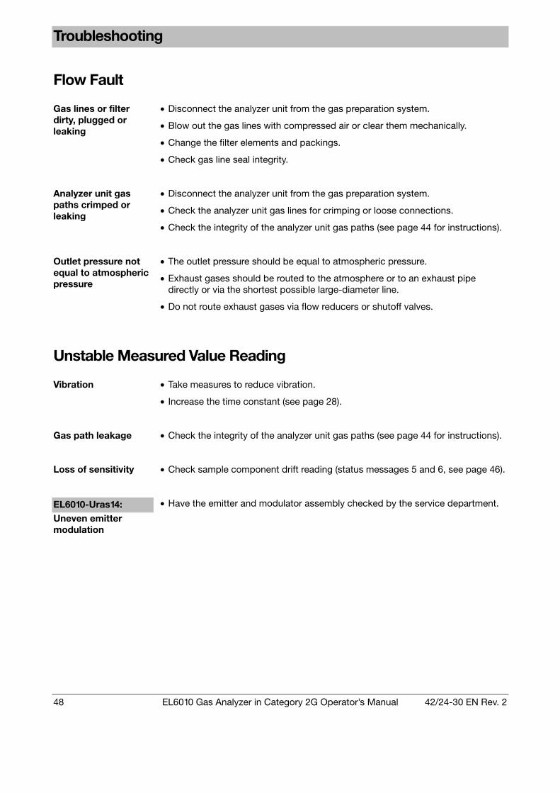
Gas lines or filter dirty, plugged or leaking
• Disconnect the analyzer unit from the gas preparation system.
• Blow out the gas lines with compressed air or clear them mechanically.
• Change the filter elements and packings.
• Check gas line seal integrity.
Analyzer unit gas paths crimped or leaking
• Disconnect the analyzer unit from the gas preparation system.
• Check the analyzer unit gas lines for crimping or loose connections.
• Check the integrity of the analyzer unit gas paths (see page 44 for instructions).
Outlet pressure not equal to atmospheric pressure
• The outlet pressure should be equal to atmospheric pressure.
• Exhaust gases should be routed to the atmosphere or to an exhaust pipe directly or via the shortest possible large-diameter line.
• Do not route exhaust gases via flow reducers or shutoff valves.
Unstable Measured Value Reading
Vibration • Take measures to reduce vibration.
• Increase the time constant (see page 28).
Gas path leakage • Check the integrity of the analyzer unit gas paths (see page 44 for instructions).
Loss of sensitivity • Check sample component drift reading (status messages 5 and 6, see page 46).
EL6010-Uras14: Uneven emitter modulation
• Have the emitter and modulator assembly checked by the service department.

42/24-30 EN Rev. 2 EL6010 Gas Analyzer in Category 2G Operator’s Manual 49
Call for Service
Who to contact for further help?
Contact your local ABB service representative or ABB Service, Telephone: +49-1 80-5-12 35 80, Telefax: +49-6 21-3 81-51 35, E-mail: [email protected]
Before you call for service ...
Before calling for service because of a problem or status message, determine whether there actually is an error and whether the gas analyzer is actually operating out of specifications.
When you call for service ...
When calling for service because of a problem or status message have the following information available: • The gas analyzer serial number (F-No.) –
Found on the identification plate and on the analyzer data sheet. • The gas analyzer Software Version –
Found in the Information menu item and on the analyzer data sheet. • An exact description of the problem or status as well as the status message
number. This information will enable service personnel to help you quickly.
When arranging for service due to a problem or status message, always have the
analyzer data sheet available as it contains valuable information that can help to identify the problem.
When returning the analyzer unit for service ...
When returning the analyzer unit to the service department, e.g. for repair, please indicate which gases have been supplied to the analyzer unit. This information is needed so that service personnel can take any safety precautions required for harmful gases.

50 EL6010 Gas Analyzer in Category 2G Operator’s Manual 42/24-30 EN Rev. 2
Chapter 9 Gas Analyzer Shutdown and Packing
Gas Analyzer Shutdown
Step Action Gas Analyzer
Shutdown Temporary Shutdown: 1 Turn off the sample gas and, if applicable, reference gas supplies. 2 Purge the gas lines and gas paths in the analyzer unit with dry fresh air
or nitrogen for at least 5 minutes. 3 Turn off the gas analyzer power supply. Additional Steps for Long-Term Shutdown: 4 Remove the gas lines from the analyzer unit ports. Tightly seal the gas
ports. 5 Disconnect the electrical wiring from the control unit connections.
Ambient Temperature Ambient temperature during storage and transport: –25 to +65 °C

42/24-30 EN Rev. 2 EL6010 Gas Analyzer in Category 2G Operator’s Manual 51
Gas Analyzer Packing
CAUTION! The EL6010-CU control unit weighs approx. 19 kg! The EL6010-... analyzer unit weighs approx. 26 kg. Two persons are needed for removal of the analyzer unit.
Step Action
1 Tightly seal the gas ports with plugs. 2 If the original packaging is not available, wrap the gas analyzer in
bubble foil or corrugated cardboard. Place the gas analyzer in an adequately sized box lined with cushion-ing material (foam or similar substance).
3
The cushioning material’s thickness should be adequate for the gas analyzer’s weight.
4 Mark the box as “Fragile Material”.
Additional Steps when Shipping Overseas
Place the gas analyzer in a 0.2-mm thick polyethylene bag, add a drying agent (such as silica gel) and seal the bag air-tight.
5
Use an amount of drying agent appropriate for the package volume and the planned shipping schedule (at least 3 months).
Packing
6 Also wrap the box in a layer of protective waterproof wrapping.
Ambient Temperature Ambient temperature during storage and transport: –25 to +65 °C
When returning the analyzer unit to the service department, e.g. for repair, please indicate which gases have been supplied to the analyzer unit. This information is needed so that service personnel can take any safety precautions required for harmful gases.

52 EL6010 Gas Analyzer in Category 2G Operator’s Manual 42/24-30 EN Rev. 2
Appendix
Application and Design
Proper Operation The gas analyzers in the EL6010 family are used for continuous quantitative
determination of individual gas components in gas mixtures. The gas analyzers are capable of measuring non-flammable and flammable gases under atmospheric conditions which can form an explosive environment (Zone 1). The mixture ratio for these gases should be well under the lower explosive limit (LEL) or well above the upper explosive limit (UEL). The start-up and shut-down conditions are exceptions to this requirement. The gas analyzers should not be used to measure corrosive gases.
Explosion Protection The gas analyzers in the EL6010 family are especially designed for use in explo-
sion risk areas. They are certified in accordance with European Directive 94/9/EC (“ATEX Directive”). The housings are pressure-tight capsules and fulfill Explosion Group IIC require-ments. For this reason the gas analyzers can even be used in hydrogen or acety-lene atmospheres. The designation is II 2G EEx de IIC T4. Measurement function per Directive 94/9/EC, Appendix II, Paragraph 1.5.5. is not covered by the EC type examination certificates.
Device Family Components
The EL6010 family includes the following analyzer units (see page 53) • EL6010-Uras14 Infrared Analyzer Unit, • EL6010-Magnos106 Oxygen Analyzer Unit and • EL6010-Caldos17 Thermal Conductivity Analyzer Unit as well as the • EL6010-CU Control Unit (see page 54).
An EL6010 gas analyzer consists of an analyzer unit and the control unit.
42/24-30 EN Rev. 2 EL6010 Gas Analyzer in Category 2G Operator’s Manual 53
Analyzer Units
EL6010-Uras14 Infrared Analyzer Unit
The EL6010-Uras14 infrared analyzer unit uses the NDIR (Non-Dispersive Infrared Absorption) technique. It measures concentrations of one or two sample compo-nents.
EL6010-Magnos106 Oxygen Analyzer Unit
The EL6010-Magnos106 oxygen analyzer unit’s measurement principle is based on the specific paramagnetic behavior of oxygen.
EL6010-Caldos17 Thermal Conductivity Analyzer Unit
The EL6010-Caldos17 thermal conductivity analyzer unit uses the different thermal conductivity of individual gases. It measures the concentration of a sample com-ponent in a binary gas mixture.
Design Each analyzer unit consists of the sensor and its associated electronics.
The analyzer unit is built according to the EN 50018 “Flame-proof Enclosure” protection type. It is contained in a pressure-tight aluminum cylinder. All gas connections are routed via flame barriers. The flame barriers and the pipe threaded connections are made of 1.4571 steel. The analyzer unit is connected to the control unit via data transmission and power supply cables. The 12- and 3-conductor cables, each 3 meters in length, are connected at the factory and are brought into the pressure-tight cylinder via pressure-tight cable openings. Housing protection type is IP 54 (O-ring seals required when mounted horizontally).
Housing Purge To protect the analyzer unit sensor electronics against the entry of an aggressive
atmosphere or corrosive sample gas components, a purge gas can flow through the pressure-tight cylinder. The purge gas enters and exits via two flame barriers which are open in the interior of the pressure-tight cylinder. In the EL6010-Magnos106 and EL6010-Caldos17 analyzer units the pressure-tight cylinder purge gas outlet is internally joined to the purge gas outlet for the thermo-stat housing. The thermostat housing purge gas inlet is open. Note: The housing purge has no significance for the purposes of EN 50016
positive pressure containment.
Calibration Essentially the gas analyzer is calibrated manually. External control of calibration
is possible via the Modbus interface. The EL6010-Uras14 infrared analyzer unit can be equipped with optional gas-filled calibration cells that extensively eliminate reliance on test gases. Because of its very low sensitivity drift, the EL6010-Magnos106 oxygen analyzer unit routinely requires only a zero calibration, if the measuring range is larger than 0 to 5 Vol.-% O2. Nitrogen or ambient air are used for this.

54 EL6010 Gas Analyzer in Category 2G Operator’s Manual 42/24-30 EN Rev. 2
Control Unit
Functions The EL6010-CU performs the following functions:
• Processing and transmitting measured values provided by the analyzer unit's sensor electronics,
• Correcting measured values, e.g. cross-sensitivity correction, • Controlling device functions, e.g. calibration, • Display and control functions, • Communicating with external systems.
Design The control unit is built according to the EN 50018 “Flame-proof Enclosure”
protection type. It is installed in a pressure-tight aluminum housing with a viewing glass. Housing protection type is IP 65.
Interfaces The control unit has
• Two analog outputs for measured values, • Three digital outputs for status signals and threshold alarm signals and • A Modbus interface (RS485 or RS232) to transfer measured values and status
signals to a host system and for controlling calibration.
Operation Four touch screen fields accessible through the control unit viewing glass allow
safe operation of the gas analyzer without opening the housing. The menu-driven control system is uniform for all three gas analyzers. The menu language is English.
Power Supply The gas analyzer requires a 85 to 250 VAC power supply. The analyzer unit is
supplied with 24 VDC by the control unit power supply.
Test per EN 60101-1:2001
Protection Class I
Overload Category Power supply: II, Signal inputs and outputs: II
Pollution Level 2
Electrical Safety
Safe Isolation The power supply is galvanically isolated from other circuits by means of reinforced or double insulation. Operational low voltage (PELV) on low-voltage side.

42/24-30 EN Rev. 2 EL6010 Gas Analyzer in Category 2G Operator’s Manual 55
EL6010-Uras14: Metrological Data
Sample Components and Smallest Measurement Ranges Sample Component
Smallest Class 1 Range
Smallest Class 2 Range
Smallest Class 2 Range with Calibration Cell
Gas Group 1)
CO 0– 100 ppm 0– 10 ppm 0– 50 ppm 2) A CO2 0– 100 ppm 0– 5 ppm 0– 25 ppm 2) A NO 0– 200 ppm 0– 150 ppm 0– 150 ppm 2) A SO2 0– 100 ppm 0– 25 ppm 0– 25 ppm 2) A N2O 0– 100 ppm 0– 20 ppm 0– 50 ppm 2) A NH3 0– 500 ppm 0– 30 ppm – B CH4 0– 100 ppm 0– 50 ppm 0– 50 ppm 2) A C2H2 0– 200 ppm 0– 100 ppm 0– 100 ppm B C2H4 0– 500 ppm 0– 300 ppm 0– 300 ppm B C2H6 0– 100 ppm 0– 50 ppm 0– 50 ppm 2) B C3H6 0– 250 ppm 0– 100 ppm 0– 100 ppm 2) B C3H8 0– 100 ppm 0– 50 ppm 0– 50 ppm 2) B C4H10 0– 100 ppm 0– 50 ppm 0– 50 ppm 2) B C6H14 0– 500 ppm 0– 100 ppm 0– 100 ppm 2) B SF6 0– 2000 ppm 0– 1900 ppm 0– 2000 ppm B H2O 0– 1000 ppm 0– 500 ppm 0– 500 ppm C
1) See price information 2) The sample component is calibrated in the factoryset
measurement range which can be increased by a factor of 5.
Other sample components on request.
Stability Linearity Deviation
≤ 1 % of span
Repeatability ≤ 0.5 % of span
Zero Drift ≤ 1 % of span per week. For ranges smaller than Class 1 to Class 2: ≤ 3 % of span per week
Sensitivity Drift ≤ 1 % of measured value per week
Output Signal Variations ≤ 0.2 % of span at 2 σ and electronic T90 time = 5 sec (Class 1)
Detection Limit ≤ 0.5 % of span
Measurement Range Data Quantity
1 range per sample component. The measurement range is freely adjustable within a range ratio of ≤ 1:5 relative to the factoryset measurement range.
Largest Measurement Range 0 to 100 Vol.% or 0 Vol.% to saturation or 0 Vol.% to LEL. Measurement ranges within ignition limits cannot be provided.
Measurement Ranges with Suppressed Zero-Point Differential measurement with flowing reference gas. Max. suppression ratio of 1:10 depending on the base level.
Influence Effects Flow Effect
Flow rate in the 20–100 l/h range: 0.5 % of span at a flow rate change of ±10 l/h
Pressure Drop at Flame Barriers Sample Gas or Reference Gas Inlet: Approx. 40 hPa at a flow rate of 50 l/h. Purge gas inlet: Approx. 20 hPa at a flow rate of 10 l/h
Associated Gas Effect /Cross Sensitivity Analyzer calibration should be based on an analysis of the sample gas. Selectivity measures to reduce associated gas effect (optional): Incorporation of interference filters, filter vessels or internal electronic crosssensitivity correction or carrier gas correction for a sample component by other sample components measured with the analyzer unit.
Temperature Effect Ambient temperature in permissible range – At zeropoint: ≤ 1 % of span per 10 °C;
for ranges smaller than Class 1 to Class 2: ≤ 2 % of span per 10 °C
– On sensitivity with temperature compensation: ≤ 3 % of measured value per 10 °C
– On sensitivity with thermostat effect at 55 °C (optional): ≤ 1 % of measured value per 10 °C
Air Pressure Effect On sensitivity with pressure correction by means of integral pressure sensor: ≤ 0.2 % of measured value per 1 % barometric pressure change. Pressure sensor working range: pabs = 600–1250 hPa
Dynamic Response Warm-Up Time
Approx. 30 minutes without thermostat; approx. 2 hours with thermostat.
T90 Time T90 = 2.5 sec for measurement cell length = 200 mm and sample gas flow = 60 l/h without signal damping (low pass filter).
Materials in Contact with the Sample Medium Analyzer (Sample Cells)
Tubing: Aluminum or goldplated aluminum; Window: CaF2 (Option: BaF2); Connectors: Rust and acidresistant steel 1.4571
Gas Lines and Connectors Rust and acidresistant steel 1.4571
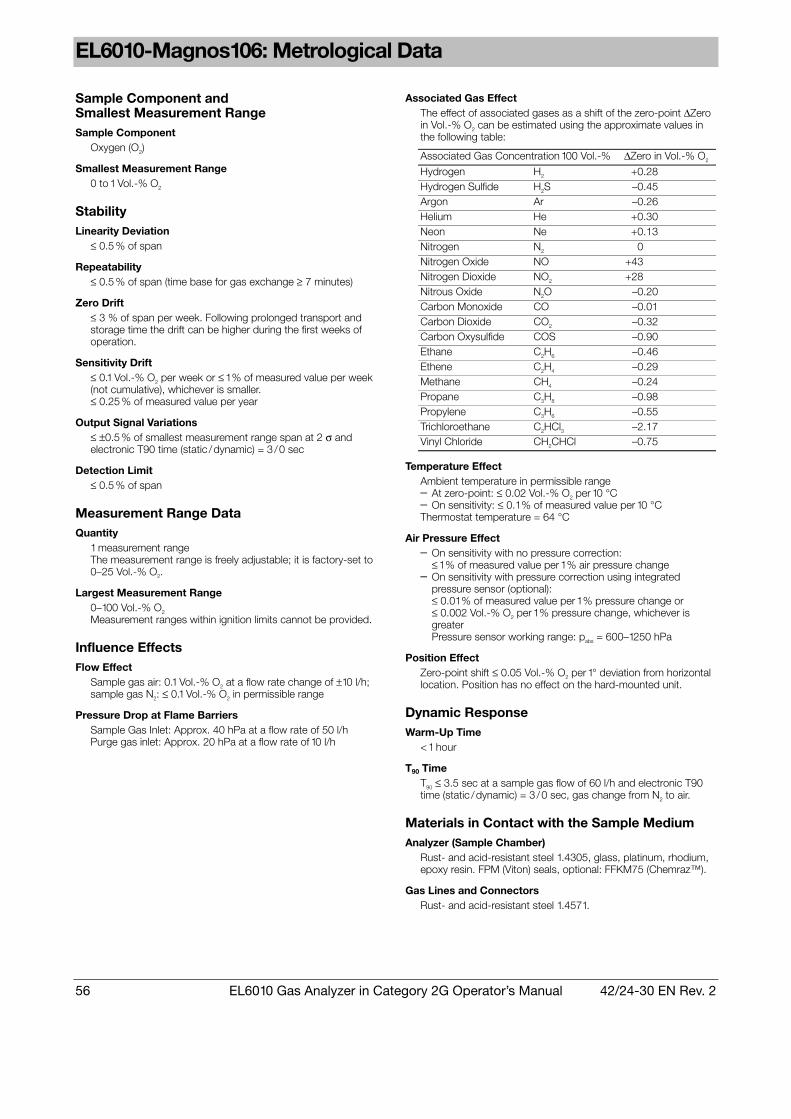
56 EL6010 Gas Analyzer in Category 2G Operator’s Manual 42/24-30 EN Rev. 2
EL6010-Magnos106: Metrological Data
Sample Component and Smallest Measurement Range Sample Component
Oxygen (O2)
Smallest Measurement Range 0 to 1 Vol.% O2
Stability Linearity Deviation
≤ 0.5 % of span
Repeatability ≤ 0.5 % of span (time base for gas exchange ≥ 7 minutes)
Zero Drift ≤ 3 % of span per week. Following prolonged transport and storage time the drift can be higher during the first weeks of operation.
Sensitivity Drift ≤ 0.1 Vol.% O2 per week or ≤ 1 % of measured value per week (not cumulative), whichever is smaller. ≤ 0.25 % of measured value per year
Output Signal Variations ≤ ±0.5 % of smallest measurement range span at 2 σ and electronic T90 time (static /dynamic) = 3 /0 sec
Detection Limit ≤ 0.5 % of span
Measurement Range Data Quantity
1 measurement range The measurement range is freely adjustable; it is factoryset to 0–25 Vol.% O2.
Largest Measurement Range 0–100 Vol.% O2 Measurement ranges within ignition limits cannot be provided.
Influence Effects Flow Effect
Sample gas air: 0.1 Vol.% O2 at a flow rate change of ±10 l/h; sample gas N2: ≤ 0.1 Vol.% O2 in permissible range
Pressure Drop at Flame Barriers Sample Gas Inlet: Approx. 40 hPa at a flow rate of 50 l/h Purge gas inlet: Approx. 20 hPa at a flow rate of 10 l/h
Associated Gas Effect The effect of associated gases as a shift of the zeropoint ∆Zero in Vol.% O2 can be estimated using the approximate values in the following table:
Associated Gas Concentration 100 Vol.% ∆Zero in Vol.% O2
Hydrogen H2 +0.28 Hydrogen Sulfide H2S –0.45 Argon Ar –0.26 Helium He +0.30 Neon Ne +0.13 Nitrogen N2 0.00 Nitrogen Oxide NO +43.00 Nitrogen Dioxide NO2 +28.00 Nitrous Oxide N2O –0.20 Carbon Monoxide CO –0.01 Carbon Dioxide CO2 –0.32 Carbon Oxysulfide COS –0.90 Ethane C2H6 –0.46 Ethene C2H4 –0.29 Methane CH4 –0.24 Propane C3H8 –0.98 Propylene C3H6 –0.55 Trichloroethane C2HCl3 –2.17 Vinyl Chloride CH2CHCl –0.75
Temperature Effect Ambient temperature in permissible range – At zeropoint: ≤ 0.02 Vol.% O2 per 10 °C – On sensitivity: ≤ 0.1 % of measured value per 10 °C Thermostat temperature = 64 °C
Air Pressure Effect – On sensitivity with no pressure correction:
≤ 1 % of measured value per 1 % air pressure change – On sensitivity with pressure correction using integrated
pressure sensor (optional): ≤ 0.01 % of measured value per 1 % pressure change or ≤ 0.002 Vol.% O2 per 1 % pressure change, whichever is greater Pressure sensor working range: pabs = 600–1250 hPa
Position Effect Zeropoint shift ≤ 0.05 Vol.% O2 per 1° deviation from horizontal location. Position has no effect on the hardmounted unit.
Dynamic Response Warm-Up Time
< 1 hour
T90 Time T90 ≤ 3.5 sec at a sample gas flow of 60 l/h and electronic T90 time (static /dynamic) = 3 /0 sec, gas change from N2 to air.
Materials in Contact with the Sample Medium Analyzer (Sample Chamber)
Rust and acidresistant steel 1.4305, glass, platinum, rhodium, epoxy resin. FPM (Viton) seals, optional: FFKM75 (Chemraz™).
Gas Lines and Connectors Rust and acidresistant steel 1.4571.

42/24-30 EN Rev. 2 EL6010 Gas Analyzer in Category 2G Operator’s Manual 57
EL6010-Caldos17: Metrological Data
Sample Components and Smallest Measurement Ranges Sample Component and Associated Gas
Smallest Measurement Range
Smallest Range with Suppressed Zero Point
N2 in Ar 0– 6 Vol.% 94–100 Vol.% Ar in N2 0– 6 Vol.% 94–100 Vol.% Air in CO2 0– 10 Vol.% 90–100 Vol.% CO2 in air 0– 10 Vol.% 90–100 Vol.% N2 in CO2 0– 10 Vol.% 90–100 Vol.% CO2 in N2 0– 10 Vol.% 90–100 Vol.% N2 in CH4 0– 6 Vol.% 94–100 Vol.% CH4 in N2 0– 6 Vol.% 94–100 Vol.% Air in He 0– 3 Vol.% 99–100 Vol.% He in air 0– 1 Vol.% 97–100 Vol.% Ar in He 0– 3 Vol.% 99–100 Vol.% He in Ar 0– 1 Vol.% 97–100 Vol.% N2 in He 0– 3 Vol.% 99–100 Vol.% He in N2 0– 1 Vol.% 97–100 Vol.% Ar in H2 0– 3 Vol.% 99–100 Vol.% H2 in Ar 0– 1 Vol.% 97–100 Vol.% CO2 in H2 0– 3 Vol.% 99–100 Vol.% H2 in CO2 0– 1 Vol.% 97–100 Vol.% CH4 in H2 0– 3 Vol.% 99–100 Vol.% H2 in CH4 0– 1 Vol.% 97–100 Vol.% N2 in H2 0– 3 Vol.% 99–100 Vol.% H2 in N2 0– 1 Vol.% 97–100 Vol.% O2 in Ar 0– 10 Vol.% – H2 in air 0– 4 Vol.% – Air in H2 0– 20 Vol.% –
1) Observe the gas inlet conditions (see page 9)
Stability The following data apply only if all influence factors (e.g. flow rate, temperature, atmospheric pressure) are constant. They relate to smallest measurement ranges given in the table. The deviations may be larger for smaller measurement ranges.
Linearity Deviation ≤ 2 % of span
Repeatability ≤ 1 % of span
Zero Drift ≤ 2 % of smallest given measurement range per week
Sensitivity Drift ≤ 0.5 % of smallest given measurement range per week
Output Signal Variations ≤ 0.5 % of smallest measurement range span at 2 σ and electronic T90 time = 0 sec
Detection Limit ≤ 0.5 % of span
Measurement Range Data Quantity
1 measurement range The measurement range is freely adjustable. It is factoryset to relative thermal conductivity (rTC) = 0–60,000.
Largest Measurement Range 0 to 100 Vol.% or 0 Vol.% to saturation, depending on measurement task. Measurement ranges within ignition limits cannot be provided.
Measurement Range with Suppressed Zero Point See “Sample Components and Smallest Measurement Ranges” table
Influence Effects The following data relate to smallest measurement ranges given in the table. The influence effects may be larger for smaller measurement ranges. The influence effects will be larger at operating altitudes > 2000 meters.
Flow Effect ≤ 0.5 % of span at a flow change of ±10 l/h, within detection limit for equal flow rates of sample and test gas.
Pressure Drop at Flame Barriers Sample Gas Inlet: Approx. 40 hPa at a flow rate of 50 l/h Purge gas inlet: Approx. 20 hPa at a flow rate of 10 l/h
Associated Gas Effect If the sample gas contains components in addition to the sample component (binary gas mixture), this will result in erroneous measurements.
Temperature Effect Ambient temperature in the range +5 to +50 °C: At each point in the measurement range: ≤ 0.5 % of span per 10 °C, based on temperature at the time of calibration. Thermostat temperature = 60 °C
Air Pressure Effect ≤ 0.25 % of span per 10 hPa for the smallest possible ranges given; for larger spans the effect is correspondingly lower. Pressure sensor working range: pabs = 600–1250 hPa
Position Effect < 1 % of span up to 30° deviation from horizontal orientation
Dynamic Response Warm-Up Time
Approx. 30 minutes
T90 Time T90 ≤ 2 sec for sample gas flow of 60 l/h
Materials in Contact with the Sample Medium Analyzer (Sample Chamber)
Sensor: Gold, silicon oxinitride; Sample chamber: Stainless steel 1.4305 Seal: FFKM75 (Chemraz™)
Gas Lines and Connectors Rust and acidresistant steel 1.4571

58 EL6010 Gas Analyzer in Category 2G Operator’s Manual 42/24-30 EN Rev. 2
Declaration of Conformity
Continued on next page

42/24-30 EN Rev. 2 EL6010 Gas Analyzer in Category 2G Operator’s Manual 59
Declaration of Conformity, continued
Continued on next page

60 EL6010 Gas Analyzer in Category 2G Operator’s Manual 42/24-30 EN Rev. 2
Declaration of Conformity, continued
Continued on next page

42/24-30 EN Rev. 2 EL6010 Gas Analyzer in Category 2G Operator’s Manual 61
Declaration of Conformity, continued
Continued on next page

62 EL6010 Gas Analyzer in Category 2G Operator’s Manual 42/24-30 EN Rev. 2
Declaration of Conformity, continued

42/24-30 EN Rev. 2 EL6010 Gas Analyzer in Category 2G Operator’s Manual 63
Control Unit EC Type Examination Certificate
Continued on next page
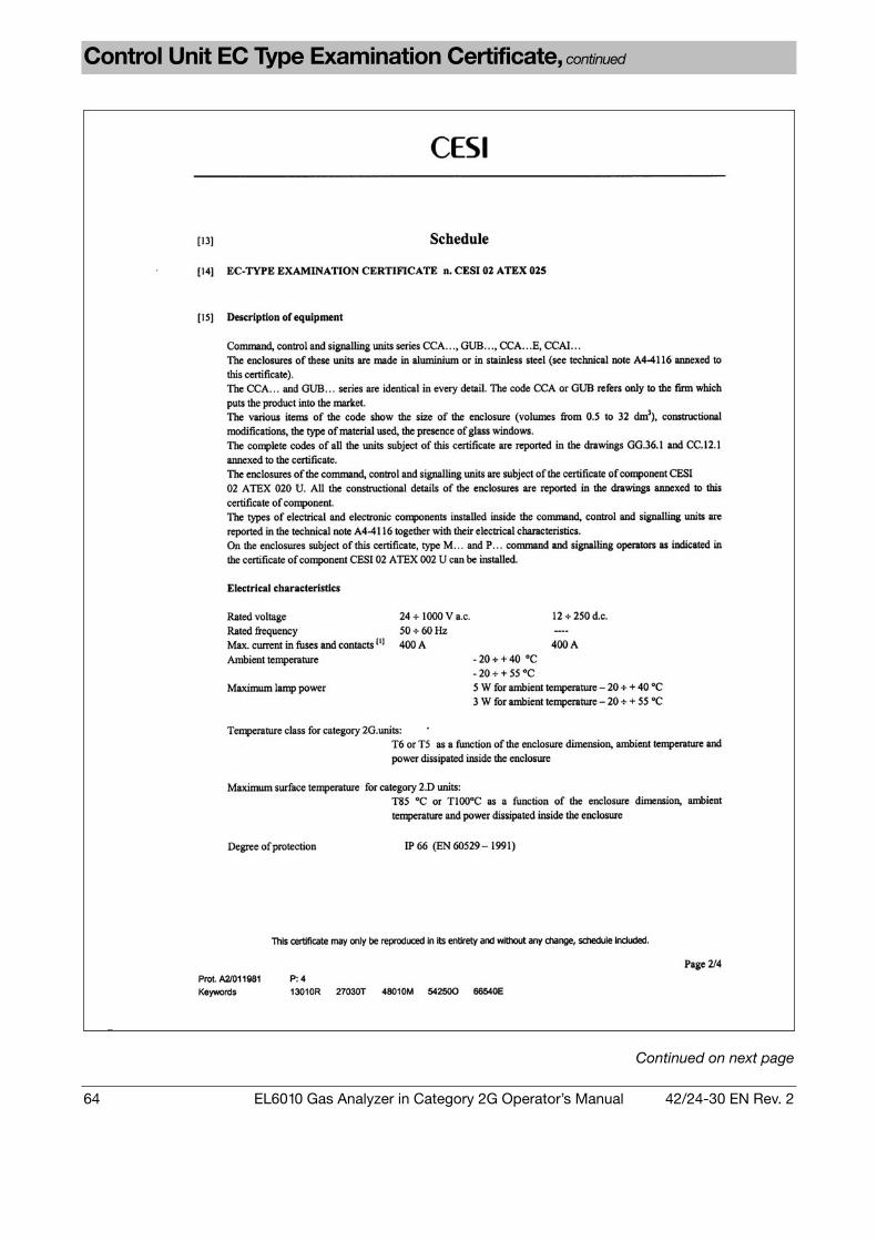
64 EL6010 Gas Analyzer in Category 2G Operator’s Manual 42/24-30 EN Rev. 2
Control Unit EC Type Examination Certificate, continued
Continued on next page

42/24-30 EN Rev. 2 EL6010 Gas Analyzer in Category 2G Operator’s Manual 65
Control Unit EC Type Examination Certificate, continued
Continued on next page

66 EL6010 Gas Analyzer in Category 2G Operator’s Manual 42/24-30 EN Rev. 2
Control Unit EC Type Examination Certificate, continued

42/24-30 EN Rev. 2 EL6010 Gas Analyzer in Category 2G Operator’s Manual 67
Junction Box EC Type Examination Certificate
Continued on next page

68 EL6010 Gas Analyzer in Category 2G Operator’s Manual 42/24-30 EN Rev. 2
Junction Box EC Type Examination Certificate, continued
Continued on next page

42/24-30 EN Rev. 2 EL6010 Gas Analyzer in Category 2G Operator’s Manual 69
Junction Box EC Type Examination Certificate, continued

70 EL6010 Gas Analyzer in Category 2G Operator’s Manual 42/24-30 EN Rev. 2
Analyzer Unit EC Type Examination Certificate
Continued on next page

42/24-30 EN Rev. 2 EL6010 Gas Analyzer in Category 2G Operator’s Manual 71
Analyzer Unit EC Type Examination Certificate, continued
Continued on next page

72 EL6010 Gas Analyzer in Category 2G Operator’s Manual 42/24-30 EN Rev. 2
Analyzer Unit EC Type Examination Certificate, continued
Continued on next page
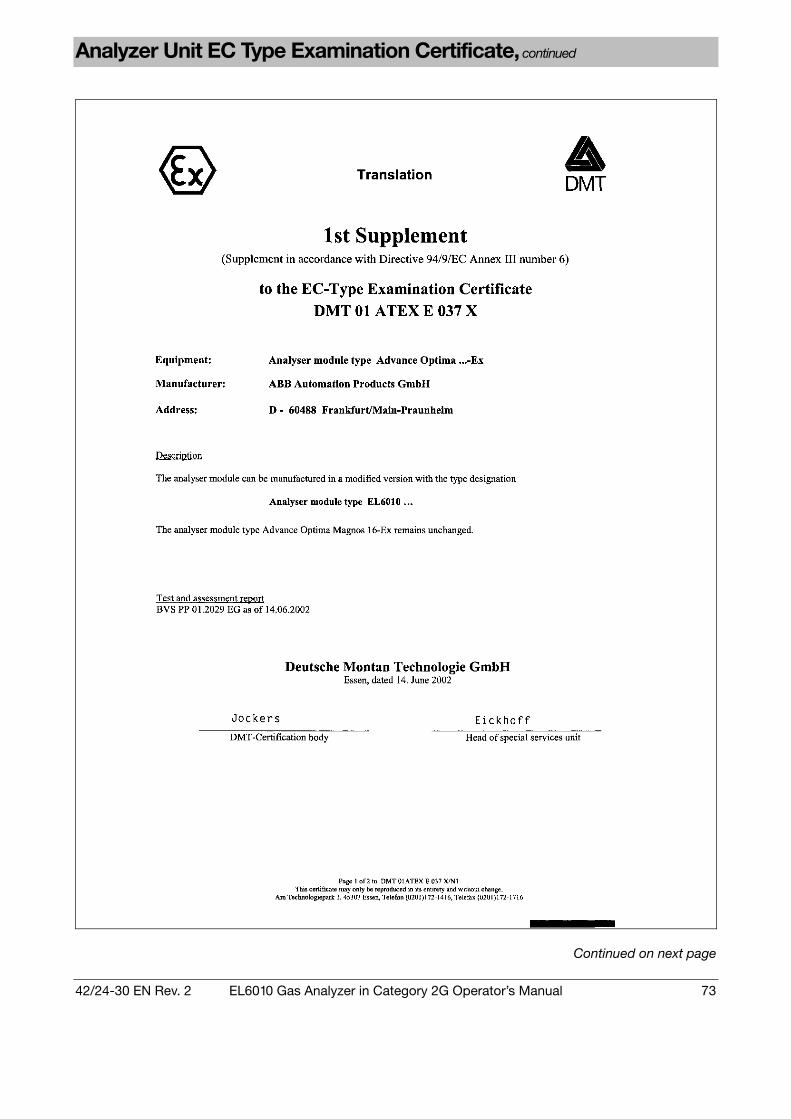
42/24-30 EN Rev. 2 EL6010 Gas Analyzer in Category 2G Operator’s Manual 73
Analyzer Unit EC Type Examination Certificate, continued
Continued on next page

74 EL6010 Gas Analyzer in Category 2G Operator’s Manual 42/24-30 EN Rev. 2
Analyzer Unit EC Type Examination Certificate, continued

42/24-30 EN Rev. 2 EL6010 Gas Analyzer in Category 2G Operator’s Manual 75
Electrical Equipment in Explosion Hazard Zones: Legal Principles
ElexV Set-up, installation and operation of the explosion-protection versions of the
EL6010 gas analyzer in the Federal Republic of Germany is covered by the 13 December 1996 “Regulations on Electrical Equipment in Explosion Hazard Zones” (ElexV).
Classification of Explosion Hazard Zones
Areas in which combustible gases, vapors or fogs pose a risk of explosion are classified as zones. Zones are distinguished by their respective probability of containing explosive atmospheres: Zone 0 Covers areas in which explosive atmospheres occur continuously or on a
long-term basis. Zone 1 Covers areas in which explosive atmospheres may occasionally be
present. Zone 2 Covers areas in which explosive atmospheres are infrequently present or
occur only for short periods of time.
Operation of Electrical Equipment in Category 2G in Zone 1
Only electrical equipment in category 2G with an EC type certification may be used in Zone 1 explosion hazard areas.
Operation of Electrical Equipment in Category 3G in Zone 2
Electrical equipment in category 3G used in Zone 2 explosion hazard areas must have • An EC type examination certificate or • A manufacturer’s certificate of suitability for use in Zone 2
Manufacturer’s Certification
By affixing a label the manufacturer confirms that unit testing was successfully completed and that the product is in accordance with the documentation submitted to the testing office.

76 EL6010 Gas Analyzer in Category 2G Operator’s Manual 42/24-30 EN Rev. 2
Electrical Equipment in Explosion Hazard Zones: Installation Instructions
Installation per EN 60079-14 (VDE 0165 Part 1)
The electrical device shall be installed according to EN 60079-14 (VDE 0165 Part 1) “Electrical Equipment in Gas Explosion Hazard Areas, Part 14: Electrical Equipment in Explosion Hazard Areas”.
Potential Compensation
The requirements of EN 60079-14 and DIN VDE 0100 Part 410 “Protection Against Electrical Shock” and Part 540 “Grounding, Protective Leads and Potential Compensation Leads” shall be observed.
Electrostatic Charges Avoid electrostatic discharges. Observe the “Guidelines for Avoiding Ignition Risks
Due to Electrostatic Discharges” published by the Executive Committee for the Industrial Professional/Trade Associations.
Testing Prior to Initial Use
The operator is required to have the electrical system tested for proper operation by a qualified electrician prior to using the unit for the first time. If the manufacturer or installer certifies that the electrical system meets ElexV requirements, no inspection prior to initial use is required.

42/24-30 EN Rev. 2 EL6010 Gas Analyzer in Category 2G Operator’s Manual 77
Electrical Equipment in Explosion Hazard Zones: Maintenance and Repair Instructions
Monitoring and Inspection
The condition of electrical systems in explosion risk areas must be monitored. As necessary, and at least ever three years the system shall be inspected by a quali-fied electrician if it is not under continuous monitoring by a responsible engineer.
Work on Electrical Systems
The power supply must be disconnected before performing any work on electrical systems in explosion risk areas. The breaker is to be fitted with an appropriate label, e.g. “Do Not Turn On – Risk of Explosion”. This does not apply to devices that are opened during operation, e.g. cleaning apparatus, or to devices which have been expressly type certified for such operation.
Work on Intrinsically Safe Circuits
Work may be performed on intrinsically safe circuits in explosion risk areas even while power is connected. However, the electrical characteristics (inductance, capacitance, current and voltage) of test equipment should be noted when such equipment is activated. Special attention is required if work is carried out on intrinsically safe circuits set up in conjunction with Zone 0 areas.
Explosion Risk The explosion risk should be eliminated prior to carrying out any repair work.
Personnel Qualifications
Repair work should only be performed by qualified personnel.
Original Parts Only original parts should be used for repairs.
Testing Prior to Returning to Service
If repairs are made on components in an electrical device necessary for explosion protection, prior to any return to service a qualified person shall inspect this device and certify that its explosion protection features are in compliance with the type and design requirements as stated in the device's certification documentation.
Manufacturer’s Repairs
Repairs can also be carried out by the manufacturer, e.g. on site by an ABB Service employee or at the manufacturer’s facility. In this case the repair carried out and the subsequent inspection will be shown on the device identification plate. An inspection by an expert is not required in such a case.
78 EL6010 Gas Analyzer in Category 2G Operator’s Manual 42/24-30 EN Rev. 2
Index
Page
Address (Modbus) 33 Analyzer Data Sheet 10 Application and Design 52
Analyzer Units 53 Control Unit 54
Baudrate (Modbus) 33
Calibration 35, 53 Calibrate Sample Component 37 Calibration Cell Measuring (EL6010-Uras14) 40 Calibration Reset 39 Drift Reading 42 Set Points 28 Test Gases 35 via Modbus 37
Connection 24-VDC Connection Cable 18 Data Transmission Cable 18 Power Supply 20
Declaration of Conformity 58 Dimensional Diagram
Analyzer Unit 12 Control Unit 11
Display 21 Drift 42
EC Type Examination Certificate Analyzer Unit 70 Control Unit 63 Junction Box 67
EL6010-Caldos17 Active Sample Component 31 Measurement Ranges with Suppressed Zero-Point 36 Measuring Range 31 Metrological Data 57 Reference Measuring Range 31 Test Gases 36
EL6010-Magnos106 Measuring Range 30 Metrological Data 56 Pressure Sensor 41 Reference Measuring Range 30 Test Gases 36
EL6010-Uras14 Calibration Cell 35 Measure Calibration Cell 40 Measuring Range 29 Metrological Data 55 Reference Measuring Range 29 Test Gases 35
Electrical Connections 17 Error List 45 Explosion Protection 52, 75, 76, 77
Filter (T90 Time) 28
Gas Connection 15 Gas Inlet Conditions 9 Gas Path Seal Integrity Verification
Maintenance 43 Prior to Start-up 13
Page
Housing Purge 15, 53
Inspection 43 Installation 14 Installation Location 8 Interface Type (Modbus) 33 Items Delivered 10
Limit 32 Low Pass 28
Measuring Range EL6010-Caldos17 31 EL6010-Magnos106 30 EL6010-Uras14 29
Menu 23 Modbus
Calibration 37 Parameters 33
Operation Display 21 Keys 22 Menu 23
Packing 51 Parameters Setting 27 Potential Compensation 16, 76 Pressure Correction 41 Pressure Sensor 15
Calibration 41 Proper Operation 52 Purge
Gas Path Purge 26 Housing Purge 15
Safety Instructions 6, 7 Screen 21
Blinking 21, 45 Service 49 Set Points (Calibration) 28 Shutdown 50 Start-up 24 Status Messages 46 Switching Hysteresis (Limit) 32
T90 Time 28 Technical Data
Dimensional Diagrams 11, 12 EL6010-Caldos17 57 EL6010-Magnos106 56 EL6010-Uras14 55 Electrical Connections 17 Environmental Conditions 8 Gas Connection 15 Gas Inlet Conditions 9 Power Consumption 20
Test Gas Concentration 28 Test Gases 35 Time-out 22 Troubleshooting 48
Unpack 13 User Settings 34


The IndustrialIT word mark and all mentioned product names in the form XXXXXIT are registered or pending trademarks of ABB. ABB has Sales & Customer Support expertise in over 100 countries worldwide. www.abb.com
The Company’s policy is one of continuous product improvement and the right is reserved to modify the information contained herein without notice.
Printed in the Fed. Rep. of Germany (04.05)
© ABB 2005
42/2
430
EN
Rev
. 2
ABB Automation GmbH Analytical Division Stierstaedter Strasse 5 60488 Frankfurt am Main Germany Phone: +49 69 793040 Fax: +49 69 79304566 EMail: [email protected]