continue to the next page · general requirements section 1 1-1 1.00 general statement the las...
TRANSCRIPT

3rd Edition - 2010
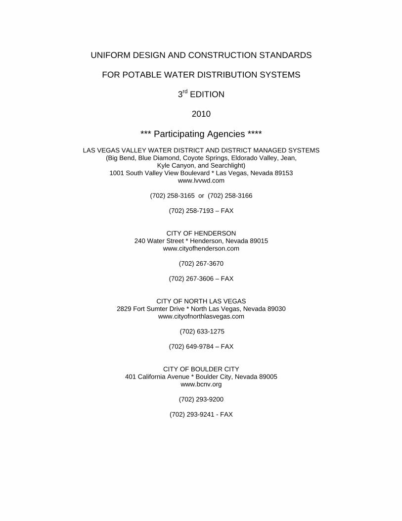
UNIFORM DESIGN AND CONSTRUCTION STANDARDS
FOR POTABLE WATER DISTRIBUTION SYSTEMS
3rd EDITION
2010
*** Participating Agencies ****
LAS VEGAS VALLEY WATER DISTRICT AND DISTRICT MANAGED SYSTEMS (Big Bend, Blue Diamond, Coyote Springs, Eldorado Valley, Jean,
Kyle Canyon, and Searchlight) 1001 South Valley View Boulevard * Las Vegas, Nevada 89153
www.lvvwd.com
(702) 258-3165 or (702) 258-3166
(702) 258-7193 – FAX
CITY OF HENDERSON 240 Water Street * Henderson, Nevada 89015
www.cityofhenderson.com
(702) 267-3670
(702) 267-3606 – FAX
CITY OF NORTH LAS VEGAS 2829 Fort Sumter Drive * North Las Vegas, Nevada 89030
www.cityofnorthlasvegas.com
(702) 633-1275
(702) 649-9784 – FAX
CITY OF BOULDER CITY 401 California Avenue * Boulder City, Nevada 89005
www.bcnv.org
(702) 293-9200
(702) 293-9241 - FAX

CONTINUE TO THE NEXT PAGE

FOREWORD The Uniform Design and Construction Standards for Potable Water Distribution Systems, 3rd Edition supersedes the 2nd edition (2003). Special provisions and drawings will be provided, when necessary, to supplement or modify these Design and Construction Standards. Agency specific request may be included as an addendum to this standard. The Uniform Design and Construction Standards for Potable Water Distribution Systems may be revised by issuance of a supplement to correct errors and omissions found in these Standards and to reflect advanced thinking and changing construction industry technology. Each supplement will supersede any previous supplement by inclusion of all pertinent portions. To implement this end, a Specifications Committee, including a representative from each participating Agency, has been organized to continually study and recommend changes to these Standards. Interested parties may address suggested changes and questions to the Committee for Design and Construction Standards for Water Distribution Systems, c/o any participating Agency listed at the beginning of the publication. The following participating agencies of Clark County, Nevada area have adopted these specifications by Resolution of their staff and/or governing bodies as follows: LAS VEGAS VALLEY WATER DISTRICT (And District Managed Systems) Adopted by Deputy General Manager, Engineering/ Operations . . . . . . Pending at Publication Date CITY OF HENDERSON Adopted by Resolution . . . . . . . . . . . . . . . . . . . . . . . . . . . . . . . . . . . . .Pending at Publication Date CITY OF NORTH LAS VEGAS Adopted by Director of Utilities. . . . . . . . . . . . . . . . . . . . . . . . . . . . . . . .Pending at Publication Date CITY OF BOULDER CITY Adopted by Resolution . . . . . . . . . . . . . . . . . . . . . . . . . . . . . . . . . . . . . Pending at Publication Date

CONTINUE TO THE NEXT PAGE
TABLE OF CONTENTS SECTION
ITEM
1
GENERAL REQUIREMENTS
2
UNIFORM DESIGN STANDARDS
3
CONSTRUCTION STANDARDS
4
TABLES AND REFERENCES
5
STANDARD PLATES
6
AGENCY ADDENDA

CONTINUE TO THE NEXT PAGE
UNIFORM DESIGN AND CONSTRUCTION STANDARDS
FOR POTABLE WATER DISTRIBUTION SYSTEMS
SECTION 1
GENERAL REQUIREMENTS

CONTINUE TO THE NEXT PAGE
UNIFORM DESIGN STANDARDS
SECTION 1
INDEX
ITEM
DESCRIPTION
PAGE
1.00
GENERAL STATEMENT
1-1
1.01
DEFINITIONS
1-2
1.02
ABBREVIATIONS
1-27
1.03
REFERENCE TO STANDARDS AND PUBLICATIONS
1-28
1.04
LINES, GRADES AND MEASUREMENTS
1-28
1.05
RIGHT-OF-WAY
1-28
1.06
OVERTIME INSPECTION FEE
1-28
1.07
NIGHT WORK
1-28
1.08
INSPECTION
1-28
1.09
INDEMNITY
1-29
1.10
GUARANTEE
1-30
1.11
RULES AND REGULATIONS
1-30
1.12
PRE-APPROVED MATERIALS LIST
1-30

CONTINUE TO THE NEXT PAGE

GENERAL REQUIREMENTS SECTION 1
1-1
1.00 GENERAL STATEMENT
The Las Vegas Valley Water District, and the Cities of Henderson, North Las Vegas, and Boulder City are governmental subdivisions of the State of Nevada which provide municipal water service. The Uniform Design and Construction Standards For Potable Water Distribution Systems presented herein has been adopted by the participating Agency's governing body and represent the minimum design and construction criteria for water distribution systems within the participating Agency's jurisdiction. The Contractor will be required to have a copy of these Standards on-site at all times during construction.
Except as expressly set forth in these Standards or otherwise directed by the Agency, the Developer or Contractor shall select the means, methods, and sequences for constructing facilities in accordance with these Standards. The participating Agency is not concerned with the means, methods, or sequences, only the results. The Developer, Engineer or Contractor may petition each Agency for a variance to these Standards on a case by case basis.
Except as expressly set forth in a written agreement approved by the governing body for the participating Agency, the Developer or the Contractor shall pay all costs of constructing facilities in accordance with these Standards. Except as expressly set forth in a written agreement approved by the participating Agency's governing body, the participating Agency assumes no liability for, and does not agree to pay any costs of constructing facilities. No statements, actions, or omissions of any participating Agency officer or employee may be construed as an assumption of liability for, or an agreement to pay any costs of constructing facilities. The participating Agency's governing body has not delegated any respective Agency officer or employee nor any other person any authority to assume liability for or agree to pay costs of constructing facilities.
Where there is a conflict between the Agency rules, regulations, or ordinances and these Uniform Design Standards, the Agency rules, regulations, or ordinances shall supersede these Standards.
GENERAL REQUIREMENTS SECTION 1
1-2
1.01 DEFINITIONS
1.01.01 Accessible When applied to an assembly or equipment, “accessible” means having
access thereto, but which first may require the removal of an obstruction. “Readily accessible” means direct access without the necessity of removing any obstruction to gain access.
1.01.02 Agency
The Las Vegas Valley Water District (And District Managed Systems), located at: 1001 South Valley View Boulevard Las Vegas, Nevada 89153; (702) 258-3165 or 258-3166. The City of Henderson, located at: 240 Water Street Henderson, Nevada 89015; (702) 267-3670. The City of North Las Vegas, located at: 2829 Fort Sumter Drive North Las Vegas, Nevada 89030; (702) 633-1275. The City of Boulder City, located at: 401 California Avenue Boulder City, Nevada 89005; (702) 293- 9200.
1.01.03 Agency's Representative The individual duly authorized by the Agency to act as the agent for an Agency or a jurisdiction.
1.01.04 Air Binding
A condition in which air accumulates in the higher points of a distribution main thus restricting the flow of water in the main.
1.01.05 Air-Gap A physical separation between the free flowing discharge end of a potable water supply pipeline and an open or non-pressurized receiving vessel. An "approved air-gap separation" shall be at least double the supply pipe diameter measured vertically above the vessel's overflow rim and in no case less than one (1) inch (2.54 cm).
GENERAL REQUIREMENTS SECTION 1
1-3
1.01.06 Air-Relief Releasing of entrapped air during filling or releasing entrained air which will accumulate and cause flow resistance with subsequent downstream pressure loss and even complete flow blockage.
1.01.07 Air Vacuum Air Relief Valve (AVAR) An air valve placed at the summit of a pipeline (1) to release air automatically and prevent air binding and pressure buildup or (2) to allow air to enter a line if the internal pressure becomes less than that of the atmosphere.
1.01.08 Alternate Fire Service Meter (See “Fire Service Meter Type II”.)
1.01.09 Altitude Control Valve
A valve that automatically:
A. Shuts off the flow of water when the water level in a storage
structure reaches a predetermined elevation; and
B. Opens when the water level in the storage structure lowers to a predetermined elevation.
1.01.10 Angle Meter Stop
(See “Meter Stop”.)
1.01.11 Appurtenances
Any machinery, appliances, structures and other parts of the main structure that will enable the main structure to function but is not considered part of the main structure.
1.01.12 Assessor’s Parcel Number
A number found in real property records. This number is assigned by Clark County to identify and track a particular parcel of land.
1.01.13 Aquifer
A geologic formation, group of geologic formations, or part of a geologic formation that is capable of yielding ground water to a well or spring.

GENERAL REQUIREMENTS SECTION 1
1-4
1.01.14 Atmospheric Vacuum Breaker A device consisting of a float check, a check seat, an air inlet port, and possibly a shutoff valve immediately upstream, designed to allow air to enter the downstream water line to prevent backsiphonage.
1.01.15 Auxiliary Water Supply
A supply of water or system for the supply of water which is available to the premises of a customer of a public water system, other than the supply or system of the public water system established to provide water to the premises, including another public water system or any natural source of water.
1.01.16 Average Day Demand
The average daily demand for water over a one (1) year period, as determined by historical data.
1.01.17 Backfill
The material used to refill an excavation.
1.01.18 Backflow
A hydraulic condition, caused by a difference in pressures, that causes non-potable water or other fluid to flow into a potable water system. (See “Backpressure” and “Backsiphonage”.)
1.01.19 Backflow Preventer The physical appurtenance or assembly designed to prevent backflow.
1.01.20 Backflow Prevention Assembly - Approved
An assembly or means that has been investigated and approved by the Agency having jurisdiction. Approval shall be based on favorable laboratory and field evaluation by an approved backflow testing laboratory.
1.01.21 Backflow Testing Laboratory The Foundation for Cross-Connection Control and Hydraulic Research of the University of Southern California; or any other person or entity who the Nevada Division of Environmental Protection authority determines:
GENERAL REQUIREMENTS SECTION 1
1-5
A. Is competent and possesses the necessary facilities to investigate and evaluate backflow prevention assemblies; and
B. Adheres to the testing and certification procedures set forth in the
American Water Works Association Standards; and C. Is independent of any backflow prevention assembly
manufacturer; and D. Performs one (1) year field evaluation in addition to laboratory
testing.
1.01.22 Backpressure A pressure that can cause water to backflow into the water supply when a user’s water system is at a higher pressure than the public water system.
A. Is caused by pumping, air pressure, steam, or the elevation of
piping; and B. Could cause a reversal in the normal direction of flow at a
particular point.
1.01.23 Backsiphonage A form of backflow due to a reduction in system pressure which causes a negative or sub-atmospheric pressure to exist at a point in the Agency's water system allowing water from the customer's system to enter the Agency's supply system.
1.01.24 Ball Valve
A valve with the closing and opening mechanism formed in the shape of a ball with a hole. The valve is opened by rotating to the flow, allowing it to pass. The valve is closed when the hole is perpendicular to the flow.
1.01.25 Bell-shaped
Having an expanding rounded entrance.
1.01.26 Blow-Off Assembly
An assembly which consists of a valve that is installed at a low point, or at the end of a pipeline, and is used primarily for purging or blowing-off accumulated sediment from low spots or dead-ends in the main and for de-watering lines or reservoirs for repairs or inspections.
GENERAL REQUIREMENTS SECTION 1
1-6
1.01.27 Butterfly Valve A valve in which a disk rotates on a shaft such that the valve is fully open when the disk is parallel to the axis of the pipe and fully closed when perpendicular.
1.01.28 Bypass Valve
A small valve attached to a much larger valve to (equalize) pressure against the main valve seat when opening or closing the main valve.
1.01.29 Casing
A. Conduit made of steel or other accepted materials used as a conduit for a pipe or main, installed through boring or open cut (See “Pipe Casing”.); or
B. A solid piece of pipe used to hold the formation open during the
construction or use of a well; or
C. The enclosure surrounding an impeller, into which the suction and discharge ports are machined.
1.01.30 Cement Grout
A mixture of portland cement, sand, and water which contains at least seven (7) sacks of cement per cubic yard and not more than seven (7) gallons of clean water for each sack of cement.
1.01.31 Cement Slurry
(See “CLSM - Controlled Low Strength Material”.)
1.01.32 Certified Backflow Prevention Assembly Tester
A person who is certified by the California/Nevada section of the American Water Works Association to test assemblies designed for the prevention of backflow.
1.01.33 Check Valves
A valve that allows flow in one direction and that closes when the flow tries to reverse.

GENERAL REQUIREMENTS SECTION 1
1-7
1.01.34 Chlorination The disinfecting process of adding chlorine to water to:
A. Kill or inactivate organisms that cause disease; or B. Act as an oxidizing agent.
1.01.35 Chlorinator
A device used to add chlorine, or a compound that contains chlorine, to water.
1.01.36 Chlorine Residual
A concentration of chlorine species present in water after the oxidant demand has been satisfied.
1.01.37 Coliform Bacteria
A group of bacteria that inhabits the intestines of humans and animals, and is occasionally found in other habitats, including:
A. All aerobic and facultative anaerobic, Gram-negative bacilli that
do not form spores and which cause the production of gas through the fermentation of lactose; and
B. All bacteria that produce a dark purplish-green colony with a
metallic sheen when the membrane-filter technique is used for the identification of coliform.
1.01.38 Combined Service
A metered service connection through which water is obtained for the dual purpose of fire protection and domestic use.
1.01.39 Commitment for Water Service
A document pursuant to which a supplier of water acknowledges that it has assumed a legal obligation to supply water to property under development or proposed to be developed for residential, commercial, or industrial purposes. The document may indicate that the obligation is subject to certain conditions precedent, including, without limitation, the payment of fees, the dedication of water rights, or the construction and dedication of infrastructure.

GENERAL REQUIREMENTS SECTION 1
1-8
1.01.40 Concentric Reducer A reducer used to connect a larger pipe to a smaller pipe in such a manner as to align the center lines of both pipes.
1.01.41 Concrete
A mixture of Portland cement, sand and water.
1.01.42 Construction Water
Metered water delivered for construction purposes including, but not limited to, compaction and dust control.
1.01.43 Contamination
A potable water quality impairment by sewage, industrial fluids, or waste liquids, compounds, or other materials to a degree that creates an actual or potential hazard to the public health.
1.01.44 Contractor
The construction firm properly licensed in the State of Nevada retained to install water facilities in accordance with these Standards.
1.01.45 Controlled Low Strength Material (CLSM)
Backfill material consisting of low strength, self-leveling concrete material per USS 208.02.07 (Known as the Blue Book), and as listed on the Interagency Quality Assurance Committee (IQAC) list. Backfill material must have a design compressive strength at an age of twenty-eight (28) days within the ranges required in the table below for the specified class: A. Class I (50 to 150 psi): Specified when the maximum strength is
of primary concern due to the desire to have material that can be excavated in the future with relative ease.
B. Class II (150 to 300 psi): Specified where the minimum strength is
of primary concern for pipe support. C. Class Special (as shown in project specifications or drawings):
Specified where project unique criteria, such as erosion control, are the primary concern.
GENERAL REQUIREMENTS SECTION 1
1-9
D. Class I and II CLSM: The mix shall result in a product having a slump in the range of six (6) to ten (10) inches (150 to 250mm), at the time of placement.
1.01.46 Corporation Stops
A water service shutoff valve located on a service lateral at the connection to the water main. This valve cannot be operated from the ground surface because it is buried and there is no valve box. Also called a corporation cock.
1.01.47 Cross-Connection
An unprotected connection or structural arrangement, whether actual or potential, between a public water system and any other source or system, through which it is possible to introduce into any part of the public water system any used water, industrial fluid, gas, or substance other than the potable water intended to supply the system. The term includes any bypass arrangements, jumper connections, removable sections, swivel or changeover devices, or other temporary or permanent devices through which or because of which backflow can occur.
1.01.48 Cross-Connection Control
The installation of an approved backflow prevention assembly at the water service connection to any customer's premises where it is physically or economically not feasible to find, and permanently eliminate or control, all actual or potential cross-connections within the customer's water system; or, it shall mean the installation of an approved backflow prevention assembly on the service line leading to and supplying a portion of a customer's water system where there are actual or potential cross-connections which cannot be effectively eliminated or controlled at the point of cross-connection.
1.01.49 Curb Stop
A shutoff valve in a water service line buried near the curb of a customer’s premises, with a box or housing over the valve extending to the surface of the ground for access to the valve.
1.01.50 Dead-End Mains
A water main which ends in a cap, plug, or blow off. The design and use of dead-end mains is to be avoided (cul-de-sacs) due to water quality problems, and distribution system reliability considerations.

GENERAL REQUIREMENTS SECTION 1
1-10
1.01.51 Design and Construction Standards for Waste Water Collection Systems Minimum design and construction criteria for sanitary sewer systems within the jurisdiction of the participating agencies.
1.01.52 Dedicated Public ROW’s
A plot of ground which, by owner definition, has been reserved for the public's use or betterment. The uses are, but not limited to, utilities, roadways, and flood control.
1.01.53 Detector Tape
A metallic tracer tape or wire which is detectable by electronic finders running along the pipe crown.
1.01.54 Developer
The individual, corporation or partnership that requires water service, either by a service lateral installation or by constructing a water main extension for proposed or existing structure(s).
1.01.55 Developer's Engineer
(See "Engineer".)
1.01.56 Disinfection
The process of destroying or inactivating pathogenic organisms (bacteria, viruses, fungi, and protozoa) by either chemical or physical means.
1.01.57 Distribution Main
Any pipe in a distribution system that allows a service line connection.
1.01.58 Distribution Storage
(See “Reservoir”.)
1.01.59 Domestic Service
A metered service connection through which water is obtained for all purposes, including residential, commercial, and industrial uses, exclusive of fire protection.
GENERAL REQUIREMENTS SECTION 1
1-11
1.01.60 Double Check Detector Assembly (DCDA) An assembly composed of a line-sized, approved, double check valve assembly and a bypass line water meter with an approved, meter-sized, double check valve assembly. Used for fire protection only.
1.01.61 Double Check Valve Assembly
An assembly which:
A. Is composed of two independently acting, approved check valves;
and B. Has tightly closing, resilient seated shutoff valves attached at
each end; and C. Is fitted with properly located, resilient seated test cocks; and
D. Has been tested and approved, in accordance with AWWA
Standard C510, “Double Check Valve Backflow Prevention Assembly”, by an approved backflow testing laboratory.
1.01.62 Double Strap Service Saddle
A ”Service Saddle” that has a wide band or two separate bands with two (2) bolts to tighten to achieve a leak-proof seal. (See “Service Saddle”.)
1.01.63 Easement
An acquired legal right to the use of land owned by others, or a plot of land reserved under County recording that allows the Agency ingress and egress to Agency facilities on private property (outside the public ROW).
1.01.64 Eccentric Reducer
A reducer used to connect a larger pipe to a smaller pipe in such a manner that one edge of both pipes is aligned.
1.01.65 Emergency
A situation in which an unusual calamity, including a flood, fire, storm, earthquake, drought, civil disturbance, accidental spill of a hazardous material, or similar occurrence, disrupts the provision of water by a public water system or endangers the quality of water provided by a pubic water system.

GENERAL REQUIREMENTS SECTION 1
1-12
1.01.66 Engineer The consulting Civil Engineer, licensed in the State of Nevada, who is responsible for the design submitted for a Developer, Owner, or Agency.
1.01.67 Existing public water system
A system for providing to the public, water for human consumption through pipes or other constructed conveyance and is operational.
1.01.68 Final Map
A final map has the meaning ascribed to it in NRS 278.0145.
1.01.69 Finished Water or Potable Water
Water that is safe and satisfactory for drinking and cooking.
1.01.70 Fire Authority The county, city, town, special district, or Agency responsible for fire protection in the area of service of a public water system.
1.01.71 Fire Demand
The total quantity of water required for protection from fire, as determined by the fire authority and expressed in gallons per minute for a specified number of hours.
1.01.72 Fire Flow
The rate of the flow of water, as determined by the fire authority and expressed in gallons per minute, which:
A. Is required for protection from fire; and
B. Can be delivered from a distribution system at a residual pressure
of twenty (20) psi within the distribution system.
1.01.73 Fire Service Meter (Combination - Fire and Domestic) A meter designed and sized for domestic and fire service, in accordance with AWWA Standard C703, “Cold-Water Meters - Fire Service Type”, consisting of one of the following types:

GENERAL REQUIREMENTS SECTION 1
1-13
TYPE I: A main-line proportional type meter having an unobstructed passageway of essentially the full pipe size for measuring high flow rates, with a bypass meter, with check valve of appropriate size for measuring domestic low flow rates. The meter shall have an automatic valve mechanism for diverting low flow rates through the bypass meter.
TYPE II: A main-line turbine meter (Class II) having an UL/FM fire service strainer, with a bypass meter with check valve of appropriate size for measuring domestic low flow rates. The meter shall have an automatic valve mechanism for diverting low flow rates through the bypass meter.
TYPE III: A mainline turbine meter (Class II) having an UL/FM fire service strainer.
1.01.74 Fire Sprinkler System
A system of piping which is connected to a public water system and has sprinklers that automatically discharge water over the area of a fire.
1.01.75 Flexible Coupling
A joint between two pipes that allows one of the pipes to be deflected without disturbing the other pipe.
1.01.76 Flowable Backfill
(See “CLSM – Controlled Low-Strength Material”.)
1.01.77 Gate Valve
A mechanical device used to turn on or shut off the flow of water in a distribution or piping system. It is operated by turning a stem that raises or lowers a disk. This disk covers the flow way, pressing against a seat when closed; it moves into a space above the flow way when open, providing an unrestricted flow.

GENERAL REQUIREMENTS SECTION 1
1-14
1.01.78 Globe Valve A valve that has a round opening to let liquid pass and that closes when a stem is turned to press a disk against the round opening. Globe valves are used in plumbing where numerous openings and closings are anticipated.
1.01.79 Head
A measure of water pressure expressed as the height of a column of water in feet or meters that would produce the corresponding pressure. This measurement may be called hydrostatic head.
1.01.80 Head Loss
A reduction in pressure as a result of friction.
1.01.81 Header
A pipe fitting with several branches for the conveyance of water.
1.01.82 Health Authority
The officers and agents of the State of Nevada Division of Environmental Protection, Bureau of Safe Drinking Water: Southern Nevada Office 2030 East Flamingo Road, Suite 230 Las Vegas, Nevada 89119. Northern Nevada Office 901 South Stewart Street, Suite 4001 Carson City, Nevada 89701
1.01.83 Hydraulic Analysis
The engineering process used to determine the pressure and flow requirements for a networked system of water mains and appurtenances either existing or proposed. (See “Section 2.03”.)
1.01.84 Hydraulic Grade Line (HGL)
If a pipe is under pressure, the HGL is the level water would rise to in a tube connected to the pipe freely vented to atmospheric pressure. Also, equal to the pressure at a given point in the distribution system, in feet, plus the elevation.
GENERAL REQUIREMENTS SECTION 1
1-15
1.01.85 Idler "Idler" is a length of pipe installed in lieu of a meter (use of an idler is not allowed).
1.01.86 Inspector
The Agency representative authorized to make detailed inspections for compliance with these standards.
1.01.87 Irrigation Service A metered service connection through which water is obtained for the sole purpose of meeting the water needs of growing plants.
1.01.88 Isolation Valve
A valve, including a ball valve, butterfly valve, gate valve, globe valve, or other type of valve, installed in a pipeline to shut off the flow of water in a portion of the pipeline for the purpose of inspection or repair.
1.01.89 Junction Node
A point in a hydraulic analysis where there is an input, demand or known set of values not subject to variation in the analysis.
1.01.90 Maximum Day Demand
The maximum daily demand for water over a one-year period, as determined by historical data.
1.01.91 Mechanical Joint
A flexible connection of two pipes or fittings with a gasket compressed by lugs and bolts.
1.01.92 Mechanically Restrained Joint
A pipe joint which has been secured using a method of thrust restraint in addition to the typical mechanical joint fitting.
1.01.93 Meter Box
An enclosure constructed of approved materials protecting one or more water meters installed in the ground outside and allows access for a person to read the meters.

GENERAL REQUIREMENTS SECTION 1
1-16
1.01.94 Meter Stop or Angle Meter Stop A service fitting with a valve incorporated used in setting water meters to allow a cut off of service.
1.01.95 Mil
One-thousandth part of an inch or .001 inch.
1.01.96 Network Hydraulic Analysis (See "Hydraulic Analysis".)
1.01.97 Nominal Size
The commercial designation used by manufacturers for the diameter of a casing or pipe.
1.01.98 Non-Potable
Water that may contain objectionable pollution, contamination, minerals, or infective agents and is considered unsafe, unpalatable, or both for drinking. Non-potable water sources include, but are not limited to, sewer water, storm water, reclaimed water, and dedicated fire lines.
1.01.99 Optimum Moisture Content
The water content (expressed in percent, dry weight) at which a given soil can be compacted to its maximum density by means of a standard method of compaction.
1.01.100 Owner
The individual, corporation, or partnership who owns the parcel of land to be developed.
1.01.101 Peak Hour Demand
The volume of water which must be supplied by a public water system to meet the greatest demand per hour of its customers for any hour during a yearly period.

GENERAL REQUIREMENTS SECTION 1
1-17
1.01.102 pH A measure of the acidity or alkalinity of a solution such that a value of 7 is neutral on a scale ranging from zero (0) to fourteen (14). Lower numbers represent acidic solutions, and higher numbers represent alkaline solutions.
1.01.103 Pipe Casing
A protective conduit into which a pipe is inserted.
1.01.104 Pipe Zone
The full trench excavation width from the top of the compacted pipe foundation to an elevation at least 12 inches above the outside top of the pipe bell.
1.01.105 Plumbing Code
Except as otherwise modified by local ordinance pursuant to NRS 444.340 to 444.430, inclusive, the International Plumbing Code or Uniform Plumbing Code as adopted by the Agency having jurisdiction.
1.01.106 Potable Water Water that is safe and satisfactory for drinking and cooking, meeting all applicable standards.
1.01.107 Pressure Reducing Valve (PRV) or Pressure Regulator
A control valve that opens to allow flow if the downstream pressure is less than a certain value and that closes when the set pressure is reached. A pressure reducing valve ensures that the downstream pressure does not become too high. It is used on house services where the distribution pressure is high and in other situations that require reductions from higher-pressure planes to lower-pressure planes.
1.01.108 Pressure Regulating Valve A device for controlling pressure in a pipeline or pressurized tank.
1.01.109 Pressure Relief Valve
A valve that opens automatically when the water pressure exceeds a preset limit.

GENERAL REQUIREMENTS SECTION 1
1-18
1.01.110 Pressure Vacuum Breaker (PVB) A backflow protection device to prevent water from being drawn back into a water supply when the line is closed. The assembly opens to the atmosphere, thus preventing a vacuum in the line, such as an irrigation line.
1.01.111 Pressure Zones
Geographical areas of a distribution system which are served by a tank, reservoir, or pump system having a specified source head. A pressure zone may be completely isolated from the remaining distribution system or it may be interconnected through open, closed, and pressure regulating valves.
1.01.112 Private Fire Service
An approved service connection through which water is obtained exclusively for fire protection.
1.01.113 Private Water Facilities
"Private Water Facilities" are all water facilities not owned by the Agency after completion.
1.01.114 Property Line Frontage
The length of private property to which a main is being installed essentially parallel to in the public ROW or easement. That portion of the property or easement along the ROW.
1.01.115 Proportional Meter
A device where a certain proportion of the total flow is diverted through a bypass meter and measured. The measuring bypass meter gears are adjusted to indicate, on its register dial, the total water volume passing through the whole unit. The flows in the bypass line and the main pipe are proportional to the ratio of the areas of the bypass line and the main pipe.
1.01.116 Public Water Facilities
The water facilities owned, operated, and maintained by the Agency after completion and acceptance.
GENERAL REQUIREMENTS SECTION 1
1-19
1.01.117 Public Water System (As Defined By NRS 445A.235) Any system, regardless of ownership, that provides the public with water for human consumption through pipes or other constructed conveyances, if the system has fifteen (15) or more service connections, as defined in NRS 445A.843, or regularly serves twenty-five (25) or more persons. The term includes:
A. A facility for the collection, pumping, treatment, storage, or
distribution of water which is controlled by the operator of the system and used primarily in connection with the system; and
B. A facility for the collection or storage before treatment of water
which is not controlled by the operator of the system but is used primarily in connection with the system.
1.01.118 Raw Water
Water that is not suited for human consumption without treatment.
1.01.119 Reaction Blocking
(See “Thrust Block”.) 1.01.120 Reclaimed Water Non-potable water that, as a result of tertiary treatment of domestic
wastewater by a public agency, is suitable for a direct beneficial use or a controlled use that would not otherwise occur. The level of treatment and quality of the reclaimed water shall be approved by the public health authority having jurisdiction.
1.01.121 Reduced Pressure Detector Assembly (RPDA)
An approved assembly designed to protect against non-potable pollution and contamination which is composed of a reduced pressure principle assembly and a bypass that contains a water meter and another reduced pressure principle assembly that has been tested and approved, in accordance with AWWA Standard C511, “Reduced-Pressure Principle Backflow Prevention Assembly”, by an approved backflow testing laboratory.
1.01.122 Reduced Pressure Principle Assembly (RPPA)
An assembly that contains: A. Two independently acting approved check valves; and

GENERAL REQUIREMENTS SECTION 1
1-20
B. A hydraulically operating, mechanically independent pressure
relief valve that is located between the approved check valves and below the upstream check valve; and
C. Has properly located, resilient, seated test cocks and tightly
closing, approved shutoff valves at each end of the assembly; and
D. Is designed to protect against pollution and contamination under
conditions of backsiphonage or backpressure by discharging to the atmosphere; and
E. Has been tested and approved, in accordance with AWWA
Standard C511, “Reduced Pressure Principle Backflow Prevention Assembly”, by an approved backflow testing laboratory.
1.01.123 Reducer
A pipe or pipe fitting that has a smaller opening at one end than at the other end. (See “Concentric Reducer and Eccentric Reducer”.)
1.01.124 Residual Pressure
The pressure remaining in the mains of a water distribution system when water is being withdrawn from the distribution system at a particular rate of flow.
1.01.125 Restrained Joints:
The use of mechanical means to counter the forces created by internal pressures of a pipe at a valve or fitting, used to stop the flow or change the direction of flow, eliminating or reducing the requirement for thrust blocks and thrust anchors. (See “Mechanically Restrained Joint”.)
1.01.126 Sack of Cement
One cubic foot (or 94 pounds) of cement.
1.01.127 Sanitary Sewer
An underground system of sewer lines for the collection and conveyance of wastewater from a home or community.

GENERAL REQUIREMENTS SECTION 1
1-21
1.01.128 Sanitary Survey
An on-site evaluation of a public water system to determine whether the water sources, facilities, equipment, processes, administration, operation, and maintenance of the system are adequate for the production and distribution of safe and reliable drinking water.
1.01.129 Service Connection
The point of connection between a public water system and the water system used by a customer of the public water system, at which the public water system loses its authority and control over the water;
If a meter is installed at a connection between a public water system and the water system used by a customer of the public water system, the downstream end of the meter shall be considered the point of service connection.
1.01.130 Service Line or Lateral for Water
The pipe and all appurtenances located between a water main of a distribution system and service connection.
1.01.131 Service Saddle
An assembly of circumferential metal strap or straps on a pipe where a connection is to be made which allows for the use of a threaded corporation stop.
1.01.132 Set Point
The pressure or flow that an automatic control is designed to maintain.
1.01.133 Sewer
(See “Sanitary Sewer” or “Storm Drain”.)
1.01.134 Sewer Main
Those pipelines designed and installed to receive tributary wastewater flows from one or more service laterals.
1.01.135 Sewer Service Lateral
A pipe or conduit that connects a building or other property to a sewer main.

GENERAL REQUIREMENTS SECTION 1
1-22
1.01.136 Soil Bearing Capacity The maximum unit pressure which a soil will withstand without failure or, without settlement to an amount detrimental to the structural integrity or function.
1.01.137 Spacer
A length of perforated pipe installed in lieu of a meter or idler on a temporary basis while facilities are under construction.
1.01.138 Spool
A short section of flanged pipe between two (2) fittings.
1.01.139 Standards
The Uniform Design and Construction Standards for Potable Water Distribution Systems (UDACS), latest edition as amended by each Agency.
1.01.140 Standard Plates
The illustrations in Section 5 of the Uniform Design and Construction Standards for Potable Water Distribution Systems, latest revision as amended by each Agency, also referred to as UDACS Plates.
1.01.141 Static Pressure (Head)
When water is not moving, the vertical distance from the specific point of interest to the water surface. The static pressure is the static head multiplied by the specific weight of water.
1.01.142 Storm Drain
A system of channels, pipelines, box culverts, and appurtenances for the collection and conveyance of surface drainage and other materials deposited into and borne by surface water to a point of disposal.
1.01.143 Subdivision
Subdivision has the meaning ascribed to it in NRS 278.320.

GENERAL REQUIREMENTS SECTION 1
1-23
1.01.144 Supplier of Water A person or other entity, including a governmental entity, which owns or operates a public water system.
1.01.145 Surge Pressure
A momentary increase in the pressure of water in a pipeline caused by a sudden change in the velocity or the direction of flow of the water.
1.01.146 Tail Piece
The portion of the service lateral extending from the meter to the property line or backflow device.
1.01.147 Tapping Pit
An excavation used for the purpose of performing a tap (wet or dry) to the distribution system.
1.01.148 Tapping Sleeve
A sleeve used in making a wet connection where a single branch line is to be tapped into a water main under pressure.
1.01.149 Temporary Fire Hydrant
A fire hydrant classified as "temporary" due to its projected useful life and in no way reflects a lesser standard of construction. Its installation will be the same as a permanent fire hydrant.
1.01.150 Temporary Service
Includes all service connections for temporary delivery of water for use during the construction of subdivisions, other construction projects, and in certain instances, for emergency services.
1.01.151 Tentative Map
Tentative map has the meaning ascribed to it in NRS 278.019.
1.01.152 Thrust Anchor
A block of concrete that is cast in place below a fitting and tied to the fitting with anchor rods for the purpose of anchoring the fitting against vertical thrust.

GENERAL REQUIREMENTS SECTION 1
1-24
1.01.153 Thrust Block A block of concrete, which may contain reinforcing steel, placed and sized to counteract the thrust or force developed in a water main when it changes direction abruptly.
1.01.154 Transmission Main
Large diameter pipelines used exclusively for moving water from one point to another. Valved outlets, if allowed, are typically at uniform distances and there are no service laterals allowed from the pipe. A water main that transports water from the main supply or source to a distant area where the water is distributed through distribution lines.
1.01.155 Treatment Facility
A facility that contains various processes for the treatment of water for a public water system.
1.01.156 Type II Backfill Material
An aggregate fill material with a specific sieve analysis, plasticity index and proctor as listed in Section 704 of the Uniform Standard Specifications for Public Works Construction Off-Site Improvements, Clark County, Nevada.
1.01.157 Type III Backfill Material
Also known as Type II Backfill Material (Modified). The soluble sulfate content shall not exceed 0.3 percent by dry weight of soil. The mineral shall be clean, hard, durable, free from any frozen lumps, deleterious matter, and harmful coatings. In addition thereto, the material shall conform to the gradation requirements of Type II aggregate base as per Section 704 of the Uniform Standard Specifications for Public Works Construction Off-Site Improvements, Clark County, Nevada.
1.01.158 Union
A mechanical coupling or adapter that is used to connect two pieces of pipe.

GENERAL REQUIREMENTS SECTION 1
1-25
1.01.159 Vacuum Breaker A mechanical device that allows air into a piping system and thereby prevents the backflow that could result when a partial vacuum creates a siphoning action. Used only when backsiphonage is present. Not to be used where backpressure is present.
1.01.160 Valve Box
A housing that encloses the operating nut of a valve and extends to the ground surface, allowing an access opening for an operating or valve key to be inserted and connected to the operating nut so that the valve may be opened and closed.
1.01.161 Warning Tape Or Locator Ribbon
A plastic tape of the color reserved for the applicable utility (i.e., blue tape for potable water).
1.01.162 Wastewater
Water which, as a result of domestic, commercial, or industrial use, contains physical, chemical, or biological impurities.
1.01.163 Water Commitment
An Agency determined allocation of water committed to a land parcel (property) which allows for the continued development of that land parcel.
1.01.164 Water Hammer
The phenomenon of pressure oscillation that occurs in pipes when a valve is opened or closed very rapidly, creating a sound similar to someone hammering on a pipe. When a valve position is changed quickly, the water pressure in a pipe increases and decreases in a very quick sequence, potentially causing serious damage to the system.
1.01.165 Water Main
The water pipe, typically located beneath the ground, from which domestic water supply is delivered to the service pipe leading to specific premises. (Also See “Distribution Main”, and “Transmission Main”.)

GENERAL REQUIREMENTS SECTION 1
1-26
1.01.166 Water Project The initial construction, renovation, modification, or expansion of the collection, pumping, treatment, storage transmission, or distribution facilities of a public water system.
1.01.167 Water Service Lateral
A pipe that conveys water from a water main to the point of use of the water.
1.01.168 Wet Tap
A connection made to an existing water main in which the main connected to remains in full service during the connection. (Also referred to as a hot tap).
1.01.169 Zone of Pressure
An area within a distribution system where the pressure in the water main is maintained within certain specified limits.

GENERAL REQUIREMENTS SECTION 1
1-27
1.02 ABBREVIATIONS
AC Asphaltic Concrete
ACI American Concrete Institute
ACP Asbestos Cement Pipe
ADA Americans with Disabilities Act
AG Air Gap separation
ANSI American National Standard Institute
ASA American Standard Association
ASTM American Society of Testing and Materials
AVAR Air Vacuum Air Relief (valve)
AWS American Welding Society
AWWA American Water Works Association
BC Back of Curb
BM Bench Mark
BSW Back of Sidewalk
C&G Curb and Gutter
CIP Cast Iron Pipe
CL Centerline
CLSM Controlled Low Strength Material
CMP Corrugated Metal Pipe
CRSI Concrete Reinforcing Steel Institute
DCDA Double Check Detector Assembly
DCVA Double Check Valve Assembly
DI Drop Inlet
DIP Ductile Iron Pipe (AWWA C151)
EL Elevation
EX Existing
FG Finish Grade
FH Fire Hydrant
FMCT Proprietary name for Class I Combination Fire
And Domestic Meter By Hersey Meters
FPS Feet Per Second
FSM Fire service meter
FT Foot
G Gas
GA Gauge
GPM Gallons Per Minute
HGL Hydraulic Grade Line
ID Inside Diameter
IPC International Plumbing Code
IPS Iron Pipe Size
IQAC Inter-Agency Quality Assurance Committee
LF Linear Feet
mg/L Milligrams per Liter
MLCP Mortar Lined and Coated Pipe (AWWA
C200 & C205)
NAC Nevada Administrative Codes
NDEP Nevada Division of Environmental Protection
NAVD 88 North American Vertical Datum of 1988
NDOT Nevada Department Of Transportation
NEMA National Electric Manufacturers Association
NPLS Nevada Professional Land Surveyor
NPE Nevada Professional Engineer
NRS Nevada Revised Statutes
NSF National Sanitation Foundation
OD Outside Diameter
PL Property Line
POC Point of Connection
ppm Parts Per Million
PRV Pressure Reducing Valve
PSF Pounds per Square Foot
PSI Pounds per Square Inch
PVB Pressure Vacuum Breaker
PVC PolyVinyl Chloride pipe (AWWA C900,
C905)
RCP Reinforced Concrete Pipe
ROW Right-Of-Way
RPDA Reduced Pressure Detector Assembly
RPPA Reduced Pressure Principle Assembly
SCCP Steel Cylinder Concrete Pipe (AWWA
C303)
SNWA Southern Nevada Water Authority
SNWS Southern Nevada Water System
SSPC Steel Structures Painting Council
STA Station
SW Sidewalk
UDACS Uniform Design and Construction
Standards for Potable Water
UPC Uniform Plumbing Code
USD Uniform Standard Drawings for Public
Works Construction Off-Site
Improvements, Clark County Area,
Nevada, commonly knows as the “Blue
Book”
USS Uniform Standard Specifications for
Public Works Construction Off-Site
Improvements, Clark County Area,
Nevada, commonly known as the “Blue
Book”
W Water
GENERAL REQUIREMENTS SECTION 1
1-28
1.03 REFERENCE TO STANDARDS AND PUBLICATIONS
Any reference made in these Standards or on approved drawings to any specification, standard, method, or publication of any scientific or technical society or other organization shall, in the absence of a specific designation to the contrary, be understood to refer to the specification, standard, method, or publication in effect as of the date the work is performed.
1.04 LINES, GRADES, AND MEASUREMENTS
The Developer's Engineer will be responsible for the establishment of such benchmarks and reference points needed for the water main installations. The Contractor shall be responsible for water facility construction to the lines and grades shown on the approved water plans.
1.05 RIGHT-OF-WAY
All water mains, services, and meters shall be located within dedicated public ROW’s or within permanent easements granted to the Agency. The size of the easements shall be as determined by the Agency (See Section 2.04). All easements shall be granted to the Agency prior to water plan approval.
1.06 OVERTIME INSPECTION FEE
Unless otherwise approved by the Agency, the Contractor will be required to pay an overtime inspection fee as established by the Agency for each hour or each portion of each hour thereof, to provide for an Inspector to be present should the Contractor work outside the established normal working hours as established by the Agency. The Contractor will also be required to pay overtime charges for Inspection services during any Agency approved holidays.
1.07 NIGHT WORK
In the event night work is permitted, the Contractor shall provide lighting and other facilities which, in the opinion of the Agency's Representative, are satisfactory and sufficient for proper work inspection and the Agency Representative’s safety.
1.08 INSPECTION
1.08.01 Duties of Inspector Inspectors employed by the Agency will be authorized to inspect all work performed and materials furnished. Such inspection may extend to all, or any part, of the work and to the preparation, fabrication, or manufacture of the materials to be used. The Inspector will not be authorized to alter or waive the provisions of the plans and specifications.

GENERAL REQUIREMENTS SECTION 1
1-29
The Inspector will, however, have the authority to reject work or materials until any questions at issue can be referred to the Engineer, and a decision made.
Work inspection by an authorized Agency Representative shall not be construed as direct control of the individual workmen and the work. The direct control shall be the sole responsibility of the Developer and/or the Contractor.
1.08.02 Inspection of Work
The Contractor shall furnish the Agency every reasonable facility, as determined by the Agency, for safely ascertaining whether the work is in accordance with the requirements and intention of these Standards.
All materials furnished and all work done under these Standards shall be subject to inspection. Work performed or covered in the absence of pre-scribed inspection shall be uncovered or taken out and replaced under proper inspection. The entire cost of removing and replacement, including the cost of all materials taken, shall be borne by the Contractor irrespective of whether the work is found to be defective or not.
Failure to reject any defective work or materials shall not in any way prevent later rejection if such defect(s) are discovered, or obligate the Agency to final acceptance.
The Agency's inspection is only for the purpose of ascertaining the work is in accordance with these Standards. The Agency does not assume any responsibility to inspect for the benefit of any person.
1.08.03 Scheduling of Inspection
No work shall begin until the water plans have been approved for construction by the Agency. Following water plan approval, notice shall be given to the Agency two (2) working days prior to the start of construction. Inspections will be requested following Agency established procedures.
1.09 INDEMNITY
The Developer and his Contractor shall indemnify and hold harmless the Agency, its officers, agents, and employees from all damages and costs to which they may be put by reason of injury to person or property resulting from the Contractor's negligence or carelessness in the work performance or in guarding the same, or from any improper materials, implements, or appliances used in its construction, or by or on account of any act or omission by the Contractor or its agents.

GENERAL REQUIREMENTS SECTION 1
1-30
1.10 GUARANTEE
The Developer shall guarantee that the entire work constructed by him will fully meet all requirements in these Standards. The Developer will perform, at his own expense, any repairs or replacements made necessary by defects in materials or workmanship supplied by him which become evident within one (1) year after the final acceptance date. Repairs or replacements shall be made in full compliance with the requirements in these Standards, including the test and guarantee requirements set forth herein. The Developer shall hold the Agency harmless from claims of any kind arising from damage due to said defects. The Developer shall make all repairs and replacements promptly upon receipt of verbal notice followed by written orders for same from the Agency's Representative. If the Developer fails to make the repairs and replacements promptly, the Agency may do the work and the Developer shall be liable to the Agency for the cost thereof.
1.11 RULES AND REGULATIONS
The Agency's rules, regulations, and ordinances shall be adhered to at all times. Copies are available at each Agency's office. Regulations as established in Nevada Revised Statutes (NRS), and Nevada Administrative Codes (NAC) shall also be complied with at all times.
1.12 PRE-APPROVED MATERIALS LIST
A Pre-Approved Materials List is available at each Agency's office. This list contains all materials and appurtenances that are pre-approved for installation in the public water system. Any individual, corporation, or other entity may submit to the Agency other materials for approval. Each submittal must include documentation demonstrating, to the Agency's satisfaction, the material meets the technical and performance requirements set forth in these and other applicable standards. In addition, a history of use at other locations and names and phone numbers of contacts for reference is required. The submittal must also demonstrate, to the Agency's satisfaction, the use of the proposed material is in conformance with the Agency's goal of developing a reliable and efficient distribution system with minimal maintenance requirements and maximum life. The individual agencies may be contacted to obtain the specific process for obtaining material approvals within their Agency.
All manufactured materials (pipe, valves, fittings, meters, etc.) shall be new and suitable for use in municipal potable water distribution systems. Used or refurbished materials are not permitted. Materials shall meet the minimum standards of AWWA, ASTM, NSF, IQAC, or certifying entity acceptable to the Agency. Unless otherwise identified in these Standards, each Agency shall have sole control over the approval and acceptance of materials to be incorporated into its system. Each Agency, at its discretion, may approve, qualify, restrict, or remove materials from its pre-approved materials list. Specific approval procedures for new materials and manufacturers are under sole Agency control. References made to particular materials in these Standards do not imply these materials are approved by all Agencies.
UNIFORM DESIGN AND CONSTRUCTION STANDARDS
FOR POTABLE WATER DISTRIBUTION SYSTEMS
SECTION 2
UNIFORM DESIGN
STANDARDS

CONTINUE TO THE NEXT PAGE
UNIFORM DESIGN STANDARDS SECTION 2
INDEX
ITEM DESCRIPTION
PAGE 2.00
GENERAL STATEMENT
2-1
2.01 WATER DISTRIBUTION SYSTEM PRESSURE ZONES
2-1
2.02 WATER DISTRIBUTION MAIN SIZES
2-2
2.03 HYDRAULIC ANALYSIS
2-3
2.04 WATER MAIN LOCATION
2-7
2.05 2.06
FULL FRONTAGE EXTENSION WATER MAIN MATERIALS
2-82-8
2.07 WATER MAIN JOINT DEFLECTION
2-10
2.08 DEPTH OF COVER
2-11
2.09 2.10
CATHODIC PROTECTION PIPE CASING
2-122-13
2.11 2.12
VALVES ABANDONMENT OF MAIN
2-142-18
2.13 CAPPING
2-18
2.14 THRUST AND ANCHOR BLOCKS
2-18
2.15 MECHANICALLY RESTRAINED JOINTS
2-18
2.16 TESTING AND DISINFECTING
2-19
2.17 SERVICE LATERALS
2-19
2.18 METERS
2-23
2.19 EXISTING/ABANDONED PRIVATE WELLS
2-25
2.20 BACKFLOW
2-26
2.21 FIRE HYDRANTS
2-27
2.22 WATER AND SEWER/STORM MAIN CROSSINGS AND CLEARANCES
2-30
2.23 NON-POTABLE WATER SYSTEMS
2-34
2.24 TAPS 4 INCHES AND LARGER
2-36
2.25 LINE STOPS 2-36
2.26 EASEMENTS
2-37
2.27 PLAN SUBMITTAL
2-39
2.28 NEVADA DEPARTMENT OF TRANSPORTATION (NDOT) PERMITS
2-43
2.29 SOUTHERN NEVADA WATER SYSTEMS (SNWS)/ SOUTHERN NEVADA WATER AUTHORITY (SNWA)
2-43

CONTINUE TO THE NEXT PAGE

UNIFORM DESIGN STANDARDS SECTION 2
2-1
2.00 GENERAL STATEMENT
The water facilities design shall include planning to meet present and future demands, population projections, per capita consumption, industrial expansion, area population densities, and fire protection requirements. These factors must then be considered to size the mains from the various sources of supply to every point in the system. Other design elements are: piping materials selection (after water and soil corrosiveness considerations), the water main pressure requirements, water main location with reference to property lines, sizing of service lines, location and size of line valves, fire hydrants, special valves, and booster pumps. All water system designs shall be prepared by, or under the direction of, a professional engineer licensed in the State of Nevada.
2.01 WATER DISTRIBUTION SYSTEM PRESSURE ZONES
2.01.01 In general, the Agency's pressure zones are designed to maintain a static pressure of forty-five (45) to one hundred (100) psi.
2.01.02 In areas where a static pressure in excess of eighty (80) psi is realized,
individual pressure reducing valves are required to be installed and maintained by the owner/developer in accordance with the Plumbing Code. The Engineer will identify on the water plans the services requiring individual pressure reducing valves.
2.01.03 Design parameters for the minimum water pressure in the various
pressure zones, during various flow conditions, are as follows:
A. Static Pressure 45 psi B. Maximum Day 40 psi C. Peak Hour 30 psi D. Maximum Day plus Fire Flow 20 psi * * Meter and backflow protection losses must be accounted for in
master metered developments. (See “Section 4” for meter and backflow tables.)
2.01.04 Where multiple pressure zones exist, the Agency having jurisdiction will
determine the pressure zone to service the parcel. No parcel will be provided service from multiple pressure zones.

UNIFORM DESIGN STANDARDS SECTION 2
2-2
2.02 WATER DISTRIBUTION MAIN SIZES 2.02.01 General Requirements
A. All water mains shall be sized based on flow demands and
pressure requirements.
B. The minimum water main size to be installed in the Agency's system shall be eight (8) inches in diameter unless otherwise approved by the Agency. Additionally the agency may establish minimum water main diameters based on road width or other criteria.
C. Departures from the minimum requirements will be considered
only in special circumstances. Water mains in cul-de-sacs, internal streets within subdivisions, and other areas where water mains will not be extended in the future, may be six (6) inches in diameter if that size water main meets the development's domestic and fire protection water demand requirements. Any departure from minimum requirements identified above shall be justified by a network hydraulic analysis.
D. Additional requirements for system reliability may be required by
the Agency on a case by case basis. Requirements may include, but are not limited to, the need to meet the minimum design criteria for fire flow and domestic requirements with portions of the system out of service such as an adjacent water main or a service point.
E. A maximum water velocity of twenty (20) fps will be utilized when
designing for fire flows and/or other emergency conditions. 2.02.02 Size - Fire Protection
A. When fire protection is to be provided, system design shall be such that fire flows and facilities are in accordance with the requirements of the Fire Department having jurisdiction. All systems must be designed with a minimum residual pressure of twenty (20) psi on the customer's side of the meter and/or backflow assembly during maximum day plus fire flow conditions.
B. The Engineer will identify the total fire flow requirements for the
project, and the on-site demands to be provided through dedicated fire service(s) or combination fire/domestic service(s) to the on-site system(s). The information will be included on the water plans and/or the Project Data Sheet, as required by the Agency.
UNIFORM DESIGN STANDARDS SECTION 2
2-3
C. The minimum water main size providing fire protection and
serving fire hydrants shall be six (6) inches in diameter. A maximum length of one-hundred fifty (150) feet of six (6) inch main serving a fire hydrant from a single source will be allowed. A larger size main will be required for any distance greater than one hundred fifty (150) feet. Larger diameter mains will also be utilized, if necessary, to meet the required minimum fire flow while maintaining minimum residual pressure. A fire hydrant shall not be connected to a main which does not have sufficient fire flow capacity.
D. Fire suppression sprinkler systems shall be designed per the fire
codes of the Fire Department having jurisdiction. The design shall not be based on a water pressure greater than ten (10) psi below the available static pressure at the water main. The design shall also take into consideration the pressure loss(es) associated with the lateral, meter, backflow assembly, etc.
E. Fire hydrants shall conform to the Standards of both the Agency
and the Fire Department having jurisdiction. All public fire hydrants shall be located eighteen (18) inches behind the ROW where an easement exists or is provided. Fire hydrants located inside the ROW when easements cannot be obtained must meet the minimum ADA requirements. (See “UDACS Plate 40”.)
F. All water plans must have the approval of the Fire Department
having jurisdiction PRIOR to Agency approval.
2.02.03 Oversizing
The Agency may require the Developer to oversize some or all of the proposed water main.
2.03 HYDRAULIC ANALYSES 2.03.01 Submittal of Hydraulic Analyses for Review and Approval
A. The submission of the hydraulic analysis report prior to water plan submission is strongly recommended and may be required by the Agency.
B. Two (2) copies of the hydraulic analysis report must be submitted.
Listed below are general requirements and specific elements that must be addressed in the hydraulic analysis submittal. The Engineer is encouraged to contact the Agency for guidance in preparing the report.
UNIFORM DESIGN STANDARDS SECTION 2
2-4
2.03.02 General
A. The hydraulic analyses must be signed and sealed by a
professional engineer licensed in the State of Nevada. B. The name, address, telephone number and fax number of the
engineering consultant, developer, and developer’s contact person must be identified on the cover of the report.
C. Each page of the submittal must be numbered. D. The name and version of software used for the hydraulic analyses
must be identified.
2.03.03 Project Description - The Project Description Shall Include the Following:
A. A written description of the type of project, location, and existing facilities.
B. A site map showing the project boundaries.
C. Development information including:
Gross acreage Land use Number of units Anticipated fire flow requirements Development schedule and phasing requirements Assessor’s Parcel Number
NOTE: A separate analysis will be required for each development phase. A land use map should be included for larger developments.
D. If the project is part of an oversizing agreement, indicate so in the
report, and use the developer-required pipeline diameter when modeling the project.
E. Include a node map clearly delineating the pipeline alignments
and diameters, layout and names of streets/roadways in which the pipelines will be installed, the pipe and node numbers used in the analyses, and all fire hydrant locations, if known.
F. The text and node maps shall use a minimum font size of ten (10)
points.

UNIFORM DESIGN STANDARDS SECTION 2
2-5
2.03.04 Source HGL and Demand Calculations
A. Clearly show the source node provided by the Agency and use the Agency-issued HGLs for that node in the analyses. Enclose a copy of the letter sent by the Agency issuing these HGLs.
B. Provide the type and location of meters, backflow assemblies,
etc., and account for the associated losses, as required by the Agency.
C. Calculate on-site and off-site demands using demand factors
provided by the Agency for gpm/acre and gpm/unit. Use the factor that produces the greater total demand for each development. Show calculations.
2.03.05 Input Data Tables
A. Provide input data tables for all pipes modeled. Pipe data tables
shall include, at a minimum, pipe numbers as shown on the node map, beginning and ending nodes, lengths in feet, diameters in inches, coefficient of friction, and other pertinent information.
B. Provide input data tables for all nodes modeled. Junction node
data tables shall, at a minimum, include node numbers as shown on the node map, elevation in feet for all nodes using the NAVD 88 datum, node demand in gpm, connecting pipes, and other pertinent information. A grading plan may be required for projects adjacent to pressure zone boundaries.
2.03.06 Analysis
A. Separate analyses for Maximum Day, Maximum Day plus Fire
Flow, and Peak Hour conditions are required for each phase of the development, as well as for the entire project. In the analyses for Maximum Day plus Fire Flow, the worst-case scenario must be considered.
B. Explain any assumptions made as part of conducting the
analyses, and provide any comments that may ease and expedite the review of the analyses.
2.03.07 Output Data Tables
A. Output results for pipes shall include, at a minimum, flow rate in
gpm, flow velocity in fps, head loss in feet, and other pertinent information for each pipe.
UNIFORM DESIGN STANDARDS SECTION 2
2-6
B. Output results for nodes shall include, at a minimum, hydraulic grade in feet, node pressure in psi, elevation, demand, and other pertinent information for each node.
C. Provide a summary table, for each phase of development,
showing the minimum and maximum residual pressures for each condition, and minimum and maximum static pressures.
2.03.08 Miscellaneous
A. The roughness factors to be used in the analyses should be as
follows:
C= 100 for all unlined cast iron pipe C= 120 for pipe < 12” in diameter C= 130 for pipe > 14” in diameter For any other sizes or materials not covered by the above, the Engineer shall contact the Agency for guidance.
B. When identifying the fire flow available in a network hydraulic
analysis, use the hydrant located at the development’s weakest point, generally the highest point in the development and/or the last hydrant on a dead end main. A junction node should be placed at the appropriate location in the model to represent the fire hydrant.
C. The elevation in the hydraulic analyses should preferably be
based on a project grading plan or the anticipated final elevation. If a grading plan deviates significantly from the elevations used in the analyses, a revised analysis will be required.
D. A chart to be used as a guide to determine water consumption for
various types of developments should be obtained from the Agency.
E. Water plans submitted for review must match the APPROVED
Network Analysis as to the diameter of water mains, configuration of the development, and the required fire flow. Any revisions to the water plans may require the resubmittal of a network analysis for review and approval.

UNIFORM DESIGN STANDARDS SECTION 2
2-7
2.04 WATER MAIN LOCATION
2.04.01 Main extensions should be located within a dedicated ROW or private street dedicated for utility purposes.
A. Water main locations will be in accordance with the Uniform Standard Drawing, Clark County Area DWG No 501 and 501A,
included in this document as Figure 2, Section 4, and as specified below:
For cul-de-sacs served by individual septic systems, water mains shall be installed five (5) feet from the street center line to maximize the separation between the water main and the septic systems.
B. If the dedicated ROW or private street dedicated for utility
purposes is not available, the applicant may petition the Agency for an alternate location for the water facilities. Upon Agency approval, a main extension and appurtenances may be located within utility easements granted to the Agency (which may include ROW or private streets), for a total thirty (30) foot utility dedication.
C. Other utilities may be located in the same easement per Section
2.04.02 and 2.04.03 or as determined by the Agency. However, easement size may be increased due to the additional utilities. Use of a joint trench is not permitted.
D. Parallel mains are to be avoided, if possible. If allowed, parallel
mains will be installed in opposite sides of the ROW whenever possible. In the event conditions do not allow installation in this manner, a minimum of a five (5) foot separation is required between the outside of the mains for maintenance purposes.
2.04.02 A distance of no less than three (3) feet horizontally should be provided
between water mains and gas mains, or other dry utilities. Use of a joint trench is not permitted.
Diameter of Main Main
Distance From Curb
Location Distance From Property Line
≤ 12-inch diameter 7 Feet 12 Feet
> 12-inch diameter 8 Feet 13 Feet

UNIFORM DESIGN STANDARDS SECTION 2
2-8
2.04.03 Mains should be located at a distance no less than ten (10) feet horizontally (outside to outside) from any non potable water line (reclaimed) or sewer line (sanitary or storm), and eighteen (18) inches vertically above any non potable water line or sewer line, or as otherwise specified in Section 2.22 and 2.23.
2.04.04 Dead-end mains shall be minimized by looping mains whenever practical.
2.04.05 Mains installed in a cul-de-sac shall run the full street length ending
approximately five (5) feet past the last service as designated on the plans. The distance between the end of the main and the back of the curb at the end of the cul-de-sac shall not be less than ten (10) feet.
2.04.06 A minimum of twelve (12) inches vertical clearance between water mains
and dry utilities, and six (6) inches vertical clearance between water laterals and dry utilities will be provided to accommodate future maintenance.
2.04.07 Field verification of the location and depth of existing utility lines is
recommended during design, and required prior to any construction of water facilities.
2.05 FULL FRONTAGE EXTENSION
Water mains may be required at the Agency's discretion along the entire length of at least one property line frontage of the property to be developed whenever future main extension is possible. The property line frontage is that portion of the property along the public ROW. If a parcel to be developed has more than one property line frontage, the Agency may require a water main to be installed along the other frontage(s). The minimum pipe diameter required in the frontage street shall be in accordance with Section 2.02, or as required by the Agency.
2.06 WATER MAIN MATERIALS The type and class of all existing and proposed water mains shall be clearly identified on
the water plans, as included in the Agency Approved Product List. Higher pressure class materials may be specified for special situations as identified by the Engineer or the Agency.
2.06.01 Polyvinyl Chloride (PVC) Pressure Pipe C900
Unless otherwise specified or shown on the drawings, polyvinyl chloride pressure pipe shall be at least Class 150 DR 18 and shall conform to AWWA Standard C900, “Polyvinyl Chloride (PVC) Pressure Pipe And Fabricated Fittings, Four (4) Inches Through Twelve (12) Inches For Water Distribution”.

UNIFORM DESIGN STANDARDS SECTION 2
2-9
2.06.02 Polyvinyl Chloride (PVC) Pressure Pipe C905 Unless otherwise specified or shown on the drawings, all sixteen (16)
inch through twenty-four (24) inch diameter polyvinyl chloride pressure pipe shall conform to AWWA Standard C905,“Polyvinyl Chloride (PVC) Pressure Pipe And Fabricated Fittings, Fourteen (14) Inches Through Forty-eight (48) Inches For Water Transmission And Distribution”. The minimum pressure rating and corresponding minimum dimension ratio shall be as follows:
Design Pressure 200 PSI Minimum Pressure Rating 235 PSI Minimum Dimension Ratio DR-18 2.06.03 Ductile-Iron Pipe (DIP) A. Materials
1. Unless otherwise specified or shown on the drawings, ductile iron pipe shall conform to the AWWA Standard C151, “Ductile-Iron Pipe, Centrifugally Cast, For Water” as follows:
a. Up to and including twelve (12) inch: Pressure
Class 350. b. Fourteen (14) inch up to and including twenty-four
(24) inch: Pressure Class 250, or as required by the Agency.
2. The lining of ductile iron pipe (DIP) shall be as follows:
a. Cement mortar line (double thickness) in accordance with AWWA Standard C104, “Cement-Mortar Lining For Ductile-Iron Pipe and Fittings For Water”.
b. Thickness of cement mortar lining:
(1) Not less than one-eighth (1/8) inch for four (4) inch to twelve (12) inch.
(2) Three-sixteenth (3/16) inch for fourteen
(14) to twenty-four (24) inch.

UNIFORM DESIGN STANDARDS SECTION 2
2-10
2.07 WATER MAIN JOINT DEFLECTION
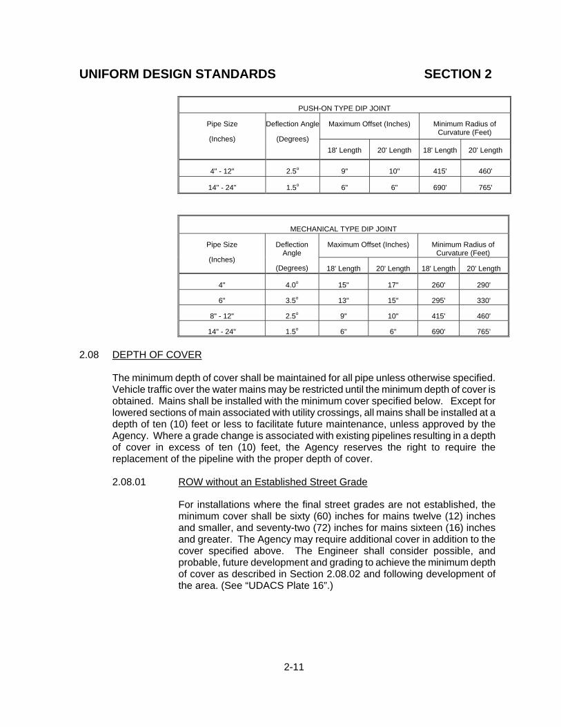
The maximum allowable water main joint deflection for various pipe materials and lengths is listed in the following tables. If these offsets conflict with the pipe manufacturer's recommendation, the more stringent requirement shall apply. Requirements in excess of these deflections identified shall require installation of fittings. However, the number of fittings and pipe joints should be minimized, while maintaining radius requirements. The use of partial lengths of pipe to create additional joints and joint deflections is not authorized. Pipes may be deflected at fitting and pipe joints, with the deflection limited to the pipe being installed. For changes in direction exceeding the maximum allowable joint deflection, fittings shall be used. The use of vertical ninety (90) degree bends, with vertical sections of water main, is not allowed for the vertical adjustment of pipeline alignment. 2.07.01 Polyvinyl Chloride (PVC) Pressure Pipe C900
Polyvinyl chloride pipe shall be deflected at the fitting and pipe joints only. The maximum allowable joint deflection shall be as stated in the following table.
Pipe Size (Inches)
Maximum Joint Deflection (degrees)
Maximum Pipe End Offset 20 Foot Pipe Lengths
(inches)
Minimum Radius of Curvature (feet)
4-12 1 4.187 1,150
2.07.02 Polyvinyl Chloride (PVC) Pressure Pipe C905
Polyvinyl chloride pipe shall be deflected at the fitting and pipe joints only. The maximum allowable joint deflection is limited and shall not exceed manufacturer recommendations. In general, fittings shall be used for all changes in direction.
2.07.03 Ductile Iron Pipe (DIP)
The maximum allowable joint deflection for push-on type joint and mechanical-joint pipe shall be as follows:
Maximum Joint Deflection (degrees)
Maximum Pipe End Offset 20 Foot Pipe Lengths
(inches)
Minimum Radius of Curvature (feet)
1 4.187 1,150
UNIFORM DESIGN STANDARDS SECTION 2
2-11
PUSH-ON TYPE DIP JOINT
Maximum Offset (Inches)
Minimum Radius of
Curvature (Feet)
Pipe Size
(Inches)
Deflection Angle
(Degrees)
18' Length
20' Length
18' Length
20' Length
4" - 12"
2.5o
9"
10"
415'
460'
14" - 24"
1.5o
6"
6"
690'
765'
MECHANICAL TYPE DIP JOINT
Maximum Offset (Inches)
Minimum Radius of
Curvature (Feet)
Pipe Size
(Inches)
Deflection
Angle
(Degrees)
18' Length
20' Length
18' Length
20' Length
4"
4.0o
15"
17"
260'
290'
6"
3.5o
13"
15"
295'
330'
8" - 12"
2.5o
9"
10"
415'
460'
14" - 24"
1.5o
6"
6"
690'
765' 2.08 DEPTH OF COVER
The minimum depth of cover shall be maintained for all pipe unless otherwise specified. Vehicle traffic over the water mains may be restricted until the minimum depth of cover is obtained. Mains shall be installed with the minimum cover specified below. Except for lowered sections of main associated with utility crossings, all mains shall be installed at a depth of ten (10) feet or less to facilitate future maintenance, unless approved by the Agency. Where a grade change is associated with existing pipelines resulting in a depth of cover in excess of ten (10) feet, the Agency reserves the right to require the replacement of the pipeline with the proper depth of cover.
2.08.01 ROW without an Established Street Grade
For installations where the final street grades are not established, the minimum cover shall be sixty (60) inches for mains twelve (12) inches and smaller, and seventy-two (72) inches for mains sixteen (16) inches and greater. The Agency may require additional cover in addition to the cover specified above. The Engineer shall consider possible, and probable, future development and grading to achieve the minimum depth of cover as described in Section 2.08.02 and following development of the area. (See “UDACS Plate 16”.)

UNIFORM DESIGN STANDARDS SECTION 2
2-12
2.08.02 ROW with an Established Street Grade
Where there is an established street grade, the following minimum depth of cover shall be provided. (See “UDACS Plate 17”.):
ROW (Feet)
Pipe Diameter (Inches)
Minimum Depth of Cover (Inches)
Sixty (60) or less
Twelve (12) and smaller
Forty-two (42)
Sixty (60) or less Greater than twelve (12)
Sixty (60)
Greater than sixty (60)
Twelve (12) and smaller
Forty-eight (48)
Greater than sixty (60) Greater than twelve (12)
Sixty (60)
Greater than sixty (60) Greater than sixteen (16)
Seventy-two (72)
Minimum
NOTE: Depth of cover is the distance from the finished grade to the top of pipe at the pipe location, and not based on the elevations for the center line of road.
2.08.03 NDOT ROW
A sixty (60) inch minimum depth of cover shall be maintained over all water mains and casings located within NDOT ROW. (See “UDACS Plate 18”.)
2.08.04 Depth of Cover During Construction A twenty-four (24) inch minimum depth of cover must be maintained during
construction.
2.09 CATHODIC PROTECTION 2.09.01 Existing Test Stations
Existing water facility cathodic protection test stations will be shown on the plans and all test stations to be relocated or adjusted will be identified. Test stations to be relocated shall be tested prior to and after relocation by a certified Cathodic Protection Specialist, Corrosion Specialist, Professional Corrosion Engineer, or other qualified person authorized by the Agency.
UNIFORM DESIGN STANDARDS SECTION 2
2-13
2.09.02 Installation Of New Facilities
For installation of ductile iron or MLCP pipe sixteen (16) inch and larger, the Agency may require a corrosion study to be performed by a certified Professional Corrosion Engineer. At a minimum, additional soils testing for corrosive soil characteristics may be required.
2.10 PIPE CASING
2.10.01 Steel Casing
Steel casings are required on all pipe installed using boring method, where required to meet specific Railroad and/or NDOT requirements, to provide structural support, or as required under other special conditions. The pipe casing shall be laid true to line and grade with no bends or changes in grade for the full casing length.
The casing shall be steel fabricated and shall conform to the requirements of ASTM A283, Grade B, C, or D. All joints shall be welded. Interior joints shall be ground to a smooth finish. All welding shall be performed in accordance with AWWA Standard C206, “Field Welding of Steel Water Pipe”.
Casing wall thickness shall be in accordance with UDACS Plate 23. The
wall thickness for casing installations over twenty-five (25) feet below finished grade shall be determined by a Nevada Licensed Professional Engineer. Casing wall thickness for installations under railroad tracks shall be determined by a Nevada Licensed Professional Engineer and approved by the Union Pacific Railroad.
Casings installed by jack and bore method shall be installed to the grade
shown on the drawings, with a maximum vertical deviation of + zero (0)o and - two (2)o, and a maximum horizontal deviation of + two (2)o provided the alignment does not conflict with other utilities and/or rights-of-way.
The water pipe installed in the casing shall be supported by Agency
approved casing spacers, and installed in accordance with the manufacturer’s recommendations. After pipe installation, the casing shall be sealed, and Agency approved end seals shall be installed per the manufacturer’s recommendations.
Where installation of casing may be accomplished by open cut methods,
water quality RCP casings may be used in lieu of steel casings, as approved by the Agency. If the casing is required in order to meet the requirements of Section 2.22, the RCP sections must be installed using Agency approved elastomeric joint sealants, in compliance with ASTM C920, or joint gaskets. RCP casings installed for future pipeline installations shall be securely

UNIFORM DESIGN STANDARDS SECTION 2
2-14
sealed with removable bulkheads at both ends in a manner acceptable to the Agency.
2.10.02 Polyvinyl Chloride Pipe (PVC)
Water quality PVC casings may be utilized in lieu of steel casing for protection of the water system (See “Section 2.22”), where installation of pipe does not require boring methods, structural support, or for Railroad and/or NDOT requirements.
2.10.03 Reinforced Concrete Pipe (RCP) Water quality RCP casings may be utilized in lieu of steel casing for protection of the water system (See “Section 2.22”), where installation of pipe does not require boring methods or structural support, as approved by the Agency.
2.10.04 Pipe Spacers The pipe shall be symmetrically supported about its centerline inside the casing at each joint end with an Agency approved polyethylene spacer, sized and designed per manufacturer recommendations.
2.10.05 Casing End Caps The casing ends shall be sealed in a manner acceptable to the Agency. The annular space between the pipe and the casing shall be filled with CLSM I or sand, as required by the Agency.
2.11 VALVES
2.11.01 Valve Location
Sufficient valves shall be provided on water mains to minimize inconvenience, degradation of fire protection and sanitary hazards during repairs. Valves shall be generally located as follows, unless otherwise approved by the Agency:
A. At intervals to isolate no more than two (2) fire hydrants at any
time.
B. In residential areas to isolate a maximum of thirty (30) services. C. A maximum of five (5) valves will be required to isolate any
location.

UNIFORM DESIGN STANDARDS SECTION 2
2-15
D. At maximum intervals of five hundred (500) feet in commercially zoned areas and residential off-site water mains for distribution mains twelve (12) inches in diameter and smaller, one thousand (1,000) foot intervals for sixteen (16) inches in diameter transmission mains, and one thousand three hundred and twenty (1,320) foot intervals for twenty (20) inch and greater diameter transmission mains. Additional valves may be required by the Agency to meet the requirements of Paragraphs “A” through “C” above. Valves on transmission mains outside of their designated pressure zone or area of service will be located a maximum spacing of one (1) mile.
E. Valves shall not be located in street gutters, valley gutters, or in
driveways.
F. A valve is required at the end of all temporarily dead-end mains. The valve location is to be a minimum of ten (10) feet upstream of the cap or blow off assembly.
G. For developments having two (2) or more sources of supply,
isolation valves are required such that partial flow can be maintained to the development when any one source is out of service for maintenance or repair.
H. Valved outlet(s) for future service laterals six (6) inches in
diameter and larger may be installed when approved by the Agency. Valved outlet installation approval does not constitute a water commitment. When valved outlet(s) for future service laterals are identified, the following note shall appear on the drawing:
CONDITIONAL APPROVAL OF VALVED OUTLET (Six (6) inches and larger) The water plans show one or more valved outlets extending out of paved areas. Installation of these outlets is acceptable; however, if the outlets are incorrectly located or not used for any reason when the property is actually developed, the Developer shall abandon the outlets at the connection to the active main in accordance with the Agency’s Standards and at the Developer's expense. Approval of the valved outlet does not provide or imply a water commitment.
UNIFORM DESIGN STANDARDS SECTION 2
2-16
I. A valve immediately adjacent to the water main shall be provided for all laterals greater than two (2) inches in diameter, and for all fire hydrant laterals.
J. The Agency may require additional valves depending upon the
project design.
2.11.02 Gate Valves
A. Gate valves may be used on all water main diameters up to, and including, twenty-four (24) inches, as required by the Agency.
B. Gate valves shall be installed in the vertical position with non-
rising stems in all locations, except vaults, unless otherwise specified by the Agency.
C. A minimum six (6) inch bypass valve and piping for pressure relief
shall be provided for all gate valves twenty-four (24) inches in diameter and greater, unless otherwise specified by the Agency.
D. All gate valves shall be resilient seat unless otherwise specified
by the Agency.
2.11.03 Butterfly Valves
Butterfly valves may be used on water mains larger than sixteen (16) inches in diameter; unless a tapping (gate) valve is required, or as required and approved by the Agency. The installation of a valve vault shall be required for all butterfly valves.
2.11.04 Valve Stem Extensions
Valve stem extensions are required within two (2) feet of finished grade where the distance from the top of the valve box to the top of the operating nut exceeds five (5) feet.
2.11.05 Valve Boxes Adjustable valve boxes shall be provided for all buried valves. Valve boxes shall be installed in accordance with UDACS Plate 39.
UNIFORM DESIGN STANDARDS SECTION 2
2-17
2.11.06 Special Valves
A. Combination air and vacuum relief valves (AVAR) may be required on pipelines’ high points and changes in grade, depending on the main size (typically twelve (12) inches and greater) and terrain, in accordance with UDACS Plate 38.
B. Pressure regulating valves (PRV) will be required where it is
necessary to reduce pressure to a maximum value as defined in Section 2.01.
C. Check valves are to be used where it is required that the water
flow in one direction only.
D. Blow-off valves are required on all permanent dead-end pipe runs and may be required at stub-out locations. Blow-off valves for these locations shall be installed in accordance with UDACS Plate 36.
E. Six (6) inch manual blow–off valves for installation for larger
diameter mains at low points shall be installed in accordance with UDACS Plate 37, as required by the Agency.
F. Backflow Prevention Assembly requirements are identified in
Section 2.20.
2.11.07 Valve Abandonment
A. Any stub and valved outlet installed, and subsequently not required, must be abandoned.
B. For valve abandonment, the following note shall appear on the
drawing:
ABANDONED VALVES All valves to be abandoned shall be abandoned in the closed position, unless shown otherwise, by removing a minimum of the top twenty-four (24) inches of the valve box and then filling the bottom of the box with a minimum of eight (8) inches of sand or Type II aggregate base. The remaining portion of the valve box shall be filled with concrete having a compressive strength of at least two thousand (2,000) psi.

UNIFORM DESIGN STANDARDS SECTION 2
2-18
C. If the stub and valve is to be abandoned with the valve in the closed position, the following note shall appear on the drawing:
CUT AND CAP The lateral must be cut within one (1) foot of the abandoned valve, or as shown on plans, and capped. The Contractor shall cut the existing pipe where shown on the drawing and install a cap complete with thrust block. Where a joint or coupling in the existing pipe is uncovered at the cut and cap locations, the installation of a plug may be permitted with Agency approval. A concrete thrust block shall be installed at all cap or plug locations in accordance with the provisions of UDACS Plate 31.
2.12 ABANDONMENT OF MAIN
All pipelines to be abandoned shall be cut and securely capped (all ends). The cut and cap location on the main to be abandoned shall be a maximum of one (1) foot from the valve or point of termination. Any abandoned pipeline larger than twelve (12) inches must be filled with CLSM I material.
2.13 CAPPING
A cap or plug with blowoff assembly will be required on the ends of all newly installed mains in accordance with UDACS Plate 36.
2.14 THRUST AND ANCHOR BLOCKS
Thrust blocks are required at all caps, valves, reducers, tees, and fittings used to change the pipe direction, and shall be placed in accordance with UDACS Plates 30 and 31 for all locations where the soil bearing capacity is three thousand (3,000) psf or greater. A special thrust block design by a NPE for each location of a thrust/anchor block is required if allowable soil bearing capacity is less than three thousand (3,000) psf. If undisturbed material is not present; (such as in fill sections), then mechanically restrained joints shall be required.
2.15 MECHANICALLY RESTRAINED JOINTS
Mechanically restrained joints are required for all mains sixteen (16) inch and larger, and may be used for smaller diameter mains at the discretion of the Agency. The length of restrained joints shall be clearly identified on drawings and calculations shall be submitted with the project for Agency review and approval.

UNIFORM DESIGN STANDARDS SECTION 2
2-19
2.16 TESTING AND DISINFECTING
A. All new water facilities shall be pressure tested and disinfected to the Agency's satisfaction as identified in Section 3.27 of this standard and in accordance with the Nevada Division of Environmental Protection requirements (See “NAC 455A.67145”.) For guidance on chlorine requirements, refer to UDACS Plate 32.
B. Provisions shall be made to provide a water velocity of two and one half (2.5)
feet-per-second while flushing water mains through the use of blow off valves, fire hydrants, or a combination thereof. (See “UDACS Plate 33”.)
2.17 SERVICE LATERALS
2.17.01 Location
A. All service laterals shall be installed in the ROW unless other provisions have been approved by the Agency.
B. The full service lateral length between a water main and water
meter shall be installed at ninety (90) degrees to the water main horizontal alignment unless otherwise approved by the Agency. A locator ribbon will be installed the entire length of the lateral for all services not installed at right angles to the main.
C. For service laterals two (2) inches in diameter and smaller,
service saddles shall not be closer than eighteen (18) inches to any other service saddle, pipe joint, valve, or fitting.
D. The sewer and water laterals leading into the property shall be
separated horizontally by a minimum of four (4) feet, the sewer lateral must be a minimum of one (1) foot lower than the water lateral, and the laterals shall be located in separate trenches, per State and local health requirements. (See “Section 2.22”.)
E. All service laterals shall be located a minimum of ten (10) feet
from septic tanks, and a minimum of twenty-five (25) feet from leach beds and/or seepage pits.
F. Location of all service laterals shall be clearly defined on the
drawings, with all services located outside of driveways, aprons, or sidewalk ramps.
G. The use of a six (6) inch diameter or larger lateral may be
required for services two (2) inches in diameter and smaller if the lateral length is in excess of one hundred (100) feet.

UNIFORM DESIGN STANDARDS SECTION 2
2-20
2.17.02 Lateral Installation
A. Service saddles shall be installed in accordance with the Agency's approved materials list for the type of pipe used.
B. Corporation stops shall be male iron pipe thread by compression
or flared connection. A corporation stop shall be installed at the water main for all service laterals two (2) inches and smaller.
C. All services laterals two (2) inches and smaller shall have a
minimum lateral diameter equal to the meter size but in no case shall the lateral diameter be less than one (1) inch (i.e. a one (1) inch diameter service lateral is required for five-eighth (5/8) inch, three-quarter (3/4) inch and one (1) inch meters).
D. All services three (3) inches and larger will require a minimum six
(6) inch lateral with valve and shall be installed with a material approved by, and in accordance with, the Agency.
2.17.03 Future Use Laterals
Service laterals two (2) inches in diameter and smaller may be approved for future lots, provided the following conditions are adhered to:
A. The laterals are to lots identified as a part of a master devel-
opment and the subdivision map is available in either final or tentative form. Agency approval of the subsequent water plan is required (i.e. future laterals will not be provided for all future lots).
B. The future laterals will only be installed where the streets over the
water main are to be developed or improved with the current project.
C. The service laterals will be clearly identified on the drawings and
the quantity listed as "laterals for future services." Fees may be required by the Agency having jurisdiction for laterals installed as "future services."
D. Approval of the future use lateral does not provide or imply a
water commitment. E. The following note shall be included on the drawing:
FUTURE USE LATERALS (One (1) inch through two (2) inch)
If any of the service laterals to be installed for future

UNIFORM DESIGN STANDARDS SECTION 2
2-21
lots are incorrectly located or are not used for any reason when the lots are developed, the Developer shall abandon the laterals at the connection to the active main in accordance with the UDACS Standards at the Developer's expense.
Installation of service laterals two (2) inches in diameter and smaller for future lots shall include the service lateral, meter box, angle meter stop, and all fittings per UDACS Plates 1 through 4. The Agency may lock these services to prevent unauthorized water use.
F. Service laterals will not be approved for future lots not part of a master development or for a development with a different owner.
2.17.04 Lateral Removal
A. When abandoning existing water service assemblies sized two (2)
inches and smaller, the following note shall appear on the drawing:
ABANDONMENT OF EXISTING SERVICE LATERALS (Two (2) inch and smaller) The Contractor shall notify the Agency two (2) full business days prior to the requested removal time to allow the Agency to take the final meter reading. The Contractor may then begin removal procedures for the affected service as follows: Existing service laterals to be abandoned from existing water mains shall have the corporation stops turned off at the main, a minimum of twelve (12) inches of the lateral cut out near the corporation stops and a brass cap installed on the corporation stop. If the corporation stop is damaged beyond repair or pulled from the existing water main, the main shall be repaired at the Contractor's expense in a manner approved by the Agency. If it is discovered the corporation stop is not water tight, through no fault of the Contractor, the Contractor shall notify the Agency for further direction. The existing meter(s) shall be removed and delivered to the Agency.

UNIFORM DESIGN STANDARDS SECTION 2
2-22
B. For existing water service assemblies three (3) inches and larger that are to be abandoned, the following note shall appear on the drawing:
ABANDONMENT OF EXISTING SERVICE LATERALS (Three (3) inch and larger) The Contractor shall notify the Agency two (2) full business days prior to the requested removal time to allow the Agency to take the final meter reading and to notify the Agency's Inspector of the impending work. The Contractor may then begin removal proce-dures for the affected service as follows: All valves to be abandoned shall be abandoned in the closed position, unless shown otherwise, by removing a minimum of the top twenty-four (24) inches of the valve box and then filling the bottom of the box with a minimum of eight (8) inches of sand or Type II aggregate base, the remaining portion of the valve box shall be filled with concrete having a compressive strength of at least two-thousand (2,000) psi.
If the valve is to be abandoned in the closed position, the lateral must be cut within one (1) foot of the abandoned valve, or as shown on plans, and capped. Where a joint or coupling in the existing pipe is uncovered at the cut and cap locations, the installation of a plug may be permitted with Agency approval. The Contractor shall install a concrete thrust block in accordance with the provisions of the UDACS Plate 31 at all cap or plug locations. The existing meter(s) shall be removed and delivered to the Agency. The Contractor shall then remove the vault or a minimum of the vault roof and the top twenty-four (24) inches of the vault walls, and backfill the abandoned vault with Type II material compacted to ninety (90)% of maximum dry density or CLSM I, as approved by the Agency.

UNIFORM DESIGN STANDARDS SECTION 2
2-23
2.17.05 Lateral Relocation
A. All existing laterals that are to be relocated must first be disconnected from the existing pipeline following abandonment procedures. (See “Section 2.17.04”.) The relocated service installation shall comply with Agency’s current standards.
B. If meter box relocation is required, Section 2.17.01.B still applies.
C. The lateral may be extended, rather than replaced, if the existing
lateral is of approved copper material or sized six (6) inches in diameter or larger, provided the ninety (90) degree angle from the existing water main is maintained. All polyethylene tubing service laterals must be fully replaced, in lieu of extension or splicing, to the Agency's current standards. If approved by the Agency, a maximum of one (1) coupling may be used to extend a copper service lateral two (2) inches or smaller. (See “UDACS Plates 1 through 6”.)
2.18 METERS
2.18.01 Size
The meter to be installed will be based on size and service requirements. The Agency shall have final approval in determining the meter size and type. The table included in Section 4, Tables A and B reflect the AWWA rated capacities for various meter types and sizes. The size for all domestic services shall be based on continuous flow meter capacities when utilizing Peak Hour Demand. Maximum meter flow capacities may be used for maximum domestic demands, when calculated utilizing the applicable plumbing code or other applicable criteria, and fire flow conditions when associated pressure losses are accounted for in the system design.
2.18.02 Agency Provided Meters
A. All meters two (2) inches and smaller are provided by the Agency
and remain the Agency's property. B. All meters three (3) inches and larger shall be provided by the
developer and must meet the requirements of, be approved by, and remain the property of, the Agency. (See “Agency Approved Product List” for requirements.)
C. Meters for single family residences with residential fire sprinkler
systems will meet American Water Works Association (AWWA) standards for this application.

UNIFORM DESIGN STANDARDS SECTION 2
2-24
2.18.03 Installation
A. All services shall be installed in accordance with UDACS Plates.
Meters will not be allowed at locations not contiguous to the property to be served. For services three (3) inches and larger, the following note(s) shall appear on the drawing.
INSTALLATION OF METER AND VAULT The meter(s) and vault(s) with traffic/non-traffic bearing cover(s) shall be installed in accordance with the UDACS Vault Drawing No. C-475, latest revision. Precast vaults approved by the Agency may be used in lieu of the cast-in-place vaults. Any block wall or other fence material shall be designed and constructed around the outside of the easement(s), to allow the Agency direct access to the vault(s) and inlet piping from the adjacent ROW, Easements shall be clearly marked or staked prior to the start of construction. INSTALLATION OF DOUBLE CHECK DETECTOR ASSSEMBLY AND VAULT The detector check(s) and vault(s) with traffic/non-traffic bearing cover(s) shall be installed in accor-dance with the UDACS Plate 60 and with UDACS Vault Drawing No. C-475, or latest revision. Precast vaults approved by the Agency may be used in lieu of the cast-in-place vaults. Easements shall be clearly marked or staked prior to the start of construction.
B. A bypass line or bypass provision is required for all meters three
(3) inches and larger on projects, unless otherwise specified by the Agency.
C. All meter and meter vaults for services three (3) inches and larger
shall be located outside of the ROW (even if there is adequate space for the vault within the ROW) and the appropriate utility easement granted to the Agency, unless otherwise specified by the Agency.

UNIFORM DESIGN STANDARDS SECTION 2
2-25
2.18.04 Meter Boxes
A. All meter boxes shall be located in the sidewalk, sidewalk area, or within a designated easement in accordance with the UDACS Plates. Meter boxes shall NOT be located in driveways or streets.
B. All meters two (2) inches and smaller shall be installed in an
approved meter box, sized per the Agency Approved Products List.
C. All meters three (3) inches and larger shall be housed in a vault.
Refer to UDACS Vault Drawing No. C-475, latest edition, for dimension and construction details.
D. Provisions for remote reading devices for all vaults shall be
provided as required by the Agency.
2.19 EXISTING/ABANDONED PRIVATE WELLS
2.19.01 Existing Private Wells To Remain In Service - If the Agency allows a private well to remain in service, the following note shall appear on the drawing:
EXISTING PRIVATE WELLS TO REMAIN IN SERVICE
If the existing private well is to remain in service, an Agency approved backflow prevention assembly shall be installed immediately downstream of the Agency's water meter in accordance with UDACS Plate 8. The new service shall not be activated until the backflow prevention assembly has been successfully tested by the Agency.
2.19.02 Private Wells To Be Removed From Service - The following note shall
appear on the drawing:
PRIVATE WELLS TO BE REMOVED FROM SERVICE The existing private well is to be abandoned. The installation of a backflow prevention assembly will not be required; however, the Agency water service will remain in the locked position until the well has been abandoned (which must be accomplished within thirty (30) days of the installation of the Agency service) or physically disconnected from the onsite system. An inspection of the on-site system will be made by the Agency's Inspection Division to verify the well has been disconnected from the on-site system and the well is no longer functional. The State of Nevada Division of Water Resources (Telephone Number 702-486-2770) may be contacted for information concerning requirements and procedures for abandoning wells.
UNIFORM DESIGN STANDARDS SECTION 2
2-26
2.20 BACKFLOW
Any connection to the Agency's distribution system shall be made in a manner that protects the public potable water supply from contamination or pollution. Containment shall be achieved by the use of an Agency approved backflow assembly that isolates, within the customer's internal distribution system(s) or the customer's private water system(s), such contaminants or pollutants that could backflow into the public water system.
2.20.01 Application
No water service connection to any premises shall be approved, installed, or maintained by the Agency unless the water supply is protected as required by State laws, State regulations, and Agency Standards. Water service to any premises shall not be activated by the Agency if the Agency determines the water service requires a backflow assembly and any of the following conditions prevail:
A. The backflow assembly is not installed or has been removed after
installation.
B. The backflow assembly has been by-passed.
C. The backflow assembly is in any way altered.
D. Any cross-connection or possibility of cross-connection exists. E. The backflow assembly receives an “unsatisfactory” test result.
2.20.02 The required backflow prevention assembly type shall be determined by
facility use. A partial list of facilities with required backflow prevention is provided in Section 4, Table E. The Agency may require all services to a facility or parcel have an equal level of backflow protection. Facilities not listed in Table E shall be Agency evaluated for backflow prevention requirements on a case by case basis.
2.20.03 Any backflow prevention assembly required herein shall be a model and
size approved by the Agency. The term "Approved Backflow Prevention Assembly" shall mean an assembly meeting the Agency's specifications.
2.20.04 When backflow prevention assemblies are required, their installation
design shall take into consideration pressure loss across the device and maintenance requirements for critical services. The installation of dual services and/or backflow assemblies is strongly recommended and may be required for critical facilities to minimize the impact of assemblies being taken out of service for maintenance and repair.
UNIFORM DESIGN STANDARDS SECTION 2
2-27
2.21 FIRE HYDRANTS 2.21.01 Location and Spacing
A. All fire hydrants, permanent or temporary, will be installed in accordance with UDACS Plates 40 and 41.
B. Hydrant spacing and location are ultimately determined by the
Fire Department having jurisdiction. C. Fire hydrants shall not be located in the following locations:
1. Within six (6) feet of a driveway, curb return, power pole,
light standard, or any obstruction.
2. On the circular portion of a cul-de-sac, or within twenty (20) feet of the cul-de-sac radius.
3. Within three (3) feet of any block wall or fence.
4. As Agency specified.
2.21.02 Materials
Fire hydrants shall be approved by, and conform to the requirements of, the Fire Department having jurisdiction.
2.21.03 Hydrant Drains
A. Hydrant drains shall not be plugged, and a gravel pocket shall be provided.
B. Hydrant drains shall not be connected to, or located within ten (10) feet of, sanitary sewers or storm drains.
2.21.04 Temporary Fire Hydrants
A. A temporary fire hydrant is classified as "temporary" due to its
projected useful life and in no way reflects a lesser standard of construction. The requirements for temporary fire hydrants, to the extent possible, will be identified during the design stage and included on the developer's plans for review and approval. If possible, this requirement should be satisfied through the use of permanent fire hydrants.
B. Temporary fire hydrants are not intended to provide fire protection
for permanent facilities.
UNIFORM DESIGN STANDARDS SECTION 2
2-28
C. Separate requests for a temporary fire hydrant installation require
the submission of a full size (twenty-four (24) inches x thirty-six (36) inches) reproducible site drawing, or an abbreviated drawing (eleven (11) inches x seventeen (17) inches) to include the items listed below. An amendment can be made to a previously approved water plan if the hydrant is for the same project. The application will, as a minimum, identify the following:
1. Dimensions from existing features and property lines, etc.,
to establish the point of connection to the water line and the extent of construction.
2. Period of time the fire hydrant will be in use, as approved
by the Agency, and the work associated with its removal. 3. Procedure for removing / abandoning the fire hydrant
upon termination of use.
4. Professional Engineer signature and seal.
5. Agency Standard Notes.
6. Agency approval (signature) block.
2.21.05 Fire Hydrant Permit
A fire hydrant permit and meter will be required to use a fire hydrant for construction and dust control purposes. Charges for their use will be in accordance with the Agency's Service Rules, latest edition. A backflow assembly may also be required as determined by the Agency.
2.21.06 Relocation/Abandonment of Fire Hydrants
A. If a hydrant lateral needs to be lengthened, continuing further
back in the same direction and at the same depth as the original lateral, the hydrant assembly shall be replaced with a new hydrant assembly approved by the Fire Department having jurisdiction, unless otherwise noted on the plans. The following note shall appear on the drawing:
RELOCATION OF FIRE HYDRANTS (Extension of Existing Lateral) The Contractor shall remove both the upper and lower barrels of the existing fire hydrant(s) where shown, extend the existing lateral as required, and install a

UNIFORM DESIGN STANDARDS SECTION 2
2-29
new hydrant(s) at the new location(s) indicated. Installation shall be in accordance with UDACS Plates 40 and 41. The existing fire hydrant shall be delivered to the Agency.
B. If a hydrant is to be relocated and the hydrant lateral must be
abandoned, the following note shall appear on the drawing:
FIRE HYDRANT RELOCATION AND LATERAL ABANDONMENT (Existing Lateral to be Abandoned) Where shown on the drawing(s), the Contractor shall abandon the existing fire hydrant(s) by removing both the upper and lower barrels of the fire hydrant so that no portion of the remaining fire hydrant assembly is closer than two (2) feet to the existing grade. A new hydrant shall be installed at the new location as indicated on the drawing, in accordance with UDACS Plate 40 and 41. The existing valve shall be abandoned in a closed position, unless shown otherwise, by removing a minimum of the top twenty-four (24) inches of the valve box, and then filling the bottom of the box with a minimum of eight (8) inches of sand or Type II aggregate base. The remaining portion of the valve box shall be filled with concrete having a compressive strength of at least two-thousand (2,000) psi. The lateral shall be cut within one (1) foot of the abandoned valve, or as shown on plans, and capped. Where a joint or coupling in the existing pipe is uncovered at the cut and cap location, the installation of a plug may be permitted, with Agency approval. A concrete thrust block shall be installed at all cut and cap locations in accordance with the provisions of UDACS Plate 31. The existing fire hydrant shall be delivered to the Agency.
C. If the fire hydrant is to be abandoned, the following note shall
appear on the drawing:
FIRE HYDRANT AND LATERAL ABANDONMENT Where shown on the drawing, the Contractor shall abandon the existing fire hydrant(s) by removing both the upper and lower fire hydrant barrels so no portion of the remaining fire hydrant assembly is closer than two (2) feet to the existing grade. The existing

UNIFORM DESIGN STANDARDS SECTION 2
2-30
hydrant shall be delivered to the Agency. The existing valve shall be abandoned in a closed position, unless shown otherwise, by removing a minimum of the top twenty-four (24) inches of the valve box and then filling the bottom of the box with a minimum of eight (8) inches of sand or Type II aggregate base. The remaining portion of the valve box shall be filled with concrete having a compressive strength of at least two-thousand (2,000) psi. The remaining portion of the lateral shall be cut within one (1) foot of the abandoned valve, or as shown on plans, and capped. The existing concrete hydrant pad shall be removed.
D. Vertical Adjustments
Where grades are changed which affect fire hydrants, the Contractor shall make adjustments as necessary to bring the fire hydrant into compliance, without the use of a fire hydrant barrel extension, with UDACS Plates 40 and 41, and Agency requirements.
2.21.07 Fire Department Approval
Approval by the Fire Department having jurisdiction is required PRIOR to obtaining final water plan approval from the Agency. Fire Department approval is also required for revisions to approved plans affecting fire hydrants, fire services, and/or fire flow requirements.
2.22 WATER AND SEWER/STORM MAIN CROSSINGS AND CLEARANCES
2.22.01 Parallel Separations (Mains)
NOTE: The sewer manhole or structure is not considered to be a sewer main provided the water main is greater than eighteen (18) inches above the sewer main.
A. The following separations must be maintained between all storm
and sanitary sewer lines which parallel water lines six (6) inches and larger. 1. Water mains and sewer lines shall be installed in separate
trenches with at least ten (10) feet of separation measured horizontally from exterior pipe walls.

UNIFORM DESIGN STANDARDS SECTION 2
2-31
2. Water mains shall be placed above sewer lines whenever
possible.
B. Where the required ten (10) foot separation is not practicable, the Engineer may petition the Agency for approval of one of the following options:
1. Less than a ten (10) foot horizontal separation with
eighteen (18) inches vertical separation, the following will apply: a. Pipes shall be installed in separate trenches. b. Horizontal separation shall be at least five (5) feet
from exterior pipe walls and sewer structures.
c. Vertical separation shall be at least eighteen (18) inches between exterior pipe walls with the water main being placed above the sewer main.
2. Where requirements included in Section 2.22.01A and
Section 2.22.01B cannot be met, the following provisions will apply: a. All efforts will be made to place the water line
above the sewer main; and b. Horizontal separation shall not be less than six (6)
feet from exterior pipe walls; and c. The sewer line will be constructed using one of the
following options, in the following priority, and as approved by the Agency(s):
(1) The sewer main will be constructed of
water supply quality materials meeting AWWA standards; or
(2) Sewer mains may be totally encased with
a minimum of four (4) inches of cement slurry (CLSM II); or
(3) Storm sewers twenty-four (24) inches in
diameter or greater may be installed with watertight joints using Agency approved internal elastomeric joint sealant, in compliance with ASTM C920, or joint
UNIFORM DESIGN STANDARDS SECTION 2
2-32
gaskets, with provisions to insure against differential settlement of the storm drain.
3. Where separation requirements cannot be met using the
above provisions, the Engineer may petition the Agency for approval to encase the water main with a minimum of four (4) inches of cement slurry (CLSM II), for a limited section; however, the Engineer must demonstrate an alternative alignment is not available.
Encasement will not be permitted for asbestos cement
pipe water mains.
2.22.02 Crossing Separations (Mains)
The following separations must be maintained between all storm and sanitary sewer mains which cross water mains six (6) inches and larger.
A. Sewer mains shall be placed below water mains, and shall be
separated vertically by at least eighteen (18) inches between exterior pipe walls.
B. Where the water main is below the sewer main, or where the
water main is above the sewer main with a vertical separation less than eighteen (18) inches, the following provisions shall apply:
1. A reasonable effort must be made to place water and
sewer pipeline joints an equal distance from the crossing point. This requirement does not apply to welded joints.
2. A vertical separation of no less than six (6) inches must
be maintained and structural support for the sewer and/or water main be determined by the Engineer and approved by the Agency having jurisdiction.
3. The sewer main will be constructed using one of the
following options, in the following priority, or as approved by the Agency:
a. The sewer main must be constructed of water
supply quality materials meeting AWWA standards.
b. The sewer main or water main may be installed in
a steel sleeve or a sleeve of water quality pipe which extends ten (10) feet perpendicular on each side of the main. (See "UDACS Plate 23".)

UNIFORM DESIGN STANDARDS SECTION 2
2-33
c. The sewer main (depending on field conditions)
shall be totally encased in a minimum of four (4) inches of cement slurry (CLSM II) for a distance of ten (10) feet on each side of the crossing.
d. The Engineer may petition the Agency for
approval to encase the water main (depending on field conditions) in a minimum of four (4) inches of cement slurry (CLSM II) for a distance of ten (10) feet on each side of the crossing. Encasement will not be permitted for asbestos cement pipe.
C. Where a section of water main is being lowered due to a sanitary
sewer, or storm drain conflict, the water main shall be constructed of ductile iron pipe, or as otherwise approved by the Agency. All pipe joints shall be restrained in accordance with the Agency’s requirements. The plans shall clearly identify the length of water main to be restrained (i.e. from station “x” to station “y”). The Engineer shall also submit all calculations used to determine the required length of restrained pipe. The water main shall be placed within a steel sleeve in accordance with UDACS Plates 21 or 22, and 23.
D. Where an existing large diameter water main, twenty-four (24)
inches or larger, is below the storm/sewer main to be constructed, or above the storm/sewer main with a vertical separation less than eighteen (18) inches, or where the size of the storm/sewer main prohibits the corrections identified in Paragraph 2.22.02, the following provisions shall apply:
1. The storm/sewer shall be constructed of cast-in-place
reinforced concrete with no expansion joints within ten (10) feet of the exterior wall of the water main; or
2. The storm/sewer shall be constructed with precast
reinforced concrete sections, installed with watertight joints using Agency approved internal elastomeric joint sealant, in compliance with ASTM C920, or joint gasket, with provisions to insure against differential settlement of the storm drain.

UNIFORM DESIGN STANDARDS SECTION 2
2-34
2.22.03 Service Lateral Crossings and Clearances
For purposes of this section, "service laterals" are those sewer and water lines extending from a main and terminating on-site. They are generally of smaller diameters (water: one (1) inch to four (4) inch; sewer: four (4) inch to six (6) inch).
A. Parallel Separation (Service Laterals)
1. Water and sewer service laterals shall be installed a
minimum of forty-eight (48) inches apart in separate trenches. Water laterals shall be a minimum of twelve (12) inches above the sewer lateral.
2. For maintenance purposes, service laterals shall be
installed a minimum of forty-eight (48) inches from the exterior of the manholes.
B. Crossings (Service Laterals)
1. Where a water service lateral crosses a sewer main or
sewer lateral, it shall be above the sewer with a vertical separation of at least eighteen (18) inches. Any relocation of existing water laterals to achieve this clearance must be performed with the approval of and in accordance with the procedures and standards of the Agency responsible for water distribution.
2. When a sewer main or sewer lateral must cross over or
under a water lateral or water main with less than eighteen (18) inches clearance, the provisions of Section 2.22.02. B3 shall apply.
3. Schedule forty (40) PVC sleeves may be used on one (1)
inch through two (2) inch copper service laterals ten (10) feet either side of the crossing. One (1) inch laterals require two (2) inch sleeves, and one and a half (1 1/2) inch and two (2) inch laterals require four (4) inch sleeves.
2.22.04 Septic Tank Clearances
(See “Section 4, Figure 1” for requirements.)
2.23 NON-POTABLE WATER SYSTEMS
This section is intended to provide the criteria for protection of the potable water distribution system in areas where non-potable, such as reclaimed and raw water

UNIFORM DESIGN STANDARDS SECTION 2
2-35
irrigation systems are installed. All requirements for the construction and operation of these non-potable water distribution systems are not identified in this standard, and the engineer shall review the standards established for these systems prior to design and construction of these systems.
2.23.01 Separation
A. The following separations must be maintained between all non-potable water mains which parallel potable water mains:
1. Potable water mains and non-potable water mains shall
be installed in separate trenches with at least ten (10) feet of separation measured horizontally from exterior pipe walls.
2. Potable water mains shall be placed above non-potable
water mains whenever possible. B. Where the required ten (10) foot separation is not practical, the
Engineer may petition the Agency for approval provided the:
1. Non-potable gravity mains will comply with the potable water location/separation criteria included in Sections 2.04 and 2.22.
2. Non-potable pressurized mains will be constructed of
AWWA quality material and:
a. The non-potable main should be installed a minimum of eighteen (18) inches below the potable line where possible, and installation at the same level will be avoided to prevent conflicts with tapping the potable main and the construction of potable water laterals.
b. Restrained joints may be required for non-potable
installation if the non-potable line is installed above the potable line, and the pressure of the non-potable line exceeds eighty (80) PSI.
2.23.02 Non-potable Water Distribution Pressure
The pressure requirements for the non-potable water system should be based on the system design; however, it is desirable that a pressure differential of ten (10) psi or greater be maintained on-site with the potable water supply having the higher pressure.
UNIFORM DESIGN STANDARDS SECTION 2
2-36
2.23.03 Backflow Prevention Backflow protection shall be provided for all potable water services servicing a site that is also provided non-potable water service. Reduced Pressure Principle Assemblies (RPPA’s) shall be the minimum levels of backflow protection provided.
2.24 TAPS FOUR (4) INCHES AND LARGER
2.24.01 Materials
A. Where the tap diameter is greater than seventy-five (75) percent of the nominal pipe diameter being tapped, and for all taps on ACP mains, Agency approved, full circumference gasket and support tapping sleeves shall be used.
B. Where the tap diameter is less than or equal to seventy-five (75)
percent of the nominal pipe diameter being tapped, mechanical joint or steel fabricated tapping sleeves shall be used for wet taps.
2.24.02 Taps On Steel Cylinder Pipe
Taps on existing steel cylinder pipe may be restricted by the Agency to maintain the reliability and integrity of the large diameter distribution/transmission systems. The engineer may petition the Agency for approval to tap the main, and when approved, the steel cylinder thickness, as well as the mortar lining and coating thickness, must be noted on all project plans where SCCP or MLCP mains are to be tapped. Details of the installation are to be included on the drawings. (See “UDACS Plate 35”.)
2.25 LINE STOPS Line stops may be required by the Agency, with or without by-pass, to insure continuous
operation of the water system. Line stops are used to temporarily shut down a pipeline system to complete modifications or repairs. They allow a system to operate without any interruption of service. Plans for line stops must include thrust restraint details, and calculations must be provided to the Agency for review. Bypass requirements must be identified on the water plans. Use of the line stop as part of the bypass configuration will require specific approval by the Agency.

UNIFORM DESIGN STANDARDS SECTION 2
2-37
2.26 EASEMENTS
2.26.01 General Requirements
A. Easements, where identified and allowed by the Agency, are re-quired whenever the water main, service lateral, meter, backflow assembly, or any associated appurtenances are not located in a public ROW. All easement locations shall be identified on the water plan, as well as any area(s) dedicated as public utility easements to be occupied by water facilities, to facilitate field verification.
B. Trees, shrubs, or decorative rocks, and any block wall or other
fence material, shall be designed and constructed around the easement(s) to allow the Agency direct access to the vault(s), backflow assemblies, and piping appurtenances from the adjacent ROW.
C. The area within the easement shall be graded to provide drainage
away from the vault and/or backflow assembly(ies) to prevent vault flooding and provide access for maintenance.
D. The area within the easement shall not contain any grades or
materials such as large rocks (greater than two (2) inches) that would hinder or restrict maintenance of the facilities.
E. For the installation of meters and backflow assemblies, the final
grade within the easement shall be at an elevation equal to back of sidewalk / ROW to allow safe ingress/egress to facilities. Where conditions prevent the above, upon Agency approval, retaining walls may be provided. However, a minimum distance of three (3) feet will be provided from the edge of the pad(s) or vault to any fence or wall.
F. All easement documents must be received by the Agency with
owner signature prior to plan approval, and must comply with Clark County Recorder’s Office most current requirements for easement document format.
G. The Agency may identify other specific requirements or limitations
for easements.
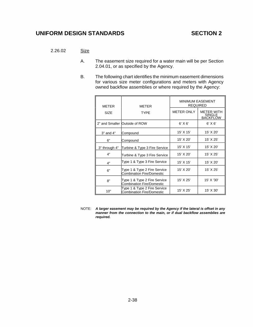
UNIFORM DESIGN STANDARDS SECTION 2
2-38
2.26.02 Size
A. The easement size required for a water main will be per Section 2.04.01, or as specified by the Agency.
B. The following chart identifies the minimum easement dimensions
for various size meter configurations and meters with Agency owned backflow assemblies or where required by the Agency:
MINIMUM EASEMENT REQUIRED
METER
SIZE
METER
TYPE
METER ONLY
METER WITH SINGLE
BACKFLOW
2” and Smaller Outside of ROW 6’ X 6’ 6’ X 6’
3" and 4"
Compound
15' X 15'
15' X 20'
6"
Compound
15' X 20'
15' X 25'
3" through 4"
Turbine & Type 3 Fire Service
15' X 15'
15' X 20'
4”
Turbine & Type 3 Fire Service
15’ X 20’
15’ X 25’
4" Type 1 & Type 3 Fire Service
15' X 15'
15' X 20'
6"
Type 1 & Type 2 Fire Service Combination Fire/Domestic
15' X 20'
15' X 25'
8"
Type 1 & Type 2 Fire Service Combination Fire/Domestic
15' X 25'
15' X '30'
10"
Type 1 & Type 2 Fire Service Combination Fire/Domestic
15' X 25'
15' X 30'
NOTE: A larger easement may be required by the Agency if the lateral is offset in any manner from the connection to the main, or if dual backflow assemblies are required.
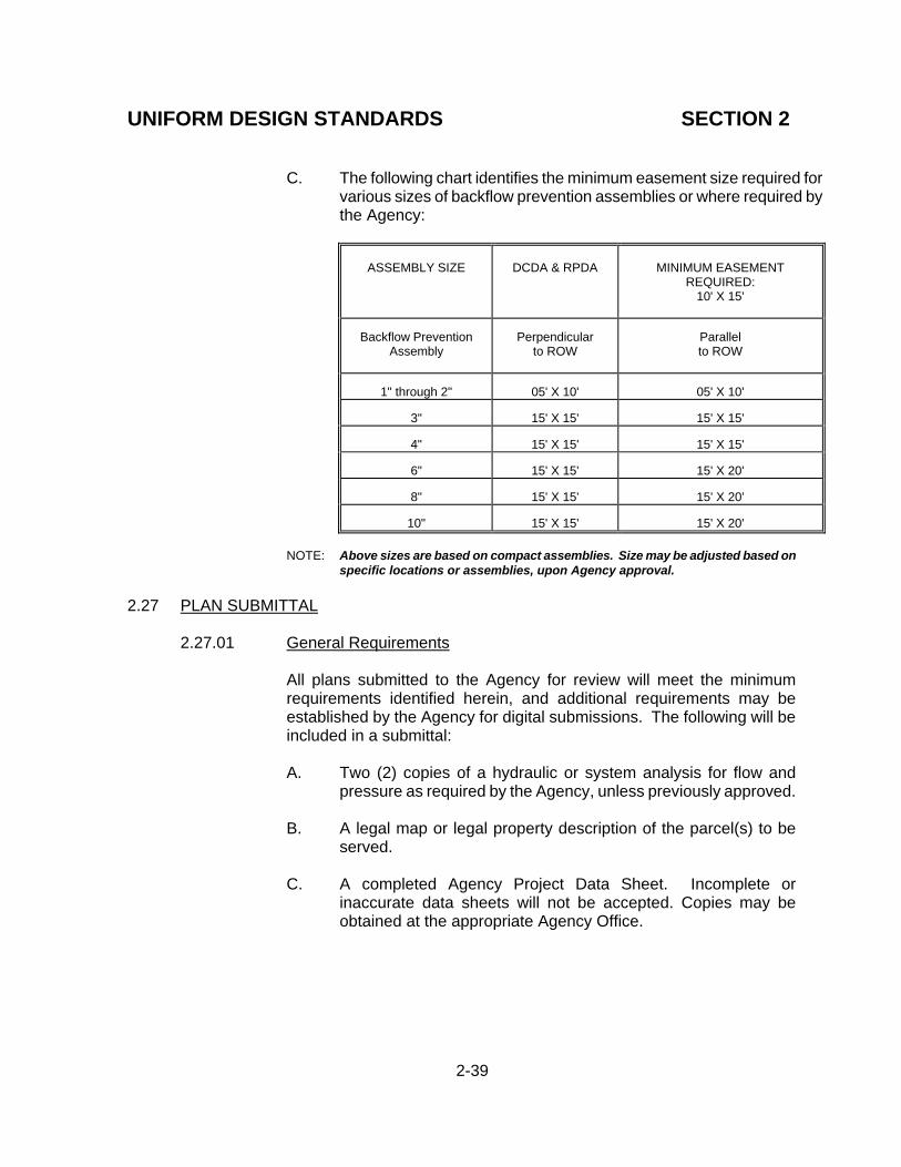
UNIFORM DESIGN STANDARDS SECTION 2
2-39
C. The following chart identifies the minimum easement size required for various sizes of backflow prevention assemblies or where required by the Agency:
ASSEMBLY SIZE
DCDA & RPDA
MINIMUM EASEMENT REQUIRED:
10' X 15'
Backflow Prevention
Assembly
Perpendicular to ROW
Parallel to ROW
1" through 2"
05' X 10'
05' X 10'
3"
15' X 15'
15' X 15'
4"
15' X 15'
15' X 15'
6"
15' X 15'
15' X 20'
8"
15' X 15'
15' X 20'
10"
15' X 15'
15' X 20' NOTE: Above sizes are based on compact assemblies. Size may be adjusted based on
specific locations or assemblies, upon Agency approval.
2.27 PLAN SUBMITTAL
2.27.01 General Requirements
All plans submitted to the Agency for review will meet the minimum requirements identified herein, and additional requirements may be established by the Agency for digital submissions. The following will be included in a submittal:
A. Two (2) copies of a hydraulic or system analysis for flow and
pressure as required by the Agency, unless previously approved. B. A legal map or legal property description of the parcel(s) to be
served.
C. A completed Agency Project Data Sheet. Incomplete or inaccurate data sheets will not be accepted. Copies may be obtained at the appropriate Agency Office.
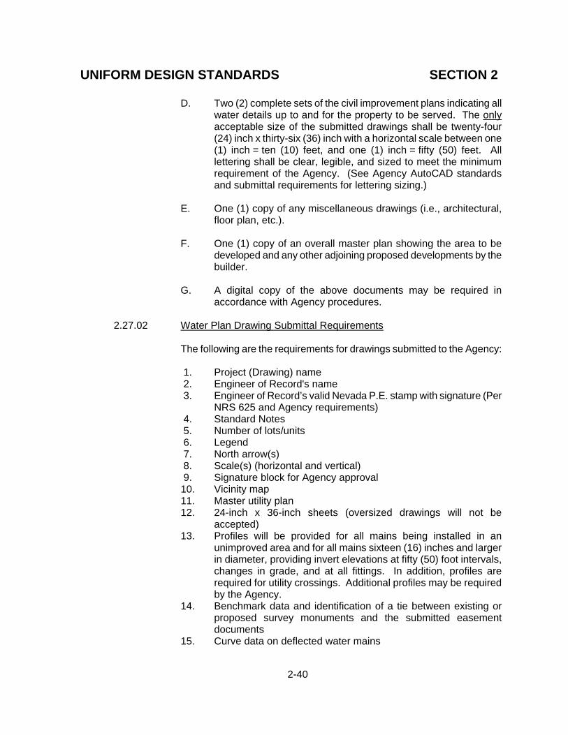
UNIFORM DESIGN STANDARDS SECTION 2
2-40
D. Two (2) complete sets of the civil improvement plans indicating all water details up to and for the property to be served. The only acceptable size of the submitted drawings shall be twenty-four (24) inch x thirty-six (36) inch with a horizontal scale between one (1) inch = ten (10) feet, and one (1) inch = fifty (50) feet. All lettering shall be clear, legible, and sized to meet the minimum requirement of the Agency. (See Agency AutoCAD standards and submittal requirements for lettering sizing.)
E. One (1) copy of any miscellaneous drawings (i.e., architectural,
floor plan, etc.).
F. One (1) copy of an overall master plan showing the area to be developed and any other adjoining proposed developments by the builder.
G. A digital copy of the above documents may be required in
accordance with Agency procedures. 2.27.02 Water Plan Drawing Submittal Requirements
The following are the requirements for drawings submitted to the Agency:
1. Project (Drawing) name 2. Engineer of Record's name 3. Engineer of Record’s valid Nevada P.E. stamp with signature (Per
NRS 625 and Agency requirements) 4. Standard Notes 5. Number of lots/units 6. Legend 7. North arrow(s) 8. Scale(s) (horizontal and vertical) 9. Signature block for Agency approval
10. Vicinity map 11. Master utility plan 12. 24-inch x 36-inch sheets (oversized drawings will not be
accepted) 13. Profiles will be provided for all mains being installed in an
unimproved area and for all mains sixteen (16) inches and larger in diameter, providing invert elevations at fifty (50) foot intervals, changes in grade, and at all fittings. In addition, profiles are required for utility crossings. Additional profiles may be required by the Agency.
14. Benchmark data and identification of a tie between existing or proposed survey monuments and the submitted easement documents
15. Curve data on deflected water mains

UNIFORM DESIGN STANDARDS SECTION 2
2-41
16. Driveway locations 17. ROW, easement(s), and property lines 18. Street names and ROW dimensions 19. Show all existing mains, laterals, valves, hydrants, etc. 20. Show all proposed mains, stubs, valves, bends, reducers etc.,
dimensioned from existing stationary markers (street light, sign, hydrant, etc.), and surveyed controls (street intersections, centerlines, property lines, etc.)
21. Show proposed service(s) 22. All new mains shall be drawn true to scale with no break lines 23. Layout should show the adjacent area and the relationship
between the new facilities and the existing facilities, (i.e., surface grading, etc.)
24. Identify all other utilities, existing and proposed (i.e., gas, sewer, etc.)
25. Locate all existing or proposed obstructions such as utility vaults, catch basins, traffic islands, etc.
26. Quantity estimates 27. Building information and fire flow requirements for each structure,
and location of all existing fire hydrants supporting the project 28. Fire Department approval 29. Notes as required by these Standards 30. Identify NDOT ROW on drawings, if applicable
2.27.03 Subdivision Water Plan Additional Drawing Requirements
In addition to the general water plan drawing requirements, the following will be required on subdivision water plans:
1. Lot and block numbers on all sheets 2. Total number of lots to be served 3. An overview map; e.g., copy of Assessor's Parcel Map, with
Assessor Parcel outlines prior to the subdivision under review. 4. Identify lots with static pressure ≥ eighty (80) psi. 5. Identify finished floor elevation for all proposed structures. 6. Provide meter box location detail as required clearly identifying
the construction of the meter box outside of driveways and other traffic areas.
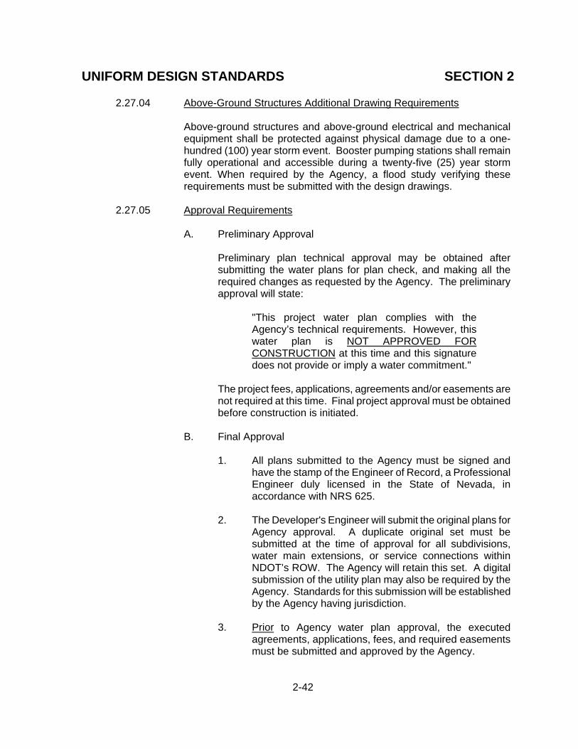
UNIFORM DESIGN STANDARDS SECTION 2
2-42
2.27.04 Above-Ground Structures Additional Drawing Requirements
Above-ground structures and above-ground electrical and mechanical equipment shall be protected against physical damage due to a one-hundred (100) year storm event. Booster pumping stations shall remain fully operational and accessible during a twenty-five (25) year storm event. When required by the Agency, a flood study verifying these requirements must be submitted with the design drawings.
2.27.05 Approval Requirements
A. Preliminary Approval
Preliminary plan technical approval may be obtained after submitting the water plans for plan check, and making all the required changes as requested by the Agency. The preliminary approval will state:
"This project water plan complies with the Agency’s technical requirements. However, this water plan is NOT APPROVED FOR CONSTRUCTION at this time and this signature does not provide or imply a water commitment."
The project fees, applications, agreements and/or easements are not required at this time. Final project approval must be obtained before construction is initiated.
B. Final Approval
1. All plans submitted to the Agency must be signed and
have the stamp of the Engineer of Record, a Professional Engineer duly licensed in the State of Nevada, in accordance with NRS 625.
2. The Developer's Engineer will submit the original plans for
Agency approval. A duplicate original set must be submitted at the time of approval for all subdivisions, water main extensions, or service connections within NDOT’s ROW. The Agency will retain this set. A digital submission of the utility plan may also be required by the Agency. Standards for this submission will be established by the Agency having jurisdiction.
3. Prior to Agency water plan approval, the executed
agreements, applications, fees, and required easements must be submitted and approved by the Agency.

UNIFORM DESIGN STANDARDS SECTION 2
2-43
4. Signature approval of the Fire Department having jurisdiction must be obtained PRIOR to the Agency's approving the final water plan.
5. All signatures required prior to the Agency approving the
final water plan must be less than one (1) year old.
C. Revised plans must contain a Professional Engineer stamp and signature of the Engineer of Record (See “Section 2.27.05B” above), and Fire Department signature, if applicable, for each revision.
2.27.06 Expiration Date
Construction must commence within one (1) year of the approval date shown on the plans, and must be diligently pursued to completion or the project may be subject to cancellation and must then be resubmitted for review and approval in accordance with the Agency's Service Rules and requirements.
2.28 NEVADA DEPARTMENT OF TRANSPORTATION (NDOT) PERMITS
A State Highway Permit is required when working on any water facilities within the ROW of any State owned or maintained road. The application for the permit will be made to the State following Agency procedures, and the developer will be responsible for the application fee. An easement for the Agency should be obtained from any underlying fee owner in the event NDOT does not own the full fee simple interest in the ROW. Prior to performing any work within the ROW, approval by the State must be received. The following note shall appear on the drawing:
NEVADA DEPARTMENT OF TRANSPORTATION (NDOT) PERMIT REQUIRED
An approved NDOT Occupancy Permit shall be obtained through the Agency prior to any construction within the NDOT ROW. Plans showing work in NDOT ROW must show NDOT stationing. The developer assumes all liability for work conducted under the Agency obtained permit through warranty expiration.
2.29 SOUTHERN NEVADA WATER SYSTEM (SNWS)/ SOUTHERN NEVADA WATER
AUTHORITY (SNWA)
If the project overlays an area involving existing or future SNWS/SNWA facilities, the Developer's engineer shall submit the plans to SNWS/SNWA for their review parallel with the Agency's review. SNWS/SNWA approval must be obtained PRIOR to Agency water plan approval. The SNWS/SNWA may be contacted by telephone at (702) 862-3444, by FAX at 862-3485, or by mail at P.O. Box 99956, Las Vegas, Nevada 89193-9956.

CONTINUE TO THE NEXT PAGE

UNIFORM DESIGN AND CONSTRUCTION STANDARDS
FOR POTABLE WATER DISTRIBUTION SYSTEMS
SECTION 3
UNIFORM
CONSTRUCTION STANDARDS

CONTINUE TO THE NEXT PAGE

UNIFORM CONSTRUCTION STANDARDS
SECTION 3
INDEX ITEM
DESCRIPTION
PAGE
3.00
GENERAL STATEMENT
3-1
3.01
STANDARD SPECIFICATIONS
3-1
3.02
CONTRACTOR'S LICENSE
3-1
3.03
CONTRACTOR'S RESPONSIBILITY
3-1
3.04
APPROVED PRODUCTS AND MATERIALS
3-1
3.05
ROW ENCROACHMENTS
3-1
3.06
CUT SHEETS
3-2
3.07
GRADE LINE
3-2
3.08
CONSTRUCTION STAKING
3-2
3.09
RECORD DRAWINGS
3-2
3.10
EARTHWORK
3-3
3.11
PIPE INSTALLATIONS
3-5
3.12 INSTALLATION OF PIPE CASING 3-14 3.13
SOILS TESTING 3-15
3.14
CONNECTIONS TO EXISTING FACILITIES 3-16
3.15
CONNECTIONS TO EXISTING STEEL CYLINDER PIPE 3-17
3.16
PROTECTIVE COATINGS 3-18
3.17
CONCRETE 3-22
3.18 REINFORCED STEEL 3-30
3.19 APPURTENANCES 3-31
3.20 CAPPING 3-36
3.21 VALVE ABANDONMENT 3-36
3.22 THRUST BLOCKS AND ANCHOR BLOCKS 3-36
3.23 MECHANICALLY RESTRAINED JOINTS 3-36 3.24 SERVICE LATERALS 3-36 3.25 BACKFLOW PREVENTION ASSEMBLIES 3-37 3.26 VALVES 3-38 3.27 TESTING AND DISINFECTING 3-38 3.28 SAFETY 3-42 3.29
3.30
JOINT USE TRENCH
OCCUPANCY PERMITS
3-423-42

CONTINUE TO THE NEXT PAGE

UNIFORM CONSTRUCTION STANDARDS SECTION 3
3-1
3.00 GENERAL STATEMENT The UDACS, Section 3, Uniform Construction Standards, is to provide a minimum
construction standard guideline to be applied in the construction phase of a project. The Contractor is responsible to perform construction per approved plans, and these standards. Any deviation shall be submitted by the Developer’s Engineer for Agency review and approval prior to construction.
3.01 STANDARD SPECIFICATIONS
Whenever the words "Standard Specification" appear on the plans or in these Uniform Design and Construction Standards for Potable Water Distribution Systems, they shall refer to the "Standard Drawings and Specifications for Public Works Construction Off-site Improvements, Clark County Area, Nevada", as amended. Unless otherwise specified herein, the "Standard Specifications" shall apply. Where conflicts may arise, the "Uniform Design and Construction Standards for Water Distribution Systems" shall govern.
3.02 CONTRACTOR'S LICENSE
All contractors installing mains, laterals, and appurtenant above-ground and under-ground structures shall have a valid license of a "Class" and a "Monetary Limit" corresponding to the work to be performed, in accordance with the provisions of the State of Nevada Contractors' License Law and NRS 624. This standard applies to all facilities located within public ROW’s and Agency easements which, when completed, will be maintained by the Agency.
3.03 CONTRACTOR'S RESPONSIBILITY
It shall be the Contractor's responsibility to perform construction as per approved plans. A copy of the approved plans, a copy of the current Uniform Design and Construction Standards (UDACS), and any amendments adopted by the Agency shall be onsite at all times. Any additions, deletions, or changes shall first be submitted by the Developer's Engineer for Agency review and approval prior to constructing any said additions, deletions, or changes.
3.04 APPROVED PRODUCTS AND MATERIALS The Contractor shall use products, materials, and mix designs identified on the Approved Products Listing of the Agency having jurisdiction, unless prior approval is obtained from the Agency.
3.05 ROW ENCROACHMENTS
The Contractor is required to comply with any restrictions imposed by permit(s) from the State, City, County, or other appropriate jurisdictional group.

UNIFORM CONSTRUCTION STANDARDS SECTION 3
3-2
3.06 CUT SHEETS
Cut sheets must be submitted for Agency approval a minimum of two (2) working days prior to any project construction in which the water main was designed with a specific profile. The cut sheets shall be prepared by, or under the supervision of, and signed by an NPLS or NPE.
Cut sheets will show, at a minimum, the following:
1. Stationing matching the approved plans 2. Hub elevations 3. Invert elevations 4. Cuts 5. Direction and distance of offset 6. Street names 7. Job title 8. Date of preparation 9. Benchmark data
10. Names of surveyors 11. Fittings, valves, and other appurtenant items
3.07 GRADE LINE
When the water main design has a profile with grades, the Agency may require a grade line be set at the designed grades prior to installing any pipe. A laser may be used in lieu of a grade line.
3.08 CONSTRUCTION STAKING
The Agency requires construction staking to include the offset, station, and the cut printed at each hub. Hubs shall be at fifty (50) foot (or less) stations, and every ten to twenty-five (10 - 25) feet on curved lines (depending on the curve radius), as required by the Agency, and ten (10) foot intervals in intersections with heavy traffic conditions.
3.09 RECORD DRAWINGS
Upon construction completion, and prior to the release of any bonds, the Contractor shall submit certified as-builts to the Developer's Engineer, as required by the Agency. At a minimum, as-builts shall include: distance between all valves and fittings, lateral locations at the property line, alignment changes, and existing utilities crossing the water main. The Engineer will provide the Agency with record drawings on mylars of good quality or in a digital format compatible with AutoCAD, at the Agency's option. The record drawings must reflect the certified as-builts, and be submitted prior to final Agency project acceptance and/or prior to issuing a Certificate of Occupancy.

UNIFORM CONSTRUCTION STANDARDS SECTION 3
3-3
3.10 EARTHWORK
The Contractor shall perform all earthwork required to construct all facilities, pipelines, and appurtenances as specified or shown on the drawings.
3.10.01 Excavation
A. Excavations, including the manner of supporting excavations and
provisions for access to trenches, shall conform to applicable Federal and State Industrial Safety requirements. All work shall be conducted in a manner to prevent damage to the work or adjoining property.
B. Pipeline excavations shall be open-cut trenches with vertical sides
up to the pipe crown, unless otherwise shown on the drawings or provided herein. The trench bottom shall have a minimum width as per the UDACS Plates. For rigid pipe, where the trench width is not defined by UDACS Plates, the trench width shall be designed by the Developer's Engineer and approved by the Agency. Compaction of foundation, bedding, and initial backfill shall extend to the trench wall.
C. Whenever the excavation is made below the grade shown on the
drawings, the over-excavated trench shall be backfilled to the re-quired grade with suitable material, as defined herein, and said material shall be brought to optimum moisture content and compacted by mechanical means to at least ninety (90) percent of maximum density in layers not exceeding six (6) inches in thickness.
D. Excess material and excavated material determined unsuitable for
backfill by the Agency's Representative shall be removed from the work site.
E. The Contractor shall provide a uniform, stable, base to the grade
shown on the plans or to the minimum depth required. F. Where an unstable or running soil condition is encountered in the
trench wall, such as may be found by excavation below groundwa-ter, this condition shall be stabilized by an approved material before laying the pipe.
G. Whenever the excavation exceeds the maximum allowed trench
width per the Standard Plates, the Developer shall provide a recommended correction by a licensed soils engineer or backfill the pipe zone with CLSM II.

UNIFORM CONSTRUCTION STANDARDS SECTION 3
3-4
3.10.02 Dewatering
Dewatering for structures and pipelines shall commence when groundwater is first encountered and shall be continuous until such times as water can be allowed to rise in accordance with the following provisions. Dewatering shall be conducted such that no concrete footings, floors, or pipelines are placed in water nor shall water be allowed to rise over them until the pipeline has been pressure tested and any concrete or mortar has achieved final set. Water shall not be allowed to rise unequally against walls until design strength is achieved or for a period of twenty-eight (28) days, nor shall water be allowed to rise in pipeline trenches or drained excavations until pipelines or facilities are backfilled or restrained to prevent flotation.
3.10.03 Pipe Bedding
The requirements for backfill materials are identified in UDACS Plates 16 through 19.
A. The pipe shall be bedded to line and grade with uniform and
continuous support for a firm base. Blocking shall not be used to bring the pipe to grade.
B. When the pipe being installed is provided with elastomeric seal
joints, bell holes shall be excavated in the bedding material to allow for unobstructed joint assembly. Care shall be taken that the bell hole is no larger than necessary to accomplish proper joint assembly. When the joint has been made, the bell hole shall be carefully filled with bedding or haunching material to provide for adequate pipe support throughout its entire length.
3.10.04 Pipe Zone Backfill
The requirements of this section will be adhered to except where more restrictive standards are recommended by the pipe manufacturer.
A. Wet Conditions - In any area where the pipe will be installed
below historic groundwater levels or where the trench could be subject to inundation, drain backfill material shall be placed to the pipe crown. In the initial stage of placing this type of material, sufficient crushed rock material shall be worked under the pipe haunch to provide adequate side support. Precautions must be taken to prevent pipe movement during material placement under the pipe haunch. Where unstable trench walls exist because of migratory materials such as water-bearing silts or fine sand, the loss of side support through the migratory action shall be prevented. In such cases, the use of CLSM may be necessary to provide needed support. CLSM shall meet the requirements as

UNIFORM CONSTRUCTION STANDARDS SECTION 3
3-5
specified in Subsection 704.03.07 of the “Uniform Standard
Specifications For Public Works’ (USS) Construction Off-Site Improvements, Clark County Area, Nevada”.
B. Dry Conditions - In any area where groundwater will not be
experienced at any time above the level of the foundation material and where the trench will not be subject to inundation, Type II material (See “UDACS Plates 16 through 19”) shall be placed in the pipe zone. The backfill material shall be placed to the pipe spring line and compacted by hand or mechanical tamping. In the initial stage of placing this material, sufficient Type II material shall be worked under the pipe to provide adequate side support to prevent pipe movement during this stage of backfilling. The initial backfill material shall be placed in two (2) stages; one to the pipe crown, and the second to a point at least twelve (12) inches over the pipe crown. Each stage shall be compacted by hand or mechanical tamping to the required density.
As an additional alternative to the preceding methods, CLSM may be used, as specified in Subsection 704.03.07 of the “Uniform Standard Specifications For Public Works’ (USS) Construction Off-Site Improvements, Clark County Area, Nevada”.
3.10.05 Trench Backfill
Backfill in the pipe trench above the pipe zone shall be in accordance with UDACS Plates 16 through 19.
3.11 PIPE INSTALLATIONS
Prior to commencing excavation, the Contractor shall have materials, labor, and equipment on the job site suitable for making emergency repairs to the existing water system should the existing facilities be damaged by the Contractor's operations. The Contractor shall take all necessary precautions to prevent the pipe from floating due to water entering the trench from any source. The Contractor shall keep the pipe interior free from foreign materials and in a clean and sanitary condition until Agency acceptance. All exposed piping shall be adequately supported with devices of appropriate design. Trenches shall be in a reasonably dry condition when the pipe is laid. Necessary facilities shall be provided for lowering and properly placing the pipe sections in the trench without damage. The pipe shall be laid carefully to the lines and grades shown without grade breaks unless designed with such, or to the minimum depths shown on the drawings, and the sections shall be closely jointed to form a smooth flow line.

UNIFORM CONSTRUCTION STANDARDS SECTION 3
3-6
Exceptional care shall be taken in placing the pipe and making the field joints. Concrete thrust blocks, per UDACS Plate 31, shall be provided at the locations and per sizes shown on the drawings. Pipe locator ribbon, detector ribbon wire, and/or locator balls, per Agency specification, shall be installed over all pipe in accordance with UDACS Plate 15. At times when pipe laying is not in progress, the open pipe end shall be sealed with a tight fitting cap or plug to prevent foreign matter entering the pipe. This provision shall apply at all times during construction until such time that the pipe has been accepted by the Agency.
3.11.01 Polyvinyl Chloride (PVC) Pressure Pipe C-900
Unless otherwise specified or shown on the drawings, polyvinyl chloride pressure pipe shall be Class 150 DR 18 and shall conform to AWWA Standard C900, "Polyvinyl Chloride (PVC) Pressure Pipe And Fabricated Fittings Four (4) Inches Through Twelve (12) inches For Water Distribution". Polyvinyl chloride pressure pipe shall have been manufactured within the eighteen (18) month period prior to installation. Polyvinyl chloride pressure pipe shall be manufacturer date coded and the Agency provided the manufacturer's code for translation. Rubber rings shall conform to the "Standard Specification for Elastomeric Seals (Gaskets) for Joining Plastic Pipe" (ASTM F477). A. Fittings
1. Unless otherwise specified or shown on the drawings, all
fittings to be used with polyvinyl chloride pressure pipe shall conform to one of the following standards or Agency approved equal, and shall be as included on the Agency’s approved materials list:
a. AWWA Standard C110, "Ductile-Iron and Gray-
Iron Fittings, Three (3) Inches Through Forty-eight (48) Inches For Water”.
b. AWWA Standard C153, "Ductile-Iron Compact
Fittings For Water Service”.
2. The contractor may use a flange adapter designed for AWWA Standard C900, "Polyvinyl Chloride (PVC) Pressure Pipe And Fabricated Fittings Four (4) Inches Through Twelve (12) Inches For Water Distribution" when connecting polyvinyl chloride pressure pipe to flanged fittings or flanged valves. Pipe ends must be cut smooth and square with no bevel. All flange adapters shall be
UNIFORM CONSTRUCTION STANDARDS SECTION 3
3-7
thoroughly cleaned, coated, and wrapped in accordance with Section 3.16 of these Standards.
3. Fittings are not to be placed under curb, gutter, or
sidewalk. All cast iron fittings shall be lined with cement mortar in
accordance with the requirements of AWWA Standard C104, “Cement-Mortar Lining For Ductile Iron Pipe And Fittings For Water”. All fittings and joint connections shall be thoroughly cleaned, coated, and wrapped in accordance with UDACS Section 3.16.
B. Installation
1. Polyvinyl chloride pressure pipe shall be installed in
accordance with the AWWA Manual M23, “PVC Pipe - Design And Installation”, and AWWA Standard C605, “Underground Installation Of Polyvinyl Chloride (PVC) Pressure Pipe And Fittings For Water”, and the manufacturer's recommendations, except as otherwise provided herein or shown on the drawings.
2. Polyvinyl chloride pressure pipe shall be connected to
four (4) inch through twelve (12) inch asbestos cement pipe only by use of the proper transition couplings approved by the Agency.
3. The manufacturer's recommended pipe lubricant shall be
used when making pipe connections by lubricating the spigot end up to, and including, the reference mark. The reference mark on the spigot end must be flush with the bell end after installation. AWWA standards and the manufacturer's recommendations shall be followed.
4. Polyvinyl chloride pressure pipe shall be stored at the job
site in a unit package provided by the manufacturer. Pipe and gaskets shall not be stored close to a source of heat, and must be kept free of dirt, foreign matter, ozone, oil, and grease. Gaskets shall not be stored exposed to sunlight.
5. Polyvinyl chloride pressure pipe, couplings, and rubber
rings shall be free from damage and defects in material and workmanship. Rejected, damaged, or defective materials shall be removed from the Site.
6. Remove from Site all polyvinyl chloride pressure pipe
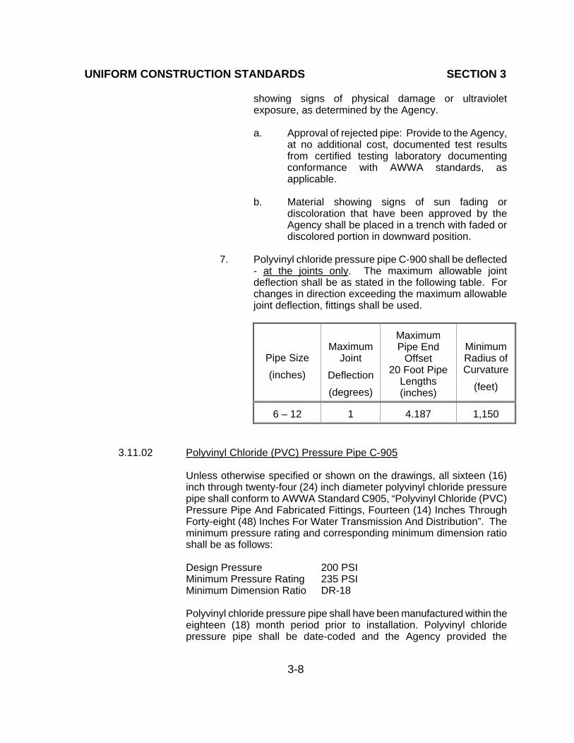
UNIFORM CONSTRUCTION STANDARDS SECTION 3
3-8
showing signs of physical damage or ultraviolet exposure, as determined by the Agency. a. Approval of rejected pipe: Provide to the Agency,
at no additional cost, documented test results from certified testing laboratory documenting conformance with AWWA standards, as applicable.
b. Material showing signs of sun fading or
discoloration that have been approved by the Agency shall be placed in a trench with faded or discolored portion in downward position.
7. Polyvinyl chloride pressure pipe C-900 shall be deflected
- at the joints only. The maximum allowable joint deflection shall be as stated in the following table. For changes in direction exceeding the maximum allowable joint deflection, fittings shall be used.
Pipe Size
(inches)
Maximum Joint
Deflection
(degrees)
Maximum Pipe End
Offset 20 Foot Pipe
Lengths (inches)
Minimum Radius of Curvature
(feet)
6 – 12
1
4.187
1,150
3.11.02 Polyvinyl Chloride (PVC) Pressure Pipe C-905
Unless otherwise specified or shown on the drawings, all sixteen (16) inch through twenty-four (24) inch diameter polyvinyl chloride pressure pipe shall conform to AWWA Standard C905, “Polyvinyl Chloride (PVC) Pressure Pipe And Fabricated Fittings, Fourteen (14) Inches Through Forty-eight (48) Inches For Water Transmission And Distribution”. The minimum pressure rating and corresponding minimum dimension ratio shall be as follows: Design Pressure 200 PSI Minimum Pressure Rating 235 PSI Minimum Dimension Ratio DR-18 Polyvinyl chloride pressure pipe shall have been manufactured within the eighteen (18) month period prior to installation. Polyvinyl chloride pressure pipe shall be date-coded and the Agency provided the

UNIFORM CONSTRUCTION STANDARDS SECTION 3
3-9
manufacturer’s code for translation. Rubber rings shall conform to the “standard specification for elastomertric seals (gaskets) for joining plastic pipe” (ASTM 477). Polyvinyl chloride pressure pipe shall be deflected at the joints only. The maximum allowable joint deflection is limited and shall not exceed manufacturer recommendations. In general, fittings shall be used for all changes in direction.
Max Joint Deflection (degrees)
Maximum Pipe End Offset
20 Foot Pipe Lengths (inches)
Minimum Radius of Curvature
(feet)
1
4.187
1,150
A. Fittings
1. Unless otherwise specified or shown on the drawings, all fittings to be used with polyvinyl chloride pressure pipe shall conform to one of the following standards or Agency approved equal, and shall be as included on the Agency’s approved materials list:
a. AWWA Standard C110, ”Ductile Iron and Gray
Iron Fittings, Three (3) Inches Through Forty-eight (48) Inches For Water.
b. AWWA Standard C153, “Ductile Iron Compact
Fittings For Water Service”. 2. All cast iron fittings shall be lined with cement mortar in
accordance with the requirements of AWWA Standard C104, “Cement-Mortar Lining For Ductile Iron Pipe And Fittings For Water”. All fittings and joint connections shall be thoroughly cleaned, coated, and wrapped in accordance with UDACS Section 3.16.
B. Installation
1. Polyvinyl chloride pressure pipe shall be installed in
accordance with AWWA Standard C905, “Polyvinyl Chloride (PVC) Pressure Pipe And Fabricated Fittings, Fourteen (14) Inches Through Forty-eight (48) Inches For Water Transmission And Distribution”, and the manufacturer's recommendations, except as otherwise provided herein or shown on the drawings.
UNIFORM CONSTRUCTION STANDARDS SECTION 3
3-10
2. The manufacturer’s recommended pipe lubricant shall be
used when making pipe connections by lubricating the spigot end up to and including the reference mark. The reference mark on the spigot end must be flush with the end of the bell after installation. AWWA Manual M-23, “PVC Pipe - Design And Installation”, and the manufacturer’s recommendations shall be followed.
3. Polyvinyl chloride pressure pipe shall be stored at the job
site in a unit package provided by the manufacturer. Pipe and gaskets shall not be stored close to a source of heat and must be kept free of dirt, foreign matter, ozone, oil, and grease. Gaskets shall not be exposed to sunlight.
4. Polyvinyl chloride pressure pipe, couplings, and rubber
rings shall be free from damage and defects in material and workmanship. Rejected, damaged, or defective materials shall be removed from Site.
5. Remove from Site all polyvinyl chloride pressure pipe
showing signs of physical damage or ultraviolet exposure, as determined by the Agency. a. Approval of rejected pipe: Provide to the Agency,
at no additional cost, documented test results from certified testing laboratory documenting conformance with AWWA standards, as applicable.
b. Material showing signs of sun fading or
discoloration that have been approved by the Agency shall be placed in a trench with faded or discolored portion in downward position.
6. Where required, restrained joints will be utilized in lieu of
thrust blocks unless otherwise shown on the drawings.
3.11.03 Asbestos Cement Pipe (ACP) (FOR REPAIR AND MODIFICATION OF EXISTING LINES ONLY)
A. Fittings
1. Unless otherwise approved and shown on the drawings, all fittings to be used with existing asbestos cement pipe shall be either cast iron or ductile iron, and shall be as included on the Agency’s approved materials list.

UNIFORM CONSTRUCTION STANDARDS SECTION 3
3-11
2. Joints made between asbestos cement pipe and cast iron
valves and fittings shall be sealed with an Agency approved rubber ring gasket, unless otherwise shown on the drawings. After assembling the joint, the rubber ring gasket position shall be checked with a suitable gauge. Rubber ring gaskets shall be located an even distance from the face of the valve or fitting, for the full pipe circumference. Precaution shall be taken while jointing to prevent dirt from entering the joint space.
B. Disposal of Asbestos Cement Pipe
Disposal of asbestos cement pipe shall be in accordance with local, state, and federal regulations.
3.11.04 Ductile-Iron Pipe (DIP)
A. Materials
1. Unless otherwise specified or shown on the drawings,
ductile iron pipe shall conform to AWWA Standard C151, “Ductile-Iron Pipe, Centrifugally Cast, For Water” as follows:
a. Up to and including twelve (12) inch: Pressure
Class 350. b. Fourteen (14) inch to twenty-four (24) inch:
Pressure Class 250, as required by the Agency. c. Twenty-four (24) inch diameter: Pressure Class
250, or as required by the Agency.
2. The lining of ductile iron pipe (DIP) shall be as follows:
a. Cement mortar line (double thickness) in accordance with AWWA Standard C104, “Cement-Mortar Lining For Ductile Iron Pipe And Fittings For Water”.
b. Thickness of cement mortar lining (double
thickness) shall be as follows:
- Not less than one-eighth (1/8) inch for four (4) inch to twelve (12) inch.

UNIFORM CONSTRUCTION STANDARDS SECTION 3
3-12
- Three-sixteenth (3/16) inch for fourteen (14) inch to twenty-four (24) inch.
3. Ductile iron pipe installed below grade shall use either
mechanical joints, restrained joints, or push on joints conforming to AWWA Standard C111, “Rubber Gasket Joints For Ductile-Iron Pressure Pipe And Fittings”, unless otherwise specified.
4. Ductile iron pipe installed above grade shall use flanged
joints in accordance with AWWA Standard C115, “Flanged Ductile-Iron Pipe With Ductile-Iron Or Gray-Iron Threaded Flanges”, unless otherwise specified on the approved plans.
B. Fittings and Couplings
1. Unless otherwise approved and shown on the drawings,
all fittings to be used with ductile iron pipe shall conform to quality and wall thickness specified in AWWA Standard C110, “Ductile-Iron And Gray-Iron Fittings, Three (3) Inches Through Forty-eight (48) Inches For Water”, or in AWWA Standard C153, “Ductile-Iron Compact Fittings For Water Service”.
2. Rubber gaskets for sealing ductile iron pipe joints shall
conform to AWWA Standard C111, “Rubber-Gasket Joints for Ductile-Iron Pressure Pipe and Fittings".
C. Installation
1. Ductile iron pipe shall be installed in accordance with
AWWA Standard C600, ”Installation of Ductile-Iron Water Mains And Their Appurtenances", and the manufacturer's recommendations except as otherwise provided herein or shown on the drawings.
2. Transition gaskets may be used to connect four (4), six
(6) or eight (8) inch diameter ductile iron pipe to four (4), six (6), or eight (8) inch diameter asbestos cement pipe.
3. Transition couplings or approved fittings, may be used to
connect four (4), six (6), or eight (8) inch diameter ductile iron pipe to four (4), six (6) or eight (8) inch diameter asbestos cement pipe. A transition coupling must be provided for all transitions ten (10) inch and larger.

UNIFORM CONSTRUCTION STANDARDS SECTION 3
3-13
4. All fittings and joint connections shall be thoroughly
cleaned and coated in accordance with Section 3.16 of these Standards.
5. The maximum allowable joint deflection for push-on type
joint and mechanical-joint pipe shall be as follows:
PUSH-ON TYPE DIP JOINT
Pipe Size
Deflection
Angle
Maximum
Offset (Inches)
Radius of
Curvature (Feet)
(Inches)
(Degrees)
18'
Length
20'
Length
18'
Length
20'
Length
4" - 12"
2.5o
9"
10"
415'
460'
14" - 24"
1.5o
6"
6"
690'
765'
MECHANICAL TYPE DIP JOINT
Maximum Offset (Inches)
Radius of Curvature
(Feet)
Pipe Size
(Inches)
Deflection Angle
(Degrees)
18'
Length
20'
Length
18'
Length
20'
Length
4"
4.0o
15"
17"
260'
290'
6"
3.5o
13"
15"
295'
330'
8" - 12"
2.5o
9"
10"
415'
460'
14" - 24"
1.5o
6"
6"
690'
765'
D. Polyethylene Encasement
1. All ductile iron pipe, fittings, and joint connections shall be encased as follows:
a. Polyethylene encasement in accordance with
AWWA Standard C105, “Polyethylene Encasement For Ductile-Iron Pipe Systems”; however, two (2) wraps shall be utilized instead of

UNIFORM CONSTRUCTION STANDARDS SECTION 3
3-14
one (1). The polyethylene film shall have a minimum thickness of eight (8) mils and two (2) wraps shall have a total minimum film thickness of sixteen (16) mils.
Nominal Pipe Diameter
Minimum Polyethylene Width (inches)
(inches)
Flat Tube
Sheet 4
16
32
6
20
40
8
24
48
10
27
54
12
30
60
14
34
68
16
37
74
18
41
82
20
45
90
24
54
108
2. The Contractor shall repair any damage to the polyethylene film as described within AWWA Standard C105, “Polyethylene Encasement For Ductile-Iron Pipe Systems”, or shall replace all damaged polyethylene film sections.
3. Provide minimum two (2) inch wide polyethylene tape.
3.12 INSTALLATION OF PIPE CASING
The Contractor shall furnish and install all pipe casing as specified herein, as shown on the approved drawings and UDACS Plate 23. The casing shall be laid true to grade and line with no bends or changes in grade for the casing's full length.
The casing shall be steel fabricated and shall conform to the requirements of ASTM A283, Grade B, C, or D. All joints shall be welded. Interior joints shall be ground to a smooth finish. All welding shall be performed in accordance with AWWA Standard C206, “Field Welding of Steel Water Pipe”. Casing wall thickness shall be in accordance with UDACS Plate 23. The wall thickness for casing installations over twenty-five (25) feet below finished grade shall be determined by a Nevada Licensed Professional Engineer. Casing wall thickness for installations under railroad tracks shall be determined by a Nevada Licensed Professional Engineer and approved by the Union Pacific Railroad.

UNIFORM CONSTRUCTION STANDARDS SECTION 3
3-15
Casings installed by jack and bore method shall be installed to the grade shown on the drawings, with a maximum vertical deviation of + zero (0)o and - two (2)o, and a maximum horizontal deviation of + two (2)o provided the alignment does not conflict with other utilities and/or rights-of-way. The water pipe installed in the casing shall be supported by Agency approved casing spacers, and installed in accordance with the manufacturer’s recommendations. After pipe installation, the casing shall be sealed, and Agency approved end seals shall be installed per the manufacturer’s recommendations. Where installation of casing may be accomplished by open cut methods, water quality RCP casings may be used in lieu of steel casings, as approved by the Agency. If the casing is required in order to meet the requirements of Section 2.22, the RCP sections must be installed using Agency approved elastomeric joint sealants or joint gaskets. RCP casings installed for future pipeline installations shall be securely sealed with removable bulkheads at both ends in a manner acceptable to the Agency.
3.13 SOILS TESTING
A. Contractor Test: The Contractor will be required to furnish the Agency a sieve analysis, plasticity index, soluble sulfate, expansion potential, and Proctor of the material when required by the Agency. Agency approval of the sieve analysis, plasticity index, and Proctor will be required prior to using the material. The Contractor shall pay all costs in providing the Proctor and having the sieve analysis and plasticity index taken by a soils lab. The Agency Representative shall be present for sampling. The Contractor will be required to furnish an updated Proctor to the Agency prior to any compaction testing. The Proctor will be in accordance with ASTM D-1557, and performed by an approved soils laboratory within the previous six (6) months or at the Agency's discretion. If the Agency's Representative determines the backfill material has changed, the Contractor will be required to supply a new Proctor.
B. Agency Test: The Agency shall take compaction tests. Agency compaction tests shall be paid for by the Agency. The number and location of compaction tests on backfill material will be determined per Agency requirements and procedures.

UNIFORM CONSTRUCTION STANDARDS SECTION 3
3-16
C. If the Contractor challenges the Agency's compaction test results, an independent
testing lab will be called to take tests using the following method:
Proctor: Tests shall be in accordance with ASTM D-1557. Sample: In place soils shall be tested in accordance with ASTM D-1556,
Method "D", with the exception no samples shall contain particles larger than three-quarter (3/4) inch.
D. If the independent soils laboratory test results fail to meet the Agency’s Standards,
the Contractor shall pay for the test(s) and retest(s). If the test results indicate the Agency standards have been met, the Agency shall pay for the testing. Where compaction tests indicate a failure to meet the required compaction, additional tests will be taken every fifty (50) feet in each direction until the failing area is defined. The entire area between the passing test locations shall be reworked until the proper compaction requirements are achieved.
3.14 CONNECTIONS TO EXISTING FACILITIES
The Contractor shall make Agency approved connections to existing facilities as shown on
the drawings. The Contractor shall notify the Agency at least two (2) business days prior to beginning any connections to the existing facilities. All pipe connection to existing main and fittings shall be swabbed internally with an approved chlorine solution. All connections shall be made in the presence of the Agency's Representative. When the new work involves new water main installation, the new mains shall be tested and disinfected in accordance with Section 3.27 of these Standards.
3.14.01 Connections To Existing Facilities – Dry Taps
Dry connections to existing facilities shall be made only at locations shown on the drawings, shall be made at times which will cause the least inconvenience to the water consumer, and shall be planned to minimize the duration of any shut down. No valves are to be operated without an Agency representative present. Existing facilities will not be shut down for connections to new facilities without prior Agency approval. In no case shall an existing pipeline be shut down for a total of more than twenty-four (24) hours (a maximum of three shut down periods, shut down should not exceed eight (8) hours each). Shutdowns for longer periods will require provisions for temporary service approved by the Agency and coordinated with the Agency’s customers. The work plans for making connections to existing facilities that require an existing pipeline shut down, shall be submitted to the Agency and shall be approved before the Contractor will be allowed to proceed. The Contractor shall notify, by a method approved by the Agency, all affected Agency

UNIFORM CONSTRUCTION STANDARDS SECTION 3
3-17
customers at least twenty-four (24) hours prior to shut down. Valves at connections to all existing facilities shall be operated by the Contractor, but only in the presence of the Agency's Representative, unless otherwise required by the Agency. If the water will be shut off for an extended period of time, the Agency may require the Contractor to supply water for the Agency's customers. The Agency cannot guarantee a watertight shut down where connections or repairs to existing facilities are required. The Contractor shall ensure all labor and equipment is available to remove fugitive water that may impede construction at all times. Coordination with Agency must take place prior to any trial shutdown. Contractor shall install temporary service to verify proper shutdown in the event no other appurtenances are available.
3.14.02 CONNECTIONS TO EXISTING FACILITIES - WET TAPS
The Contractor shall furnish and install, at his sole cost and expense, all tapping fittings and valves for all wet taps on existing Agency pipelines. The Contractor shall notify the Agency a minimum of two (2) business days prior to the time the wet tap is requested to be made.
Upon Agency acceptance of the tapping fittings and valves as having been properly installed and having passed the required pressure test, the Contractor will be allowed to tap the main. Unless otherwise shown on the drawings or specified in these Standards, the Contractor will furnish all labor and equipment, and will perform, at his sole cost and expense, all wet taps on existing Agency pipelines.
3.15 CONNECTION TO EXISTING STEEL CYLINDER PIPE Wet taps on existing steel mains (SCCP and MLC) shall be accomplished using a full
fabricated steel wrapper, and designed in accordance with AWWA Manual M11, “Steel Pipe - A Guide For Design And Installation”. (See “UDACS Plate 35”.)
When an existing pretensioned steel cylinder concrete pipe is cut for the installation of a
new steel plate special, the rod wrap on the existing pipe shall be welded to the steel cylinder on either side of the section to be cut prior to making the cut, to ensure the pipeline integrity is not impaired. Excess rod wrap shall be wrapped firmly around the pipe parallel to the cut, lapped a minimum of one and one-half (1½) laps, and welded in place to provide a continuous wrap parallel to the cut.
The Contractor shall, at his sole cost and expense, furnish all wet taps to existing Agency steel pipelines. Such wet taps, including all welding, shall be made by one of the following companies or by company (ies) listed in the Agency Addenda Section:

UNIFORM CONSTRUCTION STANDARDS SECTION 3
3-18
American Piping Services, Inc. 6625 South Valley View Blvd., Suite 200 Las Vegas, NV 89118 Telephone: (702) 362-3622 International Flow Technologies, Inc. 30230 Los Alamos Road Murrieta, CA 92563 Telephone (800) 221-3332 and ( 909) 926-4849 Tap Master 8414 West Farm Road, Suite 180-246 Las Vegas, NV 89131 Telephone (888) 982-7627 T. D. Williamson, Inc. 5727 South Lewis Ave., Suite 300 Tulsa, OK 74105-7144 Telephone: (888) 839-6766
3.16 PROTECTIVE COATINGS
3.16.01 References
A. American Water Works Association (AWWA) Standards - most recent editions:
1. AWWA C105: Polyethylene Encasement for Ductile-Iron
Pipe Systems. 2. AWWA C110: Ductile-Iron and Gray-Iron Fittings, Three
(3) Inch through Forty-eight (48) Inch For Water. 3. AWWA C116: Protective Fusion-Bonded Epoxy Coatings
for the Interior and Exterior Surfaces of Ductile-Iron and Gray-Iron Fittings For Water Supply Service.
4. AWWA C213: Fusion-Bonded Epoxy Coating For The
Interior and Exterior of Steel Water Pipelines.
B. National Sanitation Foundation (NSF) Standard - most recent edition: 1. NSF Standard 61: Drinking Water System Components -
Health Effects.
C. Society for Protective Coatings (SSPC) Standards - most recent editions.

UNIFORM CONSTRUCTION STANDARDS SECTION 3
3-19
D. United States Environmental Protection Agency, Code of Federal
Regulations (CFR).
3.16.02 Coating Materials
A. Type 11 - Multi-Use Epoxy
1. Uses: a. Primer for exposed ferrous surfaces.
b. Primer and finish coat for interior exposed ferrous surfaces.
c. Repair/touch-up of fusion bonded epoxy finishes.
B. Type 15 - Fusion Bonded Epoxy
1. Uses: a. Lining and coating submerged ferrous surfaces. b. Finish coat for exposed ferrous surfaces.
C. Type 20 - Aliphatic Polyurethane 1. Uses: a. Finish coat for exposed ferrous surfaces. b. Finish coat for masonry interior surfaces.
D. Type 40 - Petroleum Asphaltic
1. Uses: a. Buried ductile iron pipe and fittings.
b. In accordance with AWWA Standard C110, “Ductile-Iron And Gray-Iron Fittings, Three (3) Inches Through Forty-eight (48) Inches For Water.
E. Type 50 - Wax-Based Coatings
1. Uses: a. Buried miscellaneous ferrous equipment.

UNIFORM CONSTRUCTION STANDARDS SECTION 3
3-20
b. Buried nuts and bolts. F. Type 60 - Organic Rich Zinc Coating
1. Uses:
a. For small local repair of galvanized equipment only.
3.16.03 Application
A. General
1. Prepare surfaces and apply coatings in accordance with manufacturer’s instructions.
2. Primer, intermediate, and finish coat: Compatible and
from same manufacturer. 3. Field repair coatings as recommended by manufacturer.
B. Buried Ductile Iron 1. System type - Petroleum Asphaltic:
a. Factory applied, one coat: Type 40 - Petroleum Asphaltic.
b. Field repair as needed.
C. Buried Ferrous Surfaces And Fittings Prior To Wrap
1. System type - Wax based coating: a. One coat: Type 50 - wax based coating.
b. Polyethylene wrap: After coating, wrap surfaces with two layers of eight (8) mil polyethylene film and tightly seal as specified in AWWA Standard C105, “Polyethylene Encasement For Ductile-Iron Pipe Systems”.
2. System Type - Cement Mortar Coating:
a. Place mortar lining in steel piping and steel plate specials in pipe to thickness specified herein:
(1) Reinforce lining on steel plate specials
larger than sixteen (16) inches in diameter

UNIFORM CONSTRUCTION STANDARDS SECTION 3
3-21
with two (2) inch by four (4) inch number thirteen (13) gage welded steel wire mesh.
Pipe Lining Diameter Thickness Tolerances (Inches) (Inches) (Inches)
Less than 24 5/16 -1/16, + 1/8 24 through 36 1/2 -1/16, + 1/8 Greater than 36 5/8 -1/16, +3/16
(2) Other requirements of mortar lining materials and processes: As specified in AWWA Standard C205, “Cement-Mortar Protective Lining And Coating For Steel Water Pipe - Four (4) Inches And Larger - Shop Applied”.
b. Apply reinforced cement mortar coating over
outer surfaces of steel piping and steel plate specials, unless otherwise specified:
(1) Use Type V cement for mortar coatings
(ASTM C150). (2) Cement mortar mixture shall consist of
one (1) part cement to not more than three (3) parts sand (ASTM C33).
(3) Use no more than four and a half (4 1/2)
gallons of water per sack of cement. (4) Cement mortar and mortar armor coating:
One (1) inch thick with permitted tolerance of plus one quarter (1/4) inch.
(5) Pipe and specials, diameter less than
forty-eight (48) inches: Reinforce coating with spirally wound No. twelve (12) gage steel wire spaced at one (1) inch centers or with No. fourteen (14) gage steel wire at one half (1/2) inch centers positioned approximately in center of mortar coating.
(6) Pipe and specials, diameter forty-eight
(48) inches and larger: Reinforce coating with two (2) layers of spirally wound No. twelve (12) gage steel wire spaced at one (1) inch centers or with No. fourteen (14)

UNIFORM CONSTRUCTION STANDARDS SECTION 3
3-22
gage steel wire at one half (1/2) inch centers positioned at third points of mortar coating.
(7) Permitted to reinforce coating steel plate
specials with two (2) inch by four (4) inch No. thirteen (13) gage welded wire mesh in lieu of wire, positioned in coating as stated above.
(8) Lap ends of reinforcement strips four (4)
inches, and tie or loop free ends to assure continuity of reinforcement.
D. Exposed Ferrous Surfaces 1. System type: Epoxy/Polyurethane:
a. Primer: Type 11 - Multi-Use Epoxy. b. Finish coat: Type 20 - Aliphatic Polyurethane.
E. Valves and Fittings - As Specified 1. System type: Fusion Bonded Epoxy: a. One coat: Type 15 - Fusion bonded epoxy. F. Galvanized Equipment 1. “Hot-Dip” coating: a. As specified in ASTM A123 and ASTM A153. 2. Type 60 - Organic Zinc-Rich Coating a. For small local repairs only.
3.17 CONCRETE
The Contractor shall furnish all materials, equipment and labor necessary to complete the concrete work as shown on the drawings as established in the guidelines of the American Concrete Institute (ACI) and the Concrete Reinforcing Steel Institute (CRSI) and as specified herein.
3.17.01 Cementitious Materials
Cement shall be Portland Cement in accordance with the "Specification
UNIFORM CONSTRUCTION STANDARDS SECTION 3
3-23
for Portland Cement" (ASTM C 150), Type V for all concrete in contact with the ground, including pipe coatings, and Type II or V for all other concrete. Fly ash shall be in accordance with ASTM C618, Class F. A. Substitution ratio: One and one-fifth (1.2) pounds fly ash for each
one (1.0) pound of cement. B. Maximum fly ash content: Twenty (20) percent of cement
removed of specified cement weight.
3.17.02 Aggregates
Aggregates shall be obtained from pits approved by the Agency, and shall conform to the "Standard Specifications for Concrete Aggregates" (ASTM C 33). Maximum aggregate size shall be three-quarter (3/4) inch for slabs and walls, and one (1) inch for structural concrete. Footings, foundations, and thrust blocks may use one and one half (1 1/2) inch maximum size aggregate.
3.17.03 Water
Water shall be potable (clean and free of injurious amounts of acids, alkalies, organic matter or other deleterious substances).
3.17.04 Forms
A. Forms shall conform to the shape, lines, and dimensions of the
members shown on the drawings and shall be sufficiently tight to prevent leakage of mortar. Forms shall be properly braced, and tied to maintain position and shape.
B. Forms for exposed concrete shall be Fir Plywood, concrete form
grade, or faced with tempered hardboard or metal forms resulting in a concrete finish equal to that obtained by the use of plywood forms. Forms for exposed concrete surfaces shall be coated with colorless, non-staining mineral oil specifically manufactured for this purpose.
C. Forms for unexposed concrete shall be either of the type
specified for exposed concrete or wood sheathing boards of uniform thickness, without loose knots, reasonably straight, and butted with tight joints. Forms for unexposed concrete may be coated with form oil or wetted with water before the concrete is placed.
D. Forms shall be removed in such a manner and at such time as to

UNIFORM CONSTRUCTION STANDARDS SECTION 3
3-24
ensure the structure's safety. The results of strength tests made during construction may be used as evidence that the concrete has attained the required strength. Care shall be taken to avoid spalling concrete surfaces. Tie rod or bolt holes shall be filled solidly with mortar after form removal. Mortar used for filling holes on exposed concrete surfaces shall match the surface in color and texture.
3.17.05 Concrete Mixes
A. Mix designs shall be in accordance with the Interagency
Quality Assurance Committee (IQAC), or as approved by the Agency having jurisdiction.
B. Concrete compressive strength, aggregate size, and slump
shall be in accordance with the following:
Type of Construction
Compressive
Strength (psi)
Maximum
Size Aggregate in Inches
Slump
In Inches (Max.)
Slabs, Walls, and
Extruded Curb and Gutter
3,000
3/4
4
Pipeline Structures
4,500
1
4
Footing, Foundations, Reinforced Concrete Encasements, Thrust Blocks and Formed
Curb and Gutter
3,000
1-1/2
4
Site Underground Conduit Banks:
Minimum 3 lbs. Red Pigment/Sack
Cement
3,000
3/8
6
CLSM I 50 - 150 3/8 10
CLSM II 150 - 300 3/8 10
1. Compressive strength: Twenty-eight (28) day
minimum.

UNIFORM CONSTRUCTION STANDARDS SECTION 3
3-25
2. Reinforced concrete: Minimum six (6) sacks Portland
Cement per cubic yard. 3. Unreinforced concrete: Minimum five (5) sacks
Portland Cement per cubic yard. 4. Maximum water cement ratio: 0.45 by weight.
3.17.06 Ready Mixed Concrete
A. Provide a batch ticket to the Agency Representative for each delivered load ready-mixed concrete, indicating:
1. Volume of concrete. 2. Weight of cement in pounds. 3. Total weight of all ingredients in pounds. 4. Time of day at which the materials were batched. 5. In accordance with ASTM C94.
3.17.07 Expansion Joints
The Contractor shall provide expansion joints in concrete slabs where shown on the drawings. Expansion joint filler shall be thick and extend the full slab thickness. Expansion joint filler shall be pre-formed, nonextruding, resilient type constructed of cellular neoprene sponge rubber, extending the full thickness of the slab, in accordance with the "Specification for Preformed Expansion Joint Fillers for Concrete Paving and Structural Construction" (ASTM D 1751 or ASTM D 1752, Type I).
3.17.08 Placing Concrete
A. Prior to placing concrete, the Contractor shall remove any
ponded water from the excavation, and moisten fill for slabs to be placed on fill.
B. Concrete shall be placed in accordance with ACI Specifications
and this Section. C. Ready-Mix Equipment:
1. The volume of concrete for each batch shall not exceed the manufacturer’s rated capacity of the mixer.

UNIFORM CONSTRUCTION STANDARDS SECTION 3
3-26
2. The Contractor shall ensure sufficient mixing time for the concrete for uniform distribution of materials.
3. The Contractor shall discharge all concrete from the
mixer prior to mixing a new batch. 4. Ready-mixed equipment shall conform to specifications
in accordance with ASTM C94. D. Transporting:
1. The Contractor shall transport concrete from the mixer to the place of deposit by methods that will prevent segregation or loss of material.
2. The Contractor shall provide runways when
wheelbarrows are used to transport concrete. 3. The Contractor shall not use wheel conveying equipment
over reinforcement or support runways on reinforcement.
E. Placing: 1. Concrete shall be deposited in a continuous manner, and
as rapidly as possible. 2. Concrete which has attained initial set or has contained
mixing water for more than one (1) hour shall not be used.
3. Concrete shall be uniformly distributed during the
process of depositing, and in no case after depositing shall any portion be displaced in the forms more than six (6) feet in horizontal direction.
4. Deposit concrete in forms in uniform horizontal layers not
deeper than two (2) feet. Place each layer while the previous layer is still workable. No retempering of concrete will be permitted.
5. Concrete will not be allowed to drop freely more than four
(4) feet in unexposed work nor more than three (3) feet in exposed work; where greater drops are required, the use of a duct or other Agency approved method shall be employed.
6. Concrete shall not be placed against icy or frost covered
earth surfaces.
UNIFORM CONSTRUCTION STANDARDS SECTION 3
3-27
F. Compacting:
1. Compaction shall be effected by means of internal type vibrators supplemented by rodding and tamping as may be necessary, to maximum practicable density, free from pockets of coarse aggregate in such a manner that surfaces are smooth and free from voids.
2. Care shall be taken to avoid excessive vibration of
concrete, and to avoid segregation of aggregates. 3. Care shall be taken to avoid disturbance of previous lifts
where initial set has taken place. 4. The use of form vibrators or form tapping is prohibited.
G. Construction Joints: 1. Where shown on drawings, prime construction joints and
fill with joint sealant. 2. Use primer supplied by sealant manufacturer. 3. Where shown on drawings, apply sealing grout at
construction joints. 4. Brush joint clean prior to grout application. 5. Mix sealing grout in accordance with manufacturer’s
recommendations.
3.17.09 Adverse Weather Conditions
A. When the temperature is below forty (40) o F, or is likely to fall below forty (40) o F during the twenty-four (24) hour period after placing the concrete, materials shall be heated (not in excess of one hundred forty (140) o F) so the concrete will have a temperature between fifty (50) o F and ninety (90) o F. Plastic covers, curing blankets or other means of protection shall be used to protect the concrete for the twenty-four (24) hour period after placing the concrete.
B. During hot weather, materials shall be shaded from the sun or
otherwise cooled, and the water shall be cooled so the concrete temperature will not exceed ninety (90) o F at the time of placing the concrete.

UNIFORM CONSTRUCTION STANDARDS SECTION 3
3-28
C. Placing of concrete will not be permitted if, in the opinion of the Agency, wind, rain or inadequate facilities furnished by the Con-tractor will prevent proper finishing or curing of the concrete.
3.17.10 Finishes
A. Where exposed concrete surfaces are shown on the drawings,
the Contractor shall remove any fins and nails and patch defects to match adjacent surfaces in color and texture. All edges that will be exposed shall be chamfered.
B. Floor slabs shall be true plane surfaces with a tolerance of one-
quarter (1/4) inch in ten (10) feet and shall be finished monolithically. Floor slabs shall be sloped to drain where shown on the drawings. Unless otherwise shown or specified, all interior floor slabs shall receive a steel trowel finish. The concrete shall be screeded with a straight-edge to bring the sur-face to the required finish level then tamped to force the coarse aggregate away from the surface, and then floated to prepare the surface. When surface water has disappeared, the surface shall be steel-troweled to a smooth and impervious finish, free from trowel marks.
C. In lieu of hand finishing, the Contractor may use a power
finishing machine provided, in the opinion of the Agency, the results are as good, or better, than those obtained by hand finishing.
D. When approved by the Agency, the vacuum process may be
used in dehydrating and finishing floor slabs. E. Exterior flatwork shall be finished by screeding and floating to
flatten the surface followed by jointing, edging and Fresno troweling to remove float lines. After sufficient time, a light broom finish shall be applied.
3.17.11 Curing
A. Formed concrete shall have the forms left in place for not less
than fourteen (14) days, unless otherwise approved by the Agency. If the forms are allowed to be removed within fourteen (14) days, curing shall be continued in accordance with the applicable method, or as directed by the Agency.

UNIFORM CONSTRUCTION STANDARDS SECTION 3
3-29
B. Encasement concrete, concrete cradles, and anchor blocks shall be kept moist until covered, and may be covered with earth, per Section 3.10, no sooner than twenty-four (24) hours after concrete placement.
C. Concrete slabs may be cured by either of the following methods:
(Method 1) After finishing the slab, the surface shall be wetted with a fine spray of water and covered with polyethylene sheeting not less than four (4) mils thick or polyethylene-bonded waterproof paper sheeting. The sheets shall be lapped at least four (4) inches at the sides and the ends and sealed with adhesive tape. Sheeting shall be weighted down with wood planks to keep sheeting in contact with the concrete. The Contractor shall repair or replace sheets immediately if damage occurs. The curing period by this method shall be not less than seven (7) days.
(Method 2) As soon as the free water has disappeared from the finished concrete surface, the concrete shall be covered with water-saturated curing mats and kept continuously wet for not less than seven (7) days.
D. As an alternate to the previously specified curing methods for
formed and slab concrete, the Contractor may spray the surface with an Agency approved liquid curing compound which will not affect the bond of paint to the concrete surface. The curing compound shall be applied in accordance with the manufacturer's instructions immediately after completing the concrete finish or within two (2) hours after form stripping (if stripped in less than fourteen (14) days). Care shall be exercised to avoid seal damage during the curing period. Should the seal be damaged or broken before the curing period expiration, the damage or break shall be repaired immediately by the application of additional curing compound over the damaged or broken portion. The curing film method shall not be used where construction joints are to be made.
E. Evaporation retarder as approved by the Agency or other
means to prevent plastic shrinkage cracking shall be used on slabs in hot weather or other adverse weather conditions that may cause plastic shrinkage cracking.

UNIFORM CONSTRUCTION STANDARDS SECTION 3
3-30
3.17.12 Grout
All grout shall be a non-shrink, non-metallic grout Type V cement approved by the Agency.
3.17.13 Mechanical Waterstops
A. Mechanical waterstops shall be extruded from an elastomeric
polyvinylchloride compound containing plasticizers, resins, stabilizers and other materials necessary to meet requirements of specifications.
1. Store waterstops to permit free circulation of air around
waterstop material. 2. Provide special fittings fabricated for splices and joints. 3. Style: Centerbulb, flat strip. 4. Only approved waterstops identified on the Approved
Products List will be utilized.
3.17.14 Sealant
Where shown on the drawings, or otherwise approved, construction joints shall be primed and filled with joint sealant. The primer used shall be supplied by the sealant manufacturer. The sealant shall be polyurethane polymer designed for bonding to concrete that is continuously submerged in water.
3.18 REINFORCING STEEL
The Contractor shall furnish, fabricate, and install all reinforcement steel shown on the drawings and described in these specifications. The work shall include the installation of all tie wires, clips, supports, and other appurtenances necessary to meet the specification requirements and produce finished concrete structures in accordance with the Concrete Reinforcing Steel Institute (CRSI) and the American Concrete Institute (ACI) guidelines.
3.18.01 Materials
Reinforcement steel shall be deformed steel bars, cold-drawn steel wire, or fabricated forms of those materials. Materials shall conform in quality to the "Specifications for deformed Billet-Steel Bars for Concrete Reinforcement", Grade 60 (ASTM A615).
UNIFORM CONSTRUCTION STANDARDS SECTION 3
3-31
3.18.02 Installation
A. Before being positioned, all reinforcement steel shall be free from loose mill, rust scale, and from coatings that may destroy or reduce the bond. Where there is delay in depositing concrete, reinforcement steel shall be reinspected and cleaned when necessary.
B. Reinforcement steel shall be accurately positioned in accordance
with the drawings and secured using annealed iron wire ties or suitable clips at intersections, and shall be supported by concrete, metal or plastic supports, spacers, or metal hangers.
C. When it is necessary to splice reinforcement at points other than
shown on the drawings, the character and location of the splice shall be determined by the Agency. Unless otherwise shown on the drawings or specified, splices shall be lapped a minimum of thirty-two (32) bar diameters.
D. All bends shall be cold bends accurately bent to shapes and
angles as shown on the drawings. All bends shall be made in accordance with ACI 318.
3.19 APPURTENANCES
3.19.01 Couplings (Four (4) Inch To Twenty-Four (24) Inch)
A. Middle ring and follower rings shall be made of carbon steel, per ASTM A53 or ASTM A512, or ductile iron per ASTM A536. Couplings shall be in sizes to fit the pipe and fittings shown on the drawings. The middle ring shall not be less than one-quarter (1/4) inch in thickness and a minimum of five (5) inches long.
B. Gaskets shall contain no reclaimed rubber and shall be suitable for
use in potable water systems. C. All ferrous surfaces shall be fusion bonded epoxy coated at the
factory in accordance with Agency specifications. D. Bolts, nuts, and washers for buried couplings: Cadmium plated,
high strength, low alloy steel meeting composition requirements of AWWA Standard C111, “Rubber-Gasket Joints For Ductile-Iron Pressure Pipe And Fittings”, or stainless steel type 304 or 316.

UNIFORM CONSTRUCTION STANDARDS SECTION 3
3-32
3.19.02 Gaskets
Gaskets shall be one-eighth (1/8) inch thick, cloth-inserted rubber sheet or Agency approved equal. Flanged gaskets shall be full-face, and shall cover the entire inside surface of the blind flange.
3.19.03 Insulating Bushings and Unions
Pipe or fittings made of nonferrous metals shall be isolated from ferrous metals by reinforcing nylon insulating pipe bushings or unions. Such insulating bushings and unions must be approved by the Agency prior to installation.
3.19.04 Flange Insulation Sets
Flange insulation sets shall contain full-faced gaskets, full-length sleeves, and double washers. Insulation material for the flange insulation sets shall be phenolic resin and flange-faced gaskets shall be neoprene-faced phenolic resin. All insulating materials shall be of type designated by the manufacturer as suitable for use at the operating pressures specified. Flange insulation sets must be approved by the Agency prior to installation. Installation shall be per the manufacturer’s recommendation.
3.19.05 Tapping Sleeves (Other Than Steel Pipe)
A. Designed for one hundred fifty (150) psi working pressure unless
otherwise approved by the Agency.
B. Asbestos Cement Pipe: Use mechanical joint tapping sleeves or stainless steel fabricated tapping sleeves with full circumference gasket.
C. When the wet tap diameter is greater than seventy-five (75) percent of diameter of pipe being tapped, provide either of the following:
1. Mechanical joint tapping sleeves. 2. Stainless steel fabricated tapping sleeves.
D. When the wet tap diameter is less than or equal to seventy-five (75) percent of pipe diameter, provide either of the following:
1. Mechanical joint tapping sleeves. 2. Stainless steel fabricated tapping sleeves.

UNIFORM CONSTRUCTION STANDARDS SECTION 3
3-33
3. Steel fabricated tapping sleeves (for ductile iron only).
E. Steel Fabricated Tapping Sleeves: Split full circle; carbon steel body ASTM A283 Grade C; AWWA Standard C207, “Steel Pipe Flanges For Waterworks Service - Sizes Four (4) Inches Through One Hundred Forty-four (144) Inches, Class D flange, ANSI 150 lb. Drilling; Type 304 stainless steel nuts and bolts, Teflon coated; factory applied fusion bonded epoxy coating.
F. Mechanical Joint Tapping Sleeves: Split full circle; ductile iron ASTM A536 or carbon steel ASTM A283 Grade C body, AWWA Standard C110, “Ductile-Iron And Gray-Iron Fittings, Three (3) Inches Through Forty-eight (48) Inches, For Water”, with three-fourth (3/4) inch NPT test plug; ANSI B-16.1 Class 125 flange and drilling; Type 304 stainless steel nuts and bolts, Teflon coated; AWWA Standard C111, “Rubber-Gasket Joints For Ductile-Iron Pressure Pipe And Fittings”, mechanical joint ends; factory applied fusion bonded epoxy coating.
G. Stainless Steel Fabricated Tapping Sleeves: Split full circle band body, 18-8 Type 304 stainless steel; stainless steel flange, one hundred fifty (150) lb. drilling; Grade 60 full circumference gasket; Type 304 stainless steel nuts, bolts and washers, Teflon coated.
3.19.06 Service Saddles
Only Agency approved service saddles will be installed except where otherwise authorized by the Agency's representative. Service saddles shall not be installed closer than twenty-four (24) inches to the pipe end, nor closer than eighteen (18) inches to any other service saddle.
3.19.07 Manhole Frames and Covers
Except as otherwise shown on the drawings, manhole frames and covers shall be Agency approved and designed for a clear opening of thirty-six (36) inches in diameter and marked with the word WATER. Six (6), one (1) inch diameter holes shall be provided in the lid, equally spaced around the circumference of a sixteen (16) inch diameter circle.
3.19.08 Valve Boxes and Covers
A. Cast iron, sliding type, adjustable valve boxes, with covers, shall
be provided for all buried valves and shall consist of a top and bottom section with slide type extensions and large bottom base where specified. The cover shall be a drop type with a minimum skirt length of four (4) inches, marked with the word WATER, and the lid shall weigh a minimum of fourteen (14) pounds. Valve

UNIFORM CONSTRUCTION STANDARDS SECTION 3
3-34
boxes and covers shall be installed with materials from the Agency's approved materials list.
B. Valve boxes shall be installed in accordance with UDACS Plate
39. Valve boxes shall be installed plumb and centered over the valve operating nuts.
C. Valve extension stems shall be provided where the depth to the
top of the operating nut exceeds five (5) feet. The extension stem shall be a one and one-quarter (1¼) inch solid steel round shaft fitted with a two (2) inch AWWA nut and a self-centering device. The top of the extension stem operating nut shall be punch marked with a one and one-half (1½) inch high letter "E".
3.19.09 Brass Pipe and Bronze Fittings
All brass pipe and bronze fittings shall conform to ASTM B43 "Standard Specification for Seamless Red Brass Pipe, Standard Sizes, and ASTM B62 "Standard Specification for Composition Bronze or Ounce Metal Castings".
3.19.10 Polyethylene (PE) Tubing
All polyethylene tubing shall conform to AWWA Standard C901, “”Polyethylene (PE) Pressure Pipe And Tubing, One Half (1/2) Inch Through Three (3) Inch, For Water Service” and ASTM D2737 "Standard Specification for Polyethylene (PE) Plastic Tubing".
3.19.11 Copper Tubing
Copper tubing shall be seamless annealed copper tube and shall conform to ASTM B88 "Standard Specification for Seamless Copper Water Tube" and shall be Type K. Unless otherwise shown on the drawings or Standard Plates, all connections to copper tubing shall be made with compression couplings. A. Copper tubing shall be wrapped with two layers of six (6) mil
polyethylene film or tape, tightly sealed, if soil tests indicate aggressive soil conditions, or as required by the Agency.
B. An approved polyethylene coated copper tubing may be utilized
in lieu of the double wrap identified in Paragraph “A”. This material shall also be used under all concrete and decorative surfaced access drives.
3.19.12 Adjustable Pipe Supports
Adjustable pipe supports shall be designed to support pipe from one (1)

UNIFORM CONSTRUCTION STANDARDS SECTION 3
3-35
to four (4) feet above the floor. At any one assembly position, adjustable pipe supports shall have a maximum vertical adjustment of four (4) inches (i.e. a twenty (20) inch pipe support may adjust to twenty-four (24) inch before a taller pipe support is required). Adjustable pipe supports shall be capable of supporting two hundred (200) pounds per inch of pipe diameter. The total bearing area of the adjustable pipe support on the base shall be such that the base load does not exceed five hundred (500) psi at the manufacturer's rated load for the adjustable pipe support. Adjustable pipe supports shall be painted in accordance with the provisions of Section 3.16 of these Standards.
3.19.13 Non-Adjustable Pipe Supports
Non-adjustable pipe supports shall be fabricated and installed in accordance with UDACS Plate 74.
3.19.14 Fire Hydrants
Unless otherwise shown on the drawings or as directed by the Agency's Representative, all fire hydrants shall be installed in accordance with approved water plans, and UDACS Plates 40 and 41, and shall be painted in accordance with the requirements of the Fire Department having jurisdiction.
3.19.15 Service Meter Boxes
Water service meter boxes for meters of nominal size five-eighth (5/8) inch through two (2) inch shall be in accordance with the Agency's ap-proved materials list and UDACS Plates 1 through 7. All water service meter boxes shall be complete with covers. Meter boxes shall not be located in driveways.
3.19.16 Flanges
Except as otherwise specified or shown on the drawings, all flanges to be installed on pipe or fittings shall be faced and drilled in accordance with one hundred fifty (150) lb. ASA dimensions, or in lieu thereof, shall be in accordance with the AWWA Standard C207, “Steel Pipe Flanges For Waterworks Service - Sizes Four (4) Inches Through One Hundred Forty-four (144) Inches, Class D or Class E, as applicable. All flanges shall be furnished with flat faces. All pipe flanges shall be attached with bolt holes equally straddling the pipe's vertical axis unless otherwise shown on the drawings. Flange attachment to the pipe shall conform to the applicable requirements of AWWA Standard C207, “Steel Pipe Flanges For Waterworks Service - Sizes Four (4) Inches Through One Hundred Forty-four (144) Inches”.
UNIFORM CONSTRUCTION STANDARDS SECTION 3
3-36
3.20 CAPPING
3.20.01 For capping a newly installed main, a mechanical-joint cap or push-on cap or plug shall be used (See “UDACS Plate 36”), or as approved by the Agency.
3.20.02 If an existing lateral is to be abandoned, the lateral must be cut and
capped. The Contractor shall cut the existing pipe where shown on the drawing, and install a mechanical joint cap. Where a joint or coupling in the existing pipe is uncovered at, or near, the cut and cap locations, a plug may be permitted, with Agency approval.
3.21 VALVE ABANDONMENT
All valves to be abandoned shall be abandoned in the closed position, unless shown otherwise, by removing a minimum of the top twenty-four (24) inches of the valve box and then filling the bottom of the box with a minimum of eight (8) inches of sand, the remaining portion of the valve box shall be filled with concrete having a compressive strength of at least two-thousand (2,000) psi.
3.22 THRUST BLOCKS AND ANCHOR BLOCKS
Thrust blocks are required for all caps, valves, reducers, tees, and fittings, not positively anchored to the pipeline, used to change the pipe direction. Thrust and anchor blocks shall be installed in accordance with UDACS Plates 30 and 31 where the allowable soil bearing capacity is three thousand (3,000) psf or greater. Special thrust block design by a NPE is required for each installation where the allowable soil bearing capacity is identified to be less than three-thousand (3,000) psf based on the results of a certified soils laboratory or where undisturbed earth is identified. The Agency shall assume no responsibility for charges associated with verifying soil-bearing capacity.
3.23 MECHANICALLY RESTRAINED JOINTS Mechanically restrained joints are required for all mains sixteen (16) inch and larger, and
may be specified by the Engineer for pipes smaller than sixteen (16) inches. The beginning and ending locations and the restrained length shall be clearly identified on the drawings.
3.24 SERVICE LATERALS
3.24.01 Location
A. All service laterals shall be installed in the ROW unless other provisions have been approved by the Agency.
B. The full service lateral length between a water main and water
meter shall be installed at ninety (90) degrees to the water main horizontal alignment, unless otherwise approved by the Agency.
UNIFORM CONSTRUCTION STANDARDS SECTION 3
3-37
A locator ribbon shall be installed the entire length of the lateral for all services not installed at right angles to the main.
C. For service laterals two (2) inches in diameter and smaller,
service saddles shall not be closer than twenty-four (24) inches from the pipe end, nor closer than eighteen (18) inches to any other service saddle or pipe joint.
D. The sewer and water laterals leading into the property shall be
separated horizontally by a minimum of four (4) feet, and located in separate trenches, per State and local health requirements.
3.24.02 Lateral Installation
A. Service saddles shall be installed in accordance with the
Agency's approved materials list for the type of pipe being used. B. Corporation stops shall be male iron pipe thread by compression
connection. A corporation stop shall be installed at the water main for all service laterals two (2) inches and smaller.
C. All services three (3) inches and larger require a minimum six
(6) inch in diameter service lateral. The service lateral diameter shall equal the meter size for two (2) inch and smaller meters, or as approved by the Agency, but in no case shall the lateral diameter be less than one (1) inch.
D. If the service lateral material is Polyethylene (PE), the lateral
must be of one (1) pipe length. Couplings are not allowed for PE pipe. For any abrasions or breaks, the lateral must be replaced in its entirety.
E. If the service lateral material is copper tubing, the lateral must be
one (1) pipe length. Couplings are not allowed for one (1) inch copper tubing service laterals. One (1) coupling will be allowed in copper service laterals, one and a half (1/2) inch and two (2) inch diameter, over forty (40) feet in length. For any kinks, crimps, or breaks, the lateral must be replaced in its entirety.
3.25 BACKFLOW PREVENTION ASSEMBLIES
Agency approved backflow prevention assemblies shall be installed where shown on the approved plans in accordance with the current Agency Rules and Regulations and the applicable Standard Plates. Services requiring backflow prevention assemblies will not be placed in operation without the Agency's approval.

UNIFORM CONSTRUCTION STANDARDS SECTION 3
3-38
3.25.01 Application
No water service connection to any premises shall be approved, installed, or maintained by the Agency unless the water supply is protected as required by State laws, State regulations, and Agency Standards. Water service to any premises shall not be activated by the Agency if the Agency determines the water service requires a backflow assembly and any of the following conditions prevail: A. The backflow assembly is not installed or has been removed
after installation. B. The backflow assembly has been by-passed. C. The backflow assembly is in any way altered.
D. Any cross-connection or possibility of cross-connection. E. The backflow assembly receives an “unsatisfactory” test result.
3.26 VALVES
3.26.01 Gate Valves
A. All gate valves will be resilient seat unless specified otherwise, manufactured in accordance with AWWA Standard C509, “Resilient-Seated Gate Valves For Water Supply Service”, and AWWA Standard C515, “Reduced-Wall, Resilient-Seated Gate Valves For Water Supply Service”, and as approved by the Agency.
B. Unless otherwise specified by the Agency, gate valves shall be
installed in the vertical position.
3.26.02 Butterfly Valves
Water mains fourteen (14) inches in diameter and larger may use butterfly valves as required by the Agency, unless a tapping (gate) valve is required. Butterfly valves shall be manufactured in accordance with AWWA Standard C504, “Rubber-Seated Butterfly Valves”, and as approved by the Agency.
3.27 TESTING AND DISINFECTING
The Contractor shall furnish all equipment, labor and materials required for testing and disinfecting the potable water pipe. Water for testing and disinfecting will be furnished by the Agency from locations approved by the Agency. Disinfection shall be
UNIFORM CONSTRUCTION STANDARDS SECTION 3
3-39
accomplished by chlorination. All chlorine dosages, chlorinating, and testing operations shall be approved by, and done in the presence of, the Agency Representative.
3.27.01 Hydrostatic Testing
A. The Contractor may hydrostatically test ductile iron pipe and
polyvinyl chloride pipe twenty-four (24) inches in diameter and smaller with either the joints covered or exposed. Testing with exposed joints will not be allowed in wash areas. If the pipeline is tested with the joints exposed, the trench shall be partially backfilled. After the pipeline, or section thereof, has been completely filled with water, it shall be allowed to stand under a slight pressure for not less than twenty-four (24) hours to allow the pipe to absorb what water it will and to allow the escape of air from any air pockets. All valves four (4) inches and larger shall be hydrostatically tested in the closed position with the test pressure maintained on one side and atmospheric pressure on the other side. Each valve shall be driptight.
B. The pipeline hydrostatic test shall consist of holding the test
pressure on each pipeline section for a period of at least two (2) hours. The test pressure at the lowest point in the pipeline, or section thereof, being tested shall be two hundred (200) psi unless otherwise specified by the Agency.
Allowable leakage shall not exceed the limits for ductile iron pipe and polyvinyl chloride pipe as stated in AWWA Standard C605, “Underground Installation Of Polyvinyl Chloride (PVC) Pressure Pipe And Fittings For Water”,, Table 1, AWWA Standard C600, “Installation Of Ductile-Iron Water Mains And Their Appurtenances”, Table 6, and AWWA Manual M23, “PVC Pipe - Design And Installation”, Table 22 respectively. All leaks, both noticeable and above allowable limits, shall be corrected.
C. When a new pipeline is required to be connected to the valved
stub-out of an existing pipeline and when no services are connected to the existing stub-out, the Contractor may: (Method 1) Install the new pipeline to within one pipe length of the existing stub-out and install a cap or plug, along with a temporary blow-off assembly and a concrete thrust block on the new pipeline. Upon the completion of a successful test of the new pipeline performed in accordance with the provisions of Subsection 3.27 of these Standards, and obtainment of a bacteriological health sample from the new pipeline whose results meet the requirements of Section 3.27 of these Standards, the Contractor

UNIFORM CONSTRUCTION STANDARDS SECTION 3
3-40
shall remove the temporary blow-off assembly by removing the corporation stop at the main, and inserting a brass plug into the service saddle. The contractor shall also remove the thrust block, and make the final connection of the new pipeline into the exist-ing water main stub. The Contractor shall swab the closure piece with a two Hundred (200) part-per-million concentration of chlorine at the point of final connection.
(Method 2) Connect the new pipeline directly to the existing stub-out, and perform the hydrostatic pressure test and leakage test and the disinfection process of the new pipeline against the closed existing pipeline control valve. However, if this method is used, the Contractor shall assume all risk and responsibility for any failure of the existing stub-out or existing control valve and shall repair or replace any damaged portions thereof at his sole cost and expense. If the existing control valve on the stub-out is shown to the Agency to not be watertight prior to pressure and testing, the Contractor shall use Method 1 only. If the Contractor is unable to achieve a successful hydrostatic pressure test or leakage test due to apparent leakage of existing control valves, the Contractor, at his sole cost and expense, shall disconnect from the existing system and test the new pipeline by Method 1.
D. If the existing pipeline valved stub-out has service(s) connected
between the valve and the point of connection with the new pipeline, the Contractor shall use Method 1, or may elect to install a gate valve at the point of connection, at his own expense.
3.27.02 Disinfection
A. Disinfection shall be accomplished by chlorination before the
pipe is placed in service, either at the same time or after the pipe has been pressure tested.
B. A chlorine-water solution shall be applied by means of a solution-
feed chlorinating device. The chlorine-water solution shall be fed at a rate to ensure the water filling the pipeline to be disinfected will have a residual chlorine concentration of fifty (50) ppm. Care shall be taken to prevent the highly chlorinated water in the pipeline being treated from flowing back into the pipeline supplying the water.
C. Chlorinated water shall be retained in the pipeline long enough to
destroy all nonspore-forming bacteria. This period shall be at least twenty-four (24) hours. After the chlorine-treated water has

UNIFORM CONSTRUCTION STANDARDS SECTION 3
3-41
been retained for the required time, the chlorine residual at the pipeline extremities and at other representative points shall be at least ten (10) ppm.
D. During the process of chlorinating the pipelines, all valves and
other appurtenances shall be operated while the pipeline is filled with the heavily chlorinated water.
E. Following chlorination, all treated water shall be thoroughly
flushed from the pipelines and fittings at their extremities. (See “UDACS Plate 33”).
F. Following the final flushing, the pipeline shall be filled with water
and left full. G. The Contractor shall be responsible for providing connections
and apparatus necessary to obtain samples of water for bacteriological testing from the pipeline after final flushing is complete, but before the pipeline is placed into service. Samples will be drawn by the Agency at locations to be designated by the Agency. Bacteriological analysis will be performed by the Agency having jurisdiction. Should the initial treatment fail to produce satisfactory pipeline disinfection, as evidenced by the bacteriological tests, the chlorination procedure shall be repeated until acceptable results are obtained. Sampling will only be performed in accordance with the Agency's requirements. The Contractor shall also be responsible for dechlorionation of treated/chlorinated water, to ensure that all discharges comply with the effluent limitations per the Nevada Division of Environmental Protect (NDEP) requirements.
H. Upon completion of chlorination and testing, the Contractor shall
remove any solution-feed chlorinating device or water sampling apparatus from the pipeline.
3.27.03 Accidental breakage/Pressure Loss in Distribution System
In the event of a pressure loss, the contractor shall contact the Agency immediately to determine the course of action for disinfection per the Agency’s operation procedures.

UNIFORM CONSTRUCTION STANDARDS SECTION 3
3-42
3.27.04 Traffic Barricade and Control Plan
The Contractor shall be responsible for furnishing and providing barricade and traffic control at and around all work areas, whether located on public or private property, throughout the work duration. A traffic plan approved by the applicable jurisdictional organization shall be submitted to the Agency, as required. The Contractor shall comply with the barricade and traffic control plan.
3.28 SAFETY
The Contractor shall be required to adhere to all Federal, State, and local safety standards.
3.29 JOINT USE TRENCH
The Agency does not allow the joint use of any waterline trench.
3.30 OCCUPANCY PERMITS
The Agency is participating in the Occupancy Permit or Certificate of Occupancy (C of O) System(s) when initiated by the Building Department(s). Requirements established by enacted ordinances, along with other requirements established by the Building Department, must be met before an Occupancy Permit can be issued for your structure(s).
The Agency's Inspection staff will examine and test all construction within the public ROW or dedicated easements until it conforms to the Agency specifications. A Certificate of Occupancy cannot be provided for projects with major deficiencies such as density failures, unsatisfactory pressure test and/or water samples, incomplete facilities, or facilities not constructed to approved plans.

UNIFORM DESIGN AND CONSTRUCTION STANDARDS
FOR POTABLE WATER DISTRIBUTION SYSTEMS
SECTION 4
TABLES & REFERENCES

CONTINUE TO THE NEXT PAGE
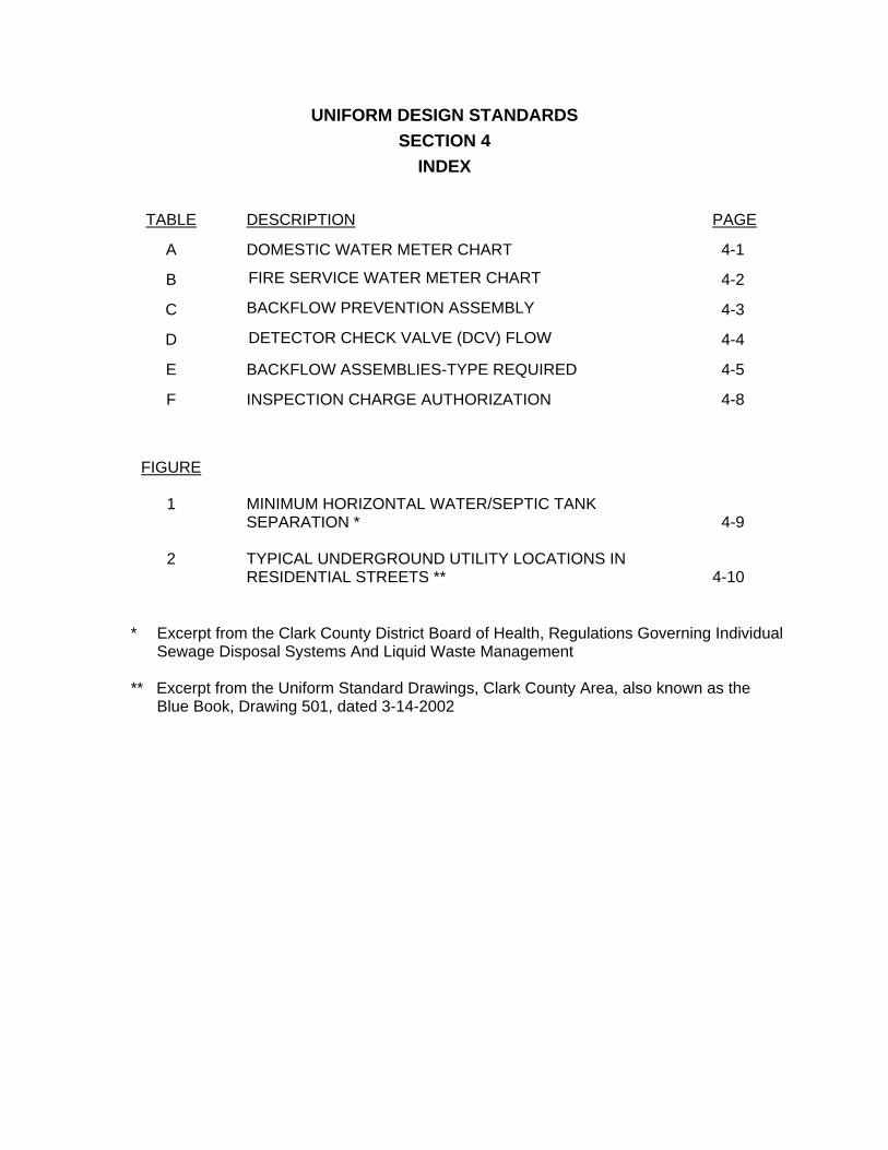
UNIFORM DESIGN STANDARDS
SECTION 4
INDEX
TABLE DESCRIPTION
PAGE
A
DOMESTIC WATER METER CHART
4-1
B FIRE SERVICE WATER METER CHART
4-2
C BACKFLOW PREVENTION ASSEMBLY
4-3
D DETECTOR CHECK VALVE (DCV) FLOW
4-4
E
BACKFLOW ASSEMBLIES-TYPE REQUIRED
4-5
F
INSPECTION CHARGE AUTHORIZATION
4-8
FIGURE
1
2
MINIMUM HORIZONTAL WATER/SEPTIC TANK SEPARATION * TYPICAL UNDERGROUND UTILITY LOCATIONS IN RESIDENTIAL STREETS **
4-9 4-10
* Excerpt from the Clark County District Board of Health, Regulations Governing Individual Sewage Disposal Systems And Liquid Waste Management
** Excerpt from the Uniform Standard Drawings, Clark County Area, also known as the
Blue Book, Drawing 501, dated 3-14-2002

CONTINUE TO THE NEXT PAGE

4-1
TABLE A
DOMESTIC WATER METER CHART Characteristics
TYPE DISPLACEMENT (1) COMPOUND (2) TURBINE (3)
SIZE GPM PSI* GPM PSI* GPM PSI*
MAX CONT @ MAX
GPM MAX CONT
@ MAX GPM
MAX CONT @ MAX
GPM
5/8 X 3/4" 20 10 15
3/4" 30 15 15 30 (4)
1" 50 25 15 50 (4)
1-1/2" 100 50 15 100 (4)
2" 160 80 15 160 (4)
3" 320 160 20 350 240 7
4" 500 250 20 630 420 7
6" 1000 500 20 1400 920 7
8" 1600 800 20 2400 1600 7
10" 2300 1150 20 3800 2500 7
* Maximum pressure loss at safe maximum operating capacity. (1) AWWA C700 Cold-Water Meters – Displacement Type, Bronze Main Case, Table 1. (2) AWWA C702 Cold Water Meters – Compound Type, Table 1. (3) AWWA C701 Cold-Water Meters – Turbine Type For Customer Service, Table 1. Class II In-line
(High Velocity Types – Pressure Losses do not include strainer). (4) Max flow for residential fire service - continuous flow and psi loss characteristics are similar to
displacement meters.

4-2
TABLE B FIRE SERVICE WATER METER CHART
Characteristics (1)
TYPE TYPE I (2) TYPE II (3) TYPE III (4)
SIZE GPM ** PSI* GPM** PSI* GPM** PSI*
MAX CONT @ MAX
GPM MAX CONT
@ MAX GPM
MAX CONT @ MAX
GPM
3" 350 250 11
4" 700 500 4 700 400 12 700 400 11
6" 1600 1150 4 1600 900 12 1600 900 11
8" 2800 2000 4 2800 1600 12 2800 1600 11
10" 4400 3100 4 4400 2200 12 4400 2200 11
* Maximum pressure loss at safe maximum operating capacity. ** Maximum flow rates may be used for fire flow requirements only. Continuous operation flow rates should be
used for all other operating conditions. (1) AWWA C703 Cold-Water Meters – Fire Service Type, Table 1. (2) Type I Devices – Proportional Fire-Service Meters with Check Valve. (3) Type II Devices – Compound Fire-Service Meter Assembly and Strainer with Check Valve (Alternate Fire-
Service Meter). (4) Type III Devices – Turbine Fire-Service and Strainer without Check Valve.

4-3
TABLE C BACKFLOW PREVENTION ASSEMBLY
CHARACTERISTICS
MAX PRESSURE LOSS (PSI)
ASSEMBLY SIZE
RATED FLOW (GPM)
RPPA (1) RPDA (2) DCVA (3)
DCDA
3/4" 30 20 22 10
1" 50 18 20 10
1 1/2" 100 16 18 10
2" 160 16 18 10
3" 320 15 17 10
4" 500 14 16 10
6" 1000 14 16 10
8" 1600 14 16 10
10" 2300 14 16 10
(1) RPPA (Reduced Pressure Principal Assembly) -- AWWA Standard C511, “Reduced-Pressure Principle Backflow Prevention Assembly”, (Table 1)
(2) RPDA (Reduced Pressure Detector Assembly) - USC FCCCHR Manual, Section 10.2.7.1, Ninth Edition, “Design, Operational And Evaluation Specifications For Reduced Pressure Principle-Detector Backflow Prevention Assemblies”
(3) DCVA (Double Check Valve Assembly) -- AWWA Standard C510, “Double Check Valve
Backflow Prevention Assembly”, (Table 1) DCDA (Double Check Detector Assembly) Notes:
Detector meter for RPDA and DCDA shall comply with agency requirements.
The use of dual assemblies may be required to accommodate meter capacity and provide
continuous service during maintenance of the assemblies.

4-4
TABLE D DETECTOR CHECK VALVE (DCV)
FLOW CHARACTERISTICS
ASSEMBLY SIZE
MAX RATED FLOW (GPM)
MAX PRESSURE LOSS (PSI)
3” 360 3
4” 750 3
6” 1500 3
8” 3000 3
10” 4500 3
Notes: Check Valves or Detector Check Valves do not meet the requirements for backflow
prevention. The information included in this table is provided to assist you in the design of the retrofits or upgrades to existing services to provide backflow protection.
It should be noted that the capacity for Check Valves or Detector Check Valves three (3)
inch and larger is greater than the capacity of a similar size backflow assembly. The installation of a larger size or dual assemblies may be required when upgrading existing services.

4-5
TABLE E BACKFLOW ASSEMBLIES - TYPE REQUIRED
FACILITY TYPE
REQUIRED BACKFLOW
PREVENTION
1. Automotive repair facilities
RPPA
*** 2.
Auxiliary water system
RPPA or DCVA
*** 3.
Beverage bottling plants
RPPA or DCVA
4.
Breweries
RPPA
5.
Building with house pump and/or water storage tanks
RPPA or DCVA
6.
Buildings with sewage ejectors
RPPA or A.G.
7.
Car washes, self-wash and automatic
RPPA or A.G.
** 8.
Centralized heating and air conditioning plants
RPPA
9.
Chemical plants
RPPA or A.G.
** 10.
Chemically treated potable water systems
RPPA or A.G.
11.
Commercial laundries
RPPA or A.G.
*** 12.
Dairies, cold storage plants, and ice manufacturers
RPPA or A.G.
13.
Dye works
RPPA or A.G.
14.
Film processing laboratories
RPPA or A.G.
15.
Fire system (Class 1, 2 & 3)
RPDA or DCDA
16.
Fire system with auxiliary supply (Class 4, 5 & 6)
RPDA
** 17.
Food processing plants
RPPA
18.
Hospitals, mortuaries, medical and dental bldg., sanitariums, nursing & convalescent homes and clinics, chiropractors, X-ray facilities
RPPA or A.G.
19.
Irrigation systems, (Premises having separate systems, such as parks, playgrounds, cemeteries, golf courses, schools, estates, ranches, churches
RPPA or A.G.
20.
Laboratories using toxic materials
RPPA or A.G.
*** 21.
Manufacturing, processing and fabricating plants using toxic and/or non-toxic materials
RPPA
22.
Motion picture studios
RPPA or A.G.

4-6
TABLE E BACKFLOW ASSEMBLIES - TYPE REQUIRED (continued)
FACILITY TYPE
REQUIRED BACKFLOW
PREVENTION *** 23.
Multi-storied buildings
RPPA
24.
Restricted, classified, or other closed facilities
RPPA or A.G.
25.
Sand and gravel plants
RPPA or A.G.
26.
Schools and colleges
RPPA or A.G.
27.
RV parks
RPPA or A.G.
** 28.
Solar heating systems
RPPA
29.
Power plants
RPPA or A.G.
30.
Veterinary clinics
RPPA or A.G.
31.
Where a hemodialysis unit (Kidney Machine) is used by an individual in his/her home
RPPA or A.G.
** 32.
Newspaper or printing publishing
RPPA or A.G.
** 33.
Dog grooming shops / pet shops
RPPA or A.G.
34.
Commercial swimming pools
RPPA or A.G.
** 35.
Church baptismal fonts & irrigation
RPPA or A.G.
36.
Metal manufacturing - cleaning, processing, & fabricating plants - plating and etching
RPPA or A.G.
** 37.
Multiple service – without known or potential hazards
RPPA or DCVA
38.
Median strip irrigation
RPPA
39.
Sewage and storm drainage facilities
A.G.
40.
Portable tank and/or vehicular water tankers
A.G.
NOTE: Agency reserves the option to require a higher level of protection for all facilities.
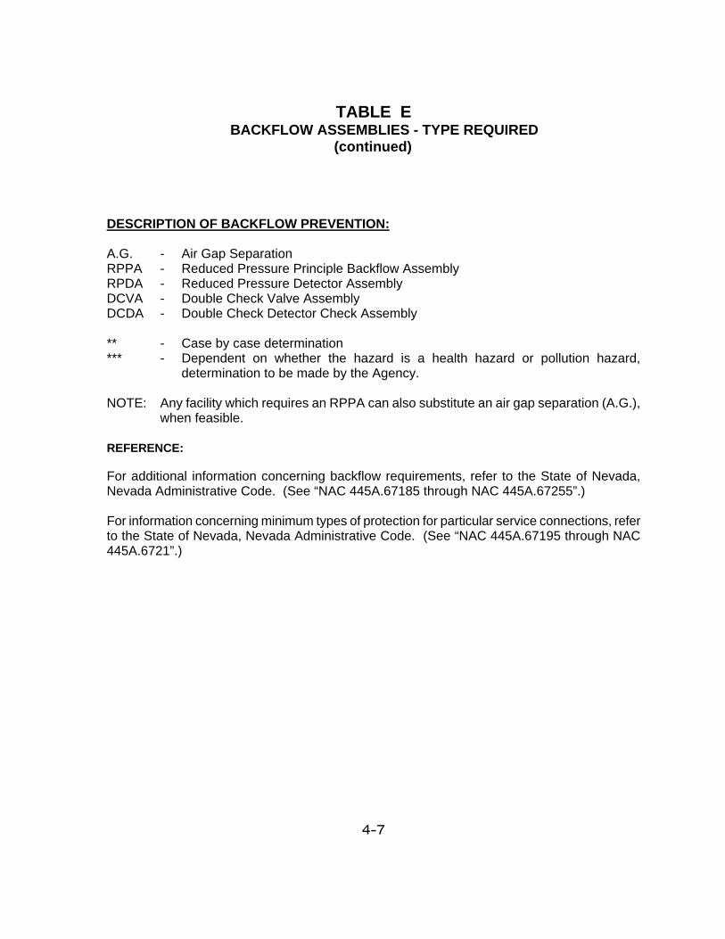
4-7
TABLE E BACKFLOW ASSEMBLIES - TYPE REQUIRED (continued) DESCRIPTION OF BACKFLOW PREVENTION: A.G. - Air Gap Separation RPPA - Reduced Pressure Principle Backflow Assembly RPDA - Reduced Pressure Detector Assembly DCVA - Double Check Valve Assembly DCDA - Double Check Detector Check Assembly ** - Case by case determination *** - Dependent on whether the hazard is a health hazard or pollution hazard,
determination to be made by the Agency. NOTE: Any facility which requires an RPPA can also substitute an air gap separation (A.G.),
when feasible. REFERENCE: For additional information concerning backflow requirements, refer to the State of Nevada, Nevada Administrative Code. (See “NAC 445A.67185 through NAC 445A.67255”.) For information concerning minimum types of protection for particular service connections, refer to the State of Nevada, Nevada Administrative Code. (See “NAC 445A.67195 through NAC 445A.6721”.)

4-8
TABLE F INSPECTION CHARGE STATEMENT OF AUTHORIZATION AND RESPONSIBILITY
(AGENCY NAME)
INSPECTION CHARGE AUTHORIZATION
Date: ___________________________ Agency Name Sat./Sun: Street Address Holiday ___________________________
Week Day: ___________________________ City-State-Zip Code
JOB NO.: JOB TITLE: OVERTIME WORKED:
PERMITTEE OR CONTRACTOR
TYPE OF WORK CONSTRUCTED DURING OVERTIME
CONTRACTOR'S REASON FOR WORKING OVERTIME
____________________________ __________________________________ INSPECTOR'S SIGNATURE CONTRACTOR'S SIGNATURE Should the Contractor desire to work outside the established normal working hours, as established by each Agency, the Contractor will be required to sign this or a similar document that constitutes approval of an overtime inspection fee. See Section 1.06 of these Standards.

4-9
FIGURE 1
MINIMUM HORIZONTAL WATER/SEPTIC TANK SEPARATION
(See: http://www.southernnevadahealthdistrict.org/download/environmental_health/sewage-regs.pdf,
Page 37, for the latest edition.)

4-10
FIGURE 2
(See: http://www.rtcsouthernnevada.com/mpo/streets/streets_drawingsvol1.cfm#UTILITIES, for the latest edition.)

4-11
FIGURE 2 (Continued)
(See: http://www.rtcsouthernnevada.com/mpo/streets/streets_drawingsvol1.cfm#UTILITIES, for the latest edition.)

CONTINUE TO THE NEXT PAGE

UNIFORM DESIGN AND CONSTRUCTION STANDARDS
FOR POTABLE WATER DISTRIBUTION SYSTEMS
SECTION 5
STANDARD PLATES

CONTINUE TO THE NEXT PAGE

UNIFORM DESIGN STANDARDS SECTION 5
INDEX
5-1
Plate No. Standard Plate Title
1 New Service Installation with 1” X 3/4” Dual Angle Meter Stops
Residential Less Than or Equal to ¼ acre Gross 3/4” Meter Sizes 2 New Service Installation with Single 1” X 3/4” Angle Meter Stop
Residential Less Than or Equal to ¼ acre Gross 5/8” and 3/4” Meter Sizes
3 New Service Installation with Dual Angle Meter Stops Commercial &
Residential Greater Than ¼ acre Gross 3/4”, 1”, 1-1/2”, and 2” Meter Sizes
4 New Service Installation with Single Angle Meter Stops Commercial &
Residential Greater Than ¼ acre Gross 5/8”, 3/4”, 1”, 1-1/2”, and 2” Meter Sizes
5 Not used 6 7
Dual Residential Service Installation with Single Angle Meter Stop 5/8” and 3/4” Meter Sizes Dual Residential Service Installation with Dual Angle Meter Stops 3/4” Meter Sizes
8 Backflow Prevention Assembly 1” – 2” Diameter 9 Dual Backflow Prevention Assembly 1” – 2” Diameter
10 - 14 Not used
15 Pipe Locator Ribbon and Locator Ball Installation
16 Trench Section Backfill Specification Unimproved Areas
17 Trench Section Backfill Specification Improved Areas
18 Trench Section Backfill Specification Improved and Unimproved Areas (NDOT Street R/W)
19
20
Trench Section Backfill Specification Notes Not used
21 Storm Drain or Sanitary Sewer Existing Water Main Crossing

UNIFORM DESIGN STANDARDS SECTION 5
INDEX
5-2
22 Storm Drain or Sanitary Sewer New Water Main Crossing
23 Casing Installation
24-29 Not used
30 Anchor Block Details for In-Line Reducers or Gate Valves 6” Through 12” Diameter
31 Thrust Block Installation
32 Chlorination Requirements
33 Water main Flushing Requirements
34 Excavation for Wet Taps
35 Wet Tap of Existing Steel Mains
36 2” Manual Blow-Off Assembly for PVC or DI Pipe
37 6” Manual Blow-Off Assembly for PVC or DI Pipe (Installation at Low Points on Pipeline)
38 Combination Air Valve Assembly for 1”, 2”, 3” and 4” Valves
39 Valve Box Installation & Adjustment
40 Fire Hydrant Installation
41 Deep Fire Hydrant Installation
42-49 Not used
50 Compound Meter With Bypass
51 Compound Meter With Bypass and Double Check Valve
52 Domestic Turbine Meter With Bypass Provisions
53 Type I Fire Service Meter With Bypass Provisions
54 Type II Fire Service Meter With Bypass Provisions
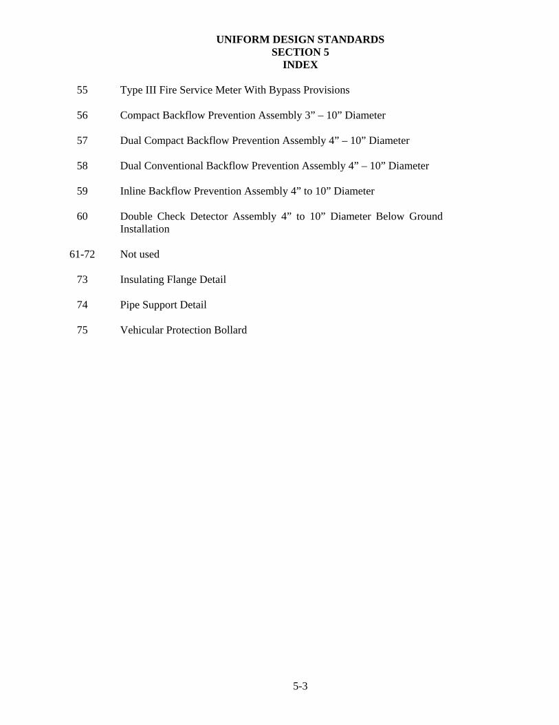
UNIFORM DESIGN STANDARDS SECTION 5
INDEX
5-3
55 Type III Fire Service Meter With Bypass Provisions
56 Compact Backflow Prevention Assembly 3” – 10” Diameter
57 Dual Compact Backflow Prevention Assembly 4” – 10” Diameter
58 Dual Conventional Backflow Prevention Assembly 4” – 10” Diameter
59 Inline Backflow Prevention Assembly 4” to 10” Diameter
60 Double Check Detector Assembly 4” to 10” Diameter Below Ground Installation
61-72 Not used
73 Insulating Flange Detail
74 Pipe Support Detail
75 Vehicular Protection Bollard

CONTINUE TO THE NEXT PAGE

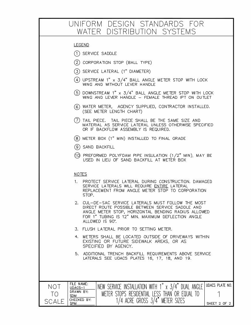


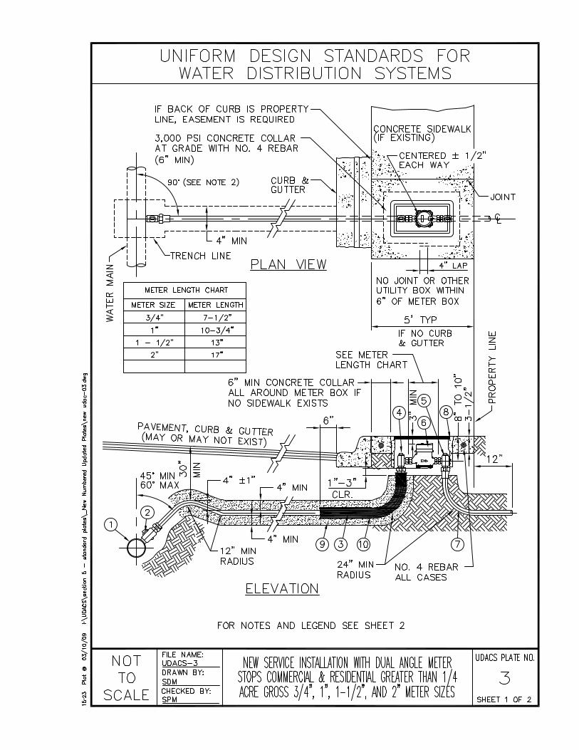
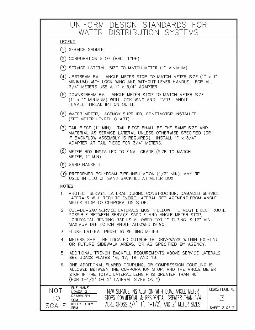


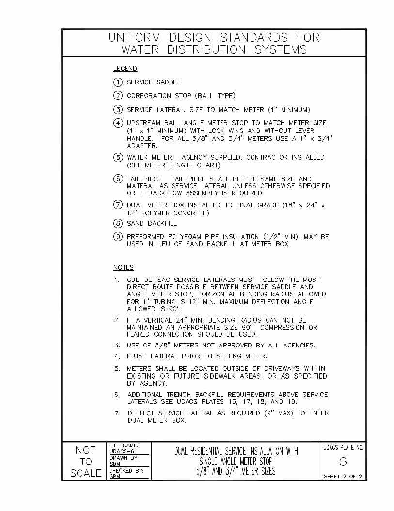


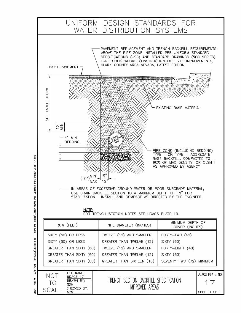


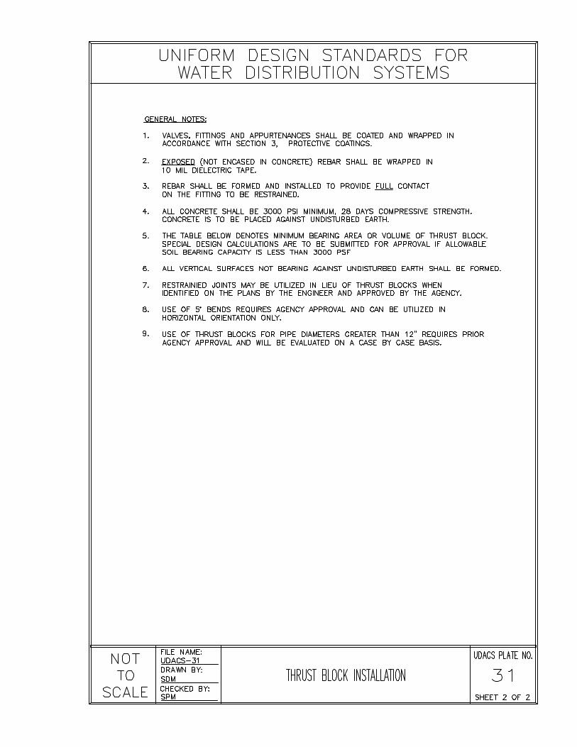


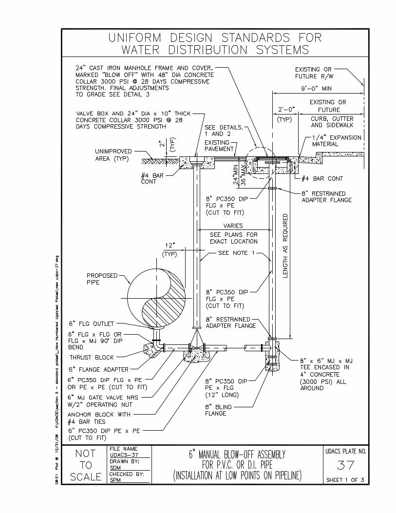
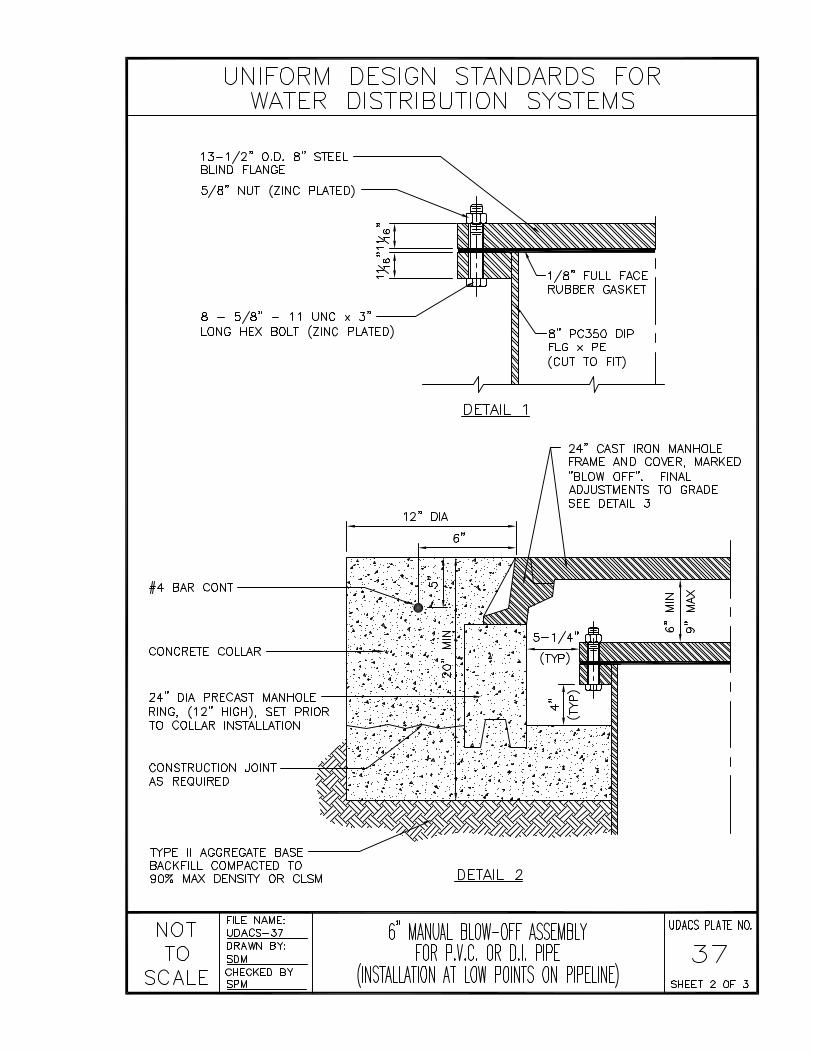


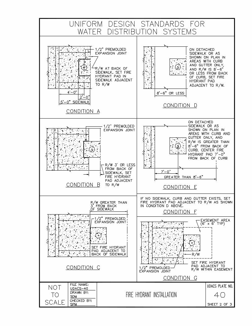
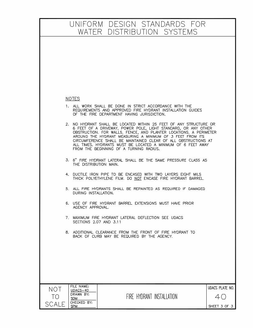
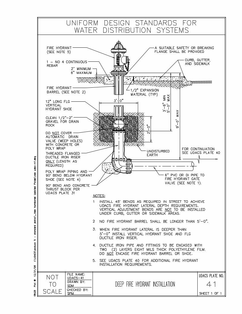

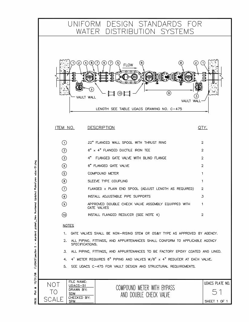


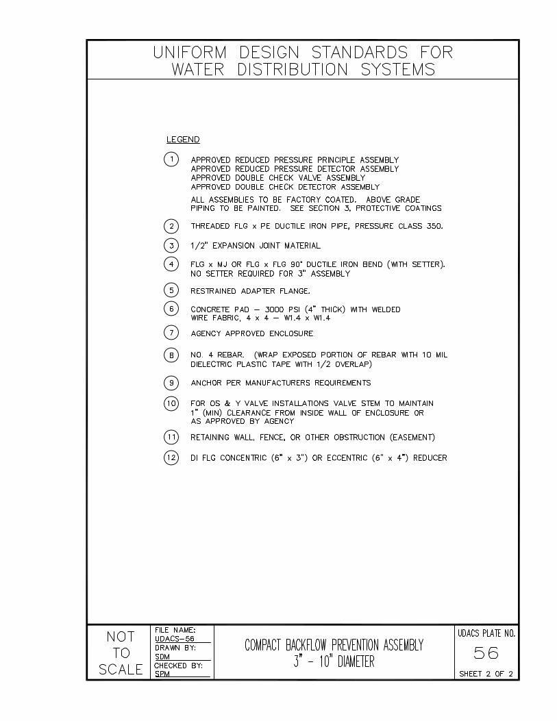


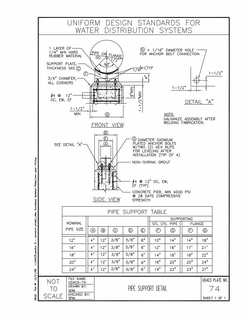


CONTINUE TO THE NEXT PAGE


UNIFORM DESIGN AND CONSTRUCTION STANDARDS
FOR POTABLE WATER DISTRIBUTION SYSTEMS
SECTION 6
AGENCY ADDENDA

CONTINUE TO THE NEXT PAGE

CITY OF BOULDER CITY
ADDENDA

CONTINUE TO THE NEXT PAGE

CITY OF BOULDER CITY ADDENDA SECTION 6 Addenda for the City of Boulder City may be picked up at:
CITY OF BOULDER CITY 401 California Avenue * Boulder City, Nevada 89005
(702) 293-9200
(702) 293-9241 – FAX

CONTINUE TO THE NEXT PAGE

CITY OF HENDERSON
ADDENDA

CONTINUE TO THE NEXT PAGE

CITY OF HENDERSON ADDENDA SECTION 6 Addenda for the City of Henderson may be picked up at:
CITY OF HENDERSON 240 Water Street * Henderson, Nevada 89015
(702) 267-3670
(702) 267-3606 – FAX

CONTINUE TO THE NEXT PAGE

CITY OF NORTH LAS VEGAS
ADDENDA

CONTINUE TO THE NEXT PAGE

CITY OF NORTH LAS VEGAS ADDENDA SECTION 6 Addenda for the City of North Las Vegas may be:
Picked up at:
CITY OF NORTH LAS VEGAS 2829 Fort Sumter Drive * North Las Vegas, Nevada 89030
(702) 633-1275
(702) 649-9784 – FAX
OR
Downloaded from the City of North Las Vegas’ website at:
http://www.cityofnorthlasvegas.com/about/forms.shtm

CONTINUE TO THE NEXT PAGE
LAS VEGAS VALLEY WATER DISTRICT
AND DISTRICT MANAGED
SYSTEMS
ADDENDA

CONTINUE TO THE NEXT PAGE
LAS VEGAS VALLEY WATER DISTRICT SECTION 6
AND DISTRICT MANAGED SYSTEMS ADDENDA Addenda for the Las Vegas Valley Water District and District Managed Systems (Big Bend, Blue Diamond, Coyote Springs, Eldorado Valley, Jean, Kyle Canyon, and Searchlight) may be picked up at:
LAS VEGAS VALLEY WATER DISTRICT ENGINEERING SERVICES DIVISION
1001 South Valley View Boulevard * Las Vegas, Nevada 89153
(702) 258-3165 or (702) 258-3166
(702) 258-7193 – FAX