contents - toolsynergie.files.wordpress.com€¦ · web viewin order to sufficiently cover memory...
TRANSCRIPT

Infrastructure Planning and Design
Windows Server® 2008 Terminal Services
Version 1.1
Published: July 2008
Updated: April 2009
For the latest information, please see microsoft.com/technet/SolutionAccelerators

Infrastructure Planning and Design Series
Solution Accelerators microsoft.com/technet/SolutionAccelerators
ii

Copyright © 2009 Microsoft Corporation. This documentation is licensed to you under the Creative Commons Attribution License. To view a copy of this license, visit http://creativecommons.org/licenses/by/3.0/us/ or send a letter to Creative Commons, 543 Howard Street, 5th Floor, San Francisco, California, 94105, USA. When using this documentation, provide the following attribution: Infrastructure Planning and Design is provided with permission from Microsoft Corporation.
This documentation is provided to you for informational purposes only, and is provided to you entirely "AS IS". Your use of the documentation cannot be understood as substituting for customized service and information that might be developed by Microsoft Corporation for a particular user based upon that user’s particular environment. To the extent permitted by law, MICROSOFT MAKES NO WARRANTY OF ANY KIND, DISCLAIMS ALL EXPRESS, IMPLIED AND STATUTORY WARRANTIES, AND ASSUMES NO LIABILITY TO YOU FOR ANY DAMAGES OF ANY TYPE IN CONNECTION WITH THESE MATERIALS OR ANY INTELLECTUAL PROPERTY IN THEM.
Microsoft may have patents, patent applications, trademarks, or other intellectual property rights covering subject matter within this documentation. Except as provided in a separate agreement from Microsoft, your use of this document does not give you any license to these patents, trademarks or other intellectual property.
Information in this document, including URL and other Internet Web site references, is subject to change without notice. Unless otherwise noted, the example companies, organizations, products, domain names, e-mail addresses, logos, people, places and events depicted herein are fictitious.
Microsoft, Active Directory, Windows, Windows Server, and Windows Vista are either registered trademarks or trademarks of Microsoft Corporation in the United States and/or other countries.
The names of actual companies and products mentioned herein may be the trademarks of their respective owners.
You have no obligation to give Microsoft any suggestions, comments or other feedback (“Feedback”) relating to the documentation. However, if you do provide any Feedback to Microsoft then you provide to Microsoft, without charge, the right to use, share and commercialize your Feedback in any way and for any purpose. You also give to third parties, without charge, any patent rights needed for their products, technologies and services to use or interface with any specific parts of a Microsoft software or service that includes the Feedback. You will not give Feedback that is subject to a license that requires Microsoft to license its software or documentation to third parties because we include your Feedback in them.
Solution Accelerators microsoft.com/technet/SolutionAccelerators

ContentsThe Planning and Design Series Approach....................................................1Introduction................................................................................................3Terminal Services in Microsoft Infrastructure Optimization...........................4Windows Server 2008 Terminal Services Design Process...............................5Step 1: Determine the Scope of the Presentation Virtualization Project.......10Step 2: Determine Which Applications to Deliver and How They Will Be Used 12Step 3: Determine Whether Terminal Services Can Deliver Each Application...............................................................................................14Step 4: Categorize Users...........................................................................19Step 5: Determine the Number of Terminal Server Farms............................20Step 6: Map Applications and Users to Farms.............................................22Step 7: Design the Farm............................................................................23Step 8: Determine Where to Store User Data..............................................30Step 9: Size and Place the Terminal Services Role Services for the Farms 33Step 10: Secure the Communications.........................................................44Conclusion................................................................................................46Appendix A: The User and Application Data Job Aid....................................47Appendix B: The Application Analysis Job Aid.............................................49Appendix C: The Farm Design Job Aid.........................................................51Appendix D: Server Performance Analyzing and Scaling..............................53Acknowledgments.....................................................................................64
Solution Accelerators microsoft.com/technet/SolutionAccelerators
The Planning and Design Series ApproachThis guide is one in a series of planning and design guides that clarify and streamline the planning and design process for Microsoft® infrastructure technologies.
Each guide addresses a unique infrastructure technology or scenario. These guides include the following topics: Defining the technical decision flow (flow chart) through the planning process. Describing the decisions to be made and the commonly available options to consider
in making the decisions. Relating the decisions and options to the business in terms of cost, complexity, and
other characteristics. Framing the decision in terms of additional questions to the business to ensure a
comprehensive understanding of the appropriate business landscape.The guides in this series are intended to complement and augment the product documentation.
Document ApproachThis guide is designed to provide a consistent structure for addressing the decisions or activities that are most critical to the successful implementation of the Terminal Services infrastructure in Windows Server® 2008.
Each decision or activity is divided into four elements: Background on the decision or activity, including context setting and general
considerations. Typical options or tasks to perform for the activity. Reference section evaluating such items as cost, complexity, and manageability of
the options or tasks. Questions for the business that may have a significant impact on the decisions to be
made.Table 1 lists the full range of characteristics discussed in the evaluation sections. Only those characteristics relevant to a particular option or task are included in each section.
Table 1. Architectural Characteristics
Characteristic Description
Complexity The complexity of this option relative to other options.
Cost The initial setup and sustained cost of this option.
Fault Tolerance How the decision supports the resiliency of the infrastructure, which ultimately affects the availability of the system.
Performance How the option affects the performance of the infrastructure.
Scalability The impact the option has on the scalability of the infrastructure.
Security Whether the option has a positive or negative impact on overall infrastructure security.
Solution Accelerators microsoft.com/technet/SolutionAccelerators

Each design option is evaluated according to these characteristics and is subjectively rated to provide a relative weighting compared with other options. The options are not explicitly rated against each other as there are too many unknowns about the business drivers to accurately compare them.
The ratings are relative and take two forms: Cost and Complexity are rated on a scale of High, Medium, or Low. The remaining characteristics are rated on the scale in Table 2.Table 2. Impact on Characteristic
Symbol Definition
↑ Positive effect on the characteristic.
→ No effect on the characteristic, or there is no basis for comparison.
↓ Negative effect on the characteristic.
The characteristics are presented either in two-column or three-column tables. A two-column table is used when the characteristic applies to all options or when there are no options available—for example, when performing a task.
A three-column table presents an option, the description, and the effect, in that order, for the characteristic.
Who Should Use This DocumentThis guide is written for information technology (IT) infrastructure specialists who are responsible for planning and designing a Terminal Services implementation in Windows Server 2008 to serve desktops or applications to devices running the Remote Desktop Client (RDC) software. These specialists include consultants, internal IT staff, and others who are concerned with design decisions relating to virtualization.
The content in this guide assumes that the reader is familiar with Terminal Services technology and is planning an implementation of Terminal Services servers, farms, or both in Windows Server 2008.
Solution Accelerators microsoft.com/technet/SolutionAccelerators

Windows Server 2008 Terminal Services
Introduction This guide leads the reader step by step through the process of planning a Windows Server 2008 Terminal Services infrastructure. The guide addresses the following fundamental decisions and tasks: Identifying which applications are to be delivered by Terminal Services and
determining whether Terminal Services is the right approach to use. Determining the resources needed to employ Terminal Services to serve the selected
applications. Designing the components, layout, security, and connectivity of the Terminal
Services infrastructure.Before starting the technical design, it’s very important to fully understand the business objectives for the project: What benefits does the business expect to achieve through the use of presentation
virtualization? Presentation virtualization uses centralized systems to host multiple user sessions, and all processing is done on those host systems. The user sessions are isolated from each other. Only the presentation information, such as keyboard and mouse inputs, and video updates are sent between the client and the host system. The client can be a full Windows-based workstation or a Windows-based terminal device.
What is the value of those benefits and, therefore, the cost case for using Terminal Services to deliver those benefits?
Is the cost justification jointly entered into by more than one business group, and if so, do they depend on the success of the project for their relationship with each other?
The business objectives should be prioritized right at the start of the project so that they are clearly understood and agreed upon between IT and the business. This is because some applications will not likely be immediately suited to delivery by Terminal Services. Those changes will incur cost and, before embarking upon them, this should be fed back to the business so that the additional costs can be understood and the best business decision arrived at.
AssumptionsThe content in this guide assumes that the reader is familiar with Terminal Services technology and is planning an implementation of servers, farms, or both in Windows Server 2008.
Solution Accelerators microsoft.com/technet/SolutionAccelerators
3

Infrastructure Planning and Design
Terminal Services in Microsoft Infrastructure OptimizationThe Infrastructure Optimization Model at Microsoft groups IT processes and technologies across a continuum of organizational maturity (for more information, see http://www.microsoft.com/infrastructure). The model was developed by industry analysts, the Massachusetts Institute of Technology (MIT) Center for Information Systems Research (CISR), and Microsoft based on its experience with its own enterprise customers. A key goal for Microsoft in creating the Infrastructure Optimization Model was to develop a simple way to use a maturity framework that is flexible and that can easily be used as the benchmark for technical capability and business value.
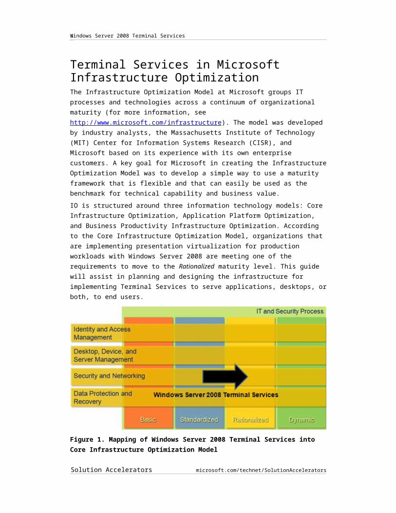
IO is structured around three information technology models: Core Infrastructure Optimization, Application Platform Optimization, and Business Productivity Infrastructure Optimization. According to the Core Infrastructure Optimization Model, organizations that are implementing presentation virtualization for production workloads with Windows Server 2008 are meeting one of the requirements to move to the Rationalized maturity level. This guide will assist in planning and designing the infrastructure for implementing Terminal Services to serve applications, desktops, or both, to end users.
Figure 1. Mapping of Windows Server 2008 Terminal Services into Core Infrastructure Optimization Model
FeedbackPlease direct questions and comments about this guide to [email protected].
Please provide feedback on the usefulness of this guide by filling out the following survey: http://go.microsoft.com/fwlink/?LinkID=132579
Solution Accelerators microsoft.com/technet/SolutionAccelerators
4
Windows Server 2008 Terminal Services
Windows Server 2008 Terminal Services Design ProcessThe goal of this Windows Server 2008 Terminal Services Infrastructure Planning and Design Solution Accelerator is to guide the planner through the information gathering, decisions, options, and tasks required to create and design a Terminal Services infrastructure. The objective is an infrastructure that is sized, configured, and appropriately placed in order to deliver the stated business benefits, while considering the end-user experience, security, manageability, performance, capacity, and fault tolerance of the system. The guide addresses the scenarios most likely to be encountered by someone designing a Terminal Services infrastructure. Customers should consider having their architecture reviewed by Microsoft Customer Service and Support prior to implementation as they are the organization that can best comment on the supportability of a particular design.
The primary components of Windows Server 2008 Terminal Services are shown in Figure 2.
Figure 2. Windows Server 2008 Terminal Services architectureThis diagram illustrates the relationship between the components that can work together to publish applications through Terminal Services. They are shown together in one possible implementation for illustrative purposes. The components can be architected in many different ways.
Solution Accelerators microsoft.com/technet/SolutionAccelerators
5

Infrastructure Planning and Design
Terminal servers are usually implemented in farms in order to provide high scale and fault tolerance. A terminal server farm is a group of terminal servers that publish an identical set of applications. All the terminal servers in the farm deliver an equivalent experience; they host the same applications, in the same configuration, even though there may be differences in the hardware from server to server.
The farm can be load balanced so that users connect to a common name; they are then connected to one of the member servers of the farm. There is no programmed limit to the number of servers that may participate in a farm.
DecisionsThis guide addresses the following decisions and activities that need to occur in preparing for Windows Server 2008 Terminal Services. The ten steps that follow represent the most critical elements in a well-planned Windows Server 2008 Terminal Services design: Step 1: Determine the scope of the presentation virtualization project. Step 2: Determine which applications to deliver and how they will be used. Step 3: Determine whether Terminal Services can deliver each application. Step 4: Categorize users. Step 5: Determine the number of terminal server farms. Step 6: Map applications and users to farms. Step 7: Design the farm. Step 8: Determine where to store user data. Step 9: Size and place the role services for the farm. Step 10: Secure the communications. Some of these items represent decisions that must be made. Where this is the case, a corresponding list of common response options is presented.
Other items in this list represent tasks that must be carried out. These items are addressed because their execution is significant to completing the infrastructure design.
Solution Accelerators microsoft.com/technet/SolutionAccelerators
6

Windows Server 2008 Terminal Services
Decision FlowThe following figure provides a graphical overview of the steps in designing a Windows Server 2008 Terminal Services infrastructure.
Figure 3. The Windows Server 2008 Terminal Services infrastructure decision flow
Solution Accelerators microsoft.com/technet/SolutionAccelerators
7

Infrastructure Planning and Design
Applicable ScenariosThis guide addresses considerations that are related to planning and designing the necessary components for a successful Windows Server 2008 Terminal Services infrastructure. The scenarios considered in creating this guide include: Organizations planning to centralize their desktop environments into regional data
centers or to a central data center. Organizations that are combining their computing resources and users after a
company merger or acquisition. An alternate rich client desktop or application may be delivered alongside their existing desktop so that they have access to applications from both parts of the merged enterprise. This can be used to significantly accelerate the integration of the acquired company’s systems. In this case, the security and directory issues around application access will of course also need to be addressed, but that is beyond the scope of this document.
Organizations that will implement Windows Server 2008 Terminal Services alongside Windows Server 2003 Terminal Services.
Delivery of full desktop environments. Organizations may choose to deliver a new desktop environment to clients that are unable to upgrade, or are waiting to upgrade, to a new operating system.
Rapid deployment of new applications across an enterprise so that end users can be up and running very quickly, without needing to wait for new applications to be installed on their desktops.
Rapid deployment of a new version of an individual application to clients that are unable to upgrade because of compatibility issues, or are waiting to upgrade.
Providing full corporate desktops to employees who work from home, either occasionally or full time, on their personal workstations. This enables the enterprise to provide full function secure application delivery without needing to be concerned about the maintenance and security of the user’s personal workstation.
Providing individual applications to external third parties, such as vendors and suppliers, in a Web browser.
Business continuity in the event of a disaster. Terminal Services can be used to rapidly provision a full working desktop to a newly acquired, or rented, population of user workstations in a new location.
Multi-forest environments in which the Terminal Services infrastructure components may span forest boundaries. This is particularly relevant in the mergers and acquisitions scenario.
Provisioning of difficult-to-maintain or infrequently used applications. The management overhead of running such applications on end-user workstations can be significant, so it can make a lot of business sense to run them centrally instead, with delivery through Terminal Services.
Delivering data-intensive client applications over low bandwidth links. Terminal Services can be used to deliver an application over bandwidth-constrained links. This is very effective for remotely accessing and manipulating large volumes of data because only a screen view of the data is transmitted over the network to the client, rather than the actual data.
Solution Accelerators microsoft.com/technet/SolutionAccelerators
8

Windows Server 2008 Terminal Services
Out of ScopeThis guide concentrates on Terminal Services design and planning exclusively. Solutions containing the following elements are to be considered out of scope for this guide: Remote assistance. Although Remote Assistance uses Remote Desktop Protocol
(RDP), this feature is used for user assistance rather than presentation virtualization. Remote Desktop for Administration. This Terminal Services capability allows up to
two remote users to connect to a Windows® desktop session for administrative purposes. It is included with Windows Server 2003, Windows Vista® Ultimate operating system, the Professional editions of Windows 2000 and Windows XP.
Multi-tenant hosting or remote hosting. Although companies hosting remote application and shared servers quite often use presentation virtualization in some form, this document does not address all of the complexities of a full multi-tenant design.
Migration from Windows 2000 Server or Windows Server 2003 Terminal Services.
Citrix MetaFrame. Third-party add-ons to Terminal Services extend the product and offer solutions for various situations, but they are too varied to cover here.
Planning for Microsoft Application Virtualization. Microsoft Application Virtualization on Terminal Services can resolve application conflicts and greatly simplify administration. Consider using the Infrastructure Planning and Design guide for Microsoft Application Virtualization 4.5, available at http://www.microsoft.com/ipd, as a complement to this guide when designing a Terminal Services infrastructure.
Additional Reading Terminal Services on the Windows Server 2008 TechCenter page, available at
http://go.microsoft.com/fwlink/?LinkID=73931. Infrastructure Planning and Design: Microsoft Application Virtualization 4.5, available
at http://www.microsoft.com/ipd. Anderson, Christa, and Kristin L. Griffin with the Microsoft Presentation Hosted
Desktop Virtualization Team. Windows Server 2008 Terminal Services Resource Kit. Redmond, WA: Microsoft Press, 2008.
Solution Accelerators microsoft.com/technet/SolutionAccelerators
9

Infrastructure Planning and Design
Step 1: Determine the Scopeof the Presentation Virtualization ProjectBefore designing a presentation virtualization infrastructure, an organization needs to determine which parts of its environment to include in the design and the objectives for the project.
This step drives decisions related to what applications to add to Terminal Services and for what user population. Server farm numbers, size, and placement are also driven by the scope of the project. Quite often, a combination of these deployment options is required to deliver the best service. For example, Terminal Services may provide a time reporting application to the entire enterprise, an accounting package to the Accounting group, and a country- or region-specific tax package to the offices in one country or region.
Task 1: Determine Location ScopeBefore the architecture can be derived, the scope of the project must first be determined so that the planners know the boundaries for which they are building a solution. The scope of the project could be enterprise-wide, one or many locations, or perhaps a single department. If an organization is considering multiple implementations of Terminal Services, it can iterate through this guide for each instantiation.
Because it is easy to get caught up in the technical details of a project, it is important to verify that the planners are clear on the scope of the project so that they can make the appropriate technical decisions to keep the project aligned with the business objectives and make the appropriate trade-offs in fault tolerance, capacity, and performance.
In order to ensure that the location scope of the project remains clear, record it now so that it can be used as a header on the job aids that will be created later, examples of which are shown in Appendices A, B, and C.
Task 2: Determine Application ScopeNow that the overall scope of the project has been determined, the second task is to define what exactly the business wants to have hosted by Terminal Services: Is the target to have entire desktops and all applications hosted by Terminal
Services? Is the goal to have a single application made available through Terminal Services? Is the objective to have as many applications as possible hosted on Terminal
Services?In order to ensure that the project stays focused on delivering the required services, it is very important to fully understand the business objectives for the project: What benefits does the business expect to achieve through the use of presentation
virtualization? What is the value of those benefits and, therefore, the cost case for using Terminal
Services to deliver those benefits? The business objectives should be prioritized right from the start so that they are clearly understood and agreed upon between IT and the business.
Solution Accelerators microsoft.com/technet/SolutionAccelerators
10

Windows Server 2008 Terminal Services
In order to ensure that the application scope of the project remains clear, record it now so that it can be used as a header on the job aids that will be created later, examples of which are shown in Appendices A, B, and C.
It’s also important to set some expectations with the business related to the published application environment. There will inevitably be concerns amongst users about loss of control of their application environment and restrictions or additional work that might be imposed on them by the new mode of operation. This can be a good time to have an open discussion about some of the changes that users may perceive. One of those changes may be additional authorization challenges that might be presented to users before they can access their applications. Although it is possible to provide seamless authorization pass-through so that a user is only challenged once for his or her credentials, this requires the use of the most recent technology and so may necessitate some upgrades, at additional cost.
Decision SummaryDecisions about the scope of the project must be based on the specific needs of the organization. The scope of the Terminal Services project in Windows Server 2008 drives decisions in future steps related to capacity requirements. Although there is no single best approach to follow, ensure that the organization is aligned with, committed to, and supportive of the selected approach before continuing the planning process.
Solution Accelerators microsoft.com/technet/SolutionAccelerators
11

Infrastructure Planning and Design
Step 2: Determine Which Applications to Deliver and How They Will Be UsedIn the previous step, the scope of the project was determined with respect to locations and applications that should be included.
This step’s goal is to look at the end-user populations that fall within that scope and to determine which applications each person uses and how he or she uses them.
Once this step is complete, project planners have a list of candidate applications.
Task 1: Gather Information About Users and ApplicationsUsing the project scope created in step 1 as the boundary encompassing the user population, gather the following information about each of the users.
This following list corresponds to the job aid spreadsheet in Appendix A: “The User and Application Data Job Aid” of this document, which is provided to assist in collecting this information. From each representative user, record: User location. Knowing how many users are at each location assists in determining
server sizing and placement. Client operating system. When the application is delivered by Terminal Services,
the screen updates, and keyboard entries and mouse clicks will flow over the network, using the RDP protocol, to the Remote Desktop Client (RDC) running on the end user’s machine. There are significant enhancements in the latest versions of the RDC and RDP, providing higher levels of encryption and increasing the efficiency of the data transmission over the network. The extent to which these can be utilized will depend on what operating system the client has installed because that determines the versions of RDC and RDP that the client system can run. For example, the single sign-on capability requires Windows Vista with Service Pack 1 (SP1) or Windows XP with SP3.This information will be used in step 5 to determine the number of terminal server farms since different farms may have to be set up for both high- and low-security clients. It will also be used in step 9 to design the TS Gateway role service.
Whether single sign-on to applications is provided. If there is a user expectation of the convenience of a single sign-on experience, that will determine the level of Remote Desktop Client (RDC)) that must be used to deliver the applications. RDC 6.1 will be required in order to provide this experience in the published applications environment. The level of RDC that is used may affect the decision on the number of farms that will be required in step 5 and the design of the role services in step 9.
Applications that are used, their version(s), and any special local customizations. If more than one implementation of a given application is in use, then a determination will need to be made on whether those different versions can co-exist in the same Terminal Services environment. If they cannot, each different version, or customization, of the application may have to be delivered by a separate terminal server farm, which will drive up the complexity and cost of the project. This determination will be made in step 5.
Solution Accelerators microsoft.com/technet/SolutionAccelerators
12

Windows Server 2008 Terminal Services
It may be possible to use Microsoft Application Virtualization 4.5 to overcome this by running each application in its own virtual environment on the terminal server. In this case, the application must be supported for delivery by Microsoft Application Virtualization 4.5, and a Microsoft Application Virtualization 4.5 environment will need to be instantiated. Note At the time of writing, Microsoft Application Virtualization 4.5 does not support 64-bit environments.
Service level agreement (SLA) levels. What SLAs are in place, what service levels do they commit to, and how many users fall under each one? Understanding what the business and user expectations are for the application defines the requirements for performance and availability. This will drive the sizing of the terminal server farm in step 7 so that it is able to deliver the expected performance to the user. It will also determine the fault tolerance approach in that step. It is particularly important to understand the performance and availability expectations that user groups have, whether formalized in an SLA or not, and to use this rather than the actual performance and availability that they experience currently as input to the design.
Connection type. Are all the users connected through local area networks (LAN), or are some connected over wide area network (WAN) links, over dial-up connections, or through an Internet service provider (ISP)? This information will be used in designing the network, security model, server placement, and sizing. It may not be possible to collect this in user interviews; more likely the network design will need to be examined by IT at the conclusion of these interviews.
It can also be helpful to gather the following information. This can prove particularly useful if additional questions arise about the application and how it is used. Application support group. List the person or persons responsible for supporting
the application. Knowing who these people are helps with preliminary testing and researching any technical issues that may arise.
Application owners. List the department or executive responsible for organizing upgrades or requesting more licenses for the application. This entity has to sign off on any change in the way the application is delivered and could help with business issues that may arise.
Decision SummaryThe list of candidate applications results have now been recorded in a spreadsheet, along with characteristics of their usage. This can be a good time to check back with the business in order to confirm the scope of the project before proceeding with an evaluation of the applications’ suitability for delivery by Terminal Services in the next step. In that meeting with the business, be sure to review the findings of this step to ensure that they match the understanding the business has regarding the ways that applications are used and the service levels that are expected.
During the next step, the characteristics of the applications will be examined to determine their suitability for delivery by Terminal Services.
Additional Reading Infrastructure Planning and Design: Microsoft Application Virtualization 4.5, available
at http://www.microsoft.com/ipd.
Solution Accelerators microsoft.com/technet/SolutionAccelerators
13

Infrastructure Planning and Design
Step 3: Determine Whether Terminal Services Can Deliver Each ApplicationThe goal of this step is to examine each application that is intended to be served through Terminal Services in Windows Server 2008 in order to identify any applications that cannot or should not be used with Terminal Services.
During this step, applications that are within the scope of the project are categorized according to their suitability for delivery in a Terminal Services environment, and this information is recorded in a spreadsheet like the job aid included in Appendix B: “The Application Analysis Job Aid.” At the end of the step, the categorized list should be reviewed with the business since some applications may not be immediately suited to delivery by Terminal Services. Those applications may require some changes in order to remain within the scope of the project. Those changes incur cost and, before embarking upon them, this information should be reviewed with the business so that those additional costs and risks can be understood and the best business decision arrived at.
The applications that remain after this step are subject to further testing and measuring in the next steps so that the servers and server farms can be sized appropriately to host them.
Task 1: Examine Each Application’s Capability to Be ServedThere are many issues that can affect whether an application can or should be hosted by a Terminal Services environment in Windows Server 2008. The issues can be divided up as follows: Issues that affect the application’s business viability. Issues that prevent an application from being served. Issues with the application’s behavior that cause problems in a multi-user server.The data may be gathered from application vendors, Terminal Services community sites, and the application support personnel.
The Application Compatibility Toolkit (ACT), available at http ://technet.microsoft.com/en- us/desktopdeployment/bb414773.aspx, can also be used to evaluate an application while it is running on a stand-alone computer for suitability in a Terminal Services environment.
Review each application against the questions below, and record the assessments in the job aid in Appendix B, along with the final determination on the application’s suitability. This will determine which applications may need to be excluded from the project.
Issues That Affect Business ViabilityA number of business issues may arise when an application is considered for delivery in a Terminal Services environment. While the application may be technically suitable for presentation virtualization, these issues could prevent its delivery in this environment. For that reason, the following issues are considered first: Can the application be licensed to run in a Windows Server 2008 Terminal
Services environment? Contact the application vendor for this information. Is the application supported on Terminal Services in Windows Server 2008? If
the vendor does not support the application in a Terminal Services environment, it
Solution Accelerators microsoft.com/technet/SolutionAccelerators
14

Windows Server 2008 Terminal Services
may not work correctly, or certain features may not be available. Or the application may still work, but additional testing may be required. A review of the risk of running an unsupported application should also be conducted to see if running the application in Terminal Services is warranted.
Does serving the applications cause license fees to become too expensive? There are numerous software licensing models. Since every terminal server in a farm has the application installed, does this present any undue financial issues given the licensing structure of the application?
Are there legal reasons for not serving an application? Can protected data, such as national security or private patient data, be allowed to exist on a server residing outside a country or region’s borders? How about data not allowed off site or off certain computers? Can the data traverse a prohibited or nonprotected area on a network?
Is the required encryption level within the means of most of the RDC clients? If the RDC clients are not yet at a version that supports the desired encryption level, wait until they are upgraded before deploying the application. Alternatively, the application might be delivered to the clients that are in compliance while leaving the other clients to run the application locally.
Issues That Prevent an Application from Being ServedThere may be limitations in the way the application is designed or runs that make it unusable in a Terminal Services environment: Can the application run on Terminal Services in Windows Server 2008? An
internally developed application may be written to install and run only on earlier operating systems. Verify that the application can run on Terminal Services in Windows Server 2008. If not, use the ACT to see if the application works in a compatibility mode.
Issues with the Application’s Behavior That Cause Problems in a Multi-User ServerAt the completion of the project, applications that have been running separately on individual workstations will be run together in a server environment. This requires that they co-exist and run in that environment without interfering with each other. The applications must also behave in a way that does not degrade their scalability and performance in this environment to the point that it is no longer cost effective. The following questions raise the issues that may commonly surface with applications: Does the application consume excessive resources or neglect to release them
appropriately? An application cannot be allowed to monopolize the CPU, memory, or other shared server resources. For instance, a small memory leak may not present much of a problem on a stand-alone computer, but 50 users concurrently running that same application on a shared server can cause the server to run out of memory very quickly. Monitor memory usage to test for the problem. If discovered, have the software’s creator fix the issue and evaluate the risk of running the application while it still leaks.
Does the application require access to client-based resources that may not be available to Windows Server? Client-side devices such as scanners, specialty printers, USB devices, and floppy or hard disk drives used by the application need to be checked for compatibility in a Terminal Services environment. A determination must be made as to whether these can be provided in the Terminal Services environment.
Does the application follow proper installation and uninstallation standards? Applications need to be functional for all users after installation, and uninstalls must not remove components needed by other applications on the terminal server. The
Solution Accelerators microsoft.com/technet/SolutionAccelerators
15

Infrastructure Planning and Design
ACT tools can help determine setup issues. If any are found, determine the impact to the server and users.
Solution Accelerators microsoft.com/technet/SolutionAccelerators
16

Windows Server 2008 Terminal Services
Does the application alter shared system files and components? An application that is changing files such as fonts, dynamic link libraries (DLLs), and drivers affects other applications’ ability to function. Use the ACT to watch for this behavior. If detected, the software must be fixed before the application can be used in Terminal Services. Alternatively, it may be possible to use Microsoft Application Virtualization 4.5 to overcome this by running each application in its own virtual environment on the terminal server. In this case, the application must be supported for delivery by Microsoft Application Virtualization 4.5, and a Microsoft Application Virtualization 4.5 environment will need to be instantiated.Note At the time of writing, Microsoft Application Virtualization 4.5 does not support 64-bit environments.
Is user data kept discrete from other data? If an application places user and temporary files in the same location, then other instances of the application can overwrite or alter the files, producing unpredictable results. Test to see if this is occurring. If so, it must be fixed before using the application in Terminal Services.
Is the registry accessed properly? An application must not make changes to the registry at a level where the change can affect other users or applications. Normally, Terminal Services installation redirects registry entries installed to HKLM\Software on a standard desktop to HKCU\Software on the terminal server, but software may be written in a way that circumvents these protections. Use the ACT or a registry comparison tool to watch for changes in the wrong areas. If such changes are discovered, evaluate the impact upon the server and users.
Do changes made by the user to program options affect other instances of the program? Changes made in a user’s environment should not affect other users. For example, when user “A” changes the default view in an e-mail client, every other user’s default view should not change as well. Some ways to fix this issue include preventing changes in programs via permissions, creating mandatory user profiles, or having the vendor fix the issue.
Is the application video-intensive? Video streams from the Terminal Services server are cached on the client, so the server only needs to send that part of the screen that changes to refresh a client. Applications with screen animations or other processes requiring significant screen updates to be sent more frequently place an increased load on both the server and the network, effectively reducing the scalability of the application. Record in the Application Analysis job aid, whether the video delivered by the application is Low, Medium, or High intensity, depending upon the level of graphics the application uses. An application such as Notepad with few screen updates is considered a Low graphics intensity application, whereas an application with several animations and embedded video would be a High graphics intensity application. High graphics intensity applications use more server-side processor and memory while consuming more network bandwidth for the frequent screen updates.
Is the application audio-intensive? Audio is another consumer of network bandwidth. Rate the audio as Low for a few system sounds, Medium for low bandwidth audio delivered occasionally, or High for an audio-intense application such as a media player or computer-based training with voice instruction.
Does the application employ code not optimized for either 32-bit or 64-bit architecture? Programs that include 16-bit code must be treated differently by the operating system, which causes the application to use a disproportionate amount of memory and CPU resources compared with programs written in 32-bit or 64-bit code. Use the ACT to detect 16-bit components and move to a newer version, have the software repaired, or decide whether the extra resources required to run the application are acceptable.
Solution Accelerators microsoft.com/technet/SolutionAccelerators
17

Infrastructure Planning and Design
Using the factors listed above, rank each of the applications according to their suitability: The application is a good candidate. Keep the application in the project and
continue working through the steps. Application has some issues but can still be run in Terminal Services. The
issues can affect the implementation but not in such a way as to prevent its inclusion in the project. Add the application to the design while you continue to monitor the risk of the application. For example, the application may not be supported by the vendor in Terminal Services; however, the business need to run it there is critical. A decision is made to leave the application as a candidate. There could be additional risk later in the process about the scalability of the application or some other reason that emerges that will force another review of the application.
Application is not suitable for Terminal Services at this time. The application is dropped from the project scope and alternative methods for dealing with the application will need to be considered by another project. Applications not ready for Terminal Services may be good candidates for other virtualization technologies. Please refer to the Infrastructure Planning and Design series, Selecting the Right Virtualization Technology, available at http://www.microsoft.com/ipd.
Decision SummaryIn this step every application has been examined for its suitability to be delivered by Terminal Services in Windows Server 2008 and ranked on that basis.
Applications that are within the scope of the project have been categorized according to their suitability for delivery in a Terminal Services environment, and this information is recorded in a spreadsheet like the job aid included in Appendix B.
Now, at the end of the step, the categorized list should be reviewed with the business. This is because some applications will likely not be immediately suited to delivery by Terminal Services. Those applications may require some changes in order to remain within the scope of the project. Those changes incur cost and, before embarking upon them, this must be fed back to the business so that those additional costs can be understood and the best business decision arrived at.
It is also possible that some applications that the business wishes to include in the scope of the project cannot be delivered without major work, and a re-evaluation of the project may be required.
The next step determines the resource requirements to deliver those applications through Terminal Services.
Tasks and Considerations Application Compatibility Toolkit (ACT). The ACT, available at http ://technet.microsoft.com/en-us/desktopdeployment/bb414773.aspx , is a group of tools that can be helpful for gathering and evaluating information about an application as it is running on a stand-alone computer as well as when it is running on a terminal server. Some of the tools most helpful to evaluating an application for Terminal Services are: Setup Analysis Tool (SAT). Watches a setup and detects the installation kernel
mode drivers and 16-bit components, among other things. Inventory Collector. Identifies installed applications within an organization. Compatibility Reporting. Helps with compiling and evaluating collected data.
Solution Accelerators microsoft.com/technet/SolutionAccelerators
18

Windows Server 2008 Terminal Services
Find compatibility information from the community. Common repository of compatibility issues and their remediation.
Additional Reading The Application Compatibility Toolkit 5.0 site, available at
http://technet.microsoft.com/en-us/windowsvista/aa905102.aspx. The Application Compatibility page, available at
http://technet.microsoft.com/en-us/windowsvista/aa905066.aspx. “Device Driver INF Changes for Plug and Play Device Redirection on Terminal
Server,” available at http://www.microsoft.com/whdc/driver/install/TS_redirect.mspx. Infrastructure Planning and Design: Selecting the Right Virtualization Technology,
available at http://www.microsoft.com/ipd. Infrastructure Planning and Design: Microsoft Application Virtualization 4.5, available
at http://www.microsoft.com/ipd.
Solution Accelerators microsoft.com/technet/SolutionAccelerators
19

Infrastructure Planning and Design
Step 4: Categorize UsersAt this point, the list of users as well as their applications that will be hosted by Terminal Services has been validated. In order to properly size the Terminal Services environment, the load that users will place on it needs to be understood.
The implementation of Terminal Services will involve a significant change to the way that an end user’s applications are run. The applications will execute in a shared environment on a remote server rather than on the user’s dedicated local workstation. In planning for such a change, it’s unrealistic to expect to calculate the precise resources required. Instead, try to estimate them as closely as possible and provide some additional capacity in the system to compensate for any spikes in usage that may occur.
In order to do that, place users into one of three categories: Heavy, Normal, or Light, based on their general usage behavior in their applications.
This categorization will be used in step 7 to provide the user load on each application as input to determining the size of the terminal server farm.
Assign each user, or group of users, to only one category since the categorization is reflective of behaviors that are likely to be the same in all applications.
Place users into the following categories: Heavy user. Spends most of the day working in one or more applications, often in
two or even three at the same time. Uses advanced features of the software and can quickly find new features and employ them. These users could be developers, engineers, graphic artists, research assistants, or project managers. Many of their applications deliver high resolution graphics that are frequently updated, perhaps with animation. They may copy large multimedia files from application to application. May log on and off applications several times a day, or work in them for extended periods of time. These users are likely to save their files frequently as they work in an application.
Normal user. Uses the computer frequently, but also performs other work tasks that do not involve the computer. Normal users may know advanced features, but often they need assistance to perform a new or infrequent task. Sometimes exchanges data between their different applications. Their job titles might be administrative assistant, salesperson, doctor, or producer. When leaving their computers to complete other work, they probably will not log off; rather they will leave the application running.
Light user. Has the computer switched on, but uses it for only a few minutes an hour. Uses only the applications they need to do their jobs, probably not more than one application. They may leave the application running for many days at a time without logging off. Could be a baker, hospital volunteer, corporate fitness expert, cashier, or electrician.
Decision SummaryUsers have now been categorized according to the intensity with which they use the applications to be hosted. Each user has been marked as Heavy, Normal, or Light intensity based on the way they use applications. This categorization, and the number of users falling into each one of the categories, will be used in step 7 to provide the user load on each application as input to determining the size of the terminal server farm.
The next step is to determine how many terminal server farms are required to deliver the applications.
Solution Accelerators microsoft.com/technet/SolutionAccelerators
20

Windows Server 2008 Terminal Services
Step 5: Determine the Number of Terminal Server FarmsA terminal server farm is a group of terminal servers that publish an identical set of applications. When a user connects to a terminal server in the farm, his or her session request is passed to the TS Session Broker role service, which uses a load balancing algorithm to redirect that session request to the least-loaded server in the farm. Note A Windows Server 2008 Terminal Services farm can include servers running Windows Server 2003 Terminal Services. However, in a mixed farm like this, TS Session Broker load balancing cannot be used. So if there are applications that must remain on Windows Server 2003, it is recommended that they be in a separate farm. The goal of this step is to arrive at an optimal number of terminal server farms for the Terminal Services design. At the completion of this step, the number of terminal server farms and their locations are recorded so that the remaining sizing and capacity steps can be completed.
Task 1: Determine the Number of Terminal Server FarmsBest practices suggest that a design should start with a single farm, and then add more farms only when required. Listed below are conditions that could require additional terminal server farms. Use this list to consider the number of additional farms that may be required: Clients separated from the current farm by WAN speeds. If there are more users
accessing the terminal server farm than the link back to the farm can accommodate, an additional terminal server farm may be placed at the remote location. In that case, make sure that the links from that farm to back-end services, such as databases that will be remote, have sufficient bandwidth. Alternatively, examine whether increasing the bandwidth of links between the farm and the remote clients may be more effective than instantiating another farm.
Traveling users. Determine whether additional farms or upgrades to bandwidth may be required to accommodate traveling users. If a number of users or users from a critical group regularly travel to other locations, steps may need to be taken to ensure that their applications can be delivered within the expected service level at those remote locations. This may require that additional farms be instantiated at the remote locations, that the bandwidth to those locations be upgraded, or that capacity be added to accommodate the traveling user. For example, a location in London, England, may host a farm for users that frequently travel there from the United States.
Requirements to run different versions of the same software, or to have different versions of the same files, such as DLLs. If users require access to more than one version of software or files and if the different versions cannot coexist, the different versions will have to be run on separate terminal server farms. However, it may be possible to use Microsoft Application Virtualization to overcome this by running each application in its own virtual environment on the terminal server. In this case, the application must be supported for delivery by Microsoft Application Virtualization 4.5, and a Microsoft Application Virtualization 4.5 environment will need to be instantiated. Note At the time of writing, Microsoft Application Virtualization 4.5 does not support 64-bit environments.
Solution Accelerators microsoft.com/technet/SolutionAccelerators
21
Infrastructure Planning and Design
Security limitations in some clients. Limitations in some of the clients may drive implementation of the application suite on two (or more) separate farms at different security levels. There may be applications that require a security implementation that can only be delivered by restricting terminal server access to clients that can support the latest security features available, such as Network Level Authentication. The security features that are available for server-client communication depend on the level of the RDC client and on the level of the operating system. So applications requiring the highest levels of security may need to be instantiated in a separate terminal server farm. Clients running earlier versions of RDC or lower levels of the operating system will not be able to connect to that farm. Compare required security levels with the security capabilities of the users who need that application. Can each client conform to the security requirements? If not, upgrade the user’s RDC client, lower security for that case, remove the application from the project, or allow the users to run it locally. Or, set up a separate, lower-security terminal server farm for the legacy clients until they can be upgraded.
Internal and external user populations. Where the same applications are being published both to internal and external users, the external users may be separated on a different farm. This separation may be required by the business even though the applications and their data are identical.
Specific encryption requirements. There are certain levels of encryption that are legal only in certain countries or regions. Terminal servers can be configured to allow the client using the highest encryption it is capable of or to deny connections from clients unable to comply with a certain level of encryption. Using the latter setting may require that terminal server farms be split if a legacy client requires access to some applications.
Organizational requirements to separate business groups. For security reasons, the accounting department may not want non-accounting personnel to be able to log on to servers containing accounting information, or Research and Development may require the higher security levels of the most recent client, which means that clients unable to comply with the security policy must connect to a different farm.
Legal considerations requiring a separate farm. National security, privacy issues, and fiduciary laws could require the separation of certain data or prevent other data from crossing national borders. If necessary, place farms to address this need.
Start with one terminal server farm, and then place additional farms in the design as required by the above reasons.
Decision SummaryThe number of terminal server farms and their locations were determined in this step. Record the number of farms, and create a job aid like the one shown in Appendix C: “The Farm Design Job Aid.” Record in it the reason that each farm must be added.
The next step is to assign applications to those farms so that the size of each farm can then be calculated in a later step.
Solution Accelerators microsoft.com/technet/SolutionAccelerators
22
Windows Server 2008 Terminal Services
Step 6: Map Applications and Users to FarmsThe goal of this step is to assign the applications and users to the appropriate terminal server farms and record that in a job aid. Now that the number of terminal server farms has been determined, each farm will be placed in the job aid, along with the users and the applications that are to be assigned to each terminal server farm. In addition to the spreadsheet job aid like the sample provided in Appendix C, it may be useful to represent the farms on a geographic background if they are spread across different locations. An existing network infrastructure diagram can also provide a useful background for this.
Task 1: Assign Users and Applications to Their Terminal Server Farms The number of users, farms, and applications can all become confusing to maintain. In this step, use the job aid to record which applications will be hosted for which users on which farms:1. Using the sample in Appendix C, map the applications onto the job aid, associating
them with the farm where they will be hosted. Be careful to place applications which have interdependencies together in the same farm.
2. Map which users will have access to each application on each farm, and record this on the job aid. Include any applications that may be unique for traveling users in each farm.
3. Where there are significant populations of traveling users, represent them on the job aid in all the locations to which they frequently travel.
Decision SummaryThis step, while somewhat easy to describe, is a time consuming and critical task that is necessary for ensuring that the appropriate capacity and performance requirements are analyzed correctly in subsequent steps. The users and applications have been mapped to the most appropriate farms, and this mapping has been recorded in the farm design job aid. This information is used in the next step to determine what resources each terminal server farm needs in order to handle the users connecting to it.
Solution Accelerators microsoft.com/technet/SolutionAccelerators
23

Infrastructure Planning and Design
Step 7: Design the Farm Terminal servers in a farm need to be serving the same published applications and be configured the same way. This ensures that users receive the same experience no matter which terminal server they connect to.
Each terminal server farm contains a unique set of applications and users. The behavior of those users in the application can be quite varied. For these reasons, capacity planning and testing is necessary for each terminal server farm.
There are many variables involved in moving a set of applications that are running on client computers to instead run on terminal servers. The goal here is to arrive at a reasonable estimate of capacity without requiring excessive modeling and precision. Implement the first set of users, and record the lessons learned; then repeat for the next set of users, adjusting to include the learnings.
This step determines the form factor of the server in each farm and, therefore, the number of servers required to deliver the applications from the farm. Additional servers may then be specified for Terminal Services Web Access (TS Web Access), fault tolerance, load balancing, and maintenance.
Perform the following for each farm, and record the results in the job aid like the sample in Appendix C.
Task 1: Select a Form Factor for the ServerThe goal of this task is to determine the most appropriate type of hardware on which to deploy the terminal servers.
Form factor in this guide refers to the combination of the servers’ characteristics including: Processor architecture (32 versus 64 bit) Number of CPUs and their speed Amount of memory installed Disk storage capacity and disk subsystem design Number of network card ports configuredTo make this selection, start with the prerequisites for Windows Server 2008 as a minimum requirement, and then determine which of the following purchasing options will be used: Use existing hardware. Organizations may already have server hardware resources
that can be reconfigured and redeployed to publish applications through Terminal Services. The primary drawback for using existing machines is that the hardware configuration might not match the “ideal” configuration for the terminal server farm. These machines can differ significantly based on the age of the hardware, the system specifications, and other capabilities. Often, using existing hardware can decrease overall costs of implementation (cost avoidance) but may result in sacrificing standardization. Since the servers in each farm must publish the same applications, they should be of the same form factor in order to provide a consistent user experience. More powerful servers can be assigned a higher server weight in the farm so that the TS Session Broker directs more sessions to them. Where there is significant variation in the form factors of the available servers, this may require that additional farms be added to the design in order to improve uniformity within each farm. That will of course drive up implementation and management costs.
Solution Accelerators microsoft.com/technet/SolutionAccelerators
24

Windows Server 2008 Terminal Services
Purchase new hardware with the organization’s standard form factor. The success of this approach will depend on how close is the organization’s standard form factor to the “ideal” configuration for the terminal server farm. Using a volume-purchased hardware configuration may lower overall costs of implementation (cost avoidance); but if it is not a close match to the ideal configuration, additional hardware units may need to be purchased in order to deliver the required performance and throughput from a farm.
Purchase new hardware with a form factor that can be selected to best fit the requirements of the farms. In this case, the organization has the opportunity to procure a hardware configuration that optimizes the Terminal Services implementation, but if it differs from previous standard configurations, the per unit acquisition cost and initial support costs may be higher.
When purchasing new hardware, there is no precise practical means of choosing a form factor. In the best case, the testing in step 7: task 2 will be conducted across several form factors, and the configuration that performs the best with the most users will be selected. It may be necessary to review this step and the defined strategy when applications are actually allocated to each farm. It is not uncommon to iterate several times through form factor decisions to find the optimal configuration.
Follow these guidelines, which are presented in priority order, to determine the ideal form factor for the servers: 64-bit versus 32-bit architecture. The 64-bit architecture removes kernel address
space limitations that affect the number of terminal server sessions that are supported by the operating system in the 32-bit architecture. 64-bit architecture will be able to support more user sessions. The most significant performance drawback when migrating to 64-bit architecture is significantly higher memory usage.
Use large memory. In the Terminal Services environment, where many users are sharing the same application, large memory can significantly improve performance because it allows each user’s work to remain in-memory rather than being swapped out to a physical disk. Additional memory will also reduce the disk I/O demand for this reason. If 64-bit architecture is being deployed instead of 32-bit, consider implementing more memory, perhaps twice as much memory.
More numerous, smaller disk spindles rather than a fewer large disks. Consider using a RAID configuration for disk fault tolerance. The key to performance though is in the total disk IOs per second (IOPS). In order to increase the IOPS for the disk subsystem, consider using more numerous, smaller disks rather than fewer but larger disks. This approach distributes the work load across more spindles, thereby increasing the overall performance. The number of spindles used has a significant effect on the response times for file access. The disk activity generated on a typical terminal server system affects the following three areas: System files and application binaries Page files User profiles and user dataIdeally, these three areas should be supported by distinct storage devices. Use storage adapters with a battery-backed cache that allows write-back optimizations. Controllers with write-back cache support offer improved support for synchronous disk writes. Because all terminal server users have an individual hive, synchronous disk writes are significantly more common on a terminal server system. Registry hives are periodically saved to disk by using synchronous write operations.
Use multi-core CPUs. In the multi-user environment of terminal server, multiple processors and cores can help reduce CPU congestion.
Solution Accelerators microsoft.com/technet/SolutionAccelerators
25

Infrastructure Planning and Design
Refer to the Performance Tuning Guidelines for Windows Server 2008 in the “Additional Reading” section of this step for more specific guidance on form factor for Terminal Services.
Whatever approach is chosen, the goal of this step is to select the server size and number that best meets the business requirements for security, service delivery, and fault tolerance with the fewest machines possible.
Document the selected form factor in the farm design job aid like the example in Appendix C, and then proceed to the scaling assessment in the next task.
Task 2: Determine the Number of Terminal Servers Required in the Farm The optimal number of servers in a terminal server farm delivers a consistent, responsive user experience while balancing system utilization, growth capacity, and cost. In order to consistently arrive at that optimal number for each farm, start with the implementation of a small farm, follow one of the methodologies presented below, and measure the results to determine whether the farm delivers the expected performance. Learn from the experience and use it to adjust the method accordingly when planning the next farm.
Two methods are presented for sizing the terminal server farm: The first method involves running multiple load tests using a fully configured server to
see how many heavy, normal, and light users, respectively, a selected form factor can handle. The form factor could be adjusted after each test—for example, by adding more memory—and then re-running the test to optimize that form factor.
The second method uses measurements of current loads on the client computers and extrapolates them to determine the server load. A load test suite should then be run against a server of the selected form factor to confirm the results.
Choose the approach below that works best for your organization. Method 2 involves additional work at the beginning in order to gather the data from the workstation environment. If the load test scenarios can be readily set up, method 1 may be shorter and more effective.
Server Sizing Method 1: Estimating LoadA practical way to estimate server capacity prior to putting it in to production is to load test a server of the selected form factor with a complete set of applications and a full complement of users.
While monitoring the performance of the server using the guidelines in Appendix D: “Server Performance Analyzing and Scaling,” use a load testing product or live tests. The Windows Server 2003 Deployment Kit provides terminal server capacity planning tools—Roboserver (Robosrv.exe) and Roboclient (Robocli.exe)—which include application scripting support. You can use these tools, which are available on the Windows Server 2003 Deployment Kit companion CD, to easily place and manage simulated loads on a server.
When performing a load test, load the server with consistent groups of users in blocks, and increment it over time. Each group should be running a typical set of applications. Monitor the system until the utilization of the processor, memory, disk, or NIC exceeds acceptable limits. When the acceptable limit has been exceeded, subtract a comfortable measure of users from that last test. This reduced number of users is the total number of users per server for the form factor. Consider removing an additional percentage of users
Solution Accelerators microsoft.com/technet/SolutionAccelerators
26

Windows Server 2008 Terminal Services
to create additional capacity in the server, which is sometimes referred to as buffer or headroom. This number is the users per server capacity value. Record it in the job aid like the example in Appendix C.
Solution Accelerators microsoft.com/technet/SolutionAccelerators
27

Infrastructure Planning and Design
Run four suites of this test:4. For heavy users, to establish the per-user cost of a heavy user.5. For normal users, to establish the per-user cost of a normal user.6. For light users, to establish the per-user cost of a light user.7. For a mix of users, who represent the expected user population since that population
will typically be a mixture of heavy, normal, and light users.In each test, add users and monitor the system until it reaches the acceptable performance threshold. Record in the job aid (Appendix C) how many users of each type the server can hold and the unit cost of each single user. Confirm that the results of the last test, completed with a mix of users, match what would have been expected for that combination of heavy, medium, and light users.
Now test with a logon load. Multiply the users per server by the percentage of users expected to log on at peak logon time. Load the server with this value of simultaneous logons. The processor usage will reach 100 percent, so the important indicator is logon time. If logon time is unacceptable under the SLA, the users per server value must be reduced and retested.
Once the users per server value is determined, divide the total number of users likely to be connected to a terminal server farm at peak times by the users per server value to arrive at the base number of servers for the farm.
Total number of users connected at peak load / users per server = number of servers in the farmRecord this number in the job aid (Appendix C). Repeat the process for each defined terminal server farm.
Proceed to Task 4 to determine the number of servers required for the TS Web Access role service.
Server Sizing 2: Client-Based CalculationsA second approach to sizing is to monitor the existing client computer resource usage and attempt to extrapolate the results and apply them to the server systems.
Use Windows Performance Monitor and Windows Task Manager to measure the resources that the applications consume on the client computers where they are currently running, assuming that they are running on existing machines. Once this data has been gathered for all the applications that will run together on a server farm, it can be used to determine the amount of memory, processor, disk IO, and network resources that will be required to deliver a satisfactory Terminal Services user experience.
Ideally, run these tests on actual Windows Server 2008 systems running the applications in Terminal Services sessions. However, for purposes of information gathering or writing an estimate, a stand-alone user workstation can be used. Appendix D: “Server Performance Analyzing and Scaling” details the most important performance counters for determining how much capacity to plan for based on the resources required to process a workload. To measure an application’s load, the following information needs to be recorded using the named counter so as to extrapolate the required capacity: Processor usage. The % Processor Time counter shows how much of the processor
capacity is being used. Memory usage. The Memory\Available Mbytes counter indicates how much memory
is available.
Solution Accelerators microsoft.com/technet/SolutionAccelerators
28

Windows Server 2008 Terminal Services
Disk. There are two counters involved: The IO per second (IOPS) counter indicates the performance load that is placed
on the disk. It is a measure of the number of read and write requests that the disk performs each second. Additional information on IOPS is provided in Appendix D.
The disk free space counter (shown in GB) should not normally be a concern, but if starting an application changes this value significantly, it becomes important because when many instances of the application are run on the Terminal Server, that increase will be multiplied up.
Network. The Bytes Total/sec measurement becomes more relevant if these tests are on a terminal server being accessed by an RDC client.
Use the instructions in Appendix D to take measurements under each of the conditions listed below in this section. Record the information for each application in the list produced from step 3.
Also, treat a remote desktop session to a terminal server as an application, and complete the same steps. A remote desktop session is functionally equivalent to a Terminal Services published application in the sense that the same amount of data is sent for each screen update whether the screen is a Remote Desktop Session or an application. The remaining resources also can be measured in the same way as any published application is measured: Baseline. Gather the system’s average processor, memory, disk access activity, and
network activity for comparison. Initial logon cost. When a user connects to the server to start a session, there is a
logon process that can be resource-intensive. Measure the value of a user’s attaching to a server to begin a terminal server session. Also record the logon time so that peak logon time can be planned for in step 8.
Startup cost. How large a spike of system memory, processor, disk access, and network activity does starting the application consume? Does the resource utilization stay at the startup levels, increase, or reduce to a steady-state value?
Operating levels. After the application finishes starting up and is ready to be used, measure the difference between the baseline measurements and the resources the application uses during operation.
Successive user startup. Record the change in resources when a second user starts the application. This may be significantly different from the first user and needs to be factored in when sizing the terminal server farms.
Resource release. Reverse the steps named earlier to measure the resources returned to the system when a user closes the applications.
Repeat these steps for each application, and record them.Note If there are different RDC client versions in scope and if the tests are being performed on a terminal server, then these tests must be run on each RDC client version. This is necessary because each newer version delivers improvements in performance and efficiency.Using the resource usage information collected above, along with the mapping of users to farms that was determined in step 6, calculate the number of users that a server of the selected form factor could support.
Complete the following steps for both processor use and memory use as determined above: 1. Add together usage percentages of a typical first user’s application set, and subtract
that number from 100.2. Divide this result by the sum of the usage percentages of typical subsequent users.
Solution Accelerators microsoft.com/technet/SolutionAccelerators
29

Infrastructure Planning and Design
The quotient plus 1 (for the first user) is the maximum users per server at normal workload. Compare the results for processor and server memory capacity, and then take the lower number.
Solution Accelerators microsoft.com/technet/SolutionAccelerators
30

Windows Server 2008 Terminal Services
See the following example.
Applications for typical user First startup Subsequent startup Percent processor usage
Percent memory usage
Percent processor usage
Percent memory usage
Microsoft Office Word 2007 2.0 1.2 1.5 .5
Adobe Acrobat 8.0 3.0 1.6 1.0 .7
Total 5.0 2.8 2.5 1.2
Processor capacity = ((100 - First startup processor percentage) ÷ Subsequent startup processor percentage) + 1 = 39 users
Server memory capacity = ((100 - First startup memory percentage) ÷ Subsequent startup memory percentage) + 1 = 82 Users
Capacity: Choose the 39 as users per server, since that is the lower number.
Realize that as the number of simultaneous logons approaches the maximum users per server, the time to log on increases. If the population consistently arrives and logs on at, or near, the same time every morning, such as at a call center or an accounting firm, then reduce the users per server value, possibly as much as 10 percent, to compensate.
Now divide this number into the number of users who will be assigned to that farm and who will be active at any given time to arrive at the number of servers that will be required in the farm.
Active users on farm / users per server = number of servers required in the farm
Record this number in the job aid (Appendix C).
Task 3: Determine the Number of Additional Servers Required for Fault Tolerance The number of servers per farm, determined in the two previous tasks, does not account for fault tolerance. It’s therefore necessary to determine the number of additional servers needed to provide a fault tolerant implementation.
Terminal servers cannot be placed in a Microsoft Cluster Service (MSCS), so fault tolerance, if desired, must be provided by additional servers with a load balancing solution. If a server goes down, the users on that server will need to restart their sessions, which may be instantiated on one of the remaining servers. Incoming session requests will be load balanced onto the remaining servers by TS Session Broker. The user will experience session interruption in this case.
Total server capacity will be reduced during the downtime because the remaining servers will be more heavily loaded, so plan for one or more servers to account for this so that capacity levels are maintained in the event of unplanned or planned maintenance server downtime.
Determine the number of additional servers required to meet the fault tolerance requirements, and record this in the job aid (Appendix C).
Solution Accelerators microsoft.com/technet/SolutionAccelerators
31
Infrastructure Planning and Design
Task 4: Determine the Number of Servers Required for TS Web AccessTS Web Access is the only Terminal Services role service that cannot be shared across farms, and for that reason it is considered here as part of the farm. Note The TS Web Access role service cannot be shared with a Windows Server 2003 Terminal Services implementation. The TS Web Access role service can be used to present applications on a Web site that is accessed by the user with a browser. However, when the user selects an application from the menu and launches it, he or she is connected directly to the terminal server, and TS Web Access is no longer involved.
At the time of writing, there is no authoritative product guidance available on the server sizing requirements for a TS Web Access role. TS Web Access is a light-weight application and can be hosted on any hardware configuration that supports a light-weight Internet Information Services (IIS) application. In a terminal server farm of a few servers, the TS Web Access role service may be hosted on an IIS Web server farm that is performing other work. It is therefore prudent to install the TS Web Access application on an existing server(s) and monitor the system usage to determine if dedicated hardware is required.
The TS Web Access role service can be made fault tolerant by duplicating the role service on additional server(s) and load balancing them using Network Load Balancing or a hardware load balancing solution. If the TS Web Access role service were to become unavailable, users who are accustomed to accessing their applications from its menu may not be able to access their applications. If these users can access their applications in another manner, balance the cost of providing high availability of the TS Web Access role service against the business benefit that it delivers in terms of user convenience. If TS Web Access is the only way for important external users, such as customers, to access applications, high availability may be imperative.
TS Web Access may be used to make a menu of applications available to both internal and external users. Consider whether the organization’s security posture will require that the internal and external facing TS Web Access users be hosted on separate systems.
Record if, where, and how many TS Web Access role services will be hosted for each farm in the job aid in Appendix C.
Decision SummaryIn this step, the design of the farm has been completed. The form factor of the terminal servers in the farm has been decided upon, the servers have been sized, and the fault tolerance approach has been determined. The TS Web Access role service, if it will be used, has also been designed since it will be a part of the farm.
Before proceeding to the next step, tasks must be repeated for any other farms that will be implemented. In the next step, decisions will be made on the storage of user profiles and data.
Additional Reading “Performance Tuning Guidelines for Windows Server 2008,” available at
http://www.microsoft.com/whdc/system/sysperf/Perf_tun_srv.mspx.
Solution Accelerators microsoft.com/technet/SolutionAccelerators
32

Windows Server 2008 Terminal Services
TS RemoteApp Step-by-Step Guide, available at http://go.microsoft.com/fwlink/?LinkID=84895.
Solution Accelerators microsoft.com/technet/SolutionAccelerators
33

Infrastructure Planning and Design
Step 8: Determine Where to Store User Data A Terminal Services user may have both a standard user profile on the Windows Server 2008 server and a Terminal Services profile. This allows the user to maintain different settings for his or her logon to the server operating system and to the terminal server. For roaming users, these profiles should be stored on a fault tolerant file server. When the user logs off, any profile data can be removed from the terminal server’s hard drive and registry, to ensure that the terminal server stays clean. However, to provide a smooth logon experience, ensure that roaming user profiles are cached locally on the terminal server.
Where users may log on to more than one farm, they may need a different Terminal Services profile for each farm. These can be stored on a file server with a path like \\fileserver\share\Farm1\username where Farm1 is the name of the farm. There would then be a similar path for the profile that is used on Farm2, and one for Farm3, and so on. The path would be set up as \\fileserver\share\%FarmName%\username in the user account, and an environment variable created for %FarmName% on each farm. At logon to a particular terminal server farm, the environment variable would be automatically substituted with the actual name, like Farm2, in the Terminal Services profile path, and the correct profile would then be available.
While user profiles are generally quite small, user data can require significant storage. Separate the user data (in My Documents and Application Data files) from the profile, and store them on a separate network drive, which can be replicated if the user travels.
User profiles and data should not be stored on the terminal server. If they are stored on a particular terminal server and the server becomes unavailable, then the user may be able to establish a new session on another server in the farm, but his or her profile and user data will not be available.
The objective of this step is to determine where to store the user data and profiles so that they are always available to all the servers in the farm.
Task 1: Decide User Profile Policy and Storage LocationDetermine the following about user storage and record the information in the job aid in Appendix C. Will users have a mandatory profile? Individual users, or user groups, can be
assigned to a mandatory profile, which is very useful on multi-user computers and kiosks. There can be more than one mandatory profile assigned to different user groups; for example, one mandatory profile can be assigned for kiosk users and a different mandatory profile can be assigned for call center personnel. Although mandatory profiles are simpler to manage than roaming user profiles, any changes made to the profile during the session are lost at logoff.
Determine how much space is required for user profiles. If mandatory profiles were chosen, just measure the size of each different mandatory profile and add them together. These profiles are likely to use less than 1 megabyte (MB), and there is only one physical user profile stored per defined mandatory profile. If users have a Terminal Services roaming profile, determine the maximum size that the profile could reach.
Solution Accelerators microsoft.com/technet/SolutionAccelerators
34

Windows Server 2008 Terminal Services
Determine where to store the user profiles. Since the terminal server, rather than the client computer, accesses the profile, the storage location needs to be easily accessible by the terminal servers. The profiles can be held on a storage area network (SAN) or any other file server.
Record the location where user profiles will be stored and the sizing of the store in the job aid (Appendix C).
Task 2: Decide User Data Policy and Storage LocationDetermine the following about user storage and record the information in the job aid in Appendix C. Determine how much space is required for user data. If users are allowed to store
data in a My Documents folder on the storage server, then the storage space required can be significant. Determine how much data users will be permitted to store. This amount multiplied by the number of users is the storage requirement. Record this value in the job aid.
Determine where to store the user data. Since the terminal server, rather than the client computer, accesses the data, the storage location needs to be easily accessible by the terminal servers. The data can be held on a storage area network (SAN) or any other file server.
Record the location where user data will be stored and the sizing of the store in the job aid (Appendix C).
Task 3: Design the Storage for User Profiles and User DataNow that the storage requirements for user profiles and user data have been determined, the two storage locations should be designed. As explained above, in an environment where a user connects to more than one farm, he or she may have different profiles and data on each farm, and so the following work must be completed separately for each farm.
For the user profile and the user data stores, address the following areas to ensure that the solution will meet the requirements of the users and business: Capacity. For each user account, add together the maximum size of the user profile
and the maximum size of the Terminal Services profile. If there may be more than one pair of profiles for each user (because they log on to more than one farm), multiply by the number of farms. Now multiply that number by the number of user accounts. This will be the space required to hold all the user profiles.
((max size of user profile + max size of Terminal Services profile) x number of farms) x number of user accounts = total user profile storage space required
Multiply the maximum data storage available for each user account by the number of user accounts. This will be the space required to hold all the user data.
Max size of user data x number of user accounts = total user data storage space required
Solution Accelerators microsoft.com/technet/SolutionAccelerators
35

Infrastructure Planning and Design
Performance. The speed at which the user profile files can be accessed is critical at user logon, so they should be stored on a high speed storage device attached to a file server. The speed at which the user data files can be accessed is critical to the users’ perception of application responsiveness, so the data should be stored on a high speed storage device attached to a file server that is local to the terminal server farm.
The goal of designing storage to meet disk performance requirements is to support the number of IOPS. To determine the IOPS requirements for these file servers, set up a test environment and record the number of IOPS generated by a user working in a data intensive application. Then multiply this number by the number of user accounts to derive the total IOPS load. Next, follow the installation’s standards to add a buffer in order to derive the IOPS needed.
Fault tolerance. Access to the user profile and the Terminal Services profile is required at logon, and access to the user data will be required in order for most applications to run. For these reasons, the profile and data files should be placed in a highly available file server configuration that provides redundancy, such as a DFS share that is replicated or in a failover cluster.
Redundant Array of Independent Disks (RAID) can be used to provide fault tolerance and to improve performance of disk arrays. Common RAID options for production file servers include RAID 1 (Disk Mirroring), RAID 5 (Disk Striping with Parity), and RAID 0+1 (Mirror Stripe Sets). Each option offers a different portfolio of capacity, performance, and cost.
By mapping this disk capacity requirement plus the RAID configuration to the size of disks in the selected subsystem, it is possible to determine the number of actual drives required for performance.
The choice of disk redundancy levels such as RAID 1 or RAID 0+1 affects the IOPS calculation. By mapping this IOPS requirement to the selected type of disk subsystem and the drive characteristics of that subsystem, it is possible to determine the number of actual drives required to achieve the performance objectives.
The actual number of disks required is the greater of the number determined necessary for capacity or the number determined necessary for performance. Usually that will be the number determined by performance.
Document the storage design in the farm design job aid, like the example in Appendix C, then proceed to the scaling assessment in the next task.
Decision SummaryDecisions have been made about what type of user profiles will be allowed, where they will be stored, and how much storage space they will require. The users’ data storage requirements have also been determined and addressed in the same way. This will ensure that the users’ profiles and their data are available on a consistent basis.
Additional Reading Step-by-Step Guide for Configuring a Two-Node File Server Failover Cluster in
Windows Server 2008, available at http://www.microsoft.com/downloads/details.aspx?FamilyID=518D870C-FA3E-4F6A-97F5-ACAF31DE6DCE&displaylang=en
Solution Accelerators microsoft.com/technet/SolutionAccelerators
36

Windows Server 2008 Terminal Services
Anderson, Christa, and Kristin L. Griffin with the Microsoft Presentation Hosted Desktop Virtualization Team. Windows Server 2008 Terminal Services Resource Kit. Redmond, WA: Microsoft Press, 2008.
Solution Accelerators microsoft.com/technet/SolutionAccelerators
37

Infrastructure Planning and Design
Step 9: Size and Place the Terminal Services Role Services for the FarmsTerminal Services Session Broker (TS Session Broker), Terminal Services Licensing (TS Licensing), and Terminal Services Gateway (TS Gateway) role services can be shared among multiple farms or can be dedicated to a specific farm. The goal of this step is to optimally place each of these role services and then to determine the number of servers required and how they will be architected.Note All of these role services can be run in a virtual machine. However, this should be carefully tested to ensure that adequate performance is delivered.At the time of writing, there is no available guidance on capacity and performance planning for the TS Session Broker, TS Licensing, or TS Gateway role services. Start by implementing the role services in a small farm, measure the performance, analyze and learn from the results, and adjust the sizing of the role services accordingly.
It may be helpful to take a pragmatic view of the load that is on each of the role services, including Terminal Services Web Access (TS Web Access); this may prove useful in sizing the roles.
Role Service or Function
Frequency of Access, per Session
Other Use Relative Weight per Session
TS Licensing 0 First time each client accesses a terminal server. When client licenses expire.
Light
TS Session Broker 1 Continuous monitoring of the number of sessions on terminal servers
Light
Redirector 1 Light
TS Gateway Many Normal
TS Web Access 1 Light
If more accuracy is required, load tests can be performed to determine the number of users that a server can support for each of the Terminal Services role services. Use the same form factor for the initial testing for all three role services. When that initial testing is complete, determine whether role services will reside on shared servers. If they won’t, the form factor may be adjusted to accommodate differences in the demands of the different role services. Note A Windows Server 2008 Terminal Services farm can include servers running Windows Server 2003 Terminal Services. However, in a mixed farm like this, TS Session Broker load balancing cannot be used. So if there are applications that must remain on Windows Server 2003, it is recommended that they be in a separate farm. At the end of this step, the number of Terminal Services role services and their form factor is determined, and the Terminal Services role services are placed in the job aid.
Solution Accelerators microsoft.com/technet/SolutionAccelerators
38

Windows Server 2008 Terminal Services
Begin by examining the Microsoft Active Directory® directory service implementation. This should be done first because it has the same implications for all three Terminal Services role services discussed below. The Terminal Services role services can work across domain boundaries, so they may be shared across more than one domain. However, there may be organizational reasons to restrict the scope of the role services to particular domains, and this can be implemented using Group Policy. In that case, a separate Terminal Services role service will need to be instantiated in each domain.
The Terminal Services role services cannot work across an Active Directory forest boundary unless a cross-forest trust is established for that purpose. So if that trust is not in place, plan to implement each of the required Terminal Services role services in each forest.
Task 1: Design and Place the TS Session BrokersTS Session Broker provides a load balancing service for incoming user session requests. When a user initiates a connection to a terminal server farm that is load balanced by TS Session Broker, he or she is first connected to a single terminal server. That terminal server then redirects the connection request to the TS Session Broker, which uses a load balancing algorithm to forward the request to the most appropriate terminal server. To decide which server is most appropriate, the algorithm will first determine whether the connecting user already has a session that is running on one of the servers in the farm. If the user does, it will reconnect the user to that session on that server. If the user does not have an existing session, he or she will be connected to the server in the farm that has the fewest sessions. TS Session Broker further balances these connections by taking account of the relative “weights” of the servers that are in the farm.
A TS Session Broker server can be shared across terminal server farms, but it will not distribute user sessions requests across farms; the connecting user can be placed only in the farm that redirected him or her to the TS Session Broker. When a TS Session Broker server is shared between farms, it will operate independently on behalf of each farm.
Using the following process, decide where TS Session Broker services are needed and in what format, and determine which farm connects to each TS Session Broker server. Place this information in the job aid (Appendix C). 1. Determine whether the TS Session Broker role service is required. In a terminal
server farm that contains more than one server, TS Session Broker is used to reconnect sessions that have been disconnected. It will reconnect the session to the server where the user’s application is running, thereby avoiding the possibility of an orphan session for that user. So for a multi-server farm, the TS Session Broker role service will be required. Note TS Session Broker redirection is supported by RDC 5.2 clients and later.
2. Determine the demand on the TS Session Broker. At the time of writing, there is no available product guidance on capacity and performance planning for TS Session Broker. Since the TS Session Broker is only used when the user connects to the farm, it can be considered a lightweight service, and its implementation can be designed as such. Start by implementing the role service in a small farm, measure the performance, analyze and learn from the results, and adjust the sizing accordingly.If more accuracy is required, establish this with a load test that closely matches the behavior that users will exhibit. The load test must be designed so that the TS Session Broker is the bottleneck, so perform it against a farm in which the terminal servers have ample capacity.
Solution Accelerators microsoft.com/technet/SolutionAccelerators
39

Infrastructure Planning and Design
Select a server form factor for the TS Session Broker, and run a load test against it using a load testing product or live tests. The Windows Server 2003 Deployment Kit provides Terminal Services capacity planning tools—Roboserver (Robosrv.exe) and Roboclient (Robocli.exe)—which include application scripting support. You can use these tools, which are available on the Windows Server 2003 Deployment Kit companion CD, to easily place and manage simulated loads on a server that reflects the typical user’s behavior in disconnecting from, and reconnecting to, sessions with terminal servers in a farm.
Monitor the performance of the TS Session Broker server, using the guidance in Appendix D to record the load on the CPU, memory, disk IO, and network. Load the server with consistent groups of users in blocks, and increment this over time. Each group should be running a typical set of applications. Monitor the system until the utilization of the processor, memory, disk, or NIC exceeds acceptable limits. When the acceptable limit has been exceeded, subtract a comfortable measure of users from that last test. This reduced number of users is the total number of users per server for the form factor. Consider removing an additional percentage of users to create additional capacity in the server, which is sometimes referred to as buffer or headroom. This number is the users per server capacity value. Record it in the job aid (Appendix C).
Run four suites of this test: For heavy users, to establish the per-user cost of a heavy user. For normal users, to establish the per-user cost of a normal user. For light users, to establish the per-user cost of a light user. For a mix of users, who represent the expected user population since that
population will typically be a mixture of heavy, normal, and light users.In each test, add users, and monitor the system until it reaches the acceptable performance threshold. Record in the job aid (Appendix C) how many users of each type the server can hold and the unit cost of each single user. Confirm that the results of the last test, completed with a mix of users, match what would have been expected for that combination of heavy, medium, and light users. Then reduce the current number of users until the utilization falls to an acceptable level, and this is the number of users that the TS Session Broker can support on the selected server form factor.
3. Determine whether to use dedicated redirectors. To increase session redirection performance in a large terminal server farm, you can configure terminal servers to be dedicated redirectors. These servers will process incoming requests but will not accept user sessions. This can deliver a faster logon experience to the user.Re-run the load test with the TS Session Broker and the redirector on separate servers of the chosen form factor. Record the results of this test, and compare them to the previous test to determine whether the separation of the redirector onto a different server increases the number of user sessions that can be supported. If it does, record that number, and weigh that benefit against the additional cost and maintenance overhead that will be incurred by the addition of a server to determine whether to separate the redirector from the TS Session Broker.
4. Determine the number of servers required. Divide the total number of users that will have sessions with the farm by the number of users that a TS Session Broker server can support in order to determine the number of servers required for
Solution Accelerators microsoft.com/technet/SolutionAccelerators
40

Windows Server 2008 Terminal Services
TS Session Broker. Complete this process for each farm, and record the value in the job aid (Appendix C).
Solution Accelerators microsoft.com/technet/SolutionAccelerators
41

Infrastructure Planning and Design
If the decision has been made to use dedicated redirectors, use the output from the tests in step 3 to determine the sizing of the dedicated redirector. Divide the total number of users that will connect to the farm by the number of users that the dedicated redirector can support. This is the number of dedicated redirectors required. Complete this process for each farm, and record the value in the job aid (Appendix C).
5. Decide whether the server(s) that host TS Session Broker can be shared. Now that the resource requirements for a dedicated TS Session Broker service are known for each farm, a decision can be made on whether the TS Session Broker role service can be shared. This can be done in the following ways:a. The TS Session Broker server can be shared between farms. In this case, sum
the number of users that has been determined for the TS Session Broker server in each farm, and divide by the number of farms. This will produce the number of users that can be supported on each shared TS Session Broker server. Divide the total number of users that will have sessions with the farms by the number of users that a TS Session Broker server can support to determine the number of servers required for TS Session Broker. Complete this process for each “shared” farm, and record the value.
b. The TS Session Broker server can host other Terminal Services role services. Complete all the tasks in this step to determine the number of users that the server form factor can support for each of the role services that will be combined on a server. Then sum the number of users for each role service that will be combined, and divide by the number of shared role services. This will produce the number of users that can be supported on each role-shared server. Divide the total number of users that will connect to the farm by the number of users that a role server can support to determine the number of servers required for the roles. Complete this process for each shared server, and record the value.
6. Determine where to place the TS Session Broker role(s) in the network. The TS Session Broker role service needs to be able to communicate with each terminal server farm whose sessions it manages. Terminal server farms on a high-speed LAN can share the TS Session Broker role service. Conversely, farms separated by WAN connections need a TS Session Broker role service assigned at each location. Place the TS Session Broker role service instances on the job aid, ensuring that every terminal server farm requiring a TS Session Broker role service can connect to one through a high-speed connection.
7. Determine the fault tolerance requirements of the TS Session Broker servers. The TS Session Broker server provides load balancing for the terminal servers in the farm. It also directs reconnection requests to the server on which a disconnected session had been running. If it is unavailable, these reconnections will not be completed, and orphan sessions will begin to appear on the terminal servers in the farm.For this reason, the TS Session Broker role service should be protected from failure by instantiating more than one copy of the role service in an MSCS cluster. This would provide continuity of service in the event of a failure during a session reconnect. Examine the SLAs with users to determine whether the service that an MSCS cluster can deliver is actually required.
Record these decisions in the job aid.
Solution Accelerators microsoft.com/technet/SolutionAccelerators
42

Windows Server 2008 Terminal Services
Task 2: Design and Place the Terminal Services License ServersThere are two types of Terminal Services client access licenses (TS CALs):1. TS Per Device CALs. When Per Device licensing mode is used and a client
computer or device connects to a terminal server for the first time, the client computer or device is issued a temporary license by default. When a client computer or device connects to a terminal server for the second time, if the license server is activated and enough TS Per Device CALs are available, the license server issues the client computer or device a permanent TS Per Device CAL.
2. TS Per User CALs. A TS Per User CAL gives one user the right to access a terminal server from an unlimited number of client computers or devices. When the client or device connects to the terminal server, Active Directory is contacted to determine whether the user has a Terminal Services client access license (TS CAL). If the user does not have a TS CAL, the TS Licensing role service is called to provide a license to associate with that client in Active Directory. TS Per User CALs are not enforced by TS Licensing. As a result, client connections can occur regardless of the number of TS Per User CALs installed on the license server. Note This does not absolve administrators from the Microsoft Software License Terms requirements to have a valid TS Per User CAL for each user. Failure to have a TS Per User CAL for each user, if Per User licensing mode is being used, is a violation of the license terms.
The TS Licensing role service can be shared across terminal server farms. If it is shared across terminal server farms, it will provide TS CALs to clients connecting to any of those farms from its pool of TS CALs.
Using the following process, plan the capacity of the license server so that it can deal with the request rate for new TS CALs. Then decide where TS Licensing services are needed and in what format, and determine which farm connects to each TS Licensing server. Place this information in the job aid (Appendix C). 1. Determine the demand on the TS Licensing server. At the time of writing, there is
no available guidance on capacity and performance planning for TS Licensing. Since TS Licensing is used when the user connects to the farm, it can be considered a lightweight service and its implementation can be designed as such. Start by implementing the role service in a small farm, measure the performance, analyze and learn from the results, and adjust the sizing of the role service in the next farm accordingly.If more precision is required, perform a load test that closely matches the behavior that users will exhibit. This load test must be designed so that the TS Licensing role service is the bottleneck, so perform it against a farm in which the terminal servers and other Terminal Services role services have ample capacity.
Select a server form factor for TS Licensing and run a load test against it using a load testing product or live tests. The Windows Server 2003 Deployment Kit provides Terminal Services capacity planning tools—Roboserver (Robosrv.exe) and Roboclient (Robocli.exe—which include application scripting support. You can use these tools, which are available on the Windows Server 2003 Deployment Kit companion CD, to easily place and manage simulated loads on a server that reflects the typical user’s behavior in disconnecting from, and reconnecting to, sessions with terminal servers in a farm.
Solution Accelerators microsoft.com/technet/SolutionAccelerators
43

Infrastructure Planning and Design
Monitor the performance of the TS Licensing server, using the guidance in Appendix D to record the load on the CPU, memory, disk IO, and network. Load the server with consistent groups of unlicensed users in blocks, and increment this over time. Each group should be running a typical set of applications. Monitor the system until the utilization of the processor, memory, disk, or NIC exceeds acceptable limits. When the acceptable limit has been exceeded, subtract a comfortable measure of users from that last test. This reduced number of users is the total number of users per server for the form factor. Consider removing an additional percentage of users to create additional capacity in the server, which is sometimes referred to as buffer or headroom. This number is the users per server capacity value. Record it in the job aid (Appendix C).
2. Determine the number of servers required. Divide the total number of users or devices that will have sessions with the farm by the number of users that a TS Licensing server can support to determine the number of servers required for TS Licensing. Complete this process for each farm, and record the value.
3. Decide whether the server(s) that host TS Licensing can be shared. Now that the resource requirements for a dedicated license server are known for each farm, a decision can be made on whether the TS Licensing role service can be shared. This can be done in the following ways:a. The TS Licensing server can be shared between farms. In this case, sum the
number of users that has been determined for the TS Licensing server in each farm, and divide by the number of farms. This will produce the number of users that can be supported on each shared TS Licensing server. Divide the total number of users that will have sessions with the farms by the number of users that a shared TS Licensing server can support to determine the number of servers required for TS Licensing. Complete this process for each “shared” farm, and record the value.
b. The TS Licensing server can host other Terminal Services role services. Complete all the tasks in this step to determine the number of users that the server form factor can support for each of the role services that will be combined on a server. Take the lowest of these numbers; that is the number of users that can be supported on each role-shared server. Divide the total number of users that will connect to the farm by the number of users that a role-shared server can support to determine the number of servers required for the roles. Complete this process for each shared server, and record the value.
The TS Licensing server can host services other than Terminal Services roles, such as a file server. Because of the possibly variable nature of those services, this scenario will require a load test in combination with the TS Licensing role service with which it will be hosted. Proceed as in step 2 above, and then divide the total number of users who will connect with the combined service (TS Licensing and the other services) by the number of users that the shared server can support, to determine the number of servers required.
4. Determine where to place the TS Licensing role(s) in the network. TS Licensing needs to be able to communicate with each terminal server farm whose licenses it manages. Terminal server farms on a high-speed LAN can share TS Licensing services. Conversely, farms separated by WAN distances need TS Licensing services assigned at each location.
Solution Accelerators microsoft.com/technet/SolutionAccelerators
44

Windows Server 2008 Terminal Services
If there are areas where terminal server licenses will be procured and administered by different entities (for example, if Research and Development have a separate support group from Engineering), it may be necessary to place additional TS Licensing roles for each of these organizational groups.
Solution Accelerators microsoft.com/technet/SolutionAccelerators
45

Infrastructure Planning and Design
5. Determine the fault tolerance requirements of TS Licensing. If TS Licensing is unavailable, new clients and clients whose licenses have expired can be denied access to the terminal servers. To reduce the possibility of this occurring, place two TS Licensing servers with half of the licenses installed on each server. Then publish both of the servers in Active Directory.
Record these decisions in the job aid.
Task 3: Design and Place the Terminal Services Gateway ServersExternal users can connect from an unsecured location to a terminal server farm in the following ways: Through a Virtual Private Network (VPN) that extends the secure zone out to the user
and provides access to all corporate applications. In this case, the user is authenticated on the network when the VPN is established.
Connecting to TS Gateway over the RDP protocol. This provides an encrypted connection but requires that the RDP port (3389) is open in the firewall.
Connecting to TS Gateway over RDP that is encapsulated in HTTPs. This provides easy Network Address Translation (NAT) and firewall traversal without requiring the RDP port (3389) to be open to the Internet.
When an external client connects to the Terminal Services environment through TS Gateway, TS Gateway acts as a security broker, performing client authentication by calling back-end services. It accepts the connection and authenticates the client through Terminal Services connection authorization policies (TS CAPs) and resource authorization policies (TS RAPs) that are called from Active Directory. It may also call Network Access Protection to test the client’s health. Figure 4 illustrates these connections.
Once authorized, the client tells the TS Gateway service which terminal server it wants to connect to. The TS Gateway service makes the connection to the requested server or terminal server farm through the firewall. The terminal server then performs a Windows authentication challenge with the user. If the user passes authentication, the Terminal Services session can begin.
Solution Accelerators microsoft.com/technet/SolutionAccelerators
46

Windows Server 2008 Terminal Services
Figure 4. How TS Gateway enables access to the Terminal Services environment for external clientsTS Gateway can also be used to broker authentication within the corporate network if business requirements necessitate.
TS Gateway works with the RDC client to deliver these capabilities and requires RDC client 6.0 or later.
Using the following process, decide where TS Gateway role services are needed and in what format, and determine which farm connects to each TS Gateway: 1. Determine whether the TS Gateway role service is required. First determine
whether clients will connect to the terminal server farm from outside a firewall. If they will, determine whether those clients already connect to the farm using a VPN network connection. If a VPN network connection does not exist or is not appropriate because it exposes the entire internal network to the clients, TS Gateway may be a better option for providing client access to the terminal server farm. If clients do not require connection to the farm from outside a firewall, TS Gateway is not required.
2. Determine the required security model and the location to place the TS Gateway role. The TS Gateway role can be placed either outside or inside the secure network, and this determines the security model: Place the TS Gateway outside the secure network in a screened subnet or
perimeter network. In this case, the client connects to the TS Gateway from the Internet over TLS/SSL through port 443 of the TS Gateway server. This is the simplest possible configuration for TS Gateway and requires the fewest servers. The downside of this configuration is that it requires that TS Gateway be a member of the Active Directory domain, and so the domain
Solution Accelerators microsoft.com/technet/SolutionAccelerators
47

Infrastructure Planning and Design
must be extended into the perimeter network. Also, port 3389, the default RDP port, will need to be opened behind TS Gateway.
Place the TS Gateway inside the secure network. In this case, ISA server or a dedicated SSL terminator is needed to remove SSL encryption. Port 443 will be open on the external firewall, and either port 443 or port 80 will be on the internal firewall. Active Directory is not exposed, nor is port 3389. The ISA server also adds another level of protection as a layer 7 firewall by monitoring the packets bound for the TS Gateway and can shut down a suspicious connection.
Decide whether the TS Gateway will be placed inside or outside the firewall.
The TS Gateway can also be configured to request that clients supply statements of health to the Network Access Protection (NAP) service hosted on the Network Policy Server (NPS). If the client passes the health check policies, it is allowed to complete the connection. If it does not have the proper health levels, it is required to update before connecting.
Determine whether security policy requires NAP to be implemented.
TS Gateway performs a critical part of the client logon process, and as such it needs to be able to communicate with the terminal server farm and with the Active Directory domain at LAN speeds. Place the TS Gateway role service so that it has high speed connections to the domain server and the farm.
3. Determine the demand on the TS Gateway. At the time of writing, there is no available guidance on capacity and performance planning for TS Gateway. Start by implementing the role service in a small farm, measure the performance, analyze and learn from the results, and adjust the sizing of the role service accordingly.Alternatively, if more precision is required, a load test can be performed that closely matches the behavior that users will exhibit. This load test must be designed so that the TS Gateway is the bottleneck, so perform it against a farm in which the terminal servers and other role services have ample capacity.
Select a server form factor for the TS Gateway, and run a load test against it that reflects the typical user’s behavior in connecting to the terminal server farm.
Select a server form factor for the TS Gateway, and run a load test against it using a load testing product or live tests. The Windows Server 2003 Deployment Kit provides Terminal Services capacity planning tools—Roboserver (Robosrv.exe) and Roboclient (Robocli.exe)—which include application scripting support. You can use these tools, which are available on the Windows Server 2003 Deployment Kit companion CD, to easily place and manage simulated loads on a server that reflects the typical user’s behavior in disconnecting from, and reconnecting to, sessions with terminal servers in a farm.
Monitor the performance of the TS Gateway server, using the guidance in Appendix D to record the load on the CPU, memory, disk IO, and network. Load the server with consistent groups of users in blocks, and increment this over time. Each group should be running a typical set of applications. Monitor the system until the utilization of the processor, memory, disk, or NIC exceeds acceptable limits. When the acceptable limit has been exceeded, subtract a comfortable measure of users from that last test. This reduced number of users is the total number of users per server for the form factor. Consider removing an additional percentage of users to create additional capacity in the server, which is sometimes referred to as buffer or
Solution Accelerators microsoft.com/technet/SolutionAccelerators
48

Windows Server 2008 Terminal Services
headroom. This number is the users per server capacity value. Record it in the job aid (Appendix C).
Solution Accelerators microsoft.com/technet/SolutionAccelerators
49

Infrastructure Planning and Design
Run four suites of this test:a. For heavy users, to establish the per-user cost of a heavy user.b. For normal users, to establish the per-user cost of a normal user.c. For light users, to establish the per-user cost of a light user.d. For a mix of users, who represents the expected user population since that
population will typically be a mixture of heavy, normal, and light users.In each test, add users, and monitor the system until it reaches the acceptable performance threshold. Record in the job aid (Appendix C) how many users of each type the server can hold and the unit cost of each single user. Confirm that the results of the last test, completed with a mix of users, match what would have been expected for that combination of heavy, medium, and light users. Then reduce the current number of users until the utilization falls to an acceptable level; this is the number of users that the TS Session Broker can support on the selected server form factor.
4. Determine the number of servers required. Divide the total number of users that will connect to the farm by the number of users that a TS Gateway server can support to determine the number of servers required for TS Gateway. Complete this process for each farm, and record the value.
5. Decide whether the server(s) that host TS Gateway can be shared. Now that the resource requirements for a dedicated TS Gateway service are known for each farm, a decision can be made on whether the TS Gateway role service can be shared. This can be done in the following ways:a. The TS Gateway server can be shared between farms. In this case, sum the
number of users that has been determined for the TS Gateway server in each farm, and divide by the number of farms. This will produce the number of users that can be supported on each shared TS Gateway server. Divide the total number of users that will have sessions with the farms by the number of users that a shared TS Gateway server can support to determine the number of servers required for TS Gateway. Complete this process for each “shared” farm, and record the value.
b. The TS Gateway server can host other Terminal Services role services. Complete all the tasks in this step to determine the number of users that the server form factor can support for each of the role services that will be combined on a server. Take the lowest of these numbers; that is the number of users that can be supported on each role-shared server. Divide the total number of users that will connect to the farm by the number of users that a role-shared server can support to determine the number of servers required for the roles. Complete this process for each shared server, and record the value.
c. The TS Gateway server can host other services, such as a file server. Because of the possibly variable nature of the other workloads, this scenario will require a load test in combination with the TS Gateway role service(s) with which it will be hosted. Proceed as in step 2 above, and then divide the total number of users that will connect with the combined service (TS Gateway and the other services) by the number of users that the shared server can support to determine the number of servers required.
Solution Accelerators microsoft.com/technet/SolutionAccelerators
50

Windows Server 2008 Terminal Services
6. Determine the fault tolerance requirements of the TS Gateway. If the TS Gateway service is unavailable, external clients will not be able to connect to the farm. To reduce the possibility of this occurring, plan to implement a fault tolerance solution using more than one TS Gateway, and load balance the traffic across those TS Gateways. There are two ways to do this:a. Implement a hardware load balancer. A wide variety of solutions are available,
and they deliver very high performance.b. Implement Windows Network Load Balancing. This is implemented with ISA
server and is relatively easy to set up. Note The TS Gateway role service cannot be implemented in an MSCS cluster.
Record these decisions in the job aid (Appendix C).
Decision SummaryThe role servers that can service multiple farms have been designed, sized, and placed for the Terminal Services implementation. Re-examine the design to ensure that every terminal server farm and every user can access the role services they require.
Of the role services addressed in this step, only TS Licensing can be shared with earlier versions of Windows Terminal Services. So a migration from Windows Server 2003 Terminal Services to Windows Server 2008 Terminal Services will involve building a new environment to deliver the terminal server function from the farm, as well as the role services.
Additional Reading Terminal Services on the Windows Server 2008 TechCenter page, available at
http://go.microsoft.com/fwlink/?LinkID=73931. “What's New in Terminal Services for Windows Server 2008,” available at
http://go.microsoft.com/fwlink/?LinkID=84635. TS Session Broker Load Balancing Step-by-Step Guide, available at
http://go.microsoft.com/fwlink/?LinkID=92670. TS Licensing Step-by-Step Guide, available at http://go.microsoft.com/fwlink/?
LinkID=85873. TS Gateway Step-by-Step Guide, available at http://go.microsoft.com/fwlink/?
LinkID=85872.
Solution Accelerators microsoft.com/technet/SolutionAccelerators
51

Infrastructure Planning and Design
Step 10: Secure the CommunicationsWhere terminal servers will connect with clients that are outside the corporate network, there are a number of ways to secure the communications. The level of security selected for each farm will depend on the security requirements of the applications that run in the farm and the capabilities and location of the clients. If clients are all inside the corporate network, then there may be no need to secure the communications except where sensitive transactions need additional protection from the possibility of eavesdropping.
Task 1: Determine the Encryption Level Between Clients and the Terminal ServerTerminal Services sessions use native 128-bit RDP encryption by default. However, if a client seeking to connect is unable to support 128-bit encryption, the encryption strength may be reduced to 56-bit.
Whenever possible, set the terminal server to negotiate. This will ensure the highest level of encryption supported by both the terminal server and the client is used.
Task 2: Determine Whether to Seal the CommunicationsRDP does not provide authentication to verify the identity of a terminal server, which makes it potentially vulnerable to man-in-the-middle attacks. TLS/SSL encryption can be used to enforce mutual authentication between the client and the server before communications are allowed to proceed. This authentication is effected by a certificate exchange.
Perform an assessment of the risk and potential cost of a man-in-the-middle attack. This will be used in the next step to determine the certification authority.
Task 3: Determine the Certification AuthorityCertificates will be required in order to use RDP or HTTPs communications between the clients and the terminal server. There are three ways to source those certificates so that they are available at the terminal server and at all the clients that will need them: Self-signed certificates. Certificates are generated locally and are then placed in
the TS Gateway or in the SSL terminator if the TS Gateway is in the secure zone. The companion certificates must then be distributed and installed on each of the clients that may connect. No infrastructure setup is required and there is no cost, but the installation of the certificates on every client machine can be significant work.
Trusted third party. There are a number of trusted certification authorities (CAs), such as VeriSign, that provide a certificate service for a fee. The client and the server both trust the CA and exchange certificates from them. No client install is required, and this can be a very convenient implementation if unmanaged clients will connect to the Terminal Services environment.
Operate a certificate server. In this case, a certificate server is set up outside the secure zone for the clients to access. It requires investment in hardware and software and involves setup work and ongoing maintenance. In addition, the clients may not all be willing to trust this server.
Solution Accelerators microsoft.com/technet/SolutionAccelerators
52

Windows Server 2008 Terminal Services
Determine the total cost in hardware, software, and effort of each of the options for the organization, and weigh that against the convenience that they provide for clients. Once that is done, select the option that is most cost-effective overall. Now compare the cost of that selection against the risk of a man-in-the-middle attack, as determined in the previous task. If the benefit outweighs the cost, implement certificates.
Task 4: Determine Whether to Encapsulate with HTTPsIf the clients connect using RDP, port 3389 must be open on the external firewall. Many organizations strive to limit the number of ports that are open to the Internet, often limiting it to ports 80 (http) and 443 (https).
Determine whether policy requires that only ports 80 and 443 can be open in the external firewall, and if that is the case, implement HTTPs communications using the TS Gateway role service.
Decision SummaryThe security implementation between the clients and the terminal server has been determined. Record this in the farm design job aid (Appendix C).
Additional Reading Windows Server 2008 Security Guide, available at
http://www.microsoft.com/technet/security/prodtech/windowsserver2008/default.mspx
Solution Accelerators microsoft.com/technet/SolutionAccelerators
53

Infrastructure Planning and Design
ConclusionThis guide has summarized the critical decisions, activities, and tasks required to enable a successful design of a Terminal Services infrastructure based on Windows Server 2008.
The guide has addressed the fundamental decisions and tasks involved in: Deciding what applications are to be delivered by Terminal Services and whether
Terminal Services is the right approach to use. Determining the resources needed to employ Terminal Services to serve the selected
applications. Designing the components, layout, security, and connectivity of the Terminal
Services infrastructure.This was done by leading the reader through the ten steps in the decision flow to arrive at a successful design. Where appropriate, the decisions and tasks have been illustrated with typical usage scenarios.
The guide has discussed the technical aspects, service characteristics, and business requirements needed to complete a comprehensive review of the decision-making process.
As stated in the introduction, it is very important at the start of a Terminal Services project to have a full understanding of the business objectives for the project: What benefits does the business expect to achieve through the use of presentation
virtualization? What is the value of those benefits, and therefore the cost case for using Terminal
Services to deliver those benefits?The business objectives should be prioritized right at the start of the project so that they are clearly understood and agreed upon between IT and the business. This is because some applications will likely not be immediately suited to delivery by Terminal Services and will therefore require some changes in order to remain within the scope of the project. Those changes incur cost and, before embarking upon them, this must be fed back to the business so that those additional costs can be understood and the best business decision arrived at.
Once an architecture has been drafted, limited “pilot” tests should be conducted before a major rollout begins so that lessons learned can be incorporated back into the design.
This guide, when used in conjunction with product documentation, allows organizations to confidently plan the implementation of Terminal Services technologies in Windows Server 2008.
Additional Reading Terminal Services Team Blog: http://blogs.msdn.com/ts/. Terminal Services installed Help topics, available at http://technet.microsoft.com/en-
us/library/cc770412.aspx
FeedbackPlease direct questions and comments about this guide to [email protected].
Solution Accelerators microsoft.com/technet/SolutionAccelerators
54
Windows Server 2008 Terminal Services
Please provide feedback on the usefulness of this guide by filling out the following survey: http://go.microsoft.com/fwlink/?LinkID=132579
Solution Accelerators microsoft.com/technet/SolutionAccelerators
55

Appendix A: The User and Application Data Job AidUse a spreadsheet like the one that follows to collect the required user and application data from interviews with representative users.
From each representative user, record: User location. Knowing how many users are at each location assists in determining
server sizing and placement. Client operating system. When the application is delivered by Terminal Services,
the screen updates, and keyboard entries and mouse clicks will flow over the network, using the RDP protocol, to the Remote Desktop Client (RDC) running on the end user’s machine. There are significant enhancements in the latest versions of the RDC and RDP, providing higher levels of encryption and increasing the efficiency of the data transmission over the network. The extent to which these can be utilized will depend on what operating system the client has installed because that determines the versions of RDC and RDP that the client system can run. For example, the single sign-on capability requires Windows Vista with Service Pack 1 (SP1) or Windows XP with SP3.This information will be used in step 5 to determine the number of terminal server farms since different farms may have to be set up for both high- and low-security clients. It will also be used in step 9 to design the TS Gateway role service.
Whether single sign-on to applications is provided. If there is a user expectation of the convenience of a single sign-on experience, that will determine the level of Remote Desktop Client (RDC)) that must be used to deliver the applications. RDC 6.1 will be required in order to provide this experience in the published applications environment. The level of RDC that is used may affect the decision on the number of farms that will be required in step 5 and the design of the role services in step 9.
Solution Accelerators microsoft.com/technet/SolutionAccelerators

Applications that are used, their version(s), and any special local customizations. If more than one implementation of a given application is in use, then a determination will need to be made on whether those different versions can co-exist in the same Terminal Services environment. If they cannot, each different version, or customization, of the application may have to be delivered by a separate terminal server farm, which will drive up the complexity and cost of the project. This determination will be made in step 5. It may be possible to use Microsoft Application Virtualization 4.5 to overcome this by running each application in its own virtual environment on the terminal server. In this case, the application must be supported for delivery by Microsoft Application Virtualization 4.5, and a Microsoft Application Virtualization 4.5 environment will need to be instantiated. Note At the time of writing, Microsoft Application Virtualization 4.5 does not support 64-bit environments.
Service level agreement (SLA) levels. What SLAs are in place, what service levels do they commit to, and how many users fall under each one? Understanding what the business and user expectations are for the application defines the requirements for performance and availability. This will drive the sizing of the terminal server farm in step 7 so that it is able to deliver the expected performance to the user. It will also determine the fault tolerance approach in that step. It is particularly important to understand the performance and availability expectations that user groups have, whether formalized in an SLA or not, and to use this rather than the actual performance and availability that they experience currently as input to the design.
Connection type. Are all the users connected through local area networks (LAN), or are some connected over wide area network (WAN) links, over dial-up connections, or through an Internet service provider (ISP)? This information will be used in designing the network, security model, server placement, and sizing. It may not be possible to collect this in user interviews; more likely the network design will need to be examined by IT at the conclusion of these interviews.
It can also be helpful to gather the following information. This can prove particularly useful if additional questions arise about the application and how it is used. Application support group. List the person or persons responsible for supporting
the application. Knowing who these people are helps with preliminary testing and researching any technical issues that may arise.Application owners. List the department or executive responsible for organizing upgrades or requesting more licenses for the application. This entity has to sign off on any change in the way the application is delivered and could help with business issues that may arise.
Solution Accelerators microsoft.com/technet/SolutionAccelerators
Appendix B: The Application Analysis Job AidUse a spreadsheet like the one that follows to record data about an applications’ suitability for delivery by Terminal Services with Windows Server 2008.
Solution Accelerators microsoft.com/technet/SolutionAccelerators

Appendix C: The Farm Design Job AidUse a spreadsheet like the one that follows to record the decisions made in designing each terminal server farm.
Solution Accelerators microsoft.com/technet/SolutionAccelerators

Appendix D: Server Performance Analyzing and ScalingThe following information identifies important monitoring counters used for capacity planning and performance monitoring of a system.
These counters are referenced in Step 7: “Design the Farm,” in which the form factor and size of the terminal servers and the TS Web Access server are determined. They are also referenced in Step 9: “Size and Place the Terminal Services Role Services for the Farm,” where the form factor and sizing for each of the Terminal Services role services is determined.
Proper design and sizing of the terminal server and the Terminal Services role services is critical to the effective operation of the environment, particularly since the servers will host a somewhat unusual workload: multiple copies of applications that were likely originally designed to run on client workstations. The variety of components in this workload means that there is no “one size fits all” answer for terminal server sizing, so careful measurements and testing must be performed in order to arrive at a design that is capable of meeting end users’ expectations.
Processor UtilizationOver-committing CPU resources can adversely affect all the workloads on the same server, causing significant performance issues for a larger number of users. Because CPU resource use patterns can vary significantly, no single metric or unit can quantify total resource requirements. At the highest level, measurements can be taken to see how the processor is utilized within the entire system and whether threads are being delayed. The following table lists the performance counters for capturing the overall average processor utilization and the number of threads waiting in the processor Ready Queue over the measurement interval.
Table D1. Performance Monitor Counters for Processor Utilization
Object Counter Instance
Processor % Processor Time _Total
System Processor Queue Length N/A
Processor\% Processor TimeAs a general rule, processors that are running for sustained periods at greater than 90 percent busy are running at their CPU capacity limits. Processors running regularly in the 75–90 percent range are near their capacity constraints and should be closely monitored. Processors regularly reporting 20 percent or less utilization can make good candidates for consolidation.
For response-oriented workloads, sustained periods of utilization above 80 percent should be investigated closely as this can affect the responsiveness of the system. For throughput-oriented workloads, extended periods of high utilization are seldom a concern, except as a capacity constraint.
Unique hardware factors in multiprocessor configurations and the use of Hyper-threaded logical processors raise difficult interpretation issues that are beyond the scope of this
Solution Accelerators microsoft.com/technet/SolutionAccelerators

document. Additionally, comparing results between 32-bit and 64-bit versions of the processor are not as straightforward as comparing performance characteristics across like hardware and processor families. A discussion of these topics can be found in Chapter 6, “Advanced Performance Topics” in the Microsoft Windows Server 2003 Performance Guide.
System\Processor Queue LengthThe Processor Queue Length can be used to identify if processor contention, or high cpu-utilization, is caused by the processor capacity being insufficient to handle the workloads assigned to it. The Processor Queue Length shows the number of threads that are delayed in the processor Ready Queue and are waiting to be scheduled for execution. The value listed is the last observed value at the time the measurement was taken.
On a machine with a single processor, observations where the queue length is greater than 5 is a warning sign that there is frequently more work available than the processor can handle readily. When this number is greater than 10, then it is an extremely strong indicator that the processor is at capacity, particularly when coupled with high cpu utilization.
On systems with multiprocessors, divide the queue length by the number of physical processors. On a multiprocessor system configured using hard processor affinity (that is, processes are assigned to specific CPU cores), which have large values for the queue length, can indicate that the configuration is unbalanced.
Although Processor Queue Length typically is not used for capacity planning, it can be used to identify if systems within the environment are truly capable of running the loads or if additional processors or faster processors should be purchased for future servers.
Memory UtilizationIn order to sufficiently cover memory utilization on a server, both physical and virtual memory usage needs to be monitored. Low memory conditions can lead to performance problems, such as excessive paging when physical memory is low, to catastrophic failures, such as widespread application failures or system crashes when virtual memory becomes exhausted.
Table D2. Performance Monitor Counters for Memory Utilization
Object Counter Instance
Memory Pages/sec N/A
Memory Available Mbytes N/A
Memory Pool Paged Bytes N/A
Memory Pool Paged Resident Bytes N/A
Memory Transition Faults/sec N/A
Memory Committed Bytes N/A
Process Working Set <Process Name>
Solution Accelerators microsoft.com/technet/SolutionAccelerators

Windows Server 2008 Terminal Services
Memory\Pages/secAs physical RAM becomes scarce, the virtual memory manager will free up RAM by transferring the information in a memory page to a cache on the disk. Excessive paging to disk might consume too much of the available disk bandwidth and slow down applications attempting to access their files on the same disk or disks. The Pages/Sec counter tracks the total paging rates, both read and writes, to disk.
For capacity planning, watch for upward trends in this counter. Excessive paging can usually be reduced by adding additional memory. Add memory when paging operations absorbs more than 20–50 percent of the total disk I/O bandwidth. Because disk bandwidth is finite, capacity used for paging operations is unavailable for application-oriented file operations.
The Total Disk I/O Bandwidth is a ratio of the Pages/sec and the Physical Disk\Disk Transfers/sec for all disks in the system:
Memory\Pages/sec ÷ Physical Disk (_Total)\Disk Transfers/sec
Memory\Available MbytesThe Available Mbytes displays the amount of physical memory, in megabytes, that is immediately available for allocation to a process or for system use. The percent Available Megabytes can be used to indicate if additional memory is required. Add memory if this value drops consistently below 10 percent. To calculate the percent of Available Megabytes:
(Memory\Available Mbytes ÷ System RAM in Megabytes) * 100
This is the primary indicator to determine whether the supply of physical memory is ample. When memory is scarce, Pages/sec is a better indicator of memory contention. Downward trends can indicate a need for additional memory. Counters are available for Available Bytes and Available Kbytes
Memory\Pool Paged Bytes and Memory\Pool Paged Resident BytesThe Pool Paged Bytes is the size, in bytes, of the paged pool, an area of system memory used by the operating system for objects that can be written to disk when they are not being used.
The Pool Paged Resident Bytes is the size, in bytes, of the nonpaged pool, an area of system memory used by the operating system for objects that can never be written to disk, but must remain in physical memory as long as they are allocated.
A ratio of Pool Paged Bytes to Pool Paged Resident Bytes can be calculated by:
Memory\Pool Paged Bytes ÷ Memory\Pool Paged Resident Bytes
This ratio can be used as a memory contention index to help in planning capacity. As this approaches zero, additional memory needs to be added to the system to allow both the Nonpaged pool and Page pool to grow.
The size returned by the Pool Paged Resident Bytes can be used for planning additional TCP connections. Status information for each TCP connection is stored in the Nonpaged pool. By adding memory, additional space can be allocated to the Nonpaged pool to handle additional TCP connections.
Solution Accelerators microsoft.com/technet/SolutionAccelerators
65

Infrastructure Planning and Design
Memory\Transition Faults/secThe Transition Faults counter returns the number of soft or transition faults during the sampling interval. Transition faults occur when a trimmed page on the Standby list is re-referenced. The page is then returned to the working set. It is important to note that the page was never saved to disk.
An upward trend is an indicator that there may be a developing memory shortage. High rates of transition faults on their own do not indicate a performance problem. However, if the Available Megabytes is at or near its minimum threshold value, usually 10 percent, then it indicates that the operating system has to work to maintain a pool of available pages.
Solution Accelerators microsoft.com/technet/SolutionAccelerators
66

Windows Server 2008 Terminal Services
Memory\Committed BytesThe Committed Bytes measures the amount of committed virtual memory. Committed memory is allocated memory that the system must reserve space for either in physical RAM or on the paging file so that this memory can be addressed by threads running in the associated process.
A memory contention index called the Committed Bytes:RAM can be calculated to aid in capacity planning and performance. When the ratio is greater than 1, virtual memory exceeds the size of RAM and some memory management will be necessary. As the Committed Bytes:RAM ratio grows above 1.5, paging to disk will usually increase up to a limit imposed by the bandwidth of the paging disks. Memory should be added when the ratio exceeds 1.5. The Committed Bytes:RAM is calculated by:
Memory\Committed Bytes ÷ System RAM in Bytes
Process\Working SetThe Working Set counter shows the amount of memory allocated to a given process that can be addressed without causing a page fault to occur. To see how much RAM is allocated overall across all process address spaces, use the _Total instance of Working Set. Watch for upward trends for important applications.
Some server applications, such as IIS, Exchange Server, and SQL Server, manage their own process working sets. To measure their working sets, application-specific counters need to be used.
Disk Storage RequirementsThe process of planning for storage requirements is divided into capacity requirements and disk performance. Although a total capacity requirement can be determined, the performance requirements, as well as fault tolerance requirements, of the system will have an impact on the implementation of the storage subsystem. For example, a single drive could provide enough storage space, but the performance of that single disk may not meet the performance needs of the system.
Due to this, both capacity and performance requirements need to be met, which may alter the decision around the size, speed, and configuration of the drives in the storage subsystem.
Disk Space CapacityThe amount of storage capacity required can be calculated based on OS requirements as well as any application-specific data that needs to be stored on the system.
Disk PerformanceDisk performance is typically expressed as a value of the total number of I/O operations that occur per second (IOPS), measured over some period of time during peak usage.
To determine the number of disks needed to meet a system’s IOPS requirement, the IOPS of a given drive needs to be determined. To further complicate matters, IOPS are very dependent upon the access pattern. For example, a drive will typically have a higher IOPS rating for sequential reads than it will for random writes. For this reason, it is normal
Solution Accelerators microsoft.com/technet/SolutionAccelerators
67

Infrastructure Planning and Design
to calculate a “worst case” IOPS measurement based on short random input/output operations.
To calculate the IOPS of a drive, information about the drive needs to be collected. The following table lists the information required that normally can be found in the manufacturer’s datasheet about the drive.
Solution Accelerators microsoft.com/technet/SolutionAccelerators
68

Windows Server 2008 Terminal Services
Table D3. Information Required for Calculating IOPS
Required Information Description
Spindle Rotational Speed (RPM) The spindle speed expressed as RPM.
Average Read Seek Time (ms) The average seek time for reads.
Average Write Seek Time (ms) The average seek time for writes.
The first step to calculating the IOPS is to determine the Average Seek Time in milliseconds that the drive is capable of doing. There is an assumption that there will be a 50/50 mix of read and write operations. If the ratio of read and write operations is modified, then the Average Seek Time will need to be adjusted. For example, if a drive has an Average Read of 4.7 ms and an Average Write of 5.3 ms, the Average Seek Time for this drive will be 5.0 ms:
5.0ms = (4.7ms + 5.3ms) ÷ 2
Next, the IO Latency needs to be calculated. This is calculated by adding the Average Seek Time to the Average Latency. The following table lists the Average Latency of common spindle speeds of drives on the market today.
Table D4. Average Latency Based on Spindle Rotational Speeds
Spindle Rotational Speed (rpm) Average Latency (ms)
4,200 7.2
5,400 5.6
7,200 4.2
10,000 3.0
15,000 2.0
The example drive has a spindle speed of 10,000 RPM. So this drive has an IO Latency of 8.0 ms:
8.0 ms = 5.0ms + 3.0msA drive can only perform one IO operation at a time. To calculate the number of IOs that can be performed in a millisecond, 1 is divided by the IO Latency. Finally, this value is converted to IO per Second by multiplying by 1000. The IOPS calculation for the example drive evaluates to 125 IOPS:
125 IOPS = (1 IO ÷ 8.0ms) * 1000 ms/sec
Storage RequirementsTo determine storage requirements, additional information is needed to be collected around the system being considered. Some of this information is easily identified and self explanatory, while other information may be more difficult to identify due to lack of quantifiable data. All of the following calculations are based on a per server; although if shared storage systems are being considered, then the information can be scaled up based on the number of systems sharing that storage. The following table shows the information that needs to be collected.
Solution Accelerators microsoft.com/technet/SolutionAccelerators
69

Infrastructure Planning and Design
Table D5. Information Required for Calculating Storage Requirements
Required Information Description Example
# Users Per Server Total number of users hosted by that server. 700
% Concurrent Users The percentage of users connected to the server during peak times.
80%
IOPS per User Required The number of IOPS generated by a user. 0.5
Storage Capacity in Gigabytes
The calculated disk storage capacity needed. 450
% Buffer Factor (for growth)
The percentage of disk storage growth allowed by the system.
20%
Read % of IOPS The percentage of IOPS that are Read operations.
50%
Write % of IOPS The percentage of IOPS that are Write operations.
50%
Disk Size (GB) The drive size being considered for the storage system.
146
Calculated Drive IOPS The calculated IOPS of the drive being considered for the storage system.
125
The information in the table above is fairly self explanatory with the exception of the IOPS per User Required. This is a measurement of the number of IOPS that a single user will generate on the system. Most venders do not have this information for their applications unless the application is extremely IO intensive. This information may be calculated from observation of a running system, but it is fraught with a number of challenges and is beyond the scope of this guide. For the purpose of this example, this guide will use the value used with Exchange Server, which is 0.5 IOPS per user.
Based on the information in Table D5, there are a number of derived values that need to be calculated. The following table lists these values.
Solution Accelerators microsoft.com/technet/SolutionAccelerators
70
Windows Server 2008 Terminal Services
Table D6. Derived Information Required for Calculating Storage Requirements
Required Information Description Example
# of Concurrent Users The number of concurrent users calculated by calculating the percentage of concurrent users and the number of users per server.
560
IOPS per Server Required
The number of IOPS generated by each user multiplied by the number of concurrent users.
280
Total Storage Requirements
The Storage Capacity increased by the percentage of growth allowed.
540
Number of Read IOPS The percentage of Reads and the IOPS per Server Required.
140
Number of Write IOPS The percentage of Reads and the IOPS per Server Required.
140
Required Information Description Example
Drive Size Actual (GB) After formatting, drives capacity is roughly 10 percent less than the advertised total capacity of the disk. This value adjusts for this loss of space. This value is calculated by taking 90 percent of the Disk Size (GB).
132
RAID 0+1 and RAID 5 are the most common drive configurations for storing data in a redundant manner on a system. However, these two RAID systems have different IOPS calculations due to how they operate.
RAID 0+1 CalculationsTo calculate the number of drives necessary to meet the storage requirements with RAID 0+1, divide the Total Storage Requirements by the Drive Size Actual. Round the result up and multiply by 2. For this example, 10 drives are needed for RAID 0+1 to meet the storage requirements:
10 = ROUNDUP(540÷132)*2
To calculate the number of drives required to meet the performance requirements with RAID 0+1, multiply the Number of Write IOPS by 2 and add the Number of Read IOPS. Divide this total by the Calculated Drive IOPS and round the result up. For this example, 4 drives are needed for RAID 0+1 to meet the performance requirements:
4 = ROUNDUP(((140*2)+140)÷125)
Although RAID 0+1 can meet the performance requirements with just 4 disks, 10 disks are required to meet the capacity requirements.
RAID 5 CalculationsTo calculate the number of drives necessary to meet the storage requirements with RAID 5, the Total Storage Requirements needs to be multiplied by 1.2 to adjust for parity storage requirements. This value is then divided by the Drive Actual Size and then
Solution Accelerators microsoft.com/technet/SolutionAccelerators
71

Infrastructure Planning and Design
rounded up. For this example, 5 drives are needed for RAID 5 to meet the storage requirements:
5 = ROUNDUP((540*1.2)÷132)
To calculate the number of drives required to meet the performance requirements with RAID 5, multiply the Number of Write IOPS by 4 and add the Number of Read IOPS. Divide this total by the Calculated Drive IOPS and round the result up. For this example, 6 drives are needed for RAID 5 to meet the performance requirements:
6 = ROUNDUP(((140*4)+140)÷125)
Although RAID 5 can meet the storage requirements with just 5 disks, 6 disks are required to meet the capacity requirements.
RAID 0+1 versus RAID 5 CalculationsAs can be seen in this example, RAID 5 looks to be the better choice when using 10K 146-GB drives. However, it is important to look at different types of drives when doing these calculations. For example, if a drive that has 300 GB is substituted for the 146-GB drives and if all other characteristics remain the same, then the choices drastically change.
Using 300-GB drives, RAID 0+1 requires just 4 drives to meet both capacity and performance characteristics. RAID 5 will require 3 drives to meet capacity but 6 drives to meet performance requirements. By changing the size of the drive, the best choice changed as well.
Storage MonitoringIOPS are used to help characterize the performance requirements of the system. However, once the system is up, additional performance monitoring can be utilized to determine if the disk subsystem is slowing the system down.
Table D7. Performance Monitor Counters for Disk Performance
Object Counter Instance
Physical Disk % Idle Time <All Instances>
Physical Disk Disk Transfers/sec <All Instances>
Physical Disk Avg. Disk secs/Transfers <All Instances>
Physical Disk Split IO/sec <All Instances>
Physical Disk\% Idle TimeThe % Idle Time counter is the percent of time that a disk was idle during the sampling interval. An idle time of less than 20 percent indicates that the disk may be overloaded.
Physical Disk(n)\Disk utilization can be derived by subtracting the Physical Disk(n)\% Idle Time from 100%.
Physical Disk\Disk Transfers/secThe Disk Transfers/sec is the number I/O request Packets (IRP) that has been completed during the sampling interval. A disk can only handle one I/O operation at a time. So the
Solution Accelerators microsoft.com/technet/SolutionAccelerators
72

Windows Server 2008 Terminal Services
number of physical disks attached to the computer serves as an upper bound on the sustainable disk IO rate. Where disk arrays are used, divide the Disk Transfers/sec by the number of disks in the array to estimate individual disk I/O rates.
The Physical Disk(n)\Average Disk Service Time/Transfer can be calculated by taking the Physical Disk(n)\Disk Utilization and dividing it by the Physical Disk(n)\Disk Transfers/sec for each physical disk. This indicates how fast the drive responds to a request. If this climbs above what is specified for the disk, it can indicate that the subsystem is overloaded.
Physical Disk\Avg. Disk secs/transfersThe Avg. Disk secs/transfer is the overall average of the response time for physical disk requests during the sampling interval. This includes both the time the request was serviced by the device and the time it spent waiting in the queue. If this climbs to over 15–25 disk I/Os per second per disk, then the poor disk response time should be investigated.
The Physical Disk(n)\Average Disk Queue Time/Transfer can be calculated by taking the Physical Disk(n)\Avg. Disk secs/Transfer and subtracting the Physical Disk(n)\Avg. Disk Service Time/Transfer. The Average Disk Queue Time/Transfer indicates the amount of time a request spent waiting in the disk queue for servicing. A high queue time can indicate a poorly responding disk subsystem or specifically a poorly responding physical disk.
Physical Disk\Split IO/secSplit IO/sec is the rate physical disk requests were split into multiple disk requests during the sampling interval. A large number of split IO/s indicates that the disk is fragmented and performance is being affected. The percentage of Split IOs can be calculated by the following formula where “n” is a specific disk:
(Physical Disk(n)\Split IO/sec ÷ Physical Disk(n)\Disk Transfers/sec) * 100
If this percentage is greater than 10 to 20 percent, check to see whether the disk needs to be defragmented.
Network PerformanceMost workloads require access to production networks to ensure communication with other applications and services and to communicate with users. Network requirements include elements such as throughput—that is, the total amount of traffic that passes a given point on a network connection per unit of time.
Other network requirements include the presence of multiple network connections.
Table D8. Performance Monitor Counters for Network Performance
Object Counter Instance
Network Interface Bytes Total/sec (Specific network adapters)
Network Interface Current Bandwidth (Specific network adapters)
Ipv4 & Ipv6 Datagrams/sec N/A
TCPv4 & TCPv6 Connections Established N/A
Solution Accelerators microsoft.com/technet/SolutionAccelerators
73

Infrastructure Planning and Design
TCPv4 & TCPv6 Segments Received/sec N/A
Network Interface\Bytes Total/sec and Network Interface\Current Bandwidth This Bytes Total/sec is the number of bytes transmitted and received over the specified interface per second The Current Bandwidth counter reflects the actual performance level of the network adaptor, not its rated capacity. If a gigabit network adapter card on a segment is forced to revert to a lower speed, the Current Bandwidth counter will reflect the shift from 1 Gps to 100 Mpbs.
Solution Accelerators microsoft.com/technet/SolutionAccelerators
74

Windows Server 2008 Terminal Services
Using these two values, the Network interface utilization can be calculated for each interface, designated as “n” with the following equation:
(Network Interface(n)\Bytes Total/sec ÷ Network Interface(n)\Current Bandwidth) *100
If % Busy for a given adapter exceeds 90 percent, then additional network resources will be necessary. Generally, the maximum achievable bandwidth on a switched link should be close to 90–95 percent of the Current Bandwidth counter.
Ipv4 & Ipv6\Datagrams/secThese counters show the total number of IP datagrams transmitted and received per second during the sampling interval. By generating a baseline around this counter, a trending and forecasting analysis of the network usage can be performed.
TCPv4 & TCPv6\Connections EstablishedThe Connections Established counter is the total number of TCP connections in the ESTABLISHED state at the end of the measurement interval. The number of TCP connections that can be established is constrained by the size of the Nonpaged pool. When the Nonpaged pool is depleted, no new connections can be established.
Trending and forecasting analysis on this counter can be done to ensure that the system is properly scaled to handle future growth. The server can be tuned using the TCP registry entries like MaxHashTableSize and NumTcTablePartitions based on the number of network users seen on average.
TCPv4 & TCPv6\Segments Received/secThe Segments Received/sec is the number of TCP segments received across established connections, averaged over the sampling interval. The average number of segments received per connection can be calculated. This can be used to forecast future load as the number of users grows. The following formula can be used to calculate the average number of segments received per connection:
TCPvn\Segments Received/sec ÷ TCPvn\Connections Established/sec
Windows Server-based File ServersFor Windows Server-based file servers, additional performance counters are available in addition to the ones mentioned previously, which can be used to monitor the performance of the system. The following table lists the most important counters.
Table D9. Performance Monitor Counters for File Server Performance
Object Counter Instance
Server Work Item Shortages N/A
Server Work Queues Available Threads <All Instances>
Server Work Queues Queue Length <All Instances>
Solution Accelerators microsoft.com/technet/SolutionAccelerators
75

Infrastructure Planning and Design
Server\Work Item Shortages The Work Item Shortages counter indicates the number of times a shortage of work items caused the file server to reject a client request. This error usually results in session termination. This is the primary indicator that the File Server service is short on resources.
Server message blocks (SMBs) requests are stored in a work item and assigned to an available worker thread. If there are not enough available threads, the work item is placed in the Available Work Items queue. If this queue becomes depleted, then the server can no longer process SMB requests.
Server Work Queues\Available Threads The Available Threads reports the number of threads from the per-processor Server Work Queue that are available to process incoming SMB requests. When the number of available threads reaches 0, incoming SMB requests must be queued. This is the primary indicator for identifying if the number of work threads defined for the per-processor Server Work queues is a potential bottleneck.
The MaxThreadsPerQueue registry DWORD value located at HKLM\SYSTEM\CurrentControlSet\Services\lanmanserver\parameters controls the number of threads that are created in the per-processor thread pools. By default, the system will create 10 threads per-processor thread pool. This value should be increased when the following conditions hold true: Available Threads is at or near zero for a sustained period. Queue Length of waiting requests is greater than 5. % Processor Time for the associated processor instance is less than 80.By increasing the available threads, additional work items can be handled; however, care should be taken not to overstress the system with the addition of the extra threads.
Server Work Queues\Queue Length The Queue Length counter reports the number of incoming SMB requests that are queued for processing, waiting for a worker thread to become available. There are separate per-processor Server Work queues to minimize inter-processor communication delays.
This is a primary indicator to determine whether client SMB requests are delayed for processing at the file server. It can also indicate that the per-processor Work Item queue is backed up because of a shortage of threads or processing resources.
If any of these queues grows beyond 5, then the underlying reason for this growth should be investigated. File server clients whose sessions are terminated because of a work item shortage must restore their sessions manually.
Solution Accelerators microsoft.com/technet/SolutionAccelerators
76

Windows Server 2008 Terminal Services
AcknowledgmentsThe Solution Accelerators – Management and Infrastructure (SA-MI) team acknowledges and thanks the people who produced the Infrastructure Planning and Design Guide for Windows Server 2008 Terminal Services. The following people were either directly responsible for or made a substantial contribution to the writing, development, and testing of this guide.
Contributors: Reed G. Porter – Studio B Fergus Stewart – MicrosoftReviewers: Christa Anderson – Microsoft Daniel H. Brown – Microsoft Charles Denny – Microsoft Olga Ivanova – Microsoft Michael Kaczmarek – Microsoft Robin Maher – Microsoft John Morello – Microsoft Tony Soper – Microsoft Tessa Wooley – MicrosoftEditors: Laurie Dunham – Microsoft Dave Field – Studio B Patricia Rytkonen – Volt Technical Services
Solution Accelerators microsoft.com/technet/SolutionAccelerators
77