contents...of different technologies including aluminium die casting, plastic injection moulding,...
TRANSCRIPT

4
1
2
3
INTRODUCTION1.1 About the operating manual 21.2 DEFA AS 2
DEFA WarmUp2.1 General information 32.2 Environment 42.3 Safety 82.4 Economy 82.5 Comfort 82.7 Timer - SmartStart™/Futura 92.8 Engine heater - SafeStart 162.9 Interior heater - Termini™/Termina 202.10 Battery charger - MultiCharger 222.11 Connection accessories - MiniPlug/EcoPlug 23
INSTALLATION3.1 General information 243.2 000-100 series - SafeStart 313.3 200 series - SafeStart 313.4 300 series - SafeStart 323.5 400 series - SafeStart 323.6 500 series - SafeStart 333.7 600 series - SafeStart 333.8 700 series - SafeStart 343.9 800 series - SafeStart 353.10 Feed through in the vehicle interior 363.11 Interior heater - Termini™ / Termina 373.12 Battery charger - MultiCharger 393.13 Timer - SmartStart™ / Futura 413.14 Connection accerssories 443.15 Circuit diagram - WUP 47
SUPPORT4.1 Engine heater - SafeStart 504.2 Interior heater - Termini™/Termina 524.3 Battery charger - MultiCharger 524.4 Timer - SmartStart™/Futura 534.5 Cables/contacts 544.6 Complaints procedure 554.7 Documentation - CE/ISO/TS 564.8 DEFA Web - www.defa.com 58
CONTENTS
DEFA WarmUp - In harmony with the environment
2
3
24
50
DEFA AS reserves the right to update and/or change our products and our products technical specification. Any printing errors and omission excepted.

TECHNICAL HANDBOOK
2 TECHNICAL HANDBOOK
1.2
This manual is intended to serve as a reference for install-ers and other technical personnel who work with DEFA WarmUp. It provides answers to frequently asked questions about the benefits of using DEFA WarmUp. The manual also contains a general description of the installation of DEFA WarmUp and a basic troubleshooting guide. Impor-tant information contained in the manual is indicated as follows:
PURPOSE & SCOPE OF THE MANUAL1.1
DEFA AS is a private company located in Norway, and it was founded in 1946. DEFA is a modern operation with about 350 employees, who have mastered a broad spectrum of different technologies including aluminium die casting, plastic injection moulding, automated cable handling and programming of microprocessors and integrated circuits. More than 80% of our turnover is derived from exports. The company is headquartered in Nesbyen/Hallingdal, adminis-tration and marketing are based in Sandvika, which is close to Oslo. Production is primarily conducted in the company’s own facilities in Norway, Sweden and China. DEFAs facili-ties are certified to ISO 9001 and ISO 14001. In addition to this, our engine heaters and cables are conforming to the requirements of ISO/TS 16949:2002.
DEFA is a market oriented company with cooperation part-ners who offer a high level of expertise in marketing, sales and distribution.
DEFA is a leading supplier of electrical vehicle heating systems in Europe.
DEFA AS
Business concept and objectives
Our strategy is clear. Innovative research and development in the high-tech sector is key in maintaining our leading position in the market. Our cooperation partners in the im-port/distribution chain shall support us with direct marketing activities for consumers.
Product groups
DEFA is the market leader in niche product groups: vehicle heating systems (DEFA WarmUp), alarm systems for vehi-cles (DEFA Auto Security) and boats (DEFA Boat Security), vehicle tracking systems (DEFA Tracking), remote control and monitoring of home and/or holiday home water and heating systems (DEFA HomeSecurity), outdoor electric power outlets (DEFA Electric Outlet) and indoor/outdoor lighting systems (DEFA Lighting).
Specify important information and practical tips for the use or installation of DEFA WarmUp.
1 - INTRODUCTION
Comfortably warm car > ice-free windows > less exhaust fumes Less engine wear > lower fuel consumption
Comfortably warm car > ice-free windows > less exhaust fumes Less engine wear > lower fuel consumption

TECHNICAL HANDBOOK 3
DEFA WarmUp is a simple, user-friendly system, which is controlled with the SmartStart™ remote controlled timer or the permanently mounted Futura timer. At the touch of a few buttons, the vehicle owner can ensure reliable starting of the engine, a comfortable climate in the interior of the vehicle, ice-free windows and a fully charged battery – in any conditions and throughout the winter.
Environmentally-friendly vehicles are becoming increas-ingly more important for manufacturers and vehicle own-ers alike, especially because legislators such as the EU, for example, are enacting ever stricter directives for maxi-mum permissible emissions from combustion engines. Regardless of how modern it may be, a cold engine pro-duces more exhaust fumes and burns more fuel. Only a warm engine can heat-up the catalytic converter quickly, and thus significantly reduce exhaust fumes. Moreover, a warm motor burns substantially less fuel, starts quicker and exhibits less wear and tear.
GENERAL INFORMATION2.1
DEFA WarmUp is what is commonly referred to as a com-plete vehicle heating system. DEFA WarmUp consists of a battery charger, interior heater, time-program controller, vehicle-specific engine heater and cables and junctions to connect the system. We have our own special designa-tions for these components:
Timer = SmartStart™ / Futura Battery charger = MultiCharger Interior heater = Termini™ / Termina Engine heater = SafeStart Connection cables = GreenLink
DEFA WarmUp ensures that a passenger car will be warm and ready-to-start, and provides the same level of com-fort that a vehicle can normally only provide after having been driven several kilometres. DEFA WarmUp offers a convenient, reliable and effective means of providing pas-senger car drivers with a warm and comfortable interior for improved safety and reduced environmental impact.
SmartStart™Timer Remote Control (RC)
MultiCharger 1203Battery charger
SafeStartEngine heater
Termini™Interior heater
GreenLinkConnection cable
Comfort and safety
SmartStart™Temperature sensor
SmartStart™Antenna
SmartStart™Vehicle Unit (VU)
2 - DEFA WarmUp

TECHNICAL HANDBOOK
4 TECHNICAL HANDBOOK
How catalytic converters workThe catalytic converter is heated by the engine exhaust. Until the catalytic converter reaches its operating tempera-ture, its cleaning function is greatly limited.
Depending on the outside temperature, the car may need to be driven for several kilometres before the catalytic converter exhibits optimum performance. The fuel mixture of vehicles with catalytic converters is set to burn richer so that the engine will start better when it is cold. This results in greater emissions of CO and HC. A warm engine produces substantially less harmful exhaust gas. Depending on the number of cold starts per year, every passenger car driver can reduce harmful exhaust gas in the first 4 km by 60 to 80%. The latest research shows that after a cold start in a normal winter, passenger car engines discharge 90% of all CO and HC exhaust gas produced in the first few kilome-tres. Hence, starting up with a warm engine during the cold season makes a significant contribution towards protecting the environment.
DEFA regularly conducts comprehensive tests for exhaust gas emissions and fuel consumption at a test laboratory in Finland. The following pages contain a summary of the latest test results.
ENVIRONMENT2.2
A combustion engine emits three primary substances/classes of substances which damage the environment: Hydrocarbon (HC), carbon monoxide (CO) and nitrogen dioxide (NOx). Diesel engines also emit fine and superfine particles, which are particularly harmful.
CO - Carbon monoxide: Poisonous, colourless and odour-less gas which can lead to cardiac arrest. It is present in large quantities. The elderly and children react more sen-sitively than the average person.
HC - Hydrocarbon: Carcinogenic, mutagenic and can damage the reproductive system.
NOx - Nitrogen dioxide: Poisonous, leads to difficulty in breathing, impaired pulmonary function and impaired resistance to respiratory infections. Can cause damage to the ozone layer.
Diesel particulate - Harmful for people with heart and lung disease, can lead to allergic diseases and cancer.
Diesel exhaust contains about 100 times as much soot particulate as petrol exhaust. In the European market, the demand for diesel vehicles has increased significantly in recent years.
2 - DEFA WarmUp

TECHNICAL HANDBOOK 5
Cold start test with/without engine heater
Exhaust gas emissions and fuel consumption of petrol and diesel vehicles were measured at cold start, with and without an engine heater. The tests were conducted in a cold chamber at -20°C at the testing centre in Tiililä Oy in Finland. 13 test vehicles were chilled down to -20°C and two series of tests were conducted: with and without an engine heater. For the cold start test with engine heater, the heater was switched on 3 hours before the test. Diesel and petrol engines alike were both tested using this procedure.In addition, tests were also conducted at -10°C with the process described above.
For petrol vehicles with an engine heater, the test indicated a substantial reduction of CO and HC exhaust gases (50 to 80%) in the first few kilometres. However, NOx and CO2 emissions were essentially unaffected by the engine heater. Fuel consumption in the first few kilometres was also re-duced by about 15 to 30 % with an engine heater. For diesel vehicles with an engine heater, CO and HC exhaust gases in the first few kilometres were reduced by 40 to 50%. In ad-dition, CO2 emissions were able to be reduced by 8 to 12%, NOx emissions by 12 to 18% and particulate emissions by 15 to 35%. Diesel fuel consumption was about 8 to 12% lower. Most significantly, the tests indicate that emissions and fuel consumption in the first few kilometres can be reduced. There were also fluctuations in the measurement values which can be attributed to the tests being conducted on different types of vehicles with different engine sizes and types. The tests do indicate, however, that compared to ve-hicles without an engine heater, the cold start performance of all vehicles tested with various types of DEFA engine heaters can be significantly improved.
The end result of the tests shows that the use of an en-gine heater with petrol and diesel engines can achieve the highest reduction for CO and HC emissions. However, CO2 emissions are also influenced to a lesser degree with petrol engines. With diesel engines, the engine heater has a relatively significant impact on the reduction of NOx and particulate emissions.
Diagram D1 shows fuel consumption with and without a DEFA engine heater at -20°C.
Exhaust gas emissions and fuel consumption D2 were measured on a rolling test bed, which simulates city driving in four identical sequences C1-C4 in continuous operation (4 cycles x approx. 1 km) and cross-country driving C5 (1 cycle x approx. 7 km) in accordance with EU directive 70/220/EEC and 98/69/EC (EURO-3 driving program). Ex-haust gas emissions and fuel consumption were measured after completion of the five individual sequences.
D2
2 - DEFA WarmUp
0
[S]15 100 200 300 400 500 600 700 800 900 1000 1100 1200
10
20
30
40
50
60
70
80
90
100
110
120 0-390 s 391-780 s 781-1180 s
C1 C2 C3 C4 C5
[Km]
0 2 4 6 8 10 [Km]0,5
1,0
1,5
2,0
2,5
3,0
[l/10Km]
D1
With DEFA heaterWithout DEFA heater

TECHNICAL HANDBOOK
6 TECHNICAL HANDBOOK
Diagram D4 shows the average reduction in fuel consump-tion and in CO, CO2, and HC emissions for petrol vehicles when a DEFA engine heater was used over the course of a specific road-test route at -20°C.
Diagram D3 shows the average reduction in fuel consump-tion and in CO, CO2, HC, NOx and particulate emissions for diesel vehicles when a DEFA engine heater was used over the course of a specific road-test route at -20°C.
Diagrams D5 and D6 show the reduction of CO, HC, CO2, particulate and NOx, and the effectiveness of the engine heater for a 1.6 litre petrol engine and a 1.9 litre diesel engine at 0°C.
The end result of the tests shows that the use of an en-gine heater with petrol and diesel engines can achieve the highest reduction for CO and HC emissions. However, CO2 emissions are also influenced to a lesser degree with petrol engines. With diesel engines, the engine heater has a relatively significant impact on the reduction of NOx and particulate emissions (PE).
100
90
80
70
60
50
40
30
20
10
0
-20˚C
-10˚C
0˚C
2 kmCO
2 kmHC
2 kmCO2
[%]
1,6l Petrol
70
60
50
40
30
20
10
02 kmCO
2 kmHC
2 kmCO2
2 kmPM
2 kmNOx
-20˚C
-10˚C
0˚C
[%]
1,9TDi Diesel
[Km]
0
10
20
30
40
50
60[%]
1 4 2 11 2 11 2 112 11 2 11
DieselCOHCCO2PENOx
D3
0
10
20
30
40
50
60
70
[%]
1 4 2 11 2 11 2 11 [Km]
PetrolCOHCCO2
D4
D5
D6
2 - DEFA WarmUp

TECHNICAL HANDBOOK 7
Diagram D8 exemplarily shows the temperature curve of the engine when the motor oil is heated (series 800 contact heater).
Diagram D7 exemplarily shows the temperature curve of the engine when the coolant is heated (series 700 hose heater).
[mg/Kg]
In the oilWithout heater
1
2
3
4
5
6
7
8
In the oilWith heater
0
Fe
Fe
MoCu
MoCu
D9
2 - DEFA WarmUp
The analysis shows that the use of DEFA engine heaters signifi-cantly reduces engine wear.
Diagram D9 shows the content of Cu (copper), Fe (iron) and Mo (molybdenum) in the oil after 30 cold starts at -20°C, with and without a DEFA engine heater.
The tests were conducted using a relatively new vehicle with fresh motor oil. In total, 30 cold start cycles were carried out. First, the vehicle was cooled down to -20°C. Then the engine was started and allowed to idle for about one minute. After the engine was cooled back down to -20°C, it was started again.
Motor oil samples were taken before and after the test for comparative analysis at the laboratory. Then the tests were repeated with engine heaters.
-20
-10
0
10
20
30
0 20 40 60 80 100 120 140 160 180[Min]
[Oc]
40
50D8
In oil panIn oilEngine block average
-20
-15
-10
-5
0
5
10
15
20
25
30
0 20 40 60 80 100 120 140 160 180[Min]
[Oc] D7
Cylinder headIn oil Engine block average

TECHNICAL HANDBOOK
8 TECHNICAL HANDBOOK
COMFORT2.5
Snow, ice, hoarfrost and fog disappear, the interior tempera-ture is raised to room temperature and the driver is spared a cold and uncomfortable car. The engine reaches operat-ing temperature more quickly and the car’s heater is able to deliver warmth faster. Scraping ice and paying fines for poor visibility are a thing of the past! A freezing driver simply cannot drive well. The freezing cold instantly distracts the driver and makes it difficult to concentrate. Research shows that a stiff neck and back pain are inevitable when the day begins in a freezing cold car. Skeletal muscles become tense and the flexibility of the discs is impaired.
Temperature-controlled activationDEFA WarmUp is designed to heat-up the engine and ve-hicle interior as quickly as possible. Hence, it is extremely inefficient to allow DEFA WarmUp to run any longer than absolutely necessary: equilibrium of heat is achieved after approximately 3 hours. Any power consumed after this is used solely to maintain the temperature. Excess energy is released into the environment.
DEFA WarmUp’s time-program control ensures that a vehicle will be warm at the desired time, whilst consuming a minimum of power. Temperature-controlled (automatic) activation of the system offers an extremely cost-effective means of operation, as the system only stays on for the required time. The higher the outside temperature, the less time the system remains switched on.
The starting power of a car’s battery is drastically reduced when it is cold. (At -18°C, starting power is reduced to only 40% of the original value.) The supply of power in modern vehicles is definitely safer and better, but power consump-tion is also much greater. This is due, for example, to front and rear windscreen heaters, seat heaters, power windows, normal heaters, etc.
DEFA WarmUp ensures that the battery is always fully charged, and also prolongs the service life of the battery. And the longer batteries last, the less the impact on the environment.
EFFICIENCY2.4
Sitting down in a cold car with iced-up windows is not the best way to start the day. Even though snow and ice can be scraped off of the outside of the windows, moisture and condensation quickly causes ice and fog to form on the inside. This often leads to serious accidents which are caused by extremely poor visibility. With DEFA WarmUp, iced-up windows and having to scrape ice become a thing of the past.
SAFETY2.3
2 - DEFA WarmUp
TECHNICAL HANDBOOK 9
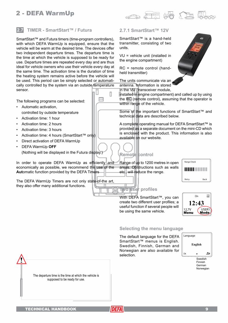
2.7.1 SmartStart™ 12VSmartStart™ is a hand-held transmitter, consisting of two units.
VU = vehicle unit (installed in the engine compartment)
RC = remote control (hand-held transmitter)
The units communicate via an antenna. Information is stored in the VU (transceiver module, installed in engine compartment) and called up by using the RC (remote control), assuming that the operator is within range of the vehicle.
Some of the important functions of SmartStart™ and technical data are described below.
A complete operating manual for DEFA SmartStart™ is provided as a separate document on the mini-CD which is enclosed with the product. This information is also available on our website.
TIMER - SmartStart™ / Futura2.7
SwedishFinnishGermanNorwegian
Remote controlRange of up to 1200 metres in open areas. Obstructions such as walls etc., will reduce the range.
Two user profilesWith DEFA SmartStart™, you can create two different user profiles; a useful function if several people will be using the same vehicle.
Selecting the menu languageThe default language for the DEFA SmartStart™ menus is English. Swedish, Finnish, German and Norwegian are also available for selection.
SmartStart™ and Futura timers (time-program controllers), with which DEFA WarmUp is equipped, ensure that the vehicle will be warm at the desired time. The devices offer two independent departure times. The departure time is the time at which the vehicle is supposed to be ready for use. Departure times are repeated every day and are thus ideal for vehicle owners who use their vehicle every day at the same time. The activation time is the duration of time the heating system remains active before the vehicle will be used. This period can be simply selected or automati-cally controlled by the system via an outside temperature sensor.
The following programs can be selected:• Automatic activation, controlled by outside temperature• Activation time: 1 hour• Activation time: 2 hours• Activation time: 3 hours• Activation time: 4 hours (SmartStart™ only)• Direct activation of DEFA WarmUp• DEFA WarmUp OFF (Nothing will be displayed in the Futura display.)
In order to operate DEFA WarmUp as efficiently and economically as possible, we recommend the use of the Automatic function provided by the DEFA Timers
The DEFA WarmUp Timers are not only state-of-the art, they also offer many additional functions.
2 - DEFA WarmUp
The departure time is the time at which the vehicle is supposed to be ready for use.

TECHNICAL HANDBOOK
10 TECHNICAL HANDBOOK
Separate activation timesIt’s possible to set separate activation times for the interior heater and the engine heater. This setting requires the use of an additional DEFA relay D23 and a separate cable. Then you will have the option of setting separate times for the engine and interior heat-ers. After you have selected the separate control of engine and interior heaters, switch to the heating program (above). Now you have the option of setting separate times for the engine and interior heaters.
Thermostat settingThe temperature sensor can be used as a thermostat for the interior or the en-gine. The thermostat function requires that the system is set to separately activate the engine and interior heaters. If the system is not set to control the engine and interior heaters together, the thermostat function will not be available.
TimerDEFA SmartStart™ has a stopwatch which also enables periods of inactivity to be ascertained.
Five- or seven-day week programYou can choose whether the departure times should be active for a five- or seven-day week. The factory default setting is for a five-day week. If a five-day week is selected, the departure times will be inactive on Saturday and Sunday.
Date-controlled activation timeWith DEFA SmartStart™, you can set a date-controlled activation time as the next departure time. DEFA WarmUp will only be activated again at a set time, which is especially practical if you leave your vehicle in a car park at the airport while travelling.
Departure timesAs a factory default, departure time I is set for 08:00 and departure time II for 16:00. In Aut mode, the heating system is automatically activated according to the outside temperature.
Oversleep2 hours beyond the departure time - if the vehicle is not started at the programmed departure time, DEFA Warmup remains active for an additional 2 hours.
Ignition signalDEFA WarmUp: voltage lossFuel heater: blue cable
The ignition signal remains suppressed for the remainder of the heating time.
[oC]
- 15- 14- 13- 12- 11- 10- 8- 6- 4- 20
+ 2+ 5+10
15 74 90 102 12650 138 150 156 162 168 174 180114
D10
[min]
Diagram D10 shows a system in which the temperature sensor is installed, for example, in the bumper. The auto-matic function then uses a common temperature sensor to control both the interior heater and the engine heater.
2 - DEFA WarmUp

TECHNICAL HANDBOOK 11
Fuel heater controlIn addition to controlling DEFA War-mUp, SmartStart™ is also capable of controlling fuel-based vehicle heating systems, provided access to an analog signal from the fuel based pre-heater. Note! For safety reasons, fuel-based systems must be switched on manually.
Heating program - fuelIf an external, fuel-based vehicle heat-ing system is integrated, SmartStart™ displays A-3 as standard. A1 through A5 represent levels of activation time according to the size of the vehicle. A1 applies to small vehicles, A3 for mid-sized vehicles and A5 for large vehicles. (e.g, vans, SUVs, etc.) Refer to diagrams D11-D13 for further details.
* Extremely cold temperatures can cause the display to indicate that the battery needs to be replaced, even when it is not necessary. Only change the battery if the indication is given while at room temperature (DEFA item no. 418103). ONLY USE LITHIUM BATTERIES.
** Therangeissignificantlyimpairedbyobstructionssuchaswalls, other vehicles, etc. You can re-establish contact in such circumstances by slightly changing your position or by aiming SmartStart™ at the top or bottom of the vehicle.
Product name: SmartStart™ Item number: 440020 (12 V) / 440021 (24 V)
Time-program control (RC)
Vehicle unit (VU)
Operating tempera-ture* -10°C < T < 60°C -40°C / +80°C
Relay output 100 mA max.
Battery type 6V Lithium. 2CR-1/3N Vehicle battery
Range** Up to 1.2 km with unobstructed view
Frequency [MHz] 868,370 MHz
Power consumption <5 µA <10mA
Testing and certification EMC in accordance wi th EN 301 489-1 :2005-04 and EN 301489-3:2002.08.Radio test in accordance with ETSI EN 300 220-1:2000-09Emissions test conducted in accordance with specifications of EN 301489-1 on meeting the requirements of 2004/104/EC.
Technical data
[oC]
+6...+10
+11...
[min]
+1...+5
- 4...0
-9...-5
-14...-10
-19...-15
-24...-20
-25....
25 36 47 58 60
A-5
D13[oC]
+6...+10
+11...
[min]
+1...+5
- 4...0
-9...-5
-14...-10
-19...-15
-24...-20
-25....
15 24 33 42 51 60
A-3
D12
[oC]
+6...+10
+11...
[min] 5 12 19 26 33 40
+1...+5
- 4...0
-9...-5
-14...-10
-19...-15
-24...-20
-25....
A-1
47 54 60
D11
2 - DEFA WarmUp

TECHNICAL HANDBOOK
12 TECHNICAL HANDBOOK
2.7.2 SmartStart™ 24VCan also be operated at 24V. SmartStart™ offers the same functionality as 12V. SmartStart™ 24V relay control requires the use of a 24V relay box. See the 24V circuit diagram D20 on page 42 for further details.
Replacing the battery
A LITHIUM BATTERY MUST BE USED. DURACELL 28L OR SANYO 2CR- 1/3N
(Spare part no. 418103)
Spare parts
#418100 SmartStart™ hand-held unit. (RC = remote control)
#418103 6V lithium battery
#418101 Unit installed in vehicle. (VU = vehicle unit)
#418072 Complete wiring harness between item no. 418101 and DEFA battery charger and/or relay for controlling fuel-based heating systems. Spare part no. for temperature sensor no. 418071.
#418100 #418103
#418072
Lithium
#418101
2 - DEFA WarmUp

TECHNICAL HANDBOOK 13
Arrow buttons These buttons are used to adjust the time and to program departure times.
Heating button The heating button enables the selection of various pre-set heating programs. Each time is pressed, the time-program controller alternates between the following heating programs:
If an outside temperature sensor has not been installed, this function will be assumed by unit’s integrated tem-perature sensor.
Button functions:
Function button Each time the button is pressed, the time-program controller displays (in succession):
• 24 h clock
• Departure time I - factory default setting 08:00
• Departure time II - factory default setting 16:00
• Battery voltage
• Outside temperature in °C
* The installation of an outside temperature sensor is required for this.
If the battery voltage and outside temperature are not dis-played, an outside temperature sensor is not installed. In this case, the time-program controller will alternate between 24 h clock, departure time I and departure time II each time the .button is pressed.
2.7.2 FuturaDEFA Futura displays the outside temperature, offers an integrated black ice warning and shows the battery/charging voltage. The unit is equipped with an illuminated display which is switched on when the engine is started or when one of the buttons is pressed.
After the time-program controller has been installed and supplied with power, the integrated clock can be adjusted and the desired departure and activation times can be programmed.
If the display lighting on the time-program controller is not on, only this lighting is switched on when one of the buttons is pressed for the first time.
Automatic activation controlled by outside temperatureSwitch on 1 hour before the set departure timeSwitch on 2 hours before the set departure timeSwitch on 3 hours before the set departure timeDEFA WarmUp ON.DEFA WarmUp OFF (no indication on the right side of the display)
2 - DEFA WarmUp

TECHNICAL HANDBOOK
14 TECHNICAL HANDBOOK
Setting the time program1. By pressing , the display will show the time, depar-ture time I or departure time II respectively, depending on which functions you want to change.
2. Simultaneously press both arrow buttons . The time/departure time will start blinking. The time-program controller is now in programming mode.
3. The arrow buttons are used to set the time/departure time.
To store the selected time, wait 5 seconds until the blink-ing stops.When the time-program controller switches on DEFA War-mUp, the On symbol in the display will start blinking.
The activation time always relates to the programmed de-parture time. If the vehicle is not started at the programmed departure time, the activation time is automatically extended by up to 2 hours (oversleep function) beyond the departure time. After that, the system switches off. It only switches on again upon reaching the activation time for the next departure time. This applies regardless of whether auto-matic mode or an activation time of 1, 3 or 3 hours has been selected. When the vehicle is started, the remaining activation time and the oversleep function are automatically cleared.Example 1:At 0°C, the DEFA WarmUp time-program controller switches on 90 minutes before the departure time. During this period, the engine temperature is raised by approximately 30°C (when a 600W engine heater is used).Example 2:At -17°C or lower, DEFA WarmUp switches on 196 minutes before the departure time and the engine temperature is raised by approximately 50°C (when a 600W engine heater is used).
The increase in the engine temperature is dependent on the type andconfigurationoftheengineheater.
20
-20
19590-30
-10
0
10
A
ºC min.
D14
Temperature-controlled activationWhen automatic mode D14 is selected, the temperature sensor measures the outside temperature and autono-mously determines the activation time according to the programmed departure time. If an outside temperature sensor was not installed, the interior temperature sensor in the timer measures the temperature. The lower the temperature, the longer the system has to stay switched on in order to achieve the desired temperature for the en-gine and interior. We recommend activating the automatic mode of the time-program control, as this operating mode is extremely economical. The diagram shows the activation time in minutes according to the outside temperature.
2 - DEFA WarmUp

TECHNICAL HANDBOOK 15
Black ice warningThe time-program controller has a slippery road warning function which triggers a warning when the vehicle enters a temperature range where there is a danger of black ice. This function requires the connection of an outside tem-perature sensor.If the vehicle enters a temperature range in which the tem-perature drops below +4°C or rises above -4°C, a warning will be indicated on the display, the button lighting on the time-program controller will blink for 6 seconds at a fast rate and the temperature will be displayed.The temperature must change by at least 2°C (compared to the previous warning) before another warning can be triggered. As the first warning is triggered at 4°C, the tem-perature must rise to at least 6°C and then subsequently drop to 4°C or lower before a new black ice warning will be given. As long as the black ice warning is active, the time-program control cannot be operated.
Starting the engineWhen the engine is started, the remaining time (where applicable) before the departure time is cleared and the On symbol will light up in the display. The time-program controller initiates an information sequence and displays the following:Battery voltage before engine is started, charge voltage after engine is started and outside temperature (each will be displayed for approx. 2 seconds). Afterwards, the time-program controller reverts back to the last function selected before the information sequence. This also applies if an outside temperature sensor is connected.
Switching off the engineWhen the engine is switched off, the time-program control-ler initiates an information sequence and displays departure times I and II. Then is reverts back to the last function selected before the information sequence.
Calibrating the temperatureThe design of the outside temperature sensor and tempera-ture display should provide the highest possible degree of accuracy. However, if an adjustment is required, proceed as follows:
1. Press until the temperature’s shown in the display.
2. Simultaneously press both arrow buttons The temperature will begin to blink. If the temperature does not blink, then the version of your time-program controller does not support this function.
3. and allow for an adjustment of +/- 3 °C.
Display lightingWhen the ignition is switched off, the time-program control-ler display lighting is switched on by pressing one of the buttons. The lighting stays on for 1 minute after a button was last pressed.Depending on the utility of the information provided by the time-program controller, the display lighting can be programmed so that it is switched On or Off while the car is being driven.
Switching display lighting on/offPress and hold for 5 seconds to switch on the display lighting.
To switch off the display lighting while drivingPress and hold for 5 seconds to switch off the display lighting.
2 - DEFA WarmUp

TECHNICAL HANDBOOK
16 TECHNICAL HANDBOOK
ENGINE HEATER - SafeStart2.8
The following factors can cause the fuse to burn out:
• Engine coolant level too low, heating element
is only partially submerged.
• Air pocket around the heating element.
• Dirty or contaminated coolant, which leads to the gradual formation of an insulating film on the heating ele-ment, thus preventing heat from being transferred to the coolant.
When a DEFA engine heater is installed, you can expect the engine temperature to be raised by as much as 50°C above the outside temperature, depending on the configuration and type of heater and amount of coolant.
The ideal activation time is dependent on the outside tem-perature. Equilibrium of heat is achieved after approximately 3 hours of operation. This means that any power consumed after this point is used solely to maintain the temperature. Any surplus energy is released into the environment. The engine heater can be left on for a prolonged period of time without damaging the heater or the engine. But this would be a needless waste of energy.
DEFA defines “Normal use” as; 3 connections for 3 hours pr. 24 hour based upon 150 users days a year (5 months a year).
It is claimable to make a yearly function control on profes-sional vehicles or engines, like emergency response vehicle or emergency power supplies, where the engine heater is connected 24/7. Yearly service costs will not be covered by DEFA AS.
At many apartment building car parking areas are they using interval power timers turning the power On and Off several times per hour. Using DEFA engine heater in such-like parking facilities will not be considered as “Normal use” and claims will be declined.
An engine heater should generate heat and transfer it to the engine as efficiently as possible. This can be done by means of convective heat transfer with direct heating of the engine fluids (coolant or motor oil) or by heat of conduction with indirect heating of the engine fluids via contact heaters in the engine block or oil pan. An engine heater should achieve equilibrium of heat, controlled by heating time and ambient temperature. Equilibrium of heat is achieved when about the same amount of heat energy that is drawn from the engine heater is delivered to the environment.
DEFA offers many types of engine heaters, depending on whether the vehicle is air or water cooled and how large or small the amount of coolant is. We also offer ideal solutions for tractors, vans, HGVs, other types of motor vehicles and stationary motors.
We have more than 500 different engine heaters in our product range for over 3400 different vehicle models. Our products are divided into 9 main series, which are differ-entiated by mode of operation and method of fastening.
We use three different series of numbers (411xxx, 412xxx and 413XXX). The last three numbers indicate the heater series.
DEFA strives to offer the optimum solution for each indi-vidual engine type. For engine types without accessible frost plugs or caps, there are DEFA engine heaters with special flanges, engine heaters for hose installation and contact heaters.
Every DEFA engine heater should warm up the engine as efficiently as possible, irrespective of the method of fas-tening. Most DEFA engine heaters are installed with the element directly in the coolant and provide a slow circula-tion of the warmed coolant. A lead fuse protects against overheating.
2 - DEFA WarmUp
DEFA defines “Normal use” as;
3 connections for 3 hours pr. 24 hour based upon 150 users days a year (5 months a year). It is claimable to make a yearly function control on professional vehicles or engines, like emergency response vehicle or emergency power supplies, where the engine heater is connected 24/7. Yearly service costs will not be covered by DEFA AS.

TECHNICAL HANDBOOK 17
2 - DEFA WarmUp
DEFA number series 201 to 299. These heaters have a threaded flange and are used in vehicles which have a threaded plug in the coolant tank that is accessible. A seal is formed between the flange and engine block walls with conical threads, an O-ring and a gasket or packing compound. In most cases, the flange is also designed so that the heating element is locked in po-sition while the flange is rotated. The heater flanges within this series are disc shaped or head shaped.
DEFA number series 001 to 099. The heater flange consists of a conical washer and the heater is fastened with a press fit. This type of heater is used for engines with a sufficiently large coolant tank, in which the entire heated part of the heating element can be installed. Generally for vehicles with larger engines and a correspondingly large coolant tank. This heater can only be installed in vehicles with cast iron engine blocks.
DEFA number series 101 to 199. These heaters have a head-shaped flange so that the heated part of the heating element can be installed in the head, either entirely of partially. These heaters are used for engines which do not have a large enough coolant tank. The heater is fastened with a press fit. This type of heater can have one or more conical sur-faces with different diameters. This makes it possible to use the heater for different types of engines. This heater can only be installed in vehi-cles with cast iron engine blocks.
DEFA number series 301 to 399. The flanges within this heater series are disc shaped or head shaped. A seal is formed between the flange and engine block walls with an O-ring or a rubber gasket. The heater is fastened to the engine block with a fixed spreader rail, which is fitted against the inside walls of the engine block, and a nut/sealing nut to secure the spreader rail. This method is also used if there is not enough space around the heating element for a press fit heater and also for aluminium engines.
DEFA number series 401 to 499. Heaters in number series 420 to 423 are an exception. For this type of engine heater, the flange consists of a metal pipe. The pipe can entirely or partially surround the heating element. The heater is attached to a specific point inside one of the en-gine’s coolant hoses, and is butted against a metal support (e.g. water pump brackets). With this method, the entire heated part of the heating element is surrounded by metal.
2.8.1 000 series – Flat conical flange
2.8.2 100 series - Conical head flange
2.8.3 200 series - Threaded flange
2.8.4 300 series - Spreader rail
2.8.5 400 series - Hose heater ex/ thermostat.

TECHNICAL HANDBOOK
18 TECHNICAL HANDBOOK
2 - DEFA WarmUp
DEFA number series 601 to 699. The heaters are used for air-cooled engines and/or in combination with an engine heater for the coolant.
Oil manufacturers have stipulated a maximum value of 2.4 W/cm² for the surface of the heating element in order to prevent any adverse effects on the quality of the oil. For large ve-hicles with ample-sized oil pans, the heated part of the element is placed directly in the oil. The power of oil heater is usually rated at 250W. Therefore, these elements do not have a lead fuse.
Oil heaters can be divided into two different groups:• Heaters for which the element is installed in place of the lid or cap on the oil pan.• Heaters which are installed in the threaded hole in the oil pan.
Also see Series 800 for indirect heating of the oil inside the oil pan.
DEFA number series 701 to 799, and they can be divided into two different groups: • Heaters without thermostat • Heaters with thermostat Heaters without thermostat These heaters are identified with the DEFA number series 701-709 and 758-799. The heaters consist of a heating element and a coolant chamber with intake and outlet con-nections for different hose dimen-sions. Heaters 758-799 do not have a thermostat and are suitable for various types of installation methods (hoses, T-connectors, hose clamps, etc.).They are usually installed in a hose on the oil cooler or in a hose for the internal vehicle heater.
Heaters with special flange or special fastener are identified with the DEFA number series 501 to 599 and 2501-2599. Several engine models have very different types of caps that are used instead of a frost plug in the coolant tank. DEFA manufactures a flange for these heaters which is identical to the original cap. The heater is fastened with bolts. A gasket or an O-ring is used to form the seal. There is also a heater available in this series which consists of a flat or head flange, and which is fastened with a holder.
DEFA number series 420 to 423 and are a sub-category of series 400. DEFA 420,421,422,423 are distin-guished from the other series 400 heaters by two basic differences:The heating element is completely surrounded by a coolant chamber. The heating temperature is lim-ited by a built-on thermostat. The thermostat regulates the coolant temperature and switches off the power supply to the element when the coolant has reached a tempera-ture of 80°C at the intake/outlet of the heater. The thermostat switches the heater back on at 70°C.
2.8.5 420 series - Hose heater incl. thermostat
2.8.6 500 series - Special fastener
2.8.7 600 series - Oil heater
2.8.8 700 series - Hose heater
Note! This is NOT a universal heater - Only to be used on recommended engines and vehicles.

TECHNICAL HANDBOOK 19
2 - DEFA WarmUp
DEFA number series 710 to 757 and they consist of heater 715 for various installation methods (hoses, T-connectors, hose clamps, etc.). Heater 715 consists of a coolant chamber with an element and a power connection box. There is ther-mostat in the connection box which measures the temperature on a metal plate between the connection box and the coolant chamber. Intake and outlet connections are designed to accommodate 5/8” or 16 mm hoses. The heater is equipped with a thermostat that regulates the cool-ant temperature and switches off the power supply to the element when the coolant has reached a tempera-ture of 80 °C at the intake/outlet of the heater. The thermostat switches the heater back on at 70°C.
The heater consists of a coolant chamber and a power connection box. There are 2 two-phase thermal fuses and thermostat in the connec-tion box which measure the tem-perature on a metal plate between the connection box and the coolant chamber. The fuses in the heater prevent the heating element from failing due to overheating.
230VºC
DEFA number series 801-899, 2801-2899 and 3801-3899.
Contact heaters can be divided into two different groups:
• Heaters for engine blocks
• Heaters for oil pans
Contact heaters consist of an ele-ment cast in aluminium, which is adapted to fit the installation point. Contact heaters for oil pans are es-sentially oil heaters which heat up the oil instead of the coolant. The rise in engine block temperature produced by a contact heater for oil pans is thus not comparable with an engine heater which heats up the coolant. A heat conducting paste is applied to the contact surfaces of the heater in order to improve the trans-fer of heat from the contact heater to the engine block or oil pan.
2.8.10 Technical dataDEFA engine heaters have a nominal power rating of between 175W and 2000W, depending on the size of the engine that is to be heated. DEFA engine heaters are compliant with the following standards: EMKO-TUB(61)NO 293/91, EN 60335-1 and EMKO-TSB(61)NO293A94.
Coolantheaters
Oil heaters
Contact heaters
Power 550-2000W 175-370W 300-400W
Voltage 230V
Protection class IP44
Overview of heaters with different thermostats (T) and power ratings (N) at 230V:
710-757 - With thermostat
721-734 - With thermostat
2.8.9 800 series - Contact heater
700W(6-12 L)*
1000W(12-18 L)*
1500W(16-24 L)*
2000W(22 L >)*
80ºC 411721 411722 411723 411724
60ºC 411727 411728 411729 411730
40ºC 411731 411732 411733 411734
NT
* Recommended used on engines with cooling system in litres (L) of coolant.

TECHNICAL HANDBOOK
20 TECHNICAL HANDBOOK
2.9.2 Technical dataThe table for Termini™ also indicates the power consump-tion for two different ambient temperatures.
DEFA interior heaters utilise a PTC heating element (PTC = Positive Temperature Coefficient), which adapts the power output according to the temperature of the intake air. A rise in temperature of 20°C results in a reduc-tion of power output by about 20%. As the interior tem-perature rises, power output is reduced and thus power consumption as well. The interior heater is equipped with an automatic overheating circuit breaker. If this breaker is tripped, it is reset by disconnecting the plug and leaving the interior heater switched off until it cools down (after approximately 30 minutes). There is also a lead fuse for additional protection. If this fuse blows, the interior heater must be sent to the factory for repair.
The interior heater is mounted in the interior of the vehicle with special holders.
2.9.1 Range of application
Termina 1400 and Termini™ 1350/1850, from small cars up to mid-sized estate cars.Termina 2000 and Termini™ 2100, from large saloon cars up to HGV cockpits.
INTERIOR HEATERS Termini™ / Termina
2.9
2 - DEFA WarmUp
Termini ™ 1350 1850 2100
Power level (W) - 25 °C 0/1350 0/850/1850 0/1300/2100
Power level (W) +25 °C 0/1100 0/720/1560 0/1060/1700
Width (mm) 138 141
Height (mm) 35 47
Depth (mm) 181 183
Weight (g) 595 745
Holder (g) 20
IP rating 20
Certification EN 60335-1, EN60 335-2-30 , NEK 554
Termina ™ 1400 2000
Power level (W) - 25 °C 0/800/1400 0/1100/2000
Width (mm) 146 200
Height (mm) 75 90
Depth (mm) 165 200
Weight (g) 890 1300
Holder (g) 35
IP rating 20
Certification EN 60335-1, EN60 335-2-30 , NEK 554
The table for Termina indicates the power consumption for an ambient temperature of -25°C.
Termini™ uses patented technology.

TECHNICAL HANDBOOK 21
2.9.3 Interior heating testThe following test results are from tests conducted in a cold chamber, and they illustrate the effectiveness of interior heaters.The tests were conducted in a cold chamber at a temperature of -20°C. The interior heaters were switched on and measurements were taken over the course of 120 minutes. The diagrams show the rise in temperature at individual, select measurement points in the interior of a typical vehicle.
Diagram D15 shows the heating curves for the interior when heated with Termini™ 2100. The tests were conducted on a large SUV.
After 2 hours of operation, the greatest measured rise in temperature was 43°C. As can be seen in the diagram, the greatest rise in temperature occurred within the first few minutes. The average increase over the last hour was merely 4°C. The heating curves progress asymptotically, so that the average increase after another hour of operation is even lower.
Diagram D16 shows the heating curves for the interior when heated with Termina 1400 and Termini™ 1350. The tests were conducted on a normal, mid-sized passenger car with notchback.
The de-icing characteristics of interior heaters are shown in the following illustration before and after a 2-hour test.
10 20 30 40 50 70 80 90 100 110 120
RoofSide windowRear headrestWindscreen
60
D15
10 20 30 40 50 70 80 90 100 110 120
RoofSide windowRear headrestWindscreen
60
D16
BEFORE
AFTER

TECHNICAL HANDBOOK
22 TECHNICAL HANDBOOK
DEFA battery charges are suitable for vented and valve-regulated batteries. The acid content of vented batteries can be measured. Valve-regulated batteries are subdivided into two categories: Gel batteries and AGM batteries (AGM = absorbed glass mat). In AGM batteries, the acid is in a free-flowing state, but it is absorbed by a glass-fibre mat. In gel batteries, the acid contains an additive which causes it to form a gel.
The charging current for batteries should generally be below 20% of the battery capacity (in Ah).
2.10.1 MultiCharger 1203 3AThe charger functions independently of the time-program control.The charger is primarily designed for passenger cars. Features:
• Modern switch-mode charging electronics, which help to preserve the battery. Therefore, the charger can be permanently connected.
• The temperature-compensated charging voltage ensures that the battery will be fully charged in all conditions.
• LED indicator for charging mode and quick charging mode (green and red).
• If the battery is so heavily loaded during the trickle charging process that the battery voltage drops to below 13V, the charger automatically switches to full-power mode (quick charge mode).
• The battery has short-circuit protection and reverse-polarity protection. This requires the installation of the enclosed fuse.
• 230V recognition, which prevents the relay from staying switched on and discharging the battery when the charger is not in use.
• 2 relay-controlled outputs for engine and parking heaters which can be activated with a time-program controller (external signal).
• Will not damage sophisticated electronics.
• Compact dimensions
• Protects the battery from degradation (sulphating) and extends the service life of the battery.
• Prevents the release of harmful gases (safety).
BATTERY CHARGER - MultiCharger2.10
2.10.2 MultiCharger 1210 10AThis charger can be used not only for passenger cars, but for the following applications as well:
• Caravans• Agricultural machines• Boats• Motorhomes• Buses and HGVs• Transporters• Wheelchairs
Features:• Modern switch-mode charging electronics, which help to preserve the battery. Therefore, the charger can be permanently connected.• The temperature-compensated charging voltage ensures that the battery will be fully charged in all conditions.• LED indicator for charging mode: quick charge mode (red) and trickle charge mode (green).• If the battery is so heavily loaded during the trickle charging process that the battery voltage drops to below 13V, the charger automatically switches to full-power mode (quick charge mode).• The battery has short-circuit protection and reverse- polarity protection. This requires the installation of the enclosed fuse.• The charger is suitable for 12V and 24V systems. (Each battery is charged separately in 24V systems.
2 - DEFA WarmUp
D17
-20oC+20oCCharging current
161514131211109876543210
1203 charging cycle
Cha
rgin
g vo
ltage
/cur
rent
Time
[V/A]

TECHNICAL HANDBOOK 23
2.10.3 Technical dataInformation on certifications can be found in chapter 4 under “CE documentation”.
2.11.1 DEFA MiniPlugThe DEFA MiniPlug is suitable for all new vehicles. It is easily flush mounted to the holder. The DEFA MiniPlug was developed with functional design, safety, maximum ease of installation and optimum user-friendliness in mind.
2.11.2 Extension cableThe main components of DEFA WarmUp can be easily con-nected with DEFA extension cables. The system provides a means of making safe and reliable connections. DEFA PlugIn contacts prevent improper connections.
2.11.3 DEFA RelayDEFA Relay 460838 can be used together with both SmartStart™ and Futura timer. Some functions will disap-pear by use of battery charger MultiCharger 1203. Refer to circuit diagram in the enclosed fitting instructions for DEFA relay.
CONNECTION ACCESSORIES2.11
MultiCharger 1203 1210Rated power [W] 45 125
Charging current [A/V] 3/12 10/12
Operating temperature [°C] -40/+40 -40/+40
Quick charging voltage [V] >14,7 >14,7
Maintenance charging [V] 13,7 13,7
Protection class IP54 IP54
H/W/D [mm] 80/70/45 205/130/65
Weight [kg] 0,24 0,50
Fuse rating 12 V [A] 5 15
Charging cable cross section [mm²]
0,75 2,5
Uneven charging is prevented.) Two chargers must be used for 24V systems.• Temperature monitors to protect the charging electronics.• Control voltage for quick charging mode 14.7V at 20 degrees (red).• Trickle charging: 13.7V at 20 degrees (green). To compensate for the self-discharge of batteries.• The charger has a 230V plug socket which can be used to connect two chargers or to provide power for additional DEFA equipment (without relay control).• Enables the trickle charging of batteries during winter storage (e.g. for boats, caravans and agricultural machines).• Will not damage sophisticated electronics.• Compact dimensions• Protects the battery from degradation (sulphating) and extends the service life of the battery.• Prevents the release of harmful gases (safety).
2 - DEFA WarmUp
H = height, W = width, D = depth
D18[V/A]
Cha
rgin
g vo
ltage
/cur
rent
161514131211109876543210
Time
1210 charging cycle
-20oC+20oC Charging current

TECHNICAL HANDBOOK
24 TECHNICAL HANDBOOK
GENERAL INFORMATION3.1
DEFA WarmUp is a modular 230V vehicle pre-heating system, which consists of an engine heater, interior heater, battery charger, timer and connection accessories.
DEFA WarmUp is offered in different sizes which corre-spond to the interior heating requirements. Engine heaters are offered separately, as they are different depending on the vehicle model.
Installation is quick and easy, improper connections are not possible and operation is intuitive and easy for the customer.
The large space requirements for equipment and the aero-dynamic design of new vehicles necessitate the adaptation of DEFA WarmUp to these conditions, in order to accom-modate and satisfy both installers and users alike. For this reason, we have developed the DEFA MiniPlug - a device connector, which is flush fitting and virtually invisible when installed and which can be mounted on brackets.
The instructions on the placement of cables and main components must be followed carefully. No components may be installed close to moving parts such as light systems, fans, steering rods and the like, or near hot engine parts such
as exhaust manifolds, exhaust pipes, turbo chargers and the like.
3 - Installation
DEFA WarmUp consists of small modules and sufficiently long cables, so that installation is possible in almost any type of vehicle. Our unique PlugIn system consists of special 230V cables and extension cables to connect the main components of DEFA WarmUp. The system prevents connection mix-ups and ensures that connections are safe and reliable.
DEFA WarmUp was developed with ease of installation and functionality in mind. The main components of the system are thus very compact, and are supplied with sufficiently long cables to make installation possible in almost any type of vehicle.
However, in order take full advantage of the length of the cables, the main components must be installed properly.

TECHNICAL HANDBOOK 25
Installation of DEFA WarmUp Termini™ 1350/1850/2100:
1. Disconnect the battery at the negative terminal. Read the instructions from the vehicle manufacturer before disconnecting the battery.2. The engine heater is selected according to the model list from DEFA. Install the engine heater at the location as specified in the respective installation manual. Fill the vehicle’s cooling system with an approved coolant and bleed air out of the system in accordance with the instructions from the vehicle manufacturer.3. Determine a suitable path to route the extension cables for the interior heater.4. Install the interior heater in the interior of the vehicle. Be sure to use the enclosed drilling template for the holder. 5. Install DEFA MiniPlug in an easily accessible spot at the front of the vehicle or where the customer requests.6. Position the battery charger/relay box in such a way that it can be connected to the extension cables from the interior heater, engine heater and device connector.7. Install the SmartStart™ vehicle unit (VU) with the cables and connect them to the MultiCharger/relay box. 8. Attach the SmartStart™ antenna outside of the engine compartment.9. Connect the battery at the negative terminal.10.Test DEFA WarmUp to ensure that it functions properly.
DEFA WarmUp Termini™ 1350/1850/2100 consists of:
Qty. Product1 Termini™ - interior heater with holder1 SmartStart™ - hand-held transmitter1 SmartStart™ - VU = unit to install in the engine compartment 1 MultiCharger 1203 - battery charger/relay1 Extension cable (0.5 m)1 Extension cable (1.0 m)1 Extension cable with interior heater plug (1.75 m)1 DEFA MiniPlug cable (1.5 m)1 Connection cable (2.5 m)1 Wiring harness for SmartStart™ and MultiCharger/charger
Fastening accessories for MiniPlug
Qty. Product1 Fastening nut1 Flat washer for nut for curved surfaces1 O-ring for fastening nut1 Holder1 Spacer for holder2 Black stainless steel bolt M4x20 mm2 Fastening bolts for PlugIn the holder (3x7 mm)2 Fastening plugs for the holder1 Self-tapping screw (4.2x13 mm)
Fastening accessories for other components
Qty. Product3 Fastening bolts (3.5x16 mm) for Termini™ holder8 Fastening strips (200 mm) for extension cable1 Fuse holder with 5A fuse1 MultiCharger cable (200 mm) between fuse holder and battery1 Rubber bushing1 Fastening bolt (4.2x16 mm) for MultiCharger holder to chassis1 Fastening bolt (4.2x32 mm) for MultiCharger to holder 1 Holder for battery charger1 Antenna fastening rail
3 - Installation

TECHNICAL HANDBOOK
26 TECHNICAL HANDBOOK
DEFA WarmUp Termina 1400/2000 consists of:
Qty. Product1 Termina - interior heater with holder1 Futura - time-program controller1 MultiCharger 1203 - battery charger with relay1 Interior heater contact1 Interior heater cable (1.5 m)1 Extension cable (0.5 m)1 Extension cable (1.0 m)1 DEFA MiniPlug cable (1.5 m)1 Connection cable (2.5 m)1 12 V wiring harness for time-program controller and charger/relay box
Fastening accessories for MiniPlug
Qty. Product1 Fastening nut1 Flat washer for nut for curved surfaces1 O-ring for fastening nut1 Holder1 Spacer for holder2 Fastening bolts for plug in the holder (3x7 mm)2 Fastening bolts (M4) for the holder2 Fastening plugs for the holder1 Self-tapping screw (4.2x13 mm)
Fastening accessories for other components
Qty. Product3 Fastening bolts (3.5x16 mm) for interior heater4 Double-sided tape for time-program controller8 Fastening strips (200 mm) for extension cable1 Fuse holder with 5A fuse1 MultiCharger cable (200 mm) between fuse holder and battery2 Fastening bolts (4.2x32 mm) for socket1 Feed through (14x28x7.5 mm)1 Fastening bolt (4.2x32 mm) for battery charger1 Fastening bolt (4.2x32 mm) for charger holder 1 Holder for battery charger
Installation of DEFA WarmUp Termina 1400/2000:
1. Disconnect the battery at the negative terminal. Read the instructions from the vehicle manufacturer before disconnecting the battery.2. The engine heater is selected according to the model list from DEFA. Install the engine heater at the location as specified in the respective installation manual. Fill the vehicle’s cooling system with an approved coolant and bleed air out of the system in accordance with the instructions from the vehicle manufacturer.3. Determine a suitable path to route the extension cables for the interior heater.4. Install the interior heater in the interior of the vehicle.5. Install DEFA MiniPlug in an easily accessible spot at the front of the vehicle or where the customer requests.6. Position the battery charger/relay box in such a way that it can be connected to the extension cables from the interior heater, engine heater and device connector.7. Place the Futura timer on the dashboard according to your customer’s wishes. Use the enclosed double-sided tape.8. Connect the battery at the negative terminal.9. Test DEFA WarmUp to ensure that it functions properly.
3 - Installation

TECHNICAL HANDBOOK 27
Drill head
Tool for routing the MiniPlug contact and PlugIn cable in the bulkhead.
Components:• Hole saw (Ø 24 mm) for MiniPlug• Hole saw (Ø 20 mm) for interior heater cable • File for guide slot • Holder with guide tap
Coolant
After the engine heater has been installed, the coolant has to be changed if it is dirty or contaminated. Otherwise, the coolant will cause a film to form on the heated part of the element and the element will burn out.
Bleed the air from the cooling system as per the instructions from the vehicle manufacturer in order to prevent an air pocket from forming around the engine heating element. An air pocket will cause the element to burn out very quickly, thus causing the engine heater to fail.
The engine heater may only be tested after the cooling system has been filled with an approved coolant and the system has been properly bled.
Only use a coolant which has been approved for the respec-tive vehicle model. DEFA WarmUp should only be installed in
accordance with the installation manual.
Tools
In addition to the usual tools found in a garage, a special tool is required for the installation of DEFA WarmUp.
The dimensions and order number for the special tool can be found in the model list / in the DEFA parts catalogue.
3 - Installation

TECHNICAL HANDBOOK
28 TECHNICAL HANDBOOK
Removing the frost plugSeries 000, 100, 300 and some series 500 DEFA engine heaters are installed in place of the frost plug or cap. The latter must therefore be removed before the heating element is installed. Depending on the configuration and material of the frost plug, different procedures and tools are required.
Extraction toolAvailable individually or as a complete set. The main ex-tractor tool (item no. 490888) is required in order to use the extractor and adapter sleeve. Single extractors and adapter sleeves are available in five different sizes, depending on the inside diameter of the frost plug which is to be removed. (See extractor for diameter.) This tool is also suitable for deep frost plugs. The tool functions like an extractor. It is securely tightened around the side walls of the frost plug by tightening the nut. Next, a suitable adapter sleeve (five different adapter sleeves) is put on. The frost plug is pulled off by tightening the nut. It is important to observe the manual for the tool.
#490843 (Ø20mm)
#490845 (Ø27mm)
#490846 (Ø31mm)
#490847 (Ø35mm)
#490848 (Ø41mm)
#490881 (Ø24mm)
#490882 (Ø31mm)
#490883 (Ø35mm)
#490884 (Ø39mm)
#490885 (Ø46mm)
#490888
Ø
I II III
#490843 (Ø20mm)
#490845 (Ø27mm)
#490846 (Ø31mm)
#490847 (Ø35mm)
#490848 (Ø41mm)
#490881 (Ø24mm)
#490882 (Ø31mm)
#490883 (Ø35mm)
#490884 (Ø39mm)
#490885 (Ø46mm)
#490888
Ø
I II III
It is imperative that the main tool is in the right position (normally on the frost plug receptacle) when the frost plug is pulled out.
ExtractorsItem no. Ø[mm]
490843 20
490845 27
490846 31
490847 35
490848 41
Item no. Ø[mm]
490881 27
490882 31
490883 35
490884 39
490885 46
Adapter sleeves
#490843 (Ø20mm)
#490845 (Ø27mm)
#490846 (Ø31mm)
#490847 (Ø35mm)
#490848 (Ø41mm)
#490881 (Ø24mm)
#490882 (Ø31mm)
#490883 (Ø35mm)
#490884 (Ø39mm)
#490885 (Ø46mm)
#490888
Ø
I II III
Item no.
490888
Main extractor tool
#490843 (Ø20mm)
#490845 (Ø27mm)
#490846 (Ø31mm)
#490847 (Ø35mm)
#490848 (Ø41mm)
#490881 (Ø24mm)
#490882 (Ø31mm)
#490883 (Ø35mm)
#490884 (Ø39mm)
#490885 (Ø46mm)
#490888
Ø
I II III
#490843 (Ø20mm)
#490845 (Ø27mm)
#490846 (Ø31mm)
#490847 (Ø35mm)
#490848 (Ø41mm)
#490881 (Ø24mm)
#490882 (Ø31mm)
#490883 (Ø35mm)
#490884 (Ø39mm)
#490885 (Ø46mm)
#490888
Ø
I II III
#490843 (Ø20mm)
#490845 (Ø27mm)
#490846 (Ø31mm)
#490847 (Ø35mm)
#490848 (Ø41mm)
#490881 (Ø24mm)
#490882 (Ø31mm)
#490883 (Ø35mm)
#490884 (Ø39mm)
#490885 (Ø46mm)
#490888
Ø
I II III
Complete set: #490871
Complete set: #490886
Complete extraction tool setMain tool + extractors + adapter sleeves: #490887
3 - Installation

TECHNICAL HANDBOOK 29
Special tool for interior feed through
Available in two versions, de-pending on whether the interior cable will be routed from the engine compartment into the inside of the interior or from the interior into the engine compartment. The tool can be secured with the insulating tape at the passage between the tool and the interior cable. Guide the tool, with the cable threaded in, through the original rubber bushing.
3.1.2 Direction of the PlugIn contactIn many cases, a specific direction is specified for the PlugIn contact for the installation of the engine heater. This is due to the following reasons:
• The PlugIn contact on the heater may not be located too close to hot parts, such as the exhaust manifold, turbo charger and the like.
• In order to prevent the heater from coming loose, thus allow-ing coolant to leak out, and in the worst case, causing dam-age to the engine. The walls of engine blocks (I) have different thicknesses. If the spreader rail or one of its legs bears down on these walls, this can cause the heater to come loose and allow cool-ant to leak out.
Therefore, it is imperative that the heater is installed according to the installation manual. The PlugIn contact of the element must point towards the specified direction.
Be careful not to damage existing cables while feeding through the interior cable. Carefully seal the area around the cables with
a suitable packing compound.
This tool must be used with extreme caution in order to avoid damaging the engine block.
The frost plug may not be hammered into the coolant casing, as this will compromise or impair the circulation of the coolant. On some engine blocks, there is a stop angle behind the frost plug. This procedure cannot be used to remove the frost plug on such
engines. The DEFA extraction tool must be used instead.
Removing the frost plugThe frost plug can also be removed by inserting a pin on the inside edge of the frost plug which is to be removed. Next, carefully tap the pin with a hammer, pushing it inward. If this is done very carefully, the cap will twist down into the frost plug receptacle. Then the frost plug can be pulled out with extraction pliers or water-pump pliers.
DEFA extraction hook
When using this tool, we rec-ommend punching a hole in the centre of the frost plug with a pin and hammer before attaching the extraction hook.
The tool is used in combination with a ½” ratchet. The extraction hook is available in 3 sizes, depending on the diameter of the frost plug which is to be removed.
3 - Installation
#490843 (Ø20mm)
#490845 (Ø27mm)
#490846 (Ø31mm)
#490847 (Ø35mm)
#490848 (Ø41mm)
#490881 (Ø24mm)
#490882 (Ø31mm)
#490883 (Ø35mm)
#490884 (Ø39mm)
#490885 (Ø46mm)
#490888
Ø
I II III
(I) Engine block

TECHNICAL HANDBOOK
30 TECHNICAL HANDBOOK
DEFAconductstrialinstallations,testsandobtainscertificationforallofissolutions,andcreatesspecificinstallationmanualsforindividualvehi-cles. We are always looking for the simplest, most ideal solution for each individual vehicle. Engine technology which eludes DEFAs monitoring
functions may result in solutions which involve a longer installation process than for other engine heaters.
Therefore, it is imperative that the instructions in the enclosed installation manual are followed during the installation of the engine heater.
3 - Installation
Integration with the vehicle
An increasing demand for environmentally friendly combustion engines and rising oil prices have lead to major advancements in engine design. Today, electronics are almost always used to measure coolant and oil tem-perature, and to regulate combustion.
Electronic control and monitoring systems and increasingly cramped engine compartments have apparently lead to logical solutions not being needed any longer.
In a best case scenario, improperly installed engine heat-ers may prevent the vehicle from starting (the electronics assume that the temperature in the vehicle is higher than it actually is at the time the vehicle is started). In a worst case scenario, improper installation may cause damage to the engine.
The heating of the coolant in the engine block or in the radiator hose not only provides a pre-heated engine, it also enables the car’s heater to deliver warmth immediately when the engine is started.This solution takes advantage of the principle that warm water rises and cold water sinks. Circulation is produced by heating the coolant at the lowest point of the circuit. For optimum results, the heater should thus be installed on the lowest radiator hose.
The installation of a hose heater on a visible and easily accessible radiator hose may be tempting, but the fact that this is not described in the installation manual has a very good reason.In modern engines, electronic temperature sensors and the like inside the radiator are often incompatible with a hose heater. In this case, the water is not circulated and the coolant will start to boil around the engine heater. This causes the engine heating element to burn out or engine heaters with a thermostat to switch off.

TECHNICAL HANDBOOK 31
The orifice must be thoroughly cleaned for both heater series. It should be free of rust, scratches, paint, score marks and other imperfections which may prevent the element from being securely seated or cause coolant to leak out. When installing the element, it is important to ensure that it is properly seated in the orifice.
Clean the orifice thoroughly after the frost plug has been removed. Use sandpaper if necessary.
Insert the heater in the orifice and check to make sure that it is seated properly and that the PlugIn contact is pointed in the right direction as specified in the installation manual. This is extremely important for the proper function of the heater. Tap the heater securely into place by tapping it in the centre with a hammer and pin. Make sure that the heater is properly seated in the orifice when fixing it in place.
There should always be a small gap between the stop angle (1) of the heater and the engine block wall after the heater has been installed.
Thoroughly clean the threads in the orifice after the corre-sponding screw cap has been removed from the coolant cover. A drop of oil on the threaded part of the heater makes it easier to screw in the heater. Guide in the threads of the heater and check to make sure that the threads are seated properly before tight-ening down the heater. On some heaters, the element can be secured while the heater is being tightened. Make sure that the PlugIn contact is pointing (2) in the right direction according to the installation manual. Seal the heater as instructed in the installation manual.
000-100 series - Flat conical flange3.2 200 series - Threaded flange 3.3
3 - Installation
DO NOT disassemble the heater before it is installed.
A drop of oil on the threaded part of the heater makes it easier to screw in the heater. Guide in the threads of the heater and check
to make sure that the threads are seated properly before tightening down the heater.
Min.: 2mm
(2)

TECHNICAL HANDBOOK
32 TECHNICAL HANDBOOK
When installing this type of heater, it is important to ensure that the spreader rail lies flush against the en-gine block wall inside coolant chamber. Engine block walls have different thicknesses. If one of the legs of the spreader rail bears down on these protrusions, this can cause the heater to become loose and/or detach. In a worst case scenario, it could also damage the engine.
Therefore, it is imperative that the heater is installed ac-cording to the installation manual. The PlugIn contact of the element must point towards the specified direction. The orifice must also be thoroughly cleaned. It should be free of rust, scratches, paint, score marks and other imperfections which may prevent the element from being securely seated or cause coolant to leak out.
300 series - Spreader rail3.4
3.4.1 Procedure for a spreader railInsert the heater directly into the frost plug orifice so that the PlugIn contact on the element is pointing in the direction specified in the instal-lation manual. Pull the heater up to the engine block wall. Make sure that the spreader rail is positioned between the element tubes. Rotate the heater by ±5° to ensure that it is properly seated, then torque the nut to 6 Nm.
Unscrew the nut almost completely, hook the spreader rail into the frost plug receptacle and place the heater in the receptacle. Make sure the heater is in the correct position. The PlugIn contact on the element must point towards the direction specified in the installation manual. Use the nut to pull the heater up to the engine block wall. Make sure that the spreader rail is positioned between the element tubes. Rotate the heater by ±5° to ensure that it is properly seated, then torque the nut to 6 Nm.
400 series - Hose heaters
3.4.2 Fixed T-rail
3.5A heater for hose installation is not a universal heater. It may only be installed in the corresponding vehicles in the model list, and in accordance with the procedures in the respective installation manual. This type of heater is used for vehicles which do not have a cap or frost plug in the coolant casing of the engine block. Installation directly in the coolant hoses or another unsuitable spot can lead to the formation of cracks in coolant hoses and leakage of coolant.
The heated part of the element must al-ways be installed so that it is completely surrounded by metal supports and does not touch any combustible parts, such as rub-ber hoses, etc. The heater must always be installed in a hose that is routed upwards.
Make sure that the spreader rail is positioned between the element tubes and that it is butted against a level base. For the 300 series,
it is especially important that the PlugIn contact on the heater is pointing in the right direction.
3 - Installation
Thistypeofheatermayonlybeusedwhenitisspecificallyrecommended by DEFA.
6 Nm tightening torque for spreader rail nuts or T-rail nuts

TECHNICAL HANDBOOK 33
420-423 - With thermostat
When the element is well protected in-side the coolant chamber, in principle, the heating can be installed in various points in the coolant hose. However, the hose must be routed upwards to-wards the engine and the thermostat for the engine must not be installed in the same hose. The connection box must be installed at the correct angle as specified in the installation manual and at least within the prescribed pitch inside the hose. Otherwise, the heated part of the element in the heater will be in an air pocket and the heater will burn out.
500 series - Special fastener3.6Remove the respective cap/frost plug and clean the fitting surface for gaskets and O-rings before installing the engine heating element. Make sure that the PlugIn contact on the heater is pointing in the right direction as indi-cated in the installation manual.
600 series - Oil heaters3.7These heaters are used in vehicles which have a cap on the oil pan. The original cap is replaced with a new cap with a cast-in heating element. Oil heaters which are installed directly in the oil pan are installed in the existing threaded hole. As an alternative, a hole can be drilled in the oil pan and the heater can be installed in this hole. Please carefully observe the installation manual for this procedure. If a hole must be drilled, use the drilling template in the installation manual and observe the instructions for the drilling proce-dure and hole diameter.
Heaters 420-423 may only be installed at the spots in the respectivevehiclesasspecifiedintheinstallationmanual.
The heater may only be installed in a hose that is routed upwards.
at least 45º at least 15º
3 - Installation

TECHNICAL HANDBOOK
34 TECHNICAL HANDBOOK
700 series - Hose heaters3.8Hose qualityIn order to guarantee optimum quality, hoses from DEFA are carefully inspected and are only selected after un-dergoing comprehensive testing in out test laboratory. If hoses which deviate from DEFA quality standards are used, they will dry out, form cracks and allow coolant to leak out after a certain amount of time.
3.8.1 701-709 - Without thermostat These heaters are installed separately or together with a mounting kit. See the installation manual for the respective vehicle for more information on this.Important notes:These heaters must be installed at the lowest possible point.The element plate must always face downward (I).The hoses must rise evenly (I).The heater may not be installed in a horizontal position (II).The hoses may not be bent too sharply (III).The hoses may not be unnecessarily long. The hoses may not touch hot/moving parts, such as turbo chargers, exhaust systems, fans, etc.
These heaters are installed separately or together with a mounting kit. See the installation manual for the respective vehicle for more information on this. Important notes:These heaters must be installed at the lowest possible point.The connection box must always face downward (I).The hoses must rise evenly (I).The heater may not be installed in a horizontal position (II).The hoses may not be bent too sharply (III).The hoses may not be unnecessarily long. The hoses may not touch hot/moving parts, such as turbo chargers, exhaust systems, fans, etc.
The engine heater may ONLY be installed at the spots in the respectivevehiclesasspecifiedintheinstallationmanual.
The heater may only be installed in a hose that is routed upwards.
(I) (II)
(III)
3 - Installation
(I)(II)
(III)
3.8.2 715 - With thermostat
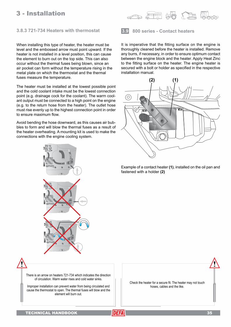
TECHNICAL HANDBOOK 35
When installing this type of heater, the heater must be level and the embossed arrow must point upward. If the heater is not installed in a level position, this can cause the element to burn out on the top side. This can also occur without the thermal fuses being blown, since an air pocket can form without the temperature rising in the metal plate on which the thermostat and the thermal fuses measure the temperature.
The heater must be installed at the lowest possible point and the cold coolant intake must be the lowest connection point (e.g. drainage cock for the coolant). The warm cool-ant output must be connected to a high point on the engine (e.g. to the return hose from the heater). The outlet hose must rise evenly up to the highest connection point in order to ensure maximum flow.
Avoid bending the hose downward, as this causes air bub-bles to form and will blow the thermal fuses as a result of the heater overheating. A mounting kit is used to make the connections with the engine cooling system.
800 series - Contact heaters3.9
It is imperative that the fitting surface on the engine is thoroughly cleaned before the heater is installed. Remove any burrs, if necessary, in order to ensure optimum contact between the engine block and the heater. Apply Heat Zinc to the fitting surface on the heater. The engine heater is secured with a bolt or holder as specified in the respective installation manual.
Example of a contact heater (1), installed on the oil pan and fastened with a holder (2)
There is an arrow on heaters 721-734 which indicates the direction of circulation. Warm water rises and cold water sinks.
Improper installation can prevent water from being circulated and cause the thermostat to open. The thermal fuses will blow and the
element will burn out.
Checktheheaterforasecurefit.Theheatermaynottouchhoses, cables and the like.
3 - Installation
(2) (1)
3.8.3 721-734 Heaters with thermostat

TECHNICAL HANDBOOK
36 TECHNICAL HANDBOOK
21
21
21
21
Feed through in the vehicle interior
3.10
On many vehicle models, the manufacturers have left openings in the bulkhead in order to accommodate the feed through of accessories. In many cases, these openings can be used to feed through the DEFA extension cable to the interior heater. Use the specially designed tool from DEFA for this. Carefully seal the area around the cables with a suitable packing compound. Some vehicle models have openings which are suitable for feeding cables through from the engine compartment into the interior through the interior trim along the A-pillar of the vehicle. In this case, the plastic interior trim must be removed.
If it is necessary to drill a hole in the firewall of the vehicle in order to feed through the DEFA extension cable into the interior of the vehicle from the engine compartment, ex-treme caution must be exercised. No holes may be drilled in double sheeting or reinforcements.
The DEFA hole saw (Ø 20 mm) is ideal for this task.
It is extremely important to ensure that the tool will not damage any installed components, brake lines, cables, etc. The supplied rubber bushing is used to seal the area around the cable.
When installing the bushing, make sure that it is properly seated. Otherwise, water may be able to penetrate the interior of the vehicle.
Before the extension cable is fed through, make sure it is routed at a downward angle in the engine compartment j so that no water runs into the interior of the vehicle k.
Whendrillingholesinthefirewall,itisimperativetomakesurethat the tool will not damage any installed components, brake
lines, cables, etc. No holes may be drilled in double sheeting or reinforcements. Apply a suitable rust protection coating around
the hole.
21
21
3 - Installation
Termini™ extension cable
Extension cables
Firewall
Firewall
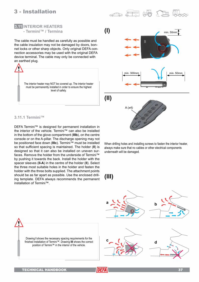
TECHNICAL HANDBOOK 37
INTERIOR HEATERS - Termini™ / Termina
3.11
3.11.1 Termini™
DEFA Termini™ is designed for permanent installation in the interior of the vehicle. Termini™ can also be installed in the bottom of the glove compartment (IIIb), on the centre console or on the A-pillar. The discharge opening may not be positioned face down (IIIc). Termini™ must be installed so that sufficient spacing is maintained. The holder (II) is designed so that it can also be installed on uneven sur-faces. Remove the holder from the underside of Termini™ by pushing it towards the back. Install the holder with the spacer sleeves (II-A) in the centre of the holder (II). Select the three most suitable holes in the holder and fasten the holder with the three bolts supplied. The attachment points should be as far apart as possible. Use the enclosed drill-ing template. DEFA always recommends the permanent installation of Termini™.
The interior heater may NOT be covered up. The interior heater must be permanently installed in order to ensure the highest
level of safety.
When drilling holes and installing screws to fasten the interior heater, always make sure that no cables or other electrical components underneath will be damaged.
3 - Installation
The cable must be handled as carefully as possible and the cable insulation may not be damaged by doors, bon-net locks or other sharp objects. Only original DEFA con-nection accessories may be used with the original DEFA device terminal. The cable may only be connected with an earthed plug.
Drawing I shows the necessary spacing requirements for the finishedinstallationofTermini™.DrawingIII shows the correct
position of Termini™ in the interior of the vehicle. d
A (x4)
a b
c
(I)
(II)
(III)
min. 300mm
min. 50mm
min. 50mm

TECHNICAL HANDBOOK
38 TECHNICAL HANDBOOK
DEFA interior heaters are based on PTC technology, in which the output is regulated by the temperature. This means that maximum heat output is delivered at -25°C, when the demand is greatest. As the interior temperature increases, output is decreased.
3.11.2 TerminaThe interior heater must be installed with the enclosed holder in a suitable spot in the interior of the vehicle. The illustrations for the instructions apply for 1400W and 2000W interior heaters from DEFA, and show the safety spacing requirements for the interior heaters.
The interior heater can be installed in the following positions:Down below, under the glove compartment for example.On the side panels, on the centre console or on the A-pillar. The discharge opening may not be positioned face down. The interior heater must be installed so that sufficient spac-ing is maintained. Spacing requirements for the interior heater are shown in the illustration.
The interior heater must be installed in such a way, that it does not pose a safety hazard in case of an accident or abrupt braking.When drilling holes and installing screws to mount the holder,
always make sure that no cables or time-program controllers on the back of the wall will be damaged.
The holder is designed so that it can also be installed on uneven surfaces. The holder is to be installed (see illus-tration) with the enclosed spacer sleeves j. Any of the holes in the holder can be used, however, we do recom-mend that the fastening points are spaced as far apart as possible. The holder is fastened with the enclosed bolts. The spacer sleeves j must be removed before the holder is installed. The interior heater is guided into the holder k until it you hear it click in place.
In order to ensure that the vehicle is heated as efficiently as possible, the flow of heat into the interior should not be obstructed by seats or other obstacles. See the illustration for more on this. Circulating air will compromise the heating process. For this reason, it is important to ensure that the air flows past the seats. See drawing III on the previous page for more on this.
3 - Installation
min
. 100
mm
min. 100mm
min. 100mm
min. 300mm

TECHNICAL HANDBOOK 39
BATTERYCHARGER - MultiCharger3.12
DEFA battery chargers are suitable for installation in the engine compartment or, for example, on an HGV chassis. The chargers are easy to install, and they ensure that the battery is always fully charged.
DEFA battery chargers are constructed and tested in ac-cordance with EN 60335-2-29.
Alternatively, the positive cable can be connected to the positive terminal on the starter. This also applies for 12 V systems. The cross section of the cable between the starter and battery is large enough that voltage drop does not need to be taken into account. If the 12 V cable must be extended, the installed cable is to be removed and replaced with a thicker cable with a larger cross section. As a rule of thumb, if the length of the cable is doubled, the cross section should also be doubled. See the technical data for more information.
The charging of batteries in poorly ventilated spaces must be avoided due to the risk of explosion. The charger must be installed with the drainage hole facing down, i.e. the white arrow on the label must point upwards.The temperature of the battery may not exceed +40°C while charging. Avoidexplosivegases,flamesandsparks.Switch off the mains supply before disconnecting the DC voltage connection. Red cable to positive terminal via fuse, black cable to negative terminal. To interrupt the charging proc-ess,themainssupply(230V)isdisconnected(i.e.negativeterminalfirst,thenthepositiveterminal).Do not shorten or extend the cables (12V), as this cause incorrect charging voltages.The charger must be correctly installed in order for water to drain. The direction is indicated on the label on the charger and/or on the top side of the charger.
3 - Installation
MultiCharger 1203
MultiCharger 1210

TECHNICAL HANDBOOK
40 TECHNICAL HANDBOOK
12V systems The charger is fastened at three of the four attachment points. Always use both of the side attachment points and either the top or bottom attach-ment point. Use the enclosed spacer discs on both sides to create a straight mounting surface.
24V systemsIn order to charge a 24V system, two 12V chargers have to be used. Two chargers can be connected directly on the 230V side. However, it is also possible to connect the chargers with an extension cable after installing both of them in their respective positions.
If two chargers are connected without an extension cable, the enclosed metal sleeve (1) must be used to secure the chargers in the common centre fastening point.
In doing so, make sure that the connection of the chargers is secure, that they are aligned one in front of the other and that the cables are not twisted. Use all of the fastening points in the centre and both points at the top and bottom. Each charger must be protected with a fuse (2) and connected with the respective battery. The 12V outputs on the chargers may not be connected in series.
Multicharger 1203
The battery charger is to be connected according to the circuit diagram in section 3.15. The enclosed fuse must be used to connect the charger to the battery. The en-closed holder can be used to simplify the attachment of the battery charger.
Route the cables onto the contacts on the battery charger (1) so that they are straight, in order to prevent the PlugIn contacts from being bent or twisted (2).
Make sure that the battery charger is not installed too close to hot parts, such as exhaust manifolds, turbo chargers and the like. Sufficient spacing must be maintained between the charger and moveable parts, such as belt pulleys, fans and steering rods.
Multicharger 1210
The battery charger must be installed on a straight, vertical surface. Route the cables onto the contacts so that they are straight, in order to prevent the PlugIn contacts from being bent or twisted. The bottom fixing tabs have two slots which allow condensation to drain from inside the charger. The charger must be installed in a vertical position so that the slots face downwards for drainage.
The MultiCharger cable (200 cm) between the fuse holder and battery may not be shortened. If the cable has to be extended, the
cross section must also be enlarged.
Double the length = double the cross section
(1) (2)
3 - Installation

TECHNICAL HANDBOOK 41
Time-program controllerSmartStart™ 12 V
3.13After SmartStart™ has been installed and connected, proceed as follows:
1. Activate the battery by removing the yellow plastic insulation. SmartStart™.2. Activate the remote control by pressing the button on the right-hand side of the unit.3. The units have already been synchronised at the factory. Press the Mode button on the right-hand side. The remote control establishes contact with the vehicle unit and accesses information contained in it.4. Set the time, date and language as instructed in the quick start guide.5. Press the right button to return to the output menu with the next departure time. The complete operating manual is contained in the mini-CD which is enclosed with SmartStart™ and it can also be accessed on our website (www.defa.com) under SmartStart™.
Observe circuit diagram D19 during the installation. Use the enclosed cable terminals.The VU must be installed in a vertical position. The ca-bles are connected from below. The enclosed fastening strips are used to secure the unit.
D* - Blue: Only required for the remote control of a fuel heater. For an electric car heater, the ignition signal is recognised when the voltage drops when the vehicle is started.
A - The end of the antenna MAY NOT be installed in the engine compartment. The end must be spaced at least 10 mm away from any metal. One suitable installation point, for example, is on outside of the vehicle in the seal between the windscreen and the bodywork.
C** - Green: Separate control of the interior heater. Re-quires an additional relay box.
REMOTE CONTROL OF THE FUEL HEATERB*** - The white cable is connected to the analog con-trol input on the fuel heater. Fuel heater control provides access to an analogue signal from the fuel based pre-heater.
WEBASTO THERMOTOP C and E:White is connected to X1, pin 1.
EBERSPÄCHER HYDRONICThe white cable is connected to S1, pin 7.
Refer to the circuit diagram for your fuel heater.
3 - Installation
D19
****
**
Fuel heater control provides access to an analogue signal from the fuel based pre-heater.
Refer to the circuit diagram for your fuel heater.

TECHNICAL HANDBOOK
42 TECHNICAL HANDBOOK
After SmartStart™ has been installed and connected, proceed as follows:
1. Activate the battery by removing the yellow plastic insulation. SmartStart™.2. Activate the remote control by pressing the button on the right-hand side of the unit.3. The units have already been synchronised at the factory. Press the Mode button on the right-hand side. The remote control establishes contact with the vehicle unit and accesses information contained in it.4. Set the time, date and language as instructed in the quick start guide.5. Press the right button to return to the output menu with the next departure time. The complete operating manual is contained in the mini-CD which is enclosed with SmartStart™ and it can also be accessed on our website (www.defa.com) under SmartStart™.
SmartStart™ 24VObserve circuit diagram D20 during the installation. Use the enclosed cable terminals.
The VU must be installed in a vertical position. The cables are connected from below. The enclosed fastening strips are used to secure the unit.
D* Blue: Only required for the remote control of a fuel heater. For an electric vehicle heating system, the ignition signal is recognised when the voltage drops when the vehicle is started.
A - The end of the antenna MAY NOT be installed in the engine compartment. The end must be spaced at least 10 mm away from any metal. One suitable installation point, for example, is on outside of the vehicle in the seal between the windscreen and the bodywork.
C** Separate control of the interior heater. Requires an additional relay.
REMOTE CONTROL OF THE FUEL HEATERB*** -The white cable is connected to the analog control input on the fuel heater. Refer to the specifications of your fuel heater.
D20
3 - Installation
****
**
Fuel heater control provides access to an analogue signal from the fuel based pre-heater.
Refer to the circuit diagram for your fuel heater.

TECHNICAL HANDBOOK 43
The plug j is installed with the red cable arranged as shown in the illustration. When the lid is closed, the thin part of the cable k must be in the opening and the thick part l must be in the inside. This relieves strain on the cable and prevents it from being pulled out.
Install the outside temperature sensor. This sensor serves two purposes:
• Temperature-controlled activation of DEFA WarmUp
• Black ice warning and outside thermometer, when the vehicle is in operation (+/- 4°C).
The temperature sensor must be arranged so that it will not be affected by hot parts such as the engine, radiator, exhaust system, etc. One such suitable spot is behind the bumper, or alternatively, in another spot on the front of the vehicle that is protected from splash water and mechanical interference.
If the outside temperature sensor is not installed, the func-tions for the display of battery voltage, black ice warnings and outside temperature will not be available. The internal temperature sensor in the time-program controller will be used for the automatic control of the activation times.
The cable for the time-program controller and battery charger is supplied as a single unit. This simplifies con-nection of the units.
Futura• Look for a suitable installation point for the control unit in the interior of the vehicle on the dashboard or on the centre console. If the customer wants to operate DEFA WarmUp using time-program control alone, the device can be installed on the sun visor inside the vehicle.
• Carefully clean the surface with suitable grease solvent (e.g. Acrysol). Do not use acetone,Tri, Breakclean and the like, as they can damage PVC and other types of plastic. The time-program controller is secured with the enclosed double-sided tape.
• The cable is connected to the controller at the contact under the small cover. The cover is opened as shown in the illustration.
The cover is different at each end. It can only be opened from the switch side.
3 - Installation
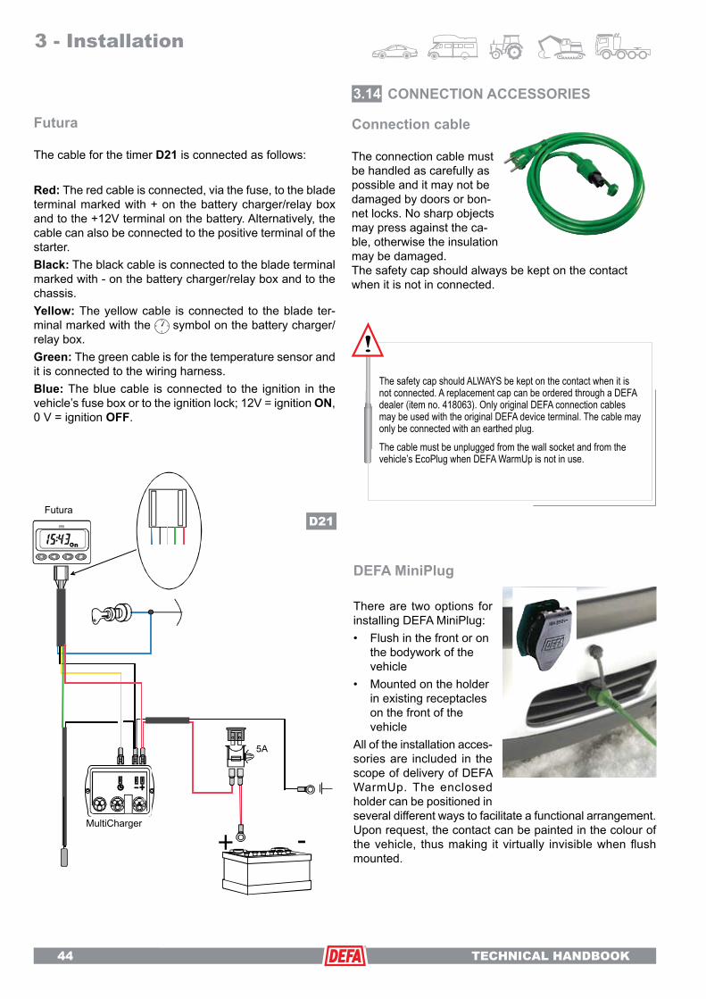
TECHNICAL HANDBOOK
44 TECHNICAL HANDBOOK
Futura
The cable for the timer D21 is connected as follows:
Red: The red cable is connected, via the fuse, to the blade terminal marked with + on the battery charger/relay box and to the +12V terminal on the battery. Alternatively, the cable can also be connected to the positive terminal of the starter.Black: The black cable is connected to the blade terminal marked with - on the battery charger/relay box and to the chassis.Yellow: The yellow cable is connected to the blade ter-minal marked with the symbol on the battery charger/relay box.Green: The green cable is for the temperature sensor and it is connected to the wiring harness.Blue: The blue cable is connected to the ignition in the vehicle’s fuse box or to the ignition lock; 12V = ignition ON, 0 V = ignition OFF.
Connection cable
The connection cable must be handled as carefully as possible and it may not be damaged by doors or bon-net locks. No sharp objects may press against the ca-ble, otherwise the insulation may be damaged.The safety cap should always be kept on the contact when it is not in connected.
CONNECTION ACCESSORIES3.14
The safety cap should ALWAYS be kept on the contact when it is not connected. A replacement cap can be ordered through a DEFA dealer (item no. 418063). Only original DEFA connection cables may be used with the original DEFA device terminal. The cable may only be connected with an earthed plug.The cable must be unplugged from the wall socket and from the vehicle’s EcoPlug when DEFA WarmUp is not in use.
3 - Installation
DEFA MiniPlug
There are two options for installing DEFA MiniPlug:• Flush in the front or on the bodywork of the vehicle• Mounted on the holder in existing receptacles on the front of the vehicle All of the installation acces-sories are included in the scope of delivery of DEFA WarmUp. The enclosed holder can be positioned in several different ways to facilitate a functional arrangement. Upon request, the contact can be painted in the colour of the vehicle, thus making it virtually invisible when flush mounted.
MultiCharger
FuturaD21

TECHNICAL HANDBOOK 45
Flush installation of DEFA MiniPlug
DEFA MiniPlug must be installed in such a way that it is protected from splash water and mechanical damage, and so that the connection cable can be easily con-nected.
If the fitting surface is not level for the fastening nut, the enclosed installation ring must be used. If used, the O-ring is inserted in the groove in the plastic nut or installation ring.
For flush installation, a hole with a diameter of 24.5 mm is drilled and a guide slot with a diameter of 3 mm is filed. Use the special tool from DEFA for this. Make sure that there is enough space on the back side for the cable and the fastening nut. Proceed with extreme caution in order to avoid damaging installed components, cables and the like.
The earth connection (black cable with ring terminal) must be connected to a bare metal part of the bodywork. Paint and the like must be removed from the attachment point for the earthing cable.
3 - Installation
The device connector must be installed outside of the inte-rior, in a place where it will be protected from splash water and mechanical damage.If at all possible, the contact should be mounted so that the front side faces downward at an angle.If the contact is mounted so that the front side faces up-ward at an angle, the lowest of three dampers will have to be opened for drainage (see drainage on the following page). This applies for installation on the holder and for flush mounting.
Drainage
Regardless of whether DEFA MiniPlug is installed flush or with a holder, the contact should always be installed to the lid at a downward angle so that water (condensation) can drain.
DEFA MiniPlug with holder
Depending on the installation point, the holder can be mounted on both sides. The contact can be adjusted and turned in order to achieve the de-sired position. The contact is normally installed with the lid hinge at the top. However, it can also be installed with the lid hinge to the side. The contact may NOT be installed with the lid hinge at the bottom.
If the contact is installed at an upward angle, the lowest of three dampers MUST be opened for drainage A. (Do not press the plastic
piece into the contact.) A knife can be used for this.
A
A

TECHNICAL HANDBOOK
46 TECHNICAL HANDBOOK
Earthing
The earth connection (black, single-phase cable with toothed ring terminal) MUST be connected to a suitable earthing point on a bare metal part of the vehicle’s body-work. Paint, primer and the like MUST be removed from the connection point for the earthing cable.
Only original DEFA connection cables may be used with the original DEFA device terminal. The connection may only be made with an earthed plug.
DEFA plug connections and extension cables
The PlugIn system makes it easy to connect the main com-ponents of DEFA WarmUp and extension cables. The plug connectors are designed so that they cannot be plugged-in incorrectly, and to ensure a safe and secure connection.
When making connections, the contacts must be pressed together firmly enough to ensure that the o-ring will suffi-ciently seal the plug contact. Make sure that the o-ring does not slip out of the groove when the contacts are pressed together.
The extension cables are fastened to suitable points in the engine compartment of the vehicle with ample spac-ing between them and moving parts such as belt pulleys, fans, etc.
Make sure that the extension cables are not routed too close to hot parts, such as exhaust manifolds, turbo charg-ers and the like. Cable connections may not be subjected to stress from twisting or bending .
3 - Installation
Do not route cables under the engine and/or where they will be near engine parts that rotate or move, or near the drive train.
Termini™ interior heater contact junctionUsed as a junction if Termini™ with an interior heater contact already exists and you would like a connection at a normal socket or 460829.
Interior heater contact 460829This contact may only be used in the interior of the vehicle. It is only protected to IP20 and thus may not be installed in the engine compartment, etc. It is also important to note that the contact is approved for a max. of 10 A.
Y-connector 460853Completely sealed connector for junctions (e.g. for interior heater set, etc.), IP44. Contains contact rails only (i.e.secure electrical connections).
90 T-connector 460831Connector for junctions (e.g. for interior heater set, etc.), IP44. Contains contact rails only (i.e. secure electrical connec-tions).
DEFA relay 460838 (12V)
Refer to circuit diagram in the enclosed fitting instructions for DEFA relay for use with SmartStart™ or Futura timer.
DEFA relay 460863 (24V)
Refer to circuit diagram in the enclosed fitting instructions for DEFA relay for use with SmartStart™ or Futura timer.
X = minimum 50mm

TECHNICAL HANDBOOK 47
CIRCUIT DIAGRAM - WarmUp3.15
3.15.1 SmartStart™ / Termini™
The MultiCharger cable between charger and battery MAY NOT be shortened.
VU = vehicle unit = unit which is installed in the engine compartment of the vehicle
Fixing tabs for stripsThe arrows must point towards each other.
Antenna rail
Observe the circuit diagram during the installation. Use the enclosed cable terminals.
The VU must be installed in a vertical position. The cables are connected from below. The enclosed fastening strips are used to secure the unit.
D* Blue: Only required for the remote control of a fuel heater. For an electric vehicle heating system, the ignition signal is rec-ognised when the voltage drops when the vehicle is started.
A - The end of the antenna MAY NOT be installed in the engine compartment. The end must be spaced at least 10 mm away from any metal. One suitable installation point, for example, is on outside of the vehicle in the seal between the windscreen and the bodywork.
C** - Separate control of the interior heater. Requires an ad-ditional relay. (D23)
REMOTE CONTROL OF THE FUEL HEATERB*** - The white cable is connected to the analog controlinput on the fuel heater.
WEBASTO THERMOTOP C and E:White is connected to X1, pin 1.
EBERSPÄCHER HYDRONICThe white cable is connected to S1, pin 7.
Refer to the circuit diagram for your fuel heater.
A = antennaB = white***C = green**D = blue*E = redF = blackG = temperature sensorH = yellow
3 - Installation
D22
A
B***
GC**
D*EF
H

TECHNICAL HANDBOOK
48 TECHNICAL HANDBOOK
3.15.2 SmartStart™ / Termini™ with independently controlled engine heater and interior heater
VU = vehicle unit = unit which is installed in the engine compart-ment of the vehicle
Fixing tabs for strips
The arrows must point towards each other.
Antenna rail
A = antennaB = white***C = green**D = blue*E = redF = blackH = yellow
G = temperature sensor. Installed in the interior if interior temperature is to be controlled separately from the engine heater.
D* Blue: Only required for the remote control of a fuel heater. For an electric car heater, the ignition signal is recognised when the voltage drops when the vehicle is started.
A - The end of the antenna MAY NOT be installed in the engine compartment. The end must be spaced at least 10 mm away from any metal. One suitable installation point, for example, is on outside of the vehicle in the seal between the windscreen and the bodywork.
C** Separate control of the interior heater. Requires an additional relay (#460838).
REMOTE CONTROL OF THE FUEL HEATERB*** -The white cable is connected to the analog control input on the fuel heater.
WEBASTO THERMOTOP C and E:White is connected to X1, pin 1.
EBERSPÄCHER HYDRONICThe white cable is connected to S1, pin 7.
Refer to the circuit diagram for your fuel heater.
The MultiCharger cable between charger and battery MAY NOT be shortened.
3 - Installation
D23
***
**
*

TECHNICAL HANDBOOK 49
3.15.3 Futura / Termina
3 - Installation
The MultiCharger cable between charger and battery MAY NOT be shortened.
The cable for the timer is connected as follows:
E - Red: The red cable is connected, via the fuse, to the blade terminal marked with + on the battery charger/relay box and to the +12V terminal on the battery. Alternatively, the cable can also be connected to the posi-tive terminal of the starter.
F - Black: The black cable is connected to the blade terminal marked with - on the bat-tery charger/relay box and to the chassis.
H - Yellow: The yellow cable is connected to the blade terminal marked with the symbol on the battery charger/relay box.
C - Green: The green cable is for the temperature sensor and it is connected to the wiring harness.
D - Blue: The blue cable is connected to the ignition in the vehicle’s fuse box or to the ignition lock; 12V = ignition ON, 0 V = ignition OFF.
T - Temperature sensor: Place the sensor in the front of the vehicle shielded from being influenced by the engines temperature.
T
D
F
F
H
E
E
C
D24

TECHNICAL HANDBOOK
50 TECHNICAL HANDBOOK
ENGINE HEATER4.1
This chapter covers troubleshooting. Before any further action is taken, two important things must be checked:
1. Is voltage present at the contact which WarmUp is connected to? If the fuse is blown, verify whether or not the circuit is laid out for the overall current drain.
2. Check the settings in the time-program controller.
The tables on the following pages contain causes and remedies to rectify simple faults which may occur with DEFA WarmUp.
Tester for engine heater elements with connection for DEFA EcoPlug. Order number: 490265
Power [W] Approx. Ohms250 211
300 176
600 88
750 70
820 64
1000 52
1500 35
2000 26
4 - Support
FAULT CAUSE REMEDY
Engine is not being heated.
The time-program control is not properly set. See chapter on the use of time-program control.
Not enough coolant. Top off coolant, bleed air out of the system.
Engine heater improperly installed.Inspect the engine heating element for damage.
Inspect according to installation manual.
The engine heating element is defective. Check the element with an ohmmeter or tester for engine heaters.
The blue cable on the time-program controller is not properly connected.
Check the connection of the blue cable onthe controller.
The engine heater generates heat, but the engine is cold.
Installation error. Inspect heater position according to installa-tion manual.
No circulation in the cooling system. Bleed air out of cooling system according to manufacturer’s instructions.
Air in cooling system. Bleed air out of cooling system according to manufacturer’s instructions.
For troubleshooting problems with engine heaters, we recommend the use of an ohmmeter and/or a tester from DEFA for engine heaters. The tables contain the measurement values of an engine heater in Ohms.
DEFA WarmUp

TECHNICAL HANDBOOK 51
4 - Support
The illustrations exemplarily show engine heater elements which are returned for replacement and are to serve as a guideline for dealers. The cause of engine heater failures can usually be determined by inspecting the surface of the engine heater elements.
Legitimate complaintFAULT CAUSE REMEDY
Clean and untarnished element Manufacturing defect Return engine heater as per the
replacement agreement.
Complaint is investigatedFAULT CAUSE REMEDY
Element or element parts are bluish-black
Insufficient cooling of the element due to:1. Installation error (see installation manual) 2. Cooling system not properly bled off3. Not enough coolant in engine4. Impaired circulation of coolant around the element
Install according to installation manual. Bleed air from cooling system, allow engine to run until warm and top off with approved coolant before connecting the engine heater element. (Inspect for coolant leaks.)
Unwarranted complaintFAULT CAUSE REMEDY
Film/deposits on element tubes (if in doubt, scratch with a knife)
Dirty or contaminated coolant (see installation instructions)
Clean cooling system and refill with fresh, approved coolant.
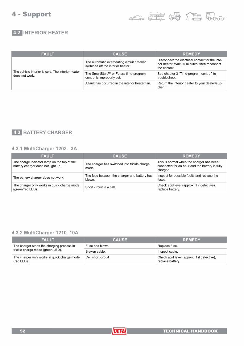
TECHNICAL HANDBOOK
52 TECHNICAL HANDBOOK
4.3.2 MultiCharger 1210. 10AFAULT CAUSE REMEDY
The charger starts the charging process in trickle charge mode (green LED).
Fuse has blown. Replace fuse.
Broken cable. Inspect cable.
The charger only works in quick charge mode (red LED).
Cell short circuit Check acid level (approx. 1 if defective), replace battery.
4 - Support
INTERIOR HEATER
BATTERY CHARGER4.3
4.2
4.3.1 MultiCharger 1203. 3A
FAULT CAUSE REMEDY
The vehicle interior is cold. The interior heater does not work.
The automatic overheating circuit breaker switched off the interior heater.
Disconnect the electrical contact for the inte-rior heater. Wait 30 minutes, then reconnect the contact.
The SmartStart™ or Futura time-program control is improperly set.
See chapter 3 “Time-program control” to troubleshoot.
A fault has occurred in the interior heater fan. Return the interior heater to your dealer/sup-plier.
FAULT CAUSE REMEDYThe charge indicator lamp on the top of the battery charger does not light up. The charger has switched into trickle charge
mode.
This is normal when the charger has been connected for an hour and the battery is fully charged.
The battery charger does not work. The fuse between the charger and battery has blown.
Inspect for possible faults and replace the fuses.
The charger only works in quick charge mode (green/red LED). Short circuit in a cell. Check acid level (approx. 1 if defective),
replace battery.

TECHNICAL HANDBOOK 53
TIMER4.4
FAULT CAUSE REMEDYThe time-program controller stays dimmed, no indication in the display.
Fuse between the charger and battery has blown.
Inspect for possible faults and replace the fuse.
The display does not light up when the engine is started.
The time-program controller is programmed to keep display lighting switched off while the vehicle is being driven.
See chapter on the use of time-program control.
WarmUp is not activated at the desired departure times.
Departure time set incorrectly.
Rectify fault.
Time-program controller stays in the OFF position.
Time-program control is set to Automatic and the outside temperature is above +10°C.
The blue cable is improperly connected.
Display lighting and digits blink while driving. Black ice warnings function.This is normal. Blinking lasts for 6 seconds.
Temperature between +4 and -4°C.
WarmUp stays switched on after engine has been switched off, although it is a long time until the next departure time.
The time-program controller normally clears the remaining activation time (and 2 hours with “Oversleep” after the engine has been switched on after the departure time). This is registered by an ignition signal.
+12V must be present at the blue cable when the ignition is on, and 0 V present when the ignition is off.
Time-program controller only works in the ON position. Blue cable improperly connected.
+12V must be present at the blue cable when the ignition is on, and 0V present when the ignition is off.
FAULT CAUSE REMEDY
The display indicates that the battery needs to be replaced. But the battery was just replaced!
When SmartStart™ is exposed to low tem-peratures, the display will prompt the user to replace the battery even if the battery has just been replaced.
Warms-up SmartStart™ to room temperature.
Check to make sure that the prescribed lithium battery has been used.
Install lithium battery.DURACELL 28L or SANYO 2CR- 1/3N
No contact with the vehicle. Antenna installation error Check to make sure the antenna is installed according to the instructions.
SmartStart™ does not start the vehicle heating system as expected.
Date and time set incorrectly. Observe the instructions in the SmartStart™ operating manual for setting the time and date.
Wrong weekly program selected. Observe the instructions in the SmartStart™ operating manual for setting a five- or seven-day week.
Date-controlled activation time is active.
Observe the instructions for deleting the date-controlled activation time in the SmartStart™ operating manual (see “Date-controlled activa-tion time” under the “Heating program” section).
4.4.1 SmartStart™
4.4.2 Futura
4 - Support

TECHNICAL HANDBOOK
54 TECHNICAL HANDBOOK
4 - Support
CABLES/CONTACTS4.5
Unwarranted complaintFAULT CAUSE REMEDY
The connection cable is no longer straight. The cable is bent.
The connection cable is under tension. Most commonly caused by driving the vehicle after the cable has been connected in such a way that it is under tension.
The connection cable MAY NOT be used. Buy a new cable. Also inspect the device connector (normally on the front of the vehicle) for damage.
Unwarranted complaintFAULT CAUSE REMEDY
Broken contact with damaged pins.
Most commonly caused by driving the vehicle after the cable has been connected in such a way that it damages the contacts.
The connection cable MAY NOT be used. Buy a new cable. Also inspect the device connector (normally on the front of the vehicle) for damage.
Unwarranted complaintFAULT CAUSE REMEDY
Charred surface between pins or earth.
Leakage current due to moisture, which, for example, can result from the contact being in the snow.
The connection cable MAY NOT be used. Buy a new cable. The socket MUST be replaced.

TECHNICAL HANDBOOK 55
1. INTRODUCTIONThis document describes the guidelines for the handling of complaints and the complaints procedure between RD and the dealer. The guidelines are applicable for complaints for DEFA products which are due to material and/or manufacturing defects.
Definitions•“Dealer”referstoadealerofproductsfromDEFAAutomotive.•“RD”referstotheregionalmarketingmanagerornational marketing manager.•“End-user”referstotheconsumer.
2. COMPLAINTS PROCEDURE AS IT RELATES TO RD AND DEALER 2.1. Complaints procedure 2.2. Handling defects 2.3. Limitation of liability
2.1. Complaints procedurea) These complaint procedures are applicable for complaints for DEFA products, which are sold to and installed for the end-user, and for which the complaint is processed by the RD through the dealer. The dealer is obligated to process complaints in accordance with the guidelines contained in this document.
b) The dealer must forward complaints which are received from the end-user to the RD, without hesitation, but no more than one week after acceptance. The shipment must contain the allegedly defective products and a brief report which contains the following information:1. Invoice, receipt of purchase or another valid form of documentation of the date of sale/installation.2. Name of the owner, address, vehicle type, engine type and model.3. Documentation which shows that the defective product was installed by an authorised garage.4. Description of the fault.5. Returned/defective product.
c)IfthecomplaintisnotsenttotheRDwithinthespecifiedperiodoftimeorthe return shipment is not properly prepared, the right to complain shall be forfeited.
d) The RD must process the complaint and inform the dealer whether or not the complaint is legitimate. There shall be no unnecessary delay in providing the dealer with this information. The dealer shall be informed no more than 2 weeks after the RD has received the shipment as per point b). If the complaint is rejected, the dealer must be informed of the reason for rejection.
e) If defects are found for which DEFA is liable according to point 2.2., the complaint shall be deemed legitimate. If the defective product was installed by an authorised garage, the removal/reinstallation costs will be covered as per the agreement.
2.2. Handling defectsWhen a dealer submits a complaint in accordance with point 2.1, the following duties apply to the RD:
a) The warranty for DEFA products is valid for three years from the date of purchase.Thedateofpurchasemustbeverifiablewithavalidreceipt.
b) The complaint must be due to faults or defects caused by material or manufacturing defects, which existed at the time when the product was delivered to the end-user.
c) The expiration date of the warranty period is based on the date as it ap-pears on the invoice or receipt of purchase.
If the end-user is submitting a claim for consequential damages caused by a DEFA product, the dealer must report this to the RD immediately. The dealer must take precautions to ensure that the object, which is alleged to be the subject of consequential damages, is not manipulated in any way, before DEFA has the opportunity to appraise the damage and determine the cause.
d) The dealer’s responsibility is limited to the creation of the required docu-mentation according to the description in this document and the forwarding of complaints, including the required information, to the RD.
e) DEFA’s responsibility is limited to the remedy of faults/defects through the repair of the product, or through the provision of a comparable product if necessary, according to what DEFA deems to be appropriate, and does not extend to cover consequential damages.
f) The RD’s responsibility is limited to the remedy of faults/defects through the provision of an equivalent replacement product or a product which has been repaired by DEFA, according to what the RD deems to be appropriate, and does not extend to cover consequential damages.
2.3 Exclusions The claim will be rejected if the fault or defect is attributed to the following causes:
a) Normal wear or ageing.
b) DEFA products were connected with third-party products and/or accesso-ries and an appropriate investigation has been conducted. An exception to the rule is SmartStart™.
c) Installation errors.
d)Insufficientmaintenance/careandimproperorunintendeduse.
e)Theproducthasbeentamperedwith,modifiedorrepaired,orattemptstodosoweremade,bypersonsnotaffiliatedwithDEFA,withouthavingfirstobtained written permission from DEFA to open, modify or repair the product.
f) Circumstances which are beyond the control of DEFA.
The dealer is not authorised to make statements to third parties on behalf of the RD, by making guarantees, providing descriptions regarding the quality of DEFA products or in any other way, directly or indirectly, unless expressly stated in a previously obtained written consent from the RD.
If there are no local DEFA distributors in your country/region, please contact main office:
DEFA AS - Automotive dept.Blingsmovn 30
N-3540 Nesbyen, Norway
Phone: +47 32 06 77 00 , Fax: +47 32 06 77 01www.defa.com
4 - Support
COMPLAINTS PROCEDURE4.6
Normal use is - 3 connections for 3 hours pr. 24 hour based upon 150 users days a year (5 months a year).

TECHNICAL HANDBOOK
56 TECHNICAL HANDBOOK
4 - Support
CE DOCUMENTATION4.7
CE - Declaration

TECHNICAL HANDBOOK 57
ISO/TS 16949:2002
ISO 14001:2004
ISO 9001:2000

TECHNICAL HANDBOOK
58 TECHNICAL HANDBOOK
4 - Support
DEFA web portal - www.defa.com4.8
Upon entering our website, the first thing you will see is the portal D25 to our user pages. The menu at the top contains links and there is an image menu on the right.
Top menu - This menu leads to a variety of information about our company, mailing addresses, the history of DEFA and our company philosophy. In addition, job postings are also displayed on these pages.
Image menu - On the right-hand side of the page you will see 8 images, which are consumer links to information about all DEFA products. DEFA WarmUp is the upper-most image on the left.
LanguageThe language can be selected after a selection is made in D25. Available languages are displayed in the topmenu
Where can I find an engine heater or a vehicle?Information about engine heaters for your vehicle can be found under “DEALER INFO” in the menu at the top of the D25 screen under the option “DEFA WarmUp”. From there, you will be guided to the D26 screen.
Proceed as follows:1. www.defa.com - D25 screen is displayed.2. From this screen, select “DEALER INFO” and click on “DEFA WarmUp”. From there, you will be guided to the D26 screen.3. Select your language from the top menu under “Language”.4. On the left-hand side all the way down at the bot tom, you can choose whether you want to search for an engine heater by vehicle, or vehicle by engine heater.
Opt. 1. Select your vehicle and model in the drop-down menu. A table with your vehicle/model will be displayed in a superimposed menu. (Assuming an engine heater is available.) The installation manual is available in the table as a PDF. Opt. 2. If you already have an engine heater and you would like to know which vehicles it is suitable for, enter the last 3 or 4 digits of the item number for your heater. The article numbers for heaters have six digits. If the number starts with 411XXX, enter the last 3 digits. If the article number starts with 412 or 413, the last 4 digits will need to be entered.
At the lower left-hand side of the screen, you can search for vehicles for which a DEFA mounting kit is available.
D25
D26
D25 - DEFA web portal.Ontheright-handsideofthispage,youwillfindlinkstoconsumerinformation about our products. The language is not selected from this page, but rather from the next page presented after a link is selected. You can alternate between the consumer pages and the professional pages D26
D26 - DEFA professional pagesYouwillalwaysfindacurrentmodellistonthispage.(Newvehicleswillbelisted as soon as a solution is available.) Hereyouwillalsofindallinstallationmanualsandmiscellaneoustechnicaldocumentation.
CE 040509 #490274 E47