contents i protective & predictive...
TRANSCRIPT

CA08104001E For more information visit:
www.eaton.com
January 2008
Contents
Protective & Predictive Relays 4.0-1
i
ii
1
2
3
4
5
6
7
8
9
10
11
12
13
14
15
16
17
18
19
20
21
Sheet 0233
Pro
tecti
ve &
Pre
dic
tive R
ela
ys
Protective & Predictive Relays
Selection Chart . . . . . . . . . . . . . . . . . . . . . . . . . . . . . . . . . . . . . . . . . . . . . . .
4.0-2
Feeder Protection . . . . . . . . . . . . . . . . . . . . . . . . . . . . . . . . . . . . . . . . . . . . .
4.1-1
Digitrip 3000 Feeder Protection Relay . . . . . . . . . . . . . . . . . . . . . . . . . .
4.1-1
Dual-Source Power Supply . . . . . . . . . . . . . . . . . . . . . . . . . . . . . . . . . .
4.1-6
Digitrip 3000 Drawout Case . . . . . . . . . . . . . . . . . . . . . . . . . . . . . . . . . .
4.1-9
Digitrip 3000 Technical Data . . . . . . . . . . . . . . . . . . . . . . . . . . . . . . . . . .
4.1-10
FP-4000 Feeder Protection Relay . . . . . . . . . . . . . . . . . . . . . . . . . . . . . .
4.1-12
FP-5000 Advanced Feeder Protection Relay . . . . . . . . . . . . . . . . . . . . .
4.1-17
FP-5000 Technical Data . . . . . . . . . . . . . . . . . . . . . . . . . . . . . . . . . . . . . .
4.1-21
Motor Protection . . . . . . . . . . . . . . . . . . . . . . . . . . . . . . . . . . . . . . . . . . . . .
4.2-1
MP-3000 Motor Protection Relay . . . . . . . . . . . . . . . . . . . . . . . . . . . . . .
4.2-1
MP-3000 Technical Data . . . . . . . . . . . . . . . . . . . . . . . . . . . . . . . . . . . . .
4.2-4
Universal RTD Module . . . . . . . . . . . . . . . . . . . . . . . . . . . . . . . . . . . . . .
4.2-10
MP-4000 Motor Protection with Voltage Relay . . . . . . . . . . . . . . . . . . .
4.2-12
Differential Protection . . . . . . . . . . . . . . . . . . . . . . . . . . . . . . . . . . . . . . . . .
4.3-1
MD-3000 Motor Differential Relay . . . . . . . . . . . . . . . . . . . . . . . . . . . . .
4.3-1
DP-300 Differential Relay . . . . . . . . . . . . . . . . . . . . . . . . . . . . . . . . . . . .
4.3-3
Voltage Protection Relay . . . . . . . . . . . . . . . . . . . . . . . . . . . . . . . . . . . . . . .
4.4-1
VR-300 Voltage Relay . . . . . . . . . . . . . . . . . . . . . . . . . . . . . . . . . . . . . . .
4.4-1
InsulGard Predictive Maintenance
General Description . . . . . . . . . . . . . . . . . . . . . . . . . . . . . . . . . . . . . . . . . . .
4.5-1
Specifications . . . . . . . . . . . . . . . . . . . . . . . . . . . . . . . . . . . . . . . . . . . . . . . .
4.5-4
General Notes. . . . . . . . . . . . . . . . . . . . . . . . . . . . . . . . . . . . . . . . . . . . . . . .
4.5-5
Switchgear Applications . . . . . . . . . . . . . . . . . . . . . . . . . . . . . . . . . . . . . . .
4.5-5
Motor Applications. . . . . . . . . . . . . . . . . . . . . . . . . . . . . . . . . . . . . . . . . . . .
4.5-6
Generator Applications . . . . . . . . . . . . . . . . . . . . . . . . . . . . . . . . . . . . . . . .
4.5-7
Connection Diagram . . . . . . . . . . . . . . . . . . . . . . . . . . . . . . . . . . . . . . . . . .
4.5-9
Specifications
See Eaton’s Cutler-Hammer Product Specification Guide on enclosed CD-ROM:1995 CSI Format: Digitrip 3000. . . . . . . . . . . . . . .
Section 16903, Paragraph 2.04.A
FP-5000 . . . . . . . . . . . . . . . . . . .
Section 16903, Paragraph 2.04.C
FP-4000 . . . . . . . . . . . . . . . . . . .
Section 16903, Paragraph 2.04.B
MP-3000 . . . . . . . . . . . . . . . . . .
Section 16903, Paragraph 2.02.D
MP-4000 . . . . . . . . . . . . . . . . . .
Section 16903, Paragraph 2.02.E
MD-3000 . . . . . . . . . . . . . . . . . .
Section 16903, Paragraph 2.02.F
DP-300 . . . . . . . . . . . . . . . . . . .
Section 16903, Paragraph 2.04.E
VR-300 . . . . . . . . . . . . . . . . . . .
Section 16903, Paragraph 2.04.D
Universal RTD Module . . . . . .
Section 16901, Paragraph 2.04.A
InsulGard . . . . . . . . . . .
Sections 16901, 16950A, 16950C, 16950DParagraph 2.03.A
2004 CSI Format: Digitrip 3000. . . . . . . . . . . . .
Section 26 09 11, Paragraph 2.04.A
FP-5000 . . . . . . . . . . . . . . . . .
Section 26 09 11, Paragraph 2.04.C
FP-4000 . . . . . . . . . . . . . . . . .
Section 26 09 11, Paragraph 2.04.B
MP-3000 . . . . . . . . . . . . . . . .
Section 26 09 11, Paragraph 2.02.D
MP-4000 . . . . . . . . . . . . . . . .
Section 26 09 11, Paragraph 2.02.E
MD-3000 . . . . . . . . . . . . . . . .
Section 26 09 11, Paragraph 2.02.F
DP-300 . . . . . . . . . . . . . . . . .
Section 26 09 11, Paragraph 2.02.E
VR-300 . . . . . . . . . . . . . . . . .
Section 26 09 11, Paragraph 2.02.D
Universal RTD Module . .
Section 26 27 13.11, Paragraph 2.04.A
InsulGard . . . . . . .
Sections 26 13 13.41, 26 11 16.15, 26 32 13.11Paragraph 2.03.A
4.0-2
For more information visit:
www.eaton.com
CA08104001E
January 2008
Protective & Predictive Relays
i
ii
1
2
3
4
5
6
7
8
9
10
11
12
13
14
15
16
17
18
19
20
21
Selection Guide
General Description
Sheet 0234
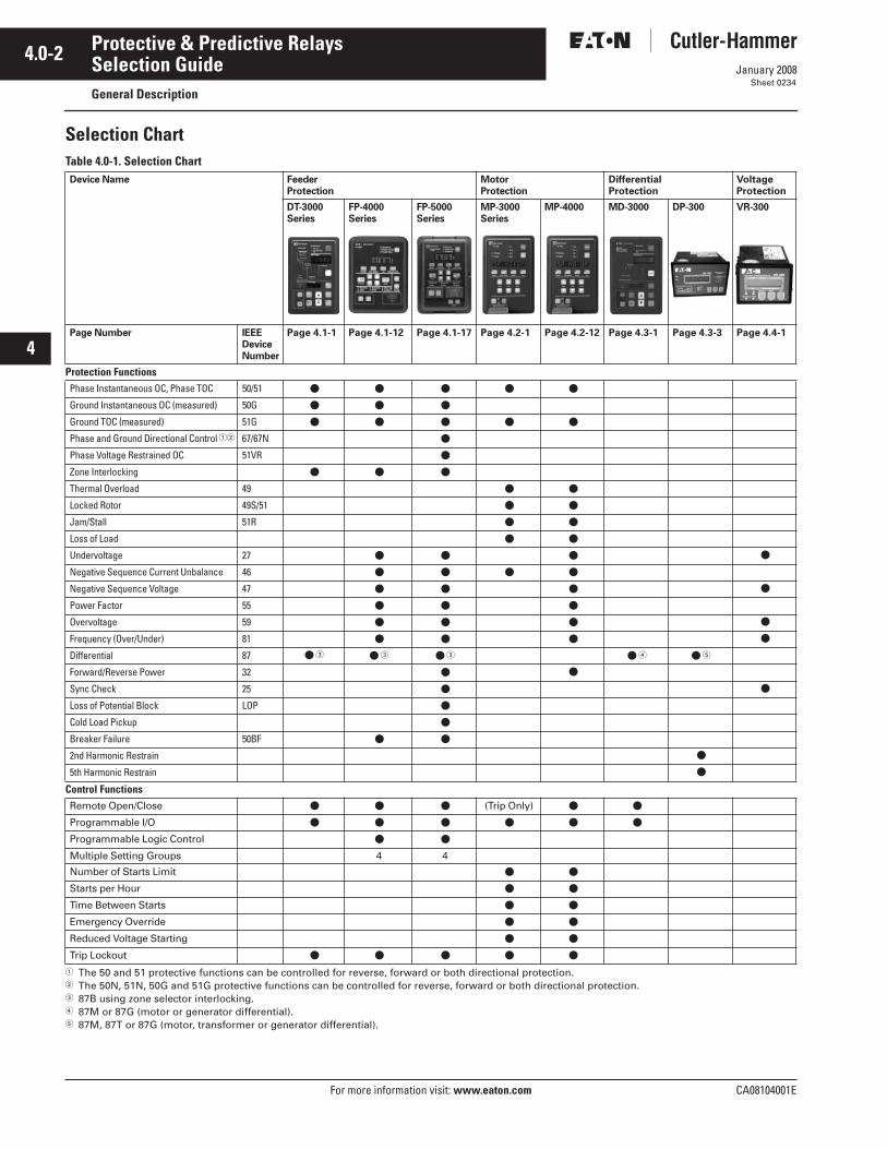
Selection Chart
Table 4.0-1. Selection Chart
The 50 and 51 protective functions can be controlled for reverse, forward or both directional protection.
The 50N, 51N, 50G and 51G protective functions can be controlled for reverse, forward or both directional protection.
87B using zone selector interlocking.
87M or 87G (motor or generator differential).
87M, 87T or 87G (motor, transformer or generator differential).
Device Name Feeder Protection
Motor Protection
Differential Protection
Voltage Protection
DT-3000 Series
FP-4000 Series
FP-5000 Series
MP-3000 Series
MP-4000 MD-3000 DP-300 VR-300
Page Number IEEE DeviceNumber
Page 4.1-1 Page 4.1-12 Page 4.1-17 Page 4.2-1 Page 4.2-12 Page 4.3-1 Page 4.3-3 Page 4.4-1
Protection Functions
Phase Instantaneous OC, Phase TOC 50/51
Ground Instantaneous OC (measured) 50G
Ground TOC (measured) 51G
Phase and Ground Directional Control
67/67N
Phase Voltage Restrained OC 51VR
Zone Interlocking
Thermal Overload 49
Locked Rotor 49S/51
Jam/Stall 51R
Loss of Load
Undervoltage 27
Negative Sequence Current Unbalance 46
Negative Sequence Voltage 47
Power Factor 55
Overvoltage 59
Frequency (Over/Under) 81
Differential 87
Forward/Reverse Power 32
Sync Check 25
Loss of Potential Block LOP
Cold Load Pickup
Breaker Failure 50BF
2nd Harmonic Restrain
5th Harmonic Restrain
Control Functions
Remote Open/Close
(Trip Only)
Programmable I/O
Programmable Logic Control
Multiple Setting Groups 4 4
Number of Starts Limit
Starts per Hour
Time Between Starts
Emergency Override
Reduced Voltage Starting
Trip Lockout

CA08104001E For more information visit:
www.eaton.com
4.0-3
January 2008
Protective & Predictive Relays
i
ii
1
2
3
4
5
6
7
8
9
10
11
12
13
14
15
16
17
18
19
20
21
Selection Guide
General Description
Sheet 0235
Table 4.0-1. Selection Chart (Continued)
Differential and restrain current only.
Device Name Feeder Protection
Motor Protection
Differential Protection
Voltage Protection
DT-3000 Series
FP-4000 Series
FP-5000 Series
MP-3000 Series
MP-4000 MD-3000 DP-300 VR-300
Page Number IEEEDeviceNumber
Page 4.1-1 Page 4.1-12 Page 4.1-17 Page 4.2-1 Page 4.2-12 Page 4.3-1 Page 4.3-3 Page 4.4-1
Metering Functions
Amperes
Ampere Demand
Volts, Frequency
Power and Demand
Energy
Trending (Load Profile)
Minimum/Maximum Recording
Maximum Only
Monitoring Functions
Trip Circuit Monitor
Breaker Wear
Failure to Close
Oscillography
Sequence of Events
Trip Target Data
Clock
Number of Starts
Acceleration Time
RTD Temperature
Communications
RS-232, RS-485
Protocols
INCOM
and/or
Modbus
Construction
Drawout Optional
Optional Optional Optional Optional
Alarm Outputs 2 Form C 2 Form C 2 Form C 3 3 2 Form C 1NO 1 Form C
Trip Outputs 2 5 5
Analog Outputs
Standards
ANSI, UL
, IEC

4.0-4
For more information visit:
www.eaton.com CA08104001E
January 2008
Protective & Predictive Relays
i
ii
1
2
3
4
5
6
7
8
9
10
11
12
13
14
15
16
17
18
19
20
21
Sheet 0236
This page intentionally left blank.

CA08104001E For more information visit: www.eaton.com
4.1-1January 2008
Protective & Predictive Relays
i
ii
1
2
3
4
5
6
7
8
9
10
11
12
13
14
15
16
17
18
19
20
21
Feeder ProtectionGeneral Description — Digitrip 3000
Sheet 0237
Digitrip 3000Feeder Protection Relay
Digitrip 3000 Front View
General DescriptionEaton’s Cutler-Hammer Digitrip 3000 Protective Relay is a multi-function, microprocessor-based overcurrent relay designed for both ANSI and IEC applications. It is a panel-mounted, self-contained unit which operates from either ac or dc control power. The Digitrip 3000 is available in an optional quick-release drawout case for panel-flush mounting. For ac control power applications, an optional Dual-Source Power Supply (DSPS) is recommended. See Page 4.1-6 for details. The Digitrip 3000 design provides true rms sensing of each phase and ground current. Only one unit is required for each 3-phase circuit. Current monitoring and opera-tor selectable protective functions are integral to each relay.
The Digitrip 3000 Relay operates from the 5 ampere secondary output of standard current transformers. Current transformer ratio information is quickly programmed into the unit via settings. This enables the relay to display metered current in primary amperes.
The Digitrip 3000 features a user-friendly operator panel to monitor, program and test the relay. Operating parameters and troubleshooting infor-mation are displayed in the two highly visible display windows. In addition, all data and information can be communicated to a host computer equipped with the appropriate software. A “Communication Trip” and “Communication Close” control command can also be initiated by a host computer with an authorized access code.
Features
General ANSI or IEC applications. User-friendly front panel. Non-volatile memory. View settings any time. Set CT ratios. Metered currents in primary
amperes. Individual phase targeting of fault. Integral test mode (phase and
ground). Program and test mode security
access cover with meter seal provision.
Continuous internal circuitryself-testing.
Programmable lockout/self reset after trip.
Relay failure alarm contact. Trip alarm contact. Optional Dual-Source Power
Supply (DSPS), see Page 4.1-6. Optional quick-release drawout
case, see Page 4.1-9.
Table 4.1-1. Catalog Numbers
Digitrip 3000 Rear View
Description CatalogNumber
Digitrip 3000 DT3000
Digitrip 3000 Drawout Relay DT3001
Digitrip 3000 Drawout Inner Chassis
DT3001-IC
Digitrip 3000 Drawout Outer Case DT3001-OC
Digitrip 3000 with 120 Vac Dual-Source Power Supply
DT3010
Digitrip 3000 with 240 Vac Dual-Source Power Supply
DT3020
Digitrip 3000 with 24/48 VdcPower Supply and CE Mark
DT3030
Digitrip 3000 with 24/48 VdcPower Supply and CE Mark inDrawout Case
DT3031
DIP Switches
TerminalBlock 1
CurrentTransformerConnections
TerminalBlock 2
CommunicationConnectionTerminal Block 2-1Terminal Block 2-2

4.1-2
For more information visit: www.eaton.com CA08104001E
January 2008
Protective & Predictive Relays
i
ii
1
2
3
4
5
6
7
8
9
10
11
12
13
14
15
16
17
18
19
20
21
Feeder ProtectionGeneral Description — Digitrip 3000
Sheet 0238
System Protection True rms sensing of each phase and
ground current. Selectable curve shapes: ANSI, IEC
or thermal curves. Phase overcurrent protection per
time-current curve. Independent ground fault protection
per time-current curve. Time overcurrent reset time delay. Ground element capable of residual,
zero sequence or external source connections.
Instantaneous phase and ground OC. Short delay phase and ground OC. Selectable true making current
release (discriminator). Configurable trip outputs. Zone selective interlocking (phase
and ground) for bus protection and reduced arc flash energy.
Information and Data Delivery Displays individual phase currents. Displays ground current. Displays magnitude and phase of
current causing trip. Displays peak demand current
for each phase and ground since last reset.
Displays current transformer ratio. Indicates cause of trip (time or
instantaneous). Data/information transmission. Provides breaker “Open” or “Close”
status to a remote location via Eaton’s Cutler-Hammer PowerNet.
Applications
GeneralThe Digitrip 3000 microprocessor-based relay provides reliable 3-phase and ground overcurrent protection for all voltage levels. It can be used for any application where instantaneous and/or time overcurrent protection is required. It is most commonly used as primary feeder circuit protection, as in Figure 4.1-1.
Figure 4.1-1. Primary Feeder Protection
The Digitrip 3000 may be applied as the transformer primary protection or as backup to the differential protec-tion, as in Figure 4.1-2.
Figure 4.1-2. Transformer Protection
The Digitrip 3000 may be connected to the secondary side of a Delta-wye grounded transformer with the ground element connected to a separate CT in the neutral connection of the trans-former. With this connection, a lower CT ratio and a pickup setting can be used to provide more sensitive ground fault protection especially for resistance grounded systems (see Figure 4.1-3).
Figure 4.1-3. Transformer SecondaryProtection with Ground CT Connection
The Digitrip 3000 relay has special provisions for connection in a Zone Interlocking Scheme which can be used for bus protection or to improve protection coordination in a tight or close system. Zone interlocking is described in more detail on Page 4.1-4.
Time Overcurrent ResetThe Digitrip 3000 includes time delay reset characteristic for the time over-current functions. This improves the overcurrent protection response to arcing fault conditions. The current during an arcing fault may vary above and below the pickup level. The time above pickup will accumulate until trip occurs.
Overcurrent ProtectionThe Digitrip 3000 provides complete 3-phase and ground protection with separate elements and settings. The relay can be used with CT ratios from 5/5 to 5000/5. The CT ratio can be set independently for phase and ground allowing the ground element to be connected in either the residual or the separate ground CT configuration, as in Figure 4.1-4 and Figure 4.1-5.
Figure 4.1-4. Residual Ground Connections
Figure 4.1-5. Separate Zero Sequence Ground CT Connections
50 51
50N 51NCB52
Digitrip3000
Load
50 51
50N 51NCB
Digitrip3000
50G 51G
50 51
Digitrip3000
Resistor
CB
abc
GND
Digitrip3000CB-52
A1 A2B1 B2C1 C2
G1 G2
50/51
50N/51N51N
CB-52
a
c
GND
Digitrip3000
A1 A2
B2C1 C2
G1 G2
50/51
50G/51G

CA08104001E For more information visit: www.eaton.com
4.1-3January 2008
Protective & Predictive Relays
i
ii
1
2
3
4
5
6
7
8
9
10
11
12
13
14
15
16
17
18
19
20
21
Feeder ProtectionGeneral Description — Digitrip 3000
Sheet 0239
ApplicationsThe phase and ground overcurrent characteristics are defined by six parameters.
Curve shape.
Overcurrent pickup.
Time multiplier or dial.
Short delay pickup.
Short delay time.
Instantaneous pickup.
Figure 4.1-6. Phase or Ground Overcurrent Characteristics
Phase Curve ShapeThe Digitrip 3000 includes the thermal, ANSI and IEC family of curves which make it easy to coordinate with any conventional protection scheme. The user can select Moderately Inverse, Very Inverse, Extremely Inverse or Definite Time characteristics. The Thermal curves It, I2t, I4t and Flat Slopes can also be selected.
Phase Time Overcurrent ProtectionTime overcurrent (overload and fault) protection is defined by the current pickup setting and time multiplier.
Phase Short Time ProtectionShort time (fault) protection responds to short circuit conditions. It is similar to the Phase Long Time Protection in that current and time settings are offered. It differs, however, in two ways: (1) “NONE” is a Short Delay Pickup setting which, if selected, will disable the Phase Short Time Protection, and (2) a slope selection is not available for the time line.
Instantaneous ProtectionInstantaneous (short circuit) protection reacts to high level fault currents. If “NONE” is selected for the instanta-neous setting, the instantaneous trip function is disabled and a true making current release (discriminator) function is provided. If selected, the discriminator is functional for 10 cycles and will trip the breaker instantaneously, if the fault current is above 11 times (In).
Ground Fault ProtectionThe ground fault protection function is a composite of the ground:
Ground curve shape. Time overcurrent and pickup
time settings. Short delay current and time
settings. Instantaneous setting.
A “NONE” setting selection disables that characteristic of the ground fault protection.
Figure 4.1-7. Digitrip 3000 Selective Curve Types
CURRENT
➀
➁
➂
➃ ➅
➄
TIM
E
CURRENT
TIM
E
(Curve Shape)
(Short Delay)
(Instantaneous)
FLAT
I4t
I2t
It
Thermal Curves
CURRENT
TIM
E
(Curve Shape)
(Short Delay)
EXTREME
ANSI Curves
(Instantaneous)
VERY
MOD
CURRENT
TIM
E
(Curve Shape)
(Short Delay)
IEC-A
IEC Curves
(Instantaneous)
IEC-B
IEC-D IEC-C

4.1-4
For more information visit: www.eaton.com CA08104001E
January 2008
Protective & Predictive Relays
i
ii
1
2
3
4
5
6
7
8
9
10
11
12
13
14
15
16
17
18
19
20
21
Feeder ProtectionGeneral Description — Digitrip 3000
Sheet 0240
Figure 4.1-8. Sample Zone Selective Interlocking System
Zone Selective Interlocking(Phase and Ground)Zone Selective Interlocking is a protec-tion function to minimize equipment damage resulting from a phase fault or a ground fault in an area where long time and/or short time delay is in use.
When the “Ground Zone Interlocking” feature is utilized, an immediate trip is initiated when the fault is in the breaker’s zone of protection, and no restraining signal received regardless of its preset time delay. When the “Phase Zone Interlocking” feature is utilized, the time overcurrent and short delay phase elements work as follows. The short delay phase element will initiate an immediate trip when the fault is in the breaker’s zone of protec-tion, and no restraining signal received regardless of its preset time delay. The time overcurrent phase element will initiate an immediate trip when the fault is in the breaker’s zone of protec-tion, and no restraining signal received regardless of its preset time delay only when the current being sensed by the Digitrip 3000 exceeds 300% (3 x In) of the current transformer rating.
Upstream Digitrip 3000 protected breakers are restrained from tripping immediately by an interlocking signal from the downstream Digitrip 3000 relay. This interlocking signal requires only a pair of wires from the down-stream breaker to the upstream breaker. It provides standard coordinated trip-ping when the fault is located outside the zone of protection.
In the sample zone interlocking system shown above, circuit breakers A, B and C are equipped with Digitrip 3000 overcurrent relays.
Fault Location Zone 3Note: For the phase time overcurrent element, the current sensed by the Digitrip 3000 must exceed 300% (3 x In) for the zone selective interlocking to initiate an immedi-ate trip signal.
If a fault occurs at a point in Zone 3, the Digitrip 3000 of Downstream Breaker C senses the fault and sends a restrain-ing signal to the upstream Digitrip 3000 of Feeder Breaker B. Having received this signal, the Digitrip 3000 of Feeder Breaker B withholds its trip command. As a result, only Downstream Breaker C is tripped.
Fault Location Zone 2Note: For the phase time overcurrent element, the current sensed by the Digitrip 3000 must exceed 300% (3 x In) for the zone selective interlocking to initiate an immedi-ate trip signal.
If a fault occurs at a point in Zone 2, the Digitrip 3000 of Feeder Breaker B senses the fault and sends a restraining signal to the upstream Digitrip 3000 of Main Breaker A.
The Digitrip 3000 of the Downstream Breaker C does not see this fault since it is situated on the downstream side of the fault. As a result, the Digitrip 3000 of Downstream Breaker C does not send a restraining signal to the Digitrip 3000 of Feeder Breaker B.
Since it did not receive a restraining signal from the Digitrip 3000 of Downstream Breaker C, the Digitrip 3000 of Feeder Breaker B identifies that the fault is in Zone 2 and immediately trips Feeder Breaker B, regardless of its time setting.
Fault Location Zone 1Note: For the phase time overcurrent element, the current sensed by the Digitrip 3000 must exceed 300% (3 x In) for the zone selective interlocking to initiate an immedi-ate trip signal.
If a fault occurs in Zone 1, no restrain-ing signal is received by the Digitrip of Main Breaker A. As a result, Main Breaker A is immediately tripped by its Digitrip overcurrent relay, regardless of its time setting.
MainBreaker
“A”
FeederBreaker
“B”
DownstreamBreaker
“C”
InterlockingWire
LOAD
Zone 1
Zone 2
Zone 3
Digitrip3000 “A”
Digitrip3000 “B”
Digitrip3000 “C”

CA08104001E For more information visit: www.eaton.com
4.1-5January 2008
Protective & Predictive Relays
i
ii
1
2
3
4
5
6
7
8
9
10
11
12
13
14
15
16
17
18
19
20
21
Feeder ProtectionTechnical Data — Digitrip 3000
Sheet 0241
Figure 4.1-9. Digitrip 3000 Fixed Mount — Dimensions in Inches (mm)
Figure 4.1-10. Digitrip 3000 Typical Schematic and Wiring Diagram
rms Amperes
High Load
Curve
Pickup (xln)
Pickup (xln)
Time
Ground
In=5A (Secondary) or CT (Primary)
InstantaneousPickup (xln)
Select
Reset
V iewSettings
SaveSettings
SelectSettings
SelectTestsTest
Program
TestLower
Raise
Amp Demand
IA
IB
IC
Operational
CommunicationsTripTime Overcurrent
Short Delay
Settings/Test Time/Trip Cause
Program
Program
Test
Test
Phase IG
5.13(130.3)
.50(12.7) 1.05
(26.7).62
(15.7)3.02
(76.7)
.29(7.4)
10.25(260.3)
9.31(236.5)
5.25(133.4)
1.48(37.6)
.38(9.7)
4.66(118.4) Typical
1.87(47.5)
3.74(95.0)
TTerminalBlock
.51(13.1)
2.67(67.8)
6.72(170.7)
3.36(85.3)

4.1-6
For more information visit: www.eaton.com CA08104001E
January 2008
Protective & Predictive Relays
i
ii
1
2
3
4
5
6
7
8
9
10
11
12
13
14
15
16
17
18
19
20
21
Feeder ProtectionGeneral Description — Dual-Source Power Supply
Sheet 0242
Digitrip 3000 Relay with Dual-Source Power Supply
Digitrip 3000 with Dual-Source Power Supply
General DescriptionEaton’s Cutler-Hammer Digitrip 3000 with Dual-Source Power Supply (DSPS) is a microprocessor-based feeder overcurrent protective relay designed for ac auxiliary power appli-cations. The DSPS versions, Digitrip 3010 and Digitrip 3020, include an integral power supply module which:
Powers the relay from nominal 120 Vac, 50/60 Hz (Digitrip 3010 model) or 240 Vac, 50/60 Hz (Digitrip 3020 model) auxiliary power, which is normally connected and available.
Operates solely from the main current transformers (CTs) during a fault if the normally connected auxiliary ac voltage is not available, like an electromechanical relay or an electronic “self-powered” relay.
The transition from external auxiliary ac power to current power is smooth with no time delay.
The CT powering capability is critical for tripping if the ac auxiliary supply or its fuses fail prior to the fault; or if the fault itself collapses, the supply volt-age at the critical moment when trip-ping is needed.
The Digitrip 3000 with Dual-Source Power Supply design offers significant performance and reliability benefits over the electromechanical or “self-powered” relays. It provides a full-time metering display, remote communica-tions, and self-monitoring functions. In addition, there is no calibration required. The burden is lower than most electromechanical and solid-state self-powered relays.
The Digitrip 3000 with DSPS provides long-term, robust, maintenance-free performance, which can’t be achieved with an energy-storing uninterruptible power supply (UPS). The DSPS will operate anytime there is a fault even after an extended power outage.
Functional DescriptionThe Dual-Source Power Supply contains one ac voltage transformer and three ac current transformers. The ac voltage transformer is used to sup-ply nominal ac control power to the unit. The current transformers are used to power the unit from the line current. Normally, the unit will operate from the ac auxiliary power. Since this voltage is usually obtained from the system containing the circuit that the relay is protecting, a fault on the protected line could cause the ac voltage to drop below an acceptable operating level. Below approximately 70 volts for Digitrip 3010 or 140 volts for Digitrip 3020, the DSPS switches over to current powering. All three cur-rent transformer secondaries are con-nected in series to supply this power. The DSPS will supply enough power to operate the Digitrip 3000 over-current relay in the tripped state with currents greater than 1.8 per unit rated secondary current, or 9 A, in a single-phase. The DSPS will operate with 3-phase currents in a tripped state with currents greater than 1.2 per unit or 6 A rated secondary current.
Note: There will be no effect to the Digitrip 3000 relay trip time accuracy when the Dual-Source Power Supply switches from normal ac voltage to fault-current power.
Burden DataIn normal operating conditions, the burden is <0.08 ohms at 1 ampere with 3-phase current, or 0.2 per unit, and drops to less than 0.04 ohms at high current levels. Figure 4.1-11 and Figure 4.1-12 present CT burden data in ohms and volt-amperes. In these cases, the burden shown is the total CT terminal value, which is the DSPS plus the relay measuring circuits, for the indicated operating condition.
Figure 4.1-11 shows burden imped-ance magnitude in ohms. The two lower curves are the values with ac power applied; the upper two are with CT powering only. For each of these pairs, one curve shows the burden for a single-phase current (representing a single-phase-to-ground fault) and the other for three balanced phases with normally arrayed 120-degree phase angle increments. There is no phase sequence sensitivity.
Figure 4.1-12 shows the burden in volt-amperes for the same four cases.
The 3-phase burden cases assume the normal angular distribution of the phases at 120-degree intervals. If the 3-phase current inputs are connected in series to a single current source for a lab-bench test, burden results will be slightly different.

CA08104001E For more information visit: www.eaton.com
4.1-7January 2008
Protective & Predictive Relays
i
ii
1
2
3
4
5
6
7
8
9
10
11
12
13
14
15
16
17
18
19
20
21
Feeder ProtectionTechnical Data — Dual-Source Power Supply
Sheet 0243
Burden Data
Figure 4.1-11. Digitrip 3010/3020 Protective Relay Burden Curves — Ohms
Figure 4.1-12. Digitrip 3010/3020 Protective Relay Burden Curves — Power in VA
CT
Bu
rden
- Z
, Oh
ms
0
0.02
0.04
0.06
0.08
0.1
0.12
0.14
0.16
0.18
0 5 10 15 20 25 30 35 40 45
CT Current — Amperes
Total Burden, With Vac, 3-Phase I
Total Burden, No Vac, 3-Phase I
Total Burden, With Vac, 1-Phase I
Total Burden, No Vac, 1-Phase I
CT
Po
wer
in V
olt
-am
per
es
CT Current — Amperes
CT Power in VA, With Vac, 3-Phase I
CT Power in VA, No Vac, 3-Phase I
CT Power in VA, With Vac, 1-Phase I
CT Power in VA, No Vac, 1-Phase I
0
10
20
30
40
50
60
70
80
0 5 10 15 20 25 30 35 40 45 50

4.1-8
For more information visit: www.eaton.com CA08104001E
January 2008
Protective & Predictive Relays
i
ii
1
2
3
4
5
6
7
8
9
10
11
12
13
14
15
16
17
18
19
20
21
Feeder ProtectionTechnical Data — Dual-Source Power Supply
Sheet 0244
Figure 4.1-13. Digitrip 3010/3020 Dual-Source Power Supply — Dimensions in Inches (mm)
Figure 4.1-14. Digitrip 3010/3020 Typical Schematic and Wiring Diagram
Digitrip 3000
6.72(170.7)
10.25(260.3)
5.45(138.4)
6.03(153.2)
.51(13.0)
.62(15.7)
.50(12.7)
1.05(26.7)
5.74(145.8)
3.74(95.0)
9.31(236.5)
AC Input100-120 Vac, 50/60Hz
Digitrip 8010 Protective Relaywith Dual-Source Power Supply
TerminalBlock
S/N000217P9712104D13125G01

CA08104001E For more information visit: www.eaton.com
4.1-9January 2008
Protective & Predictive Relays
i
ii
1
2
3
4
5
6
7
8
9
10
11
12
13
14
15
16
17
18
19
20
21
Feeder ProtectionGeneral Description — Drawout Case
Sheet 0245
Digitrip 3000 — Drawout Case Option
General DescriptionThe quick-release Drawout Case option permits easy removal and replacement of the protective unit without disruption of the wiring. The CT circuits are self-shorting with make-before-break operation on removal. All voltage inputs, discrete inputs and contact outputs are disconnected while maintaining security against false tripping.
The terminal blocks feature a 2-stage disconnect operation. Removal of the Eaton’s Cutler-Hammer Digitrip 3000 Inner Chassis will disconnect the trip circuits and short the CT secondaries before the unit control power is disconnected. Upon insertion of the Inner Chassis, the control power connections are made before the trip circuits are activated. This feature provides added security against false tripping.
Digitrip 3000 Drawout Relay
Figure 4.1-15. Rear View of Digitrip 3000 Drawout Outer Case — Terminal Layout
9.51(241.6)
5.23(132.8)
Hole for Viewing INCOMCommunications Activity LED

4.1-10
For more information visit: www.eaton.com CA08104001E
January 2008
Protective & Predictive Relays
i
ii
1
2
3
4
5
6
7
8
9
10
11
12
13
14
15
16
17
18
19
20
21
Feeder ProtectionTechnical Data — Drawout Case
Sheet 0246
Figure 4.1-16. Digitrip 3000 Drawout Relay Typical Schematic and Wiring Diagram

CA08104001E For more information visit: www.eaton.com
4.1-11January 2008
Protective & Predictive Relays
i
ii
1
2
3
4
5
6
7
8
9
10
11
12
13
14
15
16
17
18
19
20
21
Feeder ProtectionTechnical Data — Digitrip 3000
Sheet 0247
Ratings
Figure 4.1-17. Digitrip 3000 Specifications Refer to Burden Curves for Digitrip 3010/3020. For Ground Pickup < 0.2pu; Time Tolerance ± 15%.
Current Inputs
CTs: 5 Ampere SecondaryCT Burden: <0.004 ohm
<0.1 VA at Rated Current (5 A)In: 5A (Secondary) or CT (Primary)Momentary: 100 x In for 1 Second
CT (Primary) Settings Available
Phase and Ground: 5/10/25/50/75/100/150/200/250/200/250/300/400/500/600/630/800/1000/1200/1250/1500/1600/2000/2400/2500/3000/3200/4000/5000
Input VoltageDT-30XX
Nominal: 22 to 250 Vdc120 to 240 Vac 50/60 Hz
Operating Range: 28 to 280 Vdc90 to 254 Vac 50/60 Hz
Power Consumption:
DT 3010 3020 3030
Nominal: 120 Vac 240 Vac 24/48 VdcOperating Range: 70 – 140 – —
132 Vac 264 VacPower Consumption: 15 VA 15 VA —
Trip and Communications Close Output Contacts
Make 30 Amperes for 0.25 Seconds 0.25 Ampere Break at 250 Vdc 5 Ampere Break at 120/240 Vac Meets ANSI C37.90, Paragraph 6.7
Environment
Operating Temperature: -30ºC to +55°COperating Humidity: 0% to 95%
Relative Humidity(Noncondensing)
Storage Temperature: -40°C to +70°C
Auxiliary Alarm Contacts
5 Ampere Continuous5 Ampere Break at 120/240 Vac
Tests
Dielectric Strength: Current Inputs:3000 Vac for 1 MinutePhase to Phase
Seismic Test: Meets requirementsfor UBC and CaliforniaBuilding Code Zone 4.ZPA = 3.5
Standards: ANSI C37.90, C37.90.1, C37.90.2IEC 255UL 1053
Phase and Ground Time-Current Curves
Thermal: It (Moderately Inverse)I2t (Very Inverse)I4t (Extremely lnverse)FLAT (Definite Time)
ANSI: (Per ANSIC37.112, 1996) Moderately Inverse
Very InverseExtremely Inverse
IEC: (Per IEC255-3, 1989) IEC-A (Moderately
Inverse)IEC-B (Very Inverse)IEC-C (Extremely Inverse)IEC-D (Definite Time)
Phase Overcurrent Pickup Ranges
Inverse Time Overcurrent Setting: (0.2 to 2.2) x
In (28 Settings)Short Delay Setting: (1 to 11) x In,
None (25 Settings)Instantaneous Setting: (1 to 25) x In,
None (30 Settings)
Ground Overcurrent Pickup Ranges
Inverse Time Overcurrent Setting: 0.1 to 2.0) x In,
None (26 Settings)Short Delay Setting: (1 to 11) x In,
None (25 Settings)Instantaneous Setting: (1 to 25) x In,
None (30 Settings)
Time Delay Settings
Inverse Time Overcurrent Time Multiplier: It, I2t, I4t
Curve: 0.2 to 40 (47 Settings)FLAT: 0.2 to 2 (21 Settings)ANSI (all): 0.1 to 5.0(50 Settings)IEC (all): 0.025 to 1.00(40 Settings)
Short Delay Time: 0.05 to 1.5 sec (22 Settings)
Current Monitoring
True rms Sensing: 3-Phase and GroundDisplay Accuracy: ±1% of Full Scale [ln]
from 0.04 x ln to 1 x In±2% of Full Scale [ln]from 1 x ln to 2 x In
Ampere Demand: Average Demand over 5 Minute Sampling Window
High Load: 85% of Inverse TimeOvercurrent Setting
Timing Accuracy
Inverse Time Overcurrent Time: ±10% at >1.5 x PickupShort Delay Time: ±50 msStandards: ANSI C37.90
IEC 255UL 1053
Communications
PowerNet Compatible: Built-in INCOMBaud Rate: 1200 or 9600 Baud
24 48 125 250 120 240
Vdc Vdc Vdc Vdc Vdc Vac
10 W 10 W 10 W 10 W 10 VA 18 VA

4.1-12
For more information visit: www.eaton.com CA08104001E
January 2008
Protective & Predictive Relays
i
ii
1
2
3
4
5
6
7
8
9
10
11
12
13
14
15
16
17
18
19
20
21
Feeder ProtectionGeneral Description — FP-4000
Sheet 0248
FP-4000Feeder Protection Relay
FP-4000 Relay
General DescriptionEaton’s Cutler-Hammer FP-4000 feeder protection relay is a multi-functional, microprocessor-based relay for feeder circuits of all voltage levels. It may be used as primary protection for main, feeder and tie circuit breaker applications, transformers and as backup protection for high voltage lines and differential protection.
The FP-4000 feeder protection relay provides complete current and voltage protection and metering. The relay has four current inputs rated for either 5 amperes or 1 ampere and four volt-age inputs. Three of the voltage inputs are to be connected to the 3-phase power voltage for voltage protection and for metering. They can be con-nected in wye-ground, delta or open delta configuration. The fourth voltage is for independent single-phase undervoltage/overvoltage protection.
The multiple settings groups can be utilized for arc flash mitigation when an alternate settings group, set to have instantaneous elements only, is activated using a selector switch and the programmable I/O in the FP-4000.
An integral keypad and display is provided for direct user programming and retrieval of data. LEDs provide quick indication of relay status. A front port is provided for direct computer connection. An INCOM communication port on the back of the relay is standard for local area networking. Optional communication ports and protocols are available.
The FP-4000 feeder protection relay includes programmable logic func-tions. Six gates and timers may be defined and arranged for customized applications. Flash memory is used for the programming and all settings are stored in nonvolatile memory. The relay allows for four preprogrammed setting groups which can be activated through software or contact input.
The FP-4000 feeder protection relay has mass memory for data storage and a real-time clock with 1 ms time resolution. The relay will log 100 sequence of event records, detailed trip logs, minimum/maximum values, load profiles, breaker wear information and oscillography data.
The FP-4000 feeder protection relay has eight programmable binary inputs, five normally opened heavy duty outputs and one form C signal relay.
FeaturesProtection Features Phase overcurrent:
Two-stage instantaneous withtimers (50P-1 and 50P-2)
Inverse time overcurrent (51P-1) 10 standard curves Instantaneous or time delay reset
Two independent ground overcur-rent elements (one measured-IX and one calculated IR): Two-stage instantaneous with tim-
ers (50X-1 and 50X-2) (50R-1, 50R-2) Inverse time overcurrent (51X, 51R) 10 standard curves Instantaneous or time delay reset
Breaker failure (50BF). Phase unbalance negative sequence
overcurrent (46). Phase voltage unbalance and
sequence protection (47).
Under/overvoltage (27/59). Under/overfrequency (81U/81O). Power factor (55). Zone interlocking for bus
protection (87B).
Metering Features Amperes: Positive, negative and
zero sequence. Ampere demand. Volts: Positive, negative and zero
sequence. Phase angles. Volt-amperes and VA demand. Watts and kW demand. kWh (forward, reverse, net). Vars and kvar demand. kvarh (lead, leg and net). Power factor. Frequency. % THD V and I. Magnitude THD V and I. Minimum/maximum recording. Trending (load profile over time).
Monitoring Features Trip coil monitor. Close coil monitor. Breaker wear (accumulated
interrupted current). Oscillography (up to 16 events). Fault data logs (up to 16 events). Sequence of events report
(up to 100 events). Clock (1 ms time stamping).
Control Functions Remote open/close. Programmable I/O. Programmable logic gates and timers. Multiple setting groups. Bus transfer logic.
Table 4.1-2. Catalog Numbers
FP4 2 01 - 0 1
Current Range
2 = 5 Amperes3 = 1 Ampere
Packaging
1 = Fixed Case
Control Voltage
0 = 48 – 125 Vac/dc1 = 100 – 240 Vac/dc
Communications
0 = INCOM1 = Modbus

CA08104001E For more information visit: www.eaton.com
4.1-13January 2008
Protective & Predictive Relays
i
ii
1
2
3
4
5
6
7
8
9
10
11
12
13
14
15
16
17
18
19
20
21
Feeder ProtectionGeneral Description — FP-4000
Sheet 0249
Communication Features Local HMI. Password protected. Addressable. Local communication port. Remote communication port:
FSK RS-232 RS-485
Protocols: INCOM Modbus
Configuration software.
Protection FunctionsThe Eaton’s Cutler-Hammer FP-4000 feeder protection relay has been designed for maximum user flexibility and simplicity. The base relay includes all the standard current and voltage protection and metering functions.
Overcurrent Protection The FP-4000 feeder protection relay provides complete 3-phase and ground overcurrent protection. There are two independent ground overcurrent elements. The first ground element “X” uses the independently measured ground (or neutral) current from a separate current-sensing input. The second ground element “R” uses a calculated 3Io current obtained from the sum of the 3-phase currents. This calculated current could be used for either the neutral or ground current in a 3-phase, 4-wire system.
Each of the phase and ground over-current elements provides three protec-tion functions. Each element contains an inverse-time overcurrent (51) func-tion and two instantaneous overcurrent (50) functions with adjustable timers.
Inverse-Time CharacteristicsThere are 10 user-selectable inverse-time overcurrent curve characteristics. The user can select from the ANSI, IEC or thermal curve families and can select instantaneous or time delay reset characteristics.
Breaker FailureThe FP-4000 feeder protection relay includes a breaker failure (50BF, 62BF) function that can be initiated from either an internal or external trip signal. This is an independent element that can be used to operate a lockout relay or trip an upstream breaker. The timer must be longer than the breaker operat-ing time and the protective function reset times.
Voltage ProtectionThe FP-4000 feeder protection relay has four voltage-input circuits. There is a 3-phase set designated as Main Voltage (M) and a single-phase voltage circuit designated as Auxiliary Voltage (A). Both include undervoltage (27) and overvoltage (59) protection. The 3-phase voltage protection can be set to operate on a single-phase, 2 out of 3 phases, or all 3-phase logic. The Main VTs also provide phase volt-age unbalance/reversal (47 negative sequence) protection. Each element has an independent threshold set point and adjustable time delay.
Flexible Phase RotationThe FP-4000 feeder protection relay can be applied on either an A-B-C or A-C-B phase rotation. A user setting permits correct operation and indica-tion of the actual system configuration.
Frequency ProtectionThe FP-4000 relay provides under/over frequency (81U/81O) protection on the Main VT inputs. Each element has an independent threshold set point and adjustable time delay.
MeteringThe FP-4000 feeder protection relay pro-vides complete and accurate metering of the voltages, currents, frequency, power, power factor and energy. Information is available on the individual phase magnitude, angles and the symmetrical component values of positive, negative and zero sequence current and voltage.
The FP-4000 feeder protection relay includes a programmable demand fea-ture and stores the maximum demand of current, kW, kvar and kVA since last reset. The demand is user-configurable for fixed or sliding window, the time interval is adjustable and the demand interval can be synchronized to a demand pulse.
Energy usage direction and net values are given for kWh, kvarh and kVAh. The relay monitors, logs and time stamps minimum and maximum values for current, voltage, watts, vars, VA, power factor and frequency.
The FP-4000 feeder protection relay has metered set points that can be used to activate an output for an alarm, control or trip function. For example, you might want to close a contact to insert a capacitor bank if the power factor is less than 0.9 lagging or provide an alarm if the demand is greater than a preset value.
PowerPort and PowerNet Protection Overview Screen

4.1-14
For more information visit: www.eaton.com CA08104001E
January 2008
Protective & Predictive Relays
i
ii
1
2
3
4
5
6
7
8
9
10
11
12
13
14
15
16
17
18
19
20
21
Feeder ProtectionGeneral Description — FP-4000
Sheet 0250
Loading ProfileThe FP-4000 feeder protection relay has memory available to store metered data on a predetermined interval. The log holds data from 1024 time sample intervals. This information can be retrieved and plotted with a PC to show the loading profile of a given circuit over a period of time. For example, if the time interval is set for 15 minutes, then the relay will store a metered data profile over an approximate 10-day period.
Sequence of Events RecordsThe FP-4000 feeder protection relay records a maximum of 100 events associated with the relay. An eventis classified as a change of state as detected by the relay. These include relay pickups, dropouts, trips, contact closure, alarms, setting changes and self-diagnostic failures. Each event is date and time stamped to a 1 ms resolution. The events are stored in a FIFO in chronological order.
Trip LogThe FP-4000 feeder protection relay will store a maximum of 16 trip records in a FIFO trip log. Each trip record will be date and time stamped to a 1 ms resolution and reference an event num-ber associated with oscillographic and sequence of event data. The trip log record will include information on the type of fault, protection elements that operated, fault location and currents and voltages at the time of the fault.
Waveform CaptureThe FP-4000 feeder protection relay provides oscillography-recording capabilities. The relay will record all voltage and current signals along with the binary signals of pickup, trip, logic and contact closures. The FP-4000 relay can record 16 records of 16 cycles of data. Fewer records of longer duration can be selected and recorded. The waveform capture is initiated by a trip, pickup, external contact, front panel interface or through the remote communications port.
Programmable LogicThe FP-4000 feeder protection relay provides six logic gates and timers that the user can customize for special or unique applications. Each gate can be assigned a logic function of either AND, OR, NAND or NOR. Each gate can have a maximum of four input signals and each input signal can be required to be a NOT. Input signals can be external inputs received via the binary inputs or internal values associated with the protection, alarm or metering set points. Each gate has a unique output assignment and designation that can be used as the input to another gate. There are six independent timers that have adjustable pickup and dropout delay settings.
Integral User InterfaceThe front panel user interface has a 4 x 20-inch (101.6 x 508.0 mm) alpha-numeric vacuum fluorescent display for wide angle viewing in all light conditions. LEDs provide quick and easy visual display of power on, mode of operation, alarm and trip indication. Pushbuttons are provided for opera-tion mode selection, scrolling through data and settings. A security door restricts access to the program and test modes. In addition, the relay settings and test functions can be password protected.

CA08104001E For more information visit: www.eaton.com
4.1-15January 2008
Protective & Predictive Relays
i
ii
1
2
3
4
5
6
7
8
9
10
11
12
13
14
15
16
17
18
19
20
21
Feeder ProtectionGeneral Description — FP-4000
Sheet 0251
Figure 4.1-18. FP-4000 Relay Typical One-Line Diagram
Programmable I/OThe FP-4000 feeder protection relay provides five heavy-duty, trip-rated, normally open contacts and two Form C auxiliary contacts. Two trip rated contacts are fitted with a circuit continuity feature for monitoring the trip or close circuits. One Form C contact is dedicated to the relay failure alarm function and is operated in a normally energized (failsafe) mode. There are eight user-configurable discrete inputs that accept a dry contact. Each input and output is user-programmable for maximum application flexibility.
Communication SoftwareEaton provides two types of communi-cation software. The first is PowerPort. It runs on a PC or laptop for easy access to a single relay to change set points or configuration and to view metered val-ues and stored data. PowerPort is free and can be downloaded from the Eaton Web site at the following URL: http://www.EatonElectrical.com
The second package is PowerNet. PowerNet is a power management software package that is designed for continuous, remote monitoring of many devices. It provides all the func-tionality of PowerPort plus additional functions such as billing, trending and graphics. Contact your local Eaton representative for more information on PowerNet software.
TransviewTransview is a Comtrade file viewer that is required in addition to the PowerNet waveform client to view FP-4000 waveforms. Users can view individual voltage and current wave-forms, as well as phasers and digital input/output and internal protection functions such as undervoltage and current unbalance.
CB
PhaseCTs (3)
OptionalZeroSequenceCT
OptionalVT (1)
Load
59A–1
59A–2
27A–1
27A–2
50X–1
50X–2
50X–351X
FP-4000
TripCoilMonitor
50P–1
50P–2
50P–351P
50BF46–1 46–2 55A 55D
Main VTs(2) or (3)
CALC31o = IR
51R
50R–1
50R–2
50R–3
59M–1
59M–2
27M–1
27M–2
47–1
47–2
81U–1
81U–2
81O–1
81O–2
METERINGV, I, F, PF,
W, VARS, VAEnergy
DemandMin./Max.
%THDPhasors
Data LoggerWaveform
SERFault Records

4.1-16
For more information visit: www.eaton.com CA08104001E
January 2008
Protective & Predictive Relays
i
ii
1
2
3
4
5
6
7
8
9
10
11
12
13
14
15
16
17
18
19
20
21
Feeder ProtectionTechnical Data — FP-4000
Sheet 0252
Standards, Certifications and Ratings
Figure 4.1-19. FP-4000 Specifications
ComplianceUL Recognized, File # E154862UL 1053 (1994) RecognizedANSI C37.90 (1989)EN 55011 (1991)EN 61000-6-2 (1999)
Metering Accuracy (Continued)Input Signal Frequency Necessary for Accurate Operation: 60 Hz Nominal,
57 – 63 Hz (±5%)50 Hz Nominal, 47 – 53 Hz (±5%)
Clock Accuracy: Free Running ±1 Minute/Month at 25ºC
Clock Automatically Updated by PowerNet Host when Present.
Discrete InputsNumber of Contact Inputs: 8Rating: 48 Vdc Wetting Voltage
Provided with InternalGround Only
Output ContactsNumber of Output Contacts: Five Form A and Two Form C
Emission TestsEN 55011 (1991): Group 1 Class A
(CISPR-11, Class A)FCC 47 CFR Chapter 1: Part 15 Subpart b Class A Rating of Output Contacts
Momentary: Make 30 A ac/dc for 0.25 SecondsBreak 0.25 A at 250 Vdc (Resistive)Break 5 A at 120 Vac
Continuous: 5 A at 120 Vac5 A at 30 Vdc
Protective Functions
Phase and Ground Overcurrent Protection (50/51)Inverse Time Over- current Characteristics 51, 51N, 51G: Moderate, Very, Extremely,
IECA, IECB, IECC, It, I2t, I4t, FlatInverse Time Over- current Pick-up Ranges 51, 51N, 51G: 0.1 to 4.0 per Unit in 0.01 StepsInverse Time Over- current Multipliers 51, 51N, 51G: 0.05 to 10.0 in 0.01 StepsInverse Time Delay Range 51, 51N, 51G: 0 to 9999 Cycles in
1 Cycle StepsInstantaneous Over- current Pickup Ranges 50, 50N, 50G: 0.1 to 20.0 per Unit in 0.01 StepsPick-up Accuracy 50/51: ±1% (at 0.1 – 2 per Unit)Time Accuracy 51, 51N, 51G: ±3% or ±30 ms
Voltage Unbalance (47)Threshold (Minimum Voltage) 1 to 100 Volts in 1 Volt Steps.% V2/V1: 4 to 40% in 1% StepsTime Delay: 0 to 9999 Cycles in 1 Cycle Steps
Current Unbalance (46)Threshold (Minimum Current) 0.1 to 20.0 per Unit in 0.01 Steps.% I2/I1: 4 to 40% in 1% StepsTime Delay: 0 to 9999 Cycles in 1 Cycle Steps
Under/Overvoltage Protection (27/59)Pickup Range: 10 to 150 Volts in 1 Volt StepsTime Delay: 0 to 9999 Cycles in 1 Cycle Steps
Under/Overfrequency Protection (81U/810)Pickup Range: 45 to 65 Hz in 0.01 Hz StepsTime Delay: 0 to 9999 Cycles in 1 Cycle Steps
Breaker Failure Protection (50BF)Pickup Range: 0.1 to 5.0 per Unit in 0.01 StepsTime Delay: 0 to 9999 Cycles in 1 Cycle Steps
Power Factor (55)Trigger/Reset Threshold: 0.5 Lag to 0.5 Lead in 0.01 Steps
Time Delay: 0 to 1000 Seconds in 1 Second Steps
Immunity TestsANSI C37.90.1 (1989): Surge Withstand CapabilityANSI C37.90.2 (1995): EMI Immunity to 35V/mEN 61000-4-2 (1995): ESD Rating of 8 kVEN 61000-4-3 (1997): Radiated EM Field at 10V/mEN 61000-4-4 (1995): Fast Transient Burst at 2 kVEN 61000-4-5 (1995): Surge Immunity TestEN 61000-4-6 (1996): Conducted RF at 10V/mEN 61000-4-11 (1994): Voltage Dips and Variations
Logic and Control FunctionsSix Programmable Logic Gates for AND, OR, NAND, NOR OperationTwo Latching (flip/flop) GatesSix Timer Gates Provide On/Off Delays
Control PowerControl Voltage: 48 – 125 Vac/dc
100 – 240 Vac/dcOperating Voltage: 55 – 264 Vac
38 – 300 VdcInterruption Ride-through Time: 20 Cycle Interruption of
Nominal ac SupplyPower Consumption: 20 VA Maximum
INCOM CommunicationsBaud Rate: 9600 FixedMaximum Distance: 10,000 Feet (3,048 m)Protocol: INCOM
RS-485 Communication, Rear PanelBaud Rate: 9.2k, 9.6kProtocol: Modbus RTU
Current InputsNominal (In): 1 A or 5 ACT Rating: 2 x In continuous
50 x In for 1 secondCT Burdens: < 0.25 VA at 5 A (nominal)
< 0.05 VA at 1 A (nominal)
RS-232 Communication, Front PanelBaud Rate: 38.4k, 19.2k, 9.6kConnector Standard 9-pin Subminiature, 3-Wire Protocol: INCOM
Environmental RatingsOperating Temperature: -40ºC to +60ºC (-40ºF to
+140ºF) Product Testedto +85ºC
Storage Temperature: -40ºC to +85ºC (-40ºF to+185ºF)
Humidity: 5% to 95% Relative Humidity (Non-condensing)
Altitude: 0 to 6,350 Feet (0 to 2,500 m) aboveMean Sea Level
Voltage InputsNominal: 120 VacOperating Range: 69 – 150 VacBurden: <0.015 at 120 Vac
1 megaohm
Metering AccuracyPhase Current: ±0.5% or ±0.025 A from
0.02 to 20.0 per Unit FullyOffset Current Waveform
Ground Current: ±0.5% of Full Scale (In)from 0.02 to 2.0 per UnitFully Offset Current Waveform
Phase Voltage: ±0.5% or ±0.2 V from 0 – 160 Vac
Frequency Measurement Accuracy: ±0.02 HzPhase Angle: ±1ºPower Metering Accuracy: ±1.5%Metering Accuracy Temperature Range: 0ºC to 50ºCTemperature Range: ±5% for operation below
0ºC and above 50ºC
Dimensions
Behind PanelHeight: 10.15 Inches (257.9 mm)Width: 7.62 Inches (193.5 mm)Depth: 7.48 Inches (190.0 mm)
In Front of PanelHeight: 10.15 Inches (257.9mm)Width: 7.62 Inches (193.5 mm)Depth: 0.62 Inches (15.7 mm)
Weight9.0 lbs. (4.1 kg)
CA08104001E For more information visit: www.eaton.com
4.1-17January 2008
Protective & Predictive Relays
i
ii
1
2
3
4
5
6
7
8
9
10
11
12
13
14
15
16
17
18
19
20
21
Feeder ProtectionGeneral Description — FP-5000
Sheet 0253
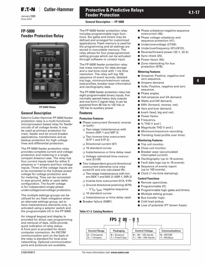
FP-5000Feeder Protection Relay
FP-5000 Relay
General DescriptionEaton’s Cutler-Hammer FP-5000 feeder protection relay is a multi-functional, microprocessor-based relay for feeder circuits of all voltage levels. It may be used as primary protection for main, feeder and tie circuit breaker applications, transformers and as backup protection for high voltage lines and differential protection.
The FP-5000 feeder protection relay provides complete current and voltage protection and metering in a single, compact drawout case. The relay has four current inputs rated for either 5 amperes or 1 ampere and four voltage inputs. Three of the voltage inputs are to be connected to the 3-phase power voltage for voltage protection and for metering. They can be connected in wye-ground, delta or open delta configuration. The fourth voltage is for independent single-phase undervoltage/overvoltage protection.
The multiple settings groups can be utilized for arc flash mitigation when an alternate settings group, set to have instantaneous elements only, is activated using a selector switch and the programmable I/O in the FP-5000.
An integral keypad and display is provided for direct user programming and retrieval of data. LEDs provide quick indication of relay status. A front port is provided for direct computer connection. An INCOM communication port on the back of the relay is standard for local area networking. Optional communication ports and protocols are available.
The FP-5000 feeder protection relay includes programmable logic func-tions. Six gates and timers may be defined and arranged for customized applications. Flash memory is used for the programming and all settings are stored in nonvolatile memory. The relay allows for four preprogrammed setting groups which can be activated through software or contact input.
The FP-5000 feeder protection relay has mass memory for data storage and a real-time clock with 1 ms time resolution. The relay will log 100 sequence of event records, detailed trip logs, minimum/maximum values, load profiles, breaker wear information and oscillography data.
The FP-5000 feeder protection relay has eight programmable binary inputs, five normally opened heavy duty outputs and one form C signal relay. It can be powered from 48 Vdc to 125 Vdc or 120 Vac to auxiliary power.
FeaturesProtection Features Phase overcurrent (forward, reverse
or both): Two-stage instantaneous with
timers (50P-1 and 50P-2) Two Inverse time overcurrent
(51P-1 and 51P-2) Directional current (67) 10 standard curves Instantaneous or time delay reset Voltage restrained time overcur-
rent (51VR) Two independent ground directional
overcurrent elements (one mea-sured-IX and one calculated IR): Two-stage instantaneous with tim-
ers (50X-1 and 50X-2) (50R-1, 50R-2) Inverse time overcurrent (51X, 51R) Ground directional polarizing (67N)
– 3 Vo, Ipol, negative sequence 10 standard curves Instantaneous or time delay reset
Breaker failure (50BF).
Phase unbalance negative sequence overcurrent (46).
Phase voltage unbalance and sequence protection (47).
Under/overvoltage (27/59). Under/overfrequency (81U/81O). Reverse/forward power (32-1, 32-2). Sync check (25). Power factor (55). Zone interlocking for bus
protection (87B).
Metering Features Amperes: Positive, negative and
zero sequence. Ampere demand. Volts: Positive, negative and zero
sequence. Phase angles. Volt-amperes and VA demand. Watts and kW demand. kWh (forward, reverse, net). Vars and kvar demand. kvarh (lead, leg and net). Power factor. Frequency. % THD V and I. Magnitude THD V and I. Minimum/maximum recording. Trending (load profile over time).
Monitoring Features Trip coil monitor. Close coil monitor. Breaker wear (accumulated
interrupted current). Oscillography (up to 16 events). Fault data logs (up to 16 events). Sequence of events report
(up to 100 events). Clock (1 ms time stamping).
Control Functions Remote open/close. Programmable I/O. Programmable logic gates and timers. Multiple setting groups. Bus transfer logic. Cold load pickup. Loss of potential (PT blown fuses).
Table 4.1-3. Catalog Numbers
FP5 2 00 - 0 1
Current Range
2 = 5 Amperes3 = 1 Ampere
Packaging
0 = Drawout1 = Fixed Case
Control Voltage
0 = 48 – 125 Vac/dc1 = 100 – 240 Vac/dc
Communications
0 = INCOM1 = Modbus

4.1-18
For more information visit: www.eaton.com CA08104001E
January 2008
Protective & Predictive Relays
i
ii
1
2
3
4
5
6
7
8
9
10
11
12
13
14
15
16
17
18
19
20
21
Feeder ProtectionGeneral Description — FP-5000
Sheet 0254
Communication Features Local HMI. Password protected. Addressable. Local communication port. Remote communication port:
FSK RS-232 RS-485
Protocols: INCOM Modbus
Configuration software.
Protection FunctionsThe Eaton’s Cutler-Hammer FP-5000 feeder protection relay has been designed for maximum user flexibility and simplicity. The base relay includes all the standard current and voltage protection and metering functions.
Directional Overcurrent Protection The FP-5000 feeder protection relay provides complete 3-phase and ground directional overcurrent protection. There are two independent ground overcurrent elements. The first ground element “X” uses the independently measured ground (or neutral) current from a separate current-sensing input. The second ground element “R” uses a calculated 3Io current obtained from the sum of the 3-phase currents. This calculated current could be used for either the neutral or ground current in a 3-phase, 4-wire system.
Each of the phase and ground over-current elements provides three protec-tion functions. Each element contains an inverse-time overcurrent (51) func-tion and two instantaneous overcurrent (50) functions with adjustable timers.
Phase direction is a function used to supervise all phase current elements (50, 51). A quadrature voltage is com-pared to a corresponding phase current to establish the direction of the fault. This function is selectable to operate in the forward, reverse or both directions.
Ground direction is used to supervise ground current elements and is accom-plished by using ground, negative sequence or residual currents super-vised by zero or positive sequence voltages or ground current. This func-tion is selectable to operate in forward, reverse or both directions.
Voltage Restrained OvercurrentVoltage restraint reduces the overcur-rent pickup level (51P-2). This modifi-cation of the pickup overcurrent level is compared to the corresponding phase input voltage. The FP-5000 uses the simple linear model below to determine the effective pickup value.
Figure 4.1-20. Voltage Restraint Coil Pickup Characteristics
Sync CheckThe sync check function is provided for double-ended power source applications. The sync check monitors voltage magnitude, phase angle and slip frequency between the bus and line. It also incorporates breaker close time, dead bus dead line, dead bus live line and live bus live line features.
Reverse PowerReverse power provides control for power flowing through a feeder. There are two elements to be configured: operate in forward or reverse; or, under or over power conditions. Reverse power is typically applied to generator or motor applications while under power is generally applied to load or generation loss.
Inverse-Time CharacteristicsThere are 10 user-selectable inverse-time overcurrent curve characteristics. The user can select from the ANSI, IEC or thermal curve families and can select instantaneous or time delay reset characteristics.
Breaker FailureThe FP-5000 feeder protection relay includes a breaker failure (50BF, 62BF) function that can be initiated from either an internal or external trip signal. This is an independent element that can be used to operate a lockout relay or trip an upstream breaker. The timer must be longer than the breaker operat-ing time and the protective function reset times.
Voltage ProtectionThe FP-5000 feeder protection relay has four voltage-input circuits. There is a 3-phase set designated as Main Voltage (M) and a single-phase voltage circuit designated as Auxiliary Voltage (A). Both include undervoltage (27) and overvoltage (59) protection. The 3-phase voltage protection can be set to operate on a single-phase, 2 out of 3 phases, or all 3-phase logic. The Main VTs also provide phase voltage unbal-ance/reversal (47 negative sequence) protection. Each element has an inde-pendent threshold set point and adjustable time delay.
Flexible Phase RotationThe FP-5000 feeder protection relay can be applied on either an A-B-C or A-C-B phase rotation. A user setting permits correct operation and indica-tion of the actual system configuration.
Frequency ProtectionThe FP-5000 relay provides under/over frequency (81U/81O) protection on the Main VT inputs. Each element has an independent threshold set point and adjustable time delay.
MeteringThe FP-5000 feeder protection relay provides complete and accurate meter-ing of the voltages, currents, frequency, power, power factor and energy. Infor-mation is available on the individual phase magnitude, angles and the symmetrical component values of positive, negative and zero sequence current and voltage.
The FP-5000 feeder protection relay includes a programmable demand feature and stores the maximum demand of current, kW, kvar and kVA since last reset. The demand is user-configurable for fixed or sliding window, the time interval is adjustable and the demand interval can be synchronized to a demand pulse.
Energy usage direction and net values are given for kWh, kvarh and kVAh. The relay monitors, logs and time stamps minimum and maximum values for current, voltage, watts, vars, VA, power factor and frequency.
The FP-5000 feeder protection relay has metered set points that can be used to activate an output for an alarm, control or trip function. For example, you might want to close a contact to insert a capac-itor bank if the power factor is less than 0.9 lagging or provide an alarm if the demand is greater than a preset value.
Pickup %
100 %
25 %

CA08104001E For more information visit: www.eaton.com
4.1-19January 2008
Protective & Predictive Relays
i
ii
1
2
3
4
5
6
7
8
9
10
11
12
13
14
15
16
17
18
19
20
21
Feeder ProtectionGeneral Description — FP-5000
Sheet 0255
Loading ProfileThe FP-5000 feeder protection relay has memory available to store metered data on a predetermined interval. The log holds data from 1024 time sample intervals. This information can be retrieved and plotted with a PC to show the loading profile of a given circuit over a period of time. For example, if the time interval is set for 15 minutes, then the relay will store a metered data profile over an approximate 10-day period.
Sequence of Events RecordsThe FP-5000 feeder protection relay records a maximum of 100 events associated with the relay. An eventis classified as a change of state as detected by the relay. These include relay pickups, dropouts, trips, contact closure, alarms, setting changes and self-diagnostic failures. Each event is date and time stamped to a 1 ms resolution. The events are stored in a FIFO in chronological order.
Trip LogThe FP-5000 feeder protection relay will store a maximum of 16 trip records in a FIFO trip log. Each trip record will be date and time stamped to a 1 ms resolution and reference an event num-ber associated with oscillographic and sequence of event data. The trip log record will include information on the type of fault, protection elements that operated, fault location and currents and voltages at the time of the fault.
Waveform CaptureThe FP-5000 feeder protection relay provides oscillography-recording capabilities. The relay will record all voltage and current signals along with the binary signals of pickup, trip, logic and contact closures. The FP-5000 relay can record 16 records of 16 cycles of data. Fewer records of longer duration can be selected and recorded. The waveform capture is initiated by a trip, pickup, external contact, front panel interface or through the remote communications port.
Programmable LogicThe FP-5000 feeder protection relay provides six logic gates and timers that the user can customize for special or unique applications. Each gate can be assigned a logic function of either AND, OR, NAND or NOR. Each gate can have a maximum of four input signals and each input signal can be required to be a NOT. Input signals can be external inputs received via the binary inputs or internal values associated with the protection, alarm or metering set points. Each gate has a unique output assignment and designation that can be used as the input to another gate. There are six independent timers that have adjustable pickup and dropout delay settings.
Integral User InterfaceThe front panel user interface has a 4 x 20-inch (101.6 x 508.0 mm) alpha-numeric vacuum fluorescent display for wide angle viewing in all light conditions. LEDs provide quick and easy visual display of power on, mode of operation, alarm and trip indication. Pushbuttons are provided for opera-tion mode selection, scrolling through data and settings. A security door restricts access to the program and test modes. In addition, the relay settings and test functions can be password protected.
FP-5000 Setpoint Overview
4.1-20
For more information visit: www.eaton.com CA08104001E
January 2008
Protective & Predictive Relays
i
ii
1
2
3
4
5
6
7
8
9
10
11
12
13
14
15
16
17
18
19
20
21
Feeder ProtectionGeneral Description — FP-5000
Sheet 0256
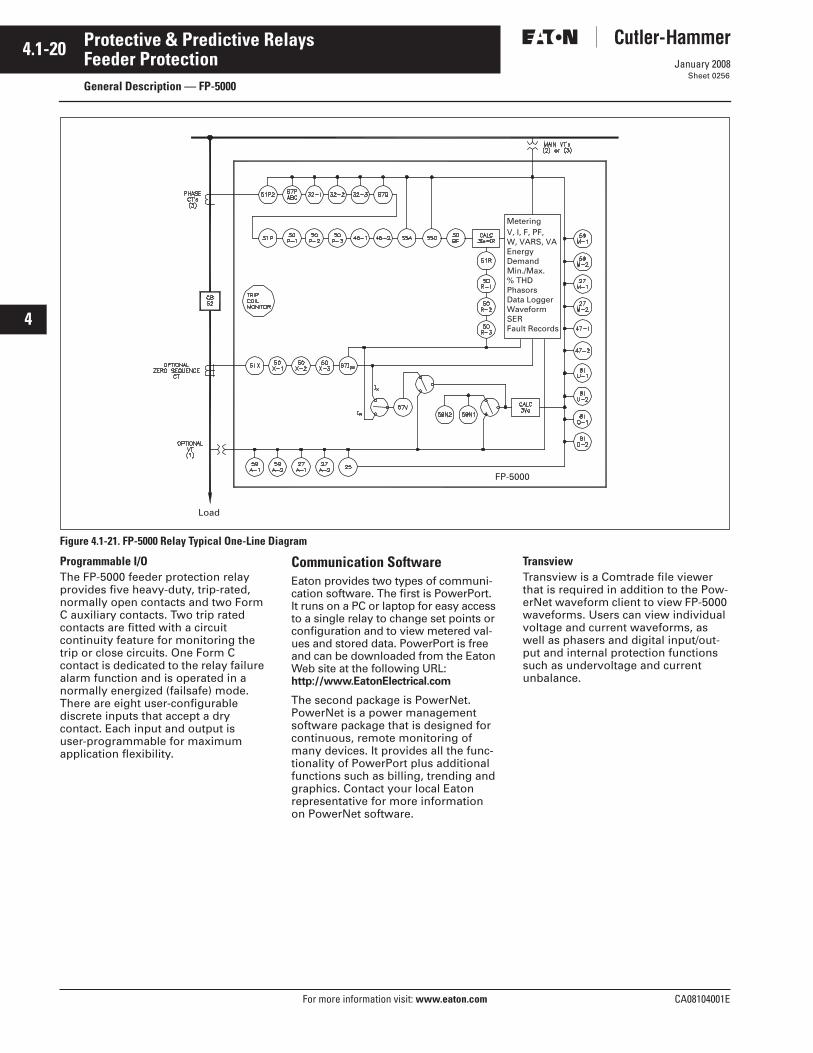
Figure 4.1-21. FP-5000 Relay Typical One-Line Diagram
Programmable I/OThe FP-5000 feeder protection relay provides five heavy-duty, trip-rated, normally open contacts and two Form C auxiliary contacts. Two trip rated contacts are fitted with a circuit continuity feature for monitoring the trip or close circuits. One Form C contact is dedicated to the relay failure alarm function and is operated in a normally energized (failsafe) mode. There are eight user-configurable discrete inputs that accept a dry contact. Each input and output is user-programmable for maximum application flexibility.
Communication SoftwareEaton provides two types of communi-cation software. The first is PowerPort. It runs on a PC or laptop for easy access to a single relay to change set points or configuration and to view metered val-ues and stored data. PowerPort is free and can be downloaded from the Eaton Web site at the following URL: http://www.EatonElectrical.com
The second package is PowerNet. PowerNet is a power management software package that is designed for continuous, remote monitoring of many devices. It provides all the func-tionality of PowerPort plus additional functions such as billing, trending and graphics. Contact your local Eaton representative for more information on PowerNet software.
TransviewTransview is a Comtrade file viewer that is required in addition to the Pow-erNet waveform client to view FP-5000 waveforms. Users can view individual voltage and current waveforms, as well as phasers and digital input/out-put and internal protection functions such as undervoltage and current unbalance.
Metering
FP-5000
Load
V, I, F, PF,W, VARS, VAEnergyDemandMin./Max.% THDPhasorsData LoggerWaveformSERFault Records

CA08104001E For more information visit: www.eaton.com
4.1-21January 2008
Protective & Predictive Relays
i
ii
1
2
3
4
5
6
7
8
9
10
11
12
13
14
15
16
17
18
19
20
21
Feeder ProtectionTechnical Data — FP-5000
Sheet 0257
Standards, Certifications and Ratings
Figure 4.1-22. FP-5000 Specifications
ComplianceUL Recognized, File # E154862UL 1053 (1994) RecognizedANSI C37.90 (1989)EN 55011 (1991)EN 61000-6-2 (1999)
Metering Accuracy (Continued)Input Signal Frequency Necessary for Accurate Operation: 60 Hz Nominal,
57 – 63 Hz (±5%)50 Hz Nominal, 47 – 53 Hz (±5%)
Clock Accuracy: Free Running ±1 Minute/Month at 25ºC
Clock Automatically Updated by PowerNet Host when Present.
Discrete InputsNumber of Contact Inputs: 8Rating: 48 Vdc Wetting Voltage
Provided with InternalGround Only
Output ContactsNumber of Output Contacts: Five Form A and Two Form C
Emission TestsEN 55011 (1991): Group 1 Class A
(CISPR-11, Class A)FCC 47 CFR Chapter 1: Part 15 Subpart b Class A Rating of Output Contacts
Momentary: Make 30 A ac/dc for 0.25 SecondsBreak 0.25 A at 250 Vdc (Resistive)Break 5 A at 120 Vac
Continuous: 5 A at 120 Vac5 A at 30 Vdc
Protective Functions
Phase and Ground Overcurrent Protection (50/51)Inverse Time Over- current Characteristics 51, 51N, 51G: Moderate, Very, Extremely,
IECA, IECB, IECC, It, I2t, I4t, FlatInverse Time Over- current Pick-up Ranges 51, 51N, 51G: 0.1 to 4.0 per Unit in 0.01 StepsInverse Time Over- current Multipliers 51, 51N, 51G: 0.05 to 10.0 in 0.01 StepsInverse Time Delay Range 51, 51N, 51G: 0 to 9999 Cycles in
1 Cycle StepsInstantaneous Over- current Pickup Ranges 50, 50N, 50G: 0.1 to 20.0 per Unit in 0.01 StepsPick-up Accuracy 50/51: ±1% (at 0.1 – 2 per Unit)Time Accuracy 51, 51N, 51G: ±3% or ±30 msDirectional 67, 67N, 67G: Reverse Overcurrent – Same
Data as Above for Reverse
Voltage Unbalance (47)Threshold (Minimum Voltage) 1 to 100 Volts in 1 Volt Steps.% V2/V1: 4 to 40% in 1% StepsTime Delay: 0 to 9999 Cycles in 1 Cycle Steps
Current Unbalance (46)Threshold (Minimum Current) 0.1 to 20.0 per Unit in 0.01 Steps.% I2/I1: 4 to 40% in 1% StepsTime Delay: 0 to 9999 Cycles in 1 Cycle Steps
Under/Overvoltage Protection (27/59)Pickup Range: 10 to 150 Volts in 1 Volt StepsTime Delay: 0 to 9999 Cycles in 1 Cycle Steps
Under/Overfrequency Protection (81U/810)Pickup Range: 45 to 65 Hz in 0.01 Hz StepsTime Delay: 0 to 9999 Cycles in 1 Cycle Steps
Breaker Failure Protection (50BF)Pickup Range: 0.1 to 5.0 per Unit in 0.01 StepsTime Delay: 0 to 9999 Cycles in 1 Cycle Steps
Power Protection (32)Forward/Reverse Over/UnderPickup Accuracy: ±1.0%Trip Time Accuracy: 0 to 12 Cycles or
0.1% whichever is greater
Synch Check (25)Phase Angle: 1 to 60°Slip Frequency: 0.1 to 2 HzVoltage Differential: 1 to 100 VoltsBreaker Close Time: 0 to 9999 Cycles
Power Factor (55)Trigger/Reset Threshold: 0.5 Lag to 0.5 Lead in 0.01 Steps
Time Delay: 0 to 1000 Seconds in 1 Second Steps
Immunity TestsANSI C37.90.1 (1989): Surge Withstand CapabilityANSI C37.90.2 (1995): EMI Immunity to 35V/mEN 61000-4-2 (1995): ESD Rating of 8 kVEN 61000-4-3 (1997): Radiated EM Field at 10V/mEN 61000-4-4 (1995): Fast Transient Burst at 2 kVEN 61000-4-5 (1995): Surge Immunity TestEN 61000-4-6 (1996): Conducted RF at 10V/mEN 61000-4-11 (1994): Voltage Dips and Variations
Logic and Control FunctionsSix Programmable Logic Gates for AND, OR, NAND, NOR OperationTwo Latching (flip/flop) GatesSix Timer Gates Provide On/Off Delays
Control PowerControl Voltage: 48 – 250 Vdc
100 – 240 VacOperating Voltage: 55 – 264 Vac
38 – 300 VdcInterruption Ride-through Time: 20 Cycle Interruption of
Nominal ac SupplyPower Consumption: 20 VA Maximum
INCOM CommunicationsBaud Rate: 9600 FixedMaximum Distance: 10,000 Feet (3,048 m)Protocol: INCOM
RS-485 Communication, Rear PanelBaud Rate: 9.2k, 9.6kProtocol: Modbus RTU
Current InputsNominal (In): 1 A or 5 ACT Rating: 2 x In continuous
50 x In for 1 secondCT Burdens: < 0.25 VA at 5 A (nominal)
< 0.05 VA at 1 A (nominal)
RS-232 Communication, Front PanelBaud Rate: 38.4k, 19.2k, 9.6kConnector Standard 9-pin Subminiature, 3-Wire Protocol: INCOM
Environmental RatingsOperating Temperature: -40ºC to +60ºC (-40ºF to
+140ºF) Product Testedto +85ºC
Storage Temperature: -40ºC to +85ºC (-40ºF to+185ºF)
Humidity: 5% to 95% Relative Humidity (Non-condensing)
Altitude: 0 to 6,350 Feet (0 to 2,500 m) aboveMean Sea Level
Voltage InputsNominal: 120 VacOperating Range: 69 – 150 VacBurden: <0.015 at 120 Vac
1 megaohm
Metering AccuracyPhase Current: ±0.5% or ±0.025 A from
0.02 to 20.0 per Unit FullyOffset Current Waveform
Ground Current: ±0.5% of Full Scale (In)from 0.02 to 2.0 per UnitFully Offset Current Waveform
Phase Voltage: ±0.5% or ±0.2 V from 0 – 160 Vac
Frequency Measurement Accuracy: ±0.02 HzPhase Angle: ±1ºPower Metering Accuracy: ±1.5%Metering Accuracy Temperature Range: 0ºC to 50ºCTemperature Range: ±5% for operation below
0ºC and above 50ºC
Dimensions
Behind PanelHeight: 6.7 Inches (170.2 mm)Width: 5.3 Inches (134.6 mm)Depth: 6.9 Inches (175.3 mm)
In Front of PanelHeight: 11.34 Inches (288.0 mm)Width: 7.72 Inches (196.1 mm)Depth: 0.80 Inches (20.3 mm)
Weight12.5 lbs. (5.7 kg)

4.1-22
For more information visit: www.eaton.com CA08104001E
January 2008
Protective & Predictive Relays
i
ii
1
2
3
4
5
6
7
8
9
10
11
12
13
14
15
16
17
18
19
20
21
Sheet 0258
This page intentionally left blank.

CA08104001E For more information visit: www.eaton.com
4.2-1January 2008
Protective & Predictive Relays
i
ii
1
2
3
4
5
6
7
8
9
10
11
12
13
14
15
16
17
18
19
20
21
Motor ProtectionGeneral Description — MP-3000
Sheet 0259
MP-3000 Motor Protection Relay
MP-3000 Motor Protection Relay
General DescriptionEaton’s Cutler-Hammer MP-3000 motor protection relay is a multi-functional microprocessor-based protective relay for the protection of any size motor at all voltage levels. It is most commonly applied on medium voltage starters and on critical or larger motors. The MP-3000 relay is a current only device that provides complete and reliable motor protection, monitoring and starting control functions.
The MP-3000 motor protection relay is available in either a fixed mount, semi-flush case or in a semi-flush quick-release drawout case. Both housings are compact and fit a standard IQ cutout.
The optional quick-release drawout case features two-stage contact discon-nection and self-shorting CT circuit terminals. A spare self-shorting termi-nal pair is available for use as relay removal alarm or for continuous motor operation (non-failsafe mode) on relay removal. The optional communication module is externally mounted on the fixed mount case and internally mounted in the drawout case.
The MP-3000 motor protection relay has three phase and one ground current inputs. Both a 5 ampere and 1 ampere version are available. The ground pro-tection and metering functions can be used with either a zero sequence ground CT or from the residual connection of the phase CTs. The zero sequence ground CT provides greater ground fault sensitivity than the residual connection. The relay is programmable for 60 Hz or 50 Hz operation.
The MP-3000 motor protection relay has two discrete inputs, four Form C (1NO and 1NC) contacts and one 4 to 20 mA analog output. The relay provides maximum user flexibility to configure the I/O. All inputs and out-puts (except for the trip output) are user-programmable. In addition, the relay has 10 LEDs for the indication of protection on, program mode, monitor mode, view setting mode, history mode, log mode, trip, alarm, auxiliary 1 and auxiliary 2 operation. A test page in the program mode provides display indication of the discrete input states and testing of the output relays, target LEDs and analog circuit.
A user-friendly operator interface and display provides quick access to the settings, monitored values, motor history and operational logs. Large LED alphanumeric character display provides easy viewing from any angle in any light. Simple keypad operation provides quick and easy navigation through all settings and stored data. The program mode and emergency override buttons are access restricted via a latched cover which can be sealed if required. An integrated help function provides an online description display of functions, abbreviations and operations.
Optimum Motor ProtectionThe MP-3000 motor protection relay has been designed for maximum motor operation and protection. It permits running the motor as close to its design limits while protecting it against excessive heating and damag-ing overload conditions. The MP-3000 field proven protection algorithms were developed based on motor designs and operating parameters for optimum operation and protection while minimizing nuisance tripping.
The MP-3000 motor protection relay utilizes a patented protection algorithm
and measurement technique based on proven positive and negative (unbal-ance) sequence current sampling and true rms calculations.
Features
General Microprocessor-based. Self diagnostics. User-friendly interface. Large LED display. Built-in help program. Built-in test mode. LED mode and target indication. Remote communications. Programmable discrete inputs. Programmable outputs.
Protection Features I2t overload protection (49/51). Locked rotor (49S/51). Ultimate trip current (51). Negative sequence phase
unbalance (46). Instantaneous overcurrent (50). Ground fault protection (50G). RTD trip and alarm with URTD
module (49/38). Underload trip (37). Starts per time (66). Jam or stall (51R). Auto or manual reset (86). Failsafe or non-failsafe trip modes.
Alarming Ground fault. I2t overload. Jam/stall. Underload. Phase unbalance.
Table 4.2-1. MP-3000 Catalog Numbers
Fiber optic cable.
Description CatalogNumber
Motor Protection in Fixed Case, 5 Ampere CT, Communication Capable with PONIMotor Protection in Drawout Case, 5 Ampere CT, No CommunicationMotor Protection in Drawout Case, 5 Ampere CT, with INCOM Communication
MP-3000MP-3001MP-3002
Motor Protection in Fixed Case, 1 Ampere CT, Communication Capable with PONIMotor Protection in Drawout Case, 1 Ampere CT, No CommunicationMotor Protection in Drawout Case, 1 Ampere CT, with INCOM Communication
MP-3100MP-3101MP-3102
Motor Protection in Fixed Case, 5 Ampere CT, with INCOM CommunicationMotor Protection in Fixed Case, 5 Ampere CT, with INCOM, URTD Module & FOC Motor Protection in Fixed Case, 1 Ampere CT, with INCOM CommunicationMotor Protection in Fixed Case, 1 Ampere CT, with INCOM, URTD Module & FOC
MP-3000 INCOMMP-3000VPIMP-3100 INCOMMP-3100VPI
Motor Protection in Fixed Case, 5 Ampere CT, with Modbus CommunicationMotor Protection in Fixed Case, 5 Ampere CT, with Modbus, URTD Module & FOC Motor Protection in Fixed Case, 1 Ampere CT, with Modbus CommunicationMotor Protection in Fixed Case, 1 Ampere CT, with Modbus, URTD Module & FOC
MP-3000 MODBUSMP-3000VPMMP-3100 MODBUSMP-3100VPM

4.2-2
For more information visit: www.eaton.com CA08104001E
January 2008
Protective & Predictive Relays
i
ii
1
2
3
4
5
6
7
8
9
10
11
12
13
14
15
16
17
18
19
20
21
Motor ProtectionGeneral Description — MP-3000
Sheet 0260
Control Features Transition for reduced voltage starts:
Transition on current level Transition on time Transition on current level or time Transition on current level
and time Incomplete sequence monitoring. Permits number of cold starts. Limits number of starts per time. Time between starts. Anti-backspin time delay. Mechanical load shedding. Zero speed switch for long
acceleration motors. Motor stop input for synchronous.
motor applications. Remote trip input. Differential trip input. Emergency override.
Monitoring Functions Motor currents:
Average current (I ave) Individual phase and ground
current in primary amperes % of full load % phase unbalance
RTD temperatures: Individual winding Motor bearing Load Auxiliary temperatures
Motor conditions: % of I2t thermal bucket Time before start Remaining starts allowed Oldest start time
History Motor history:
Operational counter Run time Highest starting and running
currents Highest % phase unbalance Maximum winding, bearing and
load RTD temperatures Number of emergency overrides
Trip history (number of trips): Ground faults Overloads Instantaneous overcurrent JAM Underload
Phase unbalance RTDs Phase reversal Incomplete sequence Remote, differential Communication Starts exceeded Time between starts Transition
Alarms history (number of alarms): Ground faults Overloads JAM Underload Phase unbalance RTDs Starts exceeded
Total history (record which cannot be reset): Total trips Run time Operations count
Logging Log book (chronological list of
last 100 events with date and time stamp).
Event log (detailed information of last 20 trips and alarms with date and time stamp).
Start log (data on most recent four starts with date and time stamp).
User InterfaceThe MP-3000 motor protection relay has a user-friendly interface that makes it easy to retrieve important information or make setting changes. LEDs provide visual indication of display and keypad mode. The push-buttons are clearly labeled and quickly access the desired information.
Protection FunctionsThe MP-3000 motor protection relay provides protection against motor overloads, short circuits and abnormal operating conditions.
I2t OverloadMotor overloads are typically limited by the rotor thermal capabilities but the measuring quantities are from the stator. This requires accurate mea-surements and good motor thermal models to provide reliable protection.
The MP-3000 motor protection relay utilizes a field proven measurement and motor thermal protection model. The relay samples the current wave-forms 36 times per cycle providing accurate measurements of the positive and negative sequence currents. The negative sequence component of current causes greater heating effect on the rotor and has a greater impact on the thermal model in the relay. This same algorithm has been used to protect thousands of motors since 1984.
The MP-3000 motor protection relay overload protection is easy to set and apply. Simply input motor nameplate information and CT ratios and the characteristic is automatically set.
When utilizing the MP-3000 motor protection relay, it is recommended that the ratio of CT primary rating to the motor full load amperes (CT Pri/Motor FLA) is selected to fall between 0.25 and 1.5. The thermal model adapts its tripping characteristics if RTDs are connected.
Instantaneous OvercurrentThe MP-3000 motor protection relay provides an instantaneous phase over-current function to trip the motor for high fault current levels. This function can be disabled and has an adjustable time delay on starting to avoid nuisance tripping on inrush.
Phase Unbalance ProtectionMotor supply circuits are often fed through fuses and can be run with a single-phase fuse blown. The motor may still see 3-phase voltage but will only have current on two phases, referred to as single-phasing the motor. The MP-3000 motor protection relay measures the current unbalance and can be used to alarm or trip the motor before damage occurs. Pickup, start and run timers and a separate alarm setting are provided.
Ground Fault ProtectionA separate circuit measures ground fault current. A ground CT is recom-mended for more sensitive protection against winding fault ground. The relay ground circuit can be connected residually from the 3-phase CTs. The ground fault protection has pickup and time delay set points or can be disabled.

CA08104001E For more information visit: www.eaton.com
4.2-3January 2008
Protective & Predictive Relays
i
ii
1
2
3
4
5
6
7
8
9
10
11
12
13
14
15
16
17
18
19
20
21
Motor ProtectionGeneral Description — MP-3000
Sheet 0261
JAM ProtectionThe user-selectable JAM function pro-tects motors that are running against a sudden mechanical jam or stall condi-tion. The common application is on motors used on crushers, chippers or conveyors. It detects an increase of motor current to a level above full load. Pickup, start and run timers and a separate alarm setting are provided.
Figure 4.2-1. MP-3000 Motor Protection Relay Functions
Underload ProtectionThe user-selectable underload func-tion is used to detect the loss of load on the motor. Coupling failure is a common cause for loss of load. Pickup, start and run timers and a separate alarm setting are provided.
Reduced Voltage StartingEaton’s Cutler-Hammer MP-3000 motor protection relay provides a transition and incomplete sequence function for reduced voltage starting. The user can select to transition based on the current level or on time.
Anti-backspinFor certain applications, for example, pumping fluid up a pipe, the motor may be driven backward for a period of time after it stops. The MP-3000 relay provides an anti-backspin timer to prevent starting the motor while itis spinning in the reverse direction. The timer begins counting from the moment a stop is declared by the relay.
Start Control TimersMotors typically have limits to the number of cold starts, hot starts, starts per time period and time between starts that are permitted without damage. The MP-3000 motor protec-tion relay incorporates these timers to prevent starting the motor beyond its capabilities.
Load SheddingThe MP-3000 motor protection relay provides a mechanical load shedding feature that can be used to control an upstream process. The load shedding function closes a contact on an over-load condition to control an upstream process from adding more load until the overload condition is gone.
Emergency OverrideThe MP-3000 motor protection relay has a user-programmable feature that will let the operator reset the start control timers and thermal overload bucket. This function is intended for use in emergency conditions only and may result in motor damage or failure.
Long Acceleration MotorsLarge motors with high inertia loads may experience starting currents that exceed the locked rotor current and time. The MP-3000 motor protection relay has logic and provisions for a zero speed switch input to differentiate between a stall and start condition. If the motor is spinning then the relay will not trip on the normal locked rotor time allowing the motor to start.
Remote/Differential TripOne of the binary inputs can be pro-grammed to accept a contact input from a separate differential relay, such as the MD-3000 or other device to trip the motor. This provides local and remote target information and utilizes the trip contacts of the MP-3000 motor protection relay. It will also record and log the motor information at the time of the trip.
Motor Starting Profile Time/Current Chart
Motor Starting ProfileThe MP-3000 relay records the average current of the motor for the last two starts. This information is available over the communications port. The motor current can then be plotted and compared to the motor overload pro-tection curve. Available in PowerPort or the PowerNet Event Viewer Client.
Motor
MP-3000Protection Functions
49/51 Overload I2T49S/51 Locked Rotor51R Jam/Stall37 Loss of Load/
Underload46 Phase Loss/
Unbalance50 Phase Inst. OC50G Ground Inst. OC66 Starts per time
period
URT
11 RTDs
Fiber Optic Link

4.2-4
For more information visit: www.eaton.com CA08104001E
January 2008
Protective & Predictive Relays
i
ii
1
2
3
4
5
6
7
8
9
10
11
12
13
14
15
16
17
18
19
20
21
Motor ProtectionTechnical Data — MP-3000
Sheet 0262
Figure 4.2-2. MP-3000 Wiring
Figure 4.2-3. MP-3000 Drawout Alternatives for Discrete Input Wiring
2A
H2B
H1C
H2C
G1
G2
MP-3000Back View
with JumperConnection
CPT
PrimaryFuses
SecondaryFuses
5
Ground
Ground
Non-CurrentCarrying Ground
M
M
MMainFuse
L1
L2
L3
L1
L2
L3
A
B
C
Gnd.
T1
T2
T3
X1 X2
CTsTTGFCT
To Motoror Load DeviceUnder Control
ac SupplyTo MP-3000
4 7
11 12STARTT T STOP
M
Alarm
18 19
Alarm Contacts
Auxiliary Trip Contacts
15 16
Aux. Trip
Trip Contacts
AdditionalControl M
Customer RemoteInput Contactsor Pushbuttons
Transformer
240 Vac
120 Vacor
3029
1211
2
60
6
4
0
8
6
4
42
Non-currentCarrying Ground
6

CA08104001E For more information visit: www.eaton.com
4.2-5January 2008
Protective & Predictive Relays
i
ii
1
2
3
4
5
6
7
8
9
10
11
12
13
14
15
16
17
18
19
20
21
Motor Protection Technical Data — MP-3000
Sheet 0263
Figure 4.2-4. MP-3000 PONI Mounting — Dimensions in Inches (mm)
124 -4/20
OUTPUT
25 +4/20OUTPUT
AU
X2
74
65
32
DISCRETESOURCE
NEUT
EARTHGROUND
120V OR240V
VAC
AU
TO
SE
LEC
TVV
DISCRETECOMMON
DISCRETEIN 1
DISCRETEIN 2
109
8
4.25(108.0)
with PONI
3.01(76.5)(76 5)
without PONI
PONIMountingBracket
Figure 4.2-5. Drilling Pattern for MP-3000 — Dimensions in Inches (mm)
.06(1.5) RAD4 Places2.23
(56.7)
4.45(113.0)
6.68(169.7)
8.90(226.1)
2.53(64.3)
5.06(128.5)
2.69(68.3)
5.38(136.7)
.218 (5.5) DIA 10 Places
9.38(238.3)
4.69(119.1)
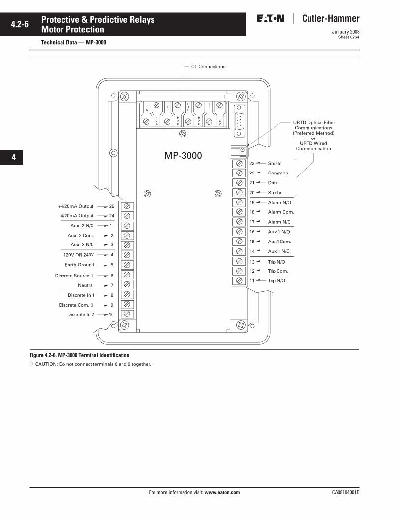
4.2-6
For more information visit: www.eaton.com CA08104001E
January 2008
Protective & Predictive Relays
i
ii
1
2
3
4
5
6
7
8
9
10
11
12
13
14
15
16
17
18
19
20
21
Motor ProtectionTechnical Data — MP-3000
Sheet 0264
Figure 4.2-6. MP-3000 Terminal Identification CAUTION: Do not connect terminals 6 and 9 together.
Aux. 2 N/O
+4/20mA Output
-4/20mA Output
Aux. 2 N/C
Aux. 2 Com.
120V OR 240V
Earth Ground
Discrete Source ➀
Neutral
Discrete In 1
Discrete Com. ➀
Discrete In 2
Trip Com.rr
Trip N/Orr
ip N/Oi
Aux 1 N/Ox.
Com.
Alarm N/C
Strobe
Alarm Com.
Alarm N/O
Data
Common
Shield
URTD Optical FiberCommunications
(Preferred Method)or
URTD WiredCommunication
CT Connections
MP-3000
1
2
3
4
5
6
7
8
9
10
25
24
23
22
21
20
19
17
18
16
11
12
13
15
14
H1A
H1B
H2A
H1C
H2B
H2C
G2
G1

CA08104001E For more information visit: www.eaton.com
4.2-7January 2008
Protective & Predictive Relays
i
ii
1
2
3
4
5
6
7
8
9
10
11
12
13
14
15
16
17
18
19
20
21
Motor ProtectionTechnical Data — MP-3000
Sheet 0265
Figure 4.2-7. MP-3000 Drawout Typical CT Circuits and Motor Control Wiring
3029
15 16
58
60
56
54
52
50
46
48
44
42
CPT
PrimaryFuses
SecondaryFuses
60
ac Supplyto MP-3000
17 19
AdditionalControl
56 54M
START STOP
M
Non-currentCarrying Ground
Alarm
51 53
Alarm Contacts
Auxiliary Trip Contacts
48 46
Aux. Trip
M
M
MMainFuseL3
L1
L2
L3 C
Trip Contacts
T1
T2
T3
X1 X2
CTsGFCT
To Motoror
Load DeviceUnder Control
3029Contacts
Ground
A
B
C
21 23 25 22 24 26 27 28
Back View of Drawout
Residual Ground Connection
Residual Ground ConnectionSee Below for
6
28
Ground
nd
Ground

4.2-8
For more information visit: www.eaton.com CA08104001E
January 2008
Protective & Predictive Relays
i
ii
1
2
3
4
5
6
7
8
9
10
11
12
13
14
15
16
17
18
19
20
21
Motor ProtectionTechnical Data — MP-3000
Sheet 0266
Figure 4.2-8. MP-3000 Specifications
Control Power
Nominal Rating: 120 Vac or 240 Vac(+10%, -25%)
Frequency: 50 or 60 Hz
Power Use: 20 VA maximumURTD: 6 VA maximumIPONI: 1 VA maximum
OperatingRange: 120 Vac: 90 – 132 Vac
240 Vac:180 – 264 VacRide through
Time: 30 cycles atNominal Vac
Current Inputs
Nominal (In): 1 A or 5 ACT Rating: 2 x In continuous
40 x In for 1 second
Phase Burden: VA at InGround Burden: VA at InSaturation: x In
Metering Accuracy
Phase Current: ± 1% of In (5% – 100%)Ground Current: ± 1.5% of In (0% – 55%)
Discrete Inputs
Number ofInputs: 2 Programmable
Rating: 1.2 VA at 120 VacMaximum OFF = 36 VacMinimum ON = 86 Vac
Output ContactsNumber of
Outputs: 4 Form C,Programmable
Momentary: Make 30 A ac/dcfor 0.25 second
(Resistive) Break 0.25 A at250 VdcBreak 5 A at 120240 Vac
Continuous: 5A at 120/240 Vac5A at 30 Vdc
Analog Output
Rating: ± 4 to 20 mAProgrammable
Maximum Load: 1 K ohm
Accuracy: 1%
Motor Overload Protection (I2t)
Full LoadAmperes: 10 to 3000 A
Locked RotorCurrent: 300% to 1200% FLA
Locked RotorTime: 1 to 120 seconds
Ultimate Trip 85% toCurrent: 150% FLA
Phase CT Ratio: 10 to 4000: InGround CT Ratio: 10 to 4000: InTiming Accuracy: ± 2.5% or ±30 ms
For I > 1.1x U.T.C.
Trip Setting Range
Ground Fault (GF): Off, 2% to 55% CT Ratio
GF Start and Run Time Delay: 2 to 60 cycles
Timer Accuracy: ± 20 ms
Instantaneous O.C.: Off, 300% to 1600% FLA
IOC Start Time Delay: 0 to 60 cycles
Timer Accuracy: ±20 ms
JAM Trip: Off, 100% to 1200% FLA
Underload Trip: Off, 1% to 90% FLA
Phase UnbalanceTrip: Off, 4% to 40%
Ineg/Ipos0 – 1200 seconds
JAM, Underload and Phase Unbalance Time Delay
Start Delay Timers: 0 to 120 secondsRun Delay Timers: 0 to 240 secondsTimer Accuracy: ±0.5% + 100 ms
Alarm Setting Range
Ground Fault: Off, 2% to 75%CT Ratio
Overload I2t: Off, 60% to 99% I2t
JAM: Off, 100% to 1200%FLA
Underload: Off, 1% to 90% FLAPhase Unbalance: Off, 4% to 40%
Ineg/Ipos
Run Delay Timers: 0 to 240 seconds
Logging
Log Book: 100 eventsLog Event: 20 trips and alarmsLog Start: Last 4 startsStart Profile: Last start
(communication only)
History Records: Motor, trips, alarms and permanent records
Start Control FunctionsStarts per Time: Off, 1 to 10 starts
Time for Startsper Time: Off, 1 to 240 minutes
Time BetweenStarts: Off, 1 to 240 minutes
Number ofCold Starts: 1 to 5 starts
Motor TransitionCurrent: 10% to 300% FLA
Time for Transition: 0 to 1200 seconds
Inc. SequenceTimer: Off, 1 to 240 seconds
Long AccelerationTimer: Off, 1 to 1200 seconds
Anti-BackspinTimer: Off, 1 to 3600 minutes
ClockAccuracy: ±1 minute/month at 25°C
CommunicationsDPONI
Type: 5-wireBaud Rate: 500K, 250K, 125K, AutoProtocol: DeviceNetFunctions: Read/write set points
Read metered valuesRead trip/alarmsRead events/historyView Starting Profile
IPONI
Type: 2-wire, FSKBaud Rate: 1200 or 9600 BaudProtocol: INCOMFunctions: Read/write set points
Read metered valuesRead trip/alarmsRead events/historyView Starting Profile
MPONI
Type: 5-wire, 485Baud Rate: 1200 or 9600 BaudProtocol: Modbus RTUFunctions: Read/write set points
Read metered valuesRead trip/alarmsRead events/historyView Starting Profile
Environmental RatingsOperating: Temperature: -20°C to +60°CStorage: Temperature: -45°C to +85°CHumidity: 0% to 95% (noncondensing)
Dimensions in Inches (mm)Height: 10.25 (260.4)Width: 6.72 (170.7)Depth: 3.70 (94.0)Weight: 7 lbs. (3 kg)
UL RecognizedFile Number E154862UL 1053ANSI C37.90, C37.90.1, C37.90.2CSA

CA08104001E For more information visit: www.eaton.com
4.2-9January 2008
Protective & Predictive Relays
i
ii
1
2
3
4
5
6
7
8
9
10
11
12
13
14
15
16
17
18
19
20
21
Motor ProtectionLayout Dimensions — MP-3000
Sheet 0267
Figure 4.2-9. MP-3000 Drawout Panel Mounting — Dimensions in Inches (mm)
Figure 4.2-10. Rear View of MP-3000 Drawout Outer Case — Dimensions in Inches (mm)
66C2020H01
Discrete
Unused
Outer Chassis Inner ChassisOuter Flange
Mounting Panel
51 (241.6)
5.33 (135.4)6.89 (175.0)
S/N000000A980000
66D2029G01REV. 1
BUILT BYF.C.
TESTED BYG.K.
+4/20O
2221
3029
26
2827
25
2423
18
2019
17
14
1615
13
1211
5251
59 60
57
55
58
56
53 54
49
47
50
48
45
43
46
44
41 42
URTD Common
Aux 2
41
43
45
47
Alarm
49
51
53
55
Aux 1
42
44
46
48
50
54
52
56
Trip
57
59 60
58Shield
66C2020H02Earth Gnd
13
11 12
14
H1A
19
15
17
21
Unused
G1
H1B
H1C
66C2020H01
27
23
25
29
20
16
18
22H2A
G2
26
24
28
H2B
H2C
30Unused
Discrete SourceURTD Shield
URTD DataURTD Strobe
-4/20 Output
+4/20 Output Unused
Unused
Poni In
Neut
120V or240V
VACAutoSelect
5.23 (132.8)
Discrete In 1
Discrete In 2
Discrete Com

4.2-10
For more information visit: www.eaton.com CA08104001E
January 2008
Protective & Predictive Relays
i
ii
1
2
3
4
5
6
7
8
9
10
11
12
13
14
15
16
17
18
19
20
21
Motor ProtectionGeneral Description — Universal RTD
Sheet 0268
Universal RTD Module
Universal RTD Module
ApplicationsMonitors as a stand-alone device or in conjunction with the MP-3000 motor protection relay.
Eaton’s Cutler-Hammer Universal RTD Module is an electronic resistance temperature detector designed to monitor as a stand-alone device or in conjunction with the Cutler-Hammer MP-3000. The Universal RTD Module can be used to monitor, for example, transformer temperature and relay that information back to a remote computer or programmable control-ler. When used in conjunction with the MP-3000, the Universal RTD Module enhances the unit’s motor protection ability. In addition to the MP-3000, the Universal RTD Module can be used with the older motor relays such as IQ-1000 II, IQ-1000 and IQ-2000.
The Universal RTD Module can be used to monitor as many as 11 RTD inputs — four groups consisting of six motor windings, two motor bearings, two load bearings and one auxiliary. The Universal RTD Module can be programmed to accept any of the following types of RTD inputs: 10 ohm copper, 100 ohm platinum, and 100 and 120 ohm nickel.
The Universal RTD Module transmits information using three conductor shielded cable, with a maximum cable distance of 500 feet (152 m). It can also transmit using a fiber optic link, with a maximum distance of 400 feet (122 m.)
Physical Characteristics
Dimensions in Inches (mm) Height: 7.67 (194.8) Width: 4.32 (109.7) Depth: 2.00 (50.8)
CommunicationsCommunications are enabled on the PowerNet Network with an optional PONI.
Table 4.2-2. Catalog Numbers
Figure 4.2-11. MP-3000 and URTD Wiring
Description Catalog Number
Universal RTD Module URTD
ACAACN
Control PowerTransformer
Noon-currentCarrying Groundarrying Ground
DataStrobe
UniversalRTD Module
MP-3000
Customer RemoteInput Contactsor Pushbuttons
Optical Fiber for URTDCommunicationsto MP-3000(Preferred Method)
2524
2345678
1
910
Shieldn
DataStrobe
2322
2019
1718
16
111213
1514
H
A
H1B
H1C
H2B
H2C
G2
G1
120 Vac H3120 Vac
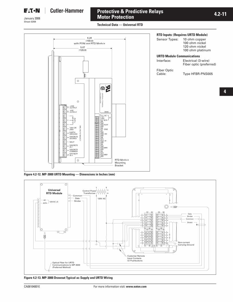
CA08104001E For more information visit: www.eaton.com
4.2-11January 2008
Protective & Predictive Relays
i
ii
1
2
3
4
5
6
7
8
9
10
11
12
13
14
15
16
17
18
19
20
21
Motor ProtectionTechnical Data — Universal RTD
Sheet 0269
Figure 4.2-12. MP-3000 URTD Mounting — Dimensions in Inches (mm)
Figure 4.2-13. MP-3000 Drawout Typical ac Supply and URTD Wiring
ACN
MB1
AUX1
120AC
MB2
LB1
LB2
GND
J3
27
29
31
33
35
202122232425
UN
IVE
RS
AL R
TD
MO
DU
LE
ST
YLE
NU
MB
ER
2D78559
1A49102H191A49102H19
6.26(159.0)
5.07(128.8)
®
®
RTD ModuleMountingBracket1
24 -4/20OUTPUT
25 +4/20OUTPUT
AU
X2
74
32
SOURCE
VAC
AU
TO
SE
LEC
TVV
DISCRETECOMMON
DISCRETE1
DISCRETEIN 2
109
8
with PONI and RTD Module
2221
3029
26
2827
25
2423
18
2019
17
14
1615
13
1211
5251
59 60
57
55
58
56
53 54
49
47
50
48
45
43
46
44
41 42StrobeData
Common
Shield
AC
ACN120VAC J3
Control PowerTransformer
Non-currentCarrying Ground
CommonData
Strobe120V AC
Universal
RTD Module
Customer RemoteInput ContactsOr Pushbuttons
Optical Fiber for URTDCommunications to MP-3000(Preferred Method)
RTD Inputs: (Requires URTD Module)Sensor Types: 10 ohm copper
100 ohm nickel120 ohm nickel100 ohm platinum
URTD Module CommunicationsInterface: Electrical (3-wire)
Fiber optic (preferred)
Fiber Optic Cable: Type HFBR-PNS005

4.2-12
For more information visit: www.eaton.com CA08104001E
January 2008
Protective & Predictive Relays
i
ii
1
2
3
4
5
6
7
8
9
10
11
12
13
14
15
16
17
18
19
20
21
Motor ProtectionGeneral Description — MP-4000
Sheet 0270
MP-4000 Motor Protection Relay with Voltage Inputs
MP-4000 Motor Protection Relay
General DescriptionEaton’s Cutler-Hammer MP-4000 motor protection relay is a multi-functional microprocessor-based protective relay for the protection of any size motor at all voltage levels. It is most commonly applied on medium voltage starters and on critical or larger motors. The MP-4000 relay provides complete and reliable motor protection, monitoring and starting control functions.
The MP-4000 motor protection relay is available in either a fixed mount, semi-flush case or in a semi-flush quick-release drawout case.
The optional quick-release drawout case features two-stage contact discon-nection and self-shorting CT circuit terminals. A spare self-shorting termi-nal pair is available for use as relay removal alarm or for continuous motor operation (non-failsafe mode) on relay removal. The optional communication module is externally mounted on the fixed mount case and internally mounted in the drawout case.
The MP-4000 motor protection relay has three phase and one ground current inputs. The MP-4000 also has three volt-age inputs. Both a 5 ampere and 1 ampere version are available. The ground protec-tion and metering functions can be used with either a zero sequence ground CT or from the residual connection of the phase CTs. The zero sequence ground CT pro-vides greater ground fault sensitivity than the residual connection. The relay is pro-grammable for 60 Hz or 50 Hz operation.
The MP-4000 motor protection relay has two discrete inputs, four Form C (1NO and 1NC) contacts and one 4 to 20 mA analog output. The relay provides
maximum user flexibility to configure the I/O. All inputs and outputs (except for the trip output) are user-program-mable. In addition, the relay has 10 LEDs for the indication of protection on, program mode, monitor mode, view setting mode, history mode, og mode, trip, alarm, auxiliary 1 and auxiliary 2 operation. A test page in the program mode provides display indication of the discrete input states and testing of the output relays, target LEDs and analog circuit.
A user-friendly operator interface and display provides quick access to the settings, monitored values, motor history and operational logs. Large LED alphanumeric character display provides easy viewing from any angle in any light. Simple keypad operation provides quick and easy navigation through all settings and stored data. The program mode and emergency override buttons are access restricted via a latched cover which can be sealed if required. An integrated help function provides an online description display of functions, abbreviations and operations.
Optimum Motor ProtectionThe MP-4000 motor protection relay has been designed for maximum motor operation and protection. It permits running the motor as close to its design limits while protecting it against excessive heating and damag-ing overload conditions. The MP-4000 field proven protection algorithms were developed based on motor designs and operating parameters for optimum operation and protection while minimizing nuisance tripping.
The MP-4000 motor protection relay uti-lizes a patented protection algorithm and measurement technique based on proven positive and negative (unbal-ance) sequence current sampling and true rms calculations.
Features
General Microprocessor-based. Self diagnostics. User-friendly interface. Large LED display. Built-in help program. Built-in test mode. LED mode and target indication. Remote communications. Programmable discrete inputs. Programmable outputs.
Protection Features I2t overload protection (49/51). Locked rotor (49S/51). Ultimate trip current (51). Undervoltage (27). Overvoltage (59). Under power (32). Negative sequence phase
unbalance (46). Negative sequence voltage
unbalance (47). Instantaneous overcurrent (50). Ground fault protection (50G). RTD trip and alarm with URTD
module (49/38). Underload trip (37). Power factor (55). Starts per time (66). Jam or stall (51R). Auto or manual reset (86). Failsafe or non-failsafe trip modes.
Alarming Ground fault. I2t overload. Jam/stall. Underload. Phase unbalance. Voltage unbalance.
Table 4.2-3. MP-4000 Catalog NumbersMotor Protection Description Catalog Number
Fixed Case, 5 Ampere CT, w/ Voltage, Communication Capable w/ PONIDrawout Case, 5 Ampere CT, w/ Voltage, No CommunicationDrawout Case, 5 Ampere CT, w/ Voltage, w/ INCOM Communication
MP-4000MP-4001MP-4002
Fixed Case, 1 Ampere CT, w/ Voltage, Communication Capable w/ PONIDrawout Case, 1 Ampere CT, w/ Voltage, No CommunicationDrawout Case, 1 Ampere CT, w/ Voltage, w/ INCOM Communication
MP-4100MP-4101MP-4102
Fixed Case, 5 Ampere CT, w/ Voltage, w/ INCOM CommunicationFixed Case, 5 Ampere CT, w/ Voltage, w/ INCOM, URTD and FOCFixed Case, 1 Ampere CT, w/ Voltage, w/ INCOM Communication
MP-4000 INCOMMP-4000 VPIMP-4100 INCOM
Fixed Case, 1 Ampere CT, w/ Voltage, w/ INCOM, URTD and FOCFixed Case, 5 Ampere CT, w/ Voltage, w/ Modbus CommunicationFixed Case, 5 Ampere CT, w/ Voltage, w/ Modbus, URTD and FOC
MP-4100 VPMP-4000 MODBUSMP-4000 VPM
Fixed Case, 1 Ampere CT, w/ Voltage, w/ Modbus CommunicationFixed Case, 1 Ampere CT, w/ Voltage, w/ Modbus, URTD and FOCFixed Case, 5 Ampere CT, w/ Voltage, DeviceNet Communication
MP-4100 MODBUSMP-4100 VPMMP-4000 DEVICEN
Fixed Case, 5 Ampere CT, w/ Voltage, w/ DeviceNet, URTD and FOCFixed Case, 1 Ampere CT, w/ Voltage, DeviceNet CommunicationFixed Case, 1 Ampere CT, w/ Voltage, w/ DeviceNet, URTD and FOC
MP-4000 VPDMP-4100 DEVICENMP-4100 VPD

CA08104001E For more information visit: www.eaton.com
4.2-13January 2008
Protective & Predictive Relays
i
ii
1
2
3
4
5
6
7
8
9
10
11
12
13
14
15
16
17
18
19
20
21
Motor ProtectionGeneral Description — MP-4000
Sheet 0271
Control Features Transition for reduced voltage starts:
Transition on current level Transition on time Transition on current level or time Transition on current level
and time Incomplete sequence monitoring. Permits number of cold starts. Limits number of starts per time. Time between starts. Anti-backspin time delay. Mechanical load shedding. Zero speed switch for long
acceleration motors. Motor stop input for synchronous.
motor applications. Remote trip input. Differential trip input. Emergency override.
Monitoring Functions Metering RTD temperatures:
Individual winding Motor bearing Load Auxiliary temperatures
Motor conditions: % of I2t thermal bucket Time before start Remaining starts allowed Oldest start time
History Motor history:
Operational counter Run time Highest starting and running
currents Highest % current unbalance Highest % voltage unbalance Highest starting and running
voltages Maximum winding, bearing and
load RTD temperatures Number of emergency overrides
Trip history (number of trips): Ground faults Overloads Instantaneous overcurrent JAM Underload Phase unbalance Voltage unbalance Overvoltage Undervoltage Overfrequency Underfrequency Under power Power factor RTDs Phase reversal Incomplete sequence Remote, differential Communication Starts exceeded Time between starts Transition
Alarms history (number of alarms): Ground faults Overloads JAM Underload Current unbalance Voltage unbalance Overvoltage Undervoltage Overfrequency Underfrequency Under power Power factor RTDs Starts exceeded
Total history (record which cannot be reset): Total trips Run time Operations count
Logging Log book (chronological list of
last 100 events with date and time stamp).
Event log (detailed information of last 20 trips and alarms with date and time stamp).
Start log (data on most recent four starts with date and time stamp).
User InterfaceThe MP-4000 motor protection relay has a user-friendly interface that makes it easy to retrieve important information or make setting changes. LEDs provide visual indication of display and keypad mode. The push-buttons are clearly labeled and quickly access the desired information.
Protection FunctionsThe MP-4000 motor protection relay provides protection against motor overloads, short circuits and abnormal operating conditions.
I2t OverloadMotor overloads are typically limited by the rotor thermal capabilities but the measuring quantities are from the stator. This requires accurate mea-surements and good motor thermal models to provide reliable protection.
The MP-4000 motor protection relay utilizes a field proven measurement and motor thermal protection model. The relay samples the current wave-forms 36 times per cycle providing accurate measurements of the positive and negative sequence currents. The negative sequence component of current causes greater heating effect on the rotor and has a greater impact on the thermal model in the relay. This same algorithm has been used to protect thousands of motors since 1984.
The MP-4000 motor protection relay overload protection is easy to set and apply. Simply input motor nameplate information and CT ratios and the characteristic is automatically set.
When utilizing the MP-4000 motor protection relay, it is recommended that the ratio of CT primary rating to the motor full load amperes (CT Pri/Motor FLA) is selected to fall between 0.25 and 1.5. The thermal model adapts its tripping characteristics if RTDs are connected.
Instantaneous OvercurrentThe MP-4000 motor protection relay provides an instantaneous phase over-current function to trip the motor for high fault current levels. This function can be disabled and has an adjustable time delay on starting to avoid nuisance tripping on inrush.

4.2-14
For more information visit: www.eaton.com CA08104001E
January 2008
Protective & Predictive Relays
i
ii
1
2
3
4
5
6
7
8
9
10
11
12
13
14
15
16
17
18
19
20
21
Motor ProtectionTechnical Data — MP-4000
Sheet 0272
Current Unbalance ProtectionMotor supply circuits are often fed through fuses and can be run with a single-phase fuse blown. The motor may still see 3-phase voltage but will only have current on two phases, referred to as single-phasing the motor. The MP-4000 motor protection relay measures the current unbalance and can be used to alarm or trip the motor before damage occurs. Pickup, start and run timers and a separate alarm setting are provided.
Voltage Unbalance ProtectionThe MP-4000 will calculate negative sequence voltage from three-phase voltages. The presence of negative sequence voltage identifies either a phase unbalance or reverse phase rotation condition. The MP-4000 pro-vides both alarm and trip functionality.
Ground Fault ProtectionA separate circuit measures ground fault current. A ground CT is recom-mended for more sensitive protection against winding fault ground. The relay ground circuit can be connected residually from the 3-phase CTs. The ground fault protection has pickup and time delay set points or can be disabled.
Frequency ProtectionThe MP-4000 provides over/under protection on the Main VT inputs. Each element has an independent threshold and time delay.
Voltage ProtectionThe MP-4000 voltage protection can be used to generate a trip or alarm if the voltage exceeds (overvoltage 59) a specified threshold for a specific time delay or drops below (undervolt-age 27) a specified threshold for a specified time delay. Voltage elements can act on one, two or three phases.
Power FactorThe power factor function in the MP-4000 can be used for many applications. For a synchronous motor, it can be used to indicate field loss. The power factor protection can generate a trip or alarm when the power factor falls between specified thresholds.
JAM ProtectionThe user-selectable JAM function pro-tects motors that are running against a sudden mechanical jam or stall condition. The common application is on motors used on crushers, chippers or conveyors. It detects an increase of motor current to a level above full load. Pickup, start and run timers and a separate alarm setting are provided.
Underload ProtectionThe user-selectable underload func-tion is used to detect the loss of load on the motor. Coupling failure is a common cause for loss of load. Pickup, start and run timers and a separate alarm setting are provided.
Reduced Voltage StartingEaton’s Cutler-Hammer MP-4000 motor protection relay provides a transition and incomplete sequence function for reduced voltage starting. The user can select to transition based on the current level or on time.
Anti-backspinFor certain applications, for example, pumping fluid up a pipe, the motor may be driven backward for a period of time after it stops. The MP-4000 relay provides an anti-backspin timer to prevent starting the motor while itis spinning in the reverse direction. The timer begins counting from the moment a stop is declared by the relay.
Start Control TimersMotors typically have limits to the number of cold starts, hot starts, starts per time period and time between starts that are permitted without damage. The MP-4000 motor protec-tion relay incorporates these timers to prevent starting the motor beyond its capabilities.
Load SheddingThe MP-4000 motor protection relay provides a mechanical load shedding feature that can be used to control an upstream process. The load shedding function closes a contact on an over-load condition to control an upstream process from adding more load until the overload condition is gone.
Emergency OverrideThe MP-4000 motor protection relay has a user-programmable feature that will let the operator reset the start control timers and thermal overload bucket. This function is intended for use in emergency conditions only and may result in motor damage or failure.
Long Acceleration MotorsLarge motors with high inertia loads may experience starting currents that exceed the locked rotor current and time. The MP-4000 motor protection relay has logic and provisions for a zero speed switch input to differentiate between a stall and start condition. If the motor is spinning then the relay will not trip on the normal locked rotor time allowing the motor to start.
Remote/Differential TripOne of the binary inputs can be pro-grammed to accept a contact input from a separate differential relay, such as the MD-3000, or other device to trip the motor. This provides local and remote target information and utilizes the trip contacts of the MP-4000 motor protection relay. It will also record and log the motor information at the time of the trip.
Motor Starting Profile Time/Current Chart
Motor Starting ProfileThe MP-4000 relay records the average current of the motor for the last two starts. This information is available over the communications port. The motor current can then be plotted and compared to the motor overload pro-tection curve. Available in PowerPort or the PowerNet Event Viewer Client.

CA08104001E For more information visit: www.eaton.com
4.2-15January 2008
Protective & Predictive Relays
i
ii
1
2
3
4
5
6
7
8
9
10
11
12
13
14
15
16
17
18
19
20
21
Motor ProtectionTechnical Data — MP-4000
Sheet 0273
Figure 4.2-14. MP-4000 Specificatio ns
Control PowerNominal Rating: 120 Vac or 240 Vac
(+10%, -25%)
Frequency: 50 or 60 Hz
Power Use: 20 VA maximumURTD: 6 VA maximumIPONI: 1 VA maximum
OperatingRange: 120 Vac: 90 – 132 Vac
240 Vac:180 – 264 VacRide through
Time: 30 cycles atNominal Vac
Current InputsNominal (In): 1 A or 5 ACT Rating: 2 x In continuous
40 x In for 1 second
Phase Burden: VA at InGround Burden: VA at InSaturation: x In
Voltage InputsNominal Rating: 120 VacOperating Range: 69 to 150 VacBurden: 2 VA
Metering AccuracyPhase Current: ± 1% of In (5% – 100%)Ground Current: ± 1.5% of In (0% – 55%)
Discrete InputsNumber of
Inputs: 2 Programmable
Rating: 1.2 VA at 120 VacMaximum OFF = 36 VacMinimum ON = 86 Vac
Output ContactsNumber of
Outputs: 4 Form C,Programmable
Momentary: Make 30 A ac/dcfor 0.25 second
(Resistive) Break 0.25 A at250 VdcBreak 5 A at 120240 Vac
Continuous: 5A at 120/240 Vac5A at 30 Vdc
Analog OutputRating: ± 4 to 20 mA
Programmable
Maximum Load: 1 K ohm
Accuracy: 1%
Motor Overload Protection (I2t)Full Load
Amperes: 10 to 3000 A
Locked RotorCurrent: 300% to 1200% FLA
Locked RotorTime: 1 to 120 seconds
Ultimate Trip 85% toCurrent: 150% FLA
Phase CT Ratio: 10 to 4000: InGround CT Ratio: 10 to 4000: InTiming Accuracy: ± 2.5% or ±30 ms
For I > 1.1x U.T.C.
Trip Setting RangeGround Fault (GF): Off, 2% to 55% CT Ratio
GF Start and Run Time Delay: 2 to 60 cycles
Timer Accuracy: ± 20 ms
Instantaneous O.C.: Off, 300% to 1600% FLA
IOC Start Time Delay: 0 to 60 cycles
Timer Accuracy: ±20 ms
JAM Trip: Off, 100% to 1200% FLA
Underload Trip: Off, 1% to 90% FLA
Current UnbalanceTrip: Off, 4% to 40%
Ineg/Ipos0 – 1200 seconds
Voltage Unbalance (47)Threshold: OFF, 1 to 100 V% V2/V1: 4% to 40%Time Delay: 0 to 1200 seconds
Under/Overvoltage (27/59)Pickup Range: OFF, 10 to 150 VTime Delay: 0 to 1200 seconds
Under/Overfrequency (81U/81O)Pickup Range: Off, 15 to 60 HzTime Delay: 0 to 60 seconds
Power Protection (32)Threshold: OFF, 0.06 to .90 *FLA *VTTime Delay: 0 to 1200 seconds
Power Factor (55)Threshold: OFF, 0.05 to 0.99Time Delay: 0 to 60 seconds
JAM, Underload and Phase Unbalance Time DelayStart Delay Timers: 0 to 120 secondsRun Delay Timers: 0 to 240 secondsTimer Accuracy: ±0.5% + 100 ms
Alarm Setting RangeGround Fault: Off, 2% to 75%
CT Ratio
Overload I2t: Off, 60% to 99% I2t
JAM: Off, 100% to 1200%FLA
Underload: Off, 1% to 90% FLAPhase Unbalance: Off, 4% to 40%
Ineg/Ipos
Run Delay Timers: 0 to 240 seconds
LoggingLog Book: 100 eventsLog Event: 20 trips and alarmsLog Start: Last 4 startsStart Profile: Last start
(communication only)History Records: Motor, trips, alarms and
permanent records
Start Control FunctionsStarts per Time: Off, 1 to 10 startsTime for Starts
per Time: Off, 1 to 240 minutesTime Between Starts: Off, 1 to 240 minutesNo. of Cold Starts: 1 to 5 startsMotor Transition
Current: 10% to 300% FLATime for Transition: 0 to 1200 secondsInc. Sequence Timer: Off, 1 to 240 secondsLong Acceleration
Timer: Off, 1 to 1200 secondsAnti-Backspin Timer: Off, 1 to 3600 minutes
ClockAccuracy: ±1 minute/month at 25°C
CommunicationsDPONIType: 5-wireBaud Rate: 500K, 250K, 125K, AutoProtocol: DeviceNetFunctions: Read/write set points
Read metered valuesRead trip/alarmsRead events/historyView Starting Profile
IPONIType: 2-wire, FSKBaud Rate: 1200 or 9600 BaudProtocol: INCOMFunctions: Read/write set points
Read metered valuesRead trip/alarmsRead events/historyView Starting Profile
MPONIType: 5-wire, 485Baud Rate: 1200 or 9600 BaudProtocol: Modbus RTUFunctions: Read/write set points
Read metered valuesRead trip/alarmsRead events/historyView Starting Profile
Environmental RatingsOperating: Temperature: -20°C to +60°CStorage: Temperature: -45°C to +85°CHumidity: 0% to 95% (noncondensing)
Dimensions in Inches (mm)Height: 10.25 (260.4)Width: 6.72 (170.7)Depth: 3.70 (94.0)Weight: 7 lbs. (3 kg)
UL RecognizedFile Number E154862UL 1053ANSI C37.90, C37.90.1, C37.90.2CSA
4.2-16
For more information visit: www.eaton.com CA08104001E
January 2008
Protective & Predictive Relays
i
ii
1
2
3
4
5
6
7
8
9
10
11
12
13
14
15
16
17
18
19
20
21
Sheet 0274
This page intentionally left blank.

CA08104001E For more information visit: www.eaton.com
4.3-1January 2008
Protective & Predictive Relays
i
ii
1
2
3
4
5
6
7
8
9
10
11
12
13
14
15
16
17
18
19
20
21
Differential ProtectionGeneral Description —MD-3000
Sheet 0275
MD-3000 Motor Differential Relay
MD-3000 Differential Relay
General DescriptionEaton’s Cutler-Hammer MD-3000 Protective Relay is a microprocessor-based sensitive 3-phase instantaneous OC relay designed for both ANSI and IEC applications. The MD-3000 is suitable for use as a motor or generator differential relay.
The MD-3000 Relay operates from the 5 ampere secondary output of standard current transformers. Current transformer ratio information is quickly programmed into the unit via settings. The MD-3000 features a user-friendly operator panel to monitor, program and test the relay. Operating parameters and trouble-shooting information are displayed in the two display windows.
Features
General ANSI and IEC applications. Phase differential metering. Monitoring and reporting of
magnitude and phase of current causing trip.
Relay failure alarm contact. Trip alarm contact. User-friendly front panel. Non-volatile memory. View settings any time. Set CT ratios. Integral test mode. Program and test mode security
access cover with meter seal provision.
Continuous internal circuitry self-testing.
Programmable lockout/self reset after trip.
Table 4.3-1. Catalog Numbers
System Protection Instantaneous sensitive phase
overcurrent trip.
Information and Data Delivery Displays current transformer ratio. Data/information transmission.
Applications
GeneralThe MD-3000 microprocessor-based relay provides reliable instantaneous trip protection for all voltage levels. It is most commonly used as a motor differential protection relay.
Diagrams
Figure 4.3-1. Self-Balancing Differential Protection
Figure 4.3-2. Conventional PhaseDifferential Protection
Description Catalog Number
Fixed Case MD3000
Drawout MD3001
87
X
87

4.3-2
For more information visit: www.eaton.com CA08104001E
January 2008
Protective & Predictive Relays
i
ii
1
2
3
4
5
6
7
8
9
10
11
12
13
14
15
16
17
18
19
20
21
Differential ProtectionTechnical Data — MD-3000
Sheet 0276
Figure 4.3-3. MD-3000 — Dimensions in Inches (mm)
Figure 4.3-4. MD-3000 Wiring Diagram
MD 3000Motor/GeneratorDifferential
7.72 (196.1)
3.86 (98.0)
5.67 (144.0)
11.34 (288.0)
1.51 (38.4)
Test
Test
Select Tests
Lower
Raise
Select Settings
Save Settings
Test
Program
ProgramTest
Settings/Test Time/Trip Cause
I =5A (Secondary)n
Time
Differential Pickup In
Operational
RMS Amperes
Reset
0.80 (20.3)
5.33 (135.4)
S/N000000W00000066D0000G00REV. 0
Built by FEC
Tested by GLK
6.89 (175.0)
Unused
Unused
Unused
Unused
Unused
Unused
Unused
11
13
1517
19
12
14
16
18
20Power Supply Input
(+)
(-)
A2
B2
C2
A1
B1
C1
Unused
Unused Unused
Unused
Current Input
21
23
27
29
22
24
26
28
30
25
Select
View Settings
Program
A DIF
B DIF
C DIF
MD 3001 Motor Differential Drawout CasePower Supply Input: Term. 17/19 AC 120-240 Vac, 50/60 Hz DC 48-250 Vdc Caution - Refer to Instruction Leaflet
5.23 (132.8)
2.61 (66.3)
11
13
15
17
19
12
14
16
18
20
41
43
45
47
49
42
44
46
48
50
21
23
25
27
29
22
24
26
28
30
51
53
55
57
52
54
56
58
4.75(120.7)
9.51(241.6)
11 12 41 42
43 44
45 46
47 48
49 50
51 52
53 54
55 56
57 58
59 60
13 14
15 16
17 18
19 20
21 22
23 24
25 26
27 28
29 30
Enclosure Rear View
Trip Alarm
DifferentialTrip
Equip Gnd
Chassis Gnd
For The DT3031 To Be "CE Compliant",The Power Supply Input Fuse Must BeRated At A Maximum Of 0.25 AMPS.
AC/DCSupply
CSC
CST
TB214
TB215
DifferentialTrip
52a
52a
TC
A
A
B
B
B1
B2
C
C
C1
C2
52
A1
A2
CT

CA08104001E For more information visit: www.eaton.com
4.3-3January 2008
Protective & Predictive Relays
i
ii
1
2
3
4
5
6
7
8
9
10
11
12
13
14
15
16
17
18
19
20
21
Differential ProtectionGeneral Description — DP-300
Sheet 0277
DP-300 Current Differential Protection Relay
DP-300
General DescriptionThe DP-300 offers a three-phase current differential protection for generators, motors and two winding transformers.
The current flowing in the individual conductors is measured by means of current transformers installed on both sides of the protection zone. These transformers form the limits of the protection zone. By means of freely configurable relays, the unit will indi-cate if any of the adjusted fault current limits have been exceeded. The unit counts with a slope characteristic to prevent operation due to CT ratio mismatches, CT ratio errors, CT saturation, and errors because of tap changes.
For transformer applications, the unit has 2nd and 5th harmonic restraints to prevent misoperation in case of inrush currents caused for energization or over excitation of the transformer. When used in transformer applications, the DP-300 allows change to the phase shift of the transformer, without having to change the connection of the exter-nal CTs, via selecting the vector group in the display. The different nominal currents of the high and low voltage side of the transformer, as well as the transformer ratio, may be configured. Every measuring point may be set separately. These features permit the DP-300 to be universal in its applications.
The DP-300 permits design simplifica-tion of the switchgear cabinet, facili-tates the commissioning, ensures the operation of the system, is user friendly, and increases the availability of the system.
Figure 4.3-5. Protected Area Principle — Fault “A” Outside = No Alarm, Fault “B” Inside = Alarm
Features True rms 6 x current measurement,
three-phase system on both sides of the protected zone.
Secondary current transformer output available as: /1 A or /5 A.
Configurable trip set points for: Differential current (Id) Restrain current (Is)
Configurable delays. Four alarm relays.
Three discrete inputs (for blocking, acknowledgment and configuration).
Two-line LC display. Configurable transformer ratio. Configurable vector group. Transformer inrush detection/
suppression. Individual configuration of the
nominal current for the high- and low-voltage side of the transformer.
Configurable transformer ratio separated for currents of high- and low-voltage side of the transformer.
Typical Nameplate
Figure 4.3-6. Typical DP-300 Nameplate
A) B)
Schematic Circuit Diagrams (Single-Phase Version): A) Fault Outside the Protection Area B) Fault Inside the Protection Area
Ia
or or
Ib
IL
Ia
or or
Ib
IL

4.3-4
For more information visit: www.eaton.com CA08104001E
January 2008
Protective & Predictive Relays
i
ii
1
2
3
4
5
6
7
8
9
10
11
12
13
14
15
16
17
18
19
20
21
Differential ProtectionTechnical Data — DP-300
Sheet 0278
Technical DataTable 4.3-2. SpecificationsDescription Specification
Measurements, Currents — IsolatedMeasured Currents (Nominal Value IN) /5 A
Measuring Frequency 40.0 to 70.0 Hz
Accuracy Class 1
Linear Measuring Range 5.0 x IN
Maximum Power Consumption per Path < 0.15 VA
Rated Short Time Current (1 s) 30.0 x IN
Ambient ConditionsVoltage Supply 90 to 250 Vac/dc
Intrinsic Consumption Maximum 10 VA
Ambient Temperature Storage -30º to 80°C (-22º to 176°F)
Operational -20º to 70°C (-4º to 158°F)
Ambient Humidity 95%, Non-condensing
Maximum Altitude 6562 ft. (2000 m)
Degree of Pollution 2
Digital Inputs — IsolatedInput Range (VCont, Digital Input) Nominal Voltage 18 to 250 Vac/dc
Input Resistance Approximately 68 KΩRelay Outputs — IsolatedContact Material AgCdO
Resistive Load (GP) (VCont, Relay Output) ac: 2.00 Aac @ 250 Vacdc: 2.00 Adc @24 Vdc, 0.36 Adc @ 125 Vdc, 0.18 Adc @ 250 Vdc
Inductive Load (PD) (VCont, Relay Output) ac: B300dc: 1.00 Adc @ 24 Vdc, 0.22 Adc @ 125 Vdc, 0.10 Adc @ 250 Vdc
Protective FunctionsOperating Time Minimum 100 ms
Differential Current Minimum 10%
HousingType APRANORM DIN 43 700
Dimensions (W x H x D) 5.67 x 3.78 x 5.20 Inches (144 x 96 x 132 mm)
Front Panel Cutout (W x H) 5.43 [+0.039] x 3.63 [=0.031] Inches (138 [+1.0] x 92 [+0.8] mm)
Terminals Screw-Type, Terminals Depending on Connector, 0.00388 in.2 (2.5 mm2) or 0.00620 in.2 (4.0 mm2)
Recommended Tightening Torque [0.00388 in.2] 4.43 in./lbs / [0.00620 in.2] 5.3 in./lbs ([2.5 mm2] 0.5 Nm / [4.0 mm2] 0.6 Nm)Use 60º/75°C (140º/167°F) Copper Wire OnlyUse Class 1 Wire Only (or Equivalent)
Weight: Approximately 2.2 lbs. (1,000 g)
Housing ProtectionProtection System IP42 from Front with Correct Mounting
IP54 from Front with GasketGasket: P/N 8923-1038)IP20 from Back
Front Foil Insulating Surface
EMC-Test (CE) Tested According to Applicable EN Guidelines
Listings CE Marking; UL Listing for Ordinary Locations, UL/cUL Listed, Ordinary Locations, File No.: E231544
Additional Approvals IEEE C37.90.1 and C37.90.2

CA08104001E For more information visit: www.eaton.com
4.3-5January 2008
Protective & Predictive Relays
i
ii
1
2
3
4
5
6
7
8
9
10
11
12
13
14
15
16
17
18
19
20
21
Differential ProtectionTechnical Data — DP-300
Sheet 0279
Wiring Diagram
Figure 4.3-7. DP-300 Wiring Diagram
DP-300
Block Differential Protection
Possible Protected Objects: M G
N
PE
L (90 to 250 Vac/dc)
Current IL1 Transducer Set 2
Current IL2 Transducer Set 2
Current IL3 Transducer Set 2
Current IL3 Transducer Set 1
Current IL2 Transducer Set 1
Current IL1 Transducer Set 1 Relay 1
Relay 2
Relay 3Ready for Operation
N/C
Relay 4
Common
N/C
Configuration Off
Acknowledgement
Blocking
Subject to Technical Modifications.L1 L2 L3
Tran
sdu
cer
Set
1 (
Hig
h V
olt
age
Sid
e)
Pro
tect
ed O
bje
ct
Tran
sdu
cer
Set
2 (
Low
Vo
ltag
e S
ide)
Th
e Tr
ansd
uce
r R
atio
is
Ad
just
able
in t
he
Dis
pla
y.T
he
Tran
sdu
cer
Rat
io is
A
dju
stab
le in
th
e D
isp
lay.
25
26
27
2
8
29
30
35
36
33
3
4
31
32
DP
-300 —
Cu
rren
t D
iffe
ren
tial
Pro
tecti
on
Rela
y
1
2
3
4
5 6
7
8
9
1
0
11
12
15
16
17
1
8
1983
8
1
79
4.3-6
For more information visit: www.eaton.com CA08104001E
January 2008
Protective & Predictive Relays
i
ii
1
2
3
4
5
6
7
8
9
10
11
12
13
14
15
16
17
18
19
20
21
Sheet 0280
This page intentionally left blank.

CA08104001E For more information visit: www.eaton.com
4.4-1January 2008
Protective & Predictive Relays
i
ii
1
2
3
4
5
6
7
8
9
10
11
12
13
14
15
16
17
18
19
20
21
Voltage Protection RelayGeneral Description — VR-300
Sheet 0281
VR-300 Multifunctional Voltage Relay
VR-300
General DescriptionThe VR-300 is an industrial grade protective relay that offers multiple protective features in a single package, ideal for stand-alone protection or for the implementation of transfer schemes.
Using a digital processor to measure true rms values enables a high degree of measuring accuracy regardless of harmonics, transients or disturbing pulses.
The compact size and multiple func-tions of the VR-300 help to simplify switchgear design. The digital display offers a user-friendly interface to set up the unit as well as monitor the opera-tion and display any alarms.
Features Over-/undervoltage monitoring
(59/27). Over-/underfrequency monitoring
(81O/U). Voltage asymmetry monitoring (47). Synch-check (25) — fixed to relay 3.
Zero voltage monitoring: dead bus start functionality (close CB to dead bus).
Two configurable relays. Discrete input for blocking of
protective functions or remote acknowledgment.
Typical Nameplate
Figure 4.4-1. Typical VR-300 Nameplate

4.4-2
For more information visit: www.eaton.com CA08104001E
January 2008
Protective & Predictive Relays
i
ii
1
2
3
4
5
6
7
8
9
10
11
12
13
14
15
16
17
18
19
20
21
Voltage Protection RelayTechnical Data — VR-300
Sheet 0282
Technical DataTable 4.4-1. Specifications
Table 4.4-2. Reference Conditions
Accuracy depending on the configured transformer ratio.
Reference ConditionsThe data apply to the following reference conditions:
Input voltage = Sinusoidal rated voltage.
Frequency = Rated frequency ±2%. Power supply = Rated voltage ±2%. Power factor cos = 1. Ambient temperature 23°C ±2K. Warm-up period = 20 minutes.
Description Specification
Measuring VoltageStandard (Vrated) 66/115 Vac
Maximum Value Vph-ph Maximum, (UL/cUL) Maximum 150 Vac
Rated Voltage Vph-ground 50 Vac/2.5 kV
Rated Surge Voltage 2.5 kV
Measuring Frequency 40.0 to 80.0 Hz
Accuracy Class 1
Linear Measuring Range 1.3 x VratedInput Resistance 0.21 MΩMaximum Power Consumption per Path < 0.15 W
Ambient VariablesWide Range Power Supply 90 to 250 Vac/dc
Intrinsic Consumption Maximum 12 VA
Ambient Temperature Storage: -30º to 80°C (-22º to 176ºF)Operational: -20º to 70°C (-4º to 158°F)
Ambient Humidity 95%, Non-condensing
Maximum Altitude 6562 ft. (2000 m)
Degree of Pollution 2
Discrete Inputs — IsolatedInput Range (VCont, Discrete Input) Rated Voltage 18 to 250 Vac/dc
Input Resistance Approximately 68 KΩRelay Outputs — Potential FreeContact Material AgCdO
General Purpose (GP) (VCont, Relay Output) ac: 2.00 Aac @ 250 Vacdc: 2.00 Adc @ 24 Vdc, 0.22 Adc @ 125 Vdc, 0.10 Adc @ 250 Vdc
Pilot Duty (PD) (VCont, Relay Output) ac: B300dc: 1.00 Adc @ 24 Vdc, 0.22 Adc @ 125 Vdc, 0.10 Adc @ 250 Vdc
HousingType APRANORM DIN 43 700
Dimensions (W x H x D) 3.78 x 2.84 x 5.20 in. (96 x 72 x 132 mm)
Front Panel Cutout (W x H) 3.62 [+0.03) x 2.68 [+0.03] in. (92 [+0.8] x 68 [+0.7] mm)
Wiring Screw-Type, Terminals 0.0039 in.2 (2.5 mm2)
Recommended Tightening Torque 0.369 ft./lbs (0.5 Nm). Use 60º/75°C (140º/167°F) Copper Wire Only. Use Class 1 Wire Only (or Equivalent)
Weight Approximately 2.14 lbs. (800 g)
ProtectionProtection System IP42 from Front with Correct Mounting
IP54 from Front with Gasket (Gasket: P/N 8923-1036) IP20 from Back
Front Foil Insulating Surface
EMC-Test (CE) Tested According to Applicable EN Guidelines
Listings CE Marking; UL Listing for Ordinary Locations, UL/cUL Listed, Ordinary Locations, File No.: E231544
Additional Approvals IEEE C37.90.1 and C37.90.2
Measuring Value
Display Range
Accuracy
FrequencyfL1, fL2, fL3 40.0 to .80.0 Hz 0.05 Hz
VoltageVL1, VL2, VL3, VL12, VL23, VL31
0 to 520, 0 to 65 kV
1%

CA08104001E For more information visit: www.eaton.com
4.4-3January 2008
Protective & Predictive Relays
i
ii
1
2
3
4
5
6
7
8
9
10
11
12
13
14
15
16
17
18
19
20
21
Voltage Protection RelayTechnical Data — VR-300
Sheet 0283
Wiring Diagram
Figure 4.4-2. VR-300 Wiring Diagram
The synchronizing voltage must be connected 3-phase if the measuring voltage is connected
3-phase (N not connected). If the measuring voltage is connected 4-phase (L1, L2, L3, N),
the synchronizing voltage may be connected 2-phase (L1-L2). L3 is connected only for
compensation and is not measured.
0 Vdc
Blocking of protective functions or remote acknowledgement.
Relay 1(Ready for Operation)
Relay 2
Subject to Technical Modifications.
2/3
Syn
chro
niz
ing
Sys
tem
(Fi
xed
)
CB
56
78
VR
-300 (
Mu
lti-
Fu
ncti
on
Vo
ltag
e R
ela
y)
90 to 250 Vac/dc
Synchronizing Voltage L1
Synchronizing Voltage L2
Synchronizing Voltage L3
7071
72
Measuring Voltage L1
Measuring Voltage L2
Measuring Voltage L3
(Measuring Voltage N)
12
34
910
1112
1314
1516Relay 3
(Fixed to synch-check zero voltage configurable)
Measuring Voltage 3-Wire or 4-Wire System
Su
per
vise
d S
yste
m (
Vari
able
) 3
/4
3/4
Measuring Voltage: 100 Vac
The socket for the PC parameterization is situated on the side of the unit. This is where the DPC must be plugged in.
Not Measured.

4.4-4
For more information visit: www.eaton.com CA08104001E
January 2008
Protective & Predictive Relays
i
ii
1
2
3
4
5
6
7
8
9
10
11
12
13
14
15
16
17
18
19
20
21
Sheet 0284
This page intentionally left blank.

CA08104001E For more information visit: www.eaton.com
4.5-1January 2008
Protective & Predictive Relays
i
ii
1
2
3
4
5
6
7
8
9
10
11
12
13
14
15
16
17
18
19
20
21
InsulGard Predictive MaintenanceGeneral Description — InsulGard
Sheet 0285
Product Description
InsulGard
The InsulGard is a continuous partial discharge monitor that can be applied to a variety of medium voltage electrical equipment rated 4 kV to 38 kV. It is commonly applied to motors, generators, switchgear, bus duct, unit substations and cable systems. The InsulGard will monitor the quality of insulation while the equipment is in service under normal operating conditions. Through monitoring, it can ascertain the relative condition of insulation, the deterioration of which is the leading cause of electrical failures.
The InsulGard system consists of sensors and a monitor. The monitor can be used as a stand-alone unit, or it can be wired so that it can remotely upload data to your system or to Eaton diagnostics personnel for analysis. While the sensors vary according to application, they are all designed to detect partial discharges — the foundation of the InsulGard technol-ogy and one of the best predictors of insulation breakdown.
The term “partial discharge” is a common name for small electrical discharges (arcs) that typically occur within or between insulation materials — usually across a void in the insula-tion. Partial discharge is also referred to as corona or surface tracking. The visible evidence of corona presents itself as white, powdery residue, typi-cally found on the end windings of motors or generators. Surface-tracking damage appears as tree-like, jagged lines, typically found on switchgear and bus ducts. Surface tracking stems from a contaminated insulation surface, often started by corona. The small arcing activity on the surface of the insulation contributes to further burning, resulting in additional stress points that promote further deteriora-tion. Both corona and surface tracking are the primary causes of insulation breakdown, which can lead to full discharges and electrical failures. It is important to note that traditional methods of detecting corona and sur-face-tracking damage require taking equipment off line. It also requires disassembling the equipment — a costly procedure. Moreover, corona and surface tracking damage have to be severe to be visible. The InsulGard system allows you to detect partial dis-charge while the electrical system is energized. It does so by detecting and analyzing the radio signal frequencies emitted by the partial discharges. More specifically, the InsulGard focuses on the 1 MHz to 20 MHz bandwidth range where the majority of partial-discharge activity can be detected. InsulGard allows predictive analysis and maintenance as opposed to preventive analysis and time-based maintenance.
The detection of partial discharge on equipment can indicate if a problem exists. Even more useful is information that can correlate the signal intensity (measured in milliwatts) associated with partial discharges to various states of insulation degradation on similar equipment. The Eaton Electrical/Cutler-Hammer Predictive Diagnostics Group has studied numer-ous cases of partial discharge on rotating equipment and switchgear. The knowledge base accumulated has allowed Eaton to develop guidelines and parameters to help one determine the seriousness (failure-time windows) of the partial-discharge activity the equipment may be exhibiting. Because it is a continuous, on-line monitoring system, it is easy to monitor conditions over time.
Cutler-Hammer InsulGard by Eaton Corporation is a stand-alone micropro-cessor-controlled continuous partial discharge monitoring device for a wide range of medium voltage power equipment. It is designed to provide an alarm based on PD characteristics at an early stage of insulation degrada-tion. It measures partial discharges from up to 15 different partial discharge sensors and stores the information in internal memory; alarming users if any set points are exceeded. InsulGard can work with constant 50/60 Hz frequency powered equipment, as well as with variable frequency applications.
Various PD sensor types can be used, depending on the application.
InsulGard has three auxiliary inputs for PD data correlation to additional parameters. One of the inputs is designated for temperature, where the other two are commonly used for load, voltage or humidity depending upon the application. InsulGard has several interfaces that allow for easy implementation into any alarm or SCADA system:
Three C-form dry relay contacts provide Yellow or Red alarm indica-tion, and the Device Status relay indicates any device malfunction.
4 –20 mA optically isolated output can be configured to represent Partial Discharge Intensity (PDI) or maximum discharge magnitude to any SCADA system.
RS-485 optically isolated interface based on Modbus RTU protocol allows for remote device configura-tion and data download. InsulGard can be networked with an existing Modbus, allowing for up to 231 addressable devices.
Note: RS-232 is also available on special order.
Communication protocol includes Modbus, proprietary binary and ASCII text options allowing a software programmer to build InsulGard into a high-level software program using simple text type commands. InsulGard is supplied with database software that allows for automated communica-tion to a device or several devices for data acquisition and analysis. The software allows for either direct network or dialup connection to a device by a regular telephone landline or a cellular connection.

4.5-2
For more information visit: www.eaton.com CA08104001E
January 2008
Protective & Predictive Relays
i
ii
1
2
3
4
5
6
7
8
9
10
11
12
13
14
15
16
17
18
19
20
21
InsulGard Predictive MaintenanceGeneral Description — InsulGard
Sheet 0286
InsulGard has 15 signal inputs (Ch1 – Ch15) for partial discharge measurement and a noise input dedicated for noise suppression (Ch16). All 16 inputs have identical conditioning circuits (CC) providing signal isolation, transient suppres-sion, and high-pass filtering of the input signals. The frequency band of the InsulGard is from 1 MHz to 20 MHz.
InsulGard acquires PD data in the form of three dimensional phase-resolved pulse height distribution (PRPHD) - PD pulse count as a function of pulse magnitude and 60(50) Hz phase. It has 24 (15 0 ) phase windows and a magni-tude dynamic range of about 70 dB, divided in 21 magnitude windows.
The data can be stored in the internal device memory in the form of three-dimensional PRPHD matrixes and/or in the brief form of integral quantities derived from these matrixes. Each record is accompanied by three additional correlation parameters.
Before each measurement, InsulGard performs self-calibration and self-test. If any problem is detected, the status relay dry contacts will open and an appropriate message will appear on the InsulGard display. Loss of power will be indicated in the same way by opening status relay contacts.
InsulGard measures signals from sig-nal inputs sequentially multiplexing them to a single metering channel. Each pulse from each sensor is vali-dated by the allowed pulse width. In the case of non-compliance, InsulGard will not count the pulse.
After each measurement, data from all active signal channels will be com-pared to alarm thresholds. If any of the Yellow threshold limits are exceeded, the Warning LED will be turned on and the Warning relay dry contacts will close. In the case of a Red level achieved, InsulGard will trigger addi-tional measurement and, if confirmed, an Alarm LED will be turned on and the Alarm relay dry contacts will close. If Red alarm is detected, full measurement data will be stored in the memory.
PD measurements can be performed on a time schedule (up to 50 per day) or in specified time intervals (from 1 minute to 23 hours 59 minutes). Four measurements per day are recommended.
Between scheduled measurements, the “High Alarm” feature is enabled. All signal sensors are connected to a summation unit and further to a sepa-rate “High Alarm” channel. InsulGard continuously searches for an appear-ance of high magnitude pulses and pulse series. Magnitude threshold and repetition in series are configurable.If five events of pulse series were detected between the scheduled measurements, InsulGard will trigger a full PD measurement, and display an alarm, if any.
Full PD measurement by InsulGard involves a measurement of statistical Phase Resolved Partial Discharge Distribution (PRPDD) for every active channel. After each measurement for every active channel, InsulGard calcu-lates PDI, Maximum PD magnitude, PD pulse repetition rate, and trend param-eters (rate of PD parameter change). The calculated parameters are com-pared to alarm set points and alarm status is determined. All calculated and alarm status parameters are stored in the internal memory for each measurement. Additionally, three auxiliary parameters (temperature, % of full load current and operating voltage or humidity) are assigned to the measurement data. PRPDD can, optionally, be stored in the internal memory. There are two modes of PD data storage “Brief” and “Full.”
Full — during this mode PRPDD is stored in the memory with the mentioned above parameters for each active channel and every measurement.
Brief — in order to save a memory, PRPDD can be stored in the memory several times a month. An operator should set a number of days and a measurement number at the current day for storing PRPDD. During the remaining measurements InsulGard will store the brief version of PD data.
InsulGard has two Megabytes of inter-nal flash memory for data storage allowing for its standalone operation. When the memory is filled, the device starts replacing the oldest data with the latest data. The rate of the memory consumption depends upon a number of active channels, frequency of mea-surements, and frequency of PRPDD storage. As an example, if all 15 chan-nels are active for measurements four times a day and PRPDD are stored twice a month, the device holds 17 months of the latest PD data in its internal memory. All stored data and settings can be accessed from the keypad, or remotely from a PC.

CA08104001E For more information visit: www.eaton.com
4.5-3January 2008
Protective & Predictive Relays
i
ii
1
2
3
4
5
6
7
8
9
10
11
12
13
14
15
16
17
18
19
20
21
InsulGard Predictive MaintenanceGeneral Description — InsulGard
Sheet 0287
AlarmsInsulGard has two configurable alarms, Red and Yellow that connect to two C-form relays. There are two groups of parameters that can gener-ate an alarm. One is if an alarm set point is exceeded (Partial Discharge Intensity (PDI) and its trend or PD pulse magnitude and its trend). One of two, PDI or Magnitude, can be configured for alarm at one time. The same parameter is config-ured for 4 – 20 mA interface output automatically. 4 – 20 mA output provides a signal with the slope of 10% of Red Alarm Threshold per 1mAmp. That means that Red alarm threshold corresponds to 14 mA output.
Alarm set points for PDI are repre-sented in terms of mW. Magnitude is represented in terms of mV.
Trend is set in terms of times per year for both PDI and Magnitude. Alarm on trend is enabled after a training period of 1/3 of the trend-sliding window.
Yellow and Red alarms operate differ-ently. In the case of a Yellow alarm, it will appear on the corresponding relay as received. In the case of a Red alarm, InsulGard will initiate an additional measurement at the time of alarm, and only if confirmed, will indicate the alarm by relay. If the Red alarm is not confirmed, the status of the alarm will be set per the last measurement. If at any measurement the alarm status will be reduced, InsulGard will indicate the reduced alarm status with both an alarm LED reading and relay.
Alarm relays can operate in two modes (configurable). Relays lock in an alarm status received at the last measurements, until the next mea-surement. Or a relay can operate for a limited configurable time and then open the contacts. At the next measurement, if an alarm status is detected, relays will hold the alarm contacts closed for the same time.
TrendInsulGard calculates trend of a param-eter enabled for alarm. Trend is nor-malized to the value of the parameter change in times per year. Trend has two alarm thresholds, Yellow and Red, connected to alarm relays and also to the alarm status LED at the front panel of the device. Trend is calculated as a linear approximation of data over specified time interval (default is 18 weeks). This 18-week time window is sliding over time while device monitors partial discharges.
Continuous Watch FeatureBetween the scheduled measurements the Continuous Watch feature (“High Alarm”) is initiated. At this time all signal sensors are summarized and connected to the separate High Alarm channel. InsulGard is continuously watching for the events of high magni-tude pulses (configurable) and their series. If five series of such events are detected, InsulGard starts full PD measurement and, in the case of Red alarm confirmation, InsulGard indicates this alarm and stores full PD data in the internal device memory.
SchedulePD measurements can be performed at specified times during a day or time interval basis (configurable). The device is shipped with “time basis” schedule enabled and set to record measurements four times a day. This is sufficient for all common applications.
If necessary, InsulGard can be set to measure up to 50 times per day at scheduled times or in specific time intervals varying from 1 minute to 23 hours 59 minutes.

4.5-4
For more information visit: www.eaton.com CA08104001E
January 2008
Protective & Predictive Relays
i
ii
1
2
3
4
5
6
7
8
9
10
11
12
13
14
15
16
17
18
19
20
21
InsulGard Predictive MaintenanceTechnical Data — InsulGard
Sheet 0288
SpecificationsTable 4.5-1. Power Source SpecificationsDescription Specification
Power Source 115 V/230 Vac +/-10% 60 (50) Hz
Power Consumption of Device (Maximum) 10 W
Power Consumption from Outlet for 120 Vac Application (Amperes Maximum)
10 A
Installation Category II
Pollution Degree 2
Temperature Range -400°C to +700°C (+850°C without NEMA 4 Enclosure)
Relative Humidity 15% RH to 98% RH
Maximum Altitude Feet (m) 1640 (500)
Sensor Interface Board 1
Input Channels (PD), Isolated 15
Noise Channels (PD), Isolated 1
Continuous Watch (High PD Activity) Channel 1
Auxiliary Temperature Input (10, 100, 1000 Ohms RTD, Specify While Ordering)
1
Auxiliary Analog Inputs (Specified to Use for Voltage, Current or Humidity)
2
Alarm C-Form Dry-Type Relay Contacts (Yellow and Red Alarms, Fully Configurable)
2120 Vac/ 5 Amperes28 Vdc/ 5 Amperes
Device Status Dry-Type, C-Form Relay Contacts 1120 Vac/ 5 Amperes28 Vdc/ 5 Amperes
4 – 20 mA Optical-Isolated Interface Represents Highest PDI or Maximum Magnitude as % of the Red Alarm Threshold
1 mA per 10% slope
Interface Optically-Isolated RS-485, Modbus RTU, or None-Isolated RS-232
Addressable (with RS-485 Interface) 231 Addresses
Internal Data Memory (Allows for Up to 2000 Days Data Storage at 2 Measurements Per Day)
2 MB
Display 8-Digit, Alphanumeric
Keypad 4 Arrows and 4 Functional Keys
LEDs (Normal Condition, Red and Yellow Alarms, and History and Setting Modes)
5 LEDs
Set-up Fully Configurable From Keypad and PC
Applications MV Equipment (Motors, Switchgears, Generators, Bus Ducts, Cable Terminations)
Calculated Parameters for Each PD Channel Partial Discharge Intensity (PDI), Pulse Repetition Rate (pps), Maximum Pulse Magnitude (Q02)
Alarming Parameters PDI, Q02, Trend
Data Record Types Full/Brief
Basic Type of Data Phase-Resolved PD Distribution
PD Channel Dynamic Range 68 dB
Number of Magnitude Windows (3.23 dB Each) 21
Number of Phase Windows (150 Each) 24
Power Frequency at the Monitored Object 25 – 120 Hz
Maximum Measured Pulse Repetition Rate 367,300 pps at 60 Hz306,000 pps at 50 Hz
Self-test and Self-calibration At Powering Up and Before Every Measurement
Allowed Coax Cable Length to a Sensor — Feet (m) Up to 150 (50)
Cable Type for PD Sensors RG-58 or Similar

CA08104001E For more information visit: www.eaton.com
4.5-5January 2008
Protective & Predictive Relays
i
ii
1
2
3
4
5
6
7
8
9
10
11
12
13
14
15
16
17
18
19
20
21
InsulGard Predictive MaintenanceProduct Selection — InsulGard
Sheet 0289
General NotesThe three basic InsulGard Packages are Switchgear Applications, Motors Applications, and Generators Applica-tions. At the beginning of each section to follow are the basic components typically found in each type of application.
Switchgear ApplicationsSwitchgear Applications have three typical components: InsulGard Switch-gear Package, Coupling Capacitor Sensors, RFCT Sensors.
lnsulGard Systems for Switchgear Applications are sold as “packages.” Packages provide greater value. Stan-dard Equipment with the lnsulGard Switchgear Package is shown in Table 4.5-2 below.
Table 4.5-2. Standard Equipment
Table 4.5-3. InsulGard Switchgear Package
Note: Information to complete the Xs in the above shown lnsulGard Switchgear Protec-tion Package Part Numbers is shown in Table 4.5-4.
Table 4.5-4 describes how the InsulGard will be mounted.
Table 4.5-4. Enclosure/Mounting Options
Description Quantity
InsulGard 1
Humidity Sensor Mounted as Specified
1
Temperature Mounted as Specified
1
RS-485 Communication Port 1
InsulGard Software CD 1
Set of Instruction Manuals 1
Description Catalog Number
InsulGard Switchgear Package Product
PD-IGP-S-EX-CX-AX
Enclosure Options Notes
E0 Door Mount (No Enclosure)
Flush Mounted on Switchgear Enclo-sure Door (Indoor Only)
E1 Back-panel Mount (No Enclosure)
Mounted in Weatherproof Enclosure or in Switchgear
E2 NEMA 4X Back-panel Mount (No Enclosure)
Not Typical for Switchgear Applications
Table 4.5-5. Communications Options — Type of Communications Desired
Note: A modem is required for the remote monitoring option. RS-485/RS-232 Converter is required to connect directly to the InsulGard with a Laptop/Computer.
Table 4.5-6. Auxiliary (Dynamic) Sensors — Where Temperature and Humidity Sensors Will be Mounted
Note: In switchgear applications, both sensors are typically installed in the same switchgear cubicle (Embedded) with the InsulGard, also please indicate if CT input is customer furnished or must be supplied and what type it is/should be.
Table 4.5-7. Coupling Capacitor Sensors
Note: The number of cubicles will determine the number of coupling capacitors required for the project. One set of (3) coupling capacitors is required for every three vertical structures. The catalog numbered set includes mounting kits, boots, cables, etc.
Table 4.5-8. RFCT Sensors
Communication Options Notes
C0 No Additional options All InsulGards have RS485 and 4 – 20 mA interfaces
C1 Modem Mounted in InsulGard enclosure
C2 TCP/IP For Communication over EtherNet
C3 Converter RS-485 to RS-232 For Communication with PC on InsulGard installation side. Need (1) for Plant
C4 C1 and C3
C5 C2 and C3
Auxiliary Sensor Options Notes
A0 Embedded Temperature Sensor and Humidity Sensor. No CTs.
TS and HS Pre-installed in InsulGard Cubicle. Usually for Door Mount or Back-panel Mount, InsulGard installed in Switchgear Cabinet (where temperature and humidity are the same as in object to be monitored).No CTs Supplied (Inputs from existing CTs).
A1 External Temperature Sensor and Humidity Sensor. No CTs.
TS and HS supplied with 65 ft. of cable for exter-nal installation. No CTs supplied. (Inputs from existing CTs.)
A2 External Temperature Sensor, Humidity Sensor and CTs.
5 A. Input Current Transformer.
A3 External RTD, HumiditySensor and CTs.
Use Spare Motor RTD (when available). Not Applicable for Motor or Generator Applications.
A4 External RTD and CTs. No Humidity Sensor.
For Hydrogen-cooled generators (where HS can’t be installed). Not Applicable for Motor or Switchgear Applications.
Description Catalog Number
5 kV Class Coupling Capacitors PD-IGC-0010
7.2 kV Class Coupling Capacitors PD-IGC-0011
15 kV Class Coupling Capacitors PD-IGC-0012
27 kV Class Coupling Capacitors (27 kV Coupling Capacitors are more expensive than 15 kV Coupling Capacitors)
PD-IGC-0013
Description Catalog Number
.75-Inch Diameter RFCT PD-IGC-0001
1-Inch Diameter RFCT PD-IGC-0002
2-Inch Diameter RFCT PD-IGC-0003
4-Inch Diameter RFCT PD-IGC-0004

4.5-6
For more information visit: www.eaton.com CA08104001E
January 2008
Protective & Predictive Relays
i
ii
1
2
3
4
5
6
7
8
9
10
11
12
13
14
15
16
17
18
19
20
21
InsulGard Predictive MaintenanceProduct Selection — InsulGard
Sheet 0290
The number of RFCTs required is determined by what cables the customer wants to protect (to protect secondary cables leaving the switchgear, incoming feeder cables to the main breaker/switch, etc.). There will be one RFCT per cubicle to protect the cabling (even if there are multiple cables per phase).
The length of cable or “sensitivity zone” of protection depends upon the type of cable, the number of splices, and the number of taps. PLIC Type Cable is protected up to maximum of 1500 ft. EPR (rubber composition) distances are shorter with protection up to a maximum of 300 ft. These are this “Rules of Thumb,” and splices/taps reduce the protected distances. For closer approximations, please provide exact cable lengths, cable types, and number of splices/taps to Eaton.
Typical Installation of RFCT Sensor
In figures shown above, the lnsulGard is protecting the (6) vertical section switchgear layout with the (2) sets of coupling capacitors and is protecting the feeder cables via the RFCTs installed on the power cable shield. An exploded view of the RFCT is also shown.
Motor ApplicationsGenerally, the Motor Application components list consists of just the InsulGard Package itself. In some applications, the customer may want to monitor the cable feeding the motor. In those cases, one will need to add line item for the appro-priate RFCT.
InsulGard Systems for Motor Applications are sold as “pack-ages.” Packages provide greater value. Standard Equipment with the lnsulGard Motor Package is shown in Table 4.5-9.
Table 4.5-9. Standard Equipment
Table 4.5-10. InsulGard Motor Package
Note: Information to complete the Xs in the above shown InsulGard Motor Protection Part Numbers is shown in Table 4.5-11.
Table 4.5-11. Enclosure/Mounting Options — How the InsulGard Will be Mounted
Table 4.5-12. Communications Options — Type of Communications Desired
Note: A Modem is required for the remote monitoring option. RS-485/RS-232 Converter is required to connect directly to the InsulGard with a Laptop/Computer.
Description Quantity
InsulGard 1
NEMA 4X Enclosure 1
Set of (3) Coupling Capacitors (For 27 kV Applications) 1
Coupling Capacitor Mounting Kit (Cabling, Hardware, Boots, Connectors)
1
RTD Module (Six Inputs) 1
External Mount Humidity Sensor (65’ Cable Pigtail Included) 1
Temperature Sensor (65’ Cable Pigtail Included) 1
RS-485 Communication Port 1
lnsulGard Software CD 1
Set of Instruction Manuals 1
Description Catalog Number
InsulGard Motor Package Product PD-IGP-M-EX-CX-AX
Enclosure Options Notes
E0 Door Mount (No Enclosure) Not Typical for Motor Applications
E1 Back-panel Mount (No Enclosure)
Not Typical for Motor Applications
E2 NEMA 4X Back-panel Mount (No Enclosure)
Typical for Motor Applications
Communication Options Notes
C0 No Additional Options All InsulGards have RS485 and 4 – 20 mA Interfaces
C1 Modem Mounted in InsulGard Enclosure
C2 TCP/IP For Communication Over EtherNet
C3 Converter RS-485 to RS-232
For Communication with PC on InsulGard Installation Side. Need (1) for Plant
C4 C1 and C3
C5 C2 and C3

CA08104001E For more information visit: www.eaton.com
4.5-7January 2008
Protective & Predictive Relays
i
ii
1
2
3
4
5
6
7
8
9
10
11
12
13
14
15
16
17
18
19
20
21
InsulGard Predictive MaintenanceProduct Selection — InsulGard
Sheet 0291
Table 4.5-13. Auxiliary (Dynamic) Sensors — Where the Temperature and Humidity Sensors Will be Mounted
Note: In most generator applications, the sensor will be external to the InsulGard Enclosure (typically field mounted in cable termination compartment) and shipped with a 65’ coaxial pigtail. Mounting in the same cubicle as the lnsulGard is not typical for generator applications. Also please indicate if CT input is customer furnished or must be supplied and what type it is/should be.
Table 4.5-14. RFCT Sensors
The length of cable or “sensitivity zone” of protection depends upon the type of cable, the number of splices, and the number of taps. PLIC Type Cable is protected up to maxi-mum of 1500 ft. EPR (rubber composition) distances are shorter with protection up to a maximum of 300 ft. These are the “Rules of Thumb,” and splices/taps reduce the protected distances. For closer approximations, please provide exact cable lengths, cable types, and number of splices/taps to Eaton.
Generator ApplicationsTypically, the Generator Package components list consists of the InsulGard Package and occasionally additional sets of coupling capacitors. For part numbers of additional sets of coupling capacitors, please see Switchgear Applications Section on Page 4.5-5.
lnsulGard Systems for Generator Applications are sold as “packages.” Packages provide greater value. Standard Equipment with the lnsulGard Generator Package is shown in Table 4.5-15.
Table 4.5-15. Standard Equipment
Table 4.5-16. InsulGard Package
Note: Information to complete the Xs in the above shown lnsulGard Motor Protection Package Part Numbers is shown in Table 4.5-17.
Table 4.5-17. Enclosure/Mounting Options — How the InsulGard Will be Mounted
Note: In most generator applications, the NEMA 4X Enclosure is common.
Table 4.5-18. Communications Options — Type of Communications Desired
Note: A modem is required for the remote monitoring option. RS-485/RS-232 Converter is required to connect directly to the InsulGard with a Laptop/Computer.
Auxiliary Sensor Options Notes
A0 Embedded Temperature Sensor and Humidity Sensor. No CTs.
TS and HS Pre-installed in InsulGard Cubicle. Usually for Door Mount or Back-panel Mount, InsulGard installed in Switchgear Cabinet (where temperature and humidity are the same as in object to be monitored).No CTs Supplied (Inputs from existing CTs).
A1 External Temperature Sensor and Humidity Sensor. No CTs.
TS and HS supplied with 65 ft. of cable for external installation. No CTs supplied. (Inputs from existing CTs.)
A2 External Temperature Sensor, Humidity Sensor and CTs.
5 A. Input Current Transformer.
A3 External RTD, Humidity Sensor, and CTs. Use Spare Motor RTD (when available). Not Applicable for Motor or Generator Applications.
A4 External RTD and CTs. No Humidity Sensor. For Hydrogen-cooled generators (where HS can’t be installed). Not Applicable for Motor or Switchgear Applications.
Description Catalog Number
.75-Inch Diameter RFCT PD-IGC-0001
1-Inch Diameter RFCT PD-IGC-0002
2-Inch Diameter RFCT PD-IGC-0003
4-Inch Diameter RFCT PD-IGC-0004
Description Quantity
InsulGard 1
NEMA 4X Enclosure 1
Set of 3 Coupling Capacitors 1
Coupling Capacitor Mounting Kit (Cabling, Hardware, Boots, Connectors)
1
RTD Module (Six Inputs) 2
External Mount Humidity Sensor (65 Cable Pigtail Included) 1
Temperature Sensor (65’ Cable Pigtail Included) 1
RS-485 Communication Port 1
lnsulGard Software CD 1
Set of Instruction Manuals 1
Description Catalog Number
Insulgard Generator Package Product PD-IGP-G-EX-CX-AX
Enclosure Options Notes
E0 Door Mount (No Enclosure) Not Typical for Generator Applications
E1 Back-panel Mount (No Enclosure)
Not Typical for Generator Applications
E2 NEMA 4X Back-panel Mount (No Enclosure)
Typical for Generator Applications
Communication Options Notes
C0 No Additional options All InsulGards have RS-485 and 4 – 20 mA Interfaces
C1 Modem Mounted in InsulGard Enclosure
C2 TCP/IP For Communication OverEthernet
C3 Converter RS-485 to RS-232 For Communication with PC on InsulGard installa-tion Side. Need (1) for Plant
C4 C1 and C3
C5 C2 and C3

4.5-8
For more information visit: www.eaton.com CA08104001E
January 2008
Protective & Predictive Relays
i
ii
1
2
3
4
5
6
7
8
9
10
11
12
13
14
15
16
17
18
19
20
21
InsulGard Predictive MaintenanceProduct Selection — InsulGard
Sheet 0292
Table 4.5-19. Auxiliary (Dynamic) Sensors — Where Temperature and Humidity Sensors Will be Mounted
Note: In most generator applications, the sensor will be external to the InsulGard Enclosure typically field mounted in cable termination com-partment and shipped with a 65’ coaxial pigtail. Mounting in the same cubicle as the lnsulGard is not typical for generator applications, also please indicate if CT input is customer furnished or must be supplied and what type it is/should be.
Auxiliary Sensor Options Notes
A0 Embedded Temperature Sensor and Humidity Sensor. No CTs. TS and HS Pre-installed in InsulGard Cubicle. Usually for Door Mount or Back-panel Mount, InsulGard installed in Switchgear Cabinet (where temperature and humidity are the same as in object to be monitored). No CTs Supplied (Inputs from existing CTs)
A1 External Temperature Sensor and Humidity Sensor. No CTs. TS and HS supplied with 65 ft. of cable for external installation. No CTs supplied. (Inputs from existing CTs)
A2 External Temperature Sensor, Humidity Sensor, and CTs. 5 A. Input Current Transformer
A3 External RTD, Humidity Sensor, and CTs. Use Spare Motor RTD (when available). Not Applicable for Motor or Generator Applications
A4 External RTD and CTs. No Humidity Sensor. For Hydrogen-cooled generators (where HS can’t be installed). Not Applicable for Motor or Switchgear Applications

CA08104001E For more information visit: www.eaton.com
4.5-9January 2008
Protective & Predictive Relays
i
ii
1
2
3
4
5
6
7
8
9
10
11
12
13
14
15
16
17
18
19
20
21
InsulGard Predictive MaintenanceConnection Diagram — InsulGard
Sheet 0293
Connection Wiring Diagram
Figure 4.5-1. Typical Connection Diagram
Notes1. Modem with Power Module are installed if ordered.
2. On motors, an unused RTD can be used as the temperature sensor (wire colors in brackets relate only to TS sensor).
3. In switchgears current sensor (CT) is not used, and if panel is installed without an enclosure, the temperature (TS) and humidity (HS) sensors can be installed directly on the panel. Use a left fitting (hub) on the enclosure for power supply cable and for the cables to the relays (Alarm1&2, R3) and use a right hub for all signal cables.
4. Fuses: Miniature Fuses 5 x 20, 250 Vac, 195 Series by Wickmann (Distributor — DigiKey.com).
5. Fuse inside InsulGard for 120 V application — 200 mA (DigiKey Part NO: WK5034-ND), for 230 Vac application – 80mA (DigiKey Part NO: WK5026-ND). Fuse on a panel: 1.0A (DigiKey Part NO: WK5048-ND).
6. Outlet is not installed for 230 Vac application.
Co
nn
ecto
r to
Insu
lGar
d
Co
ax c
able
s fr
om
PD
Sen
sors
##1
-16
Ch1
Ch2
Ch4
Ch3
Ch5
Ch6
Ch8
Ch7
Ch9
Ch10
Ch12
Ch11
Ch13
Ch14
Ch16(Noise)
Ch15
T
Sen
sor
Inte
rfac
e B
oar
d
RTD
CT
H%
S
+5
S
Ref
5
S1
S2
6
7
8
9
1011
12
43
2
1
X1
X2
H% RefSw
PC cable
to temporary brought laptop
Insu
lGar
d C
on
nec
tor
to In
terf
ace
Bo
ard
Ground Screw on back cover
Ala
rmS
tatu
sW
arn
ing
26
25
30
28
29
31
27 LINE
NEUTRAL
GROUND
+
4-20
m
AA
larm
2
GL
N
Po
wer
-+5
GB
A
RS
-485
R3
3
1
2
4
7
5
6
8
11
9
10
12
15
13
14
16
19
17
18
20
23
21
22
24
WHITE
RE
DW
HIT
E
115
VA
C
GREEN
ENCLOSURE,PANEL
GROUND
DIN RAILGROUND
GREEN
Local Port
RS485
3
1
2
RED
RJ-11Phone Cable
Modem TD-34
N
L
1
2
3
4
AL
L
B
LA
CK
A L L B L U E
GREEN
InsulGard Panel Wiring Diagram IWD115-M
RTD-WHITE 1
RTD-BLACK 2
RTD-RED 3
LOAD-SIG-RED 4
LOAD-GND-BLACK 5
H%(GND)-WHITE 6
H%(+5V)-RED 7
H%(SIG)-BLACK 8
4-20mA- (+) 9
4-20mA- (-) 10
RS485-A(+) 11
RS485-B(-) 12
RS485-ISOGND 13
ALARM - NC 14
ALARM - COM 15
ALARM - NO 16
WARNING-NC 17
WARNING-COM 18
WARNING-N0 19
STATUS-NC 20
STATUS-COM 21
STATUS-NO 22
NOT/USED 23
NOT/USED 24 DIN
-Rai
l Ter
min
al S
trip
Cables from:
RTD Temperature
Sensor
CT-Loadsensor
Humiditysensor
GR
L
N
WH
ITE
GR
EE
N
RE
D
FUSES:
On the Panel: Fast Acting 3.0A, 250 Vac, 5 x 20 mm, 191 Series by Wickman (DigiKey Part No: WK4714-ND).
RE
D
BLA
CK
Ala
rm 1
Inside InsulGard for 115 Vac Application: Time-Lag 80 mA, 250 Vac, 5 x 20 mm, 195 Series by Wickmann (DigiKey.com, Part No: WK5026-ND)
GR
EE
N

4.5-10
For more information visit: www.eaton.com CA08104001E
January 2008
Protective & Predictive Relays
i
ii
1
2
3
4
5
6
7
8
9
10
11
12
13
14
15
16
17
18
19
20
21
Sheet 0294
Cutler-Hammer is a federally registered trademark of Eaton Corporation. CSA is a registered trademark of the Canadian Standards Association. Uniform Building Code (UBC) is a trademark of the International Conference of Building Officials (ICBO). UL is a regis-tered trademark of Underwriters Laboratories Inc. NEMA is the registered trademark and service mark of the National Electrical Manufacturers Association. Modbus is a registered trademark of Modicon, a division of Schneider Electric Industries SA.