contents · • clay fill where the water will influence the foundation or where ... where...
TRANSCRIPT

CHAPTER 5: Foundations
CONTENTS
5.1 GROUND IMPROVEMENT
5.2 FOUNDATIONS NEAR TREES
5.3 STRIP AND MASS FILLED FOUNDATIONS
5.4 PILED FOUNDATIONS
5.5 RAFT FOUNDATIONS

FUNCTIONAL REQUIREMENT
Technical Manual TS
-011-09-010412
Workmanship
i. AllworkmanshipmustbewithindefinedtolerancesasdefinedinChapter 1 of this Manual.
ii. Allworktobecarriedoutbyatechnicallycompetentpersoninaworkmanlike manner.
iii.Groundimprovementschemesshouldbeappropriatelytestedtoconfirmthatthecompletedworksmeetsdesignspecifications.ThetestingregimemustbeagreedwiththeSiteAuditSurveyorpriortocommencementofwork.
iv. TheDevelopershallensurethatadequatequalitycontrolproceduresareinplace.Thequalitycontrolmustidentifythatsiteworkmeetsthedesignintention.Allproceduresshouldbeauditableandavailableforinspection
Materials
i. Allmaterialsshouldbestoredcorrectlyinamannerwhichwillnotcausedamageordeteriorationoftheproduct.
ii. Allmaterials,productsandbuildingsystemsshallbeappropriateandsuitable for their intended purpose.
iii.Thestructureshall,unlessspecificallyagreedotherwisewiththewarrantyprovider,havealifeofnotlessthan60years.Individualcomponentsandassemblies,notintegraltothestructure,mayhavealesserdurabilitybutnotinanycircumstanceslessthan15years
Design
i. Designandspecificationsshallprovideaclearindicationofthedesignintentanddemonstrateasatisfactorylevelofperformance.
ii. Siteinvestigationbyanappropriatelyqualifiedpersonshouldbeprovidedandprovidethefollowinginformation.Theinvestigationmustbeendorsedbythespecialistfoundationscontractor.
• Depthoforiginalsoiltypesbelowthestructure.• Detailsofanyfilledgroundanditssuitabilitytoacceptground
improvementstechniques.• Gasgenerationorspontaneouscombustionfromground
conditions.
iii.StructuralelementsoutsidetheparametersofApprovedDocumentA(EnglandandWales),Section1(Scotland)andTechnicalBookletD(NorthernIreland)mustbesupportedbystructuralcalculationsprovidedbyasuitablyqualifiedexpert.
iv. ThegroundimprovementworksmustmeettherelevantBuildingRegulationsandotherstatutoryrequirements,BritishStandardsandEuro-Codes.
5.1 GROUND IMPROVEMENT

Technical Manual 2012 - TS
-011-09-010412
CHAPTER 5: FoundationsCHAPTER
5:FOUNDATIO
NS
5.1.1 Introduction
Ground improvement enables sites with poor loadbearingcapacitytobestrengthenedsothattheloadingsoftheproposedbuildingcanadequatelybesupportedoffsuitablefoundations.TheguidancedetailedwillbeacceptedasasatisfactorymethodofmeetingtheFunctionalRequirements.
5.1.2 Limitations of guidance
Thefollowingsituationsarebeyondthescopeoftheguidanceinthissection:
• Wheretheoriginalgroundorsub-stratais unstableorwillcontinuetosettle.• Siteswithsoftclayswithalowbearingcapacity (30kN/m2undrained).• Filledgroundwherehighlevelsofvoidsare anticipated.• Clayfillwherethewaterwillinfluencethe foundationorwherecollapsemayoccur.
Eachdevelopmentsitehasitsownspecificcharacteristicsandwhereconditionsdonotclearlyfallwithintheguidancegiven,clarificationshouldbesoughtfromtheSiteAuditSurveyororasuitablyqualifiedandexperiencedexpert.
5.1.3 Vibratory ground improvement
5.1.3.1 Introduction
Vibrodisplacementusingvibrostonecolumnsisamethodofenhancinggroundbearingcapacityandlimitingsettlement.Typicalapplicationsinclude
supportoffoundations,slabs,hardstandings,pavements,tanksorembankments.Softsoilscanbereinforcedtoachieveimprovedspecificationrequirementwhilstslopescanbetreatedtopreventslipfailure.Bothnaturalsoilsandmadegroundcanbeimproved.
5.1.3.2 Vibratory techniques
Thevibratoryprocessisappliedtoweaknaturalsoilsandfilledgroundwithaviewtoimprovetheloadbearingcapacityandprovideanadequatebearingstratumforthebuilding’sfoundations.
TherearetwovibratorytechniquescommonlyusedintheUK.Theseareknownasthe‘drybottomfeed’and‘drytopfeed’methodsandathirdtechniquelessfrequentlyusedintheUKisknownasthe‘wetbottomfeed’method.
Dry bottom feed method
Thedrybottomfeedmethodisusedinweakersoilconditionsorwherethereisahighwatertableandtheboreholeisliabletocollapsebetweenvibroflotinsertions.Thevibroflotpenetratesusingitsmass,airflushandvibration,butatdesigndepththestoneisintroducedviaahopperintoapipefixedtothesideofthevibroflot.Thestone,usuallyof40mmsize,exitsthepipeatthetipofthevibroflotandintothebottomoftheborehole.Thestoneisthencompactedintothesurroundingsoilbyrepeatedwithdrawalandinsertionofthevibroflot.
Dry top feed method
Inthedrytopfeedmethodthevibroflotpenetratestheweaksoilorfillagainusingitsmass,airflushandvibrationtoformaborehole.Oncerefusalordesigndepthisreachedthevibroflotisremovedandstonefillisintroducedintothebore,the‘charge’istypically500-800mmdeep.Thevibroflotisre-insertedand‘packs’thestoneintothesurroundingstrata.Successivechargesofstoneareaddedandcompactedbringingthecolumnuptoworkinglevel.Typicallythestonegradingis40-75mm.
Figure 1: Vibratory techniques - dry bottom feed method
Figure 2: Vibratory techniques - dry top feed method

Technical Manual 2012 - TS
-011-09-010412
CHAPTER 5: FoundationsCHAPTER
5:FOUNDATIO
NS
passesoverthem.Itshouldalsobeestablishedatanearlystagewhetherthesitehaspreviouslycontainedanybuildingsorstructures,andwhethertheyhavebeencompletelyremovedincludingbasementwalls,floorslabsetc.Thepresenceandextentofanyexistingorredundantservicesanddrainsshouldbeinvestigatedandtheassociatedbackfilltotheexcavations.AlsotheeffectthatanyproposedSustainableDrainageSystem(SuDS)mayhaveonthegroundconditionsshouldbeidentified.
TheEngineershouldsupervisethesiteinvestigation,takinganaccountofthefindingsofthedeskstudyandfirstlyestablishwhetherthereareanycontaminatedsubstancesorgasespresent.Datashouldbegatheredbyasuitablemethodforcomparisonwiththesiteposttreatment.Investigationsshouldbemadeintothepresence,levelandnatureofanygroundwater,andifitislikelytoriseandcauseheaveorcollapsebysaturation.
Theextentofanyareasofmadeupgroundonthesiteshouldbeestablished,including:
• Theproportions,compactionanddistributionofconstituentmaterialsthroughoutitsdepth.
• Thegradingandparticlesizedistributionoffillmaterials.
• Thepotentialforgasgenerationfromfillmaterialsandtheriskofcombustionofnaturaldeposits.
TheappointedSpecialistContractorshouldbesatisfiedthatthesiteinvestigationreportprovidesadequateandrepresentativeinformationinorder
Wet bottom feed method
Wherethegroundcontainsfinesandsilts,waterjettingfromthetipofthevibroflotisusedtoremoveloosematerialsandformacavityforchargesofstonetobeaddedtoreplaceanddensifythesoftground.Thecarbonfootprintofthisactivityisgenerallylessthanwithcomparablepilingsolutions.
Figure 3: Vibratory techniques – wet bottom feed method
5.1.3.3 Suitability of ground conditions
Throughtheprocessofasiteinvestigationitshouldfirstlybeestablishedbytheappointedengineerorsuitablyqualifiedspecialistthatthegroundiscapableofbeingimprovedbyavibratorygroundimprovementtechnique.Thesiteinvestigationshoulddeterminethedepthsandproperties of the natural materials under the site, includingthepresenceofcavities,mines,rocksorsoilswhichmaydissolveorerodewhenwater
todesignthegroundimprovement.TheresultsoftheinvestigationshouldbepresentedtotheSiteAuditSurveyorpriortothecommencementofthework.
TheDevelopershallobtainwrittenconfirmationfromtheEngineerandSpecialistContractorthatthesiteissuitablefortheproposedgroundimprovementsystemandthatalldetrimentalfactorsassociatedwiththesiteandtheproposeddevelopmenthavebeentakenaccountof.ThisistobemadeavailabletotheSiteAuditSurveyorpriortothecommencementofanyworkonthesite.
Site workmanship
Thespecialistcontractorshouldappointanengineertosupervisethevibratoryfoundationworksatalltimesandensurethat:
• Therequireddepthandbearingcapacityofstonecolumnsareachieved.
• Thestonecolumnsarecorrectlylocatedbeneath the proposed foundation and in accordancewithdesigndrawings.
Figure 4: The intersection of adjacent reinforced concrete strips

Technical Manual 2012 - TS
-011-09-010412
CHAPTER 5: FoundationsCHAPTER
5:FOUNDATIO
NS
5.1.4 Engineered Fill
5.1.4.1 Design of engineered fill
Carefulselectionofthematerialandcontrolledplacementshouldensurethattheengineeredfillformsanadequatefoundationmaterial,however,insomecircumstances,significantgroundmovementscanoccur.
Figure 5: Typical engineered fill construction
Engineeredfillswhichareusedtoproducesuitablyshapedlandformsforstructuresshouldbeconstructedtohighstandardstominimisetheriskofgroundmovementscausingdamagetopropertybuilt on shallow foundations.
Indesigningandspecifyingafillwhichistoformafoundationforbuildings,thefollowingtechnicalrequirementsshouldbeestablished:
i. Awellconstructedexcavation,safelyexecuted,withallsoftandhardspotsremoved,andmadereasonablydryandwelldrained.
ii. Soundfillwithoutundesirablematerialandcapableofcompactionasspecified,providedwithstarterandcappinglayersasnecessary.
iii. Placementandcompactiontoensurethattheperformanceofthefillwillmeetrequiredcriteriaasafoundationfill.
iv. Appropriatemonitoring.TheDesignermustensurethatallworkcanbecarriedoutsafelyasrequiredbytheHealthandSafetyExecutiveConstructionDesignandManagementRegulations.
5.1.4.2 Fill selection
Fillshouldbeclearlycategorisedintomaterialwhichmayandmaynotbeused:unsuitablefill,generalfill,restrictedfillandspecialfill.Fillmaterials must not present an environmental or healthhazard.
Unsuitablefillshouldnotbeusedatanylocationon the site.
Generalfillisallmaterialexceptthatwhichisunsuitable,restrictedorspecialandisnormallythemajorityofthematerialused.Itmayincludenaturalsoilsaswellassomewasteproducts.

Technical Manual 2012 - TS
-011-09-010412
CHAPTER 5: FoundationsCHAPTER
5:FOUNDATIO
NS
Restrictedfillismaterialthatwouldbegeneralfillexceptthatitcontainsmineralshostiletothebuiltenvironment.Itcanincludenaturalmaterialssuchaspyriticshales,sulfate-bearingclaysandwastematerialssuchasburntcollierydiscardandsteelslag.Itsuseisprecludedwheregroundwatercouldrisetotheundersideofthedeepestfoundationorwhereitisrejectedforpollutionreasons.Forsomedevelopmentssuchashousingwithgardens,restrictedfillswouldincludefillswhichareharmfultopeople.
Specialfillishighqualitymaterialsuchaswellgradednaturalsandsandgravels,crushedrockorcleandemolitionrubble.Itsusewilloftenhavetobereservedforspecificallydefinedpurposessuchasacappinglayerorbackfilltoretainingwalls.Wherepossiblethough,granularsoilsshouldbeusedasgeneralfillsincethesematerialsdrainreadilyandconsolidatequickly.Thesmallerthepredominantparticlesize,thelongermaybethetimerequiredforconsolidationundertheself-weightofthefill.
5.1.4.3 End product criteria
Thegreatestthreatstosuccessfulin-serviceperformanceare:
• Collapsesettlementduetoinundationofdryorinadequatelycompactedfills.
• Excessiveconsolidationsettlementofwetcompressiblefill.
• Heaveorsettlementofclayfillsduetoclimaticchangesorvegetation.
Thesegroundmovementsdependonmoisturemovement,sobyreducingthevoidsinafill,theopportunitiesforexcessivein-servicemovementsshouldberestricted.Amaximumallowableair-voidscontentof5%isasuitablecriterionformostclayfills.However,specifyinga5%air-voidscontentisinsufficientasthisvaluemayeasilybeachievedbyaddingwatertothefillwithoutincreasingcompactiveeffort.Asuitablealternativecontrolmethodistospecifyaminimumacceptabledensityasaproportionofthemaximumdrydensitymeasuredinastandardlaboratorycompactiontest.Limitsonmoisturecontentarerequiredalso.Ifthefillistoowet,therecouldbeexcessiveconsolidationsettlementandifthefillweretoodry,itmightbevulnerabletocollapsecompression.
5.1.4.4 Placing engineered fill
Asuccessfulengineeredfillrequiresnotonlyanappropriatespecificationbutalsoadequatecontrolduringplacement.AlltheworkmustbecarriedoutwithdueregardtosafetyasrequiredbytheConstructionDesignandManagementRegulations.
5.1.4.5 Site preparation and disposition of fill
Thesiteshouldbeclearedofalltopsoilandotherunsuitable material.
Softspotsandhardspots,suchasderelictfoundations should be removed, also ponds and surfacewaterfromdepressions.Removingwaterbypumpingmaybenecessarywhenfillingsomeexcavationsbelowthegroundwaterlevel.
Whenavarietyofmaterialtypesareusedasfilltheyshouldbedepositedinhorizontallayersacrossthesite.Ifthereisonlyalimitedamountofgoodgranularmaterial,itwillbebesttouseitinlayersinterspersedbetweenlayersofpoorercohesivefill.
Thefillthicknessesshouldbereasonablyconstantbeneathastructuretominimisedifferentialsettlement.
Feather-edgesresultinginfoundationssetpartlyonfillandpartlyonnaturalgroundshouldbeavoidedandthesiteworkedinsuchawaythatstructuresarelocatedeitherdirectlyonnaturalgroundordirectlyoverfillofaconsistentthickness.
Iffillistobeplacedoverslopingnaturalground,somesteppingofthegroundmaybenecessary.Constructionoverthefaceofaquarryoranopencastmininghighwallshouldbeavoided.
Specialmeasuresmayhavetobetakenbyprovidingflexibleconnectionsforservicesatthelocationofhighwallsandbythickeningconstructionforserviceandestateroads.
Ifthenaturalgroundonwhichthefillrestsissoftandcompressible(forexample,layersofpeatorsoftclay),thesurfaceofthefillmaysettleappreciablyandunevenlyasaresultoftheweightofthefillconsolidatingthesoftlayersbelow.Thissettlementwill,ofcourse,beadditionaltothatresultingfromthecompressionofthefillitself.Sensitivestructuresmaywarrantasurface(orcapping)layerformedfromspecialfillcompacted

Technical Manual 2012 - TS
-011-09-010412
CHAPTER 5: FoundationsCHAPTER
5:FOUNDATIO
NS
tomoreonerousstandardsthantheunderlyingfill.Thisshouldhelptoensurethatdifferentialsettlementsufferedbythestructureisminimised.Wherelandscapedorothernon-loadbearingareasformpartofadevelopment,theyneedlesscompactionthantheloadbearingareas.ThereshouldbeatransitionzonearoundtheloadbearingareaasshowninFigure1.
5.1.4.6 Fill placement
Fillshouldbeplacedinhorizontallayerswitheachlayerbeingseparatelycompacted.Foragivenitemofplant,compactionperformancewillbedeterminedbyfilllayerthickness,fillmoisturecontentandthenumberofpassesofthecompactionequipment.Therearethough,otherfactorssuchastheneedtoavoidexcessivehandling.Wheneverpossible,sitetrialsshouldbeundertakentodeterminethecorrectcriteria.SomegeneralinformationaboutplacingfillsisgiveninBS6031.
Eachlayershouldbeofathicknessthatallowsthecompactiveenergytospreadthroughoutthelayer,producingthespecifiedfilldensityandlowair-voidscontent.Looselayershavingathicknessgreaterthan250mmareunlikelytobesatisfactoryforearthfillscompactedtosupportlow-risestructures.Itmaybenecessarytouselayersof200mmorless.Moisturecontentatthetimeofplacingafillisfundamentaltosubsequentperformance,particularlywherethefillcontainsalargeproportionoffinegrainedcohesivematerial.Ifthefillistoodrythereisthepossibilityofheaveorcollapsesettlement.Ifitistoowetthereisthepossibilityofinsufficientstrengthandhigh
compressibility.Itwillbedifficulttoachieveanair-voidscontentof5%orsmallerwhenthemoisturecontentislow.Inthesamewaythattheadditionoftoomuchwatercandetractfromtheperformanceofengineeredfill,soilcanbeover-compacted.Granularsoilsandcohesivesoilsdrierthanoptimum,whenrolledexcessively,becomeover-stressedandwhatshouldhavebeenafirmcompactedsurface,becomesaloosetilth.Thisshouldbeavoidedwheneverpossible.Whereafillcontainingalargeproportionoffinegrainedcohesivematerial(forexample,clay)isused,fillingduringwetweathershouldbeavoided.
5.1.4.7 Quality control
Qualitycontrolproceduresshouldbeimplementedtoensurecompliancewiththespecification.Thenatureofthecontrolprocedurewilldependonthetypeofspecificationadopted.Theendproductspecificationrequiresanappropriatetypeandquantityoftestingofthefillduringplacementtoensurethatthedesiredendproductisbeingachieved.Dependinguponthetypeofcontract,qualitycontrolmaybetheresponsibilityoftheengineerorofthecontractorworkingunderthesupervisionoftheengineer.Controlparametersshouldbethesameasthosedeterminedduringthesiteinvestigationstage.Bothdesignandcontrolparametersmustbereproducible,atermwhichdenotestherangewithinwhichmeasurementsmadeonthesamefillbydifferentoperatorsusingdifferentequipmentshouldagree.Thefollowingarethemostsignificantcontrolparameters:
• Moisturecontentinrespectofanoptimum
moisturecontentestablishedatthesiteinvestigationstage.
• Drydensityinrespectofthealreadyestablishedmaximumdrydensity.
• Air-voidscontent,whichdependsonmoisturecontentanddrydensity.
• Undrainedshearstrength,whichisanalternativetomonitoringmoisturecontentanddrydensityforclayfills.
Thelaboratorycompactiontestsandtheassociatedfieldcontroltestsaresuitableforawiderangeoffilltypes,andformthemostgenerallyapplicablemethodofapproach.Forcohesivesoils,undrainedshearstrengthformsanalternativebasisforspecificationandcontroltesting.However,differentmethodsofmeasuringtheundrainedshearstrength,suchastheunconfinedcompressiontestandthevanetest,cangivesignificantlydifferentvalues.Themeasuredvalueofcohesioncanbesensitivetoadetailedtestprocedure,suchastherateofshearing.
Itisimportantthatthemethodoftestingshouldbecloselyspecified.Whereacohesivefillcontainsgravel,itmaynotbepossibletoobtainsufficientlyundisturbedsamplesforstrengthtests.Onlargersites,thepossibilityofemployingin-situmethodssuchastheconepenetrometer(BS1377:Part9)couldbeconsidered.
Smallsitesaregenerallymoredifficulttoworkthanlargesites,asfinishedworkmaybedamagedmoreeasilyinconfinedworkingareasanddeficienciesinsitepreparationusuallyreflectmorereadilyinpoorerqualitycompactionthanonlarger

Technical Manual 2012 - TS
-011-09-010412
CHAPTER 5: FoundationsCHAPTER
5:FOUNDATIO
NS
sites.Consequently,itisnecessarytotestmorefrequentlyonasmallsitethanonalargeone.
AsuggestedminimumtestfrequencyispresentedinFigure6.However,eachsiteshouldbejudgedonitsownmeritswithcarefulnotebeingtakenofanyproblemsrevealedduringsiteinvestigation.Inveryvariableordifficultconditionsmorefrequenttestingmayberequired.Testsinvisuallydoubtful areas and re-tests of failed areas should becarriedoutadditionallytothoserecommendedinFigure6
Figure 6: Number of tests
Moderncompactioncontrolrequireslaboratoryandfieldtestingduringthesiteinvestigation,andduringandpossiblyfollowingtheearthworks.Theresultsofthisworkmustberecorded,collatedandpresentedsothatthequalityoftheoperationcanbedemonstrated.Therequireddocumentationincludes:
• Summaryofthespecificationrequirementsandtheendproductintermsoftheselected
geotechnicalparametersforthevariousfills(basedonsiteinvestigationinformation).
• Listoftherequiredsuitabilitytests,oneformtobecompletedforeachborrowpitunderinvestigation.
• Suitabilitytestresultsforeachborrowpit.• Listoftherequiredcontroltests.• Resultsofthecontroltestsoneachfilltypeor
layerorarea,asappropriate.• Alistofpost-compactionmonitoring
requirements.• Theresultsofpost-compactionmonitoring.All
completedformsshouldbesignedanddatedbythepersonresponsibleandalistpreparedofanyrequiredactionorremedialworktobecarriedout.
5.1.4.8 Monitoring of fill performance
Monitoringprovidesacheckonperformanceofthefillaftercompactionandisparticularlyimportantwherevulnerablestructuresaretobebuiltorfoundationloadingisunusuallylarge.Itisalsorequiredwherethefillisrelativelydeeporsubstantialgroundwaterrisewithinthefillisexpected.
Monitoring techniques include:
• Surfacelevellingstationstomeasurethesettlementofthefillsurface.
• Magnetextensometerstomeasurethesettlementofincrementaldepthsoffill.
• Standpipepiezometerstomeasuretheriseinthegroundwatertableinthefillafterplacement.
• Loadtestsfordirectestimationofsettlementofsurfacelayersproducedbyloadings.
Surfacelevellingstationsareeasytoinstallandveryeffective.Byopticallevellingofthestations,measurementcanbemadeofthetotalverticalmovementofthefilluponwhichtheyresttogetherwithanymovementoftheunderlyingnaturalground,althoughthisisunlikelytobelargeifallsoftmaterialhasbeenremovedpriortocompaction.Levellingstationsshouldbesufficientlyrobusttoresistdamageduetoconstructiontraffic.Aroundheadedboltcastintoaonemetreconcretecubeset300mmintothefillhasbeenfoundtobeeffective.
Magnetextensometersareunlikelytobenecessaryinshallow-depthfill.Standpipesorpiezometerswillbeofadvantageifthereisreasontosuspectthatgroundwaterwillriseintothefillatanytimeinthefuturewithconsequentsettlement.
5.1.5 Testing
Testingiscarriedouttoconfirmthatthegroundimprovementworksmeetsthedesigncriteria.Thetestsareusuallycompletedtodeterminethegroundbearingcapacity.
TheEngineershallrequiretheSpecialistContractortoverifythatthegroundtreatmenthasbeencompletedtoasatisfactorystandard.
Thiswillusuallyincludecarryingoutsuitabletestingtoestablishthedegreeofgroundimprovement,itsloadbearingcharacteristicsandsettlementpotential.Thesetestsmayinclude:

Technical Manual 2012 - TS
-011-09-010412
CHAPTER 5: FoundationsCHAPTER
5:FOUNDATIO
NS
5.1.5.1 Plate tests
Thistestwillnotdeterminethedesignbutwillallow for an assessment to be made of the workmanshiponthestonecolumns.Platetestsshouldbecarriedoutonstonecolumnsortreatedgroundatafrequencyofatleastonetestperdayperrig.
5.1.5.2 Mini zone tests
Aminizonetestcanbeusedasalimitedsubstituteforzonetests.Thetestshouldbeappliedtoatleasttwostonecolumnsandtheareaoffoundationwhichtheysupport.Tobeuseful,minizonetestsshouldbecontinuedforsufficienttimetoestablishthepresenceofcreepbehaviour.
5.1.5.3 Zone tests
Anisolatedpadorstripfootingisusedanduptoeightstonecolumnsandtheinterveninggroundcanbetested.Loadings,whichshouldsimulatethedwellingloadsareheldfor24hoursatpre-determinedstagestoexaminecreepbehaviour.
5.1.5.4 In-situ tests
Wherevibrationwillimprovethegrounditselfe.g.granularmaterials,thenin-situtestingisappropriate.Theimprovementcanbeassessedwhenthetestresultsarecomparedwiththein-situtestresultsrecordedduringthepre-treatmentinvestigation.
5.1.5.5 Trial pits
Trialpitscanbeexcavatedaroundtrialstonecolumnstoprovethattheyarefullyformedandtotherequireddepthanddiameter.Thisisadestructivetestandallowanceshouldbemadeaccordingly.
OncompletionofthetreatmenttheEngineershouldsatisfyhimselfthatthetreatedgroundhasachievedtheanticipatedconditionassumedinhisdesignandconfirmthisinwritingtotheSiteAuditSurveyor
5.1.6 Fill materials
Thefollowingmaterialsrequiretestingtoensuretheirsuitabilityforuseasfilltosupportstructuralfoundationsandslabsorasbackfilltoassociatedtrenches:
• Acidwastes• Reactivematerials• Materialsthatincludesulphates(e.g.Ggypsum)• Organicmaterials• Toxicmaterials• Materialsthatcausenoxiousfumes,rot,undue
settlementordamagetosurroundingmaterials
Thesamplestestedshouldbecarriedoutbyasuitablyqualifiedpersonanditmaybenecessarytotakeanumberofsamplestoexactlyidentifythematerialcharacteristicsofthefill.
5.1.7 Sources of fill material
Wherethematerialisofastableanduniformtypefromonesourcethetestingregimemaybereduced,howeverifmaterialisvariable,orfromanumberofsourcesregularinspectionsand/ortestingmayberequired.
RecycledaggregateorotherbuildingmaterialssuchascrushedbrickshouldonlybeusedfollowinganinspectionbytheSiteAuditSurveyor.Collieryshaleandanyotherresiduefrommineralextractionorindustrialprocessbi-productsshouldonlybeusedwithspecialistapproval.
5.1.8 Suitable foundations for sites with improved ground
Foundationsonsiteswithimprovedgroundshouldbeeitherofareinforcedstriporrafttype.BothfoundationswillrequirefulldesignbyaStructuralEngineer.FunctionalRequirement5.2Foundationsneartreesmustbemetwherefoundationsbearingoncohesivesoilsorcohesivefillmaterialiftreesarenearby.
5.1.9 Relevant British Standards and Guidance Documents
RelevantBritishStandards,CodesofPracticeandauthoritativedocumentsinclude:
• BS10175Investigationofpotentiallycontaminatedsites-CodeofPractice
• BSEN1991Actionsonstructures• BSEN14731Executionofspecialgeotechnical
works.Groundtreatmentbydeepvibration

Technical Manual 2012 - TS
-011-09-010412
CHAPTER 5: FoundationsCHAPTER
5:FOUNDATIO
NS
• BSEN1997-1Generalrules• BSEN1997-2Groundinvestigationandtesting• BSENISO14688Geotechnicalinvestigation
andtesting–Identificationandclassification of soil
• BSENISO14689Geotechnicalinvestigationandtesting–Identificationandclassification ofrock
• BSENISO22476Geotechnicalinvestigationandtesting-Fieldtesting
• BR391Specifyingvibrostonecolumns• ICESpecificationforgroundtreatment

FUNCTIONAL REQUIREMENT
Technical Manual TS
-011-09-010412
Workmanship
i. AllworkmanshipmustbewithindefinedtolerancesasdefinedinChapter 1 of this Manual.
ii. Allworktobecarriedoutbyatechnicallycompetentpersoninaworkmanlike manner.
iii.Stripfoundationsshouldbeofasuitabledepthinordertoachieveasatisfactorylevelofperformance.
Materials
i. Allmaterialsshouldbestoredcorrectlyinamannerwhichwillnotcausedamageordeteriorationoftheproduct.
ii. Allmaterials,productsandbuildingsystemsshallbeappropriateandsuitable for their intended purpose.
iii.Thestructureshall,unlessspecificallyagreedotherwisewiththewarrantyprovider,havealifeofnotlessthan60years.Individualcomponentsandassemblies,notintegraltothestructure,mayhavealesserdurabilitybutnotinanycircumstanceslessthan15years.
Design
i. Designandspecificationsshallprovideaclearindicationofthedesignintentanddemonstrateasatisfactorylevelofperformance.
ii. Foundationtypeanddepthmustbesuitabletoresistmovementfromtheinfluenceofnearbytrees.
iii.StructuralelementsoutsidetheparametersofApprovedDocumentA(EnglandandWales)Section1(Scotland)andTechnicalBookletD(NorthernIreland)mustbesupportedbystructuralcalculationsprovidedbyasuitablyqualifiedexpert.
iv. ThedesignandconstructionofthefoundationsmustmeettherelevantBuildingRegulationsandotherstatutoryrequirements,BritishStandardsandEuro-Codes.
5.2 FOUNDATIONS NEAR TREES

Technical Manual 2012 - TS
-011-09-010412
CHAPTER 5: FoundationsCHAPTER
5:FOUNDATIO
NS
5.2.1 Introduction
Thissectiongivesguidanceonfoundationdesignwhenbuildingneartrees.ThedetailsdescribedinChapter5willbeacceptedasasatisfactorymethodofmeetingtheFunctionalRequirements.
5.2.2 Limitations of guidance
Thefollowingsituationsarebeyondthescopeoftheguidanceinthissectionandwillrequireasitespecificassessmentbyasuitablyqualifiedandexperiencedexpert.
• Foundationswithdepthsgreaterthan2.5mwithintheinfluenceoftrees
• Groundwithaslopeofgreaterthan1:7• Manmadeslopessuchasembankmentsand
cuttings• Underpinning• Engineeredfoundationdesigns
Eachdevelopmentsitehasitsownspecificcharacteristicsandwereconditionsdonotclearlyfallwithintheguidancegiven,clarificationshouldbesoughtfromtheSiteAuditSurveyororasuitablyqualifiedexpert.
5.2.3 The nature of the problem
Therootsofallvegetationtakewaterfromthesoiltomakegoodthewaterlostfromtheleaves.Ifthesoilcontainsclayitwillshrinkasitisdried,orswellifitisallowedtorehydrate.Iftheshrinkingorswellingextendsbelowthefoundations,thefoundationswillsubsideorheaverespectively.Ifthemovementsareinexcessofthosethatcanbe
toleratedbythebuilding,damageislikelytooccur.
Althoughallvegetationcancausesoildrying,therootsoftreesextenddeeperandfurtherandarethusparticularlypronetocausedamage.Largeshrubscanalsoroottoconsiderabledepthsbuttheirinfluenceismorelocalised.Herbaceousplantsandgrasscanalsocausesoildryingdownto1.5mandrequiresomeprecautions.
Damageisbestavoidedbyincreasingfoundationdepthtobelowthelevelweresignificantchangesinmoisturecontentarelikelytooccur.Thissectiondefinesthedepthsthatarerequired,andthemostsuitabletypesoffoundations.Theextentofsoildryingcanbevariableandunpredictable.Ifallriskofdamageistobeavoidedtherequireddepthswouldbepunitive;insteadtheguidanceseekstominimisetheriskbystrikingabalancebetweentheextentofriskandthecostsofincreasingfoundationdepth.
Theextentofriskdependson:
i. Thesoil.ii. Thepotentialforthetreespeciestocause
soildrying.iii. Thesizeofthetree.iv. Theproximityofthetreetothefoundations.v. Thelikelyclimaticconditionsinthelocality.
Thesefactorsareconsideredingreaterdetailinthefollowingsections.
5.2.4 The soil
Soilsmaybebroadlyclassifiedintotwotypes:
i. Cohesivesoilscomprisedmainlyofclayorfinesiltparticles.Whenmoisttheyareplasticandcanbemoulded,andwillremainintactifplacedintowater.Astheybecomedriertheywillbecomestiffer,andwilleventuallycrumbleifdriedbeyondacertainpoint.Itisthesesoilsthatcanpotentiallycauseproblems.
ii. Noncohesivesoils,comprisedmainlyofsandorwithonlyaproportionofclayorsilt,theycannotbemouldedandwillbreakupifplacedinwater.Theyarenotsubjecttosignificantswellingorshrinkage.
Theclaycomponentofcohesivesoilscanvarywidely;veryfewsoilsarepureclay,buttheycontainvaryingquantitiesofsandorsilt.Claysoilsaredefinedbytheirparticlesize(lessthan2microns),anditisonlytheseclayparticlesthatwillshrinkorswell.Theparticlesaremadeupofacomplexmolecularlatticestructurethatiscapableofabsorbingwaterintothelattice.Astheyabsorbwatertheparticleswillswell,andviceversa.Therearemanydifferenttypesofclaywithdifferentmolecularstructures,allofwhichhavedifferentswellingcharacteristics.Theextentofswellingandshrinkagethatcanoccurwillthereforedependonthetypeofclayparticlesandtheproportionofclay,asopposedtosiltorsand,within the soil.
Thepotentialofthesoiltoswellorshrinkcanbedeterminedbysimpleteststodeterminetheirplasticlimit(themoisturecontentbelowwhichit

Technical Manual 2012 - TS
-011-09-010412
CHAPTER 5: FoundationsCHAPTER
5:FOUNDATIO
NS
changesfrombeingplasticandmouldable,andstartstocrumble),andtheliquidlimit(themoisturecontentabovewhichitchangesfrombeingplastic,andstartstoflowlikealiquid).TheplasticandliquidlimitscanbedeterminedbysimplelaboratorytestsinaccordancewithBS1377.Thedifferencebetweentheplasticandliquidlimitsistheplasticityindex,thehighertheplasticityindex,thegreaterthepotentialvolumechange.
5.2.5 Potential of the tree species to cause soil drying
Treespeciesdifferintheabilityoftheirrootstogrowandexploittheavailablewaterinacohesivesoil,particularlyifithashighclaycontent.Thisiscommonlyreferredtoastheir‘waterdemand’.Speciessuchasoak,poplarandeucalyptusaredeemedashighwaterdemandastheyareparticularlyefficientatexploitingclaysoils,rootingtoconsiderabledepth.Afewspeciesonlyrarelycausedamageandaredeemedoflowwaterdemand,whilstthemajorityfallintothemoderatecategory.
Hardwoodspeciestendtohaveabroad-spreadingrootsystem,extendingconsiderabledistanceslaterallyaswellastodepth.Bycontrast,theinfluenceofmostconifersismorelocalisedbutjustasdeep.Afewspecies(ofbothhardwoodsandconifers)haveintermediatecharacteristics.Theguidancetakesaccountofthedifferentpatternsofrooting,butitmustbeemphasisedthatthedistributionofrootscanbevariableandsotheguidanceshouldnotbetakenasindicatinga‘zoneofinfluence’ofatree.
5.2.6 Size of tree
Theamountofwatertakenbytherootsrelatestotheleafareaandthevigourofthetree.Withopengrowntrees,heightisusuallyconsideredtobethebestindicatorofleafarea.Thegreatestwateruptakeoccursasthetreereachesmaturity,andso‘matureheight’isthedeterminingfactor.Individualtreeswithinagrouporrowwillhaveasmallerleafarea,butastheycompetewitheachotherthematureheightoftheindividualtreesremainstherelevantfactor.
Althoughsometreesaremanagedaspollardsorsubjecttoperiodicreductiontocontroltheirsize,unlesssuchtreatmentcanbeassuredinthefuture,matureheightshouldbeused.
5.2.7 Proximity
Thecloserthetree,thedeeperthepotentialinfluence.Theguidanceindicatestherequiredfoundationdepthatanydistance.Thepartsofthefoundationsclosesttothetreerequirethegreatestdepth,butifpreferredcanbesteppeddownformore distant parts.
5.2.8 Likely climatic conditions
Weatherconditionsplayamajorroleindeterminingtheextentofsoildrying.Hotsunnyweatherwillincreasetherateofwateruptakebytheroots,whereasrainfallduringthesummercanrestorethewaterthathasbeentaken.AsthehottestanddriestconditionstendtobeinSouthEastEngland,ithasthegreatestrisk.Forotherpartsofthecountrytheguidanceallowsfor
reducingtherequiredfoundationdepthwheretherisk is less.
5.2.9 Information required for determining the foundation depth
5.2.9.1 Establishing ground conditions
TheBritishGeologicalSurveywebsite(http://www.bgs.ac.uk)canindicatethelikelysoilconditionsinanylocality.Enterthepostcodetolocatethesite.Leftclickonthelocationbringsupaboxthatshowsthebedrockgeologyandthesuperficialdeposits(ifpresent).Thenameofthebedrockorsuperficialdepositsisoftensufficienttoindicateprobablesoilconditions(e.g.LondonClay,orPlateauGravel),butifnotclickingonthenamewillbringupfurtherdetails.
Unlessthereisclearevidencethatacohesivesoilisnotpresent,siteinvestigationswillberequiredtodeterminethesoiltypetoatleastthedepthofpotentialinfluenceofadjacenttrees.Usuallytrialholesareanacceptablemethodtodeterminingthesoilstrata,butspecialistsiteinvestigationreportsare preferred if available.
Soilsamplesshouldbetakenfromatleasttwodepthsat1.5mand2.5m(orthebaseofthetrialhole,whicheveristheshallower)andsenttoasoillaboratoryfordeterminationofplasticandliquidlimit(andthusplasticityindex).Inaddition,moisturecontentofthesamplesisusuallydetermined.
Thehighestvalueofplasticityindexshouldbeusedfordeterminingfoundationdepth.

Technical Manual 2012 - TS
-011-09-010412
CHAPTER 5: FoundationsCHAPTER
5:FOUNDATIO
NS
Londonderry
Enniskillen
Dungannon
Belfast
Domoch
Inverness
Aberdeen
Perth
Stirling
EdinburghDunbar
Glasgow
Ayr
Stranraer
Carlisle
Newcastle
AlstonWorkington Middlesbrough
DarlingtonWhitby
Ripon
YorkHebden Bridge
Doncaster GrimsbySkelmersdale
ManchesterSheffield
LincolnSkegnessMacclesfieldChester
ShrewsburyStafford
LeicesterLlanidloes
Llandrindod WellsHay-on-Wye
Gloucester
Swansea
Weston-super-Mare
WatchetBarnstaple
Taunton
ExeterSidmouth
Poole
CardiffBristol
Luton
Colchester
Peterborough Norwich
NorthamptonCambridge
Welwyn Garden City
London
Newbury Staines
Aldershot Gatwick
DoverSouthampton
Brighton
Eastbourne
Swindon
Brecon
Birmingham
Nottingham
Bangor
Bala
Colwyn Bay
Hull
Dundee
5.2.9.2 Identification of trees.
ManyLocalAuthoritieswillrequireaTreeSurveyandArboriculturalMethodStatementaspartoftheplanningapplication.Thiswillusuallyservetoidentifyallrelevanttreesbothonandoffsite.Ifatreesurveyisnotavailable,assistanceontreeidentificationofallofthecommonertreescanbeobtainedfromvariouswebsites:
Natural History Museum
http://www.nhm.ac.uk/nature-online/british-natural-history/urban-tree-survey/identify-trees/tree-key/index.html
Royal Botanic Gardens, Kew
http://apps.kew.org/trees/?page_id=17ScienceandPlantsforSchool(particularlyusefulforwinteridentification,usingtwigcharacteristics)http://www-saps.plantsci.cam.ac.uk/trees/index.htm
Ifatreecannotbeidentified,itmustbeassumedtohavehighwaterdemand(deeprooting).
5.2.9.3 Size of tree.
ThematureheightofcommonertreespeciesisobtainedfromTable4inAppendixA
Matureheightshouldbeusedunless:
i. Anarboriculturalreportisobtained,indicatingthatalesserheightisappropriatefortheconditionsofthesite.
ii. Assurancecanbeprovidedthatthetreewillbemaintainedatalesserheightatalltimesinfuture.
5.2.9.4 Proximity of tree.
Measurementshouldbetakenfromthecentreofthetrunktothenearestpartofthefoundations.Ifpreferred,foundationsdepthscanbesteppeddownatgreaterdistances,inaccordancewithparagraph5.5.4,bymeasurementtootherlocationsaroundthebuilding.
5.2.9.5 Climatic conditions.
DeterminefromthemapinFigure7whetherthedepthoffoundationscanbereducedfortherelevantsitelocation.
5.2.10 Determining foundation depth
5.2.10.1 Foundation depth calculator
Foundationdepthcanbedeterminedusingthefoundationdepthcalculatorwhichcanbe found at www.premierguarantee.co.uk/foundationcalculator.
Thedepthoffoundationisdeterminedbyinputting;
i. Plasticityindexofsoil(seesection5.2.1)ii. Waterdemandofthetree(seetable4).iii. Matureheightofthetree(seetable4),or
alternativevaluesbeingused(seesection5.2.3).iv. Distanceofrelevanttreetonearestpartof
foundations,anddistanceselsewhereifsteppingfoundations(seesection5.2.4)
v. Allowanceforclimaticconditions(seesection5.2.5). Figure 7: Allowable reductions for geographical location
Figuresindicatethereductioninmetreswhichcanbeappliedtothefoundation depths obtained from the relevanttables1.09-1.11
NOTE:
Theminimumfoundationdepthforafoundationonaclaysoil,wherenotreesarepresentorhavebeenremovedwithin3yearsis
• 0.9m(900mm)forlowtomediumvolumechangepotentialsoils;• 1.0m(1000mm)forhighvolumechangepotentialsoils(PIvalue>40%);or• inaccordancewithBuildingControlpolicy,whicheverisgreater.
0.35metres
0.25metres
0.15metres
0.05metres
Useactualdepthtablesobtainedfrom1.09-1.11

Technical Manual 2012 - TS
-011-09-010412
CHAPTER 5: FoundationsCHAPTER
5:FOUNDATIO
NS
5.2.10.2 Foundation depths to allow for future tree planting.
Wherethereisalandscapeplanspecifyingfuturetreeplanting,foundationdepthsshouldbecalculatedonthebasisoftheproposedspeciesoftreeanditsproximity.Ifnospecieshasbeenspecified,theyshouldbeassumedtobemoderatewater demand.
Evenifnotreeplantinghasbeenspecified,itisadvisable to allow for reasonable future tree or shrubplantingorforthegrowthofself-seededtreesorshrubs,asshownincolumntwoofTable1.
Ifthebuildingdesignorlocationissuchthatnotreeplantingislikelyatanytimeinthefuture,minimumfoundationdepthsasshownincolumnthreeofTable1shouldbeused.
Plasticity index
Depth to allow for reasonable future tree/shrub planting (m)
Minimum depth if no future tree/shrub planting likely (m)
>40 1.5 1.0
20-40 1.25 0.9
10-20 1.0 0.75
Table 1: Minimum foundation depths.
5.2.11 Woodlands, groups or rows with mixed species of trees.
Foundationdepthshouldbedeterminedonthebasisoftheindividualtreethatrequiresthegreatestdepth.
5.2.12 Foundation design
5.2.12.1 Depths in excess of 2.5m
Wheretherequiredfoundationdepths(asdeterminedinSection5.3)areinexcessof2.5m,foundationsmustbedesignedbyasuitableexpert,i.e.aCharteredStructuralEngineer,takingaccountofthelikelymovementofthesoilonthefoundationsandsubstructure.Shortboredpileswithgroundbeamsarerecommendedandmaywellprovetobethemosteconomicalformofconstruction.Shortboredpilesareanessentialrequirementfordepthsinexcessof3.0m.
5.2.12.2 Foundation depths less than 2.5m
Conventionalstripfoundationsmaybeconstructedpracticallyandeconomicallytoamaximumdepthof2.5m.
Trenchfillfoundationsarelikelytobemosteconomicatdepthsbelow1.5mbutcanbeeconomictodepthsupto2.5m.
Forfoundationdepthsinexcessof2m,shortboredpileswithgroundbeamsarerecommended.Allpiledesignsshouldbeundertakenbyasuitableexpert,i.e.aCharteredStructuralEngineer.
Structuralraftfoundationsaregenerallynotacceptedasasuitablefoundationonsiteswithahighriskofshrinkage/heaveduetoadjacenttrees.
5.2.12.3 Heave precautions.
Allowancemustbemadefortheprobabilitythatanyexistingtreeislikelytodiesometimeduringthelifeofthebuilding.Ifthetreehasdriedthesoilpriortothefoundationsbeinglaid,whenitdies(orbecomesovermature)thesoilwillrehydrateandswell,causingupwardorlateralheavemovementofthefoundations.Severingrootswithinthefootprintofabuildingfoundationwillalsoallowthesoiltorehydrate. Iffoundationdepthisgreaterthan1m,aproprietarycompressiblematerialmustbeplacedonallinsidesurfacesoftheperipheralfoundationstoallowforlateralsoilswelling,asshowninFigures8-10.Materialisnotrequiredoninternalfoundations(asswellingpressuresarelikelytobesimilaronbothsides).Thematerialmustbecapableofcompressingtoallowforlateralswellinginaccordancewithcolumn3ofTable2. Groundbearingslabsshouldnotbeusedifthefoundationdepthisgreaterthan1.5m.Underthesecircumstancesasuspendedfloorslabshouldbeused,incorporatingeitheravoidoraproprietarycompressiblematerialontheunderside.ThethicknessofthevoidshouldbeinaccordancewithTable2,orifacompressiblematerialisuseditshouldbecapableofcompressingtoprovideavoidofthisthickness.

Technical Manual 2012 - TS
-011-09-010412
CHAPTER 5: FoundationsCHAPTER
5:FOUNDATIO
NS
Plasticity index of soil
Required foundation depth (m)
Thickness of lateral compressible material (mm)
Thickness of void on underside of edge beam and floor slabs (mm)
>40 >2.5 Engineerdesign2.0–2.5m 35mm 100mm
1.5–2.0m 25mm 75mm
20–40 >2.5 Engineerdesign
2.0–2.5m 25mm 75mm
1.5–2.0m - 50mm
<20 2.0–2.5m - 50mm
<2.0m Nospecialprecautions.
Table 2: Minimum thickness of compressible material
AtypicalfoundationdesignstoallowforheaveareshowninFigures8-10.
Figure 8: Heave protection-section through a typical mass filled foundation
Figure 9: Plan of heave protection to a mass filled foundation
Figure 10: Heave protection section-pile and beam foundation
Technical Manual 2012 - TS
-011-09-010412
CHAPTER 5: FoundationsCHAPTER
5:FOUNDATIO
NS
5.2.13 Special situations
5.2.13.1 Trees removed prior to construction.
Iftreeshavebeenremovedpriortoconstruction,precautionsmustbetakenagainstpotentialrehydrationandswellingofthesoil.Iftheyhavebeen removed within 12 months of the foundations beinglaid,designshouldbeinaccordancewithsection5.4asifthetreewasstillpresent.Iftheheightoftheformertreesisknown,thedepthshouldbedeterminedusingactualheight.Iftheidentityisnotknown,itshouldbeassumedtobeofhighwaterdemand,andifheightisnotknown,itshouldbeassumed20m.
IftreeshavebeenremovedmorethanIyearpriortoconstruction,precautionsshouldbeinaccordancewithTable3.
Plasticity index
Time since tree felled (years)
Thickness of lateral compressible material
Thickness of void below slab (mm)
>40 2-3 35mm 100mm
4-5 25 75
20-40 2-3 25 75
Table 3: Minimum thickness of compressible material where trees have been removed
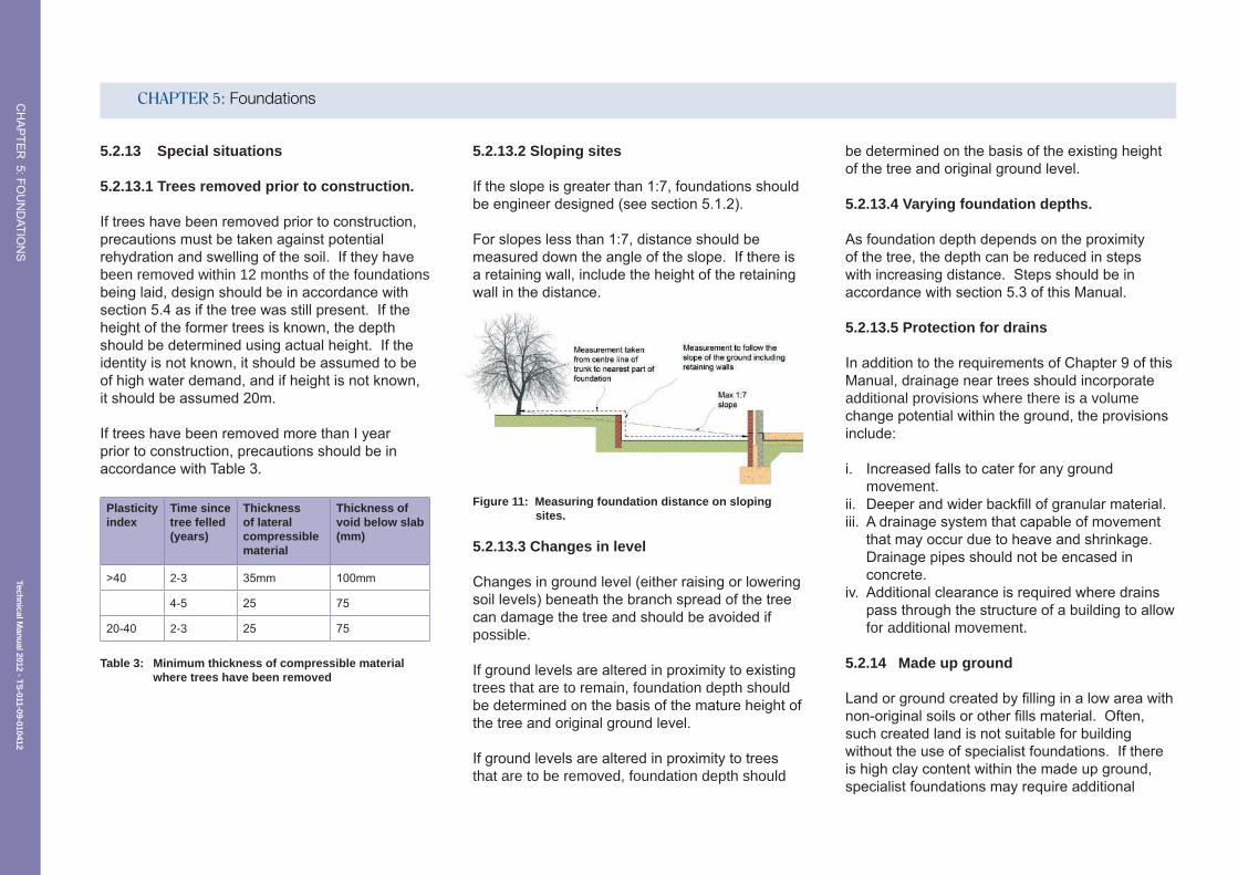
5.2.13.2 Sloping sites
Iftheslopeisgreaterthan1:7,foundationsshouldbeengineerdesigned(seesection5.1.2).
Forslopeslessthan1:7,distanceshouldbemeasureddowntheangleoftheslope.Ifthereisaretainingwall,includetheheightoftheretainingwallinthedistance.
Figure 11: Measuring foundation distance on sloping sites.
5.2.13.3 Changes in level
Changesingroundlevel(eitherraisingorloweringsoillevels)beneaththebranchspreadofthetreecandamagethetreeandshouldbeavoidedifpossible.
Ifgroundlevelsarealteredinproximitytoexistingtrees that are to remain, foundation depth should bedeterminedonthebasisofthematureheightofthetreeandoriginalgroundlevel.
Ifgroundlevelsarealteredinproximitytotreesthat are to be removed, foundation depth should
bedeterminedonthebasisoftheexistingheightofthetreeandoriginalgroundlevel.
5.2.13.4 Varying foundation depths.
Asfoundationdepthdependsontheproximityofthetree,thedepthcanbereducedinstepswithincreasingdistance.Stepsshouldbeinaccordancewithsection5.3ofthisManual.
5.2.13.5 Protection for drains
InadditiontotherequirementsofChapter9ofthisManual,drainageneartreesshouldincorporateadditional provisions where there is a volume changepotentialwithintheground,theprovisionsinclude:
i. Increasedfallstocaterforanygroundmovement.
ii. Deeperandwiderbackfillofgranularmaterial.iii. Adrainagesystemthatcapableofmovement
thatmayoccurduetoheaveandshrinkage.Drainagepipesshouldnotbeencasedinconcrete.
iv. Additionalclearanceisrequiredwheredrainspassthroughthestructureofabuildingtoallowfor additional movement.
5.2.14 Made up ground
Landorgroundcreatedbyfillinginalowareawithnon-originalsoilsorotherfillsmaterial.Often,suchcreatedlandisnotsuitableforbuildingwithouttheuseofspecialistfoundations.Ifthereishighclaycontentwithinthemadeupground,specialistfoundationsmayrequireadditional
Technical Manual 2012 - TS
-011-09-010412
CHAPTER 5: FoundationsCHAPTER
5:FOUNDATIO
NS
heaveprotection.Itisalsoimportanttoestablishthedepthofthemadeupgroundbecauseifitisarelativelyshallowdepth,theoriginalsoilbelowmaybecohesiveandbewithinthezoneofinfluenceofthetree.
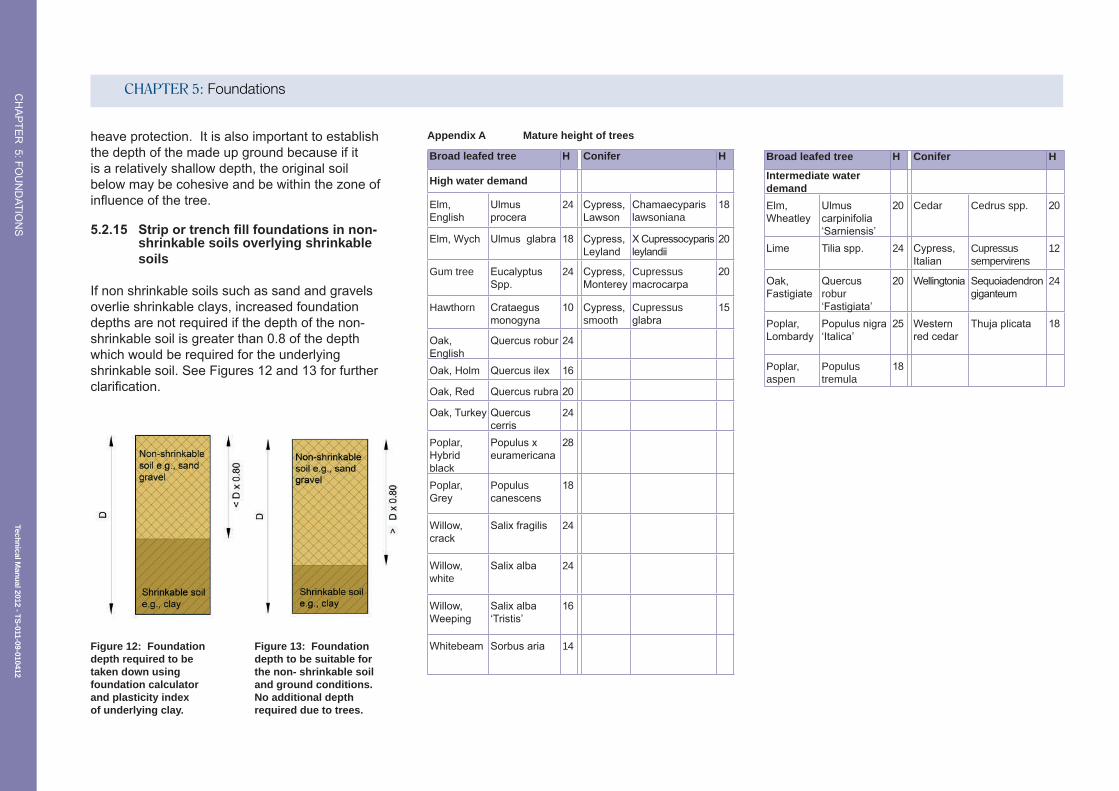
5.2.15 Strip or trench fill foundations in non- shrinkable soils overlying shrinkable soils
Ifnonshrinkablesoilssuchassandandgravelsoverlieshrinkableclays,increasedfoundationdepthsarenotrequiredifthedepthofthenon-shrinkablesoilisgreaterthan0.8ofthedepthwhichwouldberequiredfortheunderlyingshrinkablesoil.SeeFigures12and13forfurtherclarification.
Appendix A Mature height of trees
Broad leafed tree H Conifer H
High water demand
Elm, English
Ulmusprocera
24 Cypress,Lawson
Chamaecyparislawsoniana
18
Elm,Wych Ulmusglabra 18 Cypress,Leyland
XCupressocyparisleylandii
20
Gum tree EucalyptusSpp.
24 Cypress,Monterey
Cupressus macrocarpa
20
Hawthorn Crataegusmonogyna
10 Cypress,smooth
Cupressus glabra
15
Oak,English
Quercusrobur 24
Oak,Holm Quercusilex 16
Oak,Red Quercusrubra 20
Oak,Turkey Quercuscerris
24
Poplar, Hybridblack
Populusxeuramericana
28
Poplar, Grey
Populus canescens
18
Willow,crack
Salixfragilis 24
Willow,white
Salixalba 24
Willow,Weeping
Salixalba‘Tristis’
16
Whitebeam Sorbusaria 14
Broad leafed tree H Conifer H
Intermediate water demand
Elm, Wheatley
Ulmuscarpinifolia‘Sarniensis’
20 Cedar Cedrus spp. 20
Lime Tiliaspp. 24 Cypress,Italian
Cupressus sempervirens
12
Oak,Fastigiate
Quercusrobur ‘Fastigiata’
20 Wellingtonia Sequoiadendrongiganteum
24
Poplar,Lombardy
Populusnigra‘Italica’
25 Westernredcedar
Thujaplicata 18
Poplar, aspen
Populus tremula
18
Figure 12: Foundation depth required to be taken down using foundation calculator and plasticity index of underlying clay.
Figure 13: Foundation depth to be suitable for the non- shrinkable soil and ground conditions. No additional depth required due to trees.

Technical Manual 2012 - TS
-011-09-010412
CHAPTER 5: FoundationsCHAPTER
5:FOUNDATIO
NS
Broad leafed tree H Conifer H
Moderate water demand
Acacia,False
Robinia pseudoacacia
16 Dawnredwood
Metasequoiaglyptostroboides
16
Apple Malus spp. 10 Douglasfir Pseudotsugamenziesii
18
Ash Fraxinusspp. 24 Fir Abies spp 18
Beech Fagussylvatica
20 Hemlock Tsugaheterophylla
16
Cherry,Japanese
Prunus serrulata
9 Juniper Juniperus communis
6
Cherry,Fruite
Prunus cerasus
12 Larch Larixspp. 16
Cherryplum
Prunus cerasifera
10 Maidenhair tree
Ginkgobiloba 16
Cherry,Wild
Prunus avium 16 Monkeypuzzle
Auracariaauracana
14
Chestnut, Horse
Aesculushippocastanum
20 Pine Pinus spp 16
Chestnut, sweet
Castanea sativa 18 Spruce Piceaspp 16
Maple, Japanese
Acerpalmatum
8 Yew Taxusbaccata 12
Maple, Norway
Acerplatanoides
18
Mountain ash
Sorbusaucuparia
10
Pear Pyrusspp. 12
Plane Platanus spp. 22
Plum Prunus domestica
12
Sycamore Acerpseudoplatanus
20
Broad leafed tree H Conifer H
Low water demand
Birch Betulaspp. 14
Elder Sambucusnigra
10
Fig Ficuscarica 8
Hazel Corylusavellana
8
Holly Ilexaquifolium 12
Honeylocust
Gledistsia triacanathos
14
Hornbeam Carpinus betulus
16
Indianbean tree
Catalpa bignonioides
16
Laburnum Laburnumspp. 12
Magnolia Magnoliaspp 10
Mulberry Morus spp. 12
Sweetgum
Liquidambarstyraciflua
14
TreeofHeaven
Ailanthus altissima
20
Tuliptree Liriodendrontulipifera
18
Walnut Juglansregia 16
Table 4: Water demand (rooting depth) and mature heights (M) of common trees

FUNCTIONAL REQUIREMENT
Technical Manual TS
-011-09-010412
Workmanship
i. AllworkmanshipmustbewithindefinedtolerancesasdefinedinChapter 1 of this Manual.
ii.Allworktobecarriedoutbyatechnicallycompetentpersoninaworkmanlike manner.
iii.Stripfoundationsshouldbeofasuitabledepthinordertoachieveasatisfactorylevelofperformance.
Materials
i. Allmaterialsshouldbestoredcorrectlyinamannerwhichwillnotcausedamageordeteriorationoftheproduct.
ii. Allmaterials,productsandbuildingsystemsshallbeappropriateandsuitable for their intended purpose.
iii.Thestructureshall,unlessspecificallyagreedotherwisewiththewarrantyprovider,havealifeofnotlessthan60years.Individualcomponentsandassemblies,notintegraltothestructure,mayhavealesserdurabilitybutnotinanycircumstanceslessthan15years.
Design
i. Designandspecificationsshallprovideaclearindicationofthedesignintentanddemonstrateasatisfactorylevelofperformance.
ii.StructuralelementsoutsidetheparametersofApprovedDocumentA(EnglandandWales),Section1(Scotland)andTechnicalBookletD(NorthernIreland)mustbesupportedbystructuralcalculationsprovidedbyasuitablyqualifiedexpert.
iii.StripfoundationsmustmeettherelevantBuildingRegulationsandotherstatutoryrequirements,BritishStandardsandEuro-Codes.
5.3 STRIP AND MASS FILL FOUNDATIONS

Technical Manual 2012 - TS
-011-09-010412
CHAPTER 5: FoundationsCHAPTER
5:FOUNDATIO
NS
5.3.1 Introduction
Stripandmassfillfoundationsareusuallythemostsimplisticandcosteffectivefoundationforlowrisebuildingsonoriginalground,theguidanceinsection5.3,providesdetailsofhowtomeetthefunctionalrequirements.
5.3.2 Limitations of guidance
Thefollowingsituationsarebeyondthescopeoftheguidanceinthissection:
• Traditionalstripandmassfilledfoundationsforbuildingsotherthandwellings
• Dwellingsgreaterthanthreestoreys• Foundationsonfilledground• Stripandmassfilledfoundationswhere
foundationdepthsexceed2.5m
5.3.3 Design
Stripandmassfillfoundationsshallbedesignedtoensurethatthebuildingisappropriatelysupportedatalltimeswithoutexcessivesettlement.ThisfoundationtypeshouldonlybearontooriginalgroundunlessthefoundationhasbeendesignedbyaStructuralEngineerandappropriatelyreinforced.Itisthereforeimportantthatsiteconditionsareappropriatelyassessedpriortothebuildingdesign.FurtherguidanceforgroundconditionassessmentcanbefoundinChapter4SiteInvestigation.
5.3.4 Minimum foundation dimensions
Stripfoundationsshouldbe600mmminimumwidthforexternalwalls.Forsingleleafinternalwallsupto150mmthick,foundationsmaybereducedinwidthto450mm.Minimumthicknessofstripfoundationsshouldbe150mm.Foundationsshouldbesituatedcentrallybelowthewall.
Figure 14: Typical strip foundation
5.3.5 Foundation depths
Thedepthofallfoundationsshouldbedeterminedbyspecificsiteconditions.Allfoundationsmustbearontovirginstablesub-soiland,exceptwherestripfoundationsarefoundedonrock,thestripfoundation should have a minimum depth of 450mm,measuredfromfinishedgroundlevel,
totheirundersidetoavoidtheactionoffrost.Thisdepthhowever,willcommonlyneedtobeincreasedinareassubjecttolongperiodsoffrostor in order that loads are transferred to suitable ground.Wheretreesaresituatedclosetoaproposedbuildingfoundedonaclaysoil,thefoundationdepth/designwillbeaffectedandfurtherguidanceisavailableinsection5.2.
Inclaysoilswithaplasticityindexgreaterthanorequalto10%,stripfoundationsshouldbetakentoadepthwhereanticipatedgroundmovementwillnotimpairthestabilityofanypartofthebuildingtakingintoaccountoftheinfluenceofvegetationandtreesonoradjacenttothesite.Thedepthtotheundersideoffoundationsonclaysoilsshouldnotbelessthan750mmmeasuredfromfinishedgroundlevel,depthsmayneedtobeincreasedinorderthatloadsaretransferredtosuitableground.Table1givesdetailsofminimumfoundationdepths.
Modified plasticity index
Volume change potential 40 % and greater
Minimum foundation depth (m)
40%andgreater High 1.0
>20%-<40% Medium 0.9*
<20% Low 0.75*
*Ifthemodifiedplasticityindexisnotconfirmedminimumfoundation depths should be 1m.
Table 5: Minimum foundation depths

Technical Manual 2012 - TS
-011-09-010412
CHAPTER 5: FoundationsCHAPTER
5:FOUNDATIO
NS
Figure 15: Typical mass fill foundation
5.3.6 Setting out foundations
Theaccuracyofsettingoutfoundationsshouldbecheckedbyasetcontrolledtrenchmeasurements,includingtheirlocationrelativetositebordersandneighbouringbuildings.Levelsshouldbecheckedagainstbenchmarks,whereappropriate.Inparticular,forexcavationscheck:
• Trenchwidths• Trenchlengths• Lengthofdiagonalsbetweenexternalcorners
Wallsshouldbelocatedcentrallyuponthefoundation,unlessspecificallydesignedotherwise.AnydiscrepancyindimensionsshouldbereportedpromptlytotheDesigner.Resultingvariations
shouldbedistributedtoallconcernedwithsiteworks,includingtheSiteAuditSurveyor.
5.3.7 Excavations
Excavationshouldbetoadepththatgivessufficientbearingandprotectionfromfrostdamage.Toavoiddamagecausedbyfrost,thedepthofthefoundation(s)infrostsusceptiblegroundshouldbeataminimum450mmbelowgroundlevel.Ifthefinishedgroundlevelwillbeabovetheexistinggroundlevelthen,incoldconditionswhenfreezingisexpected,thefoundationdepthshouldbecalculatedfromtheexisting,notfinished,groundlevel.
Wheretrenchfillfoundationsareinexcessof2.5mdepth,theymustbedesignedbyaCharteredStructuralEngineerinaccordancewithcurrentBritishStandardsandCodesofPractice.Fortrenchfill,itisimperativetocheckthatthefinishedfoundationleveliscorrectandhorizontal.ItwillbedifficulttoadjustfordiscrepanciesinthesmallnumberofbrickcoursesbetweenfoundationandDPClevel.
Priortoconcretingexcavationsshouldbe‘bottomedout’toremoveanydebriswhichmayhavefallenintothetrench,theexcavationsshouldbe free from water and if it has been left open for alongperiodoftime,furtherexcavationmayberequiredtoanon-weatheredstrata.
Please note: ItisimportantthatHealthandSafetyobligationsaremetandthatexcavationsareappropriatelysupportedtopreventcollapse.
5.3.8 Reinforcing
Stripandtrenchfillfoundationsshouldbereinforcedwherenecessary,tosuitlocalisedgroundconditions.Reinforcement,ifneeded,shouldbecleanandfreefromlooserustandshouldalsobeplacedcorrectly.Bars,ofanappropriatesize,shouldbeappropriatelysupportedtoguaranteethattheyare75mmabovethebaseofthefoundationorasindicatedinthedesign.Theyshouldbesecuredatlapsandcrossings.Ifindoubtaboutanysoftspots,theengineer’sadviceshouldbetakenpriortoplacingtheconcrete.
5.3.9 Foundation Joints
Ifconstructionjointsarenecessary,theyshouldnotbepositionedwithin2mofacornerorjunctioninthefoundation.Allshutteringshouldberemovedbeforeworkprogressesbeyondtheconstructionjoint.
Figure 16: Using reinforcement bars across a joint

Technical Manual 2012 - TS
-011-09-010412
CHAPTER 5: FoundationsCHAPTER
5:FOUNDATIO
NS
5.3.10 Steps in foundations
StepsinfoundationsmustnotbeofagreaterdimensionthanthethicknessofthefoundationWherefoundationsarestepped(onelevation)theyshouldoverlapbytwicetheheightofthestep,bythedimensionofthefoundation,or300mm–whicheveristhegreater.AsshowninFigure17.
Figure 17: Steps in foundations
5.3.11 Standards referred to
• BS8004Codeofpracticeforfoundations.• BS59501Structuraluseofsteelworkin
buildings.• BS6399LoadingsforBuildings.• BS8103StructuralDesignoflowrisebuildings.• BS8110StructuralUseofConcrete.

FUNCTIONAL REQUIREMENT
Technical Manual TS
-011-09-010412
Workmanship
i. AllworkmanshipmustbewithindefinedtolerancesasdefinedinChapter 1 of this Manual.
ii.Allworktobecarriedoutbyatechnicallycompetentpersoninaworkmanlike manner.
iii.Pilefoundationsschemesmustbetestedtoconfirmthattheinstallationmeetsthedesignrequirements.
Materials
i. Allmaterialsshouldbestoredcorrectlyinamannerwhichwillnotcausedamageordeteriorationoftheproduct.
ii.Allmaterials,productsandbuildingsystemsshallbeappropriateandsuitable for their intended purpose.
iii.Thestructureshall,unlessspecificallyagreedotherwisewiththewarrantyprovider,havealifeofnotlessthan60years.Individualcomponentsandassemblies,notintegraltothestructure,mayhavealesserdurabilitybutnotinanycircumstanceslessthan15years.
Design
i. Designandspecificationsshallprovideaclearindicationofthedesignintentanddemonstrateasatisfactorylevelofperformance.
ii.Piledfoundationdesignsmustbesupportedbystructuralcalculationsprovidedbyasuitablyqualifiedexpert.Calculationsforfullpiling
systemsmustbeprovidedbyorendorsedbythepilingmanufacturer.
iii.PiledfoundationsmustmeettherelevantBuildingRegulationsandotherstatutoryrequirements,BritishStandardsandEuro-Codes.
5.4 PILED FOUNDATIONS

Technical Manual 2012 - TS
-011-09-010412
CHAPTER 5: FoundationsCHAPTER
5:FOUNDATIO
NS
5.4.5 Choosing the right piled solution
Thechoiceofpilingsystemtosupportthestructurewilldependentirelyuponthegroundconditionsandthereforeitisimportanttohavetheappropriatesiteinvestigationworkscarriedouttodeterminedepthsoffilledground,bearingcapacityofsoils,soiltypeandanyexistingworkingsorservicesthatmayclashwithpilelocations.AnalysisofthesiteinvestigationreportshouldbecompletedbyaspecialistpilingcontractorandStructuralEngineerastheyarebestplacedtodesignthemosteconomicpilingsystem.
Pilesareparticularlyappropriateforheavesites(treesremoved)forwhichtheyarestronglyrecommended.
Pilelayoutscanbereadilydesignedtoaccommodateanindividualplot.Agooddesignwillseektoachievecostsavingsinfoundationexcavationandmaterialsbytheincorporationoflargegroundbeamspansbetweenpilesandasmall number of piles.
ThePilingContractorshouldtakecaretoensurethatthepilesareinsertedverticallyandpiletopsarecorrectlyalignedtosupportthefoundationbeams.Anacceptableleveloftoleranceisapiletobeoffsetinplanfromtheoreticalpositionbynomorethan75mmandverticalalignmentshouldbenoworsethan1minevery75m(1:75).
5.4.1 Introduction
Pilesareusedtotransferloadsfrombuildingstothesupportingground,andareusedinawiderangeofapplicationswhereconventionalstripfootingsareinappropriate.Theyareparticularlyusedwheresoftorloosesoilsoverlaystrongsoilsorrocksatdepthsthatcanbereachedconvenientlybydrivingorboring.Theyareoftenthemosteconomictypeoffoundationwhenveryheavyloadsmustbesupportedorupliftforcesneedtoberesisted.Largepilesareextremelyusefulforlimitingthesettlementsoflargestructuresondeepstiffclays,smallerversionscanprovideappropriatefoundationsforhousesandothersmallbuildingsonstiffclaysliabletoshrinkageandswelling.Thetechniquehasbeeninuseformanyyears.
5.4.2 Limitations of guidance
Thefollowingsituationsarebeyondthescopeoftheguidanceinthissection.
• Innovativefoundationsystemsthatdonothavethirdpartyapprovaloraccreditation.
• PilingsystemswherethestructuraldesignisnotendorsedbythepilingSpecialistContractor.
5.4.3 Pile classification
Pilesofmanydifferenttypesandmethodsofinstallation have been developed to suit the wide varietyofsoils.Pilesgenerallyfallintotwomaintypes:
• Boredanddug,includingshortboredandsecant(replacementpiles).
• Drivenandjackedpiles,steel,concreteandtimber(displacementpiles).
Figure 18: The range of piling types (BRE publication)
5.4.4 How piling systems work
Therearebasicallytwogroupingsofpilesinthewaythattheytransferloadstotheground:
• End-bearingpilesderivethegreaterpartoftheirsupportfrombearingforcesatthebase.Theyactlargelyascolumnstransferringloadsthroughsoftdeposits,usuallytodensegranularsoilorrockatthefootofthepile.
• Frictionpiles,ontheotherhand,developmostoftheirsupportfromfrictionbetweentheshaftandthesoil,usuallyfirmclay.

Technical Manual 2012 - TS
-011-09-010412
CHAPTER 5: FoundationsCHAPTER
5:FOUNDATIO
NS
5.4.6 Ground beams
Pilesshouldbecappedwithanappropriategroundbeamsystem.Thereshouldbeadequateconnectionsbetweenthebeamandthepiletoensurethattheloadsaretransmittedeffectivelyorthatthebeamsareadequatelyrestrainedtothepiletoresistupliftonsitesthataresusceptibletoheave.Allexternal,internal,partitionandpartywallscanbeaccommodatedusingthissystem.
TheringbeamanditsconnectionsshouldbepartofthepiledfoundationdesignandshouldbesupportedbystructuralcalculationsprovidedbyaStructuralEngineer.
5.4.7 Pile construction records
Pileconstructionrecordsshouldbemadeavailableforallpilesinstalled.Therecordsshouldincludethefollowinginformation:
• Piletype(driventube,ContinuousFlightAuger(CFA),augerboredetc).
• Piledimensions(diameterorwidth/breadth).• Piledepth.• Drivingrecordsfromdrivenpiles–including
hammertype,weight,dropheight,sets,hammerefficiency.
• Pileverticalityconfirmation–thisshouldnotbemorethan1:75fromvertical.
• ForCFAandconcretescrewpiles,weshouldbegiventhecomputeroutputforconcretevolumeandrig.Performance–viewatypicalCFAoutputforawellconstructedpile.
5.4.8 Testing
Piled foundation installation should be appropriatelytestedtoensurethattheinstalledfoundationsmeetthedesignrequirement.Atestingplanshouldbeagreedatdesignstagethatisrepresentativeofthecomplexityofthepilingsystem.FurtherguidanceisavailablefromTheFederationofPilingSpecialistswhohasproducedthe‘HandbookonPileLoadTesting.’Sampletestingofarateofatleastonepileperhundredisusuallydeemedasanacceptableleveloftesting,howeveradditionaltestsmayberequiredonsiteswithmoreunstablegroundorwhereworkmanshiphas been an issue.
5.4.9 Test methods
TheEngineershallrequiretheSpecialistContractortoverifythatthepilingworkshavebeencompletedtoasatisfactorystandard.Thiswillusuallyincludecarryingoutsuitabletesting
Figure 19: Pile and beam detail
Technical Manual 2012 - TS
-011-09-010412
CHAPTER 5: FoundationsCHAPTER
5:FOUNDATIO
NS
toestablishthedegreeofgroundimprovement,itsloadbearingcharacteristicsandsettlementpotential.Thesetestsmayinclude:
5.4.9.1 Dynamic tests
Alsoknownaslargestraintesting,thistechniqueismostcommonlyusedforassessingthedynamicpilecapacityofdrivenpiles.Fordynamictestsondrivenpilestodeterminethedynamicpilecapacity,aminimumnumberof1testof1%oftheworkingpilesshouldbesought,whicheveristhegreater.Furthertestsmayberequiredifanomalous results are obtained.
5.4.9.2 Integrity tests
Alsoknownaslowstraintesting,therearetwotypesoftestswhichareusedsolelyforassessingpileintegrity:
• Crossholesoniclogging• Pulseecho
Forintegritytestingofcontinuousflightaugerpiles,100%ofthepilesshouldbetested.
5.4.9.3 Negative skin friction
Wherepilespassthroughgroundthatmayconsolidateorchangeinvolume(e.g.duetoachangeinwatertableorloadingduetoraisingoflevels)theeffectsofnegativeskinfrictionshouldbetakenintoaccount.Thecapacityofthepiletoresisttheadditionalcompressiveandtensilestressesshouldbecheckedatcriticalcrosssections.
5.4.10 Standards referred to:
• BS8004Codeofpracticeforfoundations.• BS5950.1Structuraluseofsteelworkin
buildings.• BS6399Loadingsforbuildings.• BS8103Structuraldesignoflowrisebuildings.• BS8110Structuraluseofconcrete

FUNCTIONAL REQUIREMENT
Technical Manual TS
-011-09-010412
Workmanship
i. AllworkmanshipmustbewithindefinedtolerancesasdefinedinChapter 1 of this Manual.
ii. Allworktobecarriedoutbyatechnicallycompetentpersoninaworkmanlike manner.
Materials
i. Allmaterialsshouldbestoredcorrectlyinamannerwhichwillnotcausedamageordeteriorationoftheproduct.
ii. Allmaterials,productsandbuildingsystemsshallbeappropriateandsuitable for their intended purpose.
iii.Thestructureshall,unlessspecificallyagreedotherwisewiththewarrantyprovider,havealifeofnotlessthan60years.Individualcomponentsandassemblies,notintegraltothestructure,mayhavealesserdurabilitybutnotinanycircumstanceslessthan15years.
Design
i. Designandspecificationsshallprovideaclearindicationofthedesignintentanddemonstrateasatisfactorylevelofperformance.
ii. Raftfoundationdesignsmustbesupportedbystructuralcalculationsprovidedbyasuitablyqualifiedexpert.
iii.RaftfoundationdesignandconstructionmustmeettherelevantBuildingRegulationsandotherstatutoryrequirements.BritishStandardsandEuro-Codes.
5.5 RAFT FOUNDATIONS

Technical Manual 2012 - TS
-011-09-010412
CHAPTER 5: FoundationsCHAPTER
5:FOUNDATIO
NS
Guidance
5.5.1 Introduction
Araftfoundationconsistsofareinforcedconcreteslab,whosethicknessandstiffnessaredesignedtospreadtheappliedwallandcolumnloadsoveralargearea.Fordomesticapplications,raftsareoftenbuiltwiththickenedperimeterstoprovideprotectionagainstfrostheave,inwhichcasetheyareeffectivelytrenchfillfoundationswithintegralgroundbearingfloorslabs.Downstandedgebeamsalsoservetostiffenthewholeofthefoundationstructure.
Raftsareusedwhereitisnecessarytolimittheloadappliedtotheunderlyingsoilortoreducetheeffectsofdifferentialfoundationmovementsasaresultofvariablesoilconditionsorvariationsinloading.
5.5.2 Limitations of guidance
Thefollowingsituationsarebeyondthescopeoftheguidanceinthissection.
Raftsarenotconsideredasanacceptedmethodoffoundationswherethegroundconditionsaresusceptibletoheaveorshrinkagee.g.wheretreesare present or have been removed.
5.5.3 Materials
Materials and workmanship should meet the requirementssetoutinChapters1and2ofthisManual.
5.5.4 Ground conditions
Raftfoundationsareusuallydesignedforsiteswithgroundconditionswithlowgroundbearingcapacityorwheretherearepocketsoffilledground.ItisthereforeimportanttocompleteasuitablesiteinvestigationmeetingtherequirementsofChapter4ofthismanualtoascertainthebearingcapacityandsuitabilityoftheground.
5.5.5 Structural design
StructuralcalculationsshouldbeprovidedbyasuitablyqualifiedStructuralEngineer,confirmingthattheraftdesignissuitableforbearingontotheground,andthatthegroundbearingcapacitysafelysupportsthestructure.Thedesignshouldprovidesufficientinformationtoensurecorrectinstallationoftheraftanditsreinforcing.Theminimumrecommendedinformationisasfollows;
• Plansanddetailsoftheproposedraftshowingreinforcingpositionsetc.
• Structuralcalculationsconfirmingthattheraftissuitable for the proposed loads applied
• Abarschedule,tobeusedbythesteelreinforcingsupplierandinstaller.
5.5.6 Ducts and sleeving
Anyservicepenetrationsthatpassthroughtheraftshouldbeappropriatelysleevedtoprotecttheserviceduct.Serviceductpositionsshouldbeplannedandindicatedondrawingstopreventreinforcingbarsfrombeencut,unlessthestructuraldesignhascateredforthis.
5.5.7 Damp proof membranes (DPM), damp proof courses (DPC) and floor finishes
Theraftfoundationandthejunctionwiththewallshouldbeappropriatelyconstructedtoresistgroundmoisturepenetration.ADPMcanbeplacedbeneaththeraft,wrappedaroundtheexternaltoeandlappedintotheinternalDPC,however,thisdetailcanbedifficulttoimplementonsiteandcommonly,puncturingofthemembranecanoccurwhenplacingreinforcing.ThepreferredmethodistoplacetheDPMontopoftheraftslabbeneaththefloorinsulationorscreedasindicatedinFigure20.
Figure 20 Typical raft foundation design

Technical Manual 2012 - TS
-011-09-010412
CHAPTER 5: FoundationsCHAPTER
5:FOUNDATIO
NS
5.5.8 Standards referred to:
• BS8004Codeofpracticeforfoundations.• BS5950:1Structuraluseofsteelworkin
buildings.• BS6399Loadingsforbuildings.• BS8103Structuraldesignoflowrisebuildings.• BS8110Structuraluseofconcrete.