contents ardos quick start... · 2 ardos is fully configurable, and you can turn off features that...
TRANSCRIPT

1
ArdOS – The Arduino Operating System
Quick Start Guide and Examples
Contents 1. Introduction ......................................................................................................................... 1
2. Obtaining ArdOS .................................................................................................................. 2
3. Installing ArdOS ................................................................................................................... 2
a. Arduino IDE Versions 1.0.4 and Prior .............................................................................. 2
b. Arduino IDE Versions 1.0.5 Onwards............................................................................... 4
c. Accessing the Examples ................................................................................................... 6
4. An ArdOS Tutorial ................................................................................................................ 7
Task 1: Writing periodically to the serial port ....................................................................... 11
Tasks 2 and 3: Reading and Writing the Message Queue ..................................................... 11
Task 4 and int0handler: Toggling the LED ............................................................................. 12
Task 5: Blinking an LED at a specific rate ............................................................................... 13
setup: Putting it all together ................................................................................................. 13
loop: This is left empty .......................................................................................................... 15
bigExample: The Full Code .................................................................................................... 16
5. Other Examples ................................................................................................................. 19
1. Introduction
Welcome to ArdOS, the operating system for the Arduino series of boards based on the
ATmega168/328/1280/2560 series of microcontrollers.
ArdOS is a powerful real-time operating system that is fully compatible with the Arduino
programming library, coming with prioritized multitasking, and communication and
coordination mechanisms that include:
Binary and counting semaphores.
Mutex locks.
Conditional variables.
FIFO message queues.
Prioritized message queues.

2
ArdOS is fully configurable, and you can turn off features that you don’t require and
these won’t be compiled into your final object code that is uploaded to the Arduino. The
design philosophy behind ArdOS is to strike a balance between ease-of-use,
compactness, and sound real-time design principles.
2. Obtaining ArdOS
ArdOS is distributed solely in source-code form, and you should have found this
document together with the ArdOS distribution package. In the event that you did not,
you can obtain ArdOS from https://bitbucket.org/ctank/ardos-ide.
3. Installing ArdOS
In this section we will look at how to install ArdOS for use in the Arduino IDE:
a. Arduino IDE Versions 1.0.4 and Prior
To add a new library you will need to locate where Arduino stores user libraries. For
most Windows installations this should be either in “Documents\Arduino\libraries”
or “My Documents\Arduino\libraries”. On a Mac it should be in
“Documents/Arduino/libraries”.
Locate your user libraries directory, and then unzip the contents of ArdOS.zip into
this directory. Your libraries directory should look something like this:

3
Double click the ArdOS directory. In addition to this document you will also find:
COPYING, COPYING.LESSER: The GNU LGPL license.
kernel.cpp, kernel.h: The main ArdOS kernel implementation.
task.cpp: Task management routines.
sema.h, sema.cpp: Binary and counting semaphore support.
queue.h, queue.cpp: FIFO and priority message queue support.
mutex.h, mutex.cpp: Mutex locks and conditional variables support.
There is also an “examples” directory containing the following examples files:
ISRDemo: How to use semaphores within interrupt service routines.
mutexDemo: How to use mutex locks and conditional variables.
prioQueueDemo: How to use priority message queues.
queueDemo: How to use FIFO message queues.
semaDemo: How to use semaphores to coordinate tasks.
bigExample: The example at the end of this document.
If you are successful you will find the ArdOS library in the “Contributed” section of
Sketch->Import Library:

4
b. Arduino IDE Versions 1.0.5 Onwards
From version 1.0.5 onwards of the Arduino IDE you can bring in new libraries by
Sketch->Import Library->Add Library:
Click on Add Library and you will get a dialog box like the one shown below:

5
Navigate to the directory where you saved the ArdOS.zip file, click on the file and
click Open.

6
The Arduino IDE will show ‘Library added to your libraries. Check “import library” menu.’ at the
bottom of the IDE screen. You can click Sketch->Import Library and you will see ArdOS listed
under the Contributed section:
c. Accessing the Examples
You can access the examples by clicking File->Examples->ArdOS:

7
4. An ArdOS Tutorial
We will now look at a comprehensive example of how to create and deploy an ArdOS
application. You can access this example by clicking File->Examples->ArdOS-
>bigExample.
If you have never used a Real-Time Operating System (RTOS) before on a tiny device like
the Arduino, you will find that programming on an RTOS is very different from
programming on a large operating system like Windows, MacOS or Linux. In particular:
The RTOS is distributed in source code form.
Tasks are organized as C functions within your program instead of as programs
on the hard disk.
If you have some experience programming in POSIX threads, you will find ArdOS
programming quite similar.
In our example we will look at:
How to use OSSleep to ensure that task code executes at fixed intervals.
How to use FIFO message queues to pass messages.
How to use semaphores to coordinate between task code and interrupt service
routines.
How to use the serial port when using ArdOS.
Wire up the following circuit for this example:

8
Parts List:
Part Description
R1 to R3 330 ohm resistors
R4 10k resistor
R5 Potentiometer
LED1 to LED3 Red or yellow LEDs
S1 Push button switch
The breadboard layout might look a little like this:

9
Essentially:
i. Wire up LEDs to digital pins 6, 9 and 11 on the Arduino (in this case we
are using the Uno – other boards should be fine as well). Connect the
cathode (negative) sides of the LED to ground through a 330 ohm
resistor to prevent burning your LEDs.
ii. Wire up a push button to digital input 2. You will need to use a 10k
resistor to pull down input 2 as well to prevent it from floating.
iii. Wire up a potentiometer to analog input 0.
You can use this same circuit for all the examples included in ArdOS.
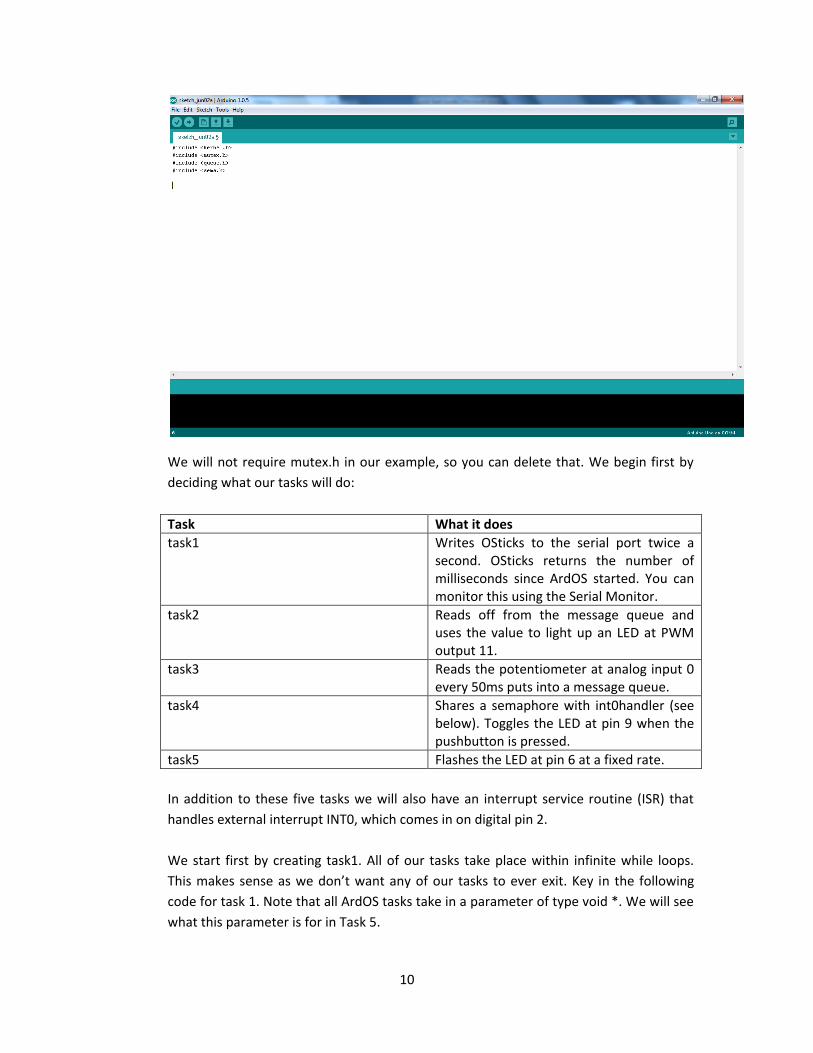
Create a new Arduino sketch, then click Sketch->Import Library->ArdOS. The Arduino
IDE will bring in all the header files for ArdOS:
10
We will not require mutex.h in our example, so you can delete that. We begin first by
deciding what our tasks will do:
Task What it does
task1 Writes OSticks to the serial port twice a second. OSticks returns the number of milliseconds since ArdOS started. You can monitor this using the Serial Monitor.
task2 Reads off from the message queue and uses the value to light up an LED at PWM output 11.
task3 Reads the potentiometer at analog input 0 every 50ms puts into a message queue.
task4 Shares a semaphore with int0handler (see below). Toggles the LED at pin 9 when the pushbutton is pressed.
task5 Flashes the LED at pin 6 at a fixed rate.
In addition to these five tasks we will also have an interrupt service routine (ISR) that
handles external interrupt INT0, which comes in on digital pin 2.
We start first by creating task1. All of our tasks take place within infinite while loops.
This makes sense as we don’t want any of our tasks to ever exit. Key in the following
code for task 1. Note that all ArdOS tasks take in a parameter of type void *. We will see
what this parameter is for in Task 5.
11
Task 1: Writing periodically to the serial port
// Writes OSticks to the serial port every 100ms.
void task1(void *p)
{
char buffer[16];
while(1)
{
sprintf(buffer, "Time: %lu", OSticks());
Serial.println(buffer);
OSSleep(500);
}
}
This code is fairly simple. The while loop prints out OSticks() (returning the number of
milliseconds since ArdOS started) into a buffer and prints that onto the serial port using
Serial.println. It then goes to sleep for ½ second. Note that Arduino library calls are not
re-entrant, and the Serial object is particularly sensitive to re-entrancy issues. If Serial is
called by more than one task it should be protected with a mutex lock or binary
semaphore. Serial should also not be called more than once every 5-50 ms depending
on the amount of text to be printed. Please see the printSerial function in mutexDemo
for the correct way to share Serial.
Tasks 2 and 3: Reading and Writing the Message Queue
Key in the following code for tasks 2 and 3.
// Reads the potentiometer at analog input 0 every 10 ms and places it
onto the message queue.
#define QLEN 8
int qbuf[QLEN];
OSQueue msg;
// Reads the message queue and controls the brightness of the LED at
PWM output 11.
void task2(void *p)
{
unsigned int val;
while(1)
{
val=(unsigned int) OSDequeue(&msg);
analogWrite(11, val);
}
}

12
To create a message queue we first create an integer buffer qbuf of length QLEN (here QEN is 8)
as well as a queue variable msg. Task 2’s loop reads off from the queue and uses the value to
control the brightness of the LED at pin 11 using analogWrite.
void task3(void *p)
{
unsigned int val, remap;
while(1)
{
val=analogRead(0);
remap=map(val, 0, 1023, 0, 255);
OSEnqueue(remap, &msg);
OSSleep(50);
}
}
Task 3 reads analog channel 0 every 50 milliseconds, and remaps the value found from 0 to 1023,
to 0 to 255. This allows the LED to light up smoothly over the entire range of the potentiometer.
It then enqueues the value and goes to sleep for 50 ms.
Task 4 and int0handler: Toggling the LED
Key in the following code for the INT0 external interrupt handler and for task 4:
OSSema sem;
// Interrupt service routine for external interrupt INT0 (digital pin
2)
void int0handler()
{
OSGiveSema(&sem);
}
// Toggles the LED at pin 9 every time the push button is pressed.
void task4(void *p)
{
unsigned char flag=HIGH;
while(1)
{
OSTakeSema(&sem);
digitalWrite(9, flag);
flag=!flag;
}
}

13
We create a new semaphore of type OSSema, as well as the interrupt handler for external
interrupt 0 (INT0), called int0handler. The handler’s main job is to release the semaphore sem
using OSGiveSema. We will still need to call attachInterrupt to actually associate this handler
with INT0.
Similarly task 4 takes the semaphore using OSTakeSema and is suspended until int0handler
releases it. When the semaphore is released task 4 toggles the LED at pin 9.
Task 5: Blinking an LED at a specific rate
Task 5’s job is very simple: to just blink the LED at pin 6 at a specific rate. However we use this
task as an example of how to pass in parameters to a task at startup:
void task5(void *p)
{
unsigned int pause=(unsigned int) p;
while(1)
{
digitalWrite(6, HIGH);
OSSleep(pause);
digitalWrite(6, LOW);
OSSleep(pause);
}
}
The argument to task 5 is passed in through the parameter p. Since p is of type void *, we apply
a cast to turn it into an unsigned int.
setup: Putting it all together
Finally we declare our setup routine to put everything together. We first define a symbol called
NUM_TASKS which shows the number of tasks we have (in this case 5). We then call OSInit with
the number of tasks we intend to create.
#define NUM_TASKS 5
void setup()
{
OSInit(NUM_TASKS);
The following few lines initialize the serial port to a bit rate of 115200 bps, and set pins 6 and 9
to be OUTPUT pins. We then call attachInterrupt to associate int0handler with INT0, and
configure it to be triggered on a rising edge on pin 2.

14
Serial.begin(115200);
pinMode(6, OUTPUT);
pinMode(9, OUTPUT);
attachInterrupt(0, int0handler, RISING);
We next call OSCreateSema to create the semaphore. The first argument is the semaphore we
are initializing, the second argument is the initial value for the semaphore, and the third
argument is a flag showing whether this is a binary semaphore (third parameter is 1) or a
counting semaphore (third parameter is 0).
OSCreateSema(&sem, 0, 1);
We next call OSCreateQueue to initialize our queue. The first argument is the integer array that
we intend to use as our buffer, the second argument is the length of this array in integers, and
the third argument is the queue we wish to initialize:
OSCreateQueue(qbuf, QLEN, &msg);
We now call OSCreateTask to register the individual tasks. The first parameter is the priority
number (smaller = higher priority. Priority 0 is the highest.), the second is the name of the
function containing the task, and the third is the argument to be passed to the task on startup.
For the first four tasks we don’t wish to pass in anything and hence we put NULL in the third
argument.
OSCreateTask(0, task1, NULL);
OSCreateTask(1, task2, NULL);
OSCreateTask(2, task3, NULL);
OSCreateTask(3, task4, NULL);
For the fifth task we pass in a parameter of 250, which will cause task5 to flash the LED at pin 6
at approximately twice per second:
OSCreateTask(4, task5, (void *) 250);
Finally we call OSRun to start ArdOS.
OSRun(); }

15
This is the full code for setup:
#define NUM_TASKS 5
void setup()
{
OSInit(NUM_TASKS);
Serial.begin(115200);
pinMode(6, OUTPUT);
pinMode(9, OUTPUT);
attachInterrupt(0, int0handler, RISING);
OSCreateSema(&sem, 0, 1);
OSCreateQueue(qbuf, QLEN, &msg);
OSCreateTask(0, task1, NULL);
OSCreateTask(1, task2, NULL);
OSCreateTask(2, task3, NULL);
OSCreateTask(3, task4, NULL);
OSCreateTask(4, task5, (void *) 250);
OSRun();
}
loop: This is left empty
Once OSRun is called ArdOS will start up and run through all the tasks. ArdOS therefore does not
require a loop function, but Arduino does. We create an empty loop function:
void loop()
{
// Empty
}

16
bigExample: The Full Code
Here is the full code again for bigExample. Once you have keyed this in you can upload it to the
Arduino board. If all goes well the LED at pin 6 will flash at twice per second, the brightness of
the LED at pin 11 can be controlled using the potentiometer, and the LED at pin 9 can be toggled
using the push button.
#include <kernel.h>
#include <queue.h>
#include <sema.h>
// Writes OSticks to the serial port every 100ms.
void task1(void *p)
{
char buffer[16];
while(1)
{
sprintf(buffer, "Time: %lu", OSticks());
Serial.println(buffer);
OSSleep(500);
}
}
// Reads the potentiometer at analog input 0 every 10 ms and places
// it onto the message queue.
#define QLEN 8
int qbuf[QLEN];
OSQueue msg;
// Reads the message queue and controls the brightness of the LED at
PWM output 11.
void task2(void *p)
{
unsigned int val;
while(1)
{
val=(unsigned int) OSDequeue(&msg);
analogWrite(11, val);
}
}

17
void task3(void *p)
{
unsigned int val, remap;
while(1)
{
val=analogRead(0);
remap=map(val, 0, 1023, 0, 255);
OSEnqueue(remap, &msg);
OSSleep(50);
}
}
OSSema sem;
// Interrupt service routine for external interrupt INT0
// (digital pin 2)
void int0handler()
{
OSGiveSema(&sem);
}
// Toggles the LED at pin 9 every time the push button is pressed.
void task4(void *p)
{
unsigned char flag=HIGH;
while(1)
{
OSTakeSema(&sem);
digitalWrite(9, flag);
flag=!flag;
}
}
void task5(void *p)
{
unsigned int pause=(unsigned int) p;
while(1)
{
digitalWrite(6, HIGH);
OSSleep(pause);
digitalWrite(6, LOW);
OSSleep(pause);
}
}

18
#define NUM_TASKS 5
void setup()
{
OSInit(NUM_TASKS);
Serial.begin(115200);
pinMode(6, OUTPUT);
pinMode(9, OUTPUT);
attachInterrupt(0, int0handler, RISING);
OSCreateSema(&sem, 0, 1);
OSCreateQueue(qbuf, QLEN, &msg);
OSCreateTask(0, task1, NULL);
OSCreateTask(1, task2, NULL);
OSCreateTask(2, task3, NULL);
OSCreateTask(3, task4, NULL);
OSCreateTask(4, task5, (void *) 250);
OSRun();
}
void loop()
{
// Empty
}

19
5. Other Examples
There are several other examples provided with ArdOS. To try these examples wire up the
circuit shown in section 4.
These can be accessed from the File->Examples->ArdOS menu:
Example Name Description
ISRDemo Demonstrates the use of semaphores to coordinate between interrupt handlers (interrupt service routines or ISRs) and tasks. You can monitor OSticks via the Serial Monitor.
mutexDemo Demonstrates how to use mutex locks and conditional variables. You can monitor what this example is doing via the Serial Monitor.
prioQueueDemo Demonstrates the use of priority queues. You can see the messages being retrieved in priority order on the Serial Monitor.
queueDemo Uses a standard first-in-first-out (FIFO) message queue to control an LED. You can monitor the value read on analog to digital converter channel 0 on the Serial Monitor.
semaDemo Demonstrates how to use semaphores to coordinate tasks.