contents” - dmaportal.files.wordpress.com · 01/02/2017 · appendix 2 model form of...
TRANSCRIPT

)
“Contents”
Preamble
Chapter 1 General
Chapter 2 Ship survival capability and location of cargo tanks
Chapter 3 Ship arrangements
Chapter 4 Cargo containment
Chapter 5 Process pressure vessels and liquids, vapour and pressure
piping systems
Chapter 6 Materials of construction and quality control
Chapter 7 Cargo pressure/Temperature control
Chapter 8 Vent systems for cargo containment
Chapter 9 Cargo containment system atmosphere control
Chapter 10 Electrical installations
Chapter 11 Fire protection and extinction
Chapter 12 Artificial ventilation in the cargo area
Chapter 13 Instrumentation and automation systems
Chapter 14 Personnel protection
Chapter 15 Special requirements
Chapter 16 Summary of minimum requirements

- 3 -
Appendix 1 IGC Guidance product data reporting form
Appendix 2 Model form of International Certificate of Fitness for the Carriage of Liquefied Gases in Bulk
Appendix 3 Example of an addendum to the International Certificate
of Fitness for the Carriage of Liquefied Gases in Bulk
Appendix 4 Non-metallic materials
Appendix 5 Standard for the use of limit state methodologies in the design of cargo containment systems of novel configuration

- 5 -
CHAPTER 1
GENERAL
1.1 Application and implementation
1.1.1 The Guidance applies to ships regardless of their size, including those of less than 500 gross tonnage, engaged in the carriage of liquefied gases having a vapour pressure exceeding 0.28 MPa absolute at a temperature of 37.8°C and other products, as shown in chapter 16, when carried in bulk.
1.1.2.1 Unless expressly provided otherwise, the Guidance applies to ships whose keels are laid, or which are at a similar stage of construction where:
.1 construction identifiable with the ship begins; and
.2 assembly of that ship has commenced, comprising at least 50 tonnes or 1% of the estimated mass of all structural material, whichever is less,
on or after 1 July 2016.
1.1.2.2 For the purpose of the Guidance, the expression "ships constructed" means ships the keels of which are laid or which are at a similar stage of construction.
1.1.2.3 Unless expressly provided otherwise, for ships constructed on or after 1 July 1986 and before 1 July 2016, the Administration shall ensure that the requirements which are applicable under this Guidance, as adopted by resolution MSC.5(48) as amended by resolutions MSC.17(58), MSC.30(61), MSC.32(63), MSC.59(67), MSC.103(73), MSC.177(79) and MSC.220(82), are complied with.
1.1.3 A ship, irrespective of the date of construction, which is converted to a gas carrier on or after 1 July 2016, shall be treated as a gas carrier constructed on the date on which such conversion commences.
1.1.4.1 When cargo tanks contain products for which the Guidance requires a type 1G ship, neither flammable liquids having a flashpoint of 60°C (closed cup test) or less, nor flammable products listed in chapter 16, shall be carried in tanks located within the protective zones described in 2.4.1.1.
1.1.4.2 Similarly, when cargo tanks contain products for which the Guidance requires a type 2G/2PG ship, the flammable liquids as described in 1.1.4.1, shall not be carried in tanks located within the protective zones described in 2.4.1.2.
1.1.4.3 In each case, for cargo tanks loaded with products for which the Guidance requires a type 1G or 2G/2PG ship, the restriction applies to the protective zones within the longitudinal extent of the hold spaces for those tanks.

- 6 -
1.1.4.4 The flammable liquids and products described in 1.1.4.1 may be carried within these protective zones when the quantity of products retained in the cargo tanks, for which the Guidance requires a type 1G or 2G/2PG ship is solely used for cooling, circulation or fuelling purposes.
1.1.5 Except as provided in 1.1.7.1, when it is intended to carry products covered by this Guidance and products covered by the International Guidance for the Construction and Equipment of Ships Carrying Dangerous Chemicals in Bulk (IBC Guidance), adopted by resolution MSC.4(48), as may be amended by the Organization, the ship shall comply with the requirements of both Guidances appropriate to the products carried.
1.1.6.1 Where it is proposed to carry products that may be considered to come within the scope of this Guidance that are not at present designated in chapter 16, the Administration and the port Administrations involved in such carriage shall establish a Tripartite Agreement based on a provisional assessment and lay down preliminary suitable conditions of carriage based on the principles of the Guidance.
1.1.6.2 For the evaluation of such products, the manufacturer of the product shall submit to the Administration a completed assessment form (see appendix 1), which includes the proposed ship type and carriage requirements.
1.1.6.3 When a provisional assessment for a pure or technically pure product has been completed and agreed with the other parties, the Administration shall submit the assessment form and a proposal for a new and complete entry in the IGC Guidance, to the relevant sub-committee of the Organization (see appendix 1).
1.1.6.4 After provisional assessment by Tripartite Agreement and express or tacit agreement has been established, an addendum to the relevant ship's certificate may be issued (see appendix 3).
1.1.7.1 The requirements of this Guidance shall take precedence when a ship is designed and constructed for the carriage of the following products:
.1 one or more of the products that are listed both in the Guidance and in the International Bulk Chemical Guidance. These products are marked with an asterisk in column "a" in the table contained within chapter 16.
1.1.7.2 When a ship is intended to exclusively carry one or more of the products referred to in 1.1.7.1.2, the requirements of the International Bulk Chemical Guidance, as amended, shall apply.
1.1.8 The ship's compliance with the requirements of the International Gas Carrier Guidance shall be shown by its International Certificate of Fitness for the Carriage of Liquefied Gases in Bulk, as described in 1.4. Compliance with the amendments to the Guidance, as appropriate, shall also be indicated in the International Certificate of Fitness for the Carriage of Liquefied Gases in Bulk.
1.1.9 Where reference is made in the Guidance to a paragraph, all the provisions of the subparagraph of that designation shall apply.
- 7 -
1.1.10 When a ship is intended to operate for periods at a fixed location in a re-gasification and gas discharge mode or a gas receiving, processing, liquefaction and storage mode, the Administration and port Administrations involved in the operation shall take appropriate steps to ensure implementation of the provisions of the Guidance as are applicable to the proposed arrangements. Furthermore, additional requirements shall be established based on the principles of the Guidance as well as recognized standards that address specific risks not envisaged by it. Such risks may include, but not be limited to:
.1 fire and explosion;
.2 evacuation;
.3 extension of hazardous areas;
.4 pressurized gas discharge to shore;
.5 high-pressure gas venting;
.6 process upset conditions;
.7 storage and handling of flammable refrigerants;
.8 continuous presence of liquid and vapour cargo outside the cargo
containment system;
.9 tank over-pressure and under-pressure;
.10 ship-to-ship transfer of liquid cargo; and
.11 collision risk during berthing manoeuvres.
1.1.11 Where a risk assessment or study of similar intent is utilized within the Guidance, the results shall also include, but not be limited to, the following as evidence of effectiveness:
.1 description of methodology and standards applied;
.2 potential variation in scenario interpretation or sources of error in the study;
.3 validation of the risk assessment process by an independent and suitable
third party;
.4 quality system under which the risk assessment was developed;
.5 the source, suitability and validity of data used within the assessment;
.6 the knowledge base of persons involved within the assessment;
.7 system of distribution of results to relevant parties; and
.8 validation of results by an independent and suitable third party.
- 8 -
1.2 Definitions
Except where expressly provided otherwise, the following definitions apply to the Guidance. Additional definitions are provided in chapters throughout the Guidance.
1.2.1 Accommodation spaces are those spaces used for public spaces, corridors, lavatories, cabins, offices, hospitals, cinemas, games and hobby rooms, barber shops, pantries without cooking appliances and similar spaces.
1.2.2 "A" class divisions are divisions as defined in regulation II-2/3.2 of the SOLAS Convention.
1.2.3 Administration means the Department of Marine Administration, the Republic of the Union of Myanmar. For Administration (port), see port Administration.
1.2.4 Anniversary date means the day and the month of each year that will correspond to the date of expiry of the International Certificate of Fitness for the Carriage of Liquefied Gases in Bulk.
1.2.5 Boiling point is the temperature at which a product exhibits a vapour pressure equal to the atmospheric pressure.
1.2.6 Breadth (B) means the maximum breadth of the ship, measured amidships to the moulded line of the frame in a ship with a metal shell, and to the outer surface of the hull in a ship with a shell of any other material. The breadth (B) shall be measured in metres.
1.2.7 Cargo area is that part of the ship which contains the cargo containment system and cargo pump and compressor rooms and includes the deck areas over the full length and breadth of the part of the ship over these spaces. Where fitted, the cofferdams, ballast or void spaces at the after end of the aftermost hold space or at the forward end of the foremost hold space are excluded from the cargo area.
1.2.8 Cargo containment system is the arrangement for containment of cargo including, where fitted, a primary and secondary barrier, associated insulation and any intervening spaces, and adjacent structure, if necessary, for the support of these elements. If the secondary barrier is part of the hull structure, it may be a boundary of the hold space.
1.2.9 Cargo control room is a space used in the control of cargo handling operations.
1.2.10 Cargo machinery spaces are the spaces where cargo compressors or pumps, cargo processing units, are located, including those supplying gas fuel to the engine-room.
1.2.11 Cargo pumps are pumps used for the transfer of liquid cargo including main pumps, booster pumps, spray pumps, etc.
1.2.12 Cargoes are products listed in chapter 16, that are carried in bulk by ships subject to the Guidance.
1.2.13 Cargo service spaces are spaces within the cargo area, used for workshops, lockers and store-rooms that are of more than 2 m2 in area.
1.2.14 Cargo tank is the liquid-tight shell designed to be the primary container of the cargo and includes all such containment systems whether or not they are associated with the insulation or/and the secondary barriers.
1.2.15 Closed loop sampling is a cargo sampling system that minimizes the escape of cargo vapour to the atmosphere by returning product to the cargo tank during sampling.
- 9 -
1.2.16 Cofferdam is the isolating space between two adjacent steel bulkheads or decks. This space may be a void space or a ballast space.
1.2.17 Control stations are those spaces in which ship's radio, main navigating equipment or the emergency source of power is located or where the fire-recording or fire control equipment is centralized. This does not include special fire control equipment, which can be most practically located in the cargo area.
1.2.18 Flammable products are those identified by an "F" in column "f" in the table of chapter 16.
1.2.19 Flammability limits are the conditions defining the state of fuel-oxidant mixture at which application of an adequately strong external ignition source is only just capable of producing flammability in a given test apparatus.
1.2.20 FSS Code is the Fire Safety Systems Code meaning the International Guidance for Fire Safety Systems, adopted by the Maritime Safety Committee of the Organization by resolution MSC.98(73), as amended.
1.2.21 Gas carrier is a cargo ship constructed or adapted and used for the carriage in bulk of any liquefied gas or other products listed in the table of chapter 16.
1.2.22 Gas combustion unit (GCU) is a means of disposing excess cargo vapour by thermal oxidation.
1.2.23 Gas consumer is any unit within the ship using cargo vapour as a fuel.
1.2.24 Hazardous area is an area in which an explosive gas atmosphere is, or may be expected to be present, in quantities that require special precautions for the construction, installation and use of electrical equipment. When a gas atmosphere is present, the following hazards may also be present: toxicity, asphyxiation, corrosivity, reactivity and low temperature. These hazards shall also be taken into account and additional precautions for the ventilation of spaces and protection of the crew will need to be considered. Examples of hazardous areas include, but are not limited to, the following:
.1 the interiors of cargo containment systems and any pipework of pressure-relief or other venting systems for cargo tanks, pipes and equipment containing the cargo;
.2 interbarrier spaces;
.3 hold spaces where the cargo containment system requires a secondary barrier;
.4 hold spaces where the cargo containment system does not require a secondary barrier;
.5 a space separated from a hold space by a single gastight steel boundary where the cargo containment system requires a secondary barrier;
.6 cargo machinery spaces;
.7 areas on open deck, or semi-enclosed spaces on open deck, within 3 m of possible sources of gas release, such as cargo valve, cargo pipe flange, cargo machinery space ventilation outlet, etc.;
- 10 -
.8 areas on open deck, or semi-enclosed spaces on open deck within 1.5 m of cargo machinery space entrances, cargo machinery space ventilation inlets;
.9 areas on open deck over the cargo area and 3 m forward and aft of the cargo area on the open deck up to a height of 2.4 m above the weather deck;
.10 an area within 2.4 m of the outer surface of a cargo containment system where such surface is exposed to the weather;
.11 enclosed or semi-enclosed spaces in which pipes containing cargoes are located, except those where pipes containing cargo products for boil-off gas fuel burning systems are located;
.12 an enclosed or semi-enclosed space having a direct opening into any hazardous area;
.13 void spaces, cofferdams, trunks, passageways and enclosed or semi-enclosed spaces, adjacent to, or immediately above or below, the cargo containment system;
.14 areas on open deck or semi-enclosed spaces on open deck above and in the vicinity of any vent riser outlet, within a vertical cylinder of unlimited height and 6 m radius centred upon the centre of the outlet and within a hemisphere of 6 m radius below the outlet; and
.15 areas on open deck within spillage containment surrounding cargo manifold valves and 3 m beyond these up to a height of 2.4 m above deck.
1.2.25 Non-hazardous area is an area other than a hazardous area.
1.2.26 Hold space is the space enclosed by the ship's structure in which a cargo containment system is situated.
1.2.27 IBC Code means the International Code for the Construction and Equipment of Ships carrying Dangerous Chemicals in Bulk, adopted by the Maritime Safety Committee of the Organization by resolution MSC.4(48), as amended.
1.2.28 Independent means that a piping or venting system, for example, is in no way connected to another system and that there are no provisions available for the potential connection to other systems.
1.2.29 Insulation space is the space, which may or may not be an interbarrier space, occupied wholly or in part by insulation.
1.2.30 Interbarrier space is the space between a primary and a secondary barrier, whether or not completely or partially occupied by insulation or other material.
1.2.31 Length (L) is the length as defined in the International Convention on Load Lines in force.
1.2.32 Machinery spaces of category A are those spaces, and trunks to those spaces, which contain either:
.1 internal combustion machinery used for main propulsion; or
- 11 -
.2 internal combustion machinery used for purposes other than main propulsion where such machinery has, in the aggregate, a total power output of not less than 375 kW; or
.3 any oil-fired boiler or oil fuel unit or any oil-fired equipment other than
boilers, such as inert gas generators, incinerators, etc.
1.2.33 Machinery spaces are machinery spaces of category A and other spaces containing propelling machinery, boilers, oil fuel units, steam and internal-combustion engines, generators and major electrical machinery, oil filling stations, refrigerating, stabilizing, ventilation and air-conditioning machinery, and similar spaces and the trunks to such spaces.
1.2.34 MARVS is the maximum allowable relief valve setting of a cargo tank (gauge pressure).
1.2.35 Nominated surveyor is a surveyor nominated/appointed by an Administration to enforce the provisions of the SOLAS Convention regulations with regard to inspections and surveys and the granting of exemptions therefrom.
1.2.36 Oil fuel unit is the equipment used for the preparation of oil fuel for delivery to an oil-fired boiler, or equipment used for the preparation for delivery of heated oil to an internal combustion engine, and includes any oil pressure pumps, filters and heaters dealing with oil at a pressure of more than 0.18 MPa gauge.
1.2.37 Organization is the International Maritime Organization (IMO).
1.2.38 Permeability of a space means the ratio of the volume within that space which is assumed to be occupied by water to the total volume of that space.
1.2.39 Port Administration means the appropriate authority of the country for the port where the ship is loading or unloading.
1.2.40 Primary barrier is the inner element designed to contain the cargo when the cargo containment system includes two boundaries.
1.2.41 Products is the collective term used to cover the list of gases indicated in chapter 16 of this Guidance.
1.2.42 Public spaces are those portions of the accommodation that are used for halls, dining rooms, lounges and similar permanently enclosed spaces.
1.2.43 Recognized organization is an organization authorized by an Administration in accordance with SOLAS regulation XI-1/1.
1.2.44 Recognized standards are applicable international or national standards acceptable to the Administration, or standards laid down and maintained by the recognized organization.
1.2.45 Relative density is the ratio of the mass of a volume of a product to the mass of an equal volume of fresh water.
1.2.46 Secondary barrier is the liquid-resisting outer element of a cargo containment system, designed to afford temporary containment of any envisaged leakage of liquid cargo through the primary barrier and to prevent the lowering of the temperature of the ship's structure to an unsafe level. Types of secondary barrier are more fully defined in chapter 4.
1.2.47 Separate systems are those cargo piping and vent systems that are not permanently connected to each other.
- 12 -
1.2.48 Service spaces are those used for galleys, pantries containing cooking appliances, lockers, mail and specie rooms, store-rooms, workshops other than those forming part of the machinery spaces, and similar spaces and trunks to such spaces.
1.2.49 SOLAS Convention means the International Convention for the Safety of Life at Sea, 1974, as amended.
1.2.50 Tank cover is the protective structure intended to either protect the cargo containment system against damage where it protrudes through the weather deck or to ensure the continuity and integrity of the deck structure.
1.2.51 Tank dome is the upward extension of a portion of a cargo tank. In the case of below-deck cargo containment systems, the tank dome protrudes through the weather deck or through a tank cover.
1.2.52 Thermal oxidation method means a system where the boil-off vapours are utilized as fuel for shipboard use or a system not using the gas as fuel complying with this Guidance.
1.2.53 Toxic products are those defined by a "T" in column "f" in the table of chapter 16.
1.2.54 Turret compartments are those spaces and trunks that contain equipment and machinery for retrieval and release of the disconnectable turret mooring system, high-pressure hydraulic operating systems, fire protection arrangements and cargo transfer valves.
1.2.55 Vapour pressure is the equilibrium pressure of the saturated vapour above the liquid, expressed in Pascals (Pa) absolute at a specified temperature.
1.2.56 Void space is an enclosed space in the cargo area external to a cargo containment system, other than a hold space, ballast space, oil fuel tank, cargo pumps or compressor room, or any space in normal use by personnel.
1.3 Equivalents
1.3.1 Where the guidance requires that a particular fitting, material, appliance, apparatus, item of equipment or type thereof shall be fitted or carried in a ship, or that any particular provision shall be made, or any procedure or arrangement shall be complied with, the Administration may allow any other fitting, material, appliance, apparatus, item of equipment or type thereof to be fitted or carried, or any other provision, procedure or arrangement to be made in that ship, if it is satisfied by trial thereof or otherwise that such fitting, material, appliance, apparatus, item of equipment or type thereof, or that any particular provision, procedure or arrangement, is at least as effective as that required by the guidance. However, the Administration may not allow operational methods or procedures to be made as an alternative to a particular fitting, material, appliance, apparatus, item of equipment, or type thereof that is prescribed by the guidance, unless such a substitution is specifically allowed by the guidance.
- 13 -
1.4 Surveys and certification
1.4.1 Survey procedure
1.4.1.1 The survey of ships, so far as regards the enforcement of the provisions of the guidance and granting of exemptions therefrom, shall be carried out by officers of the Administration. The Administration may, however, entrust the surveys either to surveyors nominated for the purpose or to organizations recognized by it.
1.4.1.2 The recognized organization, referred to in 1.2.43, shall comply with the provisions of the SOLAS Convention and with the Code for recognized organizations (RO Guidance).
1.4.1.3 The Administration nominating surveyors or recognizing organizations to conduct surveys shall, as a minimum, empower any nominated surveyor or recognized organization to:
.1 require repairs to a ship; and
.2 carry out surveys if requested by the appropriate authorities of a port State.
1.4.1.4 When a nominated surveyor or recognized organization determines that the condition of a ship or its equipment does not correspond substantially with the particulars of the International Certificate of Fitness for the Carriage of Liquefied Gases in Bulk, or is such that the ship is not fit to proceed to sea without danger to the ship or persons on board, or without presenting unreasonable threat of harm to the marine environment, the surveyor or organization shall immediately ensure that corrective action is taken and shall, in due course, notify the Administration. If such corrective action is not taken, the certificate shall be withdrawn and the Administration shall be notified immediately. If the ship is in a port of another Government, the appropriate authorities of the port State shall be notified immediately. When an officer of the Administration, a nominated surveyor or a recognized organization has notified the appropriate authorities of the port State, the Government of the port State concerned shall give the officer, surveyor or organization any necessary assistance to carry out their obligations under this paragraph. When applicable, the Government of the port State concerned shall take such steps as will ensure that the ship does not sail until it can proceed to sea or leave the port for the purpose of proceeding to the nearest appropriate repair yard available without danger to the ship or persons on board or without presenting an unreasonable threat of harm to the marine environment.
1.4.2 Survey requirements
The structure, equipment, fittings, arrangements and material (other than items in respect of which a Cargo Ship Safety Construction Certificate, Cargo Ship Safety Equipment Certificate and Cargo Ship Safety Radio Certificate; or Cargo Ship Safety Certificate, required by the SOLAS Convention, are issued) of a gas carrier shall be subjected to the following surveys:
.1 An initial survey before the ship is put in service or before the International Certificate of Fitness for the Carriage of Liquefied Gases in Bulk is issued
for the first time, which shall include a complete examination of its structure,
- 14 -
equipment, fittings, arrangements and materials in so far as the ship is covered by the Guidance. This survey shall be such as to ensure that the structure, equipment, fittings, arrangements and material fully comply with the applicable provisions of the Guidance.
.2 A renewal survey at intervals specified by the Administration, but not exceeding five years, except where regulation 1.4.6.2.1, 1.4.6.5, 1.4.6.6 or 1.4.6.7 is applicable. The renewal survey shall be such as to ensure that the structure, equipment, fittings, arrangements and material fully comply with the applicable provisions of the Guidance.
.3 An intermediate survey within three months before or after the second anniversary date, or within three months before or after the third anniversary date of the certificate, which shall take the place of one of the annual surveys specified in 1.4.2.4. The intermediate survey shall be such as to ensure that the safety equipment, and other equipment, and associated pump and piping systems fully comply with the applicable provisions of the Guidance and are in good working order. Such intermediate surveys shall be endorsed on the certificate issued under 1.4.4 or 1.4.5.
.4 An annual survey within three months before or after each anniversary date of the certificate, including a general inspection of the structure, equipment, fittings, arrangements and material referred to in 1.4.2.1 to ensure that they have been maintained in accordance with 1.4.3 and that they remain satisfactory for the service for which the ship is intended. Such annual surveys shall be endorsed on the certificate issued under 1.4.4 or 1.4.5.
.5 An additional survey, either general or partial according to the circumstances, shall be made when required after an investigation prescribed in 1.4.3.3, or whenever any important repairs or renewals are made. Such a survey shall ensure that the necessary repairs or renewals have been effectively made, that the materials and workmanship of such repairs or renewals are satisfactory, and that the ship is fit to proceed to sea without danger to the ship or persons on board or without presenting unreasonable threat of harm to the marine environment.
1.4.3 Maintenance of conditions after survey
1.4.3.1 The condition of the ship and its equipment shall be maintained to conform with the provisions of the Guidance and to ensure that the ship will remain fit to proceed to sea without danger to the ship or persons on board or without presenting unreasonable threat of harm to the marine environment.
1.4.3.2 After any survey of the ship, as described in 1.4.2, has been completed, no change shall be made in the structure, equipment, fittings, arrangements and material covered by the survey without the sanction of the Administration, except by direct replacement.
1.4.3.3 Whenever an accident occurs to a ship or a defect is discovered, either of which affects the safety of the ship or the efficiency or completeness of its life-saving appliances or other equipment covered by the guidance, the master or owner of the ship shall report at the earliest opportunity to the Administration, the nominated surveyor or recognized organization responsible for issuing the certificate, who shall cause investigations to be initiated to determine whether a survey, as required by 1.4.2.5, is necessary. If the ship is in a port of another Government, the master or owner shall also report immediately to the appropriate authorities of the port State and the nominated surveyor or recognized organization shall ascertain that such a report has been made.

- 15 -
1.4.4 Issue and endorsement of an International Certificate of Fitness of Liquefied Gases in Bulk
1.4.4.1 An International Certificate of Fitness for the Carriage of Liquefied Gases in Bulk shall be issued, after an initial or renewal survey, to a gas carrier engaged on international voyages that comply with the relevant provisions of the guidance.
1.4.4.2 Such a certificate shall be drawn up in the form corresponding to the model given in appendix 2..
1.4.4.3 The certificate issued under the provisions of this section shall be available on board for examination at all times.
1.4.5 Issue or endorsement of an International Certificate of Fitness of Liquefied Gases in Bulk by another Government
1.4.5.1 A Contracting Government to the SOLAS Convention may, at the request of another Contracting Government, cause a ship entitled to fly the flag of the other State to be surveyed and, if satisfied that the requirements of the Guidance are complied with, issue or authorize the issue of the International Certificate of Fitness for the Carriage of Liquefied Gases in Bulk to the ship and, where appropriate, endorse or authorize the endorsement of the certificate on board the ship in accordance with the Guidance. Any certificate so issued shall contain a statement to the effect that it has been issued at the request of the Government of the State whose flag the ship is entitled to fly.
1.4.6 Duration and validity of an International Certificate of Fitness of Liquefied Gases in Bulk
1.4.6.1 An International Certificate of Fitness for the Carriage of Liquefied Gases in Bulk shall be issued for a period specified by the Administration, which shall not exceed five years.
1.4.6.2.1 Notwithstanding the provisions of 1.4.6.1, when the renewal survey is completed within three months before the expiry date of the existing certificate, the new certificate shall be valid from the date of completion of the renewal survey to a date not exceeding five years from the date of expiry of the existing certificate.
1.4.6.2.2 When the renewal survey is completed after the expiry date of the existing certificate, the new certificate shall be valid from the date of completion of the renewal survey to a date not exceeding five years from the date of expiry of the existing certificate.
1.4.6.2.3 When the renewal survey is completed more than three months before the expiry date of the existing certificate, the new certificate shall be valid from the date of completion of the renewal survey to a date not exceeding five years from the date of completion of the renewal survey.
1.4.6.3 If a certificate is issued for a period of less than five years, the Administration may extend the validity of the certificate beyond the expiry date to the maximum period specified
- 16 -
in 1.4.6.1, provided that the surveys referred to in regulations 1.4.2.3 and 1.4.2.4, applicable when a certificate is issued for a period of five years, are carried out as appropriate.
1.4.6.4 If a renewal survey has been completed and a new certificate cannot be issued or placed on board the ship before the expiry date of the existing certificate, the person or organization authorized by the Administration may endorse the existing certificate. Such a certificate shall be accepted as valid for a further period which shall not exceed five months from the expiry date.
1.4.6.5 If a ship is not in a port in which it is to be surveyed at the time when a certificate expires, the Administration may extend the period of validity of the certificate. However, the extension shall be granted only for the purpose of allowing the ship to complete its voyage to the port in which it is to be surveyed, and then only in cases where it appears proper and reasonable to do so.
1.4.6.6 A certificate, issued to a ship engaged on short voyages, that has not been extended under the foregoing provisions of this section may be extended by the Administration for a period of grace of up to one month from the date of expiry stated on it. When the renewal survey is completed, the new certificate shall be valid to a date not exceeding five years from the date of expiry of the existing certificate before the extension was granted.
1.4.6.7 In special circumstances, as determined by the Administration, a new certificate need not be dated from the date of expiry of the existing certificate as required by 1.4.6.2.2, 1.4.6.5 or 1.4.6.6. In these special circumstances, the new certificate shall be valid to a date not exceeding five years from the date of completion of the renewal survey.
1.4.6.8 If an annual or intermediate survey is completed before the period specified in 1.4.2, then:
.1 the anniversary date shown on the certificate shall be amended by endorsement to a date that shall not be more than three months later than the date on which the survey was completed;
.2 the subsequent annual or intermediate survey required by 1.4.2 shall be completed, at the intervals prescribed by that section, using the new anniversary date; and
.3 the expiry date may remain unchanged, provided one or more annual or intermediate surveys, as appropriate, are carried out so that the maximum intervals between the surveys prescribed by 1.4.2 are not exceeded.
1.4.6.9 A certificate issued under 1.4.4 or 1.4.5 shall cease to be valid in any of the following cases:
.1 if the relevant surveys are not completed within the periods specified in 1.4.2;
.2 if the certificate is not endorsed in accordance with 1.4.2.3 or 1.4.2.4; and
.3 upon transfer of the ship to the flag of another State. A new certificate shall only be issued when the Government issuing the new certificate is fully satisfied that the ship is in compliance with the provisions of 1.4.3.1 and 1.4.3.2. In the case of a transfer between Contracting Governments to the SOLAS Convention, if requested within three months after the transfer has taken place, the Government of the State whose flag the ship was
- 17 -
formerly entitled to fly shall, as soon as possible, transmit to the Administration copies of the certificate carried by the ship before the transfer and, if available, copies of the relevant survey reports.
CHAPTER 2
SHIP SURVIVAL CAPABILITY AND LOCATION OF CARGO
TANKS
2.1 General
2.1.1 Ships subject to the guidance shall survive the hydrostatic effects of flooding following assumed hull damage caused by some external force. In addition, to safeguard the ship and the environment, the cargo tanks shall be protected from penetration in the case of minor damage to the ship resulting, for example, from contact with a jetty or tug, and also given a measure of protection from damage in the case of collision or grounding, by locating them at specified minimum distances inboard from the ship's shell plating. Both the damage to be assumed and the proximity of the tanks to the ship's shell shall be dependent upon the degree of hazard presented by the product to be carried. In addition, the proximity of the cargo tanks to the ship's shell shall be dependent upon the volume of the cargo tank.
2.1.2 Ships subject to the guidance shall be designed to one of the following standards:
.1 A type 1G ship is a gas carrier intended to transport the products indicated in chapter 16 that require maximum preventive measures to preclude their escape.
.2 A type 2G ship is a gas carrier intended to transport the products indicated in chapter 16, that require significant preventive measures to preclude their escape.
.3 A type 2PG ship is a gas carrier of 150 m in length or less intended to transport the products indicated in chapter 16 that require significant preventive measures to preclude their escape, and where the products are carried in type C independent tanks designed (see 4.23) for a MARVS of at least 0.7 MPa gauge and a cargo containment system design temperature of -55°C or above. A ship of this description that is over 150 m in length is to be considered a type 2G ship.
.4 A type 3G ship is a gas carrier intended to carry the products indicated in chapter 16 that require moderate preventive measures to preclude their escape.
Therefore, a type 1G ship is a gas carrier intended for the transportation of products considered to present the greatest overall hazard and types 2G/2PG and type 3G for products of progressively lesser hazards. Accordingly, a type 1G ship shall survive the most severe standard of damage and its cargo tanks shall be located at the maximum prescribed distance inboard from the shell plating.
2.1.3 The ship type required for individual products is indicated in column "c" in the table of chapter 16.
- 18 -
2.1.4 If a ship is intended to carry more than one of the products, the standard of damage shall correspond to the product having the most stringent ship type requirements. The requirements for the location of individual cargo tanks, however, are those for ship types related to the respective products intended to be carried.
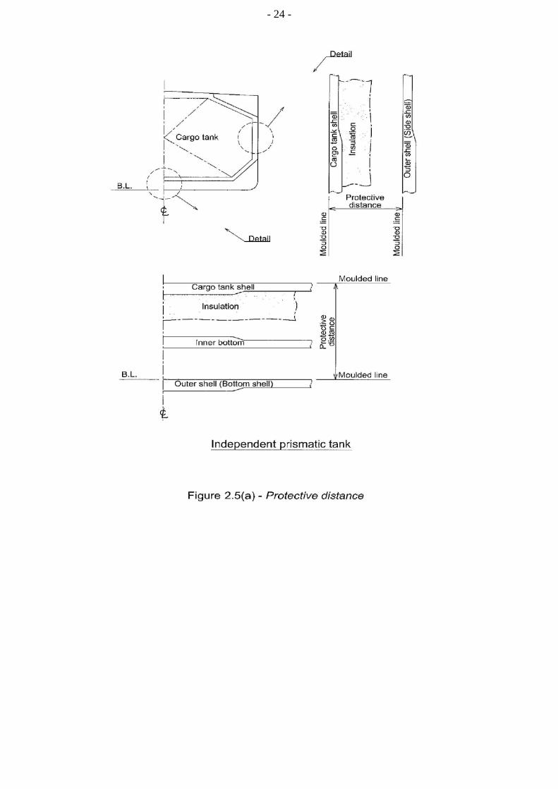
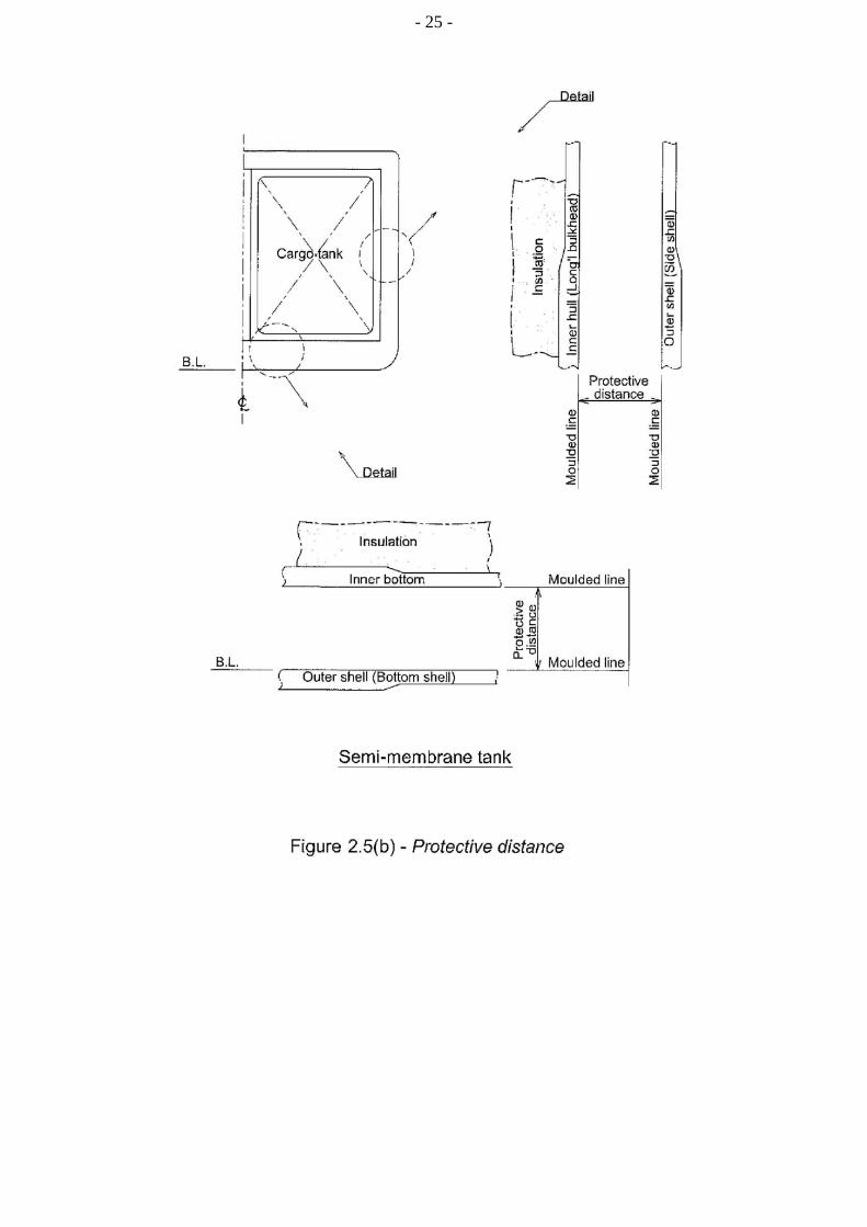
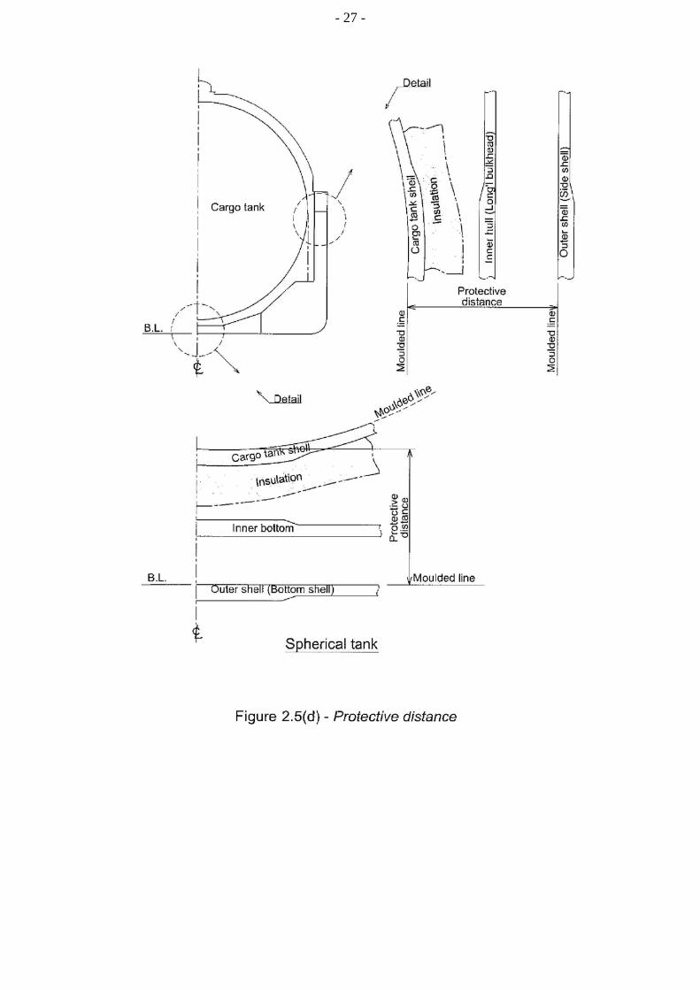
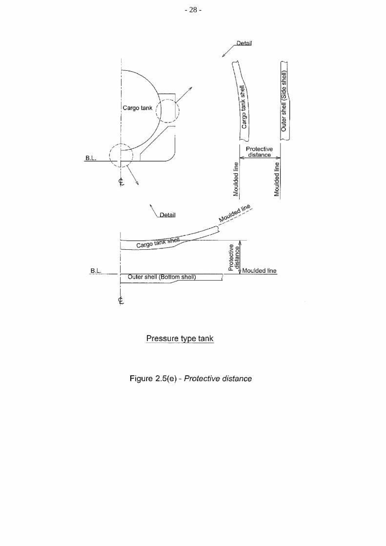
2.1.5 For the purpose of this guidance, the position of the moulded line for different containment systems is shown in figures 2.5 (a) to (e).
2.2 Freeboard and stability
2.2.1 Ships subject to the guidance may be assigned the minimum freeboard permitted by the International Convention on Load Lines in force. However, the draught associated with the assignment shall not be greater than the maximum draught otherwise permitted by this Guidance.
2.2.2 The stability of the ship, in all seagoing conditions and during loading and unloading cargo, shall comply with the requirements of the International Code on Intact Stability. This includes partial filling and loading and unloading at sea, when applicable. Stability during ballast water operations shall fulfil stability criteria.
2.2.3 When calculating the effect of free surfaces of consumable liquids for loading conditions, it shall be assumed that, for each type of liquid, at least one transverse pair or a single centre tank has a free surface. The tank or combination of tanks to be taken into account shall be those where the effect of free surfaces is the greatest. The free surface effect in undamaged compartments shall be calculated by a method according to the International Code on Intact Stability.
2.2.4 Solid ballast shall not normally be used in double bottom spaces in the cargo area. Where, however, because of stability considerations, the fitting of solid ballast in such spaces becomes unavoidable, its disposition shall be governed by the need to enable access for inspection and to ensure that the impact loads resulting from bottom damage are not directly transmitted to the cargo tank structure.
2.2.5 The master of the ship shall be supplied with a loading and stability information booklet. This booklet shall contain details of typical service conditions, loading, unloading and ballasting operations, provisions for evaluating other conditions of loading and a summary of the ship's survival capabilities. The booklet shall also contain sufficient information to enable the master to load and operate the ship in a safe and seaworthy manner.
2.2.6 All ships, subject to the guidance shall be fitted with a stability instrument, capable of verifying compliance with intact and damage stability requirements, approved by the Administration having regard to the performance standards recommended by the Organization.
.1 ships constructed before 1 July 2016 shall comply with this paragraph at the first scheduled renewal survey of the ship after 1 July 2016 but not later than 1 July 2021;
.2 notwithstanding the requirements of paragraph 2.2.6.1 a stability instrument installed on a ship constructed before 1 July 2016 need not be replaced provided it is capable of verifying compliance with intact and damage stability, to the satisfaction of the Administration; and
.3 for the purposes of control under SOLAS regulation XI-1/4, the Administration
shall issue a document of approval for the stability instrument.
- 19 -
2.2.7 The Administration may waive the requirements of paragraph 2.2.6 for the following ships, provided the procedures employed for intact and damage stability verification maintain the same degree of safety, as being loaded in accordance with the approved conditions. Any such waiver shall be duly noted on the International Certificate of Fitness referred to in paragraph 1.4.4:
.1 ships which are on a dedicated service, with a limited number of permutations of loading such that all anticipated conditions have been approved in the stability information provided to the master in accordance with the requirements of paragraph 2.2.5;
.2 ships where stability verification is made remotely by a means approved by the Administration;
.3 ships which are loaded within an approved range of loading conditions; or
.4 ships constructed before 1 July 2016 provided with approved limiting KG/GM curves covering all applicable intact and damage stability requirements.
2.2.8 Conditions of loading
Damage survival capability shall be investigated on the basis of loading information submitted to the Administration for all anticipated conditions of loading and variations in draught and trim. This shall include ballast and, where applicable, cargo heel.
- 20 -
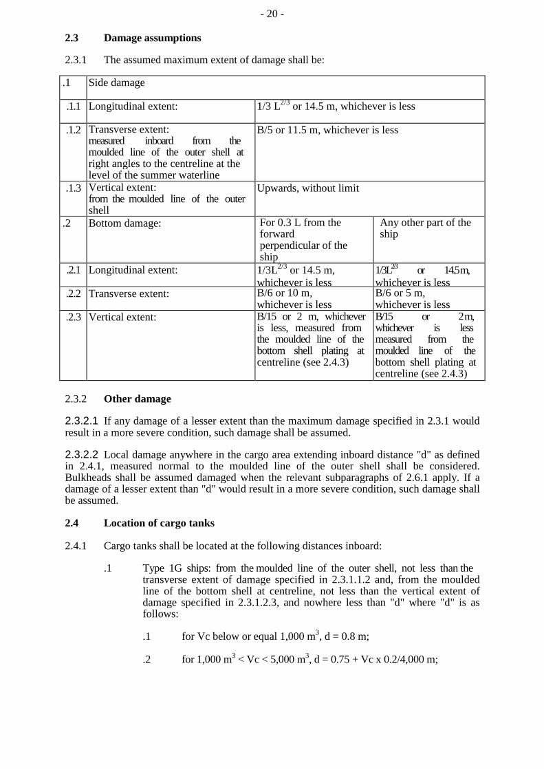
2.3 Damage assumptions
2.3.1 The assumed maximum extent of damage shall be:
.1 Side damage
.1.1 Longitudinal extent: 1/3 L2/3 or 14.5 m, whichever is less
.1.2 Transverse extent: measured inboard from the moulded line of the outer shell at right angles to the centreline at the level of the summer waterline
B/5 or 11.5 m, whichever is less
.1.3 Vertical extent: from the moulded line of the outer shell
Upwards, without limit
.2 Bottom damage: For 0.3 L from the forward perpendicular of the ship
Any other part of the ship
.2.1 Longitudinal extent: 1/3L2/3 or 14.5 m, whichever is less
1/3L2/3 or 14.5 m, whichever is less
.2.2 Transverse extent: B/6 or 10 m, whichever is less
B/6 or 5 m, whichever is less
.2.3 Vertical extent: B/15 or 2 m, whichever is less, measured from the moulded line of the bottom shell plating at centreline (see 2.4.3)
B/15 or 2 m, whichever is less measured from the moulded line of the bottom shell plating at centreline (see 2.4.3)
2.3.2 Other damage
2.3.2.1 If any damage of a lesser extent than the maximum damage specified in 2.3.1 would result in a more severe condition, such damage shall be assumed.
2.3.2.2 Local damage anywhere in the cargo area extending inboard distance "d" as defined in 2.4.1, measured normal to the moulded line of the outer shell shall be considered. Bulkheads shall be assumed damaged when the relevant subparagraphs of 2.6.1 apply. If a damage of a lesser extent than "d" would result in a more severe condition, such damage shall be assumed.
2.4 Location of cargo tanks
2.4.1 Cargo tanks shall be located at the following distances inboard:
.1 Type 1G ships: from the moulded line of the outer shell, not less than the transverse extent of damage specified in 2.3.1.1.2 and, from the moulded line of the bottom shell at centreline, not less than the vertical extent of damage specified in 2.3.1.2.3, and nowhere less than "d" where "d" is as follows:
.1 for Vc below or equal 1,000 m3, d = 0.8 m;
.2 for 1,000 m3 < Vc < 5,000 m3, d = 0.75 + Vc x 0.2/4,000 m;
- 21 -
.3 for 5,000 m3 < Vc < 30,000 m3, d = 0.8 + Vc/25,000 m; and
.4 for Vc > 30,000 m3, d = 2 m,
where:
- Vc corresponds to 100% of the gross design volume of the individual cargo tank at 20°C, including domes and appendages (see figures 2.1 and 2.2). For the purpose of cargo tank protective distances, the cargo tank volume is the aggregate volume of all the parts of tank that have a common bulkhead(s); and
- "d" is measured at any cross section at a right angle from the moulded line of outer shell.
Tank size limitations may apply to type 1G ship cargoes in accordance with chapter 17.
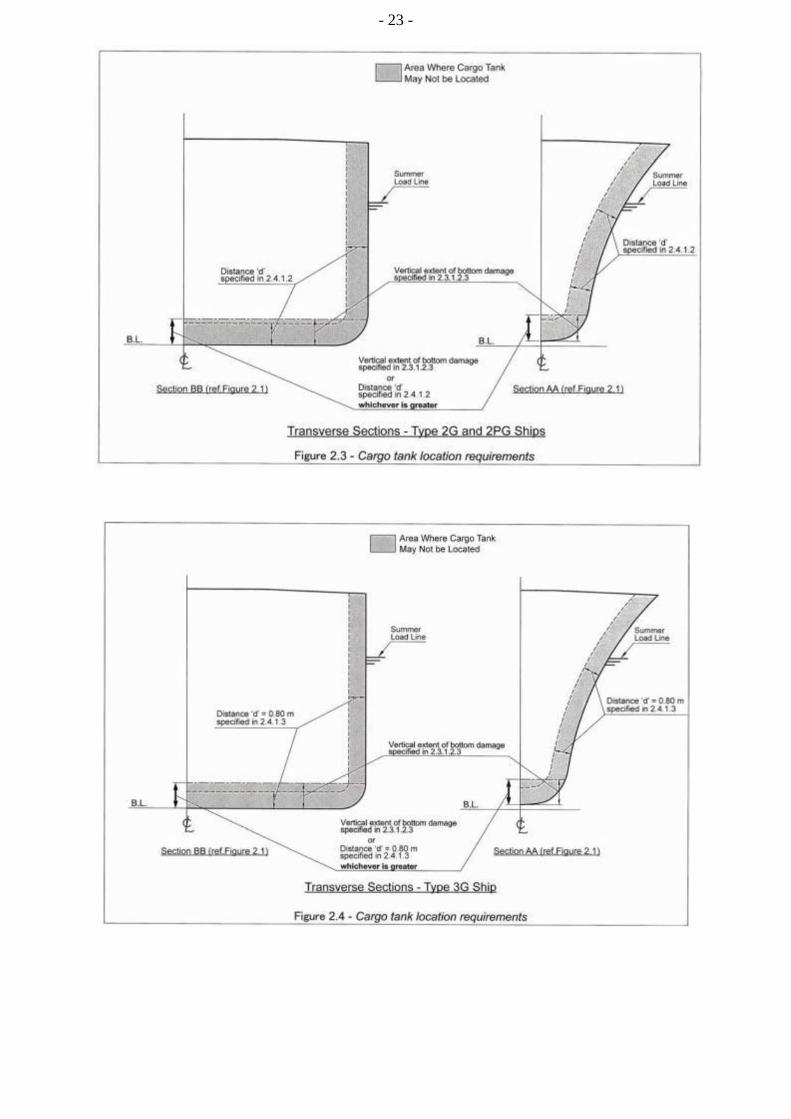
.2 Types 2G/2PG: from the moulded line of the bottom shell at centreline not less than the vertical extent of damage specified in 2.3.1.2.3 and nowhere less than "d" as indicated in 2.4.1.1 (see figures 2.1 and 2.3).
.3 Type 3G ships: from the moulded line of the bottom shell at centreline not less than the vertical extent of damage specified in 2.3.1.2.3 and nowhere less than "d", where "d" = 0.8 m from the moulded line of outer shell (see figures 2.1 and 2.4).
2.4.2 For the purpose of tank location, the vertical extent of bottom damage shall be measured to the inner bottom when membrane or semi-membrane tanks are used, otherwise to the bottom of the cargo tanks. The transverse extent of side damage shall be measured to the longitudinal bulkhead when membrane or semi-membrane tanks are used, otherwise to the side of the cargo tanks. The distances indicated in 2.3 and 2.4 shall be applied as in figures 2.5(a) to (e). These distances shall be measured plate to plate, from the moulded line to the moulded line, excluding insulation.

- 22 -
- 23 -
- 24 -
- 25 -

- 26 -
- 27 -
- 28 -
- 29 -
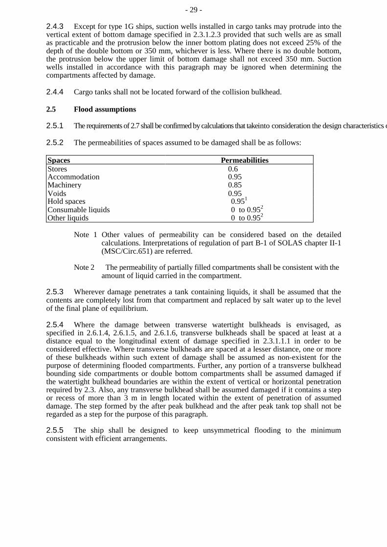
2.4.3 Except for type 1G ships, suction wells installed in cargo tanks may protrude into the vertical extent of bottom damage specified in 2.3.1.2.3 provided that such wells are as small as practicable and the protrusion below the inner bottom plating does not exceed 25% of the depth of the double bottom or 350 mm, whichever is less. Where there is no double bottom, the protrusion below the upper limit of bottom damage shall not exceed 350 mm. Suction wells installed in accordance with this paragraph may be ignored when determining the compartments affected by damage.
2.4.4 Cargo tanks shall not be located forward of the collision bulkhead.
2.5 Flood assumptions
2.5.1 The requirements of 2.7 shall be confirmed by calculations that takeinto consideration the design characteristics o
2.5.2 The permeabilities of spaces assumed to be damaged shall be as follows:
Spaces Permeabilities Stores 0.6 Accommodation 0.95 Machinery 0.85 Voids 0.95 Hold spaces 0.951 Consumable liquids 0 to 0.952 Other liquids 0 to 0.952
Note 1 Other values of permeability can be considered based on the detailed calculations. Interpretations of regulation of part B-1 of SOLAS chapter II-1 (MSC/Circ.651) are referred.
Note 2 The permeability of partially filled compartments shall be consistent with the amount of liquid carried in the compartment.
2.5.3 Wherever damage penetrates a tank containing liquids, it shall be assumed that the contents are completely lost from that compartment and replaced by salt water up to the level of the final plane of equilibrium.
2.5.4 Where the damage between transverse watertight bulkheads is envisaged, as specified in 2.6.1.4, 2.6.1.5, and 2.6.1.6, transverse bulkheads shall be spaced at least at a distance equal to the longitudinal extent of damage specified in 2.3.1.1.1 in order to be considered effective. Where transverse bulkheads are spaced at a lesser distance, one or more of these bulkheads within such extent of damage shall be assumed as non-existent for the purpose of determining flooded compartments. Further, any portion of a transverse bulkhead bounding side compartments or double bottom compartments shall be assumed damaged if the watertight bulkhead boundaries are within the extent of vertical or horizontal penetration required by 2.3. Also, any transverse bulkhead shall be assumed damaged if it contains a step or recess of more than 3 m in length located within the extent of penetration of assumed damage. The step formed by the after peak bulkhead and the after peak tank top shall not be regarded as a step for the purpose of this paragraph.
2.5.5 The ship shall be designed to keep unsymmetrical flooding to the minimum consistent with efficient arrangements.

- 30 -
2.5.6 Equalization arrangements requiring mechanical aids such as valves or cross-levelling pipes, if fitted, shall not be considered for the purpose of reducing an angle of heel or attaining the minimum range of residual stability to meet the requirements of 2.7.1, and sufficient residual stability shall be maintained during all stages where equalization is used. Spaces linked by ducts of large cross-sectional area may be considered to be common.
2.5.7 If pipes, ducts, trunks or tunnels are situated within the assumed extent of damage penetration, as defined in 2.3, arrangements shall be such that progressive flooding cannot thereby extend to compartments other than those assumed to be flooded for each case of damage.
2.5.8 The buoyancy of any superstructure directly above the side damage shall be disregarded. However, the unflooded parts of superstructures beyond the extent of damage may be taken into consideration, provided that:
.1 they are separated from the damaged space by watertight divisions and the requirements of 2.7.1.1 in respect of these intact spaces are complied with; and
.2 openings in such divisions are capable of being closed by remotely operated sliding watertight doors and unprotected openings are not immersed within the minimum range of residual stability required in 2.7.2.1. However, the immersion of any other openings capable of being closed weathertight may be permitted.
2.6 Standard of damage
2.6.1 Ships shall be capable of surviving the damage indicated in 2.3 with the flood assumptions in 2.5, to the extent determined by the ship's type, according to the following standards:
.1 a type 1G ship shall be assumed to sustain damage anywhere in its length;
.2 a type 2G ship of more than 150 m in length shall be assumed to sustain damage anywhere in its length;
.3 a type 2G ship of 150 m in length or less shall be assumed to sustain damage anywhere in its length, except involving either of the bulkheads bounding a machinery space located aft;
.4 a type 2PG ship shall be assumed to sustain damage anywhere in its length except involving transverse bulkheads spaced further apart than the longitudinal extent of damage as specified in 2.3.1.1.1;
.5 a type 3G ship of 80 m in length or more shall be assumed to sustain damage anywhere in its length, except involving transverse bulkheads spaced further apart than the longitudinal extent of damage specified in 2.3.1.1.1; and
.6 a type 3G ship less than 80 m in length shall be assumed to sustain damage anywhere in its length, except involving transverse bulkheads spaced further apart than the longitudinal extent of damage specified in 2.3.1.1.1 and except damage involving the machinery space when located after.

- 31 -
2.6.2 In the case of small type 2G/2PG and 3G ships that do not comply in all respects with the appropriate requirements of 2.6.1.3, 2.6.1.4 and 2.6.1.6, special dispensations may only be considered by the Administration provided that alternative measures can be taken which maintain the same degree of safety. The nature of the alternative measures shall be approved and clearly stated and be available to the port Administration. Any such dispensation shall be duly noted on the International Certificate of Fitness for the Carriage of Liquefied Gases in Bulk referred to in 1.4.4.
2.7 Survival requirements
Ships subject to the Guidance shall be capable of surviving the assumed damage specified in 2.3, to the standard provided in 2.6, in a condition of stable equilibrium and shall satisfy the following criteria.
2.7.1 In any stage of flooding:
.1 the waterline, taking into account sinkage, heel and trim, shall be below the lower edge of any opening through which progressive flooding or downflooding may take place. Such openings shall include air pipes and openings that are closed by means of weathertight doors or hatch covers and may exclude those openings closed by means of watertight manhole covers and watertight flush scuttles, small watertight cargo tank hatch covers that maintain the high integrity of the deck, remotely operated watertight sliding doors and sidescuttles of the non-opening type;
.2 the maximum angle of heel due to unsymmetrical flooding shall not exceed 30°; and
.3 the residual stability during intermediate stages of flooding shall not be less than that required by 2.7.2.1.
2.7.2 At final equilibrium after flooding:
.1 the righting lever curve shall have a minimum range of 20° beyond the position of equilibrium in association with a maximum residual righting lever of at least 0.1 m within the 20° range; the area under the curve within this range shall not be less than 0.0175 m-radians. The 20° range may be measured from any angle commencing between the position of equilibrium and the angle of 25° (or 30° if no deck immersion occurs). Unprotected openings shall not be immersed within this range unless the space concerned is assumed to be flooded. Within this range, the immersion of any of the openings listed in 2.7.1.1 and other openings capable of being closed weathertight may be permitted; and
.2 the emergency source of power shall be capable of operating.

- 32 -
CHAPTER 3
SHIP ARRANGEMENTS
3.1 Segregation of the cargo area
3.1.1 Hold spaces shall be segregated from machinery and boiler spaces, accommodation spaces, service spaces, control stations, chain lockers, domestic water tanks and from stores. Hold spaces shall be located forward of machinery spaces of category A. Alternative arrangements, including locating machinery spaces of category A forward, may be accepted, based on SOLAS regulation II-2/17, after further consideration of involved risks, including that of cargo release and the means of mitigation.
3.1.2 Where cargo is carried in a cargo containment system not requiring a complete or partial secondary barrier, segregation of hold spaces from spaces referred to in 3.1.1 or spaces either below or outboard of the hold spaces may be effected by cofferdams, oil fuel tanks or a single gastight bulkhead of all-welded construction forming an "A-60" class division. A gastight "A-0" class division is acceptable if there is no source of ignition or fire hazard in the adjoining spaces.
3.1.3 Where cargo is carried in a cargo containment system requiring a complete or partial secondary barrier, segregation of hold spaces from spaces referred to in 3.1.1, or spaces either below or outboard of the hold spaces that contain a source of ignition or fire hazard, shall be effected by cofferdams or oil fuel tanks. A gastight "A-0" class division is acceptable if there is no source of ignition or fire hazard in the adjoining spaces.
3.1.4 Turret compartments segregation from spaces referred to in 3.1.1, or spaces either below or outboard of the turret compartment that contain a source of ignition or fire hazard, shall be effected by cofferdams or an A-60 class division. A gastight "A-0" class division is acceptable if there is no source of ignition or fire hazard in the adjoining spaces.
3.1.5 In addition, the risk of fire propagation from turret compartments to adjacent spaces shall be evaluated by a risk analysis (see 1.1.11) and further preventive measures, such as the arrangement of a cofferdam around the turret compartment, shall be provided if needed.
3.1.6 When cargo is carried in a cargo containment system requiring a complete or partial secondary barrier:
.1 at temperatures below -10oC, hold spaces shall be segregated from the sea by a double bottom; and
.2 at temperatures below -55oC, the ship shall also have a longitudinal bulkhead forming side tanks.
3.1.7 Arrangements shall be made for sealing the weather decks in way of openings for cargo containment systems.
- 33 -
3.2 Accommodation, service and machinery spaces and control stations
3.2.1 No accommodation space, service space or control station shall be located within the cargo area. The bulkhead of accommodation spaces, service spaces or control stations that face the cargo area shall be so located as to avoid the entry of gas from the hold space to such spaces through a single failure of a deck or bulkhead on a ship having a containment system requiring a secondary barrier.
3.2.2 To guard against the danger of hazardous vapours, due consideration shall be given to the location of air intakes/outlets and openings into accommodation, service and machinery spaces and control stations in relation to cargo piping, cargo vent systems and machinery space exhausts from gas burning arrangements.
3.2.3 Access through doors, gastight or otherwise, shall not be permitted from a non-hazardous area to a hazardous area except for access to service spaces forward of the cargo area through airlocks, as permitted by 3.6.1, when accommodation spaces are aft.
3.2.4.1 Entrances, air inlets and openings to accommodation spaces, service spaces, machinery spaces and control stations shall not face the cargo area. They shall be located on the end bulkhead not facing the cargo area or on the outboard side of the superstructure or deckhouse or on both at a distance of at least 4% of the length (L) of the ship but not less than 3 m from the end of the superstructure or deckhouse facing the cargo area. This distance, however, need not exceed 5 m.
3.2.4.2 Windows and sidescuttles facing the cargo area and on the sides of the superstructures or deckhouses within the distance mentioned above shall be of the fixed (non-opening) type. Wheelhouse windows may be non-fixed and wheelhouse doors may be located within the above limits so long as they are designed in a manner that a rapid and efficient gas and vapour tightening of the wheelhouse can be ensured.
3.2.4.3 For ships dedicated to the carriage of cargoes that have neither flammable nor toxic hazards, the Administration may approve relaxations from the above requirements.
3.2.4.4 Accesses to forecastle spaces containing sources of ignition may be permitted through a single door facing the cargo area, provided the doors are located outside hazardous areas as defined in chapter 10.
3.2.5 Windows and sidescuttles facing the cargo area and on the sides of the superstructures and deckhouses within the limits specified in 3.2.4, except wheelhouse windows, shall be constructed to "A-60" class. Wheelhouse windows shall be constructed to not less than "A-0" class (for external fire load). Sidescuttles in the shell below the uppermost continuous deck and in the first tier of the superstructure or deckhouse shall be of fixed (non-opening) type.
3.2.6 All air intakes, outlets and other openings into the accommodation spaces, service spaces and control stations shall be fitted with closing devices. When carrying toxic products, they shall be capable of being operated from inside the space. The requirement for fitting air intakes and openings with closing devices operated from inside the space for toxic products need not apply to spaces not normally manned, such as deck stores, forecastle stores, workshops. In addition, the requirement does not apply to cargo control rooms located within the cargo area.
3.2.7 Control rooms and machinery spaces of turret systems may be located in the cargo area forward or aft of cargo tanks in ships with such installations. Access to such spaces containing sources of ignition may be permitted through doors facing the cargo area, provided the doors are located outside hazardous areas or access is through airlocks.

- 34 -
3.3 Cargo machinery spaces and turret compartments
3.3.1 Cargo machinery spaces shall be situated above the weather deck and located within the cargo area. Cargo machinery spaces and turret compartments shall be treated as cargo pump-rooms for the purpose of fire protection according to SOLAS regulation II-2/9.2.4, and for the purpose of prevention of potential explosion according to SOLAS regulation ll-2/4.5.10.
3.3.2 When cargo machinery spaces are located at the after end of the aftermost hold space or at the forward end of the foremost hold space, the limits of the cargo area, as defined in 1.2.7, shall be extended to include the cargo machinery spaces for the full breadth and depth of the ship and the deck areas above those spaces.
3.3.3 Where the limits of the cargo area are extended by 3.3.2, the bulkhead that separates the cargo machinery spaces from accommodation and service spaces, control stations and machinery spaces of category A shall be located so as to avoid the entry of gas to these spaces through a single failure of a deck or bulkhead.
3.3.4 Cargo compressors and cargo pumps may be driven by electric motors in an adjacent non-hazardous space separated by a bulkhead or deck, if the seal around the bulkhead penetration ensures effective gastight segregation of the two spaces. Alternatively, such equipment may be driven by certified safe electric motors adjacent to them if the electrical installation complies with the requirements of chapter 10.
3.3.5 Arrangements of cargo machinery spaces and turret compartments shall ensure safe unrestricted access for personnel wearing protective clothing and breathing apparatus, and in the event of injury to allow unconscious personnel to be removed. At least two widely separated escape routes and doors shall be provided in cargo machinery spaces, except that a single escape route may be accepted where the maximum travel distance to the door is 5 m or less.
3.3.6 All valves necessary for cargo handling shall be readily accessible to personnel wearing protective clothing. Suitable arrangements shall be made to deal with drainage of pump and compressor rooms.
3.3.7 Turret compartments shall be designed to retain their structural integrity in case of explosion or uncontrolled high-pressure gas release (overpressure and/or brittle fracture), the characteristics of which shall be substantiated on the basis of a risk analysis with due consideration of the capabilities of the pressure relieving devices.
3.4 Cargo control rooms
3.4.1 Any cargo control room shall be above the weather deck and may be located in the cargo area. The cargo control room may be located within the accommodation spaces, service spaces or control stations, provided the following conditions are complied with:
.1 the cargo control room is a non-hazardous area;
.2 if the entrance complies with 3.2.4.1, the control room may have access to the spaces described above; and
.3 if the entrance does not comply with 3.2.4.1, the cargo control room shall have no access to the spaces described above and the boundaries for such spaces shall be insulated to "A-60" class.
- 35 -
3.4.2 If the cargo control room is designed to be a non-hazardous area, instrumentation shall, as far as possible, be by indirect reading systems and shall, in any case, be designed to prevent any escape of gas into the atmosphere of that space. Location of the gas detection system within the cargo control room will not cause the room to be classified as a hazardous area, if installed in accordance with 13.6.11.
3.4.3 If the cargo control room for ships carrying flammable cargoes is classified as a hazardous area, sources of ignition shall be excluded and any electrical equipment shall be installed in accordance with chapter 10.
3.5 Access to spaces in the cargo area
3.5.1 Visual inspection of at least one side of the inner hull structure shall be possible without the removal of any fixed structure or fitting. If such a visual inspection, whether combined with those inspections required in 3.5.2, 4.6.2.4 or 4.20.3.7 or not, is only possible at the outer face of the inner hull, the inner hull shall not be a fuel-oil tank boundary wall.
3.5.2 Inspection of one side of any insulation in hold spaces shall be possible. If the integrity of the insulation system can be verified by inspection of the outside of the hold space boundary when tanks are at service temperature, inspection of one side of the insulation in the hold space need not be required.
3.5.3 Arrangements for hold spaces, void spaces, cargo tanks and other spaces classified as hazardous areas, shall be such as to allow entry and inspection of any such space by personnel wearing protective clothing and breathing apparatus and shall also allow for the evacuation of injured and/or unconscious personnel. Such arrangements shall comply with the following:
.1 Access shall be provided as follows:
.1 access to all cargo tanks. Access shall be direct from the weather deck;
.2 access through horizontal openings ̧ hatches or manholes. The dimensions shall be sufficient to allow a person wearing a breathing apparatus to ascend or descend any ladder without obstruction, and also to provide a clear opening to facilitate the hoisting of an injured person from the bottom of the space. The minimum clear opening shall be not less than 600 mm x 600 mm;
.3 access through vertical openings or manholes providing passage through the length and breadth of the space. The minimum clear opening shall be not less than 600 mm x 800 mm at a height of not more than 600 mm from the bottom plating unless gratings or other footholds are provided; and
.4 circular access openings to type C tanks shall have a diameter of not less than 600 mm.
.2 The dimensions referred to in 3.5.3.1.2 and 3.5.3.1.3 may be decreased, if the requirements of 3.5.3 can be met to the satisfaction of the Administration.
.3 Where cargo is carried in a containment system requiring a secondary barrier, the requirements of 3.5.3.1.2 and 3.5.3.1.3 do not apply to spaces separated from a hold space by a single gastight steel boundary. Such spaces shall be provided only with direct or indirect access from the weather deck, not including any enclosed non-hazardous area.
- 36 -
.4 Access required for inspection shall be a designated access through structures below and above cargo tanks, which shall have at least the cross-sections as required by 3.5.3.1.3.
.5 For the purpose of 3.5.1 or 3.5.2, the following shall apply:
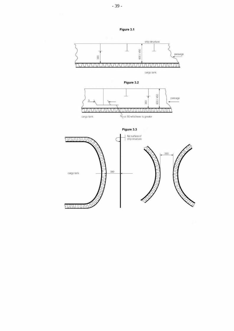
.1 where it is required to pass between the surface to be inspected, flat or curved, and structures such as deck beams, stiffeners, frames, girders, etc., the distance between that surface and the free edge of the structural elements shall be at least 380 mm. The distance between the surface to be inspected and the surface to which the above structural elements are fitted, e.g. deck, bulkhead or shell, shall be at least 450 mm for a curved tank surface (e.g. for a type C tank), or 600 mm for a flat tank surface (e.g. for a type A tank) (see figure 3.1);
.2 where it is not required to pass between the surface to be inspected and any part of the structure, for visibility reasons the distance between the free edge of that structural element and the surface to be inspected shall be at least 50 mm or half the breadth of the structure's face plate, whichever is the larger (see figure 3.2);
.3 if for inspection of a curved surface where it is required to pass between that surface and another surface, flat or curved, to which no structural elements are fitted, the distance between both surfaces shall be at least 380 mm (see figure 3.3). Where it is not required to pass between that curved surface and another surface, a smaller distance than 380 mm may be accepted taking into account the shape of the curved surface;
.4 if for inspection of an approximately flat surface where it is required to pass between two approximately flat and approximately parallel surfaces, to which no structural elements are fitted, the distance between those surfaces shall be at least 600 mm. Where fixed access ladders are fitted, a clearance of at least 450 mm shall be provided for access (see figure 3.4);
.5 the minimum distances between a cargo tank sump and adjacent double bottom structure in way of a suction well shall not be less than those shown in figure 3.5 (figure 3.5 shows that the distance between the plane surfaces of the sump and the well is a minimum of 150 mm and that the clearance between the edge between the inner bottom plate, and the vertical side of the well and the knuckle point between the spherical or circular surface and sump of the tank is at least 380 mm). If there is no suction well, the distance between the cargo tank sump and the inner bottom shall not be less than 50 mm;
.6 the distance between a cargo tank dome and deck structures shall not be less than 150 mm (see figure 3.6);
.7 fixed or portable staging shall be installed as necessary for inspection of cargo tanks, cargo tank supports and restraints (e.g. anti-pitching, anti-rolling and anti-flotation chocks), cargo tank insulation etc. This staging shall not impair the clearances specified in 3.5.3.5.1 to 3.5.3.5.4; and

- 37 -
.8 if fixed or portable ventilation ducting shall be fitted in compliance with 12.1.2, such ducting shall not impair the distances required under 3.5.3.5.1 to 3.5.3.5.4.
3.5.4 Access from the open weather deck to non-hazardous areas shall be located outside the hazardous areas as defined in chapter 10, unless the access is by means of an airlock in accordance with 3.6.
3.5.5 Turret compartments shall be arranged with two independent means of access/egress.
3.5.6 Access from a hazardous area below the weather deck to a non-hazardous area is not permitted.
3.6 Airlocks
3.6.1 Access between hazardous area on the open weather deck and non-hazardous spaces shall be by means of an airlock. This shall consist of two self-closing, substantially gastight, steel doors without any holding back arrangements, capable of maintaining the overpressure, at least 1.5 m but no more than 2.5 m apart. The airlock space shall be artificially ventilated from a non-hazardous area and maintained at an overpressure to the hazardous area on the weather deck.
3.6.2 Where spaces are protected by pressurization, the ventilation shall be designed and installed in accordance with recognized standards.
3.6.3 An audible and visible alarm system to give a warning on both sides of the airlock shall be provided. The visible alarm shall indicate if one door is open. The audible alarm shall sound if doors on both sides of the air lock are moved from the closed positions.
3.6.4 In ships carrying flammable products, electrical equipment that is located in spaces protected by airlocks and not of the certified safe type, shall be de-energized in case of loss of overpressure in the space.
3.6.5 Electrical equipment for manoeuvring, anchoring and mooring, as well as emergency fire pumps that are located in spaces protected by airlocks, shall be of a certified safe type.
3.6.6 The airlock space shall be monitored for cargo vapours (see 13.6.2).
3.6.7 Subject to the requirements of the International Convention on Load Lines in force, the door sill shall not be less than 300 mm in height.
3.7 Bilge, ballast and oil fuel arrangements
3.7.1 Where cargo is carried in a cargo containment system not requiring a secondary barrier, suitable drainage arrangements for the hold spaces that are not connected with the machinery space shall be provided. Means of detecting any leakage shall be provided.
3.7.2 Where there is a secondary barrier, suitable drainage arrangements for dealing with any leakage into the hold or insulation spaces through the adjacent ship structure shall be provided. The suction shall not lead to pumps inside the machinery space. Means of detecting such leakage shall be provided.
3.7.3 The hold or interbarrier spaces of type A independent tank ships shall be provided with a drainage system suitable for handling liquid cargo in the event of cargo tank leakage or rupture. Such arrangements shall provide for the return of any cargo leakage to the liquid cargo piping.

- 38 -
3.7.4 Arrangements referred to in 3.7.3 shall be provided with a removable spool piece.
3.7.5 Ballast spaces, including wet duct keels used as ballast piping, oil fuel tanks and non-hazardous spaces, may be connected to pumps in the machinery spaces. Dry duct keels with ballast piping passing through may be connected to pumps in the machinery spaces, provided the connections are led directly to the pumps, and the discharge from the pumps is led directly overboard with no valves or manifolds in either line that could connect the line from the duct keel to lines serving non-hazardous spaces. Pump vents shall not be open to machinery spaces.
3.8 Bow and stern loading and unloading arrangements
3.8.1 Subject to the requirements of this section and chapter 5, cargo piping may be arranged to permit bow or stern loading and unloading.
3.8.2 Bow or stern loading and unloading lines that are led past accommodation spaces, service spaces or control stations shall not be used for the transfer of products requiring a type 1G ship. Bow or stern loading and unloading lines shall not be used for the transfer of toxic products as specified in 1.2.53, where the design pressure is above 2.5 MPa.
3.8.3 Portable arrangements shall not be permitted.
3.8.4.1 Entrances, air inlets and openings to accommodation spaces, service spaces, machinery spaces and controls stations, shall not face the cargo shore connection location of bow or stern loading and unloading arrangements. They shall be located on the outboard side of the superstructure or deckhouse at a distance of at least 4% of the length of the ship, but not less than 3 m from the end of the superstructure or deckhouse facing the cargo shore connection location of the bow or stern loading and unloading arrangements. This distance need not exceed 5 m.
3.8.4.2 Windows and sidescuttles facing the shore connection location and on the sides of the superstructure or deckhouse within the distance mentioned above shall be of the fixed (non-opening) type.
3.8.4.3 In addition, during the use of the bow or stern loading and unloading arrangements, all doors, ports and other openings on the corresponding superstructure or deckhouse side shall be kept closed.
3.8.4.4 Where, in the case of small ships, compliance with 3.2.4.1 to 3.2.4.4 and 3.8.4.1 to 3.8.4.3 is not possible, the Administration may approve relaxations from the above requirements.
3.8.5 Deck openings and air inlets and outlets to spaces within distances of 10 m from the cargo shore connection location shall be kept closed during the use of bow or stern loading or unloading arrangements.
3.8.6 Firefighting arrangements for the bow or stern loading and unloading areas shall be in accordance with 11.3.1.4 and 11.4.6.
3.8.7 Means of communication between the cargo control station and the shore connection location shall be provided and, where applicable, certified for use in hazardous areas.
- 39 -

- 40 -
- 41 -
CHAPTER 4
CARGO CONTAINMENT
4.1 Definitions
4.1.1 A cold spot is a part of the hull or thermal insulation surface where a localized temperature decrease occurs with respect to the allowable minimum temperature of the hull or of its adjacent hull structure, or to design capabilities of cargo pressure/temperature control systems required in chapter 7.
4.1.2 Design vapour pressure "P0" is the maximum gauge pressure, at the top of the tank, to be used in the design of the tank.
4.1.3 Design temperature for selection of materials is the minimum temperature at which cargo may be loaded or transported in the cargo tanks.
4.1.4 Independent tanks are self-supporting tanks. They do not form part of the ship's hull and are not essential to the hull strength. There are three categories of independent tank, which are referred to in 4.21, 4.22 and 4.23.
4.1.5 Membrane tanks are non-self-supporting tanks that consist of a thin liquid and gastight layer (membrane) supported through insulation by the adjacent hull structure. Membrane tanks are covered in 4.24.
4.1.6 Integral tanks are tanks that form a structural part of the hull and are influenced in the same manner by the loads that stress the adjacent hull structure. Integral tanks are covered in 4.25.
4.1.7 Semi-membrane tanks are non-self-supporting tanks in the loaded condition and consist of a layer, parts of which are supported through insulation by the adjacent hull structure. Semi-membrane tanks are covered in 4.26.
4.1.8 In addition to the definitions in 1.2, the definitions given in this chapter shall apply throughout the Guidance.
4.2 Application
Unless otherwise specified in part E, the requirements of parts A to D shall apply to all types of tanks, including those covered in part F.
- 42 -
PART A CARGO CONTAINMENT
4.3 Functional requirements
4.3.1 The design life of the cargo containment system shall not be less than the design life of the ship.
4.3.2 Cargo containment systems shall be designed for North Atlantic environmental conditions and relevant long-term sea state scatter diagrams for unrestricted navigation. Lesser environmental conditions, consistent with the expected usage, may be accepted by the Administration for cargo containment systems used exclusively for restricted navigation. Greater environmental conditions may be required for cargo containment systems operated in conditions more severe than the North Atlantic environment.
4.3.3 Cargo containment systems shall be designed with suitable safety margins:
.1 to withstand, in the intact condition, the environmental conditions anticipated for the cargo containment system's design life and the loading conditions appropriate for them, which include full homogeneous and partial load conditions, partial filling within defined limits and ballast voyage loads; and
.2 being appropriate for uncertainties in loads, structural modelling, fatigue, corrosion, thermal effects, material variability, ageing and construction tolerances.
4.3.4 The cargo containment system structural strength shall be assessed against failure modes, including but not limited to plastic deformation, buckling and fatigue. The specific design conditions which shall be considered for the design of each cargo containment system are given in 4.21 to 4.26. There are three main categories of design conditions:
.1 Ultimate design conditions – the cargo containment system structure and its structural components shall withstand loads liable to occur during its construction, testing and anticipated use in service, without loss of structural integrity. The design shall take into account proper combinations of the following loads:
.1 internal pressure;
.2 external pressure;
.3 dynamic loads due to the motion of the ship;
.4 thermal loads;
.5 sloshing loads;
.6 loads corresponding to ship deflections;
.7 tank and cargo weight with the corresponding reaction in way of
supports;
.8 insulation weight;
.9 loads in way of towers and other attachments; and
.10 test loads.
- 43 -
.2 Fatigue design conditions – the cargo containment system structure and its structural components shall not fail under accumulated cyclic loading.
.3 The cargo containment system shall meet the following criteria:
.1 Collision – the cargo containment system shall be protectively located in accordance with 2.4.1 and withstand the collision loads specified in 4.15.1 without deformation of the supports, or the tank structure in way of the supports, likely to endanger the tank structure.
.2 Fire – the cargo containment systems shall sustain, without rupture, the rise in internal pressure specified in 8.4.1 under the fire scenarios envisaged therein.
.3 Flooded compartment causing buoyancy on tank – the anti-flotation arrangements shall sustain the upward force, specified in 4.15.2, and there shall be no endangering plastic deformation to the hull.
4.3.5 Measures shall be applied to ensure that scantlings required meet the structural strength provisions and be maintained throughout the design life. Measures may include, but are not limited to, material selection, coatings, corrosion additions, cathodic protection and inerting. Corrosion allowance need not be required in addition to the thickness resulting from the structural analysis. However, where there is no environmental control, such as inerting around the cargo tank, or where the cargo is of a corrosive nature, the Administration or recognized organization acting on its behalf may require a suitable corrosion allowance.
4.3.6 An inspection/survey plan for the cargo containment system shall be developed and approved by the Administration or recognized organization acting on its behalf. The inspection/survey plan shall identify areas that need inspection during surveys throughout the cargo containment system's life and, in particular, all necessary in-service survey and maintenance that was assumed when selecting cargo containment system design parameters. Cargo containment systems shall be designed, constructed and equipped to provide adequate means of access to areas that need inspection as specified in the inspection/survey plan. Cargo containment systems, including all associated internal equipment, shall be designed and built to ensure safety during operations, inspection and maintenance (see 3.5).
4.4 Cargo containment safety principles
4.4.1 The containment systems shall be provided with a full secondary liquid-tight barrier capable of safely containing all potential leakages through the primary barrier and, in conjunction with the thermal insulation system, of preventing lowering of the temperature of the ship structure to an unsafe level.
4.4.2 However, the size and configuration or arrangement of the secondary barrier may be reduced where an equivalent level of safety is demonstrated in accordance with the requirements of 4.4.3 to 4.4.5, as applicable.
4.4.3 Cargo containment systems for which the probability for structural failures to develop into a critical state has been determined to be extremely low, but where the possibility of leakages through the primary barrier cannot be excluded, shall be equipped with a partial secondary barrier and small leak protection system capable of safely handling and disposing of the leakages. The arrangements shall comply with the following requirements:
.1 failure developments that can be reliably detected before reaching a critical state (e.g. by gas detection or inspection) shall have a sufficiently long development time for remedial actions to be taken; and
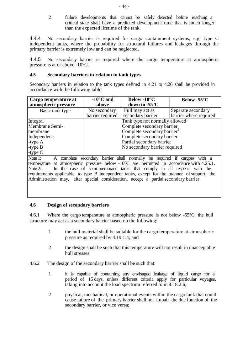
- 44 -
.2 failure developments that cannot be safely detected before reaching a critical state shall have a predicted development time that is much longer than the expected lifetime of the tank.
4.4.4 No secondary barrier is required for cargo containment systems, e.g. type C independent tanks, where the probability for structural failures and leakages through the primary barrier is extremely low and can be neglected.
4.4.5 No secondary barrier is required where the cargo temperature at atmospheric pressure is at or above -10°C.
4.5 Secondary barriers in relation to tank types
Secondary barriers in relation to the tank types defined in 4.21 to 4.26 shall be provided in accordance with the following table.
Cargo temperature at atmospheric pressure
-10°C and above
Below -10°C down to -55°C
Below -55°C
Basic tank type No secondary barrier required
Hull may act as secondary barrier
Separate secondary barrier where required
Integral Membrane Semi-membrane Independent: -type A -type B -type C
Tank type not normally allowed1
Complete secondary barrier Complete secondary barrier2 Complete secondary barrier Partial secondary barrier No secondary barrier required
Note 1: A complete secondary barrier shall normally be required if cargoes with a temperature at atmospheric pressure below -10°C are permitted in accordance with 4.25.1. Note 2: In the case of semi-membrane tanks that comply in all respects with the requirements applicable to type B independent tanks, except for the manner of support, the Administration may, after special consideration, accept a partial secondary barrier.
4.6 Design of secondary barriers
4.6.1 Where the cargo temperature at atmospheric pressure is not below -55°C, the hull structure may act as a secondary barrier based on the following:
.1 the hull material shall be suitable for the cargo temperature at atmospheric pressure as required by 4.19.1.4; and
.2 the design shall be such that this temperature will not result in unacceptable hull stresses.
4.6.2 The design of the secondary barrier shall be such that:
.1 it is capable of containing any envisaged leakage of liquid cargo for a period of 15 days, unless different criteria apply for particular voyages, taking into account the load spectrum referred to in 4.18.2.6;
.2 physical, mechanical, or operational events within the cargo tank that could cause failure of the primary barrier shall not impair the due function of the secondary barrier, or vice versa;
- 45 -
.3
.4
.5
.6
failure of a support or an attachment to the hull structure will not lead to loss of liquid tightness of both the primary and secondary barriers;
it is capable of being periodically checked for its effectiveness by means acceptable to the Administration or recognized organization acting on its behalf. This may be by means of a visual inspection or a pressure/vacuum test or other suitable means carried out according to a documented procedure agreed with the Administration or the recognized organization acting on its behalf;
the methods required in .4 above shall be approved by the Administration or recognized organization acting on its behalf and shall include, where applicable to the test procedure:
.1 details on the size of defect acceptable and the location within the secondary barrier, before its liquid-tight effectiveness is compromised;
.2 accuracy and range of values of the proposed method for detecting defects in .1 above;
.3 scaling factors to be used in determining the acceptance criteria, if full scale model testing is not undertaken; and
.4 effects of thermal and mechanical cyclic loading on the effectiveness of the proposed test; and
the secondary barrier shall fulfil its functional requirements at a static angle of heel of 30°.
4.7 Partial secondary barriers and primary barrier small leak protection system
4.7.1 Partial secondary barriers as permitted in 4.4.3 shall be used with a small leak protection system and meet all the requirements in 4.6.2. The small leak protection system shall include means to detect a leak in the primary barrier, provision such as a spray shield to deflect any liquid cargo down into the partial secondary barrier, and means to dispose of the liquid, which may be by natural evaporation.
4.7.2 The capacity of the partial secondary barrier shall be determined, based on the cargo leakage corresponding to the extent of failure resulting from the load spectrum referred to in 4.18.2.6, after the initial detection of a primary leak. Due account may be taken of liquid evaporation, rate of leakage, pumping capacity and other relevant factors.
4.7.3 The required liquid leakage detection may be by means of liquid sensors, or by an effective use of pressure, temperature or gas detection systems, or any combination thereof.
4.8 Supporting arrangements
4.8.1 The cargo tanks shall be supported by the hull in a manner that prevents bodily movement of the tank under the static and dynamic loads defined in 4.12 to 4.15, where applicable, while allowing contraction and expansion of the tank under temperature variations and hull deflections without undue stressing of the tank and the hull.
4.8.2 Anti-flotation arrangements shall be provided for independent tanks and capable of withstanding the loads defined in 4.15.2 without plastic deformation likely to endanger the hull structure.
- 46 -
4.8.3 Supports and supporting arrangements shall withstand the loads defined in 4.13.9 and 4.15, but these loads need not be combined with each other or with wave-induced loads.
4.9 Associated structure and equipment
4.9.1 Cargo containment systems shall be designed for the loads imposed by associated structure and equipment. This includes pump towers, cargo domes, cargo pumps and piping, stripping pumps and piping, nitrogen piping, access hatches, ladders, piping penetrations, liquid level gauges, independent level alarm gauges, spray nozzles, and instrumentation systems (such as pressure, temperature and strain gauges).
4.10 Thermal insulation
4.10.1 Thermal insulation shall be provided, as required, to protect the hull from temperatures below those allowable (see 4.19.1) and limit the heat flux into the tank to the levels that can be maintained by the pressure and temperature control system applied in chapter 7.
4.10.2 In determining the insulation performance, due regard shall be given to the amount of the acceptable boil-off in association with the reliquefaction plant on board, main propulsion machinery or other temperature control system.
PART B DESIGN LOADS
4.11 General
This section defines the design loads to be considered with regard to the requirements in 4.16, 4.17 and 4.18. This includes:
.1 load categories (permanent, functional, environmental and accidental) and the description of the loads;
.2 the extent to which these loads shall be considered depending on the type of tank, and is more fully detailed in the following paragraphs; and
.3 tanks, together with their supporting structure and other fixtures, that shall be designed taking into account relevant combinations of the loads described below.
4.12 Permanent loads
4.12.1 Gravity loads
The weight of tank, thermal insulation, loads caused by towers and other attachments shall be considered.
4.12.2 Permanent external loads
Gravity loads of structures and equipment acting externally on the tank shall be considered.
- 47 -
4.13 Functional loads
4.13.1 Loads arising from the operational use of the tank system shall be classified as functional loads. All functional loads that are essential for ensuring the integrity of the tank system, during all design conditions, shall be considered. As a minimum, the effects from the following criteria, as applicable, shall be considered when establishing functional loads:
.1 internal pressure;
.2 external pressure;
.3 thermally induced loads;
.4 vibration;
.5 interaction loads;
.6 loads associated with construction and installation;
.7 test loads;
.8 static heel loads; and
.9 weight of cargo.
4.13.2 Internal pressure
.1 In all cases, including 4.13.2.2, Po shall not be less than MARVS.
.2 For cargo tanks, where there is no temperature control and where the pressure of the cargo is dictated only by the ambient temperature, Po shall not be less than the gauge vapour pressure of the cargo at a temperature of 45°C except as follows:
.1 lower values of ambient temperature may be accepted by the Administration or recognized organization acting on its behalf for ships operating in restricted areas. Conversely, higher values of ambient temperature may be required; and
.2 for ships on voyages of restricted duration, Po may be calculated based on the actual pressure rise during the voyage, and account may be taken of any thermal insulation of the tank.
.3 Subject to special consideration by the Administration and to the limitations given in 4.21 to 4.26, for the various tank types, a vapour pressure Ph higher than Po may be accepted for site specific conditions (harbour or other locations), where dynamic loads are reduced. Any relief valve setting resulting from this paragraph shall be recorded in the International Certificate of Fitness for the Carriage of Liquefied Gases in Bulk.
.4 The internal pressure Peq results from the vapour pressure Po or Ph plus the maximum associated dynamic liquid pressure Pgd, but not including the effects of liquid sloshing loads. Guidance formulae for associated dynamic liquid pressure Pgd are given in 4.28.1.

- 48 -
4.13.3 External pressure
External design pressure loads shall be based on the difference between the minimum internal pressure and the maximum external pressure to which any portion of the tank may be simultaneously subjected.
4.13.4 Thermally induced loads
4.13.4.1 Transient thermally induced loads during cooling down periods shall be considered for tanks intended for cargo temperatures below -55°C.
4.13.4.2 Stationary thermally induced loads shall be considered for cargo containment systems where the design supporting arrangements or attachments and operating temperature may give rise to significant thermal stresses (see 7.2).
4.13.5 Vibration
The potentially damaging effects of vibration on the cargo containment system shall be considered.
4.13.6 Interaction loads
The static component of loads resulting from interaction between cargo containment system and the hull structure, as well as loads from associated structure and equipment, shall be considered.
4.13.7 Loads associated with construction and installation Loads or conditions associated
with construction and installation, e.g. lifting, shall be considered.
4.13.8 Test loads
Account shall be taken of the loads corresponding to the testing of the cargo containment system referred to in 4.21 to 4.26.
4.13.9 Static heel loads
Loads corresponding to the most unfavourable static heel angle within the range 0° to 30° shall be considered.
4.13.10 Other loads
Any other loads not specifically addressed, which could have an effect on the cargo containment system, shall be taken into account.
4.14 Environmental loads
Environmental loads are defined as those loads on the cargo containment system that are caused by the surrounding environment and that are not otherwise classified as a permanent, functional or accidental load.
4.14.1 Loads due to ship motion
4.14.1.1 The determination of dynamic loads shall take into account the long-term distribution of ship motion in irregular seas, which the ship will experience during its operating life. Account may be taken of the reduction in dynamic loads due to necessary speed reduction and variation of heading.

- 49 -
4.14.1.2 The ship's motion shall include surge, sway, heave, roll, pitch and yaw. The accelerations acting on tanks shall be estimated at their centre of gravity and include the following components:
.1 vertical acceleration: motion accelerations of heave, pitch and, possibly, roll (normal to the ship base);
.2 transverse acceleration: motion accelerations of sway, yaw and roll and gravity component of roll; and
.3 longitudinal acceleration: motion accelerations of surge and pitch and gravity component of pitch.
4.14.1.3 Methods to predict accelerations due to ship motion shall be proposed and approved by the Administration or recognized organization acting on its behalf.
4.14.1.4 Guidance formulae for acceleration components are given in 4.28.2.
4.14.1.5 Ships for restricted service may be given special consideration.
4.14.2 Dynamic interaction loads
Account shall be taken of the dynamic component of loads resulting from interaction between cargo containment systems and the hull structure, including loads from associated structures and equipment.
4.14.3 Sloshing loads
4.14.3.1 The sloshing loads on a cargo containment system and internal components shall be evaluated based on allowable filling levels.
4.14.3.2 When significant sloshing-induced loads are expected to be present, special tests and calculations shall be required covering the full range of intended filling levels.
4.14.4 Snow and ice loads Snow and icing
shall be considered, if relevant.
4.14.5 Loads due to navigation in ice Loads due to navigation in ice shall be
considered for vessels intended for such service.
4.15 Accidental loads
Accidental loads are defined as loads that are imposed on a cargo containment system and its supporting arrangements under abnormal and unplanned conditions.
4.15.1 Collision loads
The collision load shall be determined based on the cargo containment system under fully loaded condition with an inertial force corresponding to 0.5 g in the forward direction and 0.25 g in the aft direction, where "g" is gravitational acceleration.
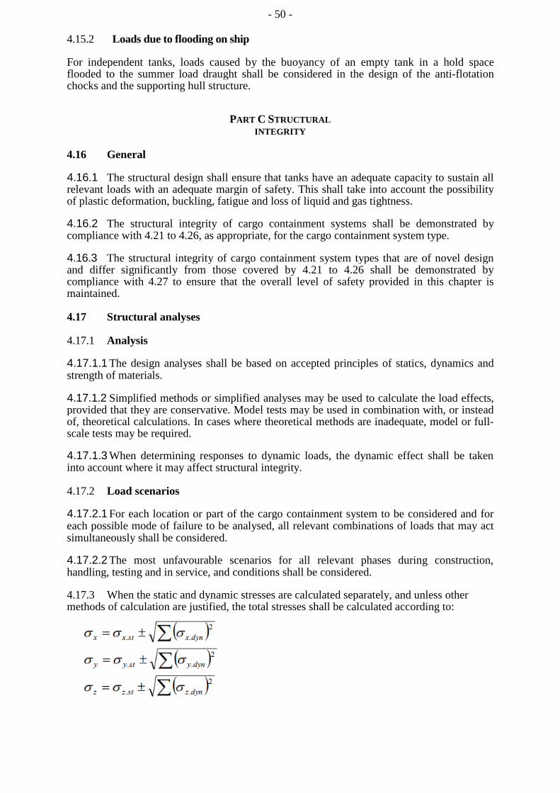
- 50 -
4.15.2 Loads due to flooding on ship
For independent tanks, loads caused by the buoyancy of an empty tank in a hold space flooded to the summer load draught shall be considered in the design of the anti-flotation chocks and the supporting hull structure.
PART C STRUCTURAL INTEGRITY
4.16 General
4.16.1 The structural design shall ensure that tanks have an adequate capacity to sustain all relevant loads with an adequate margin of safety. This shall take into account the possibility of plastic deformation, buckling, fatigue and loss of liquid and gas tightness.
4.16.2 The structural integrity of cargo containment systems shall be demonstrated by compliance with 4.21 to 4.26, as appropriate, for the cargo containment system type.
4.16.3 The structural integrity of cargo containment system types that are of novel design and differ significantly from those covered by 4.21 to 4.26 shall be demonstrated by compliance with 4.27 to ensure that the overall level of safety provided in this chapter is maintained.
4.17 Structural analyses
4.17.1 Analysis
4.17.1.1 The design analyses shall be based on accepted principles of statics, dynamics and strength of materials.
4.17.1.2 Simplified methods or simplified analyses may be used to calculate the load effects, provided that they are conservative. Model tests may be used in combination with, or instead of, theoretical calculations. In cases where theoretical methods are inadequate, model or full-scale tests may be required.
4.17.1.3 When determining responses to dynamic loads, the dynamic effect shall be taken into account where it may affect structural integrity.
4.17.2 Load scenarios
4.17.2.1 For each location or part of the cargo containment system to be considered and for each possible mode of failure to be analysed, all relevant combinations of loads that may act simultaneously shall be considered.
4.17.2.2 The most unfavourable scenarios for all relevant phases during construction, handling, testing and in service, and conditions shall be considered.
4.17.3 When the static and dynamic stresses are calculated separately, and unless other methods of calculation are justified, the total stresses shall be calculated according to:
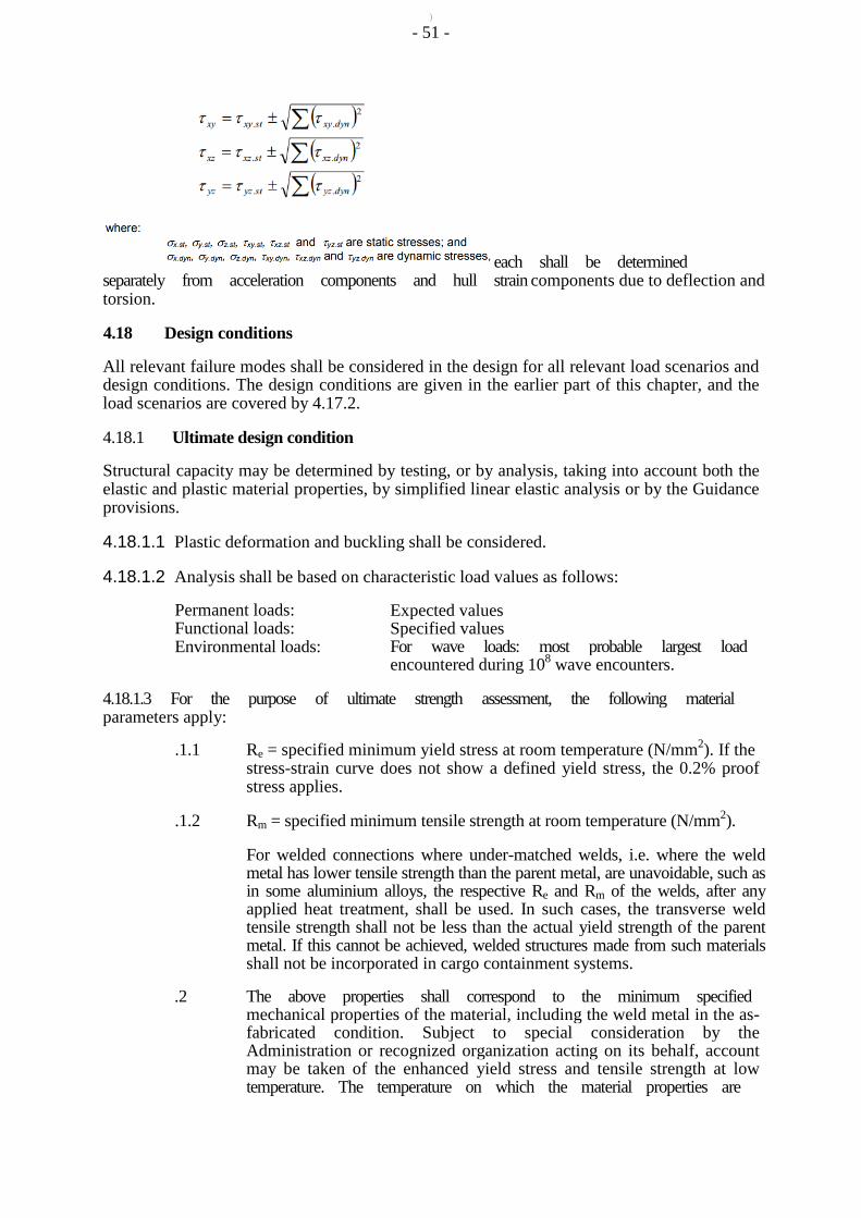
) - 51 -
each shall be determined separately from acceleration components and hull strain components due to deflection and torsion.
4.18 Design conditions
All relevant failure modes shall be considered in the design for all relevant load scenarios and design conditions. The design conditions are given in the earlier part of this chapter, and the load scenarios are covered by 4.17.2.
4.18.1 Ultimate design condition
Structural capacity may be determined by testing, or by analysis, taking into account both the elastic and plastic material properties, by simplified linear elastic analysis or by the Guidance provisions.
4.18.1.1 Plastic deformation and buckling shall be considered.
4.18.1.2 Analysis shall be based on characteristic load values as follows:
Permanent loads: Functional loads: Environmental loads:
Expected values Specified values For wave loads: most probable largest load encountered during 108 wave encounters.
4.18.1.3 For the purpose of ultimate strength assessment, the following material parameters apply:
.1.1 Re = specified minimum yield stress at room temperature (N/mm2). If the stress-strain curve does not show a defined yield stress, the 0.2% proof stress applies.
.1.2 Rm = specified minimum tensile strength at room temperature (N/mm2).
For welded connections where under-matched welds, i.e. where the weld metal has lower tensile strength than the parent metal, are unavoidable, such as in some aluminium alloys, the respective Re and Rm of the welds, after any applied heat treatment, shall be used. In such cases, the transverse weld tensile strength shall not be less than the actual yield strength of the parent metal. If this cannot be achieved, welded structures made from such materials shall not be incorporated in cargo containment systems.
.2 The above properties shall correspond to the minimum specified mechanical properties of the material, including the weld metal in the as-fabricated condition. Subject to special consideration by the Administration or recognized organization acting on its behalf, account may be taken of the enhanced yield stress and tensile strength at low temperature. The temperature on which the material properties are
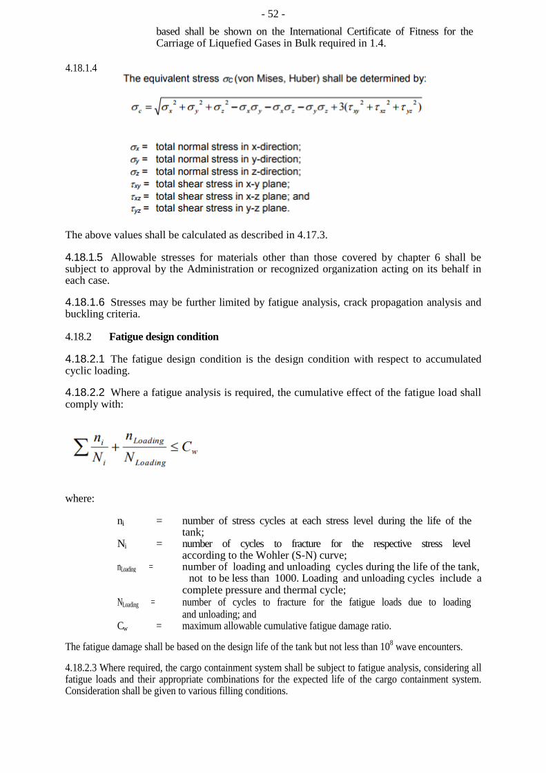
- 52 - based shall be shown on the International Certificate of Fitness for the Carriage of Liquefied Gases in Bulk required in 1.4.
4.18.1.4
The above values shall be calculated as described in 4.17.3.
4.18.1.5 Allowable stresses for materials other than those covered by chapter 6 shall be subject to approval by the Administration or recognized organization acting on its behalf in each case.
4.18.1.6 Stresses may be further limited by fatigue analysis, crack propagation analysis and buckling criteria.
4.18.2 Fatigue design condition
4.18.2.1 The fatigue design condition is the design condition with respect to accumulated cyclic loading.
4.18.2.2 Where a fatigue analysis is required, the cumulative effect of the fatigue load shall comply with:
where:
ni = number of stress cycles at each stress level during the life of the tank;
Ni = number of cycles to fracture for the respective stress level according to the Wohler (S-N) curve;
nLoading = number of loading and unloading cycles during the life of the tank, not to be less than 1000. Loading and unloading cycles include a
complete pressure and thermal cycle; NLoading = number of cycles to fracture for the fatigue loads due to loading
and unloading; and Cw = maximum allowable cumulative fatigue damage ratio.
The fatigue damage shall be based on the design life of the tank but not less than 108 wave encounters.
4.18.2.3 Where required, the cargo containment system shall be subject to fatigue analysis, considering all fatigue loads and their appropriate combinations for the expected life of the cargo containment system. Consideration shall be given to various filling conditions.

- 53 -
4.18.2.4.1 Design S-N curves used in the analysis shall be applicable to the materials and weldments, construction details, fabrication procedures and applicable state of the stress envisioned.
4.18.2.4.2 The S-N curves shall be based on a 97.6% probability of survival corresponding to the mean-minus-two-standard-deviation curves of relevant experimental data up to final failure. Use of S-N curves derived in a different way requires adjustments to the acceptable Cw values specified in 4.18.2.7 to 4.18.2.9.
4.18.2.5 Analysis shall be based on characteristic load values as follows:
Permanent loads: Expected values Functional loads: Specified values or specified history Environmental loads: Expected load history, but not less than 108 cycles
If simplified dynamic loading spectra are used for the estimation of the fatigue life, they shall be specially considered by the Administration or recognized organization acting on its behalf.
4.18.2.6.1 Where the size of the secondary barrier is reduced, as is provided for in 4.4.3, fracture mechanics analyses of fatigue crack growth shall be carried out to determine:
.1 crack propagation paths in the structure;
.2 crack growth rate;
.3 the time required for a crack to propagate to cause a leakage from the
tank;
.4 the size and shape of through thickness cracks; and
.5 the time required for detectable cracks to reach a critical state.
The fracture mechanics are, in general, based on crack growth data taken as a mean value plus two standard deviations of the test data.
4.18.2.6.2 In analysing crack propagation, the largest initial crack not detectable by the inspection method applied shall be assumed, taking into account the allowable non-destructive testing and visual inspection criterion, as applicable.
4.18.2.6.3 Crack propagation analysis under the condition specified in 4.18.2.7: the simplified load distribution and sequence over a period of 15 days may be used. Such distributions may be obtained as indicated in figure 4.4. Load distribution and sequence for longer periods, such as in 4.18.2.8 and 4.18.2.9 shall be approved by the Administration or recognized organization acting on its behalf.
4.18.2.6.4 The arrangements shall comply with 4.18.2.7 to 4.18.2.9, as applicable.
4.18.2.7 For failures that can be reliably detected by means of leakage detection:
Cw shall be less than or equal to 0.5.
Predicted remaining failure development time, from the point of detection of leakage till reaching a critical state, shall not be less than 15 days, unless different requirements apply for ships engaged in particular voyages.
- 54 -
4.18.2.8 For failures that cannot be detected by leakage but that can be reliably detected at the time of in-service inspections:
Cw shall be less than or equal to 0.5.
Predicted remaining failure development time, from the largest crack not detectable by in-service inspection methods until reaching a critical state, shall not be less than three times the inspection interval.
4.18.2.9 In particular locations of the tank, where effective defect or crack development detection cannot be assured, the following, more stringent, fatigue acceptance criteria shall be applied as a minimum:
Cw shall be less than or equal to 0.1.
Predicted failure development time, from the assumed initial defect until reaching a critical state, shall not be less than three times the lifetime of the tank.
4.18.3 Accident design condition
4.18.3.1 The accident design condition is a design condition for accidental loads with extremely low probability of occurrence.
4.18.3.2 Analysis shall be based on the characteristic values as follows:
Permanent loads: Expected values Functional loads: Specified values Environmental loads: Specified values Accidental loads: Specified values or expected values
4.18.3.3 Loads mentioned in 4.13.9 and 4.15 need not be combined with each other or with wave-induced loads.
PART D MATERIALS AND CONSTRUCTION
4.19 Materials
Goal
To ensure that the cargo containment system, primary and secondary barriers, the thermal insulation, adjacent ship structure and other materials in the cargo containment system are constructed from materials of suitable properties for the conditions they will experience, both in normal service and in the event of failure of the primary barrier, where applicable.
4.19.1 Materials forming ship structure
4.19.1.1 To determine the grade of plate and sections used in the hull structure, a temperature calculation shall be performed for all tank types when the cargo temperature is below -10°C. The following assumptions shall be made in this calculation:
.1 the primary barrier of all tanks shall be assumed to be at the cargo temperature;
.2 in addition to .1, where a complete or partial secondary barrier is required, it shall be assumed to be at the cargo temperature at atmospheric pressure for any one tank only;
- 55 -
.3 for worldwide service, ambient temperatures shall be taken as 5°C for air and 0ºC for seawater. Higher values may be accepted for ships operating in restricted areas and, conversely, lower values may be fixed by the Administration for ships trading to areas where lower temperatures are expected during the winter months;
.4 still air and seawater conditions shall be assumed, i.e. no adjustment for forced convection;
.5 degradation of the thermal insulation properties over the life of the ship due to factors such as thermal and mechanical ageing, compaction, ship motions and tank vibrations, as defined in 4.19.3.6 and 4.19.3.7, shall be assumed;
.6 the cooling effect of the rising boil-off vapour from the leaked cargo shall be
taken into account, where applicable;
.7 credit for hull heating may be taken in accordance with 4.19.1.5, provided the heating arrangements are in compliance with 4.19.1.6;
.8 no credit shall be given for any means of heating, except as described in 4.19.1.5; and
.9 for members connecting inner and outer hulls, the mean temperature may be taken for determining the steel grade.
The ambient temperatures used in the design, described in this paragraph, shall be shown on the International Certificate of Fitness for the Carriage of Liquefied Gases in Bulk required in 1.4.4.
4.19.1.2 The shell and deck plating of the ship and all stiffeners attached thereto shall be in accordance with recognized standards. If the calculated temperature of the material in the design condition is below -5°C due to the influence of the cargo temperature, the material shall be in accordance with table 6.5.
4.19.1.3 The materials of all other hull structures for which the calculated temperature in the design condition is below 0°C, due to the influence of cargo temperature and that do not form the secondary barrier, shall also be in accordance with table 6.5. This includes hull structure supporting the cargo tanks, inner bottom plating, longitudinal bulkhead plating, transverse bulkhead plating, floors, webs, stringers and all attached stiffening members.
4.19.1.4 The hull material forming the secondary barrier shall be in accordance with table 6.2. Where the secondary barrier is formed by the deck or side shell plating, the material grade required by table 6.2 shall be carried into the adjacent deck or side shell plating, where applicable, to a suitable extent.
4.19.1.5 Means of heating structural materials may be used to ensure that the material temperature does not fall below the minimum allowed for the grade of material specified in table 6.5. In the calculations required in 4.19.1.1, credit for such heating may be taken in accordance with the following:
.1 for any transverse hull structure;
.2 for longitudinal hull structure referred to in 4.19.1.2 and 4.19.1.3 where colder ambient temperatures are specified, provided the material remains suitable for the ambient temperature conditions of +5°C for air
- 56 -
and 0°C for seawater with no credit taken in the calculations for heating; and
.3 as an alternative to .2, for longitudinal bulkhead between cargo tanks, credit may be taken for heating, provided the material remain suitable for a minimum design temperature of -30°C, or a temperature 30°C lower than that determined by 4.19.1.1 with the heating considered, whichever is less. In this case, the ship's longitudinal strength shall comply with SOLAS regulation II-1/3-1 for both when those bulkhead(s) are considered effective and not.
4.19.1.6 The means of heating referred to in 4.19.1.5 shall comply with the following requirements:
.1 the heating system shall be arranged so that, in the event of failure in any part of the system, standby heating can be maintained equal to not less than 100% of the theoretical heat requirement;
.2 the heating system shall be considered as an essential auxiliary. All electrical components of at least one of the systems provided in accordance with 4.19.1.5.1 shall be supplied from the emergency source of electrical power; and
.3 the design and construction of the heating system shall be included in the approval of the containment system by the Administration or recognized organization acting on its behalf.
4.19.2 Materials of primary and secondary barriers
4.19.2.1Metallic materials used in the construction of primary and secondary barriers not forming the hull, shall be suitable for the design loads that they may be subjected to, and be in accordance with, table 6.1, 6.2 or 6.3.
4.19.2.2Materials, either non-metallic or metallic but not covered by tables 6.1, 6.2 and 6.3, used in the primary and secondary barriers may be approved by the Administration or recognized organization acting on its behalf, considering the design loads that they may be subjected to, their properties and their intended use.
4.19.2.3Where non-metallic materials, including composites, are used for, or incorporated in the primary or secondary barriers, they shall be tested for the following properties, as applicable, to ensure that they are adequate for the intended service:
.1 compatibility with the cargoes;
.2 ageing;
.3 mechanical properties;
.4 thermal expansion and contraction;
.5 abrasion;
.6 cohesion;
.7 resistance to vibrations; .8 resistance to fire and flame spread; and
- 57 -
.9 resistance to fatigue failure and crack propagation.
4.19.2.4 The above properties, where applicable, shall be tested for the range between the expected maximum temperature in service and +5°C below the minimum design temperature, but not lower than -196°C.
4.19.2.5.1 Where non-metallic materials, including composites, are used for the primary and secondary barriers, the joining processes shall also be tested as described above.
4.19.2.5.2 Guidance on the use of non-metallic materials in the construction of primary and secondary barriers is provided in appendix 4.
4.19.2.6 Consideration may be given to the use of materials in the primary and secondary barrier, which are not resistant to fire and flame spread, provided they are protected by a suitable system such as a permanent inert gas environment, or are provided with a fire-retardant barrier.
4.19.3 Thermal insulation and other materials used in cargo containment systems
4.19.3.1 Load-bearing thermal insulation and other materials used in cargo containment systems shall be suitable for the design loads.
4.19.3.2 Thermal insulation and other materials used in cargo containment systems shall have the following properties, as applicable, to ensure that they are adequate for the intended service:
.1 compatibility with the cargoes;
.2 solubility in the cargo;
.3 absorption of the cargo;
.4 shrinkage;
.5 ageing;
.6 closed cell content;
.7 density;
.8 mechanical properties, to the extent that they are subjected to cargo and
other loading effects, thermal expansion and contraction;
.9 abrasion;
.10 cohesion;
.11 thermal conductivity;
.12 resistance to vibrations;
.13 resistance to fire and flame spread; and
.14 resistance to fatigue failure and crack propagation.
4.19.3.3 The above properties, where applicable, shall be tested for the range between the expected maximum temperature in service and 5°C below the minimum design temperature, but not lower than -196°C.
- 58 -
4.19.3.4 Due to location or environmental conditions, thermal insulation materials shall have suitable properties of resistance to fire and flame spread and shall be adequately protected against penetration of water vapour and mechanical damage. Where the thermal insulation is located on or above the exposed deck, and in way of tank cover penetrations, it shall have suitable fire resistance properties in accordance with recognized standards or be covered with a material having low flame-spread characteristics and forming an efficient approved vapour seal.
4.19.3.5 Thermal insulation that does not meet recognized standards for fire resistance may be used in hold spaces that are not kept permanently inerted, provided its surfaces are covered with material with low flame-spread characteristics and that forms an efficient approved vapour seal.
4.19.3.6 Testing for thermal conductivity of thermal insulation shall be carried out on suitably aged samples.
4.19.3.7 Where powder or granulated thermal insulation is used, measures shall be taken to reduce compaction in service and to maintain the required thermal conductivity and also prevent any undue increase of pressure on the cargo containment system.
4.20 Construction processes
Goal
To define suitable construction processes and test procedures in order to ensure, as far as reasonably practical, that the cargo containment system will perform satisfactorily in service in accordance with the assumptions made at the design stage.
4.20.1 Weld joint design
4.20.1.1All welded joints of the shells of independent tanks shall be of the in-plane butt weld full penetration type. For dome-to-shell connections only, tee welds of the full penetration type may be used depending on the results of the tests carried out at the approval of the welding procedure. Except for small penetrations on domes, nozzle welds shall also be designed with full penetration.
4.20.1.2Welding joint details for type C independent tanks, and for the liquid-tight primary barriers of type B independent tanks primarily constructed of curved surfaces, shall be as follows:
.1 all longitudinal and circumferential joints shall be of butt welded, full penetration, double vee or single vee type. Full penetration butt welds shall be obtained by double welding or by the use of backing rings. If used, backing rings shall be removed except from very small process pressure vessels. Other edge preparations may be permitted, depending on the results of the tests carried out at the approval of the welding procedure; and
.2 the bevel preparation of the joints between the tank body and domes and between domes and relevant fittings shall be designed according to a standard acceptable to the Administration or recognized organization acting on its behalf. All welds connecting nozzles, domes or other penetrations of the vessel and all welds connecting flanges to the vessel or nozzles shall be full penetration welds.
4.20.1.3 Where applicable, all the construction processes and testing, except that specified in 4.20.3, shall be done in accordance with the applicable provisions of chapter 6.
- 59 -
4.20.2 Design for gluing and other joining processes
The design of the joint to be glued (or joined by some other process except welding) shall take account of the strength characteristics of the joining process.
4.20.3 Testing
4.20.3.1 All cargo tanks and process pressure vessels shall be subjected to hydrostatic or hydropneumatic pressure testing in accordance with 4.21 to 4.26, as applicable for the tank type.
4.20.3.2 All tanks shall be subject to a tightness test which may be performed in combination with the pressure test referred to in 4.20.3.1.
4.20.3.3 Requirements with respect to inspection of secondary barriers shall be decided by the Administration or recognized organization acting on its behalf in each case, taking into account the accessibility of the barrier (see 4.6.2).
4.20.3.4 The Administration may require that for ships fitted with novel type B independent tanks, or tanks designed according to 4.27 at least one prototype tank and its supporting structures shall be instrumented with strain gauges or other suitable equipment to confirm stress levels. Similar instrumentation may be required for type C independent tanks, depending on their configuration and on the arrangement of their supports and attachments.
4.20.3.5 The overall performance of the cargo containment system shall be verified for compliance with the design parameters during the first full loading and discharging of the cargo, in accordance with the survey procedure and requirements in 1.4 and the requirements of the Administration or recognized organization acting on its behalf. Records of the performance of the components and equipment essential to verify the design parameters, shall be maintained and be available to the Administration.
4.20.3.6 Heating arrangements, if fitted in accordance with 4.19.1.5 and 4.19.1.6, shall be tested for required heat output and heat distribution.
4.20.3.7 The cargo containment system shall be inspected for cold spots during, or immediately following, the first loaded voyage. Inspection of the integrity of thermal insulation surfaces that cannot be visually checked shall be carried out in accordance with recognized standards.
PART E TANK TYPES
4.21 Type A independent tanks
4.21.1 Design basis
4.21.1.1Type A independent tanks are tanks primarily designed using classical ship-structural analysis procedures in accordance with recognized standards. Where such tanks are primarily constructed of plane surfaces, the design vapour pressure Po shall be less than 0.07 MPa.
4.21.1.2If the cargo temperature at atmospheric pressure is below -10°C, a complete secondary barrier shall be provided as required in 4.5. The secondary barrier shall be designed in accordance with 4.6.

- 60 -
4.21.2 Structural analysis
4.21.2.1A structural analysis shall be performed taking into account the internal pressure as indicated in 4.13.2, and the interaction loads with the supporting and keying system as well as a reasonable part of the ship's hull.
4.21.2.2For parts, such as supporting structures, not otherwise covered by the requirements of the Guidance, stresses shall be determined by direct calculations, taking into account the loads referred to in 4.12 to 4.15 as far as applicable, and the ship deflection in way of supporting structures.
4.21.2.3The tanks with supports shall be designed for the accidental loads specified in 4.15. These loads need not be combined with each other or with environmental loads.
4.21.3 Ultimate design condition
4.21.3.1 For tanks primarily constructed of plane surfaces, the nominal membrane stresses for primary and secondary members (stiffeners, web frames, stringers, girders), when calculated by classical analysis procedures, shall not exceed the lower of Rm /2.66 or Re /1.33 for nickel steels, carbon-manganese steels, austenitic steels and aluminium alloys, where Rm and Re are defined in 4.18.1.3. However, if detailed calculations are carried out for the primary members, the equivalent stress σc, as defined in 4.18.1.4, may be increased over that indicated above to a stress acceptable to the Administration or recognized organization acting on its behalf. Calculations shall take into account the effects of bending, shear, axial and torsional deformation as well as the hull/cargo tank interaction forces due to the deflection of the double bottom and cargo tank bottoms.
4.21.3.2 Tank boundary scantlings shall meet at least the requirements of the Administration or recognized organization acting on its behalf for deep tanks taking into account the internal pressure as indicated in 4.13.2 and any corrosion allowance required by 4.3.5.
4.21.3.3 The cargo tank structure shall be reviewed against potential buckling.
4.21.4 Accident design condition
4.21.4.1The tanks and the tank supports shall be designed for the accidental loads and design conditions specified in 4.3.4.3 and 4.15, as relevant.
4.21.4.2When subjected to the accidental loads specified in 4.15, the stress shall comply with the acceptance criteria specified in 4.21.3, modified as appropriate, taking into account their lower probability of occurrence.
4.21.5 Testing
All type A independent tanks shall be subjected to a hydrostatic or hydropneumatic test. This test shall be performed such that the stresses approximate, as far as practicable, the design stresses, and that the pressure at the top of the tank corresponds at least to the MARVS. When a hydropneumatic test is performed, the conditions shall simulate, as far as practicable, the design loading of the tank and of its support structure, including dynamic components, while avoiding stress levels that could cause permanent deformation.
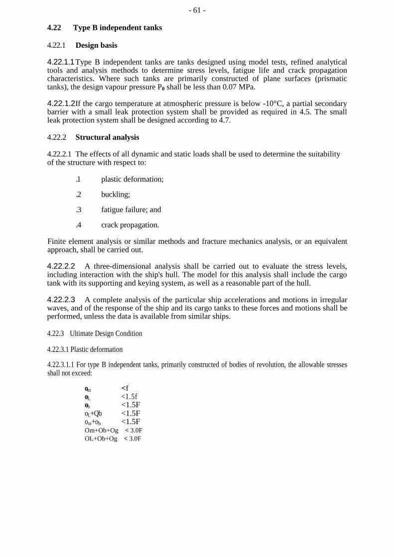
- 61 -
4.22 Type B independent tanks
4.22.1 Design basis
4.22.1.1 Type B independent tanks are tanks designed using model tests, refined analytical tools and analysis methods to determine stress levels, fatigue life and crack propagation characteristics. Where such tanks are primarily constructed of plane surfaces (prismatic tanks), the design vapour pressure P0 shall be less than 0.07 MPa.
4.22.1.2 If the cargo temperature at atmospheric pressure is below -10°C, a partial secondary barrier with a small leak protection system shall be provided as required in 4.5. The small leak protection system shall be designed according to 4.7.
4.22.2 Structural analysis
4.22.2.1 The effects of all dynamic and static loads shall be used to determine the suitability of the structure with respect to:
.1 plastic deformation;
.2 buckling;
.3 fatigue failure; and
.4 crack propagation.
Finite element analysis or similar methods and fracture mechanics analysis, or an equivalent approach, shall be carried out.
4.22.2.2 A three-dimensional analysis shall be carried out to evaluate the stress levels, including interaction with the ship's hull. The model for this analysis shall include the cargo tank with its supporting and keying system, as well as a reasonable part of the hull.
4.22.2.3 A complete analysis of the particular ship accelerations and motions in irregular waves, and of the response of the ship and its cargo tanks to these forces and motions shall be performed, unless the data is available from similar ships.
4.22.3 Ultimate Design Condition
4.22.3.1 Plastic deformation
4.22.3.1.1 For type B independent tanks, primarily constructed of bodies of revolution, the allowable stresses shall not exceed:
om <f oL <1.5f ob <1.5F oL+Qb <1.5F om+ob <1.5F Om+Ob+Og < 3.0F OL+Ob+Og < 3.0F
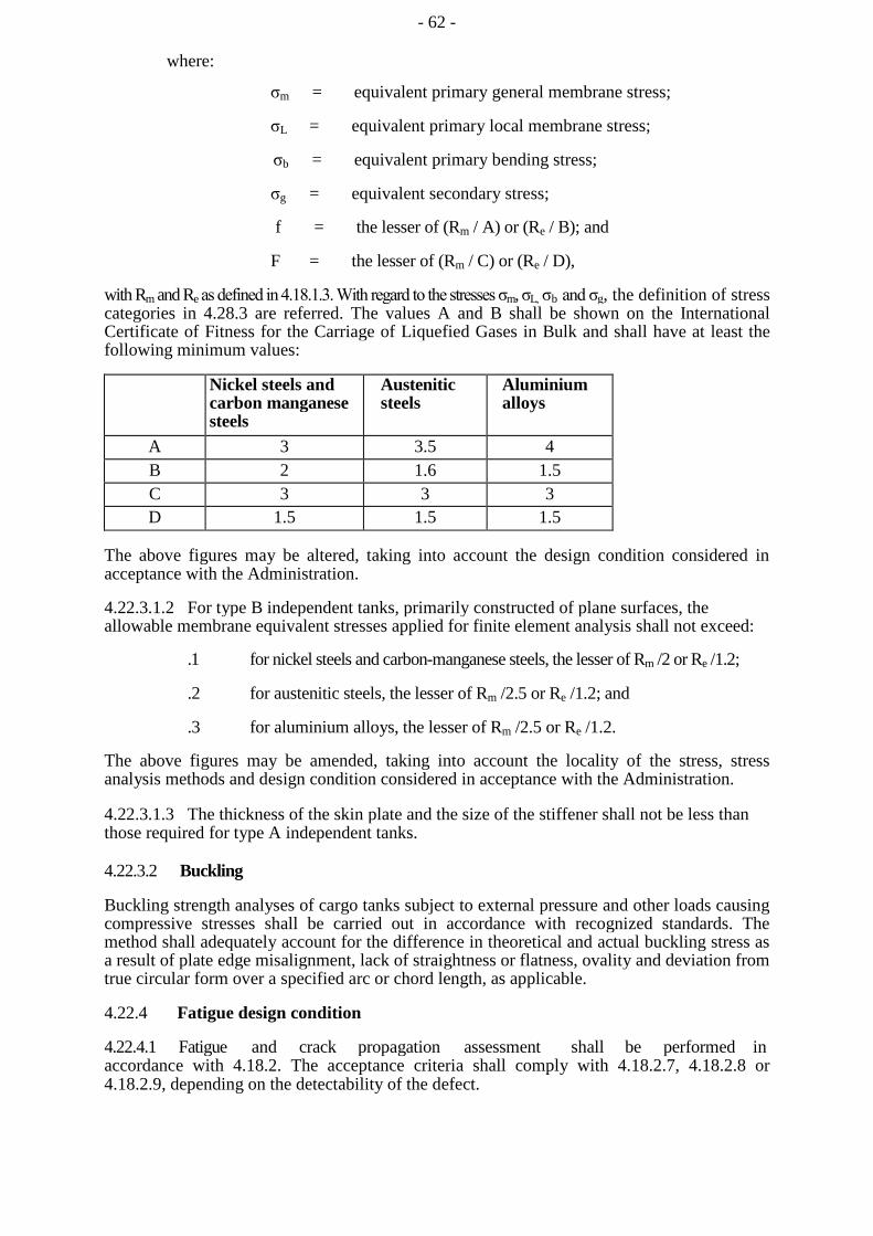
- 62 -
where:
σm = equivalent primary general membrane stress;
σL = equivalent primary local membrane stress;
σb = equivalent primary bending stress;
σg = equivalent secondary stress;
f = the lesser of (Rm / A) or (Re / B); and
F = the lesser of (Rm / C) or (Re / D),
with Rm and Re as defined in 4.18.1.3. With regard to the stresses σm, σL, σb and σg, the definition of stress categories in 4.28.3 are referred. The values A and B shall be shown on the International Certificate of Fitness for the Carriage of Liquefied Gases in Bulk and shall have at least the following minimum values:
Nickel steels and carbon manganese steels
Austenitic steels
Aluminium alloys
A 3 3.5 4 B 2 1.6 1.5 C 3 3 3 D 1.5 1.5 1.5
The above figures may be altered, taking into account the design condition considered in acceptance with the Administration.
4.22.3.1.2 For type B independent tanks, primarily constructed of plane surfaces, the allowable membrane equivalent stresses applied for finite element analysis shall not exceed:
.1 for nickel steels and carbon-manganese steels, the lesser of Rm /2 or Re /1.2;
.2 for austenitic steels, the lesser of Rm /2.5 or Re /1.2; and
.3 for aluminium alloys, the lesser of Rm /2.5 or Re /1.2.
The above figures may be amended, taking into account the locality of the stress, stress analysis methods and design condition considered in acceptance with the Administration.
4.22.3.1.3 The thickness of the skin plate and the size of the stiffener shall not be less than those required for type A independent tanks.
4.22.3.2 Buckling
Buckling strength analyses of cargo tanks subject to external pressure and other loads causing compressive stresses shall be carried out in accordance with recognized standards. The method shall adequately account for the difference in theoretical and actual buckling stress as a result of plate edge misalignment, lack of straightness or flatness, ovality and deviation from true circular form over a specified arc or chord length, as applicable.
4.22.4 Fatigue design condition
4.22.4.1 Fatigue and crack propagation assessment shall be performed in accordance with 4.18.2. The acceptance criteria shall comply with 4.18.2.7, 4.18.2.8 or 4.18.2.9, depending on the detectability of the defect.

- 63 -
4.22.4.2 Fatigue analysis shall consider construction tolerances.
4.22.4.3 Where deemed necessary by the Administration, model tests may be required to determine stress concentration factors and fatigue life of structural elements.
4.22.5 Accident design condition
4.22.5.1 The tanks and the tank supports shall be designed for the accidental loads and design conditions specified in 4.3.4.3 and 4.15, as applicable.
4.22.5.2 When subjected to the accidental loads specified in 4.15, the stress shall comply with the acceptance criteria specified in 4.22.3, modified as appropriate, taking into account their lower probability of occurrence.
4.22.6 Testing
Type B independent tanks shall be subjected to a hydrostatic or hydropneumatic test as follows:
.1 the test shall be performed as required in 4.21.5 for type A independent tanks; and
.2 in addition, the maximum primary membrane stress or maximum bending stress in primary members under test conditions shall not exceed 90% of the yield strength of the material (as fabricated) at the test temperature. To ensure that this condition is satisfied, when calculations indicate that this stress exceeds 75% of the yield strength, the prototype test shall be monitored by the use of strain gauges or other suitable equipment.
4.22.7 Marking
Any marking of the pressure vessel shall be achieved by a method that does not cause unacceptable local stress raisers.
4.23 Type C independent tanks
4.23.1 Design basis
4.23.1.1 The design basis for type C independent tanks is based on pressure vessel criteria modified to include fracture mechanics and crack propagation criteria. The minimum design pressure defined in 4.23.1.2 is intended to ensure that the dynamic stress is sufficiently low, so that an initial surface flaw will not propagate more than half the thickness of the shell during the lifetime of the tank.
4.23.1.2 The design vapour pressure shall not be less than:
P0 = 0.2 + AC(pr)1.5 (MPa)
where:
with:
- 64 -
When a specified design life of the tank is longer than 108 wave encounters, AaA shall be modified to give equivalent crack propagation corresponding to the design life.
4.23.1.3 The Administration may allocate a tank complying with the criteria of type C tank minimum design pressure as in 4.23.1.2, to a type A or type B, dependent on the configuration of the tank and the arrangement of its supports and attachments.
4.23.2 Shell thickness
4.23.2.1 The shell thickness shall be as follows:
.1 For pressure vessels, the thickness calculated according to 4.23.2.4 shall be considered as a minimum thickness after forming, without any negative tolerance.
.2 For pressure vessels, the minimum thickness of shell and heads including corrosion allowance, after forming, shall not be less than 5 mm for carbon-manganese steels and nickel steels, 3 mm for austenitic steels or 7 mm for aluminium alloys.
.3 The welded joint efficiency factor to be used in the calculation according to 4.23.2.4 shall be 0.95 when the inspection and the non-destructive testing referred to in 6.5.6.5 are carried out. This figure may be increased up to 1 when account is taken of other considerations, such as the material used, type of joints, welding procedure and type of loading. For process pressure vessels, the Administration or recognized organization acting on its behalf may accept partial non-destructive examinations, but not less than those of 6.5.6.5, depending on such factors as the material used, the design temperature, the nil-ductility transition temperature of the material, as fabricated, and the type of joint and welding procedure, but in this case an efficiency factor of not more than 0.85 shall be adopted. For special materials, the above-mentioned factors shall be reduced, depending on the specified mechanical properties of the welded joint.
- 65 -
4.23.2.2 The design liquid pressure defined in 4.13.2 shall be taken into account in the internal pressure calculations.
4.23.2.3 The design external pressure Pe, used for verifying the buckling of the pressure vessels, shall not be less than that given by:
Pe = P1+P2+P3+P4 (MPa),
where:
P1 = setting value of vacuum relief valves. For vessels not fitted with vacuum relief valves, P1 shall be specially considered, but shall not, in general, be taken as less than 0.025 MPa;
P2 = the set pressure of the pressure relief valves (PRVs) for completely closed spaces containing pressure vessels or parts of pressure vessels; elsewhere P2=0;
P3 = compressive actions in or on the shell due to the weight and contraction of thermal insulation, weight of shell including corrosion allowance and other miscellaneous external pressure loads to which the pressure vessel may be subjected. These include, but are not limited to, weight of domes, weight of towers and piping, effect of product in the partially filled condition, accelerations and hull deflection. In addition, the local effect of external or internal pressures or both shall be taken into account; and
P4 = external pressure due to head of water for pressure vessels or part of pressure vessels on exposed decks; elsewhere P4 = 0.
4.23.2.4 Scantlings based on internal pressure shall be calculated as follows: the thickness and form of pressure-containing parts of pressure vessels, under internal pressure, as defined in 4.13.2, including flanges, shall be determined. These calculations shall in all cases be based on accepted pressure vessel design theory. Openings in pressure-containing parts of pressure vessels shall be reinforced in accordance with recognized standards.
4.23.2.5 Stress analysis in respect of static and dynamic loads shall be performed as follows:
.1 Pressure vessel scantlings shall be determined in accordance with 4.23.2.1 to 4.23.2.4 and 4.23.3.
.2 Calculations of the loads and stresses in way of the supports and the shell attachment of the support shall be made. Loads referred to in 4.12 to 4.15 shall be used, as applicable. Stresses in way of the supporting structures shall be to a recognized standard acceptable to the Administration or recognized organization acting on its behalf. In special cases, a fatigue analysis may be required by the Administration or recognized organization acting on its behalf.
.3 If required by the Administration or recognized organization acting on its behalf, secondary stresses and thermal stresses shall be specially considered.
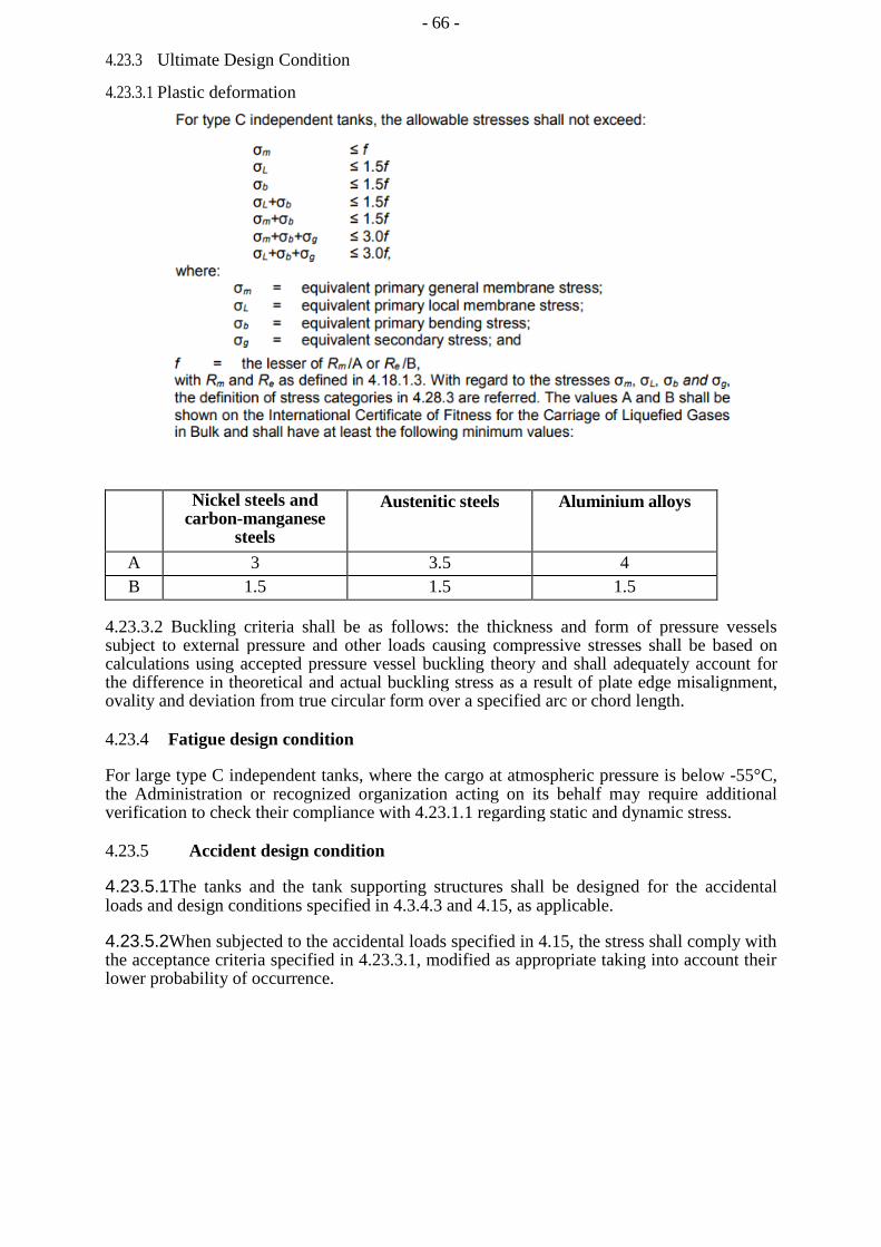
- 66 -
4.23.3 Ultimate Design Condition
4.23.3.1 Plastic deformation
Nickel steels and carbon-manganese
steels
Austenitic steels Aluminium alloys
A 3 3.5 4 B 1.5 1.5 1.5
4.23.3.2 Buckling criteria shall be as follows: the thickness and form of pressure vessels subject to external pressure and other loads causing compressive stresses shall be based on calculations using accepted pressure vessel buckling theory and shall adequately account for the difference in theoretical and actual buckling stress as a result of plate edge misalignment, ovality and deviation from true circular form over a specified arc or chord length.
4.23.4 Fatigue design condition
For large type C independent tanks, where the cargo at atmospheric pressure is below -55°C, the Administration or recognized organization acting on its behalf may require additional verification to check their compliance with 4.23.1.1 regarding static and dynamic stress.
4.23.5 Accident design condition
4.23.5.1The tanks and the tank supporting structures shall be designed for the accidental loads and design conditions specified in 4.3.4.3 and 4.15, as applicable.
4.23.5.2When subjected to the accidental loads specified in 4.15, the stress shall comply with the acceptance criteria specified in 4.23.3.1, modified as appropriate taking into account their lower probability of occurrence.

- 67 -
4.23.6 Testing
4.23.6.1Each pressure vessel shall be subjected to a hydrostatic test at a pressure measured at the top of the tanks, of not less than 1.5 Po. In no case during the pressure test shall the calculated primary membrane stress at any point exceed 90% of the yield stress of the material. To ensure that this condition is satisfied where calculations indicate that this stress will exceed 0.75 times the yield strength, the prototype test shall be monitored by the use of strain gauges or other suitable equipment in pressure vessels other than simple cylindrical and spherical pressure vessels.
4.23.6.2The temperature of the water used for the test shall be at least 30°C above the nil-ductility transition temperature of the material, as fabricated.
4.23.6.3 The pressure shall be held for 2 h per 25 mm of thickness, but in no case less than 2 h.
4.23.6.4Where necessary for cargo pressure vessels, a hydropneumatic test may be carried out under the conditions prescribed in 4.23.6.1 to 4.23.6.3.
4.23.6.5Special consideration may be given to the testing of tanks in which higher allowable stresses are used, depending on service temperature. However, the requirements of 4.23.6.1 shall be fully complied with.
4.23.6.6After completion and assembly, each pressure vessel and its related fittings shall be subjected to an adequate tightness test which may be performed in combination with the pressure testing referred to in 4.23.6.1.
4.23.6.7 Pneumatic testing of pressure vessels other than cargo tanks shall only be considered on an individual case basis. Such testing shall only be permitted for those vessels designed or supported such that they cannot be safely filled with water, or for those vessels that cannot be dried and are to be used in a service where traces of the testing medium cannot be tolerated.
4.23.7 Marking
The required marking of the pressure vessel shall be achieved by a method that does not cause unacceptable local stress raisers.
4.24 Membrane tanks
4.24.1 Design basis
4.24.1.1The design basis for membrane containment systems is that thermal and other expansion or contraction is compensated for without undue risk of losing the tightness of the membrane.
4.24.1.2A systematic approach based on analysis and testing shall be used to demonstrate that the system will provide its intended function in consideration of the events identified in service as specified in 4.24.2.1. 4.24.1.3If the cargo temperature at atmospheric pressure is below -10°C, a complete secondary barrier shall be provided as required in 4.5. The secondary barrier shall be designed according to 4.6.
4.24.1.4The design vapour pressure Po shall not normally exceed 0.025 MPa. If the hull scantlings are increased accordingly and consideration is given, where appropriate, to the strength of the supporting thermal insulation, Po may be increased to a higher value, but less than 0.07 MPa.
- 68 -
4.24.1.5The definition of membrane tanks does not exclude designs such as those in which non-metallic membranes are used or where membranes are included or incorporated into the thermal insulation.
4.24.1.6The thickness of the membranes shall not normally exceed 10 mm.
4.24.1.7The circulation of inert gas throughout the primary insulation space and the secondary insulation space, in accordance with 9.2.1, shall be sufficient to allow for effective means of gas detection.
4.24.2 Design considerations
4.24.2.1 Potential incidents that could lead to loss of fluid tightness over the life of the membranes shall be evaluated. These include, but are not limited to:
.1 Ultimate design events:
.1
.2
.3
.4
.5
.6
.7
tensile failure of membranes;
compressive collapse of thermal insulation;
thermal ageing;
loss of attachment between thermal insulation and hull structure;
loss of attachment of membranes to thermal insulation system;
structural integrity of internal structures and their supporting structures; and
failure of the supporting hull structure.
.2
.3
Fatigue design events:
.1 fatigue of membranes including joints and attachments to hull
structure;
.2 fatigue cracking of thermal insulation;
.3 fatigue of internal structures and their supporting structures; and
.4 fatigue cracking of inner hull leading to ballast water ingress.
Accident design events:
.1accidental mechanical damage (such as dropped objects inside the tank while in service);
accidental overpressurization of thermal insulation spaces; accidental vacuum in the tank; and
water ingress through the inner hull structure.
Designs where a single internal event could cause simultaneous or cascading failure of both membranes are unacceptable.
.2
.3
.4
- 69 -
4.24.2.2 The necessary physical properties (mechanical, thermal, chemical, etc.) of the materials used in the construction of the cargo containment system shall be established during the design development in accordance with 4.24.1.2.
4.24.3 Loads and load combinations
Particular consideration shall be given to the possible loss of tank integrity due to either an overpressure in the interbarrier space, a possible vacuum in the cargo tank, the sloshing effects, hull vibration effects, or any combination of these events.
4.24.4 Structural analyses
4.24.4.1Structural analyses and/or testing for the purpose of determining the ultimate strength and fatigue assessments of the cargo containment and associated structures, e.g. structures as defined in 4.9, shall be performed. The structural analysis shall provide the data required to assess each failure mode that has been identified as critical for the cargo containment system.
4.24.4.2Structural analyses of the hull shall take into account the internal pressure as indicated in 4.13.2. Special attention shall be paid to deflections of the hull and their compatibility with the membrane and associated thermal insulation.
4.24.4.3 The analyses referred to in 4.24.4.1 and 4.24.4.2 shall be based on the particular motions, accelerations and response of ships and cargo containment systems.
4.24.5 Ultimate design condition
4.24.5.1The structural resistance of every critical component, subsystem or assembly shall be established, in accordance with 4.24.1.2, for in-service conditions.
4.24.5.2The choice of strength acceptance criteria for the failure modes of the cargo containment system, its attachments to the hull structure and internal tank structures, shall reflect the consequences associated with the considered mode of failure.
4.24.5.3The inner hull scantlings shall meet the requirements for deep tanks, taking into account the internal pressure as indicated in 4.13.2 and the specified appropriate requirements for sloshing load as defined in 4.14.3.
4.24.6 Fatigue design condition
4.24.6.1Fatigue analysis shall be carried out for structures inside the tank, i.e. pump towers, and for parts of membrane and pump tower attachments, where failure development cannot be reliably detected by continuous monitoring.
4.24.6.2The fatigue calculations shall be carried out in accordance with 4.18.2, with relevant requirements depending on:
.1 the significance of the structural components with respect to structural integrity; and
.2 availability for inspection.
4.24.6.3 For structural elements for which it can be demonstrated by tests and/or analyses that a crack will not develop to cause simultaneous or cascading failure of both membranes, Cw shall be less than or equal to 0.5.

- 70 -
4.24.6.4Structural elements subject to periodic inspection, and where an unattended fatigue crack can develop to cause simultaneous or cascading failure of both membranes, shall satisfy the fatigue and fracture mechanics requirements stated in 4.18.2.8.
4.24.6.5Structural element not accessible for in-service inspection, and where a fatigue crack can develop without warning to cause simultaneous or cascading failure of both membranes, shall satisfy the fatigue and fracture mechanics requirements stated in 4.18.2.9.
4.24.7 Accident design condition
4.24.7.1The containment system and the supporting hull structure shall be designed for the accidental loads specified in 4.15. These loads need not be combined with each other or with environmental loads.
4.24.7.2Additional relevant accident scenarios shall be determined based on a risk analysis. Particular attention shall be paid to securing devices inside tanks.
4.24.8 Design development testing
4.24.8.1The design development testing required in 4.24.1.2 shall include a series of analytical and physical models of both the primary and secondary barriers, including corners and joints, tested to verify that they will withstand the expected combined strains due to static, dynamic and thermal loads. This will culminate in the construction of a prototype-scaled model of the complete cargo containment system. Testing conditions considered in the analytical and physical models shall represent the most extreme service conditions the cargo containment system will be likely to encounter over its life. Proposed acceptance criteria for periodic testing of secondary barriers required in 4.6.2 may be based on the results of testing carried out on the prototype-scaled model.
4.24.8.2The fatigue performance of the membrane materials and representative welded or bonded joints in the membranes shall be determined by tests. The ultimate strength and fatigue performance of arrangements for securing the thermal insulation system to the hull structure shall be determined by analyses or tests.
4.24.9 Testing
4.24.9.1In ships fitted with membrane cargo containment systems, all tanks and other spaces that may normally contain liquid and are adjacent to the hull structure supporting the membrane, shall be hydrostatically tested.
4.24.9.2All hold structures supporting the membrane shall be tested for tightness before installation of the cargo containment system.
4.24.9.3Pipe tunnels and other compartments that do not normally contain liquid need not be hydrostatically tested.
4.25 Integral tanks
4.25.1 Design basis
Integral tanks that form a structural part of the hull and are affected by the loads that stress the adjacent hull structure shall comply with the following:
.1 the design vapour pressure Po as defined in 4.1.2 shall not normally exceed 0.025 MPa. If the hull scantlings are increased accordingly, Po may be increased to a higher value, but less than 0.07 MPa;
- 71 -
.2 integral tanks may be used for products, provided the boiling point of the cargo is not below -10°C. A lower temperature may be accepted by the Administration or recognized organization acting on its behalf subject to special consideration, but in such cases a complete secondary barrier shall be provided; and
.3 products required by chapter 16 to be carried in type 1G ships shall not be
carried in integral tanks.
4.25.2 Structural analysis The structural analysis of integral tanks shall be in accordance
with recognized standards.
4.25.3 Ultimate design condition
4.25.3.1The tank boundary scantlings shall meet the requirements for deep tanks, taking into account the internal pressure as indicated in 4.13.2.
4.25.3.2For integral tanks, allowable stresses shall normally be those given for hull structure in the requirements of the Administration or recognized organization acting on its behalf.
4.25.4 Accident design condition
4.25.4.1The tanks and the tank supports shall be designed for the accidental loads specified in 4.3.4.3 and 4.15, as relevant.
4.25.4.2When subjected to the accidental loads specified in 4.15, the stress shall comply with the acceptance criteria specified in 4.25.3, modified as appropriate, taking into account their lower probability of occurrence.
4.25.5 Testing
All integral tanks shall be hydrostatically or hydropneumatically tested. The test shall be performed so that the stresses approximate, as far as practicable, to the design stresses and that the pressure at the top of the tank corresponds at least to the MARVS.
4.26 Semi-membrane tanks
4.26.1 Design basis
4.26.1.1Semi-membrane tanks are non-self-supporting tanks when in the loaded condition and consist of a layer, parts of which are supported through thermal insulation by the adjacent hull structure, whereas the rounded parts of this layer connecting the above-mentioned supported parts are designed also to accommodate the thermal and other expansion or contraction.
4.26.1.2The design vapour pressure Po shall not normally exceed 0.025 MPa. If the hull scantlings are increased accordingly, and consideration is given, where appropriate, to the strength of the supporting thermal insulation, Po may be increased to a higher value, but less than 0.07 MPa.
4.26.1.3For semi-membrane tanks the relevant requirements in this section for independent tanks or for membrane tanks shall be applied as appropriate.
4.26.1.4In the case of semi-membrane tanks that comply in all respects with the requirements applicable to type B independent tanks, except for the manner of support, the Administration may, after special consideration, accept a partial secondary barrier.
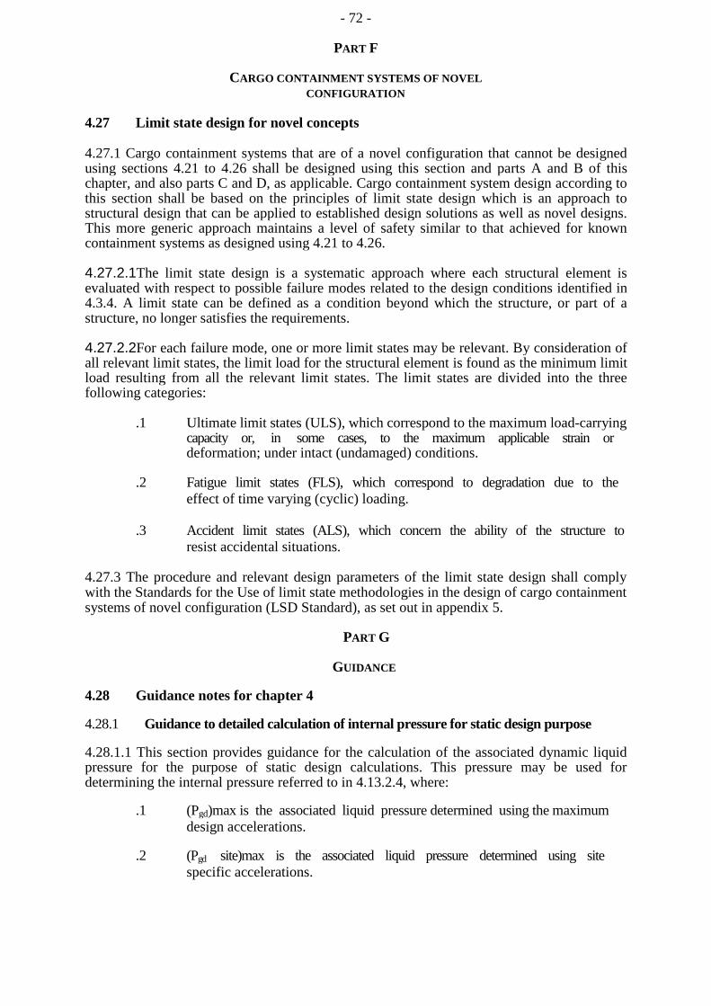
- 72 -
PART F
CARGO CONTAINMENT SYSTEMS OF NOVEL CONFIGURATION
4.27 Limit state design for novel concepts
4.27.1 Cargo containment systems that are of a novel configuration that cannot be designed using sections 4.21 to 4.26 shall be designed using this section and parts A and B of this chapter, and also parts C and D, as applicable. Cargo containment system design according to this section shall be based on the principles of limit state design which is an approach to structural design that can be applied to established design solutions as well as novel designs. This more generic approach maintains a level of safety similar to that achieved for known containment systems as designed using 4.21 to 4.26.
4.27.2.1The limit state design is a systematic approach where each structural element is evaluated with respect to possible failure modes related to the design conditions identified in 4.3.4. A limit state can be defined as a condition beyond which the structure, or part of a structure, no longer satisfies the requirements.
4.27.2.2For each failure mode, one or more limit states may be relevant. By consideration of all relevant limit states, the limit load for the structural element is found as the minimum limit load resulting from all the relevant limit states. The limit states are divided into the three following categories:
.1 Ultimate limit states (ULS), which correspond to the maximum load-carrying capacity or, in some cases, to the maximum applicable strain or deformation; under intact (undamaged) conditions.
.2 Fatigue limit states (FLS), which correspond to degradation due to the effect of time varying (cyclic) loading.
.3 Accident limit states (ALS), which concern the ability of the structure to resist accidental situations.
4.27.3 The procedure and relevant design parameters of the limit state design shall comply with the Standards for the Use of limit state methodologies in the design of cargo containment systems of novel configuration (LSD Standard), as set out in appendix 5.
PART G
GUIDANCE
4.28 Guidance notes for chapter 4
4.28.1 Guidance to detailed calculation of internal pressure for static design purpose
4.28.1.1 This section provides guidance for the calculation of the associated dynamic liquid pressure for the purpose of static design calculations. This pressure may be used for determining the internal pressure referred to in 4.13.2.4, where:
.1 (Pgd)max is the associated liquid pressure determined using the maximum design accelerations.
.2 (Pgd site)max is the associated liquid pressure determined using site specific accelerations.
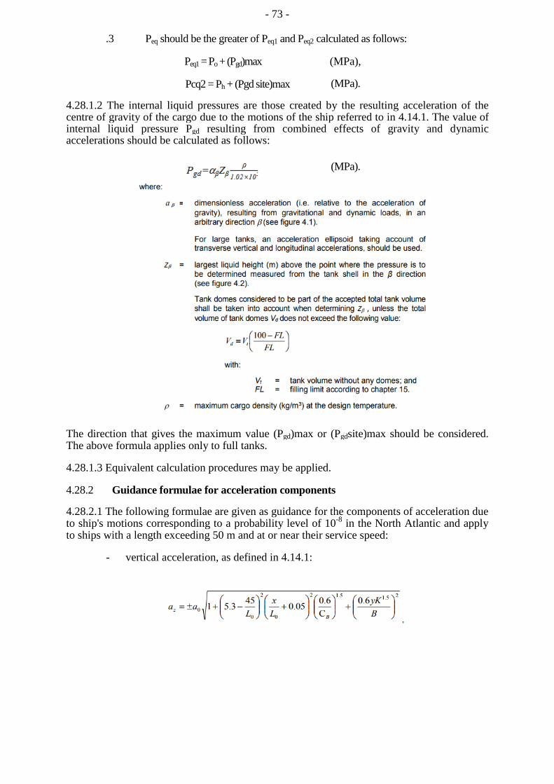
- 73 -
.3 Peq should be the greater of Peq1 and Peq2 calculated as follows:
Peq1 = Po + (Pgd)max (MPa),
Pcq2 = Ph + (Pgd site)max (MPa).
4.28.1.2 The internal liquid pressures are those created by the resulting acceleration of the centre of gravity of the cargo due to the motions of the ship referred to in 4.14.1. The value of internal liquid pressure Pgd resulting from combined effects of gravity and dynamic accelerations should be calculated as follows:
(MPa).
Wher
The direction that gives the maximum value (Pgd)max or (Pgdsite)max should be considered. The above formula applies only to full tanks.
4.28.1.3 Equivalent calculation procedures may be applied.
4.28.2 Guidance formulae for acceleration components
4.28.2.1 The following formulae are given as guidance for the components of acceleration due to ship's motions corresponding to a probability level of 10-8 in the North Atlantic and apply to ships with a length exceeding 50 m and at or near their service speed:
- vertical acceleration, as defined in 4.14.1:
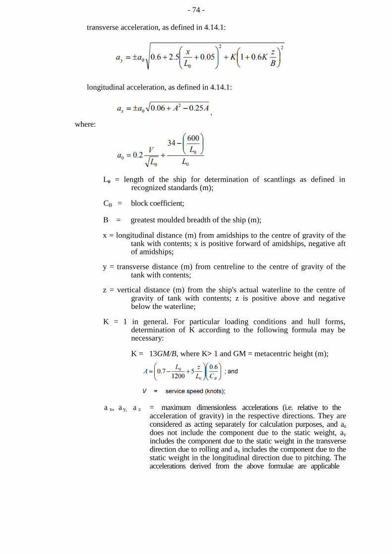
- 74 -
transverse acceleration, as defined in 4.14.1:
longitudinal acceleration, as defined in 4.14.1:
where:
Lo = length of the ship for determination of scantlings as defined in recognized standards (m);
CB = block coefficient;
B = greatest moulded breadth of the ship (m);
x = longitudinal distance (m) from amidships to the centre of gravity of the tank with contents; x is positive forward of amidships, negative aft of amidships;
y = transverse distance (m) from centreline to the centre of gravity of the tank with contents;
z = vertical distance (m) from the ship's actual waterline to the centre of gravity of tank with contents; z is positive above and negative below the waterline;
K = 1 in general. For particular loading conditions and hull forms, determination of K according to the following formula may be necessary:
K = 13GM/B, where K> 1 and GM = metacentric height (m);
a x, a y, a z = maximum dimensionless accelerations (i.e. relative to the acceleration of gravity) in the respective directions. They are considered as acting separately for calculation purposes, and az does not include the component due to the static weight, ay includes the component due to the static weight in the transverse direction due to rolling and ax includes the component due to the static weight in the longitudinal direction due to pitching. The accelerations derived from the above formulae are applicable
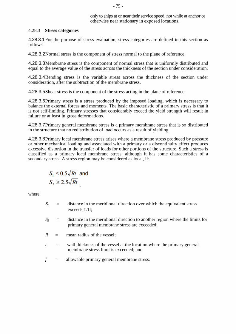
- 75 -
only to ships at or near their service speed, not while at anchor or otherwise near stationary in exposed locations.
4.28.3 Stress categories
4.28.3.1 For the purpose of stress evaluation, stress categories are defined in this section as follows.
4.28.3.2 Normal stress is the component of stress normal to the plane of reference.
4.28.3.3 Membrane stress is the component of normal stress that is uniformly distributed and equal to the average value of the stress across the thickness of the section under consideration.
4.28.3.4 Bending stress is the variable stress across the thickness of the section under consideration, after the subtraction of the membrane stress.
4.28.3.5 Shear stress is the component of the stress acting in the plane of reference.
4.28.3.6 Primary stress is a stress produced by the imposed loading, which is necessary to balance the external forces and moments. The basic characteristic of a primary stress is that it is not self-limiting. Primary stresses that considerably exceed the yield strength will result in failure or at least in gross deformations.
4.28.3.7 Primary general membrane stress is a primary membrane stress that is so distributed in the structure that no redistribution of load occurs as a result of yielding.
4.28.3.8 Primary local membrane stress arises where a membrane stress produced by pressure or other mechanical loading and associated with a primary or a discontinuity effect produces excessive distortion in the transfer of loads for other portions of the structure. Such a stress is classified as a primary local membrane stress, although it has some characteristics of a secondary stress. A stress region may be considered as local, if: where:
S1 = distance in the meridional direction over which the equivalent stress exceeds 1.1f;
S2 = distance in the meridional direction to another region where the limits for primary general membrane stress are exceeded;
R = mean radius of the vessel;
t = wall thickness of the vessel at the location where the primary general membrane stress limit is exceeded; and
f = allowable primary general membrane stress.
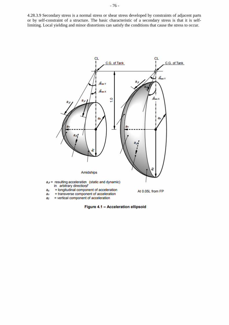
- 76 -
4.28.3.9 Secondary stress is a normal stress or shear stress developed by constraints of adjacent parts or by self-constraint of a structure. The basic characteristic of a secondary stress is that it is self-limiting. Local yielding and minor distortions can satisfy the conditions that cause the stress to occur.

- 77 -
Figure 4.2 – Determination of internal pressure heads
Figure 4.3 – Determination of liquid height Zβ for points 1, 2 and 3
2
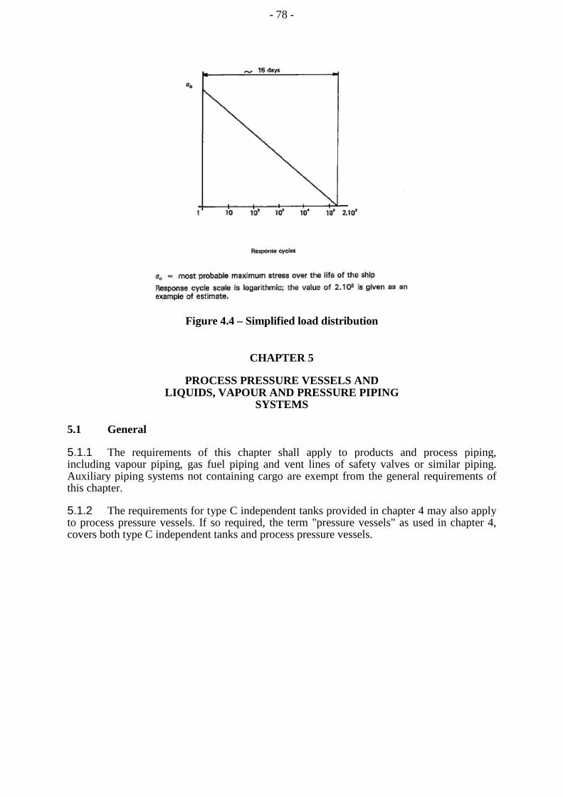
Figure 4.4 – Simplified load distribution
CHAPTER 5
PROCESS PRESSURE VESSELS AND LIQUIDS, VAPOUR AND PRESSURE PIPING
SYSTEMS
5.1 General
5.1.1 The requirements of this chapter shall apply to products and process piping, including vapour piping, gas fuel piping and vent lines of safety valves or similar piping. Auxiliary piping systems not containing cargo are exempt from the general requirements of this chapter.
5.1.2 The requirements for type C independent tanks provided in chapter 4 may also apply to process pressure vessels. If so required, the term "pressure vessels" as used in chapter 4, covers both type C independent tanks and process pressure vessels.
- 78 -

- 79 -
5.1.3 Process pressure vessels include surge tanks, heat exchangers and accumulators that store or treat liquid or vapour cargo.
5.2 System requirements
5.2.1 The cargo handling and cargo control systems shall be designed taking into account the following:
.1 prevention of an abnormal condition escalating to a release of liquid or
vapour cargo;
.2 the safe collection and disposal of cargo fluids released;
.3 prevention of the formation of flammable mixtures;
.4 prevention of ignition of flammable liquids or gases and vapours released; and
.5 limiting the exposure of personnel to fire and other hazards.
5.2.2 Arrangements: general
5.2.2.1 Any piping system that may contain cargo liquid or vapour shall:
.1 be segregated from other piping systems, except where interconnections are required for cargo-related operations such as purging, gas-freeing or inerting. The requirements of 9.4.4 shall be taken into account with regard to preventing back-flow of cargo. In such cases, precautions shall be taken to ensure that cargo or cargo vapour cannot enter other piping systems through the interconnections;
.2 except as provided in chapter 16, not pass through any accommodation space, service space or control station or through a machinery space other than a cargo machinery space;
.3 be connected to the cargo containment system directly from the weather decks except where pipes installed in a vertical trunkway or equivalent are used to traverse void spaces above a cargo containment system and except where pipes for drainage, venting or purging traverse cofferdams;
.4 be located in the cargo area above the weather deck except for bow or stern loading and unloading arrangements in accordance with 3.8, emergency cargo jettisoning piping systems in accordance with 5.3.1, turret compartment systems in accordance with 5.3.3; and
.5 be located inboard of the transverse tank location requirements of 2.4.1, except for athwartship shore connection piping not subject to internal pressure at sea or emergency cargo jettisoning piping systems.
5.2.2.2 Suitable means shall be provided to relieve the pressure and remove liquid cargo from loading and discharging crossover headers; likewise, any piping between the outermost manifold valves and loading arms or cargo hoses to the cargo tanks, or other suitable location, prior to disconnection.
5.2.2.3 Piping systems carrying fluids for direct heating or cooling of cargo shall not be led outside the cargo area unless a suitable means is provided to prevent or detect the migration of cargo vapour outside the cargo area (see 13.6.2.6).
- 80 -
5.2.2.4 Relief valves discharging liquid cargo from the piping system shall discharge into the cargo tanks. Alternatively, they may discharge to the cargo vent mast, if means are provided to detect and dispose of any liquid cargo that may flow into the vent system. Where required to prevent overpressure in downstream piping, relief valves on cargo pumps shall discharge to the pump suction.
5.3 Arrangements for cargo piping outside the cargo area
5.3.1 Emergency cargo jettisoning
If fitted, an emergency cargo jettisoning piping system shall comply with 5.2.2, as appropriate, and may be led aft, external to accommodation spaces, service spaces or control stations or machinery spaces, but shall not pass through them. If an emergency cargo jettisoning piping system is permanently installed, a suitable means of isolating the piping system from the cargo piping shall be provided within the cargo area.
5.3.2 Bow and stern loading arrangements
5.3.2.1 Subject to the requirements of 3.8, this section and 5.10.1, cargo piping may be arranged to permit bow or stern loading and unloading.
5.3.2.2 Arrangements shall be made to allow such piping to be purged and gas-freed after use. When not in use, the spool pieces shall be removed and the pipe ends blank-flanged. The vent pipes connected with the purge shall be located in the cargo area.
5.3.3 Turret compartment transfer systems
For the transfer of liquid or vapour cargo through an internal turret arrangement located outside the cargo area, the piping serving this purpose shall comply with 5.2.2, as applicable, 5.10.2 and the following:
.1 piping shall be located above the weather deck, except for the connection to the turret;
.2 portable arrangements shall not be permitted; and
.3 arrangements shall be made to allow such piping to be purged and gas-freed after use. When not in use, the spool pieces for isolation from the cargo piping shall be removed and the pipe ends blank-flanged. The vent pipes connected with the purge shall be located in the cargo area.
5.3.4 Gas fuel piping systems
Gas fuel piping in machinery spaces shall comply with all applicable sections of this chapter .
5.4 Design pressure
5.4.1 The design pressure Po, used to determine minimum scantlings of piping and piping system components, shall be not less than the maximum gauge pressure to which the system may be subjected in service. The minimum design pressure used shall not be less than 1 MPa gauge, except for open-ended lines or pressure relief valve discharge lines, where it shall be not less than the lower of 0.5 MPa gauge, or 10 times the relief valve set pressure.
- 81 -
5.4.2 The greater of the following design conditions shall be used for piping, piping systems and components, based on the cargoes being carried:
.1 for vapour piping systems or components that may be separated from their relief valves and which may contain some liquid, the saturated vapour pressure at a design temperature of 45°C. Higher or lower values may be used (see 4.13.2.2); or
.2 for systems or components that may be separated from their relief valves and which contain only vapour at all times, the superheated vapour pressure at 45°C. Higher or lower values may be used (see 4.13.2.2), assuming an initial condition of saturated vapour in the system at the system operating pressure and temperature; or
.3 the MARVS of the cargo tanks and cargo processing systems; or
.4 the pressure setting of the associated pump or compressor discharge relief valve; or
.5 the maximum total discharge or loading head of the cargo piping system considering all possible pumping arrangements or the relief valve setting on a pipeline system.
5.4.3 Those parts of the liquid piping systems that may be subjected to surge pressures shall be designed to withstand this pressure.
5.4.4 The design pressure of the outer pipe or duct of gas fuel systems shall not be less than the maximum working pressure of the inner gas pipe. Alternatively, for gas fuel piping systems with a working pressure greater than 1 MPa, the design pressure of the outer duct shall not be less than the maximum built-up pressure arising in the annular space considering the local instantaneous peak pressure in way of any rupture and the ventilation arrangements.
5.5 Cargo system valve requirements
5.5.1.1 Every cargo tank and piping system shall be fitted with manually operated valves for isolation purposes as specified in this section.
5.5.1.2 In addition, remotely operated valves shall also be fitted, as appropriate, as part of the emergency shutdown (ESD) system the purpose of which is to stop cargo flow or leakage in the event of an emergency when cargo liquid or vapour transfer is in progress. The ESD system is intended to return the cargo system to a safe static condition so that any remedial action can be taken. Due regard shall be given in the design of the ESD system to avoid the generation of surge pressures within the cargo transfer pipework. The equipment to be shut down on ESD activation includes manifold valves during loading or discharge, any pump or compressor, etc., transferring cargo internally or externally (e.g. to shore or another ship/barge) and cargo tank valves, if the MARVS exceeds 0.07 MPa.
5.5.2 Cargo tank connections
5.5.2.1 All liquid and vapour connections, except for safety relief valves and liquid level gauging devices, shall have shutoff valves located as close to the tank as practicable. These valves shall provide full closure and shall be capable of local manual operation. They may also be capable of remote operation.
- 82 -
5.5.2.2 For cargo tanks with a MARVS exceeding 0.07 MPa gauge, the above connections shall also be equipped with remotely controlled ESD valves. These valves shall be located as close to the tank as practicable. A single valve may be substituted for the two separate valves, provided the valve complies with the requirements of 18.10.2 and provides full closure of the line.
5.5.3 Cargo manifold connections
5.5.3.1 One remotely controlled ESD valve shall be provided at each cargo transfer connection in use to stop liquid and vapour transfer to or from the ship. Transfer connections not in use shall be isolated with suitable blank flanges.
5.5.3.2 If the cargo tank MARVS exceeds 0.07 MPa, an additional manual valve shall be provided for each transfer connection in use, and may be inboard or outboard of the ESD valve to suit the ship's design.
5.5.4 Excess flow valves may be used in lieu of ESD valves, if the diameter of the protected pipe does not exceed 50 mm. Excess flow valves shall close automatically at the rated closing flow of vapour or liquid as specified by the manufacturer. The piping including fittings, valves and appurtenances protected by an excess flow valve shall have a capacity greater than the rated closing flow of the excess flow valve. Excess flow valves may be designed with a bypass not exceeding the area of a 1 mm diameter circular opening to allow equalization of pressure after a shutdown activation.
5.5.5 Cargo tank connections for gauging or measuring devices need not be equipped with excess flow valves or ESD valves, provided that the devices are constructed so that the outward flow of tank contents cannot exceed that passed by a 1.5 mm diameter circular hole.
5.5.6 All pipelines or components which may be isolated in a liquid full condition shall be protected with relief valves for thermal expansion and evaporation.
5.5.7 All pipelines or components which may be isolated automatically due to a fire with a liquid volume of more than 0.05 m3 entrapped shall be provided with PRVs sized for a fire condition.
5.6 Cargo transfer arrangements
5.6.1 Where cargo transfer is by means of cargo pumps that are not accessible for repair with the tanks in service, at least two separate means shall be provided to transfer cargo from each cargo tank, and the design shall be such that failure of one cargo pump or means of transfer will not prevent the cargo transfer by another pump or pumps, or other cargo transfer means.
5.6.2 The procedure for transfer of cargo by gas pressurization shall preclude lifting of the relief valves during such transfer. Gas pressurization may be accepted as a means of transfer of cargo for those tanks where the design factor of safety is not reduced under the conditions prevailing during the cargo transfer operation. If the cargo tank relief valves or set pressure are changed for this purpose, as it is permitted in accordance with 8.2.7 and 8.2.8, the new set pressure shall not exceed Ph as is defined in 4.13.2.
5.6.3 Vapour return connections
Connections for vapour return to the shore installations shall be provided.

- 83 -
5.6.4 Cargo tank vent piping systems
The pressure relief system shall be connected to a vent piping system designed to minimize the possibility of cargo vapour accumulating on the decks, or entering accommodation spaces, service spaces, control stations and machinery spaces, or other spaces where it may create a dangerous condition.
5.6.5 Cargo sampling connections
5.6.5.1 Connections to cargo piping systems for taking cargo liquid samples shall be clearly marked and shall be designed to minimize the release of cargo vapours. For vessels permitted to carry toxic products, the sampling system shall be of a closed loop design to ensure that cargo liquid and vapour are not vented to atmosphere.
5.6.5.2 Liquid sampling systems shall be provided with two valves on the sample inlet. One of these valves shall be of the multi-turn type to avoid accidental opening, and shall be spaced far enough apart to ensure that they can isolate the line if there is blockage, by ice or hydrates for example.
5.6.5.3 On closed loop systems, the valves on the return pipe shall also comply with 5.6.5.2.
5.6.5.4 The connection to the sample container shall comply with recognized standards and be supported so as to be able to support the weight of a sample container. Threaded connections shall be tack-welded, or otherwise locked, to prevent them being unscrewed during the normal connection and disconnection of sample containers. The sample connection shall be fitted with a closure plug or flange to prevent any leakage when the connection is not in use.
5.6.5.5 Sample connections used only for vapour samples may be fitted with a single valve in accordance with 5.5, 5.8 and 5.13, and shall also be fitted with a closure plug or flange.
5.6.5.6 Sampling operations shall be undertaken as prescribed in 18.9.
5.6.6 Cargo filters
The cargo liquid and vapour systems shall be capable of being fitted with filters to protect against damage by extraneous objects. Such filters may be permanent or temporary, and the standards of filtration shall be appropriate to the risk of debris, etc., entering the cargo system. Means shall be provided to indicate that filters are becoming blocked, and to isolate, depressurize and clean the filters safely.
5.7 Installation requirements
5.7.1 Design for expansion and contraction
Provision shall be made to protect the piping, piping system and components and cargo tanks from excessive stresses due to thermal movement and from movements of the tank and hull structure. The preferred method outside the cargo tanks is by means of offsets, bends or loops, but multi-layer bellows may be used if offsets, bends or loops are not practicable.
5.7.2 Precautions against low temperature
Low temperature piping shall be thermally isolated from the adjacent hull structure, where necessary, to prevent the temperature of the hull from falling below the design temperature of the hull material. Where liquid piping is dismantled regularly, or where liquid leakage may be anticipated, such as at shore connections and at pump seals, protection for the hull beneath shall be provided.

- 84 -
5.7.3 Water curtain
For cargo temperatures below -110°C, a water distribution system shall be fitted in way of the hull under the shore connections to provide a low-pressure water curtain for additional protection of the hull steel and the ship's side structure. This system is in addition to the requirements of 11.3.1.4, and shall be operated when cargo transfer is in progress.
5.7.4 Bonding
Where tanks or cargo piping and piping equipment are separated from the ship's structure by thermal isolation, provision shall be made for electrically bonding both the piping and the tanks. All gasketed pipe joints and hose connections shall be electrically bonded. Except where bonding straps are used, it shall be demonstrated that the electrical resistance of each joint or connection is less than 1MQ.
5.8 Piping fabrication and joining details
5.8.1 General
The requirements of this section apply to piping inside and outside the cargo tanks. Relaxation from these requirements may be accepted, in accordance with recognized standards for piping inside cargo tanks and open-ended piping.
5.8.2 Direct connections
The following direct connection of pipe lengths, without flanges, may be considered:
.1 butt-welded joints with complete penetration at the root may be used in all applications. For design temperatures colder than -10°C, butt welds shall be either double welded or equivalent to a double welded butt joint. This may be accomplished by use of a backing ring, consumable insert or inert gas backup on the first pass. For design pressures in excess of 1 MPa and design temperatures of -10°C or colder, backing rings shall be removed;
.2 slip-on welded joints with sleeves and related welding, having dimensions in accordance with recognized standards, shall only be used for instrument lines and open-ended lines with an external diameter of 50 mm or less and design temperatures not colder than -55°C; and
.3 screwed couplings complying with recognized standards shall only be used for accessory lines and instrumentation lines with external diameters of 25 mm or less.
5.8.3 Flanged connections
5.8.3.1 Flanges in flanged connections shall be of the welded neck, slip-on or socket welded type.
5.8.3.2 Flanges shall comply with recognized standards for their type, manufacture and test. For all piping, except open ended, the following restrictions apply:
.1 for design temperatures colder than -55°C, only welded-neck flanges shall be used; and
.2 for design temperatures colder than -10°C, slip-on flanges shall not be used in nominal sizes above 100 mm and socket welded flanges shall not be used in nominal sizes above 50 mm.
- 85 -
5.8.4 Expansion joints
Where bellows and expansion joints are provided in accordance with 5.7.1, the following requirements apply:
.1 if necessary, bellows shall be protected against icing; and
.2 slip joints shall not be used except within the cargo tanks.
5.8.5 Other connections
Piping connections shall be joined in accordance with 5.8.2 to 5.8.4, but for other exceptional cases the Administration may consider alternative arrangements.
5.9 Welding, post-weld heat treatment and non-destructive testing
5.9.1 General Welding shall be carried out in
accordance with 6.5.
5.9.2 Post-weld heat treatment
Post-weld heat treatment shall be required for all butt welds of pipes made with carbon, carbon-manganese and low alloy steels. The Administration or recognized organization acting on its behalf may waive the requirements for thermal stress relieving of pipes with wall thickness less than 10 mm in relation to the design temperature and pressure of the piping system concerned.
5.9.3 Non-destructive testing
In addition to normal controls before and during the welding, and to the visual inspection of the finished welds, as necessary for proving that the welding has been carried out correctly and according to the requirements of this paragraph, the following tests shall be required:
.1 100% radiographic or ultrasonic inspection of butt-welded joints for piping systems with design temperatures colder than -10°C, or with inside diameters of more than 75 mm, or wall thicknesses greater than 10 mm;
.2 when such butt-welded joints of piping sections are made by automatic welding procedures approved by the Administration or recognized organization acting on its behalf, then a progressive reduction in the extent of radiographic or ultrasonic inspection can be agreed, but in no case to less than 10% of each joint. If defects are revealed, the extent of examination shall be increased to 100% and shall include inspection of previously accepted welds. This approval can only be granted if well-documented quality assurance procedures and records are available to assess the ability of the manufacturer to produce satisfactory welds consistently; and
.3 for other butt-welded joints of pipes not covered by 5.9.3.1 and 5.9.3.2, spot radiographic or ultrasonic inspection or other non-destructive tests shall be carried out depending upon service, position and materials. In general, at least 10% of butt-welded joints of pipes shall be subjected to radiographic or ultrasonic inspection.

- 86 -
5.10 Installation requirements for cargo piping outside the cargo area
5.10.1 Bow and stern loading arrangements
The following requirements shall apply to cargo piping and related piping equipment located outside the cargo area:
.1 cargo piping and related piping equipment outside the cargo area shall have only welded connections. The piping outside the cargo area shall run on the weather decks and shall be at least 0.8 m inboard, except for athwartships shore connection piping. Such piping shall be clearly identified and fitted with a shutoff valve at its connection to the cargo piping system within the cargo area. At this location, it shall also be capable of being separated by means of a removable spool piece and blank flanges, when not in use; and
.2 the piping shall be full penetration butt-welded and subjected to full radiographic or ultrasonic inspection, regardless of pipe diameter and design temperature. Flange connections in the piping shall only be permitted within the cargo area and at the shore connection.
5.10.2 Turret compartment transfer systems
The following requirements shall apply to liquid and vapour cargo piping where it is run outside the cargo area:
.1 cargo piping and related piping equipment outside the cargo area shall have only welded connections; and
.2 the piping shall be full penetration butt-welded, and subjected to full radiographic or ultrasonic inspection, regardless of pipe diameter and design temperature. Flange connections in the piping shall only be permitted within the cargo area and at connections to cargo hoses and the turret connection.
5.10.3 Gas fuel piping
Gas fuel piping, as far as practicable, shall have welded joints. Those parts of the gas fuel piping that are not enclosed in a ventilated pipe or duct according to 16.4.3, and are on the weather decks outside the cargo area, shall have full penetration butt-welded joints and shall be subjected to full radiographic or ultrasonic inspection.
5.11 Piping system component requirements
5.11.1 Piping scantlings. Piping systems shall be designed in accordance with recognized standards.
5.11.2.1 The following criteria shall be used for determining pipe wall thickness.
5.11.2.2 The wall thickness of pipes shall not be less than:
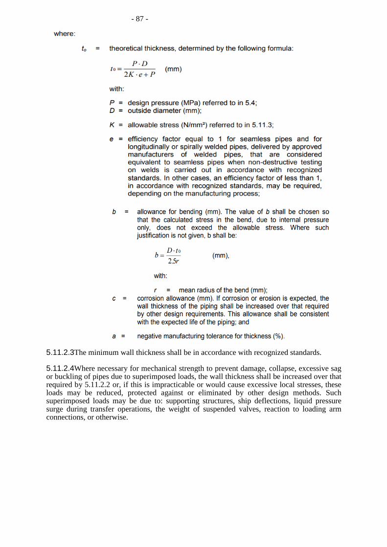
- 87 -
5.11.2.3The minimum wall thickness shall be in accordance with recognized standards.
5.11.2.4Where necessary for mechanical strength to prevent damage, collapse, excessive sag or buckling of pipes due to superimposed loads, the wall thickness shall be increased over that required by 5.11.2.2 or, if this is impracticable or would cause excessive local stresses, these loads may be reduced, protected against or eliminated by other design methods. Such superimposed loads may be due to: supporting structures, ship deflections, liquid pressure surge during transfer operations, the weight of suspended valves, reaction to loading arm connections, or otherwise.

- 88 -
5.11.3 Allowable stress
5.11.3.1 For pipes, the allowable stress K referred to in the formula in 5.11.2 is the lower of the following values:
where:
Rm = specified minimum tensile strength at room temperature (N/mm²); and
Re = specified minimum yield stress at room temperature (N/mm²). If the stress-strain curve does not show a defined yield stress, the 0.2% proof stress applies.
The values of A and B shall be shown on the International Certificate of Fitness for the Carriage of Liquefied Gases in Bulk required in 1.4.4, and have values of at least A = 2.7 and B = 1.8.
5.11.4 High-pressure gas fuel outer pipes or ducting scantlings
In fuel gas piping systems of design pressure greater than the critical pressure, the tangential membrane stress of a straight section of pipe or ducting shall not exceed the tensile strength divided by 1.5 (Rm /1.5) when subjected to the design pressure specified in 5.4. The pressure ratings of all other piping components shall reflect the same level of strength as straight pipes.
5.11.5 Stress analysis
When the design temperature is -110°C or lower, a complete stress analysis, taking into account all the stresses due to the weight of pipes, including acceleration loads if significant, internal pressure, thermal contraction and loads induced by hog and sag of the ship for each branch of the piping system shall be submitted to the Administration. For temperatures above -110°C, a stress analysis may be required by the Administration in relation to such matters as the design or stiffness of the piping system and the choice of materials. In any case, consideration shall be given to thermal stresses even though calculations are not submitted. The analysis may be carried out according to a guidance of practice acceptable to the Administration.
5.11.6 Flanges, valves and fittings
5.11.6.1Flanges, valves and other fittings shall comply with recognized standards, taking into account the material selected and the design pressure defined in 5.4. For bellows expansion joints used in vapour service, a lower minimum design pressure may be accepted.
5.11.6.2For flanges not complying with a recognized standard, the dimensions of flanges and related bolts shall be to the satisfaction of the Administration or recognized organization acting on its behalf.
5.11.6.3All emergency shutdown valves shall be of the "fire closed" type (see 5.13.1.1 and 18.10.2).
5.11.6.4The design and installation of expansion bellows shall be in accordance with recognized standards and be fitted with means to prevent damage due to over-extension or compression.

- 89 -
5.11.7 Ship's cargo hoses
5.11.7.1Liquid and vapour hoses used for cargo transfer shall be compatible with the cargo and suitable for the cargo temperature.
5.11.7.2Hoses subject to tank pressure, or the discharge pressure of pumps or vapour compressors, shall be designed for a bursting pressure not less than five times the maximum pressure the hose will be subjected to during cargo transfer.
5.11.7.3Each new type of cargo hose, complete with end-fittings, shall be prototype-tested at a normal ambient temperature, with 200 pressure cycles from zero to at least twice the specified maximum working pressure. After this cycle pressure test has been carried out, the prototype test shall demonstrate a bursting pressure of at least 5 times its specified maximum working pressure at the upper and lower extreme service temperature. Hoses used for prototype testing shall not be used for cargo service. Thereafter, before being placed in service, each new length of cargo hose produced shall be hydrostatically tested at ambient temperature to a pressure not less than 1.5 times its specified maximum working pressure, but not more than two fifths of its bursting pressure. The hose shall be stencilled, or otherwise marked, with the date of testing, its specified maximum working pressure and, if used in services other than ambient temperature services, its maximum and minimum service temperature, as applicable. The specified maximum working pressure shall not be less than 1 MPa gauge.
5.12 Materials
5.12.1 The choice and testing of materials used in piping systems shall comply with the requirements of chapter 6, taking into account the minimum design temperature. However, some relaxation may be permitted in the quality of material of open-ended vent piping, provided that the temperature of the cargo at the pressure relief valve setting is not lower than 55°C, and that no liquid discharge to the vent piping can occur. Similar relaxations may be permitted under the same temperature conditions to open-ended piping inside cargo tanks, excluding discharge piping and all piping inside membrane and semi-membrane tanks.
5.12.2 Materials having a melting point below 925°C shall not be used for piping outside the cargo tanks except for short lengths of pipes attached to the cargo tanks, in which case fire-resisting insulation shall be provided.
5.12.3 Cargo piping insulation system
5.12.3.1Cargo piping systems shall be provided with a thermal insulation system as required to minimize heat leak into the cargo during transfer operations and to protect personnel from direct contact with cold surfaces.
5.12.3.2Where applicable, due to location or environmental conditions, insulation materials shall have suitable properties of resistance to fire and flame spread and shall be adequately protected against penetration of water vapour and mechanical damage.
5.12.4 Where the cargo piping system is of a material susceptible to stress corrosion cracking in the presence of a salt-laden atmosphere, adequate measures to avoid this occurring shall be taken by considering material selection, protection of exposure to salty water and/or readiness for inspection.
- 90 -
5.13 Testing requirements
5.13.1 Type testing of piping components
5.13.1.1 Valves
Each type of valve intended to be used at a working temperature below -55oC shall be subject to the following type tests:
.1 each size and type of valve shall be subjected to seat tightness testing over the full range of operating pressures for bi-directional flow and temperatures, at intervals, up to the rated design pressure of the valve. Allowable leakage rates shall be to the requirements of the Administration or recognized organization acting on its behalf. During the testing, satisfactory operation of the valve shall be verified;
.2 the flow or capacity shall be certified to a recognized standard for each size and type of valve;
.3 pressurized components shall be pressure tested to at least 1.5 times the rated pressure; and
.4 for emergency shutdown valves, with materials having melting temperatures lower than 925°C, the type testing shall include a fire test to a standard acceptable to the Administration.
5.13.1.2 Expansion bellows
The following type tests shall be performed on each type of expansion bellows intended for use on cargo piping outside the cargo tank and where required by the Administration or recognized organization acting on its behalf, on those installed within the cargo tanks:
.1 elements of the bellows, not pre-compressed, shall be pressure tested at not less than five times the design pressure without bursting. The duration of the test shall not be less than 5 min;
2 a pressure test shall be performed on a type expansion joint, complete with all the accessories such as flanges, stays and articulations, at the minimum design temperature and twice the design pressure at the extreme displacement conditions recommended by the manufacturer, without permanent deformation;
.3 a cyclic test (thermal movements) shall be performed on a complete expansion joint, which shall withstand at least as many cycles under the conditions of pressure, temperature, axial movement, rotational movement and transverse movement as it will encounter in actual service. Testing at ambient temperature is permitted when this testing is at least as severe as testing at the service temperature; and
.4 a cyclic fatigue test (ship deformation) shall be performed on a complete expansion joint, without internal pressure, by simulating the bellows movement corresponding to a compensated pipe length, for at least 2,000,000 cycles at a frequency not higher than 5 Hz. This test is only required when, due to the piping arrangement, ship deformation loads are actually experienced.
- 91 -
5.13.2 System testing requirements
5.13.2.1The requirements of this section shall apply to piping inside and outside the cargo tanks.
5.13.2.2After assembly, all cargo and process piping shall be subjected to a strength test with a suitable fluid. The test pressure shall be at least 1.5 times the design pressure (1.25 times the design pressure where the test fluid is compressible) for liquid lines and 1.5 times the maximum system working pressure (1.25 times the maximum system working pressure where the test fluid is compressible) for vapour lines. When piping systems or parts of systems are completely manufactured and equipped with all fittings, the test may be conducted prior to installation on board the ship. Joints welded on board shall be tested to at least 1.5 times the design pressure.
5.13.2.3After assembly on board, each cargo and process piping system shall be subjected to a leak test using air, or other suitable medium, to a pressure depending on the leak detection method applied.
5.13.2.4In double wall gas-fuel piping systems, the outer pipe or duct shall also be pressure tested to show that it can withstand the expected maximum pressure at gas pipe rupture.
5.13.2.5All piping systems, including valves, fittings and associated equipment for handling cargo or vapours, shall be tested under normal operating conditions not later than at the first loading operation, in accordance with recognized standards. 5.13.3 Emergency shutdown valves
The closing characteristics of emergency shutdown valves used in liquid cargo piping systems shall be tested to demonstrate compliance with 18.10.2.1.3. This testing may be carried out on board after installation.
CHAPTER 6
MATERIALS OF CONSTRUCTION AND QUALITY CONTROL
6.1 Definitions
6.1.1 Where reference is made in this chapter to A, B, D, E, AH, DH, EH and FH hull structural steels, these steel grades are hull structural steels according to recognized standards.
6.1.2 A piece is the rolled product from a single slab or billet or from a single ingot, if this is rolled directly into plates, strips, sections or bars.
6.1.3 A batch is the number of items or pieces to be accepted or rejected together, on the basis of the tests to be carried out on a sampling basis. The size of a batch is given in the recognized standards.
- 92 -
6.1.4 Controlled rolling (CR) is a rolling procedure in which the final deformation is carried out in the normalizing temperature range, resulting in a material condition generally equivalent to that obtained by normalizing.
6.1.5 Thermo-mechanical controlled processing (TMCP) is a procedure that involves strict control of both the steel temperature and the rolling reduction. Unlike CR, the properties conferred by TMCP cannot be reproduced by subsequent normalizing or other heat treatment. The use of accelerated cooling on completion of TMCP may also be accepted, subject to approval by the Administration. The same applies for the use of tempering after completion of TMCP.
6.1.6 Accelerated cooling (AcC) is a process that aims to improve mechanical properties by controlled cooling with rates higher than air cooling, immediately after the final TMCP operation. Direct quenching is excluded from accelerated cooling. The material properties conferred by TMCP and AcC cannot be reproduced by subsequent normalizing or other heat treatment.
6.2 Scope and general requirements
6.2.1 This chapter gives the requirements for metallic and non-metallic materials used in the construction of the cargo system. This includes requirements for joining processes, production process, personnel qualification, NDT and inspection and testing including production testing. The requirements for rolled materials, forgings and castings are given in 6.4 and tables 6.1, to 6.5. The requirements for weldments are given in 6.5, and the guidance for non-metallic materials is given in appendix 4. A quality assurance/quality control programme shall be implemented to ensure that the requirements of 6.2 are complied with.
6.2.2 The manufacture, testing, inspection and documentation shall be in accordance with recognized standards and the specific requirements given in the Guidance.
6.2.3 Where post-weld heat treatment is specified or required, the properties of the base material shall be determined in the heat-treated condition, in accordance with the applicable table of this chapter, and the weld properties shall be determined in the heat treated condition in accordance with 6.5. In cases where a post-weld heat treatment is applied, the test requirements may be modified at the discretion of the Administration.
6.3 General test requirements and specifications
6.3.1 Tensile test
6.3.1.1 Tensile testing shall be carried out in accordance with recognized standards.
6.3.1.2 Tensile strength, yield stress and elongation shall be to the satisfaction of the Administration. For carbon-manganese steel and other materials with definitive yield points, consideration shall be given to the limitation of the yield to tensile ratio.
6.3.2 Toughness test
6.3.2.1 Acceptance tests for metallic materials shall include Charpy V-notch toughness tests, unless otherwise specified by the Administration. The specified Charpy V-notch requirements are minimum average energy values for three full size (10 mm × 10 mm) specimens and minimum single energy values for individual specimens. Dimensions and tolerances of Charpy V-notch specimens shall be in accordance with recognized standards. The testing and requirements for specimens smaller than 5 mm in size shall be in accordance with recognized standards. Minimum average values for subsized specimens shall be:
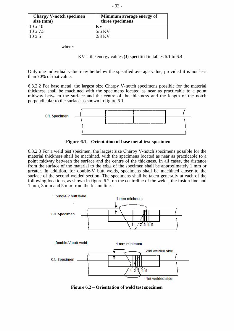
- 93 -
Charpy V-notch specimen size (mm)
Minimum average energy of three specimens
10 x 10 10 x 7.5 10 x 5
KV 5/6 KV 2/3 KV
where:
KV = the energy values (J) specified in tables 6.1 to 6.4.
Only one individual value may be below the specified average value, provided it is not less than 70% of that value.
6.3.2.2 For base metal, the largest size Charpy V-notch specimens possible for the material thickness shall be machined with the specimens located as near as practicable to a point midway between the surface and the centre of the thickness and the length of the notch perpendicular to the surface as shown in figure 6.1.
Figure 6.1 – Orientation of base metal test specimen
6.3.2.3 For a weld test specimen, the largest size Charpy V-notch specimens possible for the material thickness shall be machined, with the specimens located as near as practicable to a point midway between the surface and the centre of the thickness. In all cases, the distance from the surface of the material to the edge of the specimen shall be approximately 1 mm or greater. In addition, for double-V butt welds, specimens shall be machined closer to the surface of the second welded section. The specimens shall be taken generally at each of the following locations, as shown in figure 6.2, on the centreline of the welds, the fusion line and 1 mm, 3 mm and 5 mm from the fusion line.
Figure 6.2 – Orientation of weld test specimen
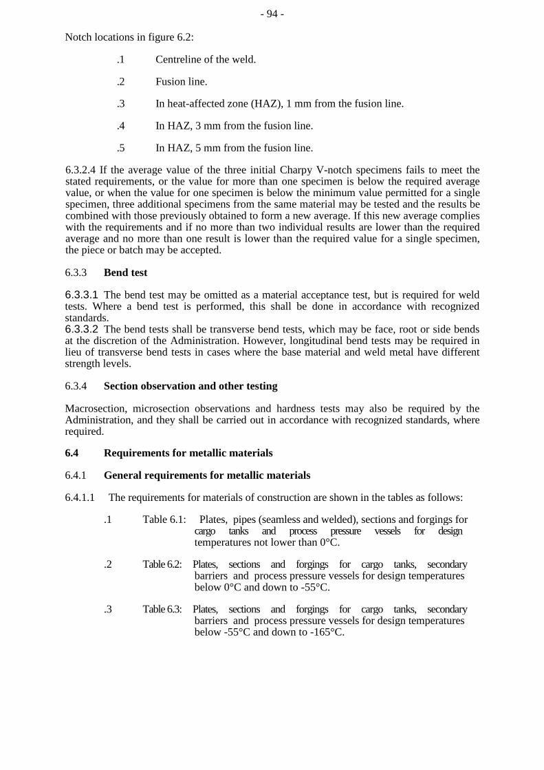
- 94 -
Notch locations in figure 6.2:
.1 Centreline of the weld.
.2 Fusion line.
.3 In heat-affected zone (HAZ), 1 mm from the fusion line.
.4 In HAZ, 3 mm from the fusion line.
.5 In HAZ, 5 mm from the fusion line.
6.3.2.4 If the average value of the three initial Charpy V-notch specimens fails to meet the stated requirements, or the value for more than one specimen is below the required average value, or when the value for one specimen is below the minimum value permitted for a single specimen, three additional specimens from the same material may be tested and the results be combined with those previously obtained to form a new average. If this new average complies with the requirements and if no more than two individual results are lower than the required average and no more than one result is lower than the required value for a single specimen, the piece or batch may be accepted.
6.3.3 Bend test
6.3.3.1 The bend test may be omitted as a material acceptance test, but is required for weld tests. Where a bend test is performed, this shall be done in accordance with recognized standards. 6.3.3.2 The bend tests shall be transverse bend tests, which may be face, root or side bends at the discretion of the Administration. However, longitudinal bend tests may be required in lieu of transverse bend tests in cases where the base material and weld metal have different strength levels.
6.3.4 Section observation and other testing
Macrosection, microsection observations and hardness tests may also be required by the Administration, and they shall be carried out in accordance with recognized standards, where required.
6.4 Requirements for metallic materials
6.4.1 General requirements for metallic materials
6.4.1.1 The requirements for materials of construction are shown in the tables as follows:
.1 Table 6.1: Plates, pipes (seamless and welded), sections and forgings for cargo tanks and process pressure vessels for design temperatures not lower than 0°C.
.2 Table 6.2: Plates, sections and forgings for cargo tanks, secondary barriers and process pressure vessels for design temperatures below 0°C and down to -55°C.
.3 Table 6.3: Plates, sections and forgings for cargo tanks, secondary barriers and process pressure vessels for design temperatures below -55°C and down to -165°C.
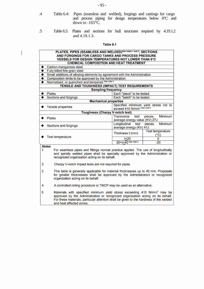
- 95 -
.4 Table 6.4: Pipes (seamless and welded), forgings and castings for cargo and process piping for design temperatures below 0°C and down to -165°C.
.5 Table 6.5: Plates and sections for hull structures required by 4.19.1.2 and 4.19.1.3.
- 96 –
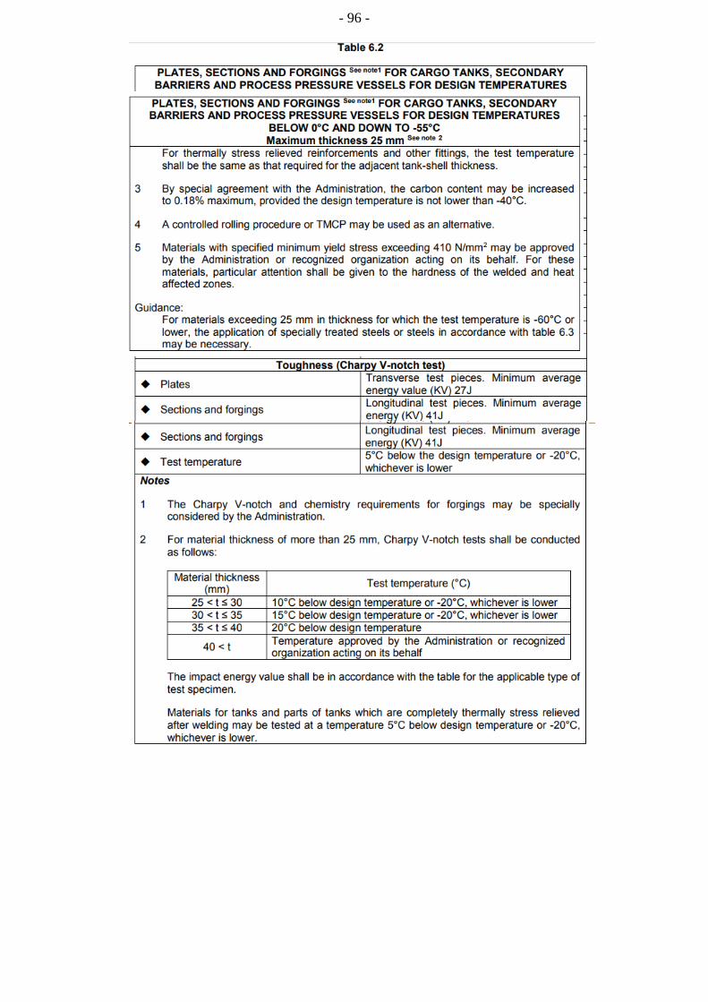
- 96 -
- 97 –
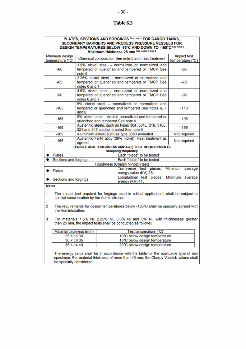
- 98 -
Table 6.3
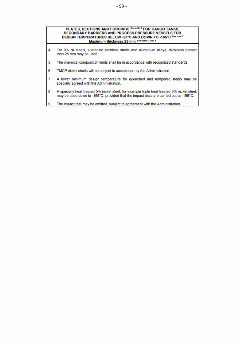
- 99 -

- 100 -
Table 6.4
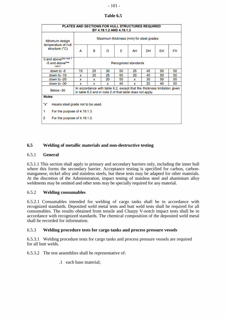
- 101 -
Table 6.5
6.5 Welding of metallic materials and non-destructive testing
6.5.1 General
6.5.1.1 This section shall apply to primary and secondary barriers only, including the inner hull where this forms the secondary barrier. Acceptance testing is specified for carbon, carbon-manganese, nickel alloy and stainless steels, but these tests may be adapted for other materials. At the discretion of the Administration, impact testing of stainless steel and aluminium alloy weldments may be omitted and other tests may be specially required for any material.
6.5.2 Welding consumables
6.5.2.1 Consumables intended for welding of cargo tanks shall be in accordance with recognized standards. Deposited weld metal tests and butt weld tests shall be required for all consumables. The results obtained from tensile and Charpy V-notch impact tests shall be in accordance with recognized standards. The chemical composition of the deposited weld metal shall be recorded for information.
6.5.3 Welding procedure tests for cargo tanks and process pressure vessels
6.5.3.1 Welding procedure tests for cargo tanks and process pressure vessels are required for all butt welds.
6.5.3.2 The test assemblies shall be representative of:
.1 each base material;
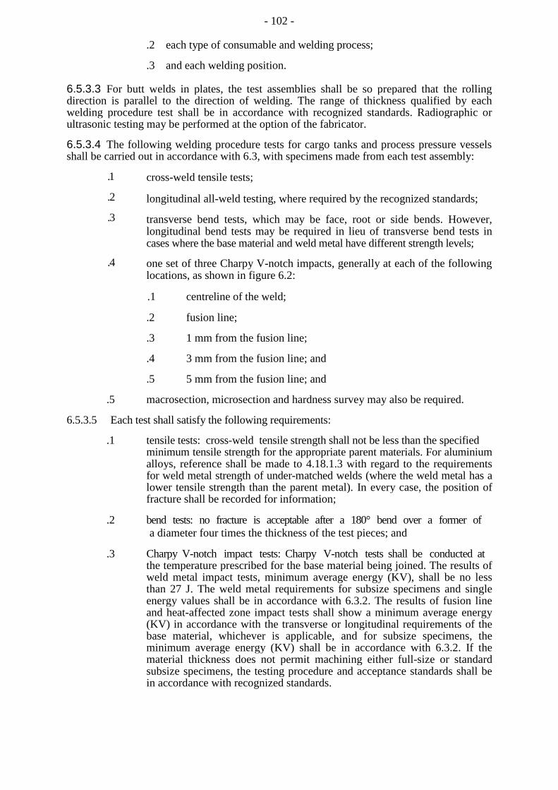
- 102 -
.2 each type of consumable and welding process;
.3 and each welding position.
6.5.3.3 For butt welds in plates, the test assemblies shall be so prepared that the rolling direction is parallel to the direction of welding. The range of thickness qualified by each welding procedure test shall be in accordance with recognized standards. Radiographic or ultrasonic testing may be performed at the option of the fabricator.
6.5.3.4 The following welding procedure tests for cargo tanks and process pressure vessels shall be carried out in accordance with 6.3, with specimens made from each test assembly:
.1
.2
.3
.4
cross-weld tensile tests;
longitudinal all-weld testing, where required by the recognized standards;
transverse bend tests, which may be face, root or side bends. However, longitudinal bend tests may be required in lieu of transverse bend tests in cases where the base material and weld metal have different strength levels;
one set of three Charpy V-notch impacts, generally at each of the following locations, as shown in figure 6.2:
.1 centreline of the weld;
.2 fusion line;
.3 1 mm from the fusion line;
.4 3 mm from the fusion line; and
.5 5 mm from the fusion line; and
.5 macrosection, microsection and hardness survey may also be required.
6.5.3.5 Each test shall satisfy the following requirements:
.1 tensile tests: cross-weld tensile strength shall not be less than the specified minimum tensile strength for the appropriate parent materials. For aluminium alloys, reference shall be made to 4.18.1.3 with regard to the requirements for weld metal strength of under-matched welds (where the weld metal has a lower tensile strength than the parent metal). In every case, the position of fracture shall be recorded for information;
.2 bend tests: no fracture is acceptable after a 180° bend over a former of a diameter four times the thickness of the test pieces; and
.3 Charpy V-notch impact tests: Charpy V-notch tests shall be conducted at the temperature prescribed for the base material being joined. The results of weld metal impact tests, minimum average energy (KV), shall be no less than 27 J. The weld metal requirements for subsize specimens and single energy values shall be in accordance with 6.3.2. The results of fusion line and heat-affected zone impact tests shall show a minimum average energy (KV) in accordance with the transverse or longitudinal requirements of the base material, whichever is applicable, and for subsize specimens, the minimum average energy (KV) shall be in accordance with 6.3.2. If the material thickness does not permit machining either full-size or standard subsize specimens, the testing procedure and acceptance standards shall be in accordance with recognized standards.
- 103 -
6.5.3.6 Procedure tests for fillet welding shall be in accordance with recognized standards. In such cases, consumables shall be so selected that exhibit satisfactory impact properties.
6.5.4 Welding procedure tests for piping
Welding procedure tests for piping shall be carried out and shall be similar to those detailed for cargo tanks in 6.5.3.
6.5.5 Production weld tests
6.5.5.1 For all cargo tanks and process pressure vessels, except integral and membrane tanks, production weld tests shall generally be performed for approximately each 50 m of butt-weld joints and shall be representative of each welding position. For secondary barriers, the same type production tests as required for primary tanks shall be performed, except that the number of tests may be reduced subject to agreement with the Administration. Tests, other than those specified in 6.5.5.2 to 6.5.5.5 may be required for cargo tanks or secondary barriers.
6.5.5.2 The production tests for type A and type B independent tanks and semi-membrane tanks shall include bend tests and, where required for procedure tests, one set of three Charpy V-notch tests. The tests shall be made for each 50 m of weld. The Charpy V-notch tests shall be made with specimens having the notch alternately located in the centre of the weld and in the heat-affected zone (most critical location based on procedure qualification results). For austenitic stainless steel, all notches shall be in the centre of the weld.
6.5.5.3 For type C independent tanks and process pressure vessels, transverse weld tensile tests are required in addition to the tests listed in 6.5.5.2. Tensile tests shall meet the requirements of 6.5.3.5.
6.5.5.4 The quality assurance/quality control programme shall ensure the continued conformity of the production welds as defined in the material manufacturers quality manual.
6.5.5.5 The test requirements for integral and membrane tanks are the same as the applicable test requirements listed in 6.5.3.
6.5.6 Non-destructive testing
6.5.6.1 All test procedures and acceptance standards shall be in accordance with recognized standards, unless the designer specifies a higher standard in order to meet design assumptions. Radiographic testing shall be used, in principle, to detect internal defects. However, an approved ultrasonic test procedure in lieu of radiographic testing may be conducted, but, in addition, supplementary radiographic testing at selected locations shall be carried out to verify the results. Radiographic and ultrasonic testing records shall be retained.
6.5.6.2 For type A independent tanks and semi-membrane tanks, where the design temperature is below -20°C, and for type B independent tanks, regardless of temperature, all full penetration butt welds of the shell plating of cargo tanks shall be subjected to non-destructive testing suitable to detect internal defects over their full length. Ultrasonic testing in lieu of radiographic testing may be carried out under the same conditions as described in 6.5.6.1.
- 104 -
6.5.6.3 Where the design temperature is higher than -20°C, all full penetration butt welds in way of intersections and at least 10% of the remaining full penetration welds of tank structures shall be subjected to radiographic testing or ultrasonic testing under the same conditions as described in 6.5.6.1.
6.5.6.4 In each case, the remaining tank structure, including the welding of stiffeners and other fittings and attachments, shall be examined by magnetic particle or dye penetrant methods, as considered necessary.
6.5.6.5 For type C independent tanks, the extent of non-destructive testing shall be total or partial according to recognized standards, but the controls to be carried out shall not be less than the following:
.1
.2
Total non-destructive testing referred to in 4.23.2.1.3:
Radiographic testing:
.1 all butt welds over their full length;
Non-destructive testing for surface crack detection:
.2 all welds over 10% of their length;
.3 reinforcement rings around holes, nozzles, etc., over their full length.
As an alternative, ultrasonic testing as described in 6.5.6.1 may be accepted as a partial substitute for the radiographic testing. In addition, the Administration may require total ultrasonic testing on welding of reinforcement rings around holes, nozzles, etc.
Partial non-destructive testing referred to in 4.23.2.1.3:
Radiographic testing:
.1 all butt-welded crossing joints and at least 10% of the full length of
butt welds at selected positions uniformly distributed;
Non-destructive testing for surface crack detection:
.2 all welds over 10% of their length;
.3 reinforcement rings around holes, nozzles, etc., over their full length; As an alternative, ultrasonic testing as described in 6.5.6.1 may be accepted as a partial substitute for the radiographic testing. In addition, the Administration may require total ultrasonic testing on welding of reinforcement rings around holes, nozzles, etc.
6.5.6.6 The quality assurance/quality control programme shall ensure the continued conformity of the non-destructive testing of welds, as defined in the material manufacturer's quality manual.
6.5.6.7 Inspection of piping shall be carried out in accordance with the requirements of chapter 5.
6.5.6.8 The secondary barrier shall be non-destructive tested for internal defects as considered necessary. Where the outer shell of the hull is part of the secondary barrier, all sheer strake butts and the intersections of all butts and seams in the side shell shall be tested by radiographic testing.
- 105 -
6.6 Other requirements for construction in metallic materials
6.6.1 General
6.6.1.1 Inspection and non-destructive testing of welds shall be in accordance with the requirements of 6.5.5 and 6.5.6. Where higher standards or tolerances are assumed in the design, they shall also be satisfied.
6.6.2 Independent tank
6.6.2.1 For type C tanks and type B tanks primarily constructed of bodies of revolution, the tolerances relating to manufacture, such as out-of-roundness, local deviations from the true form, welded joints alignment and tapering of plates having different thicknesses, shall comply with recognized standards. The tolerances shall also be related to the buckling analysis referred to in 4.22.3.2 and 4.23.3.2.
6.6.2.2 For type C tanks of carbon and carbon-manganese steel, post-weld heat treatment shall be performed after welding, if the design temperature is below -10°C. Post-weld heat treatment in all other cases and for materials other than those mentioned above shall be to recognized standards. The soaking temperature and holding time shall be to the recognized standards.
6.6.2.3 In the case of type C tanks and large cargo pressure vessels of carbon or carbon-manganese steel, for which it is difficult to perform the heat treatment, mechanical stress relieving by pressurizing may be carried out as an alternative to the heat treatment and subject to the following conditions:
.1 complicated welded pressure vessel parts such as sumps or domes with nozzles, with adjacent shell plates shall be heat treated before they are welded to larger parts of the pressure vessel;
.2 the mechanical stress relieving process shall preferably be carried out during the hydrostatic pressure test required by 4.23.6, by applying a higher pressure than the test pressure required by 4.23.6.1. The pressurizing medium shall be water;
.3 for the water temperature, 4.23.6.2 applies;
.4 stress relieving shall be performed while the tank is supported by its regular saddles or supporting structure or, when stress relieving cannot be carried out on board, in a manner which will give the same stresses and stress distribution as when supported by its regular saddles or supporting structure;
.5 the maximum stress relieving pressure shall be held for 2 h per 25 mm of thickness, but in no case less than 2 h;
.6 the upper limits placed on the calculated stress levels during stress relieving shall be the following:
.1 equivalent general primary membrane stress: 0.9 Re;
.2 equivalent stress composed of primary bending stress plus membrane stress: 1.35 Re, where Re is the specific lower minimum yield stress or 0.2% proof stress at test temperature of the steel used for the tank;

- 106 -
.7 strain measurements will normally be required to prove these limits for at least the first tank of a series of identical tanks built consecutively. The location of strain gauges shall be included in the mechanical stress relieving procedure to be submitted in accordance with 6.6.2.3;
.8 the test procedure shall demonstrate that a linear relationship between pressure and strain is achieved at the end of the stress relieving process when the pressure is raised again up to the design pressure;
.9 high-stress areas in way of geometrical discontinuities such as nozzles and other openings shall be checked for cracks by dye penetrant or magnetic particle inspection after mechanical stress relieving. Particular attention in this respect shall be paid to plates exceeding 30 mm in thickness;
.10 steels which have a ratio of yield stress to ultimate tensile strength greater than 0.8 shall generally not be mechanically stress relieved. If, however, the yield stress is raised by a method giving high ductility of the steel, slightly higher rates may be accepted upon consideration in each case;
.11 mechanical stress relieving cannot be substituted for heat treatment of cold formed parts of tanks, if the degree of cold forming exceeds the limit above which heat treatment is required;
.12 the thickness of the shell and heads of the tank shall not exceed 40 mm. Higher thicknesses may be accepted for parts which are thermally stress relieved;
.13 local buckling shall be guarded against, particularly when tori-spherical heads are used for tanks and domes; and
.14 the procedure for mechanical stress relieving shall be to a recognized standard.
6.6.3 Secondary barriers
During construction, the requirements for testing and inspection of secondary barriers shall be approved or accepted by the Administration or recognized organization acting on its behalf (see 4.6.2.5 and 4.6.2.6).
6.6.4 Semi-membrane tanks
For semi-membrane tanks, the relevant requirements in section 6.6 for independent tanks or for membrane tanks shall be applied as appropriate.
6.6.5 Membrane tanks
The quality assurance/quality control programme shall ensure the continued conformity of the weld procedure qualification, design details, materials, construction, inspection and production testing of components. These standards and procedures shall be developed during the prototype testing programme.
6.7 Non-metallic materials
6.7.1 General
The information in the attached appendix 4 is given for guidance in the selection and use of these materials, based on the experience to date.
- 107 -
CHAPTER 7
CARGO PRESSURE/TEMPERATURE
CONTROL
7.1 Methods of control
7.1.1 With the exception of tanks designed to withstand full gauge vapour pressure of the cargo under conditions of the upper ambient design temperatures, cargo tanks' pressure and temperature shall be maintained at all times within their design range by either one, or a combination of, the following methods:
.1 reliquefaction of cargo vapours;
.2 thermal oxidation of vapours;
.3 pressure accumulation; and
.4 liquid cargo cooling.
7.1.2 For certain cargoes, where required by chapter 17, the cargo containment system shall be capable of withstanding the full vapour pressure of the cargo under conditions of the upper ambient design temperatures, irrespective of any system provided for dealing with boil-off gas.
7.1.3 Venting of the cargo to maintain cargo tank pressure and temperature shall not be acceptable except in emergency situations. The Administration may permit certain cargoes to be controlled by venting cargo vapours to the atmosphere at sea. This may also be permitted in port with the authorization of the port Administration.
7.2 Design of systems
For normal service, the upper ambient design temperature shall be:
- sea: 32°C
- air: 45°C
For service in particularly hot or cold zones, these design temperatures shall be increased or decreased, to the satisfaction of the Administration. The overall capacity of the system shall be such that it can control the pressure within the design conditions without venting to atmosphere.
7.3 Reliquefaction of cargo vapours
7.3.1 General
The reliquefaction system may be arranged in one of the following ways:
.1 a direct system, where evaporated cargo is compressed, condensed and returned to the cargo tanks;
.2 an indirect system, where cargo or evaporated cargo is cooled or condensed by refrigerant without being compressed;
.3 a combined system, where evaporated cargo is compressed and condensed in a cargo/refrigerant heat exchanger and returned to the cargo tanks; and

- 108 -
.4 if the reliquefaction system produces a waste stream containing methane during pressure control operations within the design conditions, these waste gases, as far as reasonably practicable, are disposed of without venting to atmosphere.
Note:
The requirements of chapters 17 and 19 may preclude the use of one or more of these systems or may specify the use of a particular system.
7.3.2 Compatibility
Refrigerants used for reliquefaction shall be compatible with the cargo they may come into contact with. In addition, when several refrigerants are used and may come into contact, they shall be compatible with each other.
7.4 Thermal oxidation of vapours
7.4.1 General
Maintaining the cargo tank pressure and temperature by means of thermal oxidation of cargo vapours, as defined in 1.2.52 and 16.2 shall be permitted only for LNG cargoes. In general:
.1 thermal oxidation systems shall exhibit no externally visible flame and shall maintain the uptake exhaust temperature below 535°C;
.2 arrangement of spaces where oxidation systems are located shall comply with 16.3 and supply systems shall comply with 16.4; and
.3 if waste gases coming from any other system are to be burnt, the oxidation system shall be designed to accommodate all anticipated feed gas compositions.
7.4.2 Thermal oxidation systems
Thermal oxidation systems shall comply with the following:
.1 each thermal oxidation system shall have a separate uptake;
.2 each thermal oxidation system shall have a dedicated forced draught system; and
.3 combustion chambers and uptakes of thermal oxidation systems shall be
designed to prevent any accumulation of gas.
7.4.3 Burners Burners shall be designed to maintain stable combustion under all design
firing conditions.
7.4.4 Safety
7.4.4.1 Suitable devices shall be installed and arranged to ensure that gas flow to the burner is cut off unless satisfactory ignition has been established and maintained.
7.4.4.2 Each oxidation system shall have provision to manually isolate its gas fuel supply from a safely accessible position.
7.4.4.3 Provision shall be made for automatic purging the gas supply piping to the burners by means of an inert gas, after the extinguishing of these burners.

- 109 -
7.4.4.4 In case of flame failure of all operating burners for gas or oil or for a combination thereof, the combustion chambers of the oxidation system shall be automatically purged before relighting.
7.4.4.5 Arrangements shall be made to enable the combustion chamber to be manually purged.
7.5 Pressure accumulation systems
The containment system insulation, design pressure or both shall be adequate to provide for a suitable margin for the operating time and temperatures involved. No additional pressure and temperature control system is required. Conditions for acceptance shall be recorded in the International Certificate of Fitness for the Carriage of Liquefied Gases in Bulk required in 1.4.4.
7.6 Liquid cargo cooling
The bulk cargo liquid may be refrigerated by coolant circulated through coils fitted either inside the cargo tank or onto the external surface of the cargo tank.
7.7 Segregation
Where two or more cargoes that may react chemically in a dangerous manner are carried simultaneously, separate systems as defined in 1.2.47, each complying with availability criteria as specified in 7.8, shall be provided for each cargo. For simultaneous carriage of two or more cargoes that are not reactive to each other but where, due to properties of their vapour, separate systems are necessary, separation may be by means of isolation valves.
7.8 Availability
The availability of the system and its supporting auxiliary services shall be such that:
.1 in case of a single failure of a mechanical non-static component or a component of the control systems, the cargo tanks' pressure and temperature can be maintained within their design range without affecting other essential services;
.2 redundant piping systems are not required;
.3 heat exchangers that are solely necessary for maintaining the pressure and temperature of the cargo tanks within their design ranges shall have a standby heat exchanger, unless they have a capacity in excess of 25% of the largest required capacity for pressure control and they can be repaired on board without external resources. Where an additional and separate method of cargo tank pressure and temperature control is fitted that is not reliant on the sole heat exchanger, then a standby heat exchanger is not required; and
.4 for any cargo heating or cooling medium, provisions shall be made to detect the leakage of toxic or flammable vapours into an otherwise non-hazardous area or overboard in accordance with 13.6. Any vent outlet from this leak detection arrangement shall be to a non-hazardous area and be fitted with a flame screen.
- 110 -
CHAPTER 8
VENT SYSTEMS FOR CARGO CONTAINMENT
8.1 General
All cargo tanks shall be provided with a pressure relief system appropriate to the design of the cargo containment system and the cargo being carried. Hold spaces and interbarrier spaces, which may be subject to pressures beyond their design capabilities, shall also be provided with a suitable pressure relief system. Pressure control systems specified in chapter 7 shall be independent of the pressure relief systems.
8.2 Pressure relief systems
8.2.1 Cargo tanks, including deck tanks, shall be fitted with a minimum of two pressure relief valves (PRVs), each being of equal size within manufacturer's tolerances and suitably designed and constructed for the prescribed service.
8.2.2 Interbarrier spaces shall be provided with pressure relief devices. For membrane systems, the designer shall demonstrate adequate sizing of interbarrier space PRVs.
8.2.3 The setting of the PRVs shall not be higher than the vapour pressure that has been used in the design of the tank. Where two or more PRVs are fitted, valves comprising not more than 50% of the total relieving capacity may be set at a pressure up to 5% above MARVS to allow sequential lifting, minimizing unnecessary release of vapour.
8.2.4 The following temperature requirements apply to PRVs fitted to pressure relief systems:
.1 PRVs on cargo tanks with a design temperature below 0oC shall be designed and arranged to prevent their becoming inoperative due to ice formation;
.2 the effects of ice formation due to ambient temperatures shall be considered in the construction and arrangement of PRVs;
.3 PRVs shall be constructed of materials with a melting point above 925°C. Lower melting point materials for internal parts and seals may be accepted, provided that fail-safe operation of the PRV is not compromised; and
.4 sensing and exhaust lines on pilot operated relief valves shall be of suitably robust construction to prevent damage.
Valve testing
PRVs shall be type-tested. Type tests shall include:
.1 verification of relieving capacity;
.2 cryogenic testing when operating at design temperatures colder than -55°C;
8.2.5
8.2.5.1
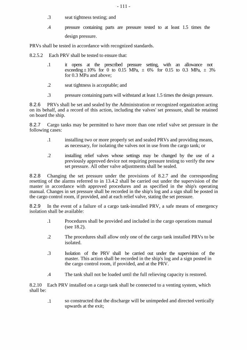
- 111 -
.3 seat tightness testing; and
.4 pressure containing parts are pressure tested to at least 1.5 times the
design pressure.
PRVs shall be tested in accordance with recognized standards.
8.2.5.2 Each PRV shall be tested to ensure that:
.1 it opens at the prescribed pressure setting, with an allowance not exceeding ± 10% for 0 to 0.15 MPa, ± 6% for 0.15 to 0.3 MPa, ± 3% for 0.3 MPa and above;
.2 seat tightness is acceptable; and
.3 pressure containing parts will withstand at least 1.5 times the design pressure.
8.2.6 PRVs shall be set and sealed by the Administration or recognized organization acting on its behalf, and a record of this action, including the valves' set pressure, shall be retained on board the ship.
8.2.7 Cargo tanks may be permitted to have more than one relief valve set pressure in the following cases:
.1 installing two or more properly set and sealed PRVs and providing means, as necessary, for isolating the valves not in use from the cargo tank; or
.2 installing relief valves whose settings may be changed by the use of a previously approved device not requiring pressure testing to verify the new set pressure. All other valve adjustments shall be sealed.
8.2.8 Changing the set pressure under the provisions of 8.2.7 and the corresponding resetting of the alarms referred to in 13.4.2 shall be carried out under the supervision of the master in accordance with approved procedures and as specified in the ship's operating manual. Changes in set pressure shall be recorded in the ship's log and a sign shall be posted in the cargo control room, if provided, and at each relief valve, stating the set pressure.
8.2.9 In the event of a failure of a cargo tank-installed PRV, a safe means of emergency isolation shall be available:
.1 Procedures shall be provided and included in the cargo operations manual (see 18.2).
.2 The procedures shall allow only one of the cargo tank installed PRVs to be isolated.
.3 Isolation of the PRV shall be carried out under the supervision of the master. This action shall be recorded in the ship's log and a sign posted in the cargo control room, if provided, and at the PRV.
.4 The tank shall not be loaded until the full relieving capacity is restored.
8.2.10 Each PRV installed on a cargo tank shall be connected to a venting system, which shall be:
.1 so constructed that the discharge will be unimpeded and directed vertically upwards at the exit;

- 112 -
.2 arranged to minimize the possibility of water or snow entering the vent system;
.3 arranged such that the height of vent exits shall not be less than B/3 or 6 m, whichever is the greater, above the weather deck; and
.4 6 m above working areas and walkways.
8.2.11.1Cargo PRV vent exits shall be arranged at a distance at least equal to B or 25 m, whichever is less, from the nearest air intake, outlet or opening to accommodation spaces, service spaces and control stations, or other non-hazardous areas. For ships less than 90 m in length, smaller distances may be permitted.
8.2.11.2All other vent outlets connected to the cargo containment system shall be arranged at a distance of at least 10 m from the nearest air intake, outlet or opening to accommodation spaces, service spaces and control stations, or other non-hazardous areas.
8.2.12 All other cargo vent outlets not dealt with in other chapters shall be arranged in accordance with 8.2.10, 8.2.11.1 and 8.2.11.2. Means shall be provided to prevent liquid overflow from vent mast outlets, due to hydrostatic pressure from spaces to which they are connected.
8.2.13 If cargoes that react in a dangerous manner with each other are carried simultaneously, a separate pressure relief system shall be fitted for each one.
8.2.14 In the vent piping system, means for draining liquid from places where it may accumulate shall be provided. The PRVs and piping shall be arranged so that liquid can, under no circumstances, accumulate in or near the PRVs.
8.2.15 Suitable protection screens of not more than 13 mm square mesh shall be fitted on vent outlets to prevent the ingress of extraneous objects without adversely affecting the flow. Other requirements for protection screens apply when carrying specific cargoes (see 17.9 and 17.21).
8.2.16 All vent piping shall be designed and arranged not to be damaged by the temperature variations to which it may be exposed, forces due to flow or the ship's motions.
8.2.17 PRVs shall be connected to the highest part of the cargo tank above deck level. PRVs shall be positioned on the cargo tank so that they will remain in the vapour phase at the filling limit (FL), under conditions of 15° list and 0.015L trim, where L is defined in 1.2.31.
8.2.18 The adequacy of the vent system fitted on tanks loaded shall be demonstrated by the Administration, taking into account the recommendations developed by the Organization. A relevant certificate shall be permanently kept on board the ship. For the purposes of this paragraph, vent system means:
.1 the tank outlet and the piping to the PRV;
.2 the PRV; and
.3 the piping from the PRVs to the location of discharge to the atmosphere, including any interconnections and piping that joins other tanks.

- 113 -
8.3 Vacuum protection systems
8.3.1 Cargo tanks not designed to withstand a maximum external pressure differential 0.025 MPa, or tanks that cannot withstand the maximum external pressure differential that can be attained at maximum discharge rates with no vapour return into the cargo tanks, or by operation of a cargo refrigeration system, or by thermal oxidation, shall be fitted with:
.1 two independent pressure switches to sequentially alarm and subsequently stop all suction of cargo liquid or vapour from the cargo tank and refrigeration equipment, if fitted, by suitable means at a pressure sufficiently below the maximum external designed pressure differential of the cargo tank; or
.2 vacuum relief valves with a gas flow capacity at least equal to the maximum cargo discharge rate per cargo tank, set to open at a pressure sufficiently below the external design differential pressure of the cargo tank.
8.3.2 Subject to the requirements of chapter 15, the vacuum relief valves shall admit an inert gas, cargo vapour or air to the cargo tank and shall be arranged to minimize the possibility of the entrance of water or snow. If cargo vapour is admitted, it shall be from a source other than the cargo vapour lines.
8.3.3 The vacuum protection system shall be capable of being tested to ensure that it operates at the prescribed pressure.
8.4 Sizing of pressure relieving system
8.4.1 Sizing of pressure relief valves
PRVs shall have a combined relieving capacity for each cargo tank to discharge the greater of the following, with not more than a 20% rise in cargo tank pressure above the MARVS:
8.4.1.1 The maximum capacity of the cargo tank inerting system, if the maximum attainable working pressure of the cargo tank inerting system exceeds the MARVS of the cargo tanks; or
8.4.1.2 Vapours generated under fire exposure computed using the following formula:
Q = FGA0.82 (m3/s),
where:
Q = minimum required rate of discharge of air at standard conditions of 273.15 Kelvin (K) and 0.1013 MPa;
F = fire exposure factor for different cargo types as follows:
- 1 for tanks without insulation located on deck;
- 0.5 for tanks above the deck, when insulation is approved by the Administration. Approval will be based on the use of a fireproofing material, the thermal conductance of insulation and its stability under fire exposure;
- 0.5 for uninsulated independent tanks installed in holds;
- 0.2 for insulated independent tanks in holds (or uninsulated independent tanks in insulated holds);
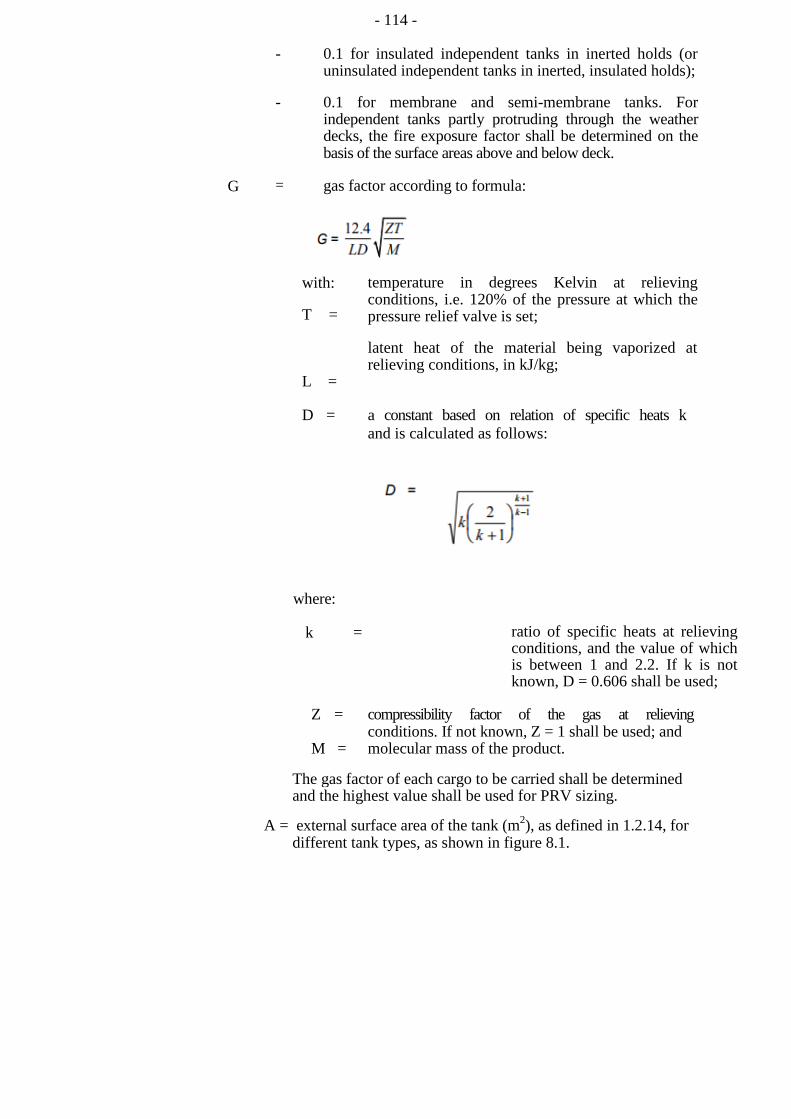
- 114 -
- 0.1 for insulated independent tanks in inerted holds (or uninsulated independent tanks in inerted, insulated holds);
- 0.1 for membrane and semi-membrane tanks. For independent tanks partly protruding through the weather decks, the fire exposure factor shall be determined on the basis of the surface areas above and below deck.
G = gas factor according to formula:
with:
T =
L =
temperature in degrees Kelvin at relieving conditions, i.e. 120% of the pressure at which the pressure relief valve is set;
latent heat of the material being vaporized at relieving conditions, in kJ/kg;
D = a constant based on relation of specific heats k and is calculated as follows:
where:
k = ratio of specific heats at relieving conditions, and the value of which is between 1 and 2.2. If k is not known, D = 0.606 shall be used;
Z = compressibility factor of the gas at relieving conditions. If not known, Z = 1 shall be used; and
M = molecular mass of the product.
The gas factor of each cargo to be carried shall be determined and the highest value shall be used for PRV sizing.
A = external surface area of the tank (m2), as defined in 1.2.14, for different tank types, as shown in figure 8.1.
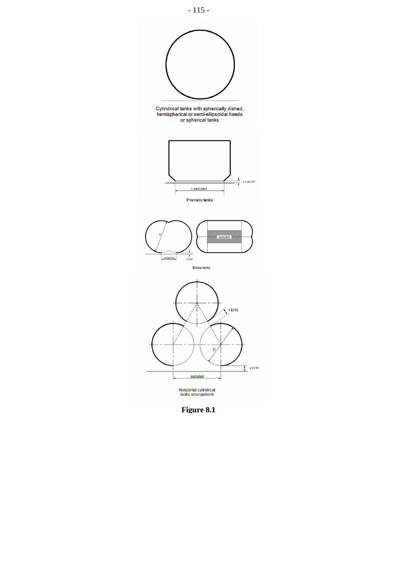
- 115 -
Figure 8.1
- 116 -
8.4.1.3 The required mass flow of air at relieving conditions is given by the formula:
Mair = Q ρair (kg/s),
where:
density of air (ρair) = 1.293 kg/m3 (air at 273.15 K, 0.1013 MPa).
8.4.2 Sizing of vent pipe system
Pressure losses upstream and downstream of the PRVs shall be taken into account when determining their size to ensure the flow capacity required by 8.4.1.
8.4.3 Upstream pressure losses
8.4.3.1 The pressure drop in the vent line from the tank to the PRV inlet shall not exceed 3% of the valve set pressure at the calculated flow rate, in accordance with 8.4.1.
8.4.3.2 Pilot-operated PRVs shall be unaffected by inlet pipe pressure losses when the pilot senses directly from the tank dome.
8.4.3.3 Pressure losses in remotely sensed pilot lines shall be considered for flowing type pilots.
8.4.4 Downstream pressure losses
8.4.4.1 Where common vent headers and vent masts are fitted, calculations shall include flow from all attached PRVs.
8.4.4.2 The built-up back pressure in the vent piping from the PRV outlet to the location of discharge to the atmosphere, and including any vent pipe interconnections that join other tanks, shall not exceed the following values:
.1 for unbalanced PRVs: 10% of MARVS;
.2 for balanced PRVs: 30% of MARVS; and
.3 for pilot operated PRVs: 50% of MARVS.
Alternative values provided by the PRV manufacturer may be accepted.
8.4.5 To ensure stable PRV operation, the blow-down shall not be less than the sum of the inlet pressure loss and 0.02 MARVS at the rated capacity.

- 117 -
CHAPTER 9
CARGO CONTAINMENT SYSTEM ATMOSPHERE CONTROL
9.1 Atmosphere control within the cargo containment system
9.1.1 A piping system shall be arranged to enable each cargo tank to be safely gas-freed, and to be safely filled with cargo vapour from a gas-free condition. The system shall be arranged to minimize the possibility of pockets of gas or air remaining after changing the atmosphere.
9.1.2 For flammable cargoes, the system shall be designed to eliminate the possibility of a flammable mixture existing in the cargo tank during any part of the atmosphere change operation by utilizing an inerting medium as an intermediate step.
9.1.3 Piping systems that may contain flammable cargoes shall comply with 9.1.1 and 9.1.2.
9.1.4 A sufficient number of gas sampling points shall be provided for each cargo tank and cargo piping system to adequately monitor the progress of atmosphere change. Gas sampling connections shall be fitted with a single valve above the main deck, sealed with a suitable cap or blank (see 5.6.5.5).
9.1.5 Inert gas utilized in these procedures may be provided from the shore or from the ship.
9.2 Atmosphere control within the hold spaces (cargo containment systems other than type C independent tanks)
9.2.1 Interbarrier and hold spaces associated with cargo containment systems for flammable gases requiring full or partial secondary barriers shall be inerted with a suitable dry inert gas and kept inerted with make-up gas provided by a shipboard inert gas generation system, or by shipboard storage, which shall be sufficient for normal consumption for at least 30 days.
9.2.2 Alternatively, subject to the restrictions specified in chapter 17, the spaces referred to in 9.2.1 requiring only a partial secondary barrier may be filled with dry air provided that the ship maintains a stored charge of inert gas or is fitted with an inert gas generation system sufficient to inert the largest of these spaces, and provided that the configuration of the spaces and the relevant vapour detection systems, together with the capability of the inerting arrangements, ensures that any leakage from the cargo tanks will be rapidly detected and inerting effected before a dangerous condition can develop. Equipment for the provision of sufficient dry air of suitable quality to satisfy the expected demand shall be provided.
9.2.3 For non-flammable gases, the spaces referred to in 9.2.1 and 9.2.2 may be maintained with a suitable dry air or inert atmosphere.
9.3 Environmental control of spaces surrounding type C independent tanks
Spaces surrounding cargo tanks that do not have secondary barriers shall be filled with suitable dry inert gas or dry air and be maintained in this condition with make-up inert gas provided by a shipboard inert gas generation system, shipboard storage of inert gas, or with

- 118 -
dry air provided by suitable air drying equipment. If the cargo is carried at ambient temperature, the requirement for dry air or inert gas is not applicable.
9.4 Inerting
9.4.1 Inerting refers to the process of providing a non-combustible environment. Inert gases shall be compatible chemically and operationally at all temperatures likely to occur within the spaces and the cargo. The dew points of the gases shall be taken into consideration.
9.4.2 Where inert gas is also stored for firefighting purposes, it shall be carried in separate containers and shall not be used for cargo services.
9.4.3 Where inert gas is stored at temperatures below 0oC, either as a liquid or as a vapour, the storage and supply system shall be designed so that the temperature of the ship's structure is not reduced below the limiting values imposed on it.
9.4.4 Arrangements to prevent the backflow of cargo vapour into the inert gas system that are suitable for the cargo carried, shall be provided. If such plants are located in machinery spaces or other spaces outside the cargo area, two non-return valves or equivalent devices and, in addition, a removable spool piece shall be fitted in the inert gas main in the cargo area. When not in use, the inert gas system shall be made separate from the cargo system in the cargo area except for connections to the hold spaces or interbarrier spaces.
9.4.5 The arrangements shall be such that each space being inerted can be isolated and the necessary controls and relief valves, etc., shall be provided for controlling pressure in these spaces.
9.4.6 Where insulation spaces are continually supplied with an inert gas as part of a leak detection system, means shall be provided to monitor the quantity of gas being supplied to individual spaces.
9.5 Inert gas production on board
9.5.1 The equipment shall be capable of producing inert gas with an oxygen content at no time greater than 5% by volume, subject to the special requirements of chapter 17. A continuous-reading oxygen content meter shall be fitted to the inert gas supply from the equipment and shall be fitted with an alarm set at a maximum of 5% oxygen content by volume, subject to the requirements of chapter 17.
9.5.2 An inert gas system shall have pressure controls and monitoring arrangements appropriate to the cargo containment system.
9.5.3 Spaces containing inert gas generation plants shall have no direct access to accommodation spaces, service spaces or control stations, but may be located in machinery spaces. Inert gas piping shall not pass through accommodation spaces, service spaces or control stations.
9.5.4 Combustion equipment for generating inert gas shall not be located within the cargo area. Special consideration may be given to the location of inert gas generating equipment using a catalytic combustion process.
- 119 -
CHAPTER 10
ELECTRICAL INSTALLATIONS
10.1 Definitions
For the purpose of this chapter, unless expressly provided otherwise, the definitions below shall apply.
10.1.1 Hazardous area is an area in which an explosive gas atmosphere is or may be expected to be present, in quantities such as to require special precautions for the construction, installation and use of electrical apparatus.
10.1.1.1Zone 0 hazardous area is an area in which an explosive gas atmosphere is present continuously or is present for long periods.
10.1.1.2Zone 1 hazardous area is an area in which an explosive gas atmosphere is likely to occur in normal operation.
10.1.1.3Zone 2 hazardous area is an area in which an explosive gas atmosphere is not likely to occur in normal operation and, if it does occur, is likely to do so infrequently and for a short period only.
10.1.2 Non-hazardous area is an area in which an explosive gas atmosphere is not expected to be present in quantities such as to require special precautions for the construction, installation and use of electrical apparatus.
10.2 General requirements
10.2.1 Electrical installations shall be such as to minimize the risk of fire and explosion from flammable products.
10.2.2 Electrical installations shall be in accordance with recognized standards.
10.2.3 Electrical equipment or wiring shall not be installed in hazardous areas, unless essential for operational purposes or safety enhancement.
10.2.4 Where electrical equipment is installed in hazardous areas as provided in 10.2.3, it shall be selected, installed and maintained in accordance with standards not inferior to those acceptable to the Administration. Equipment for hazardous areas shall be evaluated and certified or listed by an accredited testing authority or notified body recognized by the Administration. Automatic isolation of non-certified equipment on detection of a flammable gas shall not be accepted as an alternative to the use of certified equipment.
10.2.5 To facilitate the selection of appropriate electrical apparatus and the design of suitable electrical installations, hazardous areas are divided into zones in accordance with recognized standards.
- 120 -
10.2.6 Electrical generation and distribution systems, and associated control systems shall be designed such that a single fault will not result in the loss of ability to maintain cargo tank pressures, as required by 7.8.1, and hull structure temperature, as required by 4.19.1.6, within normal operating limits. Failure modes and effects shall be analysed and documented to a standard not inferior to those acceptable to the Administration.
10.2.7 The lighting system in hazardous areas shall be divided between at least two branch circuits. All switches and protective devices shall interrupt all poles or phases and shall be located in a non-hazardous area.
10.2.8 Electrical depth sounding or log devices and impressed current cathodic protection system anodes or electrodes shall be housed in gastight enclosures.
10.2.9 Submerged cargo pump motors and their supply cables may be fitted in cargo containment systems. Arrangements shall be made to automatically shut down the motors in the event of low-liquid level. This may be accomplished by sensing low pump discharge pressure, low motor current or low liquid level. This shutdown shall be alarmed at the cargo control station. Cargo pump motors shall be capable of being isolated from their electrical supply during gas-freeing operations.
CHAPTER 11
FIRE PROTECTION AND
EXTINCTION
11.1 Fire safety requirements
11.1.1 The requirements for tankers in SOLAS chapter ll-2 shall apply to ships covered by the Guidance, irrespective of tonnage including ships of less than 500 gross tonnage, except that:
.1 regulations 4.5.1.6 and 4.5.10 do not apply;
.2 regulations 10.4 and 10.5 shall apply as they would apply to tankers
of 2,000 gross tonnage and over;
.3 regulation 10.5.6 shall apply to ships of 2,000 gross tonnage and over;
.4 the following regulations of SOLAS chapter II-2 related to tankers do not apply and are replaced by chapters and sections of the Guidance as detailed below:
Regulation: Replaced by:
10.10 11.6
4.5.1.1 and 4.5.1.2 Chapter 3
4.5.5 Relevant sections in the
guidance

- 121 -
10.8 11.3 and 11.4
10.9 11.5 10.2
11.2.1 to 11.2.4;
.5 regulations 13.3.4 and 13.4.3 shall apply to ships of 500 gross tonnage and over.
11.1.2 All sources of ignition shall be excluded from spaces where flammable vapour may be present, except as otherwise provided in chapters 10 and 16.
11.1.3 The provisions of this section shall apply in conjunction with chapter 3.
11.1.4 For the purposes of firefighting, any weather deck areas above cofferdams, ballast or void spaces at the after end of the aftermost hold space or at the forward end of the forwardmost hold space shall be included in the cargo area.
11.2 Fire mains and hydrants
11.2.1 Irrespective of size, ships carrying products that are subject to the Guidance shall comply with the requirements of regulation ll-2/10.2 of the SOLAS Convention, as applicable to cargo ships, except that the required fire pump capacity and fire main and water service pipe diameter shall not be limited by the provisions of regulations ll-2/10.2.2.4.1 and ll-2/10.2.1.3, when a fire pump is used to supply the water-spray system, as permitted by 11.3.3 of the Guidance. The capacity of this fire pump shall be such that these areas can be protected when simultaneously supplying two jets of water from fire hoses with 19 mm nozzles at a pressure of at least 0.5 MPa.
11.2.2 The arrangements shall be such that at least two jets of water can reach any part of the deck in the cargo area and those portions of the cargo containment system and tank covers that are above the deck. The necessary number of fire hydrants shall be located to satisfy the above arrangements and to comply with the requirements of regulations ll-2/10.2.1.5.1 and ll-2/10.2.3.3 of the SOLAS Convention, with hose lengths as specified in regulation ll-2/10.2.3.1.1. In addition, the requirements of regulation ll-2/10.2.1.6 shall be met at a pressure of at least 0.5 MPa gauge.
11.2.3 Stop valves shall be fitted in any crossover provided and in the fire main or mains in a protected location, before entering the cargo area and at intervals ensuring isolation of any damaged single section of the fire main, so that 11.2.2 can be complied with using not more than two lengths of hoses from the nearest fire hydrant. The water supply to the fire main serving the cargo area shall be a ring main supplied by the main fire pumps or a single main supplied by fire pumps positioned fore and aft of the cargo area, one of which shall be independently driven.
11.2.4 Nozzles shall be of an approved dual-purpose type (i.e. spray/jet type) incorporating a shutoff.
11.2.5 After installation, the pipes, valves, fittings and assembled system shall be subject to a tightness and function test.
- 122 -
11.3 Water-spray system
11.3.1 On ships carrying flammable and/or toxic products, a water-spray system, for cooling, fire prevention and crew protection shall be installed to cover:
.1 exposed cargo tank domes, any exposed parts of cargo tanks and any part of cargo tank covers that may be exposed to heat from fires in adjacent equipment containing cargo such as exposed booster pumps/heaters/re-gasification or re-liquefaction plants, hereafter addressed as gas process units, positioned on weather decks;
.2 exposed on-deck storage vessels for flammable or toxic products;
.3 gas process units positioned on deck;
.4 cargo liquid and vapour discharge and loading connections, including the presentation flange and the area where their control valves are situated, which shall be at least equal to the area of the drip trays provided;
.5 all exposed emergency shut-down (ESD) valves in the cargo liquid and vapour pipes, including the master valve for supply to gas consumers;
.6 exposed boundaries facing the cargo area, such as bulkheads of superstructures and deckhouses normally manned, cargo machinery spaces, store-rooms containing high fire-risk items and cargo control rooms. Exposed horizontal boundaries of these areas do not require protection unless detachable cargo piping connections are arranged above or below. Boundaries of unmanned forecastle structures not containing high fire-risk items or equipment do not require water-spray protection;
.7 exposed lifeboats, liferafts and muster stations facing the cargo area, regardless of distance to cargo area; and
.8 any semi-enclosed cargo machinery spaces and semi-enclosed cargo motor room.
Ships intended for operation as listed (see 11.3.3.2).
in 1.1.10 shall be subject to special consideration
11.3.2.1The system shall be capable of covering all areas mentioned in 11.3.1.1 to 11.3.1.8, with a uniformly distributed water application rate of at least 10 ℓ/m2/min for the largest projected horizontal surfaces and 4 ℓ/m2/min for vertical surfaces. For structures having no clearly defined horizontal or vertical surface, the capacity of the water-spray system shall not be less than the projected horizontal surface multiplied by 10 ℓ/m2/min.
11.3.2.2On vertical surfaces, spacing of nozzles protecting lower areas may take account of anticipated rundown from higher areas. Stop valves shall be fitted in the main supply line(s) in the water-spray system, at intervals not exceeding 40 m, for the purpose of isolating damaged sections. Alternatively, the system may be divided into two or more sections that may be operated independently, provided the necessary controls are located together in a readily accessible position outside the cargo area. A section protecting any area included in 11.3.1.1 and .2 shall cover at least the entire athwartship tank grouping in that area. Any gas process unit(s) included in 11.3.1.3 may be served by an independent section.
- 123 -
11.3.3 The capacity of the water-spray pumps shall be capable of simultaneous protection of the greater of the following:
.1 any two complete athwartship tank groupings, including any gas process units within these areas; or
.2 for ships intended for operation as listed in 1.1.10, necessary protection subject to special consideration under 11.3.1 of any added fire hazard and the adjacent athwartship tank grouping,
in addition to surfaces specified in 11.3.1.4 to 11.3.1.8. Alternatively, the main fire pumps may be used for this service, provided that their total capacity is increased by the amount needed for the water-spray system. In either case, a connection, through a stop valve, shall be made between the fire main and water-spray system main supply line outside the cargo area.
11.3.4 The boundaries of superstructures and deckhouses normally manned, and lifeboats, liferafts and muster areas facing the cargo area, shall also be capable of being served by one of the fire pumps or the emergency fire pump, if a fire in one compartment could disable both fire pumps.
11.3.5 Water pumps normally used for other services may be arranged to supply the water-spray system main supply line.
11.3.6 All pipes, valves, nozzles and other fittings in the water-spray system shall be resistant to corrosion by seawater. Piping, fittings and related components within the cargo area (except gaskets) shall be designed to withstand 925°C. The water-spray system shall be arranged with in-line filters to prevent blockage of pipes and nozzles. In addition, means shall be provided to back-flush the system with fresh water.
11.3.7 Remote starting of pumps supplying the water-spray system and remote operation of any normally closed valves in the system shall be arranged in suitable locations outside the cargo area, adjacent to the accommodation spaces and readily accessible and operable in the event of fire in the protected areas.
11.3.8 After installation, the pipes, valves, fittings and assembled system shall be subject to a tightness and function test.
11.4 Dry chemical powder fire-extinguishing systems
11.4.1 Ships in which the carriage of flammable products is intended shall be fitted with fixed dry chemical powder fire-extinguishing systems, approved by the Administration based on the guidelines developed by the Organization, for the purpose of firefighting on the deck in the cargo area, including any cargo liquid and vapour discharge and loading connections on deck and bow or stern cargo handling areas, as applicable.
11.4.2 The system shall be capable of delivering powder from at least two hand hose lines, or a combination of monitor/hand hose lines, to any part of the exposed cargo liquid and vapour piping, load/unload connection and exposed gas process units.
11.4.3 The dry chemical powder fire-extinguishing system shall be designed with not less than two independent units. Any part required to be protected by 11.4.2 shall be capable of being reached from not less than two independent units with associated controls, pressurizing medium fixed piping, monitors or hand hose lines. For ships with a cargo capacity of less than 1,000 m3, only one such unit need be fitted. A monitor shall be arranged to protect any load/unload connection area and be capable of actuation and discharge both locally and remotely. The monitor is not required to be remotely aimed, if it can deliver the necessary powder to all required areas of coverage from a single position. One hose line
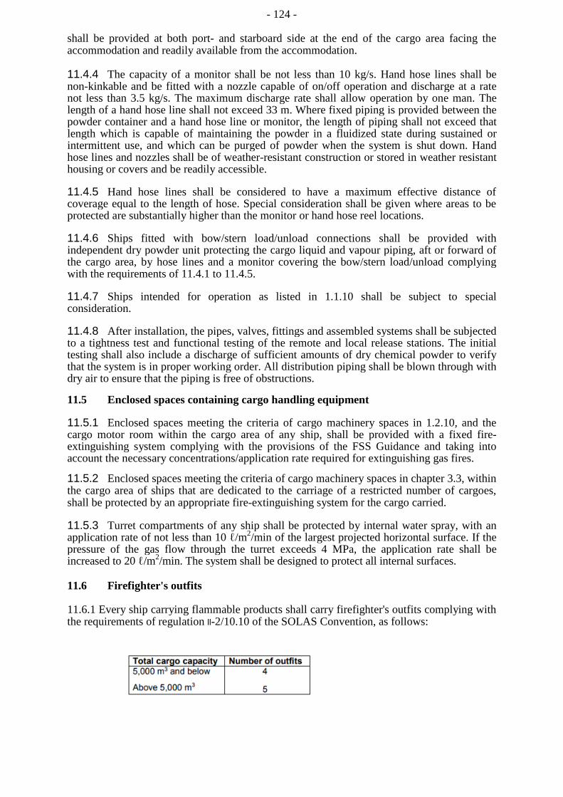
- 124 -
shall be provided at both port- and starboard side at the end of the cargo area facing the accommodation and readily available from the accommodation.
11.4.4 The capacity of a monitor shall be not less than 10 kg/s. Hand hose lines shall be non-kinkable and be fitted with a nozzle capable of on/off operation and discharge at a rate not less than 3.5 kg/s. The maximum discharge rate shall allow operation by one man. The length of a hand hose line shall not exceed 33 m. Where fixed piping is provided between the powder container and a hand hose line or monitor, the length of piping shall not exceed that length which is capable of maintaining the powder in a fluidized state during sustained or intermittent use, and which can be purged of powder when the system is shut down. Hand hose lines and nozzles shall be of weather-resistant construction or stored in weather resistant housing or covers and be readily accessible.
11.4.5 Hand hose lines shall be considered to have a maximum effective distance of coverage equal to the length of hose. Special consideration shall be given where areas to be protected are substantially higher than the monitor or hand hose reel locations.
11.4.6 Ships fitted with bow/stern load/unload connections shall be provided with independent dry powder unit protecting the cargo liquid and vapour piping, aft or forward of the cargo area, by hose lines and a monitor covering the bow/stern load/unload complying with the requirements of 11.4.1 to 11.4.5.
11.4.7 Ships intended for operation as listed in 1.1.10 shall be subject to special consideration.
11.4.8 After installation, the pipes, valves, fittings and assembled systems shall be subjected to a tightness test and functional testing of the remote and local release stations. The initial testing shall also include a discharge of sufficient amounts of dry chemical powder to verify that the system is in proper working order. All distribution piping shall be blown through with dry air to ensure that the piping is free of obstructions.
11.5 Enclosed spaces containing cargo handling equipment
11.5.1 Enclosed spaces meeting the criteria of cargo machinery spaces in 1.2.10, and the cargo motor room within the cargo area of any ship, shall be provided with a fixed fire-extinguishing system complying with the provisions of the FSS Guidance and taking into account the necessary concentrations/application rate required for extinguishing gas fires.
11.5.2 Enclosed spaces meeting the criteria of cargo machinery spaces in chapter 3.3, within the cargo area of ships that are dedicated to the carriage of a restricted number of cargoes, shall be protected by an appropriate fire-extinguishing system for the cargo carried.
11.5.3 Turret compartments of any ship shall be protected by internal water spray, with an application rate of not less than 10 ℓ/m2/min of the largest projected horizontal surface. If the pressure of the gas flow through the turret exceeds 4 MPa, the application rate shall be increased to 20 ℓ/m2/min. The system shall be designed to protect all internal surfaces.
11.6 Firefighter's outfits
11.6.1 Every ship carrying flammable products shall carry firefighter's outfits complying with the requirements of regulation II-2/10.10 of the SOLAS Convention, as follows:

- 125 -
11.6.2 Additional requirements for safety equipment are given in chapter 14.
11.6.3 Any breathing apparatus required as part of a firefighter's outfit shall be a self-contained compressed air-operated breathing apparatus having a capacity of at least 1,200 ℓ of free air.
CHAPTER 12
ARTIFICIAL VENTILATION IN THE CARGO AREA
12.1 Spaces required to be entered during normal cargo handling operations
12.1.1 Electric motor rooms, cargo compressor and pump-rooms, spaces containing cargo handling equipment and other enclosed spaces where cargo vapours may accumulate shall be fitted with fixed artificial ventilation systems capable of being controlled from outside such spaces. The ventilation shall be run continuously to prevent the accumulation of toxic and/or flammable vapours, with a means of monitoring acceptable to the Administration to be provided. A warning notice requiring the use of such ventilation prior to entering shall be placed outside the compartment.
12.1.2 Artificial ventilation inlets and outlets shall be arranged to ensure sufficient air movement through the space to avoid accumulation of flammable, toxic or asphyxiant vapours, and to ensure a safe working environment.
12.1.3 The ventilation system shall have a capacity of not less than 30 changes of air per hour, based upon the total volume of the space. As an exception, non-hazardous cargo control rooms may have eight changes of air per hour.
12.1.4 Where a space has an opening into an adjacent more hazardous space or area, it shall be maintained at an overpressure. It may be made into a less hazardous space or non-hazardous space by overpressure protection in accordance with recognized standards.
12.1.5 Ventilation ducts, air intakes and exhaust outlets serving artificial ventilation systems shall be positioned in accordance with recognized standards.
12.1.6 Ventilation ducts serving hazardous areas shall not be led through accommodation, service and machinery spaces or control stations.
- 126 -
12.1.7 Electric motors' driving fans shall be placed outside the ventilation ducts that may contain flammable vapours. Ventilation fans shall not produce a source of ignition in either the ventilated space or the ventilation system associated with the space. For hazardous areas, ventilation fans and ducts, adjacent to the fans, shall be of non-sparking construction, as defined below:
.1 impellers or housing of non-metallic construction, with due regard being
paid to the elimination of static electricity;
.2 impellers and housing of non-ferrous materials;
.3 impellers and housing of austenitic stainless steel; and
.4 ferrous impellers and housing with design tip clearance of not less than 13 mm.
Any combination of an aluminium or magnesium alloy fixed or rotating component and a ferrous fixed or rotating component, regardless of tip clearance, is considered a sparking hazard and shall not be used in these places.
12.1.8 Where fans are required by this chapter, full required ventilation capacity for each space shall be available after failure of any single fan, or spare parts shall be provided comprising a motor, starter spares and complete rotating element, including bearings of each type.
12.1.9 Protection screens of not more than 13 mm square mesh shall be fitted to outside openings of ventilation ducts.
12.1.10 Where spaces are protected by pressurization, the ventilation shall be designed and installed in accordance with recognized standards.
12.2 Spaces not normally entered
12.2.1 Enclosed spaces where cargo vapours may accumulate shall be capable of being ventilated to ensure a safe environment when entry into them is necessary. This shall be capable of being achieved without the need for prior entry.
12.2.2 For permanent installations, the capacity of 8 air changes per hour shall be provided and for portable systems, the capacity of 16 air changes per hour.
12.2.3 Fans or blowers shall be clear of personnel access openings, and shall comply with 12.1.7.
- 127 -
CHAPTER 13
INSTRUMENTATION AND AUTOMATION
SYSTEMS
13.1 General
13.1.1 Each cargo tank shall be provided with a means for indicating level, pressure and temperature of the cargo. Pressure gauges and temperature indicating devices shall be installed in the liquid and vapour piping systems, in cargo refrigeration installations.
13.1.2 If loading and unloading of the ship is performed by means of remotely controlled valves and pumps, all controls and indicators associated with a given cargo tank shall be concentrated in one control position.
13.1.3 Instruments shall be tested to ensure reliability under the working conditions, and recalibrated at regular intervals. Test procedures for instruments and the intervals between recalibration shall be in accordance with manufacturer's recommendations.
13.2 Level indicators for cargo tanks
13.2.1 Each cargo tank shall be fitted with liquid level gauging device(s), arranged to ensure that a level reading is always obtainable whenever the cargo tank is operational. The device(s) shall be designed to operate throughout the design pressure range of the cargo tank and at temperatures within the cargo operating temperature range.
13.2.2 Where only one liquid level gauge is fitted, it shall be arranged so that it can be maintained in an operational condition without the need to empty or gas-free the tank.
13.2.3 Cargo tank liquid level gauges may be of the following types:
.1 indirect devices, which determine the amount of cargo by means such as weighing or in-line flow metering;
.2 closed devices which do not penetrate the cargo tank, such as devices using radio-isotopes or ultrasonic devices;
.3 closed devices which penetrate the cargo tank, but which form part of a closed system and keep the cargo from being released, such as float type systems, electronic probes, magnetic probes and bubble tube indicators. If closed gauging device is not mounted directly onto the tank, it shall be provided with a shutoff valve located as close as possible to the tank; and
.4 restricted devices which penetrate the tank and, when in use, permit a small quantity of cargo vapour or liquid to escape to the atmosphere, such as fixed tube and slip tube gauges. When not in use, the devices shall be kept completely closed. The design and installation shall ensure that no dangerous escape of cargo can take place when opening the device. Such gauging devices shall be so designed that the maximum opening does not exceed 1.5 mm diameter or equivalent area, unless the device is provided with an excess flow valve.
- 128 -
13.3 Overflow control
13.3.1 Except as provided in 13.3.4, each cargo tank shall be fitted with a high liquid level alarm operating independently of other liquid level indicators and giving an audible and visual warning when activated.
13.3.2 An additional sensor operating independently of the high liquid level alarm shall automatically actuate a shutoff valve in a manner that will both avoid excessive liquid pressure in the loading line and prevent the tank from becoming liquid full.
13.3.3 The emergency shutdown valve referred to in 5.5 and 18.10 may be used for this purpose. If another valve is used for this purpose, the same information as referred to in 18.10.2.1.3 shall be available on board. During loading, whenever the use of these valves may possibly create a potential excess pressure surge in the loading system, alternative arrangements such as limiting the loading rate shall be used.
13.3.4 A high liquid level alarm and automatic shut-off of cargo tank filling need not be required, when the cargo tank:
.1 is a pressure tank with a volume not more than 200 m3; or
.2 is designed to withstand the maximum possible pressure during the loading operation, and such pressure is below that of the set pressure of the cargo tank relief valve.
13.3.5 The position of the sensors in the tank shall be capable of being verified before commissioning. At the first occasion of full loading after delivery and after each dry-docking, testing of high-level alarms shall be conducted by raising the cargo liquid level in the cargo tank to the alarm point.
13.3.6 All elements of the level alarms, including the electrical circuit and the sensor(s), of the high, and overfill alarms, shall be capable of being functionally tested. Systems shall be tested prior to cargo operation.
13.3.7 Where arrangements are provided for overriding the overflow control system, they shall be such that inadvertent operation is prevented. When this override is operated, continuous visual indication shall be given at the relevant control station(s) and the navigation bridge.
13.4 Pressure monitoring
13.4.1 The vapour space of each cargo tank shall be provided with a direct reading gauge. Additionally, an indirect indication shall be provided at the control position required by 13.1.2. Maximum and minimum allowable pressures shall be clearly indicated.
13.4.2 A high-pressure alarm and, if vacuum protection is required, a low-pressure alarm shall be provided on the navigation bridge and at the control position required by 13.1.2. Alarms shall be activated before the set pressures are reached.
13.4.3 For cargo tanks fitted with PRVs which can be set at more than one set pressure in accordance with 8.2.7, high-pressure alarms shall be provided for each set pressure.
13.4.4 Each cargo-pump discharge line and each liquid and vapour cargo manifold shall be provided with at least one pressure indicator.
13.4.5 Local-reading manifold pressure indication shall be provided to indicate the pressure between ship's manifold valves and hose connections to the shore.
- 129 -
13.4.6 Hold spaces and interbarrier spaces without open connection to the atmosphere shall be provided with pressure indication.
13.4.7 All pressure indications provided shall be capable of indicating throughout the operating pressure range.
13.5 Temperature indicating devices
13.5.1 Each cargo tank shall be provided with at least two devices for indicating cargo temperatures, one placed at the bottom of the cargo tank and the second near the top of the tank, below the highest allowable liquid level. The lowest temperature for which the cargo tank has been designed, as shown on the International Certificate of Fitness for the Carriage of Liquefied Gases in Bulk required by 1.4.4, shall be clearly indicated by means of a sign on or near the temperature indicating devices.
13.5.2 The temperature indicating devices shall be capable of providing temperature indication across the expected cargo operating temperature range of the cargo tanks.
13.5.3 Where thermowells are fitted, they shall be designed to minimize failure due to fatigue in normal service.
13.6 Gas detection
13.6.1 Gas detection equipment shall be installed to monitor the integrity of the cargo containment, cargo handling and ancillary systems, in accordance with this section.
13.6.2 A permanently installed system of gas detection and audible and visual alarms shall be fitted in:
.1 all enclosed cargo and cargo machinery spaces (including turrets compartments) containing gas piping, gas equipment or gas consumers;
.2 other enclosed or semi-enclosed spaces where cargo vapours may accumulate, including interbarrier spaces and hold spaces for independent tanks other than type C tanks;
.3 airlocks;
.4 spaces in gas-fired internal combustion engines;
.5 ventilation hoods and gas ducts;
.6 cooling/heating circuits, as required by 7.8.4;
.7 inert gas generator supply headers; and
.8 motor rooms for cargo handling machinery.
13.6.3 Gas detection equipment shall be designed, installed and tested in accordance with recognized standards and shall be suitable for the cargoes to be carried in accordance with column "f" in table of chapter 16.
13.6.4 Where indicated in column "f" in the table of chapter 16 ships certified for carriage of non-flammable products, oxygen deficiency monitoring shall be fitted in cargo machinery spaces and cargo tank hold spaces. Furthermore, oxygen deficiency monitoring equipment shall be installed in enclosed or semi-enclosed spaces containing equipment that may cause an oxygen-deficient environment such as nitrogen generators, inert gas generators or nitrogen cycle refrigerant systems.

- 130 -
13.6.5 In the case of toxic products or both toxic and flammable products, portable equipment can be used for the detection of toxic products as an alternative to a permanently installed system. This equipment shall be used prior to personnel entering the spaces listed in 13.6.2 and at 30-minute intervals while they remain in the space.
13.6.6 In the case of gases classified as toxic products, hold spaces and interbarrier spaces shall be provided with a permanently installed piping system for obtaining gas samples from the spaces. Gas from these spaces shall be sampled and analysed from each sampling head location.
13.6.7 Permanently installed gas detection shall be of the continuous detection type, capable of immediate response. Where not used to activate safety shutdown functions required by 13.6.9, sampling type detection may be accepted.
13.6.8 When sampling type gas detection equipment is used, the following requirements shall be met:
.1 the gas detection equipment shall be capable of sampling and analysing for each sampling head location sequentially at intervals not exceeding 30 min;
.2 individual sampling lines from sampling heads to the detection equipment shall be fitted; and
.3 pipe runs from sampling heads shall not be led through non-hazardous spaces except as permitted by 13.6.9.
13.6.9 The gas detection equipment may be located in a non-hazardous space, provided that the detection equipment such as sample piping, sample pumps, solenoids and analysing units are located in a fully enclosed steel cabinet with the door sealed by a gasket. The atmosphere within the enclosure shall be continuously monitored. At gas concentrations above 30% lower flammable limit (LFL) inside the enclosure, the gas detection equipment shall be automatically shut down.
13.6.10 Where the enclosure cannot be arranged directly on the forward bulkhead, sample pipes shall be of steel or equivalent material and be routed on their shortest way. Detachable connections, except for the connection points for isolating valves required in 13.6.11 and analysing units, are not permitted.
13.6.11 When gas sampling equipment is located in a non-hazardous space, a flame arrester and a manual isolating valve shall be fitted in each of the gas sampling lines. The isolating valve shall be fitted on the non-hazardous side. Bulkhead penetrations of sample pipes between hazardous and non-hazardous areas shall maintain the integrity of the division penetrated. The exhaust gas shall be discharged to the open air in a non-hazardous area.
13.6.12 In every installation, the number and the positions of detection heads shall be determined with due regard to the size and layout of the compartment, the compositions and densities of the products intended to be carried and the dilution from compartment purging or ventilation and stagnant areas.
13.6.13 Any alarms status within a gas detection system required by this section shall initiate an audible and visible alarm:
.1 on the navigation bridge;
- 131 -
.2 at the relevant control station(s) where continuous monitoring of the gas levels is recorded; and
.3 at the gas detector readout location.
13.6.14 In the case of flammable products, the gas detection equipment provided for hold spaces and interbarrier spaces that are required to be inerted shall be capable of measuring gas concentrations of 0% to 100% by volume.
13.6.15 Alarms shall be activated when the vapour concentration by volume reaches the equivalent of 30% LFL in air.
13.6.16 For membrane containment systems, the primary and secondary insulation spaces shall be able to be inerted and their gas content analysed individually. The alarm in the secondary insulation space shall be set in accordance with 13.6.15, that in the primary space is set at a value approved by the Administration or recognized organization acting on its behalf.
13.6.17 For other spaces described by 13.6.2, alarms shall be activated when the vapour concentration reaches 30% LFL. The crankcases of internal combustion engines that can run on gas shall be arranged to alarm before 100% LFL.
13.6.18 Gas detection equipment shall be so designed that it may readily be tested. Testing and calibration shall be carried out at regular intervals. Suitable equipment for this purpose shall be carried on board and be used in accordance with the manufacturer's recommendations. Permanent connections for such test equipment shall be fitted.
13.6.19 Every ship shall be provided with at least two sets of portable gas detection equipment that meet the requirement of 13.6.3 or an acceptable national or international standard.
13.6.20 A suitable instrument for the measurement of oxygen levels in inert atmospheres shall be provided.
13.7 Additional requirements for containment systems requiring a secondary barrier
13.7.1 Integrity of barriers
Where a secondary barrier is required, permanently installed instrumentation shall be provided to detect when the primary barrier fails to be liquid-tight at any location or when liquid cargo is in contact with the secondary barrier at any location. This instrumentation shall consist of appropriate gas detecting devices according to 13.6. However, the instrumentation need not be capable of locating the area where liquid cargo leaks through the primary barrier or where liquid cargo is in contact with the secondary barrier.
13.7.2 Temperature indication devices
13.7.2.1The number and position of temperature-indicating devices shall be appropriate to the design of the containment system and cargo operation requirements.
13.7.2.2When cargo is carried in a cargo containment system with a secondary barrier, at a temperature lower than -55°C, temperature-indicating devices shall be provided within the insulation or on the hull structure adjacent to cargo containment systems. The devices shall give readings at regular intervals and, where applicable, alarm of temperatures approaching the lowest for which the hull steel is suitable.
- 132 -
13.7.2.3If cargo is to be carried at temperatures lower than -55°C, the cargo tank boundaries, if appropriate for the design of the cargo containment system, shall be fitted with a sufficient number of temperature-indicating devices to verify that unsatisfactory temperature gradients do not occur.
13.7.2.4For the purposes of design verification and determining the effectiveness of the initial cooldown procedure on a single or series of similar ships, one tank shall be fitted with devices in excess of those required in 13.7.2.1. These devices may be temporary or permanent and only need to be fitted to the first ship, when a series of similar ships is built.
13.8 Automation systems
13.8.1 The requirements of this section shall apply where automation systems are used to provide instrumented control, monitoring/alarm or safety functions required by this Guidance.
13.8.2 Automation systems shall be designed, installed and tested in accordance with recognized standards.
13.8.3 Hardware shall be capable of being demonstrated to be suitable for use in the marine environment by type approval or other means.
13.8.4 Software shall be designed and documented for ease of use, including testing, operation and maintenance.
13.8.5 The user interface shall be designed such that the equipment under control can be operated in a safe and effective manner at all times.
13.8.6 Automation systems shall be arranged such that a hardware failure or an error by the operator does not lead to an unsafe condition. Adequate safeguards against incorrect operation shall be provided.
13.8.7 Appropriate segregation shall be maintained between control, monitoring/alarm and safety functions to limit the effect of single failures. This shall be taken to include all parts of the automation systems that are required to provide specified functions, including connected devices and power supplies.
13.8.8 Automation systems shall be arranged such that the software configuration and parameters are protected against unauthorized or unintended change.
13.8.9 A management of change process shall be applied to safeguard against unexpected consequences of modification. Records of configuration changes and approvals shall be maintained on board.
13.8.10 Processes for the development and maintenance of integrated systems shall be in accordance with recognized standards. These processes shall include appropriate risk identification and management.
13.9 System integration
13.9.1 Essential safety functions shall be designed such that risks of harm to personnel or damage to the installation or the environment are reduced to a level acceptable to the Administration, both in normal operation and under fault conditions. Functions shall be designed to fail-safe. Roles and responsibilities for integration of systems shall be clearly defined and agreed by relevant parties.
13.9.2 Functional requirements of each component subsystem shall be clearly defined to ensure that the integrated system meets the functional and specified safety requirements and takes account of any limitations of the equipment under control.
- 133 -
13.9.3 Key hazards of the integrated system shall be identified using appropriate risk-based techniques.
13.9.4 The integrated system shall have a suitable means of reversionary control.
13.9.5 Failure of one part of the integrated system shall not affect the functionality of other parts, except for those functions directly dependent on the defective part.
13.9.6 Operation with an integrated system shall be at least as effective as it would be with individual stand-alone equipment or systems.
13.9.7 The integrity of essential machinery or systems, during normal operation and fault conditions, shall be demonstrated.
CHAPTER 14
PERSONNEL PROTECTION
14.1 Protective equipment
14.1.1 Suitable protective equipment, including eye protection to a recognized national or international standard, shall be provided for protection of crew members engaged in normal cargo operations, taking into account the characteristics of the products being carried.
14.1.2 Personal protective and safety equipment required in this chapter shall be kept in suitable, clearly marked lockers located in readily accessible places.
14.1.3 The compressed air equipment shall be inspected at least once a month by a responsible officer and the inspection logged in the ship's records. This equipment shall also be inspected and tested by a competent person at least once a year.
14.2 First-aid equipment
14.2.1 A stretcher that is suitable for hoisting an injured person from spaces below deck shall be kept in a readily accessible location.
14.2.2 The ship shall have onboard medical first-aid equipment, including oxygen resuscitation equipment, based on the requirements of the Medical First Aid Guide (MFAG) for the cargoes listed on the International Certificate of Fitness for the Carriage of Liquefied Gases in Bulk shown in appendix 2.
14.3 Safety equipment
14.3.1 Sufficient, but not less than three complete sets of safety equipment shall be provided in addition to the firefighter's outfits required by 11.6.1. Each set shall provide adequate personal protection to permit entry and work in a gas-filled space. This equipment shall take into account the nature of the cargoes, listed on the International Certificate of Fitness for the Carriage of Liquified Gases in Bulk shown in appendix 2.
- 134 -
14.3.2 Each complete set of safety equipment shall consist of:
.1 one self-contained positive pressure air-breathing apparatus incorporating full face mask, not using stored oxygen and having a capacity of at least 1,200 ℓ of free air. Each set shall be compatible with that required by 11.6.1;
.2 protective clothing, boots and gloves to a recognized standard;
.3 steel-cored rescue line with belt; and
.4 explosion-proof lamp.
14.3.3 An adequate supply of compressed air shall be provided and shall consist of:
.1 at least one fully charged spare air bottle for each breathing apparatus required by 14.3.1;
.2 an air compressor of adequate capacity capable of continuous operation, suitable for the supply of high-pressure air of breathable quality; and
.3 a charging manifold capable of dealing with sufficient spare breathing apparatus air bottles for the breathing apparatus required by 14.3.1.
14.4Personal protection requirements for individual products
14.4.1 Requirements of this section shall apply to ships carrying products for which those paragraphs are listed in column "i" in the table of chapter 16.
14.4.2 Suitable respiratory and eye protection for emergency escape purposes shall be provided for every person on board, subject to the following:
.1 filter-type respiratory protection is unacceptable;
.2 self-contained breathing apparatus shall have at least a duration of service of 15 min; and
.3 emergency escape respiratory protection shall not be used for firefighting or cargo-handling purposes and shall be marked to that effect.
14.4.3 One or more suitably marked decontamination showers and eyewash stations shall be available on deck, taking into account the size and layout of the ship. The showers and eyewashes shall be operable in all ambient conditions.
14.4.4 The protective clothing required under 14.3.2.2 shall be gastight.
- 135 -
CHAPTER 15
SPECIAL REQUIREMENTS
15.1 General
The requirements of this chapter are applicable where reference thereto is made in column "i" in the table of chapter 16. These requirements are additional to the general requirements of the Guidance.
15.2 Materials of construction
Materials that may be exposed to cargo during normal operations shall be resistant to the corrosive action of the gases. In addition, the following materials of construction for cargo tanks and associated pipelines, valves, fittings and other items of equipment normally in direct contact with the cargo liquid or vapour shall not be used for certain products as specified in column "i" in the table of chapter 16:
.1 mercury, copper and copper-bearing alloys, and zinc;
.2 copper, silver, mercury, magnesium and other acetylide-forming metals;
.3 aluminium and aluminium-bearing alloys;
.4 copper, copper alloys, zinc and galvanized steel;
.5 aluminium, copper and alloys of either; and
.6 copper and copper-bearing alloys with greater than 1% copper.
15.3 Independent tanks
15.3.1 Products shall be carried in independent tanks only.
15.3.2 Products shall be carried in type C independent tanks, and the requirements of 7.1.2 shall apply. The design pressure of the cargo tank shall take into account any padding pressure or vapour discharge unloading pressure.
15.4 Refrigeration systems
15.4.1 Only the indirect system described in 7.3.1.2 shall be used.
15.4.2 For a ship engaged in the carriage of products that readily form dangerous peroxides, recondensed cargo shall not be allowed to form stagnant pockets of uninhibited liquid. This may be achieved either by:
.1 using the indirect system described in 7.3.1.2, with the condenser inside the cargo tank; or
.2 using the direct system or combined system described in 7.3.1.1 and .3 respectively, or the indirect system described in 7.3.1.2 with the condenser outside the cargo tank, and designing the condensate system to avoid any places in which liquid could collect and be retained. Where this is impossible, inhibited liquid shall be added upstream of such a place.
- 136 -
15.4.3 If the ship is to consecutively carry products as specified in 17.4.2 with a ballast passage between, all uninhibited liquid shall be removed prior to the ballast voyage. If a second cargo is to be carried between such consecutive cargoes, the reliquefaction system shall be thoroughly drained and purged before loading the second cargo. Purging shall be carried out using either inert gas or vapour from the second cargo, if compatible. Practical steps shall be taken to ensure that polymers or peroxides do not accumulate in the cargo system.
15.5 Cargoes requiring type 1G ship
15.5.1 All butt-welded joints in cargo piping exceeding 75 mm in diameter shall be subject to 100% radiography.
15.5.2 Gas sampling lines shall not be led into or through non-hazardous areas. Alarms referred to in 13.6.2 shall be activated when the vapour concentration reaches the threshold limiting value.
15.5.3 The alternative of using portable gas detection equipment in accordance with 13.6.5 shall not be permitted.
15.5.4 Cargo control rooms shall be located in a non-hazardous area and, additionally, all instrumentation shall be of the indirect type.
15.5.5 Personnel shall be protected against the effects of a major cargo release by the provision of a space within the accommodation area that is designed and equipped to the satisfaction of the Administration.
15.5.6 Notwithstanding the requirements in 3.2.4.3, access to forecastle spaces shall not be permitted through a door facing the cargo area, unless airlock in accordance with 3.6 is provided.
15.5.7 Notwithstanding the requirements in 3.2.7, access to control rooms and machinery spaces of turret systems shall not be permitted through doors facing the cargo area.
15.6 Exclusion of air from vapour spaces
Air shall be removed from cargo tanks and associated piping before loading and, then, subsequently excluded by:
.1 introducing inert gas to maintain a positive pressure. Storage or production capacity of the inert gas shall be sufficient to meet normal operating requirements and relief valve leakage. The oxygen content of inert gas shall, at no time, be greater than 0.2% by volume; or
.2 control of cargo temperatures such that a positive pressure is maintained at all times.
15.7 Moisture control
For gases that are non-flammable and may become corrosive or react dangerously with water, moisture control shall be provided to ensure that cargo tanks are dry before loading and that, during discharge, dry air or cargo vapour is introduced to prevent negative pressures. For the purposes of this paragraph, dry air is air that has a dew point of -45°C or below at atmospheric pressure.

- 137 -
15.8 Inhibition
Care shall be taken to ensure that the cargo is sufficiently inhibited to prevent self-reaction (e.g. polymerization or dimerization) at all times during the voyage. Ships shall be provided with a certificate from the manufacturer stating:
.1 name and amount of inhibitor added;
.2 date inhibitor was added and the normally expected duration of its
effectiveness;
.3 any temperature limitations affecting the inhibitor; and
.4 the action to be taken should the length of the voyage exceed the effective lifetime of the inhibitors.
15.9 Flame screens on vent outlets
When carrying a cargo referenced to this section, cargo tank vent outlets shall be provided with readily renewable and effective flame screens or safety heads of an approved type. Due attention shall be paid in the design of flame screens and vent heads, to the possibility of the blockage of these devices by the freezing of cargo vapour or by icing up in adverse weather conditions. Flame screens shall be removed and replaced by protection screens, in accordance with 8.2.15, when carrying cargoes not referenced to this section.
15.10 Maximum allowable quantity of cargo per tank
When carrying a cargo referenced to this section, the quantity of the cargo shall not exceed 3,000 m3 in any one tank.
15.11 Cargo pumps and discharge arrangements
15.11.1 The vapour space of cargo tanks equipped with submerged electric motor pumps shall be inerted to a positive pressure prior to loading, during carriage and during unloading of flammable liquids.
15.11.2 The cargo shall be discharged only by deepwell pumps or by hydraulically operated submerged pumps. These pumps shall be of a type designed to avoid liquid pressure against the shaft gland.
15.11.2 Inert gas displacement may be used for discharging cargo from type C independent tanks, provided the cargo system is designed for the expected pressure.
15.12 Ammonia
15.12.1 Anhydrous ammonia may cause stress corrosion cracking in containment and process systems made of carbon-manganese steel or nickel steel. To minimize the risk of this occurring, measures detailed in 17.12.2 to 17.12.8 shall be taken, as appropriate.
15.12.2 Where carbon-manganese steel is used, cargo tanks, process pressure vessels and cargo piping shall be made of fine-grained steel with a specified minimum yield strength not exceeding 355 N/mm2, and with an actual yield strength not exceeding 440 N/mm2. One of the following constructional or operational measures shall also be taken:
.1 lower strength material with a specified minimum tensile strength not exceeding 410 N/mm2 shall be used; or
.2 cargo tanks, etc., shall be post-weld stress relief heat treated; or
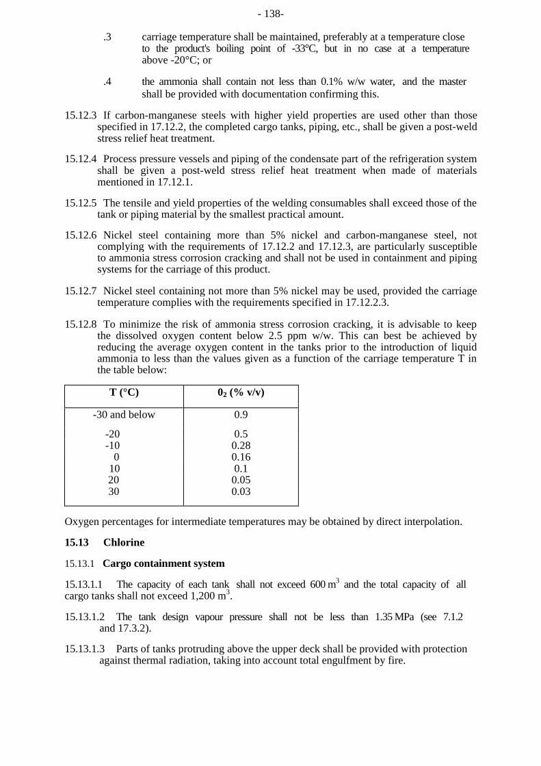
- 138-
.3 carriage temperature shall be maintained, preferably at a temperature close to the product's boiling point of -33°C, but in no case at a temperature above -20°C; or
.4 the ammonia shall contain not less than 0.1% w/w water, and the master shall be provided with documentation confirming this.
15.12.3 If carbon-manganese steels with higher yield properties are used other than those specified in 17.12.2, the completed cargo tanks, piping, etc., shall be given a post-weld stress relief heat treatment.
15.12.4 Process pressure vessels and piping of the condensate part of the refrigeration system shall be given a post-weld stress relief heat treatment when made of materials mentioned in 17.12.1.
15.12.5 The tensile and yield properties of the welding consumables shall exceed those of the tank or piping material by the smallest practical amount.
15.12.6 Nickel steel containing more than 5% nickel and carbon-manganese steel, not complying with the requirements of 17.12.2 and 17.12.3, are particularly susceptible to ammonia stress corrosion cracking and shall not be used in containment and piping systems for the carriage of this product.
15.12.7 Nickel steel containing not more than 5% nickel may be used, provided the carriage temperature complies with the requirements specified in 17.12.2.3.
15.12.8 To minimize the risk of ammonia stress corrosion cracking, it is advisable to keep the dissolved oxygen content below 2.5 ppm w/w. This can best be achieved by reducing the average oxygen content in the tanks prior to the introduction of liquid ammonia to less than the values given as a function of the carriage temperature T in the table below:
T (°C) 02 (% v/v)
-30 and below 0.9
-20 0.5 -10 0.28
0 0.16 10 0.1 20 0.05 30 0.03
Oxygen percentages for intermediate temperatures may be obtained by direct interpolation.
15.13 Chlorine
15.13.1 Cargo containment system
15.13.1.1 The capacity of each tank shall not exceed 600 m3 and the total capacity of all cargo tanks shall not exceed 1,200 m3.
15.13.1.2 The tank design vapour pressure shall not be less than 1.35 MPa (see 7.1.2 and 17.3.2).
15.13.1.3 Parts of tanks protruding above the upper deck shall be provided with protection against thermal radiation, taking into account total engulfment by fire.
- 139 -
15.13.1.4 Each tank shall be provided with two PRVs. A bursting disc of appropriate material shall be installed between the tank and the PRVs. The rupture pressure of the bursting disc shall be 0.1 MPa lower than the opening pressure of the pressure relief valve, which shall be set at the design vapour pressure of the tank but not less than 1.35 MPa gauge. The space between the bursting disc and the relief valve shall be connected through an excess flow valve to a pressure gauge and a gas detection system. Provisions shall be made to keep this space at or near the atmospheric pressure during normal operation.
15.13.1.5 Outlets from PRVs shall be arranged in such a way as to minimize the hazards on board the ship as well as to the environment. Leakage from the relief valves shall be led through the absorption plant to reduce the gas concentration as far as possible. The relief valve exhaust line shall be arranged at the forward end of the ship to discharge outboard at deck level with an arrangement to select either port or starboard side, with a mechanical interlock to ensure that one line is always open.
15.13.1.6 The Administration and the port Administration may require that chlorine is carried in a refrigerated state at a specified maximum pressure.
15.13.2 Cargo piping systems
15.13.2.1Cargo discharge shall be performed by means of compressed chlorine vapour from shore, dry air or another acceptable gas, or fully submerged pumps. Cargo discharge compressors on board ships shall not be used for this. The pressure in the vapour space of the tank during discharging shall not exceed 1.05 MPa gauge.
15.13.2.2The design pressure of the cargo piping system shall be not less than 2.1 MPa gauge. The internal diameter of the cargo pipes shall not exceed 100 mm. Only pipe bends shall be accepted for compensation of pipeline thermal movement. The use of flanged joints shall be restricted to a minimum and, when used, the flanges shall be of the welding neck type with tongue and groove.
15.13.2.3Relief valves of the cargo piping system shall discharge to the absorption plant, and the flow restriction created by this unit shall be taken into account when designing the relief valve system (see 8.4.3 and 8.4.4).
15.13.3 Materials
15.13.3.1The cargo tanks and cargo piping systems shall be made of steel suitable for the cargo and for a temperature of -40oC, even if a higher transport temperature is intended to be used.
15.13.3.2The tanks shall be thermally stress relieved. Mechanical stress relief shall not be accepted as an equivalent.
15.13.4 Instrumentation: safety devices
15.13.4.1The ship shall be provided with a chlorine absorbing plant with a connection to the cargo piping system and the cargo tanks. The absorbing plant shall be capable of neutralizing at least 2% of the total cargo capacity at a reasonable absorption rate.
15.13.4.2During the gas-freeing of cargo tanks, vapours shall not be discharged to the atmosphere.
15.13.4.3A gas detecting system shall be provided that is capable of monitoring chlorine concentrations of at least 1 ppm by volume. Sample points shall be located:
.1 near the bottom of the hold spaces;
- 140-
.2 in the pipes from the safety relief valves;
.3 at the outlet from the gas absorbing plant;
.4 at the inlet to the ventilation systems for the accommodation, service and machinery spaces and control stations; and
.5 on deck – at the forward end, midships and the after end of the cargo area. This is only required to be used during cargo handling and gas-freeing operations.
The gas detection system shall be provided with an audible and visual alarm with a set point of 5 ppm.
15.13.4.4 Each cargo tank shall be fitted with a high-pressure alarm giving an audible alarm at a pressure equal to 1.05 MPa gauge.
15.13.5 Personnel protection
The enclosed space required by 17.5.5 shall meet the following requirements:
.1 the space shall be easily and quickly accessible from the weather decks and from accommodation spaces by means of air locks, and shall be capable of being rapidly closed gastight;
.2 one of the decontamination showers required by 14.4.3 shall be located near the weather deck airlock to the space;
.3 the space shall be designed to accommodate the entire crew of the ship and be provided with a source of uncontaminated air for a period of not less than 4 h; and
.4 one set of oxygen therapy equipment shall be carried in the space.
15.13.5 Filling limits for cargo tanks
15.13.6.1The requirements of 15.1.3.2 do not apply when it is intended to carry chlorine.
15.13.6.2The chlorine content of the gas in the vapour space of the cargo tank after loading shall be greater than 80% by volume.
15.14 Ethylene oxide
15.14.1For the carriage of ethylene oxide, the requirements of 17.18 shall apply, with the additions and modifications as given in this section.
15.14.2Deck tanks shall not be used for the carriage of ethylene oxide.
15.14.3Stainless steels types 416 and 442, as well as cast iron, shall not be used in ethylene oxide cargo containment and piping systems.
15.14.4Before loading, tanks shall be thoroughly and effectively cleaned to remove all traces of previous cargoes from tanks and associated pipework, except where the immediate prior cargo has been ethylene oxide, propylene oxide or mixtures of these products. Particular care shall be taken in the case of ammonia in tanks made of steel other than stainless steel.

- 141 -
15.14.5Ethylene oxide shall be discharged only by deepwell pumps or inert gas displacement. The arrangement of pumps shall comply with 17.18.15.
15.14.6Ethylene oxide shall be carried refrigerated only and maintained at temperatures of less than 30°C.
15.14.7PRVs shall be set at a pressure of not less than 0.55 MPa gauge. The maximum set pressure shall be specially approved by the Administration.
15.14.8The protective padding of nitrogen gas, as required by 17.18.27, shall be such that the nitrogen concentration in the vapour space of the cargo tank will, at no time, be less than 45% by volume.
15.14.9Before loading, and at all times when the cargo tank contains ethylene oxide liquid or vapour, the cargo tank shall be inerted with nitrogen.
15.14.10The water-spray system required by 17.18.29 and that required by 11.3 shall operate automatically in a fire involving the cargo containment system.
15.14.11A jettisoning arrangement shall be provided to allow the emergency discharge of ethylene oxide in the event of uncontrollable self-reaction.
15.15 Separate piping systems
Separate piping systems, as defined in 1.2.47, shall be provided.
15.16 Methyl acetylene-propadiene mixtures
15.16.1 Methyl acetylene-propadiene mixtures shall be suitably stabilized for transport. Additionally, upper limits of temperatures and pressure during the refrigeration shall be specified for the mixtures.
15.16.2 Examples of acceptable stabilized compositions are:
.1 Composition 1:
.1 maximum methyl acetylene to propadiene molar ratio of 3 to 1;
.2 maximum combined concentration of methyl acetylene and propadiene of 65 mol%;
.3 minimum combined concentration of propane, butane, and isobutane of 24 mol%, of which at least one third (on a molar basis) shall be butanes and one third propane;
.4 maximum combined concentration of propylene and butadiene
of 10 mol%;
.2 Composition 2:
.1 maximum methyl acetylene and propadiene combined concentration of 30 mol%;
.2 maximum methyl acetylene concentration of 20 mol%;
.3 maximum propadiene concentration of 20 mol%;
- 142 -
.4 maximum propylene concentration of 45 mol%;
.5 maximum butadiene and butylenes combined concentration
of 2 mol%;
.6 minimum saturated C4 hydrocarbon concentration of 4 mol%; and
.7 minimum propane concentration of 25 mol%.
15.16.3Other compositions may be accepted, provided the stability of the mixture is demonstrated to the satisfaction of the Administration.
15.16.4If a ship has a direct vapour compression refrigeration system, this shall comply with the following requirements, subject to pressure and temperature limitations depending on the composition. For the example compositions given in 17.16.2, the following features shall be provided:
.1 a vapour compressor that does not raise the temperature and pressure of the vapour above 60oC and 1.75 MPa gauge during its operation, and that does not allow vapour to stagnate in the compressor while it continues to run;
.2 discharge piping from each compressor stage or each cylinder in the same stage of a reciprocating compressor shall have:
.1 two temperature-actuated shutdown switches set to operate at 60oC or less;
.2 a pressure-actuated shutdown switch set to operate at 1.75 MPa gauge or less; and
.3 a safety relief valve set to relieve at 1.8 MPa gauge or less;
.3 the relief valve required by .2.3 shall vent to a mast meeting the requirements of 8.2.10, 8.2.11 and 8.2.15 and shall not relieve into the compressor suction line; and
.4 an alarm that sounds in the cargo control position and in the navigation bridge when a high-pressure switch, or a high-temperature switch, operates.
15.16.5 The piping system, including the cargo refrigeration system, for tanks to be loaded with methyl acetylene-propadiene mixtures shall be either independent (as defined in 1.2.28) or separate (as defined in 1.2.47) from piping and refrigeration systems for other tanks. This segregation shall apply to all liquid and vapour vent lines and any other possible connections, such as common inert gas supply lines.
15.17 Nitrogen
Materials of construction and ancillary equipment such as insulation shall be resistant to the effects of high oxygen concentrations caused by condensation and enrichment at the low temperatures attained in parts of the cargo system. Due consideration shall be given to ventilation in areas where condensation might occur, to avoid the stratification of oxygen-enriched atmosphere.
- 143 -
15.18 Propylene oxide and mixtures of ethylene oxide-propylene oxide with ethylene oxide content of not more than 30% by weight
15.18.1Products transported under the provisions of this section shall be acetylene-free.
15.18.2Unless cargo tanks are properly cleaned, these products shall not be carried in tanks that have contained as one of the three previous cargoes any product known to catalyse polymerization, such as:
.1 anhydrous ammonia and ammonia solutions;
.2 amines and amine solutions; and
.3 oxidizing substances (e.g. chlorine).
15.18.3Before loading, tanks shall be thoroughly and effectively cleaned to remove all traces of previous cargoes from tanks and associated pipework, except where the immediate prior cargo has been propylene oxide or ethylene oxide-propylene oxide mixtures. Particular care shall be taken in the case of ammonia in tanks made of steel other than stainless steel.
15.18.4In all cases, the effectiveness of cleaning procedures for tanks and associated pipework shall be checked, by suitable testing or inspection, to ascertain that no traces of acidic or alkaline materials remain that might create a hazardous situation in the presence of these products.
15.18.5Tanks shall be entered and inspected prior to each initial loading of these products to ensure freedom from contamination, heavy rust deposits and any visible structural defects. When cargo tanks are in continuous service for these products, such inspections shall be performed at intervals of not more than two years.
15.18.6Tanks for the carriage of these products shall be of steel or stainless steel construction.
15.18.7Tanks that have contained these products may be used for other cargoes after thorough cleaning of tanks and associated pipework systems by washing or purging.
15.18.8All valves, flanges, fittings and accessory equipment shall be of a type suitable for use with these products and shall be constructed of steel or stainless steel in accordance with recognized standards. Disc or disc faces, seats and other wearing parts of valves shall be made of stainless steel containing not less than 11% chromium.
15.18.9Gaskets shall be constructed of materials which do not react with, dissolve in, or lower the auto-ignition temperature of, these products and which are fire-resistant and possess adequate mechanical behaviour. The surface presented to the cargo shall be polytetrafluoroethylene (PTFE) or materials giving a similar degree of safety by their inertness. Spirally-wound stainless steel with a filler of PTFE or similar fluorinated polymer may be accepted, if approved by the Administration or recognized organization acting on its behalf.
15.18.10Insulation and packing, if used, shall be of a material which does not react with, dissolve in, or lower the auto-ignition temperature of, these products.
15.18.11The following materials are generally found unsatisfactory for use in gaskets, packing and similar uses in containment systems for these products and would require testing before being approved:
.1 neoprene or natural rubber, if it comes into contact with the products;

- 144 -
.2 asbestos or binders used with asbestos; and
.3 materials containing oxides of magnesium, such as mineral wools.
15.18.12Filling and discharge piping shall extend to within 100 mm of the bottom of the tank or any sump.
15.18.13The products shall be loaded and discharged in such a manner that venting of the tanks to atmosphere does not occur. If vapour return to shore is used during tank loading, the vapour return system connected to a containment system for the product shall be independent of all other containment systems.
15.18.14During discharging operations, the pressure in the cargo tank shall be maintained above 0.007 MPa gauge.
15.18.15The cargo shall be discharged only by deepwell pumps, hydraulically operated submerged pumps or inert gas displacement. Each cargo pump shall be arranged to ensure that the product does not heat significantly if the discharge line from the pump is shut off or otherwise blocked.
15.18.16Tanks carrying these products shall be vented independently of tanks carrying other products. Facilities shall be provided for sampling the tank contents without opening the tank to atmosphere.
15.18.17Cargo hoses used for transfer of these products shall be marked "FOR ALKYLENE OXIDE TRANSFER ONLY".
15.18.18Hold spaces shall be monitored for these products. Hold spaces surrounding type A and type B independent tanks shall also be inerted and monitored for oxygen. The oxygen content of these spaces shall be maintained below 2% by volume. Portable sampling equipment is satisfactory.
15.18.19Prior to disconnecting shore lines, the pressure in liquid and vapour lines shall be relieved through suitable valves installed at the loading header. Liquid and vapour from these lines shall not be discharged to atmosphere.
15.18.20Tanks shall be designed for the maximum pressure expected to be encountered during loading, carriage or unloading of cargo.
15.18.21Tanks for the carriage of propylene oxide with a design vapour pressure of less than 0.06 MPa, and tanks for the carriage of ethylene oxide-propylene oxide mixtures with a design vapour pressure of less than 0.12 MPa, shall have a cooling system to maintain the cargo below the reference temperature. The reference temperatures are referred to in 15.1.3.
15.18.22Pressure relief valve settings shall not be less than 0.02 MPa gauge; and for type C independent tanks not greater than 0.7 MPa gauge for the carriage of propylene oxide and not greater than 0.53 MPa gauge for the carriage of ethylene oxide-propylene oxide mixtures.
15.18.23The piping system for tanks to be loaded with these products shall be completely separate from piping systems for all other tanks, including empty tanks, and from all cargo compressors. If the piping system for the tanks to be loaded with these products is not independent, as defined in 1.2.28, the required piping separation shall be accomplished by the removal of spool pieces, valves, or other pipe sections and the installation of blank flanges at these locations. The required separation applies to all liquid and vapour piping, liquid and vapour vent lines and any other possible connections such as common inert gas supply lines.
- 145 -
15.18.24The products shall be transported only in accordance with cargo handling plans approved by the Administration. Each intended loading arrangement shall be shown on a separate cargo handling plan. Cargo handling plans shall show the entire cargo piping system and the locations for installation of the blank flanges needed to meet the above piping separation requirements. A copy of each approved cargo handling plan shall be kept on board the ship. The International Certificate of Fitness for the Carriage of Liquefied Gases in Bulk shall be endorsed to include references to the approved cargo handling plans.
15.18.25Before each initial loading of these products, and before every subsequent return to such service, certification verifying that the required piping separation has been achieved shall be obtained from a responsible person acceptable to the port Administration and carried on board the ship. Each connection between a blank flange and pipeline flange shall be fitted with a wire and seal by the responsible person to ensure that inadvertent removal of the blank flange is impossible.
15.18.26The maximum allowable loading limits for each tank shall be indicated for each loading temperature that may be applied, in accordance with 15.5.
15.18.27The cargo shall be carried under a suitable protective padding of nitrogen gas. An automatic nitrogen make-up system shall be installed to prevent the tank pressure falling below 0.007 MPa gauge in the event of product temperature fall due to ambient conditions or malfunctioning of refrigeration system. Sufficient nitrogen shall be available on board to satisfy the demand of the automatic pressure control. Nitrogen of commercially pure quality (99.9% by volume) shall be used for padding. A battery of nitrogen bottles, connected to the cargo tanks through a pressure reduction valve, satisfies the intention of the expression "automatic" in this context.
15.18.28The cargo tank vapour space shall be tested prior to and after loading to ensure that the oxygen content is 2% by volume or less.
15.18.29A water-spray system of sufficient capacity shall be provided to blanket effectively the area surrounding the loading manifold, the exposed deck piping associated with product handling and the tank domes. The arrangement of piping and nozzles shall be such as to give a uniform distribution rate of 10l/m2/min. The arrangement shall ensure that any spilled cargo is washed away.
15.18.30The water-spray system shall be capable of local and remote manual operation in case of a fire involving the cargo containment system. Remote manual operation shall be arranged such that the remote starting of pumps supplying the water-spray system and remote operation of any normally closed valves in the system can be carried out from a suitable location outside the cargo area, adjacent to the accommodation spaces and readily accessible and operable in the event of fire in the areas protected.
15.18.31When ambient temperatures permit, a pressurized water hose ready for immediate use shall be available during loading and unloading operations, in addition to the above water-spray requirements.
15.19 Vinyl chloride
In cases where polymerization of vinyl chloride is prevented by addition of an inhibitor, 17.8 is applicable. In cases where no inhibitor has been added, or the inhibitor concentration is insufficient, any inert gas used for the purposes of 17.6 shall contain no more oxygen than 0.1% by volume. Before loading is started, inert gas samples from the tanks and piping shall be analysed. When vinyl chloride is carried, a positive pressure shall always be maintained in the tanks and during ballast voyages between successive carriages.
- 146 -
15.20 Mixed C4 cargoes
15.20.1Cargoes that may be carried individually under the requirements of this Guidance, notably butane, butylenes and butadiene, may be carried as mixtures subject to the provisions of this section. These cargoes may variously be referred to as "Crude C4", "Crude butadiene", "Crude steam-cracked C4", "Spent steam-cracked C4", "C4 stream", "C4 raffinate", or may be shipped under a different description. In all cases, the material safety data sheets (MSDS) shall be consulted as the butadiene content of the mixture is of prime concern as it is potentially toxic and reactive. While it is recognized that butadiene has a relatively low vapour pressure, if such mixtures contain butadiene they shall be regarded as toxic and the appropriate precautions applied.
15.20.2If the mixed C4 cargo shipped under the terms of this section contains more than 50% (mole) of butadiene, the inhibitor precautions in 17.8 shall apply.
15.20.3Unless specific data on liquid expansion coefficients is given for the specific mixture loaded, the filling limit restrictions shall be calculated as if the cargo contained 100% concentration of the component with the highest expansion ratio.
15.21 Carbon dioxide: high purity
15.21.1 Uncontrolled pressure loss from the cargo can cause "sublimation" and the cargo will change from the liquid to the solid state. The precise "triple point" temperature of a particular carbon dioxide cargo shall be supplied before loading the cargo, and will depend on the purity of that cargo, and this shall be taken into account when cargo instrumentation is adjusted. The set pressure for the alarms and automatic actions described in this section shall be set to at least 0.05 MPa above the triple point for the specific cargo being carried. The "triple point" for pure carbon dioxide occurs at 0.5 MPa gauge and -54.4°C.
15.21.2 There is a potential for the cargo to solidify in the event that a cargo tank relief valve, fitted in accordance with 8.2, fails in the open position. To avoid this, a means of isolating the cargo tank safety valves shall be provided and the requirements of 8.2.9.2 do not apply when carrying this carbon dioxide. Discharge piping from safety relief valves shall be designed so they remain free from obstructions that could cause clogging. Protective screens shall not be fitted to the outlets of relief valve discharge piping, so the requirements of 8.2.15 do not apply.
15.21.3Discharge piping from safety relief valves are not required to comply with 8.2.10, but shall be designed so they remain free from obstructions that could cause clogging. Protective screens shall not be fitted to the outlets of relief valve discharge piping, so the requirements of 8.2.15 do not apply.
15.21.4Cargo tanks shall be continuously monitored for low pressure when a carbon dioxide cargo is carried. An audible and visual alarm shall be given at the cargo control position and on the bridge. If the cargo tank pressure continues to fall to within 0.05 MPa of the "triple point" for the particular cargo, the monitoring system shall automatically close all cargo manifold liquid and vapour valves and stop all cargo compressors and cargo pumps. The emergency shutdown system required by 18.10 may be used for this purpose.
15.21.5All materials used in cargo tanks and cargo piping system shall be suitable for the lowest temperature that may occur in service, which is defined as the saturation temperature of the carbon dioxide cargo at the set pressure of the automatic safety system described in 15.21.1.
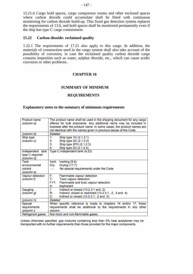
- 147 -
15.21.6 Cargo hold spaces, cargo compressor rooms and other enclosed spaces where carbon dioxide could accumulate shall be fitted with continuous monitoring for carbon dioxide build-up. This fixed gas detection system replaces the requirements of 13.6, and hold spaces shall be monitored permanently even if the ship has type C cargo containment.
15.22 Carbon dioxide: reclaimed quality
1.22.1 The requirements of 17.21 also apply to this cargo. In addition, the materials of construction used in the cargo system shall also take account of the possibility of corrosion, in case the reclaimed quality carbon dioxide cargo contains impurities such as water, sulphur dioxide, etc., which can cause acidic corrosion or other problems.
CHAPTER 16
SUMMARY OF MINIMUM
REQUIREMENTS
Explanatory notes to the summary of minimum requirements
- 166 -
APPENDIX 1
IGC GUIDANCE PRODUCT DATA REPORTING
FORM
- 167 -
2 Physical properties
Property Reference/
comments
Units Qual Lower
value
Upper
value

- 148 -
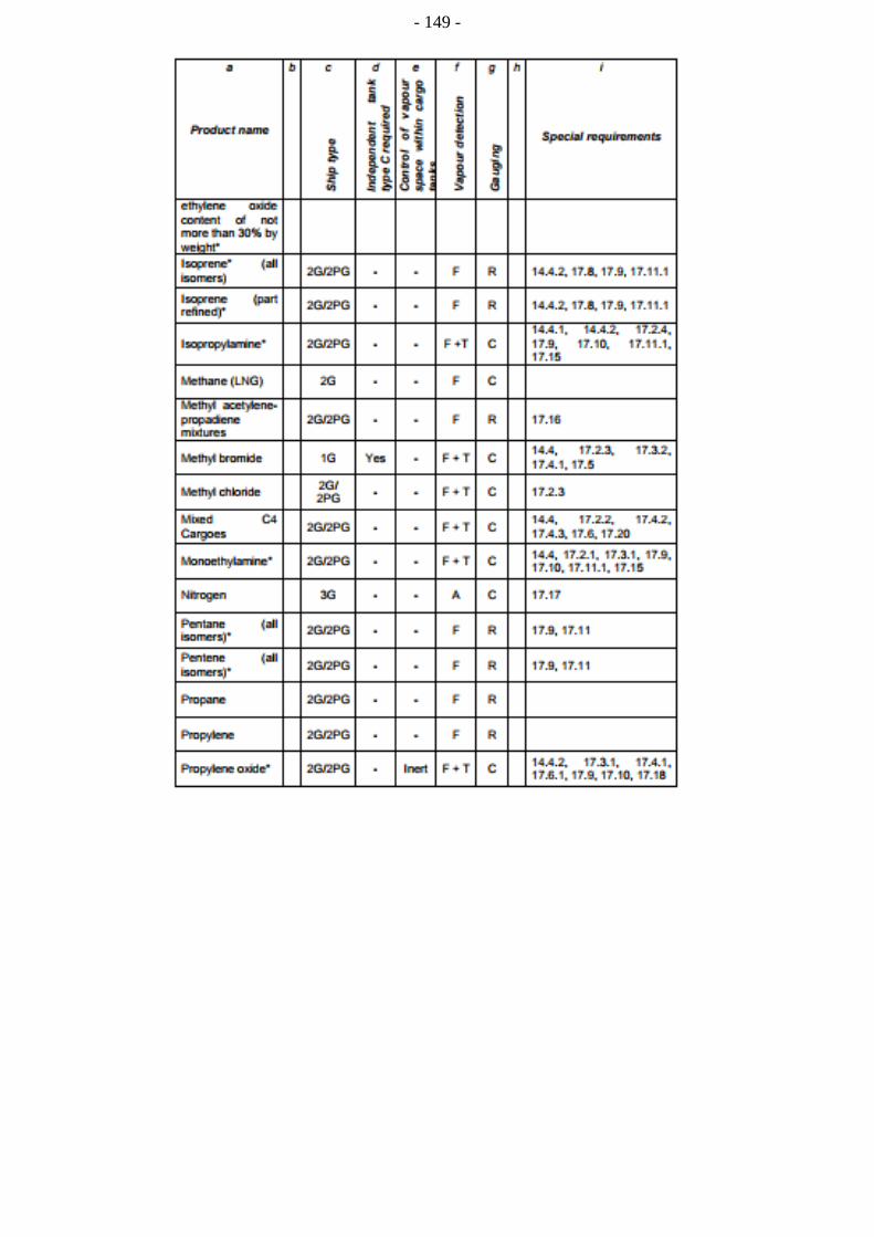
- 149 -
- 150 -

-150-
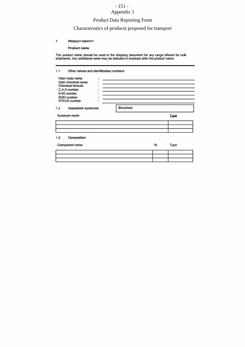
- 151 - Appendix 1
Product Data Reporting Form
Characteristics of products proposed for transport

- 152 -
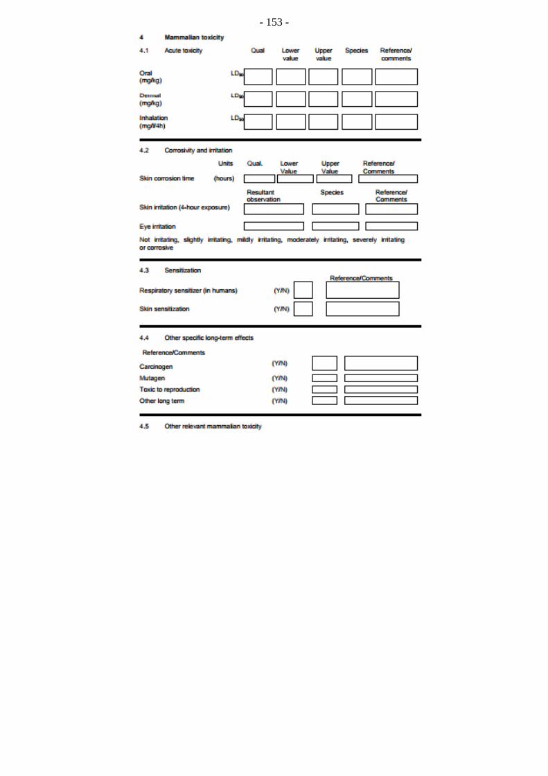
- 153 -
- 174 -
as appropriate)
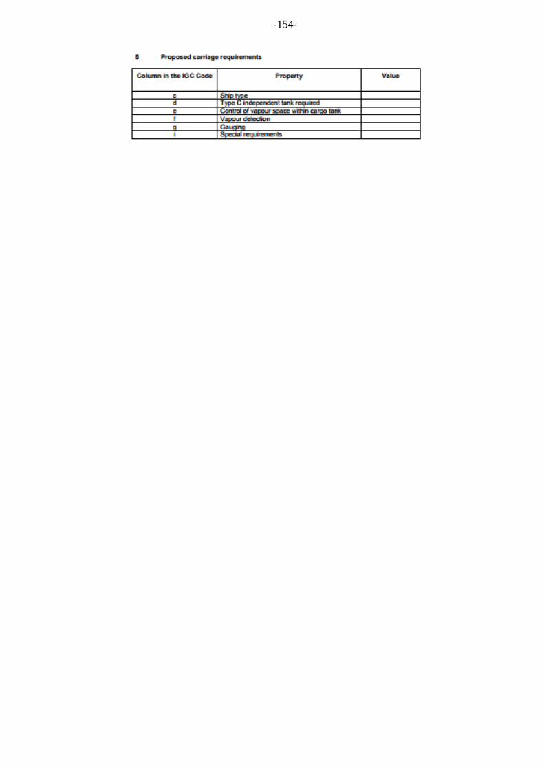
-154-
- 155 -
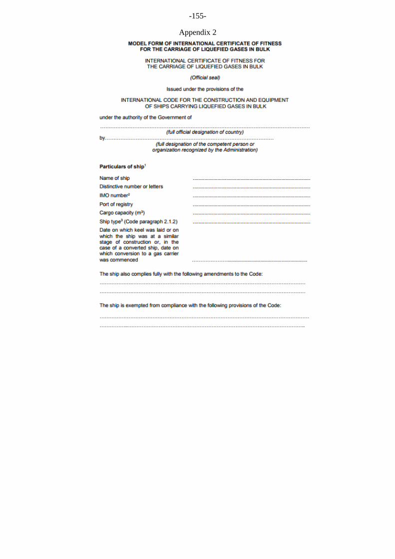
-155-
Appendix 2
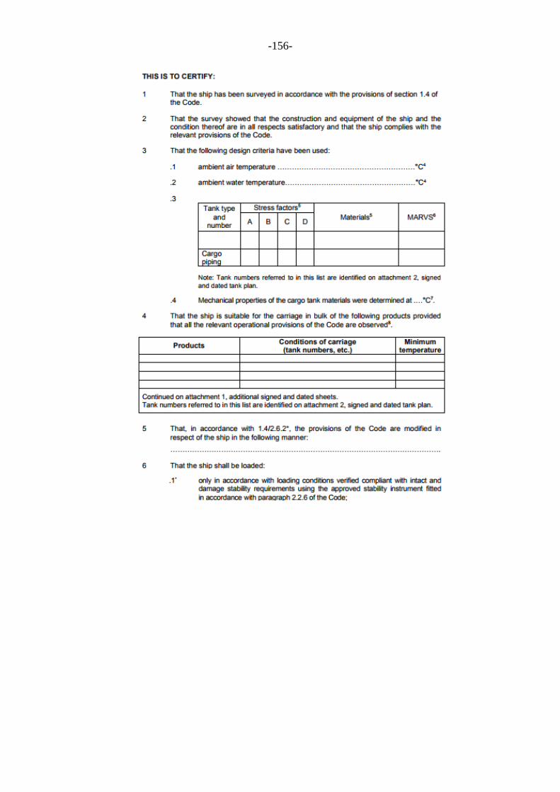
-156-
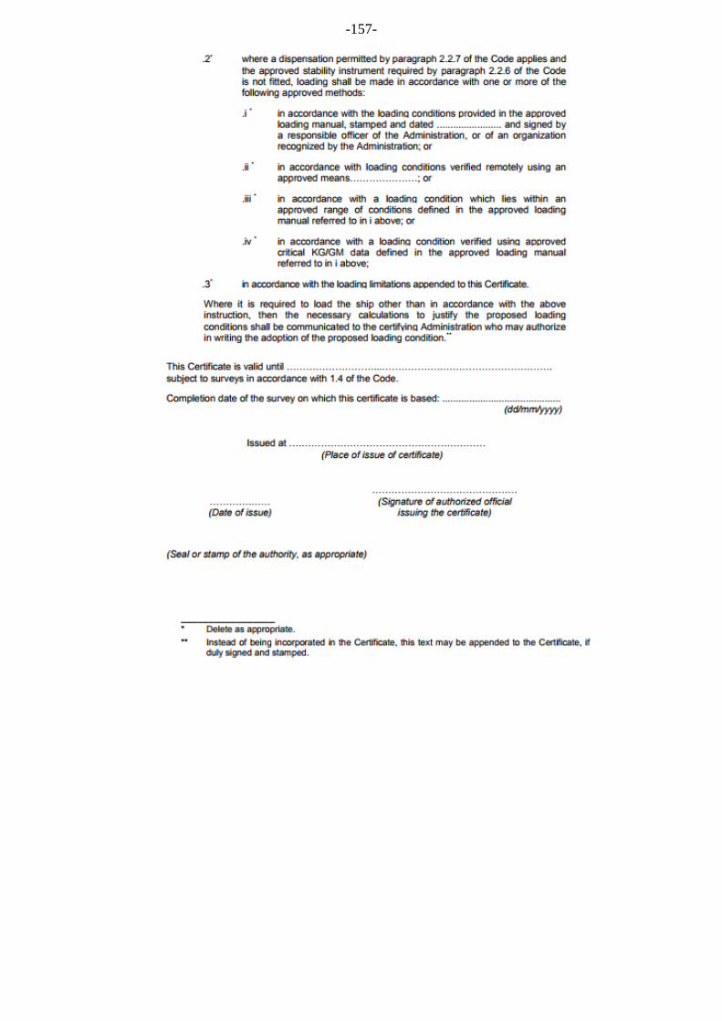
-157-
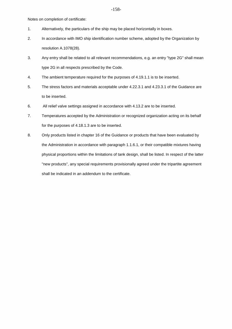
-158-
Notes on completion of certificate:
1. Alternatively, the particulars of the ship may be placed horizontally in boxes.
2. In accordance with IMO ship identification number scheme, adopted by the Organization by
resolution A.1078(28).
3. Any entry shall be related to all relevant recommendations, e.g. an entry "type 2G" shall mean
type 2G in all respects prescribed by the Code.
4. The ambient temperature required for the purposes of 4.19.1.1 is to be inserted.
5. The stress factors and materials acceptable under 4.22.3.1 and 4.23.3.1 of the Guidance are
to be inserted.
6. All relief valve settings assigned in accordance with 4.13.2 are to be inserted.
7. Temperatures accepted by the Administration or recognized organization acting on its behalf
for the purposes of 4.18.1.3 are to be inserted.
8. Only products listed in chapter 16 of the Guidance or products that have been evaluated by
the Administration in accordance with paragraph 1.1.6.1, or their compatible mixtures having
physical proportions within the limitations of tank design, shall be listed. In respect of the latter
"new products", any special requirements provisionally agreed under the tripartite agreement
shall be indicated in an addendum to the certificate.
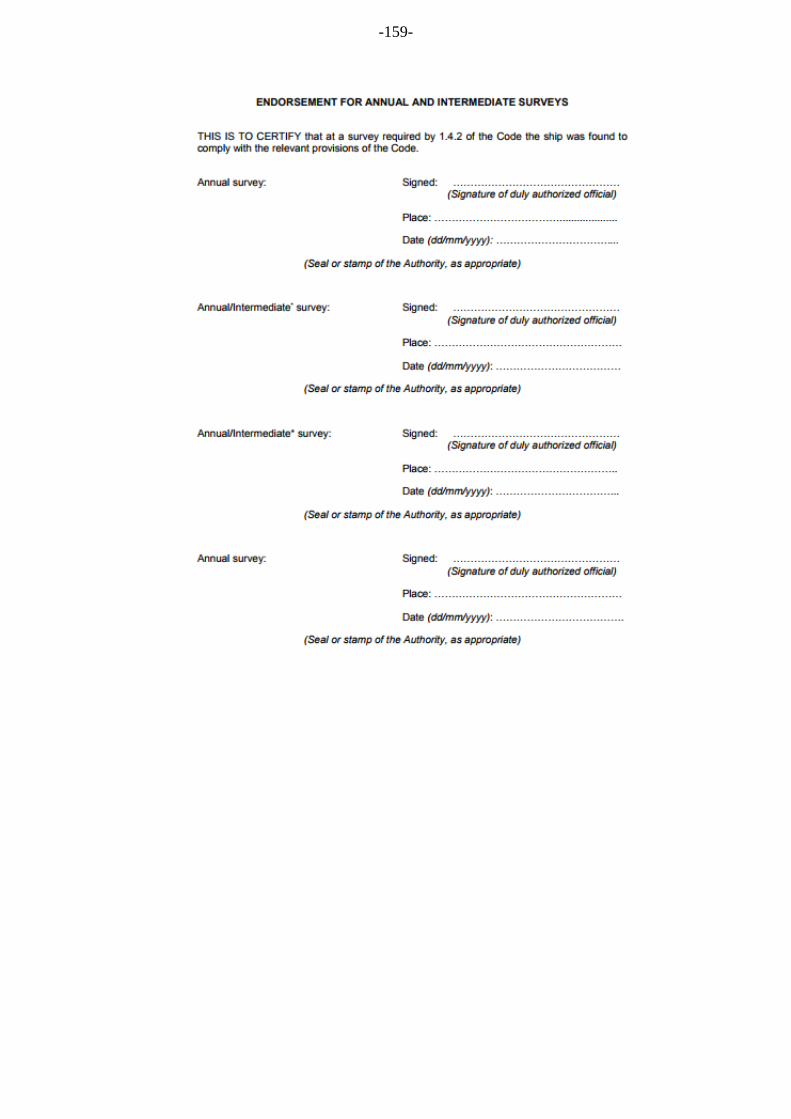
-159-
- 180 -
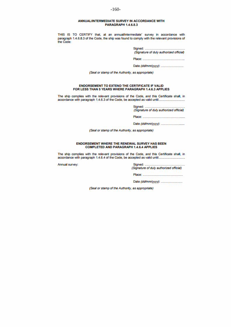
-160-
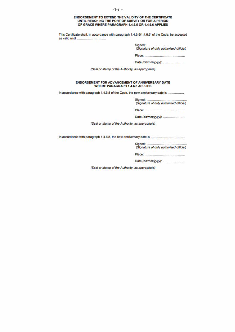
-161-

-162-

-163-
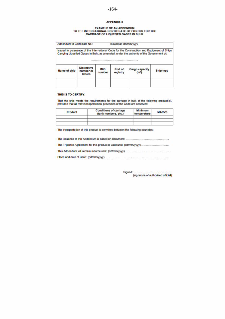
-164-
-165-
APPENDIX 4
NON-METALLIC MATERIALS
1 General
1.1 The guidance given in this appendix is in addition to the requirements of 4.19, where applicable to non-metallic materials.
1.2 The manufacture, testing, inspection and documentation of non-metallic materials should in general comply with recognized standards, and with the specific requirements of this Guidance, as applicable.
1.3 When selecting a non-metallic material, the designer should ensure that it has properties appropriate to the analysis and specification of the system requirements. A material can be selected to fulfil one or more requirements.
1.4 A wide range of non-metallic materials may be considered. Therefore, the section below on material selection criteria cannot cover every eventuality and should be considered as guidance.
2 Material selection criteria
2.1 Non-metallic materials may be selected for use in various parts of liquefied gas carrier cargo systems based on consideration of the following basic properties:
.1 insulation – the ability to limit heat flow;
.2 load bearing – the ability to contribute to the strength of the containment system;
.3 tightness – the ability to provide liquid and vapour tight barriers;
.4 joining – the ability to be joined (for example by bonding, welding or fastening).
2.2 Additional considerations may apply depending on the specific system design.
3 Properties of materials
3.1 Flexibility of insulating material is the ability of an insulating material to be bent or shaped easily without damage or breakage.
3.2 Loose fill material is a homogeneous solid generally in the form of fine particles, such as a powder or beads, normally used to fill the voids in an inaccessible space to provide an effective insulation.
3.3 Nanomaterial is a material with properties derived from its specific microscopic structure.
3.4 Cellular material is a material type containing cells that are either open, closed or both and which are dispersed throughout its mass.
3.5 Adhesive material is a product that joins or bonds two adjacent surfaces together by an adhesive process.
3.6 Other materials are materials that are not characterized in this section of the Guidance and should be identified and listed. The relevant tests used to evaluate the suitability of material for use in the cargo system should be identified and documented.

- 166 -
4 Material selection and testing requirements
4.1 Material specification
4.1.1 When the initial selection of a material has been made, tests should be conducted to validate the suitability of this material for the use intended.
4.1.2 The material used should clearly be identified and the relevant tests should be fully documented.
4.1.3 Materials should be selected according to their intended use. They should:
.1 be compatible with all the products that may be carried;
.2 not be contaminated by any cargo nor react with it;
.3 not have any characteristics or properties affected by the cargo; and
.4 be capable to withstand thermal shocks within the operating temperature range.
4.2 Material testing
The tests required for a particular material depend on the design analysis, specification and intended duty. The list of tests below is for illustration. Any additional tests required, for example in respect of sliding, damping and galvanic insulation, should be identified clearly and documented. Materials selected according to 4.1 of this appendix should be tested further according to the following table:
Function Insulation Load bearing structural
Tightness Joining
Mechanical tests X X Tightness tests X Thermal tests X
Thermal shock testing should submit the material and/or assembly to the most extreme thermal gradient it will experience when in service.
4.2.1 Inherent properties of materials
4.2.1.1 Tests should be carried out to ensure that the inherent properties of the material selected will not have any negative impact in respect of the use intended.
4.2.1.2 For all selected materials, the following properties should be evaluated:
.1 density; example standard ISO 845; and
.2 linear coefficient of thermal expansion (LCTE); example standard ISO 11359 across the widest specified operating temperature range. However, for loose fill material the volumetric coefficient of thermal expansion (VCTE) should be evaluated, as this is more relevant.
4.2.1.3 Irrespective of its inherent properties and intended duty, all materials selected should be tested for the design service temperature range down to 5°C below the minimum design temperature, but not lower than -196°C.
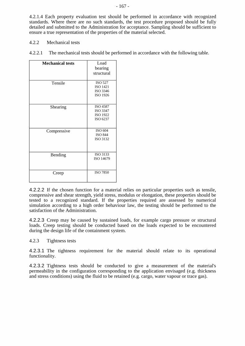
- 167 -
4.2.1.4 Each property evaluation test should be performed in accordance with recognized standards. Where there are no such standards, the test procedure proposed should be fully detailed and submitted to the Administration for acceptance. Sampling should be sufficient to ensure a true representation of the properties of the material selected.
4.2.2 Mechanical tests
4.2.2.1 The mechanical tests should be performed in accordance with the following table.
Mechanical tests Load bearing
structural
Tensile ISO 527 ISO 1421 ISO 3346 ISO 1926
Shearing ISO 4587 ISO 3347 ISO 1922 ISO 6237
Compressive ISO 604 ISO 844
ISO 3132
Bending ISO 3133 ISO 14679
Creep ISO 7850
4.2.2.2 If the chosen function for a material relies on particular properties such as tensile, compressive and shear strength, yield stress, modulus or elongation, these properties should be tested to a recognized standard. If the properties required are assessed by numerical simulation according to a high order behaviour law, the testing should be performed to the satisfaction of the Administration.
4.2.2.3 Creep may be caused by sustained loads, for example cargo pressure or structural loads. Creep testing should be conducted based on the loads expected to be encountered during the design life of the containment system.
4.2.3 Tightness tests
4.2.3.1 The tightness requirement for the material should relate to its operational functionality.
4.2.3.2 Tightness tests should be conducted to give a measurement of the material's permeability in the configuration corresponding to the application envisaged (e.g. thickness and stress conditions) using the fluid to be retained (e.g. cargo, water vapour or trace gas).
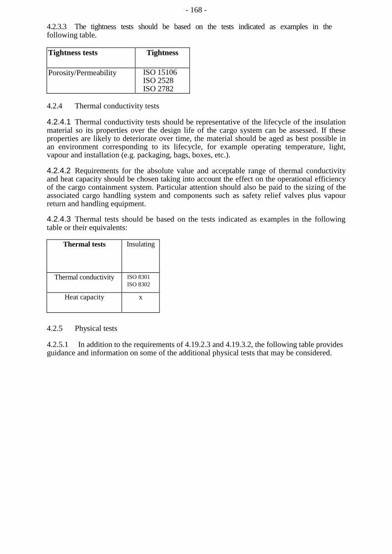
- 168 -
4.2.3.3 The tightness tests should be based on the tests indicated as examples in the following table.
Tightness tests Tightness
Porosity/Permeability ISO 15106 ISO 2528 ISO 2782
4.2.4 Thermal conductivity tests
4.2.4.1 Thermal conductivity tests should be representative of the lifecycle of the insulation material so its properties over the design life of the cargo system can be assessed. If these properties are likely to deteriorate over time, the material should be aged as best possible in an environment corresponding to its lifecycle, for example operating temperature, light, vapour and installation (e.g. packaging, bags, boxes, etc.).
4.2.4.2 Requirements for the absolute value and acceptable range of thermal conductivity and heat capacity should be chosen taking into account the effect on the operational efficiency of the cargo containment system. Particular attention should also be paid to the sizing of the associated cargo handling system and components such as safety relief valves plus vapour return and handling equipment.
4.2.4.3 Thermal tests should be based on the tests indicated as examples in the following table or their equivalents:
Thermal tests Insulating
Thermal conductivity ISO 8301 ISO 8302
Heat capacity x
4.2.5 Physical tests
4.2.5.1 In addition to the requirements of 4.19.2.3 and 4.19.3.2, the following table provides guidance and information on some of the additional physical tests that may be considered.
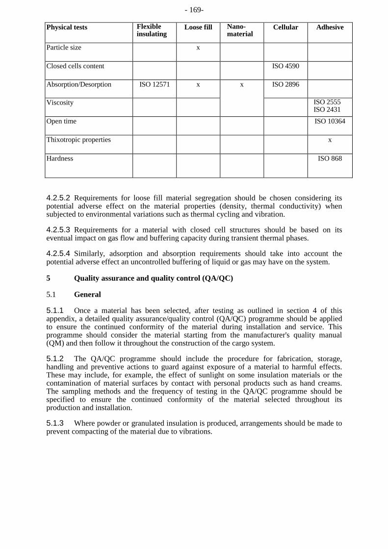
- 169-
Physical tests Flexible insulating
Loose fill Nano-material
Cellular Adhesive
Particle size x
Closed cells content ISO 4590
Absorption/Desorption ISO 12571 x x ISO 2896
Viscosity ISO 2555 ISO 2431
Open time ISO 10364
Thixotropic properties x
Hardness ISO 868
4.2.5.2 Requirements for loose fill material segregation should be chosen considering its potential adverse effect on the material properties (density, thermal conductivity) when subjected to environmental variations such as thermal cycling and vibration.
4.2.5.3 Requirements for a material with closed cell structures should be based on its eventual impact on gas flow and buffering capacity during transient thermal phases.
4.2.5.4 Similarly, adsorption and absorption requirements should take into account the potential adverse effect an uncontrolled buffering of liquid or gas may have on the system.
5 Quality assurance and quality control (QA/QC)
5.1 General
5.1.1 Once a material has been selected, after testing as outlined in section 4 of this appendix, a detailed quality assurance/quality control (QA/QC) programme should be applied to ensure the continued conformity of the material during installation and service. This programme should consider the material starting from the manufacturer's quality manual (QM) and then follow it throughout the construction of the cargo system.
5.1.2 The QA/QC programme should include the procedure for fabrication, storage, handling and preventive actions to guard against exposure of a material to harmful effects. These may include, for example, the effect of sunlight on some insulation materials or the contamination of material surfaces by contact with personal products such as hand creams. The sampling methods and the frequency of testing in the QA/QC programme should be specified to ensure the continued conformity of the material selected throughout its production and installation.
5.1.3 Where powder or granulated insulation is produced, arrangements should be made to prevent compacting of the material due to vibrations.

- 170 -
5.2 QA/QC during component manufacture
The QA/QC programme in respect of component manufacture should include, as a minimum but not limited to, the following items.
5.2.1 Component identification
5.2.1.1 For each material, the manufacturer should implement a marking system to clearly identify the production batch. The marking system should not interfere, in any way, with the properties of the product.
5.2.1.2 The marking system should ensure complete traceability of the component and should include:
.1 date of production and potential expiry date;
.2 manufacturer's references;
.3 reference specification;
.4 reference order; and
.5 when necessary, any potential environmental parameters to be maintained during transportation and storage.
5.2.2 Production sampling and audit method
5.2.2.1 Regular sampling is required during production to ensure the quality level and continued conformity of a selected material.
5.2.2.2 The frequency, the method and the tests to be performed should be defined in QA/QC programme; for example, these tests will usually cover, inter alia, raw materials, process parameters and component checks.
5.2.2.3 Process parameters and results of the production QC tests should be in strict accordance with those detailed in the QM for the material selected.
5.2.2.4 The objective of the audit method as described in the QM is to control the repeatability of the process and the efficacy of the QA/QC programme.
5.2.2.5 During auditing, auditors should be provided with free access to all production and QC areas. Audit results should be in accordance with the values and tolerances as stated in the relevant QM.
6 Bonding and joining process requirement and testing
6.1 Bonding procedure qualification
6.1.1 The bonding procedure specification and qualification test should be defined in accordance with recognized standards.
6.1.2 The bonding procedures should be fully documented before work commences to ensure the properties of the bond are acceptable.

- 171 -
6.1.3 The following parameters should be considered when developing a bonding procedure specification:
.1 surface preparation;
.2 materials storage and handling prior to installation;
.3 covering-time;
.4 open-time;
.5 mixing ratio, deposited quantity;
.6 environmental parameters (temperature, humidity); and
.7 curing pressure, temperature and time.
6.1.4 Additional requirements may be included as necessary to ensure acceptable results.
6.1.5 The bonding procedures specification should be validated by an appropriate procedure qualification testing programme.
6.2 Personnel qualifications
6.2.1 Personnel involved in bonding processes should be trained and qualified to recognized standards.
6.2.2 Regular tests should be made to ensure the continued performance of people carrying out bonding operations to ensure a consistent quality of bonding.
7 Production bonding tests and controls
7.1 Destructive testing
During production, representative samples should be taken and tested to check that they correspond to the required level of strength as required for the design.
7.2 Non-destructive testing
7.2.1 During production, tests which are not detrimental to bond integrity should be performed using an appropriate technique such as:
.1 visual examination;
.2 internal defects detection (for example acoustic, ultrasonic or shear test); and
.3 local tightness testing.
7.2.2 If the bonds have to provide tightness as part of their design function, a global tightness test of the cargo containment system should be completed after the end of the erection in accordance with the designer's and QA/QC programme.
7.2.3 The QA/QC standards should include acceptance standards for the tightness of the bonded components when built and during the lifecycle of the containment system.
- 172 -
APPENDIX 5
STANDARD FOR THE USE OF LIMIT STATE METHODOLOGIES IN THE DESIGN OF CARGO CONTAINMENT SYSTEMS OF NOVEL CONFIGURATION
1 General
1.1 The purpose of this standard is to provide procedures and relevant design parameters of limit state design of cargo containment systems of a novel configuration in accordance with section 4.27 of this Guidance.
1.2 Limit state design is a systematic approach where each structural element is evaluated with respect to possible failure modes related to the design conditions identified in section 4.3.4 of this Guidance. A limit state can be defined as a condition beyond which the structure, or part of a structure, no longer satisfies the requirements.
1.3 The limit states are divided into the three following categories:
.1 Ultimate Limit States (ULS), which correspond to the maximum load- carrying capacity or, in some cases, to the maximum applicable strain, deformation or instability in structure resulting from buckling and plastic collapse; under intact (undamaged) conditions;
.2 Fatigue Limit States (FLS), which correspond to degradation due to the effect of cyclic loading; and
.3 Accident Limit States (ALS), which concern the ability of the structure to resist accident situations.
1.4 Part A through part D of chapter 4 of this Guidance shall be complied with as applicable depending on the cargo containment system concept.
2 Design format
2.1 The design format in this standard is based on a Load and Resistance Factor Design format. The fundamental principle of the Load and Resistance Factor Design format is to verify that design load effects, Ld, do not exceed design resistances, Rd, for any of the considered failure modes in any scenario:
Ld<Rd
A design load FA is obtained by multiplying the characteristic load by a load factor relevant for the given load category:
where:ɤf is load factor; and
Fk is the characteristic load as specified in part B and part C of chapter 4 of this Guidance.
- 173 -
Table 1: Consequence classes
Consequence class Low
Medium
High
Definition Failure implies minor release of the cargo. Failure implies release of the cargo and potential for human injury. Failure implies significant release of the cargo and high potential for human injury/fatality.
3 Required analyses
3.1 Three dimensional finite element analyses shall be carried out as an integrated model of the tank and the ship hull, including supports and keying system as applicable. All the failure modes shall be identified to avoid unexpected failures. Hydrodynamic analyses shall be carried out to determine the particular ship accelerations and motions in irregular waves, and the response of the ship and its cargo containment systems to these forces and motions.

- 174 -
3.2 Buckling strength analyses of cargo tanks subject to external pressure and other loads causing compressive stresses shall be carried out in accordance with recognized standards. The method shall adequately account for the difference in theoretical and actual buckling stress as a result of plate out of flatness, plate edge misalignment, straightness, ovality and deviation from true circular form over a specified arc or chord length, as relevant.
3.3 Fatigue and crack propagation analysis shall be carried out in accordance with paragraph 5.1 of this standard.
4 Ultimate Limit States
4.1 Structural resistance may be established by testing or by complete analysis taking account of both elastic and plastic material properties. Safety margins for ultimate strength shall be introduced by partial factors of safety taking account of the contribution of stochastic nature of loads and resistance (dynamic loads, pressure loads, gravity loads, material strength, and buckling capacities).
4.2 Appropriate combinations of permanent loads, functional loads and environmental loads including sloshing loads shall be considered in the analysis. At least two load combinations with partial load factors as given in table 2 shall be used for the assessment of the ultimate limit states.
Table 2: Partial load factors
Load combination Permanent loads Functional loads Environmental loads
'a' 'b'
1.1 1.0
1.1 1.0
0.7 1.3
The load factors for permanent and functional loads in load combination 'a' are relevant for the normally well-controlled and/or specified loads applicable to cargo containment systems such as vapour pressure, cargo weight, system self-weight, etc. Higher load factors may be relevant for permanent and functional loads where the inherent variability and/or uncertainties in the prediction models are higher.
4.3 For sloshing loads, depending on the reliability of the estimation method, a larger load factor may be required by the Administration or recognized organization acting on its behalf.
4.4 In cases where structural failure of the cargo containment system are considered to imply high potential for human injury and significant release of cargo, the consequence class factor shall be taken as yc =1.2. This value may be reduced if it is justified through risk analysis and subject to the approval by the Administration or recognized organization acting on its behalf. The risk analysis shall take account of factors including, but not limited to, provision of full or partial secondary barrier to protect hull structure from the leakage and less hazards associated with intended cargo. Conversely, higher values may be fixed by the Administration or recognized organization acting on its behalf, for example, for ships carrying more hazardous or higher pressure cargo. The consequence class factor shall in any case not be less than 1.0.
4.5 The load factors and the resistance factors used shall be such that the level of safety is equivalent to that of the cargo containment systems as described in sections 4.21 to 4.26 of this Guidance. This may be carried out by calibrating the factors against known successful designs.
- 175 -
4.6 The material factor ym shall in general reflect the statistical distribution of the mechanical properties of the material, and needs to be interpreted in combination with the specified characteristic mechanical properties. For the materials defined in chapter 6 of this Guidance, the material factor ym may be taken as:
1.1 when the characteristic mechanical properties specified by the recognized organization typically represents the lower 2.5% quantile in the statistical distribution of the mechanical properties; or
1.0 when the characteristic mechanical properties specified by the recognized organization represents a sufficiently small quantile such that the probability of lower mechanical properties than specified is extremely low and can be neglected.
4.7 The partial resistance factors ysl shall in general be established based on the uncertainties in the capacity of the structure considering construction tolerances, quality of construction, the accuracy of the analysis method applied, etc.
4.7.1 For design against excessive plastic deformation using the limit state criteria given in paragraph 4.8 of this standard, the partial resistance factors ysl shall be taken as follows:
Factors A, B, C and D are defined in section 4.22.3.1 of this Guidance. Rm and Rt are defined in section 4.18.1.3 of this Guidance.
The partial resistance factors given above are the results of calibration to conventional type B independent tanks.
4.8 Design against excessive plastic deformation
4.8.1 Stress acceptance criteria given below refer to elastic stress analyses.
4.8.2 Parts of cargo containment systems where loads are primarily carried by membrane response in the structure shall satisfy the following limit state criteria:
- 176 -
With regard to the stresses am, aL, ob and ag, see also the definition of stress categories in section 4.28.3 of this Guidance.
- 177 -
4.8.4 Section stress categories
Normal stress is the component of stress normal to the plane of reference.
Equivalent section membrane stress is the component of the normal stress that is uniformly distributed and equal to the average value of the stress across the cross section of the structure under consideration. If this is a simple shell section, the section membrane stress is identical to the membrane stress defined in paragraph 4.8.2 of this standard.
Section bending stress is the component of the normal stress that is linearly distributed over a structural section exposed to bending action, as illustrated in figure 1.

- 178 -
4.9 The same factors ɤc, ɤm, ɤsl shall be used for design against buckling unless otherwise stated in the applied recognized buckling standard. In any case the overall level of safety shall not be less than given by these factors.
5 Fatigue Limit States
5.1 Fatigue design condition as described in section 4.18.2 of this Guidance shall be complied with as applicable depending on the cargo containment system concept. Fatigue analysis is required for the cargo containment system designed under section 4.27 of this Guidance and this standard.
5.2 The load factors for FLS shall be taken as 1.0 for all load categories.
5.3 Consequence class factor yc and resistance factor yR shall be taken as 1.0.
5.4 Fatigue damage shall be calculated as described in sections 4.18.2.2 to 4.18.2.5 of this Guidance. The calculated cumulative fatigue damage ratio for the cargo containment systems shall be less than or equal to the values given in table 3.
Table 3: Maximum allowable cumulative fatigue damage ratio
Consequence class
cw Low Medium High 1.0 0.5 0.5*
Note*: Lower value shall be used in accordance with sections 4.18.2.7 to 4.18.2.9 of this Guidance, depending on the detectability of defect or crack, etc.
5.5 Lower values may be fixed by the Administration or recognized organization acting on its behalf, for example for tank structures where effective detection of defect or crack cannot be assured, and for ships carrying more hazardous cargo.
5.6 Crack propagation analyses are required in accordance with sections 4.18.2.6 to 4.18.2.9 of this Guidance. The analysis shall be carried out in accordance with methods laid down in a standard recognized by the Administration or recognized organization acting on its behalf.
