contents · contents 12.1 existing elements 12.2 new elements connecting to existing structure...
TRANSCRIPT

CHAPTER 12: Conversion and Refurbishment
CONTENTS
12.1 EXISTING ELEMENTS
12.2 NEW ELEMENTS CONNECTING TO EXISTING STRUCTURE
Chapter 12
303

FUNCTIONAL REQUIREMENTS
Techn
ical Man
ual V
11
- TS-0
11
-11
.00
-18
08
14
FU
NC
TIO
NA
L RE
QU
IRE
ME
NT
S
Workmanship
i. All workmanship is to be completed by a technically competent person in a workmanlike manner.
ii. Any new work must meet the tolerances defined in Chapter 1 of this Manual. Tolerances will not apply to existing finishes that have not been upgraded or altered, or where the supporting elements will not allow for the tolerances to be met.
Materials
i. All new materials should be stored correctly in a manner that will not cause damage or deterioration of the product.
ii. Materials, products and building systems shall be appropriate and suitable for their intended purpose.
iii. The structure, regardless of whether it is a new or existing element, shall, unless specifically agreed otherwise with the Warranty provider, have a life of not less than 60 years. Individual components and assemblies, not integral to the structure, may have a lesser durability, but not in any circumstances under 15 years
iv. Existing elements that are to be retained must provide a ‘waterproof envelope’ to the building and be structurally adequate.
Design
i. The design and specifications should give clear indication of the design intent and demonstrate a satisfactory level of performance with regards the renovation of components and the interaction of new elements.
ii. Specialist reports are required to confirm that existing elements will have an adequate level of structural stability, as defined in the Materials section above; the reports must confirm the adequacy of the existing ‘waterproof envelope’.
12.1 EXISTING ELEMENTS

Techn
ical Man
ual V
11
- TS-0
11
-11
.00
-18
08
14
CHAPTER 12: Conversion and RefurbishmentCH
AP
TE
R 1
2: C
ON
VE
RSIO
N A
ND
RE
FU
RB
ISHM
EN
T
Chapter 12
305
new cavity masonry that abuts an existing solid wall construction.
Please note: that the requirements of the technical audit are quite different from those undertaken for the purposes of compliance with Building Control and planning legislation. If any such bodies have imposed restrictions on the areas above, we suggest that you contact the Technical Services Department before undertaking any works.
12.1.2 Retained elements, foundations and load-bearing structures; including floors, walls and roof
Any areas of cracking or suspected movement are to be assessed, and remedial measures provided by an appropriately qualified and experienced Structural Engineer. Any additional loads must be catered for. Consideration of the impact of any landscaping and drainage works is required. Spalling masonry can be locally repaired, with units cut out and replaced, or re-used with sound face showing. Larger areas will require a schedule of repair to be submitted and agreed
Damp Proof Courses (DPC) and membranes
All walls, floors and basements should include a DPC. Ground levels and ventilation should be checked before any remedial DPC treatments are considered. However, where remedial DPC treatments are required, these need to be appropriate to the type of construction, independently tested/approved and provided with a 10 year insurance-backed guarantee. Installed
structure and 15 years for non-structural elements, they should be systematically replaced or repaired.
Existing buildings and structures can present particular problems both initially and on an ongoing basis. Therefore, it is essential that thorough and comprehensive survey work is undertaken prior to new works commencing to understand both the current condition of any structure and the impact any proposed works may have. Although initially this may be considered an unnecessary early expense, the savings in reconstruction costs can greatly outweigh the cost of the preparatory work.
Elements of the retained structure and proposed works should not be considered in isolation, as a solution for one problem may cause issues elsewhere. Past performance is no guarantee of ongoing adequate performance because different expectations and changing living conditions can all impact on both the actual and perceived performance of a converted/refurbished structure.
It is not possible to cover every building type within this Chapter; therefore, the guidance is general, and certainly will not apply in every scenario. It is strongly recommended that early discussions are held to determine exact requirements and to enable a full review of the proposed strategy and development.
Where new work is proposed, it should follow the guidance for those elements in this Technical Manual. Where new work is applied to, or meets, existing elements, consideration on how these areas will interact must be made; for example,
12.1.1 Introduction
The following guidance has been formulated to assist both Warranty Surveyors and Developers on projects involving either the conversion or refurbishment of existing buildings.
Conversions and refurbishments are projects that involve work to existing buildings or parts of existing buildings. This could include the conversion of industrial or commercial buildings into housing; the conversion of an existing residential building into flats; an additional storey to an existing building; the refurbishment of an existing residential building; or a façade retention project.
The Warranty includes cover for the retained structural elements and waterproof envelope of any existing building for the duration of the policy. The Warranty Surveyor will always undertake an initial assessment of the existing fabric to ascertain in general terms if the proposal is capable of representing a standard risk to the Underwriter. If deemed acceptable, the development is then subject to a technical audit process during construction, and the following guidance is intended to assist all parties in ensuring the relevant requirements are met, as well as providing an element of consistency in approach.
Depending on the condition of the original building; an expert survey may be required for the different elements of the building as described in the following sections of this Chapter. If the survey concludes that any of these elements are unable to meet the life expectancy of 60 years for

Techn
ical Man
ual V
11
- TS-0
11
-11
.00
-18
08
14
CHAPTER 12: Conversion and RefurbishmentCH
AP
TE
R 1
2: C
ON
VE
RSIO
N A
ND
RE
FU
RB
ISHM
EN
T
Where some of the elements are new and replaced as part of the conversion/refurbishment, no report is necessary.
12.1.3 Substructure
12.1.3.1 Foundations
An appraisal of the existing building and its foundations should be carried out by a Structural Engineer.
This appraisal should address:
• Settlement• Heave• Foundation depth and type• Soil type• Basement walls and floors• Trees adjacent to buildings
When carrying out the appraisal, the person responsible should take into account any proposed increased loading on the structure and foundations, alterations to existing load paths and any alterations to the existing stability of the building.
Where the existing foundations are inadequate and the building has moved/cracked, and/or the proposals are to increase the load on the foundations, a Structural Engineer should design a suitable solution, which should then be discussed with your Warranty Surveyor prior to implementation.
Weather resistance of walls, including claddings, render, re-pointing, etc.
The remedial works for the external walls must have regard for the exposure rating provided in BS 5628. Any retained cladding system must be surveyed to determine a minimum 15 year life expectancy. Provision of additional thermal insulation must also be considered.
External doors and windows
A condition survey should be provided by an independent, competent and appropriately qualified Surveyor or Specialist to confirm life expectancy of 15 years. Consideration must be given to improving the thermal characteristics.
External and internal services
Any services to be retained should be suitably tested and reported by a Specialist.
Drainage
A CCTV survey should be undertaken to ensure the integrity and design of any retained system. Where the lengths of existing retained drainage do not have rodding access in accordance with current requirements, additional access points should be provided. Inspection chambers and manholes located within habitable parts of the building will not normally be acceptable. Existing interceptors should be removed, and any proposal to retain existing septic tanks/cesspools will normally be rejected.
by a member of the Property Care Association, the guarantees must cover workmanship and materials. The construction of any existing ground floor will need to be assessed, and details provided to the Warranty Surveyor for consideration.
Timber treatment against insect and fungal attack
All retained timbers will need to be assessed, logged and the remedial treatment noted. Timbers that are embedded should be exposed or removed and replaced with masonry. Where this is not possible, core samples should be taken to assess the moisture content, and remedial works considered. Any remedial treatment must be provided with a 10 year insurance-backed guarantee and undertaken by a member of the Property Care Association, where guarantees must cover workmanship and materials.
Roof coverings
Coverings and support systems should be replaced unless a specialist report compiled by an independent, competent and appropriately experienced Chartered Building Surveyor concludes that the system can provide a life span of at least 15 years. This should include the covering, battens, felt, flat roof decking, fascias, soffits, flashings, nails and clips, etc.

Techn
ical Man
ual V
11
- TS-0
11
-11
.00
-18
08
14
CHAPTER 12: Conversion and RefurbishmentCH
AP
TE
R 1
2: C
ON
VE
RSIO
N A
ND
RE
FU
RB
ISHM
EN
T
Chapter 12
307
Proposals for underpinning should be prepared by an expert and be in accordance with BS 8004.
Figure 1: Typical traditional underpinning detail
Figure 2: “Hit and miss” underpinning sequence
be provided with a new structural waterproofing (tanking) system designed by a suitably qualified and experienced Waterproofing Specialist. The work should be carried out by a competent Specialist Contractor who has been approved by the Warranty Surveyor and is a member of the Structural Waterproofing Group. Land drainage to the external perimeter of the basement must be considered in order to reduce hydrostatic pressure to acceptable levels.
Internal walls will also require tanking if they do not have an effective DPC located at the same level as the floor tanking membrane or if they link with an external wall that is in contact with the adjacent ground.
Built-in structural timbers, such as timber lintels, shall be replaced, e.g. with concrete lintels, if they are sealed by tanking.
It should be ensured that continuity of tanking is maintained around chimney breasts. To simplify the problem, consideration should be given to the removal of the chimney breast in the basement and providing adequate support at ground level to the retained chimney.
In accordance with BS 8102: 2009, adequate provision should be made to prevent surface and interstitial condensation within the basement.
Consideration must be given to:
• Appropriate ventilation• Adequate heating• Appropriate insulation
12.1.3.2 Tanking of basements
Where it is intended that there will be any useable space below ground level, then the design should be such that adequate resistance to the passage of water/moisture to the inside is achieved, following the guidance in BS 8102: 2009. Please refer to Chapter 6, Section 6.1 in this Technical Manual for our requirements for basement provision.
Relevant matters include:
• Determining the position of the water table.• Assessing the drainage characteristics of the soil.• Products used should have independent
third-party certificates and be installed by an approved installer.
• Increasing the height of the retaining walls.• Reducing the ability of the floor above to
provide lateral support to the walls.• Lowering floor levels to increase ceiling heights.• Alterations to the existing applied loadings.• Additional loading from adjacent structures.
Existing basement floors may be suitable if it can be shown that the slab is in the region of 100mm thick and is bearing onto a suitable inert hard core. The proposals to tank the basement should address both the walls and the floor, in order to ensure the integrity of the basement area.
It should not be assumed that a wall that is dry at the time of the survey will not cause a problem in future. Existing basements should
Techn
ical Man
ual V
11
- TS-0
11
-11
.00
-18
08
14
CHAPTER 12: Conversion and RefurbishmentCH
AP
TE
R 1
2: C
ON
VE
RSIO
N A
ND
RE
FU
RB
ISHM
EN
T
Hutton & Rostron: Tel No. 01483 203221, Fax No. 01483 202911, www.handr.co.uk or
Ridout Associates: Tel No. 01562 885135, Fax No. 01562 885312, www.ridoutassociates.co.uk
Fungal attack covers wet rot and dry rot. Wood rotting fungi can be divided into two categories according to their effects on the wood. These are:
• Brown rot – causes the wood to become darker in colour and crack along and across the grain when dry. Badly decayed wood will crumble to dust, and the majority of wet rot and dry rot instances fall within this group.
• White rot – the wood becomes lighter in colour, and cracks along the grain. All white rots are wet rot.
The root cause of fungal attack is dampness, which may be caused by the following:
• Rain penetration• Condensation• Hygroscopic salts• Defective rain water goods and roofs• Bridging of existing DPCs, or no DPC• Defective renders• Direct penetration of rain water through solid
walls, particularly those facing prevailing winds• Leaking drains and internal plumbing• Incorrect external levels
Fungal attack is controlled by two sets of measures, primary and secondary.
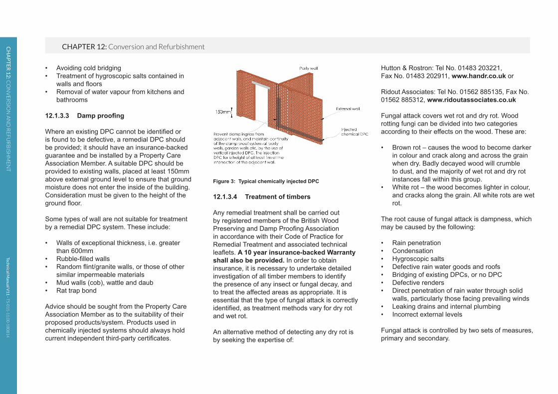
Figure 3: Typical chemically injected DPC
12.1.3.4 Treatment of timbers
Any remedial treatment shall be carried out by registered members of the British Wood Preserving and Damp Proofing Association in accordance with their Code of Practice for Remedial Treatment and associated technical leaflets. A 10 year insurance-backed Warranty shall also be provided. In order to obtain insurance, it is necessary to undertake detailed investigation of all timber members to identify the presence of any insect or fungal decay, and to treat the affected areas as appropriate. It is essential that the type of fungal attack is correctly identified, as treatment methods vary for dry rot and wet rot.
An alternative method of detecting any dry rot is by seeking the expertise of:
• Avoiding cold bridging• Treatment of hygroscopic salts contained in
walls and floors• Removal of water vapour from kitchens and
bathrooms
12.1.3.3 Damp proofing
Where an existing DPC cannot be identified or is found to be defective, a remedial DPC should be provided; it should have an insurance-backed guarantee and be installed by a Property Care Association Member. A suitable DPC should be provided to existing walls, placed at least 150mm above external ground level to ensure that ground moisture does not enter the inside of the building. Consideration must be given to the height of the ground floor.
Some types of wall are not suitable for treatment by a remedial DPC system. These include:
• Walls of exceptional thickness, i.e. greater than 600mm
• Rubble-filled walls• Random flint/granite walls, or those of other
similar impermeable materials• Mud walls (cob), wattle and daub• Rat trap bond
Advice should be sought from the Property Care Association Member as to the suitability of their proposed products/system. Products used in chemically injected systems should always hold current independent third-party certificates.
Techn
ical Man
ual V
11
- TS-0
11
-11
.00
-18
08
14
CHAPTER 12: Conversion and RefurbishmentCH
AP
TE
R 1
2: C
ON
VE
RSIO
N A
ND
RE
FU
RB
ISHM
EN
T
Chapter 12
309
• Are there any cracks in the floor slab due to settlement? If the slab has settled, it may be practical to re-level the floor with a new screed or self-levelling compound. Before undertaking any works to a settled slab, it must be ascertained whether the settlement has stopped.
• Has the slab heaved? Clay heave can be attributed to the swelling of the clay subsoil when there is a recovery of the desiccated zone following the removal of a tree. Where a slab has heaved, further investigation is necessary to determine the reason for this, and appropriate measures taken to rectify the cause and damage.
• Where it can be shown that the existing ground floor is structurally adequate but does not incorporate a Damp Proof Membrane (DPM), a DPM may be laid over the existing slab, e.g. two or three coats of bitumen paint or 1200 gauge polythene, over which a minimum 50mm, 1:3 screed should be laid. The DPM should lap with the DPC.
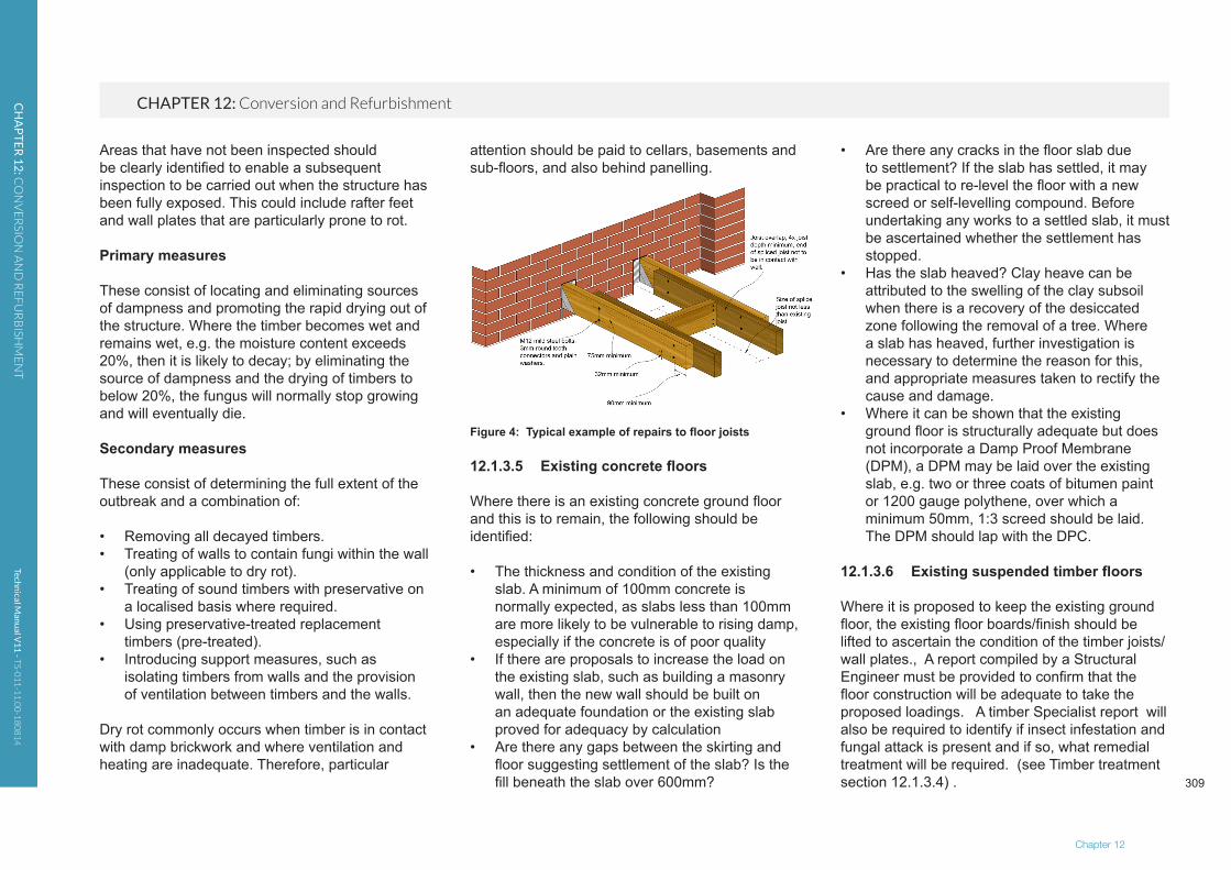
12.1.3.6 Existing suspended timber floors
Where it is proposed to keep the existing ground floor, the existing floor boards/finish should be lifted to ascertain the condition of the timber joists/wall plates., A report compiled by a Structural Engineer must be provided to confirm that the floor construction will be adequate to take the proposed loadings. A timber Specialist report will also be required to identify if insect infestation and fungal attack is present and if so, what remedial treatment will be required. (see Timber treatment section 12.1.3.4) .
attention should be paid to cellars, basements and sub-floors, and also behind panelling.
Figure 4: Typical example of repairs to floor joists
12.1.3.5 Existing concrete floors
Where there is an existing concrete ground floor and this is to remain, the following should be identified:
• The thickness and condition of the existing slab. A minimum of 100mm concrete is normally expected, as slabs less than 100mm are more likely to be vulnerable to rising damp, especially if the concrete is of poor quality
• If there are proposals to increase the load on the existing slab, such as building a masonry wall, then the new wall should be built on an adequate foundation or the existing slab proved for adequacy by calculation
• Are there any gaps between the skirting and floor suggesting settlement of the slab? Is the fill beneath the slab over 600mm?
Areas that have not been inspected should be clearly identified to enable a subsequent inspection to be carried out when the structure has been fully exposed. This could include rafter feet and wall plates that are particularly prone to rot.
Primary measures
These consist of locating and eliminating sources of dampness and promoting the rapid drying out of the structure. Where the timber becomes wet and remains wet, e.g. the moisture content exceeds 20%, then it is likely to decay; by eliminating the source of dampness and the drying of timbers to below 20%, the fungus will normally stop growing and will eventually die.
Secondary measures
These consist of determining the full extent of the outbreak and a combination of:
• Removing all decayed timbers.• Treating of walls to contain fungi within the wall
(only applicable to dry rot).• Treating of sound timbers with preservative on
a localised basis where required.• Using preservative-treated replacement
timbers (pre-treated).• Introducing support measures, such as
isolating timbers from walls and the provision of ventilation between timbers and the walls.
Dry rot commonly occurs when timber is in contact with damp brickwork and where ventilation and heating are inadequate. Therefore, particular
Techn
ical Man
ual V
11
- TS-0
11
-11
.00
-18
08
14
CHAPTER 12: Conversion and RefurbishmentCH
AP
TE
R 1
2: C
ON
VE
RSIO
N A
ND
RE
FU
RB
ISHM
EN
T
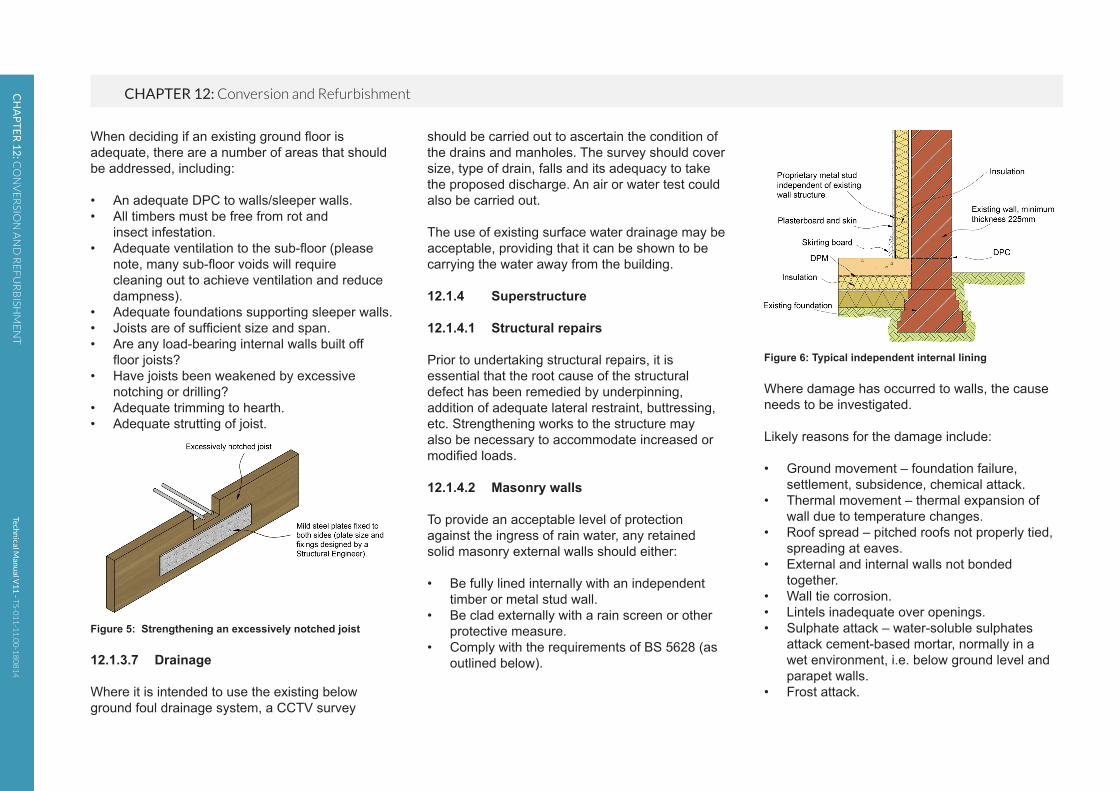
Figure 6: Typical independent internal lining
Where damage has occurred to walls, the cause needs to be investigated.
Likely reasons for the damage include:
• Ground movement – foundation failure, settlement, subsidence, chemical attack.
• Thermal movement – thermal expansion of wall due to temperature changes.
• Roof spread – pitched roofs not properly tied, spreading at eaves.
• External and internal walls not bonded together.
• Wall tie corrosion.• Lintels inadequate over openings.• Sulphate attack – water-soluble sulphates
attack cement-based mortar, normally in a wet environment, i.e. below ground level and parapet walls.
• Frost attack.
should be carried out to ascertain the condition of the drains and manholes. The survey should cover size, type of drain, falls and its adequacy to take the proposed discharge. An air or water test could also be carried out.
The use of existing surface water drainage may be acceptable, providing that it can be shown to be carrying the water away from the building.
12.1.4 Superstructure
12.1.4.1 Structural repairs
Prior to undertaking structural repairs, it is essential that the root cause of the structural defect has been remedied by underpinning, addition of adequate lateral restraint, buttressing, etc. Strengthening works to the structure may also be necessary to accommodate increased or modified loads.
12.1.4.2 Masonry walls
To provide an acceptable level of protection against the ingress of rain water, any retained solid masonry external walls should either:
• Be fully lined internally with an independent timber or metal stud wall.
• Be clad externally with a rain screen or other protective measure.
• Comply with the requirements of BS 5628 (as outlined below).
When deciding if an existing ground floor is adequate, there are a number of areas that should be addressed, including:
• An adequate DPC to walls/sleeper walls.• All timbers must be free from rot and insect infestation.• Adequate ventilation to the sub-floor (please
note, many sub-floor voids will require cleaning out to achieve ventilation and reduce dampness).
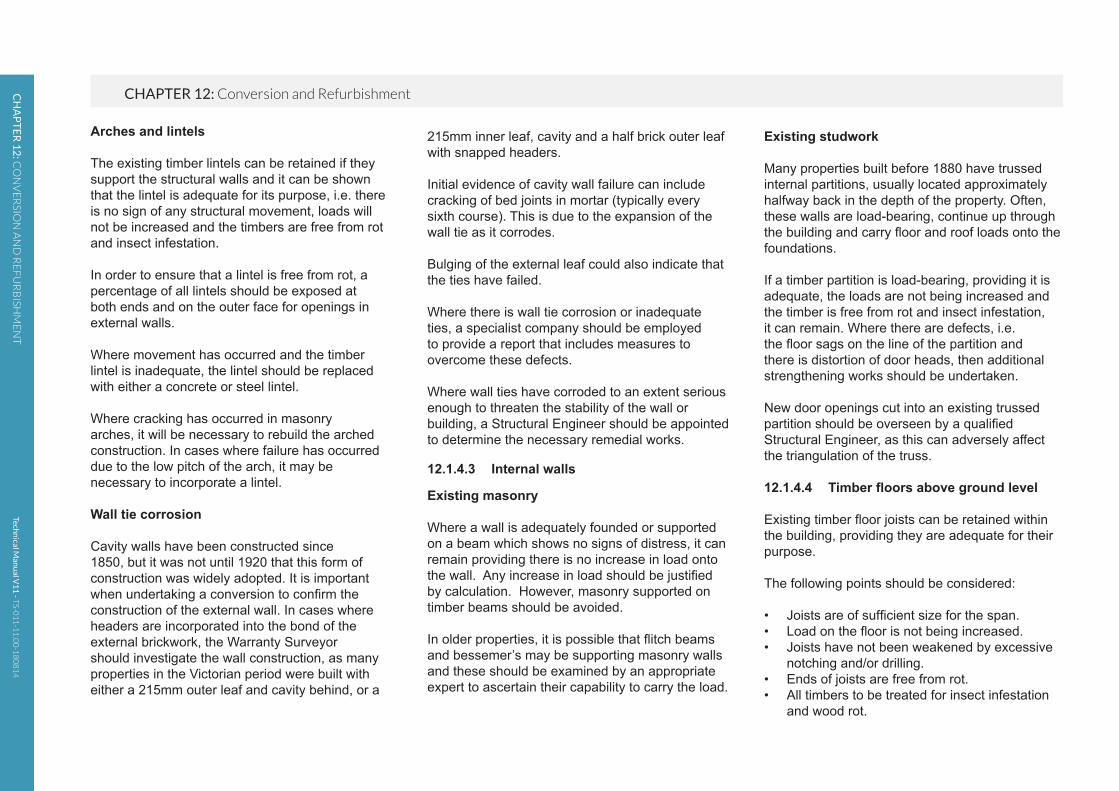
• Adequate foundations supporting sleeper walls.• Joists are of sufficient size and span.• Are any load-bearing internal walls built off floor joists?• Have joists been weakened by excessive
notching or drilling?• Adequate trimming to hearth.• Adequate strutting of joist.
Figure 5: Strengthening an excessively notched joist
12.1.3.7 Drainage
Where it is intended to use the existing below ground foul drainage system, a CCTV survey

Techn
ical Man
ual V
11
- TS-0
11
-11
.00
-18
08
14
CHAPTER 12: Conversion and RefurbishmentCH
AP
TE
R 1
2: C
ON
VE
RSIO
N A
ND
RE
FU
RB
ISHM
EN
T
Chapter 12
311
External and internal walls not bonded together
A common defect in properties up to the 1920s is the lack of bonding/tie of party walls to the external wall.
Different bricks and bricklayers were often used, with the poorer quality materials and labour being used on the party walls. This junction should be exposed when undertaking a conversion and if the bond is inadequate, a suitable stitching detail incorporated. Design by a Chartered Structural Engineer may be required.
• Bonding timbers present and subject to rot and shrinkage.
• Ineffective or no lateral support at floor and roof level.
• Moisture ingress.
Cracking in masonry walls
Minor cracking can be defined as cracking that occurs in the mortar joints and which does not extend through the masonry components. Providing that the crack is no wider than 4mm, and there has been no lateral displacement of the wall, the wall can be re-pointed.
Major cracking affects the structural integrity of the wall, and investigation should be undertaken to find the cause of the problem.
Walls out of plumb/bulging
Where walls are more than 25mm out of plumb or bulge more than 10mm within a storey height, a Structural Engineer should comment on the stability. The wall may need to be rebuilt or strengthening works undertaken.
Where it is intended to provide buttressing walls to support out of plumb and/or bulging walls, they should be designed by an Engineer.
In raised tie roofs (where no ceiling ties are provided at eaves level), lateral spread of the brickwork just below eaves level may have occurred because the roof has deflected. In such cases, it is necessary to prop the roof and rebuild the affected part of the wall.
Figure 7: Typical examples of rectifying unbounded walls
Bonding timbers
These are common in Georgian buildings, and were laid in the internal skin of the wall to reinforce it and to provide fixings for panelling, etc. With the low compressive strength of lime mortar and general timber decay, the bond timber compresses under load. As the timber is on the inner skin, the compression causes bulging outwards, which may be apparent on the external face. Normally, bond timbers should be exposed during the conversion and removed in short lengths, and replaced with bonded masonry.
Techn
ical Man
ual V
11
- TS-0
11
-11
.00
-18
08
14
CHAPTER 12: Conversion and RefurbishmentCH
AP
TE
R 1
2: C
ON
VE
RSIO
N A
ND
RE
FU
RB
ISHM
EN
T
Existing studwork
Many properties built before 1880 have trussed internal partitions, usually located approximately halfway back in the depth of the property. Often, these walls are load-bearing, continue up through the building and carry floor and roof loads onto the foundations.
If a timber partition is load-bearing, providing it is adequate, the loads are not being increased and the timber is free from rot and insect infestation, it can remain. Where there are defects, i.e. the floor sags on the line of the partition and there is distortion of door heads, then additional strengthening works should be undertaken.
New door openings cut into an existing trussed partition should be overseen by a qualified Structural Engineer, as this can adversely affect the triangulation of the truss.
12.1.4.4 Timber floors above ground level
Existing timber floor joists can be retained within the building, providing they are adequate for their purpose.
The following points should be considered:
• Joists are of sufficient size for the span.• Load on the floor is not being increased.• Joists have not been weakened by excessive
notching and/or drilling.• Ends of joists are free from rot.• All timbers to be treated for insect infestation
and wood rot.
215mm inner leaf, cavity and a half brick outer leaf with snapped headers.
Initial evidence of cavity wall failure can include cracking of bed joints in mortar (typically every sixth course). This is due to the expansion of the wall tie as it corrodes.
Bulging of the external leaf could also indicate that the ties have failed.
Where there is wall tie corrosion or inadequate ties, a specialist company should be employed to provide a report that includes measures to overcome these defects.
Where wall ties have corroded to an extent serious enough to threaten the stability of the wall or building, a Structural Engineer should be appointed to determine the necessary remedial works.
12.1.4.3 Internal walls
Existing masonry
Where a wall is adequately founded or supported on a beam which shows no signs of distress, it can remain providing there is no increase in load onto the wall. Any increase in load should be justified by calculation. However, masonry supported on timber beams should be avoided.
In older properties, it is possible that flitch beams and bessemer’s may be supporting masonry walls and these should be examined by an appropriate expert to ascertain their capability to carry the load.
Arches and lintels
The existing timber lintels can be retained if they support the structural walls and it can be shown that the lintel is adequate for its purpose, i.e. there is no sign of any structural movement, loads will not be increased and the timbers are free from rot and insect infestation.
In order to ensure that a lintel is free from rot, a percentage of all lintels should be exposed at both ends and on the outer face for openings in external walls.
Where movement has occurred and the timber lintel is inadequate, the lintel should be replaced with either a concrete or steel lintel.
Where cracking has occurred in masonry arches, it will be necessary to rebuild the arched construction. In cases where failure has occurred due to the low pitch of the arch, it may be necessary to incorporate a lintel.
Wall tie corrosion
Cavity walls have been constructed since 1850, but it was not until 1920 that this form of construction was widely adopted. It is important when undertaking a conversion to confirm the construction of the external wall. In cases where headers are incorporated into the bond of the external brickwork, the Warranty Surveyor should investigate the wall construction, as many properties in the Victorian period were built with either a 215mm outer leaf and cavity behind, or a

Techn
ical Man
ual V
11
- TS-0
11
-11
.00
-18
08
14
CHAPTER 12: Conversion and RefurbishmentCH
AP
TE
R 1
2: C
ON
VE
RSIO
N A
ND
RE
FU
RB
ISHM
EN
T
Chapter 12
313
be provided to prove the adequacy of the building and foundations.
Concrete framed buildings
Where the building is of concrete construction, additional reports are needed for:
• Carbonation• Chlorination
The two major causes of corrosion in concrete are carbonation, in association with inadequate depth of cover to the reinforcement, and chlorine penetration, due to the de-icing salts and admixtures used to accelerate the setting and hardening of concrete in temperatures at or below freezing point.
Carbonation involves a reaction of carbon dioxide in the air with the free lime present in the concrete. Over a period of time, this reduces the pH level of the concrete.
With a reduction in the alkalinity, and the presence of both water and oxygen, corrosion of the embedded steel will occur.
Visual surveys on concrete structures are a starting point to gather information. However, care should be taken, as although the concrete structure may not show any obvious signs, corrosion of the reinforcement may be occurring.
It is important that a second-stage survey incorporates the following:
12.1.4.6 Interior
Where the scheme involves converting a concrete or steel-framed building into dwellings, the following guidance is given.
An appraisal of the existing building should be carried out by an experienced and qualified Structural Engineer, taking into account the proposals for the change of use.
This will include:
• Condition of the structural frame, including joints.• Proposals to increase loadings on the
structure and foundations.• Alterations to existing load paths.• Alterations to stability systems.• Changes in environmental exposure.• Recommendations to cover additional reports
and testing by Specialists.
The floor loads on the building may decrease, as they will now be for domestic use only where previously they were, for example, offices.
A statement from a qualified Structural Engineer confirming, where appropriate, that the existing foundation design is acceptable for the new loads subject to the building showing no signs of distress, i.e. movement, cracking, etc., will be acceptable in such circumstances.
Where the intention is to increase the load on the existing structure, e.g. by the introduction of an additional floor, then structural calculations should
• No masonry walls are built off timber joists.• Appropriate strutting is provided.
Alterations to existing openings
Where existing openings are to be filled with masonry, the new work should be adequately bonded to the existing and the weather resistance of the wall maintained. However, if a party wall it should comply with the requirements for sound insulation.
12.1.4.5 Walls of special construction
If it is intended to retain walls of special construction, such as wattle and daub, Tudor, mud walls (cob), etc., they should be altered so as to form a non-structural element, e.g. by the incorporation of an additional load-bearing wall or framing to provide lateral support to the wall and support all structural loads previously supported by the wall. It will also be necessary to ensure that the wall provides an adequate barrier to the passage of rain water into the fabric or the inside of the building.
Unfortunately, due to the inherent risks and planning conditions on these types of developments, it must be noted that it may not be possible to provide a Warranty.

Techn
ical Man
ual V
11
- TS-0
11
-11
.00
-18
08
14
CHAPTER 12: Conversion and RefurbishmentCH
AP
TE
R 1
2: C
ON
VE
RSIO
N A
ND
RE
FU
RB
ISHM
EN
T
• Desk studies undertaken to identify materials used in the original construction.
• Core sampling and detailed chemical testing.
If ASR is identified, the following possible remedial works will need to be assessed by the project’s Design Engineer, and the details put to Warranty Surveyors for consideration:
• Critical examination of the robustness of the reinforcement.
• Measures to the amount of water available to the structure – any weather proofing or cladding should not impair the ability of the structure to dry naturally.
• Limited strengthening of the structure.• Partial or full demolition, followed by
rebuilding.
Furthermore, any alterations to the waterproof envelope will need to be considered to ensure that the concrete elements are not exposed to additional sources of moisture.
Steel-framed buildings
In addition to any structural reports, a visual inspection of the steel frame should be carried out to assess the extent of any corrosion of the framework.
Where corrosion is present, accurate measurements can be made using an ultrasonic gauge. Data collected can then compare the thickness of steel sections against the original steelwork drawings, British Standards and the Historical Structural Steelwork Handbook to
occur, the following need to be present in sufficient quantities:
• High alkali cement or a high cement content; it may also arise from salt contamination during batching/mixing.
• Reactive aggregate – siliceous materials such as flint and quartz, as well as recycled aggregates.
• Moisture, through exposure to rain or condensation.
If any one of these factors is absent then the ASR cannot take place. Once cracking occurs, the structure can deteriorate further as water entering the cracks generates reinforcement corrosion and this, in conjunction with the freeze/thaw cycle, can result in additional cracking and so on.
Affected concrete often exhibits surface cracking in the pattern of a star, and heavily loaded sections may exhibit cracks along the line of the main reinforcement.
Defects in structures attributable to the performance of concrete are relatively rare in the UK. Increased awareness of ASR, and the publication of guidance on avoidance, have reduced the risk of problems in new buildings to very small proportions.
Consequently, on any refurbishment project where the existing structure is concrete-frame, the Warranty Surveyor will request copies of the following to identify the presence or otherwise of ASR:
• Chemical tests on the concrete structure to ascertain if corrosion of the steelwork is occurring or likely to occur.
• Depth of carbonation can be assessed either on-site or in the laboratory, and the depth of the reinforcement measured. This allows areas of risk to be identified.
• Chloride ion content can be determined by analysis of a drilled dust sample taken from the concrete.
Where concrete repairs are necessary, they should be carried out by a Specialist Contractor.
High alumina cement concrete (HACC)
Where HACC has been used in a building, and the intentions are to keep the existing structure, consideration should be given to:
• The structure being free from obvious signs of deterioration.
• The building being weather tight.• Structural calculations being provided to show
that the floors and roof can solely carry the loads imposed on them.
Alkali silica reaction (ASR)
The ASR occurs when the strongly alkaline cement begins to dissolve susceptible sand and aggregate within the concrete itself. The chemical reaction creates a gel material that absorbs water, expands and in turn creates tremendous pressures in the pores of the concrete surface and subsequent cracking. For a damaging reaction to

Techn
ical Man
ual V
11
- TS-0
11
-11
.00
-18
08
14
CHAPTER 12: Conversion and RefurbishmentCH
AP
TE
R 1
2: C
ON
VE
RSIO
N A
ND
RE
FU
RB
ISHM
EN
T
Chapter 12
315
comment on this and provide calculations to justify the proposals.
12.1.4.7 Filler joist floors
Many buildings of the late Victorian and Edwardian periods were built with floors constructed of clinker concrete supported by embedded iron or steel joists. The concrete produced with clinker aggregate was porous, and therefore provided poor corrosive protection to the metal.
The clinker also contains particles of un-burnt or partially burnt coke or coal, which contain substantial proportions of sulphur. As the concrete is porous, the sulphur oxidises to form sulphur dioxide (SO2), and if moisture is present, this then forms sulphuric acid (H2SO4). Where floors have been subject to the weather for any length of time, severe corrosion of the embedded iron or steelwork is likely to have occurred.
When considering a conversion in a building with filler joist floors, it is important to first investigate whether the floors have been subject to damp conditions and whether any significant corrosion has taken place.
Particular attention should also be paid to ensuring that the floor remains dry during the conversion, and this could include providing a temporary covering if removal of the existing roof is necessary.
protected and the base metal suffers increased corrosion.
Where there is a possibility of this occurring, or if it has already occurred, advice should be taken from a Specialist on how to deal with it.
Cast iron, wrought iron and mild steel structures
Many older buildings that are converted into dwellings, e.g. warehouses, cotton mills, etc., were built using cast iron, wrought iron or mild steel.When the intention is to keep the existing structural elements, an appraisal of the existing building is necessary.
In addition to this, the Engineer should comment on the following:
• Determine the age of the building and the materials used.
• Assess how its construction has fared.• Justify the loadings by calculation.• Identify areas where additional testing and/or
opening up is necessary.
If the proposed loads remain unchanged or are reduced, as will probably be the case, and it can be shown that the existing structure has not suffered any deterioration due to corrosion or deflection of structural members, etc., the building may only require localised structural alterations.
Where the intention is to increase loads, carry out major structural alterations or the existing building is under-designed, a Structural Engineer should
ascertain if the structural frame is adequate for the proposed loads.
Exterior steelwork: should be inspected; where corrosion is visible, the steel can be grit blasted, cleaned and recoated.
Perimeter steelwork: in direct contact with the outer leaf of the building can be prone to corrosion, particularly in older properties. A sign indicating that this has happened is the displacement of the external masonry due to the expansion of the steelwork caused by corrosion. During the conversion process, the appropriate repairs/replacement should be carried out.
Interior steelwork: normally, corrosion of unprotected steelwork within the interior of a building is low, with only superficial rusting. Providing that a visual inspection confirms this, and the environment intends to remain dry, no further treatment of the steel will be required. Where the proposals involve the steelwork in a ‘wet’ environment, such as kitchens and bathrooms, it should be adequately protected.
Bimetallic corrosion
This should be considered in the existing and proposed structure.
Bimetallic corrosion occurs where two different metals are in electrical contact and are bridged by water or water containing other chemicals to form an electrolyte. A current passes through the solution from the base metal to the noble metal and, as a consequence, the noble metal remains

Techn
ical Man
ual V
11
- TS-0
11
-11
.00
-18
08
14
CHAPTER 12: Conversion and RefurbishmentCH
AP
TE
R 1
2: C
ON
VE
RSIO
N A
ND
RE
FU
RB
ISHM
EN
T
External treatments
Existing claddings can be retained if it can be shown that:
• The system is maintaining the integrity of the building.
• It is adequately fixed and the expected life span of the fixings, where appropriate, is in excess of 15 years.
• The cladding material is free from any defects.• Adequate provision for movement has been
allowed.
If the above situations cannot be satisfied, a new external cladding or render system will need to be installed.
Internal treatments
An alternative to preventing moisture penetration by using externally applied claddings and renders is to adopt internally applied methods.
Systems are available that are installed on the inside of existing walls to prevent moisture penetration reaching the internal accommodation. These include:
• Independent metal or timber framed systems: these should not be fixed to the existing masonry walls, but fixed at the ‘head and base’ to avoid direct contact. Ventilation should be provided to avoid a build-up of condensation between the masonry and the inner lining system.
fixings, e.g. nails and clips, should be examined if the intention is to keep the roof covering.
A Specialist’s report (See 12.1.2) will be required to confirm the adequacy of the existing roof covering and to determine whether timber treatment is required. Adequate ventilation should be provided as appropriate.
Where it is intended to re-use existing roofing tiles or slates, they should have a life span of at least 15 years.
In the case of replacement roof coverings where no extra load is incurred, it may still be necessary to strengthen the roof structure if the roof has deflected.
12.1.4.9 Claddings
Weather resistance of walls and cladding
Existing solid brick or stone walls are unlikely to be acceptable as weather-resisting, although consideration of the exposure category of the building and porosity of the masonry will be given, i.e. do existing non-gypsum-based internal linings allow for greater insulation and evaporation than gypsum plasters alone? It is anticipated that in all buildings, at least one of the additional treatments noted below will be required, and this must include appropriate insulation.
However, all solid masonry wall situations will require a Specialist’s report to identify the extent of any necessary remedial treatment.
12.1.4.8 Timber roofs
Surveying roof timbers
All roof timbers should be surveyed by a Specialist, and any necessary treatment carried out. Particular attention should be given to rafter feet, wall plates and valley timbers, as these often show signs of rot.
Roof structure
It is essential that the roof structure has adequate strength, stiffness and dimensional accuracy appropriate for the new roof covering. All strengthening work should be designed by a Structural Engineer.
Common problems encountered include:
• Excessive spans of rafters, purlins, binder and ceiling joists.
• Inadequate ties between rafters and ceiling ties.
• Insufficient number of collar ties at purlin level.• Decay of rafter feet and valley beams.• Settlement of purlin supports.• Lateral spread of raised-tie roofs.
Roof coverings
Systematic replacement of all roof coverings, including associated support systems such as battens, felt, flat roof decking, fascias, soffits and flashings, should be carried out, unless it can be shown that the existing roof covering is adequate. Fixing of slates, tiles and the condition of existing

Techn
ical Man
ual V
11
- TS-0
11
-11
.00
-18
08
14
CHAPTER 12: Conversion and RefurbishmentCH
AP
TE
R 1
2: C
ON
VE
RSIO
N A
ND
RE
FU
RB
ISHM
EN
T
Chapter 12
317
Plastering work must comply with an independent third-party, and the chemical DPC must meet the manufacturer’s recommendations. Recommended plasters usually incorporate adhesives to increase resistance to the passage of hygroscopic salts from the wall into the plaster. They should not, however, act as a vapour barrier. Gypsum plaster should not be used in conjunction with chemically injected DPC.
The plaster should not bridge the DPC or be in contact with the ground floor slab.
Final redecoration should not be carried out until residual moisture has disappeared. Matt emulsion paint is recommended for use during this period.
Internally drilled holes concealed by skirting boards, etc. should not be plugged. Other visible holes and external holes should be plugged.
Rendering for conversion/refurbishment
Where the condition and bond of the existing render can be shown to be adequate, it can remain, subject to the following exceptions:
• If the render bridges the DPC.• Above door and window openings where it is
necessary to examine the type and condition of the lintels.
• Where there are signs of structural movement in the building, and further investigation is required.
• Avoidance of cold bridges around openings and where structural elements extend through the thickness of the building envelope.
• Repeating thermal bridging must be considered, e.g. internal metal-framed walls should be used in conjunction with thermally insulated plaster board.
12.1.4.10 Render application finishes
Plaster for conversion/refurbishment
Where the condition and bond of the existing plaster can be shown to be adequate, it can remain, with the exception of the following:
• Where rising damp is present.• Where a chemical DPC is installed.• At the junction of external walls and party walls
to see if they are properly bonded.• Above openings to examine the make-up and
condition of lintels.• Where there is a possibility that bond timbers
may have decayed.• Where the wall is solid and the plaster is
gypsum-based.
Where a chemically injected DPC is installed, it is necessary to remove the plaster one meter above the DPC level or 600mm above any apparent salt line/dampness, whichever is higher.
Re-plastering work should be delayed as long as possible in order to encourage rapid evaporation of residual moisture, and the building should be well ventilated during the drying period.
• New internal walls: these would normally be formed in blockwork, must be adequately founded and, where necessary, tied to the retained and new elements of structure.
Control of damp penetration
Measures should be taken to ensure that thermal insulation in cavities does not encourage the passage of damp from the ground or from the exterior of the building to the inside of the building. Thermal insulation of walls and claddings
Various methods exist to upgrade the thermal insulation of existing walls and floors. Regardless of the methods adopted, it is essential that risks associated with increased thermal insulation are minimised, including:
• Surface condensation caused by improvements to draught proofing of the building.
• Interstitial condensation caused by moisture-laden air passing from the dwelling to within the fabric of the structure and condensing on cooler surfaces.
• Increased risk of damp penetration caused by the filling of cavities with insulation.
• Maintaining the robustness of the external and internal wall surfaces by the provision of adequate mechanical protection over insulation materials, e.g. externally applied insulation systems with render coat mechanical protection.
FUNCTIONAL REQUIREMENTS
Techn
ical Man
ual V
11
- TS-0
11
-11
.00
-18
08
14
FU
NC
TIO
NA
L RE
QU
IRE
ME
NT
S
Workmanship
i. All workmanship must be within the tolerances defined in Chapter 1 of this Manual.ii. All work is to be carried out by a technically competent person in a
workmanlike manner.
Materials
i. All materials should be stored correctly in a manner that will not cause damage or deterioration of the product.
ii. All materials, products and building systems shall be appropriate and suitable for their intended purpose.
iii. The structure shall, unless specifically agreed otherwise with the Warranty provider, have a life of not less than 60 years. Individual components and assemblies, not integral to the structure, may have a lesser durability, but not in any circumstances less than 15 years.
Design
i. The design and specifications shall provide a clear indication of the design intent and demonstrate a satisfactory level of performance.
ii. There should be a Party Wall Agreement in accordance with the Party Wall Act (please note that this requirement will be relevant where the applicant is not the owner of the adjoining property).
iii. The separating wall between the new and existing building must meet the relevant requirements of the Building Regulations.
iv. The existing foundations and wall structure must be suitable to support any proposed increased loading resulting from the construction of the new dwelling.
v. The junction of the new walls to the existing walls must ensure that dampness cannot track back into the new home or the existing home.
vi. An effective Damp Proof Course should be present in the existing wall, linked to the new Damp Proof Course and Damp Proof Membrane of the new home.
vii. At the junction of the existing and new structures, detailing should allow for differential movement without cracking. Any settlement should be limited to 2mm–3mm, which would not normally adversely affect the roof covering.
viii. The materials used for construction must meet the relevant Building Regulations, British Standards, Eurocodes and other statutory requirements.
12.2 NEW ELEMENTS CONNECTING TO EXISTING STRUCTURES

Techn
ical Man
ual V
11
- TS-0
11
-11
.00
-18
08
14
CHAPTER 12: Conversion and RefurbishmentCH
AP
TE
R 1
2: C
ON
VE
RSIO
N A
ND
RE
FU
RB
ISHM
EN
T
Chapter 12
319
12.2.5 New wall junctions
The junction of the new walls to the existing walls must ensure that dampness cannot track back into the new home or the existing home.
The detailing of this junction is critical to ensure that moisture ingress does not occur between the new and existing walls. Typical acceptable details are indicated in Figure 8 and Figure 9.
12.2.3 Separating walls
The separating wall between the new and existing building must meet the relevant requirements of the Building Regulations.
Confirmation should be provided where the existing wall is to be upgraded to meet current Building Regulations, particularly in meeting the relevant sound insulation and fire separation requirements. The structural integrity of the existing wall and its resistance to ground moisture should also meet current standards.
12.2.4 Existing foundations
The existing foundations and wall structure must be suitable to support any proposed increased loading resulting from the construction of the new dwelling.
Foundations to the existing wall should be exposed and assessed for suitability to support additional loadings. It is important to protect existing foundations at all times, and care must be taken not to ‘undermine’ existing foundations when clearing the site or reducing levels.
Where existing foundations require underpinning, a design by a Chartered Structural Engineer should be provided and approved by the Warranty Surveyor prior to work commencing on-site.
The existing wall should also be appraised to determine whether it is structurally stable and suitable to support additional loadings.
12.2.1 Introduction
A number of residential developments are attached to existing buildings, and the existing elements that form part of the new structure must meet the Functional Requirements of the Warranty. The details below give some guidance on the minimum information and standards required to meet the Functional Requirements.
12.2.2 Party Wall Agreement
There should be a Party Wall Agreement in accordance with the Party Wall Act (please note that this requirement will be relevant where the applicant is not the owner of the adjoining property).
It is highly likely that improvements to an existing wall are necessary to meet the requirements of the Warranty. This may include underpinning, injected DPC and internal linings. A signed Party Wall Agreement provides evidence that the adjacent building owner consents to any potential alterations.
Further guidance on the Party Wall Act can be found on the Planning Portal website www.planningportal.gov.uk
A Party Wall Agreement is not required if the Developer owns the adjacent building that will be connected to the new development.
Figure 8: Bonding new walls to existing solid masonry wall

Techn
ical Man
ual V
11
- TS-0
11
-11
.00
-18
08
14
CHAPTER 12: Conversion and RefurbishmentCH
AP
TE
R 1
2: C
ON
VE
RSIO
N A
ND
RE
FU
RB
ISHM
EN
T
12.2.6 Damp Proof Course (DPC)
An effective DPC should be present in the existing wall, linked to the new DPC and Damp Proof Membrane (DPM) of the new home.
Acceptable existing DPCs are considered as:
• A continuous felt or proprietary DPC material.• A chemically injected DPC supported by an
insurance-backed guarantee.• A slate DPC is considered acceptable if the
existing wall incorporates an independent wall lining system to the inner face of the new dwelling.
The new DPC should lap the existing DPC by at least 100mm.
Figure 9: Bonding new walls to existing cavity masonry wall
12.2.7 Existing and new structure junctions
At the junction of the existing and new structures, detailing should allow for differential movement without cracking. Any settlement should be limited to 2mm–3mm, which would not normally adversely affect the roof covering.
Typical details of bonding new walls to existing are indicated in Figure 8 and Figure 9.
In order to prevent excessive differential movement, the new dwelling should have the same foundation type as the existing dwelling. Where the foundation types are different, e.g. new dwelling pile and beam, existing dwelling traditional strip foundation, the new dwelling should be completely independent of the existing dwelling.