contents 1. safety information 1.1 pr …download.zeitech.de/documents/mastech_ms8229_manual.pdf ·...
TRANSCRIPT
DIGITALDIGITALDIGITALDIGITAL MULTIMETERMULTIMETERMULTIMETERMULTIMETER
OPERATOPERATOPERATOPERATIONIONIONION MANUALMANUALMANUALMANUAL
DIGITAL MULTIMETERCONTENTS
CONTENTSCONTENTSCONTENTSCONTENTS
1.1.1.1. SAFETYSAFETYSAFETYSAFETY INFORMATIONINFORMATIONINFORMATIONINFORMATION …1
1.1 PRELIMINARY …1
1.2 DOS AND DON’TS …2
1.3 SYMBOLS …3
1.4 MAINTENANCE …4
2.2.2.2. DESCRIPTIONDESCRIPTIONDESCRIPTIONDESCRIPTION …6
2.1 NAMES OF PARTS …7
2.2 SWITCH, BUTTONS AND INPUT JACKS …8
2.3 LIQUID-CRYSTAL DISPLAY (LCD) …10
3.3.3.3. SPECIFICATIONSSPECIFICATIONSSPECIFICATIONSSPECIFICATIONS …12
3.1 GENERAL SPECIFICATIONS …12
3.2 TECHNICAL SPECIFICATIONS …13
4.4.4.4. OPERATOPERATOPERATOPERATIONIONIONION INSTRUCTIONINSTRUCTIONINSTRUCTIONINSTRUCTION …23
4.1 MISCONNECTION ALARM …23
4.2 HOLDING READINGS …24
4.3 SWITCHING FUNCTIONS …24
4.4 SWITCHING RANGES …24
4.5 SWITCHING BETWEEN FREQUENCY/DUTY …25
4.6 SWITCHING TO RELATIVE MEASUREMENT …25
4.7 BACK LIGHT …26
4.8 AUTO POWER OFF …27
4.9 PREPARING FOR MEASUREMENT …28DIGITAL MULTIMETER
CONTENTS

4.10 MEASURING DC VOLTAGE …29
4.11 MEASURING AC VOLTAGE …30
4.12 MEASURING FREQUENCY …31
4.13 MEASURING DUTY …32
4.14 MEASURING DC CURRENT …32
4.15 MEASURING AC CURRENT …33
4.16 MEASURING RESISTANCE …35
4.17 MEASURING CAPACITANCE …36
4.18 TESTING DIODE …36
4.19 TESTING CONTINUITY …37
4.20 MEASURING RELATIVE HUMIDITY …38
4.21 MEASURING TEMPERATURE
(WITH THERMO-RESISTOR)
…39
4.22 MEASURING TEMPERATURE
(WITH THERMOCOUPLE)
…40
4.23 MEASURING SOUND LEVEL (dB) …41
4.24 MEASURING LUMINANCE …41
5.5.5.5. MAINTENANCEMAINTENANCEMAINTENANCEMAINTENANCE …45
5.1 REPLACING THE BATTERIES …45
5.2 REPLACING FUSE …45
5.3 REPLACING TEST LEADS …47
6.6.6.6. ACCESSORIESACCESSORIESACCESSORIESACCESSORIES …48
DIGITAL MULTIMETERSAFETY INFORMATION NTS
1.1.1.1. SAFETYSAFETYSAFETYSAFETY INFORMATIONINFORMATIONINFORMATIONINFORMATION
WARNINGWARNINGWARNINGWARNINGBEBEBEBE EXTREMELYEXTREMELYEXTREMELYEXTREMELY CAREFULCAREFULCAREFULCAREFUL WHENWHENWHENWHEN USUSUSUSINGINGINGING THISTHISTHISTHISMETER.METER.METER.METER. ImproperImproperImproperImproper useuseuseuse ofofofof thisthisthisthis devicedevicedevicedevice cancancancan resultresultresultresult ininininelectricelectricelectricelectric shockshockshockshock orororor destrdestrdestrdestructionuctionuctionuction ofofofof thethethethe meter.meter.meter.meter. TakeTakeTakeTake allallallallnormalnormalnormalnormal safetysafetysafetysafety precautionsprecautionsprecautionsprecautions andandandand followfollowfollowfollow thethethethe safeguardssafeguardssafeguardssafeguardssuggestedsuggestedsuggestedsuggested inininin thisthisthisthis manual.manual.manual.manual.
ToToToTo exploitexploitexploitexploit fullfullfullfull functionalityfunctionalityfunctionalityfunctionality ofofofof thethethethe metermetermetermeter andandandand ensureensureensureensuresafesafesafesafe operation,operation,operation,operation, pleasepleasepleaseplease readreadreadread carefullycarefullycarefullycarefully andandandand followfollowfollowfollow thethethethedirectionsdirectionsdirectionsdirections inininin thisthisthisthis manualmanualmanualmanual....
This meter complies with the general technical requirementsfor the GB/T 19978-92 multimeter as well as the safetyrequirements for GB4793.1-1995 (IEC-1010-1:1990)concerning electronic measuring instruments, with pollutiondegree 2 and overvoltage at CAT ΙΙ 1000V/ CAT ΙΙΙ 600V.
Follow all safety and operation instructions to ensure safeuse of the meter.
With proper use and care, this digital multimeter will give youyears of satisfactory service.
1.11.11.11.1 PRELIMINARYPRELIMINARYPRELIMINARYPRELIMINARY
1.1.1 When using the meter, the user must observe allnormal safety rules concerning:
1) general protection against electric shock
2) protection of the meter against misuse
- 1 -
DIGITAL MULTIMETERSAFETY INFORMATION NTS
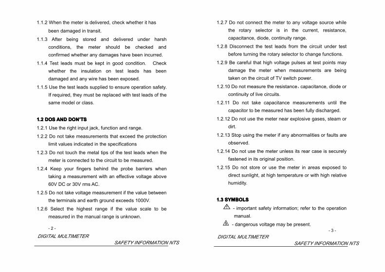
1.1.2 When the meter is delivered, check whether it has
been damaged in transit.
1.1.3 After being stored and delivered under harshconditions, the meter should be checked andconfirmed whether any damages have been incurred.
1.1.4 Test leads must be kept in good condition. Checkwhether the insulation on test leads has beendamaged and any wire has been exposed.
1.1.5 Use the test leads supplied to ensure operation safety.If required, they must be replaced with test leads of thesame model or class.
1.21.21.21.2 DOSDOSDOSDOS ANDANDANDAND DONDONDONDON’’’’TSTSTSTS1.2.1 Use the right input jack, function and range.
1.2.2 Do not take measurements that exceed the protectionlimit values indicated in the specifications
1.2.3 Do not touch the metal tips of the test leads when themeter is connected to the circuit to be measured.
1.2.4 Keep your fingers behind the probe barriers whentaking a measurement with an effective voltage above60V DC or 30V rms AC.
1.2.5 Do not take voltage measurement if the value betweenthe terminals and earth ground exceeds 1000V.
1.2.6 Select the highest range if the value scale to bemeasured in the manual range is unknown.
- 2 -
DIGITAL MULTIMETERSAFETY INFORMATION NTS
1.2.7 Do not connect the meter to any voltage source whilethe rotary selector is in the current, resistance,capacitance, diode, continuity range.
1.2.8 Disconnect the test leads from the circuit under testbefore turning the rotary selector to change functions.
1.2.9 Be careful that high voltage pulses at test points maydamage the meter when measurements are beingtaken on the circuit of TV switch power.
1.2.10 Do not measure the resistance,capacitance, diode orcontinuity of live circuits.
1.2.11 Do not take capacitance measurements until thecapacitor to be measured has been fully discharged.
1.2.12 Do not use the meter near explosive gases, steam ordirt.
1.2.13 Stop using the meter if any abnormalities or faults areobserved.
1.2.14 Do not use the meter unless its rear case is securelyfastened in its original position.
1.2.15 Do not store or use the meter in areas exposed todirect sunlight, at high temperature or with high relativehumidity.
1.31.31.31.3 SYMBOLSSYMBOLSSYMBOLSSYMBOLS
- important safety information; refer to the operationmanual.
- dangerous voltage may be present.- 3 -
DIGITAL MULTIMETERSAFETY INFORMATION NTS

- double insulation(Protection class ΙΙ).
CAT II - overvoltage (installation) category II, pollutiondegree 2 per IEC1010-1, referring to the level ofimpulse withstand voltage protection provided.
CAT III - overvoltage (installation) category III, pollutiondegree 2 per IEC1010-1, referring to the level ofimpulse withstand voltage protection provided.
- conforms to European Union Directive
- earth ground
- fuse
- battery low
1.41.41.41.4 MAINTENANCEMAINTENANCEMAINTENANCEMAINTENANCE
1.4.1 Do not attempt to remove the rear case to adjust orrepair the meter. Such actions should only beperformed by a technician who fully understands themeter and the danger involved.
1.4.2 Disconnect the test leads from all sources of electriccurrent before opening the battery cover of the mete.
1.4.3 To avoid any electric shock caused by error readings,replace the batteries immediately when the “ ” signappears on the display.
1.4.4 To avoid fire hazards, the replacement fuse must meetthe specified voltage and current at F 10A/250V (quickacting).
- 4 -
DIGITAL MULTIMETERSAFETY INFORMATION NTS
1.4.5 Use damp cloth and mild detergent to clean the meter;do not use abrasives or solvents.
1.4.6 Turn the rotary selector to OFF position to switch offthe power when the meter is not in use.
1.4.7 Remove the batteries to avoid damages to the meter ifit will idle for a long time.
- 5 -
DIGITAL MULTIMETERDESCRIPTION NTS

2.2.2.2. DESCRIPTIONDESCRIPTIONDESCRIPTIONDESCRIPTION- This meter is a portable professional measuring
instrument with large LCD to show three lines ofreadings, as well as back light for easily reading. The‘single-hand operation’ design for the range switchmakes measurement simple and easy. Overloadprotection and low battery indication are provided. Itis an ideal multi-function instrument with scores ofpractical applications for professional, workshop,school, hobby and home use.
- The meter is devised with light and sound alarm toprevent misconnection of test leads and provideadditional protection against damages caused byimproper operation.
- The 5 in 1 digital multi-tester has been designed tocombine the functions of sound level, luminance,humidity and temperature meters, as well as a digitalmultimeter.
- The sound level function is applicable to measuringnoise level in factories, schools, offices, airports and athome, and for checking the acoustics of studios,auditoriums and hi-fi installations.
- The luminance function is applicable to measuring fieldluminance with full cosine correction for angularincidence of light.
- The humidity and temperature functions are suitable for
- 6 -
DIGITAL MULTIMETERSAFETY INFORMATION NTS
measuring ambient humidity and temperature, as wellas temperature of objects.
- The digital multimeter can perform measurements ofAC/DC voltage and current, resistance,frequency, duty,capacitance, as well as continuity and diode test.
- Both the reading and unit of measurement are displayedon the LCD.
- Both auto range and manual range are available
- This meter is equipped with auto power off function.
- This meter is equipped with reading hold function.
- This meter is equipped with relative measurementfunction.
2.12.12.12.1 NAMESNAMESNAMESNAMES OFOFOFOF PARTPARTPARTPARTSSSS
1) LCD (Liquid-crystal display)
2) Auto/manual switch button (RANGE)
3) Relative measurement switch button (REL)
4) Reading hold/back light button (HOLD/B.L.)
5) Hz/duty switch button (Hz/DUTY)
6) Panel
7) Rotary selector
8) 10A input jack
9) mA/μA/TEMP input jack
10) COM input jack
11) V、Ω、Hz、 、 input jack
- 7 -
DIGITAL MULTIMETERSAFETY INFORMATION NTS

1000V 1000V 1000V 1000V
COMCOMCOMCOMuA/mAuA/mAuA/mAuA/mA
10A10A10A10A CAT III CAT III CAT III CAT III
12) OFF - switch of power
13) Function switch button (SELECT)
14) / switch button (/)
15) Humidity & Temperature sensor
16) Light sensor
17) Microphone
2.22.22.22.2 SWITCH,SWITCH,SWITCH,SWITCH, BUTTONSBUTTONSBUTTONSBUTTONS ANDANDANDAND INPUTINPUTINPUTINPUT JACKJACKJACKJACKSSSSHOLD/B.L. Button
- for holding the reading or control backlight- 8 -
DIGITAL MULTIMETERSAFETY INFORMATION NTS
SELECT Button
- for switching among measuring functions
RANGE Button
- for switching between auto and manual ranges.
Hz/DUTY Button
- for switching between Hz and duty measurement.
REL Button
- for switching to relative measurement.
/ Button (/)
- for switching between and
Rotary Selector
- for selecting functions and ranges.
OFF Position
- for turning off the power.
10A Input Jack
- for measuring current 0 ~ 10A.
mA/μA/TEMP Input Jack- for measuring current 0 ~ 400mA and temperature.V、Ω、Hz、 、 Input Jack- for measuring voltage, resistance, frequency, duty,capacitance, diode, and continuity.COM Input Jack- common input connection for current, voltage,resistance, frequency, duty, capacitance, diode, continuity,temperature measurement.
- 9 -
DIGITAL MULTIMETERSAFETY INFORMATION NTS

Humidity Sensor- for measuring humidity.Light Sensor- for measuring luminance.Microphone- for measuring sound level (dB).
2.32.32.32.3 LIQUID-CRYSTALLIQUID-CRYSTALLIQUID-CRYSTALLIQUID-CRYSTAL DISPLAYDISPLAYDISPLAYDISPLAY (LCD)(LCD)(LCD)(LCD)
1) Temperature indicator2) Humidity indicator3) Main indicator
- 10 -
DIGITAL MULTIMETERSAFETY INFORMATION NTS
~~~~ ACACACAC AAAAlternating Current
DCDCDCDC DDDDirect Current
AC or DC (alternating current or direct current)
Diode
Continuity buzzer
HHHH Reading being held
RELRELRELREL Relative measurement
AUTOAUTOAUTOAUTO Auto range
Battery low
Celsius units (Temperature)
Fahrenheir units (Temperature)
%RH%RH%RH%RH Relative Humidity units
FFFF Farad (Capacitance)
ΩΩΩΩ Ohms (Resistance)
VVVV Volts (Voltage)
AAAA Amperes (Current)
HzHzHzHz Hertz (Frequency)
%%%% Duty Cycle
dBdBdBdB Decibel
LuxLuxLuxLux Illuminance units
X10X10X10X10 Decuple
nnnn、μμμμ、mmmm、kkkk、MMMM Unit of measure prefixes: nano,micro, milli, kilo and mega
- 11 -
DIGITAL MULTIMETERSPECIFICATION NTS

3.3.3.3. SPECIFICATIONSSPECIFICATIONSSPECIFICATIONSSPECIFICATIONSCalibration is required once a year, to be carried out at atemperature between 18°C and 28 °C (64 °F to 82 °F) andrelative humidity below 75%.
3.13.13.13.1 GENERALGENERALGENERALGENERAL SPECIFICATIONSSPECIFICATIONSSPECIFICATIONSSPECIFICATIONS3.1.1 The meter is devised with light and sound alarm to
prevent test leads misconnection.
3.1.2 Auto range and manual range options are available.
3.1.3 Overrange protection is provided for all ranges.
3.1.4 Maximum voltage between terminals and earthground: 1000V DC or rms AC
3.1.5 Operating altitude: max. 2000 meters (7000 ft.)
3.1.6 Display: LCD, 3 readings at the same time
3.1.7 Maximum value display: 3999 digits
3.1.8 Polarity indication: automatic; ‘-‘ for negative polarity.
3.1.9 Overrange indication: ‘0L’ or ‘-0L’
3.1.10 Sampling time: approx. 0.4 second per sample
3.1.11 Unit indication: function and unit.
3.1.12 Auto power off time: 30 min.
3.1.13 Specification of resettable fuse: F1 500mA/250V
3.1.14 Fuse protection: F2 10A/250V (quick acting).
3.1.15 Operating power : 1.5V×3 AAA batteries
3.1.16 Battery low indication: ‘ ’ on LCD
3.1.17 Temperature factor: < 0.1×Accuracy /- 12 -
DIGITAL MULTIMETERSPECIFICATION NTS
3.1.18 Operating temperature: 0 to 40(32°F to 104°F)
3.1.19 Storage temperature: -10 to 50(10°F to 122°F)
3.1.20 Dimension: 195×92×55mm
3.1.21 Weight: approximate 400g(including batteries)
3.23.23.23.2 TECHNICALTECHNICALTECHNICALTECHNICAL SPECIFICATIONSSPECIFICATIONSSPECIFICATIONSSPECIFICATIONS
Ambient temperature: 23±5 Relative humidity: < 75%
3.2.1 DC Voltage
Range Resolution Accuracy
400mV 0.1mV
± (0.7% of reading + 2 digits)4V 1mV
40V 10mV
400V 100mV
1000V 1V
- Input Impedance: 10MΩ
- Overload protection:
400mV range: 250V DC or rms AC,
4V-1000V ranges: 1000V DC or 750V rms AC.
- Max. input voltage: 1000V DC or 750V rms AC
NOTE:NOTE:NOTE:NOTE:At small voltage range, unsteady readings will appear beforethe test leads contact the circuit. This is normal becausethe meter is highly sensitive. When the test leads contactthe circuit, the true reading will be shown.
- 13 -
DIGITAL MULTIMETERSPECIFICATION NTS

3.2.2 AC Voltage
Range Resolution Accuracy
400mV 0.1mV
4V 1mV ± (0.8% of reading + 3 digits)
40V 10mV
400V 100mV
750V 1V ± (1.0% of reading + 3 digits)
- Input Impedance: 10MΩ
- Overload protection:
400mV range: 250V DC or rms AC,
4V-750V ranges: 1000V DC or rms 750V AC.
- Max. input voltage: 1000V DC or rms 750V AC
- Frequency range: 40 to 400Hz
- Response: average, calibrated in rms of sine wave
NOTE:NOTE:NOTE:NOTE:At small voltage range, unsteady readings will appear beforethe test leads contact the circuit. This is normal becausethe meter is highly sensitive. When the test leads contactthe circuit, the true reading will be shown.
- 14 -
DIGITAL MULTIMETERSPECIFICATION NTS
3.2.3 DC Current
Range Resolution Accuracy
400µA 0.1µA
4000µA 1µA
40mA 10µA ±(1.2% of reading + 3 digits)
400mA 100µA
4A 1mA
10A 10mA ±(2.0% of reading + 10 digits)
- Overload protection:
µA、mA ranges: resettable fuses F1 500mA/250V
10A range: F2 10A/250V fuse (quick acting).
- Max. input current:
mA jack(µA ranges): 4mA,
mA jack(mA ranges): 400mA,
10A jack: 10A
- voltage drop:
400µA ranges: 40mV,
4000µA ranges: 400mV,
40mA ranges: 40mV,
400mA ranges: 400mV,
4A range: 40mV
10A range: 100Mv
- 15 -DIGITAL MULTIMETER
SPECIFICATION NTS

3.2.4 AC Current
Range Resolution Accuracy
400µA 0.1µA
4000µ A 1µA
40mA 10µ A ±(1.5% of reading + 5 digits)
400mA 100µA
4A 1mA
10A 10mA ±(3.0% of reading + 10 digits)
- Overload protection:
µA、mA ranges: resettable fuses F1 500mA/250V
10A range: F2 10A/250V fuse (quick acting),.
- Max. input current:
mA jack(µA ranges): 4mA,
mA jack(mA ranges): 400mA,
10A jack: 10A
- voltage drop:
400µA ranges: 40mV,
4000µA ranges: 400mV,
40mA ranges: 40mV,
400mA ranges: 400mV,
4A range: 40mV
10A range: 100mV
- Frequency range: 40 to 400Hz
- Response: average, calibrated in rms of sine wave- 16 -
DIGITAL MULTIMETERSPECIFICATION NTS
3.2.5 Resistance
Range Resolution Accuracy
400Ω 0.1Ω
±(1.2% of reading + 2 digits)4kΩ 1Ω
40kΩ 10Ω
400k( 100Ω
4M( 1kΩ
40M( 10kΩ ± (2.0% of reading + 5 digits)
- Open circuit voltage: ~0.25V
- Overload protection: 250V DC or rms AC
3.2.6 Capacitance
Range Resolution Accuracy
40nF 10pF
400nF 0.1nF
4µF 1nF ±(3.0% of reading + 3 digits)
40µF 10nF
100µF 100nF
- Overload protection: 250V DC or rms AC
- 17 -DIGITAL MULTIMETER
SPECIFICATION NTS

3.2.7 Frequency
Range Resolution Accuracy
9.999Hz 0.001Hz ±(2.0% of reading + 5 digits)
99.99Hz 0.01Hz
999.9Hz 0.1Hz ±(1.5% of reading + 5 digits)
9.999kHz 1Hz
99.99kHz 10Hz
199.9kHz 100Hz ±(2.0% of reading + 5 digits)
>200kHz for reference only
- by Hz range:
Measurement range: 0 ~ 200kHz
Input voltage range: 0.5V – 10V rms AC (higher inputvoltage at higher frequency)
Overload protection: 250V DC or rms AC
- by V range:
Measurement range: 0 ~ 40kHz
Input voltage range: 0.5V – 750V rms AC (higher inputvoltage at higher frequency)
Input Impedance: 10MΩ
Max. input voltage: 1000V DC or 750V rms AC
- by µA, mA or A range:
Measurement range: 0 ~ 40kHz
Input current range: ≥ 1/4 range rms AC (higher inputvoltage at higher frequency)- 18 -
DIGITAL MULTIMETERSPECIFICATION NTS
- Max. input current:
mA jack(µA ranges): 4mA,
mA jack(mA ranges): 400mA,
10A jack: 10A
- Overload Protection:
µA、mA ranges: resettable fuses F1 500mA/250V
10A range: F2 10A/250V fuse (quick acting).
NOTE:
When measuring frequency, the range by Hz range is largerthan that by the Hz of voltage range or current range, but thevalue measured beyond the range is for reference only.
3.2.8 Duty
Range Resolution Accuracy
0.1 - 99.9% 0.1% ± 3.0%
- By Hz range:
Frequency response: 0 ~ 200kHz
Input voltage range: 0.5V – 10V rms AC (higher inputvoltage at higher frequency)
Overload protection: 250V DC or rms AC (higher inputvoltage at higher frequency)
- By V range:
Frequency response: 0 ~ 40kHz
Input voltage range: 0.5V – 600V rms AC (higher inputvoltage at higher frequency)
- 19 -DIGITAL MULTIMETER
SPECIFICATION NTS
Input Impedance: 10MΩ
Max. Input Voltage: 1000V DC or 750V rms AC
- By µA, mA or A range:
Frequency response: 0 ~ 40kHz
Input current range: ≥1/4 of the rms AC for the range(higher input voltage at higher frequency)
- Max. input current:
mA jack(µA ranges): 4mA,
mA jack(mA ranges): 400mA,
10A jack: 10A
- Overload protection:
µA、mA ranges: resettable fuses F1 500mA/250V
10A range: F2 10A/250V fuse (quick acting).
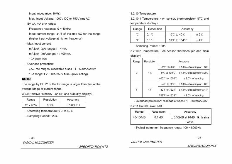
NOTE:NOTE:NOTE:NOTE:The range by DUTY of the Hz range is larger than that of thevoltage range or current range.
3.2.9 Relative Humidity(on RH and humidity display)
Range Resolution Accuracy
20 - 95% 0.1% ± 5.0%RH
- Operating temperature: 0 to 40
- Sampling Period: ~20s.
- 20 -
DIGITAL MULTIMETERSPECIFICATION NTS
3.2.10 Temperature
3.2.10.1 Temperature(on sensor, thermoresistor NTC andtemperature display)
Range Resolution Accuracy
0.1 0 to 40 ± 2
0.1 32 to 104 ± 4
- Sampling Period: ~20s.
3.2.10.2 Temperature(on sensor, thermocouple and maindisplay)
Range Resolution Accuracy
-20 to 0 ± 5.0% of reading or ± 3
1 0 to 400 ± 1.0% of reading or ± 2
400 to 1000 ± 2.0% of reading
-4 to 32 ± 5.0% of reading or ± 6
1 32 to 752 ± 1.0% of reading or ± 4
752 to 1832 ± 2.0% of reading
- Overload protection: resettable fuses F1 500mA/250V.
3.2.11 Sound Level(dB)
Range Resolution Accuracy
40-100dB 0.1 dB ± 3.5%dB at 94dB, 1kHz sinewave
- Typical instrument frequency range: 100 ~ 8000Hz
- 21 -
DIGITAL MULTIMETERSPECIFICATION NTS

3.2.12 Luminance(Lux)
Range Resolution Accuracy
Lux (4000) 1 Lux ±(5.0% of reading + 10 digits)
at color temp. 2856K calibrated to
standard incandescent lamp×10Lux
(40000)
10Lux
- Repeatability: ±2%.
3.2.13 Diode Test
Range Resolution Function
1mV displaying approximateforward voltage of diode
- Forward DC current ~1mA
- Reversed DC voltage ~1.5V
- Overload Protection: 250V DC or rms AC
3.2.14 Continuity Test
Range Function
Built-in buzzer will sound if resistance is lowerthan 40Ω.
- Open circuit voltage ~0.5V
- Overload Protection: 250V DC or rms AC
- 22 -
DIGITAL MULTIMETEROPERATING INSTRUCTION NTS
4.4.4.4. OPERATINGOPERATINGOPERATINGOPERATING INSTRUCTIONINSTRUCTIONINSTRUCTIONINSTRUCTION
4.4.4.4.1111 MISCONNECTIONMISCONNECTIONMISCONNECTIONMISCONNECTION ALARMALARMALARMALARMThe input jacks of the meter are equipped with sound andlight alarms against misconnection of test leads.
4.1.1 At V、Ω、Hz、Duty、 、 ranges:
1)The red lights at the “IN” and “COM” jacks will be offafter the test leads are plugged in.
2)The buzzer will sound upon misconnection of the testleads in the “mA” or “10A” jacks to warn the user. Atthe same time, the lights at the “IN” and “COM” jackswill flash to remind the user to plug in the test leadsthere.
4.1.2 At μA、mA, TEMP ranges:
1)The red lights at the “mA” and “COM” jacks will be offafter the test leads are plugged in.
2)The buzzer will sound upon misconnection of the testleads in the “IN” or “10A” jacks to warn the user. Atthe same time, the red lights at the “mA” and “COM”jacks will flash to remind the user to plug in the testleads there.
4.1.3 At 10A range:
1) The red lights at the “10A” and “COM” jacks will be offafter the test leads are plugged in.
2) The buzzer will sound upon misconnection of the testleads in the “IN” or “mA” jacks to warn the user.
- 23 -DIGITAL MULTIMETER
OPERATING INSTRUCTION NTS

At the same time, the lights at the “10A” and “COM”jacks will flash to remind the user to plug in the testleads there.
4.1.4 At dB and Lux range, whether the test leads areplugged in or otherwise, the meter will make noresponse because no signal input is required from theinput terminals.
4.4.4.4.2222 HOLDHOLDHOLDHOLDINGINGINGING READINGSREADINGSREADINGSREADINGS1)Press the “HOLD/B.L” button to hold the readings while
taking measurement, and the value on the display willbe held.
2 ) Press the “HOLD/B.L” button again to release theREADING HOLD function.
4.34.34.34.3 SWITCHINGSWITCHINGSWITCHINGSWITCHING FUNCTIONFUNCTIONFUNCTIONFUNCTIONSSSS
1)Press the " SELECT " button to switch between AC andDC measurement at the current and voltage ranges.
2 ) Press the " SELECT " button to switch amongresistance, diode and continuity ranges.
4.44.44.44.4 SWITCHINGSWITCHINGSWITCHINGSWITCHING RANGERANGERANGERANGESSSS
1)When the meter is turned on, it is at the auto rangemode for measuring current, voltage and resistance.
2)Press the "RANGE" button for manual range mode.The range will go up one level at each press and return- 24 -
DIGITAL MULTIMETEROPERATING INSTRUCTION NTS
to the lowest level when the highest level is reached.
3)Press the "RANGE" button for two or more seconds toreturn to the auto range.
4.54.54.54.5 SWITCHINGSWITCHINGSWITCHINGSWITCHING BETWEENBETWEENBETWEENBETWEEN FREQUENCYFREQUENCYFREQUENCYFREQUENCY/DUTY/DUTY/DUTY/DUTY1)Press the “Hz/DUTY” button at the frequency range to
switch between frequency and duty measurement.
2)When the meter is at the voltage and current ranges,press the “Hz/DUTY” button to measure the frequencyof the voltage or current signal. Another press on the“Hz/DUTY” button will change into the Duty range formeasuring the duty cycle of the voltage or currentsignal.
3)Press the “Hz/DUTY” again to resume the meter tovoltage and current measurement at the manual rangemode.
4.64.64.64.6 SWITCHINGSWITCHINGSWITCHINGSWITCHING TOTOTOTO RELATIVERELATIVERELATIVERELATIVE MEASUREMEASUREMEASUREMEASUREMENTMENTMENTMENT1 ) Press the “REL” button to enter the relative
measurement mode when taking measurements.The initial reading will resume zero.
2)At the relative measurement mode, the existing readingwill be stored in the memory as reference value for latermeasurements. The displayed reading is the differencebetween the input value and reference value. i.e.
REL (present reading) = input value - reference value- 25 -
DIGITAL MULTIMETEROPERATING INSTRUCTION NTS

3)The meter will enter the manual range mode after the“REL” button is pressed. REL mode is not availablefor Hz/Duty range because it is an automatic range.
4) Press the “REL” button again to cancel the relativemeasurement function.
5 ) Pressing the “REL” button at the HOLD mode willcancel the HOLD function. The actual measurementvalue taken will be stored in the memory as referencevalue. The readings displayed for measurementstaken afterwards will be the difference between theinput value and the reference value.
6)Press the “RANGE”, “SELECT” buttons or turning therotary selector to cancel the relative measurementfunction and resume normal measurement. The RELsymbol on the display will disappear.
7)OL triggering: Under the REL mode, OL (over limit) willflash on the display if the input value exceeds theallowed value for that range. Press the “REL” buttonagain to cancel the relative measurement function.The REL mode cannot be entered when OL is flashing.
4.4.4.4.7777 BACKBACKBACKBACK LIGHTLIGHTLIGHTLIGHT1)Press the ”HOLD/B.L” button for two or more seconds
to switch on the back light if the light in theenvironment is too dim for taking reading,.
2)Press the “HOLD/B.L” button for two or more seconds- 26 -
DIGITAL MULTIMETEROPERATING INSTRUCTION NTS
again to switch off the back light.
3 ) The back light will go off automatically after 10seconds.
NOTE:NOTE:NOTE:NOTE:1) LED, which requires a larger working current, is the
main source of back light. Although the meter isequipped with a timer set at 10 seconds (i.e. the backlight will be off automatically after 10 seconds),frequent use of the back light will shorten the life of thebatteries. Therefore, do not use the back light unlessnecessary.
2) When the battery voltage is ≤3.6V, the symbol “ ”( battery low)will appear on the LCD. When theback light is on, even if the batter is ≥3.6V, the “ ”may appear because of its large working current whichwill cause the voltage to drop. (The accuracy of themeasurement cannot be assured when the“ “ symbol appears.) In this case, you need notreplace the batteries yet. Normally, the batteries canlast until the “ ” appears when the back light is notbeing used.
4.84.84.84.8 AUTOAUTOAUTOAUTO POWERPOWERPOWERPOWER OFFOFFOFFOFF1) If there is no any operation within any thirty minute
period after the power is on, the meter will enter theauto power off mode.
- 27 -
DIGITAL MULTIMETEROPERATING INSTRUCTION NTS

2)Turn the rotary selector or press any of the“HOLD/B.L”, “SELECT”, “RANGE”, “Hz/DUTY” or“REL” button to resume operation of the meter underauto the power off mode.
3)Press the “SELECT” button to disable the auto poweroff function.
4.4.4.4.9999 PREPARATIPREPARATIPREPARATIPREPARATINGNGNGNG FORFORFORFOR MEASUREMENTMEASUREMENTMEASUREMENTMEASUREMENT4.9.1 Switch on the power by turning the rotary selector. If
the battery voltage is lower than 3.6V, the “ ”symbol will appear and the batteries should bereplaced.
4.9.2 The “ ” symbol beside the input lead shows that theinput voltage or current should not exceed thespecified value in order to protect the internal circuitfrom damage.
4.9.3 Turn the rotary selector to the required function andrange to be measured. Under the manual mode,choose the highest range when the value scale to bemeasured is unknown.
4.9.4 Connect the common test lead first and then thecharged test lead when making connection. Takeaway the charged test lead first when disconnecting.
- 28 -
DIGITAL MULTIMETEROPERATING INSTRUCTION NTS
4.4.4.4.10101010 MEASURINGMEASURINGMEASURINGMEASURING DCDCDCDC VOLTAGEVOLTAGEVOLTAGEVOLTAGE
WARNINGWARNINGWARNINGWARNINGBewareBewareBewareBeware ofofofof eeeelectrocution.lectrocution.lectrocution.lectrocution.
PayPayPayPay specialspecialspecialspecial attentionattentionattentionattention totototo avoidavoidavoidavoid electricelectricelectricelectric shockshockshockshock whenwhenwhenwhenmeasuringmeasuringmeasuringmeasuring highhighhighhigh voltage.voltage.voltage.voltage.DoDoDoDo notnotnotnot inputinputinputinput anyanyanyany voltagevoltagevoltagevoltage overoveroverover 1000V1000V1000V1000V DCDCDCDC,,,, whichwhichwhichwhich maymaymaymaydestroydestroydestroydestroy thethethethe ininininternalternalternalternal circuitcircuitcircuitcircuit,,,, althoughalthoughalthoughalthough aaaa higherhigherhigherhigher voltagevoltagevoltagevoltagecancancancan bebebebe shownshownshownshown....
4.10.1 Plug the black test lead into the COM jack and thered test lead into the V jack.
4.10.2 Set the rotary selector to the V range position.
4.10.3 Press the "SELECT" button to switch to DCmeasurement. Then press the “RANGE” button tochoose the auto range or manual range mode.
4.10.4 Connect the test leads to the voltage source or loadfor measurement.
4.10.5 Take the reading on the main indicator of the LCD.The polarity symbol denotes the polarity of the endconnected by the red test lead.
NOTE:NOTE:NOTE:NOTE:1) At small voltage range, unsteady readings will appear
before the test leads contact the circuit. This isnormal because the meter is highly sensitive. Whenthe test leads contact the circuit, the true reading willbe shown.
- 29 -
DIGITAL MULTIMETEROPERATING INSTRUCTION NTS

2) Under the manual range mode, when only ‘OL’ or ‘-OL’is shown on the LCD, it means the measurement hasexceeded the range. A higher range should beselected.
3) Under the manual range mode, when the scale of thevalue to be measured is unknown beforehand, selectthe highest range first and lower the range gradually.
4.14.14.14.11111 MEASURINGMEASURINGMEASURINGMEASURING ACACACAC VOLTAGEVOLTAGEVOLTAGEVOLTAGE
WARNINGWARNINGWARNINGWARNINGBewareBewareBewareBeware ofofofof ElectrocutioElectrocutioElectrocutioElectrocutionnnn....
PayPayPayPay specialspecialspecialspecial attentionattentionattentionattention totototo avoidavoidavoidavoid electricelectricelectricelectric shockshockshockshock whenwhenwhenwhenmeasuringmeasuringmeasuringmeasuring highhighhighhigh voltage.voltage.voltage.voltage.DoDoDoDo notnotnotnot inputinputinputinput anyanyanyany voltagevoltagevoltagevoltage 750V750V750V750V rmsrmsrmsrms ACACACAC,,,, whichwhichwhichwhich maymaymaymaydestroydestroydestroydestroy thethethethe innerinnerinnerinner circuitcircuitcircuitcircuit,,,, althoughalthoughalthoughalthough aaaa higherhigherhigherhigher voltagevoltagevoltagevoltagecancancancan bebebebe shownshownshownshown....
4.11.1 Plug the black test lead into the COM jack and the redtest lead into the V jack.
4.11.2 Set the rotary selector to the V range position.
4.11.3 Press the "SELECT" button to switch to ACmeasurement. Then press the “RANGE” button tochoose the auto range or manual range mode.
4.11.4 Connect the test leads to the voltage source or loadterminals for measurement.
4.11.5 Take the reading on the main indicator of the LCD.- 30 -
DIGITAL MULTIMETEROPERATING INSTRUCTION NTS
NOTE:NOTE:NOTE:NOTE:1) At small voltage range, unsteady readings may appear
before the test leads contact the circuit. This isnormal because the meter is highly sensitive. Whenthe test leads contact the circuit, the true reading willbe shown.
2) At the manual range mode, when only ‘OL’ or ‘-OL’ isshown on the LCD, it means the measurement hasexceeded the range. A higher range should beselected.
3) At the manual range mode, when the scale of the valueto be measured is unknown beforehand, select thehighest range first and lower the range gradually.
4.4.4.4.12121212 MEASURINGMEASURINGMEASURINGMEASURING FREQUENCYFREQUENCYFREQUENCYFREQUENCY
4.12.1 Plug the black test lead into the COM jack and thered test lead into the Hz jack.
4.12.2 Set the rotary selector to the Hz range position (orpress the “Hz/DUTY” button at the AC/DC V range toswitch to Hz measurement).
4.12.3 Connect test leads to the two ends of the source orload for measurement.
4.12.4 Take the reading on the main indicator of the LCD.
- 31 -
DIGITAL MULTIMETEROPERATING INSTRUCTION NTS

4.4.4.4.13131313 MEASURINGMEASURINGMEASURINGMEASURING DUTYDUTYDUTYDUTY4.13.1 Plug the black test lead into the COM jack and the
red test lead into the Hz jack.
4.13.2 Set the rotary selector to the Hz range position.
4.13.3 Press the "Hz/DUTY" button to switch to DUTYmeasurement (or press the “Hz/DUTY” button at theAC/DC V range to switch to DUTY measurement).
4.13.4 Connect test leads to the two end of the source orload for measurement.
4.13.5 Take the reading on the main display of the LCD.
4.14.14.14.14444 MEASURINGMEASURINGMEASURINGMEASURING DCDCDCDC CURRENTCURRENTCURRENTCURRENT
WARNINGWARNINGWARNINGWARNING
BewareBewareBewareBeware ofofofof ElectrocutioElectrocutioElectrocutioElectrocutionnnn....TurnTurnTurnTurn offoffoffoff thethethethe powerpowerpowerpower ofofofof thethethethe circuitcircuitcircuitcircuit totototo bebebebe measuredmeasuredmeasuredmeasuredbeforebeforebeforebefore connectingconnectingconnectingconnecting thethethethe metermetermetermeter totototo thethethethe circuitcircuitcircuitcircuit....
4.14.1 Plug the black test lead into the COM jack. Whenthe current to be measured is under 400mA, plug thered test lead into the mA jack; when the current to bemeasured is over 400mA but under 10A, plug the redtest lead into the 10A jack.
4.14.2 Set the rotary selector to the A range position.
4.14.3 Press the "SELECT" button to switch to DCmeasurement. Then press the “RANGE” button tochoose the auto range or manual range mode.
- 32 -
DIGITAL MULTIMETEROPERATING INSTRUCTION NTS
4.14.4 Connect the test leads to the circuit for measurement.4.14.5 Take the reading on the main indicator of the LCD.
The polarity symbol denotes the polarity of the endconnected by the red test lead.
NOTE:NOTE:NOTE:NOTE:1) At the manual range mode, when only ‘OL’ or ‘-OL’ is
shown on the LCD, it means the measurement hasexceeded the range. A higher range should beselected.
2) At the manual range mode, when the scale of the valueto be measured is unknown beforehand, set the rangeto the highest.
3) “ ” means the maximum current of the mA jack is400mA and the maximum current of the 10A jack is10A. At the 10A jack, current exceeding the limit willblow the fuse.
4.14.14.14.15555 MEASURINGMEASURINGMEASURINGMEASURING ACACACAC CURRENTCURRENTCURRENTCURRENT
WARNINGWARNINGWARNINGWARNING
BewareBewareBewareBeware ofofofof ElectrocutioElectrocutioElectrocutioElectrocutionnnn....TurnTurnTurnTurn offoffoffoff thethethethe powerpowerpowerpower ofofofof thethethethe circuitcircuitcircuitcircuit totototo bebebebe measuredmeasuredmeasuredmeasuredbeforebeforebeforebefore connectingconnectingconnectingconnecting thethethethe metermetermetermeter totototo thethethethe circuitcircuitcircuitcircuit....
4.15.1 Plug the black test lead into the COM jack. When thecurrent to be measured is under 400mA, plug the redtest lead into the mA jack; when the current to bemeasured is over 400mA but under 10A, plug the red
- 33 -
DIGITAL MULTIMETEROPERATING INSTRUCTION NTS

test lead into the 10A jack.
4.15.2 Set the rotary selector to the A range position.
4.15.3 Press the "SELECT" button to switch to ACmeasurement. Then press the “RANGE” button tochoose the auto range or manual range mode.
4.15.4 Connect the test leads to the circuit for measurement.
4.15.5 Take the reading on the main indicator of the LCD.
NOTE:NOTE:NOTE:NOTE:
1) At the manual range mode, when only ‘OL’ or ‘-OL’ isshown on the LCD, it means the measurement hasexceeded the range. A higher range should beselected.
2) Under the manual range mode, when the scale of thevalue to be measured is unknown beforehand, set therange to the highest.
3) ” means the maximum current of the mA jack is400mA and the maximum current of the 10A jack is10A. At the 10A jack, current exceeding the limit willblow the fuse.
- 34 -DIGITAL MULTIMETER
OPERATING INSTRUCTION NTS
4.14.14.14.16666 MEASURINGMEASURINGMEASURINGMEASURING RESISTANCERESISTANCERESISTANCERESISTANCE
WARNINGWARNINGWARNINGWARNINGBewareBewareBewareBeware ofofofof Electrocution.Electrocution.Electrocution.Electrocution.
WhenWhenWhenWhen measuringmeasuringmeasuringmeasuring in-circuitin-circuitin-circuitin-circuit resistance,resistance,resistance,resistance, makemakemakemake suresuresuresurethatthatthatthat thethethethe powerpowerpowerpower ofofofof thethethethe circuitcircuitcircuitcircuit underunderunderunder testtesttesttest hashashashas beenbeenbeenbeenturnedturnedturnedturned offoffoffoff andandandand thatthatthatthat allallallall capacitorscapacitorscapacitorscapacitors havehavehavehave beenbeenbeenbeen fullyfullyfullyfullydischarged.discharged.discharged.discharged.
4.16.1 Plug the black test lead into the COM jack and thered test lead into the Ω jack.
4.16.2 Set the rotary selector to the Ω range position.4.16.3 Press the "SELECT" button to switch to Ω
measurement. Then press the “RANGE” button tochoose the auto range or manual range mode.
4.16.4 Connect the test leads to the ends of the resistor orcircuit for measurement.
4.16.5 Take the reading on the main indicator of the LCD.NOTE:NOTE:NOTE:NOTE:
1) At the manual range mode, when only ‘OL’ or ‘-OL’ isshown on the LCD, it means the measurement hasexceeded the range. A higher range should beselected.
2) When the input is open, ‘OL’ will appear on the LCD toindicate that the range has been exceeded.
3) For measuring resistance above 1MΩ, it may take afew seconds to get a steady reading. This is normalfor high resistance reading.
- 35 -
DIGITAL MULTIMETEROPERATING INSTRUCTION NTS

4.14.14.14.17777 MEASURINGMEASURINGMEASURINGMEASURING CAPACITANCECAPACITANCECAPACITANCECAPACITANCE
WARNINGWARNINGWARNINGWARNINGBewareBewareBewareBeware ofofofof Electrocution.Electrocution.Electrocution.Electrocution.
ToToToTo avoidavoidavoidavoid electricelectricelectricelectric shock,shock,shock,shock, makemakemakemake suresuresuresure thatthatthatthat thethethethecapacitorscapacitorscapacitorscapacitors havehavehavehave beenbeenbeenbeen fullyfullyfullyfully dischargeddischargeddischargeddischarged beforebeforebeforebeforemeasuringmeasuringmeasuringmeasuring thethethethe capacitancecapacitancecapacitancecapacitance ofofofof aaaa capacitor.capacitor.capacitor.capacitor.
4.17.1 Plug the black test lead into the COM jack and thered test lead into the jack.
4.17.2 Set the rotary selector to the Ω range position.
4.17.3 After fully discharged the capacitor, connect the testleads to the two ends of the capacitor formeasurement.
4.17.4 Take the reading on the main indicator of the LCD.
NOTE:NOTE:NOTE:NOTE:1) It may take some time (about 30 seconds for the
200μF range) for steady readings when measuringhigh capacity.
2) Sometimes a reading may appear when the circuit isopen. In such case, press the “REL” button to resetthe reading and take measurement again.
4.14.14.14.18888 TESTINGTESTINGTESTINGTESTING DIODEDIODEDIODEDIODE
4.18.1 Plug the black test lead into the COM jack and thered test lead into the jack.
4.18.2 Set the rotary selector to the Ω range position.- 36 -
DIGITAL MULTIMETEROPERATING INSTRUCTION NTS
4.18.3 Press the "SELECT" button to switch to test.
4.18.4 Connect the red test lead to the anode and the blacktest lead to the cathode of the diode for testing.
4.18.5 Take the reading on the main indicator of the LCD.
NOTE:NOTE:NOTE:NOTE:1) The meter will show the approximate forward voltage
drop of the diode.
2) When the test leads have been reversed or open, ‘OL’will appear on the LCD.
4.14.14.14.19999 TESTINGTESTINGTESTINGTESTING CONTINUITYCONTINUITYCONTINUITYCONTINUITY
WARNINGWARNINGWARNINGWARNING
BewareBewareBewareBeware ofofofof Electrocution.Electrocution.Electrocution.Electrocution.MakeMakeMakeMake suresuresuresure thatthatthatthat thethethethe powerpowerpowerpower ofofofof thethethethe circuitcircuitcircuitcircuit hashashashas beenbeenbeenbeenturnedturnedturnedturned offoffoffoff andandandand thethethethe capacitorscapacitorscapacitorscapacitors havehavehavehave beenbeenbeenbeen fullyfullyfullyfullydischargeddischargeddischargeddischarged beforebeforebeforebefore testingtestingtestingtesting thethethethe continuitycontinuitycontinuitycontinuity ofofofof aaaa circuitcircuitcircuitcircuit....
4.19.1 Plug the black test lead into the COM jack and thered test lead into the Ω jack.
4.19.2 Set the rotary selector to the Ω range position.
4.19.3 Press the “SELECT” button to switch to forcontinuity test.
4.19.4 Connect the test leads to the two ends of the circuitfor measurement.
4.19.5 If the resistance of the circuit being tested is less than40Ω, the built-in buzzer will sound.
- 37 -
DIGITAL MULTIMETEROPERATING INSTRUCTION NTS

4.19.6 Read the resistance on the main indicator of the LCD.
NOTE:NOTE:NOTE:NOTE:
If the test leads are open or the resistance of the circuit isover 400Ω, “OL” will appear on the LCD.
4.24.24.24.20000 MEASURINGMEASURINGMEASURINGMEASURING RELATIVERELATIVERELATIVERELATIVE HUMIDITYHUMIDITYHUMIDITYHUMIDITY4.20.1 This function is used for measuring the ambient
humidity around the meter.
4.20.2 Turn the rotary selector away from the OFF position.
4.20.3 The current ambient humidity will be shown on thehumidity display of the LCD.
NOTE:NOTE:NOTE:NOTE:1)The humidity sensor is placed inside the front part of the
meter and therefore it may take a longer time to reachbalance with the environment being measured.Furthermore, it takes a longer intermission time, about20 seconds, for sampling and the meter has to beexposed to the environment for a longer time foraccurate reading. Hence it is not suitable formeasuring rapidly changing ambient humidity.
2)It will take some time for a steady RH reading when theambient humidity changes.
- 38 -
DIGITAL MULTIMETEROPERATING INSTRUCTION NTS
4.214.214.214.21 MEASURINGMEASURINGMEASURINGMEASURING TEMPERATURETEMPERATURETEMPERATURETEMPERATURE(WITH(WITH(WITH(WITH THERMO-RESISTOR)THERMO-RESISTOR)THERMO-RESISTOR)THERMO-RESISTOR)
4.21.1 This function is used for measuring the ambienttemperature around the meter.
4.21.2 Turn the rotary selector away from the OFF position.
4.21.3 The current ambient temperature will be shown onthe temperature indicator of the LCD.
4.21.4 Press the "/" button to switch between and
measurement.
NOTE:NOTE:NOTE:NOTE:1 ) The temperature sensor (thermo-resistor) is placed
inside the front part of the meter and therefore it maytake a longer time to reach thermal balance with theenvironment. Furthermore, it takes a longerintermission time, about 20 seconds, for sampling andthe meter has to be exposed to the environment for alonger time for accurate reading. Hence it is notsuitable for measuring rapidly changing ambienttemperature.
2)The working temperature of the meter is 0 ~ 40. Asthe temperature sensor is placed inside the meter, thisfunction is applicable for measuring ambienttemperature between 0 and 40.
3) If exposed to an environment beyond 0 ~ 40, themeter may show a wider range of temperaturemeasurement, but the accuracy cannot be ensuredand damage to the meter may be caused.
- 39 -
DIGITAL MULTIMETEROPERATING INSTRUCTION NTS

4.24.24.24.22222 MEASURINGMEASURINGMEASURINGMEASURING TEMPERATURETEMPERATURETEMPERATURETEMPERATURE(WITH(WITH(WITH(WITH THERMOCOUPLE)THERMOCOUPLE)THERMOCOUPLE)THERMOCOUPLE)
WARNINGWARNINGWARNINGWARNING
BewareBewareBewareBeware ofofofof eeeelectrocution.lectrocution.lectrocution.lectrocution.ToToToTo avoidavoidavoidavoid electricalelectricalelectricalelectrical shock,shock,shock,shock, dodododo notnotnotnot connectconnectconnectconnect thethethethethermocouplesthermocouplesthermocouplesthermocouples totototo chargedchargedchargedcharged circuitcircuitcircuitcircuitssss....
4.22.1 Turn the rotary selector to TEMP position.
4.22.2 “OL” will appear on the main display of the LCD atthis time.
4.22.3 Plug the red end of the ‘K’ type thermocouple into theTEMP jack and black end into the COM jack. Touchthe surface of the object or area with the temperaturesensor for measurement.
4.22.4 Press the "/" button to choose or
measurement.
4.22.5 Take the reading on the main indicator of the LCD.
NOTE:NOTE:NOTE:NOTE:The cold end compensation circuit used for measuringtemperature is placed inside the front part of the meter.It may take a longer time to reach thermal balance withthe environment. Therefore the meter should beexposed to the environment for a longer time for accuratereading.
- 40 -
DIGITAL MULTIMETEROPERATING INSTRUCTION NTS
4.234.234.234.23 MEASURINGMEASURINGMEASURINGMEASURING SOUNDSOUNDSOUNDSOUND LEVELLEVELLEVELLEVEL (dB)(dB)(dB)(dB)
WARNINGWARNINGWARNINGWARNINGToToToTo avoidavoidavoidavoid damagedamagedamagedamage totototo thethethethe meter,meter,meter,meter, dodododo notnotnotnot connectconnectconnectconnect thethethetheinputinputinputinput plugplugplugplug totototo anyanyanyany electricelectricelectricelectric signal.signal.signal.signal.
4.23.1 Turn the rotary selector to the dB range position.
4.23.2 Point the sensor located in the front part of the meterat the sound source.
4.23.3 The sound level in dB will be shown on the LCD.
NOTE:NOTE:NOTE:NOTE:Strong wind (over 10m/sec.) striking on the microphonemay cause misreading for measurement in windylocations. A windscreen should be placed in front of themicrophone in such circumstances.
4.244.244.244.24 MEASURINGMEASURINGMEASURINGMEASURING LUMINANCELUMINANCELUMINANCELUMINANCE
WARNINGWARNINGWARNINGWARNINGToToToTo avoidavoidavoidavoid damagedamagedamagedamage totototo thethethethe meter,meter,meter,meter, dodododo notnotnotnot connectconnectconnectconnect thethethetheinputinputinputinput plugplugplugplug totototo anyanyanyany electricelectricelectricelectric signal.signal.signal.signal.
4.24.1 Turn the rotary selector to the Lux or ×10Lux rangeposition.
4.24.2 Point the sensor located in the front part of the meterat the light source.
4.24.3 The luminance (in Lux) will be shown on the LCD.
- 41 -
DIGITAL MULTIMETEROPERATING INSTRUCTION NTS

NOTE:NOTE:NOTE:NOTE:1 ) When only ‘OL’ appears on the LCD, it means
over-range and a higher range should be selected.
2)Spectral sensitivity characteristic:
20
400
80
60
40
100
900600500 800700 1000
Relat
ive S
ensit
ivity
(%)
Wave Length (nm)
3)Recommended luminance:
Location Lux
Home
wardrobe, bedroom, lavatory, 70~150
staircase, corridor 70~150
living-room, study, toilet, kitchen 200 ~ 750
writing, working 500~1000
handicraft, dressmaking work 750~2000
Office
conference room, reception room 200 ~ 750- 42 -
DIGITAL MULTIMETEROPERATING INSTRUCTION NTS
clerical work 700 ~ 1,500
typing 1000 ~ 2,000
Factory
packing, passage 150 ~ 300
assembly line 300 ~ 750
inspection work 750 ~ 1,500
electronic parts assembly line 1,500 ~ 3,000
Hotel
public places, washroom 100 ~ 200
reception, front desk 200 ~1,000
Shop
staircase, corridor 150 ~ 200
display window, packing bench 750 ~ 1,500
shop window 1,500 ~ 3,000
Hospital
ward, warehouse 100 ~ 200
medical examination room 300 ~ 750
operation theatre, A&E ward 750 ~ 1,500
School
auditorium, indoor gymnasium 100 ~ 300
classroom 200 ~ 750
laboratory, library 500 ~ 1,500
- 43 -DIGITAL MULTIMETER
OPERATING INSTRUCTION NTS

Appendix:Appendix:Appendix:Appendix:Conversion between luminance and light intensity:
EEEE ==== IIII //// rrrr 2222
where E --- luminance, unit: Lux;
I --- intensity of light source, unit: cd;
r --- distance between illuminant surface of light sourceand light detector, unit: m.
When making measurement, the shortest distancebetween the illuminant surface of the light source and thelight detector should be larger than 15 times of themaximum size of the illuminant surface of the light source(or the light sensor).
- 44 -
DIGITAL MULTIMETERMAINTENANCE
5.5.5.5. MAINTENANCEMAINTENANCEMAINTENANCEMAINTENANCE
5.15.15.15.1 REPLACINGREPLACINGREPLACINGREPLACING THETHETHETHE BATTERBATTERBATTERBATTERIESIESIESIES
WARNINGWARNINGWARNINGWARNINGTTTToooo avoidavoidavoidavoid electricelectricelectricelectric shockshockshockshock,,,, makemakemakemake suresuresuresure thatthatthatthat thethethethe testtesttesttestleadsleadsleadsleads havehavehavehave beenbeenbeenbeen clearlyclearlyclearlyclearly movemovemovemove awayawayawayaway fromfromfromfrom thethethethe circuitcircuitcircuitcircuitunderunderunderunder measurementmeasurementmeasurementmeasurement bbbbeforeeforeeforeefore openingopeningopeningopening thethethethe batterybatterybatterybatterycovercovercovercover ofofofof thethethethe metermetermetermeter....
5.1.1 If the sign “ ” appears, it means that the batteriesshould be replaced.
5.1.2 Loosen the fixing screw of the battery cover andremove it.
5.1.3 Replace the exhausted batteries with new ones.
5.1.4 Put the battery cover back and fix it again to its originform.
NOTE:NOTE:NOTE:NOTE:
Do not reverse the poles of the batteries.
5.25.25.25.2 REPLACINGREPLACINGREPLACINGREPLACING FUSEFUSEFUSEFUSE5.2.1 Fuses rarely need replacement. Almost all blows are
the result of operation errors.
5.2.2 Loosen the fixing screw of the battery cover andremove it.
5.2.3 Replace the blown fuse with one at the specifiedrating.
- 45 -
DIGITAL MULTIMETERMAINTENANCE

5.2.4 Put the battery cover back and fix it again to itsoriginal form.
WARNINGWARNINGWARNINGWARNINGTTTToooo avoidavoidavoidavoid electricelectricelectricelectric shockshockshockshock,,,, makemakemakemake suresuresuresure thatthatthatthat thethethethe testtesttesttest leadsleadsleadsleadshavehavehavehave beenbeenbeenbeen clearlyclearlyclearlyclearly movemovemovemove awayawayawayaway fromfromfromfrom thethethethe circuitcircuitcircuitcircuit underunderunderundermeasurementmeasurementmeasurementmeasurement bbbbeforeeforeeforeefore openingopeningopeningopening thethethethe batterybatterybatterybattery covercovercovercover ofofofof thethethethemetermetermetermeter....
ForForForFor protectionprotectionprotectionprotection againstagainstagainstagainst firefirefirefire hazardhazardhazardhazard,,,, replacereplacereplacereplace fusesfusesfusesfuses withwithwithwithspecifiedspecifiedspecifiedspecified ratingsratingsratingsratings onlyonlyonlyonly:::: FFFF 10A/250V10A/250V10A/250V10A/250V (quick(quick(quick(quick acting).acting).acting).acting).
AAAAAA
+
-
-
++
-
- 46 -
DIGITAL MULTIMETERMAINTENANCE
5.35.35.35.3 REPLACINGREPLACINGREPLACINGREPLACING TESTTESTTESTTEST LEADSLEADSLEADSLEADS
WARNINGWARNINGWARNINGWARNINGTheTheTheThe replacementreplacementreplacementreplacement mustmustmustmust bebebebe testtesttesttest leadsleadsleadsleads inininin goodgoodgoodgoodworkingworkingworkingworking conditionconditionconditioncondition withwithwithwith thethethethe samesamesamesame orororor equivalentequivalentequivalentequivalentratingratingratingrating:::: 1000V1000V1000V1000V 10A10A10A10A....
A test lead must be replaced if the insulation layer has beendamaged, e.g. the wire inside is exposed.
- 47 -
DIGITAL MULTIMETERACCESSORIES

6.6.6.6. ACCESSORIESACCESSORIESACCESSORIESACCESSORIES1) Test leads: electric rating: 1000V 10A 1 pair (set)
2) Thermocouple (K type TP01) 1 set
3) Operation Manual 1 copy
- 48 -