containment monitoring strategies - microsoft · containment monitoring strategies ... •...
TRANSCRIPT

Containment Monitoring Strategies in the USA
1
Abdul H. Sheikh PEIman Engineering and Construction LLCEmail: [email protected]
Presentation Topics
1. USA Nuclear Power Plants2. Nuclear Power Plant Containments3. Prestressed Concrete Containments4. USNRC and ASME Regulations and Guidance5. Monitoring and Trending Prestressing Forces6. Leak Rate Testing of Containment7. US Containments Operating Experience
2

Nuclear Power Plants Containments
• Type of containments– Reinforced Concrete with steel liner plate– Prestressed concrete with steel liner plate– Steel containment with concrete shield building
3

US Nuclear Power plants
• Total nuclear plants in operation: 99• PWR plants: 65• BWR plants: 34• Plants in operation for more than 40 years: 40• USNRC has approved licensed extension for another 20 years (60 years total) for 82 plants.
• Application for another 11 plants under USNRC review.
4
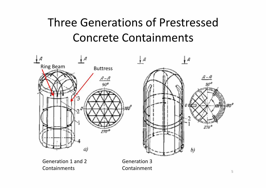
Three Generations of PrestressedConcrete Containments
ButtressRing Beam
5
Generation 1 and 2 Containments
Generation 3 Containment

USNRC and ASME Guidance for Periodic Inspection of Containments
• Concrete Containments inspected in accordance with ASME Section XI, Subsection IWL.
• Liner plate and steel containments inspected with ASME Section XI, Subsection IWE.
• ASME requirements supplemented by Code of Federal Regulations 10CFR 50.55a.
• Appendix J of 10CFR50, ”Primary Reactor Containment Leakage Testing of Water‐Cooled Power Reactors.
6

Guidance Documents for Inspection of Prestressed Concrete Containments
Containment with Ungrouted (Greased) Tendons• USNRC initially issued Regulatory Guide RG 1.35 for inspection of concrete
containments in 1973.• RG 1.35 was revised three times based on industry experience.• Last Revision in 1990• In 1996 USNRC endorsed the guidance provided ASME Section XI, Subsection IWL
for containment inspection with some additional requirements.• Additional Requirements are listed in Code of Federal Regulations 10CFR50.55a• 10CFR50.55a incorporates the guidance provided in RG 1.35• Most US nuclear power plants now follow 10CFR50.55a and ASME Section XI,
Subsection IWL requirements for containments with ungrouted tendons.Containment with Grouted Tendons• US has only plant with grouted prestressing tendons and has specific inspection
requirements approved by USNRC.• USNRC issued latest revision of RG 1.90 for containments with grouted tendons in
2012
7
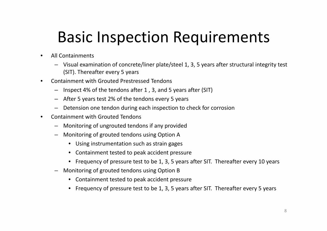
Basic Inspection Requirements• All Containments
– Visual examination of concrete/liner plate/steel 1, 3, 5 years after structural integrity test (SIT). Thereafter every 5 years
• Containment with Grouted Prestressed Tendons– Inspect 4% of the tendons after 1 , 3, and 5 years after (SIT)– After 5 years test 2% of the tendons every 5 years– Detension one tendon during each inspection to check for corrosion
• Containment with Grouted Tendons– Monitoring of ungrouted tendons if any provided– Monitoring of grouted tendons using Option A
• Using instrumentation such as strain gages • Containment tested to peak accident pressure• Frequency of pressure test to be 1, 3, 5 years after SIT. Thereafter every 10 years
– Monitoring of grouted tendons using Option B• Containment tested to peak accident pressure• Frequency of pressure test to be 1, 3, 5 years after SIT. Thereafter every 5 years
8
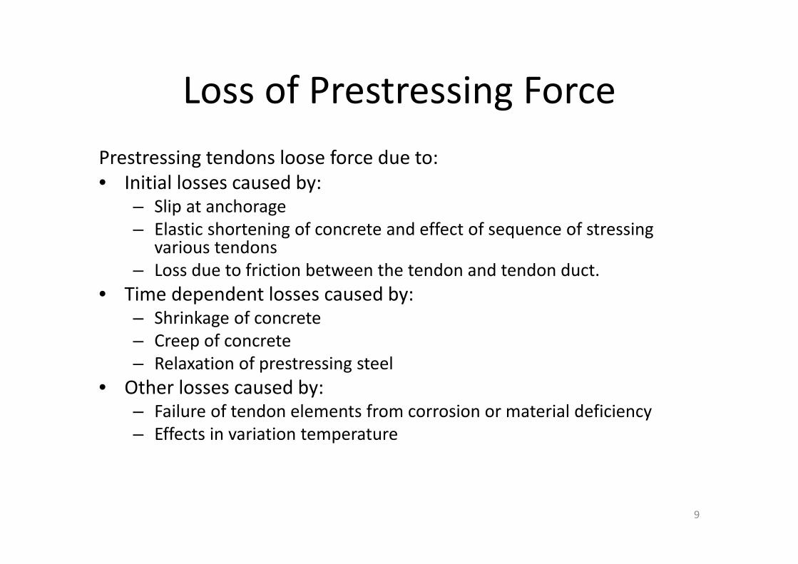
Loss of Prestressing ForcePrestressing tendons loose force due to:• Initial losses caused by:
– Slip at anchorage– Elastic shortening of concrete and effect of sequence of stressing
various tendons – Loss due to friction between the tendon and tendon duct.
• Time dependent losses caused by:– Shrinkage of concrete– Creep of concrete– Relaxation of prestressing steel
• Other losses caused by:– Failure of tendon elements from corrosion or material deficiency– Effects in variation temperature
9
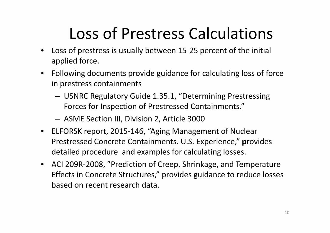
Loss of Prestress Calculations• Loss of prestress is usually between 15‐25 percent of the initial
applied force.• Following documents provide guidance for calculating loss of force
in prestress containments– USNRC Regulatory Guide 1.35.1, “Determining Prestressing
Forces for Inspection of Prestressed Containments.” – ASME Section III, Division 2, Article 3000
• ELFORSK report, 2015‐146, “Aging Management of Nuclear Prestressed Concrete Containments. U.S. Experience,” provides detailed procedure and examples for calculating losses.
• ACI 209R‐2008, ”Prediction of Creep, Shrinkage, and Temperature Effects in Concrete Structures,” provides guidance to reduce losses based on recent research data.
10

Trending of Prestressing Forces• 10 CFR50.55a(b) and ASME Section XI, Subsection IWL require:
– When evaluation of consecutive surveillances of prestressing forces for the same tendon or tendons in a group indicates a trend of prestress loss such that the tendon force(s) would be less than the minimum design prestress requirements before the next inspection interval, an evaluation must be performed.
– Average of all measured tendon forces should be equal to or greater than the minimum required prestress, and the measured force in each individual tendon is not less than the 95% of the predicted force.
• To comply with these requirements, a trending analysis is performed in accordance with RG 1.35.1.
• Trend line is constructed using the least‐square method for regression analysis.
• Microsoft Excel can draw this trend line without having to perform detailed calculations. Details provided in the report.
11
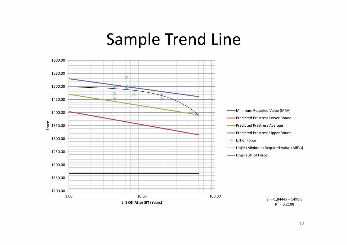
Sample Trend Line
y = ‐1,8444x + 1499,8R² = 0,2108
1100,00
1150,00
1200,00
1250,00
1300,00
1350,00
1400,00
1450,00
1500,00
1550,00
1600,00
1,00 10,00 100,00
Force
Lift Off After SIT (Years)
Minimum Required Value (MRV)
Predicted Prestress Lower Bound
Predicted Prestress Average
Predicted Prestress Upper Bound
Lift of Force
Linjär (Minimum Required Value (MRV))
Linjär (Lift of Force)
12

Leak Rate Testing of Containment
• Appendix J of 10CFR50, ”Primary Reactor Containment Leakage Testing of Water‐Cooled Power Reactors,” establishes the testing requirements and acceptance criteria for preoperational and periodic tests.
• Leak rate testing is performed to verify that containment:– Acts a leak tight barrier– Materials such as concrete, prestressing steel, piping penetrations are not degraded
– Containment isolation valves are operational
13

Options and Types of Leak Rate Tests
• Option A require performing tests at a fixed frequency. • Option B allows licensees, with a satisfactory performance history (two consecutive successful tests), to reduce the test frequency.
• Both options require performance of the following– Type A ‐ Containment integrated leak rate test (ILRT) – Type B – Containment penetrations leak rate test – Type C – Containment isolation valve leak rate test– Type B and C tests are also called as local leak rate tests (LLRT)
14
Option A and B Tests
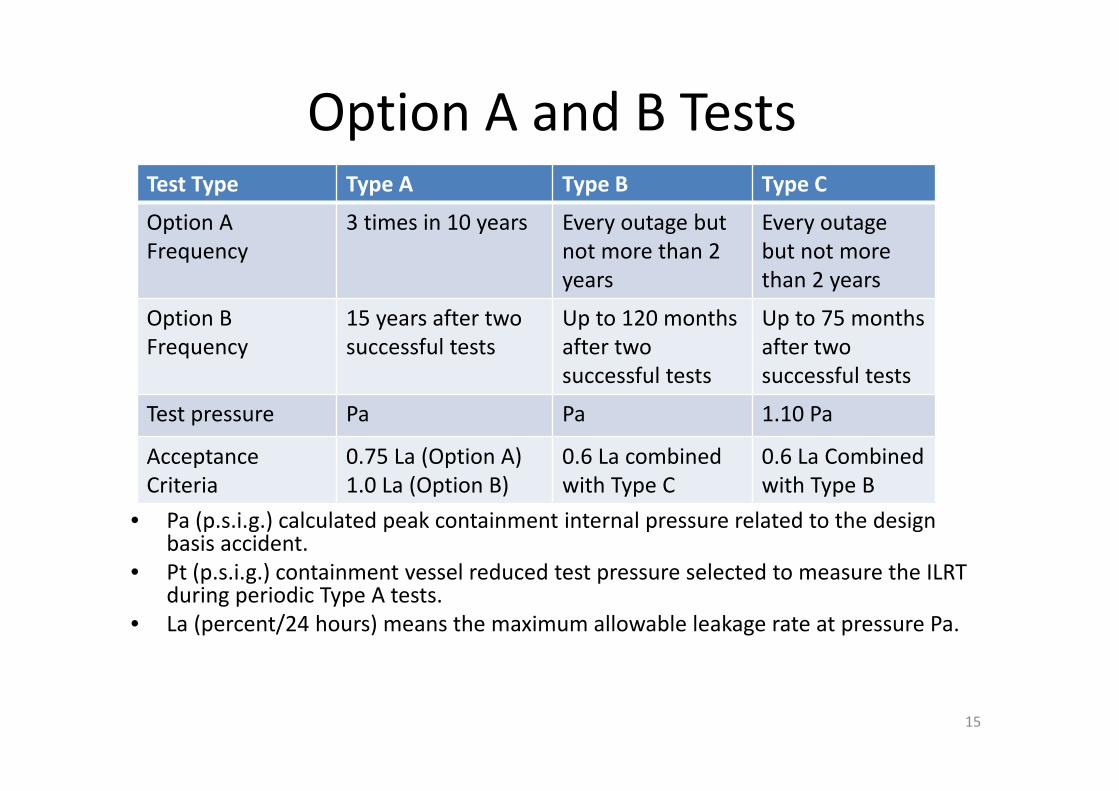
• Pa (p.s.i.g.) calculated peak containment internal pressure related to the design basis accident.
• Pt (p.s.i.g.) containment vessel reduced test pressure selected to measure the ILRT during periodic Type A tests.
• La (percent/24 hours) means the maximum allowable leakage rate at pressure Pa.
Test Type Type A Type B Type C
Option AFrequency
3 times in 10 years Every outage but not more than 2 years
Every outage but not more than 2 years
Option B Frequency
15 years after two successful tests
Up to 120 months after two successful tests
Up to 75 months after two successful tests
Test pressure Pa Pa 1.10 Pa
Acceptance Criteria
0.75 La (Option A) 1.0 La (Option B)
0.6 La combined with Type C
0.6 La Combined with Type B
15
US Containment Operating Experience
• Prestressing system– Tendon Anchor Head Corrosion– High Tendon Wire Relaxation – Grease Leakage
• Concrete Degradation– Normal Shrinkage Cracking– Cadweld exposure and surface corrosion– Alkali silica reaction– Degradation during Steam Generator Replacement (SGR) activities
16

Farley Tendon Anchor Head Stress Corrosion Cracking
17
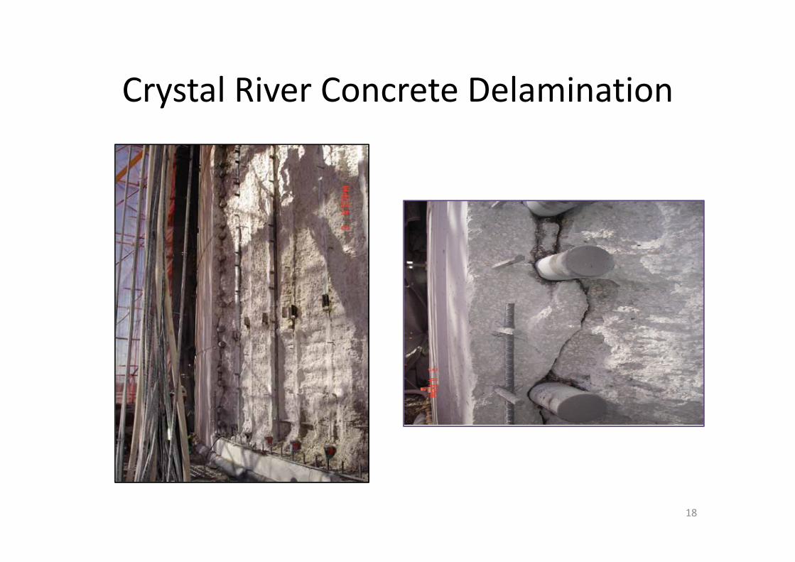
Crystal River Concrete Delamination
18
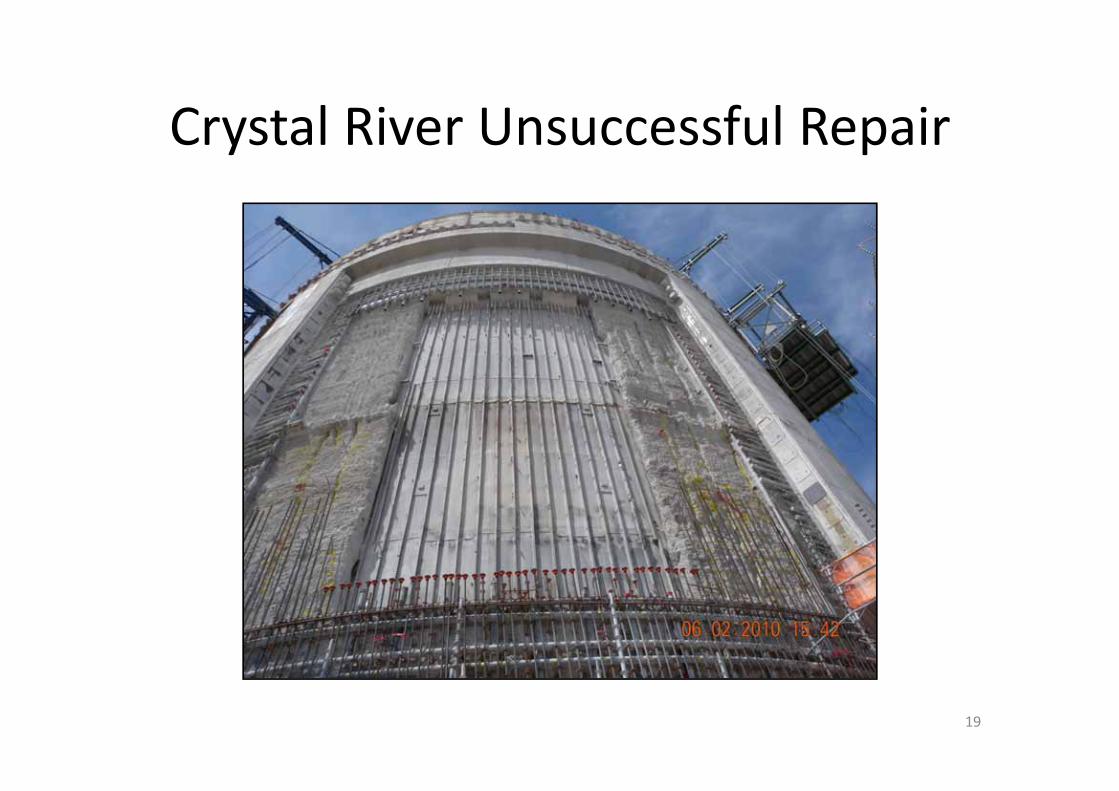
Crystal River Unsuccessful Repair
19

Seabrook Plant – Alkali Silica Reaction
20

Degraded Containment Liner
Insulation Vapor Barrier
Containment Liner Insulation Removed
Leak Chase Channel Corroded
Leak Chase ChannelLoose
Coating Powder
21

Beaver Valley Liner Plate Corrosion
Paint Blister with Corrosion Products Identified at Beaver Valley Unit 1 in 2009 (FirstEnergy, 2009).
22

Beaver Valley Liner Plate
Wood Embedded in the Concrete Discovered at Beaver Valley Unit 1 in 2009 After a Section of the Containment Liner with Through‐Liner Corrosion Was Removed
23

Questions?
24