contact stress and radial stiffness of a cylindrical ... · contact stress and radial stiffness of...
TRANSCRIPT

CONTACT STRESS AND RADIAL STIFFNESS OF A CYLINDRICAL ROLLER BEARINGWITH CORRECTED ROLLER GENERATOR
Guanci Chen1 and Hailiang Wang21Faculty of Mechanical and Electrical Engineering, Kunming University of Science and Technology, Kunming, China
2School of Mechanical Engineering, Dalian University of Technology, Dalian, ChinaE-mail: [email protected]
IMETI 2015, J5002_SCINo. 16-CSME-39, E.I.C. Accession 3925
ABSTRACTA method has been developed to study the radial stiffness of a cylindrical roller bearing with correctedroller generator. First, the finite-length contact question of roller-race contact was solved by cutting contactsurface into slices and considering the influences among slices by a flexibility coefficient matrix, whichwas more accurate than the traditional method. Further, the more precise load-approach function of thecontact of race and roller with corrected generator was determined. Then, the radial stiffness of a cylindricalroller bearing has been derived by coupling this load-approach function into a complete bearing mechanicalmodel. Results show that the corrected roller generator has a great influence on the bearing radial stiffness.The maximum stiffness difference among the cases of straight and crowned generators is 28.7%. The bearingradial stiffness decreases rapidly with the rise of profile maximum deviation hmax. It is worthy noting thatthere is a sudden change of stiffness with the adding of load when the bearing is with clearance.
Keywords: cylindrical roller bearing; contact stress; bearing stiffness; corrected generator.
PRESSION DE CONTACT ET RIGIDITÉ RADIALE D’UN ROULEMENT À ROULEAUXCYLINDRIQUES AVEC GÉNÉRATEUR DE ROULEAUX CORRIGÉ
RÉSUMÉUne méthode a été développée pour étudier la rigidité radiale d’un roulement à rouleaux avec générateurde rouleaux corrigé. En premier lieu, la question du contact à longueur finie a été résolue en coupant lasurface de contact en tranches fines et en examinant les influences entre les tranches à l’aide d’une matricede coefficient de flexibilité, laquelle est plus précise que la méthode traditionnelle. En outre, on a déterminéd’une manière plus précise la fonction de l’approche des charges au contact du disque de roulement etdes rouleaux avec générateur corrigé. La rigidité radiale du roulement à rouleaux cylindriques a alors étédérivée en couplant cette fonction d’approche des charges en un modèle complet de roulement mécanique.Les résultats indiquent que le générateur de rouleaux corrigé a une grande influence sur la rigidité. Ladifférence maximale entre les cas de générateurs de rouleaux droits ou couronnés diminue rapidement avecl’augmentation de la déviation maximale. Il est à remarquer qu’il y a un changement soudain de rigiditéavec l’addition de charge quand le rouleau est en dégagement.
Mots-clés : roulement à rouleaux cylindriques; pression de contact; rigidité du roulement; générateur cor-rigé.
Transactions of the Canadian Society for Mechanical Engineering, Vol. 40, No. 5, 2016 725
NOMENCLATURE
p contact stress (MPa)Q applied load on the roller (N)x,y coordinates of contact area (mm)E ′ equivalent elastic modulus (MPa)E elastic modulus (MPa)x′,y′ integral termz initial clearance of contact surfaces (mm)Sc contact zonea half of the slice length (mm)h half of the slice width (mm)p0 maximum contact stress (MPa)D matrix of flexibility coefficientC, t coefficientsFr radial force on the bearing (N)ur bearing radial clearance (mm)Z number of rollersJr radial load summationK radial stiffness of the cylindrical roller bearing (N/mm)h generator profile deviation (µm)
Greek symbolsν Poisson’s ratioδ contact approach (mm)ψ roller azimuth angle (rad)δr bearing radial deformation (mm)ε load distribution factor
Subscriptsi, j number of slices or roller numbermax maximum value1,2 contact body’s number
1. INTRODUCTION
Most machines suffer from some degree of mass imbalance, which results in rotating forces and excitesresonances of rotating machinery at high speed. A stiff support is helpful for absorbing little of the vibrationenergy and emitting the sound. Because of linear contact, the stiffness of cylindrical roller bearing is higherthan that of ball bearing under the same conditions. Thus, the cylindrical roller bearing is usually used underthe condition of heavy load and high stiffness. However, for reducing the stress concentration at the end ofroller, the roller with different corrected generators is often used so that the bearing stiffness is changedcertainly. To accurately analyze the dynamic performance of a rotor system, clearing how the roller withcorrected generator affects the bearing stiffness is necessary and valuable.
Early, Jones [1] proposed a completely general solution whereby the elastic compliances of a system ofany number of ball and radial roller bearings under any system of loads can be determined. This methodwas extended by Harris [2]. Gargiulo [3] presented empirical formulae for the load-stiffness and deflection-stiffness relations by assuming rigid bearing races. Those formulae were applied for radial and axial stiffnessof a few types of bearing. Lim and Singh [4] proposed a theoretical model to estimate diagonal and cross-coupling terms in the stiffness matrix. They used a discrete summation over all loaded rolling elementsto obtain total bearing forces and moments instead of the integral form. Bourdon et al. [5] developed
726 Transactions of the Canadian Society for Mechanical Engineering, Vol. 40, No. 5, 2016
an alternative method to estimate the stiffness matrix by dividing the rolling element surface and racesinto slices and computing individual contact stresses. Butner et al. [6] studied the influence of mountingcompliance and operating conditions on the radial stiffness of ball bearing by analyzing and testing. Changet al. [7] presented the formulation and used an elastohydrodynamic (EHD) lubrication model to analyzethe kinematic and dynamic behavior of high-speed cylindrical roller bearings. The bearing stiffness couldbe calculated for different parameters. Recently, Hernot et al. [8] presented a method to establish a stiffnessmatrix for angular-contact ball bearings. Kim et al. [9] investigated the effect of bearing assembly toleranceson the spindle bearing compliance. They presented the analytical and experimental investigations on thebearing compliance with additional consideration to both the elastic approach of the race and the thermalapproach of the housing in terms of the bearing stiffness. Mourad et al. [10] presented a theoretical andan experimental study on the nonlinear stiffness of ball bearing in static and dynamic mode. The nonlineardynamic behavior of the ball bearing was described by considering the ball scrolling in the cage and theeffect of rotating vector load. Guo and Parker [11] developed a finite element contact mechanics modelto obtain accurate bearing stiffness for a wide range of rolling element bearing types and parameters. Thecontact mechanics between the rolling elements and races is solved by a combined surface integral andfinite element method. A numerical method is developed to determine the full bearing stiffness matrixcorresponding to two radial, one axial, and two angular coordinates. Kang et al. [12] presented a stiffnessfunction for all angular-contact ball bearings by a back-propagation neural network method, which is trainedby using several samples. Szuminski [13] gave a method to determine the radial and axial stiffness of rollingbearings and rolling kinematic pairs as a function of the external load and the kinematics of motion. Theinfluence of distribution of rolling elements on the coefficients of stiffness has been considered. Some otherscholars [14–17] studied the profile formulas to uniform the roller-race contact stresses and to avoid thestress concentration at the end of roller.
So far, the stiffness investigations regarding the rolling element bearing are a little more. Different modelshave been presented by many researchers. However, the existing models can not express how the roller’scorrected generator affects the bearing stiffness. In this study, the finite-length contact question of raceand roller has been solved by cutting the contact surface into slices firstly. Hereinto, influence coefficientsamong slices are considered to enhance calculation precision. Further, contact approaches and stressesbetween the races and rollers with corrected generators are analyzed. A more accurate function expressingthe load-approach relations of roller-race contact is obtained. At last, the radial stiffness of a cylindricalroller bearing has been derived by coupling this load-approach function into a complete bearing mechanicalmodel. The effects of various common roller generators on the radial stiffness of a cylindrical roller bearingare analyzed.
2. SOLUTION TO FINITE-LENGTH CONTACT QUESTION OF ROLLER-RACE CONTACT
The roller-race contact in a cylindrical roller bearing is a finite-length contact question. Generally, Eq. (1)describes the load equilibrium of contact bodies for the elastic contact. Eq. (2) expresses the approachcompatibility of contact bodies. ∫∫
Sc
p(x,y)dxdy = Q (1)
1πE ′
∫∫Sc
p′(x′+ y′)dx′dy′√(x− x′)2 +(y− y′)2
= δ − z(x,y) (2)
E ′ =E1E2
E2(1−ν21 )+E1(1−ν2
2 )(3)
Transactions of the Canadian Society for Mechanical Engineering, Vol. 40, No. 5, 2016 727

Fig. 1. Slices and stress of the rollers’ contact surface. (a) Roller contact; (b) slices and stress.
where p is the contact stress, Q is the applied load, x and y are the coordinates of contact area, E ′ is theequivalent elastic modulus, x′ and y′ are the integral term, δ is the contact approach, z is the initial clearanceof contact surfaces, Sc is the contact zone, E is the elastic modulus, ν is the Poisson’s ratio, the subscripts 1and 2 are the number of contact bodies.
The numerical method is often used to solve Eqs. (1) and (2) because the analytic method is very difficultto deal with them. The contact surface of two rollers is evenly dispersed into many slices along the rolleraxis, which is shown as Fig. 1. In each slice, the contact stress is determined by Hertz contact theory. Andalong the roller axis, the contact stress distribution is assumed be same in each slice. The length of each sliceis 2a. The width of each slice is 2h. The maximum stress of each slice is p0 that locates at the generator.The influences among slices are taken into account by flexibility coefficient matrix. Therefore, as long as theslices are sufficient in number, the contact stress and approach of two rollers can be calculated accurately.
For the discrete contact surface, Eqs. (1) and (2) can be expressed as, respectively:
π
n
∑j=1
a j p0 j h j = Q (4)
1πE ′
n
∑j=1
Di j p0 j = δ − zi(yi), i = 1,2,3, . . . ,n (5)
where a is half of the slice length, h is half of the slice width, z is the initial clearance of contact surfaces,p0 is the maximum contact stress in the slice, y is the coordinate of slice, D is the matrix of flexibilitycoefficient. The subscripts i and j are the number of slices. The element Di j means the effect of jth slice onthe displacement of the ith slice. Di j can be obtained by Eq. (6). Also, Eq. (6) can be further expressed byEq. (7) where F is a function given by Eq. (8) [18]. When the number of slices is determined, the coordinateof each slice can be obtained. Further, Di j is determined.
Di j =∫∫Sc
dxdy√x2 +(y−|yi− y j|)
(6)
Di j = F(a j, |yi− y j|+h j)−F(−a j, |yi− y j|+h j)−F(a j, |yi− y j|−h j)+F(−a j, |yi− y j|−h j) (7)
F(x,y) = x ln(y+√
x2 + y2)+ y ln
(x+√
x2 + y2)
(8)
728 Transactions of the Canadian Society for Mechanical Engineering, Vol. 40, No. 5, 2016
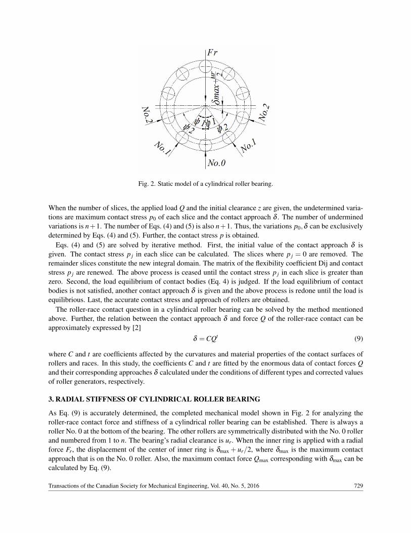
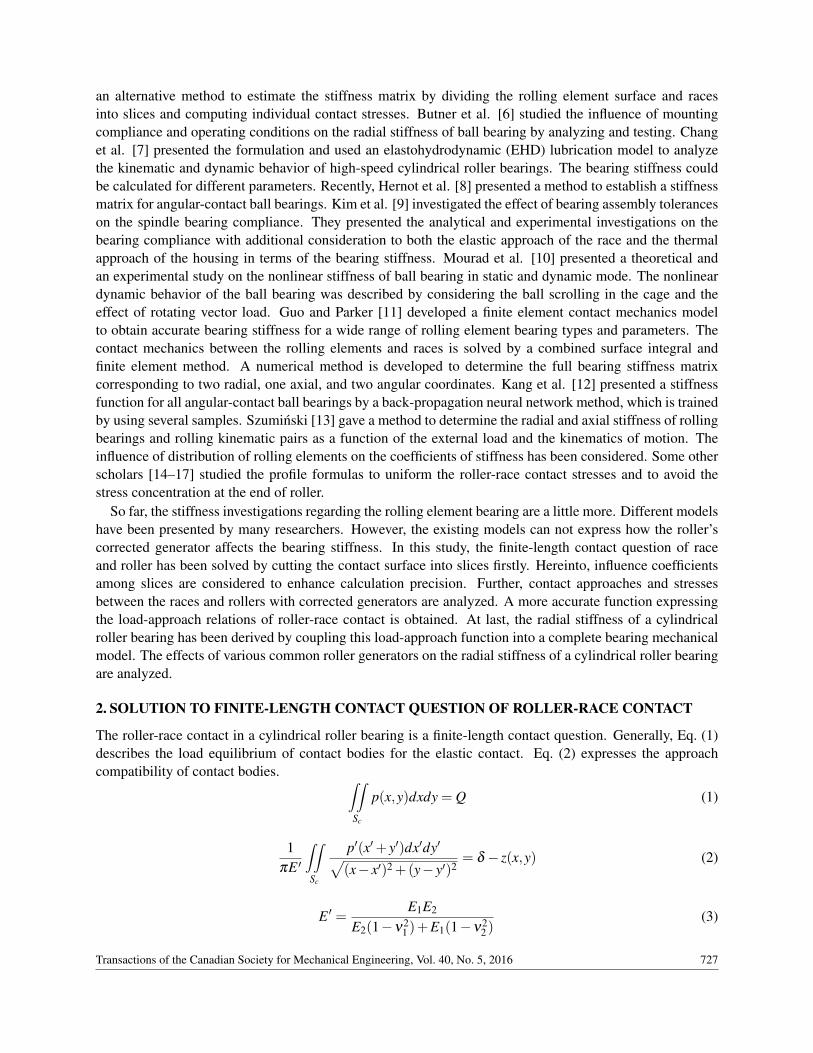
Fig. 2. Static model of a cylindrical roller bearing.
When the number of slices, the applied load Q and the initial clearance z are given, the undetermined varia-tions are maximum contact stress p0 of each slice and the contact approach δ . The number of underminedvariations is n+1. The number of Eqs. (4) and (5) is also n+1. Thus, the variations p0,δ can be exclusivelydetermined by Eqs. (4) and (5). Further, the contact stress p is obtained.
Eqs. (4) and (5) are solved by iterative method. First, the initial value of the contact approach δ isgiven. The contact stress p j in each slice can be calculated. The slices where p j = 0 are removed. Theremainder slices constitute the new integral domain. The matrix of the flexibility coefficient Dij and contactstress p j are renewed. The above process is ceased until the contact stress p j in each slice is greater thanzero. Second, the load equilibrium of contact bodies (Eq. 4) is judged. If the load equilibrium of contactbodies is not satisfied, another contact approach δ is given and the above process is redone until the load isequilibrious. Last, the accurate contact stress and approach of rollers are obtained.
The roller-race contact question in a cylindrical roller bearing can be solved by the method mentionedabove. Further, the relation between the contact approach δ and force Q of the roller-race contact can beapproximately expressed by [2]
δ =CQt (9)
where C and t are coefficients affected by the curvatures and material properties of the contact surfaces ofrollers and races. In this study, the coefficients C and t are fitted by the enormous data of contact forces Qand their corresponding approaches δ calculated under the conditions of different types and corrected valuesof roller generators, respectively.
3. RADIAL STIFFNESS OF CYLINDRICAL ROLLER BEARING
As Eq. (9) is accurately determined, the completed mechanical model shown in Fig. 2 for analyzing theroller-race contact force and stiffness of a cylindrical roller bearing can be established. There is always aroller No. 0 at the bottom of the bearing. The other rollers are symmetrically distributed with the No. 0 rollerand numbered from 1 to n. The bearing’s radial clearance is ur. When the inner ring is applied with a radialforce Fr, the displacement of the center of inner ring is δmax + ur/2, where δmax is the maximum contactapproach that is on the No. 0 roller. Also, the maximum contact force Qmax corresponding with δmax can becalculated by Eq. (9).
Transactions of the Canadian Society for Mechanical Engineering, Vol. 40, No. 5, 2016 729

The force equilibrium of the bearing is given by Eq. (10). The approach compatibility of roller-racecontacts is given by Eq. (11). The roller azimuth angle ψ is defined by Eq. (12).
Fr−Q0−2j=n
∑j=1
Q j cosψ j = 0 (10)
δ j =(
δmax +ur
2
)cosψ j−
ur
2(11)
ψ j =2π
Zj, j = 0,1,2, . . . ,n (12)
where Fr is the radial force applied on the inner ring, Q is the roller-race contact force, δ is the total approachof roller-race contact, ur is the bearing radial clearance, ψ is the roller azimuth angle, Z is the number ofrollers. The subscript j is the roller number. The subscript max means maximum value.
The maximum contact force Qmax that is on the No. 0 roller is determined by Eqs. (13–15) which arederived from Eqs. (9–12). Further, the bearing radial deformation δr is given by Eq. (16). δr equals themaximum contact approach δmax on the No. 0 roller. The transform of Eq. (16) is shown as Eq. (17). Thus,the bearing’s radial stiffness is expressed by Eq. (18).
Qmax = Q0 =Fr
ZJr(13)
Jr =1+2∑
j=nj=1
{[1− 1
2ε(1− cosψ j)
]1/t cosψ j
}Z
(14)
ε =12
(1− ur
2δmax +ur
)(15)
δr = δmax =C(
Fr
ZJr
)t
(16)
Fr =C−1/t ZJrδ1/tr (17)
K =dFr
dδr=
1tC−1/t ZJrδ
1/t−1r
+2C−1/tδ
1/tr
j=n
∑j=1
{(1− cosψ j)cosψ j
2tε2
[1−
1− cosψ j
2ε
]1/t−1 ur
(2δr +ur)2
}(18)
where Jr is the radial load summation, ε is the load distribution factor, K is the radial stiffness of thecylindrical roller bearing.
Equation (18) shows that the radial stiffness of a cylindrical roller bearing is nonlinear. Also, the bearingradial stiffness is affected by the roller corrected generator, the bearing radial deformation δr, the number Zof roller and the radial clearance ur. Figure 3 shows the flow chart for analyzing the influence of differentparameter on the bearing radial stiffness. First, the parameters C, t,Z,ur and δr are inputted. Then, thecontact approach δ j of each roller-race contact is calculated. The number n of loaded roller is determinedby judging if δ j > 0. Last, the bearing radial stiffness K and its corresponding applied radial force Fr on theinner ring are calculated.
730 Transactions of the Canadian Society for Mechanical Engineering, Vol. 40, No. 5, 2016
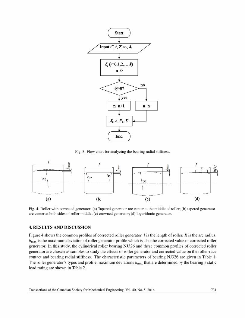
Fig. 3. Flow chart for analyzing the bearing radial stiffness.
Fig. 4. Roller with corrected generator. (a) Tapered generator-arc center at the middle of roller; (b) tapered generator-arc center at both sides of roller middle; (c) crowned generator; (d) logarithmic generator.
4. RESULTS AND DISCUSSION
Figure 4 shows the common profiles of corrected roller generator. l is the length of roller. R is the arc radius.hmax is the maximum deviation of roller generator profile which is also the corrected value of corrected rollergenerator. In this study, the cylindrical roller bearing NJ326 and these common profiles of corrected rollergenerator are chosen as samples to study the effects of roller generator and corrected value on the roller-racecontact and bearing radial stiffness. The characteristic parameters of bearing NJ326 are given in Table 1.The roller generator’s types and profile maximum deviations hmax that are determined by the bearing’s staticload rating are shown in Table 2.
Transactions of the Canadian Society for Mechanical Engineering, Vol. 40, No. 5, 2016 731

Table 1. Characteristic parameters of cylindrical roller bearing NJ326.Parameter ValueInner diameter (mm) 130Outer diameter (mm) 280Bearing width (mm) 58Roller diameter (mm) 38Number of rollers 14Roller effective length (mm) 34.8Limit load (kN) 30Young’s modulus (Mpa) 2.06×10⁵
Poisson ratio 0.3
Table 2. Generator type and profile maximum deviation hmax.Generator type Profile maximum deviation hmax (µm)Straight generator 0Tapered generator
(arc center at the middle of roller) 7.9Tapered generator
(arc center at both sides of roller middle) 7.9Crowned generator 7.9Logarithmic generator 4.5
Fig. 5. Effect of influence coefficient matrix on the roller-race contact stress.
4.1. Sensibility of Number of Slices and Effect of Matrix of Flexibility Coefficient D on ContactStress
Figure 5 gives the results of contact stress of roller with straight generator. The contact force Q on the rolleris 8742.9 N determined by the limit load 30000 N of the bearing. One of results is obtained only usingslice method. Another result is calculated using slice method and considering the influences among slicesby flexibility coefficient matrix D. The contact stress distribution on each slice is gotten by Hertz contacttheory. At the same time, the contact stress of the roller-race contact on the generator is calculated by thefinite element software ANSYS. Figure 5 shows that the stress concentration at the end of roller can be
732 Transactions of the Canadian Society for Mechanical Engineering, Vol. 40, No. 5, 2016

Fig. 6. Sensibility of the number of slices.
Table 3. Coefficients C and t of load-approach function.Generator type C(×10−6) tStraight generator 5.4725 0.9047Tapered generator(arc center at the middle of roller) 5.9254 0.9105Tapered generator(arc center at both sides of roller middle) 5.6486 0.9125Crowned generator 6.8115 0.9089Logarithmic generator 5.3551 0.9133
accurately obtained by considering the influences among slices, which is confirmed by the finite elementmethod. On the contrary, the phenomenon of contact stress concentration is not be found by only using slicemethod. Thus, considering the influences among slices by flexibility coefficient matrix D is very necessary.The contact stress gotten by the finite element method is less than those obtained by the other two methodsbecause of the element density.
Figure 6 shows the sensibility of the number of slices to the analysis of roller-race contact. The numberof slices increases from 20 to 120 every 10. Figure 6 shows that the number of slices affects the contactapproach to some extent. Although the contact approach decreases with the adding of the number of slices,the contact approach only decreases 0.74% when the number of slices increases from 20 to 120. Thus, thesensibility of the number of slices to the analysis of roller-race contact is relatively low. Considering thecalculation cost, the number of slices is taken as 60.
4.2. Determination of Load-Approach Function of Roller-Race ContactTo determine load-approach function Eq. (9) for each type of roller generator, the corresponding contactapproaches δ are calculated under the load range 1000–20000 N which is divided into 20 equal parts foreach type of roller generator. Further, the coefficient C and t in Eq. (9) of each roller generator are fittedby the function Nlinfit of Matlab. The values of coefficients C and t for different type of roller generatorare given in Table 3. This table shows that the difference of coefficients t of these cases is very small. Thedifference of maximum and minimum of coefficient t is 0.00086 that is less than 1% of the minimum. Onthe contrary, the difference of coefficient C of these cases is great. The maximum 6.8115 of coefficient Cin the case of crowned generator is 27.2% more than the minimum 5.3551 of the coefficient C in the caseof logarithmic generator. Thus, the roller generator has a great influence on the performance of roller-racecontact.
Transactions of the Canadian Society for Mechanical Engineering, Vol. 40, No. 5, 2016 733

Fig. 7. Contact stresses of outer race and roller with different generators.
4.3. Effect of Corrected Roller Generator on Roller-Race Contact StressFigure 7 shows the contact stress of outer race and roller with different generator. The contact force Q onthe roller is 50000 N. The contact stress distribution of inner race and roller, which is similar to that of outerrace and roller, is not given here. It can be seen that there is stress concentration at the end of roller whenthe roller is with straight generator or logarithmic generator. When the roller is with straight generator,the stress concentration is the most serious. There is no stress concentration at the end of roller when theroller is with tapered generator. But the stress concentration exists at the connection position of arc and line.Also, the contact stress distributions when arc center is at the middle of roller or both sides of roller middleare similar. To the crowned generator, the roller-race contact is similar to that of point contact. Althoughcontact stress concentration does not exist, the contact stress is not well-distributed. Generally speaking, thelogarithmic generator is the best for the contact stress distribution.
4.4. Effect of Profile Maximum Deviation hmax on the Contact StressFigure 8 shows the effect of profile maximum deviation hmax on the contact stress. The hmax in the cases oftapered generator-arc center at the middle of roller, tapered generator-arc center at both sides of roller middleand crowned generator are 56.8, 59.4, 62.4 and 63.1 µm. The hmax in the case of logarithmic generator are53.0, 55.9, 70.4 and 116.9 µm. Although the hmax in the case of logarithmic generator are some differentfrom those in the other three cases because the hmax is determined by the generator type and contact force Q50000 N, there is no influence to study the effect of profile maximum deviation hmax on the contact stress.It is necessary to indicate that these maximum deviation hmax are much greater than the normal value.
In the cases of tapered generator, the stress concentration increases greatly at the roller length 5.308 mmand 29.49 mm when the hmax are 62.4 and 63.1 mm. In the case of tapered generator(arc center at the middleof roller), the contact stress at the roller lengh 5.308 mm increase 1.57 times when the hmax are 56.8 mm(2176 Mpa) and 63.1 mm (3438 Mpa). The contact length decreases from 34.8 to 25.361 mm when the hmaxincreases from 56.8 to 63.1 mm. Both ends of the roller can not contact the raceway. In the cases of crownedgenerator and logarithmic generator, the contact concentration disappears when the hmax increases. But thecontact length of the roller decreases greatly and the contact stress is seriously nonuniform. In the case ofcrowned generator, the contact length of the roller is only 7.66 mm when the hmax is 63.1 mm. In a word,the contact stress is sensitive to the profile maximum deviation hmax. With the increase of profile maximum
734 Transactions of the Canadian Society for Mechanical Engineering, Vol. 40, No. 5, 2016

Fig. 8. Effect of profile maximum deviation hmax on the contact stress. (a) Tapered generator-arc center at the middle ofroller; (b) tapered generator-arc center at both sides of roller middle; (c) crowned generator; (d) logarithmic generator.
deviation hmax, the stress concentration becomes heavier in the case of tapered generator. Moreover, thestress distribution is much more nonuniform.
4.5. Effect of Generator Type on Bearing Radial StiffnessThe radial stiffness of cylindrical roller bearing under the condition of different roller generator is given inFig. 9. The bearing radial clearance is 0.05 mm. Figure 8 shows that the bearing radial stiffness is maximumwhen the roller is with straight generator and the bearing is applied with the same load. On the contrary,the bearing radial stiffness is minimum when the roller is with crowned generator. The difference amongthe cases of straight and crowned generators is about 28.7%. The bearing radial stiffness when the roller iswith the other three types of generators is among the maximum and minimum in the cases of straight andcrowed generators. Furthermore, in all of these cases, the bearing radial stiffness increases with the addingof applied load. It is worth noting that the bearing stiffness has a sudden change with the adding of appliedload. The value of sudden change of the stiffness is 2.39 times for the case of straight generator. The valueof sudden change of the stiffness is 2.9 times for the case of crowned generator. The basic reason is that thenumber of loaded rollers increases from 1 to 3. Also, the applied load causing the sudden change of stiffnessis somewhat different for these cases because of the different contact performance for each roller generator.In this study, if the applied load on the bearing is more than 1149 N, the sudden change of stiffness happensfor all of these cases. After the sudden change of stiffness, the bearing radial stiffness increases relativelyslowly with the adding of applied load. Thus, if the preload method is used to enhance the bearing stiffness,the preload had better be more than the load causing the sudden change of stiffness for the rolling elementbearings.
Transactions of the Canadian Society for Mechanical Engineering, Vol. 40, No. 5, 2016 735
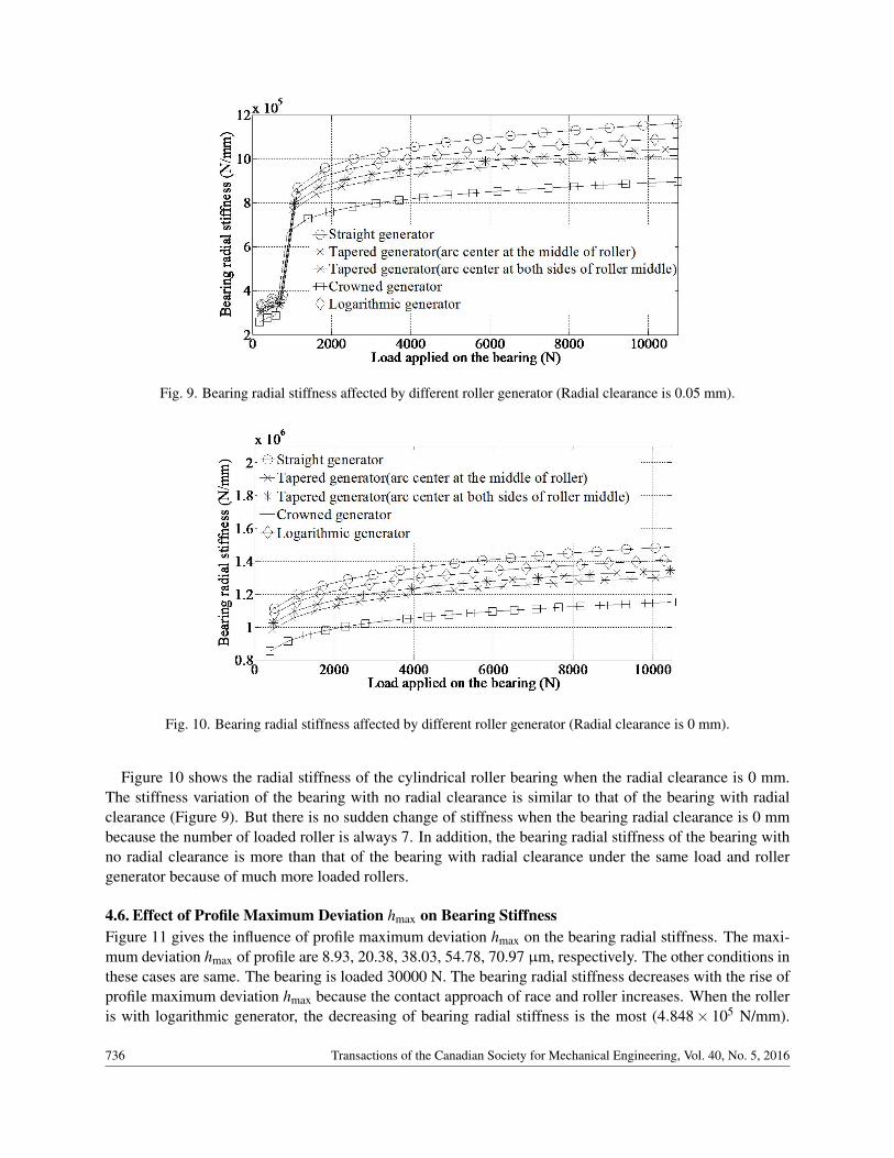
Fig. 9. Bearing radial stiffness affected by different roller generator (Radial clearance is 0.05 mm).
Fig. 10. Bearing radial stiffness affected by different roller generator (Radial clearance is 0 mm).
Figure 10 shows the radial stiffness of the cylindrical roller bearing when the radial clearance is 0 mm.The stiffness variation of the bearing with no radial clearance is similar to that of the bearing with radialclearance (Figure 9). But there is no sudden change of stiffness when the bearing radial clearance is 0 mmbecause the number of loaded roller is always 7. In addition, the bearing radial stiffness of the bearing withno radial clearance is more than that of the bearing with radial clearance under the same load and rollergenerator because of much more loaded rollers.
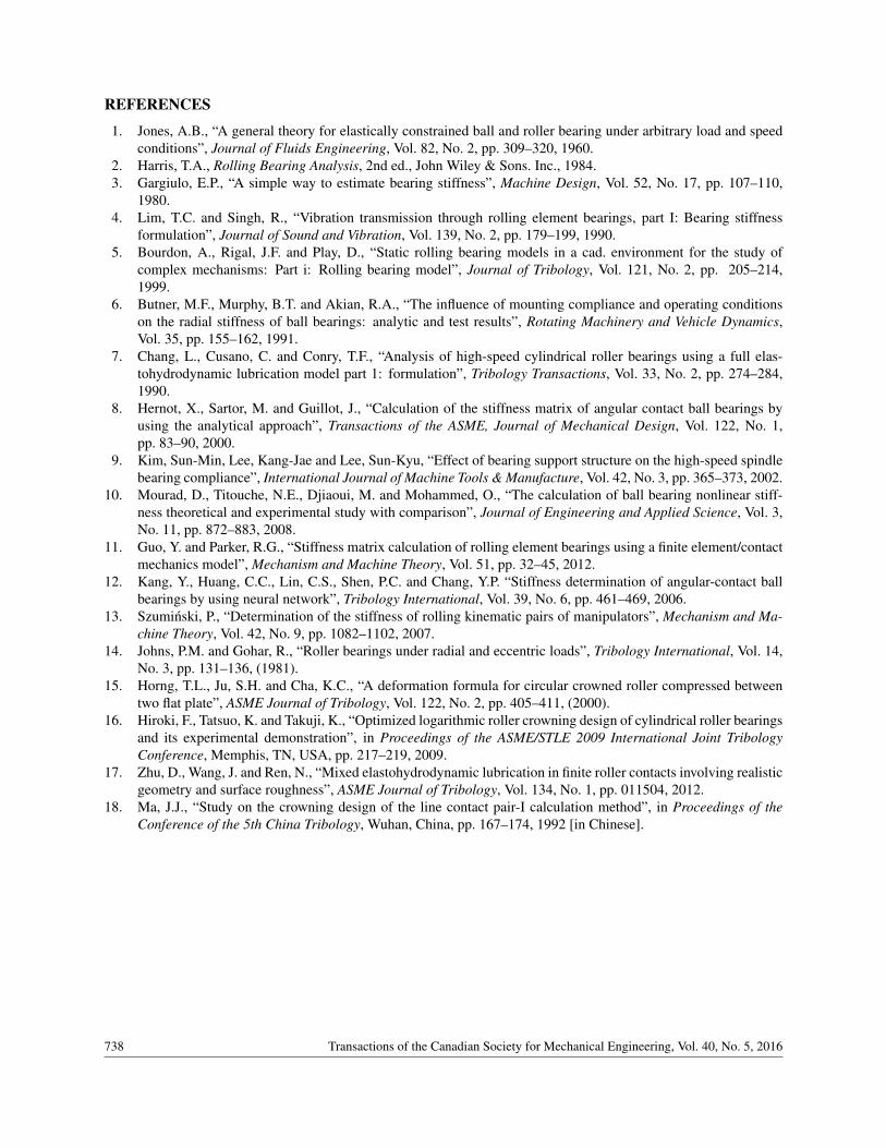
4.6. Effect of Profile Maximum Deviation hmax on Bearing StiffnessFigure 11 gives the influence of profile maximum deviation hmax on the bearing radial stiffness. The maxi-mum deviation hmax of profile are 8.93, 20.38, 38.03, 54.78, 70.97 µm, respectively. The other conditions inthese cases are same. The bearing is loaded 30000 N. The bearing radial stiffness decreases with the rise ofprofile maximum deviation hmax because the contact approach of race and roller increases. When the rolleris with logarithmic generator, the decreasing of bearing radial stiffness is the most (4.848× 10⁵ N/mm).
736 Transactions of the Canadian Society for Mechanical Engineering, Vol. 40, No. 5, 2016
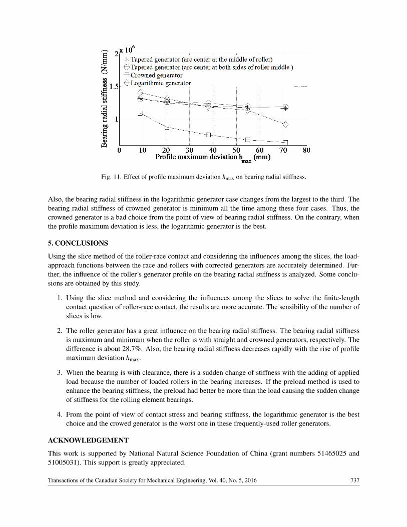
Fig. 11. Effect of profile maximum deviation hmax on bearing radial stiffness.
Also, the bearing radial stiffness in the logarithmic generator case changes from the largest to the third. Thebearing radial stiffness of crowned generator is minimum all the time among these four cases. Thus, thecrowned generator is a bad choice from the point of view of bearing radial stiffness. On the contrary, whenthe profile maximum deviation is less, the logarithmic generator is the best.
5. CONCLUSIONS
Using the slice method of the roller-race contact and considering the influences among the slices, the load-approach functions between the race and rollers with corrected generators are accurately determined. Fur-ther, the influence of the roller’s generator profile on the bearing radial stiffness is analyzed. Some conclu-sions are obtained by this study.
1. Using the slice method and considering the influences among the slices to solve the finite-lengthcontact question of roller-race contact, the results are more accurate. The sensibility of the number ofslices is low.
2. The roller generator has a great influence on the bearing radial stiffness. The bearing radial stiffnessis maximum and minimum when the roller is with straight and crowned generators, respectively. Thedifference is about 28.7%. Also, the bearing radial stiffness decreases rapidly with the rise of profilemaximum deviation hmax.
3. When the bearing is with clearance, there is a sudden change of stiffness with the adding of appliedload because the number of loaded rollers in the bearing increases. If the preload method is used toenhance the bearing stiffness, the preload had better be more than the load causing the sudden changeof stiffness for the rolling element bearings.
4. From the point of view of contact stress and bearing stiffness, the logarithmic generator is the bestchoice and the crowed generator is the worst one in these frequently-used roller generators.
ACKNOWLEDGEMENT
This work is supported by National Natural Science Foundation of China (grant numbers 51465025 and51005031). This support is greatly appreciated.
Transactions of the Canadian Society for Mechanical Engineering, Vol. 40, No. 5, 2016 737
REFERENCES
1. Jones, A.B., “A general theory for elastically constrained ball and roller bearing under arbitrary load and speedconditions”, Journal of Fluids Engineering, Vol. 82, No. 2, pp. 309–320, 1960.
2. Harris, T.A., Rolling Bearing Analysis, 2nd ed., John Wiley & Sons. Inc., 1984.3. Gargiulo, E.P., “A simple way to estimate bearing stiffness”, Machine Design, Vol. 52, No. 17, pp. 107–110,
1980.4. Lim, T.C. and Singh, R., “Vibration transmission through rolling element bearings, part I: Bearing stiffness
formulation”, Journal of Sound and Vibration, Vol. 139, No. 2, pp. 179–199, 1990.5. Bourdon, A., Rigal, J.F. and Play, D., “Static rolling bearing models in a cad. environment for the study of
complex mechanisms: Part i: Rolling bearing model”, Journal of Tribology, Vol. 121, No. 2, pp. 205–214,1999.
6. Butner, M.F., Murphy, B.T. and Akian, R.A., “The influence of mounting compliance and operating conditionson the radial stiffness of ball bearings: analytic and test results”, Rotating Machinery and Vehicle Dynamics,Vol. 35, pp. 155–162, 1991.
7. Chang, L., Cusano, C. and Conry, T.F., “Analysis of high-speed cylindrical roller bearings using a full elas-tohydrodynamic lubrication model part 1: formulation”, Tribology Transactions, Vol. 33, No. 2, pp. 274–284,1990.
8. Hernot, X., Sartor, M. and Guillot, J., “Calculation of the stiffness matrix of angular contact ball bearings byusing the analytical approach”, Transactions of the ASME, Journal of Mechanical Design, Vol. 122, No. 1,pp. 83–90, 2000.
9. Kim, Sun-Min, Lee, Kang-Jae and Lee, Sun-Kyu, “Effect of bearing support structure on the high-speed spindlebearing compliance”, International Journal of Machine Tools & Manufacture, Vol. 42, No. 3, pp. 365–373, 2002.
10. Mourad, D., Titouche, N.E., Djiaoui, M. and Mohammed, O., “The calculation of ball bearing nonlinear stiff-ness theoretical and experimental study with comparison”, Journal of Engineering and Applied Science, Vol. 3,No. 11, pp. 872–883, 2008.
11. Guo, Y. and Parker, R.G., “Stiffness matrix calculation of rolling element bearings using a finite element/contactmechanics model”, Mechanism and Machine Theory, Vol. 51, pp. 32–45, 2012.
12. Kang, Y., Huang, C.C., Lin, C.S., Shen, P.C. and Chang, Y.P. “Stiffness determination of angular-contact ballbearings by using neural network”, Tribology International, Vol. 39, No. 6, pp. 461–469, 2006.
13. Szuminski, P., “Determination of the stiffness of rolling kinematic pairs of manipulators”, Mechanism and Ma-chine Theory, Vol. 42, No. 9, pp. 1082–1102, 2007.
14. Johns, P.M. and Gohar, R., “Roller bearings under radial and eccentric loads”, Tribology International, Vol. 14,No. 3, pp. 131–136, (1981).
15. Horng, T.L., Ju, S.H. and Cha, K.C., “A deformation formula for circular crowned roller compressed betweentwo flat plate”, ASME Journal of Tribology, Vol. 122, No. 2, pp. 405–411, (2000).
16. Hiroki, F., Tatsuo, K. and Takuji, K., “Optimized logarithmic roller crowning design of cylindrical roller bearingsand its experimental demonstration”, in Proceedings of the ASME/STLE 2009 International Joint TribologyConference, Memphis, TN, USA, pp. 217–219, 2009.
17. Zhu, D., Wang, J. and Ren, N., “Mixed elastohydrodynamic lubrication in finite roller contacts involving realisticgeometry and surface roughness”, ASME Journal of Tribology, Vol. 134, No. 1, pp. 011504, 2012.
18. Ma, J.J., “Study on the crowning design of the line contact pair-I calculation method”, in Proceedings of theConference of the 5th China Tribology, Wuhan, China, pp. 167–174, 1992 [in Chinese].
738 Transactions of the Canadian Society for Mechanical Engineering, Vol. 40, No. 5, 2016