contact finite element method for dynamic meshing characteristics analysis of continuous engaged...
TRANSCRIPT
Journal of Mechanical Science and Technology 26 (6) (2012) 1671~1685
www.springerlink.com/content/1738-494x DOI 10.1007/s12206-012-0416-5
Contact finite element method for dynamic meshing characteristics analysis
of continuous engaged gear drives† Yong-jun Wu, Jian-jun Wang* and Qin-kai Han
School of Jet Propulsion, Beijing University of Aeronautics and Astronautics, HaiDian District, Beijing, China
(Manuscript Received August 31, 2011; Revised February 19, 2012; Accepted February 23, 2012)
----------------------------------------------------------------------------------------------------------------------------------------------------------------------------------------------------------------------------------------------------------------------------------------------
Abstract The dynamic meshing characteristics of gear drives have been a major concern in the design of power transmission systems as they af-
fect vibration, acoustic noise, durability and efficiency. Gaining a more comprehensive understanding of the dynamic meshing character-istics of continuous engaged gear drives is a key to the development of power transmission systems. In this paper, a dynamic contact finite element analysis method, considering the variation of the engaged teeth pairs, the loaded elastic and contact deformations, and the sliding friction, is presented for the dynamic meshing characteristics analysis of continuous and elastic engaged gear drives. Various kinds of continuous engaged gear models under low and high speed condition are simulated and compared using the presented method. The tooth profile modification was designed based on the simulation results. Moreover, the effects of the tooth profile modification, the sliding friction and the time-varying meshing stiffness upon the dynamic meshing characteristics of continuous engaged gear drives are discussed in detail. The results show that the method is not only effective in designing and evaluating the tooth profile modification, but also in studying the dynamic meshing characteristics of continuous engaged gear drives with realistic time-varying meshing stiffness and tooth sliding friction. The present method could provide an effective tool for vibration mechanism study and dynamic design of the con-tinuous engaged gear drives considering more influence factors.
Keywords: Contact finite element method; Dynamic meshing characteristics; Continuous engaged gear drives; Sliding friction; Tooth profile modification;
Time-varying meshing stiffness ---------------------------------------------------------------------------------------------------------------------------------------------------------------------------------------------------------------------------------------------------------------------------------------------- 1. Introduction
The gear drive, as a critical part of a power transmission system, provides the required torque and rotational speed by tooth mesh, mostly in the form of involute tooth profile. So its characteristics directly determine the performance of the pow-er transmission system. But the continuous mesh of gear teeth is a complex and elastic contact process, involving, e.g. multi-tooth engagement, multi-points contact, varying contact posi-tions, varying load conditions and mesh impacts. Due to the variation of the meshed teeth pairs, the loaded elastic deflec-tions and the sliding friction, severe vibration and noise could be induced by the dynamic excitations, including the time-varying meshing stiffness, dynamic meshing impact and pitch point impact. For the normal involute tooth profile gear drives, the time-varying meshing stiffness is mainly caused by the variation of the meshed teeth pairs and loaded elastic deforma-tions of gear drives. The dynamic meshing impact occurs dur-ing the approach and recess actions of the meshed tooth with the similar reasons for the meshing stiffness, neglecting the
gear backlash and the machining and assembly errors; and the pitch point impact is primarily caused by the sliding friction, especially in heavy loaded and low speed conditions. Such dynamic excitations have a detrimental effect on the dynamic meshing characteristics of the continuous engaged gear drives. Hence, gaining a more comprehensive understanding of the dynamic meshing characteristics of continuous engaged gear drives has been of the utmost interest to engineers and re-searchers for decades.
In recent years, many researches have been reported on the dynamic meshing characteristics of the gear drives. The dy-namic vibration performance of gear drives with time-varying meshing stiffness has been studied using the lumped parame-ter methods and finite element methods [1-8]. Kahramam [4] and Vaishya [5] introduced an assumptive or simplified form of the meshing stiffness in their early studies. The “realistic” time-varying meshing stiffness was calculated by static con-tact finite element method [6-8]. Although the “realistic” time-varying meshing stiffness or the static transmission error, cal-culated by static contact finite element method, is more accu-rate than the assumed or simplified form, it is still hard to de-note the dynamic characteristics of the continuous meshing process, as it neglects the interactions of the influence factors
*Corresponding author. Tel.: +86 1082317411, Fax.: +86 1082317432 E-mail address: [email protected]
† Recommended by Editor Yeon June Kang © KSME & Springer 2012
1672 Y. Wu et al. / Journal of Mechanical Science and Technology 26 (6) (2012) 1671~1685
for continuous meshed gear drives. The dynamic meshing impacts, caused by the separation of tooth pair, considering the influence of the gear backlash, the machining and assem-bly errors, have been studied mainly by using the finite ele-ment method [6, 7, 9-11]. But the dynamic meshing impact, during the approach and recess actions of the meshed tooth, mainly caused by the loaded elastic deformations, or the pitch point impact for the sliding friction, has not been studied ade-quately. Hence, it must be considered as a continuous, elastic and dynamic meshing process for the engaged gear drives.
With the development of high-performance computers, the dynamic meshing characteristics of the engaged gear drives have been studied by the contact finite element method. Bajer [12] studied the dynamic contact/impact problems of the planetary gear trains without friction, using the rigid two-dimensional contact finite element model, based on energy conservation. Lundvall [13] studied the dynamic meshing characteristics of the spur gear drives with friction, by super-posing small displacement elasticity on the rigid-body motions. In Lundvall’s research, the wheel of the gear drive is modeled as a rigid body. Parker [14], using the two-dimensional finite element/contact mechanics model, studied the dynamic re-sponse of the spur gear pairs. Moreover, the dynamic per-formance of planetary gear drives was investigated using the similar method in his studies [15, 16]. But the dynamic mesh-ing impacts of the engaged gear tooth were neglected in their studies. The transient meshing performance of helical gear drives with different modification coefficients and helical angles was investigated in literature [17], using the method of explicit dynamic finite element analysis at an energy point of view. A qualitative analysis is performed using finite element method [18], called tooth contact analysis (TCA), for the ef-fects of flank deviation on load distributions of helical gears. The modal analysis and the bending stress and contact stress for different gear trains are simulated using FEM [19]. The above-mentioned researches are sufficient for analyzing the static meshing characteristics of gear drives. However, the dynamic meshing characteristics of the continuous engaged gear drives with the sliding friction, the tooth profile modifica-tion and the elastic deformation have not gained sufficient attention.
Thus, the work of this study will fulfill this need. A precise contact model of engaged gear drive is established first in section two. Then the dynamic contact finite element analysis method of the continuous meshed gear drives is presented in the third section. The dynamic meshing characteristics of the continuous engaged gear drives for different models under low and high speed conditions are studied in section four. Some conclusions of this study are drawn in the last section.
2. Finite element model of engaged gear drive
The precise three-dimensional contact finite element model of engaged gear drives must be established for analyzing the dynamic meshing characteristics of gear drives accurately.
The key point to model a precise model is to create the invo-lute tooth profile and assemble the gear pairs. The precise involute tooth profile of gears is based on the formation theory [20] of the involute and helix first. Then the models of the driver and driven gear are established according to the geo-metric parameters of the gear drives, respectively. The precise meshed model is generated based on the meshing principle of involute gears at last.
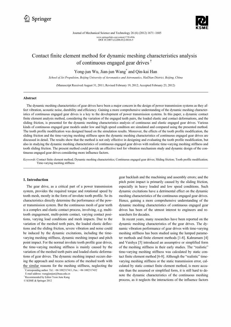
The analysis model of this paper is a pair of involute spur gears, with geometric parameters of gear teeth num-ber 1 2 36Z Z= = , module 3.18m = mm, pressure angle 20α = , face width 25.4B = mm, contact ratio 1.69ε = . According to the modeling method mentioned above, the precise contact model of gear drives is established and shown in Fig. 1. The machining and assembly errors, the elastic of the axes and bearing are neglected in this model, for comparing with the previous similar studies. The driving speed and loaded torque are applied on the driver and driven gear directly.
3. Contact FEA method for continuous engaged gear
drives
The precise contact model of the meshed gear drive was es-tablished in the previous section. The finite element analysis method for the continuous engaged gear drives will be intro-duced next.
3.1 Governing equations for continuous engaged gear drives
The whole meshing process from 0 to TT of engaged gear drives is divided into a discrete time sequences 0, ,2 , , , ,t t t t t TTΔ Δ + Δ . The dynamic contact model of the meshed gear pair at time t is shown in Fig. 2. In the figure, t
gV and tpV are the body of the driver gear and driven gear
at time t , respectively, tgS and t
pS are the tooth surface of the meshed tooth for the driver and driven gears, the contact surface of the gear pair is marked as C
t t tg pS S S= ∩ , the
contacted surface of the driver and driven gears are marked as
Fig. 1. Finite element model of meshed gear pairs.
Y. Wu et al. / Journal of Mechanical Science and Technology 26 (6) (2012) 1671~1685 1673
t gCS and t p
CS , respectively, gtLF and pt
LF are their external loads at this moment.
The global Cartesian coordinate systems 1 1 1 1O -x y z and 2 2 2 2O -x y z are defined at each center of the gear circle, for
describing the kinematics and dynamics relationship of the driver and driven gear, respectively. The local Cartesian coor-dinate system ot t t t- x y z is defined at the contact point t o of the contact surface C
tS at time t, for describing the dy-namic contact states of the gear pairs. As shown in Fig. 2 the
1t e , 2
t e and tNe are the unit vectors of the local Cartesian
coordinate system ot t t t- x y z ; one can have 1 2t t t
N = ×e e e , where t
Ne is the unit normal vector of the contact surface and point to the outward of t p
CS , and it coincides with the direction of the line-of-action; 1
t e is one of the unit tangen-tial vectors of the contact surface and points to the direction of the off-line-of-action in transverse section; 2
t e is the other unit tangential vector of the contact surface and points to the longitudinal direction of the gear pairs.
Hence, the dynamic contact force vectors of the contact point ot could be given as
o 1 o 1 2 o 2 o
o 1 o 2 o ( , ).
t i t t i t t i t t iC C C N CN
t i t i t iC C CN
F F F
i g p
= + +
= + + =
F e e e
F F F (1)
And the resultant dynamic contact force of the engaged
driver and driven gear on the contact surface CtS should be
defined as
j 1 j 1 2 j 2 j1 1
1 2 ( , ; 1,2,3, , )
M Mt i t i t t i t t i t t i
C C C C N CNj j
t i t i t iC C CN
F F F
i g p j M= =
= = + +
= + + = =
∑ ∑F F e e e
F F F (2)
where o 1t i
CF , o 2t i
CF , ot i
CNF (i = g, p) are the components of the contact force vectors, t
oiCF , whose directions coincide with
the unit vectors of the local Cartesian coordinate system ot t t t- x y z . And 1
t iCF , 2
t iCF , t i
CNF (i = g, p) are the com-ponents of the resultant contact force vectors, t i
CF , with the same directions of the local Cartesian coordinate system
ot t t t- x y z . Moreover, M is the contact point number on the contact surface of the engaged gear drives.
For analyzing the dynamic characteristics of the continuous engaged gear drives, the dynamic parameters for every mo-ment of the meshing process should be obtained first. How-ever, the contact position and state of the next moment in the dynamic meshing process are unknown beforehand. The un-known contact states are interrelated with the known states and can be obtained from the known ones. Hence, the dy-namic meshing process of gear drive should be solved by the augmented method. There are two main augmented Lagran-gian approaches to solve the contact and impact problems, including the total Lagrange formulation (T.L.) and the up-dated Lagrange formulation (U.L.) [21]. The U.L. augmented approach is introduced in this study. Based on the principle of virtual displacement, the augmented governing equations of the driver and driven gear are described as
g g g
g g g g g g Lp p p
p p p p p p L
t t t t t t t t t tt C t
t t t t t t t t t tt C t
+Δ +Δ +Δ +Δ
+Δ +Δ +Δ +Δ
⎧ + + = + −⎪⎨ + + = + −⎪⎩
M u C u K u F F FM u C u K u F F F
(3)
where,
01 1
0g 1 1
01 1
t t
t t t t
t t
+Δ
+Δ +Δ
+Δ
⎡ ⎤ ⎡ ⎤⎢ ⎥ ⎢ ⎥= −⎢ ⎥ ⎢ ⎥⎢ ⎥ ⎢ ⎥⎣ ⎦ ⎣ ⎦
x xu y y
z z;
01 1
0g 1 1
01 1
,
t
t t
t
⎡ ⎤ ⎡ ⎤⎢ ⎥ ⎢ ⎥= −⎢ ⎥ ⎢ ⎥⎢ ⎥ ⎢ ⎥⎣ ⎦ ⎣ ⎦
x xu y y
z z (4)
02 2
0p 2 2
02 2
t t
t t t t
t t
+Δ
+Δ +Δ
+Δ
⎡ ⎤ ⎡ ⎤⎢ ⎥ ⎢ ⎥= −⎢ ⎥ ⎢ ⎥⎢ ⎥ ⎢ ⎥⎣ ⎦ ⎣ ⎦
x xu y y
z z;
02 2
0p 2 2
02 2
,
t
t t
t
⎡ ⎤ ⎡ ⎤⎢ ⎥ ⎢ ⎥= −⎢ ⎥ ⎢ ⎥⎢ ⎥ ⎢ ⎥⎣ ⎦ ⎣ ⎦
x xu y y
z z (5)
g g gt t t+Δ= −u u u ; p p p
t t t+Δ= −u u u (6)
where gM and pM are the finite element mass matrix of the driver and driven gear for 0t = , gC and pC are the finite element damp matrix, g
tt K and p
tt K are the finite
element stiffness matrix of the driver and driven gear at time t , g
t t+Δ u and pt t+Δ u are their node acceleration vectors in
their own global Cartesian coordinate systems at time t t+ Δ , g
t t+Δ u and pt t+Δ u are their node velocity vectors at time
t t+ Δ , gu and pu are not the displacement vectors but the augmented vectors of the node displacement of the driver and driven gear from t to t t+ Δ , g
Lt t+Δ F and p
Lt t+Δ F are their
external node load vectors, gt tC
+Δ F and pt tC
+Δ F are their equivalent node contact force vectors, gt
t F and ptt F are their
internal node force vectors at time t . So the governing equation of the gear drive may be de-
scribed as follows:
Fig. 2. Dynamic contact model for engaged gear pair.
1674 Y. Wu et al. / Journal of Mechanical Science and Technology 26 (6) (2012) 1671~1685
t t t t t t t t t tt L C t
+Δ +Δ +Δ +Δ+ + = + −M u C u Ku F F F (7)
where
g
p
00
⎡ ⎤= ⎢ ⎥⎣ ⎦
MM
M, g
p
00
⎡ ⎤= ⎢ ⎥⎣ ⎦
CC
C, g
p
0,
0
ttt
t tt
⎡ ⎤= ⎢ ⎥⎢ ⎥⎣ ⎦
KK
K (8)
g
p
t tt t
t t
+Δ+Δ
+Δ
⎡ ⎤= ⎢ ⎥⎢ ⎥⎣ ⎦
uu
u, g
p
t tt t
t t
+Δ+Δ
+Δ
⎡ ⎤= ⎢ ⎥⎢ ⎥⎣ ⎦
uu
u, g
p
,⎡ ⎤
= ⎢ ⎥⎣ ⎦
uu
u (9)
gL
L pL
t tt t
t t
+Δ+Δ
+Δ
⎡ ⎤= ⎢ ⎥⎣ ⎦
FF
F,
g
p
t tt t C
C t tC
+Δ+Δ
+Δ
⎡ ⎤= ⎢ ⎥⎣ ⎦
FF
F,
g
p .t
t tt t
t
⎡ ⎤= ⎢ ⎥⎣ ⎦
FF
F (10)
3.2 Analysis for typical meshing states of continuous en-
gaged gear drives
The governing equations of the continuous engaged gear drives were obtained in the previous section. It is obvious that the calculation of the equivalent node contact force vector t t
C+Δ F is the key to solving the governing Eq. (7). Hence, the
expressions of the equivalent node contact force vector, t t
C+Δ F , for different meshing states will be introduced in the
following section, based on the analysis of the characteristics for different typical meshing states of continuous engaged gears.
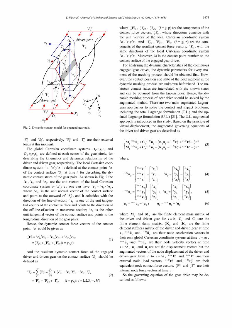
In this study, the contact ratio of the gear drive is supposed as 1 2ε< < , and the contact areas of the tooth profile are shown in Fig. 3. When the first tooth pair begins to mesh at the initial contact point (ICP), the second tooth pair gets into mesh at the highest point of single tooth contact (HPSTC), and the gear drive comes into the double tooth pair contact area. When the first tooth pair arrives at the lowest point of single tooth contact (LPSTC), the second tooth pair disengages at the final contact point (FCP), and the gear drive comes into the single tooth pair contact area. Hence, the meshing process of gear drive should be divided into four typical meshing states: the single tooth pair contact, the double tooth pair contact, single-to-double tooth pair contact, and the double-to-single tooth pair contact, respectively. All of the meshing states will
be discussed in this section.
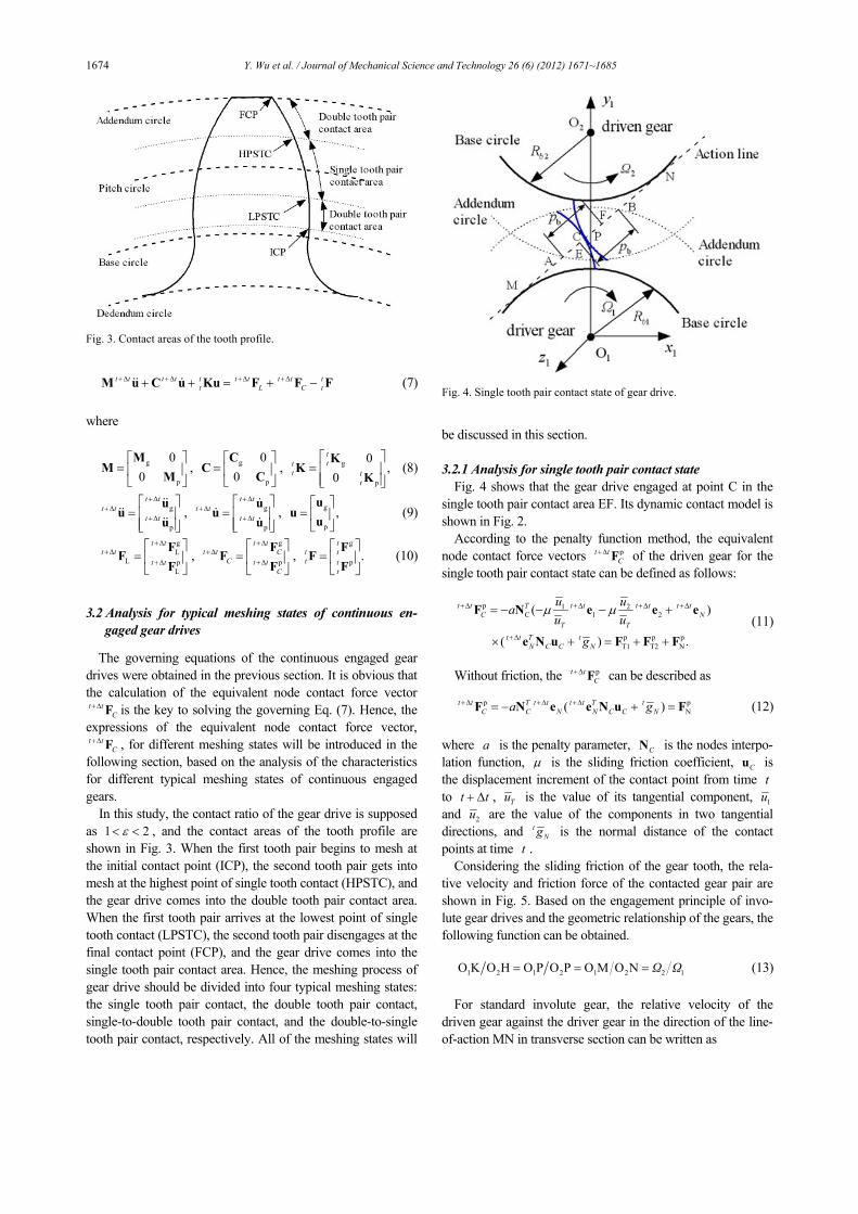
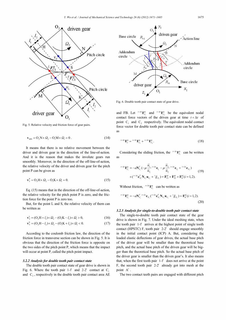
3.2.1 Analysis for single tooth pair contact state Fig. 4 shows that the gear drive engaged at point C in the
single tooth pair contact area EF. Its dynamic contact model is shown in Fig. 2.
According to the penalty function method, the equivalent node contact force vectors pt t
C+Δ F of the driven gear for the
single tooth pair contact state can be defined as follows:
p 1 2C 1 2
p p pT1 T2 N
( )
( ) .
t t T t t t t t tC N
T Tt t T t
N C C N
u uau u
g
μ μ+Δ +Δ +Δ +Δ
+Δ
= − − − +
× + = + +
F N e e e
e N u F F F (11)
Without friction, the pt t
C+Δ F can be described as
p p
N( )t t T t t t t T tC C N N C C Na g+Δ +Δ +Δ= − + =F N e e N u F (12)
where a is the penalty parameter, CN is the nodes interpo-lation function, μ is the sliding friction coefficient, Cu is the displacement increment of the contact point from time t to t t+ Δ , Tu is the value of its tangential component, 1u and 2u are the value of the components in two tangential directions, and t
Ng is the normal distance of the contact points at time t .
Considering the sliding friction of the gear tooth, the rela-tive velocity and friction force of the contacted gear pair are shown in Fig. 5. Based on the engagement principle of invo-lute gear drives and the geometric relationship of the gears, the following function can be obtained.
1 2 1 2 1 2 2 1O K O H O P O P O M O N Ω Ω= = = (13)
For standard involute gear, the relative velocity of the
driven gear against the driver gear in the direction of the line-of-action MN in transverse section can be written as
Fig. 3. Contact areas of the tooth profile.
Fig. 4. Single tooth pair contact state of gear drive.
Y. Wu et al. / Journal of Mechanical Science and Technology 26 (6) (2012) 1671~1685 1675
MN 2 2 1 1O N O M 0 .Ω Ω= × − × =v (14) It means that there is no relative movement between the
driver and driven gear in the direction of the line-of-action. And it is the reason that makes the involute gears run smoothly. Moreover, in the direction of the off-line-of-action, the relative velocity of the driver and driven gear for the pitch point P can be given as
PT 2 2 1 1O H O K 0.Ω Ω= × − × =v (15)
Eq. (15) means that in the direction of the off-line-of-action,
the relative velocity for the pitch point P is zero, and the fric-tion force for the point P is zero too.
But, for the point L and S, the relative velocity of them can be written as
LT 2 1 2 1 1 1(O H ) (O K ) 0,l Ω l Ω= + × − − × >v (16) ST 2 2 2 1 2 1(O H ) (O K ) 0.l Ω l Ω= − × − + × <v (17)
According to the coulomb friction law, the direction of the
friction force in transverse section can be shown in Fig. 5. It is obvious that the direction of the friction force is opposite on the two sides of the pitch point P, which means that the impact will occur at point P, called the pitch point impact.
3.2.2 Analysis for double tooth pair contact state
The double tooth pair contact state of gear drive is shown in Fig. 6. Where the tooth pair 1-1′ and 2-2′ contact at 1C and 2C , respectively in the double tooth pair contact area AE
and FB. Let 1
pt tC
+Δ F and 2
pt tC
+Δ F be the equivalent nodal contact force vectors of the driven gear at time t t+ Δ of point 1C and 2C respectively. The equivalent nodal contact force vector for double tooth pair contact state can be defined as
1 2
p p p .t t t t t tC C C
+Δ +Δ +Δ= +F F F (18)
Considering the sliding friction, the p
i
t tC
+Δ F can be written as
1 2p
1 2
p p pT1 T2 N
( )
( ) ( 1,2).
i i
i i i i i
i i
i i i i
t t T t t t t t tC C N
T T
t t T t i i iN C C N
u ua
u u
g i
μ μ+Δ +Δ +Δ +Δ
+Δ
= − − − +
× + = + + =
F N e e e
e N u F F F (19)
Without friction, p
i
t tC
+Δ F can be written as
p pN( ) ( 1,2).
i i i i i i i
t t T t t t t T t iC C N N C C Na g i+Δ +Δ +Δ= − + = =F N e e N u F
(20)
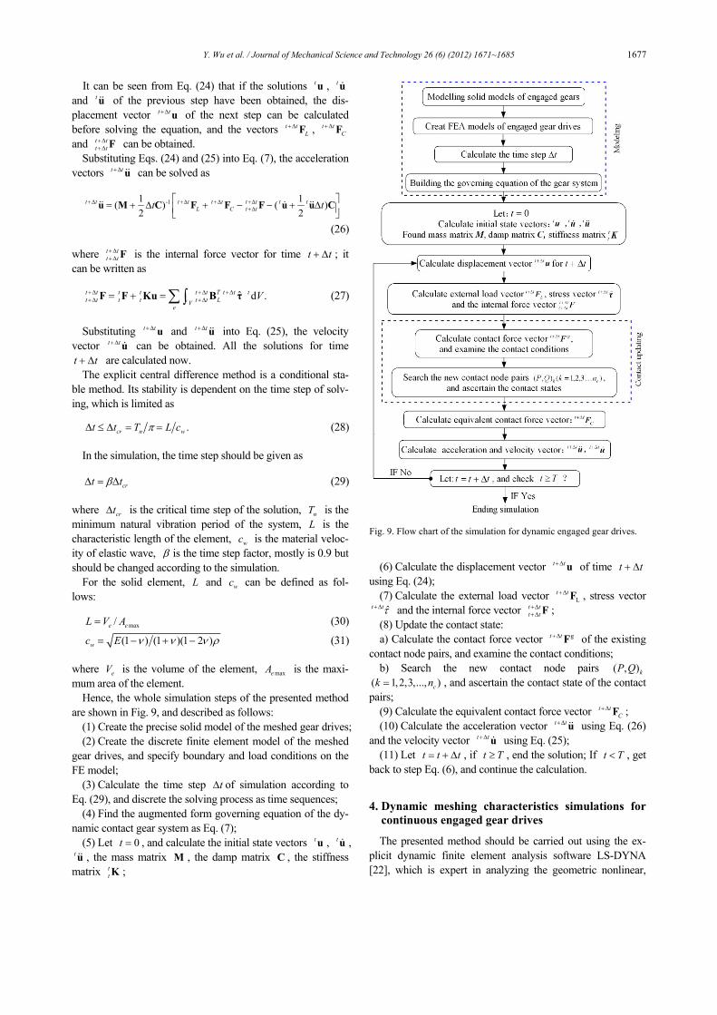
3.2.3 Analysis for single-to-double tooth pair contact state The single-to-double tooth pair contact state of the gear
drive is shown in Fig. 7. Under the ideal meshing state, when the tooth pair 1-1′ arrives at the highest point of single tooth contact (HPSTC) F, tooth pair 2-2′ should engage smoothly in the initial contact point (ICP) A. But, considering the loaded elastic deflections of gear drives, the actual base pitch of the driver gear will be smaller than the theoretical base pitch, and the actual base pitch of the driven gear will be big-ger than the theoretical base pitch. So the actual base pitch of the driver gear is smaller than the driven gear’s. It also means that, when the first tooth pair 1-1′ does not arrive at the point F, the second tooth pair 2-2′ already got into mesh at the point A′ .
The two contact teeth pairs are engaged with different pitch
Fig. 5. Relative velocity and friction force of gear pairs.
Fig. 6. Double tooth pair contact state of gear drive.
1676 Y. Wu et al. / Journal of Mechanical Science and Technology 26 (6) (2012) 1671~1685
points P and P′ as shown in Fig. 7, respectively. The pitch point for the tooth pair 2-2′ is the point P′ , which makes the instantaneous pitch radius of the driven gear become smaller, and the instantaneous rotation velocity of the driven gear increase suddenly. In the whole alternation process A-A′ , the contact tooth pair 2-2′ makes the driven gear run with a higher speed than the tooth pair 1-1′ . The sudden in-crease of the rotation velocity of driven gear will lead to an additional displacement in the direction of the line-of-action, which is the main source of the impact for this alternation state.
The equivalent node contact force vector 1
pt tC
+Δ F for the tooth pair 1-1′ can be calculated as Eqs. (19) and (20). But the contact force vector
2
pt tC
+Δ F for tooth pair 2-2′ can be given as
2 2
2 2 2 2 2
2 2
2 2 2 2
1 2p1 2
p2 p2 p2T1 T2 N
( )
( ) .
t t T t t t t t tC C N
T T
t t T tN C C N
u ua
u u
g
μ μ+Δ +Δ +Δ +Δ
+Δ
= − − − +
′× + = + +
F N e e e
e N u F F F (21)
Without friction, p
2t t
C+Δ F can be written as
2 2 2 2 2 2 2
p p2N( ) ,t t T t t t t T t
C C N N C C Na g+Δ +Δ +Δ ′= − + =F N e e N u F (22)
2 2C C′ = + Δu u u (23)
where
2C′u is the actual displacement increment of the tooth pair 2-2′ from time t to t t+ Δ ,
2Cu is the displacement increment with the rotation speed of the tooth pair 1-1′ , and Δu is the additional displacement increment caused by the sudden increase of the rotation speed. Just owing to this Δu , the approach meshing impact is generated in the whole proc-ess of the alternation state A -A′ . 3.2.4 Analysis for double-to-single tooth pair contact state
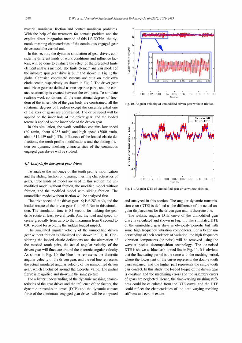
The double-to-single tooth pair contact state of the gear
drive is shown in Fig. 8. Under the ideal meshing state, when tooth pair 1-1′ arrives at the lowest point of single tooth con-tact (LPSTC) E, tooth pair 2-2′ should disengage smoothly in the final contact point (FCP) B. But it is different from the state introduced in previous section that, considering the loaded elastic deformations of gear drives, the actual base pitch of the driver gear will be bigger than the theoretical base pitch, and the actual base pitch of the driven gear will be smaller than the theoretical base pitch. So the actual base pitch of the driver gear is bigger than the driven gear’s. When the tooth pair 2-2′ arrives at point B, the tooth pair will not disengage immedi-ately but continuatively engage until the point B′ .
In the whole alternation process of double-to-single tooth pair contact, the tooth pair 2-2′ will contact along B-B′ ; the pitch points for the tooth pair 1-1′ and 2-2′ are P and P′ respectively. As shown in Fig. 8, the contact of the tooth pair 2-2′ will make the rotation speed of the driven gear decrease suddenly, which also leads to an additional displacement be-tween the pair 1-1′ and 2-2′ , and causes the meshing impact called recess meshing impact.
Similar to the single-to-double state, the equivalent node contact force vector
1
pt tC
+Δ F for the tooth pair 1-1′ can be calculated according Eqs. (19) and (20) and the
2
pt tC
+Δ F can be calculated according Eqs. (21) and (22). But, the additional displacement increment Δu is caused by the suddenly de-crease of the rotation velocity of the driven gear.
3.3 Solution of the governing equations
The explicit central difference method is adopted to solve Eq. (7). In this method, it is assumed that
21 ,
2t t t t tt t+Δ = + Δ + Δu u u u (24)
1 ( ) .2
t t t t t t t+Δ +Δ= + + Δu u u u (25)
Fig. 7. Single-to-double tooth pair contact of gear drive.
Fig. 8. Double-to-single tooth pair contact of gear drive.
Y. Wu et al. / Journal of Mechanical Science and Technology 26 (6) (2012) 1671~1685 1677
It can be seen from Eq. (24) that if the solutions t u , t u and t u of the previous step have been obtained, the dis-placement vector t t+Δ u of the next step can be calculated before solving the equation, and the vectors t t
L+Δ F , t t
C+Δ F
and t tt t+Δ+Δ F can be obtained.
Substituting Eqs. (24) and (25) into Eq. (7), the acceleration vectors t t+Δ u can be solved as
-11 1( ) ( )
2 2t t t t t t t t t t
L C t tt t+Δ +Δ +Δ +Δ+Δ
⎡ ⎤= + Δ + − − + Δ⎢ ⎥⎣ ⎦u M C F F F u u C
(26)
where t tt t+Δ+Δ F is the internal force vector for time t t+ Δ ; it
can be written as
ˆ d .t
t t t t t t T t t tt t t t t t LV
eV+Δ +Δ +Δ
+Δ +Δ= + = ∑∫F F Ku B τ (27)
Substituting t t+Δ u and t t+Δ u into Eq. (25), the velocity
vector t t+Δ u can be obtained. All the solutions for time t t+ Δ are calculated now.
The explicit central difference method is a conditional sta-ble method. Its stability is dependent on the time step of solv-ing, which is limited as
.cr n wt t T L cπΔ ≤ Δ = = (28)
In the simulation, the time step should be given as
crt tβΔ = Δ (29)
where crtΔ is the critical time step of the solution, nT is the minimum natural vibration period of the system, L is the characteristic length of the element, wc is the material veloc-ity of elastic wave, β is the time step factor, mostly is 0.9 but should be changed according to the simulation.
For the solid element, L and wc can be defined as fol-lows:
max/e eL V A= (30)
(1 ) (1 )(1 2 )wc E ν ν ν ρ= − + − (31)
where eV is the volume of the element, maxeA is the maxi-mum area of the element.
Hence, the whole simulation steps of the presented method are shown in Fig. 9, and described as follows:
(1) Create the precise solid model of the meshed gear drives; (2) Create the discrete finite element model of the meshed
gear drives, and specify boundary and load conditions on the FE model;
(3) Calculate the time step tΔ of simulation according to Eq. (29), and discrete the solving process as time sequences;
(4) Find the augmented form governing equation of the dy-namic contact gear system as Eq. (7);
(5) Let 0t = , and calculate the initial state vectors t u , t u , t u , the mass matrix M , the damp matrix C , the stiffness matrix t
t K ;
(6) Calculate the displacement vector t t+Δ u of time t t+ Δ using Eq. (24);
(7) Calculate the external load vector Lt t+Δ F , stress vector
ˆt tτ+Δ and the internal force vector t tt t+Δ+Δ F ;
(8) Update the contact state: a) Calculate the contact force vector gt t+Δ F of the existing
contact node pairs, and examine the contact conditions; b) Search the new contact node pairs ( , )kP Q
( 1,2,3,..., )ck n= , and ascertain the contact state of the contact pairs;
(9) Calculate the equivalent contact force vector t tC
+Δ F ; (10) Calculate the acceleration vector t t+Δ u using Eq. (26)
and the velocity vector t t+Δ u using Eq. (25); (11) Let t t t= + Δ , if t T≥ , end the solution; If t T< , get
back to step Eq. (6), and continue the calculation.
4. Dynamic meshing characteristics simulations for
continuous engaged gear drives
The presented method should be carried out using the ex-plicit dynamic finite element analysis software LS-DYNA [22], which is expert in analyzing the geometric nonlinear,
Fig. 9. Flow chart of the simulation for dynamic engaged gear drives.
1678 Y. Wu et al. / Journal of Mechanical Science and Technology 26 (6) (2012) 1671~1685
material nonlinear, friction and contact nonlinear problems. With the help of the treatment for contact problem and the explicit direct integration method of this LS-DYNA, the dy-namic meshing characteristics of the continuous engaged gear drives could be carried out.
In this section, the dynamic simulation of gear drives, con-sidering different kinds of work conditions and influence fac-tors, will be done to evaluate the effect of the presented finite element analysis method. The finite element analysis model of the involute spur gear drive is built and shown in Fig. 1; the global Cartesian coordinate systems are built on their own circle center, respectively, as shown in Fig. 2. The driver gear and driven gear are defined as two separate parts, and the con-tact relationship is created between the two parts. To simulate realistic work conditions, all the translational degrees of free-dom of the inner hole of the gear body are constrained, all the rotational degrees of freedom except the circumferential one of the axes of gears are constrained. The drive speed will be applied on the inner hole of the driver gear, and the loaded torque is applied on the inner hole of the driven gear.
In this simulation, the work condition contains low speed (60 r/min, about 6.283 rad/s) and high speed (3000 r/min, about 314.159 rad/s). The influences of the loaded elastic de-flections, the tooth profile modifications and the sliding fric-tion on dynamic meshing characteristics of the continuous engaged gear drives will be studied.
4.1 Analysis for low speed gear drives
To analyze the influence of the tooth profile modification and the sliding friction on dynamic meshing characteristics of gears, three kinds of model are used in this section: the un-modified model without friction, the modified model without friction, and the modified model with sliding friction. The unmodified model without friction will be analyzed first.
The drive speed of the driver gear 1Ω is 6.283 rad/s, and the loaded torque of the driven gear T is 143.6 Nm in this simula-tion. The simulation time is 0.1 second for making the gear drive rotate at least several teeth. And the load and speed in-crease gradually from zero to the maximum from 0 second to 0.01 second for avoiding the sudden loaded impact.
The simulated angular velocity of the unmodified driven gear without friction is calculated and shown in Fig. 10. Con-sidering the loaded elastic deflections and the alternation of the meshed tooth pairs, the actual angular velocity of the driven gear will fluctuate around the theoretic angular velocity. As shown in Fig. 10, the blue line represents the theoretic angular velocity of the driven gear, and the red line represents the actual simulated angular velocity of the unmodified driven gear, which fluctuated around the theoretic value. The partial figure is magnified and shown in the same picture.
For a better understanding of the dynamic meshing charac-teristics of the gear drives and the influence of the factors, the dynamic transmission errors (DTE) and the dynamic contact force of the continuous engaged gear drives will be computed
and analyzed in this section. The angular dynamic transmis-sion error (DTE) is defined as the difference of the actual an-gular displacement for the driven gear and its theoretic one.
The realistic angular DTE curve of the unmodified gear drive is calculated and shown in Fig. 11. The simulated DTE of the unmodified gear drive is obviously periodic but with some high frequency vibration components. For a better un-derstanding of their tendency of variation, the high frequency vibration components (or noise) will be removed using the wavelet packet decomposition technology. The de-noised DTE is shown as blue dash-dotted line in Fig. 11. It is obvious that the fluctuating period is the same with the meshing period, where the lower part of the curve represents the double tooth pairs engaged, and the higher part represents the single tooth pair contact. In this study, the loaded torque of the driven gear is constant, and the machining errors and the assembly errors of gears are neglected. Hence, the time-varying meshing stiff-ness could be calculated from the DTE curve, and the DTE could reflect the characteristics of the time-varying meshing stiffness to a certain extent.
Fig. 10. Angular velocity of unmodified driven gear without friction.
Fig. 11. Angular DTE of unmodified gear drive without friction.
Y. Wu et al. / Journal of Mechanical Science and Technology 26 (6) (2012) 1671~1685 1679
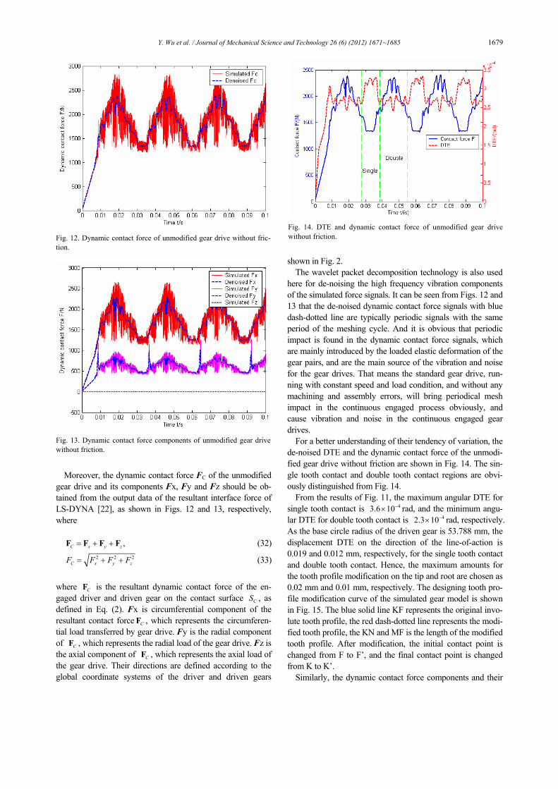
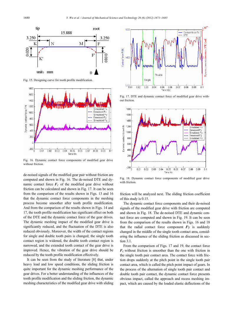
Moreover, the dynamic contact force FC of the unmodified gear drive and its components Fx, Fy and Fz should be ob-tained from the output data of the resultant interface force of LS-DYNA [22], as shown in Figs. 12 and 13, respectively, where
,C x y z= + +F F F F (32)
2 2 2C x y zF F F F= + + (33)
where CF is the resultant dynamic contact force of the en-gaged driver and driven gear on the contact surface CS , as defined in Eq. (2). Fx is circumferential component of the resultant contact force CF , which represents the circumferen-tial load transferred by gear drive. Fy is the radial component of CF , which represents the radial load of the gear drive. Fz is the axial component of CF , which represents the axial load of the gear drive. Their directions are defined according to the global coordinate systems of the driver and driven gears
shown in Fig. 2. The wavelet packet decomposition technology is also used
here for de-noising the high frequency vibration components of the simulated force signals. It can be seen from Figs. 12 and 13 that the de-noised dynamic contact force signals with blue dash-dotted line are typically periodic signals with the same period of the meshing cycle. And it is obvious that periodic impact is found in the dynamic contact force signals, which are mainly introduced by the loaded elastic deformation of the gear pairs, and are the main source of the vibration and noise for the gear drives. That means the standard gear drive, run-ning with constant speed and load condition, and without any machining and assembly errors, will bring periodical mesh impact in the continuous engaged process obviously, and cause vibration and noise in the continuous engaged gear drives.
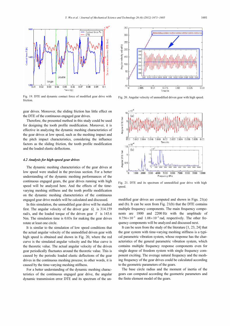
For a better understanding of their tendency of variation, the de-noised DTE and the dynamic contact force of the unmodi-fied gear drive without friction are shown in Fig. 14. The sin-gle tooth contact and double tooth contact regions are obvi-ously distinguished from Fig. 14.
From the results of Fig. 11, the maximum angular DTE for single tooth contact is 43.6 10−× rad, and the minimum angu-lar DTE for double tooth contact is 42.3 10−× rad, respectively. As the base circle radius of the driven gear is 53.788 mm, the displacement DTE on the direction of the line-of-action is 0.019 and 0.012 mm, respectively, for the single tooth contact and double tooth contact. Hence, the maximum amounts for the tooth profile modification on the tip and root are chosen as 0.02 mm and 0.01 mm, respectively. The designing tooth pro-file modification curve of the simulated gear model is shown in Fig. 15. The blue solid line KF represents the original invo-lute tooth profile, the red dash-dotted line represents the modi-fied tooth profile, the KN and MF is the length of the modified tooth profile. After modification, the initial contact point is changed from F to F’, and the final contact point is changed from K to K’.
Similarly, the dynamic contact force components and their
Fig. 12. Dynamic contact force of unmodified gear drive without fric-tion.
Fig. 13. Dynamic contact force components of unmodified gear drivewithout friction.
Fig. 14. DTE and dynamic contact force of unmodified gear drive without friction.
1680 Y. Wu et al. / Journal of Mechanical Science and Technology 26 (6) (2012) 1671~1685
de-noised signals of the modified gear pair without friction are computed and shown in Fig. 16. The de-noised DTE and dy-namic contact force FC of the modified gear drive without friction can be calculated and shown in Fig. 17. It can be seen from the comparison of the results shown in Figs. 13 and 16 that the dynamic contact force components in the meshing process become smoother after tooth profile modification. And from the comparison of the results shown in Figs. 14 and 17, the tooth profile modification has significant effect on both of the DTE and the dynamic contact force of the gear drives. The dynamic meshing impact of the modified gear drive is significantly reduced, and the fluctuation of the DTE is also reduced obviously. Moreover, the width of the contact regions for single and double tooth pairs is changed; the single tooth contact region is widened, the double tooth contact region is narrowed, and the extended tooth contact of the gear drive is improved. Hence, the vibration of the gear drive should be reduced by the tooth profile modification effectively.
It can be seen from the study of literature [8] that, under heavy load and low speed conditions, the sliding friction is quite important for the dynamic meshing performance of the gear drives. For a better understanding of the influences of the tooth profile modification and the sliding friction, the dynamic meshing characteristics of the modified gear drive with sliding
friction will be analyzed next. The sliding friction coefficient of this study is 0.15.
The dynamic contact force components and their de-noised signals of the modified gear drive with friction are computed and shown in Fig. 18. The de-noised DTE and dynamic con-tact force are computed and shown in Fig. 19. It can be seen from the comparison of the results shown in Figs. 16 and 18 that the radial contact force component Fy is suddenly changed in the middle of the single tooth contact area, consid-ering the influence of the sliding friction as discussed in sec-tion 3.1.
From the comparison of Figs. 17 and 19, the contact force FC without friction is smoother than the one with friction in the single tooth pair contact area. The contact force with fric-tion drops suddenly at the pitch point in the single tooth pair contact area, which is called the pitch point impact of gears. In the process of the alternation of single tooth pair contact and double tooth pair contact, the dynamic contact force presents obvious impact, called the approach and recess meshing im-pact, which are caused by the loaded elastic deflections of the
Fig. 15. Designing curve for tooth profile modification.
Fig. 16. Dynamic contact force components of modified gear drivewithout friction.
Fig. 17. DTE and dynamic contact force of modified gear drive with-out friction.
Fig. 18. Dynamic contact force components of modified gear drive with friction.
Y. Wu et al. / Journal of Mechanical Science and Technology 26 (6) (2012) 1671~1685 1681
gear drives. Moreover, the sliding friction has little effect on the DTE of the continuous engaged gear drives.
Therefore, the presented method in this study could be used for designing the tooth profile modification. Moreover, it is effective in analyzing the dynamic meshing characteristics of the gear drives at low speed, such as the meshing impact and the pitch impact characteristics, considering the influence factors as the sliding friction, the tooth profile modification and the loaded elastic deflections.
4.2 Analysis for high-speed gear drives
The dynamic meshing characteristics of the gear drives at low speed were studied in the previous section. For a better understanding of the dynamic meshing performances of the continuous engaged gears, the gear drives running with high speed will be analyzed here. And the effects of the time-varying meshing stiffness and the tooth profile modification on the dynamic meshing characteristics of the continuous engaged gear drive models will be calculated and discussed.
In this simulation, the unmodified gear drive will be studied first. The angular velocity of the driver gear 1Ω is 314.159 rad/s, and the loaded torque of the driven gear T is 143.6 Nm. The simulation time is 0.03s for making the gear drives rotate at least one circle.
It is similar to the simulation of low speed conditions that the actual angular velocity of the unmodified driven gear with high speed is obtained and shown in Fig. 20, where the red curve is the simulated angular velocity and the blue curve is the theoretic value. The actual angular velocity of the driven gear periodically fluctuates around the theoretic value. This is caused by the periodic loaded elastic deflections of the gear drives in the continuous meshing process; in other words, it is caused by the time-varying meshing stiffness.
For a better understanding of the dynamic meshing charac-teristics of the continuous engaged gear drive, the angular dynamic transmission error DTE and its spectrum of the un-
modified gear drives are computed and shown in Figs. 21(a) and (b). It can be seen from Fig. 21(b) that the DTE contains multiple frequency components. The main frequency compo-nents are 1800 and 2200 Hz with the amplitude of
40.756 10−× and 41.08 10−× rad, respectively. The other fre-quency components will be analyzed and discussed next.
It can be seen from the study of the literature [1, 23, 24] that the gear system with time-varying meshing stiffness is a typi-cal parametric vibration system, whose response has the char-acteristics of the general parametric vibration system, which contains multiple frequency response components even for single degree of freedom system with single frequency com-ponent exciting. The average natural frequency and the mesh-ing frequency of the gear drives could be calculated according to the geometric parameters of the gears.
The base circle radius and the moment of inertia of the gears can computed according the geometric parameters and the finite element model of the gears.
Fig. 20. Angular velocity of unmodified driven gear with high speed.
Fig. 21. DTE and its spectrum of unmodified gear drive with high speed.
Fig. 19. DTE and dynamic contact force of modified gear drive withfriction.
1682 Y. Wu et al. / Journal of Mechanical Science and Technology 26 (6) (2012) 1671~1685
bp bg 53.788R R= = (mm), (34) 3323p gI I= = (Kg.mm2). (35)
And the equivalent mass of the gear drive is calculated as
2 2( ) 0.5743e p g p bg g bpm I I I R I R= + = (Kg). (36)
The average angular displacement, θ , from the loaded
elastic deflection of the gear drive, obtained from the results of the angular DTE curves in Fig. 21(a), is -43.695 10× rad.
Then, the average equivalent meshing stiffness is given as
80 2 1.3427 10
bg
F Tkx Rθ
= = = × (N/m). (37)
And the average equivalent natural frequency of the gear
drive is given as
4a 0 1.5291 10ek mω = = × (rad/s). (38)
Hence, the transformed average equivalent natural fre-
quency of the gear drive is 2433 Hz. And the meshing fre-quency of the gear drives is 1800 Hz, according to the geo-metric parameters and work conditions.
It can be seen from Fig. 21(b) that the two main peak values are the meshing frequency 1800 Hz and the natural frequency of the gear drive 2200 Hz, respectively. According to the lit-erature [23, 24], with the variation of the rotation speed and the contact ratio, the average equivalent natural frequency is different from the natural frequency of the gear drives. So the results of the average equivalent natural frequency and natural frequency calculated in this paper are acceptable.
The spectrum of the DTE in Fig. 21(b) shows that there are other frequency components as 400, 1400, 3200, 3600, 4000 Hz etc., besides the two main peak values 1800 Hz and 2200 Hz. Where, 3600 Hz is the double frequency of the meshing frequency, 400 Hz (2200-1800 = 400) and 4000 Hz (2200+ 1800 = 4000) are the combined frequency of the average equivalent natural frequency and natural frequency, whereas 1400 Hz and 3200 Hz is the frequency obtained by the com-bined frequency after “mirror reflection” [24] of the y-coordinate. Theoretically, the second combined frequency should be 400-1800 = -1400 Hz, but in actual simulation, the frequency value should not be minus, so the second combined frequency is 1400 Hz, that is, it could be considered as the “mirror reflection” of the y-coordinate. Similarly, the third combined frequency is 3200 Hz (1400+1800 = 3200). The frequency distribution of the simulated DTE is coincident with the theoretic results of the study [23, 24]. It means that the presented dynamic contact FEA method is effective in analyz-ing the dynamic meshing characteristics of gear drives, con-sidering realistic time-varying meshing stiffness.
Moreover, the dynamic contact force of the unmodified
gear drive is calculated and shown in Fig. 20(a). Gaining a better understanding of the dynamic meshing characteristics of continuous engaged and unmodified gear drives, the one-dimensional discrete wavelet analysis is used for detecting the meshing impact single. The “Daubechies 5” is used in this study, and 3 levels of the db5 are analyzed. The first level of high frequency component D1 of the dynamic contact force for unmodified gear drives is shown in Fig. 20(b). It is obvi-ously that the meshing impact occurs in the continuous en-gaged process of gear drive. And the maximum impact in Fig. 20(b) is about 1000N.
To analyze the effects of the tooth profile modification on vibration reduction of continuous engaged gear drives, the modified gear model will be simulated and discussed next. The modified parameters and the friction coefficient of gear model are the same as the low speed conditions as shown in Fig. 15.
Similarly, the angular DTE and its spectrum of the modified gear is calculated and shown in Fig. 23. It can be seen from the comparison of Figs. 21 and 23 that mainly the frequency
Fig. 22. Dynamic contact force of unmodified gear drive with high speed.
Fig. 23. DTE and its spectrum of modified gear drive with high speed.
Y. Wu et al. / Journal of Mechanical Science and Technology 26 (6) (2012) 1671~1685 1683
components of the DTE for modified gear drive are the same as the unmodified one. But its amplitudes for main frequency are lower than the unmodified; the amplitude of the modified gear drive in 1800 Hz and 2200 Hz is 40.636 10−× and
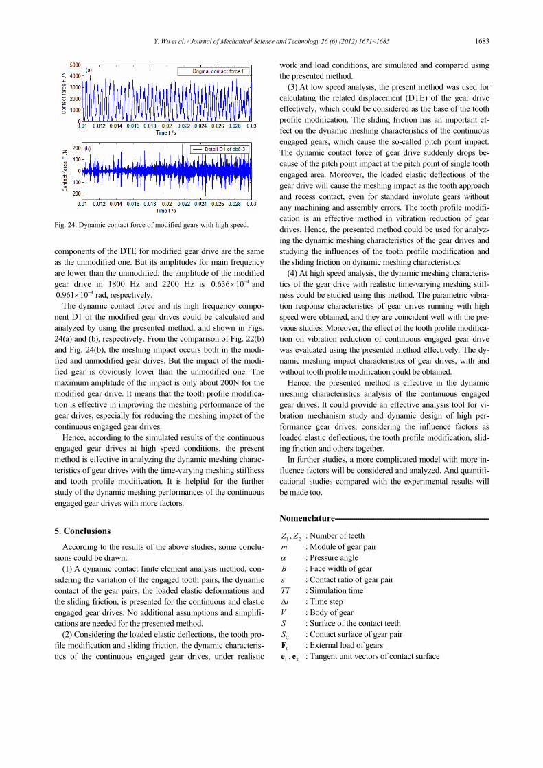
40.961 10−× rad, respectively. The dynamic contact force and its high frequency compo-
nent D1 of the modified gear drives could be calculated and analyzed by using the presented method, and shown in Figs. 24(a) and (b), respectively. From the comparison of Fig. 22(b) and Fig. 24(b), the meshing impact occurs both in the modi-fied and unmodified gear drives. But the impact of the modi-fied gear is obviously lower than the unmodified one. The maximum amplitude of the impact is only about 200N for the modified gear drive. It means that the tooth profile modifica-tion is effective in improving the meshing performance of the gear drives, especially for reducing the meshing impact of the continuous engaged gear drives.
Hence, according to the simulated results of the continuous engaged gear drives at high speed conditions, the present method is effective in analyzing the dynamic meshing charac-teristics of gear drives with the time-varying meshing stiffness and tooth profile modification. It is helpful for the further study of the dynamic meshing performances of the continuous engaged gear drives with more factors.
5. Conclusions
According to the results of the above studies, some conclu-sions could be drawn:
(1) A dynamic contact finite element analysis method, con-sidering the variation of the engaged tooth pairs, the dynamic contact of the gear pairs, the loaded elastic deformations and the sliding friction, is presented for the continuous and elastic engaged gear drives. No additional assumptions and simplifi-cations are needed for the presented method.
(2) Considering the loaded elastic deflections, the tooth pro-file modification and sliding friction, the dynamic characteris-tics of the continuous engaged gear drives, under realistic
work and load conditions, are simulated and compared using the presented method.
(3) At low speed analysis, the present method was used for calculating the related displacement (DTE) of the gear drive effectively, which could be considered as the base of the tooth profile modification. The sliding friction has an important ef-fect on the dynamic meshing characteristics of the continuous engaged gears, which cause the so-called pitch point impact. The dynamic contact force of gear drive suddenly drops be-cause of the pitch point impact at the pitch point of single tooth engaged area. Moreover, the loaded elastic deflections of the gear drive will cause the meshing impact as the tooth approach and recess contact, even for standard involute gears without any machining and assembly errors. The tooth profile modifi-cation is an effective method in vibration reduction of gear drives. Hence, the presented method could be used for analyz-ing the dynamic meshing characteristics of the gear drives and studying the influences of the tooth profile modification and the sliding friction on dynamic meshing characteristics.
(4) At high speed analysis, the dynamic meshing characteris-tics of the gear drive with realistic time-varying meshing stiff-ness could be studied using this method. The parametric vibra-tion response characteristics of gear drives running with high speed were obtained, and they are coincident well with the pre-vious studies. Moreover, the effect of the tooth profile modifica-tion on vibration reduction of continuous engaged gear drive was evaluated using the presented method effectively. The dy-namic meshing impact characteristics of gear drives, with and without tooth profile modification could be obtained.
Hence, the presented method is effective in the dynamic meshing characteristics analysis of the continuous engaged gear drives. It could provide an effective analysis tool for vi-bration mechanism study and dynamic design of high per-formance gear drives, considering the influence factors as loaded elastic deflections, the tooth profile modification, slid-ing friction and others together.
In further studies, a more complicated model with more in-fluence factors will be considered and analyzed. And quantifi-cational studies compared with the experimental results will be made too.
Nomenclature------------------------------------------------------------------------
1Z , 2Z : Number of teeth m : Module of gear pair α : Pressure angle B : Face width of gear ε : Contact ratio of gear pair TT : Simulation time
tΔ : Time step V : Body of gear S : Surface of the contact teeth
CS : Contact surface of gear pair LF : External load of gears
1e , 2e : Tangent unit vectors of contact surface
Fig. 24. Dynamic contact force of modified gears with high speed.
1684 Y. Wu et al. / Journal of Mechanical Science and Technology 26 (6) (2012) 1671~1685
Ne : Normal unit vectors of contact surface CF : Contact force vectors gear
M : Mass matrix C : Damping matrix K : Stiffness matrix u : Acceleration vector u : Velocity vector u : Augmented displacement vector F : Internal node force vector a : Penalty parameter
CN : Node interpolation function μ : Sliding friction coefficient
Ng : Normal distance between contact points bR : Radius of the base circle
R : Radius of the reference circle bp : Base pitch of gear pair
crtΔ : Critical time step of solution nT : Minimum vibration period of system wc : Material velocity of elastic wave β : Time step factor Ω : Angular velocity of gear T : Loaded torque I : Inertia of the gears
em : Equivalent mass of the gear drive θ : Related angular displacement
0k : Average equivalent meshing stiffness aω : Average equivalent natural frequency of gear drive
Subscripts
g : Driver gear p : Driven gear b : Base circle t : Time C : Contact L : Load N : Normal direction
References
[1] R. Li and Jianjun Wang, Geared system dynamic: Vibration, shock and noise, Science Press, Beijing, China (1997).
[2] H. N. Ozguven and D. R. Houser, Mathematical models used in gear dynamics-a review, Journal of Sound and Vi-bration, 121 (3) (1988) 383-411.
[3] J. Wang, R. Li and X. Peng, A survey to non-linear vibration of gear transmission system, ASME Journal of Applied Me-chanics Review, 56 (3) (2003) 309-329.
[4] A. Kahraman and R. Singh, Non-linear dynamics of a spur gear pair, Journal of sound and vibration, 142 (1990) 49-75.
[5] M. Vaishya and R. Singh, Analysis of periodically varying gear mesh systems with coulomb friction using Floquet the-ory, Journal of Sound and Vibration, 243 (3) (2001) 525-545.
[6] R. Li, Z. Tao and T. Lin et al., Numerical simulation for inner dynamic excitation of gearing. Mechanical transmis-
sion, 25 (2) (2001) 1-3. [7] T. Lin, Y. Yang and R. Li et al., Numerical simulation of the
internal dynamic excitation of a spiral bevel gear transmission, Journal of Chongqing University, 32 (6) (2009) 609-613.
[8] S. He, R. Gunda and R. Singh, Effect of sliding friction on the dynamics of spur gear pair with realistic time-varying stiffness, Journal of Sound and Vibration, 301 (2007) 927-949.
[9] H. Ou, R. Li and J. Gong, A mixed finite element algorithm of three-dimensional impact-dynamic contact problems, Journal of Chongqing University, 17 (2) (1994) 52-57.
[10] T. Lin, R. Li and B. Chen et al., Nonlinear dynamic contact analysis of meshing gears, Proc. Int. Conf. Mech. Transmis-sion, Chongqing, China (2001) 248-251.
[11] T. Lin, H. Ou and R. Li, A finite element method for 3D static and dynamic contact/impact analysis of gear drives, Computer Methods in Applied Mechanics and Engineering, 196 (2007) 1716-1728.
[12] A. Bajer and L. Demkowicz, Dynamic contact/impact problems, energy conservation, and planetary gear trains, Computer Methods in Applied Mechanics and Engineering, 191 (2002) 4159-4191.
[13] O. Lundvall, N. Stromberg and A. Klarbing, A flexible multi-body approach for frictional contact in spur gears, Journal of Sound and Vibration, 278 (2004) 479-499.
[14] R. G. Parker, S. M. Vijayakar and T. Imajo, Non-linear dynamic response of a spur gear pair: modelling and ex-perimental comparisons, Journal of Sound and Vibration, 237 (3) (2000) 435-455.
[15] R. G. Parker, V. Agashe and S. M. Vijayakar, Dynamic response of a planetary gear system using a finite ele-ment/contact mechanics model, Transactions of the ASME, 122 (2000) 304-310.
[16] V. K. Ambarisha and R. G. Parker, Nonlinear dynamics of planetary gears using analytical and finite element method, Journal of Sound and Vibration, 302 (2007) 577-595.
[17] Y. Hu, Y. Shao and Z. Chen et al., Transient meshing per-formance of gears with different modification coefficients and helical angles using explicit dynamic FEA, Mechanical System and Signal Processing, 25 (5) (2011) 1786-1802.
[18] J. Wei, W. Sun and L. Wang, Effects of flank deviation on load distributions for helical gear, Journal of mechanical science and technology, 25 (7) (2011) 1781-1789.
[19] J. B. Ooi, X. Wang and C. S. Tan et al., Modal and stress analysis of gear train design in portal axle using finite ele-ment modeling and simulation, Journal of Mechanical Sci-ence and Technology, 26 (2) (2012) 575-589.
[20] H. Sun and Z. Chen, Mechanical Theory, Sixth Ed. Higher Education Press, Beijing, China (2003).
[21] X. Wang, Finite element method, Tsinghua University press, Beijing, China (2010).
[22] J. O. Hallquist, LS-DYNA theory manual, Livermore Soft-ware Technology Corporation (2006).
[23] Q. Han, Theory and experiment study on dynamic charac-teristics of parametrically excited system, Beihang Univer-sity, Beijing, China (2010).

Y. Wu et al. / Journal of Mechanical Science and Technology 26 (6) (2012) 1671~1685 1685
[24] Q. Han, J. Wang and Q. Li, Spectral properties for the vi-bration response of parametrically excited system, Arch Appl Mech, 80 (2010) 671-685.
Yongjun Wu is a Ph.D student at the school of Jet Propulsion at Beijing Uni-versity of Aeronautics and Astronautics. His research interests are in vibration and vibration control for mechanical transmis-sion systems, structural strength and vi-bration for mechanical structures.
Jianjun Wang is a professor in the School of Jet Propulsion at Beijing Uni-versity of Aeronautics and Astronautics. He received an MS in mechanical engi-neering at Chongqing University in 1983, and a Ph.D in solid mechanics at Tsinghua University in 1998. His re-search interests are in vibration for me-
chanical transmission systems, FE simulation for various solid and fluid problems, structural strength and vibration for tur-bine engines, and active vibration control of engineering struc-tures.