construction procedures part ii - in.gov procedures part ii revised 2012 this material is to be used...
TRANSCRIPT

CERTIFIED TECHNICIAN PROGRAM TRAINING MANUAL
Construction Procedures Part II
Revised 2012

This material is to be used for training purposes only. Some of the procedures, field tests, and other operating procedures as described within these pages may be different than actual on-site procedures. Therefore, application should not be made without consideration of specific circumstances and current INDOT standards and policies.

Table of Contents Chapter One -- Traffic Signal Installation Wooden Poles With Downguys ................................................................................. 1-1 Steel Strain Poles ....................................................................................................... 1-2 Span, Catenary, and Downguys ................................................................................. 1-4 Signal Head Installation and Clearances.................................................................... 1-7 Disconnect Hanger Installation .................................................................................. 1-9 Traffic Signal Cable Installation ................................................................................ 1-9 Drip Loop Installation ................................................................................................ 1-10 Traffic Signal Cantilever Installation......................................................................... 1-11 Electric Service and Entrance Switch Installation ..................................................... 1-13 Controller Installation Including Foundation............................................................. 1-15 Steel Conduit Installation ........................................................................................... 1-18 Handhole Installation ................................................................................................. 1-19 Detector Housing and Traffic Detection Loop Installation ....................................... 1-20 Detection Housing Installation Sawing Loops Installation of Loop Wire Thermoplastic, Preformed Plastic, and Epoxy Pavement Marking Installation ........ 1-25 Chapter Two -- Ground Mounted Sign Installation Traffic Signs............................................................................................................... 2-1 Pre-Construction Duties ............................................................................................. 2-1 Working Drawings Installation of Signs Removal and Relocation Construction Inspection Duties .................................................................................. 2-4 Installation of Channel Posts Installation of Sheet Signs Reflective Sheeting Installation of Structural Steel Posts Installation of Panel Signs Measurement and Payment ........................................................................................ 2-8 Chapter Three -- Overhead Sign Structures Pre-Construction Duties ............................................................................................. 3-1 Construction Foundation Inspection Duties............................................................... 3-3

Concrete Foundations ................................................................................................ 3-3 Structure Erection ...................................................................................................... 3-4 Sign Installation ......................................................................................................... 3-4 Traffic Control ........................................................................................................... 3-6 Measurement and Payment ........................................................................................ 3-6 Chapter Four -- Highway Lighting Construction Requirements ........................................................................................ 4-1 Excavation Trench Excavation Foundation Excavation Landscape Replacement Backfilling Placing Conduit Connections in Base of Lighting Standards Placing Wire and Cable ............................................................................................. 4-5 Underground Through Cable-Duct Cable-Duct Cable Markers Underground Through Conduit Cable-Duct Cable Markers In Conduit Risers Through Conduit in Bridge Coping Aerial Cable Lighting Handholes Concrete Foundations for Lighting Standards Cast-In-Place Foundations Precast Foundations Grading of Foundations Placing Lighting Standards ........................................................................................ 4-9 Lighting Standards Under 80 ft in Height High Mast Lighting Standards 80 ft Height and Over Grounding Luminaire Installation Roadway Luminaires Sign Luminaires Underpass Luminaires High Mast Luminaires Sign, Underpass, Roadway, and High Mast Lighting Location Identification Service Point Power Entry Types of Service Points Sign and Underpass Circuits

Multiple Relay Switches Testing of Highway Lighting System ........................................................................ 4-16 Testing Lighting Circuitry Testing and Inspecting Luminaires Pay Item and Installation Summary Sheets Method of Measurement Chapter Five -- Curbs Curb Types ................................................................................................................. 5-1 Precast Concrete Curb................................................................................................ 5-4 Cast in Place Concrete Curb ...................................................................................... 5-4 Grade Preparation ...................................................................................................... 5-4 Forms ......................................................................................................................... 5-4 Concrete Curb Machines............................................................................................ 5-5 Concrete Composition and Placement ....................................................................... 5-5 Joints .......................................................................................................................... 5-6 Curing ........................................................................................................................ 5-6 Additional Requirements for Concrete Center Curb ................................................. 5-6 Construction and Inspection Procedures .................................................................... 5-7 Measurement and Payment ........................................................................................ 5-7 Chapter Six -- Sidewalks, Curb Ramps, and Steps Grade Preparation ...................................................................................................... 6-1 Forms ......................................................................................................................... 6-2 Placing Concrete ........................................................................................................ 6-2 Finishing .................................................................................................................... 6-2 Joints .......................................................................................................................... 6-2 Curing ........................................................................................................................ 6-3 Concrete Steps ........................................................................................................... 6-3 Reconstructed Concrete Sidewalks ............................................................................ 6-3 Re-Laid Sidewalk....................................................................................................... 6-4 HMA Sidewalk .......................................................................................................... 6-4 Construction and Inspection Procedures .................................................................... 6-4 Measurement and Payment ........................................................................................ 6-5 Chapter Seven -- Concrete Approaches Grade Preparation ...................................................................................................... 7-1 Forms ......................................................................................................................... 7-2 Concrete Composition and Placement ....................................................................... 7-2 Finishing and Curing.................................................................................................. 7-3 Joints .......................................................................................................................... 7-4 Concrete Approach Thickness ................................................................................... 7-4

Opening to Traffic...................................................................................................... 7-4 Construction and Inspection Procedures .................................................................... 7-5 Measurement and Payment ........................................................................................ 7-5 Chapter Eight -- Paved Side Ditch Grade Preparation ...................................................................................................... 8-1 Forms ......................................................................................................................... 8-1 Concrete Composition and Placement ....................................................................... 8-1 Cut-Off Walls and Lugs ............................................................................................. 8-1 Finishing and Curing.................................................................................................. 8-2 Construction and Inspection Procedures .................................................................... 8-2 Chapter Nine -- Concrete Barriers Grade Preparation ...................................................................................................... 9-1 Precast Concrete Median Barriers ............................................................................. 9-2 Forms Concrete Composition Placing and Finishing Concrete Removal of Forms and Curing Handling and Shipping Placement of Precast Units Testing and Inspection Requirements Cast-in-Place Concrete Median Barrier ..................................................................... 9-5 Forms Concrete Composition, Placement, and Finishing Joints Sealing Reflectorization Construction and Inspection Procedures Temporary Concrete Barriers .................................................................................... 9-9 Placing and Anchoring Delineation Measurement and Payment Construction and Inspection Procedures Chapter Ten -- Underdrains Types of Underdrains ................................................................................................. 10-1 Pre-Construction ........................................................................................................ 10-2 Trench Excavation ..................................................................................................... 10-6 Construction Requirements ........................................................................................ 10-7 Pipe Installation

Geotextiles Backfill Underdrain Outlets Outlet Protectors Video Inspection Materials and Basis for Use ....................................................................................... 10-9 Measurement .............................................................................................................. 10-10 Basis of Payment........................................................................................................ 10-11 Chapter Eleven -- Guardrail W-Beam Guardrail ..................................................................................................... 11-1 Pre-Installation Inspection During Installation Basis for Use Modified Guardrail .................................................................................................... 11-4 End Treatments and Transitions ................................................................................ 11-5 Footings and Anchors ................................................................................................ 11-6 Impact Attenuators ..................................................................................................... 11-7 Measurements and Payment ...................................................................................... 11-7 Chapter Twelve – Right-of-Way Fencing Types .......................................................................................................................... 12-1 Farm Field Type Fence .............................................................................................. 12-2 Posts Diagonal Braces Line Posts Woven Wire Fabric Barbed Wire Chain Link Type Fence .............................................................................................. 12-5 Gates .......................................................................................................................... 12-8 Measurements ............................................................................................................ 12-9 Material Acceptance .................................................................................................. 12-9 Chapter Thirteen -- Benchmarks, Posts and Tablets, Monuments, and Right-of-Way Markers Materials .................................................................................................................... 13-1 Benchmark Posts and Tablets Monuments Right of Way Markers Construction Requirements ........................................................................................ 13-3

Setting Right-of-Way Markers Resetting Right-of-Way Markers Setting Monuments Re-established Monuments Setting Benchmark Posts and Tablets Reset Benchmark Posts Method of Measurement and Payment ...................................................................... 13-7 Standard Drawings ..................................................................................................... 13-7 Chapter Fourteen -- Geotextiles Storage and Handling ................................................................................................. 14-1 Placement ................................................................................................................... 14-1 Overlapping and Pinning ........................................................................................... 14-2 Underdrains ................................................................................................................ 14-3 Placement ................................................................................................................... 14-3 Acceptance of Materials ............................................................................................ 14-3 Measurement and Payment ........................................................................................ 14-4 Chapter Fifteen -- Riprap Dumped Riprap .......................................................................................................... 15-1 Revetment, Class 1, and Class 2 Riprap .................................................................... 15-2 Grouted Riprap........................................................................................................... 15-2 Precast Concrete Riprap ............................................................................................. 15-3 Uniform Riprap .......................................................................................................... 15-4 Measurement .............................................................................................................. 15-4 Acceptance ................................................................................................................. 15-4 Chapter Sixteen -- Gabions Function ..................................................................................................................... 16-1 INDOT Usage ............................................................................................................ 16-2 Gabion Assembly ....................................................................................................... 16-3 Installation.................................................................................................................. 16-4 Filling ......................................................................................................................... 16-4 Acceptance and Payment ........................................................................................... 16-5 Chapter Seventeen -- Seeding Types of Seeding........................................................................................................ 17-1 Preparation ................................................................................................................. 17-1 Application Rate of Fertilizer .................................................................................... 17-1 Application of Seed.................................................................................................... 17-2 Seasonal Limitation ................................................................................................... 17-5
Mulching .................................................................................................................... 17-6 Placement of Mulch ................................................................................................... 17-6 Method A Method B Method C Method D Method E Acceptance of Material .............................................................................................. 17-8 Measurement of Quantities ........................................................................................ 17-10 Chapter Eighteen -- Sodding Preparation of Ground before Sodding ...................................................................... 18-1 Laying Sod ................................................................................................................. 18-2 Watering Sod ............................................................................................................. 18-3 Method of Measurement ............................................................................................ 18-3 Basis of Payment........................................................................................................ 18-3


1 Traffic Signal Installation Wooden Poles with Downguys Steel Strain Poles Span, Catenary, and Downguys Signal Head Installation and Clearances Disconnect Hanger Installation Traffic Signal Cable Installation Drip Loop Installation Traffic Signal Cantilever Installation Electrical Service and Entrance Switch Installation Controller Installation Including Foundation Steel Conduit Installation Handhole Installation

Detector Housing and Traffic Detection Loop Installation Detection Housing Installation Sawing Loops Installation of Loop Wire Thermoplastic, Preformed Plastic, and Multi-Component Pavement Marking Installation

1-1
CHAPTER ONE: TRAFFIC SIGNAL INSTALLATION
In this chapter the construction of a traffic signal system is discussed. A technician working on a traffic signal is required to be aware that work activities progress very quickly, and any unresolved problems become the controlling operation for the completion of the work. For this reason, the technician should anticipate problems before they become the controlling operation. The following steps are recommended before any work is started by the Contractor:
1) Review Sections 805, and 922 as well as Part 4 of the current edition of the Manual of Uniform Traffic Control Devices, and the appropriate Standard Sheets.
2) Closely examine the plans, and field check the planned
locations of all structures before the preconstruction conference. These include the controller, poles, pole anchors, detector housings, loops, handholes, and signal head locations.
3) Check the R/W distances as shown on the plans. This may
usually be accomplished by reviewing old road plans held by the District Production Office.
4) After the locations of all underground utilities have been
determined, again closely examine the structure locations and signal cable quantities for any conflicts. Any resulting changes outside the allowable limits of the Specifications or utility codes should be brought to the attention of the PE/PS, Area Engineer, or District Traffic Office.
5) In urban areas, check with property owners about possible
basements extending out under the sidewalk areas.
WOODEN POLES WITH DOWNGUYS
Wooden poles with downguys are generally less expensive to install than steel strain poles and are not preferred by INDOT. When laying out and inspecting the locations where wooden poles and anchors are being installed, the following items are required to be considered:
1-2
1) Each wooden pole is required to be visually inspected, and meet the requirements of Section 922.
2) The locations of the wooden poles are staked so they may be
seen from any of the other pole locations. 3) Placing wooden poles or downguy anchors in the ditch line
should be avoided. 4) Wooden poles are set a minimum of 7 ft in the ground and
raked back out of plumb 12 in. The material excavated from the hole should be observed for possible utility conflicts.
5) For single spans, the pole anchors are located by extending
the line of the span back 20 ft from the pole and swung a 7.5 ft arc in either direction.
6) For double spans, the pole anchors are located by extending
the line which divides the extension of the two spans back 20 ft and swing a 7.5 ft arc in either direction.
7) Any pole anchor location change which would place the pole
anchor closer than 15 ft from the wooden pole should generally not be permitted. The use of a strain pole should be investigated for cases of insufficient anchorage.
8) The line on the drilled hole for the pole anchor is required to
be toward the top of the wooden pole. 9) The breaking of the expansion anchor and the proper backfill
and compaction of the anchor assembly are critical to the proper functioning of the wooden pole. Initial and continued movement of the anchor assembly is required to be monitored.
STEEL STRAIN POLES
Steel strain poles (Figure 1-1) are used primarily on all intersections. These poles have a much higher initial installation cost; however, the service life is much longer than a wooden pole with downguys. When laying out and inspecting the locations where steel strain poles are being installed, the following items are required to be considered:
1) The Basis For Approval for the #4 and #10 bars in the foundation is the sequence number from a laboratory report unless they are from an approved list. The Basis For

1-3
Approval for the concrete is the sequence number reported on the IT 652. The Basis For Approval for the steel strain pole and the anchor bolts is a Type C Certification.
2) The footing dimensions are 3 ft in diameter and 12 ft deep. 3) If bed rock, loose stones, or boulders more than 1/2 yd3 in
volume are encountered before the 12 ft depth is obtained, the PE/PS or Area Engineer should be contacted. Section 206.02(b) Class X Excavation covers the procedure to be used if this occurs.
4) The Contractor always has the option of using a foundation
casing if unstable soil conditions are anticipated. 5) The exposed portion of the foundation may be 3 ft in diameter
or 3 ft square. 6) Adjacent anchor bolts are required to be oriented in the same
direction with the span or spans attached to the steel strain pole.
Figure 1-1. Steel Strain Pole
7) A tremie is used until the concrete is within 5 ft of the top of the foundation.
8) The steel strain pole foundation is finished 4 to 6 in. above
the original ground and the top edge is chamfered. In locations where the foundation is located within the sidewalk, the sidewalk elevation is the top of the foundation.

1-4
9) Each foundation has a minimum of three conduit entries with grounding bushings.
10) Each steel strain pole is grounded by a continuous #6 bare
copper wire from the grounding lug on the inside of the steel strain pole through the conduit grounding bushings and grounding duct to an 8 ft x 1/2 in. ground rod located 1 ft away from the foundation and 1 ft below the finished ground surface.
11) The exposed concrete surface of the foundation is rubbed
after the forms are removed. 12) The steel strain pole is required to be raked back 12 in. away
from each span. 13) Foundation conduits should be oriented to match the conduit
runs on the plans. If electrical service is on the steel strain pole, all three conduits from the steel strain pole are run to the controller. District Traffic should be consulted for possible future designs.
14) If a handhole is located within approximately 10 ft of a steel
strain pole foundation on a corner other than the controller corner, one of the spare conduits is required to be run to that handhole for future use.
SPAN, CATENARY, AND DOWNGUYS
The span and catenary (Figure 1-2) are one of the first things that a motorist notices about a signalized intersection. If the span and catenary are sagging or look sloppy, the whole job looks bad.

1-5
Figure 1-2. Span, Catenary, and Tether

1-6
When inspecting the installation of spans, catenaries, and downguys, the following items are required to be considered.
1) The Basis For Approval for 3/8 in. or 1/4 in. stainless steel aircraft cable is a Type C Certification.
2) Spans, catenaries, and downguys are 3/8 in. stainless steel
aircraft cable, and "A" guide wires may be 1/4 in. wire rope or 3/8 in. aircraft cable. Tether lines are generally 1/8 in. aircraft cable.
3) Spans are required to be level. Therefore, a leveling mark
should be placed on the side of each pole representing the pavement elevation at the lowest signal head.
4) The mounting height should be assumed to be 18 ft to the
bottom of the lowest signal head, and 4 ft from the span to the bottom of a three section signal head or 5 ft from the span to the bottom of a four or five section signal head.
5) The span is located by measuring 22 or 23 ft from the leveling
mark for the location of the drilled hole for the wooded pole or pole band for the steel strain pole.
6) The catenary is located a minimum of 12 in. below the top of
either a wooden pole or steel strain pole. The catenary connection may have to be lower depending on overhead utility conflicts.
7) Three Crosby clamps are used at each eye bolt or pole band
connection and are installed in alternate directions. Three bolt clamps are never used on aircraft cable.
8) The aircraft cable is doubled back 54 in. at each eye bolt or
pole band connection. The first Crosby clamp is installed 3 in. from the eye bolt, the second 18 in. from the first, and the third 18 in. from the second.
9) Downguys are required to be in place before any work is
conducted on the spans and catenaries of wooden poles. 10) The downguys is tightened until the top of the wooden pole
starts to move.
11) A span jack is used to tighten the spans. For double spans, each span is jacked alternately until very tight.

1-7
12) The catenary swinging free is required to be between 18 and
24 in. above the span at the closest point. 13) The span and catenary are connected at the center of the span.
The signal heads are supported and leveled from the catenary by means of "A" wires. Each "A" wire is connected at the bottom by two Crosby clamps spaced 12 to 24 in. apart. No Crosby clamp is used at the top of the "A" wire. The ends of the A wires are protected by servi-clips. "A" wires may be either 1/4 in. or 3/8 in. aircraft cable.
14) The National Electrical Code requires 8 ft vertical and 6 ft
horizontal clearance from any overhead primary conductor. SIGNAL HEAD INSTALLATION AND CLEARANCES
The traffic signal heads are in most cases the only part of the whole traffic signal system that the motorist actually sees. Therefore, the vertical and horizontal positioning and the directional orientation are critical to a well functioning system. When inspecting the installation of traffic signal heads, the following items are required to be considered:
1) The Basis For Approval for signal heads and accessories is a
Type C Certification. 2) Inspect each signal head assembly while still on the ground
for the following:
a. Physical defects b. Visor type c. Bulb sizes are 12 in. d. Lens orientation e. Wiring specifications f. Too much play between the balance adjustor and
weatherhead clevis g. Approximate vertical hanging for each signal head
3) Signal head clearances are required to be between 17 ft and 19 ft.

1-8
4) Signal heads are adjusted vertically to approximate a uniform
grade of all like signal heads.
5) Signal heads are located and aimed according to the plans. The minimum spacing between signal heads serving the same direction is 8 ft The minimum spacing between free swinging signal heads not serving the same direction is 4 ft The District Traffic Department should approve the layout of signal heads.
6) If a tether line is specified (Figure 1-3), all the signals are
required to be aligned vertically. This may have to be done several times if the span or catenary requires adjustment. The tether line is designed to break if hit.
Figure 1-3. Tether Line 7) If a signal head is required to be mounted more than 2 h
before use, then the entire signal head is hooded. 8) Hooded signal heads are not to be left up for more than five
days.

1-9
DISCONNECT HANGER INSTALLATION
The disconnect hanger (Figure 1-4) is an electrical junction box generally suspended at a specified location on the span, and all the wiring connections are conducted while on the span. When inspecting the installation of a disconnect hanger the technician is required to consider the following items:
1) The Basis For Approval for disconnect hangers is a Type C
Certification. 2) Each disconnect hanger is inspected on the ground for
physical defects, tightness of door latch and span hanging connections, and an 18 circuit terminal block.
Figure 1-4. Disconnect Hanger TRAFFIC SIGNAL CABLE INSTALLATION
Traffic signal cable is the multi-conductor cables which carry electrical impulses from the power source to the entrance switch, from the entrance switch to the controller, from the controller to the signal heads, and from the controller to the detection devices. Pay items are designated by the number of conductors in the cable and the gauge of the cable. When inspecting the installation of traffic signal cable, the technician is required to consider the following items:
1) The Basis For Approval for all traffic signal cable is a Type C
Certification. 2) The color coding scheme is required to be discussed at the
preconstruction conference and should conform to the District policy.

1-10
3) Fused and unfused cables are not permitted to occupy the same conduit. 3C/8 (3 conductor 8 gage wire) traffic signal cable is considered unfused.
4) The only acceptable underground splice in a handhole is a
poured epoxy splice. 5) In above ground pole handholes, an acceptable splice is a
"standing splice" utilizing wire nuts and electrical tape wrapping.
6) For traffic signal cable hung from a span, cable rings are
spaced at 12 in. 7) Traffic signal cable quantities are required to be verified.
However, plan quantity is paid if the measured quantity is within ± 25% of planned quantity.
DRIP LOOP INSTALLATION
The purpose of a drip loop (Figure 1-5) is to prevent water from entering the weatherhead at either a signal head, disconnect hanger, or traffic pole. Drip loops are required to be approximately 6 in. in diameter, contain at least one full turn of traffic signal cable, and be wrapped tightly with several wraps of electrical tape. The drip loop should not rub against the traffic signal head.
Figure 1-5. Drip Loop

1-11
TRAFFIC SIGNAL CANTILEVER INSTALLATION
Traffic signal cantilever installations (Figure 1-6) are found in urban areas where spans and catenaries are either impractical or not as aesthetically pleasing.
Figure 1-6. Pole and Mast Arm When inspecting the installation of a cantilever, the following items are required to be considered:
1) The Basis For Approval for the pole, mast arm, anchor bolts, and accessories is a Type C Certification. The Basis For Approval for the concrete used in the footing is the sequence number reported on the IT 652.
2) Field check each footing location using the planned mast arm
length and locate the end span signal head according to the plans. Any apparent errors in the plans are required to be reported to the PE/PS immediately.

1-12
3) Check the R/W distances as shown on the plans to be sure
that the footing is entirely within the R/W. 4) After the underground utilities have been located, check to
insure that the footing locations meet the following criteria:
a. The face of the pole is required to be at least 18 in. from the face of the curb.
b. Underground utility clearance requirements are
required to be satisfied. Encasement of an underground utility should never be considered without prior consent of the utility company. Unexpected or mismarked underground utilities are one of the largest causes of contract delay.
c. Do not locate a footing within the confines of a wheel
chair ramp or where a wheel chair would have difficulty maneuvering. If the foundation is required to be in the curb ramp area, then move the foundation as far out of the ramp as possible and place the top of the foundation level with the curb ramp grade. If pedestrian signal indications are specified, they are required to be clearly visible from the beginning of the crosswalk to within 10 ft of the opposite side. The footing should be kept as close to the crosswalk lines as possible. Pedestrian Push Buttons are to be mounted approximately 42” and no more than 48” above the sidewalk- see the IMUTCD, Section 4E.08.
d. The footings are located so that the signal heads are
between 40 and 120 ft from the stop bar. e. The location of the footing may be moved a maximum
of 2 ft perpendicular to flow of traffic, but the mid-mast signal head should still be located at a lane width spacing from the end mast arm signal head. The mid-mast signal head is never located beyond the curb line and the minimum spacing between signal heads is 8 ft.
5) If possible, locate the footing entirely off the sidewalk. 6) Each footing has a minimum of three conduit entries.

1-13
7) Each mast arm pole is grounded by a continuous #6 bare copper wire from the grounding lug on the inside of the mast arm pole through the conduit grounding bushings and grounding duct to an 8 ft x 1/2 in. ground rod located 1 ft away from the foundation and 1 ft below the finished surface.
8) If the footing is greater than 5 ft deep, a tremie is required
below the 5 ft level. 9) If the footing is located in a sidewalk area, the footing is
finished flush with the surrounding sidewalk. If the footing is located in a non-sidewalk area, the footing is finished 4 in. above the original ground using chamfered edges around the top of the footing.
10) Expansion joint material is used when the footing comes in
contact with any other concrete. 11) The pedestrian signal indications are located on the pole in
such a manner as to provide protection from truck turning movements.
12) The bottom of the mid-mast mounted signal head is adjusted
level with the end of the mast arm signal head. ELECTRICAL SERVICE AND ENTRANCE SWITCH INSTALLATION
The electric service (Figure 1-7) requirements vary with the utility company involved. Generally speaking, if the electric service does not meet any of the requirements of that utility company, the electricity is not hooked up. When the contract bid documents and estimate do not fully account for the cost to provide electrical service to the signal, the Area Engineer should be consulted.

1-14
Figure 1-7. Electrical Service and Entrance Switch When inspecting the installation of an electric service the following items are required to be considered:
1) The Basis For Approval for the entrance switch, the conduit
riser, the weatherhead, the traffic signal cable and all other miscellaneous material is a Type C Certification.
2) 3C/8 stranded traffic signal cable is used for the electrical
service from the service weatherhead to the entrance switch, and from the entrance switch to the controller.
3) At least 4 ft of 3C/8 is left rolled up at the weatherhead. 4) An electric meter is placed above the entrance switch if
required by the local power company, or if specified by INDOT.
5) Since the controller operates on 120 volts, one conductor of
the 3C/8 is terminated at the entrance switch. 6) For an electric service on a steel strain pole, a 1 in. riser with
weatherhead is placed on the outside of the steel strain pole. Conduit hangers are banded to the outside of the steel strain pole and the conduit is installed on the hangers.
7) An oxidation inhibitor is applied to all surfaces that mate with
a dissimilar material, such as aluminum to steel.

1-15
8) Conduit straps or hangers are placed 1 ft from the weatherhead and at a maximum spacing of 5 ft from there down.
9) Entrance switch enclosures are required to contain a single
pole 50 amp breaker. 10) The bottom of the entrance switch is mounted at a height of 4
ft. 11) The entrance switch is grounded by means of a #6 bare solid
copper wire encased in a 1/2 in. electrical conduit between the entrance switch and the ground rod.
12) The 8 ft x 1/2 in. ground rod is located 1 ft outside the pole or
foundation and 1 ft below the ground surface. The grounding connection is required to be an approved type.
CONTROLLER INSTALLATION INCLUDING FOUNDATION
The traffic signal controller (Figure 1-8) is the mechanism which makes the traffic signal system operate the way intended. The technician should never change any of the settings of any of the equipment inside the controller cabinet. Only a trained District Traffic Signal Technician has the authority to set or change any of the various controller timings.
Figure 1-8. Traffic Signal Controller

1-16
When inspecting the installation of a traffic signal controller, the following items are required to be considered:
1) The Basis For Approval for the concrete used in the
foundation is the sequence number from the IT 652. The Basis For Approval for the controller, cabinet, and all accessory items is a Type C Certification, and an approval number from a list of approved materials issued by the Office of Materials Management.
2) The controller cabinet is in the same direction oriented so that
a traffic signal technician standing at the controller with the door open may see the majority of the signal heads.
3) Always try to anticipate any future maintenance problems you
might be creating. 4) Check the plans and standard sheets for the controller
foundation location, type, dimensions, and anchor bolt placement.
5) There will be a minimum of three conduit entries into the
controller foundation. There should always be a spare conduit entry. The price of a few extra feet of conduit is small compared to the price of relocating the controller foundation on a future modernization contract.
6) The top edges of the controller foundation are required to
have chamfered edges, and the exposed sides of the foundation be rubbed.
7) Controller "A" bases in non-sidewalk areas are finished 4 in.
above the finished ground level and the top edges are chamfered. Controller "A" bases placed in sidewalk areas are finished flush with the surrounding sidewalk.
8) The top of the controller foundation is required to be sloped
toward the controller drain. 9) A continuous run of #6 bare copper wire connects the
grounding lug on the controller back panel, each conduit grounding lug, and the approved grounding connection to the ground rod.

1-17
10) An 8 ft x 1/2 in. ground rod is placed 1 ft outside the confines of the controller foundation, and 1 ft below the finished ground level.
11) The controller cabinet door is required to open and close
easily when the controller cabinet is properly aligned on the controller foundation. The outside lower edges of the controller are sealed all around with a silicone sealer.
12) All field wiring (Figure 1-9) is required to be neat and easy to
follow. The "bird nest" affect is discouraged.
Figure 1-9. Controller Cabinet Wiring 13) All traffic signal cables entering the controller cabinet, signal
poles, and handholes are tagged with aluminum tags indicating the signal phase, pedestrian phase, power, pedestrian actuation, or loop phase.
14) On traffic signal modernization contracts, the old and the new
systems are kept independent of each other at all times. 15) A District Traffic Technician is required to always be present
when a new signal system is turned on for the first time. 16) Newspapers, TV and radio stations, schools, and law
enforcement agencies are notified of the new signal turn on dates.

1-18
17) A new traffic signal system at an intersection where a traffic signal system did not exist beforehand or where a flashing beacon system is being upgraded to a traffic signal system are required to remain on flash for at least three days prior to placement on normal operation. A new signal is never placed on normal operation on a Friday or just before a holiday.
A partially completed IC 636A is required to be sent to the District Traffic Office indicating the signal turn-on date and time.
STEEL CONDUIT INSTALLATION
Steel conduit is used to carry the traffic signal cable between the controller and all points of intended use. When inspecting the installation of conduit, the following items are required to be considered:
1) The Basis For Approval for conduit is a Type C Certification. 2) Conduit is required to be 2 in. nominal diameter. The type of
conduit will be indicated on the plans or pay items. 3) Rigid grade and intermediate grade steel conduit are both
acceptable. Most Contractors elect to use rigid conduit.
4) Steel conduit is installed to a depth of no less than 24 in. below the finished grade, unless otherwise indicated.
5) The maximum length for a straight run of conduit between
handholes is approximately 250 ft This figure may be considerably less depending on the number of bends in the run of conduit.
6) All conduit inside a foundation is included in the price of the
foundation. 7) Pushed or jacked conduit is the most expensive conduit for
the Contractor. Pushing or jacking methods are required to not create an excessive void around the conduit, and the jacking pit is kept a minimum of 2 ft from the nearest pavement or shoulder.
8) The edges of all street cuts for detector housings or stopped
jacked conduits are required to be sawed. 9) Compacted B borrow is used for the backfill of all street cuts
not at a detector housing.

1-19
10) Except at detector housings, street patches are required to
match the surrounding pavement. 12 in. of concrete and 1 to 2 in. of HMA surface mix are acceptable patches for HMA pavement.
HANDHOLE INSTALLATION
Handholes (Figure 1-10) are junction points for conduit and pulling points for the traffic signal cables in these conduits. Handholes are placed as near as possible to the locations as shown on the plans.
Figure 1-10. Handhole When inspecting the installation of handholes, the following items are required to be considered:
1) The Basis For Approval of the handhole tile is an approval number (P number) stenciled on the side of the tile. The Basis For Approval of the handhole ring and cover is a Type C Certification.
2) Handholes are required to be class III reinforced concrete
pipe and be constructed per Standard Drawing 805-SGCF-04. Handhole tiles with pre-poured concrete bases are not approved for INDOT use.
3) Handholes are placed in the direct line of the conduit run, if
possible.

1-20
4) 250 ft is the maximum handhole spacing for a straight run of
conduit. 5) A handhole is not placed in a ditch line.
6) A handhole is located to alleviate any possible water standing
in a conduit and to prevent any water from backing up into the controller cabinet.
7) The grade of the ring and cover are required to match the
existing grade.
8) 12 in. of pea sized or larger gravel is used under the bottom of the handhole unless the parent material is granular.
9) Concrete for the 5 in. pad is worked under the handhole tile.
Concrete for the 5 in. pad may be either class A, B, C, or bag mix conforming to ASTM C 387.
10) Conduits are required to extend 3 to 6 in. beyond the inside
wall of the handhole tile and be grouted. Grout mix is required to conform to ASTM C 387.
11) All conduits are required to have bushings. 12) All traffic signal cable are required to have approximately 2 ft
of slack in a handhole. DETECTOR HOUSING AND TRAFFIC DETECTION LOOP INSTALLATION
The primary vehicle detection method at signalized intersections is the use of detection loops. For other vehicle detection methods, consult the manufacturer instructions on installation. Properly installed detector housings (Figure 1-11) and traffic detection loops are critical to the intended functioning and the expected service life of the detection system. The technician is required to know what to look for to avoid potential failures in the detection system in the future.

1-21
Figure 1-11. Detector Housing
When inspecting the installation of detector housings and traffic detection loops, the following items are required to be considered:
DETECTION HOUSING INSTALLATION
1) The Basis For Approval for the concrete used in the detector
housings is the sequence number from the IT 652. The Basis For Approval for the aluminum detector housing, the 1C/14 loop wire, and loop sealant is a Type C Certification.
2) The detector housings, traffic detection loop corners, and the
stop bars are first laid out according to the plans. 3) If possible, avoid crossing a working joint or working crack
with a loop wire. Moving the location of a detector housing or traffic detection loop 2 or 3 ft to avoid crossing a working joint or crack is acceptable. A detector housing may be butted up against a contraction joint.
4) If the side of a loop runs parallel to a joint or crack, at least 1
ft of clearance is required to be maintained between the loop and the joint or crack.
5) Observe traffic flow for drivers' habits, incidents of false
calls, drivers overrunning the loops, or stopping too soon to be detected by the loops. If a major change in the location or number of loops is required, contact the Area Engineer or District Traffic Office before making such a change.

1-22
6) Detector housings are generally placed inside the pavement, but should not be located where water is likely to stand, such as in a gutter line.
7) Galvanized steel elbows are used in the detector housings.
8) Detector housings poured in pavement under traffic are
poured using high early strength concrete. The high early strength concrete may be made with 564 pounds per cubic yard of type III or type IIIA portland cement or with 846 pounds per cubic yard type I or type IA portland cement.
9) The freshly poured detector housing is covered with a steel
plate, generally at least 3 ft x 3 ft, for the cure time of the concrete (Section 702).
10) HMA cold mix around the edges of the plate works well to hold the plate in place.
11) Where a portion of the road is closed or where there is no
vehicular traffic, class A concrete may be used to pour detector housings.
12) Work is required to be scheduled so that a detector housing is
poured the same day that the area is dug.
The aluminum detector housing and surrounding concrete base are required to be finished flush with the surrounding pavement; however, the aluminum detector housing may be finished 1/2 in. below the surrounding pavement.
SAWING LOOPS (Figure 1-12)
Figure 1-12. Saw Loops

1-23
1) The Contractor has the option to use either wet or dry saw
blades on the saw slots. However, wet blades are discouraged in freezing weather, and dry blades are discouraged in urban areas where air pollution standards may be violated.
2) The width of a saw slot is required to be between 3/8 in. and
7/16 in.. The minimum saw slot depth in concrete is required to be 3 in. (2 in. + 1 in. of cable), and in HMA the slot depth is 3½ in. (2½ in. + 1 in. of cable).
3) All loops are required to be octagonal (eight sided) in shape
with sides of 2 ft 6 in. in length.
4) All loop locations are subject to the approval of the District Traffic Engineer, who is notified at least 48 hours prior to any loop placement.
5) No more than one loop may be served by the same saw cut.
6) Always saw deeper and wider when crossing a working joint
or crack, and leave slack in each turn of the loop wire.
7) The saw slots are inspected for their total length for depth requirements. The saw slots are required to be totally dry before the loop wire is placed.
INSTALLATION OF LOOP WIRE
1) All loops are required to be wired with 4 turns unless
otherwise noted.
2) THW 1C/14 (one conductor 14 gage wire) wire inside a 1/4 in. O.D. PVC jacket is specified for loop wire.
3) All loop wire is placed in the saw slots in a clockwise manner
as viewed from above.
4) Loop wires are pressed into the saw slots with a blunt non-metallic object.
5) A 1/2 in. diameter x 2 in. backer rod spaced at 15 in. intervals
is installed over the loop wire. This prevents the loop wire from floating up while the sealant is applied. The loop wire is placed on the bottom of the saw slot.

1-24
6) At no time is the loop wire bent at angles less than 120 degrees.
7) All loops are is wired in series (the end tagged "in" of one
loop attached to the end tagged "out" of the next loop) unless otherwise noted.
8) The loop lead-in wires (between the loop and the detector
housing) is twisted around each other a minimum of 5 turns/ft, tied with cable ties, and coiled in the detector housing.
9) A maximum of 18 in. and a minimum of 12 in. of loop wire is
allowed in the detector housing for each loop lead-in wire. 10) In the detector housing, each lead-in wire is tagged as either
"in" or "out".
11) The black wire from the 2/16 shielded cable is spliced to the free loop lead-in wire tagged "out", and the white wire from the 2/16 shielded cable is spliced to the free loop lead-in wire tagged "in".
12) The Contractor is required to meter each loop at the detector
housing and each 2C/16 shielded cable at the controller. The technician witnesses and records each of the following test procedures:
a. Inductance in micro-henries performed at the detector
housing and at the controller cabinet. b. Resistance in ohms performed at the detector housing
and at the controller cabinet. c. Induced A.C. voltage in volts performed at the
detector housing and at the controller cabinet. d. Leakage resistance in mega-ohms performed at the
controller cabinet after the splices in the detector housing have been fully submerged for two minutes in a solution containing water and one table-spoon of baking soda.
13) Values for the above tests are required to meet the following
before the loop installation is accepted:

1-25
a. 80 - 800 micro-henries
b. Less than or equal to 8 ohms
c. Less than or equal to 3 volts
d. Greater than 100 mega-ohms
14) All loop testing is conducted at the detector housing before the loop wires are spliced and at the controller cabinet after the loop wires have been spliced. No loop sealant is placed until all the loop tests have been successfully completed. The loop sealant is not placed until all the loop tests have been successfully completed.
15) The vehicle simulator test is also required before the loops are
accepted. The test vehicle is fabricated with an 8 ft long piece of #6 bare copper wire formed into a circle. The two ends are twisted together and the circle is drug across the loop by a non-conductive string. The loop amplifier records a call as the circle is pulled across the loop and the call should be cancelled as the circle leaves the loop.
16) The loop sealant is required to be from a list of approved loop
sealants issued by the Office of Materials Management.
17) All loop splices are soldered and waterproofed in accordance with Standard Sheets.
THERMOPLASTIC, PREFORMED PLASTIC, AND MULTI-COMPONENT PAVEMENT MARKING INSTALLATION
The locations of stop bars and cross walk lines may be dependent upon the locations of the signal heads, pedestrian signal indications, wheelchair ramps, and the traffic detection devices. When installing thermoplastic or preformed plastic pavement markings, the following items are required to be considered:
1) The Basis For Approval for thermoplastic and preformed
plastic pavement markings is a Type C Certification. The Basis For Approval for 100% solids epoxy is a Type A Certification. The Basis For Approval for the glass spheres depends upon the quantity used as set out in the current edition of the Frequency Manual.

1-26
2) Check with your PE/PS or the Specifications for the weather limitations of each material used.
3) The following design considerations are important in laying
out stop bars and cross walks:
a. Common sense and observation of all traffic movements is used in the determination of stop bar and cross walk locations. The stop sign location is usually not the best place to layout the stop bar due to the site distance. Check with your PE/PS, Area Engineer, or District Traffic for the best location.
b. The beginning of the stop bar is required to be at least
40 ft from the nearest signal head and not more than 120 ft from the farthest signal head serving that direction.
c. There is required to be a minimum of 4 ft clearance
between the stop bar and the nearest point on the cross walk line.
d. The cross walk lines run parallel and are separated by
a minimum of 6 ft. e. Cross walk lines are required to proceed in a straight
line from wheel chair ramp to wheel chair ramp. f. Try to avoid crossing manhole covers or straddling
any transverse joint or crack.
4) The following removal of existing pavement markings is included in the unit price for new pavement markings:
a. All incorrect and clearly visible existing stop bars and
cross walk lines on HMA pavement. b. All existing preformed plastic pavement markings on
HMA pavement. These are generally brittle and easily dislodged at the curb line, and show sign of deformation in the wheel tracks.
c. All visible pavement markings on concrete pavement.
5) Thermoplastic may be placed over existing well worn thermoplastic or well worn traffic paint.

1-27
6) The pavement surface is required to be dry and at least 55°F
for thermoplastic and 60°F for preformed plastic pavement markings.
7) The application area is pre-stripped on all types of pavement
with a manufacturer approved binder material to insure adhesion.
8) Thermoplastic application temperatures are required to be
between 400 and 450°F.

1-28

2 Ground Mounted Sign Installation Traffic Signs Pre-Construction Duties Working Drawings Installation of Signs Removal and Relocation Construction Inspection Duties Installation of Channel Posts Installation of Sheet Signs Reflective Sheeting Installation of Structural Steel Posts Installation of Panel Signs Measurement and Payment

2-1
CHAPTER TWO: GROUND MOUNTED SIGN INSTALLATION
The installation of ground mounted signs requires the furnishing of approved materials and the erecting of traffic supports and signs according to the Specifications and the contract plans. In this chapter, the installation of ground mounted signs is discussed for pre-construction, construction inspection, and measurement and payment.
TRAFFIC SIGNS
For ground mounted sign installation, the following items are required to be reviewed:
1) Sections 802, 910.14, and 911.02. 2) “Standard Highway Signs”, and FHWA "Standard
Highway Sign” 2004 Edition with 2012 supplement. 3) Indiana Manual on Uniform Traffic Control Devices for
highway construction and maintenance operations.
PRE-CONSTRUCTION DUTIES
Generally speaking, sheet signs are mounted on square posts and panel signs (Figure 2-1) are mounted on structural steel posts. The Technician is required to be familiar with both the plan sheets and the quantity sheets of the contract plans to determine what kind of sign and support goes where. Before any work is started on a contract and preferably before the pre-construction conference, the R/W distances as shown on the plans are required to be checked. This may usually be done by reviewing old road plans held by the District Development Department.

2-2
Figure 2-1. Panel Sign
WORKING DRAWINGS (Section 802.04)
1) Closely examine the sign working drawings. The dimensions indicated on the working drawings override the dimensions indicated on the plan and quantity sheets.
2) Each sign location is required to be field checked. 3) Locate the station or mile designation indicated on the
plans.
4) Verify that the location is acceptable for the visibility of the driver on the main line pavement and does not block the view of any driver on the approaches.

2-3
INSTALLATION OF SIGNS (Section 802.08)
1) Paint the sign designation as the sign appears on the plans at the edge of the pavement. Do not paint over the white edge if edge line re-stripping is planned before sign installation.
2) Calculate and locate the horizontal offset from the edge of
pavement to each sign support for the purpose of checking the sign support lengths as indicated in the quantity sheets. Some calculations are required since the distances are usually given to the edge of the sign.
3) Refer to the sheet sign working drawing hole punching details which accompany the plans for spacing of the channel posts. Refer to the panel sign working drawings for the panel sign size. The supports are located at the 1/5 and 4/5 points of the panel size for two posts, and at 1/6, 1/2, and 5/6 points for three posts.
4) Do not permanently mark this location because the
Contractor is responsible for this after all the utilities have been located.
5) The vertical distance between the edge of pavement and
ground level at each sign support is required to be calculated. A string level or a hand-held level works for this operation.
6) For square and U-channel posts: Length of Sign Support =
(Embedment Length) + (Sign Clearance above Edge of Pavement) + (Height of Sign from the Working Drawings) +/- (Vertical Distance Between Edge of Pavement and Ground Level Of Sign Support).
See Standard 802-SNGS-10. 7) For structural steel posts: Length of Sign Support = (Sign
Clearance above The Ground) + (Height of Sign from The Working Drawings + 2 in.) + (Break-away Stub Length below the Ground) +/- (Vertical Distance between Edge of Pavement and Ground Level of Sign Support.

2-4
REMOVAL AND RELOCATION (Section 802.09)
A summary table is required to be prepared comparing the support lengths indicated in the quantity sheets with the support lengths as determined from field measurement. This table is used for the following purposes:
1) To check the Contractor’s calculations on the procedure
described above 2) To prepare any change orders necessary to cover any
quantity changes in either channel posts or structural steel posts
3) To advise Central Office Traffic Design of incorrectly sized
structural steel if the field calculated structural steel post lengths exceed planned by more than 2 or 3 ft
CONSTRUCTION INSPECTION DUTIES
After all utilities have been located, the Contractor stakes the locations of the sign supports. All signs are placed at the proper elevation above the edge of pavement and at the proper offset, leveled, and oriented correctly. The contract personnel are given no less than two days notice in advance of any staking of inspection required.
INSTALLATION OF CHANNEL POSTS
When inspecting the installation of channel posts the following items are required to be considered:
1) The Basis For Approval for steel flanged channel posts
depends upon the quantity used. Refer to the latest edition of the Frequency Manual for the frequency of samples and tests.
2) All posts are required to meet utility clearance
requirements. 3) No portion of a sign may overhang the R/W line. 4) Posts are not driven in a ditch line.
5) Posts are driven to the depth indicated on the sign detail
sheets. 6) Posts are installed plumb.

2-5
7) Back-to-back posts are bolted together and driven simultaneously.
8) For a two post installation, the second post is leveled to the
1 in. holes of the first post driven in order for the sign to be placed level.
9) Any post bent, damaged, or unfit for use in the finished
work is removed from the site and replaced with an acceptable post with no additional payment.
INSTALLATION OF SHEET SIGNS
When inspecting the installation of sheet signs, the following items are required to be considered:
1) The Basis For Approval for traffic signs is a Type C
Certification. 2) Sheet signs are installed level on the channel posts.
REFLECTIVE SHEETING
Sheet signs are fastened to the channel posts as follows:
1) Place a plastic washer against the sign face with a metal
washer. 2) Insert a bolt through the metal washer against the plastic
washer, the sign face, the post, the lock washer, and the nut. 3) After the bolts have been hand tightened snug, the bolt
head is held by a wrench to prevent any movement of the washer or bolt head while the nut is being tightened.
4) Do not over tighten the nut to prevent twisting of the sign
sheeting or denting of the sign metal. Refer to Standard 802-SNGS-04 & 07.
INSTALLATION OF STRUCTURAL STEEL POSTS
When inspecting the installation of structural steel wide flange (WF) posts (Figure 2-2), the following items are required to be considered:
1) The Basis For Approval for structural steel is a Type C
Certification. The Basis For Approval for reinforcing steel is the "J" number. The Basis For Approval for the concrete is the sequence number reported on the IT 652.

2-6
2) The foundation excavation is required to be completed to levels and dimensions as indicated in the plans. If bed rock or boulders are encountered during excavation, they are removed to the depth on the plans. The Contractor may use a foundation casing if unstable soil conditions are anticipated or encountered.
Figure 2-2. Sheet Sign on Channel Posts
3) Excavated material not used in the backfill is removed within 24 h.
4) For foundations over 5 ft deep, a tremie is used until the
concrete is within 5 ft of the top of the foundation. 5) The concrete is finished flush with the finished grade. 6) The breakaway wide flange stubs (Figure 2-3) are placed
plumb and to the proper height above the finished grade as shown on Standard 802-SNGP- 01. A maximum of 4 in. is critical for the proper breakaway. If the top of the breakaway stub is level, the upper posts do not need shimming.
Figure 2-3. Structural Steel Post on a Breakaway Stud

2-7
7) The breakaway stubs are installed prior to ordering the
posts. This means that the final length of the breakaway posts is determined by using the difference in elevation between the edge of pavement and the top of the breakaway stub.
8) The breakaway posts are assembled and torque to the
design specifications. When they arrive at the job-site 9) The breakaway posts are installed plumb, using the proper
bolts, washers, and nuts, and in the proper sequence as indicated on Standard 802-SNGP-02.
10) The back plates are required to be level between post #1
and post #2. 11) Fuse plates are to be installed per Standard Drawing 802-
SNGP-01.
INSTALLATION OF PANEL SIGNS
When inspecting the installation of panel signs (Figure 2-4), the following items are required to be considered:
1) The Basis For Approval for panel signs is a Type C
Certification. 2) Panel signs are installed level on the wide flange posts and
are placed a minimum of 1 in. above the fuse plate as indicated on Standard 802-SNGP-01.
3) For two post installations the 1/5 and 4/5 points of the sign
are marked and are required to correspond with the centers of the wide flange posts. For three posts the 1/3, 1/2, and 5/6 points are marked.
4) Panel sign clips are attached to each sign support. The top
and bottom of the panel sign are clipped to both sides of the wide flange post. The intermediate clips at one foot spacing are staggered on either side of the wide flange post. For signs greater than 24 ft. in width clips are required on both sides of all posts.
See Standard Drawing 802-SNGP-03. 5) If a secondary panel sign, such as an exit sign, is mounted
on top of the primary panel sign, two type B channel posts are used to support the secondary sign. The length of these

2-8
Type B channel posts is required to be 3 ft plus the height of the secondary sign. Sign clips are attached as described above
Figure 2-4. Panel Sign on Structural Steel Posts MEASUREMENT AND PAYMENT
Proper measurement and documentation of the installed ground mounted sign and support is essential for maintaining the progressive estimate, paying the Contractor, filling out the material records, and completing the final construction record.
Items used in the installation of ground mounted signs are measured and paid for as follows:
1) Concrete dimensions are measured along neat lines and
paid for by cubic yard. 2) Reinforcing steel is measured by the length and paid for in
pounds after conversion according to Section 703.08. 3) Structural steel is measured by the length and paid for in
pounds after conversion. The weights of the base stiffener plates, fuse plates, and back plates are added to the weight of the posts according to the Miscellaneous Standard Sheet.

2-9
4) Channel posts are measured by the square foot and paid for to the nearest foot.
5) Sheet signs are measured by the square foot as determined
by the maximum length and width of the sheet metal required to produce the sheet sign.
6) Panel signs, including legend and/or copy, are measured
and paid for by the square foot. Where sheet signs are placed on panel signs, they are measured and paid for separately.
7) Sign hardware (Figure 2-5) necessary to mount signs to
existing or new ground mounted sign structures is included in the bid price for the sheet sign or panel sign.
Figure 2-5. Ground Sign Hardware

3 Overhead Sign Structures Pre-Construction Duties Construction Foundation Inspection Duties Concrete Foundations Structure Erection Sign Installation Traffic Control Measurement and Payment

3-1
CCHHAAPPTTEERR TTHHRREEEE:: OVERHEAD SIGN STRUCTURES
Overhead sign structures (Figure 3-1) support signs over the traveled roadway. The work requires furnishing and erecting of overhead sign structures, walkways, and sign lighting according to the Specifications and the contract plans. In this chapter the installation of overhead sign structures includes the pre-construction, construction inspection, and measurement and payment duties. The following sources are required to be reviewed:
1) Sections 702, 802, 803, and 909.19. 2) Standard Sheets 802- SNCS-01 thru 801-SNCS-03, 802-
SNOB-01, 802-SCLS-01 thru 802-SCLC-22, and 802-SBTS-01 thru 802-SBTS-29
Figure 3-1. Overhead Sign Structure
PRE-CONSTRUCTION DUTIES
Overhead sign structures require much tighter horizontal and vertical tolerances than ground mounted signs. The Technician is required to become familiar with both the plan and quantity sheets before any work is started on the contract and preferably before the pre-construction conference. The following items are required to be considered:

3-2
1) Prior to the fabrication of an overhead sign structure, working drawings are submitted by the Contractor’s supplier to the INDOT Division of Design.
2) The Contractor is responsible for checking the roadway
cross sections and structure dimensions prior to the preparation of the working drawings. If any discrepancies are found, the INDOT Division of Design is required to be notified prior to the preparation of the working drawings.
3) Overhead sign structures are staked by the Construction
Engineering Sub-Contractor. The overhead sign structure is required to comply with the following requirements:
a. The sign structure is required to be perpendicular to
the pavement. A transit is used to set the alignment stakes.
b. The outline of the foundation of the sign structure is
staked as indicated on the plans.
c. All utility clearances requirements are required to be observed. Since there is little or no tolerance in the location of an overhead sign structure, utility relocation may be necessary.
d. Any possible drainage structure and highway
lighting circuit conflicts are required to be checked. A change order may be required if unplanned relocation of a drainage structure or lighting circuitry is required.
e. Final guard rail clearances are required to be
calculated for compliance with the guard rail policy of the General Instructions to Field Employees.
4) The length of the upright(s) is determined. The
calculations for truss, monotube, and cantilever sign structures are all different, but the following criteria is the same for all:
a. The difference in elevation between the edge of
pavement and the top of the concrete foundation is determined by projection of the required slope(s) using the details for Shoulder or Median Guard Rail Installation indicated on Standard Sheet 802-SNGP-01.

3-3
b) The vertical clearance indicated on the plan detail sheets is used. (17 ft minimum and 18 ft maximum)
CONSTRUCTION FOUNDATION INSPECTION DUTIES
The Contractor may not begin any work on the sign structure foundation until:
1) Approved sign structure working drawings are received by
the PE/PS. 2) Approved panel and sheet sign working drawings are
received by the PE/PS. 3) All relocation work has been complete.
CONCRETE FOUNDATIONS
When inspecting the installation of the foundation(s) for an overhead structure, the following items are required to be considered:
1) The Basis for Approval for the overhead sign structure and
anchor bolts is a Type C Certification. The Basis for Approval for reinforcing steel is the approved J number for the manufacturer. The Basis for Approval for concrete is the sequence number reported on the IT 652.
2) The foundation excavation is completed to the levels and
dimensions indicated on the plans. 3) If bed rock or boulders are encountered during excavation,
they are removed to the depth indicated on the plans. 4) Excavated material not used in the backfill is removed
within 24 h. 5) Concrete classes A or C may be used where specified in the
foundations. 6) Reinforcing steel is placed as set out in the plans and
standard sheets. The proper sizing of bars, correct numbers and spacing of bars, and proper bar cover are checked.
7) For cantilever sign structure foundations, a tremie is used
until the concrete is within 5 ft of the top of the foundation.

3-4
8) The concrete is consolidated using a vibrator adequate for the size of the pour.
9) Foundations incorporated into sections of concrete barrier
wall receive a Class 2 rubbed finish. 10) All other areas of exposed foundation concrete receive a
Class 1 rubbed finish.
STRUCTURE ERECTION
The Contractor is responsible for handling the overhead sign structure carefully during loading, shipment, unloading, and erection to avoid damage to any member of the structure. The Technician is required to consider the following items:
1) The Basis For Approval for overhead sign structures and
the signs is a Type C Certification. 2) The structure is inspected before unloading, during all
operations, and until the structure erection is complete. Any damage detected is required to be repaired before final acceptance.
3) Any field welding is done in accordance with Section 803
for aluminum, or Section 711.32 for steel. Before any field welding is conducted, the PE/PS or Area Engineer is contacted.
4) For sign trusses or monotubes, the required camber is built
onto the structure on the ground using wooden blocks. 5) Gaps in the flange connections not exceeding 1/8 in. are
shimmed before tightening the flange bolts. 6) Sign, walkway, handrail, and lighting support brackets are
generally installed on the ground in accordance with the approved sign structure working drawings before the structure is lifted in place.
SIGN INSTALLATION
When inspecting the installation of sign, walkway, handrail, and lighting support brackets the Technician is required to consider the following items:
1) The same support bracket may support the sign, the
walkway, the handrail, and the lighting assembly.

3-5
2) For sign widths greater than 30 in., a minimum of two sign
supports are required. 3) For sign heights of 7 ft or less, the maximum sign support
spacing is 7 ft, and the maximum sign overhang beyond the sign support is 3.5 ft.
4) For sign heights greater than 7 ft, the maximum sign
supports spacing is 5 ft, and the maximum sign overhang beyond the sign support will be 2.5 ft.
5) The maximum spacing of walkway support brackets is 6 ft,
and the maximum walkway overhang beyond the walkway support brackets is 1 ft.
6) If all of the above conditions are not met, additional
supports are added. 7) Panel sign clips are attached to each sign support required
to support the panel sign. The top and bottom of the panel sign is clipped to both sides of the sign support bracket. The intermediate clips at 1 ft spacing are staggered on either side of the sign support bracket. For signs greater than 24 ft. in width clips are required on both sides of all posts. See Standard Drawing 802-SNGP-03.
Figure 3-2. Overhead Sign Structure Identification Numbers
During the erection of the overhead sign structure, traffic is required to be safely controlled in accordance with Section 801. Three working days prior to commencing work that requires the stoppage of traffic, written
3-6
notice is required to be given to the District Director and the Indiana State Police. The notice gives the specific location, time, and date of the work.
TRAFFIC CONTROL (Section 801.03)
The following requirements are necessary for proper traffic control:
1) Advance warning signs are required to be located according to the Indiana Manual on Uniform Traffic Control Devices.
2) On multi-lane divided highways, a minimum of four
flagmen are required to control traffic. Eight flagmen are required for road closure in both directions.
3) On non-divided highways, a minimum of four flagmen are
required to control traffic. 4) Traffic stoppage (and/or rolling roadblocks) may not
exceed 20 minutes at one time. There is required to be enough time between consecutive stoppages to allow traffic flow to return to normal. See INDOT Work Zone Safety Section for additional details.
5) No traffic is allowed to pass directly beneath any personnel
working on an overhead structure. 6) Nylon straps or other approved methods are required to be
used in lifting the structure so as not to damage the structure.
7) When structure erection is started, the work is required to
be completed the same day to prevent damage caused by wind vibration of the upright.
MEASUREMENT AND PAYMENT
Items used in the installation of overhead sign structures are measured and paid for as follows:
1) Concrete dimensions are measured along neat lines and
paid for by the cubic yard. 2) Reinforcing steel is measured by the length and paid for in
pounds after conversion according to Section 703.07 & 703.08.
3) Each type of overhead sign structure is paid for as Each.

3-7
4) Sheet signs attached to panel signs are measured by the square foot as determined by the maximum length and width of the sheet metal required to produce the sheet sign.
5) Panel signs, including legend and/or copy, are measured
and paid for by the square foot. 6) Sign support brackets, sign hardware, excavation, backfill,
or other incidentals required to complete are not paid for directly, but the cost is included in the cost of the pay items.
4 Highway Lighting Construction Requirements Excavation Trench Excavation Foundation Excavation Landscape Replacement Backfilling Placing Conduit Connections in Base of Lighting Standards Placing Wire and Cable Underground Through Cable-Duct Cable-Duct Cable Markers Underground Through Conduit Cable-Duct Cable Markers In Conduit Risers Through Conduit in Bridge Coping Aerial Cable Lighting Handholes Concrete Foundations for Lighting Standards Cast-In-Place Foundations Precast Foundations Grading of Foundations Placing Lighting Standards Lighting Standards Under 80 ft in Height High Mast Lighting Standards 80 ft Height and Over Grounding Luminaire Installation Roadway Luminaires

Sign Luminaires Underpass Luminaires High Mast Luminaires Sign, Underpass, Roadway, and High Mast Lighting Service Point Power Entry Types of Service Points Sign and Underpass Circuits Multiple Relay Switches Testing of Highway Lighting System Testing Lighting Circuitry Testing and Inspecting Luminaires Pay Item and Installation Summary Sheets Method of Measurement

4-1
CHAPTER FOUR: HIGHWAY LIGHTING
Highway lighting consists of installing wire, cable, conduit, lighting standards, luminaires, lamps, and incidental materials in accordance with the Specifications and in reasonably close conformance with the lines, grades, and locations shown on the plans, or as directed. Lighting installations are required to be in accordance with the National Electrical Code and the National Safety Code. Existing highway illumination is maintained on all contracts unless discontinuance of the highway illumination is specifically permitted. Manufacturers' descriptive and technical literature for major items is required to be submitted for approval. Where normal trade practice requires the manufacturer to furnish a warranty, a warranty is furnished on all major items such as luminaires, lamps, poles, brackets, cable-duct, wire and cable, fuse connectors, and ballasts. The effective date of the warranty commences on the date of final acceptance. These items are required to bear the seal of approval of the Underwriters Laboratory. All flexible conduit is required to be galvanized steel, polyvinyl jacketed, and watertight. Reinforcing steel is required to be epoxy coated.
CONSTRUCTION REQUIREMENTS EXCAVATION
All excavation for the roadway lighting installation is conducted in accordance with the dimensions, elevations, and grades shown on the plans, or as directed. If class X material is encountered, foundation excavation is completed in accordance with Section 206.
TRENCH EXCAVATION
Excavation may be done either manually or with mechanical trenching equipment. The blades of road patrols or graders are not used to excavate the trenches. The depth of trenches is required to be a minimum of 2 ft. Walls of trenches for cable-duct or conduit are essentially vertical. The bottoms of trenches are smooth and free from aggregate larger than 1/2 in. Bracing, shoring, and sheathing are provided as necessary. If the

4-2
excavation is below the required level, the excess excavated area is refilled in a satisfactory manner with no additional payment. The accumulation of water in excavated areas is prevented by the use of pumps or other approved means. When rocks or other materials which might damage the cable- duct or conduit are encountered, the excavation is extended to a depth of at least 27 in. and backfilled with a 3 in. compacted layer of sand or earth containing no particles that are retained on a 1/4 in. sieve. No extra payment is made for this additional excavation or backfill.
FOUNDATION EXCAVATION
If possible, excavation for concrete foundations is done by means of drilling with an auger of sufficient size to admit the width of the foundation. Work is scheduled so that all open excavations are poured with concrete during the workday they are dug. No excavations may remain open over night or over a weekend or holiday. Accumulated water is removed from the excavation before concrete is poured. If class X material is encountered, foundation excavation is completed in accordance with Section 206.02(b).
LANDSCAPE REPLACEMENT
Where roadside shrub plantings interfere with the location of illumination installations, the plantings are reset at other locations and at such times as directed in accordance with Section 622. The cost of this work is not paid for directly, but is included in the costs of other pay items. All slopes for foundation grading are required to be sodded. Sod is placed in accordance with Section 621.
BACKFILLING
Wherever practicable, all suitable materials removed from the excavated areas are used in refilling cable-duct and conduit trenches. No excavated material is wasted without authorization. Materials authorized to be wasted are disposed of as approved. Backfill for trenches is placed in layers not to exceed 6 in. by loose measurement. The first layer is sand or earth containing no particles or lumps that would be retained on a 1/4 in. sieve. The second layer contains no particles or lumps that would be retained on a 1 in. sieve. Subsequent layers may contain no particles or lumps that would be retained on a 3 in. sieve. The second layer and each subsequent layer is compacted with pneumatic hand tamps to the satisfaction of the PE/PS to prevent any future settlement of the backfilled area. Backfilling of cable-duct and conduit trenches around lighting standard foundations, handholes, manholes, and other structures is required to be in accordance with the applicable provisions of Section 211. Finish grading of earthwork is accomplished in a satisfactory manner.

4-3
PLACING CONDUIT
Conduit is placed as shown on the plans and in accordance with the applicable provisions of Section 805.11. Conduit is required to be of a size to readily permit the passing of the cable-duct being used. Conduit installed under pavement is extended a minimum of 2 ft beyond the edge of the paved surface or improved shoulder. The ends of such conduit terminates a nominal 2 ft below the ground surface. The ends are pitched so as to provide a positive drain to the surrounding soil. The ends are protected by threaded cap fittings until the time of installation of cable or cable-duct. Threaded bushing fittings are used on all ends before cable installation. Conduits installed in bridge railing concrete sections terminate a minimum of 2 ft beyond the end of the bridge railing outside of the paved surface and a minimum of 2 ft under the ground surface. Existing conduit is extended as necessary to satisfy these requirements. Hot-dipped galvanized, malleable pipe straps and spacers are used to attach conduit to bridge structures. Galvanized steel conduit hangers or pipe clamps are not permitted. Pipe straps of the proper size are installed 4 ft center to center along the conduit. When fastening pipe straps to concrete, a 3/8 in. by 2 1/2 in. galvanized steel lag screw, with an approved sleeve, is used; however, other approved expansion anchors may be used. The pipe strap and spacer are bolted to the steel beams. Conduit for service supply are mounted on a service pole, either company or INDOT owned, near the right-of-way line. For simple supply circuits, one straight, continuous, conduit riser is used. The top end terminates with a weatherhead device, and the lower end terminates at least 2 ft below ground level with a threaded grounding bushing fitting. Unless otherwise directed, the weatherhead is 24 ft above the ground. However, the actual elevation of the weatherhead is required to meet the requirements of the utility concerned.
CONNECTIONS IN BASE OF LIGHTING STANDARDS
Conductors are required to be electrically bonded to each other, as required to satisfy circuit requirements, by means of compression type fittings of the style and type shown on the plans. Inhibitor compound is used on each compression connection. Conductor identification is maintained by connecting like color connectors. A multiple conductor compression fitting is used to connect supply conductors, and an insulating link is used to provide an extension as shown on the plans. These fittings are covered with snap-on fiber or plastic covers designed to protect them from electrical contact. Taping is not permitted. The bare extension of the supply conductor from the multiple fitting to the insulation link is no longer than necessary to admit the application of the snap-on cover for the multiple fitting.

4-4
The pole circuits are connected by means of easily separated, single conductor connector kits. The connector kit on the "hot" side of the pole circuit is fused. The connector kit for the neutral side is not fused. Fuses are of the "KTK" series with a rated capacity three times the operating amperage of the luminaire. If the required capacity is not a standard size, the next larger size fuse is used. The connector kit on the hot side of the pole circuit is required to have the following features:
1) A line side and load side housing made of plastic or water
resisting synthetic rubber suitable for direct burial in the ground or installation in sunlight
2) A water seal between the two housings 3) Each housing permanently marked "Line Side" or "Load
Side" 4) A spring loaded, 90 % minimum conductivity, contact
suitable for gripping the "KTK" cartridge fuse in each housing. These contacts are required to be fully annealed
5) An interior arrangement for each housing that adequately
receives and rigidly maintains the fuse contacts 6) A terminal on each housing designed for a crimp type
connection to the conductor that securely retains the conductor in the proper position
7) A water seal between the conductor and the housing 8) A disconnecting means that retains the fuse on the load side
when disconnected and keeps the conductive parts of the line side inaccessible
9) Sufficient silicone compound provided and used to
lubricate the metal parts and the rubber housings or boots for easy assembly
The neutral side connector kit is similar in all respects to that described for the hot side except that a dummy fuse is used for the purpose of completing the electrical circuit. The bayonet disconnect feature of the connector kits is part of the load side of both the neutral side and the hot side conductors. The line side has a socket to receive the bayonet. These kits are installed in the pole circuit between the luminaire terminals and the compression connection to the underground distribution circuit as shown on the plans. A separate insulated conductor is used to connect the neutral of the underground distribution circuit and the neutral of the pole circuit to the ground lug in the pole base from the point at which both neutrals are connected together by a compression connection. The bayonet

4-5
disconnect features from the neutral side and the hot side connector kits as cited above is included in the sign structure circuitry when luminaires are installed on the sign structures. Consecutive roadway luminaires in a circuit are alternately connected to opposite load conductors R or B as specified in the plans to balance the load. Sign luminaires on individual structures are similarly connected.
PLACING WIRE AND CABLE UNDERGROUND THROUGH CABLE-DUCT
All underground distribution conductors are required to be continuous runs between splice points. Unless otherwise authorized, splice points are inside the bases of lighting standards, inside handholes, in service distribution boxes, at points of connection to power supply in switch boxes, or in junction boxes. All splices are made with the proper connector in accordance with Section 807.07.
CABLE-DUCT
Cable-duct is placed either in a trench or plowed into place. Cable-duct is installed without sharp bends or kinks and in straight runs so as to permit withdrawal of a conductor and the installation of a new conductor without additional excavation or backfill.
Plowed cable-duct is installed at a minimum depth of 2 ft in a single cavity gored into the earth by a vibrating plow blade. The equipment used for plowing the cable-duct is designed specifically for that purpose with the power and versatility to easily and accurately bury the various sizes of cable-duct under all normal soil conditions. This equipment places the cable-duct without twisting, kinking, or damaging the material in any way. Dragging or pulling the cable-duct from the start of the trenching operation is not permitted. Where two ducts are to be installed parallel to each other, the distance between them is required to be no less than 12 in. nor more than 24 in. The plastic duct of the cable-duct is terminated 4 in. above the top of foundations or 4 in. inside handholes with sufficient excess conductors as directed. All terminations of this plastic duct are beveled free from any sharp edges or burrs. Insulation of the electrical conductor may not be damaged when cutting the duct.
CABLE MARKERS
The location of underground conduits or cable-ducts is marked with cable markers. The marker is placed at all changes in direction, where the underground distribution circuit is split, and at a maximum of 400 ft intervals on straight runs. Cable markers are a slab of concrete 2 ft square by 4 in. thick. The word "Cable" is impressed into the surface of the

4-6
marker a minimum depth of 3/8 in. with letters a minimum of 2 in. high. Arrows showing the direction of the cable are die impressed or saw cut a minimum depth of 3/8 in. into the marker surface. Curing of the concrete is required to be in accordance with Section 702.21. The cable marker is required to have a smooth metal trowel finish without scaling.
UNDERGROUND THROUGH CONDUIT
The underground distribution circuit is protected by galvanized steel conduit when installed under pavement, in road shoulders, or elsewhere as shown on the plans, or as directed.
CABLE-DUCT
Cable-duct is pulled through the entire length of galvanized steel conduit if at all possible. If this is not possible, written authorization is obtained to permit the duct to be cut away and the conductors installed in the conduit with a minimum of 2 ft of duct extended into the conduit. Where so authorized, the plastic duct is terminated in the proper transition fitting attached to the end of the conduit and each conductor of the cable-duct assembly continues undamaged and uninterrupted through the galvanized steel conduit to the other end of the conduit. A transition to the cable-duct is used again and the cable-duct is continued uninterrupted to the next designated splice point. All transitions from galvanized steel conduit to cable-duct are done with the proper adapter. This adapter provides a durable, watertight transition that has a smooth uniform interior.
CABLE MARKERS
Cable markers are required to be in accordance with Section 807.08.
IN CONDUIT RISERS
Cable-duct enters the bottom of the conduit riser with a sweeping radius bend and continues up the riser to within 3 in. of the top of the conduit riser. At this point, the plastic duct is terminated and the conductors continue uninterrupted and undamaged into the service cabinet, underpass switchbox, or through the weatherhead with sufficient excess to make the required connections.
THROUGH CONDUIT IN BRIDGE COPING
Where a cable-duct underground distribution circuit is run through conduit installed in bridge coping, the duct is cut away and the conductors are installed in the conduit with at least 2 ft of duct extended into the conduit. The conductors, through this transition, are continuous between authorized splice points. Where more than one lighting standard is to be installed on the same side of the bridge structure and connected to the same

4-7
distribution circuit, the cables pulled between these lighting standards is of the same type and size used in the cable-duct underground distribution circuit.
AERIAL CABLE
Aerial cable for overhead distribution circuits is supported and terminated as shown on the plans. The aerial cable may have a sag of no more than 5 % of the distance between lighting poles except where slack spans are indicated on the plans. Aerial cables are required to have a minimum vertical clearance of 18 ft.
LIGHTING HANDHOLES
Handholes are not placed in areas subject to flowing or ponding water and are installed with the top flush with adjoining surfaces. Precast handholes with integral bottoms are considered acceptable. Multiple compression fittings and insulating links installed in handholes are taped and waterproofed by application of an approved waterproofing device. The insulation around the area to be waterproofed is required to be cleaned before applying the waterproofing device. These waterproofing devices are designed for insulating multi-conductor cables with a minimum voltage carrying capacity of 600 volts. Heavy weave fiberglass reinforced polymer concrete service boxes are permitted as an acceptable substitute for a street and alley handhole providing that they may be placed at a location which meets both of the following conditions:
1) There is no evidence of vehicles traveling over the area
where the handhole is to be located 2) The handhole is located a minimum of 15 ft from the edge
of pavement, unless protected by guardrail, an unmountable curb, a structure, or an untraversable ditch.
The handhole is backfilled with sand or earth containing no particles that would be retained on a 1/4 in. sieve. The backfill is placed as shown on the detail sheet of the plans. No additional payment is allowed for this backfill.
CONCRETE FOUNDATIONS FOR LIGHTING STANDARDS
Foundations are required to be class A concrete in accordance with Section 702. Footings may be either round or square in shape as shown on the plans.

4-8
Anchor bolt circle dimensions are furnished and the anchor bolts are required to be in accordance with Section 920.01. A rigid template is used to center the anchor bolts in the foundation. Unless otherwise specified, the template is oriented so that the mast arm of the lighting standard is perpendicular to the centerline of the roadway. Each foundation installation is required to have provisions for grounding the lighting standard in accordance with Section 807.12. The tops of the concrete foundations are constructed level and only shims used to rake the lighting standard are permitted. Shims are not permitted with break-away couplings. Each foundation has an imprinted arrow or arrows on the top of the foundation to indicate the direction of the cable duct run. Foundations for high mast towers are constructed prior to constructing foundations for conventional roadway 1ighting.
CAST-IN-PLACE FOUNDATIONS
If the sidewalls of the excavated areas remain firm and stable, concrete may be poured directly against the dirt below the level of the top 6 in. form. Otherwise, the concrete foundation is fully formed by means of a paper preformed liner or other approved means. However, the foundation is formed to the proper size for the top 6 in. before concrete is poured. If a paper liner is used, the liner may be withdrawn as the concrete is placed or may be left in place permanently. If the liner is left in place, all voids between the excavation walls and the form are filled and compacted using size No. 53 aggregate. If the liner is withdrawn, the top 12 in. of the foundation remains formed until the concrete has obtained initial set.
PRECAST FOUNDATIONS
Precast foundations include reinforcing bars, tie bars, anchor bolts, and entry sleeves located to provide a level mounting for the lighting standard after installation. The grounding coil, as shown on the plans, may be used for grounding lighting standards set on precast foundations. Foundation backfill consists of compacted size No. 53 aggregate.
GRADING OF FOUNDATIONS
Foundation projection above the finished grade is as shown on the plans. The excavated material may be used for this grading if not granular and will readily stabilize and support the growth of sod. If the excavated material is unsuitable, the material is properly disposed of and approved materials used. The area is required to be sodded in accordance with Section 621.

4-9
PLACING LIGHTING STANDARDS LIGHTING STANDARDS UNDER 80 FT IN HEIGHT
The lighting standard assembly consists of a metal pole, a shoe base, a frangible breakaway base or coupling where shown on the plans, and a metal mast arm for attaching the luminaire. The unit is assembled on the ground. Pole circuit wiring is installed and the luminaire is attached prior to erection. The factory finish of the pole assembly is protected from mars, blemishes, scratches, or other damage. Slings and chokers for lifting purposes are of nylon or other approved material. Chains, metal rope, or other abrasive materials are not permitted for lifting devices. If damage to the factory finish occurs, repair or replacement is as directed. The base plate is designed to carry the pole assembly. The plate assembly is supported by a transformer base, which is required to be in accordance with the breakaway requirements in the AASHTO Standard Specifications for Structure Supports for Highway Signs, Luminaries, and Traffic Signals. After erection and attachment to the foundation, the pole assembly is required to be plumb. The luminaires are required to be level in both horizontal areas. Shims are not permitted with breakaway couplings. Shimming is permitted on other types of installations to rake the pole assembly to obtain the desired attitude of the luminaire where the combined weight of the pole and mast arm requires shimming and the luminaire saddle does not permit the adjustment. The mast arm is required to be perpendicular to the axis of roadway travel unless special orientation is noted on the plans. Unless otherwise specified, the lighting system consists of metal pole supports for the luminaires with an underground electrical supply system.
HIGH MAST LIGHTING STANDARDS 80 FT HEIGHT AND OVER
High mast light pole sections are mechanically fitted in the field using a factory supplied hydraulic jack or hoist puller that produces a minimum force of 10,000 lb per side. Field assembly procedures and assembly apparatus requirements are required to be submitted for approval. Field welds are not permitted except where shipping limitations prevent permanent factory assembly. Prior approval for field welds is required. The pole is erected on the lower set of the anchor bolt nuts and secured with the top nuts. The adjustments to plumb the pole are made prior to the final tightening of the top nuts. The pole is plumbed under no wind conditions before sunup, after sundown, or on an overcast day. The deviation from vertical may not exceed 1/4 in. within any 10 ft of height.

4-10
When installing the high mast power cable, one end of the power cable is securely connected to the luminaire ring. The other end of the power cable is secured to the support and terminated 3 ft below this support with a heavy duty three wire electrical plug. Adjustments of the three support cable lengths are made prior to lowering the ring for the first time. After the support cables have been adjusted and the luminaires installed on the ring, at least one complete cycle operation of die ring is conducted on each structure.
GROUNDING
Ground wire is required to be # 6 solid bare copper. Ground rods are 1/2 in. diameter by 8 ft long copper-weld ground electrodes except where larger sizes are specified. The top of the ground rod is driven at least 6 in. below grade. Ground rods are not installed within the lighting standard, sign structure, or high mast tower foundations. The ground wire is connected to the top or side of the ground rod. The ground rod, ground wire connection is made by a thermo weld process. The wire and ground rod is required to be free of oxidized materials, moisture, and other contaminates prior to inserting the wire and the ground rod into the properly sized mold. The welding material is required to sufficiently cover and secure the conductor to the rod. The completed connection is required to be nonporous. As an acceptable substitute to this process, a mechanical ground grid connection of an approved type may be used. Tap type clamps, parallel type clamps, U-bolt flat clamps, and crossover clamps are not accepted. Luminaire standards are grounded by connecting the free end of the ground wire to the grounding lug in the transformer base or pole. The free end of the ground wire enters the pole base through the entry sleeve installed in the foundation. The neutral conductor of the underground distribution circuit is connected to the ground lug in the transformer base or pole. This connection includes a quick-disconnect type connector kit so that in the event of a pole knockdown the connection readily breaks without damage to the buried conductor. The breaker boxes for the sign and underpass circuits are grounded by connecting the free end of the ground wire to the neutral grounding terminal in the breaker box and connecting this terminal to a grounding lug securely fastened to the metal interior of the breaker box. The conduit terminating in the breaker box and the sign or underpass luminaire housing are required to have a good, clean, tight connection and act as a grounding conductor for these luminaires. The neutral conductors of the feed and distribution circuits for underpass and sign illumination are connected to the neutral grounding terminal in the switch box or breaker box. The neutral conductor of the distribution circuit for underpass and sign illumination are grounded in each luminaire by connecting a jumper
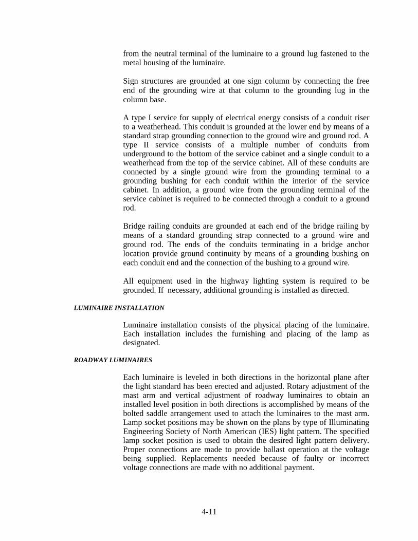
4-11
from the neutral terminal of the luminaire to a ground lug fastened to the metal housing of the luminaire.
Sign structures are grounded at one sign column by connecting the free end of the grounding wire at that column to the grounding lug in the column base. A type I service for supply of electrical energy consists of a conduit riser to a weatherhead. This conduit is grounded at the lower end by means of a standard strap grounding connection to the ground wire and ground rod. A type II service consists of a multiple number of conduits from underground to the bottom of the service cabinet and a single conduit to a weatherhead from the top of the service cabinet. All of these conduits are connected by a single ground wire from the grounding terminal to a grounding bushing for each conduit within the interior of the service cabinet. In addition, a ground wire from the grounding terminal of the service cabinet is required to be connected through a conduit to a ground rod. Bridge railing conduits are grounded at each end of the bridge railing by means of a standard grounding strap connected to a ground wire and ground rod. The ends of the conduits terminating in a bridge anchor location provide ground continuity by means of a grounding bushing on each conduit end and the connection of the bushing to a ground wire. All equipment used in the highway lighting system is required to be grounded. If necessary, additional grounding is installed as directed.
LUMINAIRE INSTALLATION
Luminaire installation consists of the physical placing of the luminaire. Each installation includes the furnishing and placing of the lamp as designated.
ROADWAY LUMINAIRES
Each luminaire is leveled in both directions in the horizontal plane after the light standard has been erected and adjusted. Rotary adjustment of the mast arm and vertical adjustment of roadway luminaires to obtain an installed level position in both directions is accomplished by means of the bolted saddle arrangement used to attach the luminaires to the mast arm. Lamp socket positions may be shown on the plans by type of Illuminating Engineering Society of North American (IES) light pattern. The specified lamp socket position is used to obtain the desired light pattern delivery. Proper connections are made to provide ballast operation at the voltage being supplied. Replacements needed because of faulty or incorrect voltage connections are made with no additional payment.
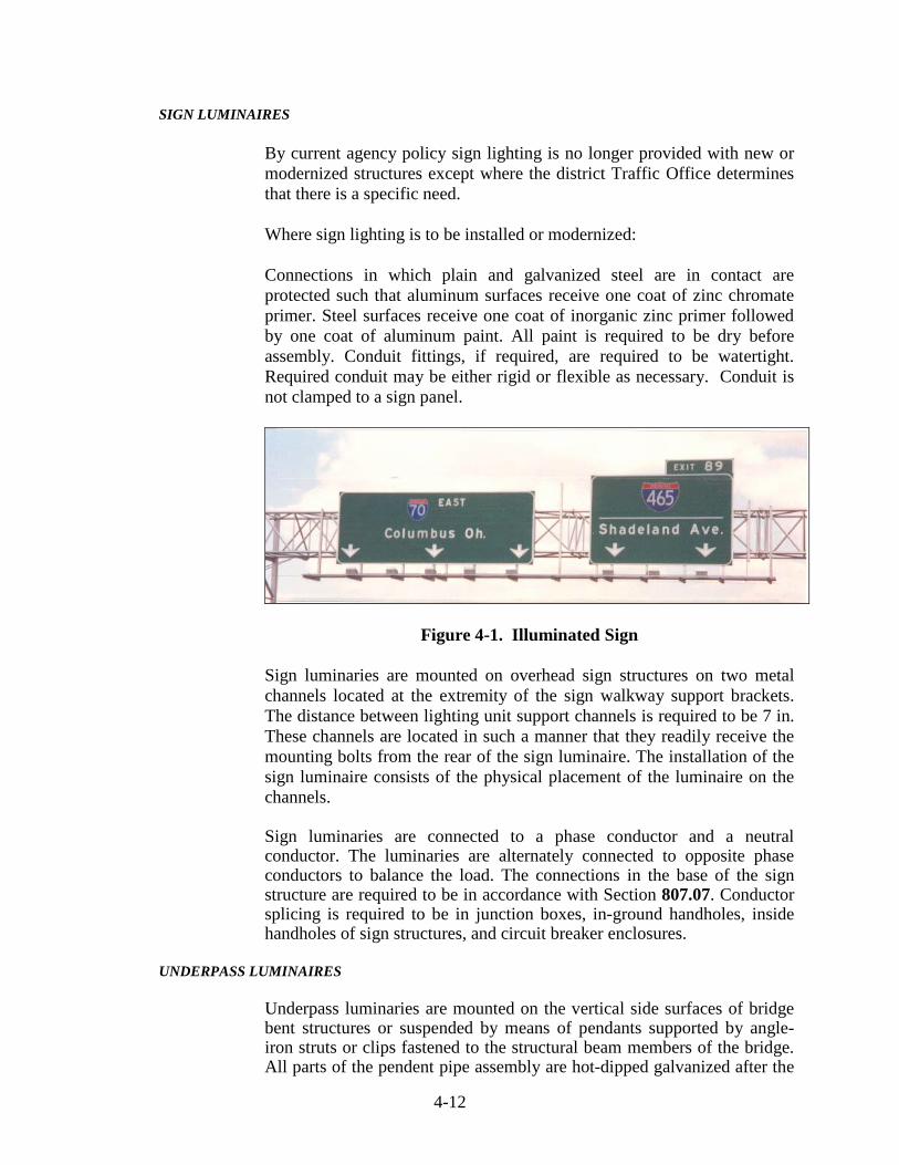
4-12
SIGN LUMINAIRES
By current agency policy sign lighting is no longer provided with new or modernized structures except where the district Traffic Office determines that there is a specific need. Where sign lighting is to be installed or modernized: Connections in which plain and galvanized steel are in contact are protected such that aluminum surfaces receive one coat of zinc chromate primer. Steel surfaces receive one coat of inorganic zinc primer followed by one coat of aluminum paint. All paint is required to be dry before assembly. Conduit fittings, if required, are required to be watertight. Required conduit may be either rigid or flexible as necessary. Conduit is not clamped to a sign panel.
Figure 4-1. Illuminated Sign
Sign luminaries are mounted on overhead sign structures on two metal channels located at the extremity of the sign walkway support brackets. The distance between lighting unit support channels is required to be 7 in. These channels are located in such a manner that they readily receive the mounting bolts from the rear of the sign luminaire. The installation of the sign luminaire consists of the physical placement of the luminaire on the channels. Sign luminaries are connected to a phase conductor and a neutral conductor. The luminaries are alternately connected to opposite phase conductors to balance the load. The connections in the base of the sign structure are required to be in accordance with Section 807.07. Conductor splicing is required to be in junction boxes, in-ground handholes, inside handholes of sign structures, and circuit breaker enclosures.
UNDERPASS LUMINAIRES
Underpass luminaries are mounted on the vertical side surfaces of bridge bent structures or suspended by means of pendants supported by angle-iron struts or clips fastened to the structural beam members of the bridge. All parts of the pendent pipe assembly are hot-dipped galvanized after the

4-13
threads are cut. Silicone caulking compound is applied to the threads during assembly of the pendent. Underpass luminaries may require separately mounted ballasts, which are installed in close proximity to the luminaries. Underpass luminaries are connected to a phase conductor and a neutral conductor. The luminaries are alternately connected to opposite phase conductors to balance the load. Conductor splicing is only allowed in junction boxes, in ground handholes, and circuit breaker enclosures.
HIGH MAST LUMINAIRES
The aiming of the luminaries is required to be as shown on the plans. When the aiming process is being done the luminaire is oriented to conform to the raised position and the ring properly tethered to prevent rotation during the aiming adjustment. The long axis of the luminaire is required to be parallel to the aiming direction indicated on the plans.
SIGN, UNDERPASS, ROADWAY, AND HIGH MAST LIGHTING LOCATION IDENTIFICATION
All high mast towers, roadway light standards, underpass lighting installations, and sign lighting installations is required to have an identification code number as shown on the plans. In addition, each luminaire at a sign or underpass installation is individually identified with a single capital letter. The code number is displayed on the light standard, sign structure column, and high mast tower as shown on the plans. The underpass code number is displayed near the breaker box at a location as directed. The code number for the lighting standard and sign structure column is applied to the pole, as specified by the manufacturer, by using individual, pressure sensitive, adhesive backed tags. The code number for the high mast tower is applied to an aluminum plate, which is mounted with spacers away from the structure as shown on the plans.
SERVICE POINT POWER ENTRY
The utility's requirements for service locations is required to be coordinated. Unless otherwise specified, a pole is furnished for the service point. If the utility requires metering of the lighting system, a meter socket is obtained from and installed in accordance with the requirements of the utility. Grounding is required to be in accordance with Section 807.12 and be a part of the service installation. Energy is required to be provided with 120/240 V service or 240/480 V service with the proper KW capacity on poles located immediately inside the right-of-way at locations designated on the plans. Electrical materials incorporated in the work are required to be compatible with the service voltages supplied by the local utility.

4-14
The service voltages supplied by the local utility are checked for compliance with the planned voltages. If a discrepancy exists, a resolution is required as directed before work is started or any electrical equipment is purchased.
TYPES OF SERVICE POINTS
Service point installations are required to be of two types as shown on the plans.
1) Type I Service Point. This service point instillation consists
of class 5 wood pole, 2.75 in. galvanized steel conduits, weatherhead, photo cell and multiple relay switch. The conduit riser is fastened and supported on the pole by means of galvanized hook pipe straps and secured to the pole by means of a galvanized lag screw, all of the proper size for the conduit being installed. Cable-duct is installed in the conduit riser in accordance with Section 807.07. The conductors extend beyond the weatherhead a minimum of 4 ft. The conductors outside of the weatherhead are ringed to prevent moisture from entering the conduit enc1osure.
2) Type II Service Point. This service point installation
consists of a service cabinet with a single galvanized steel or aluminum conduit riser to the weatherhead. A multiple number of galvanized steel conduits extend from the bottom of the service cabinet in accordance with Section 807.06. Underground cable-duct is installed in accordance with Section 807.07(c). Connections, connectors, and fixtures are required to be as shown on the plans.
The service cabinet is secured to the pole by means of a galvanized steel channel post or other approved device.
SIGN AND UNDERPASS CIRCUITS
The illumination circuits for sign structures with an overhead power supply are protected by circuit breakers mounted on the end support. Circuits for adjustable end support sign structures, bridge bracket signs, or underpasses are protected by circuit breakers mounted on the bridge or sign structure and connected to the underground distribution circuit in a handhole. Figure 4-2 shows several errors in the construction of underpass breaker boxes. Figure 4-3 shows an acceptable installation of the underpass circuitry.

4-15
Top Entry into Breaker Box is not Allowed
2 in. Steel Conduit not Attached to Steel Beam at 4 ft Intervals
Figure 4-2. Errors in Underpass Breaker Box Installation
Figure 4-3. Acceptable Underpass Circuitry

4-16
Circuits for sign structures with an underground power supply are protected by fuse connector kits in the base of the sign support. The fuse connector kits include bayonet disconnect features for the "neutral" side and "hot" side.
MULTIPLE RELAY SWITCHES
Unless otherwise specified, wood pole, multiple relay switches, service cabinet, photocells, photocell receptacles, weatherhead, conduit, and other miscellaneous items are furnished and installed as a part of the service point.
TESTING OF HIGHWAY LIGHTING SYSTEM TESTING LIGHTING CIRCUITRY
All necessary equipment and apparatus properly calibrated for testing the lighting circuits is required to be furnished. The supplying utility is given advance notice of the test scheduling so their representative may witness the testing procedures, if desired. Each main lighting circuit, including the branches, is tested for insulation resistance and continuity after completely installed but before the pole circuits, underpass circuits, sign circuits, and grounding circuits are connected. The insulation resistance test is made with a megohm meter and the resistance to ground is required to be no less than 50 megohms in all lighting circuit power cables. The meter is set for the voltage rating of the insulation. The continuity test is made with an ohmmeter properly scaled for measuring the resistance of the power cables. This test verifies the following:
1) That each power cable is continuous to the termination
points 2) That the cable coding at junction and termination points is
consistent with cable coding at the supply point
3) That power cables are not crossed with the neutral or each other
4) That the main circuit through each of the branches does not
have unusual resistance values
The entire completed installation is tested by circuit or by such portions as may be selected, and at night, if directed. Tests are required to demonstrate the following:
1) That all power, lighting, and control circuits are
continuous, free from short circuits, and free from unspecified grounds

4-17
2) That all circuits are properly connected in accordance with
applicable wiring diagrams 3) That all circuits are operable, which is demonstrated by
continuous operation of each lighting circuit for at least 1 h 4) That voltage at the ends of each lighting circuit and at inter
points is within allowable limits. A maximum of 10% voltage drop is permitted for each complete circuit.
TESTING AND INSPECTING LUMINAIRES
The lighting system from the service point through the last luminaire is subjected to 14 days of normal operation prior to final acceptance. This testing procedure may be conducted separately on each circuit or on the entire system. Normal operation is defined as the luminaires being on during the darkness hours and off during the daylight hours as controlled by the service point photocells and relay switches. Malfunctioning equipment is replaced or repaired before final inspection. The pattern of light delivered to the pavement by roadway and high mast luminaires is required to be inspected at night. At this inspection, the proper tools, equipment, and personnel are required to be available to make all adjustments. These items include a bucket truck capable of reaching all luminaires in the system, safety equipment, and a level to determine the proper luminaire position.
PAY ITEM AND INSTALLATION SUMMARY SHEETS
Prior to final inspection, two sets each of shop drawings, installation summary, and pay item summary marked Final Record are furnished for the light standards as installed. The installation summary shows the effective mounting height, arm length, foundation elevation, pay item, type of base, and catalog number or drawing for each light standard furnished. The pay item summary indicates the pay item, quantity, effective mounting height, arm length, and type of base for each type of lighting standard furnished.
METHOD OF MEASUREMENT
Luminaire, light standard with mast arm, high mast standard, identification number, connector kit, multiple compression fitting, insulating link, foundation, handhole, service point, and cable marker are required to be measured by the number of units installed. Pole circuit conductor and circuit conductor in conduit are measured by the linear foot. Pole circuit conductor is measured from the base of the lighting standard to the terminal block of the luminaire. Pole line extension is measured in a straight line between each pole.

4-18
Conductor in bridge conduit is measured by the linear foot from end to end of conduit or from the end of conduit to the last bridge light pole foundation entry. An allowance of 5 lft is made for each foundation entry. An allowance of 2 lft is made for each junction box. Removal of existing light structure, which includes the pole, mast arm, and foundation, is measured by the number of units removed. Cable-duct and conductor in underground duct or conduit is measured by the linear foot as follows: From the Face of the Concrete Foundation to the Center of the Handhole or Face of the Next Concrete Foundation: An allowance of 5 lft is made for each entry at foundations. An allowance of 2 lft is made at handholes for connection purposes. From Lighting Standard Bases or Handholes to Switch Boxes at Underpasses: An allowance of 4 lft is made at the switch box for electrical connections. From End to End of the Conduit when the Cable is in Conduit Under a Roadway Surface or Shoulder: No measurement is made of cable-duct in conduit where the cable-duct is part of a service point, sign installation, or Underpass lighting system. Basis of Payment: Luminaire is paid for at the contract unit price per each for the type and wattage specified. Service point is paid for at the contract unit price per each for the type specified. Light pole is paid for at the contract unit price per each for the estimated mounting height, length of mast arm, and base type specified. Concrete lighting foundation with grounding is paid for at the contract unit price per each for the size specified. If class X material is encountered during lighting foundation excavation, payment is made for such excavation in accordance with Section 206. Partial payment for lighting foundation in the amount of 80% is made if all such work is complete except for finish grading and sodding. The remaining percentage of payment is made upon completion of the finish grading and sodding. Connector kit is paid for at the contract unit price per each for fused or unfused, as specified. Multiple compression fitting and insulation link are paid for at the contract unit price per each for waterproofed or nonwaterproofed, as specified. Cable-duct marker, high mast tower winch drive, and handhole, lighting are paid for at the contract unit price per each. Sign, underpass, and

4-19
roadway lighting location identification are paid for at the contract unit price per each. Circuit installation is paid for at the contract unit price per each for the type, structure number, and number of luminaires specified. Removal of light structure and the portable tower lighting drive system are paid for at the contract unit price per each. Wire is paid for at the contract unit price per linear foot for the designation, copper gage, housing, and number of conductors specified. Pole circuit cable, THWH, stranded is paid for at the contract unit price per linear foot for the copper gage and number of conductors specified. Conduit, steel, galvanized, 2 in. diameter is paid for at the contract unit price per foot. The costs of lamps, ballast, optical systems, weatherproof housings, and e1ectrica1 connections are included in the cost of luminaire. The costs of the mast arm, J-support hook for pole circuit, handhole with cover, shoe base, transformer base or frangible coupling if required, installation on the foundation with the pole circuit, and luminaire installation are included in the cost of light pole. The costs of the pole, lowering system including winch assembly, power cable, support cable, concrete pad, luminaire ring, anchor bolts and nuts, lightning rod assembly, grounding system, and all incidental materials necessary to complete the installation are included in the cost of light pole, high mast. The costs of excavation, concrete, sleeves for cable duct, non-metal pipe, reinforcing steel, backfill, finish grading, and sodding are included in the cost of lighting foundation. The costs of aerial distribution service, drops to sign structures branching off from the pole line extension, weatherheads and risers required to connect the line extension to the underground electrical distribution circuit, all anchorage, guy wires, hardware, aerial cable, electrical connections, wood poles, and incidentals required to complete the pole line extension are included in the cost of cable, pole circuit. The costs of snap-on covering in light pole base and waterproof covering in underground handhole is included in the cost of multiple compression fitting. The costs of circuit breakers, breaker enclosures, conduit, flexible conduit, conduit fittings, grounding, weatherhead, aerial cable termination, incidentals required from the last luminaire to the point of attachment by the utility, the bottom of the riser at the structure base, or the connector kits in the base of the sign supports are included in the cost of circuit installation. The cost of maintaining highway illumination during the contract time is included in the costs of other pay items.

4-20

5 Curbs Curb Types Precast Concrete Curb Cast-In-Place Concrete Curb Grade Preparation Forms Concrete Curb Machines Concrete Composition and Placement Joints Curing Additional Requirements for Concrete Center Curb Construction and Inspection Procedures Measurement and Payment

5-1
CHAPTER FIVE: CURBS
This chapter discusses the construction and inspection of the various types of curbs. Curbs are used to channelize both traffic and water. They are mainly used in or near urban areas where traffic speeds are low. Curbs are also used in rural areas where traffic speeds are higher, but usually only in conjunction with guardrail for safety reasons. Curbs vary in exposed height with the higher curbs providing more traffic restriction abilities and allowing for future resurfacing without losing all of the curb exposure.
_______________________________________________________________
CURB TYPES
The various types of curbs indicated on Standard Sheets E605-CCSJ-01, E605-CCCG-01, and E605-CCIN-01. The types of curbs are as follows.
1) Curb -- This is a free standing curb, 20 in. in height with
the top 6 to 8 in. exposed. Good drainage is difficult to maintain with this type of curb where grades are relatively flat.
2) Combined Curb and Gutter (Figure 5-1) -- This type of
curb with a gutter is good for maintaining drainage where grades are relatively flat. There are three types of combined curb and gutter:
a. Combined concrete curb and gutter has a 6 in.
exposure. b. Combined concrete curb and gutter, Type B
(Mountable) has a 4 in. exposure. c. Combined concrete curb and gutter, Type C has an
8 in. exposure.

5-2
Figure 5-1. Combined Curb and Gutter
3) Intergral Curb -- This type of curb is used in conjunction
with concrete pavement and is normally poured monolithic with the pavement. Stirrup bars are placed in the curb base concrete at the time the pavement is placed. The exposed portion of the curb is then placed over the base with the stirrup bars permanently connecting the two parts. There are three types of integral curbs:
a. Integral concrete curb has a 6 in. exposure. b. Integral concrete curb Type B (Mountable) has a 4
in. exposure. c. Integral concrete curb Type C has an 8 in. exposure.
4) Integral Curbwalk -- This type of curb is poured monolithic
with a sidewalk. Integral curbwalk is seldom used and if specified would be detailed only in the plans.
5) Concrete Center Curb (Figure 5-2) -- This type of curb is
used mainly to separate traffic. Types A, B, C, and D are the four types of center curbs. Each curb has a different exposed height as indicated on Standard Sheets E605-CNCC-01 through E605-CNCC-03.

5-3
Figure 5-2. Concrete Center Curb
6) HMA Curbing -- There are three types of HMA curbs that may be used. They include HMA curb, HMA Center Curb Type A, and HMA Center Curb Type B. These curbs are indicated on Standard Sheets E605-CCSJ-01, E605-CNCB-01, and E605-CHCB-02. The HMA curb is usually placed on HMA pavement to separate traffic.
HMA curbs are easily damaged by snowplows and are best used on a shoulder where guardrail is placed. When HMA curbing is placed on a paved shoulder or pavement, the surface upon which the curb is placed is required to be cleaned and tacked as specified in Section 605.07(b). The HMA curb mixture is required to be HMA Surface Type A in accordance with Section 402.07(d) and 605.07(c) and is placed with a HMA curb machine or paver with a curb attachment.
HMA curb is considered unsatisfactory if any of the following characteristics are evident: a. Incorrect alignment b. Poor density c. Improper section d. Does not meet straight edge requirements of 1/4 in.
in 10 ft
Curb having any of these characteristics is required to be removed immediately while the curb is still hot and replaced with curb that meets Specification requirements.

5-4
PRECAST CONCRETE CURB
If a precast concrete curb is specified, the curb is detailed in the plans. The only curb of this type that has been used recently is the type used in parking lots. The curb is used to retain soil at a turn lane. The placement requirements for precast curbs are specified in the plans or contract proposal. The Specifications that apply to precast curb are the applicable portions of Section 605.03 that are not in conflict with the plans or contract proposal.
CAST-IN-PLACE CONCRETE CURB
Cast in place curb is the curb that is predominately used. This curb is placed using forms or with a slipform curb machine. All of the concrete curbs indicated on the Standard Sheets are constructed using these methods.
GRADE PREPARATION
The subgrade is cut so that the required curb grade is obtained when the curb is placed. Any soft or yielding material is removed and replaced with suitable material. The curb subgrade is compacted to a firm even surface. Although there are no specific density requirements, soft or non-compacted areas allow the curb to settle causing water to pond. For this reason, the Technician is required to observe the compactor during this operation to determine if any correction is required.
FORMS
Curb forms (Figure 5-3) may be made of wood or metal. They are required to be straight and free of warping, extend for the full depth of the curb, and secured so that they maintain the correct grade and alignment.
Figure 5-3. Curb Forms

5-5
CONCRETE CURB MACHINES
Concrete curb machines (Figure 5-4) may be used provided they produce a curb that meets the Specifications. Curb machines use low slump concrete and vibration for consolidation.
Figure 5-4. Concrete Curb Machine CONCRETE COMPOSITION AND PLACEMENT
Integral curb or integral curb and gutter usually has the portion of the curb below the surface of the pavement poured with the pavement. The concrete used for this purpose is paving concrete as specified in Section 500. All other concrete for curb, integral curb, and integral curb and gutter is required to be class A concrete in accordance with Section 702. After the concrete is placed in the forms, the concrete is consolidated by tamping, spading, or vibrating. Forms are left in place until the concrete has set sufficiently so that removal of the forms does not cause damage to the curb surface or cause the concrete to slump. After the forms are removed, the exposed surfaces are rubbed immediately to a uniform surface. Curb machines use vibrators for consolidation, and as little hand finishing as possible is done behind the machine. Excess hand finishing in conjunction with a curb machine may cause the curb to slump or be pushed out of alignment. A fine broom finish is normally used. This procedure produces an acceptable finish for either formed or machine placed curbs.

5-6
JOINTS
Pavement joints are continued through integral concrete curb. Pavement contraction joints are required to be continued through the integral concrete curb with preformed joint material 1/4 in. thick.
Curb that is not integral is required to have joints at 10 ft intervals. These joints may be sawed or formed at a depth and width indicated in the plans or standards. Preformed expansion material is placed at the beginning and end of all radii and at castings. This material is required to be 1/4 in. thick.
CURING
As soon as the finishing of the curb is complete, the curb is cured by keeping the curb wet for three days or by applying a liquid membrane curing compound (Figure 5-5) as used for pavement.
Figure 5-5. Applying Curing Compound ADDITIONAL REQUIREMENTS FOR CONCRETE CENTER CURB
The subgrade is required to be prepared the same for concrete center curb as for the adjacent pavement. If the adjacent pavement has subbase, the subbase is carried through the full width of the center curb and at the same thickness. Likewise, the joints in the center curbs adjacent to the PCCP are to be aligned with joints in the adjoining PCCP. In addition, where joints are constructed in the PCCP adjacent to the concrete center curb, these joints are extended to the center curb in accordance with 503.04(f).

5-7
If the concrete center curb is placed adjacent to HMA, then the joints are to be spaced a maximum of 18 ft apart. A minimum 3/8 in. thick expansion material is also placed at the beginning and end of all concrete center curb where the ends are adjacent to concrete pavement.
CONSTRUCTION AND INSPECTION PROCEDURES
All dimensions of curbs are required to be checked for compliance to the plans and standards. The tops and faces of all curbs are measured with a straight-edge to check the 1/4 in. in 10 ft tolerance. With experience, a visual inspection may reduce this checking to areas that appear to be out of tolerance. All curb that does not meet the straight-edge requirement is removed and replaced. All materials are required to be checked for compliance to the Specification as noted in the Frequency Manual.
MEASUREMENT AND PAYMENT
Curbing is measured by the linear foot along the front face. Curb and gutter is measured along the face of the curb. No deduction is made for castings installed in the curbing. Center curb is measured by the linear foot or by the square yard as specified in the plans. Curbing is paid by the linear foot for each kind and type specified. Bed course material is paid for at the contract unit price per ton, complete in place.

6 Sidewalks, Curb Ramps, and Steps Grade Preparation Forms Placing Concrete Finishing Joints Curing Concrete Steps Reconstructed Concrete Sidewalk Re-Laid Sidewalk HMA Sidewalk Construction and Inspection Procedures Measurement and Payment

6-1
CHAPTER SIX: SIDEWALKS, CURB RAMPS, AND STEPS Sidewalks, curb ramps, and steps are paved areas for pedestrian traffic. In
highway work, sidewalks are usually parallel to the roadway with occasional short lengths connecting the main walk to adjacent walks. Sidewalks are normally constructed only to replace existing sidewalks and are placed only where indicated on the plans.
Curb ramps (Figure 6-1) are sloping sidewalks that allow wheelchairs to
easily move from the sidewalk at curb height to the adjacent pavement at points of pedestrian street crossings. Steps are used to move pedestrian traffic from one elevation to another in a short distance. HMA sidewalks are rarely built today.
Figure 6-1. Sidewalk with Curb Ramp
This chapter discusses the construction of concrete and HMA sidewalks,
concrete curb ramps, and steps. Standard Sheets 604-SWCR-01 thru 604-SWCR-12 for sidewalk, curb ramp, and step details should be reviewed.
GRADE PREPARATION
Excavation is simply made to the required depth and to a width that accommodates the forms and braces. The base is shaped and compacted to a firm, even surface and all soft and yielding material is required to be removed.
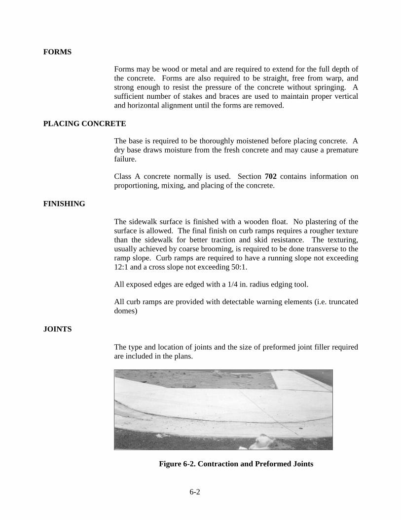
6-2
FORMS Forms may be wood or metal and are required to extend for the full depth of the concrete. Forms are also required to be straight, free from warp, and strong enough to resist the pressure of the concrete without springing. A sufficient number of stakes and braces are used to maintain proper vertical and horizontal alignment until the forms are removed.
PLACING CONCRETE
The base is required to be thoroughly moistened before placing concrete. A dry base draws moisture from the fresh concrete and may cause a premature failure.
Class A concrete normally is used. Section 702 contains information on
proportioning, mixing, and placing of the concrete. FINISHING The sidewalk surface is finished with a wooden float. No plastering of the
surface is allowed. The final finish on curb ramps requires a rougher texture than the sidewalk for better traction and skid resistance. The texturing, usually achieved by coarse brooming, is required to be done transverse to the ramp slope. Curb ramps are required to have a running slope not exceeding 12:1 and a cross slope not exceeding 50:1.
All exposed edges are edged with a 1/4 in. radius edging tool. All curb ramps are provided with detectable warning elements (i.e. truncated
domes) JOINTS The type and location of joints and the size of preformed joint filler required
are included in the plans.
Figure 6-2. Contraction and Preformed Joints

6-3
Contraction joints (Figure 6-2) are formed with a 1/4 in. radius jointing tool. All other joints are formed with a 1/4 in. radius edging tool.
Preformed 1/2 in. joint filler is placed around all manholes, utility poles etc. that extend into or through the sidewalk. This material is also used where the sidewalk abuts a structure, such as a building or bridge. The preformed joint filler is required to extend for the full depth of the concrete and be flush with the surface of the adjacent concrete.
CURING The concrete is required to be cured for at least 72 h. This is done by means
of wet burlap mats, plastic sheeting, liquid membrane curing compound, or other approved methods. No pedestrian traffic is allowed on the concrete during the curing period.
CONCRETE STEPS The construction requirements for concrete steps are the same as previously
discussed for sidewalks. All exposed edges of the concrete steps are rounded to a 1/4 in. radius.
RECONSTRUCTED CONCRETE SIDEWALK
Where existing sidewalk is to be reconstructed, all disintegrated concrete, brick, stone, or other material is required to be completely removed and replaced with new concrete.
Unless otherwise specified, the reconstructed portion of the sidewalk is
constructed to a minimum depth of 4 in. and to the width of the adjoining walk but not less than 48 in. from the face of the curb.
Before removal of the existing concrete, a straight saw cut is made with an
approved power driven saw at the limits of the removal. If the adjacent sidewalk is damaged during the sawing operation, the sidewalk is replaced with no additional payment.
Unless otherwise directed, sidewalk is removed between tool marks and
joints. Any adjacent curb that is deteriorated is also removed and replaced at the contract unit price for curb.
The new sidewalk joint pattern is required to be similar to that of the
surrounding sidewalk. Sidewalk placed at drives is 6 in. thick or the same depth as the existing drive, whichever is greater.

6-4
RE-LAID SIDEWALK If re-laying of concrete sidewalk is specified, then the work consists of
removal and re-laying of concrete, stone slab, or brick sidewalk. Care is taken not to damage the sections. Each section is required to be laid on a bed of No. 23 or 24 sand at least 2 in. in depth. Damaged sections are required to be replaced.
HMA SIDEWALK Grade preparation for HMA sidewalk is much the same as that for concrete
sidewalk; however, the base is required to be constructed with compacted coarse aggregate as indicated in the plans.
The HMA mixture is placed in one or more courses and each course is compacted with a hand operated or power roller. Inaccessible areas may be compacted with a hand tamper. If the HMA surface is too open or sticky, the surface may be coated with No. 23 or 24 sand that is broomed over the surface, leaving no excess. This sand, however, is not paid for directly.
CONSTRUCTION AND INSPECTION PROCEDURES
Sidewalks are always built with smooth transitions to existing walks. There is never a vertical lip left anywhere that a pedestrian may trip on. When constructing curb ramps, the maximum slopes indicated in the standards are not exceeded.
When inspecting the various items, all dimensions are checked carefully,
before the concrete is poured, to ensure that they meet the requirements of the plans and Specifications. Occasionally, Contractors form sidewalks with two-by-fours which are only 3-1/2 in. high and pour the walk that thickness. This practice is not acceptable.
The joints are required to be checked for the proper vertical depth and radius
as well as the spacing of the different types. On-site testing of materials is required to be done according to the Frequency
Manual. All materials are checked to verify that they are approved for use. All required basis for use documents are obtained for the material records.
MEASUREMENT AND PAYMENT
Measurement and documentation of all items is required for payment on a daily basis. These measurements are required to be accurate enough for final

6-5
payment so that additional measurements at a later date are not required. The accepted quantities of concrete sidewalk, curb ramps, and reconstructed & re-laid sidewalk are paid for at the contract unit price per square yard. HMA for sidewalk is paid for at the contract unit price per ton, complete in place. Bed course material is paid for at the contract unit price per ton. Joint material is paid for at the contract unit price per linear foot. Concrete steps are paid for at the contract unit price per cubic yard. The costs of excavation, backfill, expansion joint material, and necessary incidentals are included in the costs of the pay items.
7 Concrete Approaches Grade Preparation Forms Concrete Composition and Placement Finishing and Curing Joints Concrete Approach Thickness Opening to Traffic Construction and Inspection Procedures Measurement and Payment

7-1
CHAPTER SEVEN: CONCRETE APPROACHES This chapter discusses the construction requirements for approaches to
concrete private driveways, concrete commercial drives (Figure 7-1), and concrete mailbox approaches.
The construction techniques for each type of approach are basically the
same, the differences being the thickness, shape, and classification of each. The type or class of drive is specified in the plans. Details of these may be found on Standard Sheets 610-PRAP-14, 610-DRIV-01, 03, 08, and 15.
Figure 7-1. Commercial Drive Approach
____________________________________________________________
GRADE PREPARATION
Grade preparation for commercial and private driveway approaches is much the same as for concrete pavement. Section 207 provides further details of the requirements.
The top 6 in. of the subgrade is required to be compacted to 100 % of the
maximum dry density. If any of the subgrade material is soft or yielding or cannot be satisfactorily compacted, the subgrade is required to be corrected or removed.
During subgrade preparation and after completion, adequate drainage is
provided to prevent water from standing on the subgrade; however, the subgrade is required to be uniformily moist prior to concrete placement.

7-2
FORMS Wood forms (Figure 7-2) or metal forms are generally required for
concrete approaches. The forms are required to be of sufficient strength to resist springing and have enough stakes, pins, or bracing to firmly hold true to line and grade during placement of the concrete. The alignment of the forms is required to not deviate more than 1/4 in. in the horizontal direction from the planned PCCP width tangent sections. Forms are staked into place with a minimum of three pins for each 10 ft section. A pin is placed at each side of every joint. Form sections are locked tightly and are required to be free from play or movement in any direction. Forms are also required to be clean and oiled prior to the placing of concrete.
Figure 7-2. Approach Forms When a construction joint or a dowelled joint is required, the forms used
are required to be drilled or slotted to allow for the placement of the steel or dowels.
CONCRETE COMPOSITION AND PLACEMENT The concrete used for private and commercial drives may be paving
concrete in accordance with Section 500 or class A concrete in accordance with Section 702. Proper consolidation of the concrete is vital to the integrity of the approach. Consolidation is obtained in place through use of vibration equipment to consolidate the full width and depth of the strip of PCCP being placed. Vibrators may be either the surface pan type or the internal type with either immerse tube or multiple spuds.

7-3
FINISHING AND CURING Concrete for approaches is finished with equipment in accordance with the
Specifications. Hand methods of finishing may be used when finishing equipment breaks down or in tight working areas where field conditions limit the use of mechanical devices (Figure 7-3). Hand placed concrete is further finished by means of a longitudinal float or an approved transverse smoothing float.
Figure 7-3. Strike-Off Screed The finishing operation is required to be done so that an excess of mortar
and water is not worked to the top of the concrete. Particles collected in front of the screed are required to be thoroughly mixed into the unfinished concrete, while keeping a sufficient roll of material in front of the screed. This procedure helps prevent depressions or "ponds" from forming in the approach.
After final strike-off, floating is done to obtain a more true and even
surface. All edges are finished using a 1/4 in. radius edging tool. Finally, the textured surface of the approach is tined, unless otherwise specified. Tining consists of transverse grooves that are between 3/16 in. and 1/8 in. in width and between 1/8 in. and 3/16 in. in depth.
Curing is required for a period of 96 h after placement of the concrete. This is normally achieved by covering the approach with plastic sheeting (Figure 7-4) or blankets, or by the use of a curing compound. Other methods of curing may be used as well. If there is the danger of freezing, sufficient straw or blankets are required to be used to prevent the concrete from freezing during curing.

7-4
Figure 7-4. Curing with Plastic Sheeting JOINTS Joint requirements are specified in the Standard Drawings. Joints that may
be required are longitudinal joints, expansion joints, keyway joints, and ear construction joints.
CONCRETE APPROACH THICKNESS The Contractor is required to obtain cores at the locations determined by
the PE/PS in accordance with ITM 802-12P for the purpose of obtaining the actual thickness of the in-place approach. Four cores are taken for each 1200 yd2. No core is required when less than 1200 yd2 is placed. Four inch diameter cores are taken in the presence of the PE/PS for the full depth of the concrete approach and the PE/PS takes immediate possession of the cores. Cores are not to be taken within 2 ft of the edge of pavement, over dowels, or within 5 ft of a transverse construction joint. The cores are measured by District Testing. Core holes are filled in accordance with Specifications. Cores are not taken in formed drives unless otherwise directed. Corrections of 1/4 in. deficiencies in thickness are made before the pour.
OPENING TO TRAFFIC As in pavement, approaches are required to be closed to traffic for 14 days
after placement or until the test beams indicate a modulus of rupture of at least 550 psi. If fly ash is used in the concrete, the 14 day rule does not apply and only the modulus of rupture is used for this determination.

7-5
CONSTRUCTION AND INSPECTION PROCEDURES
The following construction and inspection procedures are required:
1) The subgrade is required to be firm. The length, width, and depth are required to be checked before the concrete is poured.
2) A string or other device is required to be placed across the
top of the forms using the same procedure for striking off the concrete to verify the depth.
3) If the drive is over 10 ft in length and not reinforced, a
transverse joint is required to be placed so that no section of the drive is over 10 ft long. The joint depth and location is required to be as shown in the Standards.
4) Opening to traffic is required to be controlled so that
premature cracking or damage to the drive does not occur. Close adherence to curing requirements also helps prevent damage to the concrete.
5) All on-site testing of materials is required to be done
according to the frequencies stated in the Frequency Manual. Materials are checked to verify they are approved for use. All required basis for use documents are required for the material records.
6) All items are required to be measured and documented for
payment on a daily basis. These measurements are required to be accurate enough for final payment so that additional measurements are not required at a later date.
MEASUREMENT AND PAYMENT Concrete for approaches is measured by the square yard of the thickness
specified and paid as Portland Cement Concrete Pavement for Approaches. The length and width of the approach is required to be as indicated on the plans.

8 Paved Side Ditch Grade Preparation Forms Concrete Composition and Placement Cut-Off Walls and Lugs Finishing and Curing Construction and Inspection Procedures

8-1
CHAPTER EIGHT: PAVED SIDE DITCH
Paved side ditch is used to prevent erosion at locations where the ditch grade is 3 % or more and sometimes on flatter grades at locations where the soils are prone to erosion, such as in sand. This chapter covers the different procedures of paved side ditch construction from location to measurement and payment. Standards 607-PSDT-01 through 607-PSDT-06 for paved side ditch and Standards 605-GTRC-01 through 605-GTRC-03 for concrete gutter are used.
GRADE PREPARATION
Excavation for a paved side ditch is required to conform to the size and shape of the bottom of the type of the ditch being built. Compaction is required to be sufficient to prevent settlement after the paved side ditch is in use. Such settlement causes the ditch to break which results in severe erosion. Also, any soft or yielding material is required to be removed and replaced with a suitable material.
FORMS
The same requirements for curb forms also apply to paved side ditch. The forms may be made of wood or metal and are required to be straight and free of warping. The forms are required to extend for the full depth of the paved side ditch and be secured so that they maintain the correct grade and alignment.
CONCRETE COMPOSITION AND PLACEMENT
Class A concrete in accordance with Section 702 is used in paved side ditch construction. After the concrete is placed in the forms, the concrete is consolidated by tamping, spading, or vibrating. Reinforcing steel is inserted at this time. The reinforcing steel may not rest on the bottom of the grade nor float to the surface.
CUT-OFF WALLS AND LUGS
Cut-off walls and lugs are required to keep the paved side ditch in the proper location on a slope. A cut-off wall is constructed at the beginning and end of any paved side ditch. Lugs are poured monolithic with the paved side ditch

8-2
on steep grades. The location and spacing of the lugs is listed in the Specifications.
FINISHING AND CURING
The concrete is normally struck off with a template cut to resemble the finished grade of the paved side ditch. Floating is done using hand floats or bull floats on larger ditches. Brooming of the surface is not required on paved side ditches. Forms are required to be left in place until the concrete has set sufficiently so that the removal does not cause damage to the paved side ditch. Curing is required for at least 72 h after placement by being kept wet and covered with plastic sheeting to hold in the moisture. A liquid membrane curing compound may also be used. If freezing could occur during the curing period, appropriate measures are required to be taken to prevent the concrete from freezing. Backfilling around the newly placed concrete is done with suitable material in layers of no more than 6 in., and this material is compacted sufficiently to prevent erosion.
CONSTRUCTION AND INSPECTION PROCEDURES
A visual inspection of the contract is required to determine the exact locations of the paved side ditch. Slight errors in grading or existing conditions varying from the plans may cause major location changes in the paved side ditch construction. The PE/PS is consulted for the correct locations and lengths. The edges of the paved side ditch are required to be 3 to 4 in. below the adjacent earth so that water may flow into the ditch and not along the side of the ditch. The forms are required to be removed and the sides of the ditch backfilled above the top of the ditch edge. This procedure is required to be done before any rains occur. All on-site testing of materials is required to be in accordance with the Frequency Manual, and all materials are verified that they are approved for use. All required basis for use documents are obtained for the material records. All items are required to be measured and documented for payment on a daily basis. These measurements are required to be accurate enough for final payment so that additional measurements are not required at a later date. The standards are required to be checked for how to pay for each lug and cut-off wall.

8-3

9 Concrete Barriers
Grade Preparation Precast Concrete Median Barriers Forms Concrete Composition Placing and Finishing Concrete Removal of Forms and Curing Handling and Shipping Placement of Precast Units Testing and Inspection Requirements Cast-In-Place Concrete Median Barriers Forms Concrete Composition, Placement, and Finishing Joints Sealing Reflectorization Construction and Inspection Procedures Temporary Concrete Barriers Placement and Anchor Delineation Measurement and Payment Construction and Inspection Procedures
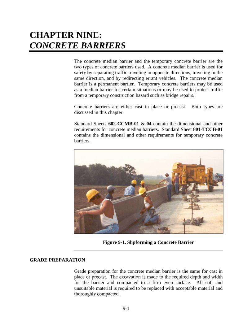
9-1
CHAPTER NINE: CONCRETE BARRIERS The concrete median barrier and the temporary concrete barrier are the
two types of concrete barriers used. A concrete median barrier is used for safety by separating traffic traveling in opposite directions, traveling in the same direction, and by redirecting errant vehicles. The concrete median barrier is a permanent barrier. Temporary concrete barriers may be used as a median barrier for certain situations or may be used to protect traffic from a temporary construction hazard such as bridge repairs. Concrete barriers are either cast in place or precast. Both types are discussed in this chapter. Standard Sheets 602-CCMB-01 & 04 contain the dimensional and other requirements for concrete median barriers. Standard Sheet 801-TCCB-01 contains the dimensional and other requirements for temporary concrete barriers.
Figure 9-1. Slipforming a Concrete Barrier
GRADE PREPARATION
Grade preparation for the concrete median barrier is the same for cast in place or precast. The excavation is made to the required depth and width for the barrier and compacted to a firm even surface. All soft and unsuitable material is required to be replaced with acceptable material and thoroughly compacted.

9-2
PRECAST CONCRETE MEDIAN BARRIERS
Precast concrete median barriers are normally produced in a casting yard or a concrete plant. After casting and final inspection, they are shipped to the job-site and set in place.
Precast units may be 10 ft to 20 ft in length. Whatever length is selected, the length is required to not vary throughout the contract except at special situations such as inlets or bridge abutments. Many special situations require that a small section of barrier be cast in place. Standard Sheets 602-CCMB-01 & 04 are required to be consulted for the proper cross-sectional dimensions.
FORMS
The forms used for precast concrete median barriers are generally made of
steel and are required to be unyielding, mortar tight, and of sufficient rigidity to prevent distortion. The forms are designed so that the finished product conforms to the required dimensions and contours. All sharp corners are required to be chamfered.
Prior to placing the concrete, the interior of the forms are coated with
paraffin oil or other approved coating. Lubricating oils, fuel oils, or kerosene are not allowed because these materials discolor the concrete. Immediately after the forms are stripped, the forms are cleaned.
CONCRETE COMPOSITION
The composition of the concrete for precast concrete median barrier is different than the concrete mixes previously discussed.
The following is a list of materials used in precast concrete construction:
1) Portland Cement
2) Fly Ash (optional)
3) Fine Aggregate, Size No. 23
4) Coarse Aggregate, Class A, Size No. 91
5) Air Entraining Admixture
6) Water Reducing / Retarding Admixtures
7) Water

9-3
The main difference with this concrete is the requirement of No.91 coarse aggregate.
The mix design is the responsibility of the Supplier. The Specifications require that the mix be capable of attaining a minimum 28 day compressive strength of 3000 lb/in2. This strength is determined by breaking cylinders as the concrete is placed in the forms. No concrete barrier may be shipped until this strength is obtained.
Since acceptance of the concrete is based on cylinders, yield tests are not taken. The slump requirement for precast concrete is 2 to 5 in. The required air content is 5 to 8 %.
PLACING AND FINISHING CONCRETE
Concrete is placed in the forms in such a manner that there is no more than 5 ft of free fall and that no segregation occurs. The concrete is placed in uniform layers and vibrated during and after placement.
Immediately after removing the forms, fins and irregular projections are removed from all exposed surfaces. All holes, honeycomb spots, cavities, broken corners or edges, and other defects are required to be thoroughly cleaned and saturated with water. The concrete is carefully pointed and trued with fresh mortar within 30 minutes of removal of the forms.
REMOVAL OF FORMS AND CURING
Side forms may be removed when no distortion, slump, or misalignment of the concrete occurs. The barrier is required to remain supported on the bottom until the concrete has reached a strength of at least 2000 lb/in2 determined from the test cylinders.
Immediately upon removing forms, the barriers are inspected for defects and the barriers are repaired, if required.
Curing is required until the ultimate strength is achieved. Curing may be achieved by covering all exposed surfaces with two layers of wet burlap or steam curing. When wet burlap is used, the burlap is required to be kept wet by automatic means. Steam curing is used in a controlled environment to speed up the curing process. Section 707 lists the procedures for steam curing and other accelerated curing methods. Liquid curing compound may be used only when a rubbed finish or sealer is not specified.

9-4
HANDLING AND SHIPPING
Unless otherwise approved, precast barriers are required to be handled with a suitable hoisting device provided with a spreader sling. This sling prevents horizontal forces from being produced in the member due to lifting. To avoid damage to the concrete barriers during handling, storing and transportation, the barriers are required to remain in an upright position at all times and be lifted by the inserts or other approved devices.
During transportation, the barriers are supported with truck bolsters or battens no less than 4 in. wide and padded with 1/2 in. of rubber. Wood blocks are placed under all tie chains to prevent chipping of the concrete.
PLACEMENT OF PRECAST UNITS
Of major importance during placement of concrete barrier units is to assure that the requirements for horizontal and vertical alignment are met. Horizontal and vertical alignment of adjacent units may not exceed 1/4 in. across joints as measured from a 10 ft straightedge.
TESTING AND INSPECTION REQUIREMENTS
Precast concrete median barriers are required to be produced by a Certified Precast Concrete Producer. Barriers shipped to a contract are required to be stamped with the manufacture date, source identification number, and the “QCast” emblem or the words “ACPA Certified Product” or the words “NPCA Certified Product”. The Technician is required to verify that the Producer is on the Approved List for Certified Producers, the barrier is properly marked, and that the precast unit visually meets the Specification requirements. The air content requirement for precast median barriers is 5 to 8 % and the slump requirement is from 2 to 5 in. The Producer is required to make a minimum of five cylinders to determine the strength during a concrete pour. These cylinders are cured for up to 28 days and then tested to determine the ultimate strength. Once the concrete strength reaches 3000 lb/in2, which could be in as little as two or three days or as much as 28 days depending on the concrete mix design used, the barriers may be shipped to the job-site. All items are measured and documented for payment on a daily basis. These measurements are required to be accurate enough for final payment so that additional measurements at a later date are not required.

9-5
CAST-IN-PLACE CONCRETE MEDIAN BARRIERS
Cast-in-place concrete median barriers are dimensionally similar to precast concrete median barriers; however, the forms are set at the exact location of the finished product. The testing requirements and basis for use is different than that required for precast barriers.
FORMS
Requirements for forms for concrete median barriers are much the same as for curbs. These forms are generally made of wood or steel and are in 8-10 ft sections. Forms are required to be cleaned and oiled before use. Wooden forms are inspected often between pours as they tend to wear out quickly and may need to be repaired or replaced often. Vertical and horizontal alignment is vital to the appearance of the barrier. The Specifications require that the surfaces of the concrete vary by no more than 1/4 in. in 10 ft. This tolerance may easily be achieved if the forms are set true and straight. When pouring barriers in conventional wood or metal forms, the force of the concrete and the vibration tends to push the forms up from the ground. For this reason, forms are required to be tied to the grade either by a combination of stakes, braces, or weights before the pour.
CONCRETE COMPOSITION, PLACEMENT, AND FINISHING
Unless otherwise specified, concrete used in cast-in-place concrete median barriers is required to be class A concrete in accordance with Section 702. Concrete is placed in the forms in at least two layers, each layer being vibrated as the concrete is being poured.
Figure 9-2. Hand Finishing Concrete Barrier

9-6
The top of the barrier is finished with a hand trowel, and the edges are chamfered or beveled (Figure 9-2). Immediately following the removal of the forms, all fins and irregular projections are required to be removed from all exposed surfaces. All cavities and holes from form ties and honeycomb spots, broken corners or edges, and other defects are required to be thoroughly cleaned, saturated with water, and carefully pointed and trued with mortar (Figure 9-3).
Unacceptable Cracks in Barrier
Figure 9-3. Concrete Barrier Repair
If the barrier is being slip-formed, the concrete is placed into the slip-form machine conveyor or auger and placed into the form. The slip-form machine (Figure 9-4) has vibrators to consolidate the concrete as the material enters the forms. If properly done, very little hand finishing should be required. The final finish on a slip-form barrier may be an approved brush finish.

9-7
Figure 9-4. Slipform Machine JOINTS
Standard Sheets 602-CCMB-01 & 02 show the various types of joints that may be required for the construction of cast-in-place concrete median barriers. An expansion joint type A is required 5 ft before and after an inlet and 10 ft away from any bridge piers or bents. There may be no more than 400 ft between type A joints. A type B joint is sawed into the barrier to a depth of 1 1/2 in. and at intervals no greater than 20 ft.
Figure 9-5. Sawing Concrete Joints

9-8
SEALING
If the barrier is placed next to a concrete pavement or base, a double application of curing compound is required before the barrier is poured. A single application may be applied at a minimum rate of 1 gal/75 ft2.
Regardless of the method of construction, all exposed surfaces of the concrete median barrier are required to be sealed with a clear sealer. The sealers that may be used are included on the Approved List of Proprietary Portland Cement Concrete Sealers as clear sealers. The time of application, the rate of application, and temperature requirements are listed on the Approved List for the particular sealer used. Before application of the sealer, the surface of the median barrier is required to be thoroughly cleaned by sandblasting. Final cleaning is done with compressed air free of water, grease, or other foreign substances.
REFLECTORIZATION
All concrete median barriers are required to be reflectorized with wide angle reflectors as indicated on the plans. These reflectors are glued to the barrier with a mastic. The reflectors used are either white or yellow. The white reflector is always used to the right of the traffic and the yellow reflector is always used to the left of the traffic.
CONSTRUCTION AND INSPECTION PROCEDURES
Placement of cast-in-place concrete median barrier by the slip-form method is required to have straightedge requirements of 1/4 in. in 10 ft. If the tolerance is not being met, the operation is stopped before an excessive amount of median barrier is placed that would have to be removed. All on-site testing of materials is done in accordance with the Frequency Manual. Materials used are tested and verified that they are approved for use. The required basis for use documents are obtained for the material records. All items for payment are measured and documented on a daily basis. These measurements are required to be accurate enough for final payment so that additional measurements at a later date are not required.

9-9
TEMPORARY CONCRETE BARRIERS
Temporary concrete barriers are precast in a manner similar to precast concrete median barriers and are fabricated with the same strength and straight-edge requirements.
PLACEMENT AND ANCHORING
Temporary concrete barriers are located as indicated on the plans or as directed. Anchoring of the barriers is required where little or no movement of the barrier by traffic may be tolerated. These areas are determined from the plans and by the PE/PS. When anchoring is required, the anchoring is done according to the details shown on Standard Sheet 801-TCCB-04.
DELINEATION
Temporary concrete barriers are delineated with type C construction warning lights and wide angle reflectors as indicated on the plans. If the barriers are used to separate two-way traffic, the warning lights are required to have bi-directional lenses so that they serve as a warning to both directions of traffic. Wide angle reflectors used on temporary barriers are white on the right side of traffic and yellow on the left side.
MEASUREMENT AND PAYMENT
Temporary concrete median barriers are measured and paid for by the linear foot and are paid for only once no matter how many times the barrier is moved to accommodate different phases of construction. Warning lights, wide angle reflectors, and anchoring is all included in the cost of the barriers.
CONSTRUCTION AND INSPECTION PROCEDURES
Temporary concrete barriers are inspected for correct location as indicated on the plans, correct anchoring hardware, and anchoring locations and methods. The reflectorization spacing of warning lights and reflectors is also checked. All materials are verified as being approved for use and all required basis for use documents for the material records are required to be obtained. All items for payment are required to be measured and documented on a daily basis. These measurements are required to be accurate enough for final payment so that additional measurements are not required at a later date.

10 Underdrains Types of Underdrains Pre-Construction Trench Excavation Construction Requirements Pipe Installation Geotextiles Backfill Underdrain Outlets Outlet Protectors Video Inspection Materials and Basis for Use Measurement Basis of Payment

10-1
CCHHAAPPTTEERR TTEENN:: UNDERDRAINS
The reduction of the moisture content of the subgrade is very important for a stable and long-lasting pavement. One procedure used for reducing subgrade moisture is underdrains. In general terms, an underdrain requires the following:
1) A trench excavated along the edge of the pavement deep
enough to drain the subgrade and with adequate slope to drain properly.
2) A perforated pipe or pipe with open joints placed in the
trench bottom to provide for entry and movement of water. 3) Trench backfill with granular filter material to allow ready
entry of water from any soil layer above the bottom of the pipe.
TYPES OF UNDERDRAINS
The types of pipe allowed for underdrain installations by Section 718 are as follows:
1) Corrugated Polyethylene Drainage Tubing 2) Corrugated Polyethylene Pipe, Type SP 3) Non-Reinforced Concrete Pipe 4) Perforated Polyvinyl Chloride Semicircular Pipe 5) Profile Wall Polyvinyl Chloride Pipe
The item usually specified in the contract is "Type 4 Pipe for under drains"; however, Standard Sheet MP allows the use of any of the above-noted pipe. Outlet pipes for underdrains are required to be non-perforated sections of one of the pipes. The item most often used is the plastic corrugated drainage pipe (Figure 10-1). This pipe is delivered in long rolls to reduce the number of splices, and is very durable, easily cut, and easily spliced.

10-2
Figure 10-1. Plastic Corrugated Drainage Pipe PRE-CONSTRUCTION
Due to the stabilizing effect of underdrains on the highway subgrade, the underdrains are required to be installed properly. Proper installation of underdrains requires good planning. Prior to installation, the PE/PS is required to review the contract to determine the need for underdrains. Granular materials, with less than 10 % passing the No. 200 sieve, in well-drained fills do not require underdrains. The underdrains are eliminated only if the same granular material is brought up to the subgrade elevation. A new borrow source may consist of materials that would require underdrains. Prior to installation, the Technician is required to check the contract for positive underdrain drainage as follows:
1) Check the necessity for special grades and depths. In
poorly drained areas, go deeper, if possible, to ensure positive drainage.
2) Check to see that minimum slope requirements are met.
Usually, the minimum slope is listed in the Plan General Notes and is 0.2 % or 0.2 ft/100 ft. Special grades are established if the profile grade is less.
3) Check outlet pipes to verify that they drain, rather than
raise a length of underdrain to provide for outlet drainage. Relocating the outlet for better drainage may be necessary.
10-3
4) Check for conflicts with cross structures. Make sure there
is an outlet before a structure or that the underdrain is high enough to clear the structures. If the outlet is into a cross structure, make sure the underdrain is high enough to provide positive drainage. Do not allow the underdrain to saturate the subgrade anytime there is rain.
Using form I.C. 401A or a Field Book, the Technician is required to sketch the underdrains indicating all related items and plan quantities. This is done for the following reasons:
1) To familiarize the Technician with the work 2) To help detect possible conflicts 3) To show where special grades and depths are required 4) To provide a sheet for the Final Construction Record
showing quantities actually placed. If plan quantities change, the quantity is crossed out and the placed quantities are used.
The I.C. 401A or Field Book is set up as indicated on Figures 10-2 and 10-3. Figure 10-2 indicates how the underdrains look when set up prior to the work. Figure 10-3 shows how the underdrains look after the completion of the work.
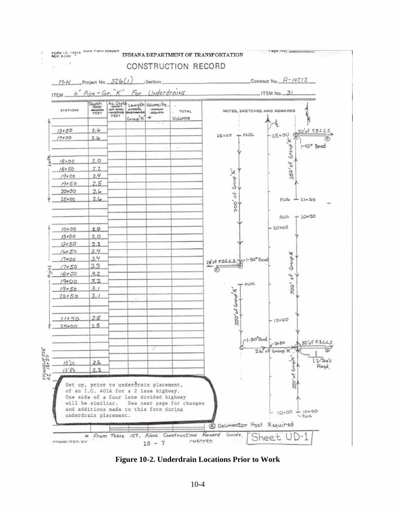
10-4
Figure 10-2. Underdrain Locations Prior to Work

10-5
Figure 10-3. Underdrain Locations after Completion of Work
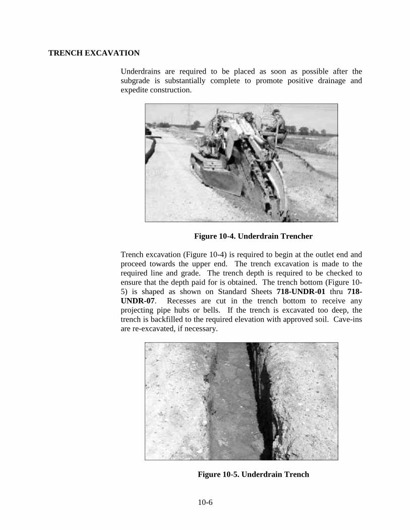
10-6
TRENCH EXCAVATION
Underdrains are required to be placed as soon as possible after the subgrade is substantially complete to promote positive drainage and expedite construction.
Figure 10-4. Underdrain Trencher
Trench excavation (Figure 10-4) is required to begin at the outlet end and proceed towards the upper end. The trench excavation is made to the required line and grade. The trench depth is required to be checked to ensure that the depth paid for is obtained. The trench bottom (Figure 10-5) is shaped as shown on Standard Sheets 718-UNDR-01 thru 718-UNDR-07. Recesses are cut in the trench bottom to receive any projecting pipe hubs or bells. If the trench is excavated too deep, the trench is backfilled to the required elevation with approved soil. Cave-ins are re-excavated, if necessary.
Figure 10-5. Underdrain Trench

10-7
CONSTRUCTION REQUIREMENTS
PIPE INSTALLATION
The pipe is laid into the trench. Splices and other connections are required to be correctly made. Perforated pipe is placed with holes down, to keep out silt, gravel, and other solids. Plastic corrugated drainage pipe is unrolled into the trench. Minor cave-ins that occur after pipe placement do not have to be cleaned. The pipe sections are joined securely with the appropriate couplings, fittings, or bands. If plain end concrete pipe is being placed, no joint width may exceed 1/4 in.
GEOTEXTILES
Storage and handling of geotextiles is required to be in accordance with the manufacturer’s recommendations. Each geotextile roll is required to be labeled or tagged. Damaged or defective geotextile are replaced as directed. The geotextile is placed loosely, but with no wrinkles or folds. The ends of subsequent rolls of geotextile are overlapped a minimum of 1 ft. The upstream geotextile overlaps the downstream geotextile. Placement of the aggregate is done following the placement of the geotextile.
BACKFILL
The trench is backfilled with No. 8 or No. 9 stone, slag, or gravel. Coarse aggregate No. 8 or 9 is used for 6 in. underdrain installations and coarse aggregate No. 9 is used for 4 in. underdrain installations. The backfilling operation is done with a device designed to fill the trench without promoting cave-ins. Prior to placing open graded HMA above the underdrain aggregate, the underdrain aggregate is required to be clean and exposed to facilitate drainage.
After the outlet pipe installation, the trench is backfilled as indicated on the plans. B Borrow for structure backfill may not extend into the limits of the underdrain trench. The trench, outside of the limits of B borrow for structure backfill, is filled with materials suitable for growing vegetation. Aggregate and stabilized materials removed from an existing shoulder may not be used as backfill and are disposed of in accordance with Section 206.07.

10-8
UNDERDRAIN OUTLETS
Pipe screens are placed in the end of the outlet pipe (Figure 10-7) as shown on Standard Sheet 718-UNDR-06. At the time of installation, a rodent screen is placed on the outlet pipe or the ends of the underdrain pipe when located in inlets or catch basins. Rodent screens are required to be woven stainless steel wire mesh or galvanized hardware cloth.
Figure 10-7. Underdrain Outlet OUTLET PROTECTORS
Underdrain outlet protectors (Figure 10-8) are required to be constructed as indicated on the plans. Types 1, 2, and 3 may be used.
Figure 10-8. Underdrain Outlet Protector
10-9
VIDEO INSPECTION
Underdrains and outlets are required to be inspected using high resolution, high sensitivity, waterproof, color video camera/recording equipment. The camera/recording equipment is specifically designed for continuous viewing and recording of detailed images of the interior wall of pipes and transitions of the specified sizes. The equipment has the capability of viewing a minimum of 450 ft into the pipes and is designed to include sufficient lighting to view the entire periphery of the pipe. The equipment has appropriate attachments to maintain a position in the center of the pipe and an electronic counter to continuously record the location of the equipment in the pipe. The recording equipment is required to have a minimum four head industrial grade VHS recorder or digital archiving and reviewing for printing observations during inspection. The PE/PS determines the runs of the underdrain installations to be inspected. Video inspection is conducted after guardrail, lighting, sign installation, and final seeding or sodding operations are completed. Damage discovered by the video inspection is required to be repaired. Damage includes but is not limited to crushed or partially crushed pipes that impede the progress of the camera, blockages, vertical pipe sags filled with water depth of d/2 or greater, 90 degree connections, connector separations, cracks, or splits in the pipes. All repaired sections are video reinspected prior to acceptance. A copy of the video inspection is submitted to the PE/PS.
MATERIALS AND BASIS FOR USE
All materials in an underdrain installation are required to meet the requirements of Section 718.02. Specific Specifications and Material Record Basis for Use requirements for the most commonly used items are as follows:
Plastic Corrugated Pipe
1) Section 907 2) Basis for Use is a Type A Certification and a visual
inspection for required dimensions and workmanship.
Aggregate
1) Section 904 2) The Basis for Use is the “D” number from the CAP source.

10-10
MEASUREMENT
Underdrains and outlet pipes are measured by the linear feet installed as follows:
1) Tee and wye fittings are measured along the centerline of
the barrel and an additional 5 ft of the same diameter pipe is paid for making the connection. If one of the pipes is a smaller diameter, then the 5 additional ft is paid at the price of the smaller diameter pipe.
2) Elbow connections are measured along the center-line of
the elbow and an additional 2 ft of the same diameter pipe is paid for the connection.
3) Increaser and reducer connections are measured by the
length of the connection and are paid at the price of the larger diameter pipe.
4) Sub-tee connections are measured and paid the same as a
tee connection. Payment includes the required connecting bands, cement mortar beads, or concrete collars.
Aggregate is measured by cubic yards complete in place to excavated lines. The trench width may not extend past neat lines shown on the plans, and the trench is required to be as specified. Underdrains and outlet pipes are measured in accordance with Section 715.13. Outlet protectors are measured by the number and type of units installed. B borrow for structure backfill is measured in accordance with Section 211.09. HMA for underdrains is measured by the ton. Geotextiles are measured by the square yard based on the neat limits shown on the plans. Video inspections for underdrains are measured by the linear foot as determined by the electronic equipment. Rodent screens, elbows, increaser or decreaser connections, and other incidentals are not measured for payment. Concrete, reinforcing steel, or sod for underdrain outlet protectors are also not measured for payment.

10-11
Documentation for measurement and payment is required to be on the I.C. 401A or in the Field Book. The plan quantities are revised to show the actual quantity placed.
BASIS OF PAYMENT
The accepted quantities of underdrains and underdrain outlet pipe are paid for in accordance with Section 715.14. Aggregate for underdrains is paid for at the contract unit price per cubic yard. Geotextile for underdrains is paid for at the contract unit per square yard. Geotextile which has been rejected due to contamination or other reasons is required to be replaced with no additional payment. Outlet protectors are paid for at the contract unit price per each of the type of unit installed, complete in place. The accepted quantities of HMA for underdrains are paid for at the contract unit price per ton.
B borrow for structure backfill is paid for in accordance with Section 211.10. The final accepted quantity video inspection for underdrain is paid for at the contract unit price per linear foot.
The costs of excavation, forming, reinforcing steel, concrete, curing materials, and sod shall be included in the cost of outlet protector. The cost of providing the video inspection equipment, technician, videotapes, or computer disks is included in the cost of the underdrain video inspection. The cost of repair of underdrain pipes, aggregates, backfill, outlet protectors, geotextile fabric, etc. is included in the cost of the other pay items. The cost of providing video reinspection of the repairs is included in the cost of the pay items. The cost of disposal of unsuitable excavated materials, installation of pipe end caps, rodent screens, elbows, increaser or decreaser connections, and other incidentals is included in the cost of other pay items.

11 Guardrail W-Beam Guardrail
Pre-Installation Inspection During Installation Basis for Use
Modified Guardrail End Treatments and Transitions Footings and Anchors Impact Attenuators Measurement and Payment

11-1
CHAPTER ELEVEN: GUARDRAIL
The purpose of placing guardrail is to reduce the severity of potential accidents caused by an errant vehicle leaving the roadway down a steep embankment. Because guardrail is also a hazard, the guardrail is only installed if the installation offers less potential hazard than the obstacle or embankment slope. The design of the contract eliminates a number of the factors that warrant the installation of guardrail. The Technician is required to ensure the guardrail is placed according to the requirements set forth in the plans and Specifications and to keep accurate accounts of all guardrail that is placed. Due to ever changing research and development associated with guardrail, the most current Standards and Specifications are required to be consulted prior to the construction of any guardrail.
W-BEAM GUARDRAIL
W-beam guardrail elements (Figure 11-1) are required to be steel and be in accordance with the applicable requirements for steel beam guardrail as indicated in the Specifications and on Standard Sheets 601-WBGA-01, & 03, 601-WBGC-01, 02, & 03, 601-CWGS-06, and 601-RHPG-03. Aluminum tubular, rub-railing, and steel block-outs are not used on new contracts, and all information in the Specifications and Standards is used for maintenance contracts for existing installations only.
The components, assembly, post spacing, post lengths, and installation for
each location are indicated on the plans. Double-facing of the guardrail is required at the locations on the plans. In locations that do not allow for the standard 7 ft posts, 6 ft posts may be substituted when approved.

11-2
Figure 11-1. W-Beam Guardrail
PRE-INSTALLATION
Prior to the inspection of guardrail placement, the Technician is required to review all of the following information:
1) The General Notes section of the plans may specify a type of railing, end section, and post spacing.
2) The Detail Sheets section of the plans indicate the specific
location, length, and type of rail required, along with the locations and type of end treatment.
3) Specifications provide a description of the work, materials
used, general requirements, the method of measurement and basis of payment. The latest manufacturers manual is also checked.
4) Shop drawings are sent to INDOT for review and approval. 5) The General Instructions to Field Employees provides
helpful ideas concerning the guardrail procedures.
Before guardrail is placed, the Technician is required to verify that the correct type and quantity of guardrail is specified and that the basis of use requirements are met.

11-3
INSPECTION DURING INSTALLATION
The Technician is required to carefully inspect the Contractor’s work to ensure proper placement. The following items are checked:
1) The slope of shoulder from the edge of the pavement to the
face of the guardrail is required to be the same as that of the planned shoulder slope, with a distance between the two of no more than 2 ft (Standard Sheet 601-WBGA-01).
2) The guardrail is required to be placed at a height of 2 ft 3
in., measured along the front face of the rail. 3) The front face of the rail is required to be the correct
distance specified in the plans from the edge of the pavement. Except for flares and tapers at the end of the railing, the shoulder is paved up to the front face of the railing.
4) The rail is required to be built as parallel to the ground as
possible; however, the rail is adjusted vertically to maintain a uniform appearance.
5) Metal posts are required to be driven. If conditions do not
allow driving the posts, then at least a 12 in. diameter hole is drilled and backfilled with soil in 6 in. lifts after which the post is then driven.
6) Rail Elements are required to be lapped in the direction of
the closest traffic. For example, roofing shingles are lapped in the direction of the flow of water down the roof.
7) When new guardrail is being installed to replace existing
guardrail and traffic is maintained during the work, the installation of the new guardrail follows the removal of the existing guardrail as closely as practical. Adequate safety protection is provided as directed between the time that the existing guardrail is removed and the time that the installation of the new guardrail is complete.
8) When new guardrail is being installed where there is no existing guardrail and traffic is to be maintained during the work, the time between the installation of the posts and the mounting of the blocks and rail elements may not exceed 24 h. Drums are placed to mark all installed guardrail posts left bare overnight.

11-4
9) Blocks and rail elements are required to be erected in a manner resulting in a smooth, continuous installation.
10) Elements which are cut or drilled are coated with a high
zinc dust-zinc oxide paint in accordance with the Specifications.
11) Expansion joint openings in guardrail, where connected to
the bridge rail, are required to be 1 in. plus the deck expansion joint installation opening.
12) All bolts are required to be tightened.
BASIS FOR USE
The basis for use requirements and acceptance of steel beam guardrail is as follows:
1) Installer on a certification basis with random in-place
testing of guardrail on a yearly basis: The installer is assigned a 6 digit “Q” number which is the basis of use for the Material Record.
2) Installer not on a certification basis: Materials are sampled
at the job-site after delivery with no materials being used until they are tested and approved. The laboratory number is the basis of use for the Material Record.
MODIFIED GUARDRAIL
Modified guardrail is regular railing with adjustments such as longer or shorter posts, different post spacing, nesting of the railing, or the use of double faced railing. When a pay item of modified guardrail is included in the contract, the Specifications are checked. An example of an area requiring modified guardrail would be at supports for overhead sign structures. Placement is required to be as indicated on Standard Sheet 601-RHPG-03.
When existing guardrail no longer meets the 2 ft 3 in. minimum height requirement, usually due to the addition of resurface material, one of the following items is specified:
1) “Adjust Guardrail Height, Adjustable Post Bracket” is used
when the use of existing adjustable post brackets allows the existing railing to be raised to the required 2 ft 3 in.

11-5
2) “Adjust Guardrail Height” is used when replacement of existing post brackets with adjustable post brackets is required to raise the existing railing to the required 27 in.
3) “Reset Guardrail” is used when the addition of adjustable
post brackets does not raise the existing railing to the required 27 in. height. Reset guardrail is set with a 30 in. rail height and consists of the careful removal of existing guardrail, possible storing, and then erecting where shown on plans or as directed. This work also includes the replacement of damaged or missing parts and new posts as directed.
4) Complete replacement of the guardrail may be another
option, if the guardrail is not up-to-date and the cost is comparable to resetting.
END TREATMENTS AND TRANSITIONS
The end of the guardrail which faces approaching traffic is required to have some type of end treatment to decrease the chances of vehicle impalement. The SKT 350, ET-2000, and ET-Plus are the most common end treatments used. Other end treatments such as the C-A-T are more complicated and expensive. The Technician is required to have a complete set of shop drawings if the item is not clearly indicated on the Standard Sheets. Incorrectly following the shop drawings may cause serious injury to a motorist hitting the end treatment. For example, placing washers in the correct place is critical to the end treatment because the end treatment does not function properly without the washers. The Technician is required to also verify that the required shoulder slopes and rail flares are placed in the vicinity of the end treatment.
End treatments (Figure 11-2) may be detailed on the plans as is the case for Type I and II sections, or may be selected from an approved list which includes OS, MS, and Type I end treatments. The plans include reflectorization and grading requirements for each of the end treatments. Each unit is required to be installed in accordance with the manufacturer’s recommendations and within 24 h of completion of the guardrail.

11-6
Figure 11-2. Guardrail End Treatment
Assembly and installation of end treatments is required to be supervised or conducted at all times by an installer trained and certified by the unit’s manufacturer. A copy of the installer’s certificate is required to be provided to the PE/PS prior to the start of work. Basis for use for all guardrail end treatments is a six digit “W” number, which represents the manufacturer of the specified treatment.
When installing end treatments to existing rub-rail type guardrail, the rub-rail, if not spliced at the last existing post, is cut and the end repositioned behind the flange of the post (Standard Sheet 601-TTVH-01). Guardrail transitions are required to connect the guardrail to the bridge rail, and the guardrail to piers (Standard Sheet 601-TTGB-01). Guardrail buried end sections are considered a Type II end treatment and are rarely used.
FOOTINGS AND ANCHORS
Some modified guardrail sections require concrete either as concrete footings or as anchors. The recommended inspection is required to be as follows:
1) Inspect the excavation for the required dimensions 2) Inspect the proposed finished concrete grade. The air
content, yield, and slump are required to be checked as required by the Frequency Manual.

11-7
3) Verify that the excavation is reasonably dry 4) Verify the posts are plumb and to the required grade 5) Verify that the concrete anchors have the proper
attachments set into the concrete at the proper position, along with any specified reinforcements
6) Verify that the proper curing of the concrete is done
IMPACT ATTENUATORS
Impact Attenuators are used as crash cushions in high speed environments on the face of blunt objects located within the clear zone. They are very similar to end treatments, but are designed to prevent vehicles from coming into contact with hazards at speeds of up to 70 mph. Notable locations of use would be bridge piers, overhead signs, and other such objects that pose a hazard to the traveling public. G-R-E-A-T (Guardrail Energy-Absorbing Terminal), Sentre, REACT 350, and QuadGuard are examples of Impact Attenuators that are used (Figures 11-3 to 11-7)
Impact Attenuators are selected from those included on the INDOT list of approved Impact Attenuators. Each unit is required to be placed in accordance with the manufacturer's recommendations on a concrete pad. The installation is supervised or conducted at all times by an installer trained and certified by the unit’s manufacturer. A copy of the installer’s certificate is provided to the PE/PS prior to the start of work.
MEASUREMENT AND PAYMENT
Measurement of guardrail is done by the linear foot along the top of the rail. End treatments, transitions, and attenuators are excluded from the measurement because they are paid as a lump sum for each. All items are measured and documented for payment on a daily basis. These measurements are required to be accurate enough for final payment so that additional measurements are not required at a later date. The cost of reflectorization, grading, earthwork, concrete pad, excavation, concrete footings, reinforcement, and structural steel tubing for modified posts is included in the cost of the perspective pay items.
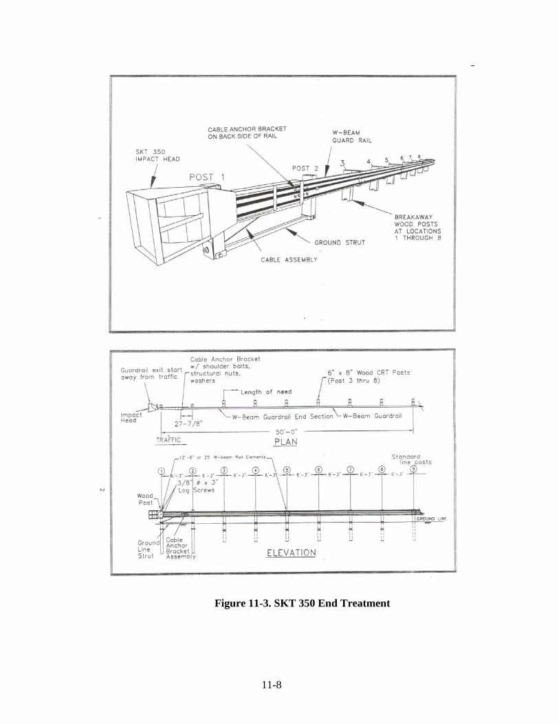
11-8
Figure 11-3. SKT 350 End Treatment

11-9
Figure 11-4. ET-PLUS End Treatment

11-10
Figure 11-5. C-A-T End Treatment

11-11
Figure 11-6. Guardrail Energy-Absorbing Terminal (GREAT)

11-12
Figure 11-7. Sentre Impact Attenuator

11-13

12 Right-of-Way Fencing
Types Farm Field Type Fence Posts Diagonal Braces Line Posts Woven Wire Fabric Barbed Wire Chain Link Type Fence Gates Measurements Material Acceptance

12-1
CHAPTER TWELVE: RIGHT-OF-WAY FENCING
Under certain conditions, right-of-way fence is specified on contracts at various locations. For example, right-of-way fences are placed along limited controlled access highways for the purpose of denying access to the highway except at designated locations. The types of fencing, materials, placement procedures, and basis of payment are discussed in this chapter.
TYPES
Right-of-way fencing normally consists of six types:
1) Farm Field Type Fence (F.F.T.F.) 2) Chain Link Type Fence (C.L.T.F.) 3) Barbed Wire Type Fence 4) Temporary Fence 5) Reset Fence 6) Gates
F.F.T.F. is the most commonly used and consists of a woven wire fabric. Often known as Farm Fence, F.F.T.F. is used in agricultural or non-residential areas. C.L.T.F. is used in residential, industrial and commercial areas, or areas with a high concentration of people. For example; C.L.T.F. is used in rest areas around sewage treatment plants and between the rest area and the roadway. C.L.T.F. consists of a woven wire fabric sometimes known as industrial fence. Barbed wire type fence is not commonly used. This fence consists of two strands of barbed wire on "T" posts. Barbed wire fence is detailed on Standard Sheet 603-FFTF-03. The posts are placed similar to F.F.T.F. except for post spacing. Temporary fence is used only on a temporary basis. On portions of a contract where fence is required on the right-of-way, the required permanent fence is erected and maintained at locations where the property owner desires to use the adjacent area for pasture for livestock. If the

12-2
permanent fence has not been erected by the time the adjacent property owner uses the pasture, a temporary fence is erected and maintained. The temporary fence is required to be sufficient to prevent the livestock from entering the right-of-way. Temporary fence is not paid for unless there is a bid item in the contract. If the temporary fence is a pay item, the fence is measured and paid for by the linear foot. Resetting fence consists of the removal of an existing fence within the limits of a new improvement, storing the fence, and resetting the fence when and where indicated on the plans. Resetting fence is completed as if the fence were new fence. If the fence is F.F.T.F. then the fence is required to be placed in the same manner as new F.F.T.F. The replacement of damaged or missing parts, including posts, is included in resetting. Reset fence is paid for at the contract unit price per linear foot. Gates are infrequently used in INDOT work. A right-of-way fence that represents a property line does not often have a gate. Gates are used in internal fences located within the right-of-way. For example, a C.L.T.F. around a rest area sewage treatment plant is an internal fence. Gates are used to give access to such an area so that maintenance activities may be done. Gates of this nature are of the same woven fabric as the fencing that is interrupted.
FARM FIELD TYPE FENCE
There are basically seven individual parts to F.F.T.F. Standard Sheet 603-FFTF-01 details the parts. They are:
1) End, Corner, or Pull Posts 2) Diagonal Braces 3) Line Posts 4) Woven Wire Fabric 5) Barbed Wire 6) Concrete 7) Fasteners
POSTS
End, corner, or pull posts are made of galvanized or aluminum coated tubular steel. These tubular steel posts have a diameter of 2 in., a weight of 3.65 lb/lft, and a length of 7 ft. The posts act as an anchoring device for the fence fabric and barbed wire. An end post is the post at the beginning
12-3
or end of a run of fence. A corner post is a post that is placed at locations in which there is a horizontal change in the property line (R/W). A change of direction with an angle of 10° or more requires a corner post. A pull post is an intermediate post in between an end post and a corner post. Pull posts are required to be placed no farther than 500 ft intervals in straight runs and at each vertical angle point of 10° or more.
Because end, corner, and pull posts are anchoring devices, they are placed in concrete. The concrete may be either Class A or B. The concrete and post are placed in a drilled hole with a diameter of 1 ft and a depth of 36 in. The post is required to extend into the concrete 2 ft 6 in. and be at the required grade and alignment. All end, corner, and pull posts are fitted with caps to protect the post against moisture.
DIAGONAL BRACES
Diagonal braces are placed at all end, corner, and pull posts. The purpose of the diagonal brace is to keep the posts in alignment. Diagonal braces are made of galvanized tubular steel with a diameter of 1 1/4 in., a weight of 2.27 lb/lft., and a length of 7 ft. The diagonal brace is fastened to the end, corner, or pull post by the methods detailed on Standard Sheet 603-FFTF-01. The opposite end is placed in a Class A or Class B concrete anchor. This anchor is approximately 2 ft in length and 1 ft in diameter, and is also detailed on Standard Sheet 603-FFTF-01. Care is taken during placement of the concrete anchors for end, corner, pull posts and the diagonal braces. If the concrete is allowed to take a "mushroom" shape, future damage may occur. A mushroom anchor allows the freezing and thawing action of the surrounding soil to lift the post or diagonal brace. Therefore, the upper limits of the concrete are required to not exceed the circumference of the drilled hole. No tension or strain is placed on posts or braces until the concrete has cured 4 days.
LINE POSTS
Line posts in F.F.T.F. are the intermediate posts between end, corner, or pull posts. Their function is to give the fence fabric and barbed wires support and correct the alignment. Line posts may be studded T or U posts. Line posts are required to be:
1) Galvanized 2) Have an anchor plate

12-4
3) Spaced uniform as practicable 4) Driven to the required grade and alignment 5) Placed at each abrupt change in grade 6) Set on 16 ft centers 7) Set with a 2 ft spacing tolerance at special locations
Occasionally, special cases arise and the PE/PS may direct other placements. For example, if a tree is located on the right-of-way and is to remain in place, the fence may be set off line enough to miss the tree. Such a case requires a gradual offset for at least three posts in each direction to eliminate sharp bends.
WOVEN WIRE FABRIC
Forty seven inch woven fence fabric for F.F.T.F. is a series of 10 horizontal line wires kept in alignment by vertical stays. Both the line wires and vertical stays are galvanized or aluminum coated No. 9 gauge wire. Two methods of securing the vertical stays are detailed on Standard Sheet 603-FFTF-01. The methods are "wrapped" and "welded". The wrapped type is the most commonly used. Placement of the fence fabric has several general factors to consider during the inspection procedure:
1) The tension required to stretch the fabric is applied by
mechanical fence stretchers. 2) All slack is removed before making permanent attachments
elsewhere. 3) Line wires are fastened to end, corner, or pull posts by
wrapping the wires around the post and tying the wire back on the wire with no less than 1 1/2 tightly wrapped twists.
4) All splices in the fabric are securely made with the best
practice and the recommendations of the manufacturer. 5) The fabric is placed on the side of the post facing the
pavement. 6) The fabric is fastened to intermediate or line posts with at
least five wire ties.

12-5
BARBED WIRE
Two strands of barbed wire are used with F.F.T.F. One is placed below the fence fabric and the other is placed above the fence fabric. Barbed wire is composed of a No. 12 1/2 gauge galvanized or aluminum coated steel wire. The barbs are spaced at approximately 5 in. and are 4 round, 14 gauge barbs. Barbed wire No. 15 1/2 gauge, high tensile strength line wires with No. 16 1/2 gauge barbs may be substituted. The barb points and spacing are the same as No. 12 1/2 barbed wire.
Placement of the barbed wire has several general factors to consider during the inspection procedure as follows:
1) The tension required to stretch the wire is applied with single wire stretchers.
2) All slack is removed before making permanent attachments
elsewhere. 3) Line wires are fastened to end, corner, or pull posts by
wrapping the wire back on itself with no less than 1 1/2 tightly wrapped twists.
4) All splices in the wire are securely made with the best
practice and the recommendations of the manufacturer. 5) The barbed wire is placed on the side of the post facing the
pavement. 6) The top barbed wire is placed 2 in. above the fence fabric.
The lower barbed wire is placed 1 1/2 in. to 2 in. below the fence fabric or 1 to 1 1/2 in. above the ground line.
7) The barbed wires are attached to each line post.
Additional barbed wire may be required at small stream crossings and ground depressions. The space below the fence fabric is required to have barbed wire as shown on Standard Sheet 603-FFTF-03. If the installation causes collecting drifts in the channel, the barbed wire is not placed. The wires are stretched taut between posts and fastened to the posts such that vertical movement is prevented.
CHAIN LINK TYPE FENCE
There are basically nine individual parts to C.L.T.F. Standard Sheet 603-CLTF-01 details the parts. They are:

12-6
1) End, corner, and pull posts 2) Nominal braces 3) Line posts 4) Truss rod 5) Woven wire fabric 6) Stretcher bar 7) Tension Wire 8) Concrete 9) Fasteners
End, corner, and pull posts are the same material as used for F.F.T.F. and are also placed the same as F.F.T.F. Line posts in C.L.T.F. are placed in concrete anchors in the same manner as end, corner, and pull posts. Therefore, they are usually placed at the same time as these posts. The line post is required to be 1 1/4 in. tubular. Line posts in C.L.T.F. are required to be:
1) Galvanized 2) Set on 10 ft maximum centers 3) Spaced as uniform as practicable 4) Placed in concrete class A or B 5) Placed at the required grade and alignment 6) Placed at each abrupt change in grade 7) Fitted with a cap to exclude moisture
The bracing for C.L.T.F. at end, corner, or pull post is different than for F.F.T.F. Bracing includes:
1) The first line post 2) A 1 1/4 in. nominal brace 3) A truss rod

12-7
4) A turnbuckle with 4 in. of take up 5) Necessary fittings
The assembly of C.L.T.F. bracing is detailed on Standard Sheet 603-CLTF-01. The Technician is required to inspect the bracing to verify correct assembly. The truss rods, turnbuckles, and fittings are required to be commercial quality steel, malleable iron, or wrought iron that is galvanized. Tension wire is used at the top and bottom of chain link fence. These wires are required to be No. 7 gage spring coil or crimped steel, zinc or aluminum coated, and have a minimum breaking load of 1950 lb. The placement procedures for the tension wires include the following requirements:
1) Be placed prior to fence fabric 2) Be stretched taut by single wire stretchers 3) Be secured at the ends in a satisfactory manner 4) Be secured to all posts 5) Not be placed until the concrete anchors have cured 4 days
The fence fabric used for C.L.T.F. is a series of bent wires woven together. This weaving creates a 2 in. mesh pattern. After the wires are weaved, they are twisted together at the top and bottom. The twisting creates a barbed finish that is called "selvage". The chain link fence fabric is required to have the following qualities:
1) A height of 48 in. (unless otherwise specified) 2) Be made of No. 9 gage wire 3) Have a woven mesh of 2 in. 4) Be galvanized or aluminum coated (coated after weaving)
or be aluminum fabric

12-8
Placement of the fence fabric has several general factors to consider during the inspection procedure:
1) The fabric is attached to the terminal ends with a stretcher
bar. This bar is flat and measures 3/16 in. x 3/4 in.. The stretcher bar is threaded through the loops of the fabric and is secured to the posts by means of clamps with bolts and nuts. The number of clamps is indicated on Standard Sheet 603-CLFT-01.
2) The fabric is stretched using mechanical fence stretchers. 3) All slack is removed before making permanent attachments
elsewhere. 4) The fabric is fastened to the line posts with ties or clips.
The ties are spaced 12 in. center to center. Therefore, 5 ties are required on 48 in. fabric.
5) The fabric is fastened to the tension wires with ties. These
ties are made of aluminum wire. Galvanized steel wire ties may be used and are required to be no smaller than No. 12 gage. All ties are spaced 24 in. center to center along the tension wires.
6) Fence fabric is placed 3 in. above the ground level and 3 in.
below the top of the posts.
GATES
Gates used in fence are detailed on Standard Sheet 603-CLFT-03. Gates may be single or double swing. Single gates may be as wide as 32 ft and double swing gates may be as wide as 64 ft. The width of the gate opening determines the diameter size of the gate post. Gate post sizes are indicated on a table in Section 910.18(d). The materials required for a gate are as follows:
1) Galvanized gate post 2) Galvanized 1 1/2 in. nominal gate frame with weld joint,
riveted construction, or malleable fittings 3) 3/8 in. round truss rod 4) Stretcher bar with fittings 5) Galvanized standard hinge

12-9
6) Galvanized standard lock 7) Fence fabric
MEASUREMENTS
Fence and resetting fence is measured by the linear foot. Measurement is made along the top of the fence. Measurements begin from the outside of an end post, continue to the outside of another end post, and are made to the nearest 0.5 ft. Measurements are recorded in a systematic method and retained for the final record. The Technician consults with the PE/PS concerning a preferred systematic method. Gates are paid for as each as set out in the itemized proposal.
MATERIAL ACCEPTANCE
Fencing materials are inspected by INDOT Testing. Once inspections are complete, tags with "seal" numbers are attached to the materials. Rolls of fence fabric, barbed wire, and tension wire are required to have tags on each roll. Groups of individual items may have only one seal number. For example, a bundle of 100 "T" posts has one number. Miscellaneous materials and gates are visually accepted. The seal numbers indicate that the materials have been tested and are acceptable for use. Damaged material from shipment or placement may not be used or corrected before used. Seal numbers are required to be recorded and given to the PE/PS.

13 Benchmark Posts and Tablets, Monuments, and Right-of-Way Markers Materials Benchmark Posts and Tablets Monuments Right-of-Way Markers Construction Requirements Setting Right-of-Way Markers Resetting Right-of-Way Markers Setting Monuments Re-established Monuments Setting Benchmark Posts and Tablets Reset Benchmark Posts Method of Measurement and Payment Standard Drawings

13-1
CHAPTER THIRTEEN: BENCHMARK POSTS AND TABLETS, MONUMENTS, AND RIGHT-OF-WAY MARKERS
This chapter discusses furnishing and setting, setting only, or resetting of right-of-way markers, monuments for marking section or other lines, and bench-mark posts and tablets in accordance with Section 615.
MATERIALS BENCHMARK POSTS AND TABLETS
Bench mark posts (Figure 13-1) are required to be of the dimensions indicated on the plans and cast in accordance with applicable provisions of Section 615.03, except the strength is determined by concrete cores taken from the finished product. At least two concrete cores are taken from each unit and the average strength of the unit is required to be at least 4000 lb/in2 with no individual core strength less than 3600 lb/in2. Tablets are furnished by INDOT and are set in the posts as indicated on the plans.
Figure 13-1. Benchmark

13-2
MONUMENTS
Monuments (Figure 13-2) are required to be of the type specified in the contract. Any portion extending above the ground is finished in accordance with Section 702.20. Where concrete is required, Class A concrete is used in accordance with Section 702. When placed in the forms, the concrete is tamped in layers until mortar covers the outer surface. The tops of the monuments are floated smooth. Monuments are cast in place or precast and then set.
Figure 13-2. Type B Monument
The pin in the monument is set perpendicular to and flush with the top of the monument while the concrete is plastic and left undisturbed until the concrete has set. The pin is copper and is required to be 1 in. in diameter and 5 in. long. For type D monuments, the hole is drilled in the center with a 1/8 in. drill for a depth of 1.5 in. The hole is filled with lead flush with the end of the pin. Castings for protected monuments are required to be in accordance with Section 910.05(a).
RIGHT-OF-WAY MARKERS
Reinforced concrete right-of-way markers are required to conform to the dimensions and lettering indicated on the plans. The reinforcement is securely held in place by at least four spacers of an approved design. The markers are required to have a smooth workmanlike finish free from cracks, patches, honeycomb, exposed reinforcement, and excessive bubble holes. Each marker is plainly marked near the bottom with the trademark or initials of the manufacturer and the date of manufacture. These letters and figures are no less than 1 in. in height and indented 1/8 in. Right-of-way markers require a Type C certification in accordance with Section 916.

13-3
CONSTRUCTION REQUIREMENTS SETTING RIGHT-OF-WAY MARKERS
The back face of right-of-way markers (Figure 13-3) is required to be set on right-of-way lines approximately 1000 ft apart. Markers are set at all corners of irregular right-of-way lines, opposite each P.C. and P.T. of curves, and not to exceed 500 ft apart on the inside and outside of curves. Markers on tangents are located so that the marker is plainly visible from each of the adjacent markers.
Figure 13-3. Right-of-Way Marker
Markers are set plumb to the depth required on the plans and with the letters facing the pavement. Portions of the holes not occupied by markers are backfilled and compacted in layers with suitable material to the level of the original ground. The markers may not be displaced during backfilling.

13-4
Markers are typically set with 18 in. of exposed face except for lawns in urban areas where the marker is set flush with the existing ground (Figure 13-4).
Figure 13-4. Right-of-Way Marker set Flush with Ground RESETTING RIGHT-OF-WAY MARKERS
When the contract provides that existing right-of-way markers be reset, the existing markers are required to be removed and reset at designated locations in accordance with Section 615.07.
SETTING MONUMENTS
INDOT sets monuments to define section lines and to permanently establish vital survey points. Monuments are described and indicated on Miscellaneous Standard Sheet MA. These monuments are Section Corner Monuments and Monuments as listed below for survey lines (Figure 13-5).
1) Monument Type "A" for vitrified brick or HMA surface on
concrete base 2) Monument Type "B" for HMA pavement 3) Monument Type "C" for outside the pavement area 4) Monument Type "D" for concrete pavement

13-5
Figure 13-5. Survey Monument Sign All section corners and quarter section corners that fall within the right-of-way for a new or re-constructed facility are required to be established. The local county surveyor establishes all section corners and section lines not already defined by monuments at the time of construction. Should the county surveyor fail to establish such points as requested, the monument is eliminated from the contract. Original survey points (e.g. P.I.'s, P.C.'s, P.T.'s, P.O.T.'s and P.O.C.'s) are monumented so that the original survey line for the highway facility may be re-established accurately after construction. Intermediate points are monumented so that a surveyor may see a range pole set on an adjacent monument in at least one direction. Also, monuments are located so that the line of sight between adjacent monuments falls within the right-of-way. If the location of a monument falls within the limits of a concrete pavement, a copper pin, the details of which are indicated on the plans, is required to be set perpendicular to and flush with the top of the finished pavement. The pin is placed just before the concrete takes initial set and then left undisturbed until the concrete has set. Other monuments are required to be of the type shown on the plans, depending on the type of surface of the pavement in which they are placed or if they are placed outside the pavement. Necessary excavation is done to the required depth. The bottom of the excavation is required to be firm and true to line and grades given. After a monument is in place, the remaining excavated areas are backfilled with suitable material firmly tamped in layers. The monument may not be disturbed during this operation.
13-6
Existing monuments, which are not required to be disturbed or re-established but which are disturbed during construction operations, are required to be re-established.
RE-ESTABLISHED MONUMENTS
Existing monuments may need to be re-established in pavements or bases which are disturbed unavoidably or covered by operations done in the contract. If the existing monument contains a brass or copper pin, the pin is extended to the surface of the new pavement by attaching a brass or copper pin of at least a 1 in. diameter and of the length required. These extensions are attached by tapping the original pin and providing a necessary screw attachment such that the extension may be fastened securely to the original pin. The tapped hole is at least 0.25 in. in diameter and no less than 1 in. deep. The screw attachment is required to have the same diameter as that for the hole in the original pin and be no less than 1 in. in length. Where an existing monument has not been re-established on a previous contract, the monument is re-established in the same manner. Where existing monuments are protected and encased in cast iron, the castings are adjusted to meet the elevation of the proposed surface by means of an asphalt coated, cast iron, adjustment casting. The size is the same as the original casting, and the depth necessary to meet the elevation of the proposed new surface is used.
SETTING BENCHMARK POSTS AND TABLETS
Benchmark posts are required to be set at locations indicated on the plans or as directed. Excavation is made to the depth indicated and to dimensions sufficient to provide for the concrete backfilling. This concrete is Class A and extends for 6 in. around and below the post. The bottom is required to be monolithic with the sides. The remainder of the excavation up to the original ground line is backfilled with suitable material that is well tamped in layers. Care is taken not to disturb the post. When specified on the plans, or directed, benchmark tablets furnished by INDOT are placed in newly constructed or existing drainage structures located within the limits of the contracts.
RESET BENCHMARK POSTS
When the contract provides that existing benchmark posts be reset, the existing benchmark posts are removed and reset at designated locations in accordance with Section 615.11. When the relocation of an existing bench mark post is necessary, an item in the contract is included as "Reset Bench Mark Post". Resetting is the same as for a new bench mark post.

13-7
Other permanent benchmark systems are required to be saved. These include benchmarks for:
1) U.S. Coastal and Geodetic Survey 2) U.S. Geological Survey 3) U.S. Army Engineers 4) Indiana Flood Control & Water Resources System
The appropriate agency is notified by INDOT Design when a benchmark is found during the original survey that construction for the contract may disturb. A new benchmark tablet along with relocation instructions is available in advance of construction.
If an existing benchmark is discovered and may be disturbed during construction, a letter is required to be sent to the agency involved. The necessity for the move and the designation of the tablet is included in the request. The agency involved is required to send a new tablet properly stamped to show the benchmark has been reset and the necessary instructions for setting.
METHOD OF MEASUREMENT AND PAYMENT
Right-of-way markers, reset right-of-way markers, monuments, re-established monuments, castings adjusted to grade monuments, bench mark posts, and reset bench mark posts are measured by the number of units installed and paid for at the contract unit price per each complete in place.
STANDARD DRAWINGS
The following Standard Drawings include further details of benchmark posts and tablets, monuments, and right-of-way markers.
615-RWPB-01 615-SCMN-01 615-SLBM-01 615-SLMN-01.

14 Geotextiles Storage and Handling Placement Overlapping and Pinning Underdrains Placement Acceptance of Materials Measurement and Payment

14-1
CHAPTER FOURTEEN: GEOTEXTILES
Prior to 1988, geotextiles were called plastic filter cloth or filter fabric. Because of the increase in the number of products being manufactured to be used as filter cloth, the Specifications were revised. This material is now identified as "Geotextile". In this chapter, geotextiles for use under riprap and with underdrains are discussed.
STORAGE AND HANDLING
Storage and handling of geotextiles is required to be in accordance with the manufacturer's recommendations. INDOT also requires that the geotextiles be protected from the following:
1) Direct sunlight 2) Ultraviolet rays 3) Water 4) Temperatures greater than 140° F 5) Mud, dirt, and dust 6) Debris
Any of the above may affect the strength, toughness, and permeability of the geotextile. Exposure of geotextiles to the elements between laydown and covering is required to be a maximum of 14 days. At the time of installation, the geotextile may be rejected and replaced if defective, ripped, flawed, deteriorated, or damaged. These problems may occur during construction, manufacturing, transportation, or storage of the geotextile.
PLACEMENT
The ground surface that receives the geotextiles is required to be prepared to a relatively smooth condition that is free of obstructions, depressions, or debris. Geotextiles used along channels are required to be placed with the machine direction of the material parallel to the channel. If successive sheets are required, they are overlapped so that the upstream sheet is

14-2
placed over the downstream sheet. If additional sheets are required to reach the top of the channel, the upslope sheet overlaps the downslope sheet. Geotextiles used for 2 to 1 slopes or greater are required to be placed with the machine direction of the geotextile sheets perpendicular to the toe of the slope. The geotextile sheets are overlapped in the direction of the anticipated movement of the water. For example, on a foreslope the movement of the water is from the pavement and the geotextile sheets start at the bottom of the slope and proceed upslope.
OVERLAPPING AND PINNING
Adjacent pieces of geotextile may be joined by sewing or by overlapping. Most Contractors prefer overlapping. When geotextile sheets are overlapped they are required to be pinned. The minimum overlap is 18 in. When the geotextiles are placed under water, the minimum overlap is 3 ft. If an overlap is periodically subjected to being under water, the overlap is required to also be 3 ft.
The overlaps are secured by pinning and the securing pins are required to be:
1) Steel 2) 3/16 in. in diameter 3) 18 in. long 4) Pointed at one end 5) Fabricated with a head to retain a steel washer. The
washers are required to have an outside diameter of at least 1 1/2 in.
Securing pins are required to be inserted through both strips of overlapped geotextile. The pins are placed through the midpoint of the overlap. The spacing intervals of the pins are determined by the slopes the geotextile is being placed on in accordance with the following: SLOPE PIN SPACING PER ROW
(Horizontal:Vertical) (Center:Center)
steeper than 3:1 2 ft 3:1 to 4:1 3 ft 4:1 or flatter 5 ft

14-3
The pins are driven until the washer bears against the geotextile so that the geotextile is secured firmly to the ground. Additional pins are installed as necessary to prevent any slippage of the fabric.
UNDERDRAINS
The geotextiles for underdrains are required to be inspected and handled in the same manner as the geotextiles for riprap. The overlap for geotextiles for underdrains is 1 ft and the upstream geotextiles always overlap the downstream geotextiles. As soon as the geotextile for the underdrains is placed, the trench is backfilled with the aggregate for the underdrains.
PLACEMENT
The geotextile is required to be placed such that the placement of the overlaying materials does not excessively stretch the geotextile, tear the geotextile, or pull the overlap or seam apart.
The following requirements are also verified by the Technician:
1) Construction equipment is not allowed on the exposed geotextile.
2) Placement of riprap or stone is required to start at the base
of the slope, and move upward and from the center outward.
3) Riprap is not allowed to roll downslope. 4) The height drop for riprap is required to be less than 2 ft.
ACCEPTANCE OF MATERIALS
The geotextile used under riprap is required to be in accordance with Section 918.02 (Riprap) and Section 918.03 (Underdrains), and be on an approved list. The PE/PS is responsible for determining when geotextiles are sampled, if required.
MEASUREMENT AND PAYMENT
Geotextiles are measured in place, and the accepted quantities are in square yards. The payment for geotextiles is per the contract unit which normally is per square yard. The unit price includes excavation, grading, sewing, pinning, and all other incidentals required to complete the work.

15 Riprap Dumped Riprap Revetment, Class 1, and Class 2 Riprap Grouted Riprap Precast Concrete Riprap Uniform Riprap Measurement Acceptance

15-1
CHAPTER FIFTEEN: RIPRAP
Riprap is used to protect a slope against erosion or scour and is placed where vegetation or other methods would be ineffective or impracticable. The types of riprap that may be used are:
1) Dumped Riprap 2) Revetment Riprap 3) Class 1 or 2 Riprap 4) Grouted Riprap 5) Precast Concrete Riprap 6) Uniform Riprap
Regardless of the type of riprap used, the foundation grade is required to be stable and true for the riprap to be effective.
DUMPED RIPRAP
Dumped riprap may consist of several different types of material. Often the riprap is waste material that is on the contract. Dumped riprap may consist of any of the following:
1) Broken concrete, masonry, or stone removed from an old
structure 2) Broken pieces removed from concrete pavement, base, or
monolithic brick pavement 3) Broken rock from Class X or Class Y, unclassified
excavation 4) Broken rock from solid rock excavation 5) Material produced from sources outside the right-of-way.
These materials are required to be coarse aggregate, class F or higher.

15-2
Dumped riprap is placed at locations shown on the plans or as directed by the PE/PS. The placement is required to have the following characteristics:
1) A finished surface of approximate regularity
2) A finish surface varying no more than 9 in. from a true plane
3) A thickness or no more than 2 ft nor less than 1 ft. The
thickness is measured perpendicular to the material surface. REVETMENT, CLASS 1, AND CLASS 2 RIPRAP
Revetment riprap is the most commonly used riprap. Revetment riprap, Class 1 riprap and Class 2 riprap are required to consist of aggregate, Class F or higher. This material is required to be in accordance with Section 904.04 for gradation. The maximum dimension of an individual piece is required to not be greater than three times the minimum dimension and have a gradation as follows:
1) 100 % of the materials passes a 18 in. sieve
2) 90 to 100 % of the material passes a 12 in. sieve
3) 20 to 40 % of the material passes a 6 in. sieve
4) Not more than 10 % of the material passes a 3 in sieve
Stone containing shale, unsound sandstone, or any other material which readily disintegrates may not be used.
Revetment riprap, Class 1 riprap, and Class 2 riprap may be placed by dumping. Revetment riprap is usually placed with a thickness of 18 in. The finished surface may vary no more than 9 in. from a true plane and be free from small clusters of small or large stones. These materials are placed at locations as indicated on the plans or as directed by the PE/PS.
GROUTED RIPRAP
Grouted riprap is required to have the same aggregate, preparation of slope, and method of placement as that required for Revetment, Class 1, and Class 2 riprap. After the aggregate has been placed and accepted, all interspaces are filled with a cement grout. Interspaces are the small spaces between the spalls and the larger aggregate. The grout is composed of 1 part Portland cement to 4 parts of No. 23 fine aggregate. Water is added during mixing until the

15-3
grout attains a consistency that allows the material to flow into the interspaces.
The finished surface of the grouted riprap is required to be:
1) Smooth
2) Solid
3) True to line
4) True to grade
5) True to section
PRECAST CONCRETE RIPRAP
Precast concrete riprap consists of unreinforced concrete units. The nominal thickness is detailed on the plans or proposal. These units are required to be produced by an INDOT Certified Precast Concrete Producer.
The slope on which riprap is placed is required to be the cross section as indicated on the plans. The laying procedure follows the following format:
1) Laying begins in a trench below the toe of the slope and
progresses upward
2) Each piece is laid by hand perpendicular to the slope
3) Each piece is firmly embedded against the slope in such manner that the vertical joint space between individual units does not exceed 3/8 in.
4) Half blocks, odd shaped blocks, or class A concrete is used
to fill the voids at the ends of sections to be placed or on curved shape sections
5) The top course is required to conform with the prescribed berm or shoulder elevation. Any adjustment necessary to achieve this is obtained by constructing a wedge course near the tip of the slope. This wedge course is Class A concrete or a mixture of one to two mortar. The toe wall, when required, is required to consist of class A concrete.

15-4
UNIFORM RIPRAP
Uniform riprap is placed to produce a surface of approximate regularity with the edges having projections no more than 3 in. above the required cross section. This material is hand placed, and the gradation is required to be in accordance with Section 904.04(d).
MEASUREMENT
Included below is a table summarizing the different types of riprap and the measuring and payment application of each.
Type and Conditions Measurement & Payment
Revetment and Dumped from within R/W if shown on the plans No Payment Revetment and Dumped from within R/W if placement not shown on the plans Square Yards Revetment, Class 1, Class 2, outside of R/W Tons Uniform Riprap Tons Precast Concrete Riprap Square Yards Dumped riprap using blast Order planned furnace slag tonnage x 2.3 / 2.6; Pay tonnage received x 2.6 / 2.3 ACCEPTANCE
A CAPP “D” number is required for the basis for approval for riprap. Therefore, the Technician is required to verify that the riprap is a Certified Material from a CAPP source. Precast concrete riprap requires that the material be supplied by an approved Producer on the Approved List.

15-5

16 Gabions Function INDOT Usage Gabion Assembly Installation Filling Acceptance and Payment

16-1
CHAPTER SIXTEEN: GABIONS
Gabions are compartmented rectangular containers made of heavily galvanized steel woven wire that are filled with stone. The gabion is used as a large, flexible, and permeable building block from which a broad range of structures may be built (see RSP 625 R-194). Gabions are used for the following:
1) Erosion control 2) Channels 3) Earth control 4) Shoreline protection 5) Rockfalls
FUNCTION
Several features make gabions suitable for INDOT use as erosion control and channel liners. These features include:
1) Flexibility - In the presence of unstable ground and moving
water, this unique feature allows a gabion structure to settle and deform without failure and loss of efficiency.
2) Strength - The strength and flexibility of the horizontal
triple-twist mesh allows gabion structures to withstand the natural forces of flood, torrential flow, and ice and earth pressures.
3) Permeability - Gabion structures allow water collecting at
the rear to drain through without the aid of an expensive drainage system.
4) Durability - Gabions have a very high resistance to
atmospheric corrosion due to the well bonded zinc coating on the wire and their ability to support vegetation growth.
Gabion structures may be subjected to various stresses and they are required to be able to settle, twist, and conform to channel and foundation shifts and changes. At the same time, gabions are required to have

16-2
sufficient strength to contain the weight of the rocks with which they are filled and of additional gabions that may be placed upon them. Gabions also are required to resist the impact force of high velocity currents and soil pressure.
Gabions are required to have the following physical features:
1) Hexagonal mesh pattern which under stress deforms but does not break
2) Triple-twist which makes the mesh non-ravelling 3) Reinforcing wires woven into each corner that increase the
strength at the critical points and help the gabion retain shape during and after filling
4) A diaphragm securely attached to the base which prevents
the shifting of the stone and at the same time reinforces the gabion
INDOT USAGE
INDOT uses gabions for erosion control, revetments, and channel linings. The dimensions of the gabions (baskets) used for erosion control and channel linings are normally detailed in the plans or proposal. When gabions are used for revetments they are called "revet mattresses" and are only 9 in. in thickness. Only the Specifications for gabions are discussed since both types are similar. For cage thicknesses up to 12 in., gabions are required to be made of hexagonal triple twist mesh with heavily galvanized steel wire. For cage thicknesses of 12 in. or greater, the mesh is required to be hexagonal double twist mesh. The maximum linear dimension of the mesh opening may not exceed 5 in. The area of the mesh opening is required to not exceed 10 in2.
The length of the Gabion is required to be multiples (2, 3, or 4) of the horizontal width. For example, if the basket is 3 ft wide then the length of any basket may be 6 ft, 9 ft, or 12 ft. Where the length of the basket exceeds 4 ft, the basket is required to be divided by diaphragms that are the same mesh and gauge as the basket. The diaphragms divide the basket into cells of equal length and width. Gabions are required to be fabricated in such a manner that the sides, ends, lids, and diaphragms may be assembled at the construction site into a rectangular basket of the specified sizes. The base, lid, and sides of the gabion are woven into a single unit. The ends and diaphragms are connected to the base section of the gabion. This connection is such that

16-3
strength and flexibility at the point of connection is at least equal to that of the mesh. All perimeter edges of the mesh forming the gabion are required to securely selvedged with wire. This wire is required to have a diameter of not less than 0.153 in. The joints formed by tying the selvedges are required to have at least the same strength as the body of mesh. Lacing wire is supplied in sufficient quantity for securely fastening all edges of the gabion and diaphragms. Lacing wire is also used in connecting each gabion to the adjacent gabion. The diameter of the wire is required to be not be less than 0.0866 in. (Gauge 13 1/2).
GABION ASSEMBLY
The assembly, installation, and filling of gabions are the responsibility of the Contractor, but the Technician is required to verify the procedure is correct. The following are assembling instructions recommended by the manufacturer:
1) Lay a single gabion on a hard flat surface 2) Stretch the gabion and stamp out all kinks 3) Fold the front and back panels to a right angle by stepping
on the base along the crease 4) Fold up the end panels and diaphragms and fasten them to
the front and back panels using the heavy gage wire projecting from the upper corners of each panel
5) Securely lace all vertical edges of ends and diaphragms.
Only the connecting wire supplied for this purpose is used. The lacing procedure is as follows:
a. Cut a length of lacing wire approximately 1
1/2 times the distance to be laced. This length of wire may not exceed 5 ft.
b. Secure the wire terminal at the corner by
looping and twisting c. Start lacing with single and double loops at
approximately 5 in.
d. Securely fasten the other lacing wire terminal

16-4
INSTALLATION
The assembled gabions are carried to the job-site and placed in their proper location. Before placing the baskets, the ground surface is required to be relatively smooth and even. The following method applies to 3 ft high gabions:
1) Gabions are placed empty and laced for a stretch
approximately 100 linear feet. For structural integrity, adjacent gabions are required to be laced along the perimeter of all contact surfaces.
2) The first gabion is firmly anchored. Anchoring may be
done by partially filling the first gabion with stone. 3) Tension is applied to the other end with a come-a-long or
other means to achieve the proper alignment. 4) While gabions are being stretched, all corners are inspected
for open "V's" which result if corners are not properly secured. Such "V's" are required to be closed by replacing.
FILLING
The fill material is required to consist of hard, durable, clean stone, 3 to 6 in. in size. The following procedure is required to be taken during the filling operation:
1) The gabions are filled in three lifts, 1 ft at a time. 2) Two connecting wires are placed between each lift in each
cell of all exposed faces. 3) To protect the vertical panels from being bent during
filling, rebars may be temporarily placed and laced along the upper edges. Another method is to bend a length of pliable metal and place this material over the vertical panels.
4) Gabions may be filled by almost any type of earth-handling
equipment. Some manual stone adjustment during the filling is required to prevent undue voids.
5) All exposed faces are required to be hand-placed to prevent
bulging and for an acceptable appearance.

16-5
6) The last lift of stone is required to be level with the top of
the gabion. 7) The lids are then closed and laced to the top edges of the
individual gabions and diaphragms. ACCEPTANCE AND PAYMENT
Each shipment of gabions to a job-site is required to be accompanied by a Type C certification that states the material conforms to the requirements of the Specification. The certification is required to be on company letterhead and be signed by an officer of the company having legal authority to bind the company. Payment is normally by the cubic yard; however, the contract is checked to verify the payment unit.

17 Seeding Types of Seeding Preparation Application Rate of Fertilizer Application of Seed Seasonal Limitation Mulching Placement of Mulch Method A Method B Method C Method D Method E Acceptance of Materials Measurement of Quantities

17-1
CHAPTER SEVENTEEN: SEEDING
Seeding is considered a beautification process and often is the last item of the contract to be completed. However, beautification is the secondary purpose for seeding. The primary purpose of seeding is erosion control. Erosion control is done by scheduling seeding and sodding operations as early as possible. Stage seeding is required to also be done. Large cut and fill slopes are required to be seeded as soon as they are finished. Seeding for the prevention of soil erosion is not only one of the major items in road construction, but is also an important maintenance factor. The Technician is required to inspect all seeding operations to insure the correct quantities, proper mixing of seed, and correct preparation of the seed bed.
TYPES OF SEEDING
The two types of seeding are plain seeding and mulched seeding. The only difference between these two types of seeding is that mulching material is placed on the areas where necessary for mulched seeding. The amount of seed and fertilizer and method of preparation and placement for the two kinds of seeding are the same. Plain seeding is seldom used.
PREPARATION
Prior to the placement of seed, the soil is required to be prepared. The preparation allows the seed to readily attach the root system to the soil. A seed may sprout laying on a large rock but does not continue to grow without a root system. The area to be seeded is required to be:
1) In accordance with the required cross section and finished
grade 2) Made smooth and uniform 3) Loosened to a minimum depth of 3 in. 4) Covered with top soil, if required
APPLICATION RATE OF FERTILIZER
After the soil is prepared, fertilizer is spread uniformly over the area at the rate of 800 lb per acre. Fertilizer applied with hydro-seeders is done with a minimum of 500 gallons of water per acre. This procedure yields a
17-2
visual means of inspection for an even distribution and insures a dampening effect which begins the release of the fertilizer chemicals into the soil. Some Contractors may experience difficulty in obtaining the specified 12-12-12 fertilizer and may request substitutes. These substitutes may be approved upon written request. The substitute is required to contain balanced ingredients such as 10-10-10. The application rate, however, is required to be adjusted to compensate for this change. All fertilizer is based on the 800 lb per acre for seeding and 400 lb per acre under sod.
A change from 12-12-12 to 10-10-10 would mean the application of 12/10 x 800 or 960 lb per acre. However, only 800 lb would be paid for. Accurate records are required to be maintained of all the fertilizer used and recorded in the contract records. The computations converting the total actual quantity used to equivalent tons of 12-12-12 are required to be shown in the final construction record.
APPLICATION OF SEED
Seed may be drilled into the ground; however, the seed may not be covered by more than 1/2 in. of soil. The seed may also be mixed with water and sprayed over the area to be seeded. This is referred to as hydro-seeding. Hydro-seeding allows the Contractor to reach areas often inaccessible with seed drilling devices. There may still be other inaccessible small areas that require seeding with a hand-operated cyclone seeder. The cyclone seeder may also be used where the area to be seeded is small. For example, seeding around new luminaire bases when the balance of the area is already established may require a cyclone seeder. Leguminous seeds, unless otherwise specified, are required to be inoculated with a culture. These are seeds that belong to the pea plant family. Such legumes as peas, beans, and peanuts do not make good roadway vegetation; however, alfalfa, clover and vetch do. Their purpose is as follows:
1) The massive root system helps prevent future erosion of
embankments 2) The biological activity is important 3) Taking nitrogen from the air and changing the nitrogen into
forms that may be used by other plants
The culture is a nitrogen fixing bacteria that enhances the germination of the seed. The culture (inoculant) is mixed with sufficient water to distribute the material. The seed is wetted thoroughly with the solution. Once the inoculation is complete the seed is allowed to dry sufficiently.

17-3
The inoculated seed is sown within 30 hours after the treatment. Often the legumous seeds are hydraulic applied. If so, the inoculant may be added to the water in the spray tank. The amount of inoculant is required to be two times the manufacturer's recommendations and the inoculant is not used if more than one year old. Seeding is usually indicated by a "Seed Mixture Type" item in the contract. A contract may have several different types of seed mixtures. Where the different mixtures are placed, the type of seed mixtures to be used and the proposed rate of application of each mixture are items the Technician is required to know.
The type of seed is normally only indicated in the Proposal quantity items. Occasionally, the type is found on the plans if differing types are to be used. INDOT uses eight types of seed mixtures:
1) Seed Mixture "R" 2) Seed Mixture "U" 3) Seed Mixture "P" 4) Seed Mixture "CV" 5) Seed Mixture "Legume" 6) Seed Mixture “D” 7) Seed Mixture “T” 8) Seed Mixture “Grass”
The letter notation (R, U, P, CV, D, T) indicates the general area where the seed is to be placed. Seed mixture R is a general purpose seed mixture normally placed in rural areas. The application rate for mixture "R" is 170 pounds per acre. The mixture consists of the following grasses:
1) 95 lb of Kentucky 31 Fescue or approved equal 2) 65 lb of Perennial Ryegrass 3) 10 lb of Jasper Red Fescue or approved equal
Seed mixture U is applied at specific locations normally in urban areas. The application rate is 150 lb per acre. The mixture consists of the following grasses:

17-4
1) 95 lb of a 4-way blend of turf type tall fescue 2) 20 lb of Jasper Red Fescue or approved equal 3) 35 lb Certified fine balded perennial ryegrass such as
Regal, Fiesta, Blazer, or approved equal
The application rate for Mixture P is 80 lb per acre. Mixture P consists of the following grasses:
1) 20 lb of Perennial Ryegrass 2) 30 lb Fults Puccinella Distans 3) 30 lb Jasper Red Fescue
Seed mixture CV consists of Crown Vetch. The application rate is 10 lb per acre. Crown Vetch is placed at the following locations:
1) All slopes 3 to 1 or steeper 2) On granular slopes 3) On slopes highly susceptible to erosion
Because of the premium price of crown vetch seeding, this seed is used only on selected areas and slopes, sown with a hand type spreader, and placed just prior to placing specified seed mixture. Seed mixture legume is placed at specific locations noted on the plans. Normally legumes are planted on the original ground behind the backslope. There are two types of legume seed mixture:
1) Type 1 is placed at the rate of 190 lb per acre and consists
of:
a. 10 lb of Sericea Lespedeza or Korean Lespedeza
b. 10 lb of medium Red Clover or Alsike
Clover c. the mixture specified for Seed Mixture R.
2) Type 2 is placed at the rate of 110 lb per acre and consists
of:
17-5
a. 10 lb of Sericea Lespedeza or Korean Lespedeza
b. 10 lb of medium Red Clover or Alsike
Clover c. 10 lb of Birdsfoot Trefoil d. 40 lb of Certified Common Kentucky
Bluegrass e. 30 lb of Creeping Red Fescue f. 10 lb of Annual Ryegrass
There are a number of other seed mixtures used in special situations such as ditches with chronic saturated soils and temporary cover for disturbed soil. These include Seed Mixture D, Seed Mixture T, Spring Mix and Fall Mix; and Seed Mixture Grass, Types 1 and 2. The Technician may refer to Section 621.06 for these mixtures.
SEASONAL LIMITATION
The Contractor is required to post a warranty bond for all permanent seeding done from October 16 through January 31. Only completed seeding with seed mixtures R, U, or P require the warranty bond. Seeding without mulch may not be done between May 1 and August 15.
MULCHING
The next step in the process of seeding is the placement of a mulching material.
Mulch for seeding may consist of:
1) Straw 2) Excelsior mulch 3) Excelsior blankets 4) Paper mat 5) Straw mat 6) Wood cellulose fiber mulch

17-6
Because straw and wood cellulose fiber mulch is the most commonly used, the manufactured mats are discussed further. Sections 621.05 and 914.05(a) contain requirements for manufactured mats. Excelsior mulch is wood fibers cut from sound green timber. The fibers are required to have an average length of 4 to 6 in. The cut is at a slight angle to the natural grain, to cause the fibers to splinter. The splintering in turn provides adherence in the fibers and to the soil during weathering. Wood cellulose fiber mulch is made from wood chip particles. These particles are manufactured such that they may be discharged uniformly. The placement is done by a hydraulic water sprayer. The sprayer is required to agitate the particles to keep the material suspended in the water, thus yielding a uniform cover. The wood cellulose mulch fibers intertwine physically to form a strong moisture holding mat on the ground surface. The wood cellulose mulch is placed at a rate of 1 ton/acre within 24 h after seeding.
PLACEMENT OF MULCH
Mulching material is applied uniformly in a continuous blanket at the rate of 2 tons per acre. Too much mulch is not only wasteful but will retard the growth of the vegetation. Too little mulch does not afford sufficient protective cover for the seed. Mulch is required to be placed within 24 h after seeding. The percent of moisture in the mulch is determined in accordance with Section 621.14(c). Adequate provision for holding the mulching material in place is important. Unless the mulching material is retained, winds or traffic blasts adjacent to the pavement may displace the mulch. The approved methods that give satisfactory results are:
1) Punching 2) Method A 3) Method B 4) Method C 5) Method D 6) Method E
The most common method used is punching. The punching operation partially covers the mulch with soil. The tool used for the punching is required to have:

17-7
1) Disks that are notched 2) Disks with 16 in. minimum diameters 3) Disks that are flat or uncupped 4) Disks spaced a maximum of 8 in. apart along the axle 5) Disks performing longitudinally with the mulch tiller 6) Axle sections not exceeding 8 ft in length 7) The capabilities to have weight added or hydraulic force
pushing the disks into the ground
Methods A, B, C, D, and E, are permitted on slopes steeper than 3 to 1. These methods may also be specified by the contract proposal or the PE/PS.
METHOD A
In Method A the mulch is held in place by use of a mulch binder which is in accordance with all applicable State and Federal regulations and applied according to the manufacturer’s instructions. The product contains a coverage indicator to aid in visual inspection for evenness of application. If the mulch fails to stay in place, the Contractor is required to repair all damaged areas.
METHOD B
In Method B, the mulch is held in place by spraying the mulch with a satisfactory liquid asphalt or asphalt emulsion. This material may be applied immediately after the mulch is placed or may be injected into the mulch as the mulch leaves a power driven mulch spreader. If applied to the mulch surface, the asphalt is applied at a rate of approximately 0.06 gal. per square yard. If applied with the mulch through the spreader, the rate is approximately 60 gal. per 1 ton of mulch. The exact amount is required to be as directed.
METHOD C
Method C utilizes binder twine and wooden pegs to hold the mulch in place. The pegs are required to be not less than 6 in. and spaced 4 ft apart. The twine is placed parallel to the pavement. Additional twine is placed at 60 degrees with the pavement edge in both directions. The diagonal strands are spaced 12 ft center to center along the parallel strands. The next parallel strand is spaced at the intersections of the diagonal strands.

17-8
This intersection is 12 ft from the previous parallel strand intersection measured along the diagonal strand.
METHOD D
In Method D the mulch is held in place with a polymeric plastic net. During placement the net should:
1) Be unrolled such that the mulch lays out flat, evenly and
smooth. The mulch is not stretched. 2) Be held in place by wire staples, spaced 4 ft apart with
alternating spacing 3) Be secured at top and bottom of the slope with staples 1 ft
on centers 4) Be overlapped 4 in. and stapled on the ends and edges 5) Be placed with the material length running from top of
slope to toe of slope or the length running horizontally or parallel to the contour
6) Be stapled 1 ft on center along overlaps parallel to the slope 7) Be stapled 3 ft on center along overlaps perpendicular to
the slope METHOD E
For Method E the area is covered with erosion control blankets. The Contractor is allowed to use excelsior blanket, paper mat, or straw mat where mulched seeding or erosion control blanket is specified. Wood cellulose fiber mulch may be used where mulched seeding is specified. Section 621.05 includes information on applying fertilizer, seed and mulch.
ACCEPTANCE OF MATERIALS
Grass seed is required to be received:
1) Bagged proportionatly. (i.e. seed mixture "R" is supplied in 42.5 lb bags. Four bags complete one acre. Seed mixture "U" is supplied in 50 lb bags. Three bags complete one acre.)
2) Fully tagged. The tag contains the following vital
information:

17-9
a. Mix composition which match the
Specifications b. Source of supply. The source of supply is
required to have been sampled, tested, and reported by the State Seed Commission.
c. An expiration date. Seed beyond the
expiration date is not used. d. A laboratory number which is used for the
material record
The acceptance of mulch is dependent upon the mulch being used. The following mulches are accepted visually and require a Type C Certification:
1) Wood cellulose fiber 2) Excelsior blankets 3) Paper mats 4) Straw mats
All other types of mulching materials are accepted visually. All mulches are tested to verify the moisture requirements. One test is required for each 20 tons of mulch. Additional tests may be required if visual inspection indicates a significant amount of moisture in the mulch. The results of this test are recorded on form TD 647. Fertilizer standards are covered by the guidelines of the Indiana State Seed Commission. The Technician is only concerned about the analysis of the fertilizer. If fertilizer is bagged, the bag is required to contain the analysis of 12-12-12. The Contractor may use a different analysis with adjustments to the application rates; however, the bag is required to contain the analysis (i.e., 8-8-8). If the fertilizer is received in bulk or liquid form, a Type C Certification is the basis for acceptance. A visual inspection is made of the bulk material to assure that the fertilizer has never been extremely wet. This may be detected by many large discolored clumps.

17-10
MEASUREMENT OF QUANTITIES
The measurement and payment of seeding items are dependent entirely on the contract proposal. The proposal outlines separate items for seeding, or only one item is listed as “Mulched Seeding, Class____, Type____”. If seeding is paid by separate bid items, the units normally are as follows:
1) Seed Mixture Pound 2) Fertilizer Ton 3) Mulching Material Ton
If seeding is paid for by separate bid items, the Technician is required to verify that the seed is weighed each day and the proper reports are made. Counting sacks of fertilizer used each day then multiplying by the weight of one sack to obtain the daily record of fertilizer is allowed. The price of sodding includes the fertilizer. Accurate records of all fertilizer delivered to the contract is required. The amount of fertilizer used in sodding is required to be determined so that the correct pay quantity for fertilizer may be determined. The amount of fertilizer used in sodding may easily be determined by multiplying the acres of sod by the specified amount of fertilizer per acre. Mulching material is paid for by the ton; therefore, each truck load is required to be weighed and a weigh ticket made. Representative samples are required to be taken from the mulching material to determine the amount of moisture in the material. This sample is weighed at the time of delivery, then re-weighed when the mulching material is dry to determine the moisture content. To determine the moisture, this sample is placed in a large burlap sack then placed in a suitable location to dry. The number of samples required depends on the total amount of mulching required, weather conditions, and the sources of supply. If the contract proposal has an item of "mulched seeding", then measurement and payment is different. The item "mulched seeding" includes all ingredients needed to complete the seeding operation. (i.e. the seed, fertilizer, and mulching material.) Mulched seeding is measured and paid for by the square yard.

17-11

18 Sodding Preparation of Ground Before Sodding Laying Sod Watering Sod Method of Measurement Basis of Payment

18-1
CHAPTER EIGHTEEN: SODDING
Sod is grass which is cut from a well established field of grass and placed at other locations. The locations at which sod is placed is determined by the plans and as directed by PE/PS.
Nursery sod and sod are the two types of sod listed in the Specifications. These materials are generally placed at the following locations:
1) Slopes steeper than 2 to 1 2) Slopes where runoff from the adjacent property may cause
erosion 3) In front of dwellings 4) In ditches with a grade of 1 % to 3 % 5) Adjacent to curbs, sidewalks, inlets, end sections, paved
side ditch, etc. 6) In areas where mulch seeding does not serve satisfactorily
This chapter includes the Specifications for:
1) Preparation of ground before sodding 2) Laying sod 3) Watering sod 4) Limitations 5) Measurement and payment 6) Acceptance of sod
____________________________________________________________
PREPARATION OF GROUND BEFORE SODDING
The area to be sodded is required to be smooth, uniform, and in accordance with the required cross section. Surfaces prepared for sod are required to be of sufficient depth below unseated areas so that newly laid sod is level with the surrounding surface. For those areas which are

18-2
covered with topsoil, the procedure for the application of topsoil is required to be in accordance with Section 621.04. After the area has been prepared for sod, fertilizer is applied at the rate of 400 lb/acre. The surface is loosened to a depth of 1 to 2 in. and then raked before the sod is placed. All clods, lumps, boulders, or waste material are removed. In areas where the above method of preparation is impracticable, a different method may be approved. Notching for sod is required to be of sufficient depth that newly laid sod is level with the surrounding soil surface. Notching eliminates the possibility of the sod edges from drying out and dying. Notching is required to be done when sodding is layed adjacent to:
1) Surrounding soil 2) Sidewalk and curb 3) Existing sod 4) Pavement
Notching is not required along paved side ditch, end sections and graded box end sections, or curbs along slope walls.
LAYING SOD
Sod strips are required to be laid by hand in the designated direction. The sod is fitted to the surrounding grade and fixed objects and is butted together closely to avoid open joints. Overlapping of sod is not permitted. After laying and initial watering, the sod is tamped or rolled to ensure contact with the soil underneath and to be level with the surrounding surface. After compaction, the sod is required to present a smooth even surface free from lumps and depressions. On slopes of 3:1 or flatter, the use of broken sod strips is permitted. Where broken pieces are laid, no overlaps are allowed. Sod placed in ditches with grades steeper than 1 % and on slopes 3: 1 and steeper are required to be pegged. The pegs are spaced not over 2 ft apart in each strip measured lengthwise of the strip. Pegs are required to be driven down until no more than 1 in. protrudes above the surface of the sod. Grades and slopes flatter than specified herein are required to be pegged as directed. Pegs are required to be wood and be at least 0.5 in. by 0.075 in. by 12 in. Instead of pegs, T-shaped wire pins may be used. T-shaped pins are required to be machine bent from 8 gage low carbon steel with a minimum

18-3
of a 8 in. leg, a 4 in. head, and a 1 in. secondary drive. Pins are driven flush with the top of the sod.
WATERING SOD
Sod is watered immediately after laying. The amount of watering is required to be sufficient to saturate the sod and the upper few inches of the underlying soil. The sod is required to be watered once each day of the first week, once every second day of the second week, once every third day of the third week, and once a week thereafter. Sod is maintained for a minimum of four weeks from the time the sod is laid before being accepted. During periods of ample rainfall, watering may be modified to simulate the above schedule. Sod placed during the months of June, July, and August is required to be in good, live, growing condition and be placed within 36 h after cutting, and be protected from damage during the 36 h period. Winter sodding is allowed when the temperature is above 35° F. No frozen sod may be laid, and no sod may be laid on frozen soil. Sod is required to be properly protected from drying and be laid within 48 h after cutting.
METHOD OF MEASUREMENT
Sod is measured in place and the measurements recorded in a field book. If a small contract quantity is required, an IC 614 may be used. The data recorded in the field book includes:
1) A drawing showing location 2) Date placed 3) Detailed measurements 4) Name(s) of personnel doing the measuring 5) Computation of areas
The field measurements are taken to the nearest 1/2 ft. The computation of individual areas is required to be to the nearest 0.1 yd2. Once the individual areas are totaled, the final sum is rounded to the nearest whole square yard.
BASIS OF PAYMENT
The sod is required to be free from all primary noxious weeds. Noxious weeds are:
1) Canada Thistle

18-4
2) Field Bindweed 3) Johnson Grass 4) Quack Grass 5) Perennial Peppergrass 6) Perennial Sowthistle 7) Russian Knapweed 8) Wild Garlic
Sod is accepted by visual inspection. Acceptance in the field before cutting does not preclude rejection of the sod when delivered to the contract site. Nursery Sod is required to meet the requirements for sod. Nursery sod is a variety or blend of Kentucky bluegrass and is required to comply with nursery inspections and plant quarantine regulations of the States of origin. Nursery sod is required to comply with Federal regulations governing interstate movement of nursery stock. A valid copy of the certification of nursery inspection is required to accompany each shipment. The Technician is required to obtain the certification of nursery inspection from the Contractor. Sodding and Nursery Sodding is paid for at the contract unit price per square yard complete in place. The accepted quantity of fertilizer furnished and delivered complete in place is included in the price for sodding. Topsoil is paid for at the contract price per cubic yard.

18-5