construction of asimplified wood gas generator for fueling
TRANSCRIPT

FEDERAL EMERGENCY MANAGEMENT AGENCY __ RR·28/ Reprinted July 1989
Construction of a SimplifiedWood Gas Generator for FuelingInternal Combustion Engines in aPetroleum EmergencyFinal Report
APPROVED FOR PUBLIC RELEASE: DISTRIBUTION UNLIMITED


FEDERAL EMERGENCY MANAGEMENT AGENCY
Construction of a SimplifiedWood Gas Generator for FuelingInternal Combustion Engines in aPetroleum EmergencyFinal Report
by:H. LaFontaine, Biomass Energy Foundation, Inc.Miami, FloridaandF. P. Zimmerman, Oak Ridge National Laboratory, Energy Division
FEMA Interagency Agreement Number: EMW·84·E·1737Work Unit: 3521 D
for:Federal Emergency Management AgencyWashington, D.C. 20472
"This report has been reviewed in the Federal Emergency ManagementAgency and approved for publication. Approval does not signify that thecontents necessarily reflect the views and policies of the FederalEmergency Management Agency."
Date Published: March 1989
APPROVED FOR PUBLIC RELEASE: DISTRIBUTION UNLIMITED
Prepared by:Oak Ridge National LaboratoryOak Ridge, Tennessee 37831·6285for the U.S. Department of Energy


SECURITY CLASSIFICATION OF THIS ~AGE
REPORT DOCUMENTATION PAGE
1a REPORT SECURITY CLASSIFICATION 'b "ESTRICTIVE ;V1ARKINGS
Iln,li1c;c;ifipn None203 SECURITY CLASSIFICATION AU THORITY 3 DISTRIBUTION! AVAILABILITY OF REPORT
2b DECLASSIFICATION! DOWNGRADING SCHEDULE
N/A Unl irnited4 PERFORMING ORGANIZATION REPORT NUMBER(S) 5 MONITORING ORGANIZATION REPORT NUMBER(S)
ORNL-6404 N/A603 NAME OF PERFORMING ORGANIZATION 6b OFFICE SYMBOL 7a. ,\JAME OF MONITORING ORGANIZATION
Oak Ridge National Lab.(If applicable)
6e ADDRESS (City, State, and ZIP Code) 7b ADDRESS (City, State, and lIP Code)
p. Oc Box 2008Oak Ridge, TN 37831-6190
803. NAME OF FUNDING / SPONSORING 8b. OFFICE SYMBOL 9 PROCUREMENT INSTRUMENT IDENTIFICATION NUMBERORGANIZATION (If applicable)
Federal Fmprnpn,v iv1nmt Ann,v Tn+oY'::l,",onr !\ ~In CML 0/1 C 17')7
8e ADDRESS (City, State, and ZIP Code) 10 SOURCE OF FUNDING NUMBERS
500 C Street, SW PROGRAM PROJECT TASK WORK UNIT
Wash ington, DC 20472ELEMENT NO NO NO ACCESSION NO
3521011 TITLE (Include Security Classification) Construction of a Simpllfied Wood Gas Generator for Fuel ing
Internal Combustion Engines in a Petroleum Emergency
12 PERSONAL AUTHOR(S)
~-b Y'Y' I ::lJ:""n+"~,.,,, r, Zjmmprmao00
(Year, Month, Day) 1s.13a. TYPE OF REPORT , 3b. TIME COVERED
114 DATE OF REPORT PAGE COUNT
Final FROM TO M"':dJ 1.9." Q g~
16 SUPPLEMENTARY NOTATION
17 COSATI CODES , 8 SUBJECT TE RMS (Continue on reverse if necessary and identify by block num~r)
FIELD GROUP SUB·GROUP Emergency Technology, Wood Gasification, Wood Gas, ProducerGas, Downdraft Gasifier, Stratified Gasifier, PetroleumCrisis. Alternate Fuels. Internal Combustion Enqines
19 A8STRACT (Continue on reverse if necessary and identify by block num~r)
[This report is one in a series of emergency technology assessments sponsored by the FederalEmergency Management Agency (FE~1A). The purpose of this report is to develop detailed,illustrated instructions for the fabrication, installation, and operation of a biomass~asifier unit (that is, a "producer gas" generator, also called a "wood gas" generator) which's capable of providing emergency fuel for vehicles, such as tractors and trucks, in thepvent that normal petroleum sources were severely disrupted for an extended period of time.
hese instructions are prepared in the format of a manual for use by any mechanic who is~easonably proficient in metal fabrication or engine repair.
his report attempts to preserve the knowledge about wood gasification as put into practical~se during World War II. Deta il ed , step-by-step fahrication procedures are presented for apimrlified version of the World War II, Imbert wood gas generator. This simple, stratified,
(contd)20. DISTRIIiUTION / AVAILABILITY OF ABSTRACT 21 ABSTRACT SECURITY CLASSIFICATION
o UNCLASSIFIED/UNLIMITED o SAME AS RPT o DTIC USERS
22a NAME OF RESPONSIBLE INDIVIDUAL 22b. TELEPHONE (Include Area Code)122C. OFFICE SYMBOL
DD·FORM 1473.84 MAR 83 APR edition may be used until exhausted
All other editions are obsolete.SECURITY CLASSIFICATION OF THIS PAGE

19. ABSTRACT (contd)
downdraft gasifier unit can be constructed from materials which would be widelyavailable in the United States in a prolonged petroleum crisis o For example,the body of the unit consists of a galvanized metal garbage can atop a smallmetal drum; common plumbing fittings are used throughout; and a large, stainlesssteel mixing bowl is used for the grate o The entire compact unit was mounted ontothe front of a farm tractor and successfully field tested, using wood chips asthe only fuel. Photographic documentation of the actual assembly of the unitas well as its operation is included.
SECURITY CLASSIFICATION OF THIS PAGE
CONTENfS
Page
EXECUTIVE SUMMARY v
S.l. PRINCIPLES OF SOLID FUEL GASIFICATION VI
S.2. THE STRATIFIED, DOWNDRAFf GASIFIER VI
CONVERSION FACfORS FOR SI UNITS Xlii
LIST OF FIGURES xv
LIST OF TABLES XVII
ABSTRACf 1
1. WHAT IS A WOOD GAS GENERATOR AND HOW DOES IT WORK? 31.1. INTRODUCfION 31.2. PRINCIPLES OF SOLID FUEL GASIFICATION 41.3. BACKGROUND INFORMATION 5
1.3.1. The World War II, Imbert Gasifier 61.3.2. The Stratified, Downdraft Gasifier 7
2. BUILDING YOUR OWN WOOD GAS GENERATOR 132.1. BUILDING THE GAS GENERATOR UNIT AND THE
FUEL HOPPER 142.2. BUILDING THE PRIMARY FILTER UNIT 172.3. BUILDING THE CARBURETING UNIT WITH THE AIR AND
THROTTLE CONTROLS 19
3. OPERATING AND MAINTAINING YOUR WOOD GAS GENERATOR 553.1. USING WOOD AS A FUEL 553.2. SPECIAL CONSIDERATIONS AND ENGINE MODIFICATIONS .. , 553.3. INITIAL START-UP PROCEDURE 563.4. ROUTINE START-UP PROCEDURE 563.5. DRIVING AND NORMAL OPERATION 573.6. SHUTTING-DOWN THE GASIFIER UNIT 573.7. ROUTINE MAINTENANCE 57
3.7.1 Daily Maintenance 583.7.2 Weekly Maintenance (or every 15 hours of operation) 583.7.3 Biweekly Maintenance (or every 30 hours of operation) 58
3.8. OPERATING PROBLEMS AND TROUBLE-SHOOTING 583.9. HAZARDS ASSOCIATED WITH GASIFIER OPERATION 58
3.9.1. Toxic Hazards 583.9.2. Technical A"pects of "Generator Gas Poisoning" 593.9.3. Fire Hazard 59
BIBLIOGRAPHY
III
67


EXECUITVE SUMMARY
This report is one in a series of emergency technology assessments sponsored by theFederal Emergency Management Agency (FEMA). The purpose of this report is to developdetailed, illustrated instructions for the fabrication, installation, and operation of a biomassgasifier unit (i.e., a "producer gas" generator, also called a "wood gas" generator) which iscapable of providing emergency fuel for vehicles, such as tractors and trucks, should normalpetroleum sources be severely disrupted for an extended period of time. These instructionshave been prepared as a manual for use by any mechanic who is reasonably proficient inmetal fabrication or engine repair.
Fuel gas, produced by the reduction of coal and peat, was used for heating as early as1840 in Europe and by 1884 had been adapted to fuel engines in England. Prior to 1940,gas generator units were a familiar, but not extensively utilized, technology. However, petroleum shortages during World War II led to widespread gas generator applications in thetransportation industries of Western Europe. (Charcoal-burning taxis, a related application,were still common in Korea as late as 1970.) The United States, never faced with suchprolonged or severe oil shortages, has lagged far behind Europe and the Orient in familiaritywith and application of this technology. However, a catastrophic event could disrupt thesupply of petroleum in this country so severely that this technology might be critical inmeeting the energy needs of some essential economic activities, such as the production anddistribution of food.
In occupi'ed Denmark during World War II, 95% of all mobile farm machinery,tractors, trucks, stationary engines, and fishing and ferry boats were powered by wood gasgenerator units. Even in neutral Sweden, 40% of all motor traffic operated on gas derivedfrom wood or charcoal. Allover Europe, Asia, and Australia, millions of gas generators werein operation between 1940 and 1946. Because of the wood gasifier's somewhat low efficiency, the inconvenience of operation, and the potential health risks from toxic fumes, mostof such units were abandoned when oil again became available in 1945. Except for thetechnology of producing alternate fuels, such as methane or alcohol, the only solution foroperating existing internal combustion engines, when oil and petroleum products are notavailable, has been these simple, inexpensive gasifier units.
This report attempts to preserve the knowledge about wood gasification that was putinto practical use during World War II. In this report, detailed step-by-step procedures arepresented for constructing a simplified version of the World War II wood gas generator; thissimple, stratified, downdraft gasifier unit (shown schematically in Fig. S-l) can be constructedfrom materials which would be widely available in the United States in a prolongedpetroleum crisis. For example, the body of the unit consists of a galvanized metal garbagecan atop a small metal drum; common plumbing fittings are used throughout; and a large,stainless steel mixing bowl is used for the grate. A prototype gasifier unit was fabricatedfrom these instructions (see Fig. S-2); this unit was then mounted onto the front of a farmtractor and successfully field tested, using wood chips as the only fuel (see Fig. S-3). Photographic documentation of the actual assembly of the unit, as well as its operational field test,is included in the body of this report.
The use of wood gas generators need not be limited to transportation applications.Stationary engines can also be fueled by wood gasifiers to run electric generators, pumps,and industrial equipment. In fact, the use of wood gas as a fuel is not even restricted to
v
gasoline engines; if a small amount of diesel fuel is used for ignition, a properly adjusteddiesel engine can be operated primarily on wood gas introduced through the intake manifold.
S.1. PRINCIPLES OF SOLID FUEL GASIFICATION
All internal combustion engines actually run on vapor, not liquid. The liquid fuels usedby gasoline engines are vaporized before they enter the combustion chamber above thepistons. In diesel engines, the fuel is sprayed into the combustion chamber as fine dropletswhich burn as they vaporize. The purpose of a gasifier, then, is to transform solid fuels intogaseous ones and to keep the gas free ,of harmful constituents. A gas generator unit issimultaneously an energy converter and a filter. In these twin tasks lie its advantages and itsdifficulties.
In a sense, gasification is a form of incomplete combustion-heat from the burning solidfuel creates gases which are unable to burn completely because of the insufficient amountsof oxygen from the available supply of air. The same chemical laws which govern combustion processes also apply to gasification. There are many solid biomass fuels suitable forgasification-from wood and paper to peat, lignite, and coal, including coke derived from coal.All of these solid fuels are composed primarily of carbon with varying amounts of hydrogen,oxygen, and impurities, such as sulphur, ash, and moisture. Thus, the aim of gasification isthe almost complete transformation of these constituents into gaseous form so that only theashes and inert materials remain. In creating wood gas for fueling internal combustionengines, it is important that the g'as not only be properly produced, but also preserved andnot consumed until it is introduced into the engine where it may be appropriately burned.
Gasification is a physiochemical process in which chemical transformations occur alongwith the conversion of energy. The chemical reactions and thermochemical conversions whichoccur inside a wood gas generator are too long and too complicated to be covered here;however, such knowledge is not necessary for constructing and operating a wood gasifier. Byweight, gas (wood gas) produced in a gasifier unit contains approximately 20% hydrogen(Hz), 20% carbon monoxide (CO), and small amounts of methane, all of which arecombustible, plus 50 to 60% nitrogen (N z). The nitrogen is not combustible; however, it doesoccupy volume and dilutes the wood gas as it enters and burns in an engine. As the woodgas burns, the products of combustion are carbon dioxide (COz) and water vapor (HzO).
One of the by-products of wood gasification is carbon monoxide, a poisonous gas. Thetoxic hazards associated with breathing this gas should be avoided during refueling operationsor prolonged idling, particularly in inadequately ventilated areas. Except for the obvious firehazard resulting from the combustion processes inside the unit, carbon monoxide poisoningis the major potential hazard during normal operation of these simplified gasifier units.
S.2 THE STRATIFIED, DOWNDRAFf GASIFIER
Until the early 1980s, wood gasifiers all over the world (including the World War IIdesigns) operated on the principle that both the fuel hopper and the combustion unit beabsolutely airtight; the hopper was sealed with a top or lid which had to be opened everytime wood was added. Smoke and gas vented into the atmosphere while wood was beingloaded; the operator had to be careful not to breathe the unpleasant smoke and toxic fumes.
VI

Over the last few years, a new gasifier design has been developed through cooperativeefforts among researchers at the Solar Energy Research Institute in Colorado, the Universityof California in Davis, the Open University in London, the Buck Rogers Company in Kansas,and the Biomass Energy Foundation, Inc., in Florida. This simplified design employs abalanced, negative-pressure concept in which the old type of sealed fuel hopper is no longernecessary. A closure is only used to preserve the fuel when the engine is stopped. This newtechnology has several popular names, including "stratified, downdraft gasification" and "opentop gasification." Several years of laboratory and field testing have indicated that such simple,inexpensive gasifiers can be built from existing hardware and will perform very well asemergency units.
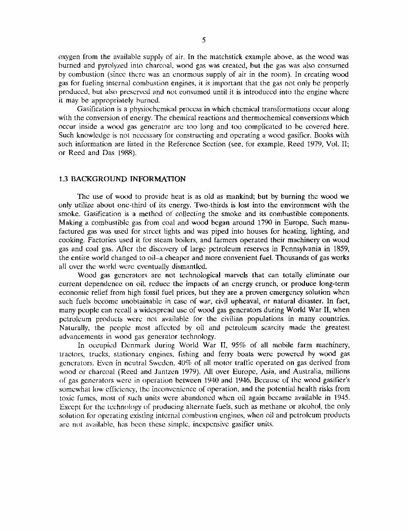
A schematic diagram of the stratified, downdraft gasifier is shown in Fig. S-1. Duringoperation of this gasifier, air passes uniformly downward through four zones, hence the name"stratified:"
1. The uppermost zone contains unreacted fuel through which air and oxygen enter. Thisregion serves the same function as the fuel hopper in the older, World War II designs.
2. In the second zone, the wood fuel reacts with oxygen during pyrolysis. Most of thevolatile components of the fuel are burned in this zone and provide heat for continuedpyrolysis reactions. At the bottom of this zone, all of the available oxygen from the airshould be completely reacted. The open top design ensures uniform access of air tothe pyrolysis region.
3. The third zone is made up of charcoal from the second zone. Hot combustion gasesfrom the pyrolysis region react with the charcoal to convert the carbon dioxide andwater vapor into carbon monoxide and hydrogen.
4. The inert char and ash, which constitute the fourth zone, are normally too cool tocause further reactions; however, because the fourth zone is available to absorb heator oxygen as conditions change, it serves both as a buffer and as a charcoal storageregion. Below this zone is the grate. The presence of char and ash serves to protectthe grate from excessive temperatures.
The stratified, downdraft design has a number of advantages over the World War IIgasifier designs. The open top permits fuel to be fed more easily and allows easy access. Thecylindrical shape is easy to fabricate and permits continuous flow of fuel. No special fuelshape or pretreatment is necessary; any blocky fuel can be used.
The foremost question about the operation of the stratified, downdraft gasifier concernschar and ash removal. As the charcoal reacts with the combustion gases, it eventually reachesa very low density and breaks up into a dust containing all of the ash as well as a percentageof the original carbon. This dust may be partially carried away by the gas and might eventually begin to plug the gasifier. Hence, it must be removed by shaking or agitation. Whenthe stratified gasifier unit is used to power vehicles, it is automatically shaken by the vehicle'smotion.
An important issue in the design of the stratified, downdraft gasifier is the preventionof fuel bridging and channeling. High-grade biomass fuels, such as wood blocks or chips, willflow down through the gasifier because of gravity and downdraft air flow. However, otherfuels (such as shredded chips, sawdust, and bark) can form a bridge, which will obstruct
VII
continuous flow and cause very high temperatures. Bridging can be prevented by stirring,shaking, or by agitating the grate or by having it agitated by the vehicle's movement. Forprolonged idling, a hand-operated shaker has been included in the design in this report.
A prototype unit of the stratified, downdraft gasifier design (see Figs. 5-2 and 5-3) hasbeen fabricated according to the instructions in this report; however, it has not been widelytested at this time. The reader is urged to use his ingenuity and initiative in constructing hisown wood gas generator. As long as the principle of airtightness in the combustion regions,in the connecting piping, and in the filter units is followed, the form, shape, and method ofassembly is not important.
The wood gasifier design presented in this report has as its origin the proventechnology used in World War II during actual shortages of gasoline and diesel fuel. Itshould be acknowledged that there are alternate technologies (such as methane productionor use of alcohol fuels) for keeping internal combustion engines in operation during aprolonged petroleum crisis; the wood gasifier unit described in this report represents onlyone solution to the problem.
Vl1l

ORNL-DWG 87-14553
XO
Wood Fuel
IlI'l
Blower
Throttle Valve
Wood Chips asFilter Media
To Engine Manifold
Grate
Fire Tube
Shaker
'-..._------......."..... ./
CARBURETOR CONNECTIONS..... ~..---- ~
FILTER UNIT..... ----..-----,/
GASIFIER UNIT
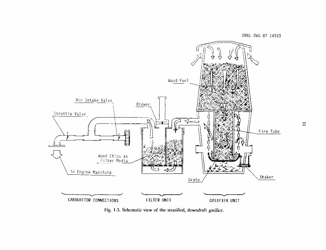
Fig. 8-1. Schematic view of the stratified, downdraft gasifier.

ORNL Photo 5321-86
Fig. S-2. The prototype wood gas generator unit mounted onto a tractor.
x

~.
ORNL-Photo 5325-86
Fig. S-3. Wood gas generator unit in operation during field testing.


CONVERSION FAcroRS FOR SI UNITS
English units have been retained in the body of this report. The report refers tocommercially available matcrials and sizes which are commonly expressed in English units.The conversion factors for 51 units arc given below:
To convert from
cubic feet (ft')cubic yards (yd l
)
Fahrenheit degrecs (OF)foot (ft)gallon (gal)horsepower (hp)inch (in.)pound (lb)quart (qt.)
To
cubic metcrs (m3)
cubic meters (m3)
Kelvin dcgrees (oK)meter (m)cubic mctcrs (m3
)
watt (W)meter (m)kilogram (kg)cubic meters (m3)
Multiply by
0.02830.7646(scc Notc 1)0.30483.785 X 10-3
745.70.02540.45369.464 X 10-4
Note 1: To convert temperatures, use the following equation,
K = 273 + 0.5556 X (F - 32) ,
where
F is the temperature in Fahrenheit degrees, and
K is the temperature in Kelvin dcgrees.
XIII


Fig. S-1.Fig. S-2.
Fig. S-3.Fig. 1-1.Fig. 1-2.Fig. 1-3.Fig. 2-1.
Fig. 2-2.
Fig. 2-3.Fig. 2-4.
Fig. 2-5.Fig. 2-6.Fig. 2-7.
Fig. 2-8.
Fig. 2-9.Fig. 2-10.
Fig. 2-11.Fig. 2-12.Fig. 2-13.Fig. 2-14.Fig. 2-15.Fig. 2-16.
Fig. 2-17.
Fig. 2-18.Fig. 2-19.Fig. 2-20.
Fig. 2-21.
Fig. 2-22.
Fig. 2-23.Fig. 2-24.Fig. 2-25.Fig. 2-26.Fig. 2-27.
LIST OF FIGURES
Schematic view of the stratified, downdraft gasifier IX
The prototype wood gas generator unit mountedonto a tractor xWood gas generator unit in operation during field testing Xl
Wood gas generator unit in operation during field testing 9Schematic view of the World War II, Imbert gasifier 10Schematic view of the stratified, downdraft gasifier 11The prototype wood gas generator unit mountedonto a tractor 22Exploded, schematic diagram of the wood gas generator unitand the fuel hopper 23The fire tube and circular top plate of the gasifier unit 24Drilling holes into the stainless steel mixing bowl to be usedfor the grate 25Chains attached to the lip of the stainless steel mixing bowl 26Connect the mixing bowl to the top plate with chains 27Braze, do not weld, the plumbing fittings to the thinwalled drums 28Exploded, schematic diagram of the grateshaking mechanism 29Parts for the shaker assembly 30The support frame can be brazed or bolted to the side of thegasifier unit 31Containers used in constructing the prototype gasifier unit 32Cover for the fuel hopper. 33Operating configuration of the fuel hopper and its cover 34Lock ring and welded tabs 35Exploded, schematic diagram of the filter unit 36Detail of the standoffs for the bottom plate ofthe filter unit 37Divider plate (#1) and bottom plate (#3), with standoffs (#4),for the filter unit 38Circular lid (#1) for the filter unit 39Blower (#1) with exhaust extension assembly 40Assembled and installed blower (#1), extension assembly (#4),and conduit connectors for gas inlet (#2) and outlet (#3) onlid of filter unit 41Filter container (#1) showing latches (#2) for lid and hose(#3) around top 42Exploded, schematic diagram of the carbureting unit andcontrol valves 43Schematic diagram of a butterfly control valve. 44Parts required for the butterfly valve 45Butterfly valve assembly 46Assembled butterfly valves 47Assembled carburetion unit 48
xv

Fig. 2-28.
Fig. 3-1.Fig. 3-2.
Fig. 3-3.
Fig. 3-4.Fig. 3-5.
usr OF FIGURES (continued)
Carburetion unit attached to engine's existingintake manifold 49Virtually all varieties of wood chips can be used for fuel 60Ignite a single piece of newspaper to start the gasifier unit;push the flaming newspaper through the ignition port anddirectly into the grate 61Igniting the exhaust gas will demonstrate that the gasifier unitis working properly 62Refill the fuel hopper before it becomes two-thirds empty 63The lid must be used to cover the fuel hopper in wet weatheror when shutting the unit down 64
xvi

Table 2-1.
Table 2-2.Table 2-3.Table 2-4.Table 3-1.Table 3-2.
UST OF TABLES
List of materials for the gasifier unit and the woodfuel hopper .Fire tube dimensions .List of materials for the primary filter unit .List of materials for the carbureting unit .Trouble-shooting your wood gas generator .Effects of breathing carbon monoxide .
XVII
505253546566


1
CONSlRucnON OF A SIMPUFIED WOOD GAS GENERATORFOR FUELING INTERNAL COMBUsnON ENGINES
IN A PETROLEUM EMERGENCY
H. LaFontaineG. P. Zimmerman
ABSTRACf
This report is one in a series of emergency technology assessments sponsoredby the Federal Emergency Management Agency (FEMA). The purpose of thisreport is to develop detailed, illustrated instructions for the fabrication,installation, and operation of a biomass gasifier unit (i.e., a "producer gas"generator, also called a "wood gas" generator) that is capable of providingemergency fuel for vehicles, such as tractors and trucks, in the event that normalpetroleum sources were severely disrupted for an extended period of time. Theseinstructions have been ptepared as a manual for use by any mechanic who isreasonably proficient in metal fabrication or engine repair.
This report attempts to preserve the knowledge about wood gasification thatwas put into practical use during World War II. Detailed, step-by-step fabricationprocedures are presented for a simplified version of the World War II, Imbertwood gas generator. This simple, stratified, downdraft gasifier unit can beconstructed from materials that would be widely available in the United Statesin a prolonged petroleum crisis. For example, the body of the unit consists of agalvanized metal garbage can atop a small metal drum; common plumbing fittingsthroughout; and a large, stainless steel mixing bowl for the grate. The entirecompact unit was mounted onto the front of a farm tractor and successfully fieldtested, using wood chips as the only fuel. Photographic documentation of theactual assembly of the unit as well as its operation is included.


3
1. WHAT IS A WOOD GAS GENERATOR AND HOW DOES IT WORK?
This report is one in a series of emergency technology assessments sponsored by theFederal Emergency Management Agency (FEMA). The purpose of this report is to developdetailed, illustrated instructions for the fabrication, installation, and operation of a biomassgasifier unit (i.e., a "producer gas" generator, also called a "wood gas" generator) that iscapable of providing emergency fuel for vehicles, such as tractors and trucks, in the eventthat normal petroleum sources were severely disrupted for an extended period of time. Theseinstructions have been prepared as a manual for use by any mechanic who is reasonably proficient in metal fabrication or engine repair.
1.1 INTRODUCTION
Fuel gas, produced by the reduction of coal and peat, was used for heating, as earlyas 1840 in Europe, and by 1884 it had been adapted to fuel engines in England. Before1940, gas generator: units were a familiar, but not extensively utilized, technology. However,petroleum shortages during World War II led to widespread gas generator applications in thetransportation industries of Western Europe. (Charcoal-burning taxis, a related application,were still common in Korea as late as 1970.) The United States, never faced with such prolonged or severe oil shortages, has lagged far behind Europe and the Orient in familiaritywith and application of this technology; however, a catastrophe could so severely disruptthe supply of petroleum in this country that this technology might be critical in meeting theenergy needs of some essential economic activities, such as the production and distributionof food.
This report attempts to preserve the knowledge about wood gasification as put intopractical use during World War II. Detailed, step-by-step procedures are presented in thisreport for constructing a simplified version of the World War II, Imbert wood gas generator.This simple, stratified, downdraft gasifier unit can be constructed from materials that wouldbe widely available in the United States in a prolonged petroleum crisis. For example, thebody of the unit consists of a galvanized metal garbage can atop a small metal drum;common plumbing fittings throughout; and a large, stainless steel mixing bowl for the grate.A prototype gasifier unit was fabricated from these instructions. This unit was then mountedonto the front of a gasoline-engine farm tractor and successfully field tested, using woodchips as the only fuel; see Fig. 1-1 (all figures and tables are presented at the end of theirrespective sections). Photographic documentation of the actual assembly of the unit, as wellas its operational field test, is included in this report.
The use of wood gas generators need not be limited to transportation applications.Stationary engines can also be fueled by wood gasifiers to run electric generators, pumps, andindustrial equipment. In fact, the use of wood gas as a fuel is not even restricted to gasoline engines; if a small amount of diesel fuel is used for ignition, a properly adjusted dieselengine can be operated primarily on wood gas introduced through the intake manifold.However, this report is concerned with the operation of four-cycle gasoline engines ratedfrom 10 to 150 horsepower. If more information is needed about operating gasifiers on other

4
fuels (such as coal, charcoal, peat, sawdust or seaweed), a list of relevant literature iscontained in the Bibliography at the end of this report.
The goal of this report is to furnish information for building a homemade wood gasgenerator made out of ordinary, available hardware, in order to get tractors, trucks, andother vehicles operating without delay, if a severe liquid fuel emergency should arise. Section 1 describes gasification principles and wood gas generators, in general, and gives somehistorical background about their operation and effectiveness. Section 2 contains detailedstep-by-step instructions for constructing your own wood gas generator unit; illustrations andphotographs are included to prevent confusion. Section 3 contains information on operating,maintaining, and trouble-shooting your wood gas generator; also included are some veryimportant guidelines on safety when using your gasifier system.
The wood gasifier design presented in this report has as its origin the proventechnology used in World War II during actual shortages of gasoline and diesel fuel. Itshould be acknowledged that there are alternate technologies (such as methane productionor use of alcohol fuels) for keeping internal combustion engines in operation during aprolonged petroleum crisis; the wood gasifier unit described in this report represents onlyone solution to the problem.
1.2 PRINCIPLES OF SOLID FUEL GASIFICATION
All internal combustion engines actually run on vapor, not liquid. The liquid fuels usedin gasoline engines are vaporized before they enter the combustion chamber above thepistons. In diesel engines, the fuel is sprayed into the combustion chamber as fine dropletswhich burn as they vaporize. The purpose of a gasifier, then, is to transform solid fuels intogaseous ones and to keep the gas free of harmful constituents. A gas generator unit is,simultaneously, an energy converter and a filter. In these twin tasks lie its advantages andits difficulties.
The first question many people ask about gasifiers is, "Where does the combustible gascome from?" Light a wooden match; hold it in a horizontal position; and notice that whilethe wood becomes charcoal, it is not actually burning but is releasing a gas that begins toburn brightly a short distance away from the matchstick. Notice the gap between thematchstick and the luminous flame; this gap contains the wood gas which starts burning onlywhen properly mixed with air (which contains oxygen). By weight, this gas (wood gas) fromthe charring wood contains approximately 20% hydrogen (H2), 20% carbon monoxide (CO),and small amounts of methane, all of which are combustible, plus 50 to 60% nitrogen (N2).
The nitrogen is not combustible; however, it does occupy volume and dilutes the wood gasas it enters and burns in an engine. As the wood gas burns, the products of combustion arecarbon dioxide (C02) and water vapor (H20).
The same chemical laws which govern combustion processes also apply to gasification.The solid, biomass fuels suitable for gasification cover a wide range, from wood and paperto peat, lignite, and coal, including coke derived from coal. All of these solid fuels arecomposed primarily of carbon with varying amounts of hydrogen, oxygen, and impurities, suchas sulphur, ash, and moisture. Thus, the aim of gasification is the almost completetransformation of these constituents into gaseous form so that only the ashes and inertmaterials remain.
In a sense, gasification is a form of incomplete combustion; heat from the burning solidfuel creates gases which are unable to burn completely, due to insufficient amounts of
5
oxygen from the available supply of air. In the matchstick example above, as the wood wasburned and pyrolyzed into charcoal, wood gas was created, but the gas was also consumedby combustion (since there was an enormous supply of air in the room). In creating woodgas for fueling internal combustion engines, it is important that the gas not only be properlyproduced, but also preserved and not consumed until it is introduced into the engine whereit may be appropriately burned.
Gasification is a physiochemical process in which chemical transformations occur alongwith the conversion of energy. The chemical reactions and thermochemical conversions whichoccur inside a wood gas generator are too long and too complicated to be covered here.Such knowledge is not necessary for constructing and operating a wood gasifier. Books withsuch information are listed in the Reference Section (see, for example, Reed 1979, Vol. II;or Reed and Das 1988).
13 BACKGROUND INFORMATION
The use of wood to provide heat is as old as mankind; but by burning the wood weonly utilize about one-third of its energy. Two-thirds is lost into the environment with thesmoke. Gasification is a method of collecting the smoke and its combustible components.Making a combustible gas from coal and wood began around 1790 in Europe. Such manufactured gas was used for street lights and was piped into houses for heating, lighting, andcooking. Factories used it for steam boilers, and farmers operated their machinery on woodgas and coal gas. After the discovery of large petroleum reserves in Pennsylvania in 1859,the entire world changed to oil-a cheaper and more convenient fuel. Thousands of gas worksall over the world were eventually dismantled.
Wood gas generators are not technological marvels that can totally eliminate ourcurrent dependence on oil, reduce the impacts of an energy crunch, or produce long-termeconomic relief from high fossil fuel prices, but they are a proven emergency solution whensuch fuels become unobtainable in case of war, civil upheaval, or natural disaster. In fact,many people can recall a widespread use of wood gas generators during World War II, whenpetroleum products were not available for the civilian populations in many countries.Naturally, the people most affected by oil and petroleum scarcity made the greatestadvancements in wood gas generator technology.
In occupied Denmark during World War II, 95% of all mobile farm machinery,tractors, trucks, stationary engines, fishing and ferry boats were powered by wood gasgenerators. Even in neutral Sweden, 40% of all motor traffic operated on gas derived fromwood or charcoal (Reed and Jantzen 1979). Allover Europe, Asia, and Australia, millionsof gas generators were in operation between 1940 and 1946. Because of the wood gasifier'ssomewhat low efficiency, the inconvenience of operation, and the potential health risks fromtoxic fumes, most of such units were abandoned when oil again became available in 1945.Except for the technology of producing alternate fuels, such as methane or alcohol, the onlysolution for operating existing internal combustion engines, when oil and petroleum productsare not availahle, has been these simple, inexpensive gasifier units.
6
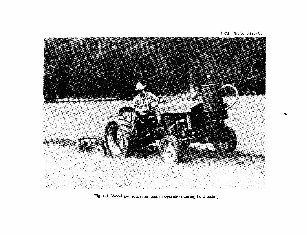
13.1 The World War II, Imbert Gasifier
The basic operation of two gasifiers is described in this and the following section. Theiroperating advantages and disadvantages will also be discussed. This information is includedfor the technically interested reader only; it is intended to give the reader more insight intothe subtleties of the operating principles of the wood gas generator described in this manual.Those readers who are anxious to begin construction of their own wood gas generator mayskip the material below and proceed directly to Sect. 2 without any loss of continuity.
The constricted hearth, downdraft gasifier shown in Fig. 1-2 is sometimes called the"Imbert" gasifier after its inventor, Jacques Imbert; although, it has been commerciallymanufactured under various names. Such units were mass produced during World War II bymany European automotive companies, including General Motors, Ford, and Mercedes-Benz.These units cost about $1500 (1985 evaluation) each. However, after World War II beganin 1939, it took six to eight months before factory-made gasifiers were generally available.Thousands of Europeans were saved from certain starvation by home-built, simple gasifierunits made from washing machine tubs, old water heaters, and metal gas or oxygen cylinders.Surprisingly, the operation of these units was nearly as efficient as the factory-made units;however, the homemade units lasted for only about 20,000 miles with many repairs, whilethe factory-made units operated, with few repairs, up to 100,000 miles.
In Fig. 1-2, the upper cylindrical portion of the gasifier unit is simply a storage bin orhopper for wood chips or other biomass fuel. During operation, this chamber is filled everyfew hours as needed. The spring-loaded, airtight cover must be opened to refill the fuelhopper; it must remain closed and sealed during gasifier operation. The spring permits thecover to function as a safety valve because it will pop open in case of any excessive internalgas pressure.
About one-third of the way up from the bottom of the gasifier unit, there is a set ofradially directed air nozzles; these allow air to be injected into the wood as it movesdownward to be gasified. In a gas generator for vehicle use, the downstroke of the engine'spistons creates the suction force which moves the air into and through the gasifier unit;during startup of the gasifier, a blower is used to create the proper airflow. The gas is introduced into the engine and consumed a few seconds after it is made. This gasification methodis called "producer gas generation," because no storage system is used; only that amount ofgas demanded by the engine is produced. When the engine is shut off, the production of gasstops.
During normal operation, the incoming air burns and pyrolyzes some of the wood, mostof the tars and oils, and some of the charcoal that fills the constricted area below thenozzles. Most of the fuel mass is converted to gas within this combustion zone. The Imbertgasifier is, in many ways, self-adjusting. If there is insufficient charcoal at the air nozzles,more wood is burned and pyrolyzed to make more charcoal. If too much charcoal forms,then the charcoal level rises above the nozzles, and the incoming air burns the charcoal.Thus, the combustion zone is maintained very close to the nozzles.
Bclow this combustion zone, the resulting hot combustion gases-carbon dioxide (CO z)and water vapor (HzO)-pass into the hot charcoal where they are chemically reduced tocombustible fuel gases: carbon monoxide (CO) and hydrogen (Hz). The hearth constrictioncauses all gases to pass through the reaction zone, thus giving maximum mixing and minimumheat loss. The highest temperatures are reached in this region.
Fine char and ash dust can eventually clog the charcoal bed and will reduce the gasflow unless the dust is removed. The charcoal is supported by a movable grate which can be
7
shaken at intervals. Ash buildup below the grate can be removed during cleaning operations.Usually, wood contains less than 1% ash (by weight). However, as the charcoal is consumed,it eventually collapses to form a powdery charcoal/ash mixture which may represent 2 to 10%(by weight) of the total fuel mass.
The cooling unit required for the Imbert gasifier consists of a water-filled precipitatingtank and an automotive radiator-type gas cooler. The precipitating tank removes all unacceptable tars and most of the fine ash from the gas flow, while the radiator further cools thegas. A second filter unit, containing a fine-mesh filtration material, is used to remove the lasttraces of any ash or dust that may have survived passage through the cooling unit. Once outof the filter unit, the wood gas is mixed with air in the vehicle's carburetor and is thenintroduced directly into the engine's intake manifold.
The World War II, Imbert gasifier requires wood with a low moisture content (lessthan 20% by weight) and a uniform, blocky fuel in order to allow easy gravity feed throughthe constricted hearth. Twigs, sticks, and bark shreds cannot be used. The constriction at thehearth and the protruding air nozzles present obstructions to the passage of the fuel and maycreate bridging and channeling followed by poor quality gas output, as unpyrolyzed fuel fallsinto the reaction zone. The vehicle units of the World War II era had ample vibration tojar the carefully sized wood blocks through the gasifier. In fact, an entire industry emergedfor preparing wood for use in vehicles at that time (Reed and Jantzen 1979). However, theconstricted hearth design seriously limits the range of wood fuel shapes that can besuccessfully gasified without expensive cubing or pelletizing pretreatment. It is this limitationthat makes the Imbert gasifier less flexible for emergency use.
In summary, the World War II Imbert gasifier design has stood the test of time andhas successfully been mass produced. It is relatively inexpensive, uses simple constructionmaterials, is easy to fabricate, and can be operated by motorists with a minimum amount oftraining.
1.3.2 The Stratified, Downdraft Gasifier
Until the early 1980s, wood gasifiers all over the world (including the World War IIdesigns) operated on the principle that both the fuel hopper and the combustion unit beairtight; the hopper was sealed with a top or lid that had to be opened every time wood wasadded. Smoke and gas vented into the atmosphere while new wood was being loaded; theoperator had to be careful not to breathe the unpleasant smoke and toxic fumes.
Over the last few years, a new gasifier design has been developed through cooperativeefforts among researchers at the Solar Energy Research Institute in Colorado, the Universityof California in Davis, the Open University in London, the Buck Rogers Company in Kansas,and the Biomass Energy Foundation, Inc., in Florida (Reed and Das 1988). This simplifieddesign employs a balanced, negative-pressure concept in which the old type of sealed fuelhopper is no longer necessary. A closure is only used to preserve the fuel when the engineis stopped. This new technology has several popular names, including "stratified, downdraftgasification" and "open top gasification." Two years of laboratory and field testing haveindicated that such simple, inexpensive gasifiers can be built from existing hardware and willperform very well as emergency units.
A schematic diagram of the stratified, downdraft gasifier is shown in Fig. 1-3. Duringoperation of this gasifier, air passes uniformly downward through four zones, hence the name"stratified:"
8
1. The uppermost zone contains unreacted fuel through which air and oxygen enter. Thisregion serves the same function as the fuel hopper in the Imbert design.
2. In the second zone, the wood fuel reacts with oxygen during pyrolysis. Most of thevolatile components of the fuel are burned in this zone and provide heat for continuedpyrolysis reactions. At the bottom of this zone, all of the available oxygen from the airhas completely reacted. The open top design ensures uniform access of air to thepyrolysis region.
3. The third zone is made up of charcoal from the second zone. Hot combustion gasesfrom the pyrolysis region react with the charcoal to convert the carbon dioxide andwater vapor into carbon monoxide and hydrogen.
4. The inert char and ash, which constitute the fourth zone, are normally too cool tocause further reactions; however, since the fourth zone is available to absorb heat oroxygen as conditions change, it serves both as a buffer and as a charcoal storageregion. Below this zone is the grate. The presence of char and ash serves to protectthe grate from excessive temperatures.
The stratified, downdraft design has a number of advantages over the World War II,Imbert gasifier. The open top permits fuel to be fed more easily and allows easy access. Thecylindrical shape is easy to fabricate and permits continuous flow of fuel. No special fuelshape or pretreatment is necessary; any blocky fuel can be used.
The foremost question about the operation of the stratified, downdraft gasifier concernschar and ash removal. As the charcoal reacts with the combustion gases, it eventually reachesa very low density and breaks up into a dust containing all of the ash as well as a percentageof the original carbon. This dust may be partially carried away by the gas; however, it mighteventually begin to plug the gasifier,'and so it must be removed by shaking or agitation. Boththe Imbert gasifiers and the stratified concept have a provision for shaking the grate; whenthey are used to power vehicles, they are automatically shaken by the vehicle's motion.
An important issue in the design of the stratified, downdraft gasifier is the preventionof fuel bridging and channeling. High-grade biomass fuels such as wood blocks or chips willflow down through the gasifier under the influence of gravity, and downdraft air flow.However, other fuels (such as shredded wood, sawdust, and bark) can form a bridge that willprevent continuous flow and cause very high temperatures. Obviously, it is desirable to usethese widely available biomass residues. Bridging can be prevented by stirring, shaking, or byagitating the grate or by having it agitated by the vehicle's movement. For prolonged idling,a hand-operated shaker has been included in the design.
A prototype design of the stratified, downdraft gasifier design has been developed. Thedetailed but simple design is described and illustrated in Sect. 2; however, it has not beenwidely tested at this time. The reader is urged to use his ingenuity and initiative in constructing his own wood gas generator. As long as the principle of airtightness in thecombustion regions, in the connecting piping, and in the filter units is followed, the form,shape, and method of assembly is not important.
ORNL-Photo 5325-86
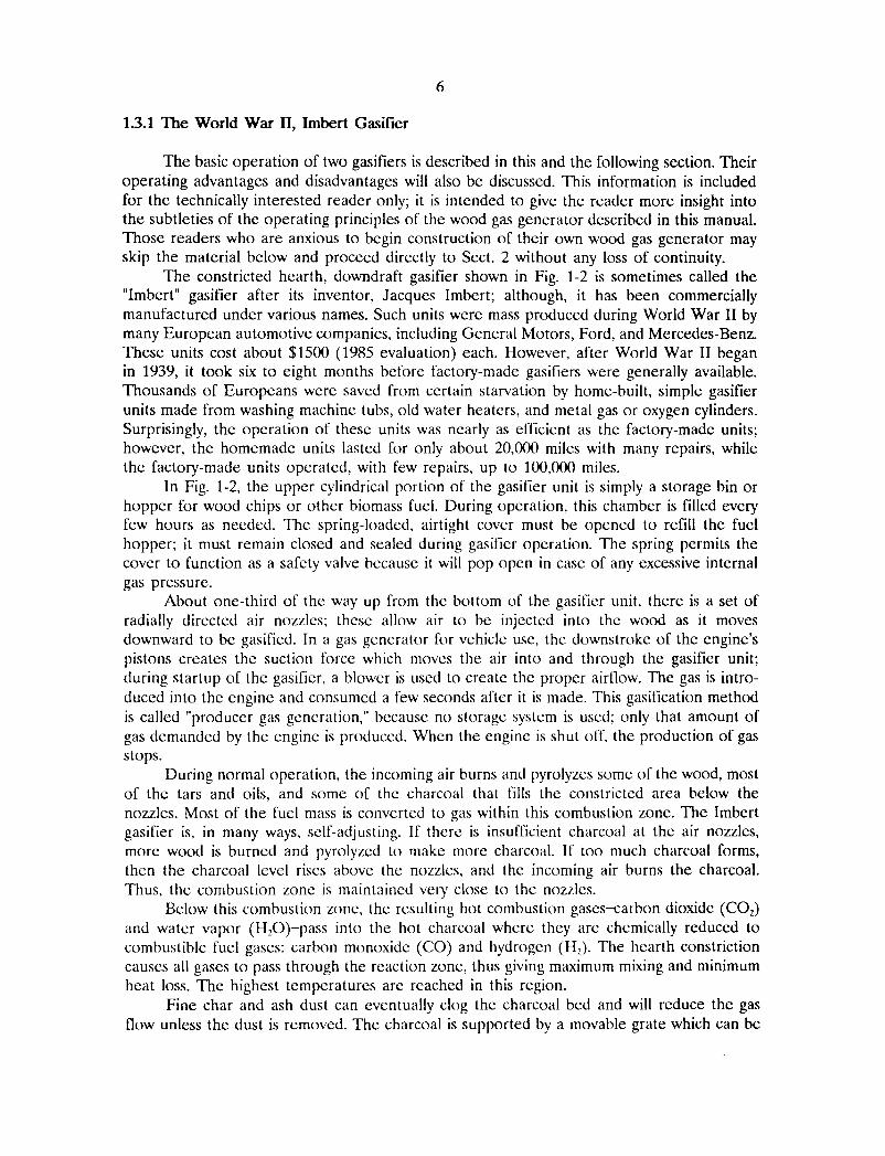
Fig. 1-1. Wood gas generator unit in operation during field testing.
10

ORNL-DWG 87-14552
Safety Lid
.....o
Engine
Blower
Carburetor
Gas Cooler
(End View)~
Wood Fuel
Shaker Grate
One-Way AirIntake Valve
Air Nozzles
""-- --.,,- ." ""-- .........--------~ ""- --.,,- ."
GASIFIER UNIT COOLING UNIT FILTER UNIT ANDCARBURETOR CONNECTIONS
Fig. 1-2 Schematic view of the World War n, Imbert gasifier.
ORNL-DWG 87-14553
Air Intake Valve
Throttle Valve
Wood Chips asFilter Media
To Engine Manifold
...... -..".....- /
CARBURETOR CONNECTIONS
Wood Fuel
fIr1
Blower
...... " ~
FILTER UNIT
Grate
..... ~ ~
GASIFIER UNIT
Fire Tube
Shaker
.......
.......
Fig. 1-3. Schematic view of the stratified, downdraft gasifier.

13
2 BUILDING YOUR OWN WOOD GAS GENERATOR
The following fabrication instructions, parts lists, and illustrations describe the prototypegasifier unit shown schematically in Fig. 1-3. These instructions are simple and easy to follow.The dimensions in the following plans are given in inches rather than in millimeters to makeconstruction easier for those who might be unfamiliar with the metric system and to allowthe builder to take advantage of available, alternate construction materials. It will be obviousto the experienced engineer, mechanic, or builder that most of the dimensions (for example,plate thicknesses and cleanout diameters) are not critical to the acceptable performance ofthe finished gasifier unit.
The prototype gasifier unit described in the following text was actually constructed andfield tested on a gasoline-engine farm tractor (a 35-hp, John Deere 1010 Special); see Fig. 21. The unit operated very well, and on par with the European, World War II designs, butit has not had the test of time nor the millions of operating hours like the older Imbertdesign. This new stratified design was developed for the construction of simple, inexpensiveemergency wood gas generator units. The prototype design below should be considered tobe the absolute minimum in regard to materials, piping and filter arrangement, andcarburetor system connections.
The gasifier unit, as described below, is designed to maintain proper cooling, even atmoderate vehicle speeds. If this unit is to be used on stationary engines or on slow-movingvehicles, a gas cooler and a secondary filter must be placed in the piping system between thegenerator unit and the carburetor. The ideal temperature for the wood gas at the inlet tothe carburetor manifold would be 700F, with acceptable peaks of 140 to 1600F. For every 10degrees above 700F, an estimated 1% horsepower is lost. Cooler gas has higher density and,therefore, contains more combustible components per unit volume.
The millions of wood gasifiers built during World War II proved that shape, form, andconstruction material had little or no effect on the performance of the unit. Judicioussubstitution or the use of scavenged parts is, therefore, quite acceptable. What ~ importantis that:
1. the fire tube dimensions (inside diameter and length) must be correctly selected tomatch the rated horsepower of particular engine which is to be fueled,
2. airtightness of the gas generator unit and all connecting piping must be maintained atall times, and
3. unnecessary friction should be eliminated in all of the air and gas passages by avoidingsharp bends in the piping and by using piping sizes which are not too small.
14
21. BUILDING TIIE GAS GENERAmR UNIT AND TIIE FUEL HOPPER
Figure 2-2 shows an exploded view of the gas generator unit and the fuel hopper; thelist of materials is given in Table 2-1 (all figures and tables mentioned in Sect. 2 arepresented at the end of Sect. 2). Only the dimensions of the fire tube (Item lA) must bereasonably close; all other dimensions and materials can be substituted as long as completeairtightness is maintained. In the following instructions, all item numbers refer both to Fig.2-2 and to Table 2-1.
The prototype unit described in this report was constructed for use with a 35-hpgasoline engine; the unit has a fire tube diameter of 6 in. (as determined from Table 2-2).A gas generator unit containing a fire tube up to 9-in. diameter (i.e., a gasifier unit forfueling engines up to about 65 hp) can be constructed from the following instructions. Ifyour engine requires a fire tube diameter of 10 in. or more, use a 55-gal drum for the gasunit and another 55-gal drum for the fuel hopper.
The following fabrication procedure is very general and can be applied to theconstruction of gas generator units of any size; however, the specific dimensions which aregiven in the parts list and in the instructions below are for this particular prototype unit. Allaccompanying photographs were taken during the actual assembly of the prototype unit.
The fabrication procedure is as follows:
1. Vsing the displacement or horsepower rating of the engine to be fueled by the gasifierunit, determine the dimensions (inside diameter and length) of the fire tube (Item lA)from Table 2-2. Fabricate a cylindrical tube or cut a length of correctly sized pipe tomatch the dimensions from Table 2-2. (For the prototype gasifier unit illustrated in thisreport, a 6-in.-diam firetube was used; its length was 19 in.)
2. The circular top plate (Item 2A) should be cut to a diameter equal to the outsidediameter of the gasifier housing drum (Item 3A) at its top. A circular hole should thenbe cut in the center of the top plate; the diameter of this hole must be equal to theoutside diameter of the fire tube. The fire tube (Item lA) should then be welded ata right angle to the top plate (Item 2A) as shown in Fig. 2-3.
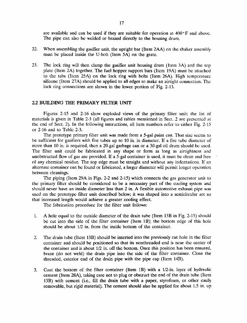
3. The grate (Item 4A) should be made from a stainless steel mixing bowl or colander.Approximately 125 holes with diameters of 1/2 in. should be drilled in the bottom andup the sides of the mixing bowl; see Fig. 2-4. A V-bolt (Item 5A) should be weldedhorizontally to the side of the grate, 2 in. from its bottom. This V-bolt will beinterlocked with the shaker mechanism (Item 12A) in a later step.
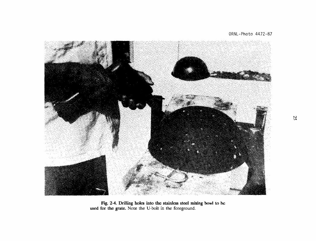
4. The support chains (Item 6A) are to be attached to the grate in three evenly spacedholes drilled under the lip of the mixing bowl or colander; see Fig. 2-5. These chainsare to be connected to the top plate (Item 2A) with eyebolts (Item 7A), as shown inFig. 2-6. Each eyebolt should have two nuts, one on each side of the top plate, so thatthe eyebolts can be adjusted to the proper length. When assembled, the bottom of thefiretube should be 1.25 in. above the bottom of the mixing bowl.
5. A hole equal to the outside diameter of the ash cleanout port (Item 8A) should be cutinto the side of the gasifier housing drum (Item 3A); the bottom edge of this hole

15
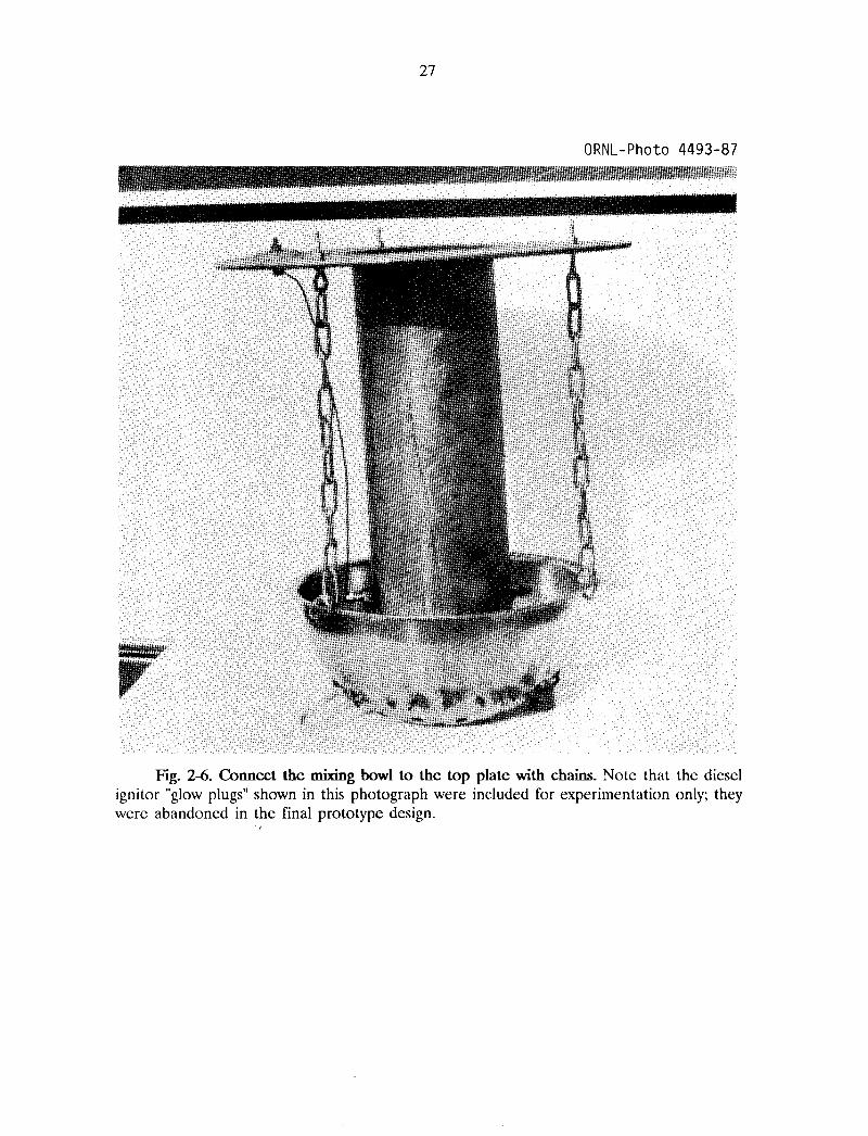
should be about 1/2 in. from the bottom of the drum. Because of the thin wallthickness of oil drums and garbage cans, welding is not recommended; brazing suchparts to the drums or cans will ensure both strength and airtightness (see Fig. 2-7).
6. Two holes, equal to the outside diameters of the ignition ports (Item lOA), are to becut with their centers at a distance from the top of the housing drum (Item 3A) equalto the firetube length less 7 in. (19 in. less 7 in. equals 12 in. for this prototype unit);the holes should be placed opposite each other as shown in Fig. 2-2. The ignition portsshould be attached to the wall of the housing drum by brazing.
7. When the ash cleanout port (Item 8A) and the ignition ports (Item lOA) have beenattached to the wall of the gasifier housing drum (Item 3A), they should then be closedwith pipe caps, Items 9A and 11A respectively. The threads of the pipe caps shouldbe first coated with high temperature silicone (Item 27A) to ensure airtightness. Anoptional steel crossbar welded to the pipe cap will reduce the effort required to openthese caps later.
8. The shaker assembly (Item 12A) is shown in Fig. 2-8. The l/2-in. pipe (Item 1AA)should be brazed into the side of the housing drum (Item 3A), 1.5 inches from thebottom of the drum; the length of this pipe which protrudes into the drum must bechosen so that the upright bar (Item 2AA) is in line with the V-bolt (Item 5A) on thegrate. Likewise, the length of the upright bar must be selected so as to connect intothe V-bolt.
9. Weld the upright bar (Item 2AA) to the head of the bolt (Item 3AA). The threadedend of the bolt should be ground down or flattened on one side, as shown in Fig. 29, to positively interlock with a slot to be drilled and filed in the handle (Item 4AA).The handle can be formed or bent into any desired or convenient shape.
10. A hole should be drilled in the pipe cap (Item 7AA) so that there is a close fitbetween this hole and the bolt (Item 3AA). The close fit will help to ensureairtightness.
11. Before assembling the shaker, as shown in Fig. 2-8, coat the bolt (Item 3AA) with asmall amount of grease. Before iiiserting the bolt, fill the pipe (Item 1AA) with hightemperature silicone (Item 27A) to ensure airtightness. Tighten the nuts (Item 6AA)so that the position of the handle (Item 4AA) is maintained by friction, yet is capableof being turned and agitated during cleanout or stationary operation.
12. Fabricate the supports (Item 13A) for the gasifier unit housing drum (Item 3A) outof rectangular, iron bar stock. The shape and height of the support flanges must bedetermined by the frame of the vehicle to which the gasifier is to be mounted. Thesupports can either be bolted to the bottom and side with the 1/4-in. bolts (Item 14A)or can be brazed directly to the drum; see Fig. 2-10. Remember to seal all bolt holesfor airtightness.
13. Completely cover the bottom of the housing drum (Item 3A) with 1/2 in. of hydraulicce~ent (Item 28A). The cement should also be applied to the inside of the drum for
16
about 5 in. up the inside walls near the bottom. All edges should be rounded for easyash removal.
14. The fuel hopper (Item 15A) is to be made from a second container with its bottomup as shown in Fig. 2-11. Remove the bottom, leaving a l/4-in. lip around the circumference.
15. A garden hose (Item 17A) should be cut to a length equal to the circumference of thefuel hopper (Item 15A) and should then be slit along its entire length. It should beplaced over the edge of the fuel hopper from which the bottom was removed. This willprevent injury to the operator when adding wood fuel to the unit. To insure close fitof the garbage can lid (Item 16A), a piece of weather stripping (Item 18A) should beattached under the lid where it makes contact with the fuel hopper.
16. Cut four support bars (Item 19A) to lengths 2.5 in. longer than the height of the fuelhopper (Item 15A). Drill a 3/8-in. hole in each end of all four support bars; theseholes should be centered 3/4 in. from the ends. Bend 2 in. of each end of thesesupport bars over at a right angle; then, mount them evenly spaced around the fuelhopper (Item 15A) with 1/4-in. bolts (Item 20A). One of the bends on each supportbar should be as close to the lower edge of the fuel hopper as possible.
17. Cut four metal triangular standoffs (Item 21A) and braze, weld, or rivet them flatagainst the edge of the garbage can lid (Item 16A) as shown in Fig. 2-12; they mustbe aligned with the four support bars (Item 19A) attached to the fuel hopper. Duringoperation, the garbage can lid must have a minimum 3/4-in. opening for air passage;the standoffs should provide this clearance when they are engaged into the holes inthe top edges of the support bars (Item 19A); see Fig. 2-13.
18. Two eye hooks (Item 22A) should be attached to opposite sides of the garbage canlid (Item 16A). Two screen door springs (Item 23A) should be attached to the garbagecan handles and used under tension to keep the top lid (Item 16A) either open orclosed.
19. Cut the oil drum lock ring (Item 24A) to the exact circumference of the top plate(Item 2A) so that it will fit snugly around the gasifier unit housing drum (Item 3A).
20. Cut four 2 by 2 by 1/4-in. tabs (Item 25A); then, braze these tabs to the lock ring(Item 24A), evenly spaced and in alignment with the support bars (Item 19A) on thefuel hopper. Drill a 3/8-in. hole in each tab to align with the holes in the fuel hoppersupport bars (Item 19A). The lock ring is shown in Fig. 2-14.
21. The connecting pipe (Item 29A) between the gasifier unit and the filter unit shouldbe attached to the gasifier housing drum (Item 3A) at a point 6 in. below the top ofthe drum. This pipe must be a minimum of 2-in. in diameter and should be at least 6ft long for cooling purposes. At least one of the ends of this pipe must be removablefor cleaning and maintenance. On this prototype unit, an airtight electrical conduitconnector was used; this connection is visible in Fig. 2-1. Many similar plumbing devices
17
are available and can be used if they are suitable for operation at 400 0 F and above.The pipe can also be welded or brazed directly to the housing drum.
22. When assembling the gasifier unit, the upright bar (Item 2AA) on the shaker assemblymust be placed inside the V-bolt (Item 5A) on the grate.
23. The lock ring will then clamp the gasifier unit housing drum (Item 3A) and the topplate (Item 2A) together. The fuel hopper support bars (Item 19A) must be attachedto the tabs (Item 25A) on the lock ring with bolts (Item 26A). High temperaturesilicone (Item 27A) should be applied to all edges to make an airtight connection. Thelock ring connections are shown in the lower portion of Fig. 2-13.
22 BUILDING TIlE PRIMARY FILlER UNIT
Figures 2-15 and 2-16 show exploded views of the primary filter unit; the list ofmaterials is given in Table 2-3 (all figures and tables mentioned in Sect. 2 are presented atthe end of Sect. 2). In the following instructions, all item numbers refer to either Fig. 2-15or 2-16 and to Table 2-3.
The prototype primary filter unit was made from a 5-gal paint can. That size seems tobe sufficient for gasifiers with fire tubes up to 10 in. in diameter. If a fire tube diameter ofmore than 10 in. is required, then a 20-gal garbage can or a 30-gal oil drum should be used.The filter unit could be fabricated in any shape or form as long as airtightness andunobstructed flow of gas are provided. If a 5-gal container is used, it must be clean and freeof any chemical residue. The top edge must be straight and without any indentations. If analternate container can be found or fabricated, a larger diameter will permit longer operationbetween cleanings.
The piping (Item 29A in Figs. 2-2 and 2-15) which connects the gas generator unit tothe primary filter should be considered to be a necessary part of the cooling system andshould never have an inside diameter less than 2 in. A flexible automotive exhaust pipe wasused on the prototype filter unit described below; it was shaped into a semicircular arc sothat increased length would achieve a greater cooling effect.
The fabrication procedure for the filter unit follows:
1. A hole equal to the outside diameter of the drain tube (Item 13B in Fig. 2-15) shouldbe cut into the side of the filter container (Item IB); the bottom edge of this holeshould be about 1/2 in. from the inside bottom of the container.
2. The drain tube (Item 13B) should be inserted into the previously cut hole in the filtercontainer and should be positioned so that its nonthreaded end is near the center ofthe container and is about 1/2 in. off the bottom. Once this position has been ensured,braze (do not weld) the drain pipe into the side of the filter container. Close thethreaded, exterior end of the drain pipe with the pipe cap (Item 14B).
3. Coat the bottom of the filter container (Item IB) with a 1/2-in. layer of hydrauliccement (Item 28A), taking care not to plug or obstruct the end of the drain tube (Item13B) with cement (i.e., fill the drain tube with a paper, styrofoam, or other easilyremovable, but rigid material). The cement should also be applied for about 1.5 in. up

18
the inside walls of the container near its bottom. Round the edges slightly; the cementis to provide a pathway for any liquid condensate to drain out through the drain tube.The cement must be allowed to harden before proceeding with the fabrication stepsbelow. Remove the tIller materialfrom the drain tube when the cement has hardened.
4. A circular bottom plate (Item 2B) should be cut to a diameter 1/2 in. smaller than theinside diameter of the filter container (Item IB). This will allow for heat expansion andeasy removal for cleaning. This bottom plate should be drilled with as many 3/4-in.holes as are practical for the size of the plate. Three evenly spaced 3/8-in. holes shouldalso be drilled around the edge of the bottom plate for the spacer bolts (Item 3B).
5. Fig. 2-16 shows the detail of using three bolts (Item 3B) as spacers for the bottomplate (Item 2B). The length of the bolts should be adjusted to provide a clearance ofabout 2-in. between the layer of cement in the bottom of the container (Item IB) andthe bottom plate (Item 2B).
6. A rectangular divider plate (Item 4B) should be cut to a width 1/4 in. less than theinside diameter of the filter container (Item IB) and to a height 2.5 in. less than theinside height of the container. This divider plate should then be welded at a right angleto the centerline of the bottom plate (Item 2B) as shown in Fig. 2-17.
7. Cut a piece of high-temperature hydraulic hose (Item 5B) to a length equal to thecircumference of the filter container. It should be slit along its entire length and thenplaced over the top edge of the filter container (Item IB) to ensure airtightness.
8. A circular lid (Item 6B) should be cut equal to the outside diameter of the filtercontainer (Item IB). Three holes should be cut into this lid for the exhaust pipe (Item29A) from the gasifier unit, the blower (Item 7B), and the filter exhaust pipe (ItemlOB) to the engine manifold. Note the arrangement of these holes: the pipe (Item29A) from the gasifier unit must enter the lid on one s,ide of the divider plate (Item4B); the blower (Item 7B) and the filter exhaust pipe (Item lOB) to the enginemanifold must be located on the other side of the divider plate. This arrangement canbe seen in Fig. 2-18.
9. The connecting pipe (Item 29A) between the gasifier unit and the filter unit shouldbe attached to the lid (Item 5B) of the filter container. At least one of the ends of theconnecting pipe (Item 29A) must be removable for cleaning and maintenance. On thisprototype unit, an airtight electrical conduit connector was used. Many similar plumbingdevices are available and can be used if they are suitable for operation at 400 0 F andabove. The pipe can also be welded or brazed directly to the lid.
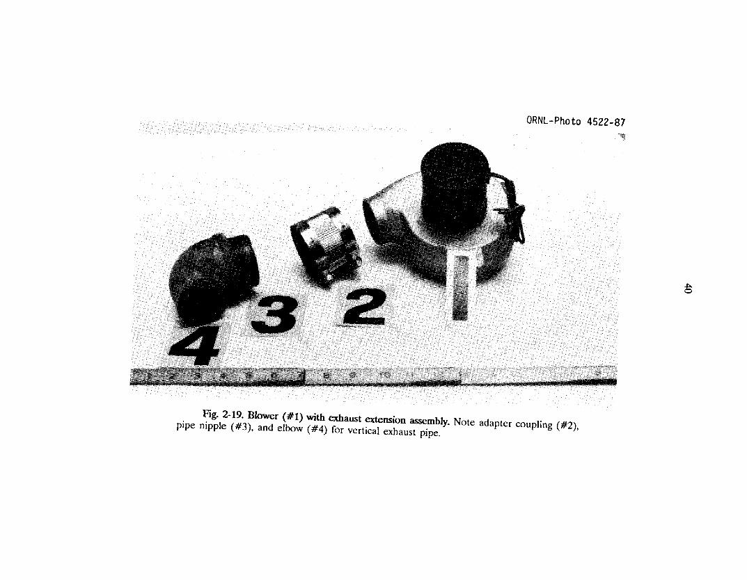
10. Attach the blower (Item 7B) to the filter container lid (Item 6B). On the prototypegasifier illustrated in this report, a heater blower from a Volkswagen automobile wasused. Connections for a vertical extension tube (Item 8B) will have to be fabricatedas shown in Fig. 2-19. A closing cap (Item 9B) is required for the blower exhaust tube.A plumbing cap of steel or plastic with a close fit can be used or fabricated to fit. Thevertical extension and the closing cap are visible in Fig. 2-1.

19
11. The gas outlet (Item lOB) to the carbureting unit on the engine should be 1.25 in.minimum diameter. In fabricating this connection, all abrupt bends should be avoidedto ensure free flow of gas. Using plumbing elbows is one solution. The gas outlet (ItemlOB) can either be welded or brazed to the lid (Item 6B) of the filter container or anairtight, electrical conduit connector can be used.
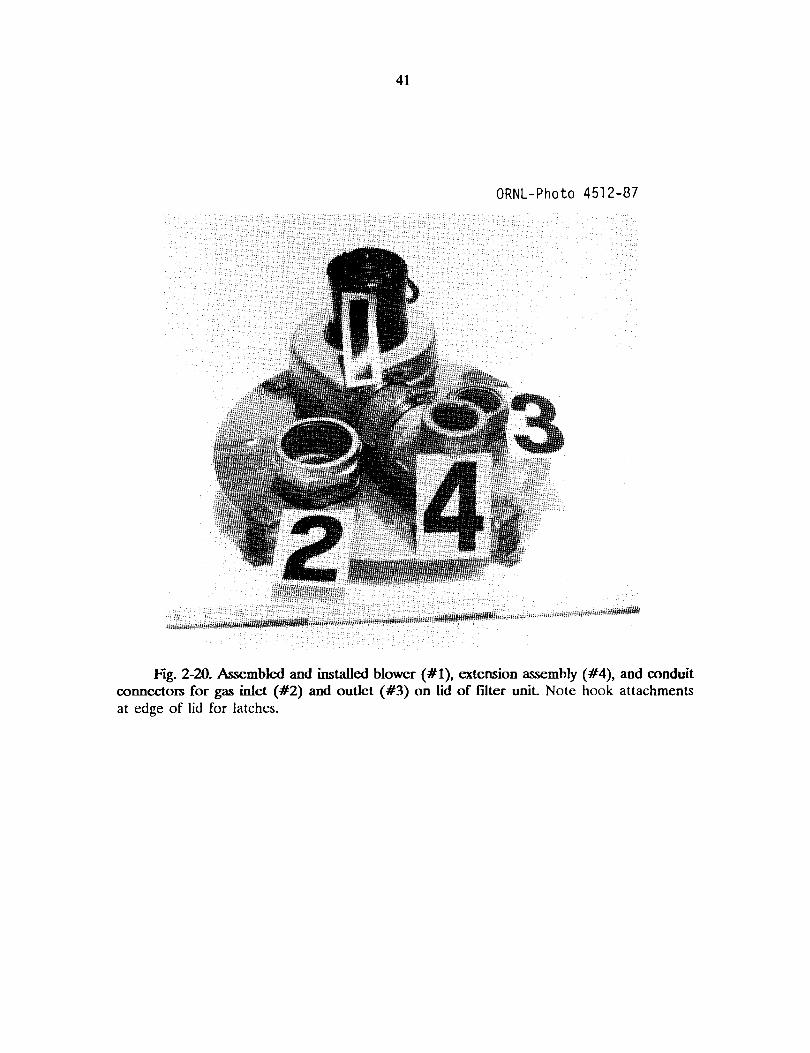
12. Latching devices (Item lIB) should be welded or brazed to the lid (see Fig. 2-20) andto the sides (see Fig. 2-21) of the filter container. An air-tight connection between thelid and the filter container must be maintained.
13. Cut two lengths of high-temperature hydraulic hose (Item 12B) equal to the height ofthe divider plate (Item 4B); cut a third length of hose equal to the width of the dividerplate. Slit each hose along its entire length. Place the first two hoses on each side ofthe divider plate, and place the third hose along the top edge of the divider plate asshown in Fig. 2-17.
14. Insert the divider plate (Item 4B) into the filter container (Item 1B), making sure thatthe hoses (Item 12B) create an airtight seal along all sides. By changing the length ofthe spacer bolts (Item 3B), adjust the height of the divider plate so that it is exactlyflush with the top of the filter container. Make sure that the lid (Item 5B) will seatflatly and tightly against the top edge of the divider plate.
15. Fill the filter container (Item 1B) on both sides of the divider plate with wood chips,the same kind as would be used for fuel in the gasifier unit. Nter carefully packingand leveling these wood chips, place the lid (Item 6B) on the filter container, and closethe latches tightly.
2.3. BUILDING THE CARBURETING UNIT WITH THE AIR AND THROTTLECONTROLS
Figures 2-22 and 2-23 show exploded views of the carbureting unit; the list of materialsis given in Table 2-4 (all figures and tables mentioned in Sect. 2 are presented at the endof Sect. 2). In the following instructi0l1cs, all item numbers refer both to Figs. 2-22 and 223 and to Table 2-4. The following is a simple and easy way to assemble a carburetor toachieve both air mixture and throttle control. It can be mounted to either updraft ordowndraft manifolds by simply turning the unit over. Most of the fabrication procedure belowis devoted to the assembly of two butterfly valves: one for the throttle valve and one for theair mixture valve. The remainder of the carburetor unit can be assembled from ordinary,threaded plumbing parts.
The inside diameter of the piping used in the carburetor unit must be related to thesize of the engine and should never be smaller than the intake opening on the enginemanifold. If in doubt on the inside diameter for the pipe and/or hose sizes, always go witha larger diameter. This will reduce friction losses and will give longer operating hoursbetween cleanings.
When the wood gas leaves the filter unit it should normally be below 180"F. About 2ft from the filter container, an automotive water hose can be connected to the pipe on thecarbureting unit. This rubber hose will keep engine vibration from creating air leaks in the

20
filter unit or in the connecting piping. The hose must be a fairly new item; such hoses havea steel spring inside to keep them from collapsing when negative pressure is applied. Thespring will soon rust if it has first been subjected to water and then to the hot wood gasenriched with hydrogen.
The fabrication procedure for the assembly of two butterfly valves follows:
1. The manifold adapter (Item 1C in Fig. 2-22) must be fitted with bolts and/or holes formounting onto the engine's existing intake manifold. Because gasoline engines areproduced with so many different types of intake manifolds, ingenuity and commonsense must be used to modify the manifold adapter (Item 1C) for each different engineto be operated on wood gas. A gasket (Item 7C) should be cut to match the shape ofthe engine intake fitting.
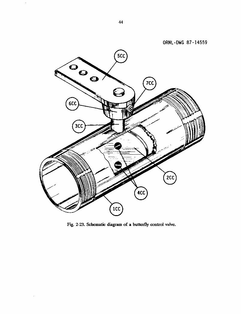
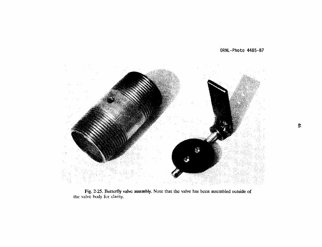
20 The butterfly valve (Item 3C) is shown in Figs. 2-24 and 2-25; two such valves arerequired. A 3/8-in. hole should be drilled through the diameter of each valve body(Item 1CC) at the midpoint of its length.
30 The valve plate (Item 2CC) must be oval in shape with the dimensions given in Table2-4. An oval valve plate must be used so that, in the closed position, the valve will beabout 10" off center. This will ensure that the valve will come to a complete stop inthe closed position.
4. The edges of the valve plate (Item 2CC), around the longer diameter of the oval,should be beveled to provide a positive, airtight closure. Two evenly spaced, l/4-in.holes should be drilled along the shorter diameter of the oval plate.
5. The valve support rod (Item 3CC) should be filed or ground flat on one side as shownin Fig. 2-24; the flat area must begin 1/4 in. from one end and must continue for adistance equal to the inside diameter of the valve body (Item 1CC).
60 Two 3/16-in. holes should be drilled into the flat area of the valve support rod (Item3CC); these holes must align with the holes in the valve plate (Item 2CC). They mustalso be tapped (with threads) to accept the valve plate screws (Item 4CC).
70 The butterfly valve (Item 3C) should be assembled by first placing the valve supportrod (Item 3CC) through the hole in the valve body (Item 1CC)o The valve plate (Item2CC) should be dropped into one end of the valve body and then inserted into the flatarea of the valve support rod. The two screws (Item 4CC) should be used to attachthe valve plate to the support rod. Check to see that the assembled valve plate rotatesfreely and seats completely in the closed position.
80 A nut (Item 6CC) should be welded flat against one side of the throttle arm (Item5CC) near its end. A 1/8-in. hole should be drilled into the side of the nut and mustbe threaded to accept the set screw (Item 7CC). At least one hole should be drilledinto the throttle arm for attachment of the engine throttle control or air controllinkages.

21
9. Place the nut (Item 6CC) on the throttle arm over the end of the valve support rod(Item 3CC) and use the set screw (Item 7CC) to secure the assembly. The throttle armcan be placed in any convenient orientation. Assembled butterfly valves are shown inFig. 2-26.
10. The remaining parts of the carburetor assembly should be screwed together as shownin Fig. 2-27. Pipe thread compound should be used to make airtight connections. Theassembled carburetor unit should be attached to the engine's intake manifold as shownin Fig. 2-28
11. This prototype gasifier was designed to operate if gasoline were unavailable; but, if dualoperation on wood and gasoline is desired, the elbow (Item 2C) could be replaced witha tee, allowing a gasoline carburetor to also be mounted.
12. The arm on the butterfly valve (Item 3C) which is closest to the elbow (Item 2C) isto be connected to the foot- (or, on tractors, hand-) operated accelerator. The otherbutterfly valve is to be used as the air mixture control valve and can be operated witha manual choke cable. If the engine has an automatic choking device, then a handoperated choke cable should be installed. Both butterfly valves and their connectingcontrol linkages must operate smoothly with the ability to adjust the valve yet keep itstationary in the selected position during operation. The linkages must close the valvesairtight when the engine is off.
13. The air inlet (Item 6C) should be connected by an extension hose or pipe, either ironor plastic, to the existing engine's air filter in order to prevent road dust or agriculturalresidue from entering the engine.
14. The wood gas inlet (Item 5C) is to be connected to the outlet piping (Item lOB asshown in Fig. 2-15) from the wood gas filter unit. Part of this connection should bea high-temperature rubber or neoprene hose to absorb engine vibration.

22
ORNL-Photo 5321-86
Fig. 2-1. The prototype wood gas generator unit mounted onto a tractor.

ORNL-OWG 87 -145
,.
§'" ,,'" J~ -. ( 25A
~/
I ~I I
I
llA
l
I
.~
I
e-i 3A
~,tv~""
ft-GI
/ ~12A~
/
Fig. 2-2. Exploded, schematic diagram of the wood gas generator unit and the fuelhopper.

24
ORNL-Photo 4533-87
Fig. 2-3. The fire tube and circular top plate of the gasifier unit.
ORNL-Photo 4472-87
Fig. 2-4. Drilling holes into the stainless steel mixing bowl to beused for the grate. Note the V-bolt in the foreground.
~

ORNL-Photo 4473-87
Fig. 2-5. Chains attached to the lip of the stainless steel mixing bowl
~
27
ORNL-Photo 4493-87
Fig. 2-6. Connect the mixing bowl to the top plate with chains. Note that the dieselignitor "glow plugs" shown in this photograph were included for experimentation only; theywere abandoned in the final prototype design.
28
I'.00
~
I0'>N
2
L()o::;t
"0
0
]
+J0
~
..l::
~
0....I
c::::
-l
:.a
za:::
-0
~,.Q-.9~.9--l.COIl.9];:)
'a
~

29
ORNL-DWG 87-14555
Fig. 2-8. Exploded, schematic diagram of the grate shaking mechanism.

ORNL-Photo 4496-87
Fig. 2-9. Parts for the shaker assembly. Note the flattened portion of the bolt (atextreme left) which positively locks into the handle (third from right). At the extreme rightis a "poker bar" which engages into the hole in the top of the handle to operate the shakermechanism; the shaker handle will get very hot during normal gasifier operation.
~o

ORNL-Photo 4527-87
Fig. 2-10. The support frame can be brazed or bolted to the side of the gasifier uniLAll bolts should be sealed air tight.
w......

32
ORNL-Photo 4499-87
Fig. 2-11. Containers used in constructing the prototype gasifier unit. At right, a 20gal garbage can (the fuel hopper) is shown on top of a 30-gal metal drum (the gasifier unit
housing). The 5-gal paint can, at left, is used as the filter container.

ORNL-Photo 4508-87
Fig. 2-12 Cover for the fuel hopper. Note the foam weatherstripping (#3) attachedto the underside of the lid where it contacts the fuel hopper. Attach four standoffs (#2) tothe lid (#1) as shown.
ww

34
ORNL-Photo 5342-86
Fig. 2-13. Operating configuration of the fuel hopper and iL<; coveL

ORNL-Photo 4506-87
Fig. 2-14. Lock ring and welded tabs. Also pictured inside the lock ring (#1): the ashcleanout cover cap (#2), and the ignition cover cap (#3).
VJVI

36
ORNL-DWG 87-14556
~I
!
18
Fig. 2-15. Exploded, schematic diagram of the filter unit.

37
ORNL-DWG 87-14557
3/4-;". Hole
3/8-;". Hole
Fig. 2-16. Detail of the standoffs for the bottom plate of the filter unit

38
ORNL-Photo 4519-87
Fig. 2-17. Divider plate (#1) and bottom plate (#3), with standoffs (#4), for the filterunit. Note the high-temperature hose lining the sides of the divider plate.

ORNL-Photo 4525-87
Fig. 2-18. Circular lid (#1) for the filter unit Note the arrangement of the holes;divider plate would roughly run from 10 o'clock position to 4 o'clock position (assuming 12o'clock is taken to be at the rear of the photograph). Also shown are the conduit connectors(#2 and #3) and accompanying nuts (#4 and #5) for inside the lid.
w\0
ORNL-Photo 4522-87
Fig. 2-19. Blower (#1) with exhaust extension assembly. Note adapter coupling (#2),pipe nipple (#3), and elbow (#4) for vertical exhaust pipe.
~
41
ORNL-Photo 4512-87
Fig. 2-20. ksembled and installed blower (#1), extension assembly (#4), and conduitconnectors for gas inlet (#2) and outlet (#3) on lid of filter unit. Note hook attachmentsat edge of lid for latches.

42
ORNL-Photo 4517-87
Fig. 2-21. Filter container (#1) showing latches (#2) for lid and hose (#3) around top.

ORNL-DWG 87-14558
~
Fig. 2-22. Exploded, schematic diagram of the carbureting unit and control valves.
44
ORNL-DWG 87-14559
Fig. 2-23. Schematic diagram of a butterfly control valve.

,....,ex>,qex>qq-
o+oJo.r;a..
I-lZc::o
45
ORNL-Photo 4485-87
Fig. 2-25. Butterfly valve assembly. Note that the valve has been assembled outside ofthe valve body for clarity.
~

47
ORNL-Photo 4487-87
Fig. 2-26. Assembled butterfly valves.

ORNL-Photo 4490-87
Fig. 2-27. Assembled carburetion unit Note the gasket on the closet flange.
~
ORNL-Photo 5317-86
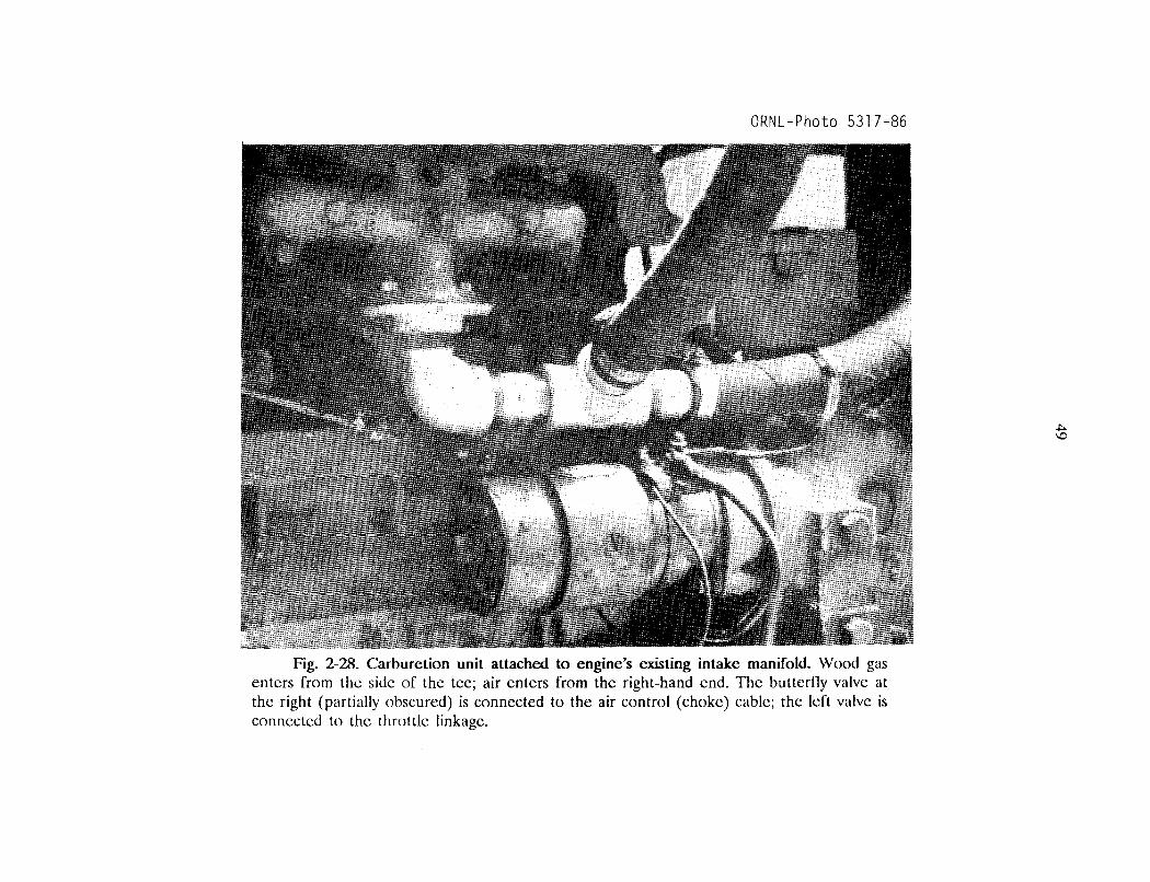
Fig. 2-28. Carburetion unit attached to engine's existing intake manifold. Wood gasenters from the side of the tee; air enters from the right-hand end. The buttcrlly valve atthe right (partially obscured) is connected to the air control (choke) cable; the left valve isconnected to the throttle linkage.
.,I::.\D

50
Table 2-1. List of materials for the gasifier unit and the wood fuel hopper
Item Quantity Description
1A 1 Metal pipe, tube, or other, open-ended metal cylinder; diameter andlength from Table 2-2; minimum wall thickness of 1/4 in.
2A 1 Circular metal plate with thickness of 1/8 in.; diameter equal tooutside diameter of Item 1A.
3A 1 3D-gal metal oil drum or metal container with approximate dimensionsof 18 in. (diameter) by 29 in. (height); container must have a bottom.
4A 1 lO-quart stainless steel mixing bowl, colander, or other stainless steelbowl with approximately 14-in. diameter and 6-in. depth.
5A 1 2-in. metal V-bolt.
6A 1 3/16-in. metal chain with I-in. links; 7 ft total length.
7A 3 1/4-in. eyebolts, 3 in. length with two nuts for each eyebolt.
8A 1 4-in. metal pipe nipple.
9A 1 Metal pipe cap for Item 8A.
lOA 2 3-in. metal pipe nipple.
llA 2 Metal pipe cap for Item lOA.
12A
1AA
2AA
3AA
4AA
5AA
6AA
7AA
1
1
1
1
1
2
1
Shaker assembly; see Fig. 2-8.
Metal l/2-in. pipe; 6 in. length.
Iron bar stock; square or round, 1/2 in.; 6 in. length.
1/2-in. bolt; 8 in. long.
Iron bar stock; rectangular, 1/4 by 1 in.; 10 in. length.
l/2-in. flat washer.
l/2-in. nuts.
Metal pipe cap or bushing for Item 1AA.

51
Table 2-1. (continued)
Item Quantity Description
13A 1 Iron bar stock; rectangular, 1/4 by 2 in.; 10 ft length.
14A 25 1/4-in. bolts; 3/4 in. length; with nuts.
15A 1 20-gal metal garbage can or metal container with approximatedimensions of 18 in. (top diameter) by 24 in. (height); bottom is notrequired.
16A 1 Lid for 20-gal garbage can.
17A 1 Garden hose; 1/2 to 5/8 in. diameter; length equal to circumferenceof Item 15A
18A 1 Foam weather stripping with adhesive backing; 1/4 by 1 in.; lengthequal to circumference of Item 15A
19A 1 Iron bar stock; rectangular, 1/4 by 2 in.; 10 ft length.
20A 12 1/4-in. bolts; 3/4 in. length; with nuts.
21 A 4 Metal triangles; 2 by 2.5 in., 1/8 to 1/4 in. thick.
22A 2 Metal eye hook.
23A 2 Screen door spring, 14 in. length.
24A 1 Lock ring for 30-gal (or larger) oil drum.
25A 4 Metal squares; 2 by 2 in., 1/4 in. thick.
26A 4 3/8-in. bolts; 3 in. length.
27A 1 Tube of high temperature silicone or liquid high temperature gasketmaterial.
28A 1 6O-lb. sack of hydraulic or other waterproof cement [such as SECPLUG (tm), which is maunfactured by the Atlas Chemical Company,Miami, FL].
29A 1 2-in. pipe, electrical conduit, flexible automobile exhaust pipe, orother metal tubing; 6-ft minimum length. Pipe must be able towithstand temperatures of 400'F.
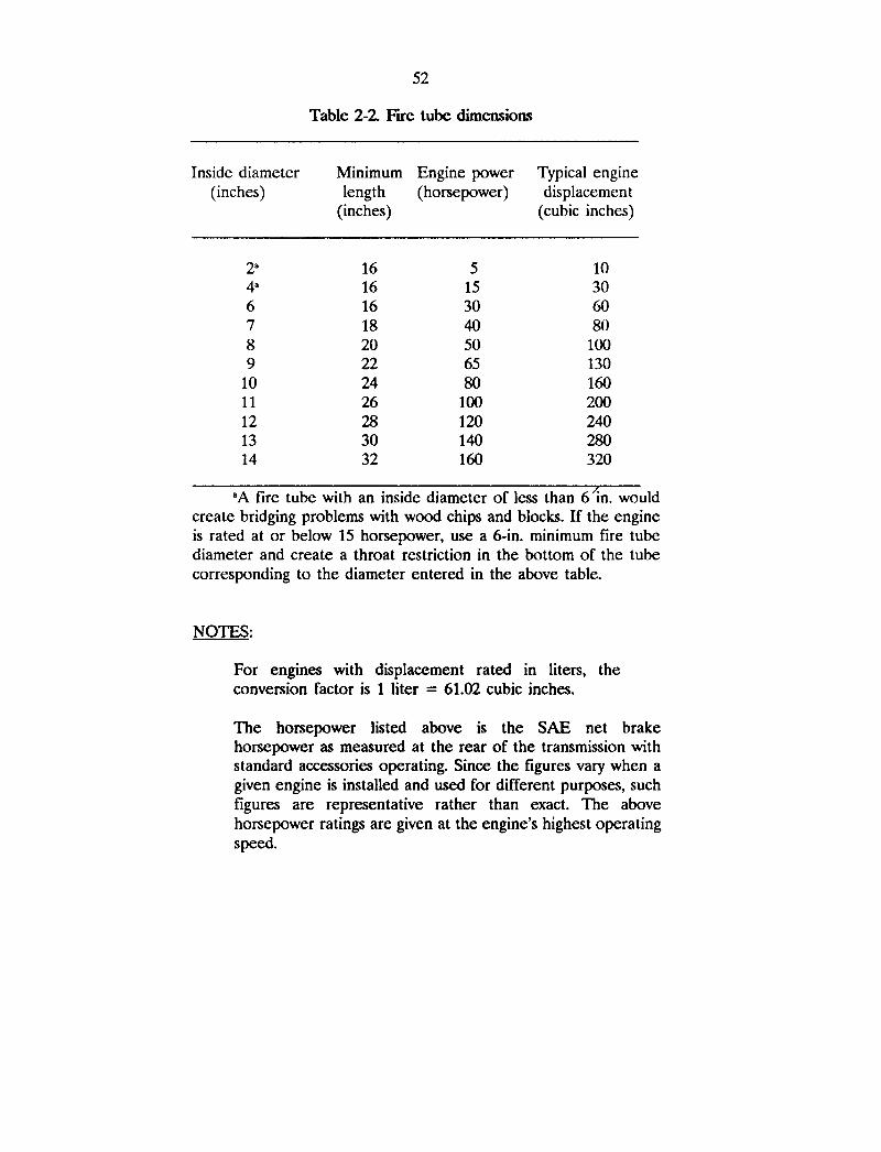
52
Table 2-2 FIre tube dimensions
Inside diameter Minimum Engine power Typical engine(inches) length (horsepower) displacement
(inches) (cubic inches)
2" 16 5 104" 16 15 306 16 30 607 18 40 808 20 50 1009 22 65 130
10 24 80 16011 26 100 20012 28 120 24013 30 140 28014 32 160 320
"A fire tube with an inside diameter of less than 61n. wouldcreate bridging problems with wood chips and blocks. If the engineis rated at or below 15 horsepower, use a 6-in. minimum fire tubediameter and create a throat restriction in the bottom of the tubecorresponding to the diameter entered in the above table.
NOTES:
For engines with displacement rated in liters, theconversion factor is 1 liter = 61.02 cubic inches.
The horsepower listed above is the SAE net brakehorsepower as measured at the rear of the transmission withstandard accessories operating. Since the figures vary when agiven engine is installed and used for different purposes, suchfigures are representative rather than exact. The abovehorsepower ratings are given at the engine's highest operatingspeed.

53
Table 2-3. List of materials for the primary filter unit
Item Quantity Description
IB 1 5-gal metal can or other metal container with minimum dimensionsof 11.5-in. diameter and 13 in. tall.
2B 1 Circular metal plate; diameter equal to 1/2 in. smaller than insidediameter of Item IB; thickness of 1/8 in.
3B 3 3/8-in. bolts; 3 in. length with two nuts for each bolt.
4B 1 Rectangular metal plate; width equal to 1/4 in. smaller than insidediameter of Item IB; height equal to 2.5 in. smaller than internalheight of Item IB; 1/8 in. thick.
5B 1 High-temperature hose, 3/8 to 5/8 in. diameter; length equal tocircumference of Item lB.
6B 1 Circular metal plate; diameter equal to outside diameter of Item 1B;thickness of 1/8 in.
7B 1 12-volt blower (automotive heater type); case and fan must be allmetal.
8B 1 Metal extension pipe for blower outlet, including elbows andconnections for vertical orientation; 1 ft. minimum length.
9B 1 Cap for Item 8B; plastic is acceptable.
lOB 1 1.25-in. metal pipe, electrical conduit, automotive exhaust pipe, orother metal tubing; 2 ft minimum length.
11B 3 Metal latch for securely connecting Items 1B and 6B together. Suchdevices as suitcase or luggage catches, bail-type latches, window sashcatches (with strike), or wing-nut latches are acceptable.
12B 1 High-temperature hose, 3/8 to 5/8 in. diameter; length equal to threetimes the height of Item 4B.
13B 1 Metal 1/2-in. pipe, threaded on one end; 8 in. length.
14B 1 Metal pipe cap for Item BE.

54
Table 2-4. tist of materials for the carbureting unit
Item Quantity Description
1C 1 1.25-in. closet flange.
2C 1 1.25-in. male-to-female 45· pipe elbow.
3C
lCC
2CC
3CC
4CC
5CC
6CC
7CC
4C
5C
6C
7C
8C
2
2
2
4
2
1
1
1
1
1
1
1
Butterfly valve; see Fig. 2-23.
1.25-in. pipe nipple or threaded length of pipe, 3-in. length.
Oval metal plate; 1/16 in. thick; short dimension equal to insidediameter of Item 1CC; long dimension equal to 1.02 times the shortdimension.
3/8-in. diameter rod; 2.5 in. length.
3/16-in. screws; 3/16 in. length.
Flat bar stock; rectangular, 1/2 by 3 in.; 1/8 in. thick.
7/16-in. nut.
l/8-in. set screw.
1.25-in. tee with all female threads.
1.25-in. pipe nipple or threaded length of pipe, 3 in. length.
1.25-in. pipe or hose.
Gasket material; sized to cover Item 1C.
Tube of pipe compound or Teflon tape for sealing threadedassemblies.

55
3. OPERATING AND MAINTAINING YOUR WOOD GAS GENERATOR
3.1 USING WOOD AS A FUEL
Because wood was used extensively as generator fuel during World War II, and sinceit is plentiful in most parts of the populated United States, it merits particular attention foruse as an emergency source of energy. When used in gas generators, about 20 Ib of woodhave the energy equivalence of one gallon of gasoline.
Wood consists of carbon, oxygen, hydrogen, and a small amount of nitrogen. As a gasgenerator fuel, wood has several advantages. The ash content is quite low, only 0.5 to 2%(by weight), depending on the species and upon the presence of bark. Wood is free ofsulphur, a contaminant that easily forms sulfuric acid which can cause corrosion damage toboth the engine and the gas generator. Wood is easily ignited-a definite virtue for theoperation of any gas generator unit.
The main disadvantages for wood as a fuel are its bulkiness and its moisture content.A<; it is a relatively light material, one cubic yard of wood produces only 500 to 600 Ib of gasgenerator fuel. Moisture content is notoriously high in wood fuels, and it must be broughtbelow 20% (by weight) before it can be used in a gas generator unit. By weight, themoisture in green wood runs from 25 to 60%, in air-dried wood from 12 to 15%, and inkiln-dried wood about 8%. Moisture content can be measured quite easily by carefullyweighing a specimen of the wood, placing it in an oven at 220 0 F for thirty minutes,reweighing the specimen, and reheating it until its weight decreases to a constant value. Theoriginal moisture content is equivalent to the weight lost.
The prototype unit in this manual (with an 6-in.-diam firetube) operated well on bothwood chips (minimum size: 3/4 by 3/4 by 1/4 in.) and blocks (up to 2-in. cubes); see Fig. 31 (all figures and tables mentioned in Sect. 3 are presented at the end of Sect. 3). Largersizes could be used, if the firetube diameter is increased to prevent bridging of the individualpieces of wood; of course, a throat restriction would then have to be added to the bottomof the firetube so as to satisfy the dimensions in Table 2-2 in Sect. 2.
3.2 SPECIAL CONSIDERATIONS AND ENGINE MODIFICATIONS
To start the fire in the gasifier, the blower must be used to create a suction airflowthrough the wood in the hopper and downward in the firetube. If an especially high horsepower engine is to be fueled by the gasifier unit, then it might be necessary to install twosuch blowers and run them simultaneously during start-up.
When the wood gas leaves the gasifier unit, all the oxygen pulled down with the airthrough the firetube has been chemically converted and is contained in carbon monoxide(CO) and water (H20). The wood gas is unable to burn without being mixed with the properamount of additional oxygen. If an air leak develops below the grate area, the hot gas willburn while consuming the available oxygen and will create heat; this will almost certainlydestroy the gasifier unit if it is not detected soon. If an air leak develops in the filter unitor in the connecting piping, the gas will become saturated with improper amounts of oxygen

56
and will become too dilute to power the engine. Therefore, airtightness from the gasifierunit to the engine is absolutely essential.
Ideally, as the wood gas enters the engine manifold it should be mixed with air in aratio of 1:1 or 1.1:1 (air to gas) by volume. The carburetion system described in this reportwill provide this mixture with a minimum of friction losses in the piping. The throttle controlvalve and the air control valve must be operable from the driver's seat of the vehicle.
The engine's spark plug gaps should be adjusted to between 0.012 and 0.015 in.; theignition timing should be adjusted to "early."
3.3 INITIAL START-UP PROCEDURE
Initially, you will need to add charcoal to the grate below the firetube. Subsequentoperation will already have the grate full of charcoal which has been left over from theprevious operating period.
Fill the firetube with charcoal" to a level 4 in. above the grate. Fill the hopper withair-dried wood; then, proceed with the routine start-up directions below.
3.4 ROUTINE START-UP PROCEDURE
1. Agitate the grate shaker handle for at least twenty seconds to shake down the charcoalfrom the previous operating period.
2. Open the ash cleanout port and remove the ashes from the generator housing drum.Lubricate the threads of the cleanout port with high-temperature silicone, and closethe cover of the cleanout port so that it is airtight.
3. Fill the hopper with wood fuel, and tamp the fuel down lightly. Either leave the lidcompletely off the fuel hopper, or adjust the opening around the lid to a 3/4-in. (orlarger) clearance.
4. Close the carburetor's air control valve and remove the cover from the blower exhauston top of the filter unit. Start the blower, and let it run for thirty seconds to avoidexplosion of residual gas in the system. Then, with the blower still operating, proceedwith the next step.
5. Open the ignition port, and ignite a 12- by 12-in. piece of newspaper; with a long stickor wire, push the burning sheet of newspaper into the grate; see Fig. 3-2. Close theignition port. If no smoke appears at the blower's exhaust port, repeat the start-up
·Charcoal produced for outdoor barbecue grills is not well suited for gas generatoruse. To produce a better grade of charcoal, place a rag soaked in alcohol on the grate,or place 3 to 5 pages of newspaper on the grate, then fill the fire tube to a height of 10to 12 in. with well-dried wood. Have all the valves closed and let the fire tube act as achimney until the wood is converted to charcoal.

57
sequence from Step (e). If repeated attempts fail, new charcoal should be added to theunit as described in Sect. 3.3, above, and the start-up ignition sequence should berepeated.
6. After a few minutes of smoky exhaust, test the gas at the blower exhaust by safely andcarefully attempting to ignite it; see Fig. 3-3. When the gas burns consistently well, stopthe blower and replace the cover on the blower exhaust.
7. Open the carburetor's air control valve, adjust the engine's accelerator, and start theengine in a normal manner. Let the engine warm up slowly (two to five minutes). Ifthe engine fails to start or dies repeatedly, restart the blower and repeat the ignitionsequence from Step (4).
3.5 DRIVING AND NORMAL OPERATION
Shift gears so as to keep the engine speed (rpm) high at all times. Remember that itis the vacuum created by the pistons that provides the force which moves the gas from thegasifier unit into the engine.
Refill the hopper with wood (as shown in Fig. 3-4) before it is completely empty, butavoid refilling just before the end of engine operation. Periodically shake down the ashesfrom thc grate. If your system is cquipped with a gas cooler, drain water from the coolerfrom time to time.
Under operation in dry weather, the gasifier can be operated without the lid on thefud hoppcr. However, when the gasifier unit is shut down the hopper must be covercd toprevent air from continuing to burn the wood in the hopper. Under wet-weather operation,the cover must be piaced on the fuel hopper, and then lifted up and rotated about 2 in. untilthe triangular pieces line up with the holes in the support bars. The tension of the screendoor springs will then hold the lid closed. See Fig. 3-5 for clarification.
3.6 SHU1TING-DOWN TIIE GASIFIER UNIT
When shutting down the gasifier unit, turn off the ignition switch and open thecarburetor's air control valve for tcn seconds to relieve any pressure from within the system.Then, completely close the air control valve, and place the cover tightly on the fuel hopper.When restarting after a short stopover, let the engine warm up brietly. After longer stops(up to one hour), tamp down the wood lightly and try to use the blower for restartingwithout relighting the wood fuel. After very long stops (over two hours) the charcoal mustbe ignited again.
3.7 ROUTINE MAINTENANCE
Periodically check all nuts on the gasifier unit, the fuel hopper, the filter unit, and thecarburetor for snugness; check all penetrations and fittings for airtightness. In addition,perform the following maintenance activities as scheduled:
58
3.7.1 Daily Maintenance
Open the ash cleanout port of the gasifier housing drum and remove the ashes aftershaking the grate for at least thirty seconds. Replace the cover of the port after coating thethreads with high-temperature silicone to ensure airtightness. Open the drain tube at thebottom of the filter container and allow any liquid condensate to drain out; remember toclose the drain tube when finished.
3.7.2 Weekly Maintenance (or every 15 hours of operation)
Clean out the gasifier housing drum, the fuel hopper, and the filter. Rinse out thepiping and connections to and from the filter. Replace the wood chips inside the filter. (Theused wood chips from the filter can be dumped into the fuel hopper and burned to producewood gas.) Use high-temperature silicone on all pipe connections and on the filter lid toensure airtightness.
3.73 Biweekly Maintenance (or every 30 hours of operation)
Make sure that all pipe connections are secure and airtight. Check and tighten allmounting connections to the vehicle chassis. Check for rust on the outside of the gasgenerator housing drum, especially on the lower region. Coat with high-temperatureprotective paint as necessary.
3.8 OPERATING PROBLEMS AND TROUBLE-SHOOTING
A discussion of problems and their related causes and cures is contained in the troubleshooting guide of Table 3-1. Many operational problems can be traced to failure to maintainthe airtightness of all piping connections and fittings; the piping should be routinely checkedto prevent such problems.
3.9 HAZARDS ASSOCIATED WITH GASIFIER OPERATION
Unfortunately, gas generator operation involves certain problems, such as toxic hazardsand fire hazards. These hazards should not be treated lightly; their inclusion here, at the endof this report, does not mean that these hazards are unimportant. The reader should notunderestimate the dangerous nature of these hazards.
3.9. t Toxic Hazards
Many deaths in Europe during World War II were attributed to poisoning from woodgas generators. The danger of "generator gas poisoning" was one of the reasons that suchgasifiers were readily abandoned at the end of World War II. It is important to emphasizethat "generator gas poisoning" is carbon monoxide (CO) poisoning. Acute "generator gas

59
poisoning" is identical with the symptoms that may develop if a heating stove damper isclosed too early, or if a gasoline vehicle is allowed to idle in a poorly ventilated garage.Table 3-2 shows how poisoning symptoms develop according to the concentration of carbonmonoxide in breathable air. It is important to note that rather brief exposures to very smallconcentrations of carbon monoxide result in undesirable physiological effects.
In case of carbon monoxide poisoning, first aid should consist of the followingprocedures:
1. Move the victim quickly out into the open air or to a room with fresh air and goodventilation. All physical exertion on the part of the victim must be avoided.
2. If the victim is unconscious, every second is valuable. Loosen any tight clothing aroundthe neck. If breathing has stopped, remove foreign objects from the mouth (false teeth,chewing gum, etc.) and immediately give artificial respiration.
3. Keep the victim warm.
4. Always call a physician.
5. In case of mild carbon monoxide poisoning without unconsciousness, the victim shouldbe given oxygen if possible.
3.9.2 Technical Aspects of "Generator Gas Poisoning"
Generator gas poisoning is often caused by technical defects in the functioning of thegas generator unit. When the engine is running, independent of the starting blower, theentire system is under negative pressure created by the engine's pistons; the risk of poisoningthrough leakage is therefore minimal. However, when the engine is shut off, formation ofwood gas continues, causing an increase of pressure inside the generator unit. This pressureincrease lasts for approximately 20 minutes after the engine is shut off. For this reason, itis not advisable to stay in the vehicle during this period. Also, the gas generator unit shouldbe allowed to cool for at least 20 minutes before the vehicle is placed in an enclosed garageconnected with living quarters. It should be emphasized that the gas formed during the shutdown period has a carbon monoxide cOntent of 23 to 27% and is thus very toxic.
3.9.3 Fire Hazard
The outside of a gas generator housing drum may reach the same temperature as acatalytic converter on today's automobiles. Care should be taken when operating in areaswhere dry grass or combustible material can come into contact with the housing drum of thegas generator unit. If a gas generator unit is mounted on a personal car, bus, van or truck,a minimum 6-in. clearance must be maintained around the unit. Disposal of ashes must onlybe attempted after the unit has cooled down (to below 150"F). Such residue must be placedaway from any combustible material and preferably be hosed down with water for absolutesafety.

ORNL-Photo 5332-86
Fig. 3-1. VIrtually all varieties of wood chips can be used for fuel. (Minimum sizefor this 6-in. firetube unit: 3/4 by 3/4 by 1/4 in.; maximum size: 2-in. cubes.)
~

61
ORNL-Photo 5313-86
Fig. 3-2 Ignite a single piece of newspaper to start the gasifier unit. Push theflaming newspaper through the ignition port and directly into the grate. (At the right of thephoto, note the battery which is operating the blower atop the filter unit.)
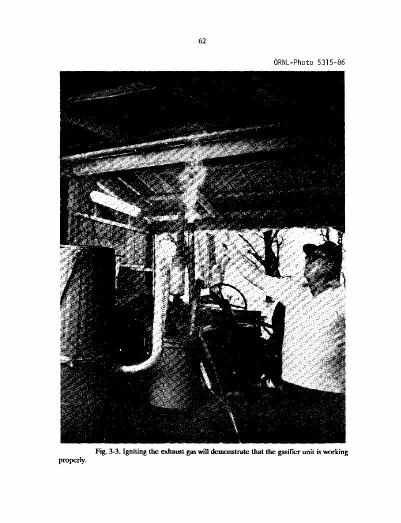
62
ORNL-Photo 5315-86
properly.Fig. 3-3. Igniting the exhaust gas will demonstrate that the gasifier unit is working

63
ORNL-Photo 5324-86
Fig. 3-4. Refill the fuel hopper before it becomes two-thirds empty.
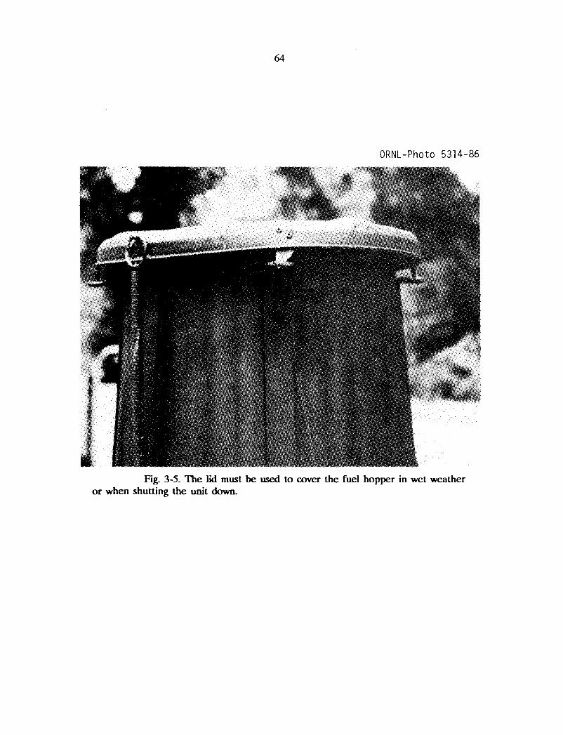
64
ORNL-Photo 5314-86
Fig. 3-5. The lid must be used to cover the fuel hopper in wet weatheror when shutting the unit down.

65
Table 3-1. Trouble-shooting your w<XXl gas generator
Trouble Cause Remedy
Start up takes 1. Dirty system Clean the gasifier unittoo long. or clogged pipes. and all connecting piping.
2. Blower is Check the blower andtoo weak. test the battery's charge.
3. Wet or poor Check charcoal and replacequality charcoal. or refill to proper level.
4. Wood fuel bridges Lightly tamp down the woodin the fire tube. fuel in the hopper and fire
tube or replace the fuelwith smaller-sized chips.
Engine will l. Insufficient gas. Use the blower longer duringnot start. start up.
2. Wet wood fuel. Vent steam and smoke throughthe fire tube and fuel hopperfor several minutes.
3. Incorrect fuel- Regulate the carburetor's airair mixture. control valve for proper
mixing.
Engine starts, l. Not enough gas Use low RPM while startingbut soon dies. has been produced. engine and do not rev engine
for several minutes.
2. Air channels Tamp down wood fuel lightlythrough fire tube. in hopper. Do not crush
charcoal above the grate.
Engine loses l. Restricted gas Reduce air mixture valvepower under flow in piping. setting. Check for partialload. blockage of unit or piping.
2. Leaks in system. Check all covers and pipesfor air tightness.

66
Table 3-2 Effects of breathing carbon monoxide
Carbon monoxidecontent of inhaled
air (%)
0.020
0.040
0.080
0.160
0.320
0.640
1.280
Physiological effects
Possible mild frontal headache after two tothree hours.
Frontal headache and nausea after one totwo hours; occipital (rear of head) headacheafter 2.5 to 3.5 hours.
Headache, dizziness, and nausea in 45 min;collapse and possible unconsciousness intwo hours.
Headache, dizziness, and nausea in 20 min;collapse, unconsciousness and possible deathin two hours.
Headache and dizziness in 5 to 10 min;unconsciousness and danger of death in 30 min.
Headache and dizziness in 1 to 2 min;unconsciousness and danger of death in10 to 15 min.
Immediate physiological effect;unconsciousness and danger of death in1 to 3 min.
Source: Murakoa, J. S., Shelter Habitability Studies-The Effects of Oxygen Depletion andFire Gases on Occupants of Shelter, NCEL-TR-144, U.S. Naval Civil Engineering Laboratory,Port Hueneme, CA, July 1961.

67
BffiUOGRAPHY
Anonymous, "Coast to Coast on Homemade Fuel," The Mother Earth News (No. 73)pp. 178-179 (JanuarylFebruary 1982).
Anonymous, "Wood Gas Update," The Mother Earth News (No. 71) pp. 164-165(September/October 1981).
Anonymous, "Mother's Woodburning Truck," The Mother EaIth News (No. 69) pp. 126-129(May/June 1981).
Chatterjee, AK, State of the Art Report on Pyrolysis of Wood and Agricultural Biomass, PNAAK-818, U.S. Department of Agriculture, Newark, NJ, March 1981.
Cruz, I.E, Producer-Gas Technology for Rural Applications, published by the Food andAgriculture Organization of the United Nations, New York, NY, 1985.
Donath, EE, "Vehicle Gas Producers," Processing Technology (3) pp. 141-153 (1980).
Eoff, KM., and D.M. Post, "How to Power a Gasoline Engine with Wood," TechnicalReprint No.1, The Mother Earth News, Hendersonville, NC, 1981.
Kaupp, A, and J.R. Goss, State of the Art Report for Small Scale (to 50kW) Gas ProducerEngine Systems, USDA Contract No. 53-319R-O-141, University of California, Davis,CA, March 1981.
Miller, B., State-of-the-Art Survey of Wood GasiflCation, EPRI-AP-3101, Fred C. HartAssociates, Inc., Washington, DC, May 1983.
Nygards, N., Wood Gas Generator for Vehicles (a translation of the Swedish book), publishedby Purwaco International, Minneapolis, MN, 1979.
Oliver, ED., Technical Evaluation of Wood GasiflCation, EPRI-AP-2567, Synthetic FuelsAssociation, Inc., Palo Alto, CA, August 1982.
Reed, T.B. (ed), A Survey of Biomass GasiflCation, Vol. I--Synopsis and Executive Summary,SERI/TR-33-239 (Vol. I), Solar Energy Research Institute, Golden, CO, July 1979.
Reed, T.B. (ed), A Survey of Biomass Gasification, Vol. II--Principles of Gasification,SERI/TR-33-239 (Vol. II), Solar Energy Research Institute, Golden, CO, July 1979.
Reed, T.B. (cd), A Survey ofBiomass GasiflCation, Vol. III--Cwrent Technology and Research,SERI/TR-33-239 (Vol. III), Solar Energy Research Institute, Golden, CO, April 1980.
Reed, T.B., and A Das, Handbook of Biomass Downdraft Gasifier Engine Systems,SERIISP-271-3022, Solar Research Institute, Golden, CO, March 1988.
68
Reed, T.B., and D. Jantzen, Generator Gas: The Swedish Experience from 1939-1945 (atranslation of the Swedish book, Gengas), SERI/SP-33-140, Solar Energy ResearchInstitute, Golden, CO, January 1979.
Skov, N., and M.L. Papworth, PEGASUS (Petroleum/Gasoline Substitute Systems), publishedby the Pegasus Publishing Co., Miami, FL, 1974.
Vietmeyer, N.L., et al., Producer Gas: Another Fuel for Motor Vehicle Transport, publishedby the National Academy Press, Washington, DC, 1983.
Wise, D.L. (ed.), Fuel Gas from Biomass, published by the CRC Press, Boca Raton, FL,1981.
Construction Plans for Other Wood Gas Generator Unitscan be Purchased from the Following Organizations:
PEGASUS Publishing Co.1995 Keystone Blvd.Miami, FL 33181
Missouri Gasification Systems, Inc.Route 3, Box 198California, MO 65018
Mother's PlansThe Mother Earth NewsP.O. Box 70Hendersonville, NC 28791
Nunnikhoven IndustriesP. O. Box 580Mediapolis, IA 52637
U.S. GOVERNMENT PRINTING OFFICE: 1989 Q-94Q.3li6