construction administration and inspection task manual · inspection task manual. ... grading,...
TRANSCRIPT

April 2005
Construction Administration
And
Inspection Task Manual
Ministry of Transportation
April 2005
To all users of the Construction Administration and Inspection Task Manual (CAITM), April 2005 Enquiries regarding the purchase and distribution of this manual should be directed to:
Publications Ontario 880 Bay Street Toronto, Ontario, Canada M7A 1N8
www.publications.gov.on.ca Phone: 416 326 5300 800 668 9938 TTY: 800 268 7095 Fax: 613 566 2234
Enquiries regarding amendments, suggestions, or comments should be directed to:
Ministry of Transportation Construction Office, 2nd Floor North Garden City Tower 301 St. Paul Street St. Catharines, Ontario L2R 7R4 Attention: Robert Belansky, Construction Officer
"Ce document hautement spécialisé n’est disponible qu’en français, vertu du règlement 411/97, qui exemple l’application de la Loi sur les services en français. Pour obtenir de l’aide en français, veuillez communiquer avec le ministère des Transports, Bureau des services en français au 905-704-2046 ou 905-704-2045.”

April 2005 i
CONSTRUCTION ADMINISTRATION AND INSPECTION TASK MANUAL
TABLE OF CONTENTS
PART A: CONSTRUCTION ADMINISTRATION SECTION 1.0: INTRODUCTION..................................................................................... 1
1.1 PURPOSE OF THE MANUAL .......................................................................... 1 1.2 DUE DILIGENCE .............................................................................................. 1 1.3 CONFIDENTIALITY .......................................................................................... 2 1.4 DEFINITIONS ................................................................................................... 2
SECTION 2.0: PRE-CONSTRUCTION........................................................................... 3
2.1 CONSULTANT ASSIGNMENT START-UP MEETING..................................... 3 2.1.1 Construction Administration Agreement.......................................................... 3 2.1.2 Consultant’s Quality Control of Services and Deliverables Plan ..................... 3 2.1.3 Consultant Invoices......................................................................................... 3 2.1.4 General ........................................................................................................... 4 2.1.5 Survey Requirements...................................................................................... 4 2.1.6 Inspection Tasks ............................................................................................. 5 2.1.7 Insurance and Risk Management Issues ........................................................ 5 2.1.8 Contractor’s Performance Rating .................................................................... 5 2.1.9 Turnover of Documents from MTO to Consultant............................................ 6 2.1.10 Concerns / Expectations on Issues ............................................................... 6 2.1.11 Pre-Construction Photos / Video ................................................................... 8 2.1.12 Documents Copied to MTO........................................................................... 8 2.1.13 Material and Testing / Sampling Testing Materials........................................ 8 2.1.14 Engineering Materials Field Testing Reference Table................................. 14 2.1.15 Quality Assurance Frequency of Monitoring / Audit Checks........................ 15 2.1.16 Off-Site Inspection of Structural Items......................................................... 15 2.1.17 Geotechnical ............................................................................................... 15 2.1.18 Electrical..................................................................................................... 15 2.1.19 Environmental ............................................................................................. 15 2.1.20 Traffic Management And Public Information Services................................. 18 2.1.21 MTO Roles .................................................................................................. 21 2.1.22 Consultant’s Performance Appraisal ........................................................... 21 2.1.23 Well Investigations ...................................................................................... 21 2.1.24 Project Construction Report ........................................................................ 21
2.2 DESIGN PACKAGE HANDOVER MEETING ................................................. 21 2.3 CONTRACT AWARD...................................................................................... 23 2.4 PRE-START MEETING WITH CONTRACTOR.............................................. 24 2.5 CONTRACTOR QUALITY CONTROL MONITORING CHECKLIST............... 33 2.6 NOTIFICATIONS ............................................................................................ 34
2.6.1 Notifications Prior to Construction ................................................................. 34

April 2005 ii
2.6.2 Traffic Control / Lane Closure Notification..................................................... 34 SECTION 3.0: DURING CONSTRUCTION .................................................................. 36
3.1 MISCELLANEOUS ......................................................................................... 36
3.1.1 Contract Meetings ......................................................................................... 36 3.1.2 Constructor Issue .......................................................................................... 40
3.2 APPROVALS .................................................................................................. 41 3.2.1 Working Days / Completion Date .................................................................. 41 3.2.2 Ministry Acceptance / Approvals ................................................................... 41 3.2.3 Schedules / Critical Path ............................................................................... 42 3.2.4 Verification of Weighed Items........................................................................ 43 3.2.5 Expenditure Control ...................................................................................... 44 3.2.6 Contractor’s Payment Approvals................................................................... 44 3.2.7 Rock Material Management Plan .................................................................. 45
3.3 DOCUMENTATION ........................................................................................ 45 3.3.1 Documentation of Daily Activities .................................................................. 45 3.3.2 Instruction Notice to Contractor..................................................................... 50 3.3.3 Contractor’s Infraction Report ....................................................................... 50
3.4 CHANGES ...................................................................................................... 51 3.4.1 Change Proposals......................................................................................... 51 3.4.2 “Change in the Work” and “Extra Work” ........................................................ 51 3.4.3 Additional Work ............................................................................................. 56 3.4.4 Adjusting Quantities for Plan Quantity Payment (PQP) Items....................... 57 3.4.5 Work Directive............................................................................................... 58 3.4.6 Engineering Claims ....................................................................................... 59 3.4.7 Media Enquires ............................................................................................. 59
3.5 SUBSTANTIAL PERFORMANCE & COMPLETION OF THE WORK ............ 59 3.5.1 Certificate of Substantial Performance of the Contract ................................. 60 3.5.2 Certification of Subcontractor Completion..................................................... 60 3.5.3 Final Completion of the Work ........................................................................ 60 3.5.4 Acceptance of the Work ................................................................................ 62
3.6 ASSESSING COMPLIANCE TO THE QUALITY CONTROL PERFORMANCE MEASURES ................................................................................................... 62
SECTION 4.0: POST-CONSTRUCTION ...................................................................... 66
4.1 CONTRACT CLOSING PROCESS ................................................................ 66 4.2 CONTRACTOR’S PERFORMANCE RATING ................................................ 67 4.3 SUBMISSION OF RECORD DOCUMENTS................................................... 67 4.4 RECORD DRAWINGS.................................................................................... 71 4.5 PROJECT CONSTRUCTION REPORT ......................................................... 71 4.6 DESIGN PACKAGE EVALUATION ................................................................ 71

April 2005 iii
APPENDIX A ................................................................................................................ 72 LIST OF CONTRACT ADMINISTRATION FORMS................................................... 72
APPENDIX B ................................................................................................................ 76
ROLE OF THE CONTRACT ADMINISTRATOR (CA) WITH RESPECT TO QUALITY
VERIFICATION ENGINEER (QVE) SERVICES............................................. 76 APPENDIX C ................................................................................................................ 79
QC INCIDENTS AND DEVIATIONS WITH TYPICAL EXAMPLES............................ 79
APPENDIX D ................................................................................................................ 87
TECHNICAL STANDARDS AND SPECIFICATIONS................................................ 87
April 2005 Section 1 Introduction
1
SECTION 1.0: INTRODUCTION 1.1 PURPOSE OF THE MANUAL This manual has been prepared to assist the Contract Administrator and the Inspection Staff in the administration of highway construction and maintenance contracts for the Ministry of Transportation, Ontario. The Consultant Contract Administrator is responsible for providing the Contract Administration Services and Deliverables in accordance with the Construction Administration Legal Agreement including the Construction Administration and Inspection Task Manual. The manual is divided into two parts. Part A outlines the requirements for construction administration from the time of award of the Consultant Assignment to the submission of the final deliverables. Part A is divided into three sections dealing with pre-construction, during construction and post construction. While Section 2.0 pf Part A outlines Pre-Construction requirements, some of the points discussed under sub-section 2.1 Consultant Start-Up Meeting, refer to deliverables to be completed during construction and post-construction. This part of the manual is to be used for the processing of approvals, documentation requirements, change approvals, and as a standard for meetings. Part B consists of Inspection Tasks. The tasks are intended to provide those involved in inspection on Ministry of Transportation Contracts with a resource to ensure that the quality and quantity of the work is in accordance with Ministry specifications, standards, drawings, policies and procedures. This part of the manual is divided into eight sections dealing with: Grading, Concrete and Structures, Bituminous, Electrical, ATMS, Traffic Control, Environmental, and Weighed Materials. This document does not contend to be a complete documentation of the construction administration process. Additional direction and guidance should be obtained from the Contract Control Officer. 1.2 DUE DILIGENCE The Consultant Contract Administrator and field staff shall make themselves aware of ARTICLE 2 – APPOINTMENT AND RELATIONSHIP, ARTICLE 4 - DUTIES OF THE CONSULTANT, AND ARTICLE 9 - CONSTRUCTION CONTRACT ADMINISTRATION PHASE, OF THE CONSTRUCTION CONTRACT ADMINISTRATION LEGAL AGREEMENT.

April 2005 Section 1 Introduction
2
1.3 CONFIDENTIALITY The Consultant shall ensure that the Consultant, its partners, directors, officers and personnel maintain confidentiality, and secure all material and information, that are the property of the Ministry, and which comes into the Consultant’s possession or under the Consultant’s control during the term of the Construction Administration Agreement. All Contractor records are to be treated as confidential documents. Information requests received from subcontractors, suppliers, the media, or by third parties shall be discussed with the Contract Control Officer prior to release. 1.4 DEFINITIONS Contract Administrator means the Consultant’s on-site representative who has the responsibility of administering the construction contract between the Ministry and the Contractor. Contract Control Officer means the individual designated by the Manager of Contracts as the primary contact with the consultant on a day-to-day basis.

April 2005 Section 2 Pre-Construction
3
SECTION 2.0: PRE-CONSTRUCTION 2.1 CONSULTANT ASSIGNMENT START-UP MEETING The purpose of the Consultant Assignment Start-up meeting is to define the roles and responsibilities of both the Ministry and the Consultant. The process for the handling of documentation and approvals will also be discussed. The Contract Control Officer will arrange and conduct the Consultant Assignment Start-Up Meeting. The Consultant’s Project Manager and Contract Administrator(s), and the Area Contracts Engineer shall be in attendance. The Consultant will be responsible for the minutes of this meeting. This meeting shall take place even after the work starts. The following issues should be discussed at the meeting: 2.1.1 Construction Administration Agreement Review the status of the Construction Administration Agreement. Changes or revisions to the RFP/RFQ must be requested in writing by the Consultant and approved by the Ministry prior to implementation. 2.1.1.1 MTO Staff Training The Contract Administrator is responsible to provide on the job training in accordance with the “On the Job Training Program” manual or direction provided by the Ministry. 2.1.2 Consultant’s Quality Control of Services and Deliverables Plan The Consultant’s Quality Control of Services and Deliverable Plan, the Audit Reports for Milestone Inspection, the Final Verification Audit check for Services and Deliverables and the Audit Reports showing compliance and non-compliance to their plan will be made available to the Ministry for review, in the field office site, throughout the term of the agreement. The Consultant will immediately address and correct identified non-compliances to the Quality Control of Services and Deliverables Plan. 2.1.3 Consultant Invoices Review the requirements of the Construction Administration Agreement. Confirm the frequency and method of invoicing for the Consultant’s Services and Deliverables. Discuss the format of the Monthly Status Reports to be prepared by the Consultant that should include things such as: the status and staffing of the consultant assignment, requests for addenda and their rationale, etc.

April 2005 Section 2 Pre-Construction
4
2.1.4 General Review the construction administration requirements as outlined in Part A of this
manual. Address issues and concerns from both MTO and the Consultant with respect to
expectations and results with emphasis on the Services and Deliverables. Discuss documentation to be copied to MTO. The Contract Administrator shall
obtain two sets of pre-construction photographs immediately in advance of commencement of construction, and provide one set to the MTO Contract Control Officer.
Discuss the change of work procedure as outlined in Section 3.4.2 of this Manual. Discuss/determine location of Consultant’s field office. Discuss Consultant/Contractor Identification signs as per OTM Book 7 Discuss roles and identify MTO staff (i.e. Quality Assurance Officer, Area Contracts
Engineer, Contract Control Officer, and Environmental Planner). Discuss the Consultant Performance Appraisal Discuss sampling and testing of materials. Discuss delivery of samples to laboratories for testing. Discuss quality assurance frequency for grade and compaction, monitoring and
auditing checks. Discuss timing and allocation of test results. Discuss the need for calculating price adjustments for materials in a timely manner
to ensure Contractor’s work is not affected. Identify name and location of Ministry designate laboratory. Discuss the need for providing input into Post Construction Engineering Appraisal
through the Design Package Evaluation. 2.1.5 Survey Requirements The Consultant shall survey the following as required: After stripping the overburden, all new original rock cross sections shall be taken,
independently of the Contractor. Ensure that zero rock stations are supported by field measurement prior to blasting operations.
All new original rock cross sections shall be surveyed and inputted into the original Highway Design System (construction) Design File. The HDS Project File shall not be altered, nor duplicate files made. The new original rock line and the design rock line shall be shown in the original HDS cross section Design File and where the new original rock line differs from the rock line used in design then the quantities of overburden, rock and shatter shall be recalculated and the cross sections in HDS updated monthly for progress and final payment purposes.
Actual muskeg depth and width. Verify under-fill stripping widths and depths and control over-stripping widths on a
borrow contract. Topsoil piles for volumes if by cubic metre and not square metre.

April 2005 Section 2 Pre-Construction
5
Earth borrow and rock borrow if in bank volume is used as opposed to truck haul (imported).
Any sub-excavation or soft spots by elevation to ensure below specified sub-grade elevation verify record data including elevations and changes.
Streambed elevation for any in-water work, if not provided in the design. Quality Assurance checks for subgrade and granulars shall include the record of
station, actual elevation and offset. This information is to be recorded at the specified intervals in a separate field book. The Consultant survey work will be separate and independent from the Contractor’s Quality Control surveys.
All Transition Points to be verified by elevation and offset. Verify and document 10% of Contractor’s alignment layout throughout the life of the
contract. Review HDS template sheets when matching to existing tie-ins, structures, or new
structures to ensure that elevations and transitions are properly coordinated. 2.1.6 Inspection Tasks Review and ensure the inspection task requirements are carried out as outlined in
Part B of this manual. Ensure that all applicable milestone inspections are carried out and documented in
the appropriate diaries. Review staffing levels on the contract ensuring they meet contract related
documents. 2.1.7 Insurance and Risk Management Issues Reference: Provincial Highways Directive PHY-B-103 Claims for Compensation for Personal
and Business Losses During Construction Review Regional Construction Office policy regarding Third Party claims. All claims for compensation for personal and business loss shall be forwarded to the Contractor, with a copy to be maintained by the Contract Administrator. The Contract Administrator shall obtain copies, and maintain a file of any pertinent accident reports from the appropriate police force. When the claims are forwarded through Management Board Secretariat’s Insurance and Risk Management Section, the Contract Administrator shall examine the contract documentation and respond to requests for information. Copies of all correspondence copied to the Contract Control Officer. 2.1.8 Contractor’s Performance Rating The Contractor’s Performance Rating (CPR) report shall be maintained throughout the duration of the contract (as appropriate) and finalized upon completion of the contract. The CPR shall be reviewed with the contractor at the following intervals:

April 2005 Section 2 Pre-Construction
6
– Pre-Start meeting – Monthly site meetings – End of the contract
Discussing the CPR throughout the contract allows the contractor the opportunity to improve their operations before the final assessment. It also ensures that the Contract Administrator is keeping appropriate documentation during construction. The Contract Control Officer shall review the report(s). The final document (rating and form B’s) where applicable must include clear, complete and factual information to support the rating given with references to diary sheets, minutes or other record document. 2.1.9 Turnover of Documents from MTO to Consultant Copies of the tender documents, contract drawings, and addenda. Signed Contract (when available). List of MTO contact names for the contract. Ministry supplied documents (including digital files) listed in the Construction
Administration Agreement. Standard Ministry forms available in electronic format. See Appendix A for a listing
of standard forms available. Copies of any project-specific environmental assessment documentation
(Transportation Environmental Study Report, Design and Construction Report, etc.). Copies of any project-specific environmental permits/approvals/exemptions and the
associated applications. Completed Statement of Imported Content Form. Design Calculations Templates Documents received at the Design Package Turnover meeting.
2.1.10 Concerns / Expectations on Issues Establishing and maintaining appropriate relationships with suppliers, sub-
contractors, adjacent property owners, municipalities, other Ministries representatives, the OPP, local politicians, local police and emergency services, school boards, transit authorities, utility companies, etc.; and
Recording all discussions and meetings. Providing day-to-day liaison with the Contractor Providing first line interpretations of the Contract Documents to the Contractor,
consistent with the intent of the Contract Documents Communicating the Ministry’s decisions to the Contractor Traffic management, lane and ramp closure notification protocol to be discussed. Inform MTO of issues which may lead to delays or claims Inform MTO of any overruns and/or underruns

April 2005 Section 2 Pre-Construction
7
Review the procedures for administration of progress payments Request a copy of all Change Orders. Include justification, rational and expected
costs with recommendations. Include impact statements such as, “it is agreed this negotiation will include all impact costs associated with this work” obtain / review a copy of the contractor’s schedule. All required recommendations to come as a comprehensive summary on Consultant letterhead.
Documentation turned over to MTO in a timely fashion Ensure the contractor delivers their approvals and deliverables in a timely, accurate
manner Receiving submissions such as shop drawings, plans, proposals, and product data
from the Contractor and forwarding them, with the Consultant’s comments, within two working days, to the Ministry for the Ministry’s approval, acceptance or permission to proceed
Discuss Health and Safety Plan; issues and protection of employees working on freeways
Advise consultant that they are ministry representatives and must abide by the Personal Protective Equipment Guideline
Review the requirements of the special provisions for the contractor to submit CVORs for equipment on site and supplying source materials throughout the duration of the contact
Performing a cursory review of all documents pertaining to the work for the purpose of identifying errors and omissions and advising the Ministry of such errors and omissions; including but not limited to, the use of HDS, CDS and other Ministry-compatible software packages
Carrying out all on-site inspection, surveying including layout not required of the contractor, measuring and verification of construction methods as required by the Contract Documents, as defined in the MTO General Conditions of Contract to satisfy the Ministry that the Work is constructed in conformance with the Contract Documents
Monitoring and reviewing the quality of Contractor’s work to confirm that the Contractor is discharging its obligations and responsibilities under the Contract
Notifying the Contractor of any deficiencies in the construction of the Work identified by the Ministry or Consultant’s monitors and reviewers, instructing the Contractor to take appropriate corrective measures and confirming and reporting the results of the corrective measures
Distributing appropriate copies of all documents, reports, and test result forms to the applicable Ministry offices
Maintaining control of the receipt, use and final disposition of all Ministry-supplied materials in accordance with Ministry procedures
Reasonable travel to/from the Ministry’s regional office or other local location for pick-up/delivery of mail or other materials
Identify and track any design related issues maintaining sufficient supporting documentation.
Written recommendations on situations / issues deemed necessary by the Ministry.

April 2005 Section 2 Pre-Construction
8
2.1.11 Pre-Construction Photos / Video Detail signs, all entrances, sideroads, ingress and egress of posted construction
entrances, existing structures, electrical plant (i.e. traffic signals, highway lighting), power plants, other authority’s equipment such as hydro, bell, railways, deliverables to MTO.
2.1.12 Documents Copied to MTO Statement of Record of Working Days (if applicable) All Change Orders, reports on delays, monitor reports on over- or under-runs,
minutes of meetings Instruction Notices to Contractor Extension of time requests Accidents or claims from the public or property owners Major issues or delays Notification of lane closures/lane reductions (faxed at time of initiation/cancellation) All other applicable documents requested by the Ministry. All documents are to distributed as indicated on the form
2.1.13 Material and Testing / Sampling Testing Materials As per Contract Documents, CAITM, Ministry Directives (i.e. QST B-22),
Memoranda, future meeting requirements 2.1.13.1 Samples for Testing The CA is responsible for monitoring the contractor’s operation to ensure proper sampling techniques, sample identification and delivery to the appropriate laboratory. The CA is responsible for witnessing of contractor sampling and proper application of security bags and tags. All samples of materials are to be delivered to the designated laboratory in a timely fashion, in a suitable testing condition with proper identification (e.g. contract number, date sampled, mix type, contact person, tests required, etc.) and WHMIS labels in accordance with applicable Dangerous Goods Legislation. The CA is to review deficiencies in these operations as identified by his staff and the laboratory and take appropriate action if problems arise. The CA shall maintain a log of QA samples sent to the laboratories. This log shall include the lots, sublots, seal numbers, date shipped, date the test results were received from the lab, and turnaround times. The CA is required to evaluate QC and QA test results in a timely manner. Upon receipt of the test data, the CA shall verify the security seal identification provided with the tests results by the lab against those applied in the field.

April 2005 Section 2 Pre-Construction
9
2.1.13.2 Contact with Laboratories The CA must provide the laboratory with the pertinent contract details (contract number, WP number, phone and fax numbers and e-mail address) as well as all pertinent information, which affects testing procedures (hot mix re-compaction temperatures etc.). The CA shall notify the labs in writing (fax or e-mail) as to which samples are to be tested and which tests are to be conducted (mix properties, air voids, compaction, etc.). The CA is responsible to ensure that if samples are to be delivered outside of normal business hours, the testing lab receives at least one business day’s notice by the Contractor in order to arrange for personnel to receive the samples. Contract Administrators should liaise directly with the labs on routine matters as required, however, issues related to the performance of the Area and/or MERO Testing Labs (e.g. turn around times and quality of results) or any other related concerns shall be brought to the attention of the MTO in writing/fax. Although most QA testing is done by the Area Testing Laboratories, some specialized materials testing is conducted through the MTO Materials Engineering and Research Office (MERO) as listed below: Bituminous: Anti-stripping Additive Crack Sealing Quality Concrete: Portland Cement, Hydraulic Slag or Fly Ash Material Quality Latex Modifier Quality Post Tension Cables Shotcrete Cores Bridge Deck Waterproofing and Protection Board Quality Hot Poured Rubberized Asphalt Joint Seal Quality Expansion Joint Seals Elastomeric/Rotational Bearings Structural Steel Coating Material Quality Metal Wire Galvanizing Traffic Paint Quality (not thickness) Glass Beads Quality Thermoplastic Pavement Markings Field Reacted Polymer Pavement Marking Pre-formed Pavement Marking Tape Stainless Steel Reinforcing Steel Soils & Aggregates: Geotextile Quality
April 2005 Section 2 Pre-Construction
10
2.1.13.3 Review and Acceptance of Concrete and Asphalt Mix Designs The Consultant shall review all concrete and asphalt mix designs for compliance with the contract documents. The mix design package, including the independent Superpave Mix Design Verification, shall be scanned and saved into a single “PDF” format file and submitted to the Ministry CCO and Head of QA together with a summary of the review indicating acceptability of the design within four (4) business days of the design being properly submitted by the Contractor. The procedures for processing concrete mix designs are given in HOC #2005-02, Acceptance and Use of Concrete Mix Designs. 2.1.13.4 Review and Submission of Test Results The CA is responsible for determining if the material meets the contract requirements and using the results to calculate payments and adjustments, standard deviations, averages, lot summaries, etc., as required by the contract. The role of the lab is only to provide raw data and not determine acceptability. After review by the CA, copies of test results should also be sent as detailed in the “Guidelines For Test Result Submissions” to the CCO and/or Head of QA (as determined by the Regional Construction Office). Test results are to be submitted within four (4) business days of the results having been submitted to the CA or within four (4) business days of the samples being available for testing in cases where the CA is responsible for testing. The Consultant shall monitor, record and ensure that the test result submissions are meeting the required time frames. All submissions must be sent with an appropriate cover letter, identifying the material represented, the acceptability of results, and any actions required as a result of not meeting the specification requirements. Where price adjustments are to be imposed, the cover letter should also summarize the price adjustments and indicate the responsibility for cost of referee and/or additional QA testing. For materials that are decisioned using lots and sublots, individual test results need only be submitted when the results are outside of specified requirements (ie. low cylinder breaks). These submissions should be accompanied by comments regarding any action that is being taken. The “Guidelines For Test Result Submissions” has been developed, as an aid to Contract Administrators in order to more clearly identify which test results must be submitted to the Ministry. It is a general list that is to be used in conjunction with the Contract Documents and does not include all possible items which may be required to be submitted. If a conflict exists between the list and the Contract Documents, then the Contract Documents take precedence. Not all materials are covered in the attached guideline. Generally, copies of all Quality Assurance results and all Contractor QC results, which are used for acceptance, should be submitted to the Ministry.

April 2005 Section 2 Pre-Construction
11
2.1.13.5 Year End Summaries Year-end summaries for Granular, Concrete, and Bituminous materials are to be submitted in electronic form ASAP, no later than 30 days from last placement of the relevant material. For carry-over contracts, summaries shall be submitted at the end of each calendar year (by December 31) for the work completed to that date. The summaries shall include the completion of forms provided by the Ministry for that purpose. 2.1.13.6 Guidelines For Test Result Submissions ITEMS DETAILS OF SUBMISSIONS Bituminous Asphalt ERS Test Results
ERS spreadsheet to be submitted electronically upon completion of the QA/QC comparison. Individual tests results are not required to be submitted unless specifically requested. If referee testing is invoked, the final spreadsheet shall also be submitted
Smoothness Sketch of sublot locations and list of approved exempted sublots Summary of results on the Summary Acceptance Forms to be submitted electronically including scallops. This includes profiles taken for sublots re-tested Summary of audit data as specified in the “FIELD GUIDE FOR THE ACCEPTANCE OF HOT MIX AND BRIDGE DECK WATERPROOFING” Final summary of payment for the entire lot indicating pay factors and any penalties imposed for scallops
Hot Mix Aggregates Physical Properties
QC and QA results Referee results if applicable
Pavement markings
Pavement Marking forms (glass bead application rates, paint thickness, paint quality samples taken and submitted) to be submitted upon completion of pavement marking within 30 days
Segregation Listing of areas of segregation including a description of severity as required by the “FIELD GUIDE FOR THE ACCEPTANCE OF HOT MIX AND BRIDGE DECK WATERPROOFING”
Miscellaneous Asphalt Products PGAC Granular sealing Rout and Seal Tack Coat Anti-strip etc
QC and QA test results Referee results if applicable

April 2005 Section 2 Pre-Construction
12
ITEMS DETAILS OF SUBMISSIONS Granular Granular O, A, B, SSM Physical Properties
QC and QA test results Referee results if applicable
Granular O, A, B, SSM Production Samples
ERS spreadsheet to be submitted electronically upon completion of the lot. Individual tests results are not required to be submitted unless specifically requested. If referee testing is invoked, the final spreadsheet including referee data shall also be submitted
Compaction Checks
Monthly summary of QC and QA compaction results and summary of acceptability Trial Strip/Proctor results and QA/QC correlation results to be submitted upon completion
Reinforced Earth Walls
All QC data required by the contract.
Miscellaneous Soils and Aggregates Products Geotextiles Seeding etc
QC and QA test results Referee Results if Applicable
Concrete & Structural Items Compressive Strength Results
ERS spreadsheet to be submitted electronically monthly for each class of concrete.
Temperature Records
Cold and Hot weather temperature records after completion of the curing period
Concrete Aggregates Physical Properties
QC and QA results Referee results if applicable
Air Voids in Hardened Concrete
QC test results
Tensile Bond Test QC test results Rapid Chloride Permeability
QC test results
Additional Requirements for High Performance Concrete (HPC)
Results of Trial batch Results of Trial Slab - Confirmation of consolidation from cores and acceptable placement, finish and cure Temperature records for the 7d curing period
Covermeter Survey Completed Survey together with calculated summary (ie. mean, standard dev etc). Make and model of covermeter used to be indicated
Waterproofing Copy of Thickness Report and payment adjustment calculations Material Quality test results for membrane and protection board

April 2005 Section 2 Pre-Construction
13
ITEMS DETAILS OF SUBMISSIONS Half Cell Survey Copy of Half Cell Survey and continuity check form to be
submitted to QA and Regional Structural Office (or as indicated by CCO). Note: Submitted immediately upon completion and prior to initiation of removals
Water test for expansion joints (if applicable)
Copy of form
Proprietary Products
On an as required basis - Name of product - Test data for compressive strength, rapid chloride permeability, shrinkage and tensile bond or as per specification -Type of repair it is being used for. -Contractors proposal for use
Structural Steel Coating
QC data as required by SP plus Daily Coating Reports and Summary Report
Miscellaneous Concrete Materials Testing Portland Cement, Hydraulic Slag / Fly Ash Curing Compounds Admixtures, Air Entraining Expansion Joint Seals Elastomeric Bearings Post Tension Cables Grout results Hot Poured Rubberized Sealant
QC and QA Test results Referee Results if applicable

April 2005 Section 2 Pre-Construction
14
2.1.14 Engineering Materials Field Testing Reference Table
Material Field Test Reference Document(s)
Earth Compaction Construction Administration and Inspection Task Manual
Granulars Compaction Construction Administration and Inspection Task Manual
Hot Mix Review Mix-Design Documentation Contract Specifications
Hot-In-Place Recycling Contract Specifications
Cold-In-Place Recycling Contract Specifications
Macrotexture (Sand Patch) Field Guide
QA Audit Check on pavement Smoothness (profilograph)
Construction Administration and Inspection Task Manual, Field Guide For The Acceptance Of Hot Mix And Bridge Deck Waterproofing
Expanded Asphalt Contract Specifications
Concrete Half Cell Survey Guidelines for Conducting Half Cell Surveys
Covermeter Survey Guidelines for Conducting Covermeter Surveys
Review Mix-Design Documentation Contract Specifications
Bridge Deck Waterproofing Thickness
Field Guide For The Acceptance Of Hot Mix And Bridge Deck Waterproofing
Concrete QA Audit Check on pavement Smoothness (profilograph)
Construction Administration and Inspection Task Manual
Miscellaneous Traffic Paint Thickness Guidelines for Sampling and Testing of Pavement Markings
Glass Bead Distribution GSTPM * The Consultant is responsible for conducting an audit of the Contractor’s smoothness results. The audit shall consist of actual field-testing of at least 10% of the Contractor’s results.

April 2005 Section 2 Pre-Construction
15
Note: Field tests as indicated above are considered part of the duties of site staff (or specialty sub-consultants). The Proponent is to make an allowance as per the requirements of Table 4 in Section 12, the Construction Reference Documents or issued Construction Memorandums and incorporate those costs into the Lump Sum Bid which includes the supply of applicable testing equipment and materials (such as metal plates for paint thickness.) 2.1.15 Quality Assurance Frequency of Monitoring / Audit Checks As per the guidelines in the RFP, Construction Administration and Inspection Task
Manual, directives and memorandums Ensure the contractor provides the deliverables in a timely and accurate manner Review the QVE process
2.1.16 Off-Site Inspection of Structural Items Check to see if Structural has identified any components for off-site inspection Examples: Pre-Cast Beams, Structural Steel and Aluminium Sign Supports QVE may do Pre-Cast Concrete Beams or some Regions may require additional
inspections 2.1.17 Geotechnical Review the Consultant’s responsibilities for inspecting and administering non-
commercial pits and quarries. 2.1.18 Electrical Electrical quality assurance shall include the ongoing and final inspection of, but not limited to the following: Overhead lines; Cathodic protection; Periodic inspection of highway electrical systems, such as highway lighting,
traffic signals, and vehicle detection equipment; Spot-checking validity of contractor-issued certificates, pre-installation testing,
and proof of performance testing. Electrical quality assurance activities pertaining to Contractor electrical
maintenance activities shall continue during winter shutdown Verification of traffic signal PH-M-125 drawings
2.1.19 Environmental Compliance with the project environmental deliverables for construction administration assignments, as noted below are necessary to meet the requirements of environmental statutory duty and environmental due diligence on behalf of the Ministry, including but not restricted to, compliance with the ‘Class Environmental Assessment for Provincial Transportation Facilities’ (submitted 1997, approved 1999, amended 2000), and the

April 2005 Section 2 Pre-Construction
16
environmental requirements of the Construction Administration and Inspection Task Manual. Environmental statutory duty is outlined in Section 1.7.3 of the Class EA; environmental protection and monitoring requirements during construction are outlined in Section 4.8 of the Class EA. The penalties for not demonstrating environmental due diligence can be severe, including substantial monetary fines and jail terms. For the purpose of clarity in completing the Environmental Sub-Plan specified in Section 6.4 of the Request for Proposal, the environmental inspection tasks detailed in Part B of the Construction Administration and Inspection Task Manual, and the project environmental deliverables for construction administration shown below, are related as follows: Inspection Tasks ENV 1, ENV 2, ENV 3, ENV 4 and ENV 5 support environmental
deliverable #1 below; Inspection Tasks ENV 4, ENV 5 and ENV 6 support environmental deliverable #2
below; and Inspection Task ENV 1 supports environmental deliverable #3 below.
Specific requirements for environmental deliverables for construction administration, including monitoring the Contractor’s day-to-day operations, and considering any Contractor change proposals, are provided below. The project environmental deliverables for construction administration are the following: 1. Ensure compliance with contract document environmental requirements and
with project-specific environmental assessment process documentation. The environmental measures for which construction compliance is required include: Environmental design elements; Environmental mitigation and enhancement measures; and Environmental construction constraints. Incident management
In the event of any deficiencies in those measures: The Contractor shall be notified and instructed to take appropriate corrective
measures; and The implementation of the corrective measures shall be confirmed.
Project-specific environmental assessment process documentation may be a Transportation Environmental Study Report, Design and Construction Report, Environmental Screening Document, etc. Environmental assessment documentation may also include an Environmental Synopsis and a Summary of Environmental Concerns and Commitments.

April 2005 Section 2 Pre-Construction
17
2. Ensure effectiveness of project environmental protection measures. The effectiveness of project environmental protection measures shall be assessed to ensure that: Environmental protection measures are what is needed; in place when needed;
positioned where needed; and are working as required; Operations, equipment and materials are only where they are permitted;
occurring/operating/placed when they are permitted; and doing what is permitted; and
Deficiencies are corrected when they are needed, using what is needed, and doing it where it is needed including those needed as a result of an incident.
Particular attention shall be directed to areas of high environmental sensitivity; high cost and or large scale and/or high maintenance environmental components of the work; and areas of high environmental interest/concern to external agencies/groups, and those subject to formal approvals under legislation. 3. Ensure compliance with formal environmental approval requirements and
timing constraints. The construction shall be monitored to ensure: Conformance with project-specific environmental permits/approvals obtained by the
Ministry (e.g. under the federal Fisheries Act); Fisheries-related dates for working in water are difficult, if not impossible to adjust
due to regulatory inflexibility: Inflexibility of fisheries-related dates for in-water work must be considered during
review of the Contractor’s construction schedule and critical path schedules; and Construction activities that require project-specific environmental approvals that
have not been obtained by the Ministry at the date of tender closing, shall not occur unless such permits/approvals have been obtained by the Contractor.
4. Review Contractor environmental submissions. Contractor environmental submissions shall be reviewed as follows to the provisions of the construction contract documents, project-specific environmental assessment documentation, and formal environmental approval requirements.
1. CA reviews for constructability; 2. CA’s Environmental Monitor and/or Fisheries Biologist (as appropriate) reviews
for compliance with contract and any Fisheries Act approvals; and 3. If proposal passes 1 and 2, then forward to MTO for acceptance.
In dealing with the Contractor, the CA must keep in mind that review of change proposals, especially for in-water work, can take a significant amount of time, particularly where regulatory agencies may need to be consulted with respect to possible impact of the proposal on Fisheries Act approvals.

April 2005 Section 2 Pre-Construction
18
5. Maintain environmental records. Environmental records shall include: Maintaining a diary of the Contractor’s environmental protection measures and their
effectiveness, including successes, deficiencies, and the results of corrective measures taken, and providing a copy to the Ministry at the completion of work;
Record of non-compliance / non-conformance with environmental timing constraints and action taken to address, and communications with MTO and agencies;
Maintaining a record of spills or other environmental incidents, including, but not restricted to when the incident took place, actions taken or intended to be taken by the Contractor regarding the incident such as containment of spills, notifications made to proper authorities, actions taken to clean up and restore the environment to pre-incident conditions, investigations, charges, stop work orders and remedial instructions by regulatory agencies, environmental complaints by the public; and a copy of the Incident Report Form required to be submitted by the Contractor.
Documenting in the “Summary of Environmental Concerns and Commitments” form available electronically from MTO, Contractor compliance with the project-specific environmental mitigation, protection and monitoring described in the form;
Providing a copy of environmental incident documentation to the Ministry within the same business day as the incident occurs; and
Providing a written copy of any communication between the Contractor and the Ministry regarding environmental issues within the same business day as the communication occurs (all such communication shall be by verbal and written means).
Providing monitoring reports in a timely manner, as stipulated in the agreement. 6. Prepare and submit the ‘MTO Class EA Process Monitoring Questionnaire for
Construction Administration staff. Forward a copy to the MTO Environmental Planner (See form for details).
The information used to complete the ‘MTO Class EA Process Monitoring Questionnaire for Construction Administration Staff’ shall be collected from, but not limited to: investigations/charges, stop work orders, remedial instructions from regulatory agencies, and public complaints. Two copies of the completed questionnaire shall be provided to the ministry. 2.1.20 Traffic Management And Public Information Services The Contract Administrator shall ensure that all Traffic Management and Public Information Services and Deliverables in the construction documents or required by law are complied with. To ensure compliance with the traffic control plan requirements of the contract the Contract Administrator shall:

April 2005 Section 2 Pre-Construction
19
Prior to work starting: Instruct the Contractor to provide a copy of their health and safety policy and
program, which includes the traffic control plan for the contract, to the Contract Administrator at the pre-work meeting (reference the Compliance with the Occupational Health and Safety Act special provisions in the construction contract);
Assess the contractor’s Traffic Control Plan, to ensure that all construction contract requirements including, but not limited to, those in the Ontario Traffic Manual (OTM) Book 7 Temporary Conditions, the Ontario Traffic Manual (OTM) Book 7 Temporary Conditions (Field Edition), the Occupational Health and Safety Act and any specific traffic control contract requirements are complied with and provide satisfactory levels of safety for workers and motorists;
Provide any Ministry approved instructions to the contractor regarding the traffic control plan and any further receipt, assessment and instructions to the contractor, as necessary.
In addition, the proponent shall assess the effectiveness of the traffic control measures planned by the contractor to ensure that: The traffic control measures to be implemented by the contractor will be what is
needed; in place when needed; positioned where needed; and will be working as required;
Operations, equipment and materials will be only where they are permitted; occurring/operating/placed when they will be permitted; and will be doing what is permitted;
Deficiencies will be corrected when they are needed, using what is needed; and doing it where it is needed.
Review Initial Construction Schedule and Critical Path Schedule prior to work starting, in regards to traffic control.
A report detailing the assessment procedure, findings and recommendations is to be submitted to the Ministry within two (2) business days of receiving the submission from the Contractor. During construction: Monitor the traffic control measures implemented by the contractor to ensure that the
actual measures are consistent with those shown in the previously assessed Traffic Control Plan and that the measures provide satisfactory levels of safety for workers and motorists.
The minimum frequency of this monitoring for the first 24-hour period any traffic control measures are in place, shall be:
1. Once during the period immediately following the installation of the measures; 2. Once during the period one half hour before sun rise;

April 2005 Section 2 Pre-Construction
20
3. Once during the day-light period; 4. Once during the period one half hour after sun set; and 5. Once during the night time (dark period).
The minimum frequency for this monitoring, after the initial 24-hours, shall be such that: At least two (2) of the above noted daytime periods are monitored each 24-hours,
and; Each period has been monitored twice during the normal work week; and Each period has been monitored twice during the weekend period. Assess the effectiveness of the traffic control measures used by the contractor,
during the first 24-hour monitoring periods each time a new traffic control set up is placed or after any alteration to an existing set up, to ensure that:
The traffic control measures implemented by the contractor are what is needed; in place when needed; positioned where needed; and are working as required;
Operations, equipment and materials are only where they are permitted; occurring/operating/placed when they are permitted; and are doing what is permitted; deficiencies are corrected when they are needed by using what is needed; and doing it where it is needed;
Notify the Contractor of any deficiencies identified in the traffic control measures, instructing the Contractor to take appropriate corrective measures and confirming and reporting the results of the corrective measures;
Provide a copy of the Contractor’s traffic control signing diary, to the Ministry, on each Monday or day following a holiday for the preceding week or more frequently if requested by the Ministry;
Ensure that Contractor’s site supervisor performs traffic control/lane closure notifications including co-ordinating traffic management and public communications with other roadway work in the vicinity of the project;
Provide notification to local media and the Ministry of any potential traffic delays, and on termination of the delay or associated activity, the proponent is to immediately notify the Ministry of instances that involve fatalities or serious injuries;
Maintain adequate Public Traffic Staging Records including review of proposed staging plans sufficient to document and support all actions taken;
Maintain adequate Public Notification Records sufficient to track all notifications; Providing a record of traffic accidents, public notifications and complaints that occur
in the work zone, in all cases, a copy of all documentation is to be provided to the Ministry within the same business day as the traffic incident occurs;
Videotape haul road conditions prior to use by the Contractor; and Perform all traffic control related tasks listed in the Contract Administration and
Inspection Task Manual. Monitor the Contractor’s operations for compliance with Ministry safety policies
concerning the provision of safe passage for the travelling public. In all cases, any communication between the Contractor and/or the Contract Administration staff and/or the Ministry shall be by verbal and written means, and a copy

April 2005 Section 2 Pre-Construction
21
of all documentation is to be provided to the Ministry within the same business day as the communication occurs. 2.1.21 MTO Roles Contract Control Officer – approvals, mediation, ensure compliance with agreement,
monitor consultant’s performance and report to construction office. Monitor consultant’s conformance to the consultant agreement, provide procedural information, and provide contact names for various offices in the region.
Quality Assurance – advisors, information resources (including maintenance coordinators), provides technical expertise to senior contracts and consultant field staff through the CCO.
Area Contracts Engineer – approvals, continuity of construction 2.1.22 Consultant’s Performance Appraisal Review the Consultant Performance Appraisal form. Random checks to monitor consultant’s performance and adherence to the
agreement, Services and Deliverables and records (select date for initial review). A Contract Payment and Records Assessment may be performed on payment
records and documentation after contract completion. When recommended in the CPRA Report, the Consultant Appraisal will be reviewed for potential adjustment of the rating.
2.1.23 Well Investigations Consultant to review the requirements under Directive OPR-C-002 (21/05/2004) and
the environmental assessment process documentation. Consultant to follow “Guidelines For Drinking Well Water Sampling And Testing In
Ministry Of Transportation Activities”. 2.1.24 Project Construction Report To include all warranty items, specify the terms and beginning and end dates. Follow format of Head Office Construction Memorandum No. 2002-01, Project
Construction Report The final signed copy of the CA’s report must be submitted to the CCO within the
applicable time frame specified. 2.2 DESIGN PACKAGE HANDOVER MEETING Reference: Directive Provincial Highways PHY-C-47 Design Package Handover Meeting
The purpose of this meeting is for the designers to hand over any relevant documentation and information, and give an overview of the project and any pertinent

April 2005 Section 2 Pre-Construction
22
issues. The Contract Control Officer shall contact the MTO Design Project Engineer/Manager to initiate the terms of Directive PHY-C-47 (other specific project assignment turnover deliverables be included) and arrange to the Design Package Handover Meeting (location, attendees, taking of minutes, etc.). The MTO Design Project Engineer / Project Manager, with the assistance of the CCO, shall prepare an agenda, including a list of invitees, and a design synopsis for distribution one week prior to the meeting. The Contract Control Officer shall chair the meeting and with the assistance of the MTO Design Project Engineer / Project Manager be responsible for ensuring that the required deliverables have been handed over to the Consultant Contract Administrator. The Consultant Contract Administrator shall prepare minutes of the meeting and shall distribute these minutes. Value engineering judgements, contract simplification, etc., decisions made during the design phase should be discussed and documented in the minutes to identify and discuss red flag items and contentious issues that may arise during construction, and any recommended courses of action and the rationale for these. After the contract is awarded, the following drawings and documents may be obtained from the Regional, Contracts Office or the MTO Project Engineer/Manager (if applicable):
1. Pavement Marking Drawings 2. Utility Work Orders 3. Original Structure Drawings 4. Overhead and Ground-Mount Message Sign Layouts 5. Horizontal and Vertical Control Sheets 6. Environmental Documentation:
– Transportation Environmental Study Report (TESR) or Design Construction Report (DCR)
– Environmental Screening Document – Summary of Environmental Concerns and Commitments*
7. Design Reports: – Foundation Investigation Reports – Geotechnical Reports – Original Cross Sections (hardcopy) – Original Plots (digital files)
8. Additional copies of tender documents and contract drawings 9. Any other digital files 10. Traffic Signal Legal Drawing (PH-M-125) 11. Property Agreements 12. Property Mark-up Plan.
* This document is available electronically from MTO and must be obtained for
addition of comments by the Contract Administrator relative to Contractor compliance with pro-specific environmental mitigation, protection and monitoring measures described in the form.

April 2005 Section 2 Pre-Construction
23
Suggested List of Attendees: MTO Project Engineer/Manager Consultant Designer Area Contracts Engineer Contract Control Officer(s) Consultant Project Manager Consultant Contract Administrator Geotechnical / Traffic / Structural / Electrical / Property / ATMS Environmental (Planner / Fisheries Biologist / Inspector) Field Services Engineer Other appropriate attendees that may be required The MTO Design Project Engineer/Manager shall decide on the attendees based on contract scope. The design change protocol will be discussed at this time. 2.3 CONTRACT AWARD Reference: Provincial Highways PHY-B-152 Commencement of Work by a Contractor
The “Designation of Construction Zone” Form shall be completed and submitted by the Contract Control Officer before the tender opening date. The Contract Administrator shall obtain the Designation of Construction Zone from the Contract Control Officer. The Head of Contract Administration will advise the Contract Control Officer when the Ministry has issued the “Notification of Acceptance of Contract” letter. This letter states that the required bonds and certificates of insurance have been received and are acceptable. The Contract Control Officer will duly notify the Consultant Project Manager and the Contract Administrator of the acceptance letter. Follow up will be required if notification is not received within the required time frame. The contractor may start work provided that the Critical Path Schedule has been accepted by the MTO (see section 3.2.3). The Contract Administrator shall issue an Instruction Notice to the Contractor to notify when work may commence on the right-of-way and forward a copy to Contracts Section. The Contract Administrator must become familiar with the contract drawings and documents in preparation for the Pre-Start meeting.

April 2005 Section 2 Pre-Construction
24
2.4 PRE-START MEETING WITH CONTRACTOR The Pre-Start meeting is held after the contract has been awarded by the Contracts Section and before the start of any work on the contract. The Pre-Start meeting is organized by the Ministry. The Contract Administrator shall chair the meeting and arrange for the minutes to be taken and distributed. The agenda can be revised as appropriate for the contract. CONTRACT NO.: LOCATION: DATE: PLACE:
NOTIFIED ATTENDANCEADMINISTRATIVE REPRESENTATIVES
YES NO YES NO Contract Control Officer Consultant Project Manager Consultant Contract Administrator Area Contracts Engineer Contractor Field Services Engineer’s Representative (local patrol, sign shop, electrical, etc.)
Ministry of Labour Regional Quality Assurance QVE(s), QC Administrator (and QC Co-ordinator, if applicable)
Highway Carrier Section Regional Environmental Section Regional Structural Section Regional Electrical Section Regional Geotechnical Section Regional Traffic Section Regional Advanced Traffic Management Section Ontario Provincial Police Regional/Municipal Police External Environmental Agencies (MOE, MNR, Conservation Authority, DFO, etc.)
The following should be notified if applicable to the work: Emergency Services (Fire Response, Ambulance, etc.)

April 2005 Section 2 Pre-Construction
25
Local Traffic Authorities Local Transit Authorities Municipality Road Superintendent Railway Representative MTO Property Office (if limited interest, or other)
Health and Safety Representative Regional Construction Administration Office (to be notified)
Utilities (Please identify) Others (Please identify) CA is to introduce all in attendance (i.e. persons name, representation, roles, responsibilities, distribution of business cards, etc.) Take Attendance, noting Name of Person, Firm or Office Represented, Telephone Number(s), Facsimile Number, and E-mail Address. Administration and Staffing A-1 Identify Contractor’s Site Representative and alternates with signing authority. A-2 Identify the MTO representatives with signing authority. A-3 Determine the location of the Contractor’s field office and yard. A-4 Confirm the location of the Contract Administrator’s field office. A-5 Assemble the emergency 24-hour phone numbers: Ministry (Contract Control
Officer and Consultant Contract Administrator) and the Contractor (minimum two (2) representatives). Copies of the emergency name, position and phone numbers to be sent to the Regional Construction Office, O.P.P., Regional or Municipal Police, MTO or AMC Patrol, Area Office and/or Radio Room/COMPASS Centre with contract number and location.
Name Firm Work Tel. # Cell Phone # Pager #
E-mail Address
Fax # Home Tel. #

April 2005 Section 2 Pre-Construction
26
Ministry of Labour L-1 Address any concerns identified by the Ministry of Labour. Drivers & Vehicles Discuss Weighing and Overloading Issues D-1 Outline that the Contractor is responsible for any overloading that occurs on the
contract, and that the Ministry Drivers & Vehicles Section will monitor compliance.
D-2 Indicate that the Contract Administrator will notify Drivers & Vehicles when
overloading is suspected. D-3 Request the haul routes proposed by the Contractor and outline the Contractor’s
responsibilities (load limits, responsibilities of Contractor, local by-laws, etc.) D-4 Address any concerns of Drivers & Vehicles D-5 Discuss CVOR Special Provision D-6 Review the requirements of OPSS 102 General Specification for Weighing of
Materials Area/Regional Operations O-1 Review and discuss concerns of Area/Regional Operations (Maintenance,
Service Crews, Electrical Crew, MTO and or AMC representative, etc.) Environmental E-1 Provide the Contractor with a copy of any project-specific environmental
assessment documentation and any project-specific environmental permits/approvals obtained by the ministry. Review the key concerns/ requirements with the Contractor.
E-2 Ask the Contractor what environmental permits/approvals and/or amendments
they anticipate obtaining for the work. Remind the Contractor that they must take into account the processing time that may be involved with the formal application process, and that application for federal permits also “triggers” the Canadian Environmental Assessment Act process. Tell the Contractor that copies of any permits/approvals they acquire must be provided to the Contract Administrator prior to commencing the related work.

April 2005 Section 2 Pre-Construction
27
E-3 Ask the Contractor to identify any area that they plan to disturb outside the specified limits of the work (access, storage, disposal, work yard, etc.). Remind the Contractor that the selection and use of any such areas must comply with environmental assessment and environmental permit/approval requirements/ commitments.
E-4 Review the key environmental requirements of the contract. Advise the
Contractor that, with respect to statutory environmental requirements and prohibitions, they are responsible for providing environmental protection measures that are required solely because of the choices made by the Contractor with respect to construction means, methods, techniques, sequences and procedures.
E-5 Remind the Contractor that applicable environmental forms provided by the
Contract Administrator must be completed and submitted to the Contract Administrator with regard to the following:
a) Use of sites for disposal or storage of “disposable fill”; b) Shipment of non-hazardous waste (MOE Reg. 347 Waste Manifests); c) Use of air-cooled blast furnace slag as granular material; and d) Incident Management Form under environmental legislation (PH-CC-818).
E-6 Remind the Contractor that applicable environmental timing constraints must be
complied with, as follows: a) Maximum time between removal of original vegetative surface cover and
placement of final cover; b) Cut-off dates for seed and cover; c) Timing requirements for replacement of straw bales in sediment barriers
and flow checks; d) Requirement to check that temporary erosion control measures are in
effective working order prior to forecast storm events and following a storm event;
e) Fisheries timing constraints; f) Control of construction noise in noise sensitive areas; and g) Migratory Birds Act / timing constraints and requirements for netting, if
required h) Any other timing constraints that are specified in the contract.
E-7 Request submission of any environmental drawings or plans that are required by
the contract, including contractor proposals for dewatering procedures or in water work. Explain the review process and the time required for any approvals.
E-8 Identify the designated inspector who will monitor environmental protection/
mitigation and maintain an environmental diary. E-9 Obtain Contractor’s contact names, positions and telephone numbers for the
following:

April 2005 Section 2 Pre-Construction
28
a) The Contractor staff to be notified for follow-up of any environmental accidents/incidents/problems both during the work and during periodic/ seasonal shut-downs; and
b) The Contractor staff person ultimately responsible for meeting statutory environmental duty in the event that regulatory agencies wish to pursue any problems.
E-10 Identify the requirements of the MTO General Conditions of Contract with respect
to Incident Management Under Legislation Protecting the Environment and Natural Resources.
Traffic T-1 Review the Contractor’s responsibilities with respect to traffic, staging, detours,
traffic control, maintenance of traffic, signing as per Ontario Traffic Manual (OTM) Book 7 Temporary Conditions, Freeway Detour Signing Guidelines, safety precautions, and special provisions (e.g. Traffic Control Signing, Hours for Lane Closures, Maintenance of a Traffic Control Diary, etc.).
T-2 Review traffic staging revision submission and approval requirements. Review
PHM125 Drawings. The Regional Traffic Section prior to the change taking effect must approve changes. Timeframes for submissions and approvals is to be provided by the Regional Traffic Section.
T-3 The specified minimum clearances (horizontal and vertical; protocol for advising
about clearances) must be maintained in accordance with the contract drawings and specifications. Any vertical clearance of less than 4.5m must be identified and Regional Structural Section and Drivers & Vehicles and Head of Regional Contracts notified. Clarify that the Pre-construction bridge clearances for each lane and for shoulders must be measured by the Contract Administrator and forwarded to the Regional Structural Section. The Contractor must provide an opportunity for the Contract Administrator to obtain these measurements.
T-4 Make the Contractor aware of their duties with respect to construction and traffic
safety, and to abide by the Occupational Health and Safety Act. T-5 Advise the Contractor of any reduced speed zones to be in effect (if applicable). T-6 Review the concerns of any other interested agencies. T-7 Facilitate the advance notification of closures, detours, etc. to be provided to
emergency services, municipalities, transit authorities, etc.

April 2005 Section 2 Pre-Construction
29
Quality Assurance QA-1 Discuss the requirements for properly managing non-conformances and the
consequences of major and minor deviations. QA-2 Review the initiatives and special provisions related to quality assurance items
and the Contractor’s Quality Control (if applicable). QA-3 Advise the contractor that the Statement of Imported Content form will be
checked to ensure that imported steel has been declared. QA-4 Chair a Pre-Pave meeting prior to asphalt placement. Meetings are to be
scheduled in conjunction with the Contractor’s schedule of work. The Ministry Quality Assurance Officer must be invited to attend.
QA-5 Chair Pre-Placement meetings prior to the first concrete placement, bridge deck
pour, bridge deck overlay, or any other major placement. Meetings are to be scheduled in conjunction with the Contractor’s schedule. The Ministry Quality Assurance Officer must be invited to attend.
QA-6 Advise the Contractor that all structures are to be inspected by the Regional
Structural Section a minimum of three (3) weeks prior to opening to traffic, with the exact time determined by construction field staff with the Contractor’s assistance.
Structural S-1 A separate meeting with Regional Structural Office may be required on
Rehabilitation and complex Structural work to review the design assumptions (check with the Regional Structure Office representative).
S-2 Check on Regional Structural Office requirement for notification of oversize load
restrictions through structures including clearance restrictions (Form OSCLIS.xls in applicable regions).
S-3 Check with Regional Structural Office to see if any off-site inspection has been
identified for Structural steel, Aluminium Sign Support structures or Precast Concrete beams.
Geotechnical GT-1 Check with the Regional Geotechnical office to see if there are any specific
concerns or requirements. GT-2 A separate meeting with Geotechnical may be require on complex contracts.

April 2005 Section 2 Pre-Construction
30
GT-3 Advise the contractor of legislative responsibilities and Ministry process for operating non-commercial pits and quarries.
General G-1 Submissions required from the contractor:
a) Sub-Contractor’s forms: Sub-Contractor’s Consent (PH-CC-762); Consent to Sublet (PH-CC-742);
b) Contractor’s work schedule and weekly work schedules, or acknowledgement of critical path schedule in writing;
c) List of material sources for all materials supplied by the contractor, including suppliers for concrete, hot-mix, granular materials and manufactured products, including approved Designated Sources of Material (DSM) references;
d) Current Workplace Hazardous Materials Information System (WHMIS) documentation and Material Safety Data Sheets for designated materials must be submitted to the Contract Administrator prior to the commencement of construction;
e) Samples for testing in appropriate containers affixed with complete and accurate identification labels and WHMIS labels. Ensure that labelling and placarding of goods under the Transportation of Dangerous Goods Act is carried out;
f) Concrete and Asphalt mix designs including supporting documentation; g) Permits required (pit or quarry permits for aggregates and borrow,
environmental permits/approvals, forest resources licence prior to harvesting trees within a crown land pit or quarry boundary);
h) Written confirmation of contractor’s price for asphalt cement supply and hauling (e.g. paid invoice from supplier);
i) Other submissions required by the terms of the contract. G-2 Review of contract drawings, special provisions, specifications, etc.:
a) Identify and discuss any provisions, unique problems, Ministry commitments and constraints to the contract;
b) Instructions from the Contract Administrator must be adhered to in all cases. Disregarding verbal instruction will result in written notices, and could ultimately result in an Infraction Report being issued.
G-3 Advise that contract layout is to be done by the Contractor. The Contract
Administrator shall: a) Review requirements of special provisions and any new initiatives; b) Advise the Contractor of the location and number of co-ordinate bars,
benchmarks and alignment ties. (Hand over horizontal and vertical control sheets). Pre-engineering survey data may be available for viewing at the Contract Administrator’s field office;
c) Review requirements for submission of Record Drawings data and drawings (red-line revisions) for the contract. Digital files for contract

April 2005 Section 2 Pre-Construction
31
drawings may be available to the Contractor for this purpose; Replacement of layout (property bars, benchmarks, etc.) destroyed by the Contractor will be the responsibility of the Contractor;
d) Review milestone field review requirements and submission procedures; e) Advise the Contractor of their responsibility to carry out a pre-blast survey.
G-4 Utility Work (Special Provisions)
a) Advise that the Contractor is responsible for obtaining stake-out of existing utilities;
b) Advise the Contractor to provide proper notification to utilities, in advance of any work affecting their plant;
c) Advise the Contractor to abide by the O.H.S.A. (Constructor Issue); d) Review compliance with Operational Constraints relating to utilities.
G-5 Property
a) Advise the Contractor of any property restrictions, expropriations, easements, clearances or restrictions, and Permission to Enter agreements. Review the terms of each property agreement (if applicable).
G-6 Railways
a) Receive proper notification from the Contractor in order to make arrangements with railway officials;
b) Confirm that appropriate insurance requirements are in place as per special provisions or the railway requirements;
c) Check that the Contractor advises the railway authority when working within the railway right-of-way.
G-7 Contract Meetings
a) To be held at regular intervals (as determined by the extent of work involved);
b) Convene and chair meetings with utility and municipal authorities as required.
G-8 Correspondence
a) All contract correspondence must flow through the Contract Administrator. G-9 Extra Work
Ensure that the contractor advises of any extra work under the terms of the contract. The Contractor is not required to proceed with extra work until a Change Order has been issued. The Change Order will establish the method of payment. The four methods of payment are, in order of preference:
1. Variation in tender quantities; 2. Negotiated lump sum or negotiated unit prices; 3. Ongoing or future negotiations;

April 2005 Section 2 Pre-Construction
32
Advise the Contractor that interim payments will be made and that Daily Work Records must be kept until the negotiations are concluded.
4. Time and Material a) Equipment rates will be as per OPSS 127 unless otherwise approved by
the Contract Administrator. The Contractor shall supply an equipment list with sufficient detail to establish 127 rates;
b) No labour premium payment (e.g. overtime, shift premium) will be made without prior approval of the Contract Administrator;
c) Time and Material Summary For Payment, and all supporting invoices, etc. are to be forwarded to the Contract Administrator for verification prior to invoicing for payment.
The Contractor may apply for an extension of time in accordance with the MTO General Conditions of Contract regardless of the method of payment.
G-10 Work Directive
Discuss process for issuing a Work Directive when there is a dispute as to whether a Change Order should be issued.
G-11 Progress Payments
Review Non-Standard Special Provision for Progress Payment. Set cut-off dates for each monthly progress payment.
G-12 Damage to Permanent or Temporary Installations
Review MTO Provincial Highways Directive PHY-B-102. Advise the Contractor of the safety and legal aspects of installations.
G-13 Claims by Motorists, Property Owners, etc.
Advise that all claims during the construction period will be forwarded to the contractor.
G-14 Winter/Seasonal Shutdown of Work
During the construction season, the Contractor is responsible for maintenance of the highway infrastructure within the construction zone as per the General Conditions of Contract. This includes debris on the roadway, existing signing, pavement markings, safety devices, etc. In order to transfer this responsibility back to MTO during a shutdown, the Contractor must provide written notification of the shutdown period, including effective dates, to the Contract Administrator. The Contract Administrator shall notify the applicable MTO office, and shall provide a written response to the Contractor. Clearly indicate to the Contractor that they remain responsible for ensuring environmental protection associated with the work during the shutdown period. Note: The contract may require the contractor to perform routine and non-routine maintenance activities on electrical systems (i.e. traffic signals and highway lighting) during a shutdown. In this case, clearly indicate to the contractor that

April 2005 Section 2 Pre-Construction
33
the electrical quality assurance and maintenance activities shall continue during the shutdown.
G-15 Substantial Performance and Final Acceptance of Work
Review the MTO General Conditions of Contract. Two weeks advance notice for final inspection should be provided to the Contract Administrator in writing.
G-16 Contractor Performance Rating Report
Review the process for compiling the report and the impacts of assessments. G-17 Incentive/Disincentive and Penalty/Bonus Clauses
Clearly indicate requirements for assessing bonuses/penalties and incentives/disincentives in accordance with special provisions and/or operational constraints.
G-18 Infraction Report
Discuss current process for issuing and receiving an Infraction Report with emphasis on impacts.
Documents to be provided to the Contractor by the Contract Administrator: Standard forms related to the contract Templates Pavement Marking Drawings Fair Wage Schedule (if applicable). The Contractor shall post one copy of the
contract “Fair Wage Schedule” in the site trailer and one copy at the weigh scale. One copy of the “Fair Wage Schedule” shall be posted in the Contract Administrator’s field office.
Minutes are to be signed and dated by the Contract Administrator, with distribution list appended, and sent to all in attendance. Any noted errors or omissions should be brought to the attention of the Contract Administrator within one week of receipt of the minutes. 2.5 CONTRACTOR QUALITY CONTROL MONITORING CHECKLIST References: Contract documents
The Contract Administrator will: Based on the QC requirements specified in the Contract Documents including
the Special Provision for Quality Control Compliance, produce a Consultant Contractor QC Monitoring checklist of related requirements, and submissions made by the contractor and submit the checklist to the Ministry prior to the start of construction work. As a minimum, the checklist shall include:
– The QC activities/submissions/records to be monitored
April 2005 Section 2 Pre-Construction
34
– Place to indicate whether or not the contractor complied at the time of the monitoring – Place to date and sign off when the monitoring is complete for each activity/submission/set of records
2.6 NOTIFICATIONS 2.6.1 Notifications Prior to Construction Before construction begins, notifications should be provided to Property Owners and Businesses. The Contract Administrator shall give written notice to all property owners and businesses within the limits of the contract. The notice shall indicate that construction is about to begin and should identify the prime contractor, the contractor’s representative and a telephone number. Also provide a general description of the work, the anticipated completion date, and the name and office telephone number of the Contract Administrator. The Contract Administrator shall keep all appropriate agencies apprised of any construction activity that may have an impact on their daily operations, including:
– Schools – Utilities – O.P.P. – Municipal/Regional Police Forces – Fire – Ambulance – Transit Authorities – Municipalities – Maintenance Patrols/Operations – Ministry of Natural Resources – Department of Fisheries and Oceans – Conservation Authority – Others as required
2.6.2 Traffic Control / Lane Closure Notification References: Ontario Traffic Manual (OTM) Book 7 Temporary Conditions NSSP – Traffic Control Signing Ontario Traffic Manual (OTM) Book 7 Temporary Conditions (Field Edition) Regional Protocols for lane and ramp closure notification Regional Protocols for OSCLS (Ontario Structural Clearance and Load Information
System) The Contract Administrator shall ensure that the Contractor maintains and updates a Traffic Signing Diary as required. The Contract Administrator shall check that all traffic control, staging, detours and lane closures by the Contractor follow Ontario Traffic Manual (OTM) Book 7 Temporary Conditions.

April 2005 Section 2 Pre-Construction
35
The Contract Administrator shall ensure that appropriate Traffic Control Lane Closure Notifications are submitted in accordance with Regional Protocols, whenever lane restrictions will be in place either on a permanent or temporary basis.

April 2005 Section 3 During Construction
36
SECTION 3.0: DURING CONSTRUCTION 3.1 MISCELLANEOUS 3.1.1 Contract Meetings General Minutes of meetings are to be provided within 5 business days of the meeting. 3.1.1.1 Contract Progress / Site Meetings The Contract Administrator, in consultation with the Contractor, prepares an agenda three days before the progress / site meeting and forwards copies to the Contractor, Contract Control Officer, Area Contracts Engineer, and Head of Quality Assurance. For RFQ Assignments, the design consultant should be invited to a progress meeting prior to contract completion. The following issues should be discussed at the meeting: Review the minutes of the previous meeting MTO or Contractor concerns, which have not been resolved on a day-to-day
basis Safety and environmental issues Adherence to the Quality Control performance measures (incidents, deviations) Quality Assurance Issues Project status to date / planned activities / critical path updates Review the Contractor’s Performance Rating report (Form Bs) Claims/change orders/negotiations Safety-traffic control/accidents/MOL concerns/OPP New business/contractor issues/Ministry issues
The minutes of meetings are an important contract document. Each meeting should begin with a statement that the contents and wording of the previous minutes of meeting be accepted as written. Any amendments (i.e. errors, omissions and additional comments) are to be noted. If there are discussions pertaining to items in the previous minutes, these are to be discussed under “New Business” with reference to the previous minutes’ number, e.g. Item No. 2, Site Meeting No. 6, Date. The minutes should also include the following information: Meeting Number # Contract Number Date/Time and Location of the meeting

April 2005 Section 3 During Construction
37
Invited Guests / In Attendance or not Name of the person chairing the meeting Time that the meeting adjourned Date / Time and Location of the next meeting to be held Name of the person compiling the minutes Cc all present / copy to file
3.1.1.2 Pre-Start Meeting for Concrete A pre-start meeting shall be arranged prior to placement of any concrete on the
contract. The agenda should be reviewed with the Quality Assurance Officer. The purpose of this meeting is to establish the lot and sublot sizes as per the
requirements for concrete strength acceptance and review submission, testing and inspection requirements.
The minutes of this meeting are to be recorded and documented with copies to all in attendance, absentees and other appropriate persons.
The following is a suggested list of attendees and topics to be discussed at the meeting: Attendees:
1. Consultant - Project Manager and Contract Administrator - Concrete Inspectors - Materials Testing Consultant Representative
2. Contractor 3. Sub-Contractor (if applicable) 4. Ready Mix Supplier 5. Testing Personnel 6. MTO Contract Control Officer 7. MTO Quality Assurance Officer 8. MTO Area Contracts Engineer
Topics: 1. Ensure that all submissions have been received as required (e.g. mix design,
etc.). 2. Review all applicable Special Provisions and specifications including concrete
acceptance. 3. The lot testing and acceptance procedures should be established and/or
reviewed with the contractor. 4. Review the Inspection Milestones. 5. Review drawings as required. 6. Issue all relevant concrete forms to the Contractor. 7. Discuss distribution of test results.
3.1.1.3 Pre-Placement Meeting for Concrete A pre-placement meeting shall be arranged prior to any significant concrete
operations on the contract.

April 2005 Section 3 During Construction
38
The purpose of this meeting is to review placement details of significant concrete operations prior to the event.
The minutes of this meeting are to be recorded and documented with copies to all in attendance, absentees and other appropriate persons.
The following is a suggested list of attendees and topics to be discussed at the meeting: Attendees:
1. Consultant - Contract Administrator - Concrete Inspectors - Materials Testing Consultant Representative
2. Contractor 3. Sub-Contractor (if applicable) 4. Concrete Supplier 5. Testing Personnel 6. MTO Contract Control Officer 7. MTO Quality Assurance Officer 8. MTO Area Contracts Engineer
Topics:
1. Establish persons in charge 2. Date and time of placement 3. Review status of falsework and foundation certification, and dry run 4. Expected duration of placement 5. Equipment requirements 6. Representatives required at placement 7. Concrete mix properties 8. Testing procedures including acceptance/rejection of loads 9. Curing of cylinders 10. Retarders 11. Weather forecast 12. Hot/Cold weather protection/precautions 13. Surface finishing 14. Curing 15. General
3.1.1.4 Pre-Paving Meeting A pre-pave meeting shall be arranged prior to placement of any asphalt materials
on the contract. The agenda should be reviewed with the Quality Assurance Officer. The lot testing and acceptance procedures should be established and reviewed with the Contractor.
The purpose of this meeting is to review the special provisions and administration
requirements. The minutes of this meeting are to be recorded and documented with copies to all in attendance, absentees and appropriate persons. This

April 2005 Section 3 During Construction
39
meeting shall be held a minimum of one (1) week prior to the commencement of paving.
The following is a suggested list of attendees and topics to be discussed at the meeting: Attendees:
1. Consultant - Project Manager, Contract Administrator and Road Inspector - Materials Testing Sub-Consultant
2. Quality Assurance Lab Representative (optional) 3. Contractor 4. Sub-Contractor and/or Hot Mix Producers if required. 5. MTO Area Contracts Engineer 6. MTO Contract Control Officer 7. MTO Quality Assurance Officer
Topics:
1. Review all mix design with MTO representatives 2. Review of special provisions 3. Review of quality control performance measures 4. Review of Field Guide for the Acceptance of Hot Mix and Bridge Deck
Waterproofing 5. Review plans, Traffic Control, Scheduling, etc. 6. Review Construction Administration and Inspection Task Manual milestones 7. Request that all paperwork is in order prior to commencement 8. Request that Contractor/Sub-Contractor/Hot Mix Producer/Quality Control Lab
have appropriate forms and software 9. Confirm certification of labs and staff to carry out testing 10. Request that Quality Control test results are forwarded to the Contract
Administrator 11. Review sketch of sublots to be measured by PMD, areas to be exempt from
surface smoothness measurements/penalties and all other additional measurements required (e.g. existing surface beneath single lifts)
12. Discuss with the Contractor whose profilograph will be carrying out the PMD measurements for acceptance
13. Discuss any new technologies that may be used on contract 3.1.1.5 Pre-start Meeting for Electrical A pre-start meeting shall be arranged prior to the installation of any electrical
material or equipment on the contract. The agenda should be reviewed with the Electrical Quality Assurance Officer and / or the Electrical Coordinator.
The purpose of this meeting is to review construction and maintenance requirements for the new and existing electrical plant.
The minutes of the meeting are to be recorded and documented with copies to all in attendance, absentees, and other appropriate persons.

April 2005 Section 3 During Construction
40
The following is a suggested list of attendees and topics to be discussed at the meeting: Attendees:
1. Consultant Project Manager, Contract Administrator and Electrical Inspector
2. Contractor 3. Sub-Contractor (if applicable) 4. MTO Contract Control Officer 5. MTO Electrical Quality Assurance Officer 6. MTO Electrical Coordinator 7. MTO Superintendent of Electrical and ATMS Services 8. Local Power Supply Authorities 9. Local Municipalities (if applicable)
Topics:
1. Review all applicable special provisions 2. Review contract requirements for the contractor to maintain existing electrical
systems 3. Review condition of existing electrical plant 4. Review coordination needs with MTO electrical coordinators, local municipalities
and power supply authorities 5. Review locates and clearances (overhead and underground) 6. Review schedule and material ordering and delivery timelines
3.1.1.6 Special Meetings Traffic meetings to discuss major changes in operations (staging, detours, night
closures, etc.) are to be held prior to any change. It may be beneficial to hold a separate Pre-Work Environmental Meeting with MNR
and/or DFO, the Environmental Planner, and the CCA Environmental Monitor for any in-water, or de-watering work in the project.
Any other meetings that are deemed necessary such as Emergency Services and Seasonal Shutdown shall be held and minutes taken and distributed.
Prepare agenda, chair meeting and take minutes of the post construction Design Package Evaluation meeting.
3.1.2 Constructor Issue Reference: Provincial Highways Directive PHY-B-238 and QST B-036, Designation of a
Constructor The Contract Administrator shall become familiar with their responsibilities regarding the Directives and ensure that the Contractor co-ordinates all work with adjacent contractors / maintenance staff and service crews.

April 2005 Section 3 During Construction
41
3.2 APPROVALS 3.2.1 Working Days / Completion Date References: MTO General Conditions of Contract Provincial Highways Directive PHY-B-114 Extensions of Time
The Contract Administrator shall become familiar with and administer the contract requirements or special provisions regarding contract completion dates, incentives/disincentives, the charging of working days/calendar days, and liquidated damages, if applicable. The Contractor must request an Extension of Time in accordance with the MTO General Conditions of Contract. The Contract Administrator shall receive and evaluate the Contractor’s requests for extension of time, and provide a comprehensive written report with recommendations to the Ministry (within an agreed to time frame). The request and consultant recommendations will be reviewed with the Contract Control Officer. The MTO Regional Contracts Office shall grant approval or disapproval of the Contractor’s request. 3.2.2 Ministry Acceptance / Approvals In addition to requirements outlined elsewhere in the Agreement, the Consultant must secure the Construction related specific approvals and acceptance of the Ministry as noted. The Consultant shall submit to the Ministry, the Construction items within the time lines indicated below. The time lines will commence upon receipt of all required documentation from the construction contractor.
Ministry Acceptance/Approvals Turnaround Time
External Approvals/Commitment Conditions and TESR and Changes Thereto Approval 3 Weeks
Layout and Wording of Permanent Signs Approval 3 Weeks
Design and Layout of Temporary and Permanent Signals Approval 3 Weeks
Traffic Control Plan (Operational Constraints) Approval 3 Weeks
Design Criteria Approval 4 Weeks
Project Physical Configuration Approval 3 Weeks
Horizontal and Vertical Project Control Approval 3 Weeks
Structure General Arrangement Drawing Approval 4 Weeks

April 2005 Section 3 During Construction
42
Transportation of Oversized Loads Approval 1 Week
Load Limits (as per Highway Traffic Act) Approval 3 Weeks
Contract Package Acceptance 3 Weeks Construction Contract Change Orders (<$30K only if precedent setting, >$30K and all changes to traffic operations constraints)
Approval 1 Week
Construction Contract – Contractor Initiated Change Proposals Approval **
Changes to Contractor’s Working Days/Completion Date Approval **
Contract Substantial Performance Acceptance Approval 3 Business Days
Sub-Contract Substantial Performance Acceptance Approval 3 Business Days
Stop Work Order (Non-Safety Related) Approval Same Business Day
Issue of Certificate of Completion Approval 3 Business Days
Property Related Agreements with Municipalities/Private Owners Approval 3 Weeks
Property Request Approval 3 Weeks
Utility Relocation Cost-Sharing Arrangements Approval 3 Weeks ** To be agreed by the Ministry and the Consultant 3.2.3 Schedules / Critical Path References: Contract Documents Contract Specific Special Provisions
The Contract Administrator shall review the Contractor’s critical path schedules, submitted by the contractor for practicality / achievability, and conformance to the Special Provisions of the contract documents. Analyse the originally submitted (as-bid) Critical Path Schedule in detail. Identify and if necessary, challenge the contractor on any deficiencies or impracticalities. Non-conforming schedules shall be returned to the Contractor, noting deficiencies and requesting a resubmission. The preliminary contractor schedule checklist shall be completed and forwarded to the Ministry. The Contract Administrator shall review the Contractor’s progress with respect to the schedule and/or critical path. The Contractor Administrator shall review weekly updates of the Contractor’s intended work operations. Analyse critical path updates received

April 2005 Section 3 During Construction
43
from the contractor, and respond/administer these accordingly. The schedule and progress should be reviewed with the Contractor at every site meeting. Monitor the Contractor’s progress throughout the construction period, and take action as appropriate in the event that the planned schedule is not maintained. If the Contractor is behind schedule, the Contract Administrator shall request an action plan (whether to accelerate or do nothing). Discuss reasons for delays, determine if any delays are due to MTO, Contractor, or other parties, and document it in the minutes of the meeting. Notify the Ministry of problems that may affect the completion time. The Contract Administrator shall apply information gained from the critical path schedule, to assess in detail any requests for extension of time, and provide detail recommendations to the Ministry, with reasons. The Contract Administrator shall apply knowledge gained from the critical path schedule to arising issues, including but not limited to delays (however caused), deleted, extra or additional work, potential acceleration, claim negotiations, and/or issue resolution processes, and provide input and detail recommendations to the Ministry, with reasons. 3.2.4 Verification of Weighed Items Reference: Quality and Standards Directive QST-B-9 Weighing Controls and Axle Weight
Enforcement OPSS 102 General Specification for Weighing of Materials Special Provision No. 101S18 – Bar Coding on Material Delivery Invoices Progress and Final Payment Guidelines
The Contract Administrator shall check that the weighed materials are administered according to current policy and that all weighed materials are paid under the appropriate items. The Contract Administrator shall also maintain up-to-date quantities and daily summaries of the weighed materials. Documentation, including tickets, for all weighed items shall be retained until all claims are settled and final payment is verified. Multiplier factors shall be applied to the weighed quantities for the types of aggregate used as specified in the contract. The Contract Administrator shall check that each scale used for weighed items is within the tolerances specified by turning trucks over that scale. The frequency of scale checks shall be a minimum of twice weekly or as instructed by the Ministry while the scales are in operation for the contract; frequency of checks to be increased if warranted.

April 2005 Section 3 During Construction
44
3.2.5 Expenditure Control The consultant shall use the Construction Administration System (CAS) supplied by the Ministry of Transportation for the production and tracking of change orders. The Expenditure Forecast Summary Form will be utilized for tracking overruns and under runs. The Regional Contracts Office will use this form for expenditure control and forecasting. The Contract Administrator will be responsible for submitting a hard copy of an accurate expenditure forecast on a monthly basis along with the approved Progress Payment. All changes shall be listed and an accurate detailed explanation is required for each change. The CAS database must be submitted at the same time electronically to the Regional Contracts Office. The Contract Information Form in CAS must be updated monthly to include an updated contract completion date, all estimated expenditures for the current fiscal year (April 1st –March 31st) as well as carryover expenditures for the next fiscal year (if any). 3.2.6 Contractor’s Payment Approvals References: MTO General Conditions of Contract Supply and Fabrication of Structural Steel and Precast Concrete Beams QST-C19 Provincial Highways Directive PHY-B-241 Construction Lien Act, 1983 Construction Lien Act
The Contract Administrator shall review the Contractor’s Progress Payment Application and ensure it contains the information as stated in the Special Provision. The Contract Administrator shall establish and maintain appropriate levels of inspection to ensure accurate verification of all item quantities (e.g. rock excavation, rock face, pavement markings, etc.) and for work approved through Change Orders. Where quality assurance and other checks (e.g. grade checks, compaction checks, material tests, etc.) are part of the basis of payment for the tender item, the Contract Administrator shall ensure that these have been carried out as a condition of payment. The Contractor’s invoice shall be reviewed by the Contract Administrator for completeness and subsequent approval for payment, along with the Invoice Cover Sheet and forwarded to the Contract Control Officer within five (5) business days for processing. The Contract Administrator shall ensure verification of progress and final quantity reports to support payment to the construction contractor, including 100% on-site verification of weighed materials Reviewing Contractor’s invoice for work performed on

April 2005 Section 3 During Construction
45
a Time and Material basis; verify all extensions and additions; certify that the invoice is correct and in accordance with Ministry policies. 3.2.7 Rock Material Management Plan References: Special Provision SP 206S03 Earth Excavation, Grading
Excavation for Pavement Widening Rock Excavation, Grading Rock Face Rock Embankment The Contract Administrator shall review the Contractor’s initial Rock Material Management Plan submission for conformance with the contract documents. Any deficiencies in the submission should be noted with non-conforming plans returned to the contractor. The Contract Administrator shall monitor the contractor’s actual work progress and rock materials management against the submitted plan. The Contract Administrator shall review the monthly updates to the plan for conformance to the contract documents and reflection of actual conditions. The Contract Administrator shall apply information obtained from the Rock Materials Management Plan and monthly updates, to analyze contractor claims. 3.3 DOCUMENTATION 3.3.1 Documentation of Daily Activities 3.3.1.1 Documentation of Contract Activities The Contract Administrator and technical support staff shall provide sufficient documentation of all contract activities occurring on each day of the contract. It is essential that an accurate and detailed description of contract operations be maintained. This is of paramount importance in assisting in the preparation of the final estimate, and in dealing with claims and Change Orders. 3.3.1.1.1 Contract Administrator’s Diary The Contract Administrator’s Diary shall be properly titled, noting the Contract Number, the Region, and the Location. The name and address of the Contract Administrator keeping the Diary shall be placed on the personnel page, as well as a complete listing of all personnel assigned to the Contract. Daily entries must be made in the Contract Administrator’s Diary by the Contract Administrator or his representative in his absence.

April 2005 Section 3 During Construction
46
The minimum documentation requirements are as follows:
• Index (for any significant issues, claims, etc.) • Date • Weather conditions; recording frequency should increase when conditions are
near critical thresholds (i.e. low temperature, precipitation) • General progress of the work, especially at the beginning and ending of
important phases, and an account of any difficulties encountered by the Contractor including achievement of milestones and whether notification was made to the Contract Administrator
• Record of labour, materials, equipment, activity and location whenever there is the potential for a change in the contract or the Contractor has raised the potential for a change in the contract
• Assessment of working days and controlling operation • Contractor’s claims or complaints • Verbal and written instructions given to the Contractor • Record of events that could have an effect on the Contractor’s production and
possibly require shut down on the Contractor’s part • Any significant event that occurs on the contract and an assessment of the
potential impacts • Dates of the relocation of utilities and all pertinent data regarding the effects such
as relocation has on the Contractor’s use of equipment • All discussions, complaints, concerns, etc. or dealings with property owners (i.e.
date of physical acquisition of property) • All discussions or dealings with municipalities, other ministries, utilities, third
parties, etc. • Record of any grade or alignment changes together with the rationale for and
acceptance of the change • Deviations from plans, profiles, specifications, special provisions along with the
rationale for acceptance of the change • Any decisions or recommendations made by MTO officials must be recorded,
including the date, subject, decisions and final results. A copy of this record shall be promptly sent to the Contract Control Officer for information and / or for forwarding to appropriate individuals
• Irregularities in any item during construction • Explanation for underbuilding and / or overbuilding and for underexcavation and /
or over-excavation • Any changes in the work, including additions and deletions, identification of the
compensation mechanism, including references and appropriate justification • Reference to Change Orders • Data required for reconciliation of Daily Work Records • Record all accidents within the contract limits, and on operations connected with
the contract (I.e. set up of closures or traffic queues resulting from closures, etc.) • Maintain a record of environmental incidents, including, but not restricted to when
the incident took place, actions taken or intended to be taken by the Contractor

April 2005 Section 3 During Construction
47
regarding the incident such as containment of spills, notifications made to proper authorities, actions taken to clean up and restore the environment to pre-incident conditions, investigations, charges, stop work orders and remedial instructions by regulatory agencies, environmental complaints by the public.
• The condition of haul roads before and after construction, including appropriate documentation (i.e. photographs)
• Explanations for incompleteness of any field records • The necessity for re-excavation or sub-excavation not indicated on the plans • Contamination of any materials, reasons for replacement and method of payment • Record of non-compliance / non-conformance with environmental timing
constraints and action taken to address, and communications with MTO and agencies
• Report Information shall be recorded in the Diary for the preparation of the Project Construction Report. All peculiarities as they occur such as design and construction problems, and their solutions, quality assurance problems, tender item overruns and overruns, etc. must be documented
3.3.1.1.2 Inspector’s Diary The Inspector shall maintain accurate and detailed description of contract operations relative to the Contractor’s activities. This applies to operations involving equipment and labour as well as other items which the Ministry may either have to make payment or would require knowledge of at a future date. Contractor’s activities will be recorded in the Inspector’s Diary by actual times when staff are present and by the best practical estimate of times when staff are not present, (i.e. the estimated times will be based on the Contractor’s statements or a realistic appraisal of production rates, etc. Any abnormalities or explanations will be noted in the remarks column of the records. A separate Inspector’s Diary must be kept for Grade, Structures, Bituminous, Electrical, Environmental, and other major items as directed by the Consultant Contract Administrator. The Inspector’s attendance time on the operation will be recorded above his signature. The minimum documentation requirements are as follows:
• The Inspector’s Diary shall be titled noting the Region, Contract Number, Highway Number and Location, and the name of the Contractor
• Six pages are provided for an operational code index. The operational code numbers, item description and unit shall be entered by the Inspector at the commencement of work relative to Contract items.
• Four pages shall be used for an equipment inventory. This section may be completed from the “Master List of Equipment” provided by the Contractor at the start of construction. The inventory must record all appropriate data to establish

April 2005 Section 3 During Construction
48
a MTO 127 rate for all Contractor owned and rented equipment used on the contract. Where possible, the owner of the rented equipment shall be shown in the remarks column.
• Date • Weather conditions; recording frequency should increase when conditions are
near critical thresholds (i.e. low temperature, precipitation) • Contractor’s hours of work • General progress of work: where the Contractor is working and what he is doing • Equipment being moved or arriving on the job and it’s purpose • Visits to the contract of MTO officials, and any specific instructions they may
have given. • Instructions given to the Contractor • Contractor’s claims or complaints • All discussions and dealings with property owners • Work performed on the contract by public utilities, noting start and completion of
the work • Stoppage of work by the Contractor for any reasons with full description of why
contract was shut down • Separate Time and Materials Records are maintained • Complete description of how cuts are excavated, type of equipment used and
difficulties encountered due to either improper equipment or nature of material • The source and nature of excavated material and its final disposition including
the equipment involved and the time and duration of the work • Number of loads of material where possible without consulting with the
weighman’s or Contractor’s records • Records of irregularities in the weighing operation and explain the remedial
action taken or instructions given • Maintain a record of incidents, including, but not restricted to when the incident
took place, actions taken or intended to be taken by the Contractor regarding the incident such as containment of spills, notifications made to proper authorities, actions taken to clean up and restore the environment to pre-incident conditions, investigations, charges, stop work orders and remedial instructions by regulatory agencies, environmental complaints by the public.
• Record of non-compliance / non-conformance with environmental timing constraints and action taken to address, and communications with MTO and agencies
• Obtain and record accurate measurements of work done by the Contractor. • All equipment that is on the contract must be recorded with the applicable code,
whether it is working or not • The name and type of equipment, and contractor’s equipment number shall be
recorded • The number and type of labour shall be recorded • The actual hours worked must be recorded with the applicable operations code • The actual hours not worked must be recorded with the applicable codes • Inspection activities and verification results

April 2005 Section 3 During Construction
49
• Documented verification of all contract items Note: Working time, downtime and stand-by time must equal total daily working hours.
• The actual areas worked shall be noted station to station • Location and length of any work stoppages and the reasons why • Where the method of payment in the tender is a rental hourly rate, the equipment
hours should be recorded accurately to the nearest one half hour. Note: To support contract payment in accordance with Plan Quantity Payment Procedures, additional diary entries are necessary. A payment statement in the diary is required:
• At the end of each payment period in which the item of work is in progress • When a quantity of work, as identified on the Quantity Sheet, is complete • When an item of work is complete
Additional information includes:
• The item number • The limits of the work, by station or structure number, as identified on the
Quantity Sheet / for each item are recorded by stations • The payment quantity / percentage for progress payment and payment sub-code
(i.e. Item # 14 Culverts / Culvert – “Pay 15m sub-code 14-23”) • Details of changes affecting the plan quantity (i.e. additions or deletions) shall be
recorded Diaries (CA and Inspector’s) Submissions Diaries (CA and Inspector’s) must be hardbound books with numbered pages. There should be duplicate, perforated and carbonized pages for daily entries to allow for easy removal of a copy for distribution. The original copy of the diaries must be submitted to the Field Office on a daily basis, and forwarded to the Contract Control Officer on a weekly basis. The second (bound) hard copy of the diary sheets shall be kept at the Consultant Contract Administrator’s Field Office for submission with the Final Estimate. The Consultant Contract Administrator shall also retain a third hard copy of the diary sheets in a secure, separate location. 3.3.1.2 Documentation of Consultant’s Activities On a daily basis, the Consultant shall make available to the Ministry, sufficient documentation to ensure that they are satisfying their obligations under the Construction Administration Agreement and the Construction Administration and Inspection Task Manual requirements. Inspection tasks and time spent on each should be referenced in the Inspector’s Diaries.

April 2005 Section 3 During Construction
50
3.3.1.3 Documentation/Certification Documentation requirements related to inspection have not been specifically identified within the individual tasks in Part B of this manual. It is the responsibility of the Contract Administrator to ensure that all documentation specified by the contract is available or has been received and/or approved at the time and in the specified manner. Related work shall not proceed until the documentation requirements of the contract have been met. These documents include but are not limited to the following: Certificates of component Certificate of conformance Stamped drawings Proposals Material certificates and material data sheets Facilities and personnel certificates Electrical service manuals Proposed Aggregate Permit/Wayside Permit Applications
3.3.2 Instruction Notice to Contractor Instruction Notices to the Contractor shall be issued to document concerns and deviations, clarify requirements of the contract, communicate information, and transmit documentation. Instruction Notices shall be signed by the Contract Administrator and the Contractor to acknowledge receipt of the Notice. Signed copies shall be distributed to the Contractor, Area Contracts Engineer, Contract Control Officer, and Contract Administrator. Examples for the use of Instruction Notices to the Contractor include the following: Changes in the work Approvals Transmittal of documents Safety issues Non-compliance of the contract Warnings Suspension of work, stop work order issued by MTO or its agents Specific Instructions from the Ministry PQP adjustments as detailed in section 3.4.4
3.3.3 Contractor’s Infraction Report Reference: Procedures for Processing the Contractor’s Infraction Report – December 2003
The Contract Administrator shall prepare the Contractor’s Warning of Infraction Report upon discussion with the Contract Control Officer, and shall attach appropriate documentation. The completed Warning of Infraction Report shall be forwarded to the Contract Control Officer. The Contract Administrator shall prepare the Contractor’s

April 2005 Section 3 During Construction
51
Infraction Report at the direction of the Contract Control Officer and Area Contracts Engineer, and shall attach appropriate documentation. The prepared Infraction Report will be forwarded to the Regional Contracts Office for further action. The Contract Administrator shall attend any meetings with the Contractor to discuss the issuance of the Warning of Infraction Report or the Infraction Report at the request of the Regional Contracts Office. 3.4 CHANGES References: Provincial Highways Directive PHY-B-113 Plan Quantity Payment for Construction
Contracts Quality and Standards Directive QST-B-39 Delegation of Authority MTO General Conditions of Contract
3.4.1 Change Proposals Reference: Contract Documents
If the contract contains a special provision permitting the contractor to submit Change Proposals, the Contract Administrator will be required to review and provide a preliminary evaluation and recommendations, within two business days, to the Ministry (Contract Control Officer) for approval. The Regional Contracts Office must give approval in advance of any change being implemented. If the Consultant requires additional resources/expertise, this may be considered a Scope Change in accordance with the Agreement, and may be eligible for additional compensation from the Ministry. If the proposal is accepted, the Consultant shall maintain appropriate Record Documents to ensure that the approved changes are implemented and the proposed benefits are achieved. 3.4.2 “Change in the Work” and “Extra Work” The consultant shall use the Construction Administration System (CAS) supplied by the Ministry of Transportation for the production and tracking of change orders. “Change in the Work” and “Extra Work” are defined in the MTO General Conditions of Contract. When changes are made to a contract, either by altering existing tender items or by adding work (within the scope of the contract) that was not anticipated in the contract documents, a Change Order must be issued to the Contractor detailing the changes and establishing the basis of payment. The Contract Control Officer is to be notified of all Change Orders issued or anticipated, regardless of value. The term “extra work” is used throughout this section to mean either “Change in the Work” or “Extra Work”.
April 2005 Section 3 During Construction
52
The Contractor is not required to proceed with extra work until a Change Order has been issued. Two forms are required for all extra work:
1. The Change Order which instructs the Contractor to proceed with the extra work. The Change Order describes the extra work, establishes the basis of payment, and instructs the Contractor to proceed with the extra work.
2. a) The “Price Agreement for Change in the Work, Extra Work, or Additional
Work” which confirms the price where there is agreement between the ministry and the Contractor, or b) The “Estimated Cost of Change in the Work, Extra Work, or Additional Work” which is used to authorize payment for any work being done on a Time and Material basis, or to authorize interim payments where negotiations have not been completed.
3.4.2.1 Change Order Change Orders are issued by completing the form, “CHANGE ORDER – CHANGES IN THE WORK, EXTRA WORK”. The Change Order form contains the contract identification information, name and address of the Contractor and the Ministry’s Regional Contracts Office, the date that the form is initiated, and the Change Order identification number. The Contract Administrator should confirm with the Contract Control Officer the Regional process for numbering Change Orders. When the need for extra work is identified, the Contract Administrator shall complete the “Description of the Change in Work, or Extra Work” portion of the form, and request the Contractor to prepare a detailed estimate of the price for the extra work. This portion of the form should clearly and concisely address the following: Specifically, what work is to be performed (this must be sufficiently detailed for the
Contractor to be able to submit a realistic price and perform the extra work, and also to give the person with approval authority a clear picture of the scope of the extra work).
Precise location of the work with station-to-station limits and offsets. Detailed drawings, SPs, etc. may be attached.
When the work will be performed (this will allow the Contractor to estimate how long it will take to complete, as well as the impacts to incentives/disincentives, working days and/or completion dates).
Reductions or deletion of existing tender item quantities as a result of the work on the Change Order.
The Contract Administrator shall also prepare a detailed estimate of the value of the extra work, and shall indicate their assessment of the impact to the contract schedule

April 2005 Section 3 During Construction
53
and any associated incentives or disincentives. The estimate should be prepared using the categories listed in Section 3.4.2.4. The estimates prepared by the Contract Administrator and the Contractor will be used to establish the basis of payment and extension of contract time for completing the extra work. The form “CHANGE ORDER – CHANGE IN THE WORK, EXTRA WORK” provides four methods for the basis of payment in order of preference. The purpose of stating a preference for the basis of payment for work is to encourage negotiation and settlement in the field. Only one method of payment shall be shown on the form. Method 1. By variation in tender quantities Method 2. By revised tender prices, negotiated unit price (for a new item) or
negotiated lump sum Method 3. By ongoing or future negotiations Method 4. By Time and Material Method 1. In the case of revisions to contract items, basis of payment will be at the tender price for the item. If the revision results in major items varying by more than 15% of the tender quantity, the price may be adjusted in accordance with the MTO General Conditions of Contract. Method 2. Is used wherever prices are negotiated, by revisions of tender prices, by negotiation of unit prices for a new item, or by agreement on a lump sum price that includes all direct and indirect costs. Where the extra work results in associated costs and impact costs (e.g. mobilization, traffic control, standby time, inefficiencies in production, acceleration costs, etc.) the MTO General Conditions of Contract (as amended) provide for negotiation with the Contractor to revise the tender price upwards or downwards, as appropriate. Method 3. Is to be used where it is necessary to instruct the Contractor to proceed with the extra work even though the negotiations to establish the payment are incomplete. Daily Work Records must be kept until the negotiations have been completed. It should be noted that the ministry does not condone delaying negotiations until the extra work has been completed and using the Daily Work Records to establish a “negotiated” price. Method 4. With one exception, is intended for use only as a last resort, and for items of small value. The Time and Material method is discouraged because it is not conducive to efficient construction and requires significant resources to administer. The exception is that Method 4 should be used for recoverable costs, such as insurance claims. Method 4 provides a detailed cost breakdown of labour, equipment and materials that is often required by third parties. For all four methods, the Contractor may apply for an extension of contract time in accordance with the MTO General Conditions of Contract, using Form PH-CC-775.
April 2005 Section 3 During Construction
54
A Change Order is issued by the Contract Administrator; some circumstances may require it to be issued expeditiously to avoid delaying work on the contract. In cases where the financial impact is expected to exceed the Contract Administrator’s Authority ($30,000) per occurrence, the procedures for obtaining approval to issue the Change Order shall be in accordance with the limits set out in Directive QST-B-39, Delegation of Authority, Construction and Maintenance Activities and in Schedule “B” of the Construction Administration Agreement. Signed copies of the Change Order will be distributed to the Contractor, Field Office, and the Regional Contracts Office (with the appropriate backup documentation and price substantiation). Provided that where the value of a change order is $30,000.00 or less per occurrence, the Consultant may instruct the Contractor to carry out the change without prior approval of the Ministry. The Contractor’s signature on the form indicates receipt of the form, and not necessarily agreement with the content. 3.4.2.2 The Price Agreement for Change in the Work, Extra Work, or Additional
Work Form The form “Price Agreement for Change in the Work, Extra Work, or Additional Work” (henceforth called the Price Agreement Form) is used to authorize the payment of invoices for the work described on the Change Order where the basis of payment is Method 1 or Method 2. The Price Agreement form is issued only after the price has been agreed. The Contractor enters the agreed upon unit prices or lump sum and dates and signs the form. The Approval Authority for each Price Agreement form is based on the net value of the extra work or additional work identified on the Change Order in accordance with the limits set out in Directive QST-B-39 and in Schedule “B” of the Construction Administration Agreement. If the net value shown on the Price Agreement form is within the signing authority of the Contract Administrator, then the Contract Administrator may sign for acceptance and distribute the three copies (one to the Contractor, one to be retained by the CA in the field office, and one to the Regional Contracts Office). If the net value of the Price Agreement form is above the signing authority level of the Contract Administrator, then the Contract Administrator shall sign the form and forward four (4) copies to the Contract Control Officer for acceptance or for recommendation to the next level of authority, depending on the value of the work. When the appropriate level of authority has been reached, and approval has been obtained, two (2) copies will be returned to the Contract Administrator for distribution, and the remaining copy will be retained by the Regional Contracts Office. Care must be taken when using digital forms to ensure that the appropriate number of copies are being distributed. There should be an original signature on all copies. The distribution of each copy should be highlighted on the bottom of each sheet.

April 2005 Section 3 During Construction
55
3.4.2.3 Estimated Cost of Change in the Work, Extra Work, or Additional Work Where the basis of payment for the extra work is Method 3 or Method 4, the Contract Administrator shall complete the form “Estimated Cost of Change in the Work, Extra Work, or Additional Work” (henceforth called the Estimated Cost Form) and attach a detailed estimate of the cost. The purpose of the form is to obtain approval authority to make interim payments under Method 3, or progress payments under Method 4. Once a price has been negotiated for extra work being done under Method 3, a Price Agreement form must be completed. When the estimated cost differs from the negotiated cost for Method 3 or the actual cost for Method 4 by variance of at least 10% and $5000, a written explanation is required. The procedure for obtaining the appropriate signing authority is the same as described in Section 3.4.2.2 and applies to the net value of the extra work or additional work. The distribution of the form is one copy to the field office, and one copy to the Regional Contracts Office. The Contractor does not receive a copy. The actual cost of the work may, in some cases, increase from the original estimate to a new signing authority level. Re-approval should be sought as soon as the actual cost exceeds, or is expected to exceed, the original approval authority level. The Contract Administrator shall have the authority to approve invoicing received relevant to each Change Order to the limit of Total Estimated Cost shown on the Estimated Cost Form as approved by the appropriate authority. If this value is exceeded at any time, the Contract Administrator may recommend the invoice for payment and discuss with the Contract Control Officer in order to obtain approval for payment. 3.4.2.4 Interim Payments The Ministry will make interim payments to the Contractor in accordance with the MTO General Conditions of Contract (as amended) for changes in the work, or extra work, executed under Method 3. The MTO General Conditions of Contract recognize that, while it is often not possible to calculate all costs, especially impact costs, the Contractor will incur costs to complete the extra work that are not in dispute, and payment of these costs should be included in progress payments. The principle is to include all costs that are not in dispute. These will typically include the direct costs associated with the extra work: Salaries and wages plus payroll burden Equipment costs Materials Payments to subcontractors
April 2005 Section 3 During Construction
56
Where overhead costs are not in dispute, (e.g. site overhead when the extra work is on the critical path) payment should also be included. The preferred method of calculating the interim payments is to negotiate with the Contractor a lump sum estimate of the undisputed costs. The lump sum is then pro-rated in accordance with the percentage of work completed for inclusion in the monthly progress payment. Where agreement cannot be reached, the calculation of interim payments will be made on a Time and Material basis from the Daily Work Records. Interim payments are not a substitute for completing the negotiations to establish a lump sum payment that covers all direct and indirect costs (Method 2). The interim payments simply recognize that the Contractor should be reimbursed for those costs not in dispute, and not have to wait for resolution of a claim to receive any monies. 3.4.2.5 Documentation The Contractor shall prepare Daily Work Records for Methods 3 and 4 that shall be reconciled on a daily basis by the Contractor and the Contract Administrator. The Contract Administrator shall note comments and areas of concern directly on the Daily Work Records. For Change Orders, in addition to the description contained on the change order form, the Contract Administrator shall document the following: Justification: Why the work is required, why the work is considered to be extra work
and is not covered by the terms and conditions of the existing items, and who requested that the work be performed. Attach a copy of recommendations that support the extra work.
Whether work is recoverable from a Third Party, including additional information (e.g. municipality, homeowners, accidents, etc.)
3.4.3 Additional Work The essential difference between “Additional Work” and “Changes in the Work” or “Extra Work” is that additional work is considered by the Contract Administrator not to be essential to the satisfactory completion of the contract. The Contractor is not obligated to do additional work. Where the need for additional work is identified, the Contract Administrator shall only complete the upper portion (including the description of the additional work) of the form “Change Order – Additional Work” without signing the form and request a detailed estimate of the price and impact on contract time from the Contractor. The Contract Administrator shall also prepare a detailed estimate of the additional work. The two estimates shall be used to negotiate the basis of payment. As in the case of extra work, the options listed on the change order form are given in order of preference. The Time and Material method of payment is intended for small items of additional work.

April 2005 Section 3 During Construction
57
Once full agreement has been reached with the Contractor, the CHANGE ORDER – ADDITIONAL WORK is re-issued with the Contract Administrator’s signature to authorize the additional work to be done, and a Price Agreement form is issued to authorize payment of invoices for the additional work. If the additional work is to be paid on a Time and Materials basis, the Estimated Cost form is used instead of the Price Agreement form. The procedures are the same as those described for extra work. The Contractor’s signature on the CHANGE ORDER – ADDITIONAL WORK form indicates agreement to proceed with the additional work. Where the additional work has an impact on the Contractor’s schedule, application for an extension of contract time may be made in accordance with the MTO General Conditions of Contract using Form PH-CC-775. The contractor may decline to sign the CHANGE ORDER – ADDITIONAL WORK form until there is mutual agreement on the impact on contract time. 3.4.4 Adjusting Quantities for Plan Quantity Payment (PQP) Items A Change Order and Price Agreement are required for PQP quantity adjustments. When it first becomes apparent to the Contract Administrator that a PQP item(s) requires adjustment, the Contract Administrator will issue a Change Order indicating on the Change Order form that the basis of payment will be “by variation in tender quantities at the tender prices for the applicable work”. A Change Order may be issued for one or more PQP items for one or more reasons. (“Reason” means the Head Office Category and Sub category chosen by the Contract Administrator when the Change Order is generated using the Contract Administration System (CAS).) When a Change Order includes PQP adjustments to one or more items for the same reason, there is no dollar limit to the value of the Change Order. However, if it appears that the final value will exceed the authority of the person that originally approved the Change Order, the Contract Administrator shall revise the estimate and have the Price Agreement approved by the person with the proper signing authority. When a Change Order includes PQP adjustments to one or more items for more than one reason, the value of the Change Order is limited to a maximum increase or decrease in value of $30,000 per occurrence. If the value exceeds $30,000 per occurrence, more than one Change Order will be required so that none of the Change Orders exceed $30,000 per occurrence. (This is necessary to ensure the reasons for Change Order’s recorded in CAS are accurate enough to identify recurring problems within regions or across the province.) The Head Office and Regional Category/sub-category for the Change Order should be selected based on the initial reason for the Change Order. However, when the items are complete or the maximum value has been reached, which ever occurs first, the Contract Administrator shall revise the Head Office and Regional Office category and sub-category based on the reason with the greatest dollar value. When a Change Order is initiated, the Contract Administrator shall prepare an estimate of the change in quantity and value of the item(s). The estimate shall be based on the

April 2005 Section 3 During Construction
58
Contract Administrator’s knowledge of the accuracy of the design quantities and the variability of the type of work. The Price Agreement should be issued immediately based on the initial estimate. However, for contracts with a Rock Excavation PQP item, where a realistic estimate cannot be made because changes are likely to occur several times over several months, the Price Agreement may be issued when the item is finished or at the end of each calendar year, whichever occurs first. The applicable signing authority shall be obtained for the Price Agreement. There is no limit to the number of PQP items covered by one Change Order but the Price Agreement form will become longer than one page when rows are added in CAS. In that case, signatures must be included on all pages of the Price Agreement. The description of the change on the Change Order shall state: “This Change Order is for all PQP adjustments for Item(s) X1, X2, X3 and related items where applicable, not to exceed an aggregate value of $YY, YYY. Details of the individual adjustments will be provided by Instruction Notice on a monthly basis with reference to the applicable Change Order. The Price Agreement for PQP adjustments shall not affect the right of either party to renegotiate a major item in accordance with the MTO General Conditions of Contract.” The Contract Administrator shall track each change to the item as it occurs and list them in an Instruction Notice to the Contractor once a month, noting the applicable Change Order number. An Instruction Notice may include reference to more than one Change Order. The requirements for proper supporting documentation for individual PQP adjustments remain unchanged. If any of the PQP items are, or become, major items as defined in the MTO General Conditions of Contract and the quantity has changed by more than 15%, then the Contract Administrator shall consider the need for negotiating a credit. The Contractor may also initiate negotiations for major item changes that exceed 15%. 3.4.5 Work Directive Cases may arise where the Contractor interprets a situation as requiring extra work and may refuse to proceed until a Change Order is issued. The Contract Administrator will not issue a Change Order because the CA does not recognize that a change has occurred within the meaning of the contract, or there is disagreement as to the cause of the Change Order. In the case of such disputes, it is essential that work on a controlling operation not be delayed, and the Contract Administrator shall issue a Work Directive to the Contractor. The Work Directive instructs the Contractor to proceed with the work. The Contractor may pursue resolution of the dispute in accordance with the MTO General Conditions of Contract.

April 2005 Section 3 During Construction
59
3.4.6 Engineering Claims References: MTO General Conditions of Contract Provincial Highways Directive PHY-B-151 Claim Releases on Engineering Contracts
Ensure that the Claims process and timeframes for resolutions are documented and the contract documents are adhered to. The Contractor must notify the Contract Administrator of a potential claim situation. It is the Contractor’s responsibility to maintain work records in support of their (potential) claim. The Contract Administrator shall prepare a preliminary report on the details of the (potential) claim for the Contract Control Officer. The Contractor and Contract Administrator shall reconcile work records pertaining to potential claims on a daily basis. The Contract Administrator shall liaise with the Contract Control Officer to ensure proper notice, input into the negotiations and facilitate the satisfactory resolution of possible claims and disputes. The Contract Administrator shall: Receive all notices of intent to claim, claims, disputes and other matters in
question relating to the Contractor’s performance and the quality of the work or the interpretation made by the Consultant, they shall review options for resolution with the Ministry’s representative and act upon the preferred option
Provide reports and recommendations to assist the Ministry’s representatives in dealing with claims, disputes and other matters in question relating to the Contractor’s performance and the quality of the work or the interpretation of the Contract Documents;
Investigate all allegations of a change in the character of the work made by the Contractor, review options for resolution with the Ministry, and issue appropriate instructions to the Contractor based on the preferred option;
Identify and Track any design related issues maintaining sufficient supporting documentation.
3.4.7 Media Enquires The Contract Administrator must handle all media enquiries as per applicable Regional protocol. 3.5 SUBSTANTIAL PERFORMANCE & COMPLETION OF THE WORK References: Provincial Highways Directive PHY-B-241 Construction Lien Act
The Contractor must request Substantial Performance and/or Completion of the Work in writing and provide two weeks notice to Contract Administrator to make arrangements for the Final Completion Meeting.

April 2005 Section 3 During Construction
60
The Contract Administrator shall participate in joint inspections of the work with representatives of the Contractor and the Ministry, following receipt of a written request from the Contractor, for the purpose of establishing the date of substantial performance of the work and/or the date of completion of the work. 3.5.1 Certificate of Substantial Performance of the Contract The Contract Administrator shall monitor the progress and financial status of the contract and shall generate the Certificate of Substantial Performance at such time when the requirements of Substantial Performance have been met and will be signed by the Contract Administrator and the Project Manager to be forwarded to the Regional Contracts Office. The Contract Administrator will submit their calculations to support the eligibility for the Substantial Performance as identified in the MTO General Conditions of Contract and should also include a deficiency list or any outstanding work. The Substantial Performance shall be processed in accordance with the appropriate contract documents. The CA must also identify set-offs to the contract so that there is payments held back to ensure the contractor returns to complete deficient work. Once all of the above has been addressed, the certificate can be issued to the contractor for publication. 3.5.2 Certification of Subcontractor Completion Before the work has reached the stage of substantial performance, the Contractor may notify the Contract Administrator that a subcontract is completed satisfactorily and ask that the Contract Administrator certify the completion of the subcontract. The purpose of this request is to allow for the holdback on the subcontracted items, that have been completed, to be released. The Contract Administrator should follow the process as outlined in the MTO General Conditions of Contract. 3.5.3 Final Completion of the Work The Completion Checklist shall be generated by the Contract Administrator and reviewed with the Contract Control Officer prior to the Completion Meeting. All deficiencies in the work should be noted and reviewed with the Contract Control Officer and the Contractor for rectification. The Contract Administrator/Contract Control Officer will notify the Regional Contracts Office of the completion date and a Certificate of Completion will be issued and signed by the Area Contracts Engineer. The General Warranty period begins with the completion of the work. Item-specific warranties begin as specified in the contract documents. Completion should not be certified until all work in the field is complete.

April 2005 Section 3 During Construction
61
CONTRACT COMPLETION CHECKLIST (*Denotes items to be completed prior to Completion of the Work)
ACTION REQUIRED ACTION TAKEN DATE COMMENTS
* Request for Completion from Contractor in writing (including Substantial Performance with proof of advertising).
* Notify Contract Control Officer two (2) weeks prior to anticipated Contract Completion and arrange meeting to review contract.
* Notify Head, Quality Assurance Section two (2) weeks prior to anticipated Contract Completion.
*
Notify Field Services Engineer/Patrol Supervisor/Area Maintenance Contract representative, two (2) weeks prior to anticipated Contract Completion. Arrange field review with Patrol Supervisor to determine deficiencies.
* Notify Regional Structural Section two (2) weeks prior to anticipated Contract Completion.
* Notify Regional Environmental Office.
*
Notify permit-issuing agency for rehabilitation of pits or quarries under wayside permits or aggregate permits. Complete Compliance Report as per document “Procedures for Administration of Mineral Aggregate Extraction on MTO Contracts”
*
Notify: Municipal Officials Railway Officials Utilities Other Interested Parties
* Complete Structural Clearance Report.
* Review status of working days/completion date.
* Develop deficiency list.
* Review deficiency list with Contract Control Officer.
* Meet with the Contractor to resolve outstanding deficiencies.
* Ensure that the Contractor replaces any property and/or horizontal and vertical bars damaged or removed during construction.

April 2005 Section 3 During Construction
62
*
Prepare/obtain a list of outstanding: Change Orders Intents to Claim Infraction Reports Test Results and Calculations of Penalties/
Bonuses Major Item Overruns / Underruns Cost Sharing/Recoverables Releases for disposal areas, pits, etc. All certifications PQP Adjustments
* Review the status of: Permanent signs Pavement markings
* Notify Regional Electrical Section
Notify Electrical Coordinator
* Notify Advanced Traffic Management Section
Complete a report regarding Management of Materials (OPSS 180).
Contract Completion Meeting.
Record Drawings
3.5.4 Acceptance of the Work The Regional Contracts Office issues the Acceptance of Work form, which is signed by the Manager of Contracts, after the expiry of all warranties. 3.6 ASSESSING COMPLIANCE TO THE QUALITY CONTROL PERFORMANCE
MEASURES References: Appendix B Appendix C
The Contract Administrator (CA) will:
1. Ensure all consultant staff are aware of the Contractor QC Compliance requirements and their roles and responsibilities for the assigned work. When the RFP requires a separate person to assist in monitoring compliance, the CA

April 2005 Section 3 During Construction
63
will ensure that person clearly knows their role with respect to the other consultant staff that also monitor compliance.
2. Review Declaration of Qualification of Firms and Personnel, Declarations of QVE
Qualifications and Certificates of Conformance as required by the Contract Documents, to ensure proper wording and submissions (see Appendix B for QVE’s).
3. Randomly audit declarations of qualifications for personnel and firms by
requesting and reviewing supporting documentation from the contractor for a minimum of two declarations or 10% of the total number of declarations, whichever is greater. The selected declarations shall include both individuals and firms. If problems are found with the work of certain individuals or firms, further audits shall be carried out after consultation with the Contract Control Officer. The results of the audits shall be submitted to the Contract Control Officer and the Regional QC Advisor.
4. Use the checklist prepared prior to the start of work to monitor and clearly
document the contractor’s compliance, during construction and within 30 days after the date of certification of the completion of the Work (i.e. “Work” as defined in the MTO General Conditions of Contract).
5. Monitor the Contractor’s operations, identify deviations, and record all incidents
and deviations from the QC requirements (using the form PH-CC-861 Summary of Quality Control Incidents and Deviations provided by MTO).
Note: All incidents and deviations are to be listed on the summary. Though incidents will not be “penalized” financially or under Performance Rating, the contractor’s willingness and ability to self-identify and address incidents are important indicators of the contractor’s commitment to quality.
6. Receive a Non-Conformance Report from the contractor when there is a non-
conformance to a QC performance measure that documents their proposed corrective (or mitigating) actions to address the non-conformance (see clause 6.2.1 of the Special Provision entitled “Quality Control Compliance Incentive”). The CA will review the Non-Conformance Report to decide if the corrective action to be taken is appropriate. This decision will be made with consideration given to the effect of the proposed corrective action on the quality of the end product. If the corrective action is unusual or precedent setting, it is essential that the CA provides recommendations and obtains input from the appropriate Ministry personnel. Within 3 business days of receiving the Non-Conformance Report, the CA will notify the Contractor in writing that the non-conformance is;
- an incident, or - a deviation including the reason for the deviation, or - under review with the Ministry.
April 2005 Section 3 During Construction
64
After the submission has been reviewed, the Contractor is to be informed by the CA of the decision. For minor non-conformances, the contractor may make proposals verbally, if agreed with the CA, and followed up afterward by the contractor with documentation of the corrective action.
7. Confirm that deviations actually have occurred and determine the classification of
the deviation, major or minor, using clauses 6.2.2 and 6.2.4 of Special Provision entitled “Quality Control Compliance Incentive” and the Ministry’s current list of typical examples of major/minor deviations (see Appendix C).
8. Where the classification is not obvious or may be precedent setting, obtain
Ministry involvement to ensure consistency. In this case, the CA will produce a summary report (using the form PH-CC-858 “Details of Possible Major Deviation”). The report provides background information, rationalizes the deviation and provides a recommendation. The CA will submit this to the Ministry’s Contract Control Officer and Regional QC Compliance Advisor within 2 business days of the deviation occurring.
9. Using form PH-CC-862 “Deviation Notification to Contractor”, inform the
contractor that there has been a deviation, after allowing a reasonable time for the Contractor’s QC process to function by taking in consideration the seriousness of the departure and the urgency of corrective action. If in doubt about the classification, inform the contractor using an Instruction Notice that a deviation has occurred but the classification is being reviewed and will be determined after the review. The CA shall distribute copies of each deviation notification form to Ministry staff noted on the form within 5 business days of the deviation occurring. The initial notice to the contractor can be verbal, however form PH-CC-862 shall follow for all deviations within a reasonable time.
10. For each deviation, review the requirements of the contract documents that
resulted in the deviation to identify any requirements the Contractor must still complete. If the Contractor does not complete the requirements within 3 business days of receiving the Deviation Notification to Contractor, the CA shall issue an Instruction Notice to the Contractor for the requirements that must still be completed. The deviation will not be waived regardless of the Contractor’s compliance with the instruction. If the Contractor does not comply with the instruction, the CA shall consult with the Ministry to determine other appropriate administrative action.
11. When there are deficient materials and / or workmanship requiring corrective
work, review the contractor’s proposal in the contractor’s Deficiency Report to ensure it will correct the deficiency. Review and approve / disapprove, in writing, the contractor’s proposal for associated testing and inspection to ensure the

April 2005 Section 3 During Construction
65
proposal will demonstrate that corrective action has been effective and the resulting material or elements of work are acceptable. Consult with the Contract Control Officer in unusual or precedent setting cases.
12. Determine the classification of a deviation in a timely manner but no later than 30
calendar days after the date of certification of the completion of the Work (i.e. “Work” as defined in the MTO General Conditions of Contract. If major deviations have been assessed, make appropriate deductions from the Quality Control Compliance Incentive after Contract Completion before the incentive payment is made.
13. If deviations have been assessed, make appropriate deductions from the
Contractor Performance Rating as per the Contractor Performance Rating guidelines.
14. Recommend initiation of, or act upon recommendations to initiate the infraction
process to the Ministry if contractor’s QC non-compliance warrants such action (i.e. when all the points allotted for QC Compliance under the Contractor Performance Rating system have been used up and major deviations continue to occur).
15. Prepare and submit, to the appropriate distribution list, a monthly and year-end
Summary of Quality Control Incidents and Deviations (form PH-CC-861 provided by MTO).
16. In addition to the Summary of Quality Control Incidents and Deviations, produce
and submit a monthly QC monitoring report, as part of the Monthly Status Report, with the consultant’s monthly invoice under the signature of the Project Manager which:
Demonstrates the CA’s monitoring process and contractor’s conformance
with the prepared checklist for the period; Summarizes the CA’s action taken with respect to the contractor’s QC
activities including but not limited to changes, QC personnel changes, QC deviations, QC related instruction notices, infraction reports, site meetings and work stoppages.
17. Respond to routine Ministry reports including but not limited to QAO inspection
reports, CCO’s consultant Contract Administration performance reports that pertain to the CA’s QC monitoring.

April 2005 Section 4 Post-Construction
66
SECTION 4.0: POST-CONSTRUCTION 4.1 CONTRACT CLOSING PROCESS The Contract Administrator shall complete the Contract Closing Checklist as follows:
ACTION REQUIRED ACTION TAKEN DATE COMMENTS
Fill out Certificate of Completion form
Complete Contractor’s Performance Rating
Forward Certificate of Completion form, and Contractor’s Performance Rating to the Contract Control Officer
Identify Contract Work under Warranty with Expiration Time Frame as per the Contract
Send electrical record drawings (one copy), electrical shop drawings and service manuals to the Electrical Coordinator
Submit Project Construction Report to Contract Control Officer
Complete Pit & Quarry After Use Report PH-D-46-02-01 (commercial, wayside and permit sources)
Material Summaries in a Digital Format Acceptable to the Ministry
Disposal Site Permits & Property Owner Clearance Certificates
Completed MTO Class EA Process Monitoring Questionnaire
Submit Final Estimate Package
Substantial Performance Form and proof of advertisement
List of any known outstanding issues

April 2005 Section 4 Post-Construction
67
4.2 CONTRACTOR’S PERFORMANCE RATING Reference: Contractor Performance Rating (A Contact Administrator’s Guide To Rating)
The final document (rating and form B’s) where applicable must include clear, complete and factual information to support the rating given with references to diary sheets, minutes of meetings or other record document. The CA shall prepare the Contractor Performance Rating documents as per the Ministry Guidelines, for Ministry approval. 4.3 SUBMISSION OF RECORD DOCUMENTS The Contract Administrator shall prepare, package, and submit the no later than the end date indicated for the Term of Agreement, or five weeks from the completion of construction activities, whichever is the later date (unless otherwise noted below). Record Documents shall be placed in Record Document file folders. The folders shall be titled and numbered. The folders shall be numbered starting with the Correspondence Folder #1. The measured items and extra items, together with contents, shall then be placed in Record Document Folders in the same sequence as the Tender Items in the Contract (Folder #2 – Item #1 Clearing; Folder #3 - Item #2 Grubbing; Folder #4 - Earth Excavation, etc.). Wherever possible and available, digital information should be provided as well. The Record Documents shall be assembled in plain brown storage boxes (12”W x 15”D x 10”H) with attached hinged lids. A transfer list and contents listing must be provided for each box. The contents listing should be taped onto the inside lid of each box. There should be no writing on the outside of the box. Contract numbers and box numbers should be written on separate sheets of paper attached to the outside of the boxes. The Record Documents include, but are not limited to the following documentation: Record Documents Checklist to CCO Records of Services and Deliverables, according to the Construction
Administration Agreement Records of inspections and verifications of Contractor’s work including QVE
certificates Releases (Property Owners, Pits, etc.) Intents to Claim and related documentation Project Construction Report (to be prepared within 60 days of completion of the
construction contract) Contractor’s Performance Rating (hard copy plus digital) Record Drawings

April 2005 Section 4 Post-Construction
68
Design Package Evaluation (Hard copy and digital) Contract Drawings (complete package) Tender (including all addenda) Final Payment Certificate (including Contractor invoice in hard copy and digital
format) Itemized list of Breakdown Quantities with Payment References Final Estimate Quantities and Cost Sheet Correspondence Folders (related to the contract) Minutes of all Meetings Instruction Notices (signed hard copies) All Field Books and pre-engineering notes (grade checks, field measured items
showing all dimensions, original rock sections, roadway signs) (with index describing contents in detail)
Contract Administrator’s Diaries Inspectors Diaries Contractor’s Traffic Signing Diary Traffic Accident Records including Police Reports; Survey Party Diary Contract Signing Diary acknowledging granular and borrow deductions Item summaries, summary quantity and detail sheets for all non PQP & Adjusted
PQP Items that require calculations (including references to supporting field notes and all calculations for advanced payments)
List of Personnel on site, their position titles and dates of employment List of Field Books, Cross Section Rolls and Diaries, including a brief description
of their content Numbered Cross Section Rolls with tags, design rolls with construction revisions,
topsoil piles, original rock after overburden removed and borrow pit rolls Statement of Record of Working Days (with signatures) All Required Certificates (QVE, Certification of Components & Conformance,
etc.) All Digital Files (CAS, CDS, HDS, CPR, etc.) Shop Drawings Contractor’s Master Equipment List Extension of Time Request/Approval Change Proposal Documentation Substantial Performance Certificate Copy of Certificate of Completion List of Warranty Inspection Dates List of Outstanding Issues (claims, over-run/under-run negotiations, etc.) Contractors Schedule (critical path) CA’s Completed Contractor QC Checklist Deficiency Lists Summary of QC Major/Minor Deviations Consultants Contract Administration QC Plan for CA Services (including
Monitoring / Auditing Records QAO and CCO Reports

April 2005 Section 4 Post-Construction
69
All Correlation Documentation All Bonus/Reduction Calculations (e.g. completion incentives, lane rentals, A+B,
waterproofing, covermeter, etc.) All Physical Test Results – QC/QA All Acceptance Test Results (e.g. covermeter survey, waterproofing, line
painting, geotextile, granular sealing, etc.) Electrical Service Manuals Illumination and Traffic Signals Quality Records Verified traffic signal PH-M-125’s ATMS inspection and testing records Speciality Work Quality Records New Product Quality Records Environmental Quality Assurance Records (diary for environmental quality
control during construction, and the Contractor’s performance relative to same) Final half-cell and delamination survey records MTO Class Environmental Assessment (EA) Process Monitoring Questionnaire Complete package of design calculations and revisions for all PQP items Invoice of Plans, Profiles, Notes, etc. (i.e. Packing Slip or Transmittal Record) List of benchmarks Sketches of grids Construction Grading Report and revisions or templates complete with recorded
verification limits (signed by the inspector) Notice to Contractor to review final quantities (Regional Construction Office) Truck Register CVORS Scale Accuracy Inspections Daily Truck Tares Overload Reports Daily Summaries Up-to-date Summaries Cancelled Loads Report All Weigh Tickets Change Orders (signed change orders, price agreements, invoices, estimates
daily work records, justification for the change, documentation, etc.) Compaction Reports QC/QA One Point Proctor Tests (or control strip records) Gradations QC/QA (price reduction calculations) Grade Checks (including certifications) Template Sheets/Grading Reports All Earth and Rock Quantity Calculations (field adjusted volume reports, HDS
files, boulders, etc.) Muskeg Excavation Cross-Sections Underfill Stripping Measurements (including calculation adjustments) Disposal Agreements and Releases Pit and Quarry After-Use Report (for all applicable commercial, wayside and
permit sources)
April 2005 Section 4 Post-Construction
70
Rock Blasting Reports (include drilling patterns) Asphalt Mix Designs All QC/QA Tests Miscellaneous Items Quality Records Records documenting how property related commitments and construction
concerns have been addressed ERS Price Adjustment Calculations Distribution Checks A/C Test Results A/C Indexing Calculation A/C for bidding purposes calculation Hot Mix Summaries – hard copy and digital (copies should also be forwarded to
Bituminous Office) Concrete Mix Design Compressive Strength Test Results Compressive Strength (price adjustment calculations) Hardened Air Void Tests (price adjustment calculations) Notification of Placement of Structural Concrete All other related test results and documentation List of borrow pits, waste disposal areas and the related release forms Contractor’s Consent to Sublet List of Subcontractors Completed Summary of Environmental Concerns and Commitments. Environmental Monitoring Reports if any Company Environmental Compliance Records complying with The environmental statutes and regulations including but not limited to the
transportation of dangerous goods and hazardous waste; and The statute and regulations regarding use and transportation of nuclear
density gauges. Photographic and Video Records
• Provide full video record (both directions) of construction zone at one week intervals:
• Provide photographic records of the following (but not limited to) significant incidents/accidents, potential claim or delay situations, signing configurations/changes, unusual or critical field operations, or other situations as appropriate at the discretion of the CA;
• All records are to accurately record the date and time they were recorded;
• Photographic records relating to accidents, claims, or potential legal action are to be of conventional (not digital) nature;
• Records of complex matters are to be accompanied by a narrative or diary reference that clarifies the situation.
April 2005 Section 4 Post-Construction
71
4.4 RECORD DRAWINGS The Consultant Contract Administrator shall compile and submit Record Drawings illustrating constructed deviations from the original contract drawings in Hard Copy and Scanned Digital Copy. Authorized deviations from the original contract drawings shall be marked up in red on one set of contract drawing prints in a neat, legible manner. The Consultant Contract Administrator will also review and submit the Contractor’s as-built records for structural and electrical work, along with the marked up drawings. It is not intended that the consultant duplicate the work already required of the contractor. The following scanning criteria is to be utilized when scanning “Record Drawings” upon completion of construction: All documents are to be scanned at a resolution of 200 dpi. Scanned images are to be cropped to the edge of the original drawing so as to
reduce file storage requirements. All files must be stored aligned and oriented to allow normal viewing and
maximization of the image on retrieval at the viewing workstation (no user rotation required).
Files are to be stored using “Tiff CCITT Group 4 Standard Compression” format. Record Drawings should be kept in the field office and updated regularly, as work progresses. 4.5 PROJECT CONSTRUCTION REPORT Reference: HOC Memorandum No. 2002-01, Project Construction Report
The CA shall prepare the Project Construction Report within 60 days of completion of the construction contract (or as otherwise agreed to by the Ministry). The Region will prepare Part A and distribute the report. 4.6 DESIGN PACKAGE EVALUATION The CA shall prepare and submit the Design Package Evaluation documents, as per the Ministry Guidelines, for Ministry approval. The Consultant Contract Administrator and the Project Manager shall prepare an agenda and minutes for the Design Package Evaluation meeting, and both shall be in attendance at the review meeting and / or presentation.

April 2005 Appendix A List of Contract Administration Forms
72
APPENDIX A LIST OF CONTRACT ADMINISTRATION FORMS

April 2005 Appendix A List of Contract Administration Forms
73
CONTRACT ADMINISTRATION FORMS LIST
ADM-R-44 RECORD OF EXPANSION JOINT - WATER TESTING PH-A-106 LIST OF MATERIALS FROM DESIGNATED SOURCES PH-CC-009 FIELD COMPACTION REPORT (NUCLEAR GUAGE) PH-CC-010 ONE POINT PROCTOR TEST PH-CC-106 BITUMINOUS ROAD INSPECTOR'S DAILY REPORT PH-CC-117 COLD WEATHER CONCRETING RECORD TEMPERATURE PH-CC-129A WATERPROOFING MEMBRANE THICKNESS REPORT PH-CC-130 DETERMINING PAYMENT PER SHIPMENT OF EMULSIFIED ASPHALTS PH-CC-131 DETERMING THE PERCENTAGE ADJUSTMENT FOR EMULSIFIED ASPHALTS PH-CC-132 DETERMINING THE PERCENTAGE ADJUSTMENT FOR EMULSIFIED ASPHALT PRIMERS PH-CC-133 DETERMINING THE PERCENTAGE ADJUSTMENT FOR LIQUID ASPHALTS PH-CC-134 DETERMING THE PERCENTAGE ADJUSTMENT FOR POLYMER MODIFIED EMULSIFIED
ASPHALTS PH-CC-139 BITUMINOUS SAMPLE IDENTIFICATION PH-CC-247 HOT MIX - ACCEPTANCE TEST RESULT FOR RECOVERED PENETRATION PH-CC-249 ERS – HOT MIX – EXTRACTION TEST RESULT FOR GRADATION AND AC PH-CC-255 HOT MIX – COMPACTION ACCEPTANCE AND PRICE ADJUSTMENT SHEET PH-CC-322 CONCRETE CONSTRUCTION REPORT PH-CC-340 FIELD SAMPLE DATA SHEET - CONCRETE PH-CC-349 BITUMINOUS MATERIAL (PRODUCT SAMPLE FORM) PH-CC-360 PAVEMENT MARKING SAMPLE DATA ENG. MATERIALS OFFICE CHEMICAL SECTION PH-CC-427 BRIDGE DECK COVERMETER SURVEY PH-CC-430 STRUCTURAL COATING SAMPLE DATA PH-CC-433A CONCRETE MIX DESIGN SUBMISSION FORM A PH-CC-433B CONCRETE MIX DESIGN SUBMISSION FORM B PH-CC-443 GEOTEXTILE TESTING REQUEST PH-CC-448a AGGREGATE TEST DATA – CONCRETE (Physical Properties – Fine Aggregate) PH-CC-448b AGGREGATE TEST DATA – CONCRETE (Physical Properties – Coarse Aggregate) PH-CC-449a AGGREGATE TEST DATA – HOT MIX ASPHALT (Physical Properties – Fine Aggregate) PH-CC-449b AGGREGATE TEST DATA – HOT MIX ASPHALT (Physical Properties – Coarse Aggregate) PH-CC-449c AGGREGATE TEST DATA – HOT MIX ASPHALT (Superpave – Consensus Properties) PH-CC-450 AGGREGATE TEST DATA – GRANULAR A, B, M, O and Subgrade Material (SSM) PH-CC-451 AGGREGATE TEST DATA – SURFACE TREATMENT (Physical Properties) PH-CC-703 SCALE ACCURACY INSPECTION PH-CC-704 LEASE AGREEMENT MTO AND LANDLORD PH-CC-708 DAILY REPORT GLASS BEAD APPLICATION RATE PH-CC-709 INSTRUCTION NOTICE TO CONTRACTORS PH-CC-711 SUMMARY REPORT PAVEMENT MARKINGS PH-CC-712 RECONCILLIATION OF MTO SUPPLIED MATERIALS PH-CC-713 DAILY REPORT PAVEMENT MARKINGS PH-CC-716 SUMMARY QUANTITY SHEETS PH-CC-719 COVER FORM FOR MATERIAL WEIGH TICKETS PH-CC-721 RECORD OF SCALE AND WEIGHING INSPECTION PH-CC-730 SUMMARY FOR ITEM PH-CC-731 FINAL PAYMENT QUANTITY PH-CC-732 MATERIAL CONTROL LEDGER, CONTRACT MATERIALS PH-CC-735 CROSS SECTION TEMPLATE (SUB - GRADE)

April 2005 Appendix A List of Contract Administration Forms
74
PH-CC-736 NOTIFICATION OF PLACEMENT OF STRUCTURAL CONCRETE PH-CC-742 CONSENT TO SUBLET PH-CC-754 DAILY WORK RECORD PH-CC-761 REQUEST TO ENTER UPON CROWN LANDS TO WORK A PIT OR QUARRY PH-CC-762 SUB-CONTRACTOR’S CONSENT TO SUBLET PH-CC-763 STATEMENT OF RECORD OF WORKING DAYS PH-CC-775 EXTENSION OF TIME REQUEST AND APPROVAL FORM PH-CC-782 DAILY REPORT STRUCTURAL STEEL COATING PH-CC-783 SUMMARY REPORT STRUCTURAL STEEL COATING PH-CC-796 TIME & MATERIAL SUMMARY FOR PAYMENT PH-CC-797 CERTIFICATE OF COMPLETION OF SUBCONTRACT PH-CC-798 STATUTORY DECLARATION OF COMPLETION OF SUBCONTRACT PH-CC-799 CERTIFICATE OF SUBSTANTIAL PERFORMANCE PH-CC-800 CLAIM FOR LIEN PH-CC-801 RELEASE OF LIEN PH-CC-802 FINAL ACCEPTANCE CERTIFICATE PH-CC-811 CERTIFICATION OF THE COMPONENT PH-CC-817 APPLICATION FOR SUBSTANTIAL PERFORMANCE / CONTRACT COMPLETION PH-CC-818 INCIDENT NOTIFICATION FORM PH-CC-819 ACTUAL PAYROLL BURDEN PH-CC-820 CERTIFICATION OF GRADE ELEVATION / CROSSFALL PH-CC-821 DECLARATION OF QVE QUALIFICATIONS PH-CC-822 CERTIFICATE OF CONFORMANCE PH-CC-822HMP CERTIFICATE OF CONFORMANCE HIGH MAST POLES PH-CC-823 ADVANCE PAYMENT FOR GRANULAR PH-CC-824 APPLICATION FOR AN AGGREGATE PERMIT PH-CC-825 LETTER OF APPROVAL (LAND OWNER AGREEMENT) PH-CC-826 CERTIFICATE OF COMPLETION PH-CC-827 DECLARATION OF QUALIFICATION PH-CC-828 CHANGE PROPOSALS DURING CONSTRUCTION PH-CC-829 FINAL ESTIMATE QUANTITES AND COST SHEET PH-CC-830 CONTRACT VALUE REPORT FOR SUBCONTRACTOR’S PH-CC-831 DESIGNATION AND INSPECTION OF HAUL ROADS PH-CC-832 CONTRACTOR'S INFRACTION REPORT PH-CC-833 WARNING OF INFRACTION REPORT PH-CC-834 MEMORANDUM RE: MAJOR ITEM OVERRUN/UNDERRUN PH-CC-835 MEDIA ENQUIRIES PH-CC-836 MPP ENQUIRIES PH-CC-837 RELEASE OF PIT AREAS & WASTE SITES ON CROWN LAND PH-CC-838 PRELIMINARY CONTRACTOR SCHEDULE CHECKLIST FOR SP 100 S25 PH-CC-839 MTO CLASS EA MONITORING QUESTIONNAIRE FOR CONSULTANT CA STAFF PH-CC-840 REGIONAL ROAD REPORT PH-CC-841 WARRANTIES PH-CC-842 INSP., TESTING AND SAMPLING OF DESIGNATED SOURCE MATERIAL PH-CC-843 NUCLEAR MOISTURE / DENSITY, GAUGE INSPECTION WORKSHEET (QC) PH-CC-844 PRICE ADJUSTMENT FOR CONCRETE PH-CC-845 DAILY CONCRETE LOAD TEST RESULTS PH-CC-846 HOT MIX COMPACTION CORE SAMPLE LOCATION PH-CC-847 HOT MIX SUMMARY FOR COMBINED ERS

April 2005 Appendix A List of Contract Administration Forms
75
PH-CC-848 HOT MIX / CONCRETE SMOOTHNESS ACCEPTANCE & PRICE ADJUSTMENT SHEET PH-CC-849 DETERMINATION OF SCARIFICATION DEPTH FOR HOT-IN-PLACE RECYCLING PH-CC-850 CHANGE ORDER - ADDITIONAL WORK PH-CC-851 CHANGE ORDER - CHANGE IN THE WORK, EXTRA WORK PH-CC-852 FORCE ACCOUNT BAR GRAPH PH-CC-853 WEEKLY EQUIPMENT RECORD PH-CC-854 ESTIMATED COST OF CHANGE IN THE WORK, EXTRA WORK OR ADDITIONAL WORK PH-CC-855 MONTHLY EQUIPMENT REGISTRY PH-CC-856 PRICE AGREEMENT FOR CHANGE IN THE WORK, EXTRA WORK OR ADDITIONAL WORK PH-CC-857 WORK DIRECTIVE PH-CC-858 DETAILS OF POSSIBLE MAJOR DEVIATION PH-CC-860 QC COMPLIANCE QUARTERLY REPORT PH-CC-861 MONTHLY SUMMARY OF QUALITY CONTROL INCIDENTS AND DEVIATIONS PH-CC-862 DEVIATION NOTIFICATION TO CONTRACTOR PH-CC-863 ANNUAL DECLARATION: MTO MINIMUM QUALITY MANAGEMENT SYSTEM PH-CC-864 ANNUAL DECLARATION: ISO 9001 QUALITY MANAGEMENT STANDARD PH-CC-866 APPLICATION FOR FIELD ADJUSTMENT TO JMF PH-CC-867 MACROTEXTURE RATIO CALCULATION FORM PH-CC-868 ERS 2004 – HOT MIX QC/QA COMPARISON AND PAY FACTOR CALCULATION PH-CC-869 LETTER TO CONTRACTOR (Version 4.0) Re: MUTUAL AGREEMENT FOR OPTING-INTO
THE SEGREGATION SPECIFICATION PH-CC-870 LIFT THICKNESS MEASUREMENT RECORDING FORM PH-CC-871 FORM A: CONCRETE COVER METER CALIBRATION REPORT &
FORM B: REPORT ON LIFT THICKNESS AS DETERMINED FROM CONCRETE COVERMETER READINGS
PH-CC-872 SAMPLE LETTER TO CONTRACTOR - Re: Contractor Mix Designation as required by SP for Acceptance of Hot Mix by End Result Specification
PH-CC-873 SAMPLE LETTER TO CONTRACTOR (Version 1.0) Re: Notice of (General/Mid-Lane) Segregation
PH-CC-874 HOT MIX - SMOOTHNESS ACCEPTANCE AND PRICE ADJUSTMENT SHEET PH-CC-875 VISUAL ASSESSMENT OF HOT MIX DEFICIENCES PH-D-046 PIT AND QUARRY AFTER USE REPORT PH-D-10 SAMPLE DATA SHEET PH-D-1A GRANULAR A GRADATION COMPUTATION ACCEPTANCE & PAYMENT ADJUSTMENT
SHEET PH-D-1B GRANULAR B TYPES 1, 11 & 111 GRADATION COMPUTATION ACCEPTANCE & PAYMENT
ADJUSTMENT SHEET PH-D-1M GRANULAR M GRADATION COMPUTATION ACCEPTANCE & PAYMENT ADJUSTMENT
SHEET PH-D-1O GRANULAR O GRADATION COMPUTATION ACCEPTANCE & PAYMENT ADJUSTMENT
SHEET PH-D-1SSM SSM GRADATION COMPUTATION ACCEPTANCE & PAYMENT ADJUSTMENT SHEET PH-D-205 BRIDGE CONSTRUCTION PILE DRIVING RECORD PH-D-352 MISCELLANEOUS DETAIL SHEET PH-D-359 INVOICE OF PLANS, PROFILES, NOTES, ETC. PH-M-002 SURFACE TREATMENT DAILY REPORT PH-M-101 DESIGNATION OF CONSTRUCTION ZONE PH-M-238 SEEDING INSPECTORS DAILY REPORT
These forms are available from the Regional Contracts Office.

April 2005 Appendix B Role of the Contract Administrator – QVE Services
76
APPENDIX B ROLE OF THE CONTRACT ADMINISTRATOR (CA) WITH RESPECT TO QUALITY VERIFICATION ENGINEER (QVE) SERVICES

April 2005 Appendix B Role of the Contract Administrator – QVE Services
77
PRINCIPLES The CA shall monitor the performance of the Contractor (and by extension the QVE) by verifying the Contractor’s processes, rather than assessing the quality of the Work. The CA shall conduct random assessments to determine whether or not the QVE services, including the issuing of Certificates of Conformance (CofC’s), are in general conformance with the Contract Documents. It is suggested that the assessments be made within 48 hours after completion of an activity. It is important that the CA not assume any responsibility for the QVE services or the quality of the Work. CA SERVICES The CA shall provide the following services, as a minimum: QVE Personnel Proposals Receiving Contractor submissions for QVE personnel; Confirming, documenting and reporting that the Contractor has submitted a
“Declaration of QVE Qualification” form for each QVE. This includes QVEs who may act as alternates.
Consulting MTO Construction staff if there is a suspicion that a “Declaration of QVE Qualification” is improper.
Working Drawings (including shop drawings, construction drawings/details and related submissions) Receiving Working Drawings; Confirming, documenting and reporting that Working Drawings:
– Are received within the specified time frame – Consist of the specified number of copies, content and format – Are sealed and signed by the shop/construction drawing detailer and are
accompanied by a CofC sealed and signed by the QVE – Conducting random assessments of QVE services: – Consists of checking for conformance with Contract Documents without creating
Contractor expectations that details will be checked or that the owner assumes any responsibility for the quality of the QVE services or the Work
– Recording what aspects of the submissions have been checked – Recognizing Contractor change proposals so as to require the Contractor to
follow the procedures contained in MTO General Conditions of Contract Construction Receiving CofC’s for Construction; Confirming, documenting and reporting that CofC’s:
– Are received within the specified time frame – Consist of the specified content and format (defined in SP199S48) – Are sealed and signed by the QVE

April 2005 Appendix B Role of the Contract Administrator – QVE Services
78
Conducting random assessments of the Work; This activity includes conducting a random assessment on the % of work specified in the Contract Administration and Inspection Task Manual for that item, random assessment of fabricated components when received on site, and immediately advising MTO Construction staff (CCO) if the as-constructed work differs from the description in the CofC;
Facilitating speedy consideration of Contractor proposals for Amendments to Contract Documents in cases of non-conformance.
QVE Performance Monitoring Report The CA shall submit a QVE monitoring report to the Regional Contracts Office as a
component of the Contractor Performance Rating report; The report is not an audit of the construction work but the results of an audit of the
Certificates of Conformance (CofC) and the Contractor’s processes; The monitoring shall include:
– Has the Contractor complied with the Special Provision for QVE Services and the Quality Control Compliance Incentive Special Provision? – Has the QVE been on-site when required by the Contract, or at the fabrication plant (if applicable)? – What procedures did the QVE perform? – Did the QVE perform all the procedures required by the applicable SP?
The report shall include: – Contract item/specification; – Component monitored; – Location of component monitored; – Details of their monitoring procedures; – Date/time of monitoring.

April 2005 Appendix C QC Incidents and Deviations
79
APPENDIX C QC INCIDENTS AND DEVIATIONS WITH TYPICAL EXAMPLES

April 2005 Appendix C QC Incidents and Deviations
80
QC Incidents and Deviations "Incident" means any non-conformance to the quality performance measures detailed in sub-section 5.3, 5.4 or 5.5 of the Special Provision “Quality Control Compliance Incentive” that is properly managed. For a non-conformance to subsection 5.2, 5.6 and 5.7, a deviation is assessed regardless of the Contractor’s action because, in the Ministry’s opinion, it is not possible or feasible to correct the non-conformance. See subsection 6.2 of the Special Provision “ Quality Control Compliance Incentive” for further details. The Contract Administrator will assess the Contractor’s compliance to the performance measures related to:
a) The production and supply Engineering Materials; b) The removal, rehabilitation, modification or construction, of temporary or
permanent elements of work that comprised of Engineering Materials, and c) Inspection, sampling, testing and QC records associated with a) and b) above
For the purposes of the Special Provision, Engineering Materials includes:
Granular Base and Sub-Base Materials Bituminous Materials Concrete Materials Electrical Materials Grading, Drainage and Backfill Materials Structures and Foundations Materials Guide rail Items, end treatments and pavement markings
The Special Provision does not cover engineering materials used solely for traffic control signing or protection of the natural environment. Deviations from the QC performance measures in the Special Provision “Quality Control Compliance Incentive” shall be worded carefully when recording them using form PH-CC-862 “Deviation Notification to Contractor”. Reference should be made to the applicable performance measure in Section 5.0 of the Special Provision “Quality Control Compliance Incentive”. Reference should also be made to the applicable part of clause 6.2.4 of the Special Provision for major deviations. A major deviation negatively impacts, or increases the Ministry’s risk of negatively impacting one or more important aspects of the project that are specified in clause 6.2.4 of the Special Provision Quality Control Compliance Incentive. A major deviation is also any deviation specified in clause 6.2.4 of the Special Provision “Quality Control Compliance Incentive”. These deviations demonstrate the Contractor has failed to maintain an effective quality control program. Deviations are associated with a problem or failure in the contractor’s QC “process” or “procedure”. The actual impact of a deviation on the quality of work is not relevant to the classification of the deviation as Major or Minor. “No harm – no foul” does not apply

April 2005 Appendix C QC Incidents and Deviations
81
to QC deviations. Quality cannot be accidental but must be the planned outcome of the QC process. Deficient work, while it may be associated with a QC deviation, is not by itself, a deviation from the QC performance measures. If the contractor had done proper quality control and has also properly identified the deficient work together with carrying out acceptable corrective and preventative action, then there will not be a deviation. Generally, the deviation is related to lack of testing, inspection, reporting or corrective/preventative action rather than the occurrence of deficient work. TYPICAL EXAMPLES: Major/Minor Deviations from the performance measures in Section 5.0 of the Special Provision “Quality Control Compliance Incentive”. The following list contains typical examples of Major and Minor deviations. It is NOT intended to be a complete list of all possible deviations. The list is a “living document” and may be revised as the construction season progresses. It should be used as a guide in deciding whether a deviation is “Major” or “Minor” in nature. Because circumstances vary considerably, a deviation that would normally be Minor may be judged to be Major due to its severity or repeated occurrences. UNLESS OTHERWISE STATED IN THE FOLLOWING LIST, THE 3RD AND EACH SUBSEQUENT OCCURRENCE OF THE SAME OR SIMILAR MINOR DEVIATION ARE MAJOR DEVIATIONS. IN THIS CASE, THE FIRST 2 MINOR DEVIATIONS ARE NOT CANCELLED. A. Quality Control Personnel/Firms
Description of the Deviation Classification
1) Failure to submit an accurate Declaration of QVE Qualifications, or Declaration of Qualification of Personnel or Firms (The CA should not accept an incomplete declaration)
Major
2) Failure to submit a Declaration of QVE Qualifications or Declaration of Qualification of Personnel or Firms
Major (late may be minor)
3) Failure to ensure use of qualified or certified personnel as specified in the Contract Documents, including failure to submit a proper Declaration of QVE Qualifications for an alternate QVE
Major
4) Failure to ensure notification of the CA prior to substitution of QC staff named in a Declaration, including a QVE, when the substitute has started work and is: Qualified Unqualified
Minor Major

April 2005 Appendix C QC Incidents and Deviations
82
5) Failure to ensure one (1) day notice is provided to the CA prior to substitution of a Quality Verification Engineer. Notice was given prior to substitution but it was less than 1 day.
Minor
6) Failure to ensure use of a qualified lab. Major
7) Failure to submit a Declaration of Qualification to the CA prior to substitution of a lab when the substitute is: Unqualified Qualified
Major Minor
B. Sampling, Testing and Submission of Results
Sampling and Testing 1) Failure to ensure measurements/tests are carried out in accordance with the Contract Documents or a sample is taken, handled, delivered, prepared, or tested in accordance with the Contract Documents. Note: Some sampling and testing deviations in this sub-category add little risk to the Ministry of a poor product. If this may be the case, please contact the QC Compliance Advisor for advice before assessing the deviation as minor.
Major (late delivery or sampling at the wrong
time may be Minor)
2) Failure to have the testing equipment required to perform a test (this is in addition to failure to perform a test).
Major
3) Failure to use functioning certified or calibrated testing equipment if specified in the Contract Documents.
Major
4) Failure to take a sample at the proper location (e.g. shifting core locations).
Major
Concrete-Specific Examples 5) Failure to provide a temperature controlled environment in the curing facility for the concrete cylinders (no tolerance is allowed outside the specified range).
Major
6) Failure to provide temperature records or a working data logger for continuous recording of cylinder curing temperatures.
Minor
7) Failure to provide a minimum/maximum thermometer in the curing facility.
Minor
Submission of Results 8) Providing test results that are incomplete, inaccurate or late. Occurrences accumulate for the entire work, not by item or operation.
Minor
9) Failure to submit data in an acceptable format. Minor C. Material Sources and Mix Designs 1) Failure to ensure notification of the CA prior to substitution of a product, material or a material/product source including a change to a mix design (mix designs also require checking for
Major

April 2005 Appendix C QC Incidents and Deviations
83
contract compliance by the CA prior to use). 2) Failure to prevent rejectable material from being incorporated into the work when rejectable QC test results were available (or should have been available) beforehand, or when QC results were not available/required but rejectable QA results had been given to the contractor beforehand.
Major
3) Failure to ensure the use of materials from sources identified in the accepted mix design submission and/or from approved/designated sources when specified in the Contract Documents
Major
4) Failure to ensure submission of an acceptable mix design (including all necessary documentation) to Contract Administrator prior to placement.
Major (Missing information on a form may be
Minor) Bituminous –Specific Example
5) Failure to ensure that hot mix is produced with anti-strip additive in a way that is effective (e.g. Incorrect dosage, improper storage of treated aggregates, etc.)
Major
D. Construction Quality Control Inspection 1) For QC inspection records and reports, except certifications, failure to submit required documentation specified in the Contract Documents
Minor
2) Except for certifications, failure to have complete and accurate inspection reports available or submitted as specified in the Contract Documents.
Minor
3) Failure to provide QC testing and/or inspection staff on site when specified in the Contract Documents Except: significant absence at a critical time (e.g. on-site testing when responsible for deciding on use of the material immediately after the testing is complete).
Minor
Major 4) Failure to carryout inspection tasks in accordance with the QC requirements for the work Occurrences accumulate for the work, not by item or operation
Minor
Concrete- Specific Examples 5) Failure to ensure finishing equipment is provided which meets the contract requirements.
Major
6) Failure to ensure that a finished concrete deck surface is provided which meets the contract requirement without the need of hand finishing (i.e. bull floating). This excludes areas around screed rails and start & end of placement of concrete.
Major
7) Failure to ensure conformance to the placement, consolidation or finishing procedures outlined in the specifications.
Minor

April 2005 Appendix C QC Incidents and Deviations
84
8) Failure to ensure that specified curing procedures are followed, during the placement of the concrete (e.g. burlap applied, but not properly pre-soaked; curing compound applied, but coverage is poor etc.)
Minor
9) Failure to ensure the timely application of curing protection, during the placement of concrete (i.e. it’s occurring, but it’s slower than specified).
Severe neglect of the specified timing requirements (i.e. it’s not occurring at all, or it’s so far behind that one may conclude the requirements are being neglected).
Minor
Major
10) Failure to ensure that acceptable curing protection is provided and maintained for the duration of the curing period.
Major
11) Failure to ensure that the specified temperature of the concrete is maintained for the duration of the curing period or failure to ensure that temperature differentials are maintained within specification requirements.
Major (a 2 degree deviation
may be Minor)
12) Failure to monitor temperatures prior to placing concrete (i.e. temperature of forms & steel, ground, anything concrete is placed against).
Major
13) Failure to ensure that thermocouples are installed meeting the contract requirements and/or the temperature of the concrete is monitored for the duration of the curing period and beyond if necessary to demonstrate conformance to specifications.
Major
14) Failure to ensure that the properly sized jackhammers are used for Concrete Removal.
Major
E. Certification of Conformance and Stamping of Drawings/Documents 1) Certification of work that is not complete or is not in general conformance to the Contract Documents. Major
2) Failure to ensure certification (C of C) has been submitted, when required, prior to proceeding with the next phase of the work (i.e. the specification required the C of C before the next operation could begin.)
Major
3) Failure to provide full and complete inspection of the work as specified in the Contract for which certification was issued (even if the work is acceptable).
Major
4) Submission of a certificate containing notes or exceptions when followed up in a timely manner with a proper certificate. (The CA should not accept the certification with notes or exceptions)
Minor
5) Submission of stamped drawings with minor errors in information not essential to certify general conformance to the Contract Documents.
Minor

April 2005 Appendix C QC Incidents and Deviations
85
6) Submission of stamped of drawings with errors in information essential to certify general conformance to the Contract Documents.
Major
7) Submission of stamped drawings that contain notes or conditions for certifying general conformance to the Contract Documents when followed up in a timely manner with a proper submission. (The CA should not accept the drawings with notes or exceptions)
Minor
8) Failure to ensure that drawings stamped by the Quality Verification Engineer are in general conformance to the Contract Documents. Examples of non-conformance are: Substitution of materials Substitution of structural sections and alteration of details
that makes the element unfit for its intended purpose or contrary to a requirement of a standard or code referenced by the Contract Documents
An alteration necessary due to method/technology of construction that leads to increased stress and/or lower capacity in the member or component.
Major
9) Failure to provide a submission of drawings to the Contract Administrator at the milestone identified in the Contract Documents.
Major (late submission may be
minor) F. Disposition of Deficient Materials and Workmanship 1) Failure by the contractor to identify deficient materials or workmanship
Minor
2) Failure to submit complete documentation for deficient materials or workmanship in a Deficiency Report as specified in the Quality Control Compliance Special Provision.
Minor
3) Undertaking subsequent operations which prevent or impede corrective work on deficient materials or workmanship Major
4) Refusal of the contractor to carry out corrective action Major
Bituminous-Specific Examples
5) Failure to ensure Tack Coat is applied. – Non-uniform application or inadequate curing may be minor. Major
6) Failure to prevent excessive milling depth leading to reduced pavement strength (in final design) or break-up of milled surface under traffic.
Major
7) Failure to control milling quantities (e.g. improper depth, width, length) or milled surface quality (cleanliness, uniformity, cross-fall, alignment).
Minor
8) Failure to identify and prevent medium and/or severe segregation, including mid-lane segregation regardless of lift or Minor

April 2005 Appendix C QC Incidents and Deviations
86
mix type.
9) Failure to ensure paved and/or milled lanes match at the end of the day (when specified in the Contract Documents):
i) proactive adequate remedial measures are implemented, and safety concerns are addressed; ii) remedial measures are inadequate but safety concerns are adequately addressed iii) remedial measures are inadequate and fail to address safety concerns
i) No deviation ii) Minor iii) Major
10) Failure to prevent excessive lift thickness in Crack Repairs without prior approval. Minor
11) Paving at incorrect super-elevation or cross-fall (tangent sections, or full super areas only). (i.e. outside of specified tolerances).
Major
G. General 1) The third and fourth occurrence of the same or similar non-conformance when the first 2 occurrences were incidents. Each occurrence of the same or similar non-conformance after the 3rd and 4th ones have been assessed as minor deviations
Minor
Major

April 2005 Appendix D Technical Standards and Specifications
87
APPENDIX D TECHNICAL STANDARDS AND SPECIFICATIONS

April 2005 Appendix D Technical Standards and Specifications
88
TECHNICAL STANDARDS AND SPECIFICATIONS
Document Distributor
Abbreviation and Symbols Manual Ronen House Publishing
Archaeological Protocol Ronen House Publishing
AutoCAD Drawings – Structural Library Ronen House Publishing
AutoCAD Standards Guide Ronen House Publishing
Bailey Bridge Manual Ronen House Publishing
Bridge Clearance and Load Restriction Manual Ronen House Publishing
Canadian Bridge Analysis System (CANBAS) Ronen House Publishing
Canadian Bridge Analysis System (CANBAS) Examples Manual Ronen House Publishing
Canadian Bridge Analysis System (CANBAS) Input Instruction Manual Ronen House Publishing
Canadian Highway Bridge Design Code Ronen House Publishing
Canadian Portland Cement Association “Thickness Design for Concrete Highways and Street Pavements”
Canadian Portland Cement Association
Cathodic Protection Manual for Concrete Bridges Ronen House Publishing Class Environmental Assessment for Provincial Transportation Facilities (submitted 1997, approved 1999, amended July 2000)
Ronen House Publishing
Commercial Site Access Policy and Standards Manual Ronen House Publishing
Commercial Vehicle Survey Customized Report Ronen House Publishing
Concrete Culvert Design and Detailing Manual Ronen House Publishing
Construction Administration and Inspection Task Manual Ronen House Publishing
Construction Contract Administration Regional Memoranda MTO – Regional Contracts Office
Consultant Performance and Selection System, Consultant Reviews and Consultant Infraction Reports – Process Guide MTO – Website
Consultant Quality Control (QC) Plan – Process Procedures Guide MTO – Website
Construction Inspector’s Environmental Field Guide Ronen House Publishing

April 2005 Appendix D Technical Standards and Specifications
89
Contractor Performance Rating Guideline MTO – Regional Contracts Office
Contract Design Estimating and Documentation Manual Ronen House Publishing
Corridor Control and Permit Procedures Manual Ronen House Publishing
Design Manual for Highway Illumination – Metric MTO – Traffic Operations Engineering Section (905-704-2955)
Designated Sources for Materials Ronen House Publishing
DGS Design Graphic System User Manual Ronen House Publishing
Drainage Management Manual – Volumes 1,2,3 and 4 Ronen House Publishing
Electrical Engineering Manual Volume 1 – Electrical Design Ronen House Publishing
Electrical Engineering Manual Volume 2 – Electrical Maintenance Ronen House Publishing
Electrical Engineering Manual Volume 3 – C.D.E.D. Ronen House Publishing
Electrical Engineering Manual Volume 4 – ATMS C.D.E.D. Ronen House Publishing
Environmental Guidelines for Structural Steel Coating Ronen House Publishing
Environmental Manual – Erosion and Sedimentation Control MTO – Environmental Policy and Standards Section (905-704-2104)
Environmental Manual – Fisheries – Volume 1 Ronen House Publishing
Environmental Office Manual – Technical Areas – Noise MTO – Environmental Policy and Standards Section (905-704-2104)
Environmental Reference for Highway Design Ronen House Publishing
Exceptions to the Canadian Highway Bridge Design Code CAN/CSA – S6-00-Sign Support Inspection Guidelines MTO Bridge Office
Field Guide for the Acceptance of Hot Mix and Bridge Deck Waterproofing Ronen House Publishing
A Fisheries Protocol – An Agreement between MTO and MNR for Protecting Fisheries Resources on Provincial Highway Undertakings
Ronen House Publishing
Flexible Link Slab for Steel Girder Bridges MTO Bridge Office

April 2005 Appendix D Technical Standards and Specifications
90
Formwork and Falsework Manual Ronen House Publishing
Geometric Design Standards for Ontario Highways – Metric Ronen House Publishing
Guideline for the Design of Snowmobile Bridges MTO Bridge Office
Guidelines For Drinking Well Water Sampling and Testing In Ministry of Transportation Activities Ronen House Publishing
HDS Highway Design System User’s Manual (Volumes 1–3) Ronen House Publishing
Highway Design Office Bulletins / Memos Highway Design Office
Highway Engineering Standards Drawings: Structural Ronen House Publishing
Highway Equipment Standards Manual Ronen House Publishing
Inspector’s Diary Ronen House Publishing
Integral Abutment Bridges Ronen House Publishing
Interim Guide to Environmental Assessment: Co-ordinating Provincial and Federal Legislative Requirements
MTO – Environmental Policy and Standards Section (905-704-2104)
King’s Highway Guide Signing Policy Manual Ronen House Publishing
Laboratory Testing Manual (MTO) Ronen House Publishing
Maintenance Manual Ronen House Publishing
Management of Excess Materials in Road Construction and Maintenance Protocol
MTO – Environmental Policy and Standards Section (905-704-2104)
Manual for Condition Rating of Flexible Pavements (SP-024) MTO – Materials Engineering and Research Office
Manual for Condition Rating of Rigid Pavements (SP-005) MTO – Materials Engineering and Research Office
Manual of Standard Short Span Steel Bridges Ronen House Publishing
Mix Design Method for Recycled Hot Mix MTO – Materials Engineering and Research Office
MTO Class EA Process Monitoring Program (Sept. 2000) MTO – Environmental Policy and Standards

April 2005 Appendix D Technical Standards and Specifications
91
Section (905-704-2104)
MTO General Conditions of Contract Ronen House Publishing
MTO Soil Classification Manual Ronen House Publishing
MTO Technical Guidelines for Identification, Assessment, and Remediation of Contaminated Property Ronen House Publishing
Noise Protocol Ronen House Publishing
Ontario Bikeways: Planning/Design Guidelines Ronen House Publishing
Ontario Highway Bridge Design Code (3rd Edition, 1991) Ronen House Publishing
Ontario Highway Traffic Volumes 1988 – 2002 Ronen House Publishing
OPS Specifications for Roads and Municipal Services, Volume 1, General Conditions of Contract and Specifications for Construction (Division 1 to 9)
Ronen House Publishing
OPS Specifications for Roads and Municipal Services, Volume 2, Specifications for Material Ronen House Publishing
OPS Specifications for Roads and Municipal Services, Volume 3, Drawings for Roads, Barriers, Drainage, Sanitary Sewers, Water-Mains, and Structures
Ronen House Publishing
OPS Specifications for Roads and Municipal Services, Volume 4, Drawings for Electrical Work Ronen House Publishing
Ontario Structure Inspection Manual Ronen House Publishing
Ontario Traffic Manual (OTM) Book 5 Regulatory Signs University of Toronto Press & Ronen House Publishing
Ontario Traffic Manual (OTM) Book 6 Warning Signs University of Toronto Press & Ronen House Publishing
Ontario Traffic Manual (OTM) Book 7 Temporary Conditions University of Toronto Press & Ronen House Publishing
Ontario Traffic Manual (OTM) Book 7 Temporary Conditions (Field Edition)
University of Toronto Press & Ronen House Publishing
Ontario Traffic Manual (OTM) Book 11 Markings and Delineation
University of Toronto Press & Ronen House Publishing
Ontario Traffic Manual (OTM) Book 12 Traffic Signals University of Toronto Press & Ronen House Publishing

April 2005 Appendix D Technical Standards and Specifications
92
Ontario Traffic Signal Control Equipment Specifications Ronen House Publishing
Overcoating – Technical Assessment of Existing Coatings of Steel Bridges for Overcoating MTO – Bridge Office
Pavement Design and Rehabilitation Manual Ronen House Publishing
Pesticides Spray Manual Ronen House Publishing
Pile Load and Extraction Tests, 1954 – 1992 Ronen House Publishing
Post - Tensioned Decks Ronen House Publishing
Pre-stressed Concrete Manual for Quality Assurance of Bridges During Construction Ronen House Publishing
Prioritized Contract Content Guidelines Ronen House Publishing
Procedures for the Design of High Mast Pole Foundations MTO – Bridge Office
Procedures for Administration of Mineral Aggregate Extraction on MTO Contracts
MTO – Materials Engineering and Research Office
Progress and Final Payment Guidelines (July 2003) MTO – Regional Contracts Office
Property Request Manual MTO – Property Section
Provincial Highways Distance Table Ronen House Publishing
Remote Airport Lighting Manual Ronen House Publishing
Roadside Safety Manual Ronen House Publishing
Seeding And Cover Quality Assurance Visual Inspection Field Guide Ronen House Publishing
Short Span Steel Bridges Ronen House Publishing
Sign Support Manual Ronen House Publishing
Standard Ministry Forms related to Construction Contract Administration Services
MTO - Regional Contracts Office
Standards for Engineering Surveys, Version 2.0 Ronen House Publishing
Structural Financial Analysis Manual Ronen House Publishing
Standards for Engineering Surveys Version 2.0 Ronen House Publishing

April 2005 Appendix D Technical Standards and Specifications
93
Structural Manual Ronen House Publishing
Structural Steel Coating Manual Ronen House Publishing
Structure Rehabilitation Manual Ronen House Publishing
Survey Book Ronen House Publishing
Surveys and Plans Manual (Volume 1–3) Ronen House Publishing Traffic Control Signal Timing and Capacity Analysis for Signalized Intersections MTO – Traffic Office
1993 AASHTO Guide for the Design of Pavement Structures for Rigid and Flexible Pavements AASHTO
Applicable Ministry Directives and Regional Memoranda MTO - Regional Contracts Office
Central Region Operation Constraints Non-Standard SP’s MTO – Central Region
Northwestern Region Geotechnical Investigation Minimum Requirements, Version 1
MTO – Northwestern Region Geotechnical Office
Northwestern Region Geotechnical Pavements Design Thickness Chart
MTO – Northwestern Region Geotechnical Office
Northwestern Region L:/ Drive Files MTO – Northwestern Region P & D
Guidelines for Conducting ½ Cell Survey & Covermeter Survey
MTO – Regional Contracts Office
Stormwater Management Requirement for Land Development Proposals
MTO – Drainage Management Website
Evaluation of Drainage Management Software MTO – Drainage Management Website

April 2005 i
CONSTRUCTION ADMINISTRATION AND INSPECTION TASK MANUAL
TABLE OF CONTENTS
PART B: TASKS
GRADING AND DRAINAGE .......................................................................................... 1 TASK GD 1 – CLEARING, CLOSE CUTTING, AND GRUBBING................................... 1 TASK GD 2 – BOULDER CLEAN-UP ............................................................................. 2 TASK GD 3 – STRIPPING .............................................................................................. 3 TASK GD 4 – SWAMP TREATMENT ............................................................................. 4 TASK GD 5 – EARTH CUT ............................................................................................. 6 TASK GD 6 – EARTH EMBANKMENT ........................................................................... 8 TASK GD 7 – ROCK CUT............................................................................................... 9 TASK GD 8 – ROCK EMBANKMENT........................................................................... 12 TASK GD 9 – TRANSITION TREATMENTS IN ROCK OR EARTH ............................. 13 TASK GD 10 – FROST HEAVE TREATMENT ............................................................. 14 TASK GD 11 – BASE AND SUBBASE.......................................................................... 15 TASK GD 12 – RESTORING ROADWAY SURFACES ................................................ 16 TASK GD 13 – GRADE AND COMPACTION ............................................................... 17 TASK GD 14 – BORROW PITS AND QUARRIES........................................................ 18 TASK GD 15 – WAYSIDE PERMIT, AGGREGATE PERMIT, AND LETTER OF
APPROVAL PITS AND QUARRIES...................................................... 19 TASK GD 16 – EQUIPMENT RENTAL ......................................................................... 20 TASK GD 17 – DITCHING ............................................................................................ 21 TASK GD 18 – SUBDRAINS......................................................................................... 22 TASK GD 19 – EXCAVATION FOR CULVERTS.......................................................... 24 TASK GD 20 – BEDDING AND BACKFILL FOR CULVERTS ...................................... 26 TASK GD 21 – SEWER IN TRENCH............................................................................ 28 TASK GD 22 – SEWER TUNNEL / JACK AND BORE ................................................. 30 TASK GD 23 – WATERMAIN IN TRENCH ................................................................... 32 TASK GD 24 – MANHOLES, CATCHBASINS, AND DITCH INLETS ........................... 34 TASK GD 25 – GEOTEXTILE ....................................................................................... 35 TASK GD 26 – GRANULAR BLANKET ........................................................................ 36 TASK GD 27 – RIP RAP ............................................................................................... 37 TASK GD 28 – GABIONS ............................................................................................. 38 TASK GD 29 – TOPSOIL .............................................................................................. 40 TASK GD 30 – SODDING............................................................................................. 41 TASK GD 31 – SEEDING AND MULCHING................................................................. 42 TASK GD 32 – FENCE ................................................................................................. 44 TASK GD 33 – GUIDE RAIL ......................................................................................... 46 TASK GD 34 – ECCENTRIC LOADER BARRIER AND EXTRUDERS......................... 48 TASK GD 35 – TEMPORARY CONCRETE BARRIER (RELOCATION) ...................... 50

April 2005 ii
TASK GD 36 – INERTIAL BARRIER MODULE ............................................................ 51 TASK GD 37 – CRASH/CUSHION ATTENUATING TERMINAL BARRIER ................. 52 TASK GD 38 – TREND END TREATMENT BARRIER................................................. 54 TASK GD 39 – GUIDE RAIL ENERGY ABSORBING TERMINAL BARRIER............... 55 TASK GD 40 – CONNETICUT IMPACT ATTENUATION SYSTEM BARRIER............. 56 TASK GD 41 – NOISE BARRIER ................................................................................. 57 TASK GD 42 – SURCHARGING................................................................................... 58 TASK GD 43 – HAUL ROADS ...................................................................................... 59 TASK GD 44 – WICK DRAINS...................................................................................... 60 CONCRETE AND STRUCTURES ................................................................................ 61 TASK CS 1 – CONCRETE PLACEMENT, CONSOLIDATION, FINISHING, AND
CURING................................................................................................ 61 TASK CS 2 – HIGH PERFORMANCE CONCRETE ..................................................... 63 TASK CS 3 – TREMIE CONCRETE ............................................................................. 67 TASK CS 4 – CURB AND GUTTER.............................................................................. 68 TASK CS 5 – CONCRETE SIDEWALK ........................................................................ 69 TASK CS 6 – CONCRETE BARRIER WALLS.............................................................. 70 TASK CS 7 – CONCRETE BASE AND PAVEMENT .................................................... 71 TASK CS 8 – CONCRETE BASE AND PAVEMENT – FULL DEPTH REPAIR ............ 74 TASK CS 9 – CONCRETE BASE AND PAVEMENT – FULL DEPTH REPAIR (FAST
TRACK)................................................................................................. 76 TASK CS 10 – CONCRETE BASE AND PAVEMENT – PARTIAL DEPTH REPAIR.... 77 TASK CS 11 – STRUCTURE REHABILITATION – REMOVAL OF WATERPROOFING
SYSTEM FROM DECK SURFACE....................................................... 79 TASK CS 12 – STRUCTURE REHABILITATION – CONCRETE REMOVALS............. 80 TASK CS 13 – STRUCTURE REHABILITATION – SURFACE PREPARATION.......... 84 TASK CS 14 – STRUCTURE REHABILITATION – NORMAL CONCRETE OVERLAY85 TASK CS 15 – STRUCTURE REHABILITATION _ CATHODIC PROTECTION _
ANODE MESH SYSTEM AND CONCRETE OVERLAY....................... 89 TASK CS 16 – STRUCTURE REHABILITATION – SILICA FUME CONCRETE
OVERLAY ............................................................................................. 90 TASK CS 17 – STRUCTURE REHABILITATION _ LATEX-MODIFIED CONCRETE
OVERLAY ............................................................................................. 91 TASK CS 18 – STRUCTURE REHABILITATION – CONCRETE PATCHES................ 92 TASK CS 19 – STRUCTURE REHABILITATION – CONCRETE REFACING .............. 95 TASK CS 20 – APPLICATION OF SILICA FUME OR NORMAL SHOTCRETE ........... 97 TASK CS 21 – STRUCTURE EXCAVATION................................................................ 99 TASK CS 22 – COFFERDAMS, SHEET PILING, TIE BACKS, AND ROADWAY
PROTECTION..................................................................................... 101 TASK CS 23 – UNWATERING ................................................................................... 103 TASK CS 24 – PILING ................................................................................................ 104 TASK CS 25 – CAISSON FOUNDATIONS................................................................. 106 TASK CS 26 – STRUCTURE BACKFILLING.............................................................. 108 TASK CS 27 – FORMWORK ...................................................................................... 109

April 2005 iii
TASK CS 28 – FALSEWORK ..................................................................................... 110 TASK CS 29 – INSTALLATION OF BEARINGS ......................................................... 111 TASK CS 30 – CONCRETE AND STRUCTURAL STEEL BEAM ERECTION ........... 112 TASK CS 31 – REINFORCING STEEL PLACEMENT................................................ 113 TASK CS 32 – PRESTRESSING SYSTEMS.............................................................. 114 TASK CS 33 – STRESSING OPERATION ................................................................. 115 TASK CS 34 – GROUTING OF POST-TENSIONING DUCTS ................................... 116 TASK CS 35 – BRIDGE DECK WATERPROOFING .................................................. 117 TASK CS 36 – CATHODIC PROTECTION – COKE MIX PRODUCTION AND PAVING
............................................................................................................ 119 TASK CS 37 – INSTALLATION OF EXPANSION JOINTS......................................... 120 TASK CS 38 – TEMPORARY MODULAR BRIDGES ................................................. 122 TASK CS 39 – STRUCTURAL STEEL COATING ...................................................... 123 TASK CS 40 – STEEL PARAPET RAILING................................................................ 125 TASK CS 41 – OVERHEAD SIGN PLACEMENT ....................................................... 126 TASK CS 42 – RETAINED SOIL SYSTEMS............................................................... 127 TASK CS 43 – ABRASIVE BLAST CLEANING OF CONCRETE SURFACES AND
REINFORCING STEEL....................................................................... 129 TASK CS 44 – LIGHTWEIGHT FILL MATERIALS...................................................... 130 BITUMINOUS ............................................................................................................ 132 TASK BIT 1 – GRANULAR SEALING......................................................................... 132 TASK BIT 2 – RECLAIMING ASPHALT PAVEMENT ................................................. 133 TASK BIT 3 – HOT MIX PAVING................................................................................ 134 TASK BIT 4 – CUT AND FILL GROOVES .................................................................. 135 TASK BIT 5 – ROUTING AND SEALING CRACKS.................................................... 136 TASK BIT 6 – TACK COAT......................................................................................... 138 TASK BIT 7 – PAVEMENT MARKING........................................................................ 139 TASK BIT 8 – SURFACE TREATMENT ..................................................................... 141 TASK BIT 9 – HOT-IN-PLACE RECYCLING (HIR)..................................................... 142 TASK BIT 10 – COLD-IN-PLACE RECYCLING (CIR) ................................................ 143 TASK BIT 11 – IN-PLACE FULL DEPTH RECLAMATION OF BITUMINOUS
PAVEMENT AND UNDERLYING GRANULAR................................... 144 TASK BIT 12 – SURFACE SMOOTHNESS MEASUREMENTS................................. 145 TASK BIT 13 – EXPANDED ASPHALT STABILIZATION........................................... 147 TASK BIT 14 – OPEN GRADED DRAINAGE LAYER................................................. 149 ELECTRICAL ............................................................................................................ 150 TASK E 1 – ELECTRICAL CHAMBERS ..................................................................... 150 TASK E 2 – UNDERGROUND DUCTS....................................................................... 151 TASK E 3 – POLE FOUNDATIONS AND POLE ERECTION ..................................... 152 TASK E 4 – GROUNDING .......................................................................................... 153 TASK E 5 – CABLE INSTALLATION .......................................................................... 154 TASK E 6 – LUMINAIRES........................................................................................... 155

April 2005 iv
TASK E 7 – POWER SUPPLY EQUIPMENT.............................................................. 156 TASK E 8 – TRAFFIC SIGNAL EQUIPMENT ............................................................. 157 TASK E 9 – TRAFFIC ACTUATION AND DETECTION EQUIPMENT ....................... 158 TASK E 10 – HIGH MAST LIGHTING......................................................................... 160 ATMS SYSTEM .......................................................................................................... 161 TASK ATMS 1 – ATMS CHAMBERS.......................................................................... 161 TASK ATMS 2 – ATMS CONDUITS ........................................................................... 162 TASK ATMS 3 – ATMS ELECTRICAL CABLE INSTALLATION................................. 163 TASK ATMS 4 – GROUNDING................................................................................... 164 TASK ATMS 5 – POWER SUPPLY EQUIPMENT ...................................................... 165 TASK ATMS 6 – CLOSED CIRCUIT TELEVISION (CCTV) POLES AND
MAINTENANCE SITES....................................................................... 166 TASK ATMS 7 – COMMUNICATION CABLE INSTALLATION................................... 167 TASK ATMS 8 – DATA TRANSMISSION EQUIPMENT INSTALLATION................... 168 TASK ATMS 9 – VIDEO TRANSMISSION / DISPLAY EQUIPMENT INSTALLATION169 TASK ATMS 10 – CAMERA EQUIPMENT INSTALLATION....................................... 170 TASK ATMS 11 – VEHICLE DETECTION EQUIPMENT INSTALLATION ................. 171 TASK ATMS 12 – CABINET AND CONTROLLER INSTALLATION ........................... 173 TASK ATMS 13 – CHANGEABLE MESSAGE SIGN (CMS) INSTALLATION ............ 175 TASK ATMS 14 – SYSTEM INTEGRATION TEST (SIT) VERIFICATION.................. 177 TRAFFIC CONTROL .................................................................................................. 178 TASK TC 1 – GENERAL ............................................................................................. 178 ENVIRONMENTAL ..................................................................................................... 180 TASK ENV 1 – GENERAL ENVIRONMENTAL COMPLIANCE .................................. 180 TASK ENV 2 – USE OF WASTE PRODUCTS / MATERIALS IN THE WORK ........... 181 TASK ENV 3 – MANAGEMENT AND DISPOSAL OF EXCESS MATERIALS............ 182 TASK ENV 4 – WORK IN, ADJACENT TO, AND OVER WATERBODIES ................. 183 TASK ENV 5 – WORK IN AND ADJACENT TO AREAS OF TREES NOT
DESIGNATED FOR REMOVAL.......................................................... 184 TASK ENV 6 – CONTROL OF DUST FROM THE WORK.......................................... 185 TASK ENV 7 – TEMPORARY EROSION AND SEDIMENTATION CONTROL .......... 186 TASK ENV 8 – INCIDENT MANAGEMENT ................................................................ 188 WEIGHED MATERIALS ............................................................................................. 189 TASK WM 1 – VERIFICATION OF THE PLACEMENT OF WEIGHED MATERIALS . 189

April 2005 v
1.1 LEVELS OF INSPECTION The following tables identify the required level of inspection noted at the bottom of each inspection task. Table 1 LEVEL OF INSPECTION MINIMUM FREQUENCY
A1 Continuous
B1 Twice Per Day
C1 Once Per Day
D1 Every Other Day
E1 Once Per Week
Table 2 LEVEL OF INSPECTION TIME ON SITE
A2 100% of the time the contractor is on site carrying out that task
B2 75% of the time the contractor is on site per day carrying out that task
C2 50% of the time the contractor is on site per day carrying out that task
D2 25% of the time the contractor is on site per day carrying out that task
E2 10% of the time the contractor is on site per day carrying out that task
F2 10% of the time contractor is on site carrying out that task
Some tasks may consist of a combination of the above two (2) tables, with a statement to define the inspection effort. For example:
Level of Inspection – C1/E2 means that Contract Administrator (or designee) shall be on site to inspect an operation once per day and inspect 10% of the day’s production.
Where practical, for tasks that require less than full time inspection, the required time shall be interspersed throughout the day. (i.e. for a task requiring a 25% time commitment, the inspection should not occupy the first quarter of the day, with no further inspection for the rest of the day).

April 2005 vi
The required levels of inspection are specified as minimums. If the Contractor is not performing well, or test results are continually poor, then the level of inspection may need to be increased to a higher level in order to ensure a quality end product. This situation must be reported to the Contract Control Officer. In conjunction with the inspection tasks outlined in this manual, the Contract Administrator shall inspect the work as required to verify and document non-compliance to the Contractor’s Quality Control Performance Measures. Any inspection activity identified as a milestone requires a Contract Administrator (or designee) on site to inspect and document an operation(s) at predetermined critical phases (milestones). Subsequent work on an operation shall not proceed until the milestone inspection is complete including corrective action if required. A milestone may be at an intermediate stage or at the final inspection stage. A “milestone” is the component of the work that is critical, prior to continuing with the remainder of the operation or the next operation. All milestone inspections must be carried out and documented regardless of the levels of inspection specified. Obtain photographs of Milestone Inspections where practical (i.e. pile splices). Milestones are indicated with an “M” beside the activity. ‘W’ indicates a warranty activity. 1.2 DOCUMENTATION Documentation requirements related to inspection have not been specifically
identified within the individual tasks in Part B of this manual. Various tasks state to verify operations and dimensions. Any findings shall be documented in the Inspector’s Diaries.

April 2005 Grading and Drainage 1
GRADING AND DRAINAGE – TASK GD 1
CLEARING, CLOSE CUTTING, AND GRUBBING Task # Activity GD 1.1 Check for proper installation of tree barrier protection prior to clearing,
close cutting or grubbing activities. GD 1.2 Check that all clearing, close cutting and grubbing debris is removed and
managed as per OPSS 180. GD 1.3 Check that clearing, close cutting and grubbing is carried out to the limits
given. LEVEL OF INSPECTION – B1/E2

April 2005 Grading and Drainage 2
GRADING AND DRAINAGE – TASK GD 2
BOULDER CLEAN-UP Task # Activity GD 2.1 Record location of disposal sites. GD 2.2 M Confirm boulders 1 cubic metre and greater in volume are measured
and recorded for payment as rock excavation LEVEL OF INSPECTION – B1/E2
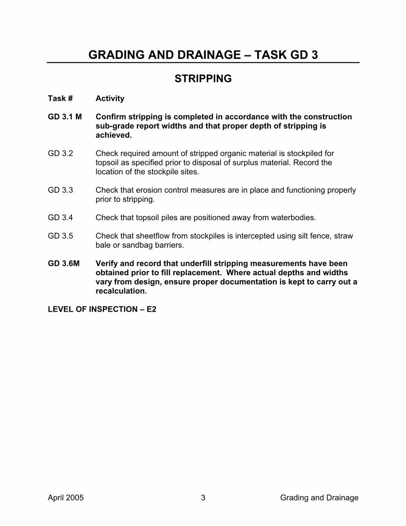
April 2005 Grading and Drainage 3
GRADING AND DRAINAGE – TASK GD 3
STRIPPING Task # Activity GD 3.1 M Confirm stripping is completed in accordance with the construction
sub-grade report widths and that proper depth of stripping is achieved.
GD 3.2 Check required amount of stripped organic material is stockpiled for
topsoil as specified prior to disposal of surplus material. Record the location of the stockpile sites.
GD 3.3 Check that erosion control measures are in place and functioning properly
prior to stripping. GD 3.4 Check that topsoil piles are positioned away from waterbodies. GD 3.5 Check that sheetflow from stockpiles is intercepted using silt fence, straw
bale or sandbag barriers. GD 3.6M Verify and record that underfill stripping measurements have been
obtained prior to fill replacement. Where actual depths and widths vary from design, ensure proper documentation is kept to carry out a recalculation.
LEVEL OF INSPECTION – E2

April 2005 Grading and Drainage 4
GRADING AND DRAINAGE – TASK GD 4
SWAMP TREATMENT Task # Activity GD 4.1 Floating the road.
(i) Check during construction that the integrity of the mat material is maintained.
(ii) Check that no rock fill is in contact with the root mat. (iii) Check that care is taken in locating ditching and that root material is
not disturbed. (iv) Beware of culverts being inserted below the root mat. (v) Swamp waves shall not be excavated or otherwise disturbed. (vi) Confirm each layer is built using an outside to inside sequence by
keeping the outer one third portions of the layer a least 30 metres ahead of the centre portion
(vii) Check that if geotextiles are used that they are placed in accordance with the specifications
GD 4.2 M Excavation
(i) Survey and record the limits and depth of the excavation and compare them to the design limits.
(ii) Document daily all of the Contractor’s excavation and disposal equipment (make, model, operating weights, bucket sizes, boom lengths), and the Contractor’s production accomplished. Estimate weekly the projected completion of these operations, using the Contractor’s current production rate.
(iii) Check that during excavation, material removed is managed of as specified in the contract documents.
(iv) Ensure, if using Truck Rental items for disposal of swamp excavation, that hours are for the time that the trucks are working, and verify the efficiency of operation to ensure that maximum productivity is achieved. Verify and record hours daily with the Contractor.
(v) Check that excavation of displaced materials and backfilling is carried out simultaneously, and in such a way as to displace the muskeg and produce a mud wave (displacement method).
(vi) If excavated material is being used for, or blended for use as topsoil, then check that the required amount of excavated organic material is stockpiled for topsoil as specified prior to disposal of surplus material. Record location of stockpile site.
(vii) Check that backfill materials are as specified in the contract and are compacted to the target density.

April 2005 Grading and Drainage 5
GD 4.3 Surcharging – See Task GD 42 (i) Check construction staging and verify embankment and surcharge
is constructed in accordance with staging details. (ii) Check that surcharge is placed to the geometry shown on the
contract drawings. M (iii) Ensure proper surcharge material is used and placed to height
and limits specified in the contract. Ensure surcharge is removed only after required time period, settlement, or pore water pressure is achieved.
LEVEL OF INSPECTION – A2

April 2005 Grading and Drainage 6
GRADING AND DRAINAGE – TASK GD 5
EARTH CUT Task # Activity GD 5.1 M Check suitability of cut material for use as fill in other locations.
Consult with Contract Control Officer if anticipated volume of suitable earth material from individual cuts differs markedly from Contract estimate.
GD 5.2 Watch for any seepage areas in earth cuts, and provide for appropriate
treatments as required. Check that any advanced dewatering scheme to facilitate the excavation is carried out.
GD 5.3 M Check that treatment of frost susceptible soil area is completed as
specified in the contract documents. Check the Contractor’s records to ensure that the disposition of material from each earth cut area is recorded.
GD 5.4 M Boulders 1 cubic metre and greater in volume are measured and
recorded for payment as rock excavation. GD 5.5 Check for proper crown and that adequate drainage is maintained. GD 5.6 Check that the excavation is carried out to the required geometry. GD 5.7 M Verify and record that grading tolerances are correctly applied and
all slopes conform to the acceptance envelope. GD 5.8 Check that longitudinal and transverse transition treatments (cut to fill, fill
to fill) are constructed correctly. GD 5.9 Check that soil sloughing is avoided and controlled during excavation
procedure. GD 5.10 Check that toe drains, slope drains and / or interceptor ditches are
properly constructed. GD 5.11 Check that erosion and sediment control schemes are in place and
functioning (i.e. gravel sheeting, rip rap, rock protection). GD 5.12 Record starting and ending dates of various earth operations for
conformance with timing constraints.

April 2005 Grading and Drainage 7
GD 5.13 Check that backfilling of overexcavated areas is carried out in accordance with the specification.
GD 5.14 Check that boulders on excavated slopes are removed in accordance with
the specifications. LEVEL OF INSPECTION – D2

April 2005 Grading and Drainage 8
GRADING AND DRAINAGE – TASK GD 6
EARTH EMBANKMENT Task # Activity GD 6.1 M Check that erosion and sediment control schemes are in place and
functioning. Determine if additional erosion control measure, or additional locations may be required.
GD 6.2 Check that any organic or deleterious material is sub-excavated prior to
embankment construction. GD 6.3 Check that special embankment foundation and benching is carried out as
specified in the contract documents. GD 6.4 M Check Contractor’s required quality control tests to ensure target
density is obtained. GD 6.5 Inspect embankment construction to ensure that the specified depth of
layers are maintained, that oversize and frozen material is not used, that material is not placed on frozen ground or on ice or snow, and that the cross fall is adequate for drainage.
GD 6.6 Check that boulders are placed in accordance with the specifications. GD 6.7 If a berm is required; check that it is constructed before the main fill is built
to a level higher than the berm. GD 6.8 If a surcharge is used, see task GD 42. GD 6.9 M Verify and record that grading tolerances are correctly applied and
all slopes conform to the acceptance envelope prior to placement of subbase material.
GD 6.10 Check that fill is placed and compacted according to the specifications –
layer compaction or modified layer compaction. GD 6.11 Check that appropriate construction procedure is conducted for side hill or
sloping sections. LEVEL OF INSPECTION – D2

April 2005 Grading and Drainage 9
GRADING AND DRAINAGE – TASK GD 7
ROCK CUT Task # Activity GD 7.1 Check to ensure that the Contractor has removed all stumps, roots,
vegetation and soil overlaying rock to be excavated to the width specified on the construction subgrade report.
GD 7.2 M Check that overburden is excavated from each transition treatment
area prior to blasting. GD 7.3 Check that removal of overburden and earth is carried out sufficiently in
advance to permit surveying of original rock cross-sections. GD 7.4 Check that disposal of overburden material is as specified. Check that
disposal sites are positioned away from waterbodies. Check that sheetflow from disposal is intercepted using silt fence, straw bale or sandbag barriers.
GD 7.5 M Survey for payment purposes all original and stripped rock cross-
sections and ensure that zero rock stations are supported by field measurement prior to blasting operations. Zero rock stations shall be determined and recorded when the grade is checked or when the original cross-sections are obtained, and referenced in HDS or to the cross-section rolls. Ensure that the construction portion is being used to enter the original rock lines. When the original rock line differs from the rock line used in Design, then the quantities of rock and shatter, where appropriate, shall be re-calculated monthly to the lines of the grading standard. Revised cross-section templates shall be submitted to the Contractor. The original cross-section template must be signed by the Contractor to acknowledge the receipt of the report.
GD 7.6 Check that blasting design, blasting permit, and pre-construction survey
have been submitted. GD 7.7 Check qualifications of the Blasting Designer. GD 7.8 Check that proper notifications are provided to the appropriate authorities. GD 7.9 Check that all safety precautions are observed prior to blasting, including
the sounding of audible warning device before and after blasting as required.

April 2005 Grading and Drainage 10
GD 7.10 Check that protective measures to control fugitive flyrock, as specified, are
used around private properties and/or utility locations. GD 7.11 Check that noise, vibration and dust levels are controlled as required. GD 7.12 M Check that a “Trial Blast” for drilling and blasting is carried out to
verify the blasting design in general. GD 7.13 Check that drilling depth is sufficient to provide the required shatter and
extra depth shatter is specified. GD 7.14 Check that extra depth shatter is verified and drilling depths recorded. GD 7.15 Check that drilling pattern is as per the blasting design. Record type and
amount of explosive material used. Record drilling depths, limits and pattern.
GD 7.16 M Check that there is effective drainage to ditches and transition
treatments by confirming that no undrained pockets are left in the road bed or ditches.
GD 7.17 During and after scaling inspect rock face for potential rockfall hazard and
discuss any concerns with the Contract Control Officer. Ensure any special rockfall hazard designs have been properly implemented, as indicated in the contract documents.
GD 7.18 M Surface boulders 1 cubic metre or greater in volume are measured
and recorded as rock excavation. GD 7.19 Document the disposition of all rock excavation material showing how cut
is excavated, type of equipment used, where it is being disposed including the equipment involved and the time and duration of the work.
GD 7.20 Check that a post construction survey is carried out by the Contractor GD 7.21M Verify and record that grading tolerances are correctly applied and
all excavations conform to the acceptance envelope. GD 7.22 Coordinate with Rock Engineering Specialist (if applicable) to inspect rock
face locations such as foundations founded on a rock ledge to ensure rock mass stabilization.
GD 7.23 Check that appropriate notification is conducted prior to blasting.

April 2005 Grading and Drainage 11
GD 7.24 Check that blasting monitoring equipment, procedure and recording is conducted as specified.
LEVEL OF INSPECTION – C2

April 2005 Grading and Drainage 12
GRADING AND DRAINAGE – TASK GD 8
ROCK EMBANKMENT Task # Activity GD 8.1 Check that rock fill is built in accordance with SP206S03, unless otherwise
specified in the contract documents. GD 8.2 Verify by survey, a minimum of 25% of the stations of the excavated base
forming the bottom of each rock embankment, prior to embankment construction. Compare with contract plans. If there is a significant difference, verify all of the embankment stations, and make appropriate adjustments to the plan quantity.
GD 8.3 Check that rock fill is not placed on frozen soil. GD 8.4 If rock fill is used to displace soft underlying materials, the centre should
be kept ahead of the sides or one side on sidehill organic displacement. GD 8.5 Check equipment type and size, number of passes, and lift thickness for
the compaction of rock embankment. GD 8.6 Check that shale embankment materials are spread and compacted in
uniform layers as specified in the contract documents. GD 8.7 Check that large particle sizes are within specified size restriction and are
properly positioned within the rockfill embankment. GD 8.8 Check that chinking is carried out to fill surface voids. GD 8.9 Check that approved procedures are followed for surcharge loading. See
Task GD 42. GD 8.10 M Verify and record that grading tolerances are correctly applied and
all fill slopes conform to the acceptance envelope. Where overbuilding is known to have occurred, notify the Contractor by Instruction Notice prior to placement of subbase material. Record the natural angle of repose before adjustments are made.
GD 8.11 Record daily, the construction of Rock Fill (location of source of material
used, final disposition of the material, the equipment involved, and the time and duration of the work).
LEVEL OF INSPECTION – D2

April 2005 Grading and Drainage 13
GRADING AND DRAINAGE – TASK GD 9
TRANSITION TREATMENTS IN ROCK OR EARTH Task # Activity GD 9.1 M Verify and record that proper transition treatment is carried out
during initial construction period, before fill placement interferes with the excavation. Verify and record that grading tolerances are correctly applied and all slopes conform to the acceptance envelope prior to backfilling. Backfill as specified in the contract documents.
GD 9.2 Check that transition has positive drainage. LEVEL OF INSPECTION – D2

April 2005 Grading and Drainage 14
GRADING AND DRAINAGE – TASK GD 10
FROST HEAVE TREATMENT Task # Activity GD 10.1 Check that material supplied by the Contractor is sampled as required. GD 10.2 Check that the polystyrene complies with environmental specifications. GD 10.3 M Record that frost susceptible soils are removed and replaced with
acceptable material to the specified grades, lengths and tolerances. Adjust grades and limits depending on extent of frost susceptible soils. Verify transition between frost treatment and normal grading sections is constructed properly.
GD 10.4 Check to ensure adequate drainage from treated area. GD 10.5 Check expanded polystyrene is installed as follows:
(i) Check that the sheets are properly placed with regards to tight and staggered joints;
(ii) Check that sheets are secured to prepared surface; and (iii) Check that backfill is placed by dumping, spread and compacted in
one lift, free of oversized material and is of sufficient depth to protect the polystyrene.
GD 10.6 Check that backfill materials comply with the specifications and are
compacted to the target density. LEVEL OF INSPECTION – B2

April 2005 Grading and Drainage 15
GRADING AND DRAINAGE – TASK GD 11
BASE AND SUBBASE Task # Activity GD 11.1 Check that the Contractor has submitted QC test results prior to delivery
of materials and that they meet the physical property and production requirements as specified in the contract documents.
GD 11.2 Check for any evidence of contamination from subgrade pumping into
subbase and have the Contractor take appropriate corrective action. GD 11.3 Check that quality assurance samples are obtained for testing as specified
in the contract documents. Conduct visual inspection of material for contamination, including clay balls, clay coated particles or foreign material. Where contamination is observed or suspected take appropriate action.
GD 11.4 M Check that subbase and base materials comply as specified in the
contract documents. Check that no Blast Furnace Slag material is being place in the base and sub base. Check Contractor’s compaction density readings to see that all the work falls within the specified tolerances.
GD 11.5 M Check that Contractor has obtained the required weigh scale
certification in accordance with the contract documents. GD 11.6 M Verify and record horizontal and vertical grading tolerances prior to
the placement of the next type of material or pavement. GD 11.7 Check that material control, distribution and weighing conform to the
contract documents. LEVEL OF INSPECTION – D2

April 2005 Grading and Drainage 16
GRADING AND DRAINAGE – TASK GD 12
RESTORING ROADWAY SURFACES Task # Activity GD 12.1 Check that the restored roadway surface is compacted to the target
density. GD 12.2 M Check the Contractor’s crossfall on the restored roadway surface for
correctness prior to placement of the next type of material or pavement.
LEVEL OF INSPECTION – E2

April 2005 Grading and Drainage 17
GRADING AND DRAINAGE – TASK GD 13
GRADE AND COMPACTION Task # Activity
Horizontal and Vertical Grading Tolerances GD 13.1 M A monitoring checking frequency of a minimum of 25% (but not
limited to), is required to be recorded for all of Contractor’s quality control grade checks to verify the Contractor’s ability to ensure that the grades and cross sections are within the specified tolerances. When one half of the Contractor’s quality control operation has been successfully completed the monitoring frequency may be reduced to a minimum (but not limited to) of 5%, with the approval of the Contract Control Officer. During the grade check, the width of placement should be checked and recorded, and when the horizontal tolerances are exceeded, elevations and distances must be recorded.
Compaction
GD 13.2 M A testing frequency of a minimum of 25% (but not limited to), is
required to be recorded for all of Contractor’s quality control testing requirements to verify the Contractor’s ability to control compaction. This is to be done on an ongoing base. When one half of the Contractor’s quality control operation has been successfully completed the physical testing frequency may be reduced to a minimum (but not limited to) of 5%, with the approval of the Contract Control Officer.
LEVEL OF INSPECTION – D2

April 2005 Grading and Drainage 18
GRADING AND DRAINAGE – TASK GD 14
BORROW PITS AND QUARRIES Task # Activity GD 14.1 Check that the pit or quarry is worked to the approved line and grade and
appropriate measurements are taken to support payment. GD 14.2 M Survey, for payment purposes, all original cross sections (after
stripping) and final cross sections for the borrow pit or quarry (in bank volume).
GD 14.3 Check that stripping material does not contaminate the borrow. GD 14.4 Check that the operation of the pit or quarry is carried out in accordance
with the Aggregate Sources List, site plan and permit / Letter of Approval. If the Contractor does not operate in accordance with the site plan and/or the site plan standards and operational requirements, notify the Contractor by Instruction Notice and notify the Contract Control Officer immediately.
GD 14.5 M Check that the rehabilitation of the pit or quarry, at the completion of
the job, is in accordance with the site plan. LEVEL OF INSPECTION – C1
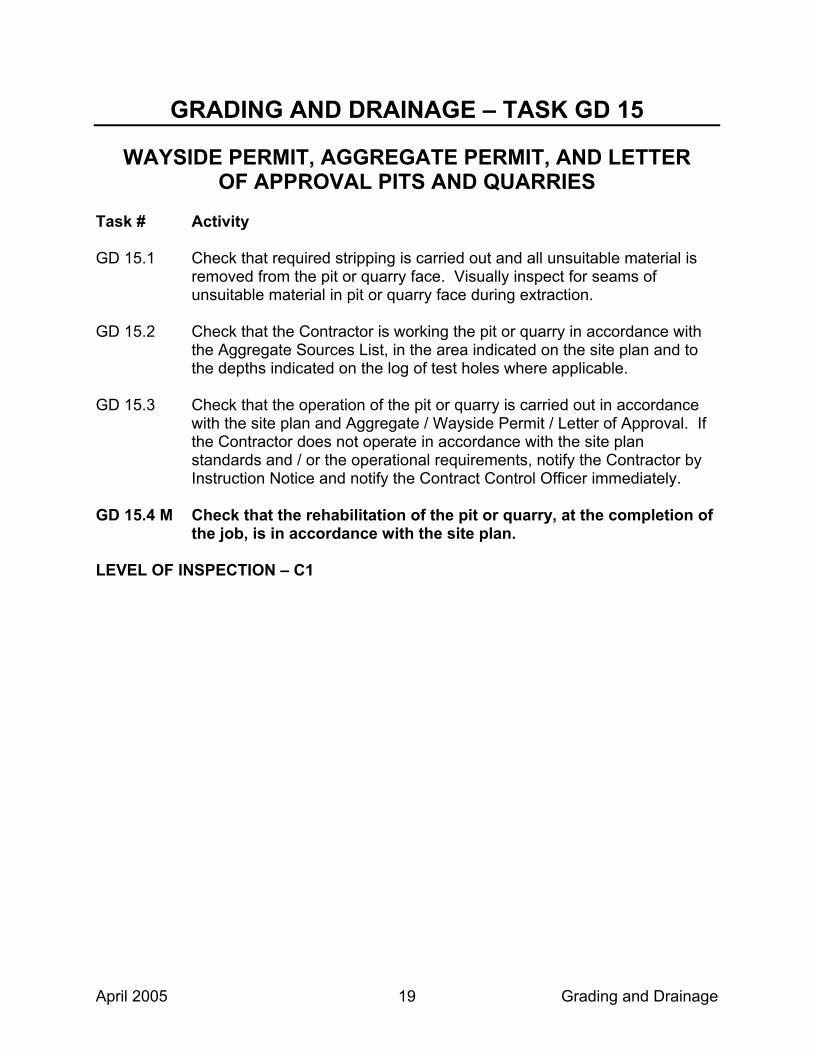
April 2005 Grading and Drainage 19
GRADING AND DRAINAGE – TASK GD 15
WAYSIDE PERMIT, AGGREGATE PERMIT, AND LETTER OF APPROVAL PITS AND QUARRIES
Task # Activity GD 15.1 Check that required stripping is carried out and all unsuitable material is
removed from the pit or quarry face. Visually inspect for seams of unsuitable material in pit or quarry face during extraction.
GD 15.2 Check that the Contractor is working the pit or quarry in accordance with
the Aggregate Sources List, in the area indicated on the site plan and to the depths indicated on the log of test holes where applicable.
GD 15.3 Check that the operation of the pit or quarry is carried out in accordance
with the site plan and Aggregate / Wayside Permit / Letter of Approval. If the Contractor does not operate in accordance with the site plan standards and / or the operational requirements, notify the Contractor by Instruction Notice and notify the Contract Control Officer immediately.
GD 15.4 M Check that the rehabilitation of the pit or quarry, at the completion of
the job, is in accordance with the site plan. LEVEL OF INSPECTION – C1

April 2005 Grading and Drainage 20
GRADING AND DRAINAGE – TASK GD 16
EQUIPMENT RENTAL Task # Activity GD 16.1 Record that the equipment used meets the requirements specified in the
contract documents (i.e. size, capacity, horsepower). GD 16.2 Check the efficiency of operation to ensure productivity of rented
equipment. GD 16.3 Record and verify hours daily with the Contractor. GD 16.4 M The CA shall issue one equipment rental ticket daily for each type of
equipment used and shall indicate the total number of hours. The tickets are to be signed by both the CA and the Contractor.
LEVEL OF INSPECTION – D2

April 2005 Grading and Drainage 21
GRADING AND DRAINAGE – TASK GD 17
DITCHING Task # Activity GD 17.1 M Check that appropriate measures are taken to prevent erosion of
ditches prior to the start of ditching. Check that erosion and sediment control schemes are in place and functioning. Determine if additional erosion control measures, or additional locations may be required.
GD 17.2 M Check that ditch grading tolerances are correctly applied and all
slopes conform to acceptance envelope. GD 17.3 Check that suitable material excavated from ditches is utilized in fill areas. GD 17.4 Check that unsuitable material is managed as specified in the contract
documents. GD 17.5 M Check for positive drainage from field tiles. LEVEL OF INSPECTION – E2

April 2005 Grading and Drainage 22
GRADING AND DRAINAGE – TASK GD 18
SUBDRAINS Task # Activity GD 18.1 Check specified size of pipe, including filter material. GD 18.2 Check that all the delivered material is stored properly and verify that it is
being supplied from the approved list that was submitted by the Contractor at the commencement of the contract.
GD 18.3 Check that perforations are placed down when their purpose is to collect
water and they are bedded in free draining filter material. Check that pipes without perforations are used when their purpose is to transport water.
GD 18.4 Check that couplings are suitable for and compatible with the class and
type of pipe and installed correctly. GD 18.5 M Check that granular materials comply with the specifications and are
compacted to the target density. GD 18.6 If impervious clay cap is required, check that cap is properly built. GD 18.7 Check that proper connection to manholes, catchbasins, and ditch inlets
(grouting and grade) are made. GD 18.8 Check that each outlet location is marked with an approved marker and is
visible from the driving portion of the roadway. GD 18.9 Check that outlet and collector pipers are not crushed during backfilling
operations. Monitor the video camera inspection of subdrain installation. GD 18.10 Check that outlet and collector pipes are placed to required slope and
grade to ensure gravity flow. GD 18.11 Check that rodent grates are installed securely and quickly after subdrain
installation. GD 18.12 Check that the trenches are excavated to the width, grade and alignment
specified in the Contract Documents. GD 18.13 Check for trench stability during excavation.

April 2005 Grading and Drainage 23
GD 18.14 Check that pipe bedding and backfilling is conducted as specified. GD 18.15 Check that inspection report is completed by the Contractor for the
excavation, bedding and backfilling. GD 18.16 Check that a non-woven geotextile is used to wrap the trench when 19
mm clear stone is specified as backfill. GD 18.17 Check that video camera inspection is conducted as specified. LEVEL OF INSPECTION – D2

April 2005 Grading and Drainage 24
GRADING AND DRAINAGE – TASK GD 19
EXCAVATION FOR CULVERTS Task # Activity GD 19.1 Verify and record that the requirements of all fisheries authorizations have
been achieved prior to the start of excavation. GD 19.2 Check that erosion and sediment control schemes are in place and
functioning. Determine if additional erosion control measures, or additional locations may be required.
GD 19.3 Check that the water table level is managed as specified in the contract
documents. Check for advance unwatering requirements. GD 19.4 Check that unwatering is not causing erosion of soil at the outlet and other
environmental concerns (i.e. muddy water discharge). Check that the Contractor has the standby equipment (pumps, hose, etc.) on site as required in the environmental submission.
GD 19.5 Check to ensure that dust and debris from construction operations is not
entering a watercourse or Environmentally Sensitive Area. GD 19.6 Confirm that any other relevant environmental constraints have been
addressed. GD 19.7 Check that the founding soil is sound and undisturbed. Check that all
loosened, soft, organic and deleterious material and boulders at the foundation base are removed and replaced with suitable, compacted granular material or mass concrete.
GD 19.8 M Confirm and record limits of excavation (width and depth) to ensure
that they conform to contract documents. Confirm and record limits of frost tapers at shoulderline and centreline. Confirm that the specified taper slope continues until it intersects subgrade / bottom of roadbed granular. If the crossing is identified as a watercourse in the contract documents, limit disturbance beyond the end of the culverts.
GD 19.9 For crossings identified as watercourses in the contract documents,
survey existing streambed elevation if not provided in the contract documents to ensure that the new culvert depth does not exceed the exiting streambed elevation (i.e. a minimum 300mm depression unless
April 2005 Grading and Drainage 25
otherwise specified in the contract documents) to maintain low flow channel.
GD 19.10 Check for signs of basal heave due to unbalanced hydrostatic head
conditions. GD 19.11 Check for working slabs / working pads. LEVEL OF INSPECTION – C2

April 2005 Grading and Drainage 26
GRADING AND DRAINAGE – TASK GD 20
BEDDING AND BACKFILL FOR CULVERTS Task # Activity GD 20.1 Check that erosion and sediment control schemes are in place and
functioning prior to placement of bedding and backfill. Determine if additional erosion control measures, or additional locations may be required.
GD 20.2 Check that unwatering is not causing erosion of soil at the outlet and other
environmental concerns (i.e. muddy water discharge). Check that the Contractor has the standby equipment (pumps, hose, etc.) on site as required in the environmental submission.
GD 20.3 M Check that the bedding and backfill materials are sampled as
required, comply with the specifications, and are compacted to the target density. Check that the proper compacted lift thickness is as specified. (Elevation not to exceed existing streambed elevation.)
GD 20.4 Check the bedding site for: transition from firm to soft material; high points;
soft spots; stones or boulders under culvert; general foundation problems due to unstable soil conditions. Investigate pipe relocation to avoid cutting the organic mat when the embankment rides the swamp.
GD 20.5 Check all the delivered material to verify that it is being supplied from the
approved list that was submitted by the Contractor at the commencement of the contract.
GD 20.6 If required, check that upstream end of the pipe is embedded in clay and
properly compacted to prevent seepage. GD 20.7 Check for proper camber. GD 20.8 Check that the bedding and the backfill materials are placed in the dry as
specified in the contract documents. GD 20.9 Check that backfill is compacted under the haunches. GD 20.10 Check that backfill is brought up evenly on both sides of the pipe at the
same time. GD 20.11 Check that compaction equipment does not impose excessive vibrations
on structure.

April 2005 Grading and Drainage 27
GD 20.12 Check that specified depth of cover is placed before heavy equipment is
allowed over culvert location. GD 20.13 Check that strutting requirements are met when required. GD 20.14 Check frost taper requirements are met and dimensions recorded. GD 20.15 For crossings identified as watercourses in the contract documents,
survey existing streambed elevation if not provided in the contract documents to ensure that the new culvert depth does not exceed the exiting streambed elevation (i.e. a minimum 300mm depression unless otherwise specified in the contract documents) to maintain low flow channel.
GD 20.16 Check excavation limits. GD 20.17 Check that proper gaskets and couplers are used. GD 20.18 Check that advanced dewatering is conducted as required to prevent soil
sloughing, basal heave and boiling. LEVEL OF INSPECTION – C2

April 2005 Grading and Drainage 28
GRADING AND DRAINAGE – TASK GD 21
SEWER IN TRENCH Task # Activity GD 21.1 Check that erosion and sediment control schemes are in place and
functioning prior to the start of trenching for sewer. Determine if additional erosion control measures, or additional locations may be required.
GD 21.2 Check that advanced unwatering is conducted as required to prevent soil
sloughing, basal heave and boiling. Check that excavations are free of water at all times.
GD 21.3 Check that unwatering is not causing erosion of soil at the outlet and other
environmental concerns (i.e. muddy water discharge). Check that the Contractor has the standby equipment (pumps, hose, etc.) on site as required in the environmental submission.
GD 21.4 Check all the delivered material to verify that it is being supplied from the
approved list that was submitted by the Contractor at the commencement of the contract.
GD 21.5 Check that the founding soil is sound and undisturbed. GD 21.6 M Check that alignment, grade and designed widths are adhered to, as
loading on pipe is partially dependent on trench widths. GD 21.7 Check that specified bedding is used and constructed as per standard. GD 21.8 Check all pipes to ensure correct class and reject those that are damaged
and cannot be repaired. GD 21.9 During progress of work, check that pipes and connections are kept clean
and free of foreign material. GD 21.10 Check that all gaskets and joints are tight. GD 21.11 M Check that backfill materials are as specified in the contract and the
required compaction checks are made. GD 21.12 Check that oversize particles are removed. GD 21.13 Where applicable, check that joints are lapped in direction of flow.
April 2005 Grading and Drainage 29
GD 21.14 Check that proper equipment is used for compaction until the specified depth of cover over the pipes is achieved.
GD 21.15 Check that backfill is placed evenly on both sides of the pipe. GD 21.16 Record trench widths, type of bedding and type of backfill. LEVEL OF INSPECTION – D2

April 2005 Grading and Drainage 30
GRADING AND DRAINAGE – TASK GD 22
SEWER TUNNEL / JACK AND BORE Task # Activity GD 22.1 Check that erosion and sediment control schemes, and cofferdams are in
place and functioning prior to the start of tunnelling. Determine if additional erosion control measures, or additional locations may be required.
GD 22.2 Check that sheetflow from stockpiles of excavated material is intercepted
using silt fence, straw bale or sandbag barriers. Check that stockpiles are positioned away from waterbodies.
GD 22.3 Check that unwatering is not causing erosion of soil at the outlet and other
environmental concerns (i.e. muddy water discharge). Check that the Contractor has the standby equipment (pumps, hose, etc.) on site as required in the environmental submission.
GD 22.4 Check that sufficient indicators are set up and maintained to detect and
monitor any movements within and outside the tunnel. GD 22.5 Check that techniques employed meet the specification. GD 22.6 Check that alignment and grade are maintained. GD 22.7 Check all the delivered material to verify that it is being supplied from the
approved list that was submitted by the Contractor at the commencement of the contract.
GD 22.8 Check that permanent liners are supplied and installed. GD 22.9 Check and verify the soil spoil. GD 22.10 Check that grouting materials are properly supplied and placed. GD 22.11 Report all ground movements, failures, seepage zones and changes in
soil conditions to the Contract Control Officer. GD 22.12 Check that appropriate dewatering is conducted to avoid soil cave-in and
sloughing during the tunnelling. GD 22.13 Check to verify any obstructions attributable to boulders and cobbles.
April 2005 Grading and Drainage 31
GD 22.14 Check that a preconstruction survey has been conducted. GD 22.15 Check that excavation shafts and shoring systems are stable. LEVEL OF INSPECTION – C2

April 2005 Grading and Drainage 32
GRADING AND DRAINAGE – TASK GD 23
WATERMAIN IN TRENCH Task # Activity GD 23.1 Check that erosion and sediment control schemes are in place and
functioning prior to the start of trenching. Determine if additional erosion control measures, or additional locations may be required.
GD 23.2 Check that unwatering is not causing erosion of soil at the outlet and other
environmental concerns (i.e. muddy water discharge). Check that the Contractor has the standby equipment (pumps, hose, etc.) on site as required in the environmental submission.
GD 23.3 Check all the delivered material to verify that it is being supplied from the
approved list that was submitted by the Contractor at the commencement of the contract.
GD 23.4 Check that excavations are free of water at all times. GD 23.5 M Check that alignment and designed widths are adhered to as loading
on pipe is partially dependent on trench widths. GD 23.6 Check that specified bedding is used and constructed as per standard. GD 23.7 Check that watermain is placed in trench to depth as specified in the
contract for frost penetration. GD 23.8 Check all pipes to ensure correct type and class. GD 23.9 During progress of work check that pipes, connections and appurtenances
are kept clean and free of foreign material. GD 23.10 Check that all pipe ends are lubricated with material recommended by the
pipe manufacturer prior to installation. GD 23.11 Check that fabricated bends are used when changes in line or grade are
required. GD 23.12 Check that any connections, caps and bends are provided with thrust
blocks and wedges. GD 23.13 M Check that backfill materials are as specified in the contract
documents and the required compaction checks are made.

April 2005 Grading and Drainage 33
GD 23.14 Check that backfill is brought up evenly on both sides of the pipe at the
same time. GD 23.15 Check that oversize particles are removed. GD 23.16 Check that appropriate equipment is used for compaction until the
specified depth of cover over the pipe is achieved. GD 23.17 Observe all appropriate testing for approvals. GD 23.18 Check that top of pipe elevations are recorded. GD 23.19 Check that measurements of bends, ties, connections, etc. are recorded. GD 23.20 Check that watermains are flushed and disinfected as specified. LEVEL OF INSPECTION – C2

April 2005 Grading and Drainage 34
GRADING AND DRAINAGE – TASK GD 24
MANHOLES, CATCHBASINS, AND DITCH INLETS Task # Activity GD 24.1 Check all the delivered material to verify that it is being supplied from the
approved list that was submitted by the Contractor at the commencement of the contract.
GD 24.2 Check type, alignment, offset and grades of manholes, catchbasins and
ditch inlets. GD 24.3 Check correct positioning and installation of ladder rungs and safety
grates. GD 24.4 Visually check all materials used for quality and/or damage (Pre-Cast); i.e.
honeycombing, cracks, voids, surface defects, etc. GD 24.5 M Check that, backfill materials are as specified in the contract and are
compacted to the target density. GD 24.6 Check that poured in place manholes, catchbasins and ditch inlets
conform to the contract standards. GD 24.7 Check that the frustum is located and constructed properly. GD 24.8 Check for the correct placement of reinforcing steel. GD 24.9 Check that specified compaction is obtained under pipes entering or
exiting manholes, catchbasins and ditch inlets. GD 24.10 Check for proper placement of weep-holes. GD 24.11 Check for proper placement of pipe subdrain outlet in structures. GD 24.12 Check that manholes, catchbasins and ditch inlets are cleaned out.
Check that excess materials from the work are stored and disposed of as specified in the contract documents Check that honeycombed areas are parged and the grates and pipes are grouted upon completion.
LEVEL OF INSPECTION – E2

April 2005 Grading and Drainage 35
GRADING AND DRAINAGE – TASK GD 25
GEOTEXTILE Task # Activity GD 25.1 Check all the delivered material to verify that it is being supplied from the
approved list that was submitted by the Contractor at the commencement of the contract.
GD 25.2 Check that material supplied by the Contractor is sampled as required and
forwarded for testing. GD 25.3 M Check that each roll to be used has a tag showing product name and
number and it meets the design requirements (woven or non-woven, Class I or Class II, F.O.S.).
GD 25.4 Check that the geotextile is contained in opaque (light blocking) wrapping. GD 25.5 Check installation area for removal of sharp objects that may puncture the
geotextile. GD 25.6 Check that the proper overlap has been maintained during installation. GD 25.7 Check that the geotextile is not exposed to sunlight for more than three
days. GD 25.8 Check that drop height for material placed onto it is less that 1 metre to
ensure material is not damaged. GD 25.9 Check that sufficient geotextile is placed on the ditch sides to ensure
water does not erode the sides of the ditch. GD 25.10 Check that all materials contaminated or damaged during installation are
either replaced or repaired so that the geotextile will perform as intended. LEVEL OF INSPECTION – E2

April 2005 Grading and Drainage 36
GRADING AND DRAINAGE – TASK GD 26
GRANULAR BLANKET Task # Activity GD 26.1 Check that erosion and sediment control schemes are in place and
functioning prior to start of excavation. Determine if additional erosion measures, or additional locations may be required.
GD 26.2 Check that granular materials comply with the specifications. GD 26.3 M Check that slope to receive blanket is properly prepared. Excavate
beyond finished surface such that the granular blanket will fit the theoretical cut slope line.
GD 26.4 Check that granular blanket is placed as excavation progresses and
completion of the blanket coincides with completion of the cut. GD 26.5 Check construction of interceptor ditches. GD 26.6 Check the placement of any subdrains below the ditch line. GD 26.7 Check that care is taken in placement to minimize segregation, especially
if placed under water. GD 26.8 Check thickness and evenness of placement to ensure a stable free
draining slope material. LEVEL OF INSPECTION – E2
April 2005 Grading and Drainage 37
GRADING AND DRAINAGE – TASK GD 27
RIP RAP Task # Activity GD 27.1 Check that erosion and sediment control schemes are in place and
functioning prior to the placement of rip rap. Determine if additional erosion measures, or additional locations may be required.
GD 27.2 Check that rip rap material is the specified quality and size. GD 27.3 Check that rip rap has an adequate foundation. GD 27.4 M When placed on slopes, check that rip rap is countersunk into the
surface of the slope. GD 27.5 Check that rip rap is placed in a manner that will not tear or otherwise
damage the geotextile. GD 27.6 Check that rip rap is placed in accordance with any applicable timing
restrictions. LEVEL OF INSPECTION – C1/E2

April 2005 Grading and Drainage 38
GRADING AND DRAINAGE – TASK GD 28
GABIONS Task # Activity GD 28.1 Check that erosion and sediment control schemes (and coffer dams if
required) are in place and functioning prior to the installation of gabions. Determine if additional erosion control measures, or additional locations may be required.
GD 28.2 Check that the water table level is managed as specified in the contract
documents. GD 28.3 If working in the water, ensure that work is isolated from the water as
specified. Ensure that timing restrictions are adhered to, as specified. GD 28.4 If working at a watercourse, check that unwatering is not causing erosion
of soil at the outlet and other environmental concerns (i.e. muddy water discharge). Check that the Contractor has the standby equipment (pumps, hoses, sediment bags, etc.) on site as required in the environmental submission.
GD 28.5 Confirm that any other relevant environmental constraints have been
addressed. GD 28.6 Check all delivered material to verify that it is being supplied from the
approved list that was submitted by the Contractor at the commencement of the contract.
GD 28.7 Check that bed is uniform, trimmed, not frozen and consolidated and
check for the need of scour protection. GD 28.8 Check that gabions are installed to the lines and grades as specified in the
contract documents. GD 28.9 Check proper assembly, positioning and tying. GD 28.10 Check that gabions are placed in tension prior to filling to achieve proper
alignment and compaction. GD 28.11 Check that transverse and vertical joints between gabions are staggered. GD 28.12 Verify the quality, size and proper placement of the stone.
April 2005 Grading and Drainage 39
GD 28.13 Check that the front face is hand packed to minimize voids. LEVEL OF INSPECTION – C1/E2

April 2005 Grading and Drainage 40
GRADING AND DRAINAGE – TASK GD 29
TOPSOIL Task # Activity GD 29.1 Verify that original cross-sections have been taken on the topsoil stockpile
prior to use and final cross-sections taken for payment. GD 29.2 Check that topsoil stockpiles are positioned away from waterbodies. GD 29.3 Check that erosion and sediment schemes are in place and functioning.
Sheet flow from stockpiles should be intercepted using silt fence, straw bale or sandbag barriers. Determine if additional erosion control measures, or additional locations may be required.
GD 29.4 Check the quality of imported topsoil in accordance with the contract
documents. GD 29.5 Check that imported topsoil trucks are measured and tickets issued in
accordance with the ministry requirements. GD 29.6 Check that topsoil is not used for filling depressions or wasted. GD 29.7 M Check that topsoil is spread uniformly to the depth specified. LEVEL OF INSPECTION – B1/E2

April 2005 Grading and Drainage 41
GRADING AND DRAINAGE – TASK GD 30
SODDING Task # Activity GD 30.1 Check that erosion and sediment control schemes are in place and
functioning prior to sodding. Determine if additional erosion control measures, or additional locations may be required.
GD 30.2 M Check that scarification and preparation of topsoil has been carried
out. GD 30.3 Check application of fertilizer. GD 30.4 Check sod before placement to ensure condition is as specified. GD 30.5 Check placement of sod ensuring that the staking pattern is correct and
that the sod edges are countersunk. GD 30.6 Check the stake dimensions to ensure that they conform to specification
requirements. GD 30.7 Check that sod is applied within the appropriate period and in accordance
with the applicable timing constraints as specified in the contract documents.
GD 30.8 Ensure that sodding operation is complete at temperatures or time of year
allowed by specification or shown in the contract documents. GD 30.9 W Check that the end result meets the provision of the warranty
requirements. Follow the inspection intervals specified in the Special Provision.
If Warranty is included only do items noted with “W” If No Warranty is included do all items. LEVEL OF INSPECTION – E2

April 2005 Grading and Drainage 42
GRADING AND DRAINAGE – TASK GD 31
SEEDING AND MULCHING Task # Activity GD 31.1 Check that erosion and sediment control schemes are in place and
functioning prior to seeding and mulching. Determine if additional erosion control measures, or additional locations may be required.
GD 31.2 Check all the delivered material to verify that it is being supplied from the
approved list that was submitted by the Contractor at the commencement of the contract.
GD 31.3 Check that material supplied by the Contractor is sampled as required. GD 31.4 W Check that material supplied by the Contractor bears a label
indicating the specified information. GD 31.5 Check that hydraulic seeding/mulching equipment has the tank volume
certification plate affixed in plain view. GD 31.6 M Check specified preparation of soil prior to seeding and mulching. GD 31.7 Check that hydraulic seeder/mulcher is calibrated before commencement. GD 31.8 Check charging of seeder, recording amounts of seed, fertilizer and/or
hydraulic mulch placed in tank. GD 31.9 Check that asphalt tank on mulcher has been inspected for cleanliness
and calibration. GD 31.10 Check that mulch is applied within one hour of being charged into the
hydraulic seeder/mulcher tank. GD 31.11 Check specified rates and uniform application of seed fertilizer, hydraulic
mulch, or straw mulch and asphalt adhesive. GD 31.12 Ensure that seeding / mulching operation is completed at temperatures or
time of year allowed by specification or shown in the contract documents. GD 31.13 Check for growth of plant material, and / or erosion of seeded areas. GD 31.14 W Check that the end result meets the provisions of the warranty
requirements. Follow the inspection intervals specified in the Special Provision.

April 2005 Grading and Drainage 43
If Warranty is included only do items noted with “W” If No Warranty is included do all items LEVEL OF INSPECTION – E2

April 2005 Grading and Drainage 44
GRADING AND DRAINAGE – TASK GD 32
FENCE Task # Activity GD 32.1 W Check all the delivered material to verify that it is being supplied
from the approved list that was submitted by the Contractor at the commencement of the contract.
GD 32.2 Check that preservative treated wood is identified with certification marks
authorized by the Canadian Wood Preservers Bureau. GD 32.3 Check the preservative treated wood to ensure the splits and checks are
within specified limits. GD 32.4 Check that all posts and rails are fabricated from galvanized steel pipe for
chain link fence. GD 32.5 Check that fence is placed in accordance with the requirements of the
property agreements. GD 32.6 Check that fence posts are the specified length. GD 32.7 Check that all end, corner, anchor, line, straining and gate posts are
properly installed with regard to depth, alignment, and spacing. GD 32.8 Check all bracings are correctly installed. GD 32.9 Check that loose material in the bottom of the posthole is tamped or
removed prior to placing the posts. GD 32.10 Check that all posts are vertical with the large end down and that the
backfill is properly tamped. GD 32.11 Check that steel wire for chain link fence fabric conforms to
CAN2-138.1-M and has a uniform 50mm diamond pattern. GD 32.12 Check that all fittings and accessories for chain link fences are galvanized. GD 32.13 Check that all gates for chain link fence open approximately 180 degrees
and that the gates for highway fence open into the owner’s land and close by gravity.

April 2005 Grading and Drainage 45
GD 32.14 Check that all fences are maintained throughout the duration of the contract.
GD 32.15 Check that concrete footings are constructed properly with regards to
forming and placement of concrete. GD 32.16 Check that all abraded and damaged surfaces are repaired and coated
with approved zinc pigmented paint. GD 32.17 W Check that the results meet the provisions of the warranty
requirements. If Warranty is included only do items noted with “W” If No Warranty is included do all items LEVEL OF INSPECTION – E1
April 2005 Grading and Drainage 46
GRADING AND DRAINAGE – TASK GD 33
GUIDE RAIL Task # Activity GD 33.1 Check all the delivered material to verify that it is being supplied from the
approved list that was submitted by the Contractor at the commencement of the contract.
GD 33.2 Check that all preservative treated wood is identified with certification
marks authorized by the Canadian Wood Preservers Bureau. GD 33.3 Check a minimum of 10% of the guide rail during installation and record
any deficiencies.
I. Check that cable guide rail is never located behind a curb. II. Check the guide posts to ensure the splits and checks are within
specified limits. III. Check that guide rail is erected at the specified location and offset. IV. Check that guide posts are the specified length. V. Check that loose material in the bottom of the post hole is tamped or
removed prior to placing the posts. VI. Check that anchor blocks are constructed properly with regards to
forming and placement of concrete.
GD 33.4 M Upon completion and receipt of the contractor’s guide rail checklist complete a detailed inspection of 25 % of the guide rail recording any deficiencies.
I. Check that all posts are vertical and that the backfill is properly
tamped. II. Check the guide posts for cracks and splits. III. Check that stretching, stapling and splicing is completed. IV. Check that posts are cut off correctly, chamfered and tops treated
and mounting height is correct.
April 2005 Grading and Drainage 47
V. Check that the steel beam mounting height is correct. VI. Check that Steel Beam guide rail in the vicinity of concrete surfaces
is bolted to these surfaces. VII. Confirm placement of reflectorized strips. VIII. Check that the Steel Beam guide rail elements are overlapped in the
direction of adjacent traffic flow. IX. Check that where the steel beam guide rail is behind the curb, the
offset is less that 250mm. X. Check that all bolts, washers and nuts are placed and affixed
securely to all plates, angles, posts and steel rail, as required. LEVEL OF INSPECTION – B1/D2

April 2005 Grading and Drainage 48
GRADING AND DRAINAGE – TASK GD 34
ECCENTRIC LOADER BARRIER AND EXTRUDERS Task # Activity
GD 34.1 Check all the delivered material to verify that it is being supplied from the approved list that was submitted by the Contractor at the commencement of the contract.
GD 34.2 Check that all preservative treated wood is identified with certification
marks authorized by the Canadian Wood Preservers Bureau. GD 34.3 Check a minimum of 10% of the end treatments during installations and
record any deficiencies.
I. Check the preservative treated wood to ensure the splits and checks are within specified limits.
II. Check that guide rail is erected at the proper locations. III. Check that guide rail posts are the specified length. IV. Check that anchor posts, breakaway posts and offset blocks are
properly installed with regards to depth, alignment and spacing. Check the holes drilled at the front of the posts are in the direction of traffic.
V. Check foundation tubes and soils bearing plates are properly
installed. VI. Check that loose material in the bottom of the posthole is tamped or
removed prior to placing the posts.
VII. Check that foreslope crossfall is graded properly to allow proper end treatment installation and positive drainage.
GD 34.4 M Check the certificate of conformance is supplied and complete a
detailed inspection of 25% of the end treatments recording any deficiencies.
I. Check that all posts are vertical and that the backfill is properly
tamped.

April 2005 Grading and Drainage 49
II. Check in the area 3m wide and 30m long behind the end treatment that the ground is not steeper than 4:1 and is traversable (protrusions, rip rap, etc. size below 75mm are acceptable).
III. Check that the strut between foundation tubes at post one and two is
attached properly. IV. Check that channels are installed at proper locations, elevations, and
are terminated as required. V. Check that the steel beam mounting height is correct. VI. Check that cable is snug and the breakaway holes are the proper
size and location. VII. Check that corrugated steel loader section is installed properly and
all loader assembly installation details are adhered to. VIII. Check that posts are cut off correctly, corner post (No. 1) is
chamfered and all tops treated. IX. Check that guide rail cable is properly attached with clamps to steel
beam, as required. X. Check that all bolts, washers and nuts are placed and affixed
securely to all plates, angles, posts and steel rail, as required. LEVEL OF INSPECTION – E1

April 2005 Grading and Drainage 50
GRADING AND DRAINAGE – TASK GD 35
TEMPORARY CONCRETE BARRIER (RELOCATION) Task # Activity GD 35.1 Check for any defects in the barrier after installation. GD 35.2 Check that the AI connector is always inserted in the channel end of
adjacent unit. GD 35.3 M Check that placement, end treatments and offsets are as specified in
the contract documents. GD 35.4 During construction, periodically check for any misaligned or damaged
barrier. Ensure that replacement or repair is carried out as required. GD 35.5 Check that removal or relocation is carried out as specified in the contract
documents. LEVEL OF INSPECTION – E2
April 2005 Grading and Drainage 51
GRADING AND DRAINAGE – TASK GD 36
INERTIAL BARRIER MODULE Task # Activity GD 36.1 Check all the delivered material to verify that it is being supplied from the
approved list that was submitted by the Contractor at the commencement of the contract.
GD 36.2 Check that sand/salt mixture is mixed at the approved rate. GD 36.3 Check that module is assembled correctly, precisely in the configuration
required and at the location as specified in the contract documents. GD 36.4 Check that module is set firmly in a vertical position and filled correctly. LEVEL OF INSPECTION – E1

April 2005 Grading and Drainage 52
GRADING AND DRAINAGE – TASK GD 37
CRASH/CUSHION ATTENUATING TERMINAL BARRIER Task # Activity GD 37.1 Check all the delivered material to verify that it is being supplied from the
approved list that was submitted by the Contractor at the commencement of the contract.
GD 37.2 Check that all preservative treated wood is identified with certification
marks authorized by the Canadian Wood Preservers Bureau. GD 37.3 Check a minimum of 10% of the end treatment during installation and
record and deficiencies.
I. Inspect the preservative treated wood to ensure the splits and checks are within specified limits.
II. Check that guide rail is erected at the proper locations. III. Check that guide posts are the specified length. IV. Check that steel posts are properly installed with regards to depth,
alignment and spacing. V. Check that loose material in the bottom of the posthole is tamped or
removed prior to placing the posts. GD 37.4 M Check the certificate of conformance is supplied and complete a
detailed inspection of 25% of the end treatments recording any deficiencies.
I. Check that all posts are vertical and that the backfill is properly
tamped. II. Check that channels are installed at proper locations, elevations and
are terminated as specified in the contract documents. III. Check that the steel beam mounting height is correct. IV. Check that spacer channel is installed properly and all connection
details for posts 1 through 6 are adhered to. V. Check that anchor cable is installed at the correct height.
April 2005 Grading and Drainage 53
VI. Check that guide rail is properly attached as required. VII. Check that all bolts, washers and nuts are placed and affixed
securely to all plates, angles, posts and steel rail as required. LEVEL OF INSPECTION – E1

April 2005 Grading and Drainage 54
GRADING AND DRAINAGE – TASK GD 38
TREND END TREATMENT BARRIER Task # Activity GD 38.1 Check all the delivered material to verify that it is being supplied from the
approved list that was submitted by the Contractor at the commencement of the contract.
GD 38.2 Check a minimum of 10% of the end treatments during installation and
record any deficiencies.
I. Check that granular is placed to required length and width prior to forming concrete pad.
II. Check that reinforcing steel is installed as specified in the contract
documents. III. Check that posts are specified length prior to affixing to concrete pad. IV. Check that plastic sand/salt filled containers are installed correctly. V. Check that anchor block is constructed properly with regards to
forming and placement of concrete. GD 38.3 M Check the certificate of conformance is supplied and complete a
detailed inspection of 25% of the end treatments recording any deficiencies.
I. Check that restraining cable is properly attached to post and anchor
block. II. Check that the steel beam mounting height is correct. III. Check that all bolts, washers and nuts are placed and affixed
securely to all plates, angles, posts and steel rail, as required. IV. Check that in the area 4 metres wide behind the end treatment that
the ground is not steeper than 4:1 and is traversable. (Protrusions, rip rap, anchor block, etc. size below 75mm are acceptable).
LEVEL OF INSPECTION – E1

April 2005 Grading and Drainage 55
GRADING AND DRAINAGE – TASK GD 39
GUIDE RAIL ENERGY ABSORBING TERMINAL BARRIER Task # Activity GD 39.1 Check all delivered material to verify that it is being supplied from the
approved list that was submitted by the Contractor at the commencement of the contract.
GD 39.2 Check a minimum of 10% of the end treatments during installation and
record any deficiencies.
I. Check that the minimum number of bays are constructed to suit design speed.
II. Check that the length of the concrete pad constructed matches the
design number of bays. GD 39.3 M Check the certificate of conformance is supplied and complete a
detailed inspection of 25% of the end treatments recording any deficiencies.
I. Check that the restraining cable is installed when a permanent
system has four or more bays or a temporary system has six bays. II. Check that delineator posts are installed where median hazards
exist. III. Check that reflectorized markers are mounted 45 degrees to
centreline of median on both sides of delineator posts. IV. Check that the thrie beam fender panel height is correct. V. Check that all bolts, washers and nuts are placed and affixed
securely to all plates, angles, posts and steel rail as required. VI. Check where two way traffic is present that a deflector panel is
attached to the system and back of concrete wall or barrier, to shield against wrong-way hits.
LEVEL OF INSPECTION – E1

April 2005 Grading and Drainage 56
GRADING AND DRAINAGE – TASK GD 40
CONNETICUT IMPACT ATTENUATION SYSTEM BARRIER Task # Activity GD 40.1 Check all the delivered material to verify that it is being supplied from the
approved list that was submitted by the Contractor at the commencement of the contract.
GD 40.2 Check a minimum of 10% of the end treatments during installations and
record any deficiencies.
I. Check that concrete pad and backwall are constructed as specified in the contract documents.
II. Check that granular pad constructed is a minimum 150mm in depth
and compacted. III. Check that asphaltic concrete pad constructed as specified in the
contract documents. GD 40.3 M Check the certificate of conformance is supplied and complete a
detailed inspection of 25% of the end treatments recording any deficiencies.
I. Check that cylinders A through N are positioned correctly in relation
to each other by measuring wall thickness of cylinder. II. Check that the system is placed along the designed centreline. III. Check that the lids are supplied and attached to the cylinders with a
chain. IV. Check that the portable (temporary) backwall is supplied when
specified in the contract documents. V. Check that all bolts, washers and nuts are placed and affixed
securely to all plates, angles, posts and steel rail, as required. VI. Check that the back row of cylinders is bolted to the backwall as
specified in the contract documents. LEVEL OF INSPECTION – E1
April 2005 Grading and Drainage 57
GRADING AND DRAINAGE – TASK GD 41
NOISE BARRIER Task # Activity GD 41.1 Check all the delivered material to verify that it is being supplied from the
approved list that was submitted by the Contractor at the commencement of the contract.
GD 41.2 M Check that grading and berm construction is completed as required
in the contract drawings prior to footing construction. GD 41.3 Check that barrier for tree protection is in place as specified prior to
commencement. GD 41.4 Check that all loose material is removed from the bottom of the postholes
or is compacted prior to post installation. GD 41.5 Check that posts are installed to the proper alignment and depth. GD 41.6 Check that earth and granular material comply with specification and are
compacted to the target density. GD 41.7 Check that each panel is installed in its proper location in the noise barrier
system. GD 41.8 Check bottom panels to ensure no voids are visible, required minor
grading is carried out and installation matches ground profile. GD 41.9 Check that tree pruning is carried out correctly and kept to a minimum. GD 41.10 Check that barrier is constructed within the tolerances of the lines and
grades as specified in the contract documents. GD 41.11 Check all galvanized surfaces to ensure any abrasions are cleaned and
painted with the required paint. GD 41.12 Check that all side fences are reconnected in accordance with contractual
requirements. GD 41.13 Check the testing of the mounting bolts when attached to retaining walls to
ensure specified torque. GD 41.14 Check that all drainage requirements have been implemented. LEVEL OF INSPECTION – E2

April 2005 Grading and Drainage 58
GRADING AND DRAINAGE – TASK GD 42
SURCHARGING Task # Activity GD 42.1 Check that erosion and sediment control schemes are in place and
functioning prior to the start of surcharging. Determine if additional erosion control measures, or additional locations may be required.
GD 42.2 Check that surcharge is built and removed to the requirements shown in
the contract documents. GD 42.3 M Check that surcharge is removed only after required settlement is
achieved, the specified time has elapsed, or the required pore water pressure has been achieved.
LEVEL OF INSPECTION – E2

April 2005 Grading and Drainage 59
GRADING AND DRAINAGE – TASK GD 43
HAUL ROADS Task # Activity GD 43.1 M Inspect haul road prior to construction use with Contract Control
Officer, Contractor and local officials. GD 43.2 Ensure photographs or videos are taken prior to haul road being used. GD 43.3 Check that haul road is upgraded, as required, prior to use. GD 43.4 Check that Contractor adheres to load limits on existing structures and/or
township roads. GD 43.5 Periodically inspect haul road and ensure safe conditions exist. GD 43.6 In the case of a contractor constructed haul road, check that erosion and
sediment control schemes are in place and functioning. Determine if additional erosion control measures, or additional locations may be required.
GD 43.7 Check that Contractor maintains haul road throughout the duration of
contract, as required. GD 43.8 M Inspect haul road upon completion of the contract to determine what
repairs are required. GD 43.9 M Check that Contractor restores haul road to a safe condition. LEVEL OF INSPECTION – E1

April 2005 Grading and Drainage 60
GRADING AND DRAINAGE – TASK GD 44
WICK DRAINS Task # Activity GD 44.1 Check qualifications of specialized subcontractor. GD 44.2 Check that the wick drain satisfies the physical and mechanical properties
specified. GD 44.3 Check that sample of wick drain is submitted prior to construction. GD 44.4 Check that the wick drain is properly stored and protected from sunlight,
dirt, dust, mud, debris and any other detrimental substances. GD 44.5 Check the appropriate equipment is used to install the wick drains. GD 44.6 Check if preaugering is required. GD 44.7 Check that material supplied by the Contractor is sampled as required and
forwarded for testing. GD 44.8 Check that the installation procedure submission requirement is satisfied. GD 44.9 Check that trial drains are installed. GD 44.10 Check layout of drains. GD 44.11 Check plumbness of drains GD 44.12 Check cut-off of drains GD 44.13 Check method for drain installation when obstructions are encountered. LEVEL OF INSPECTION – C2

April 2005 Concrete and Structures 61
CONCRETE AND STRUCTURES – TASK CS 1
CONCRETE PLACEMENT, CONSOLIDATION, FINISHING, AND CURING
Task # Activity
Placement CS 1.1 Obtain and review concrete mix design and supporting documentation. CS 1.2 Check to ensure all materials are from approved lists and meet the
requirements of the contract documents. CS 1.3 Review details of “pre-placement” meeting regularly for compliance. CS 1.4 Check that thermal coupler wire and/or copper tubing is installed correctly
at locations decided by the Contract Administrator. CS 1.5 Check transferring systems (concrete pumps, belts, runways, etc.). CS 1.6 Obtain and review submissions for Cold & Hot Weather Concrete
placement. CS 1.7 M Ensure “Notification of Placement of Structural Concrete” form letter
is issued and that the form is signed by Contractor. CS 1.8 M Ensure concrete delivery tickets are checked for correct class of
concrete and batching time. CS 1.9 Check that placement operations are as specified in the contract
documents. Correct the placing sequence, if applicable. CS 1.10 Check that all required quality control testing, quality assurance testing
and sampling are carried out. CS 1.11 Check that the technician performing the testing of plastic concrete is
certified by A.C.I. or C.S.A. CS 1.12 Check that test cylinders are handled, cured and transported as per
C.S.A. LEVEL OF INSPECTION – A1

April 2005 Concrete and Structures 62
Consolidation CS 1.13 Check that vibratory equipment is in good operating condition and meets
specification requirements. CS 1.14 Check for adequate consolidation and proper use of vibrators. LEVEL OF INSPECTION – A1
Finishing CS 1.15 Check that deck finishing equipment is as specified in the contract
documents. CS 1.16 Check that deck finisher dry run is conducted. CS 1.17 Check that finishing of plastic concrete is as specified in the contract
documents. CS 1.18 Check that finished concrete is within tolerances specified in the contract
documents. LEVEL OF INSPECTION – A1
Curing CS 1.19 Check that specified curing is carried out. CS 1.20 Check that hot and cold weather protection requirements are carried out
as specified in the contract documents including monitoring concrete temperatures where applicable.
CS 1.21 M Carryout the covermeter survey. LEVEL OF INSPECTION – A1 at the time of application
– B1/E2 after initial set NOTE: These levels of inspection apply to all inspection tasks, which reference
CS 1.

April 2005 Concrete and Structures 63
CONCRETE AND STRUCTURES – TASK CS 2
HIGH PERFORMANCE CONCRETE (This task list is in addition to CS 1 and should be used in conjunction with CS 1) Task # Activity CS 2.1 Obtain the Contractor’s mix design submission and verify that it meets the
requirements of the contract documents. In addition, for trial batch mix verify that the trial batch concrete meets the requirements of the Special Provision for air content, slump and temperature of the plastic concrete and compressive strength at 28 days, rapid chloride permeability at 28 days and air void system parameters. For all other mixes verify that the submission includes documentation demonstrating that the results meet the requirements for air void system, compressive strength and rapid chloride permeability.
CS 2.2 Review concrete mix design and verify that Type GUb 8 SF or GUb
22S/5SF cement is used and the content of blast furnace slag, fly ash or the mixture of slag and fly ash does not exceed 25%.
CS 2.3 Obtain documentation certifying that the superplasticizer conforms to
ASTM C494 and C1017 and that no chlorides were added to the superplasticizer during its manufacture.
CS 2.4 Obtain the Contractor’s Temperature Control Plan and verify that it meets
the requirement of the Special Provision for the Temperature Control Plan, and Control of Temperature and Temperature Difference for High Performance Concrete.
LEVEL OF INSPECTION – A1
TRIAL BATCH CS 2.5 Review and approve or reject the Contractor’s proposed location for trial
batch. CS 2.6 Witness trial batch mixing, sampling and testing to verify that it is carried
out in accordance with the requirements of the Special Provision. CS 2.7 Give or deny permission to incorporate concrete from trial batch into parts
of structure that require concrete of specified strength lower than 50 MPa.

April 2005 Concrete and Structures 64
TRIAL SLAB FOR BRIDGE DECK (WHERE APPLICABLE) CS 2.8 Review and approve or reject the Contractor’s proposed location for trial
slab, when trial slab is required. CS 2.9 Check the Contractor’s ability to adequately place, finish and cure the
concrete during the construction of the trial slab, and document the personnel, methods and equipment used in the construction of trial slab.
CS 2.10 Check that four (4) cores have been taken from the trial slab and verify if
the consolidation is adequate by examining the slab and cores, then return one core to the Contractor for the analysis of air void system parameters.
CS 2.11 Give or deny permission to place high performance concrete in the
structural deck within 24 hours of receiving the cores from the Contractor based on the Contractor’s ability to adequately place, finish and cure the concrete and on verification that adequate consolidation was achieved.
CS 2.12 Obtain results from the Contractor for air void analysis on the core taken
from the trial slab and forward the result to the Ministry. LEVEL OF INSPECTION – A2
PLACEMENT AND CURING CS 2.13 Check that the thermocouples for temperature and temperature difference
control are installed as per the Contractor’s plan. CS 2.14 Check that the personnel, methods and equipment to be used to place
deck concrete are the same as used in trial slab, where trial slab was required.
CS 2.15 Check that the concrete temperature is between 10°C and 25°C, the
slump is less than 230 mm and the air content is within 1.5% of the target value provided in the mix design, immediately prior to placing concrete.
CS 2.16 Check that the concrete does not segregate during placement and
consolidation. CS 2.17 Check for lumps in the concrete. Reject concrete containing lumps and
when another trial batch is required by the Special Provision, attend the trial batch testing to verify that the Contractor identified and addressed cause(s) of the problem and eliminated the lumps. Give or deny approval for placement to proceed based on the new trial batch testing.

April 2005 Concrete and Structures 65
CS 2.18 Check structure decks, approach slabs, curbs and sidewalks, to ensure that fog mist is applied continuously from the time concrete is deposited in the deck until it is covered with burlap.
CS 2.19 Check that burlap is prevented from freezing during cold weather. CS 2.20 Obtain the Contractor’s datalogger temperature records and a records of
any action taken by the Contractor, daily, to verify that the Contractor takes action when necessary to ensure that the temperature of the concrete and the temperature difference within the concrete is controlled within the specified limits.
CS 2.21 Take random readings of thermocouples installed in bridge deck and
substructure and compare to the datalogger temperature records submitted by the Contractor, to verify thermocouple function and readings.
CS 2.22 Obtain from the Contractor a complete temperature record including
graphical plot at the end of the temperature-monitoring period. LEVEL OF INSPECTION – A1
CRACKS IN FORMED AND UNFORMED SURFACES CS 2.23 Obtain results of the Contractor’s crack inspection and the Contractor’s
Plan for remedial action and verify that the Plan addresses all areas of deficiency.
CS 2.24 Accept or deny acceptance of the Contractor’s proposed limits of
repair/replacement. CS 2.25 Give or deny permission to waterproof following completion of a bridge
deck repair based on verification that the repair has been completed satisfactorily and the deck has dried for three (3) days.
TESTING
CS 2.26 Check that the moulds used for making test cylinders conform to the
requirement of the Special Provision. CS 2.27 Determine if additional compressive strength cylinders shall be cast for
information purposes. CS 2.28 Determine random locations for coring specimens for testing of air void
system and rapid chloride permeability.

April 2005 Concrete and Structures 66
CS 2.29 Obtain air void system results from the Contractor within 21 days of concrete placement.
CS 2.30 Obtain rapid chloride permeability results within 37 days of concrete
placement. CS 2.31 Obtain the Contractor’s written statement of intent to invoke AVS referee
testing, if applicable, within three weeks of concrete placement and at the time of submission of the original test results.
CS 2.32 Invoke referee testing by the Owner when conditions specified in the
Special Provision are met. Identify AVS samples for re-testing. Contact the QA Section and the Concrete Section for assistance with the criteria and identification of samples for re-testing.
CS 2.33 Advise the Contractor of the Owner’s desire to invoke referee testing. CS 2.34 Obtain the Contractor’s AVS samples within 5 days of the referee test
being invoked by either the Contractor or the Owner and forward to the referee testing laboratory.
CS 2.35 Provide the Contractor with the names of referee testing laboratory and
operator. CS 2.36 Notify the Owner and the Contractor of the date of the referee testing at
least one business day in advance to allow the Contractor and Owner to witness the testing.
CS 2.37 Obtain referee test results from the referee laboratory and verify that re-
polishing is documented if the referee laboratory carried it out. CS 2.38 Obtain the referee test cores from the referee laboratory and retain them
until the contract’s Final Acceptance. LEVEL OF INSPECTION – A1
ACCEPTANCE/ PAYMENT CS 2.39 Accept components with formed and unformed surfaces based on
verification that the cracks in the completed work were treated as required by the Special Provision.
CS 2.40 Determine the quantity of concrete in lots using the dimensions in the
Contract Documents, for the purpose of calculating bonus or penalty for air void system, or penalty for rapid chloride permeability.
LEVEL OF INSPECTION – A1

April 2005 Concrete and Structures 67
CONCRETE AND STRUCTURES – TASK CS 3
TREMIE CONCRETE Task # Activity CS 3.1 Obtain and review submission “Tremie Placement Plan”. CS 3.2 Check that erosion and sediment control schemes are in place and
functioning prior to placement of Tremie concrete. CS 3.3 Check that unwatering is not carried out prior to when it is specified in the
contract documents. CS 3.4 Check that unwatering is not causing erosion of soil at the outlet and other
environmental concerns (i.e. muddy water discharge). Check that the Contractor has the standby equipment (pumps, hoses, filter bags, etc.) on site as required in the environmental submission.
CS 3.5 Check that placement operations are as specified. CS 3.6 Check that concrete placement, consolidation, finishing and curing
operations are in accordance with CS 1. CS 3.7 Check elevation at which the placement is terminated. CS 3.8 M Check proper removals, cleaning and soundness of top surface prior
to placing additional concrete. CS 3.9 Ensure that formed enclosure meets water tightness specified in the
Contractor’s submission, when placement is required next to a watercourse.
LEVEL OF INSPECTION – A1
April 2005 Concrete and Structures 68
CONCRETE AND STRUCTURES – TASK CS 4
CURB AND GUTTER Task # Activity CS 4.1 Check that proper type of curb is constructed. CS 4.2 Check for proper alignment, grade and proper granular base preparation. CS 4.3 Check for proper positioning of joints. CS 4.4 Check for proper positioning of manhole frames and grates. CS 4.5 Check that concrete placement, consolidation, finishing and curing
operations are in accordance with CS 1. CS 4.6 If extrusion method is being used, check that the proper percentage of air
is being maintained behind slip former. CS 4.7 Check for proper drop curb at entrances and at Traffic Signal locations. LEVEL OF INSPECTION – B1/E2

April 2005 Concrete and Structures 69
CONCRETE AND STRUCTURES – TASK CS 5
CONCRETE SIDEWALK Task # Activity CS 5.1 Check for proper alignment, grade, granular base preparation and extra
thickness at entrances. CS 5.2 Check for proper positioning of construction joints and expansion joints. CS 5.3 Check that concrete placement, consolidation finishing and curing
operations are in accordance with CS 1. CS 5.4 Check that a chase is installed on structures where a chase is specified in
the contract documents. LEVEL OF INSPECTION – B1/E2

April 2005 Concrete and Structures 70
CONCRETE AND STRUCTURES – TASK CS 6
CONCRETE BARRIER WALLS Task # Activity CS 6.1 Check that the method of construction is as specified in the contract
documents CS 6.2 Conventional Wooden or Steel Form Method
(i) Check for correct alignment, grade and granular base preparation. (ii) Check for correct joint detail and spacing. (iii) Check that concrete placement, consolidation and finishing
operations are in accordance with CS 1. (iv) Check that specified curing requirements are carried out. (v) Check for surface tolerances and cracking. (vi) Check that railing mounts / anchorages are correctly installed
(Location, elevation, flushness, and anchor bolt protrusion is adequate for tube rails)
(vii) Check that the inside face of formwork is clean and in good order, to produce a smooth cast face.
(viii) Check that the barrier wall forms are adequately restrained to prevent uplift.
CS 6.3 Extruded Method (Not allowed on bridge decks)
(i) Check for correct alignment, grade and granular base preparation. (ii) Check that concrete placement, consolidation and finishing
operations are in accordance with CS 1. (iii) Check that specified percentage of air is being maintained. (iv) Check that construction joints, isolation joints and contraction joints
are constructed as per the Contract requirements. (v) Check that specified curing requirements are met. (vi) Check for surface tolerances and cracking. (vii) Check that the E.R.S. requirements have been met where
applicable. CS 6.4 Pre-Cast (Not allowed on bridge decks)
(i) Check that the foundation is prepared for acceptance of pre-cast units.
(ii) Check that pre-cast units are as specified and are supplied from the approved list.
(iii) Check for correct installation of interlocking devices and check that no damaged units are installed.
(iv) Check for correct alignment and grade.
LEVEL OF INSPECTION – B1/D2

April 2005 Concrete and Structures 71
CONCRETE AND STRUCTURES – TASK CS 7
CONCRETE BASE AND PAVEMENT Task # Activity Submission: CS 7.1 Obtain a plan detailing curing and protection when concrete is placed in
cold weather conditions. Ensure plan includes method by which in-place minimum concrete temperatures are maintained.
CS 7.2 Obtain Contractor’s submission and verify that the concrete mix design
along with the supporting documentation meets the requirements of the Contract requirements.
LEVEL OF INSPECTION – A1 Construction: CS 7.3 Check that all the delivered material is supplied from the approved list and
is properly stored, sampled and tested. CS 7.4 Check that the tie bars and dowel bars are the proper length and
diameter. Check that the tie bars and dowel bars are properly stored on-site and the amount of damage to the epoxy coated. Reject any bars not meeting the Contract requirements.
CS 7.5 Check for proper alignment, grade and base preparation. CS 7.6 Check that the dowel bars are entirely coated with bond breaker prior to
installing them. CS 7.7 Check that the dowel bars and tie bars are placed and remain in the
specified location. Check that load transfer devices are placed on the proper skew and staked in place. Check that the spacer wires are cut on the load transfer devices prior to placing concrete. Check that the location of the dowel bars are visibly marked on the side of the concrete for joint cutting.
CS 7.8 Check the temperature of the existing surface to receive the concrete, to
ensure it is not above 35ºC or below 5ºC. Check the air temperature to ensure it is not below 0ºC or above 32ºC prior to or during the concrete placing operation.

April 2005 Concrete and Structures 72
CS 7.9 Load transfer devices should be checked following paving operations to ensure that they have not been moved.
CS 7.10 Check that concrete placement, consolidation, finishing and curing
operations are in accordance with CS 1 and the contract requirements. CS 7.11 Check that the specified trial run of the paving equipment is made. After
the first day’s production, check cut-out to ensure that the position and alignment of the dowel bars is according to the contract requirements. Check that repair is according to the contract requirements.
CS 7.12 When fixed form pavers are used, check that hand held vibrators are used
properly to supplement consolidation. CS 7.13 Check that specified finishing and texturing procedures are adhered to.
Check the width, centres and depth of grooves to ensure they meet the Contract requirements.
CS 7.14 Check that timing of form removal is as specified and any honeycombed
areas are properly repaired. CS 7.15 Check that the joints are the correct type and are cut at the proper
location. CS 7.16 Check that the initial sawcut is made to the depth specified in the contract
documents. Ensure this initial sawcut is done within the constraints specified in the contract documents, without damaging the concrete surface.
CS 7.17 Inspect hardened concrete surface for cracks outside of the joints and to
ensure it is within surface tolerance. CS 7.18 M Check that traffic is not permitted on the concrete pavement/base
until the concrete has attained a compressive strength of 20 MPa. CS 7.19 Check that Quality Assurance cores are obtained and delivered to the
designated laboratory. CS 7.20 Calculate the Percent Within Limits for the criteria of strength and
thickness. LEVEL OF INSPECTION – A1 /A2

April 2005 Concrete and Structures 73
Surface Roughness: CS 7.21 Ensure the profile measuring device (PMD) meets the contract
requirements and that it has been correlated with the Owner’s PMD. CS 7.22 Ensure that the measuring of the concrete surface for roughness is carried
out as per the contract documents in the presence of the Contract Administrator.
LEVEL OF INSPECTION – A2 / A2 CS 7.23 M Check profile traces and ensure scallops are ground prior to sealing
joints, where specified. CS 7.24 Calculate the Percent Within Limits for the criteria of surface roughness. CS 7.25 Check that the contract has an effluent containment system in place. LEVEL OF INSPECTION – A1 / A2 Sealing Joints for Concrete Pavement CS 7.26 Check that reservoir cuts are made to specified widths and depths. CS 7.27 Check that the reservoir cuts are immediately flushed with water to
remove slurry as per the contract requirements. CS 7.28 Check that all the joint faces are abrasive blast cleaned according to
OPSS 929 immediately prior to joint sealing and are blown clean and dry. CS 7.29 Check that reservoir cuts are sealed according to the contract
requirements. LEVEL OF INSPECTION – A1 / A2

April 2005 Concrete and Structures 74
CONCRETE AND STRUCTURES – TASK CS 8 CONCRETE BASE AND PAVEMENT – FULL DEPTH REPAIR
Task # Activity
SUBMISSIONS CS 8.1 Obtain Contractor’s submission and verify that the concrete mix design
meets the requirements of the special provision for air void system in the hardened concrete and minimum specified 28 day compressive strength.
CS 8.2 Obtain documentation certifying that the superplasticizer meets the special
provision requirements. CS 8.3 Obtain the Contractor’s linear shrinkage test results within 28 days after
the time the mix design submission and forward a copy to the Quality Assurance Section and a copy to the Concrete Section.
CS 8.4 Check that all supporting test data is not more than 12 months old from
the date the concrete mix design was submitted. CS 8.5 Obtain the Contractors details of the method of concrete removal at least
two weeks prior to start of any work and ensure it is according to the special provision.
LEVEL OF INSPECTION – A1
CONSTRUCTION CS 8.6 Check that removal limits shown in the contract drawings are appropriate
to existing field conditions. CS 8.7 Check that the saw cuts are full depth. CS 8.8 Check Contractor is using proper equipment to remove the concrete slabs. CS 8.9 Check that the concrete removal operation does not damage the subbase
or adjacent concrete surfaces. If the subbase is disturbed, ensure disturbed material is removed.
CS 8.10 Check that the dowels, tie bars and load transfer devices are placed as
specified in the contract documents. CS 8.11 Ensure gang drills are used to drill holes for dowel bars.

April 2005 Concrete and Structures 75
CS 8.12 Check that all dowel bars are completely encased by epoxy for the full
depth of the hole and that a grout retention disk is attached. CS 8.13 Check concrete placement, consolidation, finishing and curing procedures
are in accordance with CS 1 unless otherwise specified elsewhere in the contract documents.
CS 8.14 Check that the concrete is sampled and tested in accordance with the
special provision. CS 8.15 Check the work for any of the defects listed in the special provision. CS 8.16 Calculate the Percent Within Limit for the 28-day compressive strength. CS 8.17 Check that the contract has an effluent containment system in place. LEVEL OF INSPECTION – A2 until Contractor demonstrates satisfactory
performance of operation then reducing to E2.

April 2005 Concrete and Structures 76
CONCRETE AND STRUCTURES – TASK CS 9 CONCRETE BASE AND PAVEMENT – FULL DEPTH REPAIR
(FAST TRACK) (This task list is in addition to CS 8 and should be used in conjunction to CS 8)
Task # Activity CS 9.1 Obtain fast track repair submission at the time of the mix design
submission and verify that it meets the requirements of the special provision, including: - Calibration chart indicating compressive strength vs. temperature. - Calibration chart indicating temperature vs. time. - Ambient air temperature during trial. - Cover letter signed and sealed by P. Eng detailing curing method, test
method and development of calibration chart.
TRIAL AREA CS 9.2 Review and approve or reject Contractor’s proposed location for the trial
area, if location is not designated in the contract documents. CS 9.3 Check the Contractor’s ability to adequately complete the trial repair area
within the time frame of the closure as defined in the contract documents. CS 9.4 Check repair trial area for deficiencies such as poor finish and cracks. CS 9.5 Check that the Contractor has verified the calibration charts. CS 9.6 M Give or deny permission to proceed with repairs to the Contract.
CONSTRUCTION CS 9.7 Check that mid-lane longitudinal joints are as per the special provision. CS 9.8 Check that autogenous cylinders are made and tested according to the
special provision. CS 9.9 Check that the Contractor has installed 2 thermocouple wires for early
strength determination in the final full depth repair area for each closure according to the special provision.
LEVEL OF INSPECTION – A1
April 2005 Concrete and Structures 77
CONCRETE & STRUCTURES - TASK CS 10
CONCRETE BASE AND PAVEMENT – PARTIAL DEPTH REPAIR
Task # Activity
SUBMISSIONS CS 10.1 Obtain Contractor’s submission and verify that the concrete mix design
meets the requirements of the special provision for air void system in the hardened concrete and minimum specified 28 day compressive strength.
CS 10.2 Obtain documentation certifying that the superplasticizer meets the special
provision. CS 10.3 Obtain the Contractor’s linear shrinkage test results within 28 days after
the time the mix design submission and forward a copy to the Quality Assurance Section and a copy to the Concrete Section.
CS 10.4 Check that all supporting test data is not more than 12 months old from
the date the concrete mix design was submitted. CS 10.5 Obtain the Contractors details of the method of concrete removal at least
two weeks prior to start of any work and ensure it is according to the special provision.
CS 10.6 If the Contractor submits a proposal to use a proprietary product instead of
concrete, check if material is on the Ministry’s approval list and that the dimension of the repair area(s) are less than 300 mm.
LEVEL OF INSPECTION – A1
CONSTRUCTION CS 10.7 Delineate the limits of the areas to be repaired. CS 10.8 Check that the perimeter of the repair area is sawcut vertically to a depth
of 50 mm. CS 10.9 Check that concrete removal is being done correctly and as specified in
the Contract.

April 2005 Concrete and Structures 78
CS 10.10 Check that preparation work, prior to placing concrete is carried out according to the Contract. (ie. Abrasive blast cleaning, pre-wetting and application of bonding agent)
CS 10.11 Check that joints are formed in the repair area, where the repair includes
an existing pavement joint or working crack. Check joints are formed according to the Contract.
CS 10.12 Check concrete placement, consolidation, finishing and curing procedures
are in accordance with CS 1, unless otherwise specified elsewhere in the Contract.
CS 10.13 Check the work for any of the defects listed in the special provision. CS 10.14 Calculate the Percent Within Limit for the 28-day compressive strength. LEVEL OF INSPECTION – A1

April 2005 Concrete and Structures 79
CONCRETE AND STRUCTURES – TASK CS 11
STRUCTURE REHABILITATION – REMOVAL OF WATERPROOFING SYSTEM FROM DECK SURFACE
(For deck to be subsequently rehabilitated by patch / waterproofing and paving) Task # Activity CS 11.1 Check that all old waterproofing membrane are completely removed from
the concrete surface without any damage to the existing surface of the deck.
CS 11.2 Identify any damage to the deck surface due to removal operation of
waterproofing and all repairs and remedial work that needs to be carried out prior to waterproofing.
CS 11.3 Check that all repairs and remedial work to the concrete deck have been
completed. CS 11.4 Check that dust and debris from exposed work, and from construction
operations such as concrete cutting / grinding, abrasive blast cleaning of concrete and steel, does not cause a nuisance to pedestrian and vehicular traffic within the ROW, adjacent residential / commercial / institutional properties, and is not entering a watercourse or Environmentally Significant Area.
LEVEL OF INSPECTION – D2
April 2005 Concrete and Structures 80
CONCRETE AND STRUCTURES – TASK CS 12
STRUCTURE REHABILITATION – CONCRETE REMOVALS Task # Activity
SUBMISSION CS 12.1 Obtain from the Contractor an identification of equipment and
manufacturer’s published specification for concrete removals. CS 12.2 Obtain Working Drawings for “Concrete Removal – Structural
Component” and “Concrete Removal – Complete Deck” at least one week prior to the commencement of the concrete removals and verify that it meets the Contract requirements and that it has been sealed and signed by the Design Engineer and Design Check Engineer.
CS 12.3 Obtain Certificates of Conformance for “Concrete Removal – Structural
Component” and “Concrete Removal – Complete Deck” for the following: Upon completion of each critical milestone identified in the Working Drawings. Upon completion of the concrete removals for the structural component and/or the complete deck. Verify that certificates have been sealed, signed and dated by the QVE and state that the work has been carried out in general conformance with the Working Drawings and the contract documents.
CS 12.4 Obtain notification from the Contractor, 24 hours prior to, the
commencement of the scarifying operation.
CONRETE SURVEYS CS 12.5 Upon receipt of written notification from the Contractor to carry out all
applicable concrete survey(s), check that all work requirements identified in the Contract have been completed by the Contractor prior to commencing concrete surveys.
CS 12.6 Notify the Quality Assurance Section and the Regional Structural Section
as soon as the Contractor submits notification to commence with the concrete surveys.
CS 12.7 Carry out a covermeter survey (if applicable) for all asphalt covered
decks after the first pass of the scarifying equipment where concrete removals from the top surface of the deck are specified. Grid points shall be the same as the ones on the corrosion potential survey, where

April 2005 Concrete and Structures 81
specified. Plot readings on a separate drawing other than the concrete removal survey drawing.
CS 12.8 Carry out, as per the contract requirement, the following concrete removal
surveys as part of determining and demarcating the actual location and extent of removals: • Visual and Delamination Survey – Identify areas of scaling,
honeycombing and delaminated concrete. • Corrosion Potential Survey (Half-Cell) (if applicable) – where
concrete is to be removed based on corrosion potential criteria when specified in the contract documents. Grid points shall be the same as the ones for the original bridge deck condition survey.
CS 12.9 Carry out concrete removal survey(s) for the soffit when Type B or
localized full depth removals in the deck are specified in the contract documents.
CS 12.10 Determine full depth localized removal areas in the deck by performing the
following: • Complete the concrete removal surveys on both the top surface of the
deck and the soffit. • Superimpose both the concrete removal surveys on the original bridge
deck condition survey. CS 12.11 Determining areas of removal on structures where the existing concrete
overlay will not be completely removed by performing the following: • Complete the concrete removal survey(s) on the top surface of the
overlay. • Complete a second delamination survey on the top surface of the
original deck within the removal area, after the concrete has been removed.
• Demarcate removal areas where the concrete is delaminated in the second survey.
CS 12.12 Superimpose all concrete removal surveys on original bridge deck
condition surveys. Clearly identify all delaminations and actively corroding areas in different colours.
CS 12.13 Immediately after completion of surveys, deliver coloured copies of the
covermeter survey and the concrete removal survey(s), along with revised estimated quantities, to the Regional Structural Section for review and approval.
CS 12.14 After permission to remove concrete and/or further direction has been
received from the Regional Structural Section; the Contract Administrator shall square off and clearly identify all removal areas with spray paint.

April 2005 Concrete and Structures 82
CS 12.15 Provide the Contractor with written permission to proceed with the
concrete removals.
SCARIFYING CS 12.16 Demarcate all areas of exposed reinforcing steel prior to scarifying
operation. For scarifying greater than 10 mm, demarcate areas of low cover.
CS 12.17 Check weight of equipment does not exceed the limit specified. CS 12.18 Check portion of the structure to be scarified and depth of scarifying are
according to the contract documents. CS 12.19 Check portion of curb face, barrier wall or parapet wall which will be
covered by an overlay is roughened according to the contract documents.
CONCRETE REMOVALS CS 12.20 Check that concrete removal is being done correctly and as specified in
the contract documents. (ie. Hammer size and strokes, size and weight of equipment, location and depth of removals, staging of removal and strength of adjacent new concrete)
CS 12.21 After concrete removals are completed, check within the demarcated
areas and along the perimeter for soundness of concrete and delamination to determine if additional removals are required.
CS 12.22 Notify the Quality Assurance Section and Regional Structural Section if
the concrete is delaminated beyond 25 mm of the 1st layer of reinforcing steel; or if the Contractor has removed concrete more than the specified depth.
CS 12.23 Check existing reinforcing steel, post-tensioned cables, adjacent concrete,
hardware and components to remain in place are not damaged during concrete removal. Check to ensure existing concrete to remain in place has not been contaminated.
CS 12.24 Check reinforcing steel to remain in place for bar loss and heavy rust.
Notify the Regional Structural Section if bar loss is greater than 20 % or heavy rust exists in any location.
CS 12.25 Check that the contractor does not damage the top flange of steel girders.
If damage does take place, all relevant details, including size and location

April 2005 Concrete and Structures 83
of the damage shall be documented and reported to the Regional Structural Section within 48 hours.
CS 12.26 For full depth removal with full depth sawcut construction joint, ensure the
sawcut surfaces are roughened. CS 12.27 Measure concrete removal areas to determine quantities. CS 12.28 Check that dust and debris from exposed work, and from construction
operations such as concrete cutting / grinding, abrasive blast cleaning of concrete and steel, does not cause a nuisance to pedestrian and vehicular traffic within the ROW, adjacent residential / commercial / institutional properties, and is not entering a watercourse or Environmentally Significant Area.
CS 12.29 Check that environmental protection enclosures or containment systems
are in place and functioning. LEVEL OF INSPECTION – A1
April 2005 Concrete and Structures 84
CONCRETE AND STRUCTURES – TASK CS 13 STRUCTURE REHABILITATION - SURFACE PREPARATION
Task # ACTIVITY CS 13.1 Check surface of deck to determine whether extra work is required (i.e.
to correct scaling). CS 13.2 M Check that surface preparation is as specified in the contract
documents. CS 13.3 Check that dust and debris from exposed work, and from construction
operations such as concrete cutting / grinding, abrasive blast cleaning of concrete and steel, does not cause a nuisance to pedestrian and vehicular traffic within the ROW, adjacent residential / commercial / institutional properties, and is not entering a watercourse or Environmentally Significant Area.
LEVEL OF INSPECTION - D2

April 2005 Concrete and Structures 85
CONCRETE AND STRUCTURES – TASK CS 14
STRUCTURE REHABILITATION – NORMAL CONCRETE OVERLAY
Task # Activity
SUBMISSION CS 14.1 Obtain Contractor’s submission at least one week prior to production of
the concrete and verify that the concrete mix design meets the requirements of the Special Provision for air void system in the hardened concrete and minimum specified 28 day compressive strength.
CS 14.2 Obtain documentation certifying that the superplasticizer meets the
following: Conforms to ASTM C 494 and C017 requirements No chlorides were added during the manufacturer of the superplasticizer
CS 14.3 Obtain the Contractor’s linear shrinkage test results within 28 days after
the time of mix design submission and forward to the Ministry. CS 14.4 Check that all supporting test data is not more than 12 months old from
the date the concrete mix design was submitted. LEVEL OF INSPECTION – A1
TRIAL RUN CS 14.5 Check that the screed rails have been installed outside the area to be
waterproofed. CS 14.6 Check that the Contractor’s trial run has been completed before each
placing operation to ensure that the minimum thickness of the overlay can be achieved.
CS 14.7 Check that the Contractor has submitted a Certificate of Trial Run,
verifying that a trial run has been completed before proceeding with the placement of the overlay in accordance with the contract requirements.
CS 14.8 Check that the Contractor has verified that the screed rails and finishing
machine have been set to ensure that the thickness of the overlay meets the requirements of the contract documents before proceeding with the placement of the overlay.

April 2005 Concrete and Structures 86
LEVEL OF INSPECTION – A1
PLACEMENT AND CURING CS 14.9 Check that all full depth patches have been repaired prior to placing the
overlay, unless otherwise specified in the contract documents. CS 14.10 Check that concrete for all partial depth removal areas in the deck are
placed at the same time as the overlay. CS 14.11 Check that overlay is not placed adjacent to any new concrete less than
48 hours old. If the ambient air temperature falls below 10° C within the first 48 hours after placement of concrete, the 48hour time requirement is extended to 96 hours.
CS 14.12 Check the temperature of the air and existing concrete surface to receive
the overlay, to ensure it meets contract requirements prior to and during concrete operations
CS 14.13 If the air temperature drops below 5ºC during curing, ensure cold weather
protection is provided according to the specifications. CS 14.14 Check equipment and runways for the concrete transporting equipment to
ensure they are not supported by reinforcing steel. CS 14.15 Check that only the finishing machine and buggies used to place concrete
are allowed on the abrasive blast cleaned portions of the deck. No other vehicles or equipment, including concrete ready mix trucks shall be permitted.
CS 14.16 Check that heavy vehicles such as concrete ready mix trucks or dump
trucks are not permitted on the deck where concrete removal has taken place.
CS 14.17 Check that concrete surface and reinforcing steel have been abrasive
blast cleaned according to CS 43. CS 14.18 Check that removal of all dust and loose material is carried out by oil-free
compressed air. CS 14.19 Check that the prepared surface is maintained in a wet condition for six
hours prior to placing concrete. CS 14.20 Check that excess water is removed by oil-free compressed air
immediately prior to application of bonding agent.
April 2005 Concrete and Structures 87
CS 14.21 Check that areas of reinforcing steel and prepared concrete surface are protected from oil leaks and dropping grout or concrete from placing equipment.
CS 14.22 Check that all vertical and horizontal surfaces against which the overlay
will be placed receive a thorough, even coating of bonding grout, with no excess left in place.
CS 14.23 Check that the application of grout is such that the brushed material does
not become dry before it is covered with overlay concrete. Check that bonding grout, which is not used within 30 minutes after mixing, is discarded.
CS 14.24 Check that concrete placement, consolidation, finishing and curing
procedures are in accordance with CS1 unless specified otherwise in the contract documents.
CS 14.25 Check that the overlay is cured with burlap and water regardless of
ambient temperature. Check that the burlap is maintained in a continuously wet condition throughout the curing period by means of a soaker hose. The soaker hoses shall be placed on the burlap prior to placing the moisture barrier.
CS 14.26 Check that the burlap is prevented from freezing during cold weather. CS 14.27 Obtain temperature-monitoring data to ensure concrete temperature does
not fall below 10ºC within 7 days following concrete placement. CS 14.28 Check that the construction joints are placed as specified in the contract
documents. CS 14.29 Define the lots and determine core locations for air void system and
tensile bond strength test. LEVEL OF INSPECTION - A1
QUALITY ASSURANCE CS 14.30 Check that the tensile bond strength testing is carried out as per the
contract requirements. CS 14.31 Check that the core holes have been filled according to the contract
requirements. CS 14.32 Obtain and review tensile bond strength within 4 business days of testing
and forward the results to the Ministry.

April 2005 Concrete and Structures 88
CS 14.33 Check overlay for any areas of debonding, honeycombed areas or cracks. CS 14.34 Obtain and verify Contractor’s crack inspection report and review
Contractor’s crack treatment proposal if applicable. CS 14.35 Check that permission to waterproof is not issued until cracks are treated
(if applicable) and the deck is air dried for three days. CS 14.36 Obtain and review Contractor’s air void system test results within 3 weeks
of concrete placement and forward the results to the Ministry. LEVEL OF INSPECTION – B2

April 2005 Concrete and Structures 89
CONCRETE AND STRUCTURES – TASK CS 15
STRUCTURE REHABILITATION – CATHODIC PROTECTION – ANODE MESH SYSTEM
AND CONCRETE OVERLAY Task # Activity CS 15.1 Check that all delivered material, equipment and cabinets are supplied
from the approved list in the contract documents. CS 15.2 Review all required submissions for conformance with contract
documents. CS 15.3 Ensure one copy of all required submissions is forwarded to Bridge Office. CS 15.4 Check that all patch repair has been completed in accordance with
contract document before any wiring, reference cells and anode mesh is placed.
CS 15.5 Check that the top surface of all patched areas has been scarified or
roughened in accordance with contract document before anode mesh is placed.
CS 15.6 Check that all saw cuts for wiring and reference cells installation are within
the specified tolerance for depth, width and locations, and are properly filled with specified material afterwards without any voids.
CS 15.7 Check placement and anchoring of anode mesh, welding of distribution
bars, and verify tests for short circuits between anode mesh, rebars and other metallic appurtenances.
CS 15.8 Check the surface preparation, concrete placement, finishing and curing of
the overlay are in accordance with CS 14. CS 15.9 Check that all electrical equipment, including CP cabinets, junction boxes,
etc. is properly located as specified in the contract documents. CS 15.10 Check that the acceptance testing is performed in accordance with the
contract documents; review the acceptance testing report. LEVEL OF INSPECTION – C2

April 2005 Concrete and Structures 90
CONCRETE AND STRUCTURES – TASK CS 16
STRUCTURE REHABILITATION – SILICA FUME CONCRETE OVERLAY
(This task list is in addition to CS 1 and CS 14, should be used in conjunction With CS 1 and CS 14)
Task # Activity
SUBMISSION CS 16.1 In addition to the submissions outlined in CS 14, verify that the concrete
mix and materials meet the requirements of the Special Provision for rapid chloride permeability at 28 days.
TRIAL RUN
CS 16.2 Check that the trial run procedures are in accordance with CS14 and that
the Contractor has demonstrated their ability to fog mist using the same equipment to be used for the overlay.
PLACEMENT
CS 16.3 Check that concrete placement, consolidation, finishing and curing
operations are in accordance with CS 1 and CS 14. CS 16.4 Check that fog mist is applied continuously from the time of screeding until
concrete is covered with burlap. CS 16.5 Define the lots and determine core locations for air void system, tensile
bond strength and rapid chloride permeability test.
QUALITY ASSURANCE CS 16.6 Check that Quality Assurance operations are in accordance with CS 14. CS 16.7 Obtain and review rapid chloride permeability results within 4 business
days of testing and forward the results to the Ministry. CS 16.8 Check that dust and debris from exposed work, and from construction
operations such as concrete cutting / grinding, abrasive blast cleaning of concrete and steel, does not cause a nuisance to pedestrian and vehicular traffic within the ROW, adjacent residential / commercial / institutional properties, and is not entering a watercourse or Environmentally Significant Area.
LEVEL OF INSPECTION – A1

April 2005 Concrete and Structures 91
CONCRETE AND STRUCTURES – TASK CS 17
STRUCTURE REHABILITATION - LATEX-MODIFIED CONCRETE OVERLAY
Task # Activity CS 17.1 Check that all the delivered material is being supplied from the approved
list and stored properly. CS 17.2 Check that material supplied by the Contractor is sampled and tested as
specified in the contract documents. CS 17.3 Check that fine and coarse aggregate (enough for each stage) are
stockpiled at the site three weeks prior to placing concrete. Sample as per contract requirements and deliver to designated lab for mix design purposes. Check that sufficient latex modifier to complete each stage is delivered at least seven (7) days prior to placing concrete.
CS 17.4 M Check that concrete mix design is available prior to the material
discharge test on the mixing unit. CS 17.5 Check that the aggregate discharge test and the test for flow rate of latex
modifier are carried out as specified in the contract documents. CS 17.6 M Check that Contractor carries out a yield test as specified in the
contract documents. Check dimensions of yield box and verify that data is being recorded accurately.
CS 17.7 Check that the trial run procedures are in accordance with CS 14. CS 17.8 Check that the placement and quality assurance procedures are in
accordance with CS 14 unless otherwise specified in the contract documents.
LEVEL OF INSPECTION – A1

April 2005 Concrete and Structures 92
CONCRETE AND STRUCTURES – TASK CS 18
STRUCTURE REHABILITATION – CONCRETE PATCHES Task # Activity CS 18.1 Obtain Contractor’s submission at least one week prior to production of
the concrete and verify that the concrete mix design meets the requirements of the Special Provision for air void system in the hardened concrete and minimum specified 28 day compressive strength.
CS 18.2 Obtain documentation certifying that the superplasticizer meets the
following: Conforms to ASTM C 494 and C 1017 requirements: No chlorides were added during the manufacturer of the superplasticizer.
CS 18.3 Obtain the Contractor’s linear shrinkage test results within 28 days after
the time of the mix design submission and forward to the Ministry. CS 18.4 Check that all supporting test data is not more than 12 months old from
the date the concrete mix design was submitted. CS 18.5 For FORM AND PUMP placement method, obtain and review the
Contractor’s proposal at least one week prior to commencement of the work. Ensure that proposal includes methodology and equipment to be used for this construction contract and that it is signed and sealed by a Professional Engineer.
CS 18.6 For FORM AND PUMP placement method, check that the pump is a
positive displacement type pump and that it is capable of delivering adequate volumes of concrete to maintain a continuous placement.
LEVEL OF INSPECTION – A1
PLACEMENT CS 18.7 Check the temperature of the air and existing concrete surface to receive
the patches, to ensure it meets contract requirements prior to and during concrete operation.
CS 18.8 Check equipment and runways, vehicles for the concrete
transporting/transferring equipment to ensure they are not supported by reinforcing steel.

April 2005 Concrete and Structures 93
CS 18.9 Check removal of all dust and loose material is carried out by oil-free compressed air.
CS 18.10 Check that the concrete surface and reinforcing steel have been abrasive
blast cleaned according to CS 43. CS 18.11 Check that the prepared surface is maintained in a wet condition for six
hours prior to placing concrete. CS 18.12 Check excess water is removed by oil-free compressed air immediately
prior to application of bonding grout. CS 18.13 Check concrete placement, consolidation, finishing and curing procedures
in accordance with CS 1 and CS 14 unless specified otherwise elsewhere in the contract.
CS 18.14 Check that thermocouple wires have been installed in the concrete for
cold weather protection as specified in the Special Provision. CS 18.15 Review Contractor’s temperature records daily for cold weather protection
(if applicable). CS 18.16 Check that prior to seasonal shut down, all patches are completed in all
areas of concrete removal. CS 18.17 Check that no construction vehicles, equipment or traffic, with the
exception of sawcutting equipment be permitted on the finished surface of the patches until the curing period has elapsed and a minimum of 80% of the specified compressive strength has been attained.
CS 18.18 Define the lots and determine core locations for air void system and
tensile bond strength test. LEVEL OF INSPECTION – B2
QUALITY ASSURANCE CS 18.19 Check that the tensile bond strength testing is carried out as per the
contract requirement. CS 18.20 Check that the core holes have been filled according to the contract
requirement. CS 18.21 Obtain and review tensile bond strength within four (4) business days of
testing and forward the results to the Ministry.

April 2005 Concrete and Structures 94
CS 18.22 Check patches for any areas of debonding, honeycombed areas or cracks.
CS 18.23 Obtain and verify Contractor’s crack inspection report, review Contractor’s
crack treatment proposal if applicable. CS 18.24 Check that permission to waterproof is not issued until the cracks are
treated (if applicable) and the patches in the deck are dried for three (3) days.
CS 18.25 Obtain and review Contractor’s air void system test results within three (3)
weeks of concrete placement and forward the results to the Ministry. LEVEL OF INSPECTION – A1
April 2005 Concrete and Structures 95
CONCRETE AND STRUCTURES – TASK CS 19
STRUCTURE REHABILITATION – CONCRETE REFACING (This task list is in addition to CS 1 and CS 18, should be used in conjunction
with CS 1 and CS 18) Task # Activity
WELDED STEEL WIRE FABRIC (If applicable) CS 19.1 Check that the welded steel wire fabric is welded galvanized steel and
conforms to CSA G 30.5. CS 19.2 Check that the anchors for the attachment of the wire fabric to the
concrete surface are galvanized in conformance with CAN/CSA G 164. CS 19.3 Check that the anchors are of adequate length and strength to resist a
pull-out force of 1.0 kN. CS 19.4 Check that the wire fabric is installed after the concrete surface and
exposed reinforcing steel in the repair area have been abrasive blast cleaned.
CS 19.5 Check that the wire fabric is installed in accordance with the Special
Provision in the locations shown on contract drawings using spacers and anchors.
CS 19.6 Check that the wire fabric is kept clean of any contamination.
PLACEMENT CS 19.7 Check that submissions, concrete placement, finishing, curing, and quality
assurance procedures are in accordance with CS 1 and CS 18 unless specified otherwise elsewhere in the contract documents.
CS 19.8 Check that the surface of the existing concrete is roughened according to
the contract requirements.
CURING CS 19.9 Check that burlap and water is applied immediately to the top of all
exposed concrete surfaces, within 2 to 4 m from the finishing operation. CS 19.10 Check that burlap is kept continuously wet by means of a soaker hose
placed along the top of the component being refaced. Check that the

April 2005 Concrete and Structures 96
soaker is placed immediately after the concrete has set without causing fines to wash out.
CS 19.11 Check that the forms are removed within 16 to 24 hours of concrete
placement and that the concrete is cured as specified in the Special Provision.
CS 19.12 Check that dust and debris from exposed work, and from construction
operations such as concrete cutting / grinding, abrasive blast cleaning of concrete and steel, does not cause a nuisance to pedestrian and vehicular traffic within the ROW, adjacent residential / commercial / institutional properties, and is not entering a watercourse or Environmentally Significant Area.
CS 19.13 Check that environmental protection enclosures or containment systems
are in place and functioning. LEVEL OF INSPECTION – C2

April 2005 Concrete and Structures 97
CONCRETE AND STRUCTURES – TASK CS 20
APPLICATION OF SILICA FUME OR NORMAL SHOTCRETE Task # Activity CS 20.1 Check that environmental protection enclosures or containment systems
are in place and functioning prior to silica fume or shotcrete application. CS 20.2 During silica fume or shotcrete application check that dust and debris from
exposed work, and from construction operations such as concrete cutting / grinding, abrasive blast cleaning of concrete and steel, does not cause a nuisance to pedestrian and vehicular traffic within the ROW, adjacent residential / commercial / institutional properties, and is not entering a watercourse or Environmentally Sensitive Area.
CS 20.3 Obtain mix proportions and the name of the supplier of the prebagged
shotcrete mix for approval at least one week prior to the application of shotcrete.
CS 20.4 Obtain with the mix design submissions all the supporting documents in
accordance with the contract documents. CS 20.5 Check that all supporting test data is not more than 12 months old from
the date the mix design was submitted. CS 20.6 Check shotcrete equipment submission is in accordance with the contract
documents. CS 20.7 Check that the nozzle operator is certified. CS 20.8 Obtain and check the curing submission which includes equipment and
procedures to be used one week prior to the commencement of the application of shotcrete.
CS 20.9 Check where applicable, cold weather protection and hot weather
shotcreting descriptions are in accordance with the contract documents. LEVEL OF INSPECTION – C2 CS 20.10 Check that the shotcrete material supplied meets the Contract
requirements and that it is properly stored. CS 20.11 Check Date of Manufacture to ensure shelf life has not expired. CS 20.12 Check that the following items meet specified requirements:

April 2005 Concrete and Structures 98
(i) Shotcrete mixing equipment; (ii) Removal of concrete, abrasive blasting, placement of steel wire
fabric and protection of adjacent surfaces; (iii) Pre-wetting of repair areas; (iv) Mix proportions of material delivered to site; (v) Application of shotcrete; (vi) Temperature before, during and after application of shotcrete.
CS 20.13 M Check that shotcrete is cured in accordance with the contract
documents. CS 20.14 M Sound for deficiencies in the repair areas. CS 20.15 Randomly select locations for testing of compressive strength, tensile
bond and rapid chloride permeability. Check for cracks that require remedial action.
LEVEL OF INSPECTION – C2

April 2005 Concrete and Structures 99
CONCRETE AND STRUCTURES – TASK CS 21
STRUCTURE EXCAVATION Task # Activity CS 21.1 Check that erosion and sediment control schemes (and coffer dams if
required) are in place and functioning prior to structure excavation. Determine if additional erosion control measures, or additional locations may be required.
CS 21.2 Check that advanced unwatering is conducted as required to prevent soil
sloughing, basal heave and boiling. CS 21.3 Check that unwatering is not causing erosion of the soil at the outlet and
other environmental concerns (e.g. muddy water discharge). Check that the Contractor has the standby equipment (pumps, hoses, sediment bags, etc.) on site as required in the environmental submission.
CS 21.4 Confirm that any other relevant environmental constraints have been
addressed. CS 21.5 M Check that the Certificate of Conformance is supplied and reviewed
as per the time requirements of the contract documents. CS 21.6 Check the geometry of temporary slopes to facilitate excavation. CS 21.7 Check that all footing excavations conform to size, shape, line, elevations
and grades as specified in the contract documents. CS 21.8 Check that loosened material, soft material, boulders and other
deleterious material at the foundation base are removed and replaced with suitable compacted material or mass concrete.
CS 21.9 Record the depth, length, width, type of material used, and how it was
placed, when the contractor uses a working slab. CS 21.10 Check that any adjacent utility / structure is not affected or undermined by
the footing excavation. CS 21.11 Check that the founding soil is protected and preserved. CS 21.12 Check that the excavation is rendered stable during footing excavation
and construction.

April 2005 Concrete and Structures 100
CS 21.13 Check that preconstruction survey of property and structures that may be affected by the work is submitted.
CS 21.14 Check that protection schemes are constructed as per working drawings. CS 21.15 Check that excavation for frost tapers are carried out according to
specifications. LEVEL OF INSPECTION – E2
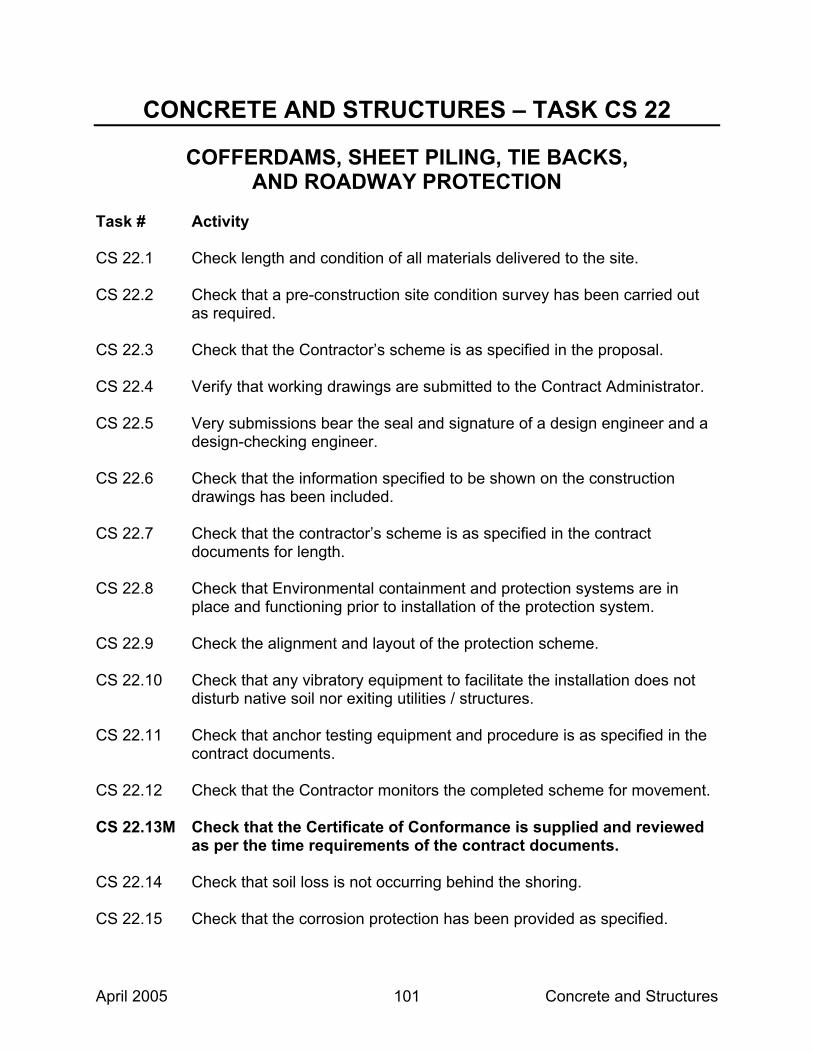
April 2005 Concrete and Structures 101
CONCRETE AND STRUCTURES – TASK CS 22
COFFERDAMS, SHEET PILING, TIE BACKS, AND ROADWAY PROTECTION
Task # Activity CS 22.1 Check length and condition of all materials delivered to the site. CS 22.2 Check that a pre-construction site condition survey has been carried out
as required. CS 22.3 Check that the Contractor’s scheme is as specified in the proposal. CS 22.4 Verify that working drawings are submitted to the Contract Administrator. CS 22.5 Very submissions bear the seal and signature of a design engineer and a
design-checking engineer. CS 22.6 Check that the information specified to be shown on the construction
drawings has been included. CS 22.7 Check that the contractor’s scheme is as specified in the contract
documents for length. CS 22.8 Check that Environmental containment and protection systems are in
place and functioning prior to installation of the protection system. CS 22.9 Check the alignment and layout of the protection scheme. CS 22.10 Check that any vibratory equipment to facilitate the installation does not
disturb native soil nor exiting utilities / structures. CS 22.11 Check that anchor testing equipment and procedure is as specified in the
contract documents. CS 22.12 Check that the Contractor monitors the completed scheme for movement. CS 22.13M Check that the Certificate of Conformance is supplied and reviewed
as per the time requirements of the contract documents. CS 22.14 Check that soil loss is not occurring behind the shoring. CS 22.15 Check that the corrosion protection has been provided as specified.

April 2005 Concrete and Structures 102
CS 22.16 Check that a record of each anchor hole excavation is submitted. CS 22.17 Check that the quality of grout is being tested as specified. LEVEL OF INSPECTION – E2
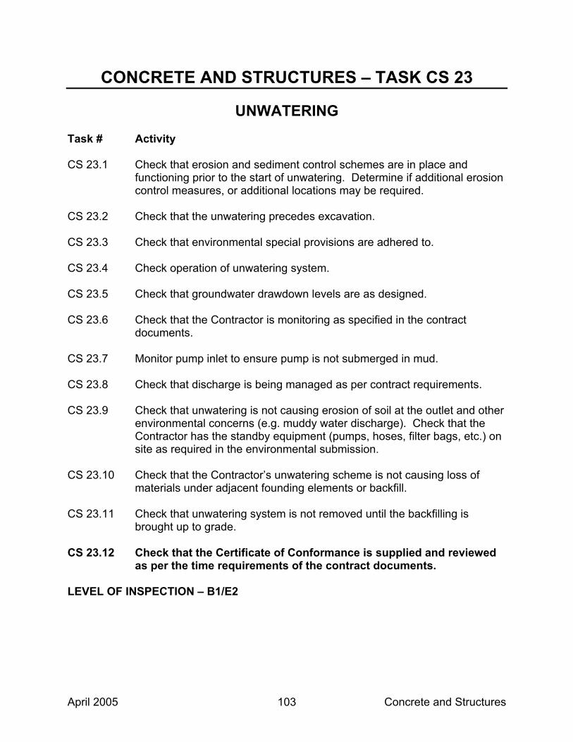
April 2005 Concrete and Structures 103
CONCRETE AND STRUCTURES – TASK CS 23
UNWATERING Task # Activity CS 23.1 Check that erosion and sediment control schemes are in place and
functioning prior to the start of unwatering. Determine if additional erosion control measures, or additional locations may be required.
CS 23.2 Check that the unwatering precedes excavation. CS 23.3 Check that environmental special provisions are adhered to. CS 23.4 Check operation of unwatering system. CS 23.5 Check that groundwater drawdown levels are as designed. CS 23.6 Check that the Contractor is monitoring as specified in the contract
documents. CS 23.7 Monitor pump inlet to ensure pump is not submerged in mud. CS 23.8 Check that discharge is being managed as per contract requirements. CS 23.9 Check that unwatering is not causing erosion of soil at the outlet and other
environmental concerns (e.g. muddy water discharge). Check that the Contractor has the standby equipment (pumps, hoses, filter bags, etc.) on site as required in the environmental submission.
CS 23.10 Check that the Contractor’s unwatering scheme is not causing loss of
materials under adjacent founding elements or backfill. CS 23.11 Check that unwatering system is not removed until the backfilling is
brought up to grade. CS 23.12 Check that the Certificate of Conformance is supplied and reviewed
as per the time requirements of the contract documents. LEVEL OF INSPECTION – B1/E2

April 2005 Concrete and Structures 104
CONCRETE AND STRUCTURES – TASK CS 24
PILING Task # Activity CS 24.1 M Check that the Certificate of Conformance is supplied and reviewed
as per the time requirements of the contract documents. CS 24.2 Check that erosion and sediment control schemes are in place and
functioning prior to the start of pile driving. Determine if additional erosion control measures are in place and functioning around them.
CS 24.3 M Record and verify the pile type, length, condition of the pile splices
and driving shoes and length to cut off. Verify straightness of piles. CS 24.4 Check that all the delivered material is supplied from the approved list,
and handled and stored so as to prevent damage to the piles. CS 24.5 Check that the correct value of imported steel has been declared on the
“Statement of Imported Content” form. Collect all mill certificates (test results should be from Canadian testing facilities). Check that mill certificates satisfy the requirements in general and specifically for imported steel.
CS 24.6 Check that pile driving equipment conforms to specified requirements.
Monitor hammer performance. CS 24.7 Check that the end treatments are correctly applied (i.e. shoes, Oslo
Points, Bearing Points, collars, etc.). CS 24.8 Check that pile installation sequence is as per submission, and that layout
of piles conforms to contract requirements. CS 24.9 Check that vertical and batter alignment of pile meets specified
requirements. CS 24.10 Verify that piles are not overdriven and hence damaged during installation. CS 24.11 Check that welder is certified. Check that welding of splicing conforms to
specified requirements, and that pile splices are carried out properly. CS 24.12 Check that pile set and refusal criteria are satisfied. Check that actual tip
elevation corresponds to design founding stratum.
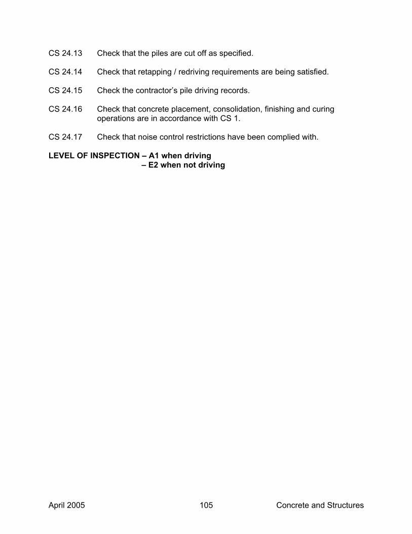
April 2005 Concrete and Structures 105
CS 24.13 Check that the piles are cut off as specified. CS 24.14 Check that retapping / redriving requirements are being satisfied. CS 24.15 Check the contractor’s pile driving records. CS 24.16 Check that concrete placement, consolidation, finishing and curing
operations are in accordance with CS 1. CS 24.17 Check that noise control restrictions have been complied with. LEVEL OF INSPECTION – A1 when driving – E2 when not driving

April 2005 Concrete and Structures 106
CONCRETE AND STRUCTURES – TASK CS 25
CAISSON FOUNDATIONS Task # Activity CS 25.1 Check type, length and condition of caisson liners. CS 25.2 Check that welder is certified. CS 25.3 Check that installation equipment is as specified in the contract
documents. CS 25.4 Check that erosion and sediment control schemes are in place and
functioning. Determine if additional erosion control measures or additional locations may be required.
CS 25.5 Check that caisson is drilled to design tip elevation. CS 25.6 Check that penetration and cut off are in accordance with design data. CS 25.7 Check that sidewall and basal stability is maintained during the caisson
foundation installation. CS 25.8 M Check that caissons are cleaned out prior to placing reinforcing steel
and concrete. CS 25.9 Check the contractor’s cleaned out material containment location. Ensure
that containment locations are placed away from watercourses and that erosion and sediment control measures are in place and functioning around them.
CS 25.10 M Check that the Certificate of Conformance is supplied and reviewed
as per the time requirements of the contract documents. CS 25.11 Check that concrete placement, consolidation, finishing and curing
operations are performed in accordance with CS 1. CS 25.12 Check that slurry properties are being tested and verified as per contract
requirements. CS 25.13 Check that reinforcement steel is being properly placed as per contract
requirements.

April 2005 Concrete and Structures 107
CS 25.14 Check that vertical and batter alignment of caisson are as specified in the contract documents.
LEVEL OF INSPECTION – B2
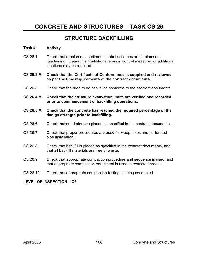
April 2005 Concrete and Structures 108
CONCRETE AND STRUCTURES – TASK CS 26
STRUCTURE BACKFILLING Task # Activity CS 26.1 Check that erosion and sediment control schemes are in place and
functioning. Determine if additional erosion control measures or additional locations may be required.
CS 26.2 M Check that the Certificate of Conformance is supplied and reviewed
as per the time requirements of the contract documents. CS 26.3 Check that the area to be backfilled conforms to the contract documents. CS 26.4 M Check that the structure excavation limits are verified and recorded
prior to commencement of backfilling operations. CS 26.5 M Check that the concrete has reached the required percentage of the
design strength prior to backfilling. CS 26.6 Check that subdrains are placed as specified in the contract documents. CS 26.7 Check that proper procedures are used for weep holes and perforated
pipe installation. CS 26.8 Check that backfill is placed as specified in the contract documents, and
that all backfill materials are free of waste. CS 26.9 Check that appropriate compaction procedure and sequence is used, and
that appropriate compaction equipment is used in restricted areas. CS 26.10 Check that appropriate compaction testing is being conducted LEVEL OF INSPECTION – C2

April 2005 Concrete and Structures 109
CONCRETE AND STRUCTURES – TASK CS 27
FORMWORK Task # Activity CS 27.1 M Check that the Certificate of Conformance is supplied and reviewed
as per the requirements of the contract documents. CS 27.2 Check all material, including hardware, for condition, quality, adjustment
and fit. CS 27.3 Check that dimensions of forms are as specified in the contract
documents. CS 27.4 Check that form release oil is applied to the forms before the installation of
reinforcing steel. CS 27.5 Check forms (several times) for alignment and possible deformation,
during concrete placement. LEVEL OF INSPECTION – E2

April 2005 Concrete and Structures 110
CONCRETE AND STRUCTURES – TASK CS 28
FALSEWORK Task # Activity CS 28.1 M Check that the Certificate of Conformance is supplied and reviewed
as per the time requirements of the contract documents. CS 28.2 M Check that stamped falsework drawings are on site. Check installed
falsework against stamped working drawings prior to pour. (Specifically ensure member sizes and spacing, mudsill locations and associated member sizes, longitudinal and transverse bracing, max extension on screw heads of towers, type and location of hangers and location of screed rails).
CS 28.3 Check that the founding soil is prepared. CS 28.4 Check that any foundation bearing pad is properly placed and compacted. CS 28.5 Monitor falsework (several times) during concrete placement operation for
deflection and settlement. CS 28.6 M Check that the required concrete strength has been reached prior to
removing falsework. LEVEL OF INSPECTION – E2

April 2005 Concrete and Structures 111
CONCRETE AND STRUCTURES – TASK CS 29
INSTALLATION OF BEARINGS Task # Activity CS 29.1 M Check that the Certificate of Conformance and the Adjustment of
Bearing drawings are supplied and reviewed as per the time requirements of the contract documents.
CS 29.2 Check that all the delivered material is being supplied from the approved
list and properly stored. CS 29.3 Check and record from elastomeric bearings, the size, name of
manufacturer, part number and date of manufacture and also check that the bearing is not on the list of defective bearings put out by the Concrete Section.
CS 29.4 When specified, randomly select and then have the Contractor ship the
sample bearing(s) for testing as specified. CS 29.5 Check that surface and bedding of bearing seats are within tolerances and
meet the requirements of the applicable specifications. CS 29.6 Check that each bearing is installed at the correct location, elevation, and
is properly aligned as specified in the contract documents. CS 29.7 Check for removal of any shipping device or restraints from bearings as
specified in the contract and/or shop drawings. CS 29.8 M Upon completion of the structure, visually inspect the bearings to
ensure they have full and uniform bearing at top and bottom, and that bearing components are not out of position.
CS 29.9 Check the timing and procedure for jacking and re-alignment of bearings. LEVEL OF INSPECTION – D2

April 2005 Concrete and Structures 112
CONCRETE AND STRUCTURES – TASK CS 30
CONCRETE AND STRUCTURAL STEEL BEAM ERECTION Task # Activity CS 30.1 M Check that the Certificate of Conformance is supplied and reviewed
as per the time requirements of the contract documents. CS 30.2 Check that the steel is supplied from a designated source and that the
correct value of imported steel has been declared on the “Statement of Imported Content” form.
CS 30.3 Check that the stamped erection drawings are on site. CS 30.4 Check that beams have not been damaged and are set to the specified
alignment and seated properly. CS 30.5 Collect steel mill certificates (coupon tags) and store on file in site office. LEVEL OF INSPECTION – D2

April 2005 Concrete and Structures 113
CONCRETE AND STRUCTURES – TASK CS 31
REINFORCING STEEL PLACEMENT Task # Activity CS 31.1 Examine reinforcing steel schedule and drawings. CS 31.2 Check for proper site storage and handling. CS 31.3 Check mill certificates to ensure that the steel is supplied from a
designated source. CS 31.4 Check that the correct value of imported steel has been declared in the
“Statement of Imported Content” form. CS 31.5 Obtain a sample of stainless steel rebar as per the contract documents. CS 31.6 M Check that the Certificate of Conformance is supplied and reviewed
as per the time requirements of the contract documents. CS 31.7 Check that the correct grade and size of steel has been placed in
accordance with the contract documents. LEVEL OF INSPECTION – E2

April 2005 Concrete and Structures 114
CONCRETE AND STRUCTURES – TASK CS 32
PRESTRESSING SYSTEMS Task # Activity CS 32.1 Check type, size and condition of prestressing materials delivered to the
site. CS 32.2 Check for proper site storage of prestressing materials. CS 32.3 Check that material supplied by the Contractor is sampled and tested as
required. CS 32.4 Check installation of prestressing sheaths, support cables, and
anchorages. CS 32.5 Check the elevation and alignment of cable sheaths. CS 32.6 Check that cable sheaths are secured firmly in place. CS 32.7 Check that grout vent hoses are installed at all the proper locations. CS 32.8 M Check that the Certificate of Conformance is supplied and reviewed
as per the time requirements of the contract documents. LEVEL OF INSPECTION – B2

April 2005 Concrete and Structures 115
CONCRETE AND STRUCTURES – TASK CS 33
STRESSING OPERATION Task # Activity CS 33.1 Check that stressing working drawings are on site. CS 33.2 Check that the correct calibration tests have been carried out by an
approved authority in the last six months. CS 33.3 M Check that void hold-downs are released prior to stressing. CS 33.4 M Check that concrete is up to specified strength prior to stressing. CS 33.5 Check that cables are stressed in proper sequence. CS 33.6 Check that cables are marked and measured and that elongation, gauge
pressure and slip are recorded. CS 33.7 M Check that the Certificate of Conformance is supplied and reviewed
as per the time requirements of the contract documents. LEVEL OF INSPECTION – C2

April 2005 Concrete and Structures 116
CONCRETE AND STRUCTURES – TASK CS 34
GROUTING OF POST-TENSIONING DUCTS Task # Activity CS 34.1 Check that ducts are blown out with water and oil free air. CS 34.2 Check that all vent tubes are free from blockage. CS 34.3 Check that each grout mix component is from an approved source. CS 34.4 Check that the concrete temperature of the deck is as specified in the
contract documents. CS 34.5 Check the mixer and pump. Check that pressure gauge at pump or
intake, water measures, and timer are accurate. CS 34.6 M Prior to the grouting operations, check that the test batch has been
mixed and that the quality of the grout meets the specified requirements.
CS 34.7 Check that the grout is being tested and meets the specified requirements. CS 34.8 Check that grout cubes are taken for testing and delivered as required to
the specified testing facility. CS 34.9 Check that grouting operation is continuous and hoses are topped-up prior
to tying off as specified in the contract documents. CS 34.10 M Check that the Certificate of Conformance is supplied and reviewed
as per the time requirements of the contract documents. CS 34.11 Check Contractor’s placing schedule such that placement of sidewalks,
curbs, median curbs, etc., is done after the grouting of post tension grout tubes.
LEVEL OF INSPECTION – A1

April 2005 Concrete and Structures 117
CONCRETE AND STRUCTURES – TASK CS 35
BRIDGE DECK WATERPROOFING Task # Activity CS 35.1 M Check that the deck meets requirement for surface tolerance and
surface finish. CS 35.2 Identify all repairs and remedial work that needs to be carried out prior to
waterproofing including texture surfaces, sawcut grooves and scaling. CS 35.3 Check that all repairs and remedial work to the concrete deck have been
completed. CS 35.4 M Check that the air and concrete surface temperature are 5°C or
higher. CS 35.5 Check that contractor performing the waterproofing is approved. CS 35.6 M Permission is given to contractor to proceed after verifying that the
deck surface, face of the curbs and barrier walls were completely treated by abrasive blast cleaning to expose sound, laitance-free concrete.
CS 35.7 Check that no traffic, other than the construction equipment directly
associated with the waterproofing operation, is allowed on the abrasive blast cleaned deck.
CS 35.8 Ensure that the Contractor takes adequate protective measures to mask
concrete and prevent over-spray of tack coat materials onto adjacent concrete surfaces (curb face, barrier wall, abutments, columns, etc.) to prevent waterproofing material from entering a watercourse.
CS 35.9 Check that all delivered materials are approved. CS 35.10 Check that tack coat is cured completely and free of any surface moisture
and dirt before waterproofing membrane is applied. CS 35.11 Check that temperature of waterproofing membrane at time of placing is
as specified. CS 35.12 Check for correct placement of membrane reinforcement over joints. CS 35.13 Check for correct placing of protection boards.

April 2005 Concrete and Structures 118
CS 35.14 Check proper lapping of waterproofing at construction joint and staging
boundaries. CS 35.15 Upon completion of each lot, measure and record membrane thickness
following the procedure in the “Field Guide for the Acceptance of Hot Mix and Bridge Deck Waterproofing”.
CS 35.16 M Compute payment adjustment factor and have the Contractor sign
form PH-CC-129 A prior to paving. CS 35.17 Check that all test results have been received and price adjustments
calculated and applied as appropriate. CS 35.18 Check that asphalt drainage tubes are open. CS 35.19 Check tack coating of protection boards just prior to paving. LEVEL OF INSPECTION – B2

April 2005 Concrete and Structures 119
CONCRETE AND STRUCTURES – TASK CS 36
CATHODIC PROTECTION – COKE MIX PRODUCTION AND PAVING
Task # Activity CS 36.1 Check that all the delivered material is supplied from the approved list and
is stored properly. CS 36.2 Check that material supplied by the Contractor is sampled and tested as
required. CS 36.3 M Check that an approved mix design has been established. CS 36.4 Check the coke breeze for gradation and moisture content of less than
one percent by mass. CS 36.5 Check that the resistivity test carried out on the electrically conductive mix
meets the specified requirements. CS 36.6 Check the Contractor has carried out the specified resistivity testing on a
trial batch of the mix and the material from the trial batch is not incorporated in the work.
CS 36.7 M Check that the concrete surface is not tack coated and is dry and
free of debris. Also check that adhesive tape is removed from anodes and voltage probes and the anode top surfaces are cleaned with a wire brush.
CS 36.8 Check that the electrically conductive mix is not placed within 150mm of
any metal appurtenances such as deck drains, expansion joints, etc. Check that this space is filled with a hot mix containing a non-conductive aggregate.
LEVEL OF INSPECTION – C2 – A2 – During paving operation

April 2005 Concrete and Structures 120
CONCRETE AND STRUCTURES – TASK CS 37
INSTALLATION OF EXPANSION JOINTS Task # Activity CS 37.1 Check that no damage occurs during handling. CS 37.2 Check all delivered material to verify that it is being supplied from the
approved list that was submitted by the Contractor at the commencement of the contract.
CS 37.3 Check that material supplied by the Contractor is sampled as required. CS 37.4 Check for proper storage of the joints. CS 37.5 Check that field splices in steel components are located and welded as
per shop drawings and are performed by a certified welder. CS 37.6 Check that the dimensions of the block-out to receive the joint assembly
are in accordance with the contract drawings and standard drawings. CS 37.7 Check that the block-out area to receive the joint is abrasive blast cleaned,
without damaging the epoxy coated steel. CS 37.8 Check that all debris in the block-out has been removed and the area is
coated with a cement paste prior to placing concrete. CS 37.9 M Check that the proper gap or “j” dimension of the unit has been
established prior to placing concrete, and check that the constant gap is achieved throughout the total length.
CS 37.10 M Check that the Certificate of Conformance is supplied and reviewed
for each task and as per the time requirements of the contract documents.
CS 37.11 Check that concrete placement, consolidation, finishing and curing
operations are in accordance with CS 1. CS 37.12 Check that clamping angles or channels are removed as specified in the
contract documents. Cs 37.13 Check that holes left from removal of clamping angles or channels are
cleaned and grouted with approved epoxy.

April 2005 Concrete and Structures 121
CS 37.14 Check for concrete blockages in the expansion joint opening. CS 37.15 Check that seal is properly installed with no damage, wrinkles or splices. CS 37.16 Check that sliding plates on sidewalk, curbs and median have been
installed properly with regards to the direction of traffic. CS 37.17 Check that formwork including styrofoam has been removed below
expansion joint assembly between deck and ballast wall. CS 37.18 Check for cracks in the concrete adjacent to the expansion joint. CS 37.19 M Ensure traffic is not allowed on the deck joint assembly until the
epoxy injection has been completed and cured, and clamping bars are installed for Type A expansion joints.
CS 37.20 Ensure end dam concrete has been cured for a minimum of 7 days and
has reached 25 MPa prior to epoxy injection. CS 37.21 Check that the injection method is in accordance with the Contract
Documents and injected by the supplier of the expansion joint system, or an agent approved by the supplier.
CS 37.22 M Sound the steel armour for voids. If voids are detected, ensure
proper procedures are taken to fill the voids. CS 37.23 Check that a water test has been carried out. CS 37.24 Check that all waste material (Styrofoam) is disposed of as per the
contract documents. LEVEL OF INSPECTION – C2

April 2005 Concrete and Structures 122
CONCRETE AND STRUCTURES – TASK CS 38
TEMPORARY MODULAR BRIDGES Task # Activity CS 38.1 Check that erosion and sediment control schemes are in place and
functioning prior to start of modular bridge installation. Determine if additional erosion control measures, or additional locations may be required.
CS 38.2 Check that all environmental constraints have been complied with
(fisheries approvals, work on the banks, etc.) prior to installation. CS 38.3 M Visually check foundations. CS 38.4 Check that layout and elevations of the launching and construction rollers
have been approved. Check that founding elements, cribs, and footings are located as per plan.
CS 38.5 Check that all bracing bolts, chord bolts and transom clamps remain fully
tightened. CS 38.6 Check that base plates and bearings are free of debris. CS 38.7 Inspect base plates and cribs for settlement. CS 38.8 Visually check timber for soundness and specified requirements. CS 38.9 Check material control is as specified in the contract documents. LEVEL OF INSPECTION – E2

April 2005 Concrete and Structures 123
CONCRETE AND STRUCTURES – TASK CS 39
STRUCTURAL STEEL COATING Task # Activity CS 39.1 Check all the delivered material to verify that it is being supplied from the
approved list that was submitted by the Contractor at the commencement of the contract.
CS 39.2 Check that material supplied by the Contractor is sampled as required. CS 39.3 Check that all requirements of manufacturers product data sheets are met. CS 39.4 Check that individual coating products used in the coating system come
from the same manufacturer and are compatible. CS 39.5 Check that environmental operations including enclosure systems,
negative pressure, management including sampling, testing, storage, documentation / manifesting, transportation and disposal of spent blast medium and removed coating material are as specified in contract and/or Contractor’s approved proposal. Ensure a copy of all test results and manifests are provided to the MTO Environmental Planner – Waste Management.
CS 39.6 M Check that surface preparation is carried out as specified in the
contract and meets the specified SSPC standard. CS 39.7 Check sample(s) of spent blast medium is obtained as specified in the
contract documents. CS 39.8 M Check that coating of structural steel follows cleaning within the time
as specified in the contract documents. CS 39.9 Check air temperature and dewpoint restrictions. CS 39.10 Check that the coat application is carried out as specified in the contract
documents. CS 39.11 Check that the dry film thickness gauge and any DFT gauge utilized by the
Contractor are calibrated to SSPC PA-2 and any special provision requirements. Only type 2 gauges are to be used.
CS 39.12 M Check that each coat meets the dry film thickness requirements. Test
frequencies and acceptance to be in accordance with SSPC PA-2

April 2005 Concrete and Structures 124
except that acceptance of multiple coats will be based on the cumulative minimum requirements after each coat application. Deficiencies to be corrected before acceptance and proceeding with subsequent coat.
CS 39.13 Check that all blast abrasive, dust and other debris are removed from the
steel surface and each coating surface prior to the application of the subsequent coat.
CS 39.14 Complete Daily Inspection Report Form PH-CC-782 each day and
Summary Form PH-CC-783 after the completion of the work on each structure.
CS 39.15 Check condition of galvanized components during installation. Ensure
repairs are as specified in the contract documents. CS 39.16 M Ensure that the consultant or sub-consultant inspecting the
structural steel coating holds the appropriate certifications. LEVEL OF INSPECTION – A1

April 2005 Concrete and Structures 125
CONCRETE AND STRUCTURES – TASK CS 40
STEEL PARAPET RAILING Task # Activity CS 40.1 Check type, size, length and condition of materials (including protective
coatings) delivered to the site. CS 40.2 Check that all the delivered material is being supplied from the approved
list and is properly stored. CS 40.3 Check that installation is as specified in the contract documents. CS 40.4 Check the condition of completed posts and rails. Check that damaged
areas are properly repaired. LEVEL OF INSPECTION – E2

April 2005 Concrete and Structures 126
CONCRETE AND STRUCTURES – TASK CS 41
OVERHEAD SIGN PLACEMENT Task # Activity CS 41.1 Check that erosion and sediment control schemes are in place and
functioning prior to start of overhead sign placement. Determine if additional erosion control measures, or additional locations may be required.
CS 41.2 M Check that the Certificate of Conformance is supplied and reviewed
as per the time requirements of the contract documents. CS 41.3 Check footings with regards to “as constructed” elevations and type,
plumbness of footing, alignment between two founding elements and the distance between the two founding elements (C/C footings).
CS 41.4 Check all delivered material to verify that it is being supplied from the
approved list that was submitted by the Contractor at the commencement of the contract.
CS 41.5 Check that the correct value of imported steel has been declared on the
“Statement of Imported Content” form. CS 41.6 Check overhead sign structure to ensure that installation is in accordance
with the contract drawings and shop drawings. CS 41.7 Check to ensure full bearing of all base plates. CS 41.8 Check that sign structure is installed facing in the proper direction and that
the required number of sign clamps have been supplied. CS 41.9 Check for cracking of erected sign structure. CS 41.10 Check that exposed anchorage threads do not exceed 3 diameters. CS 41.11 Check the top of footing for surface finish and levelness. LEVEL OF INSPECTION – E2
April 2005 Concrete and Structures 127
CONCRETE AND STRUCTURES – TASK CS 42
RETAINED SOIL SYSTEMS Task # Activity CS 42.1 M Check that the Certificates of Conformance are supplied and
reviewed in a timely manner to correspond with the intervals that meet the specified contract requirements.
CS 42.2 Check that all submissions bear the seal and signature of the Design
Engineer and the Design Check Engineer. CS 42.3 Check that the Contractor has selected a RSS designated as A
(Accepted) or DE (Demonstration) on the DSM List that meets the specified contract requirements.
CS 42.4 Check that the Contractor has a copy of the stamped working drawings on
site at all times. CS 42.5 Check that the working drawings include at least the following:
• All design, fabrication and construction drawings and specifications for the RSS
• Details of all excavation, unwatering, drainage and backfilling required to construct the RSS, including type and source of associated backfill
• Details at joints and connections to other structures where shown in the Contract Drawings
• Details of all protection systems • Statement of bearing resistance required by the RSS foundation, and
the bearing resistance provided in accordance with the OHBDC • Statement of satisfactory internal and external stability • All design, fabrication and construction drawings and specifications for
traffic barriers and base, and finishing caps, where applicable • Details of how all relevant Operational Constraints and Environmental
Constraints, as specified elsewhere in the contract, will be adhered to • A copy of the Approved Product Drawings covering material and
construction details. CS 42.6 Check that the Contract Administrator forwards one set of the stamped
working drawings to the Pavement and Foundation Section, Ministry of Transportation, Downsview, for information purposes
CS 42.7 Check that all loose, softened, deleterious material at the founding
elevation of the RSS is removed.

April 2005 Concrete and Structures 128
CS 42.8 Check that the contractor is following the foundation preparation as per the
manufacturers recommendations specified, working drawings and contract documents.
CS 42.9 Check that the backfill type is as indicated on the working drawings and
that the contractor is placing the backfill as per the manufacturers recommendations, working drawings and contract documents.
CS 42.10 Check alignment such as stations, lines and grades, cross-sections, verify
levelling pad elevation and other constraints as specified in the Contract Drawings.
CS 42.11 Check for Out-of-Tolerance Geometry, Performance and Aesthetics
Conditions / Deficiencies as per working drawing requirements. For walls: visible distress in wall, differential settlement, tilting or rotating
facing elements, bulging, panel / block contact resulting in spalling or chipping, wall facing out of vertical (plumb) or horizontal alignment.
For slopes: lack of vegetation, sloughing, lack of erosion protection,
maximum slope angle exceeds that specified in contract. CS 42.12 Check that Warranty requirements are satisfied. LEVEL OF INSPECTION – A1/A2

April 2005 Concrete and Structures 129
CONCRETE AND STRUCTURES – TASK CS 43
ABRASIVE BLAST CLEANING OF CONCRETE SURFACES AND REINFORCING STEEL
Task # Activity CS 43.1 Check that Environmental containment systems are in place and
functioning prior to start of abrasive blast cleaning. CS 43.2 Check that concrete surface and reinforcing steel are abrasive blast
cleaned according to the contract documents. CS 43.3 Check that dust and debris from exposed work, and from abrasive blast
cleaning of concrete and steel, does not cause a nuisance to pedestrian and vehicular traffic within the ROW, adjacent residential / commercial / institutional properties, and is not entering a watercourse or Environmentally Sensitive Area.
CS 43.4 Ensure the subsequent concrete is placed within the time limit specified in
the contract documents. CS 43.5 Verify contract document requirement for removal of epoxy coating from
existing epoxy coated reinforcing steel. CS 43.6 Ensure all new epoxy coated reinforcing steel in the vicinity of the abrasive
blast cleaning is protected. LEVEL OF INSPECTION – C2

April 2005 Concrete and Structures 130
CONCRETE AND STRUCTURES – TASK CS 44
LIGHTWEIGHT FILL MATERIALS Task # Activity SLAG CS 44.1 M Check that the Contractor has submitted Certificates of
Conformance stating that the material satisfies the requirements of the specification, and the work has been carried out in general conformance with the contract documents.
CS 44.2 Check that the contractor has submitted the Certificates of Conformance
for the material properties prior to placement. CS 44.3 Check that the contractor submits Quality Control Test Results. CS 44.4 Check that the contractor has retained a laboratory accepted by the MTO
to conduct testing of the physical, mechanical and chemical properties of the material.
CS 44.5 Check that the trial area is properly constructed. CS 44.6 Check that the insitu unit weight requirements and overcrushing
restrictions are satisfied during the trial and also during construction. CS 44.7 Check that the contractor’s compaction equipment and procedure satisfies
the requirements of the specification. CS 43.8 Check that the Quality Assurance component of the Special Provision is
enforced. Expanded Poly Styrene CS 44.9 Check that the shop drawings are reviewed, signed and sealed by the
Quality Verification Engineer prior to commencement of work. CS 44.10 Check that a final Certificate of Conformance signed and sealed by the
Quality Verification Engineer is submitted. CS 44.11 Check that the materials satisfy the requirements of the Special
Provisions.

April 2005 Concrete and Structures 131
CS 44.12 Check that foundation excavation and preparation is conducted to remove any loosened or deleterious materials.
CS 44.13 Check that the levelling pad is properly placed and compacted. CS 44.14 Check that the EPS are properly installed. CS 44.15 Check that the EPS blocks are properly covered with polyethylene. CS 44.16 Check that the concrete slab is properly constructed on top of the EPS
blocks. CS 44.17 Check that side slope material is placed without damage to the blocks. CS 44.18 Check that the Quality Assurance component of the Special Provision is
enforced. LEVEL OF INSPECTION – C2

April 2005 Bituminous 132
BITUMINOUS – TASK BIT 1
GRANULAR SEALING Task # Activity BIT 1.1 Check that areas to be sealed are shaped and dampened before sealing. BIT 1.2 Check that granular is not frozen, air temperature is above minimum, wind
does not cause drifting off designated area in contract and precipitation is not imminent.
BIT 1.3 Check all the delivered material to verify that it is being supplied from the
approved list that was submitted by the Contractor at the commencement of the contract.
BIT 1.4 Check that material supplied by the Contractor is sampled and tested as
required. BIT 1.5 Check environmental constraints before applying sealant. BIT 1.6 Check for proper rate and method of application and uniform coating. LEVEL OF INSPECTION – D2

April 2005 Bituminous 133
BITUMINOUS – TASK BIT 2
RECLAIMING ASPHALT PAVEMENT Task # Activity BIT 2.1 Check that random samples of Reclaimed Asphalt Pavement (RAP) to be
used in Recycled Hot Mix (RHM) have been taken after processing. BIT 2.2 M Check that reclaiming is carried out full width to essentially the same
station before shutdown each day and properly ramped. BIT 2.3 Check that there is no contamination with granular shoulder and granular
base material when RAP is to be used in RHM. BIT 2.4 Partial Pavement Removal
(i) Check for correct crossfall, depth and surface texture during milling; (ii) Record reclaimed asphalt removal rate (kg/m²); (iii) Check that the milled surface is broomed and inspected, and that
areas of asphalt rich dust are removed. BIT 2.5 Full Depth Removal
(i) Check that granular is restored to specified requirements following pavement removal;
(ii) Check and record depths of removal. LEVEL OF INSPECTION – B1/D2

April 2005 Bituminous 134
BITUMINOUS – TASK BIT 3
HOT MIX PAVING Task # Activity BIT 3.1 Check proper joint construction including location of longitudinal joints,
preparation, tack coating and compaction. BIT 3.2 Check that paving is carried out full width to essentially the same station,
with ramping as specified in the contract prior to shutdown each day, including edge ramping.
BIT 3.3 Check the condition of substrata (compaction, etc.) ahead of paving
operation. Confirm surface to be paved is unfrozen, clean, dry and free of standing water.
BIT 3.4 Check sequence of paving operations including, but not limited to, paving
intersections, tapers, ramps, bridge decks and all staging plans. BIT 3.5 Check placement of hot mix including alignment, crossfall, surface
tolerance, width, smoothness, depth of asphalt mat and distribution (kg/m²). Check that the distribution rates of premium surface courses are revised to account for the mass multiplier factors.
BIT 3.6 Check that air temperature at the surface of the road is above the
minimum specified in the contract to permit paving. BIT 3.7 Check that temperature of mix delivered to the site does not exceed the
maximum discharge temperature allowed. BIT 3.8 Visually inspect mix placed for dragging, segregation and other visual
defects prior to covering with another lift and / or stage changes. BIT 3.9 Check paving in echelon operation to ensure specified distance between
pavers is maintained. BIT 3.10 M Check and witness that all required samples are taken at correct
(random) locations and tonnages. BIT 3.11 Check that equipment does not impact or damage areas beyond the
shoulder. BIT 3.12 M Check for proper reinstatement of sample locations (plates and
cores) on a daily basis. LEVEL OF INSPECTION – A2

April 2005 Bituminous 135
BITUMINOUS – TASK BIT 4
CUT AND FILL GROOVES Task # Activity BIT 4.1 Check all the delivered material to verify that it is being supplied from the
approved list that was submitted by the Contractor at the commencement of the contract.
BIT 4.2 Check that material supplied by the Contractor is sampled and tested as
specified in the contract. BIT 4.3 Check that existing pavement joints are marked to ensure that the new
groove is located precisely over the existing joints. BIT 4.4 Check that the grooves are cleaned and dried immediately, a maximum of
two minutes prior to pouring the joint sealing compound. BIT 4.5 Check that grooves are cut and filled as soon as possible after paving, as
specified in the contract documents. LEVEL OF INSPECTION – B1/D2

April 2005 Bituminous 136
BITUMINOUS – TASK BIT 5
ROUTING AND SEALING CRACKS Task # Activity
WITH WARRANTY BIT 5.1 Document non-compliance with contract requirements.
WITHOUT WARRANY BIT 5.2 Check all the delivered material to verify that it is being supplied from the
approved list that was submitted by the Contractor at the commencement of the contract.
BIT 5.3 Check that the material supplied by the Contractor is sampled and tested
as required and batch numbers are recorded as specified in the contract documents.
BIT 5.4 Check that cracks as specified in the contract documents are routed to the
specified width and depth and that the rout is centered on the crack. BIT 5.5 Check that all routed and unrouted cracks are blown clean and dry using
hot compressed air lance before sealing commences. BIT 5.6 Check that dust and debris from exposed work, and from routing and
sealing operations, does not cause a nuisance to pedestrian and vehicular traffic within the ROW, adjacent residential / commercial / institutional properties, and is not entering a watercourse or Environmentally Sensitive Area.
BIT 5.7 Check that sealing material is applied immediately after cleaning and
drying. BIT 5.8 Check that sealing material is heated within the manufacturers
recommended range and is being continuously agitated. BIT 5.9 Check that cracks are filled with sealant as specified in the contract
documents and that no spillage occurs. BIT 5.10 Check that debris, including excess sealing material, is removed from
routed area and adjacent pavement.

April 2005 Bituminous 137
BIT 5.11 Check that completed cracks are dusted with a suitable bond breaker before exposing to traffic.
LEVEL OF INSPECTION – C1/E2 with warranty
– B1/C2 without warranty

April 2005 Bituminous 138
BITUMINOUS – TASK BIT 6
TACK COAT Task # Activity BIT 6.1 Check all the delivered material to verify that it is being supplied from the
approved list that was submitted by the Contractor at the commencement of the contract.
BIT 6.2 Check that existing pavement is dry and clean before applying tack coat. BIT 6.3 Check that proper rate of application and coverage is used. BIT 6.4 M Check that tack coat has cured to the desired level before placing
hot mix pavement. BIT 6.5 M Check that traffic is not allowed on the tack coated area before
paving. BIT 6.6 Check that all required samples are taken and delivered as specified in
the contract documents. LEVEL OF INSPECTION – B1/D2

April 2005 Bituminous 139
BITUMINOUS – TASK BIT 7
PAVEMENT MARKING Task # Activity BIT 7.1 Check all the delivered material to verify that it is being supplied from the
approved list that was submitted by the contractor at the commencement of the contract.
BIT 7.2 Check that the material supplied by the Contractor is sampled and tested
as specified in the contract documents. BIT 7.3 Check that air temperature, pavement temperature and surface condition
requirements are met. BIT 7.4 Check that the locations of the markings applied are as specified in the
contract documents. BIT 7.5 Check that the surface is dry and free of loose and/or foreign material. BIT 7.6 Temporary and Permanent Tape
(i) Check for correct spacing and application; (ii) Check that only butt splices are used; (iii) Check that specified tamping has been carried out; (iv) Check that material is stored as specified.
BI 7.7 M Pavement Marking
(i) Check that zone painting is completed on any temporary driving surface prior to opening to traffic;
(ii) Check zone painting has a well defined edge, free from waviness, uniformly dimensioned and shaded with no splatter or overspray;
(iii) Check for correct material application temperature; (iv) Check that glass beads are applied uniformly prior to the paint
drying; (v) Check that the pavement markings are applied as specified in
the contract documents; (vi) Check that the glass beads are applied as specified in the
contract documents; (vii) Conduct a bond/adhesion test on durable marking materials
(for thermoplastic and field reacted polymeric: (viii) A monitoring frequency of a minimum of 25%, but not limited
to, is required to be performed and recorded to ensure the
April 2005 Bituminous 140
contractor has properly applied sight distance requirements as specified.
LEVEL OF INSPECTION – B1/D2

April 2005 Bituminous 141
BITUMINOUS – TASK BIT 8
SURFACE TREATMENT Task # Activity BIT 8.1 If a Contractor warranty is in place, document non-compliance with the
contract requirements.
If no warranty, the following applies: BIT 8.2 Check the condition of the grade for compaction, profile, potholes, grade
failure repair and brooming, etc. BIT 8.3 Check all the delivered material to verify that it is being supplied from the
approved list that was submitted by the Contractor at the commencement of the contract.
BIT 8.4 Check that material supplied by the Contractor is sampled and tested as
specified in the contract documents. BIT 8.5 Check that quality and aggregate gradation tests have been done in
accordance with the current Ministry test method. BIT 8.6 Check the adequacy of the following:
1) Binder and aggregate distribution and application 2) Width of application 3) Emulsion temperature 4) Air temperature 5) Centreline and transverse joints 6) Rolling operation 7) Brooming off of excess aggregates
BIT 8.7 Check that material is confined to the area specified in the contract
documents. BIT 8.8 Check that all test results are received and price adjustments are
calculated and applied as applicable. LEVEL OF INSPECTION – D1/E2 – With warranty
– B1/C2– Without warranty

April 2005 Bituminous 142
BITUMINOUS – TASK BIT 9
HOT–IN–PLACE RECYCLING (HIR) Task # Activity BIT 9.1 Check that the Mix Design and material submissions meet the
requirements as specified in the contract documents. BIT 9.2 Check that the material supplied by the Contractor is sampled and tested
as specified in the contract documents. BIT 9.3 Check the pavement is prepared as specified in the contract documents. BIT 9.4 Check that HIR scarification depth tests are carried out and are
acceptable as specified in the contract documents. BIT 9.5 (i) Check that there is no direct flame in contact with the pavement; (ii) Check that there is no charring of the pavement occurring;
(iii) Check that the fine aggregate added is dry and uniform; (iv) Check that there is no excess smoke; (v) Check that the mix temperature meets the requirements as
specified in the contract documents; (vi) Visually inspect the mat appearance for uniform mixing, no
segregation flushing or lumps; (vii) Check that longitudinal and transverse joints are constructed as
specified in the contract documents; (viii) Check the ring test to determine depth of HIR. (ix) Check for white aggregate (broken stones) produced by
scarification. (Shows proof of insufficient heating which results in cold milling.)
BIT 9.6 Check that HIR is sampled and tested as specified in the contract
documents. BIT 9.7 Check smoke emission level to ensure traffic safety. LEVEL OF INSPECTION – A2

April 2005 Bituminous 143
BITUMINOUS – TASK BIT 10
COLD–IN–PLACE RECYCLING (CIR) Task # Activity BIT 10.1 Check that the Mix Design and material submissions meet the
requirements specified in the contract documents. BIT 10.2 Check that all the delivered material is supplied from the approved list
submitted by the Contractor at the commencement of the contract. BIT 10.3 Check that pavement is prepared as specified in the contract documents. BIT 10.4 Check that the ambient temperature meets the requirements as specified
in the contract documents. BIT 10.5 Check that the pavement is reclaimed as specified in the contract
documents. BIT 10.6 Check that the CIR material has been mixed properly, contains no
oversize particles and that the processed material is not slumping. BIT 10.7 Check that compaction is carried out as specified in the contract
documents. BIT 10.8 Check that CIR material is sampled and tested as specified in the contract
documents. BIT 10.9 M Check that traffic is restricted as specified in the contract
documents. BIT 10.10 M Check that CIR pavement meets requirements as specified in the
contract prior to placement of the wearing surface. BIT 10.11 Check that the wearing surface is placed within the time restriction
specified in the contract documents. LEVEL OF INSPECTION – B1/D2

April 2005 Bituminous 144
BITUMINOUS – TASK BIT 11
IN–PLACE FULL DEPTH RECLAMATION OF BITUMINOUS PAVEMENT AND UNDERLYING GRANULAR
Task # Activity BIT 11.1 Check that the in–place materials are processed to the depths, widths and
gradation as specified in the contract documents. BIT 11.2 Check that the composition of the blended material is as specified in the
contract documents. BIT 11.3 Check that oversized material has been removed or reprocessed as
specified in the contract documents. BIT 11.4 M Check that operational constraints are carried out as specified in the
contract documents. BIT 11.5 M Check that surface shaping and compaction is as specified in the
contract documents. LEVEL OF INSPECTION – B1/D2

April 2005 Bituminous 145
BITUMINOUS – TASK BIT 12
SURFACE SMOOTHNESS MEASUREMENTS Task # Activity BIT 12.1 Review the Contractor’s sketch of sub-lots at the Pre-Pave meeting to
ensure that all of the sub-lots which must be measured and those which are to be measured but not subject to price-reductions and/or repairs are shown, that the sub-lots are consecutively numbered, that no two sub-lots have the same sub-lot number and that the proposed reference lines and offsets are indicated.
BIT 12.2 Check that the PMD Operator or the Contractor’s QCT has been approved
by the Ministry by asking to see the Ministry’s approval card, then record the Manufacturer and serial number of the PMD that the Contractor is using and check with the applicable Regional Quality Assurance Section (or the Bituminous Section) whether that particular PMD has been approved for use on MTO contracts.
BIT 12.3 Prior to the commencement of any surface smoothness measurements
each day, check that the tire pressure and the height calibration of the measuring (i.e. “bicycle”) wheel are within allowable limits, that the PMD is tracking properly and then discuss with the Contractor which sub-lots the Contractor intends to measure that day, agree to and record the reference line(s) and offsets that the Contractor intends to use.
BIT 12.4 When the Contractor is carrying out any surface smoothness
measurements which are required under the terms of the contract (including surface courses, binders, existing surfaces, etc.) check, at least once each hour, that the PMD is always taking measurements in the direction of traffic, that any particular sub-lot and wheel path is only being measured once and that all other requirements stated in SP 103F31 and the Field Guide for the Acceptance of Hot Mix and Bridge Deck Waterproofing are being adhered to (e.g. the operator is following well-defined stating markings and offsets, the PMD is tracking properly, etc.) and sign the profile record with the date and time at the point when the visit was made.
BIT 12.5 Check that one unbroken, continuous profile trace representing all of the
sub-lots and any other pavement surfaces measured that day has been received before the PMD leaves the site for the day and that all of the various mix types, lane numbers and direction and wheel paths are all clearly indicated on the trace with all the appropriate headings and input parameters (blanking band, bump height/width, etc.).

April 2005 Bituminous 146
BIT 12.6 Check that all relevant profile traces, summary sheets and electronic files
from all areas which are to be measured have been received on time and in their proper format in accordance with the requirements of SP 103F31 and the Field Guide for the Acceptance of Hot Mix and Bridge Deck Waterproofing and that an electronic copy of all initial measurements taken in every area measured (including all measured areas which are exempt from penalties) during any construction season, is sent to both the appropriate Regional Quality Assurance Section and MTO’s Bituminous Section no longer than one month after the last smoothness measurement is taken during that same construction season.
BIT 12.7 Check that all of the profile indices from the traces for each wheel path
match those given in the summary sheet and that the locations and amplitudes of all scallops shown on the profile traces have been accurately recorded on the summary sheets.
BIT 12.8 Hire a California profilograph company and/or approved operator to
provide audit testing of at least 10% of the sub-lots that were measured by the Contractor using exactly the same reference lines and offsets that the Contractor used after discussion with the appropriate Regional Quality Assurance Section and using the guidelines laid out in the Field Guide for the Acceptance of Hot Mix and Bridge Deck Waterproofing.
BIT 12.9 Check that all repairs of rejectable sub-lots and scallops and the re-
decisioning of all repaired areas have been completed prior to the end of the contract or current construction season, whichever occurs first, as long as temperature conditions permit it.
BIT 12.10 Determine the overall price adjustment for the surface course. BIT 12.11 Produce a written report containing a summary of the QC data with
reasons for any areas which were exempt from measurements and/or penalties, a summary of the side-by-side QC versus QA data, a summary and all decisions regarding rejectable sub-lots and scallops and a summary of the tolerance measurements which were carried out in areas that were either not measured by PMD or were measured by PMD but were exempt from penalties.
LEVEL OF INSPECTION – C2
April 2005 Bituminous 147
BITUMINOUS – TASK BIT 13
EXPANDED ASPHALT STABILIZATION Task # Activity BIT 13.1 Check that the Mix Design and material submissions meet the
requirements as specified in the contract documents. BIT 13.2 Check that all the delivered material is supplied from the approved list that
was submitted by the contractor at the commencement of the contract. BIT 13.3 Check that oversize material has been removed or reprocessed as
specified in the contract documents. BIT 13.4 Ensure that an acceptable trial section is completed as specified in the
contract documents. BIT 13.5 Monitor and record materials including any corrective aggregate
incorporated in the mix. BIT 13.6 Check that the system of nozzles provides a uniform application of
expanded asphalt. BIT 13.7 Check that the material is sampled and tested as specified in the contract
documents. BIT 13.8 Check and record thickness measurements at the frequencies specified in
the contract documents. BIT 13.9 Check that compaction is in accordance with the requirements of the
contract. BIT 13.10 Check that the finished surface has a uniform texture, is free of surface
dust defects and meets the profile and cross-section specified in the contract documents.
BIT 13.11 M Check that the material meets the requirements (dry, wet and tensile
strength ratio, thickness, compaction, surface tolerance) specified in the contract documents prior to placing the wearing surface.
BIT 13.12 M Check that the reclaiming and / or stabilizing is completed across the
full width of pavement prior to the closing down of operations each day.

April 2005 Bituminous 148
BIT 13.13 M Check all vertical clearances from top of asphalt to the bottom of beam at the edge of all lanes.
BIT 13.14 M Check and record applied rate of expanded asphalt to ensure design
rate is met at the end of each day’s operation. LEVEL OF INSPECTION – B1/D2

April 2005 Bituminous 149
BITUMINOUS – TASK BIT 14
OPEN GRADED DRAINAGE LAYER Task # Activity BIT 14.1 Check that material submissions meet the requirements specified in the
contract documents. BIT 14.2 Check that equipment to be used meets the requirements specified in the
contract documents. BIT 14.3 Ensure that environmental conditions are met as specified in the contract
documents. BIT 14.4 M Check that the drainage system is operational prior to placing the
OGDL. BIT 14.5 M Check that an acceptable trial section is completed as specified in
the contract documents. BIT 14.6 Check that the material is sampled and tested as specified in the contract
documents. BIT 14.7 Check that that Portland cement treated OGDL is cured as specified in the
contract documents. BIT 14.8 Check that traffic is restricted as specified in the contract documents. BIT 14.9 Check that the wearing course is placed over the OGDL within the time
restrictions specified in the contract documents. LEVEL OF INSPECTION – B1/C2

April 2005 Electrical 150
ELECTRICAL – TASK E 1
ELECTRICAL CHAMBERS Task # Activity E 1.1 Check all the delivered material to verify that it is being supplied from the
approved list that was submitted by the Contractor at the commencement of the contract.
E 1.2 Check that the type, alignment, offset, station, elevation relative to final
grade, and depth of maintenance holes and hand holes conforms to contract requirements.
E 1.3 M Check that the number of concrete adjustment units conforms to
contract requirements. E 1.4 Check that the correct number of sleeves and openings are installed.
Ensure correct positioning and installation of ladder rungs, pulling irons, duct sleeves, drainage pipe and frames and covers
E 1.5 Check that drainage installation has been completed as specified in the
contract documents. E 1.6 M Check that backfill materials are as specified in the contract and are
compacted to the target density. E 1.7 Check that rigid ducts entering maintenance holes are installed with
standard end bells placed flush with the face of the inside wall of the unit. E 1.8 M Check that frames and covers of electrical chambers are connected
to the system ground. E 1.9 M Check that frames and covers of electrical chambers are free of
debris and that drain openings are clear. LEVEL OF INSPECTION – E2
April 2005 Electrical 151
ELECTRICAL – TASK E 2
UNDERGROUND DUCTS Task # Activity E 2.1 Check all the delivered material to verify that it is being supplied from the
approved list that was submitted by the Contractor at the commencement of the contract.
E 2.2 Check that excavation for the duct and/or duct bank conforms to the
specified dimensions. E 2.3 Check that the depth of ducts conforms to contract requirements. E 2.4 M Check that wobble joints are installed as specified in the contract. E 2.5 Check that the correct size and number of ducts are being installed. E 2.6 M Check that backfill materials are as specified in the contract
documents and are compacted to the target density. E 2.7 Check that surface mounted duct has been installed in accordance with
the manufacturer’s recommendations. E 2.8 M Where Electrical Non-Metallic Tubing (ENT) is used; check that it has
been installed in accordance with the manufacturer’s recommendations.
E 2.9 Check that marker tape and cable bricks have been installed as specified
in the contract documents. E 2.10 M Check that ducts are free of debris. E 2.11 Check that all unused ducts have a fishwire installed, and are plugged. E 2.12 M Check that ducts for underpass luminaries consist of non-metallic
liquid tight conduit and connectors. LEVEL OF INSPECTION – E2

April 2005 Electrical 152
ELECTRICAL – TASK E 3
POLE FOUNDATIONS AND POLE ERECTION Task # Activity E 3.1 Check all the delivered material to verify that it is being supplied from the
approved list that was submitted by the Contractor at the commencement of the contract.
E 3.2 Check that the Contractor augers the holes to the specified dimensions for
footings. E 3.3 Visually check all poles for dents, cracks, scratches, paint chipping, and
any other obvious imperfections. E 3.4 Check that the Contractor properly stores, erects and supports the poles
in accordance with the manufacturer’s recommendations. E 3.5 Check that pole orientation and handhole orientation are as specified in
the contract documents. E 3.6M Check that the orientation and elevation of the frangible base is as
specified in the contract documents. E 3.7 M Check that pole foundations and poles are installed to the correct
elevation, station and offset, as specified in the contract documents. E 3.8 M Check that the local grading around the pole foundations is
completed as specified in the contract documents. E 3.9 M Check that the distance between the pole bases and the pole footing
is according to the contract documents. E 3.10 M Check that the Certificate of Conformance is supplied and reviewed
as per the time requirements of the contract. E 3.11 M Check that all formwork is removed. LEVEL OF INSPECTION – E2

April 2005 Electrical 153
ELECTRICAL – TASK E 4
GROUNDING Task # Activity E 4.1 Check all the delivered material to verify that it is being supplied from the
approved list that was submitted by the Contractor at the commencement of the contract.
E 4.2 Check that insulated ground wire is of correct colour and type, as specified
in the contract documents. E 4.3 Check that the specified ground electrodes are used and that the
dimensions are correct. E 4.4 Check that all ground connectors are CSA approved, and are of the size
and type as specified in the contract documents. E 4.5 M Check that all inaccessible ground connections are installed as
specified in the contract documents. E 4.6 M Check that the Contractor conducts the resistance to ground tests.
Check that the Contractor ensures that the grounding system complies with the requirements of the Electrical Safety Authority.
E 4.7 M Check that all metal components throughout the contract are
grounded. LEVEL OF INSPECTION – D2

April 2005 Electrical 154
ELECTRICAL – TASK E 5
CABLE INSTALLATION Task # Activity E 5.1 Check all the delivered material to verify that it is being supplied from the
approved list that was submitted by the Contractor at the commencement of the contract.
E 5.2 M Check that the size, type and colour of cable are as specified in the
contract documents. E 5.3 M Check that all communication cable on-reel tests have been
completed successfully, immediately following delivery and prior to any communication cable installation work.
E 5.4 Check that the Contractor pulls the cables through the ducts without
exceeding the maximum pulling tension recommended by the manufacturer and without underground splices. Check that a cable lubricant is used during the pulling operation.
E 5.5 Where direct buried cable is installed, check that marker tape and cable
bricks are installed as specified in the contract documents. E 5.6 Check that all splices and terminations conform as specified in the
contract documents. E 5.7 M For Low Voltage Systems and Extra Low Voltage Systems, check
that the Contractor performs continuity and resistance to ground tests, as specified in the contract documents.
E 5.8 M Check that all continuity and attenuation tests on all connectorized
links are as specified in the contract documents. E 5.9 M For High Voltage Systems, check that the Contractor performs all
testing required by the local authorities and all tests identified as specified in the contract documents.
E 5.10 Check that all ducts terminating in traffic signal control cabinets,
distribution assemblies with wiring installed are sealed. E 5.11 Check that coils and slack cable is provided as specified in the contract
documents. LEVEL OF INSPECTION – C2

April 2005 Electrical 155
ELECTRICAL – TASK E 6
LUMINAIRES Task # Activity E 6.1 Check all the delivered material to verify that it is being supplied from the
approved list that was submitted by the Contractor at the commencement of the contract.
E 6.2 Check that the luminaires delivered have the correct lamp, socket position,
photometrics, ballast, and that they are dated. E 6.3 M Check that luminaires are installed and aligned correctly. E 6.4 M Check that luminaire shields, refractors, and reflectors are installed
and aligned correctly. E 6.5 M Check that all luminaires and associated hardware and materials are
in place and are visually checked for cracks, dents and other damage.
E 6.6 M Once all of the luminaires have been installed, perform an aerial
inspection on a minimum of 5 percent of the conventional (non-high mast) luminaires.
E 6.7 M Check that all luminaires operate properly when the system is
energized. E 6.8 M Check that the luminaire “burn-in” period meets requirements as
specified in the contract documents. E 6.9 Check that fuses are of the correct amperage and type. LEVEL OF INSPECTION – F2

April 2005 Electrical 156
ELECTRICAL – TASK E 7
POWER SUPPLY EQUIPMENT Task # Activity E 7.1 Check all the delivered material to verify that it is being supplied from the
approved list that was submitted by the Contractor at the commencement of the contract.
E 7.2 M Check that the Contractor has obtained the Electrical Safety
Authority label of approval prior to installation of the power supply. E 7.3 Check the equipment for obvious defects or damage. E 7.4 Check that the equipment is as specified, paying special attention to the
rating for volts and amps. E 7.5 M Check that the specified grounding is completed. E 7.6 Where applicable, check that the power supply is mounted at the correct
height, using the specified brackets. E 7.7 M Check that the Contractor has tested the cables and the grounding
system in accordance with contract specifications. E 7.8 M Check that the photoelectric controllers are installed and orientated
correctly. E 7.9 M Check that the component layout conforms to the approved shop
drawings. E 7.10 M Check that the Contractor has obtained a connection authorization
from the Electrical Safety Authority prior to energization. LEVEL OF INSPECTION – F2
April 2005 Electrical 157
ELECTRICAL – TASK E 8
TRAFFIC SIGNAL EQUIPMENT Task # Activity E 8.1 Check all the delivered material to verify that it is being supplied from the
approved list that was submitted by the Contractor at the commencement of the contract.
E 8.2 M Receive manufacturer’s certificate for pre-installation testing of
equipment. E 8.3 M Check that the PH-M-125 (legal approval form) is received prior to
signal equipment (both permanent and temporary) being activated. E 8.4 Check that the signal heads and brackets are the correct size and type. E 8.5 Check that the lamps or the LED modules are the correct wattage and are
installed correctly. E 8.6 Check the orientation and mounting heights of traffic signal heads. E 8.7 Check that test results for loops conform to the contract requirements. E 8.8 Check that all actuation devices operate properly. E 8.9 M Once all of the signal displays have been installed, perform an aerial
inspection on a minimum of 5 percent of the traffic signal displays. E 8.10 M Check that the Contractor has tested all traffic signal control
equipment, demonstrated that it is fully operational and that it conforms to the requirements as specified in the contract documents.
E 8.11 M Check that traffic signal operation conforms to the timing plan and
operational parameters set by the Regional Traffic Section. LEVEL OF INSPECTION – E2

April 2005 Electrical 158
ELECTRICAL – TASK E 9
TRAFFIC ACTUATION AND DETECTION EQUIPMENT Task # Activity E 9.1 Check all the delivered material (cabinet, controller, modem, sealant, etc.)
to verify that it is being supplied from the approved list that was submitted by the Contractor at the commencement of the contract.
E 9.2M Receive manufacturer’s certificate for pre-installation testing of
equipment. E 9.3 Check that sealant is the approved type and rated for the temperature at
which time the installation is taking place. E 9.4 Check that loop layout and installation are in conformance with the
contract documents. E 9.5 Check that the Contractor has accurately laid out the loops. The position
(centred within the lane), dimensions and spacing to upstream or downstream loops are critical. Check that the Contractor applies special treatment (neoprene tubing) to sawcut slots that cross pavement irregularities and that the corners have been rounded as detailed in the contract documents.
E 9.6 Check that the loop cable end at the splice point which progresses
clockwise is marked with multiple bands of electrical vinyl tape which also indicate the loop number (loop number four (4) requires four (4) bands of tape, etc.).
E 9.7 Check that the saw cut slot depth is as required and has been cleaned
with pressurized water and dried by means of compressed forced air and / or a heat lance.
E 9.8 Check that the black conductor of the extra low voltage cable is
consistently connected to the clockwise winding of the loop lead cable. E 9.9 Ensure that detector wires are encapsulated in neoprene tubing where
detector wires are crossing pavement irregularities such as pavement cracks.
E 9.10 M Check to ensure backing rods are the correct length, diameter and are
spaced as required in the contract documents.

April 2005 Electrical 159
E 9.11 Check that the type, alignment, offset, station, elevation relative to final grade, and depth of hand holes conforms to contract requirements.
E 9.12 Check that frames and covers of electrical chambers are free of debris. E 9.13 Check that backfill materials are as specified in the contract documents
and are compacted to the target density. E 9.14 Check that post, accessories (reflector / chain etc.) and handhole sizes,
type and orientation is as specified in the contract documents. E 9.15 Check that the metallic shield of extra-low voltage cables are cut off
cleanly and left unconnected in the resin loop splice. E 9.16 Verify all loop splices and ensure that they are encased in a resin splice
with the splices positioned to obtain a minimum coverage of 6mm of resin around each splice.
E 9.17 Check that initially, the sensitivity switches or amplifiers are set to Level 4.
Fine-tuning of the sensitivity switches will be adjusted during the physical car counting process.
E 9.18 Check that the High (FH) Low (FL) frequency switches of amplifiers
alternate on each channel. E 9.19 Check that the Contractor tests the loop with a “megger” and with an
inductance meter and submits the measured values for verification. E 9.20M Verify that the loop is operating as specified in the contract
documents. LEVEL OF INSPECTION – D2

April 2005 Electrical 160
ELECTRICAL – TASK E10
HIGH MAST LIGHTING Task # Activity E 10.1 Check all the delivered material to verify that it is being supplied from the
approved list that was submitted by the Contractor at the commencement of the contract.
E 10.2 M Check that the supply erection drawings and procedures have been
received prior to the commencement of the assembly of any high mast poles.
E 10.3 M Check that the high mast equipment training certificates for the
Contractor’s employees have been received prior to the commencement of construction of any high mast poles.
E 10.4 M Check that the shop drawings (poles, anchorage assemblies and
raising/lowering equipment) have been received prior to the commencement of any high mast poles.
E 10.5 M Check that the distance from the top of the high mast pole footing to
the bottom of the bottom levelling nuts is according to the contract documents.
E 10.6 Inspect the high mast lighting luminaires in accordance with Task E6 E 10.7 M Check that all high mast lighting equipment and materials are in
place and are visually checked for cracks, dents and other damage. E 10.8 M Check that the Contractor has tested all high mast lighting
equipment, particularly the raising and lowering equipment, demonstrated that it is fully operational, and that it conforms to the requirements as specified in the contract documents.
E 10.9 M Check that the certificate of compliance has been received. E 10.10 Check that the fuses are of the correct amperage and type. E 10.11 M Check that shielding is correctly in place and providing required light
transmission cut off prior to the burn-in test. LEVEL OF INSPECTION – F2

April 2005 ATMS 161
ATMS – TASK ATMS 1
ATMS CHAMBERS Task # Activity ATMS 1.1 M Check all the delivered material to verify that it is being supplied
from the approved material selection approval (MSA) that was submitted by the Contractor at the commencement of the contract. Record all non-conformance items and provide recommendations.
ATMS 1.2 Check type, alignment, offset and grade of ATMS chambers and junction
boxes. ATMS 1.3 Check that the correct number of sleeves and openings are installed.
Check for correct positioning, alignment and installation of ladder rungs, pulling irons, duct sleeves, drainage pipe and frames and covers.
ATMS 1.4 Check that drainage installation has been completed as specified in the
contract documents. ATMS 1.5 M Check that backfill materials are as specified in the contract
documents and are compacted to the target density. ATMS 1.6 Check that communication ducts entering ATMS chambers are installed
such that they extend 150mm beyond the face of the inside wall of the unit.
ATMS 1.7 Check that flexible ducts entering ATMS chambers are installed with
standard end bells placed flush with the face of the inside wall of the unit. ATMS 1.8 M Check that frames and covers of ATMS chambers are connected to
the system ground. LEVEL OF INSPECTION – C1/E2

April 2005 ATMS 162
ATMS – TASK ATMS 2
ATMS CONDUITS Task # Activity ATMS 2.1 M Check all the delivered material to verify that it is being supplied
from the approved material selection approval (MSA) that was submitted by the Contractor at the commencement of the contract. Record all non-conformance items and provide recommendations.
ATMS 2.2 M Check that wobble joints are installed as specified in the contract
documents. ATMS 2.3 Check that excavation for the duct and/or duct bank conforms to the
specified dimensions. ATMS 2.4 Check that the correct size, type and number of ducts are being installed. ATMS 2.5 M Check that backfill materials are as specified in the contract
documents and are compacted to the target density. ATMS 2.6 Check that surface mounted duct has been installed in accordance with
the manufacturer’s recommendations and contract drawings. ATMS 2.7 Check that marker tape and cable bricks have been installed as specified
in the contract documents. ATMS 2.8 M Check that ducts are free of debris. ATMS 2.9 M Check that all unused ducts are plugged with plastic plugs and have
fishwire installed. LEVEL OF INSPECTION – A1

April 2005 ATMS 163
ATMS – TASK ATMS 3
ATMS ELECTRICAL CABLE INSTALLATION Task # Activity ATMS 3.1 M Check all the delivered material to verify that it is being supplied
from the approved material selection approval (MSA) that was submitted by the Contractor at the commencement of the contract.
Record all non-conformance items and provide recommendations. ATMS 3.2 Check that size, type and colour of cable is as specified in the contract
documents. ATMS 3.3 Check that the Contractor pulls the cables through the ducts without
exceeding the maximum pulling tension recommended by the manufacturer. Ensure that a cable lubricant is used during the pulling operation.
ATMS 3.4 Check that all splices and terminations conform as specified in the
contract documents. ATMS 3.5 M For Low Voltage Systems and Extra Low Voltage Systems, check
that the Contractor performs continuity and resistance to ground tests, as specified in the contract documents.
ATMS 3.6 Check that all ducts terminating in ATMS cabinets or power supply
cabinets with wiring installed are sealed. ATMS 3.7 M Check that coils and slack cable is provided as specified in the
contract documents. LEVEL OF INSPECTION – C1/C2

April 2005 ATMS 164
ATMS – TASK ATMS 4
GROUNDING Task # Activity ATMS 4.1 M Check all the delivered material to verify that it is being supplied
from the approved material selection approval (MSA) that was submitted by the Contractor at the commencement of the contract. Record all non-conformance items and provide recommendations.
ATMS 4.2 Check that insulated ground wire is of the correct colour and type, as
specified in the contract documents. ATMS 4.3 Check that the specified ground electrodes are used and that the
dimensions are correct. ATMS 4.4 M Check that all ground connectors are Canadian Standards
Association (CSA) approved, and are of the size and type specified in the contract documents.
ATMS 4.5 M Check that all inaccessible ground connections are installed as
specified in the contract documents. ATMS 4.6 M Check that the Contractor conducts the resistance to ground tests as
specified in the contract documents. ATMS 4.7 Check that all metal components throughout the contract are grounded. ATMS 4.8 Check that the system ground is continuous throughout. LEVEL OF INSPECTION – A1

April 2005 ATMS 165
ATMS – TASK ATMS 5
POWER SUPPLY EQUIPMENT Task # Activity ATMS 5.1 M Check all the delivered material to verify that it is being supplied
from the approved material selection approval (MSA) that was submitted by the Contractor at the commencement of the contract. Record all non-conformance items and provide recommendations.
ATMS 5.2 M Check that the Contractor has obtained the Electrical Safety
Association (ESA) label of approval prior to installation of the power supply.
ATMS 5.3 Check the equipment for obvious defects or damage. ATMS 5.4 Check that the equipment is as specified, paying special attention to the
rating for volts, amps, and wattage. ATMS 5.5 Check that the power supply is mounted at the correct height, using the
specified brackets. ATMS 5.6 Check that the specified grounding is completed. ATMS 5.7 M Check that the Contractor has tested the cables and the grounding
system in accordance with the contract specifications. LEVEL OF INSPECTION – E2

April 2005 ATMS 166
ATMS – TASK ATMS 6
CLOSED CIRCUIT TELEVISION (CCTV) POLES AND MAINTENANCE SITES
Task # Activity ATMS 6.1 M Check all the delivered material to verify that it is being supplied
from the approved material selection approval (MSA) that was submitted by the Contractor at the commencement of the contract. Record all non-conformance items and provide recommendations.
ATMS 6.2 Check that the Contractor augers the holes to the specified dimensions. ATMS 6.3 Visually check all poles for dents, cracks, scratches and any other obvious
imperfections. ATMS 6.4 Check that the Contractor properly stores, erects and supports the poles
in accordance with the manufacturer’s recommendations and contract constraints.
ATMS 6.5 Check that pole orientation is as specified in the contract documents. ATMS 6.6 Check that poles are installed to the correct elevation, station, offset, and
vertically aligned, as specified in the contract documents. ATMS 6.7 Check that the opening for the maintenance site is not less than 5.0m and
has the proper taper back to the edge of pavement. ATMS 6.8 M Check the installation of the subdrain as specified in the contract
documents. ATMS 6.9 M Check that the Contractor compacts the fill materials of the
maintenance site to the target density. LEVEL OF INSPECTION – C1/E2

April 2005 ATMS 167
ATMS – TASK ATMS 7
COMMUNICATION CABLE INSTALLATION Task # Activity ATMS 7.1 M Check all the delivered material to verify that it is being supplied
from the approved material selection approval (MSA) that was submitted by the Contractor at the commencement of the contract. Record all non-conformance items and provide recommendations.
ATMS 7.2 M Check that all on-reel tests have been completed successfully,
immediately following delivery and prior to any communication cable installation work.
ATMS 7.3 Check that a generous amount of cable lubricant is applied during the
installation. ATMS 7.4 Check that the communication cable is installed according to all the
constraints of the contract and that none of the dynamic characteristics of the cable are exceeded to prevent damage.
ATMS 7.5 M Check that all slack in maintenance chambers as identified in the
contract documents is provided (typically at bridge crossings, and upstream and downstream of communication pedestals).
ATMS 7.6 Check that all unused communication ducts have a fishwire installed and
are capped with plastic plugs. Check that used communication ducts are plugged with duct sealing compound.
ATMS 7.7 M Check that all continuity and attenuation tests on all connectorized
links as per the Proof of Performance (POP) and contract documents are performed successfully.
ATMS 7.8 M Check that all cables are labelled according to the contract. LEVEL OF INSPECTION – C1/D2
April 2005 ATMS 168
ATMS – TASK ATMS 8
DATA TRANSMISSION EQUIPMENT INSTALLATION Task # Activity ATMS 8.1 M Check all the delivered material to verify that it is being supplied
from the approved material selection approval (MSA) that was submitted by the contractor at the commencement of the contract. Record all non-conformance items and provide recommendations.
ATMS 8.2 M Check that the equipment has passed Pre–Installation Testing (PIT)
as required prior to any installation work. ATMS 8.3 Check that the field and traffic operations centre (TOC) equipment is
installed and secured in the cabinets’ designated reserved space as per the contract drawings.
ATMS 8.4 Check that all cables are neatly trained together within the cabinet when
routed along the same path and supported along the rails of the equipment rack and that no maximum bending radii have been exceeded.
ATMS 8.5 Check that the equipment is connected to the proper power distribution
assembly (PDA) receptacle reserved for the communication equipment. ATMS 8.6 Check that the proper data terminal equipment/data communications
equipment (DTE/DCE) to DTE/DCE data interface cable is installed to match the type of controller equipment.
ATMS 8.7 M Check that all data interface equipment has successfully passed
Proof of Performance (POP) testing prior to commencing data system line-up acceptance testing (DSLAT) testing and that DSLAT testing is completed successfully.
ATMS 8.8 M Check that the data communications documentation being supplied
meets the contract requirements. LEVEL OF INSPECTION – C1/D2

April 2005 ATMS 169
ATMS – TASK ATMS 9
VIDEO TRANSMISSION / DISPLAY EQUIPMENT INSTALLATION
Task # Activity ATMS 9.1 M Check all the delivered material to verify that it is being supplied
from the approved material selection approval (MSA) that was submitted by the Contractor at the commencement of the contract. Record all non-conformance items and provide recommendations.
ATMS 9.2 M Check that the equipment has passed Pre–Installation Testing (PIT)
as required prior to any installation work. ATMS 9.3 Check that the field and traffic operations centre (TOC) equipment is
installed and secured in the cabinets’ designated reserved space as per the Contract Drawings.
ATMS 9.4 Check that all cables are neatly trained together within the cabinet when
routed along the same path and supported along the rails of the equipment rack and that no maximum bending radii have been exceeded.
ATMS 9.5 Check that the equipment is connected to the proper power distribution
assembly (PDA) receptacle reserved for the video transmission / display equipment.
ATMS 9.6 M Check that all video transmission / display equipment has
successfully passed Proof of Performance (POP) testing prior to commencing video system line-up acceptance testing (VSLAT) testing and that VSLAT testing is completed successfully.
LEVEL OF INSPECTION – C1/C2

April 2005 ATMS 170
ATMS – TASK ATMS 10
CAMERA EQUIPMENT INSTALLATION Task # Activity ATMS 10.1 M Check all the delivered material to verify that it is being
supplied from the approved material selection approval (MSA) that was submitted by the Contractor at the commencement of the contract. Record all non-conformance items and provide recommendations.
ATMS 10.2 M Check that the equipment has passed Pre–Installation Testing
(PIT) as required prior to any installation work. ATMS 10.3 Check that the entire pole top is grounded according to the contract
drawings. ATMS 10.4 Check that the field equipment is installed and secured in the
cabinets’ designated reserved space as per the contract drawings. ATMS 10.5 Check that all cables are neatly trained together within the cabinet
when routed along the same path and supported along the rails of the equipment rack and that no maximum bending radii have been exceeded.
ATMS 10.6 Check that the equipment is connected to the proper power
distribution assembly (PDA) receptacle reserved for the camera equipment.
ATMS 10.7 Check that the pan/tilt range stops are field adjusted with the
assistance and guidance of advanced traffic management systems (ATMS).
ATMS 10.8 M Check that all camera equipment has successfully passed
Proof of Performance (POP) testing. LEVEL OF INSPECTION – C1/D2
April 2005 ATMS 171
ATMS – TASK ATMS 11
VEHICLE DETECTION EQUIPMENT INSTALLATION Task # Activity ATMS 11.1 M Check all the delivered material to verify that it is being
supplied from the approved material selection approval (MSA) that was submitted by the Contractor at the commencement of the contract. Record all non-conformance items and provide recommendations.
ATMS 11.2 M Check that the equipment has passed Pre–Installation Testing
(PIT) as required prior to any installation work. ATMS 11.3 M Check that the Contractor has accurately laid out the loops.
The position (centred within the lane), dimensions and spacing to upstream or downstream loops are critical. Check that the Contractor applies special treatment to sawcut slots that cross pavement irregularities and that the corners have been rounded as detailed in the contract documents.
ATMS 11.4 Check that the sawcut slot is the required depth, and has been
cleaned with pressurized water and dried by means of compressed forces air.
ATMS 11.5 Check that the loops are installed with the size, winding direction,
number of turns and type of cable specified. ATMS 11.6 Check that the loop cable end at the splice point which progresses
clockwise is marked with multiple bands of electrical vinyl tape which also indicate the loop number (loop number four (4) requires four (4) bands of tape, etc.).
ATMS 11.7 Check that the Contractor tests the loop with a “Megger” and with
an inductance meter and submits the measured values for verification.
ATMS 11.8 Check that the black conductor of the extra low voltage cable is
consistently connected to the clockwise winding of the loop lead cable.
ATMS 11.9 Check that the metallic shield of extra-low voltage cables are cut off
leanly and left unconnected in the resin loop splice.

April 2005 ATMS 172
ATMS 11.10 M Verify all loop splices and ensure that they are encased in a
resin splice with the splices positioned to obtain a minimum coverage of 6mm of resin around each splice.
ATMS 11.11 Check that the operating mode of all connected detector amplifiers
is set to presence (PR) mode. ATMS 11.12 Check that initially, the sensitivity switches of amplifiers are set to
Level 4. Fine tuning of the sensitivity switches will be adjusted during the physical car counting process.
ATMS 11.13 Check that the High (FH) Low (FL) frequency switches of amplifiers
alternate on each channel. ATMS 11.14 Check that each detector station is identified with a nameplate on
the inside wall of the splice point. ATMS 11.15 Check that the loop location is accurately marked with a cut cross
on each curb. ATMS 11.16 M Check that all vehicle detection station (VDS) equipment has
successfully passed Proof of Performance (POP) testing. LEVEL OF INSPECTION – C1/C2

April 2005 ATMS 173
ATMS – TASK ATMS 12
CABINET AND CONTROLLER INSTALLATION Task # Activity ATMS 12.1 M Check all the delivered material to verify that it is being
supplied from the approved material selection approval (MSA) that was submitted by the Contractor at the commencement of the contract. Record all non-conformance items and provide recommendations.
ATMS 12.2 M Check that the equipment has passed Pre–Installation Testing
(PIT) as required prior to any installation work. ATMS 12.3 Check that all concrete cabinet pads are installed to the correct
elevation, station and offset, as specified in the contract documents.
ATMS 12.4 Check that all conduits for the concrete cabinet pads are installed
to the proper dimensions. ATMS 12.5 Check that all conduits into the cabinets are identified as to their
purpose. ATMS 12.6 Check that all unused conduits into a cabinet have a fishwire
installed and are plugged with plastic plugs, used conduits should be sealed.
ATMS 12.7 Check that the cabinet is installed with the door orientation
specified in the Contract Drawings. ATMS 12.8 Check that the proper 12 character laminated phenolic identification
nameplate is installed on the cabinet so as to be visible when approaching along the highway.
ATMS 12.9 Check that the cabinet ground bus is connected to the system
ground at the power supply ground termination. ATMS 12.10 Check that the loop input wires (extra low voltage cables) are
labelled and terminated at the I/J file according to the contract drawings.
ATMS 12.11 Check the controller is plugged into the proper outlet of the cabinet
power distribution assembly (PDA).
April 2005 ATMS 174
ATMS 12.12 Check the controller is left with the power switch in the “on” position.
ATMS 12.13 M Check that all controller and cabinet equipment has
successfully passed Proof of Performance (POP) testing. LEVEL OF INSPECTION – C1/E2
April 2005 ATMS 175
ATMS – TASK ATMS 13
CHANGEABLE MESSAGE SIGN (CMS) INSTALLATION Task # Activity ATMS 13.1 M Check all the delivered material to verify that it is being
supplied from the approved material selection approval (MSA) that was submitted by Contractor at the commencement of the contract. Record all non-conformance items and provide recommendations.
ATMS 13.2 M Check that the equipment has passed Pre–Installation Testing
(PIT) as required prior to any installation work. ATMS 13.3 Check that the structural support truss is grounded according to the
contract drawings. ATMS 13.4 Check that the field equipment is installed and secured in the
cabinets’ designated reserved space as per the contract drawings. ATMS 13.5 Check that all cables are neatly trained together within the cabinet
when routed along the same path and supported along the rails of the equipment rack and that no maximum bending radii have been exceeded.
ATMS 13.6 Check that the CMS is positioned on the truss as per the contract
drawings. ATMS 13.7 Check that the Contractor has all tools tied off while working on the
structure and that all Operation Constraints for traffic control from the contract documents have been followed.
ATMS 13.8 Check that all support clamps are secured prior to removing the
crane support. ATMS 13.9 Check that the CMS is installed with the tile angle recommended
within the contract documents. ATMS 13.10 Check that all access doors are anchored and/or secured properly. ATMS 13.11 Check that all attachment bolts and/or nuts are tightened to the
recommended manufacturer’s torque.

April 2005 ATMS 176
ATMS 13.12 M Check that all CMS equipment has passed Proof of Performance (POP).
LEVEL OF INSPECTION – C1/D2

April 2005 ATMS 177
ATMS – TASK ATMS 14
SYSTEM INTEGRATION TEST (SIT) VERIFICATION Task # Activity ATMS 14.1 M Check that all equipment installed in the Contract has
successfully completed its Pre- Installation Test (PIT) and / or Proof of Performance (POP) testing prior to commencing with SIT.
ATMS 14.2 M Check that the Contractor tests in the following chronological
order: Complete all equipment and subsystem tests required in
the contract documents; Test each subsystem independently on the communication
subsystem; Test each subsystem independently through the
communications subsystem with the head end control device in the traffic operations centre (TOC);
Add subsystems one at a time and monitor the head end performance at the TOC;
Fail safe testing of all subsystems one at a time and monitor the lead end performance at the TOC
ATMS 14.3 M Check that the Contractor follows the approved SIT test
procedures. ATMS 14.4 M Check that all tests are successfully completed and all results
(PIT, POP and Stage 1 of SIT) are submitted for verification. ATMS 14.5 M Check that a notification to start the 14 day burn-in test is
submitted 5 business days in advance, before the commencement of the test.
ATMS 14.6 M Check daily that the Event and Error Logs of the Compass
System during the 14 day burn-in test are error free and to notify the Contractor promptly if there are any errors.
LEVEL OF INSPECTION – A1/A2

April 2005 Traffic Control 178
TRAFFIC CONTROL – TASK TC 1
GENERAL Task # Activity TC 1.1 Review the Approved Signing Requirements with the Contractor. TC 1.2 Record Contractor’s contact person(s) responsible for traffic control and
the Traffic Control Signing diary. TC 1.3 Ensure that the construction zone designation is in place before speed
limit signs are changed or the construction zone begins / ends signs are installed.
TC 1.4 Check that layout of signs is in accordance with Ontario Traffic Manual
Book 7 Temporary Conditions or as modified by the Regional Traffic Office.
TC 1.5 Check that Contractor’s initial sign placements (by station, offset and
height above pavement) and all revisions are clearly documented in the Traffic Control Signing diary.
TC 1.6 Check that all signs and traffic control devices are properly maintained,
and in good working order, (i.e. flashers, etc.), and that temporary traffic signals are working properly with no long delays.
TC 1.7 Check that signs and traffic control devices are retro-reflective, clean,
legible and in good working order. TC 1.8 Check for the removal of temporary signs when they are no longer
required. TC 1.9 Check that (on a regular basis) the contractor records each stage change
or sign change in the Traffic Control Signing diary. TC 1.10 If an accident occurs check that the contractor has documented all traffic
control devices, signing, time of inspection and any other pertinent information including measurements, photos and police accident reports.
TC 1.11 Check that all lane closure protocol is adhered to as per the requirements
of the contract documents.

April 2005 Traffic Control 179
TC 1.12 The CA is to drive through the site on a regular basis (once per week and after every time that we work on the travelled lanes) and document observations.
LEVEL OF INSPECTION – A1 NOTE: This task shall be performed by all staff on the contract on an “ongoing”
basis. It shall be performed at the initial installation of the traffic stage and every change throughout the life of the contract.

April 2005 Environmental 180
ENVIRONMENTAL – TASK ENV 1
GENERAL ENVIRONMENTAL COMPLIANCE Task # Activity ENV 1.1 Check compliance with design and construction commitments in
environmental assessment documentation. ENV 1.2 Check that work does not cause environmental impacts. ENV 1.3 Check compliance with technical environmental requirements and
prohibitions of federal and provincial legislation, particularly with respect to environmental impacts.
ENV 1.4 Check compliance with environmental permits/approvals. ENV 1.5 Check that all environmental permits/approvals are obtained (i.e. noise by-
law exemptions, wayside pit permits, archaeological investigations and sign-off by MOC prior to stockpiling, authorization under the Fisheries Act, etc.).
ENV 1.6 Confirm that all environmental protection systems and environmental
constraints have been addressed and are monitored. LEVEL OF INSPECTION – C1 until the Contractor demonstrates satisfactory
performance of operations – D1 after the Contractor demonstrates satisfactory
performance of operations

April 2005 Environmental 181
ENVIRONMENTAL – TASK ENV 2
USE OF WASTE PRODUCTS / MATERIALS IN THE WORK Task # Activity ENV 2.1 M Check that waste product dust suppressants meet the material and
construction requirements of the contract documents. ENV 2.2 M Check that any use/placement of reclaimed/excess concrete, asphalt
pavement, etc. as aggregate, embankment material, slope flattening material or fill is in compliance with the material and construction requirements of the contract documents.
ENV 2.3 M Check that standard forms regarding use of blast furnace slag in the
work are submitted 3 weeks prior to any use of the material. ENV 2.4 M Check that any use/placement of blast furnace slag as aggregate,
embankment material, slope flattening material or fill is in compliance with the material and construction requirements of the contract documents.
LEVEL OF INSPECTION – C1

April 2005 Environmental 182
ENVIRONMENTAL – TASK ENV 3
MANAGEMENT AND DISPOSAL OF EXCESS MATERIALS Task # Activity ENV 3.1 M Check that sampling, testing, storage, documentation / manifesting,
transportation and disposal of excess materials is conducted in accordance with the contract documents. Ensure a copy of all test results and waste manifests are provided to the MTO Environmental Planner – Waste Management.
ENV 3.2 M Check that standard forms regarding the management of excess
material are submitted prior to disposal of excess material off site. ENV 3.3 Record the locations of disposal/management areas and sources of
excess material being disposed. LEVEL OF INSPECTION – C1

April 2005 Environmental 183
ENVIRONMENTAL – TASK ENV 4
WORK IN, ADJACENT TO, AND OVER WATERBODIES Task # Activity ENV 4.1 Check that sediment and other deleterious material are prevented from
reaching watercourses, and other water bodies. ENV 4.2 Check that entry of equipment and construction materials to watercourses
and waterbodies, and undertaking of any work, is limited to that specified in the contract documents and environmental documentation, and as may be authorized through environmental permits/approvals.
ENV 4.3 Check that work specified in the watercourses/waterbodies and their
banks is in compliance with that specified in the contract documents and environmental documentation, and as may be authorized through environmental permits/approvals.
ENV 4.4 Check that temporary water passage systems, temporary waterbody
crossings, cofferdams and turbidity curtains are installed, maintained and removed in compliance with contract requirements.
ENV 4.5 Check that disturbance/damage to watercourse/waterbody beds, banks
and bank vegetation is limited to that specified in the contract documents and environmental documentation, and as may be authorized through environmental permits/approvals.
ENV 4.6 Check for compliance with the time constraints specified in the contract
documents relative to work in and adjacent to watercourses. ENV 4.7 Check weather forecast prior to understanding critical operations
(depending on the watercourse, type and duration of work, etc.) ENV 4.8 Check that re-grading and restoration measures are undertaken as
specified in the contract documents that the erosion/sedimentation control schemes are in place and functioning. Determine if additional erosion control measures, or additional locations may be required.
LEVEL OF INSPECTION – C1
– A1 During critical operations (i. e. in-water work, beginning and ending of unwatering operations.

April 2005 Environmental 184
ENVIRONMENTAL – TASK ENV 5
WORK IN AND ADJACENT TO AREAS OF TREES NOT DESIGNATED FOR REMOVAL
Task # Activity ENV 5.1 Check that sediment and other deleterious material are prevented from
reaching areas of trees not designated for removal. ENV 5.2 Check that the specified limits of grading are not exceeded in and
adjacent to areas of trees not designated for removal, and that damage/removal of trees is limited to that specified in the contract documents and environmental documentation.
ENV 5.3 Check that entry of equipment, construction materials and excess
materials to areas of trees not designated for removal is limited to that specified in the contract documents and environmental documentation.
ENV 5.4 Check that tree barrier protection is in place prior to commencement of
construction activities. ENV 5.5 Check for proper placement and maintenance of barrier for tree protection. ENV 5.6 Check for any damage to trees, and have them repaired / replaced as
necessary. LEVEL OF INSPECTION – C1

April 2005 Environmental 185
ENVIRONMENTAL – TASK ENV 6
CONTROL OF DUST FROM THE WORK Task # Activity ENV 6.1 Check that dust from exposed work, and from construction operations
such as grading, concrete cutting/grinding, abrasive blast cleaning of concrete and steel, and road sweeping does not cause a nuisance to pedestrian and vehicular traffic within the ROW, adjacent residential/commercial/institutional properties, and is not entering a watercourse or Environmentally Significant Area.
LEVEL OF INSPECTION – A1 NOTE: This task shall be performed by all staff on the contract on an “ongoing” basis.

April 2005 Environmental 186
ENVIRONMENTAL – TASK ENV 7
TEMPORARY EROSION AND SEDIMENTATION CONTROL Task # Activity ENV 7.1 M Check that sediment barriers, flow checks, sediment traps, turbidity
curtains and cofferdams are installed where and when they are specified in the contract documents, or are adjusted when installed, according to site conditions and staging activities.
ENV 7.2 Check that construction of temporary erosion and sedimentation control
measures complies with contract requirements. ENV 7.3 Check that temporary erosion and sedimentation control measures are
maintained and replaced as specified in the contract documents. Check that contingency supplies where specified in the contract, such as straw bales, stakes, rock and silt fence are on site for the purposes of maintenance or repair of erosion and sediment control measures.
ENV 7.4 Check that accumulated sediment is cleaned out from temporary erosion
and sedimentation control measures as specified in the contract documents, and that temporary erosion and sedimentation control measures are checked for effective working condition prior to forecasted major storm events, and subsequent to storm events.
ENV 7.5 Check that sediment discharges to watercourses and other sensitive
areas are removed in consultation with environmental staff. ENV 7.6 Check that temporary erosion and sedimentation control measures are
removed as specified in the contract documents, and in a manner that prevents sediment escape.
ENV 7.7 Check for compliance with time constraints on the maximum period
between removal of original vegetative surface cover and placement of final specified surface cover. Check that such compliance also provides for compliance with the cut-off dates for seed and cover specified in the contract documents.
ENV 7.8 Check that the Contractor installs any additional erosion and
sedimentation control measures that are necessary solely because of preferred means, methods, techniques, sequences and procedures selected by the Contractor.
ENV 7.9 Check that the Contractor installs any additional erosion and
sedimentation control measures that were not anticipated during design, but are required because of site conditions.
April 2005 Environmental 187
LEVEL OF INSPECTION – C1 during installation – C1 prior to forecasted major storm events – C1 following significant storm events
– E1 for routine maintenance, unless maintenance / repairs are required upon inspection and after significant storm events

April 2005 Environmental 188
ENVIRONMENTAL – TASK ENV 8
INCIDENT MANAGEMENT (As required by clause GC7.13.03 of the MTO General Conditions of Contract) Task # Activity ENV 8.1 Check that any spill, discharge, emission, release or escape of a
material, pollutant, containment, deleterious substance or dangerous good as a result of an incident under the control of the Contractor or as a result of the Contractor’s operations, is immediately contained.
ENV 8.2 Check that the Contractor undertakes immediate notification of the spill /
environmental incident to the proper authorities (SP199F34). ENV 8.3 If the Contractor is unable or unwilling to make the required notifications,
or there is any doubt that they have been made, the CA shall make the immediate notifications on behalf of the Contractor.
ENV 8.4 Check that the Contractor undertakes cleanup and restoration of the
environment to pre-spill / environmental incident conditions. ENV 8.5 Check that the Contractor completes the Incident Notification Form (PH-
CC-818) within 48 hours of the incident. LEVEL OF INSPECTION - A1 Upon notification by the Contractor of an incident as
required by MTO GC 7.13.03, or upon direct discovery by the CA

April 2005 Weighed Materials 189
WEIGHED MATERIALS – TASK WM 1
VERIFICATION OF THE PLACEMENT OF WEIGHED MATERIALS
Task # Activity WM 1.1 Witness the dumping of the material and ensure that each load is
completely dumped. WM 1.2 Collect one original and two copies of the weigh ticket from the truck
operator at the dumping point. Ensure that the material is placed in the area designated for that type of material.
WM 1.3 Ensure that the type of material delivered is the same as the type of
material indicated on the weigh ticket. WM 1.4 Visually inspect each load of material and report any obvious defects or
deficiencies. WM 1.5 Ensure that the weigh ticket is completely filled out. WM 1.6 Write the word “Cancelled” on weigh tickets for loads of material rejected
or not received on the job. Record the reason on the ticket and sign it. WM 1.7 Fill in the line “placed” on the weigh ticket (i.e. station and use of the
material). WM 1.8 Sign the original and the two copies of the weigh ticket. LEVEL OF INSPECTION – A1/A2