constructability report - mca zambia · 2016-05-18 · development of tender documents for stage 1...
TRANSCRIPT

THE REPUBLIC OF ZAMBIA
MINISTRY OF LOCAL GOVERNMENT AND HOUSING
LUSAKA CITY COUNCIL
In Financial Cooperation
with
Lusaka Water Supply, Sanitation and Drainage (LWSSD) Project
Design Mazyopa Drain, Prepare
Environmental and Social Impact
Assessment (ESIA) and Resettlement
Action Plan (RAP) for Mazyopa Area
and Develop Tender Documents
CONSTRUCTABILITY REPORT
May, 2014

Lusaka Water Supply, Sanitation and Drainage (LWSSD) Project
Design Mazyopa Drain, Prepare
Environmental and Social Impact
Assessment (ESIA) and Resettlement
Action Plan (RAP) for Mazyopa Area
and Develop Tender Documents
Submitted to:
USACE Europe District
Millennium Challenge Corporation
H.P. GAUFF INGENIEURE GmbH & Co. KG
Passauer Strasse 7
90480, Nuernberg, Germany
in association
with

8th May, 2014
USACE Europe District
ATTN: Wayne Uhl
Konrad-Adenauer Ring 39
65187 Wiesbaden, Germany
Millennium Challenge Corporation
ATTN: Marc Tkach
875 Fifteenth St. NW
Washington, DC 20005-2221
Re: Lusaka Water Supply, Sanitation and Drainage (LWSSD) Project
Design Mazyopa Drain, Prepare Environmental and Social Impact Assessment (ESIA)
and Resettlement Action Plan (RAP) for Mazyopa Area and Develop Tender Documents
Constructability Report
Dear Mr Uhl and Mr. Tkach,
We are pleased to submit the above referenced report under Modification to W912GB-12-D-0019
Task Order 0011. This report describes our criteria for undertaking the Detailed Engineering Designs
and Tender Documents for Drainage Projects.
Please do not hesitate to contact us if any clarifications or additional information are required.
Yours faithfully,
Stefan Dörner
Program Manager

Lusaka Water Supply, Sanitation and Drainage (LWSSD) Project
Detailed Engineering Design and Tender Documents for Drainage
Projects Constructability Report
Gauff Ingenieure Page I
LUSAKA WATER SUPPLY, SANITATION
AND DRAINAGE (LWSSD) PROJECT
Design Mazyopa Drain, Prepare Environmental and Social Impact Assessment (ESIA) and Resettlement Action Plan (RAP) for Mazyopa Area and Develop Tender
Documents
CONSTRUCTABILITY REPORT
Table of Contents
1. BACKGROUND ............................................................................................................... 1-1
1.1 Scope of this Report ......................................................................................................... 1-2
1.2 Aims and Objectives of the Constructability Report .......................................................... 1-2
1.3 Organisation of the Report ................................................................................................ 1-3
2. DESCRIPTION OF THE DRAINAGE SYSTEM AND WORKS ......................................... 2-1
2.1 Description of the Bombay Drainage System .................................................................... 2-1
2.2 The Main Works Proposed for the Existing Drains ............................................................ 2-2
3. RECOMMENDED PACKAGING OF CONSTRUCTION CONTRACTS ............................ 3-4
3.1 Packaging Rationale ......................................................................................................... 3-4
3.2 Construction Packages ..................................................................................................... 3-4
3.3 Contract Package 1 – CP7: Improvement of Bombay Drainage System (north)................ 3-5
3.4 Contract Package 2 – CP8: Improvement of Bombay Drainage System (south) ............... 3-5
4. MAZYOPA DRAIN ........................................................................................................... 4-7
4.1 Culverts ............................................................................................................................ 4-8
4.2 Rectangular and Covered Drains ...................................................................................... 4-8
4.3 Safety Fencing ................................................................................................................. 4-9
4.4 Foot Bridges ................................................................................................................... 4-10
4.5 The Main Components of the Works............................................................................... 4-10 4.5.1 Construction Methodology for Drains .............................................................................. 4-11 4.5.2 RCOI and Minimum Space requirement for Construction ............................................... 4-15 4.5.3 Summary of Value of Components ................................................................................. 4-18
5. SUMMARY OF CONSTRUCTABILITY CHECKLISTS ..................................................... 5-1
6. PROJECT CONSTRUCTION SCHEDULE ....................................................................... 6-1
6.1 Contract Package CP7 - Improvement of Bombay Drainage System + Mazyopa ............. 6-1

Lusaka Water Supply, Sanitation and Drainage (LWSSD) Project
Detailed Engineering Design and Tender Documents for Drainage
Projects Constructability Report
Gauff Ingenieure Page II
Index of Tables
Table 2-1: Description of Bombay Drains ..................................................................................... 2-1 Table 2-2: Main Works ................................................................................................................. 2-2 Table 2-3: Location of Works for the two drainage packages ....................................................... 3-4 Table 4-1: Summary of the Main Components of the Works ...................................................... 4-10 Table 4-2: Effect on Property ..................................................................................................... 4-17 Table 4-3: Value Bracket Cost Ranges ...................................................................................... 4-18 Table 4-4: Value Bracket of Design Packages ........................................................................... 4-18 Table 5-1: Constructability Checklist Summary Table .................................................................. 5-1
Index of Figures
Figure 2-1: Alignments of the Bombay Drainage System ............................................................. 2-2 Figure 3-1: Boundary between the Proposed Contract Packages CP7 and CP8 .......................... 3-6 Figure 4-1: Fence on the Left Bank and on Right-Bank where Public Access is Possible ............ 4-9 Figure 4-2: Two-stage Channel Construction of the Main Drainage Channel through Mazyopa . 4-12 Figure 4-3: Diversion of Water by Building Temporary Cofferdams ........................................... 4-14 Figure 4-4: Outline of Working Methodology .............................................................................. 4-16 Figure 4-5: Specifications of a typical Traxcavator ..................................................................... 4-17

Lusaka Water Supply, Sanitation and Drainage (LWSSD) Project
Detailed Engineering Design and Tender Documents for Drainage
Projects Constructability Report
Gauff Ingenieure Page III
Annexes
Annex I Constructability Check List
Annex II General Drainage Alignment, Mazyopa Drain
Annex III Work Programme: Contract Package CP7

Lusaka Water Supply, Sanitation and Drainage (LWSSD) Project
Detailed Engineering Design and Tender Documents for Drainage
Projects Constructability Report
Gauff Ingenieure Page IV
Acronyms and Abbreviations
AE Architect-Engineer (the Consultant: HP Gauff Ingenieure GmbH)
BoQ Bill of Quantities
BS British Standard
CBD Central Business District
Dwf Dry Weather Flow
ESIA Environmental and Social Impact Assessment
ESMP Environmental and Social Management Plan
GRZ Government of the Republic of Zambia
LCC Lusaka City Council
LCC-WMU Lusaka City Council Waste Management Unit
LSKA Lusaka Karstic Aquifer
RAP Resettlement Action Plan
RCOI Resettlement Corridor of Impact
USACE United States Army Corps of Engineers
USD United States Dollar
ZESCO Zambia Electricity Supply Corporation

Lusaka Water Supply, Sanitation and Drainage (LWSSD) Project
Detailed Engineering Design and Tender Documents for Drainage
Projects Constructability Report
Gauff Ingenieure 1-1
1. BACKGROUND
The Government of the Republic of Zambia (GRZ) has identified access to clean and safe
water supply and adequate sanitation, drainage system and solid waste management in the
Capital City of Lusaka as key priorities and have worked with the Millennium Challenge
Corporation (MCC) to develop priority projects to be funded by MCC. The priority sub-
projects were identified in the “Investment Master Plans” for water supply, sanitation and
drainage financed by the MCC.
MCC and GRZ have agreed and signed a Compact program that focuses on the
improvement of drainage infrastructure in order to reduce the adverse effects of flooding in
parts of the Capital City of Lusaka.
The Lusaka Water Supply, Sanitation and Drainage (LWSSD) project covers the
engineering design and tender documentation to source contracts for the main drains that
drain the Central Business District that are part of the Ngwerere Stream catchment, known
as the Bombay and Lumumba drains.
The Constructability Report for the Bombay and Lumumba drains was submitted in
February, 2013. This report recommended two construction packages, namely:
Package CP7: Bombay drains situated mainly north of the Great East Road and
Lumumba drain east of the Great North Road;
Package CP8: Bombay drains situated south of the Great East Road, Lumumba
drain west of the Great North Road and the Kalambo Road (ZESCO) link drain.
This demarcation is illustrated in Fig 3-1 below.
With the improved Bombay and Lumumba drainage system, substantially larger peak flood
flows will occur in future downstream of the initially envisaged outfall some 330 metres
north of Kasangula Road. In addition, and some 580 metres downstream of this location
there is the confluence between the Ngwerere Stream and two relatively large unimproved
sub-catchments draining the Luangwa (Northmead) and City Airport sub-catchments that lie
to the immediate east of the Bombay Drainage catchment.
This enlarged influx of flood waters will have a serious detrimental effect on the community
which is settled in the immediate downstream Mazyopa Informal Settlement area, as this
largely occupies what was once the floodplain.
In order to mitigate the adverse effects of these potential flood waters, the AE conducted a
study and submitted a report in April, 2013 entitled Assessment of Flood Risk for Mazyopa
Settlement arising from Improvements targeted for Bombay and Lumumba Drain. This
study recommended a two stage drainage system for Mayopa as providing for the least
cost of a stage 1 project.
The present study (this study) is an elaboration of the above work that will include the
development of tender documents for stage 1 drainage works through the Mazyopa area as
an inclusion to the existing tender documents already developed for the Bombay and
Lumumba drains and contained in Contract Package CP7
In view of the above, this Constructability Report covers the Mazyopa-specific aspects of
the proposed works for the improvement and enlargement of the stage 1 drain.

Lusaka Water Supply, Sanitation and Drainage (LWSSD) Project
Detailed Engineering Design and Tender Documents for Drainage
Projects Constructability Report
Gauff Ingenieure 1-2
The envisaged works for Mazyopa will be included in Package CP7
1.1 Scope of this Report
The scope of this report, as required by the Statement of Service, is as follows:
“The AE shall prepare and submit a Constructability Report that includes the following
elements:
Mitigation Strategy for Difficult Construction Conditions
The AE shall identify strategies to develop specific language for consideration and inclusion
in the tender documents to protect MCC and MCA-Zambia from cost escalation and
construction overruns due to rainy season construction and drainage, flooding, and
unsuitable conditions in the project areas. Include a section on rock construction,
dewatering and blasting methodology (with corresponding mitigation measures in the ESIA
and tender documents) or specialized equipment required to construct the works.
The Constructability Report details the interactions of the sub-projects, defines overlapping
project areas and presents a construction schedule demonstrating that the work designed
can be reasonably accomplished within the Compact timeline.”
1.2 Aims and Objectives of the Constructability Report
The aims of the constructability review process are to:
1. Enhance Early Planning
2. Minimize Scope Changes
3. Reduce Design Related Change Orders
4. Improve Contractors Productivity
5. Develop Construction-Friendly Specifications
6. Enhance Quality
7. Reduce Delays/Meet Schedules
8. Improve Public Image
9. Reduce damage to other utilities
10. Promote Construction Safety
11. Reduce Conflicts/Disputes
12. Reduce resettlement costs
13. Decrease Construction/Maintenance Costs
The constructability review process should assure that:
The project, as detailed in the plans and specifications, can be constructed using
standard construction methods, materials and techniques;
The plans and specifications provide the contractor with clear, concise information
that can be utilized to prepare a competitive, cost-effective bid;

Lusaka Water Supply, Sanitation and Drainage (LWSSD) Project
Detailed Engineering Design and Tender Documents for Drainage
Projects Constructability Report
Gauff Ingenieure 1-3
The work when constructed in accordance with the plans and specifications will
result in a project that can be maintained in a cost-effective manner by LCC over the
life of the project.
1.3 Organisation of the Report
This chapter introduces the broad project - its background and objectives.
Chapter 1: Introduction
This chapter describes the works contained in the two design packages already completed and the work envisaged to be most appropriate for the current assignment in Mazyopa. The purpose is to summarise the works already included in CP7 and add the requirements for Mazyopa.
Chapter 2: Description of the Works
This chapter uses the information in Chapter 2 to make recommendations for merging and breaking up the works contained in the design package into logical construction contract packages.
Chapter 3: Recommended packaging of Construction Contracts
This Chapter contains the summary of constructability review of the design package. This is a checklist based review with summary tables of the major issues affecting each component of the project.
Chapter 4: Summary of Constructability Checklists
This chapter gathers the information on construction packaging and constructability issues and utilises it to recommend contract time scales for the construction package. Constraints on scheduling for the package are highlighted and a construction programme of work is presented for the contract package.
Chapter 5: Project Construction Schedule

Lusaka Water Supply, Sanitation and Drainage (LWSSD) Project
Detailed Engineering Design and Tender Documents for Drainage
Projects Constructability Report
Gauff Ingenieure 2-1
2. DESCRIPTION OF THE DRAINAGE SYSTEM AND WORKS
2.1 Description of the Bombay Drainage System
The Bombay drainage system including the Mazyopa Ngwerere stream section consists of
the features shown in the table below.
Table 2-1: Description of Bombay Drains
Item Nr
Item Description Length (Approx.)
Features
1 Bombay Main 11.6 km The southern parts are mostly man-made while the north consists of the natural Ngwerere Stream
2 Bombay, Segment 2 5.2 km Most of this segment is man-made, is unlined and comprises road-side drains
3 Bombay, Segment 3 2.2 km Although the southern part of this segment is man-made, in its northern part especially it has thick vegetation growth. The point at which it is joined by the ZESCO link drain was originally the source of the Ngwerere Stream
4 Bombay, Segment 4 2.6 km A natural contributory stream that runs along the railway lines from west or south to east
5 Bombay, Segment 5 2.1 km A natural contributory stream that runs northwards along the railway line
6 Lumumba Drain North 6.3 km Man-made, lined runs towards the north and north east and joints Bombay Main.
7 Lumumba Drain South 3.2 km Man-made, lined runs in a southern direction. The flow is linked to the ZESCO Drain together with the flow coming from the south..
8 Kalambo Rod (ZESCO) link Drain
0.91 km Man-made lined and covered runs towards the east and joins the southern part of Lumumba Drain to Bombay Main Drain
9 Mazyopa Ngwerere Stream 2.6 km Part of Ngwerere natural stream, which meanders to the immediate eastern side of an informal settlement of about 3,900 people (interpolated from 2010 Census). The flow consists of a large contribution of urban stormwater runoff, plus continuous discharge from treated wastewater and spring water.
Note: The above distances are approximate horizontal distances.
The Bombay Main drain flows from the south towards the north and then takes a north
easterly direction to the outfall. In its way, the Bombay Main Drain is joined by the 4
segments indicated above.
The Lumumba drain flows from two slightly raised points towards the south and towards the
north. This drain runs along Lumumba Road and is in two separate parts – it is not joined
between the two high points. The Kalambo Road (ZESCO) Link Drain runs towards the
north-east and joins the southern part of Lumumba Drain to the Bombay Main Drain.
The routes of the drains are shown in Figure 2-1.

Lusaka Water Supply, Sanitation and Drainage (LWSSD) Project
Detailed Engineering Design and Tender Documents for Drainage
Projects Constructability Report
Gauff Ingenieure 2-2
Figure 2-1: Alignments of the Bombay Drainage System
2.2 The Main Works Proposed for the Existing Drains
The main objective of the works is to improve the main drainage system in order to reduce
the adverse effects of flooding in the central parts of Lusaka.
The description of the main works to improve the performance of the drains is summarised
in the table below. The works will include excavations, filling and compaction, improvement
of gradients, concrete lining of the drains, replacement of box culverts, installation of safety
rails, covering of some drains, etc.
Table 2-2: Main Works
Item
Nr
Item Description Length
(Approx.)
Main Works
1 Bombay Main 11.6 km Substantial clearance of vegetation in the natural Ngwerere Stream part of the drain. Mostly trapezoidal sectioned drains with about 5.5 km of rectangular drains and about 706 m covered. Major road culverts – 16 nr, railway culvert – 1 nr.
2 Bombay, Segment 2 5.2 km Mostly trapezoidal sectioned drained a small section
of about 250 m of rectangular drains with 56 m
covered. Large number of culverts (23 nr) of sizes
from 2x1.5 m single to 7 nr. 2.4x2.4 m double and 1

Lusaka Water Supply, Sanitation and Drainage (LWSSD) Project
Detailed Engineering Design and Tender Documents for Drainage
Projects Constructability Report
Gauff Ingenieure 2-3
Item
Nr
Item Description Length
(Approx.)
Main Works
nr. 3x1.8 m
3 Bombay, Segment 3 2.2 km This segment is also largely trapezoidal with about
340 m of open rectangular drains and 4 box culverts,
the largest being 3x2.4 m single, 1 nr.
4 Bombay, Segment 4 1.8 km Natural stream runs along the railway line from south
west to south east direction. This will require
substantial vegetation clearance. Will require 4
culverts, the largest being 2x1.5 m single, and two
railway culverts.
5 Bombay, Segment 5 2.9 km Natural stream runs along the railway line towards
the north. This will require vegetation clearance.
There will be only 4 culverts, the largest being 2x 1.5
m, double.
6 Lumumba Drain
(North and South)
9.5 km Parts of this drain are heavily populated by traders.
About 3.0 km will be rectangular with 1.8 km covered.
There will be 24 nr road culverts from 6 nr 2x1.5 m
single, 5 nr 2.4x2.4 m double to 1 nr 3x1.8 m and 1
nr. railway culvert.
7 Kalambo Road
(ZESCO) Drain
0.91 km This drain will be rehabilitated with repairs to the
manholes and internal structural repairs.
8 Mazyopa Ngwerere
Stream
2.6 km Natural stream which will require a two stage
drainage with both lined and unlined sections. There
are no culverts in this section.
The Constructability Report submitted in February, 2013, recommended two construction
packages arranged geographically, one mainly in the north and the other mainly in the
south but having approximately equal duration of construction time.
The construction package for the north will now include the Mazyopa section.
This packaging strategy is discussed in the following chapter.

Lusaka Water Supply, Sanitation and Drainage (LWSSD) Project
Detailed Engineering Design and Tender Documents for Drainage
Projects Constructability Report
Gauff Ingenieure 3-4
3. RECOMMENDED PACKAGING OF CONSTRUCTION CONTRACTS
3.1 Packaging Rationale
The rationale used in selecting the works to go into each contract package is broadly as
follows:
1. Where possible all works in one geographical area should be carried out by the same
contractor. This minimises the amount of interaction and overlap between contractors
and reduces the chance of them interfering with each other’s work progress.
2. Where possible all works that are co-dependent are included in a single contract. In this
way the possibility of claims arising from a contractor due to the failure to perform by
another contractor is minimised.
3. Works of a dissimilar nature, or size are generally kept in separate contracts unless
they represent a small part of the contract and can be easily subcontracted.
With regard to these drainage works, the logical packaging is by dividing geographically.
Two packages are recommended to enable one contractor to work on the larger works in
the north and the other on the smaller works in the south and west.
Each contract will have all the works which are co-dependent apart from the point where
the works of one contract will end and that of the other commence. It will be important for
the supervising engineer to provide the two contractors the levels and other relevant
information for such locations. As it is probable that each contractor will opt to work in an
upstream direction, the contractor responsible for package CP8 will have completed his
contract interface work long before the contractor for contract CP7 reaches these locations
so that the risk of a failure to tie in the works will be minimal.
The two recommended packages are discussed further below.
3.2 Construction Packages
The Works associated with these drains are divided into the two work packages (Package CP 7 and Package CP 8) as follows:
Table 2-3: Location of Works for the two drainage packages
Drain Package CP 7 (m)
Package CP 8 (m)
Total (m)
Bombay Main: 4,782 5,813 10,595
Bombay Segment 2: - 4,984 4,984
Bombay Segment 3: 1,159 899 2,058
Bombay Segment 4: 616 - 616
Bombay Segment 5: 4,319 - 4,319
Lumumba North: 901 5,195 6,096
Lumumba South: - 2,864 2,864
ZESCO (Kalambo Road): - 910 910
Mazyopa* 2,600 - 2,600

Lusaka Water Supply, Sanitation and Drainage (LWSSD) Project
Detailed Engineering Design and Tender Documents for Drainage
Projects Constructability Report
Gauff Ingenieure 3-5
Total 14,377 20,665 35,042
* approximate length awaiting confirmation after detailed design
The explanation of the main features of the two proposed packages is provided below.
3.3 Contract Package 1 – CP7: Improvement of Bombay Drainage System (north)
Contract package CP7 will include all of the works for the improvement of the drains in the
north east as shown in Figure 3.1. This will include:
Bombay Main: From the culvert under the Great East Road northwards to and
including the Trash Trap and the downstream footbridge;
Lumumba North: From the culvert under the Great North Road eastwards to the
junction with Bombay Main;
Bombay Segment 3: the section north of the Great East Road;
Bombay Segment 4;
Bombay Segment 5;
Trash trap, No. 01;
Mazyopa;
Trash trap, No. 02 (Mazyopa).
These works will also include the manufacture and installation of the components for two
trash traps. Substantial earthworks will be required for the works in this package. Ground
water and leakages occur especially from the large interceptor sewer that runs adjacent to
the natural Lumumba Drain watercourse along the southern edge of Mutambe and north of
Chaisa, west of the Garden Ponds. This will require some short-term diversion work and in
the case of the leakage from the interceptor sewer will probably require temporary plugging
of the sewer at an upslope manhole and the pumping of sewage between this and the
downstream manhole during the drainage improvement works in the otherwise affected
drain section.
Accessibility to the Mazyopa drain section is extremely limited at present and will require as
a minimum improvement to an existing access track near the southern end of the section
and a new access track at the extreme northern end. The latter will subsequently form the
permanent access road for periodic removal of the trash captured in Trash trap No. 2. Both
these and any other access tracks required by the Contractor will cross the
Lusaka/Copperbelt Railway line, and although the use of this line is very limited, and
usually involves a night train, liaison with Zambia Railways Ltd will be essential.
3.4 Contract Package 2 – CP8: Improvement of Bombay Drainage System (south)
Contract package CP8 will include all of the works for the improvement of the drains in the
north-west and towards the south, i.e.
Bombay Main: south of the culvert under the Great East Road;
Lumumba Drain: west of the culvert on the Great North Road;

Lusaka Water Supply, Sanitation and Drainage (LWSSD) Project
Detailed Engineering Design and Tender Documents for Drainage
Projects Constructability Report
Gauff Ingenieure 3-6
ZESCO Link Drain;
Bombay Segment 3: the section south of Great East Road;
Bombay Segment 2.
There will be limited disruption from ground water except possibly towards the end of a
rainy season. Moderate amounts of rock excavation will be required. However, and as there
are numerous road culverts on very busy roads along much of these drains, all of which
need replacing, temporary vehicle diversions will be many and close liaison with the
appropriate road authority (LCC or the Road Development Agency) will be required..
The boundaries of the two packages and the areas covered are shown in the figure below.
Figure 3-1: Boundary between the Proposed Contract Packages CP7 and CP8

Lusaka Water Supply, Sanitation and Drainage (LWSSD) Project
Detailed Engineering Design and Tender Documents for Drainage
Projects Constructability Report
Gauff Ingenieure 4-7
4. MAZYOPA DRAIN
The Mazyopa drain has an approximate length of 2.6 km. The drain commences from the
discharge point to the proposed Trash Trap for the Bombay and Lumumba drainage system
(Trash Trap No. 1). The section after the trash trap to the confluence with the Luangwa/City
Airport drain has a length of about 600 m; this will be constructed as a single stage drain for
a flood return period of 1:20 years.
The features of the Mazyopa Drain are shown in Annex II and briefly described below:
Starting point is an open space with vegetation on both sides of the drain, although
adjacent to the right bank there are walled compounds;
At a distance of about 600 m from trash trap no. 1, the inflow from the Luangwa and
City Airport catchments enters the drain and in the vicinity of this, the sharp, deep
bend in the natural channel will be reduced to avoid impacting on the right hand side
of the drain;
The alignment then passes for about 740 m along an area of informal houses on the
left hand side where the Mazyopa south settlement is situated. On the right hand
side, there are low density houses, mainly in walled compounds and the area is
covered with trees. It is not envisaged that any of the plot boundary walls on the
Roma side will be impacted by the stage 1 drain or contractors required working
area while on the left bank, the stage 2 RCOI avoids all buildings that were
constructed or under construction at the time of the detailed survey;
After the above, and on the left bank, there is a walled private plot with a frontage
length of about 140 m. The walls close to the stream will have to be shortened to
clear the stage 2 RCOI and a strip of land within this plot will be lost. Immediately
downstream of the northern boundary wall is a pipe bridge, which is also used as a
pedestrian crossing although it was specifically not designed for this purpose. A new
pedestrian crossing at this location will be necessary and this should be constructed
prior to any removal of the existing downstream footbridge so as to maintain
pedestrian access across the stream;
After the pipe bridge, there is the Mazyopa North informal settlement also on the left
bank with low density houses and walled compounds on the right. At about 1,130 m,
downstream of the confluence there is an old abandoned weir wall and as a result a
waterfall. This is not only unnecessary, but it also increases the upstream flood
water depth and impacts on nearby buildings, and will need demolition. The stream
then enters a shallow but deeper valley section and hence has a reduced cross-
section where there will be possibly little or no impact on structures on either bank
within the RCOI. However, contractor working space will be limited or difficult as a
result of the steepness of the valley sides;
At a distance of about 1,100 m downstream of the weir is the recently constructed
suspension footbridge with a span of 27 m. This will either require replacement of
the deteriorating wooden planks forming its floor or complete replacement if
confirmed to be insufficient in length. One of the two supporting abutment
foundations should however be capable of retention. After this bridge, there is an

Lusaka Water Supply, Sanitation and Drainage (LWSSD) Project
Detailed Engineering Design and Tender Documents for Drainage
Projects Constructability Report
Gauff Ingenieure 4-8
open space on the right hand side with a few houses on the left, although again any
that were present at the time of the detailed survey should be outside the RCOI;
The last section of the drain is about 270 m further downstream and this section is
in an area with only a few houses, but some farmed vegetation;
Trash trap no. 2 and energy dissipating structure will be located at the end of the
improved section and just downstream of the point where the small drain entering
on the left bank from the Chipata area occurs. The last few meters of this Chipata
drain will need to be slightly re-routed and lined so that it discharges at an acute
angle into the main channel to help improve the inflowing flow direction and hence
the efficiency of the trash capture;
At present there is no vehicular access to or in the vicinity of the termination point
and the proposed site for trash trap no. 2, and access will be required from the left
hand side and so from the tarmacked road above. A track of about 210 meters
length will be required and will need to be in a shallow S-shape to reduce the
steepness of the upper section and have in part to be embanked to achieve this.
During the construction phase, this track will provide the contractor with access to
the northern end of the drainage works, and upon substantial completion it will need
final upgrading to provide LCC with means of a permanent lorry access to be able to
periodically remove the trash accumulated in the trash containment bay.
4.1 Culverts
No culverts presently exist across the Mazyopa drain, although a small vehicular access
bridge that accesses a walled and high cost property on the left bank flood plain from the
Roma side will need to be replaced by a new double box culvert similar to that proposed
immediately upstream of trash trap no. 1.
4.2 Rectangular and Covered Drains
There is no need of providing any covered drains for the drainage system in Mazyopa.
Nearly the whole of the drain will be trapezoidal in cross-section although it will comprise of
a combination of a 1:5 year lined channel with central dwf cunette and unlined earthern but
partially improved side channel sections.
A short length of rectangular open lined drain will lead from the immediate downstream end
of the road culvert carrying the sub-catchment inflow into Ngwerere stream from the
Luangwa and City Airport sub-catchments.
A short length of lined rectangular open drain will be provided for the Roma North inflow
drain.
A short length of lined rectangular open drain will be provided from the Mazyopa area into
the main drain.
A short length of lined rectangular open drain will also be provided for a very short
relocated section for the Chipata inflow drain before it joins the flow in the main drain just
upstream of trash trap no.2.

Lusaka Water Supply, Sanitation and Drainage (LWSSD) Project
Detailed Engineering Design and Tender Documents for Drainage
Projects Constructability Report
Gauff Ingenieure 4-9
4.3 Safety Fencing
Safety concrete post and rail fencing with child deterrent spiked topping will be provided in
a few areas of public accessibility from the right bank where hazardous conditions will be
present due either to the depth of the drains and/or where high velocities of flood water may
be encountered. These only occur in the vicinity of the drain confluence, at the existing and
proposed new footbridge site and at the far northern end of the improved drain section.
From trash trap no. 1 and throughout both Mazyopa North and Mazyopa South similar
fencing will be provided, only interrupted by the private walled compound that separates
them. This will be along the alignment of the stage 2 RCOI to minimize the likelihood of any
new construction within this reserved future area. It is envisaged that lockable gates with
keys only in the possession of LCC, will be located within this fence, situated on average
every 200 m or so at suitable access points, but only for maintenance purposes. Access by
Mazyopa residents should be strictly forbidden as they would be likely to use any open
areas for cultivation purposes and hence dig up the protective grassing and reinforced
grassing that will form the floors of the unlined drain side-sections that in consequence
would become prone to scour and erosion as a result. Instead, nearby residents should be
encouraged to use the wall for the growing of climbing fruit bushes such as passion fruit
(granadilla).
A typical fence proposed for this purpose is shown in the drawing below.
Figure 4-1: Fence on the Left Bank and on Right-Bank where Public Access is Possible

Lusaka Water Supply, Sanitation and Drainage (LWSSD) Project
Detailed Engineering Design and Tender Documents for Drainage
Projects Constructability Report
Gauff Ingenieure 4-10
4.4 Foot Bridges
There is an existing suspension bridge consisting of steel wire ropes and wooden decking
planks with side safety netting. The span is about 27 m and it links Mazyopa North and
North Roma. This bridge was built in 2008 and is located at about 1,100 m downstream
from the abandoned weir.
Rehabilitation of the suspension bridge will be carried out by the replacement of the
following items:
Wooden decking
Safety netting
Besides the above, there is a pipe bridge situated some 330 metres upstream of the weir,
which is unsuitable for pedestrian crossings but is regularly used for such a purpose,
notwithstanding the safety hazard in doing so. Either the pipe bridge will be upgraded to
make it usable by pedestrians if this is approved by LWSSC, or alternatively a pedestrian
footbridge constructed alongside it.
4.5 The Main Components of the Works
A summary of the main components of the works is presented in the table below where:
BM: Bombay Main Drain;
BS: Bombay Segments (Segment 3. 4. & 5 for CP7);
LM: Lumumba Drain;
MZ: Mazyopa Drain;
Is a major component of the work;
Is a minor component of the work;
Is not included in the work;
Table 4-1: Summary of the Main Components of the Works
Works Package Package CP7
Drains BM BS LM MZ
Work Item
Procurement
Foreign Procurement
Local Procurement
Dry Weather Diversion of Water
Attention to Other Utilities
Excavations
Class I Material
Class II Material
Class III Material
Filling and Compaction
Replacement of Box Culverts

Lusaka Water Supply, Sanitation and Drainage (LWSSD) Project
Detailed Engineering Design and Tender Documents for Drainage
Projects Constructability Report
Gauff Ingenieure 4-11
Works Package Package CP7
Drains BM BS LM MZ
Work Item
Small Section
Medium Section
Large Section *
Terminal Trash Trap
Drain Cross-Sections
Trapezoidal
Rectangular
Access Chambers
Safety Fences
Resettlement Issues
Land acquisition
Clearing of wayleaves
Compensation
Environmental
Hazardous Wastes
* One only
4.5.1 Construction Methodology for Drains
Drains
The Mazyopa drain is about 2.6 km long and consists at present of a natural meandering
stream with surrounding vegetation.
A two stage drain is proposed after discussion with the IE. The first stage is based on a
1:5yr. event lined section with central dwf cunette that generally follows the existing
meandering path of the stream, plus improved unlined channel sections on either side,
suitably protected against scour such that the composite channel can carry a 1:20yr. design
flood that would occur from the improved Bombay drain and the unimproved sub-
catchments. Its construction is included in the proposed CP7 package. The second stage is
based on a 1:20yr. event again with improved but generally unlined side sections for the
eventual fully improved drains. This will be constructed at some future point in time as
Phase 2 of the works, but as yet the date is unknown.
The details of the two stage drain are provided in figure 4-2.

Lusaka Water Supply, Sanitation and Drainage (LWSSD) Project
Detailed Engineering Design and Tender Documents for Drainage
Projects Constructability Report
Gauff Ingenieure 4-12
Figure 4-2: Two-stage Channel Construction of the Main Drainage Channel through Mazyopa
Drain Improvements
Provide an access track from the existing road on the western side of Mazyopa and
near its presently tarmacked northern end down to and across the railway line to the
site of trash trap no. 2.
Construct the permanent dry weather flow (dwf) bypass to the trash trap/stilling
basin area, followed by construction of the trash trap itself complete with outlet
stilling basin. The capacity of the dwf bypass is set at 0.5 m3/sec.
At the same time as constructing the trash trap, commence construction of the 1:5yr.
lined channel. This will require the diversion of the dry weather flow via temporary
gravity or pumped conduits, around the working section and will be complete with
necessary diversionary cofferdams. Use of a temporary bypass side channel is not
Inter
im 1:
5 yr
Futur
e 1:5
yrFu
ture 1
:20 yr
B 1D 1
B 2D 2
Desig
n Flow
(m3 /s)
(m)
(m/km
)(m
³/s)
(m³/s
)(m
³/s)
(m)
(m)
Freeb
oard
0.3 m
w/o F
reeb
oard
(m)
(m)
w/o F
reeb
oard
119
9.03
4.058
.758
.796
.35.5
1.844
.859
.716
.301.2
496
.4
221
3,36
12.9
58.7
58.7
96.3
5.51.8
80.7
107.2
--
-
398
3.58
4.599
.416
1.623
0.113
.01.8
121.4
162.4
24.80
1.27
230.3
452
6.39
6.699
.416
1.623
0.113
.01.8
147.1
196.7
18.80
1.12
230.6
562
5.45
7.010
8.718
2.526
3.913
.01.8
151.5
202.5
22.10
1.20
264.1
624
9.02
6.911
7.419
8.229
1.513
.01.8
150.4
201.1
25.60
1.29
292.2
Desig
n Flow
(m³/s
)
Stag
e I
Stag
e II
d1 = 1
.5 m
/ Des
ign flo
w w/
o fre
eboa
rd =
1:5yr
Futur
e / no
t cha
nging
lined
chan
nel d
imen
sions
after
larg
er X
-secti
on
CS00
048
Secti
onSt
art-
node
Slop
e Le
ngth
CS00
002
CS00
004
CS00
008
CS00
030
CS00
040
Flows
(m³/s
)
Origi
nal b
anks
full n
atural
chan
nel (a
pp. 1
:2yr)
Stag
e 1 ch
anne
l con
crete
lined
. Flow
1:5y
r (imp
roved
Bom
bay +
Othe
r curr
ent)
Stag
e 1 co
mpac
ted fil
l (as r
eq’d)
with
stab
ilized
surfa
ce
Stag
e 1 ch
anne
l, ban
ks pa
rt stab
ilized
. Flow
1:20
yr (im
prove
d Bom
bay +
Othe
r curr
ent)
Futur
e Stag
e 1 2
chan
nel p
art st
abiliz
ed. F
low 1:
20yr
(impro
ved B
omba
y and
Othe
r)
Exist
ing ch
anne
l and
flood
plain

Lusaka Water Supply, Sanitation and Drainage (LWSSD) Project
Detailed Engineering Design and Tender Documents for Drainage
Projects Constructability Report
Gauff Ingenieure 4-13
recommended as there would be the need to pump the polluted water up into it. The
length of each temporary dammed-off section will depend on the temporary work
method adopted by the contractor but is likely to be of the order 100 m.
Work should start at the downstream end and work upstream and so once a section
is completed, a new section would be constructed upstream by breaching the
downstream cofferdam. Dependent upon the contractors work method, the diverted
water might have to be pumped around the new working section into the recently
completed channel.
However, the contractor may choose to have two (or more) teams working
progressively along the lined section, one constructing the cunette section first and
the second team or teams following on behind to complete the remainder of the
1:5yr. channel bed and sides of each section with the cunette in use to allow for the
dwf. In this case it may prove practicable to cofferdam of immediately upstream of
the working area, to a depth sufficient to lift the inflowing water to discharge by
gravity within the temporary pipework around the cunette.
Confirmation of levels to ensure the required gradients.
Earthworks consisting of excavation of soil and rock, the latter by the use of an
approved non-explosive method, reshaping and improvement of the gradients
where required and protecting critical outer bends and banks using grasscrete or a
similar and approved scour resistant material and method. The material selected will
need to meet the velocity requirements that can occur both on the channel bed just
off the outer bend side of the lined channel and of the side slope adjacent or near
this. Because the lined section meanders through the overall width of the composite
channel, the contractor’s earth moving equipment will have to be able to pass over
the lined channel section on a number of occasions. His sizing and hence weight of
such plant will then determine or be determined by the temporary bridging
structures he brings to site.
Demolition of the abandoned weir.
Attention to the footbridges and the two piped utilities crossing the drains, the pipe
bridge and the interceptor sewer that crosses the main drain just upstream of its
confluence with the Luangwa/City Airport Drain, raising, lowering or re-location if
required.
Base of drains
o Blinding layer to the base;
o Laying pre-cast sections of the central cunette or constructing in-situ as
preferred by the contractor;
o Casting the base slab of the 1:5yr lined drain;
Drain sides
o Side trimming
o Polythene sheeting for in-situ concreting of drain side walls;
o Free-draining material for drain side walls

Lusaka Water Supply, Sanitation and Drainage (LWSSD) Project
Detailed Engineering Design and Tender Documents for Drainage
Projects Constructability Report
Gauff Ingenieure 4-14
o In-situ concreting or laying of pre-cast side slabs according to the
contractor’s preference;
All but four short sections of the drains will be of trapezoidal section. Only a short
section of the joining Luangwa/ City Airport drain, the inflow drain from Roma North,
a small inflow drain from Mazyopa and the last short section of the inflow drain from
Chipata that flows through the far north of Mazyopa will be of rectangular section.
The anticipated methodology for dewatering using low lift pumping is illustrated in the
sketch below.
Figure 4-3: Diversion of Water by Building Temporary Cofferdams

Lusaka Water Supply, Sanitation and Drainage (LWSSD) Project
Detailed Engineering Design and Tender Documents for Drainage
Projects Constructability Report
Gauff Ingenieure 4-15
4.5.2 RCOI and Minimum Space requirement for Construction
Within the Mazyopa area, the Ngwerere stream passes through undeveloped terrain and
there are no roads along or across the stream. Present access for contractor’s plant and
trucks is presently limited to only one or possibly two tracks in addition to the far
downstream section, where the proposed access road for the trash trap would be used.
Substantial excavations will be required and to cart away the spoil, it will be necessary for
tipper trucks to first reach the downstream end of the drain and as work progresses using
the existing or if necessary additional accesses although there is little if any space for such
between the closely spaced buildings.
The Contractor will first need to prepare the proposed new access road to the trash trap
site. This road would then be used to transport the excavated material and also transport
supply materials such as precast cunettes, and side panels, construction materials such as
sand and cement, infill and backfill material at least as far south as the location of the
suspension footbridge where he may be able to improve the existing track to at least bring
in construction materials and haul out surplus excavated material using a crane of bucket
lifter to lower/raise the necessary material up to end of track level.
The work is therefore likely to, proceed in the following manner:
Excavation and Cart Away
Preparation of the downstream access track
Excavation within the drain with traxcavator
Rock excavation with pneumatic jack hammers or non-explosive expansion
breaking techniques,
Grading and levelling the earthen sides of the composite channel,
Temporary bridging for crossing from one side of the lined drain section to the other
Cart away with traxcavators and dumpers
Loading on to the trucks/tippers
Transporting to the dump site
As the work proceeds upstream, the two additional tracks may be used. These are
situated at distances of 660 m and 740 m from the upstream start point of Mazyopa
drain. These tracks can only be used for light materials carried in a pick-up or a light
dumper.
Supply of Materials
The supply of materials such as precast slabs, materials for in-situ casting, and
backfill may be undertaken on the same basis as above
Stock-piling of materials along the stream for laying and installation.

Lusaka Water Supply, Sanitation and Drainage (LWSSD) Project
Detailed Engineering Design and Tender Documents for Drainage
Projects Constructability Report
Gauff Ingenieure 4-16
RCOI
The RCOI will be confined within the total width of the proposed two stage drain,
which will have a width of 24.9 m (max)
This width will however vary between 9.0 m and 24.9 m
The above widths may be slightly adjusted at the detailed design stage.
The left bank RCOI setting out is necessary to confirm whether or not there are any post
survey structures that will be affected as initial mapping shows that there will be no pre-
survey houses or businesses which will be affected by the proposed construction. A
relatively large number of fruit trees and some vegetable plots used by the residents who
live in the vicinity will be affected on both sides of the drainage RCOI but primarily along the
left bank. In addition, some short lengths of boundary walls on the Roma side may be
affected but only when the Stage 2 drain is constructed at some future date.
This RCOI and the procedure stated above is illustrated in the sketch below:
Figure 4-4: Outline of Working Methodology
A typical traxcavator which can work along the drain is shown in the Figure below. With a
width of 1980 mm, it can work within the drain.
However, the selection and size of plant to be used by the contractor must be left for him to
decide

Lusaka Water Supply, Sanitation and Drainage (LWSSD) Project
Detailed Engineering Design and Tender Documents for Drainage
Projects Constructability Report
Gauff Ingenieure 4-17
Figure 4-5: Specifications of a typical Traxcavator
A Length with Bucket 4.5 m G Clearance at Full Ht 2.6 m
B Width over Tracks 1.9 m H Reach at Full Ht 1.0m
C Height to Top of Cab 2.8 m G Track Gauge 1.5 m
E Ground Clearance 0.38 m Weight 11.3 t
Property Likely to be Affected in Mazyopa
A summary of the property likely to be affected is given in the table below:
Table 4-2: Effect on Property
Item
Nr Item Description Likely Affect
Mazyopa
Drain Length (m)
1 Mazyopa (A) 50
2 Mazyopa (B) 2200
6 Total 2,250
(A): Existing compound walls on the right bank flood plain to be demolished during stage 2
construction;
(B): Fruit trees and vegetables

Lusaka Water Supply, Sanitation and Drainage (LWSSD) Project
Detailed Engineering Design and Tender Documents for Drainage
Projects Constructability Report
Gauff Ingenieure 4-18
4.5.3 Summary of Value of Components
The client has expressed a preference that actual values not be included in reports for
general circulation. Therefore the various packages have been assigned into value
brackets as follows:
Table 4-3: Value Bracket Cost Ranges
Value Bracket Value Range
Medium 12 to 20 million US$
Large 20 to 35 million US$
Very Large 35 to 50 million US$
Using these brackets the design packages listed above can be categorised as follows:
Table 4-4: Value Bracket of Design Packages
Design Package Value Bracket
CP7 Very Large
CP8 Very Large

Lusaka Water Supply, Sanitation and Drainage (LWSSD) Project
Detailed Engineering Design and Tender Documents for Drainage
Projects Constructability Report
Gauff Ingenieure 5-1
5. SUMMARY OF CONSTRUCTABILITY CHECKLISTS
Annex I contains a constructability checklist for both the proposed drainage construction
package CP7 plus Mazyopa. The table below summarise key points from the checklists,
where:
BM: Bombay Main Drain
BS: Bombay Segments (Segment 3. 4. & 5 for CP7)
MZ: Mazyopa
Works largely unaffected by issue
Works moderately affected by issue
Works significantly impacted by issue
Table 5-1: Constructability Checklist Summary Table
Works Package Package CP7
BM BS LM MZ
Issues
Long Procurement Lead Times
Location of Existing Utilities
Access to Working Areas
Weather Disruption (rains)
Dewatering and flow diversion
Geotechnical
Undefined geotechnical risk
Known rock occurrence (2 -3m)
Groundwater in excavations
Traffic Accommodation
Public road traffic
Public access disruption
Resettlement
Land Acquisition Required
Compensation for damage
Compensation for disruption

Lusaka Water Supply, Sanitation and Drainage (LWSSD) Project
Detailed Engineering Design and Tender Documents for Drainage
Projects Constructability Report
Gauff Ingenieure 6-1
6. PROJECT CONSTRUCTION SCHEDULE
A revised time schedules has been developed for contract package CP7. The initial
schedule for CP7 was provided in the Constructability Report, February 2013. Key
considerations and constraints in the scheduling of each component are given below. In
addition to the specific programming requirements shown below the following general
requirements have been applied:
1. The updated ESIAs Report Annex for Mazyopa will be submitted in June, 2014 and
the Final Mazyopa Annex to RAP shall be delivered in August, 2014.
2. Contracts are, therefore, proposed to start by 1st February, 2015 to allow adequate
time for bid invitations, bidding, evaluation and award. Also, in February 2015, the
2014-2015 rainy season can be expected to be coming towards its end.
3. In areas where resettlement and land acquisition compensation is to occur,
construction will not be permitted until RAP implementation has been concluded.
4. At the commencement of the construction phase there are time allowances for
mobilisation and procurement of materials. These have been applied as follows:
a. Local supply materials – the majority of the materials are available in Zambia
and these will be procured as and when required;
b. Foreign supply materials – the main materials that may have to be imported
are S-Class road, and possibly SAR-class railway Culvert Portals, which are
available in Zimbabwe, but not yet in Zambia.
5. It is assumed that the contractor will mobilise during the first 2 months of the
contract and that there will be limited field activity during this time.
6. The approximate periods of construction are provided below for contract CP7,
inclusive of Mazyopa.
6.1 Contract Package CP7 - Improvement of Bombay Drainage System + Mazyopa
On average it is estimated that 25 m of drains upstream of Mazyopa can be
constructed per day, whereas in the Mazyopa area this will reduce to about 6 to 8
metres per day. The total requirement will therefore be 22 dry months for Bombay
and Lumumba drains and about 15 dry months for Mazyopa. Assuming that the
CP7 contractor runs the two sites separately but concurrently, the two can be
constructed in parallel. With up to 8 dry months per year, 2.7 years would be
required for the main works and 2.4 years for the Mazyopa works. Allowing a 15%
contingency for the longer period, a total of not less than about 3.1 years will be
required for Bombay and Lumumba drains and Mazyopa to complete Contract
Package CP7.
The installation of both trash trap no’s 1 and 2 can be done concurrently with the
other works.
Pre-casting works, if included can be carried on during each rainy season.
The work programme envisaged is shown under Annex III.

Lusaka Water Supply, Sanitation and Drainage (LWSSD) Project
Detailed Engineering Designs and Tender Documents for Drainage
Projects
Constructability Report
Gauff Ingenieure
ANNEX I
CONSTRUCTABILITY CHECK LIST

Page 1
Drainage - Constructability Checklist (Package CP7 + Mazyopa)
Checklist Item Drainage Constructability Comments
1. GENERAL
1.1. Are areas available for:
1.1.1. Contractor’s camp and offices The drainage project extends over an area of about 9.8 km N-S and 4.8 km W-E including Mazyopa drain. The Contractor will need to run the Mazyopa and Bombay Area sub-sites in parallel, one, one north and one south, however, suitable commercial rental properties are available.
1.1.2. Materials stockpiles Yards for stockpiles are also available.
1.1.3. Disposal of waste materials Non soil waste to be disposed in Council designated waste dump at Chunga, which is situated off Chitanda Road, about 5 km by road, north west of the site of trash trap no. 1 and 9 km west of trash trap site no. 2.
Topsoil and unsuitable materials that cannot be disposed of onsite shall be disposed of in gravel material borrow pits, subject to ZEMA approval.
1.2. Are the necessary skilled personnel available in the local market and where necessary will the contractor be able to bring in staff from outside the country?
Required trades are available within Zambia. Immigration rules allow for management staff and staff with specialist skills to be brought from outside the country.
1.3. Do the works require the importation of any high value items of specialist nature? If so have alternatives that eliminate this need been considered?
If by the start of the contract, Infraset in Zambia have still not started a new compliant production line for the pre-cast S Class portal culverts these will come from Zimbabwe unless the contractor opts to pre-cast his own.

Page 2
Checklist Item Drainage Constructability Comments
1.4. Will double handling of materials be involved?
Pre-cast concrete units (if imported) would have to be delivered to the contractor’s storage areas. If from Infraset then they can in most cases be delivered directly to a specific works site. Alternatively, a Contractor may opt to pre-cast his own units, possibly to occupy his skilled works personnel during each rainy season.
Steel reinforcement would be stockpiled at the contractor’s storage areas.
Any other special materials e.g. for the trash traps would probably be delivered first to the contractor’s storage area. Similarly for steel sections to fabricate the pipe and footbridges.
Except when quantities are small allowing for on-site mixing, mass concrete shall be mixed at contractor’s batching plant(s) and transferred to the work sites for in-situ construction.
Earthworks materials and special bedding materials may be delivered directly to the point of use.

Page 3
Checklist Item Drainage Constructability Comments
1.5. Is there space for stockpiling of materials?
Away from roads, space exists along the drain alignment for temporary storage of excavated material and dumping of special bedding materials.
Along road sides excavated material should be transferred directly into haulage lorries and carted away.
For the central Mazyopa drain section, it may prove necessary for both materials being delivered to the site and the removal of excess spoil for this to be lowered down/lifted up from the works site by crane or bucket loader with extended jib to offload/onload to the lorry some metres above.
1.6. Are utility locations accurately defined?
Visible utilities (NWSC, ZESCO and ZAMTEL) have been accurately surveyed and utility crossing detail sheets produced for each to aid identification and a decision on relocation where necessary.
In the Mazyopa area, only one sub-surface utility, namely a large diameter interceptor sewer is known to exist and its location is known.
Locations of existing underground cables, pipes and sewers have been obtained from the relevant utility providers but are subject to confirmation by the Utility concerned.
In the vicinity of the interceptor sewer, the drain alignment is being modified such that the sewer bridge can be constructed in the dry before the drainage flow is diverted to the new channel beneath.

Page 4
Checklist Item Drainage Constructability Comments
1.7. Has the need for utility relocation been identified and have the costs been defined with the appropriate utility?
Some existing water pipelines will need to be realigned (raised or lowered).
Where sewers impede the drain section, the drain is to be widened locally to maintain the flow cross-section.
Some other non-LWSC utilities are still subject to final confirmation.
The estimated costs of realignment to be included in BoQs.
The cost for a new pipe/footbridge in the Mazyopa area is included in the BoQ.
To be agreed with the relevant Utility organisation.
1.8. Access consideration
1.8.1. Are personnel work areas easily accessible?
All structures and work areas are readily accessible in the Bombay sub-contract area..
In the Mazyopa sub-contract area, accessibility is problematic in parts of the drain and will require walking short distances along the course of the drainage wayleave from the nearest pedestrian access point.
However in some areas away from roads temporary access tracks will have to be established especially in flood plains.
In Mazyopa, the accessibility is there but the passages are around the houses.
1.8.2. Is there access for excavation plant?
In the Bombay sub-contract area, some sections are accessible only along or off the main roads. Several other streets are narrow because of market stalls constructed within the way-leaves. These have left limited space for the drains.
In the Mazyopa sub-contract area, plant accessibility is more difficult and may have to be, either from the far northern end along a new, 200 m long access track, leading off a tarmacked road or along an existing track of similar length to a point near the southern end, again from the same tarmacked road. In both cases the Lusaka to Copperbelt railway line will have to be crossed.
Will be addressed under the RAP consultancy
In Mazyopa, an access road will have to be constructed to allow the movement of heavy plant into and away from the northern most end of the site and across the Lusaka-Copperbelt railway line. However this line is only normally in use twice a day and both times at night.

Page 5
Checklist Item Drainage Constructability Comments
1.8.3. Is there access for haulage trucks to all areas they need to dump?
In the Bombay sub-contract area there are no access constraints.
In Mazyopa, the proposed new northern access track will be used for the movement of haulage trucks, as will the existing but improved southern access track. In the central northern area it may be necessary to lift material for dumping up onto haulage trucks by crane or an extended boom loader.
1.8.4. Are there traffic restrictions or congestion issues affecting site access?
In the Bombay sub-contract area, yes, especially in the outer City area where movement of materials to/from the sites will have to join the general traffic congestion.
In the Mazyopa area there is far less traffic movement and congestion is occasional only.
1.8.5. Are there measures available such as opening up temporary access routes that would considerably improve constructability?
Demolition of structures hindering access and severely constraining or preventing constructability has been or will be provided for.
In the northern Mazyopa area a new permanent access track is being constructed under the sub-contract.
Providing temporary tracks from the nearest road within the flood plains
In Mazyopa, there are two existing access tracks which can be used for lighter equipment and for supply and carting away of materials, although the northernmost of these will require the lifting or lowering of materials from the track to the drainage site below..

Page 6
Checklist Item Drainage Constructability Comments
1.9. Will weather become a factor for the successful completion of the job?
All site operations become an issue in the heavy rainfall months of December to April.
In the lower, northern reaches, channel flow is perennial and provision for a dwf central channel (cunetter) within the drain bed and coffer damming and either pumping or gravity flow diversion through flexible tubular containment from upstream to downstream around the coffer dammed area during construction of the section concerned will be necessary.
In the Mazyopa sub-area, the dwf is significant and of the order of 0.5 m3/sec such that, slightly deeper cofferdams, pre-construction of the cunette and gravity diversion rather than pumping is likely to be the contractors more cost effective temporary works option.
Make allowances for reduced to nil productivity in these months in the project timescale in the Contract Document.
1.10. Efficiency of construction

Page 7
Checklist Item Drainage Constructability Comments
1.10.1. Are there non-standard or complex methods of construction and could any of these be simplified?
Standard construction methods used in areas
where there is unrestricted wayleave.
In the Bombay sub-contract areas where
wayleave width is limited due to the presence
of property boundary walls on both sides, it
may either be necessary to demolish and after
construction rebuild the wall or use a non-
standard construction method where the drain
floor becomes the means of accessing light
plant, materials and workers in order to
construct in-situ side walls.
In the Mazyopa area, space for the lined
channel section is in general more than
sufficient, however the side improved eastern
sections of the composite drain vary from side
to side so the contractor will have to provide
temporary and easily constructible crossing
structures, of strength commensurate with the
weight of the plant he proposes to use.
1.10.2. Has construction sequencing been considered in the design?
Yes. Work will progress in an upstream direction along any drain section.
1.11. Construction efficiency in specification

Page 8
Checklist Item Drainage Constructability Comments
1.11.1. Are specifications adequate to meet functional requirements without being unnecessarily onerous which may introduce construction difficulties?
In general yes; however in some parts of the Bombay sub-contract area progressive site hand over to a Contractor will be necessary and he will be required to complete and hand back within a limited time period to allow commercial enterprises affected during construction to be subjected to minimum disruption.
Throughout Mazyopa the complete site can be handed over upon contract commencement.
In Mazyopa, there are no commercial enterprises within the vicinity of the works.
1.11.2. Have new items been introduced in the specifications/ method of measurement where standard items might suffice?
Method of Measurement, no. Specifications, yes, but only as far as necessary due to specific site related constraints.
1.11.3. Do the specifications contain any restrictive clauses regarding source of material or equipment or manufacturing standard which may reduce options for competitive pricing?
All materials etc. are specified in terms of functional requirements and appropriate Standards.
Where manufacturer’s names are used in the specifications or drawings, these are always suffixed with ‘or equivalent, or better’ to remove restriction whilst placing the emphasis on the contractor to demonstrate equality.
1.12. Are pay items in the bid tabulation apparent in the specifications and in the drawings?
A standard specification and method of measurement is used (CESMM) and new items only introduced where the work items are not covered by the standard.
Drawings will contain cross references to pay items where necessary.
Add cross references to drawings.
Divide certain pay items in the BoQ such as concrete, earthworks etc. to indicate the location of the work.

Page 9
Checklist Item Drainage Constructability Comments
1.13. Are materials purchasing requirements simple to accurately extract from the Bill of Quantities?
CESMM bills use separate ‘supply’ and ‘install’ items for some elements.
Ensure ‘supply’ and ‘install’ quantities are consistent.
Ensure drawings contain sufficient labelling and callouts to reference with items in the BoQ.
2. EARTHWORKS
2.1. Has the design been earthworks balanced to reduce the need for imported materials?
Where practicable, yes, although in general excavated material is considered unsuitable to be used as a well drained backfill due to its silt and clay content. However, in rocky areas and where the present natural drain section is larger than the final lined section, imported material for backfilling will be necessary. Surplus rock and soil will need removal, especially in parts of the Mazyopa sub-contract area.
2.2. Where imported materials are required is the specification appropriate to the requirement?
Yes. Details of quality of material for imported backfill are provided for in the Specifications.
3. Drain Construction
3.1. Have the materials through which trenches are to be excavated been properly categorised?
Geotechnical investigations have characterised the materials along all proposed drain lines in the Bombay sub-contract area and results from the Mazyopa area do not suggest the need for any modifications to the specified categories.
3.2. Have any potential areas of ‘hard’ or intermediate excavation been identified and have sufficient quantities of such excavation been allowed for in the BoQ?
Extra-over excavation volumes for areas with rock have been determined based on the geotechnical spot check results with interpolation of quantities in between and estimates of the necessary quantities of the different material classes have been provided for in the BoQs.
Extent and depth of intermediate excavation material to be marked on profile drawings and cross referenced to geotechnical investigations.

Page 10
Checklist Item Drainage Constructability Comments
3.3. Are trenches stable to the required digging depths or is shoring required. Do the specifications and drawings indicate the areas where shoring is required?
Excavation for drains in deep sections will be trapezoidal in section as will the drain to be constructed. Shoring up of some boundary and building walls during construction in areas with limited wayleave width will however be necessary. Geotechnical investigations show reasonable stability throughout the areas, subject to the above noted provisions.
In Mazyopa, the main drain will be trapezoidal throughout with a central but meandering lined section and graded earthen sides, also trapezoidal in section.
3.4. Is groundwater likely to be encountered in any excavations?
Yes, especially in central and northern areas where the drain will largely follow natural stream beds where there is perennial dry weather flow.
In Mazyopa, considerable ground water will is expected especially after heavy rainfall.
3.5. Is specialist equipment required and if so have alternatives been considered to eliminate the need for it?
Dewatering pumps may be needed in areas with perennial flow and together with sewer stoppers for the old, life expired Interceptor Sewer section adjacent to the last section of the Lumumba drain that is leaking and prone to burst.
In Mazyopa, the progressive upstream use of dewatered cofferdams will be required.
3.6. Is rock likely to be encountered and has provision been made in the designs?
Yes. Extra-over excavation for areas with rock has been provided for in the BoQs.
3.7. Is rock blasting possible or are alternative measures for rock removal required?
Non-explosive rock removal is mandatory and either the use of chemical expansion blasting, or the breaking out by the use of jack-hammers will be necessary where rock is encountered.
Specifications l clearly state that non-explosive rock removal methods are mandatory and where this is by the use of rapidly expanding chemicals what type is acceptable (e.g. fractal, gas system, etc.)

Page 11
Checklist Item Drainage Constructability Comments
4. STRUCTURES
4.1. Are founding conditions suited to the structure foundation design?
Yes. The ground conditions are suitable for the construction of the works, although in some flood plain areas it may be necessary to import granular backfill material to place below the structure.
4.2. Is sufficient working space available for structural works?
An existing boundary wall, illegally constructed within the flood plain will need to be demolished for the trash trap. Illegal structures such as walls are known to have been constructed across drains in a few areas.
Has been addressed under the RAP consultancy for the Bombay sub-contract area and is being addressed under the Mazyopa area sub-consultancy.
5. MECHANICAL
5.1. Is mechanical equipment specified ‘standard’ and well supported with spares and technical knowledge?
Not applicable.
5.2. Is any long manufacturing lead time mechanical equipment specified and could this be replaced by more standard ‘off the shelf’ equipment?
Not applicable.
5.3. Is all mechanical equipment accessible for installation, maintenance and replacement?
Not applicable.
5.4. Are the functional requirements of all mechanical equipment clearly indicated in the drawings or bills of quantities?
Not applicable.

Page 12
Checklist Item Drainage Constructability Comments
6. ELECTRICAL
6.1. Are electrical standards used in design appropriate to local practice?
Not applicable.
6.2. Is electrical equipment specified ‘standard’ and well supported with spares and technical knowledge?
Not applicable.
6.3. Is any long manufacturing lead time electrical equipment specified and could this be replaced by more standard ‘off the shelf’ equipment?
Not applicable.
6.4. Are electrical designs appropriate for tropical installation and have resilience to lightning strikes and power fluctuations been considered?
Not applicable.
7. BUILDINGS
7.1. Are building materials specified readily available?
Most are local stock items. The only exception may be pre-cast culverts if the local manufacturer has not upgraded his factory to meet the requirements of the current design standard issued in 2006. For the two trash traps some pre-fabrication/protective coating of some metal components will be necessary, however suitable skilled workshops exist within the City for this.
In Mazyopa, no culverts are envisaged.

Page 13
Checklist Item Drainage Constructability Comments
7.2. Are founding conditions suited to the building foundation design?
Geotechnical investigations have confirmed acceptable founding conditions in most areas. However, where drain straightening means the new drain will deviate from the present natural irregular course in the flood plain, it will be necessary to over excavate and import suitable backfill material where the new drain invert is higher than the previous natural channel bed that largely defines the interface level between sound material and flood plain sedimentary deposits. This will include the area for trash trap no. 1 that will require some limited over-excavation and backfill.
8. TRAFFIC ACCOMMODATION
8.1. Is public access disrupted? Yes there will be considerable disruption along roads, especially in the Bombay sub-contract area where the new culverts are to be installed. This will be kept to a minimum by maximising on the use of pre-cast concrete culvert sections and bases.
Ensure that dealing with access disruption is included in the specifications.
In Mazyopa, only light vehicular and pedestrian traffic along the existing tracks will be affected. There will also be some short-term disruption to the crossing of the drain at both the formal crossing site and at the informal site where at present an existing pipe bridge is used illegally for this purpose.
8.2. Has access disruption to local businesses been considered?
Yes. Temporary removal of market stalls and informal shops along the drain routes has l been considered in the Bombay/Lumumba area RAP. However this RAP leaves the required detailing in informal market areas to the eventual supervisory RAP Consultant.
Ensure inclusion in RAP
In Mazyopa, there are no businesses within the drain vicinity.

Page 14
Checklist Item Drainage Constructability Comments
8.3. Has provision been made to ensure local people have access to their properties?
The specifications provide for temporary provision of access to people’s properties during construction. The only known short term accessibility disruption will be for the private vehicular movement of the occupant/owner of the property built illegally within the floodplain just upstream of Mazyopa who accesses the plot from the opposite (Roma) side of the drain across a privately constructed bridge and which will be replaced by a double box culvert under the contract.
Ensure provision of temporary access during construction is included in the specifications.
8.4. Is there provision for a traffic management plan?
Provision of ensuring control of traffic e.g. through placement of adequate signs, and temporary barriers is included in the specifications.
Ensure provision of traffic management system is included in the specifications.
9. SHUTDOWNS
9.1. Will provision of water/ sanitation services be disrupted?
Yes. Shut-downs will be necessary to allow for the installation of new pipeline sections to existing pipelines where raising or lowering is necessary. These shall be done by manually operating the sluice/gate valves that are nearest to the pipe sections concerned.
Specifications to indicate maximum periods of disruption of water supply
Specification/BoQ to include item for advertisement/ announcement of water supply disruption in local newspaper and on radio.
9.2. Is there provision for a shutdown management plan?
This will need to be agreed to with LWSC to minimise disruptions and coordinate between various work components.
Specification to include requirements for shutdown management plan.

Page 15
Checklist Item Drainage Constructability Comments
10. RESETTLEMENT
10.1. Is sufficient survey data available to identify resettlement need?
The detailed topographical surveys have picked up all walls and buildings near to drain lines.
Acquisition of a narrow strip of land on the right bank at the site of trash trap no. 1 will be necessary notwithstanding the fact that the boundary wall was illegally constructed within the flood plain.
Within the Mazyopa area the post-detailed survey construction of several new dwellings close to the drain has been noted and whether or not these will be impacted by the proposed works will only become apparent once the RCOI is set out.
10.2. Has a resettlement corridor of impact been identified and constraints arising from it indicated in the drawings
The RCOI for the Bombay sub-contract has been defined and set out and some buildings and market stalls along the drain routes will need to be temporarily removed to allow for the construction of the drains.
The RCOI for the Mazyopa sub-contract has been defined based upon the preliminary design with setting out in progress. Some minor adjustments may however become necessary in a few locations as a result of the detailed design, especially upstream of three locations where drop structures have been found to be necessary, requiring the flattening of the drain to reduce the risk of the formation of rolling waves.
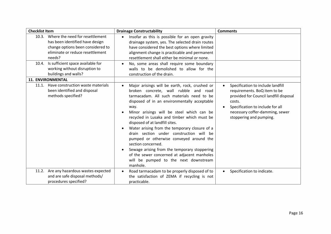
Page 16
Checklist Item Drainage Constructability Comments
10.3. Where the need for resettlement has been identified have design change options been considered to eliminate or reduce resettlement needs?
Insofar as this is possible for an open gravity drainage system, yes. The selected drain routes have considered the best options where limited alignment change is practicable and permanent resettlement shall either be minimal or none.
10.4. Is sufficient space available for working without disruption to buildings and walls?
No, some areas shall require some boundary walls to be demolished to allow for the construction of the drain.
11. ENVIRONMENTAL
11.1. Have construction waste materials been identified and disposal methods specified?
Major arisings will be earth, rock, crushed or broken concrete, wall rubble and road tarmacadam. All such materials need to be disposed of in an environmentally acceptable way.
Minor arisings will be steel which can be recycled in Lusaka and timber which must be disposed of at landfill sites.
Water arising from the temporary closure of a drain section under construction will be pumped or otherwise conveyed around the section concerned.
Sewage arising from the temporary stoppering of the sewer concerned at adjacent manholes will be pumped to the next downstream manhole.
Specification to include landfill requirements. BoQ item to be provided for Council landfill disposal costs.
Specification to include for all necessary coffer-damming, sewer stoppering and pumping.
11.2. Are any hazardous wastes expected and are safe disposal methods/ procedures specified?
Road tarmacadam to be properly disposed of to the satisfaction of ZEMA if recycling is not practicable.
Specification to indicate.

Page 17
Checklist Item Drainage Constructability Comments
12. HEALTH AND SAFETY
12.1. As designed, do the construction methods have any intrinsic safety issues? Have these been addressed in the specification?
Deep drain sections and those where high flow velocities will occur are a safety hazard and will either be covered (Bombay sub-contract area) or properly fenced off and closed as part of the construction or as soon as possible afterwards.
Excavations are generally shallow and geotechnical investigations indicate stable trenching conditions except in some flood plain areas.
The specifications need to contain detailed requirements for health and safety regarding trenches, dust, etc.
12.2. Are National Health and Safety regulations sufficiently rigorous when compared to international best practice or should additional HS clauses be included?
The final ESIA will cover all health and safety issues and will propose additional specification clauses if found necessary.

Lusaka Water Supply, Sanitation and Drainage (LWSSD) Project
Detailed Engineering Designs and Tender Documents for Drainage
Projects
Constructability Report
Gauff Ingenieure
ANNEX II
GENERAL DRAINAGE ALIGNMENT, MAZYOPA DRAIN

ONCE DRAINAGE
WORKS
UNDERTAKEN,
THIS AREA MIGHT
BECOME
AVAILABLE
FOR RELOCATION
OPEN SPACE
PROBABLE TRASH
TRAP SITE
LEVEL
CROSSING
PROPOSED
ACCESS
ROAD
CS00002
CS00004
CS00006
CS00008
CS00010
CS00012
CS00016
CS00014
CS00018
CS00020
CS00022
CS00024
CS00026
CS00028
CS00030
CS00032
CS00034
CS00036
CS00038
CS00040
CS00042
CS00044
CS00046
CS00048
CS00050
CS00052
100
(SCALE BAR)
500 250m150 200
END OF
BOMBAY
MAIN DRAIN
G: 1,219.00 m
I: 1,217.45 m
w(b): 8.0 m
h: 2.40 m
START OF
MAZYOPA
DRAIN
CS00000
EXISTING
SUSPENDED
BRIDGE
EXISTING
PIPE
BRIDGE
EXISTING
WEIR
WALL
Lusaka Water Supply, Sanitation
and Drainage (LWSSD) Project
Detailed Engineering Design, Tender Documents,
Detailed ESIAs and ESMPs for Drainage Projects
LWSSD/GL/D/003/1.1-7A
SCALE 1:6500
S.D
D.B G.M
MARCH 2014
1 OF 1
General Drainage Alignment
Mazyopa Drain
LEGEND:
PROPOSED DRAIN
RAILROAD
FLOW DIRECTION
POINTS
EXISTING PIPE BRIDGE
PROPOSED BRIDGE

Lusaka Water Supply, Sanitation and Drainage (LWSSD) Project
Detailed Engineering Designs and Tender Documents for Drainage
Projects
Constructability Report
Gauff Ingenieure
ANNEX III
WORK PROGRAMME: CONTRACT PACKAGE 7 (CP7)

ID Topic
CP7: Improvement of Bombay Drainage System + Mazyopa J A S O N D J F M A M J J A S O N D J F M A M J J A S O N D J F M A M J J A S O N D J F M A M J J A S O N D J F M A M J J A S O N D
1 Contract Package CP7
1.1 Commencement date
1.2 Mobilisation
2 Pre-contract Activities
2.1 Resettlement Compensation
3 Procurement Activities
3.1 Local Procurement
3.2 Foreign Procurements (mainly for S Classs portals, if required)
4 Preliminary Works
4.1 Confirm location of existing services
4.2 Confirmation of wayleaves
Drainage Works
5 Bombay Main and Lumumba
5.1 Drainage Works - Trapezoidal, 6347 m; Rect 5430 m (covered 530 m)
5.2 Safety Rails (3100 m)
5.3 Precasting of concrete members (incl for Mazyopa)
5.4 Installation of box culverts (20 nr)
5.5 Foot bridges and Driveways
Concrete works for Trash Trap No 01
5.6 Trash Trap No 01 Deflector Wall, Ramp, etc
6 Mazyopa
6.1 Drainage Works - Trapezoidal, 2600 m incl a short length of rect channel
6.2 Safety Rails (2600 + m)
6.3 Installation of box culverts (1 nr)
6.4 Foot bridges
6.5 Concrete works for Trash Trap
Trash Trap Deflector Wall, Ramp, etc
7 Commissioning and Hand-Over
7.1 Partial Commissioning and Hand-Over 1
7.2 Partial Commissioning and Hand-Over 2
7.3 Final Commissioning and Hand-over
7.4 Defects liability Period 1
7.5 Defects liability Period 2
7.6 Defects liability Period 3
Continuous work
Intermittent works
Rainy season
Half 2, 2018 Half 1, 2019 Half 2, 2019Half 2 , 2014 Half 1, 2018Half 1 , 2015 Half 2, 2015 Half 1 , 2016 Half 2, 2016 Half 1 , 2017 Half 2, 2017