constant speed induction motor supplied from a three-phase
TRANSCRIPT

Research Collection
Doctoral Thesis
Analyse des Betriebsverhaltens von Gasturbinen mit derAnalogrechenmaschine
Author(s): Nussbaumer, Ernst
Publication Date: 1963
Permanent Link: https://doi.org/10.3929/ethz-a-000104993
Rights / License: In Copyright - Non-Commercial Use Permitted
This page was generated automatically upon download from the ETH Zurich Research Collection. For moreinformation please consult the Terms of use.
ETH Library

Prom. No. 3345
Constant Speed Induction Motor Suppliedfrom a Three-Phase Silicon
Controlled Valve Power Inverter
THESIS
PRESENTED TO
THE SWISS FEDERAL INSTITUTE OF TECHNOLOGY, ZURICH
FOR THE DEGREE OF
DOCTOR OF TECHNICAL SCIENCES
BY
Abdel-Fattah Kheireldin
B. Sc., M. Sc. Electrical Engineering
Citizen of the U.A.R.
Accepted on the Recommendation of
Prof. Ed. Gerecke and Prof. A. Dutoit
Zurich 1963
Dissertationsdruckerei Leemann AG

Leer - Vide - Empty

TO MY MOTHER

Leer - Vide - Empty

Acknowledgement
I wish to acknowledge my great indebtedness to Professor Ed. Gerecke for
his valuable advice and superior guidance presented during the execution of
this research work.
I desire here to express my best thanks and appreciation to Professor
A. Dutoit for having accepted to examine this thesis.
My sincere thanks are also introduced to the Director of the Analogue
Computing Center at the Institute as well as to every person there who has
tried to present any facility to me during the execution of this work.
5

Leer - Vide - Empty

Contents
Section I
Introduction 11
Section II
Experimental investigations 13
2.1. Apparatus used in the experiments 13
2.2. The three-phase power inverter supplying the induction motor 14
2.3. The transistorized three-phase variable frequency firing circuit 15
2.4. Experimental investigations 18
2.4.1. Determination of the machine data 18
2.4.2. Ossana circle diagram 19
2.5. Automatic speed regulating circuit 20
2.5.1. Investigation of a triode oscillator disturbed by an external signal in its
grid circuit 24
2.5.2. Operation of the circuit for automatic frequency regulation 27
2.5.3. Static testing of the circuit for automatic frequency regulation 32
Section III
Mathematical analysis of the three-phase inverter loaded by a three-phase induction motor 34
3.1. The three-phase inverter 34
3.2. Transformation of the three-phase machine into an equivalent two-phase one . 37
3.2.1. The resultant current vector 37
3.2.2. The direct, quadrature and zero components of current 38
3.2.3. Derivation of the direct and quadrature components of the stator and
rotor voltages 39
3.2.4. The electric torque of the three-phase machine 42
3.2.5. The mechanical equation of the system 43
3.2.6. Check of the system equations 43
3.2.6.1. Rotor being locked 44
3.2.6.2. Rotor having synch, speed 44
7

Section IV
Analogue computation 46
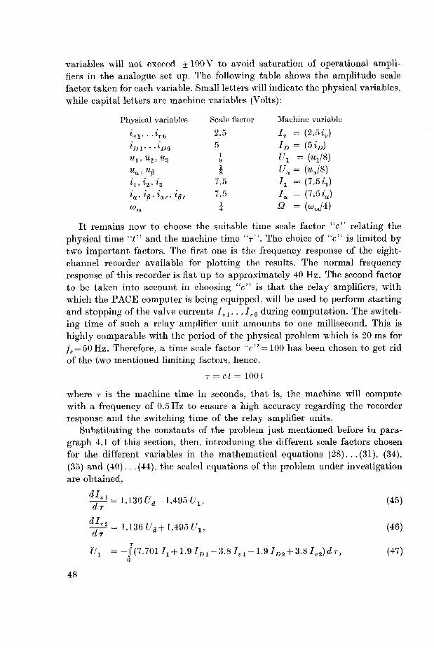
4.1. Numerical example 46
4.2. Scaling of the system equations 47
4.3. The computer diagram and the patching of the problem 49
4.4. The three-phase transistorized gating circuit 50
4.5. Pot set tabulation 52
4.6. The static test 53
4.7. The eight-channel recorder for plotting the results 55
4.8. Problem investigation on the analogue computer 56
4.8.1. Motor starts under no-load condition 56
4.8.2. Motor starts under load 58
4.8.3. Sudden variation of inverter frequency 58
4.8.4. Comparison between the experimental oscillograms and the current and
voltage waveforms obtained by simulating the physical problem on the
analogue computer 59
Section V
Conclusion 61
Zusammenfassung 63
References 65
8

List of symbols
Units
u voltage [V]
Ud d. c. supply voltage
%, u2, u3 output voltages from phase 1, 2 and 3 of the three-phaseinverter
u8 resultant stator voltage vector
ua, up the direct and quadrature components of us
ur resultant rotor voltage vector
uar,Ugr the direct and quadrature components of ur referred
to stator axes
i current [A]
iBl. . .iog current through silicon controlled valves
ini. . .in6 current through feedback diodes
i1, i2, i3 stator phase currents
is resultant stator current vector
ia, io the direct and quadrature components of is
ir,irs resultant rotor current vector referred to rotor and to
stator axes respectively
iar,iRr the rotor direct and quadrature current componentsreferred to stator axes
i0 zero sequence component of stator current
Icl short circuit current of the induction motor
I01 no-load current of the induction motor
i/j flux linkage (Vs]
ifis stator flux linkage vector
tpr rotor flux linkage vector
B resistance [Q]
Rs, Rr stator and rotor winding resistance respectivelyL main inductance of the induction machine [H]
Lm main inductance due to current flow in all three phasesof the machine = 1.5 L
La leakage inductane of induction motor
X reactance [Q]
9
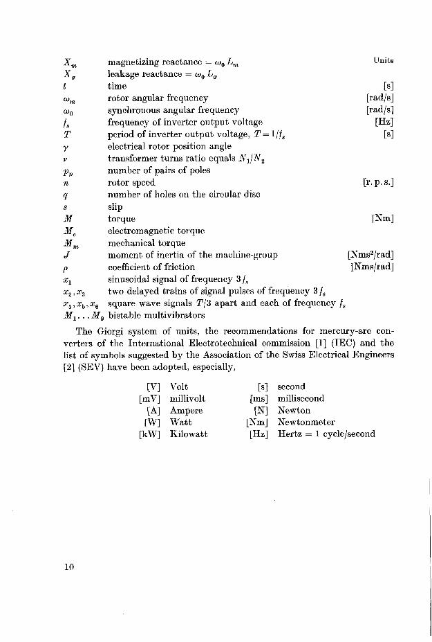
Xm magnetizing reactance = co0 Lm Units
Xa leakage reactance = o>0 Lat time [s]
wm rotor angular frequency [rad/s]
w0 synchronous angular frequency [rad/s]
/g frequency of inverter output voltage [Hz]
T period of inverter output voltage, T=ljfs [s]
y electrical rotor position angle
v transformer turns ratio equals N-yjN2
pp number of pairs of polesn rotor speed [r. p. s.]
q number of holes on the circular disc
s slipM torque [Nm]
Me electromagnetic torque
Mm mechanical torque
J moment of inertia of the machine-group [Nms2/rad]
p coefficient of friction [Nms/rad]
xx sinusoidal signal of frequency 3 fs
x2, x3 two delayed trains of signal pulses of frequency 3 fs
xi,x5,x6 square wave signals T/3 apart and each of frequency fs
M1... M9 bistable multivibrators
The Giorgi system of units, the recommendations for mercury-arc con¬
verters of the International Electrotechnical commission [1] (IEC) and the
list of symbols suggested by the Association of the Swiss Electrical Engineers
[2] (SEV) have been adopted, especially,
[V] Volt [s] second
[mV] millivolt [ms] millisecond
[A] Ampere [N] Newton
TW] Watt [Nm] Newtonmeter
[kW] Kilowatt [Hz] Hertz = 1 cycle/second
10
SECTION I
Introduction
Three-phase induction motors offer distinct advantages over d. c, or single
phase a. c. or two-phase a. c. motors. The d. c. motors have commutators
which get dirty and short, brushes which wear and sometimes make poor
contact. These mechanical features may be highly undesirable from a relia¬
bility point of view especially when maintenance is one of the first problems.
Single phase a. c. motors, in addition to coming up to rated speed rather
slowly, require starting circuitry. As far as two-phase motors are concerned,
it would be somewhat difficult to design a two-phase motor which could match
the performance of three-phase motors of comparable size and weight.Sometimes it may be decided upon to use three-phase induction motors
and these are to be powered from a d. c. supply. Electronic power inverters
are recommended for converting the available d. c. voltage into a three-phaseone. Thyratron gas tubes have been already used to perform this process of
power conversion.
Since the announcement of the new silicon controlled rectifier [3] attention
was focused on the application of this device in inversion equipment. The
small size, short turn-off time, and low forward voltage drop of this valve
made it possible for it to replace gas thyratrons in many existing circuits. Its
characteristics are similar to those of a gas thyratron except the forward dropis about one tenth that of a thyratron and the deionization time is less byseveral orders of magnitude. The inverter used is that developed by W. McMur-
ray and B. D. Bedford [4] of the General Electric Laboratories. Although this
circuit resembles a conventional parallel inverter, its method of commutation
is entirely different and the use of feedback diodes makes it uniqely suited for
driving reactive loads. A major advantage of the new circuit is its ability to
operate under lightly loaded or open circuit conditions. In the conventional
parallel inverter [5], [6], as the load current is reduced, the peak anode voltagecan rise to many times the supply voltage. In the McMurray-Bedford circuit,
11
the feedback diodes prevent the voltage across either half of the primary
winding from exceeding the supply voltage.Small sized squirrel cage induction motors show a remarkable decrease in
speed by increasing load when supplied from a constant frequency supply.The use of self-excited inverters gives the possibility of varying the motor
speed by varying the frequency of the signal driving the inverter. To generatea three-phase system of voltages whose frequency can be regulated at will, a
specially designed firing circuit has been constructed to deliver the driving
signals to the inverter. The input signal to this firing circuit is a sinusoidal
wave and can be supplied from a signal generator. The output is a three-phase
system of square waves 1/3 period apart for all frequencies. Another circuit
has been designed to regulate the motor speed and keeps it constant from
no-load to rated load. This is achieved by regulating the frequency of the
signal supplying the firing circuit that drives the three-phase inverter.
The thesis consists of five sections. This first section is an introduction, it
contains the previous literature of the subject. Section II comprises the experi¬mental investigation. Section III is devoted to the mathematical analysis of
the three-phase inverter loaded with an induction motor. The solution of the
differential equations of the system under test is executed on the PACE
analogue computer, that is, the precision analogue computing equipment
present in the Institute for Automatic Control and Industrial Electronics of
the Swiss Federal Institute of Technology, as will be given in Section IV.
Section V contains the conclusion.
12
SECTION II
Experimental investigations
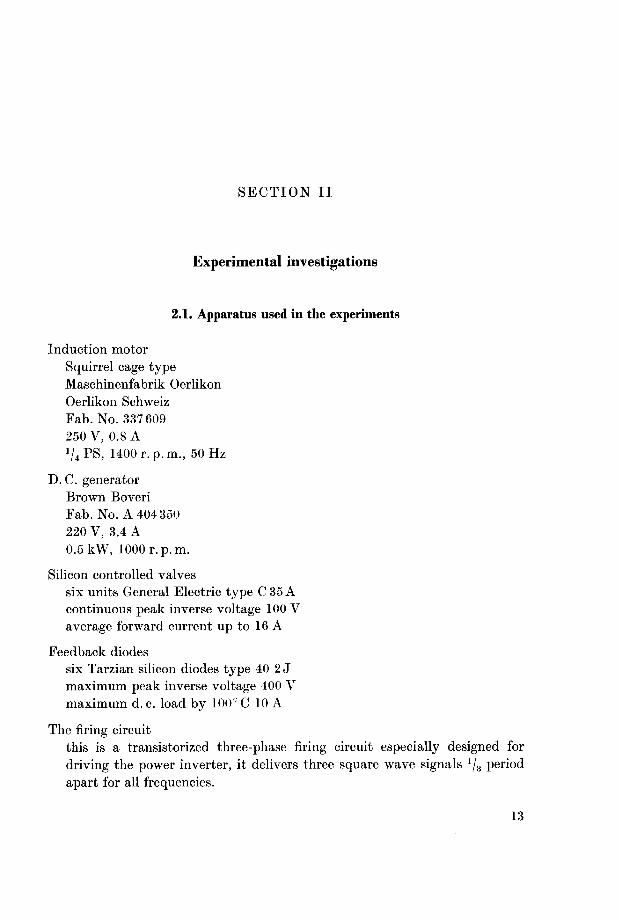
2.1. Apparatus used in the experiments
Induction motor
Squirrel cage typeMaschinenfabrik Oerlikon
Oerlikon Schweiz
Fab. No. 337609
250 V, 0.8 A
V4PS, 1400 r.p.m., 50 Hz
D. C. generatorBrown Boveri
Fab. No. A 404350
220 V, 3.4 A
0.5 kW, 1000 r.p.m.
Silicon controlled valves
six units General Electric type C 35 A
continuous peak inverse voltage 100 V
average forward current up to 16 A
Feedback diodes
six Tarzian silicon diodes type 40 2 J
maximum peak inverse voltage 400 V
maximum d. c. load by 100° C 10 A
The firing circuit
this is a transistorized three-phase firing circuit especially designed for
driving the power inverter, it delivers three square wave signals x/3 period
apart for all frequencies.
13

The frequency regulating circuit
this is also especially designed for regulating motor speed automatically by
regulating the inverter frequency.
2.2. The three-phase power inverter supplying the induction motor
The three-phase silicon controlled valve power inverter consists of three
single phase d. c. to a. c. inverters, driven in such a manner so as to generate
a three-phase system of voltages 1/3 period apart. Fig. 1 shows a connection
diagram of the inverter and the induction motor under test. The inverter used
Fig. 1. Connection diagram of the three phase power inverter supplying an induction
motor.
Vi... V» six silicon controlled valves.
Di. . .De feedback diodes.
R limiting resistance.
La, C inductance and capacitance forming an oscillotary circuit for commutatingvalve currents.
Ua d. c. supply voltage.DAM induction motor.
GMn d. c. generator.
The terminals 1,2. ..9 are connected to the corresponding ones given in fig. 4.
14

has been developed by W. McMurray and B. D. Bedford to take maximum
advantages of the properties of the silicon controlled valves. Although the
new circuit superficially resembles a conventional parallel inverter, its method
of commutation is entirely different and the use of feedback diodes makes it
suited for driving reactive loads. It has been found necessary to provide a
square wave drive to the gates of the valves rather than short turn-on pulses.This is especially important with reactive loads to ensure proper operation,
otherwise, the transient currents flowing during commutation may cause a
silicon controlled valve to turn off before the end of a half cycle. If it is requiredto generate a three-phase system of voltages at one fixed frequency, 120 degrees
apart, the inverter driver need only consist of monostable multivibrators
designed to produce the required three square waves at 1/3 period apart. For
variable frequency drive of the three-phase inverter, we shall present a new
circuit capable of delivering three square wave signals 1/3 period apart with
respect to each other for all input frequencies, the frequency range is limited
by the highest time constant in the circuit.
2.3. The transistorized 3-phase variable frequency firing circuit
Fig. 2 a shows a block diagram of this specially constructed firing circuit [7]and the signal waveforms at the input and output terminals. The signals x2
and x3 are two trains of negative pulses each of frequency 3 fs, where fs is the
frequency of the a. c. voltage to be generated in the inverter circuit. These
are generated from a sinusoidal signal x1 having a frequency 3/s. At the
instants when the sine wave xx crosses the time axis and is changing sign from
negative to positive x2 will take place, while x3 occurs at the instants when xx
changes sign from positive to negative. Therefore, the signal pulses x3 are
delayed T/6 from those of x2 as shown in fig. 2 a, and T = l//s.The circuit consists mainly of six bistable multivibrators Mx. . .M6 con¬
nected in a ring system [8] as shown in fig. 2a and 2b. The connection diagramof one of these six bistable multivibrators is given in fig. 3. It has two stable
states: transistor Tx conducting while T2 is "off", and vice versa. The designof such a multivibrator [9] involves the selection of — Ux and + U2 and the
calculation of R2, R3 and RL to satisfy the "on" and "off" transistor require¬ments. The function of B3 is to supply a reverse base current equal to Ic0,the collector leakage current, at the highest operating temperature, to prevent
the collector leakage current in the "off" transistor from exceeding Ic0. It
must also supply a level shifting component of current to put a reverse voltagebias at the base of the "off" transistor, and therefore gives it some immunityto noise signals. A multivibrator will be considered "on" when the right hand
transistor T2 is conducting, otherwise it is "off".
15

The signal x2 is coupled to the bases of the right hand transistors of M1,
M3 and M5, while x3 is coupled to those of M2, M4 and Jf6.To start the circuit,
switch S is left open and all the units M2.. .Me are turned "on", while M1 is
in the "off" state. Now, at the instant switch S is closed, the units which are
in the on-state will not be affected, while Mx will be turned "on", as soon as a
signal pulse from x2 reaches the base of its right hand transistor. At the instant
Mx is turned "on", a signal s7 is transferred to M2 turning it "off". This signal
s1 is obtained by differentiating the signal sx appearing at the collector ter¬
minal of the right hand transistor of Mx and amplifying the derivative in a
class-B amplifier. Thus, the "off" state has advanced to M2, and M2 will
remain "off" until a signal pulse from x3 reaches the base of its right hand
~T=vr-\
s
Fig. 2 a.
Mi. . .Mo
Ms,
..08
M7,
d.
S7. . .S12
X2,X3
xn ,xs,xe
Mi
1 1 c'
«r-1—1—
1—r-HI 1 :S]U
4=1* * r^i s«
K- r -H
-n-r/s1' 1
7/3-H h-
ll—1*
"1
-| 1
tTTT 1 ' 1 [Hp-E"
/*>
L c< J L-
"< s< y s«"V/*1""
ll 1 1
a-n—k-l | !
iwkll 1
sn
%
u U L'l 1
% % —7 %2T/3
L_l q—l^_Jsr/t
'
1 I
Signal flow diagram of the three-phase variable frequency firing circuit.
bistable multivibrators connected in a ring counter system.three bistable multivibrators functioning as hold circuits.
converters for the derivation of the signals 57. . . S12 from the signals «i. . . «o
respectively through differentiation and amplification in a class-B amplifier.
output square wave signals of the multivibrators M\. . . M$ respectively,each has a frequency fs and leads the succeeding one by T/6.six trains of signal pulses derived from the signals si. . . sg respectively throughdifferentiation and amplification in a class-B amplifier.input sinusoidal signal of frequency 3 /«.two trains of signal pulses derived from xi, each of frequency 3 fs and are
shifted T/6.the three square wave signals of frequency /g and having a phase shift of
T/3 apart.
16

Fig. 2 b. Same as fig. 2 a, redrawn in a ring form.
+u2
Fig. 3. The bistable multivibrator.
17

transistor turning it "on" again. The "off-state then advances to M3 and
the cycle of events is again repeated. As the signals x2 and x3 are T/6 out of
phase, therefore, each multivibrator of these six units will remain in the "off-
state T/6 and as it is turned "on" the "off-state advances to the succeeding
stage. Fig. 16 shows an oscillogram of the two trains of signal pulses x2 and x3,
and an oscillogram of the output signals sx and s2 at the collector terminals of
M1 and M2 respectively. The signals s1. . .s6 will appear at each collector
terminal of the right hand transistor of M1. . .Jf
6 respectively. It is clear that
each of the signals s1... se has a frequency fs and leads the succeeding one by
T/6, as shown in fig. 2 a. Each of the six trains of signal pulses s7. . . s12 is derived
from s1... s6 respectively, through differentiation and amplification in a class-B
amplifier as shown in fig. 2 a and 4.
To generate the three-phase system of square wave signals x4, x5 and x6
which are always T/3 apart with respect to each other irrespective of frequency,three other bistable multivibrators if7, Ma and ilf9 were built. The trains of
signal pulses s7 and s10 which are T/2 out of phase, and each of frequency fsare used to trigger M1 as shown in fig. 2 a, 2 b and in fig. 4. Similarly, s9 and s12
are used to trigger M8, while M9 is triggered from sn and ss. The output
signals xi, x5 and xe will be of frequency fa and will possess a phase shift of
T/3 from each other. The designed circuit covered a frequency range extendingfrom 3 fs = 20.
. .3000 Hz. The highest frequency range is limited by the highest
time constant in the circuit. To extend the frequency range of this circuit, it
is only necessary to choose suitable elements as will be shown later on in
chapter 4.4 when simulating the three-phase inverter on the analogue com¬
puter.For driving the silicon controlled valves of the three-phase inverter, each
of the square wave signals x4, x5 and x6 is coupled to an emitter follower stage,the output of which is transformer coupled to the gates of the correspondingvalves of each phase. Fig. 4 shows the connection diagram of this firing circuit.
Each one of the six diodes on the secondary side of the coupling transformer
will provide a low resistance by-pass to the p-n (gate-cathode) junction of the
non-conducting valve.
2.4. Experimental investigation
2.4.1. Determination of the machine data [10]
The resistance of the stator winding per phase Rs has been measured usinga wheatstone bridge. From the no-load and short circuit tests, the equivalentcircuit components have been calculated. The following calculated machine
data are all referred to the stator side. Er represents the rotor conductors
equivalent resistance, the motor being a squirrel cage one:
18

VC4 **°- M6*CS
\*-J=Vf-*\ \~-T=1/f-\
Fig. 4. Connection diagram of the transistorized three-phase firing circuit driving the inverter circuit. Each of the output terminals 1,2. . .9 is connected to the corresponding one of fig. 1.
(Transistors used are of type OC76.)

Rs = 18 J2
Rr = 13.3 Q
a = 0.0688
Lm = 1.5 L = 0.738 #
where £m is the main inductance due to the current flow in all three phasesof the machine and a is the leakage factor.
The friction losses of the machine group is determined by extrapolating the
no-load input power curve to zero voltage and equals 46 Watts. Running the
machine lightly, then switching off the power supply, a curve giving the
relation between the output voltage (proportional to speed), at the outputterminals of the d. c. generator, against time is recorded. From this curve [11],the mechanical time constant of the machine group rm = Jjp is found to be 6 s,
J being the moment of inertia of the system and p the coefficient of friction.
J= 0.01117 Nms2/rad
p = 0.001862 Nms /rad
Fig. 1 shows a connection diagram of the circuit under load test, that is,
the three-phase inverter, the three-phase squirrel cage induction motor coupledto a d. c. generator and the load resistance. The power supply to the inverter
is a d. c. one having a voltage of about 30 V.
2.4.2. Ossana circle diagram
The induction motor under test is supplied from the inverter output as
shown in fig. 1. At standstill, the short circuit readings are taken, while the
no-load readings are registered with the motor running light near the syn¬
chronous speed. Different conditions of loading, between no-load and rated
load are also taken by loading the d. c. generator coupled to the induction
motor through a variable resistance. A signal generator is used to supply the
input sinusoidal signal x1 to the three-phase firing circuit driving the power
inverter. Signals having a frequency 3/s=100, 150, and 200 Hz have been
chosen to generate a three-phase system of voltages having a frequency
/„ = 33.33, 50 and 66.67 Hz respectively. The Ossana circle diagrams of the
induction motor have been drawn experimentally for these three frequenciesstated before as shown in fig. 5. It is clear from this figure that the radius of
the circle diagram increases as the inverter frequency decreases, the motor
current being limited by the reactance of the machine. The Ossana circle
diagram is redrawn in fig. 6 for fs = 50 Hz.
Fig. 7 a and 7 b give the oscillograms of the voltages and currents of the
three-phase inverter with locked rotor and with motor at nominal load respec¬
tively, at a frequency fs = 50 Hz. Oscillograms of the different currents and
19

voltages of the McMurray and Bedford single phase parallel inverter are
published by Ed. Gerecke and Udo Meier [12] for the case of passive loading.Three different cases were considered, resistive, inductive or capacitive loading
respectively at a frequency of 110 Hz. These oscillograms agree to some extent
with those of fig. 7 a and 7 b. The deviation may be due to the fact that the
constants of the circuit used by Gerecke-Meier as well as the nature of loadingare different.
2.5. Automatic speed regulating circuit
Considering an induction motor on no-load, its speed will be very close to
the synchronous speed and the induced voltage in the rotor conductors will
be very small, and so will the currents, giving a torque only sufficient to main¬
tain the rotor in motion. Suppose now that a mechanical load is put on the
rotor shaft, the rotor will slow down, and in so doing it will increase the slip,
/»//,;lmll,l
*c«f«0 OS IDA
Fig. 5. Ossana circle diagrams for three
different frequencies:
a) /, = 33.33 Hz
b) /, = 50 Hz
c) /, - 66.67 Hz
Li,Li2, L3 no-load current pointsd > O2, Ca short circuit current points
Fig. 6. Ossana circle diagram,
/, = 50 Hz.
OL no-load current
OC short circuit current
LC power line
LP^ torque line
20

40v
a) phase voltage 1vu\
-20A
d) valve current iv\
40V \s
b) valve voltage m8 i
«=W +f+++f f^+++
e) diode current ini
10A
40V+++t Wtt ti^++*+A*t jttf+«+tiVmjj <m ~^
c) voltage Mi across La
4.5A
f) motor phase current i\
Fig. 7 a. Oscillograms of voltages and currents of the inverter circuit, motor standstill,
/, = 50 Hz and Ua = 20 V.
21

a) phase voltage 2vui d) valve current
V
b) valve voltage u, i e) diode current it>\
c) voltage ul across La f) motor phase current i\
7 b. Oscillograms of voltages and currents of the inverter circuit, /„ = 50 Hz,
Ua = 30 V and Mm = 1.2 Nm.

and increases its speed relative to that of the rotating magnetic field. The
induced voltage of the rotor conductors will now increase both in magnitudeand frequency, and will produce more current and therefore more torque, as
long as the effect of the reactance permits. Conditions of equilibrium are
attained when the slip has increased enough to allow a torque to be developedsufficient to meet the mechanical or load torque applied to the shaft. The
change of speed, or slip, of about 6% in a small sized motor may be sufficient
to allow rated load torque to be developed. Fig. 8 shows the torque-speedcharacteristics of the induction motor supplied from the three-phase silicon
controlled valve power inverter. Curve "a" is obtained for /s = 50 Hz, that is,
the inverter supplies in this case a voltage having a fixed frequency. The speedcan be regulated automatically, as shown in curve "6" of fig. 8, to keep it
more or less constant from no-load to rated-load by regulating the inverter
frequency automatically. The following describes a specially designed elec¬
tronic circuit that regulates the frequency of the input signal xx driving the
firing circuit.
Fig. 12 b gives a block diagram of the circuit for automatic frequency
regulation and the three-phase inverter loaded by an induction motor. Before
discussing the operation of this circuit it has been found necessary to give a
short hint on triode oscillators when disturbed by an external signal in the
grid circuit [13]. The oscillator may be synchronized or pulled, depending on
the frequency of the injected signal as well as on its amplitude.
15 Nm
Fig. 8. Torque speed characteristics.
a) inverter supplying constant frequency fs = 50 Hz.
b) inverter frequency is being regulated by the feedback circuit given in fig. 12.
23

2.5.1. Investigation of a triode oscillator disturbed by an external signal in its
grid circuit
When a triode oscillator is disturbed by an external signal ua as shown in
fig. 9, in its grid circuit, the free oscillations are generally pulled to the applied
signal, that is, the signal controls the oscillations. The amount of control
depends on the amplitude Ua of the applied signal as well as on the amount
of detuning z = /0 — jg between the free oscillation frequency f0 and the fre¬
quency /„ of the applied signal. If z is small and V Jl)\ is reasonable, the free
oscillations may be locked with the signal. Ut is the induced voltage in the
grid coil which is mutually coupled with that of the plate tank circuit. The
locking range depends on Ua as well as on the figure of merit Q of the tuned
circuit. As Ua increases, the locking range increases. The higher the figure of
merit Q, the smaller the locking range, this is a natural result since for a high
Q circuit, the developed amplitude of the free oscillations is large and the
amount of control of the applied signal decreases.
If z increases, other parameters being the same, locking cannot be main¬
tained, but the free oscillations are pulled to the signal. The average frequencyof oscillations is not equal to the free frequency, it tends toward the signal
frequency.If z is further increased, the control will be very weak and the signal may
loose its control, the system will operate freely (free oscillation), but there
is still an output voltage, although very small, of the signal frequency (forced
oscillation). The two oscillations, free and forced, will heterodyne resulting in
Fig. 9. The triode oscillator Q\ of free frequency
/oi = 550 Hz.
ua the external signal of frequency / injected in
the grid circuit.
M mutual inductance between anode and gridcoils.
Ut induced voltage in grid coil.
u output amplitude modulated voltage, amplitudemodulation frequency <*afai — ja when the undis¬
turbed beat frequency zu is large.
24
a beat frequency component equal to the difference between /0 and fa. Duringthe interval at which the free and forced oscillations are in phase, the resultant
amplitude is maximum. However, at the interval where both oscillations are
out of phase, the amplitude of oscillation is minimum. The result is that the
amplitude of oscillation will fluctuate between maximum and minimum at a
rate equal to the amount of detuning. If z is reduced, but still outside the
locking range, then during the peak portion of the beat cycle the signal will
assist the oscillations and will therefore have a strong control, the signal pullsthe oscillations and tries to lock it. At the valley portions of the beat cycle,the forced oscillation will oppose the free one and the control of the signal
reduces, the oscillation in this portion of the cycle tries to get rid of the control
of the signal and continues freely. In this way, the apparent beat frequencywill be less than the undisturbed beat frequency as shown in fig. 11. The
amount of reduction increases as the relative amount of detuning z approachesthe locking range. If z is very large, the apparent beat frequency, termed the
disturbed beat frequency, will approach the undisturbed one.
To determine the relation between the actual (undisturbed) amount of
detuning "zu" and the apparent (disturbed) amount of detuning "zd", the
following experiment was carried out. The frequency variation method was
adopted. As shown in fig. 10, a sinusoidal signal from the signal generator (1),
having a frequency near /01, the free oscillation frequency of the triode oscilla¬
tor G1, is injected in the grid circuit of G1. The output of Gx is applied to the
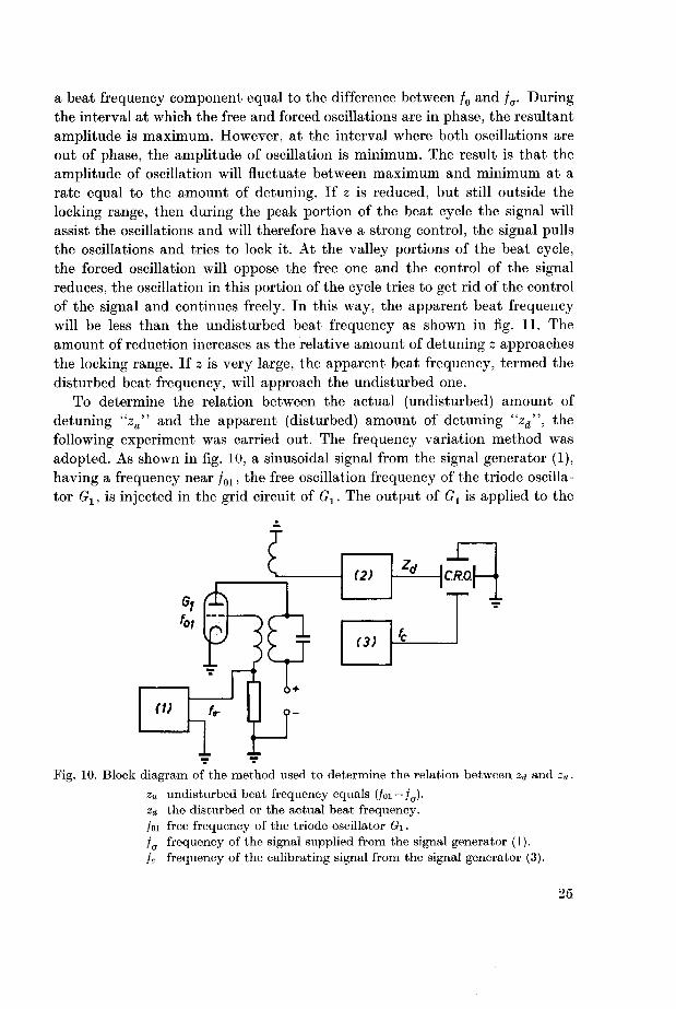
Fig. 10. Block diagram of the method used to determine the relation between za and zu.
zu undisturbed beat frequency equals (foi — fa)-Zd the disturbed or the actual beat frequency.
/oi free frequency of the triode oscillator Oi.
fa frequency of the signal supplied from the signal generator (1).
fc frequency of the calibrating signal from the signal generator (3).
25
detector-amplifier stage (2) and the output of the latter is applied to the
X-plates of the C.R.O., while a reference signal from the well calibrated beat-
frequency oscillator (3) is applied to the F-plates. Varying the frequency faof the synchronizing signal by different steps and adjusting the reference
oscillator till a stationary closed figure is indicated on the screen, the detuningof the synchronizing generator from the free frequency gives "z„", while the
indication of the reference oscillator (3) gives "zd". Fig. 11 gives the relation
between "zd" and "z„" for different signals. It is clear that as the amount of
detuning increases "zd" approaches "zM".It is to be noted that, as the frequency fa approaches a multiple or a sub-
multiple of the free oscillation frequency /01, the oscillator may be locked
with the signal.The circuit for automatic frequency regulation that follows in the next
chapter uses the phenomena of pulled oscillations to generate a sinusoidal
signal of frequency 3/s = /01 — /„ for triggering the three-phase transistorized
firing circuit, fs being the frequency of the inverter output voltage. The free
running frequency /01 of the triode oscillator G1 has been chosen equal to
550 Hz, while fa is always proportional to motor speed. The designed circuit
allows a range of variation of the inverter frequency fs by an amount of about
10% from its no-load value. This is adequate for the present work as the
maximum slip from no-load to rated-load will not exceed 6%.
*H Hz
ISO
100.
50 -
—i—
SO 100 ISO 200 zu Hz
Fig. 11. The relation between "z<j" and "zu" for different signal amplitudes.
(1) £7a = 0.5V (2)17S=1.0V (3) U„ = 1.5 V
26

2.5.2. Operation of the circuit for automatic frequency regulation
Fig. 12 a shows a simplified signal flow diagram of the circuit designed for
automatic speed regulation. The triode oscillator Ax has been built either to
supply a signal of frequency /02 = 3/s= 150 Hz or it may be synchronized by
injecting an appropriate signal in its grid circuit. With switch S open, Ax
supplies a signal of frequency 150 Hz to the firing circuit A2 that delivers three
square wave signals T/3 apart each having a frequency of 50 Hz. These are
used to trigger the six silicon controlled valves of the inverter circuit A3
feeding the induction motor At. As stated before, without speed regulationthe motor speed drops by about 6% from no-load to rated-load. With switch
S being closed, the heterodyne action between the signal of frequency /01 =
= 550 Hz and that of frequency fa will result in a signal component of fre¬
quency /oi -/,,, where /„ is derived in Ab and is proportional to motor speed n.
The frequency of the output signal from the triode oscillator Ax will follow
that of the synchronizing signal of frequency /oi-/CT=3/s. By loading the
motor, fa decreases and 3/s increases thus increasing the synchronous speedto maintain the rotor speed constant.
Fig. 12a. Simplified block diagram of the circuit for automatic speed regulation.
Ai triode oscillator having a free frequency /02 == 3/s = 150 Hz.
A2 firing circuit that divides the frequency of its input signal by three and builds three
square wave signals T/3 apart and each of frequency fs.
A3 the power inverter.
A\ induction motor.
A$ conversion of the mechanical speed n into an electrical signal of frequency )a — nq.
fi stator frequency.n rotor speed in r. p. s.
q number of holes on the circular disc mounted on the motor shaft, q = 16.
/ frequency of an electrical signal that is proportional to motor speed, fa = nq Hz.
/01 the free frequency of the triode oscillator Ox equals 550 Hz.
27

For clarifying the function of the speed regulating circuit, a numerical
example will be introduced. Assuming the no-load speed to be n = 25 r. p. s.
(1500 r. p. m.) and q = lQ, then /o = 400 Hz. The frequency /01 of the triode
oscillator Ox has been chosen to be equal to 550 Hz, hence, 3/s = /01 —/„ =
= 550-400= 150 Hz and the stator frequency will be /s = 50 Hz. Now, if the
Fig. 12b. Block diagram of the circuit for automatic speed regulation together with the
three-phase firing circuit, the inverter and the induction motor loaded by a d. c. generator.
Ai source of light.Az circular disc mounted on the motor shaft and having a number of holes q= 16.
Az phototransistor delivering the signal yi of frequency fa = nq Hz, and n is motor speed
in r. p.s.
B\ amplifier stage followed by a monostable multivibrator that generates the square
wave signal y2 of frequency / .
Bi band-pass filter F\ for deriving the sinusoidal signal yz of frequency / from the
signal 2/2 •
Bz the beat frequency oscillator Gi of free frequency /oi = 550 Hz when subtracted from
fa gives the signal j/4 of frequency 3 fs = /oi — faB\ the synchronized triode oscillator Gi of free frequency /o2= 150 Hz.
B5 amplifier limiter stage followed by a band-pass filter F% to supply the sinusoidal
signal x\ to the converter Bs
Be converter for generating the two trains of signal pulses x2 and Xs each of frequency
3/,, T/6 apart.
B7 the three-phase firing circuit given in fig. 4.
Bg the three-phase power inverter.
DAM the three-phase induction motor.
(JMn d. c. generator.
28
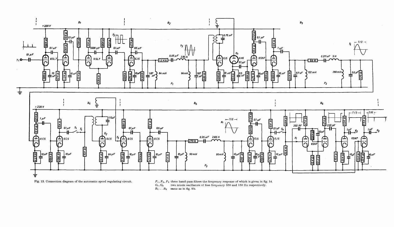
Fig. 13. Connection diagram of the automatic speed regulating circuit. Fi, F2, F3 three band-pass filters the frequency response of which is given in fig. 14.
Oi, ©2 two triode oscillators of free frequency 550 and 150 Hz respectively.J5i. . . Be same as in fig. 9b.

motor is loaded the speed will drop for example to 24.5 r. p. s. (1470 r.p.m.)to allow for the slip. Accordingly, fa will change to 24.5x16 = 392 Hz and
3/g rises to 550 — 392 = 158 Hz, that is, the stator frequency will increase to
/s = 52.7 Hz and hence the motor speed to substitute for the slip.A more complete signal flow diagram of the circuit for automatic speed
regulation is given in fig. 12 b. The signal yx is generated at the collector terminal
of a phototransistor by interrupting a beam of light falling on it by a circular
disc having q holes (g=16) and mounted on the motor shaft. As the motor
rotates with a speed n r. p. s., the signal y1 will possess a frequency fa = nq Hz.
This signal yx, after being amplified, is used to trigger a monostable multi¬
vibrator to get a square wave signal y2 as shown in fig. 12b. A sinusoidal
signal yz is then obtained by filtering the square wave signal y2 in the band¬
pass filter Fx [14] as shown in the circuit diagram of figure 13. It is to be
noticed that yx, y2 and y3 have the same frequency fa = nq, that is, proportionalto the motor speed. The amplitude frequency response of the band-pass filter
Fx is given in fig. 14a, the pass band extends between 350...450 Hz.
The sinusoidal signal y3 is injected in the grid circuit of the tuned-platetriode oscillator Gx, designed to have a free running frequency /01 = 550 Hz.
Conditions have been adjusted so that the free oscillation and the signal y3
will heterodyne, and the output from Ox will contain a component voltage of
frequency very nearly equal to the difference between /01 and fa. The output
from the oscillator Ox is then detected, amplified and filtered in the band-passfilter Fz to obtain the sinusoidal signal yt having a frequency 3/s = /01— /„. as
shown in the signal flow diagram of fig. 12 b and the connection diagram of
fig. 13, where /s is the motor stator frequency supplied from the inverter circuit.
Fig. 14b gives the amplitude frequency response of the band-pass filter F2,the pass band extends between 140.
..180 Hz. It is to be noted again that the
frequency fa is proportional to the motor speed. Hence, as the motor speeddecreases by loading, the frequency /„ decreases while 3 fs increases in such a
manner so as to maintain the motor speed constant.
Another tuned-plate triode oscillator (?2 having a free frequency /02 =150 Hz
has been also designed as shown in fig. 13. This oscillator can operate either
freely to generate a sinusoidal signal voltage of fixed frequency or synchronized
by feeding the signal yi of frequency 3/s in its grid circuit. Precautions have
been taken such that the signal yi will synchronize the oscillator 02 as the
frequency varies between 140 and 180 Hz. Thus, the frequency of the signal
y5 at the output terminal of the oscillator G% will follow that of yi for the
stated range of frequency.As the frequency of the synchronizing signal y4 is varied, the amplitude of
the output signal yh from the triode oscillator G2 will follow a resonance curve.
The maximum value occurs when the frequency 3/s of the synchronizing
29

Uf/Urr,
1.0.
05
00
ZOO Hz
i—i i i i i i| -| ,— iT
20 50 fOO 200 500 WOO 2000 frHz
(a)
20 SO 100 200
(b)
i ""I
500 1000 (3fs) Hz
Uf'Um
10
0.5.
0.0
150 Hz
' \ ••••\
10 20 50 100 200 500 1000 3fs Hz
(c)
Fig 14 Amplitude frequency response of the band pass filters Fi, F2 and Fs
a) response of the filter F\ of mid frequency 400 Hz
b) and c) response of Fi and ^3 respectively, each has a mid frequency 150 Hz
30

signal is near the free frequency /02 of the oscillator G2. This is clear from
curve b of fig. 15. Therefore, it has been found necessary to use a limitingcircuit that delivers an output voltage of more or less constant amplitude in
the useful range of frequency that extends from 3 fs = 145... 170 Hz. Thus, the
signal voltage y5 after being amplified is injected in the grid circuit of a triode
amplifier designed to clip yb during both positive and negative half cycles.The negative portions are limited as the amplifier is driven below cut off,
while the positive parts are clipped as grid current flows when the grid is
driven positive. The output of the limiter is then passed through the band¬
pass filter F3 as shown in fig. 13 to pass freely the fundamental component xx
of frequency 3/s. Fig. 14c gives the amplitude-frequency response of the
band-pass filter F3.The signal x1 having a frequency 3/s, after being amplified, triggers a
Schmitt trigger circuit designed to deliver two symmetrical square wave
signals which are anti-phase, as shown in fig. 13. Each of these two square
waves is differentiated and then coupled to a class-i? amplifier. The negativepulses are rejected while the positive ones are amplified and inverted in polarityand we are left with the two trains of signal pulses x2 and x3 each of frequency
3/s. As stated before, x2 occurs at the instants the sinusoidal signal xx crosses
370 380 390 400 410 fa- Hz
Fig. 15. The family of curves obtained when testing the automatic speed regulating
circuit, the z-abscissa represents the frequency / of the input signal y% supplied from a
signal generator.
a) ua is the amplitude of the output signal from stage B3 of fig. 12 b.
b) Ub is the amplitude of the output signal of frequency 3/s from the synchronizedoscillator (?2.
c) uc is the amplitude of the sinusoidal signal X\ of frequency 3 fs.
d) the frequency 3 fs of the output signal xi.
31

the time axis and is changing sign from negative to positive, while x3 occurs
T/6 later at the instants when x1 crosses the time axis and is changing signfrom positive to negative. These trains of signal pulses x2 and x3 are used to
trigger the three-phase firing circuit described before in chapter 2.3 to obtain
the three square wave signal voltages xt, x5 and x6 of frequency fs=ljT.These square waves are always T/3 apart and are the driving signals of the
silicon controlled valves in the three-phase inverter circuit.
2.5.3. Static testing of the circuit for automatic frequency regulation
For testing purpose a square wave signal generator whose frequency can be
varied between 375 and 415 Hz have been used to supply the signal y1 of
frequency fa to the circuit of fig. 13. Fig. 15 shows a family of curves obtained
at the different output terminals of the circuit of fig. 13 as /„ is varied from
375...415 Hz. Curve a shows the amplitude of the signal y4 of frequency
/01 — /ff = 3/s obtained by the heterodyne action between /01 and /„ in the
triode oscillator G1, while curve b gives the amplitude of the signal voltage y5
at the output terminal of the locked oscillator G2 as a function of fa. It is
clear from curve b that the amplitude of y5 is highly dependent on frequencyand shows a peak near /CT = 400 Hz, at which 3/s = 550 — 400= 150Hz=/02 the
free running frequency of the triode oscillator G2.Curve "c
" shown in fig. 15 gives the amplitude of the sinusoidal signal xx of fre¬
quency 3 /s as a function of fa. This signal x1 is obtained by passing y5 througha limiting circuit and filtering the resulting wave in the band-pass filter F3 as
shown in fig. 13. The straight line relation "a" given in fig. 15 gives the
frequency 3 fs of the sinusoidal signal xx as a function of the frequency fa of
the input signal. It is clear from this figure that 3/s=150 Hz at the pointwhere /CT = 400 Hz and as /„ decreases, 3/s will increase and vice versa. This
is actually what happens when the circuit of fig. 13 is used for automatic
speed regulation. Oscillograms of the signals y1, y2, y3, xx, x2 and x3 are also
taken and shown in fig. 16.
Fig. 16 a. y\ the signal at the collector terminal of the photo-transistor of frequency
fa = nq.
2/3 sinusoidal signal of frequency fa derived from j/i.
Fig. 16b. j/2, J/3 square wave and sinusoidal signal respectively, each of frequency fa.Fig. 16 c. x± sinusoidal signal of frequency 3 fs = /oi — fa
X2 train of negative pulses of frequency 3 fs
Fig. 16 d. %2,X3 the two trains of signal pulses each of frequency 3/s and are T/6 apart.
Fig. 16e. si,S2 the square wave signals at the collector terminals of the multivibrators
Mi and M2 respectively each of frequency fs and are T/6 apart.
Fig. 16 f. Xi square wave signal of frequency/s.
S5 the signal at the collector terminal of the right hand transistor of Ms.
32

*3
d)
b) e)
c) f)
*4
i"S5
Fig. 16. Oscillograms of the voltages obtained from the firing circuit and the automatic
speed regulating circuit.
33

SECTION III
Mathematical analysis of the three-phase inverter loaded by a three-
phase induction motor
3.1. The three-phase inverter
Fig. 17 shows a connection diagram of one phase of the three-phase inverter
under test. The other two phases are similar, the only difference is that the
triggering signals are shifted T/3 and 2 T/3 respectively from the signal con-
troling phase "1", where T = l//s and fs is the frequency of the inverter output
voltage. It is to be noted that the silicon controlled valves V1 and F2 carry
the current alternately for intervals of Tj2. Diode current will flow only when
either D1 or D2 is forwardly biased. The voltage % and the current ix given
Circuit diagram of
of the three phaseinverter,
input d. e. voltage,silicon controlled valves.
: feedback diodes,
limiting resistance,
inductance and capaci¬tance forming an oscilla¬
tory circuit for commu-
tating valve currents,
motor phase voltage and
phase current,
transformation ratio
equals v.
The terminals 1, 2 and 3 are
supplied from the correspond¬
ing ones given in fig. 4.
Fig. 17.
phase "1'
VUV2
-Dl,-D2
R
L„,G
U\,%\
Ni/Nz
34

in fig. 17 on the secondary side of the transformer are the motor phase voltageand phase current respectively.
To analyse the inverter circuit, the transformer will be assumed ideal, that
is, the magnetizing current is assumed zero and its leakage reactances and
winding resistances are neglected. For the assumption of zero magnetizingcurrent in the transformer, the algebraic sum of the magnetizing effect of the
currents ilt im and in in the three windings upon the core must be equal to
zero. Thus, aided with fig. 17 we get
i1N2-imN1-inN1 = 0 (1)
where N1IN2 = v = the transformer turns ratio.
Applying Kirchhof's second law at the junction points c and d respectively,
we get,
V-^i + ^>i + ^ = ° (2)
and *ft + ic + i»2-*D2 =°- (3)
From relations (1), (2) and (3) an expression relating the capacitor current
ic to the o1 her currents in the circuit is obtained,
1 .
ic=2
'— (4)
It is to be remembered that the valves Vy and V2 are alternately switched
on and off for intervals of Tj2 and that the diode current will only flow when
either diode is forwardly biased.
The differential equations relating the currents and voltages of phase "1"
of the three-phase inverter will be derived keeping in mind that the potential
of the point b above that of c is equal to that of d above b equals v%, where
ux is the motor phase voltage. Assuming V1 conducting while V2 is being off,
the differential equation for the mesh abceghk is,
Ud = vu1 + Ld^f. (5)
A similar equation is also obtained for the interval when V2 is conducting
while Fx is off,
U^-vu. + L.^f (6)
and for the closed mesh bde we get,
t
Ue=(j\ hdt = 2vui- (7a)
o
35

Substitution from equation (4) into (7 a) gives,
t
Ul=JCvJ \ivl-iDl-ir2 + iD2-~h\dt. (7)
0
This relation gives the motor phase voltage ux as a function of ivl, iv2, ijn,
iD2 and the motor phase current i1. The diode currents are obtained from the
following two relations, with the condition that either diode is forwardlybiased, otherwise the diode current is zero,
*'2>l = ^g("ttl-tf<j) (8)
and iD2 = -ft(-vUi-Ud)- (9)
Similar equations to (5).. . (9), relating the different variables of phase "1",
can also be derived for the other two phases, phase "2" and phase "3", of
the three-phase inverter. It is only important to notice that the signals drivingthe silicon controlled valves V3 and VA of phase "2" and F5 and V6 of phase"3" are delayed T/3 and 2 T/3 from that driving phase "1", respectively.Thus, the voltages ux, u2 and u3 will always have a phasing of T/3 apart.These are the three-phase system of voltages generated in the three-phaseinverter feeding the induction motor under test.
From fig. 1 it is clear that the transformer secondary as well as the stator
windings of the induction motor are star connected. Hence, the sum of the
instantaneous values of the currents i1, i2 and i3 is equal to zero, that is,
H + H + H — 0•
For the completion of the mathematical analysis of the three-phase inverter
loaded by a three-phase induction motor, it is necessary to derive the relations
relating the motor input voltages, stator and rotor currents and the constants
of the machine. These relations are to be substituted in the foregoing equa¬
tions (5). . .(9) describing phase "1" and the similar ones of the other two
phases.The two-axis theory has been applied to reduce the three-phase induction
motor to an equivalent two phase one, supplied with two ficticious voltages
ua and up. These are termed the direct and quadrature voltage components
respectively, and are derived from the phase voltages ul, u2 and u3 as will be
stated in the next chapter.The application of the two-axis theory in analysing the three-phase induc¬
tion motor supplied from the three-phase power inverter is twofold. Firstly,it will simplify the calculations and reduce the number of differential equations
36

relating the stator and rotor voltages and currents. The second advantage of
this method of transformation is that, by writing the flux equations, althoughthe mutual inductance between stator and rotor windings varies periodicallywith respect to time due to rotation of the machine, it is found to be independ¬ent of time when the equations are written either in stator or in rotor systemof coordinates. These results are correct assuming a constant permeability.In the analysis that follows afterwards, stator system of coordinates has been
arbitrarily chosen as the reference axes for both stator and rotor quantities.
3.2. Transformation of the three-phase machine into an equivalent two-phase
stator two-phase rotor one
Instead of handling three-phase quantities the two-axis theory will be
applied to reduce both stator and rotor to an equivalent two-phase machine.
Space vectors and their direct and quadrature components along the stator
axes will be introduced. This complex method of analysis is also described byKovacs and Racz [15] where sinusoidal voltages and currents were assumed
to take place. The method of analysis can also be generalised for any form of
voltage and current other than sinusoidal.
3.2.1. The resultant current vector
The arrangement of the stator windings in a machine built with three-phase
symmetrical windings, especially in large machines, is such that the air gap
magnetic field will have a very nearly sinusoidal distribution. This resultant
sinusoidal field pattern will always have a constant peak value and rotates
with the synchronous speed, the machine being supplied from a three-phasesystem of sinusoidal voltages having a constant frequency. The rotating
magnetic field can be represented by a vector whose direction coincides with
that of the peak value of the sinusoidal resultant field. The magnitude of this
vector is equal to the peak value of the sinusoidal magnetic field pattern.The rotating magnetic field vector is determined from the instantaneous
values of the phase currents at any arbitrary time instant. Similarly, the
instantaneous phase currents can also be obtained if their resultant vector is
known. It is possible to deal with currents instead of magnetic fields as theyare proportional so long as magnetic saturation is being neglected.
If ilt i2 and i3 are the instantaneous phase currents in the three-phasemachine of any waveform other than sinusoidal, the resultant current vector
in the complex gaussian plain will be,
% = f(h + ai2 + a2i3)» (10)
37

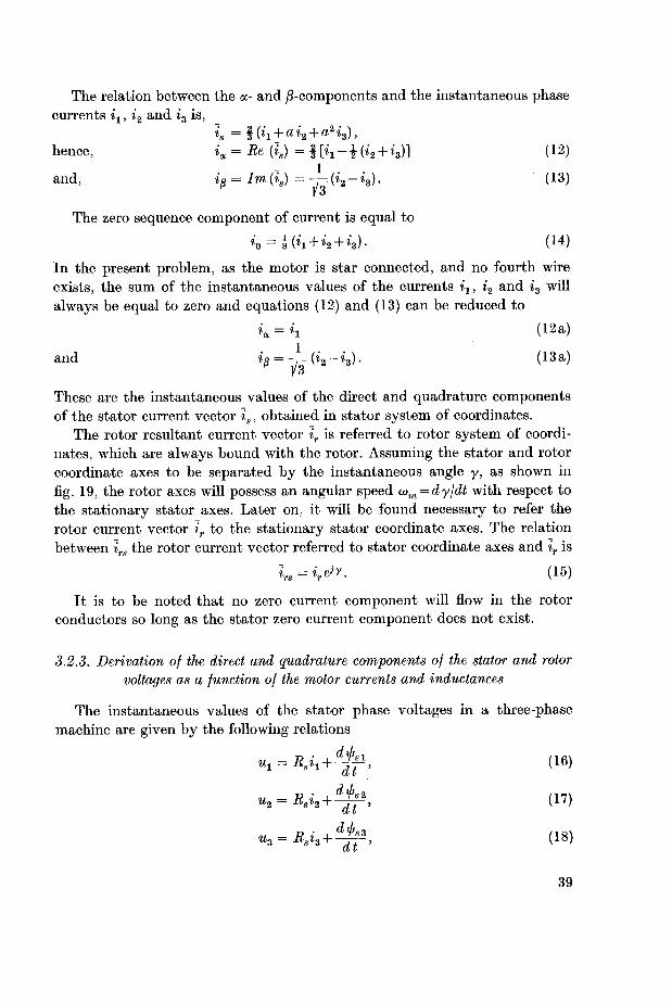
where,
and, a2 = e~^3 =-l-jl^-.
3.2.2. The direct, quadrature and zero components of current
The stator resultant current vector is can be resolved into the two compo¬
nents ia and io, the direct and quadrature components of current respectively.These are obtained by resolving the current vector is in its real and imaginary
parts along the a- and the /3-axes respectively, the real axis being taken to
coincide with the axis of the winding of phase "1" as shown in fig. 18. The
j3-axis is taken perpendicular to the real axis.
Resolving the resultant current vector is in its two components ia and ip is
achieved from the following relation,
»« = *a + /*> (11)
that is, ia = Be(is) and io = Im(is). This is physically interpreted as if the
resultant magnetic field vector created by the current vector is were the
resultant of two magnetic field components of two ficticious windings perpen¬
dicular to each other and energized by the currents ia and ip respectively.
+a
Rotor
Fig. 18. The stationary direct and quadrature axes
of the stator system of coordinates, the a-axis has
been chosen along the axis of the winding of
phase "1".
Fig. 19. The stator and rotor co¬
ordinate axes separated by the in¬
stantaneous angle y.
<am = the rotor angular speed =•—-.
38
The relation between the a- and ^-components and the instantaneous phasecurrents ix, i2 and i3 is,
\ = \ (h + ai2 + a2i3),
hence, ia = Re (is) = §[»i-i(*a + t8)] (12)
and, ip = Im(is) = — (iz-i3). (13)
The zero sequence component of current is equal to
h^iih + H + h)- (u)
In the present problem, as the motor is star connected, and no fourth wire
exists, the sum of the instantaneous values of the currents ix, i2 and i3 will
always be equal to zero and equations (12) and (13) can be reduced to
ia = ix (12a)
and ip = -=(it-ia). (13a)
These are the instantaneous values of the direct and quadrature components
of the stator current vector is, obtained in stator system of coordinates.
The rotor resultant current vector iT is referred to rotor system of coordi¬
nates, which are always bound with the rotor. Assuming the stator and rotor
coordinate axes to be separated by the instantaneous angle y, as shown in
fig. 19, the rotor axes will possess an angular speed tom = dy\dt with respect to
the stationary stator axes. Later on, it will be found necessary to refer the
rotor current vector ir to the stationary stator coordinate axes. The relation
between irs the rotor current vector referred to stator coordinate axes and ir is
Is = \^y- (15)
It is to be noted that no zero current component will flow in the rotor
conductors so long as the stator zero current component does not exist.
3.2.3. Derivation of the direct and quadrature components of the stator and rotor
voltages as a function of the motor currents and inductances
The instantaneous values of the stator phase voltages in a three-phasemachine are given by the following relations
n1 = Rsi1+djf, (16)
u2 = Rsi2 +^f, (17)
u3 = Rsi3 +^f, (18)
39

where Rg is the stator winding resistance per phase and ipal, i/is2 or i/«s3 is the
flux linking with the winding of phase "1", phase "2" or phase "3" respec¬
tively. Multiplying both sides of equation (16) by (2/3), equation (17) by (2 a/3)and equation (18) by (2a2/3) and then adding them we get
2 2 2 d-i^ + au^ + a2^) =^Ss(h + ai2 + a2i3)+-j-t(iljsl+atljs2 + a2il>sS). (19a)
Introducing the resultant current vector is defined by equation (10) as well
as the resultant voltage vector us and the stator resultant flux linkage vector
i/js in equation (19 a) gives
u8=Rjs + (lff, (19)
where !^s is a function of both stator and rotor currents and the inductances
of the machine. Equation (19) is written referred to the stationary system of
coordinates bound with the stator.
In a similar manner, the resultant vector equation of the rotor voltagesreferred to rotor system of coordinates is
Ur = Rr'l'r + ~J7' (20a)
where ifir is the rotor resultant flux linkage vector, it depends on both stator
and rotor currents and the inductances of the machine.
The relation between the rotor resultant flux linkage vector ifir referred to
rotor axes and iprs when referred to the stator system of coordinates is
$r = $„e-JY, (20 b)
where y is the instantaneous position angle of the rotor axes with respect to
those of the stator as shown in figure 19. The suffix "s" in i/irs means that it is
written referred to stator coordinate axes.
Multiplying both sides of equation (20a) by e?y and substituting ifir by its
value given by equation (20 b) gives
elyur = t>vBrlT + z>yj-% (frse~iv)
d ifirs .d y
~df~]~dt
or urs = Rr~irs + ~^f-j ojm<prs, (20)
where a>m = dyjdt = rotor angular speed.
40

Equations (19) and (20) represent the stator and rotor resultant voltage
equations in vectorial form, both being referred to the stationary stator
coordinate axes.
The relations between the vectors ifis, ifir, stator current vector is, rotor
current vector ir and the inductances of the machine are,
<AS = Lsis + eivLmir, tj>r = e-irLmis + Lrir, (21)
where, Ls = La + Lm = Lr, and La is the leakage inductance, while Lm=l.5Land L is the main inductance per phase.
Each vector appearing in equations (21) has been referred to its own systemof coordinates. Refering all quantities to the stator stationary axes, equations
(21) become,
i's = Lsh + Lm is > "Ars = Lm h + Lr is (22)
Substituting equations (22) into equations (19) and (20) gives,
urs = Mrirs + Lm-=j + Lr—j- ] tom(Lmis + Lrirs).
(23)
To determine the direct and quadrature components of stator and rotor
voltages for stator axes, substitute in equations (23) the following relations,
us = ua + j Up , urs = u0Lr + jupris =ia + jip, irs ^iar + iiflr
then, equating real and imaginary parts on both sides gives,
ua = Btia + L8^ + Lm^, (24)
up =Baif + L,^f + Lm^, (25)
(I i (L i
v-ctr = Sriar + Lm-jf + Lr-^+u}m{Lmip + Lripr), (26)
«/3r = K^r+ Lnfjf+ Lr-^ - ^m(Lmioc + LrLr) (27)
These are the equations defining the direct and quadrature components of
voltages and currents of the three-phase machine after being transformed to
the equivalent two-phase one. It is to be remembered that all quantities
41

appearing in these equations, (24).. .(27), are referred to the stator system of
coordinates. From these equations, it is clear that the rotor components are
independent from each other only when o>m = 0, that is, the motor beingstandstill.
Normally, induction motors are designed to operate with the rotor windingsshort circuited, that is, the rotor terminal voltage is normally equal to zero.
In such a case the voltages uar and Ugr on the left hand sides of equations (26)and (27) are equal to nought.
Substituting uar and uBr with zero in equations (26) and (27), then, elimi¬
nating diarjdt and digr\dt from equations (24) and (25) by substitution from
equations (26) and (27) and rearranging these equations we get,
di„ 1.5+ ct 1.5„
.
, rrl 1.5
. .\
dt (3 + o-)aI
dis 1.5 + (t I"„
.1.5
„.
, „TI 1.5
. .\"
diar_
1.5 dia [" Br .I 1.5
. .\
~dT= ~Tb^~di~ [JiJ+a)Lt"+U)m\i'JTa^+^rf
dip,._
1.5 dig I" Er .I 1.5
~JV=
~l.5 + <j~dl~ [(1.5 + a)L^r~aJm\l.5 + a,+ ln
(28)
(29)
(30)
(31)
These are the differential equations describing the direct and quadrature
components of the stator and rotor currents. All quantities in these equationsare referred to the stationary axes bound with the stator. As stated before,
the real axis coincides with the axis of the winding of phase "1" of the stator.
3.2.4. The electric torque of the three-phase machine
In a two-pole three-phase machine, the relation between the electric torque
Me, the resultant stator flux linkage vector ifjs and the stator resultant current
vector is is
Me = WaXi8 (33)
The cross product on the right hand side of equation (33) can be easilycarried out by assuming three unit vectors /, g and h along the direct-, the
quadrature- and the machine-axis respectively and by substituting for ^sand is the following two relations
</>* = >P<x + J>PfS> (34a)
42

where i[>a= Lsia + Lmiar,
hence, writing equation (33) in a determinant form gives
3ir ^ *3
Me = ^a h ° =2^^-^K)- (34d)
For a machine having pp pairs of poles and after the substitution of ifiaand ifia as given by equation (34c) we get
^e = f Lmpp(ipiar-iaiPr). (34)
3.2.5. TAc mechanical equation of the system
The mechanical system under investigation is a three-phase induction
motor supplied from the three-phase power inverter. The motor is mechani¬
cally coupled to a d. c. generator, and the latter is loaded by a resistive load.
Assuming the mechanical torque at the motor shaft to be Mm, the moment
of inertia of the moving parts is J, p being the coefficient of friction and com
is the rotor angular speed in electrical radians per second, the following relation
can be written,
M<~M" = i{jdir+">-)' (35)
where, Me is already defined by equation (34) and pp is equal to the number
of pairs of poles of the machine under test.
3.2.6. Check of the system equations
The differential equations relating the currents and voltages in a three-
phase machine reduced to a two-phase one applying the two-axis theory are
given by equations (28)... (31). To check the validity of these equations, two
cases will be checked assuming the machine to be supplied from a source of
sinusoidal voltages. The cases to be checked are the derivation of the short
circuit current Icl as well as the no-load current I01 of the machine and com¬
paring the results with those obtained from the classical equivalent circuit of
the three-phase induction motor. For the derivation of the current Icl, the
rotor angular speed wm is equated to zero, while, for determining I01 all losses
will be neglected and the rotor will be assumed to have an angular speed wm
very close to the synchronous speed, that is, wm^ai0.
43

3.2.6.1. Rotor being locked
Equations (24) and (26) will be rewritten with "?'w0" substituted for d\dtand uar = 0,
Ua = BsTa + (l.& + a)}a>0LIa+1.5ju>0LIar, (36)
0 = Br7ar+l.5jw0LIa + {1.5 + a)jw0LIar (37)
and by solving these two equations we get,
or' Ia =T^TTTTTW^OT^'
(38a)
where Xo = a)0a L = leakage reactance, and Xm is the magnetizing reactance.
As the motor is star connected and no fourth wire exists, it can be easilyshown that Ia = I1, while Ua = U1 in case the induction motor is being suppliedfrom a balanced sinusoidal three-phase system of voltages U1, U2 and U3,hence,
This is the short circuit current of a three-phase induction motor, derived
from the equations of the equivalent two-phase motor. It coincides with the
value of Icl calculated from the classical equivalent circuit shown in figure 20
for the case of a slip s = 1.
3.2.6.2. Rotor having synchronous speed
At synchronous speed, o)m = w0 and s = 0, hence the rotor currents will be
equal to zero, that is, Iar=Ior = 0.
Rewriting equation (28) and substituting:
Ip = — (I02 — ^03) — ~ 1 Ia as can be seen from equation (30) for wm = tu0,
Ia = I01 and Ua = U1 we get,
(1.5 + tr)
/WoL/01-(L5 + ff)2_(15)2
1.52
Ul-B°I*-(riTJjja,oLI<<01
0r» -*01 ~ Tfln/Y _L V \' ( '
44

Equation (39) gives the no-load current 701 of the machine assuming the
rotor having an angular speed a>m^co0 equal to the synchronous speed. The
same result can be obtained when calculating the no-load current from the
equivalent circuit of the induction motor shown in figure 20, in this case the
slip s is assumed to be equal to zero.
R/hs)
Fig. 20. The classical equivalent circuit of a three-phase induction motor, the core losses
have been neglected.
45

46
-p(-vui~Ud).=
%D2
tfd),-£("«!-=lD2
0
%DX\vl4CvJ~~ux
(44)Ud).^{-vux-=iDi
and,
(43)
(42)lD2--h]dt>+-l„2
i
\dt
^vi(41)vuJ,+^iUa
=
di"*
(40)TdlUd-VUl],=d-t
are,currentsandvoltagesphasemotorthecurrents,diodes
feedbackthecurrents,valvecontrolledsilicontheinverter,powerphase
three-thesupplyingUdvoltagec.d.therelatingequationsdifferentThe
machine.
theoftorquetheandcurrentsphasemotortheinverter,three-phasethe
fromsuppliedvoltagesphasemotorinductionthecalculatetotreatedbewill
examplenumericalaanalysistheoreticalforegoingtheclarifytoorderIn
exampleNumerical4.1.
Gerecke.Ed.Prof.ofdirectiontheunder
Zurich,Technology,ofInstituteFederalSwisstheofElectronicsIndustrialand
ControlAutomaticforInstitutetheatpresentiswhichandU.S.A.,Jersy,New
Incorporated,AssociatesElectronicthebymanufacturedequipmentputing
com¬analogueprecisiontheis,that[16],ComputerAnaloguePACEtheon
simulatedbetoismotorinductionthebyloadedinverterthree-phaseThe
currentsandvoltagesphasemotortheofcomputationAnalogue
IVSECTION

These are equations (5). . . (9) derived before in Section III relating the different
variables of phase "1". The same equations can represent phase "2" or phase
"3", only changing the suffixes to correspond to the case to be considered. It
is to be remembered again that the valve currents ivl and iv2 are controlled
to flow alternately for intervals of T/2 and that the diode currents will flow
only when either diode is forwardly biased. The instants of firing the silicon
controlled valves V3 and F4 of phase "2" are delayed T\2> from those of V1and F2 of phase "1", similarly, a delay of T/3 exists between the instants of
firing of V5 and Ve of phase "3" and those of Vs and F4 respectively.The differential equations of the three-phase induction motor relating its
input voltages to the stator and rotor currents, the motor being transformed
to a two-phase one using the two-axis theory, and all quantities being referred
to the stator coordinate axes are given by equations (28)...(31). Equations
(34) and (35) describe the electric torque and the mechanical equation of the
system respectively.The numerical values of the different constants appearing in the foregoing
set of equations to be substituted in order to check these equations by solvingthem on the analogue computer are,
Ud=30V Rr = 13.3X3
Ld = 22 mH L = 0.492 H
R = \Q a = 0.0688
C = 200/^F J = 0.01117 Nms2/radv = 0.165 P = 0.00186 Nms /rad
Rs = 1SQ
Analogue computing will replace the physical system by another which has
the same mathematical formulation as the original system, but which is easier
to manipulate [17]. The basic physical equations will be followed as closelyas possible in the machine set up.
4.2. Scaling of the system equations
The system equations are arranged in a form in which the analogue com¬
puter, being a general purpose one, can solve them. These mathematical
equations describing the physical system have been derived using physical
laws, experimental results and reasonable simplifying assumptions. Before
scaling, an upper boundary for each variable is to be chosen, being as close as
possible to the actual maximum. The choice of amplitude scales is generallybased on the knowledge of the physical problem under investigation. Hence,
suitable scale factors have been chosen in such a manner that the machine
47
variables will not exceed + 100 V to avoid saturation of operational ampli¬
fiers in the analogue set up. The following table shows the amplitude scale
factor taken for each variable. Small letters will indicate the physical variables,
while capital letters are machine variables (Volts):
Machine variable
h = (2.5 it)
In = (&iD)
u1 = («i/8)
ua = K/8)
h = (7.5h)
h = (7.5 ia)Q = (com/4)
It remains now to choose the suitable time scale factor "c" relating the
physical time "t" and the machine time "t". The choice of "c" is limited bytwo important factors. The first one is the frequency response of the eight-channel recorder available for plotting the results. The normal frequency
response of this recorder is fiat up to approximately 40 Hz. The second factor
to be taken into account in choosing "c" is that the relay amplifiers, with
which the PACE computer is being equipped, will be used to perform startingand stopping of the valve currents Irl. . . 7,.6 during computation. The switch¬
ing time of such a relay amplifier unit amounts to one millisecond. This is
highly comparable with the period of the physical problem which is 20 ms for
/, = 50Hz. Therefore, a time scale factor "c" = 100 has been chosen to get rid
of the two mentioned limiting factors, hence,
T = ct = lOOt
where r is the machine time in seconds, that is, the machine will compute
with a frequency of 0.5 Hz to ensure a high accuracy regarding the recorder
response and the switching time of the relay amplifier units.
Substituting the constants of the problem just mentioned before in para¬
graph 4.1 of this section, then, introducing the different scale factors chosen
for the different variables in the mathematical equations (28)...(31), (34),
(35) and (40). . .(44), the scaled equations of the problem under investigationare obtained,
^=1.1361^-1.495^, (45)
^=1.136^+1.495^, (46)(It
Vx =-j(7J01I1+l.9ID1-3.8Ivl-\.9ID2 + 3.8lv2)dT, (47)o
Physical variables Scale factor
«>i. -V6 2.5
lDi- -%d6 «'
0} 4
48

+ 100V ""•
x-v ^^
®—cr^o-(P0flU-(a oo\
10.3S62 la* xar;
Fig. 21. The computer connection diagram simulating the three-phase power inverter loaded by an induction motor, the potentiometer settings are tabulated in chapter 4.5. MOJ-MOK,M1J-M1K, and M2J-M2K are the three relay amplifier units actuated by the signals X4, x& and xe respectively supplied from the gating circuit given in fig. 23.
(1) the three-phase inverter.
(2) transformation of U\, U2 and Us into Ua and Uo.
(3) simulation of the induction motor.

10 (0.5 17^-0.6580 C^), (48)
10(0.5 Ua + O.mSOUj), (49)
9.058 Ua- 2.717 Ia + 1.921 Iar + 0.4457^(0.9562/^ + IBr), (50)
9.058^-2.717^+1.921/^,-0.4457^(0.95624+ 4,.), (51)
0.9562—^-[0.1724 Iar + 0.04J2 (0.9562 IB + IBr)], (52)
0.9562-^-[0.1724Ior-0.04&(0.9562 Ia + JTar)], (53)
[0.01760 (/a ISr - Ip Iar) + 0.4475 Mm + 0.001667&)]. (54)
4.3. The computer diagram and the patching of the problem
From the scaled equations (45)...(54) the computer diagram shown in
fig. 21 is drawn showing all details of the problem tackled. Equations (45). . . (49)deal with phase "1" of the three-phase inverter under test. They can also
represent either phase "2" or phase "3", only the variables Irl, Iv2, ID1,
ID2, Ux and 4 are changed to 4s. hi> ^d3> ^z>4> U2 and 4 or hi,> ^.-e. ^ds>
ID6, U3 and Iz, respectively.In fig. 21, a definite adress is given for each element in such a way that
minimizes patch-panel clutter. The elements used in the present problem are,
42 operational amplifiers used as summators or inverters,
13 integrators,4 time division electronic multipliers,
68 potentiometers, 12 of which for performing a static test,
3 relay amplifiers.
The operational amplifier of the PACE analogue computer is made of a
standard d. c. amplifier and an operational network which decides its function.
Two different types of operational networks are available with the operational
amplifiers: a combination network and a summing network. When used with
the combination network, the operational unit can be used as an integratoror summer, while with the summer network it can only be used as a summer.
Each unit is chopper stabilised, has a high d. c. gain of about 108, a wide band
width performance up to 25 kHz and a low noise level of 5 mV peak-to-peakmaximum within amplifier pass band.
Time division electronic multipliers have been used because they have
excellent characteristics as regards accuracy and frequency response.
Idi =
*D2 =
dladr
djA=
dr
dlar=
dr
dlgr_
dr
dQ
1r~
49

The three relay amplifier units are used to start and stop the valve currents
Ivl... Iv6 in the computer set up at the correct instants simulating the physicalcircuit. The operation of a relay amplifier is clearly explained in fig. 22. The
switches change position according to the polarity of the input signal xi, x5
or x6 respectively, supplied from the gating circuit of fig. 23. The switchingtime is a one millisecond and a typical unit is capable of 100 operations per
second. Hysteresis of the switching point is smaller than 5 mV. The input
impedance is 100 kQ. The PACE relay amplifiers are completely transistorized.
The transistorized gating circuit for generating the three square wave
signals xt, x5 and x6 which are always J/3 period apart, has been speciallyconstructed to drive the relay amplifiers.
ao \l00kS2
.0 \100kS2
Fig 22. The relay amplifier: input "a" is supplied from the gating circuit of fig. 23 with
Xi, xs or #6 while input "6" is earthed.
(1) high gain operational amplifier.
(2) relay coil.
(3) and (4) are two double pole switches.
4.4. The three-phase transistorized gating circuit
This circuit is the same as that described before in chapter 2.3 with some
modifications to suit the purpose for which it is to be used. As it is intended
to use it for gating the valve currents in the analogue set up, and the computa¬tion frequency has been chosen to be f's = 0.5 Hz, suitable elements have been
used to extend its frequency range to very low frequencies. The frequencyrange of this modified circuit extends between 0.01 and 300 Hz.
Fig. 23 shows the connection diagram of this modified gating circuit. The
input sinusoidal signal xx to this circuit is obtained by solving the differential
equation d2yjdt2= —n2y. Two integrators, an inverter and four potentio¬meters, as shown in fig. 24, have been used to solve this differential equationon the analogue computer. The frequency of this sinusoidal signal x1 is adjustedto be equal to 3 f's, where f's is the frequency of computation.
As shown in fig. 23, the signal xx is used to trigger a Schmitt trigger, thus
50

*1®—*<>—Wka_
Fig 23 Connection diagram of the gating circuit generating the square wave signals Xi, X5 and xe each of frequency /»' and which are T'/3 apart. These are the input driving
signals to the three relay amplifier units given in fig. 21.
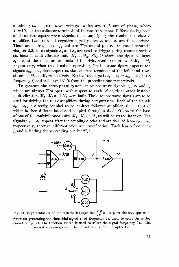
obtaining two square wave voltages which are T'j2 out of phase, where
T' = ljj's, at the collector terminals of its two transistors. Differentiating each
of these two square wave signals, then amplifying the result in a class-5
amplifier, two trains of negative signal pulses x2 and x3 are thus derived.
These are of frequency 3/, and are T'/Q out of phase. As stated before in
chapter 2.3, these signals x2 and x3 are used to trigger a ring counter havingsix bistable multivibrator units M1. . .M6. Fig. 23 shows the signal voltages
s1. . .s6 at the collector terminals of the right hand transistors of M1. . .Me
respectively, when the circuit is operating. On the same figure appears the
signals s13. . . s18 that appear at the collector terminals of the left hand tran¬
sistors of M1.. .M6 respectively. Each of the signals s1. . .s6 or s13.. .s18 has a
frequency f's and is delayed T'\& from the preceding one respectively.To generate the three-phase system of square wave signals x4, x5 and x6
which are always T'/S apart with respect to each other, three other bistable
multivibrators M7, M8 and M9 were built. These square wave signals are to be
used for driving the relay amplifiers during computation. Each of the signals
s13.. .s18 is directly coupled to an emitter follower amplifier, the output of
which is then differentiated and coupled through a diode OA85 to the base
of one of the multivibrator units M7, M8 or M9 as will be stated later on. The
signals s19. . . s24 appear after the coupling diodes and are derived from s13.. . s18
respectively, through differentiation and rectification. Each has a frequency
f's and is leading the succeeding one by T'/6.
Fig. 24. Representation of the differential equation -=-| = —n2y on the analogue com¬
puter for generating the sinusoidal signal x\ of frequency 3/s used to drive the gating
circuit of fig. 23. The function switch is used to select the signal frequency 3/s. The
pot-settings are given in the pot set tabulation in chapter 4.5.
51

To trigger the multivibrator M7, generating the square wave signal x4, the
signals s19 and s22 being T'/2 apart, are coupled to the bases of the two tran¬
sistors of M1 respectively through the diodes OA85. The diodes will pass
freely the negative pulses while the positive ones will be rejected. Similarly,
M8 and M9 are triggered from the pairs of signals s21 and s24, s23 and s20 respec¬
tively. The signals x4, x5 and xe are taken from the collector terminals of the
right hand transistors of M7, Ma and Mg respectively. Each of these square
wave signals is applied to an emitter follower stage that functions as a buffer
stage between the relay amplifiers and the multivibrator units M~, M8 and
M9 respectively.
4.5. Potentiometer set tabulation
The following table gives the adress of each potentiometer used in the
analogue set up as well as the corresponding coefficient it is to be adjustedto give,
Pot adress Coefficient Pot adress Coefficient
POO 0.1500 Q 00 0.2272
P01 0.4475 Q01 variable
P02 0.1495 Q02 0.4441
P03 0.6580 Q 03 0.1500
P04 0.3800 Q04 0.3800
P08 0.1900 Q07 0.1900
P 10 0.1495 Q 13 0.6580
P 13 0.3800 Q 14 0.1495
P 14 0.9058 Q 17 0.1900
P 18 0.1900 Q 20 0.5770
P 20 0.3800 Q22 0.7895
P 21 0.1495 Q23 0.6580
P 22 0.1974 Q24 0.1495
P 23 0.3800 Q 27 0.1900
P 24 0.5770 Q 30 0.1495
P 28 0.1900 Q 31 0.5000
P 30 0.3800 Q 32 0.9562
P 31 0.7701 Q33 0.4000
P 32 0.2717 Q 34 0.4000
P 33 0.1921 Q 35 0.8660
P 34 0.1724 Q 38 0.8660
P 35 0.2717 Q42 0.3333
P 37 0.9058 Q 52 0.7701
P 38 0.9562 Q 53 0.7701
P 39 0.1921 Q54 0.1760
P 41 0.3333 Q 63 0.1667
P42 0.6667 Q73 0.4457
P 47 0.1724 Q 74 0.4457
52

4.6. The static test
The static check is the most complete check that can be done quickly and
without major patching changes on the computer. This check shows up errors
that may have occured in the problem preparation or in the operation of the
machine elements.
This static check is carried out by precalculating from the original equations,
by hand or by a desk calculator, what the voltage should be at the output of
every component, subject to a selected set of initial conditions. Initial con¬
ditions are inserted on all integrators and the pots setting these initial con¬
ditions are fed by the test reference voltage. This voltage is only connected
during the static test, that is, when the static-mode button is depressed. It is
necessary to state here that all initial conditions of integrators have been taken
equal to zero when the computer is in the operate-mode. Now, as the static-
mode button is depressed, all integrators will receive their assumed initial
condition voltages from the test reference voltage, and the condition is as if
the computer is in the reset-mode. The precalculated values are comparedwith the actual computer component output voltages.
The following tabulation gives the adress of each integrator, the pot used
to insert the initial condition and the pot setting:
Integrator Pot adress Pot setting
A 00 P05 0.25
A 10 P06 0.20
A 31 P07 0.30
A 40 P 09 0.40
A 20 Q 05 0.30
A 11 Q09 0.40
A 35 Q06 0.30
A 45 Q08 0.40
A 21 Qll 0.30
A 30 Q10 0.20
A 60 Q12 0.20
A 80 P 12 0.50
Calculated and measured outputs at the different elements in the analogueset up are given in the static check tabulation that follows. It is clear from
this table that computed and measured values agree and hence the differential
equations solved by the machine correspond to the original equations. The
operational amplifiers having zero output voltage have been separately checked.
53

Static check tabulation
Component Calculated Measured
adress output output
A 00 -25.00 -25.01
A 01 -30.00 -30.01
A 02 -15.00 -15.00
A 03 - 0.42 - 0.40
A 04 0.00 0.00
A 07 28.16 28.14
A 08 - 1.84 - 1.83
A 10 -20.00 -20.03
A 11 -40.00 -40.01
A 12 - 7.89 - 7.88
A 13 0.00 0.00
A 14 20.00 20.02
A 17 - 4.74 - 4.74
A 18 -34.74 -34.74
A 20 30.00 30.01
A 21 -30.00 -30.01
A 22 - 6.40 - 6.41
A 23 0.00 0.00
A 24 -20.00 -20.01
A 27 1.84 1.86
A 28 -28.16 -28.16
A 30 20.00 20.01
A 31 30.00 30.00
A 32 -30.00 -30.01
A 33 -11.31 -11.31
A 34 11.31 11.31
A 35 30.00 30.01
A 37 - 5.77 - 5.77
A 38 -30.00 -30.01
A 39 68.68 68.69
A 40 40.00 40.00
A 42 30.00 29.98
A 43 - 5.98 - 5.96
A 44 5.98 5.98
A 45 -40.00 -40.01
A 47 -68.68 -68.70
A 50 0.00 0.00
A 51 0.00 0.00
A 52 -40.98 -41.00
A 53 10.98 10.98
A 54 -24.00 -24.03
A 60 20.00 20.00
A 62 - 2.00 - 2.00
A 63 0.20 0.20
54

Component Calculated Measured
adress output output
A 64 4.47 4.47
A 70 9.01 9.00
A 71 0.00 0.00
A 72 - 20.00 -20.02
A 73 80.00 79.95
A 74 80.00 80.00
A 80 - 50.00 -50.01
A 81 15.00 15.00
A 82 -15.00 -15.01
A 83 0.00 0.00
A 84 0.00 0.00
M1G 3.39 3.39
M2G 20.61 20.63
M3G - 8.00 - 7.99
M4G - 8.00 - 8.01
Note: The gain of the operational amplifier A 54 has been divided by a factor of 10
during the static test to avoid saturation of the unit.
4.7. The eight-channel recorder for plotting the results
Eight variables can be plotted simultaneously against time, as represented
by the motion of the chart paper. The hot wire method is used and records
are obtained directly on rectilinear coordinates. The eight channels are identical
but each is independent of any other. The normal frequency response of the
recorder is flat up to approximately 40 Hz. However, for applications where
frequencies higher than 40 Hz are of interest, it is possible to improve the
frequency response between 40 and 70 Hz by means of a frequency response
control. A frequency f's = 0.5 Hz has been chosen for solving the problemunder investigation to avoid any errors that may be present due to the limited
frequency response of the recorder.
A quick and accurate time calibration is obtained by a timer unit writingone pulse each second with a special thermal pen, independently from paper
speed. This enables to read rapidly the time scale without having to remember
it, after records are done.
The eight-channel recorder is connected to the computer, and the "initial
conditions", "hold", and "operate" controls are slaved. Hence, it is possibleto control the computer indifferently from the computer or from the recorder
by means of push buttons. This is very convenient, since it enables to stop or
start computations while inspecting the results.
55

4.8. Problem investigation on the analogue computer
As stated before, the differential equations have been carefully scaled, the
computer diagram is drawn following these scaled equations as shown in
fig. 21, the problem is then patched on the pre-patch panel and introduced in
the patch-bay on the machine. A static test has been executed to be sure that
the differential equations solved by the machine correspond to the original
equations as stated before in chapter 4.6. The machine is now ready for trial
runs. Suitable speed and voltage sensitivities of the recorder are chosen.
It is necessary to state here that the initial conditions of all integrators in
the main problem have been assumed equal to zero. The three-phase tran¬
sistorized gating circuit, described in chapter 4.4, is used for starting and
stopping the valve currents Il.1. . . 7r6 by actuating the relay amplifiers.
4.8.1. Motor starts under no-load condition
To start computation, switches R01 and R02, shown in fig. 21, are left
open, that is Ud = 0 and the applied mechanical torque Mm = 0. Then, the
computer is switched in the operation-mode thus generating the sinusoidal
signal xx required for driving the gating circuit supplying the three square
wave signals x4, x5 and xe which are T'/3 apart. These are the input signals to
the three relay amplifier units that start and stop the valve currents Ivl. . .It,eat the correct instants during computation. The action of the relay amplifierswill simulate the silicon controlled valves of the physical system to be tested.
As the switch R01 is now closed, the computer being in the operation-mode, the d. c. voltage Ud will be suddenly applied to the circuit. The three
relay amplifier units energized by the signals xi, xb and xe from the gatingcircuit will start and stop the valve currents at the required instants and the
three-phase voltages m1 , u% and w3 are obtained. Fig. 25 gives the set of variables
Ud, u1, ia, iar, irl, iD1, Me and com recorded by the eight-channel recorder for
the case when Mm is equal to zero, that is, switch R02 is left open during
computation. From these records it is clear that the rotor current iar decreases
as the angular speed a>m increases and diminishes to a very small value as the
steady state condition is reached.
During this run, and after steady state is reached, a sudden torque Mm is
applied by closing the switch R 02. It is clear from fig. 25 that the rotor current
has increased to a remarkable value after the application of Mm. This is a
natural result due to the fall in speed as can be shown from the record of wm
on fig. 25.
56

~-
MM'
"
:- - —
_; :=~~
J_ X _J t= -i~B~-
,- P<^I ] -
-r ""
i. .r - -
i i
1
H" |I ,
-
" ^
~
1- -r1 3 —i u
"\ r „
-f
,-4 KJ
.
/1
"
^J--^
_
-1: -~i
"±
r3
to
1
f
u i u
1
"-
| i T7 r~T r _i. -
=
i-,t :
;
^
*—
jf 1,F
~ ^
1
?-* \j
{v~ J
;_ r,^"
" 1 "*"
r 'i rJ
=
'.
» J-|y ^ lZ' "
—
I j i, i
*"" 1-i_^
= j i | j . .
~
' 1
—
. . "1 = i n 11 1 i
-
~^
1
1 'Miii 1 j-
~=
zl-?
w
*H-,-
.A .
-
^ i i
I
ul- ;ii"
j- i
rT-
^
v - ^- -e3 ^ r.
r
"r
*^#-
'
J /- --
1-' r- {
'
" "
-
--
'
- b-
.
< 1-= I
1A /', i /ji7
kU l-
1 \
--
-
'
/ \i
-01 | -
T=- -^ *r*r
- 1 i
v \fV N ' k/
3
-f-1 M I \
'
-
j ,i -. _j_.
I - L_ j -=
iMH V H BRUSH INSTHUMCNTB 0 VISMX Of CLEVfU CO«»OWlT)OM CLKVILAMO )UK KINTED IN u A
r
] I—
1
! w1-
^
«^>,
>^
^n
uV f ^* -
1 """ ' *" jJ" - \^
"
=-r-
•>
-j
r
u 1-1U O ^ *.- ^ \- V ^ c^ V
E"- ^~ *- V
"
* ^ ' Xtl~
^
zA—
*-"„ f i f- /
'
--
J T T J1
_
1 " J__ =
1 r
i I '.
^ T?
1 = ip +"
-1
~i 9 r \ J r b i/1*• V / I ./ / ^ u I i> / ,J
...
\/ i ^"J
' ^ fi^ J* ^ i^ \ i-
-
=
az\
_.
'
:.,
^~
^ ^
J •j j **- T M^
--
1
- ^
-
ij
- OP 00 ^-i.; .
if- <J
1 I'lff
Fig 25 Motor started under no load condition, after steady state is reached, a torque Mm = 15 Nm
is applied The scales are.
Vi 1 div £ 50 V
ui 1 div =~ 200 V
ia 1 di% =~ 10/3 A
»ar 1 div =~ 10/3 A
in ldiv =? 10 A
tm 1 div "= 5 A
3f, 1 div =^ 9 83 Nm
aim 1 div =? 100 rad/s

:-— - -
— " :-
:
L.
. _......
.
.-=--
-: j_:...
" -1,
L..... .
-
:.
:3
:
-
=_;.; _ . _...
.:_:_::.
-
_
- - =. - - -=
- :^ = = —...
-
V
!* ' : 1 X f :j fP I i
'^ x l-' -_r j. ^^hJ1'i ^Il'Tl jir^i -I t f J4 \
1'
• J .• J / j J '< V J • V r " ^ lJ V ^ *
-
: 1.
1 '
E
- •
-I"- -
"
= =
L it ±± ~
C'l]u j'
:•' -L V^^- ^-£^£5-^-, >c
;' .-**. V .''-!*
- "
_ j ,
^
J ,
^. ^
. ^.. . _
J
.: =.
- -
=.
l_
:
^
:.
"
-
. . --*:
,. .-. ---^ — — ~ — r
-
E—i"
- —
t _--{. - =
—- =
r 4 i ,• f\ '\ j a ,; a a / a ,--
. ^
-: CL
-
: *:'
\ -r -5'
- * £— £^ -4 H- ^ „ ^. 1 3(1^^
i""
v l_\ ^ sVi L\ i t v l v_, ,
"
'
-
-
fc_ 11 '~
BRUSH INSTRUMENTS o *is on o( clsv ti cowobatkw cuvtt>NO Otw
p-f- := = = = = = -~:^__. .. j j . _ .
-
~
|r=. .
C' ±Z "
^^. . , I . . , u,. 1
'
*
M ^ ..T^: 4-1
-t ^/1t-4- 4- -^- - "• ^ J
- \i ' ^ I'' l- ^' \. U -*-*- ^
E. - «^ '^ -
"
—
- -
-
=
f~j
' * T " 1 f"
T
—---
-: j .--.-_
: 1 ..
r1 "
'
,
"
. -I n"' "
/ ; 'J ]'r i-' T .V ( r J.
„
>'
r* -'"lr~^l' / V ' iy- II ' \t V1 iy ! ^ / ^ 1st
....
- .
-
EE"
—
=-- ...-.__-..: : "-.::.:"- -- .
.. . .=
-
"
"^
— .--- -----' " ' '
-- . ._
=1.
:
"
:-
=_ : :. _ .
_ . ..
"
h^ t -
r• *— S1~ Hr—
r -
.r
-
:
=- -
.--:-
' " _
- ;--
._- -- — _._.___._
_.. ..__._~
=="
: ~:.
: "H T-
=~
'
jF .--.. .
B- - -L >ir~"
—--
'
- —.
_..._-
^—
—, ___, __
-: t ..-
t -.--.-.
. . . . _
J
.
=
1 I HI I II 1 1 itlMIl 1
Fig. 26a. Motor started with load being applied, C/<j = 30 V and Mm = 2 Nm. The scales are the same
as given in figure 25.

11 Li 1 I 11 Lin] ill Ml 1 M M'Miiii.."".": .7J *~~- '"
:_
:=r^
"- -CH"" J
:-
-.-
_ _
v :,
-
-: -
._:-
•
_
|.
--.:-
-=
^s^rQni" a r^ X~-* ^ TM^ii-^^tC ^Jt^^tf l*?-" ^Dt " =
l'.t' :' a Li a / &. i'l, l_ ^ _+, ^. „ _t j_
_
' .iLjiiL ^-1L 4J-L -j-"^^
. . - . "it ~
--^=
_
: -
||"~
--
_
=
1
= =_- _: 1 | -:—-
— - -
- -
= = r
"
--:':-.
" "
-:
~
- .
•
-=
J-^jtt^ Ki>$rj et* * „-~
*: Jt==
--"fc :.
" II^T -'rh ."••T.I..
f.Vi^V^^ "^^fe J\Pb^± a^e-i^* N_
-: 3 oi n r^ 5 * ^^ 4: =-
~ lI"
'
: -:— -
-_
- -__-
-_:—
J - -: --' -
'
=
'
-
: z
' -
-
1 / 1 1 A \ / \ li A \ / r 1 a
~~
- -
'
^inruiiLcii lZ7*t iv 57M iV^^,v^ .__._;_ ._..,_ =^ia.eL^JJ7 tMlt ji, Q^^LHIv ^£*=
"^° *^ ^-""''^'",'"0-"jf**
- -
*vit\ prstl vi!^ ^A- 7T
1"
J = =— —
^ i :"
OM CUVVUh* D uc PBMTS H u S *1BRUSH
— ;= ^
.
,_
t 1_ t1 '1V r
^ ** \* w r- \* S-' \J
-
r s. T
- V
rj "- ^ /
*- 1t
H
,
-\ ?- V1 E t-* "71 /' ') V I
1
J / \ J .
' I J f- r 1 V / s. V iV \j s \. V / Ti
'
ft t;
-+- S415 M
!
i_
—
-
tt(, ? T
_
1 r
Fig 26 b Motor started with load being applied, Ut = 30 V and Mm =15 Nm. The scales are the same
as given in figure 25

Ill '
—
~--- -
T. \ .
-
.!
= -- s... V&'i ft a"4 \ ft 1 ii f; ir A A j A A { ft ft j ft, ft 1 \ ft j I ft j IS ft | ft ft 1. ft ft <
= F."n =, ffli ; Tphf V. ;h ; 71 :; \7l.-i ttH: TTTi: Ttli fill T'f I'll fiTfrftf i'
=
v
-
"If ;: W: ,Ti. ;; -i ; ; "H ;; iMqj.vhp;: inH|;T:; ||t]f ;!
! ljII- o-1 tl^'^i Hi s/ u \ i/~i?l ru 1 Tvi ftn" ; v1 ru riM/i'-j;:: "_"-_-_"-'__""" j
-
_.--- . .
- j-1
._.
** -3 >o
'
!
"
: :-.,._- -—-- X^ —.='
-
..___
. _. .
^
i* r* &
~
c* o < p* _, d „ o ^! ;
- * i : \7,
U ^7 v? ^ ^ ^ ^
:''
n. O O.
£ 1 t jI
a a a >0 i_ <a 4 ;.,
b> ^ iy ".' 1 I -y t? E7 C^
:~'
"
;
^ =:-
-
:"
"-';"-... !|e:
~
i i1:
-
: ^_ r- ^_ ,---; ,- ! \ ;-.,-. 1 £j, o • £J ^ Q /V £S ^ £S r» /^ /V A ,« L_ a*--: *=---- v-- c? b •„ b p; b n; b ^ b b b b b b'
....
:
^=
~
- =-
.._._
2T i
A fc 5-M
P-
b~
A I:
P^
-L-
r
\ "*:"(
n
P
Uf
b
Ji-ft
r*-.
i:HJ
*==- U
I'if
f"r-
i3
,/
CVL^AAAJ
L'
. V ,- V. ^- V. ^ -v.-
1rt
C
y-
t
jj„ ^_ 0.
V=-
m
Q4
Mu
"'• 1 ;
"
j ; :--
T Ji-
'
j t ! =
L
I~ -+--; -
u|- p I [ \- t' -(—- i i \ ;" i T 1 -ly, -i
i_'' t ij « A A a a a Ai4.a^u^'„L i L L I 1 L i- \ 1 I- I i L i. i i V A =
--
^ '- t r/ C ry v ""'^"" / WA ^%~ ^A C'"'' t° t'"- t- ir- 1c 1,^ 1^ V U -i£ 1^ \--_ I- I-" I»r l«r.I -- 1
= ^2.'
I "'f=r_ :' =
= :" " _.--. -....r-:-:
—:..
" -
- - -
.
.... -
.,
"
.' '
tJi
......
—f Si -
-
-2 5 c c c ^^"
;r r," rr "1c f,n -^ i^ \^ \r Trir .\/- ~l/-
v "^ "\/ \/ \s-u-
-X^u*" w- aa -t
.
...... ^ r p p W r/ -^ \J- y \f~
V t? v u ^ \- *-' -t^ v/ v/ v/ vy y/ v/ v^ ^ v^ \. w ^^.
j =
Li ---..-: I _""
- :^
1 ;'
e: ; -'- -
'.
.-.".
=:- r-— '~-..
i - -
f
1
^"
.
^ -""'_.. r 1
" "
-
...
r
— F . >«~
=
^ *•,., ^^.^.^.^^-v--- K--— •»--'—— ^-'— ^-'^k—^"l— "-.*-—''— -^ s- -—
= ;....
'
_^ ,^
_?-..—~ ""
-
i
^_-_ .-: t"
--
:"
• '"."-: -
'
"-_: : "
*"" 4 "-*","" -
=
=£ P. .
'
"
" '
'*-','"'. ' =
^ i ' -'"•.-=
-""""u m
' "1 \/2 ^
--r:-..
^^. ^-- "--^ ^' W *--- "-^ --^.
>-^ >--" '-"" ^--" *--" •—!— —
n ---....
""" ! +-e—
—""""""^r
" ^
,_.
:"
-^^ .L.-*"*- .^-* ^-^ j-^-r- ; ^—1 -^~- -^"*" -^"^ "^"^ **
''
.—...". -..-^
i 1 HI 1 1 inn if 1 iff 11
Fig. 26c. Motor started with load being applied, Ud = 30 V and Mm = 1.5 Nm. The scales are: Xl ldiv. 2- 5V u,i 1 div. -S- 44 V
ut ldiv. S- 10 V i'oi 1 div. 3- 2A
Ml ldiv. ^•200V t„i 1 div. •^ 10A
llL 1 div. ^ 44 V ii-2 1 div. S- 10 A

IJ 1 I I I I i I I j II II 1 1 Mill ' i i I M ' 1 i
HV L 1 l-l F f t 1 .
i 1
__
j i_L_It 1. ^
JPFDihll nil tiUHli -JH- [I I |iaj 11 i :t ilii .ij , 1 * _*._*< i > i t
J ^ i I \ it1 'j.i ijli I ki fii i-
rWT]iip jit \\ InOffltiL 1 1 mi 11 1 lilmffl £ 1 1F
I Mi i
'
i . .v,.i
E ^ 11 [• •iiit*n" Titffi Itlr IIS ill 11 Hi t s !f ' i 11 r i -. , I • \> t ^
MSBl&f$lh $< 111 tm.m Ifflf : P t J 1' 1 1
immitiitr
r Jv 1 I j r -- ^~iljjlll -ffifetfp^l||i| ^p : !1f", f : .ill"! f
' ! Tt~— ——*
T F^ ^ ^ t ; -4= :i i . t f •
. i 1± -p-
= = 1 M =—
_ - | 1 i i t 1 | , . . .
L Ez = = rE^± z = |-i- t1
Lj.
*
j = -~:
p 1 *^
y.=— - %-¥' - —
: '—
— M r—-
t— -r^-
K)> Ljl_^_
-- 4-1— —
'
i " p * *'
z_.. 1 i i lJi 1 - r
11
1-
, j i= = it .. _. _ X ~t _i.L. - ij= z^^-
.
"
j^
~ ~
i_. -_: _-.
" -- -- - —
.
: ^^1 i I
t* -
-
_: ... I
Ul
{ rw- '--'
" " '" .1 I
:"
--
—:r__
i
I T- j i
1
: "t_ ._
^^_ , —.-; .
--—
r— - ^J
..
. __
I i I
I I [ L
~-
'
-- ± i [ 1 -:
"._ . I "
-
'
L^ ~- ==
fw X- ^Pn 'W-t ^ j" 7 rn ^~~%
.
"7
* fi n I + r T"P4^=
. ; ! L 1 t . 11 :
~?f JEE"'
= L. f' ! -y r a1-?1M^ r~c* T -
_ 1F t
"' , i.
— ft I ::-
.
"
WJ | -. - : ] -=i= =
= =^~ = ——-- — — - U~ ----- i T \= =
=
" ' "
j=
BRUSH INBTHUMCNT8 D *»CK>N Of CLEVtTI CO**0*ATK>M CLtvtLAMD OHtO HMNTtO INUIt
= —= =— -
-
'
- -
"
i-^
_. )h--t I"
" T*-^ L -i-4_L-t-»-* : ^ +- ^^ :i-i- !
j-I-U ii
I
H\ 1 '
\ \'
t
4-1- t Vi:—:^ y" a frfy i-«
1 i ^r5
\1 ;
L
kt
U-'
\ {\ ! nr
^_
F,
1
I.^VT'A^Vy - -v -vJ "
f-
. 1J ^
*.-
_
"
-
_
: . ..Zl
. ..
. _ . _"
:r
- i=Z = ^- :- ^ =
= ee l- -
-.-
" t -
-
= = := ^ 3^ ^4 - -
:"
-
- -1^
^4tt i 1 i! 1
_
. t '! fI :
"
1 ;c^ -i
-h ^-"1 i1
1 t
~ [ -u V 1
L" '
-• 1V i
- gip=T0IIffi 2-^1'I^ £^4^ ^C^C \f1_ _L _i .
'
£">
=t ri t L
-r-
~—
~=
==I
. .^ £ == -
—
—---
; -
'
1 1 '
r —--. J : "-. . . :
.-
-. i .^J
-
"-J
'
-
'
: -_- t ".— ZZl
^ = -
' ~" i ~1
= = =
,
"
-.
"M. -i w^
= = rj ~:_
: ":-
:1
= = 5* :_ . .
. : r ^r -^- .<--*? i' r* ^j 0 ~~ ^ '-*- -" 'h - i- ^ -.
' t •*" v~ s V- 51
^ = ^T.
"
!
^,-
-',_
g = == =*L='-1, _,-??:
*-^ ;::"j -
—
z.-
-
= = ~= — a- -
:.
— --
-
- -
. . . _
- -
.
'
-
'
" — t .~
_ _ . . .
"
-
I=.; -
.
:t .
— '-
-l j?~
7~
T--
,*
U
~r
'
i
h Tif—
y ^ { ^-.fc *r >-' ta-' V e* i-' ^* ^r- s '" ^ ^ - s-- lr \ r- >^
=" ^: '-
. ; -4_-'^
. _ .
:
-. -' '- r-Vl- ^ '""
- --+ '- . . .
: T. :._ L
"
4-= 4 t {
lllllll 111 i
Fig. 26d. Motor started with load being applied, £7,1 = 30 V and Mm= 1-5 Nm. The scales are: xi 1 div. ^ 5V ttL ldiv. ^ 44 V
xi 1 div. •^ 5V "t'l ldiv •S- 44 V
Ui 1 div ^- 10 V *l)l ldiv. £• 10A
ui 1 div ^200V 1,2 ldiv -3- 10 A

Ui
u,
Uvl1
h n/ .
/ / •
M
'D1
r\ r\t
Fig. 26e. Enlarged samples of the computed oscillograms of wi, ul, m»i, ivi and %d\ givenin fig. 26 c.
57
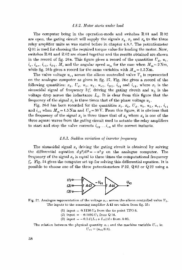
4.8.2. Motor starts under load
The computer being in the operation-mode and switches R01 and R02
are open, the gating circuit will supply the signals xit xa and x6 to the three
relay amplifier units as was stated before in chapter 4.8.1. The potentiometer
Q 01 is used for choosing the required torque value for loading the motor. Now,
switches R01 and R02 are closed together and the results obtained are shown
in the record of fig. 26a. This figure gives a record of the quantities Ud, uly
ia, iar, ivl, iD1, Me and the angular speed a>m for the case when ilfm = 2Nm,while fig. 26b gives a record for the same variables with Mm= 1.5Nm.
The valve voltage uKl across the silicon controlled valve V1 is representedon the analogue computer as given in fig. 27. Fig. 26 c gives a record of the
following quantities: xlt Ud, ux, uL, uvl, iD1, ivl and iv2, where xx is the
sinusoidal signal of frequency 3/^. driving the gating circuit and uL is the
voltage drop across the inductance Ld. It is clear from this figure that the
frequency of the signal xx is three times that of the phase voltage %.Fig. 26d has been recorded for the quantities xx, xit Ud, %, uL, uvl, i0l
and iB2 when Mm= 1.5Nm and £7d = 30V. From this figure, it is obvious that
the frequency of the signal xx is three times that of x4 where x± is one of the
three square waves from the gating circuit used to actuate the relay amplifiersto start and stop the valve currents ivl. . .i„6 at the correct instants.
4.8.3. Sudden variation of inverter frequency
The sinusoidal signal x1 driving the gating circuit is obtained by solvingthe differential equation dy2/dt2= —n2y on the analogue computer. The
frequency of the signal xt is equal to three times the computational frequencyf's. Fig. 24 gives the computer set up for solving this differential equation. It is
possible to choose one of the three potentiometers P22, Q02 or Q22 using a
Fig. 27. Analogue representation of the voltage uvi across the silicon controlled valve V\.
The inputs to the summing amplifier A 43 are taken from fig. 21:
(1) input = 0.1136 Ud from the tie point TPO 5.
(2) input = -0.1495 lh from Q 14.
(3) input = -0.1d{Ivi + Ivi)/dr{Tom A03.
The relation between the physical quantity Uvi and the machine variable £/„i is:
Uvi = Ki/8.8).
58

function switch to determine the frequency of the signal xx. These potentio¬meters have been set to give a frequency 3/^=1 respectively 1.5 and 2 Hz.
Thus, the computational frequency f's can be changed from 0.3333 to 0.5 or
0.6667 Hz, by adjusting the position of the function switch to the R-, C- or
L-position respectively. As stated before, the square wave signals xi, x5 and
x6 will always possess a phasing of T'/3 apart, independent from the frequency3 f's of the sinusoidal signal xx.
Fig. 28 gives the records obtained for the case when Ud = 30 V and Mm =
= 1.5 Nm. The computation has been started with the function switch, shown
in fig. 24, set in the imposition, that is, f's= 0.3333 Hz corresponding to a
frequency /s = 33.33 Hz in the physical system. As the steady state is reached,the frequency is suddenly changed to 0.5 Hz by adjusting the function switch
to the C-position. In a similar manner the computational frequency is changedfrom 0.5 to 0.6667 Hz by setting the function switch to the L-position. The
variables recorded and shown in fig. 28 during this computer run are: Ud, ux,
*<*> V' Ki> foi> Me and the angular speed a>m. The transition instants at which
the computational frequency is suddenly changed from 0.3333 to 0.5 and then
to 0.6667 Hz are shown on this figure.The record of the electric torque Me given in fig. 28 shows a six harmonic
component and this is more clear when the frequency f's is equal to 0.3333 Hz.
It is also clear from this record of Me that the torque oscillates as the inverter
frequency is suddenly changed. It goes negative for a small interval of time
and the oscillations are then damped and steady state is reached. This pheno¬mena can be interpreted by stating that the electric torque Me of the motor
changes sign from positive to negative as it functions as a brake and electric
power will be fed to the d. c. side.
4.8.4. Comparison between the experimental oscillograms and the current and
voltage waveforms obtained by simulating the physical problem on the analogue
computer
The oscillograms shown in fig. 7a are taken with Ud = 20V and the rotor
being locked, to correspond to a short circuit test of the induction motor.
These oscillograms when compared with the computed waveforms shown in
fig. 25 and 26 during the early periods after starting where, the motor speedis very low, will show a remarkable coincidence. We have to take into consid¬
eration that the calculated curves are for the case when Ud = 30 V.
As steady state is reached and the nominal speed has been attained, the
recorded results shown in fig. 25 and 26 are compared with the experimental
oscillograms given in fig. 7 b for the case when the motor is at its rated load.
Both the records taken on the analogue computer and the oscillograms of
59

fig. 7 b are taken with Ud = 30 V. Although some simplifying assumptions have
been introduced during the mathematical formulation of the problem, such
as the neglection of the iron losses in the motor and the assumption of an
ideal transformer in the inverter circuit, the experimental and the calculated
results agree highly with each other.
It is to be stated that the star point of the three-phase system under
investigation has a variable potential of three times the inverter frequency.Consideration of this statement is taken into account when simulating the
three-phase system on the analogue computer by calculating ua from ux, u2
and u3 as shown in the computer connection diagram of fig. 21.
60

• VORLAGE-GROSS-ETH*
Vorlage > A3
1*
innV 0
iinR
11L 1
mn\ G
IIE
111- G
11R 0
IIIS
1S
HIllllE T
IIH
y*

SECTION V
Conclusion
Sometimes, it may be necessary to operate a three-phase induction motor
by energizing it from a d. c. supply using electronic inverter circuits. This is
of special importance in missiles where motors of high reliability are to be
used and solar batteries are the only source of energy available. The method
described in the present thesis gives the possibility of inverting the d. c. voltageinto a three-phase system of voltages of adjustable frequency, which is advan¬
tageous for speed regulation of induction motors.
To invert the d. c. voltage into a three-phase one, the silicon controlled
valves (SCR) of the General Electric have been used. The inverter used is
that suggested by McMurray and Bedford with feedback diodes to avoid the
difficulties that may take place under no-load conditions. A transistorized
three-phase firing circuit for driving the six silicon controlled valves of the
inverter circuit has been specially constructed. The input signal to this circuit
is a sinusoidal one of frequency 3 /, supplied from a signal generator of a power
not more than one watt. It delivers the driving signals to the six silicon con¬
trolled valves each of frequency /s and which are always 60° electrical from
each other for all input frequencies. The highest time constant limits the
frequency range of this firing circuit.
An electronic circuit has been also designed to regulate the motor speedto keep it constant from no-load to rated-load. This occurs by automatically
regulating the frequency 3 fs of the signal driving the firing circuit. Heterodyneaction between a signal of frequency fa proportional to motor speed and another
one having a fixed frequency /01 will result in a signal of frequency 3 /s = /01 - /„.As the motor speed tries to drop, ja will follow it and accordingly 3 /s will rise
in such a manner to keep the speed constant independent from loading.The two-axis theory has been applied to reduce the three-phase induction
motor to an equivalent two-phase stator two-phase rotor one. This trans¬
formation simplified the calculations by reducing the number of differential
61

equations relating the stator and rotor voltages and currents. The second
advantage of this method is that, by writing the flux equations, although the
mutual inductance between the stator and rotor windings varies periodicallywith respect to time due to rotation of the machine, it is found to be indepen¬dent of time when the equations are written either in stator or in rotor system
of coordinates assuming a constant permeability.To solve the mathematical equations of the system under investigation,
the physical problem has been simulated on the PACE analogue computerat the Institute for Automatic Control and Industrial Electronics. A specially
designed circuit has been built to simulate the action of the silicon controlled
valves in the physical problem. This circuit actuates three relay amplifierunits which are used to start and stop the valve currents at the correct instants
during computation. The computational frequency is taken equal to f's = 0.5 Hz
that corresponds to a physical frequency /, = 50Hz. The choice is limited bytwo factors, the frequency response of the eight channel recorder available
for plotting the results and the switching time of the relay amplifier units.
A computer run has been also performed with a frequency f'a = 0.3333 Hz and
after steady state wasreached, a sudden transitionwas made to a frequency f's = 0.5
and finally to 0.6667 Hz as given in fig. 28. From the waveforms of the electric
torque Me it is clear that a sixth harmonic component takes place and that
at the instants of transition the torque oscillates and takes even a negativevalue for a small interval of time after which steady state is again reached.
The negative torque can be interpreted by the fact that during this interval,
electric power will be fed back to the d. c. side.
The experimental oscillograms obtained when investigating the three phasesilicon controlled valve power inverter loaded by an induction motor agree
with the waveforms recorded when simulating the physical problem on the
analogue computer. It is clear from the experimental and the computed results
that the valve current is intermittent and flows for half a period during each
cycle. Sometimes, it may occur that the valve current terminates before the
end of the half cycle at the instant it tries to reverse direction [12], [18]. This
phenomena did not occur in the present work, otherwise it would have been
necessary to modify the gating circuit described in paragraph 4.4 by intro¬
ducing voltage comparators to determine the instants of termination of the
valve currents.
62

Zusammenfassung
Zu untersuchen war die Arbeitsweise eines Asynchronmotors, der ilber einen
Wechselrichter aus einer Gleichstromquelle gespeist wird. Gesteuerte Silizium-
ventile ermoglichen die Umwandlung der Gleichspannung in eine Dreiphasen-
spannung variabler Frequenz, welche zur Speisung des Motors fur konstante
oder veranderliche Drehzahl verwendet werden kann. Der Motor zeigt bei
konstanter Wechselrichterfrequenz einen betrachtlichen Drehzahlabfall mit
steigender Last. Durch automatische Erhohung der Wechselrichterfrequenzist die Drehzahl konstant gehalten worden.
Es wurde ein dreiphasiger Wechselrichter gebaut unter Hinzunahme von
6 steuerbaren Siliziumventilen (SCR) der General Electric. Um die Schwierig-keiten bei Leerlauf des Wechselrichters zu vermeiden, wurde die von McMurrayund Bedford vorgeschlagene Schaltung mit nicht steuerbaren Antiventilen
verwendet. Zur Ziindung der SCR-Ventile wurde eine sechsphasige aus Halb-
leitern aufgebaute Steuerung verwendet. Zur Erzeugung der 6 zeitlich um 60°
versetzten Zundimpulse wurde eine Sinusspannung von der 3-fachen Stator-
frequenz gewahlt, deren Nulldurchgange beniitzt wurden, wodurch die Phasen-
verschiebungswinkel unabhangig von der Frequenz wurden.
Der Asynchronmotor arbeitete auf einen NebenschluB-Gleichstrom-Gene-
rator, der verschieden stark belastet werden konnte. Die Drehzahl wurde
vermittelst einer Lochscheibe digital gemessen. Deren Sollwert wurde einem
kleinen Tongenerator entnommen und deren Differenz gegenuber der Rotor-
Pulszahl bestimmt. Die Nulldurchgange dieser Differenzfrequenz wurden nun
zur Steuerung der Thyristoren verwendet, womit die Statorfrequenz gleicheinem Drittel dieser Differenzfrequenz wurde. Der Zusammenbau aller Teile
des Regelkreises ergab eine von der Last praktisch unabhangige Drehzahl.
Die genaue mathematische Erfassung der Phasenspannungen und der
Phasenstrome mit aktiver Last ist zur Zeit noch nicht moglich, da die Diffe-
rentialgleichungen transzendent sind. Danach wurden die Vorgange auf dem
neuen PACE-Analogrechner vom Institut fur Automatik und Industrielle
Elektronik der ETH nachgebildet. Das bedingte zunachst die Simulierungdes dreiphasigen Wechselrichters und dessen Ausgangsspannungen und Aus-
gangsstrome bei noch unbekannter Belastung. Dann kommt die Umwandlung
63

in ein aquivalentes Zweiphasensystem, wodurch die Zweiphasentheorie von
Park angewendet wurde. Dann ist die Asynchronmaschine nachzubilden und
schlieBlich deren mechanische Belastung. Hierzu sind total 55 Verstarker,
4 elektronische Multiplikatoren, 68 Potentiometer und 3 Relais-Verstarker
verwendet worden. Die Resultate sind in Form von Oszillogrammen festge-halten. Diese zeigen die Ventilspannungen, die Ventilstrome sowie die Strome
der Gegendioden und ferner den Einschaltvorgang sowie die Wirkung einer
plotzlichen Frequenzanderung. Interessant sind ferner die Oszillogramme des
elektromagnetischen Drehmoments, das man ja nicht an einem realen Motor
bestimmen kann.
64

References
[1] International Electrotechmcal Commission (IEC), recommendations for mercury
arc converters, Publication 84, 1957
[2] Schweizenscher Elektrotechmscher Verem (SEV), Regeln und Leitsatze fur Buch
stabensymbole und Zeichen, df Nr 0192 1959
[3] General Electric Publication ECG 371 1 Notes on the application of the silicon
controlled rectifier, Syracuse, New York, December 1958
[4] General Electric Publication ECG 425 Addendum, Circuit designers guide, Syracuse,New York
[5] Wagner, G F Parallel inverter with resistive load Electrical Engineering, Novembei
1935, p 1227—1235
[6] Wagner, C F Parallel inverter with inductive load Electrical Engineering, September 1936, p 970—980
[7] Kheireldm, A A transistorized three phase variable frequency firing circuit for
driving a three phase silicon controlled valve power inverter Neue Technik, 3/1962,
p 146—148
[8] Deuitch, D E A novel ring counter using junction transistors Transistors I,
Published by RCA Laboratories, Princeton N J,1956 (Book), p 640—645
[9] Pressman, Abraham I Design of transistorized circuits for digital computers John
F Rider Publisher, Inc,New York, 1960 (Book)
[10] Say, M O The performance and design of alternating current machines Sir Isaac
Pitman & Sons, Ltd, London, 1949 (Book)
[11] Nurnberg Die Asynchronmaschme Springer Verlag, Heidelberg, 1952 (Book)
[12] Gerecke und Meter Fremdgesteuorter Einphasen und Mehrphasenwechselnchter,Neue Technik, 11/1961, p 741—757
[13] Khetreldtn, A Theoretical and experimental investigations of pulled oscillations in
a triode oscillator disturbed by an external signal M Sc thesis presented to Alexan
dna University, January 1956
[14] Milton Dishal Design of dissipative band pass filters producing desired exact
amplitude frequency characteristics, Proceedings of the IRE, September 1949,
p 1050—1069
[15] Kovacs und Racz Transiente Vorgange in Wechselstrommaschinen Verlag der
Ungarischen Akademie der Wissenschaften, Budapest, Band I, 1959 (Book)
[16] Electronic Associates Inc,New Jersy, USA Operation of E A I precision anlogue
computing equipment, Electronic Associates Inc, European Computation Center,
Brussels
[17] Korn, O and Korn, T Electronic analogue computers McGraw Hill, New York,
1952 (Book)
[18] Badr, H Primary side thyratron controlled three phase induction machine, ETH,
Zurich, Prom Nr 3060
65

Curriculum vitae
I have been born on the 16 th of August 1929 at Alexandria, Egypt. Duringthe years 1937—1941 and 1941—1946 I visited the primary and the secondaryschools at Alexandria, respectively, and passed the maturity examination in
June 1946. In October 1946 I began my studies at the Faculty of Engineeringof the University of Alexandria and after five years of study I have been
awarded the B.Sc. degree in Electrical Engineering in June 1951. Since then,I joined the same Faculty as an assistant, meanwhile, I carried out a research
work under the supervision of Prof. Dr. Abdel-Samie Mostafa, Prof, of Radio
Engineering, dealing with: "Theroretical and experimental investigations of
pulled oscillations in a triode oscillator disturbed by an external signal." For
this work, I have been granted the M. Sc. degree in Electrical Engineering in
April 1956 after the recommendation of Prof. Dr. Willis Jackson, Director of
Research and Education at the Metropolitan-Vicker's Electrical Company,Manchester.
Since the 1st. of November 1957, the date of my arrival in Switzerland,
I continued my studies at the Swiss Federal Institute of Technology at Zurich
and passed the admission examination to the doctorate in November 1959.
The problem studied in this thesis was firstly suggested by Professor Ed.
Gerecke in November 1958, the research work has been executed under his
supervision during the years 1960—1962. The thesis has been officially pre¬
sented on October 1962 and I passed the Doctorate Degree Examination on
18th. January 1963.