consequences of peri-implant bone loss in the occlusal
TRANSCRIPT

Research ArticleConsequences of Peri-Implant Bone Loss in the Occlusal LoadTransfer to the Supporting Bone in terms of Magnitude of Stress,Strain, and Stress Distribution: A Finite Element Analysis
Esteban Pérez-Pevida ,1,2 David Chávarri-Prado ,3 Markel Diéguez-Pereira ,3
Alejandro Estrada-Martínez,3 Oier Montalbán-Vadillo,1 and Antonio Jiménez-Garrudo1
1Department of Surgery, Faculty of Medicine, University of Salamanca, Salamanca, Spain2Faculty of Dentistry, Miguel de Cervantes European University, Valladolid, Spain3Department of Surgery and Medical-Surgical Specialties, Faculty of Medicine, University of Oviedo, Oviedo, Spain
Correspondence should be addressed to Esteban Pérez-Pevida; [email protected]
Received 13 April 2021; Revised 21 July 2021; Accepted 18 August 2021; Published 2 September 2021
Academic Editor: Andrea Scribante
Copyright © 2021 Esteban Pérez-Pevida et al. This is an open access article distributed under the Creative Commons AttributionLicense, which permits unrestricted use, distribution, and reproduction in any medium, provided the original work isproperly cited.
Background and Objective. Marginal bone loss around dental implants is one of the most prevalent complication, and itsbiomechanical impact may be critical for treatment prognosis. The objective of this study was to evaluate the influence ofmarginal bone loss around dental implants in the occlusal load transfer to the bone in terms of magnitude of stress and strainand distribution of such transferred stress. Methods. Three models of a single internal connection bone level-type implantinserted into a posterior mandible bone section were constructed using a 3D finite element software: one control modelwithout marginal bone loss and two test models, both with a circumferential peri-implant bone defect, one with a 3mm highdefect and the other one 6mm high. A 150N static load was tested on the central fossa at 6° relative to the axial axis of theimplant. Results. The results showed differences in the magnitude of strain and stress transferred to the bone between models,being the higher strain found in the trabecular bone around the implant with greater marginal bone loss. Stress distributiondiffered between models, being concentrated at the cortical bone in the control model and at the trabecular bone in the testmodels. Conclusion. Marginal bone loss around dental implants under occlusal loading influences the magnitude anddistribution of the stress transferred and the deformation of peri-implant bone, being higher as the bone loss increases.
1. Introduction
Dental implants have become the most widely used andpredictable way to treat edentulism, with high rates of successand long-term survival [1]. Nevertheless, treatment withdental implants is not without its limitations and complica-tions. Peri-implantitis, defined as the infection of the tissuesurrounding a dental implant characterized by inflammationof the peri-implant connective tissue and by a progressiveloss of supporting bone in an accelerated and nonlinear pat-tern, is among the most frequent complications [2, 3].
Nowadays, although periodontal and peri-implant dis-eases are some of the most studied topic in dentistry [3],the etiology of peri-implant diseases remains controversial.
Peri-implantitis has traditionally been considered a bacterialinfection, similar to that assumed for periodontal disease.Accordingly, evidence regarding the role of certain period-ontopathogenic bacteria in the infectious etiology of peri-implantitis, including Porphyromonas gingivalis, Treponemadenticola, and Tannerella forsythia, is moderate, whereasevidence for other types of bacteria, including Prevotellaintermedia and Campylobacter rectus, is mild [4].
Other trends have advocated the primary inflammatoryetiology of periodontal disease over bacterial infection alone.Accordingly, Hajishengallis and Lamont argued that com-mensal microbial complexes transition into pathogenic com-plexes as a result of uncontrolled inflammation in theperiodontal or peri-implant area. Communication between
HindawiBioMed Research InternationalVolume 2021, Article ID 3087071, 10 pageshttps://doi.org/10.1155/2021/3087071

bacterial species leads to synergy between metabolicallycompatible organisms that have acquired functional special-ization. The researchers also argued that key pathogens, suchas Porphyromonas gingivalis, even in low abundance, subvertthe nonspecific immune system of the host, causing sus-tained inflammation, evading phagocytosis, and suppressingits bactericidal capacity, both at the cellular and complementlevels, thereby leading to bacterial dysbiosis, which increasesthe virulence of the entire bacterial complex [5–7]. Althoughthese studies refer to the etiology of periodontal diseases,they should be taken into account in the assessment of theetiology of peri-implant diseases due to the degree of simi-larity between both diseases.
Therefore, the bacterial etiology of classical periodonto-pathogens is currently under discussion, further highlightingthe role of an inflammatory reaction. Inflammation, throughthe activation of key pathogens, leads to this dysbiosis of thebacterial microbiota, in turn destroying the host tissue.
Numerous factors may affect the onset and progressionof peri-implantitis, including the patient, surgical technique,implant, or implant-supported prosthesis applied [8–12].Other factors apparently also contribute to marginal boneloss, despite a lack of strong evidence supporting their role.Accordingly, an occlusal overload affects peri-implant mar-ginal loss. However, because of difficulties in conductingclinical trials evaluating this variable, only in vitro assaysand animal model studies comparing this effect are currentlyavailable [13–17]. To assess the effect of an occlusal overloadon peri-implant bone, the biomechanical behavior of theprosthesis-implant-bone system must be understood.
Wolff’s law states that bones undergo remodelingaccording to the forces to which they are subjected duringtheir function, modifying their internal and external archi-tecture and in turn altering their shape and density [18,19]. Mechanically, bones behave similarly to any other mate-rial, undergoing strain when subjected to a load. Therefore,all bones are capable of withstanding some strain, whichcauses microfractures and leads to bone loss. This micro-strain clinically translates into micromovements of the toothor implant; micromovements of greater than 150μm arepoorly tolerated by the bone-implant system and may resultin the failure of the osseointegration process [20]. Neverthe-less, there are no studies assessing the micromovementrequired in order to lose implant osseointegration onceachieved, although the available evidence suggests that forcesthat trigger micromovements exceeding the elastic limit ofthe bone may cause the loss of bone-implant union.
Several studies have shown the influence of various fac-tors on the way in which stress transfer occurs to the peri-implant marginal bone, as a result of the application of afunctional or parafunctional load, such as the macroscopicdesign and surface treatment of the implant, the type of load,the quantity and quality of the peri-implant bone, and theproperties of the prosthesis and implant material [21, 22].
However, there is limited evidence of the effect of peri-implantitis on a load transfer to the support bone, that is,how the amount of marginal bone loss around the dentalimplant affects the biomechanical behavior of theprosthesis-implant-bone system.
The objective of this finite element analysis is to assessthe effect of the amount of marginal bone loss on the loadtransfer to the peri-implant bone in terms of the magnitudeand distribution of stress and strain.
The null hypothesis of this work is that the loss of peri-implant marginal bone does not produce changes in theamount and distribution of stress transferred to the supportsite.
2. Materials and Methods
2.1. Finite Element Model Design. A type-3 edentulous poste-rior mandible bone section was designed according to theclassification by Lekholm and Zarb [23]. The bone sur-rounding the implant was 23mm high and 12mm wide witha 1mm thick cortical bone section, with the remaining sec-tion consisting of trabecular bone.
In the macroscopic design of the threaded implant, a stan-dard Ti-6Al-4V alloy internal connection implant with a2.8mm smooth neck section (Straumann Standard, InstituteStraumann AG, Basel, Switzerland), 10mm in length,4.1mm in body diameter, and 4.8mm in platform diameter,was used as a reference. The implant body is located withthe treated surface below the bone crest in the cortical bone,leaving a smooth neck outside the bone and thus promotingthe ideal placement of an implant with such characteristics.A corresponding platform with a 4.8mm diameter and a5.5mm high titanium screw-retained abutment was modeled(RN synOcta, Institute Straumann AG, Basel Switzerland).
An 8mm high, 10.6mm wide, and 3mm thick Cr-Coalloy metal-ceramic crown (1mm metal alloy and 1 to2mm ceramic coating) with feldspathic ceramic coatingcemented on a titanium abutment was modelled.
Three 3D finite element models were designed to evalu-ate the magnitude and distribution of peri-implant bonestress, namely, a control model without marginal bone loss,and test models 1 and 2 with a 3mm and 6mm circumferen-tial bone defect around the implant, respectively (Figure 1).
2.2. Properties of the Materials and Interface Conditions. Theproperties of all materials used in the finite element modelswere extracted from the literature and are outlined inTable 1 [21]. All materials used in these models are consid-ered linearly elastic, homogenous, and isotropic. Ideal(100%) osseointegration in the interface between the boneand implant was assumed in this study. The cement layerbetween the crown and abutment was omitted, consideringan exact passive fit and an effective bonding between bothcomponents.
2.3. Loading and Boundary Conditions. The models weredeveloped and analyzed using the Ansys 11.0 3D finite ele-ment modeling software (Ansys, Swanson Analysis System,Canonsburg, PA, USA).
Under all assumptions, a load of 150N was applied tothe central occlusal fossa of the crown in the vestibule-lingual direction and with a 6° angle with respect to the axialaxis of the implant, thus promoting the physiological load-ing conditions of a mandibular premolar-molar sector [24].
2 BioMed Research International

Numerical von Mises stress and strain and stress datawere collected from all finite element models and encodedinto colorimetric scales to more easily compare the differ-ences between study models.
The finite element model of the control used in this studyconsisted 33,268 elements and 45,517 nodes, test model 1 con-sisted 706,329 elements and 1,073,794 nodes, and test model 2consisted 752,945 elements and 1,084,077 nodes.
3. Results
The results of the finite element analysis of the three studymodels showed the magnitudes of the von Mises stress andstrain of the cortical bone, trabecular bone, and implant, as
well as the distribution of the stress transferred to theprosthesis-implant-bone complex.
The results of the maximum von Mises stress transferredto the cortical bone, trabecular bone, and implant are out-lined in Table 2. In cortical bone, the highest maximum ten-sion transfer occurred in the control model withoutmarginal bone loss at 16.945MPa, whereas the lowest max-imum stress transfer occurred in the test model with 6mmof marginal bone loss at 5.8849MPa. The opposite resultswere found in the trabecular bone in which the highest max-imum stress transfer occurred in the test model with 6mmof marginal bone loss at 9.995MPa, whereas the lowest max-imum stress occurred in the control model without peri-implant loss. The implant subjected to the highest stresswas the control model without bone loss (91.23MPa),whereas the implants of both models with marginal boneloss were under a lower stress, with 53.678MPa for themodel with 3mm of loss and 56.861 in the model with6mm of loss.
The strain, expressed in microns (μm), found in the cor-tical and trabecular bone and in the implants of the threestudy models, is outlined in Table 3. In cortical bone, thehighest strain was observed in the control model withoutbone loss (6.251μm) and the lowest value appeared in themodel with 6mm of loss (3.408μm). The opposite resultswere found in trabecular bone, wherein the highest strainwas assessed in the model with 6mm of loss (14.899μm)and the lowest in the control model without bone loss(6.055μm). The maximum strain values were significantlyhigher in trabecular bone than in cortical bone for the testmodels with bone loss. The implant showed results similarto those of trabecular bone, wherein the highest strain was
(a) (b)
Figure 1: Finite element model with circumferential bone defect (a) and without marginal bone loss (b).
Table 1: Mechanical properties of materials and fixtures.
Material ComponentYoung’s
modulus (GPa)Poisson’scoefficient
Cortical bone 15 0.30
Trabecularbone
1 0.25
Ti-6Al-4Valloy
Abutment andscrew
107.2 0.30
Dentalimplant
110 0.35
Cr-Co alloyCrownstructure
218 0.33
Feldspathicceramic
Crownveneering
65 0.25
3BioMed Research International

found in the implant of the model with 6mm of loss(36.392μm) and the lowest in the implant of the controlmodel without bone loss (8.314μm).
The analysis of the color charts of the study modelsshowed marked differences in the distribution of the straintransferred to the prosthesis-implant-bone system(Figures 2–4). In the three study models, most of the peri-implant bone stress was located in the coronal bone in con-tact with the implant. Accordingly, in the control modelwithout bone loss, the stress was primarily located in theperi-implant cortical bone, and to a lesser extent, in the bonesurrounding the apex of the implant. In both test modelswith marginal bone loss, the stress distribution changedbecause the cortical bone was not in contact with theimplant; therefore, the stress was essentially transferred inthe coronal area of the trabecular bone in contact with theimplant, transferring more apically in the test model withthe greatest bone loss around the implant. In the threemodels, the stress was primarily transferred to the peri-implant bone on the side of the direction of the applied loadvector. In this case, the vector has a buccolingual direction.Therefore, the stress was mostly distributed in the lingualsector of the bone around the implant. Some stress was alsotransferred to the bone adjacent to the apex of the implant,which responds to the axial component of the load appliedto the model.
4. Discussion
This study uses a 3D finite element analysis to compare themagnitude and distribution of the stress and strain of theperi-implant bone and of the implant itself depending onthe existence of marginal bone loss and its magnitude.
Based on these findings, the null hypothesis of this studyis rejected because significant differences are found in thestress transfer depending on the presence of marginal boneloss around the implant. However, these results must be
interpreted with caution because the validity of the finite ele-ment analysis of the stress depends on the degree to whichthe properties of the materials, their geometry, the appliedload, and the conditions of the interface adjust to reality[25]. During this test, the structures simulated in the modelswere assumed to be homogeneous, isotropic, and linearlyelastic, although this does not correspond to reality, particu-larly regarding bone. However, this assumption was requiredto simplify the model to complete the analysis, similar tonumerous finite element tests evaluating the variations instress in models of single implants [26–29].
As in most biomechanical finite element analyses, in thisstudy, the trabecular and cortical bones have the samemechanical properties throughout the model because weassume a preestablished osseointegration. In this regard,studies have provided different properties of bone in closecontact with an implant and the rest of the modeled bone,simulating a transitional bone undergoing healing duringthe osseointegration process [30].
The occlusal load used in the present analysis was150N at 6° with respect to the axial axis of the implant,thus simulating the average values collected in a patientwith a dental implant, which are considered a physiologi-cal occlusal force similar to the masticatory forces [24].However, the force tested in this analysis is essentiallystatic, corresponding to the parafunctional force typicalof centric bruxism, whereas the masticatory forces are fun-damentally dynamic. The type of load and the elasticproperties of the modeled materials may affect the biome-chanical results, and these limitations must be consideredwhen evaluating the findings.
After applying the load, the three studied models followthe same pattern of stress transfer to the peri-implant bone.This stress is primarily transferred to the coronal bone incontact with the implant, in line with the principle of a com-posite beam analysis, which stipulates that, when two mate-rials with different elastic modulus (bone and implant in thistest) are brought into contact and one of them is subjected toa load, the greatest stress is transferred to the first point ofcontact between the two materials, that is, to the most coro-nal bone in contact with the implant [31]. Accordingly, inthe control model without bone loss, the stress is mostlytransferred to the cortical bone in contact with the implant;conversely, in the test models with a bone defect around theimplant, the stress is primarily transferred to the trabecularbone because this marginal bone loss coincides with the cor-tical bone loss.
The design of this peri-implantitis model, with corticalbone loss, is in line with other finite element analysis [4],but some studies have modeled cortical bone in peri-implant defects [26, 32, 33]. In this regard, this studyassumes that marginal bone loss results from an activeperi-implant disease, and therefore, based on histologicalstudies, from the osteoclastic activity of the cortical bonecharacterized by the presence of Howship’s lacunae withnumerous resident osteoclasts [34–36]. Nevertheless, somestudies have shown partial bone corticalization in peri-implant defects preestablished by a biomechanical reinforce-ment of the residual trabecular bone [37].
Table 2: Maximum von Mises stresses (MPa) in cortical andtrabecular bones and implants for all the models evaluated.
Model Cortical bone Trabecular bone Implant
3mm defect 5.934MPa 8.109MPa 53.678MPa
6mm defect 5.884MPa 9.995MPa 56.861MPa
Control 16.945MPa 2.038MPa 91.23MPa
Table 3: Maximum and minimum deformations (μm) in corticaland trabecular bone and in implants for all the models evaluated.
Model Cortical bone Trabecular bone Implant
3mm defectMin 0μm 0μm 5.691 μm
Max 3.4866 μm 10.553μm 18.06μm
6mm defectMin 0μm 0μm 5.563 μm
Max 3.408 μm 14.899μm 36.392μm
ControlMin 0μm 0μm 4.500 μm
Max 6.251 μm 6.055μm 8.314μm
4 BioMed Research International

The analysis of the results of the magnitude of stresstransferred to the bone in the three models shows thatthe maximum stress is transferred to the cortical bone ofthe control model without bone loss, similar to numerousfinite element analyses of single implants without bone loss[21, 27–29]. However, when evaluating the stress trans-ferred to the trabecular bone, we observed that the maxi-mum stress increases with the increase in the marginal
bone loss. In addition, the highest value was found inthe test model with a 6mm defect around the implant.These data match those found in several finite elementanalyses assessing the effect of the peri-implant boneresorption on the load transfer to the support ground, witha directly proportional relationship between the increasedbone loss and increased stress transferred to the bone[32, 33, 38, 39].
(a) (b)
(c)
Figure 2: Stress distribution in cortical bone (a), trabecular bone (b), and implant (c) for the control model without marginal bone loss.
5BioMed Research International
However, the maximum value of stress transferred tothe cortical bone in the control model without bone loss(16.945MPa) is higher than the maximum value of stresstransferred to the trabecular bone in the test model with6mm of bone loss (9.995MPa). However, the importanceof these results lies in Hooke’s law, according to which σ= E · ε; that is, when applying stress (σ) to a material witha specific modulus of elasticity or Young’s modulus (E),this body experiences strain (ε), which is directly propor-
tional to the applied stress [40]. That is, when applyingthe same occlusal load, the increased stress transferred tothe trabecular bone is more decisive because Young’smodulus of the trabecular bone is lower than that of thecortical bone, and therefore, the former tends to suffergreater strain than the latter.
These data match the bone strain values determined dur-ing this trial, wherein the highest strain was found in the tra-becular bone of the test model with the greatest bone loss. In
(a) (b)
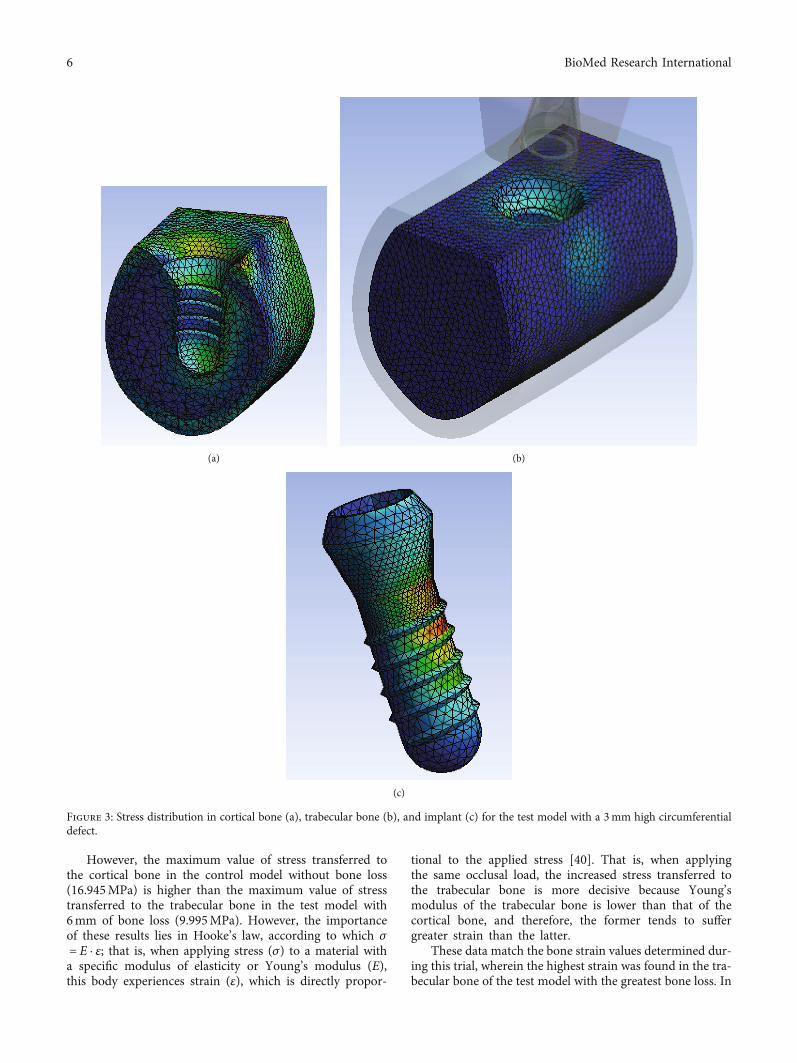
(c)
Figure 3: Stress distribution in cortical bone (a), trabecular bone (b), and implant (c) for the test model with a 3mm high circumferentialdefect.
6 BioMed Research International

other words, although the maximum value of stress wasfound in the cortical bone of the control model, the maxi-mum strain was assessed in the trabecular bone of the modelwith a 6mm defect around the implant. These strain datacorroborate the findings of Akca and Cehreli, which is theonly finite element analysis found evaluating the peri-implant bone strain in models with a different progressionof marginal bone loss. In this analysis of models with mar-ginal bone loss ranging from 0 to 2mm with 0.25mm incre-ments, bone strain is directly proportional to the height ofthe peri-implant defect [38].
In this regard, Frost proposed a criterion for boneremodeling based on the magnitude of the internal stressthat the bone experiences while performing its function; thatis, the bone is able to withstand strain up to a specific thresh-old from which microfractures will occur, which in turnleads to bone loss [18]. More recently, Wiskott and Belserestablished a set of bone remodeling categories, from disuseatrophy to fracture, through a series of bone adaptation win-dows, depending on the strain experienced by the bone. Inthis sense, the bone which suffers less than 100 microns ofdeformation (με) may be likely to suffer from bone disuse
(a) (b)
(c)
Figure 4: Stress distribution in cortical bone (a), trabecular bone (b), and implant (c) for the test model with a 6mm high circumferentialdefect.
7BioMed Research International

atrophy and, in the other hand, may be at risk of fractureunder more than 25,000με. In between these two extremes,three ranges can be defined, a normal load with bonehomeostasis (100 − 2000με), mild overload with an increaseof bone mass (2000 − 4000με), and pathologic overload withan irreversible bone damage (4000 − 2500με) [41].
Extrapolating the data collected in this trial to a clinicalsetting, all bone strain values assessed in this test are withinthe range of physiological bone adaptation without a risk ofanabolic bone reaction owing to excess strain. However, theload applied to the three models was a static load of 150N,compatible with a functional physiological magnitude; thus,the strain values should be evaluated when simulating a par-afunctional occlusion or occlusal alteration with a consider-able increase in the magnitude of the applied load.Therefore, if we apply a greater force simulating a parafunc-tional pattern or an occlusal alteration, such as a prematurecontact or interference, the presence of higher strain valuesclose to the pathological overload limit described by Wiskottmay be feasible, particularly in implants with great marginalbone loss. In this sense, an exhaustive clinical managementof occlusal factors should be recommended when marginalbone loss occurs around dental implants in order to mini-mize the load transferred to peri-implant bone, such asocclusal adjustments or modifications of the rehabilitationmaterials.
On the other hand, both models with peri-implant boneloss show higher values of deformation of the trabecularbone which has lower elastic limit compared to corticalbone. This result clinically may lead to a faster and higherprogression of peri-implant disease due to the poor toleranceof trabecular bone to higher values of deformation, whichcould result in a progressive bone loss worsening the stageof the disease.
Finally, the results obtained in this study may have appli-cations in the diagnosis of peri-implant bone loss using lessinvasive methods than traditional ones, such as resonancefrequency analysis (RFA). In this sense, if marginal bone lossleads to a worse biomechanical behavior of bone-implantcomplex with higher bone deformation and implant micro-movement, it could be diagnosed using RFA devices with adecrease in implant stability quotient (ISQ) values. In thisrespect, several studies have shown the influence of peri-implant bone defects on ISQ values using RFA devices, sug-gesting it a potential use in the diagnosis of peri-implant dis-ease [42, 43].
Given the limitations of extrapolating results to clinicalpractice, and the fact that it is impossible to reproduce oralphysiological and anatomical conditions exactly in finite ele-ments analysis, the present results should be treated withcaution.
5. Conclusions
According to the findings, and within the limitations of thisin vitro study, we can deduce the following:
(1) When an implant with marginal bone loss is sub-jected to a functional load, the trabecular bone tends
to receive a higher stress and therefore a higherstrain as this loss increases
(2) Increased bone strain may increase the risk of path-ological overload, which in the presence of a paraf-unction or unfavorable biomechanical situationmay exacerbate the anabolic bone reaction
(3) The results from this study reject the initial nullhypothesis according to which the bone around animplant with marginal bone loss subjected to a func-tional load will tend to experience similar stress andtherefore similar strain, regardless of the amount ofbone loss, in comparison with the bone around animplant without peri-implantitis.
Data Availability
The pictures of data used to support the findings of thisstudy are included within the article. The entered sheet dataof this study are available from the corresponding authorupon request.
Conflicts of Interest
The authors declare that they have no known competingfinancial interests or personal relationships that could haveappeared to influence the work reported in this paper.
References
[1] R. Adell, B. Eriksson, U. Lekholm, P. I. Branemark, andT. Jemt, “Long-term follow-up study of osseointegratedimplants in the treatment of totally edentulous jaws,” TheInternational Journal of Oral & Maxillofacial Implants,vol. 5, no. 4, pp. 347–359, 1990.
[2] N. P. Lang, T. Berglundh, and on Behalf of Working Group 4of the Seventh European Workshop on Periodontology, “Peri-implant diseases: where are we now? - Consensus of the Sev-enth European Workshop on Periodontology,” Journal ofClinical Periodontology, vol. 38, pp. 178–181, 2011.
[3] T. Berglundh, G. Armitage, M. G. Araujo et al., “Peri-implantdiseases and conditions: consensus report of workgroup 4 ofthe 2017 World Workshop on the classification of periodontaland peri-implant diseases and conditions,” Journal of ClinicalPeriodontology, vol. 45, pp. S286–S291, 2018.
[4] P. J. Pérez-Chaparro, P. M. Duarte, J. A. Shibli et al., “The cur-rent weight of evidence of the microbiologic profile associatedwith peri-implantitis: a systematic review,” Journal of Peri-odontology, vol. 87, no. 11, pp. 1295–1304, 2016.
[5] R. J. Lamont and G. Hajishengallis, “Polymicrobial synergyand dysbiosis in inflammatory disease,” Trends in MolecularMedicine, vol. 21, no. 3, pp. 172–183, 2015.
[6] G. Hajishengallis and R. J. Lamont, “Breaking bad: manipula-tion of the host response by Porphyromonas gingivalis,” Euro-pean Journal of Immunology, vol. 44, no. 2, pp. 328–338, 2014.
[7] G. Hajishengallis and R. J. Lamont, “Beyond the red complexand into more complexity: the polymicrobial synergy and dys-biosis (PSD) model of periodontal disease etiology,”MolecularOral Microbiology, vol. 27, no. 6, pp. 409–419, 2012.
8 BioMed Research International

[8] S. H. Safii, R. M. Palmer, and R. F. Wilson, “Risk of implantfailure and marginal bone loss in subjects with a history ofperiodontitis: a systematic review and meta-analysis,” ClinicalImplant Dentistry and Related Research, vol. 12, no. 3, pp. 165–174, 2010.
[9] M. Clementini, P. H. Rossetti, D. Penarrocha, C. Micarelli,W. C. Bonachela, and L. Canullo, “Systemic risk factors forperi-implant bone loss: a systematic review and meta-analy-sis,” International Journal of Oral and Maxillofacial Surgery,vol. 43, no. 3, pp. 323–334, 2014.
[10] I. D. Vouros, C. D. Kalpidis, A. Horvath, A. Petrie, andN. Donos, “Systematic assessment of clinical outcomes inbone-level and tissue-level endosseous dental implants,” TheInternational Journal of Oral & Maxillofacial Implants,vol. 27, no. 6, pp. 1359–1374, 2012.
[11] C. A. Lemos, V. E. de Souza Batista, D. A. Almeida, J. F. Santi-ago Júnior, F. R. Verri, and E. P. Pellizzer, “Evaluation ofcement-retained versus screw-retained implant-supported res-torations for marginal bone loss: a systematic review andmeta-analysis,” The Journal of Prosthetic Dentistry, vol. 115, no. 4,pp. 419–427, 2016.
[12] B. R. Chrcanovic, T. Albrektsson, and A. Wennerberg, “Dentalimplants inserted in fresh extraction sockets versus healedsites: a systematic review and meta-analysis,” Journal of Den-tistry, vol. 43, no. 1, pp. 16–41, 2015.
[13] T. Miyata, Y. Kobayashi, H. Araki, Y. Motomura, and K. Shin,“The influence of controlled occlusal overload on peri-implanttissue: a histologic study in monkeys,” The International Jour-nal of Oral & Maxillofacial Implants, vol. 13, no. 5, pp. 677–683, 1998.
[14] T. Miyata, Y. Kobayashi, H. Araki, T. Ohto, and K. Shin, “Theinfluence of controlled occlusal overload on peri-implant tis-sue. Part 3: a histologic study in monkeys,” International Jour-nal of Oral & Maxillofacial Implants, vol. 15, pp. 425–443,2000.
[15] T. Miyata, Y. Kobayashi, H. Araki, T. Ohto, and K. Shin, “Theinfluence of controlled occlusal overload on peri-implant tis-sue. part 4: a histologic study in monkeys,” International Jour-nal of Oral & Maxillofacial Implants, vol. 17, no. 3, pp. 384–390, 2002.
[16] F. Isidor, “Loss of osseointegration caused by occlusal load oforal implants. A clinical and radiographic study in monkeys,”Clinical oral Implants Research, vol. 7, no. 2, pp. 143–152,1996.
[17] F. Isidor, “Histological evaluation of peri-implant bone atimplants subjected to occlusal overload or plaque accumula-tion,” Clinical Oral Implants Research, vol. 8, no. 1, pp. 1–9,1997.
[18] H. M. Frost, “FromWolff ‘s law to the Utah paradigm: insightsabout bone physiology and its clinical applications,” The Ana-tomical Record, vol. 4, pp. 398–419, 2001.
[19] E. Roberts, L. Garetto, and N. Brezniak, Bone Physiology andMetabolism, Mosby, St Louis, Missouri, 1994.
[20] S. Szmukler-Moncler, H. Salama, Y. Reingewirtz, and J. H.Dubruille, “Timing of loading and effect of micromotion onbone-dental implant interface: review of experimental litera-ture,” Journal of Biomedical Materials Research, vol. 43,no. 2, pp. 192–203, 1998.
[21] E. Pérez-Pevida, A. Brizuela-Velasco, D. Chávarri-Prado et al.,“Biomechanical consequences of the elastic properties of den-tal implant alloys on the supporting bone: finite element anal-
ysis,” BioMed Research International, vol. 2016, Article ID1850401, 9 pages, 2016.
[22] L. Hingsammer, B. Pommer, S. Hunger, R. Stehrer, G. Watzek,and A. Insua, “Influence of implant length and associatedparameters upon biomechanical forces in finite element analy-ses: a systematic review,” Implant Dentistry, vol. 28, no. 3,pp. 296–305, 2019.
[23] U. Lekholm and G. A. Zarb, “Patient selection and prepara-tion,” in Tissue-integrated prostheses. Osseointegration in clin-ical dentistry, P.-I. Bränemark, G. A. Zarb, and T. Albreksson,Eds., Quintessence, Chicago, 1985.
[24] M.Watanabe, Y. Hattori, and C. Satoh, “Biological and biome-chanical perspectives of normal dental occlusion,” Interna-tional Congress Series, vol. 1284, pp. 21–27, 2005.
[25] H. J. Meijer, F. J. Starmans, F. Bosman, and W. H. Steen, “Acomparison of three finite element models of an edentulousmandible provided with implants,” Journal of Oral Rehabilita-tion, vol. 20, no. 2, pp. 147–157, 1993.
[26] E. Kitamura, R. Stegaroiu, S. Nomura, and O. Miyakawa,“Influence of marginal bone resorption on stress around animplant - a three-dimensional finite element analysis,” Journalof Oral Rehabilitation, vol. 32, no. 4, pp. 279–286, 2005.
[27] J. P. Geng, K. B. Tan, and G. R. Liu, “Application of finite ele-ment analysis in implant dentistry: a review of the literature,”The Journal of Prosthetic Dentistry, vol. 85, no. 6, pp. 585–598, 2001.
[28] G. Papavasiliou, P. Kamposiora, S. C. Bayne, and D. A. Felton,“Three-dimensional finite element analysis of stress-distribution around single tooth implants as a function of bonysupport, prosthesis type, and loading during function,” TheJournal of Prosthetic Dentistry, vol. 76, no. 6, pp. 633–640,1996.
[29] H. Oliveira, A. Brizuela Velasco, J. V. Ríos-Santos et al., “Effectof different implant designs on strain and stress distributionunder non-axial loading: a three-dimensional finite elementanalysis,” International Journal of Environmental Researchand Public Health, vol. 17, no. 13, p. 4738, 2020.
[30] A. Alvarez-Arenal, L. Segura-Mori, I. Gonzalez-Gonzalez,H. DeLlanos-Lanchares, F. Sanchez-Lasheras, andJ. Ellacuria-Echevarria, “Stress distribution in the transitionalperi-implant bone in a single implant-supported prosthesiswith platform-switching under different angulated loads,”Odontology, vol. 105, no. 1, pp. 68–75, 2017.
[31] T. Baumeister and E. A. Avallone,Mark’s Standard Handbookof Mechanical Engineers, Mc Graw-Hill, New York, 1978.
[32] M. Jafarian, F. S. Mirhashemi, and N. Emadi, “Finite elementanalysis of stress distribution around a dental implant with dif-ferent amounts of bone loss: an in vitro study,” Dental andMedical Problems, vol. 56, no. 1, pp. 27–32, 2019.
[33] A. Tsouknidas, E. Lympoudi, K. Michalakis et al., “Influence ofalveolar bone loss and different alloys on the biomechanicalbehavior of internal-and external-connection implants: athree-dimensional finite element analysis,” The InternationalJournal of Oral & Maxillofacial Implants, vol. 30, pp. 30–42,2015.
[34] C. P. Marinello, T. Berglundh, I. Ericsson, B. Klinge, P. O.Glantz, and J. Lindhe, “Resolution of ligature-induced peri-implantitis lesions in the dog,” Journal of Clinical Periodontol-ogy, vol. 22, no. 6, pp. 475–479, 1995.
[35] J. P. Albouy, I. Abrahamsson, L. G. Persson, and T. Berglundh,“Spontaneous progression of ligatured induced peri-
9BioMed Research International

implantitis at implants with different surface characteristics.An experimental study in dogs II: histological observations,”Clinical Oral Implants Research, vol. 20, no. 4, pp. 366–371,2009.
[36] N. U. Zitzmann, T. Berglundh, I. Ericsson, and J. Lindhe,“Spontaneous progression of experimentally induced periim-plantitis,” Journal of Clinical Periodontology, vol. 31, no. 10,pp. 845–849, 2004.
[37] M. E. Galárraga-Vinueza, S. Tangl, M. Bianchini et al., “Histo-logical characteristics of advanced peri-implantitis bonedefects in humans,” International Journal of Implant Dentistry,vol. 6, no. 1, p. 12, 2020.
[38] K. Akca and M. C. Cehreli, “Biomechanical consequences ofprogressive marginal bone loss around oral implants: a finiteelement stress analysis,” Medical & Biological Engineering &Computing, vol. 44, no. 7, pp. 527–535, 2006.
[39] Y. Duan, R. Chandran, and D. Cherry, “Influence of alveolarbone defects on the stress distribution in quad zygomaticimplant-supported maxillary prosthesis,” The InternationalJournal of Oral & Maxillofacial Implants, vol. 33, no. 3,pp. 693–700, 2018.
[40] S. Timoshenko and J. N. Goodier, Theory of Elasticity, NuevaYork, Mc Graw-Hill, 1951.
[41] H. W. A. Wiskott and U. C. Belser, “Lack of integration ofsmooth titanium surfaces: a working hypothesis based onstrains generated in the surrounding bone,” Clinical OralImplants Research, vol. 10, no. 6, pp. 429–444, 1999.
[42] A. Monje, A. Insua, F. Monje et al., “Diagnostic accuracy of theimplant stability quotient in monitoring progressive peri-implant bone loss: an experimental study in dogs,” ClinicalOral Implants Research, vol. 29, no. 10, pp. 1016–1024, 2018.
[43] T. F. Tözüm, I. Turkyilmaz, and E. A. McGlumphy, “Relation-ship between dental implant stability determined by resonancefrequency analysis measurements and peri-implant verticaldefects: an in vitro study,” Journal of Oral Rehabilitation,vol. 35, no. 10, pp. 739–744, 2008.
10 BioMed Research International