consent decree (90-5-2-1-10811) – 1:15-cv-00841 rbj end of phase report for tank ... · ·...
TRANSCRIPT

Consent Decree (90-5-2-1-10811) – 1:15-cv-00841 RBJ
End of Phase Report for Tank Systems in Group III
April 5, 2018

Table of Contents
Introduction and Purpose 1
1.0 Engineering Design Standard Overview 3
1.1 Vapor Control Technologies 3
1.2 Site-specific Construction Constraints 4
1.3 Tank-to-combustor piping system design considerations 4
1.4 Separator liquid dump characteristics 4
1.5 Storage tanks headspace 4
1.6 Other Vapor Control System design considerations 4
2.0 Requirements, Constraints, and Limitations of Operation and/or Design Parameters 4
3.0 Summary of Design or Implementation Challenges Encountered 4
4.0 Summary of Vapor Control System Operations 5
5.0 Summary of Other Significant Observations 5
6.0 Certification 6
Appendices
Appendix A – Noble Modeling Guideline
Appendix B – Summary of Reliable Information for PG3 Certified Locations

1
Introduction and Purpose
Consistent with the requirements of Paragraph 59 of the Consent Decree (“CD”) between the
United States, the State of Colorado (“State”), and Noble Energy, Inc. (“Noble”), Civil Action No.
1:15-cv-00841-RBJ, entered by the U.S. District Court for the District of Colorado as final
judgment on June 2, 2015, Noble has prepared this Fifth End of Phase Report (“Fifth Report”)
for Tank Systems1 associated with Well Production Operations which produced gas into sales
lines that, as of August 17, 2014, had line pressures less than 186 pounds per square inch (psi),
met the Engineering Evaluation deadline of July 1, 2017, and were not part of the Tank Systems
discussed in the First, Second, Third, or Fourth End of Phase Reports. These Tank Systems are
also referred to as “Group III” Tank Systems.
The Consent Decree requires an End of Phase Report after the Engineering Evaluation deadline
for each group of Tank Systems to provide a public summary of useful information gleaned
from Engineering Evaluations, and any modifications to improve capture and control achieved
by Vapor Control Systems.
Noble submitted its first End of Phase Report (“First Report”) on July 30, 2015. The First Report
addressed Tanks Systems that had, as of September 2014, actual uncontrolled annual volatile
organic compound (“VOC”) emissions of 50 tons per year (“TPY”) or more with an Engineering
Evaluation deadline of May 1, 2015. Noble received approval of its First Report on December
14, 2015 and in turn made it publically available at jointagreement.noblecolorado.com.
Noble submitted its second End of Phase Report (“Second Report”) on January 29, 2016. The
Second Report addressed Tanks Systems that were part of the Cross Section Sampling and
Analysis with an Engineering Evaluation deadline of July 1, 2015. Noble received approval of its
Second Report on March 16, 2016, and in turn made it publically available at
jointagreement.noblecolorado.com.
Noble submitted its third End of Phase Report (“Third Report”) on July 28, 2016. The Third
Report addressed Tanks Systems that were part of the Group I Tanks with an Engineering
Evaluation deadline of December 31, 2015. Noble received approval of its Third Report on
February 28, 2017, and in turn made it publically available at
jointagreement.noblecolorado.com.
1 Pursuant to Section III of the CD, “Tank System” shall mean one or more tanks that store Condensate and share a
common Vapor Control System.

2
Noble submitted its fourth End of Phase Report (“Fourth Report”) on July 28, 2017. The Fourth
Report addressed Tank Systems that were part of the Group II Tanks with an Engineering
Evaluation deadline of December 31, 2016. Noble received approval of its Fourth Report on
February 23, 2018, and in turn made it publicly available at jointagreement.noblecolorado.com.
In some instances, information provided by Noble in its First, Second, Third, and Fourth Reports
remains applicable to this Fifth Report. This is due to no material changes to the design and
selection of equipment to control Tank System vapors since the previous reporting periods.
Where appropriate, Noble has included notations directing the reader to the First, Second,
Third, or Fourth Report instead of including identical details in this Fifth Report.
As noted in the First, Second, Third, and Fourth Reports:
1. An Engineering Evaluation is the process of applying an appropriate Engineering Design
Standard2 to determine if the existing Vapor Control System3 at each Tank System is
adequately designed and sized to handle the Potential Peak Instantaneous Vapor Flow
Rate (“PPIVFR”);4
2 Pursuant to Section III of the CD, “Engineering Design Standard” shall mean an engineering standard developed
by Noble pursuant to Paragraph 9 (Engineering Design Standard).
3 Pursuant to Section III of the CD, “Vapor Control System” shall mean the system used to contain, convey, and
control vapors from Condensate (including flashing, working, breathing, and standing losses, as well as any
unintentional gas carry-through to Condensate tanks) at a Tank System. A Vapor Control System includes a Tank
System, piping to convey vapors from a Tank System to a combustion device and/or vapor recovery unit, fittings,
connectors, liquid knockout vessels or vapor control piping, openings on Condensate tanks (such as pressure relief
valves (“PRVs”) and thief hatches), and emission control devices.
4 Pursuant to Section III of the CD, “Potential Peak Instantaneous Vapor Flow Rate” shall mean the maximum
instantaneous amount of vapors routed to a Vapor Control System during Normal Operations (defined as all
periods of operation, excluding Malfunctions, and explicitly including, for storage tanks at well production facilities,
liquid dumps from the Separator), including flashing, working, breathing, and standing losses, as determined using
the Modeling Guideline (defined as the modeling guideline developed by Noble pursuant to Paragraph 8
(Development of a Modeling Guideline)).

3
2. Noble’s oil and natural gas production operations in the Denver-Julesburg (“D-J”) Basin
include the use of Condensate5 tanks, which have the potential to produce vapors from
flashing6 and working and breathing7 losses;
3. Noble’s operations also include the use of produced water storage tanks that may also
produce vapors from flashing and working and breathing losses such that the associated
emissions are considered by the Engineering Evaluations when they are connected to a
Tank System’s Vapor Control System;
4. Vapor Control Systems are installed on Noble Tank Systems to route vapors from a Tank
System to an emission control device; and
5. Where flashing, breathing, and/or working emissions have the potential to exceed
Vapor Control System capacity, Vapor Control System modifications are necessary to
ensure proper capture and control of emissions.
For purposes of the Tank Systems covered by this Fifth Report, Noble did not create a general
Engineering Design Standard for use at multiple Tank Systems. Rather, Noble used a site-
specific Engineering Design Standard to ensure a Vapor Control System was designed and
adequately sized for the PPIVFR of the Tank System.
This Fifth Report covers the Vapor Control Systems for 168 Group III Tank Systems8.
5 Pursuant to Section III of the CD, “Condensate” shall mean hydrocarbon liquids that remain liquid at standard
conditions (68 degrees Fahrenheit and 29.92 inches mercury) and are formed by condensation from, or produced
with, natural gas, and which have an American Petroleum Institute gravity (“API gravity”) of 40 degrees or greater.
6 Flashing occurs when Condensate or produced water is dumped from pressurized two-phase and three-phase
Separators (Pursuant to Section III of the CD, a “Separator” is a pressurized vessel used for separating a well stream
into gaseous and liquid components) into storage tanks, at or near atmospheric pressure, causing vapors to be
released or “flashed” into a gaseous state as a result of the pressure drop.
7 Working and breathing losses are vapors that may be released from Condensate due to liquid level changes and
temperature fluctuations.
8 Of the 684 Tank Systems that were included in the July 28, 2017 Certification of Completion Report, 14 were
associated with the Stipulation for Termination of the CD filed with the U.S. District Court of Colorado on July 21,
2017, 166 were certified as complete, and 504 were certified as shut in. Noble incorrectly reported that Tank
Systems 833 and 1179, two of the 504 Tank Systems certified as shut in, were shut in during the 5th semi-annual
reporting period, bringing the total Tank Systems covered by this Fifth Report to 168. The VCS Modification for
Tank System 833 was complete on February 22, 2017, and the VCS Verification was complete on March 30, 2017.
The VCS Modification for Tank System 1179 was complete on February 17, 2017, and the VCS Verification was
complete on March 30, 2017. Please refer to Section Problems & Solutions of the January 29, 2017 6th Semi-
Annual Report for additional details.

4
As was the case with the First, Second, Third, and Fourth Reports, this Fifth End of Phase Report
is also divided into five (5) sections that, based on the best currently available information,
address the following:
• Section 1: An overview of the Engineering Design Standard considerations identified in
Paragraph 9 of the CD;
• Section 2: A discussion of requirements, constraints, and limitations of operation and/or
design parameters for the Tank Systems and Vapor Control Systems;
• Section 3: A summary of design and implementation challenges;
• Section 4: A summary of Vapor Control Systems operations; and
• Section 5: A discussion of any other significant observations associated with the Tank
Systems and Vapor Control Systems.
1. Engineering Design Standard Overview
During this reporting period, Noble did not develop a Three Line Pressure Grouping or subset
grouping Engineering Design Standard for the Tank Systems. Instead, Noble developed
individual site-specific Engineering Design Standards for those Tank Systems covered during this
reporting period.
1.1 Vapor Control Technologies
As these considerations did not change, please refer to the First Report.
1.2 Site-specific Construction Constraints
As these considerations did not change, please refer to the First Report.
1.3 Tank-to-combustor piping system design considerations
As these considerations did not change, please refer to the First Report.
1.4 Separator liquid dump characteristics
As these considerations did not change, please refer to the First Report.
1.5 Storage tank headspace
As these considerations did not change, please refer to the First Report.
1.6 Other Vapor Control System design considerations
As a result of considerations identified during Noble’s 2016 Third Party Verification, which are
set forth in Paragraph 20 of the CD, Noble updated Engineering Evaluations and STEM plans to

5
incorporate vapor sources from Truck Loadout Control Systems on all applicable Vapor Control
Systems. As of December 31, 2017, Noble incorporated all sources of vapor in its calculation of
PPIVFR for all remaining Tank Systems.
2. Requirements, Constraints, and Limitations of Operation and/or Design Parameters
As these considerations did not change, please refer to the First Report.
3. Summary of Design or Implementation Challenges Encountered
As was the case with the Fourth End of Phase Report, the Unloading of Produced Water into
Tank Truck Loadout Control Systems Implementation Challenge encountered for Group II also
applies to the Group III Tank Systems and Vapor Control Systems modified during this reporting
period. Noble encountered an additional Design Challenge and three Implementation
Challenges applicable to Group III Tank Systems and Vapor Control Systems modified during this
reporting period.
Design Challenge:
Revision to the Modeling Guideline
Noble revised the Modeling Guideline during this reporting period. For ease of reference, a
copy of the revised Modeling Guideline is attached to this End of Phase Report as Appendix A.
The revisions to the modeling guideline were completed as a result of a finding in the Third-
Party Verification Draft Audit Report dated March 30, 2017 issued by SLR International
Corporation (“SLR”) related to calculating the PPIVFR at banked Tank Systems. SLR’s findings
noted that in some cases all sources of vapor were not included in the calculation of the PPIVFR
(i.e., breathing losses were not incorporated for the non-producing, storage-only bank). While
Noble disagreed with SLR’s finding, Noble indicated that it did not include the PPIVFR
contribution from breathing losses for the tank bank not receiving condensate liquid and flash
vapors because it also excluded from consideration any Vapor Control System (“VCS”) capacity
contribution associated with headspace surge. Noble concluded that by excluding both data
points, Noble’s Engineering Evaluation considered the worst-case scenario with all condensate
liquid and flash vapors producing into one bank of tanks. Nonetheless, Noble subsequently
incorporated all sources of vapor into its calculation of PPIVFR. This incorporation has been
included in the revised Modeling Guideline.
Implementation Challenge:
Unloading of Produced Water into Tank Truck Loadout Control Systems

6
As a result of reviewing tank pressure monitoring (“TPM”) data and conducting site
investigations during the 4th semi-annual reporting period, Noble determined that its current
operational procedure for unloading produced water had the potential to create TPM trigger
point exceedances. Specifically, the produced water unloading is accomplished by routing the
water vapors through the Vapor Control System VCS of Tank Systems to minimize exposure to
the potential presence of hydrogen sulfide. At that time, preliminary information suggested
that the trigger point exceedances for these instances were associated with inert gases and not
VOCs.
Although this implementation challenge is not limited to Group III Tank Systems and does not
appear to be associated with a specific line pressure grouping, this challenge was discovered
and researched thoroughly during the time period of developing the Fourth Report.
Specifically, Noble conducted an internal study during produced water unloading events with a
third-party contractor to determine the root cause for these over-pressuring events during the
time period of the Fourth Report.
The results of the internal study identified the following as the root cause for these over
pressuring events:
• Water hauls differ from oil hauls in that they are completed with vacuum suction
methods;
• Observation of the typical tank pressure profile suggested that the over-pressure
events are initiated by the exhaust flow rate after the hook-up of the vapor recovery
line to the tanker vacuum pump when the vacuum pump is turned on;
• Over-pressure events occur at the onset of vacuum pump activation to evacuate the
tanker; prior to any water flow; and
• The over-pressure events that occurred at the study locations indicate that a root
cause of the over-pressure events during water hauling is due to the initial exhaust
flow from the vacuum pump upon onset of pump down.
Using these internal study results, Noble considered alternative approaches to produced water
unloading that would provide for safety considerations while minimizing the likelihood of any
TPM trigger point exceedances. These internal discussions included review of alternatives
aimed at slowing down the initial rate of exhaust from the vacuum pump as seen by the vapor
return line. Through discussions with hauling vendors, it was determined it would not be
feasible to implement alternative loadout activities at a specific subset of Noble Tank Systems.
During this Fifth Report reporting period, Noble developed an alternative approach to ensure
that each Tank System with Tank Truck Loadout Control Systems meets the Engineering Design
Standards as discussed below:
7
• On December 7, 2017, Noble conducted a pilot program that consisted of
conducting IR Camera investigations at Tank Systems retrofitted with Tank Truck
Loadout Control Systems;
• Investigations were conducted with a water hauler on location. Videos were
recorded with an IR Camera while the water hauler was connected to the Vapor
Recover Line and pulling a vacuum on the Water Tank;
• If the IR Camera investigation found VOC emissions from the Tank System, Reliable
Information was recorded and maintenance, repairs or replacement was conducted
on the vapor combustion equipment; and
• Once the vapor combustion equipment was repaired or replaced, a second IR
Camera investigation was conducted to ensure no VOC emissions were detected
from the Tank System.
Noble estimates that all Tank Systems will be investigated on or before the 8th semi-annual
reporting period deadline.
Design Limit and OPS Limit Buffer
Noble has observed that an additional buffer between the design limit and the operating limit is
warranted on smaller facilities’ Tank Systems tied to vertical wells under two (2) circumstances:
(1) sales line pressure increases; and (2) nearby hydraulic fracturing operations by Noble or
other O&G operators.
Noble enforces its design limit through the use of automation. Operational limits are enforced
by way of pneumatic controllers. If vertical wells experience increased production as a result of
nearby hydraulic fracturing operations, the buffer between the design limit and operating limit
may become less adequate. Similarly, if low pressure flash gas rates increase due to increasing
line pressure, the buffer between design and operating limit may become less adequate.
Thus, Noble is increasing the buffer between the maximum separator pressure and the
operational limit in an effort to reduce the opportunity for the wells to load up due to high line
pressure or nearby hydraulic fracturing operations. Such buffer increase should further help
Noble maintain achievement with applicable performance standards. When the operational
limit is reached, and without exceeding the maximum separator pressure, there can be
“carryover” pressure as the system equalizes after the controller shuts. This carryover pressure
increases with increasing line pressure. By dropping the operational limit 10 psig, the potential
to hit the maximum separator pressure is reduced and prevents hard shut-ins. For example:
For a Tank System with a maximum separator pressure of 70 psig (automation device set to
shut-in wellhead) and an initial operational limit of 60 psig (pneumatic controller set to prevent

8
hitting the maximum separator pressure) Noble has adjusted the operational limit to 50 psig
(pneumatic controller).
Increased line pressure is not causing a change in the set point of the maximum separator
pressure, thus it does not impact the design adequacy of our Vapor Control Systems. As a result
our Engineering Evaluations and PPIVFR are not affected by increased line pressure.
Level Control Valve Failure Associated with TPM Trigger Point Exceedances
Liquid level controllers are designed to control the flow of produced fluids from the High
Pressure (“HP”) vessel to the Low Pressure (“LP”) vessel of the High-Low Pressure (“HLP”)
separator. During the second wave of TPM Tank Systems, level control valve failure was
identified as the potential root cause of 11 isolated TPM trigger point exceedances. Specifically,
the liquid level controller on certain HLP separators have been staying open for too long,
allowing raw gas to flow into the LP vessel, and consequently sending gas to the production
tanks. Replacing liquid level controllers is a common maintenance practice for Lease Operators
and thus Lease Operators keep a number of level controllers in their vehicles. Noble installs two
types of level controllers, a miser-type level control valve and a “SnapTroll” control valve. To
address this issue, Noble is either replacing existing failed liquid level controllers with new like-
kind miser-type units (separator design pressures greater than 500 psig) or, where design limits
will allow (separator design pressures less than 500 psig), replacing the failed controllers with
“Snap Troll” control valves which have a lower failure rate. In all cases where a “SnapTroll”
failure occurs, it is replaced with another “SnapTroll”.
4. Summary of Vapor Control System Operations
Pursuant to Paragraph 12.a. of the CD, Noble was required to conduct an IR camera inspection
of each Tank System before, during and immediately after a dump event to confirm the VCS is
adequately designed and associated tanks were not emitting VOCs. VCS Verifications for the
modified Tank Systems covered by this reporting period did not observe VOC emissions from
storage tank PRVs or thief hatches.
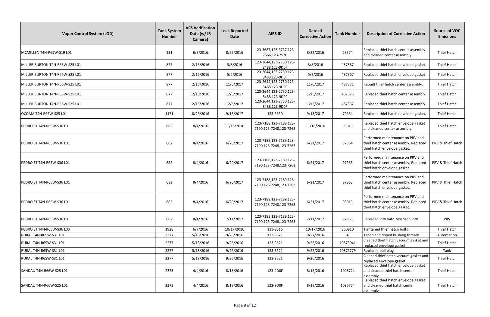
Pursuant to Paragraph 59.iv. of the CD, a summary of Reliable Information9 Noble obtained for
the 167 Tank Systems covered in this Fifth Report can be found in Appendix B. The data set is
9 Pursuant to Paragraph III of the CD, “Reliable Information” shall mean any observance or detection of VOC
emissions from a Tank System using an optical gas imaging infrared camera, EPA Method 21 monitoring, CDPHE
Approved Instrument Monitoring Method (“AIMM”), or audio, visual, olfactory (“AVO”) inspections by EPA,
CDPHE, or local government inspectors trained by CDPHE, Noble employees or Noble contractors trained to
conduct inspections for emissions, or, in the case of the consultant selected by Noble to perform a third party
audit, VOC emissions detected or observed using an optical gas imaging infrared camera. For purposes of this
Decree only, evidence of past surface staining alone shall not be considered Reliable Information.

9
reflective of the period beginning with each VCS Modification date and ending December 31,
2017 (the end of the reporting period for the Fifth Semi-Annual Report). This document
provides instances of VOC emissions after modifications and a description of any associated
corrective actions.
5. Summary of Other Significant Observations
For this reporting period, there were no other significant observations associated with the Tank
Systems and Vapor Control Systems.


APPENDIX A
NOBLE MODELING GUIDELINE

Rev: 3Date: 12/19/2017
Noble Modeling Guideline,Well Site Tank SystemSTATE OF COLORADO
December 2017
Rev. Date Description By Checked Approved
1 3/30/15 INITIAL RELEASE JVS AGJ2 5/21/2015 EDITED FOR CLARITY JVS
3 12/19/2017EDITED TO CORRECT
WORKING/BREATHING LOSSES PAD SMG

Rev: 3Date: 12/19/2017
ii
SPECIAL NOTES
This guideline addresses engineering practices of a general nature. This guideline is intended to facilitatea design of systems using proven and sound engineering practices. This guideline can be used by anyonewishing to do so, however, this guideline does not, nor does Noble Energy, condone its use to, negate,override, or replace local, state, or federal laws and regulations. Noble Energy does not endorse or takeresponsibility for any non-Noble Energy product or system designed or claiming to be in accordance withthis guide. Nothing contained in this guideline should be construed as insuring anyone against liability forinfringement and violation of intellectual property laws and regulations. Every effort has been made toensure accuracy and reliability of this guideline; however, Noble Energy makes no representation,guarantee, or warranty in connection with this guideline or its use by any party other than Noble Energy.This guideline is intended as an evergreen guideline and subsequent revisions of this guideline shall notbe considered to be material changes pursuant to Paragraph XX of the Consent Decree.

Rev: 3Date: 12/19/2017
iii
TABLE OF CONTENTS1 SCOPE............................................................................................................................................ 1
2 TERMS AND DEFINITIONS ............................................................................................................ 2
3 EXCLUSIONS.................................................................................................................................. 4
4 ENGINEERING FACTORS .............................................................................................................. 5
5 SOURCES OF VAPOR TO BE CONSIDERED ................................................................................ 5
5.1 CONDENSATE TANKS............................................................................................................ 5
5.2 SEPARATORS ........................................................................................................................ 5
5.3 MULTIPLE SEPARATORS....................................................................................................... 5
5.4 VAPOR RECOVERY TOWERS ............................................................................................... 5
5.5 VORTEX VAPOR ENTRAINMENT........................................................................................... 6
5.6 TRUCK LOADING LOSSES..................................................................................................... 6
5.7 OTHER SOURCES.................................................................................................................. 6
6 DETERMINING VAPOR LOSSES.................................................................................................... 7
6.1 CONDENSATE TANK THROUGHPUT .................................................................................... 7
6.2 CONDENSATE TANK BREATHING VAPOR LOSSES............................................................. 8
6.3 CONDENSATE TANK WORKING LOSSES ............................................................................. 8
6.4 CONDENSATE TANK FLASH VAPOR LOSSES...................................................................... 8
6.4.1 PROCESS SIMULATORS ................................................................................................ 8
6.4.2 CORRELATIONS ............................................................................................................. 9
6.4.3 DIRECT MEASUREMENT................................................................................................ 9
6.5 VORTEX GAS ENTRAINMENT LOSSES................................................................................. 9
6.6 SEPARATOR VAPOR LOSSES............................................................................................... 9
6.7 VRT VAPOR LOSSES ........................................................................................................... 10
6.8 OTHER VAPOR LOSSES ...................................................................................................... 10
6.9 TOTAL VAPOR LOSSES ....................................................................................................... 10
7 BIBLIOGRAPHY ............................................................................................................................ 11

Rev: 3Date: 12/19/2017
iv
INTRODUCTION
This guideline is intended to determine the Potential Peak Instantaneous Vapor Flow Rate fromCondensate tanks and other sources, but does not include discussion of implementation of mitigating
factors or controls (e.g., limiting the liquid level in Condensate tanks or reducing valve flow coefficients).
This guideline is intended to be used in conjunction with the Vapor Control System Design Guide. ThePotential Peak Instantaneous Vapor Flow Rate under Normal Operating Conditions calculated herein
should be used to design and/or evaluate the Vapor Control System. Although some of the calculation
tools discussed herein may also be used for reporting purposes, this document covers their use for
design purposes only, and the appropriate Normal Operating Conditions (e.g. temperature, pressure)should be selected accordingly.
Any changes or deviations to critical design parameters discussed in this guideline or in the Vapor Control
System Design Guide may require redetermination of the Potential Peak Instantaneous Vapor Flow Rate.

Rev: 3Date: 12/19/2017
1
1 SCOPE
The scope of this modeling guideline includes all vapor sources that are captured by the Vapor Control
System and contribute to calculation of the Potential Peak Instantaneous Vapor Flow Rate through theVapor Control System under Normal Operating Conditions.

Rev: 3Date: 12/19/2017
2
2 TERMS AND DEFINITIONS
“API Gravity” means a scale used to reflect the specific gravity (SG) of a fluid such as crude oil,Condensate, water, or natural gas. The API gravity is calculated as [(141.5/SG) - 131.5], where SG is thespecific gravity of the fluid at 60°F relative to water at 60°F, and where API refers to the AmericanPetroleum Institute.
“Condensate” shall mean hydrocarbon liquids that remain liquid at standard conditions (68 degreesFahrenheit and 29.92 inches Mercury) and are formed by condensation from, or produced with, naturalgas, and which have an American Petroleum Institute gravity (“API gravity”) of 40 degrees or greater.
“Condensate Tank” shall mean any tank or series of tanks (i.e., tank battery) that store Condensate atatmospheric pressure.
“Flashing” means the release of hydrocarbons and other dissolved gases from liquid to surroundingswhen the liquid changes temperature and/or pressure.
“Flash Vapor” means the released hydrocarbons and other entrained gases from liquid that are emitted tosurroundings when the liquid changes temperature and/or pressure.
“Gas-Oil-Ratio (GOR)” means the ratio of gas produced from a barrel of crude oil or Condensate whencooling and depressurizing these liquids to final, weathered conditions, expressed in terms of standardcubic feet of gas per barrel of oil or Condensate.
“Instrument Gas” refers to hydrocarbon vapors utilized for pneumatic actuation of site components andequipment in lieu of instrument air or inert gas.
“Maximum Design Flowrate” – The instantaneous liquid flowrate, Q, is expressed in barrels/day. It is themaximum flowrate that occurs through the Condensate throughput valve. It is a function of the valvecapacity, Cv, at its wide open condition.
“Normal Operating Conditions” – The maximum foreseeable operating conditions at a specific location,used in the determination of the Potential Peak Instantaneous Vapor Flow Rate. These are theconditions that result in the maximum amount of vapor flash at the Condensate Tanks, but do not includeconditions due to mechanical failure or abnormal operations (e.g. a stuck-open dump valve), thoseconditions that are prevented from occurring due to installed safeguards (e.g. high pressure shut downs,PSV or other relief device), or any other condition that cannot reasonably be expected to occur.
“Potential Peak Instantaneous Vapor Flow Rate” shall mean the maximum instantaneous amount ofvapors from a Tank System during normal operations, including flashing, working, breathing, andstanding losses, as determined using the Modeling Guideline.
“Pressurized Liquids” shall mean hydrocarbon liquids separated from, condensed from, or produced withnatural gas while still under pressure.
“Separator” shall mean a pressurized vessel used for separating a well stream into gaseous and liquidcomponents.
“Tank System” shall mean one or more tanks that store Condensate and share a common Vapor ControlSystem.
“VOC” or “VOCs” shall mean volatile organic compounds not including methane and ethane.
“Vortex Eliminator” shall mean any configuration of, or component on, a Separator designed to preventthe formation of a vortex while Pressurized Liquids are conveyed from the Separator so as to preventnatural gas from being carried through with the Pressurized Liquid to Condensate tank/tank batteries.

Rev: 3Date: 12/19/2017
3
“Vapor Control System” shall mean the system used to contain, convey, and control vapors fromCondensate (including flashing, working, breathing, and standing losses, as well as natural gas carry-through to Condensate tanks) at a Tank System. A Vapor Control System includes a Tank System,piping to convey vapors from a Tank System to a combustion device and/or vapor recovery unit, fittings,and connectors, liquid knockout vessels or vapor control piping, openings on Condensate tanks (such aspressure relief valves (“PRVs”) and thief hatches), and emission control devices .
“Vapor Recovery Unit” means equipment installed on tanks, vessels, piping, connections, and ifnecessary, flow-inducing devices, designed to capture, control, or treat gaseous emissions, or for routinggas into a process as a product, such as a fuel source. The VRUs referred to in this guide are thoseassociated with capture of gases from the Condensate tanks / Vapor Control System.

Rev: 3Date: 12/19/2017
4
3 EXCLUSIONS
This guideline provides guidance on estimating vapor release from equipment associated with the TankSystem, it does not provide guidance on sizing or design of Tank System equipment (Condensate tanks,vessels, compressors, etc). It is left to the owner to apply the applicable design standards for thosecomponents and ensure compliance with local, state, and federal regulations.

Rev: 3Date: 12/19/2017
5
4 ENGINEERING FACTORS
This guideline includes factors inherent to the methodology. These include:
Maximum Operating Conditions – Maximum operating conditions were assumed. This guide
assumes the Separator/vapor recovery tower is operating at the pressure safety valve (PSV) setpressure or set point of the emergency pressure control system. In addition, flash vapors aredetermined using a temperature in the Separator that results in the maximum amount of vapor
carried over to the downstream Condensate tank.
5 SOURCES OF VAPOR TO BE CONSIDERED
5.1 CONDENSATE TANKS
Vapors released from Condensate tanks are attributed to the following:
Breathing Losses, ṁBREATHING, are thermal losses due to temperature changes of the liquid in thetank. These changes are most commonly due to ambient temperature changes, although heatingeffects due to tank heaters and any other heat source, if present, should also be considered, asappropriate. Ambient conditions at the location should be considered when selecting the maximumrate of temperature change used to calculate breathing losses.
Working Losses, ṁWORKING, are losses that occur due to agitation and displacement.
Flash Losses, ṁFLASH, are losses that occur due to pressure drop from an upstream Separator tothe Condensate tank. Flash losses can be the largest source of vent vapors. Flash lossesexperienced during normal operations should be considered in the sizing of the Vapor ControlSystem. When selecting the Normal Operating Conditions used to calculate flash losses, thetemperature effect of any upstream heater must be accounted for, where appropriate. Flash lossesexperienced during process upsets or failures are not considered in the sizing of the Vapor ControlSystem but are considered in the design of the emergency venting system (e.g., thief hatches,PSVs, PVRVs).
5.2 SEPARATORS
Vapors from the Separator need to be captured for sale, use, or disposal. In most cases, the vapors fromthe Separators (there may be several Separator stages) are routed for gathering (i.e., sales). However, ifthe Separator vapor is not routed for gathering, it must be either routed to an alternative disposal/salelocation or captured into the Vapor Control System (ṁSEP, in scfh), in which case it should be consideredwhen calculating the Potential Peak Instantaneous Vapor Flowrate through the Vapor Control System.
5.2.1 MULTIPLE SEPARATORS
When multiple Separators feed one or more Condensate tanks, the maximum design flowrate to the
Condensate tank(s) must be calculated assuming that all Separators dump simultaneously, unlessautomation or other controls are in place to prevent multiple Separators from dumping at the same time.
5.3 VAPOR RECOVERY TOWERS
Vapor recovery towers (VRTs) are secondary Separator vessels that are used to reduce the vapor
pressure of the Condensate. In most cases, the vapors from VRTs are routed for gathering. If VRT vaporis not routed for gathering, the vapor must be either routed to an alternative disposal/sale location or
captured into the Vapor Control System (ṁVRT, in scfh), in which case it should be considered whencalculating the Potential Peak Instantaneous Vapor Flowrate through the Vapor Control System.

Rev: 3Date: 12/19/2017
6
5.4 VORTEX VAPOR ENTRAINMENT
Separators and other equipment should be designed to prevent gas entrainment (vortex) into the fluidstream entering the Condensate tank. This may be accomplished by installing a vortex eliminator or by
maintaining the liquid level height to a height greater than the “critical liquid height”, which can beprovided by the vendor, calculated or determined based on empirical data. If the liquid level height is
below the critical height, and no mitigations are made to prevent a vortex, the entrained vapor massflowrate should be calculated and included in the Potential Peak Instantaneous Vapor Flowrate for theVapor Control System.
Throughput valves are not expected to fail open during normal operating conditions and therefore vapor
entrainment as a result of a stuck open valve should not be included in the Potential Peak InstantaneousVapor Flowrate for the Vapor Control System.
5.5 TRUCK LOADING LOSSES
If vapor losses during Condensate transfer to trucks is captured in the Vapor Control System, trucktransfer vapor losses, ṁTRUCK (in scfh), should be included in the Potential Peak Instantaneous Vapor
Flowrate through the Vapor Control System. If enrichment gas is included in the truck loading system,that flow should also be included in the Potential Peak Instantaneous Vapor Flowrate through the VaporControl System.
5.6 OTHER SOURCES
If vapors from other sources (e.g. blanket gas, purge/inerting/diluting gas, water tanks) are captured by theVapor Control System, (ṁOTHER, in scfh), they must be considered when calculating the Potential PeakInstantaneous Vapor Flowrate through the Vapor Control System.

Rev: 3Date: 12/19/2017
7
6 DETERMINING VAPOR LOSSES
6.1 CONDENSATE TANK THROUGHPUT
The initial step is to determine the maximum design flowrate of Condensate from each Separatordumping to a Condensate tank using the below equations, other industry recognized methods oralternative methods provided by the valve manufacturer. If vapor pressure and critical pressure data forthe fluid is available from site specific data collected and analyzed in accordance with the Sampling andAnalysis Plan (SAP) (Attachment 1) or from a representative cross section sampling analysis, the flowrate can be determined using Equation 1 below [Reference 10, 12]:
5.141
5.131*2.34**
APIPCCQ VFV [Eq. 1]
If, SPV PP *5.0 , then the flow is choked and therefore:
VSPV PPP [Eq. 2]
Otherwise, if SPV PP *5.0
V
CR
VSPV P
P
PPP
28.096.0 [Eq. 3]
Where,
Q maximum design liquid flowrate in bbl/day
VC flow coefficient of valve, gpm/psid
FC liquid pressure recovery factor per valve manufacturer
API gravity of pressurized fluid in Separator, °API
VP pressure drop across valve, psid
SPP Separator pressure, psia
VP absolute vapor pressure, psia, at flow temperature
CRP critical pressure, psia
If vapor pressure and critical pressure data for the fluid is not available, for simplicity (but resulting in a
higher flowrate), unchoked flow may be assumed and the above equations may be reduced to:
5.141
5.131*2.34**
APIPCCQ FV [Eq. 4]
Where,
Q maximum design flowrate in bbl/day
VC flow coefficient of valve, gpm/psid
FC pressure recovery factor per valve manufacturer (if not available CF = 1)
API gravity of pressurized fluid in Separator, °API

Rev: 3Date: 12/19/2017
8
P pressure drop across valve, psid, after considering line losses upstream anddownstream of the valve. Consult References 10 and 12.
6.2 CONDENSATE TANK BREATHING VAPOR LOSSES
Condensate tank breathing (or thermal) losses ṁBREATHING, should be calculated using the methods in APISTD 2000 (Section 4.3 or Annex A) or equivalent method. The normal breathing vent rate is based on theflash point of the fluid entering the Condensate tank and the size of the Condensate tank, VST. Breathing
losses, ṁBREATHING, are expressed in scfh.
For Tank Systems with a “banked” tank configuration – where multiple groups of Condensate Tanks arepart of the same Vapor Control System, but isolated via independent VOC combustion devices or one-
way flow devices (e.g. check valves), the breathing loss calculation should consider each individual“bank” as well as both “banks” together. Evaluating a single bank, while reducing total calculated
breathing losses, significantly reduces available headspace, which is one of the primary components ofVCS design capacity calculated during the Engineering Evaluation. Considering both “banked” and “non-banked” configurations will ensure design adequacy for all operating scenarios.
6.3 CONDENSATE TANK WORKING LOSSES
Condensate tank working losses should be calculated using the methods in API STD 2000 (Section 4.3 or
Annex A) or equivalent method. The normal working vent rate, ṁWORKING, is based on the flash point of the
fluid entering the Condensate tank and the maximum design flowrate of the fluid entering the Condensatetank, Q. Working losses, ṁWORKING, are expressed in scfh.
6.4 CONDENSATE TANK FLASH VAPOR LOSSES
There are several methods available to determine the tank flash vapor losses, including use of process
modeling programs, use of correlations and direct measurement. The appropriate method should beselected based on considerations including the stage of development (design phase or in operation), data
available and limitations of each method. In many instances multiple methods may be used.
6.4.1 PROCESS SIMULATORS
There are many widely used process simulators with oil-and-gas capabilities, including, but not limited to,
HYSYS, ProMax, VMGSim and E&P Tanks. In general, process simulators will provide the most accurate
estimation of flash vapor losses due to their ability to calculate multiple equations simultaneously. Theinput to process simulators is more detailed than the input to correlations and the user will be required to
collect more data before beginning the simulation. The accuracy of the process simulation will depend onthe accuracy of the data input, and inaccurate input data may affect the final result more than if using a
correlation. Factors that must be considered when developing the process model include, but are notlimited to:
Pressurized liquid sample analysis
Normal Operating Conditions in upstream separator (NOTE: not conditions assumed for
permitting purposes)
Final weathered conditions of oil in the Condensate tank
Effect of liquids already in the Condensate tank when the new liquid is introduced
Ambient temperature effects
At the beginning of a comprehensive system study, process simulation may be the preferred method for
calculating flash losses due to the lack of historical data to compare results with. As more locations arestudied and comprehensive data is gathered, the user may evaluate the use of correlations and through a

Rev: 3Date: 12/19/2017
9
comparison of available correlations, select one or more that provide accurate results for those specificoperations.
6.4.2 CORRELATIONS
There are many correlations that have been developed to assist in calculating flash vapors (e.g. Valko
and McCain, Vasquez-Beggs, Rollins, McCain, Creeger, Weldon Gas-Oil Ratio chart, etc). Such
correlations provide simplified equations that are easy to use and validated by laboratory data. Tosimplify the equations used to calculate flash, each correlation makes unique assumptions based on thedata available to the authors of the correlation and the specific set of conditions the correlation was
developed to cover. For example, most correlations only apply to specific API, temperature or pressureranges. Because of these simplifications, many correlations can be used to approximate flash losses
without obtaining a detailed oil and gas analysis.
Before using any correlation, it should be verified that the selected correlation is appropriate for thespecific conditions at the location(s) in question.
6.4.3 DIRECT MEASUREMENT
If the facility is already constructed and in operation, instrumentation may be installed to measure theflash vapors produced each time a separator dumps. This method will provide real-time flash data that isspecific to the location under study. The limitations of this method include the cost of installing and
monitoring the instrumentation, feasibility of applying it to a large number of locations in tandem,operational concerns and environmental factors. For example, direct measurement alone may not
provide the best flash estimation if the facility is operating below the normal operating conditions or if theambient temperatures are abnormally low. Additionally, a large scale study covering multiple locations
may be completed quicker, and to the same level of accuracy, using a correlation or process simulator.
When designing the test, consideration should be given to the following factors:
Length of test necessary to capture all required operation conditions
Selection of devices that do not alter operating conditions (e.g. flow meters that will not introduce
backpressure to the Vapor Control System)
Selection of devices appropriate to the test conditions (especially the low pressure in the VaporControl System)
QA/QC concerns with the measurement devices
Any other concerns
6.5 VORTEX GAS ENTRAINMENT LOSSES
Gas entrainment losses, ṁVORTEX (in scfh) should be calculated if the liquid level height drops below the
critical height and there is no vortex eliminator installed. The equipment vendor, industry standards or
empirical data may be consulted on the amount of vapor entrained in the fluid flow per barrel ofthroughput fluid.
6.6 SEPARATOR VAPOR LOSSES
If Separator gases are not collected for sale, the vapor must be either routed to an alternativedisposal/sale location or captured into the Vapor Control System, in which case the vapor losses from the
Separator, ṁSEP (in scfh), must be considered in calculating the Potential Peak Instantaneous Vapor
Flowrate through the Vapor Control System. The amount of vapor may be determined using a processsimulator, equation of state calculator, or other industry accepted method.

Rev: 3Date: 12/19/2017
10
6.7 VRT VAPOR LOSSES
If vapor recovery tower (VRT) gases are not collected for sale, the vapor must be either routed to analternative disposal/sale location or captured into the Vapor Control System (ṁVRT, in scfh), in which case
the vapor losses must then be considered in calculating the Potential Peak Instantaneous Vapor Flowratethrough the Vapor Control System. The amount of vapor may be determined using a process simulator,
equation of state calculator, or other industry accepted method.
6.8 OTHER VAPOR LOSSES
Vapors from other sources that are captured by the Vapor Control System, (ṁOTHER, in scfh), must beobtained from vendors / vendor literature or calculated by industry accepted methods. If captured into theVapor Control System, they must be considered when calculating the Potential Peak Instantaneous VaporFlowrate through the Vapor Control System.
6.9 TOTAL VAPOR LOSSES
For an existing system the Potential Peak Instantaneous Vapor Flowrate (scfh) is calculated as:
OTHERTRUCKVRTSEPTANKSVORTEXWORKINGBREATHINGFLASHPEAK mmmmmmmmm
[Eq. 15]
For systems where Separator and VRT gases are sent for sale/gathering, vortex entrainment is notsuspected, and there is no recovery from trucks, the above equation reduces to:
TANKSWORKINGBREATHINGFLASHPEAK mmmm [Eq. 16]

Rev: 3Date: 12/19/2017
11
7 BIBLIOGRAPHY
[1] http://www.epa.gov/airquality/oilandgas/index.html
[2] APDG 5942, “Calculating Volatile Organic Compounds (VOCs) Flash Emissions from Crude Oil and
Condensate Tanks at Oil and Gas Production Sites”, May 2012.
[3] Griswold, John A. Power Services, Inc. and Ted C. Ambler, A&N Sales, In 1978. A Practical Approachto Crude Oil Stock Tank Vapor Recovery. Presented at the 1978 SPE Rocky Mountain Regional Meeting,
Cody, QY, May 1978. SPE Technical Paper No. 7175
[4] Beggs, H. Dale and Vazquez, Milton, “Correlation for Fluid Physical Property Prediction”, April 1978.SPE Technical Paper 6719
[5] Creeger, J. Todd; McCain, William D.; Rollins, John B.; “Estimation of Solution GOR of Black Oils”
January 1990. SPE Technical Paper 18602
[6] Gas Processors Suppliers Association, Engineering Data Book, 11th Edition, 1998
[7] McCain, W.D., Valko, P.P; “Reservoir oil bubblepoint pressures revisited; solution gas-oil rations andsurface gas specific gravities”, October 2002, Journal of Petroleum Science and Engineering Vol 37, pg
153-169.
[8] Weldon, R.E.JR, “Recognizing and Evaluating Stock-tank Vapor-recovery Applications”, March 1961,API 61-122
[9] Lubin, B.A., Springer, G.S: “The Formation of a Drop on the Surface of a Liquid Draining from a Tank”Journal of Fluid Mechanics, 1967, Vol 29, part 2 pp. 385-390.
[10] Crane Technical Paper 410, “Flow of Fluids Through Valves, Fittings, and Pipe”, Crane Valves North
America, 1988.
[11] ANSI/HI 9.8, Pump Intake Design
[12] ANSI/ISA 75.01.01, Flow Equations for Control Valves
[13] API Std 2000, Venting Atmospheric and Low-pressure Storage Tanks: Nonrefrigerated andRefrigerated

APPENDIX B
SUMMARY OF RELIALBE INFORMATION FOR PG III LOCATIONS
CERTIFIED ON JULY 28, 2017

Vapor Control System (LOD)Tank System
Number
VCS Verification
Date (w/ IR
Camera)
Leak Reported
DateAIRS ID
Date of
Corrective ActionTank Number Description of Corrective Action
Source of VOC
Emissions
ALBERT GRASSHOPPER ASHLEY BENIRSCHKE RITCHEY T3N-R65W-S23 L01 2133 7/20/2017 9/19/2017 123-3269 9/19/2017 6741686
Cleaned thief hatch center assembly,
envelope gasket, seal surface, and
vacuum gasket. Replaced thief hatch
envelope gasket.
Thief Hatch
ANDERSEN HEADLEY LARSON T4N-R65W-S33 L01 2328 6/23/2016 11/27/2017 123-3292 11/27/2017 6741673 Replaced thief hatch envelope gasket. Thief Hatch
ANDERSEN HSR MINTON T4N-R65W-S33 L01 2287 6/6/2017 7/31/2017 123-3345 7/31/2017 371129
Cleaned thief hatch center assembly
and vacuum gasket. Replaced thief
hatch envelope gasket.
Thief Hatch
ANDERSON MARLEY ROBT UPRR PANAM T4N-R65W-S33 L01 2330 8/17/2016 8/14/2017 123-3331 8/14/2017 6744115Cleaned thief hatch center assembly.
Replaced thief hatch envelope gasket.Thief Hatch
ANDERSON MARLEY ROBT UPRR PANAM T4N-R65W-S33 L01 2330 8/17/2016 8/14/2017 123-3331 8/14/2017 6744115 Tightened tank bolts. Tank
ANDERSON MARLEY ROBT UPRR PANAM T4N-R65W-S33 L01 2330 8/17/2016 8/14/2017 123-3331 8/14/2017 10876977Cleaned thief hatch center assembly.
Replaced thief hatch envelope gasket.Thief Hatch
ANDERSON MARLEY ROBT UPRR PANAM T4N-R65W-S33 L01 2330 8/17/2016 8/14/2017 123-3331 8/14/2017 483799Cleaned thief hatch center assembly.
Replaced thief hatch envelope gasket.Thief Hatch
ARISTOCRAT T3N-R65W-S2 L01 436 5/31/2016 6/8/2016 123-9222,123-9922 6/8/2016 6134913 Tightened thief hatch nuts Thief Hatch
ARISTOCRAT T3N-R65W-S2 L01 436 5/31/2016 6/8/2016 123-9222,123-9922 6/8/2016 6134913 Cleaned thief hatch Thief Hatch
BADGER FED T8N-R60W-S3 L01 2068 4/14/2016 7/18/2017 123-9CEF 7/18/2017 6141682Cleaned thief hatch center assembly.
Replaced thief hatch envelope gasket.Thief Hatch
BALL RANCH T7N-R63W-S3 L01 571 7/17/2017 7/31/2017 123-9A76,123-9A7A 8/1/2017 F14383Disassembled, retaped, and reinstalled
VOC line and collar/union.VOC Line
BETZ T4N-R65W-S9 L01 270 6/22/2016 11/10/2016 123-2951,123-9178 11/10/2016 360553 Replaced thief hatch envelope gasket Thief Hatch
BOEHNER T4N-R65W-S8 L03 719/720 5/8/2017 12/12/2017 123-2712,123-7150 12/12/2017 715401 Cleaned and replaced PRV. PRV
BOOTH T4N-R64W-S26 L01 1573/495 1/18/2017 9/22/2017123-1793,123-1844,123-
2891,123-76589/22/2017 5118
Replaced thief hatch envelope gasket
and spring.Thief Hatch
BORN SITZMAN FOOS T4N-R64W-S27 L01 486 11/22/2016 5/15/2017123-2110,123-5801,123-
7061,123-7709,123-77275/15/2017 94469 Cleaned tank. Tank
BORN SITZMAN FOOS T4N-R64W-S27 L01 486 11/22/2016 9/21/2017123-2110,123-5801,123-
7061,123-7709,123-77279/21/2017 98297
Replaced thief hatch center assembly
and spring.Thief Hatch
BORN SITZMAN FOOS T4N-R64W-S27 L01 486 11/22/2016 9/21/2017123-2110,123-5801,123-
7061,123-7709,123-77279/21/2017 97880
Replaced thief hatch center assembly
and spring.Thief Hatch
BREHON LORENZ LYNCH T4N-R65W-S18 L01 2138 5/11/2016 5/19/2016 123-3327 5/20/2016 6747307 Taped bull plug on tank Tank
BREHON LORENZ LYNCH T4N-R65W-S18 L01 2138 5/11/2016 8/22/2016 123-3327 8/23/2016 6747288 Replaced tank bull plug Tank
End of Phase Report for Tank Systems in Group III - Appendix B
Summary of Reliable Information for PG III Locations Certified on July 28, 2017
Data Reported is from Date of Vapor Recovery System Verification to December 31, 2017
Page 1 of 12

Vapor Control System (LOD)Tank System
Number
VCS Verification
Date (w/ IR
Camera)
Leak Reported
DateAIRS ID
Date of
Corrective ActionTank Number Description of Corrective Action
Source of VOC
Emissions
BREHON LORENZ LYNCH T4N-R65W-S18 L01 2138 5/11/2016 8/22/2016 123-3327 8/22/2016 6747288 Retaped and doped tank nipple Tank
BREHON LORENZ LYNCH T4N-R65W-S18 L01 2138 5/11/2016 8/22/2016 123-3327 8/22/2016 6747283 Retaped and doped tank plug Tank
BREHON LORENZ LYNCH T4N-R65W-S18 L01 2138 5/11/2016 8/22/2016 123-3327 8/22/2016 6747288 Retaped and doped tank connection Tank
BREHON LORENZ LYNCH T4N-R65W-S18 L01 2138 5/11/2016 6/28/2017 123-3327 6/28/2017 6747283Cleaned thief hatch center assembly.
Replaced thief hatch envelope gasket.Thief Hatch
BREHON LORENZ LYNCH T4N-R65W-S18 L01 2138 5/11/2016 7/10/2017 123-3327 7/10/2017 6747288Cleaned thief hatch center assembly.
Replaced thief hatch envelope gasket.Thief Hatch
BROWNWOOD GARCIA ORR AMOCO T4N-R67W-S25 L01 2140 4/19/2017 11/30/2017 123-4645 11/30/2017 674306
Cleaned thief hatch seal surface.
Replaced thief hatch center assembly
and spring.
Thief Hatch
BULLEIT FED T8N-R59W-S4 L01 2371 10/27/2015 5/25/2016 123-9CF3 5/25/2016 6141861 Cleaned PRV PRV
BUTTERBALL MILE HI T3N-R64W-S19 L01 403 8/24/2016 8/4/2017 123-8664,123-9866 8/4/2017 98395Cleaned and replaced thief hatch
envelope gasket.Thief Hatch
COALVIEW DINNER G01 ECONODE T4N-R65W-S1 L01 236 7/26/2016 7/7/2017123-2932,123-2936,123-
9154,123-91617/7/2017 443 Cleaned thief hatch seals. Thief Hatch
COALVIEW DINNER G01 ECONODE T4N-R65W-S1 L01 236 7/26/2016 7/7/2017123-2932,123-2936,123-
9154,123-91617/7/2017 392 Replaced thief hatch envelope gasket. Thief Hatch
COALVIEW DINNER G01 ECONODE T4N-R65W-S1 L01 236 7/26/2016 7/7/2017123-2932,123-2936,123-
9154,123-91617/7/2017 439 Replaced thief hatch envelope gasket. Thief Hatch
COALVIEW DINNER G01 ECONODE T4N-R65W-S1 L01 236 7/26/2016 10/3/2017123-2932,123-2936,123-
9154,123-916110/4/2017 487415 Replaced load line balon valve. Load Line Valve
COALVIEW DINNER G01 ECONODE T4N-R65W-S1 L01 236 7/26/2016 10/3/2017123-2932,123-2936,123-
9154,123-916110/4/2017 487415 Replaced balon valve. Balon Valve
COALVIEW DINNER G01 ECONODE T4N-R65W-S1 L01 236 7/26/2016 11/16/2017123-2932,123-2936,123-
9154,123-916111/16/2017 487417 Closed tank vent line valve. Tank Vent Line
CRAVEN EVANS MURRY T4N-R65W-S17 L01 137 11/15/2016 8/10/2017 123-3153 8/10/2017 3111464Cleaned thief hatch center assembly.
Replaced thief hatch envelope gasket.Thief Hatch
CRAVEN GAGES GATES MNOOKIN SCARPULLA T4N-R65W-S17 L01 2216 6/23/2016 9/21/2017 123-3262 9/21/2017 6741089
Cleaned thief hatch center assembly
and rim. Replaced thief hatch envelope
gasket.
Thief Hatch
CRAVEN GAGES GATES MNOOKIN SCARPULLA T4N-R65W-S17 L01 2216 6/23/2016 9/21/2017 123-3262 9/21/2017 6741089Cleaned Morrison PRV. Reset Morrison
PRV O-ring.PRV
CRAVEN GAGES GATES MNOOKIN SCARPULLA T4N-R65W-S17 L01 2216 6/23/2016 11/13/2017 123-3262 11/13/2017 6741089 Rebuilt thief hatch center assembly. Thief Hatch
DANE FRICO REI T3N-R65W-S10 L01 2105 3/8/2016 1/9/2017 123-3230 1/9/2017 6741926Cleaned thief hatch center assembly.
Replaced thief hatch envelope gasket.Thief Hatch
DANE FRICO REI T3N-R65W-S10 L01 2105 3/8/2016 1/9/2017 123-3230 1/9/2017 6741323Cleaned thief hatch center assembly.
Replaced thief hatch envelope gasket.Thief Hatch
DANE FRICO REI T3N-R65W-S10 L01 2105 3/8/2016 5/16/2017 123-3230 5/16/2017 6741323Cleaned thief hatch center assembly.
Replaced thief hatch envelope gasket.Thief Hatch
DANE FRICO REI T3N-R65W-S10 L01 2105 3/8/2016 5/16/2017 123-3230 5/16/2017 6741926Cleaned thief hatch center assembly.
Replaced thief hatch envelope gasket.Thief Hatch
Page 2 of 12

Vapor Control System (LOD)Tank System
Number
VCS Verification
Date (w/ IR
Camera)
Leak Reported
DateAIRS ID
Date of
Corrective ActionTank Number Description of Corrective Action
Source of VOC
Emissions
DANE FRICO REI T3N-R65W-S10 L01 2105 3/8/2016 7/17/2017 123-3230 7/17/2017 6741926Cleaned thief hatch center assembly.
Replaced thief hatch envelope gasket.Thief Hatch
DANE FRICO REI T3N-R65W-S10 L01 2105 3/8/2016 11/14/2017 123-3230 11/15/2017 6741323 Retaped elbow on blowdown. Blowdown
DANE FRICO REI T3N-R65W-S10 L01 2105 3/8/2016 11/14/2017 123-3230 11/14/2017 371645Cleaned thief hatch vacuum gasket.
Replaced thief hatch envelope gasket.Thief Hatch
DANE FRICO REI T3N-R65W-S10 L01 2105 3/8/2016 11/14/2017 123-3230 11/14/2017 6741926 Cleaned PRV O-ring and weight. PRV
DANE FRICO REI T3N-R65W-S10 L01 2105 3/8/2016 11/14/2017 123-3230 11/14/2017 6741323Cleaned thief hatch vacuum gasket.
Replaced thief hatch envelope gasket.Thief Hatch
DANE FRICO REI T3N-R65W-S10 L01 2105 3/8/2016 11/14/2017 123-3230 11/14/2017 371645 Cleaned PRV O-ring and weight. PRV
DECHANT COHN CROWE UPRR T3N-R65W-S25 L01 2173 11/10/2016 8/2/2017 123-3223 8/2/2017 6743062 Cleaned PRV. PRV
DECHANT T3N-R64W-S7 L02 380 7/6/2016 6/6/2017123-2681,123-7324,123-
9609,123-96106/6/2017 36116 Reseated PRV O-ring. PRV
DECHANT T3N-R64W-S7 L02 380 7/6/2016 8/4/2017123-2681,123-7324,123-
9609,123-96108/4/2017 361117 Cleaned thief hatch center assembly. Thief Hatch
DECKER KRIEG SCHMIDT T4N-R66W-S26 L01 2097 8/15/2016 8/17/2016 123-3238 8/17/2016 Replaced PRV PRV
DECKER KRIEG SCHMIDT T4N-R66W-S26 L01 2097 8/15/2016 11/20/2017 123-3238 11/20/2017 126765 Cleaned PRV O-ring and weight. PRV
DECKER KRIEG SCHMIDT T4N-R66W-S26 L01 2097 8/15/2016 11/20/2017 123-3238 11/20/2017 126765 Replaced thief hatch envelope gasket. Thief Hatch
DINNER T6N-R65W-S14 L03 1725 7/11/2016 1/13/2017 123-4435 1/13/2017 17766
Cleaned thief hatch center assembly
and vacuum gasket. Replaced thief
hatch envelope gasket and spring.
Rebuilt thief hatch center assembly.
Thief Hatch
DINNER T6N-R65W-S14 L03 1725 7/11/2016 1/13/2017 123-4435 1/13/2017
Cleaned thief hatch center assembly
and vacuum gasket. Replaced thief
hatch envelope gasket.
Thief Hatch
DINNER T6N-R65W-S14 L03 1725 7/11/2016 8/15/2017 123-4435 8/15/2017 11765Cleaned thief hatch center assembly.
Replaced thief hatch envelope gasket.Thief Hatch
DONOVAN BOOTH T3N-R64W-S2 L01 499 4/18/2017 7/20/2017 123-5078,123-8231 7/20/2017 1011894Cleaned and replaced thief hatch
center assembly.Thief Hatch
DOVE DURYEA SARCHET T3N-R65W-S22 L01 2137 11/21/2016 8/10/2017 123-3243 8/10/2017 6743060Cleaned thief hatch center assembly.
Flipped thief hatch envelope gasket.Thief Hatch
EHRLICH T4N-R67W-S13 L01 1715 4/19/2017 6/12/2017 123-2984 6/12/2017 90682 Replaced spacer plate and thief hatch.Spacer Plate &
Thief Hatch
FARMERS FRICO T3N-R65W-S14 L01 2217 10/11/2016 12/1/2016 123-7234 12/1/2016 6732492 Tightened thief hatch washers Thief Hatch
FARMERS FRICO T3N-R65W-S14 L01 2217 10/11/2016 12/1/2016 123-7234 12/1/2016 6732486 Tightened thief hatch washers Thief Hatch
FARMERS FRICO T3N-R65W-S14 L01 2217 10/11/2016 6/1/2017 123-7234 6/1/2017 6732489Cleaned thief hatch center assembly.
Replaced thief hatch envelope gasket.Thief Hatch
FARMERS FRICO T3N-R65W-S14 L01 2217 10/11/2016 6/1/2017 123-7234 6/1/2017 6732492Cleaned thief hatch center assembly.
Replaced thief hatch envelope gasket.Thief Hatch
FARMERS FRICO T3N-R65W-S14 L01 2217 10/11/2016 6/5/2017 123-7234 6/5/2017 6732281Placed Viton washers and steal washers
on leaking bolts.Tank
Page 3 of 12

Vapor Control System (LOD)Tank System
Number
VCS Verification
Date (w/ IR
Camera)
Leak Reported
DateAIRS ID
Date of
Corrective ActionTank Number Description of Corrective Action
Source of VOC
Emissions
FARMERS FRICO T3N-R65W-S14 L01 2217 10/11/2016 7/10/2017 123-7234 7/10/2017 6732486
Cleaned thief hatch center assembly
and vacuum gasket. Replaced thief
hatch envelope gasket.
Thief Hatch
FARMERS FRICO T3N-R65W-S14 L01 2217 10/11/2016 8/1/2017 123-7234 8/1/2017 6732492Cleaned thief hatch center assembly.
Replaced thief hatch envelope gasket.Thief Hatch
FAULKNER CECIL FARMS USX T7N-R64W-S30 L01 599 4/6/2017 11/27/2017123-5567,123-6957,123-
915011/27/2017 167902 Cleaned thief hatch. Thief Hatch
FIVE RIVERS MONFORT GILCRST T4N-R66W-S16 L01 190 6/28/2016 7/15/2016123-3723,123-8562,123-
86327/15/2016 98701
Replaced thief hatch envelope gasket,
cleaned center assembly and sealThief Hatch
FIVE RIVERS USX T4N-R66W-S9 L01 189 5/10/2016 4/12/2017123-3762,123-8232,123-
8233,123-8242,123-82434/12/2017 169508
Tightened thief hatch center assembly
bolts.Thief Hatch
FIVE RIVERS USX T4N-R66W-S9 L01 189 5/10/2016 4/12/2017123-3762,123-8232,123-
8233,123-8242,123-82434/12/2017 169498 Removed and retaped 4" bull plug. Tank
GITTLEIN UPRC ART RED FRONT RANGE T3N-R64W-S9 L01 536 9/6/2016 9/20/2017123-2811,123-7351,123-
9A6A9/20/2017 378901
Cleaned thief hatch center assembly.
Replaced thief hatch envelope gasket.Thief Hatch
GOLLNER OIL T4N-R67W-S27 L01 1750 5/12/2016 5/16/2016 123-2998 5/16/2016 Applied bond glue to tank crack Tank
GOLLNER OIL T4N-R67W-S27 L01 1750 5/12/2016 4/3/2017 123-2998 4/3/2017 12157Cleaned PRV. Replaced thief hatch
center assembly.PRV & Thief Hatch
GOLLNER OIL T4N-R67W-S27 L01 1750 5/12/2016 8/23/2017 123-2998 8/24/2017 1 Resealed tank plug. Tank
GOLLNER OIL T4N-R67W-S27 L01 1750 5/12/2016 8/23/2017 123-2998 8/24/2017 1 Resealed tank plug. Tank
GOLLNER OIL T4N-R67W-S27 L01 1750 5/12/2016 8/28/2017 123-2998 8/31/2017 12157 Replaced tank fitting on top of tank. Tank
GURTLER T3N-R65W-S24 L02 429/1885 3/8/2017 7/19/2017123-2203,123-6880,123-
90297/19/2017 360498 Cleaned thief hatch envelope gasket. Thief Hatch
GURTLER T3N-R65W-S24 L02 429/1885 3/8/2017 7/19/2017123-2203,123-6880,123-
90297/19/2017 360497 Replaced thief hatch envelope gasket. Thief Hatch
HARRISON KOCH RAY T4N-R65W-S32 L01 2360 6/23/2016 8/23/2016 123-3289 8/23/2016 371053
Replaced thief hatch envelope gasket,
cleaned and rebuilt center assembly
and seat and tightened bolts
Thief Hatch
HARTMAN KOSKELA LAURICE SHELTON T3N-R65W-S1 L01 2260 7/6/2016 8/22/2016 123-3291 8/22/2016 6754049 Replaced thief hatch center assembly Thief Hatch
HARTMAN KOSKELA LAURICE SHELTON T3N-R65W-S1 L01 2260 7/6/2016 8/22/2016 123-3291 8/22/2016 6755033 Replaced thief hatch center assembly Thief Hatch
HSR KINZER T5N-R67W-S23 L01 2092 4/26/2016 8/9/2016 123-2238 8/9/2016 372598Replaced thief hatch envelope gasket,
cleaned center assembly and sealThief Hatch
HSR KINZER T5N-R67W-S23 L01 2092 4/26/2016 6/7/2017 123-2238 6/7/2017 372598Cleaned thief hatch. Replaced thief
hatch center assembly.Thief Hatch
HSR KINZER T5N-R67W-S23 L01 2092 4/26/2016 7/6/2017 123-2238 7/6/2017 372597Cleaned thief hatch center assembly
and envelope gasket.Thief Hatch
HSR KIRKHAM TUDOR T4N-R65W-S31 L01 2134 8/16/2016 12/12/2017 123-3305 12/12/2017 2015247 Tightened PRV. PRV
HSR KIRKHAM TUDOR T4N-R65W-S31 L01 2134 8/16/2016 12/12/2017 123-3305 12/12/2017 2015247 Rebuilt thief hatch center assembly. Thief Hatch
IRENE ROY SCHMIDT T4N-R65W-S30 L01 101 5/23/2016 8/18/2016123-9A24,123-9A25,123-
9A2D,123-9A6F,123-9B348/18/2016 6137355
Replaced thief hatch envelope gasket
and cleaned center assemblyThief Hatch
Page 4 of 12

Vapor Control System (LOD)Tank System
Number
VCS Verification
Date (w/ IR
Camera)
Leak Reported
DateAIRS ID
Date of
Corrective ActionTank Number Description of Corrective Action
Source of VOC
Emissions
IRENE ROY SCHMIDT T4N-R65W-S30 L01 101 5/23/2016 8/18/2016123-9A24,123-9A25,123-
9A2D,123-9A6F,123-9B348/19/2016 6137013 Replaced tank connection Tank
IRENE ROY SCHMIDT T4N-R65W-S30 L01 101 5/23/2016 8/18/2016123-9A24,123-9A25,123-
9A2D,123-9A6F,123-9B348/18/2016 6136967 Tightened thief hatch bolts Thief Hatch
IRENE ROY SCHMIDT T4N-R65W-S30 L01 101 5/23/2016 8/18/2016123-9A24,123-9A25,123-
9A2D,123-9A6F,123-9B348/18/2016 6136967 Rebuilt thief hatch center assembly Thief Hatch
IRENE ROY SCHMIDT T4N-R65W-S30 L01 101 5/23/2016 8/18/2016123-9A24,123-9A25,123-
9A2D,123-9A6F,123-9B348/18/2016 6137074 Retaped and doped PRV threads PRV
IRENE ROY SCHMIDT T4N-R65W-S30 L01 101 5/23/2016 8/18/2016123-9A24,123-9A25,123-
9A2D,123-9A6F,123-9B348/19/2016 6137074 Repaired tank blow down Tank
IRENE ROY SCHMIDT T4N-R65W-S30 L01 101 5/23/2016 2/21/2017123-9A24,123-9A25,123-
9A2D,123-9A6F,123-9B342/21/2017 6137014
Cleaned thief hatch center assembly.
Replaced thief hatch envelope gasket.Thief Hatch
IRENE ROY SCHMIDT T4N-R65W-S30 L01 101 5/23/2016 9/5/2017123-9A24,123-9A25,123-
9A2D,123-9A6F,123-9B349/5/2017 6137552 Replaced thief hatch envelope gasket. Thief Hatch
IRENE ROY SCHMIDT T4N-R65W-S30 L01 101 5/23/2016 12/5/2017123-9A24,123-9A25,123-
9A2D,123-9A6F,123-9B3412/5/2017 37013 Cleaned thief hatch. Thief Hatch
IRENE ROY SCHMIDT T4N-R65W-S30 L01 101 5/23/2016 12/5/2017123-9A24,123-9A25,123-
9A2D,123-9A6F,123-9B3412/5/2017 6137074 Replaced thief hatch center assembly. Thief Hatch
IRENE ROY SCHMIDT T4N-R65W-S30 L01 101 5/23/2016 12/5/2017123-9A24,123-9A25,123-
9A2D,123-9A6F,123-9B3412/5/2017 37355 Cleaned thief hatch. Thief Hatch
JOHNSON T4N-R65W-S12 L01 624 6/28/2016 9/8/2016123-8706,123-8707,123-
8708,123-8709,123-87509/8/2016 98698
Cleaned and tightened thief hatch nuts
and boltsThief Hatch
JOHNSON T4N-R65W-S12 L01 624 6/28/2016 9/8/2016123-8706,123-8707,123-
8708,123-8709,123-87509/8/2016 98754
Cleaned and tightened thief hatch nuts
and boltsThief Hatch
JOHNSON T4N-R65W-S12 L01 624 6/28/2016 11/16/2016123-8706,123-8707,123-
8708,123-8709,123-875011/16/2016 9445 Replaced thief hatch envelope gasket Thief Hatch
JOHNSON T4N-R65W-S12 L01 624 6/28/2016 11/16/2016123-8706,123-8707,123-
8708,123-8709,123-875011/16/2016 9445
Sanded down thief hatch and cleaned
center assemblyThief Hatch
JOHNSON T4N-R65W-S12 L01 624 6/28/2016 11/16/2016123-8706,123-8707,123-
8708,123-8709,123-875011/16/2016 Replaced thief hatch envelope gasket Thief Hatch
JOHNSON T4N-R65W-S12 L01 624 6/28/2016 3/1/2017123-8706,123-8707,123-
8708,123-8709,123-87503/1/2017 9134 Replaced thief hatch envelope gasket. Thief Hatch
JOHNSON T4N-R65W-S12 L01 624 6/28/2016 3/1/2017123-8706,123-8707,123-
8708,123-8709,123-87503/1/2017 9463 Replaced thief hatch envelope gasket. Thief Hatch
Page 5 of 12

Vapor Control System (LOD)Tank System
Number
VCS Verification
Date (w/ IR
Camera)
Leak Reported
DateAIRS ID
Date of
Corrective ActionTank Number Description of Corrective Action
Source of VOC
Emissions
JOHNSON T4N-R65W-S12 L01 624 6/28/2016 4/7/2017123-8706,123-8707,123-
8708,123-8709,123-87504/7/2017 9466 Cleaned thief hatch center assembly. Thief Hatch
JOHNSON T4N-R65W-S12 L01 624 6/28/2016 4/7/2017123-8706,123-8707,123-
8708,123-8709,123-87504/7/2017 9463
Cleaned thief hatch center assembly.
Replaced thief hatch envelope gasket.Thief Hatch
JOHNSON T4N-R65W-S12 L01 624 6/28/2016 6/1/2017123-8706,123-8707,123-
8708,123-8709,123-87506/1/2017 9445 Cleaned thief hatch. Thief Hatch
JOHNSON T4N-R65W-S12 L01 624 6/28/2016 6/1/2017123-8706,123-8707,123-
8708,123-8709,123-87506/1/2017 9134 Cleaned thief hatch. Thief Hatch
JOHNSON T4N-R65W-S12 L01 624 6/28/2016 6/1/2017123-8706,123-8707,123-
8708,123-8709,123-87506/1/2017 9466 Cleaned thief hatch. Thief Hatch
JOHNSON T4N-R65W-S12 L01 624 6/28/2016 6/1/2017123-8706,123-8707,123-
8708,123-8709,123-87506/1/2017 9470 Cleaned thief hatch. Thief Hatch
JOHNSON T4N-R65W-S12 L01 624 6/28/2016 7/10/2017123-8706,123-8707,123-
8708,123-8709,123-87507/10/2017 9134 Cleaned thief hatch center assembly. Thief Hatch
JOHNSON T4N-R65W-S12 L01 624 6/28/2016 9/14/2017123-8706,123-8707,123-
8708,123-8709,123-87509/14/2017 9466 Rebuilt thief hatch center assembly. Thief Hatch
JOHNSON T4N-R65W-S12 L01 624 6/28/2016 9/14/2017123-8706,123-8707,123-
8708,123-8709,123-87509/14/2017 9445 Rebuilt thief hatch center assembly. Thief Hatch
JOHNSON T4N-R65W-S12 L01 624 6/28/2016 9/14/2017123-8706,123-8707,123-
8708,123-8709,123-87509/14/2017 9463 Rebuilt thief hatch center assembly. Thief Hatch
JOHNSON T4N-R65W-S12 L01 624 6/28/2016 9/14/2017123-8706,123-8707,123-
8708,123-8709,123-87509/14/2017 9134 Rebuilt thief hatch center assembly. Thief Hatch
JOHNSON T4N-R65W-S12 L01 624 6/28/2016 9/14/2017123-8706,123-8707,123-
8708,123-8709,123-87509/14/2017 9470 Rebuilt thief hatch center assembly. Thief Hatch
JOHNSON T4N-R65W-S12 L01 624 6/28/2016 11/1/2017123-8706,123-8707,123-
8708,123-8709,123-875011/1/2017 9466 Cleaned thief hatch center assembly. Thief Hatch
KARAKAKES T3N-R65W-S13 L02 2009 9/27/2016 9/27/2016 123-9B27 9/27/2016 4 Tightened bull plug Bull Plug
KATE WHITE JESSIE T3N-R64W-S29 L01 1120 1/21/2016 1/7/2017 123-3683 1/7/2017 87198 Cleaned thief hatch envelope gasket. Thief Hatch
KEISHA WHITE WOODY ABBEY T3N-R64W-S1 L01 542 6/30/2016 2/10/2017 123-2767,123-9487 2/10/2017 Replaced thief hatch envelope gasket. Thief Hatch
KISSLER BOOTH T4N-R64W-S23 L01 468 3/23/2017 3/27/2017 123-4837,123-7650 3/27/2017 Cleaned Morrison PRV gasket. PRV
KISSLER BOOTH T4N-R64W-S23 L01 468 3/23/2017 3/27/2017 123-4837,123-7650 3/27/2017 Cleaned thief hatch center assembly. Thief Hatch
KLEIN T5N-R64W-S16 L01 308 5/4/2016 8/8/2016123-9343,123-9378,123-
94918/8/2016 709 Taped and doped PRV threads PRV
KOHLHOFF T7N-R63W-S9 L01 1970 7/14/2016 6/9/2017 123-99C3 6/9/2017 0000Inspected that all thief hatches and
valves at location were shut.Thief Hatch
Page 6 of 12

Vapor Control System (LOD)Tank System
Number
VCS Verification
Date (w/ IR
Camera)
Leak Reported
DateAIRS ID
Date of
Corrective ActionTank Number Description of Corrective Action
Source of VOC
Emissions
LEHFELDT HERBST T4N-R64W-S27 L02 480 5/24/2016 8/18/2016123-1819,123-6677,123-
8027,123-9A07,123-9A088/18/2016 127262 Cleaned thief hatch Thief Hatch
LEHFELDT HERBST T4N-R64W-S27 L02 480 5/24/2016 6/8/2017123-1819,123-6677,123-
8027,123-9A07,123-9A086/8/2017 127262
Cleaned and replaced thief hatch
center assembly.Thief Hatch
LEHFELDT HERBST T4N-R64W-S27 L02 480 5/24/2016 6/8/2017123-1819,123-6677,123-
8027,123-9A07,123-9A086/8/2017 331346
Cleaned thief hatch center assembly.
Replaced thief hatch envelope gasket.Thief Hatch
LEHFELDT HERBST T4N-R64W-S27 L02 480 5/24/2016 9/26/2017123-1819,123-6677,123-
8027,123-9A07,123-9A089/26/2017 868107 Replaced thief hatch center assembly. Thief Hatch
LEHFELDT HERBST T4N-R64W-S27 L02 480 5/24/2016 9/26/2017123-1819,123-6677,123-
8027,123-9A07,123-9A089/26/2017 331346 Replaced thief hatch envelope gasket. Thief Hatch
LOWER LATHAM WEEZER T4N-R65W-S3 L01 240 8/15/2016 10/21/2016123-3485,123-7354,123-
7397,123-909810/21/2016 72717 Repaired thief hatch vacuum gasket Thief Hatch
LOWER LATHAM WEEZER T4N-R65W-S3 L01 240 8/15/2016 8/3/2017123-3485,123-7354,123-
7397,123-90988/3/2017 72717 Tightened tank reducer. Tank
LOWER LATHAM WEEZER T4N-R65W-S3 L01 240 8/15/2016 11/14/2017123-3485,123-7354,123-
7397,123-909811/14/2017 98164
Cleaned thief hatch center assembly.
Replaced thief hatch envelope gasket.Thief Hatch
LOWER LATHAM WEEZER T4N-R65W-S3 L01 240 8/15/2016 11/14/2017123-3485,123-7354,123-
7397,123-909811/14/2017 98157
Cleaned thief hatch center assembly.
Replaced thief hatch envelope gasket.Thief Hatch
LOWER LATHAM WEEZER T4N-R65W-S3 L01 240 8/15/2016 11/14/2017123-3485,123-7354,123-
7397,123-909811/14/2017 98158 Replaced thief hatch center assembly. Thief Hatch
LOWER LATHAM WEEZER T4N-R65W-S3 L01 240 8/15/2016 11/14/2017123-3485,123-7354,123-
7397,123-909811/14/2017 72717
Cleaned thief hatch center assembly.
Replaced thief hatch envelope gasket.Thief Hatch
LOWER LATHAM WEEZER T4N-R65W-S3 L01 240 8/15/2016 11/14/2017123-3485,123-7354,123-
7397,123-909811/14/2017 98095
Cleaned thief hatch center assembly.
Replaced thief hatch envelope gasket.Thief Hatch
MARSHALL MEL SMOOKLER RURAL LAND T4N-R65W-S32 L01 365 5/18/2016 12/13/2016123-2106,123-3635,123-
987012/13/2016 Repaired VOC pilot and mother board. VOC Burner
MARTINSON T4N-R66W-S25 L01 159 9/9/2016 4/10/2017123-4883,123-7989,123-
79904/11/2017 98360
Retaped nipple out of the top of the
tank to the PRV. Doped PRV elbow.PRV
MARTINSON T4N-R66W-S25 L01 159 9/9/2016 4/10/2017123-4883,123-7989,123-
79904/10/2017 98360
Cleaned thief hatch vacuum gasket.
Replaced thief hatch envelope gasket.Thief Hatch
MARTINSON T4N-R66W-S25 L01 159 9/9/2016 9/15/2017123-4883,123-7989,123-
79909/15/2017 98360
Took apart PRV. Cleaned O-ring and
sealing surfaces. Cleaned theif hatch
center assembly. Replaced theif hatch
envelope gasket.
PRV & Thief Hatch
MASSEY SIAMA RURAL T4N-R65W-S31 L01 2215 9/1/2016 7/5/2017 123-3333 7/5/2017 735300836 Cleaned PRV inside and O-ring. PRV
MASSEY SIAMA RURAL T4N-R65W-S31 L01 2215 9/1/2016 7/5/2017 123-3333 7/5/2017 1011633Cleaned thief hatch base gasket.
Replaced thief hatch envelope gasket.Thief Hatch
MASSEY SIAMA RURAL T4N-R65W-S31 L01 2215 9/1/2016 11/13/2017 123-3333 11/13/2017 735300836 Rebuilt thief hatch center assembly. Thief Hatch
MASSEY SIAMA RURAL T4N-R65W-S31 L01 2215 9/1/2016 11/13/2017 123-3333 11/13/2017 1011633 Rebuilt thief hatch center assembly. Thief Hatch
Page 7 of 12
Vapor Control System (LOD)Tank System
Number
VCS Verification
Date (w/ IR
Camera)
Leak Reported
DateAIRS ID
Date of
Corrective ActionTank Number Description of Corrective Action
Source of VOC
Emissions
MCMILLEN T4N-R65W-S19 L01 131 6/8/2016 8/22/2016123-3687,123-3737,123-
7566,123-75708/22/2016 68374
Replaced thief hatch center assembly
and cleaned center assemblyThief Hatch
MILLER BURTON T4N-R66W-S25 L01 877 2/16/2016 3/8/2016123-2644,123-2750,123-
8488,123-9D0F3/8/2016 487367 Replaced thief hatch envelope gasket Thief Hatch
MILLER BURTON T4N-R66W-S25 L01 877 2/16/2016 5/2/2016123-2644,123-2750,123-
8488,123-9D0F5/2/2016 487367 Replaced thief hatch envelope gasket Thief Hatch
MILLER BURTON T4N-R66W-S25 L01 877 2/16/2016 11/6/2017123-2644,123-2750,123-
8488,123-9D0F11/6/2017 487371 Rebuilt thief hatch center assembly. Thief Hatch
MILLER BURTON T4N-R66W-S25 L01 877 2/16/2016 12/5/2017123-2644,123-2750,123-
8488,123-9D0F12/5/2017 487373 Replaced thief hatch center assembly. Thief Hatch
MILLER BURTON T4N-R66W-S25 L01 877 2/16/2016 12/5/2017123-2644,123-2750,123-
8488,123-9D0F12/5/2017 487367 Replaced thief hatch center assembly. Thief Hatch
OCOMA T4N-R65W-S25 L01 1171 8/25/2016 9/13/2017 123-3650 9/13/2017 79664 Replaced thief hatch envelope gasket. Thief Hatch
PEDRO ST T4N-R65W-S36 L01 682 8/4/2016 11/18/2016123-7188,123-7189,123-
7190,123-7248,123-726311/18/2016 98013
Replaced thief hatch envelope gasket
and cleaned center assemblyThief Hatch
PEDRO ST T4N-R65W-S36 L01 682 8/4/2016 6/20/2017123-7188,123-7189,123-
7190,123-7248,123-72636/21/2017 97964
Performed maintenance on PRV and
thief hatch center assembly. Replaced
thief hatch envelope gasket.
PRV & Thief Hatch
PEDRO ST T4N-R65W-S36 L01 682 8/4/2016 6/20/2017123-7188,123-7189,123-
7190,123-7248,123-72636/21/2017 97965
Performed maintenance on PRV and
thief hatch center assembly. Replaced
thief hatch envelope gasket.
PRV & Thief Hatch
PEDRO ST T4N-R65W-S36 L01 682 8/4/2016 6/20/2017123-7188,123-7189,123-
7190,123-7248,123-72636/21/2017 97963
Performed maintenance on PRV and
thief hatch center assembly. Replaced
thief hatch envelope gasket.
PRV & Thief Hatch
PEDRO ST T4N-R65W-S36 L01 682 8/4/2016 6/20/2017123-7188,123-7189,123-
7190,123-7248,123-72636/21/2017 98013
Performed maintenance on PRV and
thief hatch center assembly. Replaced
thief hatch envelope gasket.
PRV & Thief Hatch
PEDRO ST T4N-R65W-S36 L01 682 8/4/2016 7/11/2017123-7188,123-7189,123-
7190,123-7248,123-72637/11/2017 97965 Replaced PRV with Morrison PRV. PRV
PEDRO ST T4N-R65W-S36 L03 1928 6/7/2016 10/17/2016 123-9516 10/17/2016 360910 Tightened thief hatch bolts Thief Hatch
RURAL T4N-R65W-S31 L01 2277 5/18/2016 9/26/2016 123-3521 9/27/2016 4 Taped and doped bushing threads Automation
RURAL T4N-R65W-S31 L01 2277 5/18/2016 9/26/2016 123-3521 9/26/2016 10875041Cleaned thief hatch vacuum gasket and
replaced envelope gasketThief Hatch
RURAL T4N-R65W-S31 L01 2277 5/18/2016 9/26/2016 123-3521 9/27/2016 10875779 Replaced bull plug Tank
RURAL T4N-R65W-S31 L01 2277 5/18/2016 9/26/2016 123-3521 9/26/2016Cleaned thief hatch vacuum gasket and
replaced envelope gasketThief Hatch
SANDAU T4N-R66W-S25 L01 2373 4/4/2016 8/18/2016 123-9D0F 8/18/2016 1096724
Replaced thief hatch envelope gasket
and cleaned thief hatch center
assembly.
Thief Hatch
SANDAU T4N-R66W-S25 L01 2373 4/4/2016 8/18/2016 123-9D0F 8/18/2016 1096724
Replaced thief hatch envelope gasket
and cleaned thief hatch center
assembly.
Thief Hatch
Page 8 of 12

Vapor Control System (LOD)Tank System
Number
VCS Verification
Date (w/ IR
Camera)
Leak Reported
DateAIRS ID
Date of
Corrective ActionTank Number Description of Corrective Action
Source of VOC
Emissions
SANDAU T4N-R66W-S25 L01 2373 4/4/2016 8/18/2016 123-9D0F 8/18/2016 6115964
Replaced thief hatch envelope gasket
and cleaned thief hatch center
assembly.
Thief Hatch
SANDAU T4N-R66W-S25 L01 2373 4/4/2016 8/18/2016 123-9D0F 8/18/2016 1096726 Tightened thief hatch bolts. Thief Hatch
SANDAU T4N-R66W-S25 L01 2373 4/4/2016 8/18/2016 123-9D0F 8/18/2016 1096724
Replaced thief hatch envelope gasket
and cleaned thief hatch center
assembly.
Thief Hatch
SANDAU T4N-R66W-S25 L01 2373 4/4/2016 8/18/2016 123-9D0F 8/18/2016 96727
Replaced thief hatch envelope gasket
and cleaned thief hatch center
assembly.
Thief Hatch
SANDAU T4N-R66W-S25 L01 2373 4/4/2016 8/18/2016 123-9D0F 8/18/2016 1096727 Tightened thief hatch bolts. Thief Hatch
SANDAU T4N-R66W-S25 L01 2373 4/4/2016 4/19/2017 123-9D0F 4/19/2017 1096845Adjusted handle on vapor recovery line
valve.
Vapor Recovery
Line
SANDAU T4N-R66W-S25 L01 2373 4/4/2016 6/28/2017 123-9D0F 6/28/2017 6115965Cleaned thief hatch vacuum gasket.
Replaced thief hatch envelope gasket.Thief Hatch
SANDAU T4N-R66W-S25 L01 2373 4/4/2016 7/3/2017 123-9D0F 7/3/2017 1096845Adjusted handle on vapor recovery line
valve.
Vapor Recovery
Line
SARCHET T3N-R65W-S24 L02 1935 4/21/2016 3/13/2017 123-9666 3/13/2017 1170 Cleaned thief hatch center assembly. Thief Hatch
SARCHET T3N-R65W-S24 L02 1935 4/21/2016 9/14/2017 123-9666 9/14/2017 1171
Cleaned thief hatch center assembly,
envelope gasket, seal surface, and
vacuum gasket. Replaced thief hatch
center assembly.
Thief Hatch
SATER T4N-R63W-S18 L01 2374 5/25/2016 5/16/2017 123-9D20 5/16/2017 6141710Cleaned thief hatch center assembly.
Replaced thief hatch envelope gasket.Thief Hatch
SAUER T5N-R65W-S33 L02 2031 5/3/2016 7/7/2017 123-9BE6 7/7/2017 486553 Cleaned thief hatch seals and rim. Thief Hatch
SAUER T5N-R65W-S33 L02 2031 5/3/2016 7/7/2017 123-9BE6 7/7/2017 486554 Cleaned thief hatch seals and rim. Thief Hatch
SCHMIDT T4N-R66W-S25 L01 158 6/20/2016 7/14/2016123-2627,123-2643,123-
82467/14/2016 57891 Replaced thief hatch envelope gasket Thief Hatch
SCHMIDT T4N-R66W-S25 L01 158 6/20/2016 7/14/2016123-2627,123-2643,123-
82467/14/2016 72034 Tightened thief hatch bolts Thief Hatch
SCHMIDT T4N-R66W-S25 L01 158 6/20/2016 7/14/2016123-2627,123-2643,123-
82467/14/2016 72034 Replaced thief hatch center assembly Thief Hatch
SCOOTER HORNTON T3N-R64W-S18 L01 379 9/19/2016 12/8/2016 123-3589,123-9605 12/8/2016 360943 Replaced thief hatch envelope gasket Thief Hatch
SCOOTER HORNTON T3N-R64W-S18 L01 379 9/19/2016 12/8/2016 123-3589,123-9605 12/8/2016 361051 Cleaned thief hatch center assembly Thief Hatch
SCOOTER HORNTON T3N-R64W-S18 L01 379 9/19/2016 12/8/2016 123-3589,123-9605 12/8/2016 361050 Replaced thief hatch envelope gasket Thief Hatch
SCOOTER HORNTON T3N-R64W-S18 L01 379 9/19/2016 6/13/2017 123-3589,123-9605 6/13/2017 360943 Cleaned thief hatch center assembly. Thief Hatch
SCOOTER HORNTON T3N-R64W-S18 L01 379 9/19/2016 9/14/2017 123-3589,123-9605 9/14/2017 361050Cleaned Morrison PRV. Reset Morrison
PRV O-ring.PRV
SCOOTER HORNTON T3N-R64W-S18 L01 379 9/19/2016 9/14/2017 123-3589,123-9605 9/14/2017 361050
Cleaned thief hatch center assembly,
envelope gasket, seal surface, and
vacuum gasket. Replaced thief hatch
envelope gasket.
Thief Hatch
Page 9 of 12

Vapor Control System (LOD)Tank System
Number
VCS Verification
Date (w/ IR
Camera)
Leak Reported
DateAIRS ID
Date of
Corrective ActionTank Number Description of Corrective Action
Source of VOC
Emissions
SCOOTER HORNTON T3N-R64W-S18 L01 379 9/19/2016 9/14/2017 123-3589,123-9605 9/14/2017 361051
Cleaned thief hatch center assembly,
envelope gasket, seal surface, and
vacuum gasket. Replaced thief hatch
envelope gasket.
Thief Hatch
SCOOTER HORNTON T3N-R64W-S18 L01 379 9/19/2016 9/14/2017 123-3589,123-9605 9/14/2017 360943
Cleaned thief hatch center assembly,
envelope gasket, seal surface, and
vacuum gasket. Replaced thief hatch
envelope gasket.
Thief Hatch
SCOTT WESTERMAN T7N-R64W-S32 L01 1787 5/15/2017 8/18/2017 123-7287 8/18/2017 12230Replaced and rebuilt thief hatch center
assembly.Thief Hatch
SEMMEN USX UPRR SLOAN T2N-R64W-S17 L01 564 5/12/2017 11/9/2017 123-1712,123-8683 11/9/2017 3111569 Cleaned Morrison PRV cap and O-ring. PRV
SHABLE T4N-R66W-S7 L01 1299 4/26/2016 3/1/2017 123-2653 3/1/2017 15950 Replaced thief hatch center assembly. Thief Hatch
SHABLE T4N-R66W-S7 L01 1299 4/26/2016 3/1/2017 123-2653 3/1/2017 15949 Replaced thief hatch center assembly. Thief Hatch
SHABLE T4N-R66W-S7 L01 1299 4/26/2016 9/19/2017 123-2653 9/20/2017 1096628 Cleaned and replaced tank bull plug. Tank
SHABLE T4N-R66W-S7 L01 1299 4/26/2016 9/19/2017 123-2653 9/19/2017 15950 Cleaned PRV O-ring and weight. PRV
SHABLE T4N-R66W-S7 L01 1299 4/26/2016 9/19/2017 123-2653 9/19/2017 15950Cleaned thief hatch seals. Replaced
thief hatch envelope gasket.Thief Hatch
SHABLE T4N-R66W-S7 L01 1299 4/26/2016 9/19/2017 123-2653 9/19/2017 1096626Cleaned thief hatch seals. Replaced
thief hatch envelope gasket.Thief Hatch
SHABLE T4N-R66W-S7 L01 1299 4/26/2016 10/16/2017 123-2653 10/16/2017 15971 Rebuilt thief hatch center assembly. Thief Hatch
SHABLE T4N-R66W-S7 L01 1299 4/26/2016 10/16/2017 123-2653 10/16/2017 6627 Tightened PRV. PRV
SHABLE T4N-R66W-S7 L01 1299 4/26/2016 10/16/2017 123-2653 10/16/2017 6635 Tightened PRV. PRV
SHABLE T4N-R66W-S7 L01 1299 4/26/2016 11/14/2017 123-2653 11/14/2017 1096629 Tightened inspection plate bolts. Inspection Plate
SHABLE T4N-R66W-S7 L01 1299 4/26/2016 11/14/2017 123-2653 11/14/2017 1096630 Cleaned vapor recovery line ball valve.Vapor Recovery
Line
SHELTON STROH T3N-R65W-S1 L01 692 5/31/2016 2/13/2017123-9203,123-9A10,123-
9A112/14/2017 4
Retaped, doped, and tightened
automation fitting.Automation
SHELTON STROH T3N-R65W-S1 L01 692 5/31/2016 6/13/2017123-9203,123-9A10,123-
9A116/13/2017 98521 Cleaned thief hatch center assembly. Thief Hatch
SHELTON STROH T3N-R65W-S1 L01 692 5/31/2016 7/17/2017123-9203,123-9A10,123-
9A117/17/2017 37886 Cleaned PRV gasket. PRV
SHELTON T3N-R65W-S2 L01 2171 3/17/2017 8/1/2017 123-4120 8/1/2017 372953Cleaned thief hatch center assembly.
Replaced thief hatch envelope gasket.Thief Hatch
SHELTON T3N-R65W-S2 L01 2171 3/17/2017 8/1/2017 123-4120 8/1/2017 6735821Cleaned thief hatch center assembly.
Replaced thief hatch envelope gasket.Thief Hatch
SHELTON T3N-R65W-S2 L01 2171 3/17/2017 11/14/2017 123-4120 11/14/2017 6735821 Cleaned thief hatch seals. Thief Hatch
SHELTON T3N-R65W-S2 L01 2171 3/17/2017 11/14/2017 123-4120 11/14/2017 372953 Cleaned thief hatch seals. Thief Hatch
SHELTON T3N-R65W-S2 L01 2171 3/17/2017 11/14/2017 123-4120 11/14/2017 372953 Cleaned PRV O-ring and weight. PRV
SKYWAY T5N-R67W-S11 L01 2325 1/5/2016 6/21/2017 123-5647 6/22/2017 6746208 Removed and retaped all connections. Connections
Page 10 of 12

Vapor Control System (LOD)Tank System
Number
VCS Verification
Date (w/ IR
Camera)
Leak Reported
DateAIRS ID
Date of
Corrective ActionTank Number Description of Corrective Action
Source of VOC
Emissions
SPAYD T4N-R65W-S29 L01 2293 9/2/2016 4/24/2017 123-3121 4/24/2017 10876878
Cleaned PRV and thief hatch center
assembly. Replaced thief hatch center
assembly and envelope gasket.
PRV & Thief Hatch
SPAYD T4N-R65W-S29 L01 2293 9/2/2016 12/11/2017 123-3121 12/11/2017 10876881 Rebuilt thief hatch center assembly. Thief Hatch
ST T4N-R64W-S36 L01 500/804 4/21/2016 9/28/2016123-2215,123-9360,123-
9361,123-9375,123-94299/28/2016 360776 Repaired union connection on tank Tank
ST T4N-R64W-S36 L01 500/804 4/21/2016 9/28/2016123-2215,123-9360,123-
9361,123-9375,123-94299/28/2016 860484 Retaped tank connection Tank
ST T4N-R64W-S36 L01 500/804 4/21/2016 9/28/2016123-2215,123-9360,123-
9361,123-9375,123-94299/28/2016 360776 Cleaned thief hatch Thief Hatch
STROH T3N-R65W-S12 L04 701 5/31/2016 8/22/2016123-2881,123-8252,123-
89868/23/2016 91198 Cleaned thief hatch Thief Hatch
STROH T3N-R65W-S12 L04 701 5/31/2016 10/19/2016123-2881,123-8252,123-
898610/19/2016 169520 Cleaned thief hatch Thief Hatch
STROH T3N-R65W-S12 L04 701 5/31/2016 9/21/2017123-2881,123-8252,123-
89869/21/2017 360428
Cleaned thief hatch center assembly,
envelope gasket, seal surface, and
vacuum gasket.
Thief Hatch
STROH T3N-R65W-S12 L04 701 5/31/2016 9/21/2017123-2881,123-8252,123-
89869/21/2017 360577
Cleaned thief hatch center assembly,
envelope gasket, seal surface, and
vacuum gasket. Replaced thief hatch
envelope gasket.
Thief Hatch
STROH T3N-R65W-S12 L04 701 5/31/2016 9/21/2017123-2881,123-8252,123-
89869/21/2017 8184
Cleaned thief hatch center assembly,
envelope gasket, seal surface, and
vacuum gasket. Replaced thief hatch
envelope gasket.
Thief Hatch
STROH T3N-R65W-S12 L04 701 5/31/2016 9/21/2017123-2881,123-8252,123-
89869/21/2017 360430
Cleaned thief hatch center assembly,
envelope gasket, seal surface, and
vacuum gasket. Replaced thief hatch
envelope gasket.
Thief Hatch
STROH T3N-R65W-S12 L04 701 5/31/2016 9/21/2017123-2881,123-8252,123-
89869/21/2017 360429
Cleaned thief hatch center assembly,
envelope gasket, seal surface, and
vacuum gasket. Replaced thief hatch
envelope gasket.
Thief Hatch
STROH T3N-R65W-S12 L04 701 5/31/2016 9/21/2017123-2881,123-8252,123-
89869/21/2017 169520
Cleaned thief hatch center assembly,
envelope gasket, seal surface, and
vacuum gasket. Replaced thief hatch
envelope gasket.
Thief Hatch
TANIA BLUE GUTTERSEN T3N-R64W-S2 L01 522 8/17/2016 11/6/2017 123-1738 11/6/2017 123637Cleaned thief hatch center assembly.
Replaced thief hatch envelope gasket.Thief Hatch
Page 11 of 12

Vapor Control System (LOD)Tank System
Number
VCS Verification
Date (w/ IR
Camera)
Leak Reported
DateAIRS ID
Date of
Corrective ActionTank Number Description of Corrective Action
Source of VOC
Emissions
THOMPSON T4N-R64W-S28 L03 508 4/28/2017 7/7/2017123-4867,123-4905,123-
9595,123-9596,123-96027/7/2017 361076
Cleaned thief hatch center assembly.
Replaced thief hatch envelope gasket.Thief Hatch
THOMPSON T4N-R64W-S28 L03 508 4/28/2017 10/10/2017123-4867,123-4905,123-
9595,123-9596,123-960210/10/2017 361080
Cleaned thief hatch center assembly.
Replaced thief hatch envelope gasket.Thief Hatch
THOMPSON T4N-R64W-S28 L03 508 4/28/2017 10/10/2017123-4867,123-4905,123-
9595,123-9596,123-960210/10/2017 361080
Tightened thief hatch base gasket nuts
and bolts.Thief Hatch
THOMPSON T4N-R64W-S28 L03 508 4/28/2017 10/10/2017123-4867,123-4905,123-
9595,123-9596,123-960210/10/2017 361077
Cleaned thief hatch center assembly.
Replaced thief hatch envelope gasket.Thief Hatch
TULO SCHMIDT T4N-R65W-S19 L01 135 6/20/2016 9/8/2016 123-7983,123-9AA8 9/8/2016 62433Replaced thief hatch envelope gasket
and cleaned center assemblyThief Hatch
TULO SCHMIDT T4N-R65W-S19 L01 135 6/20/2016 9/8/2016 123-7983,123-9AA8 9/8/2016 375632Replaced thief hatch envelope gasket
and cleaned center assemblyThief Hatch
UPRC T3N-R65W-S23 L02 405 1/21/2016 8/16/2016 123-3718,123-6847 8/16/2016 4Repaired bushing on tank monitoring
systemBushing
UPRC T4N-R65W-S8 L01 1911 2/24/2016 7/10/2017 123-9351 7/10/2017 360743 Cleaned thief hatch center assembly. Thief Hatch
UPRC T4N-R65W-S8 L01 1911 2/24/2016 10/12/2017 123-9351 10/12/2017 360744 Replaced thief hatch center assembly. Thief Hatch
UPRC T4N-R65W-S8 L01 1911 2/24/2016 10/12/2017 123-9351 10/12/2017 360743 Replaced thief hatch center assembly. Thief Hatch
UPV SADIE BOOTH T4N-R63W-S31 L01 1013 7/25/2016 12/12/2017 123-3710,123-4930 12/12/2017 4975 Tightened access panel nuts and bolts. Access Panel
UPV SATER T4N-R64W-S13 L02 473 4/24/2017 10/11/2017123-2219,123-7640,123-
764110/13/2017 4885 Applied new tank patch. Tank
Page 12 of 12