connectx®-2 vpi single and dual port qsfp infiniband … 2_vpi...table 3: single port cards list 11...
TRANSCRIPT

ConnectX®-2 VPI Single and Dual Port QSFP InfiniBand and Ethernet Adapter Card User
Manual
P/N: MHRH29B-XTR, MHRH29B-XSR, MHQH29B-XTR, MHQH29B-XSR, MHQH29C-XTR, MHQH29C-
XSR, MHRH19C-XTR, MHRH19C-XSR, MHQH19C-XTR, MHQH19C-XSR, MHQH19B-XSR, MHQH19B-XTR, MHRH19B-XSR, MHRH19B-XTR
Rev 1.6
www.mellanox.com
ConnectX®-2 VPI Single and Dual Port QSFP InfiniBand and Ethernet Adapter Card User ManualRev 1.6
NOTE: THIS HARDWARE, SOFTWARE OR TEST SUITE PRODUCT (“PRODUCT(S)”) AND ITS RELATED DOCUMENTATION ARE PROVIDED BY MELLANOX TECHNOLOGIES “AS-IS” WITH ALL FAULTS OF ANY KIND AND SOLELY FOR THE PURPOSE OF AIDING THE CUSTOMER IN TESTING APPLICATIONS THAT USE THE PRODUCTS IN DESIGNATED SOLUTIONS. THE CUSTOMER'S MANUFACTURING TEST ENVIRONMENT HAS NOT MET THE STANDARDS SET BY MELLANOX TECHNOLOGIES TO FULLY QUALIFY THE PRODUCT(S) AND/OR THE SYSTEM USING IT. THEREFORE, MELLANOX TECHNOLOGIES CANNOT AND DOES NOT GUARANTEE OR WARRANT THAT THE PRODUCTS WILL OPERATE WITH THE HIGHEST QUALITY. ANY EXPRESS OR IMPLIED WARRANTIES, INCLUDING, BUT NOT LIMITED TO, THE IMPLIED WARRANTIES OF MERCHANTABILITY, FITNESS FOR A PARTICULAR PURPOSE AND NONINFRINGEMENT ARE DISCLAIMED. IN NO EVENT SHALL MELLANOX BE LIABLE TO CUSTOMER OR ANY THIRD PARTIES FOR ANY DIRECT, INDIRECT, SPECIAL, EXEMPLARY, OR CONSEQUENTIAL DAMAGES OF ANY KIND (INCLUDING, BUT NOT LIMITED TO, PAYMENT FOR PROCUREMENT OF SUBSTITUTE GOODS OR SERVICES; LOSS OF USE, DATA, OR PROFITS; OR BUSINESS INTERRUPTION) HOWEVER CAUSED AND ON ANY THEORY OF LIABILITY, WHETHER IN CONTRACT, STRICT LIABILITY, OR TORT (INCLUDING NEGLIGENCE OR OTHERWISE) ARISING IN ANYWAY FROM THE USE OF THE PRODUCT(S) AND RELATED DOCUMENTATION EVEN IF ADVISED OF THE POSSIBILITY OF SUCH DAMAGE.
Mellanox Technologies350 Oakmead Parkway Suite 100 Sunnyvale, CA 94085 U.S.A.www.mellanox.comTel: (408) 970-3400Fax: (408) 970-3403
Mellanox Technologies, Ltd.PO Box 586 Hermon BuildingYokneam 20692IsraelTel: +972-4-909-7200Fax: +972-4-959-3245
© Copyright 2011. Mellanox Technologies. All rights reserved.Mellanox®, BridgeX®, ConnectX®, InfiniBlast®, InfiniBridge®, InfiniHost®, InfiniRISC®, InfiniScale®, InfiniPCI®, PhyX® CORE-Direct®, and Virtual Protocol Interconnect® are registered trademarks of Mellanox Technologies, Ltd. FabricIT™ and SwitchX™ aretrademarks of Mellanox Technologies, Ltd. All other marks and names mentioned herein may be trademarks of their respective companies.
Document Number: 3156Mellanox Technologies2

ConnectX®-2 VPI Single and Dual Port QSFP InfiniBand and Ethernet Adapter Card User Manual Rev 1.6
Table of Contents
Table of Contents 3
List of Figures 5
List of Tables 6
Revision History 7
About this Manual 8
Intended Audience 8Related Documentation 8Online Resources 8Document Conventions 8Technical Support 8Firmware and Software Updates 9
Chapter 1 Overview 101.1 Adapter Cards Covered in this Manual 111.2 Mellanox Part Numbering Legend 131.3 Finding the GUID/ MAC and Serial Number on the Adapter Cards 141.4 Safety Warnings 14
Chapter 2 Adapter Card Interfaces 162.1 I/O Interfaces 16
2.1.1 InfiniBand Interface 162.1.2 Ethernet Interface 172.1.3 VPI Port Configuration 172.1.4 PCI Express Interface 172.1.5 LED Assignment 182.1.6 I2C-compatible Interface 18
2.2 Power 192.3 QSFP Power Level 192.4 Memory 19
2.4.1 System Memory 192.4.2 SPI (Flash) 192.4.3 EEPROM 19
Chapter 3 VPI Adapter Card Installation 273.1 Hardware Requirements 273.2 Installation Instructions 273.3 Identify the Card in Your System 27
3.3.1 On Windows 273.3.1.1 Linux 29
3.4 Cables and Modules 293.4.1 Optical Modules for QSFP 293.4.2 Modules for QSFP to SFP+ 293.4.3 Cable Installation 29
3.4.3.1 Inserting a Cable into the Adapter Card 303.4.3.2 Removing a Cable from the Adapter Card 31
Chapter 4 Driver Software and Firmware 324.1 Driver Software 32
4.1.1 Linux 324.1.2 Windows 35
4.2 Port Type Management Via Driver SW 364.2.1 Linux 364.2.2 Windows 37
Mellanox Technologies 3

Rev 0.10
4.3 FlexBoot 384.4 NVIDIA GPUDirect Support 39
4.4.1 Hardware and Software Requirements 394.4.2 Installation 39
4.4.2.1 Kernel Installation: 394.4.2.2 MLNX OFED Drivers Installation: 394.4.2.3 NVIDIA Driver Installation: 40
4.5 CORE-Direct (Collectives Offload Resource Engine) 404.5.1 Hardware and Software Requirements 404.5.2 Installation 40
4.6 RDMA over Converged Ethernet (RoCE) 404.6.1 Hardware and Software Requirements 414.6.2 Installation 41
4.7 Updating Adapter Card Firmware 41
Appendix A Specifications 44
A.1 MHQH19C-X[TSR] Specifications 44 A.2 MHRH19B-X[ST]R Specifications 45 A.3 MHQH19B-X[ST]R Specifications 46 A.4 MHQH29C-X[ST]R Specifications 47 A.5 MHRH29B-X[ST]R Specifications 48 A.6 MHQH29B-X[ST]R Specifications 49 A.7 Board Mechanical Drawing and Dimensions 50 A.8 Regulatory Statements 52
Appendix B Interface Connectors Pinout 53
B.1 I2C-Compatible Connector Pinout 53 B.2 PCI Express x8 Connector Pinout 53 B.3 QSFP Connector Pinout 54
Appendix C Replacing a Tall Bracket With a Short Bracket 56
C.1 Remove the Existing Bracket from the Adapter Card 57 C.2 Installing the New Bracket 57
Appendix D Avertissements de sécurité d’installation (Warnings in French) 60
Appendix E Installation - Sicherheitshinweise (German) 62
Appendix F Advertencias de seguridad para la instalación (Warnings in Spanish) 63
Mellanox Technologies4
ConnectX®-2 VPI Single and Dual Port QSFP InfiniBand and Ethernet Adapter Card User Manual Rev 1.6
Mellanox Technologies 5
List of Figures
Figure 1: Single Port Card Component Side 11
Figure 2: Dual Port Card Component Side 12
Figure 3: Card Product Label 14
Figure 4: Dual Port Numbering 16
Figure 5: LED - Port Association 18
Figure 6: I2C Connector 18
Figure 7: Flash Jumper 19
Figure 8: PCI Device 28
Figure 9: Connector Orientation (example) 31
Figure 10: Device Manager 36
Figure 11: Support Download Assistant 42
Figure 12: Schematic of the Dual Port Adapter Card MHQH29C 50
Figure 13: Schematic of the Dual Port Adapter Card MH[RQ]H29B-X[ST]R 51
Figure 14: Schematic of the Single Port Adapter Card MH[QR]H19[BC]-X[ST]R 51
Figure 15: Compatible Connector Plug and Pinout 53
Figure 16: Connector and Cage Views 54
Figure 17: Remove the Bracket 57
Figure 18: Gasket Installation 58
Figure 19: Placing the Bracket on the Card 59
ConnectX®-2 VPI Single and Dual Port QSFP InfiniBand and Ethernet Adapter Card User ManualRev 1.6
Mellanox Technologies6
List of Tables
Table 1: Revision History Table 7
Table 2: Documents List 8
Table 3: Single Port Cards List 11
Table 4: Dual Port Cards List 12
Table 5: Mellanox Cards Part Numbering Key 13
Table 6: Supported Port Configurations 17
Table 7: Unsupported Port Configurations 17
Table 8: Physical and Logical Link Indications 18
Table 9: Jumper Configuration 19
Table 10: MHQH[12]9B-XTR 20
Table 11: MHRH[12]9B-XT[CR] 21
Table 12: MH[QR]H19C-X[STN]R VPD 22
Table 13: MHRH19B-X[ST]R 23
Table 14: MHQH19B-X[ST]R 24
Table 15: MHQH29B-X[ST]R VPD 25
Table 16: MHQH29C-X[ST]R VPD 26
Table 17: Hardware Requirements 27
Table 18: Specifications for MHQH19C-X[ST]R 44
Table 19: Specifications for MHRH19B-X[ST]R 45
Table 20: Specifications for MHQH19B-X[ST]R 46
Table 21: Specifications for MHQH29C-X[ST]R 47
Table 22: Specifications for MHRH29B-X[ST]R 48
Table 23: Specifications for MHQH29B-X[ST]R 49
Table 24: I2C-Compatible Connector Pinout 53

ConnectX®-2 VPI Single and Dual Port QSFP InfiniBand and Ethernet Adapter Card User Manual Rev 1.6
Mellanox Technologies 7
Revision History
This document was printed on October 30, 2011.
Table 1 - Revision History Table
Date Rev Comments/Changes
Feb. 14th, 2010 1.6 Added MHRH19B-X[ST]R and MHQH19B-X[ST]RChanged Air Flow to min. 200LFMMade changes to the Set Up sectionMinor fixes
Nov. 24th, 2010 1.5 Added MHRH19C-X[ST]R and MHQH19C-X[ST]R
Nov. 21st, 2010 1.4 Added MHQH29C-X[ST]R
Oct. 27th, 2010 1.3 Added Technical Support and Firmware and Software sections to the Preface sectionsAdded KCC statementAdded GPUDirectAdded CORE-DirectAdded RoCEAdded FlexbootAdded Set Up sectionFixed card dimensionsUpdated photographsUpdated Figure 11Formatted EMC tableChanged EN 60950-1:2011 to EN 60950-1:2006Added LED Port Association figureUsed graphics from media kitChanged regulatory section on 2 productsMinor formattingNew overviewMAC is derived from GUIDNew template
Apr. 2010 1.2 Updated power numbersAdded VPI
Feb. 2010 1.1 Combined singleand dual port cards
Jan. 2010 1.0 Initial Release

Rev 1.6
About this Manual
This User Manual describes Mellanox Technologies ConnectX®-2 Single and Dual Port VPIInfiniBand and Ethernet PCI Express x8 adapter cards. It provides details as to the interfaces of the board, specifications, required software and firmware for operating the board, and relevant docu-mentation.
Intended Audience
This manual is intended for the installer and user of these cards.
The manual assumes basic familiarity with InfiniBand® and Ethernet networks and architecture specifications.
Related Documentation
Table 2 -
Mellanox Firmware Tools (MFT) User ManualDocument no. 2204UG
User Manual describing the set of MFT firmware management tools for a single node. See http://www.mellanox.com => Firmware & Downloads => Download Firmware ToolsOr http://www.mellanox.com => Support => Download Firmware Tools
IBTA Specification Release 1.2.1 InfiniBand Architecture Specification
IEEE Std 802.3 Specification This is the IEEE Ethernet specification http://standards.ieee.org/getieee802
PCI Express 2.0 Specifications Industry Standard PCI Express 2.0 Card Electromechanical Specification, Rev 1.3.
Documents List
Online Resources• Mellanox Technologies Web pages: http://www.mellanox.com
• Mellanox Technologies Firmware download Web page: http://www.mellanox.com => Support => Download Center
Document Conventions
When discussing memory sizes, MB and MBytes are used in this document to mean size in mega bytes. The use of Mb or Mbits (small b) indicates size in mega bits.
Technical Support
Customers who purchased Mellanox products directly from Mellanox are invited to contact us through the following methods:
Mellanox Technologies8
ConnectX®-2 VPI Single and Dual Port QSFP InfiniBand and Ethernet Adapter Card User Manual Rev 1.6
• URL: http://www.mellanox.com => Support
• E-mail: [email protected]
• Tel: +1.408.916.0055
Customers who purchased Mellanox M-1 Global Support Services, please see your contract for details regarding Technical Support.
Customers who purchased Mellanox products through a Mellanox approved reseller should first seek assistance through their reseller.
Firmware and Software Updates
The Mellanox support downloader contains software, firmware and knowledge database informa-tion for Mellanox products. Access the data base from the Mellanox Support Web page,
http://www.mellanox.com => Support
or use the following link to go directly to the Mellanox Support Download Assistant page:
http://www.mellanox.com/supportdownloader/.
Mellanox Technologies 9
OverviewRev 1.6
1 Overview
This document is a User Manual for Mellanox Technologies VPI adapter cards based on the Con-nectX®-2 VPI integrated circuit device. The cards described in this manual have the following main features:
• Virtual Protocol Interconnect
• InfiniBand Architecture Specification v1.2.1 compliant
• Compliant with QSFP MSA spec Rev. 1.0
• PCI Express 2.0 (1.1 compatible) through an x8 edge connector up to 5GT/s
• Single- and Dual-Port options available
• Compatible with copper cables and optical cables with the use of QSFP connectors. Support for SFP+ cables is available through QSA (Quad to Serial) adapters.
• CPU offload of transport operations
• CORE-Direct® application offload
• GPU-Direct application offload
• RDMA over converged Ethernet (RoCE)
• End-to-end QoS and congestion control
• Hardware-based I/O virtualization
• TCP/UDP/IP stateless offload
• Fibre Channel encapsulation (FCoIB or FCoE)
• RoHS-R6
• Two bracket heights: short and tall
Mellanox Technologies10
ConnectX®-2 VPI Single and Dual Port QSFP InfiniBand and Ethernet Adapter Card User Manual Rev 1.6
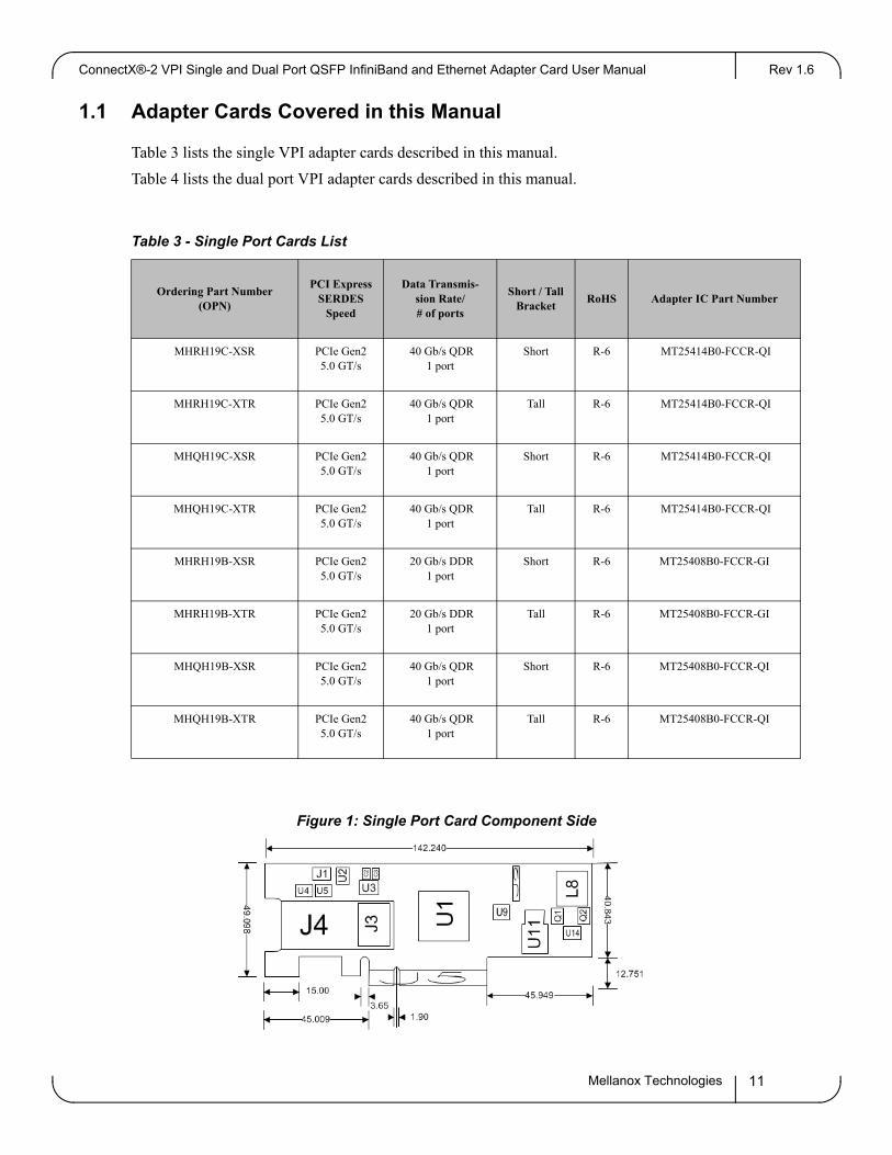
1.1 Adapter Cards Covered in this Manual
Table 3 lists the single VPI adapter cards described in this manual.
Table 4 lists the dual port VPI adapter cards described in this manual.
Table 3 - Single Port Cards List
Ordering Part Number (OPN)
PCI Express SERDES
Speed
Data Transmis-sion Rate/# of ports
Short / Tall Bracket
RoHS Adapter IC Part Number
MHRH19C-XSR PCIe Gen25.0 GT/s
40 Gb/s QDR1 port
Short R-6 MT25414B0-FCCR-QI
MHRH19C-XTR PCIe Gen25.0 GT/s
40 Gb/s QDR1 port
Tall R-6 MT25414B0-FCCR-QI
MHQH19C-XSR PCIe Gen25.0 GT/s
40 Gb/s QDR1 port
Short R-6 MT25414B0-FCCR-QI
MHQH19C-XTR PCIe Gen25.0 GT/s
40 Gb/s QDR1 port
Tall R-6 MT25414B0-FCCR-QI
MHRH19B-XSR PCIe Gen25.0 GT/s
20 Gb/s DDR1 port
Short R-6 MT25408B0-FCCR-GI
MHRH19B-XTR PCIe Gen25.0 GT/s
20 Gb/s DDR1 port
Tall R-6 MT25408B0-FCCR-GI
MHQH19B-XSR PCIe Gen25.0 GT/s
40 Gb/s QDR1 port
Short R-6 MT25408B0-FCCR-QI
MHQH19B-XTR PCIe Gen25.0 GT/s
40 Gb/s QDR1 port
Tall R-6 MT25408B0-FCCR-QI
Figure 1: Single Port Card Component Side
Mellanox Technologies 11
OverviewRev 1.6
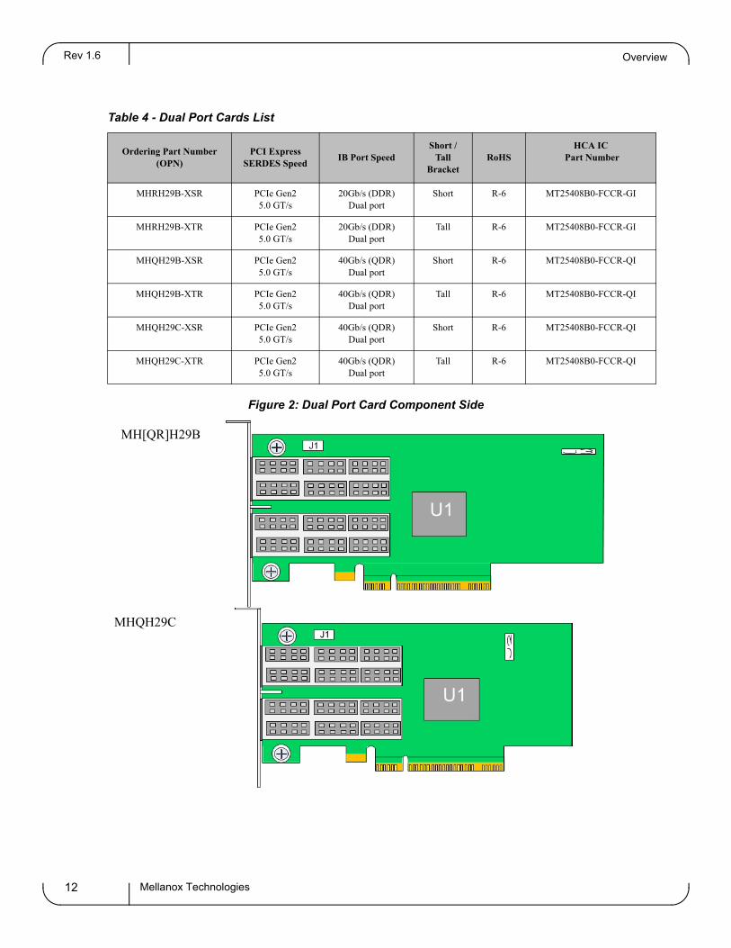
Table 4 - Dual Port Cards List
Ordering Part Number (OPN)
PCI Express SERDES Speed
IB Port SpeedShort /
Tall Bracket
RoHS HCA IC
Part Number
MHRH29B-XSR PCIe Gen25.0 GT/s
20Gb/s (DDR)Dual port
Short R-6 MT25408B0-FCCR-GI
MHRH29B-XTR PCIe Gen25.0 GT/s
20Gb/s (DDR)Dual port
Tall R-6 MT25408B0-FCCR-GI
MHQH29B-XSR PCIe Gen25.0 GT/s
40Gb/s (QDR)Dual port
Short R-6 MT25408B0-FCCR-QI
MHQH29B-XTR PCIe Gen25.0 GT/s
40Gb/s (QDR)Dual port
Tall R-6 MT25408B0-FCCR-QI
MHQH29C-XSR PCIe Gen25.0 GT/s
40Gb/s (QDR)Dual port
Short R-6 MT25408B0-FCCR-QI
MHQH29C-XTR PCIe Gen25.0 GT/s
40Gb/s (QDR)Dual port
Tall R-6 MT25408B0-FCCR-QI
Figure 2: Dual Port Card Component Side
MH[QR]H29B
MHQH29C
Mellanox Technologies12
ConnectX®-2 VPI Single and Dual Port QSFP InfiniBand and Ethernet Adapter Card User Manual Rev 1.6
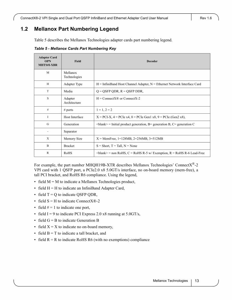
1.2 Mellanox Part Numbering Legend
Table 5 describes the Mellanox Technologies adapter cards part numbering legend.
Table 5 - Mellanox Cards Part Numbering Key
Adapter Card OPN
MHTS#I-XBRField Decoder
M Mellanox Technologies
H Adapter Type H = InfiniBand Host Channel Adapter, N = Ethernet Network Interface Card
T Media Q = QSFP QDR, R = QSFP DDR,
S Adapter Architecture
H = ConnectX® or ConnectX-2
# # ports 1 = 1, 2 = 2
I Host Interface X = PCI-X, 4 = PCIe x4, 8 = PCIe Gen1 x8, 9 = PCIe (Gen2 x8),
G Generation <blank> = Initial product generation, B= generation B, C= generation C
- Separator
X Memory Size X = MemFree, 1=128MB, 2=256MB, 3=512MB
B Bracket S = Short, T = Tall, N = None
R RoHS <blank> = non RoHS, C = RoHS R-5 w/ Exemption, R = RoHS R-6 Lead-Free
For example, the part number MHQH19B-XTR describes Mellanox Technologies’ ConnectX®-2 VPI card with 1 QSFP port, a PCIe2.0 x8 5.0GT/s interface, no on-board memory (mem-free), a tall PCI bracket, and RoHS R6 compliance. Using the legend,
• field M = M to indicate a Mellanox Technologies product,
• field H = H to indicate an InfiniBand Adapter Card,
• field T = Q to indicate QSFP QDR,
• field S = H to indicate ConnectX®-2
• field # = 1 to indicate one port,
• field I = 9 to indicate PCI Express 2.0 x8 running at 5.0GT/s,
• field G = B to indicate Generation B
• field X = X to indicate no on-board memory,
• field B = T to indicate a tall bracket, and
• field R = R to indicate RoHS R6 (with no exemptions) compliance
Mellanox Technologies 13

OverviewRev 1.6
1.3 Finding the GUID/ MAC and Serial Number on the Adapter Cards
Each Mellanox adapter card has a label on the print side that shows the card serial number, the card MAC for Ethernet protocol, and the card GUID for InfiniBand protocol. VPI cards have both a GUID and a MAC (derived from the GUID).
Figure 3: Card Product Label
Port 1 uses the GUID or MAC ID described on the label. For Port 2 GUID or MAC add 1 to Port 1's respective values.
1.4 Safety Warnings
For safety warnings in French see “Avertissements de sécurité d’installation (Warnings in French)” on page 60. For safety warnings in German see “Installation - Sicherheitshinweise (German)” on page 62. For safety warnings in Spanish see “Advertencias de seguridad para la instalación (Warn-ings in Spanish)” on page 63.
1. Installation Instructions
Read all installation instructions before connecting the equipment to the power source.
Mellanox Technologies14

ConnectX®-2 VPI Single and Dual Port QSFP InfiniBand and Ethernet Adapter Card User Manual Rev 1.6
2. Over-temperature
This equipment should not be operated in an area with an ambient temperature exceed-ing the maximum recommended: 55°C (131°F). To guarantee proper air flow, allow at least 8cm (3 inches) of clearance around the ven-tilation openings.
3. During Lightning - Electrical Hazard
During periods of lightning activity, do not work on the equipment or connect or dis-connect cables.
4. Copper Cable Connecting/Disconnecting
Some copper cables are heavy and not flexible, as such they should be carefully attached to or detached from the connectors. Refer to the cable manufacturer for spe-cial warnings and instructions.
5. Equipment Installation
This equipment should be installed, replaced, or serviced only by trained and qualified personnel.
6.
Disposal of this equipment should be in accordance to all national laws and regula-tions.
Equipment Disposal
7.
This equipment should be installed in compliance with local and national electrical codes.
Local and National Electrical Codes
Mellanox Technologies 15

Adapter Card InterfacesRev 1.6
2 Adapter Card Interfaces
2.1 I/O Interfaces
Each adapter card includes the following interfaces:
• QSFP ports
• PCI Express x8 edge connector
• I/O panel LEDs
• I2C-compatible connector (for debug)
For dual port cards, port 1 connects to connector 1 of the device, while port 2 connects to connec-tor 2 of the device.
Figure 4:
Port 2
Port 1
Dual Port Numbering
2.1.1 InfiniBand Interface
The ConnectX®-2 adapter card is compliant with the InfiniBand Architecture Specification, Release 1.2.1. VPI adapter cards listed above, based on this device, provide access to its network ports by means of QSFP connectors.
Mellanox Technologies16

ConnectX®-2 VPI Single and Dual Port QSFP InfiniBand and Ethernet Adapter Card User Manual Rev 1.6
2.1.2 Ethernet Interface
The ConnectX-2 adapter card is compliant with the IEEE Std 802.3. The VPI adapter cards listed above, based on this device, provide access to the Ethernet ports by means of QSFP connec-tors.The Mellanox QSA (QSFP to SFP+) adapter modules can be ordered through Mellanox Tech-nologies authorized dealers.
2.1.3 VPI Port Configuration
VPI ports are auto-sensing but can be manually configured using a script.
Table 6 lists the configurations supported by dual-port VPI adapter cards.
Table 6 - Supported Port Configurations
Port 1 Port 2
Ethernet Ethernet
IB IB
auto-sensing auto-sensing
IB Ethernet
IB auto-sensing
auto-sensing Ethernet
Table 7 lists the configurations not supported by dual-port VPI adapter cards.
Table 7 - Unsupported Port Configurations
Port 1 Port 2
Ethernet IB
Ethernet auto-sensing
auto-sensing IB
For port type configuration instructions please refer to Section 4.2, “Port Type Management Via Driver SW,” on page 36.
2.1.4 PCI Express Interface
The ConnectX®-2 adapter cards support PCI Express 2.0 (1.1 compatible) through an x8 edge connector. The device can be either a master initiating the PCI Express bus operations or a slave responding to PCI bus operations.
Mellanox Technologies 17

Adapter Card InterfacesRev 1.6
2.1.5 LED Assignment
There are two I/O LEDs per port, green and yellow, located on the I/O panel. Table 8 outlines the different LED functions.
Figure 5: LED - Port Association
Table 8 - Physical and Logical Link Indications
LED Function
Green - Physical link • Constant on indicates a good physical link• Blinking indicates a problem with the physical link• If neither LED is lit, then the physical link has not been established
Yellow -Logical (data activity) link
• A constant yellow indicates a valid logical (data activity) link without data transfer.
• A blinking yellow indicates a valid logical link with data transfer• If only the green LED is lit and the yellow LED is off, then the logical
link has not been established.
The short bracket has the same port and LED footprints as the tall bracket.
2.1.6 I2C-compatible Interface
A three-pin header on the adapter card is provided as the I2C-compatible interface. See Appendix A,“Specifications,” on page 44 for the location on the board.
Figure 6: I2C Connector
Mellanox Technologies18
ConnectX®-2 VPI Single and Dual Port QSFP InfiniBand and Ethernet Adapter Card User Manual Rev 1.6
2.2 Power
All adapter cards receive 12V and 3.3V power from the PCI Express Edge connector. All other required power voltages are generated by on-board switch mode regulators. See “Specifications” on page 44.
2.3 QSFP Power Level
The card supports power level 3, according to SFF Committee SFF-8436 Specification for QSFP (Quad Small Form-factor Pluggable) Transceiver.
2.4 Memory
The adapter cards support multiple memory devices through the PCI, SPI (Flash) and I2C inter-faces.
2.4.1 System Memory
The adapter cards utilize the PCI Express interface to store and access IB fabric and/or Ethernet fabric connection information and packet data on the system memory.
2.4.2 SPI (Flash)
Each of the adapter cards includes one 16MB SPI Flash device (M25P16-VME6G device by ST Microelectronics) accessible via the Flash interface of the ConnectX®-2 VPI adapter card.
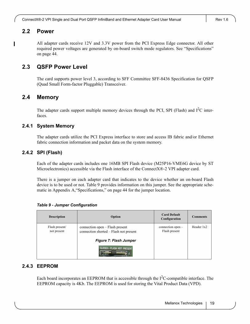
There is a jumper on each adapter card that indicates to the device whether an on-board Flash device is to be used or not. Table 9 provides information on this jumper. See the appropriate sche-matic in Appendix A,“Specifications,” on page 44 for the jumper location.
Table 9 - Jumper Configuration
Description OptionCard Default Configuration
Comments
Flash present/ not present
connection open – Flash presentconnection shorted – Flash not present
Figure 7: Flash Jumper
connection open – Flash present
Header 1x2
2.4.3 EEPROM
Each board incorporates an EEPROM that is accessible through the I2C-compatible interface. The EEPROM capacity is 4Kb. The EEPROM is used for storing the Vital Product Data (VPD).
Mellanox Technologies 19

Adapter Card InterfacesRev 1.6
The PCI VPD (Vital Product Data) layout, for each of the adapter cards complies with the format defined in the PCI 2.3 Specification, Appendix I.
Table 10 - MHQH[12]9B-XTR
Offset (Decimal)
Item Value Format Description
0 Large Resource Type ID String Tag (0x02)
0x82
1 Length [7:0] LSB 0xA
2 Length [15:8] MSB 0x0
3 Data FALCON QDR STR
13 Large Resource Type VPD-R Tag (0x10)
0x90
14 Length [7:0] LSB 0x4F
15 Length [15:8] MSB 0x00
16 VPD Keyword PN STR Add in Card Part Number
18 Length 0x15
19 PN PN %STR_SPC
40 VPD Keyword EC STR Engineering Change Level of the card (rev)
42 Length 0x2
43 Revision RV %STR PCB revision
45 VPD Keyword SN STR Serial Number
47 Length 0x18
48 SerialNumber %STR_SPC “00..00XXXX..XX”
72 VPD Keyword V0 STR Misc Information
74 Length 0x10
75 Data PCIe Gen2 x8 STR_SPC
91 VPD Keyword RV STR
93 Length 0x1
94 Data 0,93 %CS0
95 Large Resource Type VPD-W Tag (0x11)
0x91
96 Length [7:0] LSB 0x9D
97 Length [15:8] MSB 0x00
98 VPD Keyword V1 STR EFI Driver version
100 Length 0x6
101 Data N/A STR_SPC
107 VPD Keyword YA STR Asset Tag
109 Length 0x20
110 Data N/A STR_SPC “N/A”
142 VPD Keyword RW STR Remaining read/write area
144 Length 0x6E
145 Data STR_ZERO Reserved (0x00)
255 Small Resource Type END Tag (0x11)
0x78
Mellanox Technologies20
ConnectX®-2 VPI Single and Dual Port QSFP InfiniBand and Ethernet Adapter Card User Manual Rev 1.6
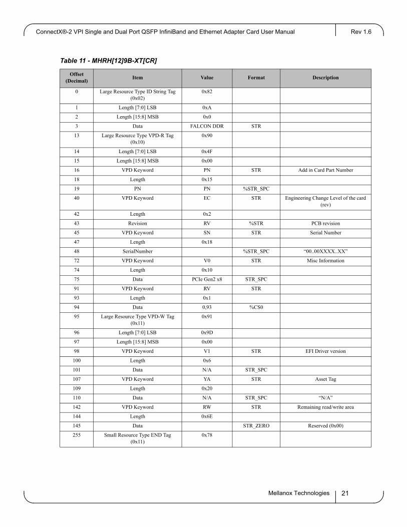
Table 11 - MHRH[12]9B-XT[CR]
Offset (Decimal)
Item Value Format Description
0 Large Resource Type ID String Tag (0x02)
0x82
1 Length [7:0] LSB 0xA
2 Length [15:8] MSB 0x0
3 Data FALCON DDR STR
13 Large Resource Type VPD-R Tag (0x10)
0x90
14 Length [7:0] LSB 0x4F
15 Length [15:8] MSB 0x00
16 VPD Keyword PN STR Add in Card Part Number
18 Length 0x15
19 PN PN %STR_SPC
40 VPD Keyword EC STR Engineering Change Level of the card (rev)
42 Length 0x2
43 Revision RV %STR PCB revision
45 VPD Keyword SN STR Serial Number
47 Length 0x18
48 SerialNumber %STR_SPC “00..00XXXX..XX”
72 VPD Keyword V0 STR Misc Information
74 Length 0x10
75 Data PCIe Gen2 x8 STR_SPC
91 VPD Keyword RV STR
93 Length 0x1
94 Data 0,93 %CS0
95 Large Resource Type VPD-W Tag (0x11)
0x91
96 Length [7:0] LSB 0x9D
97 Length [15:8] MSB 0x00
98 VPD Keyword V1 STR EFI Driver version
100 Length 0x6
101 Data N/A STR_SPC
107 VPD Keyword YA STR Asset Tag
109 Length 0x20
110 Data N/A STR_SPC “N/A”
142 VPD Keyword RW STR Remaining read/write area
144 Length 0x6E
145 Data STR_ZERO Reserved (0x00)
255 Small Resource Type END Tag (0x11)
0x78
Mellanox Technologies 21

Adapter Card InterfacesRev 1.6
Table 12 - MH[QR]H19C-X[STN]R VPD
Offset (Decimal)
Item Value Format Description
0 Large Resource Type ID String Tag (0x02)
0x82
1 Length [7:0] LSB 0xF
2 Length [15:8] MSB 0x0
3 Data ConnectX-2 QSFP STR
18 Large Resource Type VPD-R Tag (0x10)
0x90
19 Length [7:0] LSB 0x4F
20 Length [15:8] MSB 0x00
21 VPD Keyword PN STR Add in Card Part Number
23 Length 0x15
24 PN PN %STR_SPC
45 VPD Keyword EC STR Engineering Change Level of the card (rev)
47 Length 0x2
48 Revision RV %STR PCB revision
50 VPD Keyword SN STR Serial Number
52 Length 0x18
53 SerialNumber %STR_SPC “00..00XXXX..XX”
77 VPD Keyword V0 STR Misc Information
79 Length 0x10
80 Data PCIe Gen2 x8 STR_SPC
96 VPD Keyword RV STR
98 Length 0x1
99 Data 0,98 %CS0
100 Large Resource Type VPD-W Tag (0x11)
0x91
101 Length [7:0] LSB 0x98
102 Length [15:8] MSB 0x00
103 VPD Keyword V1 STR EFI Driver version
105 Length 0x6
106 Data N/A STR_SPC
112 VPD Keyword YA STR Asset Tag
114 Length 0x20
115 Data N/A STR_SPC “N/A”
147 VPD Keyword RW STR Remaining read/write area
149 Length 0x69
150 Data STR_ZERO Reserved (0x00)
255 Small Resource Type END Tag (0x11)
0x78
Mellanox Technologies22

ConnectX®-2 VPI Single and Dual Port QSFP InfiniBand and Ethernet Adapter Card User Manual Rev 1.6
Table 13 - MHRH19B-X[ST]R
Offset (Decimal)
Item Value Format Description
0 Large Resource Type ID String Tag (0x02)
0x82
1 Length [7:0] LSB 0xB
2 Length [15:8] MSB 0x0
3 Data KESTREL DDR STR
14 Large Resource Type VPD-R Tag (0x10)
0x90
15 Length [7:0] LSB 0x4F
16 Length [15:8] MSB 0x00
17 VPD Keyword PN STR Add in Card Part Number
19 Length 0x15
20 PN PN %STR_SPC
41 VPD Keyword EC STR Engineering Change Level of the card (rev)
43 Length 0x2
44 Revision RV %STR PCB revision
46 VPD Keyword SN STR Serial Number
48 Length 0x18
49 SerialNumber %STR_SPC “00..00XXXX..XX”
73 VPD Keyword V0 STR Misc Information
75 Length 0x10
76 Data PCIe Gen2 x8 STR_SPC
92 VPD Keyword RV STR
94 Length 0x1
95 Data 0,94 %CS0
96 Large Resource Type VPD-W Tag (0x11)
0x91
97 Length [7:0] LSB 0x9C
98 Length [15:8] MSB 0x00
99 VPD Keyword V1 STR EFI Driver version
101 Length 0x6
102 Data N/A STR_SPC
108 VPD Keyword YA STR Asset Tag
110 Length 0x20
111 Data N/A STR_SPC “N/A”
143 VPD Keyword RW STR Remaining read/write area
145 Length 0x6D
146 Data STR_ZERO Reserved (0x00)
255 Small Resource Type END Tag (0x11)
0x78
Mellanox Technologies 23

Adapter Card InterfacesRev 1.6
Table 14 - MHQH19B-X[ST]R
Offset (Decimal)
Item Value Format Description
0 Large Resource Type ID String Tag (0x02)
0x82
1 Length [7:0] LSB 0xB
2 Length [15:8] MSB 0x0
3 Data KESTREL QDR STR
14 Large Resource Type VPD-R Tag (0x10)
0x90
15 Length [7:0] LSB 0x4F
16 Length [15:8] MSB 0x00
17 VPD Keyword PN STR Add in Card Part Number
19 Length 0x15
20 PN PN %STR_SPC
41 VPD Keyword EC STR Engineering Change Level of the card (rev)
43 Length 0x2
44 Revision RV %STR PCB revision
46 VPD Keyword SN STR Serial Number
48 Length 0x18
49 SerialNumber %STR_SPC “00..00XXXX..XX”
73 VPD Keyword V0 STR Misc Information
75 Length 0x10
76 Data PCIe Gen2 x8 STR_SPC
92 VPD Keyword RV STR
94 Length 0x1
95 Data 0,94 %CS0
96 Large Resource Type VPD-W Tag (0x11)
0x91
97 Length [7:0] LSB 0x9C
98 Length [15:8] MSB 0x00
99 VPD Keyword V1 STR EFI Driver version
101 Length 0x6
102 Data N/A STR_SPC
108 VPD Keyword YA STR Asset Tag
110 Length 0x20
111 Data N/A STR_SPC “N/A”
143 VPD Keyword RW STR Remaining read/write area
145 Length 0x6D
146 Data STR_ZERO Reserved (0x00)
255 Small Resource Type END Tag (0x11)
0x78
Mellanox Technologies24

ConnectX®-2 VPI Single and Dual Port QSFP InfiniBand and Ethernet Adapter Card User Manual Rev 1.6
Table 15 - MHQH29B-X[ST]R VPD
Offset (Decimal)
Item Value Format Description
0 Large Resource Type ID String Tag (0x02)
0x82
1 Length [7:0] LSB 0xA
2 Length [15:8] MSB 0x0
3 Data FALCON QDR STR
13 Large Resource Type VPD-R Tag (0x10)
0x90
14 Length [7:0] LSB 0x4F
15 Length [15:8] MSB 0x00
16 VPD Keyword PN STR Add in Card Part Number
18 Length 0x15
19 PN PN %STR_SPC
40 VPD Keyword EC STR Engineering Change Level of the card (rev)
42 Length 0x2
43 Revision RV %STR PCB revision
45 VPD Keyword SN STR Serial Number
47 Length 0x18
48 SerialNumber %STR_SPC “00..00XXXX..XX”
72 VPD Keyword V0 STR Misc Information
74 Length 0x10
75 Data PCIe Gen2 x8 STR_SPC
91 VPD Keyword RV STR
93 Length 0x1
94 Data 0,93 %CS0
95 Large Resource Type VPD-W Tag (0x11)
0x91
96 Length [7:0] LSB 0x9D
97 Length [15:8] MSB 0x00
98 VPD Keyword V1 STR EFI Driver version
100 Length 0x6
101 Data N/A STR_SPC
107 VPD Keyword YA STR Asset Tag
109 Length 0x20
110 Data N/A STR_SPC “N/A”
142 VPD Keyword RW STR Remaining read/write area
144 Length 0x6E
145 Data STR_ZERO Reserved (0x00)
255 Small Resource Type END Tag (0x11)
0x78
Mellanox Technologies 25
Adapter Card InterfacesRev 1.6
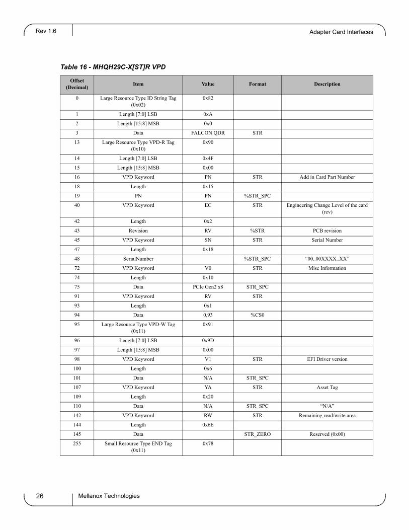
Table 16 - MHQH29C-X[ST]R VPD
Offset (Decimal)
Item Value Format Description
0 Large Resource Type ID String Tag (0x02)
0x82
1 Length [7:0] LSB 0xA
2 Length [15:8] MSB 0x0
3 Data FALCON QDR STR
13 Large Resource Type VPD-R Tag (0x10)
0x90
14 Length [7:0] LSB 0x4F
15 Length [15:8] MSB 0x00
16 VPD Keyword PN STR Add in Card Part Number
18 Length 0x15
19 PN PN %STR_SPC
40 VPD Keyword EC STR Engineering Change Level of the card (rev)
42 Length 0x2
43 Revision RV %STR PCB revision
45 VPD Keyword SN STR Serial Number
47 Length 0x18
48 SerialNumber %STR_SPC “00..00XXXX..XX”
72 VPD Keyword V0 STR Misc Information
74 Length 0x10
75 Data PCIe Gen2 x8 STR_SPC
91 VPD Keyword RV STR
93 Length 0x1
94 Data 0,93 %CS0
95 Large Resource Type VPD-W Tag (0x11)
0x91
96 Length [7:0] LSB 0x9D
97 Length [15:8] MSB 0x00
98 VPD Keyword V1 STR EFI Driver version
100 Length 0x6
101 Data N/A STR_SPC
107 VPD Keyword YA STR Asset Tag
109 Length 0x20
110 Data N/A STR_SPC “N/A”
142 VPD Keyword RW STR Remaining read/write area
144 Length 0x6E
145 Data STR_ZERO Reserved (0x00)
255 Small Resource Type END Tag (0x11)
0x78
Mellanox Technologies26

ConnectX®-2 VPI Single and Dual Port QSFP InfiniBand and Ethernet Adapter Card User Manual Rev 1.6
3 VPI Adapter Card Installation
3.1 Hardware Requirements
Before installing the adapter card, please make sure that the system meets the hardware require-ments listed in Table 17. Refer to Chapter 4,“Driver Software and Firmware” on page 32 for download and installation instructions.
Table 17 - Hardware Requirements
Requirement Description
Hardware • PCI Express x8 or x16 slots
3.2 Installation Instructions
Read all installation instructions before connecting the equipment to the power source.
The adapter cards listed in Table 3 on page 11 and Table 4 on page 12 are standard PCI Express cards, each with a standard x8 edge connector. Please consult the host machine documentation for instructions on how to install a PCI Express card.
When more than one PCI slot is available make sure to use the PCI slot with the proper configuration.
Any PCI slot with the proper configuration is acceptable for connection.
If the card is installed in a PCI slot with less lanes than the card requires then the adapter card will not provide the optimum data transfer.
3.3 Identify the Card in Your System
3.3.1 On Windows
1. Open Device Manager on the server. Click start => Run, and then enter “devmgmt.msc”.
2. Expand System Devices and locate your Mellanox ConnectX-2 adapter card.
3. Select Properties to display the adapter card properties window.
Mellanox Technologies 27

VPI Adapter Card InstallationRev 1.6
4. Click the Details tab and select Device Instance Id (Windows 2003) or Hardware Ids (Win-dows 2008/R2) from the Property pull-down menu.
If you cannot find any PCI device, click Action --> Scan for hardware changes. If no PCI devices are detected, check that the network adapter card(s) is correctly installed in the PCI slot or try installing the adapter card into a different PCI slot.
Figure 8: PCI Device
5. In the Value display box, check the fields VEN and DEV (fields are separated by ‘&’). In the display example above, notice the sub-string “PCI\VEN_15B3&DEV_6368”: VEN is equal to 0x15B3 – this is the Vendor ID of Mellanox Technologies; and DEV is equal to 0x6368 – this is a valid Mellanox Technologies PCI Device ID.
If the PCI device does not have a Mellanox adapter ID, return to Step 4 to check another device
Mellanox Technologies28
ConnectX®-2 VPI Single and Dual Port QSFP InfiniBand and Ethernet Adapter Card User Manual Rev 1.6
.
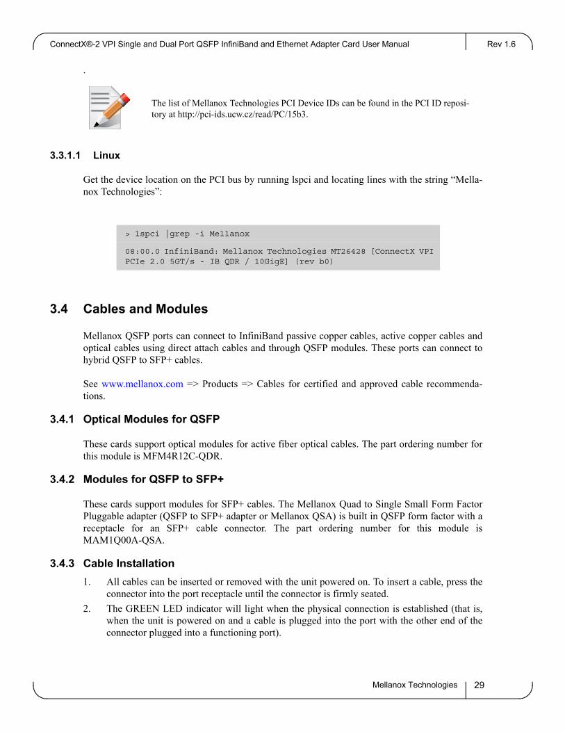
The list of Mellanox Technologies PCI Device IDs can be found in the PCI ID reposi-tory at http://pci-ids.ucw.cz/read/PC/15b3.
3.3.1.1 Linux
Get the device location on the PCI bus by running lspci and locating lines with the string “Mella-nox Technologies”:
> lspci |grep -i Mellanox
08:00.0 InfiniBand: Mellanox Technologies MT26428 [ConnectX VPI PCIe 2.0 5GT/s - IB QDR / 10GigE] (rev b0)
3.4 Cables and Modules
Mellanox QSFP ports can connect to InfiniBand passive copper cables, active copper cables and optical cables using direct attach cables and through QSFP modules. These ports can connect to hybrid QSFP to SFP+ cables.
See www.mellanox.com => Products => Cables for certified and approved cable recommenda-tions.
3.4.1 Optical Modules for QSFP
These cards support optical modules for active fiber optical cables. The part ordering number for this module is MFM4R12C-QDR.
3.4.2 Modules for QSFP to SFP+
These cards support modules for SFP+ cables. The Mellanox Quad to Single Small Form Factor Pluggable adapter (QSFP to SFP+ adapter or Mellanox QSA) is built in QSFP form factor with a receptacle for an SFP+ cable connector. The part ordering number for this module is MAM1Q00A-QSA.
3.4.3 Cable Installation
1. All cables can be inserted or removed with the unit powered on. To insert a cable, press the connector into the port receptacle until the connector is firmly seated.
2. The GREEN LED indicator will light when the physical connection is established (that is, when the unit is powered on and a cable is plugged into the port with the other end of the connector plugged into a functioning port).
Mellanox Technologies 29
VPI Adapter Card InstallationRev 1.6
3. After plugging in a cable, lock the connector using the latching mechanism particular to the cable vendor. When a logical connection is made the YELLOW LED will come on. When data is being transferred the yellow led will blink.
When installing cables make sure that the latches engage.
Always install and remove cables by pushing or pulling the cable and connector in a straight line with the card.
4. Care should be taken as not to impede the air exhaust flow through the ventilation holes. Cable lengths should be used which allow for routing horizontally around to the side of the chassis before bending upward or downward in the rack.
5. To remove a cable, disengage the locks and slowly pull the connector away from the port receptacle. Both LED indicators will turn off when the cable is unseated.
Cables, especially long copper cables, can weigh a substantial amount. Make sure that the weight of the cable is supported on its own and is not hanging from the adapter card.
3.4.3.1 Inserting a Cable into the Adapter Card
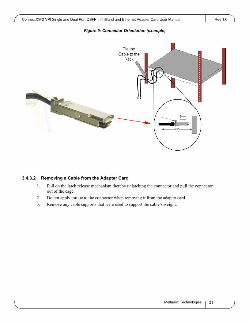
1. Support the weight of the cable before connecting the cable to the adapter card. Do this by using a cable holder or tying the cable to the rack.
2. Determine the correct orientation of the connector to the card before inserting the connector. Do not try and insert the connector up side down. This may damage the adapter card.
3. Insert the connector into the adapter card. Be careful to insert the connector straight into the cage. Do not apply any torque, up or down, to the connector cage in the adapter card.
4. Make sure that the connector locks in place.
Mellanox Technologies30
ConnectX®-2 VPI Single and Dual Port QSFP InfiniBand and Ethernet Adapter Card User Manual Rev 1.6
Figure 9: Connector Orientation (example)
3.4.3.2 Removing a Cable from the Adapter Card
1. Pull on the latch release mechanism thereby unlatching the connector and pull the connector out of the cage.
2. Do not apply torque to the connector when removing it from the adapter card.
3. Remove any cable supports that were used to support the cable’s weight.
Mellanox Technologies 31

Driver Software and FirmwareRev 1.6
4 Driver Software and Firmware
4.1 Driver Software
4.1.1 Linux
For Linux, download and install the latest OpenFabrics Enterprise Distribution (OFED) software package available via the Mellanox web site at: http://www.mellanox.com => Products => Soft-ware/Drivers => InfiniBand & VPI Software/Drivers => Mellanox OFED => Download. Follow the installation instructions included in the download package (also available from the download page). To ensure that communication has been established follow the instructions below.
Check the link status
First check the network interface name by running the “ifconfig –a” command.
run: ethtool <interface>
Host# ethtool eth0
Settings for eth0:
Supported ports: [ TP ]
Supported link modes: 10baseT/Half 10baseT/Full
100baseT/Half 100baseT/Full
1000baseT/Full
Supports auto-negotiation: Yes
Advertised link modes: 10baseT/Half 10baseT/Full
100baseT/Half 100baseT/Full
1000baseT/Full
Advertised auto-negotiation: Yes
Speed: 1000Mb/s
Duplex: Full
Port: Twisted Pair
PHYAD: 1
Transceiver: internal
Auto-negotiation: on
Supports Wake-on: g
Wake-on: d
Link detected: yes
Mellanox Technologies32

ConnectX®-2 VPI Single and Dual Port QSFP InfiniBand and Ethernet Adapter Card User Manual Rev 1.6
To check the IB link status, for IB and VPI cards, run “ibstat” and focus on the Physical state attributes.
Example:
Host# ibstat
CA 'mlx4_0'
CA type: MT26428
Number of ports: 2
Firmware version: 2.9.1000
Hardware version: b0
Node GUID: 0x0002c903000e9c5e
System image GUID: 0x0002c903000e9c61
Port 1:
State: Active
Physical state: LinkUp
Rate: 40
Base lid: 2
LMC: 0
SM lid: 1
Capability mask: 0x02510868
Port GUID: 0x0002c903000e9c5f
Link layer: IB
Port 2:
State: Down
Physical state: Polling
Rate: 70
Base lid: 0
LMC: 0
SM lid: 0
Capability mask: 0x02510868
Port GUID: 0x0002c903000e9c60
Link layer: IB
Check the OFED version
Mellanox Technologies 33
Driver Software and FirmwareRev 1.6
To get the version of the running Mellanox OFED/BXOFED, run the following command:
# ofed_info |head -1
MLNX_OFED_LINUX-1.5.3-0.1.6 (OFED-1.5.3-0.1.6):
Troubleshooting MLNX_OFED Installation
For troubleshooting driver installation, please check Mellanox OFED driver user manual ar http://www.mellanox.com => Support => InfiniBand Products => Mellanox OFED.
Loading the Ethernet Driver
By default, the Mellanox OFED stack loads mlx4_en. Run ‘lsmod’ to verify that the module is listed.
Example:
Host# lsmod |grep mlx4_en
mlx4_en 114184 0
mlx4_core 156512 2 mlx4_ib,mlx4_en
If you don’t see the mlx4_en driver, run: ’ modprobe mlx4_en’
Another option is to use the command below to see which modules are active.
Edit ”/etc/infiniband/openib.conf” which modules needs to load from a service.
For example:
# Load MLX4_EN module
MLX4_EN_LOAD=yes
The “Usage: openibd {start|stop|restart|status}” command to modify this file and thereby control the drivers.
Ethernet Driver Usage and Configuration
To assign an IP address to the interface run:
#> ifconfig eth<n> <ip>
where 'n' is the OS assigned interface number.
• To check driver and device information run:
Mellanox Technologies34
ConnectX®-2 VPI Single and Dual Port QSFP InfiniBand and Ethernet Adapter Card User Manual Rev 1.6
#> ethtool -i eth<n>
Example:
ethtool -i eth0
driver: igb
version: 2.1.0-k2
firmware-version: 1.4-3
bus-info: 0000:01:00.0
#> ethtool -i eth0
driver: bnx2
version: 2.0.2
firmware-version: 5.0.11 NCSI 2.0.4
bus-info: 0000:01:00.0
• The mlx4_en parameters can be found under /sys/module/mlx4_en (or /sys/module/mlx4_en/parameters, depending on the OS) and can be listed using the command:
#> modinfo mlx4_en
To set non-default values to module parameters, the following line should be added to the file/etc/modprobe.conf:
"options mlx4_en <param_name>=<value> <param_name>=<value> ..."
Ethernet Network Tuning
To improve network performance by tuning your network see the Mellanox Performance Tuning Guide located at:
www.mellanox.com => Products => Software/Drivers => Ethernet SW/Drivers => Linux Driver
4.1.2 Windows
For Windows, download and install the latest Mellanox WinOF VPI for Windows software pack-age available via the Mellanox web site at: http://www.mellanox.com => Products => Software/Drivers => InfiniBand & VPI Software/Drivers => Mellanox WinOF VPI => Download. Follow the installation instructions included in the download package (also available from the download page). To ensure that communication has been established follow the instructions below.
Mellanox Technologies 35

Driver Software and FirmwareRev 1.6
Displaying the Device Manager will show the Mellanox adapter devices and an IPoIB (network) device for each port. Note that MLNX_VPI configures the ports of VPI cards – at installation time – to run the InfiniBand protocol. See Chapter 8: “Port Protocol Configuration” for instructions to change this configuration.
Figure 10: Device Manager
Note: If the cards are connected to a managed switch, there is no need to run openSM. Only one OpenSM should run per subnet.
In InfiniBand interfaces, OpenSM is installed as a disabled Windows service. To enable it, enter at the command line:
> sc start opensm
Whereas in Ethernet interfaces, there is no need to run OpenSM.
4.2 Port Type Management Via Driver SW
4.2.1 Linux
If you wish to change the port type, use the connectx_port_config script after the driver is loaded.
The script is installed as part of the Mellanox OFED for Linux package (under /sbin). See the Mel-lanox OFED for the Linux User Manual available at http://www.mellanox.com => Support => InfiniBand Products => Mellanox OFED. Running "/sbin/connectx_port_config -s" will show the current port configuration for all ConnectX®-2 adapter cards.
Port configuration is saved in the file: /etc/infiniband/connectx.conf. This saved configuration is restored at driver restart only if done via "/etc/init.d/openibd restart".
Possible port types are:
Mellanox Technologies36

ConnectX®-2 VPI Single and Dual Port QSFP InfiniBand and Ethernet Adapter Card User Manual Rev 1.6
• "eth" - Always Ethernet
• "ib" - Always Infiniband
• "auto" - Link sensing mode - detect the port type based on the attached network type. If no link is detected, the driver retries link sensing every few seconds.
The port link type can be configured for each device in the system at run time using the "/sbin/connectx_port_config" script. This utility will prompt for the PCI device to be modified (if there is only one it will be selected automatically). At the next stage the user will be prompted for the desired mode for each port. The desired port configuration will then be set for the selected device. Note: This utility also has a non-interactive mode:
/sbin/connectx_port_config [[-d|--device <PCI device ID>] -c|--conf <port1,port2>]
4.2.2 Windows
For Windows, download and install the latest Mellanox WinOF VPI for Windows software pack-age available via the Mellanox Web site at: http://www.mellanox.com => Follow the installation instructions included in the download package. After installing Mellanox WinOF VPI for Win-dows on your machine, you can change a port's protocol configuration. The following steps describe how to configure the port type:
Step 1 Display the Device Manager and expand “Network adapters”.
Mellanox Technologies 37

Driver Software and FirmwareRev 1.6
Step 2. Right-click on the Mellanox ConnectX VPI network adapter and left-click Properties. Select the Port Protocol tab from the Properties sheet.
Note: The "Port Protocol” tab is displayed only if the NIC is a VPI (IB and ETH). If the NIC is either only IB or ETH, the tab will not be shown.
Note: The figure below is an example of the displayed Port Protocol sheet for a dual-port VPI adapter card.
Step 3. In this step, you can perform two different functions: (a) Choose the desired port protocol for the available port(s), and (b) activate or deactivate the WSD, ND, and/or SDP ULPs.
Note: IB must be always the first port in Port 1. If you choose ETH as your first port in Port 1, then the second port in Port 2 can be only ETH
Note: WSD is not supported in Windows 7. Consequently, on this OS the WSD checkbox is grayed out and cannot be selected.
4.3 FlexBoot
FlexBoot enables remote boot over Ethernet or InfiniBand using Boot over InfiniBand (BoIB), Boot over Ethernet (BoE), or Boot over iSCSI (Bo-iSCSI). This technology is based on the Pre-boot Execution Environment (PXE) standard specification, and FlexBoot software is based on the open source EtherBoot/gPXE project (see www.etherboot.org). For more information go to
Mellanox Technologies38

ConnectX®-2 VPI Single and Dual Port QSFP InfiniBand and Ethernet Adapter Card User Manual Rev 1.6
http://www.mellanox.com => Products => Software/Drivers => InfiniBand & VPI Software/Driv-ers => FlexBoot => Download
4.4 NVIDIA GPUDirect Support
Utilizing the high computational power of the Graphics Processing Unit (GPU), the GPU-to-GPU method has proven valuable in various areas of science and technology. Mellanox ConnectX-2 based adapter card provides the required high throughput and low latency for GPU-to-GPU com-munications.
4.4.1 Hardware and Software Requirements
Software:
Operating Systems:
• RHEL5.4 2.6.18-164.el5 x86_64 or later
• Mellanox OFED with GPUDirect support
• NVIDIA Development Driver for Linux version 195.36.15 or later
Hardware:
• Mellanox ConnectX-2 adapter card
• NVIDIA Tesla series
4.4.2 Installation
For installation instructions visit: http://www.mellanox.com => Support => VPI SW/Driver.
4.4.2.1 Kernel Installation:
Use Red Hat Package Manager (RPM) to install the Kernel RPM files:
- Install the required RPMs, for example, run:
# rpm --force -ivh *.rpm - Modify the boot loader configuration file if needed (e.g., edit /etc/grub.conf) - Reboot the machine with the new kernel # reboot
4.4.2.2 MLNX OFED Drivers Installation:
The MLNX driver is called MLNX_OFED_LINUX-Nvidia-1.5.1.
- Mount the ISO file:
# mount -o ro, loop MLNX_OFED_<version>.iso /mnt - Run the installation script: # /mnt/mlnxofed install - Restart the driver: # /etc/init.d/openibd restart - To make sure that GPUDirect is enabled, run:
Mellanox Technologies 39

Driver Software and FirmwareRev 1.6
# cat /sys/module/ib_core/parameters/gpu_direct_enable => 1
The number of shared pages by GPUDirect is reported under:
# cat /sys/module/ib_core/parameters/gpu_direct_shares
4.4.2.3 NVIDIA Driver Installation:
Install NVIDIA Development Driver for Linux x86_64, available under:
http://developer.nvidia.com/object/cuda_3_0_downloads.html
For example:
- Run: devdriver_3.0_linux_64_195.36.15.run - Follow the installation wizard instructions
To make sure that the NVIDIA driver was installed successfully:
- Load nvidia driver: # modprobe nvidia - Check the driver version, for example:# cat /proc/driver/nvidia/version => version 195.36.15 (or later)
4.5 CORE-Direct (Collectives Offload Resource Engine)
CORE-Direct (Collectives Offload Resource Engine) provides the most advanced solution for handling collectives operations, ensures maximum scalability, minimizes the CPU overhead and provides the capability for overlapping communications with computations. Mellanox Con-nectX®-2 adapters address the collectives communication scalability problems by offloading the communications to the adapters and switches.
4.5.1 Hardware and Software Requirements
Software:
Operating system RHEL 5.4 or later
Mellanox OFED 1.5.1 or later
Hardware:
Mellanox ConnectX®-2 adapter card
Disk Space for Installation 400 MB
4.5.2 Installation
For installation instructions visit: http://www.mellanox.com => Support => VPI SW/Driver.
4.6 RDMA over Converged Ethernet (RoCE)
ConnectX-2 with RoCE utilizes advances in Data Center Bridging (DCB) to enable efficient and low cost implementations of RDMA over Ethernet, supporting the entire breadth of RDMA and
Mellanox Technologies40
ConnectX®-2 VPI Single and Dual Port QSFP InfiniBand and Ethernet Adapter Card User Manual Rev 1.6
low latency features. This includes reliable connected service, datagram service, RDMA and send/receive semantics, atomic operations, user level multicast, user level I/O access, kernel bypass, and zero copy.
ConnectX-2 with RoCE based network management is the same as that for any Ethernet and DCB-based network management, eliminating the need for IT managers to learn new technologies.
4.6.1 Hardware and Software Requirements
Software:
Operating System Mellanox OFED 1.5.1 or later
Hardware:
ConnectX-2 Adapter Card
To use RoCE you will need the following versions of firmware and software:
• OFED 1.5.1 or later
• firmware version 2.7.700 or later
4.6.2 Installation
For installation instructions visit: www.mellanox.com => Support => Ethernet SW/Driver
4.7 Updating Adapter Card Firmware
Each card is shipped with the latest version of qualified firmware at the time of manufacturing. Firmware is updated occasionally, and the most recent firmware can be obtained from: => Support => Download Center. Check that the firmware on your card is the latest found on the Mellanox site, if not, update to the latest version found on the Mellanox website.
Firmware can be updated on the stand alone single card using the flint tool of the Mellanox Firm-ware Tools (MFT) package. This package is available for download, along with its user manual, from the Mellanox Firmware Tools page. See http://www.mellanox.com => Support => Download Center.
A firmware binaries table lists a binary file per adapter card. The file name of each such binary is composed by combining the firmware name, the firmware release version, and the card part num-ber. Please contact Mellanox System Support if you cannot find the firmware binary for your adapter card.
The following steps describe how to retrieve the PSID (firmware identification) and programmed firmware version of your adapter card. They also describe how to update the card with the latest firmware version available.
1. Retrieve the PSID and firmware version:
Mellanox Technologies 41

Driver Software and FirmwareRev 1.6
a. Install the MFT package. The package is available at http://www.mellanox.com => Products => Adapter IB/VPI SW => Firmware Tools. Make sure to download the package corre-sponding to your computer’s operating system.
b. Enter: mst start
c. Get the Mellanox mst device name using the command "mst status". The mst device name will be of the form: /dev/mst/mt<dev_id>_pci{_cr0|conf0
d. Get the PSID (firmware identification) and programmed firmware version using the command
> flint -d /dev/mst/mt23108_pci_cr0 queryImage type: FailSafeChip rev.: A1...Board ID: (MT_0E90110009) <--- This is the PSID
2. Compare the programmed firmware version with the latest available.
a. Go to Mellanox’s web site: http://www.mellanox.com/supportdownloader. See Figure 11
b. Enter your card PSID to display the latest firmware
Figure 11: Support Download Assistant
Mellanox Technologies42

ConnectX®-2 VPI Single and Dual Port QSFP InfiniBand and Ethernet Adapter Card User Manual Rev 1.6
3. If a newer firmware version exists for your adapter card, update the firmware
a. Download the firmware image zip file from the Download Center (see Step 2a above)
b. Unzip the firmware image
c. Burn the firmware image. Enter:
> flint -d <device_name> -i <binary image> burn
d. Reboot the computer
e. Enter: mst start
f. Verify that the card firmware was updated successfully
> flint -d /dev/mst/mt23108_pci_cr0 query
...
Mellanox Technologies 43

Rev 1.6
Appendix A: Specifications
A.1 MHQH19C-X[TSR] Specifications
Table 18 - Specifications for MHQH19C-X[ST]R
Physical Power and Environmental
Size:
Air Flow:
QSFP 40Gb/s Connector:
2.11in. x5.6 in. (53.58mm x 142.24 mm)
200LFMa
a. Air flow is measured ~1” from the heat sink between the heat sink and the cooling air inlet.
InfiniBand (Copper and optical) Max power per port 2.0 W.Cable power budget class 2.
Voltage:
Typ Power:
Maximum Power:
Temperature:
12V, 3.3V
Passive Cables 7.04W Active Cables 9.04W
Passive Cables 7.69W Active Cables 9.69W
0°C to 55°C
Protocol Support Regulatory
InfiniBand:
QoS:
Data Rate:
PCI Express
IBTA v1.2.1, Auto-Negotiationb
b. The auto-negotiation protocol is proprietary of Mellanox Technologies and compliant with the InfiniBand Architec-ture Specification, Release 1.2.
(40Gb/s, 10Gb/s per lane), (20Gb/s, 5Gb/s per lane) or (10Gb/s, 2.5Gb/s per lane)
8 InfiniBand Virtual Lanes
QDR
2.0 SERDES @5.0 GT/s
EMC:
Safety:
RoHS:
FCC 47 CFR part 15:2006, subpart B, class AICES-003:2004 Issue 4, class AVCCI V-3/2007.04, class AEN 55022:1998+A1:2000+A2:2003 class A, EN 61000-3-2:2000+A2:2005, EN61000-3-3:1995+A2:2005, EN 55024:1998 + A1:2001+A2:2003 standards, harmonized under EMC Directive 2004/108/EC Article 6(2);AS/NZS 3548
IEC/EN 60950-1:2006ETSI EN 300 019-2-2IEC 60068-2- 64, 29, 32
RoHS-R6
Mellanox Technologies44

ConnectX®-2 VPI Single and Dual Port QSFP InfiniBand and Ethernet Adapter Card User Manual Rev 1.2
A.2 MHRH19B-X[ST]R Specifications
Table 19 - Specifications for MHRH19B-X[ST]R
Physical Power and Environmental
Size:
Air Flow:
QSFP 10Gb/s Connector:
2.1in x 5.6in (53.6mm x 142.24mm)
200LFMa
a. Air flow is measured ~1” from the heat sink between the heat sink and the cooling air inlet.
InfiniBand (Copper and optical) Max power per port 2.0 WCable power budget class 2.
Voltage:
Typ. Power:
Maximum Power:
Temperature:
12V, 3.3V
Passive Cables 6.69W Active Cables 8.69W
Passive Cables 7.34W Active Cables 9.34W
0°C to 55°C
Protocol Support Regulatory
InfiniBand:
QoS:
RDMA Support:
Data Rate:
PCI Express:
IBTA v1.2.1, Auto-Negotiationb
b. The auto-negotiation protocol is proprietary of Mellanox Technologies and compliant with the InfiniBand Architecture Specification, Release 1.2.
(20Gb/s, 5Gb/s) or (10Gb/s, 2.5Gb/s)
8 InfiniBand Virtual Lanes for each port
Yes, All Ports
DDR – InfiniBand10Gb/s – Ethernet
2.0 SERDES @ 5.0GT/s
EMC:
Safety:
RoHS:
FCC 47 CFR part 15:2006, subpart B, class AICES-003:2004 Issue 4, class AVCCI V-3/2007.04, class AEN 55022:1998+A1:2000+A2:2003 class A, EN 61000-3-2:2000+A2:2005, EN61000-3-3:1995+A2:2005, EN 55024:1998 + A1:2001+A2:2003 standards, harmonized under EMC Directive 2004/108/EC Article 6(2);AS/NZS 3548
IEC/EN 60950-1:2006ETSI EN 300 019-2-2IEC 60068-2- 64, 29, 32
RoHS-R6
Mellanox Technologies 45

Rev 1.6
A.3 MHQH19B-X[ST]R Specifications
Table 20 - Specifications for MHQH19B-X[ST]R
Physical Power and Environmental
Size:
Air Flow:
QSFP 20Gb/s Connector:
2.1in x5.6in (53.60mm x 142.24mm)
200LFMa
a. Air flow is measured ~1” from the heat sink between the heat sink and the cooling air inlet.
InfiniBand (Copper and optical) Max power per port 2.0W.Cable power budget class 2
Voltage:
Typ. Power:
Maximum Power:
Temperature:
12V, 3.3V
Passive Cables 7.04W Active Cables 9.04W
Passive Cables 7.69W Active Cables 9.69W
0°C to 55°C
Protocol Support Regulatory
InfiniBand:
QoS:
RDMA Support:
Data Rate:
PCI Express:
IBTA v1.2.1, Auto-Negotiationb
b. The auto-negotiation protocol is proprietary of Mellanox Technologies and compliant with the InfiniBand Architecture Specification, Release 1.2.
(20Gb/s, 5Gb/s) or (10Gb/s, 2.5Gb/s)
8 InfiniBand Virtual Lanes for each port
Yes, All Ports
QDR – InfiniBand10Gb/s – Ethernet
2.0 SERDES @ 5.0GT/s
EMC:
Safety:
RoHS:
FCC 47 CFR part 15:2006, subpart B, class AICES-003:2004 Issue 4, class AVCCI V-3/2007.04, class AEN 55022:1998+A1:2000+A2:2003 class A, EN 61000-3-2:2000+A2:2005, EN61000-3-3:1995+A2:2005, EN 55024:1998 + A1:2001+A2:2003 standards, harmonized under EMC Directive 2004/108/EC Article 6(2);AS/NZS 3548
IEC/EN 60950-1:2006ETSI EN 300 019-2-2IEC 60068-2- 64, 29, 32
RoHS-R6
Mellanox Technologies46

ConnectX®-2 VPI Single and Dual Port QSFP InfiniBand and Ethernet Adapter Card User Manual Rev 1.2
A.4 MHQH29C-X[ST]R Specifications
Table 21 - Specifications for MHQH29C-X[ST]R
Physical Power and Environmental
Size:
Air Flow:
QSFP 40Gb/s Connector:
2.66in. x5.6 in. (67.5mm x 142.24 mm)
200LFMa
a. Air flow is measured ~1” from the heat sink between the heat sink and the cooling air inlet.
InfiniBand (Copper and optical) Max power per port 2.0 W.Cable power budget class 2.
Voltage:
Typ Power:
Maximum Power:
Temperature:
12V, 3.3V
Passive Cables 8.78W Active Cables 12.78W
Passive Cables 9.36W Active Cables 13.36W
0°C to 55°C
Protocol Support Regulatory
InfiniBand:
QoS:
Data Rate:
PCI Express:
IBTA v1.2.1, Auto-Negotiationb
b. The auto-negotiation protocol is proprietary of Mellanox Technologies and compliant with the InfiniBand Architec-ture Specification, Release 1.2.
(40Gb/s, 10Gb/s per lane), (20Gb/s, 5Gb/s per lane) or (10Gb/s, 2.5Gb/s per lane)
8 InfiniBand Virtual Lanes for each port
QDR – InfiniBand10Gb/s – Ethernet
2.0 SERDES @ 5.0GT/s
EMC:
Safety:
RoHS:
FCC 47 CFR part 15:2006, subpart B, class AICES-003:2004 Issue 4, class AVCCI V-3/2007.04, class AEN 55022:1998+A1:2000+A2:2003 class A, EN 61000-3-2:2000+A2:2005, EN61000-3-3:1995+A2:2005, EN 55024:1998 + A1:2001+A2:2003 standards, harmonized under EMC Directive 2004/108/EC Article 6(2);AS/NZS 3548
IEC/EN 60950-1:2006ETSI EN 300 019-2-2IEC 60068-2- 64, 29, 32
RoHS-R6
Mellanox Technologies 47

Rev 1.6
A.5 MHRH29B-X[ST]R Specifications
Table 22 - Specifications for MHRH29B-X[ST]R
Physical Power and Environmental
Size:
Air Flow:
QSFP 20Gb/s Connector:
2.69in. x6.60in. (68.40mm x 167.65mm)
200LFMa
a. Air flow is measured ~1” from the heat sink between the heat sink and the cooling air inlet.
InfiniBand (Copper and optical) Max power per port 2.0 W.Cable power budget class 2.
Voltage:
Typ Power:
Maximum Power:
Temperature:
12V, 3.3V
Passive Cables 8.15W Active Cables 12.15W
Passive Cables 8.80W Active Cables 12.80W
0°C to 55°C
Protocol Support Regulatory
InfiniBand:
QoS:
Data Rate:
PCI Express:
IBTA v1.2.1, Auto-Negotiationb
b. The auto-negotiation protocol is proprietary of Mellanox Technologies and compliant with the InfiniBand Architec-ture Specification, Release 1.2.
(40Gb/s, 10Gb/s per lane), (20Gb/s, 5Gb/s per lane) or (10Gb/s, 2.5Gb/s per lane)
8 InfiniBand Virtual Lanes for each port
DDR – InfiniBand10Gb/s – Ethernet
2.0 SERDES @ 5.0 GT/s
EMC:
Safety:
RoHS:
FCC 47 CFR part 15:2006, subpart B, class AICES-003:2004 Issue 4, class AVCCI V-3/2007.04, class AEN 55022:1998+A1:2000+A2:2003 class A, EN 61000-3-2:2000+A2:2005, EN61000-3-3:1995+A2:2005, EN 55024:1998 + A1:2001+A2:2003 standards, harmonized under EMC Directive 2004/108/EC Article 6(2);AS/NZS 3548
IEC/EN 60950-1:2006ETSI EN 300 019-2-2IEC 60068-2- 64, 29, 32
RoHS-R6
Mellanox Technologies48

ConnectX®-2 VPI Single and Dual Port QSFP InfiniBand and Ethernet Adapter Card User Manual Rev 1.2
A.6 MHQH29B-X[ST]R Specifications
Table 23 - Specifications for MHQH29B-X[ST]R
Physical Power and Environmental
Size:
Air Flow:
QSFP 40Gb/s Connector:
2.69in. x6.60in. (68.40mm x 167.65mm)
200LFMa
a. Air flow is measured ~1” from the heat sink between the heat sink and the cooling air inlet.
InfiniBand (Copper and optical) Max power per port 2.0 W.Cable power budget class 2.
Voltage:
Typ Power:
Maximum Power:
Temperature:
12V, 3.3V
Passive Cables 8.78W Active Cables 12.78W
Passive Cables 9.36W Active Cables 13.36W
0°C to 55°C
Protocol Support Regulatory
InfiniBand:
QoS:
Data Rate:
PCI Express:
IBTA v1.2.1, Auto-Negotiationb
b. The auto-negotiation protocol is proprietary of Mellanox Technologies and compliant with the InfiniBand Architec-ture Specification, Release 1.2.
(40Gb/s, 10Gb/s per lane), (20Gb/s, 5Gb/s per lane) or (10Gb/s, 2.5Gb/s per lane)
8 InfiniBand Virtual Lanes for each port
QDR – InfiniBand10Gb/s – Ethernet
2.0 SERDES @ 5.0GT/s
EMC:
Safety:
RoHS:
FCC 47 CFR part 15:2006, subpart B, class AICES-003:2004 Issue 4, class AVCCI V-3/2007.04, class AEN 55022:1998+A1:2000+A2:2003 class A, EN 61000-3-2:2000+A2:2005, EN61000-3-3:1995+A2:2005, EN 55024:1998 + A1:2001+A2:2003 standards, harmonized under EMC Directive 2004/108/EC Article 6(2);AS/NZS 3548
IEC/EN 60950-1:2006ETSI EN 300 019-2-2IEC 60068-2- 64, 29, 32
RoHS-R6
Mellanox Technologies 49
Rev 1.6
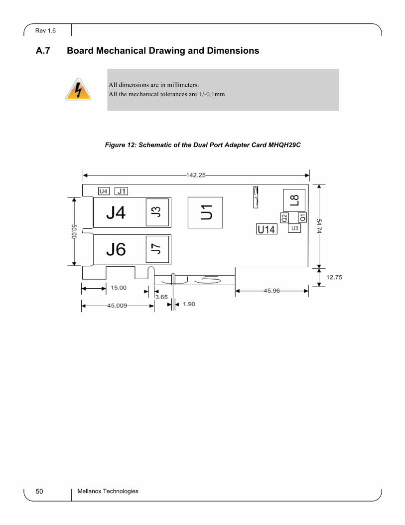
A.7 Board Mechanical Drawing and Dimensions
All dimensions are in millimeters.
All the mechanical tolerances are +/-0.1mm
Figure 12: Schematic of the Dual Port Adapter Card MHQH29C
Mellanox Technologies50

ConnectX®-2 VPI Single and Dual Port QSFP InfiniBand and Ethernet Adapter Card User Manual Rev 1.2
Figure 13: Schematic of the Dual Port Adapter Card MH[RQ]H29B-X[ST]R
167.65
68.40
56.15
96.30
57.15
15.00
33.35
56.9764.40
J1- I2C ConnectorJ3 - Flash jumper
Figure 14: Schematic of the Single Port Adapter Card MH[QR]H19[BC]-X[ST]RJ1 – I2C Connector J2 – Flash Jumper
Mellanox Technologies 51

Rev 1.6
A.8 Regulatory Statements
For regulatory statements for all ConnectX®-3 cards please refer to: http://www.mellanox.com/related-docs/user_manuals/Regulatory_and_Compliance_Guide.pdf
Mellanox Technologies52

ConnectX®-2 VPI Single and Dual Port QSFP InfiniBand and Ethernet Adapter Card User Manual Rev 1.6
Appendix B: Interface Connectors Pinout
B.1 I2C-Compatible Connector Pinout
Figure 15: Compatible Connector Plug and Pinout
5 1 2 3 4
5 1 2 3 4
Table 24 - I2C-Compatible Connector
Connector Pin Number Signal Name
1 SPSDA
2 SPSCL
3 GND
4 NC
5 NC
B.2 PCI Express x8 Connector Pinout
These cards use a standard PCI Express x8edge connector and the PCI Express x8 standard pinout according to the PCI Express 2.0 specification.
Mellanox Technologies 53

Rev 1.6
B.3 QSFP Connector Pinout
Figure 16: Connector and Cage Views
Table 25 - Connector Pin Name and Number to Signal Name Correspondence
Connector Pin Number Connector Pin Name Port A Signal Name
1 GND GND
2 TXN_2 Tx2n
3 TXP_2 Tx2p
4 GND GND
5 TXN_4 Tx4n
6 TXP_4 Tx4p
7 GND GND
8 ModSelL_Port0 ModSelL
9 ResetL_Port0 ResetL
10 VccRx
11 SCL SCL
12 SDA SDA
13 GND GND
14 RXP_3 Rx3p
15 RXN_3 Rx3n
Mellanox Technologies54

ConnectX®-2 VPI Single and Dual Port QSFP InfiniBand and Ethernet Adapter Card User Manual Rev 1.6
16 GND GND
17 RXP_1 Rx1p
18 RXN_1 Rx1n
19 GND GND
20 GND GND
21 RXN_2 Rx2n
22 RXP_2 Rx2p
23 GND GND
24 RXN_4 Rx4n
25 RXP_4 Rx4p
26 GND GND
27 ModPrsl_Port0 Mod PrsL
28 IntL IntL
29 VccTx
30 Vcc1
31 LPMode_Port0 LPMode
32 GND GND
33 TXP_3 Tx3p
34 TXN_3 Tx3n
35 GND GND
36 TXP_1 Tx1p
37 TXN_1 Tx1n
38 GND GND
Table 25 - Connector Pin Name and Number to Signal Name Correspondence
Connector Pin Number Connector Pin Name Port A Signal Name
Mellanox Technologies 55

Rev 1.6
Appendix C: Replacing a Tall Bracket With a Short Bracket
This section provides instructions on how to remove the tall bracket of a standard Mellanox Tech-nologies adapter card and replace it with a short one. It includes the following sections:
• Removing a bracket
• Installing a new bracket
To replace the bracket you will need the following parts:
• the new bracket of the proper height
• one new QSFP EMI gasket
• the 2 screws saved from the removal of the bracket
• the 2 fiber washers saved from the removal of the bracket
Mellanox Technologies56

ConnectX®-2 VPI Single and Dual Port QSFP InfiniBand and Ethernet Adapter Card User Manual Rev 1.6
C.1 Remove the Existing Bracket from the Adapter Card
Figure 17: Remove the Bracket
Screws
Gaskets
LEDs
Screws
Gasket
LEDs
1. Remove the two screws holding the bracket in place.
2. The bracket comes loose from the card.
Be careful not to put stress on the LEDs.
3. Save the two screws and the two fiber washers.
C.2 Installing the New Bracket 1. Remove the paper to expose the adhesive on the gasket.
2. Place the gasket for each port onto the new bracket. Make sure to correctly align the gasket with the hole in the bracket.
Mellanox Technologies 57
Rev 1.6
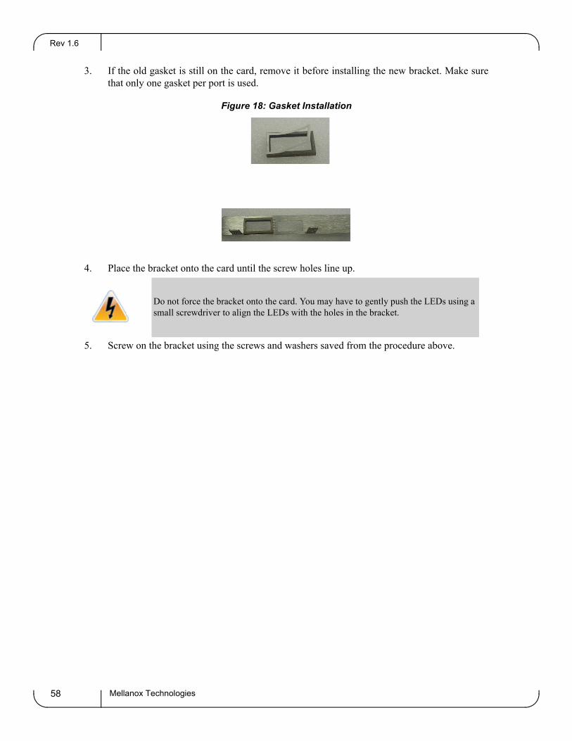
3. If the old gasket is still on the card, remove it before installing the new bracket. Make sure that only one gasket per port is used.
Figure 18: Gasket Installation
4. Place the bracket onto the card until the screw holes line up.
Do not force the bracket onto the card. You may have to gently push the LEDs using a small screwdriver to align the LEDs with the holes in the bracket.
5. Screw on the bracket using the screws and washers saved from the procedure above.
Mellanox Technologies58

ConnectX®-2 VPI Single and Dual Port QSFP InfiniBand and Ethernet Adapter Card User Manual Rev 1.6
Figure 19: Placing the Bracket on the Card
Gaskets in place on the bracket.
6. Make sure that the LEDs are aligned onto the bracket holes.
7. Use a torque driver to apply up to 2 lbs-in torque on the screw
Mellanox Technologies 59

Rev 1.6
Appendix D: Avertissements de sécurité d’installation (Warnings in French)
1. Instructions d’installation
Lisez toutes les instructions d’installation avant de brancher le matériel à la source d’alimentation électrique.
2. Température excessive
Ce matériel ne doit pas fonctionner dans une zone avec une température ambiante dépassant le maximum recommandé de 55°C (131°F). Un flux d’air de 200LFM à cette température ambiante maximale est nécessaire. En outre, pour garantir un bon écoulement de l’air, laissez au moins 8 cm (3 pouces) d’espace libre autour des ouver-tures de ventilation.
3. Orages – dangers électriques
Pendant un orage, il ne faut pas utiliser le matériel et il ne faut pas brancher ou débrancher les câbles.
4. Branchement/débranchement des câbles en cuivre
Les câbles en cuivre sont lourds et ne sont pas flexibles, il faut donc faire très attention en les branchant et en les débranchant des connecteurs. Consultez le fabricant des câbles pour connaître les mises en garde et les instructions spéciales.
5. Installation du matériel
Ce matériel ne doit être installé, remplacé ou entretenu que par du personnel formé et qualifié.
6. Elimination du matériel
L’élimination de ce matériel doit s’effectuer dans le respect de toutes les législations et réglementations nationales en vigueur.
Mellanox Technologies60

ConnectX®-2 VPI Single and Dual Port QSFP InfiniBand and Ethernet Adapter Card User Manual Rev 1.6
7. Codes électriques locaux et nationaux
Ce matériel doit être installé dans le respect des codes électriques locaux et nationaux.
8. Exposition au rayonnement grave
Mise en garde – l'utilisation de commandes ou de réglages ou l'exécution de procédures autres que ce qui est spécifié dans les présentes peut engendrer une exposition au rayonnement grave.
PRODUIT LASER DE CLASSE 1 » et références aux normes laser les plus récentes CEI 60 825-1:1993 + A1:1997 + A2:2001 et NE 60825-1:1994+A1:1996+ A2:2001
Mellanox Technologies 61
Rev 1.6
Mellanox Technologies62
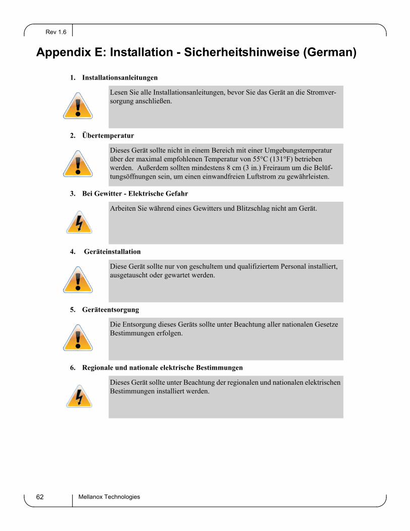
Appendix E: Installation - Sicherheitshinweise (German)
1. Installationsanleitungen
Lesen Sie alle Installationsanleitungen, bevor Sie das Gerät an die Stromver-sorgung anschließen.
2. Übertemperatur
Dieses Gerät sollte nicht in einem Bereich mit einer Umgebungstemperatur über der maximal empfohlenen Temperatur von 55°C (131°F) betrieben werden. Außerdem sollten mindestens 8 cm (3 in.) Freiraum um die Belüf-tungsöffnungen sein, um einen einwandfreien Luftstrom zu gewährleisten.
3. Bei Gewitter - Elektrische Gefahr
Arbeiten Sie während eines Gewitters und Blitzschlag nicht am Gerät.
4. Geräteinstallation
Diese Gerät sollte nur von geschultem und qualifiziertem Personal installiert, ausgetauscht oder gewartet werden.
5. Geräteentsorgung
Die Entsorgung dieses Geräts sollte unter Beachtung aller nationalen Gesetze Bestimmungen erfolgen.
6. Regionale und nationale elektrische Bestimmungen
Dieses Gerät sollte unter Beachtung der regionalen und nationalen elektrischen Bestimmungen installiert werden.

ConnectX®-2 VPI Single and Dual Port QSFP InfiniBand and Ethernet Adapter Card User Manual Rev 1.6
Mellanox Technologies 63
Appendix F: Advertencias de seguridad para la instalación (Warnings in Spanish)
1. Instrucciones de instalación
Antes de conectar el equipo a la fuente de alimentación, leer todas las instrucciones de instalación.
2. Sobrecalentamiento
No se debe utilizar el equipo en un área con una temperatura ambiente superior a la máxima recomendada: 55°C(131°F). Además, para garantizar una circulación de aire adecuada, se debe dejar como mínimo un espacio de 8 cm (3 pulgadas) alrededor de las aberturas de ventilación.
3. Cuando hay rayos: peligro de descarga eléctrica
No utilizar el equipo ni conectar o desconectar cables durante períodos de actividad de rayos.
4. Instalación de equipos
La instalación, el reemplazo y el mantenimiento de este equipo estarán a cargo única-mente de personal capacitado y competente.
5. Eliminación de equipos
La eliminación definitiva de este equipo se debe efectuar conforme a todas las leyes y reglamentaciones nacionales.
6. Códigos eléctricos locales y nacionales
Este equipo se debe instalar conforme a los códigos eléctricos locales y nacionales.