connector basics - learn.sparkfun connector terminology categorize connectors into distinguishable...
TRANSCRIPT

Connector Basics a learn.sparkfun.com tutorial
Available online at: http://sfe.io/t18
Contents
IntroductionConnector TerminologyUSB ConnectorsAudio ConnectorsPower ConnectorsSMA Antenna ConnectorsPin Header ConnectorsTemporary ConnectorsOther ConnectorsResources and Going Further
Introduction
Connectors are used to join subsections of circuits together. Usually, a connector is used where it may be desirable to disconnect the subsections at some futuretime: power inputs, peripheral connections, or boards which may need to be replaced.
Covered in This Tutorial
In this tutorial we will go over:
Basic connector terminologyCategorize connectors into distinguishable categoriesTalk about the differences between connectors within those categories.Show how to identify polarized connectorsTalk about which connectors are best suited for certain applications
Suggested Reading
You may find these concepts useful before starting on this tutorial:
What is a Circuit?
Every electrical project starts with a circuit. Don't know what a circuit is? We're here to help.Favorited Favorite 45
Voltage, Current, Resistance, and Ohm's Law
Learn about Ohm's Law, one of the most fundamental equations in all electrical engineering.Favorited Favorite 83
How to Power a Project
A tutorial to help figure out the power requirements of your project.Favorited Favorite 43
Working with Wire
How to strip, crimp, and work with wire.Favorited Favorite 22
Polarity
An introduction to polarity in electronic components. Discover what polarity is, which parts have it, and how to identify it.Favorited Favorite 33
Connector Terminology
Before we get started discussing some commonly used connectors, let's explore the terminology used to describe connectors.
Gender
Gender - The gender of a connector refers to whether it plugs in or is plugged into and is typically male or female, respectively (kids, ask your parents for a morethorough explanation). Unfortunately, there are cases where a connector may be referred to as "male" when it would appear to be female; in the examplessection, we'll point a few of those out as we discuss individual component types and explain why that's the case.
Page 1 of 26

Male (left) and female 2.0mm PH series JST connectors. In this case, gender is determined by the individual conductor.
Polarity
Polarity - Most connectors can only be connected in one orientation. This trait is called polarity, and connectors which have some means to prevent them beingconnected wrong are said to be polarized, or sometimes keyed.
A polarized North American wall plug. By having two different widths for the plug blades, the plug will only go into the outlet one way.
Contact
Contact - Contacts are the business portion of the connector. They are the metal parts which touch each other, forming an electrical connection. This is alsowhere problems occur: the contacts can become soiled or oxidized, or the springiness required to hold the contacts together may fade with time.
The contacts on this connector are clearly visible.
Pitch
Pitch - Many connectors consist of an array of contacts in a repeated pattern. The pitch of the connector is the distance from the center of one contact to thecenter of the next. This is important, because there are many families of contacts which look very similar but may differ in pitch, making it difficult to know thatyou are purchasing the right mating connector.
Page 2 of 26

The pitch of the pins on the headers on a standard Arduino is .1".
Mating Cycles
Mating cycles - Connectors have a finite life, and connecting and disconnecting them is what wears them out. Datasheets usually present that information interms of mating cycles, and it varies widely from one technology to another. A USB connector may have a lifetime in the thousands or tens of thousands ofcycles, while a board-to-board connector designed for use inside of consumer electronics may be limited to tens of cycles. It's important that you select aconnector with a suitable life for the application.
Mating connector for the GS406 GPS module. The connector's datasheet indicates a maximum of 50 insertion cycles for this part.
Mount
Mount - This one has the potential for being confusing. The term "mount" can refer to several things: how the connector is mounted in use (panel mount, free-hanging, board mount), what the angle of the connector is relative to its attachment (straight or right-angle), or how it is mechanically attached (solder tab,surface mount, through hole). We'll discuss this more in the examples section for each individual connector.
A comparison of three different methods of mounting the same barrel connector: (left to right) board mount, inline cable mount, and panel mount.
Strain Relief
Page 3 of 26

Strain relief - When a connector mounts to a board or cable, the electrical connections tend to be somewhat fragile. It is typical to provide some kind of strainrelief to transfer any forces acting on that connector to a more mechanically sound object than the fragile electrical connections. Again, there will be some goodexamples of this later on.
This 1/8" headphone jack comes with a strain relief "boot" slid over the cable to prevent forces on the cable from being transmitted directly to the electrical joints.
USB Connectors
USB connectors come in two flavors: host and peripheral. In the USB standard, there is a difference between the two, and the connectors on cables anddevices reflect this. However, all USB connectors will have some things in common:
Polarization - A USB connector can only nominally be inserted one way. It may be possible to force a connector in wrong, but that will result in damage tothe device.Four contacts - All USB connectors have at least four contacts (although some may have five, and USB 3.0+ connectors have even more). These are forpower, ground, and two data lines (D+ and D-). USB connectors are designed to transmit 5V, up to 500mA.Shielding - USB connectors are shielded, such that a metal shell which is not part of the electrical circuit is provided. This is important to keep the signalintact in environments with a lot of electrical "noise".Robust power connection - It's important for the power pins to make connection before the data lines, to avoid trying to power the device over the datalines. All USB connectors are designed with this in mind.Molded strain relief - All USB cables have plastic overmolding at the connector to prevent strain on the cable that could potentially damage the electricalconnections.
A USB extension cable, with some of the common features of USB connectors labeled.
USB-A Connectors
USB-A female is the standard "host" connector type. This is found on computers, hubs, or any device intended to have peripherals plugged into it. It is alsopossible to find extension cables with a female A connector and a male A connector on the other end.
Page 4 of 26

Female USB-A ports on the side of a laptop. The blue connector is USB 3.0 compliant.
USB-A male is the standard "peripheral" connector type. Most USB cables will have one end terminating in a USB-A male connector, and many devices (suchas keyboards and mice) will have a built-in cable terminated with a USB-A male connector. It's also possible to find USB-A male connectors that are boardmountable, for devices like USB memory sticks.
Two types of Male USB-A connectors, on a SparkFun Cerberus cable and an AVR Stick development board.
USB-B Connectors
USB-B female is a standard for peripheral devices. It's bulky, but robust, so in applications where size is not an issue, it's the preferred means for providing aremovable connector for USB connectivity. It is usually a through-hole board mount connector, for maximum reliability, but there are panel-mount options for it aswell.
Page 5 of 26

Arduino boards, including this Uno, have long used the female USB-B connector, due to its low cost and durability.
USB-B male is almost exclusively found at the end of a cable. USB-B cables are ubiquitous and inexpensive, which also contributes to the popularity of theUSB-B connection.
USB-B male connector on the end of a SparkFun Cerberus cable.
USB-Mini Connectors
The USB-Mini connection was the first standard attempt to reduce the size of the USB connector for smaller devices. USB-Mini female is typically found onsmaller peripherals (MP3 players, older cellphones, small external hard drives), and is usually a surface mount connector, trading robustness for size. USB-Miniis slowly being phased out in favor of the USB-Micro connector.
USB-Mini female connector on a Protosnap Pro Mini.
USB-Mini male is another cable-only connector. As with USB-B, it's extremely common, and cables can be found cheaply almost anywhere.
Page 6 of 26

USB-Mini male connector on the end of a SparkFun Cerberus cable.
USB-Micro Connectors
USB-Micro is a fairly recent addition to the USB connector family. As with USB-Mini, the primary concern is size reduction, but USB-Micro adds a fifth pin forlow-speed signalling, allowing it to be used in USB-OTG (On-the-go) applications where a device may want to operate as either a host or a peripheral dependingon circumstances.
USB-Micro female is found on many newer peripherals, such as digital cameras and MP3 players. The adoption of USB-micro as a standard charge port for allnew cellular phones and tablet computers means that chargers and data cables are becoming increasingly common, and USB-Micro is likely to supplant USB-Mini in the coming years as the small-factor USB connector of choice.
USB-Micro female connector on a LilyPad Arduino USB board.
USB-Micro male is also a cable-only connector. There are generally two types of cables with USB-Micro male ends: one for connecting a device with a USB-Micro port as a peripheral to a USB host device and one for adapting the USB-Micro female port to a USB-A female port, to be used in USB-OTG capabledevices.
Page 7 of 26

USB-Micro male connector on the SparkFun Cerberus cable.
Adapter pigtail for using USB-OTG capable devices having only a USB-Micro port with standard USB peripherals. Note that not all devices supporting USB-OTGwill work with this pigtail.
USB 3.0 micro-B Cable
USB 3.0 micro-B cables look similar to USB 2.0 micro-B connectors but they include additional pins for two differential pairs and a ground.
Page 8 of 26

USB 3.0 Type A to Micro-B Cable
USB 3.1 C Cable
USB C packs 24 pins into the USB connector. Unlike the previous versions predecessors, this version is reversable! The design of the USB C cable also allowsfor current above 500mA for your power hungry devices.
USB 3.1 Cable A to C
Heads up! Depending on the cable, not all of the pins are broken out for USB C. Some cables may be limited to the USB 2.0 specification with 4 pins asopposed to the full USB 3.1 specification. The reversible USB A to C cables and SuzyQable are a few examples. Depending on the USB port that is used, youmay also be limited in the amount of current that can be provided to your device.
Reversible USB
Page 9 of 26

With the advancements in technology and manufacturing, USB connectors can be inserted either way! Below are examples of a reversible type A and type micro-b connector from the catalog.
Page 10 of 26

Reversible Type A Connector End Reversible Type Micro B Connector End
If you are looking for a USB connector or cable, check out our USB Buying Guide or catalog.
GPIB-USB Controller
BOB-00549$149.956Favorited Favorite 5Wish List
SparkFun USB Type A Female Breakout
BOB-12700$4.506Favorited Favorite 18Wish List
SparkFun USB-C Breakout
BOB-15100$4.502Favorited Favorite 8Wish List
SparkFun USB MicroB Plug Breakout
BOB-10031$4.2511Favorited Favorite 18
Page 11 of 26

Wish List
Audio Connectors
Another familiar connector group are those used for audio-visual applications--RCA and phono. While these can't truly be considered to be of the same family, asthe various USB connectors are, we'll consider both of them to be in the same vein.
"Phone" Type Connectors
You'll probably immediately recognize the 1/8" version of this connector as a the plug on the end of a pair of headphones. These connectors actually come inthree common sizes: 1/4" (6.35mm), 1/8" (3.5mm), and 2.5mm. ¼" size connectors find a lot of use in the professional audio and music community- most electricguitars and amplifiers have 1/4" tip-sleeve (TS) jacks on them. 1/8" tip-ring-sleeve (TRS) is very common as the connector for headphones or audio outputsignals on MP3 players or computers. Some cell phones will provide a 2.5mm tip-ring-ring-sleeve (TRRS) jack for connecting to headphones that also include amicrophone for hands-free communications.
The common availability of these connectors and cables makes them a good candidate for general purpose connectivity applications--for instance, long beforeUSB, Texas Instruments graphing calculators used a 2.5mm TRS connector for a serial programming connector. It should be remembered that tip-sleeveconnector types are not designed for carrying power; during insertion, the tip and the sleeve can be momentarily shorted together, which may damage the powersupply. The lack of shielding makes them poor candidates for high-speed data, but low speed serial data can be passed through these connectors.
Headphone-type TRS phone plug, 1/8". Typically, tip and ring will carry the stereo audio signals while sleeve will be connected to ground.
1/8" phone plug. Note the lack of a ring contact on this connector.
1/8" board mount headphone jack with pins corresponding pin connections labeled. When no jack is inserted, an internal switch connects the tip and ring pins tothe adjacent unmarked pins, allowing insertion detection.
RCA Connectors
Familiar as the home-stereo connector of choice for many decades, the RCA connector was introduced in the 1940s by RCA for home phonographs. It is slowlybeing supplanted by connections like HDMI in the audio-visual realm, but the ubiquity of the connectors and cables makes it a good candidate for home-builtsystems. It will be a long time before it is obsolete.
Page 12 of 26

Female RCA connectors are usually found on devices, although it is possible to find extension or conversion cables with female jacks on them. Most RCAconnectors are connected to one of four types of signals: component video (PAL or NTSC, depending on where the equipment was sold), composite video,stereo audio, or S/PDIF audio.
Female RCA connector, for video signals. Typically, NTSC or PAL video signal connectors will be yellow.
Male RCA connectors are usually found on cables.
Male RCA plugs. Red and white are usually for audio applications, with red denoting the "right" audio channel.
Power Connectors
While many connectors carry power in addition to data, some connectors are used specifically to provide power connections to devices. These vary widely byapplication and size, but we will only focus on some of the most common ones here.
Barrel Connectors
Barrel connectors are typically found on low-cost consumer electronics which can be plugged into wall power via bulky AC wall adaptors. Wall adaptors arewidely available, in a variety of power ratings and voltages, making barrel connectors a common means for connecting power to small projects.
The female barrel connector, or "jack", can be purchased in several varieties: PCB mounted (surface mount or through hole), cable mount, or panel mount. Someof these connectors will have an additional contact that allows the application to detect whether a power supply is plugged into the barrel jack or not, thusallowing the device to bypass batteries and save battery life when running on external power.
Female barrel connector. When no plug is inserted, the "insertion detection" pin will be shorted to the "sleeve" pin.
The male barrel connector, or "plug", is usually only found in a wire termination variety, although there are multiple methods of attaching the plug to the end ofthe wire. It's also possible to get plugs that come pre-attached to a cable.
Page 13 of 26

Unattached male barrel plug, for attachment to any power supply. Note that the sleeve connection is designed to be crimped onto the wire for extra strain relief.
Barrel connectors provide only two connections, frequently referred to as "pin" or "tip" and "sleeve". When ordering, there are three differentiating characteristicsof a barrel connection- inner diameter (the diameter of the pin inside the jack), outer diameter (the diameter of the sleeve on the outside of the plug), and polarity(whether the sleeve voltage is higher or lower than the tip voltage).
Sleeve diameter is most commonly either 5.5mm or 3.5mm.
Pin diameter is contingent upon sleeve diameter; a 5.5mm sleeve will have either a 2.5mm or 2.1mm pin. Unfortunately, this means that a plug designed for a2.5mm pin will fit in a 2.1mm jack, but that the connection will be, at best, intermittent. 3.5mm sleeve plugs usually mate to a jack with a 1.3mm pin.
Polarity is the final aspect to consider; most often, the sleeve will be considered 0V and the tip will be a positive voltage relative to the sleeve. Many devices willhave a small diagram indicating the polarity expected by the device; care should be taken to adhere to this, as an improper power supply may damage thedevice.
Plugs of both sleeve sizes are usually 9.5mm long, but longer and shorter ones do exist. All SparkFun products use a negative 5.5mm sleeve and a positive2.1mm pin; we recommend sticking to that standard where possible, as it seems to be the most common flavor found in the wild.
Common polarity diagrams for AC adaptors with barrel plugs. Positive polarity (tip positive, sleeve 0V) is most common. Diagram courtesy Wikipedia user Three-quarter-ten.
"Molex" Connectors
Most computer hard drives, optical drives, and other internal peripherals get power through what is typically called a "Molex" connector. To be more accurate, it'sa Molex series 8981 connector--Molex is actually the name of the company which initially designed this connector back in the 1950s--but common usage hasdenuded that fact somewhat.
Molex connectors are designed to carry a lot of current: up to 11A per pin. For projects where a lot of power may be needed--a CNC machine, for instance, or a3D printer- a very common method for powering the project is to use a desktop PC power supply and connecting the various system circuits through Molexconnectors.
The Molex connector is one where the male/female terminology is a bit odd. The female connector is usually found on the end of a cable, and it slips inside of aplastic shell which surrounds the male pins on the male connector. Usually, the connectors are press-fit only, and very, very tight--they are intended to beconnected and disconnected only a few times and, as such, are a bad choice for systems where connections will frequently be changed.
Page 14 of 26

Male Molex connector. The gender of the pins inside the connector is what signifies the gender of the connector as a whole.
Female Molex connector on a project power supply.
IEC Connector
As with the Molex connector, this is a case where a generalized component name has come to be synonymous with a single, particular item. IEC connectorusually refers to the power supply inlet which is commonly seen on desktop PC power supplies. Strictly speaking, that's an IEC 60320-1 C13 (female) and C14(male) connector.
C14 male IEC power inlet, on a DC project power supply. Note that, as with the Molex connector, the gender of the connector is defined by the pins within thehood.
C13 female IEC power connector, on a fairly standard AC power supply cable. Cables with this end can be found all around the world, usually with the dominantlocal AC connector at the other end.
IEC connectors are used almost exclusively for AC power input. The nice thing about using one on a project is that IEC-to-wall cables are extremely commonand available with localized wall plugs for most international locations!
JST Connector
Page 15 of 26

At SparkFun, we frequently refer to "2.0mm JST Connectors". This is yet another generalization of a specific product- JST is a Japanese company which makeshigh-quality connectors, and our 2.0mm JST connector of choice is the PH series two-position polarized connector.
All of SparkFun's single-cell lithium-polymer ion batteries come standard with this type of JST connector, and many of our boards include this connector (or afootprint for it) as a power supply input. It has the advantage of being compact, durable, and difficult to connect backwards. Another feature, which can be anadvantage or a disadvantage, depending on how you look at it, is that the JST connector is wicked hard to disconnect (although a carefully applied diagonalcutter can be helpful!) once it's mated. While this makes it unlikely to fail during use, it also means that disconnecting the battery for charging can damage thebattery connector.
2-Pin JST male connector on a LilyPad Arduino USB board. Again, as with the Molex, the pins inside the hood determine the gender of the connector.
Male and female 2-pin JST connectors.
There are PH series connectors with more than two positions; SparkFun even sells them. However, our most frequent application is for the 2-position batteryconnection.
SMA Antenna Connectors
Next up is the explanation of the confusing naming conventions for SMA connectors. If you would rather not understand why the convention is the way it is, youcan just look at the 4 pictures and move on. Otherwise, have fun with the read!
RF Connector Conventions
SparkFun uses SMA-type connectors on a few boards that need a 50 Ohm impedance connection to an external antenna (GPS, Bluetooth, cellular, Nordic, andXBee). However, some of these boards use different genders and polarities of the SMA connector. Therefore, we need different antennas to match the specificgender or polarity of the RF connections.
There are 4 different types of SMA connectors using a combination of gender, which refers to the center pin and polarity, which refers to…..uh, this is where itgets confusing. Wikipedia tries to explain it. But from what I have found there was an original “old” design for SMA connectors.
SMA Connectors
The original SMA design called for two compliant connectors:
Page 16 of 26

SMA Male Center Pin, Inner Threads
SMA Female Center Hole, Outer Threads
The above two connectors were designed to be used together, but there was a problem with this configuration and the FCC started moving towards Part 15compliance. All this means is that all the SMA RF connectors are changing gender (center pin). Really annoying for those of us who need to mate an antenna toan RF device. The FCC gender change was instituted to prevent home users from damaging RF equipment (think home WiFi) when screwing on an antenna. Ifall antennas are female, there is no way to damage the center connector.
There is one consistency however; all antennas, cables or anything was being attached to a potential stationary object used an outer nut or inner thread designand all stationary devices used the outer thread design. This applies for all SparkFun products. All of our antennas are either SMA male or RP-SMA female. Allof our boards are either SMA female or RP-SMA male.
RP-SMA Connectors
The only thing that changed with the Part 15 compliance was the center pin, thus reversing the polarity of the connection and forming a “new” standard; thereversed polarized SMA (RP-SMA). The RP (reverse polarity) is named after its “thread gender” and has an opposite-gender pin.
The next two photos are considered reversed polarized (RP-SMA).
RP-SMA MaleCenter Hole, “Male” Inner Threads
RP-SMA FemaleCenter Pin, “Female” Outer Threads
If the board does not have a u.FL connector to attach an external antenna, SparkFun RF boards and antennas will use a combination of the old (SMA) and new(RP-SMA):
Cellular and GPS (900/1700/1800MHz and 1.57542GHz respectively) generally use the old convention: SMA male for the antennas and SMA female for themodules.
Anything 2.4GHz (Bluetooth, ZigBee, WiFi, and Nordic) generally use the new convention: RP-SMA male on the antennas and RP-SMA female on themodules.
Really, you can ignore the gender descriptor. If you have a RP-SMA board or module, you need a RP-SMA antenna and so forth for SMA. Pretty simple, right?!Just make sure to match the antenna frequency with the your board.
And just in case if you happen to find the old and new mixing, we sell a SMA male to RP-SMA male and a RP-SMA female to RP-SMA male connector that willmost combinations of antenna and connector to be mated.
RPSMA Male to SMA Female Adapter
Page 17 of 26

WRL-09232$1.95Favorited Favorite 2Wish List
SMA Male to RPSMA Male Adapter
WRL-09233$1.951Favorited Favorite 3Wish List
I hope you are not thoroughly confused!
If you are looking for an RF connector or antenna, check out our RF Connector Buying Guide or catalog.
GNSS Multi-Band Magnetic Mount Antenna - 5m (SMA)
GPS-15192$64.95Favorited Favorite 5Wish List
UHF RFID Antenna (TNC)
WRL-14131$37.953Favorited Favorite 11Wish List
Interface Cable SMA to U.FL
WRL-09145$4.953Favorited Favorite 12Wish List
Page 18 of 26

Interface Cable - SMA Female to SMA Male (25cm)
WRL-12861$4.951Favorited Favorite 4Wish List
Pin Header Connectors
Pin header connectors comprise several different means of connection. Generally, one side is a series of pins which are soldered to a PCB, and they can eitherbe at a right-angle to the PCB surface (usually called "straight") or parallel to the board's surface (confusingly referred to as "right-angle" pins). Such connectorscome in a variety of pitches, and may have any number of individual rows of pins.
Right-angle female header pin connection on an FTDI basic board.
The most commonly seen pin headers are .1" single or double row connectors. These come in male and female versions, and are the connectors used toconnect Arduino boards and shields together. Other pitches are not uncommon; for instance, the XBee wireless module uses a 2.0mm pitch version of the sameconnector.
.1" pin header connectors, male and female, on an Arduino Uno board.
A common variation on this part is a "machine pin" version. While the normal version is formed out of stamped and folded sheet metal, machine pin connectorsare formed by tooling the metal into the desired shape. The result is a more robust connector, with a better joint and longer life, making it somewhat moreexpensive.
Page 19 of 26

Female machine pin headers. Note that these are designed to be snapped apart into smaller sections, while standard .1" female header pin connectors are not.It's also important to note that not all non-machine pin header connectors will mate with the machine pin variety.
Cables made to connect to these pin headers are usually one of two types: individual wires with crimp connectors on them or ribbon cables with insulationdisplacement connectors. These can simply be clamped onto the end of a ribbon cable, which creates a connection to each one of the conductors in the ribboncable. Generally, cables are only available as female gender and expect a male pin to mate with.
Six-position crimp-type cable. Each wire is individually stripped, a connector crimped to it, and then the connectors are inserted into the plastic frame.
2x5 insulation displacement connectors (IDC) on a ribbon cable. This type of cable can be quickly assembled because it does not require stripping of individualconnectors. It also has polarizing tabs on each end, to prevent incorrect insertion in the mating board-side connector.
Temporary Connectors
Screw Terminals
In some cases, it may be desirable to be able to connect bare, unterminated wire to a circuit. Screw terminals provide a good solution for this. They are alsogood for situations in which a connection should be capable of supporting multiple different connecting devices.
The downside of screw terminals is that they can come undone fairly easily, leaving a bare wire waving around in your circuit. A small dab of hot glue canaddress this without being too difficult to remove later.
Screw terminals are typically designed for a narrow range of wire gauges, and wires that are too small can be as big a problem as wires that are too big.SparkFun carries four types of screw terminal – a 2.54mm (0.1" breadboard standard), a 3.5mm, 5mm, and 10mm pitch version.
Screw Terminals 3.5mm Pitch (2-Pin)
PRT-08084$0.95Favorited Favorite 12Wish List
Screw Terminals 5mm Pitch (2-Pin)
PRT-08432$0.951
Page 20 of 26

Favorited Favorite 11Wish List
Screw Terminals 2.54mm Pitch (2-Pin)
PRT-10571$0.752Favorited Favorite 13Wish List
Terminal Block - 3 Position (15A, 600V)
PRT-13060$1.951Favorited Favorite 7Wish List
Click Here for More Screw Terminals
Most screw terminals are highly modular, and they can easily be extended at the same pitch by simply connecting two or more smaller sections together.
3.5mm pitch screw terminals, showing the insertion point of the wire to be connected, the retention screw which holds the wire in place, and the modularconnectors on the sides of the individual units allowing multiple pieces to be ganged together.
Spring Terminals
Alternatives to screw terminals include spring terminals (a.k.a. "push-in", "cage-clamp", or "poke-home" connectors). Spring terminals work in a similar fashion asscrew terminals. However, instead of tightening a screw to make a connection with piece of wire, a spring clamps together pieces of metal together.
Spring terminals provide an alternative to screw terminals. They work better in environments with a lot of vibrations (i.e. automotive applications) or when a wireexpanding/contracting due to temperature cycling. Additionally, the tension is automatically adjusted to the wire gauge (assuming it is within the accepted wirethickness) as opposed to variances in tension when a user tightens the screw terminal. Below are a few spring terminal connectors that SparkFun carries in thecatalog.
Page 21 of 26

Spring Terminals - PCB Mount (3-Pin)
PRT-08074$1.50Favorited Favorite 6Wish List
Spring Terminals - PCB Mount (2-Pin)
PRT-08073$1.50Favorited Favorite 7Wish List
Spring Terminals - PCB Mount (6-Pin)
PRT-08077$1.50Favorited Favorite 8Wish List
Spring Terminals - PCB Mount (4-Pin)
PRT-08075$1.50Favorited Favorite 7Wish List
Speaker Terminal - 4 Spring
COM-11145$0.75Favorited Favorite 9Wish List
Certain boards (like the gamer:bit, LumiDrive, and Qwiic MP3 Trigger to name a few) are populated with a spring terminal for easy access to I/O pins.
Page 22 of 26
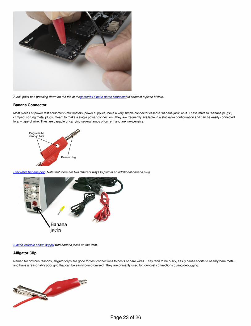
A ball-point pen pressing down on the tab of the gamer:bit's poke-home connector to connect a piece of wire.
Banana Connector
Most pieces of power test equipment (multimeters, power supplies) have a very simple connector called a "banana jack" on it. These mate to "banana plugs",crimped, sprung metal plugs, meant to make a single power connection. They are frequently available in a stackable configuration and can be easily connectedto any type of wire. They are capable of carrying several amps of current and are inexpensive.
Stackable banana plug. Note that there are two different ways to plug in an additional banana plug.
Extech variable bench supply with banana jacks on the front.
Alligator Clip
Named for obvious reasons, alligator clips are good for test connections to posts or bare wires. They tend to be bulky, easily cause shorts to nearby bare metal,and have a reasonably poor grip that can be easily compromised. They are primarily used for low-cost connections during debugging.
Page 23 of 26

A "third hand" tool, which uses alligator clips to hold work pieces, holding a wire terminated with an alligator clip for electrical test. Note the plastic bootsurrounding the alligator clip, to make it less likely to short to other connections.
IC Clip (or IC Hook)
For more delicate probing operations, there are a variety of IC clips on the market. These are sized to allow a user to clip them onto the pins of an IC withoutcontacting adjacent pins; some of them are delicate enough to be clipped onto even fine-pitched SMD component legs. These smaller clips can be found on logicanalyzers as well as test leads, which are great for prototyping or troubleshooting circuits.
A large IC clip on the end of a wire. This clip is still small enough to be connected to a single leg on a through-hole chip without causing a problem for adjacentpins.
Other Connectors
RJ-type Modular Connectors
Registered jack connectors are standard for telecommunications equipment into a local exchange. The names one normally hears associated with them (RJ45,RJ12, etc) are not necessarily correct, as the RJ designator is a based on a combination of the number of positions, the number of conductors actually present,and the wiring pattern. For example, while the ends of a standard ethernet cable are usually referred to as "RJ45", RJ45 actually implies not only an 8 position, 8conductor modular jack, it also implies that it is wired for ethernet.
These modular connectors can be very useful, since they combine ready availability, multiple conductors, moderate flexibility, low cost, and moderate currentcarrying capacity. While not originally intended to deliver a great deal of power, these cables can be used to deliver data and a couple of hundred milliamps fromone device to another. Care should be taken to ensure that jacks provided for applications like this are not connected to conventional ethernet ports, as damagewill result.
A standard 8p8c (8-position, 8-conductor) "RJ45" modular jack. Be aware that if you intend to use this type of jack to pass DC signals and power, you must avoidusing connectors with built-in signal transformers.
D-sub Type Connectors
Named for the shape of their shell, D-subminiature connectors are a classic standard in the computing world. There are four very common varieties of thisconnector: DA-15, DB-25, DE-15, and DE-9. The pin number indicates the number of connections provided, and the letter combination indicates the size of theshell. Thus, DE-15 and DE-9 have the same shell size, but a different number of connections.
Female DE-9 board-mount connector. Gender is defined by the pins or sockets associated with each signal, not the connector as a whole, making this connectorfemale despite the fact that it effectively inserts into the shell of the mating connector.
Page 24 of 26

DB-25 and DE-9 are the most useful to the hardware hacker; many desktop computers still include at least one DE-9 serial port, and often one DB-25 parallelport. Cables terminated with DE-9 and DB-25 connectors are widely available, too. As with the modular connector above, these can be used to provide powerand point-to-point communications between two devices. Again, since the common usage of these cables does not include power transmission, it is veryimportant that any repurposing of the cables be done cautiously, as a non-standard device plugged into a standard port can easily cause damage.
Resources and Going Further
You should now have a good idea which connectors are suited best for certain applications and which connectors will be useful to you in your next project.Please check out these other links to lean more about connectors.
Giant database of connectors and pinouts - Everything you never wanted to know about pretty much any connector, ever. A good site for basic info aboutconnectors, but often quite shy on interface details.Wikipedia article on registered jack connectors - More on the confusing world of the registered jack (RJ) connector, which is often misunderstood andmisused.Wikipedia article on D-subminiature connectors - As with the registered jack connector, misinformation abounds on the D-subminiature standard. Wikipediahas a great article about it.Mouser electronics catalog - Browsing an electronics supplier catalog is often a great place to start looking for the name of an unidentified connector;Mouser's enhanced online catalog is just as good as the print version, with fewer papercuts!
If you'd like top explore more SparkFun tutorials, check out these other offerings:
Serial Communication
Asynchronous serial communication concepts: packets, signal levels, baud rates, UARTs and more!Favorited Favorite 70
Serial Peripheral Interface (SPI)
SPI is commonly used to connect microcontrollers to peripherals such as sensors, shift registers, and SD cards.Favorited Favorite 67
What is an Arduino?
What is this 'Arduino' thing anyway?Favorited Favorite 32
Logic Levels
Learn the difference between 3.3V and 5V devices and logic levels.Favorited Favorite 49
Electric Power
An overview of electric power, the rate of energy transfer. We'll talk definition of power, watts, equations, and power ratings. 1.21 gigawatts of tutorial fun!Favorited Favorite 34
I2C
An introduction to I2C, one of the main embedded communications protocols in use today.Favorited Favorite 86
Alternating Current (AC) vs. Direct Current (DC)
The differences between AC and DC.Favorited Favorite 35
Three Quick Tips About Using U.FL
Quick tips regarding how to connect, protect, and disconnect U.FL connectors.Favorited Favorite 4
Or check out these related blog post:
Headers or No Headers?
February 3, 2016Favorited Favorite 1
The Wild World of Connectors
March 9, 2017Favorited Favorite 3
New Connector System
Page 25 of 26

April 3, 2017Favorited Favorite 0
learn.sparkfun.com | CC BY-SA 3.0 | SparkFun Electronics | Niwot, Colorado
Page 26 of 26