connectivity solutions utilizing base-8 structured cabling · the structured cabling solution...
TRANSCRIPT

Engineering Services Department 800 17th St NW | PO Box 489 Hickory, North Carolina 28603-0489
800 743-2671 f 828 901-5533 www.corning.com/cablesystems
AE Note 149 Revision: Issue - Page 1 of 29
© 2012 Corning Cable Systems LLC. All rights reserved
Published: 06/25/2018
Connectivity Solutions Utilizing Base-8 Structured Cabling AEN 156, Revision: 2 This Application Engineering Note will discuss the different Corning Optical Communications components that are available to provide fiber optic connectivity utilizing Base-8 structured cabling. This document will be specific by providing connectivity solutions that use OM3/OM4 Laser-Optimized 50µm multimode and OS2 single-mode fiber (This document will only provide OM4 and OS2 part numbers). This document will cover duplex (2-fiber), parallel (8-fiber/20-fiber), and parallel to duplex optical links. For Base-12 solutions, please refer to AEN151 “Four-Channel Parallel Optic Connectivity Solutions Utilizing Base-12 Structured Cabling”. For Base-12 four-channel parallel to duplex transmission, please refer to AEN152 “Four-channel Parallel to Duplex Optical Connectivity Solutions Utilizing Base-12 Structured Cabling”. Duplex and Parallel Optical Links A duplex optical link, also known as duplex communications, is accomplished by using two fibers as shown in Figure 1. The optical signal will be transmitted on the B connector and received on the A connector. For these types of links operating in a duplex optical system, the most commonly used connector is the duplexed LC.
Figure 1: Duplex Fiber Optic Transmission
A parallel optical link is accomplished by combining two or more channels. Parallel optical links can be achieved by using eight fibers (4 fibers for Tx and 4 fibers for Rx), twenty fibers (10 fibers for Tx and 10 fibers for Rx), or twenty-four fibers (12 fibers for Tx

Engineering Services Department 800 17th St NW | PO Box 489 Hickory, North Carolina 28603-0489
o 800 743-2671 f 828 901-5533 www.corning.com/opcomm
AE Note 156, Revision: 2 - Page 2 of 29 © 2016 Corning Optical Communications LLC. All rights reserved
Published: 06/25/2018
and 12 fibers for Rx). The standard cabling to accomplish an 8-fiber parallel optical link is a 12-fiber trunk with a MTP® connector interface (12-fiber connector), as shown in Figure 2. For parallel connectivity (8-fiber), Tx1 has to follow a path that requires the data to exit on Rx1. As Figure 1 illustrates if Tx1 enters on fiber position 1 it needs to exit on fiber position 12. This is the same if the transmit enters on fiber position 12 it needs to exit on fiber position 1. This is accomplished by using a Type B polarity component (according to TIA-568). As components are added to the optical system an odd number of Type B components are required to maintain the correct polarity scheme so the light enters and exits (transmit versus receive) the correct fiber positions.
Figure 2: Parallel Fiber (8-fiber) Optic Transmission
The standard cabling to accomplish a twenty fiber parallel optical link with a one-plug, two-row transceiver is a 12-fiber based trunk infrastructure using a Y-jumper at each end with two 12-fiber legs MTP® (12-fiber connector) to a MTP connector interface (24-fiber connector), as shown in Figure 3. For parallel connectivity (20-fiber), Tx1 has to follow a path that requires the data to exit on Rx1. As Figure 3 illustrates if Tx1 enters on fiber position 2, bottom row it needs to exit on fiber position 2, top row. This is the same if the transmit enters on fiber position 2, top row it needs to exit on fiber position 2, bottom row.

AE Note 156, Revision: 2 - Page 3 of 29 © 2016 Corning Optical Communications LLC. All rights reserved
Published: 06/25/2018
Figure 3: Parallel Fiber (20-fiber) Optic Transmission
Why Utilize a Base-8 Infrastructure? With the current transceiver technology advancements, network switch vendors are all tooling up their 100GbE switch portfolios based on 25GbE electrical traces instead of 10GbE electrical traces. This reduces the fiber requirement for 100GbE from twenty to eight fibers. In addition, 40GbE transceivers are currently available in two and eight fiber solutions for both Single-mode/Multimode links. At the same time, similar solutions are currently in the development phase for 200GbE and 400GbE. Recently, Fibre Channel vendors on the SAN side of the DC are following a similar path at 128GFC by using a SR4 communications, utilizing an eight fiber MTP®. After much discussion with transceiver and switch vendors, the solutions today (40/100GbE) and in the future (200/400GbE) all converge on duplex and 8f parallel solutions with some interim solutions along the way. With current transceivers and switch vendor’s trends leading to 2F and 8F transceivers, there is a need for optimized solutions. Traditional MTP solutions are based on 12F connectors, which is not always divisible by 8. Based on this information, to simplify network design and operation, improve fiber utilization, reduce costs and attenuation in an optical link, an 8 fiber based infrastructure would provide you with the optimal solution. Fiber Utilization with a Base-8 Infrastructure A Base-8 infrastructure consists of backbone trunks that have 8-fiber legs, modules that have 4 ports (8-fibers) and eight fiber harnesses. Since parallel connectivity uses 8-fibers out of the available 12-fibers in the connector, the issue arises with a Base-12 infrastructure to either leave the four middle fibers dark or use some type of conversion device. A conversion device can convert two 12-fiber links into three 8-fiber links. This allows all fibers to be utilized giving you three parallel links for each 24 fibers of installed Base-12 trunk cables. This is not necessary when a Base-8 infrastructure is installed. Migration from duplex to parallel links is easy without

Engineering Services Department 800 17th St NW | PO Box 489 Hickory, North Carolina 28603-0489
o 800 743-2671 f 828 901-5533 www.corning.com/opcomm
AE Note 156, Revision: 2 - Page 4 of 29 © 2016 Corning Optical Communications LLC. All rights reserved
Published: 06/25/2018
the added complexity since the infrastructure is already 8-fibers (each trunk cable has 8 fiber legs). The conversion is made easy by removing the modules used for duplex communication and replacing them with MTP adapter panels. MTP-MTP array jumpers would provide the link from the trunks to the QFSP+ transceivers. The installation of a Base-8 infrastructure allows for 100% fiber utilization when migrating to parallel links without the need of conversion modules or harnesses. The solutions provided (BOMs) in this document do not include housing part numbers because the density requirement differs from one project to another project. It is important to remember that an EDGE8™ housing would be required to hold EDGE8 modules, EDGE8 Port Breakout Modules, and EDGE8 Adapter Panels. For BOMs including MTP® to LC harnesses, a part number with 24” non-staggered LC legs will be provided as default. For harness options with LC staggered legs based on specific SAN or LAN switches, please refer to AEN157 “Choosing the Correct Harness for your Switch”. NOTE: EDGE8 consists of pinned trunks and non-pinned modules which is the opposite of EDGE™ products which have non-pinned trunks and pinned modules. EDGE8 modules and trunks should not be connected to EDGE modules and trunks. EDGE8 is designed with visual indicators to enable the differentiation between EDGE8 and EDGE components. An “8” is designated on all EDGE8 components and MTP jumpers will state 8F on the jacket. Modules/panels are gray in color, as shown in Figure 4. EDGE8 trays can be installed in EDGE housings to enable installation of EDGE8 systems in a previous installed EDGE environment, as shown in Figure 5.
Figure 4: EDGE8 Solution Product

AE Note 156, Revision: 2 - Page 5 of 29 © 2016 Corning Optical Communications LLC. All rights reserved
Published: 06/25/2018
Figure 5: EDGE8 Solution Trays and EDGE Solution Trays in the same EDGE Housing
With the broad offering of transmission protocols in the market, there are several configurations to create your network infrastructure utilizing Base-8 connectivity solutions. This AE Note will aid the designer by providing the Corning Optical Communications products that are needed to connect duplex and parallel transceivers.
EDGE8 Solution Trays
EDGE Solution Trays

Engineering Services Department 800 17th St NW | PO Box 489 Hickory, North Carolina 28603-0489
o 800 743-2671 f 828 901-5533 www.corning.com/opcomm
AE Note 156, Revision: 2 - Page 6 of 29 © 2016 Corning Optical Communications LLC. All rights reserved
Published: 06/25/2018
At the end of this document, you will find all the polarity drawings for Corning Optical Communications products that will be discussed throughout this Application Engineering Note in Appendix A. Duplex Fiber Optic Transmission Links (2-fiber to 2-fiber) In this section, we will discuss the products required to connect two duplex transceivers. These protocols include, but are not limited to, the following: 10GBase-SR, 10GBase-LR, 10GBase-ER, 40GBase-BiDi, 40GBase-LR4, 40GBase-LRL4, 40GBase-UNIV, 40GBase-FR, 100GBase-LR4, 100GBase-ER4, 100GBase-CWDM4, 100GBase-BiDi, 1GFC, 2GFC, 4GFC, 8GFC, 16GFC, 32GFC, IB-1x-SX, IB-1x-LX, IB-4x-LX, IB-1x-DDR-SX, IB-1x-DDR-LX , IB-1x-QDR-SX, and IB-1x-QDR-LX. Duplex Direct Connectivity Solutions When directly connecting one SFP transceiver to another SFP transceiver a Type A-B duplex cable assembly (jumper) is required. This type of direct connectivity is only suggested within a given row of racks/cabinets. Figure 6 shows two SFP transceivers being connected with a LC Duplex to LC Duplex jumper.
Figure 6: Direct Connectivity Utilizing an A-B Duplex Jumper
Bill of Materials for Figure 6 Item OM4 Part Number OS2 Part Number Description
1 797902QD120xxxF 787802GD120xxxF EDGE™ LC Uniboot to LC Uniboot Duplex Jumper, Riser, xxx ft.
Duplex Inter-connect Solutions The structured cabling solution allows for patching on both ends of the optical network. An 8 to 144-fiber MTP® trunk (with 8-fiber legs) is deployed with 8-fiber modules connected to the end of the trunk. Reverse polarity LC Uniboot jumpers provide connectivity to the active components. The use of MTP trunks provides a robust solution
1

AE Note 156, Revision: 2 - Page 7 of 29 © 2016 Corning Optical Communications LLC. All rights reserved
Published: 06/25/2018
that allows the cable to be placed in cable trays without the fear of the trunk cable being crushed resulting in fiber damage. Structured cabling allows for easier moves, adds, and changes (MACs). Figure 7 illustrates this solution.
Figure 7: Duplex Connectivity with Inter-connect Structured Cabling
Bill of Materials for Figure 7 Item OM4 Part Number OS2 Part Number Description
1 797902QD120xxxF 787802GD120xxxF EDGE™ LC Uniboot to LC Uniboot Duplex Jumper, Riser, xxx ft.
2 GE5E508QPNDDUxxxF GE7E708GPNDDUxxxF
EDGE8™ Trunk Cable, MTP® Connector (pinned) to MTP Connector (pinned), 8 Fibers, with 33/33 inch legs, pulling grip one side, xxx ft.
3 ECM8-UM08-05-E6Q-ULL ECM8-UM08-04-E8G-ULL EDGE8 Ultra Low Loss Module, LC Duplex to MTP (non-pinned), 8 Fibers
Note: EDGE8 trunk cables are available in fiber counts from 8 to 144 fibers. The solution shown in figure 8 is also an inter-connect solution, but deploys an 8-fiber trunk harness on one end of the link. A MTP adapter panel and an 8-fiber harness replace the module and LC duplex jumper used in the previous solution. This cabling solution works best when connectivity is required for a high port count switch.
Figure 8: Duplex Connectivity with Inter-connect Structured
Cabling utilizing a 8-fiber Module and Harness
1
3
1 2
3
1 3
2 4
5
Engineering Services Department 800 17th St NW | PO Box 489 Hickory, North Carolina 28603-0489
o 800 743-2671 f 828 901-5533 www.corning.com/opcomm
AE Note 156, Revision: 2 - Page 8 of 29 © 2016 Corning Optical Communications LLC. All rights reserved
Published: 06/25/2018
Bill of Materials for Figure 8 Item OM4 Part Number OS2 Part Number Description
1 797902QD120xxxF 787802GD120xxxF EDGE™ LC Uniboot to LC Uniboot Duplex Jumper, Riser, xxx ft.
2 ECM8-UM08-05-E6Q-ULL ECM8-UM08-04-E8G-ULL EDGE8™ Ultra Low Loss Module, LC Duplex to MTP® (non-pinned), 8 Fibers
3 GE5E508QPNDDUxxxF GE7E708GPNDDUxxxF
EDGE8 Trunk Cable, MTP Connector (pinned) to MTP Connector (pinned), 8 Fibers, with 33/33 inch legs, pulling grip one side, xxx ft.
4 EDGE8-CP32-V3 EDGE8-CP32-V1 EDGE8 32 Fibers MTP Adapter Panel, (4 port)
5 HE67908QPH-KAxxxF HE87808GPH-KAxxxF EDGE8 Type-A Harness, MTP (non-pinned), 8 Fibers, xxx ft., 24-in LC Uniboot legs
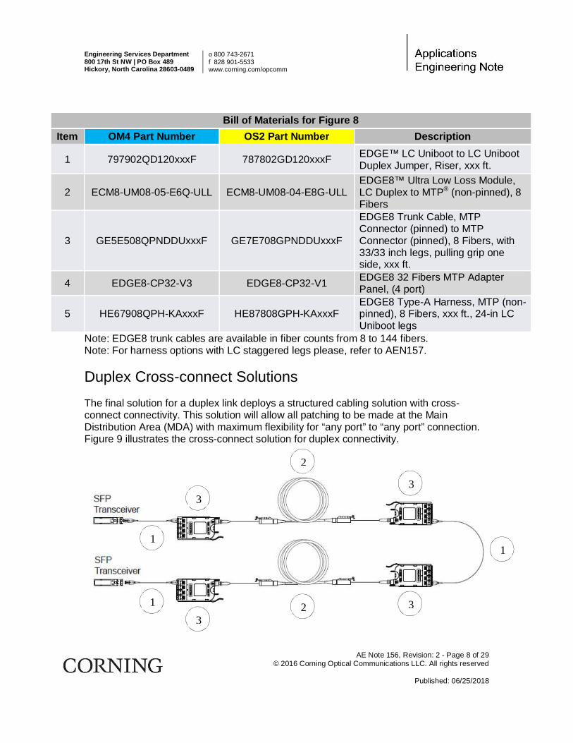
Note: EDGE8 trunk cables are available in fiber counts from 8 to 144 fibers. Note: For harness options with LC staggered legs please, refer to AEN157. Duplex Cross-connect Solutions The final solution for a duplex link deploys a structured cabling solution with cross-connect connectivity. This solution will allow all patching to be made at the Main Distribution Area (MDA) with maximum flexibility for “any port” to “any port” connection. Figure 9 illustrates the cross-connect solution for duplex connectivity.
1
2 3
1
2
1
3
3 3

AE Note 156, Revision: 2 - Page 9 of 29 © 2016 Corning Optical Communications LLC. All rights reserved
Published: 06/25/2018
Figure 9: Duplex Connectivity with Cross-connect Structured Cabling

Engineering Services Department 800 17th St NW | PO Box 489 Hickory, North Carolina 28603-0489
o 800 743-2671 f 828 901-5533 www.corning.com/opcomm
AE Note 156, Revision: 2 - Page 10 of 29 © 2016 Corning Optical Communications LLC. All rights reserved
Published: 06/25/2018
Bill of Materials for Figure 9 Item OM4 Part Number OS2 Part Number Description
1 797902QD120xxxF 787802GD120xxxF EDGE™ LC Uniboot to LC Uniboot Duplex Jumper, Riser, xxx ft.
2 GE5E508QPNDDUxxxF GE7E708GPNDDUxxxF
EDGE8™ Trunk Cable, MTP® Connector (pinned) to MTP Connector (pinned), 8 Fibers, with 33/33 inch legs, pulling grip one side, xxx ft.
3 ECM8-UM08-05-E6Q-ULL ECM8-UM08-04-E8G-ULL EDGE8 Ultra Low Loss Module, LC Duplex to MTP (non-pinned), 8 Fibers
Note: EDGE8 trunk cables are available in fiber counts from 8 to 144 fibers. Parallel Fiber Optic Transmission Links (8-fibers to 8-fibers) In this section, we will discuss the products required to connect two 8-fiber transceivers. These protocols include, but are not limited to, the following: 40GBase-SR4, 40GBase-xSR4/cSR4/eSR4, 40GBase-PLR4, 40GBase-PSM4, 100GBase-SR4, 100GBase-eSR4, 100GBase-PSM4, IB-4x-SX, and IB-4x-DDR-SX. Parallel Direct Connectivity Solutions When directly connecting one QFSP+ transceiver to another QFSP+ transceiver a Type-B non-pinned MTP® to non-pinned MTP (8-fiber) cable assembly (jumper) is required. This type of direct connectivity is only suggested for short distances within a given row of racks/cabinets. Figure 10 shows two QFSP+ transceivers being connected with a MTP (non-pinned) 8-fiber jumper.
Figure 10: Parallel Connectivity Utilizing an 8-fiber Type B MTP Jumper
Bill of Materials for Figure 10 Item OM4 Part Number OS2 Part Number Description
1

AE Note 156, Revision: 2 - Page 11 of 29 © 2016 Corning Optical Communications LLC. All rights reserved
Published: 06/25/2018
1 JE6E608QE8-NBxxxF JE8E808GE8-NBxxxF EDGE8™, MTP (non-pinned) to MTP (non-pinned), 8 F Jumper, TIA-568 Type-B polarity, xxx ft.
Parallel Inter-connect Solutions The next solution is similar to the previous, but instead of using an 8-fiber jumper, an 8 to 144-fiber MTP® trunk is deployed. Using a MTP trunk cables provides for a durable solution that allows the cable to be placed in cable trays without the fear of the trunk cable being crushed. Structured cabling allows for easier moves, adds and changes (MACs). Figure 11 illustrates this solution.
Figure 11: Parallel Connectivity with Inter-connect Structured Cabling
Bill of Materials for Figure 11 Item OM4 Part Number OS2 Part Number Description
1 JE6E608QE8-NBxxxF JE8E808GE8-NBxxxF EDGE8™, MTP (non-pinned) to MTP (non-pinned), 8 F Jumper, TIA-568 Type-B polarity, xxx ft.
2 GE5E508QPNDDUxxxF GE7E708GPNDDUxxxF
EDGE8 Trunk Cable, MTP Connector (pinned) to MTP Connector (pinned), 8 Fibers, with 33/33 inch legs, pulling grip one side, xxx ft.
3 EDGE8-CP32-V3 EDGE8-CP32-V1 EDGE8 32 Fibers MTP Adapter Panel, (4 port)
Note: EDGE8 trunk cables are available in fiber counts from 8 to 144 fibers. Parallel Cross-connect Solution The solution in Figure 12 utilizes MTP trunk cables to provide a structured cable solution with cross-connect connectivity with complete port replication. This solution will allow all MACs to be made at one location (usually the MDA). Utilizing pinned trunks allows all array jumpers to be non-pinned to non-pinned, thus reducing ordering and inventory complexity.
2
3 3
1 1

Engineering Services Department 800 17th St NW | PO Box 489 Hickory, North Carolina 28603-0489
o 800 743-2671 f 828 901-5533 www.corning.com/opcomm
AE Note 156, Revision: 2 - Page 12 of 29 © 2016 Corning Optical Communications LLC. All rights reserved
Published: 06/25/2018
Figure 12: Parallel Connectivity with Cross-connect Structured Cabling
Bill of Materials for Figure 12 Item OM4 Part Number OS2 Part Number Description
1 JE6E608QE8-NBxxxF JE8E808GE8-NBxxxF EDGE8™, MTP® (non-pinned) to MTP (non-pinned), 8 F Jumper, TIA-568 Type-B polarity, xxx ft.
2 GE5E508QPNDDUxxxF GE7E708GPNDDUxxxF
EDGE8 Trunk Cable, MTP Connector (pinned) to MTP Connector (pinned), 8 Fibers, with 33/33 inch legs, pulling grip one side, xxx ft.
3 EDGE8-CP32-V3 EDGE8-CP32-V1 EDGE8™ 32 Fibers MTP Adapter Panel, (4 port)
Note: EDGE8 trunk cables are available in fiber counts from 8 to 144 fibers. Parallel Fiber Optic Transmission Links (20-fiber or 24-fiber) In this section, we will discuss the products required to connect two 20 or 24-fiber transceivers. These protocols include, but are not limited to, the following: 100GBase-SR10, IB-12x-SX, and IB-12x-DDR-SX. The following solutions can apply for either 20 or 24-fiber transceivers. Interconnect Solutions (20-fiber or 24-fiber)
1
2
3
1
1 2
3
3
3

AE Note 156, Revision: 2 - Page 13 of 29 © 2016 Corning Optical Communications LLC. All rights reserved
Published: 06/25/2018
The solution in figure 13 illustrates the products required to provide connectivity from a CFP to a CFP transceiver (or 20-fibers to 20-fibers). To break-out the CFPs to transmit the signal across an 8-fiber infrastructure a 1 X 3 Breakout Harness (24-fiber MTP to three 8-fiber MTP®) is required. A Breakout Harness (or sometimes-referred to as Trident Harness) is required on the other end of the optical link to couple the 8-fiber links together to connect to the corresponding CFP.
Figure 13: 20-fiber to 20-Fiber Inter-connect Structured Cabling
Bill of Materials for Figure 13 Item OM4 Part Number OS2 Part Number Description
1 HA67524QPH-KAxxxF HA99024GPH-KAxxxF
EDGE™ AO 24 F MTP Breakout Harness, 24 F MTP (non-pinned) to 8 F MTP (non-pinned), Type A polarity, 8 Fibers leg length of 24 in (K), xxx ft.
2 EDGE8-CP32-V3 EDGE8-CP32-V1 EDGE8™ 32 Fibers MTP Adapter Panel, (4 port)
3 GE5E524QPNDDUxxxF GE7E708GPNDDUxxxF
EDGE8 Trunk Cable, MTP Connector (pinned) to MT® Connector (pinned), 24 Fibers, with 33/33 inch legs, pulling grip one side, xxx ft.
Note: EDGE8 trunk cables are available in fiber counts from 8 to 144 fibers. Parallel to Duplex Fiber Optic Transmission Links (8-fiber to 2-fiber) This section will discuss the different Corning Optical Communications Base-8 components that are available to provide fiber optic connectivity 40GBase-SR4, 40GBase-xSR4/cSR4/eSR4(for example fiber optic connectivity between 40GbE transceivers and 10GbE transceivers).
1
2 2
3 1

Engineering Services Department 800 17th St NW | PO Box 489 Hickory, North Carolina 28603-0489
o 800 743-2671 f 828 901-5533 www.corning.com/opcomm
AE Note 156, Revision: 2 - Page 14 of 29 © 2016 Corning Optical Communications LLC. All rights reserved
Published: 06/25/2018
Direct Connectivity Solutions (8-fiber to 2-fiber) When directly connecting an 8-fiber transceiver to the four corresponding duplex ports, an 8-fiber LC harness is required. The harness will have four LC Duplex connectors and the fibers will be paired in a specific way, assuring the proper polarity is maintained. This type of direct connectivity is only suggested for short distances within a given row or in the same rack/cabinet. Figure 14 shows the parallel transceiver connected to four duplex transceivers.
Figure 14: Direct Connect Structured Cabling With An 8-fiber Harness
Bill of Materials for Figure 14 Item OM4 Part Number OS2 Part Number Description
1 HE67908QPH-KBxxxF HE87808GPH-KBxxxF EDGE8™ Type-B Harness, MTP® (non-pinned), 8 Fibers, xxx ft., 24-in LC Uniboot legs
Note: For harness options with LC staggered legs please, refer to AEN157. Interconnect Solutions (8-fiber to 2-fiber) The structured cabling solution in Figure 15 allows for patching on both ends of the optical network. The patching on the QFSP+ end is accomplished by using Type-A non-pinned MTP to non- pinned MTP jumper, which connects to the trunk cable. The patching on the 10GbE end is accomplished using EDGE8 modules and LC Uniboot jumpers
1
2 4
5 3
1

AE Note 156, Revision: 2 - Page 15 of 29 © 2016 Corning Optical Communications LLC. All rights reserved
Published: 06/25/2018
Figure 15: 8-fiber to 2-Fiber Inter-connect Structured Cabling
Bill of Materials for Figure 15 Item OM4 Part Number OS2 Part Number Description
1 JE6E608QE8-NAxxxF JE8E808GE8-NAxxxF EDGE8™, MTP® (non-pinned) to MTP (non-pinned), 8 F Jumper, TIA-568 Type-A polarity, xxx ft.
2 EDGE8-CP32-V3 EDGE8-CP32-V1 EDGE8 32 Fibers MTP Adapter Panel, (4 port)
3 GE5E508QPNDDUxxxF GE7E708GPNDDUxxxF
EDGE8 Trunk Cable, MTP Connector (pinned) to MTP Connector (pinned), 8 Fibers, with 33/33 inch legs, pulling grip one side, xxx ft.
4 ECM8-UM08-05-E6Q-ULL ECM8-UM08-04-E8G-ULL EDGE8 Ultra Low Loss Module, LC Duplex to MTP (non-pinned), 8 Fibers
5 797902QD120xxxF 787802GD120xxxF EDGE™ LC Uniboot to LC Uniboot Duplex Jumper, Riser, xxx ft.
Note: EDGE8 trunk cables are available in fiber counts from 8 to 144 fibers. The cabling solution shown in Figure 16, works best when the active equipment being connected is within the same row. It is also an excellent solution to port replicate and breakout an 8-fiber transceiver into a 2-fiber patching field. This solution does reduce the amount of system attenuation by removing a MTP connector pair. The disadvantage of this solution would be that the port breakout module has a limited tail length.
Figure 16: 8-fiber to 2-Fiber Inter-connect Structured Cabling Utilizing a Port Breakout Module
Bill of Materials for Figure 16
Item OM4 Part Number OS2 Part Number Description
1 ECM8-05E6-QE8B-xxxF ECM8-04E8-GE8B-xxxF EDGE8 Port Breakout Module, LC Duplex to MTP (non-pinned), 8 Fiber, Type B Polarity, Plenum, xxx ft.
1
2

Engineering Services Department 800 17th St NW | PO Box 489 Hickory, North Carolina 28603-0489
o 800 743-2671 f 828 901-5533 www.corning.com/opcomm
AE Note 156, Revision: 2 - Page 16 of 29 © 2016 Corning Optical Communications LLC. All rights reserved
Published: 06/25/2018
2 797902QD120xxxF 787802GD120xxxF EDGE LC Uniboot to LC Uniboot Duplex Jumper, Riser, xxx ft.
Figure 17 illustrates the last inter-connect solution for 8-fiber to 2-fiber connectivity. A disadvantage of using this solution is that flexibility is lost on the SFP+ end because the transceiver ports need to be located in the same chassis. This is because the leg lengths for the LC Duplexed legs will be the same. However, this approach allows for an easy upgrade path moving from 2-fiber to 8-fiber connectivity. To connect to the SFP+s ports use the 8-fiber harness as shown in the diagram, and an 8-fiber MTP® jumper would be used from the adapter panel for the QFSP+ connectivity, thus allowing a mix and match upgrade path without having to change out the patch panels.
Figure 17: 8-fiber to 2-Fiber Inter-connect Structured Cabling utilizing an 8-fiber Harness
Bill of Materials for Figure 17
Item OM4 Part Number OS2 Part Number Description
1 JE6E608QE8-NBxxxF JE8E808GE8-NBxxxF EDGE8™, MTP (non-pinned) to MTP (non-pinned), 8 F Jumper, TIA-568 Type-B polarity, xxx ft.
2 EDGE8-CP32-V3 EDGE8-CP32-V1 EDGE8 32 Fibers MTP Adapter Panel, (4 port)
3 GE5E508QPNDDUxxxF GE7E708GPNDDUxxxF
EDGE8 Trunk Cable, MTP Connector (pinned) to MTP Connector (pinned), 8 Fibers, with 33/33 inch legs, pulling grip one side, xxx ft.
4 HE67908QPH-KBxxxF HE87808GPH-KBxxxF EDGE8 Type-B Harness, MTP (non-pinned), 8 Fibers, xxx ft., 24-in LC Uniboot legs
Note: EDGE8 trunk cables are available in fiber counts from 8 to 144 fibers. Note: For harness options with LC staggered legs please, refer to AEN157. Cross-Connect Solution (8-fiber to 2-fiber)
1
2
4
2
3

AE Note 156, Revision: 2 - Page 17 of 29 © 2016 Corning Optical Communications LLC. All rights reserved
Published: 06/25/2018
The final two solutions for connecting a QFSP+ to a SFP+ are both cross-connects but use different components at the QFSP+ end. The solution in figure 18 uses an 8-fiber port breakout module to connect to the QFSP+. The MTP tail of the module connects to the active component and breaks out the 8-fiber transceiver into a 2-fiber patching field. This is also known as port mapping or port replication. The one drawback to using the port breakout module is the length of the tail, which would make this a “local” solution. This solution would have less loss that the typical cross-connect solution because two MTPs would be removed. The port breakout module would patch to an 8-fiber module that is connected to a fiber optic trunk (or link backbone). The other end of the trunk would have a module and LC jumpers that are connected to the SFP+.
Figure 18: 8-fiber to 2-Fiber Cross-connect Structured Cabling utilizing a Port Breakout Module
Bill of Materials for Figure 18
Item OM4 Part Number OS2 Part Number Description
1 ECM8-05E6-QE8B-xxxF ECM8-04E8-GE8B-xxxF
EDGE8™ Port Breakout Module, LC Duplex to MTP® (non-pinned), 8 Fiber, Type B Polarity, Plenum, xxx ft.
2 797902QD120xxxF 787802GD120xxxF EDGE™ LC Uniboot to LC Uniboot Duplex Jumper, Riser, xxx ft.
3 ECM8-UM08-05-E6Q-ULL ECM8-UM08-04-E8G-ULL EDGE8 Ultra Low Loss Module, LC Duplex to MTP (non-pinned), 8 Fibers
4 GE5E508QPNDDUxxxF GE7E708GPNDDUxxxF
EDGE8 Trunk Cable, MTP Connector (pinned) to MTP Connector (pinned), 8 Fibers, with 33/33 inch legs, pulling grip one side, xxx ft.
Note: EDGE8 trunk cables are available in fiber counts from 8 to 144 fibers. The solution in Figure 19 is similar to the previous solution except that the cross-connect would not have to be located “locally”. The port breakout module is replaced with an 8-fiber array jumper, adapter panel, trunk, and an 8-fiber module. The trunk can be placed in a tray to protect the fiber from damage and allows for a greater distance between the distribution areas.
1
2 2
3
4
3

Engineering Services Department 800 17th St NW | PO Box 489 Hickory, North Carolina 28603-0489
o 800 743-2671 f 828 901-5533 www.corning.com/opcomm
AE Note 156, Revision: 2 - Page 18 of 29 © 2016 Corning Optical Communications LLC. All rights reserved
Published: 06/25/2018
Figure 19: 8-fiber to 2-Fiber Cross-connect Structured Cabling Utilizing a MTP® Jumper and EDGE8™ Modules
Bill of Materials for Figure 19
Item OM4 Part Number OS2 Part Number Description
1 JE6E608QE8-NAxxxF JE8E808GE8-NAxxxF EDGE8, MTP (non-pinned) to MTP® (non-pinned), 8 F Jumper, TIA-568 Type-A polarity, xxx ft.
2 EDGE8-CP32-V3 EDGE8-CP32-V1 EDGE8 32 Fibers MTP Adapter Panel, (4 port)
3 GE5E508QPNDDUxxxF GE7E708GPNDDUxxxF
EDGE8 Trunk Cable, MTP Connector (pinned) to MTP Connector (pinned), 8 Fibers, with 33/33 inch legs, pulling grip one side, xxx ft.
4 ECM8-UM08-05-E6Q-ULL ECM8-UM08-04-E8G-ULL EDGE8 Ultra Low Loss Module, LC Duplex to MTP (non-pinned), 8 Fibers
5 797902QD120xxxF 787802GD120xxxF EDGE™ LC Uniboot to LC Uniboot Duplex Jumper, Riser, xxx ft.
Note: EDGE8 trunk cables are available in fiber counts from 8 to 144 fibers. Interconnect Solutions (20-fiber to 2-fiber)
1
3 5
2
5
4 3
4
4

AE Note 156, Revision: 2 - Page 19 of 29 © 2016 Corning Optical Communications LLC. All rights reserved
Published: 06/25/2018
The interconnect solution in figure 20 shows how to take a CFP transceiver (20-fibers) and break it out into 10 SFP+ transceivers (2-fiber). A Breakout Harness similar to the one utilized in the twenty to twenty fiber interconnect solution would be used once again to split the 20-fibers into 3 different paths. The MTPs of the trident harness will be connected to 8-fiber modules. The connection to the SFPs is accomplished using LC Uniboot jumpers.
Figure 20: 20-fiber to 2-Fiber Inter-connect Structured Cabling
Bill of Materials for Figure 20
Item OM4 Part Number OS2 Part Number Description
1 HA69324QPH-KAxxxF HA98924GPH-KAxxxF
EDGE™ AO 24 F MTP® Breakout Harness, 24 F MTP (non-pinned) to 8 F MTP (pinned), Type A polarity, 8 Fibers leg length of 24 in (K), xxx ft.
2 ECM8-UM08-05-E6Q-ULL ECM8-UM08-04-E8G-ULL EDGE8™ Ultra Low Loss Module, LC Duplex to MTP (non-pinned), 8 Fibers
3 797902QD120xxxF 787802GD120xxxF EDGE LC Uniboot to LC Uniboot Duplex Jumper, Riser, xxx ft.
The best application for your network will depend on many factors such as design, equipment location, migration path, cost, pathway availability, etc. For additional questions, contact Corning Optical Communications’ Technical Support Line at 800-743-2671 or [email protected]
1
2 3

Engineering Services Department 800 17th St NW | PO Box 489 Hickory, North Carolina 28603-0489
o 800 743-2671 f 828 901-5533 www.corning.com/opcomm
AE Note 156, Revision: 2 - Page 20 of 29 © 2016 Corning Optical Communications LLC. All rights reserved
Published: 03/05/2018
Appendix A: Polarity drawings for each scenario.
Figure 6-a: Direct Connectivity Utilizing an A-B Duplex Jumper
Figure 7-a: Duplex Connectivity with Inter-connect Structured Cabling

AE Note 156, Revision: 2 - Page 21 of 29 © 2016 Corning Optical Communications LLC. All rights reserved
Published: 06/25/2018
Figure 8-a: Duplex Connectivity with Inter-connect Structured Cabling Utilizing an 8-fiber Module and Harness

Engineering Services Department 800 17th St NW | PO Box 489 Hickory, North Carolina 28603-0489
o 800 743-2671 f 828 901-5533 www.corning.com/opcomm
AE Note 156, Revision: 2 - Page 22 of 29 © 2016 Corning Optical Communications LLC. All rights reserved
Published: 03/05/2018
Figure 9-a: Duplex Connectivity with Cross-connect Structured Cabling

AE Note 156, Revision: 2 - Page 23 of 29 © 2016 Corning Optical Communications LLC. All rights reserved
Published: 06/25/2018
Figure 10-a: Parallel Connectivity Utilizing an 8-fiber Type B MTP® Jumper
Figure 11-a: Parallel Connectivity with Inter-connect Structured Cabling

Engineering Services Department 800 17th St NW | PO Box 489 Hickory, North Carolina 28603-0489
o 800 743-2671 f 828 901-5533 www.corning.com/opcomm
AE Note 156, Revision: 2 - Page 24 of 29 © 2016 Corning Optical Communications LLC. All rights reserved
Published: 03/05/2018
Figure 12-a: Parallel Connectivity with Cross-connect Structured Cabling

AE Note 156, Revision: 2 - Page 25 of 29 © 2016 Corning Optical Communications LLC. All rights reserved
Published: 06/25/2018
Figure 13-a: 20-fiber to 20-Fiber Inter-connect Structured Cabling
Figure 14-a: Direct Connect Structured Cabling
TXRX
TXRX
TXRX
TXRX
SFP+8
7
6
4
3
2
1
RXTX
RXTX
RXTX
RXTX
5
1
12
KeyUp
112
SFP+
SFP+
SFP+
Rx1Rx2Rx3Rx4
xxxx
Tx4Tx3Tx2Tx1
QSFPAccepts Key Up
EDGE8 Type B Harness

Engineering Services Department 800 17th St NW | PO Box 489 Hickory, North Carolina 28603-0489
o 800 743-2671 f 828 901-5533 www.corning.com/opcomm
AE Note 156, Revision: 2 - Page 26 of 29 © 2016 Corning Optical Communications LLC. All rights reserved
Published: 03/05/2018
Figure 15-a: 8-fiber to 2-Fiber Inter-connect Structured Cabling
Figure 16-a: 8-fiber to 2-Fiber Inter-connect Structured Cabling Utilizing a Port Breakout Module

AE Note 156, Revision: 2 - Page 27 of 29 © 2016 Corning Optical Communications LLC. All rights reserved
Published: 06/25/2018
Figure 17-a: 8-fiber to 2-Fiber Inter-connect Structured Cabling Utilizing an 8-fiber Harness
1
2
3
4
5
6
7
8
RXTX
RXTX
RXTX
RXTX
KeyUp
121
1
2
3
4
5
6
7
8
RXTX
RXTX
RXTX
RXTX
1
12
KeyUp
121
Key Down
112
Key Down
112
EDGE8 Trunk EDGE8 ModuleEDGE8 Module A-B Duplex Jumper
BA
BA
BA
BA B
A
BA
Rx1Rx2Rx3Rx4
xxxx
Tx4Tx3Tx2Tx1
QSFPAccepts Key Up
EDGE8 Type B Breakout Module
1
2
3
4
5
6
7
8
RXTX
RXTX
RXTX
RXTX
1
12
KeyUp
121
A-B Duplex Jumper
BAB
A TXRX SFP+
BAB
A TXRX SFP+
BAB
A TXRX SFP+
BAB
A TXRX SFP+
BA
BA
Figure 18-a: 8-fiber to 2-Fiber Cross-connect Structured Cabling Utilizing a Port Breakout Module and EDGE8™ Modules
TXRX
TXRX
TXRX
TXRX
SFP+
SFP+
SFP+
SFP+
KeyUp
KeyUp
8
7
6
4
3
2
1
RXTX
RXTX
RXTX
RXTX
5
1
12
KeyUp
Rx1Rx2Rx3Rx4
xxxx
Tx4Tx3Tx2Tx1
QSFPAccepts Key Up
Key Down
Key Down
EDGE8 TrunkEDGE8 MTP Adapter Panel
EDGE8 Type B MTP Jumper
EDGE8 Type B Harness
EDGE8 MTP Adapter Panel
Engineering Services Department 800 17th St NW | PO Box 489 Hickory, North Carolina 28603-0489
o 800 743-2671 f 828 901-5533 www.corning.com/opcomm
AE Note 156, Revision: 2 - Page 28 of 29 © 2016 Corning Optical Communications LLC. All rights reserved
Published: 03/05/2018
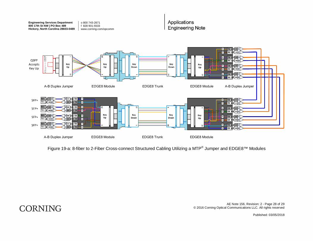
Figure 19-a: 8-fiber to 2-Fiber Cross-connect Structured Cabling Utilizing a MTP® Jumper and EDGE8™ Modules

AE Note 156, Revision: 2 - Page 29 of 29 © 2016 Corning Optical Communications LLC. All rights reserved
Published: 06/25/2018
Figure 20-a: 20-fiber to 2-Fiber Inter-connect Structured Cabling