connections should be post-finished quickly with a
TRANSCRIPT

7.5Module 07A B2 - Maintenance Practices
connections should be post-finished quickly with a suitable finish coating.
• Corrosion prevention—electrolytic action may rapidly corrode a bonding connection if suitable precautions are not taken. Aluminum alloy jumpers are recommended for most cases; however, copper jumpers should be used to bond together parts made of stainless steel, cadmium plated steel, copper, brass, or bronze. Where contact between dissimilar metals cannot be avoided, the choice of jumper and hardware should be such that corrosion is minimized; the part likely to corrode should be the jumper or associated hardware.
• Bonding jumper attachment—the use of solder to attach bonding jumpers should be avoided. Tubular members should be bonded by means of clamps to which the jumper is attached. Proper choice of clamp material should minimize the probability of corrosion.
• Ground return connection—when bonding jumpers carry substantial ground return current, the current rating of the jumper should be determined to be adequate, and a negligible voltage drop is produced. (Figure 7-4)
Figure 7-3. Bonding jumpers.
Structure Screw or Bolt and Nut Plate Locknut
Aluminum Terminal and Jumper
Washer A Washer B Washer C
Cadmium-platedsteel or aluminum
Cadmium-platedsteel or aluminum
Cadmium-platedsteel or aluminum
Cadmium-platedsteel or aluminum
None
None or magnesium alloy
Cadmium-plated steel
Cadmium-plated steel
Cadmium-plated steel or aluminum
Magnesium-alloy
Cadmium-platedsteel
Corrosion-resistingsteel
Cadmium-plated steel
Cadmium-plated steel
Cadmium-platedsteel
Cadmium-platedsteel
Aluminum alloys
Magnesium alloys
Cadmium-plated steel
Corrosion-resisting steel
Aluminum alloys
Magnesium alloys¹
Cadmium-plated steel
Corrosion-resisting steel
Cadmium-plated steel
Cadmium-plated steel
Cadmium-platedsteel
Corrosion-resisting steel orCadmium-plated steel
Tinned Copper Terminal and Jumper
Cadmium-platedsteel
Cadmium-platedsteel
Corrosion-resisting steel orcadmium-plated steel
Cadmium-platedsteel
Cadmium-platedsteel
Cadmium-platedsteel
Cadmium-platedsteel
Cadmium-platedsteel
Cadmium-platedsteel
Cadmium-platedsteel
Cadmium-platedsteel
Corrosion-resistingsteel
Aluminum alloys²
none
none
¹ Avoid connecting copper to magnesium. ² Use washers with a conductive finish treated to prevent corrosion, such as AN960JD10L.
Lockwasher
Terminal (limit to 4)
Locknut
Washer A
Washer B
Washer C
Structure
Screw or Bolt
Figure 7-4. Bolt and nut bonding or grounding to flat surface.
ELE
CT
RIC
AL
WIR
ING
(EW
IS)
7.6 Module 07A B2 - Maintenance Practices
WIRE TERMINATION
STRIPPING WIREBefore wire can be assembled to connectors, terminals, splices, etc., the insulation must be stripped from connecting ends to expose the bare conductor. Copper wire can be stripped in a number of ways depending on the size and insulation. Aluminum wire must be stripped using extreme care, since individual strands break very easily after being nicked. The following general precautions are recommended when stripping any type of wire: 1. When using any type of wire stripper, hold the
wire so that it is perpendicular to cutting blades. 2. Adjust automatic stripping tools carefully; follow the
manufacturer's instructions to avoid nicking, cutting, or otherwise damaging strands. This is especially important for aluminum wires and for copper wires smaller than No. 10. Examine stripped wires for damage. Cut off and re-strip (if length is sufficient), or reject and replace any wires having more than the allowable number of nicked or broken strands listed in the manufacturer's instructions.
3. Make sure insulation is clean-cut with no frayed or ragged edges. Trim, if necessary.
4. Make sure all insulation is removed from stripped area. Some types of wire are supplied with a transparent layer of insulation between the conductor and the primary insulation. If this is present, remove it.
5. When using hand-plier strippers to remove lengths of insulation longer than 3⁄4 inch, it is easier to accomplish in two or more operations.
6. Re-twist copper strands by hand or with pliers, if necessary, to restore natural lay and tightness of strands.
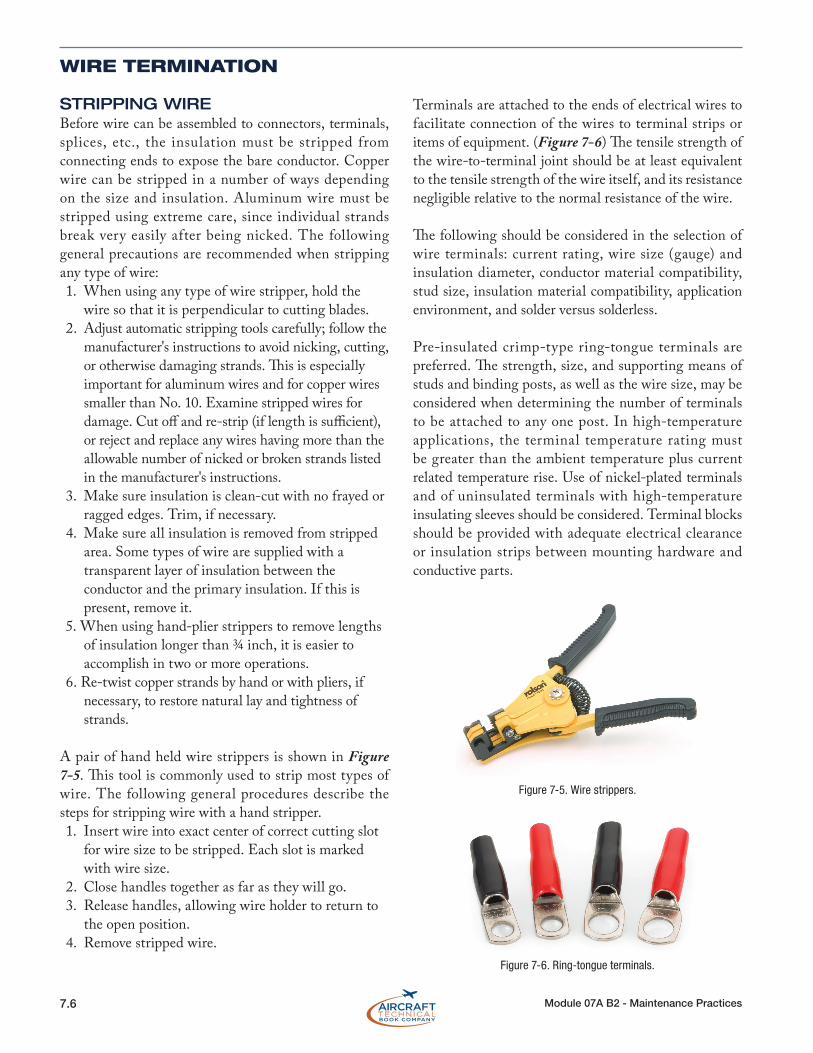
A pair of hand held wire strippers is shown in Figure 7-5. This tool is commonly used to strip most types of wire. The following general procedures describe the steps for stripping wire with a hand stripper. 1. Insert wire into exact center of correct cutting slot
for wire size to be stripped. Each slot is marked with wire size.
2. Close handles together as far as they will go. 3. Release handles, allowing wire holder to return to
the open position. 4. Remove stripped wire.
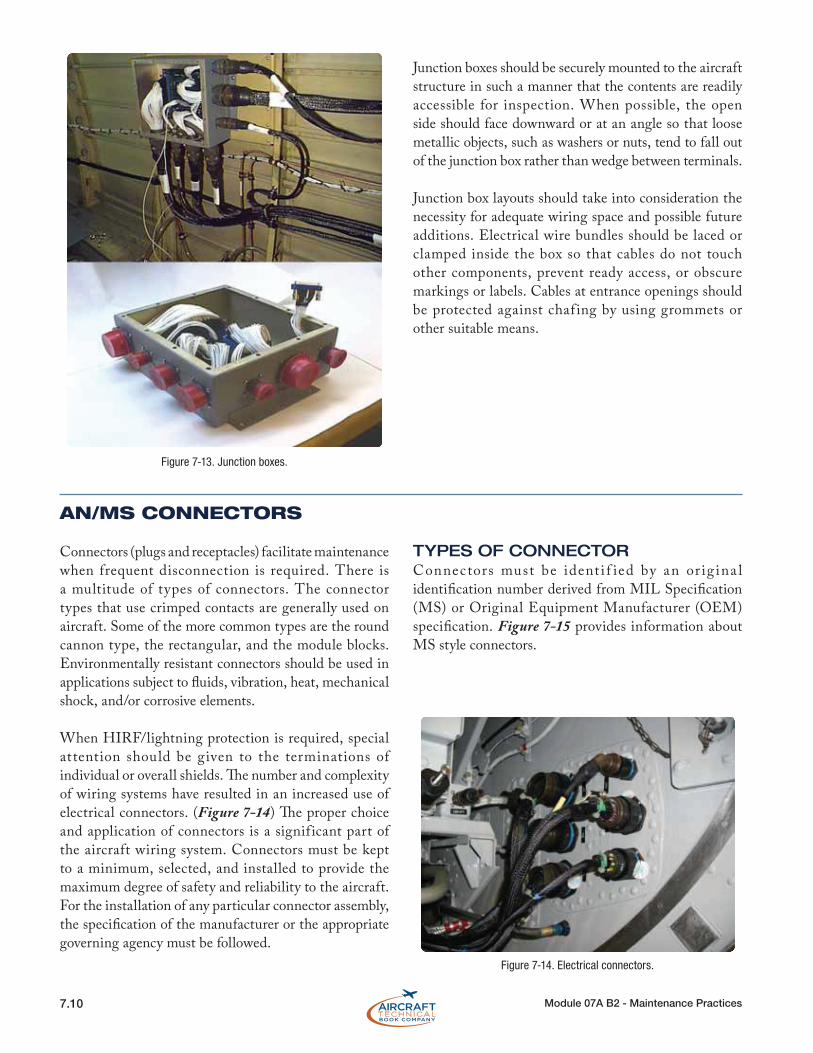
Terminals are attached to the ends of electrical wires to facilitate connection of the wires to terminal strips or items of equipment. (Figure 7-6) The tensile strength of the wire-to-terminal joint should be at least equivalent to the tensile strength of the wire itself, and its resistance negligible relative to the normal resistance of the wire.
The following should be considered in the selection of wire terminals: current rating, wire size (gauge) and insulation diameter, conductor material compatibility, stud size, insulation material compatibility, application environment, and solder versus solderless.
Pre-insulated crimp-type ring-tongue terminals are preferred. The strength, size, and supporting means of studs and binding posts, as well as the wire size, may be considered when determining the number of terminals to be attached to any one post. In high-temperature applications, the terminal temperature rating must be greater than the ambient temperature plus current related temperature rise. Use of nickel-plated terminals and of uninsulated terminals with high-temperature insulating sleeves should be considered. Terminal blocks should be provided with adequate electrical clearance or insulation strips between mounting hardware and conductive parts.
Figure 7-5. Wire strippers.
Figure 7-6. Ring-tongue terminals.

7.7Module 07A B2 - Maintenance Practices
TERMINAL STRIPSWires are usually joined at terminal strips. (Figure 7-7) A terminal strip f itted with barriers may be used to prevent the terminals on adjacent studs from contacting each other. Studs should be anchored against rotation.When more than four terminals are to be connected together, a small metal bus should be mounted across two or more adjacent studs. In all cases, the current should be carried by the terminal contact surfaces and not by the stud itself. Defective studs should be replaced with studs of the same size and material since terminal strip studs of the smaller sizes may shear due to over-tightening the nut. The replacement stud should be securely mounted in the terminal strip and the terminal securing nut should be tight. Terminal strips should be mounted in such a manner that loose metallic objects cannot fall across the terminals or studs. It is good practice to provide at least one spare stud for future circuit expansion or in case a stud is broken.
Terminal strips that provide connection of radio and electronic systems to the aircraft electrical system should be inspected for loose connections, metallic objects that may have fallen across the terminal strip, dirt and grease accumulation, etc. These conditions can cause arcing, which may result in a fire or system failures.
TERMINAL LUGSWire terminal lugs should be used to connect wiring to terminal block studs or equipment terminal studs. No more than four terminal lugs, or three terminal lugs and a bus bar, should be connected to any one stud. The total number of terminal lugs per stud includes a common bus bar joining adjacent studs. Four terminal lugs plus a common bus bar are not permitted on one stud. Terminal lugs should be selected with a stud hole diameter that matches the diameter of the stud. However, when the terminal lugs attached to a stud vary in diameter, the greatest diameter should be placed on the bottom and the smallest diameter on top. Tightening terminal connections should not deform the terminal lugs or the studs. Terminal lugs should be positioned so that bending of the terminal lug is not required to remove the fastening screw or nut, and movement of the terminal lugs tends to tighten the connection.
COPPER WIRE TERMINALSSolderless crimp-style, copper wire, terminal lugs may be used which conform to MIL-T-7928. Spacers or washers should not be used between the tongues of terminal lugs. (Figure 7-8)
ALUMINUM WIRE TERMINALSThe aluminum terminal lugs should be crimped to aluminum wire only. The tongue of the aluminum terminal lugs, or the total number of tongues of aluminum terminal lugs when stacked, should be sandwiched between two flat washers when terminated on terminal studs. Spacers or washers should not be used between the tongues of terminal lugs. Special attention should be given to aluminum wire and cable installations to guard against conditions that would result in excessive voltage drop and high resistance at junctions that may ultimately lead to failure of the junction.
Examples of such conditions are improper installation of terminals and washers, improper torsion (torquing of nuts), and inadequate terminal contact areas.
Figure 7-7. Terminal strip.
XX 22-1
B
Barrel
Wire Insulation Stripped Wire
Color-Coded Insulation
Insulation Grip TongueManufacturer’s
Mark
Range of Wire Sizes
Figure 7-8. Wire terminal.
ELE
CT
RIC
AL
WIR
ING
(EW
IS)

7.8 Module 07A B2 - Maintenance Practices
PRE-INSULATED SPLICESPre-insulated terminal lugs and splices must be installed using a high-quality crimping tool. Such tools are provided with positioners for the wire size and are adjusted for each wire size. It is essential that the crimp depth be appropriate for each wire size. If the crimp is too deep, it may break or cut individual strands. If the crimp is not deep enough, it may not be tight enough to retain the wire in the terminal or connector. Crimps that are not tight enough are also susceptible to high resistance due to corrosion buildup between the crimped terminal and the wire. (Figure 7-9)
CRIMPING TOOLSHand, portable, and stationary power tools are available for crimping terminal lugs. These tools crimp the barrel to the conductor, and simultaneously form the insulation support to the wire insulation. Figure 7-10 illustrates typical manually operated crimping tools. The wire is simply inserted properly into the crimp terminal and then placed into the proper location for its size in the crimper. Squeezing the handles together applies the proper force to the assemble for an airworthy crimp. Be sure the wire and insulation are inserted correctly in the terminal and that the terminal end is inserted correctly into the crimp tool.
Hydraulic crimping tools may also be used, especially when dealing with large wire sizes and cable. A hand operated hydraulic crimping tool is shown in (Figure 7-11). It has a four-position upper die and a common lower die for crimping terminal wire sizes 9, 6, 4, and 2. To operate, open the tool by pressing the latch. Pull back the nest lock and turn the thumb lock until the required die appears and the lock springs into place. Position the wire terminal assembly in the die and close the head. Rotate the reservoir handle clockwise to close the hydraulic f luid pressure return port. When the handle moves, hydraulic fluid is then pumped and the die begins to close. A sudden decrease in effort indicates
that the crimping is complete. Rotate the reservoir handle anti-clockwise to release the hydraulic pressure and open the die.
EMERGENCY SPLICING REPAIRSBroken wires can be repaired by means of crimped splices, by using terminal lugs from which the tongue has been cut off, or by soldering together and potting broken strands. These repairs are applicable to copper wire. Damaged aluminum wire must not be temporarily spliced. These repairs are for temporary emergency use only and should be replaced as soon as possible with permanent repairs. Since some manufacturers prohibit splicing, the applicable manufacturer's instructions should always be consulted.
INSPECTION AND TESTING OF CRIMPED JOINTSProperly crimped joints should be very strong. The wire and insulation should not slip or move when a tension load is applied. The tensile strength of the wire-to-terminal joint should be at least equivalent to the tensile strength of the wire itself. Resistance of wire-to-terminal joint should be negligible, relative to the normal resistance of the wire. The correct combination of wire, terminal end, and proper crimping with the depth mark in the correct location should all be evident. Both the conductor and insulator must be correctly inserted in the terminal end fitting. Only conductor material should be in the crimp barrel. Neither the conductor or insulator should appear damaged in any way with insulator material gripped by the insulation crimp so that the conductor is not visible.
Figure 7-9. Terminal splices. Figure 7-10. Crimping pliers.

7.9Module 07A B2 - Maintenance Practices
Actual testing of crimps is not usually performed on an installation made with the proper crimping tool. Crimping tools should be inspected annually and on condition if excessive play is detected. Crimps made with the tool can be checked using go/no-go gauges supplied by the tool manufacturer. Tensile strength and voltage carrying capability of crimps made with a specif ic crimping tool can be tested in the shop. Example voltage and tensile strength values for testing of crimped connections on a range of wire sizes are given in Figure 7-12.
JUNCTION BOXES
Junction boxes are used for collecting, organizing, and distributing circuits to the appropriate harnesses that are attached to the equipment. (Figure 7-13) Junction boxes are also used to conveniently house miscellaneous components, such as relays and diodes. Junction boxes that are used in high-temperature areas should be made of stainless steel.
Replacement junction boxes should be fabricated using the same material as the original or from a fire-resistant, nonabsorbent material, such as aluminum, or an acceptable plastic material. Where fireproofing is necessary, stainless steel junction box is recommended. Rigid construction prevents oil-canning of the box that could result in internal short circuits. In all cases, drain holes should be provided in the lowest portion of the box. Cases of electrical power equipment must be
insulated from metallic structures to avoid ground fault related fires.
The junction box arrangement should permit easy access to any installed items of equipment, terminals, and wires. Where marginal clearances are unavoidable, an insulating material should be inserted between current carrying parts and any grounded surface. It is not good practice to mount equipment on the covers or doors of junction boxes, since inspection for internal clearance is impossible when the door or cover is in the closed position.
Figure 7-11. Hand operated hydraulic crimping tool.
Wire Size Test Current Voltage Drop (Max)Millivolts
(Min.) Pull-ApartLoad (lbs.)
26 3 8 7 24 4.5 8 10 22 9 7 15 20 11 6 19 18 16 5 38 16 22 7 50 14 32 6 70 12 41 5 110 10 55 5 150 8 73 5 225 6 101 5 300 4 135 5 400
Figure 7-12. Crimped joint test table.
ELE
CT
RIC
AL
WIR
ING
(EW
IS)
7.10 Module 07A B2 - Maintenance Practices
Junction boxes should be securely mounted to the aircraft structure in such a manner that the contents are readily accessible for inspection. When possible, the open side should face downward or at an angle so that loose metallic objects, such as washers or nuts, tend to fall out of the junction box rather than wedge between terminals.
Junction box layouts should take into consideration the necessity for adequate wiring space and possible future additions. Electrical wire bundles should be laced or clamped inside the box so that cables do not touch other components, prevent ready access, or obscure markings or labels. Cables at entrance openings should be protected against chaf ing by using grommets or other suitable means.
AN/MS CONNECTORS
Connectors (plugs and receptacles) facilitate maintenance when frequent disconnection is required. There is a multitude of types of connectors. The connector types that use crimped contacts are generally used on aircraft. Some of the more common types are the round cannon type, the rectangular, and the module blocks. Environmentally resistant connectors should be used in applications subject to fluids, vibration, heat, mechanical shock, and/or corrosive elements.
When HIRF/lightning protection is required, special attention should be given to the terminations of individual or overall shields. The number and complexity of wiring systems have resulted in an increased use of electrical connectors. (Figure 7-14) The proper choice and application of connectors is a significant part of the aircraft wiring system. Connectors must be kept to a minimum, selected, and installed to provide the maximum degree of safety and reliability to the aircraft. For the installation of any particular connector assembly, the specification of the manufacturer or the appropriate governing agency must be followed.
TYPES OF CONNECTORConnectors must be ident i f ied by an or ig ina l identification number derived from MIL Specification (MS) or Original Equipment Manufacturer (OEM) specification. Figure 7-15 provides information about MS style connectors.
Figure 7-13. Junction boxes.
Figure 7-14. Electrical connectors.