connecting a model pel 102/103/105 to dataview · the models pel 102, 103, and 105. these...
TRANSCRIPT

Connecting a Model PEL 102/103/105 to
DataView®
ENGLISH Tutorial
1

Copyright Copyright © Chauvin Arnoux®, Inc. d.b.a. AEMC® Instruments. All rights reserved. No part of this documentation may be reproduced in any form or by any means (including electronic storage and retrieval or translation into any other language) without prior agreement and written consent from Chauvin Arnoux®, Inc., as governed by United States and International copyright laws.
Chauvin Arnoux®, Inc. d.b.a. AEMC® Instruments 15 Faraday Drive, Dover, NH 03820 USA Tel: (800) 945-2362 or (603) 749-6434, Fax: (603) 742-2346
This documentation is provided “as is,” without warranty of any kind, expressed, implied, or otherwise. Chauvin Arnoux®, Inc. has made every reasonable effort to ensure that this documentation is accurate; but does not warrant the accuracy or completeness of the text, graphics, or other information contained in this documentation. Chauvin Arnoux®, Inc. shall not be liable for any damages, special, indirect, incidental, or inconsequential; including (but not limited to) physical, emotional, or monetary damages due to lost revenues or lost profits that may result from the use of this documentation, whether or not the user of the documentation has been advised of the possibility of such damages. Chauvin Arnoux®, Inc., AEMC®, DataView® & PowerPad® are registered trademarks of AEMC® Instruments.
2

Contents Introduction ................................................................................................................................................. 4 Lesson 1: USB ............................................................................................................................................. 5 Lesson 2: Bluetooth .................................................................................................................................... 8 Lesson 3: Ethernet LAN ........................................................................................................................... 11 Lesson 4: Ethernet Direct (Point-to-Point, APIPA Mode) ...................................................................... 14 Lesson 5: Wi-Fi Ethernet .......................................................................................................................... 16 Lesson 6: Wi-Fi Direct .............................................................................................................................. 20 Lesson 7: IRD Server ................................................................................................................................ 23 Contacting AEMC ...................................................................................................................................... 27
3

Introduction Welcome to the tutorial for connecting a Power and Energy Logger Model PEL 100 Series instrument to a computer running the DataView® PEL Control Panel. The PEL Control Panel is designed for working with the Models PEL 102, 103, and 105. These instruments offer a variety of connection options, including: Connection Type PEL 102/103 PEL 105 USB ✓ ✓
Bluetooth ✓ ✓
Ethernet LAN ✓ ✓
Ethernet direct, APIPA (Automatic Private IP Addressing) mode ✓
Ethernet Wi-Fi ✓
Wi-Fi direct ✓
IRD (Internet Relay Device) server ✓ This tutorial explains how to set up each of these connection types.
Before You Begin
• This tutorial explains how to use the PEL Control Panel to enabling and disable various communication options. Some of these options can also be enabled/disabled through the instrument’s front panel. Consult the user manual that comes with your PEL instrument for instructions on how to do this.
• The tutorial is designed to provide a hands-on experience. As we explain each task, we suggest
you follow along using your own instrument and computer. So before you begin, install DataView (version 3.15 or later) with the PEL Control Panel. If you need assistance installing DataView, consult your instrument’s user manual.
• For detailed information about using the PEL Control Panel, open the Control Panel and press F1
to open the Help system. (The Help system is context-sensitive and provides specific information about the task you are currently performing.) Another good source of information is the AEMC YouTube channel; see https://www.youtube.com/user/AEMCinstruments.
• We encourage you to proceed with this tutorial at your own pace. If there are lessons you’d like to
repeat, simply stop the tutorial and go back to the beginning of the lesson. Conversely, feel free to skip any topics with which you are already familiar.
• The instructions and screenshots in this tutorial assume you are running Windows 7. They should
also apply to later versions of Windows; although you may encounter some small differences when using these operating systems.
• The steps described in this tutorial were performed with the PEL Model 105. Configuration
options may vary slightly with other PEL models.
4
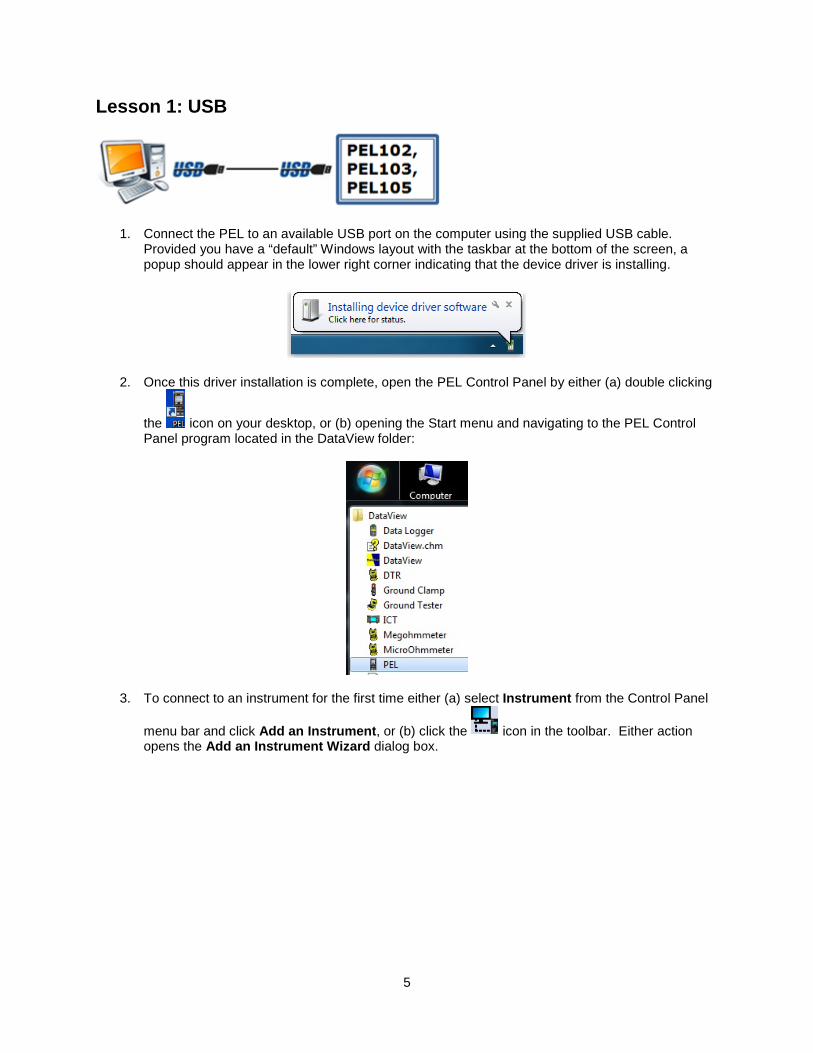
Lesson 1: USB
1. Connect the PEL to an available USB port on the computer using the supplied USB cable. Provided you have a “default” Windows layout with the taskbar at the bottom of the screen, a popup should appear in the lower right corner indicating that the device driver is installing.
2. Once this driver installation is complete, open the PEL Control Panel by either (a) double clicking
the icon on your desktop, or (b) opening the Start menu and navigating to the PEL Control Panel program located in the DataView folder:
3. To connect to an instrument for the first time either (a) select Instrument from the Control Panel
menu bar and click Add an Instrument, or (b) click the icon in the toolbar. Either action opens the Add an Instrument Wizard dialog box.
5

4. Ensure the USB radio button is selected, and then click Next. This displays the Add an Instrument Wizard – USB dialog box:
5. The Instrument field lists any PEL instrument(s) currently connected to the computer via USB. Click the downarrow to display a drop-down list of all available instruments. Select the appropriate PEL and click Next.
6

6. If the connection is successful, the following screen will appear:
Select Finish to exit the Add an Instrument Wizard and return to the main Control Panel screen.
7

Lesson 2: Bluetooth
Bluetooth provides a direct connection similar to USB; however it requires several prerequisite steps.
1. Ensure the computer has Bluetooth capability, either built-in or via a Bluetooth/USB adapter. (The remaining steps in this lesson assume you are using an adapter. Your steps and screens may be different depending on how your computer is configured for Bluetooth.)
2. Ensure Bluetooth is enabled on the PEL, as indicated by the Bluetooth LED on the instrument’s front panel. On the PEL 103 and 105, you can enable Bluetooth through the instrument’s front panel interface, as instructed by the instrument’s user guide. On the PEL 102, you must connect the instrument to the computer through a USB connection (see Lesson 1) and use the Control Panel to enable Bluetooth. (Consult the Control Panel Help for instructions.)
3. You must now pair the instrument to the computer. Click the Start button and select Devices and Printers.
4. Click Add a device on the top left. The computer scans for all Bluetooth devices within the range of its Bluetooth radio. When finished, available devices are listed in the Add a device screen.
8
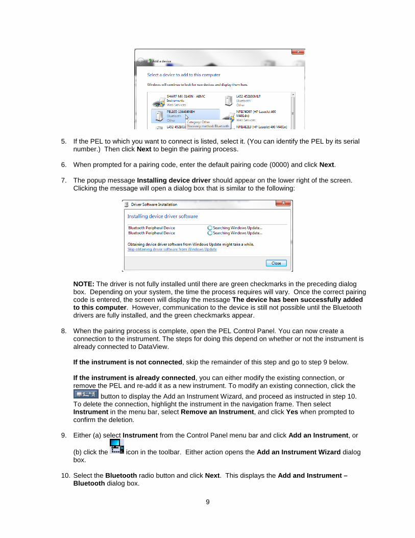
5. If the PEL to which you want to connect is listed, select it. (You can identify the PEL by its serial number.) Then click Next to begin the pairing process.
6. When prompted for a pairing code, enter the default pairing code (0000) and click Next.
7. The popup message Installing device driver should appear on the lower right of the screen. Clicking the message will open a dialog box that is similar to the following:
NOTE: The driver is not fully installed until there are green checkmarks in the preceding dialog box. Depending on your system, the time the process requires will vary. Once the correct pairing code is entered, the screen will display the message The device has been successfully added to this computer. However, communication to the device is still not possible until the Bluetooth drivers are fully installed, and the green checkmarks appear.
8. When the pairing process is complete, open the PEL Control Panel. You can now create a connection to the instrument. The steps for doing this depend on whether or not the instrument is already connected to DataView. If the instrument is not connected, skip the remainder of this step and go to step 9 below. If the instrument is already connected, you can either modify the existing connection, or remove the PEL and re-add it as a new instrument. To modify an existing connection, click the
button to display the Add an Instrument Wizard, and proceed as instructed in step 10. To delete the connection, highlight the instrument in the navigation frame. Then select Instrument in the menu bar, select Remove an Instrument, and click Yes when prompted to confirm the deletion.
9. Either (a) select Instrument from the Control Panel menu bar and click Add an Instrument, or
(b) click the icon in the toolbar. Either action opens the Add an Instrument Wizard dialog box.
10. Select the Bluetooth radio button and click Next. This displays the Add and Instrument – Bluetooth dialog box.
9

11. When this dialog box first opens, the computer builds a list of PEL instruments available for Bluetooth connection. When this process is finished, click the downarrow to display a drop-down list of all available instruments. Select the appropriate PEL and click Next.
12. If the connection is successful, a screen appears informing you of this. Click Finish to exit the Add an Instrument Wizard and return to the main Control Panel screen.
10

Lesson 3: Ethernet LAN
This lesson assumes the PEL instrument to which you want to connect is located on your local network via an Ethernet cable, and the computer is also connected to that network via LAN or Wi-Fi. To set up an Ethernet LAN connection, you must be connected to the instrument via a USB (Lesson 1) or Bluetooth (Lesson 2) connection. Then proceed as follows:
1. Ensure that an Ethernet cable is connected to the network port on the front panel of the instrument, with the other end of the cable connected to an appropriate network jack (wall or router) which has access to the local network.
2. In the PEL Control Panel, highlight the instrument in the navigation frame. Then select
Instrument in the menu bar, and click Configure (or click the icon in the toolbar) to display the Configure Instrument dialog box.
3. Open the Communication tab.
11
4. Ensure the Enable DHCP checkbox is checked. DHCP (Dynamic Host Configuration Protocol) is a standard network protocol for dynamically distributing network configuration parameters, such as IP addresses for interfaces and services. Also take note of the settings in the Port number and Protocol (UDP or TCP) fields. The default port is 3041. NOTE: For PEL 102/103, the protocol defaults to UDP and TCP is not supported.
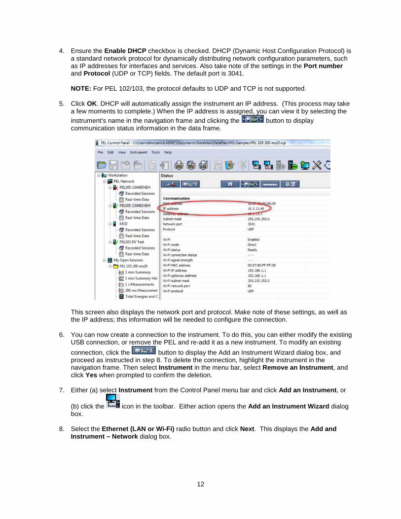
5. Click OK. DHCP will automatically assign the instrument an IP address. (This process may take a few moments to complete.) When the IP address is assigned, you can view it by selecting the instrument’s name in the navigation frame and clicking the button to display communication status information in the data frame.
This screen also displays the network port and protocol. Make note of these settings, as well as the IP address; this information will be needed to configure the connection.
6. You can now create a connection to the instrument. To do this, you can either modify the existing USB connection, or remove the PEL and re-add it as a new instrument. To modify an existing connection, click the button to display the Add an Instrument Wizard dialog box, and proceed as instructed in step 8. To delete the connection, highlight the instrument in the navigation frame. Then select Instrument in the menu bar, select Remove an Instrument, and click Yes when prompted to confirm the deletion.
7. Either (a) select Instrument from the Control Panel menu bar and click Add an Instrument, or
(b) click the icon in the toolbar. Either action opens the Add an Instrument Wizard dialog box.
8. Select the Ethernet (LAN or Wi-Fi) radio button and click Next. This displays the Add and Instrument – Network dialog box.
12

9. Enter the PEL’s IP address, protocol, and port number as displayed in the instrument status screen (see step 5 above). When finished, click Next.
10. If the connection is successful, a screen appears informing you of this. Click Finish to exit the Add an Instrument Wizard and return to the main Control Panel screen.
13

Lesson 4: Ethernet Direct (Point-to-Point, APIPA Mode)
Point-to-Point Ethernet communication establishes a direct link between the computer and the instrument via Ethernet cable. To do this, you must be connected to the instrument via a USB connection (Lesson 1). Then proceed as follows:
1. In the PEL Control Panel, highlight the instrument in the navigation frame. Then select
Instrument in the menu bar, and click Configure (or click the icon in the toolbar) to display the Configure Instrument dialog box.
2. Open the Communication tab.
3. Ensure the Enable DHCP checkbox is checked. If not, select it. Also take note of the settings in the Port number field. The default port is 3041. Then click OK.
4. Plug one end of an Ethernet cable into the instrument’s Ethernet port, and the other end into the computer’s Ethernet port. Consult the user documentation that comes with the PEL and/or your computer to locate these ports. The DHCP automatically assigns an IP address to the PEL.
14

5. Highlight the instrument in the navigation frame and click . This displays the Communication Status screen. Make note of the displayed IP Address.
6. You can now create a connection to the instrument. To do this, you can either modify the existing USB connection, or remove the PEL and re-add it as a new instrument. To modify an existing connection, click the button to display the Add an Instrument Wizard, and proceed as instructed in step 8. To delete the connection, highlight the instrument in the navigation frame. Then select Instrument in the menu bar, select Remove an Instrument, and click Yes when prompted to confirm the deletion.
7. Either (a) select Instrument from the Control Panel menu bar and click Add an Instrument, or
(b) click the icon in the toolbar. Either action opens the Add an Instrument Wizard dialog box.
8. Select Point-to-point Ethernet cable (APIPA mode) and click Next. This displays the Add and Instrument – Network dialog box:
9. Enter the PEL’s IP address, protocol, and port number as displayed in the instrument status screen (see step 5 above). When finished, click Next.
10. If the connection is successful, a screen appears informing you of this. Click Finish to exit the Add an Instrument Wizard and return to the main Control Panel screen.
15

Lesson 5: Wi-Fi Ethernet
This lesson assumes the PEL 105 instrument to which you want to connect has never before been connected to the computer via Wi-Fi. To set up an Ethernet Wi-Fi connection, you must be connected to the instrument via a USB (Lesson 1) or Bluetooth (Lesson 2) connection. You must also have available the following information about your Wi-Fi router:
• SSID of the wireless network • port number • password
Consult your network administrator or IT department if you need help obtaining this information. Then proceed as follows:
1. Ensure the computer is connected to the network via Ethernet or Wi-Fi connectivity.
2. Ensure Wi-Fi is enabled on the PEL 105, as indicated by the Wi-Fi indicator on the instrument’s front panel. You can enable Wi-Fi through the instrument’s front panel interface, as instructed by the instrument’s user guide.
3. In the PEL Control Panel, highlight the instrument in the navigation frame. Then select
Instrument in the menu bar, and click Configure (or click the icon in the toolbar) to display the Configure Instrument dialog box.
4. Open the Communication tab.
16

5. Ensure Enable Wi-Fi is checked. If not, select it.
6. Select Connect to a router if it is not already selected.
7. Enter the router’s SSID number and password in the SSID and Password fields.
8. Enter the router’s port number. By default, this is 3041.
9. Select the router’s communication protocol. By default, this is UDP.
10. Check the setup by pressing the Test button. The following dialog box will appear:
During this process, the instrument will attempt to communicate with the router.
17

If the test is successful, the Status field in the Testing Wi-Fi dialog box will change to Success.
The dialog box will also display the MAC Address and Wi-Fi IP address the router has assigned to the instrument.
11. Click the button to display communication status information in the data frame.
Make note of the Wi-Fi address, port, and protocol settings.
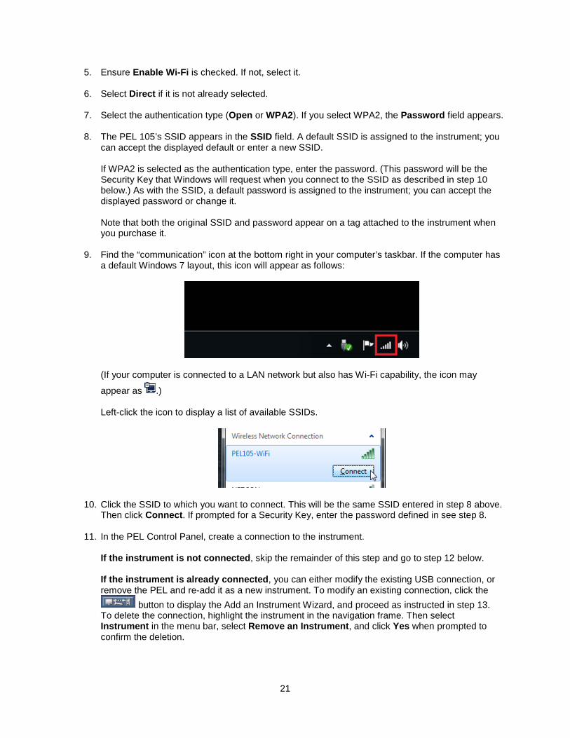
12. Find the “communication” icon at bottom right in the computer’s taskbar. If the computer has a default Windows 7 layout, this icon will appear as follows:
(If your computer is connected to a LAN network but also has Wi-Fi capability, the icon may
appear as .) Left-click the icon to display a list of available wireless networks, identified by their SSIDs.
18

13. Click the network to which you want to connect. This will be the same SSID entered in step 7 above. Then click Connect. If prompted for a password, enter it (see step 7).
14. In the PEL Control Panel, create a connection to the instrument. If the instrument is not connected, skip the remainder of this step and go to step 15 below. If the instrument is already connected, you can either modify the existing USB connection, or remove the PEL and re-add it as a new instrument. To modify an existing connection, click the
button to display the Add an Instrument Wizard, and proceed as instructed in step 16. To delete the connection, highlight the instrument in the navigation frame. Then select Instrument in the menu bar, select Remove an Instrument, and click Yes when prompted to confirm the deletion.
15. Either (a) select Instrument from the Control Panel menu bar and click Add an Instrument, or
(b) click the icon in the toolbar. Either action opens the Add an Instrument Wizard dialog box.
16. Select the Ethernet (LAN or Wi-Fi) radio button and click Next. This displays the Add and Instrument – Network dialog box.
17. Enter the router’s IP address, protocol, and port number as displayed in the instrument communication status screen (see step 11 above). When finished, click Next.
18. If the connection is successful, a screen appears informing you of this. Click Finish to exit the Add an Instrument Wizard and return to the main Control Panel screen.
19

Lesson 6: Wi-Fi Direct
This lesson assumes the PEL 105 instrument to which you want to connect has never before been connected to the computer via Wi-Fi. To set up a Wi-Fi direct connection, you must be connected to the instrument via a USB (Lesson 1) or Bluetooth (Lesson 2) connection. You must also have available the PEL 105’s SSID, port number, and password. Then proceed as follows:
1. Ensure the computer has Wi-Fi capability, either built in or via a Wi-Fi adapter.
2. Ensure Wi-Fi is enabled on the PEL 105, as indicated by the Wi-Fi indicator on the instrument’s front panel. You can enable Wi-Fi through the instrument’s front panel interface, as instructed by the instrument’s user guide.
3. In the PEL Control Panel, highlight the instrument in the navigation frame. Then select
Instrument in the menu bar, and click Configure (or click the icon in the toolbar) to display the Configure Instrument dialog box.
4. Open the Communication tab.
20
5. Ensure Enable Wi-Fi is checked. If not, select it.
6. Select Direct if it is not already selected.
7. Select the authentication type (Open or WPA2). If you select WPA2, the Password field appears.
8. The PEL 105’s SSID appears in the SSID field. A default SSID is assigned to the instrument; you can accept the displayed default or enter a new SSID. If WPA2 is selected as the authentication type, enter the password. (This password will be the Security Key that Windows will request when you connect to the SSID as described in step 10 below.) As with the SSID, a default password is assigned to the instrument; you can accept the displayed password or change it. Note that both the original SSID and password appear on a tag attached to the instrument when you purchase it.
9. Find the “communication” icon at the bottom right in your computer’s taskbar. If the computer has a default Windows 7 layout, this icon will appear as follows:
(If your computer is connected to a LAN network but also has Wi-Fi capability, the icon may
appear as .) Left-click the icon to display a list of available SSIDs.
10. Click the SSID to which you want to connect. This will be the same SSID entered in step 8 above. Then click Connect. If prompted for a Security Key, enter the password defined in see step 8.
11. In the PEL Control Panel, create a connection to the instrument. If the instrument is not connected, skip the remainder of this step and go to step 12 below. If the instrument is already connected, you can either modify the existing USB connection, or remove the PEL and re-add it as a new instrument. To modify an existing connection, click the
button to display the Add an Instrument Wizard, and proceed as instructed in step 13. To delete the connection, highlight the instrument in the navigation frame. Then select Instrument in the menu bar, select Remove an Instrument, and click Yes when prompted to confirm the deletion.
21
12. Either (a) select Instrument from the Control Panel menu bar and click Add an Instrument, or
(b) click the icon in the toolbar. Either action opens the Add an Instrument Wizard dialog box.
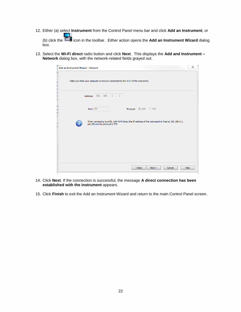
13. Select the Wi-Fi direct radio button and click Next. This displays the Add and Instrument – Network dialog box, with the network-related fields grayed out.
14. Click Next. If the connection is successful, the message A direct connection has been established with the instrument appears.
15. Click Finish to exit the Add an Instrument Wizard and return to the main Control Panel screen.
22
Lesson 7: IRD Server
You can establish a connection from a computer to a PEL 105 via the IRD (Internet Relay Device) server. This is a computer that facilitates communication between a PEL 105 and a computer running the PEL Control Panel on a private network connected to the internet. This enables you to connect your computer to instruments located on different private networks. The IRD server is hosted by AEMC Instruments and is made available as a free service to all PEL 105 owners. The PEL 105 offers both an Ethernet and Wi-Fi option for IRD connection. When connected to a network that has internet access, the instrument will automatically register itself with the IRD server using the default serial number and password provided in the instrument. To configure an IRD connection, your computer must be connected to the instrument via a USB connection (Lesson 1). Then proceed as follows:
1. In the PEL Control Panel, highlight the instrument in the navigation frame. Then select
Instrument in the menu bar, and click Configure (or click the icon in the toolbar) to display the Configure Instrument dialog box.
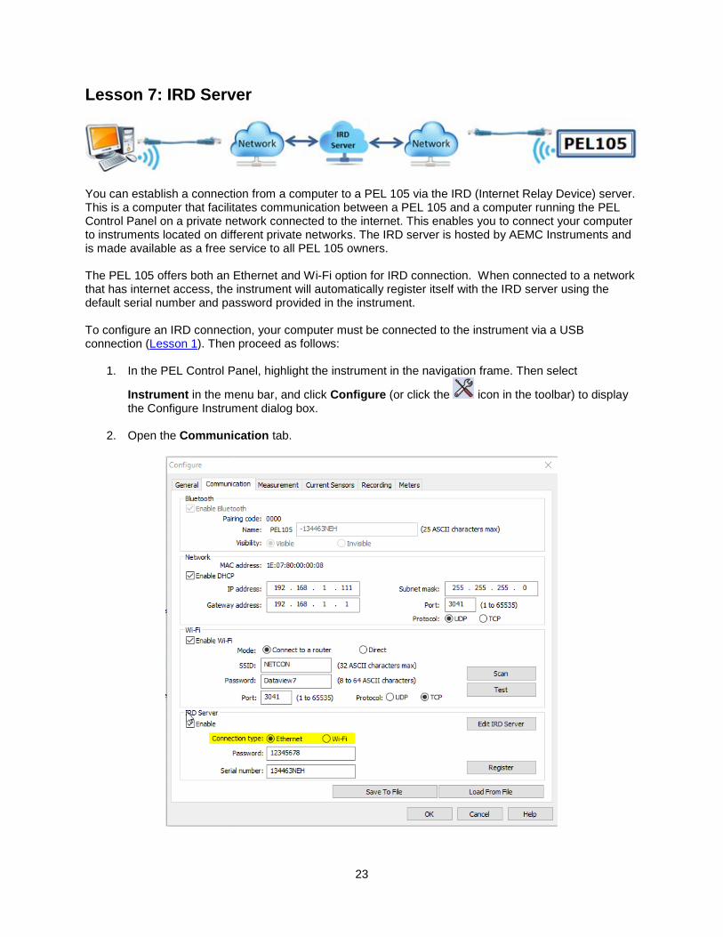
2. Open the Communication tab.
23

3. In the IRD Server section, ensure Enable is checked. If not, select it now. When this option is checked, the Password and Serial number fields appear. (To disable IRD server connection capability, de-select Enable.)
4. Connection type identifies the connection medium (Ethernet or Wi-Fi) through which the PEL 105 communicates with its private network. Ensure this setting matches the connection type used by your instrument.
5. To change the password, enter the new password in the Password field.
6. Edit IRD Server displays the IRD Server Settings dialog box. This lets you change the IRD server URL and port number. In North and South America, the default settings for these are as follows and in normal operation should not be changed: URL: www.ca-ird.com Port number: 80 Outside of the Americas, the default URL is www.ca-ird.eu. (Note that at present both URLs go to the same physical server.)
7. If you make any changes to the IRD server settings, you must re-register the instrument with the server. To do this, click the Register button. A message box appears displaying the progress of the registration process. If successful, this message appears as follows:
8. If the preceding message indicates registration did not complete successfully, review the IRD server settings described in steps 3 through 6 above. Otherwise click OK. Then click OK a second time to leave the Configure dialog box.
9. Highlight the instrument in the navigation frame and click . This displays the Communication Status screen. Ensure the IRD Server Status setting is Registration successful:
10. You can now create a connection to the instrument. To do this, you can either modify the existing USB connection, or remove the PEL and re-add it as a new instrument. To modify an existing connection, click the button to display the Add an Instrument Wizard, and proceed as instructed in step 12. To delete the connection, highlight the instrument in the navigation frame. Then select Instrument in the menu bar, select Remove an Instrument, and click Yes when prompted to confirm the deletion.
24

11. Either (a) select Instrument from the Control Panel menu bar and click Add an Instrument, or
(b) click the icon in the toolbar. Either action opens the Add an Instrument Wizard dialog box.
12. Select the IRD server radio button and click Next. This displays the Add and Instrument – IRD dialog box.
13. Check the IRD server URL and ensure it is appropriate for your region. If you need to change this, click the IRD Server button and select the URL (www.ca-ird.com or www.ca-ird.eu depending on your region).
14. Enter the PEL 105 serial number and password. The default settings for these are printed on a tag attached to the instrument when you purchase it. You can change the default password (see step 5 above); the serial number cannot be changed. When finished, click Next.
15. If the connection is successful, a screen appears informing you of this. If the PEL 105 and your computer are on the same private network, a screen appears as follows:
25
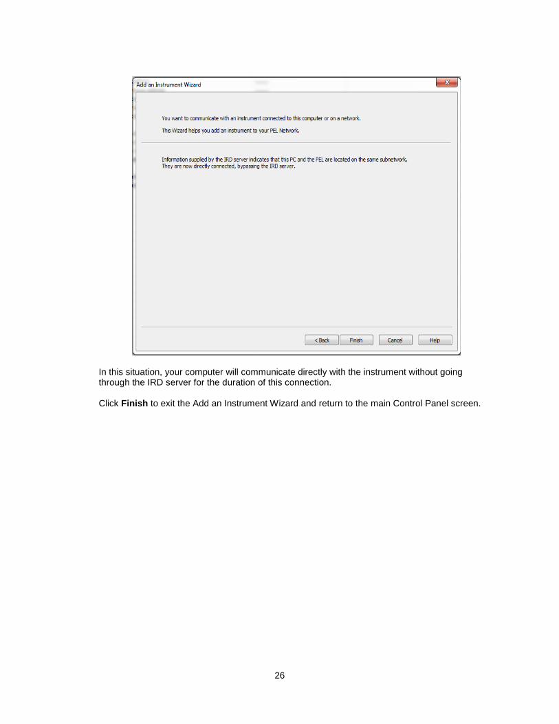
In this situation, your computer will communicate directly with the instrument without going through the IRD server for the duration of this connection. Click Finish to exit the Add an Instrument Wizard and return to the main Control Panel screen.
26

Contacting AEMC For instrument repair and calibration:
Chauvin Arnoux®, Inc. d.b.a. AEMC® Instruments 15 Faraday Drive Dover, NH 03820 USA Phone: (800) 945-2362 (Ext. 360) (603) 749-6434 (Ext. 360) Fax: (603) 742-2346 or (603) 749-6309 E-mail: [email protected] (Or contact your authorized distributor.) For Technical and Sales Assistance:
Chauvin Arnoux®, Inc. d.b.a. AEMC® Instruments 200 Foxborough Boulevard Foxborough, MA 02035 USA Phone: (800) 343-1391, (508) 698-2115 Fax: (508) 698-2118 E-mail: [email protected] www.aemc.com
27