conformal antennas and integrated design … meeting...conformal antennas and integrated design...
TRANSCRIPT

Conformal Antennas and Integrated Design Procedures
Mauro Bandinelli, Aldo Citriniti, Antonio Guidoni IDS Ingegneria Dei Sistemi SpA
Via Livornese 1019, PISA (Loc. San Piero a Grado), 56010, Italy Phone: ++39.050.3124264, Fax: ++39.050.3124201
[email protected], [email protected], [email protected]
ABSTRACT
At present radio communications and radio assistance services aboard aircrafts and helicopters are generally scattered among a number of antennas and sensors across the whole airframe. This policy, which is probably convenient from the point of view of equipment procurement, inevitably causes installation problems on medium/small aircraft, helicopters and UAVs, where only a reduced portion of the airframe surface is usually available for antenna location. Consequently, performance reductions have to be accepted, both due to antenna pattern distortion from the aircraft structures and to EMI among the sensors. This problem will probably become even more serious on multi-role vehicles, where different requirements have to be satisfied depending on the mission goal. A possible solution to the problem of antenna proliferation could be found in the field of conformal and multi-band antennas.
An activity of analysis, modelling and evaluation has been performed and has dealt with the following main items:
a) system level analyses aimed at identifying possible synergies between radio services;
b) identification of multi-band antennas suitable for working with standard avionic equipment;
c) identification of possible conformal radiating structures;
d) modelling and performance evaluation of some possible solutions.
A modelling tool named E-MIND (Electromagnetic Multi-code INtegrated Design) has been developed to support the designer in phase (d). It provides electromagnetic modelling tools, suitable for antenna design, model validation vs. measured data, installed antenna analysis through to antenna location optimization. Statistical (e.g. genetic algorithm) and deterministic (e.g. gradient-like) optimization methods have been integrated into E-MIND, co-operating with the electromagnetic modelling tools, in order to support the user in the final optimization phase.
Special effort has been devoted to developing E-MIND in such a way that it is able to provide “full engineering cycle support” to the designer, i.e. starting from the stand-alone antenna design up to antenna installation on the airframe and performance evaluation at sub-system level.
Both “multi-method” and “combined method” electromagnetic concepts have been implemented, so that the user can:
• select the most suitable modelling method for the given antenna problem (it is worth noting that no single modelling method can provide the best management of different antenna configurations, airframe geometries, frequency bands, therefore a “multi-method” approach is required);
• build up complex sequences of modelling sessions to obtain the best results, using different modelling methods in the different modelling phases of complex structures.
RTO-MP-AVT-141 23 - 1
UNCLASSIFIED/UNLIMITED
UNCLASSIFIED/UNLIMITED
Bandinelli, M.; Citriniti, A.; Guidoni, A. (2006) Conformal Antennas and Integrated Design Procedures. In Multifunctional Structures / Integration of Sensors and Antennas (pp. 23-1 – 23-22). Meeting Proceedings RTO-MP-AVT-141, Paper 23. Neuilly-sur-Seine, France: RTO. Available from: http://www.rto.nato.int/abstracts.asp.
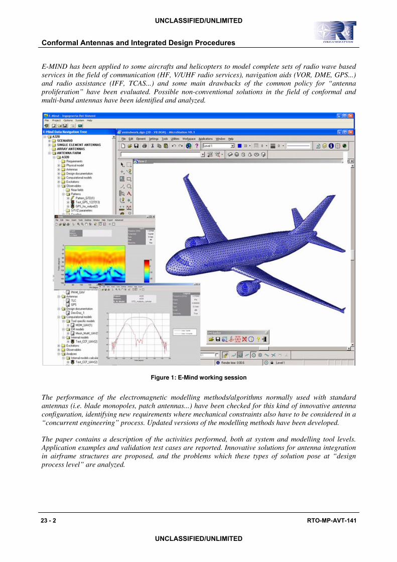
E-MIND has been applied to some aircrafts and helicopters to model complete sets of radio wave based services in the field of communication (HF, V/UHF radio services), navigation aids (VOR, DME, GPS...) and radio assistance (IFF, TCAS...) and some main drawbacks of the common policy for “antenna proliferation” have been evaluated. Possible non-conventional solutions in the field of conformal and multi-band antennas have been identified and analyzed.
Figure 1: E-Mind working session
The performance of the electromagnetic modelling methods/algorithms normally used with standard antennas (i.e. blade monopoles, patch antennas...) have been checked for this kind of innovative antenna configuration, identifying new requirements where mechanical constraints also have to be considered in a “concurrent engineering” process. Updated versions of the modelling methods have been developed.
The paper contains a description of the activities performed, both at system and modelling tool levels. Application examples and validation test cases are reported. Innovative solutions for antenna integration in airframe structures are proposed, and the problems which these types of solution pose at “design process level” are analyzed.
Conformal Antennas and Integrated Design Procedures
23 - 2 RTO-MP-AVT-141
UNCLASSIFIED/UNLIMITED
UNCLASSIFIED/UNLIMITED

1.0 INTRODUCTION
Most civil and military aircraft currently transport a range of radio systems: High Frequency (HF), Very High Frequency (VHF), Ultra High Frequency (UHF), SATellite COMmunication systems (SATCOM), Identification Friend or Foe (IFF), TACtical Air Navigation (TACAN), Global Positioning System (GPS) and others (TCAS, VOR/LOC, DME, etc...).
There are many problems linked to the increasing number of antennas to be installed on the very limited surface of an aircraft: first of all, each aircraft has a limited surface and the antennas need a separation distance (isolation) to operate correctly and avoid possible electromagnetic interference (EMI); in addition, even on very large aircraft, there is not much “good” space for their positioning because the installation position which meets the specific requirements of the associated service is often the same area of the aircraft. Furthermore, there is also an aerodynamic problem: the further the antennas protrude from the aircraft, the stronger the resistance due to wind, vibrations, mechanical and thermal stress etc. Designers of antenna farm layouts are therefore constantly confronted with installation constraints.
Finally, most of the installed services are working in frequency bands that are either wholly or in part overlapped (TCAS and IFF for example), so installation must be optimised both for EMI control and coverage right from the platform design phase.
This is, in brief, the reason why there is a need for design procedures able to consider the aircraft and its antennas as a whole, and able to manage the complexity of a multi-parameter, multi-constraint environment.
There are naturally other non antenna specific requirements to be managed: currently, the industry is particularly focused on reducing the Part Numbers associated with the various installed antennas to reduce production and maintenance costs and improve platform reliability.
A conceptual solution to all these problems is the use of multi-function “low-profile” (conformal) antennas.
This type of antenna would consist of a radiating element, multiplexing equipment and a connector for each radio function supported by the antenna.
A multifunction antenna features the following important properties:
• it must be broadband to manipulate the functions at the various frequencies;
• it should have various radiation patterns (Multi-Mode), with different polarities if necessary, according to the various functional requirements;
• if possible, it must be low profile (conformal antenna).
This paper describes E-MIND, the IDS product implementing integrated design procedure for avionic applications [9].
Its capabilities will be presented by reporting results from two application examples: a VOR-LOC (VHF Omnidirectional Range-Localizer) and GS (Glide Slope) system integration and an example of EMI interference analysis between TCAS and DME antennas. The first example was carried out on a model of Aermacchi M346, the second one on an A320 model.
When using simulation tools, their validation is mandatory to ensure accurate results. This paper also presents results relating to the most significant validation activities performed with E-MIND.
Conformal Antennas and Integrated Design Procedures
RTO-MP-AVT-141 23 - 3
UNCLASSIFIED/UNLIMITED
UNCLASSIFIED/UNLIMITED

1.1 E-MIND approach E-MIND v2.0 is an integrated environment providing support through the entire design cycle of avionic platforms: from antenna modelling (usually in a reference condition), through radiating systems performance verification and optimization (antenna siting) up to EMC/EMI risk identification and control.
E-MIND features a concurrent and integrated working environment for:
• stand alone antenna modelling, performance evaluation and validation;
• installed radiating systems performance verification and optimization; antenna siting optimization;
• system level analyses.
Figure 2: E-Mind working environments
Each of these environments shares and exchanges data with the others.
Integrated and streamlined working procedures ease and speed up the typical work flow of avionic system integrator:
• identification of requirements (e.g. link requirements, standards, norms);
• antenna modelling and validation in a stand alone configuration or measurements set-up;
• antenna siting optimization;
• sub system modelling and system level parameters computation for:
• radiating S/S performance optimization;
• EMI/EMC mitigation;
• link budget optimization;
Conformal Antennas and Integrated Design Procedures
23 - 4 RTO-MP-AVT-141
UNCLASSIFIED/UNLIMITED
UNCLASSIFIED/UNLIMITED

and allow a straightforward repetition of the modelling process when many antennas are installed on a platform and many optimization loops have to be performed to optimize system level performances.
An efficient work flow, data integrity and reliable results are assured even when a large amount of data has to be managed.
Figure 3: E-Mind work flow
E-MIND also features a dedicated modelling section for planar arrays. This section is completely integrated in the work flow described in Figure 3 (it is a part of the antenna modelling and validation environment), making it possible to evaluate and optimize the performance of installed arrays. This section it is particularly useful for the analysis of new airframe-satellite based applications requiring array antennas (e.g. Boeing SpacewayTM): e.g. two-way communications for Internet, data, voice and multimedia
An extension to conformal arrays is foreseen in the near future.
1.2 Extending the bundle of the “integrated design procedures” In the recent past, many mechanical devices have been replaced with electronic circuits. Unfortunately, electronic circuits may respond to any input which can couple to the wire bundles, integrated circuits (IC), electrical junctions etc. The use of composite materials is reducing the E.M. shielding capabilities of aircrafts while the number and TX power of RF emitters is increasing. In this scenario, the identification and control of the risk of electromagnetic interference (EMI) among electronic circuits and the ElectroMagnetic Environment (EME) where the aircraft is flying is a crucial issue.
E-MIND will integrate a working environment dedicated to HIRF capable of supporting the user in the “routes to compliance” paths suggested by the Civil Airworthiness Authorities.
Conformal Antennas and Integrated Design Procedures
RTO-MP-AVT-141 23 - 5
UNCLASSIFIED/UNLIMITED
UNCLASSIFIED/UNLIMITED

Specific procedures will support the user in:
• modelling the EME according to International Authorities definitions;
• evaluating the avionic platform transfer function (field-to-field);
• evaluating the field-to-cables transfer function;
• reducing the HIRF internal environment adjacent to installed electronic equipment;
• minimizing the field coupling to wire bundles.
2.0 MODELLING AND PERFORMANCE EVALUATION OF A VOR-LOC/GS INTEGRATED ANTENNA
Both VOR-LOC and GS are navigation aid components of the Instrument Landing System (ILS) used by aircraft/helicopters in their final approach to the airport to intercept the optimal path.
VOR-LOC and GS are good candidates for an easy integration into a single antenna, since they both operate in horizontal polarisation, have similar gain (2-3 dBi), and work in two quite close frequency bands (VHF for VOR-LOC, UHF for GS). Another aspect in favour of the integration of the two systems into a single antenna is that the VOR-LOC and GS working frequencies are paired, thus reducing the complexity of the receiver.
2.1 Antenna model and simulation results The VOR-LOC receiving antenna considered consists of two semi-loops installed on the airplane fin-cup or on the helicopter tail.
The antenna was modelled with a single feeding point connected to each semi-loop by means of a signal combiner and two non radiating feeding lines. The antenna model was simulated and refined until the available measured data were matched: an omni-directional radiation pattern in the yaw plane with appropriate gain (>-5dBi) [2] and [6]. Measurements (provided by the antenna manufacturer) were relevant to the antenna installed on a reference platform.
Then the antenna model was modified to generate radiation diagrams with appropriate characteristics for both the systems to be integrated. In particular, chokes were introduced to make the antenna work in both the required frequency bands and to ensure that its radiation pattern in UHF frequency band had a forward looking lobe similar to that of a dipole with reflector (typical of the GS service) [6].
Many simulations were required to optimize all the antenna modelling parameters with respect to the VOR-LOC and GS service requirements: geometry of the radiating elements (loops), lengths and impedance characteristics of the feeding lines, position and values of the chokes. In particular, the position and the value of the chokes were critical parameters since they significantly modified the shape and the front to back ratio of the radiation pattern in the two working bands. A trade-off value had to be chosen to obtain a quasi omni-directional pattern for the VOR-LOC operating frequencies and a forward looking lobe with the typical front to back ratio (5-6 dBi) in the GS working band [6].
The antenna radiation pattern was finally simulated when installed on a mock-up of the M346 fin-cup.
Figure 4 and Figure 5 show respectively the CAD model of the VOR-LOC-GS antenna radome and its electromagnetic model with the two semi-loops, the signal combiner symbol and the location of ports and chokes.
Conformal Antennas and Integrated Design Procedures
23 - 6 RTO-MP-AVT-141
UNCLASSIFIED/UNLIMITED
UNCLASSIFIED/UNLIMITED

Figure 4: VOR-LOC/GS antenna radome model
Figure 5: VOR-LOC/GS antenna model
Figure 6 shows the meshed model used for the simulations and the induced currents on the M346 fin-cup and the antenna at 336 MHz.
Figure 6: VOR-LOC/GS on the fin-cup mock-up: mesh model and induced currents (336 MHz)
Chokes location
Semi-loop feeding point
Combiner
Conformal Antennas and Integrated Design Procedures
RTO-MP-AVT-141 23 - 7
UNCLASSIFIED/UNLIMITED
UNCLASSIFIED/UNLIMITED

All the simulations were performed in the E-MIND antenna modelling environment using a Method of Moments based code.
A large amount of data was produced during the antenna model optimization phase and the same simulation was executed many times, introducing slight changes to some input parameters. Data integrity, tracking of the history of modifications and multiple repetition of the same analysis were efficiently managed by E-MIND project management and configuration control functions.
Figure 7 shows the directivity of the electric field total component on the Yaw plane (elevation = 0°) for both the working frequencies of the VOR-LOC/GS antenna.
Figure 7: VOR-LOC/GS radiation pattern at 108 (black line) and 336 MHz (red line), Yaw plane (El=0°)
Once the antenna electromagnetic model was optimised, the antenna was installed on the aircraft and the analyses were repeated to check for performance degradation due to the antenna/platform interaction. These simulations were performed in the E-MIND antenna siting working environment, directly installing the optimized antenna model on the whole meshed model of the M346 aircraft. Again, a Method of Moments based code was used.
Figure 8 shows the directivity of the electric field total component on the Yaw plane for both the working frequencies of the antenna installed on the whole M346 aircraft model. It is worth noting the distortion introduced on the pattern when the whole aircraft is considered compared to the installation on the stand-alone fin-cup (Figure 7).
Figure 9 shows the comparison of the directivity of the total component of the electric field on the Yaw plane when the antenna is installed on the fin-cup and on the aircraft.
Conformal Antennas and Integrated Design Procedures
23 - 8 RTO-MP-AVT-141
UNCLASSIFIED/UNLIMITED
UNCLASSIFIED/UNLIMITED

Figure 8: VOR-LOC/GS installed radiation pattern at 108 (black line) and 336 MHz (red line), Yaw plane (El=0°)
Figure 9: VOR-LOC/GS installed (continuous lines) and on mock-up (dashed lines) radiation pattern at 108 (black line) and 336 MHz (red line), Yaw plane (El=0°)
Figure 10 shows the currents induced on the M346 aircraft at 108 MHz.
Conformal Antennas and Integrated Design Procedures
RTO-MP-AVT-141 23 - 9
UNCLASSIFIED/UNLIMITED
UNCLASSIFIED/UNLIMITED

Figure 10: Currents induced on a M346 aircraft by the integrated VOR-LOC/GS antenna
3.0 EMI INTERFERENCE ANALYSIS BETWEEN TCAS AND DME ANTENNA
Traffic alert Collision Avoidance System (TCAS) assists aircraft pilots in mid-air collision avoidance: it must be able to determine the bearing of possible intruders, to assess their threats and eventually to provide information to avoid collisions. This result is accomplished by processing the response of other aircraft to its interrogation signal.
When mounted on an aircraft, this system usually consists of two “cooperative” antennas: for example one mounted on the top and the other on the bottom of the fuselage.
In order to demonstrate E-MIND capabilities in providing support to avionic system performance evaluation and EMI problems, we hypothesised two possible installation positions of a TCAS antenna on the bottom of the fuselage of an A320 aircraft: the first one (position A) close to the engines, the second one (position B) close (1 m) to a DME antenna (see Figure 12). This is a typical antenna siting problem when many antennas (e.g. TCAS, IFF and GPS) have to be installed on the top/bottom of small platforms (e.g. helicopter). The TCAS antenna bearing error was calculated in the two positions while the coupling between the two antennas was computed using different procedures only for the TCAS antenna installation in position B (close to the DME antenna).
It is worth noting that several coupling evaluation procedures are available in E-MIND:
• Field/Field Reaction Integral ([8]);
• Field/Current Reaction Integral (Uniform Theory of Diffraction and Physical Optics/Physical Theory of Diffraction/Integral Theory of Diffraction methods);
• S parameters matrix processing [7] (Method of Moments);
• Frijs formulation (Uniform Theory of Diffraction method).
Comparison of the outputs from different procedures and different modelling methods allows the accuracy of the results to be verified.
Conformal Antennas and Integrated Design Procedures
23 - 10 RTO-MP-AVT-141
UNCLASSIFIED/UNLIMITED
UNCLASSIFIED/UNLIMITED

3.1 Antenna model and simulation results The selected TCAS antenna was an array of four vertical polarized elements. The direction of a possible intruder is determined transmitting an interrogation signal at 1030 MHz. Transponders of surrounding aircrafts transmit a reply signal at 1090 MHz. The bearing of the intruder is determined by processing the signals received by the four radiating elements composing the array. The processing algorithm is based on the interferometry principle: the phases of the signal received by the four elements of the antenna, taken in pairs, are compared.
The array was simulated in the array design section of E-MIND. Its model was validated in a typical measurement set-up: a circular plate of 1.2 m diameter (Figure 11).
Figure 11: Mesh of the measurement set-up used to validate the TCAS antenna model
Then the antenna was installed on the A320 aircraft (see the following figure) and the performance of the system in term of bearing error has been evaluated.
Figure 12: Installation points of the TACS and DME antennas on the A320 aircraft model.
Conformal Antennas and Integrated Design Procedures
RTO-MP-AVT-141 23 - 11
UNCLASSIFIED/UNLIMITED
UNCLASSIFIED/UNLIMITED

Figure 13 shows the TCAS antenna bearing error in the two positions. It is worth noting that the peaks in the bearing error appear in the directions corresponding to the angle of view of the engines and that the installation in position B is compliant with the required performance reported in [5] (peak bearing error lower than 30°).
Figure 13: TCAS antenna bearing error (see [4] for the implemented algorithm) when installed in position A and B
Finally the coupling level between the TCAS and the DME antennas was computed with the TCAS antenna installed in position B to check for possible EMI problems due to the short distance (1 m) between the two antennas. To verify the accuracy of the simulations the results obtained using two different procedures (S-matrix processing and Field-Field Reaction Integral) were compared.
Figure 14 shows that the two procedures give similar results and predict a coupling level of about -27 dB in the whole frequency band of interest (lower than the typical system requirements [5]).
Conformal Antennas and Integrated Design Procedures
23 - 12 RTO-MP-AVT-141
UNCLASSIFIED/UNLIMITED
UNCLASSIFIED/UNLIMITED

Figure 14: Coupling level between TCAS and DME antennas. Comparison between field/field reaction integral and S-parameter processing procedures.
4.0 VALIDATIONS
When using an integrated working procedure based on simulation tools, validation of the tools is crucial to guarantee accurate and reliable results.
Validations have to be performed on measured data covering both:
• antennas in a stand-alone configuration or in controlled measurement environment;
• antennas installed on an avionic platform in flight conditions.
While the first kind of measurements can be easily performed and are sometimes provided by antenna manufacturers, the second type are not generally available because they are much more expensive to perform. Furthermore, in-flight measurements are affected by several uncontrollable uncertainties (e.g. the aircraft attitude is known with a limited accuracy, scattering from the surrounding environment can be significant etc) which make it difficult to properly describe the measurement set-up and therefore to perform validations with the same degree of accuracy obtainable for stand-alone antennas.
E-MIND simulation tools have been validated in real life configurations. The most significant results are reported in the following.
Conformal Antennas and Integrated Design Procedures
RTO-MP-AVT-141 23 - 13
UNCLASSIFIED/UNLIMITED
UNCLASSIFIED/UNLIMITED

4.1 Dual mode UHF SATCOM antenna A UHF antenna for satellite communication has to guarantee an appropriate gain value in all operative conditions. Two different working modes are foreseen: low angle (satellite angle of view from an elevation of 10° up to 30°) and high angle (satellite angle of view greater then 30°). The signal is transmitted in Right Hand Circular Polarization (RHCP).
Geometry
The following picture shows the antenna radome CAD model.
Figure 15: Antenna radome CAD
Results
Measurements were performed by Chelton Ltd with the antenna installed on the Chelton experimental set-up.
The following pictures show the comparison between simulated and measured data in the two working modes (high angle and low angle) of the SATCOM antenna.
Figure 16: Calculated (continuous black line) vs. measured (dashed blue line) patterns for Low Angle Mode. Pitch gain comparison, f = 258 MHz, RHCP polarization.
Conformal Antennas and Integrated Design Procedures
23 - 14 RTO-MP-AVT-141
UNCLASSIFIED/UNLIMITED
UNCLASSIFIED/UNLIMITED
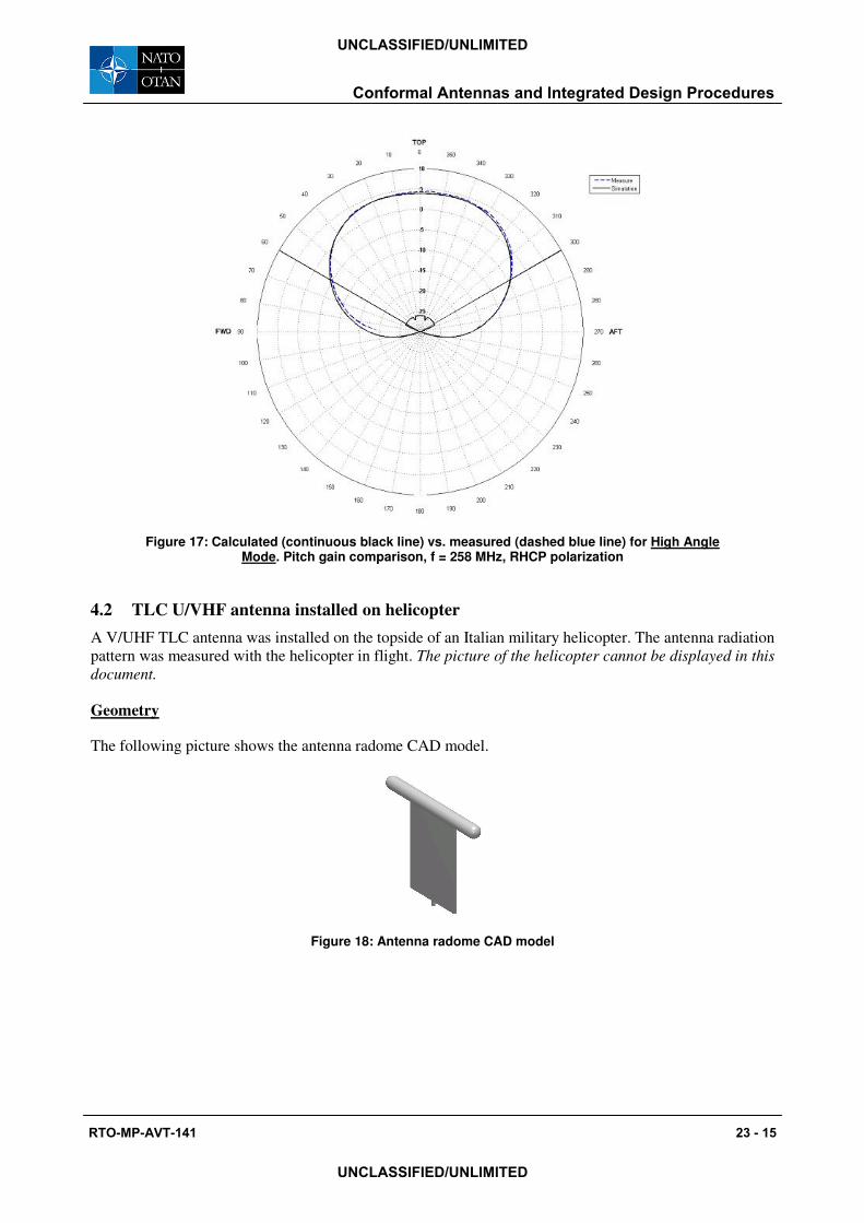
Figure 17: Calculated (continuous black line) vs. measured (dashed blue line) for High Angle Mode. Pitch gain comparison, f = 258 MHz, RHCP polarization
4.2 TLC U/VHF antenna installed on helicopter A V/UHF TLC antenna was installed on the topside of an Italian military helicopter. The antenna radiation pattern was measured with the helicopter in flight. The picture of the helicopter cannot be displayed in this document.
Geometry
The following picture shows the antenna radome CAD model.
Figure 18: Antenna radome CAD model
Conformal Antennas and Integrated Design Procedures
RTO-MP-AVT-141 23 - 15
UNCLASSIFIED/UNLIMITED
UNCLASSIFIED/UNLIMITED

Measurement set-up
Measurements were performed by Agusta S.p.A. in the following configuration: the receiving antenna was located on the top of a 20m high tower and the helicopter was flying at a distance of about 5 miles. The measurement set-up was not “a fully controlled one”: the description of the presence and location of surrounding buildings and infrastructures is unknown.
Simulation results
The simulation model took into account the helicopter geometrical configuration and the helicopter attitude (bank and pitch) with respect to ground. No “secondary” effects (such as scattering from the buildings surrounding the receiving tower and Rotor Blade Modulation (RBM) effects from the main and secondary rotors) were considered.
The following pictures show the comparison between simulated patterns, measured raw data (where RBM effects are clearly visible) and a filtered version of measured data (digitalized data). The helicopter attitude is also reported.
Figure 19: Radiation pattern on Yaw plane at 116 MHz. Vertical polarization. Simulated results and digitalized measured results
Conformal Antennas and Integrated Design Procedures
23 - 16 RTO-MP-AVT-141
UNCLASSIFIED/UNLIMITED
UNCLASSIFIED/UNLIMITED

Figure 20: Radiation pattern (vertical polarization) at 116 MHz. Measured raw data
Figure 21: Pitch and bank angles of the Helicopter
Conformal Antennas and Integrated Design Procedures
RTO-MP-AVT-141 23 - 17
UNCLASSIFIED/UNLIMITED
UNCLASSIFIED/UNLIMITED

-50
-40
-30
-20
-10
0
10 dB30
210
60
240
90270
120
300
150
330
180
0 SimulationsMeasurements
Figure 22: Radiation pattern on Yaw plane at 400 MHz. Vertical polarization. Simulated results and digitalized measured results
Figure 23: Radiation pattern (vertical polarization) at 400 MHz. Measured raw data.
Conformal Antennas and Integrated Design Procedures
23 - 18 RTO-MP-AVT-141
UNCLASSIFIED/UNLIMITED
UNCLASSIFIED/UNLIMITED
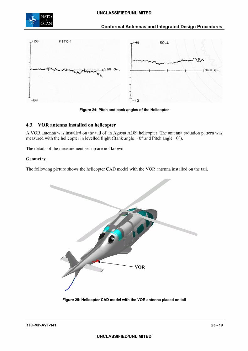
Figure 24: Pitch and bank angles of the Helicopter
4.3 VOR antenna installed on helicopter A VOR antenna was installed on the tail of an Agusta A109 helicopter. The antenna radiation pattern was measured with the helicopter in levelled flight (Bank angle = 0° and Pitch angle= 0°).
The details of the measurement set-up are not known.
Geometry
The following picture shows the helicopter CAD model with the VOR antenna installed on the tail.
Figure 25: Helicopter CAD model with the VOR antenna placed on tail
VOR
Conformal Antennas and Integrated Design Procedures
RTO-MP-AVT-141 23 - 19
UNCLASSIFIED/UNLIMITED
UNCLASSIFIED/UNLIMITED

Results
Figure 26: MoM-simulated versus measured pattern on Yaw plane. f = 111.1 MHz.
The simulated data are normalized with respect to the maximum value of the measured ones.
Figure 27: Induced Current Distribution at 108 MHz
Conformal Antennas and Integrated Design Procedures
23 - 20 RTO-MP-AVT-141
UNCLASSIFIED/UNLIMITED
UNCLASSIFIED/UNLIMITED

5.0 CONCLUSIONS
The number and complexity of radio based services working on avionic platforms is constantly growing, even on small aircrafts, helicopters and UAVs.
At the same time, the necessity to reduce risks and costs pushes the technical community to renew design procedures towards the use of numerical modelling techniques, more suitable than experimental and “cut and try” activities for the analysis in advance of several possible solutions, to understand the underlying physics and therefore to focus on the best ones.
The E-MIND electromagnetic modelling framework has been developed to provide the aircraft industry with modelling tools able to manage antenna and EMC/EMI problems across the entire frequency range of interest, with working procedures and software services able to manage the complexity of a whole aircraft (up to 30 antennas have been installed on a small helicopter!) while maintaining an overall view of the system.
Latest approaches to reduce the platform complexity, based on the use of integrated and conformal antennas (i.e. a single radiator able to work with more than one piece of equipment, matched to the aircraft structure or even using the superstructure as a part of the antenna itself) can be modelled and checked within E-MIND by building complex antenna models and modelling the full-wave interaction with the aircraft structure.
A multi-method approach is available because no one single modelling method can properly and effectively manage all frequency bands and all possible antenna/aircraft features (shapes and materials) and level of interactions. Full-wave electromagnetic modelling tools (such as Method of Moments), high frequency algorithms (such as Physical Optics, Incremental Theory of Diffraction and Uniform Theory of Diffraction) and hybrid ones are available and can be sequentially executed to build flexible and efficient modelling procedures.
References:
[1] Kayton M., Fried W, “Avionics navigation systems - 2nd Edition”, John Wiley & Sons – USA, 1997
[2] ICAO Aeronautical Telecommunications Annex 10 Volume IV
[3] RTCA/DO 185A “Minimum Operational Performance Standards for Traffic Alert and Collision Avoidance System II (TCAS II) Airborne Equipment”
[4] R.G.Rojas, K. S. Sampath, W. D. Burnside, “Analysis and simulation of collision avoidance TCAS antennas mounted on aircraft”, IEEE/APS International Symposium and Radio Science Meeting, San Jose, CA, June 1989
[5] Honeywell, “System installation manual – Bendix/King KMH 980/KTA 970 Multi Hazard Awareness / Traffic Alert & Collision Avoidance, TCAS I System, Manual number 006-10633-0002
[6] IDS Technical Report RT/2002/122 “Antenna Siting analysis on Aircraft M-346”
[7] R.E. Collin “Foundation for Microwave Engineering”, McGraw Hill international edition
[8] C. A. Balanis , “Advanced engineering electromagnetic”, John Wiley & Sons – USA, 1989
[9] E-MIND official web site: www.idscompany.it Aeronautical Division�Products�E-MIND
Conformal Antennas and Integrated Design Procedures
RTO-MP-AVT-141 23 - 21
UNCLASSIFIED/UNLIMITED
UNCLASSIFIED/UNLIMITED

Conformal Antennas and Integrated Design Procedures
23 - 22 RTO-MP-AVT-141
UNCLASSIFIED/UNLIMITED
UNCLASSIFIED/UNLIMITED
SYMPOSIA DISCUSSION – PAPER NO: 23
Author’s Name: M. Bandinelli
Question (M. Knott): What is/are the numerical method(s) which you are using for different parts of the object?
Author’s Response: For platforms: Method of moments (EFIE formulation) Uniform theory of diffraction (UTD) Physical Optics extended with Physical Theory of Diffraction and Integral Theory of Diffraction Hybrid MOM/PO/PTD/ITD Hybrid MOM/UTD For antenna/array: Method of moment with multilayer Green function and extension to Synthetic Function Expansion (SFX) Question (R. Kolonay): 1) What was the protocol used to do your network communications in your computing environment? 2) How was the data communicated between applications?
Author’s Response: 1) Using LAN + TC/IP (assuming ftp) 2) Data transferred by ASCII and binary files from one application to the next.