configuring the transport stream information - cisco.com · dvb-asi output...
TRANSCRIPT

Configuring the Transport Stream Information
This section describes how to set up and configure the transport stream outputs in the D9800 NetworkTransport Receiver.
• Transport Stream Outputs, page 1
• Configuring the ASI or MPEGoIP Output General Settings, page 3
• Configuring the ASI or MPEGoIP Output Mode, page 4
• Configuring the MPE Settings, page 7
• Setting Up Redundancy Controls for MPEG over IP and MPE Outputs, page 8
• Synchronizing the Output Services, page 9
• Resolving Conflicts, page 13
• Setting up the DPM Program Entries, page 13
• Copying between ASI and MPEGoIP DPM Settings, page 17
• Configuring the Program Entries, page 17
• Setting the SAP IP Address, page 21
• Setting the Transport Packet Limits, page 21
• Configuring the Forward Error Correction Settings, page 22
• Configuring MPEG over IP or IP Data Streams, page 25
• Configuring the Transcoder Settings, page 26
Transport Stream OutputsThe ASI and MPEGoIP transport outputs are individually configurable and provide the capability of carryinga decrypted program for digital tier distribution. This helps the compressed video programs are efficientlydistributed to households equipped with digital set-top boxes. Digital Program Insertion (DPI) informationwill also be available along with the video and audio PIDs (Packet Identifiers) for external ad insertion incompressed digital format.
Cisco D9800 Network Transport Receiver Version 2.75 Installation and Configuration Guide 1

DVB-ASI OutputThe D9800 receiver has one DVB-ASI output. This output can be used as an input for a DVB-T transmitteror other types of DVB-ASI reception equipment.
MPEGoIP OutputThe MPEGoIP output provides a number of output modes including the capability of carrying a decryptedprogram for digital tier distribution. This helps ensure that compressed video programs are efficiently distributedto households equipped with digital set-top boxes. Digital Program Insertion (DPI) information will also beavailable along with the video and audio PIDs (Packet Identifiers) for external ad-insertion in compresseddigital format.
The diagram below shows an example of the D9800 receiver used in an MPEGoIP application.
MPE OutputTheMultiprotocol Encapsulation (MPE) output provides a means to carry packet oriented IP protocols on topof a transport stream. The MPE output receives IP packets from the transport stream and the IP data can besent through an Ethernet switch to an IP router or directly to a receiving device.
The diagram below shows an example of the D9800 receiver used in an MPE application.
Cisco D9800 Network Transport Receiver Version 2.75 Installation and Configuration Guide2
Configuring the Transport Stream InformationDVB-ASI Output
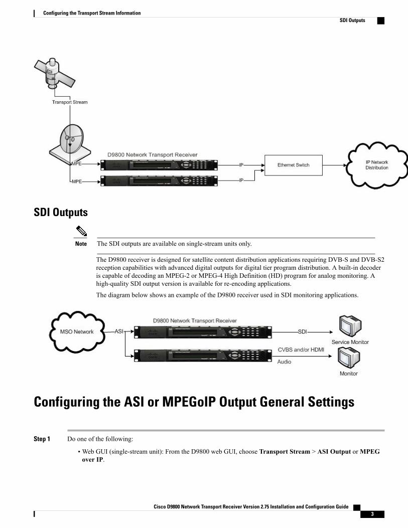
SDI Outputs
The SDI outputs are available on single-stream units only.Note
The D9800 receiver is designed for satellite content distribution applications requiring DVB-S and DVB-S2reception capabilities with advanced digital outputs for digital tier program distribution. A built-in decoderis capable of decoding an MPEG-2 or MPEG-4 High Definition (HD) program for analog monitoring. Ahigh-quality SDI output version is available for re-encoding applications.
The diagram below shows an example of the D9800 receiver used in SDI monitoring applications.
Configuring the ASI or MPEGoIP Output General Settings
Step 1 Do one of the following:
•Web GUI (single-stream unit): From the D9800 web GUI, choose Transport Stream > ASI Output orMPEGover IP.
Cisco D9800 Network Transport Receiver Version 2.75 Installation and Configuration Guide 3
Configuring the Transport Stream InformationSDI Outputs

• Front Panel (single-stream unit): From the Main Menu of the D9800 front panel, choose Setup > Outputs > TSOut > ASI orMOIP.
•Web GUI (multi-stream unit): From the D9800 web GUI, choose Transport Stream > ASI 1 Output, ASI 2Output, IP Data 1/Data 2 Output, or IP Data 3/Data 4 Output.
• Front Panel (multi-stream unit): From the Main Menu of the D9800 front panel, choose Setup > Outputs > TSOut > ASI or IP, and choose the input you want to configure from the ASI or IP front panel menu.
Step 2 TheRate Control drop-down list is set to User, as the method used to calculate the output rate. The output rate is specifiedby the User Rate field or front panel menu. It is determined by the user setting regardless of the input source.
Step 3 In the User Rate field or front panel menu, choose the maximum output bit rate expected by the equipment connectedto the ASI or MPEGoIP output (0 to 206 Mbps).
The output data may be lost if this bit rate is set to a value less than the actual bitrate.
Note
Step 4 From the Descrambled drop-down list, or the Descramble Mode front panel menu, choose whether to descramble theoutput if the input is descrambled. The following describes the available options:
• Scrambled - The output channel remains scrambled, even if the PE is authorized and can descramble the channel.
• Descrambled (default) - Descrambles the output channel, and passes in-the-clear channels.
Step 5 For ASI output, choose Yes or No from the Null Packet Insertion drop-down list, or the Insert Null Packet front panelmenu to determine whether to insert null packets into the output to maintain output at a constant bit rate. Null packetsare always inserted if the configured output bit rate is higher than the payload rate of the transport stream to be encapsulated.For MPEGoIP output or IP Data output, theNull Packet Insertion drop-down list, or the Insert Null Packet front panelmenu is set to Yes.
Step 6 Apply your changes.
Configuring the ASI or MPEGoIP Output Mode
Step 1 Do one of the following:
•Web GUI (single-stream unit): From the D9800 web GUI, choose Transport Stream > ASI Output orMPEGover IP Output.
• Front Panel (single-stream unit): From the Main Menu of the D9800 front panel, choose Setup > Outputs > TSOut > ASI orMOIP.
•Web GUI (multi-stream unit): From the D9800 web GUI, choose Transport Stream > ASI 1 Output, ASI 2Output, IP Data 1/Data 2 Output, or IP Data 3/Data 4 Output.
Cisco D9800 Network Transport Receiver Version 2.75 Installation and Configuration Guide4
Configuring the Transport Stream InformationConfiguring the ASI or MPEGoIP Output Mode

• Front Panel (multi-stream unit): From the Main Menu of the D9800 front panel, choose Setup > Outputs > TSOut >ASI or IP, and choose the input you want to configure general settings from theASI or IP front panel menu.
Step 2 From the Output Mode drop-down list or front panel menu, choose the DPM output mode for the current output. Withthe exception of No Output, choosing a mode will configure the DPM settings to achieve the specified behavior. In thisway, they act as DPM presets. We highly recommend that you use either one of the basic modes (Passthrough or ServiceChannels Only), or, for advanced setup, enter the DPM mapping before setting the output mode.Each PE in the Single Program Transport Stream (SPTS) creates its own transport stream, which includes PAT, CAT,SDT, and PMT tables for one service channel only, as well as ES PIDs for the PE.
DescriptionOption
No ASI, MPEGoIP, or IP output will be generated and the ASI or DATA ports will bedisabled.
No Output
All PEs will be set to Pass and other DPM settings will also be set.Passthrough
This is similar to Passthrough, except that only channels applied to program entries areavailable on the output.
Service Channels Only
The output will be identical to the input, except that channels assigned to PEs and PIDswill be mapped using the DPM settings. If the input is tuned to a valid channel, the PEsare automatically set toMap. Otherwise, the PEs are automatically set to Drop.
When choosingMAP Passthrough, a message appears to confirm that you want toresynchronize the output changes and PIDs to match the selected input programs. Clickor choose Yes to set the DPM mapping to the last valid (or saved) configuration. Clickor choose No to use the existing DPM maps.
If the PE is mapped, it uses the last saved output MAP configuration. The outputmap (for example, output channel PMT) does not change automatically if theinput or channel number is changed.
Note
MAP Passthrough
This is similar toMAP Passthrough, except that only channels applied to program entriesare available on the output. If the input is tuned to a valid channel, the PEs areautomatically set toMap. Otherwise, the PEs are automatically set to Drop.
When choosingMAP Service Channels Only, a message appears to confirm that youwant to resynchronize the output changes and PIDs to match the selected input programs.Click or choose Yes to set the DPM mapping to the last valid (or saved) configuration.Click or choose No to use the existing DPM maps.
If the PE is mapped, it uses the last valid input. The output map (for example,output channel PMT) does not change automatically if the input or channelnumber is changed.
Note
MAP Service Channels Only
The output will be generated using the DPMMAP settings, except that the DPMActionwill be set to XCode and theDescrambledmode will be set to Descrambled. If the inputis tuned to a valid channel, the PEs are automatically set to XCode. Otherwise, the PEsare automatically set to Drop.
If the PE is transcoded, it uses the last valid input. The output map (for example,output channel PMT) does not change automatically if the input or channelnumber is changed.
Note
Transcoding (multi-streamunits only)
Cisco D9800 Network Transport Receiver Version 2.75 Installation and Configuration Guide 5
Configuring the Transport Stream InformationConfiguring the ASI or MPEGoIP Output Mode

DescriptionOption
The service channel is passed with the same channel number, PMT PIDs, and ES PIDs.SPTS Service Channels Only(MPEG over IP only)
The service channel is mapped to the preconfigured channel number, PMT PIDs, andES PIDs.
SPTSMAPService ChannelsOnly (MPEG over IP only)
The service channel is mapped to the preconfigured channel number, PMT PIDs, andES PIDs. The PEs are automatically set to XCode.
SPTS Transcoding(multi-stream units only)
You are prompted to Resync All for the selected output. This resynchronizes the inputs to outputs for the current PMTaccording to the service assignments and the PIDs for the PE.
TheMode Status field, or theConfig Type front panel menu, indicates the current DPM configuration change by a userafter changing the Output Mode. The following table lists the statuses:
DescriptionMode Status or Config Type
No changes were made after setting a new output mode.
In a multi-stream unit, this applies to single input mode only. Formore information on single input mode, see Assigning a Channelto a Program Entry.
In a multi input mode,Unmodified (MSMode) status is displayed.
Unmodified
DPM changes were made by the user after setting the OutputMode.
In a multi-stream unit, this applies to a single input mode only. Formore information on the single input mode, see Assigning a Channelto a Program Entry.
In a multi input mode, Edited by User (MS Mode) status isdisplayed.
Edited by User
The output map changed automatically to fix the output channel orPID conflicts at the time of setup.
In a multi-stream unit, this applies to a single input mode only. Formore information on the single input mode, see Assigning a Channelto a Program Entry.
In a multi input mode, Auto re-mapped (MS Mode) status isdisplayed.
Auto Re-Mapped
DPM output changes were made, based on the uplink request aftersetting the Output Mode.
In a multi-stream unit, this applies to a single input mode only. Formore information on the single input mode, see Assigning a Channelto a Program Entry.
In a multi input mode, Chg by Unplink (MS Mode) status isdisplayed.
Chg by Uplink
Cisco D9800 Network Transport Receiver Version 2.75 Installation and Configuration Guide6
Configuring the Transport Stream InformationConfiguring the ASI or MPEGoIP Output Mode
DescriptionMode Status or Config Type
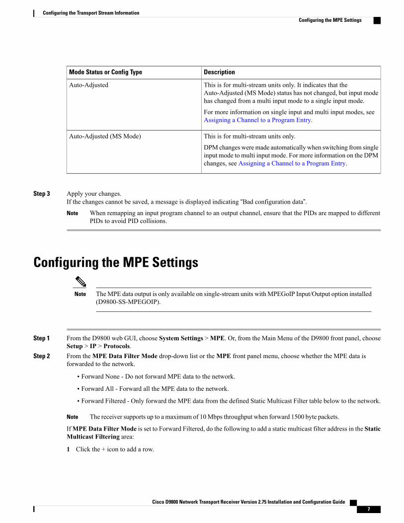
This is for multi-stream units only. It indicates that theAuto-Adjusted (MSMode) status has not changed, but input modehas changed from a multi input mode to a single input mode.
For more information on single input and multi input modes, seeAssigning a Channel to a Program Entry.
Auto-Adjusted
This is for multi-stream units only.
DPM changes weremade automatically when switching from singleinput mode to multi input mode. For more information on the DPMchanges, see Assigning a Channel to a Program Entry.
Auto-Adjusted (MS Mode)
Step 3 Apply your changes.If the changes cannot be saved, a message is displayed indicating “Bad configuration data”.
When remapping an input program channel to an output channel, ensure that the PIDs are mapped to differentPIDs to avoid PID collisions.
Note
Configuring the MPE Settings
TheMPE data output is only available on single-stream units withMPEGoIP Input/Output option installed(D9800-SS-MPEGOIP).
Note
Step 1 From the D9800 web GUI, choose System Settings >MPE. Or, from the Main Menu of the D9800 front panel, chooseSetup > IP > Protocols.
Step 2 From theMPE Data Filter Mode drop-down list or theMPE front panel menu, choose whether the MPE data isforwarded to the network.
• Forward None - Do not forward MPE data to the network.
• Forward All - Forward all the MPE data to the network.
• Forward Filtered - Only forward the MPE data from the defined Static Multicast Filter table below to the network.
The receiver supports up to a maximum of 10Mbps throughput when forward 1500 byte packets.Note
IfMPEData FilterMode is set to Forward Filtered, do the following to add a static multicast filter address in the StaticMulticast Filtering area:
1 Click the + icon to add a row.
Cisco D9800 Network Transport Receiver Version 2.75 Installation and Configuration Guide 7
Configuring the Transport Stream InformationConfiguring the MPE Settings

2 In theMulticast Filter Addresses field, enter the IP address that sets the destination for multicast MPE data, in therange from 224.0.0.0 to 239.0.0.0.
3 Click Save.
Step 3 Apply the changes.
What to Do Next
To edit or delete an existing multicast filter address, click the radio button of the address entry and click edit
( ) to edit the entry, or click delete ( ) to remove the entry.
Setting Up Redundancy Controls for MPEG over IP and MPEOutputs
The Redundancy Control area allows you to configure redundancy for MPEG over IP or IP Data, and MPEoutputs when an active port fails due to a physical connectivity loss. The DATA1 and DATA2 connectors,and DATA3 and DATA4 connectors (multi-stream units only) on the rear panel are used as redundant portpairs.
Step 1 Do one of the following:
•Web GUI (single-stream unit): From the D9800 web GUI, choose Transport Stream >MPEG over IP Output,or choose System Settings >MPE.
•Web GUI (multi-stream unit): From the D9800 web GUI, choose Transport Stream > IP Data 1/Data 2 Outputor IP Data 3/Data 4 Output.
• Front Panel: From the Main Menu of the D9800 front panel, choose Setup > IP > Redundancy.
Step 2 Refer to the Redundancy Control area.Step 3 From theMode drop-down list or front panel menu, choose one of the following:
• Manual: First Port or Manual: Second Port - For single-stream units, the setting only uses DATA 1 or DATA 2port for output data. If you are configuring redundancy for IP Data 3/Data 4 Output on a multi-stream unit, FirstPort is the DATA 3 port, and Second Port is the DATA 4 port. The remaining redundancy controls below are notapplicable.
• Backup: First Port or Backup: Second Port - Use DATA 1 or DATA 2 port as the primary data port and if a physicalconnectivity loss occurs, it will failover to the backup port. The backup port is the port that is not used as a primaryport in a port pair. For example, if Data 1 is the primary port, the backup port is Data 2. If you are configuringredundancy for IP Data 3/Data 4 Output on a multi-stream unit, First Port is the DATA 3 port, and Second Port isthe DATA 4 port. See Step 4 to configure specific settings for this mode.
Cisco D9800 Network Transport Receiver Version 2.75 Installation and Configuration Guide8
Configuring the Transport Stream InformationSetting Up Redundancy Controls for MPEG over IP and MPE Outputs

• Mirroring - Send the same data to both DATA 1 and DATA 2 ports, or DATA 3 and DATA 4 ports. The remainingredundancy controls below are not applicable.
Step 4 If Backup: First Port or Backup: Second Port is set as theMode, choose one of the following from the Directiondrop-down list or front panel menu:
DescriptionOptions
Attempt to revert back to the primary port when using the backup port and the primary port isactive again. Set the following parameters:
• Delay Forward - Set the time to switch the data port after the system detects a failure, in arange from 0 to 10000 milliseconds.
• Delay Back - Set the time to wait when reverting back to the primary port once the primarylink is active again, in a range from 1 to 120 seconds.
Revertive
If the system detects a link loss, the primary port will failover to the backup port (if active). If thebackup port is active and it detects a link loss, and the primary link is active, it will attempt toswitch back to the primary port. Set the following parameter:
• Delay Forward - Set the time to switch the data port after the system detects a failure, in arange from 0 to 10000 milliseconds.
Non-Revertive
Step 5 Apply the changes.You can view the latest redundancy status changes in the Redundancy Status area. The Ports In Use column displaysthe current output port in use, the Change Reason column displays a description of the reason for the last redundancystatus change (Link or Setup+Link), and theChange Date &Time column displays the last date and time the redundancystatus changed.
Synchronizing the Output ServicesThere are two methods for resynchronizing the program entry output with its input: resynchronize orresynchronize all. The resynchronize option allows you to customize the synchronization. The resynchronizeall option synchronizes all the DPM output with the PMT data for all the program entries on the selectedoutput.
Step 1 Do one of the following:
•WebGUI (single-stream unit): From the D9800webGUI, chooseTransport Stream >Digital ProgramMappingfor ASI or MPEG over IP.
•Web GUI (multi-stream unit): From the D9800 web GUI, chooseTransport Stream >Digital ProgramMappingfor ASI 1 Output, ASI 2 Output, IP Data 1/Data 2 Output, or IP Data 3/Data 4 output.
Cisco D9800 Network Transport Receiver Version 2.75 Installation and Configuration Guide 9
Configuring the Transport Stream InformationSynchronizing the Output Services

• Front Panel: From the Main Menu of the D9800 front panel, choose Setup > Outputs > TS Out > DPM.
Step 2 In the DPM Program Entry Setup area, do one of the following:
• Click Resynchronize All all the DPM output with the PMT data for all the program entries on the selected output.Or, select the Global front panel menu and choose the output.
• Click the radio button of the program entry you want to synchronize and then click Resynchronize to synchronizeeach PE output to its input according to one of the four output modes listed below. Or, select the ASI,MOIP, orIP front panel menu, choose the program entry you want to synchronize from the PE Resync menu, and thenchoose one of the four options below.
DescriptikonFront Panel optionWeb GUI option
The receiver synchronizes the PE output accordingto the services and then the PIDs assigned to eachservice.
AllResynchronize Program, PMTPID, ES List & ES PIDs
The receiver synchronizes the PE output accordingto the available input services only, and ignore theinput to output service PID mapping.
This is useful when you already have PIDassignments set for the services, but want to ensurethat the services are mapped correctly.
SvcsResynchronize ES List
The receiver synchronizes the PE output accordingto the input PIDs only, and ignore the serviceassignment categories/names.
This is useful when you already have the servicesset up, but want to synchronize to the incomingPIDs.
PIDsResynchronize ES PIDs
Allows you to preset the input to output mappingof a PE according to the preset template. This ishelpful in pre-configuring any number of PEs forfuture use.
TemplateResynchronize Template ES List& PIDs
If a conflict occurs, a message that the conflicts will be fixed automatically and to preview the changes prior to savingis displayed. For more information, see Resolving Conflicts, on page 13.
Cisco D9800 Network Transport Receiver Version 2.75 Installation and Configuration Guide10
Configuring the Transport Stream InformationSynchronizing the Output Services

Setting up the Auto Synchronization OptionsTheASI,MoIP, IPData 1/Data 2 Auto Sync area or theAutoMap front panel menu allows you to configurethe DPM without editing each output channel and PID separately.
Step 1 Do one of the following:
•Web GUI (single-stream unit): From the D9800 web GUI, choose Transport Stream > ASI Output orMPEGover IP Output and refer to the Auto Sync area.
• Front Panel (single-stream unit): From the Main Menu of the D9800 front panel, choose Setup > Outputs > TSOut > ASI orMOIP.
•Web GUI (multi-stream unit): From the D9800 web GUI, choose Transport Stream > ASI 1 Output, ASI 2Output, IP Data 1/Data 2 Output, or IP Data 3/Data 4 Output and refer to the Auto Sync area.
• Front Panel (multi-stream unit): From the Main Menu of the D9800 front panel, choose Setup > Outputs > TSOut > ASI1, ASI2, IP1/2, or IP 3/4.
Step 2 From the Enable Auto Fix for Collision drop-down list, or the Auto Map front panel menu, choose Yes for the DPMto resolve channel and PID collisions automatically on the transport outputs. New values are assigned to the parametersthat caused the conflict. The new assigned values are not used by any incoming transport or other PE outputs. If a collisionis detected, you can review the new changes and click Apply to accept the new changes.Choose No and a detailed list of all the conflicts is displayed in the Output Channel and PID Conflicts table (click ViewConflicts) when a conflict occurs. You can then resolve the conflicts manually. For information on resolving conflicts,see Resolving Conflicts, on page 13. The Enable Auto Map for Auxiliary PE is automatically set to No.
Step 3 From the Enable Auto Map For Auxiliary PEs drop-down list, choose Yes for the DPM to set the output actions forall the Auxiliary PEs to MAP when the Output Mode is set to Transcode. The Enable Auto Fix for Collision isautomatically set to Yes. If the Enable Fixed Table Output is set to Yes, the output configuration for the auxiliary PEsis determined by the fixed output table options when you resynchronize the output channels and PIDs to match the inputprograms. The DPM resolves any output conflicts automatically, even if the Enable Auto Fix for Collision is set to No.This setting is for multi-stream units only.
Step 4 Apply your changes.
Setting up the Resynchronize All Option
Step 1 Do one of the following:
•Web GUI (single-stream unit): From the D9800 web GUI, choose Transport Stream > ASI Output orMPEGover IP Output, and refer to the Auto Sync area.
•Web GUI (multi-stream unit): From the D9800 web GUI, choose Transport Stream > ASI 1 Output, ASI 2Output, IP Data 1/Data 2 Output, or IP Data 3/Data 4 Output, and refer to the Auto Sync area.
Cisco D9800 Network Transport Receiver Version 2.75 Installation and Configuration Guide 11
Configuring the Transport Stream InformationSetting up the Auto Synchronization Options

• Front Panel: From the Main Menu of the D9800 front panel, choose Setup > Outputs > TS Out > Options, andchoose the input you want to configure from the Output front panel menu.
Step 2 From the Enable Fixed Output drop-down list, or the Fixed Output front panel menu, choose Yes for the DPM toassign new values for all the output channels and PIDs according to the fixed output options defined, when you synchronizethe inputs to the outputs according to the service assignments only (Resynchronize All).
Step 3 Click Fixed Output Option, or scroll the front panel menus to configure the fixed output options and click OK.a) From the Use Input Channel Numbers drop-down list, or the Use Imp Chan front panel menu, choose Yes to use
the output channel. Otherwise, choose No (default) to use the first or start channel and channel offset or step assignedbelow.
• In the First Channel Number field, or the Start front panel menu, set the first PE channel number to use (from1 to 65535). By default, the channel is set to 1.
• In the Channel Numbers Offset field, or the Step front panel menu, set the subsequent PE channel numbers(from 1 to 65535). For example, if the First Channel Number is set to 100 and the Channel Numbers Offsetis set to 10, then the first channel number is 100, and the second channel number is 110.
b) From the Use Input PMT PID Numbers drop-down list, or the Use Inp PMT front panel menu, choose Yes to usethe input PMT PID number. Otherwise, choose No (default) to use the first or start PE PID number and PID offsetor step number assigned below.
• In the First Channel First ES PID Number field (or the Start front panel menu), enter the first PE PMT PIDnumber (from 1 to 8192). The default is 1701.
• In the PMT PID Numbers Offset field, or the Step front panel menu, set the offset of the subsequent PE PMTPID numbers (from 1 to 8192). For example, if the First Channel First ES PID Number is set to 1701 and thePMT PID Numbers Offset is set to 1, then the first PMT PID number is 1701, and the second PMT PID numberis 1702.
c) From the Use Input ES PID Numbers drop-down list, or the Use Inp PIDs front panel menu, choose Yes to usethe input ES PID number. Otherwise, choose No (default) to use the first or start ES PID number and the ES PIDoffset or step number assigned below.
• In the First Channel First ES PID Number field, or the Start front panel menu, set the first ES PID number.The default is 101.
• In the First ES PID Numbers Offset field, set the offset of the first ES PID of subsequent channel numbers.For example, if the First ES PID Number is set to 101 and the ES PID Numbers Offset is set to 100, then thefirst ES PID number is 101, and the second ES PID number is 201.
d) From the Use Input PMT ES Stream Order drop-down list, or the Use Inp Ord front panel menu, choose Yes toassign the ES PID according to the incoming PMT order. Otherwise, set to No to use the reserved PIDs definedbelow.
• In the PCR, VID, AUD, SUBT, VBI, DPI, MPE, TTX, DATA, LSD, CDT, ETV fields or front panel menus,set the number of PIDs for the specified streams (PCR, VID, AUD, SUBT, VBI, DPI, MPE, TTX, DATA,LSD, CDT, ETV) in one channel (from 1 to 64).
Step 4 Apply your changes.
Cisco D9800 Network Transport Receiver Version 2.75 Installation and Configuration Guide12
Configuring the Transport Stream InformationSetting up the Resynchronize All Option

Resolving ConflictsIf a conflict occurs and the Enable Auto Map for Collision field, or the Auto Map front panel menu, is setto No, a detailed list of all the conflicts is displayed in the Output Channel and PID Conflicts table when youclick View Conflicts. You can then resolve the conflicts manually.
If a conflict occurs and the Enable Auto Map for Collision field (or the Auto Map front panel menu) is setto Yes, a message that the conflicts will be fixed automatically and the Output Channel and PID Conflictstable is empty when you click View Conflicts.
Any changes made to the ASI DPM values will automatically change theMode Status toEdited by User.Note
• For channel conflicts, the systemwill only automatically change the duplicated output channel numbers.If both PE actions are set to Map, the output channel number of the higher PE is changed. Otherwise,the output channel number of the mapped PE is changed. The new channel number selected is the nextchannel number that does not appear in the current PAT or belong to any other PEs.
• For PID conflicts, the system will only automatically change the duplicated output PID numbers. If bothPE actions are set to Map, the output PID number of the higher PE is changed. Otherwise, the outputPID number of the mapped PE is changed. For example, if the PMT PID of PE1 matches the ES PIDof PE2, the ES PID of PE2 is changed. The new PID number selected is the next number that does notappear in the output of any PE and it is not in the current transport input.
Setting up the DPM Program EntriesThe DPM feature allows you to groom functionality on a program basis, where individual service PIDmodifications are provided on a limited scale. Use the digital program mapping feature to:
• configure the transport output bit rate.
• configure the output mode for a program entry.
• configure the service and PID output settings in a program entry.
This section defines all the available fields. For an example of a typical setup of the DPM, see Typical DigitalProgram Mapping Setup, on page 16.
Configuring DPM General Settings
Step 1 Do one of the following:
•WebGUI (single-stream unit): From the D9800webGUI, chooseTransport Stream >Digital ProgramMappingfor ASI or MPEG over IP output, and refer to the DPM General Settings area.
• Front Panel (single-stream unit): From the D9800 front panel, choose Setup > Outputs > TS Out > DPM > ASIorMOIP.
Cisco D9800 Network Transport Receiver Version 2.75 Installation and Configuration Guide 13
Configuring the Transport Stream InformationResolving Conflicts

•WebGUI (multi-stream unit): From theD9800webGUI, chooseTransport Stream >Digital ProgramMappingforASI 1 Output, ASI 2 Output, IP Data 1/Data 2 Output, or IP Data 3/Data 4 Output, and refer to the DPMGeneralSettings area.
• Front Panel (multi-stream unit): from the D9800 front panel, choose Setup > Outputs > TS Out > DPM > ASI1, ASI2, IP1/2, or IP3/4.
Step 2 From the Remapping Mode drop-down list, or theMap Mode front panel menu, choose the DPM mapping mode forthis output.
• Svc ID - The elementary PIDs are not changed. Channels are remapped by changing their PSI references. Whenthis mode is selected, PE detailed PID mapping in the PD menu are ignored.
• Svc ID & PID - Channels and the elementary service PIDs can be mapped in the DPM PE PID MAP window.If you use this mode, youmust choose how to handle duplicate programs from theDuplicationMethod drop-downlist, or the Duplic Mode front panel menu:
◦PSI Remap - Every input PID can be mapped to only one output PID. If PID mapping conflicts exist, DPMwill use the Precedence Rule to decide which output PID to use. All PMTs using the input PIDwill be updatedto reference the output PID specified by the winner.
◦Pkt Copy - An input PID can be mapped to multiple output PIDs. The PID will be duplicated as many timesas needed (up to a certain hardware limitation). Pkt Copy is recommended for most applications.
This may increase the output bandwidth of thestream.
Note
Step 3 From theUnreferenced Content drop-down list, or theUnref front panel menu, choose the action to use for unreferencedcontent. Unreferenced content is the remainder of the transport stream that is not filtered by the program entries. ChooseDrop (default) to drop all unreferenced content. Choose Pass to pass all unreferenced content to the output unchanged.For multi-stream units only, chooseMode-i to use a customer-specific mode. ClickMode-i Options, or choosePAT/PMTOffset and NIT Offset front panel menus, to set the PAT Offset and NIT Plus Offset information. This is only used ifdirected by Cisco. For more information, contact Cisco Services.
Mode-i is not supported in multi input mode. If you switch to multi input mode by adding a second active input,the unreferenced content will drop.
Note
Step 4 From the Service ID Output drop-down list, or the Service ID front panel menu, choose whether the transcoder shouldalways generate PSI tables for the Mapped PE even if the selected input channel is not available, or for only valid servicechannels/IDs. The following describes each service ID:
• Valid Ch - Only transmits the PSI tables for the mapped program if the program exists on the input stream.
• All Ch - Transmits the PSI tables for the mapped program even if the program does not exist in the input stream.All Ch is only valid if the PAT, NIT, SDT and PMT are set to Regenerate.
Step 5 Apply the changes.
Cisco D9800 Network Transport Receiver Version 2.75 Installation and Configuration Guide14
Configuring the Transport Stream InformationConfiguring DPM General Settings

Setting the PSI Table Options
Step 1 Do one of the following:
•WebGUI (single-stream only): From the D9800 web GUI, chooseTransport Stream >Digital ProgramMappingfor ASI, MPEG over IP output, and refer to the DPM General Settings area.
• Front Panel (single-stream only): From the D9800 front panel, choose Setup > Outputs > TS Out > DPM > ASIorMOIP.
•WebGUI (multi-stream only): From the D9800 webGUI, chooseTransport Stream >Digital ProgramMappingfor ASI 1 Output, ASI 2 Output, IP Data 1/Data 2 Output, or IP Data 3/Data 4 Output, and refer to theDPMGeneralSettings area.
• Front Panel (multi-stream only): From the D9800 front panel, choose Setup >Outputs > TS Out >DPM >ASI1,ASI2, IP1/2, or IP3/4.
Step 2 From the PSI Table Output Option drop-down list, or the PSI Options front panel menu, choose the action to performon the PSI tables for the output stream. The following describes each option:
• Pass All - Transmits the incoming PSI tables as is; does not modify the content and rate. The SI RegenerationOption (or the PSI Rate front panel menu) and table settings are ignored.
• Drop All - Does not transmit any PSI tables. The SI Regeneration Option and table settings are ignored.
• Ctl By Table - The incoming PSI tables are transmitted, according to the output mode set in the table options (seeStep b below). You must set the following:
1 From the SI Regeneration Option drop-down list, or the PSI Rate front panel menu, choose the regenerationrate for the PSI tables being regenerated. The following describes each PSI rate:
• Auto - Matches the generated PSI tables' output rate to the incoming rate.
• MPEG Min - Transmits the generated PSI tables on the longest intervals that are allowed by MPEGstandard.
• SA Std - Transmits the generated PSI tables based on PowerVu standard intervals.
2 Click Table Options, or scroll down the front panel menu to choose the table specific output mode for eachtable. From each of the table drop-down lists, choose pass, drop, regenerate (Regen), or pass with rate control(PwRC) and click OK.
For the front panel, the table menus (PAT, CAT, PMT, TSDT, NIT, NITO, SDT, SDTO, BAT EIT, TDT,RST, TOT, DIT, SIT, EMC, EMM, DRT, CDT) will only appear if you choose Ctl by Table.
Note
The CDT is different from the other tables listed because the CDT is referred to within the PMT, rather thanoutside the PMT. Check the Block CDT Output check box (or choose Pass from the CDT front panel menu)to override the DPM PID map configuration for CDT PIDs and to always drop all CDTs. Otherwise, unchecktheBlockCDTOutput (or choose Drop from theCDT front panel menu) to permit the output of CDTs followingthe configured DPM PID map configuration and all other DPM constraints.
Note
Cisco D9800 Network Transport Receiver Version 2.75 Installation and Configuration Guide 15
Configuring the Transport Stream InformationSetting the PSI Table Options

Step 3 From the PSI Regeneration Option drop-down list. or the Setup >Outputs > TS Out >DPM >Global >Regeneratefront panel menu, choose whether to regenerate the PSI tables in the output. Choose Always to regenerate all the tablesor choose As Needed to only regenerate the tables if the content has changed.
Step 4 Apply the changes.
Typical Digital Program Mapping Setup
Step 1 Verify that you are receiving a valid signal and that you have set up the channels that you want to pass, drop, or map.Step 2 Set the following output parameters:
• Output Mode - Map Service Channels Only.
• Descrambled - Scrambled or descrambled for downstream viewing or monitoring.
For more information, see Configuring the ASI or MPEGoIP Output General Settings, on page 3.
Step 3 From the ASI, MPEG over IP, or IP Digital Program Mapping page:
• Click Resynchronize All or choose the Resync All from the Global front panel menu.
• Edit a program entry in the DPM Program Entry Setup area and add a new record.
For more information, see Synchronizing the Output Services, on page 9 and Mapping the Program PIDs, on page19.
Step 4 Set the following DPM general settings:
• Remapping Mode or Map Mode - Svc ID & PID
• Duplication Method or Duplic Mode - Pkt Copy
• Unreferenced Content or Unref - Drop
• Service ID Output or Svc ID - Valid Ch or All Ch
• PSI Output Option or PSI Options - Ctrl By Table
• PSI Regeneration Option or PSI Rate - Always or As Needed
For more information, see Configuring DPM General Settings, on page 13.
Step 5 Set the following table options:
• PAT, CAT, PMT, SDT - Regen
• TSDT, NITO, SDTO, BAT, EIT, ECM, EMM, DRT, CDT - Drop
• TDT, RST, TOT, DIT, SIT - Pass
• NIT - Regen or Drop
Cisco D9800 Network Transport Receiver Version 2.75 Installation and Configuration Guide16
Configuring the Transport Stream InformationTypical Digital Program Mapping Setup

For more information, see Setting the PSI Table Options, on page 15.
Step 6 Apply the changes.
Copying between ASI and MPEGoIP DPM Settings
Step 1 Do one of the following:
•WebGUI (single-stream unit): From the D9800webGUI, chooseTransport Stream >Digital ProgramMappingfor ASI or MPEG over IP output.
•Web GUI (multi-stream unit): From the D9800 web GUI, chooseTransport Stream >Digital ProgramMappingfor ASI 1 Output, ASI 2 Output, IP Data 1/Data 2 Output, or IP Data 3/Data 4 Output.
• Front Panel: From the D9800 front panel, choose Setup > Outputs > TS Out > DPM > Global.
Step 2 For a single-stream unit, do one of the following:
• Click Copy To MOIP, or choose the Copy: > ASI->MOIP front panel menu, to copy all the DPM data from theASI output to the MOIP output.
• ClickCopy To ASI, or choose theMOIP->ASI front panel menu, to copy all the DPM data from the MOIP outputto the ASI output.
For a multi-stream unit, do one of the following:
•Web GUI: Click Copy and check the output check boxes to copy all the DPM data from the output displayed inthe From field, to the outputs selected in the To field. Click Apply.
• Front Panel: Choose Copy: From to select the output from which you want to copy all the DPM data, and thenchoose Copy: To to select the output to which you want to copy all the DPM data. Choose Yes from the Applymenu to apply the changes.
Configuring the Program Entries
Step 1 Do one of the following:
•WebGUI (single-stream unit): From the D9800webGUI, chooseTransport Stream >Digital ProgramMappingfor ASI or MPEGoIP.
Cisco D9800 Network Transport Receiver Version 2.75 Installation and Configuration Guide 17
Configuring the Transport Stream InformationCopying between ASI and MPEGoIP DPM Settings

• Front Panel (single-stream unit): From the D9800 front panel, choose Setup > Outputs > TS Out > DPM > ASIorMOIP
•Web GUI (multi-stream unit): From the D9800 web GUI, chooseTransport Stream >Digital ProgramMappingfor ASI 1 Output, ASI 2 Output, IP Data 1/Data 2 Output, or IP Data 3/Data 4 Output.
• Front Panel (multi-stream unit): From the D9800 front panel, choose Setup >Outputs > TS Out > DPM > ASI1,ASI2, IP1/2, or IP3/4.
The DPM Program Entry Setup area displays a list of DPM program entries in the Program Entry column, or the PEmenu. There are 16 channels for single-stream units, and 32 channels for multi-stream units. Each program entry displaysthe input channel number in theChl # column, or the InCh front panel menu, and the channel name in theName column.
On a multi-stream unit, depending on the number of transcoder boards installed, the unit can have up to 16 auxiliarychannels (PE1A to PE16A). For example, if there is one transcoder board, there are 8 auxiliary channels, and if thereare two transcoder boards, there are 16 auxiliary channels. For more information on viewing the number of transcoderboards installed, see the number of D9800-TXB entries listed in the HW Board Versions area (System Settings >System). The auxiliary channels automatically tune to the corresponding PE channels. If the main PE is not transcoding,the auxiliary PE is dropped.
Step 2 Click the program entry you want to edit, or choose the program entry from the PE front panel menu.Step 3 On a multi-stream unit, choose the input you want to assign to the program entry from the Input Name drop-down list.
On a single-stream unit, the Input Name column displays the input used (RF, ASI, or MOIP). You can also set this onthe Channel Selection page. For more information, see Assigning a Channel to a Program Entry.
Step 4 From the Channel drop-down list, choose or enter the channel number of the current program entry. You can also setthis on the Channel Selection page. For more information, see Assigning a Channel to a Program Entry. The channel isdisplayed in the InCh front panel menu.
Step 5 From the Action column, or the Act front panel menu, choose the action to perform on the current program entry. Thissetting controls the overall DPM behavior of the program entry and affects how the PID mapping operates.
• Pass (default) - The output channel is the same as the input channel. The Output Chl # and PMT PID settings(OutCh and PMT front panel menus) are ignored. All PIDmap entries are ignored except for entries that explicitlydrop a service.
• Map - The output channel is mapped to the Output Chl # and PMT PID (OutCh and PMT front panel menu)settings. Only services which have entries in the PID map are available on the output. These services will appearin the PMT even if the stream is not present. To edit the channel number and PMT PID that will be mapped to theinput channel or PMT PID, click the radio button of the program entry and click Edit. For more information, seeMapping the Program PIDs, on page 19. If the PE is mapped, it uses the last valid input. The output map (forexample, output channel PMT) does not change automatically if the input or channel number is changed.
• Drop - The current channel is not sent to the output and its PMT is removed from the output. The OutCh, PMT,and PID map entries are ignored.
• XCode (multi-stream units only) - Provides the flexibility to define all the outgoing PID numbers for a PE, includingthose not currently on transmission, as in Map mode, plus the video PID is transcoded to output at the rate andsettings defined for the transcode channel. The Auxiliary Programs (P1A to P16A) cannot be set to XCode. Also,they are automatically dropped when the corresponding Main PE is not transcoding.
Step 6 Click Save or press Apply on the front panel.
Cisco D9800 Network Transport Receiver Version 2.75 Installation and Configuration Guide18
Configuring the Transport Stream InformationConfiguring the Program Entries

Configuring Auxiliary Program EntriesYou can only configure auxiliary program entries on a multi-stream unit.
Step 1 Ensure that the Enable Auto Map For Auxiliary PEs drop-down list is set to Yes. For more information, see Settingup the Auto Synchronization Options, on page 11.
Step 2 From the D9800 web GUI, choose Transport Stream > Digital Program Mapping for ASI 1, ASI 2, IP Data 1/Data2, or IP Data 3/Data 4. Or, from the D9800 front panel, choose Setup > Outputs > TS Out > DPM > ASI1, ASI2,IP1/2, or IP3/4.
Step 3 Click a PxA to edit or choose a PxA from the PE front panel menu.Step 4 ChooseMap from theAction drop-down list, or theAct front panel menu. For more information on the Action parameter,
see Configuring the Program Entries, on page 17.Step 5 Save your changes.Step 6 Click Resynchronize All or choose Resync: All front panel menu to ensure that the inputs and outputs are the same.
Mapping the Program PIDsThe PID mapping feature allows you to map input services to output PIDs. If the PE Action is Pass, or thePE Action is Map and the Remapping Mode is set to Svc ID, only entries which drop a service are appliedand all other services are passed through. If the PE action is Map and Map Mode is Svc ID & PID, all entriesare applied. Any services not mapped by an entry will be dropped.
For the front panel, press up and down to scroll through the PID map entries. Press ADV to insert or deleteentries from the PID map. After inserting an entry, specify the service using OutType and In, and set thedesired Action. If the action is Map, select the output PID value as well. Then press APPLY and save thesettings to see the selected input service that will follow that mapping.
Step 1 Do one of the following:
•WebGUI (single-stream unit): From the D9800webGUI, chooseTransport Stream >Digital ProgramMappingfor ASI or MPEG over IP output.
• Front Panel (single-stream unit): From the D9800 front panel, choose Setup > Outputs > TS Out > DPM > ASIorMOIP.
•Web GUI (multi-stream unit): From the D9800 web GUI, chooseTransport Stream >Digital ProgramMappingfor ASI 1 Output, ASI 2 Output, IP Data 1/Data 2 Output, or IP Data 3/Data 4 Output.
Cisco D9800 Network Transport Receiver Version 2.75 Installation and Configuration Guide 19
Configuring the Transport Stream InformationConfiguring Auxiliary Program Entries

• Front Panel (single-stream unit): from the D9800 front panel, choose Setup >Outputs > TS Out > DPM > ASI1,ASI2, IP1/2,or IP3/4.
Step 2 Click the program entry radio button you want to map the PIDs and click Edit or choose the program entry from the PEfront panel menu.
Step 3 In the Output Channel # field, or the OutCh front panel menu, enter the output channel number you want to map tothe input channel (displayed in the Input Channel # field or the InCh front panel menu). This value is only used if thePE Action is set to Map. You can enter a range from 1 to 65535.
Step 4 In the Output PMT PID field, or the second PMT front panel menu, enter the output PMT PID number you want tomap to the input PMT PID (displayed in the Input PMT PID field or the first PMT front panel menu). This value isonly used if the PE Action is set to Map. You can enter a range from 2 to 8190.
Step 5 For front panel only, choose the PID menu to map the program PIDs.Step 6 You can click on the radio button of an existing PID mapping entry you want to modify or click the + button to insert a
new PID mapping. If there is no record available on the front panel, choose Yes to insert a new record.The Input Stream, or the ITyp front panel menu, indicates the input service that will be mapped by the current entry.The Input PID, or the PID front panel menu, displays the input PID (1 to 8190) that will be mapped by the current entry.This is only used if Action is set toMap.
Step 7 From theAction drop-down list, or theAct front panel menu, choose the action to perform on the current PID. The Dropaction is always performed, but the Map option is only applied if the PE Action is Map and the Remapping Mode is SvcID & PID in the DPM General Settings section.
DescriptionOption
The service selected by the Category and Instance will be mapped to the specified PID. This isonly applied if the PE action is Map and the Remapping Mode is Svc ID & PID.
Drop
The service selected by the Category and Instance will be removed from the PMT and the outputstream.
Map
Step 8 If the Action, or the Act front panel menu, is set to Map, enter the output PID number (0 to 8192) in the Output PIDfield, or the PID front panel menu.
Step 9 In the Stream Type field, or the StTyp front panel menu, enter a stream type to map within a PE to a specified PID (0to 255).
Step 10 From the Category drop-down list, or the OTyp front panel menu, choose the service to configure. If an input servicematches this type and Instance, then the Action will be applied. This value is only used if Action is set to Map.
Step 11 In the Instance field, or the In front panel menu, enter the instance of the service specified by Category to configure (1to 64). If an input service matches this type and instance, then the Action will be applied.
Step 12 Click Save, and then click OK.Step 13 Apply the changes.
Cisco D9800 Network Transport Receiver Version 2.75 Installation and Configuration Guide20
Configuring the Transport Stream InformationMapping the Program PIDs

Setting the SAP IP Address
Step 1 Do one of the following:
•Web GUI (single-stream unit): From the D9800 web GUI, choose Transport Stream >MPEG over IP Output.
• Front Panel (single-stream unit): From the Main Menu of the D9800 front panel, choose Setup > Outputs > TSOut >MOIP >MOIP Streams.
•Web GUI (multi-stream unit): From the D9800 web GUI, choose Transport Stream > IP Data 1/Data 2 Outputor Data 3/Data 4 Output.
• Front Panel (multi-stream unit): From the Main Menu of the D9800 front panel, choose Setup > Outputs > TSOut > IP > Streams Configuration.
Step 2 In the SAPMulticast IP Address field, or the SAP Address front panel menu, set the Session Announcement Protocol(SAP) destination IP address. This is the IP address where the SAP announcements are sent, if required.
We recommend that you do not change the default IP address (224.2.127.254).Note
Step 3 In the SAPDestinationUDPPort field or SAPPort front panel menu, set the SAP destination port number (1 to 65534).This is the UDP port where the SAP announcements are sent, if required.
We recommend that you do not change the default SAP port of9875.
Note
Step 4 Apply the changes.The front panel has the following additional settings:
• Send SAP - Select whether to send Session Announcement Protocol messages (None or RFC2327).
• SAP ID - Choose the SAP output stream name source (User String or SDT Channel).
• SAP User Str - Enter the SAP user string, up to 31 characters.
Setting the Transport Packet Limits
Step 1 Do one of the following:
•Web GUI (single-stream unit): From the D9800 web GUI, choose Transport Stream >MPEG over IP Output.
• Front Panel (single-stream unit): From the Main Menu of the D9800 front panel, choose Setup > Outputs > TSOut >MOIP >MOIP Streams.
•Web GUI (multi-stream unit): From the D9800 web GUI, choose Transport Stream > IP Data 1/Data 2 or IPData 3/Data 4 Output.
Cisco D9800 Network Transport Receiver Version 2.75 Installation and Configuration Guide 21
Configuring the Transport Stream InformationSetting the SAP IP Address

• Front Panel (multi-stream unit): From the Main Menu of the D9800 front panel, choose Setup > Outputs > TSOut > IP > Streams Configuration.
Step 2 In theMaximumTransport Packets/Ethernet Frame field, or theTS/IP front panel menu, enter or choose themaximumnumber of transport packets per IP packet (1 to 7).
Step 3 In theMinimumnumber Packets/Second field, or theMin IP/s front panel menu, enter or choose theminimum numberof transport packets per IP packet (0 or 2 to 1000).
Configuring the Forward Error Correction SettingsDue to the nature of an IP network (occasionally packet loss, packet reordering, and/or stream jitter) it is notthe perfect channel for transmitting broadcast-quality compressed video content. Forward Error Correction(FEC) developed by the Pro-MPEG forum is a unique technology to enhance the robustness of video trafficover IP networks. The D9800 receiver supports Pro-MPEG FEC Code of Practice (COP) #3 release2 andSMPTE-2022, which is based on the exclusive or (XOR) boolean operator applied to a number of data packets.When a FEC packet is created by performing the XOR boolean operation on a number of RTP packets, amissing RTP packet can always be reconstructed by performing the XOR operation on the FEC packet andthe remaining RTP packets.
• FEC = RTP1 XOR RTP2
• RTP1 = FEC XOR RTP2
• RTP2 = FEC XOR RTP1
Step 1 Do one of the following:
•Web GUI (single-stream unit): From the D9800 web GUI, choose Transport Stream >MPEG over IP Output> Stream tab.
• Front Panel (single-stream unit): From the Main Menu of the D9800 front panel, choose Setup > Outputs > TSOut >MOIP >MOIP Streams.
•Web GUI (multi-stream unit): From the D9800 web GUI, choose Transport Stream > IP Data 1/Data 2 or IPData 3/Data 4 Output > Stream tab.
• Front Panel (multi-stream unit): From the Main Menu of the D9800 front panel, choose Setup > Outputs > TSOut > IP > Streams Configuration.
Step 2 Click the radio button of the stream you want to configure FEC settings, or choose the ID front panel menu and choosethe stream.
Step 3 Click FEC.Step 4 From the FEC Mode drop-down list, or the FEC front panel menu, choose an error protection profile.
• Choose 1D to use the 1D FEC profile. The 1D FEC profile maps the RTP packet stream across columns (matrixof data packets). The following is an example:
Cisco D9800 Network Transport Receiver Version 2.75 Installation and Configuration Guide22
Configuring the Transport Stream InformationConfiguring the Forward Error Correction Settings

Cisco D9800 Network Transport Receiver Version 2.75 Installation and Configuration Guide 23
Configuring the Transport Stream InformationConfiguring the Forward Error Correction Settings

• Choose 2D to use the 2D FEC profile. The 2D FEC profile maps the RTP packet stream across both the columnpackets and row packets. In the following example, a FEC packet is created for each row and each column:
• Choose None to disable the error protection for the MPEGoIP stream.
Step 5 The generation of the FEC packets is based on the use of a matrix. The matrix size is defined by the Length (L) andDepth (D) parameters. In the FEC Columns (L) field or front panel menu, set the spacing between non-consecutivepackets used to calculate the FEC packet (1 to 20).If the FECMode or the FEC front panel menu is set to 2D, set the depth of the matrix in the FEC Rows (D) field or frontpanel menu (4 to 20).
If the FEC Mode or the FEC front panel menu is set to 2D, set the depth of the matrix in the FEC Rows (D) field orfront panel menu (4 to 20).
For additional restrictions on L and D values (depending on the FEC Scheme and FEC Mode), refer to Pro-MPEG FECCOP#3 and SMPTE-2022.
Step 6 In the FEC Columns UDP Port field, or the FEC1 UDP front panel menu, enter the UDP port number for the FECColumns stream (2 to 65534, even number only). We recommend that you set the port number to TS UDP port + 2.If the FEC Mode or the FEC front panel menu is set to 2D, enter the destination UDP port number for the FEC Rowsstream in the FECRowsUDP Port field (or the FEC2UDP front panel menu). The range is from 2 to 65534, even numberonly. We recommend that you set the port number to TS UDP port +4.
Step 7 Click OK and apply the changes.
Cisco D9800 Network Transport Receiver Version 2.75 Installation and Configuration Guide24
Configuring the Transport Stream InformationConfiguring the Forward Error Correction Settings

Configuring MPEG over IP or IP Data Streams
Step 1 Do one of the following:
•Web GUI (single-stream unit): From the D9800 web GUI, choose Transport Stream >MPEG over IP Output> Stream tab.
• Front Panel (single-stream unit): From the Main Menu of the D9800 front panel, choose Setup > Outputs > TSOut >MOIP >MOIP Streams.
•Web GUI (multi-stream unit): From the D9800 web GUI, choose Transport Stream > IP Data 1/Data 2 or IPData 3/Data 4 Output > Stream tab.
• Front Panel (multi-stream unit): From the Main Menu of the D9800 front panel, choose Setup > Outputs > TSOut > IP > Streams Configuration.
Step 2 Double-click the stream you want to edit, or from the ID front panel menu, choose the stream you want to edit. Asingle-stream unit has up to 16 streams, and a multi-stream unit has up to 32 streams.If theOutputMode is set to NoOutput, Passthrough, Service Channels Only,MAP Passthrough,MAP Service ChannelsOnly, or Transcoding, you can configure the Multi Program Transport Stream (MPTS). PE2 to PE16 or PE32 are notapplicable.
If the Output Mode is set to SPTS Service Channels Only, SPTS MAP Service Channels Only, or SPTS Transcoding,you can configure PE1 to PE16 or PE32 streams. Each PE creates its own transport stream for the assigned servicechannel and ES PIDs.
Step 3 From the Bitrate field, or the User Rate front panel menu, enter the output rate of the transport stream, in Mbps.Step 4 From the Encapsulation drop-down list, or theMOIP front panel menu, choose the transport protocol to use for the
output stream (UDP or RTP).Step 5 In the Destination IP field, or the DestAddr front panel menu, enter the unicast (valid host IP only) or multicast
destination IP address.Step 6 In the Destination UDP Port field, or the UDPPort front panel menu, choose the destination port number (1024 to
65534).If Encapsulation is set to RTP, you must choose an even destination port number.Note
Step 7 Apply the changes.
Configuring Advanced MPEG over IP or IP Data Stream Settings
Step 1 Do one of the following:
•Web GUI (single-stream unit): From the D9800 web GUI, choose Transport Stream >MPEG over IP Output> Stream tab.
Cisco D9800 Network Transport Receiver Version 2.75 Installation and Configuration Guide 25
Configuring the Transport Stream InformationConfiguring MPEG over IP or IP Data Streams

• Front Panel (single-stream unit): From the Main Menu of the D9800 front panel, choose Setup > Outputs > TSOut >MOIP >MOIP Streams.
•Web GUI (multi-stream unit): From the D9800 web GUI, choose Transport Stream > IP Data 1/Data 2 Outputor IP Data 3/Data 4 Output > Stream tab.
• Front Panel (multi-stream unit): From the Main Menu of the D9800 front panel, chooseSetup > Outputs > TSOut > IP > Stream Configuration.
Step 2 Click the radio button of the stream you want to configure advanced settings and click Advanced, or from the ID frontpanel menu, choose the stream you want to edit. A single-stream unit has up to 16 streams, and a multi-stream unit hasup to 32 streams.
Step 3 In the Traffic Class field, or the TOS front panel menu, enter the quality of service (0 to 255).Step 4 In the Time to Live (Max #hops) field, or the TTL front panel menu, enter the hop limit of the packet's lifespan (0 to
255).Step 5 In the Source UDP Port field, or the SrcPort front panel menu, enter the source UDP port number (0 to 65535).
Set the Source UDP Port to 0 to use the default UDP port (49162).Note
Step 6 From the Announce Type drop-down list, or the Send SAP front panel menu, choose RFC 2327 to send the SessionAnnouncement Protocol (SAP) messages according to the RFC 2327 standard. Otherwise, chooseNone to not send SAPmessages.
Step 7 From the Announce Title Source drop-down list, or the SAP ID front panel menu, choose User String to use the SAPstring as the channel name, defined in the Announce User's Title below. Otherwise, choose SDT Channel to use theSDT string as the channel name.
Step 8 In the Announce User's Title field, or the SAP User Str front panel menu, enter the SAP identifier or string (up to 31characters), if the Announce Title Source or SAP ID front panel is set to User String.
Step 9 Apply the changes.
Configuring the Transcoder SettingsThe Transcoder Setup page is available onmulti-stream units only. The transcode feature, with the appropriatelicenses, allows you to convert MPEG-4 HD services to MPEG-2, for use in CATV headends.
Step 1 From the D9800 web GUI, choose Transport Stream > Transcoder Setup. Or, from the Main Menu of the D9800front panel, choose Setup > Outputs > TS Out > Transcode > Transcode.
Step 2 From theAction on Loss of Input drop-down list, or theLO1Action front panel menu, choose the action the transcodertakes when there is a loss of input signal (No Output or Black Output).
Step 3 From Transcoder 1 Output to Transcoder 16 Output drop-down lists, choose the video format of the transcodedoutput. The number of transcoder outputs depends on the transcoding licenses available. Or, from the PE front panelmenu, choose the transcoder index, as referenced by the DPM, and then choose the video format of the transcoded outputfrom the Video Mode front panel menu. The table below describes the options.
Cisco D9800 Network Transport Receiver Version 2.75 Installation and Configuration Guide26
Configuring the Transport Stream InformationConfiguring the Transcoder Settings

DescriptionOption
The input video format and resolution remains unchanged during transcoding. For example, ifthe input video format is SD, the output video format is also SD.
Auto
The video down-converts fromHD to SDwhen an HD input signal is received. The SD horizontalresolution will follow the SD HRes parameter set in transcoder settings. For more information ontranscoder settings, see Configuring the HD and SD Transcode Settings, on page 28.
SD Output
The input video up-converts from SD to HD 1080i when receiving an SD input signal. The HDhorizontal resolution will follow the HD HRes parameter, set in transcoder settings. For moreinformation on transcoder settings, see Configuring the HD and SD Transcode Settings, on page28.
HD Output
Step 4 Apply your changes.The Remaining HD Transcoders field displays the remaining HD licenses available to transcode on the unit. Thenumber of resources available is updated automatically when you choose the transcoder output. Choosing Auto or HDOutput decreases the HD license count by one.
Setting up TranscodingThis is for multi-stream units only (D9800-MS-MPEGOIP).
Step 1 Verify that you are receiving a valid signal and that you have set up the channels that you want to transcode.Step 2 Set the ASI and/or IP Data Output Mode to Transcoding. You will be prompted to Resync All for the selected output.
This resynchronizes the inputs to outputs for the current PMT according to the service assignments and the PIDs for theprogram entry. For more information, see Configuring the ASI or MPEGoIP Output Mode, on page 4.
Step 3 Save your changes. If the changes cannot be saved, an error message is displayed.When remapping an input program channel to an output program channel, ensure that the PIDs are mapped todifferent PIDs to avoid PID collisions.
Note
Step 4 If desired, set a program channel for the second transcoder channel (PE2) and repeat Step 2, depending on the transcodinglicenses. For more information on assigning a program channel to a PE, see Assigning a Channel to a Program Entry.
Cisco D9800 Network Transport Receiver Version 2.75 Installation and Configuration Guide 27
Configuring the Transport Stream InformationSetting up Transcoding
Configuring the HD and SD Transcode Settings
Step 1 From the D9800 web GUI, choose Transport Stream > Transcoder Setup. Or, from the Main Menu of the D9800front panel, choose Setup > Outputs > TS Out > Transcode.
Step 2 Click the Transcoder 1, 2, 3, 4, 5, 6, 7, or 8 Output radio button to select the channel you want to configure, and clickTranscoder Config. Or, from the PE front panel menu, choose the program entry index, as referenced by the DPM.
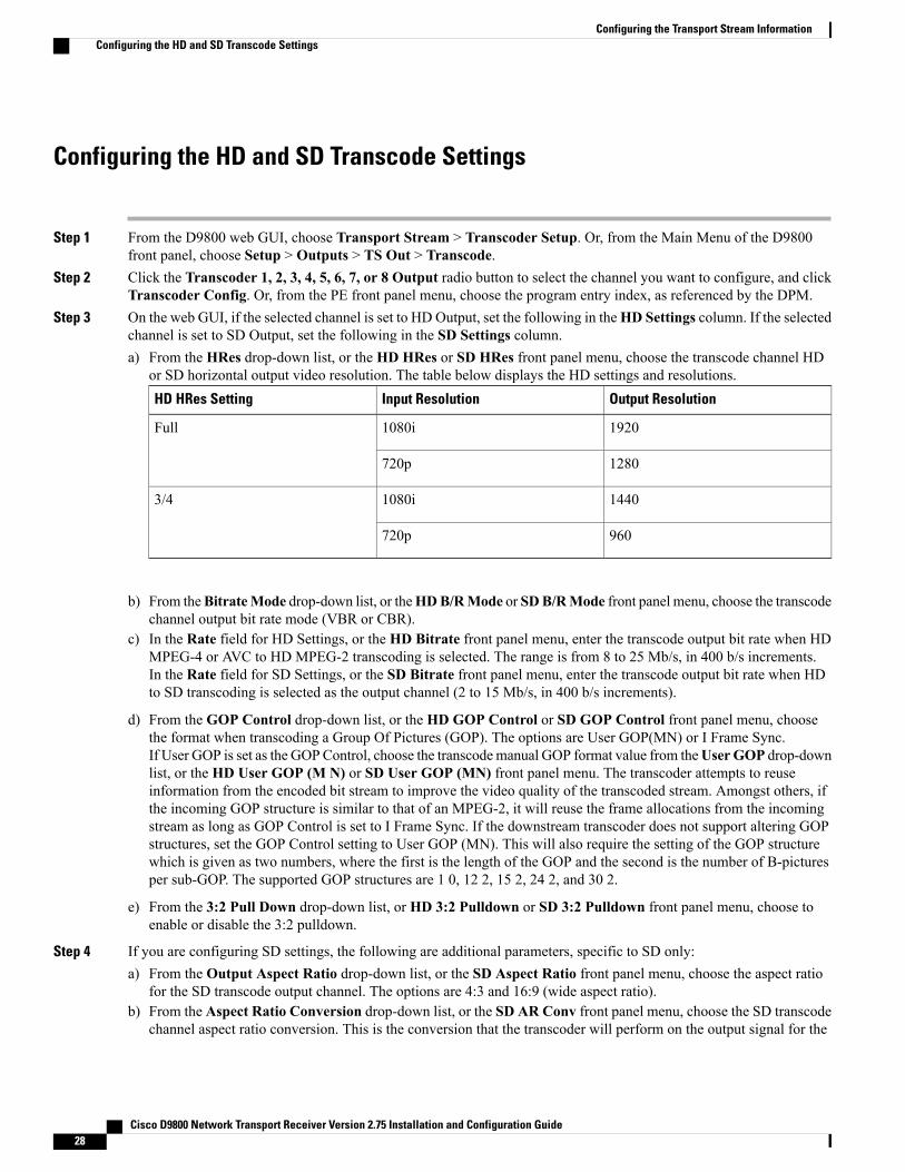
Step 3 On the web GUI, if the selected channel is set to HD Output, set the following in theHD Settings column. If the selectedchannel is set to SD Output, set the following in the SD Settings column.a) From the HRes drop-down list, or the HD HRes or SD HRes front panel menu, choose the transcode channel HD
or SD horizontal output video resolution. The table below displays the HD settings and resolutions.Output ResolutionInput ResolutionHD HRes Setting
19201080iFull
1280720p
14401080i3/4
960720p
b) From theBitrateMode drop-down list, or theHDB/RMode or SDB/RMode front panel menu, choose the transcodechannel output bit rate mode (VBR or CBR).
c) In the Rate field for HD Settings, or the HD Bitrate front panel menu, enter the transcode output bit rate when HDMPEG-4 or AVC to HD MPEG-2 transcoding is selected. The range is from 8 to 25 Mb/s, in 400 b/s increments.In the Rate field for SD Settings, or the SD Bitrate front panel menu, enter the transcode output bit rate when HDto SD transcoding is selected as the output channel (2 to 15 Mb/s, in 400 b/s increments).
d) From the GOP Control drop-down list, or the HD GOP Control or SD GOP Control front panel menu, choosethe format when transcoding a Group Of Pictures (GOP). The options are User GOP(MN) or I Frame Sync.If User GOP is set as the GOPControl, choose the transcodemanual GOP format value from theUserGOP drop-downlist, or the HD User GOP (M N) or SD User GOP (MN) front panel menu. The transcoder attempts to reuseinformation from the encoded bit stream to improve the video quality of the transcoded stream. Amongst others, ifthe incoming GOP structure is similar to that of an MPEG-2, it will reuse the frame allocations from the incomingstream as long as GOP Control is set to I Frame Sync. If the downstream transcoder does not support altering GOPstructures, set the GOP Control setting to User GOP (MN). This will also require the setting of the GOP structurewhich is given as two numbers, where the first is the length of the GOP and the second is the number of B-picturesper sub-GOP. The supported GOP structures are 1 0, 12 2, 15 2, 24 2, and 30 2.
e) From the 3:2 Pull Down drop-down list, or HD 3:2 Pulldown or SD 3:2 Pulldown front panel menu, choose toenable or disable the 3:2 pulldown.
Step 4 If you are configuring SD settings, the following are additional parameters, specific to SD only:a) From the Output Aspect Ratio drop-down list, or the SD Aspect Ratio front panel menu, choose the aspect ratio
for the SD transcode output channel. The options are 4:3 and 16:9 (wide aspect ratio).b) From the Aspect Ratio Conversion drop-down list, or the SD AR Conv front panel menu, choose the SD transcode
channel aspect ratio conversion. This is the conversion that the transcoder will perform on the output signal for the
Cisco D9800 Network Transport Receiver Version 2.75 Installation and Configuration Guide28
Configuring the Transport Stream InformationConfiguring the HD and SD Transcode Settings

picture to be displayed correctly (for example, to correspond to the aspect ratio of your TV) on your TV, based onyour selection.
c) From the Closed Caption Packet 1 and Closed Caption Packet 2 drop-down lists, or the CC Pkt 1 and CC Pkt 2front panel menus, choose the order to output the closed caption packets on the transcoded SD output.
Step 5 Click OK.
Inserting Subtitles to Transcoded Video
Step 1 From the D9800 web GUI, choose Transport Stream > Transcoder Setup.Step 2 Click the radio button of the channel you want to insert subtitles to transcoded video (Transcoder 1, 2, 3, 4, 5, 6, 7, or 8
Output), and click Subtitle Burn-In.Step 3 From the Subtitle Control drop-down list, choose the control to use to display the program subtitles. The table below
describes the available options.DescriptionOption
No subtitles are displayed.Off
Displays DVB or Imitext subtitles, if available.On
Displays only DVB subtitles, if available. Otherwise, no subtitles are displayed.DVB
Displays only Imitext subtitles, if available. Otherwise, no subtitles are displayed.Imitext
Step 4 From the Select By drop-down list, choose the input source for the subtitle language. The default is Language List.Language Entry and PMT Order are more applicable for advanced applications.
• If Language List is selected as the input source, choose the MPEG language to display from the Language Listdrop-down list. The supported languages are according to ISO 639-2 Language Codes.
• If Language Entry is selected as the input source, enter the three-character code provided by your uplink serviceprovider (for example, eng for English) in theManual Entry field. The supported languages are according to ISO639-2 Language Codes.
• If PMT is selected as the input source, choose the subtitle PID entry to display (First to Eighth) from the PMTOrder drop-down list. This information is available from your uplink provider.
Step 5 From the Imitext Position drop-down list, choose the position of the on-screen subtitle text (Standard or Extended).This setting is only applicable if the Subtitle Control is set to On or Imitext.
Step 6 From the Imitext Foreground Color drop-down list, choose the color for Imitext subtitles. Auto displays text in thecolor transmitted by the subtitling equipment. Yellow and White overrides the color set by the uplink and display textin the selected color. This setting is only applicable if the Subtitle Control is set to On or Imitext.
Step 7 From the Imitext Background Color drop-down list, choose one of the following text background for Imitext subtitles:
Cisco D9800 Network Transport Receiver Version 2.75 Installation and Configuration Guide 29
Configuring the Transport Stream InformationInserting Subtitles to Transcoded Video

DescriptionOption
Uses the uplink subtitling equipment setting.Auto
Applies an outline to the right side of each text character. No background box is appliedto subtitles, that is, text is visible directly on top of video.
Shadow
Applies a black box to each text character.Opaque
Applies a semi-transparent box to subtitle text.Semi
No shadow or outline is applied to subtitle text.None
This setting is only applicable if the Subtitle Control is set to On or Imitext.
Step 8 Click OK.
Applying Inband SettingsYou can apply uplink parameters for transcoding (such as, bit rate, GOP, and resolution) to the local transcodersettings for the selected program entry. This is only supported with an uplink that uses uplink transcodingcontrols for the user address of the selected program entry.
Step 1 From the D9800 web GUI, choose Transport Stream > Transcoder Setup, and click Apply Inband Settings. Or,from the main menu of the D9800 front panel, choose Setup > Outputs > TS Out > Transcode > Inband.
Step 2 Check the transcoder/program entry check box that you want to apply uplink parameters, or choose the program entryfrom the PE front panel menu and then choose Yes or No from the Apply Inband front panel menu.The disabled check box on the web GUI indicates that you do not have sufficient transcoder licenses.
Step 3 Click OK.
Cisco D9800 Network Transport Receiver Version 2.75 Installation and Configuration Guide30
Configuring the Transport Stream InformationApplying Inband Settings