configuring multiprotocol label · pdf fileconfiguring multiprotocol label switching...
TRANSCRIPT
n thear
outers..
Configuring Multiprotocol Label Switching
This chapter describes how to configure your network to perform Multiprotocol Label Switching(MPLS). For a complete description of the MPLS commands, see the chapter “MPLS Commands” iCisco IOS Switching Services Command Reference. For documentation of other commands that appein this chapter, you can use the command reference master index or search online.
This chapter contains the following sections:
• Configuring MPLS Levels of Control
• Configuring MPLS Traffic Engineering
• Configuring MPLS Traffic Engineering Paths
• Configuring MPLS Virtual Private Networks
• Configuring MPLS CoS Backbone Support
• Configuring MPLS CoS
• Configuring the Label Switch Controller
• MPLS Configuration Examples
Configuring MPLS Levels of ControlThis section describes three sample cases where MPLS is configured on Cisco 7500/7200 series rThese cases show the levels of control possible in selecting how MPLS is deployed in a network
Table 16 lists the cases, including the steps to perform MPLS and their correspondingCisco IOS CLI commands.
XC-75Cisco IOS Switching Services Configuration Guide

Configuring Multiprotocol Label SwitchingConfiguring MPLS Levels of Control
n the
tline
For more information about the Cisco IOS CLI commands, see the chapter “MPLS Commands” iCisco IOS Switching Services Command Reference.
Figure 21 shows a router-only MPLS network with Ethernet interfaces. The following sections outhe procedures for configuring MPLS and displaying MPLS information in a network based on thetopology shown in Figure 21.
Note Ethernet interfaces are shown in Figure 21, but any of the interfaces that are supportedcould be used instead. ATM interfaces operating as TC-ATM interfaces are the exceptionto this statement.
Figure 21 A Router-Only MPLS Network with Ethernet Interfaces
Table 16 MPLS—Levels of Control
Levels of Control Examples Describes
Example 1—Enable MPLS Incrementally in aNetwork
The steps necessary for incrementally deployingMPLS through a network, assuming that packetsto all destination prefixes should be labelswitched.
Example 2—Route Labeled Packets to Network AOnly
The mechanism by which MPLS can berestricted, such that packets are label switched toonly a subset of destinations.
Example 3—Limit Label Distribution on a MPLSNetwork
The mechanisms for further controlling thedistribution of labels within a network.
Network A
Network B
S59
18
R1
R2 R5 R8
R4 R 7
e0/1
e0/1
e0/1
e0/1
e0/2
e0/2
e0/2
e0/2
e0/1
e0/1
e0/1 e0/2
R6R3
e0/4 e0/3
e0/1
e0/4
e0/2e0/2
e0/2 e0/3
XC-76Cisco IOS Switching Services Configuration Guide

Configuring Multiprotocol Label SwitchingConfiguring MPLS Levels of Control
ters,f the
outer
e0/1,
ate onling
Example 1—Enable MPLS Incrementally in a NetworkIn the first case, assume that you want to deploy MPLS incrementally throughout a network of roubut that you do not want to restrict which destination prefixes are label switched. For a description ocommands listed in these cases, see the chapter “MPLS Commands” in theCisco IOS Switching ServicesCommand Reference.
To enable MPLS incrementally in a network, use the following steps and enter the commands in rconfiguration mode (see Figure 21):
After you perform these steps, R1 applies labels to packets that are forwarded through interfacewith a next hop to R3.
You can enable MPLS throughout the rest of the network by repeating steps 1 and 2 as appropriother routers until all routers and interfaces are enabled for MPLS. See the example in the “EnabMPLS Incrementally in a Network Example” section.
Command Purpose
Step 1 At R1:Router# configuration terminalRouter(config)# ip cef distributedRouter(config)# tag-switching advertise-tagsRouter(config)# interface e0/1Router(config-if)# tag-switching ipRouter(config-if)# exitAt R3:Router# configuration terminalRouter(config)# ip cef distributedRouter(config)# tag-switching advertise-tagsRouter(config)# interface e0/1Router(config-if)# tag-switching ip
Enables MPLS between R1 and R3.
In order to configure distributed VIP MPLS, you mustconfigure distributed CEF switching. Enter theip cefdistributed command on all routers.
Step 2 At R3:Router(config)# interface e0/2Router(config-if)# tag-switching ipRouter(config-if)# exitAt R4:Router# configuration terminalRouter(config)# ip cef distributedRouter(config)# tag-switching advertise-tagsRouter(config)# interface e0/2Router(config-if)# tag-switching ipRouter(config-if)# exit
Enables MPLS between R3 and R4.
XC-77Cisco IOS Switching Services Configuration Guide

Configuring Multiprotocol Label SwitchingConfiguring MPLS Levels of Control
optiono thatt the
21):
ion
beled,ple,
s R1,eledeled
abeled
y,s that1, R3,
aten.
Example 2—Route Labeled Packets to Network A OnlyIn the second case, assume that you want to enable MPLS for a subset of destination prefixes. Thismight be used to test MPLS across a large network. In this case, you would configure the system sonly a small number of destinations is label switched (for example, internal test networks) withoumajority of traffic being affected.
Use the following commands at each router in the network in router configuration mode (see Figure
Example 3—Limit Label Distribution on a MPLS NetworkThe third case demonstrates the full control which is available to you in determining the destinatprefixes and paths for which MPLS is enabled.
Configure the routers so that packets addressed to network A are labeled, all other packets are unlaand only links R1-R3, R3-R4, R4-R6, and R6-R7 carry labeled packets addressed to A. For examsuppose the normally routed path for packets arriving at R1 addressed to network A or network B iR3, R5, R6, R7. A packet addressed to A would flow labeled on links R1-R3 and R6-R7, and unlabon links R3-R5 and R5-R6. A packet addressed to B would follow the same path, but would be unlabon all links.
Assume that at the outset the routers are configured so that packets addressed to network A are land all other packets are unlabeled (as at the completion of Case 2).
Use thetag-switching advertise-tagscommand and access lists to limit label distribution. Specificallyou need to configure routers R2, R5, and R8 to distribute no labels to other routers. This ensureno other routers send labeled packets to any of those three. You also need to configure routers RR4, R6, and R7 to distribute labels only for network A and to distribute them only to the appropriadjacent router; that is, R3 distributes its label for network A only to R1, R4 only to R3, and so o
To limit label distribution on a MPLS network, use the following commands in router configurationmode:
Command Purpose
Step 1 Router(config)# access-list 1 permit A Limits label distribution by using an accesslist.
(Enter the actual network address andnetmask in place of permit A. For example,
access-list 1 permit 192.5.34. 0 0.0.0.255.)
Step 2 Router(config)# tag-switching advertise-tags for 1 Instructs the router to advertise for networkA only to all adjacent label switch routers.
Any labels for other destination networksthat the router may have distributed beforethis step are withdrawn.
Command Purpose
Step 1 Router(config)# no tag-switching advertise-tags Configures R2 to distribute no labels.
Step 2 Router(config)# no tag-switching advertise-tags Configures R5 to distribute no labels.
Step 3 Router(config)# no tag-switching advertise-tags Configures R8 to distribute no labels
XC-78Cisco IOS Switching Services Configuration Guide

Configuring Multiprotocol Label SwitchingConfiguring MPLS Traffic Engineering
Configuring MPLS Traffic EngineeringPerform the following tasks before enabling MPLS traffic engineering:
• Configure MPLS tunnels
• Enable Cisco Express Forwarding (CEF)
• Enable IS-IS
Perform the tasks in the following sections to configure MPLS traffic engineering:
• Configuring a Device to Support Tunnels
• Configuring an Interface to Support RSVP-based Tunnel Signalling and IGP Flooding
• Configuring an MPLS Traffic Engineering Tunnel
• Configuring IS-IS for MPLS Traffic Engineering
Step 4 Router(config)# access-list 2 permit R1Router(config)# no tag-switching advertise-tags for 1Router(config)# tag-switching advertise-tags for 1 to 2Router(config)# exit
Configures R3 by defining an access list andby instructing the router to distribute labelsfor the networks permitted by access list 1(created as part of Case 2) to the routerspermitted by access list 2.
Theaccess list 2 permit R1 commandpermits R1 and denies all other routers.
(Enter the actual network address andnetmask in place of permit R1. For example,access-list 1 permit 192.5.34.0 0.0.0.255.)
Step 5 Router(config)# access-list 1 permit ARouter(config)# access-list 2 permit R1Router(config)# tag-switching advertise-tags for 1 to 2Router(config)# exit
Configures R3.
(Enter the actual network address andnetmask in place of permit R1. For example,access-list 1 permit 192.5.34.0 0.0.0.255.)
Step 6 Router(config)# access-list 1 permit ARouter(config)# access-list 2 permit R3Router(config)# tag-switching advertise-tags for 1 to 2Router(config)# exit
Configures R4.
(Enter the actual network address andnetmask in place of permit R1. For example,access-list 1 permit 192.5.34.0 0.0.0.255.)
Step 7 Router(config)# access-list 1 permit ARouter(config)# access-list 2 permit R4Router(config)# tag-switching advertise-tags for 1 to 2Router(config)# exit
Configures R6.
(Enter the actual network address andnetmask in place of permit R1. For example,access-list 1 permit 192.5.34.0 0.0.0.255.)
Step 8 Router(config)# access-list 1 permit ARouter(config)# access-list 2 permit R6Router(config)# tag-switching advertise-tags for 1 to 2Router(config)# exit
Configures R7.
(Enter the actual network address andnetmask in place of permit R1. For example,access-list 1 permit 192.5.34.0 0.0.0.255.)
Command Purpose
XC-79Cisco IOS Switching Services Configuration Guide

Configuring Multiprotocol Label SwitchingConfiguring MPLS Traffic Engineering
ing
Configuring a Device to Support TunnelsTo configure a device to support tunnels, use the following commands in configuration mode:
Configuring an Interface to Support RSVP-based Tunnel Signalling and IGPFlooding
To configure an interface to support RSVP-based tunnel signalling and IGP flooding, use the followcommands in interface configuration mode:
Note You need to enable the tunnel feature and specify the amount of reservable RSVPbandwidth if you have an interface that supports MPLS traffic engineering.
Command Purpose
Step 1 Router(config)# ip cef Enables standard CEF operation.
For information about CEF configuration and commandsyntax, see theCisco IOS Switching ServicesConfiguration Guide andCisco IOS Switching ServicesCommand Reference.
Step 2 Router(config)# mpls traffic-eng tunnels Enables the MPLS traffic engineering tunnel feature on adevice.
Command Purpose
Step 1 Router(config-if)# mpls traffic-eng tunnels Enables the MPLS traffic engineering tunnel feature on aninterface.
Step 2 Router(config-if)# ip rsvp bandwidth bandwidth Enables RSVP for IP on an interface and specify amountof bandwidth to be reserved.
For a description of IP RSVP command syntax, see theCisco IOS Quality of Service Command Reference.
XC-80Cisco IOS Switching Services Configuration Guide

Configuring Multiprotocol Label SwitchingConfiguring MPLS Traffic Engineering
tionath.
ds
Configuring an MPLS Traffic Engineering TunnelTo configure an MPLS traffic engineering tunnel, use the following commands in interface configuramode. This tunnel has two path setup options—a preferred explicit path and a backup dynamic p
Configuring IS-IS for MPLS Traffic EngineeringTo configure IS-IS for MPLS Traffic engineering, use the following IS-IS traffic engineering commanin interface configuration mode. For a description of IS-IS commands (excluding the IS-IS trafficengineering commands), see theCisco IOS IP and IP Routing Configuration Guide.
Command Purpose
Step 1 Router(config)# interface tunnel1 Configures an interface type and enter interfaceconfiguration mode.
Step 2 Router(config-if)# tunnel destination A.B.C.D Specifies the destination for a tunnel.
Step 3 Router(config-if)# tunnel mode mpls traffic-eng Sets encapsulation mode of the tunnel to MPLS trafficengineering.
Step 4 Router(config-if)# tunnel mpls traffic-engbandwidth bandwidth
Configures bandwidth for the MPLS traffic engineeringtunnel.
Step 5 Router(config-if)# tunnel mpls traffic-engpath-option 1 explicit name test
Configures a named IP explicit path.
Step 6 Router(config-if)# tunnel mpls traffic-engpath-option 2 dynamic
Configures a backup path to be dynamically calculatedfrom the traffic engineering topology database.
Command Purpose
Step 1 Router(config)# router isis Enables IS-IS routing and specify an IS-IS process for IP,which places you in router configuration mode.
Step 2 Router(config-router)# mpls traffic-eng level 1 Turns on MPLS traffic engineering for IS-IS level 1.
Step 3 Router(config-router)# mpls traffic-engrouter-id loopback0
Specifies the traffic engineering router identifier for thenode to be the IP address associated with interfaceloopback0.
Step 4 Router(config-router)# metric-style wide Configures a router to generate and accept only new-styleTLVs.
XC-81Cisco IOS Switching Services Configuration Guide

Configuring Multiprotocol Label SwitchingConfiguring MPLS Traffic Engineering Paths
ow youeered
d for
dle”om
Configuring MPLS Traffic Engineering PathsThis section describes two sample examples supported by traffic engineering. These cases show hcan engineer traffic across a path in the network and establish a backup route for that traffic enginpath (see Table 17).
In both cases, the assumption is made that traffic from R1 and R2 (in Figure 22), which is intendeR11, would be directed by Layer 3 routing along the “upper” path R3-R4-R7-R10-R11.
Figure 22 shows a router-only MPLS network with traffic engineered paths.
Figure 22 Sample MPLS Network with Traffic Engineered Paths
Example 1—Engineer Traffic Across a PathThe following table lists the configuration commands you need to engineer traffic across the “midpath R3-R5-R8 by building a tunnel R1-R3-R5-R8-R10, without affecting the path taken by traffic frR2 (see Figure 22).
Table 17 Sample Traffic Engineering Examples
This case Describes
Example 1—Engineer trafficacross a path
The steps necessary to engineer traffic across the “middle” pathR3-R5-R8 (see Figure 22).
Example 2—Establish a backuppath
The steps necessary for establishing a backup traffic engineeringroute for the engineered traffic for Case 1.
Network A
S63
00
R1
R2
R6 R9
R4
R5
R3
R7
R8 R10 R11
e0/1e0/1
e0/2
e0/1
e0/1
e0/2 e0/2e0/1
e0/1
e0/1
e0/2e0/3 e0/1
e0/2 e0/1
e0/2
e0/5 e0/4
e0/2e0/1
e0/2
e0/2
e0/2
e0/4
e0/3 e0/1
XC-82Cisco IOS Switching Services Configuration Guide

Configuring Multiprotocol Label SwitchingConfiguring MPLS Traffic Engineering Paths
To engineer traffic across a path, use the following commands in router configuration mode:
Command Purpose
Step 1 At R1:Router(config)# ip cef distributedRouter(config)# tag-switching tsp-tunnelsRouter(config)# interface e0/1Router(config-if)# tag-switching tsp-tunnelsRouter(config-if)# exitAt R3:Router(config)# ip cef distributedRouter(config)# tag-switching tsp-tunnelsRouter(config)# interface e0/1Router(config-if)# tag-switching tsp-tunnelsRouter(config-if)# exitRouter(config)# interface e0/3Router(config-if)# tag-switching tsp-tunnelsRouter(config-if)# exitAt R5 and R8:Router(config)# ip cef distributedRouter(config)# tag-switching tsp-tunnelsRouter(config)# interface e0/1Router(config-if)# tag-switching tsp-tunnelsRouter(config-if)# exitRouter(config)# interface e0/2Router(config-if)# tag-switching tsp-tunnelsRouter(config-if)# exitAt R10:Router(config)# ip cef distributedRouter(config)# tag-switching tsp-tunnelsRouter(config)# interface e0/1Router(config-if)# tag-switching tsp-tunnelsRouter(config-if)# exit
Configures support for LSP tunnel signalingalong the path.
In order to configure distributed VIP MPLS,you must configure distributed CEF switching.Enter the ip cef distributed command on allrouters.
Note To configure a Cisco 7200 series router,enterip cef. To configure a Cisco 7500series router, enterip cef distributed.
Step 2 At R1:Router(config)# interface tunnel 2003Router(config-if)# ip unnumbered e0/1Router(config-if)# tunnel mode tag-switchingRouter(config-if)# tunnel tsp-hop 1 10.10.0.103Router(config-if)# tunnel tsp-hop 2 10.11.0.105Router(config-if)# tunnel tsp-hop 3 10.12.0.108Router(config-if)# tunnel tsp-hop 4 10.13.0.110 lasthopRouter(config-if)# exit
Configures a LSP tunnel at the headend.
( IP address of R3:e0/1)
( IP address of R5:e0/1)
( IP address of R8:e0/1)( IP address of R10:e0/1)
Step 3 At R1:Router(config)# router traffic-engineeringRouter(config)# traffic-engineering filter 1 egress10.14.0.111 255.255.255.255
Configures the traffic engineering filter toclassify the traffic to be routed.
The filter selects all traffic where theautonomous system (AS) egress router is10.14.0.111( 10.14.0.111 is the IP address ofR11:e0/1).
Step 4 At R1:Router(config)# router traffic-engineeringRouter(config)# traffic-engineering route 1 tunnel 2003
Configures the traffic engineering route to sendthe engineered traffic down the tunnel.
XC-83Cisco IOS Switching Services Configuration Guide

Configuring Multiprotocol Label SwitchingConfiguring MPLS Virtual Private Networks
se 1.yer 3
the
Example 2—Establish a Backup PathExample 2 involves establishing a backup traffic engineering route for the engineered traffic for CaThis backup route uses the “lower” path. The backup route uses a tunnel R1-R3-R6 and relies on Larouting to deliver the packet from R6 to R11.
To set up a traffic engineering backup path (assuming Case 1 steps have been performed), use following commands in router configuration mode:
Configuring MPLS Virtual Private NetworksPerform the tasks in the following sections to configure and verify VPNs:
• Defining VPNs
• Configuring BGP Routing Sessions
• Configuring PE to PE Routing Sessions
• Configuring BGP PE to CE Routing Sessions
• Configuring RIP PE to CE Routing Sessions
• Configuring Static Route PE to CE Routing Sessions
• Verifying VPN Operation
Command Purpose
Step 1 At R6:Router(config)# ip cef distributedRouter(config)# tag-switching tsp-tunnelsRouter(config)# interface e0/1Router(config-if)# tag-switching tsp-tunnelsRouter(config-if)# exitAt R3:Router(config)# ip cef distributedRouter(config)# tag-switching tsp-tunnelsRouter(config)# interface e0/4Router(config-if)# tag-switching tsp-tunnelsRouter(config-if)# exit
Enables LSP tunnel signalling along the path(where such signalling is not alreadyenabled).
Step 2 At R1:Router(config)# interface tunnel 2004Router(config-if)# ip unnumbered e0/1Router(config-if)# tunnel mode tag-switchingRouter(config-if)# tunnel tsp-hop 1 10.10.0.103Router(config-if)# tunnel tsp-hop 2 10.21.0.106 lasthopRouter(config-if)# exit
Configures the LSP tunnel at the headend.
(IP address of R3:e0/1)(IP address of R6:e0/1)
Step 3 At R1:Router(config)# router traffic-engineeringRouter(config)# traffic-engineering route 1 tunnel 2004pref 200
Configures the traffic engineering route tosend the engineered traffic down the tunnel ifthe middle path (Case 1 route) is unavailable.
XC-84Cisco IOS Switching Services Configuration Guide
Configuring Multiprotocol Label SwitchingConfiguring MPLS Virtual Private Networks
e PE
ter
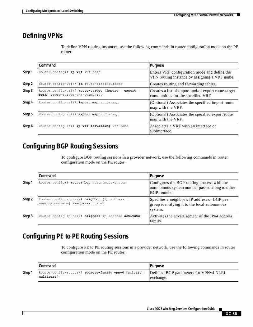
Defining VPNsTo define VPN routing instances, use the following commands in router configuration mode on throuter:
Configuring BGP Routing SessionsTo configure BGP routing sessions in a provider network, use the following commands in routerconfiguration mode on the PE router:
Configuring PE to PE Routing SessionsTo configure PE to PE routing sessions in a provider network, use the following commands in rouconfiguration mode on the PE router:
Command Purpose
Step 1 Router(config)# ip vrf vrf-name Enters VRF configuration mode and define theVPN routing instance by assigning a VRF name.
Step 2 Router(config-vrf)# rd route-distinguisher Creates routing and forwarding tables.
Step 3 Router(config-vrf)# route-target { import | export |both } route-target-ext-community
Creates a list of import and/or export route targetcommunities for the specified VRF.
Step 4 Router(config-vrf)# import map route-map (Optional) Associates the specified import routemap with the VRF.
Step 5 Router(config-vrf)# export map route-map (Optional) Associates the specified export routemap with the VRF.
Step 6 Router(config-if)# ip vrf forwarding vrf-name Associates a VRF with an interface orsubinterface.
Command Purpose
Step 1 Router(config)# router bgp autonomous-system Configures the BGP routing process with theautonomous system number passed along to otherBGP routers.
Step 2 Router(config-router)# neighbor { ip-address |peer-group-name } remote-as number
Specifies a neighbor’s IP address or BGP peergroup identifying it to the local autonomoussystem.
Step 3 Router(config-router)# neighbor ip-address activate Activates the advertisement of the IPv4 addressfamily.
Command Purpose
Step 1 Router(config-router)# address-family vpnv4 [ unicast |multicast ]
Defines IBGP parameters for VPNv4 NLRIexchange.
XC-85Cisco IOS Switching Services Configuration Guide
Configuring Multiprotocol Label SwitchingConfiguring MPLS Virtual Private Networks
ode
ode
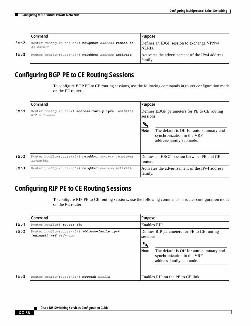
Configuring BGP PE to CE Routing SessionsTo configure BGP PE to CE routing sessions, use the following commands in router configuration mon the PE router:
Configuring RIP PE to CE Routing SessionsTo configure RIP PE to CE routing sessions, use the following commands in router configuration mon the PE router:
Step 2 Router(config-router-af)# neighbor address remote-asas-number
Defines an IBGP session to exchange VPNv4NLRIs.
Step 3 Router(config-router-af)# neighbor address activate Activates the advertisement of the IPv4 addressfamily.
Command Purpose
Command Purpose
Step 1 Router(config-router)# address-family ipv4 [ unicast ]vrf vrf-name
Defines EBGP parameters for PE to CE routingsessions.
Note The default is Off for auto-summary andsynchronization in the VRFaddress-family submode.
Step 2 Router(config-router-af)# neighbor address remote-asas-number
Defines an EBGP session between PE and CErouters.
Step 3 Router(config-router-af)# neighbor address activate Activates the advertisement of the IPv4 addressfamily.
Command Purpose
Step 1 Router(config)# router rip Enables RIP.
Step 2 Router(config-router-af)# address-family ipv4[ unicast ] vrf vrf-name
Defines RIP parameters for PE to CE routingsessions.
Note The default is Off for auto-summary andsynchronization in the VRFaddress-family submode.
Step 3 Router(config-router-af)# network prefix Enables RIP on the PE to CE link.
XC-86Cisco IOS Switching Services Configuration Guide

Configuring Multiprotocol Label SwitchingConfiguring MPLS Virtual Private Networks
ation
ing
Configuring Static Route PE to CE Routing SessionsTo configure static route PE to CE routing sessions, use the following commands in router configurmode on the PE router:
Verifying VPN OperationTo verify VPN operation by displaying routing information on the PE routers, use any of the followshow commands in any order:
Command Purpose
Step 1 Router(config)# ip route vrf vrf-name Defines static route parameters for every PE to CEsession.
Step 2 Router(config-router)# address-family ipv4 [ unicast ]vrf vrf-name
Defines static route parameters for every BGP PEto CE routing session.
Note The default is Off for auto-summary andsynchronization in the VRFaddress-family submode.
Step 3 Router(config-router-af)# redistribute static Redistributes VRF static routes into the VRF BGPtable.
Step 4 Router(config-router-af)# redistribute staticconnected
Redistributes directly connected networks into theVRF BGP table.
Command PurposeRouter# show ip vrf Displays the set of defined VRFs and interfaces.
Router# show ip vrf [{ brief | detail | interfaces }] vrf-name Displays information about defined VRFs andassociated interfaces.
Router# show ip route vrf vrf-name Displays the IP routing table for a VRF.
Router# show ip protocols vrf vrf-name Displays the routing protocol information for a VRF.
Router# show ip cef vrf vrf-name Displays the CEF forwarding table associated with aVRF.
Router# show ip interface interface-number Displays the VRF table associated with an interface.
Router# show ip bgp vpnv4 all [ tags ] Displays information about all BGP VPN-IPv4prefixes.
Router# show tag-switching forwarding vrf vrf-name [ prefixmask/length ][ detail ]
Displays label forwarding entries that correspond toVRF routes advertised by this router.
XC-87Cisco IOS Switching Services Configuration Guide
Configuring Multiprotocol Label SwitchingConfiguring MPLS CoS Backbone Support
ing onilding
uters
ively,
SR.
abel
ration
Ce LSRface.
stion
Configuring MPLS CoS Backbone SupportSeveral different methods exist for supporting CoS across an MPLS backbone, the choice dependwhether the core has label switch routers (LSRs) or ATM LSRs. In each case, however, the CoS bublocks are the same: CAR, WRED, and WFQ.
Three configurations are described below:
• LSRs used at the core of the network backbone
• ATM LSRs used at the core of the network backbone
• ATM switches without the MPLS feature enabled
LSRsLSRs at the core of the MPLS backbone are usually either Cisco 7200 and Cisco 7500 series rorunning MPLS software. Packets are processed as follows:
1. IP packets enter into the edge of the MPLS network.
2. The edge LSRs invoke CAR to classify the IP packets and possibly set IP precedence. AlternatIP packets can be received with their IP precedence already set.
3. For each packet, the router performs a lookup on the IP address to determine the next-hop L
4. The appropriate label is placed on the packet with the IP precedence bits copied into every lentry in the MPLS header.
5. The labeled packet is then forwarded to the appropriate output interface for processing.
6. The packets are differentiated by class. This is done according to drop probability (WRED) oaccording to bandwidth and delay (WFQ). In either case, LSRs enforce the defined differentiby continuing to employ WRED or WFQ on each hop.
ATM LSRsATM LSRs at the core implement the multiple label virtual circuit model (LVC). In the multiple LVmodel, one label is assigned for each service class for each destination. The operation of the edgis the same as that described previously for the LSR case, except that the output is an ATM interWRED is used to define service classes and determine discard policy during congestion.
In the multiple LVC model, however, class-based WFQ is used to define the amount of bandwidthavailable to each service class. Packets are scheduled by class during congestion. The ATM LSRparticipate in the differentiation of classes with WFQ and intelligently drop packets when congesoccurs. The mechanism for this discard activity is weighted early packet discard (WEPD).
XC-88Cisco IOS Switching Services Configuration Guide
Configuring Multiprotocol Label SwitchingConfiguring MPLS CoS Backbone Support
LSRs,r thed onbe edge
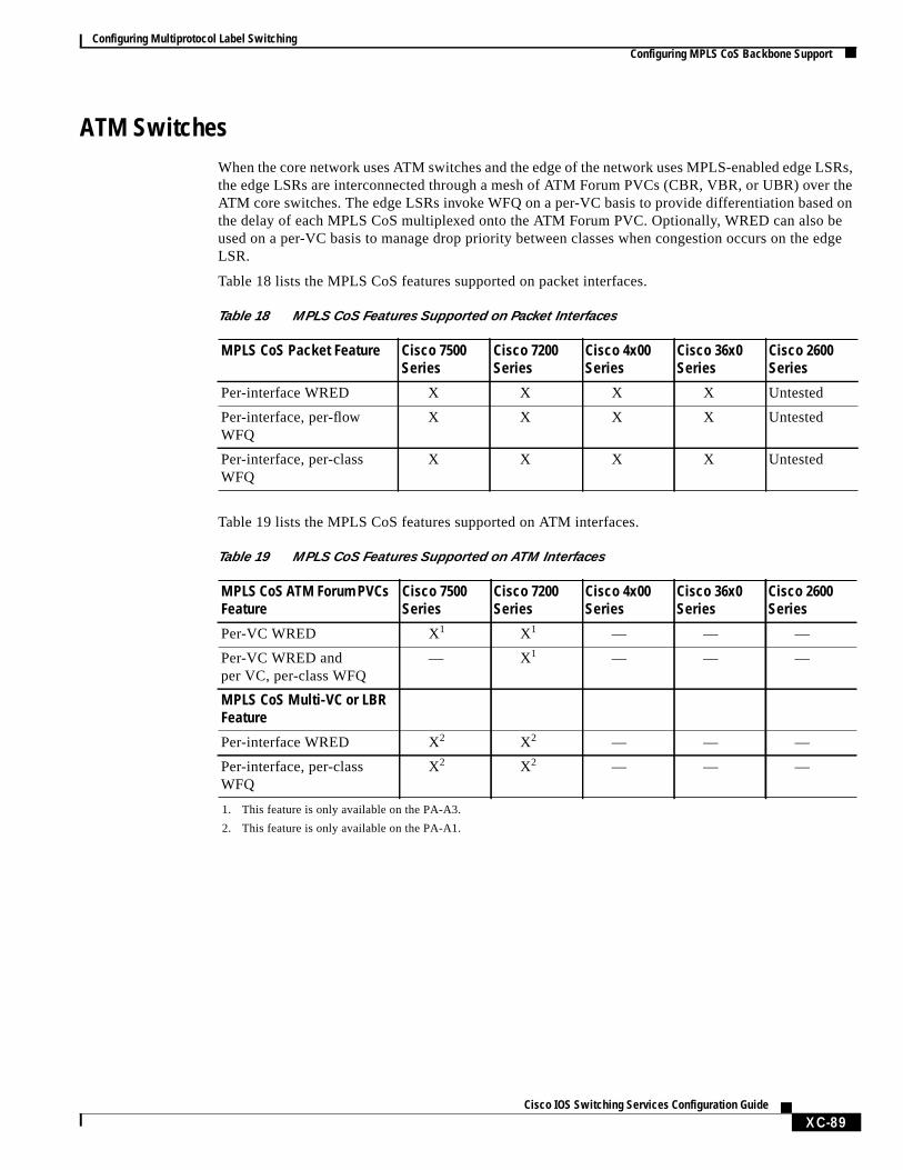
ATM SwitchesWhen the core network uses ATM switches and the edge of the network uses MPLS-enabled edgethe edge LSRs are interconnected through a mesh of ATM Forum PVCs (CBR, VBR, or UBR) oveATM core switches. The edge LSRs invoke WFQ on a per-VC basis to provide differentiation basethe delay of each MPLS CoS multiplexed onto the ATM Forum PVC. Optionally, WRED can also used on a per-VC basis to manage drop priority between classes when congestion occurs on theLSR.
Table 18 lists the MPLS CoS features supported on packet interfaces.
Table 19 lists the MPLS CoS features supported on ATM interfaces.
Table 18 MPLS CoS Features Supported on Packet Interfaces
MPLS CoS Packet Feature Cisco 7500Series
Cisco 7200Series
Cisco 4x00Series
Cisco 36x0Series
Cisco 2600Series
Per-interface WRED X X X X Untested
Per-interface, per-flowWFQ
X X X X Untested
Per-interface, per-classWFQ
X X X X Untested
Table 19 MPLS CoS Features Supported on ATM Interfaces
MPLS CoS ATM Forum PVCsFeature
Cisco 7500Series
Cisco 7200Series
Cisco 4x00Series
Cisco 36x0Series
Cisco 2600Series
Per-VC WRED X1
1. This feature is only available on the PA-A3.
X1 — — —
Per-VC WRED andper VC, per-class WFQ
— X1 — — —
MPLS CoS Multi-VC or LBRFeature
Per-interface WRED X2
2. This feature is only available on the PA-A1.
X2 — — —
Per-interface, per-classWFQ
X2 X2 — — —
XC-89Cisco IOS Switching Services Configuration Guide

Configuring Multiprotocol Label SwitchingConfiguring MPLS CoS
tion
Table 20 lists the MPLS CoS features supported on ATM switches.
Configuring MPLS CoSPerform the tasks in the following sections to configure the MPLS CoS feature:
• Configuring PVC Mode in a Non-MPLS-Enabled Core
• Configuring Multi-VC Mode in a MPLS-Enabled Core
• Configuring Multi-VCs Using the Cos-Map Function
• Configuring DWFQ and Changing Queue Weights on an Outgoing Interface
• Verifying CoS Operation
Configuring PVC Mode in a Non-MPLS-Enabled CoreTo configure a PVC in a non-MPLS-enabled core, use the following commands in router configuramode:
Table 20 MPLS CoS Features Supported on ATM Switches
MPLS CoS ATM ForumPVCs Feature
BPX 8650Series
MGX 8800Series
LightStream1010 ATMSwitch1
Catalyst 8540MSR1
1. This can be used for the core only.
MPLS CoS ATM ForumPVCs
X X X X
MPLS CoS Multi-VC orLBR—per-class WFQ
X — — —
Command Purpose
Step 1 Router(config)# interface type number point-to-point Configures a point-to-point ATM subinterface.
Step 2 Router(config-subif)# ip unnumbered Loopback0 Assigns IP address to the subinterface.
Step 3 Router(config-subif)# pvc 4/40 Creates a PVC on the subinterface.
Step 4 Router(config-if-atm-vc)# random-detect attachgroupname
Activates (D)WRED on the interface.
Step 5 Router(config-if-atm-vc)# encapsulation aal5snap Sets encapsulation type for the PVC.
Step 6 Router(config-subif)# exit Exits from PVC mode and enters subinterfacemode.
Step 7 Router(config-subif)# tag-switching ip Enables MPLS IP on the point-to-point interface.
XC-90Cisco IOS Switching Services Configuration Guide
Configuring Multiprotocol Label SwitchingConfiguring MPLS CoS
s byr
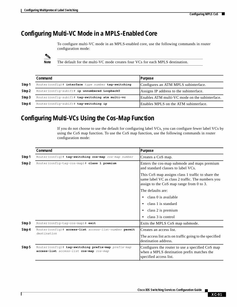
Configuring Multi-VC Mode in a MPLS-Enabled CoreTo configure multi-VC mode in an MPLS-enabled core, use the following commands in routerconfiguration mode:
Note The default for the multi-VC mode creates four VCs for each MPLS destination.
Configuring Multi-VCs Using the Cos-Map FunctionIf you do not choose to use the default for configuring label VCs, you can configure fewer label VCusing the CoS map function. To use the CoS map function, use the following commands in routeconfiguration mode:
Command Purpose
Step 1 Router(config)# interface type number tag-switching Configures an ATM MPLS subinterface.
Step 2 Router(config-subif)# ip unnumbered Loopback0 Assigns IP address to the subinterface.
Step 3 Router(config-subif)# tag-switching atm multi-vc Enables ATM multi-VC mode on the subinterface.
Step 4 Router(config-subif)# tag-switching ip Enables MPLS on the ATM subinterface.
Command Purpose
Step 1 Router(config)# tag-switching cos-map cos-map number Creates a CoS map.
Step 2 Router(config-tag-cos-map)# class 1 premium Enters the cos-map submode and maps premiumand standard classes to label VCs.
This CoS map assigns class 1 traffic to share thesame label VC as class 2 traffic. The numbers youassign to the CoS map range from 0 to 3.
The defaults are:
• class 0 is available
• class 1 is standard
• class 2 is premium
• class 3 is control
Step 3 Router(config-tag-cos-map)# exit Exits the MPLS CoS map submode.
Step 4 Router(config)# access-list access-list-number permitdestination
Creates an access list.
The access list acts on traffic going to the specifieddestination address.
Step 5 Router(config)# tag-switching prefix-map prefix-mapaccess-list access-list cos-map cos-map
Configures the router to use a specified CoS mapwhen a MPLS destination prefix matches thespecified access list.
XC-91Cisco IOS Switching Services Configuration Guide

Configuring Multiprotocol Label SwitchingConfiguring the Label Switch Controller
ng
as ated
andith the
the
SR.
Configuring DWFQ and Changing Queue Weights on an Outgoing InterfaceTo configure distributed fair queueing and change queue weights on an interface, use the followicommands in interface configuration mode after specifying the interface:
Verifying CoS OperationTo verify the operation of MPLS CoS, use the following commands in configuration mode:
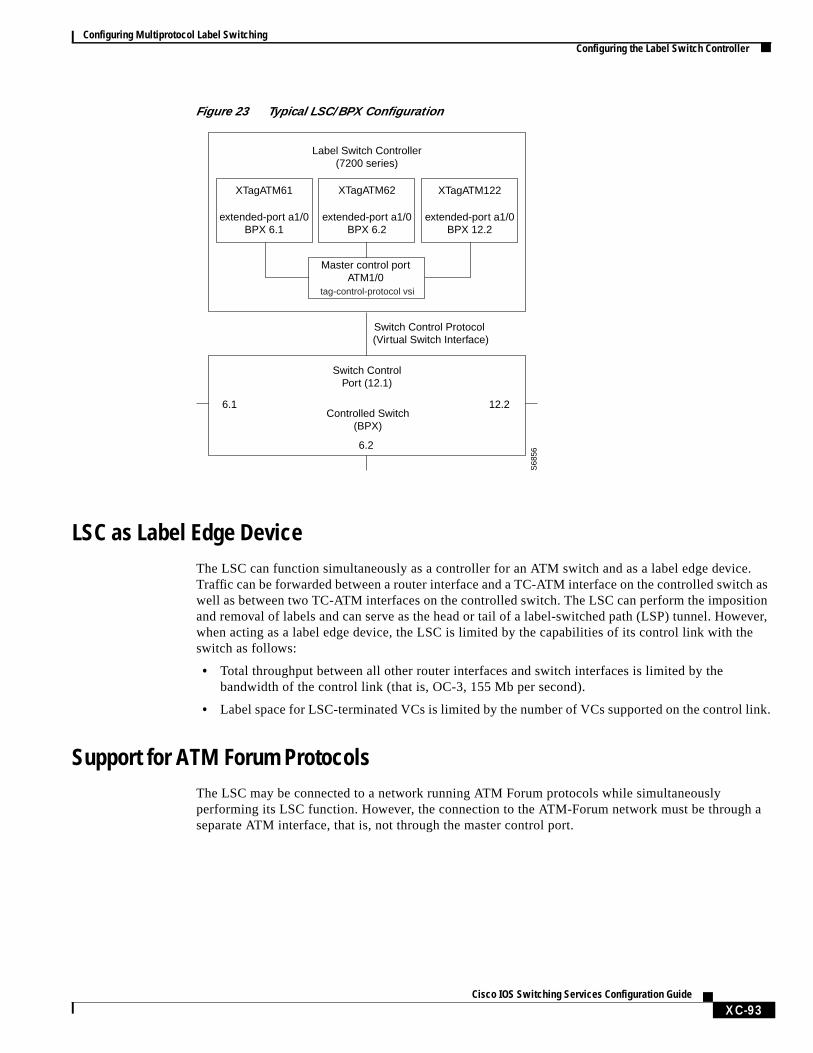
Configuring the Label Switch ControllerOn the Label Switch Controller (LSC), the TC-ATM ports on the controlled switch are representednew IOS interface type called extended Label ATM (XmplsATM). XmplsATM interfaces are associawith particular physical interfaces on the controlled switch through theextended-port interfaceconfiguration command.
Figure 23 illustrates a configuration in which a LSC is controlling three ports on a BPX—6.1, 6.2,12.2. These corresponding XmplsATM interfaces have been created on the LSC and associated wcorresponding ATM ports using theextended-port interface configuration command. Note that anadditional port on the BPX (12.1) acts as the switch control port, and an ATM interface (ATM1/0) onLSC acts as the master control port.
Figure 23 shows a typical LSC configuration where the LSC and BPX together function as an ATM-L
Command Purpose
Step 1 Router(config)# interface type number Specifies the interface type and number.
Step 2 Router(config-if)# fair-queue tos Configures an interface to use fair queueing
Step 3 Router(config)# fair-queue tos class weight Changes the class weight on the specifiedinterface.
Command Purpose
Step 1 Router# show tag-switching interfaces interfaces Displays detailed information about labelswitching interfaces.
Step 2 Router# show tag-switching cos-map Displays the CoS map used to assign VCs.
Step 3 Router# show tag-switching prefix-map Displays the prefix map used to assign a CoS mapto network prefixes.
XC-92Cisco IOS Switching Services Configuration Guide
Configuring Multiprotocol Label SwitchingConfiguring the Label Switch Controller
ce.h astionever,
he
link.
h a
Figure 23 Typical LSC/BPX Configuration
LSC as Label Edge DeviceThe LSC can function simultaneously as a controller for an ATM switch and as a label edge deviTraffic can be forwarded between a router interface and a TC-ATM interface on the controlled switcwell as between two TC-ATM interfaces on the controlled switch. The LSC can perform the imposiand removal of labels and can serve as the head or tail of a label-switched path (LSP) tunnel. Howwhen acting as a label edge device, the LSC is limited by the capabilities of its control link with tswitch as follows:
• Total throughput between all other router interfaces and switch interfaces is limited by thebandwidth of the control link (that is, OC-3, 155 Mb per second).
• Label space for LSC-terminated VCs is limited by the number of VCs supported on the control
Support for ATM Forum ProtocolsThe LSC may be connected to a network running ATM Forum protocols while simultaneouslyperforming its LSC function. However, the connection to the ATM-Forum network must be througseparate ATM interface, that is, not through the master control port.
Label Switch Controller(7200 series)
XTagATM61
extended-port a1/0BPX 6.1
XTagATM62
extended-port a1/0BPX 6.2
Master control portATM1/0
Switch Control Protocol (Virtual Switch Interface)
Switch ControlPort (12.1)
Controlled Switch(BPX)
6.1 12.2
6.2
S68
56
XTagATM122
extended-port a1/0BPX 12.2
tag-control-protocol vsi
XC-93Cisco IOS Switching Services Configuration Guide
Configuring Multiprotocol Label SwitchingMPLS Configuration Examples
gh
Configuring MPLS on a LSC-Controlled BPX PortTo configure MPLS on a port of the BPX that is being controlled by the LSC, use the followingcommands in configuration mode. The assumption is that the BPX is connected to the LSC throuATM1/0; the goal is to configure MPLS on slot 6, port 1 of the BPX.
MPLS Configuration ExamplesThis section provides sample configurations. It contains the following sections:
• Enabling MPLS Incrementally in a Network Example
• Enabling MPLS for a Subset of Destination Prefixes Example
• Selecting the Destination Prefixes and Paths Example
• Displaying MPLS LDP Binding Information Example
• Displaying MPLS Forwarding Table Information Example
• Displaying MPLS Interface Information Example
• Displaying MPLS LDP Neighbor Information Example
• Enabling LSP Tunnel Signalling Example
• Configuring a LSP Tunnel Example
• Displaying the LSP Tunnel Information Example
• Configuring a Traffic Engineering Filter and Route Example
• Displaying Traffic Engineering Configuration Information Example
• Configuring an MPLS Traffic Engineering Tunnel Example
• Configuring MPLS Virtual Private Networks Example
• Configuring MPLS on a LSC-Controlled BPX Port Example
• Implementing MPLS CoS Example
Command Purpose
Step 1 Router(config)# interface atm1/0Router(config-if)# tag-control-protocol vsi
Enables the VSI protocol on the control interface(ATM1/0).
Step 2 Router(config-if)# interface XTagATM61Router(config-if)# extended-port atm1/0 bpx 6.1
Creates an extended label ATM (XmplsATM)virtual interface and bind it to BPX port 6.1.
Step 3 Router(config-if)# ip address 192.103.210.5255.255.255.0Router(config-if)# tag-switching ipRouter(config-if)# exit
Configures MPLS on the extended label ATMinterface. (extended label ATM interfaces differfrom ordinary ATM interfaces in that MPLS isconfigured on the primary interface of an extendedlabel ATM interface, whereas it is configured on aMPLS subinterface of an ordinary ATMinterface.)
Step 4 Router(config)# ip cef switch Enables Cisco Express Forwarding (CEF)switching.
XC-94Cisco IOS Switching Services Configuration Guide
Configuring Multiprotocol Label SwitchingMPLS Configuration Examples
e 21)
r only
ationnonfigurecentR3,
Enabling MPLS Incrementally in a Network ExampleThe following example shows you how to configure MPLS incrementally throughout a network ofrouters. You enable MPLS first between one pair of routers (in this case, R1 and R3 shown in Figurand add routers step by step until every router in the network is label switch enabled.
router-1# configuration terminalrouter-1(config)# ip cef distributedrouter-1(config)# tag-switching iprouter-1(config)# interface e0/1router-1(config-if)# tag-switching iprouter-1(config-if)# exitrouter-1(config)#router-3# configuration terminalrouter-3(config)# ip cef distributedrouter-3(config)# tag-switching iprouter-3(config)# interface e0/1router-3(config-if)# tag-switching iprouter-3(config-if)# exitrouter-3(config)#
Enabling MPLS for a Subset of Destination Prefixes ExampleThe following example shows the commands you enter at each of the routers to enable MPLS foa subset of destination prefixes (see Figure 21).
Router(config)# access-list-1 permit ARouter(config)# tag-switching advertise-tags for 1
Selecting the Destination Prefixes and Paths ExampleThe following example shows the commands you enter to configure the routers to select the destinprefixes and paths for which MPLS is enabled. When you configure R2, R5, and R8 to distribute labels to other routers, you ensure that no routers send them labeled packets. You also need to corouters R1, R3, R4, R6, and R7 to distribute labels only for network A and only to the applicable adjarouter. This configuration ensures that R3 distributes its label for network A only to R1, R4 only toR6 only to R4, and R7 only to R6 (see Figure 21).
router-2(config)# no tag-switching advertise-tagsrouter-5(config)# no tag-switching advertise-tagsrouter-8(config)# no tag-switching advertise-tagsrouter-1(config)# access-list permit R1router-1(config)# no tag-switching advertise-tags for 1router-1(config)# tag-switching advertise-tags for 1 to 2router-1(config)# exit
router-3# access-list 1 permit Arouter-3# access-list 2 permit R1router-3# tag-switching advertise-tags for 1 to 2router-3# exit
router-4# access-list 1 permit Arouter-4# access-list 2 permit R3router-4# tag-switching advertise-tags for 1 to 2router-4# exit
XC-95Cisco IOS Switching Services Configuration Guide

Configuring Multiprotocol Label SwitchingMPLS Configuration Examples
itedr
router-6# access-list 1 permit Arouter-6# access-list 2 permit R4router-6# tag-switching advertise-tags for 1 to 2router-6# exitrouter-7# access-list 1 permit Arouter-7# access-list 2 permit R6router-7# tag-switching advertise-tags for 1 to 2router-7# exit
Displaying MPLS LDP Binding Information ExampleThe following example shows how to use theshow tag-switching tdp bindingscommand to display thecontents of the Label Information Base (LIB). The display can show the entire database or can be limto a subset of entries, based on prefix, input or output label values or ranges, and/or the neighboadvertising the label.
Note This command displays downstream mode bindings. For label VC bindings, see theshowtag-switching atm-tdp bindingscommand.
Router# show tag-switching tdp bindings
Matching entries: tib entry: 10.92.0.0/16, rev 28 local binding: tag: imp-null(1) remote binding: tsr: 172.27.32.29:0, tag: imp-null(1) tib entry: 10.102.0.0/16, rev 29 local binding: tag: 26 remote binding: tsr: 172.27.32.29:0, tag: 26 tib entry: 10.105.0.0/16, rev 30 local binding: tag: imp-null(1) remote binding: tsr: 172.27.32.29:0, tag: imp-null(1) tib entry: 10.205.0.0/16, rev 31 local binding: tag: imp-null(1) remote binding: tsr: 172.27.32.29:0, tag: imp-null(1) tib entry: 10.211.0.7/32, rev 32 local binding: tag: 27 remote binding: tsr: 172.27.32.29:0, tag: 28 tib entry: 10.220.0.7/32, rev 33 local binding: tag: 28 remote binding: tsr: 172.27.32.29:0, tag: 29 tib entry: 99.101.0.0/16, rev 35 local binding: tag: imp-null(1) remote binding: tsr: 172.27.32.29:0, tag: imp-null(1) tib entry: 100.101.0.0/16, rev 36 local binding: tag: 29 remote binding: tsr: 172.27.32.29:0, tag: imp-null(1) tib entry: 171.69.204.0/24, rev 37 local binding: tag: imp-null(1) remote binding: tsr: 172.27.32.29:0, tag: imp-null(1) tib entry: 172.27.32.0/22, rev 38 local binding: tag: imp-null(1) remote binding: tsr: 172.27.32.29:0, tag: imp-null(1) tib entry: 210.10.0.0/16, rev 39 local binding: tag: imp-null(1) tib entry: 210.10.0.8/32, rev 40 remote binding: tsr: 172.27.32.29:0, tag: 27
XC-96Cisco IOS Switching Services Configuration Guide

Configuring Multiprotocol Label SwitchingMPLS Configuration Examples
tputeachuest
is
Displaying MPLS Forwarding Table Information ExampleThe following example shows how to use the show tag-switching forwarding-tablecommand todisplay the contents of the Label Forwarding Information Base (LFIB). The LFIB lists the labels, ouinterface information, prefix or tunnel associated with the entry, and number of bytes received withincoming label. A request can show the entire LFIB or can be limited to a subset of entries. A reqcan also be restricted to selected entries in any of the following ways:
• Single entry associated with a given incoming label
• Entries associated with a given output interface
• Entries associated with a given next hop
• Single entry associated with a given destination
• Single entry associated with a given tunnel having the current node as an intermediate hop
Router# show tag-switching forwarding-table
Local Outgoing Prefix Bytes tag Outgoing Next Hoptag tag or VC or Tunnel Id switched interface26 Untagged 10.253.0.0/16 0 Et4/0/0 172.27.32.428 1/33 10.15.0.0/16 0 AT0/0.1 point2point29 Pop tag 10.91.0.0/16 0 Hs5/0 point2point 1/36 10.91.0.0/16 0 AT0/0.1 point2point30 32 10.250.0.97/32 0 Et4/0/2 10.92.0.7 32 10.250.0.97/32 0 Hs5/0 point2point34 26 10.77.0.0/24 0 Et4/0/2 10.92.0.7 26 10.77.0.0/24 0 Hs5/0 point2point35 Untagged [T] 10.100.100.101/32 0 Tu301 point2point36 Pop tag 168.1.0.0/16 0 Hs5/0 point2point 1/37 168.1.0.0/16 0 AT0/0.1 point2point
[T] Forwarding through a TSP tunnel. View additional tagging info with the 'detail' option
Displaying MPLS Interface Information ExampleThe following example shows how to use the show tag-switching interfaces command to showinformation about the requested interface or about all interfaces on which MPLS is enabled.The per-interface information includes the interface name and indications as to whether IP MPLSenabled and operational.
Router# show tag-switching interfaces
Interface IP Tunnel OperationalHssi3/0 Yes Yes NoATM4/0.1 Yes Yes Yes (ATM tagging)Ethernet5/0/0 No Yes YesEthernet5/0/1 Yes No YesEthernet5/0/2 Yes No NoEthernet5/0/3 Yes No YesEthernet5/1/1 Yes No No
XC-97Cisco IOS Switching Services Configuration Guide
Configuring Multiprotocol Label SwitchingMPLS Configuration Examples
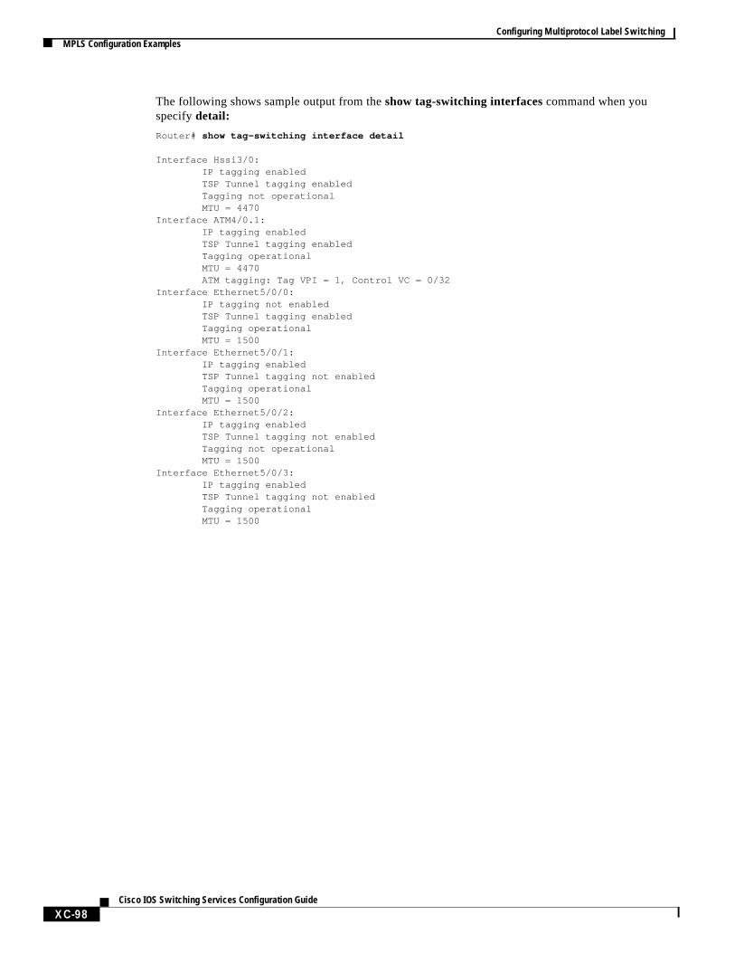
The following shows sample output from theshow tag-switching interfacescommand when youspecifydetail:
Router# show tag-switching interface detail
Interface Hssi3/0: IP tagging enabled TSP Tunnel tagging enabled Tagging not operational MTU = 4470Interface ATM4/0.1: IP tagging enabled TSP Tunnel tagging enabled Tagging operational MTU = 4470 ATM tagging: Tag VPI = 1, Control VC = 0/32Interface Ethernet5/0/0: IP tagging not enabled TSP Tunnel tagging enabled Tagging operational MTU = 1500Interface Ethernet5/0/1: IP tagging enabled TSP Tunnel tagging not enabled Tagging operational MTU = 1500Interface Ethernet5/0/2: IP tagging enabled TSP Tunnel tagging not enabled Tagging not operational MTU = 1500Interface Ethernet5/0/3: IP tagging enabled TSP Tunnel tagging not enabled Tagging operational MTU = 1500
XC-98Cisco IOS Switching Services Configuration Guide

Configuring Multiprotocol Label SwitchingMPLS Configuration Examples
veLDP
ling
hops
2, yous
Displaying MPLS LDP Neighbor Information ExampleThe following example shows how to use the show tag-switching tdp neighborscommand to displaythe status of Label Distribution Protocol (LDP) sessions. The neighbor information branch can hainformation about all LDP neighbors or can be limited to the neighbor with a specific IP address or,identifier, or to LDP neighbors known to be accessible over a specific interface.
Router# show tag-switching tdp neighbors
Peer TDP Ident: 10.220.0.7:1; Local TDP Ident 172.27.32.29:1 TCP connection: 10.220.0.7.711 - 172.27.32.29.11029 State: Oper; PIEs sent/rcvd: 17477/17487; Downstream on demandUp time: 01:03:00TDP discovery sources: ATM0/0.1Peer TDP Ident: 210.10.0.8:0; Local TDP Ident 172.27.32.29:0 TCP connection: 210.10.0.8.11004 - 172.27.32.29.711 State: Oper; PIEs sent/rcvd: 14656/14675; Downstream;Up time: 2d5h TDP discovery sources: Ethernet4/0/1 Ethernet4/0/2 POS6/0/0 Addresses bound to peer TDP Ident: 99.101.0.8 172.27.32.28 10.105.0.8 10.92.0.8 10.205.0.8 210.10.0.8
Enabling LSP Tunnel Signalling ExampleThe following example shows how to configure support for label-switched path (LSP) tunnel signalalong a path and on each interface crossed by one or more tunnels:
Router(config)# ip cef distributedRouter(config)# tag-switching tsp-tunnelsRouter(config)# interface e0/1Router(config-if)# tag-switching tsp-tunnelsRouter(config-if)# interface e0/2Router(config-if)# tag-switching tsp-tunnelsRouter(config-if)# exit
Configuring a LSP Tunnel ExampleThe following example shows how to set the encapsulation of the tunnel to MPLS and how to definein the path for the LSP.
Follow these steps to configure a two-hop tunnel, hop 0 being the headend router. For hops 1 andspecify the IP addresses of the incoming interfaces for the tunnel. The tunnel interface number iarbitrary, but must be less than 65,535.
Router(config)# interface tunnel 2003Router(config-if)# tunnel mode tag-switchingRouter(config-if)# tunnel tsp-hop 1 10.10.0.12Router(config-if)# tunnel tsp-hop 2 10.50.0.24 lasthopRouter(config-if)# exit
XC-99Cisco IOS Switching Services Configuration Guide

Configuring Multiprotocol Label SwitchingMPLS Configuration Examples
ple
To shorten the previous path, delete the hop by entering the following commands:
Router(config)# interface tunnel 2003Router(config-if)# no tunnel tsp-hop 2Router(config-if)# tunnel tsp-hop 1 10.10.0.12 lasthopRouter(config-if)# exit
Displaying the LSP Tunnel Information ExampleThe following example shows how to use the show tag-switching tsp tunnels command to displayinformation about the configuration and status of selected tunnels.
Router# show tag-switching tsp-tunnels
Signalling Summary: TSP Tunnels Process: running RSVP Process: running Forwarding: enabled
TUNNEL ID DESTINATION STATUS CONNECTION10.106.0.6.200310.2.0.12up up
Configuring a Traffic Engineering Filter and Route ExampleThe following example shows how to configure the traffic engineering routing process, a trafficengineering filter, and a traffic engineering route for that filter over a LSP-encapsulated tunnel.
Router(config)# router traffic-engineeringRouter(config-router)# traffic-engineering filter 5 egress 83.0.0.1 255.255.255.255Router(config-router)# traffic-engineering route 5 tunnel 5
Displaying Traffic Engineering Configuration Information ExampleThe following example shows how to use theshow ip traffic-engineering configuration command todisplay information about the configured traffic engineering filters and routes. The following is samoutput from the show ip traffic-engineering configuration detailcommand.
Router# show ip traffic-engineering configuration detail
Traffic Engineering Configuration Filter 5: egress 44.0.0.0/8, local metric: ospf-0/1 Tunnel5 route installed interface up, route enabled, preference 1 loop check on, passing, remote metric: connected/0 Filter 6: egress 43.0.0.1/32, local metric: ospf-300/3 Tunnel7 route installed interface up, route enabled, preference 50 loop check on, passing, remote metric: ospf-300/2 Tunnel6 route not installed interface up, route enabled, preference 75 loop check on, passing, remote metric: connected/0
XC-100Cisco IOS Switching Services Configuration Guide
Configuring Multiprotocol Label SwitchingMPLS Configuration Examples
o the
bal,
.
Configuring an MPLS Traffic Engineering Tunnel ExampleThe following example shows how to configure a dynamic tunnel and how to add a second tunnel tsame destination with an explicit path. Note that this example specifies point-to-point outgoing IPaddresses. Before you configure MPLS traffic engineering tunnels, you must enter the following gloIS-IS, and interface commands on the router.
configure terminalip cefmpls traffic-eng tunnelsinterface loopback 0ip address 11.11.11.11 255.255.255.255ip router isis
interface s1/0ip address 131.0.0.1 255.255.0.0ip router isismpls traffic-eng tunnels ip rsvp bandwidth 1000 mpls traffic-eng administrative-weight 10
router isisnet 47.0000.0011.0011.00is-type level-1metric-style wide mpls traffic-eng router-id Loopback0 mpls traffic-eng level-1
This example includes the commands for configuring a dynamic tunnel from Router 1 to Router 5
configure terminalinterface tunnel1 ip unnumbered loopback 0 tunnel destination 17.17.17.17 tunnel mode mpls traffic-eng tunnel mpls traffic-eng autoroute announce tunnel mpls traffic-eng bandwidth 100 tunnel mpls traffic-eng priority 1 1 tunnel mpls traffic-eng path-option 1 dynamic
To verify that the tunnel is up and traffic is routed through the tunnel, enter these commands:
show mpls traffic-eng tunnelshow ip route 17.17.17.17show mpls traffic-eng autorouteping 17.17.17.17show interface tunnel1 accountingshow interface s1/0 accounting
To create an explicit path, enter these commands:
configure terminalip explicit-path identifier 1 next-address 131.0.0.1 next-address 135.0.0.1 next-address 136.0.0.1 next-address 133.0.0.1
XC-101Cisco IOS Switching Services Configuration Guide
Configuring Multiprotocol Label SwitchingMPLS Configuration Examples
To add a second tunnel to the same destination with an explicit path, enter these commands:
configure terminalinterface tunnel2 ip unnumbered loopback 0 tunnel destination 17.17.17.17 tunnel mode mpls traffic-eng tunnel mpls traffic-eng autoroute announce tunnel mpls traffic-eng bandwidth 100 tunnel mpls traffic-eng priority 1 1 tunnel mpls traffic-eng path-option 1 explicit identifier 1
To verify that the tunnel is up and traffic is routed through the tunnel, enter these commands:
show mpls traffic-eng tunnelshow ip route 17.17.17.17show mpls traffic-eng autorouteping 17.17.17.17show interface tunnel1 accountingshow interface s1/0 accounting
Configuring MPLS Virtual Private Networks ExampleThe following example provides a sample configuration file from a PE router.
ip cef distributed ! CEF switching is pre-requisite for label Switchingframe-relay switching!ip vrf vrf1 ! Define VPN Routing instance vrf1 rd 100:1 route-target both 100:1 ! Configure import and export route-targets for vrf1!ip vrf vrf2 ! Define VPN Routing instance vrf2 rd 100:2 route-target both 100:2 ! Configure import and export route-targets for vrf2 route-target import 100:1 ! Configure an additional import route-target for vrf2 import map vrf2_import ! Configure import route-map for vrf2!interface lo0 ip address 10.13.0.13 255.255.255.255!interface atm9/0/0 ! Backbone link to another Provider router!interface atm9/0/0.1 tag-switching ip unnumbered loopback0no ip directed-broadcasttag-switching atm vpi 2-5 tag-switching ip
interface atm5/0no ip addressno ip directed-broadcastatm clock INTERNALno atm ilmi-keepalive
interface Ethernet1/0ip address 3.3.3.5 255.255.0.0no ip directed-broadcastno ip mroute-cacheno keepalive
XC-102Cisco IOS Switching Services Configuration Guide

Configuring Multiprotocol Label SwitchingMPLS Configuration Examples
interface Ethernet5/0/1 ! Set up Ethernet interface as VRF link to a CE router ip vrf forwarding vrf1 ip address 10.20.0.13 255.255.255.0 !interface hssi 10/1/0
hssi internal-clock encaps fr frame-relay intf-type dce frame-relay lmi-type ansi!interface hssi 10/1/0.16 point-to-point ip vrf forwarding vrf2 ip address 10.20.1.13 255.255.255.0 frame-relay interface-dlci 16 ! Set up Frame Relay PVC subinterface as link to another! ! CE router
router bgp 1 ! Configure BGP sessions no synchronization no bgp default ipv4-activate ! Deactivate default IPv4 advertisements neighbor 10.15.0.15 remote-as 1 ! Define IBGP session with another PE neighbor 10.15.0.15 update-source lo0! address-family vpnv4 unicast ! Activate PE exchange of VPNv4 NLRI neighbor 10.15.0.15 activate exit-address-family! address-family ipv4 unicast vrf vrf1 ! Define BGP PE-CE session for vrf1 redistribute static redistribute connected neighbor 10.20.0.60 remote-as 65535 neighbor 10.20.0.60 activate no auto-summary exit-address-family! address-family ipv4 unicast vrf vrf2 ! Define BGP PE-CE session for vrf2 redistribute static redistribute connected neighbor 10.20.1.11 remote-as 65535 neighbor 10.20.1.11 update-source h10/1/0.16 neighbor 10.20.1.11 activate no auto-summary exit-address-family!! Define a VRF static routeip route vrf vrf1 12.0.0.0 255.0.0.0 e5/0/1 10.20.0.60!route-map vrf2_import permit 10 ! Define import route-map for vrf2. ...
XC-103Cisco IOS Switching Services Configuration Guide

Configuring Multiprotocol Label SwitchingMPLS Configuration Examples
vice
Configuring MPLS on a LSC-Controlled BPX Port ExampleIn this example, the network topology includes ATM-LSRs in a MPLS network (see Figure 24).The following subsections provide configurations for two LSCs (Cisco 7200 routers), two BPX SerNodes, and two edge LSRs (Cisco 7500 routers).
Figure 24 ATM-LSR Network Configuration Example
LSC1 Configuration7200 TSC1: ip cef switch ! interface ATM3/0 no ip addresstag-control-protocol vsi!interface XTagATM13 extended-port ATM3/0 bpx 1.3 ! ip address 142.4.133.13 255.255.0.0 tag-switching ip ! interface XTagATM22 extended-port ATM3/0 bpx 2.2 ! ip address 142.6.133.22 255.255.0.0 tag-switching ip !
BPX1 and BPX2 ConfigurationBPX1 and BPX2: uptrk 1.1 cnfrsrc 1.1 256 0 1 e 0 2000 1 255 0 353000 uptrk 1.3 cnfrsrc 1.3 256 0 1 e 0 2000 1 255 0 353000 uptrk 2.2 cnfrsrc 2.2 256 0 1 e 0 2000 1 255 0 353000 addshelf 1.1 v 1 1
LSC1(Cisco 7200
series)
LSC2(Cisco 7200
series)
Cisco BPX1
ATM 3/0
ATM 2/0/0 ATM 2/0/0
ATM 3/0
1.11.1
Cisco BPX2
2.2 2.21.31.3Edge LSR1(Cisco 7500
series)
Edge LSR2(Cisco 7200
series)
ATM-LSR ATM-LSR
S69
08
XC-104Cisco IOS Switching Services Configuration Guide
Configuring Multiprotocol Label SwitchingMPLS Configuration Examples
LSC2 Configuration7200 TSC2: ip cef switch ! interface ATM3/0 no ip address tag-control-protocol vsi slaves 2 ! interface XTagATM13 extended-port ATM3/0 bpx 1.3 ! ip address 142.4.143.13 255.255.0.0 tag-switching ip ! interface XTagATM22 extended-port ATM3/0 bpx 2.2 ! ip address 142.2.143.22 255.255.0.0 tag-switching ip !
Edge LSR1 Configuration7500 TSR1: ip cef distributed switch ! interface ATM2/0/0 no ip address ! interface ATM2/0/0.5 tag-switching ip address 142.6.132.2 255.255.0.0 tag-switching ip !
Edge LSR2 Configuration7500 TSR2: ip cef distributed switch ! interface ATM2/0/0 no ip address ! interface ATM2/0/0.9 tag-switching ip address 142.2.142.2 255.255.0.0 tag-switching ip !
XC-105Cisco IOS Switching Services Configuration Guide

Configuring Multiprotocol Label SwitchingMPLS Configuration Examples
ingd 2
a
Implementing MPLS CoS ExampleFigure 25 illustrates a sample MPLS topology that implements the MPLS CoS feature. The followsections contain the configuration commands entered on Routers R1 to R6 and on Switches 1 anincluded in this figure.
Figure 25 Sample MPLS Topology Implementing CoS
Configuring Cisco Express Forwarding
The following configuration commands enable Cisco express forwarding (CEF). CEF switching isprerequisite for the MPLS feature and must be running on all routers in the network.
ip cef distributedtag-switching ip!
1897
0
Router 2
Router 4
lo0:10.10.10.10
lo0:11.11.11.11
Router 3
Router 5
lo0:13.13.13.13
lo0:16.16.16.16
Switch 1Switch 2
lo0:17.17.17.17
Router 6
e0/3e0/1
93.0.0.194.0.0.1
lo0:14.14.14.14
Router 1
p0/3
p0/3
p3/0/0
p3/0/0
e0/1
e0/1
a1/1/0
a0/0/3 a0/0/1
a2/0/0
a0/0/0
a0/1/1
a0/1/1h2/1/0
h3/1/0e0/2
e0/2
lo0:15.15.15.15
lo0:12.12.12.12
a1/1/0a0/0/0a1/1/0
XC-106Cisco IOS Switching Services Configuration Guide

Configuring Multiprotocol Label SwitchingMPLS Configuration Examples
Running IP on Router 2
The following commands enable IP routing on Router 2. All routers must have IP enabled.
Note Router 2 is not part of the MPLS network.
!ip routing!hostname R2!interface Loopback0 ip address 10.10.10.10 255.255.255.255!interface POS0/3 ip unnumbered Loopback0crc 16 clock source internal!router ospf 100 network 10.0.0.0 0.255.255.255 area 100!
Running IP on Router 1
The following commands enable IP routing on Router 1.
Note Router 1 is not part of the MPLS network.
ip routing!hostname R1!interface Loopback0 ip address 15.15.15.15 255.255.255.255!interface POS0/3 ip unnumbered Loopback0crc 16 clock source internal!router ospf 100 network 15.0.0.0 0.255.255.255 area 100
XC-107Cisco IOS Switching Services Configuration Guide

Configuring Multiprotocol Label SwitchingMPLS Configuration Examples
mittedn on
tndd
tainsg
Running MPLS on Router 4
Router 4 is a label edge router. CEF and the MPLS feature must be enabled on this router. ComAccess Rate (CAR) is also configured on Router 4 on interface POS3/0/0 (see the following sectioconfiguring CAR).
!hostname R4!ip routingtag-switching iptag-switching advertise-tags!ip cef distributed!interface Loopback0 ip address 11.11.11.11 255.255.255.255!interface Ethernet0/1 ip address 90.0.0.1 255.0.0.0tag-switching ip!
Configuring CAR
Lines 3 and 4 of the following sample configuration contain the CAR rate policies. Line 3 sets thecommitted information rate (CIR) at 155,000,000 bits and the normal burst/maximum burst size a200,000/800,000 bytes. The conform action (action to take on packets) sets the IP precedence atransmits the packets that conform to the rate limit. The exceed action sets the IP precedence antransmits the packets when the packets exceed the rate limit.
!interface POS3/0/0 ip unnumbered Loopback0rate-limit input 155000000 2000000 8000000 conform-action set-prec-transmit 5exceed-action set-prec-transmit 1 ip route-cache distributed!router ospf 100 network 11.0.0.0 0.255.255.255 area 100 network 90.0.0.0 0.255.255.255 area 100
Running MPLS on Router 3
Router 3 is running MPLS. CEF and the MPLS feature must be enabled on this router. Router 3 coninterfaces that are configured for WRED, multi-VC, per VC WRED, WFQ, and CAR. The followinsections contain these sample configurations.
!hostname R3!ip cef distributed!interface Loopback0 ip address 12.12.12.12 255.255.255.255!interface Ethernet0/1 ip address 90.0.0.2 255.0.0.0tag-switching ip
XC-108Cisco IOS Switching Services Configuration Guide
Configuring Multiprotocol Label SwitchingMPLS Configuration Examples
efer
a
Configuring Point-to-Point WRED
The following commands configure WRED on an ATM interface. In this example, the commands rto a PA-A1 port adapter.
!interface ATM1/1/0ip route-cache distributed atm clock INTERNAL random-detect!
Configuring an Interface for Multi-VC Mode
The following commands configure interface ATM1/1/0 for multi-VC mode. In this example, thecommands refer to a PA-A1 port adapter.
!interface ATM1/1/0.1 tag-switching ip unnumbered Loopback0tag-switching atm multi-vc tag-switching ip!
Configuring WRED and Multi-VC Mode on a PA-A3 Port-Adapter Interface
The commands to configure a PA-A3 port adapter differ slightly from the commands to configurePA-A1 port adapter as shown previously.
On an PA-A3 port-adapter interface, (D)WRED is supported only per-VC, not per-interface.
To configure a PA-A3 port adapter, enter the following commands:
!interface ATM1/1/0ip route-cache distributedatm clock INTERNAL!interface ATM 1/1/0.1 tag-switchingip unnumbered Loopback0tag-switching multi-vctag-switching random detect attach groupname!
XC-109Cisco IOS Switching Services Configuration Guide

Configuring Multiprotocol Label SwitchingMPLS Configuration Examples
and
tndd
Configuring Per VC WRED
The following commands configure per VC WRED on a PA-A3 port adapter only.
Note The PA-A1 port adapter does not support the per-VC WRED drop mechanism.
!interface ATM2/0/0 no ip addressip route-cache distributed
interface ATM2/0/0.1 point-to-point ip unnumbered Loopback0 no ip directed-broadcast pvc 10/100 random-detect encapsulation aal5snap exit ! tag-switching ip
Configuring WRED and WFQ
Lines 5 and 6 of the following sample configuration contain the commands for configuring WREDWFQ on interface Hssi2/1/0.
!interface Hssi2/1/0 ip address 91.0.0.1 255.0.0.0ip route-cache distributedtag-switching ip random-detectfair queue toshssi internal-clock!
Configuring CAR
Lines 3 and 4 of the following sample configuration contain the CAR rate policies. Line 3 sets thecommitted information rate (CIR) at 155,000,000 bits and the normal burst/maximum burst size a200,000/800,000 bytes. The conform action (action to take on packets) sets the IP precedence atransmits the packets that conform to the rate limit. The exceed action sets the IP precedence antransmits the packets when the packets exceed the rate limit.
!interface POS3/0/0 ip unnumbered Loopback0rate-limit input 155000000 2000000 8000000 conform-action set-prec-transmit 2exceed-action set-prec-transmit 2 ip route-cache distributed!router ospf 100 network 12.0.0.0 0.255.255.255 area 100 network 90.0.0.0 0.255.255.255 area 100 network 91.0.0.0 0.255.255.255 area 100!ip route 93.0.0.0 255.0.0.0 Hssi2/1/0 91.0.0.2!
XC-110Cisco IOS Switching Services Configuration Guide
Configuring Multiprotocol Label SwitchingMPLS Configuration Examples
r.PVC
Running MPLS on Router 5
Router 5 is running the MPLS feature. CEF and the MPLS feature must be enabled on this routeRouter 5 has also been configured to create an ATM subinterface in multi-VC mode and to create aon a Point-to-Point subinterface. The sections that follow contain these sample configurations.
!hostname R5!ip cef distributed!interface Loopback0 ip address 13.13.13.13 255.255.255.255!interface Ethernet0/2 ip address 92.0.0.1 255.0.0.0tag-switching ip
Configuring an ATM Interface Example
The following commands create an ATM interface.
!interface ATM1/0/0 no ip addressip route-cache distributed atm clock INTERNAL!
Configuring an ATM MPLS Subinterface in Multi-VC Mode Example
The following commands create an MPLS subinterface in multi-VC mode.
!interface ATM1/0/0.1 tag-switching ip unnumbered Loopback0tag-switching atm multi-vc tag-switching ip!
XC-111Cisco IOS Switching Services Configuration Guide

Configuring Multiprotocol Label SwitchingMPLS Configuration Examples
r.
Configuring a PVC on Point-to-Point Subinterface
The following commands create a PVC on a point-to-point subinterface (interface ATM1/0/0.2).
!interface ATM1/0/0.2 point-to-point ip unnumbered Loopback0pvc 10/100 random-detect encapsulation aal5snap exit ! tag-switching ip!interface Hssi3/0 ip address 91.0.0.2 255.0.0.0tag-switching ip hssi internal-clock!router ospf 100 network 13.0.0.0 0.255.255.255 area 100 network 91.0.0.0 0.255.255.255 area 100 network 92.0.0.0 0.255.255.255 area 100!
Running MPLS on Router 6
Router 6 is running the MPLS feature. CEF and the MPLS feature must be enabled on this route
!hostname R6!ip cef distributed!interface Loopback0 ip address 14.14.14.14 255.255.255.255!interface Ethernet0/1 ip address 93.0.0.1 255.0.0.0tag-switching ip!interface Ethernet0/2 ip address 92.0.0.2 255.0.0.0 tag-switching ip!interface Ethernet0/3 ip address 94.0.0.1 255.0.0.0 tag-switching ip!router ospf 100 network 14.0.0.0 0.255.255.255 area 100 network 92.0.0.0 0.255.255.255 area 100 network 93.0.0.0 0.255.255.255 area 100 network 94.0.0.0 0.255.255.255 area 100!
XC-112Cisco IOS Switching Services Configuration Guide

Configuring Multiprotocol Label SwitchingMPLS Configuration Examples
Configuring ATM Switch 2
Switch 2 is configured for MPLS and creates an ATM Forum PVC.
!hostname S2!interface Loopback0 ip address 16.16.16.16 255.255.255.255!interface ATM0/0/0 ip unnumbered Loopback0tag-switching ip!interface ATM0/0/1 ip unnumbered Loopback0 tag-switching ipatm pvc 10 100 interface ATM0/0/0 10 100
interface ATM0/0/2 no ip address no ip directed-broadcast!interface ATM0/0/3 ip unnumbered Loopback0tag-switching ip!interface ATM1/1/0ip unnumbered Loopback0tag-switching ip!router ospf 100 network 16.0.0.0 0.255.255.255 area 100!
Configuring ATM Switch 1
Switch 1 is configured to create an ATM Forum PVC.
!hostname S1!interface Loopback0 ip address 17.17.17.17 255.255.255.255!interface ATM0/0/0 ip unnumbered Loopback0tag-switching ip!
XC-113Cisco IOS Switching Services Configuration Guide

Configuring Multiprotocol Label SwitchingMPLS Configuration Examples
um
Configuring Label VCs and an ATM Forum PVC
Line 3 of the following sample configuration contains the configuration command for an ATM ForPVC.
!interface ATM0/1/1 ip unnumbered Loopback0atm pvc 10 100 interface ATM0/0/0 10 100 tag-switching ip!interface ATM1/1/0 ip unnumbered Loopback0tag-switching ip!router ospf 100 network 17.0.0.0 0.255.255.255 area 100!
XC-114Cisco IOS Switching Services Configuration Guide