configurations lmplc control see pages 16 & 17 fdo · pdf fileelectrical transformer: ......
TRANSCRIPT

NOT FOR RESIDENTIAL USE
LOGIC CONTROLLC2 Wiring
F A C T O R Y S E T
See pages 16 & 17for other wiringconfigurations
ogicL 3
LMPLC CONTROLLMPLC
B2/C2 Wiring
C O N T R O L W I R E D
Serial # Box
Installation Date
2 YEAR WARRANTY
THIS PRODUCT IS TO BE INSTALLED AND SERVICED BY A TRAINED DOOR SYSTEMS TECHNICIAN ONLY.
FDO AU AND BUADVANCED LOGIC
COMMERCIAL/INDUSTRIAL DUTY DOOR OPERATOR

2
TABLE OF CONTENTSSAFETY INFORMATION 2
SPECIFICATIONS 3-4Operator Specifications 3Door Type and Maximum Door Area 4Operator Dimensions 4
THEORY OF OPERATION 5-6General Description 5-6
INSTALLATION 6-7Operator Mounting 7
ADJUSTMENT 8Limit Switch Adjustment 8Brake Adjustment 8
POWER WIRING AND GROUND WIRINGImportant Safety Warnings 9Power Wiring Connections 9Ground Wiring Connections 9
CONTROL STATION WIRING AND INSTALLATION 10Important Safety Warnings 10Control Station Wiring 10Mounting Instructions 10
ENTRAPMENT PROTECTION 11-14Liftmaster Monitored Entrapment Protection 11Install the Photoelectric Sensors 12Mount the Photoelectric Sensors 13Entrapment Protection Accessories 14Liftmaster Monitored Entrapment Protection Wiring 14
CONTROL SETTINGS 15-16Logic Board Illustration 15Optional Control Settings 16
DIAGRAMS 17-21Standard Power and Control Connection Diagrams 171 Phase Wiring Diagram 18-193 Phase Wiring Diagram 20-21
MAINTENANCE SCHEDULE / CONTACT INFORMATION 22
REPAIR PARTS 23-30Repair Parts Kits - FDO5011BU and FDO5021BU 23Illustrated Parts - FDO5011BU and FDO5021BU 24Repair Parts Kits - FDO5011AU and FDO5021AU 25Illustrated Parts - FDO5011AU and FDO5021AU 26Repair Parts Kits - FDO1023BU and FDO1043BU 27Illustrated Parts - FDO1023BU and FDO1043BU 28Repair Parts Kits - FDO1023AU and FDO1043AU 29Illustrated Parts - FDO1023AU and FDO1043AU 30
ACCESSORIES 31
CONTROL CONNECTION DIAGRAM 32
When you see these Safety Symbols and Signal Words on the following pages, they will alert you to the possibility of serious injury or death if you do not comply with the warnings that accompany them. The hazard may come from something mechanical or from electric shock. Read the warnings carefully.When you see this Signal Word on the following pages, it will alert you to the possibility of damage to your door and/or the door operator if you do not comply with the cautionary statements that accompany it. Read them carefully.
Mechanical
Electrical
IMPORTANT NOTES:• BEFORE attempting to install, operate or maintain the operator,
you must read and fully understand this manual and follow all safety instructions.
• DO NOT attempt repair or service of your commercial door and operator unless you are an Authorized Service Technician.
SAFETY INFORMATION
ENGLISH WARNINGS AT 50%
SPANISH WARNINGS AT 50%
FRENCH WARNINGS AT 50%
ENGLISH WARNINGS AT 50%
SPANISH WARNINGS AT 50%
FRENCH WARNINGS AT 50%
ENGLISH WARNINGS AT 50%
SPANISH WARNINGS AT 50%
FRENCH WARNINGS AT 50%
WARNING: This product can expose you to chemicals including lead, which are known to the State of California to cause cancer or birth defects or other reproductive harm. For more information go to www.P65Warnings.ca.gov

3
MOTORTYPE: . . . . . . . . . . . . . . . . . . . . . . . . . . . . . . . . . . Continuous dutyHORSEPOWER: . . . . . . . . . . . . . . . . . . . . . . . . . . 1/2 HP and 1 HPSPEED: . . . . . . . . . . . . . . . . . . . . . . . . . . . . . . . . . . . . . .1725 RPMVOLTAGE: . . . . . . . . . . . . . . . . . . . . . . . . . . . . . . . 115/230 1 Phase
230/460 3 Phase
CONTINUOUS POWER RATING1/2 HP: . . . . . . . . . . . . . . . . . . . . . . . . . . . . . . . . . . . 175 ft-lbs/sec1 HP: . . . . . . . . . . . . . . . . . . . . . . . . . . . . . . . 275 ft- lbs/sec
OUTPUT TORQUE1/2 HP: . . . . . . . . . . . . . . . . . . . . . . . . . . . . . . . . . . . . . . 560 in-lbs.1 HP:. . . . . . . . . . . . . . . . . . . . . . . . . . . . . . . . . . . . . . . . 900 in-lbs.
ELECTRICALTRANSFORMER:. . . . . . . . . . . . . . . . . . . . . . . . . . . . .24 Vac, 75 VACONTROL STATION: . . . . . . . . . . . . . . . . . . . . . . . . 3-Button Station
OPEN/CLOSE/STOP WIRING TYPE: . . . . . . . . . . . . . . . . . . . . . . . . . . . C2 (Standard)/B2
(Optional with LiftMaster Monitored Entrapment Protection (LMEP) installed)
LIMIT ADJUST: . . . . . . . . . . . . . . . . . .Linear driven, fully adjustable screw type cams. 70 revolutions
maximum at limit shaftFUSE: . . . . . . . . . . . . . . . . . . . . . . . . 250V, 3AG, 2 AMP Slow-Blow
MECHANICALDRIVE REDUCTION 1/2 HP: . . . . . . . . .50:1 Reduction In Line Gear
Reduced MotorDRIVE REDUCTION 1 HP:. . . . . . . . . . .56:1 Reduction In Line Gear
ReducerMAX. BACK DRIVING FORCE . . . . . . . . . . . . . . . . . . . . . 140 in-lbs.OUTPUT SHAFT SPEED: . . . . . . . . . . . . .1/2 HP (30 RPM) and 1 HP
(35 RPM)DOOR SPEED 1/2 AND 1 HP: . . 12" (30 cm) per second depending
on doorBRAKE: . . . . . . . . . . . . . . . . . . . . . . . . Solenoid actuated disc brake
SPECIFICATIONSOPERATOR SPECIFICATIONS
CURRENT (Amperage):Model FDO5011AU / BU Voltage-Phase 1/2 HP 115-1Ø, 60Hz 11.2
Model FDO5021AU / BU Voltage-Phase 1/2 HP 230-1Ø, 60Hz 5.6
Model FDO1023AU / BU Voltage-Phase 1 HP 230-3Ø, 60Hz 6
Model FDO1043AU / BU Voltage-Phase 1HP 460-3Ø, 60Hz 3

4
MOUNTING DIMENSIONS
MOUNTING DIMENSIONS
DIMENSIONS 1/2 HP
DIMENSIONS 1 HP
13.9" (35.5 cm)
4.5" (11.5 cm)
14.2" (36.1 cm)
22.3" (56.6 cm)
2.9" (7.5 cm)
3.4" (8.5 cm)
4.5" (11.5 cm)
3.4" (8.5 cm)
0.35" (.89 cm) x 0.55" 1.39 cm) Slot
(4 places)
0.43" (1.09 cm) x 0.73" (1.85
cm) Slot (4 places)
15.8" (40.2 cm)
0.44" (1.12 cm) Holes
(2 places)
2.8" (7.1 cm)
5.6" (14.3 cm)
12.5." (31.7 cm)
15.8" (40.2 cm)12.5" (31.7 cm)
14.1" (35.7 cm)
15.4" (39.1 cm)
MAX.
5.6" (14.3 cm)
7.2" (18.3 cm)
MAX.
4.4" (11.2 cm)
MAX.
24" (60.9 cm) MAX.
5.6" (14.3 cm)
16.7" (42.4 cm)
5.6" (14.3 cm)
20.2" (51.4 cm)
A
8.6" (21.8 cm)
8.6" (21.8 cm)
2.9" (7.3 cm)
3.9" (10 cm)
1.7" (4.3 cm)
DOOR TYPE AND MAXIMUM DOOR AREA (SQ FT.)For use on overhead rolling doors.1/2 HP not to exceed 355 sq ft.1 HP not to exceed 576 sq ft.
SPECIFICATIONS
NOTE: Door size may vary due to door manufacturer's qualification testing. Do not exceed door manufacturer's maximum qualified door size for this operator.
0.44" (1.12 cm) Holes
(2 places)
3.2" (8 cm)
4.3" (10.9 cm)
3.9" (10 cm)

5
Battery TestThe FDO-B provides internal battery testing to ensure the battery capacity is sufficient and that it has not been disconnected and the system can perform it’s intended functionality in the event of a loss of AC power. The battery is checked for presence once an hour for 10 seconds. If this test fails, the battery has failed or is significantly depleted. A major fault (see “a” and “b” examples) is declared and must be immediately rectified. The battery is also load tested for five minutes. The five minute load test is performed once per week to ensure that the power remaining in the batteries is sufficient to handle an emergency condition. The test will occur within 12 hours of a power outage or an aborted test due to user input.The severity of the battery test failures are defined as a minor fault and a major fault and are described as follows:a. Minor Fault. This fault mode occurs when the system determines
that the batteries fail to maintain the minimum voltage between 10 seconds and 5 minutes of load testing. The alarm within operator will begin notification immediately at 3 seconds per minute. The batteries will be retested every week. The controller will attempt to close the door after 45 days of notification and test failures.
b. Major Fault. This fault mode occurs when the system determines the batteries fail to maintain the minimum voltage for less than 10 seconds of load testing. The batteries are either not connected or are core (significantly) depleted, and the batteries must be replaced. The system will attempt to close the door after the dip switch selected alarm delay (see page 16). Notification will occur as a 1 second on 1 second off pulse train until Battery Test passes. Whenever a major fault battery failure occurs, the batteries must be connected or replaced immediately in order to ensure normal system operation. If for any reason the battery voltage drops below the minimum voltage, the unit will activate the optional warning system and automatically close the door via a controlled descent.
If the system passes the Battery Test, then all alarms are cleared.Battery DisposalReplaced batteries must be treated as a hazardous waste and disposed on in accordance with State, Local and Federal Regulations. See the battery manufacturer’s Material Safety Data Sheets (01-30839 “MSDS Sheets, Battery, Standard”).Battery ReplacementTo order a replacement battery kit, see contact information on page 22.Battery Maintenance / TestingThe batteries are maintenance free. However, to insure proper and safe operation, it is recommended that the batteries be replaced every two years. Battery testing is conducted automatically. See the Battery Test Description.Battery Handling / StorageRefer to the battery manufacturer’s Safety Data Sheets (01-30839 “MSDS Sheets, Battery, Standard”). LiftMaster does not recommend storage of batteries in the field. Batteries are intended for immediate use.• The battery connections in the system are tested once every hour.
If the batteries are not connected, the operator will attempt to close the door after dip switch selected Alarm Delay or Close. The alarm within the operator will sound pattern of one second on, one second off until the batteries are reconnected or replaced in the event of a major fault.
GENERAL DESCRIPTION:The Door Operator, FDO-A or FDO-B, is intended for use within an integrated fire door control system. It is designed to interface with a normally close (N.C.) or normally open (N.O.) dry contact alarm system to control the operation of a fire door. The control station is the standard B2/C2 wiring. There are two (2) models for the FDO:• A model: A (AC only) model has no battery backup nor electronic
speed control for door’s descent. The brake is disengaged when there is no AC power.
• B model: B (Battery backup) model provides battery backup operations and electronic speed control for door’s descent when there is no AC power. The brake is engaged when there is no power.
NOTE: This operator is not a fire alarm system. It can not detect a fire condition.NOTE: This operator supports three (3) types of entrapment protection:1) CPS-EI, a LiftMaster Monitored Entrapment Protection (LMEP)
4 wire edge interface. 2) CPS-U or CPS-UN4 LMEP photoelectric sensors.3) Operation under constant pressure to close mode with no LMEP
installed.Optionally a non-monitored 2-wire edge may be used in combination with the CPS-U, CPS-UN4 or constant pressure to close modes to provide additional entrapment protection. The following descriptions of operation are with a reversing device installed.1. FDO-A MODEL:IMPORTANT: Door Descent Speed Control is required for FDO-A model.1.1 UNIT HAS AC POWER AND NO ALARM CONDITION:• The B2/C2 control station is used to operate the door electrically.• Activation of the simple, non-monitored 2-wire safety edge or
LMEP safety device while door is closing will cause it to reverse to full open limit.
• Activation of safety edge while door is opening will cause it to stop. LMEP will have no effect.
• Activating the optional key-test switch for at least 6 seconds will put the operator in active alarm mode.
NOTE: The key test mode will expire in 1 minute.1.2 UNIT HAS AC POWER AND ACTIVE ALARM CONDITION:• The warning system (optional in FDO-A) will activate. The door will
automatically close after the preset time delay. The time delay is set by means of dip switches 1 and 2, (see page 16).
• The door will reverse to full open limit if an obstruction is encountered while closing. The door will automatically close again after the preset time delay. If the obstruction is not cleared, upon the 3rd attempt to close, the door will stop on the obstruction and activate the warning system (optional) then release the brake after 10 seconds. Subsequent obstruction will cause the door to stop for two (2) seconds then release the brake.
1.3 UNIT HAS NO AC POWER:• The unit is not functional and the brake is released.2. FDO-B MODEL:2.1 BATTERY MANAGEMENT SYSTEM: • The battery is charged, tested and monitored automatically by the
logic based system.
THEORY OF OPERATION

6
THEORY OF OPERATION• During a power loss, the operator will activate the warning system
and automatically close the door whenever the battery voltage drops below the minimum voltage. When this occurs the strobe will flash until the battery is sufficiently charged.
2.2 UNIT HAS AC POWER AND NO ALARM CONDITION:• The B2/C2 control station is used to operate the door electrically.• Activation of the simple, non-monitored 2-wire safety edge or LMEP safety device while door is closing will cause it to reverse to full open limit. • Activation of safety edge while door is opening will cause it to stop. LMEP will have no effect.• Activating the optional key-test switch for at least 6 seconds will put the operator in active alarm mode.NOTE: The key test mode will expire in 1 minute.2.3 UNIT HAS AC POWER AND ACTIVE ALARM CONDITION:• The warning system will activate. The door will automatically close after the preset time delay. The time delay is set by means of dip switches 1 and 2, (see page 16).• The door will reverse to full open limit if obstruction is
encountered while closing. The door will automatically close again after the preset time delay. If the obstruction is not cleared, upon the 3rd attempt to close, the door will stop on the obstruction and activate the warning system then release the brake, after 10 seconds. Subsequent obstruction will cause the door to stop for two (2) seconds then release the brake with a 2-wire non-monitored reversing edge. An LMEP will not perform subsequent obstruction detection.
• After the 3rd attempt to close, the integrated braking system controls the door’s descending speed.2.4 UNIT HAS NO AC POWER AND NO ALARM CONDITION:• The CLOSE and STOP buttons of the B2/C2 control station are functional. The close button will disengage the brake. The door’s descending speed is controlled by the integrated braking system. The stop button will re-engage the brake.• The door will stop if obstruction is encountered while closing. • The OPEN button is NOT functional.2.5 UNIT HAS NO AC POWER AND ACTIVE ALARM CONDITION:• The warning system (optional) will activate. The door will
automatically close after the preset time delay. The time delay is set by means of dip switches 1 and 2, (see page 16). The brake will release and the door's descending speed will be controlled by the integrated braking system.
• 2-wire non-monitored reversing edge: If an obstruction is encountered the door will stop for 2 seconds then release the brake. Subsequent obstruction will cause the door to stop for 2 seconds then release the brake.• LiftMaster Monitored Entrapment Protection: LMEP is disabled and will have no effect.2.6 ACTIVATION of The KEY TEST switch:• Activating the key test switch for at least 6 seconds will put the
operator into an Active Alarm condition with AC power. (See ACTIVE ALARM section 2.3 for detailed operation.)
TO REDUCE THE RISK OF SEVERE INJURY OR DEATH:
IMPORTANT INSTALLATION INSTRUCTIONS
1. READ AND FOLLOW ALL INSTALLATION WARNINGS AND INSTRUCTIONS.
2. Install door operator ONLY on a properly operating, balanced and lubricated door. An improperly balanced door may NOT reverse when required and could result in SEVERE INJURY or DEATH.
3. ALL repairs to cables, spring assemblies and other hardware MUST be made by a trained door systems technician BEFORE installing operator.
4. Disable ALL locks and remove ALL ropes connected to door BEFORE installing operator to avoid entanglement.
5. Install door operator 8 feet (2.44 m) or more above floor. 6. NEVER connect door operator to power source until
instructed to do so. 7. NEVER wear watches, rings or loose clothing while installing
or servicing operator. They could be caught in door or operator mechanisms.
8. Install control station:• within sight of the door.• out of reach of children at minimum height of 5 feet (1.5 m).• away from ALL moving parts of the door.
9. Install the control station far enough from the door to prevent the user from coming in contact with the door while operating the controls.
10. Install the entrapment warning placard on wall next to the control station in a prominent location that is visible from the door.
11. Place manual release/safety reverse test label in plain view on inside of door.
12. Upon completion of installation, test entrapment protection device.
13. This door operator is not intended to replace door locks. With enough force, a door without a door lock can be opened. LiftMaster always recommends the use of door locks to properly secure a door
14. SAVE THESE INSTRUCTIONS.
WARNING
WARNING
WARNING
INSTALLATION

7
OPERATOR MOUNTINGWall Mount: The operator should generally be installed below the door shaft, and as close to the door as possible (Figure 1).Bracket Shelf Mounting: The operator may be mounted either above or below the door shaft (Figure 2).
IMPORTANT: The shelf or bracket must provide adequate support, prevent play between operator and door shaft, and permit operator to be fastened securely and with the drive shaft parallel to the door shaft.
NOTE: The optimum distance between the door shaft and operator drive shaft is between 12" - 15" (30.5 - 38.1 cm).1. Place door sprocket on the door shaft. Do not insert the key at
this time.2. Place drive sprocket on the appropriate side of the operator.
Do not insert the key at this time.3. Wrap drive chain around door sprocket and join roller chain
ends together with master link.4. Raise operator to approximate mounting position and position
chain over operator sprocket.5. Raise or lower operator until the chain is taut (not tight). Make
sure the operator output shaft is parallel to door shaft and sprockets are aligned. When in position, secure the operator to wall or mounting bracket (Figure 3).
6. Align sprockets and secure.
FIGURE 1
FIGURE 2
Before your operator is installed, be sure the door has been properly aligned and is working smoothly. The operator may be wall mounted or mounted on a bracket or shelf. Refer to the illustration and instructions below that suits your application. To prevent possible SERIOUS INJURY or DEATH:
• DO NOT connect electric power until instructed to do so.• If the door lock needs to remain functional, install an
interlock switch.• ALWAYS call a trained professional door serviceman if door
binds, sticks or is out of balance. An unbalanced door may NOT reverse when required.
• NEVER try to loosen, move or adjust doors, door springs, cables, pulleys, brackets or their hardware, ALL of which are under EXTREME tension and can cause SERIOUS PERSONAL INJURY.
• Disable ALL locks and remove ALL ropes connected to door BEFORE installing and operating door operator to avoid entanglement.
• To prevent possible SERIOUS INJURY or DEATH from a falling door, ALL doors intended to be motor operated should be manufactured with solid door shafts.
• Fasten the operator SECURELY to structural supports if not mounted to door shield.
• Concrete anchors MUST be used if installing ANY brackets in masonry.
ATTENTION
AVERTISSEMENT AVERTISSEMENT
AVERTISSEMENT
WARNING
CAUTION
WARNING
WARNING
ENGLISH WARNINGS AT 50%
SPANISH WARNINGS AT 50%
FRENCH WARNINGS AT 50%
PRECAUCIÓN ADVERTENCIA
ADVERTENCIAADVERTENCIA
FIGURE 3
(Right-Hand Wall Mount Shown) (Left-Hand Wall Mount Shown)
(Right-Hand Hood Mount Shown) (Left-Hand Hood Mount Shown)
INSTALLATION

8
BRAKE ADJUSTMENTThe brake is adjusted at the factory and should not need additional adjustment for the life of the friction pad. Replace friction pads when necessary. Refer to the illustrations on page 24, 26, 28 and 30 for identification of components for the solenoid type brake system.
LIMIT SWITCH ADJUSTMENT
NOTE: Make sure the limit nuts are positioned between the limit switch actuators before proceeding with adjustments.1. Depress retaining plate to allow nut to spin freely. After
adjustment, release plate and move nut back and forth to ensure it is fully seated in slot.
2. To increase door travel, spin nut away from actuator. To decrease door travel, spin limit nut toward actuator.
3. Adjust open limit nut so that door will stop in open position with the bottom of the door even with top of door opening.
4. Repeat steps 1 and 2 for close cycle. Adjust close limit nut so that actuator is engaged as door fully seats at the floor.
Brake Pad
ADJUSTMENT
To avoid SERIOUS PERSONAL INJURY or DEATH from electrocution, disconnect electric power BEFORE manually moving limit nuts.
ATTENTION
AVERTISSEMENT AVERTISSEMENT
AVERTISSEMENT
WARNING
CAUTION
WARNING
WARNING
ENGLISH WARNINGS AT 50%
SPANISH WARNINGS AT 50%
FRENCH WARNINGS AT 50%
PRECAUCIÓN ADVERTENCIA
ADVERTENCIAADVERTENCIA
If other problems persist, call our toll-free number for assistance:1-800-528-2806.
TO REDUCE THE RISK OF SEVERE INJURY OR DEATH:
IMPORTANT SAFETY INSTRUCTIONS
1. READ AND FOLLOW ALL WARNINGS AND INSTRUCTIONS. 2. ALWAYS keep remote controls out of reach of children.
NEVER permit children to operate or play with door control push buttons or remote controls.
3. ONLY activate door when it can be seen clearly, it is properly adjusted and there are no obstructions to door travel.
4. Personnel should keep away from a door in motion and ALWAYS keep door in sight until completely closed. NO ONE SHOULD CROSS THE PATH OF THE MOVING DOOR.
5. NO ONE SHOULD GO UNDER A STOPPED, PARTIALLY OPENED DOOR.
6. If possible, use manual release handle to disengage door ONLY when door is CLOSED. Weak or broken springs or unbalanced door could result in an open door falling rapidly and/or unexpectedly causing SEVERE INJURY or DEATH.
7. NEVER use manual release handle unless doorway is clear of persons and obstructions.
8. After ANY adjustments are made, the entrapment protection device MUST be tested. Failure to adjust the operator properly may cause SEVERE INJURY and DEATH.
9. Entrapment Protection device MUST be tested every month. Failure to adjust the operator properly may cause SEVERE INJURY and DEATH.
10. ALWAYS KEEP DOOR PROPERLY OPERATING AND BALANCED. An improperly balanced door may NOT reverse when required and could result in SEVERE INJURY or DEATH. See door manufacturer’s owners manual.
11. ALL repairs to cables, spring assemblies and other hardware, ALL of which are under EXTREME tension, MUST be made by a trained door systems technician.
12. ALWAYS disconnect electric power to door operator BEFORE making ANY repairs or removing covers.
13. SAVE THESE INSTRUCTIONS.
WARNING
WARNING
WARNING
RAYNOR
INDUSTRIAL OPERATORS
Retaining Plate CLOSE Limit Switch
SAFETY(Aux. Close) Limit Switch
OPEN Limit Switch
Actuator RPM Board (FDO-B only)
Rotator Cup (FDO-B only)

9
7/8" Power Wiring Access Hole(On Either Side)
7/8" ControlWiring Access Hole (On Either Side)
Remove the cover from the electrical enclosure. Inside this enclosure you will find the wiring diagram(s) for your unit. Refer to the diagram (glued on the inside of the cover) for all connections described below. If this diagram is missing, see contact information on page 22.
POWER WIRING CONNECTIONS1. Be sure that the power supply is of the correct voltage, phase,
frequency, and amperage to supply the operator. Refer to page 3 for current/amperage specifications.
2. Using the 7/8" conduit access knockout as shown, bring supply lines to the operator and connect wires to the terminals indicated on the WIRING CONNECTIONS DIAGRAM.
NOTES:• Do not turn power on until you have finished making all power
and control wiring connections and have completed the limit switch adjustment procedure.
• On three phase machines ONLY, incorrect phasing of the power supply will cause the motor to rotate in the wrong direction (open when CLOSE button is pressed and vice-versa). To correct this, interchange any two of the incoming three phase power lines with power off.
GROUND WIRING CONNECTIONS1. Connect earth ground to the chassis ground screw in the
electrical box enclosure.2. Use same conduit entry into the electrical box as the power
wiring.
IMPORTANT NOTE: This unit must be properly grounded. Failure to properly ground this unit could result in electric shock and serious injury.
POWER WIRING AND GROUND WIRING
To reduce the risk of SEVERE INJURY or DEATH:• ANY maintenance to the operator or in the area near the
operator MUST NOT be performed until disconnecting the electrical power and locking-out the power. Upon completion of maintenance the area MUST be cleared and secured, at that time the unit may be returned to service.
• Disconnect power at the fuse box BEFORE proceeding. Operator MUST be properly grounded and connected in accordance with national and local electrical codes. The operator should be on a separate fused line of adequate capacity.
• ALL electrical connections MUST be made by a qualified individual.
• DO NOT install ANY wiring or attempt to run the operator without consulting the wiring diagram.
• ALL power wiring should be on a dedicated circuit and well protected. The location of the power disconnect should be visible and clearly labeled.
• ALL power and control wiring MUST be run in separate conduit.
ATTENTION
AVERTISSEMENT AVERTISSEMENT
AVERTISSEMENT
WARNING
CAUTION
WARNING
WARNING
ENGLISH WARNINGS AT 50%
SPANISH WARNINGS AT 50%
FRENCH WARNINGS AT 50%
PRECAUCIÓN ADVERTENCIA
ADVERTENCIAADVERTENCIA

10
IMPORTANT NOTE: ALL inputs MUST be dry contact only! This includes: alarm inputs, control inputs, sensing edges and sensing devices. For any other devices not mentioned, please consult the factory.
CONTROL STATION WIRINGRefer to Control Connection Diagrams on pages 17 and 32. Make connection through hole marked with the label shown below. Be sure to use the control box opening with the 7/8" knockout for CONTROL cable(s).
All power wires use the 1-1/16" knockout. Do not run control wires in the same conduit as power wires.Complete electrical connections to the operator and the control station. Fasten the control station to the wall and MOUNT THE ENTRAPMENT WARNING PLACARD BESIDE OR BELOW THE PUSH BUTTON STATION.1. Apply power to the operator. Press OPEN push button and
observe direction of door movement and then press the STOP button.If door did not move in the correct direction, check for improper wiring at the control station or between operator and control station.If the operator is three phase and control station wiring is correct, exchange any two of the three incoming power leads.If electrical problems persist, see contact information on page 22.
MOUNTING INSTRUCTIONS1. Mount control stations no further than 12" (30.5 cm) from each
other.2. Mount control stations 12" (30.5 cm) from the door enclosure.3. Mount ENTRAPMENT WARNING PLACARD beside or below the
control station.
NEPO
ESOLC
POTS
W A R N I N GOPEN
C O L E S
S T O P
TO PREVENT ENTRAPMENT DONOT START DOOR DOWNWARD
UNLESS DOORWAY IS CLEAR
WARNING
Keep Door in Sight at all Times When Door is Moving
Moving Door Can CauseSerious Injury or Death
Keep Clear! Door May Move at any Time
Without Prior Warning
Do Not Let Children Operate the Door or Play
in the Door Area
CONTROL STATION WIRING AND INSTALLATION
To prevent possible SERIOUS INJURY or DEATH from electrocution:• Be sure power is NOT connected BEFORE installing door
control.To prevent possible SERIOUS INJURY or DEATH from a closing door:• Install door control within sight of door, out of reach of
children at a minimum height of 5 feet (1.5 m) and away from ALL moving parts of door.
• Install the control station far enough from the door to prevent the user from coming in contact with the door while operating the controls.
• Install the entrapment warning placard on wall next to the control station in a prominent location that is visible from the door.
• NEVER permit children to operate or play with door control push buttons or remote controls.
• Activate door ONLY when it can be seen clearly, is properly adjusted and there are no obstructions to door travel.
• ALWAYS keep door in sight until completely closed. NEVER permit anyone to cross path of closing door.
Control Station
Push Buttons
CONTROL WIRINGUSE COPPER WIRE ONLY 40-10032B
SCALED 2:1
UL Entrapment Placard

11
ENTRAPMENT PROTECTION
To prevent possible SERIOUS INJURY or DEATH from a closing door:• Be sure power is NOT connected to the door operator
BEFORE installing the photoelectric sensor.• The door MUST be in the fully opened or closed position
BEFORE installing the LiftMaster Monitored Entrapment Protection device.
To prevent SERIOUS INJURY, DEATH, ENTRAPMENT, or PROPERTY DAMAGE:• Correctly connect and align the photoelectric sensor.• Install the photoelectric sensor beam NO HIGHER than
6" (15 cm) above the floor.• This is a required safety device for B2, TS, T, and FSTS
wiring types and MUST NOT be disabled. For D1, C2, and E2 wiring the installation of an entrapment device is recommended.
• LiftMaster Monitored Entrapment Protection devices are for use with LiftMaster Commercial Door Operators ONLY. Use with ANY other product voids the warranty.
• If an edge sensor is being used on a horizontal slide door, then place one or more edge sensors on both the leading and trailing edge.
• If an edge sensor is being used on a vertically moving door, then place one or more edge sensors on the bottom edge of the door.
ATTENTION
AVERTISSEMENT AVERTISSEMENT
AVERTISSEMENT
WARNING
CAUTION
WARNING
WARNING
ENGLISH WARNINGS AT 50%
SPANISH WARNINGS AT 50%
FRENCH WARNINGS AT 50%
PRECAUCIÓN ADVERTENCIA
ADVERTENCIAADVERTENCIA
LIFTMASTER MONITORED ENTRAPMENT PROTECTION (LMEP)
Safety ReversingSensor
Invisible Light BeamProtection AreaSafety Reversing
Sensor
— Right Side of Garage ——Left Side of Garage—
Photoelectric Sensor 6" (15 cm) max. above
floor
Invisible Light Beam Protection AreaPhotoelectric Sensor
6" (15 cm) max. above floor
IMPORTANT INFORMATION ABOUT THE LIFTMASTER MONITORED ENTRAPMENT PROTECTION DEVICESA LiftMaster Monitored Entrapment Protection (LMEP) device is required for most wiring types. If a LiftMaster Monitored Entrapment Protection device is not installed, constant pressure to close will be required from the control station.When properly connected and aligned, the photoelectric sensors will detect an obstruction in the path of its invisible light beam. If an obstruction breaks the light beam while the door is closing, the door will stop and typically reverse to the full open position.The photoelectric sensors must be installed facing each other across the door, no more than 6" (15 cm) above the floor.Each photoelectric sensor has an LED that will glow steady when the sensor is properly connected and aligned. The LEDs on both photoelectric sensors will flicker rapidly when obstructed or misaligned.

12Floor
Indicator Light
InsideWall
Mounting Bracketwith Slot
Attach withconcrete anchors(not provided)
Mounting Bracketwith Square Holes
“C” Wrap
Sensor with wire
Figure 5 Alternate Floor Mount
InsideWall
“C” ShapedWrap
Mounting Bracketwith Square Holes
1/4-20x1/2"Carriage Bolts
1/4" Lock Nuts
Drill 3/8"Holes
Door Track
Figure 3 DOOR Track Installation
Mounting BracketWith Square Holes
#10-32x3/8"Screws
“C” Wrap
#10-32Lock Nuts
Figure 1 WALL or DOOR Track Installation
Mounting Bracketwith Slot
1/4"-20Lock Nuts
1/4x1-1/2"Lag Screws
1/4-20x1/2" Carriage Bolts(with square shoulder)
InsideWall
“C” Wrap
Mounting Bracketwith Square Holes
Figure 2 WALL Installation
Figure 4 Alternate Wall Mount
“C” Wrap
InsideWall
Mounting Bracketwith Square Holes
Mounting Bracketwith Slot
Sensorwith wire
Indicator Light
Floor
ENTRAPMENT PROTECTION
Floor
Indicator Light
InsideWall
Mounting Bracketwith Slot
Attach withconcrete anchors(not provided)
Mounting Bracketwith Square Holes
“C” Wrap
Sensor with wire
Figure 5 Alternate Floor Mount
InsideWall
“C” ShapedWrap
Mounting Bracketwith Square Holes
1/4-20x1/2"Carriage Bolts
1/4" Lock Nuts
Drill 3/8"Holes
Door Track
Figure 3 DOOR Track Installation
Mounting BracketWith Square Holes
#10-32x3/8"Screws
“C” Wrap
#10-32Lock Nuts
Figure 1 WALL or DOOR Track Installation
Mounting Bracketwith Slot
1/4"-20Lock Nuts
1/4x1-1/2"Lag Screws
1/4-20x1/2" Carriage Bolts(with square shoulder)
InsideWall
“C” Wrap
Mounting Bracketwith Square Holes
Figure 2 WALL Installation
Figure 4 Alternate Wall Mount
“C” Wrap
InsideWall
Mounting Bracketwith Square Holes
Mounting Bracketwith Slot
Sensorwith wire
Indicator Light
Floor
Floor
Indicator Light
InsideWall
Mounting Bracketwith Slot
Attach withconcrete anchors(not provided)
Mounting Bracketwith Square Holes
“C” Wrap
Sensor with wire
Figure 5 Alternate Floor Mount
InsideWall
“C” ShapedWrap
Mounting Bracketwith Square Holes
1/4-20x1/2"Carriage Bolts
1/4" Lock Nuts
Drill 3/8"Holes
Door Track
Figure 3 DOOR Track Installation
Mounting BracketWith Square Holes
#10-32x3/8"Screws
“C” Wrap
#10-32Lock Nuts
Figure 1 WALL or DOOR Track Installation
Mounting Bracketwith Slot
1/4"-20Lock Nuts
1/4x1-1/2"Lag Screws
1/4-20x1/2" Carriage Bolts(with square shoulder)
InsideWall
“C” Wrap
Mounting Bracketwith Square Holes
Figure 2 WALL Installation
Figure 4 Alternate Wall Mount
“C” Wrap
InsideWall
Mounting Bracketwith Square Holes
Mounting Bracketwith Slot
Sensorwith wire
Indicator Light
Floor
INSTALL THE PHOTOELECTRIC SENSORS (PROVIDED)
WALL INSTALLATION
2. Connect each assembly to a slotted bracket, using the hardware shown. Note alignment of brackets for left and right sides of the door.
3. Finger tighten the lock nuts.
4. Use bracket mounting holes as a template to locate and drill (2) 3/16" diameter pilot holes on both sides of the garage door, 4-6 inches (10-15 cm) above the floor. Do not exceed 6 inches (15 cm).
5. Attach bracket assemblies with 1/4"x1-1/2" lag screws.
6. Adjust right and left side bracket assemblies to the same distance out from mounting surface. Make sure all door hardware obstructions are cleared. Tighten the nuts securely.
ALTERNATE WALL INSTALLATION ALTERNATE FLOOR INSTALLATION
1/4" x1-1/2" Lag Screws
1/4-20x12" Carriage Bolts (with square shoulders)
1/4"-20 Lock Nuts
Inside Wall
Mounting Bracket with Slot
Mounting Bracket with Square Holes
“C” Wrap
Mounting Bracket
with Slot Mounting Bracket with Square Holes
“C” Wrap
Sensor with Wire
Indicator Light
Floor
Inside Wall
Sensor with Wire
Inside Wall
Indicator Light
Mounting Bracket with Square Holes
Mounting Bracket with Slot“C” Wrap
Floor
Attach with Concrete Anchors (Not Provided)
The following instructions show recommended assembly of the bracket(s) and “C” wrap based on the wall installation of the photoelectric sensors on each side of the door or on the door tracks themselves. There are also alternate mounting methods which may fit your installation requirements better. Make sure the wraps and brackets are aligned so the photoelectric sensors will face each other across the door.
1. Fasten the “C” wraps to the mounting brackets having square holes, using hardware shown.
Floor
Indicator Light
InsideWall
Mounting Bracketwith Slot
Attach withconcrete anchors(not provided)
Mounting Bracketwith Square Holes
“C” Wrap
Sensor with wire
Figure 5 Alternate Floor Mount
InsideWall
“C” ShapedWrap
Mounting Bracketwith Square Holes
1/4-20x1/2"Carriage Bolts
1/4" Lock Nuts
Drill 3/8"Holes
Door Track
Figure 3 DOOR Track Installation
Mounting BracketWith Square Holes
#10-32x3/8"Screws
“C” Wrap
#10-32Lock Nuts
Figure 1 WALL or DOOR Track Installation
Mounting Bracketwith Slot
1/4"-20Lock Nuts
1/4x1-1/2"Lag Screws
1/4-20x1/2" Carriage Bolts(with square shoulder)
InsideWall
“C” Wrap
Mounting Bracketwith Square Holes
Figure 2 WALL Installation
Figure 4 Alternate Wall Mount
“C” Wrap
InsideWall
Mounting Bracketwith Square Holes
Mounting Bracketwith Slot
Sensorwith wire
Indicator Light
Floor
Mounting Bracket with Square Holes
“C” Wrap
#10-32x3/8" Screws
#10-32 Lock Nuts

13
ENTRAPMENT PROTECTIONMOUNT THE PHOTOELECTRIC SENSORS (PROVIDED)
1. Center each sensor in the bracket with the lenses pointing toward each other across the door.
2. Attach the sensors to the brackets with the provided hardware. Finger tighten the receiving sensor wing nut. Securely tighten the sending sensor wing nut.
3. Run the wires from both sensors to the operator. Use insulated staples to secure wire to the wall and ceiling.
4. Connect the sensor wires to the operator.
Wire
Indicator Light
“C” Wrap
Wing Nut
1/4-20x1-1/2" Hex BoltSensor
Photoelectric Sensor 6" (15 cm) max. above floor
Photoelectric Sensor 6" (15 cm) max. above floor
Invisible Light Beam Protection Area
Wire
Secure wire with insulated staples
Connect wire to Operator
14
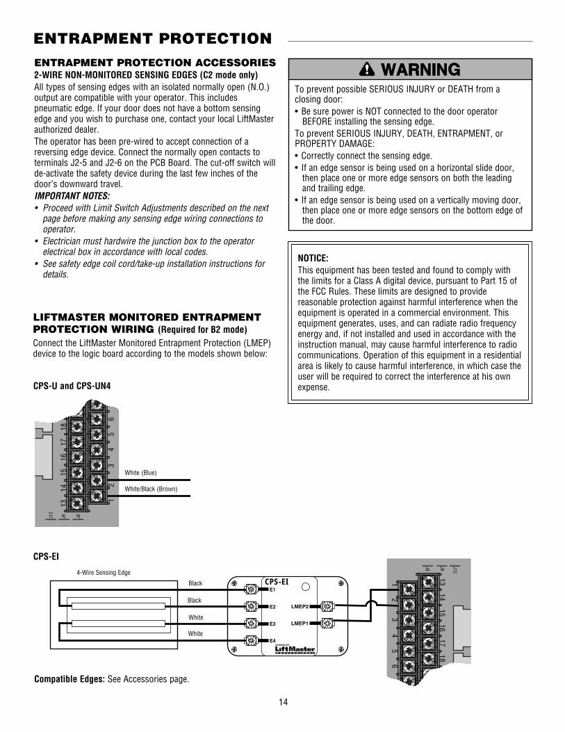
ENTRAPMENT PROTECTION ACCESSORIES2-WIRE NON-MONITORED SENSING EDGES (C2 mode only)All types of sensing edges with an isolated normally open (N.O.) output are compatible with your operator. This includes pneumatic edge. If your door does not have a bottom sensing edge and you wish to purchase one, contact your local LiftMaster authorized dealer.The operator has been pre-wired to accept connection of a reversing edge device. Connect the normally open contacts to terminals J2-5 and J2-6 on the PCB Board. The cut-off switch will de-activate the safety device during the last few inches of the door’s downward travel.IMPORTANT NOTES:• Proceed with Limit Switch Adjustments described on the next
page before making any sensing edge wiring connections to operator.
• Electrician must hardwire the junction box to the operator electrical box in accordance with local codes.
• See safety edge coil cord/take-up installation instructions for details.
NOTICE: This equipment has been tested and found to comply with the limits for a Class A digital device, pursuant to Part 15 of the FCC Rules. These limits are designed to provide reasonable protection against harmful interference when the equipment is operated in a commercial environment. This equipment generates, uses, and can radiate radio frequency energy and, if not installed and used in accordance with the instruction manual, may cause harmful interference to radio communications. Operation of this equipment in a residential area is likely to cause harmful interference, in which case the user will be required to correct the interference at his own expense.
To prevent possible SERIOUS INJURY or DEATH from a closing door:• Be sure power is NOT connected to the door operator
BEFORE installing the sensing edge.To prevent SERIOUS INJURY, DEATH, ENTRAPMENT, or PROPERTY DAMAGE:• Correctly connect the sensing edge.• If an edge sensor is being used on a horizontal slide door,
then place one or more edge sensors on both the leading and trailing edge.
• If an edge sensor is being used on a vertically moving door, then place one or more edge sensors on the bottom edge of the door.
ATTENTION
AVERTISSEMENT AVERTISSEMENT
AVERTISSEMENT
WARNING
CAUTION
WARNING
WARNING
ENGLISH WARNINGS AT 50%
SPANISH WARNINGS AT 50%
FRENCH WARNINGS AT 50%
PRECAUCIÓN ADVERTENCIA
ADVERTENCIAADVERTENCIA 1 2
3 4
5 6
7
13
14
15
16
17
18
19
2
J8J9J12
40-34141-1
LMEP2
E1
E2
LMEP1E3
E4
CPS-EI 1 2
3 4
5 6
7
13 14
15 16
17 18
19 2
J8 J9 J12
40-34141-1
LMEP2
E1
E2
LMEP1E3
E4
CPS-EI 1 2
3 4
5 6
7
13 14
15 16
17 18
19 2
J8 J9 J12
1 2
3 4
5 6
7
13
14
15
16
17
18
19
2
J8J9J12
LiftMasterCPS-MEI
White (Blue)
White/Black (Brown)
CPS-U and CPS-UN4
1 2
3 4
5 6
7
13
14
15
16
17
18
19
2
J8J9J12
40-34141-1
LMEP2
E1
E2
LMEP1E3
E4
CPS-EI 1 2
3 4
5 6
7
13 14
15 16
17 18
19 2
J8 J9 J12
40-34141-1
LMEP2
E1
E2
LMEP1E3
E4
CPS-EI 1 2
3 4
5 6
7
13 14
15 16
17 18
19 2
J8 J9 J12
1 2
3 4
5 6
7
13
14
15
16
17
18
19
2
J8J9J12
LiftMasterCPS-MEI
4-Wire Sensing Edge
Black
Black
White
White
CPS-EI
LIFTMASTER MONITORED ENTRAPMENT PROTECTION WIRING (Required for B2 mode)Connect the LiftMaster Monitored Entrapment Protection (LMEP) device to the logic board according to the models shown below:
ENTRAPMENT PROTECTION
Compatible Edges: See Accessories page.

15
Terminal Block (J1)
Heat Sink
Dip Switches (S1)
LOGIC BOARD ILLUSTRATION
Terminal Block (J2)
NOTE: For dip switch field settings, see page 16.
CONTROL SETTINGS

16
1 2 3 4
ON
OFF 1 2 3 4
ON
OFF
1 2 3 4
ON
OFF 1 2 3 4
ON
OFF
1 2 3 4
ON
OFF 1 2 3 4
ON
OFF
1 2 3 4
ON
OFF 1 2 3 4
ON
OFF
1 2 3 4
ON
OFF 1 2 3 4
ON
OFF
1 2 3 4
ON
OFF 1 2 3 4
ON
OFF
1 2 3 4
ON
OFF 1 2 3 4
ON
OFF
1 2 3 4
ON
OFF
1 2 3 4
ON
OFF 1 2 3 4
ON
OFF
1 2 3 4
ON
OFF 1 2 3 4
ON
OFF
1 2 3 4
ON
OFF 1 2 3 4
ON
OFF
1 2 3 4
ON
OFF 1 2 3 4
ON
OFF
1 2 3 4
ON
OFF 1 2 3 4
ON
OFF
1 2 3 4
ON
OFF 1 2 3 4
ON
OFF
1 2 3 4
ON
OFF 1 2 3 4
ON
OFF
1 2 3 4
ON
OFF
ALARM DELAY TO CLOSES1-1 and S1-2 set the Alarm Delay to Close time of the operator. Alarm Delay to Close is the time between when the operator first receives an active alarm signal and the door starts to close. Refer to illustrations below for various settings.
10 SECOND DELAY 30 SECOND DELAY
45 SECOND DELAY 60 SECOND DELAY
N.O. ALARM N.C. ALARM
FIRE ALARM SYSTEMSelect the alarm system being used. If the alarm is a normally open system then S1-3 must be off. If the alarm is a normally close system then S1-3 must be on.
OPTIONAL CONTROL SETTINGS
1 2 3 4
ON
OFF 1 2 3 4
ON
OFF
1 2 3 4
ON
OFF 1 2 3 4
ON
OFF
1 2 3 4
ON
OFF 1 2 3 4
ON
OFF
1 2 3 4
ON
OFF 1 2 3 4
ON
OFF
1 2 3 4
ON
OFF 1 2 3 4
ON
OFF
1 2 3 4
ON
OFF 1 2 3 4
ON
OFF
1 2 3 4
ON
OFF 1 2 3 4
ON
OFF
1 2 3 4
ON
OFF
1 2 3 4
ON
OFF 1 2 3 4
ON
OFF
1 2 3 4
ON
OFF 1 2 3 4
ON
OFF
1 2 3 4
ON
OFF 1 2 3 4
ON
OFF
1 2 3 4
ON
OFF 1 2 3 4
ON
OFF
1 2 3 4
ON
OFF 1 2 3 4
ON
OFF
1 2 3 4
ON
OFF 1 2 3 4
ON
OFF
1 2 3 4
ON
OFF 1 2 3 4
ON
OFF
1 2 3 4
ON
OFF
LIFTMASTER MONITORED ENTRAPMENT PROTECTION CONNECTED
LIFTMASTER MONITORED ENTRAPMENT PROTECTION NOT CONNECTED
LiftMaster Monitored Entrapment Protection (LMEP)S1-4 must be on if LiftMaster Monitored Entrapment Protection (LMEP) is connected. S1-4 must be off if LiftMaster Monitored Entrapment Protection (LMEP) is not connected.
CONTROL SETTINGS

17
LMPLC BOARD - 230V/460V 3PH
J2
1 2 3 4 5 6 7 8 9 10 11 12
13 14 15 16 17 18 19 20 21 22 23 24
J1
L1 L2 L3
J2
1 2 3 4 5 6 7 8 9 10 11 12
13 14 15 16 17 18 19 20 21 22 23 24
J1
L1 L2 L3
GREENGROUNDSCREW
OPEN
CLOSE
STOP
2-WIRE NON-MONITORED
REVERSE EDGE
2-WIRE NON-MONITORED
REVERSE EDGE
HOT NEUTRAL
CHASSIS GROUND
GREENGROUNDSCREW
OPEN
CLOSE
STOP
230/460V 3PH.POWER IN
FROM EESWP INTERFACE PANEL
CHASSIS GROUND
LIFTMASTER MONITORED ENTRAPMENT PROTECTION
(LMEP)
115/230 1PH.POWER IN
FROM EESWP INTERFACE PANEL
LIFTMASTER MONITORED ENTRAPMENT PROTECTION
(LMEP)
ALARMAND/OR
FUSIBLE LINKINPUT
(dry contact)N.O or N.C.
ALARMAND/OR
FUSIBLE LINKINPUT
(dry contact)N.O or N.C.
J2
1 2 3 4 5 6 7 8 9 10 11 12
13 14 15 16 17 18 19 20 21 22 23 24
J1
L1 L2 L3
J2
1 2 3 4 5 6 7 8 9 10 11 12
13 14 15 16 17 18 19 20 21 22 23 24
J1
L1 L2 L3
GREENGROUNDSCREW
OPEN
CLOSE
STOP
2-WIRE NON-MONITORED
REVERSE EDGE
2-WIRE NON-MONITORED
REVERSE EDGE
HOT NEUTRAL
CHASSIS GROUND
GREENGROUNDSCREW
OPEN
CLOSE
STOP
230/460V 3PH.POWER IN
FROM EESWP INTERFACE PANEL
CHASSIS GROUND
LIFTMASTER MONITORED ENTRAPMENT PROTECTION
(LMEP)
115/230 1PH.POWER IN
FROM EESWP INTERFACE PANEL
LIFTMASTER MONITORED ENTRAPMENT PROTECTION
(LMEP)
ALARMAND/OR
FUSIBLE LINKINPUT
(dry contact)N.O or N.C.
ALARMAND/OR
FUSIBLE LINKINPUT
(dry contact)N.O or N.C.
STANDARD POWER AND CONTROL CONNECTION DIAGRAMS
NOTE: The operator should be on a separate fused line of adequate capacity.
Operator must be permanently wired as per NFPA 70 (National Electrical Code). Ground must be pulled with each service. Service voltage must be run SEPARATELY from class 2 circuits (controls).
LMPLC BOARD - 115V/230V 1PH
DIAGRAMS

18
1 PHASE WIRING DIAGRAM (FDO5011AU AND FDO5021AU)
NOTES:1. See owner’s manual for dip switch functions and programming
procedures.2. To REVERSE motor direction; REVERSE purple and gray motor
wires at J6 and J7.3. Unit comes standard in C2 wiring mode. B2 wiring mode
requires a LiftMaster Monitored Entrapment Protection device. For B2 mode, remove one end of jumper from J2-3 and connect to J2-16. Dip switch #4 (S1-4) must be in the ON position.
4. If using fusible link, wire with alarm. If alarm is N.C., wire in series. If alarm is N.O., wire in parallel.
To protect against fire and electrocution:• Replace ONLY with fuse of same type and rating.
ATTENTION
AVERTISSEMENT AVERTISSEMENT
AVERTISSEMENT
WARNING
CAUTION
WARNING
WARNING
ENGLISH WARNINGS AT 50%
SPANISH WARNINGS AT 50%
FRENCH WARNINGS AT 50%
PRECAUCIÓN ADVERTENCIA
ADVERTENCIAADVERTENCIA
DIAGRAMS
SINGLE PHASE WIRING DIAGRAM 47-35901
J2 1 2 3 4 5 6 7 8 9 10 11 12
13 14 15 16 17 18 19 20 2221 23 24
10
9
8
7
6
5
4
3
2
1
L3L2L1
C NO
J12
J9
J8
J1J29J22
J27
J26
J5
J25
J23
J28
J6
J7
J20
J30
J3
J15
J21
J13
J14
J4
S1 J24
J17J16
J19J18
NCNO
NCNO
NCNO
C
C C
OPEN
CLOSE
KEY-TEST
STOP
OPTIONAL USER INTERFACE
SPEAKER
(PU)
(YE)
(PU)
(YE)
2-WIRE NON-
MONITORED REVERSE
EDGE
SEE NOTE 3
VOICEBOARD
250 MAMAX
MOTOR
DC BRAKESOLENOID
OPENLIMIT SW.
SAFETYLIMIT SW.
CLOSELIMIT SW.
115/230VPOWER IN
BREAKER
(BK) (BK)
230V MOTOR CONNECTION115V MOTOR CONNECTION
LIFTMASTERMONITORED
ENTRAPMENTPROTECTION
(LMEP)
AUXILIARY TERMINAL BLOCK
STROBE LIGHT 24V+ (RD)
_ (BK)
(BR)
(BK)
(RD)
TRANSFORMER
SECO
NDAR
Y
PRIM
ARY
(YE)
(GY)
(BL)
115VONLY
(PU)
(BR)
(BR) (BK)
(WH)
(BK)__
(RD)+
(RD) (BL)
(BK)
(BL)
(GY)
(YE)
(BK)
(WH)
(WH)
(YE)
(WH)
ALARM AND/ORFUSIBLE LINK INPUT(DRY CONTACT ONLY. DO NOT INDUCE VOLTAGE)SEE NOTE 4
(BR)
(BL)(YE)
(OR)
(RD)
(YE)
(BK)
(BK)
(BL)
(PU)
(BK)
(OR)(BK)
FUSE
2AMP
(BR)
(BK)
(BK)
(YE)
(PU)
(GY)(GY)
(PU)
CHASSISGROUND

19
1 PHASE WIRING DIAGRAM (FDO5011BU AND FDO5021BU)
NOTES:1. See owner’s manual for dip switch functions and programming
procedures.2. To REVERSE motor direction; REVERSE purple and gray motor
wires at J6 and J7.3. Unit comes standard in C2 wiring mode. B2 wiring mode
requires a LiftMaster Monitored Entrapment Protection device. For B2 mode, remove one end of jumper from J2-3 and connect to J2-16. Dip switch #4 (S1-4) must be in the ON position.
To protect against fire and electrocution:• Replace ONLY with fuse of same type and rating.
ATTENTION
AVERTISSEMENT AVERTISSEMENT
AVERTISSEMENT
WARNING
CAUTION
WARNING
WARNING
ENGLISH WARNINGS AT 50%
SPANISH WARNINGS AT 50%
FRENCH WARNINGS AT 50%
PRECAUCIÓN ADVERTENCIA
ADVERTENCIAADVERTENCIA
DIAGRAMS
4. If using fusible link, wire with alarm. If alarm is N.C., wire in series. If alarm is N.O., wire in parallel.
SINGLE PHASE WIRING DIAGRAM 47-35903
J2 1 2 3 4 5 6 7 8 9 10 11 12
13 14 15 16 17 18 19 20 2221 23 24
10
9
8
7
6
5
4
3
2
1
L3L2L1
C NO
J12
J9
J8
J1J29J22
J27
J26
O/L
J5
J25
J23
J28
J6
J7
J20
+
+
-
-
J7
J5
J3 J4J6J1J2
J30
4 3 2 1
J3
J21
J4
S1 J24
J17
J16
J19J18
NCNO
NCNO
C
C C
J14
J13
J15
NCNO
OPEN
CLOSE
KEY-TEST
STOP
SPEAKER
(BL)(YE)
(OR)
(PU)
(YE)
(PU)
(YE)
(RD)
2-WIRE NON-
MONITORED REVERSE
EDGE
SEE NOTE 3
VOICEBOARD
250 MAMAX
CHASSISGROUND
DC BRAKESOLENOID
SAFETYLIMIT SW.
CLOSELIMIT SW.
POWER DISCONNECT
115/230V 1PHPOWER IN
BREAKER
(BK) (BK)
(YE)
(BK)
(BK)
(BL)
(PU)
230V MOTOR CONNECTION
115V MOTOR CONNECTION
LIFTMASTERMONITORED
ENTRAPMENTPROTECTION
(LMEP)
AUXILIARY TERMINAL BLOCK
POWER DISCONNECT
STROBE LIGHT 24V
+ (RD)
_ (BK)
(BR)
(BK)
(BK)(BR)
(WH)(BR)
(RD)
TRANSFORMER
SECO
NDAR
Y
PRIM
ARY
(YE)
(YE)
(BK)
(GY)
(PU)
(BL)
(GY)
(BL)
115VONLY
(PU)(OR)
(BK)
(BK)
(RD)
(BK)
(BK)(YE)
(PU)
(WH)(WH)
(BK)
(RD)
(RD)
BATTERY BOARD
(GY)
(GY)
(BL)
(RD)
(BK)
12 VdcBATTERY
(BL)
RPM BOARD
25 OHM 50 WRESISTOR
(BK)
(WH)
(WH)
(YE)
(WH)
ALARM AND/ORFUSIBLE LINK INPUT(DRY CONTACT ONLY. DO NOT INDUCE VOLTAGE)SEE NOTE 4
OPENLIMIT SW.
(RD)
(BR)
FUSE
2AMP
(BR)
(BL)

20
3 PHASE WIRING DIAGRAM (FDO1023AU AND FDO1043AU)
NOTES:1. See owner’s manual for dip switch functions and programming
procedures.2. To REVERSE motor direction; REVERSE purple and gray motor
wires at J6 and J7.3. Unit comes standard in C2 wiring mode. B2 wiring mode
requires a LiftMaster Monitored Entrapment Protection device. For B2 mode, remove one end of jumper from J2-3 and connect to J2-16. Dip switch #4 (S1-4) must be in the ON position.
4. If using fusible link, wire with alarm. If alarm is N.C., wire in series. If alarm is N.O., wire in parallel.
To protect against fire and electrocution:• Replace ONLY with fuse of same type and rating.
ATTENTION
AVERTISSEMENT AVERTISSEMENT
AVERTISSEMENT
WARNING
CAUTION
WARNING
WARNING
ENGLISH WARNINGS AT 50%
SPANISH WARNINGS AT 50%
FRENCH WARNINGS AT 50%
PRECAUCIÓN ADVERTENCIA
ADVERTENCIAADVERTENCIA
DIAGRAMS
THREE PHASE WIRING DIAGRAM 47-35900
C NO
J15
T2
J7
10
9
8
7
6
5
4
3
2
1
C
C C
_ +
T3
T1
J14
J13
J3
J30 J17
J16
J19J18
13
1 2 3 4 5 6 7 8 9 10 11 12
14 15 16 17 19 20 21 22 23 2418
J5
J24
J23
J6J21
J12
J2
J22J26
J1J29
J20
J28
J25
L1 L2 L3
L3
95
96
T3
T2
T1
L2
L1
J27
J9
J8
J4
S1
NC
NO
NC
NO
NC
NO
INTERNAL MOTOR CONNECTIONS
230V - 3 PHMOTOR CONNECTION
460V - 3 PHMOTOR CONNECTION
CHASSIS GROUNDSEE
NOTE 3
OPEN
KEY-TEST
CLOSE
STOP
(BR)
OPTIONAL USER INTERFACE
STROBE LIGHT 24V
(BK)
TRANSFORMER
AUXILIARY TERMINAL BLOCK
SPEAKER
(PU)MOTOR
(GY)
(PU)
(PU)
(RD)
(YE)
(RD)
(OR)
(BK)
(BL)
(WH)
(WH)
(WH)
(YE)
(YE)(BR)
(PU)
(BR)(GY)
(YE)(BR)
(PU)
(BR)(GY)
(YE)
(RD)
(RD)
(YE)
(BR)
250 MAMAX
(BR)
(BR)
TARJETA DE VOZ
230/460V 3PHPOWER IN
(BK)
(BK)
(BL)
(BK)
(BK)
(BK)
(BK)
(BK)
(WH)
LIFTMASTERMONITORED
ENTRAPMENTPROTECTION
(LMEP)
2-WIRE NON-
MONITORED REVERSE
EDGE
MOTOR O/L
DC BRAKESOLENOID
SEE NOTE 4
SECO
NDAR
Y
PRIM
ARY
CLOSELIMIT SW.
OPENLIMIT SW.
ALARM AND/ORFUSIBLE LINK INPUT(DRY CONTACT ONLY. DO NOT INDUCE VOLTAGE)SEE NOTE 4
+ (RD)
_ (BK)
(BK)FUSE
2 AMP
(BK)
(BK) (BK)
(BR)
SAFETYLIMIT SW.
(BR)

21
3 PHASE WIRING DIAGRAM (FDO1023BU AND FDO1043BU)
To protect against fire and electrocution:• Replace ONLY with fuse of same type and rating.
ATTENTION
AVERTISSEMENT AVERTISSEMENT
AVERTISSEMENT
WARNING
CAUTION
WARNING
WARNING
ENGLISH WARNINGS AT 50%
SPANISH WARNINGS AT 50%
FRENCH WARNINGS AT 50%
PRECAUCIÓN ADVERTENCIA
ADVERTENCIAADVERTENCIA
NOTES:1. See owner’s manual for switch functions and programming
procedures.2. To REVERSE motor direction; REVERSE purple and gray motor
wires at J6 and J7.3. Unit comes standard in C2 wiring mode. B2 wiring mode
requires a LiftMaster Monitored Entrapment Protection device. For B2 mode, remove one end of jumper from J2-3 and connect to J2-16. Dip switch #4 (S1-4) must be in the ON position.
DIAGRAMS
4. If using fusible link, wire with alarm. If alarm is N.C., wire in series. If alarm is N.O., wire in parallel.
THREE PHASE WIRING DIAGRAM 47-35902
10
9
8
7
6
5
4
3
2
1
J2
J7
J6
J23
J5
J24
J21
J3J14
J15
J13
J4
S1
J19J18
J16
J30 J17
C NO
4
5
6
4
5
6
9
8
7
9
8
7
1
2
3
1
2
3
L3L2L1
J1
J29
1 2 3 4 5 6 7 8 9 10 11 12J22
J26
J28
J25
J20
J27
C
C C
13 14 15 16 17 18 19 20 2221 23 24
(YE)
(YE)
(BR)
(RD)
(RD)
(RD)
(RD)
(BL)
(BL)
(BK)
(BK)
(BK)
(BR)
(PU)
(WH)
(WH)
(WH)
(WH)
(WH)
(GY)
(YE)
(BR)
(BR)
(PU)
(GY)
460V - 3 PH MOTOR CONNECTION
230V - 3 PH MOTOR CONNECTION
+ (RD)
(BR)
(PU)
(YE)
- (BK)
(YE)
(BK) (RD)
(PU)
(GY)
250 MAMAX
SPEAKER
VOICEBOARD
AUXILIARY TERMINAL BLOCK
12 VdcBATTERY
STROBE LIGHT 24V
POWER DISCONNECT
RPM BOARD
DC BRAKE SOLENOID
BATTERYBOARD
OPENLIMIT SW.
CLOSELIMIT SW.
25 OHM 50 WRESISTOR
SAFETYLIMIT SW.
MOTOR O/L
SEE NOTE 4
(BK)
(BL)(BK) (BK)
(PU)
(YE) (RD)
(BK)
(BK)
(BK)
(BK)
(BK)
(BK)
(OR)(RD)
(RD)
LIFTMASTERMONITORED
ENTRAPMENTPROTECTION
(LMEP)
2-WIRE NON-
MONITORED REVERSE
EDGE OPEN
STOP
CLOSE
SEE NOTE 3 KEY-TEST
TRANSFORMER
230V/460V 3PH.POWER IN
MOTOR
CHASSISGROUND
FUSE
2AMP
ALARM AND/ORFUSIBLE LINK INPUT(DRY CONTACT ONLY. DO NOT INDUCE VOLTAGE)SEE NOTE 4
(BR)
(BR)
(BR)
(BL)
(BR)(BR)
POWER DISCONNECT
(BR) (WH)
(BK)
SECO
NDAR
Y
PRIM
ARY

22
● Use SAE 30 Oil. (Never use grease or silicone spray.)♦ Repeat ALL procedures.■ Do not lubricate motor. Motor bearings are rated for
continuous operation.■ Inspect and service whenever a malfunction is observed or
suspected.
Check at the intervals listed in the following chart:
MAINTENANCE SCHEDULE
HOW TO ORDER REPAIR PARTSOUR LARGE SERVICE ORGANIZATION SPANS AMERICA
For installation and service information call our TOLL FREE number:
1-800-528-2806
To avoid SERIOUS PERSONAL INJURY or DEATH:• Disconnect electric power BEFORE performing ANY
adjustments or maintenance.• ALL maintenance MUST be performed by a trained door
systems technician.
ATTENTION
AVERTISSEMENT AVERTISSEMENT
AVERTISSEMENT
WARNING
CAUTION
WARNING
WARNING
ENGLISH WARNINGS AT 50%
SPANISH WARNINGS AT 50%
FRENCH WARNINGS AT 50%
PRECAUCIÓN ADVERTENCIA
ADVERTENCIAADVERTENCIA
ITEM PROCEDUREEVERY
3 MONTHSEVERY
6 MONTHSEVERY
12 MONTHSEVERY
24 MONTHS
Drive Chain Check for excessive slack Check and adjust as required Lubricate ● ♦
Sprockets Check set screw tightness ● ♦
Fasteners Check and tighten as required ● ♦
Bearings and Shafts Check for wear and lubricate ● ♦
Battery Maintenance Replace batteries ●

23
Refer to the parts lists below for replacement kits available for your operator. If optional modifications and/or accessories are included with your operator, certain components may be added or
removed from these lists. Individual components of each kit may not be available. Please consult a parts and service representative regarding availability of individual components.
REPAIR PARTS KITS - FDO5011BU AND FDO5021BU
INDIVIDUAL COMPONENTSITEM PART # DESCRIPTION QTY1 Electrical Box Bracket 12 15-14650 Sprocket 13 80-207-19 Key 14 32-16214 Gear Reducer 1
K-FDO5011BU AND K-FDO5021BU - ELECTRICAL BOX KITITEM PART # DESCRIPTION QTYE1 K74-16437 RPM Sensor Assembly 1E2 K75-17351-3 Electrical Box Cover 1E3 Electrical Box 1E4 Battery Top Plate 1E5 Battery Strap 1E6 21-16699 Transformer, 75VA PT Series 1E7 See Variables Overload 1E8 29-NP712 Battery, 12V 2E9 29-R250B7KWR Power Resistor 1E10 35-313-002 Fuse, 2 AMP 1E11 42-110 10 Pole Terminal Block 1E12 79-30805-FDO Voice Board 1E13 Standoff Assembly, FDO PCB 7E14 K79-13493B-600 Logic Board Kit 1E15 Bracket, Resistor 2E16 25-3000-K Overload Bracket (3-PH only) 1E17 K002D0776 PCB Battery Board 1*Electrical Box Kits include parts from K72-13580 and K75-13816
VARIABLE COMPONENTSITEM PART # DESCRIPTION QTYE7 25-2010 Overload 115V 1
25-2006 Overload 230V 1
K72-13580 LIMIT SHAFT ASSEMBLY KITITEM PART # DESCRIPTION QTYL1 Rotator Cup 1L2 Limit Shaft 1L3 12-10028 Flange Bearing 2L4 13-10024 Limit Nut 2L5 15-48B9A1 Sprocket, #48B9 x 3/8" Bore 1L6 Washer, Spacer 2L7 Roll Pin, 1/8" x 1" long 1L8 E-Ring, 3/8" 1
K20-1050C-2PSF - MOTOR KIT ITEM DESCRIPTION QTYM1 Motor 1
K75-32620 - BRAKE ASSEMBLY KITITEM PART # DESCRIPTION QTYB1 Brake Release Lever 1B2 Brake Disc 1B3 Brake Cover 1B4 Plate, DC Solenoid 1B5 Solenoid Cover 1B6 Spring Cup 4B7 Brake Stud 4B8 Spring, Brake 4B9 19-48001 Chain, #48 x 1 Pitch 1B10 22-13028 DC Solenoid 1B11 Standoff 2B12 Pressure Plate Assembly 1B13 Mounting Bracket Assembly 1B14 Cotter Pin, 1/8" x 1-1/4" 2B15 Stop, DC Solenoid 1
K75-13816 - LIMIT SWITCH ASSEMBLY KITITEM PART # DESCRIPTION QTYS1 Depress Plate 1S2 Nut Plate Switch 3S3 Backup Plate 3S4 Depress Spring 2S5 23-10041 Limit Switch 3S6 Standoff, Switch 3S7 Screw, #4-40 Pan Head 6S8 Screw, #6-32 Pan Head 2S9 Lock Nut, #6-32 2
REPAIR PARTS

24
ILLUSTRATED PARTS - FDO5011BU AND FDO5021BU
8E
11E
01E
6E
4L
2L4L
3L
7L
5E
3E
5L
6L
5S
6S
2S
3S
7S5B
01B
4S
9S
51E
31B
2B
11B
1B
21B
6B
B8
7B
41B
4B
9B
51B
S8
1S
3B9E
1L
6L
1E 6
E7
L83L
1E
31E
4E
41E
21E
4
1 1M
2
3
E17
E2E2
E8
E10
E5
E11
E13
E12
E3E7
E4
E14
E1
E15
B3E9
S1
S8
B15
B9
B14
B8
B7
B6
B12
B1
B11
B2
B13
B4
B5
M1
S7
1
3
2
4
L6
L5
L7
L3
L4
E6 L2
L4
E17
S5
S6
S2
S3B10
S4
S9
E16L3 L8
L6
L1
REPAIR PARTS

25
Refer to the parts lists below for replacement kits available for your operator. If optional modifications and/or accessories are included with your operator, certain components may be added or
removed from these lists. Individual components of each kit may not be available. Please consult a parts and service representative regarding availability of individual components.
K-FDO5011AU AND K-FDO5021AU - ELECTRICAL BOX KITITEM PART # DESCRIPTION QTYE1 K75-17351-3 Electrical Box Cover 1E2 Electrical Box 1E3 Battery Top Plate 1E4 21-16699 Transformer 1E5 See Variables Overload 1E6 42-110 10 Pole Terminal Block 1E7 79-30805 Voice Board (Optional) 1E8 Standoff Assembly, FDO PCB 7E9 K79-13493A-600 Logic Board Kit 1E10 25-3000-K Overload Bracket (3-PH only) 1
* Electrical Box Kits include parts from K72-13581 and K75-13816
VARIABLE COMPONENTS ITEM PART # DESCRIPTION QTYE5 25-2010 Overload, 115V 1
25-2006 Overload, 230V 1
K72-13581 LIMIT SHAFT ASSEMBLY KITITEM PART # DESCRIPTION QTYL1 Limit Shaft 1L2 12-10028 Flange Bearing 2L3 13-10024 Limit Nut 2L4 15-48B9A1 Sprocket, #48B9 x 3/8" Bore 1L5 Washer, Spacer 2L6 Roll Pin, 1/8" x 1" long 1L7 E-Ring, 3/8" 1
K20-1050C-2PSF - MOTOR KITITEM DESCRIPTION QTYM1 Motor 1
K75-32621 - BRAKE ASSEMBLY KITITEM PART # DESCRIPTION QTYB1 Brake Disc 1B2 Brake Release Lever 1B3 Brake Cover 1B4 Extension Bracket 1B5 Spring Cup 4B6 Spring Cap 2B7 Brake Stud 4B8 Standoff 2B9 Spring, Compression 1B10 Spring, Compression 1B11 19-48001 Chain, #48 x 1 Pitch 1B12 22-13028 DC Solenoid 1B13 Pressure Plate Assembly 1B14 Mounting Bracket Assembly 1B15 Screw, #6-32 Pan Head 2B16 Cotter Pin, 1/8" x 1-1/4" 2B17 Plate, DC Solenoid 1B18 Stop, DC Solenoid 1
REPAIR PARTS KITS - FDO5011AU AND FDO5021AU
K75-13816 - LIMIT SWITCH ASSEMBLY KITITEM PART # DESCRIPTION QTYS1 Depress Plate 1S2 Nut Plate Switch 3S3 Backup Plate 3S4 Depress Spring 2S5 23-10041 Limit Switch 3S6 Standoff, Switch 3S7 Screw, #4-40 Pan Head 6S8 Screw, #6-32 Pan Head 2S9 Lock Nut, #6-32 2
INDIVIDUAL COMPONENTSITEM PART # DESCRIPTION QTY1 Bracket, Electrical Box 12 15-14650 Sprocket 13 80-207-19 Key 14 32-16214 Gear Reducer 1
REPAIR PARTS

26
ILLUSTRATED PARTS - FDO5011AU AND FDO5021AU
6E
9E
3E
8E3L
2L
2E
6L
4L
5L
9S
4S
4B
8S
1S
21B
71B
M11
4
41B
3B
31B 51B
6B
9B1B
01B
61B
5B
7B
8B
2B
11B
7S81B
2S
4E
5L
7L
2L
5S
6S
3S
01E
5E
7E
1E
2
3
L3
L1
E6
E1
E4
L5
L7
L2
S5
E7
E2E9
E3
E8L3
L1
L3
L2
L6
L4
L5
S9
S4
B4
S8
S1
B12
B17
B18
S2
S7
S3
S6
B2
B8
B7
B5
B16
B11
B10
B1
B13
B9
B6
B15
B3
B14
M11
3
2
4
E10
E5
REPAIR PARTS

27
Refer to the parts lists below for replacement kits available for your operator. If optional modifications and/or accessories are included with your operator, certain components may be added or
removed from these lists. Individual components of each kit may not be available. Please consult a parts and service representative regarding availability of individual components.
K-FDO1023BU AND K-FDO1043BU - ELECTRICAL BOX KITITEM PART # DESCRIPTION QTYE1 K74-16437 RPM Sensor Assembly 1 E2 K75-17351-3 Electrical Box Cover 1E3 Electrical Box 1E4 Battery Top Plate 1E5 Battery Strap 1E6 21-16698 Transformer, 75VA PT Series 1E7 See Variables Overload 1E8 29-NP712 Battery, 12V 2E9 29-R250B7KWR Power Resistor 1E10 35-313-002 Fuse, 2 AMP 1E11 42-110 10 Pole Terminal Block 1E12 79-30805-FDO Voice Board 1E13 Standoff Assembly, FDO PCB 7E14 K79-13493B-600 Logic Board 1E15 Bracket, Resistor 2E16 25-3000-K Overload Bracket (3-PH only) 1E17 K002D0776 PCB Battery Board 1* Electrical Box Kits include parts from K72-13580 and
K75-13816
VARIABLE COMPONENTSITEM PART # DESCRIPTION QTYE4 25-4004-K Overload 3.3-5.5 Amp
(230V 3 Ph)1
25-4002-5K Overload 1.6-2.5 Amp (460V 3 Ph)
1
K72-13580 LIMIT SHAFT ASSEMBLY KITITEM PART # DESCRIPTION QTYL1 Rotator Cup 1L2 Limit Shaft 1L3 12-10028 Flange Bearing 2L4 13-10024 Limit Nut 2L5 15-48B9A1 Sprocket, #48B9 x 3/8" Bore 1L6 Washer, Spacer 2L7 Roll Pin, 1/8" x 1" long 1L8 E-Ring, 3/8" 1
K75-13742 - MOTOR KITITEM PART # DESCRIPTION QTYM1 Brake Hub 1M2 20-3100C-4T Motor, 1 HP 230/460V 3Ph,
TEFC1
K75-14995 - BRAKE ASSEMBLY KITITEM PART # DESCRIPTION QTYB1 Brake Release Lever 1B2 Brake Disc 1B3 Brake Cover 1B4 Plate, DC Solenoid 1B5 10-14647 Solenoid Cover 1B6 Spring Cup 4B7 Brake Stud 4B8 Spring, Brake 4B9 19-48001 Chain, #48 x 1 Pitch 1B10 22-13028 DC Solenoid 1B11 Standoff 2B12 Pressure Plate Assembly 1B13 Mounting Bracket Assembly 1B14 Cotter Pin, 1/8" x 1-1/4" 2B15 Stop, DC Solenoid 1
REPAIR PARTS KITS - FDO1023BU AND FDO1043BU
K75-13816 - LIMIT SWITCH ASSEMBLY KITITEM PART # DESCRIPTION QTYS1 Depress Plate 1S2 Nut Plate Switch 3S3 Backup Plate 3S4 Depress Spring 2S5 23-10041 Limit Switch 3S6 Standoff, Switch 3S7 Screw, #4-40 Pan Head 6S8 Screw, #6-32 Pan Head 2S9 Lock Nut, #6-32 2
INDIVIDUAL COMPONENTSITEM PART # DESCRIPTION QTY1 Electric Box Bracket 12 15-48B18QGH Sprocket 48B18 13 15-50B18QGH Sprocket 50B18 14 32-16234 Gear Reducer 1
REPAIR PARTS

28
ILLUSTRATED PARTS - FDO1023BU AND FDO1043BU
REPAIR PARTS
1M
8E
11E
01E
6E
4L
2L4L
3L
7L
5E
3E
2E
5L
6L
5S
6S
2S
3S
7S5B
01B
4S
9S
51E
31B
2B
11B
1B
21B
6B
B8
7B
41B
4B
9B
51B
S8
1S
3B9E
1L
6L
1E 6
E7
L83L
1E
31E
E4
41E
21E
4
1 1M
2
E17
3
E2
E8
E11
E10
E6
L4
L2L4
L3
L7
L5
L6
S5
S6
S2
S3
1 M2
4
2
3
B5
S7
M1
B10
S4
S9E17
E15
E9
S1
S8
B15
B3
B9
B14
B4
B11
B2
B13
B1
B12
B6
B7
B8
E16
E7
L8L3
L6
L1
E1E12
E5
E3
E13
E4
E14

29
Refer to the parts lists below for replacement kits available for your operator. If optional modifications and/or accessories are included with your operator, certain components may be added or
removed from these lists. Individual components of each kit may not be available. Please consult a parts and service representative regarding availability of individual components.
K-FDO1023AU AND K-FDO1043AU - ELECTRICAL BOX KITITEM PART # DESCRIPTION QTYE1 K75-17351-3 Electrical Box Cover 1E2 Electrical Box 1E3 Battery Top Plate 1E4 21-16698 Transformer 1E5 See Variables Overload 1E6 42-110 10 Pole Terminal Block 1E7 79-30805-FDO Voice Board (Optional) 1E8 Standoff Assembly, FDO PCB 7E9 K79-13493A-600 Logic Board 1E10 25-3000-K Overload Bracket 1
* Electrical Box Kits include parts from K72-13581 and K75-13816
VARIABLE COMPONENTS ITEM PART # DESCRIPTION QTYE5 25-4004-K Overload 3.3-5.5 Amp
(230V 3 Ph)1
25-4002-5K Overload 1.6-2.5 Amp (460V 3 Ph)
1
K72-13581 LIMIT SHAFT ASSEMBLY KITITEM PART # DESCRIPTION QTYL1 Limit Shaft 1L2 12-10028 Flange Bearing 2L3 13-10024 Limit Nut 2L4 15-48B9A1 Sprocket, #48B9 x 3/8" Bore 1L5 Washer, Spacer 2L6 Roll Pin, 1/8" x 1" long 1L7 E-Ring, 3/8" 1
MOTORITEM PART # DESCRIPTION QTYM1 Brake Hub 1M2 20-3100C-4T Motor, 1 HP 230/460V 3Ph,
TEFC1
K75-15006 - BRAKE ASSEMBLY KITITEM PART # DESCRIPTION QTYB1 Brake Disc 1B2 Brake Release Lever 1B3 Brake Cover 1B4 Solenoid Cover 1B5 Spring Cup 4B6 Spring Cap 2B7 Brake Stud 4B8 Standoff 2B9 Spring, Compression 2B10 Spring, Compression 4B11 19-48001 Chain, #48 x 1 Pitch 1B12 22- 13028 DC Solenoid 1B13 Pressure Plate Assembly 1B14 Mounting Bracket Assembly 1B15 Screw, #6-32 Pan Head 2B16 Cotter Pin, 1/8" x 1-1/4" 2B17 Plate, DC Solenoid 1B18 Stop, DC Solenoid 1
REPAIR PARTS KITS - FDO1023AU AND FDO1043AU
K75-13816 - LIMIT SWITCH ASSEMBLY KITITEM PART # DESCRIPTION QTYS1 Depress Plate 1S2 Nut Plate Switch 3S3 Backup Plate 3S4 Depress Spring 2S5 23-10041 Limit Switch 3S6 Standoff, Switch 3S7 Screw, #4-40 Pan Head 6S8 Screw, #6-32 Pan Head 2S9 Lock Nut, #6-32 2
INDIVIDUAL COMPONENTSITEM PART # DESCRIPTION QTY1 Electric Box Bracket 12 15-48B18QGH Sprocket 48B18 13 15-50B18QGH Sprocket 50B18 14 32-16234 Gear Reducer 1
REPAIR PARTS

30
ILLUSTRATED PARTS - FDO1023AU AND FDO1043AU
REPAIR PARTS
3
1
5
2
6E
9E
3E
8E3L
2L
2E
6L
4L
5L
9S
4S
4B
8S
1S
21B
71B
M1
41B
3B
31B 51B
6B
9B1B
01B
61B
5B
7B
8B
2B
11B
7S81B
2S
4E
5L
7L
2L
5S
6S
3S
01E
5E
7E
1E
2
L3
L1
6
1M
M1
1
4
2
3
E1
E6
E9
E3
E8
E2
E4
L5
L7
L2
E7
S5
S6
S3
E10
E5
S2
B18
S1
L3
L1
L3
L2
L6
L4
L5
S9
S4
B4
S8B12
B17
B11
B2
B8
B9
B6
B15
S7
B5
B16
B1
B10
M1B13
B3
B14
M21
2
3
4
B7

31
M O D E L M T 5 0 1 1 U / B M T 5 0 1 1 UQUICK START
aglkdngdna diakdnalkndjandjanadlknsa;fkn;dagndan;djksna;dkjndgajndsandoailangdlaknskdnoalknagdndjoang;gksdjna;ogdnraglkna;gn;djkandadgsndajgndoialajgdajngciosuhadoajdna lddagjdl;abndjnbag;duhajbdnkajbnagjdaghadsuabndkjbndsgakjbndsubhadsjbnakjdbnkgjadkjbagudbkdsjgbsAZdlsuabhdijbadub
^^OPEN
CLOSE
OSTOP
3-Button Control Station:Steel enclosure.
02-103
Commercial Protector System®:Provides protection on doors up to 45' (13.7 m) wide. NEMA-4 rated.
CPS-UN4
Commercial Protector System®:Provides protection on doors up to 30' (9.1 m) wide.
CPS-U
ENTRAPMENT PROTECTION DEVICES
CONTROL STATION AND KEYSWITCH
ACCESSORIES
CPS-EI Monitored Safety Edge Interface:For use with the approved 4-wire safety edge (see below).
OES-4504
OES-5104
LM4WB
LM4WTB
1-3/4" x 1-3/4", 16 feet (4.9 m) long PVC sectional door channel (4 piece).
2" x 2", 16 feet (4.9 m) long PVC sectional door channel (4 pieces).
Smoke Detector 24 Vdc 4-Wire Photo:Plug-in detector line mounting base included. N.O. contact output. Power from external source.
Smoke Detector 24 Vdc 4-Wire Photo Thermal and Form C Relay:Same as LM4WB but with restorable, built-in, fixed temperature (135° F) thermal detector.
Field Installation Kit:Factory modification adding the 24 V speaker strobe and voiceboard.
90-FDOSV-24V
Field Installation Kit:Factory modification adding the 24 V speaker strobe only.
90-FDOS-24V
Field Installation Kit: Provides both a 24 V speaker strobe and voiceboard.
K90-FDOSV-24V
Field Installation Kit: Provides a 24 V speaker strobe only.
K90-FDOS-24V
MOUNTING CHANNELS
FDO ALARM AND NOTIFICATION DEVICES
FIELD MODIFICATION KITS
MONITORED
Test Keyswitch:02-109 FDO
LMHS2475ADA
71-17148
Horn/Strobe 24 Vdc
Retrofit Fuse Link Kit:Allows for an existing fuse link to interface with the fire door operator.
CPS-RPEN4 Monitored Retro-Reflective Photo Eyes• Polarized reflector for use in applications
with highly reflective surfaces.• NEMA 4X enclosure protects against
direct water spray and corrosion.• Retro-reflective sensor.• For indoor/outdoor use.• Maximum range of 50 feet (15 m).
(CPS-UN4)
(CPS-U)
(CPS-RPEN4)
(CPS-OPEN4)
Optical Edge System (OES)
(CPS3CARD)
CPS-OPEN4 Monitored Dual-Sided Photo Eyes• Flexible housings maintain alignment in
areas with a high propensity for sensor contact.
• NEMA 4X enclosure protects against direct water spray and corrosion.
• Dual-sided infrared sensors.• For indoor/outdoor use.• Maximum range of 45 feet (13.7 m).
(CPS-UN4)
(CPS-U)
(CPS-RPEN4)
(CPS-OPEN4)
Optical Edge System (OES)
(CPS3CARD)
Existing Fuse Link
Existing Fuse Link Chain
Center Line of Door
Fuse Link Retrofit Switch (optional)
Key-ring
(DOOR HOOD)
(CPS-UN4)
(CPS-U)
(CPS-RPEN4)
(CPS-OPEN4)
Optical Edge System (OES)
(CPS3CARD)
(CPS-UN4)
(CPS-U)
(CPS-RPEN4)
(CPS-OPEN4)
Optical Edge System (OES)
(CPS3CARD)

© 2017, The Chamberlain Group, Inc. 01-35771H All Rights Reserved
CONTROL CONNECTION DIAGRAM
5 6J2
9 10 11 126 7 89 106 7 8
1 2 11 12 11 12
15 17
+-
1 2
J2 J2
J2 J2 J2
J2 TB1
9 106 7 8J2
2-wire non-monitored reversing edge
3-BUTTON STATION OR 3 POSITION KEYSWITCH WITH SPRING RETURN TO CENTER AND STOP BUTTON
KEY-TEST2 OR MORE
Close
Open
IMPORTANT NOTE:The 3-Button Control Station provided must be connected for operation.
IMPORTANT: All inputs must be contact only! This includes: Alarm Inputs, Control Inputs, Sensing Edges and Sensing Devices. For any other devices not mentioned please consult the factory.
Keyswitch
Stop
Close
Open
Close
Open
LIFTMASTER MONITOREDENTRAPMENT PROTECTION
SENSING DEVICETO REVERSE OR STOP
LMEPN.C. Contacts N.O. Contacts
ALARM SYSTEMN.O. OR N.C. CONTACTS
STROBE LIGHT/SPEAKER WIRING
Strobe Light Speaker
Must set DIP switch #3(S1-3) to ON.
Must set DIP switch #3(S1-3) to OFF.
STANDARD
Stop
Close
Open
Must set DIP switch #4(S1-4) to ON.
Stop Stop