configuration manual simocode pro modbus rtu · avoiding potential hazards when working with these...
TRANSCRIPT

GerätehandbuchConfiguration Manual
SIMOCODE proMotor Management and Control DevicesSIMOCODE pro for Modbus RTU
Edition
Answers for industry.
04/2015


SIMOCODE pro Modbus RTU
___________________
___________________
___________________
___________________
___________________
___________________
___________________
___________________
___________________
SIMOCODE pro
SIRIUS SIMOCODE pro Modbus RTU
Configuration Manual
04/2015 A5E33498234002A/RS-AA/001
Introduction 1
System configuration and commissioning with RTU
2
Communication 3
Modbus data tables 4
Dimension drawings 5
Technical data 6
Safety and commissioning information for EEx areas
7
List of abbreviations A
Appendix B

Siemens AG Division Digital Factory Postfach 48 48 90026 NÜRNBERG GERMANY
3ZX1012-0UF70-2AC1 Ⓟ 04/2015 Subject to change
Copyright © Siemens AG 2015. All rights reserved
Legal information Warning notice system
This manual contains notices you have to observe in order to ensure your personal safety, as well as to prevent damage to property. The notices referring to your personal safety are highlighted in the manual by a safety alert symbol, notices referring only to property damage have no safety alert symbol. These notices shown below are graded according to the degree of danger.
DANGER indicates that death or severe personal injury will result if proper precautions are not taken.
WARNING indicates that death or severe personal injury may result if proper precautions are not taken.
CAUTION indicates that minor personal injury can result if proper precautions are not taken.
NOTICE indicates that property damage can result if proper precautions are not taken.
If more than one degree of danger is present, the warning notice representing the highest degree of danger will be used. A notice warning of injury to persons with a safety alert symbol may also include a warning relating to property damage.
Qualified Personnel The product/system described in this documentation may be operated only by personnel qualified for the specific task in accordance with the relevant documentation, in particular its warning notices and safety instructions. Qualified personnel are those who, based on their training and experience, are capable of identifying risks and avoiding potential hazards when working with these products/systems.
Proper use of Siemens products Note the following:
WARNING Siemens products may only be used for the applications described in the catalog and in the relevant technical documentation. If products and components from other manufacturers are used, these must be recommended or approved by Siemens. Proper transport, storage, installation, assembly, commissioning, operation and maintenance are required to ensure that the products operate safely and without any problems. The permissible ambient conditions must be complied with. The information in the relevant documentation must be observed.
Trademarks All names identified by ® are registered trademarks of Siemens AG. The remaining trademarks in this publication may be trademarks whose use by third parties for their own purposes could violate the rights of the owner.
Disclaimer of Liability We have reviewed the contents of this publication to ensure consistency with the hardware and software described. Since variance cannot be precluded entirely, we cannot guarantee full consistency. However, the information in this publication is reviewed regularly and any necessary corrections are included in subsequent editions.

SIMOCODE pro Modbus RTU Configuration Manual, 04/2015, A5E33498234002A/RS-AA/001 5
Table of contents
1 Introduction................................................................................................................................... 7
1.1 Important information........................................................................................................... 7
1.2 IT security information ......................................................................................................... 9
2 System configuration and commissioning with RTU ......................................................................... 11
2.1 General ............................................................................................................................. 11
2.2 Modbus RTU connection to the SIMOCODE pro device ..................................................... 12
2.3 Commissioning with Modbus RTU ..................................................................................... 14
2.4 Configuration information ................................................................................................... 19
3 Communication ........................................................................................................................... 21
3.1 Modbus RTU ..................................................................................................................... 21 3.1.1 Modbus RTU communication ............................................................................................. 21 3.1.2 Supported data transfer rates for RTU ............................................................................... 21 3.1.3 Assignment of SIMOCODE data to Modbus addresses ...................................................... 22 3.1.4 Modbus data transfer......................................................................................................... 22 3.1.4.1 Principle of Modbus data transfer ...................................................................................... 22 3.1.4.2 Options for data transfer .................................................................................................... 23 3.1.5 frame structure .................................................................................................................. 23 3.1.6 SIMOCODE pro function codes ......................................................................................... 24 3.1.6.1 General ............................................................................................................................. 24 3.1.6.2 Function codes 01 - Read Coils and 02 - Read Discrete Inputs .......................................... 26 3.1.6.3 Function codes 03 - Read Holding Register and 04 - Read Input Registers ........................ 27 3.1.6.4 Function code 05 - Write Single Coil .................................................................................. 28 3.1.6.5 Function code 06 - Write Single Register ........................................................................... 29 3.1.6.6 Function code 15 - Write Multiple Coils .............................................................................. 30 3.1.6.7 Function code 16 - Write Multiple Registers ....................................................................... 31 3.1.6.8 Function code 23 - Read/Write Multiple Registers .............................................................. 32 3.1.6.9 Function code 43 - Read Device Identification ................................................................... 34
3.2 Error codes ....................................................................................................................... 35 3.2.1 Exception responses ......................................................................................................... 35 3.2.2 Error codes supported by SIMOCODE pro......................................................................... 35
4 Modbus data tables ..................................................................................................................... 37
4.1 General ............................................................................................................................. 37 4.1.1 Memory image .................................................................................................................. 37 4.1.2 Byte arrangement .............................................................................................................. 38 4.1.3 Specifications .................................................................................................................... 38
4.2 Process image output - command data .............................................................................. 39
4.3 Process image input - monitoring data ............................................................................... 40
4.4 Measured values ............................................................................................................... 41

Table of contents
SIMOCODE pro Modbus RTU 6 Configuration Manual, 04/2015, A5E33498234002A/RS-AA/001
4.5 Display and statistical data .................................................................................................42
4.6 Device diagnostics .............................................................................................................43
4.7 Error memory .....................................................................................................................51
4.8 Event memory ....................................................................................................................52
4.9 Trace data ..........................................................................................................................53
4.10 I&M0 - device identification .................................................................................................54
4.11 I&M1 - Tag .........................................................................................................................55
4.12 I&M2 - Installation date .......................................................................................................56
4.13 I&M3 - Comment ................................................................................................................57
4.14 Basic device parameter 1 ...................................................................................................58
4.15 Extended device parameters 1 ...........................................................................................65
4.16 Marking ..............................................................................................................................77
5 Dimension drawings .................................................................................................................... 79
6 Technical data ............................................................................................................................ 81
7 Safety and commissioning information for EEx areas ...................................................................... 83
A List of abbreviations .................................................................................................................... 85
A.1 List of abbreviations ...........................................................................................................85
B Appendix ................................................................................................................................... 87
B.1 Correction sheet .................................................................................................................87
Glossary .................................................................................................................................... 89
Index ......................................................................................................................................... 91

SIMOCODE pro Modbus RTU Configuration Manual, 04/2015, A5E33498234002A/RS-AA/001 7
Introduction 1 1.1 Important information
Purpose of this manual In this SIMOCODE pro Modbus Configuration Manual, specific device features are shown in detail with regard to Modbus communication.
The SIMOCODE pro V Modbus basic unit corresponds to the SIMOCODE pro V basic unit.
The complete system description is included in the SIMOCODE pro PROFIBUS (http://support.automation.siemens.com/WW/view/en/20017780) System Manual. Both these system manuals contain a detailed description of the motor management system with its functions. The two system manuals offer information on configuring, commissioning, service and maintenance, as well as help in detecting faults. A typical example of a reversing starter application is used to teach the user quickly and practically how to use the system. The two manuals include circuit diagrams, dimension drawings and technical data of the system components as configuration aids.
Required basic knowledge To understand this manual you will require basic knowledge of low-voltage controls and distribution, digital circuit engineering and automation technology.
Scope of application This manual is only valid for the Modbus components of the SIMOCODE pro system.
SIEMENS reserves the right to include updated information about new components or new versions of components in a Product Information.
Introduction 1.1 Important information
SIMOCODE pro Modbus RTU 8 Configuration Manual, 04/2015, A5E33498234002A/RS-AA/001
Further information ● Please read the operating instructions of the respective components. You can find the
operating instructions for SIMOCODE pro at: SIMOCODE pro operating instructions (http://www.siemens.com/sirius/manuals)
● You will need the following manuals in addition to this system manual:
– "Failsafe Digital Modules SIMOCODE pro Safety" manual (http://support.automation.siemens.com/WW/view/en/50564852)
– The appropriate manual for the DP master
You will find further information under
● Internet (http://www.siemens.com/simocode)
● Information and Download Center (http://www.siemens.com/sirius/infomaterial)
● Product Information System (ProdIS) (http://www.siemens.com/sirius/support)
● Certificates (http://www.siemens.com/sirius/approvals)
Further support (Service and Support) Technical Assistance (http://www.siemens.com/sirius/technical-assistance)
Telephone: +49 (0) 911-895-5900 (8 a.m. to 5 p.m. CET)
Fax: +49 (0) 911-895-59 07
E-Mail: [email protected]
Correction sheet A correction sheet is included at the end of this manual. Please use it to enter your suggestions for improvements, additions and corrections, and send it back to us. This will help us to improve the next edition of the manual.
Disclaimer of liability The products described here have been developed to carry out safety-related functions as part of a complete plant or machine. In general, a complete safety system consists of sensors, evaluation units, signaling devices and methods for safe tripping. The manufacturer is responsible for ensuring safe functioning of the complete plant or machine. Siemens AG, its subsidiaries, and associated companies (hereinafter referred to as "Siemens") are not in a position to guarantee every characteristic of a complete plant or machine not designed by Siemens.
Siemens also denies all responsibility for any recommendations that are made or implied in the following description. No new guarantee, warranty, or liability claims above those standard to Siemens can be derived from the following description.

Introduction 1.2 IT security information
SIMOCODE pro Modbus RTU Configuration Manual, 04/2015, A5E33498234002A/RS-AA/001 9
1.2 IT security information Siemens provides products and solution with industrial security functions that support the secure operation of plants, solutions, machines, equipment, and/or networks. They are important components of a holistic industrial security concept. The products and solutions from Siemens are continuously developed with this aspect in mind. Siemens recommends that you inform yourself regularly about product updates.
For the secure operation of Siemens products and solutions, it is necessary to take suitable preventive action (e.g. cell protection concept) and integrate each component into a holistic, state-of-the-art industrial security concept. Third-party products that may be in use should also be considered. You will find more information about industrial security at Industrial Security (http://www.siemens.com/industrialsecurity)
To stay informed about product updates as they occur, sign up for a product-specific newsletter. You will find more information on this at Support (http://support.automation.siemens.com).

Introduction 1.2 IT security information
SIMOCODE pro Modbus RTU 10 Configuration Manual, 04/2015, A5E33498234002A/RS-AA/001

SIMOCODE pro Modbus RTU Configuration Manual, 04/2015, A5E33498234002A/RS-AA/001 11
System configuration and commissioning with RTU 2 2.1 General
SIMOCODE pro devices with Modbus communication have been developed in accordance with the "MODBUS over serial line specification and implementation guide" (available at (http://www.modbus.org)). You can find the relevant information on establishing Modbus RTU communication in this specification. The key points for a Modbus RTU communication network ("Multipoint System requirements") listed in the specification apply equally for a communication network with SIMOCODE devices.

System configuration and commissioning with RTU 2.2 Modbus RTU connection to the SIMOCODE pro device
SIMOCODE pro Modbus RTU 12 Configuration Manual, 04/2015, A5E33498234002A/RS-AA/001
2.2 Modbus RTU connection to the SIMOCODE pro device
Connecting Modbus RTU to the SIMOCODE pro V Modbus basic unit Modbus RTU can be connected to the SIMOCODE pro V basic unit both via the connecting terminals as well as via the sub-D connector. The maximum data transfer rate for both connection methods is 57,600 bps.
NOTICE
9-pin sub-D connection
The 9-way sub-D connection is an alternative to the A/B terminals!
Connecting Modbus RTU to the SIMOCODE pro V Modbus basic unit via the device terminals Terminal assignment: Terminal Modbus signal A D0 or DA B D1 or DB SPE Common / shielding
Connecting Modbus RTU to the SIMOCODE pro V Modbus basic unit via the sub-D connector The pin assignments of the 9-pin sub-D socket for SIMOCODE pro correspond to the assignments defined for PROFIBUS DP. The sub-D connector has the following assignments: Pin Modbus signal 8 D0 or DA 3 D1 or DB 5 Common / shielding

System configuration and commissioning with RTU 2.2 Modbus RTU connection to the SIMOCODE pro device
SIMOCODE pro Modbus RTU Configuration Manual, 04/2015, A5E33498234002A/RS-AA/001 13
Figure 2-1 Connecting the 9-pin sub-D connector to the SIMOCODE pro V Modbus RTU basic unit
Figure 2-2 PIN assignments 9-pin sub-D socket
SIMATIC Industrial Communication 6ES7972* RS485 connectors can be used to connect Modbus RTU to the sub-D interface thanks to the identical pin assignments to PROFIBUS DP (see RS485 bus connector (https://mall.industry.siemens.com/mall/en/WW/Catalog/Products/9300041?tree=CatalogTree) in the Industry Mall).
NOTICE
Using the PROFIBUS DP connector
When the PROFIBUS DP connector is used, the bus terminator does not conform to the Modbus specification.
Possible functional constraints resulting from the use of the PROFIBUS DP bus terminator with a MODBUS TCP are the user's responsibility.

System configuration and commissioning with RTU 2.3 Commissioning with Modbus RTU
SIMOCODE pro Modbus RTU 14 Configuration Manual, 04/2015, A5E33498234002A/RS-AA/001
2.3 Commissioning with Modbus RTU
Commissioning sequence of the SIMOCODE pro V Modbus basic unit
Table 2- 1 Commissioning sequence of the SIMOCODE pro V Modbus basic unit
Step Description 1 Switch on the power supply. In a fault-free state, the "Device" LED should light up
green. 2 Connect the PC / PG to the system interface with the PC cable (see the figure below) 3 Parameterize SIMOCODE pro or check the existing parameterization with a PC on
which SIMOCODE ES V13 + SP1 (or later) is installed. 4 If automatic baud rate detection is activated, the "Bus" LED flashes green as soon as
the setting selected by the controller is found. When the controller exchanges data with the device, the "Bus" LED lights up green.
Figure 2-3 Connecting a PC to the SIMOCODE pro V Modbus RTU basic unit

System configuration and commissioning with RTU 2.3 Commissioning with Modbus RTU
SIMOCODE pro Modbus RTU Configuration Manual, 04/2015, A5E33498234002A/RS-AA/001 15
Software for configuring and commissioning SIMOCODE ES V13 + SP1 (or later) is required for full configuring and commissioning. Here, you can choose between:
● SIMOCODE ES V13 Basic: text-oriented configuration of SIMOCODE
● SIMOCODE ES V13 Standard: configuration of SIMOCODE using graphically interconnectable function blocks.
Note
The SIMOCODE ES V13 Premium software does not have more functionality than SIMOCODE ES V13 Standard for SIMOCODE pro Modbus devices, but it can nevertheless be used for commissioning.
The functional principle of SIMOCODE ES software is described in the online help. A "Getting Started" is available on the internet in a multimedia format to help you become more familiar with the software in the initial fundamental steps: Getting Started (http://www.industry.siemens.com/topics/global/en/tia-portal/tia-portal-framework/Pages/default.aspx) → "Guided Tour" tab.
Device addressing As supplied, the default setting for the device address 126. This must be reassigned when commissioning the devices.
Setting the Modbus RTU address via addressing plug Proceed as follows:
Table 2- 2 Setting the Modbus RTU address via addressing plug
Step Description 1 Set the desired valid address on the DIP switch.
The switches are numbered. Addresses from 1 to 247 can be assigned. For example, address 21: Put the "16"+"4"+"1" switches in the "ON" position. 1)
2 Plug the addressing plug into the system interface. The "Device" LED lights up yellow. 3 Briefly press the "TEST/RESET" button. The address you set is now stored. The
"Device" LED flashes yellow for approx. 3 seconds. 4 Remove the addressing plug from the system interface.
1)
Note Labeling for the address "128"
Labeling for the address "128" is not available on the addressing plug, that is, the unlabeled switch corresponds to the address "128".

System configuration and commissioning with RTU 2.3 Commissioning with Modbus RTU
SIMOCODE pro Modbus RTU 16 Configuration Manual, 04/2015, A5E33498234002A/RS-AA/001
Setting of the Modbus RTU address with SIMOCODE ES in the TIA Portal Proceed as follows:
Table 2- 3 Setting the Modbus RTU address with SIMOCODE ES
Step Description 1 Plug the PC cable into the system interface. 2 Start SIMOCODE ES V13+SP1 (or later version) 3 Select "Online → Connect online" or click the "Connect online" button
Communication parameters The following Modbus communication parameters can be set in the SIMOCODE ES V13 software under "Parameter → Modbus":
Figure 2-4 Modbus settings

System configuration and commissioning with RTU 2.3 Commissioning with Modbus RTU
SIMOCODE pro Modbus RTU Configuration Manual, 04/2015, A5E33498234002A/RS-AA/001 17
● Baud rate: The baud rate of SIMOCODE pro V Modbus can be set in the range from 0.3 - 57.6 kbps. The parameter setting "auto" activates automatic baud rate detection with which the device autonomously determines the setting selected by the controller. Automatic baud rate search encompasses baud rates in the range from 4.8 ... 57.6 kbps.
Note
Automatic baud rate detection
Use of this function is only possible when the "Watchdog" function is activated.
Idle time:
Messages begin and end with a transmission break of at least 3.5 characters. The shortest idle time depends on the baud rate. The following table shows the default values:
Bits per second (bps) Shortest idle time (ms) 300 128 600 64 1200 32 2400 16 4800 8 9600 4 19200 2 57600 2
● Baud rate (detected): Information about the detected baud rate, if automatic baud rate detection (baud rate = auto) is set.
● Modbus address: Setting the Modbus address for the SIMOCODE device. The address can be set in the range from 1 - 247. As supplied, the address for SIMOCODE pro V devices is set to the default value of 126
● Port configuration: The number of stop bits and the selected parity of the Modbus interface can be set here. The following settings are possible:
– 8E1 - 1 stop bit, even parity
– 8O1 - 1 stop bit, odd parity
– 8N2 - 2 stop bits, no parity
– 8N1 - 1 stop bit, no parity
● Wait time / wait time (default value): The time duration of the pause between a received request and the reply from SIMOCODE pro can be set with the "Wait time" and "Wait time (default value)" parameters. If the default value of the Modbus specification is to be used, selection of the "Wait time (default value)" parameter is recommended. The "Wait time" parameter is available for free setting. The setting is made in ms. The smallest settable value corresponds to the default value of the Modbus specification. If longer wait times are required, these can be defined using the "Wait time" parameter.

System configuration and commissioning with RTU 2.3 Commissioning with Modbus RTU
SIMOCODE pro Modbus RTU 18 Configuration Manual, 04/2015, A5E33498234002A/RS-AA/001
● Watchdog / Watchdog time: Monitoring of the bus communication can be activated with these parameters. This is necessary when automatic baud rate detection is selected, or if the SIMOCODE device were to experience a fault if the bus communication fails. If the watchdog is activated, SIMOCODE monitors whether a valid read or write access to the device occurs within the set watchdog time. If this is not the case, SIMOCODE begins a new search for a valid baud rate if automatic rate detection is set. In addition, a "Fault - bus" is generated if the "Watchdog → Bus monitoring" parameter is also activated.
Bus and controller monitoring on Modbus With the SIMOCODE pro V Modbus basic unit, both the bus communication and the controller function can be monitored. The functions "Bus monitoring" and "PLC / PCS monitoring" are available for this purpose.
The functionality differs slightly from that described in the SIMOCODE pro PROFIBUS system manual.
● Bus monitoring: With this type of monitoring, the "Fault - bus" fault is generated if
– "Bus monitoring" is active
– In the "Remote" operating mode (mode selector S1 = 1 and S2 = 1), cyclic data access to Modbus registers between the PLC and SIMOCODE pro is interrupted for longer than the set bus monitoring time, e.g. as the result of an interruption of the Modbus connection.
– The "Status - bus o. k." can always be evaluated. If SIMOCODE pro is cyclically exchanging data with the PLC, "Status - Bus o. k." is set to "1".
● PLC / PCS monitoring: With this type of monitoring, the "Fault - PLC/PCS" message is generated if
– "PLC/PCS monitoring" is active
– The input "PLC/PCS monitoring - input" switches to logic zero when in the "Remote" operating mode (mode selector S1=1 and S2=1). "PLC/PCS monitoring - input" is connected preferably with the bit "Cyclic receive - bit 0.7".
– The status "PLC/PCS in Run" can always be evaluated. If SIMOCODE pro is in cyclic data exchange with the PLC, and the input "PLC/PCS monitoring" is set, "PLC/PCS in Run" is set to "1".
You can find the further description of the function block "Watchdog" (PLC/PCS monitoring) in the SIMOCODE pro PROFIBUS System Manual (http://support.automation.siemens.com/WW/view/en/20017780).
System configuration and commissioning with RTU 2.4 Configuration information
SIMOCODE pro Modbus RTU Configuration Manual, 04/2015, A5E33498234002A/RS-AA/001 19
2.4 Configuration information The following expansion modules are not supported:
● DM-F PROFIsafe fail-safe digital module (3UF7330-..)
● Ground-fault module (3UF7500-..).

System configuration and commissioning with RTU 2.4 Configuration information
SIMOCODE pro Modbus RTU 20 Configuration Manual, 04/2015, A5E33498234002A/RS-AA/001

SIMOCODE pro Modbus RTU Configuration Manual, 04/2015, A5E33498234002A/RS-AA/001 21
Communication 3 3.1 Modbus RTU
3.1.1 Modbus RTU communication Modbus RTU (Remote Terminal Unit) is a standard protocol for network communication and uses the electrical RS485 connection for serial data transmission between Modbus devices in the network.
Modbus RTU uses a master/slave network in which the entire communication is triggered by only one master device while the slaves can only respond to the request of the master. The master sends a request to a slave address and only this slave address responds to the command (exception: broadcast frames to slave address 0 which are not acknowledged by the slaves).
3.1.2 Supported data transfer rates for RTU SIMOCODE pro supports the following data transfer rates in Modbus RTU mode:
● 300 baud
● 600 baud
● 1,200 baud
● 2,400 baud
● 4,800 baud
● 9,600 baud
● 19,200 baud (default setting)
● 57,600 baud.

Communication 3.1 Modbus RTU
SIMOCODE pro Modbus RTU 22 Configuration Manual, 04/2015, A5E33498234002A/RS-AA/001
3.1.3 Assignment of SIMOCODE data to Modbus addresses All SIRIUS data are available in datasets or in the process image:
● System datasets
● Datasets specific to a device subfamily
● Product-specific datasets.
To be addressable via Modbus, the data in these datasets or in this process image are converted to Modbus data formats. Data access to Data type according to Modbus nomenclature Read-only bits Discrete inputs Read/write bits Coils Read-only datasets and words (16-bit) Input registers Read/write datasets and words Holding registers
1 coil corresponds to 1 bit.
1 register corresponds to 1 word (2 bytes).
3.1.4 Modbus data transfer
3.1.4.1 Principle of Modbus data transfer In contrast to cyclic/acyclic data transfer in the PROFIBUS bus system, the data are transferred linearly using the Modbus protocol.
The master is an automation system (PLC). The slave is a SIMOCODE pro device.
The master takes the initiative in the data transfer. SIMOCODE pro works as a slave and supplies the corresponding feedback signals to the bits/registers called up by the master, or it accepts the bits/registers written by the master into the internal SIMOCODE memory.
The master sends requests to one or more slaves. The slave processes the requests of the master and responds within a certain time with an acknowledgment, or with the requested data, or an error code if applicable. The requests contain the function code and additional data. The data can only be transferred between the master and a slave. Requests cannot be transferred between slaves. A slave cannot transfer any information, e.g. alarms, autonomously to the master. This always requires continuous polling of the corresponding bit by the master.

Communication 3.1 Modbus RTU
SIMOCODE pro Modbus RTU Configuration Manual, 04/2015, A5E33498234002A/RS-AA/001 23
3.1.4.2 Options for data transfer The following figure shows the data transfer options:
Figure 3-1 Options for data transfer
3.1.5 frame structure The data exchange "Master → Slave" and/or the corresponding response "Slave → Master" begins with the slave address, followed by the function code. Following this, the data are transferred. The structure of the data field depends on the function code used. The CRC check is transmitted at the end of the frame. The response frame from the slave to the master contains the same slave address and the same function code. The data area is filled according to the requested data. Slave address Function code DATA CRC-CHECK 1 byte 1 byte n bytes 2 bytes
● Slave address: This address is used to address a defined slave on the bus. Standard address: 1 to 247
● Function code: Defines the slave function desired by the frame
● DATA = frame data: Function-code-dependent administration data and net data. When transferring the register data, the high byte is always transferred first, followed by the low byte, in accordance with the Modbus specification.
● CRC CHECK = frame checksum: The end of the frame is identified by the CRC-16 checksum of two bytes in length,

Communication 3.1 Modbus RTU
SIMOCODE pro Modbus RTU 24 Configuration Manual, 04/2015, A5E33498234002A/RS-AA/001
End of frame The end of frame is recognized when no transmission takes place during the time period required for the transmission of three and a half characters (3.5 times character delay time) (see Modbus Protocol Reference Guide).
Exception responses On recognition of an error in the request frame from the master (illegal register address, for example), the slave sets the highest value bit in the function code of the response frame (that is, the requested function code + 80h). This step is followed by transmission of a byte with the exception code that describes the cause of the error.
For details: See Error codes (Page 35).
3.1.6 SIMOCODE pro function codes
3.1.6.1 General
Definition of function code The function code defines the meaning of the message frame. The frame structure is also defined by the function code.
Overview of the function codes The table below provides an overview of the supported function codes. Which of these are supported by SIMOCODE pro depends on the start address (see Section Modbus data tables (Page 37)).
Table 3- 1 Overview of the function codes
Function code (decimal/hexadecimal)
Designation according to Modbus specification
01 / 0x01 (Page 26) Read Coils 02 / 0x02 (Page 26) Read Discrete Inputs 03 / 0x03 (Page 27) Read Holding Registers 04 / 0x04 (Page 27) Read Input Registers 05 / 0x05 (Page 28) Write Single Coil 06 / 0x06 (Page 29) Write Single Register 15 / 0x0F (Page 30) Write Multiple Coils 16 / 0x10 (Page 31) Write Multiple Registers 23 / 0x17 (Page 32) Read/Write Multiple Registers 43 / 0x2B (Page 34) Read Device Identification

Communication 3.1 Modbus RTU
SIMOCODE pro Modbus RTU Configuration Manual, 04/2015, A5E33498234002A/RS-AA/001 25
Access to memory areas In SIMOCODE pro, only two memory areas are used, one each for addressing the bit information and the register information.
The function codes for bit information (01, 02, 05, 15) thus always access the bit memory area. The function codes for register information (03, 04, 06, 16, 23) always access the register memory area.
The distinction as to whether information is read-only (r) or read/writeable (r/w), can be seen from the dataset tables (see Section Modbus data tables (Page 37)).
Figure 3-2 Memory areas used in SIMOCODE pro

Communication 3.1 Modbus RTU
SIMOCODE pro Modbus RTU 26 Configuration Manual, 04/2015, A5E33498234002A/RS-AA/001
3.1.6.2 Function codes 01 - Read Coils and 02 - Read Discrete Inputs
Function
These functions enable the Modbus master system to read individual bits from the SIMOCODE pro bit memory area.
Functions codes 01 and 02 behave in the same way here and supply an identical feedback signal. A valid offset from the bit memory area is expected as the start address. Up to 2000 bits can be read per frame.
If a number that is not equal to a multiple of eight bits is called up, the remaining bits are filled with zeros. The number of bytes n always refers to the number of fully returned bytes.
Note Start address and number of coils
The start address and the number of coils must be within the valid range.
Request message frame Slave address Function code Start address Number of bits CRC 1 byte 1 byte 2 bytes 2 bytes 2 bytes
Response message frame Slave address Function code Number of
bytes n Bit status CRC
1 byte 1 byte 1 byte n bytes 2 bytes
Example
Reading in of the SIMOCODE pro device statuses from slave number 16. The device statuses start from offset 0x1C08 and are 16 bits in length.
Request message frame Slave address Function code Start address Number of bits CRC 1 byte 1 byte 2 bytes 2 bytes 2 bytes 0x10 0x01 0x1C08 0x000F 0x....
Response message frame Slave address Function code Number of bytes n Bit status CRC 1 byte 1 byte 1 byte 2 bytes 2 bytes 0x10 0x01 0x02 0x3C08 0x....

Communication 3.1 Modbus RTU
SIMOCODE pro Modbus RTU Configuration Manual, 04/2015, A5E33498234002A/RS-AA/001 27
In the example, the following status information is returned: ● Device ok ● Bus ok ● PLC/PCS ok ● Current flowing ok ● Motor on>
See also Device diagnostics (Page 43) for more information.
The returned bytes contain the bits in the following order: Byte 1: 0x3C == address 0x1C0F - 0x1C08 Byte 2: 0x08 == address 0x1C17 - 0x1C10
3.1.6.3 Function codes 03 - Read Holding Register and 04 - Read Input Registers
Function
This function enables the Modbus master system to read registers from the SIMOCODE pro register memory area.
Functions codes 03 and 04 behave in the same way here and supply an identical feedback signal. A valid offset from the register memory area is expected as the start address. Up to 125 registers per frame can be read.
Request message frame Slave address Function code Start address Number of registers CRC 1 byte 1 byte 2 bytes 2 bytes 2 bytes
Response message frame Slave address Function code Number of bytes Register value CRC 1 byte 1 byte 1 byte n registers 2 bytes
Example: Reading in of the SIMOCODE pro current measured values from slave number 16. The current measured values start from offset 0x0807 and comprise 3 registers.
Request message frame Slave address Function code Start address Number of registers CRC 1 byte 1 byte 2 bytes 2 bytes 2 bytes 0x10 0x03 0x07 0x00 0x03 0x ....
Response message frame Slave address Function code Number of bytes Register value CRC 1 byte 1 byte 1 byte 3 registers (6 bytes) 2 bytes 0x10 0x03 0x06 0x0064 0x0064 0x0064 0x ....
In the example, the measured values of the current motor current in phases 1, 2 and 3, each with 100 % (0x0064) of the rated motor current, are returned as the feedback signal.

Communication 3.1 Modbus RTU
SIMOCODE pro Modbus RTU 28 Configuration Manual, 04/2015, A5E33498234002A/RS-AA/001
3.1.6.4 Function code 05 - Write Single Coil
Function
This function enables the Modbus master system to write an individual bit from the SIMOCODE pro bit memory area.
A valid address from the bit memory area is expected as the start address. The selected address must be designated as writable (see the tables in Section Modbus data tables (Page 37), "Access" column).
0000h for a logical zero and FF00h for a logical one are accepted as data. Any other value is impermissible and given a negative acknowledgment.
Request message frame Slave address Function code Start address Data CRC 1 byte 1 byte 2 bytes 2 bytes 2 bytes
Response message frame Slave address Function code Start address Data CRC 1 byte 1 byte 2 bytes 2 bytes 2 bytes
Example
Controlling a motor connected to SIMOCODE pro from slave address 16 (assuming the assignment of the process image corresponds to the default settings). For this purpose, bit address 00 0x02 (see the tables in Section Modbus data tables (Page 37)) is controlled with logical one. This bit address lies within the process image output that can be accessed both by bit access and by register access.
Request message frame Slave address Function code Start address Data CRC 1 byte 1 byte 2 bytes 2 bytes 2 bytes 0x10 0x05 0x00 0x02 0xFF 0x00 0x....
Response message frame Slave address Function code Start address Data CRC 1 byte 1 byte 2 bytes 2 bytes 2 bytes 0x10 0x05 0x00 0x02 0xFF 0x00 0x....

Communication 3.1 Modbus RTU
SIMOCODE pro Modbus RTU Configuration Manual, 04/2015, A5E33498234002A/RS-AA/001 29
3.1.6.5 Function code 06 - Write Single Register
Function
This function enables the Modbus master system to write an individual register from the SIMOCODE pro register memory area.
A valid address from the register memory area is expected as the start address. The selected address must be designated as writable (see the tables in Section Modbus data tables (Page 37), "Access" column).
Typical SIMOCODE parameters that can be written via Modbus RTU are the motor protection parameters (e.g. rated motor current, trip class, as well as delay times of the function blocks).
Request message frame Slave address Function code Start address Data CRC 1 byte 1 byte 2 bytes 2 bytes 2 bytes 0x10 0x06 0x419A 0x0258 0x....
Response message frame Slave address Function code Start address Data CRC 1 byte 1 byte 2 bytes 2 bytes 2 bytes 0x10 0x06 0x419A 0x0258 0x....
Example:
The cooling down period of the motor on SIMOCODE with slave address 16 is to be reset. To this end, the new cooling down period value of 600 s is loaded into SIMOCODE.
The register address for the cooling down period is 0x419A. Cooling down period in seconds: 600 s = 0x0258.

Communication 3.1 Modbus RTU
SIMOCODE pro Modbus RTU 30 Configuration Manual, 04/2015, A5E33498234002A/RS-AA/001
3.1.6.6 Function code 15 - Write Multiple Coils
Function
This function enables the Modbus master system to write several bits from the SIMOCODE pro bit memory area.
A valid address from the bit memory area is expected as the start address. The selected address must be designated as writable (see the tables in Section Modbus data tables (Page 37), "Access" column).
When writing several bits, they must be marked as a "writable" coherent block. A bit area that is interrupted by read-only bits cannot be written to as a block.
Request message frame Slave address
Function code
Start address Number of bits
Number of bytes
Data CRC
1 byte 1 byte 2 bytes 2 bytes n bytes n bytes 2 bytes
Response message frame Slave address Function code Start address Number of bits CRC 1 byte 1 byte 2 bytes 2 bytes 2 bytes
Example
Several output bits in the area of the PIQ (process image output) of the SIMOCODE pro with slave address 16 are to be written via Modbus. Using these bits, the motor is usually switched on and off, "Remote/Manual" mode selected, or a reset command output.
In the case shown, the motor is to be started and "Remote" mode activated for a SIMOCODE device operated as a direct-on-line starter (see Section "Example circuits" in SIMOCODE pro PROFIBUS System Manual (http://support.automation.siemens.com/WW/view/en/20017780)): Offset Meaning State 0x0001 Motor off 0 0x0002 Motor on 1 0x0003 Test function 0 0x0004 Emergency start 0 0x0005 Remote 1
Value to be transferred: 00010010b = 0x12
Request message frame Slave address
Function code Start address Number of bits
Bytes Data CRC
1 byte 1 byte 2 bytes 2 bytes 1 byte n bytes 2 bytes 0x10 0x0F 0x0001 0x0005 0x01 0x12 0x....

Communication 3.1 Modbus RTU
SIMOCODE pro Modbus RTU Configuration Manual, 04/2015, A5E33498234002A/RS-AA/001 31
Response message frame Slave address Function code Start address Number of bits CRC 1 byte 1 byte 2 bytes 2 bytes 2 bytes 0x10 0x0F 0x0001 0x0005 0x....
3.1.6.7 Function code 16 - Write Multiple Registers
Function
This function enables the Modbus master system to write several registers from the SIMOCODE pro register memory area.
A valid address from the register memory area is expected as the start address. The selected addresses must be designated as writable (see the tables in Section Modbus data tables (Page 37), "Access" column).
Typical SIMOCODE parameters that can be written via Modbus RTU are the motor protection parameters (e.g. rated motor current, trip class) and the warning and trip levels, as well as delay times of the function blocks.
When writing several registers, they must be marked as a "writable" coherent block. A register area that is interrupted by read-only registers cannot be written to as a block.
Request message frame Slave address
Function code
Start address Number of registers
Number of bytes
Data CRC
1 byte 1 byte 2 bytes 2 bytes 1 byte n x 2 bytes 2 bytes
Response message frame Slave address Function code Start address Number of
registers CRC
1 byte 1 byte 2 bytes 2 bytes 2 bytes
Example
The rated motor current of the SIMOCODE pro with slave address 16, stored as a double word, is to be changed via Modbus. For this purpose, the new rated motor current of 10 A is to be written to the device. The expected value is the rated motor current in units of 10 mA, that is, 10 A = 10,000 mA = 1000 x 10 mA = 03E8h x 10 mA.
Request message frame Slave address
Function code Start address Number of registers
Number of bytes
Data CRC
1 byte 1 byte 2 bytes 2 bytes 1 byte n x 2 bytes 2 bytes 0x10 0x10h 0x41A8 0x0002 0x04 0x0000
0x03E8 0x....

Communication 3.1 Modbus RTU
SIMOCODE pro Modbus RTU 32 Configuration Manual, 04/2015, A5E33498234002A/RS-AA/001
Response message frame Slave address Function code Start address Number of
registers CRC
1 byte 1 byte 2 bytes 2 bytes 2 bytes 0x10h 0x10 0x41A8 0x0002 0x....
3.1.6.8 Function code 23 - Read/Write Multiple Registers
Function
This function enables the Modbus master system to write and read several registers from SIMOCODE using a single function call. The write operation is the first executed operation here. This function is the typically used function call for outputting cyclic data in SIMOCODE and for reading back inputs or device statuses.
A valid address from the bit memory area is expected as the start address. The selected address must be designated as writable (see the tables in Section Modbus data tables (Page 37), "Access" column).
Request message frame Slave address
Function code
Start address read operation
Number of registers (read access)
Start address write operation
Number of registers N (write access)
Number of bytes (write access)
Data (write access)
CRC
1 byte 1 byte 2 bytes 2 bytes 2 bytes 2 bytes 1 byte Nx 2bytes
2 bytes
Response message frame Slave address Function code Number of
bytes N Data CRC
1 byte 1 byte 1 byte Nx2 bytes 2 bytes
Example
Writing the outputs and reading back the input signals of the SIMOCODE pro device. To do this, register 0x0000 in the PIQ (process image output) is written, and at the same time, 4 registers from 0x0400 in the PII (process image input) are read. Slave address of the SIMOCODE pro = 16 (10h).
The register written to SIMOCODE here is to start the motor in clockwise rotation in "Remote" mode (24h).

Communication 3.1 Modbus RTU
SIMOCODE pro Modbus RTU Configuration Manual, 04/2015, A5E33498234002A/RS-AA/001 33
In this example, it must be noted that the requested function "Start motor clockwise" is not returned in the same cycle as the new status. This is due to the ON command execution time in SIMOCODE and the delay of the contactors. Not until a few communication cycles later will the feedback signal of the PII also begin with 0x0024.
Note Read/Write Multiple Registers
The FC23 can only access the PII/PIQ.
Request message frame Slave address
Function code
Start address read operation
Number of registers (read access)
Start address write operation
Number of registers N (write access)
Number of bytes (write access)
Data (write access)
CRC
1 byte 1 byte 2 bytes 2 bytes 2 bytes 2 bytes 1 byte Nx2bytes 2 bytes 0x10 0x17 0x04 0x00 0x0004 0x00
0x00 0x00 0x01
0x02 0x00 0x24
Response message frame Slave address Function code Number_bytes Data CRC 1 byte 1 byte 1 byte Nx2 bytes 2 bytes 0x10 0x17 0x08 0x00 0x00 0x00 0x00
Note "Read/Write Multiple Registers" function
The "Read/Write Multiple Registers" function cannot be used for writing parameter values via Modbus.
Writing of parameter values results in an execution time in SIMOCODE for writing parameters to the internal memory during which this SIMOCODE cannot respond to a communication request and/or the command "Read/Write Multiple Registers" cannot be concluded.

Communication 3.1 Modbus RTU
SIMOCODE pro Modbus RTU 34 Configuration Manual, 04/2015, A5E33498234002A/RS-AA/001
3.1.6.9 Function code 43 - Read Device Identification
Function The function "43/14 (0x2B/0x0E) Read Device Identification" enables identification of the addressed device configuration.
Modbus identification data The Modbus identification data are a representation of the device I&M0 data.
Table 3- 2 Assignment of the I&M0 for Modbus identification
Modbus object ID SIRIUS device information
Type Mandatory/optional Assignment of I&M0
Manufacturer SIEMENS AG ASCII string Mandatory Name of manufacturer Article number MLFB ASCII string Mandatory FW version Vx.x ASCII string Mandatory Software revision Internet address of the manufacturer
Device-specific ASCII string Optional -
Device family Device-specific ASCII string Optional - Device subfamily Device-specific ASCII string Optional - Name of the user Device-specific ASCII string Optional

Communication 3.2 Error codes
SIMOCODE pro Modbus RTU Configuration Manual, 04/2015, A5E33498234002A/RS-AA/001 35
3.2 Error codes
3.2.1 Exception responses
Operating principle On recognition of an error in the request frame from the master (illegal register address, for example), the slave sets the highest value bit in the function code of the response frame (that is, the requested function code + 80h). This step is followed by transmission of a byte with the exception code that describes the cause of the error.
Typical exception code frame The exception code frame from the slave has the following structure, for example: slave address 5, requested function code 5, exception code 2.
Response frame from slave: Slave address Function code Error code CRC 05H 85H 02H 0x....
3.2.2 Error codes supported by SIMOCODE pro
Error code
Meaning in accordance with Modbus specification
Cause Brief description
1 Illegal function Illegal function code The requested function code is not supported. It is not included in the list of function codes supported by SIMOCODE pro (see General (Page 24)).
2 Illegal data address
Illegal bit or register address on the slave
Address does not exist. For functions that work with an addressing range, all addresses affected by the request are checked.
3 Illegal data value
Slave has illegal data value
The number of addresses is not correct. The number of parameters for the requested function was too high (or 0)
4 Failure in Associated Device
Slave has internal error
There is an unspecified server error that prevented execution of the request.
6 Busy, rejected message
Slave is not ready to receive
The device is busy and unable to process the request at this time. This can occur following a parameterization operation via Modbus when the new parameter values are transferred to the device.

Communication 3.2 Error codes
SIMOCODE pro Modbus RTU 36 Configuration Manual, 04/2015, A5E33498234002A/RS-AA/001

SIMOCODE pro Modbus RTU Configuration Manual, 04/2015, A5E33498234002A/RS-AA/001 37
Modbus data tables 4 4.1 General
4.1.1 Memory image Hexadecimal address Chapter 0x0000 See Process image output - command data (Page 39) 0x0400 See Process image input - monitoring data (Page 40) 0x0800 See Measured values (Page 41) 0x0C00 See Display and statistical data (Page 42) 0x1C00 See Device diagnostics (Page 43) 0x2100 See Error memory (Page 51) 0x2200 See Event memory (Page 52) 0x2A80 See Trace data (Page 53) 0x4000 See I&M0 - device identification (Page 54) 0x4020 See I&M1 - Tag (Page 55) 0x4040 See I&M2 - Installation date (Page 56) 0x4060 See I&M3 - Comment (Page 57) 0x4180 See Basic device parameter 1 (Page 58) 0x4380 See Extended device parameters 1 (Page 65) 0x4880 See Marking (Page 77)
Modbus data tables 4.1 General
SIMOCODE pro Modbus RTU 38 Configuration Manual, 04/2015, A5E33498234002A/RS-AA/001
4.1.2 Byte arrangement
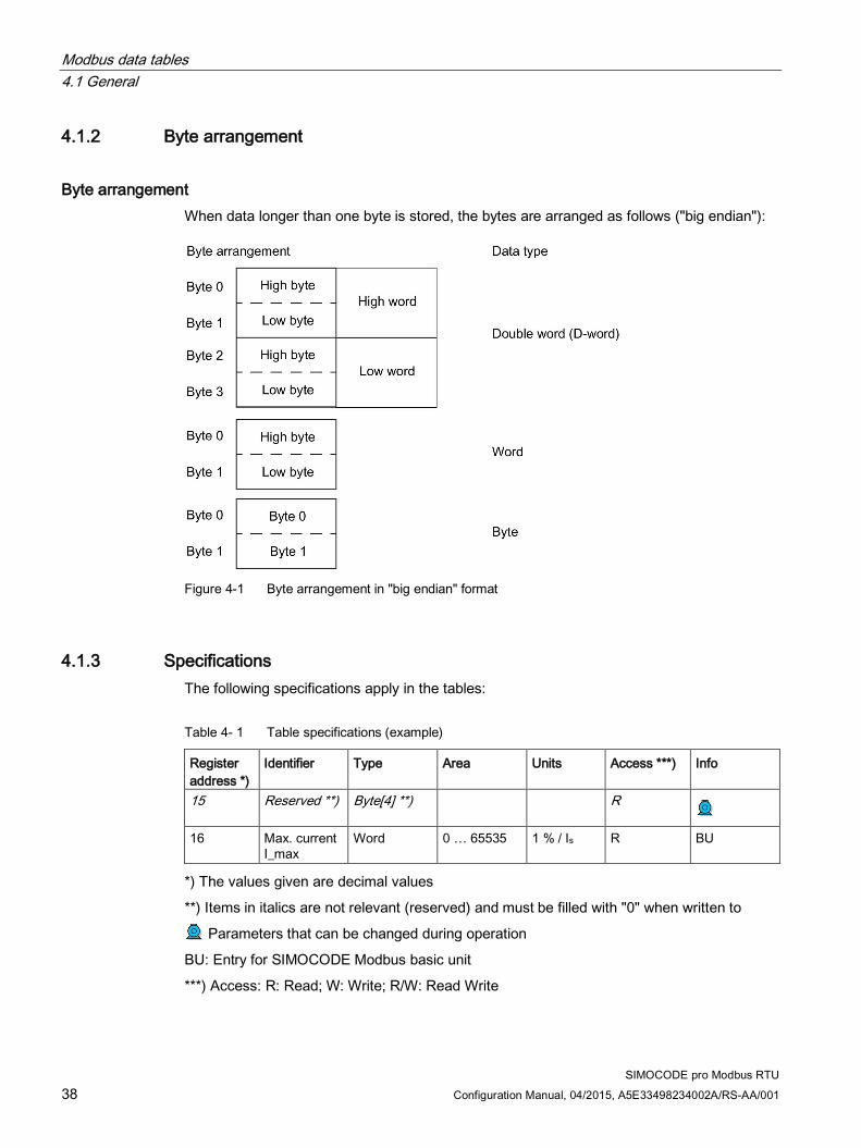
Byte arrangement When data longer than one byte is stored, the bytes are arranged as follows ("big endian"):
Figure 4-1 Byte arrangement in "big endian" format
4.1.3 Specifications The following specifications apply in the tables:
Table 4- 1 Table specifications (example)
Register address *)
Identifier Type Area Units Access ***) Info
15 Reserved **) Byte[4] **) R
16 Max. current I_max
Word 0 … 65535 1 % / Is R BU
*) The values given are decimal values
**) Items in italics are not relevant (reserved) and must be filled with "0" when written to
Parameters that can be changed during operation
BU: Entry for SIMOCODE Modbus basic unit
***) Access: R: Read; W: Write; R/W: Read Write

Modbus data tables 4.2 Process image output - command data
SIMOCODE pro Modbus RTU Configuration Manual, 04/2015, A5E33498234002A/RS-AA/001 39
4.2 Process image output - command data The command data can be written via the register memory area with the function codes 06 and 16, or via the coil memory area with function codes 05 and 15.
Read access is possible from the register memory area with function codes 03 and 04, or the coil memory area with function codes 01 and 02.
Max. data length per access: 2 registers, 16 coils.
Table 4- 2 Process image output - command data
Register address
high/low Coil address
Type Description Default value Access
0x0000 low 0x0000 Bit Cyclic receive - bit 0.0 Control station - PLC/PCS [DP] ON<
r/w
0x0001 Bit Cyclic receive - bit 0.1 Control station - PLC/PCS [DP] OFF
r/w
0x0002 Bit Cyclic receive - bit 0.2 Control station - PLC/PCS [DP] ON>
r/w
0x0003 Bit Cyclic receive - bit 0.3 Test 1 r/w 0x0004 Bit Cyclic receive - bit 0.4 Motor protection emergency start r/w 0x0005 Bit Cyclic receive - bit 0.5 Mode selector S1 r/w 0x0006 Bit Cyclic receive - bit 0.6 Reset 1 r/w 0x0007 Bit Cyclic receive - bit 0.7 Unassigned r/w
high 0x0008 Bit Cyclic receive - bit 1.0 Unassigned r/w 0x0009 Bit Cyclic receive - bit 1.1 Unassigned r/w 0x000A Bit Cyclic receive - bit 1.2 Unassigned r/w 0x000B Bit Cyclic receive - bit 1.3 Unassigned r/w 0x000C Bit Cyclic receive - bit 1.4 Unassigned r/w 0x000D Bit Cyclic receive - bit 1.5 Unassigned r/w 0x000E Bit Cyclic receive - bit 1.6 Unassigned r/w 0x000F Bit Cyclic receive - bit 1.7 Unassigned r/w
0x0001 Word Cyclic receive - Analog value Unassigned r/w

Modbus data tables 4.3 Process image input - monitoring data
SIMOCODE pro Modbus RTU 40 Configuration Manual, 04/2015, A5E33498234002A/RS-AA/001
4.3 Process image input - monitoring data Access to the monitoring data is possible from the register memory area with function codes 03 and 04, or the coil memory area with function codes 01 and 02.
Max. data length per access: 5 registers, 16 coils.
Table 4- 3 Process image input - monitoring data
Register address
high/low Coil address
Type Description Default value Access
0x0400 low 0x0400 Bit Cyclic send - bit 0.0 Status - On< r 0x0401 Bit Cyclic send - bit 0.1 Status - Off r 0x0402 Bit Cyclic send - bit 0.2 Status - On> r 0x0403 Bit Cyclic send - bit 0.3 Event - overload operation r 0x0404 Bit Cyclic send - bit 0.4 Status - Interlocking time
active r
0x0405 Bit Cyclic send - bit 0.5 Status - Remote mode r 0x0406 Bit Cyclic send - bit 0.6 Status - group fault r 0x0407 Bit Cyclic send - bit 0.7 Status - group warning r
high 0x0408 Bit Cyclic send - bit 1.0 Unassigned r 0x0409 Bit Cyclic send - bit 1.1 Unassigned r 0x040A Bit Cyclic send - bit 1.2 Unassigned r 0x040B Bit Cyclic send - bit 1.3 Unassigned r 0x040C Bit Cyclic send - bit 1.4 Unassigned r 0x040D Bit Cyclic send - bit 1.5 Unassigned r 0x040E Bit Cyclic send - bit 1.6 Unassigned r 0x040F Bit Cyclic send - bit 1.7 Unassigned r
0x0401 Word PLC/PCS analog. Input 1 Max. current I_max r 0x0402 Word PLC/PCS analog. Input 2 Unassigned r 0x0403 Word PLC/PCS analog. Input 3 Unassigned r 0x0404 Word PLC/PCS analog. Input 4 Unassigned r

Modbus data tables 4.4 Measured values
SIMOCODE pro Modbus RTU Configuration Manual, 04/2015, A5E33498234002A/RS-AA/001 41
4.4 Measured values Read-only access to the measured values is possible from the register memory area with function codes 03 and 04.
Max. data length per access: 16 registers. Table 4- 4 Measured values
Input/holding register Identifier Type Area Units Access 5) Address offset high/low 0x0800 Reserved Byte[2] r 0x0801 Reserved Byte[2] r 0x0802
high Thermal motor model Byte 0 - 255 See 2) r low Phase unbalance Byte 0 - 100 1 % r
0x0803
high Cos phi Byte 0 - 100 1 % r low Reserved Byte[1] r
0x0804 Reserved Byte[2] r 0x0805 Reserved Byte[2] r 0x0806 Max. current I_max Word 0 - 65535 1 % / Is r 0x0807 Current I_L1 Word 0 - 65535 1 % / Is r 0x0808 Current I_L2 Word 0 - 65535 1 % / Is r 0x0809 Current I_L3 Word 0 - 65535 1 % / Is r 0x080A Last trip current Word 0 - 65535 1 % / Is r 0x080B Time to trip Word 0 - 65535 100 ms r 0x080C Cooling down period Word 0 - 65535 100 ms r 0x080D Voltage U_L1 Word 0 - 65535 1 V r 0x080E Voltage U_L2 Word 0 - 65535 1 V r 0x080F Voltage U_L3 Word 0 - 65535 1 V r 0x0810 AM1 - output Word 0 - 32767 See 1) r 0x0811 AM1 - input 1 Word 0 - 32767 r 0x0812 AM1 - input 2 Word 0 - 32767 r 0x0813 Reserved Word 0 - 32767 r 0x0814 TM1 - Temperature Word 0 - 65535 1 K see 3) r 0x0815 TM1 - temperature 1 Word 0 - 65535 r 0x0816 TM1 - temperature 2 Word 0 - 65535 r 0x0817 TM1 - temperature 3 Word 0 - 65535 r 0x0818 EM+ 4) - ground-fault current Word 0 - 65535 r 0x0819 EM+ 4) - last tripping current Word 0 - 65535 r 0x081A Active power P D word 0 - 0xFFFFFFFF 1 W r 0x081C Apparent power S D word 0 - 0xFFFFFFFF 1 VA r
1) S7 format: 0/4 mA = 0; 20 mA = 27648 2) Representation of the "Thermal motor model": Value related to symmetrical trip level, representation in steps of 2 % in bits 6 ...0 (range 0 to 254 %), bit 7 shows unbalance (fixed level 50 %) 3) Representation in Kelvin 4) 3UF7510-1AA00-0 ground-fault module 5) r/w: Value is read/write; r: Value is read-only

Modbus data tables 4.5 Display and statistical data
SIMOCODE pro Modbus RTU 42 Configuration Manual, 04/2015, A5E33498234002A/RS-AA/001
4.5 Display and statistical data Read access to the display and statistical data is possible both from the register memory area with function codes 03 and 04, or the coil memory area with function codes 01 and 02.
Individual statistical data can be written via the register memory area with function codes 06 and 16, and be reset, for example.
Max. data length per access: 38 registers.
Table 4- 5 Display and statistical data
Input/holding register Description Type Range Unit Access 1) Address high/low 0x0C00 Coordination Byte[4] r 0x0C02
high Permissible starts - actual value Byte 0 .. 255 r/w low DM-F - Time until test
requirement Byte 0 .. 255 1 week r
0x0C03 Reserved Byte[2] r 0x0C04 Number of parameterizations Word 0 .. 65535 r 0x0C05 Number of overload trips Word 0 .. 65535 r/w 0x0C06 Number of internal overload trips Word 0 .. 65535 r 0x0C07 Stop time Word 0 .. 65535 1 h r/w 0x0C08 Timer 1 actual value Word 0 .. 65535 100 ms r 0x0C09 Timer 2 actual value Word 0 .. 65535 100 ms r 0x0C0A Timer 3 actual value Word 0 .. 65535 100 ms r 0x0C0B Timer 4 actual value Word 0 .. 65535 100 ms r 0x0C0C Counter 1 actual value Word 0 .. 65535 r 0x0C0D Counter 2 actual value Word 0 .. 65535 r 0x0C0E Counter 3 actual value Word 0 .. 65535 r 0x0C0F Counter 4 actual value Word 0 .. 65535 r 0x0C10 Calculator 1 output Word 0 .. 65535 r 0x0C11 Calculator 2 output Word 0 .. 65535 r 0x0C12 Reserved Word[2] r 0x0C14 Motor operating hours D word 0 to 0xFFFFFFFF 1 s r/w 0x0C16 Internal motor operating hours D word 0 .. 0xFFFFFFFF 1 s r 0x0C18 Device operating hours D word 0 .. 0xFFFFFFFF 1 s r 0x0C1A Number of starts D word 0 .. 0xFFFFFFFF r/w 0x0C1C Number of internal starts CW D word 0 .. 0xFFFFFFFF r 0x0C1E Number of internal starts CCW D word 0 .. 0xFFFFFFFF r 0x0C20 Energy W D word 0 .. 0xFFFFFFFF 1 kWh r/w
1) r/w: Value is read/write; r: Value is read-only

Modbus data tables 4.6 Device diagnostics
SIMOCODE pro Modbus RTU Configuration Manual, 04/2015, A5E33498234002A/RS-AA/001 43
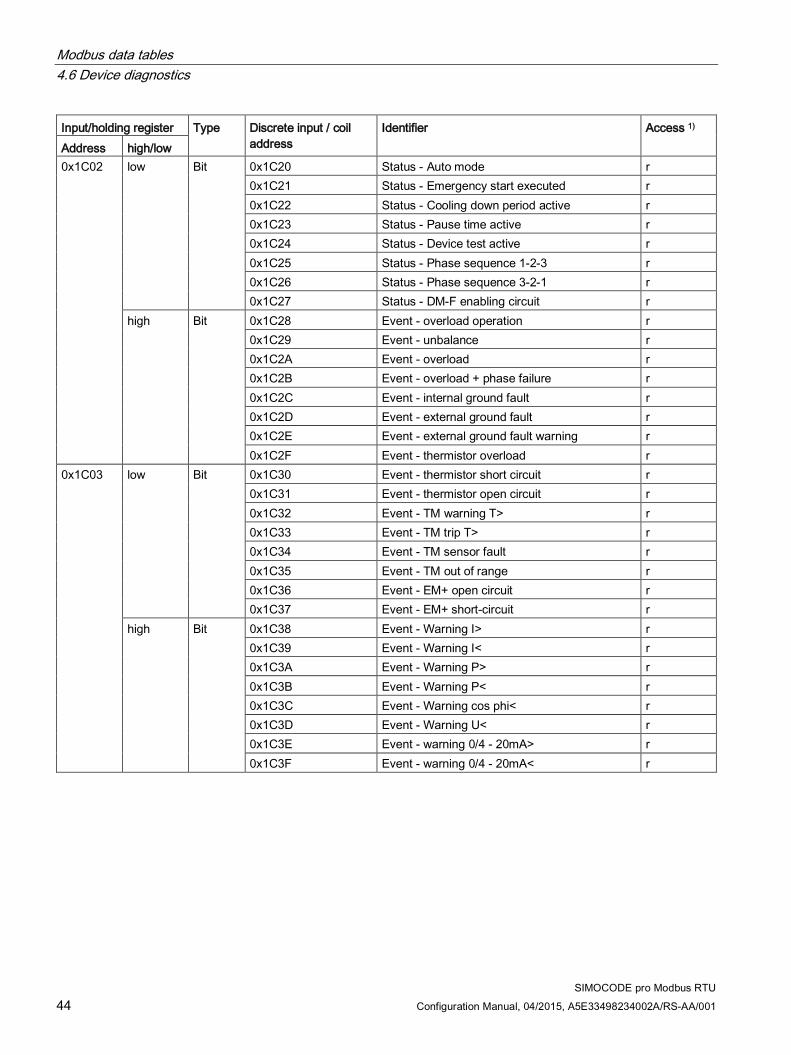
4.6 Device diagnostics Read-only access to the device diagnostics is possible from the register memory area with function codes 03 and 04, or the coil memory area with function codes 01 and 02.
Max. data length per access: 16 registers.
Table 4- 6 Device diagnostics
Input/holding register Type Discrete input / coil address
Identifier Access 1) Address high/low 0x1C00
low Bit 0x1C00 Reserved r 0x1C01 Reserved r 0x1C02 Reserved r 0x1C03 Reserved r 0x1C04 Reserved r 0x1C05 Reserved r 0x1C06 Reserved r 0x1C07 Reserved r
high
Bit 0x1C08 Status - group fault r 0x1C09 Status - group warning r 0x1C0A Status - device r 0x1C0B Status - bus r 0x1C0C Status - PLC/PCS r 0x1C0D Status - current flowing r 0x1C0E Status - PE command Start_Pause pending r 0x1C0F Status - PE energy saving mode active r
0x1C01
low Bit 0x1C10 Status - On<< r 0x1C11 Status - On< r 0x1C12 Status - Off r 0x1C13 Status - On> r 0x1C14 Status - On>> r 0x1C15 Status - start active r 0x1C16 Status - Interlocking time active r 0x1C17 Status - Change-over pause active r
high
Bit 0x1C18 Status - Runs in open direction r 0x1C19 Status - Runs in close direction r 0x1C1A Status - FC r 0x1C1B Status - FO r 0x1C1C Status - TC r 0x1C1D Status - TO r 0x1C1E Status - Cold run TPF r 0x1C1F Status - OPO r
Modbus data tables 4.6 Device diagnostics
SIMOCODE pro Modbus RTU 44 Configuration Manual, 04/2015, A5E33498234002A/RS-AA/001
Input/holding register Type Discrete input / coil address
Identifier Access 1) Address high/low 0x1C02
low Bit 0x1C20 Status - Auto mode r 0x1C21 Status - Emergency start executed r 0x1C22 Status - Cooling down period active r 0x1C23 Status - Pause time active r 0x1C24 Status - Device test active r 0x1C25 Status - Phase sequence 1-2-3 r 0x1C26 Status - Phase sequence 3-2-1 r 0x1C27 Status - DM-F enabling circuit r
high Bit 0x1C28 Event - overload operation r 0x1C29 Event - unbalance r 0x1C2A Event - overload r 0x1C2B Event - overload + phase failure r 0x1C2C Event - internal ground fault r 0x1C2D Event - external ground fault r 0x1C2E Event - external ground fault warning r 0x1C2F Event - thermistor overload r
0x1C03
low Bit 0x1C30 Event - thermistor short circuit r 0x1C31 Event - thermistor open circuit r 0x1C32 Event - TM warning T> r 0x1C33 Event - TM trip T> r 0x1C34 Event - TM sensor fault r 0x1C35 Event - TM out of range r 0x1C36 Event - EM+ open circuit r 0x1C37 Event - EM+ short-circuit r
high Bit 0x1C38 Event - Warning I> r 0x1C39 Event - Warning I< r 0x1C3A Event - Warning P> r 0x1C3B Event - Warning P< r 0x1C3C Event - Warning cos phi< r 0x1C3D Event - Warning U< r 0x1C3E Event - warning 0/4 - 20mA> r 0x1C3F Event - warning 0/4 - 20mA< r

Modbus data tables 4.6 Device diagnostics
SIMOCODE pro Modbus RTU Configuration Manual, 04/2015, A5E33498234002A/RS-AA/001 45
Input/holding register Type Discrete input / coil address
Identifier Access 1) Address high/low 1x1C04
low Bit 0x1C40 Event - Trip I> r 0x1C41 Event - Trip I< r 0x1C42 Event - Trip P> r 0x1C43 Event - Trip P< r 0x1C44 Event - Trip cos phi< r 0x1C45 Event - Trip U< r 0x1C46 Event - Trip 0/4-20 mA> 1 r 0x1C47 Event - Trip 0/4-20 mA< 1 r
high Bit 0x1C48 Event - Stalled rotor r 0x1C49 Reserved bit[1] r 0x1C4A Reserved bit[1] r 0x1C4B Event - no start permitted r 0x1C4C Event - No. of starts > r 0x1C4D Event - Just one start possible r 0x1C4E Event - Motor operating hours > r 0x1C4F Event - Motor stop time > r
0x1C05
low Bit 0x1C50 Event - Limit 1 r 0x1C51 Event - Limit 2 r 0x1C52 Event - Limit 3 r 0x1C53 Event - Limit 4 r 0x1C54 Event - External fault 1 r 0x1C55 Event - External fault 2 r 0x1C56 Event - External fault 3 r 0x1C57 Event - External fault 4 r
high Bit 0x1C58 Event - External fault 5 r 0x1C59 Event - External fault 6 r 0x1C5A Reserved event - External fault 7 r 0x1C5B Reserved event - External fault 8 r 0x1C5C Event - AM1 open circuit r 0x1C5D Event - DM-F safety-related tripping r 0x1C5E Event - DM-F - Test requirement r 0x1C5F Reserved r

Modbus data tables 4.6 Device diagnostics
SIMOCODE pro Modbus RTU 46 Configuration Manual, 04/2015, A5E33498234002A/RS-AA/001
Input/holding register Type Discrete input / coil address
Identifier Access 1) Address high/low 0x1C06
low Bit 0x1C60 Event - timestamp function active + ok r 0x1C61 Reserved r 0x1C62 Event - DM-FL safety ok r 0x1C63 Reserved r 0x1C64 Event - Configured operator panel missing r 0x1C65 Event - Module not supported r 0x1C66 Event - module voltage missing r 0x1C67 Reserved r
high Bit 0x1C68 Event - memory module read in r 0x1C69 Event - memory module programmed r 0x1C6A Event - Memory module erased r 0x1C6B Reserved r 0x1C6C Event - Initialization module read in r 0x1C6D Event - Initialization module programmed r 0x1C6E Event - Initialization module cleared r 0x1C6F Event - Addressing plug read in r
0x1C07
low Bit 0x1C70 Event - startup parameter block active r 0x1C71 Event - parameter changes not allowed in the
current operating state r
0x1C72 Event - Device does not support the required functions
r
0x1C73 Event - Bad parameter r 0x1C74 Event - Password wrong r 0x1C75 Event - Password protection active r 0x1C76 Event - Factory settings r 0x1C77 Event - Parameterization active r
high Bit 0x1C78 Event - Prm error number r 0x1C79 Event - Prm error number r 0x1C7A Event - Prm error number r 0x1C7B Event - Prm error number r 0x1C7C Event - Prm error number r 0x1C7D Event - Prm error number r 0x1C7E Event - Prm error number r 0x1C7F Event - Prm error number r

Modbus data tables 4.6 Device diagnostics
SIMOCODE pro Modbus RTU Configuration Manual, 04/2015, A5E33498234002A/RS-AA/001 47
Input/holding register Type Discrete input / coil address
Identifier Access 1) Address high/low 0x1C08
low Bit 0x1C80 Event - DM-FL configuration operation r 0x1C81 Event - DM-FL actual and set configuration are
different r
0x1C82 Event - DM-FL waiting for start-up test r 0x1C83 Reserved r 0x1C84 Event - initialization module write-protected,
parameter changes not allowed r
0x1C85 Event - memory module write-protected r 0x1C86 Event - initialization module write-protected r 0x1C87 Event - initialization module ident. data write
protected r
high Bit 0x1C88 Warning - overload operation r 0x1C89 Warning - Unbalance r 0x1C8A Warning - Overload r 0x1C8B Warning - Overload + phase failure r 0x1C8C Warning - Internal ground fault r 0x1C8D Warning - external ground fault r 0x1C8E Reserved r 0x1C8F Warning - Thermistor overload r
0x1C09
low Bit 0x1C90 Warning - Thermistor short circuit r 0x1C91 Warning - Thermistor open circuit r 0x1C92 Warning - TM1 warning T > r 0x1C93 Reserved r 0x1C94 Warning - TM1 sensor fault r 0x1C95 Warning - TM1 out of range r 0x1C96 Warning - EM+ open circuit r 0x1C97 Warning - EM+ short circuit r
high Bit 0x1C98 Warning - Warning I> r 0x1C99 Warning - Warning I< r 0x1C9A Warning - Warning P> r 0x1C9B Warning - Warning P< r 0x1C9C Warning - Warning cos phi< r 0x1C9D Warning - Warning U< r 0x1C9E Warning - Warning 0/4 - 20mA> r 0x1C9F Warning - Warning 0/4 - 20mA< r

Modbus data tables 4.6 Device diagnostics
SIMOCODE pro Modbus RTU 48 Configuration Manual, 04/2015, A5E33498234002A/RS-AA/001
Input/holding register Type Discrete input / coil address
Identifier Access 1) Address high/low 0x1C0A
low Bit 0x1CA0 Warning - Stalled rotor r 0x1CA1 Reserved r 0x1CA2 Reserved r 0x1CA3 Warning - No start possible r 0x1CA4 Warning - Number of starts > r 0x1CA5 Warning - Just one start possible r 0x1CA6 Warning - Motor operating hours> r 0x1CA7 Warning - Motor stop time > r
high Bit 0x1CA8 Warning - External fault 1 r 0x1CA9 Warning - External fault 2 r 0x1CAA Warning - External fault 3 r 0x1CAB Warning - External fault 4 r 0x1CAC Warning - External fault 5 r 0x1CAD Warning - External fault 6 r 0x1CAE Reserved warning - External fault 7 r 0x1CAF Reserved warning - External fault 8 r
0x1C0B
low Bit 0x1CB0 Warning - AM1 open circuit r 0x1CB1 Warning - DM-F safety-related tripping r 0x1CB2 Warning - DM-F test requirement r 0x1CB3 Reserved r 0x1CB4 Reserved r 0x1CB5 Reserved r 0x1CB6 Warning - DM-F feedback circuit r 0x1CB7 Warning - DM-FL simultaneity r
high Bit 0x1CB8 Fault - hardware fault basic unit r 0x1CB9 Fault - Module fault r 0x1CBA Fault - Temporary components r 0x1CBB Fault - configuration error r 0x1CBC Fault - Parameterization r 0x1CBD Fault - bus r 0x1CBE Fault - PLC/PCS r 0x1CBF Reserved r

Modbus data tables 4.6 Device diagnostics
SIMOCODE pro Modbus RTU Configuration Manual, 04/2015, A5E33498234002A/RS-AA/001 49
Input/holding register Type Discrete input / coil address
Identifier Access 1) Address high/low 0x1C0C
low Bit 0x1CC0 Fault - execution ON command r 0x1CC1 Fault - execution STOP command r 0x1CC2 Fault - feedback (FB) ON r 0x1CC3 Fault - feedback (FB) OFF r 0x1CC4 Fault - stalled positioner r 0x1CC5 Fault - double 0 r 0x1CC6 Fault - double 1 r 0x1CC7 Fault - end position r
high Bit 0x1CC8 Fault - antivalence r 0x1CC9 Fault - Cold run (TPF) error r 0x1CCA Fault - power failure (UVO) r 0x1CCB Fault - Operational Protection Off (OPO) r 0x1CCC Reserved r 0x1CCD Reserved r 0x1CCE Reserved r 0x1CCF Reserved r
0x1C0D
low Bit 0x1CD0 Reserved r 0x1CD1 Fault - unbalance r 0x1CD2 Fault - overload r 0x1CD3 Fault - overload + phase failure r 0x1CD4 Fault - int. ground fault r 0x1CD5 Fault - ext. ground fault r 0x1CD6 Reserved r 0x1CD7 Fault - thermistor overload r
high Bit 0x1CD8 Fault - thermistor short circuit r 0x1CD9 Fault - thermistor open circuit r 0x1CDA Reserved r 0x1CDB Trip - TM1 trip T> r 0x1CDC Trip - TM1 sensor fault r 0x1CDD Trip - TM1 out of range r 0x1CDE Fault - EM+ open circuit r 0x1CDF Fault - EM+ short circuit r

Modbus data tables 4.6 Device diagnostics
SIMOCODE pro Modbus RTU 50 Configuration Manual, 04/2015, A5E33498234002A/RS-AA/001
Input/holding register Type Discrete input / coil address
Identifier Access 1) Address high/low 0x1C0E
low Bit 0x1CE0 Fault - trip I> r 0x1CE1 Fault - trip I< r 0x1CE2 Fault - trip P> r 0x1CE3 Fault - trip P< r 0x1CE4 Fault - trip cos phi< r 0x1CE5 Fault - trip U< r 0x1CE6 Fault - Trip 0/4 - 20mA>
r
0x1CE7 Fault - Trip 0/4 - 20mA< r high Bit 0x1CE8 Fault - stalled rotor r
0x1CE9 Reserved r 0x1CEA Reserved r 0x1CEB Reserved r 0x1CEC Fault - Number of starts > r 0x1CED Reserved r 0x1CEE Reserved r 0x1CEF Reserved r
0x1C0F
low Bit 0x1CF0 Fault - External fault 1 r 0x1CF1 Fault - External fault 2 r 0x1CF2 Fault - External fault 3 r 0x1CF3 Fault - External fault 4 r 0x1CF4 Fault - External fault 5 r 0x1CF5 Fault - External fault 6 r 0x1CF6 Reserved fault - External fault 7 r 0x1CF7 Reserved fault - External fault 8 r
high Bit 0x1CF8 Fault - AM1 open circuit r 0x1CF9 Fault - test trip r 0x1CFA Fault - DM-F safety-related tripping r 0x1CFB Fault - DM-F wiring r 0x1CFC Fault - DM-FL cross circuit r 0x1CFD Reserved r 0x1CFE Reserved r 0x1CFF Reserved r
1) r/w: Value is read/write; r: Value is read-only
Modbus data tables 4.7 Error memory
SIMOCODE pro Modbus RTU Configuration Manual, 04/2015, A5E33498234002A/RS-AA/001 51
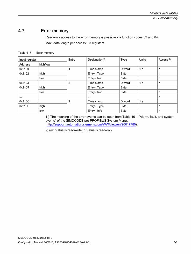
4.7 Error memory Read-only access to the error memory is possible via function codes 03 and 04 .
Max. data length per access: 63 registers.
Table 4- 7 Error memory
Input register Entry Designation1) Type Units Access 2) Address high/low 0x2100 1 Time stamp D word 1 s r 0x2102
high Entry - Type Byte r low Entry - Info Byte r
0x2103 2 Time stamp D word 1 s r 0x2105
high Entry - Type Byte r low Entry - Info Byte r
... ... r 0x213C 21 Time stamp D word 1 s r 0x213E
high Entry - Type Byte r low Entry - Info Byte r
1 ) The meaning of the error events can be seen from Table 16-1 "Alarm, fault, and system events" of the SIMOCODE pro PROFIBUS System Manual (http://support.automation.siemens.com/WW/view/en/20017780).
2) r/w: Value is read/write; r: Value is read-only
Modbus data tables 4.8 Event memory
SIMOCODE pro Modbus RTU 52 Configuration Manual, 04/2015, A5E33498234002A/RS-AA/001
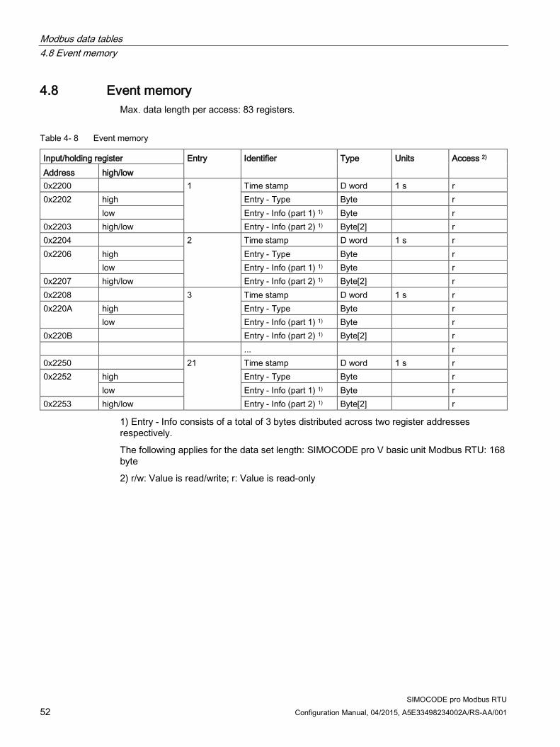
4.8 Event memory Max. data length per access: 83 registers.
Table 4- 8 Event memory
Input/holding register Entry Identifier Type Units Access 2) Address high/low 0x2200 1
Time stamp D word 1 s r
0x2202
high Entry - Type Byte r low Entry - Info (part 1) 1) Byte r
0x2203 high/low Entry - Info (part 2) 1) Byte[2] r 0x2204 2 Time stamp D word 1 s r 0x2206
high Entry - Type Byte r low Entry - Info (part 1) 1) Byte r
0x2207 high/low Entry - Info (part 2) 1) Byte[2] r 0x2208 3 Time stamp D word 1 s r 0x220A
high Entry - Type Byte r low Entry - Info (part 1) 1) Byte r
0x220B Entry - Info (part 2) 1) Byte[2] r ... r 0x2250 21 Time stamp D word 1 s r 0x2252
high Entry - Type Byte r low Entry - Info (part 1) 1) Byte r
0x2253 high/low Entry - Info (part 2) 1) Byte[2] r
1) Entry - Info consists of a total of 3 bytes distributed across two register addresses respectively.
The following applies for the data set length: SIMOCODE pro V basic unit Modbus RTU: 168 byte
2) r/w: Value is read/write; r: Value is read-only

Modbus data tables 4.9 Trace data
SIMOCODE pro Modbus RTU Configuration Manual, 04/2015, A5E33498234002A/RS-AA/001 53
4.9 Trace data Max. data length per access: 100 registers.
Table 4- 9 Trace data
Input/holding register Identifier Type Area Access 1) Address high/low byte;
bit position Bit
0x2A80 StartPos Word 0 r 0x2A81
high Channel No. Byte 0 ... 59 r low 0 Trace status - Trace
recording in progress Bit 0, 1 r
1 Trace status - Trigger event occurred
Bit 0, 1 r
2-7 Reserved Bit[6]
0 r
0x2A82 Measured value (0) Word 0 ... 65535 r 0x2A83 Measured value (1) Word 0 ... 65535 r ... ... Word 0 ... 65535 r 0x2ABD Measured value (59) Word 0 ... 65535 r
1) r/w: Value is read/write; r: Value is read-only

Modbus data tables 4.10 I&M0 - device identification
SIMOCODE pro Modbus RTU 54 Configuration Manual, 04/2015, A5E33498234002A/RS-AA/001
4.10 I&M0 - device identification Max. data length per access: 32 registers.
Table 4- 10 I&M (device identification)
Input register Content Size Coding (H) Access 1) Address 0x4000 RESERVED 10 byte 0x00, ... 0x00 r 0x4005 MANUFACTURER_ID 2 bytes 42 = 0x002A (SIEMENS AG) r 0x4006 ORDER_ID 20 byte "3UF7 ..." r 0x4010 SERIAL_NUMBER 16 byte ASCII r 0x4018 HARDWARE_REVISION 2 bytes r 0x4019 SOFTWARE_REVISION 4 byte Va.b.c r 0x401B REVISION_COUNTER 2 bytes 0x0000 r 0x401C PROFILE_ID 2 bytes 0x5E10 = VA, GG3 = 0 r 0x401D PROFILE_SPECIFIC_TYPE 2 bytes 0x1039 = GG2_MBR r 0x401E IM_VERSION 2 bytes 0x0101 (V1.1) r 0x401F IM_SUPPORTED 2 bytes 0x000E r
Data set length: 64 bytes
1) r/w: Value is read/write; r: Value is read-only

Modbus data tables 4.11 I&M1 - Tag
SIMOCODE pro Modbus RTU Configuration Manual, 04/2015, A5E33498234002A/RS-AA/001 55
4.11 I&M1 - Tag Max. data length per access: 32 registers.
Table 4- 11 I&M1 - Tag
Input/holding register Content Size Access 1) Address 0x4020 Reserved 10 byte r 0x4025 Plant identifier 32 byte r/w 0x4035 ... 0x403F Location designation 22 byte r/w
Access to these designations via Modbus: read/write
1) r/w: Value is read/write; r: Value is read-only

Modbus data tables 4.12 I&M2 - Installation date
SIMOCODE pro Modbus RTU 56 Configuration Manual, 04/2015, A5E33498234002A/RS-AA/001
4.12 I&M2 - Installation date Max. data length per access: 32 registers.
Table 4- 12 I&M2 - Installation date
Input/holding register Content Size Access 1) Address 0x4040 Reserved 10 byte r 0x4045 Date 16 byte r/w
1) Access to the installation date via Modbus: read/write

Modbus data tables 4.13 I&M3 - Comment
SIMOCODE pro Modbus RTU Configuration Manual, 04/2015, A5E33498234002A/RS-AA/001 57
4.13 I&M3 - Comment Max. data length per access: 32 registers.
Table 4- 13 I&M3 - Comment
Input/holding register Content Size Access 1) Address 0x4060 Reserved 10 byte r 0x4065 ... 0x407F Comments 54 byte r/w
1) Access to the comment via Modbus: read/write

Modbus data tables 4.14 Basic device parameter 1
SIMOCODE pro Modbus RTU 58 Configuration Manual, 04/2015, A5E33498234002A/RS-AA/001
4.14 Basic device parameter 1 Read access to the device parameters is possible from the register memory area with function codes 03 and 04.
Individual parameter data (marked with the motor symbol in the "Info" column) can be written via Modbus RTU via the register memory area with function codes 06 and 16. This function can be used to adjust settings such as the rated motor current during operation of the motor.
Max. dataset length per access: 46 registers.
Nevertheless, the "SIMOCODE ES V13" software is required for full parameterization of the SIMOCODE pro V Modbus devices (see also Section Commissioning with Modbus RTU (Page 14)).
Table 4- 14 Basic device parameter 1
Input/holding register Description Type Range Unit Default Comments Info Access 1) Address high/
low Bit
0x4180 Coordination Byte[4] r 0x4182 Device configuration Byte[8] r 0x4186
high 0 No configuration fault due to OP
Bit 0, 1 0 r
1 Startup parameter block active
Bit 0, 1 0 r
2 TEST/RESET buttons blocked
Bit 0, 1 0 r
3 Bus and PLC/PCS - Reset
Bit 0, 1 0 0 = Manual 1 = Auto
r
4 Reserved Bit 0 r 5 Reserved Bit 0 r 6 Reserved Bit 0 r 7 Reserved Bit 0 r
low 0 Diagnostics for process events
Bit 0, 1 0 r
1 Diagnostics for process warnings
Bit 0, 1 1 r
2 Diagnostics for process faults
Bit 0, 1 1 r
3 Diagnostics for device faults
Bit 0, 1 1 r
4 Reserved Bit 0 r 5 Reserved Bit 0 r 6 Bus monitoring Bit 0, 1 1 r 7 PLC/PCS monitoring Bit 0, 1 1 r

Modbus data tables 4.14 Basic device parameter 1
SIMOCODE pro Modbus RTU Configuration Manual, 04/2015, A5E33498234002A/RS-AA/001 59
Input/holding register Description Type Range Unit Default Comments Info Access 1) Address high/
low Bit
0x4187 high 0 Motor protection - Type of load
Bit 0, 1 0 0 = 3-phase 1 = 1-phase
r
1 Motor protection - Reset Bit 0, 1 0 0 = Manual 1 = Auto
r
2 Reserved Bit 0 r 3 Save change-over
command Bit 0, 1 0 r
4 Non-maintained command mode
Bit 0, 1 0 r
5 Cold start level (TPF) Bit 0, 1 0 0 = NO contact 1 = NC contact
r
6 Type of consumer load Bit 0, 1 0 0 = Motor 1 = ohmic load
r
7 Reserved Bit 0 r low 0 External fault level 1 Bit 0, 1 0 0 = NO contact
1 = NC contact r
1 External fault level 2 Bit 0, 1 0 r 2 External fault level 3 Bit 0, 1 0 r 3 External fault level 4 Bit 0, 1 0 r 4 Monitoring external
fault 1 Bit 0, 1 0 0 = Always
1 = Only motor ON
r
5 Monitoring external fault 2
Bit 0, 1 0 r
6 Monitoring external fault 3
Bit 0, 1 0 r
7 Monitoring external fault 4
Bit 0, 1 0 r

Modbus data tables 4.14 Basic device parameter 1
SIMOCODE pro Modbus RTU 60 Configuration Manual, 04/2015, A5E33498234002A/RS-AA/001
Input/holding register Description Type Range Unit Default Comments Info Access 1) Address high/
low Bit
Part - Bit[2] parameter 0x4188 high 0-1 Thermistor - Overload
response Bit[2] 1, 2, 3 3 0 = disabled
1 = Signaling 2 = Warning 3 = Tripping
r
2-3 Thermistor - Response to sensor fault
Bit[2] 0, 1, 2, 3
2 r
4-5 Internal ground fault - Response
Bit[2] 0, 1, 2, 3
0 r
6-7 Motor protection - Overload response
Bit[2] 0, 1, 2, 3
0 r
low 0-1 Motor protection - Overload response
Bit[2] 0, 1, 2 2 r
2-3 Motor protection - Response to unbalance
Bit[2] 0, 1, 2, 3
2 r
4-5 Trip response I> Bit[2] 0, 1, 3 0 r 6-7 Warning response I> Bit[2] 0, 1, 2 0 r
0x4189 high 0-1 Trip response I< Bit[2] 0, 1, 3 0 r 2-3 Warning response I< Bit[2] 0, 1, 2 0 r 4-5 Response to stalled
rotor Bit[2] 0, 1, 2,
3 0 r
6-7 EM+ - Response to sensor fault
Bit[2] 0, 1, 2, 3
0 r
low 0-1 Response to number of starts >
Bit[2] 0, 1, 2, 3
0 r
2-3 Response to early warning number of starts >
Bit[2] 0, 1, 2 0 r
4-5 Motor operating hours response >
Bit[2] 0, 1, 2 0 r
6-7 Motor stop time response >
Bit[2] 0, 1, 2 0 r

Modbus data tables 4.14 Basic device parameter 1
SIMOCODE pro Modbus RTU Configuration Manual, 04/2015, A5E33498234002A/RS-AA/001 61
Input/holding register Description Type Range Unit Default Comments Info Access 1) Address high/
low Bit
0x418A high 0-1 External fault response 1
Bit[2] 1, 2, 3 1 r
2-3 External fault response 2
Bit[2] 1, 2, 3 1 r
4-5 External fault response 3
Bit[2] 1, 2, 3 1 r
6-7 External fault response 4
Bit[2] 1, 2, 3 1 r
low 0-1 Reserved Bit[2] 0 r 2-3 Delay for BU inputs Bit[2] 0 ... 3 10 ms 1 Offset 6 ms r 4-5 Timer 1 - type Bit[2] 0, 1, 2,
3 0 0 = With
closing delay 1 = Closing delay with memory 2 = With OFF delay 3 = With fleeting closing
r
6-7 Timer 2 - type Bit[2] 0, 1, 2, 3
0 r
0x418B high 0-1 Signal conditioning 1 - type
Bit[2] 0, 1, 2, 3
0 0 = Non-inverting 1 = Inverting 2 = Edge rising with memory 3 = Edge falling with memory
r
2-3 Signal conditioning 2 - type
Bit[2] 0, 1, 2, 3
0 r
4-5 Non-volatile element 1 - type
Bit[2] 0, 1, 2, 3
0 r
6-7 Non-volatile element 2 - type
Bit[2] 0, 1, 2, 3
0 r
low 0-1 EM+ - monitoring Bit[2] 0, 1, 2, 3
0 0 = on 1 = on+ 2 = run 3 = run+
r
2-3 EM+ - monitoring warning
Bit[2] 0, 1, 2, 3
0 r
4-5 Reserved Bit[2] 0 r 6-7 Reserved Bit[2] 0 r

Modbus data tables 4.14 Basic device parameter 1
SIMOCODE pro Modbus RTU 62 Configuration Manual, 04/2015, A5E33498234002A/RS-AA/001
Input/holding register Description Type Range Unit Default Comments Info Access 1) Address high/
low Bit
Part - Bit[4] parameters r 0x418C high Reset response external
fault 1 Bit[4] 0 ...
1111B 0101B Bit[0] = Panel
reset Bit[1] = Auto reset Bit[2] =Remote reset Bit[1] = OFF command reset
r
Reset response external fault 2
Bit[4] 0 ... 1111B
0101B r
low Reset response external fault 3
Bit[4] 0 ... 1111B
0101B r
Reset response external fault 4
Bit[4] 0 ... 1111B
0101B r
0x418D high 0-3 Hysteresis current levels Bit[4] 0 ... 15 1 % 5 r 4-7 EM+ - hysteresis Bit[4] 0 ... 15 1 % 5 r
low Reserved Bit[4] 0 r Reserved Bit[4] 0 r
Part - Byte parameters 0x418E
high Internal ground fault - Delay
Byte 0 ... 255 100 ms 5 IM/UM
r/w
low Motor protection - Class Byte 5, 10 ... 35, 40
10
r/w
0x418F
high Motor protection - Delay with overload operation
Byte 0 ... 255 100 ms 5 IM/UM
r/w
low Motor protection - Unbalance level
Byte 0 ... 100 1 % 40 IM/UM
r/w
0x4190
high Motor protection - Delay with unbalance
Byte 0 ... 255 100 ms 5 IM/UM
r/w
low Interlocking time Byte 0 ... 255 1 s 0
r/w
0x4191
high FB time Byte 0 ... 255 100 ms 5 0 = disabled
r/w
low Trip level I> Byte 0 ... 255 4 % / I_s
0 IM/UM
r/w

Modbus data tables 4.14 Basic device parameter 1
SIMOCODE pro Modbus RTU Configuration Manual, 04/2015, A5E33498234002A/RS-AA/001 63
Input/holding register Description Type Range Unit Default Comments Info Access 1) Address high/
low Bit
0x4192
high Warning level I> Byte 0 ... 255 4 % / I_s
0 IM/UM
r/w
low Trip level I< Byte 0 ... 255 4 % / I_s
0 IM/UM
r/w
0x4193
high Warning level I< Byte 0 ... 255 4 % / I_s
0 IM/UM
r/w
low Stalled rotor level Byte 0 ... 255 4 % / I_s
0 IM/UM
r/w
0x4194
high Trip delay I> Byte 0 ... 255 100 ms 5 IM/UM
r/w
low Warning delay I> Byte 0 ... 255 100 ms 5 IM/UM
r/w
0x4195
high Trip delay I< Byte 0 ... 255 100 ms 5 IM/UM
r/w
low Warning delay I< Byte 0 ... 255 100 ms 5 IM/UM
r/w
0x4196
high Blocking delay Byte 0 ... 255 100 ms 5 IM/UM
r/w
low Monitoring the number of starts - Permissible starts
Byte 1 ... 255 1
r/w
0x4197
high Reserved Byte 0 low EM+ - warning delay Byte 0 ... 255 100 ms 1
r/w
0x4198
high Truth table 1 type 3I/1O Byte 0 ...11111111B
0 r
low Truth table 2 type 3I/1O Byte 0 ...11111111B
0 r
0x4199
high Truth table 3 type 3I/1O Byte 0 ...11111111B
0 r
low Reserved Byte 0 r

Modbus data tables 4.14 Basic device parameter 1
SIMOCODE pro Modbus RTU 64 Configuration Manual, 04/2015, A5E33498234002A/RS-AA/001
Input/holding register Description Type Range Unit Default Comments Info Access 1) Address high/
low Bit
Part - Word parameters 0x419A Motor protection -
Cooling down period Word 600 ...
65535 100 ms 3000 IM/UM
r/w
0x419B Motor protection - Pause time
Word 0 ... 65535
100 ms 0 0 = disabled IM/UM
r/w
0x419C Validity period Word 0 ... 65535
100 ms 10 0 = disabled
r/w
0x419D Monitoring the number of starts - Time range for starts
Word 0 ... 65535
1 s 0
r/w
0x419E Monitoring the number of starts - Interlocking time
Word 0 ... 65535
1 s 0
r/w
0x419F Motor stop time level > Word 0 ... 65535
1 h 0
r/w
0x41A0 Timer 1 value Word 0 ... 65535
100 ms 0
r/w
0x41A1 Timer 2 value Word 0 ... 65535
100 ms 0
r/w
0x41A2 Counter 1 value Word 0 ... 65535
0
r/w
0x41A3 Counter 2 value Word 0 ... 65535
0
r/w
0x41A4 EM+ - trip level Word 30 ... 40000
1 mA 1000
r/w
0x41A5 EM+ - warning level Word 30 ... 40000
1 mA 500
r/w
Part - D word parameter 0x41A6 Operator control
enables Bit[32] 0 ...
1 ... 1B 0 ... 0B r
0x41A8 Motor protection - Set current Is1 2)
D word 10 mA 30 IM/UM
r/w
0x41AA Motor operating hours level >
D word 0 ... 0xFFFFFFFF
1 s 0
r/w
0x41AC Reserved D word 0 r
1) r/w: Value is read/write; r: Value is read-only
2) Bit 15 = 1 → Transformation ratio active
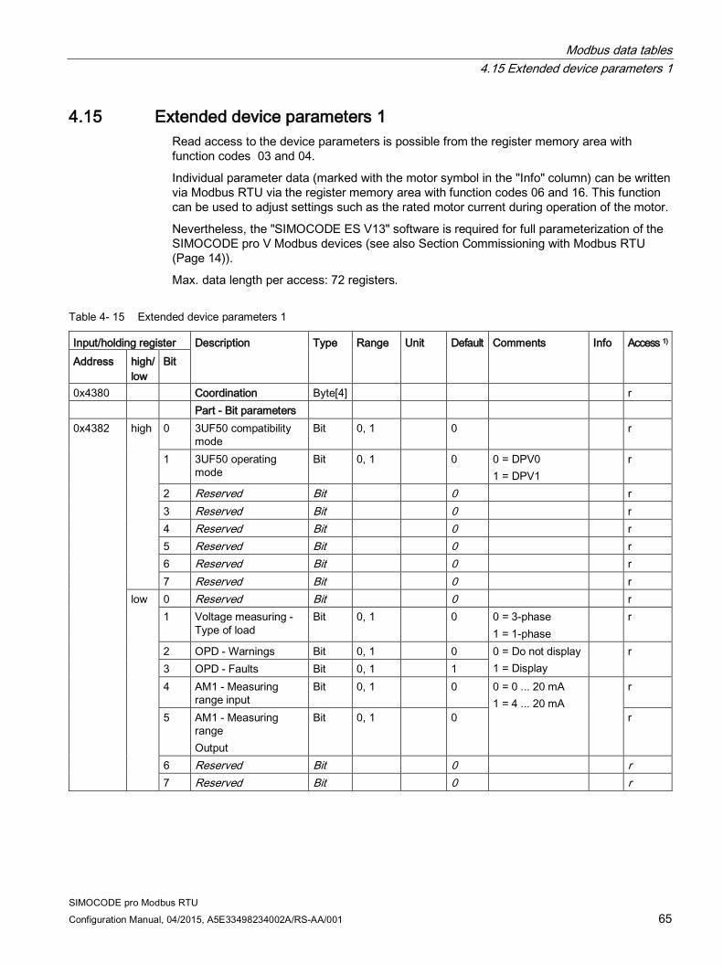
Modbus data tables 4.15 Extended device parameters 1
SIMOCODE pro Modbus RTU Configuration Manual, 04/2015, A5E33498234002A/RS-AA/001 65
4.15 Extended device parameters 1 Read access to the device parameters is possible from the register memory area with function codes 03 and 04.
Individual parameter data (marked with the motor symbol in the "Info" column) can be written via Modbus RTU via the register memory area with function codes 06 and 16. This function can be used to adjust settings such as the rated motor current during operation of the motor.
Nevertheless, the "SIMOCODE ES V13" software is required for full parameterization of the SIMOCODE pro V Modbus devices (see also Section Commissioning with Modbus RTU (Page 14)).
Max. data length per access: 72 registers.
Table 4- 15 Extended device parameters 1
Input/holding register Description Type Range Unit Default Comments Info Access 1) Address high/
low Bit
0x4380 Coordination Byte[4] r Part - Bit parameters 0x4382 high 0 3UF50 compatibility
mode Bit 0, 1 0 r
1 3UF50 operating mode
Bit 0, 1 0 0 = DPV0 1 = DPV1
r
2 Reserved Bit 0 r 3 Reserved Bit 0 r 4 Reserved Bit 0 r 5 Reserved Bit 0 r 6 Reserved Bit 0 r 7 Reserved Bit 0 r
low 0 Reserved Bit 0 r 1 Voltage measuring -
Type of load Bit 0, 1 0 0 = 3-phase
1 = 1-phase r
2 OPD - Warnings Bit 0, 1 0 0 = Do not display 1 = Display
r 3 OPD - Faults Bit 0, 1 1 4 AM1 - Measuring
range input Bit 0, 1 0 0 = 0 ... 20 mA
1 = 4 ... 20 mA r
5 AM1 - Measuring range Output
Bit 0, 1 0 r
6 Reserved Bit 0 r 7 Reserved Bit 0 r

Modbus data tables 4.15 Extended device parameters 1
SIMOCODE pro Modbus RTU 66 Configuration Manual, 04/2015, A5E33498234002A/RS-AA/001
Input/holding register Description Type Range Unit Default Comments Info Access 1) Address high/
low Bit
0x4383 high 0 Overshooting/ undershooting limit 1
Bit 0, 1 0 0 = > (overshooting) 1 = < (undershooting)
r
1 Overshooting/ undershooting limit 2
Bit 0, 1 0 r
2 Overshooting/ undershooting limit 3
Bit 0, 1 0 r
3 Overshooting/ undershooting limit 4
Bit 0, 1 0 r
4 Line-to-line voltage Bit 0, 1 0 0 = No 1 = Yes
r
5 OPO level Bit 0, 1 0 0 = NO contact 1 = NC contact
r
6 Positioner response for OPO
Bit 0, 1 0 0 = CLOSED 1 = OPEN
r
7 Star-delta - Transformer mounting
Bit 0, 1 0 0 = Delta 1 = In supply cable
r
low 0 External fault level 5 Bit 0, 1 0 0 = NO contact 1 = NC contact
r 1 External fault level 6 Bit 0, 1 0 r 2 Reserved Bit 0 r 3 Reserved Bit 0 r 4 Monitoring external
fault 5 Bit 0, 1 0 0 = Always
1 = Only motor ON r
5 Monitoring external fault 5
Bit 0, 1 0 r
6 Reserved Bit 0, 1 0 r 7 Reserved Bit 0, 1 0 r

Modbus data tables 4.15 Extended device parameters 1
SIMOCODE pro Modbus RTU Configuration Manual, 04/2015, A5E33498234002A/RS-AA/001 67
Input/holding register Description Type Range Unit Default Comments Info Access 1) Address high/
low Bit
0x4384 high 0 Calculator 2 - Operating mode
Bit 0, 1 0 0 = Word 1 = D word
r
1 Reserved Bit 0 r 2 DM-F - Safe tripping
function Bit 0, 1 0 0 = No
1 = Yes r
3 DM-F - Safety-related tripping reset
Bit 0, 1 0 0 = Manual 1 = Auto
r
4 Time stamping active Bit 0, 1 0 r 5 Reserved Bit 0 r 6 Reserved Bit 0 r 7 Reserved Bit 0 r
low
0 DM-FL - Configuration 1
Bit 0, 1 0 Configurable parameters comparable with the module configuration
r
1 DM-FL - Configuration 2
Bit 0, 1 0 r
2 DM-FL - Configuration 3
Bit 0, 1 0 r
3 DM-FL - Configuration 4
Bit 0, 1 0 r
4 DM-FL - Configuration 5
Bit 0, 1 0 r
5 DM-FL - Configuration 6
Bit 0, 1 0 r
6 DM-FL - Configuration 7
Bit 0, 1 0 r
7 DM-FL - Configuration 8
Bit 0, 1 0 r

Modbus data tables 4.15 Extended device parameters 1
SIMOCODE pro Modbus RTU 68 Configuration Manual, 04/2015, A5E33498234002A/RS-AA/001
Input/holding register Description Type Range Unit Default Comments Info Access 1) Address high/
low Bit
Part - Bit[2] parameter r 0x4385 high 0-1 3UF50 basic type Bit[2] 0, 1, 2 0 r
2-3 Reserved Bit[2] 0 r 4-5 UVO timebase Bit[2] 0, 1, 2 0 0 = 100 ms
1 = 1 s 2 = 10 s
r
6-7 UVO operating mode Bit[2] 0, 1, 2 0 0 = disabled 1 = Device connected to voltage (reserved) 2 = Voltage fails
r
low 0-1 Trip monitoring U< Bit[2] 0, 1, 2 1 0 = ON (always) 1 = ON+ (always, not TPF) 2 = RUN (motor ON, not TPF)
r 2-3 Warning monito-
ring U < Bit[2] 0, 1, 2 1 r
4-5 Reserved Bit[2] 0 r 6-7 Reserved Bit[2] 0 r
0x4386 high 0-1 Trip monitoring 0/4-20mA >
Bit[2] 0, 1, 2, 3
0 r
2-3 Warning monitoring 0/4-20mA >
Bit[2] 0, 1, 2, 3
0 r
4-5 Trip monitoring 0/4-20mA <
Bit[2] 0, 1, 2, 3
0 r
6-7 Warning monitoring 0/4-20mA <
Bit[2] 0, 1, 2, 3
0 r
low 0-1 Monitoring limit 1 Bit[2] 0, 1, 2, 3
0 r
2-3 Monitoring limit 2 Bit[2] 0, 1, 2, 3
0 r
4-5 Monitoring limit 3 Bit[2] 0, 1, 2, 3
0 r
6-7 Monitoring limit 4 Bit[2] 0, 1, 2, 3
0 r

Modbus data tables 4.15 Extended device parameters 1
SIMOCODE pro Modbus RTU Configuration Manual, 04/2015, A5E33498234002A/RS-AA/001 69
Input/holding register Description Type Range Unit Default Comments Info Access 1) Address high/
low Bit
0x4387 high 0-1 Reserved Bit[2] 0 r 2-3 Reserved Bit[2] 0 r 4-5 Reserved Bit[2] 0 r 6-7 AM1 - active inputs Bit[2] 0, 1, 2 0 0 = 1 input
1 = 2 inputs 2 = 3 inputs
r
low 0-1 DM - Input delay Bit[2] 0 ... 3 10 ms 1 Offset 6 ms r 2-3 AM1 - Response to
open circuit Bit[2] 1, 2, 3 2 0 = disabled
1 = Signaling 2 = Warning 3 = Tripping
r
4-5 EM - response to an external ground fault
Bit[2] 1, 3 1 r
6-7 EM - response to warning of an external ground fault
Bit[2] 0, 1, 2 0 r
0x4388 high 0-1 Reserved Bit[2] 0 r 2-3 Reserved Bit[2] 0 r 4-5 DM-F - Test
requirement response Bit[2] 0, 1, 2 0 r
6-7 DM-F - safety-related tripping response
Bit[2] 0, 1, 2, 3
0 r
low 0-1 TM1 - Trip response T>
Bit[2] 1, 3 3 r
2-3 TM1 - Warning response T>
Bit[2] 0, 1, 2 2 r
4-5 TM1 - Response to a sensor fault / out of range
Bit[2] 0, 1, 2, 3
2 r
6-7 TM1 - active sensors Bit[2] 0, 1, 2 2*) 0 = 1 sensors 1 = 2 sensors 2 = 3 sensors
r

Modbus data tables 4.15 Extended device parameters 1
SIMOCODE pro Modbus RTU 70 Configuration Manual, 04/2015, A5E33498234002A/RS-AA/001
Input/holding register Description Type Range Unit Default Comments Info Access 1) Address high/
low Bit
0x4389 high 0-1 Trip response P> Bit[2] 0, 1, 3 0 0 = disabled 1 = Signaling 2 = Warning 3 = Tripping
r 2-3 Warning response P> Bit[2] 0, 1, 2 0 4-5 Trip response P< Bit[2] 0, 1, 3 0 r 6-7 Warning response P< Bit[2] 0, 1, 2 0 r
low 0-1 Trip response cos phi <
Bit[2] 0, 1, 3 0 r
2-3 Warning response cos phi <
Bit[2] 0, 1, 2 0 r
4-5 Trip response U< Bit[2] 0, 1, 3 0 r 6-7 Warning response U< Bit[2] 0, 1, 2 0 r
0x438A high 0-1 Trip response 0/4-20 mA >
Bit[2] 0, 1, 3 0 r
2-3 Warning response 0/4-20 mA >
Bit[2] 0, 1, 2 0 r
4-5 Trip response 0/4-20 mA <
Bit[2] 0, 1, 3 0 r
6-7 Warning response 0/4-20 mA <
Bit[2] 0, 1, 2 0 r
low 0-1 Reserved Bit[2] 0 r 2-3 Reserved Bit[2] 0 r 4-5 Reserved Bit[2] 0 r 6-7 Reserved Bit[2] 0 r
0x438B high 0-1 External fault response 5
Bit[2] 1, 2, 3 1 r
2-3 External fault response 6
Bit[2] 1, 2, 3 1 r
4-5 Reserved Bit[2] 0 r 6-7 Reserved Bit[2] 0 r
low 0-1 Trace - Trigger edge Bit[2] 0, 1 0 0 = positive 1 = negative
r
2-3 Reserved Bit[2] 0 r 4-5 Reserved Bit[2] 0 r 6-7 Reserved Bit[2] 0 r

Modbus data tables 4.15 Extended device parameters 1
SIMOCODE pro Modbus RTU Configuration Manual, 04/2015, A5E33498234002A/RS-AA/001 71
Input/holding register Description Type Range Unit Default Comments Info Access 1) Address high/
low Bit
0x438C high 0-1 Reserved Bit[2] 0 r 2-3 Reserved Bit[2] 0 r 4-5 Reserved Bit[2] 0 r 6-7 Reserved Bit[2] 0 r
low 0-1 Timer 3 - type Bit[2] 0, 1, 2, 3
0 0 = With closing delay 1 = Closing delay with memory 2 = With OFF delay 3 = With fleeting closing
r
2-3 Timer 4 - type Bit[2] 0, 1, 2, 3
0 r
4-5 Signal conditioning 3 - type
Bit[2] 0, 1, 2, 3
0 0 = Non-inverting 1 = Inverting 2 = Edge rising with memory 3 = Edge falling with memory
r
6-7 Signal conditioning 4 - type
Bit[2] 0, 1, 2, 3
0 r
0x438D high 0-1 Non-volatile element 3 - type
Bit[2] 0, 1, 2, 3
0 r
2-3 Non-volatile element 4 - type
Bit[2] 0, 1, 2, 3
0 r
4-5 Calculator 2 - Operator
Bit[2] 0, 1, 2, 3
0 r
6-7 Reserved Bit[2] 0 r low 0-1 Reserved Bit[2] 0 r
2-3 Reserved Bit[2] 0 r 4-5 OPD - Operator panel
display (bit 0 ... 1) Bit[2] 0 ... 4 2 0 = Manual
1 = 3 s 2 = 10 s 3 = 1 min 4 = 5 min
r
6-7 OPD - Operator panel display (bit 2 ... 3)
Bit[2] r

Modbus data tables 4.15 Extended device parameters 1
SIMOCODE pro Modbus RTU 72 Configuration Manual, 04/2015, A5E33498234002A/RS-AA/001
Input/holding register Description Type Range Unit Default Comments Info Access 1) Address high/
low Bit
Part - Bit[4] parameters
r
0x438E high 0-2 TM1 - sensor type Bit[3] 000B to 100B
000B 000B = PT100 001B = PT1000 010B = KTY83 011B = KTY84 100B = NTC
r
Reserved Bit r 4-7 OPD language Bit[4] 0 ... 15 0 r
low 0-3 Reset response external fault 5
Bit[4] 0 ... 1111B
0101B Bit[0] = Panel reset Bit[1] = Auto reset Bit[2] = Remote reset Bit[3] = OFF command reset
r
4-7 Reset response external fault 6
Bit[4] 0 ... 1111B
0101B r
0x438F high 0-3 OPD - Contrast (bit 0 ... 3)
Bit[4] 0 ... 255 1 % 50 r
4-7 OPD - Contrast (bit 4 ... 7)
Bit[4] r
low 0-3 OPD - Profile (bit 0 ... 3)
Bit[4] 0 ... 33 0 r
4-7 OPD - Profile (bit 4 ... 7)
Bit[4] r
0x4390 high 0-3 Truth table 7 type 2I/1O
Bit[4] 0 ... 1111B
0 r
4-7 Truth table 8 type 2I/1O
Bit[4] 0 ... 1111B
0 r
low 0-3 Is1 conversion factor - Denominator
Bit[4] 0 ... 15 0 r
4-7 Is2 conversion factor - Denominator
Bit[4] 0 ... 15 0 r
0x4391 high 0-3 Hysteresis P - cos phi - U
Bit[4] 0 ... 15 1 % 5 r
4-7 Hysteresis 0/4-20 mA Bit[4] 0 ... 15 1 % 5 r low 0-3 Hysteresis free limits Bit[4] 0 ... 15 1 % 5 r
4-7 OPD - Lighting Bit[4] 0 ... 4 2 0 = OFF 1 = 3 s 2 = 10 s 3 = 1 min 4 = 5 min
r

Modbus data tables 4.15 Extended device parameters 1
SIMOCODE pro Modbus RTU Configuration Manual, 04/2015, A5E33498234002A/RS-AA/001 73
Input/holding register Description Type Range Unit Default Comments Info Access 1) Address high/
low Bit
Part - Byte parameters
0x4392
high Byte r low EM - Delay Byte 0 ... 255 100 ms 5 EM
r/w
0x4393
high Trip level cos phi< Byte 0 ... 100 1 % 0 UM
r/w
low Warning level cos phi<
Byte 0 ... 100 1 % 0 UM
r/w
0x4394
high Trip level U< Byte 0 ... 255 8 V 0 UM
r/w
low Warning level U< Byte 0 ... 255 8 V 0 UM
r/w
0x4395
high Trip level 0/4-20 mA> Byte 0 ... 255 *128 0 AM1
r/w
low Warning level 0/4-20 mA>
Byte 0 ... 255 *128 0 AM1
r/w
0x4396
high Trip level 0/4-20 mA< Byte 0 ... 255 *128 0 AM1
r/w
low Warning level 0/4-20 mA>
Byte 0 ... 255 *128 0 AM1
r/w
0x4397
high Trip delay P> Byte 0 ... 255 100 ms 5 UM
r/w
low Warning delay P> Byte 0 ... 255 100 ms 5 UM
r/w
0x4398 high Trip delay P< Byte 0 ... 255 100 ms 5 UM
r/w
low Warning delay P< Byte 0 ... 255 100 ms 5 UM
r/w
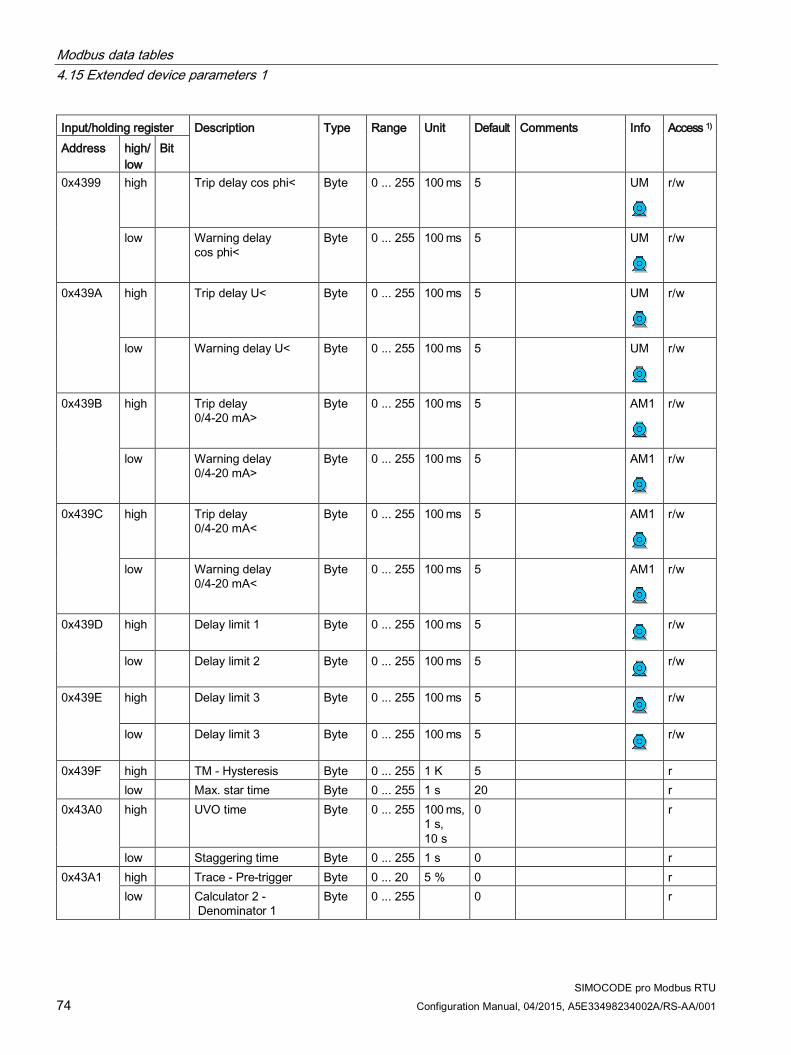
Modbus data tables 4.15 Extended device parameters 1
SIMOCODE pro Modbus RTU 74 Configuration Manual, 04/2015, A5E33498234002A/RS-AA/001
Input/holding register Description Type Range Unit Default Comments Info Access 1) Address high/
low Bit
0x4399 high Trip delay cos phi< Byte 0 ... 255 100 ms 5 UM r/w
low Warning delay cos phi<
Byte 0 ... 255 100 ms 5 UM r/w
0x439A high Trip delay U< Byte 0 ... 255 100 ms 5 UM r/w
low Warning delay U< Byte 0 ... 255 100 ms 5 UM r/w
0x439B high Trip delay 0/4-20 mA>
Byte 0 ... 255 100 ms 5 AM1 r/w
low Warning delay 0/4-20 mA>
Byte 0 ... 255 100 ms 5 AM1 r/w
0x439C high Trip delay 0/4-20 mA<
Byte 0 ... 255 100 ms 5 AM1 r/w
low Warning delay 0/4-20 mA<
Byte 0 ... 255 100 ms 5 AM1 r/w
0x439D high Delay limit 1 Byte 0 ... 255 100 ms 5 r/w
low Delay limit 2 Byte 0 ... 255 100 ms 5 r/w
0x439E high Delay limit 3 Byte 0 ... 255 100 ms 5 r/w
low Delay limit 3 Byte 0 ... 255 100 ms 5 r/w
0x439F high TM - Hysteresis Byte 0 ... 255 1 K 5 r low Max. star time Byte 0 ... 255 1 s 20 r
0x43A0 high UVO time Byte 0 ... 255 100 ms, 1 s, 10 s
0 r
low Staggering time Byte 0 ... 255 1 s 0 r 0x43A1 high Trace - Pre-trigger Byte 0 ... 20 5 % 0 r
low Calculator 2 - Denominator 1
Byte 0 ... 255 0 r

Modbus data tables 4.15 Extended device parameters 1
SIMOCODE pro Modbus RTU Configuration Manual, 04/2015, A5E33498234002A/RS-AA/001 75
Input/holding register Description Type Range Unit Default Comments Info Access 1) Address high/
low Bit
0x43A2 high Calculator 2 - Numerator 2
Byte 0 ... 255 0 r
low Calculator 1 - Denominator
Byte 0 ... 255 0 r
0x43A3 high Truth table 4 type 3I/1O
Byte 0 ... 11111111B
0 r
low Truth table 5 type 3I/1O
Byte 0 ... 11111111B
0 r
0x43A4 high Truth table 6 type 3I/1O
Byte 0 ... 11111111B
0 r
low Calculator 2 - Numerator 1
Byte -128… 127
0 r/w
0x43A5 high Calculator 2 - Denominator 2
Byte -128.. 127
0 r/w
low DM-F - Test requirement level
Byte 0 ... 255 Week 0 r/w
Part - Word parameters
r/w
0x43A6 AM1 - Start value output
Word 0 ... 65535
0 Value for 0/4 mA AM1 r/w
0x43A7 AM1 - End value output
Word 0 ... 65535
27648 Value for 20 mA AM1 r/w
0x43A8 TM1 - Trip level T> Word 0 ... 65535
1 K 0 TM1 r/w
0x43A9 TM1 - Warning level T>
Word 0 ... 65535
1 K 0 TM1 r/w
0x43AA Limit level 1 Word 0 ... 65535
0 r/w
0x43AB Limit level 2 Word 0 ... 65535
0 r/w
0x43AC Limit level 3 Word 0 ... 65535
0 r/w
0x43AD Limit level 4 Word 0 ... 65535
0 r/w
0x43AE Timer 3 - value Word 0 ... 65535
100 ms 0 r
0x43AE Timer 4 - value Word 0 ... 65535
100 ms 0 r

Modbus data tables 4.15 Extended device parameters 1
SIMOCODE pro Modbus RTU 76 Configuration Manual, 04/2015, A5E33498234002A/RS-AA/001
Input/holding register Description Type Range Unit Default Comments Info Access 1) Address high/
low Bit
0x43B0 Counter 3 - value Word 0 ... 65535
0
r/w
0x43B1 Counter 4 - value Word 0 ... 65535
0
r/w
0x43B2 Change-over pause Word 0 ... 65535
10 ms 0
r/w
0x43B3 Trace - Sampling period
Word 1 ... 50000
1 ms 100
r/w
0x43B4 Is1 - Conversion factor - Numerator
Word 0 ... 65535
1/8 0
r/w
0x43B5 Is2 - Conversion factor - Numerator
Word 0 ... 65535
1/8 0
r/w
Part - D word parameter
0x43B6 Motor protection - Set current Is2
D word 10 mA 0 r
0x43B8 Trip level P> D word 0 ... 0xFFFFFFFF
1 W 0
r/w
0x43BA Warning level P> D word 0 ... 0xFFFFFFFF
1 W 0
r/w
0x43BC Trip level P< D word 0 ... 0xFFFFFFFF
1 W 0
r/w
0x43BE Warning level P< D word 0 ... 0xFFFFFFFF
1 W 0
r/w
0x43C0 Truth table 9 5I/2O type - Output 1
Bit[32] 0 ... 1 ... 1B
0 r
0x43C2 Truth table 9 5I/2O type - Output 2
Bit[32] 0 ... 1 ... 1B
0 r
0x43C4 Calculator 2 - Offset D word -0x800 00000 ..0x7FFFFFFF
0 r
0x43C6 ..0x43C7
Calculator 1 - Numerator / offset
D word 2x -32768 ..32767
0 r
1) r/w: Value is read/write; r: Value is read-only

Modbus data tables 4.16 Marking
SIMOCODE pro Modbus RTU Configuration Manual, 04/2015, A5E33498234002A/RS-AA/001 77
4.16 Marking
Max. data length per access: 100 registers.°
Table 4- 16 Marking
Input/holding register Identifier Type Access 1) Address high/low 0x4880 Coordination Byte[4] r 0x4882 Reserved Byte[6] r/w 0x4885 Marking - external fault 1 Byte[10] r/w 0x488A Marking external fault 2 Byte[10] r/w 0x488F Marking external fault 3 Byte[10] r/w 0x4894 Marking external fault 4 Byte[10] r/w 0x4899 Marking external fault 5 Byte[10] r/w 0x489E Marking external fault 6 Byte[10] r/w 0x48A3 Reserved Byte[10] r/w 0x48A8 Reserved Byte[10] r/w 0x48AD Marking limit 1 Byte[10] r/w 0x48B2 Marking limit 2 Byte[10] r/w 0x48B7 Marking limit 3 Byte[10] r/w 0x48BC Marking limit 4 Byte[10] r/w 0x48C1 Marking TM1 warning T > Byte[10] r/w 0x48C6 Marking TM1 trip T > Byte[10] r/w 0x48CB Marking warning 0/4-20mA > Byte[10] r/w 0x48D0 Marking warning 0/4-20mA < Byte[10] r/w 0x48D5 Trip marking 0/4-20mA > Byte[10] r/w 0x48DA Trip marking 0/4-20mA < Byte[10] r/w 0x48DF Reserved Byte[10] r/w
Data set length: 200 bytes
1) Access to the marking via Modbus: read/write

Modbus data tables 4.16 Marking
SIMOCODE pro Modbus RTU 78 Configuration Manual, 04/2015, A5E33498234002A/RS-AA/001
SIMOCODE pro Modbus RTU Configuration Manual, 04/2015, A5E33498234002A/RS-AA/001 79
Dimension drawings 5See SIMOCODE pro PROFIBUS System Manual (http://support.automation.siemens.com/WW/view/en/20017780), SIMOCODE pro V basic unit.

Dimension drawings
SIMOCODE pro Modbus RTU 80 Configuration Manual, 04/2015, A5E33498234002A/RS-AA/001
SIMOCODE pro Modbus RTU Configuration Manual, 04/2015, A5E33498234002A/RS-AA/001 81
Technical data 6See SIMOCODE pro PROFIBUS System Manual (http://support.automation.siemens.com/WW/view/en/20017780), SIMOCODE pro V basic unit.

Technical data
SIMOCODE pro Modbus RTU 82 Configuration Manual, 04/2015, A5E33498234002A/RS-AA/001

SIMOCODE pro Modbus RTU Configuration Manual, 04/2015, A5E33498234002A/RS-AA/001 83
Safety and commissioning information for EEx areas 7See SIMOCODE pro PROFIBUS System Manual (http://support.automation.siemens.com/WW/view/en/20017780)

Safety and commissioning information for EEx areas
SIMOCODE pro Modbus RTU 84 Configuration Manual, 04/2015, A5E33498234002A/RS-AA/001

SIMOCODE pro Modbus RTU Configuration Manual, 04/2015, A5E33498234002A/RS-AA/001 85
List of abbreviations AA.1 List of abbreviations
Overview
Table A- 1 Meaning of abbreviations
Abbreviation Term ADU Application data unit AM Analog module OP Operator panel OPD Operator panel with display CRC Cyclic Redundancy Check DM1 Digital module 1 DM2 Digital module 2 DM-FL DM-F Local fail-safe digital module DM-FP DM-F PROFIsafe fail-safe digital module EM Ground-fault module FC Function code BU SIMOCODE pro Modbus basic unit HMI Human Machine Interface IM Current measuring module M Message MBAP Modbus Application Protocol PIQ Process Image Output PII Process image input PDU Protocol Data Unit RP Requirements Profile RTU Remote Terminal Unit S Fault SF Control function TCP Transmission Control Protocol TM Temperature module Th Thermistor UM Current/voltage measuring modules R Read access RW Read and write access W Warning or write

List of abbreviations A.1 List of abbreviations
SIMOCODE pro Modbus RTU 86 Configuration Manual, 04/2015, A5E33498234002A/RS-AA/001

SIMOCODE pro Modbus RTU Configuration Manual, 04/2015, A5E33498234002A/RS-AA/001 87
Appendix BB.1 Correction sheet
Correction sheet Have you noticed any errors while reading this manual? If so, please use this form to tell us about them. We welcome comments and suggestions for improvement.
Fax response
From (please complete): To SIEMENS AG DF CP PRM IM 2 92220 Amberg / Germany
Name
Company / Department
Address
_________________________________________________________________________________
Fax: +49 (0)9621-80-3337
Manual title:
Errors, comments, and suggestions for improvements

Appendix B.1 Correction sheet
SIMOCODE pro Modbus RTU 88 Configuration Manual, 04/2015, A5E33498234002A/RS-AA/001
SIMOCODE pro Modbus RTU Configuration Manual, 04/2015, A5E33498234002A/RS-AA/001 89
Glossary
Cyclic redundancy check (CRC) Cyclic redundancy check for checking Modbus RTU transmission errors
Function code (FC) Identification of a function
Local Human Machine Interface (HMI) for SIRIUS devices Human Machine Interface for a SIRIUS device or for several SIRIUS devices
Modbus address table Data with similar properties are combined in one of four address tables: Discrete inputs, coils, input register, holding register
Modbus RTU Modbus remote terminal unit: Serial Modbus protocol
Octet Sequence of bytes. Octet n: Sequence of n bytes
Offset A reference within an address table
Protocol data unit (PDU) Consists of function code and the data
Record Data record/data set
Server Service provider

Glossary
SIMOCODE pro Modbus RTU 90 Configuration Manual, 04/2015, A5E33498234002A/RS-AA/001

SIMOCODE pro Modbus RTU Configuration Manual, 04/2015, A5E33498234002A/RS-AA/001 91
Index
A Abbreviations, 85 Access to memory areas, 25
B Basic device parameter 1, 58 Baud rate, 17 Baud rate (detected), 17 Bus and controller monitoring on Modbus, 18 Byte arrangement, 38
C Commissioning sequence of the SIMOCODE pro V Modbus basic unit, 14 Communication parameters, 16 Connecting a PC to the SIMOCODE pro V Modbus RTU basic unit, 14 Connecting Modbus RTU to the SIMOCODE pro V Modbus basic unit, 12 Connecting Modbus RTU to the SIMOCODE pro V Modbus basic unit via the device terminals, 12 Connecting Modbus RTU to the SIMOCODE pro V Modbus basic unit via the sub-D connector, 12 Correction sheet, 87
D DATA, 23 Device addressing, 15 Device diagnostics, 43 Disclaimer of liability, 8 Display and statistical data, 42
E End of frame, 24 Error memory, 51 Event memory, 52 Exception responses, 24 Extended device parameters 1, 65
F frame checksum, 23 Function code, 23 Further information, 8
I I&M (device identification), 54 I&M1 - Tag, 55 I&M2 - Installation date, 56 I&M3 - Comment, 57 Idle time, 17 Interface configuration, 17
L Labeling for the address "128", 15
M Marking, 77 Measured values, 41 Modbus address, 17 Modbus identification data, 34
O Operating instructions, 8 Options for data transfer, 23
P Process image input - monitoring data, 40 Process image output - command data, 39
S Service and support, 8 Setting of the Modbus RTU address with SIMOCODE ES in the TIA Portal, 16 Setting the Modbus RTU address via addressing plug, 15

Index
SIMOCODE pro Modbus RTU 92 Configuration Manual, 04/2015, A5E33498234002A/RS-AA/001
Slave address, 23 Software for configuring and commissioning, 15
T Table specifications, 38 Trace data, 53
W Wait time, 17 Wait time (default value), 17 Watchdog, 18 Watchdog time, 18