configuration manager 3 - netcam.cz x1600), video receivers (e.g. vip xd) or vrms. caution! security...
TRANSCRIPT

Configuration Manager 3.2
en Operating Manual


Configuration Manager 3.2 Table of Contents | en 3
Bosch Security Systems Operating Manual DOC | 3.2 | 2010.05
Table of Contents
1 Introduction 51.1 About this Manual 51.2 Conventions in this Manual 51.3 Configuration Manager 51.4 System Requirements 81.5 Additional Documentation 9
2 Installation and Starting 102.1 Installation 102.2 Starting the Program 112.3 Deinstallation 11
3 Operation 123.1 The User Interface 133.2 Main Menu 143.2.1 File 143.2.2 Tools 153.2.3 Help 173.2.4 Toolbar 183.2.5 Info Bar 193.2.6 Status Bar 203.3 Main Tabs: Network, Devices and Cameras 213.3.1 Popup Menu 223.3.2 The View Window 253.3.3 Blocked Input Fields 263.4 The System Main Tab 27
4 Working with Configuration Manager 284.1 System - General Main Tab 294.1.1 Directories 294.1.2 Logging 294.1.3 Client/Server 304.1.4 BVIP Lite Suite User Management 30

4 en | Table of Contents Configuration Manager 3.2
DOC | 3.2 | 2010.05 Operating Manual Bosch Security Systems
4.1.5 Hardware Monitors 314.2 System - Applications Main Tab 334.2.1 Archive Player 334.2.2 Configuration Manager 354.2.3 Viewer 384.3 Basic Functions 394.3.1 Network Scan 394.3.2 Unit Access 394.3.3 Device Information 414.3.4 Device Allocator 414.3.5 Device Configuration Using Configuration Wizard 454.3.6 Device Configuration Using the View Window 464.3.7 Notes on Multiple Configuration 474.3.8 Table View 494.3.9 Device Health Monitor 524.3.10 iqn-Mapper 534.3.11 Work Offline 544.3.12 System emulation 564.3.13 Replacement 574.4 Working with BVIP Software and Firmware Modules 594.4.1 IVA / IVMD 594.4.2 Archive Player 594.4.3 Viewer 594.4.4 VRM 594.4.5 VIDOS 604.4.6 Monitor Wall 60
Index 61

Configuration Manager 3.2 Introduction | en 5
Bosch Security Systems Operating Manual DOC | 3.2 | 2010.05
1 Introduction
1.1 About this ManualThis manual is intended for persons responsible for configuring and managing a CCTV system. This manual describes how to use the Configuration Manager program.This document assumes that the reader is familiar with both the CCTV system and the other programs that are integrated into the system.
1.2 Conventions in this ManualIn this manual, the following symbols and notations are used to draw attention to special situations:
Terms that you can find in the program, such as menu options or commands, are written in bold.
1.3 Configuration ManagerConfiguration Manager provides the following functions (the availability of these depends on the environment in which the program is used):– Network Scan
This function automatically detects all compatible devices present in a network such as video senders (e.g. VIP X1600), video receivers (e.g. VIP XD) or VRMs.
CAUTION! Security instructions where non-compliance can result in loss of data are marked with this symbol.
NOTICE! This symbol indicates special features and provides tips and information for easier, more convenient use of the software.

6 en | Introduction Configuration Manager 3.2
DOC | 3.2 | 2010.05 Operating Manual Bosch Security Systems
– Device information and configurationComparable with the Web browser view, Configuration Manager shows the current configuration for each deviceand allows you to change the settings.
– Device system integrationYou use the Device allocator in Configuration Manager to make devices accessible for use with Viewer or Archive Player.
– Configuration WizardA Configuration Wizard guides you through the configuration of all devices for basic operation in just a few steps, even for extensive systems.
– Basic configuration for BVIP programsFor certain BVIP programs (Bosch Video over IP), fundamental system settings are made using Configuration Manager.
– Multiple configurationYou can use Configuration Manager to make individual settings for multiple devices simultaneously (e.g. time settings), allowing you to configure large systems more quickly.
– Simpler access to devicesThe Screenshot Scan gives an overview of all the cameras that provide video data. The screenshots can be used to identify the camera and device, and give you direct access to said camera or device.
– Table ViewThis allows you to compile specific parameter settings for selected devices. This provides you with a quick overview of the settings that are of interest to you and allows you to export this information for archiving at the push of a button.
– Device Health MonitorThis provides you with a quick overview of the status for selected devices, for example encoder load or Ethernet link type.
Configuration Manager 3.2 Introduction | en 7
Bosch Security Systems Operating Manual DOC | 3.2 | 2010.05
– Work OfflineConfiguration Manager allows you to make settings for selected devices offline. When in operation, the configuration data of the devices is transferred to your computer where it can be edited offline.This functionality can also be used to back up the configuration data of the devices locally. If, for example, a device needs to be replaced by another of the same type, this data can then be transferred to the new device.This functionality is extended with the Replacement command. Replaced devices are detected and automatic configuration is possible thanks to the saved data.
– System emulationThe total system’s configuration can be saved as a system image and emulated by another Configuration Manager application. This feature helps to dive into issues without going onsite.
– Access to license managementFirmware modules requiring a license, such as IVA (Intelligent Video Analysis), are set up using Configuration Manager.

8 en | Introduction Configuration Manager 3.2
DOC | 3.2 | 2010.05 Operating Manual Bosch Security Systems
1.4 System Requirements
Operating system Windows XP HomeWindows XP Professional SP2/SP3Windows Vista SP1/SP2
CPU Dual Core, 3.0 GHz or faster
RAM 2 GB or more
Graphics card NVIDIA Quadro FX 1500 PCIeNVIDIA Quadro FX 1700 PCIeNVIDIA Quadro FX 1800 PCIeNVIDIA Quadro FX 3800 PCIeNVIDIA Quadro FX 4600 PCIeNVIDIA Quadro FX 4800 PCIeATI FireGL V3300 PCIeATI FireGL V5700 PCIeATI FireGL V7200 PCIeATI FireGL V7750 PCIeor better
Sound card Recommended
Network adapter 100 Mbps
Configuration Manager 3.2 Introduction | en 9
Bosch Security Systems Operating Manual DOC | 3.2 | 2010.05
1.5 Additional DocumentationOnce Configuration Manager has been installed, this document is also available as online Help within the program. Depending on the configuration of your system, the following documentation may also be useful:– Camera documentation
The manufacturer will provide you with separate documentation for each camera.
– VideoJet, VIP etc.Bosch will provide you with documentation for each device. This explains the typical device settings.
– Archive Player, Monitor Wall, VRM, IVA, IVMD and other BVIP softwareBosch will provide you with separate documentation for each of these software products.

10 en | Installation and Starting Configuration Manager 3.2
DOC | 3.2 | 2010.05 Operating Manual Bosch Security Systems
2 Installation and Starting
2.1 InstallationConfiguration Manager is automatically part of the installation for all BVIP programs that require it for configuration purposes. Each device that can be set up using Configuration Manager is supplied with a CD on which you will find the installation file for Configuration Manager.You can install Configuration Manager on as many computers running Microsoft Windows as you wish.1. Close all other applications before beginning the
installation.2. Insert the installation CD into the computer's CD-ROM
drive. The CD runs automatically.If the CD does not run automatically, open the index.html page from the root.
3. Select the required language for the user interface.4. Click one of the entries under Installation Packages to
start installing the relevant installation package. You will be guided through the installation of each individual package.
5. When installing individual packages, several installation processes will run one after the other where necessary.During installation, you will be prompted to select target directories for the programs. It is advisable to accept the defaults.
When selecting components, a description for each one is displayed when you hover the mouse cursor over them.If individual programs are already installed on your PC, you can exclude these from the installation in the Choose Components dialog box.
Configuration Manager 3.2 Installation and Starting | en 11
Bosch Security Systems Operating Manual DOC | 3.2 | 2010.05
2.2 Starting the ProgramAfter successful installation, you will find the following icon on your desktop:
Double-click this icon to start the program. Configuration Manager can also be called up from the Start menu. Several BVIP programs enable you to start Configuration Manager directly within the relevant program.Operation of Configuration Manager varies according to the context in which it is being used. In some cases, it is merely a tool that enables you to configure BVIP devices more conveniently and more comprehensively. For certain BVIP programs and firmware modules, however, Configuration Manager is indispensable, as it is the only way to set these up. You can obtain additional information here: Section 4 Working with Configuration Manager, page 28.
2.3 DeinstallationIf you no longer want to use Configuration Manager on your PC, uninstall the program. 1. Click Start > Settings > Control Panel. 2. Double-click Add or Remove Programs.3. Select the Bosch Configuration Manager entry. 4. Click Remove.
12 en | Operation Configuration Manager 3.2
DOC | 3.2 | 2010.05 Operating Manual Bosch Security Systems
3 OperationIn the Configuration Manager program, you have access to all devices and software components in your CCTV network.The program offers a configuration wizard for quick basic configuration of devices. However, you can also carry out the configuration via the normal user interface. There are two options here for configuring the devices or checking the current settings:– Basic Mode
Configuration Manager is started in this view– Advanced Mode
This view is activated via the main menuIn Basic Mode, only the most important parameters are displayed, on a small number of tabs. This allows you to change the basic settings with just a few entries and then put the device into operation.Advanced Mode is recommended for expert users or system support personnel. You can access all device parameters in this mode. Settings that affect the fundamental functionality of the device (such as firmware updates) can only be altered in Advanced Mode.

Configuration Manager 3.2 Operation | en 13
Bosch Security Systems Operating Manual DOC | 3.2 | 2010.05
3.1 The User Interface
1 Main menu
2 ToolbarButtons for quick access to the most important functions (see: Section 3.2.4 Toolbar, page 18)
3 Main tabs: Network, Devices, System (and optionally Cameras)
4 Info bar with name, type and IP address of the selected device plus additional status information
5 Additional functions
6 Status bar
7 View windowDepending on the main tab selected, this window displays different tabs with configuration options and information.

14 en | Operation Configuration Manager 3.2
DOC | 3.2 | 2010.05 Operating Manual Bosch Security Systems
Below, you will find more detailed information about the program's general user interface. The main tabs are explained in detail in separate sections:– Section 3.3 Main Tabs: Network, Devices and Cameras,
page 21You can choose to show or hide the Cameras main tab.The display area for each main tab contains a series of tabs through which the selected devices can be configured. The number and grouping of tabs displayed depends on whether you are working in Basic or Advanced Mode.
– Section 3.4 The System Main Tab, page 27Here, you can make basic settings for Configuration Manager itself and other BVIP programs.
3.2 Main MenuBelow are the lists of commands available in the main menu.
3.2.1 FileAdvanced Mode If this option is activated you have
access to all device settings.If this option is deactivated, Configuration Manager is in Basic Mode and only the most important device settings are accessible. The Help information for each tab is displayed directly.This option corresponds to the option of the same name in the Web browser view of the devices.
Connect to Server... Connects Configuration Manager to a Server. This allows you to set up a server and configure a client/server system.
Disconnect from Server
The connection between Configuration Manager and a Server is broken.

Configuration Manager 3.2 Operation | en 15
Bosch Security Systems Operating Manual DOC | 3.2 | 2010.05
3.2.2 Tools
Work OfflineWork Online
The settings for selected devices can be made offline while the device remains in operation. For this purpose, the configuration files of the devices are backed up locally on your computer. You can edit the data and send it back to the devices at a later stage.
Emulate Alien System...Abandon Emulation
Imports the system image of an alien Configuration Manager system (see: Section 4.3.12 System emulation, page 56)
Close The Configuration Manager program is closed. This also breaks the connection between Configuration Manager and the server.
Configuration Wizard... Starts the wizard for the basic configuration of devices (see: Section 4.3.5 Device Configuration Using Configuration Wizard, page 45)
Logging... Displays the Device Communication Log dialog box.Here, you can view the RCP+ commands that are transmitted by Configuration Manager when connecting to devices, if you have enabled logging.
Device Allocator... Displays the Device Allocator dialog box (see: Section 4.3.4 Device Allocator)
Table View Displays the Devices Table View dialog box (see: Section 4.3.8 Table View, page 49)
16 en | Operation Configuration Manager 3.2
DOC | 3.2 | 2010.05 Operating Manual Bosch Security Systems
Screenshot Scan... Displays a window in which a screenshot for each of the connected cameras is displayed. The popup menu of the screenshots gives you access to the settings relevant for the device. The device can be added to the system.
Device Health Monitor...
Displays the Device Health Monitor dialog box, which offers you a quick overview on the status of selected devices (see: Section 4.3.9 Device Health Monitor, page 52)
Save System Image... Saves an image of the current Configuration Manager system for emulation on another PC (see: Section 4.3.12 System emulation, page 56)
Archive PlayerViewerand others
Other software components can be started directly.The prerequisite for this is that the relevant program is installed on the same PC.
iqn-Mapper... Displays the iqn-Mapper dialog box, with which you map replay clients to NetApp iSCSI systems (see: Section 4.3.10 iqn-Mapper, page 53)
Configuration Manager 3.2 Operation | en 17
Bosch Security Systems Operating Manual DOC | 3.2 | 2010.05
3.2.3 HelpOnline Help... Opens the online Help
About... Displays the About Configuration Manager dialog box, which contains information about:– The Bosch software applications
installed on this PC together with their version numbers and storage location
– The version numbers of the components installed by Bosch
– The language in which the programs are currently displayed, and information about the storage location for the system files
– The licenses currently available on this PCYou will find the License Viewer... button in the Licenses tab. This is used to call up the License Viewer, which you use to manage your licenses.

18 en | Operation Configuration Manager 3.2
DOC | 3.2 | 2010.05 Operating Manual Bosch Security Systems
3.2.4 ToolbarThe toolbar enables quick access to the most important functions.The toolbar can be configured individually (see: Section Appearance Tab, page 37).
Reload page Reloads the page for the selected device
Info This opens up a window that contains detailed information about the selected device:
Live video A window opens, displaying the live video data from the selected device. You are offered different display options depending on which device you selected.
Logging Displays the Device Communication Log dialog box.Here, you can view the RCP+ commands that are transmitted by Configuration Manager when connecting to devices, if you have enabled logging.
Configuration Manager 3.2 Operation | en 19
Bosch Security Systems Operating Manual DOC | 3.2 | 2010.05
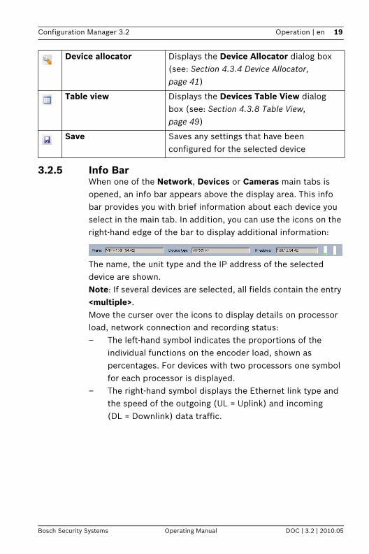
3.2.5 Info BarWhen one of the Network, Devices or Cameras main tabs is opened, an info bar appears above the display area. This info bar provides you with brief information about each device you select in the main tab. In addition, you can use the icons on the right-hand edge of the bar to display additional information:
The name, the unit type and the IP address of the selected device are shown.Note: If several devices are selected, all fields contain the entry <multiple>.Move the curser over the icons to display details on processor load, network connection and recording status:– The left-hand symbol indicates the proportions of the
individual functions on the encoder load, shown as percentages. For devices with two processors one symbol for each processor is displayed.
– The right-hand symbol displays the Ethernet link type and the speed of the outgoing (UL = Uplink) and incoming (DL = Downlink) data traffic.
Device allocator Displays the Device Allocator dialog box (see: Section 4.3.4 Device Allocator, page 41)
Table view Displays the Devices Table View dialog box (see: Section 4.3.8 Table View, page 49)
Save Saves any settings that have been configured for the selected device

20 en | Operation Configuration Manager 3.2
DOC | 3.2 | 2010.05 Operating Manual Bosch Security Systems
– On the far right information on the recording status are displayed:– green marking: recording running– red marking: error– orange marking: recording scheduler active, no
recording running– gray marking: recording scheduler not active, no
recording running
3.2.6 Status BarThe status bar at the bottom edge of the window shows the following:– In the left-hand section: whether or not a network scan is
currently in progress.– In the central section: the number of detected, visible and
selected devices.– In the right-hand section: whether you are currently
working in Online or Offline mode, and whether or not Configuration Manager is currently connected to a server. If it is connected to a server, the server IP address is displayed. Otherwise the entry DB local appears here.If you are emulating an alien system the entry System emulation appears here.
– On the far right the version number of Configuration Manager is displayed.

Configuration Manager 3.2 Operation | en 21
Bosch Security Systems Operating Manual DOC | 3.2 | 2010.05
3.3 Main Tabs: Network, Devices and CamerasThese main tabs are used to configure devices and therefore have a very similar structure. They each show a device list that can be generated in various ways:– The Network main tab shows all BVIP devices supported
by Configuration Manager that are detected in the network scan.
– The Devices main tab shows all devices that have previously been manually allocated to the system.
– You can choose to display the Cameras main tab. This shows the cameras that are allocated to the system directly or via a video encoder.
Icons are displayed in front of the listed devices to indicate the device status. In the Network and Devices main tabs, the standard icon is a server; in the Cameras tab, it is a camera. However, additional graphics are identical:
The information about a device is shown in bold if the device is newly detected since the last network scan.The information about a device is shown in red if the device has an IP address or a MAC address that is already used by another device in the system. This might be the case, for example, if several devices that have not yet been configured are connected directly after one another.Additional information about the devices can be seen if you scroll to the right.
Device/camera is online.
Device/camera is offline.A red cross indicates devices with which communication is not possible. For example, these could be devices for which the power supply has been interrupted.
Device/camera is password-protected.Devices that are protected by a password are indicated by a padlock until you have authenticated yourself for the device.
Device/camera is password-protected and offline.

22 en | Operation Configuration Manager 3.2
DOC | 3.2 | 2010.05 Operating Manual Bosch Security Systems
3.3.1 Popup MenuRight-click a device to open the popup menu. If you have selected multiple devices, not all options in the popup menu are active. You do not have access to all commands in Basic Mode either.The following table provides an overview of the commands:
Command Action
Add to System...(Network main tab)
The selected device is allocated to the system.Before making an allocation, you can select a group or create a new one. Leave the field empty if you want to add a device to the system without allocating it to a group.You find more information on allocating devices and creating groups in another chapter (see: Section 4.3.4 Device Allocator, page 41).
Select Group(Devices and Cameras main tabs)
If several devices have been grouped, you use this option to select all devices or cameras of that group for editing.
New Device...(Devices main tab)
You can allocate a non-listed device to the system. This menu option is only active if you click the area in the main tab in which no devices are listed.
Delete(Devices main tab)
The selected device is deleted from the system.
Set Session Authentication...
If a selected device is protected by a password, you must authenticate yourself for that device. To do this, enter your password for one of the user levels (user, live, service) in the Session Authentication dialog box.Any fields you are not authorized to change remain marked by a padlock and are blocked for editing.

Configuration Manager 3.2 Operation | en 23
Bosch Security Systems Operating Manual DOC | 3.2 | 2010.05
File Upload Firmware...You can select the desired upload file and start the upload. Refer to the information about firmware uploads in the documentation for the relevant device.You can use this command to carry out a firmware upload for several devices at the same time. You must ensure that all selected devices are of the same device type when you carry out a firmware upload for several devices at the same time.SSL Certificate...Upload an SSL certificate to the device to enable encrypted communication with the device.Decoder Logo...The decoder logo is displayed with live video, in Archive Player and in Viewer if there is a connection to the device but no data is currently being transferred. You can upload your own logo for this purpose. This must be in .h263 format.
Command Action

24 en | Operation Configuration Manager 3.2
DOC | 3.2 | 2010.05 Operating Manual Bosch Security Systems
Settings Download...Configuration data of the selected devices is saved on your computer for offline editing.Upload...The configuration data that was edited offline is sent to the selected device. Once the upload has been successfully completed, the device operates according to the new configuration data (see: Section 4.3.11 Work Offline, page 54).Replacement... (only in the Devices main tab)Configuration data of replaced devices is automatically replaced with locally stored data of a device of the same type (see: Section 4.3.13 Replacement, page 57).
Device Network Settings...
You will see the Network settings dialog box. Use this dialog box to change the IP address, subnet mask and gateway of the selected device or to activate automatic IP assignment with DHCP.This is only possible for devices that are not password-protected.
Show Live Video... A window opens, displaying the live video data from the selected device. You are offered different display options depending on which device you selected.
Show in Web browser... The livepage of the Web browser view for the device is opened in the default browser.
Show Settings in Web Browser...
The configuration page of the Web browser view for the device is opened in the default browser.
Device Info... The dialog box containing device information is displayed.
Command Action
Configuration Manager 3.2 Operation | en 25
Bosch Security Systems Operating Manual DOC | 3.2 | 2010.05
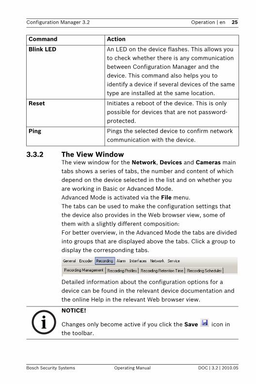
3.3.2 The View WindowThe view window for the Network, Devices and Cameras main tabs shows a series of tabs, the number and content of which depend on the device selected in the list and on whether you are working in Basic or Advanced Mode. Advanced Mode is activated via the File menu.The tabs can be used to make the configuration settings that the device also provides in the Web browser view, some of them with a slightly different composition:For better overview, in the Advanced Mode the tabs are divided into groups that are displayed above the tabs. Click a group to display the corresponding tabs.
Detailed information about the configuration options for a device can be found in the relevant device documentation and the online Help in the relevant Web browser view.
Blink LED An LED on the device flashes. This allows you to check whether there is any communication between Configuration Manager and the device. This command also helps you to identify a device if several devices of the same type are installed at the same location.
Reset Initiates a reboot of the device. This is only possible for devices that are not password-protected.
Ping Pings the selected device to confirm network communication with the device.
Command Action
NOTICE!
Changes only become active if you click the Save icon in the toolbar.

26 en | Operation Configuration Manager 3.2
DOC | 3.2 | 2010.05 Operating Manual Bosch Security Systems
3.3.3 Blocked Input FieldsIt is possible that some fields are blocked for editing. The causes for the block are indicated by different entries in the fields.
If several devices are selected, some settings cannot be made. The input fields are marked with a padlock.
If a device is currently recording, some settings cannot be modified. The input fields are marked with a padlock. If necessary, stop the recording.
If the respective data is not yet transmitted or if there is a configuration error, individual fields are marked accordingly.This icon is also displayed if the device is offline and you attempt to load or save settings.
Click to reload the page.
Input fields you are not authorized to change are marked by a padlock and are blocked for editing.
Some input fields cannot be edited when you are working offline (date and time settings).

Configuration Manager 3.2 Operation | en 27
Bosch Security Systems Operating Manual DOC | 3.2 | 2010.05
3.4 The System Main TabThis main tab enables you to access general and application-specific settings. Here, you can carry out the basic configuration for Configuration Manager itself and for additional BVIP programs such as Archive Player. The tab has a tree structure. If necessary, click + in front of an item to expand the subordinate items.
The View WindowOnce again, the display window shows various additional tabs when you select an entry from the list. The content of the individual tabs is dealt with in the next section in the context of the component for which the settings are applicable.For more details, refer to:– Section 4.1 System - General Main Tab, page 29– Section 4.2 System - Applications Main Tab, page 33

28 en | Working with Configuration Manager Configuration Manager 3.2
DOC | 3.2 | 2010.05 Operating Manual Bosch Security Systems
4 Working with Configuration ManagerConfiguration Manager is automatically part of the installation for all BVIP programs that require it for configuration purposes. It can also be found on every product CD for BVIP devices as you can use it independently of other BVIP software, for example, to simplify the configuration in a CCTV system with many similar video senders. The following section describes the settings that you must make in the System main tab to use the program for your system.This is then followed by a description of the features that Configuration Manager offers for configuring hard and software components.
Configuration Manager 3.2 Working with Configuration Manager | en 29
Bosch Security Systems Operating Manual DOC | 3.2 | 2010.05
4.1 System - General Main TabThis is where you make the settings that affect several programs.
4.1.1 DirectoriesIn the Directories tab, you specify where screenshots and recording sequences should be saved.These settings are relevant for:– Archive Player– Viewer– PlayerIn the relevant input field, enter the path for the storage location or click … to select a folder.You can select any directory that is available in the network as the target location.If you do not enter anything here, the following default settings are used:– %current user%\My Documents
\Bosch\VIDOS\Snapshotsand
– %current user%\My Documents\Bosch\VIDOS\Recordings
4.1.2 LoggingHere, you enable or disable the logging of RCP+ commands. A log file is created for every device in the system.You can also specify the minimum period for which you want the log data to be saved.
NOTICE!
Changes only become active if you click the Save icon in the toolbar.
WARNING! Check the selected directories regularly for available memory space. Delete recordings you no longer require to free up memory space.

30 en | Working with Configuration Manager Configuration Manager 3.2
DOC | 3.2 | 2010.05 Operating Manual Bosch Security Systems
4.1.3 Client/Server
Access TabConnect to serverEnable this option if you manage your system with VRM Server.For details, refer to the separate VRM documentation.Server IP addressIP address backup server 1IP address backup server 2Enter the IP address of the computer on which VRM Server has been started and, if necessary, the IP addresses of the backup server computers.
iSCSI Media TabPasswordEnter the password for accessing the iSCSI media, if these are protected with a password. When you are creating the passwords, please note that these need to be valid for the entire system.
4.1.4 BVIP Lite Suite User ManagementYou can use Configuration Manager to set up a User management that regulates access to the Configuration Manager, Archive Player and Viewer programs.To do this, you create users that belong to a predefined user group with associated access rights.ActiveIf this option is activated, users are required to identify themselves with a user name and password when they start the Configuration Manager, Archive Player and Viewer programs.UsersClick Add... to create another user. A dialog box appears, for you to enter the user name and password. Select one of the predefined user groups: admin, user or guest. Only users in the admin user group have access to Configuration Manager.Click Edit... to change the details for a selected user.Click Remove to delete the selected user from the list.

Configuration Manager 3.2 Working with Configuration Manager | en 31
Bosch Security Systems Operating Manual DOC | 3.2 | 2010.05
You can also restrict access to Configuration Manager separately using a password (see: Section Access Tab, page 35).
4.1.5 Hardware MonitorsHardware monitors are video monitors that are integrated into the system via video decoders. Software monitors are the monitors displayed in the Viewer and Archive Player playback windows. You can use this matrix to permanently connect hardware and software monitors to one another. This means that as soon as a software monitor that is connected in this way is activated in Viewer or Archive Player, the image is also displayed on the associated hardware monitor.
Connection setupHere you specify the allocation of software monitors to hardware monitors.For each of the ten possible connections, enter the position (column; row) of a software monitor in the layout. You specify the position in Archive Player or Viewer, by entering numbers at the top left from 0 and 0 upwards.Sample layout:
TextEnter text here that is displayed in Archive Player or Viewer on the selected software monitor while no camera connection is active.For example, enter the location of the connected hardware monitor here. This makes it easy to see where else the video data for the camera connected here is displayed.DestinationEnter the IP address of the hardware monitor here.
Column=0; row=0 3; 0
3; 1
3; 2
0; 3 1; 3 2; 3 3; 3

32 en | Working with Configuration Manager Configuration Manager 3.2
DOC | 3.2 | 2010.05 Operating Manual Bosch Security Systems
Video OutputQuadrantSpecify which of the available video transmissions is displayed on the hardware monitor. The selection depends on the device selected.Use with Archive PlayerEnable this option if camera connections that are switched in Archive Player are also to be switched for the corresponding hardware monitors.Use with ViewerEnable this option if camera connections that are switched in Viewer are also to be switched for the corresponding hardware monitors.

Configuration Manager 3.2 Working with Configuration Manager | en 33
Bosch Security Systems Operating Manual DOC | 3.2 | 2010.05
4.2 System - Applications Main TabThis is where you make the settings that affect an individual program.
4.2.1 Archive PlayerConfiguration Manager is indispensable when working with Archive Player, as it allocates those devices to the system to which Archive Player is to have access.This is where you configure the default settings for Archive Player.
General TabMaximum trick mode instancesDependent on your hardware's specification, you can select the number of playback instances on which you want to apply trick mode simultaneously.Enable smooth playbackThis function is switched on and off here.Pre-event offset (ms)Here, you can define the point at which the playback should start by entering the number of milliseconds running up to the event you have selected. If you enter 5000, for example, the playback will always show the five seconds prior to the event.Animate monitor layout changeThis function is switched on and off here.COM portIf the program is operated via an IntuiKey control panel, enter the number of the COM port here.
Export TabDefault export formatHere you can select the file format for exports. Select the Sender (Bosch MPEG) option if the data is to be displayed with
NOTICE!
Changes only become active if you click the Save icon in the toolbar.

34 en | Working with Configuration Manager Configuration Manager 3.2
DOC | 3.2 | 2010.05 Operating Manual Bosch Security Systems
Archive Player or Player. Metadata and bookmarks are also saved. Select the Windows (*.wmv) option if the data is to be displayed on a Windows PC, irrespective of the CCTV system. Metadata and bookmarks are not saved.Default export pathHere you can select the path to the folder to which Archive Player will export recordings. The path can be changed subsequently in Archive Player for individual exports.If you do not enter anything here, the following default setting is used:%current user%\My Documents\Bosch\VIDOS\ExportMaximum concurrent downloadsArchive Player provides recordings from all available devices in the network locally on a PC and allows the corresponding files to be exported. Under certain circumstances, exporting recordings can result in a heavy network load. For this reason, you can limit the number of concurrent downloads here. This setting depends on both the local network's and the PC's specification.Maximum download attemptsIf a recording cannot be exported at the first attempt, Archive Player repeats the attempt several times. These attempts block other outstanding exports. For this reason, you can limit the number of download attempts here.Maximum download speed (%)The download speed can be adjusted for exports in Sender (Bosch MPEG) format. For example, if you enter 100, the download occurs at normal speed, but if you enter 200, it will occur twice as quickly. Select 0 (zero) if all exports are to be carried out at the maximum possible speed.This option does not affect exports in Windows (*.wmv) format.Resume aborted exportsSelect On if interrupted exports in Sender (Bosch MPEG) format are to be restarted when the program has been rebooted.
Configuration Manager 3.2 Working with Configuration Manager | en 35
Bosch Security Systems Operating Manual DOC | 3.2 | 2010.05
This option does not affect exports in Windows (*.wmv) format.
VRM Server TabConnect to serverActivate this option if VRM Video Recording Management is being used on your system.Server IP addressIP address backup serverEnter the IP address of the computer on which VRM Server has been started and, if necessary, the IP address of the backup server computer.
4.2.2 Configuration ManagerThis is where you can change the default settings for Configuration Manager.
Access TabPasswordYou can assign a password here that protects access to Configuration Manager. This password is only valid for the computer on which it was set up.If this field is left empty and you have not assigned other user rights, the program will start without asking for a password (see: Section 4.1.4 BVIP Lite Suite User Management, page 30).
Network Scan TabRun continuous network scanEnable this option if the network is to be scanned at regular intervals.Scan interval (s)You can enter the time interval in seconds for automatic scanning here, choosing a value between 10 and 3600 seconds (1 hour).Use MulticastIf you are using devices in various subnets, activate this option. This allows all devices that belong to a different subnet than the PC on which Configuration Manager is installed to also be

36 en | Working with Configuration Manager Configuration Manager 3.2
DOC | 3.2 | 2010.05 Operating Manual Bosch Security Systems
included in the network scan. Otherwise you will have to manually add these devices to the system.Multicast operation requires a multicast-enabled network that uses the UDP and the Internet Group Management IGMP protocols.ModeYou can define IP address ranges here and explicitly allow or deny the use of these addresses.
Video TabRefresh intervalSelect how often the screenshots that are shown in the various tabs (e.g. VCA) are refreshed:– Continuous
Image is refreshed as often as possible.– 0 seconds
Image is displayed once but not refreshed.– 1 … 10 seconds
Image is refreshed accordingly.EncoderChoose whether the images should be displayed in video format (MPEG) or as constantly updated screenshots (JPEG).
Repository TabDatabase folderSelect the path to the folder for offline configuration.If you do not enter anything here, the following default setting is used:%current user%\My Documents\Bosch\VIDOS\ConfigurationRepository
Configuration Manager 3.2 Working with Configuration Manager | en 37
Bosch Security Systems Operating Manual DOC | 3.2 | 2010.05
Appearance TabRestore last viewIf you enable this option, the view last used is displayed when Configuration Manager is next started.After confirmation onlyIf you enable this option, the next time you start Configuration Manager you will be asked whether you want to restore the last view used.Show 'Cameras' tabIf you enable this option, the Cameras main tab is displayed.This tab makes it easy to access typical camera settings such as the setup of alarm triggering events.Main toolbarYou can adapt the main toolbar to your requirements here:1. Click Edit... to call up the Toolbar Settings dialog box.2. Click an entry to highlight it.3. Click one of the arrow buttons to move the entry.
You can move an entry from the Available actions list to the Showed actions list or vice versa.You can move an entry in the Showed actions list to another position.
4. Click Apply to adopt the changes and make further changes.
5. Click Default to restore the original settings.6. Click OK to save the changes and close the dialog box.Prefix device name to camera nameIn the case of cameras that are integrated into the system via video encoders, the encoder device name is also displayed before the camera name in the camera list if this option is activated.

38 en | Working with Configuration Manager Configuration Manager 3.2
DOC | 3.2 | 2010.05 Operating Manual Bosch Security Systems
4.2.3 ViewerConfiguration Manager is indispensable when working with Viewer, as it allocates those devices to the system to which Viewer is to have access.You change the default settings for Viewer here.
General TabMaximum concurrent decoder instancesHere you can set how many video streams can be shown simultaneously in real time in Viewer. You can also open further monitors and add connections; however, these are only displayed as preview screens. In this way, you can limit the network load.Lip syncIf this option is activated, audio and video data is synchronized, meaning that there may be a delay when transferring audio data, depending on the connection."Instant Replay" time range (min)Here, you enter the time for which you want instant replay to be displayed.Show VCA metadataWhen a video is displayed in Viewer, the video content analysis metadata, such as object outlines, is also displayed if this option is activated.Animate monitor layout changeThis function is switched on and off here.Automatic device reconnectionIf this option is activated, all the connections that were last enabled are automatically restored when Viewer is restarted.For details, refer to the separate Viewer documentation.

Configuration Manager 3.2 Working with Configuration Manager | en 39
Bosch Security Systems Operating Manual DOC | 3.2 | 2010.05
4.3 Basic Functions
4.3.1 Network ScanThe network scan is performed via the Network main tab. It is started automatically every time Configuration Manager is called up and, with the default settings, is repeated at regular intervals.The network scan is not only designed to list all compatible devices in the network. The status of a device is also queried in each scan and then indicated by the icons in front of the devices.Disable the Run continuous network scan option if you do not want to use this function; note that the status of the devices will not then be checked regularly either.Regardless of the default setting, you can trigger a network scan manually at any time in the Network main tab. To do this, click the Refresh button below the main tab.
4.3.2 Unit AccessIf a device is not currently communicating with the system, e.g. because it is only temporarily contactable (connection via ISDN) or because a firewall is blocking communication, information to this effect will be shown in the display window.

40 en | Working with Configuration Manager Configuration Manager 3.2
DOC | 3.2 | 2010.05 Operating Manual Bosch Security Systems
In this case, the tab offers various setting options to enable communication again.– IP address
Communication can fail because the device IP address has been changed (e.g. via the device's Web browser view) and Configuration Manager is still using the old IP address to establish the connection. Enter the new IP address here, so that Configuration Manager can use this to establish a connection. Any changes here will not have an effect on the device IP address.
– ISDNEnter the telephone number for the device's ISDN connection here.
– Device accessIf a firewall is blocking communication between the device and Configuration Manager, you can change the transmission protocol in the Protocol field:StandardUDP transmission via unspecified portHTTPTCP transmission via preset portHTTPSTCP transmission via preset portIf you have selected HTTP or HTTPS as the protocol, you must set the port to correspond to the settings stored in the device.In the Authentication field, you can set up a password for a user name of the relevant device. This means that Configuration Manager automatically has access to the device when establishing a connection without the password protection having to be disabled each time.

Configuration Manager 3.2 Working with Configuration Manager | en 41
Bosch Security Systems Operating Manual DOC | 3.2 | 2010.05
4.3.3 Device InformationConfiguration Manager gives you easy access to all devices in the network and you can quickly obtain all the information you need for each individual device in a clear format.There are various options for doing this:– The Network and Devices main tabs (and the Cameras
tab, where this is displayed) show additional information (e.g. IP addresses) for all devices in the list.Scroll to the right or widen the main tab window so that you can see all the details.
– The info bar above the display window shows the name, device type and IP address plus additional status information.
– The Device info window shows hardware, configuration and connection information for the selected device. You open this window from the popup menu or by using the icon in the toolbar.
– The tabs in the display window show all the available configuration settings (comparable with the Web browser view for the relevant device). The number of tabs displayed depends on whether you are working in Basic or Advanced Mode.
4.3.4 Device AllocatorYou can configure all devices via the Network main tab. It is also possible to allocate devices to the system by adding them to the Devices main tab. This simplifies configuration as you can limit yourself to a relevant selection of available devices and clearly arrange the allocated devices in groups.Before working with Archive Player and Viewer, you must complete allocation, as both programs can only access devices that have been allocated to the system.
1. In the toolbar, click the Device allocator icon .The Device Allocator dialog box is opened.All devices detected in the network are displayed on the left-hand side of the dialog box, while those allocated to the system appear on the right.

42 en | Working with Configuration Manager Configuration Manager 3.2
DOC | 3.2 | 2010.05 Operating Manual Bosch Security Systems
2. Use the mouse (drag-and-drop) to move unallocated devices from the left to the right-hand side of the window.
3. Click OK.The devices are integrated into the system. The Device Allocator dialog box is closed. If it is not possible to integrate a device, a warning message appears.
Note: In the Device Allocator dialog box, you can sort the list of entries by clicking the appropriate table header.
Dedicating an Unlisted DeviceThe Device Allocator dialog box also enables you to allocate devices to the system that were not detected during the network scan, e.g. if they belong to a different subnet or have not yet been switched on. 1. Right-click in the Dedicated devices area of the window.
The popup menu appears. 2. Select the New Device... command from the popup menu.
The Device Editor dialog box appears.
3. Enter the URL (for example the IP address with the port number) of the device. The IP address must previously have been set on the device.
4. In the Type field select <Auto detect> or select the device type from the list of supported devices.If you select an ISDN-compatible device, the field for the telephone number is also activated.
5. Enter the telephone number for the ISDN connection if you want a device to be connected using an ISDN line.
6. Click OK. The device is listed on the right-hand side of the window.
Configuration Manager 3.2 Working with Configuration Manager | en 43
Bosch Security Systems Operating Manual DOC | 3.2 | 2010.05
Creating GroupsThe popup menu in the Device Allocator dialog box enables you to clearly combine the devices in the list into groups, e.g. sorted by locations.1. Right-click in the Dedicated devices area of the window.
The popup menu appears. 2. Select the New Group... command from the popup menu.3. Enter a name for the new group.4. Click OK.
The group is displayed in the list.The name of the group can be changed later. The Rename command in the popup menu is available to do this.5. Use the mouse (drag-and-drop) to move a device from the
list to the group name.The device is added to the group and listed under the corresponding name.
6. Any devices that have been added in error can be easily removed from the group using drag-and-drop.
7. Click OK.The grouping is represented by a tree structure in the main tab.
You can also create sub-groups by dragging a group to the name of another group in the Device Allocator dialog box.
Additional Options for Device AllocationYou can also select the New Device... command from the popup menu of the Devices main tab and then proceed as described here: Section Dedicating an Unlisted Device, page 42.The popup menu of the Network main tab contains the Add to System... command for a selected device.
NOTICE! Only supported devices can be allocated. The dedication is not made until you also click OK in the Device Allocator dialog box.In the list display in the main tab, these devices are marked with a red cross until they can be contacted in the network.

44 en | Working with Configuration Manager Configuration Manager 3.2
DOC | 3.2 | 2010.05 Operating Manual Bosch Security Systems
The popup menu in the Screenshot Scan window also contains the Add to System... command for the screenshots displayed. In both cases, a dialog box is opened, in which you can assign the device to a group. To do so, you can also select an existing group or create a new group. Leave the field empty if you do not want to assign the device to a group.
Clearing Device AllocationsYou can remove devices from the system at any time by clearing the allocation. The devices are then no longer listed in the Devices main tab and can no longer be accessed in Archive Player or Viewer.
1. In the toolbar, click the Device allocator icon .The Device Allocator dialog box is opened.
2. With the mouse button held down, drag a device from the right to the left-hand side of the windoworselect Delete in the popup menu.
3. Click OK.The device no longer appears in the list in the main tab and is no longer displayed in Archive Player or Viewer.
Groups can also be deleted in the same way. If you delete a group, you also clear the allocation of all devices that you have allocated to that group.

Configuration Manager 3.2 Working with Configuration Manager | en 45
Bosch Security Systems Operating Manual DOC | 3.2 | 2010.05
4.3.5 Device Configuration Using Configuration WizardThe Configuration Wizard helps you to configure devices in the network quickly and conveniently for basic operation. In Basic Mode, the wizard starts automatically each time a device with a default IP address is detected in the network scan.1. Select Tools > Configuration Wizard... from the menu.
The Configuration Wizard leads you through the configuration in seven steps.
2. Device SelectionAll devices detected in the network are listed. If you do not wish to configure one of the devices using the wizard, remove the check mark next to the entry by clicking on it.Note: Not all devices support IP address configuration via DHCP. If required, click Resolve to configure these devices manually at a later stage.
3. NetworkActivate the Use DHCP option if all devices support DHCP and you want to assign IP addresses automatically in this way.Alternatively, enter an IP address range. This must provide sufficient IP addresses for all the devices to be configured.
4. Date and TimeThe date and time are adopted from the settings on your PC. If required, reconfigure the system time and system date on your PC.
5. PasswordsYou are now given the option of assigning passwords that apply to all devices.If you do not wish to do this, leave the input fields empty.
6. Video QualityYou are now given the option of specifying the quality of the video data for all devices. As an alternative, you can limit the maximum network bandwidth. The relevant settings for each device are made automatically.
7. RecordingYou can start recording on the local recording media directly with the wizard. To do this, select your favorite
46 en | Working with Configuration Manager Configuration Manager 3.2
DOC | 3.2 | 2010.05 Operating Manual Bosch Security Systems
recording mode: Continuous for uninterrupted recording, Motion for recording only in case of motion in the video image.
8. SummaryA summary of the selected settings is displayed.If you want to change individual settings, click < Back to go back step by step in the wizard.Click Apply to configure the devices according to the selected settings.Click Cancel to cancel the wizard.
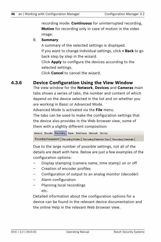
4.3.6 Device Configuration Using the View WindowThe view window for the Network, Devices and Cameras main tabs shows a series of tabs, the number and content of which depend on the device selected in the list and on whether you are working in Basic or Advanced Mode. Advanced Mode is activated via the File menu.The tabs can be used to make the configuration settings that the device also provides in the Web browser view, some of them with a slightly different composition:
Due to the large number of possible settings, not all of the details are dealt with here. Below are just a few examples of the configuration options:– Display stamping (camera name, time stamp) on or off– Creation of encoder profiles– Configuration of output to an analog monitor (decoder)– Alarm configuration– Planning local recordings
etc.Detailed information about the configuration options for a device can be found in the relevant device documentation and the online Help in the relevant Web browser view.
Configuration Manager 3.2 Working with Configuration Manager | en 47
Bosch Security Systems Operating Manual DOC | 3.2 | 2010.05
Basic Information for Operation1. Select the device in the main tab.2. If you are working in Advanced Mode, click one of the
groups to display all the corresponding tabs.3. Click the tab for the area you want to edit.4. Make the desired changes.
5. Click the Save icon in the toolbar to save the new settings.The changed settings for that tab are now saved. You can click another tab to change more settings for this device or edit a different device.Note: Some settings (e.g. Device time) can only be changed if the device is not currently recording. If necessary, stop any recordings before making changes.
4.3.7 Notes on Multiple ConfigurationYou can select several devices and then simultaneously make settings for all selected devices. In this way, CCTV systems can be set up quickly and efficiently. 1. Select a device that you want to configure in the Network,
Devices or Cameras main tab.2. Press the Ctrl key and select the other devices you want to
configure by clickingorpress the Shift key and then click another device to select all entries that lie between the two selected devices.A group can be selected from the popup menu.The entries for selected devices have a colored background.
48 en | Working with Configuration Manager Configuration Manager 3.2
DOC | 3.2 | 2010.05 Operating Manual Bosch Security Systems
3. In the display window, select the tab in which you want to make changes.The following special features are available for multiple selections:– On the right-hand side, only those tabs that are
available for all selected devices are shown.– Input fields that can only be changed for individual
devices (e.g. Device IP address) are blocked.– Input fields where the settings for the selected
devices differ because of their type (e.g. recording planning for different video senders) are blocked.
– Input fields that already have identical settings for all selected devices show these settings.
– Input fields containing different entries for the selected devices show <multiple> or M.
– Options that are only enabled (checked) for some of the selected devices are grayed out.
4. Change the settings as desired.
5. Click the Save icon in the toolbar to confirm the changes.Changed input fields that previously contained <multiple> or M now display the uniform value.
6. Repeat steps 3 to 5 for all tabs in which you want to make changes.

Configuration Manager 3.2 Working with Configuration Manager | en 49
Bosch Security Systems Operating Manual DOC | 3.2 | 2010.05
4.3.8 Table ViewThe table view provides the option of presenting a summary of specific settings for individual selected devices in the form of a clearly arranged table. This table can be exported in *.csv format.1. In one of the Network, Devices or Cameras main tabs,
select one or more devices or cameras.
2. In the toolbar, click the Table view icon.The Table View dialog box opens.
The table contains a column in which all previously highlighted devices and cameras are listed.

50 en | Working with Configuration Manager Configuration Manager 3.2
DOC | 3.2 | 2010.05 Operating Manual Bosch Security Systems
3. Use the mouse (drag-and-drop) to move the names of the required setting parameters from the different tabs into the table.
A new column is created in the table for the parameter; this displays the value for each of the selected devices and cameras.
4. Keep adding more columns to the table in this way until all the required parameters are available in this view.Not all parameters can be added to the view.
5. Hold the Ctrl key down and highlight further devices or cameras in the main tab to add these to the Table View.
6. Click in a field in the table. You can set parameters for individual devices or cameras directly from here.

Configuration Manager 3.2 Working with Configuration Manager | en 51
Bosch Security Systems Operating Manual DOC | 3.2 | 2010.05
Toolbar in the Table View
Additional Options in the Table View– Sorting the table
Click a column header to sort the table.– Popup menu for devices
Right-click one of the entries. You are offered options very similar to those in the main tab (see: Section 3.3.1 Popup Menu, page 22).
– Removing a columnRight-click a column header and select Remove Column.
– Removing all columnsRight-click the Device column header on the left and select Remove All Columns. The selection for the devices and cameras remains the same.
– Moving a columnHold the right mouse button down and drag a column header to move the column to another position.
Set Saves any changes that you have made to the settings for devices and cameras from within the Table View
Export Exports the table in *.csv format
Reload Reloads the original display. You can reject all changes by doing this.
Copy Copies the table to the clipboard
Topmost The Table View is always displayed as the topmost window. If required, enable this option before you drag parameters from the tabs into the table.

52 en | Working with Configuration Manager Configuration Manager 3.2
DOC | 3.2 | 2010.05 Operating Manual Bosch Security Systems
4.3.9 Device Health MonitorThe device health monitor displays combined in one dialog the status information on selected devices which you otherwise get via the icons on the right-hand edge of the info bar (see: Section 3.2.5 Info Bar, page 19).1. In one of the Network, Devices or Cameras main tabs,
select one or more devices or cameras.2. Select Tools > Device Health Monitor....
The Device Health Monitor dialog box opens.
For each selected device the info bar icons are displayed in a small box.
3. Move the curser over the icons to display details on processor load, network connection and recording status:– The left-hand symbol indicates the proportions of the
individual functions on the encoder load, shown as percentages.
– The right-hand symbol displays the Ethernet link type and the speed of the outgoing (UL = Uplink) and incoming (DL = Downlink) data traffic.
– On the far right information on the recording status are displayed:green marking: recording running
red marking: error
orange marking: recording scheduler active, no recording running
gray marking: recording scheduler not active, no recording running

Configuration Manager 3.2 Working with Configuration Manager | en 53
Bosch Security Systems Operating Manual DOC | 3.2 | 2010.05
4. To view information on other devices, change the selection in the main tab and click Selection in the dialog box.
5. To rearrange the order of display, click Sort and choose the category by which to sort.
6. Click View to display a tool bar for quick access to the various menu entries.
4.3.10 iqn-MapperBosch iqn-Mapper is a tool to map replay clients to NetApp iSCSI systems. The mapping is a precondition to enable replays of video data stored on NetApp iSCSI systems. It is not necessary for replay of video data stored on other iSCSI systems supported by Bosch or on local storage media like USB hard disks or CF cards.You do not need to select the respective devices; iqn-Mapper automatically maps only those entries in the Devices main tab that record on NetApp iSCSI systems. This includes all senders that use NetApp iSCSI systems as local storage and all VRM systems.1. Select Tools > iqn-Mapper....
The iqn-Mapper dialog box opens.
The first parameter is detected automatically where possible. No additional input is required.The second parameter Configuration password (sender only) is only available if iqn-Mapper detects senders in the Devices main tab that use NetApp iSCSI systems as local storage.
2. If the second parameter is available enter the password for the root user that is defined for the NetApp iSCSI drive.

54 en | Working with Configuration Manager Configuration Manager 3.2
DOC | 3.2 | 2010.05 Operating Manual Bosch Security Systems
3. Click OK to start the mapping for the iSCSI drive with the respective password.The progress is displayed in the progress bar and you get additional status information in the lower window pane.
4. Repeat steps 2 and 3 for all root passwords in your system. If you also have storage that is not password protected repeat step 3 once more leaving the Configuration password (sender only) field empty.
5. If the second parameter is not available simply click OK. The entire mapping will be done automatically.
6. If no error messages appear in the lower window pane the mapping was completed successfully. Click Close.
You can now replay the recorded video data on the PC.The mapping procedure is only necessary once on any PC that you want to use for replay of video data. Only when you have added additional iSCSI drives to your system you have to repeat the procedure to map the new drives.
4.3.11 Work OfflineThe Work Offline function is used for the following:– To transmit configuration data of all selected devices to
one PC, to allow this to be edited locally.– To back up the configuration files of all selected devices
locally on one PC. If a device is replaced by one of the same type, the configuration data can be transmitted straight to the new device.
The Work Offline function can only be used on devices allocated to the system – such devices are given in the Devices main tab. For detailed information on how to allocate devices to the system, please see here: Section 4.3.4 Device Allocator, page 41.The location in which configuration data is to be backed up can be changed in the System main tab under Applications > Configuration Manager. Click the Directories tab.

Configuration Manager 3.2 Working with Configuration Manager | en 55
Bosch Security Systems Operating Manual DOC | 3.2 | 2010.05
Downloading Data for Offline Configuration1. Select File > Work Offline.
If any of the devices in the system do not support offline configuration, you will receive a message to that effect.Click OK to continue.
2. In the next dialog box, you can choose whether current configuration data of all devices in the system is to be saved to the local repository. Click Yes to update your locally saved device database.
3. The Download of Settings dialog box lists all devices for which configuration data is currently being transferred.
4. Click Start.If it is not possible to transfer all the data for individual devices, the number of data packets that are not transferred is listed in the Failed column.If the Cancel button is replaced by the Close button, the procedure is complete.
5. Click Close.If the configuration data is inconsistent for individual devices, you will receive a warning message. You can cancel the procedure at this stage and then continue to work online. If you ignore the warning, you will work offline.Offline now appears in the status bar.
6. Now use Configuration Manager to configure the devices offline. Any changes that you now make will only be saved locally on your computer.
You can also perform the transfer for an individual device, e.g. to back up the configuration locally before a device is replaced. To do this, right-click the device in the Network or Devices main tab and select Settings > Download....
Uploading Offline Configuration Data1. Select File > Work Online.2. To send the amended configuration data to selected
devices, select these devices in the Devices main tab.

56 en | Working with Configuration Manager Configuration Manager 3.2
DOC | 3.2 | 2010.05 Operating Manual Bosch Security Systems
3. In the popup menu, select Settings > Upload....The selected devices are displayed in the Upload of Settings dialog box.
4. Click Start to start the procedure.If the Cancel button is replaced by the Close button, the procedure is complete.
5. Click Close.If the configuration data is inconsistent for individual devices, you will receive a warning message. You can cancel the procedure at this stage and then continue to work offline. If you ignore this warning, you will work online.
The devices now have the offline configuration settings and Online appears in the status bar again:
Note: Configuration Manager always starts up in the mode that was used before closing the system.
4.3.12 System emulationThe total system’s configuration can be saved as a system image and emulated by another Configuration Manager application. This feature helps to dive into issues without going onsite.
Save System Image1. Select Tools > Save System Image....
The Save System Image dialog box opens.2. Specify where you want to save the zip-file and what name
you want to save it under.3. Click Save.
Emulating an Alien System1. Save the zip-file of the image of the alien system to your
PC.2. Select File > Emulate Alien System.... A new dialog box
opens in which you can select the storage location and the image file.
Configuration Manager 3.2 Working with Configuration Manager | en 57
Bosch Security Systems Operating Manual DOC | 3.2 | 2010.05
3. Click Open. The emulation is done automatically. System emulation now appears in the status bar.
4. Select File > Abandon Emulation to return to your own system. System emulation no longer appears in the status bar.
4.3.13 ReplacementIf devices have to be replaced, most of the configuration for the new devices can be done automatically.The Replacement function can only be used on devices that are allocated to the system – such devices are given in the Devices main tab. For detailed information on how to allocate devices to the system, please see here: Section 4.3.4 Device Allocator, page 41.1. Right-click the device and select Settings > Download....
The device configuration settings are saved locally on your PC.
The location in which configuration data is to be backed up can be changed in the System main tab under Applications > Configuration Manager.There, click the Directories tab.2. Replace the device.3. Select the Devices main tab in Configuration Manager.
The replaced device is shown as not being configured.4. Right-click the device and select
Settings > Replacement....The Device Replacement Wizard dialog box lists all devices that are the same type as the replaced device and for which configuration data is also saved.
5. Select the replacement device that was installed instead of the selected device.
6. Click Next >.Automatic configuration is started.
7. You will be informed if the firmware version of the device and the configuration file differ. You are able to download a new firmware version onto the device.
58 en | Working with Configuration Manager Configuration Manager 3.2
DOC | 3.2 | 2010.05 Operating Manual Bosch Security Systems
8. Click Next > again.The Device Replacement dialog box is displayed, which lists the selected device and additional information.
9. Click Start.The configuration files are transferred. If it is not possible to transfer all the data, the number of data packets that are not transferred is listed in the Failed column.Once the transfer is complete the device is rebooted so that the new settings take effect.If the Cancel button is replaced by the Close button, the procedure is complete.
10. Click Close.The Device Replacement Wizard dialog box appears again.
11. Click Finish to complete the procedure.
Configuration Manager 3.2 Working with Configuration Manager | en 59
Bosch Security Systems Operating Manual DOC | 3.2 | 2010.05
4.4 Working with BVIP Software and Firmware Modules
4.4.1 IVA / IVMDIVA (Intelligent Video Analysis) and IVMD (Intelligent Video Motion Detection) are modules in the device's firmware that require a license. These are enabled in the Licenses tab of the relevant device; the license applies to that BVIP device only. IVA and IVMD are set up exclusively using Configuration Manager.More detailed information on IVA and IVMD and on the configuration of this firmware module using Configuration Manager can be found in the separate documentation supplied when you purchased the license.
4.4.2 Archive PlayerConfiguration Manager is indispensable when working with Archive Player, as it allocates those devices to the system to which Archive Player is to have access. In addition, you can use the System main tab to make basic settings for using Archive Player.Please also refer to the separate Archive Player documentation.
4.4.3 ViewerConfiguration Manager is indispensable when working with Viewer, as it allocates those devices to the system to which Viewer is to have access. In addition, you can use the System main tab to make basic settings for using Viewer.Please also refer to the separate Viewer documentation.
4.4.4 VRMIf you want to play back recordings managed by VRM using Archive Player, the devices for which the recordings are to be available, must be allocated to the system via Configuration Manager. In addition, a connection must be established to the VRM server.Further details can be found in the separate VRM documentation.
60 en | Working with Configuration Manager Configuration Manager 3.2
DOC | 3.2 | 2010.05 Operating Manual Bosch Security Systems
4.4.5 VIDOSFor VIDOS, Configuration Manager is primarily a tool for performing the device configuration efficiently, i.e. it is primarily the program's basic functions that are used.
4.4.6 Monitor WallMonitor Wall is treated as a hardware decoder by Configuration Manager. As soon as Monitor Wall is running on a PC with an IP network connection, it is added to the list after the network scan.You can use Configuration Manager to make various settings, which are explained in more detail in the separate Monitor Wall documentation.

Configuration Manager 3.2 Index | en 61
Bosch Security Systems Operating Manual DOC | 3.2 | 2010.05
IndexAAnimation of layout change 33, 38Authentication 22BBasic Mode 12Blink LED 25BVIP 6CCameras 37COM port 33Connection
local or server 20DDatabase
folder 36Device
allocating 41allocating group 43clearing allocation 44IP address 40ISDN 40protected 21replacing 57reset 25synchronized settings 47unattainable 21
Device allocator 41Device grouping 43Device health monitor 16Device network settings 24Device status 21DHCP 24Download 24Download speed 34EExport format (Archive Player) 33Export path (Archive Player) 34FFirewall 40Firmware upload 23HHelp (menu) 17
IInfo bar 19Instant replay
time range 38IP address range 36iqn-Mapper 16ISDN 40IVMD 59LLicense 17Limit
decoder instances 38download attempts 34file export 34trick mode instances 33
live 22Logging 29MMulticast 35multiple 19NNetwork scan 35OOffline 15Online 15PPadlock 21, 22, 26Password
Configuration Manager 35device 21iSCSI media 30
Programstarting 11
RRCP+ logging 29Recording
specifying directory 29Refresh 39Replacement 24Resuming exports 34
62 en | Index Configuration Manager 3.2
DOC | 3.2 | 2010.05 Operating Manual Bosch Security Systems
SScan interval 35Screenshot
refresh interval 36specifying directory 29
Screenshot scan 16service 22Session authentication 22Set session authentication 22Status bar 20Storage location
system files 17Symbols 5System
refresh view 39System emulation 15, 16, 56TTrick mode 33UUnit access 39Upload 24user 22VVersion numbers
applications 17components 17
VRM 35, 59WWeb browser view 24

Bosch Security SystemsWerner-von-Siemens-Ring 1085630GrasbrunnGermanywww.boschsecurity.com © Bosch Security Systems, 2010