configuration guide for solaris™ host attachment · mk-96rd632-05 configuration guide for...
TRANSCRIPT

MK-96RD632-05
Configuration Guide for Solaris™ Host Attachment
Hitachi Virtual Storage Platform Hitachi Universal Storage Platform V/VM
FASTFIND LINKS
Document Organization
Product Version
Getting Help
Contents

ii
Configuration Guide for Solaris Host Attachment
Copyright © 2010 Hitachi, Ltd., all rights reserved.
No part of this publication may be reproduced or transmitted in any form or by any means, electronic or mechanical, including photocopying and recording, or stored in a database or retrieval system for any purpose without the express written permission of Hitachi, Ltd. (hereinafter referred to as “Hitachi”) and Hitachi Data Systems Corporation (hereinafter referred to as “Hitachi Data Systems”).
Hitachi Data Systems reserves the right to make changes to this document at any time without notice and assumes no responsibility for its use. This document contains the most current information available at the time of publication. When new and/or revised information becomes available, this entire document will be updated and distributed to all registered users.
All of the features described in this document may not be currently available. Refer to the most recent product announcement or contact your local Hitachi Data Systems sales office for information about feature and product availability.
Notice: Hitachi Data Systems products and services can be ordered only under the terms and conditions of the applicable Hitachi Data Systems agreement(s). The use of Hitachi Data Systems products is governed by the terms of your agreement(s) with Hitachi Data Systems.
Hitachi is a registered trademark of Hitachi, Ltd. in the United States and other countries. Hitachi Data Systems is a registered trademark and service mark of Hitachi, Ltd. in the United States and other countries.
All other trademarks, service marks, and company names are properties of their respective owners.
Microsoft product screen shot(s) reprinted with permission from Microsoft Corporation.

Contents iii
Configuration Guide for Solaris Host Attachment
Contents
Preface................................................................................................... v
Intended Audience ..............................................................................................vi Product Version...................................................................................................vi Document Revision Level .....................................................................................vi Source Documents for this Revision ..................................................................... vii Changes in this Revision ..................................................................................... vii Referenced Documents....................................................................................... vii Document Organization ..................................................................................... viii Document Conventions........................................................................................ ix Convention for Storage Capacity Values .................................................................x Accessing Product Documentation .........................................................................x Getting Help .......................................................................................................xi Comments ..........................................................................................................xi
Introduction......................................................................................... 1-1
About the Hitachi RAID Storage Systems.............................................................1-2 Device Types ....................................................................................................1-3 Installation and Configuration Roadmap..............................................................1-7
Installing the Storage System................................................................ 2-1
Requirements ...................................................................................................2-2 Preparing for Storage System Installation............................................................2-3
Hardware Installation Considerations............................................................2-3 LUN Manager Software Installation ..............................................................2-3 Setting the Host Mode ................................................................................2-4 Setting the Host Mode Options ....................................................................2-5 Configuring the Fibre-Channel Ports .............................................................2-6
Port Address Considerations for Fabric Environments ..............................2-7 Loop ID Conflicts .................................................................................2-7
iv Contents
Configuration Guide for Solaris Host Attachment
Configuring the Host Fibre-Channel HBAs ........................................................... 2-8 Verifying the HBA Installation ..................................................................... 2-8 Setting the Disk and Device Parameters....................................................... 2-9
Connecting the Storage System to the Solaris Host ........................................... 2-11
Configuring the New Disk Devices.......................................................... 3-1
Setting and Recognizing the LUs........................................................................ 3-2 Verifying Recognition of New Devices................................................................. 3-5 Partitioning and Labeling the New Devices.......................................................... 3-6 Creating and Mounting the File Systems ........................................................... 3-24
Creating the File Systems ......................................................................... 3-25 Creating and Verifying the Mount Directories.............................................. 3-26 Mounting and Verifying the File Systems.................................................... 3-27 Setting and Verifying the Auto-Mount Parameters....................................... 3-29
Failover and SNMP Operations............................................................... 4-1
Host Failover.................................................................................................... 4-2 Path Failover.................................................................................................... 4-2 SNMP Remote System Management................................................................... 4-3
Troubleshooting ................................................................................... 5-1
General Troubleshooting ................................................................................... 5-2 Verbose Mode .................................................................................................. 5-3 Calling the Hitachi Data Systems Support Center................................................. 5-4
Fibre Port Addressing ........................................................................... A-1
Online Device Installation...................................................................... B-1
Sun Fibre-Channel Host Bus Adapter Installation................................................. B-1
Using MPxIO Path Failover Software ...................................................... C-1
Note on Using Veritas Cluster Server...................................................... D-1
Acronyms and Abbreviations

Preface v
Configuration Guide for Solaris Host Attachment
Preface
This document describes and provides instructions for installing and configuring the devices on the Hitachi RAID storage systems for operations in a Solaris environment. The Hitachi RAID storage system models include the Hitachi Virtual Storage Platform (VSP) and the Hitachi Universal Storage Platform V and Hitachi Universal Storage Platform VM (USP V/VM).
Please read this document carefully to understand how to use this product, and maintain a copy for reference purposes.
This preface includes the following information:
Intended Audience
Product Version
Document Revision Level
Source Documents for this Revision
Changes in this Revision
Document Organization
Referenced Documents
Document Conventions
Convention for Storage Capacity Values
Getting Help
Comments

vi Preface
Configuration Guide for Solaris Host Attachment
Intended Audience This document is intended for system administrators, Hitachi Data Systems representatives, and authorized service providers who are involved in installing, configuring, and operating the Hitachi RAID storage systems.
Readers of this document should meet the following requirements:
• You should have a background in data processing and understand RAID storage systems and their basic functions.
• You should be familiar with the Hitachi RAID storage system(s), and you should have read the User and Reference Guide for the storage system.
• You should be familiar with the Storage Navigator software for the Hitachi RAID storage system(s), and you should have read the Storage Navigator User’s Guide.
• You should be familiar with the Solaris operating system and the hardware hosting the Solaris system.
• You should be familiar with the hardware used to attach the Hitachi RAID storage system to the Solaris host, including fibre-channel cabling, host bus adapters (HBAs), switches, and hubs.
Product Version
This document revision applies to the following microcode levels:
• Hitachi Virtual Storage Platform microcode 70-01-0x or later.
• Hitachi Universal Storage Platform V/VM microcode 60-03-2x or later.
Document Revision Level
Revision Date Description
MK-96RD632-P February 2007 Preliminary Release
MK-96RD632-00 May 2007 Initial Release, supersedes and replaces MK-96RD632-P
MK-96RD632-01 September 2007 Supersedes and replaces MK-96RD632-00
MK-96RD632-02 June 2009 Revision 2, supersedes and replaces MK-96RD632-01
MK-96RD632-03 November 2009 Revision 3, supersedes and replaces MK-96RD632-02
MK-96RD632-04 January 2010 Revision 4, supersedes and replaces MK-96RD632-03
MK-96RD632-05 October 2010 Revision 5, supersedes and replaces MK-96RD632-04

Preface vii
Configuration Guide for Solaris Host Attachment
Source Documents for this Revision • MK-96RD632-05a-1_RSDreview
Changes in this Revision • Added the Hitachi Virtual Storage Platform storage system.
• Added information about the 8-Gbps fibre-channel interface (Table 2-1).
• Added a link to the Hitachi Data Systems interoperability site for specific information about supported OS versions, HBAs, drivers, hubs, and switches (Table 2-1).
Referenced Documents
Hitachi Virtual Storage Platform documentation:
• Provisioning Guide for Open Systems, MK-90RD7022
• Storage Navigator User’s Guide, MK-90RD7027
• Storage Navigator Messages, MK-90RD7028
• User and Reference Guide, MK-90RD7042
Hitachi Universal Storage Platform V/VM documentation:
• Hitachi LUN Manager User’s Guide, MK-96RD615
• Hitachi LUN Expansion (LUSE) User’s Guide, MK-96RD616
• Hitachi Storage Navigator User’s Guide, MK-96RD621
• Hitachi Virtual LVI/LUN and Volume Shredder User’s Guide, MK-96RD630
• User and Reference Guide, MK-96RD635
• Hitachi Cross-OS File Exchange User’s Guide, MK-96RD647
• Hitachi Dynamic Link Manager for Solaris User’s Guide, MK-92DLM114
Solaris user documentation

viii Preface
Configuration Guide for Solaris Host Attachment
Document Organization
The following table provides an overview of the contents and organization of this document. Click the chapter title in the left column to go to that chapter. The first page of each chapter provides links to the sections in that chapter.
Chapter Description
Chapter 1, Introduction Provides a brief overview of the Hitachi RAID storage systems, supported device types, and an installation roadmap.
Chapter 2, Installing the Storage System
Provides instructions for installing and connecting the Hitachi RAID storage system to a Solaris host.
Chapter 3, Configuring the New Disk Devices
Provides instructions for configuring the new devices on the Hitachi RAID storage system for use.
Chapter 4, Failover and SNMP Operations
Describes how to configure the Hitachi RAID storage system for failover and SNMP.
Chapter 5, Troubleshooting Provides information for identifying and resolving problems.
Appendix A, Fibre Port Addressing
Provides information about fibre port addressing.
Appendix B, Online Device Installation
Provides instructions for online installation of new devices.
Appendix C, Using MPxIO (Sun Path Failover Software)
Describes how to use Solaris Operating Environment Multi−path I/O with the Hitachi RAID storage system.
Appendix D, Note on Using Veritas Cluster Server
Provides information about adding reserve keys for LUs to increase disk capacity.
Preface ix
Configuration Guide for Solaris Host Attachment
Document Conventions
The terms “Virtual Storage Platform” and “VSP” refer to all models of the Hitachi Virtual Storage Platform storage system, unless otherwise noted.
The terms “Universal Storage Platform V” and “Universal Storage Platform VM” refer to all models of the Hitachi Universal Storage Platform V and VM storage systems, unless otherwise noted.
This document uses the following typographic conventions:
Convention Description
Bold Indicates text on a window, other than the window title, including menus, menu options, buttons, fields, and labels. Example: Click OK.
Italic Indicates a variable, which is a placeholder for actual text provided by the user or system. Example: copy source-file target-file
Angled brackets (< >) are also used to indicate variables.
screen/code Indicates text that is displayed on screen or entered by the user. Example: # pairdisplay -g oradb
< > angled brackets Indicates a variable, which is a placeholder for actual text provided by the user or system. Example: # pairdisplay -g <group>
Italic font is also used to indicate variables.
[ ] square brackets Indicates optional values. Example: [ a | b ] indicates that you can choose a, b, or nothing.
{ } braces Indicates required or expected values. Example: { a | b } indicates that you must choose either a or b.
| vertical bar Indicates that you have a choice between two or more options or arguments. Examples:
[ a | b ] indicates that you can choose a, b, or nothing.
{ a | b } indicates that you must choose either a or b.
underline Indicates the default value. Example: [ a | b ]
# A pound sign at the beginning of a line indicates an operating system command line prompt.
This document uses the following icons to draw attention to information.
Icon Meaning Description
Note Calls attention to important and/or additional information.
Tip Provides helpful information, guidelines, or suggestions for performing tasks more effectively.
Caution Warns of adverse conditions and/or consequences (e.g., disruptive operations).
WARNING Warns of severe conditions and/or consequences (e.g., destructive operations).

x Preface
Configuration Guide for Solaris Host Attachment
Convention for Storage Capacity Values
Physical storage capacity values (e.g., disk drive capacity) are calculated based on the following values:
Physical capacity unit Value
1 KB 1,000 (103) bytes
1 MB 1,000 KB or 1,0002 bytes
1 GB 1,000 MB or 1,0003 bytes
1 TB 1,000 GB or 1,0004 bytes
1 PB 1,000 TB or 1,0005 bytes
1 EB 1,000 PB or 1,0006 bytes
Logical storage capacity values (e.g., logical device capacity) are calculated based on the following values:
Logical capacity unit Value
1 block 512 bytes
1 KB 1,024 (210) bytes
1 MB 1,024 KB or 1,0242 bytes
1 GB 1,024 MB or 1,0243 bytes
1 TB 1,024 GB or 1,0244 bytes
1 PB 1,024 TB or 1,0245 bytes
1 EB 1,024 PB or 1,0246 bytes
Accessing Product Documentation
The user documentation for the Hitachi RAID storage systems is available on the Hitachi Data Systems Portal: https://hdssupport.hds.com. Check this site for the most current documentation, including important updates that may have been made after the release of the product.

Preface xi
Configuration Guide for Solaris Host Attachment
Getting Help
The Hitachi Data Systems customer support staff is available 24 hours a day, seven days a week. If you need technical support, log on to the Hitachi Data Systems Portal for contact information: https://hdssupport.hds.com
Comments
Please send us your comments on this document: [email protected] Include the document title, number, and revision, and refer to specific section(s) and paragraph(s) whenever possible.
Thank you! (All comments become the property of Hitachi Data Systems.)

xii Preface
Configuration Guide for Solaris Host Attachment

1
Introduction 1-1
Configuration Guide for Solaris Host Attachment
Introduction
This chapter provides an overview of the Hitachi RAID storage systems and host attachment:
About the Hitachi RAID Storage Systems
Device Types
Installation and Configuration Roadmap

1-2 Introduction
Configuration Guide for Solaris Host Attachment
About the Hitachi RAID Storage Systems
The Hitachi RAID storage systems offer a wide range of storage and data services, including thin provisioning with Hitachi Dynamic Provisioning™ software, application-centric storage management and logical partitioning, and simplified and unified data replication across heterogeneous storage systems. These storage systems are an integral part of the Services Oriented Storage Solutions architecture from Hitachi Data Systems, providing the foundation for matching application requirements to different classes of storage and delivering critical services such as:
• Business continuity services
• Content management services (search, indexing)
• Non-disruptive data migration
• Volume management across heterogeneous storage arrays
• Thin provisioning
• Security services (immutability, logging, auditing, data shredding)
• Data de-duplication
• I/O load balancing
• Data classification
• File management services
The Hitachi RAID storage systems provide heterogeneous connectivity to support multiple concurrent attachment to a variety of host operating systems, including Solaris and other UNIX platforms as well as Windows, Linux, VMware, and mainframe servers, enabling massive consolidation and storage aggregation across disparate platforms. The storage systems can operate with multi-host applications and host clusters, and are designed to handle very large databases as well as data warehousing and data mining applications that store and retrieve terabytes of data.
The Hitachi RAID storage systems are configured with OPEN-V logical units (LUs) and are compatible with most fibre-channel (FC) host bus adapters (HBAs). Users can perform additional LU configuration activities using the LUN Manager, Virtual LVI/LUN (VLL), and LUN Expansion (LUSE) features provided by the Storage Navigator software, which is the primary user interface for the storage systems.
For further information on storage solutions and the Hitachi RAID storage systems, please contact your Hitachi Data Systems account team.
Introduction 1-3
Configuration Guide for Solaris Host Attachment
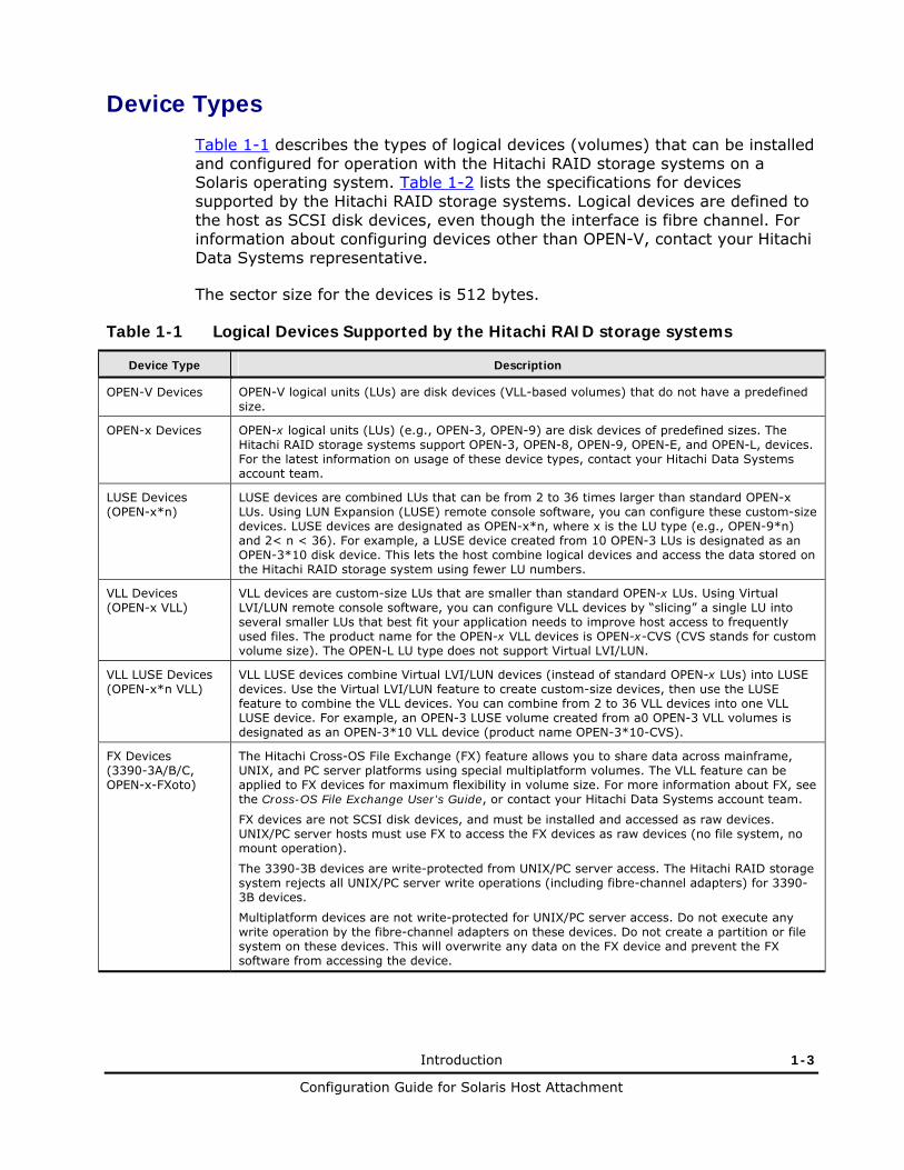
Device Types
Table 1-1 describes the types of logical devices (volumes) that can be installed and configured for operation with the Hitachi RAID storage systems on a Solaris operating system. Table 1-2 lists the specifications for devices supported by the Hitachi RAID storage systems. Logical devices are defined to the host as SCSI disk devices, even though the interface is fibre channel. For information about configuring devices other than OPEN-V, contact your Hitachi Data Systems representative.
The sector size for the devices is 512 bytes.
Table 1-1 Logical Devices Supported by the Hitachi RAID storage systems
Device Type Description
OPEN-V Devices OPEN-V logical units (LUs) are disk devices (VLL-based volumes) that do not have a predefined size.
OPEN-x Devices OPEN-x logical units (LUs) (e.g., OPEN-3, OPEN-9) are disk devices of predefined sizes. The Hitachi RAID storage systems support OPEN-3, OPEN-8, OPEN-9, OPEN-E, and OPEN-L, devices. For the latest information on usage of these device types, contact your Hitachi Data Systems account team.
LUSE Devices (OPEN-x*n)
LUSE devices are combined LUs that can be from 2 to 36 times larger than standard OPEN-x LUs. Using LUN Expansion (LUSE) remote console software, you can configure these custom-size devices. LUSE devices are designated as OPEN-x*n, where x is the LU type (e.g., OPEN-9*n) and 2< n < 36). For example, a LUSE device created from 10 OPEN-3 LUs is designated as an OPEN-3*10 disk device. This lets the host combine logical devices and access the data stored on the Hitachi RAID storage system using fewer LU numbers.
VLL Devices (OPEN-x VLL)
VLL devices are custom-size LUs that are smaller than standard OPEN-x LUs. Using Virtual LVI/LUN remote console software, you can configure VLL devices by “slicing” a single LU into several smaller LUs that best fit your application needs to improve host access to frequently used files. The product name for the OPEN-x VLL devices is OPEN-x-CVS (CVS stands for custom volume size). The OPEN-L LU type does not support Virtual LVI/LUN.
VLL LUSE Devices (OPEN-x*n VLL)
VLL LUSE devices combine Virtual LVI/LUN devices (instead of standard OPEN-x LUs) into LUSE devices. Use the Virtual LVI/LUN feature to create custom-size devices, then use the LUSE feature to combine the VLL devices. You can combine from 2 to 36 VLL devices into one VLL LUSE device. For example, an OPEN-3 LUSE volume created from a0 OPEN-3 VLL volumes is designated as an OPEN-3*10 VLL device (product name OPEN-3*10-CVS).
FX Devices (3390-3A/B/C, OPEN-x-FXoto)
The Hitachi Cross-OS File Exchange (FX) feature allows you to share data across mainframe, UNIX, and PC server platforms using special multiplatform volumes. The VLL feature can be applied to FX devices for maximum flexibility in volume size. For more information about FX, see the Cross-OS File Exchange User’s Guide, or contact your Hitachi Data Systems account team.
FX devices are not SCSI disk devices, and must be installed and accessed as raw devices. UNIX/PC server hosts must use FX to access the FX devices as raw devices (no file system, no mount operation).
The 3390-3B devices are write-protected from UNIX/PC server access. The Hitachi RAID storage system rejects all UNIX/PC server write operations (including fibre-channel adapters) for 3390-3B devices.
Multiplatform devices are not write-protected for UNIX/PC server access. Do not execute any write operation by the fibre-channel adapters on these devices. Do not create a partition or file system on these devices. This will overwrite any data on the FX device and prevent the FX software from accessing the device.

1-4 Introduction
Configuration Guide for Solaris Host Attachment
Table 1-2 Device Specifications
Device Type (Note 1)
Category (Note 2)
Product Name (Note 3)
# of Blocks (512-byte
blk)
# of Cylinders
# of Heads
# of Sectors
per Track
Capacity MB
(Note 4)
OPEN-3 SCSI disk OPEN-3 4806720 3338 15 96 2347
OPEN-8 SCSI disk OPEN-8 14351040 9966 15 96 7007
OPEN-9 SCSI disk OPEN-9 14423040 10016 15 96 7042
OPEN-E SCSI disk OPEN-E 28452960 19759 15 96 13893
OPEN-L SCSI disk OPEN-L 71192160 49439 15 96 34761
OPEN-3*n SCSI disk OPEN-3*n 4806720*n 3338*n 15 96 2347*n
OPEN-8*n SCSI disk OPEN-8*n 14351040*n 9966*n 15 96 7007*n
OPEN-9*n SCSI disk OPEN-9*n 14423040*n 10016*n 15 96 7042*n
OPEN-E*n SCSI disk OPEN-E*n 28452960*n 19759*n 15 96 13893*n
OPEN-L*n SCSI disk OPEN-L*n 71192160*n 49439*n 15 96 34761*n
OPEN-3 VLL SCSI disk OPEN-3-CVS Note 5 Note 6 15 96 Note 7
OPEN-8 VLL SCSI disk OPEN-8-CVS Note 5 Note 6 15 96 Note 7
OPEN-9 VLL SCSI disk OPEN-9-CVS Note 5 Note 6 15 96 Note 7
OPEN-E VLL SCSI disk OPEN-E-CVS Note 5 Note 6 15 96 Note 7
OPEN-V VLL SCSI disk OPEN-V Note 5 Note 6 15 128 Note 7
OPEN-3*n VLL SCSI disk OPEN-3*n-CVS Note 5 Note 6 15 96 Note 7
OPEN-8*n VLL SCSI disk OPEN-8*n-CVS Note 5 Note 6 15 96 Note 7
OPEN-9*n VLL SCSI disk OPEN-9*n-CVS Note 5 Note 6 15 96 Note 7
OPEN-E*n VLL SCSI disk OPEN-E*n-CVS Note 5 Note 6 15 96 Note 7
OPEN-V*n VLL SCSI disk OPEN-V*n Note 5 Note 6 15 128 Note 7
3390-3A FX otm/mto 3390-3A 5820300 3345 15 116 2844
3390-3B FXmto 3390-3B 5816820 3343 15 116 2842
3390-3C FXotm OP-C-3390-3C 5820300 3345 15 116 2844
FX OPEN-3 FXoto OPEN-3 4806720 3338 15 96 2347
3390-3A VLL FX otm/mto 3390-3A-CVS Note 5 Note 6 15 116 Note 7
3390-3B VLL FXmto 3390-3B-CVS Note 5 Note 6 15 116 Note 7
3390-3C VLL FXotm OP-C-3390-3C- CVS
Note 5 Note 6 15 116 Note 7
FX OPEN-3 VLL FXoto OPEN-3-CVS Note 5 Note 6 15 96 Note 7
Table Notes:
1: The availability of a specific device type depends on the level of microcode installed on the Hitachi RAID storage system.

Introduction 1-5
Configuration Guide for Solaris Host Attachment
2: The category of a device (SCSI disk or raw) determines its volume usage. Table 1-3 shows the volume usage for SCSI disk devices and raw devices. The SCSI disk devices (OPEN-x, VLL, LUSE, VLL LUSE) require partitions and file systems for Solaris operations. The multiplatform devices (e.g., 3390-3A/B/C) must be installed as raw devices and can only be accessed using FX. Do not create a partition or file system on any device used for FX operations.
Table 1-3 Volume Usage for Device Categories
Category Device Type Volume Usage
SCSI Disk
OPEN-x, OPEN-x VLL, OPEN-x*n LUSE, OPEN-x*n VLL LUSE
File System or raw device (e.g., some applications use raw devices)
FX 3390-3A/B/C 3390-3A/B/C VLL OPEN-x for FXoto, OPEN-x VLL for FXoto
Raw Device
3: The command device (used for Hitachi Command Control Interface operations) is distinguished by -CM on the product name (e.g., OPEN-3-CM, OPEN-3-CVS-CM). The product name for OPEN-x VLL devices is OPEN-x CVS (CVS = custom volume size).
4: The device capacity can sometimes be changed by the BIOS or HBA. Different capacities may be due to variations such as 1 MB = 10002 or 10242 bytes.
5: The number of blocks for a VLL volume is calculated as follows:
# of blocks = (# of data cylinders) × (# of heads) × (# of sectors per track)
Example 1: For an OPEN-3 VLL volume with capacity = 37 MB:
# of blocks = (53 cylinders – see Note 6) × (15 heads) × (96 sectors per track) = 76320
Example 2: For an OPEN-V VLL volume with capacity = 49 MB:
# of blocks = (53 cylinders – see Note 6) × (15 heads) × (128 sectors per track) = 101760

1-6 Introduction
Configuration Guide for Solaris Host Attachment
6: The number of data cylinders for a VLL volume is calculated as follows (↑…↑ means the value should be rounded up to the next integer):
• Number of data cylinders for OPEN-x VLL volume (except for OPEN-V) = # of cylinders = ↑ (capacity (MB) specified by user) × 1024/720 ↑
Example: For an OPEN-3 VLL volume with capacity = 37 MB:
# of cylinders = ↑37 × 1024/720↑ = ↑52.62↑ (rounded up to next integer) = 53 cylinders
• Number of data cylinders for an OPEN-V VLL volume = # of cylinders = ↑ (capacity (MB) specified by user) × 16/15 ↑
Example: For an OPEN-V VLL volume with capacity = 49 MB:
# of cylinders = ↑49 × 16/15↑ = ↑52.26↑ (rounded up to next integer) = 53 cylinders
• Number of data cylinders for an OPEN-3/8/9/E VLL LUSE volume = # of cylinders = ↑ (capacity (MB) specified by user) × 1024/720 ↑ × n
Example: For an OPEN-3 VLL LUSE volume with capacity = 37 MB and n = 4:
# of cylinders = ↑37 × 1024/720↑ × 4 = ↑52.62↑× 4 = 53 × 4 = 212
• Number of data cylinders for an OPEN-V VLL LUSE volume = # of cylinders = ↑ (capacity (MB) specified by user) × 16/15 ↑ × n
Example: For an OPEN-V VLL LUSE volume with capacity = 49 MB and n = 4:
# of cylinders = ↑49 × 16/15↑ × 4 = ↑52.26↑× 4 = 53 × 4 = 212
• Number of data cylinders for a 3390-3A/C VLL volume = # of cylinders = (number of cylinders specified by user) + 9
• Number of data cylinders for a 3390-3B VLL volume = # of cylinders = (number of cylinders specified by user) + 7
7: The size of an OPEN-x volume is specified by capacity in MB, not number of cylinders. The size of an OPEN-V VLL volume can be specified by capacity in MB or number of cylinders. The user specifies the volume size using the Virtual LVI/LUN software.

Introduction 1-7
Configuration Guide for Solaris Host Attachment
Installation and Configuration Roadmap
The steps in Table 1-4 outline the general process you follow to install and configure the Hitachi RAID storage system on a Solaris operating system.
Table 1-4 Installation and Configuration Roadmap
Task
1. Verify that the system on which you are installing the Hitachi RAID storage system meets the minimum requirements for this release.
2. Prepare the Hitachi RAID storage system for the installation.
3. Prepare the fibre-channel HBAs for the installation.
4. Connect the Hitachi RAID storage system to a Solaris host.
5. Set and recognize the LUs.
6. Verify recognition of the new devices.
7. Partition disk devices and label the new devices.
8. Create mount directories, mount and verify the file system, and set and verify auto-mount parameters.

1-8 Introduction
Configuration Guide for Solaris Host Attachment

2
Installing the Storage System 2-1
Configuration Guide for Solaris Host Attachment
Installing the Storage System
This chapter describes how to install the Hitachi RAID storage system on a Solaris operating system:
Requirements
Preparing for Storage System Installation
Configuring the Host Fibre-Channel HBAs
Connecting the Storage System to the Solaris Host

2-2 Installing the Storage System
Configuration Guide for Solaris Host Attachment
Requirements Table 2-1 lists and describes the requirements for installing the Hitachi RAID storage system on the Solaris operating system.
Table 2-1 Requirements
Item Requirements
Hitachi RAID storage system
The availability of features and devices depends on the level of microcode installed on the Hitachi RAID storage system.
Use the LUN Manager software on Storage Navigator to configure the fibre-channel ports.
Solaris system hardware
Sun SPARCstation series
Sun SPARCserver series
Sun SPARCcenter series
Sun Ultra series
Contact Oracle to make sure the most current OS patches are installed.
Solaris operating system
Please refer to the Hitachi Data Systems interoperability site for specific support information for the Solaris operating system: http://www.hds.com/products/interoperability
Root login access to the Solaris system is required.
Fibre-channel HBAs The Hitachi RAID storage system supports fibre-channel HBAs equipped as follows:
8-Gbps fibre-channel interface, including shortwave non-OFC (open fibre control) optical interface and multimode optical cables with LC connectors.
4-Gbps fibre-channel interface, including shortwave non-OFC (open fibre control) optical interface and multimode optical cables with LC connectors.
2-Gbps fibre-channel interface, including shortwave non-OFC (open fibre control) optical interface and multimode optical cables with LC connectors.
1-Gbps fibre-channel interface, including shortwave non-OFC optical interface and multimode optical cables with SC connectors.
If a switch or HBA with a 1-Gbps transfer rate is used, configure the device to use a fixed 1-Gbps setting instead of Auto Negotiation. Otherwise, it may prevent a connection from being established.
However, the transfer speed of CHF port cannot be set as 1 Gbps when the CHF is 8US/8UFC/16UFC. Therefore 1 Gbps HBA and switch cannot be connected.
Do not connect OFC-type fibre-channel interfaces to the storage system. For information about supported fibre-channel HBAs, optical cables, hubs, and fabric switches, contact your Hitachi Data Systems account team.
For information about supported HBAs, drivers, hubs, and switches, see the Hitachi Data Systems interoperability site: http://www.hds.com/products/interoperability
Fibre-channel utilities and tools
Refer to the documentation for your fibre-channel HBA for information about installing the utilities and tools for your adapter.
Fibre-channel drivers
Do not install/load the driver(s) yet. When instructed in this guide to install the drives for your fibre-channel HBA, refer to the documentation for your adapter.

Installing the Storage System 2-3
Configuration Guide for Solaris Host Attachment
Preparing for Storage System Installation
The following sections describe preinstallation considerations to follow before installing the Hitachi RAID storage system.
Hardware Installation Considerations
The Hitachi Data Systems representative performs the hardware installation by following the precautions and procedures in the Maintenance Manual for the storage system.
Hardware installation activities include:
• Assembling all hardware and cabling
• Installing and formatting the logical devices (LDEVs). Be sure to obtain the desired LDEV configuration information from the user, including the desired number of OPEN-x, LUSE, VLL, VLL LUSE, and multiplatform (FX) devices.
• Installing the fibre-channel HBAs and cabling. The total fibre cable length attached to each fibre-channel adapter must not exceed 500 meters (1,640 feet).
– Do not connect any OFC-type connectors to the storage system.
– Do not connect/disconnect fibre-channel cabling that is being actively used for I/O. This can cause the Solaris system to hang.
– Always confirm that the devices on the fibre cable are offline before connecting/disconnecting the fibre cable.
• Configuring the fibre port topology. The fibre topology parameters for each fibre-channel port depend on the type of device to which the port is connected, and the type of port. Determine the topology parameters supported by the device, and set your topology accordingly (see Configuring the Fibre-Channel Ports).
Before starting the installation, check all specifications to ensure proper installation and configuration.
LUN Manager Software Installation
The LUN Manager software on Storage Navigator is used to configure the fibre-channel ports. For instructions on installing LUN Manager, see the Storage Navigator User’s Guide.

2-4 Installing the Storage System
Configuration Guide for Solaris Host Attachment
Setting the Host Mode
The Hitachi RAID storage system has host modes that the storage administrator must set for all new installations (newly connected ports) to Solaris hosts.
The required host mode for Solaris is 09. Do not select a host mode other than 09 for Solaris.
Use the LUN Manager software to set the host mode. For instructions, see the LUN Manager User’s Guide for the USP V/VM or the Provisioning Guide for Open Systems for the VSP.
Caution: Changing host modes on a storage system that is already installed and configured is disruptive and requires the server to be rebooted.

Installing the Storage System 2-5
Configuration Guide for Solaris Host Attachment
Setting the Host Mode Options
When each new host group is added, the storage administrator must make sure that the host mode options (HMOs) are set for all host groups connected to Solaris hosts. Use the LUN Manager software to set the HMOs. For instructions, see the LUN Manager User’s Guide for the USP V/VM or the Provisioning Guide for Open Systems for the VSP.
Table 2-2 lists the HMOs for Solaris and specifies the conditions for setting the mode. Note that HMO 13 is common to all platforms.
Caution: Changing HMOs on a storage system that is already installed and configured is disruptive and requires the server to be rebooted.
Table 2-2 Host Mode Options for Solaris
HMO Function Description Notes
2 Veritas Database Edition™/ Advanced Cluster
Select HMO 2 if you are using either:
Veritas Database Edition™/Advanced Cluster for Real Application Clusters, or
Veritas Cluster Server™ 4.0 or later (I/O fencing function).
Mandatory. Do not apply this option to Sun Cluster.
7 Automatic recognition function of LUN
Select HMO 7 when all of the following conditions are satisfied:
You are using host mode 00 Standard or 09 Solaris, and
You are using SUN StorEdge SAN Foundation Software Version 4.2 or later, and
You want to automate recognition of increase and decrease of devices when a SUN HBA is connected.
Optional
13 SIM report at link failure
Select HMO 13 to enable SIM notification when the number of link failures detected between ports exceeds the threshold.
Optional
This mode is common to all host platforms.
22 Veritas Cluster Server
When a reserved volume receives a Mode Sense command from a node that is not reserving this volume, the host will receive the following responses from the storage system:
ON: Normal response OFF (default): Reservation Conflict
Note:
1. When HMO 22 is ON, the volume status (reserved/non-reserved) will be checked more frequently (several tens of msec per LU).
2. When HMO 22 is ON, the host OS will not receive warning messages when a Mode Select command is issued to a reserved volume.
3. There is no impact on the Veritas Cluster Server software when HMO 22 is OFF. Set HMO 22 to ON when the software is experiencing numerous reservation conflicts.
4. Set HMO 22 to ON when Veritas Cluster Server is connected.
Note:
Before setting HMO 22 ask your Hitachi Data Systems representative for assistance.
HMO 22 can be changed while the host is online. However I/O activity may be affected when it is being changed. It is recommended to stop the host IO on the port where you want to change the HMO 22 setting.

2-6 Installing the Storage System
Configuration Guide for Solaris Host Attachment
Configuring the Fibre-Channel Ports
Use the LUN Manager software to configure the fibre-channel ports with the appropriate fibre parameters. You select the appropriate settings for each fibre-channel port based on the device to which the port is connected: Determine the topology parameters supported by the device, and set your topology accordingly. The Hitachi RAID storage system supports up to 2048 LUs per fibre-channel port.
Table 2-3 explains the fibre parameter settings for the Hitachi RAID storage system.
Table 2-3 Fibre Parameter Settings
Fabric Connection Provides
Enable FC-AL FL-port (fabric port)
Enable Point-to-Point F-port (fabric port)
Disable FC-AL NL-port (private arbitrated loop)
Disable Point-to-Point Not supported
Notes: • If you plan to connect different types of servers to the Hitachi RAID
storage system via the same fabric switch, use the zoning function of the fabric switch.
• Contact Hitachi Data Systems for information about port topology configurations supported by HBA/switch combinations. Not all switches support F-port connection.

Installing the Storage System 2-7
Configuration Guide for Solaris Host Attachment
Port Address Considerations for Fabric Environments
In fabric environments, port addresses are assigned automatically by fabric switch port number and are not controlled by the port settings. In arbitrated loop environments, the port addresses are set by entering an AL-PA (arbitrated-loop physical address, or loop ID).
Table 2-4 shows the available AL-PA values ranging from 01 to EF. Fibre-channel protocol uses the AL-PAs to communicate on the fibre-channel link, but the software driver of the platform host adapter translates the AL-PA value assigned to the port to a SCSI TID. See Appendix A for a description of the AL-PA-to-TID translation.
Table 2-4 Available AL-PA Values
EF CD B2 98 72 55 3A 25
E8 CC B1 97 71 54 39 23
E4 CB AE 90 6E 53 36 1F
E2 CA AD 8F 6D 52 35 1E
E1 C9 AC 88 6C 51 34 1D
E0 C7 AB 84 6B 4E 33 1B
DC C6 AA 82 6A 4D 32 18
DA C5 A9 81 69 4C 31 17
D9 C3 A7 80 67 4B 2E 10
D6 BC A6 7C 66 4A 2D 0F
D5 BA A5 7A 65 49 2C 08
D4 B9 A3 79 63 47 2B 04
D3 B6 9F 76 5C 46 2A 02
D2 B5 9E 75 5A 45 29 01
D1 B4 9D 74 59 43 27
CE B3 9B 73 56 3C 26
Loop ID Conflicts
The Solaris operating system assigns port addresses from lowest (01) to highest (EF). To avoid loop ID conflict, assign the port addresses from highest to lowest (i.e., starting at EF). The AL-PAs should be unique for each device on the loop to avoid conflicts. Do not use more than one port address with the same TID in same loop (e.g., addresses EF and CD both have TID 0, see Appendix A for the TID-to-AL-PA mapping).

2-8 Installing the Storage System
Configuration Guide for Solaris Host Attachment
Configuring the Host Fibre-Channel HBAs
Configure the fibre-channel HBA(s) connected to the Hitachi RAID storage system. The HBAs have many configuration options. For information, refer to the documentation for your HBA(s). The following sections describe considerations to follow before installing the Hitachi RAID storage system.
Verifying the HBA Installation
Before configuring the fibre-channel HBA(s), verify the HBA installation and recognition of the fibre-channel HBA and driver.
1. Log in to the Solaris system as root and confirm that all existing devices are powered on and properly connected to the Solaris system.
2. Display the host configuration using the dmesg command (see Figure 2-1). The fibre information (underlined in the following example) includes the recognition of the fibre channel adapter, SCSI bus characteristics, world wide name, and FCA driver. Ensure the host recognizes these four classes. If this information is not displayed or if error messages are displayed, the host environment may not be configured properly.
# dmesg Nov 9 23:14 ems, Inc. mem = 65536K (0x4000000) avail mem = 60129280 Ethernet address = 8:0:20:92:32:48 root nexus = Sun Ultra 1 SBus (UltraSPARC 167MHz) sbus0 at root: UPA 0x1f 0x0 ... espdma0 at sbus0: SBus0 slot 0xe offset 0x8400000 esp0: esp-options=0x46 esp0 at espdma0: SBus0 slot 0xe offset 0x8800000 Onboard device sparc9 ipl 4 sd0 at esp0: target 0 lun 0 sd0 is /sbus@1f,0/espdma@e,8400000/esp@e,8800000/sd@0,0 <SUN2.1G cyl 2733 alt 2 hd 19 sec 80> sd6 at esp0: target 6 lun 0 sd6 is /sbus@1f,0/espdma@e,8400000/esp@e,8800000/sd@6,0 fca0: JNI Fibre Channel Adapter (1062 MB/sec), model FC Verify that fca0: SBus 1: IRQ 4: FCODE Version 11.0.9 [1a6384]: SCSI ID 125: AL_PA 01 these items fca0: Fibre Channel WWN: 100000e0690000d5 are listed. fca0: FCA Driver Version 2.2.HIT.03, Oct 09, 1999 Solaris 2.5, 2.6 fca0: All Rights Reserved. fca0: < Total IOPB space used: 1125824 bytes > fca0: < Total DMA space used: 565277 bytes > root on /sbus@1f,0/espdma@e,8400000/esp@e,8800000/sd@0,0:a fstype ufs zs0 at sbus0: SBus0 slot 0xf offset 0x1100000 Onboard device sparc9 ipl 12 zs0 is /sbus@1f,0/zs@f,1100000 zs1 at sbus0: SBus0 slot 0xf offset 0x1000000 Onboard device sparc9 ipl 12 zs1 is /sbus@1f,0/zs@f,1000000 keyboard is </sbus@1f,0/zs@f,1000000> major <29> minor <2> mouse is </sbus@1f,0/zs@f,1000000:b> major <29> minor <3> stdin is </sbus@1f,0/zs@f,1000000> major <29> minor <2> • • • • • • • • • • • • • • • • • • • • • • • • • • • • • • • • •
Figure 2-1 Displaying the Fibre Device Information (Jaycor FC-1063)

Installing the Storage System 2-9
Configuration Guide for Solaris Host Attachment
Setting the Disk and Device Parameters
The queue depth parameter (max_throttle) for the Hitachi RAID storage system devices must be set as specified in Table 2-5.
Table 2-5 Max Throttle (Queue Depth) Requirements
Requirement for Queue Depth Note
(Number of LUs) × (queue_depth) ≤ 2048
and
queue_depth ≤ 32
It is recommended that queue_depth be specified between 8 and 16 per LU.
You can adjust the queue depth for the devices later as needed (within the specified range) to optimize the I/O performance.
The required I/O time-out value (TOV) for Hitachi RAID storage system devices is 60 seconds (default TOV=60). If the I/O TOV has been changed from the default, change it back to 60 seconds by editing the sd_io_time or ssd_io_time parameter in the /etc/system file.
Several other parameters (e.g., FC fibre support) may also need to be set. Please refer to the user documentation that came with your HBA to determine whether other options are required to meet your operational requirements.
Use the same settings and device parameters for all Hitachi RAID storage system devices. For fibre-channel, the settings in the system file apply to the entire system, not to just the HBA(s).
To set the I/O TOV and queue depth:
1. Make a backup of the /etc/system file: cp /etc/system /etc/system.old
2. Edit the /etc/system file.
3. To set the TOV, add the following to the /etc/system file (see Figure 2-2): set sd:sd_io_time=0x3c For Sun generic HBA: set ssd:ssd_io_time=0x3c
4. To set the queue depth, add the following to the /etc/system file (see Figure 2-3): set sd:sd_max_throttle = x (for x see Table 2-5) For Sun generic HBA: set ssd:ssd_max_throttle = x (for x see Table 2-5)
5. Save your changes, and exit the text editor.
6. Shutdown and reboot to apply the I/O TOV setting.

2-10 Installing the Storage System
Configuration Guide for Solaris Host Attachment
*ident “@(#)system 1.15 92/11/14 SMI” /* SVR4 1.5 */ * * SYSTEM SPECIFICATION FILE * : * To set a variable named ‘debug’ in the module named ‘test_module’ * * set test_module:debug = 0x13 set sd:sd_io_time = 0x3c Add this line to /etc/system set ssd:ssd_io_time = 0x3c Add this line to /etc/system (for Sun generic HBA)
Figure 2-2 Setting the I/O TOV
: * To set a variable named ‘debug’ in the module named ‘test_module’ * * set test_module:debug = 0x13 set sd:sd_max_throttle = 8 Add this line to /etc/system set ssd:ssd_max_throttle = 8 Add this line to /etc/system (for Sun HBA)
Figure 2-3 Setting the Max Throttle (Queue Depth)

Installing the Storage System 2-11
Configuration Guide for Solaris Host Attachment
Connecting the Storage System to the Solaris Host
After you prepare the storage system hardware and software and the fibre-channel HBA(s), connect the Hitachi RAID storage system to the Solaris system.
Table 2-6 summarizes the steps for connecting the Hitachi RAID storage system to the Solaris host. Some steps are performed by the Hitachi Data Systems representative, while others are performed by the user.
Table 2-6 Steps for Connecting the Storage System to a Solaris Host
Activity Performed by Description
1. Verify storage system installation.
Hitachi Data Systems representative
Confirm that the status of the fibre-channel ports and LDEVs is NORMAL.
2. Shut down the Solaris system.
User Power off the Solaris system before connecting the Hitachi RAID storage system:
Shut down the Solaris system.
When shutdown is complete, power off the Solaris display.
Power off all peripheral devices except for the Hitachi RAID storage system.
Power off the host system. You are now ready to connect the Hitachi RAID storage system.
3. Connect the storage system to the Solaris system.
Hitachi Data Systems representative
Install fibre-channel cables between the storage system and the Solaris host. Follow all precautions and procedures in the Maintenance Manual. Check all specifications to ensure proper installation and configuration.
4. Power on the Solaris system.
User Power on the Solaris system after connecting the Hitachi RAID storage system:
Power on the Solaris system display.
Power on all peripheral devices. The Hitachi RAID storage system should be on, the fibre-channel ports should be configured, and the driver configuration file and system configuration file should be edited. If the fibre ports are configured or configuration files edited after the Solaris system is powered on, restart the system to have the new devices recognized.
Confirm the ready status of all peripheral devices, including the Hitachi storage system.
Power on the Solaris system.
5. Boot the Solaris system.
User When the OK prompt appears, boot the system using the boot -r command. The -r option tells the system to rebuild the devices. Using boot by itself will not build the new devices on the Hitachi RAID storage system.

2-12 Installing the Storage System
Configuration Guide for Solaris Host Attachment

3
Configuring the New Disk Devices 3-1
Configuration Guide for Solaris Host Attachment
Configuring the New Disk Devices
This chapter describes how to configure the new disk devices that you attached to the Solaris system:
Setting and Recognizing the LUs
Verifying Recognition of New Devices
Partitioning and Labeling the New Devices
Creating and Mounting the File Systems
For information about configuring the Hitachi RAID storage system for failover and SNMP, see Chapter 4.
For information about fibre port addressing (AL-PA to SCSI TID mapping) for Solaris systems, see Appendix A.
For information about online device installation, see Appendix B.

3-2 Configuring the New Disk Devices
Configuration Guide for Solaris Host Attachment
Setting and Recognizing the LUs
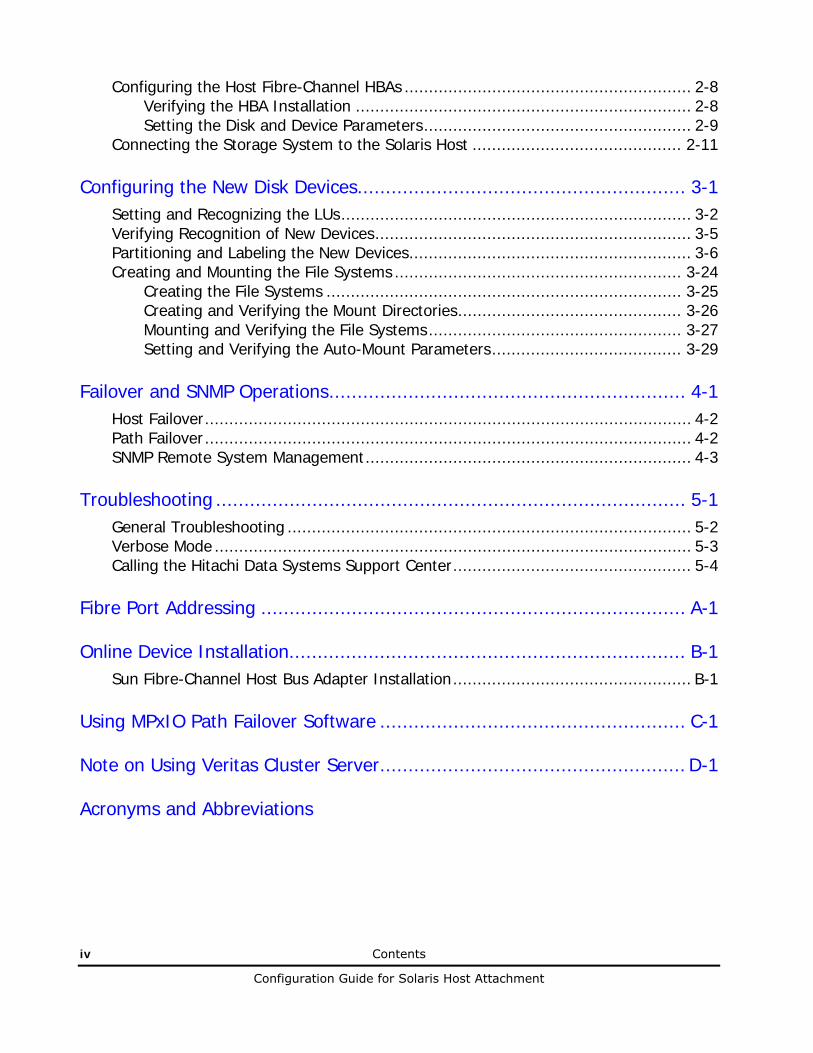
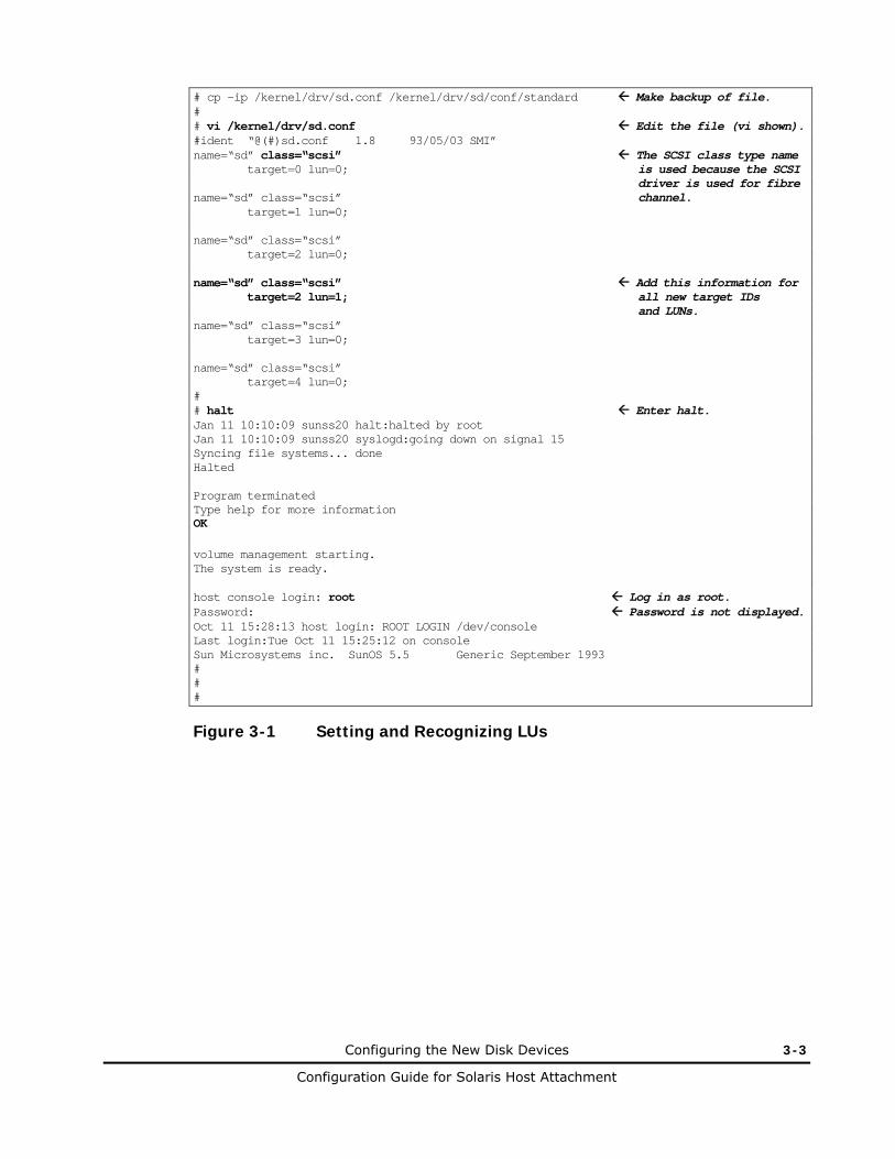
Once the Hitachi RAID storage system is installed and connected, set and recognize the new LUs by adding the logical devices to the sd.conf file (/kernel/drv/sd.conf). The sd.conf file includes the SCSI TID and LUN for all LDEVs connected to the Solaris system. After editing the sd.conf file, you will halt the system and reboot.
To set and recognize LUs:
1. Log in as root, and make a backup copy of the /kernel/drv/sd.conf file:
cp -ip /kernel/drv/sd.conf /kernel/drv/sd.conf.standard
2. Edit the /kernel/drv/sd.conf file as shown in Figure 3-1. Be sure to make an entry (SCSI TID and LUN) for each new device being added to the Solaris system.
If the LUs have already been added to the sd.conf file, verify each new LU.
3. Exit the vi editor by entering the command:
ESC + :wq
4. Halt the Solaris system: halt
5. Reboot the Solaris system: boot -r
6. Log in to the system as root, and verify that the system recognizes the Hitachi RAID storage system (see Figure 3-2): dmesg | more
7. Verify that the vendor name, product name, and number of blocks match the values shown in Figure 3-2.
Configuring the New Disk Devices 3-3
Configuration Guide for Solaris Host Attachment
# cp -ip /kernel/drv/sd.conf /kernel/drv/sd/conf/standard Make backup of file. # # vi /kernel/drv/sd.conf Edit the file (vi shown). #ident “@(#)sd.conf 1.8 93/05/03 SMI” name=“sd” class=“scsi” The SCSI class type name target=0 lun=0; is used because the SCSI driver is used for fibre name=“sd” class=“scsi” channel. target=1 lun=0; name=“sd” class=“scsi” target=2 lun=0; name=“sd” class=“scsi” Add this information for target=2 lun=1; all new target IDs and LUNs. name=“sd” class=“scsi” target=3 lun=0; name=“sd” class=“scsi” target=4 lun=0; # # halt Enter halt. Jan 11 10:10:09 sunss20 halt:halted by root Jan 11 10:10:09 sunss20 syslogd:going down on signal 15 Syncing file systems... done Halted Program terminated Type help for more information OK volume management starting. The system is ready. host console login: root Log in as root. Password: Password is not displayed. Oct 11 15:28:13 host login: ROOT LOGIN /dev/console Last login:Tue Oct 11 15:25:12 on console Sun Microsystems inc. SunOS 5.5 Generic September 1993 # # #
Figure 3-1 Setting and Recognizing LUs

3-4 Configuring the New Disk Devices
Configuration Guide for Solaris Host Attachment
# dmesg | more : sbus0 at root: UPA 0x1f 0x0 ... fas0: rev 2.2 FEPS chip SUNW,fas0 at sbus0: SBus0 slot 0xe offset 0x8800000 and slot 0xe offset 0x8810000 Onboard device sparc9 ipl 4 SUNW,fas0 is /sbus@1f,0/SUNW,fas@e,8800000 sd0 at SUNW,fas0: target 0 lun 0 sd0 is /sbus@1f,0/SUNW,fas@e,8800000/sd@0,0 <SUN2.1G cyl 2733 alt 2 hd 19 sec 80> sd6 at SUNW,fas0: target 6 lun 0 sd6 is /sbus@1f,0/SUNW,fas@e,8800000/sd@6,0 WARNING: fca0: fmle: sc1: 000e0000 sc2: 00000000 fca0: JNI Fibre Channel Adapter (1062 MB/sec), model FC fca0: SBus 1 / IRQ 4 / FCODE Version 10 [20148b] / SCSI ID 125 / AL_PA 0x1 fca0: Fibre Channel WWN: 100000e0690002b7 fca0: FCA Driver Version 2.1+, June 24, 1998 Solaris 2.5, 2.6 fca0: All Rights Reserved. fca0: < Total IOPB space used: 1100624 bytes > fca0: < Total DMA space used: 532644 bytes > fca0: <HITACHI :OPEN-3 :5235> target 2 (alpa 0xe4) lun 0 online sd192 at fca: target 2 lun 0 LUN = 0 target ID = 2 sd192 is /sbus@1f,0/fca@1,0/sd@2,0 WARNING: /sbus@1f,0/fca@1,0/sd@2,0 (sd192) corrupt label - wrong magic number Not yet labeled. Vendor ‘HITACHI’, product ‘OPEN-3’, 4806720 512 byte blocks Vendor name Number of blocks Product name fca0: <HITACHI :OPEN-3 :5235> target 2 (alpa 0xdc) lun 2 online sd193 at fca: target 2 lun 1 (LUN=1, target ID=2) sd193 is /sbus@1f,0/fca@1,0/sd@2,1 WARNING: /sbus@1f,0/fca@1,0/sd@2,1 (sd193) corrupt label - wrong magic number Vendor ‘HITACHI’, product ‘OPEN-3’, 4806720 512 byte blocks fca0: <HITACHI :OPEN-9 :5235> target 6 (alpa 0xdc) lun 0 online sd.. at fca: target lun 0 (LUN=0, target ID=6) sd.. is /sbus@1f,0/fca@1,0/sd@4,0 WARNING: /sbus@1f,0/fca@1,0/sd@4,0 (sd..) corrupt label - wrong magic number Not yet labeled. Vendor ‘HITACHI’, product ‘OPEN-9’, 14423040 512 byte blocks sd.. at fca: target 6 lun 0 Verify target ID. corrupt label - wrong magic number Not yet labeled. Vendor ‘HITACHI’, product ‘OPEN-9’, 14423040 512 byte blocks sd.. is /sbus@1f,0/fca@1,0/sd@5,0 WARNING: /sbus@1f,0/fca@1,0/sd@5,0 (sd..) corrupt label - wrong magic number Not yet labeled. Vendor ‘HITACHI’, product ‘3390-3B’, 5822040 512 byte blocks sd.. is /sbus@1f,0/fca@1,0/sd@6,0 WARNING: /sbus@1f,0/fca@1,0/sd@6,0 (sd..) corrupt label - wrong magic number Not yet labeled. Vendor ‘HITACHI’, product ‘3390-3A’, 5825520 512 byte blocks sd.. is /sbus@1f,0/fca@1,0/sd@8,0
Figure 3-2 Fibre Device Recognition
Note: If the FX volumes (e.g., 3390-3A/B/C) are customized, their block number may be lower than the number displayed in this example.
Configuring the New Disk Devices 3-5
Configuration Guide for Solaris Host Attachment
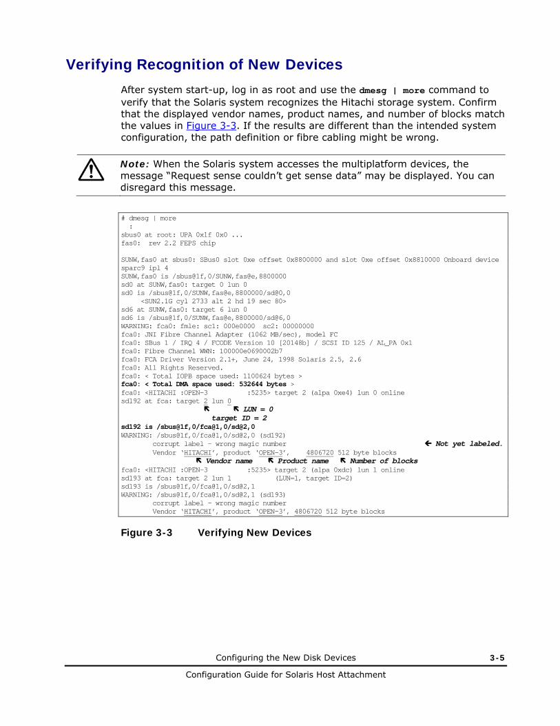
Verifying Recognition of New Devices
After system start-up, log in as root and use the dmesg | more command to verify that the Solaris system recognizes the Hitachi storage system. Confirm that the displayed vendor names, product names, and number of blocks match the values in Figure 3-3. If the results are different than the intended system configuration, the path definition or fibre cabling might be wrong.
Note: When the Solaris system accesses the multiplatform devices, the message “Request sense couldn’t get sense data” may be displayed. You can disregard this message.
# dmesg | more : sbus0 at root: UPA 0x1f 0x0 ... fas0: rev 2.2 FEPS chip SUNW,fas0 at sbus0: SBus0 slot 0xe offset 0x8800000 and slot 0xe offset 0x8810000 Onboard device sparc9 ipl 4 SUNW,fas0 is /sbus@1f,0/SUNW,fas@e,8800000 sd0 at SUNW,fas0: target 0 lun 0 sd0 is /sbus@1f,0/SUNW,fas@e,8800000/sd@0,0 <SUN2.1G cyl 2733 alt 2 hd 19 sec 80> sd6 at SUNW,fas0: target 6 lun 0 sd6 is /sbus@1f,0/SUNW,fas@e,8800000/sd@6,0 WARNING: fca0: fmle: sc1: 000e0000 sc2: 00000000 fca0: JNI Fibre Channel Adapter (1062 MB/sec), model FC fca0: SBus 1 / IRQ 4 / FCODE Version 10 [20148b] / SCSI ID 125 / AL_PA 0x1 fca0: Fibre Channel WWN: 100000e0690002b7 fca0: FCA Driver Version 2.1+, June 24, 1998 Solaris 2.5, 2.6 fca0: All Rights Reserved. fca0: < Total IOPB space used: 1100624 bytes > fca0: < Total DMA space used: 532644 bytes > fca0: <HITACHI :OPEN-3 :5235> target 2 (alpa 0xe4) lun 0 online sd192 at fca: target 2 lun 0 LUN = 0 target ID = 2 sd192 is /sbus@1f,0/fca@1,0/sd@2,0 WARNING: /sbus@1f,0/fca@1,0/sd@2,0 (sd192) corrupt label - wrong magic number Not yet labeled. Vendor ‘HITACHI’, product ‘OPEN-3’, 4806720 512 byte blocks Vendor name Product name Number of blocks fca0: <HITACHI :OPEN-3 :5235> target 2 (alpa 0xdc) lun 1 online sd193 at fca: target 2 lun 1 (LUN=1, target ID=2) sd193 is /sbus@1f,0/fca@1,0/sd@2,1 WARNING: /sbus@1f,0/fca@1,0/sd@2,1 (sd193) corrupt label - wrong magic number Vendor ‘HITACHI’, product ‘OPEN-3’, 4806720 512 byte blocks
Figure 3-3 Verifying New Devices

3-6 Configuring the New Disk Devices
Configuration Guide for Solaris Host Attachment
This example shows two new disks on fca@1: target ID is 2, LUNs are 0 and 1, vendor name is “HITACHI”, product name is “OPEN-3”, and number of blocks is 4806720. LUNs 0 and 1 are assigned as device names sd192 and sd193, respectively. Details for other disks:
• vendor name “HITACHI”, product name “OPEN-9” and 14423040 512-byte blocks
• vendor name “HITACHI”, product name “3390-3B” and 5822040 512-byte blocks
• vendor name “HITACHI”, product name “3390-3A” and 5825520 512-byte blocks
Partitioning and Labeling the New Devices
After the Solaris system recognizes the new devices, partition and label the devices. All new devices, including all SCSI disk devices and FX devices, must be partitioned and labeled using the format utility (see WARNING below).
• Each SCSI disk device (e.g., OPEN-x) can have more than one partition.
• Each FX device (e.g., 3390-3A) must have one partition of fixed size.
The disk partitioning and labeling procedure involves the following tasks:
1. Defining and setting the disk type.
2. Setting the partition(s).
3. Labeling the disk (required for devices to be managed by HDLM).
4. Verifying the disk label.
A good way to partition and label the disks is to partition and label all devices of one type (e.g., OPEN-3), then all devices of the next type (e.g., OPEN-9), and so on until you partition and label all new devices. You will enter this information into the Solaris system during the disk partitioning and labeling procedure.
WARNING: Be extremely careful when using the Solaris format utility. Do not use any format commands not described in this document. The format utility is designed for Sun disks. Some format commands are not compatible with the Hitachi RAID storage system and can overwrite the data on the disk. The Hitachi RAID storage system will not respond to the format command (devices are formatted using the SVP), and will not report any defect data in response to the defect command.

Configuring the New Disk Devices 3-7
Configuration Guide for Solaris Host Attachment
To partition and label the new devices/disks:
1. Enter format at the root prompt to start the format utility (see Figure 3-4).
a. Verify that all new devices are displayed. If not, exit the format utility (quit or Ctrl-d), and then be sure the SCSI/fibre-to-LDEV paths were defined for all devices and that all new devices were added to the driver configuration file). See Chapter 5 for troubleshooting information.
b. Write down the character-type device file names (e.g., c1t2d0) for all of the new devices. You will need this information later to create the file systems.
2. When prompted to specify the disk, enter the number (from the list) for the device to be partitioned and labeled. Remember the device type of this device (e.g., OPEN-3).
3. When prompted to label the disk, enter y for “yes” and enter the desired label. Devices that will be managed by HDLM require a label. If you are sure that the device will not need a label, you can enter n for “no”.
4. When the format menu appears, enter type to display the disk types. The disk types are listed in Table 1-2 (vendor name + product name, e.g., HITACHI OPEN-3).
5. If the disk type for the selected device is already defined, enter the number for that disk type and skip to step 7.
Note: • Do not use HITACHI-OPEN-x-0315, HITACHI-3390-3A/B-0315. These
disk types are created automatically by the Solaris system and cannot be used for the Hitachi RAID storage system devices.
• LU capacity must be less than 1 TB. In case of selecting other type, the disk type parameters described below cannot be set for an LU larger than 32,767 data cylinders.
6. If the disk type for the selected device is not already defined, enter the number for other to define a new disk type.
7. Enter the disk type parameters for the selected device using the data provided above. Be sure to enter the parameters exactly as shown in Figure 3-5.
8. When prompted to label the disk, enter n for “no”.
9. When the format menu appears, enter partition to display the partition menu.
10. Enter the desired partition number and the partition parameters in Figure 3-6 and Table 3-1 through Table 3-8.
11. At the partition> prompt, enter print to display the current partition table.
3-8 Configuring the New Disk Devices
Configuration Guide for Solaris Host Attachment
12. Repeat steps 9 and 10 as needed to set the desired partitions for the selected device.
Note: This step does not apply to the multiplatform devices (e.g., 3390-3A/B/C), because these devices can only have one partition of fixed size.
13. After setting the partitions for the selected device, enter label at the partition> prompt and enter y to label the device (see Figure 3-7).
Note: The Solaris system displays the following warnings when an FX device (e.g., 3390-3A/B/C) is labeled. You can ignore these warnings. Warning: error warning VTOC. Warning: no backup labels. Label failed.
14. Enter quit to exit the partition utility and return to the format utility.
15. At the format> prompt, enter disk to display the available disks. Be sure the disk you just labeled is displayed with the proper disk type name and parameters.
16. Repeat steps 2 through 15 for each new device to be partitioned and labeled. After a device type is defined (e.g., HITACHI OPEN-3), you can label all devices of that same type without having to enter the parameters (skipping steps 6 and 7). For this reason, you may want to label the devices by type (e.g., labeling all OPEN-3 devices, then all OPEN-9 devices, and so on) until all new devices have been partitioned and labeled.
17. When you finish partitioning and labeling the disks and verifying the disk labels, exit the format utility by entering quit or Ctrl-d.

Configuring the New Disk Devices 3-9
Configuration Guide for Solaris Host Attachment
# format Start format utility. Searching for disks...done c1t2d0: configured with capacity of 2.29GB (OPEN-3) These devices are not yet labeled. c1t2d1: configured with capacity of 2.29GB (OPEN-3) c2t4d0: configured with capacity of 6.88GB (OPEN-9) c2t5d0: configured with capacity of 2.77GB (3390-3B) c2t6d0: configured with capacity of 2.78GB (3390-3A)
These character-type device file names are used later to create the file systems. AVAILABLE DISK SELECTIONS: 0. c0t1d0 <SUN1.05 cyl 2036 alt 2 hd 14 sec 72> Already labeled. /iommu@f,e0000000/sbus@f,e0001000/espdma@f,400000/esp@f,800000/sd@1,0 1. c0t3d0 <SUN1.05 cyl 2036 alt 2 hd 14 sec 72> Already labeled. /iommu@f,e0000000/sbus@f,e0001000/espdma@f,400000/esp@f,800000/sd@3,0 2. c1t2d0 <HITACHI-OPEN-3-52-34 Not yet labeled: LUN Product version Vendor Product ID Target Id Logical Controller ID /iommu@f,e0000000/sbus@f,e0001000/....,isp@1,10000/sd@2,0 OPEN-3, TID=2, LUN=0 3. c1t2d1 <HITACHI-OPEN-3-52-34 Not yet labeled: /iommu@f,e0000000/sbus@f,e0001000/....,isp@1,10000/sd@2,1 OPEN-3, TID=2, LUN=1 4. c1t4d0 <HITACHI-OPEN-9-52-34 Not yet labeled: /iommu@f,e0000000/sbus@f,e0001000/....,isp@1,10000/sd@4,0 OPEN-9, TID=4, LUN=0 5. c1t5d0 <HITACHI-3390-3B-52-34 Not yet labeled: /iommu@f,e0000000/sbus@f,e0001000/....,isp@1,10000/sd@5,0 3390-3B, TID=5, LUN=0 6. c1t6d0 <HITACHI-3390-3A-52-34 Not yet labeled: /iommu@f,e0000000/sbus@f,e0001000/....,isp@1,10000/sd@6,0 3390-3A, TID=6, LUN=0 Specify disk (enter its number): 2 Select device. selecting c1t2d0 [disk formatted] Disk not labeled. Label it now ? n Enter “n” for no. : #
Figure 3-4 Verifying New Devices for Disk Partitioning

3-10 Configuring the New Disk Devices
Configuration Guide for Solaris Host Attachment
FORMAT MENU: disk - select a disk type - select (define) a disk type partition - select (define) a partition table current - describe the current disk format - format and analyze the disk repair - repair a defective sector label - write label to the disk analyze - surface analysis defect - defect list management backup - search for backup labels verify - read and display labels save - save new disk/partition definitions inquiry - show vendor, product and revision volume - set 8-character volume name quit # format> type Enter type. : AVAILABLE DRIVE TYPES 0. Auto configure : 14. SUN2.1G 15. HITACHI-OPEN-3-0315 Do not select this disk type. 16. other (see Note 3) Specify disk type (enter its number):16 Enter number for “other” to define. Enter number of data cylinders:3336 Enter value from Table 3-1 (Note 1) Enter number of alternate cylinders[2]:2 Enter value from Table 3-1 Enter number of physical cylinders[3338]: (press Enter for default) Enter number of heads:15 Enter value from Table 3-2 Enter number of physical sectors/track[defaults]: (press Enter for default) Enter rpm of drive [3600]:10000 Enter value from Table 3-1 (Note 2) Enter format time[defaults]: (press Enter for default) Enter cylinder skew[defaults]: (press Enter for default) Enter track skew[defaults]: (press Enter for default) Enter track per zone[defaults]: (press Enter for default) Enter alternate tracks[defaults]: (press Enter for default) Enter alternate sectors[defaults]: (press Enter for default) Enter cache control[defaults]: (press Enter for default) Enter prefetch threshold[defaults]: (press Enter for default) Enter minimum prefetch[defaults]: (press Enter for default) Enter maximum prefetch[defaults]: (press Enter for default) Enter disk type name(remember quotes):”HITACHI OPEN-3” Enter name from Table 1-2. selecting c1t2d0 [disk formatted] No defined partition tables. Disk not labeled. Label it now ? n Enter “n” for no. format>
Figure 3-5 Defining and Setting the Disk Type

Configuring the New Disk Devices 3-11
Configuration Guide for Solaris Host Attachment
Table Notes:
1: The number of cylinders for the 3390-3B is 3346, and the Hitachi RAID storage system returns ‘3346 cylinder’ to the Mode Sense command, and ‘5822040 blocks’ (Maximum LBA 5822039) to the Read capacity command. When 3390-3B is not labeled yet, Solaris displays 3344 data cylinders and 2 alternate cylinders. When 3390-3B is labeled by the Solaris format type subcommand, use 3340 for data cylinder and 2 for alternate cylinder. This is similar to the 3390-3B VLL.
2: The Hitachi RAID storage system reports the RPM of the physical disk drive in response to the type subcommand parameter.
3: It is also possible to follow the procedure using type => “0. Auto Configure” => label the drive without calculating detail values like as Cylinder, Header, Blocks/Tracks.
4: Setting host mode 16 affects the geometry parameter reported by the Hitachi RAID storage system (see Table 3-1) as follows:
• Setting host mode option 16 to ON increases the number of cylinders by 4 and reduces the number of blocks per track by ¼.
• Setting host mode option 16 to OFF lowers the number of cylinders by ¼ and increases the number of blocks per track by 4. Therefore, if you use host mode 16, please account for these differences. For example, if you change the host mode option 16 from OFF to ON, you may want to make either of the following changes in the format menu:
• Increase the number of block setting per track by ¼ and the number of heads by 4.
• Increase the number of blocks per track to ¼, the number of cylinders by 2, and the number of heads by 2.
If the number of cylinders entered exceeds 65,533, the total LU block number equals or is less than 65,533. Use the Format Menu to specify the numbers of cylinders, heads, and blocks per track.

3-12 Configuring the New Disk Devices
Configuration Guide for Solaris Host Attachment
format> disk AVAILABLE DISK SELECTIONS 0. c0t1d0 <SUN1.05 cyl 2036 alt 2 hd 14 sec 72> /iommu@f,e0000000/sbus@f,e0001000/espdma@f,400000/esp@f,800000/sd@1,0 1. c0t3d0 <SUN1.05 cyl 2036 alt 2 hd 14 sec 72> /iommu@f,e0000000/sbus@f,e0001000/espdma@f,400000/esp@f,800000/sd@3,0 2. c1t2d0 <HITACHI OPEN-3 cyl 3336 alt 2 hd 15 sec 96> ...already labeled /iommu@f,e0000000/sbus@f,e0001000/....,isp@0,10000/sd@2,0 3. c1t2d1 <HITACHI-OPEN-3-52-34 .....> ...not yet labeled /iommu@f,e0000000/sbus@f,e0001000/....,isp@0,10000/sd@2,1 4. c1t4d0 <HITACHI-OPEN-9-52-34 .....> ...not yet labeled /iommu@f,e0000000/sbus@f,e0001000/....,isp@1,10000/sd@4,0 5. c1t5d0 <HITACHI-3390-3B-52-34 ....> ...not yet labeled /iommu@f,e0000000/sbus@f,e0001000/....,isp@1,10000/sd@5,0 6. c1t6d0 <HITACHI-3390-3A-52-34 ....> ...not yet labeled /iommu@f,e0000000/sbus@f,e0001000/....,isp@1,10000/sd@6,0 Specify disk (enter its number): 3 FORMAT MENU: disk - select a disk type - select (define) a disk type partition - select (define) a partition table current - describe the current disk format - format and analyze the disk repair - repair a defective sector label - write label to the disk analyze - surface analysis defect - defect list management backup - search for backup labels verify - read and display labels save - save new disk/partition definitions inquiry - show vendor, product and revision volume - set 8-character volume name quit format> type Enter type. AVAILABLE DRIVE TYPES 0.Auto configure : 13. SUN1.3G 14. SUN2.1G 15. HITACHI-OPEN-3-52-34 16. HITACHI OPEN-3 17. other Specify disk type (enter its number):16 Enter the number for : the desired drive type. selecting c0t2d0 [disk formatted] No defined partition tables. Disk not labeled. Label it now ? n Enter n for no. format>
Figure 3-6 Setting the Partition(s) (continues on the next page)

Configuring the New Disk Devices 3-13
Configuration Guide for Solaris Host Attachment
FORMAT MENU: disk - select a disk type - select (define) a disk type partition - select (define) a partition table current - describe the current disk format - format and analyze the disk repair - repair a defective sector label - write label to the disk analyze - surface analysis defect - defect list management backup - search for backup labels verify - read and display labels save - save new disk/partition definitions inquiry - show vendor, product and revision volname - set 8-character volume name <cmd> - execute <cmd>, then return quit format> partition Display partition menu. PARTITION MENU 0 - change ‘0’ partition 1 - change ‘1’ partition 2 - change ‘2’ partition 3 - change ‘3’ partition 4 - change ‘4’ partition 5 - change ‘5’ partition 6 - change ‘6’ partition 7 - change ‘7’ partition select - select a predefined table modify - modify a predefined partition table name - name the current table print - display the current table label - write partition map and label to the disk quit partition> 0 Select partition number. Part Tag Flag Cylinders Size Blocks 0 unassigned wm 0 - 0 (0/0/0) Enter partition id tag [root]: Press enter for default. Enter partition permission flags [wm]: Press enter for default. Enter new starting cyl [0]: Press enter for default. Enter partition size [0b, 0c, 0.00mb]:3336c Enter size (Table_3_1). partition> print Display partition table. : (see Note, below) Current partition table (unnamed) Part Tag Flag Cylinders Size Blocks 0 root wm 0 - 0 (0/0/0) 0 1 swap wm 0 - 0 (0/0/0) 0 2 backup wu 0 - 3335 2.29 GB (3336/0/0) 4803840 3 unassigned wu 0 - 0 (0/0/0) 0 4 unassigned wm 0 - 0 (0/0/0) 0 5 unassigned wm 0 - 0 (0/0/0) 0 6 usr wm 336 - 3335 204 GB (2970/0/0) 4276800 7 unassigned wm 0 - 0 (0/0/0) 0
Figure 3-6 Setting the Partition(s) (continued)

3-14 Configuring the New Disk Devices
Configuration Guide for Solaris Host Attachment
PARTITION MENU 0 - change ‘0’ partition 1 - change ‘1’ partition 2 - change ‘2’ partition 3 - change ‘3’ partition 4 - change ‘4’ partition 5 - change ‘5’ partition 6 - change ‘6’ partition 7 - change ‘7’ partition select - select a predefined table modify - modify a predefined partition table name - name the current table print - display the current table label - write partition map and label to the disk quit partition> label Label the disk. Ready to label disk, continue? Y Enter Y for yes. * (see Note, below) partition> quit Return to format. format> disk Display disks. AVAILABLE DISK SELECTIONS 0. c0t1d0 <SUN1.05 cyl 2036 alt 2 hd 14 sec 72> /iommu@f,e0000000/sbus@f,e0001000/espdma@f,400000/esp@f,800000/sd@1,0 1. c0t3d0 <SUN1.05 cyl 2036 alt 2 hd 14 sec 72> /iommu@f,e0000000/sbus@f,e0001000/espdma@f,400000/esp@f,800000/sd@3,0 2. c1t2d0 <HITACHI OPEN-3 cyl 3336 alt 2 hd 15 sec 96> Verify disk label. Track size. Number of heads. Number of alternate cylinders. Number of data cylinders. Disk type name. /iommu@f,e0000000/sbus@f,e0001000/....,isp@0,10000/sd@2,0 3. c1t2d1 <HITACHI-OPEN-3-0315 ..................... > Not yet labeled. /iommu@f,e0000000/sbus@f,e0001000/....,isp@0,10000/sd@2,1 4. c1t4d0 <HITACHI-OPEN-9-0315 ..................... > Not yet labeled. /iommu@f,e0000000/sbus@f,e0001000/....,isp@1,10000/sd@4,0 5. c1t5d0 <HITACHI-3390-3B-0315 .................... > Not yet labeled. /iommu@f,e0000000/sbus@f,e0001000/....,isp@1,10000/sd@5,0 6. c1t6d0 <HITACHI-3390-3A-0315 .................... > Not yet labeled. /iommu@f,e0000000/sbus@f,e0001000/....,isp@1,10000/sd@6,0 Specify disk (enter its number): 3 Enter number for next disk to label, or press Ctrl-d to quit.
Figure 3-7 Labeling the Disk and Verifying the Disk Label
Note: The Sun Solaris system displays the following warnings when an FX device (e.g., 3390-3A) is labeled. You can ignore these warnings: Warning: error warning VTOC. Warning: no backup labels. Label failed.

Configuring the New Disk Devices 3-15
Configuration Guide for Solaris Host Attachment
Table 3-1 Device Geometry Parameters
Device Type # of Data Cylinders
# of AlternateCylinders
RPM Partition Size (sample)
OPEN-3 3336 2 10,000 3336c
OPEN-8 9964 2 10,000 9964c
OPEN-9 10014 2 10,000 10014c
OPEN-E 19757 2 10,000 19757c
OPEN-L 19013 2 10,000 19013c
OPEN-3*n N1* 2 10,000 N4*
OPEN-8*n N26* 2 10,000 N29*
OPEN-9*n N5* 2 10,000 N8*
OPEN-E*n N30* 2 10,000 N33*
OPEN-L*n N34 2 10,000 N37
OPEN-x VLL See Table 1-2 2 10,000 See Table 1-2
OPEN-3*n VLL N22* 2 10,000 N25*
OPEN-8*n VLL N22* 2 10,000 N25*
OPEN-9*n VLL N22* 2 10,000 N25*
OPEN-E*n VLL N22* 2 10,000 N25*
OPEN-V*n VLL N22* 2 10,000 N25*
3390-3A 3346 2 10,000 3346c
3390-3B 3340 2 10,000 3340c
3390-3C 3346 2 10,000 3346c
FX OPEN-3 3336 2 10,000 3336c
3390-3A VLL See Table 1-2 2 10,000 See Table 1-2
3390-3B VLL See Table 1-2 2 10,000 See Table 1-2
3390-3C VLL See Table 1-2 2 10,000 See Table 1-2
FX OPEN-3 VLL See Table 1-2 2 10,000 See Table 1-2
Note: For the values indicated by Nxx (e.g., N15, N22), see Table 3-2 through Table 3-8.

3-16 Configuring the New Disk Devices
Configuration Guide for Solaris Host Attachment
Table 3-2 Geometry Parameters for OPEN-3*n LUSE Devices
n Data Cylinders-N1 Partition Size-N4
Heads-N2 Blocks/ Track-N3
Usable Blocks (N1+2)*N2*N3
Provided Blocks =3338*15*96*n
Diff.
2 6674 15 96 9613440 9613440 0
3 10012 15 96 14420160 14420160 0
4 13350 15 96 19226880 19226880 0
5 16688 15 96 24033600 24033600 0
6 20026 15 96 28840320 28840320 0
7 23364 15 96 33647040 33647040 0
8 26702 15 96 38453760 38453760 0
9 30040 15 96 43260480 43260480 0
10 16688 30 96 48067200 48067200 0
11 20026 33 80 52873920 52873920 0
12 20026 30 96 57680640 57680640 0
13 20026 39 80 62487360 62487360 0
14 23364 30 96 67294080 67294080 0
15 16688 45 96 72100800 72100800 0
16 26702 30 96 76907520 76907520 0
17 30040 34 80 81714240 81714240 0
18 30040 30 96 86520960 86520960 0
19 30040 38 80 91327680 91327680 0
20 16688 60 96 96134400 96134400 0
21 23364 45 96 100941120 100941120 0
22 30040 55 64 105747840 105747840 0
23 30040 46 80 110554560 110554560 0
24 20026 60 96 115361280 115361280 0
25 16688 45 160 120168000 120168000 0
26 20026 39 160 124974720 124974720 0
27 30040 45 96 129781440 129781440 0
28 23364 60 96 134588160 134588160 0
29 30040 58 80 139394880 139394880 0
30 16688 45 192 144201600 144201600 0
31 30040 62 80 149008320 149008320 0
32 26702 60 96 153815040 153815040 0
33 30040 55 96 158621760 158621760 0
34 30040 64 85 163428480 163428480 0

Configuring the New Disk Devices 3-17
Configuration Guide for Solaris Host Attachment
n Data Cylinders-N1 Partition Size-N4
Heads-N2 Blocks/ Track-N3
Usable Blocks (N1+2)*N2*N3
Provided Blocks =3338*15*96*n
Diff.
35 30040 56 100 168235200 168235200 0
36 30040 60 96 173041920 173041920 0
Notes:
N1,N2,N3: Use value in Table 3-1.
N4: Use same value as N1. Specify as NNNNc, where NNNN = # of cylinders and c = cylinder (e.g. enter 6674c for OPEN-3*2).
Table 3-3 Geometry Parameters for OPEN-8*n LUSE Devices
n Data Cylinders-N26 Partition Size-N29
Heads-N27
Blocks/ Track-N28
Usable Blocks (N26+2)*N27*N28
Provided Blocks =9966*15*96*n
Diff.
2 19930 15 96 28702080 28702080 0
3 29896 15 96 43053120 43053120 0
4 29896 20 96 57404160 57404160 0
5 29896 25 96 71755200 71755200 0
6 29896 30 96 86106240 86106240 0
7 29896 35 96 100457280 100457280 0
8 29896 40 96 114808320 114808320 0
9 29896 45 96 129159360 129159360 0
10 29896 50 96 143510400 143510400 0
11 29896 55 96 157861440 157861440 0
12 29896 60 96 172212480 172212480 0
13 29896 52 120 186563520 186563520 0
14 29896 56 120 200914560 200914560 0
15 29896 60 120 215265600 215265600 0
16 29896 64 120 229616640 229616640 0
17 29896 34 240 243967680 243967680 0
18 29896 36 240 258318720 258318720 0
19 29896 38 240 272669760 272669760 0
20 29896 40 240 287020800 287020800 0
21 29896 42 240 301371840 301371840 0
22 29896 44 240 315722880 315722880 0
23 29896 46 240 330073920 330073920 0
24 29896 48 240 344424960 344424960 0
25 29896 50 240 358776000 358776000 0
26 29896 52 240 373127040 373127040 0
27 29896 54 240 387478080 387478080 0
28 29896 56 240 401829120 401829120 0

3-18 Configuring the New Disk Devices
Configuration Guide for Solaris Host Attachment
n Data Cylinders-N26 Partition Size-N29
Heads-N27
Blocks/ Track-N28
Usable Blocks (N26+2)*N27*N28
Provided Blocks =9966*15*96*n
Diff.
29 29896 58 240 416180160 416180160 0
30 29896 60 240 430531200 430531200 0
31 29896 62 240 444882240 444882240 0
32 29896 64 240 459233280 459233280 0
33 32614 60 242 473584320 473584320 0
34 29896 64 255 487935360 487935360 0
35 30655 64 256 502284288 502286400 2112
36 31531 64 256 516636672 516637440 768
Notes:
N26,N27,N28 : Use values in Table 1-2.
N29: Use same value as N26. Specify as NNNNc, where NNNN = # of cylinders and c = cylinder (e.g. enter 19930c for OPEN-8*2).
Note: Data cylinders must be less than or equal to 32767, heads must be less than or equal to 64, blocks per track must be less than or equal to 256 when these values are specified as parameters of Solaris format type subcommand. The whole data blocks of OPEN-3*2 ~ OPEN-3*36 can be used by above parameters.
Table 3-4 Geometry Parameters for OPEN-9*n LUSE Devices
n Data Cylinders-N5 Partition Size-N8
Heads-N6
Blocks/ Track-N7
Usable Blocks (N5+2)*N6*N7
Provided Blocks =10016*15*96*n
Diff.
2 20030 15 96 28846080 28846080 0
3 30046 15 96 43269120 43269120 0
4 30046 20 96 57692160 57692160 0
5 30046 25 96 72115200 72115200 0
6 30046 30 96 86538240 86538240 0
7 30046 35 96 100961280 100961280 0
8 30046 40 96 115384320 115384320 0
9 30046 45 96 129807360 129807360 0
10 30046 50 96 144230400 144230400 0
11 30046 55 96 158653440 158653440 0
12 30046 60 96 173076480 173076480 0
13 30046 52 120 187499520 187499520 0
14 30046 56 120 201922560 201922560 0
15 30046 60 120 216345600 216345600 0
16 30046 64 120 230768640 230768640 0

Configuring the New Disk Devices 3-19
Configuration Guide for Solaris Host Attachment
n Data Cylinders-N5 Partition Size-N8
Heads-N6
Blocks/ Track-N7
Usable Blocks (N5+2)*N6*N7
Provided Blocks =10016*15*96*n
Diff.
17 30046 34 240 245191680 245191680 0
18 30046 36 240 259614720 259614720 0
19 30046 38 240 274037760 274037760 0
20 30046 40 240 288460800 288460800 0
21 30046 42 240 302883840 302883840 0
22 30046 44 240 317306880 317306880 0
23 30046 46 240 331729920 331729920 0
24 30046 48 240 346152960 346152960 0
25 30046 50 240 360576000 360576000 0
26 30046 52 240 374999040 374999040 0
27 30046 54 240 389422080 389422080 0
28 30046 56 240 403845120 403845120 0
29 30046 58 240 418268160 418268160 0
30 30046 60 240 432691200 432691200 0
31 30046 62 240 447114240 447114240 0
32 30046 64 240 461537280 461537280 0
33 30985 64 240 475960320 475960320 0
34 31924 64 240 490383360 490383360 0
35 31298 63 256 504806400 504806400 0
36 31689 64 256 519225344 519229440 4096
Notes:
N5,N6,N7: Use value in Table 3-1 and Table 3-2.
N8: Use same value as N5. Specify as NNNNc, where NNNN = # of cylinders and c = cylinder (e.g. enter 20030c for OPEN-9*2).

3-20 Configuring the New Disk Devices
Configuration Guide for Solaris Host Attachment
Table 3-5 Geometry Parameters for OPEN-E*n LUSE Devices
n Data Cylinders-N30 Partition Size-N33
Heads-N31
Blocks/ Track-N32
Usable Blocks (N30+2)*N31*N32
Provided Blocks =9966*15*96*n
Diff.
2 19757 30 96 56905920 56905920 0
3 19757 45 96 85358880 85358880 0
4 19757 60 96 113811840 113811840 0
5 19757 30 240 142264800 142264800 0
6 19757 45 192 170717760 170717760 0
7 19757 60 168 199170720 199170720 0
8 19757 60 192 227623680 227623680 0
9 19757 60 216 256076640 256076640 0
10 19757 60 240 284529600 284529600 0
11 27166 60 192 312975360 312982560 7200
12 29636 60 192 341429760 341435520 5760
13 32106 60 192 369884160 369888480 4320
14 27660 60 240 398332800 398341440 8640
15 29636 60 240 426787200 426794400 7200
16 31612 60 240 455241600 455247360 5760
17 31612 60 255 483694200 483700320 6120
18 31257 64 256 512147456 512153280 5824
Notes:
N30,N31,N32: Use value in Table 3-1.
N33: Use same value as N30. Specify as NNNNc, where NNNN = # of cylinders and c = cylinder (e.g. enter 19757c for OPEN-E*2).
Note: Data cylinders must be less than or equal to 32767, heads must be less than or equal to 64, blocks per track must be less than or equal to 256 when these values are specified as parameters of Solaris format type subcommand. The whole data blocks of OPEN-E*2∼OPEN-E*10 can be used by above parameters. About OPEN-E*11~OPEN-E*18, some blocks must become unusable.

Configuring the New Disk Devices 3-21
Configuration Guide for Solaris Host Attachment
Table 3-6 Geometry Parameters for OPEN-L*n LUSE Devices
n Data Cylinders-N34 Partition Size-N37
Heads-N35
Blocks/ Track-N36
Usable Blocks (N34+2)*N35*N36
Provided Blocks =49439*15*96*n
Diff.
2 19013 64 117 142384320 142384320 0
3 30422 36 195 213576480 213576480 0
4 30422 45 208 284768640 284768640 0
5 30422 60 195 355960800 355960800 0
6 30422 60 234 427152960 427152960 0
7 30897 63 256 498339072 498345120 6048
Notes:
N34, N35, N36: Use value in Table 3-1.
N37: Use same value as N34. Specify as NNNNc, where NNNN = # of cylinders and c = cylinder (e.g. enter 19013c for OPEN-L*2).
Note: Data cylinders must be less than or equal to 32767, heads must be less than or equal to 64, blocks per track must be less than or equal to 256 when these values are specified as parameters of Solaris format type subcommand. The whole data blocks of OPEN-L*2∼OPEN-L*6 can be used by above parameters. About OPEN-L*7, some blocks must become unusable.

3-22 Configuring the New Disk Devices
Configuration Guide for Solaris Host Attachment
Table 3-7 Geometry Parameters for OPEN-x*n VLL-LUSE Devices (Example)
Data Cylinders-N22 Partition Size-N25
Heads-N23
Blocks/Track-
N24
Usable Blocks (N22+2)*N23*
N24
Provided Blocks-N21 Diff.
98 15 96 144000 35MB×2 volumes
↑35×1024/720↑×2=100
100×15×96=144000
0
2590 15 96 3732480 50MB×36 volumes
↑50×1024/720↑×36=2592
2592×15×96=3732480
0
284 15 96 411840 100MB×2 volumes
↑100×1024/720↑×2=286
286×15×96=411840
0
5694 15 96 8202240 500MB×8 volumes
↑500×1024/720↑×8=5696
5696×15×96=8202240
0
22758 30 96 65548800 2000MB×2 volumes
↑2000×1024/720↑×16=45520
45520×15×96=65548800
0
27455 40 188 206476640 2800MB×36 volumes
↑2800×1024/720↑×36=143388
143388×15×96=206478720
2080
Notes:
N21 # of blocks of LUSE composed by VLL volumes are calculated by:
N21 = N20 × (# of heads) × (# of sectors per track).
N22: N20 – 2, Use total cylinder – 2.
N23, N24: Use value in Table 3-1 and Table 3-2.
N25: Use same value as N22.

Configuring the New Disk Devices 3-23
Configuration Guide for Solaris Host Attachment
Table 3-8 Geometry Parameters for OPEN-V*n VLL-LUSE Devices (Example)
Data Cylinders-N22
Partition Size-N25
Heads-N23
Blocks/Track-
N24
Usable Blocks (N22+2)*N23*
N24
Provided Blocks-N21 Diff.
48 15 128 92160 45 MB volumes ↑ 45 × 16/15 ↑ = 48 48 × 15 × 128 = 92160
0
27305 30 128 104858880 50 GB volumes ↑ 50 × 1024 × 16/15 ↑ = 54614 54614 × 15 × 128 = 104858880
0
10921 150 128 209721600 10 GB × 10 volumes ↑ 10 × 1024 × 16/15 ↑ × 10 = 109230 109230 × 15 × 128 = 209721600
0
32767 100 128 419443200 20 GB × 10 volumes ↑20 × 1024 × 16/15↑ × 10 = 218460 218460 × 15 × 128 = 419443200
0
Notes:
N21 # of blocks of LUSE composed by VLL volumes are calculated by:
N21 = N20 × (# of heads) × (# of sectors per track).
N22: N20 – 2, Use total cylinder – 2.
N23, N24: Use value in Table 3-1 and Table 3-2.
N25: Use same value as N22.
• For OPEN-V, because the capacity is not fixed, AutoConfig is recommended for the geometry setting.
• The geometry setting is also available manually as needed. In this case, the OPEN-V geometry of X GB can be calculated according to the equations in Example 1 and Example 2 using the values of N22, N23, and N24:
Example 1:
N22(Cyl)×N23(Head)×N24(Block/Trk)×512(Byte) = or < X GB(=×1024×1024×1024 Byte) is as follows:
16000(Cyl)×256(Head)×256(Block)×512(Byte)=536870912000Byte=500GB 32000(Cyl)×128(Head)×256(Block)×512(Byte)=536870912000Byte=500GB
Example 2 (a variation of Example 1):
22(Cyl)×N23(Head)×N24(Block/Trk) = or < X GB(=×1024×1024×1024 Byte)/ 512 (Byte) = Usable Blocks is as follows:
15000(Cyl)×256(Head)×256(Block)×512(Byte)=536870912000Byte=468.75GB<500GB

3-24 Configuring the New Disk Devices
Configuration Guide for Solaris Host Attachment
Creating and Mounting the File Systems
After you partition and label all new disks, create and mount the file systems for the SCSI disk devices (e.g., OPEN-x). Table 3-9 summarizes the steps for creating and mounting the file systems for the new SCSI disk devices.
Table 3-9 Steps for Creating and Mounting the File Systems
Task
1. Create the file systems
2. Create and verify the mount directories
3. Mount and verify the file systems
4. Set the auto-mount parameters (optional)
Note: Do not create file systems or mount directories for the FX devices (e.g., 3390-3A). These devices are accessed as raw devices and do not require any further configuration after being partitioned and labeled.

Configuring the New Disk Devices 3-25
Configuration Guide for Solaris Host Attachment
Creating the File Systems
To create the file systems for the newly installed SCSI disk devices:
1. Create the file system using the newfs -C <maxcontig> command (see Figure 3-8).
a. Use 6 or one of the following multiples of 6 as the maxcontig value for all SCSI disk devices on the Hitachi RAID storage system: 12, 18, 24, or 30. If 6 is used, the Solaris system will access 48 KB as a unit (6 × 8 KB), which matches the track size of the OPEN-x devices. These maxcontig values (6, 12, 18, 24, 30) optimize the I/O performance by keeping the I/O data range on one track. The maxcontig value that you choose depends on your applications, and you can always change the maxcontig parameter to a different value at any time.
b. Use the character-type device file as the argument. For example:
/dev/rdsk/c1t2d0s0
2. When the confirmation appears, verify that the device file name is correct. If so, enter y for yes. If not, enter n for no, and then repeat step (1) using the correct device file name.
3. Repeat steps (1) and (2) for each new SCSI disk device on the storage system. Be sure to use the same maxcontig value for all Hitachi RAID storage system devices.
# newfs -C 6 /dev/rdsk/c1t2d0s0 Create file system. newfs:construct a new file system /dev/rdsk/c1t2d0s0:(y/n) y Verify correct device. /dev/rdsk/c1t2d0s0: 4803840 sectors in 3336 cylinders of 15 tracks, 96 sectors 2345.6MB in 209 cyl groups (16 c/g, 11.25MB/g, 5440 i/g) super-block backups (for fsck -F ufs -o b=#) at: 32, 23168, 46304, 69440, 92576, 115712, 138848, 161984, 185120, 208256, : 4747616, 4770752, 4792352, # newfs -C 6 /dev/rdsk/c1t2d1s0 Create file system on next disk using same maxcontig value.
Figure 3-8 Creating the File Systems

3-26 Configuring the New Disk Devices
Configuration Guide for Solaris Host Attachment
Creating and Verifying the Mount Directories
After you create the file systems, create and verify the mount directories for the new SCSI disk devices. Each logical partition requires a unique mount directory, and the mount directory name should identify the logical volume and the partition.
To create the mount directories for the newly installed SCSI disk devices:
1. Go to the root directory (see Figure 3-9).
2. Use the mkdir command to create the mount directory.
To delete a mount directory, use the rmdir command (e.g., rmdir /USP_LU00).
3. Choose a name for the mount directory that identifies both the logical volume and the partition. For example, to create a mount directory named USP_LU00, enter:
mkdir /USP_LU00
4. Use the ls -x command to verify the new mount directory.
5. Repeat steps 2 and 3 for each logical partition on each new SCSI disk device.
# cd Go to the root directory. # pwd Display current directory. / # mkdir /USP_LU00 Create new mount directory. # ls –x Verify new mount directory. USP_LU00 bin dev device etc export correctly floppy home hstsboof kadb kernel lib #
Figure 3-9 Creating and Verifying a Mount Directory

Configuring the New Disk Devices 3-27
Configuration Guide for Solaris Host Attachment
Mounting and Verifying the File Systems
After you create the mount directories, mount and verify the file systems for the new SCSI disk devices. The file system for each logical partition should be mounted and verified to ensure that all new logical units are fully operational.
To mount and verify the file systems for the new devices (see Figure 3-10):
1. Mount the file system using the mount command. Be sure to use the correct block-type device file name and mount directory for the device/partition. For example, to mount the file /dev/dsk/c1t2d0s0 with the mount directory /USP_LU00, enter: mount /dev/dsk/c1t2d0s0 /USP_LU00
To unmount a file system, use the umount command (e.g., umount /USP_LU00).
Note: If you already set the auto-mount parameters (see Setting and Verifying the Auto-Mount Parameters), you do not need to specify the block-type device file, only the mount directory.
2. Repeat step 1 for each partition of each newly installed SCSI disk device.
3. Display the mounted devices using the df -k command, and verify that all new SCSI disk devices are displayed correctly. OPEN-x devices will display as OPEN-3, OPEN-9, OPEN-E, OPEN-L devices.
4. As a final verification, perform some basic UNIX operations (e.g., file creation, copying, and deletion) on each logical unit to ensure the new file systems are fully operational.

3-28 Configuring the New Disk Devices
Configuration Guide for Solaris Host Attachment
# mount /dev/dsk/c1t2d0s0 /USP_LU00 Mount file system. Block-type device file name # mount /dev/dsk/c1t2d1s0 /USP_LU01 Mount next file system. Mount directory name # mount /dev/dsk/c1t2d2s0 /USP_LU02 Mount next file system. : : # # df –k Display file systems. File system Kbytes used avail capacity Mounted on /dev/dsk/c0t3d0s0 28775 27706 0 100% / /dev/dsk/c0t3d0s6 269191 234897 7384 97% /usr /proc 0 0 0 0% /proc fd 0 0 0 0% /dev/fd /dev/dsk/c0t3d0s4s 57567 29515 22302 57% /var swap 142204 20 142184 0% /tmp /dev/dsk/c0t3d0s7 462119 206000 209909 50% /export/home /dev/dsk/c0t3d0s5 47975 42059 1126 97% /opt /dev/dsk/c1t2d0s0 2256436 9 2030787 0% /USP_LU00 Verify file systems. /dev/dsk/c1t2d1s0 2256436 9 2030787 0% /USP_LU01 OPEN-3 device. /dev/dsk/c1t2d2s0 6774358 9 6548709 0% /USP_LU02 OPEN-9 device. : # mount /dev/dsk/c1t2d0s0 /USP_LU00 Mount file system. # cd /USP_LU00 Go to mount directory. # cp /bin/vi /USP_LU00/vi.back1 Copy a file. # ls –l Verify the file copy. drwxr-xr-t 2 root root 8192 Mar 15 11:35 lost+found -rwxr-xr-x 1 root sys 2617344 Mar 15 11:41 vi.back1 # cp vi.back1 vi.back2 Copy file again. # ls –l Verify file copy again. drwxr-xr-t 2 root root 8192 Mar 15 11:35 lost+found -rwxr-xr-x 1 root sys 2617344 Mar 15 11:41 vi.back1 -rwxr-xr-t 1 root sys 2617344 Mar 15 11:52 vi.back2 # rm vi.back1 Remove test files. # rm vi.back2 Remove test files.
Figure 3-10 Mounting and Verifying the File System

Configuring the New Disk Devices 3-29
Configuration Guide for Solaris Host Attachment
Setting and Verifying the Auto-Mount Parameters
You can add any or all of the new SCSI disk devices to the /etc/vfstab file to specify the auto-mount parameters for each device. Once a device is added to this file, you can mount the device without having to specify its block-type device file name (e.g., mount /USP_LU00), since the /etc/vfstab file associates the device with its mount directory.
To set the auto-mount parameters for the desired devices (see Figure 3-11):
1. Make a backup copy of the /etc/vfstab file:
cp /etc/vfstab /etc/vfstab.standard
2. Edit the /etc/vfstab file to add one line for each device to be auto-mounted. Table 3-10 shows the auto-mount parameters. If you make a mistake while editing, exit the vi editor without saving the file, and then begin editing again.
3. Reboot the Solaris system after you are finished editing the /etc/vfstab file.
4. Use the df -k command to display the mounted devices and verify that the desired devices were auto-mounted.
# cp -ip /etc/vfstab /etc/vfstab.standard Make backup before editing. # vi /etc/vfstab Edit the file. #device device mount FS fsck mount mount #to mount to fsck point type pass at boot options
See Table 3-9.
/proc - /proc procfs - no - fd - /dev/fd fd - no - swap - /tmp tmpfs - yes - /dev/dsk/c0t3d0s0 /dev/rdsk/c0t3d0s0 / ufs 1 no - /dev/dsk/c0t3d0s6 /dev/rdsk/c0t3d0s6 /usr ufs 2 no - /dev/dsk/c0t3d0s7 /dev/rdsk/c0t3d0s7 /export ufs 3 yes - /dev/dsk/c0t3d0s5 /dev/rdsk/c0t3d0s5 /opt ufs 4 yes - /dev/dsk/c0t3d0s1 - - swapfs - no - /dev/dsk/c1t2d0s0 /dev/rdsk/c1t2d0s0 /USP_LU00 ufs 5 yes - Add one line /dev/dsk/c1t2d1s0 /dev/rdsk/c1t2d1s0 /USP_LU01 ufs 5 yes - for each LUN.
Figure 3-11 Setting the Auto-Mount Parameters

3-30 Configuring the New Disk Devices
Configuration Guide for Solaris Host Attachment
Table 3-10 Auto-Mount Parameters
Parameter # Name Enter:
Device to mount Block-type device file name
Device to fsck Character-type device file name
Mount point Mount directory name
FS type File system type (e.g., ufs)
Fsck pass Order for performing file system checks
Mount at boot Yes = auto-mounted at boot/mountall No = not auto-mounted at boot/mountall
Mount options Desired mount options: - no options (typical) -ro read-only access (e.g., for 3390- 3B devices)

4
Failover and SNMP Operations 4-1
Configuration Guide for Solaris Host Attachment
Failover and SNMP Operations
The Hitachi RAID storage systems support industry-standard products and functions that provide host and/or application failover, I/O path failover, and logical volume management (LVM). The Hitachi RAID storage systems also support the industry-standard simple network management protocol (SNMP) for remote system management from the UNIX/PC server host. SNMP is used to transport management information between the storage system and the SNMP manager on the host. The SNMP agent sends status information to the host(s) when requested by the host or when a significant event occurs.
This chapter describes how failover and SNMP operations are supported on the Hitachi RAID storage system.
Host Failover
Path Failover
SNMP Remote System Management
Note: The user is responsible for configuring the failover and SNMP management software on the UNIX/PC server host. For assistance with failover and/or SNMP configuration on the host, refer to the user documentation, or contact the vendor’s technical support.

4-2 Failover and SNMP Operations
Configuration Guide for Solaris Host Attachment
Host Failover
The Hitachi RAID storage systems support the Veritas Cluster Server and Sun Cluster host failover products for the Solaris operating system. Be sure to configure the host failover software and any other high-availability (HA) software as needed to recognize and operate with the newly attached Hitachi RAID storage system devices.
Note: You must set HOST MODE=09 before installing Sun Cluster, or the Quorum Device will not be assigned to the Hitachi RAID storage system.
For assistance with Veritas Cluster Server operations, refer to the Veritas user documentation, see Appendix_D Note on Using Veritas Cluster Server, or contact Symantec technical support. For assistance with Sun Cluster operations, refer to the Sun Cluster user documentation, or contact the vendor’s technical support. For assistance with specific configuration issues related to the Hitachi RAID storage system, please contact your Hitachi Data Systems representative.
Path Failover
The Hitachi RAID storage systems support the Hitachi Dynamic Link Manager (HDLM) and Veritas Volume Manager path failover products for the Solaris operating system. Be sure to configure the path failover software and any other products as needed to recognize and operate with the newly attached Hitachi RAID storage system devices.
Note: Devices that will be managed by HDLM must have a label (see Partitioning and Labeling the New Devices).
For assistance with Hitachi Dynamic Link Manager, refer to the Hitachi Dynamic Link Manager for Solaris User’s Guide or contact your Hitachi Data Systems representative. For assistance with Veritas Volume Manager operations, refer to the Veritas user documentation or contact Symantec technical support.

Failover and SNMP Operations 4-3
Configuration Guide for Solaris Host Attachment
SNMP Remote System Management
SNMP is a part of the TCP/IP protocol suite that supports maintenance functions for storage and communication devices. The Hitachi RAID storage systems use SNMP to transfer status and management commands to the SNMP Manager on the UNIX/PC server host via the SVP (see Figure 4-1). When the SNMP manager requests status information or when a service information message (SIM) occurs, the SNMP agent on the Hitachi RAID storage system notifies the SNMP manager on the UNIX/PC server. Notification of error conditions is made in real time, providing the UNIX/PC server user with the same level of monitoring and support available to the mainframe user. The SIM reporting via SNMP enables the user to monitor the Hitachi RAID storage system from the UNIX/PC server host.
When a SIM occurs, the SNMP agent initiates trap operations, which alert the SNMP manager of the SIM condition. The SNMP manager receives the SIM traps from the SNMP agent, and can request information from the SNMP agent at any time.
Note: The user is responsible for configuring the SNMP manager on the Solaris server host. For assistance with SNMP manager configuration on the Solaris server host, refer to the user documentation, or contact the vendor’s technical support.
Private LAN
Error Info.Public LAN
SNMP Manager
Service Processor
UNIX/PC Server
SIM
Hitachi RAID storage system
Figure 4-1 Example of an SNMP Environment

4-4 Failover and SNMP Operations
Configuration Guide for Solaris Host Attachment

5
Troubleshooting 5-1
Configuration Guide for Solaris Host Attachment
Troubleshooting
This chapter provides troubleshooting information for Solaris host attachment and includes instructions for calling technical support.
General Troubleshooting
Verbose Mode
Calling the Hitachi Data Systems Support Center
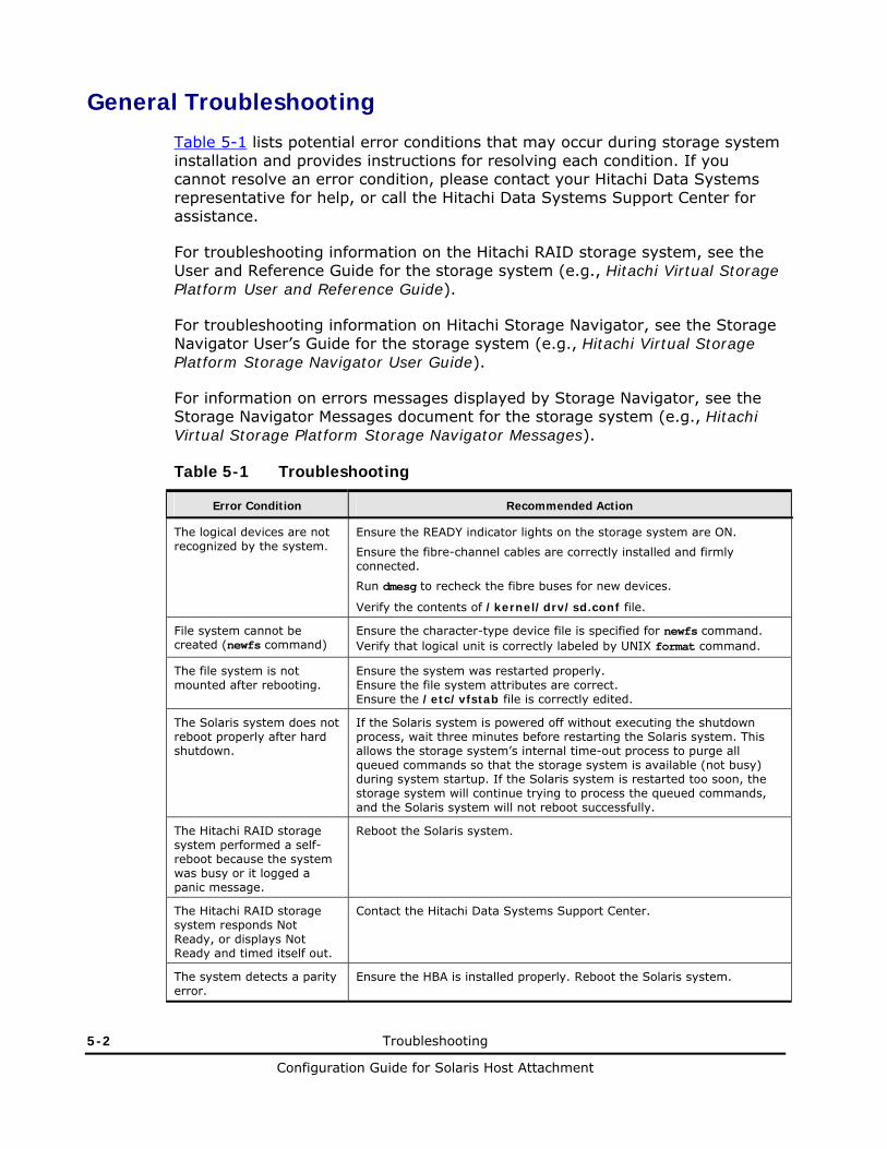
5-2 Troubleshooting
Configuration Guide for Solaris Host Attachment
General Troubleshooting
Table 5-1 lists potential error conditions that may occur during storage system installation and provides instructions for resolving each condition. If you cannot resolve an error condition, please contact your Hitachi Data Systems representative for help, or call the Hitachi Data Systems Support Center for assistance.
For troubleshooting information on the Hitachi RAID storage system, see the User and Reference Guide for the storage system (e.g., Hitachi Virtual Storage Platform User and Reference Guide).
For troubleshooting information on Hitachi Storage Navigator, see the Storage Navigator User’s Guide for the storage system (e.g., Hitachi Virtual Storage Platform Storage Navigator User Guide).
For information on errors messages displayed by Storage Navigator, see the Storage Navigator Messages document for the storage system (e.g., Hitachi Virtual Storage Platform Storage Navigator Messages).
Table 5-1 Troubleshooting
Error Condition Recommended Action
The logical devices are not recognized by the system.
Ensure the READY indicator lights on the storage system are ON.
Ensure the fibre-channel cables are correctly installed and firmly connected.
Run dmesg to recheck the fibre buses for new devices.
Verify the contents of /kernel/drv/sd.conf file.
File system cannot be created (newfs command)
Ensure the character-type device file is specified for newfs command. Verify that logical unit is correctly labeled by UNIX format command.
The file system is not mounted after rebooting.
Ensure the system was restarted properly. Ensure the file system attributes are correct. Ensure the /etc/vfstab file is correctly edited.
The Solaris system does not reboot properly after hard shutdown.
If the Solaris system is powered off without executing the shutdown process, wait three minutes before restarting the Solaris system. This allows the storage system’s internal time-out process to purge all queued commands so that the storage system is available (not busy) during system startup. If the Solaris system is restarted too soon, the storage system will continue trying to process the queued commands, and the Solaris system will not reboot successfully.
The Hitachi RAID storage system performed a self-reboot because the system was busy or it logged a panic message.
Reboot the Solaris system.
The Hitachi RAID storage system responds Not Ready, or displays Not Ready and timed itself out.
Contact the Hitachi Data Systems Support Center.
The system detects a parity error.
Ensure the HBA is installed properly. Reboot the Solaris system.

Troubleshooting 5-3
Configuration Guide for Solaris Host Attachment
Verbose Mode
One way to troubleshoot Solaris operations involves the “verbose” mode for the HBA configuration file. This section provides examples of error messages that may occur. A possible debugging method is to select the device and turn on verbose mode, then attempt the boot process again. Verbose error messages provide information that will help isolate the problem. Use the steps in Figure 5-1 to turn on the verbose flag. Figure 5-2 contains examples of error messages.
ok “ /sbus/fca” select-dev ok true to fca-verbose ok boot fcadisk
Figure 5-1 Turning on Verbose Flag
Error message: Cannot Assemble drivers for /sbus@1f,0/fcaw@1,0/sd@0,0:a Cannot Mount root on /sbus@1f,0/fcaw@1,0/sd@0,0:a Problem: The process of copying the OS to the fibre channels was not complete, or the drive specified on the boot command is not the same as the one the OS was constructed on.
Error message: Can’t open boot device Problem: The wwn specified with the set-bootn0-wwn does not correspond to the wwn of the device. Could also be a cable problem – the adapter cannot initialize.
Error message: The file just loaded does not appear to be bootable Problem: The bootblk was not installed on the target.
Error message: mount: /dev/dsk/c0t0d0s0 – not of this fs type Problem: At this point the process hangs. This happens if the /etc/vfstab File has not been updated on the fibrechannel boot drive to reflect the new target.
Error message: Get PortID request rejected by nameserver Problem: The wwn of the target is not correct. Select the adapter and perform set-bootn0-wwn. If this is correct, check the switch to see that target is properly connected.
Error message: Can’t read disk label Problem: The selected target is not a Solaris filesystem.
Figure 5-2 Examples of Error Messages (continues on the next page)

5-4 Troubleshooting
Configuration Guide for Solaris Host Attachment
Error message: Nport init failed – Problem: Card is connected to an arbitrated loop device, but wants to initialize as an NPORT. The bootn0-wwn property has probably been set to a valid WWN.
Error message: Panic dump not saved Problem: After the system is successfully booted to Solaris from the fibrechannel and a panic occurs the panic does not get saved to the swap device. This can be the result not properly defined the swap partition. Use the format command to view the slices on the fibre channel drive. Take the partition option, then the print option. The swap partition should look something like this: 1 swap wm 68-459 298.36MB (402/0/0) 611040 Sizes and cylinders will probably be different on your system. Make sure that the flag is wm and that the sizes are defined (not 0). Then use the label option from partition to write the label to the drive. After this the panic should be saved to the swap partition. If the partition needs to be changed chose the partition option, and enter 1 to select slice 1.
Figure 5-2 Examples of Error Messages (continued)
Calling the Hitachi Data Systems Support Center
If you need to call the Hitachi Data Systems Support Center, please gather as much information about the problem as possible, including:
• The circumstances surrounding the error or failure.
• The content of any error messages displayed on the host system(s).
• The content of any error messages displayed by Storage Navigator.
• The service information messages (SIMs), including reference codes and severity levels, displayed by Storage Navigator.
The Hitachi Data Systems customer support staff is available 24 hours a day, seven days a week. If you need technical support, log on to the Hitachi Data Systems Portal for contact information: https://hdssupport.hds.com

A
Fibre Port Addressing A-1
Configuration Guide for Solaris Host Attachment
Fibre Port Addressing
In a FC-AL (fibre channel arbitrated loop) configuration, the host communicates with the devices comprising the loop with 8 bit AL-PA (arbitrated loop physical address, also called the port address). The number of available port addresses is 126. (There are 127 port addresses, but address 00H is reserved for fibre connection.)
Devices communicate with hosts using individual port addresses. However, hosts map SCSI protocol to fibre channel devices. The hosts access the device’s LUs using the device files /dev/dsk/c*t*d* and /dev/rdsk/c*t*d*. SCSI and fibre channel devices are accessed the same way; however, the device files for SCSI and fibre channel devices are configured differently. Table A-1 lists the AL-PA and the corresponding SCSI address.
Table A-1 Fibre Port Addressing
AL-PA T value AL-PA T value AL-PA T value AL-PA T value
EF 0 CD 16 B2 32 98 48
E8 1 CC 17 B1 33 97 49
E4 2 CB 18 AE 34 90 50
E2 3 CA 19 AD 35 8F 51
E1 4 C9 20 AC 36 88 52
E0 5 C7 21 AB 37 84 53
DC 6 C6 22 AA 38 82 54
DA 7 C5 23 A9 39 81 55
D9 8 C3 24 A7 40 80 56
D6 9 BC 25 A6 41 7C 57
D5 10 BA 26 A5 42 7A 58
D4 11 B9 27 A3 43 79 59
D3 12 B6 28 9F 44 76 60
D2 13 B5 29 9E 45 75 61
D1 14 B4 30 9D 46 74 62

A-2 Fibre Port Addressing
Configuration Guide for Solaris Host Attachment
AL-PA T value AL-PA T value AL-PA T value AL-PA T value
CE 15 B3 31 9B 47 73 63
72 64 55 80 3A 96 23 112
71 65 54 81 39 97 23 113
6E 66 53 82 36 98 1F 114
6D 67 52 83 35 99 1E 115
6C 68 51 84 34 100 1D 116
6B 69 4E 85 33 101 1B 117
6A 70 4D 86 32 102 18 118
69 71 4C 87 31 103 17 119
67 72 4B 88 2E 104 10 120
66 73 4A 89 2D 105 0F 121
65 74 49 90 2C 106 08 122
63 75 47 91 2B 107 04 123
5C 76 46 92 2A 108 02 124
B
Online Device Installation B-1
Configuration Guide for Solaris Host Attachment
Online Device Installation
After initial installation and configuration of the Hitachi RAID storage system, additional devices can be installed or de-installed online without having to restart the Solaris system. After online installation, the device parameters for new volumes must be changed to match the LUs defined under the same fibre-channel port (see Verifying Recognition of New Devices). This procedure should be performed by the system administrator (i.e., super-user).
Note: For additional instructions about online installation and deinstallation of LUs, see the Maintenance Manual.
Sun Fibre-Channel Host Bus Adapter Installation
The following procedures apply to online installation of the Sun fibre-channel HBA:
1. Set up the Solaris server:
– Confirm that the Sun fibre-channel HBA(s) are installed.
– Confirm that Sun StorEdge SAN Foundation Software version 4.2 or later is installed.
2. Set up the Hitachi RAID storage system:
– Ensure the latest microcode is loaded. Non-disruptive version-up requires alternate path.
– Install the front-end director(s) and LDEVs, and connect fibre cable if necessary.
– Execute online LU installation from the service processor (SVP) or using the Storage Navigator software.
– Verify the SCSI path configuration.
3. Execute the Format command. Solaris will recognize the new volumes.
4. If new volumes are not recognized, the following operation is not needed. Refer to the Solaris documentation as needed.

B-2 Online Device Installation
Configuration Guide for Solaris Host Attachment
– Disconnect and reconnect the fibre cable connected to the paths on which you are adding LUs.
– Use the following command to display available paths to the HBAs: luxadm –e port
– With the path from the output, issue the following command: luxadm –e forcelip path
– Use the following command to display devices: cfgadm –al
– Bring fabric devices back onto the system.
– Execute the Format command.

C
Using MPxIO Path Failover Software C-1
Configuration Guide for Solaris Host Attachment
Using MPxIO Path Failover Software
The Hitachi RAID storage systems are compatible with the Solaris Operating Environment Multi-path I/O (MPxIO) multi-pathing driver that offers hardware transparency and multi-pathing capabilities. MPxIO is fully integrated within the Solaris operating system (beginning with Solaris 8) and enables I/O devices to be accessed through multiple host controller interfaces from a single instance of the I/O device.
MPxIO enables you to more effectively to represent and manage devices that are accessible through multiple I/O controller interfaces within a single instance of the Solaris operating system. The MPxIO architecture:
• Helps protect against I/O outages due to I/O controller failures. Should one I/O controller fail, MPxIO automatically switches to an alternate controller.
• Increases I/O performance by load balancing across multiple I/O channels.
For the Hitachi RAID storage system to work with MPxIO:
1. Configure the Hitachi RAID storage system to use a host mode of 09 (see Setting the Host Mode).
2. Modify the configuration file /kernel/drv/scsi_vhci.conf to enable MPxIO to manage the path failover:
mpxio-disable="no";
Note: You do not have to edit /kernel/drv/sd.conf.
3. Connect the Hitachi RAID storage system to the Solaris system.
4. Reboot the server.
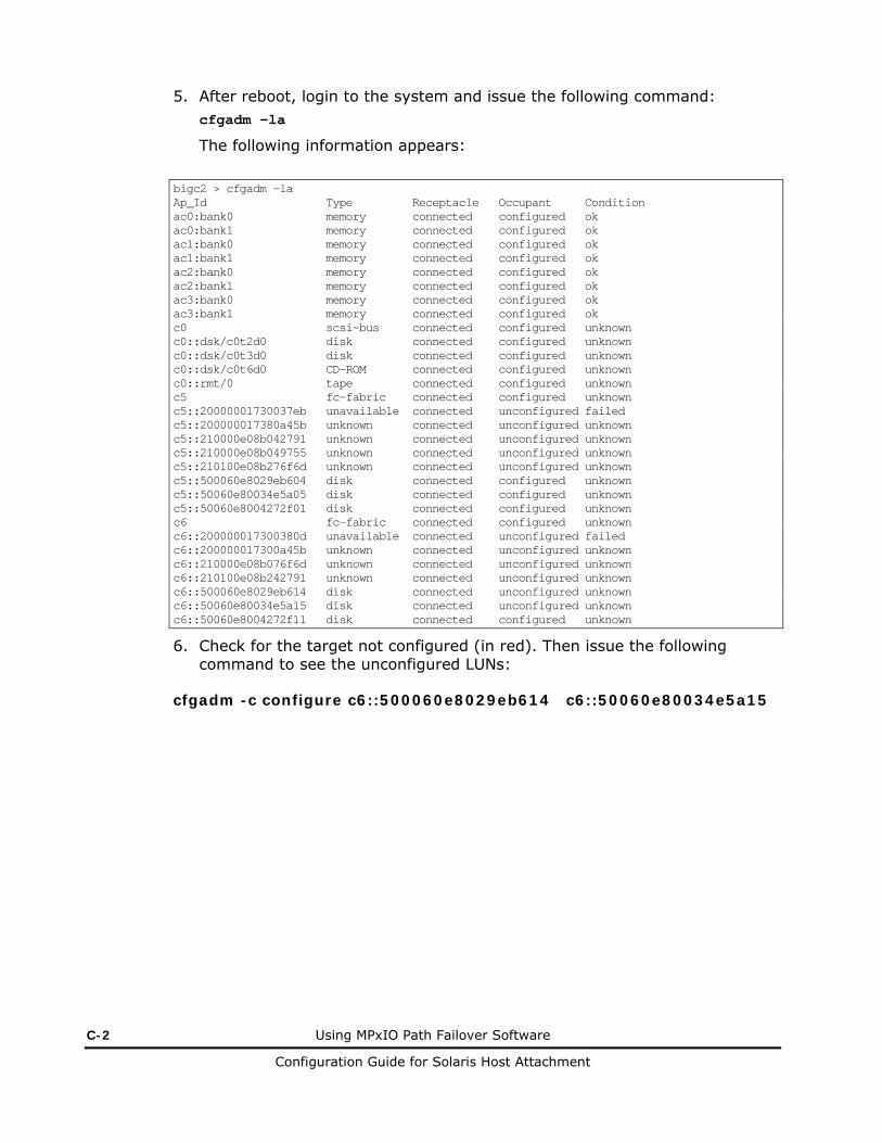
C-2 Using MPxIO Path Failover Software
Configuration Guide for Solaris Host Attachment
5. After reboot, login to the system and issue the following command: cfgadm -la
The following information appears:
bigc2 > cfgadm -la Ap_Id Type Receptacle Occupant Condition ac0:bank0 memory connected configured ok ac0:bank1 memory connected configured ok ac1:bank0 memory connected configured ok ac1:bank1 memory connected configured ok ac2:bank0 memory connected configured ok ac2:bank1 memory connected configured ok ac3:bank0 memory connected configured ok ac3:bank1 memory connected configured ok c0 scsi-bus connected configured unknown c0::dsk/c0t2d0 disk connected configured unknown c0::dsk/c0t3d0 disk connected configured unknown c0::dsk/c0t6d0 CD-ROM connected configured unknown c0::rmt/0 tape connected configured unknown c5 fc-fabric connected configured unknown c5::20000001730037eb unavailable connected unconfigured failed c5::200000017380a45b unknown connected unconfigured unknown c5::210000e08b042791 unknown connected unconfigured unknown c5::210000e08b049755 unknown connected unconfigured unknown c5::210100e08b276f6d unknown connected unconfigured unknown c5::500060e8029eb604 disk connected configured unknown c5::50060e80034e5a05 disk connected configured unknown c5::50060e8004272f01 disk connected configured unknown c6 fc-fabric connected configured unknown c6::200000017300380d unavailable connected unconfigured failed c6::200000017300a45b unknown connected unconfigured unknown c6::210000e08b076f6d unknown connected unconfigured unknown c6::210100e08b242791 unknown connected unconfigured unknown c6::500060e8029eb614 disk connected unconfigured unknown c6::50060e80034e5a15 disk connected unconfigured unknown c6::50060e8004272f11 disk connected configured unknown
6. Check for the target not configured (in red). Then issue the following command to see the unconfigured LUNs:
cfgadm -c configure c6::500060e8029eb614 c6::50060e80034e5a15

D
Note on Using Veritas Cluster Server D-1
Configuration Guide for Solaris Host Attachment
Note on Using Veritas Cluster Server
By issuing a SCSI-3 Persistent Reserve command for a Hitachi RAID storage system, the Veritas Cluster Server (VCS) provides the I/O fencing function that can prevent data corruption from occurring if the cluster communication stops. Each node of VCS registers reserve keys to the storage system, which enables these nodes to share a disk to which the reserve key is registered.
Each node of VCS registers the reserve key when importing a disk groups. One node registers the identical reserve key for all paths of all disks (LU) in the disk group. The reserve key contains a unique value for each disk group and a value to distinguish nodes.
Key format: <Node # + disk group-unique information>
Example: APGR0000, APGR0001, BPGR0000, and so on
When the Hitachi RAID storage system receives a request to register the reserve key, the reserve key and port WWN of node are recorded on a key registration table of each port of the storage system where the registration request is received. The number of reserve keys that can be registered to one storage system is 128 for a port. The storage system confirms duplication of registration by a combination of the node Port WWN and reserve key. Therefore, the number of entries of the registration table does not increase even though any request for registering duplicated reserve keys is accepted.
Calculation formula for the number of used entries of key registration table: (number of nodes) × (port WWN number of node) × (number of disk groups)
When the number of registered reserve keys exceeds the upper limit of 128, key registration as well as operations such as installing a LU to the disk group fail. To avoid failure of reserve key registration, the number of reserve keys needs to be kept below 128. For this, restrictions such as imposing a limit on the number of nodes or on the number of server ports using LUN security function, or maintaining the number of disk groups appropriate are necessary.

D-2 Note on Using Veritas Cluster Server
Configuration Guide for Solaris Host Attachment
Example:
When adding a LU to increase disk capacity, do not add the number of disk groups, but add a LU to the current disk group.
FC-SW
LU0 LU1
LU2 disk group 1
LU4 LU5
LU6 disk group 2
LU4 LU5
disk group 3
1A 2A Security List
・WWNa0
・WWNb0
Security List
・WWNa1
・WWNb1
Node A
WWNa0 WWNa1
Node B
WWNb0 WWNb1
Key registration table for Port-1A Key registration table for Port-2A
Entry Reserve Key WWN Entry Reserve Key WWN
0 APGR0001 WWNa0 0 APGR0001 WWNa1
1 APGR0002 WWNa0 1 APGR0002 WWNa1
2 APGR0003 WWNa0 2 APGR0003 WWNa1
3 BPGR0001 WWNb0 3 BPGR0001 WWNb1
4 BPGR0002 WWNb0 4 BPGR0002 WWNb1
5 BPGR0003 WWNb0 5 BPGR0003 WWNb1
6 - - 6 - -
: : : : : :
127 - - 127 - -
Figure D-1 Adding Reserve Keys for LUs to Increase Disk Capacity

Acronyms and Abbreviations Acronyms-1
Configuration Guide for Solaris Host Attachment
Acronyms and Abbreviations
AL arbitrated loop AL-PA arbitrated loop-physical address
blk block
CHF channel adapter-fibre (also called front-end director) CVS custom volume size cyl cylinder
FC fibre-channel FCA fibre-channel adapter FX Hitachi Cross-OS File Exchange
GB gigabyte Gbps gigabits per second
HBA host bus adapter HDLM Hitachi Dynamic Link Manager
I/O input/output
KB kilobyte
LBA logical block address LDEV logical device LU logical unit LUN logical unit number LUSE LU Size Expansion LVI logical volume image LVM Logical Volume Manager
MB megabyte msec millisecond mto mainframe-to-open
OFC open fibre control otm open-to-mainframe oto open-to-open
PA physical address PB petabyte
Acronyms-2 Acronyms and Abbreviations
Configuration Guide for Solaris Host Attachment
PC personal computer system PCI peripheral component interconnect
RAID redundant array of independent disks rpm revolutions per minute
SCSI small computer system interface SIM service information message SNMP simple network management protocol SVP service processor
TID target ID TOV time-out value trk track USP V/VM Hitachi Universal Storage Platform V/VM
VCS Veritas Cluster Server VLL Virtual LVI/LUN VSP HitachiVirtual Storage Platform VTOC volume table of contents
WWN world-wide name

Configuration Guide for Solaris Host Attachment
MK-96RD632-05
Hitachi Data Systems
Corporate Headquarters 750 Central Expressway Santa Clara, California 95050-2627 U.S.A. Phone: 1 408 970 1000 www.hds.com [email protected]
Asia Pacific and Americas 750 Central Expressway Santa Clara, California 95050-2627 U.S.A. Phone: 1 408 970 1000 [email protected]
Europe Headquarters Sefton Park Stoke Poges Buckinghamshire SL2 4HD United Kingdom Phone: + 44 (0)1753 618000 [email protected]