configuration file reference - ibm · communications server for windows, version 6.1 personal...
TRANSCRIPT
Communications Server for Windows, Version 6.1
Personal Communications for Windows, Version 5.9
Configuration File Reference
SC31-8655-07
���


Communications Server for Windows, Version 6.1
Personal Communications for Windows, Version 5.9
Configuration File Reference
SC31-8655-07
���

Note
Before using this information and the product it supports, read the information in Appendix I, “Notices,” on page 267.
Eighth Edition (July 2006)
This edition applies to Version 6.1 of IBM Communications Server for Windows, Version 5.9 of IBM Personal
Communications for Windows (program number: 5639–I70), and to all subsequent releases and modifications until
otherwise indicated in new editions.
© Copyright International Business Machines Corporation 1998, 2006. All rights reserved.
US Government Users Restricted Rights – Use, duplication or disclosure restricted by GSA ADP Schedule Contract
with IBM Corp.
Contents
About This Book . . . . . . . . . . . ix
Who Should Use This Book . . . . . . . . . ix
How to Use This Book . . . . . . . . . . . x
Icons . . . . . . . . . . . . . . . . x
Number Conventions . . . . . . . . . . x
Where to Find More Information . . . . . . xi
Chapter 1. Introduction to ASCII
Configuration . . . . . . . . . . . . 1
ASCII Configuration File Structure . . . . . . . 1
Kinds and Types of Keywords . . . . . . . . 1
Kinds of Keywords . . . . . . . . . . . 1
Types of Simple Keywords . . . . . . . . . 2
Labels Used in Keyword Descriptions . . . . . 2
Template File and Response File Keywords . . . . 3
ASCII Configuration File Syntax Rules . . . . . . 3
Syntax Examples . . . . . . . . . . . . . 4
Assigning Values to ASCII Configuration File
Keywords . . . . . . . . . . . . . . . 4
Chapter 2. Verifying and Editing an
ASCII Configuration File . . . . . . . . 7
ASCII Configuration Verify Utility . . . . . . . 7
Verifying a Configuration File . . . . . . . 7
Editing a Configuration File . . . . . . . . . 8
Chapter 3. ADJACENT_NODE . . . . . 9
Keyword Definition . . . . . . . . . . . . 9
ADJACENT_NODE Sample . . . . . . . . . 9
ADJACENT_NODE Parameter Keywords . . . . . 9
FQ_CP_NAME . . . . . . . . . . . . 9
FQ_LU_NAME . . . . . . . . . . . . 10
LU_ENTRY . . . . . . . . . . . . . 10
WILDCARD_LU . . . . . . . . . . . . 10
Chapter 4. AS400_COMMON . . . . . 13
Keyword Definition . . . . . . . . . . . 13
AS400_COMMON Sample . . . . . . . . . 13
AS400_COMMON Parameter Keywords . . . . . 13
LU_NAME . . . . . . . . . . . . . 13
MODE_NAME . . . . . . . . . . . . 14
PASSWORD . . . . . . . . . . . . . 14
USER_ID . . . . . . . . . . . . . . 15
Chapter 5. AS400_SERVER . . . . . . 17
Keyword Definition . . . . . . . . . . . 17
AS400_SERVER Sample . . . . . . . . . . 17
AS400_SERVER Parameter Keywords . . . . . . 17
DEFAULT_SERVER . . . . . . . . . . . 17
DEVICE . . . . . . . . . . . . . . 18
PASSWORD . . . . . . . . . . . . . 18
PATH . . . . . . . . . . . . . . . 19
SERVER_NAME . . . . . . . . . . . . 19
SHARED_FOLDER . . . . . . . . . . . 19
USER_ID . . . . . . . . . . . . . . 20
Chapter 6. CONNECTION_NETWORK 21
Keyword Definition . . . . . . . . . . . 21
CONNECTION_NETWORK Sample . . . . . . 21
CONNECTION_NETWORK Parameter Keywords 21
FQCN_NAME . . . . . . . . . . . . 21
PORT_NAME . . . . . . . . . . . . 22
INHERIT_PORT_LIMITED_RESOURCE . . . . 22
Chapter 7. CPIC_SIDE_INFO . . . . . 23
Keyword Definition . . . . . . . . . . . 23
CPIC_SIDE_INFO Sample . . . . . . . . . 23
CPIC_SIDE_INFO Parameter Keywords . . . . . 23
CONVERSATION_SECURITY_TYPE . . . . . 23
MODE_NAME . . . . . . . . . . . . 24
PARTNER_LU_NAME . . . . . . . . . . 24
SECURITY_PASSWORD . . . . . . . . . 25
SECURITY_USER_ID . . . . . . . . . . 25
SYM_DEST_NAME . . . . . . . . . . . 26
TP_NAME . . . . . . . . . . . . . . 26
TP_NAME_TYPE . . . . . . . . . . . 26
USER_DATA . . . . . . . . . . . . . 27
Chapter 8. CRL_SUPPORT . . . . . . 29
Keyword Definition . . . . . . . . . . . 29
CRL_SUPPORT Sample . . . . . . . . . . 29
CRL_SUPPORT Parameter Keywords . . . . . . 29
CRL_SUPPORT_ENABLE . . . . . . . . . 29
LDAP_ID . . . . . . . . . . . . . . 29
LDAP_ID_TYPE . . . . . . . . . . . . 30
PASSWORD . . . . . . . . . . . . . 30
PORT . . . . . . . . . . . . . . . 31
USER_ID . . . . . . . . . . . . . . 31
Chapter 9. DLUR_DEFAULTS . . . . . 33
Keyword Definition . . . . . . . . . . . 33
DLUR_DEFAULTS Sample . . . . . . . . . 33
DLUR_DEFAULTS Parameter Keywords . . . . . 33
BKUP_DLUS_NAME . . . . . . . . . . 33
DEFAULT_PU_NAME . . . . . . . . . . 34
DLUS_RETRY_LIMIT . . . . . . . . . . 34
DLUS_RETRY_TIMEOUT . . . . . . . . . 34
FQ_DLUS_NAME . . . . . . . . . . . 35
Chapter 10. DOWNSTREAM_LU . . . . 37
Keyword Definition . . . . . . . . . . . 37
DOWNSTREAM_LU Sample . . . . . . . . 37
DOWNSTREAM_LU Parameter Keywords . . . . 37
DSLU_NAME . . . . . . . . . . . . 37
DSPU_NAME . . . . . . . . . . . . 38
HOST_LU_NAME . . . . . . . . . . . 38
NAU_ADDRESS . . . . . . . . . . . . 38
© Copyright IBM Corp. 1998, 2006 iii
Chapter 11. DSPU_TEMPLATE . . . . . 39
Keyword Definition . . . . . . . . . . . 39
DSPU_TEMPLATE Sample . . . . . . . . . 39
DSPU_TEMPLATE Parameter Keywords . . . . 39
DSLU_TEMPLATE . . . . . . . . . . . 39
HOST_LU . . . . . . . . . . . . . . 40
MAX_INSTANCE . . . . . . . . . . . 40
MAX_NAU . . . . . . . . . . . . . 40
MIN_NAU . . . . . . . . . . . . . 41
NUMBER_OF_DSLU_TEMPLATES . . . . . 41
TEMPLATE_NAME . . . . . . . . . . 41
Chapter 12. FOCAL_POINT . . . . . . 43
Keyword Definition . . . . . . . . . . . 43
FOCAL_POINT Sample . . . . . . . . . . 43
FOCAL_POINT Parameter Keywords . . . . . . 43
BKUP_FP_FQCP_NAME . . . . . . . . . 43
BKUP_MS_APPL_NAME . . . . . . . . . 44
FP_FQCP_NAME . . . . . . . . . . . 44
MS_APPL_NAME . . . . . . . . . . . 45
MS_CATEGORY . . . . . . . . . . . . 45
Chapter 13. HS_CRITICAL_SERVER . . 47
Keyword Definition . . . . . . . . . . . 47
HS_CRITICAL_SERVER Sample . . . . . . . 47
HS_CRITICAL_SERVER Parameter Keywords . . . 47
HOST_LINK_NAME . . . . . . . . . . 47
SERVER_NAME . . . . . . . . . . . . 48
Chapter 14. INTERNAL_PU . . . . . . 49
Keyword Definition . . . . . . . . . . . 49
INTERNAL_PU Sample . . . . . . . . . . 49
INTERNAL_PU Parameter Keywords . . . . . 49
BKUP_DLUS_NAME . . . . . . . . . . 49
DEPENDENT_LU_COMPRESSION . . . . . 50
DEPENDENT_LU_ENCRYPTION . . . . . . 50
FQ_DLUS_NAME . . . . . . . . . . . 51
NODE_ID . . . . . . . . . . . . . . 51
PU_NAME . . . . . . . . . . . . . 51
STARTUP . . . . . . . . . . . . . . 52
Chapter 15. LINK_STATION . . . . . . 53
Keyword Definition . . . . . . . . . . . 53
LINK_STATION Samples . . . . . . . . . . 53
LINK_STATION Parameter Keywords . . . . . 56
ACTIVATE_AT_STARTUP . . . . . . . . 56
ACTIVATION_DELAY_TIMER . . . . . . . 56
ADJACENT_BRANCH_EXTENDER_NODE . . 56
ADJACENT_NODE_ID . . . . . . . . . 57
ADJACENT_NODE_TYPE . . . . . . . . 58
AUTO_ACTIVATE_SUPPORT . . . . . . . 59
BKUP_DLUS_NAME . . . . . . . . . . 60
BRANCH_EXTENDER_LINK . . . . . . . 60
COST_PER_BYTE . . . . . . . . . . . 61
COST_PER_CONNECT_TIME . . . . . . . 61
CP_CP_SESS_SUPPORT . . . . . . . . . 61
DEFAULT_NN_SERVER . . . . . . . . . 62
DELAY_APPLICATION_RETRIES . . . . . . 62
DEPENDENT_LU_COMPRESSION . . . . . 63
DEPENDENT_LU_ENCRYPTION . . . . . . 63
DEST_ADDRESS . . . . . . . . . . . 64
DISABLE_REMOTE_ACT . . . . . . . . . 64
DLUS_NAME . . . . . . . . . . . . 64
DSPU_NAME . . . . . . . . . . . . 65
DSPU_SERVICES . . . . . . . . . . . 65
EFFECTIVE_CAPACITY . . . . . . . . . 66
ETHERNET_FORMAT . . . . . . . . . . 66
FQ_ADJACENT_CP_NAME . . . . . . . . 67
HPR_LINK_LVL_ERROR . . . . . . . . . 67
HPR_SUPPORT . . . . . . . . . . . . 68
INHERIT_PORT_RETRY_PARMS . . . . . . 68
LIMITED_RESOURCE . . . . . . . . . . 69
LINK_DEACT_TIMER . . . . . . . . . . 69
LINK_STATION_ROLE . . . . . . . . . 70
LS_NAME . . . . . . . . . . . . . . 71
MAX_ACTIVATION_ATTEMPTS . . . . . . 71
MAX_IFRM_RCVD . . . . . . . . . . . 72
MAX_SEND_BTU_SIZE . . . . . . . . . 72
NODE_ID . . . . . . . . . . . . . . 73
NULL_ADDRESS_MEANING . . . . . . . 73
PORT_NAME . . . . . . . . . . . . 74
PROPAGATION_DELAY . . . . . . . . . 74
PU_NAME . . . . . . . . . . . . . 75
RETRY_LINK_ON_DISCONNECT . . . . . . 75
RETRY_LINK_ON_FAILED_START . . . . . 75
RETRY_LINK_ON_FAILURE . . . . . . . 76
REVERSE_ADDRESS_BYTES . . . . . . . 76
SECURITY . . . . . . . . . . . . . . 76
SOLICIT_SSCP_SESSION . . . . . . . . . 77
TG_CHARS . . . . . . . . . . . . . 77
TG_NUMBER . . . . . . . . . . . . 78
USE_DEFAULT_TG_CHARS . . . . . . . . 79
USE_PU_NAME_IN_XID . . . . . . . . . 79
USER_DEFINED_1 . . . . . . . . . . . 79
USER_DEFINED_2 . . . . . . . . . . . 80
USER_DEFINED_3 . . . . . . . . . . . 80
LINK_STATION_ANYNET_SPECIFIC_DATA . . 80
LINK_STATION_LAN_SPECIFIC_DATA . . . . 80
LINK_STATION_OEM_SPECIFIC_DATA . . . 80
LINK_STATION_SDLC_SPECIFIC_DATA . . . 80
LINK_STATION_X25_SPECIFIC_DATA . . . . 81
Chapter 16. LOAD_BALANCING . . . . 83
Keyword Definition . . . . . . . . . . . 83
LOAD_BALANCING Sample . . . . . . . . 83
LOAD_BALANCING Parameter Keywords . . . . 83
ADVERTISE_FREQUENCY . . . . . . . . 83
APPC_LU_LOAD_FACTOR . . . . . . . . 84
DEFAULT_MAX_LU62_SESSIONS . . . . . . 84
ENABLE_LOAD_BALANCING . . . . . . . 84
HOST_LU_LOAD_FACTOR . . . . . . . . 85
LOAD_VARIANCE . . . . . . . . . . . 85
SCOPE_NAME . . . . . . . . . . . . 85
Chapter 17. LOCAL_LU . . . . . . . . 87
Keyword Definition . . . . . . . . . . . 87
LOCAL_LU Sample . . . . . . . . . . . 87
LOCAL_LU Parameter Keywords . . . . . . . 87
DEFAULT_POOL . . . . . . . . . . . 87
LU_ALIAS . . . . . . . . . . . . . . 88
iv Configuration File Reference
LU_NAME . . . . . . . . . . . . . 88
LU_SESSION_LIMIT . . . . . . . . . . 88
MODEL_NAME . . . . . . . . . . . . 89
NAU_ADDRESS . . . . . . . . . . . . 90
PU_NAME . . . . . . . . . . . . . 90
ROUTE_TO_CLIENT . . . . . . . . . . 90
SYNCPT_SUPPORT . . . . . . . . . . 91
USER_ID . . . . . . . . . . . . . . 91
Chapter 18. LU_0_TO_3 . . . . . . . 93
Keyword Definition . . . . . . . . . . . 93
LU_0_TO_3 Sample . . . . . . . . . . . . 93
LU_0_TO_3 Parameter Keywords . . . . . . . 93
APPLICATION_TYPE . . . . . . . . . . 93
ASSOC_PRINTER . . . . . . . . . . . 94
CLASS_TYPE . . . . . . . . . . . . . 94
LU_MODEL . . . . . . . . . . . . . 95
LU_NAME . . . . . . . . . . . . . 95
MODEL_NAME . . . . . . . . . . . . 96
NAU_ADDRESS . . . . . . . . . . . . 96
POOL_NAME . . . . . . . . . . . . 97
PRIORITY . . . . . . . . . . . . . . 97
PU_NAME . . . . . . . . . . . . . 97
Chapter 19. LU62_TIMEOUT . . . . . . 99
Keyword Definition . . . . . . . . . . . 99
LU62_TIMEOUT Sample . . . . . . . . . . 99
LU62_TIMEOUT Parameter Keywords . . . . . 99
LU62_TIMEOUT_RESOURCE_NAME . . . . 99
LU62_TIMEOUT_RESOURCE_TYPE . . . . . 99
LU62_TIMEOUT_VALUE . . . . . . . . 100
Chapter 20. LU_LU_PASSWORD . . . 101
Keyword Definition . . . . . . . . . . . 101
LU_LU_PASSWORD Sample . . . . . . . . 101
LU_LU_PASSWORD Parameter Keywords . . . 101
LU_PAIR . . . . . . . . . . . . . . 101
PASSWORD . . . . . . . . . . . . . 102
Chapter 21. MODE . . . . . . . . . 103
Keyword Definition . . . . . . . . . . . 103
MODE Sample . . . . . . . . . . . . . 103
MODE Parameter Keywords . . . . . . . . 103
AUTO_ACT . . . . . . . . . . . . . 103
COMPRESSION . . . . . . . . . . . 104
COS_NAME . . . . . . . . . . . . . 104
DEFAULT_RU_SIZE . . . . . . . . . . 104
ENCRYPTION_SUPPORT . . . . . . . . 105
MAX_INCOMING_COMPRESSION_LEVEL . . 105
MAX_NEGOTIABLE_SESSION_LIMIT . . . . 106
MAX_OUTGOING_COMPRESSION_LEVEL 106
MAX_RU_SIZE_UPPER_BOUND . . . . . . 107
MIN_CONWINNERS_SOURCE . . . . . . 107
MODE_NAME . . . . . . . . . . . . 107
PLU_MODE_SESSION_LIMIT . . . . . . . 108
RECEIVE_PACING_WINDOW . . . . . . 109
Chapter 22. NODE . . . . . . . . . 111
Keyword Definition . . . . . . . . . . . 111
NODE Sample . . . . . . . . . . . . . 111
NODE Parameter Keywords . . . . . . . . 111
ANYNET_SUPPORT . . . . . . . . . . 111
CP_ALIAS . . . . . . . . . . . . . 112
DEFAULT_PREFERENCE . . . . . . . . 112
DISCOVERY_GROUP_NAME . . . . . . . 113
DISCOVERY_SUPPORT . . . . . . . . . 114
DLUR_SUPPORT . . . . . . . . . . . 114
FQ_CP_NAME . . . . . . . . . . . . 115
GVRN_SUPPORT . . . . . . . . . . . 115
MAX_LOCATES . . . . . . . . . . . 116
MAX_LS_EXCEPTION_EVENTS . . . . . . 116
NODE_ID . . . . . . . . . . . . . 116
NODE_TYPE . . . . . . . . . . . . 117
REGISTER_WITH_CDS . . . . . . . . . 117
REGISTER_WITH_NN . . . . . . . . . 118
SEND_TERM_SELF . . . . . . . . . . 119
TP_SECURITY_BEHAVIOR . . . . . . . . 119
Chapter 23. PARTNER_LU . . . . . . 121
Keyword Definition . . . . . . . . . . . 121
PARTNER_LU Sample . . . . . . . . . . 121
PARTNER_LU Parameter Keywords . . . . . . 121
ADJACENT_CP_NAME . . . . . . . . . 121
CONV_SECURITY_VERIFICATION . . . . . 122
FQ_PLU_NAME . . . . . . . . . . . 122
MAX_MC_LL_SEND_SIZE . . . . . . . . 122
PARALLEL_SESSION_SUPPORT . . . . . . 123
PARTNER_LU_ALIAS . . . . . . . . . 123
PREFERENCE . . . . . . . . . . . . 124
Chapter 24. PORT . . . . . . . . . 125
Keyword Definition . . . . . . . . . . . 125
PORT Samples . . . . . . . . . . . . . 125
PORT Parameter Keywords . . . . . . . . . 126
ACTIVATION_DELAY_TIMER . . . . . . 126
COST_PER_BYTE . . . . . . . . . . . 126
COST_PER_CONNECT_TIME . . . . . . . 126
DEFAULT_TG_CHARS . . . . . . . . . 127
DELAY_APPLICATION_RETRIES . . . . . 127
DLC_DATA . . . . . . . . . . . . . 127
DLC_NAME . . . . . . . . . . . . 128
EFFECTIVE_CAPACITY . . . . . . . . . 128
IMPLICIT_BRANCH_EXTENDER_LINK . . . 128
IMPLICIT_CP_CP_SESS_SUPPORT . . . . . 129
IMPLICIT_DEACT_TIMER . . . . . . . . 129
IMPLICIT_DSPU_SERVICES . . . . . . . 130
IMPLICIT_DSPU_TEMPLATE . . . . . . . 130
IMPLICIT_HPR_SUPPORT . . . . . . . . 131
IMPLICIT_LIMITED_RESOURCE . . . . . . 131
IMPLICIT_LINK_LVL_ERROR . . . . . . . 132
LINK_STATION_ROLE . . . . . . . . . 132
MAX_ACTIVATION_ATTEMPTS . . . . . . 133
MAX_IFRM_RCVD . . . . . . . . . . 133
MAX_RCV_BTU_SIZE . . . . . . . . . 134
PORT_NAME . . . . . . . . . . . . 134
PORT_TYPE . . . . . . . . . . . . . 135
PROPAGATION_DELAY . . . . . . . . 135
RETRY_LINK_ON_DISCONNECT . . . . . 136
RETRY_LINK_ON_FAILED_START . . . . . 136
RETRY_LINK_ON_FAILURE . . . . . . . 136
Contents v

PORT_LAN_SPECIFIC_DATA . . . . . . . 137
PORT_OEM_SPECIFIC_DATA . . . . . . . 137
PORT_SDLC_SPECIFIC_DATA . . . . . . 137
PORT_TWINAX_SPECIFIC_DATA . . . . . 137
PORT_X25_SPECIFIC_DATA . . . . . . . 137
SECURITY . . . . . . . . . . . . . 137
USER_DEFINED_1 . . . . . . . . . . 138
USER_DEFINED_2 . . . . . . . . . . 138
USER_DEFINED_3 . . . . . . . . . . 138
Chapter 25. RTP_TUNING . . . . . . 139
Keyword Definition . . . . . . . . . . . 139
RTP_TUNING Sample . . . . . . . . . . 139
RTP_TUNING Parameter Keywords . . . . . . 139
PATH_SWITCH_ATTEMPTS . . . . . . . 139
SHORT_REQ . . . . . . . . . . . . 140
NETWORK_PATH_SWITCH_TIME . . . . . 140
HIGH_PATH_SWITCH_TIME . . . . . . . 140
MEDIUM_PATH_SWITCH_TIME . . . . . . 141
LOW_PATH_SWITCH_TIME . . . . . . . 141
MAX_SHORT_REQ_TIME . . . . . . . . 142
MAX_REFIFO_TIME . . . . . . . . . . 142
Chapter 26. SPLIT_STACK . . . . . . 143
Keyword Definition . . . . . . . . . . . 143
SPLIT_STACK Sample . . . . . . . . . . 143
SPLIT_STACK Parameter Keywords . . . . . . 143
POOL_NAME . . . . . . . . . . . . 143
STARTUP . . . . . . . . . . . . . 143
Chapter 27. TN3270E_DEF . . . . . . 145
Keyword Definition . . . . . . . . . . . 145
TN3270E_DEF Sample . . . . . . . . . . 145
TN3270E_DEF Parameter Keywords . . . . . . 145
AUTO_LOGOFF . . . . . . . . . . . 145
DEFAULT_POOL_NAME . . . . . . . . 145
DEFAULT_PRINTER_POOL_NAME . . . . . 146
ENABLE_FILTERING . . . . . . . . . 146
FILTER_PREFERENCE . . . . . . . . . 146
FREQUENCY . . . . . . . . . . . . 147
KEEPALIVE_TYPE . . . . . . . . . . 147
LOGOFF . . . . . . . . . . . . . . 148
LU_TAKEOVER . . . . . . . . . . . 148
LU_TAKEOVER_TIMER . . . . . . . . . 149
TIMER . . . . . . . . . . . . . . 149
Chapter 28. TN3270E_FILTER . . . . 151
Keyword Definition . . . . . . . . . . . 151
TN3270E_FILTER Sample . . . . . . . . . 151
TN3270E_FILTER Parameter Keywords . . . . . 151
CLASS_TYPE . . . . . . . . . . . . 151
CLIENT_ID_TYPE . . . . . . . . . . . 152
FILTER_ENTRY . . . . . . . . . . . 152
IP_ADDR_MASK_PAIR . . . . . . . . . 153
IS_POOL . . . . . . . . . . . . . . 154
NAME . . . . . . . . . . . . . . 154
Chapter 29. TN3270_PORT_DEF . . . 155
Keyword Definition . . . . . . . . . . . 155
TN3270_PORT_DEF Sample . . . . . . . . 155
TN3270_PORT_DEF Parameter Keywords . . . . 155
CLIENT_AUTHENTICATION . . . . . . . 155
DEFAULT_POOL . . . . . . . . . . . 156
PORT . . . . . . . . . . . . . . . 156
SECURITY . . . . . . . . . . . . . 157
SECURITY_LEVEL . . . . . . . . . . 157
Chapter 30. TN5250_DEF . . . . . . 159
Keyword Definition . . . . . . . . . . . 159
TN5250_DEF Sample . . . . . . . . . . . 159
TN5250_DEF Parameter Keywords . . . . . . 159
AUTO_LOGOFF . . . . . . . . . . . 159
DYNAMIC_LU_SUPPORT . . . . . . . . 160
ENABLE_FILTERING . . . . . . . . . 160
FILTER_PREFERENCE . . . . . . . . . 160
FREQUENCY . . . . . . . . . . . . 161
KEEPALIVE_TYPE . . . . . . . . . . 161
LOGOFF . . . . . . . . . . . . . . 162
LU_PREFIX . . . . . . . . . . . . . 162
NUMBER_OF_DYNAMIC_LUS . . . . . . 162
TIMER . . . . . . . . . . . . . . 163
Chapter 31. TN5250_FILTER . . . . . 165
Keyword Definition . . . . . . . . . . . 165
TN5250_FILTER Sample . . . . . . . . . . 165
TN5250_FILTER Parameter Keywords . . . . . 165
AS400_SERVER_ENTRY . . . . . . . . . 165
CLIENT_ID_TYPE . . . . . . . . . . . 166
IP_ADDR_MASK_PAIR . . . . . . . . . 166
Chapter 32. TN5250_PORT_DEF . . . 169
Keyword Definition . . . . . . . . . . . 169
TN5250_PORT_DEF Sample . . . . . . . . 169
TN5250_PORT_DEF Parameter Keywords . . . . 169
CLIENT_AUTHENTICATION . . . . . . . 169
DEFAULT_SERVER . . . . . . . . . . 170
PORT . . . . . . . . . . . . . . . 170
SECURITY . . . . . . . . . . . . . 171
SECURITY_LEVEL . . . . . . . . . . 171
Chapter 33. TP . . . . . . . . . . . 173
Keyword Definition . . . . . . . . . . . 173
TP Sample . . . . . . . . . . . . . . 173
TP Parameter Keywords . . . . . . . . . . 173
API_CLIENT_USE . . . . . . . . . . . 173
CONVERSATION_TYPE . . . . . . . . 174
DUPLEX_SUPPORT . . . . . . . . . . 174
DYNAMIC_LOAD . . . . . . . . . . 174
INCOMING_ALLOCATE_TIMEOUT . . . . 175
LOAD_TYPE . . . . . . . . . . . . 175
PARAMETERS . . . . . . . . . . . . 175
PATHNAME . . . . . . . . . . . . 176
PIP_ALLOWED . . . . . . . . . . . 176
QUEUED . . . . . . . . . . . . . . 177
RECEIVE_ALLOCATE_TIMEOUT . . . . . 177
SECURITY_RQD . . . . . . . . . . . 177
SYNC_LEVEL . . . . . . . . . . . . 178
TP_INSTANCE_LIMIT . . . . . . . . . 178
TP_NAME . . . . . . . . . . . . . 178
TP_NAME_FORMAT . . . . . . . . . . 179
vi Configuration File Reference
Chapter 34. USERID_PASSWORD . . . 181
Keyword Definition . . . . . . . . . . . 181
USERID_PASSWORD Sample . . . . . . . . 181
USERID_PASSWORD Parameter Keywords . . . 181
PASSWORD . . . . . . . . . . . . . 181
USER_ID . . . . . . . . . . . . . . 181
Chapter 35. VERIFY . . . . . . . . . 183
Keyword Definition . . . . . . . . . . . 183
VERIFY Sample . . . . . . . . . . . . 183
VERIFY Parameter Keywords . . . . . . . . 183
CFG_LAST_SCENARIO . . . . . . . . . 183
CFG_MODIFICATION_LEVEL . . . . . . 184
CFG_VERSION_LEVEL . . . . . . . . . 184
Appendix A. AnyNet-Specific Data 185
LINK_STATION Keywords for the AnyNet DLC 185
DEST_ADDRESS . . . . . . . . . . . 185
LINK_STATION_ANYNET_SPECIFIC_DATA 185
PORT Keywords for the AnyNet DLC . . . . . 186
DLC_NAME . . . . . . . . . . . . 186
Appendix B. EE-Specific Data . . . . 187
LINK_STATION Keywords for an EE DLC . . . 187
LINK_STATION_OEM_SPECIFIC_DATA . . . 187
PORT Keywords for an EE DLC . . . . . . . 190
DLC_NAME . . . . . . . . . . . . 190
PORT_OEM_SPECIFIC_DATA . . . . . . . 190
Appendix C. LAN-Specific Data . . . . 197
LINK_STATION Keywords for the LAN DLC . . 197
DEST_ADDRESS . . . . . . . . . . . 197
PORT Keywords for the LAN DLC . . . . . . 197
DLC_DATA . . . . . . . . . . . . . 197
DLC_NAME . . . . . . . . . . . . 197
PORT_LAN_SPECIFIC_DATA . . . . . . . 198
Appendix D. OEM-Specific Data . . . 207
LINK_STATION Keywords for an OEM DLC . . . 207
DEST_ADDRESS . . . . . . . . . . . 207
LINK_STATION_OEM_SPECIFIC_DATA . . . 207
PORT Keywords for an OEM DLC . . . . . . 210
DLC_DATA . . . . . . . . . . . . . 210
DLC_NAME . . . . . . . . . . . . 210
PORT_OEM_SPECIFIC_DATA . . . . . . . 210
Appendix E. SDLC-Specific Data . . . 217
LINK_STATION Keywords for the SDLC DLC . . 217
DEST_ADDRESS . . . . . . . . . . . 217
LINK_STATION_SDLC_SPECIFIC_DATA . . . 217
PORT Keywords for the SDLC DLC . . . . . . 221
DLC_DATA . . . . . . . . . . . . . 222
DLC_NAME . . . . . . . . . . . . 222
PORT_SDLC_SPECIFIC_DATA . . . . . . 222
Appendix F. Twinaxial-Specific Data 233
LINK_STATION Keywords for the Twinaxial DLC 233
DEST_ADDRESS . . . . . . . . . . . 233
PORT Keywords for the Twinaxial DLC . . . . 233
DLC_NAME . . . . . . . . . . . . 233
PORT_TWINAX_SPECIFIC_DATA . . . . . 233
Appendix G. X.25-Specific Data . . . . 237
LINK_STATION Keywords for the X.25 DLC . . . 237
LINK_STATION_X25_SPECIFIC_DATA . . . . 237
PORT Keywords for the X.25 DLC . . . . . . 243
DLC_DATA . . . . . . . . . . . . . 243
DLC_NAME . . . . . . . . . . . . 244
PORT_X25_SPECIFIC_DATA . . . . . . . 244
Appendix H.
ANYNET_COMMON_PARAMETERS . . 263
Keyword Definition . . . . . . . . . . . 263
ANYNET_COMMON_PARAMETERS Sample . . 263
ANYNET_COMMON_PARAMETERS Parameter
Keywords . . . . . . . . . . . . . . 263
CONN_RETRY_SECS . . . . . . . . . . 263
CONNWAIT_SECS . . . . . . . . . . 264
DG_IDLE_TIMEOUT . . . . . . . . . . 264
INACTIVITY_TIMER_SECS . . . . . . . 264
SNASUFFIX . . . . . . . . . . . . . 265
SNA_IP_NODE_TYPE . . . . . . . . . 265
UNACKED_DG_RETRY_SECS . . . . . . 266
UNSENT_DG_RETRY_SECS . . . . . . . 266
Appendix I. Notices . . . . . . . . . 267
Trademarks . . . . . . . . . . . . . . 268
Index . . . . . . . . . . . . . . . 269
Contents vii

viii Configuration File Reference

About This Book
IBM® Communications Server for Windows® (referred to in this book as
Communications Server) is a communications services platform. This platform
provides a wide range of services for Windows 2000, Windows 2003 and Windows
XP workstations that communicate with host computers and with other
workstations. Communications Server users can choose from among a variety of
remote connectivity options.
IBM Personal Communications for Windows, Version 5.9 (referred to in this book
as Personal Communications) is a full-function emulator. In addition to host terminal
emulation, it provides these useful features:
v File transfer
v Dynamic configuration
v An easy-to-use graphical interface
v APIs for SNA-based client applications
v An API allowing TCP/IP-based applications to communicate over an SNA-based
network.
Configuration File Reference contains information about creating configuration files
and using them to configure Communications Server or Personal Communications.
It lists configuration file keywords and shows sample keyword definitions. Each
keyword parameter and the values that can be specified for the parameter are
explained.
The format of an ASCII configuration file is governed by the OCDNTS50.DAT file.
This file is stored in the installation directory of the product. Not all of the
keywords and parameters in the OCDNTS50.DAT file are documented in this
manual, because they are not configured by the user.
The keywords and parameters described in this manual were complete at the time
of publication. However, changes to the product after publication of this manual
may have added or changed keywords, parameters, or values. The
OCDNTS50.DAT file contains the most accurate listing of the keywords,
parameters, and values.
For Communications Server and Personal Communications, it is assumed that you
are using Windows 2000, Windows Server 2003, or Windows XP as your base
operating system.
Who Should Use This Book
This book is a reference for network administrators who install, reinstall, or
upgrade Communications Server or Personal Communications on a group of
remote workstations from a central site.
© Copyright IBM Corp. 1998, 2006 ix

How to Use This Book
The Configuration File Reference book helps you manage the configuration of ASCII
configuration files for Personal Communications and Communications Server
products.
This book contains the following:
v An introduction to ASCII configuration files
v Instructions for creating or editing a configuration file
v Instructions for verifying a configuration file
v The kinds and types of keywords used in a configuration file
v Descriptions of keywords, parameters, and values used in configuration files.
Icons
In this book, when it is necessary to communicate special information, the
following icons appear:
This icon appears when the information applies only to the
Communications Server program.
This icon appears when the information applies only to the Personal
Communications program.
Number Conventions
Binary numbers Represented as B'xxxx xxxx' or B'x' except in certain instances
where they are represented with text (“A value of binary xxxx
xxxx is...”).
Bit positions Start with 0 at the rightmost position (least significant bit).
Decimal numbers Decimal numbers over 4 digits are represented in metric style.
A space is used rather than a comma to separate groups of 3
digits. For example, the number sixteen thousand, one hundred
forty-seven is written 16 147.
Hexadecimal numbers Represented in text as hex xxxx or X'xxxx' (“The address of the
adjacent node is hex 5D, which is specified as X'5D'.”)
x Configuration File Reference

Where to Find More Information
For more information, refer to Quick Beginnings, which contains a
complete description of both the Communications Server library and
related publications.
To view a specific book after Communications Server has been installed,
use the following path from your desktop:
1. Programs
2. IBM Communications Server
3. Documentation
4. Choose from the list of books
The Communications Server books are in Portable Document Format
(PDF), which is viewable with the Adobe Acrobat Reader. If you do not
have a copy of this program on your machine, you can install it from
the Documentation list.
The Communications Server home page on the Internet has general
product information as well as service information about APARs and
fixes. To get to the home page using an Internet browser, go to the
following Web site:
http://www.ibm.com/software/network/commserver/
For more information, refer to Quick Beginnings, which contains a
complete description of both the Personal Communications library and
related publications.
The Personal Communications books are included on the CD-ROM in
portable document format (pdf). Books can be accessed directly from
the publications directory of the Personal Communications CD-ROM or
from the Install Manager welcome panel.
To view the Personal Communications documentation using Install
Manager, select View Documentation from the main panel of the Install
Manager on the CD-ROM. Clicking View Documentation invokes
Adobe Acrobat Reader from your system to view the books. If Acrobat
Reader is not detected on your system, you are given the opportunity
to install it at this time. After installation of Acrobat Reader is complete,
a window opens displaying the books available on the CD-ROM.
Notes:
1. You can copy the book files from the CD-ROM to a local or network
drive to view at a later time.
2. Quick Beginnings in HTML format is installed during installation of
Personal Communications.
The Personal Communications home page on the Internet has general
product information as well as service information about APARs and
fixes. To get the home page, using an Internet browser such as IBM
Web Explorer, go to the following Web site:
http://www.ibm.com/software/network/pcomm/
The complete IBM Dictionary of Computing is available on the World
Wide Web at http://www.ibm.com/networking/nsg/nsgmain.htm.
About This Book xi

xii Configuration File Reference
Chapter 1. Introduction to ASCII Configuration
This chapter describes the ASCII configuration provided by Communications
Server and Personal Communications. The ASCII configuration provides a method
of creating, storing, and accessing configuration information. This method uses
ASCII files instead of binary files to store configuration records. This enables users
to create and modify a configuration file without using the SNA Node
Configuration application.
The format of an ASCII configuration file, whether it is created by the SNA Node
Configuration application or by an ASCII editor, is governed by the
OCDNTS50.DAT file. This file is stored in the installation directory of the product.
Not all of the keywords and parameters in the OCDNTS50.DAT file are
documented in this manual, because they should not be configured by the user.
ASCII Configuration File Structure
The ASCII configuration (.ACG) file is a standard ASCII file containing assignment
statements that are generally in the form of keyword = value. The keyword is always
placed on the left side of the statement and identifies the configuration parameter.
The value is placed on the right side of the statement and is either a string of
characters or a list of one or more keyword = value lines.
For example:
keyword = value
keyword = (
keyword = value
keyword = value
...
)
Kinds and Types of Keywords
To help understand how to read and interpret the data in the ASCII configuration
file, the kinds and types of keywords are described in this section.
Kinds of Keywords
There are two kinds of keywords:
Simple keyword
A keyword that does not contain other keywords; that is, it has no
embedded keywords. It is of the form keywordname = value; where value
is not a left parenthesis. In the following example, FQ_CP_NAME and
NODE_TYPE are simple keywords, but NODE is not.
NODE=(
FQ_CP_NAME=USIBMNM.NT265
NODE_TYPE=END_NODE
)
Complex keyword
Contains embedded simple or complex keywords. In the following
example, PORT and PORT_LAN_SPECIFIC_DATA are complex keywords.
© Copyright IBM Corp. 1998, 2006 1
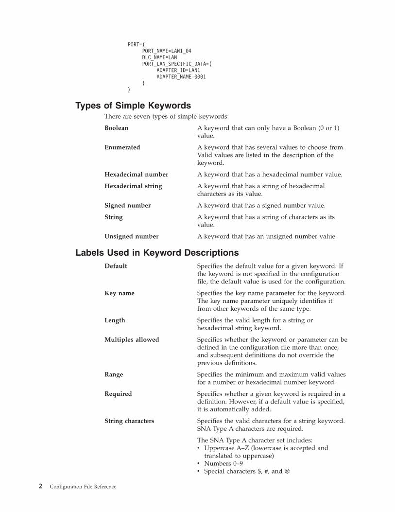
PORT=(
PORT_NAME=LAN1_04
DLC_NAME=LAN
PORT_LAN_SPECIFIC_DATA=(
ADAPTER_ID=LAN1
ADAPTER_NAME=0001
)
)
Types of Simple Keywords
There are seven types of simple keywords:
Boolean A keyword that can only have a Boolean (0 or 1)
value.
Enumerated A keyword that has several values to choose from.
Valid values are listed in the description of the
keyword.
Hexadecimal number A keyword that has a hexadecimal number value.
Hexadecimal string A keyword that has a string of hexadecimal
characters as its value.
Signed number A keyword that has a signed number value.
String A keyword that has a string of characters as its
value.
Unsigned number A keyword that has an unsigned number value.
Labels Used in Keyword Descriptions
Default Specifies the default value for a given keyword. If
the keyword is not specified in the configuration
file, the default value is used for the configuration.
Key name Specifies the key name parameter for the keyword.
The key name parameter uniquely identifies it
from other keywords of the same type.
Length Specifies the valid length for a string or
hexadecimal string keyword.
Multiples allowed Specifies whether the keyword or parameter can be
defined in the configuration file more than once,
and subsequent definitions do not override the
previous definitions.
Range Specifies the minimum and maximum valid values
for a number or hexadecimal number keyword.
Required Specifies whether a given keyword is required in a
definition. However, if a default value is specified,
it is automatically added.
String characters Specifies the valid characters for a string keyword.
SNA Type A characters are required.
The SNA Type A character set includes:
v Uppercase A–Z (lowercase is accepted and
translated to uppercase)
v Numbers 0–9
v Special characters $, #, and @
2 Configuration File Reference
An SNA type A character string can not begin with
a digit (0–9).
The SNA Type AE character set includes:
v Lowercase a–z
v Uppercase A–Z
v Numbers 0–9
v Special characters $, #, @, and the period (.)
Template File and Response File Keywords
When creating configurations for a large number of servers to implement, you can
create a template configuration file that represents the common configuration
elements for all servers. Using a response file with only those changes necessary
for each server, you can distribute the template and response file and merge the
two to create the target configuration. Template files and response files can specify
the following keywords:
DELETE The DELETE keyword causes all information associated with a
keyword to be removed. When the DELETE keyword is
encountered in a list, all other keywords in the list are ignored.
INCLUDE A response file is merged into a template file by specifying the
INCLUDE keyword at the end of the template file. The original
template configuration file is left unchanged, if a new target file
name is specified during verification.
For detailed information on how to use template files and response files for
configuration and installation, refer to Network Administration Guide for
Communications Server or Quick Beginnings for Personal Communications.
ASCII Configuration File Syntax Rules
The syntax rules for ASCII configuration (.ACG) files are:
v An opening parenthesis, used to begin a list of values, must follow the
keyword = on the same line.
v A closing parenthesis, used to delimit a list, must be on its own line.
v Because an opening parenthesis begins a list, you can not assign a single
opening parenthesis as a value to a keyword.
v ASCII configuration (.ACG) files are not column dependent.
You can use indentation or blank lines to make the files more readable. An
ASCII configuration (.ACG) file does not have any column-specific or
indentation restrictions.
v You can include a comment in an ASCII configuration (.ACG) file by using an
asterisk (*) or semicolon (;) as the first nonblank character in a line. However,
within a value list only the semicolon (;) can be used because the asterisk (*) can
be a valid value within the list.
v Comments must always appear as separate lines within a ASCII configuration
(.ACG) file.
v Keywords are not case sensitive.
v Each keyword must appear on a separate line.
v If a keyword or parameter is specified multiple times in a configuration file, but
multiple definitions of that keyword is not allowed, the last specification of the
keyword is used in the configuration.
Chapter 1. Introduction to ASCII Configuration 3

v You should verify an ASCII configuration file (.ACG) before you use it.
Syntax Examples
If you need to assign a list of values to a keyword, you can use a nested list form.
The data inside the nested list is referred to as a value list. A value list can have
more than one value per line and can be separated by either a space or a comma.
The following example shows several ways to format value lists.
keyword = (
keyword = value
keyword = (
subvalue1
subvalue2
subvalue3
subvalue4
subvalue5
)
keyword = (
subvalue1, subvalue2, subvalue3,
subvalue4, subvalue6, subvalue7
)
keyword = (
subvalue1 subvalue2 subvalue3
subvalue4 subvalue6 subvalue7
)
)
Assigning Values to ASCII Configuration File Keywords
A value is a string of characters that is placed on the right side of an ASCII
configuration (.ACG) file assignment statement. A value can be a list of one or
more keyword = value lines:
keyword = (
keyword = value
keyword = value
keyword = value
keyword = value
keyword = value
keyword = value
)
The type of value you can specify for a keyword uses one of the following forms:
v Boolean value
0 n or N = No
1 y or Y = Yes
You can not specify NO or YES.
v Characters
1 through 12 characters
Be sure you assign the specified number of alphabetic, numeric, or special
characters.
v Numbers (integers)
Integer (1–3)
1=Secondary
2=Primary
3=Negotiable
Assign the integer that represents the value you want.
4 Configuration File Reference

v The value description can specify a specific string such as BLANK or an asterisk
(*) that represents a special value. These values are explicitly defined in the
description of the keywords where they are used.
v In some cases, the value or the = value portion of a line is optional.
These cases are explicitly defined in the descriptions of the keywords where they
are used. For example, the DELETE keyword does not use the equal sign (=) or
the value. In cases where a value is required but not specified, the keyword is
ignored.
Chapter 1. Introduction to ASCII Configuration 5

6 Configuration File Reference
Chapter 2. Verifying and Editing an ASCII Configuration File
You can create an ASCII configuration file with the SNA Node Configuration
application. The ASCII configuration file is an ASCII representation of your
configuration, with a file extension of .ACG.
You can edit the ASCII configuration file to match your configuration needs. You
can use any editor that creates an ASCII file to edit an ASCII configuration file.
ASCII Configuration Verify Utility
The ASCII configuration verify utility checks your configuration file to ensure that
there are no errors. If there are errors, you must edit the file without going through
the SNA Node Configuration application.
Verifying a Configuration File
Communications Server and Personal Communications provide two utilities for
verifying a configuration file:
v Console verification (command line) utility
v Configuration Verification application
Console Verification
The console verification utility runs as a Windows DOS application. You can start
this by issuing the following command line syntax from a DOS prompt:
vacgcon <filename> <target_file_name>
where <filename> is the name of the .ACG file and <target_file_name> is the name
you want the file to have. The <target_file_name> is optional. If you specify a
<target_file_name>, the original file is left unchanged.
The verification is performed and a message is generated indicating if the
verification was successful. Messages and errors are written to the DOS console
screen. The output from the command line utility can be redirected to a file.
Configuration Verification Application
The Configuration Verification application runs as a Windows application. You can
start this application by either selecting the Verification icon located within the
product folder, or by issuing the following command line syntax:
vacgwin <filename>
where <filename> is the .ACG file.
If you use the command option, the file is automatically opened and verified. If
you select the icon, use the Windows menu or toolbar functions to verify the file.
Do the following:
1. Select and open a configuration file.
2. Verify the file.
3. View any errors and messages.
© Copyright IBM Corp. 1998, 2006 7
Editing a Configuration File
If either verification utility (console or the Configuration Verification application)
generated errors, edit the .ACG file using any ASCII text editor. To edit a
configuration file:
v From the menu bar:
1. Select File.
2. Select Edit.
3. Launch an ASCII editor with the configuration file name selected.
4. Edit the file as needed.
5. Save the file.
6. Re-verify the file.v From the icon toolbar:
1. Select the Edit icon (pencil).
2. Launch an ASCII editor with the configuration file name selected.
3. Edit the file as needed.
4. Save the file.
5. Re-verify the file.
See the online help for specific details on how to use the selections on the menu
bar or toolbar for the Configuration Verification application.
8 Configuration File Reference

Chapter 3. ADJACENT_NODE
This chapter describes the parameter keywords and values you can specify for the
ADJACENT_NODE keyword.
Keyword Definition
Required? No
Keyword Type Complex
Key Name FQ_CP_NAME
Multiples Allowed? Yes, but each ADJACENT_NODE keyword
must have a unique FQ_CP_NAME
parameter
ADJACENT_NODE Sample
The following is a sample of the ADJACENT_NODE keyword:
ADJACENT_NODE=(
FQ_CP_NAME=USIBMNM.PARTNER
LU_ENTRY = (
FQ_LU_NAME=USIBMNM.PARTLU
)
)
ADJACENT_NODE Parameter Keywords
FQ_CP_NAME
Required? Yes
Keyword Type String
Field Length 3–17
Multiples Allowed? No, only one for each ADJACENT_NODE
keyword
The FQ_CP_NAME parameter specifies the fully qualified name of the control
point in the adjacent end node. This should match the name the node sends on its
XIDs (if supported), and the adjacent control point name
(FQ_ADJACENT_CP_NAME) specified on the LINK_STATION keyword for the
node link.
The fully qualified CP name is a 17-byte character string. The fully qualified CP
name consists of two parts: the network name and the CP name, concatenated with
a period. The network name is a 1- to 8-byte SNA Type A character string. The CP
name is a 1- to 8-byte SNA Type A character string. The fully qualified CP name is
also known as the network qualified CP name.
This parameter is required.
© Copyright IBM Corp. 1998, 2006 9

FQ_LU_NAME
Required? Yes
Keyword Type String
Field Length 1–17
Multiples Allowed? No, only one for each LU_ENTRY parameter
The FQ_LU_NAME parameter specifies the LU name to be defined. If this name is
not fully qualified, the network ID of the CP name is assumed.
The fully qualified LU name is a 17-byte character string. The fully qualified name
consists of two parts: the network name and the LU name, concatenated with a
period. The network name is a 1- to 8-byte SNA Type A character string. The LU
name is a 1- to 8-byte SNA Type A character string.
This parameter is required.
LU_ENTRY
Required? No
Keyword Type Complex
Multiples Allowed? Yes
The LU_ENTRY parameter is a complex keyword comprised of the following
parameter keywords:
v FQ_LU_NAME
v WILDCARD_LU
See the descriptions of the parameter keywords to define the LU_ENTRY
parameter.
WILDCARD_LU
The WILDCARD_LU parameter keyword applies to Communications
Server only.
Required? Yes
Keyword Type Boolean
Default 0
Multiples Allowed? No, only one for each LU_ENTRY parameter
The WILDCARD_LU parameter indicates whether the LU name specified on the
LU_ENTRY parameter is to be considered a wildcard name. Valid values are:
0 The LU name is not a wildcard name.
1 The LU name is a wildcard name.
This parameter is required. The default is 0; the LU name is not a wildcard name.
ADJACENT_NODE
10 Configuration File Reference

Wildcard LU names are used to identify the location of all LUs whose names
match the wildcard. A wildcard character (asterisk) is appended to the name.
Wildcards can not be made out of a full LU name (the LU name portion of the
fully qualified name is 8 characters long). Only one full wildcard is allowed (where
only the wildcard (asterisk) is specified). If WILDCARD_LU is set to 1, the only
other valid option is the fully qualified CP name, and it is required.
ADJACENT_NODE
Chapter 3. ADJACENT_NODE 11

12 Configuration File Reference

Chapter 4. AS400_COMMON
This chapter describes the parameter keywords and values you can
specify for the AS400_COMMON keyword.
Keyword Definition
Required? No
Keyword Type Complex
Multiples Allowed? No
AS400_COMMON Sample
The following is a sample of the AS400_COMMON keyword:
AS400_COMMON=(
LU_NAME=LABREC4
MODE_NAME=QPCSUPP
PASSWORD=BF84DC3CAC50B856748B
USER_ID=REDOPR
)
AS400_COMMON Parameter Keywords
LU_NAME
Required? No
Keyword Type String
Field Length 1–8
Multiples Allowed? No
The LU_NAME parameter specifies the logical unit (LU) name used for all sessions
with iSeries™, eServer™ i5, or System i5™. If you do not specify this parameter, the
name of the CP LU is used.
LU_NAME is a 1- to 8-byte SNA Type A character string. Valid values are:
v The first character must be an uppercase alphabetic character (A-Z) or a special
character (@, #, $).
v The remaining characters can be alphanumeric characters (A-Z, 0-9) or special
characters (@, #, $).
This parameter is optional.
© Copyright IBM Corp. 1998, 2006 13
MODE_NAME
Required? No
Keyword Type String
Field Length 1–8
Multiples Allowed? No
The MODE_NAME parameter specifies the name of the default mode used for all
iSeries, eServer i5, or System i5 sessions.
This parameter is optional.
MODE_NAME is a 1- to 8-byte SNA Type A character string. You can specify one
of the following:
v BLANK
v #BATCH
v #BATCHSC
v #INTER
v #INTERSC
v QPCSUPP
v SNASVCMG
v A unique mode name for each mode you define. If you define your own mode
name, valid characters are:
– All blanks
– The first character must be an uppercase alphabetic character (A-Z) or a
special character (@, #, $).
– The remaining characters can be alphanumeric characters (A-Z, 0-9) or special
characters (@, #, $).
The mode name is used by the session initiator to designate the allocated session
characteristics for the conversation. The mode defines a set of characteristics that
can apply to one or more sessions. These characteristics include: traffic-pacing
values, message-length limits, synchronization point and cryptography options,
and the class of service within the transport network.
PASSWORD
Required? No
Keyword Type Hexadecimal string
Field Length 1–20
Multiples Allowed? No
The PASSWORD parameter specifies the default password used with the USER_ID
parameter for accessing all iSeries, eServer i5, or System i5 sessions. This password
is supplied by an application, such as a TN5250 application, attempting to access
the iSeries, eServer i5, or System i5. The password supplied by the application is
converted to a 20-character hexadecimal string by the encryption process. To
AS400_COMMON
14 Configuration File Reference
override this value for a specific iSeries, eServer i5, or System i5, specify the
password for that iSeries, eServer i5, or System i5 in the definition of the iSeries,
eServer i5, or System i5.
Note: Since this value is encrypted, you should not attempt to enter this value
directly into the ACG file. The value should only be entered using the SNA
Node Configuration application.
This parameter is optional.
USER_ID
Required? No
Keyword Type String
Field Length 1–10
Multiples Allowed? No
The USER_ID parameter specifies the default user ID for all iSeries, eServer i5, or
System i5 sessions. The user ID is supplied by an application, such as a TN5250
application, attempting to access the iSeries, eServer i5, or System i5. To override
this value for a specific iSeries, eServer i5, or System i5, specify the user ID for that
iSeries, eServer i5, or System i5 in the definition of the iSeries, eServer i5, or
System i5.
This parameter is optional.
USER_ID is a 1- to 10-byte character string. Valid characters are:
v Alphanumeric:
– A - Z
– a - z
– 0 - 9v Special characters:
– blank (space)
– ( (left parenthesis)
– ) (right parenthesis)
– . ( period)
– , (comma)
– ; (semicolon)
– : (colon)
– - (dash)
– / (slash)
– % (percent)
– ? (question mark)
– ’ (apostrophe)
– ″ (quotation mark)
– = (equal sign)
– > (greater than)
– < (less than)
– _ (underline)
AS400_COMMON
Chapter 4. AS400_COMMON 15

AS400_COMMON
16 Configuration File Reference
Chapter 5. AS400_SERVER
This chapter describes the parameter keywords and values you can
specify for the AS400_SERVER keyword.
Keyword Definition
Required? No
Keyword Type Complex
Key Name SERVER_NAME
Multiples Allowed? Yes, but each AS400_SERVER keyword must
have a unique SERVER_NAME parameter
AS400_SERVER Sample
The following is a sample of the AS400_SERVER keyword:
AS400_SERVER=(
SERVER_NAME=USIBMNM.RTP02EN
DEFAULT_SERVER=0
AS400_SERVER Parameter Keywords
DEFAULT_SERVER
Required? No
Keyword Type Boolean
Default 0
Multiples Allowed? No, only one for each AS400_SERVER
keyword
The DEFAULT_SERVER parameter specifies whether this iSeries, eServer i5, or
System i5 is the default iSeries, eServer i5, or System i5.
Valid values are:
0 This iSeries, eServer i5, or System i5 is not the default iSeries, eServer i5, or
System i5.
1 This iSeries, eServer i5, or System i5 is the default iSeries, eServer i5, or
System i5.
This parameter is optional. The default is 0; this iSeries, eServer i5, or System i5 is
not the default iSeries, eServer i5, or System i5.
© Copyright IBM Corp. 1998, 2006 17

DEVICE
Required? No
Keyword Type String
Field Length 1
Multiples Allowed? No, only one for each SHARED_FOLDER
parameter
The DEVICE parameter specifies the name of an available local server disk device
to associate with the iSeries, eServer i5, or System i5 folder. The server shares the
disk device to enable clients to access it using a NET USE command. By sharing a
disk device, a client can connect to the iSeries, eServer i5, or System i5 folder as if
it were a disk on their workstation.
The value for DEVICE must be a valid drive letter between D and Z (uppercase or
lowercase). The values A, B, and C (both uppercase and lowercase) are reserved by
the system and cannot be used.
This parameter is optional.
PASSWORD
Required? No
Keyword Type Hexadecimal string
Field Length 1–20
Multiples Allowed? Yes, one for each AS400_SERVER keyword or
SHARED_FOLDER parameter
The PASSWORD parameter specified outside of the SHARED_FOLDER parameter
is used with the USER_ID parameter to validate iSeries, eServer i5, or System i5
access. This password is supplied by an application, such as a TN5250 application,
attempting to access the iSeries, eServer i5, or System i5. The password supplied
by the application is converted to a 20-character hexadecimal string by the
encryption process.
Note: Since this value is encrypted, you should not attempt to enter this value
directly into the ACG file. The value should only be entered using the SNA
Node Configuration application.
The PASSWORD parameter specified for the SHARED_FOLDER parameter
validates iSeries, eServer i5, or System i5 folder access, and overrides the
PASSWORD parameter supplied by an application. You can further restrict access
to iSeries, eServer i5, or System i5 resources or grant users the same access rights
as they already have on the iSeries, eServer i5, or System i5.
This parameter is optional.
AS400_SERVER
18 Configuration File Reference

PATH
Required? No
Keyword Type String
Field Length 1–256
Multiples Allowed? No, only one for each SHARED_FOLDER
parameter
The PATH parameter specifies the path to a folder in the iSeries Integrated File
System (IFS). For example, if you specify QSYSLIB, the user has access to all
resources available under QSYSLIB.
The value is a 1-256 character string.
This parameter is optional.
SERVER_NAME
Required? Yes
Keyword Type String
Field Length 3–17
Multiples Allowed? No, only one for each AS400_SERVER
keyword
The SERVER_NAME parameter specifies the fully qualified CP name of the iSeries,
eServer i5, or System i5.
The fully qualified server name is a 17-byte character string. The fully qualified
server name consists of two parts: the network name and the CP name,
concatenated with a period. The network name is a 1- to 8-byte SNA Type A
character string. The CP name is a 1- to 8-byte SNA Type A character string. The
fully qualified CP name is also known as the network qualified CP name.
This parameter is required.
SHARED_FOLDER
Required? No
Keyword Type Complex
Key Name N/A
Multiples Allowed? Yes
The SHARED_FOLDER parameter is a complex keyword comprised of the
following parameter keywords:
v DEVICE
v PASSWORD
v PATH
v USER_ID
AS400_SERVER
Chapter 5. AS400_SERVER 19

See the descriptions of the parameter keywords to define the SHARED_FOLDER
parameter.
USER_ID
Required? No
Keyword Type String
Field Length 1–10
Multiples Allowed? Yes, one for each AS400_SERVER keyword or
SHARED_FOLDER parameter
The USER_ID parameter specified outside of the SHARED_FOLDER parameter
validates iSeries, eServer i5, or System i5 access. The user ID is supplied by an
application, such as a TN5250 application, attempting to access the iSeries, eServer
i5, or System i5.
The USER_ID parameter specified for the SHARED_FOLDER parameter validates
iSeries, eServer i5, or System i5 folder access and overrides the USER_ID parameter
supplied by a TN5250 application. You can further restrict access to iSeries, eServer
i5, or System i5 resources or grant users the same access rights as they already
have on the iSeries, eServer i5, or System i5.
This parameter is optional.
USER_ID is a 1- to 10-byte character string. Valid characters are:
v Alphanumeric:
– A - Z
– a - z
– 0 - 9v Special characters:
– blank (space)
– ( (left parenthesis)
– ) (right parenthesis)
– . ( period)
– , (comma)
– ; (semicolon)
– : (colon)
– - (dash)
– / (slash)
– % (percent
– ? (question mark)
– ’ (apostrophe)
– ″ (quotation mark)
– = (equal sign)
– > (greater than)
– < (less than)
– _ (underline)
AS400_SERVER
20 Configuration File Reference
Chapter 6. CONNECTION_NETWORK
This chapter describes the parameter keywords and values you can specify for the
CONNECTION_NETWORK keyword.
Keyword Definition
Required? No
Keyword Type Complex
Key Name FQCN_NAME
Multiples Allowed? Yes, but each CONNECTION_NETWORK
keyword must have a unique FQCN_NAME
parameter
CONNECTION_NETWORK Sample
The following is a sample of the CONNECTION_NETWORK keyword:
CONNECTION_NETWORK=(
FQCN_NAME=USIBMNR.CONNET
PORT_NAME=LAN0_04
INHERIT_PORT_LIMITED_RESOURCE=NO
)
CONNECTION_NETWORK Parameter Keywords
FQCN_NAME
Required? Yes
Keyword Type String
Field Length 3–17
Multiples Allowed? No, only one for each
CONNECTION_NETWORK keyword
The FQCN_NAME parameter specifies the name of the virtual network node
through which sessions appear to be routed between two nodes in the same
connection network. Two nodes participating in the same connection network must
specify the same connection network name.
This parameter is required.
The fully qualified connection network name is a 17-byte character string. The fully
qualified connection network name consists of two parts: the network name and
the virtual CP name, concatenated with a period. The network name is a 1- to
8-byte SNA Type A character string. The virtual CP name is a 1- to 8-byte SNA
Type A character string. The fully qualified CP name is also known as the network
qualified CP name.
Valid characters are:
© Copyright IBM Corp. 1998, 2006 21
v The first character must be an uppercase alphabetic character (A-Z) or a special
character (@, #, $).
v The remaining characters can be alphanumeric characters (A-Z, 0-9) or special
characters (@, #, $).
PORT_NAME
Required? No
Keyword Type String
Field Length 1–8
Multiples Allowed? Yes
The PORT_NAME parameter specifies the name of the physical connection to the
link hardware. A port is sometimes referred to as an adapter. One or more ports can
be controlled by a single data link control (DLC) process. However, IBMEEDLC
(IPv4) and IBMEE006 (IPv6) cannot be on the same connection network.
This parameter is optional.
PORT_NAME is a 1- to 8-byte character string.
INHERIT_PORT_LIMITED_RESOURCE
Required? No
Keyword Type Enumerated
Default No
Multiples Allowed? No, only one for each
CONNECTION_NETWORK keyword
The INHERIT_PORT_LIMITED_RESOURCE parameter controls whether the values
specified on the IMPLICIT_LIMITED_RESOURCE keyword of PORT are used for
the connection networks.
Valid values are:
NO The values specified on the IMPLICIT_LIMITED_RESOURCE parameter of
the PORT keyword are not used. The connection networks are defined as
limited resource.
YES The values specified on the IMPLICIT_LIMITED_RESOURCE of the PORT
keyword are used. In this case, the connection networks are defined as
either limited resource or non-limited resource, based on the values
specified on the IMPLICIT_LIMITED_RESOURCE of the PORT keyword.
See “IMPLICIT_LIMITED_RESOURCE” on page 131.
This parameter is optional.
CONNECTION_NETWORK
22 Configuration File Reference
Chapter 7. CPIC_SIDE_INFO
This chapter describes the parameter keywords and values you can specify for the
CPIC_SIDE_INFO keyword.
Keyword Definition
Required? No
Keyword Type Complex
Key Name SYM_DEST_NAME
Multiples Allowed? Yes, but each CPIC_SIDE_INFO keyword
must have a unique SYM_DEST_NAME
parameter
CPIC_SIDE_INFO Sample
The following is a sample of the CPIC_SIDE_INFO keyword:
CPIC_SIDE_INFO=(
SYM_DEST_NAME=APINGD
CONVERSATION_SECURITY_TYPE=NONE
MODE_NAME=#INTER
PARTNER_LU_NAME=USIBMNM.PARTNER1
TP_NAME=APINGD
TP_NAME_TYPE=APPLICATION_TP
)
CPIC_SIDE_INFO Parameter Keywords
CONVERSATION_SECURITY_TYPE
Required? No
Keyword Type Enumerated
Default NONE
Multiples Allowed? No, only one for each CPIC_SIDE_INFO
keyword
The CONVERSATION_SECURITY_TYPE parameter specifies the type of
conversation security to be used. Valid values are:
NONE Attach manager sends the partner LU an allocation request that
includes no security information.
SAME Attach manager sends the partner LU an allocation request that
includes the same level of access security information as that in the
request received from the partner LU.
PROGRAM Attach manager sends the partner LU an allocation request that
includes a security user ID and security password that you define.
STRONG Attach manager sends the partner LU an allocation request that
includes a password substitution created by using the password
© Copyright IBM Corp. 1998, 2006 23
you defined. This enables a more secure conversation. The
password substitution must be supported on both ends.
This parameter is optional. The default is NONE.
MODE_NAME
Required? No
Keyword Type String
Field Length 1–8
Multiples Allowed? No, only one for each CPIC_SIDE_INFO
keyword
The MODE_NAME parameter specifies the name of the mode to be used for the
session.
This parameter is optional.
MODE_NAME is a 1- to 8-byte SNA Type A character string. You can specify one
of the following:
v BLANK
v #BATCH
v #BATCHSC
v #INTER
v #INTERSC
v QPCSUPP
v SNASVCMG
v A unique mode name for each mode you define. If you define your own mode
name, valid characters are:
– All blanks
– The first character must be an uppercase alphabetic character (A-Z) or a
special character (@, #, $).
– The remaining characters can be alphanumeric characters (A-Z, 0-9) or special
characters (@, #, $).
The mode name is used by the session initiator to designate the allocated session
characteristics for the conversation. The mode defines a set of characteristics that
can apply to one or more sessions. These characteristics include: traffic-pacing
values, message-length limits, synchronization point and cryptography options,
and the class of service within the transport network.
PARTNER_LU_NAME
Required? Yes
Keyword Type String
Field Length 1–17
Multiples Allowed? No, only one for each CPIC_SIDE_INFO
keyword
CPIC_SIDE_INFO
24 Configuration File Reference

The PARTNER_LU_NAME parameter specifies the fully qualified name of the
partner LU.
The fully qualified name is a 17-byte character string. The fully qualified name
consists of two parts: the network name and the LU name, concatenated with a
period. The network name is a 1- to 8-byte SNA Type A character string. The LU
name is a 1- to 8-byte SNA Type A character string.
This parameter is required.
SECURITY_PASSWORD
Required? No
Keyword Type Hexadecimal string
Field Length 1–20
Multiples Allowed? No, only one for each CPIC_SIDE_INFO
keyword
The SECURITY_PASSWORD parameter specifies the 1-20 character password used
to enforce conversation-level security. The security password is used with the
SECURITY_USER_ID parameter for access validation to the remote program by the
partner logical unit (LU). The password is converted to a 20-character hexadecimal
string by the encryption process.
Note: Since this value is encrypted, you should not attempt to enter this value
directly into the ACG file. The value should only be entered using the SNA
Node Configuration application.
This parameter is optional.
SECURITY_USER_ID
Required? No
Keyword Type String
Field Length 1–10
Multiples Allowed? No, only one for each CPIC_SIDE_INFO
keyword
The SECURITY_USER_ID parameter specifies the 1-10 character user ID used to
enforce conversation-level security.
This parameter is optional.
The security user identifier is used for access validation to the remote program by
the partner logical unit (LU).
CPIC_SIDE_INFO
Chapter 7. CPIC_SIDE_INFO 25
SYM_DEST_NAME
Required? Yes
Keyword Type String
Field Length 1–8
Multiples Allowed? No, only one for each CPIC_SIDE_INFO
keyword
The SYM_DEST_NAME parameter specifies the 1-8 character symbolic destination
name that identifies the side information entry.
This parameter is required.
The symbolic destination name is the name used by common programming
interface for communications (CPI-C) applications to identify the side information
definition and to access the network resources.
TP_NAME
Required? No
Keyword Type String
Field Length 1–64
Multiples Allowed? No, only one for each CPIC_SIDE_INFO
keyword
The TP_NAME parameter specifies the 1-64 character transaction program name
that provides information about accepting incoming Attaches and optionally
starting workstation programs. Valid characters are any locally displayable
characters using the native encoding of the local system. The TP name may also
refer to a service transaction program.
This parameter is optional.
A transaction program (TP) uses the advanced program-to-program
communications (APPC) system to communicate with a partner application
program at the partner node.
TP_NAME_TYPE
Required? Yes
Keyword Type Enumerated
Default APPLICATION_TP
Multiples Allowed? No, only one for each CPIC_SIDE_INFO
keyword
The TP_NAME_TYPE parameter specifies the type of transaction program used.
Valid values are:
APPLICATION_TP The transaction program name supplied is not a
service transaction program. All characters
CPIC_SIDE_INFO
26 Configuration File Reference

specified in the transaction program name must be
valid characters in the locally displayable character
set.
SNA_SERVICE The transaction program name supplied is a
service transaction program. All characters, except
the first, specified in the transaction program name
must be valid characters in the locally displayable
character set. The first character must be a
hexadecimal digit in the range X'01'–X'3F',
excluding X'0E' and X'0F'.
This parameter is required. The default is APPLICATION_TP.
USER_DATA
Required? No
Keyword Type String
Field Length 1–32
Multiples Allowed? No, only one for each CPIC_SIDE_INFO
keyword
The USER_DATA parameter specifies the 1–32 character data string returned on
the QUERY_CPIC_SIDE_INFO command, and is not used or interpreted by
Communications Server.
Personal Communications uses the USER_DATA field to store a
LOCAL_LU_ALIAS name for use with this CPIC_SIDE_INFO definition. For
example:
USER_DATA= LLU_ALIAS=myalias
All CPI-C applications using this CPIC_SIDE_INFO definition will use the local LU
designated by myalias when establishing the session. The local LU alias myalias
must be configured in a Local LU 6.2 LU definition.
The USER_DATA string must contain the keyword LLU_ALIAS in all uppercase
characters, followed by the equal sign, then the LU alias. There can be no spaces or
tabs between LLU_ALIAS, the equal sign, or the LU alias. The LU alias does not
have to be padded with spaces. This string may appear anywhere in the
USER_DATA field (for example, it may be preceded by other strings), but the total
length of the entire USER_DATA string may not exceed 32 characters.
CPIC_SIDE_INFO
Chapter 7. CPIC_SIDE_INFO 27

28 Configuration File Reference
Chapter 8. CRL_SUPPORT
This chapter describes the parameter keywords and values you can
specify for the CRL_SUPPORT keyword.
Keyword Definition
Required? No
Keyword Type Complex
Multiples Allowed? No
CRL_SUPPORT Sample
The following is a sample of the CRL_SUPPORT keyword:
CRL_SUPPORT=(
CRL_SUPPORT_ENABLE=1
LDAP_ID=vpn131
LDAP_ID_TYPE=HOST_NAME
PORT=389
)
CRL_SUPPORT Parameter Keywords
CRL_SUPPORT_ENABLE
Required? Yes
Keyword Type Boolean
Default 0
Multiples Allowed? No
The CRL_SUPPORT_ENABLE parameter specifies whether certificate revocation
list (CRL) support is enabled. Valid values are:
0 CRL support is disabled.
1 CRL support is enabled.
This parameter is required. The default is 0.
LDAP_ID
Required? Yes
Keyword Type String
Field Length 1–257
Multiples Allowed? No
The LDAP_ID parameter specifies one of the following:
© Copyright IBM Corp. 1998, 2006 29

v The host name of the LDAP server containing the certificate revocation list.
v The IP address of the LDAP server containing the certificate revocation list.
Whether the value you specify is a host name or IP address is determined by the
LDAP_ID_TYPE parameter.
The value is a 1- to 257-character string.
This parameter is required.
LDAP_ID_TYPE
Required? No
Keyword Type Enumerated
Default IP_ADDRESS
Multiples Allowed? No
The LDAP_ID_TYPE parameter indicates the type of address the value of the
LDAP_ID parameter specifies. Valid values are:
HOST_NAME The value of the LDAP_ID parameter specifies a
host name.
IP_ADDRESS The value of the LDAP_ID parameter specifies the
IP address of a TCP/IP workstation.
This parameter is optional. The default is IP_ADDRESS.
PASSWORD
Required? No
Keyword Type Hexadecimal string
Field Length 1–102
Multiples Allowed? No
The PASSWORD parameter specifies the password used with the USER_ID
parameter for accessing the LDAP server. The password is converted to a
hexadecimal string by an encryption process.
Note: Since this value is encrypted, you should not attempt to enter this value
directly into the ACG file. The value should only be entered using the Node
Configuration application.
This parameter is optional.
CRL_SUPPORT
30 Configuration File Reference

PORT
Required? Yes
Keyword Type Unsigned number
Default 389
Range 1–65 535
Multiples Allowed? No
The PORT parameter specifies the port number of the LDAP server.
The value is an integer in the range 1–65 535.
This parameter is required. The default is 389.
Normally, the LDAP server uses port 389.
Note: If you change the port number from 389, the port number defined on
TN5250 clients must be changed to the number specified here.
USER_ID
Required? No
Keyword Type Hexadecimal string
Field Length 1–1002
Multiples Allowed? No
The USER_ID parameter specifies the user ID used with the PASSWORD
parameter for accessing the LDAP server. The user ID is converted to a
hexadecimal string by an encryption process.
Note: Since this value is encrypted, you should not attempt to enter this value
directly into the ACG file. The value should only be entered using the Node
Configuration application.
This parameter is optional.
CRL_SUPPORT
Chapter 8. CRL_SUPPORT 31

32 Configuration File Reference
Chapter 9. DLUR_DEFAULTS
This chapter describes the parameter keywords and values you can specify for the
DLUR_DEFAULTS keyword.
Keyword Definition
Required? No
Keyword Type Complex
Multiples Allowed? No
DLUR_DEFAULTS Sample
The following is a sample of the DLUR_DEFAULTS keyword:
DLUR_DEFAULTS=(
BKUP_DLUS_NAME=USIBMNR.DLURBACK
DEFAULT_PU_NAME=NT265
DLUS_RETRY_LIMIT=3
DLUS_RETRY_TIMEOUT=5
FQ_DLUS_NAME=USIBMNM.DLURSRV
)
DLUR_DEFAULTS Parameter Keywords
BKUP_DLUS_NAME
Required? No
Keyword Type String
Field Length 3–17
Multiples Allowed? No
The BKUP_DLUS_NAME parameter specifies the backup dependent logical unit
server name the Communications Server or Personal Communications
automatically tries to establish a connection with if the primary DLUS connection
fails.
The fully qualified backup DLUS name consists of two parts: the network name
and the LU name, concatenated with a period. The network name is a 1- to 8-byte
SNA Type A character string. The LU name is a 1- to 8-byte SNA Type A character
string. Type a 1- to 8-byte character string for each.
This parameter is optional. If you do not specify this parameter, the current backup
default DLUS is revoked.
When AnyNet® is configured, the routing preference assigned for the DLUS is the
node default routing preference. If you want to override the routing preference for
the DLUS, use Configure Devices for the AnyNet SNA/IP DLC.
© Copyright IBM Corp. 1998, 2006 33

DEFAULT_PU_NAME
Required? No
Keyword Type String
Field Length 1–8
Multiples Allowed? No
The DEFAULT_PU_NAME parameter specifies the default DLUR PU name. The
name is a 1- to 8-byte character string. Valid values are:
v The first character must be an uppercase alphabetic character (A-Z) or a special
character (@, #, $).
v The remaining characters can be alphanumeric characters (A-Z, 0-9) or special
characters (@, #, $).
This parameter is optional.
DLUS_RETRY_LIMIT
Required? Yes
Keyword Type Unsigned Number
Default 3
Range 1–65 535
Multiples Allowed? No
The DLUS_RETRY_LIMIT parameter specifies the maximum number of attempts to
reconnect a DLUS without receiving an acknowledgment in the time set by the
DLUS_RETRY_TIMEOUT parameter.
The value for the retry limit is an integer in the range 1–65 535.
This parameter is required. The default is 65 535. If zero is specified, the default
value is used. If 65 535 is specified, the product retries indefinitely.
DLUS_RETRY_TIMEOUT
Required? Yes
Keyword Type Unsigned number
Default 5
Range 1–65 535
Multiples Allowed? No
The DLUS_RETRY_TIMEOUT parameter specifies the interval, in seconds, between
second and subsequent attempts to contact a DLUS. The interval between the
initial attempt and the first retry is always one second.
The value for the timeout is an integer in the range 1–65 535 seconds.
This parameter is required. The default is 5 seconds. If zero is specified, the default
value is used.
DLUR_DEFAULTS
34 Configuration File Reference

FQ_DLUS_NAME
Required? No
Keyword Type String
Field Length 3–17
Multiples Allowed? No
The FQ_DLUS_NAME parameter specifies the fully qualified DLUS name of the
primary dependent logical unit server a connection is to be established with.
The fully qualified DLUS name is a 17-byte character string. The fully qualified
DLUS name consists of two parts: the network name and the CP name,
concatenated with a period. The network name is a 1- to 8-byte SNA Type A
character string. The CP name is a 1- to 8-byte SNA Type A character string.
This parameter is optional.
DLUR_DEFAULTS
Chapter 9. DLUR_DEFAULTS 35

36 Configuration File Reference

Chapter 10. DOWNSTREAM_LU
This chapter describes the parameter keywords and values you can
specify for the DOWNSTREAM_LU keyword.
Keyword Definition
Required? No
Keyword Type Complex
Key Name DSLU_NAME
Multiples Allowed? Yes, but each DOWNSTREAM_LU keyword
must have a unique DSLU_NAME parameter
DOWNSTREAM_LU Sample
The following is a sample of the DOWNSTREAM_LU keyword:
DOWNSTREAM_LU=(
DSLU_NAME=GR08005
DSPU_NAME=GR08
HOST_LU_NAME=PUBLIC
NAU_ADDRESS=5
)
DOWNSTREAM_LU Parameter Keywords
DSLU_NAME
Required? Yes
Keyword Type String
Field Length 1–8
Multiples Allowed? No, only one for each DOWNSTREAM_LU
keyword
The DSLU_NAME parameter specifies the downstream LU name. The name is a 1-
to 8-byte SNA Type A character string. Valid values are:
v The first character must be an uppercase alphabetic character (A-Z) or a special
character (@, #, $).
v The remaining characters can be alphanumeric characters (A-Z, 0-9) or special
characters (@, #, $).
This parameter is required.
© Copyright IBM Corp. 1998, 2006 37

DSPU_NAME
Required? Yes
Keyword Type String
Field Length 1–8
Multiples Allowed? No, only one for each DOWNSTREAM_LU
keyword
The DSPU_NAME parameter specifies the component name that manages and
monitors the resources (such as attached links and adjacent link station) associated
with a downstream node. The name is a 1- to 8-byte SNA Type A character string.
Valid values are:
v The first character must be an uppercase alphabetic character (A-Z) or a special
character (@, #, $).
v The remaining characters can be alphanumeric characters (A-Z, 0-9) or special
characters (@, #, $).
This parameter is required.
HOST_LU_NAME
Required? Yes
Keyword Type String
Field Length 1–8
Multiples Allowed? No, only one for each DOWNSTREAM_LU
keyword
The HOST_LU_NAME parameter is the host LU name or host LU pool name to
which the downstream LU is being mapped. The name is a 1- to 8-byte SNA Type
A character string.
This parameter is required.
NAU_ADDRESS
Required? Yes
Keyword Type Unsigned number
Range 1–255
Multiples Allowed? No, only one for each DOWNSTREAM_LU
keyword
The NAU_ADDRESS parameter specifies the network addressable unit address of
the downstream LU. The value is an integer in the range 1-255.
This parameter is required.
A network addressable unit (NAU) address is the address of a logical unit (LU),
physical unit (PU), control point (CP), or system services control point (SSCP). It is
the address of the origin or destination of information transmitted by the path
control network.
DOWNSTREAM_LU
38 Configuration File Reference

Chapter 11. DSPU_TEMPLATE
This chapter describes the parameter keywords and values you can
specify for the DSPU_TEMPLATE keyword.
Keyword Definition
Required? No
Keyword Type Complex
Key Name TEMPLATE_NAME
Multiples Allowed? Yes, but each DSPU_TEMPLATE keyword
must have a unique TEMPLATE_NAME
parameter
DSPU_TEMPLATE Sample
The following is a sample of the DSPU_TEMPLATE keyword:
DSPU_TEMPLATE=(
TEMPLATE_NAME=DOWN
MAX_INSTANCE=0
NUMBER_OF_DSLU_TEMPLATES=1
DSLU_TEMPLATE=(
HOST_LU=PUBLIC
MAX_NAU=5
MIN_NAU=1
)
)
DSPU_TEMPLATE Parameter Keywords
DSLU_TEMPLATE
Required? No
Keyword Type Complex
Multiples Allowed? Yes
The DSLU_TEMPLATE parameter is a complex keyword comprised of the
following parameter keywords:
v HOST_LU
v MAX_NAU
v MIN_NAU
See the descriptions of the parameter keywords to define the DSLU_TEMPLATE
parameter.
© Copyright IBM Corp. 1998, 2006 39
HOST_LU
Required? No
Keyword Type String
Field Length 1–8
Multiples Allowed? No, only one for each DSLU_TEMPLATE
parameter
The HOST_LU parameter specifies the host LU name or host LU pool name to
which all downstream LUs are being mapped.
The name is a 1- to 8-byte SNA Type A character string.
This parameter is optional.
MAX_INSTANCE
Required? No
Keyword Type Unsigned number
Range 0–65 535
Multiples Allowed? No, only one for each DSPU_TEMPLATE
keyword
The MAX_INSTANCE parameter specifies the maximum number of instances of
the template concurrently active. While the number of instances is equal to the
value specified, no new instances can be created.
The range for this value is 0-65 535. If zero is specified, there is no limit to the
number of concurrent instances of the template.
This parameter is optional.
MAX_NAU
Required? No
Keyword Type Unsigned number
Range 1–255
Multiples Allowed? No, only one for each DSLU_TEMPLATE
parameter
The MAX_NAU parameter specifies the maximum network addressable unit
address in the range.
The range for this value is 1-255.
This parameter is optional.
DSPU_TEMPLATE
40 Configuration File Reference
MIN_NAU
Required? No
Keyword Type Unsigned number
Range 1–255
Multiples Allowed? No, only one for each DSLU_TEMPLATE
parameter
The MIN_NAU parameter specifies the minimum network addressable unit
address in the range.
The range for this value is 1-255.
This parameter is optional.
NUMBER_OF_DSLU_TEMPLATES
Required? No
Keyword Type Unsigned number
Range 0–255
Multiples Allowed? No, only one for each DSPU_TEMPLATE
keyword
The NUMBER_OF_DSLU_TEMPLATES parameter specifies the number of DSLU
template overlays which follow the DSPU template.
The range for this value is 0-255.
This parameter is optional.
TEMPLATE_NAME
Required? No
Keyword Type String
Field Length 1–8
Multiples Allowed? No, only one for each DSPU_TEMPLATE
keyword
The TEMPLATE_NAME parameter specifies the eight character name of the DSPU
template. This corresponds to the IMPLICIT_DSPU_TEMPLATE parameter on the
PORT keyword.
All eight characters must be specified. Valid characters are any locally displayable
characters.
This parameter is optional.
DSPU_TEMPLATE
Chapter 11. DSPU_TEMPLATE 41

42 Configuration File Reference

Chapter 12. FOCAL_POINT
This chapter describes the parameter keywords and values you can specify for the
FOCAL_POINT keyword.
Keyword Definition
Required? No
Keyword Type Complex
Key Name MS_CATEGORY
Multiples Allowed? Yes, but each FOCAL_POINT keyword must
have a unique MS_CATEGORY parameter
FOCAL_POINT Sample
The following is a sample of the FOCAL_POINT keyword:
FOCAL_POINT=(
BKUP_FP_FQCP_NAME=USIBMNR.BACKUP
BKUP_MS_APPL_NAME=23F0F1F6
FP_FQCP_NAME=USIBMNR.FOCAL
MS_APPL_NAME=23F0F1F6
MS_CATEGORY=23F0F1F7
)
FOCAL_POINT Parameter Keywords
BKUP_FP_FQCP_NAME
Required? No
Keyword Type String
Field Length 3–17
Multiples Allowed? No, only one for each FOCAL_POINT
keyword
The BKUP_FP_FQCP_NAME parameter specifies the backup focal point fully
qualified control point name.
The fully qualified control point name is a 17-byte character string. The fully
qualified name consists of two parts: the network name and the CP name,
concatenated with a period. The network name is a 1- to 8-byte SNA Type A
character string. The CP name is a 1- to 8-byte SNA Type A character string.
This parameter is optional.
The backup focal point control point (CP) specifies the node in the APPN®
network to which management services data is forwarded for processing, if the
primary focal point is unavailable. If the backup focal point is being revoked, do
not specify this parameter.
© Copyright IBM Corp. 1998, 2006 43
BKUP_MS_APPL_NAME
Required? No
Keyword Type Hexadecimal string
Field Length 1–16
Multiples Allowed? No, only one for each FOCAL_POINT
keyword
The BKUP_MS_APPL_NAME parameter specifies the backup focal point
application name.
The application name can either be one of the 4-byte architecturally defined values
for management services applications, or an 8-byte type 1134 EBCDIC
installation-defined name.
This parameter is optional.
If the backup focal point is being revoked, do not specify this parameter.
If you are defining a focal point for forwarding alerts, the values are:
23F0F3F1 Alert/Network Operations for the management services category
23F0F3F0 Entry Point Alert for the application name
Valid application names are:
23F0F1F4 Entry Point Common Operations
23F0F1F5 Common Operations/Network Operations
23F0F1F6 Entry Point Operations
23F0F1F7 Operations Management
23F0F3F0 Entry Point Alert
23F0F3F1 Alert/Network Operations
FP_FQCP_NAME
Required? Yes
Keyword Type String
Field Length 3–17
Multiples Allowed? No, only one for each
FOCAL_POINT keyword
The FP_FQCP_NAME parameter specifies the focal point fully qualified control
point name. The primary focal point control point (CP) specifies the node in the
APPN network to which management services data is forwarded for processing.
The fully qualified CP name is a 17-byte character string. The fully qualified CP
name consists of two parts: the network name and the CP name, concatenated with
a period. The network name is a 1- to 8-byte SNA Type A character string. The CP
name is a 1- to 8-byte SNA Type A character string. The fully qualified CP name is
also known as the network qualified CP name.
FOCAL_POINT
44 Configuration File Reference

This parameter is required.
MS_APPL_NAME
Required? Yes
Keyword Type Hexadecimal string
Field Length 1–16
Multiples Allowed? No, only one for each FOCAL_POINT
keyword
The MS_APPL_NAME parameter specifies the primary focal point application
name.
The application name can either be one of the 4-byte architecturally defined values
for management services applications, or an 8-byte type 1134 EBCDIC
installation-defined name.
If the focal point is being revoked, do not specify this parameter.
If you are defining a focal point for forwarding alerts, the values are:
23F0F3F1 Alert/Network Operations for the management services category
23F0F3F0 Entry Point Alert for the application name
Valid application names are:
23F0F1F4 Entry Point Common Operations
23F0F1F5 Common Operations/Network Operations
23F0F1F6 Entry Point Operations
23F0F1F7 Operations Management
23F0F3F0 Entry Point Alert
23F0F3F1 Alert/Network Operations
MS_CATEGORY
Required? Yes
Keyword Type Hexadecimal string
Field Length 1–16
Multiples Allowed? No, only one for each FOCAL_POINT
keyword
The MS_CATEGORY parameter specifies the management services category, an
identifier that associates related management services data for network
management.
The application name can either be one of the 4-byte architecturally defined values
for management services applications, or an 8-byte type 1134 EBCDIC
installation-defined name.
This parameter is required.
FOCAL_POINT
Chapter 12. FOCAL_POINT 45

If you are defining a focal point for forwarding alerts, the values are:
23F0F3F1 Alert/Network Operations for the management services category
23F0F3F0 Entry Point Alert for the application name
Valid application names are:
23F0F1F4 Entry Point Common Operations
23F0F1F5 Common Operations/Network Operations
23F0F1F6 Entry Point Operations
23F0F1F7 Operations Management
23F0F3F0 Entry Point Alert
23F0F3F1 Alert/Network Operations
FOCAL_POINT
46 Configuration File Reference
Chapter 13. HS_CRITICAL_SERVER
This chapter describes the parameter keywords and values you can
specify for the HS_CRITICAL_SERVER keyword.
Keyword Definition
Required? No
Keyword Type Complex
Key Name SERVER_NAME
Multiples Allowed? Yes, but each HS_CRITICAL_SERVER
keyword must have a unique
SERVER_NAME parameter
HS_CRITICAL_SERVER Sample
The following is a sample of the HS_CRITICAL_SERVER keyword:
HS_CRITICAL_SERVER=(
SERVER_NAME=SERVER1
HOST_LINK_NAME=LINK0000
HOST_LINK_NAME=LINK0001
HOST_LINK_NAME=LINK0002
HOST_LINK_NAME=LINK0003
)
HS_CRITICAL_SERVER Parameter Keywords
HOST_LINK_NAME
Required? Yes, minimum of one
Keyword Type String
Field Length 1–8
Multiples Allowed? Yes
The HOST_LINK_NAME parameter specifies the connection definition activated
when a failure is detected with the server specified by the SERVER_NAME
parameter.
HOST_LINK_NAME is a 1- to 8-byte character string.
A minimum of one specification of this parameter is required.
© Copyright IBM Corp. 1998, 2006 47

SERVER_NAME
Required? Yes
Keyword Type String
Field Length 1–15
Multiples Allowed? No, only one for each
HS_CRITICAL_SERVER keyword
The SERVER_NAME parameter specifies the critical server TCP/IP host name. The
critical server is the server being backed up by the local node. When connection to
the server is lost, the connection specified by the HOST_LINK_NAME parameter is
activated and provides the functions of the critical server.
SERVER_NAME is a 1- to 15-byte character string.
This parameter is required.
HS_CRITICAL_SERVER
48 Configuration File Reference
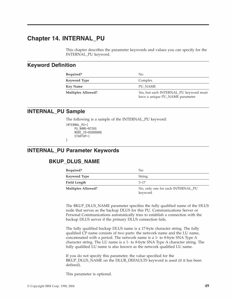
Chapter 14. INTERNAL_PU
This chapter describes the parameter keywords and values you can specify for the
INTERNAL_PU keyword.
Keyword Definition
Required? No
Keyword Type Complex
Key Name PU_NAME
Multiples Allowed? Yes, but each INTERNAL_PU keyword must
have a unique PU_NAME parameter
INTERNAL_PU Sample
The following is a sample of the INTERNAL_PU keyword:
INTERNAL_PU=(
PU_NAME=NT265
NODE_ID=05D00000
STARTUP=1
)
INTERNAL_PU Parameter Keywords
BKUP_DLUS_NAME
Required? No
Keyword Type String
Field Length 3–17
Multiples Allowed? No, only one for each INTERNAL_PU
keyword
The BKUP_DLUS_NAME parameter specifies the fully qualified name of the DLUS
node that serves as the backup DLUS for this PU. Communications Server or
Personal Communications automatically tries to establish a connection with the
backup DLUS server if the primary DLUS connection fails.
The fully qualified backup DLUS name is a 17-byte character string. The fully
qualified CP name consists of two parts: the network name and the LU name,
concatenated with a period. The network name is a 1- to 8-byte SNA Type A
character string. The LU name is a 1- to 8-byte SNA Type A character string. The
fully qualified LU name is also known as the network qualified LU name.
If you do not specify this parameter, the value specified for the
BKUP_DLUS_NAME on the DLUR_DEFAULTS keyword is used (if it has been
defined).
This parameter is optional.
© Copyright IBM Corp. 1998, 2006 49

DEPENDENT_LU_COMPRESSION
The DEPENDENT_LU_COMPRESSION parameter keyword applies to
Communications Server only.
Required? No
Keyword Type Boolean
Default 0
Multiples Allowed? No, only one for each INTERNAL_PU
keyword
The DEPENDENT_LU_COMPRESSION parameter specifies whether data
compression is used for conventional LU (LU 0 to 3) sessions dependent on this
PU. Valid values are:
0 Data compression is not used.
1 Data compression is used if the host requests compression.
DEPENDENT_LU_COMPRESSION=1 is ignored if the node does not
support compression.
This parameter is optional. The default is 0.
DEPENDENT_LU_ENCRYPTION
Required? Yes
Keyword Type Enumerated
Default OPTIONAL
Multiples Allowed? No, only one for each INTERNAL_PU
keyword
The DEPENDENT_LU_ENCRYPTION parameter specifies whether session level
encryption is required for conventional LU (LU 0 to 3) sessions dependent on this
PU. Valid values are:
MANDATORY Session level encryption is performed if an import
key is available to the LU. If an import key is not
available, encryption must be performed by the
application using the LU.
Note: If the DSPU_SERVICES parameter is
specified as PU_CONCENTRATION,
encryption is performed by a downstream
LU.
NONE Session level encryption is not performed.
OPTIONAL Session level encryption is performed by request
from the adjacent node.
For Communications Server, the default is OPTIONAL.
INTERNAL_PU
50 Configuration File Reference
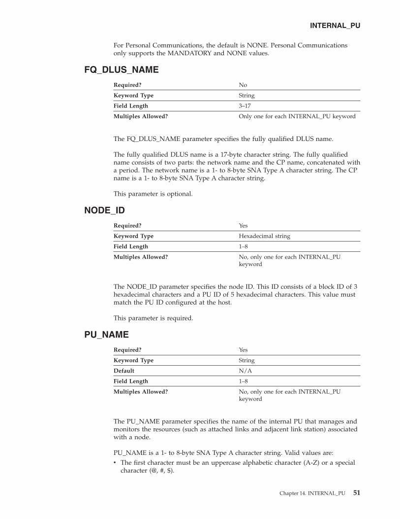
For Personal Communications, the default is NONE. Personal Communications
only supports the MANDATORY and NONE values.
FQ_DLUS_NAME
Required? No
Keyword Type String
Field Length 3–17
Multiples Allowed? Only one for each INTERNAL_PU keyword
The FQ_DLUS_NAME parameter specifies the fully qualified DLUS name.
The fully qualified DLUS name is a 17-byte character string. The fully qualified
name consists of two parts: the network name and the CP name, concatenated with
a period. The network name is a 1- to 8-byte SNA Type A character string. The CP
name is a 1- to 8-byte SNA Type A character string.
This parameter is optional.
NODE_ID
Required? Yes
Keyword Type Hexadecimal string
Field Length 1–8
Multiples Allowed? No, only one for each INTERNAL_PU
keyword
The NODE_ID parameter specifies the node ID. This ID consists of a block ID of 3
hexadecimal characters and a PU ID of 5 hexadecimal characters. This value must
match the PU ID configured at the host.
This parameter is required.
PU_NAME
Required? Yes
Keyword Type String
Default N/A
Field Length 1–8
Multiples Allowed? No, only one for each INTERNAL_PU
keyword
The PU_NAME parameter specifies the name of the internal PU that manages and
monitors the resources (such as attached links and adjacent link station) associated
with a node.
PU_NAME is a 1- to 8-byte SNA Type A character string. Valid values are:
v The first character must be an uppercase alphabetic character (A-Z) or a special
character (@, #, $).
INTERNAL_PU
Chapter 14. INTERNAL_PU 51
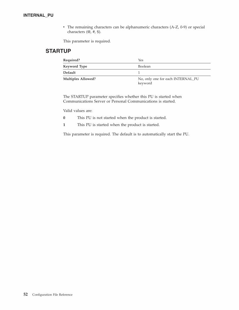
v The remaining characters can be alphanumeric characters (A-Z, 0-9) or special
characters (@, #, $).
This parameter is required.
STARTUP
Required? Yes
Keyword Type Boolean
Default 1
Multiples Allowed? No, only one for each INTERNAL_PU
keyword
The STARTUP parameter specifies whether this PU is started when
Communications Server or Personal Communications is started.
Valid values are:
0 This PU is not started when the product is started.
1 This PU is started when the product is started.
This parameter is required. The default is to automatically start the PU.
INTERNAL_PU
52 Configuration File Reference

Chapter 15. LINK_STATION
This chapter describes the parameter keywords and values you can specify for the
LINK_STATION keyword.
The LINK_STATION keyword should contain one of the
LINK_STATION_*_SPECIFIC DATA keywords. Which
LINK_STATION_*_SPECIFIC DATA keyword to use is dependent on the value of
PORT_NAME. For example, if the value of PORT_NAME refers to a LAN port, a
LINK_STATION_LAN_SPECIFIC_DATA keyword should be included.
Keyword Definition
Required? No
Keyword Type Complex
Key Name LS_NAME
Multiples Allowed? Yes, but each LINK_STATION keyword must
have a unique LS_NAME parameter
LINK_STATION Samples
The following are samples of the LINK_STATION keyword:
LINK_STATION=(
LS_NAME=LINK0000
ACTIVATE_AT_STARTUP=0
ADJACENT_NODE_TYPE=LEARN
AUTO_ACTIVATE_SUPPORT=1
CP_CP_SESS_SUPPORT=1
DEFAULT_NN_SERVER=0
DEST_ADDRESS=40000000000004
DISABLE_REMOTE_ACT=0
DSPU_SERVICES=NONE
HPR_LINK_LVL_ERROR=0
HPR_SUPPORT=0
LIMITED_RESOURCE=NO
LINK_DEACT_TIMER=0
LINK_STATION_ROLE=USE_ADAPTER_DEFAULTS
MAX_IFRM_RCVD=0
MAX_SEND_BTU_SIZE=65535
NODE_ID=05D00000
PORT_NAME=LAN0_04
SOLICIT_SSCP_SESSION=0
SUPPRESS_CP_NAME=NO
TG_NUMBER=0
USE_DEFAULT_TG_CHARS=1
LINK_STATION_LAN_SPECIFIC_DATA=(
TEST_RETRY_INTERVAL=8
TEST_RETRY_LIMIT=5
XID_RETRY_INTERVAL=8
XID_RETRY_LIMIT=5
)
)
LINK_STATION=(
LS_NAME=LINK0001
ACTIVATE_AT_STARTUP=0
ADJACENT_NODE_TYPE=DSPU_XID
© Copyright IBM Corp. 1998, 2006 53
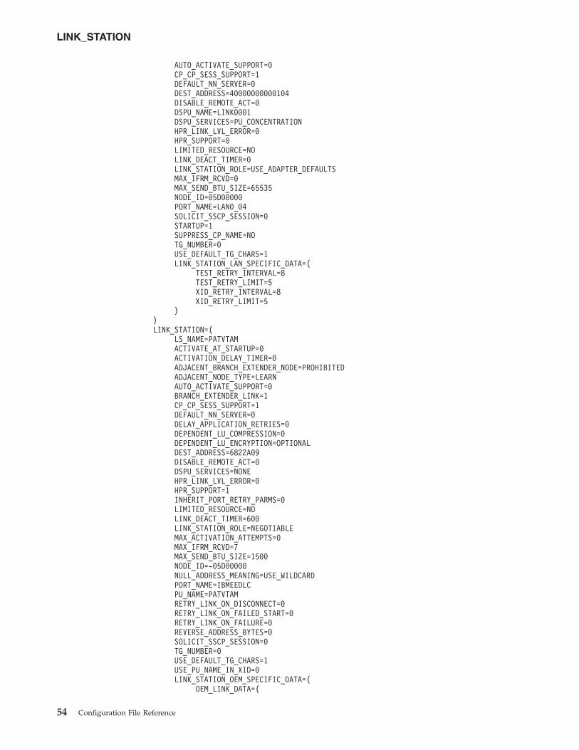
AUTO_ACTIVATE_SUPPORT=0
CP_CP_SESS_SUPPORT=1
DEFAULT_NN_SERVER=0
DEST_ADDRESS=40000000000104
DISABLE_REMOTE_ACT=0
DSPU_NAME=LINK0001
DSPU_SERVICES=PU_CONCENTRATION
HPR_LINK_LVL_ERROR=0
HPR_SUPPORT=0
LIMITED_RESOURCE=NO
LINK_DEACT_TIMER=0
LINK_STATION_ROLE=USE_ADAPTER_DEFAULTS
MAX_IFRM_RCVD=0
MAX_SEND_BTU_SIZE=65535
NODE_ID=05D00000
PORT_NAME=LAN0_04
SOLICIT_SSCP_SESSION=0
STARTUP=1
SUPPRESS_CP_NAME=NO
TG_NUMBER=0
USE_DEFAULT_TG_CHARS=1
LINK_STATION_LAN_SPECIFIC_DATA=(
TEST_RETRY_INTERVAL=8
TEST_RETRY_LIMIT=5
XID_RETRY_INTERVAL=8
XID_RETRY_LIMIT=5
)
)
LINK_STATION=(
LS_NAME=PATVTAM
ACTIVATE_AT_STARTUP=0
ACTIVATION_DELAY_TIMER=0
ADJACENT_BRANCH_EXTENDER_NODE=PROHIBITED
ADJACENT_NODE_TYPE=LEARN
AUTO_ACTIVATE_SUPPORT=0
BRANCH_EXTENDER_LINK=1
CP_CP_SESS_SUPPORT=1
DEFAULT_NN_SERVER=0
DELAY_APPLICATION_RETRIES=0
DEPENDENT_LU_COMPRESSION=0
DEPENDENT_LU_ENCRYPTION=OPTIONAL
DEST_ADDRESS=6822A09
DISABLE_REMOTE_ACT=0
DSPU_SERVICES=NONE
HPR_LINK_LVL_ERROR=0
HPR_SUPPORT=1
INHERIT_PORT_RETRY_PARMS=0
LIMITED_RESOURCE=NO
LINK_DEACT_TIMER=600
LINK_STATION_ROLE=NEGOTIABLE
MAX_ACTIVATION_ATTEMPTS=0
MAX_IFRM_RCVD=7
MAX_SEND_BTU_SIZE=1500
NODE_ID=-05D00000
NULL_ADDRESS_MEANING=USE_WILDCARD
PORT_NAME=IBMEEDLC
PU_NAME=PATVTAM
RETRY_LINK_ON_DISCONNECT=0
RETRY_LINK_ON_FAILED_START=0
RETRY_LINK_ON_FAILURE=0
REVERSE_ADDRESS_BYTES=0
SOLICIT_SSCP_SESSION=0
TG_NUMBER=0
USE_DEFAULT_TG_CHARS=1
USE_PU_NAME_IN_XID=0
LINK_STATION_OEM_SPECIFIC_DATA=(
OEM_LINK_DATA=(
LINK_STATION
54 Configuration File Reference
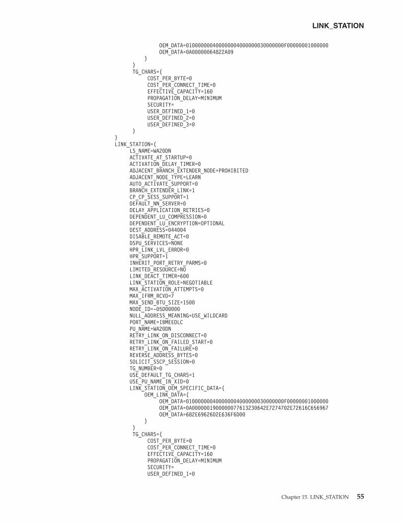
OEM_DATA=010000000400000004000000030000000F00000001000000
OEM_DATA=0A00000064822A09
)
)
TG_CHARS=(
COST_PER_BYTE=0
COST_PER_CONNECT_TIME=0
EFFECTIVE_CAPACITY=160
PROPAGATION_DELAY=MINIMUM
SECURITY=
USER_DEFINED_1=0
USER_DEFINED_2=0
USER_DEFINED_3=0
)
)
LINK_STATION=(
LS_NAME=WA20DN
ACTIVATE_AT_STARTUP=0
ACTIVATION_DELAY_TIMER=0
ADJACENT_BRANCH_EXTENDER_NODE=PROHIBITED
ADJACENT_NODE_TYPE=LEARN
AUTO_ACTIVATE_SUPPORT=0
BRANCH_EXTENDER_LINK=1
CP_CP_SESS_SUPPORT=1
DEFAULT_NN_SERVER=0
DELAY_APPLICATION_RETRIES=0
DEPENDENT_LU_COMPRESSION=0
DEPENDENT_LU_ENCRYPTION=OPTIONAL
DEST_ADDRESS=044004
DISABLE_REMOTE_ACT=0
DSPU_SERVICES=NONE
HPR_LINK_LVL_ERROR=0
HPR_SUPPORT=1
INHERIT_PORT_RETRY_PARMS=0
LIMITED_RESOURCE=NO
LINK_DEACT_TIMER=600
LINK_STATION_ROLE=NEGOTIABLE
MAX_ACTIVATION_ATTEMPTS=0
MAX_IFRM_RCVD=7
MAX_SEND_BTU_SIZE=1500
NODE_ID=-05D00000
NULL_ADDRESS_MEANING=USE_WILDCARD
PORT_NAME=IBMEEDLC
PU_NAME=WA20DN
RETRY_LINK_ON_DISCONNECT=0
RETRY_LINK_ON_FAILED_START=0
RETRY_LINK_ON_FAILURE=0
REVERSE_ADDRESS_BYTES=0
SOLICIT_SSCP_SESSION=0
TG_NUMBER=0
USE_DEFAULT_TG_CHARS=1
USE_PU_NAME_IN_XID=0
LINK_STATION_OEM_SPECIFIC_DATA=(
OEM_LINK_DATA=(
OEM_DATA=010000000400000004000000030000000F00000001000000
OEM_DATA=0A0000001900000077613230642E7274702E72616C656967
OEM_DATA=682E69626D2E636F6D00
)
)
TG_CHARS=(
COST_PER_BYTE=0
COST_PER_CONNECT_TIME=0
EFFECTIVE_CAPACITY=160
PROPAGATION_DELAY=MINIMUM
SECURITY=
USER_DEFINED_1=0
LINK_STATION
Chapter 15. LINK_STATION 55
USER_DEFINED_2=0
USER_DEFINED_3=0
)
)
LINK_STATION Parameter Keywords
ACTIVATE_AT_STARTUP
Required? Yes
Keyword Type Boolean
Default 1
Multiples Allowed? No, only one for each LINK_STATION
keyword
The ACTIVATE_AT_STARTUP parameter specifies whether the link is activated
when the product is started.
Valid values are:
0 The link is not activated when the product is started.
1 The link is activated when the product is started.
This parameter is required. The default is to activate the link.
ACTIVATION_DELAY_TIMER
Required? Yes
Keyword Type Signed number
Default -1
Range -1–3 600
Multiples Allowed? No, only one for each LINK_STATION
keyword
The ACTIVATION_DELAY_TIMER parameter specifies the number of seconds
between automatic retry attempts, and between application-driven activation
attempts if the DELAY_APPLICATION_RETRIES parameter is specified.
The value is an integer in the range of -1–3 600.
v If -1 is specified, the value specified on the ACTIVATION_DELAY_TIMER
parameter of the PORT keyword is used.
v If 0 is specified, a default value of 30 seconds is used.
This parameter is required. The default is -1.
ADJACENT_BRANCH_EXTENDER_NODE
The ADJACENT_BRANCH_EXTENDER_NODE parameter keyword
applies to Communications Server only.
LINK_STATION
56 Configuration File Reference
Required? Yes
Keyword Type Enumerated
Default PROHIBITED
Multiples Allowed? No, only one for each LINK_STATION
keyword
The ADJACENT_BRANCH_EXTENDER_NODE parameter specifies whether the
node adjacent to a local branch extender node can also be a branch extender node.
This parameter is only valid if the NODETYPE parameter on the NODE keyword
is specified as BRANCH_EXTENDER_NODE and the ADJACENT_NODE_TYPE
parameter on the LINK_STATION keyword is specified as LEARN or
NETWORK_NODE. Valid values are:
OPTIONAL The definition of the adjacent node as a branch
extender node in optional.
PROHIBITED The adjacent node must not be a branch extender
node, or the link activation fails.
REQUIRED The adjacent node must be a branch extender node,
or the link activation fails.
Note: If ADJACENT_NODE_TYPE=NETWORK_NODE and
AUTO_ACTIVATE_SUPPORT=1 on the LINK_STATION keyword, this
parameter must be specified as either REQUIRED or PROHIBITED.
This parameter is required. The default is PROHIBITED.
ADJACENT_NODE_ID
Required? No
Keyword Type Hexadecimal string
Field Length 1–8
Multiples Allowed? No, only one for each LINK_STATION
keyword
The ADJACENT_NODE_ID parameter specifies the node ID of the adjacent node.
An adjacent node is directly connected to this node via this link definition.
Specify a block ID of 3 hexadecimal characters and a PU ID of 5 hexadecimal
characters.
LINK_STATION
Chapter 15. LINK_STATION 57
This parameter is optional.
Notes:
1. If ADJACENT_NODE_TYPE indicates that the adjacent node is a
T2.1 node (END_NODE, LEARN, NETWORK_NODE, or
SUBAREA_LEN), this parameter is ignored unless it is nonzero, and
either ADJACENT_NODE_TYPE is set to SUBAREA_LEN or the
adjacent node does not send a network name control vector in its
XID3.
2. If ADJACENT_NODE_TYPE is specified as HOST_DEP_LU_ONLY
or HOST_XID0, this parameter is ignored.
3. If ADJACENT_NODE_TYPE is specified as DSPU_XID and this
parameter is specified as nonzero, it is used to check the identity of
the downstream PU.
4. If ADJACENT_NODE_TYPE is specified as DSPU_NO_XID and
DSPU_SERVICES is specified as PU_CONCENTRATION, this
parameter is ignored.
5. If ADJACENT_NODE_TYPE is specified as DSPU_NO_XID and
DSPU_SERVICES is specified as DLUR, this parameter is used to
identify the downstream PU to the DLUS.
Notes:
1. If ADJACENT_NODE_TYPE indicates that the adjacent node is a
T2.1 node (END_NODE, LEARN, NETWORK_NODE, or
SUBAREA_LEN), this parameter is ignored unless it is nonzero, and
either ADJACENT_NODE_TYPE is set to SUBAREA_LEN or the
adjacent node does not send a network name control vector in its
XID3.
2. If ADJACENT_NODE_TYPE is specified as HOST_DEP_LU_ONLY,
this parameter is ignored.
ADJACENT_NODE_TYPE
Required? Yes
Keyword Type Enumerated
Default LEARN
Multiples Allowed? No, only one for each LINK_STATION
keyword
The ADJACENT_NODE_TYPE parameter identifies the SNA node type of the
adjacent CP. Valid values are:
DSPU_NO_XID The adjacent node is a downstream
PU and the product does not
include XID exchange in link
activation.
LINK_STATION
58 Configuration File Reference
DSPU_XID The adjacent node is a downstream
PU and the product includes XID
exchange in link activation.
END_NODE The adjacent node is an APPN end
node or an up-level node.
HOST_DEP_LU_ONLY The adjacent node is a host and the
product responds to a polling XID
from the node with a format 3 XID.
HOST_XID0 The adjacent node is a host and the
product responds to a polling XID
from the node with a format 0 XID.
For a link using the AnyNet DLC
supporting dependent LU sessions,
you must specify this value.
LEARN The adjacent node is an APPN
network node, an APPN end node,
or an up-level node. The node type
is learned during XID exchange.
NETWORK_NODE The adjacent node is an APPN
network node.
SUBAREA_LEN The adjacent node does not send the
control point name in the XID. For a
link using the AnyNet DLC
supporting independent LU sessions,
you must specify this value.
Note: Independent LU 6.2 (APPC) traffic is only allowed over links
with the ADJACENT_NODE_TYPE parameter specified as END_NODE,
LEARN, NETWORK_NODE, or SUBAREA_LEN.
For the Enterprise Extender (EE) DLC and multipath channel (MPC)
DLC, ADJACENT_NODE_TYPE must be specified as END_NODE,
LEARN, or NETWORK_NODE.
For the Enterprise Extender (EE) DLC, ADJACENT_NODE_TYPE must
be specified as END_NODE, LEARN, or NETWORK_NODE.
This parameter is required. The default is LEARN.
AUTO_ACTIVATE_SUPPORT
Required? No
Keyword Type Boolean
Multiples Allowed? No, only one for each LINK_STATION
keyword
The AUTO_ACTIVATE_SUPPORT parameter specifies whether the link is activated
automatically when required by a session. Valid values are:
0 The link is not activated automatically.
1 The link is activated automatically when required by a session.
LINK_STATION
Chapter 15. LINK_STATION 59

This parameter is optional.
If the link is not to an APPN node, this parameter can always be specified as 1.
If the link is to an APPN node, this parameter can not be specified as 1 if the link
also supports CP-CP sessions. The parameter can be set to 1 if TG_NUMBER is
defined for the link, and the specified value of TG_NUMBER is between 1 and 20.
This allows an inactive link configured with AUTO_ACTIVATE_SUPPORT to be
used when determining the best route for a session, then activating the link when
it is needed. TG numbers are normally assigned only to active links (TGs).
BKUP_DLUS_NAME
Required? No
Keyword Type String
Field Length 3–17
Multiples Allowed? No, only one for each LINK_STATION
keyword
The BKUP_DLUS_NAME parameter specifies the fully qualified backup DLUS
name for the downstream PU, with which Communications Server or Personal
Communications automatically tries to establish a connection if the primary DLUS
connection fails.
The fully qualified backup DLUS name is a 17-byte character string. The fully
qualified CP name consists of two parts: the network name and the LU name,
concatenated with a period. The network name is a 1- to 8-byte SNA Type A
character string. The LU name is a 1- to 8-byte SNA Type A character string. The
fully qualified LU name is also known as the network qualified LU name.
If you do not specify this parameter, the value specified for the
BKUP_DLUS_NAME on the DLUR_DEFAULTS keyword is used (if defined.) This
parameter is ignored if DSPU_SERVICES is not set to DLUR.
This parameter is optional.
BRANCH_EXTENDER_LINK
The BRANCH_EXTENDER_LINK parameter keyword applies to
Communications Server only.
Required? No
Keyword Type Boolean
Default 0
Multiples Allowed? No, only one for each LINK_STATION
keyword
The BRANCH_EXTENDER_LINK parameter specifies whether this connection is
designated as a branch extender link. This parameter is only valid if the
NODETYPE parameter on the NODE keyword is specified as
BRANCH_EXTENDER_NODE and the ADJACENT_NODE_TYPE parameter on
LINK_STATION
60 Configuration File Reference

the LINK_STATION keyword is specified as END_NODE, LEARN,
NETWORK_NODE, or SUBAREA_LEN. Valid values are:
0 This connection is not designated as a branch extender link.
1 This connection is designated as a branch extender link. The link connects
to another network from the local branch network. This value is only valid
if the ADJACENT_NODE_TYPE parameter on the LINK_STATION
keyword is specified as NETWORK_NODE.
This parameter is optional. The default is 0.
COST_PER_BYTE
Required? No
Keyword Type Unsigned number
Range 0–255
Multiples Allowed? No, only one for each LINK_STATION
keyword
The COST_PER_BYTE parameter specifies the cost per byte for this link station.
The value is an integer in the range 0-255.
This parameter is optional.
COST_PER_CONNECT_TIME
Required? No
Keyword Type Unsigned number
Range 0–255
Multiples Allowed? No, only one for each LINK_STATION
keyword
The COST_PER_CONNECT_TIME parameter specifies the cost per connect time
for this link station.
The value is an integer in the range 0-255.
This parameter is optional.
CP_CP_SESS_SUPPORT
Required? No
Keyword Type Boolean
Multiples Allowed? No, only one for each LINK_STATION
keyword
The CP_CP_SESS_SUPPORT parameter specifies whether CP-CP sessions are
supported on this connection. This parameter is only relevant if the link is to an
APPN node.
LINK_STATION
Chapter 15. LINK_STATION 61
If you specify ADJACENT_NODE_TYPE as HOST_XID0, HOST_DEP_LU_ONLY,
or SUBAREA_LEN, or if you specify LIMITED_RESOURCE is specified as YES,
this parameter is ignored and is assumed to be 0.
Valid values are:
0 CP-CP sessions are not supported.
1 CP-CP sessions are supported.
For a multipath channel (MPC) DLC, CP_CP_SESS_SUPPORT must be
specified as 1.
This parameter is optional.
DEFAULT_NN_SERVER
Required? No
Keyword Type Boolean
Multiples Allowed? No, only one for each LINK_STATION
keyword
The DEFAULT_NN_SERVER parameter specifies whether a link can be
automatically activated by an end node to support CP-CP sessions to a network
node server. The link must be defined to support CP-CP sessions for this
parameter to effective. Valid values are:
0 CP-CP sessions are not supported.
1 CP-CP sessions are supported.
This parameter is optional.
DELAY_APPLICATION_RETRIES
Required? No
Keyword Type Boolean
Multiples Allowed? No, only one for each LINK_STATION
keyword
The DELAY_APPLICATION_RETRIES parameter specifies whether link activation
retries initiated by applications are delayed by the value specified for the
ACTIVATION_DELAY_TIMER parameter. Valid values are:
0 Link activation retries initiated by applications are not delayed.
1 Link activation retries initiated by applications are delayed.
This parameter is optional.
LINK_STATION
62 Configuration File Reference

DEPENDENT_LU_COMPRESSION
The DEPENDENT_LU_COMPRESSION parameter keyword applies to
Communications Server only.
Required? No
Keyword Type Boolean
Default 0
Multiples Allowed? No, only one for each LINK_STATION
keyword
The DEPENDENT_LU_COMPRESSION parameter specifies whether data
compression is used for conventional LU (LU 0 to 3) sessions on this connection.
This parameter is only valid for connections supporting conventional LU sessions.
Valid values are:
0 Data compression is not used.
1 Data compression is used if the host requests compression.
DEPENDENT_LU_COMPRESSION=1 is ignored if the node does not
support compression.
This parameter is optional. The default is 0.
DEPENDENT_LU_ENCRYPTION
Required? Yes
Keyword Type Enumerated
Default OPTIONAL
Multiples Allowed? No, only one for each LINK_STATION
keyword
The DEPENDENT_LU_ENCRYPTION parameter specifies whether session level
encryption is required for conventional LU (LU 0 to 3) sessions on this connection.
This parameter is only valid for connections supporting conventional LU sessions.
Valid values are:
MANDATORY Session level encryption is performed if an import
key is available to the LU. If an import key is not
available, encryption must be performed by the
application that uses the LU.
Note: If the DSPU_SERVICES parameter is
specified as PU_CONCENTRATION,
encryption is performed by a downstream
LU.
NONE Session level encryption is not performed.
OPTIONAL Session level encryption is performed by request
from the adjacent node.
For Communications Server, the default is OPTIONAL.
LINK_STATION
Chapter 15. LINK_STATION 63
For Personal Communications, the default is NONE. Personal Communications
only supports the MANDATORY and NONE values.
DEST_ADDRESS
The DEST_ADDRESS parameter specifies information specific to the DLC you are
using.
For information on defining the DEST_ADDRESS parameter for the DLC, refer to
the following sections:
v Appendix A, “AnyNet-Specific Data,” on page 185
v Appendix C, “LAN-Specific Data,” on page 197
v Appendix D, “OEM-Specific Data,” on page 207
v Appendix E, “SDLC-Specific Data,” on page 217
v Appendix F, “Twinaxial-Specific Data,” on page 233
DISABLE_REMOTE_ACT
Required? Yes
Keyword Type Boolean
Default 0
Multiples Allowed? No, only one for each LINK_STATION
keyword
The DISABLE_REMOTE_ACT parameter specifies whether remote activation of
this link is supported. Valid values are:
0 Remote activation is supported.
1 Remote activation is not supported.
This parameter is required. The default is 0; remote link activation is supported.
DLUS_NAME
Required? No
Keyword Type String
Field Length 3–17
Multiples Allowed? No, only one for each LINK_STATION
keyword
The DLUS_NAME parameter is the name of the primary dependent logical unit
server with which a connection is to be established.
This parameter is optional.
The fully qualified DLUS name is a 17-byte character string. The fully qualified CP
name consists of two parts: the network name and the LU name, concatenated
with a period. The network name is a 1- to 8-byte SNA Type A character string.
The LU name is a 1- to 8-byte SNA Type A character string. The fully qualified LU
name is also known as the network qualified LU name.
LINK_STATION
64 Configuration File Reference

If you do not specify this parameter, the value specified for the
BKUP_DLUS_NAME on the DLUR_DEFAULTS keyword is used (if defined.) If
BKUP_DLUS_NAME on the DLUR_DEFAULTS keyword has not been defined, the
DLUR does not initiate SSCP contact when the link is activated. This parameter is
ignored if DSPU_SERVICES is not specified as DLUR.
DSPU_NAME
Required? No
Keyword Type String
Field Length 1–8
Multiples Allowed? No, only one for each LINK_STATION
keyword
The DSPU_NAME parameter specifies the downstream PU name.
The downstream physical unit (PU) manages and monitors the resources (such as
attached links and adjacent link station) associated with a downstream node.
DSPU_NAME is a 1- to 8-byte character string. Valid values are:
v The first character must be an uppercase alphabetic character (A-Z) or a special
character (@, #, $).
v The remaining characters can be alphanumeric characters (A-Z, 0-9) or special
characters (@, #, $).
This parameter must be specified if DSPU_SERVICES is specified as
PU_CONCENTRATION or DLUR. Otherwise, the parameter is ignored.
DSPU_SERVICES
Required? Yes
Keyword Type Enumerated
Default NONE
Multiples Allowed? No, only one for each LINK_STATION
keyword
The DSPU_SERVICES parameter specifies the local node services provided to the
downstream PU across this link. Valid values are:
NONE Local node provides no services for this
downstream PU.
DLUR Local node provides DLUR services for the
downstream PU.
PU_CONCENTRATION Local node provides PU concentration for the
downstream PU.
This parameter is required. The default is NONE.
Notes:
1. The DSPU_NAME parameter must also be specified if this parameter is
specified as PU_CONCENTRATION or DLUR.
LINK_STATION
Chapter 15. LINK_STATION 65

2. This parameter must be specified as PU_CONCENTRATION or DLUR if the
adjacent node is defined as a downstream PU (that is, NODE_TYPE is specified
as DSPU_XID or DSPU_NO_XID).
3. This parameter can be specified as PU_CONCENTRATION or DLUR on a link
to an APPN node if SOLICIT_SSCP_SESSION is specified as 0.
4. This field is ignored if the adjacent node is defined as a host.
EFFECTIVE_CAPACITY
Required? No
Keyword Type Unsigned number
Multiples Allowed? No, only one for each LINK_STATION
keyword
The EFFECTIVE_CAPACITY parameter specifies the units of effective capacity for
this link station. The value is encoded as a 1-byte floating-point number,
represented by the following formula:
0.1 mmm * 2 eeeee
where the bit representation of the byte is eeeeemmm. Each unit of effective
capacity is equal to 300 bits per second.
This parameter is optional.
ETHERNET_FORMAT
The ETHERNET_FORMAT parameter keyword applies to Personal
Communications only.
Required? Yes
Keyword Type Boolean
Default 0
Multiples Allowed? No, only one for each LINK_STATION
keyword
The ETHERNET_FORMAT parameter specifies whether the LAN destination
address is transmitted in token-ring format (unmodified) or Ethernet format
(byte-reversal).
Note: The Ethernet format may not be appropriate for some Ethernet connections.
Valid values are:
0 The LAN destination address is transmitted in token-ring format.
1 The LAN destination address is transmitted in Ethernet format.
This parameter is required. The default is 0; transmit the LAN destination address
in token-ring format.
LINK_STATION
66 Configuration File Reference

FQ_ADJACENT_CP_NAME
Required? No
Keyword Type String
Field Length 3–17
Multiples Allowed? No, only one for each LINK_STATION
keyword
The FQ_ADJACENT_CP_NAME parameter specifies the fully qualified control
point (CP) name that is directly connected to your workstation across this link.
The fully qualified CP name is a 17-byte character string. The fully qualified CP
name consists of two parts: the network name and the CP name, concatenated with
a period. The network name is a 1- to 8-byte SNA Type A character string. The CP
name is a 1- to 8-byte SNA Type A character string. The fully qualified CP name is
also known as the network qualified CP name.
This parameter is optional.
Notes:
1. This field is only relevant for links to APPN nodes and is otherwise ignored.
2. For links to APPN nodes, do not specify this parameter unless you specify the
TG_NUMBER parameter as a number in the range 1-20 or you specify the
ADJACENT_NODE_TYPE parameter as SUBAREA_LEN.
If you specify this parameter, it is checked against the name received from the
adjacent node during XID exchange, unless the ADJACENT_NODE_TYPE
parameter is specified as SUBAREA_LEN, in which case it is used to identify
the adjacent node.
HPR_LINK_LVL_ERROR
Required? No
Keyword Type Boolean
Multiples Allowed? No, only one for each LINK_STATION
keyword
The HPR_LINK_LVL_ERROR parameter specifies whether HPR traffic should be
sent on this link using link-level error recovery. This parameter is ignored if
HPR_SUPPORT is specified as 0. Valid values are:
0 HPR traffic should not be sent on this link using link-level error recovery.
1 HPR traffic should be sent on this link using link-level error recovery.
This parameter is optional.
LINK_STATION
Chapter 15. LINK_STATION 67
HPR_SUPPORT
Required? No
Keyword Type Boolean
Default 0
Multiples Allowed? No, only one for each LINK_STATION
keyword
The HPR_SUPPORT parameter specifies whether HPR is supported on this link.
This field is only relevant if the link is to an APPN node and is otherwise ignored.
Valid values are:
0 HPR is not supported on this link.
1 HPR is supported on this link.
For the Enterprise Extender (EE) DLC and multipath channel (MPC)
DLC, HPR_SUPPORT must be specified as 1.
For the Enterprise Extender (EE) DLC, HPR_SUPPORT must be
specified as 1.
This parameter is optional. The default is not to support HPR.
INHERIT_PORT_RETRY_PARMS
Required? No
Keyword Type Boolean
Default 0
Multiples Allowed? No, only one for each LINK_STATION
keyword
The INHERIT_PORT_RETRY_PARMS parameter specifies whether the values
specified on the PORT keyword are used for the following parameters (if they are
not specified for the LINK_STATION keyword):
v DELAY_APPLICATION_RETRIES
v RETRY_LINK_ON_DISCONNECT
v RETRY_LINK_ON_FAILED_START
v RETRY_LINK_ON_FAILURE
Valid values are:
0 The values specified on the PORT keyword are not used.
1 The values specified on the PORT keyword are used.
This parameter is optional.
LINK_STATION
68 Configuration File Reference

LIMITED_RESOURCE
Required? Yes
Keyword Type Enumerated
Multiples Allowed? No, only one for each LINK_STATION
keyword
The LIMITED_RESOURCE parameter specifies whether this link station is
deactivated when there are no active sessions. Valid values are:
NO The link is not a limited resource and is not be deactivated
automatically.
YES The link is a limited resource and is deactivated automatically
when there are no active sessions. A limited resource link station
can be configured for CP-CP session support. (This is done by
setting this field to YES and CP_CP_SESS_SUPPORT to 1.) In this
case, if CP-CP sessions are brought up over the link,
Communications Server or Personal Communications does not
treat the link as a limited resource (and does not bring the link
down).
INACTIVITY The link is a limited resource and is deactivated automatically
when there are no active sessions, or when no data has flowed on
the link for the time period specified by the LINK_DEACT_TIMER
parameter. Note that link stations on a nonswitched port can not
be configured as limited resources.
For a multipath channel (MPC) DLC, LIMITED_RESOURCE must be
specified as NO.
This parameter is required.
LINK_DEACT_TIMER
Required? No
Keyword Type Unsigned number
Default 10
Default 600
Range 0–60000
Multiples Allowed? No, only one for each
LINK_STATION keyword
The LINK_DEACT_TIMER parameter specifies the time, in seconds, that this link
can be idle before it automatically deactivates. The link deactivation timer is only
used when the LIMITED_RESOURCE parameter is specified as INACTIVITY.
LINK_STATION
Chapter 15. LINK_STATION 69

The value is an integer in the range of 0–60000 seconds.
The default is 10 seconds.
The default is 600 seconds.
This parameter is optional.
Note: If zero is specified, the default value is used. Otherwise, the minimum value
is 5. (If it is set any lower, the specified value is ignored and 5 is used.)
LINK_STATION_ROLE
Required? No
Keyword Type Enumerated
Default NEGOTIABLE
Multiples Allowed? No, only one for each
LINK_STATION keyword
The LINK_STATION_ROLE parameter defines the responsibility that the link
station has for controlling the communication with its adjacent link stations. Valid
values are:
NEGOTIABLE When the connection is established, the local link
station becomes either a primary or secondary link
station.
PRIMARY The primary link station controls the conversation
on the link.
SECONDARY The secondary link station must wait to be polled
by the primary link station before data is sent.
USE_ADAPTER_DEFAULTS Use the value specified on the PORT keyword.
The default is NEGOTIABLE.
This parameter is optional.
Notes:
1. If DLC_NAME on the PORT keyword is specified as TWINAX, only
SECONDARY is valid.
2. If DLC_NAME on the PORT keyword is specified as ANYNET, and LS_NAME
is $ANYNET$, PRIMARY is not valid.
LINK_STATION
70 Configuration File Reference
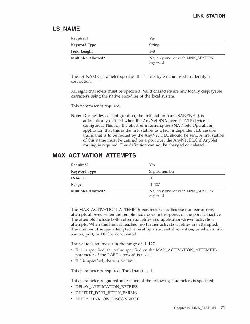
LS_NAME
Required? Yes
Keyword Type String
Field Length 1–8
Multiples Allowed? No, only one for each LINK_STATION
keyword
The LS_NAME parameter specifies the 1- to 8-byte name used to identify a
connection.
All eight characters must be specified. Valid characters are any locally displayable
characters using the native encoding of the local system.
This parameter is required.
Note: During device configuration, the link station name $ANYNET$ is
automatically defined when the AnyNet SNA over TCP/IP device is
configured. This has the effect of informing the SNA Node Operations
application that this is the link station to which independent LU session
traffic that is to be routed by the AnyNet DLC should be sent. A link station
of this name must be defined on a port over the AnyNet DLC if AnyNet
routing is required. This definition can not be changed or deleted.
MAX_ACTIVATION_ATTEMPTS
Required? Yes
Keyword Type Signed number
Default -1
Range -1–127
Multiples Allowed? No, only one for each LINK_STATION
keyword
The MAX_ACTIVATION_ATTEMPTS parameter specifies the number of retry
attempts allowed when the remote node does not respond, or the port is inactive.
The attempts include both automatic retries and application-driven activation
attempts. When this limit is reached, no further activation retries are attempted.
The number of retries attempted is reset by a successful activation, or when a link
station, port, or DLC is deactivated.
The value is an integer in the range of -1–127.
v If -1 is specified, the value specified on the MAX_ACTIVATION_ATTEMPTS
parameter of the PORT keyword is used.
v If 0 is specified, there is no limit.
This parameter is required. The default is -1.
This parameter is ignored unless one of the following parameters is specified:
v DELAY_APPLICATION_RETRIES
v INHERIT_PORT_RETRY_PARMS
v RETRY_LINK_ON_DISCONNECT
LINK_STATION
Chapter 15. LINK_STATION 71

v RETRY_LINK_ON_FAILED_START
v RETRY_LINK_ON_FAILURE
MAX_IFRM_RCVD
Required? No
Keyword Type Unsigned number
Range 0–127
Multiples Allowed? No, only one for each LINK_STATION
keyword
The MAX_IFRM_RCVD parameter determines the maximum number of I-frames
that can be received by the local link stations before an acknowledgment is sent.
The value is an integer in the range of 0-127 frames.
If MAX_IFRM_RCVD is set to zero, the default value from the PORT keyword is
used.
For a multipath channel (MPC) DLC, MAX_IFRM_RCVD must be
specified as 0.
This parameter is optional.
MAX_SEND_BTU_SIZE
Required? No
Keyword Type Unsigned number
Multiples Allowed? No, only one for each LINK_STATION
keyword
The MAX_SEND_BTU_SIZE parameter specifies the maximum BTU size that can
be sent from this link station. This value is used to negotiate the maximum BTU
size that can be transmitted between a link station pair.
This parameter is optional.
Notes:
1. If the link is not HPR-capable, this value must be set to a value greater than or
equal to 99.
2. If the link is HPR-capable, this value must be set to a value greater than or
equal to 768.
For a multipath channel (MPC) DLC, MAX_SEND_BTU_SIZE should be
specified as 32 768 to allow the DLC to determine the size.
LINK_STATION
72 Configuration File Reference

NODE_ID
Required? No
Keyword Type Hexadecimal string
Field Length 1–8
Multiples Allowed? No, only one for each LINK_STATION
keyword
The NODE_ID parameter specifies the node ID sent in XIDs on this link station.
This ID consists of a block ID of 3 hexadecimal characters and a PU ID of 5
hexadecimal characters.
This parameter is optional.
Notes:
1. If this field is set to zero, the NODE_ID parameter value specified on the
NODE keyword is used in XID exchanges (see Chapter 22, “NODE,” on page
111).
2. If this field is nonzero, the link definition replaces the value from the NODE
definition for XID exchanges on this link station.
NULL_ADDRESS_MEANING
The NULL_ADDRESS_MEANING parameter keyword applies to
Communications Server only.
Required? Yes
Keyword Type Enumerated
Default USE_WILDCARD
Multiples Allowed? No, only one for each LINK_STATION
keyword
The NULL_ADDRESS_MEANING parameter specifies how a null destination
address for an incoming LAN connection is matched to this link station. Valid
values are:
USE_CPNAME_NODEID The destination address for the incoming LAN
connection is matched to this link station using the
adjacent CP name or adjacent node ID.
USE_WILDCARD The destination address for the incoming LAN
connection is matched to this link station as a
wildcard. This link station is matched to any
incoming connection request that is not matched
by another defined link station.
This parameter is required. The default is USE_WILDCARD.
LINK_STATION
Chapter 15. LINK_STATION 73
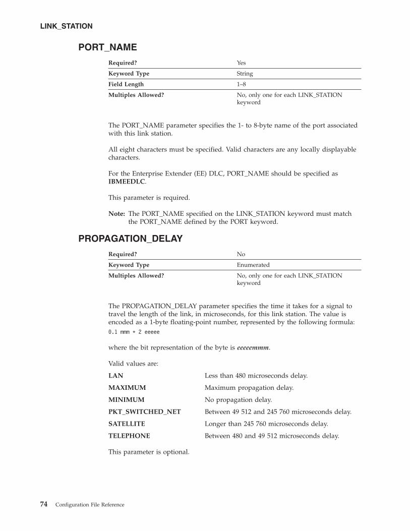
PORT_NAME
Required? Yes
Keyword Type String
Field Length 1–8
Multiples Allowed? No, only one for each LINK_STATION
keyword
The PORT_NAME parameter specifies the 1- to 8-byte name of the port associated
with this link station.
All eight characters must be specified. Valid characters are any locally displayable
characters.
For the Enterprise Extender (EE) DLC, PORT_NAME should be specified as
IBMEEDLC.
This parameter is required.
Note: The PORT_NAME specified on the LINK_STATION keyword must match
the PORT_NAME defined by the PORT keyword.
PROPAGATION_DELAY
Required? No
Keyword Type Enumerated
Multiples Allowed? No, only one for each LINK_STATION
keyword
The PROPAGATION_DELAY parameter specifies the time it takes for a signal to
travel the length of the link, in microseconds, for this link station. The value is
encoded as a 1-byte floating-point number, represented by the following formula:
0.1 mmm * 2 eeeee
where the bit representation of the byte is eeeeemmm.
Valid values are:
LAN Less than 480 microseconds delay.
MAXIMUM Maximum propagation delay.
MINIMUM No propagation delay.
PKT_SWITCHED_NET Between 49 512 and 245 760 microseconds delay.
SATELLITE Longer than 245 760 microseconds delay.
TELEPHONE Between 480 and 49 512 microseconds delay.
This parameter is optional.
LINK_STATION
74 Configuration File Reference

PU_NAME
Required? No
Keyword Type String
Field Length 1–8
Multiples Allowed? No, only one for each LINK_STATION
keyword
The PU_NAME parameter specifies the name of the local PU that uses this link if
the adjacent node is defined to be a host or if the SOLICIT_SSCP_SESSIONS is
specified as 1 on a link to an APPN node. If the adjacent node is not defined to be
a host, and is not defined as an APPN node with SOLICIT_SSCP_SESSIONS=1,
this field is ignored.
PU_NAME is a 1- to 8-byte SNA Type A character string. Valid values are:
v The first character must be an uppercase alphabetic character (A-Z) or a special
character (@, #, $).
v The remaining characters can be alphanumeric characters (A-Z, 0-9) or special
characters (@, #, $).
This parameter is optional.
RETRY_LINK_ON_DISCONNECT
Required? No
Keyword Type Boolean
Multiples Allowed? No, only one for each LINK_STATION
keyword
The RETRY_LINK_ON_DISCONNECT parameter specifies whether link activation
is retried when the link is stopped normally by the remote node. Valid values are:
0 Link activation is not retried.
1 Link activation is retried.
This parameter is optional.
RETRY_LINK_ON_FAILED_START
Required? No
Keyword Type Boolean
Multiples Allowed? No, only for each LINK_STATION keyword
The RETRY_LINK_ON_FAILED_START parameter specifies whether link activation
is retried if no response is received from the remote node when activation is
attempted. If the port is inactive when activation is attempted, an attempt is made
to activate it. Valid values are:
0 Link activation is not retried.
1 Link activation is retried.
LINK_STATION
Chapter 15. LINK_STATION 75

This parameter is optional.
RETRY_LINK_ON_FAILURE
Required? No
Keyword Type Boolean
Multiples Allowed? No, only one for each LINK_STATION
keyword
The RETRY_LINK_ON_FAILURE parameter specifies whether link activation is
retried if the link fails while in an active or pending active state. If the port fails,
an attempt is made to activate it. Valid values are:
0 Link activation is not retried.
1 Link activation is retried.
This parameter is optional.
REVERSE_ADDRESS_BYTES
The REVERSE_ADDRESS_BYTES parameter keyword applies to
Communications Server only.
Required? No
Keyword Type Boolean
Multiples Allowed? No, only one for each LINK_STATION
keyword
The REVERSE_ADDRESS_BYTES parameter specifies whether the bytes of the
destination address are swapped at runtime. Many SNA devices, such as Ethernet
routers, require that the destination address be byte-swapped before use. The
destination address displayed remains the same regardless of the value of this
field. Valid values are:
0 Do not byte-swap the address.
1 Byte-swap the address at runtime.
This parameter is optional.
SECURITY
Required? No
Keyword Type Enumerated
Multiples Allowed? No, only one for each LINK_STATION
keyword
The SECURITY parameter specifies the type of security used for transmission of
data over the connection for this link station. Valid values are:
ENCRYPTED
There is encryption over the line.
LINK_STATION
76 Configuration File Reference

GUARDED_CONDUIT
The conduit is protected against physical tapping.
GUARDED_RADIATION
The line is protected against physical and radiation tapping.
NONSECURE
No security exists.
PUBLIC_SWITCHED_NETWORK
Data is transmitted over a public switched network.
SECURE_CONDUIT
The line is a secure conduit that is not guarded.
UNDERGROUND_CABLE
Data is transmitted over a secure underground cable.
This parameter is optional.
SOLICIT_SSCP_SESSION
Required? No
Keyword Type Boolean
Multiples Allowed? No, only one for each LINK_STATION
keyword
The SOLICIT_SSCP_SESSION parameter specifies whether SSCP sessions are
initiated on this link. Valid values are:
0 Requests no sessions with the SSCP on this link.
1 Requests the adjacent node to initiate sessions between the SSCP and the
local control point and dependent LUs. If this value is specified, the
PU_NAME parameter must be specified.
This parameter is optional.
Notes:
1. The SOLICIT_SSCP_SESSION parameter is only valid if the link is to an APPN
node and is otherwise ignored.
2. If the adjacent node is defined to be a host (ADJACENT_NODE_TYPE is
specified as HOST_DEP_LU_ONLY (Communications Server), HOST_XID3
(Personal Communications), or HOST_XID0), the product always requests the
host to initiate sessions between the SSCP and the local control point and
dependent LUs. The PU_NAME parameter must be specified.
For a multipath channel (MPC) DLC, SOLICIT_SSCP_SESSION must be
specified as 0.
TG_CHARS
Required? No
Keyword Type Complex
Multiples Allowed? No, only one for each LINK_STATION
keyword
LINK_STATION
Chapter 15. LINK_STATION 77

The TG_CHARS parameter is a complex keyword comprised of the following
parameter keywords:
v COST_PER_BYTE
v COST_PER_CONNECT_TIME
v EFFECTIVE_CAPACITY
v PROPAGATION_DELAY
v SECURITY
v USER_DEFINED_1
v USER_DEFINED_2
v USER_DEFINED_3
See the descriptions of the parameter keywords to define the TG_CHARS
parameter.
TG_NUMBER
Required? No
Keyword Type Unsigned number
Default 0
Range 0–20
Multiples Allowed? No, only one for each LINK_STATION
keyword
The TG_NUMBER parameter specifies a preassigned TG number. This field is only
relevant if the link is to an adjacent APPN node and is otherwise ignored.
This parameter is optional. The default is 0.
Notes:
1. If ADJACENT_NODE_TYPE is specified as SUBAREA_LEN, TG_NUMBER is
ignored and assumed to be specified as 1.
2. For links to adjacent APPN nodes, TG_NUMBER must be set in the range 1-20.
This number is used to represent the link when the link is activated.
Communications Server does not accept any other number from the adjacent
node during activation of this link.
3. To avoid link-activation failure because of a mismatch of preassigned TG
numbers, the same TG number must be defined by the adjacent node on the
adjacent link station (if using preassigned TG numbers).
4. If a preassigned TG number is specified, the FQ_ADJACENT_CP_NAME must
also be defined (and can not be set to all zeros) and the
ADJACENT_NODE_TYPE must be specified as NETWORK_NODE or
END_NODE.
5. If zero is entered, the TG number is not preassigned and is negotiated when
the link is activated.
LINK_STATION
78 Configuration File Reference

USE_DEFAULT_TG_CHARS
Required? No
Keyword Type Boolean
Multiples Allowed? No, only one for each LINK_STATION
keyword
The USE_DEFAULT_TG_CHARS parameter specifies whether the default TG
characteristics specified on the PORT keyword should be used.
USE_DEFAULT_TG_CHARS is only valid if the link is to an APPN node and is
otherwise ignored. Valid values are:
0 Do not use the default TG characteristics specified on the PORT keyword.
1 Use the default TG characteristics specified on the PORT keyword. The
values defined on the LINK_STATION TG_CHARS parameters are ignored.
This parameter is optional.
USE_PU_NAME_IN_XID
The USE_PU_NAME_IN_XID parameter keyword applies to
Communications Server only.
Required? No
Keyword Type Boolean
Default 0
Multiples Allowed? No, only one for each LINK_STATION
keyword
The USE_PU_NAME_IN_XID parameter specifies whether the PU_NAME value in
this LINK_STATION keyword should be used instead of the FQ_CP_NAME value
from the NODE keyword during XID3 negotiation at link startup. Valid values are:
0 Use the CP name in XID3 negotiation
1 Use the PU name instead of the CP name in XID3 negotiation
This field is ignored unless ADJACENT_NODE_TYPE is specified as
HOST_DEP_LU_ONLY or SUBAREA_LEN (Communications Server), or
BACK_LEVEL_LEN_NODE or HOST_XID3 (Personal Communications).
This parameter is optional. The default is 0; use the node CP name during XID3
negotiation.
USER_DEFINED_1
Required? No
Keyword Type Unsigned number
Multiples Allowed? No, only one for each LINK_STATION
keyword
LINK_STATION
Chapter 15. LINK_STATION 79
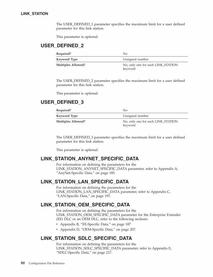
The USER_DEFINED_1 parameter specifies the maximum limit for a user defined
parameter for this link station.
This parameter is optional.
USER_DEFINED_2
Required? No
Keyword Type Unsigned number
Multiples Allowed? No, only one for each LINK_STATION
keyword
The USER_DEFINED_2 parameter specifies the maximum limit for a user defined
parameter for this link station.
This parameter is optional.
USER_DEFINED_3
Required? No
Keyword Type Unsigned number
Multiples Allowed? No, only one for each LINK_STATION
keyword
The USER_DEFINED_3 parameter specifies the maximum limit for a user defined
parameter for this link station.
This parameter is optional.
LINK_STATION_ANYNET_SPECIFIC_DATA
For information on defining the parameters for the
LINK_STATION_ANYNET_SPECIFIC_DATA parameter, refer to Appendix A,
“AnyNet-Specific Data,” on page 185.
LINK_STATION_LAN_SPECIFIC_DATA
For information on defining the parameters for the
LINK_STATION_LAN_SPECIFIC_DATA parameter, refer to Appendix C,
“LAN-Specific Data,” on page 197.
LINK_STATION_OEM_SPECIFIC_DATA
For information on defining the parameters for the
LINK_STATION_OEM_SPECIFIC_DATA parameter for the Enterprise Extender
(EE) DLC or an OEM DLC, refer to the following sections:
v Appendix B, “EE-Specific Data,” on page 187
v Appendix D, “OEM-Specific Data,” on page 207.
LINK_STATION_SDLC_SPECIFIC_DATA
For information on defining the parameters for the
LINK_STATION_SDLC_SPECIFIC_DATA parameter, refer to Appendix E,
“SDLC-Specific Data,” on page 217.
LINK_STATION
80 Configuration File Reference

LINK_STATION_X25_SPECIFIC_DATA
For information on defining the parameters for the
LINK_STATION_X25_SPECIFIC_DATA parameter, refer to Appendix G,
“X.25-Specific Data,” on page 237.
LINK_STATION
Chapter 15. LINK_STATION 81

82 Configuration File Reference

Chapter 16. LOAD_BALANCING
This chapter describes the parameter keywords and values you can
specify for the LOAD_BALANCING keyword.
Keyword Definition
Required? No
Keyword Type Complex
Multiples Allowed? No
LOAD_BALANCING Sample
The following is a sample of the LOAD_BALANCING keyword:
LOAD_BALANCING=(
ADVERTISE_FREQUENCY=1
APPC_LU_LOAD_FACTOR=0
ENABLE_LOAD_BALANCING=1
HOST_LU_LOAD_FACTOR=0
LOAD_VARIANCE=3
SCOPE_NAME=SCOPE1
)
LOAD_BALANCING Parameter Keywords
ADVERTISE_FREQUENCY
Required? No
Keyword Type Unsigned number
Default 1
Range 1-60
Multiples Allowed? No
The ADVERTISE_FREQUENCY parameter specifies how often, in minutes, the
server checks the APPC and host session loads to determine if the threshold value
specified on the LOAD_VARIANCE parameter has been reached.
The value is an integer in the range of 1-60 minutes.
This parameter is optional. The default is one minute.
© Copyright IBM Corp. 1998, 2006 83

APPC_LU_LOAD_FACTOR
Required? No
Keyword Type Signed number
Default 0
Range -100–100
Multiples Allowed? No
The APPC_LU_LOAD_FACTOR parameter specifies the factor used when the
APPC session load for the server is calculated. Specifying a negative number
decreases the calculated session load, and specifying a positive number increases
the calculated session load. For example, if this server has a relatively fast CPU,
you can decrease the load factor to increase the number of sessions the server
manages.
The value is an integer in the range of -100–100.
This parameter is optional. The default is 0.
DEFAULT_MAX_LU62_SESSIONS
Required? Yes
Keyword Type Unsigned number
Default 512
Range 0–65 535
Multiples Allowed? No
The DEFAULT_MAX_LU62_SESSIONS parameter specifies the default maximum
number of independent LU 6.2 sessions allowed per LU. This value is used when a
maximum is not specified in the LU definition itself.
DEFAULT_MAX_LU62_SESSIONS is used to determine the congestion in a node
during load balancing calculations. As the number of active independent sessions
per LU nears this value, the congestion in the node increases.
The value is an integer in the range of 0–65 535.
This parameter is required. The default is 512.
ENABLE_LOAD_BALANCING
Required? No
Keyword Type Boolean
Default 0
Multiples Allowed? No
The ENABLE_LOAD_BALANCING parameter specifies whether this server
participates in load balancing.
LOAD_BALANCING
84 Configuration File Reference
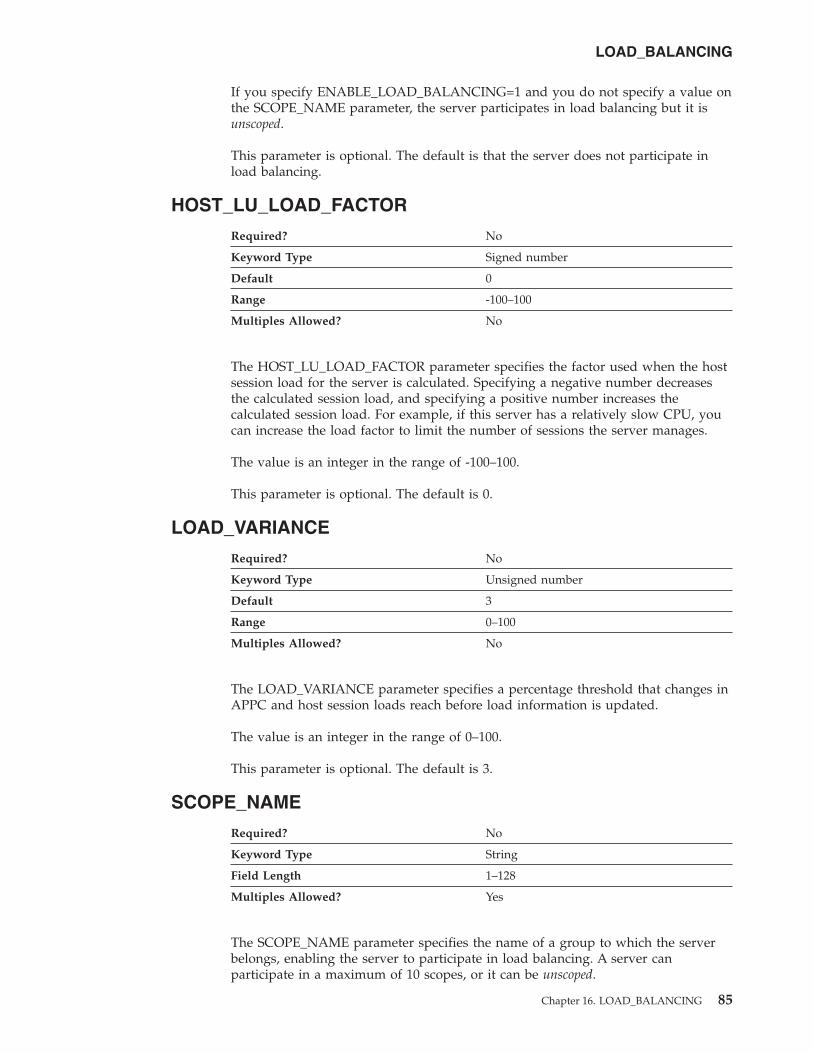
If you specify ENABLE_LOAD_BALANCING=1 and you do not specify a value on
the SCOPE_NAME parameter, the server participates in load balancing but it is
unscoped.
This parameter is optional. The default is that the server does not participate in
load balancing.
HOST_LU_LOAD_FACTOR
Required? No
Keyword Type Signed number
Default 0
Range -100–100
Multiples Allowed? No
The HOST_LU_LOAD_FACTOR parameter specifies the factor used when the host
session load for the server is calculated. Specifying a negative number decreases
the calculated session load, and specifying a positive number increases the
calculated session load. For example, if this server has a relatively slow CPU, you
can increase the load factor to limit the number of sessions the server manages.
The value is an integer in the range of -100–100.
This parameter is optional. The default is 0.
LOAD_VARIANCE
Required? No
Keyword Type Unsigned number
Default 3
Range 0–100
Multiples Allowed? No
The LOAD_VARIANCE parameter specifies a percentage threshold that changes in
APPC and host session loads reach before load information is updated.
The value is an integer in the range of 0–100.
This parameter is optional. The default is 3.
SCOPE_NAME
Required? No
Keyword Type String
Field Length 1–128
Multiples Allowed? Yes
The SCOPE_NAME parameter specifies the name of a group to which the server
belongs, enabling the server to participate in load balancing. A server can
participate in a maximum of 10 scopes, or it can be unscoped.
LOAD_BALANCING
Chapter 16. LOAD_BALANCING 85

The value is a 1- to 128-byte character string.
This parameter is optional.
Clients reach the SNA network through servers that are configured with the same
scope or that are unscoped; clients must be configured to participate in load
balancing through a single scope or through unscoped servers.
LOAD_BALANCING
86 Configuration File Reference

Chapter 17. LOCAL_LU
This chapter describes the parameter keywords and values you can specify for the
LOCAL_LU keyword.
Keyword Definition
Required? No
Keyword Type Complex
Multiples Allowed? Yes, but each LOCAL_LU keyword must
have a unique LU_NAME parameter
LOCAL_LU Sample
The following is a sample of the LOCAL_LU keyword:
LOCAL_LU=(
LU_NAME=LOCLU62
LU_ALIAS=LOCALIAS
LU_SESSION_LIMIT=0
NAU_ADDRESS=0
ROUTE_TO_CLIENT=0
)
LOCAL_LU Parameter Keywords
DEFAULT_POOL
Required? No
Keyword Type Boolean
Default 0
Multiples Allowed? No, only one for each LOCAL_LU keyword
The DEFAULT_POOL parameter specifies whether the LU is a member of the
dependent LU 6.2 default pool. Only one LU 6.2 LU may be specified as a member
of this pool. If more than one is specified, the last one is used. The LU may be
either dependent or independent. The LU specified overrides the Control Point LU
as the default. Valid values are:
0 The LU is not a member of the dependent LU 6.2 pool.
1 The LU is a member of the dependent LU 6.2 pool.
This parameter is optional. The default is 0.
© Copyright IBM Corp. 1998, 2006 87

LU_ALIAS
Required? Yes
Keyword Type String
Field Length 1–8
Multiples Allowed? No, only one for each LOCAL_LU keyword
The LU_ALIAS parameter specifies an alternate 1- to 8-byte name for the local LU.
Local applications can use this name, instead of the fully qualified LU name, to
refer to the local LU.
All eight characters must be specified. Valid characters are any locally displayable
characters using the native encoding of the local system.
This parameter is required.
Alias names are used for convenience of writing applications, such as transaction
programs and management services programs. Local programs can use alias names
instead of network names to refer to network resources, such as the local CP, a
local LU, and a partner LU. Changes can be made to the network names of these
resources without affecting the alias names. A network administrator can change
the fully qualified name of a CP or LU without affecting the local applications that
use the alias names for these resources.
LU_NAME
Required? Yes
Keyword Type String
Field Length 1–8
Multiples Allowed? No, only one for each LOCAL_LU keyword
The LU_NAME parameter specifies the name of a type of network accessible unit
(NAU) that enables end users to communicate with each other and gain access to
network resources.
LU_NAME is a 1- to 8-byte SNA Type A character string. Valid values are:
v The first character must be an uppercase alphabetic character (A-Z) or a special
character (@, #, $).
v The remaining characters can be alphanumeric characters (A-Z, 0-9) or special
characters (@, #, $).
This parameter is required.
LU_SESSION_LIMIT
Required? No
Keyword Type Unsigned number
Default 0
Range 0–65 535
Multiples Allowed? No, only one for each LOCAL_LU keyword
LOCAL_LU
88 Configuration File Reference

The LU_SESSION_LIMIT parameter specifies the maximum number of sessions
supported by the LU.
The value for the session limit is an integer in the range 0–65 535. Zero means no
limit.
This parameter is optional. The default is 0.
Notes:
1. If the LU is independent, LU_SESSION_LIMIT can be set to any value in the
range.
2. If the LU is dependent, LU_SESSION_LIMIT must be set to 1.
MODEL_NAME
Required? No
Keyword Type String
Field Length 1–7
Multiples Allowed? No, only one for each LOCAL_LU keyword
The MODEL_NAME parameter identifies a string used to search for a match with
the LU entry in the VTAM LUGROUP definition. The LUGROUP used is selected
by the LUGROUP parameter coded on the VTAM PU. This LUGROUP parameter
refers to a separate VTAM major node (VBUILD TYPE=LUGROUP), which maps
the various terminal MODEL_NAME parameters with LU characteristics (for
example, DLOGMOD).
VTAM dynamically creates an LUNAME based on the content of the LUSEED
parameter, which is also coded on the VTAM PU statement. For each LU coded
with MODEL_NAME in the Communications Server configuration (.ACG) file,
VTAM matches the name with the contents of the LUGROUP definitions. When a
match is found, the host creates an LUNAME based on the LUSEED parameter,
replacing the ## with the hexadecimal NAU address or replacing ### with the
decimal value of the NAU address received in the NMVT.
Wildcard entries can be configured in the LUGROUP definition, using the @
character. The wildcards can match any MODEL_NAME entry received. If there is
only one type of LU to be defined, LUGROUP can be configured with a single
wildcard, using the @ character.
MODEL_NAME is a 1- to 7-byte SNA Type A character string. Valid characters can
be alphanumeric characters (A-Z, 0-9) or special characters (@, #, $).
This parameter is optional. This parameter only applies to dependent LUs.
Note: If a value other than all zeros (0) is specified and the host system supports
SDDLU (self-defining dependent LU), the node generates an unsolicited
PSID NMVT reply. If the specified string matches a VTAM LUGROUP entry,
a dynamic LU is created at the host.
LOCAL_LU
Chapter 17. LOCAL_LU 89
NAU_ADDRESS
Required? No
Keyword Type Unsigned number
Range 0–255
Multiples Allowed? No, only one for each LOCAL_LU keyword
The NAU_ADDRESS parameter specifies the network addressable unit address of
the LU. The value is an integer in the range 0-255.
This parameter is optional.
Notes:
1. Zero implies the LU is an independent LU.
2. A nonzero value implies the LU is a dependent LU.
PU_NAME
Required? No
Keyword Type String
Field Length 1–8
Multiples Allowed? No, only one for each LOCAL_LU keyword
The PU_NAME parameter specifies the PU name this LU uses.
This field is only used by dependent LUs, and should be set to all binary zeros for
independent LUs.
PU_NAME is a 1- to 8-byte SNA Type A character string. Valid values are:
v The first character must be an uppercase alphabetic character (A-Z) or a special
character (@, #, $).
v The remaining characters can be alphanumeric characters (A-Z, 0-9) or special
characters (@, #, $).
This parameter is optional.
ROUTE_TO_CLIENT
Required? No
Keyword Type Boolean
Multiples Allowed? No, only one for each LOCAL_LU keyword
The ROUTE_TO_CLIENT parameter specifies whether all incoming application
requests over sessions with this LU are routed to the client. Valid values are:
0 This LU is meant to be used by a server-based TP.
1 Application requests are handled by SNA Client Services and forwarded to
any SNA API client that has logged into Communications Server or
Personal Communications and has registered its transaction programs with
this LU.
LOCAL_LU
90 Configuration File Reference
This parameter is optional.
SYNCPT_SUPPORT
The SYNCPT_SUPPORT parameter keyword applies to
Communications Server only.
Required? Yes
Keyword Type Boolean
Default 0
Multiples Allowed? No, only one for each LOCAL_LU keyword
The SYNCPT_SUPPORT parameter specifies whether a sync point manager is
available for this LU. Valid values are:
0 A sync point manager is not available.
1 A sync point manager is available.
This parameter is required. The default is that a sync point manager is not
available.
This value should always be specified as 0, unless a sync point manager is
available for this LU.
USER_ID
The USER_ID parameter keyword applies to Personal Communications
only.
Required? No
Keyword Type String
Field Length 1–20
Default none
Multiples Allowed? No, only one for each LOCAL_LU keyword
The USER_ID parameter specifies the user ID name that this LU uses.
When this keyword is used, incoming Transaction Programs for this Local LU are
routed to the desktop of the specified user ID.
LOCAL_LU
Chapter 17. LOCAL_LU 91

92 Configuration File Reference
Chapter 18. LU_0_TO_3
This chapter describes the parameter keywords and values you can specify for the
LU_0_TO_3 keyword.
Keyword Definition
Required? No
Keyword Type Complex
Key Name LU_NAME
Multiples Allowed? Yes, but each LU_0_TO_3 keyword must
have a unique LU_NAME parameter
LU_0_TO_3 Sample
The following is a sample of the LU_0_TO_3 keyword:
LU_0_TO_3=(
LU_NAME=LUA2
LU_MODEL=3270_DISPLAY_MODEL_2
NAU_ADDRESS=2
PRIORITY=MEDIUM
PU_NAME=NT265
)
LU_0_TO_3 Parameter Keywords
APPLICATION_TYPE
Required? No
Keyword Type Enumerated
Default UNASSIGNED
Multiples Allowed? No, only one for each LU_0_TO_3
keyword
The APPLICATION_TYPE parameter specifies which LU 0 to 3 LUs are enabled for
TN3270 clients. The TN3270E Server may make use of an LU 0 to 3 LU definition
to allow nonnative (TCP/IP) clients to communicate with a host. Valid values are:
TN3270E
This LU is enabled for TN3270E or TN3270 client use.
UNASSIGNED
Only normal SNA 3270 clients may use this LU.
Note: LUs with an application type of TN3270E may also be used for
normal SNA 3270 client traffic as long as the LU is not already in
use by a TN3270E or TN3270 client.
This parameter is optional.
© Copyright IBM Corp. 1998, 2006 93
The default is UNASSIGNED.
ASSOC_PRINTER
Required? No
Keyword Type String
Field Length 1–8
Multiples Allowed? No, only one for each LU_0_TO_3 keyword
The ASSOC_PRINTER parameter identifies the printer associated with an explicit
workstation or an LU in a pool of implicit workstations. This list contains the LU
names for all printer LUs that are unassigned and, if previously defined, the name
of the printer currently assigned to this workstation LU.
ASSOC_PRINTER is a 1- to 8-byte SNA Type A character string. Valid values are:
v The first character must be an uppercase alphabetic character (A-Z) or a special
character (@, #, $).
v The remaining characters can be alphanumeric characters (A-Z, 0-9) or special
characters (@, #, $).
This parameter is optional.
CLASS_TYPE
Required? No
Keyword Type Enumerated
Multiples Allowed? No, only one for each LU_0_TO_3 keyword
The CLASS_TYPE parameter indicates how this LU or pool is used. Valid values
are:
TN_ASSOC_PRINTER
Use for connections that require a printer associated with an explicit
workstation or an LU in a pool of implicit workstations.
TN_EXPLICIT_PRINTER
Use for connections that require a specific printer device name.
TN_EXPLICIT_WORKSTATION
Use for connections that require a specific workstation device name.
TN_IMPLICIT_PRINTER
Use for connections that do not require a specific printer device name.
TN_IMPLICIT_WORKSTATION
Use for connections that do not require a specific workstation device name.
TN_UNASSIGNED
Use to delete the TN3270E definition for the selected LU or pool.
This parameter is optional.
LU_0_TO_3
94 Configuration File Reference

LU_MODEL
Required? Yes
Keyword Type Enumerated
Default 3270_DISPLAY_MODEL_2
Multiples Allowed? No, only one for each LU_0_TO_3 keyword
The LU_MODEL parameter specifies the display model type to use with this LU.
Valid values are:
3270_DISPLAY_MODEL_2 3270 Display 2 - 24 x 80
3270_DISPLAY_MODEL_2 3270 Display 3 - 32 x 80
3270_DISPLAY_MODEL_4 3270 Display 4 - 43 x 80
3270_DISPLAY_MODEL_5 3270 Display 5 - 27 x 132
RJE_WKSTN Remote job entry workstation
PRINTER Printer
UNKNOWN Dependent LU type, such as LU6.2
This parameter is required. The default is 3270_DISPLAY_MODEL_2.
Note: If a value other than UNKNOWN is specified and the host system supports
SDDLU (self-defining dependent LU), the node generates an unsolicited
PSID NMVT reply and dynamically defines the local LU at the host.
If the MODEL_NAME parameter is specified, the LU_MODEL parameter is
ignored.
LU_NAME
Required? Yes
Keyword Type String
Field Length 1–8
Multiples Allowed? No, only one for each LU_0_TO_3 keyword
The LU_NAME parameter specifies the name of a type of network accessible unit
(NAU) that enables end users to communicate with each other and gain access to
network resources.
LU_NAME is a 1- to 8-byte SNA Type A character string. Valid values are:
v The first character must be an uppercase alphabetic character (A-Z) or a special
character (@, #, $).
v The remaining characters can be alphanumeric characters (A-Z, 0-9) or special
characters (@, #, $).
This parameter is required.
LU_0_TO_3
Chapter 18. LU_0_TO_3 95
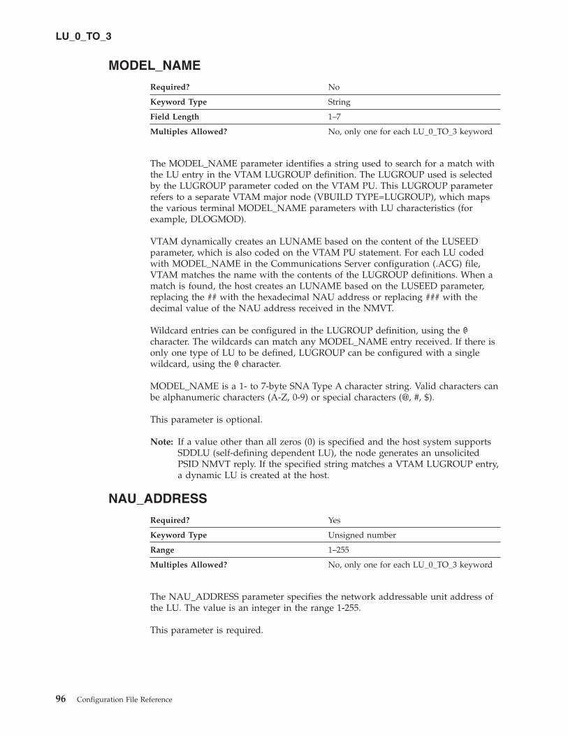
MODEL_NAME
Required? No
Keyword Type String
Field Length 1–7
Multiples Allowed? No, only one for each LU_0_TO_3 keyword
The MODEL_NAME parameter identifies a string used to search for a match with
the LU entry in the VTAM LUGROUP definition. The LUGROUP used is selected
by the LUGROUP parameter coded on the VTAM PU. This LUGROUP parameter
refers to a separate VTAM major node (VBUILD TYPE=LUGROUP), which maps
the various terminal MODEL_NAME parameters with LU characteristics (for
example, DLOGMOD).
VTAM dynamically creates an LUNAME based on the content of the LUSEED
parameter, which is also coded on the VTAM PU statement. For each LU coded
with MODEL_NAME in the Communications Server configuration (.ACG) file,
VTAM matches the name with the contents of the LUGROUP definitions. When a
match is found, the host creates an LUNAME based on the LUSEED parameter,
replacing the ## with the hexadecimal NAU address or replacing ### with the
decimal value of the NAU address received in the NMVT.
Wildcard entries can be configured in the LUGROUP definition, using the @
character. The wildcards can match any MODEL_NAME entry received. If there is
only one type of LU to be defined, LUGROUP can be configured with a single
wildcard, using the @ character.
MODEL_NAME is a 1- to 7-byte SNA Type A character string. Valid characters can
be alphanumeric characters (A-Z, 0-9) or special characters (@, #, $).
This parameter is optional.
Note: If a value other than all zeros (0) is specified and the host system supports
SDDLU (self-defining dependent LU), the node generates an unsolicited
PSID NMVT reply. If the specified string matches a VTAM LUGROUP entry,
a dynamic LU is created at the host.
NAU_ADDRESS
Required? Yes
Keyword Type Unsigned number
Range 1–255
Multiples Allowed? No, only one for each LU_0_TO_3 keyword
The NAU_ADDRESS parameter specifies the network addressable unit address of
the LU. The value is an integer in the range 1-255.
This parameter is required.
LU_0_TO_3
96 Configuration File Reference

POOL_NAME
Required? No
Keyword Type String
Field Length 1–8
Multiples Allowed? No, only one for each LU_0_TO_3 keyword
The POOL_NAME parameter specifies the name of LU pool to which this LU
belongs. The name of the pool is a 1- to 8-byte SNA Type A character string. Valid
values are:
v The first character must be an uppercase alphabetic character (A-Z) or a special
character (@, #, $).
v The remaining characters can be alphanumeric characters (A-Z, 0-9) or special
characters (@, #, $).
This parameter is optional.
PRIORITY
Required? Yes
Keyword Type Enumerated
Default MEDIUM
Multiples Allowed? No, only one for each LU_0_TO_3 keyword
The PRIORITY parameter specifies the data priority for the LU when sending to
the host. Valid values are:
LOW Used for #BATCH, #BATCHSC, and other class of service
definitions typically used when throughput is preferred but not at
the expense of interactive traffic.
MEDIUM Used for #CONNECT and other class of service definitions
typically used when connectivity is preferred over response time
and throughput
HIGH Used for #INTER, #INTERSC, and other class of service definitions
typically used for interactive traffic where good response time is
preferred
NETWORK Reserved for CPSVCMG, SNASVCMG, RSETUP, and other class of
service definitions used for connections that carry SNA network
control messages
This parameter is required. The default is MEDIUM.
PU_NAME
Required? Yes
Keyword Type String
Field Length 1–8
Multiples Allowed? No, only one for each LU_0_TO_3 keyword
LU_0_TO_3
Chapter 18. LU_0_TO_3 97

The PU_NAME parameter specifies the name of the internal PU that manages and
monitors the resources (such as attached links and adjacent link station) associated
with a node.
PU_NAME is a 1- to 8-byte SNA Type A character string. Valid values are:
v The first character must be an uppercase alphabetic character (A-Z) or a special
character (@, #, $).
v The remaining characters can be alphanumeric characters (A-Z, 0-9) or special
characters (@, #, $).
This parameter is required.
LU_0_TO_3
98 Configuration File Reference

Chapter 19. LU62_TIMEOUT
This chapter describes the parameter keywords and values you can specify for the
LU62_TIMEOUT keyword.
Keyword Definition
Required? No
Keyword Type Complex
Key Name LU62_TIMEOUT_RESOURCE_TYPE
Multiples Allowed? No
LU62_TIMEOUT Sample
The following is a sample of the LU62_TIMEOUT keyword:
LU62_TIMEOUT=(
LU62_TIMEOUT_RESOURCE_TYPE=GLOBAL_TIMEOUT
LU62_TIMEOUT_VALUE=20
)
LU62_TIMEOUT Parameter Keywords
LU62_TIMEOUT_RESOURCE_NAME
Required? No, if LU62_TIMEOUT_RESOURCE_TYPE is
set to GLOBAL_TIMEOUT
Yes, if LU62_TIMEOUT_RESOURCE_TYPE is
set to LOCAL_LU_TIMEOUT,
PARTNER_LU_TIMEOUT, or
MODE_TIMEOUT
Keyword Type String
Field Length 1–17
Multiples Allowed? No, only one for each LU62_TIMEOUT
The LU62_TIMEOUT_RESOURCE_NAME parameter specifies the name of the
resource that is being defined. See the description of the
LU62_TIMEOUT_RESOURCE_TYPE parameter for the format of this field.
LU62_TIMEOUT_RESOURCE_TYPE
Required? No
Keyword Type Enumerated
Default GLOBAL_TIMEOUT
Multiples Allowed? No, only one for each LU62_TIMEOUT
© Copyright IBM Corp. 1998, 2006 99

The LU62_TIMEOUT_RESOURCE_TYPE parameter specifies the type of the
timeout being defined. Valid values are:
GLOBAL_TIMEOUT
Timeout applies to all LU6.2 sessions for the local node. The resource name
should be set to all zeros.
LOCAL_LU_TIMEOUT
Timeout applies to all LU 6.2 sessions for the local LU specified in the
LU62_TIMEOUT_RESOURCE_NAME parameter. Only the first 8 bytes of
the LU62_TIMEOUT_RESOURCE_NAME parameter are valid and should
be set to the name of the local LU.
PARTNER_LU_TIMEOUT
Timeout applies to all LU 6.2 sessions to the partner LU specified in the
LU62_TIMEOUT_RESOURCE_NAME parameter. All 17 bytes of the
LU62_TIMEOUT_RESOURCE_NAME parameter are valid and should be
set to the fully qualified name of the partner LU.
MODE_TIMEOUT
Timeout applies to all LU 6.2 sessions on the mode specified in the
LU62_TIMEOUT_RESOURCE_NAME parameter. Only the first 8 bytes of
the LU62_TIMEOUT_RESOURCE_NAME parameter are valid and should
be set to the name of the mode.
This parameter is optional.
LU62_TIMEOUT_VALUE
Required? No
Keyword Type Unsigned number
Default 20
Range 0–60000
Multiples Allowed? No, only one for each LU62_TIMEOUT
The LU62_TIMEOUT_VALUE parameter specifies the interval in seconds for
unused LU6.2 sessions. LU 6.2 sessions are terminated when the session remains
unused for the configured timeout value.
The value for the timeout is an integer from 0–60000 seconds. If zero is specified,
the session immediately becomes free.
This parameter is optional.
LU62_TIMEOUT
100 Configuration File Reference
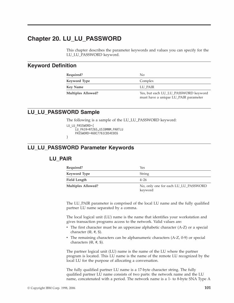
Chapter 20. LU_LU_PASSWORD
This chapter describes the parameter keywords and values you can specify for the
LU_LU_PASSWORD keyword.
Keyword Definition
Required? No
Keyword Type Complex
Key Name LU_PAIR
Multiples Allowed? Yes, but each LU_LU_PASSWORD keyword
must have a unique LU_PAIR parameter
LU_LU_PASSWORD Sample
The following is a sample of the LU_LU_PASSWORD keyword:
LU_LU_PASSWORD=(
LU_PAIR=NT265,USIBMNM.PARTLU
PASSWORD=460C7761C854E0E6
)
LU_LU_PASSWORD Parameter Keywords
LU_PAIR
Required? Yes
Keyword Type String
Field Length 4–26
Multiples Allowed? No, only one for each LU_LU_PASSWORD
keyword
The LU_PAIR parameter is comprised of the local LU name and the fully qualified
partner LU name separated by a comma.
The local logical unit (LU) name is the name that identifies your workstation and
gives transaction programs access to the network. Valid values are:
v The first character must be an uppercase alphabetic character (A-Z) or a special
character (@, #, $).
v The remaining characters can be alphanumeric characters (A-Z, 0-9) or special
characters (@, #, $).
The partner logical unit (LU) name is the name of the LU where the partner
program is located. This LU name is the name of the remote LU recognized by the
local LU for the purpose of allocating a conversation.
The fully qualified partner LU name is a 17-byte character string. The fully
qualified partner LU name consists of two parts: the network name and the LU
name, concatenated with a period. The network name is a 1- to 8-byte SNA Type A
© Copyright IBM Corp. 1998, 2006 101
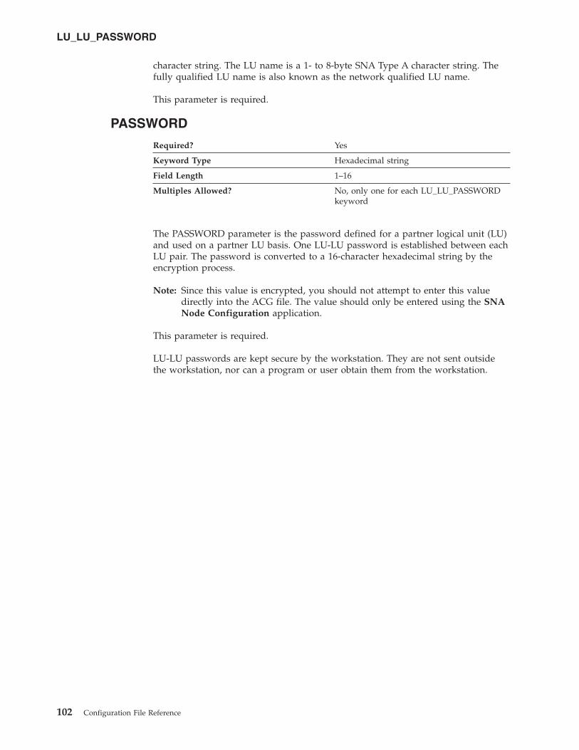
character string. The LU name is a 1- to 8-byte SNA Type A character string. The
fully qualified LU name is also known as the network qualified LU name.
This parameter is required.
PASSWORD
Required? Yes
Keyword Type Hexadecimal string
Field Length 1–16
Multiples Allowed? No, only one for each LU_LU_PASSWORD
keyword
The PASSWORD parameter is the password defined for a partner logical unit (LU)
and used on a partner LU basis. One LU-LU password is established between each
LU pair. The password is converted to a 16-character hexadecimal string by the
encryption process.
Note: Since this value is encrypted, you should not attempt to enter this value
directly into the ACG file. The value should only be entered using the SNA
Node Configuration application.
This parameter is required.
LU-LU passwords are kept secure by the workstation. They are not sent outside
the workstation, nor can a program or user obtain them from the workstation.
LU_LU_PASSWORD
102 Configuration File Reference
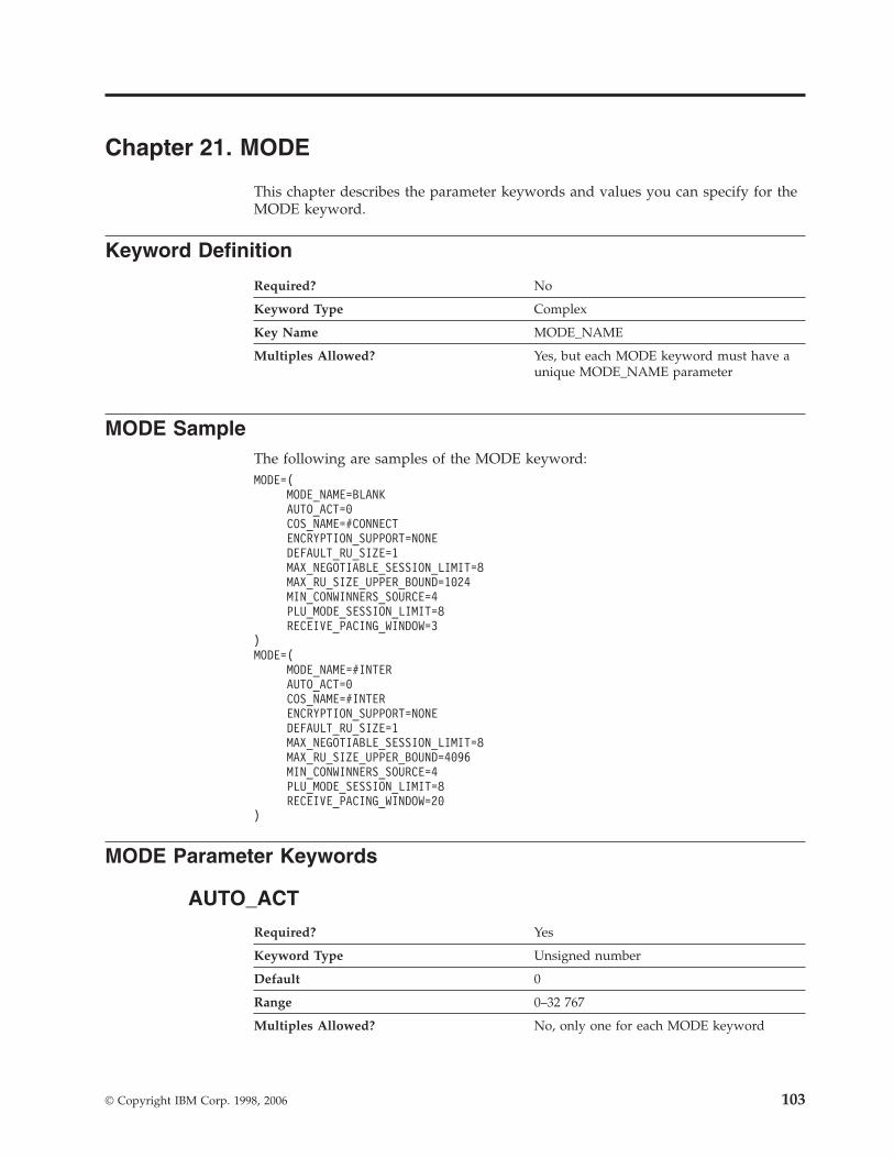
Chapter 21. MODE
This chapter describes the parameter keywords and values you can specify for the
MODE keyword.
Keyword Definition
Required? No
Keyword Type Complex
Key Name MODE_NAME
Multiples Allowed? Yes, but each MODE keyword must have a
unique MODE_NAME parameter
MODE Sample
The following are samples of the MODE keyword:
MODE=(
MODE_NAME=BLANK
AUTO_ACT=0
COS_NAME=#CONNECT
ENCRYPTION_SUPPORT=NONE
DEFAULT_RU_SIZE=1
MAX_NEGOTIABLE_SESSION_LIMIT=8
MAX_RU_SIZE_UPPER_BOUND=1024
MIN_CONWINNERS_SOURCE=4
PLU_MODE_SESSION_LIMIT=8
RECEIVE_PACING_WINDOW=3
)
MODE=(
MODE_NAME=#INTER
AUTO_ACT=0
COS_NAME=#INTER
ENCRYPTION_SUPPORT=NONE
DEFAULT_RU_SIZE=1
MAX_NEGOTIABLE_SESSION_LIMIT=8
MAX_RU_SIZE_UPPER_BOUND=4096
MIN_CONWINNERS_SOURCE=4
PLU_MODE_SESSION_LIMIT=8
RECEIVE_PACING_WINDOW=20
)
MODE Parameter Keywords
AUTO_ACT
Required? Yes
Keyword Type Unsigned number
Default 0
Range 0–32 767
Multiples Allowed? No, only one for each MODE keyword
© Copyright IBM Corp. 1998, 2006 103
The AUTO_ACT parameter specifies how many sessions are auto-activated for this
mode. This value is used when change number of sessions (CNOS) exchange is
initiated implicitly. The value is an integer in the range 0–32 767.
This parameter is required. The default is 0.
COMPRESSION
Required? Yes
Keyword Type Enumerated
Default PROHIBITED
Multiples Allowed? No, only one for each MODE keyword
The COMPRESSION parameter specifies whether data compression is enabled for
sessions that use this mode. Valid values are:
PROHIBITED Data compression is prohibited for sessions using this mode.
REQUESTED Data compression is requested for sessions using this mode.
This parameter is required. The default is PROHIBITED.
COS_NAME
Required? Yes
Keyword Type String
Field Length 1–8
Multiples Allowed? No, only one for each MODE keyword
The COS_NAME parameter specifies the name of the class of service to request
when activating sessions on this mode. The name is a 1- to 8-byte SNA Type A
character string.
This parameter is required.
DEFAULT_RU_SIZE
Required? Yes
Keyword Type Boolean
Default 1
Multiples Allowed? No, only one for each MODE keyword
The DEFAULT_RU_SIZE parameter specifies whether a default upper bound for
the maximum RU size is used. Valid values are:
0 The value for the MAX_RU_SIZE_UPPER_BOUND parameter is used.
1 The value for the MAX_RU_SIZE_UPPER_BOUND parameter is ignored.
The upper bound for the maximum RU size is set to the link basic
transmission unit (BTU) size, minus the size of the transmission header
(TH) and the request/response unit header (RH).
MODE
104 Configuration File Reference

This parameter is required. The default is 1.
ENCRYPTION_SUPPORT
Required? No
Keyword Type Enumerated
Default NONE
Multiples Allowed? No, only one for each MODE keyword
The ENCRYPTION_SUPPORT parameter specifies whether session-level
cryptography is used. Valid values are:
MANDATORY Session-level cryptography is mandatory.
NONE No session-level cryptography is used.
This parameter is optional. The default is NONE.
MAX_INCOMING_COMPRESSION_LEVEL
The MAX_INCOMING_COMPRESSION_LEVEL parameter keyword
applies to Communications Server only.
Required? Yes
Keyword Type Enumerated
Default NONE
Multiples Allowed? No, only one for each MODE keyword
The MAX_INCOMING_COMPRESSION_LEVEL parameter specifies the maximum
level of decompression supported for data coming into this node. The level of
decompression specified must be less than or equal to the value specified on the
MAX_COMPRESSION_LEVEL parameter on the NODE keyword. Valid values are:
NONE This node does not support decompression.
RLE This node supports RLE decompression.
LZ9 This node supports RLE and LZ9 decompression.
LZ10 This node supports RLE, LZ9, and LZ10 decompression.
Note: If compression is negotiated using a non-extended BIND, the decompression
level used is LZ9.
This parameter is required. The default is NONE.
MODE
Chapter 21. MODE 105
MAX_NEGOTIABLE_SESSION_LIMIT
Required? Yes
Keyword Type Unsigned number
Default 128
Range 0–32 767
Multiples Allowed? No, only one for each MODE keyword
The MAX_NEGOTIABLE_SESSION_LIMIT parameter specifies the maximum
number of sessions allowed in this mode between any local logical unit (LU) and
partner LU. This value is used when change number of sessions (CNOS) exchange
is initiated implicitly. The value is an integer in the range 0–32 767.
A value of zero (0) means no implicit CNOS exchange.
This parameter is required. The default is 128.
MAX_OUTGOING_COMPRESSION_LEVEL
The MAX_OUTGOING_COMPRESSION_LEVEL parameter keyword
applies to Communications Server only.
Required? Yes
Keyword Type Enumerated
Default NONE
Multiples Allowed? No, only one for each MODE keyword
The MAX_OUTGOING_COMPRESSION_LEVEL parameter specifies the maximum
compression level supported for data being sent from this node. The level of
decompression specified must be less than or equal to the value specified on the
MAX_COMPRESSION_LEVEL parameter on the NODE keyword. Valid values are:
NONE This node does not support compression.
RLE This node supports RLE compression.
LZ9 This node supports RLE and LZ9 compression.
LZ10 This node supports RLE, LZ9, and LZ10 compression.
Note: If compression is negotiated using a non-extended BIND, the compression
level used is RLE.
This parameter is required. The default is NONE.
MODE
106 Configuration File Reference
MAX_RU_SIZE_UPPER_BOUND
Required? Yes
Keyword Type Unsigned number
Default 4 096
Range 256–61 440
Multiples Allowed? No, only one for each MODE keyword
The MAX_RU_SIZE_UPPER_BOUND parameter specifies the maximum size of the
request/response units (RUs) sent and received on the sessions in this mode and is
negotiated during session activation.
The value is an integer in the range 256–61 440.
This parameter is required. The default is 4 096.
MAX_RU_SIZE_UPPER_BOUND is ignored if the DEFAULT_RU_SIZE parameter
is specified as 1.
MIN_CONWINNERS_SOURCE
Required? Yes
Keyword Type Unsigned number
Default 16
Range 0–32 767
Multiples Allowed? No, only one for each MODE keyword
The MIN_CONWINNERS_SOURCE parameter specifies the minimum number of
sessions that can be activated by a local logical unit (LU) using this mode to win a
contention with a partner. When your workstation is the contention winner, it can
allocate a conversation on that session without requesting permission from the
partner LU to use the session. The number you enter must be less than or equal to
the PLU_MODE_SESSION_LIMIT. The value is an integer in the range 0–32 767.
This parameter is required. The default is 16.
A value of zero (0) means no implicit change number of sessions (CNOS)
exchange.
MODE_NAME
Required? Yes
Keyword Type String
Field Length 1–8
Multiples Allowed? No, only one for each MODE keyword
The MODE_NAME parameter specifies the name of the mode to be used for the
session.
This parameter is required.
MODE
Chapter 21. MODE 107
MODE_NAME is a 1- to 8-byte SNA Type A character string. You can specify one
of the following:
v BLANK
v #BATCH
v #BATCHSC
v #INTER
v #INTERSC
v QPCSUPP
v SNASVCMG
v A unique mode name for each mode you define. If you define your own mode
name, valid characters are:
– All blanks
– The first character must be an uppercase alphabetic character (A-Z) or a
special character (@, #, $).
– The remaining characters can be alphanumeric characters (A-Z, 0-9) or special
characters (@, #, $).
The mode name is used by the initiator of the session to designate the
characteristics for the session allocated for the conversation. The mode defines a set
of characteristics that can apply to one or more sessions. These characteristics
include traffic-pacing values, message-length limits, synchronization point and
cryptography options, and the class of service within the transport network.
PLU_MODE_SESSION_LIMIT
Required? Yes
Keyword Type Unsigned number
Default 32
Range 0–32 767
Multiples Allowed? No, only one for each MODE keyword
The PLU_MODE_SESSION_LIMIT specifies the maximum number of concurrently
active LU-LU sessions that a particular LU can support. The value is an integer in
the range 0–32 767.
This parameter is required. The default is 32.
A value of zero (0) means no implicit change number of sessions (CNOS)
exchange.
Notes:
1. Increase the number if your most important application programs are coming
up too slowly.
2. Decrease the number to improve overall system response time.
MODE
108 Configuration File Reference
RECEIVE_PACING_WINDOW
Required? Yes
Keyword Type Unsigned number
Default 1
Range 1–63
Multiples Allowed? No, only one for each MODE keyword
The RECEIVE_PACING_WINDOW parameter indicates to the partner logical unit
(LU) how many request units (RUs) it can send before receiving a pacing response.
The value is an integer in the range 1-63. The value zero is not allowed.
This parameter is required. The default is 1.
Session pacing helps to prevent local buffers from overrunning. The receive pacing
window size is the session pacing limit for sessions in this mode. The actual value
used may be negotiated between the nodes when the session is started.
For fixed pacing, this value specifies the receive pacing window. For adaptive
pacing, this value is used as an initial receive window size. Communications
Server always uses adaptive pacing unless the adjacent node specifies that it does
not support it.
MODE
Chapter 21. MODE 109

110 Configuration File Reference

Chapter 22. NODE
This chapter describes the parameter keywords and values you can specify for the
NODE keyword.
Keyword Definition
Required? No
Keyword Type Complex
Multiples Allowed? No
NODE Sample
The following is a sample of the NODE keyword:
NODE=(
ANYNET_SUPPORT=ACCESS_NODE
CP_ALIAS=NT265
DEFAULT_PREFERENCE=NATIVE
DISCOVERY_GROUP_NAME=<NONE>
DISCOVERY_SUPPORT=DISCOVERY_CLIENT
DLUR_SUPPORT=MULTI_SUBNET
FQ_CP_NAME=USIBMNM.NT265
NODE_ID=05D00000
NODE_TYPE=END_NODE
REGISTER_WITH_CDS=1
REGISTER_WITH_NN=1
SEND_TERM_SELF=0
)
NODE Parameter Keywords
ANYNET_SUPPORT
Required? Yes
Keyword Type Enumerated
Default NONE
Multiples Allowed? No
The ANYNET_SUPPORT parameter specifies the level of support for ANYNET
provided by the node. Valid values are:
© Copyright IBM Corp. 1998, 2006 111

ACCESS_NODE This node supports AnyNet access node
functions
NONE No AnyNet function supported. The
DEFAULT_PREFERENCE parameter must be
specified as NATIVE.
ANYNET_SUPPORTED No AnyNet function is supported. The
DEFAULT_PREFERENCE parameter must be
specified as NATIVE.
GATEWAY This node supports AnyNet Gateway functions.
This value is only valid if the NODE_TYPE
parameter is specified as NETWORK_NODE.
This parameter is required.
The default is NONE.
Note: The ANYNET_SUPPORT parameter cannot be set using the SNA Node
Configuration application.
CP_ALIAS
Required? No
Keyword Type String
Field Length 1–8
Multiples Allowed? No
The CP_ALIAS parameter specifies an alternate 1- to 8-byte name for the local CP.
Local applications can use this name, instead of the fully qualified CP name, to
refer to the local CP.
All eight characters must be specified. Valid characters are any locally displayable
characters using the native encoding of the local system.
This parameter is optional.
Alias names are used for convenience of writing applications, such as transaction
programs and management services programs. Local programs can use alias names
instead of network names to refer to network resources, such as the local CP, a
local LU, and a partner LU. Changes can be made to the network names of these
resources without affecting the alias names. A network administrator can change
the fully qualified name of a CP or LU, without affecting the local applications that
use the alias names for these resources.
DEFAULT_PREFERENCE
Required? Yes
Keyword Type Enumerated
Default NATIVE
Multiples Allowed? No
NODE
112 Configuration File Reference

The DEFAULT_PREFERENCE parameter specifies the type of routing that you
want the node to use by default when initiating sessions to partner LUs for which
DEFAULT_PREFERENCE is specified. Valid values are:
NATIVE
Use native (APPN) routing protocols only.
NONNATIVE
Use nonnative (AnyNet) protocols only.
Note: This value is only meaningful when an AnyNet DLC is available to
the Node Operator Facility, and there is an AnyNet link station
defined. (See Chapter 15, “LINK_STATION,” on page 53).
NATIVE_THEN_NONNATIVE
Try native (APPN) protocols, and if the partner LU can not be located,
retry session activation using nonnative (AnyNet) protocols.
Note: This value is only meaningful when an AnyNet DLC is available to
the Node Operator Facility, and there is an AnyNet link station
defined. (See Chapter 15, “LINK_STATION,” on page 53).
NONNATIVE_THEN_NATIVE
Try nonnative (AnyNet) protocols, and if the partner LU can not be
located, retry session activation using native (APPN) protocols.
Note: This value is only meaningful when an AnyNet DLC is available to
the Node Operator Facility, and there is an AnyNet link station
defined. (See Chapter 15, “LINK_STATION,” on page 53).
This parameter is required. The default is NATIVE.
Note: The DEFAULT_PREFERENCE parameter cannot be set using the SNA Node
Configuration application.
DISCOVERY_GROUP_NAME
Required? No
Keyword Type String
Field Length 1–8
Multiples Allowed? No
The DISCOVERY_GROUP_NAME parameter specifies the group name to be used
on discovery functions utilized by the node. DISCOVERY_GROUP_NAME is a 1-
to 8-byte character string.
If you do not specify this parameter, the default group name is used.
This parameter is optional.
NODE
Chapter 22. NODE 113

DISCOVERY_SUPPORT
Required? Yes
Keyword Type Enumerated
Default DISCOVERY_CLIENT
Multiples Allowed? No
The DISCOVERY_SUPPORT parameter specifies whether discovery functions are
to be utilized by this node. Valid values are:
NO No discovery functions are to be used by this node.
DISCOVERY_CLIENT Discovery client function is used to try to
dynamically configure and activate a link to a
network node server when necessary. This value is
only valid if the NODE_TYPE parameter is
specified as END_NODE.
DISCOVERY_SERVER Discovery server function is used to respond to
searches from clients. This value is only valid if the
NODE_TYPE parameter is specified as
NETWORK_NODE.
This parameter is required. The default is DISCOVERY_CLIENT.
DLUR_SUPPORT
Required? Yes
Keyword Type Enumerated
Default MULTI_SUBNET
Multiples Allowed? No
The DLUR_SUPPORT parameter specifies the level of support for DLUR provided
by the node. This field is ignored for LEN links. Valid values are:
MULTI_SUBNET
DLUR full multi-subnet is supported. Broadcast searches are not received.
This value is valid only if the NODE_TYPE parameter is specified as
END_NODE.
For end node or branch network node: DLUR is supported, but is not used
to connect to a DLUS in another subnet. If multi-subnet operation is not
required, you should use the MULTI_SUBNET value instead of NORMAL
to reduce network traffic and congestion at the network node.
NORMAL
DLUR full multi-subnet is supported. Broadcast searches are received.
LIMITED (same as MULTI_SUBNET)
DLUR limited multi-subnet is supported.
This parameter is required.
If the REGISTER_WITH_CDS value is 1, then the DLUR_SUPPORT value is
MULTI_SUBNET. Otherwise, set the DLUR_SUPPORT keyword to NORMAL. The
default settings are REGISTER_WITH_CDS=1, REGISTER_WITH_NN=1, and
NODE
114 Configuration File Reference

DLUR_SUPPORT=MULTI_SUBNET. These settings result in better performance by
reducing network locate traffic and congestion at the network node.
Note: The DLUR_SUPPORT parameter cannot be set using the SNA Node
Configuration application.
FQ_CP_NAME
Required? Yes
Keyword Type String
Field Length 3–17
Multiples Allowed? No
The FQ_CP_NAME parameter specifies the fully qualified node name of the
control point.
The fully qualified CP name is a 17-byte character string. The fully qualified CP
name consists of two parts: the network name and the CP name, concatenated with
a period. The network name is a 1- to 8-byte SNA Type A character string. The CP
name is a 1- to 8-byte SNA Type A character string. The fully qualified CP name is
also known as the network qualified CP name.
This parameter is required.
GVRN_SUPPORT
Required? No
Required? Yes
Keyword Type Boolean
Default 0
Default 1
Multiples Allowed? No
The GVRN_SUPPORT parameter specifies whether Connection Networks can be
used across different networks. Valid values are:
0 Connection Networks can be used across networks.
1 Connection Networks cannot be used across networks.
This parameter is required for Personal Communications but is not required for
Communications Server.
NODE
Chapter 22. NODE 115

MAX_LOCATES
The MAX_LOCATES parameter keyword applies to Communications
Server only.
Required? No
Keyword Type Unsigned number
Multiples Allowed? No
The MAX_LOCATES parameter specifies the maximum number of locates that the
node can process simultaneously.
This parameter is optional.
MAX_LS_EXCEPTION_EVENTS
The MAX_LS_EXCEPTION_EVENTS parameter keyword applies to
Communications Server only.
Required? Yes
Keyword Type Unsigned number
Default 200
Range 0–200
Multiples Allowed? No
The MAX_LS_EXCEPTION_EVENTS parameter specifies the maximum number of
LS_EXCEPTION entries recorded by the node.
The value is an integer in the range 0-200.
This parameter is required. The default is 200.
NODE_ID
Required? Yes
Keyword Type Hexadecimal string
Default X'05D00000'
Field Length 1–8
Multiples Allowed? No
The NODE_ID parameter specifies the ID of the node. This ID consists of a block
ID of 3 hexadecimal characters and a PU ID of 5 hexadecimal characters.
This parameter is required. The default is X'05D00000'.
NODE
116 Configuration File Reference
NODE_TYPE
Required? Yes
Keyword Type Enumerated
Default END_NODE
Multiples Allowed? No
The NODE_TYPE specifies the APPN node type of this node. Valid values are:
BRANCH_EXTENDER_NODE Defines this node as a branch
extender node.
END_NODE Defines this node as an end node.
NETWORK_NODE Defines this node as a network
node.
END_NODE is the required value for Personal Communications.
This parameter is required. The default is END_NODE.
REGISTER_WITH_CDS
Required? Yes
Keyword Type Boolean
Default 1
Multiples Allowed? No
The REGISTER_WITH_CDS parameter specifies whether resources are registered
with a central directory server.
If NODE_TYPE is specified as an END_NODE, valid values are:
0 The network node server is not allowed to register end node resources
with a central directory server.
1 The network node server is allowed to register end node resources with a
central directory server.
Note: The REGISTER_WITH_CDS parameter is ignored if REGISTER_WITH _NN
is set to 0.
If NODE_TYPE is specified as a NETWORK_NODE, valid values are:
0 Local and domain resources can not be registered with a central directory
server.
1 Local and domain resources can optionally be registered with a central
directory server.
This parameter is required. The default is 1.
NODE
Chapter 22. NODE 117
REGISTER_WITH_NN
Required? Yes
Keyword Type Enumerated
Keyword Type Boolean
Default ALL
Default 1
Multiples Allowed? No
The REGISTER_WITH_NN parameter specifies whether resources are registered
with the network node server.
REGISTER_WITH_NN is only valid if NODE_TYPE is specified as
END_NODE or BRANCH_EXTENDER_NODE.
Valid values are:
ALL
v If NODE_TYPE=END_NODE, the network node server only
forwards directed locates to the end node.
v If NODE_TYPE=BRANCH_EXTENDER_NODE, local LUs
and LUs within the branch domain are registered with the
network node server.
Note: LUs registered to a branch extender node from end
nodes consider the local branch extender node to be the
network node server.
LOCAL_ONLY
Only LUs resident on the local node are registered with the
network node server. This value is only valid if NODE_TYPE
is specified as BRANCH_EXTENDER_NODE.
NONE
v If NODE_TYPE=END_NODE, the network node server
forwards all broadcast searches to the end node.
v If NODE_TYPE=BRANCH_EXTENDER_NODE, no LU
resources are registered with the network node server.
0 Resources are not registered with the network node server.
1 Resources are registered with the network node server.
NODE
118 Configuration File Reference

The default is ALL.
The default is 1.
This parameter is required.
SEND_TERM_SELF
Required? Yes
Keyword Type Boolean
Default 0
Multiples Allowed? No
The SEND_TERM_SELF parameter specifies how host LU sessions for LUs
configured as displays or printers are terminated after a connection disconnect.
0 Host LU sessions are terminated by sending an UNBIND to the host.
Sending an UNBIND to the host terminates the session without cleaning
up all host resources. Depending on the host application, UNBIND enables
the user to recover at the point of termination. A subsequent logon to the
host might recover the host application data. This enables host applications
to handle unsolicited disconnections without losing session data, but uses
additional host resources to save the status.
1 Host LU sessions are terminated by sending an TERM-SELF to the host.
Sending a TERM-SELF to the host cleans up host resources before the host
sends an UNBIND to the workstation. This frees host resources such that a
user cannot recover from the termination point. Host resources are freed
and can be reused. This termination type should be used when host
applications are to be stopped completely and recovery from a termination
point is not possible.
This parameter is required. The default is 0.
TP_SECURITY_BEHAVIOR
Required? No
Keyword Type Enumerated
Default VERIFY_EVEN_IF_NOT_DEFINED
Multiples Allowed? No
The TP_SECURITY_BEHAVIOR parameter enables you to determine how the node
is to handle security information present in the ATTACH if the TP is not
configured for security.
IGNORE_IF_NOT_DEFINED
If security parameters are present in the ATTACH, ignore them if the TP is
not configured for security.
NODE
Chapter 22. NODE 119

VERIFY_EVEN_IF_NOT_DEFINED
If security parameters are present in the ATTACH, verify them even if the
TP is not configured for security. This is the default.
NODE
120 Configuration File Reference
Chapter 23. PARTNER_LU
This chapter describes the parameter keywords and values you can specify for the
PARTNER_LU keyword.
Keyword Definition
Required? No
Keyword Type Complex
Key Name FQ_PLU_NAME
Multiples Allowed? Yes, but each PARTNER_LU keyword must
have a unique FQ_PLU_NAME parameter
PARTNER_LU Sample
The following is a sample of the PARTNER_LU keyword:
PARTNER_LU=(
FQ_PLU_NAME=USIBMNM.DLURSRV
CONV_SECURITY_VERIFICATION=1
MAX_MC_LL_SEND_SIZE=32767
PARALLEL_SESSION_SUPPORT=1
PARTNER_LU_ALIAS=DLURSRV
PREFERENCE=USE_DEFAULT_PREFERENCE
)
PARTNER_LU Parameter Keywords
ADJACENT_CP_NAME
Required? No
Keyword Type String
Field Length 3–17
Multiples Allowed? No, only one for each PARTNER_LU
keyword
The ADJACENT_CP_NAME parameter is the name of the CP directly connected to
your workstation across this link.
The fully qualified adjacent CP name is a 17-byte character string. The fully
qualified adjacent CP name consists of two parts: the network name and the CP
name, concatenated with a period. The network name is a 1- to 8-byte SNA Type A
character string. The CP name is a 1- to 8-byte SNA Type A character string. The
fully qualified CP name is also known as the network qualified CP name.
This parameter is optional.
© Copyright IBM Corp. 1998, 2006 121

CONV_SECURITY_VERIFICATION
Required? No
Keyword Type Boolean
Default 1
Multiples Allowed? No, only one for each PARTNER_LU
keyword
The CONV_SECURITY_VERIFICATION parameter specifies whether the partner
LU is authorized to validate user IDs on behalf of local LUs; that is, whether the
partner LU can set the already verified indicator in an Attach request. Valid values
are:
0 The partner LU is not authorized to validate user IDs on behalf of local
LUs.
1 The partner LU is authorized to validate user IDs on behalf of local LUs.
This parameter is optional. The default is 1.
FQ_PLU_NAME
Required? Yes
Keyword Type String
Field Length 3–17
Multiples Allowed? No, only one for each PARTNER_LU
keyword
The FQ_PLU_NAME parameter specifies the fully qualified name of the partner
LU.
The fully qualified partner LU name is a 17-byte character string. The fully
qualified partner LU name consists of two parts: the network name and the LU
name, concatenated with a period. The network name is a 1- to 8-byte SNA Type A
character string. The LU name is a 1- to 8-byte SNA Type A character string. The
fully qualified LU name is also known as the network qualified LU name.
This parameter is required.
MAX_MC_LL_SEND_SIZE
Required? No
Keyword Type Unsigned number
Default 32 767
Range 1–32 767
Multiples Allowed? No, only one for each PARTNER_LU
keyword
The MAX_MC_LL_SEND_SIZE parameter specifies the maximum size of line
length (LL) records sent by and received by mapped conversation services at the
partner LU.
PARTNER_LU
122 Configuration File Reference

The value is an integer in the range of 1–32 767.
This parameter is optional. The default is 32 767.
The maximum line length (LL) record size is the maximum size of the logical
record in the data stream for basic conversations. Basic conversations allow
programs to exchange data in a standardized format. This format is a stream of
data containing 2-byte length fields (referred to as LLs) that specify the amount of
data to follow before the next length field.
PARALLEL_SESSION_SUPPORT
Required? No
Keyword Type Boolean
Default 1
Multiples Allowed? No, only one for each PARTNER_LU
keyword
The PARALLEL_SESSION_SUPPORT parameter specifies whether the partner LU
supports parallel sessions. Valid values are:
0 The partner LU does not support parallel sessions.
1 The partner LU does support parallel sessions.
This parameter is optional. The default is 1.
The parallel session support specifies whether the partner LU supports two or
more currently active sessions between the same two LUs using different pairs of
network addresses or session identifiers.
PARTNER_LU_ALIAS
Required? No
Keyword Type String
Field Length 1–8
Multiples Allowed? No, only one for each PARTNER_LU
keyword
The PARTNER_LU_ALIAS parameter specifies an alternate 1- to 8-byte name for
the partner LU. Local applications can use this name, instead of the fully qualified
LU name, to refer to the partner LU.
All eight characters must be specified. Valid characters are any locally displayable
characters using the native encoding of the local system.
Do not specify this parameter for a partner LU that has no alias associated with it.
This parameter is optional.
Alias names are used for convenience of writing applications, such as transaction
programs and management services programs. Local programs can use alias names
instead of network names to refer to network resources, such as the local CP, a
PARTNER_LU
Chapter 23. PARTNER_LU 123

local LU, and a partner LU. Changes can be made to the network names of these
resources without affecting the alias names. A network administrator can change
the fully qualified name of a CP or LU without affecting the local applications that
use the alias names for these resources.
PREFERENCE
Required? Yes
Keyword Type Enumerated
Default USE_DEFAULT_PREFERENCE
Multiples Allowed? No, only one for each PARTNER_LU
keyword
The PREFERENCE parameter specifies the type of routing that you want the node
to use by default. Valid values are:
NATIVE
Use native (APPN) routing protocols only.
NONNATIVE
Use nonnative (AnyNet) protocols only.
Note: This value is only meaningful when an AnyNet DLC is available to
the Node Operator Facility, and there is an AnyNet link station
defined. (See Chapter 15, “LINK_STATION,” on page 53).
NATIVE_THEN_NONNATIVE
Try native (APPN) protocols, and if the partner LU can not be located,
retry session activation using nonnative (AnyNet) protocols.
Note: This value is only meaningful when an AnyNet DLC is available to
the Node Operator Facility, and there is an AnyNet link station
defined. (See Chapter 15, “LINK_STATION,” on page 53).
NONNATIVE_THEN_NATIVE
Try nonnative (AnyNet) protocols, and if the partner LU can not be
located, retry session activation using native (APPN) protocols.
Note: This value is only meaningful when an AnyNet DLC is available to
the Node Operator Facility, and there is an AnyNet link station
defined. (See Chapter 15, “LINK_STATION,” on page 53).
USE_DEFAULT_PREFERENCE
Use the default preference defined when the node was started. (This can be
recalled by QUERY_NODE.)
This parameter is required. The default is USE_DEFAULT_PREFERENCE.
Note: The PREFERENCE parameter cannot be set using the SNA Node
Configuration application.
PARTNER_LU
124 Configuration File Reference
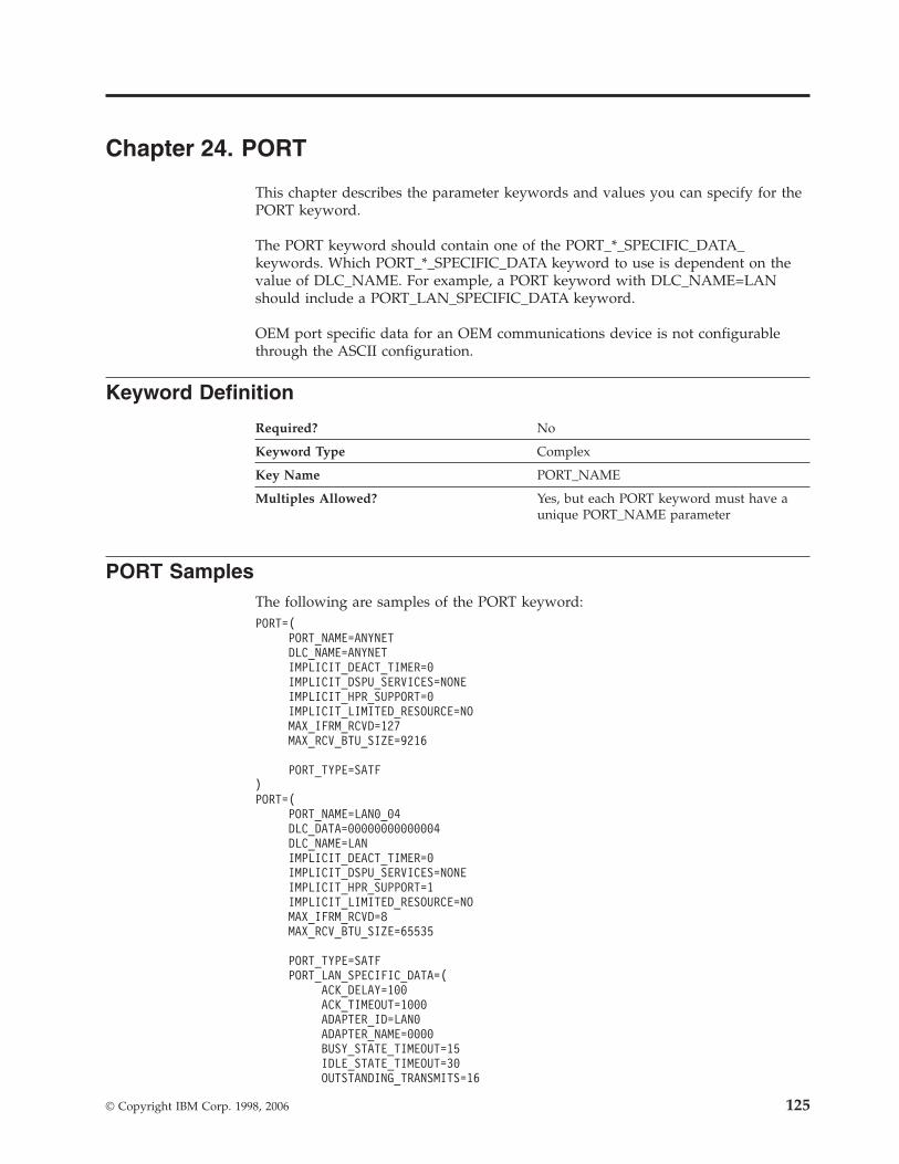
Chapter 24. PORT
This chapter describes the parameter keywords and values you can specify for the
PORT keyword.
The PORT keyword should contain one of the PORT_*_SPECIFIC_DATA_
keywords. Which PORT_*_SPECIFIC_DATA keyword to use is dependent on the
value of DLC_NAME. For example, a PORT keyword with DLC_NAME=LAN
should include a PORT_LAN_SPECIFIC_DATA keyword.
OEM port specific data for an OEM communications device is not configurable
through the ASCII configuration.
Keyword Definition
Required? No
Keyword Type Complex
Key Name PORT_NAME
Multiples Allowed? Yes, but each PORT keyword must have a
unique PORT_NAME parameter
PORT Samples
The following are samples of the PORT keyword:
PORT=(
PORT_NAME=ANYNET
DLC_NAME=ANYNET
IMPLICIT_DEACT_TIMER=0
IMPLICIT_DSPU_SERVICES=NONE
IMPLICIT_HPR_SUPPORT=0
IMPLICIT_LIMITED_RESOURCE=NO
MAX_IFRM_RCVD=127
MAX_RCV_BTU_SIZE=9216
PORT_TYPE=SATF
)
PORT=(
PORT_NAME=LAN0_04
DLC_DATA=00000000000004
DLC_NAME=LAN
IMPLICIT_DEACT_TIMER=0
IMPLICIT_DSPU_SERVICES=NONE
IMPLICIT_HPR_SUPPORT=1
IMPLICIT_LIMITED_RESOURCE=NO
MAX_IFRM_RCVD=8
MAX_RCV_BTU_SIZE=65535
PORT_TYPE=SATF
PORT_LAN_SPECIFIC_DATA=(
ACK_DELAY=100
ACK_TIMEOUT=1000
ADAPTER_ID=LAN0
ADAPTER_NAME=0000
BUSY_STATE_TIMEOUT=15
IDLE_STATE_TIMEOUT=30
OUTSTANDING_TRANSMITS=16
© Copyright IBM Corp. 1998, 2006 125
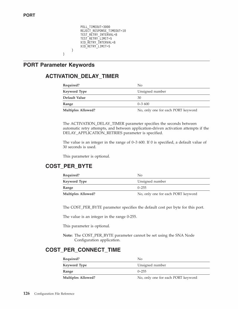
POLL_TIMEOUT=3000
REJECT_RESPONSE_TIMEOUT=10
TEST_RETRY_INTERVAL=8
TEST_RETRY_LIMIT=5
XID_RETRY_INTERVAL=8
XID_RETRY_LIMIT=5
)
)
PORT Parameter Keywords
ACTIVATION_DELAY_TIMER
Required? No
Keyword Type Unsigned number
Default Value 30
Range 0–3 600
Multiples Allowed? No, only one for each PORT keyword
The ACTIVATION_DELAY_TIMER parameter specifies the seconds between
automatic retry attempts, and between application-driven activation attempts if the
DELAY_APPLICATION_RETRIES parameter is specified.
The value is an integer in the range of 0–3 600. If 0 is specified, a default value of
30 seconds is used.
This parameter is optional.
COST_PER_BYTE
Required? No
Keyword Type Unsigned number
Range 0–255
Multiples Allowed? No, only one for each PORT keyword
The COST_PER_BYTE parameter specifies the default cost per byte for this port.
The value is an integer in the range 0-255.
This parameter is optional.
Note: The COST_PER_BYTE parameter cannot be set using the SNA Node
Configuration application.
COST_PER_CONNECT_TIME
Required? No
Keyword Type Unsigned number
Range 0–255
Multiples Allowed? No, only one for each PORT keyword
PORT
126 Configuration File Reference
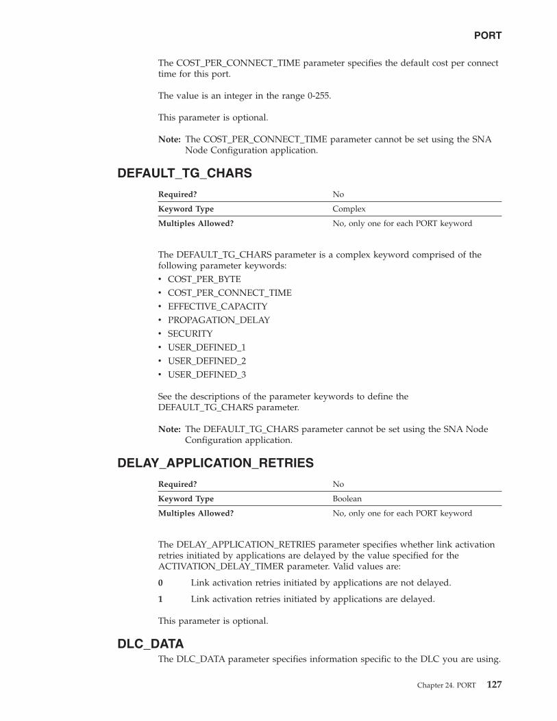
The COST_PER_CONNECT_TIME parameter specifies the default cost per connect
time for this port.
The value is an integer in the range 0-255.
This parameter is optional.
Note: The COST_PER_CONNECT_TIME parameter cannot be set using the SNA
Node Configuration application.
DEFAULT_TG_CHARS
Required? No
Keyword Type Complex
Multiples Allowed? No, only one for each PORT keyword
The DEFAULT_TG_CHARS parameter is a complex keyword comprised of the
following parameter keywords:
v COST_PER_BYTE
v COST_PER_CONNECT_TIME
v EFFECTIVE_CAPACITY
v PROPAGATION_DELAY
v SECURITY
v USER_DEFINED_1
v USER_DEFINED_2
v USER_DEFINED_3
See the descriptions of the parameter keywords to define the
DEFAULT_TG_CHARS parameter.
Note: The DEFAULT_TG_CHARS parameter cannot be set using the SNA Node
Configuration application.
DELAY_APPLICATION_RETRIES
Required? No
Keyword Type Boolean
Multiples Allowed? No, only one for each PORT keyword
The DELAY_APPLICATION_RETRIES parameter specifies whether link activation
retries initiated by applications are delayed by the value specified for the
ACTIVATION_DELAY_TIMER parameter. Valid values are:
0 Link activation retries initiated by applications are not delayed.
1 Link activation retries initiated by applications are delayed.
This parameter is optional.
DLC_DATA
The DLC_DATA parameter specifies information specific to the DLC you are using.
PORT
Chapter 24. PORT 127
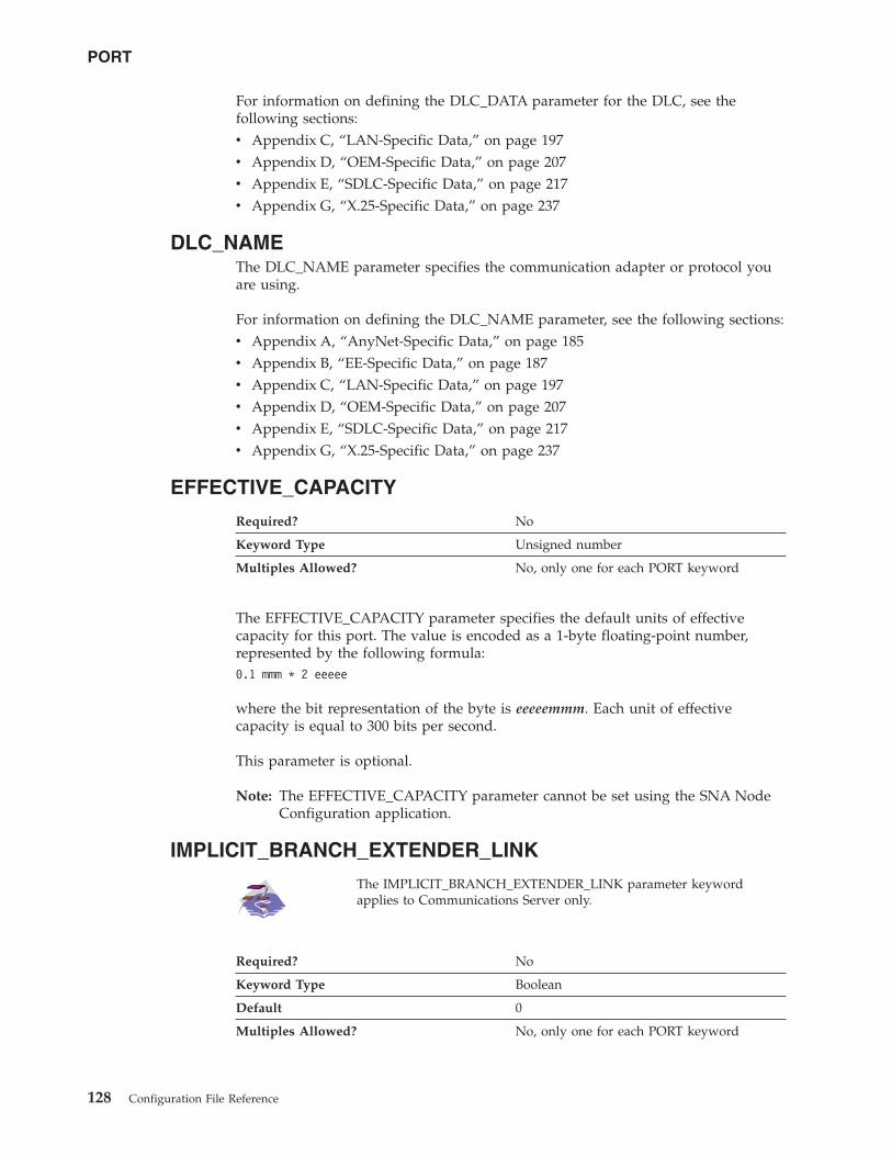
For information on defining the DLC_DATA parameter for the DLC, see the
following sections:
v Appendix C, “LAN-Specific Data,” on page 197
v Appendix D, “OEM-Specific Data,” on page 207
v Appendix E, “SDLC-Specific Data,” on page 217
v Appendix G, “X.25-Specific Data,” on page 237
DLC_NAME
The DLC_NAME parameter specifies the communication adapter or protocol you
are using.
For information on defining the DLC_NAME parameter, see the following sections:
v Appendix A, “AnyNet-Specific Data,” on page 185
v Appendix B, “EE-Specific Data,” on page 187
v Appendix C, “LAN-Specific Data,” on page 197
v Appendix D, “OEM-Specific Data,” on page 207
v Appendix E, “SDLC-Specific Data,” on page 217
v Appendix G, “X.25-Specific Data,” on page 237
EFFECTIVE_CAPACITY
Required? No
Keyword Type Unsigned number
Multiples Allowed? No, only one for each PORT keyword
The EFFECTIVE_CAPACITY parameter specifies the default units of effective
capacity for this port. The value is encoded as a 1-byte floating-point number,
represented by the following formula:
0.1 mmm * 2 eeeee
where the bit representation of the byte is eeeeemmm. Each unit of effective
capacity is equal to 300 bits per second.
This parameter is optional.
Note: The EFFECTIVE_CAPACITY parameter cannot be set using the SNA Node
Configuration application.
IMPLICIT_BRANCH_EXTENDER_LINK
The IMPLICIT_BRANCH_EXTENDER_LINK parameter keyword
applies to Communications Server only.
Required? No
Keyword Type Boolean
Default 0
Multiples Allowed? No, only one for each PORT keyword
PORT
128 Configuration File Reference
The IMPLICIT_BRANCH_EXTENDER_LINK parameter specifies whether
incoming calls are designated as branch extender links. Valid values are:
0 The incoming calls are treated as normal links.
1 The incoming call is treated as a branch extender link. The link connects to
another network from this local branch network. This value is only valid if
the incoming call is from an end node.
Note: Incoming calls from network nodes are always treated as branch
extender links, if NODETYPE=BRANCH_EXTENDER_NODE is
specified for the local node.
This parameter is optional. The default is 0.
Note: The IMPLICIT_BRANCH_EXTENDER_LINK parameter cannot be set using
the SNA Node Configuration application.
IMPLICIT_CP_CP_SESS_SUPPORT
Required? No
Keyword Type Boolean
Multiples Allowed? No, only one for each PORT keyword
The IMPLICIT_CP_CP_SESS_SUPPORT parameter specifies whether CP-CP
sessions are permitted for implicit link stations off this port. Valid values are:
0 CP-CP sessions are not permitted.
1 CP-CP sessions are permitted.
For a multipath channel (MPC) DLC,
IMPLICIT_CP_CP_SESS_SUPPORT must be specified as 1.
This parameter is optional.
Note: The IMPLICIT_CP_CP_SESS_SUPPORT parameter cannot be set using the
SNA Node Configuration application.
IMPLICIT_DEACT_TIMER
Required? No
Keyword Type Unsigned number
Default 600
Range 0–1000
Range 0–60000
Multiples Allowed? No, only one for each PORT
keyword
PORT
Chapter 24. PORT 129
The IMPLICIT_DEACT_TIMER parameter specifies the time, in seconds, that this
link can be idle before it automatically deactivates.
The implicit link deactivation timer is only used when
IMPLICIT_LIMITED_RESOURCE is specified as INACTIVITY or YES.
The value is an integer in the range of 0–1000 seconds. The default is
600 seconds.
The value is an integer in the range of 0–60000 seconds. The default is
600 seconds.
This parameter is optional.
IMPLICIT_DSPU_SERVICES
Required? Yes
Keyword Type Enumerated
Default NONE
Multiples Allowed? No, only one for each PORT keyword
The IMPLICIT_DSPU_SERVICES parameter specifies the services the local node
provides to the downstream PU across implicit links activated on this port. Valid
values are:
DLUR The local node provides DLUR services for the
downstream PU (using the default DLUS specified
on the DLUR_DEFAULTS keyword).
NONE The local node provides no services for the
downstream PU.
PU_CONCENTRATION The local node provides PU concentration for the
downstream PU (and puts definitions in place as
specified by the DSPU template named on the
IMPLICIT_DSPU_TEMPLATE keyword.
This parameter is required. The default is NONE.
Note: The IMPLICIT_DSPU_SERVICES parameter cannot be set using the SNA
Node Configuration application.
IMPLICIT_DSPU_TEMPLATE
Required? No
Keyword Type String
Field Length 1–8
Multiples Allowed? No, only one for each PORT keyword
The IMPLICIT_DSPU_TEMPLATE parameter specifies the 1- to 8-byte name of the
DSPU template, defined on the DSPU_TEMPLATE keyword, which is used for
definitions if the local node is to provide PU concentration for an implicit link
PORT
130 Configuration File Reference

activated on this port. If the specified template does not exist (or is already at its
instance limit) when the link is activated, activation fails.
If the IMPLICIT_DSPU_SERVICES parameter is not set to PU_CONCENTRATION,
this field is ignored.
All eight characters must be specified. Valid characters are any locally displayable
characters using the native encoding of the local system.
This parameter is optional.
Note: The IMPLICIT_DSPU_TEMPLATE parameter cannot be set using the SNA
Node Configuration application.
IMPLICIT_HPR_SUPPORT
Required? No
Keyword Type Boolean
Multiples Allowed? No, only one for each PORT keyword
The IMPLICIT_HPR_SUPPORT parameter specifies whether HPR should be
supported on implicit links. Valid values are:
0 HPR should not be supported on implicit links.
1 HPR should be supported on implicit links.
For the Enterprise Extender (EE) DLC or a multipath channel (MPC)
DLC, IMPLICIT_HPR_SUPPORT must be specified as 1.
For the Enterprise Extender (EE) DLC, IMPLICIT_HPR_SUPPORT must
be specified as 1.
IMPLICIT_LIMITED_RESOURCE
Required? No
Keyword Type Enumerated
Multiples Allowed? No, only one for each PORT keyword
The IMPLICIT_LIMITED_RESOURCE parameter specifies whether implicit link
stations off this port should be deactivated when there are no sessions using the
link. Valid values are:
INACTIVITY Implicit links are a limited resource and are deactivated
automatically when no active sessions are using them, or when no
data has followed on the link for the time period specified by the
IMPLICIT_DEACT_TIMER parameter.
NO Implicit links are not limited resources and are not deactivated
automatically.
YES Implicit links are a limited resource and are deactivated
automatically when no active sessions are using them, or when no
PORT
Chapter 24. PORT 131

data has followed on the link for the time period specified by the
IMPLICIT_DEACT_TIMER parameter.
For a multipath channel (MPC) DLC, IMPLICIT_LIMITED_RESOURCE
must be specified as NO.
This parameter is optional.
IMPLICIT_LINK_LVL_ERROR
Required? No
Keyword Type Boolean
Multiples Allowed? No, only one for each PORT keyword
The IMPLICIT_LINK_LVL_ERROR parameter specifies whether HPR traffic should
be sent on implicit links using link-level error recovery.
Note: The IMPLICIT_LINK_LVL_ERROR parameter is ignored if
IMPLICIT_HPR_SUPPORT is set to 0.
Valid values are:
0 Do not route HPR traffic on implicit links using link-level error recovery.
1 Route HPR traffic on implicit links using link-level error recovery.
Note: The IMPLICIT_LINK_LVL_ERROR parameter cannot be set using the SNA
Node Configuration application.
LINK_STATION_ROLE
Required? No
Keyword Type Enumerated
Default NEGOTIABLE
Multiples Allowed? No, only one for each PORT
keyword
The LINK_STATION_ROLE parameter defines the responsibility that the link
station has for controlling the communication with its adjacent link stations. Valid
values are:
NEGOTIABLE When the connection is established, the local link
station becomes either a primary or secondary link
station.
PRIMARY The primary link station controls the conversation
on the link.
SECONDARY The secondary link station must wait to be polled
by the primary link station before data is sent.
This parameter is optional.
The default is NEGOTIABLE.
PORT
132 Configuration File Reference

Notes:
1. If DLC_NAME is specified as TWINAX, only SECONDARY is valid.
2. If DLC_NAME is specified as ANYNET, and LS_NAME on the LINK_STATION
keyword is $ANYNET$, PRIMARY is not valid.
MAX_ACTIVATION_ATTEMPTS
Required? No
Keyword Type Unsigned number
Default Value 0
Range 0–127
Multiples Allowed? No, only one for each PORT keyword
The MAX_ACTIVATION_ATTEMPTS parameter specifies the number of retry
attempts allowed when the remote node is not responding or the port is inactive.
The attempts include both automatic retries and application-driven activation
attempts. When this limit is reached, no further activation retries are attempted.
The number of retries attempted is reset by a successful activation, or when a link
station, port, or DLC is deactivated.
The value is an integer in the range of 0-127. A zero means no limit.
This parameter is optional.
This parameter is ignored unless the LINK_STATION keyword referencing this
port specifies MAX_ACTIVATION_ATTEMPTS=-1 and one of the following
parameters on the LINK_STATION keyword is specified:
v DELAY_APPLICATION_RETRIES
v INHERIT_PORT_RETRY_PARMS
v RETRY_LINK_ON_DISCONNECT
v RETRY_LINK_ON_FAILED_START
v RETRY_LINK_ON_FAILURE
MAX_IFRM_RCVD
Required? No
Keyword Type Unsigned number
Range 0–127
Multiples Allowed? No, only one for each PORT keyword
The MAX_IFRM_RCVD parameter determines the maximum number of I-frames
that can be received by the local link stations before an acknowledgment is sent.
The value is an integer in the range of 0-127 frames.
This parameter is optional.
Note: The MAX_IFRM_RCVD parameter cannot be set using the SNA Node
Configuration application.
PORT
Chapter 24. PORT 133

MAX_RCV_BTU_SIZE
Required? No
Keyword Type Unsigned number
Range No defined range.
Range 99–32 767
Multiples Allowed? No, only one for each PORT
keyword
The MAX_RCV_BTU_SIZE parameter specifies the maximum BTU size that can be
received. If implicit HPR-capable links are not supported on the port, this must be
set to a value greater than or equal to 99. If implicit HPR-capable links are
supported on the port, this must be set to a value greater than or equal to 768. If
this port is for the AnyNet DLC, you must use 9 216.
For a multipath channel (MPC) DLC, MAX_RCV_BTU_SIZE should be
specified as 32 768 to allow the DLC to determine the size.
There is no defined range.
The value is an integer in the range of 99–32 767.
This parameter is optional.
Note: The MAX_RCV_BTU_SIZE parameter cannot be set using the SNA Node
Configuration application.
PORT_NAME
Required? Yes
Keyword Type String
Field Length 1–8
Multiples Allowed? No, only one for each PORT keyword
The PORT_NAME parameter specifies the 1- to 8-byte name of the port associated
with the link station.
All eight characters must be specified. Valid characters are any locally displayable
characters.
For the Enterprise Extender (EE) DLC, PORT_NAME should be IBMEEDLC (IPv4)
or IBMEE006 (IPv6).
PORT
134 Configuration File Reference
This parameter is required.
Note: The PORT_NAME specified on the PORT keyword must match the
PORT_NAME defined by the LINK_STATION keyword.
PORT_TYPE
Required? No
Keyword Type Enumerated
Multiples Allowed? No, only one for each PORT keyword
The PORT_TYPE parameter specifies the type of line used by the port. Valid values
are:
NONSWITCHED Connections are using leased, direct point-to-point
connections. Nonswitched routes are statically
defined by the direct line between the two end
nodes of the connection.
SATF Connections are using shared access transport
facility (SATF). SATF describes a network transport
with shared contention-based or token-based
access, such as Ethernet or token-ring. Typically,
SATF networks are called local area networks
(LAN).
SWITCHED Connections are using dial-up services, requiring
the use of a modem, a packet switched network
(such as a long distance telephone network), and
remote dial-up addressing (such as a telephone
number). Switched routes are dynamically
determined at runtime through the packet switched
network.
This parameter is optional.
Notes:
1. If this parameter is specified as SATF, the LS_ROLE parameter must be
specified as NEGOTIABLE.
2. The PORT_TYPE parameter cannot be set using the SNA Node Configuration
application.
PROPAGATION_DELAY
Required? No
Keyword Type Enumerated
Multiples Allowed? No, only one for each PORT keyword
The PROPAGATION_DELAY parameter specifies the default time it takes for a
signal to travel the length of the link, in microseconds, for this port. The value is
encoded as a 1-byte floating-point number, represented by the following formula:
0.1 mmm * 2 eeeee
where the bit representation of the byte is eeeeemmm.
PORT
Chapter 24. PORT 135

Valid values are:
LAN Less than 480 microseconds delay.
MAXIMUM Maximum propagation delay.
MINIMUM No propagation delay.
PKT_SWITCHED_NET Between 49 512 and 245 760 microseconds delay.
SATELLITE Longer than 245 760 microseconds delay.
TELEPHONE Between 480 and 49 512 microseconds delay.
This parameter is optional.
Note: The PROPAGATION_DELAY parameter cannot be set using the SNA Node
Configuration application.
RETRY_LINK_ON_DISCONNECT
Required? No
Keyword Type Boolean
Multiples Allowed? No, only one for each PORT keyword
The RETRY_LINK_ON_DISCONNECT parameter specifies whether link activation
is retried when the link is stopped normally by the remote node. Valid values are:
0 Link activation is not retried.
1 Link activation is retried.
This parameter is optional.
RETRY_LINK_ON_FAILED_START
Required? No
Keyword Type Boolean
Multiples Allowed? No, only one for each PORT keyword
The RETRY_LINK_ON_FAILED_START parameter specifies whether link activation
is retried if no response is received from the remote node when activation is
attempted. If the port is inactive when activation is attempted, an attempt is made
to activate it. Valid values are:
0 Link activation is not retried.
1 Link activation is retried.
This parameter is optional.
RETRY_LINK_ON_FAILURE
Required? No
Keyword Type Boolean
Multiples Allowed? No, only one for each PORT keyword
PORT
136 Configuration File Reference
The RETRY_LINK_ON_FAILURE parameter specifies whether link activation is
retried if the link fails while in an active or pending active state. If the port fails,
an attempt is made to activate it. Valid values are:
0 Link activation is not retried.
1 Link activation is retried.
This parameter is optional.
PORT_LAN_SPECIFIC_DATA
For information on defining the parameters for the PORT_LAN_SPECIFIC_DATA
parameter, see Appendix C, “LAN-Specific Data,” on page 197.
PORT_OEM_SPECIFIC_DATA
For information on defining the parameters for the PORT_OEM_SPECIFIC_DATA
parameter for the Enterprise Extender (EE) DLC or an OEM DLC, see the
following sections:
v Appendix B, “EE-Specific Data,” on page 187
v Appendix D, “OEM-Specific Data,” on page 207
PORT_SDLC_SPECIFIC_DATA
For information on defining the parameters for the PORT_SDLC_SPECIFIC_DATA
parameter, see Appendix E, “SDLC-Specific Data,” on page 217.
PORT_TWINAX_SPECIFIC_DATA
For information on defining the parameters for the
PORT_TWINAX_SPECIFIC_DATA parameter, see Appendix F, “Twinaxial-Specific
Data,” on page 233.
PORT_X25_SPECIFIC_DATA
For information on defining the parameters for the PORT_X25_SPECIFIC_DATA
parameter, see Appendix G, “X.25-Specific Data,” on page 237.
SECURITY
Required? No
Keyword Type Enumerated
Multiples Allowed? No, only one for each PORT keyword
The SECURITY parameter specifies the default type of security used for
transmission of data over the connection for this port. Valid values are:
ENCRYPTED
There is encryption over the line.
GUARDED_CONDUIT
The conduit is protected against physical tapping.
GUARDED_RADIATION
The line is protected against physical and radiation tapping.
NONSECURE
No security exists.
PORT
Chapter 24. PORT 137
PUBLIC_SWITCHED_NETWORK
Data is transmitted over a public switched network.
SECURE_CONDUIT
The line is a secure conduit that is not guarded.
UNDERGROUND_CABLE
Data is transmitted over a secure underground cable.
This parameter is optional.
USER_DEFINED_1
Required? No
Keyword Type Unsigned number
Multiples Allowed? No, only one for each PORT keyword
The USER_DEFINED_1 parameter specifies the default maximum limit for a user
defined parameter for this port.
This parameter is optional.
USER_DEFINED_2
Required? No
Keyword Type Unsigned number
Multiples Allowed? No, only one for each PORT keyword
The USER_DEFINED_2 parameter specifies the default maximum limit for a user
defined parameter for this port.
This parameter is optional.
USER_DEFINED_3
Required? No
Keyword Type Unsigned number
Multiples Allowed? No, only one for each PORT keyword
The USER_DEFINED_3 parameter specifies the default maximum limit for a user
defined parameter for this port.
This parameter is optional.
PORT
138 Configuration File Reference

Chapter 25. RTP_TUNING
This chapter describes the parameter keywords and values you can specify for the
RTP_TUNING keyword.
Keyword Definition
Required? No
Keyword Type Complex
Key Name PATH_SWITCH_ATTEMPTS
Multiples Allowed? No
RTP_TUNING Sample
The following is a sample of the RTP_TUNING keyword:
RTP_TUNING = (
PATH_SWITCH_ATTEMPTS = 6
SHORT_REQ = 0
NETWORK_PATH_SWITCH_TIME = 60
HIGH_PATH_SWITCH_TIME = 120
MEDIUM_PATH_SWITCH_TIME = 240
LOW_PATH_SWITCH_TIME = 480
MAX_SHORT_REQ_TIME = 6
MAX_REFIFO_TIME = 4000
)
RTP_TUNING Parameter Keywords
PATH_SWITCH_ATTEMPTS
Required? No
Keyword Type Unsigned Number
Default 6
Range 0–255
Multiples Allowed? No
The PATH_SWITCH_ATTEMPTS parameter specifies the number of path switch
attempts that will be attempted before a disconnect is initiated for the active link.
This parameter is optional.
© Copyright IBM Corp. 1998, 2006 139

SHORT_REQ
Required? No
Keyword Type Unsigned Number
Default 0
Range 0–255
Multiples Allowed? No
The SHORT_REQ parameter specifies the number of times a packet with the Status
Request Indicator will be sent before a path switch is attempted. If 0 is specified, a
default value of 30 seconds is used.
This parameter is optional.
Additional information about tuning RTP connections in Personal Communications
can be found on the Personal Communications Information Center.
NETWORK_PATH_SWITCH_TIME
Required?
Keyword Type Unsigned Number
Default 60
Range 1-65535
Multiples Allowed? No
The NETWORK_PATH_SWITCH_TIME parameter specifies the length of time in
seconds that an attempt is made to path switch a disconnected RTP connection.
Path switch times are specified as four separate time limits for each of the valid
transmission priorities in order: LOW_PATH_SWITCH_TIME,
MEDIUM_PATH_SWITCH_TIME, HIGH_PATH_SWITCH_TIME, and
NETWORK_PATH_SWITCH_TIME. The value you specify for each of these
transmission priorities must not exceed the value for any lower transmission
priority.
If 0 is specified for NETWORK_PATH_SWITCH_TIME, a default value of 60 is
used.
HIGH_PATH_SWITCH_TIME
Required?
Keyword Type Unsigned Number
Default 120
Range 1-65535
Multiples Allowed? No
The HIGH_PATH_SWITCH_TIME parameter specifies the length of time in
seconds that an attempt is made to path switch a disconnected RTP connection.
Path switch times are specified as four separate time limits for each of the valid
transmission priorities in order: LOW_PATH_SWITCH_TIME,
RTP_TUNING
140 Configuration File Reference
MEDIUM_PATH_SWITCH_TIME, HIGH_PATH_SWITCH_TIME, and
NETWORK_PATH_SWITCH_TIME. The value you specify for each of these
transmission priorities must not exceed the value for any lower transmission
priority.
If 0 is specified for HIGH_PATH_SWITCH_TIME, a default value of 120 is used.
MEDIUM_PATH_SWITCH_TIME
Required?
Keyword Type Unsigned Number
Default 240
Range 1-65535
Multiples Allowed? No
The MEDIUM_PATH_SWITCH_TIME parameter specifies the length of time in
seconds that an attempt is made to path switch a disconnected RTP connection.
Path switch times are specified as four separate time limits for each of the valid
transmission priorities in order: LOW_PATH_SWITCH_TIME,
MEDIUM_PATH_SWITCH_TIME, HIGH_PATH_SWITCH_TIME, and
NETWORK_PATH_SWITCH_TIME. The value you specify for each of these
transmission priorities must not exceed the value for any lower transmission
priority.
If 0 is specified for MEDIUM_PATH_SWITCH_TIME, a default value of 240 is
used.
LOW_PATH_SWITCH_TIME
Required?
Keyword Type Unsigned Number
Default 480
Range 1-65535
Multiples Allowed? No
The LOW_PATH_SWITCH_TIME parameter specifies the length of time in seconds
that an attempt is made to path switch a disconnected RTP connection. Path switch
times are specified as four separate time limits for each of the valid transmission
priorities in order: LOW_PATH_SWITCH_TIME, MEDIUM_PATH_SWITCH_TIME,
HIGH_PATH_SWITCH_TIME, and NETWORK_PATH_SWITCH_TIME. The value
you specify for each of these transmission priorities must not exceed the value for
any lower transmission priority.
If 0 is specified for LOW_PATH_SWITCH_TIME, a default value of 480 is used.
RTP_TUNING
Chapter 25. RTP_TUNING 141
MAX_SHORT_REQ_TIME
Required?
Keyword Type Unsigned Number
Default 6
Range 1-255
Multiples Allowed? No
The MAX_SHORT_REQ_TIME parameter specifies the number of times a Status
Request is sent before and RTP connection is disconnected and starts path switch
processing. If 0 is specified, a default value of 6 is used.
MAX_REFIFO_TIME
Required?
Keyword Type Unsigned Number
Default 4000
Range 250-12000
Multiples Allowed? No
The MAX_REFIFO_TIME parameter specifies a maximum value in milliseconds
beyond which the Re-FIFO timer cannot increase. In some situations, setting this
maximum value (rather than letting the timer value be calculated by the RTP
protocol) can improve performance. Setting a value of 0 means that the timer is not
limited and can take any value calculated by the RTP protocol.
RTP_TUNING
142 Configuration File Reference
Chapter 26. SPLIT_STACK
This chapter describes the parameter keywords and values you can
specify for the SPLIT_STACK keyword.
Keyword Definition
Required? No
Keyword Type Complex
Multiples Allowed? No
SPLIT_STACK Sample
The following is a sample of the SPLIT_STACK keyword:
SPLIT_STACK=(
STARTUP=1
)
SPLIT_STACK Parameter Keywords
POOL_NAME
Required? No
Keyword Type String
Field Length 1–8
Multiples Allowed? No
The POOL_NAME parameter specifies the 1- to 8-character default pool name
from which SNA API clients obtain available LU 0 to 3 LUs if an explicit one is not
required. If one is specified, all new host LUs created are added to this pool by
default. Valid values are:
v The first character must be an uppercase alphabetic character (A-Z) or a special
character (@, #, $).
v The remaining characters can be alphanumeric characters (A-Z, 0-9) or special
characters (@, #, $).
This parameter is optional.
STARTUP
Required? Yes
Keyword Type Boolean
Default 1
Multiples Allowed? No
© Copyright IBM Corp. 1998, 2006 143

The STARTUP parameter specifies whether LU 6.2 sessions can be configured for a
remote client at run time. Valid values are:
0 LU 6.2 sessions can still be configured for a remote client, but can not be
established at run time.
1 LU 6.2 sessions can be configured and established for a remote client.
This parameter is required. The default is 1.
SPLIT_STACK
144 Configuration File Reference
Chapter 27. TN3270E_DEF
This chapter describes the parameter keywords and values you can
specify for the TN3270E_DEF keyword.
Keyword Definition
Required? No
Keyword Type Complex
Multiples Allowed? No
TN3270E_DEF Sample
The following is a sample of the TN3270E_DEF keyword:
TN3270E_DEF=(
AUTO_LOGOFF=1
DEFAULT_POOL_NAME=POOL1
FREQUENCY=60
KEEPALIVE_TYPE=TN_NOP
LOGOFF=30
TIMER=10
)
TN3270E_DEF Parameter Keywords
AUTO_LOGOFF
Required? Yes
Keyword Type Boolean
Default 0
Multiples Allowed? No
The AUTO_LOGOFF parameter specifies whether the connection is automatically
terminated when the value of the LOGOFF parameter is reached. Valid values are:
0 The connection is not terminated.
1 The connection is terminated.
This parameter is required. The default is 0.
DEFAULT_POOL_NAME
Required? No
Keyword Type String
Field Length 1–8
Multiples Allowed? No
© Copyright IBM Corp. 1998, 2006 145
The DEFAULT_POOL_NAME parameter identifies the name of the pool of
unassigned workstations or pool of implicit workstations that is used when the
TN3270 client does not specify an LU name. The name of the pool is a 1- to 8-byte
character string.
This parameter is optional.
DEFAULT_PRINTER_POOL_NAME
Required? No
Keyword Type String
Field Length 1–8
Multiples Allowed? No
The DEFAULT_PRINTER_POOL_NAME parameter identifies the name of the pool
of unassigned printers or pool of implicit printers that is used when the TN3270
client does not specify an LU name. The name of the pool is a 1- to 8-byte
character string.
This parameter is optional.
ENABLE_FILTERING
Required? Yes
Keyword Type Boolean
Default 0
Multiples Allowed? No
The ENABLE_FILTERING parameter specifies whether TN3270E filtering is
enabled. Valid values are:
0 TN3270E filtering is not enabled. Any TCP/IP workstation is granted
access to available host resources (that is, those host resources which have
been defined as TN3270E resources).
1 TN3270E filtering is enabled. Only TCP/IP workstations matching the IP
address and subnet mask of at least one of the filter definitions are allowed
access to the host resources defined in the appropriate filters.
This parameter is required. The default is 0.
FILTER_PREFERENCE
Required? No
Keyword Type Enumerated
Default HOSTNAME_FIRST
Multiples Allowed? No
The FILTER_PREFERENCE parameter specifies the filter record processing order
used when determining a match with an incoming client request. Valid values are:
TN3270E_DEF
146 Configuration File Reference
HOSTNAME_FIRST
Specifies that all filters specifying either a TCP/IP host name or
domain name should be processed and checked against the client’s
hostname or domain name before processing filters specifying a
TCP/IP address.
IP_ADDR_FIRST
Specifies that all filters specifying a TCP/IP address should be
processed before processing filters specifying either a host name or
domain name.
This parameter is optional. The default is HOSTNAME_FIRST.
FREQUENCY
Required? Yes
Keyword Type Unsigned number
Default 60
Range 1–65 535
Multiples Allowed? No
The FREQUENCY parameter specifies the seconds to wait after data has been sent
or received on a connection before beginning keepalive detection. Choosing a high
number means that the connections are checked less often and the resulting
network traffic is reduced. Choosing a low frequency means that the connections
are checked more frequently and connections are freed more rapidly.
The value is an integer in the range 1–65 535.
This parameter is required. The default is 60.
KEEPALIVE_TYPE
Required? Yes
Keyword Type Enumerated
Default TN_NONE
Multiples Allowed? No
The KEEPALIVE_TYPE parameter specifies the method used to free connections.
Valid values are:
TN_NONE Do not use either the TN_NOP nor the
TN_TIMING_MARK methods to free connections.
TN_NOP Use if it is not necessary to free connections after a
specific amount of time. Detection and freeing of
the connection take an unpredictable amount of
time. When the time specified on the FREQUENCY
parameter is reached, the connection is tested to
see if it is broken.
TN_TIMING_MARK Use if it is necessary to define when connections
are freed and additional traffic on the network is
acceptable. Detection and freeing of the connection
TN3270E_DEF
Chapter 27. TN3270E_DEF 147

take place as specified by the TIMER parameter.
When the specified time is reached and the client
has not responded, the connection is freed.
This parameter is required. The default is TN_NONE.
LOGOFF
Required? Yes
Keyword Type Unsigned number
Default 30
Range 1–65 535
Multiples Allowed? No
The LOGOFF parameter specifies the amount of idle time to allow before a session
is disconnected. This parameter is only valid if the AUTO_LOGOFF parameter is
specified as AUTO_LOGOFF=1.
The value is an integer in the range 1–65 535.
This parameter is required. The default is 30.
LU_TAKEOVER
Required? Yes
Keyword Type Boolean
Default 0
Multiples Allowed? No
The LU_TAKEOVER parameter specifies whether LU takeover processing is used
for controlling unused LU resources at the server.
LU takeover is one technique for controlling unused LU resources at the server.
When a new TN3270E session request specifies an LU that is in use at the server,
the TN3270E server sends a timing mark to the client of that connection. If the
client does not respond to the timing mark within the number of seconds that you
specify, the server disconnects the session and assigns the LU to the new
connection request.
LU takeover enables you to disconnect unused sessions when they are needed,
without the additional network traffic generated by keepalive detection. Keepalive
detection enables you to free unused connections more frequently, but generates
more network traffic.
Valid values are:
0 LU takeover processing is not used for controlling unused LU resources.
1 LU takeover processing is used for controlling unused LU resources.
This parameter is required. The default is 0.
TN3270E_DEF
148 Configuration File Reference

LU_TAKEOVER_TIMER
Required? Yes
Keyword Type Unsigned number
Default 10
Range 1–65 535
Multiples Allowed? No
The LU_TAKEOVER_TIMER parameter specifies the number of seconds of idle
time to allow before a session is disconnected.
The value is an integer in the range 1–65 535.
This parameter is required. The default is 10.
TIMER
Required? Yes
Keyword Type Unsigned number
Default 10
Range 1–65 535
Multiples Allowed? No
The TIMER parameter specifies the number of seconds to wait for a response to a
timing mark before the connection is freed.
The value is an integer in the range 1–65 535.
This parameter is required. The default is 10.
TN3270E_DEF
Chapter 27. TN3270E_DEF 149

150 Configuration File Reference

Chapter 28. TN3270E_FILTER
This chapter describes the parameter keywords and values you can
specify for the TN3270E_FILTER keyword.
Keyword Definition
Required? No
Keyword Type Complex
Key Name IP_ADDR_MASK_PAIR
Multiples Allowed? Yes, but each TN3270E_FILTER keyword
must have a unique IP_ADDR_MASK_PAIR
parameter
TN3270E_FILTER Sample
The following is a sample of the TN3270E_FILTER keyword:
TN3270E_FILTER=(
CLIENT_ID_TYPE=HOST_NAME
IP_ADDR_MASK_PAIR=nfl.raleigh.ibm.com
FILTER_ENTRY=(
CLASS_TYPE=TN_IMPLICIT_WORKSTATION
IS_POOL=1
NAME=PUBLIC
)
)
TN3270E_FILTER Parameter Keywords
CLASS_TYPE
Required? No
Keyword Type Enumerated
Multiples Allowed? No, only one for each FILTER_ENTRY
parameter
The CLASS_TYPE parameter indicates how this LU or pool is used. Valid values
are:
TN_ASSOC_PRINTER
Use for connections that require a printer associated with an explicit
workstation or an LU in a pool of implicit workstations.
TN_EXPLICIT_PRINTER
Use for connections that require a specific printer device name.
TN_EXPLICIT_WORKSTATION
Use for connections that require a specific workstation device name.
TN_IMPLICIT_PRINTER
Use for connections that do not require a specific printer device name.
© Copyright IBM Corp. 1998, 2006 151

TN_IMPLICIT_WORKSTATION
Use for connections that do not require a specific workstation device name.
TN_UNASSIGNED
Use to delete the TN3270E definition for the selected LU or pool.
This parameter is optional.
CLIENT_ID_TYPE
Required? No
Keyword Type Enumerated
Default IP_ADDRESS
Multiples Allowed? No, only one for each TN3270E_FILTER
keyword
The CLIENT_ID_TYPE parameter indicates the type of address the value of the
IP_ADDR_MASK_PAIR parameter specifies. Valid values are:
DOMAIN_NAME The value of the IP_ADDR_MASK_PAIR parameter
specifies a domain name.
HOST_NAME The value of the IP_ADDR_MASK_PAIR parameter
specifies a host name.
IP_ADDRESS The value of the IP_ADDR_MASK_PAIR parameter
specifies the source IP address and subnet mask of
a TCP/IP workstation.
This parameter is optional. The default is IP_ADDRESS.
FILTER_ENTRY
Required? No
Keyword Type Complex
Multiples Allowed? Yes
The FILTER_ENTRY parameter is a complex keyword comprised of the following
parameter keywords:
v CLASS_TYPE
v IS_POOL
v NAME
See the descriptions of the parameter keywords to define the FILTER_ENTRY
parameter.
TN3270E_FILTER
152 Configuration File Reference

IP_ADDR_MASK_PAIR
Required? Yes
Keyword Type String
Field Length 1–256
Multiples Allowed? No, only one for each TN3270E_FILTER
keyword
The IP_ADDR_MASK_PAIR parameter specifies one of the following:
v The domain name to which you wish to restrict host resources (LUs)
v The host name to which you wish to restrict host resources (LUs)
v The source IP address and subnet mask of the TCP/IP workstation(s) to which
you wish to restrict host resources (LUs). The IP address and the subnet mask
values are separated by a comma. Only those clients matching the IP address
and subnet mask combination are granted access to the list of resources
represented by this filter.
Whether the value you specify is a domain name, host name, or IP address and
subnet mask is determined by the CLIENT_ID_TYPE parameter.
The value is a 1- to 256-character string.
This parameter is required.
If you wish to restrict host resources to a specific workstation, specify that
workstation IP address and the subnet mask of 255.255.255.255. If you wish to
restrict host resources to all workstations in a particular IP subnetwork, such as a
local office LAN, specify one of the workstation IP addresses and a subnet mask to
identify the IP address values that are significant for identifying the subnetwork.
For example, to restrict host resources for all workstations in the subnet 9.57.0.0,
you might specify a source IP address of 9.57.126.4 and a subnet mask of
255.255.0.0. If you specify a specific IP address and full subnet mask (filtering for a
specific workstation), that workstation is granted access to the first available host
resource, whether it be an explicit LU or an LU from a pool of LUs. If the filter is
designated for workstations on a particular subnetwork, these workstations are
only granted use of available host resources from pool definitions in this filter; no
use of explicit LUs is granted. Ordering of host LUs and host LU pools in the filter
list is important. The order implies the ordering of workstations’ access to host
resources. In other words, if the first LU or pool on the list is in use, access is
granted to the next resource on the list. All LUs from within a pool must be in use
before the pool is considered in use.
If a full subnet mask is specified (255.255.255.255), host resources are being chosen
for use by the specific workstation whose address is specified. If a partial subnet
mask is specified (such as 255.0.0.0), any workstation from the subnetwork
(identified by the significant fields of the IP address as specified by the subnet
mask) may have access to host resources specified in the filter.
If you specify an IP address of 0.0.0.0, all workstations and printers that do not
match another filter entry are allowed access to the specified resources.
TN3270E_FILTER
Chapter 28. TN3270E_FILTER 153

IS_POOL
Required? Yes
Keyword Type Boolean
Default 0
Multiples Allowed? No, only one for each FILTER_ENTRY
parameter
The IS_POOL parameter specifies whether the NAME value in the same
FILTER_ENTRY complex keyword refers to a host LU name or a host LU pool
name. Valid values are:
0 NAME refers to a host LU name.
1 NAME refers to a host LU pool name.
This parameter is required. The default is 0.
NAME
Required? No
Keyword Type String
Field Length 1–8
Multiples Allowed? No, only one for each FILTER_ENTRY
parameter
The NAME parameter specifies either a 1- to 8-character host LU name
(LU_0_TO_3 definition) or a 1- to 8-character host LU pool name, specified by a
collection of LU_0_TO_3 definitions. The value of the IS_POOL parameter specifies
whether NAME refers to a host LU name or a host LU pool name.
This parameter is optional.
TN3270E_FILTER
154 Configuration File Reference
Chapter 29. TN3270_PORT_DEF
This chapter describes the parameter keywords and values you can
specify for the TN3270_PORT_DEF keyword.
Keyword Definition
Required? No
Keyword Type Complex
Key Name PORT
Multiples Allowed? Yes, but each TN3270_PORT_DEF keyword
must have a unique PORT parameter
TN3270_PORT_DEF Sample
The following is a sample of the TN3270E_PORT_DEF keyword:
TN3270_PORT_DEF=(
PORT=3023
CLIENT_AUTHENTICATION=0
SECURITY=0
SECURITY_LEVEL=HIGH
)
TN3270_PORT_DEF Parameter Keywords
CLIENT_AUTHENTICATION
Required? Yes
Keyword Type Boolean
Default 0
Multiples Allowed? No, only one for each TN3270_PORT_DEF
keyword
The CLIENT_AUTHENTICATION parameter specifies whether verification that
clients are authorized to establish a secure connection to the TN3270E server is
performed. Valid values are:
0 Verification of client authorization is not performed.
1 Verification of client authorization is performed.
This parameter is required. The default is 0.
© Copyright IBM Corp. 1998, 2006 155
DEFAULT_POOL
Required? No
Keyword Type String
Field Length 3–17
Multiples Allowed? No, only one for each TN3270_PORT_DEF
keyword
The DEFAULT_POOL parameter specifies the fully qualified name of a pool of LUs
that is used when the TN3270 client does not specify an LU resource name.
Note: If you specify this parameter, the pool name will override the values
specified on the DEFAULT_POOL_NAME and
DEFAULT_PRINTER_POOL_NAME of the TN3270E_DEF keyword.
The fully qualified CP name is a 17-byte character string. The fully qualified CP
name consists of two parts: the network name and the CP name, concatenated with
a period. The network name is a 1- to 8-byte SNA Type A character string. The CP
name is a 1- to 8-byte SNA Type A character string. The fully qualified CP name is
also known as the network qualified CP name.
This parameter is optional.
PORT
Required? Yes
Keyword Type Unsigned number
Default 23
Range 1–65 535
Multiples Allowed? No, only one for each TN3270_PORT_DEF
keyword
The PORT parameter specifies the number of the port that the TN3270 client uses
to connect to the server.
The value is an integer in the range 1–65 535.
This parameter is required. The default is 23.
Normally, the TN3270E server uses port 23. Telnet typically uses port 23, so if
another application is running and is using port 23, you need to change the
default. The port number must be not be assigned to any other application. If two
applications use the same port number, one of the applications fails.
Note: If you change the port number from 23, the port number defined on TN3270
clients must be changed to the number specified here.
TN3270_PORT_DEF
156 Configuration File Reference

SECURITY
Required? Yes
Keyword Type Boolean
Default 0
Multiples Allowed? No, only one for each TN3270_PORT_DEF
keyword
The SECURITY parameter specifies whether security is enabled for TN3270
communication sessions on the specified port. Valid values are:
0 Security is not enabled for TN3270 communication sessions on the port.
1 Security is enabled for TN3270 communication sessions on the port.
This parameter is required. The default is 0.
SECURITY_LEVEL
Required? Yes
Keyword Type Enumerated
Default HIGH
Multiples Allowed? No
The SECURITY_LEVEL parameter specifies the level of security used for the
connection with a client when the SECURITY parameter is specified as
SECURITY=1. Valid values are:
AUTHENTICATION_ONLY
Specifies that certificates to authenticate one or both ends of the
connection are exchanged, but data is not encrypted.
MEDIUM Specifies that Communications Server can establish connections
with any supported level of encryption.
HIGH Specifies that for Communications Servers supporting strong
encryption, the port will only accept connections from clients
supporting strong encryption. For Communications Servers
supporting export encryption only, HIGH is the same as MEDIUM.
This parameter is required. The default is HIGH.
TN3270_PORT_DEF
Chapter 29. TN3270_PORT_DEF 157

158 Configuration File Reference
Chapter 30. TN5250_DEF
This chapter describes the parameter keywords and values you can
specify for the TN5250_DEF keyword.
Keyword Definition
Required? No
Keyword Type Complex
Multiples Allowed? No
TN5250_DEF Sample
The following is a sample of the TN5250_DEF keyword:
TN5250_DEF=(
AUTO_LOGOFF=0
DYNAMIC_LU_SUPPORT=1
ENABLE_FILTERING=0
FILTER_PREFERENCE=HOSTNAME_FIRST
FREQUENCY=60
KEEPALIVE_TYPE=TN_NONE
LOGOFF=10
LU_PREFIX=TN52
NUMBER_OF_DYNAMIC_LUS=10
TIMER=10
)
TN5250_DEF Parameter Keywords
AUTO_LOGOFF
Required? Yes
Keyword Type Boolean
Default 0
Multiples Allowed? No
The AUTO_LOGOFF parameter specifies whether the connection is automatically
terminated when the value of the LOGOFF parameter is reached. Valid values are:
0 The connection is not terminated.
1 The connection is terminated.
This parameter is required. The default is 0.
© Copyright IBM Corp. 1998, 2006 159
DYNAMIC_LU_SUPPORT
Required? Yes
Keyword Type Boolean
Default 0
Multiples Allowed? No
The DYNAMIC_LU_SUPPORT parameter specifies whether the TN5250 server
should dynamically generate independent LU 6.2 local LU definitions for
supporting sessions with iSeries, eServer i5, or System i5 servers. Valid values are:
0 Dynamic LUs are not supported. Sessions with iSeries, eServer i5, or
System i5 use statically defined independent local LUs, including the CP
LU.
1 Dynamic LUs are supported. The TN5250 server automatically generates as
many LUs as indicated by the NUMBER_OF_DYNAMIC_LUS parameter,
using the LU_PREFIX parameter value as the common naming prefix for
each LU (so that they can easily be identified as dynamically generated
LUs).
This parameter is required. The default is 0.
Since each iSeries, eServer i5, or System i5 supports a maximum of 512 concurrent
sessions with any one local LU, it may be desirable to have a number of LUs
available if more than 512 sessions are active at any given time.
ENABLE_FILTERING
Required? Yes
Keyword Type Boolean
Default 0
Multiples Allowed? No
The ENABLE_FILTERING parameter specifies whether TN5250 filtering is enabled.
Valid values are:
0 TN5250 filtering is not enabled. Any TCP/IP workstation is granted access
to available host resources (that is, those host resources which have been
defined as TN5250 resources.)
1 TN5250 filtering is enabled. Only TCP/IP workstations matching the IP
address and subnet mask of at least one of the filter definitions are allowed
access to the host resources defined in the appropriate filter(s).
This parameter is required. The default is 0.
FILTER_PREFERENCE
Required? No
Keyword Type Enumerated
Default HOSTNAME_FIRST
Multiples Allowed? No
TN5250_DEF
160 Configuration File Reference

The FILTER_PREFERENCE parameter specifies the filter record processing order
used when determining a match with an incoming client request. Valid values are:
HOSTNAME_FIRST
Specifies that all filters specifying either a TCP/IP host name or
domain name should be processed and checked against the client’s
hostname or domain name before processing filters specifying a
TCP/IP address.
IP_ADDR_FIRST
Specifies that all filters specifying a TCP/IP address should be
processed before processing filters specifying either a host name or
domain name.
This parameter is optional. The default is HOSTNAME_FIRST.
FREQUENCY
Required? Yes
Keyword Type Unsigned number
Default 60
Range 1–65 535
Multiples Allowed? No
The FREQUENCY parameter specifies the number of seconds to wait after data has
been sent or received on a connection before beginning keepalive detection.
Choosing a high number means that connections are checked less often and the
resulting network traffic is reduced. Choosing a low frequency means that
connections are checked more frequently and connections are freed more rapidly.
The value is an integer in the range 1–65 535.
This parameter is required. The default is 60.
KEEPALIVE_TYPE
Required? Yes
Keyword Type Enumerated
Default TN_NONE
Multiples Allowed? No
The KEEPALIVE_TYPE parameter specifies the method used to free connections.
Valid values are:
TN_NONE Do not use either the TN_NOP nor the
TN_TIMING_MARK methods to free connections.
TN_NOP Use if it is not necessary to free connections after a
specific amount of time. Detection and freeing of
the connection take an unpredictable amount of
TN5250_DEF
Chapter 30. TN5250_DEF 161

time. When the time specified on the FREQUENCY
parameter is reached, the connection is tested to
see if it is broken.
TN_TIMING_MARK Use if it is necessary to define when connections
are freed and additional traffic on the network is
acceptable. Detection and freeing of the connection
take place as specified by the TIMER parameter.
When the specified time is reached and the client
has not responded, the connection is freed.
This parameter is required. The default is TN_NONE.
LOGOFF
Required? Yes
Keyword Type Unsigned number
Default 30
Range 1–65 535
Multiples Allowed? No
The LOGOFF parameter specifies the amount of idle time to allow before a session
is disconnected. This parameter is only valid if the AUTO_LOGOFF parameter is
specified as AUTO_LOGOFF=1.
The value is an integer in the range 1–65 535.
This parameter is required. The default is 30.
LU_PREFIX
Required? No
Keyword Type String
Field Length 1–5
Multiples Allowed? No
The LU_PREFIX parameter specifies the common naming prefix for each LU (so
that they can easily be identified as dynamically generated LUs).
LU_PREFIX is a 1- to 5-byte SNA Type A character string.
This parameter is optional.
NUMBER_OF_DYNAMIC_LUS
Required? No
Keyword Type Unsigned number
Default 8
Range 0–1000
Multiples Allowed? No
TN5250_DEF
162 Configuration File Reference

The NUMBER_OF_DYNAMIC_LUS parameter specifies how many dynamic LUs
can be automatically generated by the TN5250 server.
The value is an integer in the range 0–1000.
This parameter is optional. The default is 8.
TIMER
Required? Yes
Keyword Type Unsigned number
Default 10
Range 1–65 535
Multiples Allowed? No
The TIMER parameter specifies the number of seconds to wait for a response to a
timing mark before the connection is freed.
The value is an integer in the range 1–65 535.
This parameter is required. The default is 10.
TN5250_DEF
Chapter 30. TN5250_DEF 163

164 Configuration File Reference

Chapter 31. TN5250_FILTER
This chapter describes the parameter keywords and values you can
specify for the TN5250_FILTER keyword.
Keyword Definition
Required? No
Keyword Type Complex
Key Name IP_ADDR_MASK_PAIR
Multiples Allowed? Yes, but each TN5250_FILTER keyword must
have a unique IP_ADDR_MASK_PAIR
parameter
TN5250_FILTER Sample
The following is a sample of the TN5250_FILTER keyword:
TN5250_FILTER=(
IP_ADDR_MASK_PAIR=195.67.99.1,255.255.255.0
CLIENT_ID_TYPE=IP_ADDRESS
AS400_SERVER_ENTRY=
)
TN5250_FILTER Parameter Keywords
AS400_SERVER_ENTRY
Required? No
Keyword Type String
Field Length 3–17
Multiples Allowed? Yes
The AS400_SERVER_ENTRY parameter specifies the fully qualified CP name of the
iSeries, eServer i5, or System i5. Access is granted to TN5250 clients that match this
filter definition, as specified in the IP_ADDR_MASK_PAIR parameter.
Note: The AS400_SERVER_ENTRY must specify a server which has been defined
using an AS400_SERVER keyword.
The fully qualified CP name is a 17-byte character string. The fully qualified CP
name consists of two parts: the network name and the CP name, concatenated with
a period. The network name is a 1- to 8-byte SNA Type A character string. The CP
name is a 1- to 8-byte SNA Type A character string. The fully qualified CP name is
also known as the network qualified CP name.
This parameter is optional.
© Copyright IBM Corp. 1998, 2006 165
Up to 32 AS400_SERVER_ENTRIES are allowed. The order of the entries in the
TN5250_FILTER keyword determines the order used to establish a session between
a TN5250 client and an available iSeries, eServer i5, or System i5.
CLIENT_ID_TYPE
Required? No
Keyword Type Enumerated
Default IP_ADDRESS
Multiples Allowed? No, only one for each TN5250_FILTER
keyword
The CLIENT_ID_TYPE parameter indicates the type of address the value of the
IP_ADDR_MASK_PAIR parameter specifies. Valid values are:
DOMAIN_NAME The value of the IP_ADDR_MASK_PAIR parameter
specifies a domain name.
HOST_NAME The value of the IP_ADDR_MASK_PAIR parameter
specifies a host name.
IP_ADDRESS The value of the IP_ADDR_MASK_PAIR parameter
specifies the source IP address and subnet mask of
a TCP/IP workstation.
This parameter is optional. The default is IP_ADDRESS.
IP_ADDR_MASK_PAIR
Required? Yes
Keyword Type String
Field Length 1–256
Multiples Allowed? No, only one for each TN5250_FILTER
keyword
The IP_ADDR_MASK_PAIR parameter specifies one of the following:
v The domain name to which you wish to restrict host resources (LUs)
v The host name to which you wish to restrict host resources (LUs)
v The source IP address and subnet mask of the TCP/IP workstation(s) to which
you wish to restrict host resources (LUs). The IP address and the subnet mask
values are separated by a comma. Only those clients matching the IP address
and subnet mask combination are granted access to the list of resources
represented by this filter
Whether the value you specify is a domain name, host name, or IP address and
subnet mask is determined by the CLIENT_ID_TYPE parameter.
The value is a 1- to 256-byte character string.
This parameter is required.
If you wish to restrict host resources to a specific workstation, specify that
workstation’s IP address and the subnet mask of 255.255.255.255. If you wish to
TN5250_FILTER
166 Configuration File Reference

restrict host resources to all workstations in a particular IP subnetwork, such as a
local office LAN, specify one of the workstation IP addresses and a subnet mask to
identify the IP address values that are significant for identifying the subnetwork.
For example, to restrict host resources for all workstations in the subnet 9.57.0.0,
you might specify a source IP address of 9.57.126.4 and a subnet mask of
255.255.0.0. If you specify a specific IP address and full subnet mask (filtering for a
specific workstation), that workstation is granted access to the first available host
resource, whether it be an explicit LU or an LU from a pool of LUs. If the filter is
designated for workstations on a particular subnetwork, these workstations are
only granted use of available host resources from pool definitions in this filter; no
use of explicit LUs is granted. Ordering of host LUs and host LU pools in the filter
list is important. The order implies the ordering of workstations’ access to host
resources. In other words, if the first LU or pool on the list is in use, access is
granted to the next resource on the list. All LUs from within a pool must be in use
before the pool is considered in use.
If a full subnet mask is specified (255.255.255.255), host resources are being chosen
for use by the specific workstation whose address is specified. If a partial subnet
mask is specified (such as 255.0.0.0), any workstation from the subnetwork
(identified by the significant fields of the IP address as specified by the subnet
mask) may have access to host resources specified in the filter.
If you specify an IP address of 0.0.0.0 and a subnet mask of 0.0.0.0, all workstations
that do not match another filter entry are allowed access to the specified resources.
TN5250_FILTER
Chapter 31. TN5250_FILTER 167

168 Configuration File Reference

Chapter 32. TN5250_PORT_DEF
This chapter describes the parameter keywords and values you can
specify for the TN5250_PORT_DEF keyword.
Keyword Definition
Required? No
Keyword Type Complex
Key Name PORT
Multiples Allowed? Yes, but each TN5250_PORT_DEF keyword
must have a unique PORT parameter
TN5250_PORT_DEF Sample
The following is a sample of the TN3270E_PORT_DEF keyword:
TN5250_PORT_DEF=(
PORT=23
CLIENT AUTHENTICATION=0
DEFAULT_SERVER=USIBMNM.RTP02EN
SECURITY=0
SECURITY_LEVEL=HIGH
)
TN5250_PORT_DEF Parameter Keywords
CLIENT_AUTHENTICATION
Required? Yes
Keyword Type Boolean
Default 0
Multiples Allowed? No, only one for each TN5250_PORT_DEF
keyword
The CLIENT_AUTHENTICATION parameter specifies whether verification that
clients are authorized to establish a secure connection to the TN5250 server is
performed. Valid values are:
0 Verification of client authorization is not performed.
1 Verification of client authorization is performed.
This parameter is required. The default is 0.
© Copyright IBM Corp. 1998, 2006 169
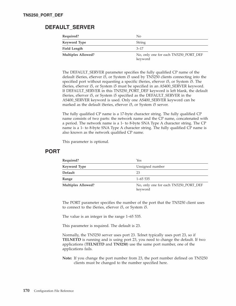
DEFAULT_SERVER
Required? No
Keyword Type String
Field Length 3–17
Multiples Allowed? No, only one for each TN5250_PORT_DEF
keyword
The DEFAULT_SERVER parameter specifies the fully qualified CP name of the
default iSeries, eServer i5, or System i5 used by TN5250 clients connecting into the
specified port without requesting a specific iSeries, eServer i5, or System i5. The
iSeries, eServer i5, or System i5 must be specified in an AS400_SERVER keyword.
If DEFAULT_SERVER in this TN5250_PORT_DEF keyword is left blank, the default
iSeries, eServer i5, or System i5 specified as the DEFAULT_SERVER in the
AS400_SERVER keyword is used. Only one AS400_SERVER keyword can be
marked as the default iSeries, eServer i5, or System i5 server.
The fully qualified CP name is a 17-byte character string. The fully qualified CP
name consists of two parts: the network name and the CP name, concatenated with
a period. The network name is a 1- to 8-byte SNA Type A character string. The CP
name is a 1- to 8-byte SNA Type A character string. The fully qualified CP name is
also known as the network qualified CP name.
This parameter is optional.
PORT
Required? Yes
Keyword Type Unsigned number
Default 23
Range 1–65 535
Multiples Allowed? No, only one for each TN5250_PORT_DEF
keyword
The PORT parameter specifies the number of the port that the TN5250 client uses
to connect to the iSeries, eServer i5, or System i5.
The value is an integer in the range 1–65 535.
This parameter is required. The default is 23.
Normally, the TN5250 server uses port 23. Telnet typically uses port 23, so if
TELNETD is running and is using port 23, you need to change the default. If two
applications (TELNETD and TN5250) use the same port number, one of the
applications fails.
Note: If you change the port number from 23, the port number defined on TN5250
clients must be changed to the number specified here.
TN5250_PORT_DEF
170 Configuration File Reference

SECURITY
Required? Yes
Keyword Type Boolean
Default 0
Multiples Allowed? No, only one for each TN5250_PORT_DEF
keyword
The SECURITY parameter specifies whether security is enabled for TN5250
communication sessions on the specified port. Valid values are:
0 Security is not enabled for TN5250 communication sessions.
1 Security is enabled for TN5250 communication sessions.
This parameter is required. The default is 0.
SECURITY_LEVEL
Required? Yes
Keyword Type Enumerated
Default HIGH
Multiples Allowed? No
The SECURITY_LEVEL parameter specifies the level of security used for the
connection with a client when the SECURITY parameter is specified as
SECURITY=1. Valid values are:
AUTHENTICATION_ONLY
Specifies that certificates to authenticate one or both ends of the
connection are exchanged, but data is not encrypted.
MEDIUM Specifies that Communications Server can establish connections
with any supported level of encryption.
HIGH Specifies that for Communications Servers supporting strong
encryption, the port will only accept connections from clients
supporting strong encryption. For Communications Servers
supporting export encryption only, HIGH is the same as MEDIUM.
This parameter is required. The default is HIGH.
TN5250_PORT_DEF
Chapter 32. TN5250_PORT_DEF 171

172 Configuration File Reference
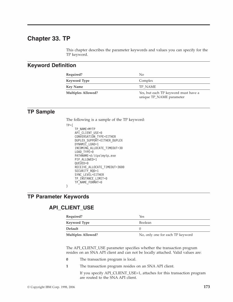
Chapter 33. TP
This chapter describes the parameter keywords and values you can specify for the
TP keyword.
Keyword Definition
Required? No
Keyword Type Complex
Key Name TP_NAME
Multiples Allowed? Yes, but each TP keyword must have a
unique TP_NAME parameter
TP Sample
The following is a sample of the TP keyword:
TP=(
TP_NAME=MYTP
API_CLIENT_USE=0
CONVERSATION_TYPE=EITHER
DUPLEX_SUPPORT=EITHER_DUPLEX
DYNAMIC_LOAD=1
INCOMING_ALLOCATE_TIMEOUT=30
LOAD_TYPE=0
PATHNAME=d:\tps\mytp.exe
PIP_ALLOWED=1
QUEUED=0
RECEIVE_ALLOCATE_TIMEOUT=3600
SECURITY_RQD=1
SYNC_LEVEL=EITHER
TP_INSTANCE_LIMIT=0
TP_NAME_FORMAT=0
)
TP Parameter Keywords
API_CLIENT_USE
Required? Yes
Keyword Type Boolean
Default 0
Multiples Allowed? No, only one for each TP keyword
The API_CLIENT_USE parameter specifies whether the transaction program
resides on an SNA API client and can not be locally attached. Valid values are:
0 The transaction program is local.
1 The transaction program resides on an SNA API client.
If you specify API_CLIENT_USE=1, attaches for this transaction program
are routed to the SNA API client.
© Copyright IBM Corp. 1998, 2006 173
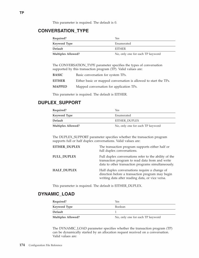
This parameter is required. The default is 0.
CONVERSATION_TYPE
Required? Yes
Keyword Type Enumerated
Default EITHER
Multiples Allowed? No, only one for each TP keyword
The CONVERSATION_TYPE parameter specifies the types of conversation
supported by this transaction program (TP). Valid values are:
BASIC Basic conversation for system TPs.
EITHER Either basic or mapped conversation is allowed to start the TPs.
MAPPED Mapped conversation for application TPs.
This parameter is required. The default is EITHER.
DUPLEX_SUPPORT
Required? Yes
Keyword Type Enumerated
Default EITHER_DUPLEX
Multiples Allowed? No, only one for each TP keyword
The DUPLEX_SUPPORT parameter specifies whether the transaction program
supports full or half duplex conversations. Valid values are:
EITHER_DUPLEX The transaction program supports either half or
full duplex conversations.
FULL_DUPLEX Full duplex conversations refer to the ability of the
transaction program to read data from and write
data to other transaction programs simultaneously.
HALF_DUPLEX Half duplex conversations require a change of
direction before a transaction program may begin
writing data after reading data, or vice versa.
This parameter is required. The default is EITHER_DUPLEX.
DYNAMIC_LOAD
Required? Yes
Keyword Type Boolean
Default 1
Multiples Allowed? No, only one for each TP keyword
The DYNAMIC_LOAD parameter specifies whether the transaction program (TP)
can be dynamically started by an allocation request received on a conversation.
Valid values are:
TP
174 Configuration File Reference
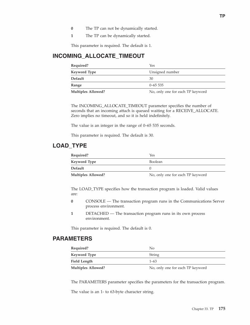
0 The TP can not be dynamically started.
1 The TP can be dynamically started.
This parameter is required. The default is 1.
INCOMING_ALLOCATE_TIMEOUT
Required? Yes
Keyword Type Unsigned number
Default 30
Range 0–65 535
Multiples Allowed? No, only one for each TP keyword
The INCOMING_ALLOCATE_TIMEOUT parameter specifies the number of
seconds that an incoming attach is queued waiting for a RECEIVE_ALLOCATE.
Zero implies no timeout, and so it is held indefinitely.
The value is an integer in the range of 0–65 535 seconds.
This parameter is required. The default is 30.
LOAD_TYPE
Required? Yes
Keyword Type Boolean
Default 0
Multiples Allowed? No, only one for each TP keyword
The LOAD_TYPE specifies how the transaction program is loaded. Valid values
are:
0 CONSOLE — The transaction program runs in the Communications Server
process environment.
1 DETACHED — The transaction program runs in its own process
environment.
This parameter is required. The default is 0.
PARAMETERS
Required? No
Keyword Type String
Field Length 1–63
Multiples Allowed? No, only one for each TP keyword
The PARAMETERS parameter specifies the parameters for the transaction program.
The value is an 1- to 63-byte character string.
TP
Chapter 33. TP 175
This parameter is optional.
The program parameters are the names of the variables in which the logical unit
(LU) places verbs and other program statements that make up the
transaction-processing portion of the program.
PATHNAME
Required? No
Keyword Type String
Field Length 1–255
Multiples Allowed? No, only one for each TP keyword
The PATHNAME parameter specifies the path and transaction program name.
The value is a character string 1–255 bytes in length. The path name cannot
include spaces.
This parameter is optional.
The complete path name describes the location of the program to be executed. The
location may include the drive, the directory, the subdirectory, and the file name.
The special character ″ can not be used.
PIP_ALLOWED
Required? Yes
Keyword Type Boolean
Default 1
Multiples Allowed? No, only one for each TP keyword
The PIP_ALLOWED parameter specifies whether the transaction program can
receive program initialization (PIP) parameters. Valid values are:
0 The transaction program can not receive program initialization (PIP)
parameters.
1 The transaction program can receive program initialization (PIP)
parameters.
This parameter is required. The default is 1.
Program initialization parameters (PIPs) are the names of variables for the remote
transaction programs (TPs). The PIPs are supplied by the allocating program. The
contents of the PIPs have meaning only to the TPs and are not examined or used
by the logical unit (LU).
TP
176 Configuration File Reference

QUEUED
Required? Yes
Keyword Type Boolean
Default 0
Multiples Allowed? No, only one for each TP keyword
The QUEUED parameter specifies whether the transaction program is queued
while waiting for an Attach. Valid values are:
0 The transaction program is not be queued.
1 The transaction program is queued.
This parameter is required. The default is 0.
RECEIVE_ALLOCATE_TIMEOUT
Required? Yes
Keyword Type Unsigned number
Default 3 600
Range 0–65 535
Multiples Allowed? No, only one for each TP keyword
The RECEIVE_ALLOCATE_TIMEOUT parameter specifies the number of seconds
that a RECEIVE_ALLOCATE verb is queued while waiting for an Attach. Zero
implies no timeout, and so it is held indefinitely.
The value is an integer in the range of 0–65 535 seconds.
This parameter is required. The default is 3 600 seconds.
SECURITY_RQD
Required? Yes
Keyword Type Boolean
Default 1
Multiples Allowed? No, only one for each TP keyword
The SECURITY_RQD parameter specifies whether conversation security
information is required to start the transaction program. Valid values are:
0 Conversation security information is not required.
1 Conversation security information is required.
This parameter is required. The default is 1.
Conversation security allows controlled access to system resources through security
parameters associated with a request for access to those resources.
TP
Chapter 33. TP 177

SYNC_LEVEL
Required? Yes
Keyword Type Enumerated
Default EITHER
Multiples Allowed? No, only one for each TP keyword
The SYNC_LEVEL parameter specifies the synchronization levels supported by the
transaction program. The synchronization level is the level allowed on allocation
requests that start the local and remote transaction programs (TPs). Valid values
are:
CONFIRM_SYNC_LEVEL The transaction program supports a
synchronization level of Confirm.
EITHER The transaction program supports a
synchronization level of None or Confirm.
NONE The transaction program supports a
synchronization level of None.
SYNCPT_NEGOTIABLE The transaction program supports a
synchronization level of None, Confirm, or
Sync-point.
SYNCPT_REQUIRED The transaction program supports a
synchronization level of Sync-point.
This parameter is required. The default is EITHER.
TP_INSTANCE_LIMIT
Required? Yes
Keyword Type Unsigned number
Default 0
Range 0–65 535
Multiples Allowed? No, only one for each TP keyword
The TP_INSTANCE_LIMIT parameter specifies the maximum number of
concurrently active TP instances. A value of zero means no limit.
The value is an integer in the range of 0–65 535 instances.
This parameter is required. The default is 0.
TP_NAME
Required? Yes
Keyword Type String
Field Length 1–64
Multiples Allowed? No, only one for each TP keyword
TP
178 Configuration File Reference

The TP_NAME parameter specifies the 1-64 character name of the transaction
program that provides information about how to accept incoming Attaches and
optionally start programs on the workstation. Valid characters are any locally
displayable characters using the native encoding of the local system. The TP name
may also refer to a service transaction program.
This parameter is required.
A transaction program (TP) is a program that uses the advanced
program-to-program communications (APPC) system to communicate with a
partner application program at the partner node.
Service TPs use a restricted character set for their names. A service TP name must
begin with a two-digit hex value between X'00' and X'3D'. The remainder of the
name must be three ASCII characters. For example, 07abc is a valid service TP
name. 7abc is not a valid service TP name.
TP_NAME_FORMAT
Required? Yes
Keyword Type Boolean
Default 0
Multiples Allowed? No, only one for each TP keyword
The TP_NAME_FORMAT parameter specifies whether the TP_NAME value is a
service TP or normal TP. Valid values are:
0 The TP_NAME value is a normal TP.
1 The TP_NAME value is a service TP.
This parameter is required. The default is 0.
TP
Chapter 33. TP 179

180 Configuration File Reference
Chapter 34. USERID_PASSWORD
This chapter describes the parameter keywords and values you can specify for the
USERID_PASSWORD keyword.
Keyword Definition
Required? No
Keyword Type Complex
Key Name USER_ID
Multiples Allowed? Yes, but each USERID_PASSWORD keyword
must have a unique USER_ID parameter
USERID_PASSWORD Sample
The following is a sample of the USERID_PASSWORD keyword:
USERID_PASSWORD=(
USER_ID=MYUSER
PASSWORD=A098C824DC22B856748B
)
USERID_PASSWORD Parameter Keywords
PASSWORD
Required? Yes
Keyword Type Hexadecimal string
Field Length 1–20
Multiples Allowed? No, only one for each USERID_PASSWORD
keyword
The PASSWORD parameter specifies the user password. The password is
converted to a 20-character hexadecimal string by the encryption process.
Note: Since this value is encrypted, you should not attempt to enter this value
directly into the ACG file. The value should only be entered using the SNA
Node Configuration application.
This parameter is required.
USER_ID
Required? Yes
Keyword Type String
Field Length 1–10
Multiples Allowed? No, only one for each USERID_PASSWORD
keyword
© Copyright IBM Corp. 1998, 2006 181

The USER_ID parameter specifies the user identifier.
USER_ID is a 1- to 10-byte SNA Type A character string.
This parameter is required.
USERID_PASSWORD
182 Configuration File Reference
Chapter 35. VERIFY
This chapter describes the parameter keywords and values you can specify for the
VERIFY keyword.
The VERIFY keyword is required for product configuration.
This keyword should not be modified or deleted by the user.
Keyword Definition
Required? Yes
Keyword Type Complex
Multiples Allowed? No
VERIFY Sample
The following is a sample of the VERIFY keyword:
VERIFY=(
CFG_MODIFICATION_LEVEL = 12
CFG_VERSION_LEVEL = 1
)
VERIFY Parameter Keywords
CFG_LAST_SCENARIO
The CFG_LAST_SCENARIO parameter keyword applies to
Communications Server only.
Required? No
Keyword Type Unsigned number
Range 0–20
Multiples Allowed? No
The CFG_LAST_SCENARIO parameter specifies the last configuration scenario
used in the SNA Node Configuration application. When this configuration file is
opened by the application, the initial configuration scenario will be set according
to this value.
The value corresponds to the zero-based index of the scenario name in the
Scenario pull-down on the menu bar of the SNA Node Configuration application.
Note: You should not attempt to enter this value directly into the ACG file. The
value should only be entered by the SNA Node Configuration application.
CFG_LAST_SCENARIO is an integer in the range 0-20.
© Copyright IBM Corp. 1998, 2006 183
This parameter is optional.
CFG_MODIFICATION_LEVEL
Required? No
Keyword Type Unsigned number
Range 0–100
Multiples Allowed? No
The CFG_MODIFICATION_LEVEL parameter value is set when a configuration is
stored and read when a configuration is loaded. If a new version of
Communications Server or Personal Communications reads an older configuration
file (indicated by the combination of this value and the CFG_VERSION_LEVEL
value being less than the current value), the product migrates the configuration to
the new level, if necessary.
Note: You should not attempt to enter this value directly into the ACG file. The
value should only be entered by the SNA Node Configuration application.
CFG_MODIFICATION_LEVEL is an integer in the range 0-100.
This parameter is optional.
CFG_VERSION_LEVEL
Required? No
Keyword Type Unsigned number
Range 0–10
Multiples Allowed? No
The CFG_VERSION_LEVEL parameter value is set when a configuration is stored
and read when a configuration is loaded. If a new version of Communications
Server or Personal Communications reads an older configuration file (indicated by
the combination of this value and the CFG_MODIFICATION_LEVEL value being
less than the current value), the product migrates the configuration to the new
level, if necessary.
Note: You should not attempt to enter this value directly into the ACG file. The
value should only be entered by the SNA Node Configuration application.
CFG_VERSION_LEVEL is an integer in the range 0-10.
This parameter is optional.
VERIFY
184 Configuration File Reference
Appendix A. AnyNet-Specific Data
If you are using the AnyNet DLC, use this appendix to define the keyword
parameters for the LINK_STATION and PORT keywords.
In addition to the keyword parameters for the LINK_STATION and PORT
keywords, you must also define the ANYNET_COMMON_PARAMETERS keyword
described in Appendix H, “ANYNET_COMMON_PARAMETERS,” on page 263.
LINK_STATION Keywords for the AnyNet DLC
The following section describes the parameter keywords you can specify in the
LINK_STATION keyword to use the AnyNet DLC.
DEST_ADDRESS
Required? No
Keyword Type Hexadecimal string
Field Length 0–34
Multiples Allowed? No, only one for each LINK_STATION
keyword
The DEST_ADDRESS parameter specifies the hexadecimal equivalent of either the
adjacent CP name (in EBCDIC) or the node ID. The value of this parameter should
match the type specified by the PARTNER_ADDRESS_TYPE parameter.
This parameter is optional.
LINK_STATION_ANYNET_SPECIFIC_DATA
Required? No
Keyword Type Complex
Multiples Allowed? No, only one for each LINK_STATION
keyword
The LINK_STATION_ANYNET_SPECIFIC_DATA parameter is a complex keyword
comprised of the PARTNER_ADDRESS_TYPE parameter keyword.
See the description of the PARTNER_ADDRESS_TYPE parameter keyword to
define the LINK_STATION_ANYNET_SPECIFIC_DATA parameter.
PARTNER_ADDRESS_TYPE
Required? No
Keyword Type Enumerated
Default USE_CP_NAME
Multiples Allowed? No, only one for each
LINK_STATION_ANYNET_SPECIFIC_
DATA parameter
© Copyright IBM Corp. 1998, 2006 185

The PARTNER_ADDRESS_TYPE parameter specifies how the partner address is
identified.
USE_BLOCK_ID_AND_PU_ID
The partner address is identified by the block ID and PU ID.
USE_CP_NAME
The partner address is identified by the CP name.
This parameter is optional. The default is to use the CP name to identify the
partner address.
PORT Keywords for the AnyNet DLC
The following section describes the parameter keyword you can specify in the
PORT keyword to use the AnyNet DLC.
DLC_NAME
Required? Yes
Keyword Type String
Field Length 1–8
Multiples Allowed? No
The DLC_NAME parameter specifies the 1- to 8-byte name of the communication
adapter or protocol you are using. For the AnyNet DLC, DLC_NAME should be
specified as ANYNET.
This parameter is required.
AnyNet-Specific Data
186 Configuration File Reference

Appendix B. EE-Specific Data
If you are using the Enterprise Extender (EE) DLC, use this appendix to define the
keyword parameters for the LINK_STATION and PORT keywords.
LINK_STATION Keywords for an EE DLC
The following section describes the parameter keywords you can specify in the
LINK_STATION keyword to use the Enterprise Extender (EE) DLC.
LINK_STATION_OEM_SPECIFIC_DATA
Required? No
Keyword Type Complex
Multiples Allowed? No, only one for each LINK_STATION
keyword
The LINK_STATION_OEM_SPECIFIC_DATA parameter is a complex keyword
comprised of the OEM_LINK_DATA parameter keyword.
See the description of the OEM_DATA parameter keyword to define the
LINK_STATION_OEM_SPECIFIC_DATA parameter.
Considerations
The LINK_STATION_OEM_SPECIFIC_DATA parameter defines a link station.
Refer to the following example from a .ACG configuration file:
LINK_STATION_OEM_SPECIFIC_DATA=(
OEM_LINK_DATA=(
OEM_DATA=010000000400000004000000030000000F00000001000000
OEM_DATA=0F000000DE01A8C0
)
)
Take the OEM_DATA fields and concatenate them in order, as follows:
010000000400000004000000030000000F000000010000000F000000DE01A8C0
Then break that into 4-byte words:
01000000
04000000
04000000
03000000
0F000000
01000000
0F000000
DE01A8C0
Reverse the order of the bytes, as follows:
00000001
00000004
00000004
00000003
© Copyright IBM Corp. 1998, 2006 187

0000000F
00000001
0000000F
C0A801DE
The fields are as follows:
00000001: Link Type—only value allowed
00000004: DSAP (Remote SAP)
00000004: SSAP (Local SAP)
00000003: XID retry count (Connect retry count)
0000000F: XID retry timer (Connect timer)
00000001: Reserved
0000000A: Liveness timer (Inactivity timer)
C0A801DE: IP address (Remote IP address)
Notes:
1. All values are in hexadecimal notation.
2. The names in parentheses are the parameter labels in the EEDLC Connection
tab of the EEDLC link station definition in the SNA Node Configuration tool.
3. Other than the IP address, all the values shown are the default values. There is
no default IP address.
4. When you change one of these values in the Node Configuration tool and save
to the .ACG file, the relevant byte of OEM_DATA is changed in the
configuration file.
For the IP address, convert each byte to decimal to obtain the IP address. The
above example converts to 192.168.1.222, as follows:
C0: 192
A8: 168
01: 1
DE: 222
If you enter a host name instead of an IP address, the IP address field becomes the
length of the host name, and the host name (in ASCII hex codes) is appended, with
a trailing 00 byte to mark the end. The bytes of the host name are not swapped.
See the following example:
LINK_STATION_OEM_SPECIFIC_DATA=(
OEM_LINK_DATA=(
OEM_DATA=010000000400000004000000030000000F00000001000000
OEM_DATA=0A000000150000006C6F63616C686F73742E6C6F63616C64
OEM_DATA=6F6D61696E00
)
)
Concatenation produces the following:
010000000400000004000000030000000F000000010000000A000000
150000006C6F63616C686F73742E6C6F63616C646F6D61696E00
Breaking it up into words and swapping bytes (except the host name) produces the
following:
00000001: Link Type—only value allowed
00000004: DSAP (Remote SAP)
00000004: SSAP (Local SAP)
00000003: XID retry count (Connect retry count)
EE-Specific Data
188 Configuration File Reference

0000000F: XID retry timer (Connect timer)
00000001: Reserved
0000000A: Liveness timer (Inactivity timer).
The range of valid values is 1–255 seconds.
6C6F63616C686F73742E6C6F63616C646F6D61696E:
Host name (localhost.localdomain)
00: End of host name marker
OEM_DATA
Required? No
Keyword Type Hexadecimal string
Multiples Allowed? Yes
The OEM_DATA parameter specifies four bytes of data in byte-swapped
hexadecimal format for each of the following values:
Link type
This value is always 1 (X'01').
Remote Service Access Point (SAP) or DSAP
Valid values are X'04'—X'FC'. The value must be a multiple of 4.
Local Service Access Point (SAP) or SSAP
Valid values are X'04'—X'FC'. The value must be a multiple of 4.
XID retry count (limit)
The exchange identification (XID) retry limit is the maximum number of
times Communications Server will send XID commands to the remote
station to establish a link without receiving an acknowledgment from the
remote station in the time set by the XID retry interval. Valid values are 3
to 29 times.
XID retry timer (interval)
The exchange identification (XID) retry interval is the time the link station
waits for a reply to an XID command before sending another XID to the
remote station. The number of times an XID is sent is based on the XID
retry count. Valid values are 1 to 59 seconds.
Liveness mode
This value is always 0 (X'00').
Liveness timer (retry interval)
Liveness timer is the time the link station waits before testing whether the
link is still active. After the specified amount of time elapses, a TEST
command is sent to the remote station to check if the link is still active.
Valid values are 1 to 255 seconds.
Remote Host Name
This is the remote partner’s IP location. You can either enter the IPv6 or
IPv4 name (for example, somesystem or
somesystem.somedomain.somecompany.com) or IPv4 address (for example,
9.37.51.32). To utilize IP name support, you must have DNS enabled in
your TCP/IP configuration.
Data in byte-swapped hexadecimal format is in reverse order of bytes. For
example, the IP address 9.68.43.100 in hexadecimal format is X'09442B64', but in
byte-swapped hexadecimal format is X'642B4409'.
EE-Specific Data
Appendix B. EE-Specific Data 189

Note: Since the format of this data is byte-swapped, it is recommended that the
values only be entered using the Node Configuration application.
This parameter is optional.
OEM_LINK_DATA
Required? No
Keyword Type Complex
Multiples Allowed? No, only one for each
LINK_STATION_OEM_SPECIFIC_DATA
parameter
The OEM_LINK_DATA parameter is a complex keyword comprised of the
OEM_DATA parameter keyword.
See the description of the OEM_DATA parameter keyword to define the
OEM_LINK_DATA parameter.
PORT Keywords for an EE DLC
The following section describes the parameter keywords you can specify in the
PORT keyword to use the Enterprise Extender (EE) DLC.
DLC_NAME
Required? Yes
Keyword Type String
Field Length 1–8
Multiples Allowed? No, only one for each PORT keyword
The DLC_NAME parameter specifies 1- to 8-byte name of the communication
adapter or protocol you are using. For the Enterprise Extender (EE) DLC,
DLC_NAME should be specified as IBMEEDLC.
This parameter is required.
PORT_OEM_SPECIFIC_DATA
Required? No
Keyword Type Complex
Multiples Allowed? No, only one for each PORT keyword
The PORT_OEM_SPECIFIC_DATA parameter is a complex keyword comprised of
the following parameter keywords:
v OEM_LINK_DATA
v OEM_PORT_DATA
v OEM_PORT_DEFAULTS
See the descriptions of the parameter keywords to define the
PORT_OEM_SPECIFIC_DATA parameter.
EE-Specific Data
190 Configuration File Reference

COST_PER_CONNECT_TIME
Required? No
Keyword Type Unsigned number
Range 0–255
Multiples Allowed? No, only one for each PORT keyword
The COST_PER_CONNECT_TIME parameter specifies the cost per connect time.
The value is an integer in the range 0-255.
This parameter is optional.
EFFECTIVE_CAPACITY
Required? No
Keyword Type Unsigned number
Multiples Allowed? No, only one for each PORT keyword
The EFFECTIVE_CAPACITY parameter specifies the actual units of effective
capacity. The value is encoded as a 1-byte floating-point number, represented by
the following formula:
0.1 mmm * 2 eeeee
where the bit representation of the byte is eeeeemmm. Each unit of effective
capacity is equal to 300 bits per second.
This parameter is optional.
INB_LINK_ACT_LIM
Required? No
Keyword Type Unsigned number
Multiples Allowed? No, only one for each PORT keyword
The INB_LINK_ACT_LIM parameter specifies the number of link stations reserved
for inbound activation on this port. The maximum number of outbound link
stations that can be active concurrently is the value of the TOT_LINK_ACT_LIM
parameter minus the value of the INB_LINK_ACT_LIM parameter.
Notes:
1. If the PORT_TYPE on the PORT keyword is specified as NONSWITCHED and
the LINK_STATION_ROLE on the PORT keyword is specified as NEGOTIABLE
or PRIMARY, the INB_LINK_ACT_LIM parameter must be specified as 0.
2. If the PORT_TYPE on the PORT keyword is specified as NONSWITCHED and
the LINK_STATION_ROLE on the PORT keyword is specified as SECONDARY,
the INB_LINK_ACT_LIM parameter must be specified as 0 or 1.
3. If this port is for the AnyNet DLC, the INB_LINK_ACT_LIM parameter must
be specified as 0.
This parameter is optional.
EE-Specific Data
Appendix B. EE-Specific Data 191
OEM_DATA
Required? No
Keyword Type Hexadecimal string
Multiples Allowed? Yes
The OEM_DATA parameter specifies four bytes of data in byte-swapped
hexadecimal format for each of the following values:
Link type
This value is always 1 (X'01').
Remote Service Access Point (SAP) or DSAP
This value is always 0 (X'00').
Local Service Access Point (SAP) or SSAP
This value is always 0 (X'00').
XID retry limit (count)
The exchange identification (XID) retry limit is the maximum number of
times Communications Server will send XID commands to the remote
station to establish a link without receiving an acknowledgment from the
remote station in the time set by the XID retry interval. Valid values are 3
to 29 times.
XID retry interval (timer)
The exchange identification (XID) retry interval is the time the link station
waits for a reply to an XID command before sending another XID to the
remote station. The number of times an XID is sent is based on the XID
retry count. Valid values are 1 to 59 seconds.
Liveness mode
This value is always 0 (X'00').
Liveness retry interval (timer)
Liveness retry interval is the time the link station waits before testing
whether the link is still active. After the specified amount of time elapses, a
TEST command is sent to the remote station to check if the link is still
active. Valid values are 1 to 255 seconds.
Data in byte-swapped hexadecimal format is in reverse order of bytes. For
example, the IP address 9.68.43.100 in hexadecimal format is X'09442B64', but in
byte-swapped hexadecimal format is X'642B4409'.
Note: Since the format of this data is byte-swapped, it is recommended that the
values only be entered using the Node Configuration application.
This parameter is optional.
OEM_LINK_DATA
Required? No
Keyword Type Complex
Multiples Allowed? No, only one for each
PORT_OEM_SPECIFIC_DATA parameter
EE-Specific Data
192 Configuration File Reference
The OEM_LINK_DATA parameter defines the settings for link stations that are
dynamically created when an incoming connection request does not match any
predefined link station definitions.
The OEM_LINK_DATA parameter is a complex keyword comprised of the
OEM_DATA parameter keyword. See the description of the OEM_DATA parameter
keyword to define the OEM_LINK_DATA parameter.
OEM_PORT_DATA
The OEM_PORT_DATA parameter keyword applies to Communications
Server only.
Required? No
Keyword Type Complex
Multiples Allowed? Yes
OEM_PORT_DATA=(
OEM_DATA=00
)
The first byte specifies use of IPv4 host name. Valid values are as follows:
00 An IPv4 hostname is used (default).
01 An IPv4 hostname is not used.
This enables the option to use only IP addresses when establishing
connections; this prevents a DNS lookup, which could introduce a short
delay on some networks.
OEM_PORT_DEFAULTS
Required? No
Keyword Type Complex
Multiples Allowed? No, only one for each
PORT_OEM_SPECIFIC_DATA parameter
The OEM_PORT_DEFAULTS parameter is a complex keyword comprised of the
following parameter keywords:
v COST_PER_CONNECT_TIME
v EFFECTIVE_CAPACITY
v INB_LINK_ACT_LIM
v OUT_LINK_ACT_LIM
v PROPAGATION_DELAY
v SECURITY
v TOT_LINK_ACT_LIM
See the descriptions of the parameter keywords to define the
OEM_PORT_DEFAULTS parameter.
EE-Specific Data
Appendix B. EE-Specific Data 193
OUT_LINK_ACT_LIM
Required? No
Keyword Type Unsigned number
Multiples Allowed? No, only one for each PORT keyword
The OUT_LINK_ACT_LIM parameter specifies the number of link stations
reserved for outbound activation on this port. The maximum number of inbound
link stations that can be active concurrently is the value of the
TOT_LINK_ACT_LIM parameter minus the value of the OUT_LINK_ACT_LIM
parameter.
Notes:
1. If the PORT_TYPE on the PORT keyword is specified as NONSWITCHED and
the LINK_STATION_ROLE on the PORT keyword is specified as
NEGOTIABLE, the OUT_LINK_ACT_LIM parameter must be specified as 0.
2. If the LINK_STATION_ROLE on the PORT keyword is specified as PRIMARY,
the value of the OUT_LINK_ACT_LIM parameter must be specified as equal to
the value of the TOT_LINK_ACT_LIM parameter.
3. If the PORT_TYPE on the PORT keyword is specified as NONSWITCHED and
the LINK_STATION_ROLE on the PORT keyword is specified as SECONDARY,
the OUT_LINK_ACT_LIM parameter must be specified as 0 or 1.
4. If this port is for the AnyNet DLC, the OUT_LINK_ACT_LIM parameter must
be specified as 0.
This parameter is optional.
PROPAGATION_DELAY
Required? No
Keyword Type Enumerated
Multiples Allowed? No, only one for each
PORT_OEM_SPECIFIC_DATA parameter
The PROPAGATION_DELAY parameter specifies the time it takes for a signal to
travel the length of the link, in microseconds. The value is encoded as a 1-byte
floating-point number, represented by the following formula:
0.1 mmm * 2 eeeee
where the bit representation of the byte is eeeeemmm.
Valid values are:
LAN Less than 480 microseconds delay.
MAXIMUM Maximum propagation delay.
MINIMUM No propagation delay.
PKT_SWITCHED_NET Between 49 512 and 245 760 microseconds delay.
SATELLITE Longer than 245 760 microseconds delay.
TELEPHONE Between 480 and 49 512 microseconds delay.
This parameter is optional.
EE-Specific Data
194 Configuration File Reference

SECURITY
Required? No
Keyword Type Enumerated
Multiples Allowed? No, only one for each
PORT_OEM_SPECIFIC_DATA parameter
The SECURITY parameter specifies the type of security used for transmission of
data over the connection. Valid values are:
ENCRYPTED
There is encryption over the line.
GUARDED_CONDUIT
The conduit is protected against physical tapping.
GUARDED_RADIATION
The line is protected against physical and radiation tapping.
NONSECURE
No security exists.
PUBLIC_SWITCHED_NETWORK
Data is transmitted over a public switched network.
SECURE_CONDUIT
The line is a secure conduit that is not guarded.
UNDERGROUND_CABLE
Data is transmitted over a secure underground cable.
This parameter is optional.
TOT_LINK_ACT_LIM
Required? No
Keyword Type Unsigned number
Multiples Allowed? No
The TOT_LINK_ACT_LIM parameter specifies the maximum number of link
stations that can be active concurrently. This must be greater than or equal to the
sum of the INB_LINK_ACT_LIM and OUT_LINK_ACT_LIM parameter values.
Notes:
1. If the PORT_TYPE on the PORT keyword is specified as NONSWITCHED and
the LINK_STATION_ROLE on the PORT keyword is specified as NEGOTIABLE
or SECONDARY, the TOT_LINK_ACT_LIM parameter must be specified as 1.
2. If the LINK_STATION_ROLE on the PORT keyword is specified as PRIMARY,
the TOT_LINK_ACT_LIM parameter must be specified in the range greater
than or equal to 1-256.
3. If this port is for the AnyNet DLC, the TOT_LINK_ACT_LIM parameter must
be specified as 65 535.
This parameter is optional.
EE-Specific Data
Appendix B. EE-Specific Data 195

196 Configuration File Reference
Appendix C. LAN-Specific Data
If you are using the LAN DLC, use this appendix to define the keyword
parameters for the LINK_STATION and PORT keywords.
LINK_STATION Keywords for the LAN DLC
The following section describes the parameter keyword you can specify in the
LINK_STATION keyword to use the LAN DLC.
DEST_ADDRESS
Required? No
Keyword Type Hexadecimal string
Multiples Allowed? No, only one for each LINK_STATION
keyword
The DEST_ADDRESS parameter specifies a 14 byte hexadecimal string comprised
of the 12 byte medium access control (MAC) address concatenated with the two
byte service access point (SAP) address.
This parameter is optional.
PORT Keywords for the LAN DLC
The following section describes the parameter keywords you can specify in the
PORT keyword to use the LAN DLC.
DLC_DATA
Required? No
Keyword Type Hexadecimal string
Multiples Allowed? No, only one for each PORT keyword
The DLC_DATA parameter specifies a 14 byte hexadecimal string comprised of 12
zeros concatenated with the two byte local service access point (SAP) address
specified on the LOCAL_SAP parameter.
This parameter is optional.
DLC_NAME
Required? Yes
Keyword Type String
Field Length 1–8
Multiples Allowed? No, only one for each PORT keyword
© Copyright IBM Corp. 1998, 2006 197
The DLC_NAME parameter specifies 1- to 8-byte name of the communication
adapter or protocol you are using. For the LAN DLC, DLC_NAME should be
specified as LAN.
This parameter is required.
PORT_LAN_SPECIFIC_DATA
Required? No
Keyword Type Complex
Multiples Allowed? No, only one for each PORT keyword
The PORT_LAN_SPECIFIC_DATA parameter is a complex keyword comprised of
the following parameter keywords:
v ACK_DELAY
v ACK_TIMEOUT
v ADAPTER_NUMBER
v BUSY_STATE_TIMEOUT
v IDLE_STATE_TIMEOUT
v INB_LINK_ACT_LIM
v LOCAL_SAP
v MAX_RETRY
v OUT_LINK_ACT_LIM
v OUTSTANDING_TRANSMITS
v POLL_TIMEOUT
v POOL_SIZE
v REJECT_RESPONSE_TIMEOUT
v TEST_RETRY_INTERVAL
v TEST_RETRY_LIMIT
v TOT_LINK_ACT_LIM
v XID_RETRY_INTERVAL
v XID_RETRY_LIMIT
See the descriptions of the parameter keywords to define the
PORT_LAN_SPECIFIC_DATA parameter.
ACK_DELAY
Required? Yes
Keyword Type Unsigned number
Default 100
Range 30–1000
Multiples Allowed? No, only one for each
PORT_LAN_SPECIFIC_DATA parameter
The ACK_DELAY parameter specifies the time that the LAN device withholds a
response to a received frame in order to allow more frames to be received and
acknowledged with the same Request Ready (RR).
LAN-Specific Data
198 Configuration File Reference
ACK_DELAY is an integer in the range 30–1000 milliseconds.
This parameter is required. The default value is 100 milliseconds.
ACK_TIMEOUT
Required? Yes
Keyword Type Unsigned number
Default 10000
Default 3000
Range 500–10000
Multiples Allowed? No, only one for each
PORT_LAN_SPECIFIC_DATA
parameter
The ACK_TIMEOUT parameter specifies the time that a station should wait for an
acknowledgment from a remote station after sending data.
ACK_TIMEOUT is an integer in the range 500–10000 milliseconds. The
default is 10000 milliseconds.
ACK_TIMEOUT is an integer in the range 500–10000 milliseconds. The
default is 3000 milliseconds.
This parameter is required.
ADAPTER_NUMBER
Required? Yes
Keyword Type Unsigned number
Range 0–7
Range 0–7 or 9 999
Multiples Allowed? No, only one for each
PORT_LAN_SPECIFIC_DATA
parameter
The ADAPTER_NUMBER parameter uniquely identifies this adapter.
ADAPTER_NUMBER is an integer in the range 0–7.
LAN-Specific Data
Appendix C. LAN-Specific Data 199
ADAPTER_NUMBER is an integer in the range 0–7 or 9 999. The value
9 999 indicates that the first available LAN adapter will be used.
This parameter is required.
If you are creating a configuration to be exported to another Communications
Server system, you can select any adapter number for this definition.
BUSY_STATE_TIMEOUT
Required? Yes
Keyword Type Unsigned number
Default 15
Range 10–60
Multiples Allowed? No, only one for each
PORT_LAN_SPECIFIC_DATA parameter
The BUSY_STATE_TIMEOUT parameter specifies the time that the local node waits
for the remote node to exit a busy state. A busy state is entered when there is not
enough memory to receive the incoming frames; the incoming frames are rejected.
When resources are freed, the node exits the busy state.
BUSY_STATE_TIMEOUT is an integer in the range 10-60 seconds.
This parameter is required. The default value is 15.
IDLE_STATE_TIMEOUT
Required? Yes
Keyword Type Unsigned number
Default 30
Range 10–120
Multiples Allowed? No, only one for each
PORT_LAN_SPECIFIC_DATA parameter
The IDLE_STATE_TIMEOUT parameter specifies the time that the LAN device
driver waits for a frame to be received before declaring the link to be inoperative.
IDLE_STATE_TIMEOUT is an integer in the range 10-120 seconds.
This parameter is required. The default value is 30 seconds.
INB_LINK_ACT_LIM
The INB_LINK_ACT_LIM parameter keyword applies to
Communications Server only.
LAN-Specific Data
200 Configuration File Reference
Required? No
Keyword Type Unsigned number
Default 128
Range 0–255
Multiples Allowed? No, only one for each PORT keyword
The INB_LINK_ACT_LIM parameter specifies the number of link stations reserved
for inbound activation on this port. The maximum number of outbound link
stations that can be active concurrently is the value of the TOT_LINK_ACT_LIM
parameter minus the value of the INB_LINK_ACT_LIM parameter.
Note: If the PORT_TYPE on the PORT keyword is specified as NONSWITCHED
and the LINK_STATION_ROLE on the PORT keyword is specified as
PRIMARY, the INB_LINK_ACT_LIM parameter must be specified as 0.
This parameter is optional.
LOCAL_SAP
Required? Yes
Keyword Type Hexadecimal number
Default X'04'
Range X'04'–X'FC'
Multiples Allowed? No, only one for each
PORT_LAN_SPECIFIC_DATA parameter
The LOCAL_SAP parameter specifies the local service access point (SAP) number
of the local port. The value must be a multiple of 4.
LOCAL_SAP is a hexadecimal value in the range X'04'–X'FC'.
This parameter is required. The default value is X'04'.
MAX_RETRY
Required? Yes
Keyword Type Unsigned number
Default 10
Range 1–127
Multiples Allowed? No, only one for each
PORT_LAN_SPECIFIC_DATA parameter
The MAX_RETRY parameter specifies the number of times a frame is resent while
waiting for the remote device to respond. When a frame is sent to the remote
device with the POLL bit set, the local device waits the amount of time specified
for the POLL_TIMEOUT parameter for the remote device to respond. If the
timeout expires, the frame is resent and the timeout is reset. This occurs the
number of times specified by MAX_RETRY.
This parameter is required. The default value is 10 retries.
LAN-Specific Data
Appendix C. LAN-Specific Data 201
OUT_LINK_ACT_LIM
The OUT_LINK_ACT_LIM parameter keyword applies to
Communications Server only.
Required? No
Keyword Type Unsigned number
Default 127
Range 1–255
Multiples Allowed? No, only one for each PORT keyword
The OUT_LINK_ACT_LIM parameter specifies the number of link stations
reserved for outbound activation on this port. The maximum number of inbound
link stations that can be active concurrently is the value of the
TOT_LINK_ACT_LIM parameter minus the value of the OUT_LINK_ACT_LIM
parameter.
Note: If the LINK_STATION_ROLE on the PORT keyword is specified as
PRIMARY, the value of the OUT_LINK_ACT_LIM parameter must be
specified as equal to the value of the TOT_LINK_ACT_LIM parameter.
This parameter is optional.
OUTSTANDING_TRANSMITS
Required? Yes
Keyword Type Unsigned number
Default 16
Range 2–64
Multiples Allowed? No, only one for each
PORT_LAN_SPECIFIC_DATA parameter
The OUTSTANDING_TRANSMITS parameter specifies the maximum number of
frames the LAN device queues to a link station before sending a Receive Not
Ready (RNR) to the adjacent link station.
OUTSTANDING_TRANSMITS is an integer in the range 2-64 frames.
This parameter is required. The default value is 16 frames.
LAN-Specific Data
202 Configuration File Reference

POLL_TIMEOUT
Required? Yes
Keyword Type Unsigned number
Default 8000
Default 3000
Range 500–10000
Multiples Allowed? No, only one for each
PORT_LAN_SPECIFIC_DATA
parameter
The POLL_TIMEOUT parameter specifies the time that the LAN device waits for a
response to a frame sent with the POLL bit set.
POLL_TIMEOUT is an integer in the range 500–10000 milliseconds.
The default is 8000 milliseconds.
The default is 3000 milliseconds.
This parameter is required.
POOL_SIZE
Required? Yes
Keyword Type Unsigned number
Default 32
Range 2–64
Multiples Allowed? No, only one for each
PORT_LAN_SPECIFIC_DATA parameter
The POOL_SIZE parameter specifies the number of buffers that are reserved in
memory to hold data received from the host until it can be processed. Each buffer
is the size of the PIU.
POOL_SIZE is an integer in the range 2-64 buffers.
This parameter is required. The default value is 32 buffers.
LAN-Specific Data
Appendix C. LAN-Specific Data 203
REJECT_RESPONSE_TIMEOUT
Required? Yes
Keyword Type Unsigned number
Default 10
Range 5–30
Multiples Allowed? No, only one for each
PORT_LAN_SPECIFIC_DATA parameter
The REJECT_RESPONSE_TIMEOUT parameter specifies the time that the LAN
device waits to receive a response to an REJ frame.
REJECT_RESPONSE_TIMEOUT is an integer in the range 5–30 seconds.
This parameter is required. The default value is 10 seconds.
TEST_RETRY_INTERVAL
Required? Yes
Keyword Type Unsigned number
Default 8
Range 5–30
Range 5–60
Multiples Allowed? No, only one for each
PORT_LAN_SPECIFIC_DATA
parameter
The TEST_RETRY_INTERVAL parameter specifies the time between attempts to
find the adjacent link station on the local area network (LAN). The number of
attempts made are based on the value specified for the TEST_RETRY_LIMIT
parameter.
TEST_RETRY_INTERVAL is an integer in the range 5-30 seconds.
TEST_RETRY_INTERVAL is an integer in the range 5-60 seconds.
This parameter is required. The default value is 8 seconds.
LAN-Specific Data
204 Configuration File Reference
TEST_RETRY_LIMIT
Required? Yes
Keyword Type Unsigned number
Default 5
Range 3–30
Multiples Allowed? No, only one for each
PORT_LAN_SPECIFIC_DATA parameter
The TEST_RETRY_LIMIT parameter specifies the maximum number of attempts to
find the adjacent link station on the local area network (LAN) without receiving an
acknowledgment in the time set by the value for the TEST_RETRY_INTERVAL
parameter.
TEST_RETRY_LIMIT is an integer in the range 3-30 attempts.
This parameter is required. The default value is 5 attempts.
TOT_LINK_ACT_LIM
The TOT_LINK_ACT_LIM parameter keyword applies to
Communications Server only.
Required? No
Keyword Type Unsigned number
Default 255
Range 1–255
Multiples Allowed? No, only one for each PORT keyword
The TOT_LINK_ACT_LIM parameter specifies the maximum number of link
stations that can be active concurrently. This must be greater than or equal to the
sum of the INB_LINK_ACT_LIM and OUT_LINK_ACT_LIM parameter values.
Note: If the PORT_TYPE on the PORT keyword is specified as NONSWITCHED
and the LINK_STATION_ROLE on the PORT keyword is specified as
NEGOTIABLE or SECONDARY, the TOT_LINK_ACT_LIM parameter must
be specified in the range greater than or equal to 1-255.
This parameter is optional.
XID_RETRY_INTERVAL
Required? Yes
Keyword Type Unsigned number
Default 8
Range 5–60
Multiples Allowed? No, only one for each
PORT_LAN_SPECIFIC_DATA parameter
LAN-Specific Data
Appendix C. LAN-Specific Data 205

The XID_RETRY_INTERVAL parameter specifies the time the link station waits for
a reply to an XID command before sending another XID to the remote station. The
number of times an XID is sent is based on the value specified on the
XID_RETRY_LIMIT parameter.
XID_RETRY_INTERVAL is an integer in the range 5-60 seconds.
This parameter is required. The default value is 8 seconds.
XID_RETRY_LIMIT
Required? Yes
Keyword Type Unsigned number
Default 5
Range 3–30
Multiples Allowed? No, only one for each
PORT_LAN_SPECIFIC_DATA parameter
The XID_RETRY_LIMIT parameter specifies the maximum number of times
Communications Server or Personal Communications sends XID commands to the
remote station to establish a link, without receiving an acknowledgment from the
remote station in the time specified for the XID_RETRY_INTERVAL parameter.
XID_RETRY_LIMIT is an integer in the range 3-30 times.
This parameter is required. The default value is 5 times.
LAN-Specific Data
206 Configuration File Reference

Appendix D. OEM-Specific Data
If you are using an OEM DLC, use this appendix to define the keyword
parameters for the LINK_STATION and PORT keywords.
LINK_STATION Keywords for an OEM DLC
The following section describes the parameter keywords you can specify in the
LINK_STATION keyword to use an OEM DLC.
DEST_ADDRESS
Required? No
Keyword Type Hexadecimal string
Field Length 0–34
Multiples Allowed? No, only one for each LINK_STATION
keyword
The DEST_ADDRESS parameter specifies the necessary addressing information to
contact a remote node over this DLC. The value is a 0- to 34-byte hexadecimal
character string. This addressing information is manufacturer-specific.
This parameter is optional.
LINK_STATION_OEM_SPECIFIC_DATA
Required? No
Keyword Type Complex
Multiples Allowed? No, only one for each LINK_STATION
keyword
The LINK_STATION_OEM_SPECIFIC_DATA parameter is a complex keyword
comprised of the OEM_LINK_DATA parameter keyword.
See the description of OEM_DATA to define the
LINK_STATION_OEM_SPECIFIC_DATA parameter.
Considerations
The LINK_STATION_OEM_SPECIFIC_DATA parameter defines a link station.
Refer to the following example from a .ACG configuration file:
LINK_STATION_OEM_SPECIFIC_DATA=(
OEM_LINK_DATA=(
OEM_DATA=010000000400000004000000030000000F00000001000000
OEM_DATA=0F000000DE01A8C0
)
)
Take the OEM_DATA fields and concatenate them in order, as follows:
010000000400000004000000030000000F000000010000000F000000DE01A8C0
© Copyright IBM Corp. 1998, 2006 207

Then break that into 4-byte words:
01000000
04000000
04000000
03000000
0F000000
01000000
0F000000
DE01A8C0
Reverse the order of the bytes, as follows:
00000001
00000004
00000004
00000003
0000000F
00000001
0000000F
C0A801DE
The fields are as follows:
00000001: Link Type—only value allowed
00000004: DSAP (Remote SAP)
00000004: SSAP (Local SAP)
00000003: XID retry count (Connect retry count)
0000000F: XID retry timer (Connect timer)
00000001: Reserved
0000000A: Liveness timer (Inactivity timer)
C0A801DE: IP address (Remote IP address)
Notes:
1. All values are in hexadecimal notation.
2. The names in parentheses are the parameter labels in the EEDLC Connection
tab of the EEDLC link station definition in the SNA Node Configuration tool.
3. Other than the IP address, all the values shown are the default values. There is
no default IP address.
4. When you change one of these values in the Node Configuration tool and save
to the .ACG file, the relevant byte of OEM_DATA is changed in the
configuration file.
For the IP address, convert each byte to decimal to obtain the IP address. The
above example converts to 192.168.1.222, as follows:
C0: 192
A8: 168
01: 1
DE: 222
If you enter a host name instead of an IP address, the IP address field becomes the
length of the host name, and the host name (in ASCII hex codes) is appended, with
a trailing 00 byte to mark the end. The bytes of the host name are not swapped.
See the following example:
LINK_STATION_OEM_SPECIFIC_DATA=(
OEM_LINK_DATA=(
OEM_DATA=010000000400000004000000030000000F00000001000000
OEM-Specific Data
208 Configuration File Reference
OEM_DATA=0A000000150000006C6F63616C686F73742E6C6F63616C64
OEM_DATA=6F6D61696E00
)
)
Concatenation produces the following:
010000000400000004000000030000000F000000010000000A000000
150000006C6F63616C686F73742E6C6F63616C646F6D61696E00
Breaking it up into words and swapping bytes (except the host name) produces the
following:
00000001: Link Type—only value allowed
00000004: DSAP (Remote SAP)
00000004: SSAP (Local SAP)
00000003: XID retry count (Connect retry count)
0000000F: XID retry timer (Connect timer)
00000001: Reserved
0000000A: Liveness timer (Inactivity timer).
The range of valid values is 1–255 seconds.
6C6F63616C686F73742E6C6F63616C646F6D61696E:
Host name (localhost.localdomain)
00: End of host name marker
OEM_DATA
Required? No
Keyword Type Hexadecimal string
Multiples Allowed? Yes
The OEM_DATA parameter specifies binary information specific for the OEM card
manufacturer’s use only. Communications Server or Personal Communications
supports the use of OEM communications devices where the OEM manufacturer
provides its own configuration panels. More than one OEM_DATA parameter
might appear in the ASCII configuration file.
Note: Since the format of this binary data is very specific to the OEM device, you
should not attempt to enter this value directly into the ACG file. The value
should only be entered using the configuration application provided by the
OEM manufacturer.
This parameter is optional.
OEM_LINK_DATA
Required? No
Keyword Type Complex
Multiples Allowed? No, only one for each
LINK_STATION_OEM_SPECIFIC DATA
parameter
The OEM_LINK_DATA parameter is a complex keyword comprised of the
OEM_DATA parameter keyword.
OEM-Specific Data
Appendix D. OEM-Specific Data 209

See the description of the OEM_DATA parameter keyword to define the
OEM_LINK_DATA parameter.
PORT Keywords for an OEM DLC
The following section describes the parameter keywords you can specify in the
PORT keyword to use an OEM DLC.
DLC_DATA
Required? No
Keyword Type Hexadecimal string
Field Length 1–32
Multiples Allowed? No, only one for each PORT keyword
The DLC_DATA parameter specifies information that is manufacturer-specific. The
value is a 1- to 32-byte hexadecimal character string.
This parameter is optional.
DLC_NAME
Required? Yes
Keyword Type String
Field Length 1–8
Multiples Allowed? No, only one each PORT keyword
The DLC_NAME parameter specifies the 1- to 8-byte character name of the
communication adapter or protocol you are using.
For OEM devices, DLC_NAME is manufacturer-specific.
This parameter is required.
PORT_OEM_SPECIFIC_DATA
Required? No
Keyword Type Complex
Multiples Allowed? No, only one for each PORT keyword
The PORT_OEM_SPECIFIC_DATA parameter is a complex keyword comprised of
the following parameter keywords:
v OEM_LINK_DATA
v OEM_PORT_DATA
v OEM_PORT_DEFAULTS
See the descriptions of the parameter keywords to define the
PORT_OEM_SPECIFIC_DATA parameter.
OEM-Specific Data
210 Configuration File Reference
COST_PER_CONNECT_TIME
Required? No
Keyword Type Unsigned number
Range 0–255
Multiples Allowed? No, only one for each PORT keyword
The COST_PER_CONNECT_TIME parameter specifies the cost per connect time.
The value is an integer in the range 0-255.
This parameter is optional.
EFFECTIVE_CAPACITY
Required? No
Keyword Type Unsigned number
Multiples Allowed? No, only one for each PORT keyword
The EFFECTIVE_CAPACITY parameter specifies the actual units of effective
capacity. The value is encoded as a 1-byte floating-point number, represented by
the following formula:
0.1 mmm * 2 eeeee
where the bit representation of the byte is eeeeemmm. Each unit of effective
capacity is equal to 300 bits per second.
This parameter is optional.
INB_LINK_ACT_LIM
Required? No
Keyword Type Unsigned number
Multiples Allowed? No, only one for each PORT keyword
The INB_LINK_ACT_LIM parameter specifies the number of link stations reserved
for inbound activation on this port. The maximum number of outbound link
stations that can be active concurrently is the value of the TOT_LINK_ACT_LIM
parameter minus the value of the INB_LINK_ACT_LIM parameter.
Notes:
1. If the PORT_TYPE on the PORT keyword is specified as NONSWITCHED and
the LINK_STATION_ROLE on the PORT keyword is specified as NEGOTIABLE
or PRIMARY, the INB_LINK_ACT_LIM parameter must be specified as 0.
2. If the PORT_TYPE on the PORT keyword is specified as NONSWITCHED and
the LINK_STATION_ROLE on the PORT keyword is specified as SECONDARY,
the INB_LINK_ACT_LIM parameter must be specified as 0 or 1.
3. If this port is for the AnyNet DLC, the INB_LINK_ACT_LIM parameter must
be specified as 0.
This parameter is optional.
OEM-Specific Data
Appendix D. OEM-Specific Data 211
OEM_DATA
Required? No
Keyword Type Hexadecimal string
Multiples Allowed? Yes
The OEM_DATA parameter specifies binary information specific for the OEM card
manufacturer’s use only. Communications Server or Personal Communications
supports the use of OEM communications devices where the OEM manufacturer
provides its own configuration panels. More than one OEM_DATA parameter
might appear in the ASCII configuration file.
Note: Since the format of this binary data is very specific to the OEM device, you
should not attempt to enter this value directly into the ACG file. The value
should only be entered using the configuration application provided by the
OEM manufacturer.
This parameter is optional.
OEM_LINK_DATA
Required? No
Keyword Type Complex
Multiples Allowed? No, only one for each
PORT_OEM_SPECIFIC_DATA parameter
The OEM_LINK_DATA parameter defines the settings for link stations that are
dynamically created when an incoming connection request does not match any
predefined link station definitions.
The OEM_LINK_DATA parameter is a complex keyword comprised of the
OEM_DATA parameter keyword. See the description of the OEM_DATA parameter
keyword to define the OEM_LINK_DATA parameter.
OEM_PORT_DATA
The OEM_PORT_DATA parameter keyword applies to Communications
Server only.
Required? No
Keyword Type Complex
Multiples Allowed? Yes
OEM_PORT_DATA=(
OEM_DATA=00
)
The first byte specifies use of IPv4 host name. Valid values are as follows:
00 An IPv4 hostname is used (default).
01 An IPv4 hostname is not used.
OEM-Specific Data
212 Configuration File Reference

This enables the option to use only IP addresses when establishing
connections; this prevents a DNS lookup, which could introduce a short
delay on some networks.
OEM_PORT_DEFAULTS
Required? No
Keyword Type Complex
Multiples Allowed? No, only one for each
PORT_OEM_SPECIFIC_DATA parameter
The OEM_PORT_DEFAULTS parameter is a complex keyword comprised of the
following parameter keywords:
v COST_PER_CONNECT_TIME
v EFFECTIVE_CAPACITY
v INB_LINK_ACT_LIM
v OUT_LINK_ACT_LIM
v PROPAGATION_DELAY
v SECURITY
v TOT_LINK_ACT_LIM
See the descriptions of the parameter keywords to define the
OEM_PORT_DEFAULTS parameter.
OUT_LINK_ACT_LIM
Required? No
Keyword Type Unsigned number
Multiples Allowed? No, only one for each PORT keyword
The OUT_LINK_ACT_LIM parameter specifies the number of link stations
reserved for outbound activation on this port. The maximum number of inbound
link stations that can be active concurrently is the value of the
TOT_LINK_ACT_LIM parameter minus the value of the OUT_LINK_ACT_LIM
parameter.
Notes:
1. If the PORT_TYPE on the PORT keyword is specified as NONSWITCHED and
the LINK_STATION_ROLE on the PORT keyword is specified as
NEGOTIABLE, the OUT_LINK_ACT_LIM parameter must be specified as 0.
2. If the LINK_STATION_ROLE on the PORT keyword is specified as PRIMARY,
the value of the OUT_LINK_ACT_LIM parameter must be specified as equal to
the value of the TOT_LINK_ACT_LIM parameter.
3. If the PORT_TYPE on the PORT keyword is specified as NONSWITCHED and
the LINK_STATION_ROLE on the PORT keyword is specified as SECONDARY,
the OUT_LINK_ACT_LIM parameter must be specified as 0 or 1.
4. If this port is for the AnyNet DLC, the OUT_LINK_ACT_LIM parameter must
be specified as 0.
This parameter is optional.
OEM-Specific Data
Appendix D. OEM-Specific Data 213
PROPAGATION_DELAY
Required? No
Keyword Type Enumerated
Multiples Allowed? No, only one for each PORT keyword
The PROPAGATION_DELAY parameter specifies the time it takes for a signal to
travel the length of the link, in microseconds. The value is encoded as a 1-byte
floating-point number, represented by the following formula:
0.1 mmm * 2 eeeee
where the bit representation of the byte is eeeeemmm.
Valid values are:
LAN Less than 480 microseconds delay.
MAXIMUM Maximum propagation delay.
MINIMUM No propagation delay.
PKT_SWITCHED_NET Between 49 512 and 245 760 microseconds delay.
SATELLITE Longer than 245 760 microseconds delay.
TELEPHONE Between 480 and 49 512 microseconds delay.
This parameter is optional.
SECURITY
Required? No
Keyword Type Enumerated
Multiples Allowed? No, only one for each PORT keyword
The SECURITY parameter specifies the type of security used for transmission of
data over the connection. Valid values are:
ENCRYPTED
There is encryption over the line.
GUARDED_CONDUIT
The conduit is protected against physical tapping.
GUARDED_RADIATION
The line is protected against physical and radiation tapping.
NONSECURE
No security exists.
PUBLIC_SWITCHED_NETWORK
Data is transmitted over a public switched network.
SECURE_CONDUIT
The line is a secure conduit that is not guarded.
UNDERGROUND_CABLE
Data is transmitted over a secure underground cable.
This parameter is optional.
OEM-Specific Data
214 Configuration File Reference

TOT_LINK_ACT_LIM
Required? No
Keyword Type Unsigned number
Multiples Allowed? No, only one for each PORT keyword
The TOT_LINK_ACT_LIM parameter specifies the maximum number of link
stations that can be active concurrently. This must be greater than or equal to the
sum of the INB_LINK_ACT_LIM and OUT_LINK_ACT_LIM parameter values.
Notes:
1. If the PORT_TYPE on the PORT keyword is specified as NONSWITCHED and
the LINK_STATION_ROLE on the PORT keyword is specified as NEGOTIABLE
or SECONDARY, the TOT_LINK_ACT_LIM parameter must be specified as 1.
2. If the LINK_STATION_ROLE on the PORT keyword is specified as PRIMARY,
the TOT_LINK_ACT_LIM parameter must be specified in the range greater
than or equal to 1-256.
3. If this port is for the AnyNet DLC, the TOT_LINK_ACT_LIM parameter must
be specified as 65 535.
This parameter is optional.
OEM-Specific Data
Appendix D. OEM-Specific Data 215

216 Configuration File Reference

Appendix E. SDLC-Specific Data
If you are using the SDLC DLC, use this appendix to define the keyword
parameters for the LINK_STATION and PORT keywords.
LINK_STATION Keywords for the SDLC DLC
The following section describes the parameter keywords you can specify in the
LINK_STATION keyword to use the SDLC DLC.
DEST_ADDRESS
Required? No
Keyword Type Hexadecimal string
Multiples Allowed? No, only one for each LINK_STATION
keyword
The DEST_ADDRESS parameter specifies the link station address.
The value is a 2 byte hexadecimal character string.
This parameter is optional.
LINK_STATION_SDLC_SPECIFIC_DATA
Required? No
Keyword Type Complex
Multiples Allowed? No, only one for each LINK_STATION
keyword
The LINK_STATION_SDLC_SPECIFIC_DATA parameter is a complex keyword
comprised of the following parameter keywords:
v BACKUP_PHONE_NUMBER
v CONNECT_RETRY_COUNT
v CONNECT_TIMER
v FRAMING_STANDARD
v INACTIVITY_TIMER
v PORT_SPEED
v PRIMARY_PHONE_NUMBER
v RESPONSE_RETRY_COUNT
v RESPONSE_TIMER
v USE_NRZI_ENCODING
See the descriptions of the parameter keywords to define the
LINK_STATION_SDLC_SPECIFIC_DATA parameter.
© Copyright IBM Corp. 1998, 2006 217
BACKUP_PHONE_NUMBER
Required? No
Keyword Type String
Field Length 1–62
Multiples Allowed? No, only one for each
LINK_STATION_SDLC_SPECIFIC_DATA
parameter
The BACKUP_PHONE_NUMBER parameter specifies the 1- to 62-character phone
number used as the backup phone number.
This parameter is optional.
CONNECT_RETRY_COUNT
Required? No
Keyword Type Unsigned number
Default 10
Range 0–127
Multiples Allowed? No, only one for each
LINK_STATION_SDLC_SPECIFIC_DATA
parameter
The CONNECT_RETRY_COUNT parameter is used with CONNECT_TIMER
parameter to allow enough time for the receipt of an exchange identifier (XID)
response from the secondary link station. This is needed if the local link station is
specified or negotiated as primary. The link activation fails if no XID response is
received from the secondary station for the interval (CONNECT_TIMER value
times CONNECT_RETRY_COUNT value).
The value is an integer in the range 0-127 retries.
This parameter is optional. The default is 10.
CONNECT_TIMER
Required? No
Keyword Type Unsigned number
Default 2
Range 1–30
Multiples Allowed? No, only one for each
LINK_STATION_SDLC_SPECIFIC_DATA
parameter
The CONNECT_TIMER parameter is used with the CONNECT_RETRY_COUNT
parameter to allow enough time for the receipt of an exchange identifier (XID)
response from the secondary link station. This is needed if the local link station is
specified or negotiated as primary. The link activation fails if no XID response is
received from the secondary station for the interval (CONNECT_TIMER value
times CONNECT_RETRY_COUNT value).
SDLC-Specific Data
218 Configuration File Reference
The value is an integer in the range 1-30 seconds.
This parameter is optional. The default is 2 seconds.
FRAMING_STANDARD
Required? No
Keyword Type Enumerated
Default SNA_OVER_ASYNC
Multiples Allowed? No, only one for each
LINK_STATION_SDLC_SPECIFIC_DATA
parameter
The FRAMING_STANDARD parameter specifies the framing options that support
the medium access control (MAC) function for COM port devices. The type of
standards that can be specified are:
ADVANTIS SDLC over asynchronous communications when
connecting with Advantis (IIN).
HAYES AUTOSYNC SDLC over asynchronous communications via a
Hayes AutoSync modem
SNA_OVER_ASYNC Synchronous data link control (SDLC) over
asynchronous communications, as in the
International Organization for Standardization
(ISO) Standard 3309.
This parameter is optional. The default is SNA_OVER_ASYNC
INACTIVITY_TIMER
Required? No
Keyword Type Unsigned number
Default 80
Range 40–160
Multiples Allowed? No, only one for each
LINK_STATION_SDLC_SPECIFIC_DATA
parameter
The INACTIVITY_TIMER parameter specifies the amount of time before the link is
disconnected when the secondary link station has not received a poll. The
inactivity timer is only used when the link station role is specified or negotiated as
primary.
The value is an integer in the range 40-160 seconds.
This parameter is optional. The default is 80 seconds.
SDLC-Specific Data
Appendix E. SDLC-Specific Data 219

PORT_SPEED
Required? No
Keyword Type Unsigned number
Default 57 600
Range 2 400–115 200
Multiples Allowed? No, only one for each
LINK_STATION_SDLC_SPECIFIC_DATA
parameter
The PORT_SPEED parameter specifies the serial port speed supported by the
device used for the connection.
The value is an integer in the range 2 400–115 200 bits per second (bps).
This parameter is optional. The default is 57 600.
If the highest carrier speed of your modem is 14 400 bps, specify a port speed of
57 600 bps or lower. If the highest carrier speed is 28 800 bps or higher, specify a
port speed of 115 200 to use the maximum compression capabilities for the
modem. A port speed of 115 200 bps is recommended for systems with Pentium®
processors.
PRIMARY_PHONE_NUMBER
Required? No
Keyword Type String
Field Length 1–62
Multiples Allowed? No, only one for each
LINK_STATION_SDLC_SPECIFIC_DATA
parameter
The PRIMARY_PHONE_NUMBER parameter specifies the 1- to 62-character phone
number used as the primary phone number.
This parameter is optional.
RESPONSE_RETRY_COUNT
Required? No
Keyword Type Unsigned number
Default 10
Range 1–127
Multiples Allowed? No, only one for each
LINK_STATION_SDLC_SPECIFIC_DATA
parameter
The RESPONSE_RETRY_COUNT parameter is used with the RESPONSE_TIMER
parameter to help maintain the link connection to the secondary link station. The
retry count is only used when the link station role is specified or negotiated as
SDLC-Specific Data
220 Configuration File Reference

primary. The link is disconnected when no response is received from the secondary
station for the interval (RESPONSE_TIMER parameter value times
RESPONSE_RETRY_COUNT value).
The value is an integer in the range 1-127 retries.
This parameter is optional. The default is 10.
RESPONSE_TIMER
Required? No
Keyword Type Unsigned number
Default 4
Range 2–20
Multiples Allowed? No, only one for each
LINK_STATION_SDLC_SPECIFIC_DATA
parameter
The RESPONSE_TIMER parameter is used with the RESPONSE_RETRY_COUNT
parameter to help maintain the link connection to the secondary link station. The
response timer is only used when the link station role is specified or negotiated as
primary. The link is disconnected if no response is received from the secondary
station for the interval (RESPONSE_TIMER value times
RESPONSE_RETRY_COUNT value).
The value is an integer in the range 2-20 seconds.
This parameter is optional. The default is 4 seconds.
USE_NRZI_ENCODING
Required? No
Keyword Type Boolean
Default 0
Multiples Allowed? No, only one for each
LINK_STATION_SDLC_SPECIFIC_DATA
parameter
The USE_NRZI_ENCODING specifies how synchronous data sent to the modem is
encoded. Valid values are:
0 Use non-return-to-zero (NRZ) encoding.
1 Use non-return-to-zero inverted (NRZI) encoding.
This parameter is optional. The default is 0.
PORT Keywords for the SDLC DLC
The following section describes the parameter keywords you can specify in the
PORT keyword to use the SDLC DLC.
SDLC-Specific Data
Appendix E. SDLC-Specific Data 221
DLC_DATA
Required? No
Keyword Type Hexadecimal string
Multiples Allowed? No, only one for each
PORT_SDLC_SPECIFIC_DATA parameter
The DLC_DATA parameter specifies the link station address.
The value is a 2 byte hexadecimal character string in the range of X'00'–X'FF'.
This parameter is optional. The default address is X'C1'.
If the LINK_STATION_ROLE parameter on the PORT or LINK_STATION keyword
is specified as PRIMARY, this value is forced to X'FF'.
If the LINK_STATION_ROLE parameter on the PORT or LINK_STATION keyword
is specified as SECONDARY, this value is forced to X'00'.
DLC_NAME
Required? Yes
Keyword Type String
Field Length 1–8
Multiples Allowed? No, only one for each PORT keyword
The DLC_NAME parameter specifies the 1- to 8-byte name of the communication
adapter or protocol you are using. For the SDLC DLC, DLC_NAME should be
specified as SDLC.
This parameter is required.
PORT_SDLC_SPECIFIC_DATA
Required? No
Keyword Type Complex
Multiples Allowed? No, only one for each PORT keyword
The PORT_SDLC_SPECIFIC_DATA parameter is a complex keyword comprised of
the following parameter keywords:
v ACCEPT_INCOMING_CALLS
v CONNECT_RETRY_COUNT
v CONNECT_TIMER
v DUMB_CARD_INTERFACE
v FRAMING_STANDARD
v FULL_DUPLEX_SUPPORT
v INACTIVITY_TIMER
v IRQ_LEVEL
v MODEM_NAME
SDLC-Specific Data
222 Configuration File Reference

v MULTIDROP_PRIMARY_SERVER
v OEM_DATA
v OEM_PORT_DATA
v PORT_SPEED
v RESPONSE_RETRY_COUNT
v RESPONSE_TIMER
v SHARED_RAM_ADDRESS
v STATION_POLL_COUNT
v TRANSMISSION_FLAGS
v USE_CONSTANT_RTS
v USE_NRZI_ENCODING
See the descriptions of the parameter keywords to define the
PORT_SDLC_SPECIFIC_DATA parameter.
ACCEPT_INCOMING_CALLS
Required? Yes
Keyword Type Boolean
Default 0
Multiples Allowed? No, only one for each
PORT_SDLC_SPECIFIC_DATA parameter
The ACCEPT_INCOMING_CALLS parameter specifies whether Communications
Server or Personal Communications is able to accept calls from other computers.
Valid values are:
0 The product is not able to accept calls from other computers.
1 The product is able to accept calls from other computers.
This parameter is required. The default is 0.
If you allow the product to accept incoming calls through a COM port, it has
exclusive use of the port when you start the configuration. If you want another
program to use this port, you must stop Communications Server or Personal
Communications to stop the COM port device. (Merely closing the session using
the port is not enough, because that does not stop the COM port devices.)
CONNECT_RETRY_COUNT
Required? Yes
Keyword Type Unsigned number
Default 10
Range 0–127
Multiples Allowed? No, only one for each
PORT_SDLC_SPECIFIC_DATA parameter
The CONNECT_RETRY_COUNT parameter is used with CONNECT_TIMER
parameter to allow enough time for the receipt of an exchange identifier (XID)
response from the secondary link station. This is needed if the local link station is
specified or negotiated as primary. The link activation fails if no XID response is
SDLC-Specific Data
Appendix E. SDLC-Specific Data 223
received from the secondary station for the interval (CONNECT_TIMER value
times CONNECT_RETRY_COUNT value).
The value is an integer in the range 0-127 retries.
This parameter is required. The default is 10.
CONNECT_TIMER
Required? Yes
Keyword Type Unsigned number
Default 2
Range 1–30
Multiples Allowed? No, only one for each
PORT_SDLC_SPECIFIC_DATA parameter
The CONNECT_TIMER parameter is used with the CONNECT_RETRY_COUNT
parameter to allow enough time for the receipt of an exchange identifier (XID)
response from the secondary link station. This is needed if the local link station is
specified or negotiated as primary. The link activation fails if no XID response is
received from the secondary station for the interval (CONNECT_TIMER value
times CONNECT_RETRY_COUNT value).
The value is an integer in the range 1-30 seconds.
This parameter is optional. The default is 2 seconds.
DUMB_CARD_INTERFACE
The DUMB_CARD_INTERFACE parameter keyword applies to
Communications Server only.
Required? Yes
Keyword Type Boolean
Default 0
Multiples Allowed? No, only one for each
PORT_SDLC_SPECIFIC_DATA parameter
The DUMB_CARD_INTERFACE parameter specifies whether the OEM
communications device uses the Microsoft® SNA Server synchronous dumb card
interface. Communications Server supports the use of OEM communications
devices where the OEM manufacturer provides its own configuration panels. Valid
values are:
0 The OEM communications device does not use the Microsoft SNA Server
synchronous dumb card interface. The device uses the shallow interface
provided by Communications Server.
1 The OEM communications device uses the Microsoft SNA Server
synchronous dumb card interface.
Note: This value should only be entered using the configuration application
provided by the OEM manufacturer.
SDLC-Specific Data
224 Configuration File Reference
This parameter is required. The default is 0.
FRAMING_STANDARD
Required? Yes
Keyword Type Enumerated
Default SNA_OVER_ASYNC
Multiples Allowed? No, only one for each
PORT_SDLC_SPECIFIC_DATA parameter
The FRAMING_STANDARD parameter specifies the framing options that support
the medium access control (MAC) function for COM port devices. The type of
standards that can be specified are:
ADVANTIS SDLC over asynchronous communications when
connecting with Advantis (IIN).
HAYES AUTOSYNC SDLC over asynchronous communications via a
Hayes AutoSync modem
SNA_OVER_ASYNC Synchronous data link control (SDLC) over
asynchronous communications, as in the
International Organization for Standardization
(ISO) Standard 3309.
This parameter is required. The default is SNA_OVER_ASYNC
FULL_DUPLEX_SUPPORT
Required? Yes
Keyword Type Boolean
Default 0
Multiples Allowed? No, only one for each
PORT_SDLC_SPECIFIC_DATA parameter
The FULL_DUPLEX_SUPPORT parameter specifies whether this transaction
program supports full duplex conversations. Valid values are:
0 The transaction program does not support full duplex conversations.
1 The transaction program supports full duplex conversations.
This parameter is required. The default is 0.
Full duplex conversations refer to the ability of the transaction program to read
data from and write data to other transaction programs simultaneously. Half
duplex conversations require a change of direction before a transaction program
may begin writing data after reading data, or vice versa. If you specify a 1, the
transaction program supports either full duplex or half duplex conversations. If
you specify a 0, the transaction program may only support half duplex
conversations.
SDLC-Specific Data
Appendix E. SDLC-Specific Data 225

INACTIVITY_TIMER
Required? Yes
Keyword Type Unsigned number
Default 80
Range 40–160
Multiples Allowed? No, only one for each
PORT_SDLC_SPECIFIC_DATA parameter
The INACTIVITY_TIMER parameter specifies the amount of time before the link is
disconnected when the secondary link station has not received a poll. The
inactivity timer is only used when the link station role is specified or negotiated as
primary.
The value is an integer in the range 40-160 seconds.
This parameter is required. The default is 80 seconds.
IRQ_LEVEL
Required? Yes
Keyword Type Unsigned number
Default 3
Range 2–15
Multiples Allowed? No, only one for each
PORT_SDLC_SPECIFIC_DATA parameter
The IRQ_LEVEL parameter (interrupt request level) specifies the IRQ level used to
send or receive data frames to and from the device. Select a value that matches the
installed adapter.
The value is an integer in the range 2-15.
Select a value that matches the IRQ level value specified on the installed adapter
card.
This parameter is required. The default is 3.
This option only applies to industry standard architecture (ISA) adapters. For the
synchronous data link control (SDLC) ISA adapters, the value must be 3. For the
Multiprotocol adapter (MPA) for ISA adapters, the value can be set to 3 or 4.
MODEM_NAME
Required? No
Keyword Type String
Field Length 1–256
Multiples Allowed? No, only one for each
PORT_SDLC_SPECIFIC_DATA parameter
SDLC-Specific Data
226 Configuration File Reference
The MODEM_NAME parameter specifies the 1- to 256-character name of the
modem as defined to the operating system. A PORT keyword passes this name to
the communications port device driver, which can use this name to open the
modem device and initialize it.
Note: Since the Node Configuration application produces a list of available
modems from which to choose, you should not attempt to enter this value
directly into the ACG file.
The value is a 1-256 character string.
This parameter is optional.
MULTIDROP_PRIMARY_SERVER
Required? Yes
Keyword Type Boolean
Default 0
Multiples Allowed? No, only one for each
PORT_SDLC_SPECIFIC_DATA parameter
The MULTIDROP_PRIMARY_SERVER parameter specifies whether this server is a
multidrop primary server. Valid values are:
0 This server is not a multidrop primary server.
1 This server is a multidrop primary server.
This parameter is required. The default is 0.
A multidrop primary server allows an SNA node (Gateway, Network and HPR
node) to support multiple SDLC secondary PUs with one physical leased line. This
support helps to minimize operating costs by reducing the number of lines and
hardware required to connect to downstream PUs. The support requires the use of
multidrop modems with a configuration of one master and multiple slaves. The
primary must be set to use constant RTS while the secondaries must use switched
RTS. A modified round robin polling algorithm is used. The polling algorithm
consists of an active list (stations which responded to a poll) and an inactive list.
Stations from the active list are polled round robin a user-specified number of
times before a station is polled from the inactive list. Stations are rotated on the
inactive list after each unsuccessful poll.
OEM_DATA
The OEM_DATA parameter keyword applies to Communications Server
only.
Required? No
Keyword Type Hexadecimal string
Multiples Allowed? Yes
The OEM_DATA parameter specifies binary information specific for the OEM card
manufacturer’s use only. Communications Server supports the use of OEM
SDLC-Specific Data
Appendix E. SDLC-Specific Data 227
communications devices where the OEM manufacturer provides its own
configuration panels. More than one OEM_DATA parameter might appear in the
ASCII configuration file.
Note: Since the format of this binary data is very specific to the OEM device, you
should not attempt to enter this value directly into the ACG file. The value
should only be entered using the configuration application provided by the
OEM manufacturer.
This parameter is optional.
OEM_PORT_DATA
The OEM_PORT_DATA parameter keyword applies to Communications
Server only.
Required? No
Keyword Type Complex
Multiples Allowed? Yes
The OEM_PORT_DATA parameter is a complex keyword comprised of the
OEM_DATA parameter keyword.
See the description of the OEM_DATA parameter keyword to define the
OEM_PORT_DATA parameter.
PORT_SPEED
Required? Yes
Keyword Type Unsigned number
Default 57 600
Range 2 400–115 200
Multiples Allowed? No, only one for each
PORT_SDLC_SPECIFIC_DATA parameter
The PORT_SPEED parameter specifies the serial port speed supported by the
device used for the connection.
The value is an integer in the range 2 400–115 200 bits per second (bps).
This parameter is required. The default is 57 600.
If the highest carrier speed of your modem is 14 400 bps, specify a port speed of
57 600 bps or lower. If the highest carrier speed is 28 800 bps or higher, specify a
port speed of 115 200 to use the maximum compression capabilities for the
modem. A port speed of 115 200 bps is recommended for systems with Pentium
processors.
SDLC-Specific Data
228 Configuration File Reference

RESPONSE_RETRY_COUNT
Required? Yes
Keyword Type Unsigned number
Default 10
Range 1–127
Multiples Allowed? No, only one for each
PORT_SDLC_SPECIFIC_DATA parameter
The RESPONSE_RETRY_COUNT parameter is used with the RESPONSE_TIMER
parameter to help maintain the link connection to the secondary link station. The
retry count is only used when the link station role is specified or negotiated as
primary. The link is disconnected when no response is received from the secondary
station for the interval (RESPONSE_TIMER parameter value times
RESPONSE_RETRY_COUNT value).
The value is an integer in the range 1-127 retries.
This parameter is required. The default is 10.
RESPONSE_TIMER
Required? Yes
Keyword Type Unsigned number
Default 4
Range 2–20
Multiples Allowed? No, only one for each
PORT_SDLC_SPECIFIC_DATA parameter
The RESPONSE_TIMER parameter is used with the RESPONSE_RETRY_COUNT
parameter to help maintain the link connection to the secondary link station. The
response timer is only used when the link station role is specified or negotiated as
primary. The link is disconnected if no response is received from the secondary
station for the interval (RESPONSE_TIMER value times
RESPONSE_RETRY_COUNT value).
The value is an integer in the range 2-20 seconds.
This parameter is required. The default is 4 seconds.
SHARED_RAM_ADDRESS
Required? No
Keyword Type Hexadecimal number
Range X'C0000'–X'FC000'
Multiples Allowed? No, only one for each
PORT_SDLC_SPECIFIC_DATA parameter
The SHARED_RAM_ADDRESS parameter specifies the address in memory at
which the 16K buffer used by the adapter starts.
SDLC-Specific Data
Appendix E. SDLC-Specific Data 229
The value is a hexadecimal character string in the range X'C0000'–X'FC000'.
This parameter is optional.
If you are using an industry standard architecture (ISA) adapter, you must specify
the shared RAM address. If you are using an IBM Micro Channel adapter, the
shared RAM address is determined automatically.
STATION_POLL_COUNT
Required? No
Keyword Type Unsigned number
Default 1
Range 1–10
Multiples Allowed? No, only one for each
PORT_SDLC_SPECIFIC_DATA parameter
The STATION_POLL_COUNT parameter specifies the number of times an active
station is polled in the context of the polling list before a station from the inactive
list is polled.
The value is an integer in the range 1-10 polls.
This parameter is optional. The default is 1 poll.
TRANSMISSION_FLAGS
Required? Yes
Keyword Type Unsigned number
Default 1
Range 1–10
Multiples Allowed? No, only one for each
PORT_SDLC_SPECIFIC_DATA parameter
The TRANSMISSION_FLAGS parameter specifies the minimum number of flags
inserted to produce idle time between transmitted frames.
A flag is the time it takes to send one byte, and represents a delay between frames.
The values are 1, 3, 4, 6, and 10. Change this parameter to a value other than 1 if
the device at the other end of the communication link can not receive frames with
only one intervening flag.
This parameter is required. The default is 1 flag.
USE_CONSTANT_RTS
Required? Yes
Keyword Type Boolean
Default 1
Multiples Allowed? No, only one for each
PORT_SDLC_SPECIFIC_DATA parameter
SDLC-Specific Data
230 Configuration File Reference
The USE_CONSTANT_RTS (request-to-send) parameter specifies whether flow
control is used between an adapter and the modem. Valid values are:
0 The adapter waits for the CTS (clear-to-send) signal before sending data to
the modem.
1 There is no flow control to the modem.
This parameter is required. The default is 1.
By default, for a synchronous data link control (SDLC) connection, constant RTS is
specified. When this local station is a secondary link station on a multidrop
connection, constant RTS should not be specified.
USE_NRZI_ENCODING
Required? Yes
Keyword Type Boolean
Default 0
Multiples Allowed? No, only one for each
PORT_SDLC_SPECIFIC_DATA parameter
The USE_NRZI_ENCODING specifies how synchronous data sent to the modem is
encoded. Valid values are:
0 Use non-return-to-zero (NRZ) encoding.
1 Use non-return-to-zero inverted (NRZI) encoding.
This parameter is required. The default is 0.
SDLC-Specific Data
Appendix E. SDLC-Specific Data 231

232 Configuration File Reference

Appendix F. Twinaxial-Specific Data
If you are using the twinaxial DLC, use this appendix to define the keyword
parameters for the LINK_STATION and PORT keywords.
LINK_STATION Keywords for the Twinaxial DLC
The following section describes the parameter keyword you can specify in the
LINK_STATION keyword to use the twinaxial DLC.
DEST_ADDRESS
Required? No
Keyword Type Hexadecimal number
Range X'00'–X'06'
Multiples Allowed? No, only one for each LINK_STATION
keyword
The DEST_ADDRESS parameter specifies the TDLC station address.
The value is a 1-byte hexadecimal character string in the range of X'00'–X'06'.
This parameter is optional.
PORT Keywords for the Twinaxial DLC
The following section describes the parameter keywords you can specify in the
PORT keyword to use the twinaxial DLC.
DLC_NAME
Required? Yes
Keyword Type String
Field Length 1–8
Multiples Allowed? No, only one for each PORT keyword
The DLC_NAME parameter specifies the 1- to 8-byte name of the communication
adapter or protocol you are using. For the twinaxial DLC, DLC_NAME should be
specified as TWINAX.
This parameter is required.
PORT_TWINAX_SPECIFIC_DATA
Required? No
Keyword Type Complex
Multiples Allowed? No, only one for each LINK_STATION
keyword
© Copyright IBM Corp. 1998, 2006 233
The PORT_TWINAX_SPECIFIC_DATA parameter is a complex keyword comprised
of the following parameter keywords:
v ADAPTER_TYPE
v IO_ADDRESS
v IRQ_LEVEL
v MEMORY_ADDRESS
See the descriptions of the parameter keywords to define the
PORT_TWINAX_SPECIFIC_DATA parameter.
ADAPTER_TYPE
Required? Yes
Keyword Type Enumerated
Default NONE
Multiples Allowed? No, only one for each
PORT_TWINAX_SPECIFIC_DATA
The ADAPTER_TYPE parameter specifies the type of adapter to be used for
twinaxial communication. Valid values are:
IBM_5250_EXPRESS_ISA_ADAPTER
IBM_5250_EXPRESS_PCI_ADAPTER
NONE
OTHER_TWINAX_ADAPTER
SYSTEM_36_WORKSTATION_EMULATION_ADAPTER_A
5250_AT_COMMUNICATION_ADAPTER
5250_EMULATION_ADAPTER_A
5250_EMULATION_PCI_ADAPTER
5250E_DISPLAY_STATION_EMULATION_ADAPTER
IBM_5250_EXPRESS_PC_CARD
5250_EMULATION_PCMCIA_ADAPTER
5250_PCMCIA_ADAPTER_CARD
This parameter is required. The default is NONE.
If you choose OTHER_TWINAX_ADAPTER, the product assumes that the
necessary software for the adapter is installed. If it is not, you receive an error
message when you start the session.
Twinaxial-Specific Data
234 Configuration File Reference
IO_ADDRESS
Required? No
Keyword Type Hexadecimal number
Default X'271A'
Range X'240A'–X'27FA'
Multiples Allowed? No, only one for each
PORT_TWINAX_SPECIFIC_DATA
The IO_ADDRESS parameter must be set for the following adapters:
v IBM Enhanced 5250 Display Station Emulation Adapter
v IBM 5250 AT-Bus Communication Adapter
The value is a hexadecimal address in the range X'240A'–X'27FA'.
This parameter is optional. The default is X'271A'.
IRQ_LEVEL
Required? No
Keyword Type Unsigned number
Default 5
Range 3–7
Multiples Allowed? No, only one for each
PORT_TWINAX_SPECIFIC_DATA
The IRQ_LEVEL parameter must be set for the following adapters:
v IBM Enhanced 5250 Display Station Emulation Adapter
v IBM 5250 AT-Bus Communication Adapter
The value is an integer in the range 3-7. Select a value that matches the IRQ level
value specified on the installed adapter card.
This parameter is optional. The default is 5.
MEMORY_ADDRESS
Required? No
Keyword Type Hexadecimal number
Default X'DC000'
Range X'C0000'–X'DC000'
Multiples Allowed? No, only one for each
PORT_TWINAX_SPECIFIC_DATA parameter
The MEMORY_ADDRESS parameter specifies the location of the shared
workstation memory used by this adapter. The IRQ_LEVEL parameter must be set
for the following adapters:
v IBM Enhanced 5250 Display Station Emulation Adapter
v IBM 5250 AT-Bus Communication Adapter
Twinaxial-Specific Data
Appendix F. Twinaxial-Specific Data 235

The value is a hexadecimal address in the range X'C0000'–X'DC000'. Check your
adapter documentation for details on how to select the memory address.
This parameter is optional. The default is X'DC000'.
Twinaxial-Specific Data
236 Configuration File Reference

Appendix G. X.25-Specific Data
If you are using the X.25 DLC, use this appendix to define the keyword parameters
for the LINK_STATION and PORT keywords.
LINK_STATION Keywords for the X.25 DLC
The following section describes the parameter keywords you can specify in the
LINK_STATION keyword to use the X.25 DLC.
LINK_STATION_X25_SPECIFIC_DATA
Required? No
Keyword Type Complex
Multiples Allowed? Yes
The LINK_STATION_X25_SPECIFIC_DATA parameter is a complex keyword
comprised of the following parameter keywords:
v ADDITIONAL_FACILITIES
v CALL_USER_GROUP_FORMAT
v CALL_USER_GROUP_INDEX
v CONNECTION_ID
v CONNECTION_TYPE
v LOGICAL_CHANNEL_NUMBER
v NETWORK_USER_ID
v PACKET_SIZE
v REMOTE_CONFORMANCE
v REQUEST_REVERSE_CHARGING
v WINDOW_SIZE
v X25_DESTINATION_ADDRESS
See the descriptions of the parameter keywords to define the
LINK_STATION_X25_SPECIFIC_DATA parameter.
ADDITIONAL_FACILITIES
Required? No
Keyword Type Hexadecimal string
Field Length 1–110
Multiples Allowed? No, only one for each
LINK_STATION_X25_SPECIFIC_DATA
parameter
The ADDITIONAL_FACILITIES parameter describes the other X.25 optional
facilities that apply to this directory entry. To determine which facilities you can
specify, refer to the information that you received from the network supplier when
© Copyright IBM Corp. 1998, 2006 237

you subscribed to the network. The CCITT X.25 Recommendation also provides
general information about the network facilities and their hexadecimal format
(facility codes, etc.).
The value is a 1- to 110-byte hexadecimal character string.
This parameter is optional.
Type 1- to 109-bytes of information for each X.25 optional facility in hexadecimal
format (0-9, A-F). Do not enclose the information in single quotation marks. To
specify more than one facility, keep typing without separating the information with
a comma or blank.
If you are using a network user ID for this terminal and the ID contains
nonstandard ASCII characters, you need to enter the network user ID in this field
in hex format. Type the following information:
v 06 for the facility code
v Number of characters in the network user ID
v Network user ID
CALL_USER_GROUP_FORMAT
Required? No
Keyword Type Enumerated
Multiples Allowed? Yes, only one for each
LINK_STATION_X25_SPECIFIC_DATA
parameter
The CALL_USER_GROUP_FORMAT parameter describes the type of closed user
group subscription assigned to the terminal by the network supplier. This
parameter is also referred to as the Closed User Group Format. The value you select
is the one provided by the network supplier when you subscribed to the network.
Valid values are:
BASIC The terminal can only use index names in the range of 00–99.
EXTENDED The terminal can use index names in the range of 0 000–9 999.
NONE No closed user group (CUG) is requested.
This parameter is optional.
CALL_USER_GROUP_INDEX
Required? No
Keyword Type String
Field Length 1–6
Multiples Allowed? No, only one for each
LINK_STATION_X25_SPECIFIC_DATA
parameter
The CALL_USER_GROUP_INDEX parameter is the index closed user group (CUG)
supplied by the provider. The value of the CUG index depends on the closed
group (CUG) format selected.
X.25-Specific Data
238 Configuration File Reference

The value is a 1- to 6-byte character string.
This parameter is optional.
CONNECTION_ID
Required? No
Keyword Type Hexadecimal string
Field Length 1–16
Multiples Allowed? No, only one for each
LINK_STATION_X25_SPECIFIC_DATA
parameter
The CONNECTION_ID parameter permits IBM SNA X.25 DTEs to accept or reject
incoming calls based on its content.
The value is a 1- to 16-byte hexadecimal character string, specified in eight octets.
This parameter is optional.
The following rules apply to the use of the optional CID:
1. Some IBM SNA X.25 DTEs may not support the CID.
2. For IBM SNA X.25 DTEs that do support a CID, its use is optional on a per call
basis at the discretion of the user.
3. IBM SNA X.25 DTEs that support CIDs may reject incoming calls by
transferring a CLEAR_REQUEST with the appropriate diagnostic code when
the CID does not compare with the one that is expected.
CONNECTION_TYPE
Required? No
Keyword Type Enumerated
Default PVC
Multiples Allowed? No, only one for each
LINK_STATION_X25_SPECIFIC_DATA
parameter
The CONNECTION_TYPE parameter specifies the connection type this directory
entry uses. Valid values are:
PVC This directory entry uses permanent virtual circuit (PVC).
SVC This directory entry uses switched virtual circuit (SVC).
This parameter is optional. The default is PVC.
DTE_ADDRESS
Required? No
Keyword Type String
Field Length 1–16
Multiples Allowed? No, only one for each
X25_DESTINATION_ADDRESS parameter
X.25-Specific Data
Appendix G. X.25-Specific Data 239
The DTE_ADDRESS parameter specifies the address that was assigned to your
data terminal equipment (DTE) when you subscribed to the network. The remote
DTE address is the X.25 network address of the remote DTE your workstation
communicates with. Each DTE link to an X.25 network is identified by its DTE
address. The DTE address identifies an X.25 DTE uniquely throughout the world.
It includes a 3-digit country code and a national terminal number (NTN). The first
four digits of the DTE address contain the data network identification code (DNIC)
that defines the country and the service within that country. The first three digits
of the DNIC identify the country code, followed by a one-digit number for the
service.
The value is a 1- to 16-byte character string.
This parameter is optional.
Note: The data identification code is not always required. For example, you can
omit the data identification code for local calls or for a private network that
uses its own addressing method. Some networks do not use the full 15
digits when assigning DTE addresses. In this case, you can use the
remaining digits as a suffix for your own purposes, such as routing calls to
different applications, according to the suffix of the local DTE address of a
caller.
DTE_ADDRESS_EXTENSION
Required? No
Keyword Type String
Field Length 1–42
Multiples Allowed? No, only one for each
X25_DESTINATION_ADDRESS parameter
The DTE_ADDRESS_EXTENSION parameter specifies the X.25 network address
extension of the remote DTE your workstation communicates with. The address
extension is an optional CCITT-specified DTE facility which may be used for a
given call. It provides for the transparent conveyance in CALL REQUEST and
INCOMING CALL packets of all or part of the Network Services Access Point
(NSAP) address.
The value is a 1- to 42-byte character string.
This parameter is optional.
The X.25 local DTE address extension was assigned to your data terminal
equipment (DTE) when you subscribed to the network.
LOGICAL_CHANNEL_NUMBER
Required? No
Keyword Type Unsigned number
Range 0–60000
Multiples Allowed? No, only one for each
LINK_STATION_X25_SPECIFIC_DATA
parameter
X.25-Specific Data
240 Configuration File Reference

The LOGICAL_CHANNEL_NUMBER parameter specifies the number of the PVC
to be used for this connection. The number you type must be in the range of
logical channel numbers reserved for PVCs.
The value is an integer in the range 0–60000.
This parameter is optional.
NETWORK_USER_ID
Required? No
Keyword Type Hexadecimal string
Field Length 1–42
Multiples Allowed? No, only one for each
LINK_STATION_X25_SPECIFIC_DATA
parameter
The NETWORK_USER_ID parameter enables the transmitting data terminal
equipment (DTE) to provide billing, security, or management information on a
per-call basis to the data circuit terminating equipment. The value that you type in
this field is the one provided by the network supplier when you subscribed to the
network. If the terminal subscription from the network supplier includes a network
user ID in standard ASCII characters, type the ID. If the network user ID contains
non-standard ASCII characters, type the ID using the ADDITIONAL_FACILITIES
parameter.
The value is a 1- to 42-byte character string
This parameter is optional.
PACKET_SIZE
Required? No
Keyword Type Unsigned number
Default 128
Range 16–4 096
Multiples Allowed? No, only one for each
LINK_STATION_X25_SPECIFIC_DATA
parameter
The PACKET_SIZE parameter refers to the length of user data in a data packet.
The value that you select should be the value that was agreed upon when you
subscribed to the network.
If your network complies with the 1980 or 1984 CCITT recommendation, the
agreed-upon size is one of the following: 16, 32, 64, 128, 256, 512, 1 024.
If your network complies with the 1988 CCITT recommendation, the agreed-upon
size is one of the following: 16, 32, 64, 128, 256, 512, 1 024, 2 048, or 4 096.
The value is an integer in the range 16–4 096.
This parameter is optional. The default is 128.
X.25-Specific Data
Appendix G. X.25-Specific Data 241
REMOTE_CONFORMANCE
Required? No
Keyword Type Enumerated
Default 1984_COMPLIANCE
Multiples Allowed? No, only one for each
LINK_STATION_X25_SPECIFIC_DATA
parameter
The REMOTE_CONFORMANCE parameter specifies the level of CCITT
(International Telegraph and Telephone Consultative Committee) compliance. Valid
values are:
v USE_ADAPTER_DEFAULTS
v 1980_COMPLIANCE
v 1984_COMPLIANCE
v 1988_COMPLIANCE
v 1980_COMPLIANCE
v 1984_COMPLIANCE
v 1988_COMPLIANCE
This parameter is optional. The default is 1984_COMPLIANCE.
The CCITT recommendations define the protocols to be used for information
exchange at each interface between data terminal equipment (DTE) and data
circuit-terminating equipment (DCE) on a packet-switching data network.
Warning: If you change the year from 1984 or 1988 to 1980, you can encounter
communications problems if you have used packet sizes larger than 1024. The 1984
and 1988 CCITT X.25 recommendations allow some enhancements that are not
supported or defined in the 1980 recommendation.
REQUEST_REVERSE_CHARGING
Required? No
Keyword Type Boolean
Default 0
Multiples Allowed? No, only one for each
LINK_STATION_X25_SPECIFIC_DATA
parameter
The REQUEST_REVERSE_CHARGING parameter specifies whether the cost of the
call is assigned to the remote (calling) data terminal equipment (DTE). Valid values
are:
0 The cost of the call is not assigned to the remote (calling) data terminal
equipment (DTE).
1 The cost of the call is assigned to the remote (calling) data terminal
equipment (DTE).
This parameter is optional. The default is 0.
X.25-Specific Data
242 Configuration File Reference
WINDOW_SIZE
Required? No
Keyword Type Unsigned number
Default 2
Range 1–127
Multiples Allowed? No, only one for each
LINK_STATION_X25_SPECIFIC_DATA
parameter
The WINDOW_SIZE parameter specifies the number of frames that can be sent or
received on a virtual circuit without acknowledgment.
The value is an integer in the range 1-127.
This parameter is optional. The default is 2.
X25_DESTINATION_ADDRESS
Required? No
Keyword Type Complex
Multiples Allowed? Yes, with a maximum of eight
The X25_DESTINATION_ADDRESS parameter is a complex keyword comprised of
the following parameter keywords:
v DTE_ADDRESS
v DTE_ADDRESS_EXTENSION
See the descriptions of the parameter keywords to define the
X25_DESTINATION_ADDRESS parameter.
PORT Keywords for the X.25 DLC
The following section describes the parameter keywords you can specify in the
PORT keyword to use the X.25 DLC.
DLC_DATA
Required? No
Keyword Type Hexadecimal string
Field Length 1–32
Multiples Allowed? No, only one for each PORT keyword
The DLC_DATA parameter specifies the 1- to 32-byte local data terminal
equipment (DTE) address in hexadecimal format.
This parameter is optional.
X.25-Specific Data
Appendix G. X.25-Specific Data 243

DLC_NAME
Required? Yes
Keyword Type String
Field Length 1–8
Multiples Allowed? No, only one for each PORT keyword
The DLC_NAME parameter specifies the 1- to 8-byte communication adapter or
protocol you are using. For the X.25 DLC, DLC_NAME should be specified as X25.
This parameter is required.
PORT_X25_SPECIFIC_DATA
Required? No
Keyword Type Complex
Multiples Allowed? Yes
The PORT_X25_SPECIFIC_DATA parameter is a complex keyword comprised of
the following parameter keywords:
v ACCEPT_CHARGES
v ACCEPT_INCOMING_CALLS
v ALTERNATE_REMOTE_PHONE_NUMBER
v COMPLIANCE
v DEFAULT_WINDOW_SIZE
v DIAL_TYPE
v DTE_ADDRESS
v DTE_ADDRESS_EXTENSION
v DUMB_CARD_INTERFACE
v FRAME_INACTIVITY_TIMEOUT
v FRAME_RETRANSMISSION_TIMEOUT
v FRAME_SEQUENCE
v FRAME_TRANSMISSION_RETRY_COUNT
v FRAME_WINDOW_SIZE
v INCOMING_CALL_FILTER
v INSERT_CALLING_ADDRESS
v IN_ONLY_SVC_COUNT
v IN_ONLY_SVC_START
v LOCAL_DTE_ADDRESS
v MAX_PIU_SIZE
v MODEM_NAME
v NETWORK_CONNECTION_TYPE
v OEM_PORT_DATA
v OUT_ONLY_SVC_COUNT
v OUT_ONLY_SVC_START
v PACKET_SIZE
X.25-Specific Data
244 Configuration File Reference
v PORT_SPEED
v PVC_COUNT
v PVC_START
v REMOTE_PHONE_NUMBER
v SEQUENCING
v SHARED_RAM_ADDRESS
v TRANSMISSION_FLAGS
v TWO_WAY_SVC_COUNT
v TWO_WAY_SVC_START
v USE_CONSTANT_RTS
v USE_NRZI_ENCODING
v USE_X32_PROTOCOL
v X32_IDENTITY
v X32_SIGNATURE
See the descriptions of the parameter keywords to define the
PORT_X25_SPECIFIC_DATA parameter.
ACCEPT_CHARGES
Required? No
Keyword Type Boolean
Default 0
Multiples Allowed? No, only one for each
INCOMING_CALL_FILTER parameter
The ACCEPT_CHARGES parameter specifies whether charges from a calling user
are accepted. If the calling user requests Reverse Charges, the filter defined for that
user must be set to accept reverse charges. Valid values are:
0 The cost of the call are assigned to the remote (calling) data terminal
equipment (DTE).
1 The cost of the call are not assigned to the remote (calling) data terminal
equipment (DTE).
This parameter is optional. The default is 0.
ACCEPT_INCOMING_CALLS
Required? No
Keyword Type Boolean
Default 0
Multiples Allowed? No, only one for each
PORT_X25_SPECIFIC_DATA parameter
The ACCEPT_INCOMING_CALLS parameter specifies whether Communications
Server or Personal Communications is able to accept calls from other computers.
Valid values are:
0 The product is not able to accept calls from other computers.
X.25-Specific Data
Appendix G. X.25-Specific Data 245
1 The product is able to accept calls from other computers.
This parameter is optional. The default is 0.
If you allow the product to accept incoming calls through a COM port, it has
exclusive use of the port when you start this configuration. If you want another
program to use this port, you must stop the product; that is, you must use SNA
Node Operations to stop the COM port device. (Merely closing the session that is
using the port is not enough, because that does not stop the COM port devices.)
ALTERNATE_REMOTE_PHONE_NUMBER
Required? No
Keyword Type String
Field Length 1–64
Multiples Allowed? No, only one for each
PORT_X25_SPECIFIC_DATA parameter
The ALTERNATE_REMOTE_PHONE_NUMBER parameter specifies the phone
number to dial if the primary remote phone number fails.
The phone number is a 1- to 64-digit string.
This parameter is optional.
COMPLIANCE
Required? No
Keyword Type Enumerated
Default 1984_COMPLIANCE
Multiples Allowed? No, only one for each
PORT_X25_SPECIFIC_DATA parameter
The COMPLIANCE parameter specifies the level of CCITT (International Telegraph
and Telephone Consultative Committee) compliance. Valid values are:
v 1980_COMPLIANCE
v 1984_COMPLIANCE
v 1988_COMPLIANCE
This parameter is optional. The default is 1984_COMPLIANCE.
The CCITT recommendations define the protocols to be used for information
exchange at each interface between data terminal equipment (DTE) and data
circuit-terminating equipment (DCE) on a packet-switching data network.
X.25-Specific Data
246 Configuration File Reference
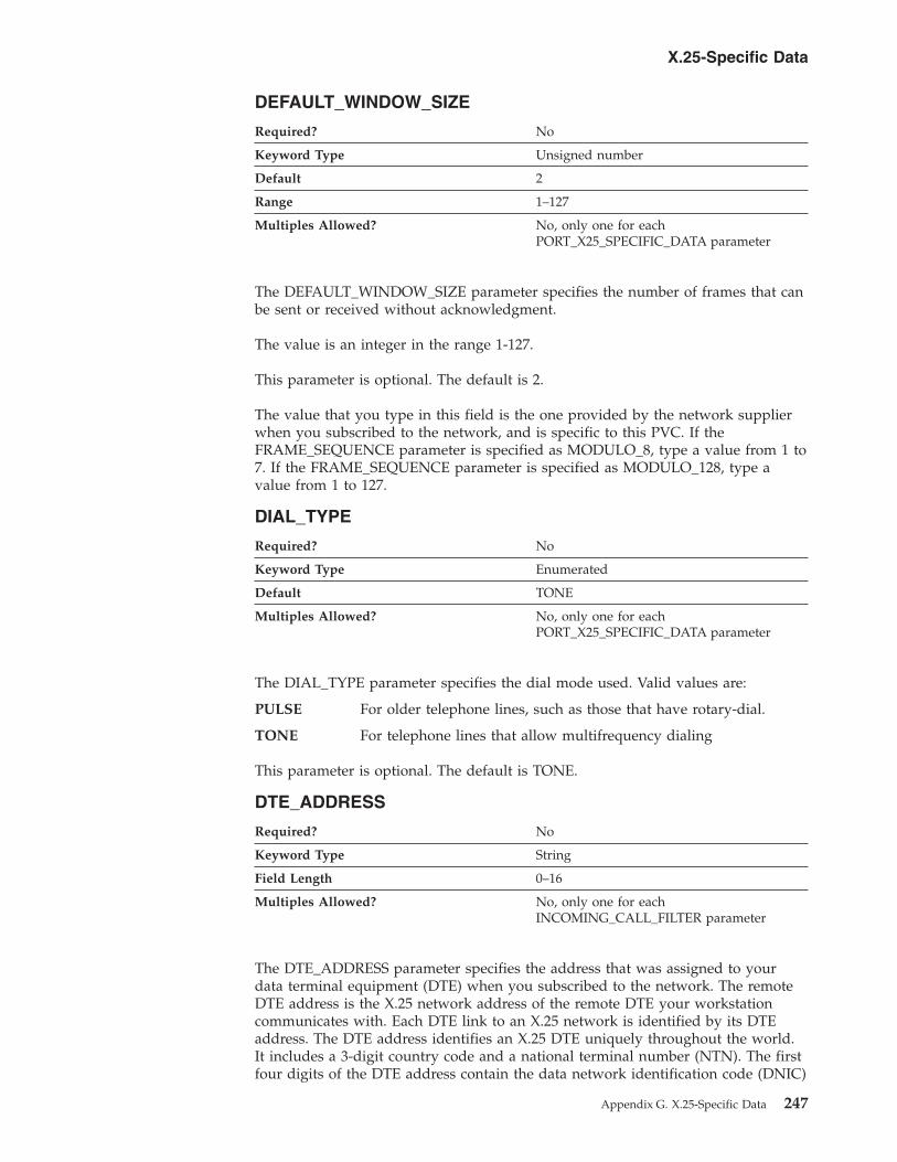
DEFAULT_WINDOW_SIZE
Required? No
Keyword Type Unsigned number
Default 2
Range 1–127
Multiples Allowed? No, only one for each
PORT_X25_SPECIFIC_DATA parameter
The DEFAULT_WINDOW_SIZE parameter specifies the number of frames that can
be sent or received without acknowledgment.
The value is an integer in the range 1-127.
This parameter is optional. The default is 2.
The value that you type in this field is the one provided by the network supplier
when you subscribed to the network, and is specific to this PVC. If the
FRAME_SEQUENCE parameter is specified as MODULO_8, type a value from 1 to
7. If the FRAME_SEQUENCE parameter is specified as MODULO_128, type a
value from 1 to 127.
DIAL_TYPE
Required? No
Keyword Type Enumerated
Default TONE
Multiples Allowed? No, only one for each
PORT_X25_SPECIFIC_DATA parameter
The DIAL_TYPE parameter specifies the dial mode used. Valid values are:
PULSE For older telephone lines, such as those that have rotary-dial.
TONE For telephone lines that allow multifrequency dialing
This parameter is optional. The default is TONE.
DTE_ADDRESS
Required? No
Keyword Type String
Field Length 0–16
Multiples Allowed? No, only one for each
INCOMING_CALL_FILTER parameter
The DTE_ADDRESS parameter specifies the address that was assigned to your
data terminal equipment (DTE) when you subscribed to the network. The remote
DTE address is the X.25 network address of the remote DTE your workstation
communicates with. Each DTE link to an X.25 network is identified by its DTE
address. The DTE address identifies an X.25 DTE uniquely throughout the world.
It includes a 3-digit country code and a national terminal number (NTN). The first
four digits of the DTE address contain the data network identification code (DNIC)
X.25-Specific Data
Appendix G. X.25-Specific Data 247

that defines the country and the service within that country. The first three digits
of the DNIC identify the country code, followed by a one-digit number for the
service.
The value is a 0- to 16-byte character string.
This parameter is optional.
Note: The data identification code is not always required. For example, you can
omit the data identification code for local calls or for a private network that
uses its own addressing method. Some networks do not use the full 15
digits when assigning DTE addresses. In this case, you can use the
remaining digits as a suffix for your own purposes, such as routing calls to
different applications, according to the suffix of the local DTE address of a
caller.
DTE_ADDRESS_EXTENSION
Required? No
Keyword Type String
Field Length 0–8
Multiples Allowed? No, only one for each
INCOMING_CALL_FILTER parameter
The DTE_ADDRESS_EXTENSION parameter specifies the X.25 network address
extension of the remote DTE your workstation communicates with. The address
extension is an optional CCITT-Specified DTE facility which may be used for a
given call. It provides for the transparent conveyance in CALL REQUEST and
INCOMING CALL packets of all or part of the Network Services Access Point
(NSAP) address.
The value is a 0- to 8-byte character string.
This parameter is optional.
The X.25 local DTE address extension was assigned to your data terminal
equipment (DTE) when you subscribed to the network.
DUMB_CARD_INTERFACE
The DUMB_CARD_INTERFACE parameter keyword applies to
Communications Server only.
Required? Yes
Keyword Type Boolean
Default 0
Multiples Allowed? No, only one for each
PORT_X25_SPECIFIC_DATA parameter
The DUMB_CARD_INTERFACE parameter specifies whether the OEM
communications device uses the Microsoft SNA Server synchronous dumb card
X.25-Specific Data
248 Configuration File Reference
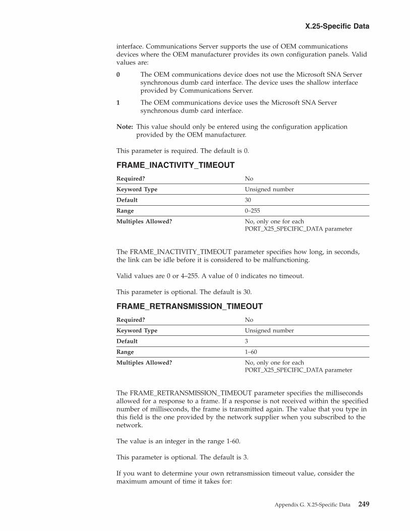
interface. Communications Server supports the use of OEM communications
devices where the OEM manufacturer provides its own configuration panels. Valid
values are:
0 The OEM communications device does not use the Microsoft SNA Server
synchronous dumb card interface. The device uses the shallow interface
provided by Communications Server.
1 The OEM communications device uses the Microsoft SNA Server
synchronous dumb card interface.
Note: This value should only be entered using the configuration application
provided by the OEM manufacturer.
This parameter is required. The default is 0.
FRAME_INACTIVITY_TIMEOUT
Required? No
Keyword Type Unsigned number
Default 30
Range 0–255
Multiples Allowed? No, only one for each
PORT_X25_SPECIFIC_DATA parameter
The FRAME_INACTIVITY_TIMEOUT parameter specifies how long, in seconds,
the link can be idle before it is considered to be malfunctioning.
Valid values are 0 or 4–255. A value of 0 indicates no timeout.
This parameter is optional. The default is 30.
FRAME_RETRANSMISSION_TIMEOUT
Required? No
Keyword Type Unsigned number
Default 3
Range 1–60
Multiples Allowed? No, only one for each
PORT_X25_SPECIFIC_DATA parameter
The FRAME_RETRANSMISSION_TIMEOUT parameter specifies the milliseconds
allowed for a response to a frame. If a response is not received within the specified
number of milliseconds, the frame is transmitted again. The value that you type in
this field is the one provided by the network supplier when you subscribed to the
network.
The value is an integer in the range 1-60.
This parameter is optional. The default is 3.
If you want to determine your own retransmission timeout value, consider the
maximum amount of time it takes for:
X.25-Specific Data
Appendix G. X.25-Specific Data 249

v A frame to travel to the data circuit terminating equipment (DCE) from the data
terminal equipment (DTE)
v DCE processing
v A response frame to return to the DTE from the DCE
Frame retransmission speed depends on the link speed and the frame size.
Maximum frame size is related to the maximum packet size. If you do not allow
enough time, a response can not be received. If you allow more than enough time,
line connection costs increase because excess time passes before a frame is
transmitted.
FRAME_SEQUENCE
Required? No
Keyword Type Enumerated
Default MODULO_8
Multiples Allowed? No, only one for each
PORT_X25_SPECIFIC_DATA parameter
The FRAME_SEQUENCE parameter applies to frames that have been either sent or
received. The value that you select is the one provided by the network supplier
when you subscribed to the network. Valid values are:
MODULO_8 The frame sequence number fields are modulo 8 (3
bits). For modulo 8, the frame sequence numbers
range from 1 to 7.
MODULO_128 The frame sequence number fields are modulo 128
(7 bits). For Modulo 128, the frame sequence
numbers range from 1 to 127.
This parameter is optional. The default is MODULO_8.
FRAME_TRANSMISSION_RETRY_COUNT
Required? No
Keyword Type Unsigned number
Default 20
Range 1–255
Multiples Allowed? No, only one for each
PORT_X25_SPECIFIC_DATA parameter
The FRAME_TRANSMISSION_RETRY_COUNT parameter specifies the maximum
number of times an X.25 frame can be transmitted before the link is considered to
be malfunctioning. The value that you type in this field is the one provided by the
network supplier when you subscribed to the network.
The value is an integer in the range 1-255.
This parameter is optional. The default is 20.
X.25-Specific Data
250 Configuration File Reference

FRAME_WINDOW_SIZE
Required? No
Keyword Type Unsigned number
Default 7
Range 1–127
Multiples Allowed? No, only one for each
PORT_X25_SPECIFIC_DATA parameter
The FRAME_WINDOW_SIZE parameter specifies the number of frames that can
be sent or received without acknowledgment. The value that you type is the one
provided by the network supplier when you subscribed to the network. If the
frame sequence is MODULO_8, type a value from 1 to 7. If the frame sequence is
MODULO_128, type a value from 1 to 127.
The value is an integer in the range 1-127.
This parameter is optional. The default is 7.
INCOMING_CALL_FILTER
Required? No
Keyword Type Complex
Multiples Allowed? Yes
The INCOMING_CALL_FILTER parameter is a complex keyword comprised of the
following parameter keywords:
v ACCEPT_CHARGES
v DTE_ADDRESS
v DTE_ADDRESS_EXTENSION
See the descriptions of the parameter keywords to define the
INCOMING_CALL_FILTER parameter.
INSERT_CALLING_ADDRESS
Required? No
Keyword Type Boolean
Multiples Allowed? No, only one for each
PORT_X25_SPECIFIC_DATA parameter
The INSERT_CALLING_ADDRESS parameter specifies whether to insert the
address of the local data terminal equipment (DTE) into the calling address field of
the call request packet. Valid values are:
0 Do not insert the address of the local data terminal equipment (DTE) into
the calling address field of the call request packet.
1 Insert the address of the local data terminal equipment (DTE) into the
calling address field of the call request packet.
This parameter is optional.
X.25-Specific Data
Appendix G. X.25-Specific Data 251
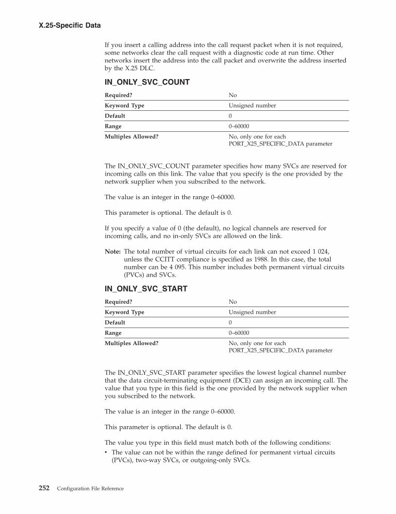
If you insert a calling address into the call request packet when it is not required,
some networks clear the call request with a diagnostic code at run time. Other
networks insert the address into the call packet and overwrite the address inserted
by the X.25 DLC.
IN_ONLY_SVC_COUNT
Required? No
Keyword Type Unsigned number
Default 0
Range 0–60000
Multiples Allowed? No, only one for each
PORT_X25_SPECIFIC_DATA parameter
The IN_ONLY_SVC_COUNT parameter specifies how many SVCs are reserved for
incoming calls on this link. The value that you specify is the one provided by the
network supplier when you subscribed to the network.
The value is an integer in the range 0–60000.
This parameter is optional. The default is 0.
If you specify a value of 0 (the default), no logical channels are reserved for
incoming calls, and no in-only SVCs are allowed on the link.
Note: The total number of virtual circuits for each link can not exceed 1 024,
unless the CCITT compliance is specified as 1988. In this case, the total
number can be 4 095. This number includes both permanent virtual circuits
(PVCs) and SVCs.
IN_ONLY_SVC_START
Required? No
Keyword Type Unsigned number
Default 0
Range 0–60000
Multiples Allowed? No, only one for each
PORT_X25_SPECIFIC_DATA parameter
The IN_ONLY_SVC_START parameter specifies the lowest logical channel number
that the data circuit-terminating equipment (DCE) can assign an incoming call. The
value that you type in this field is the one provided by the network supplier when
you subscribed to the network.
The value is an integer in the range 0–60000.
This parameter is optional. The default is 0.
The value you type in this field must match both of the following conditions:
v The value can not be within the range defined for permanent virtual circuits
(PVCs), two-way SVCs, or outgoing-only SVCs.
X.25-Specific Data
252 Configuration File Reference
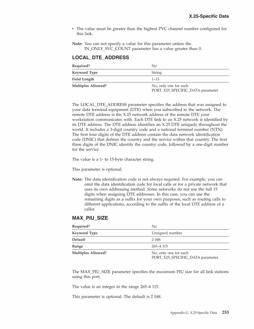
v The value must be greater than the highest PVC channel number configured for
this link.
Note: You can not specify a value for this parameter unless the
IN_ONLY_SVC_COUNT parameter has a value greater than 0.
LOCAL_DTE_ADDRESS
Required? No
Keyword Type String
Field Length 1–15
Multiples Allowed? No, only one for each
PORT_X25_SPECIFIC_DATA parameter
The LOCAL_DTE_ADDRESS parameter specifies the address that was assigned to
your data terminal equipment (DTE) when you subscribed to the network. The
remote DTE address is the X.25 network address of the remote DTE your
workstation communicates with. Each DTE link to an X.25 network is identified by
its DTE address. The DTE address identifies an X.25 DTE uniquely throughout the
world. It includes a 3-digit country code and a national terminal number (NTN).
The first four digits of the DTE address contain the data network identification
code (DNIC) that defines the country and the service within that country. The first
three digits of the DNIC identify the country code, followed by a one-digit number
for the service.
The value is a 1- to 15-byte character string.
This parameter is optional.
Note: The data identification code is not always required. For example, you can
omit the data identification code for local calls or for a private network that
uses its own addressing method. Some networks do not use the full 15
digits when assigning DTE addresses. In this case, you can use the
remaining digits as a suffix for your own purposes, such as routing calls to
different applications, according to the suffix of the local DTE address of a
caller.
MAX_PIU_SIZE
Required? No
Keyword Type Unsigned number
Default 2 048
Range 265–4 115
Multiples Allowed? No, only one for each
PORT_X25_SPECIFIC_DATA parameter
The MAX_PIU_SIZE parameter specifies the maximum PIU size for all link stations
using this port.
The value is an integer in the range 265–4 115.
This parameter is optional. The default is 2 048.
X.25-Specific Data
Appendix G. X.25-Specific Data 253
Note: This value is negotiated between the origin node and destination node when
link activation occurs. Each node has a defined maximum. The smaller of
the MAX_PIU_SIZE parameter values is used for the link.
MODEM_NAME
Required? No
Keyword Type String
Field Length 1–256
Multiples Allowed? No, only one for each
PORT_X25_SPECIFIC_DATA parameter
The MODEM_NAME parameter specifies the name of the modem as defined to the
operating system. A PORT keyword passes this name to the communications port
device driver, which uses this name to open the modem device and initialize it.
Note: Since the Node Configuration application produces a list of available
modems from which to choose, you should not attempt to enter this value
directly into the ACG file.
The value is a 1- to 256-byte character string.
This parameter is optional.
NETWORK_CONNECTION_TYPE
Required? No
Keyword Type Enumerated
Default SWITCHED
Multiples Allowed? No, only one for each
PORT_X25_SPECIFIC_DATA parameter
The NETWORK_CONNECTION_TYPE parameter specifies whether the connection
is a leased or a switched connection. Valid values are:
LEASED A leased line is a permanent connection into your telephone
network.
SWITCHED A switched line uses a dialed connection. A switched line has a
telephone number.
This parameter is optional. The default is SWITCHED.
OEM_DATA
The OEM_DATA parameter keyword applies to Communications Server
only.
Required? No
Keyword Type Hexadecimal string
Multiples Allowed? Yes
X.25-Specific Data
254 Configuration File Reference
The OEM_DATA parameter specifies binary information specific for the OEM card
manufacturer’s use only. Communications Server supports the use of OEM
communications devices where the OEM manufacturer provides its own
configuration panels. More than one OEM_DATA parameter might appear in the
ASCII configuration file.
Note: Since the format of this binary data is very specific to the OEM device, you
should not attempt to enter this value directly into the ACG file. The value
should only be entered using the configuration application provided by the
OEM manufacturer.
This parameter is optional.
OEM_PORT_DATA
The OEM_PORT_DATA parameter keyword applies to Communications
Server only.
Required? No
Keyword Type Complex
Multiples Allowed? Yes
The OEM_PORT_DATA parameter is a complex keyword comprised of the
OEM_DATA parameter keyword. See the descriptions of the parameter keyword to
define the OEM_PORT_DATA parameter.
See the description of the OEM_DATA parameter keyword to define the
OEM_PORT_DATA parameter.
OUT_ONLY_SVC_COUNT
Required? No
Keyword Type Unsigned number
Default 0
Range 0–60000
Multiples Allowed? No, only one for each
PORT_X25_SPECIFIC_DATA parameter
The OUT_ONLY_SVC_COUNT parameter specifies how many outgoing-only SVCs
can be used on this link. The value that you type in this field is the one provided
by the network supplier when you subscribed to the network.
The value is an integer in the range 0–60000.
This parameter is optional. The default is 0.
If you type a value of 0 (the default), no out-only SVCs are allowed on the link.
Note: The total number of virtual circuits for each link can not exceed 1 024,
unless the CCITT compliance is specified as 1988. In this case, the total
number can be 4 095. This number includes both permanent virtual circuits
(PVCs) and SVCs.
X.25-Specific Data
Appendix G. X.25-Specific Data 255
OUT_ONLY_SVC_START
Required? No
Keyword Type Unsigned number
Default 0
Range 0–60000
Multiples Allowed? No, only one for each
PORT_X25_SPECIFIC_DATA parameter
The OUT_ONLY_SVC_START parameter specifies the lowest logical channel
number that the data terminal equipment (DTE) can assign to an outgoing call.
The value that you type in this field is the one provided by the network supplier
when you subscribed to the network.
The value is an integer in the range 0–60000.
This parameter is optional. The default is 0.
The value you type in this field must match both of the following conditions:
v The value can not be within the range defined for the two other SVCs (in-only
SVCs and two-way SVCs).
v The value must be greater than the highest two-way SVC channel number
configured for this link.
Note: You can not specify a value for this parameter unless the
OUT_ONLY_SVC_COUNT parameter has a value greater than 0.
PACKET_SIZE
Required? No
Keyword Type Unsigned number
Default 128
Field Length 16–4 096
Multiples Allowed? No, only one for each
PORT_X25_SPECIFIC_DATA parameter
The PACKET_SIZE parameter refers to the length of user data in a data packet.
The value that you select should be the value that was agreed upon when you
subscribed to the network.
If your network complies with the 1980 or 1984 CCITT recommendation, the
agreed-upon size is one of the following: 16, 32, 64, 128, 256, 512, 1 024.
If your network complies with the 1988 CCITT recommendation, the agreed-upon
size is one of the following: 16, 32, 64, 128, 256, 512, 1 024, 2 048, or 4 096.
The value is a 16–4 096 byte character string.
This parameter is optional. The default is 128.
X.25-Specific Data
256 Configuration File Reference

PORT_SPEED
Required? No
Keyword Type Unsigned number
Default 57 600
Range 2 400–115 200 bps
Multiples Allowed? No, only one for each
PORT_X25_SPECIFIC_DATA parameter
The PORT_SPEED parameter specifies the serial port speed supported by the
device used for the connection.
The value is an integer in the range 2 400–115 200 bits per second (bps).
This parameter is optional. The default is 57 600.
If the highest carrier speed of your modem is 14 400 bps, specify a port speed of
57 600 bps or lower. If the highest carrier speed is 28 800 bps or higher, specify a
port speed of 115 200 to use the maximum compression capabilities for the
modem. A port speed of 115 200 bps is recommended for systems with Pentium
processors.
PVC_COUNT
Required? No
Keyword Type Unsigned number
Default 0
Range 0–60000
Multiples Allowed? No, only one for each
PORT_X25_SPECIFIC_DATA parameter
The PVC_COUNT parameter specifies how many PVCs are reserved on this link.
The value that you type in this field is the one provided by the network supplier
when you subscribed to the network.
The value is an integer in the range 0–60000.
This parameter is optional. The default is 0.
Note: The total number of virtual circuits for each link can not exceed 1 024,
unless the CCITT compliance is specified as 1988. In this case, the total
number can be 4 095. This number includes both permanent virtual circuits
(PVCs) and SVCs.
X.25-Specific Data
Appendix G. X.25-Specific Data 257
PVC_START
Required? No
Keyword Type Unsigned number
Default 0
Range 0–60000
Multiples Allowed? No, only one for each
PORT_X25_SPECIFIC_DATA parameter
The PVC_START parameter specifies the lowest logical channel number assigned
to PVCs. The value that you type in this field is the one provided by the network
supplier when you subscribed to the network.
The value is an integer in the range 0–60000.
This parameter is optional. The default is 0.
REMOTE_PHONE_NUMBER
Required? No
Keyword Type String
Field Length 1–64
Multiples Allowed? No, only one for each
PORT_X25_SPECIFIC_DATA parameter
The REMOTE_PHONE_NUMBER parameter specifies the phone number dialed to
activate a connection to the destination.
The phone number is a 1- to 64-digit string.
This parameter is optional.
SEQUENCING
Required? No
Keyword Type Enumerated
Default MODULO_8
Multiples Allowed? No, only one for each
PORT_X25_SPECIFIC_DATA parameter
The SEQUENCING parameter specifies how data frames are numbered to
guarantee transmission. These numbers are used for acknowledgment and
retransmission of frames. Valid values are:
v MODULO_8
v MODULO_128
This parameter is optional. The default is MODULO_8.
X.25-Specific Data
258 Configuration File Reference

SHARED_RAM_ADDRESS
Required? No
Keyword Type Hexadecimal number
Range X'C0000'–X'FC000'
Multiples Allowed? No, only one for each
PORT_X25_SPECIFIC_DATA parameter
The SHARED_RAM_ADDRESS parameter specifies the address in memory at
which the 16K buffer, used by the adapter, starts.
The value is a hexadecimal character string in the range X'C0000'–X'FC000'.
This parameter is optional.
If you are using an industry standard architecture (ISA) adapter, you must select
the shared RAM address. If you are using a Micro Channel adapter, the shared
RAM address is set automatically. When you select the shared RAM address and
your configuration contains another definition of an SDLC-WAC or X.25-WAC
device that uses the same adapter number, that definition is automatically updated
to use this shared RAM address.
TRANSMISSION_FLAGS
Required? No
Keyword Type Unsigned number
Default 1
Range 1–10
Multiples Allowed? No, only one for each
PORT_X25_SPECIFIC_DATA parameter
The TRANSMISSION_FLAGS parameter specifies the minimum number of flags
that are inserted to produce idle time between transmitted frames.
The value is an integer in the range 1-10 flags.
This parameter is optional. The default is 1 flag.
A flag is the time it takes to send one byte, and represents a delay between frames.
The values are 1, 3, 4, 6, and 10. Change this parameter to a value other than 1
when you know the device at the other end of the communication link can not
receive frames with only one intervening flag.
TWO_WAY_SVC_COUNT
Required? No
Keyword Type Unsigned number
Default 0
Range 0–60000
Multiples Allowed? No, only one for each
PORT_X25_SPECIFIC_DATA parameter
X.25-Specific Data
Appendix G. X.25-Specific Data 259

The TWO_WAY_SVC_COUNT parameter specifies how many two-way SVCs can
be used by this link for incoming calls or by the data terminal equipment (DTE)
for outgoing calls. The value that you type in this field is the one provided by the
network supplier when you subscribed to the network.
The value is an integer in the range 0–60000.
This parameter is optional. The default is 0.
Note: The total number of virtual circuits for each link can not exceed 1 024,
unless the CCITT compliance is specified as 1988. In this case, the total
number can be 4 095. This number includes both permanent virtual circuits
(PVCs) and SVCs.
TWO_WAY_SVC_START
Required? No
Keyword Type Unsigned number
Default 0
Range 0–60000
Multiples Allowed? No, only one for each
PORT_X25_SPECIFIC_DATA parameter
The TWO_WAY_SVC_START parameter specifies the lowest logical channel
number that the data circuit-terminating equipment (DCE) can assign an incoming
call or by the data terminal equipment (DTE) for outgoing calls. The value that you
type in this field is the one provided by the network supplier when you subscribed
to the network.
The value is an integer in the range 0–60000.
This parameter is optional. The default is 0.
The value you type in this field must match both of the following conditions:
v The value can not be within the range defined for the two other SVCs (in-only
SVCs and outgoing-only SVCs).
v The value must be greater than the highest in-only SVC channel number
configured for this link.
Note: You can not type a value in this field unless the TWO_WAY_SVC_COUNT
parameter has a value greater than 0.
USE_CONSTANT_RTS
Required? No
Keyword Type Boolean
Default 1
Multiples Allowed? No, only one for each
PORT_X25_SPECIFIC_DATA parameter
The USE_CONSTANT_RTS (request-to-send) parameter specifies whether flow
control is used between an adapter and the modem. Valid values are:
X.25-Specific Data
260 Configuration File Reference
0 The adapter waits for the CTS (clear-to-send) signal before sending data to
the modem.
1 There is no flow control to the modem.
This parameter is optional. The default is 1.
USE_NRZI_ENCODING
Required? No
Keyword Type Boolean
Default 0
Multiples Allowed? No, only one for each
PORT_X25_SPECIFIC_DATA parameter
The USE_NRZI_ENCODING specifies how synchronous data sent to the modem is
encoded. Valid values are:
0 Use non-return-to-zero (NRZ) encoding.
1 Use non-return-to-zero inverted (NRZI) encoding.
This parameter is optional. The default is 0.
USE_X32_PROTOCOL
Required? No
Keyword Type Boolean
Default 0
Multiples Allowed? No, only one for each
PORT_X25_SPECIFIC_DATA parameter
The USE_X32_PROTOCOL parameter specifies whether you are using X.32
procedures for security signaling. Valid values are:
0 The X.32 protocol is not be used.
1 The X.32 protocol is used.
This parameter is optional. The default is 0.
X32_IDENTITY
Required? No
Keyword Type Hexadecimal string
Field Length 1–32
Multiples Allowed? No, only one for each
PORT_X25_SPECIFIC_DATA
parameter
The X32_IDENTITY parameter specifies the exchange station ID (XID) that
identifies your workstation to your X.25 network supplier. The information that
you type in this field is provided by the network supplier when you subscribed to
the network.
X.25-Specific Data
Appendix G. X.25-Specific Data 261

The value is a 1- to 32-byte hexadecimal character string.
This parameter is optional.
X32_SIGNATURE
Required? No
Keyword Type Hexadecimal string
Field Length 1–32
Multiples Allowed? No, only one for each
PORT_X25_SPECIFIC_DATA
parameter
The X32_SIGNATURE parameter specifies the signature identification that is used
to enable the network operator to authenticate the claimed identity of the data
terminal equipment (DTE). The information that you type in this field is provided
by the network supplier when you subscribed to the network.
The value is a 1- to 32-byte hexadecimal character string
This parameter is optional.
X.25-Specific Data
262 Configuration File Reference

Appendix H. ANYNET_COMMON_PARAMETERS
This appendix describes the parameter keywords and values you can specify for
the ANYNET_COMMON_PARAMETERS keyword.
Keyword Definition
Required? No
Keyword Type Complex
Multiples Allowed? No
ANYNET_COMMON_PARAMETERS Sample
The following is a sample of the ANYNET_COMMON_PARAMETERS keyword:
ANYNET_COMMON_PARAMETERS=(
CONNWAIT_SECS=30
CONN_RETRY_SECS=300
DG_IDLE_TIMEOUT=90
INACTIVITY_TIMER_SECS=30
SNASUFFIX=SNA.IBM.COM
SNA_IP_NODE_TYPE=1
UNACKED_DG_RETRY_SECS=10
UNSENT_DG_RETRY_SECS=3
)
ANYNET_COMMON_PARAMETERS Parameter Keywords
CONN_RETRY_SECS
Required? No
Keyword Type Unsigned number
Default 300
Range 1–65 535
Multiples Allowed? No
The CONN_RETRY_SECS parameter specifies the maximum time, in seconds, for
SNA over TCP/IP to set up a multiprotocol transport network (MPTN) connection
over TCP/IP. When an MPTN connection setup fails, Communications Server or
Personal Communications tries every IP address associated with a LU name in the
domain name server or HOSTS file until all the addresses are exhausted, or until
the specified time is reached.
The value is an integer in the range of 1–65 535 seconds.
This parameter is optional. The default is 300 seconds.
© Copyright IBM Corp. 1998, 2006 263
CONNWAIT_SECS
Required? No
Keyword Type Unsigned number
Default 30
Range 1–65 535
Multiples Allowed? No
The CONNWAIT_SECS parameter specifies the maximum time, in seconds, that
SNA over TCP/IP waits to receive a multiprotocol transport network (MPTN)
connection or connection response packet after the TCP connection is established.
This limit prevents the connecting node from waiting too long for a session partner
to send a packet.
The value is an integer in the range of 1–65 535 seconds.
This parameter is optional. The default is 30 seconds.
DG_IDLE_TIMEOUT
Required? No
Keyword Type Unsigned number
Range 1–65 535
Multiples Allowed? No
The DG_IDLE_TIMEOUT parameter specifies the time that a datagram
conversation remains idle before it is deallocated and closed. This timer enables
you to balance using system resources to maintain an existing datagram
conversation and taking longer to reestablish a new datagram conversation. The
value is in the range of 1–65 535 seconds.
This parameter is optional. The default is 90 seconds.
INACTIVITY_TIMER_SECS
Required? No
Keyword Type Unsigned number
Range 1–65 535
Multiples Allowed? No
The INACTIVITY_TIMER_SECS parameter specifies the seconds of inactivity
allowed between two partner nodes before SNA over TCP/IP tries to determine
whether the partner node is still active. The value is an integer in the range of 1–65
535 seconds.
This parameter is optional. The default is 30 seconds.
Setting the interval below 10 seconds might seriously affect system performance. If
you are unsure about what value to enter, use the default.
ANYNET_COMMON_PARAMETERS
264 Configuration File Reference
SNASUFFIX
Required? No
Keyword Type String
Default SNA.IBM.COM
Field Length 1–257
Multiples Allowed? No
The SNASUFFIX parameter specifies a user-defined domain name suffix created
using the hierarchical-naming format recognized by TCP/IP. The suffix consists of
strings concatenated with periods. Each string must be less than or equal to 63
characters, with a total length of less than, or equal to, 257 characters.
The value is a 1- to 257-byte character string. Valid characters for each string are:
v The first character must be an alphabetic character (A-Z, a-z).
v The last character must be an alphanumeric character (A-Z, a-z, 0-9).
v The remaining characters can be alphanumeric characters (A-Z, a-z, 0-9) or the
special character (-).
This parameter is optional. The default is SNA.IBM.COM.
SNA_IP_NODE_TYPE
Required? No
Keyword Type Unsigned number
Default 1
Range 1–2
Multiples Allowed? No
The SNA_IP_NODE_TYPE parameter specifies what type of node is being
configured. Valid values are: Valid values are:
1 Access node
2 Gateway
This parameter is optional. The default is 1.
The value of the SNA_IP_NODE_TYPE parameter keyword is always 1.
ANYNET_COMMON_PARAMETERS
Appendix H. ANYNET_COMMON_PARAMETERS 265

UNACKED_DG_RETRY_SECS
Required? No
Keyword Type Unsigned number
Default 10
Range 1–65 535
Multiples Allowed? No
The UNACKED_DG_RETRY_SECS parameter specifies the maximum time, in
seconds, that SNA over TCP/IP waits to resend an unacknowledged out-of-band
(OOB) or MPTN keepalive datagram. When expedited data is sent over TCP/IP,
this interval is used to help control the delivery of expedited data in congested
situations. In SNA, some control messages are sent as expedited data (for example,
messages requesting the right to send data or messages taking down a session).
Expedited data is not subject to congestion control and can move ahead of normal,
non-expedited data. To ensure delivery, AnyNet might send expedited data as
normal data and as an OOB datagram.
The value is an integer in the range 1–65 535 seconds.
This parameter is optional. The default is 10 seconds.
UNSENT_DG_RETRY_SECS
Required? No
Keyword Type Unsigned number
Default 3
Range 1–65 535
Multiples Allowed? No
The UNSENT_DG_RETRY_SECS parameter specifies the maximum time, in
seconds, that Communications Server or Personal Communications waits for an
acknowledgment after sending expedited data on a TCP connection, before sending
the data as an out-of-band (OOB) datagram. When expedited data is sent over
TCP/IP, this interval is used to help improve the delivery of expedited data in
congested situations. In SNA, some control messages are sent as expedited data
(for example, messages requesting the right to send data or messages taking down
a session). Expedited data is not subject to congestion control and can move ahead
of normal, non-expedited data. To ensure delivery, AnyNet might send expedited
data as normal data and as an OOB datagram.
The value is an integer in the range 1–65 535 seconds.
This parameter is optional. The default is 3 seconds.
ANYNET_COMMON_PARAMETERS
266 Configuration File Reference
Appendix I. Notices
This information was developed for products and services offered in the U.S.A.
IBM may not offer the products, services, or features discussed in this document in
other countries. Consult your local IBM representative for information on the
products and services currently available in your area. Any reference to an IBM
product, program, or service is not intended to state or imply that only that IBM
product, program, or service may be used. Any functionally equivalent product,
program, or service that does not infringe any IBM intellectual property right may
be used instead. However, it is the user’s responsibility to evaluate and verify the
operation of any non-IBM product, program, or service.
IBM may have patents or pending patent applications covering subject matter
described in this document. The furnishing of this document does not give you
any license to these patents. You can send license inquiries, in writing, to:
IBM Director of Licensing
IBM Corporation
500 Columbus Avenue
Thornwood, NY 10594
U.S.A.
For license inquiries regarding double-byte (DBCS) information, contact the IBM
Intellectual Property Department in your country or send inquiries, in writing, to:
IBM World Trade Asia Corporation
Licensing
2-31 Roppongi 3-chome, Minato-ku
Tokyo 106, Japan
The following paragraph does not apply to the United Kingdom or any other
country where such provisions are inconsistent with local law:
INTERNATIONAL BUSINESS MACHINES CORPORATION PROVIDES THIS
PUBLICATION “AS IS” WITHOUT WARRANTY OF ANY KIND, EITHER
EXPRESS OR IMPLIED, INCLUDING, BUT NOT LIMITED TO, THE IMPLIED
WARRANTIES OF NON-INFRINGEMENT, MERCHANTABILITY OR FITNESS
FOR A PARTICULAR PURPOSE. Some states do not allow disclaimer of express or
implied warranties in certain transactions, therefore, this statement may not apply
to you.
This information could include technical inaccuracies or typographical errors.
Changes are periodically made to the information herein; these changes will be
incorporated in new editions of the publication. IBM may make improvements
and/or changes in the product(s) and/or the program(s) described in this
publication at any time without notice.
Licensees of this program who wish to have information about it for the purpose
of enabling: (i) the exchange of information between independently created
programs and other programs (including this one) and (ii) the mutual use of the
information which has been exchanged, should contact:
IBM Corporation
Department TL3B/062
P.O. Box 12195
© Copyright IBM Corp. 1998, 2006 267
Research Triangle Park, NC 27709-2195
U.S.A.
Such information may be available, subject to appropriate terms and conditions,
including in some cases, payment of a fee.
The licensed program described in this information and all licensed material
available for it are provided by IBM under terms of the IBM Customer Agreement,
International Programming License Agreement, or any equivalent agreement
between us.
Information concerning non-IBM products was obtained from the suppliers of
those products, their published announcements or other publicly available sources.
IBM has not tested those products and cannot confirm the accuracy of
performance, compatibility or any other claims related to non-IBM products.
Questions on the capabilities of non-IBM products should be addressed to the
suppliers of those products.
Trademarks
The following are trademarks of the Internation Business Machines Corporation in
the United States, in other countries, or both:
AnyNet
APPN
IBM
iSeries
eServer
System i5
Microsoft, Windows, and the Windows logo are registered trademarks of Microsoft
Corporation in the United States, other countries, or both.
Pentium is a registered trademark of Intel Corporation in the United States, other
countries, or both.
Other company, product, and service names may be trademarks or service marks
of others.
268 Configuration File Reference

Index
AACCEPT_CHARGES
PORT_X25_SPECIFIC_DATA 245
ACCEPT_INCOMING_CALLSPORT_SDLC_SPECIFIC_DATA 223
PORT_X25_SPECIFIC_DATA 245
ACK_DELAYPORT_LAN_SPECIFIC_DATA 198
ACK_TIMEOUTPORT_LAN_SPECIFIC_DATA 199
ACTIVATE_AT_STARTUPLINK_STATION 56
ACTIVATION_DELAY_TIMERLINK_STATION 56
PORT 126
ADAPTER_NUMBERPORT_LAN_SPECIFIC_DATA 199
ADAPTER_TYPEPORT_TWINAX_SPECIFIC_DATA 234
ADDITIONAL_FACILITIESLINK_STATION_X25_SPECIFIC_DATA 237
ADJACENT_BRANCH_EXTENDER_NODELINK_STATION 56
ADJACENT_CP_NAMEPARTNER_LU 121
ADJACENT_NODE 9
ADJACENT_NODE_IDLINK_STATION 57
ADJACENT_NODE_TYPELINK_STATION 58
ADVERTISE_FREQUENCYLOAD_BALANCING 83
ALTERNATE_REMOTE_PHONE_NUMBERPORT_X25_SPECIFIC_DATA 246
AnyNet specific data 185
LINK_STATION 185
DEST_ADDRESS 185
PARTNER_ADDRESS_TYPE 185
PORT 186
DLC_NAME 186
ANYNET_COMMON_PARAMETERS 263
ANYNET_SUPPORTNODE 111
API_CLIENT_USETP 173
APPC_LU_LOAD_FACTORLOAD_BALANCING 84
APPLICATION_TYPELU_0_TO_3 93
AS400_COMMON 13
AS400_SERVER 17
AS400_SERVER_ENTRYTN5250_FILTER 165
ASCII configuration 1
ASCII configuration filekeyword types 2
structure 1
syntax rules 3
ASSOC_PRINTERLU_0_TO_3 94
AUTO_ACTMODE 103
AUTO_ACTIVATE_SUPPORTLINK_STATION 59
AUTO_LOGOFFTN3270E_DEF 145
TN5250_DEF 159
BBACKUP_PHONE_NUMBER
LINK_STATION_SDLC_SPECIFIC_DATA 218
BKUP_DLUS_NAMEDLUR_DEFAULTS 33
INTERNAL_PU 49
LINK_STATION 60
BKUP_FP_FQCP_NAMEFOCAL_POINT 43
BKUP_MS_APPL_NAMEFOCAL_POINT 44
BRANCH_EXTENDER_LINKLINK_STATION 60
building a response file 3
BUSY_STATE_TIMEOUTPORT_LAN_SPECIFIC_DATA 200
CCALL_USER_GROUP_FORMAT
LINK_STATION_X25_SPECIFIC_DATA 238
CALL_USER_GROUP_INDEXLINK_STATION_X25_SPECIFIC_DATA 238
certificate revocation list (CRL) 29
CFG_LAST_SCENARIOVERIFY 183
CFG_MODIFICATION_LEVELVERIFY 184
CFG_VERSION_LEVELVERIFY 184
CLASS_TYPELU_0_TO_3 94
TN3270E_FILTER 151
CLIENT_AUTHENTICATIONTN3270_PORT_DEF 155
TN5250_PORT_DEF 169
CLIENT_ID_TYPETN3270E_FILTER 152
TN5250_FILTER 166
COMPLIANCEPORT_X25_SPECIFIC_DATA 246
COMPRESSIONMODE 104
CONN_RETRY_SECSANYNET_COMMON_PARAMETERS 263
CONNECT_RETRY_COUNTLINK_STATION_SDLC_SPECIFIC_DATA 218
PORT_SDLC_SPECIFIC_DATA 223
CONNECT_TIMERLINK_STATION_SDLC_SPECIFIC_DATA 218
PORT_SDLC_SPECIFIC_DATA 224
© Copyright IBM Corp. 1998, 2006 269
CONNECTION_IDLINK_STATION_X25_SPECIFIC_DATA 239
CONNECTION_NETWORK 21
INHERIT_PORT_LIMITED_RESOURCE 22
CONNECTION_TYPELINK_STATION_X25_SPECIFIC_DATA 239
CONNWAIT_SECSANYNET_COMMON_PARAMETERS 264
CONV_SECURITY_VERIFICATIONPARTNER_LU 122
CONVERSATION_SECURITY_TYPECPIC_SIDE_INFO 23
CONVERSATION_TYPETP 174
COS_NAMEMODE 104
COST_PER_BYTELINK_STATION 61
PORT 126
COST_PER_CONNECT_TIMELINK_STATION 61
PORT 126
PORT_OEM_SPECIFIC_DATAEE 191
OEM 211
CP_ALIASNODE 112
CP_CP_SESS_SUPPORTLINK_STATION 61
CPIC_SIDE_INFO 23
creating an ASCII configuration fileassigning values to keywords 4
assigning values using SNA character sets 2
keyword types 2
structure 1
syntax example 4
syntax rules 3
CRL_SUPPORT 29
CRL_SUPPORT_ENABLECRL_SUPPORT 29
DDEFAULT_MAX_LU62_SESSIONS
LOAD_BALANCING 84
DEFAULT_NN_SERVERLINK_STATION 62
DEFAULT_POOLLOCAL_LU 87
TN3270_PORT_DEF 156
DEFAULT_POOL_NAMETN3270E_DEF 145
DEFAULT_PREFERENCENODE 112
DEFAULT_PRINTER_POOL_NAMETN3270E_DEF 146
DEFAULT_PU_NAMEDLUR_DEFAULTS 34
DEFAULT_RU_SIZEMODE 104
DEFAULT_SERVERAS400_SERVER 17
TN5250_PORT_DEF 170
DEFAULT_TG_CHARSPORT 127
DEFAULT_WINDOW_SIZEPORT_X25_SPECIFIC_DATA 247
DELAY_APPLICATION_RETRIESLINK_STATION 62
PORT 127
DELETE 3
DEPENDENT_LU_COMPRESSIONINTERNAL_PU 50
LINK_STATION 63
DEPENDENT_LU_ENCRYPTIONINTERNAL_PU 50
LINK_STATION 63
DEST_ADDRESSAnyNet Specific Data 185
LAN Specific Data 197
LINK_STATION 64
OEM Specific Data 207
SDLC Specific Data 217
Twinaxial Specific Data 233
DEVICEAS400_SERVER 18
DG_IDLE_TIMEOUTANYNET_COMMON_PARAMETERS 264
DIAL_TYPEPORT_X25_SPECIFIC_DATA 247
DISABLE_REMOTE_ACTLINK_STATION 64
DISCOVERY_GROUP_NAMENODE 113
DISCOVERY_SUPPORTNODE 114
DLC_DATALAN Specific Data 197
OEM Specific Data 210
PORT 127
SDLC Specific Data 222
X.25 Specific Data 243
DLC_NAMEAnyNet Specific Data 186
EE Specific Data 190
LAN Specific Data 197
OEM Specific Data 210
PORT 128
SDLC Specific Data 222
Twinaxial Specific Data 233
X.25 Specific Data 244
DLUR_DEFAULTS 33
DLUR_SUPPORTNODE 114
DLUS_NAMELINK_STATION 64
DLUS_RETRY_LIMITDLUR_DEFAULTS 34
DLUS_RETRY_TIMEOUTDLUR_DEFAULTS 34
DOWNSTREAM_LU 37
DSLU_NAMEDOWNSTREAM_LU 37
DSLU_TEMPLATEDSPU_TEMPLATE 39
DSPU_NAMEDOWNSTREAM_LU 38
LINK_STATION 65
DSPU_SERVICESLINK_STATION 65
DSPU_TEMPLATE 39
DTE_ADDRESSLINK_STATION_X25_SPECIFIC_DATA 239
PORT_X25_SPECIFIC_DATA 247
270 Configuration File Reference

DTE_ADDRESS_EXTENSIONLINK_STATION_X25_SPECIFIC_DATA 240
PORT_X25_SPECIFIC_DATA 248
DUMB_CARD_INTERFACEPORT_SDLC_SPECIFIC_DATA 224
PORT_X25_SPECIFIC_DATA 248
DUPLEX_SUPPORTTP 174
DYNAMIC_LOADTP 174
DYNAMIC_LU_SUPPORTTN5250_DEF 160
Eediting an ASCII configuration file
assigning values to keywords 4
assigning values using SNA character sets 2
keyword types 2
structure 1
syntax example 4
syntax rules 3
EE specific data 187
LINK_STATION 187
OEM_DATA 189
OEM_LINK_DATA 190
PORTCOST_PER_CONNECT_TIME 191
DLC_NAME 190
EFFECTIVE_CAPACITY 191
INB_LINK_ACT_LIM 191
OEM_DATA 192
OEM_LINK_DATA 192, 193, 212
OEM_PORT_DEFAULTS 193
OUT_LINK_ACT_LIM 194
PROPOGATION_DELAY 194
SECURITY 195
TOT_LINK_ACT_LIM 195
EFFECTIVE_CAPACITYLINK_STATION 66
PORT 128
PORT_OEM_SPECIFIC_DATAEE 191
OEM 211
ENABLE_FILTERINGTN3270E_DEF 146
TN5250_DEF 160
ENABLE_LOAD_BALANCINGLOAD_BALANCING 84
ENCRYPTION_SUPPORTMODE 105
Enterprise Extender (EE) specific data 187
LINK_STATION 187
OEM_DATA 189
OEM_LINK_DATA 190
PORTCOST_PER_CONNECT_TIME 191
DLC_NAME 190
EFFECTIVE_CAPACITY 191
INB_LINK_ACT_LIM 191
OEM_DATA 192
OEM_LINK_DATA 192, 193, 212
OEM_PORT_DEFAULTS 193
OUT_LINK_ACT_LIM 194
PROPOGATION_DELAY 194
SECURITY 195
TOT_LINK_ACT_LIM 195
ETHERNET_FORMATLINK_STATION 66
FFILTER_ENTRY
TN3270E_FILTER 152
FILTER_PREFERENCETN3270E_DEF 146
TN5250_DEF 160
FOCAL_POINT 43
FP_FQCP_NAMEFOCAL_POINT 44
FQ_ADJACENT_CP_NAMELINK_STATION 67
FQ_CP_NAMEADJACENT_NODE 9
NODE 115
FQ_DLUS_NAMEDLUR_DEFAULTS 35
INTERNAL_PU 51
FQ_LU_NAMEADJACENT_NODE 10
FQ_PLU_NAMEPARTNER_LU 122
FQCN_NAMECONNECTION_NETWORK 21
FRAME_INACTIVITY_TIMEOUTPORT_X25_SPECIFIC_DATA 249
FRAME_RETRANSMISSION_TIMEOUTPORT_X25_SPECIFIC_DATA 249
FRAME_SEQUENCEPORT_X25_SPECIFIC_DATA 250
FRAME_TRANSMISSION_RETRY_COUNTPORT_X25_SPECIFIC_DATA 250
FRAME_WINDOW_SIZEPORT_X25_SPECIFIC_DATA 251
FRAMING_STANDARDLINK_STATION_SDLC_SPECIFIC_DATA 219
PORT_SDLC_SPECIFIC_DATA 225
FREQUENCYTN3270E_DEF 147
TN5250_DEF 161
FULL_DUPLEX_SUPPORTPORT_SDLC_SPECIFIC_DATA 225
GGVRN_SUPPORT 115
HHIGH_PATH_SWITCH_TIME 140
HOST_LINK_NAMEHS_CRITICAL_SERVER 47
HOST_LUDSPU_TEMPLATE 40
HOST_LU_LOAD_FACTORLOAD_BALANCING 85
HOST_LU_NAMEDOWNSTREAM_LU 38
HPR_LINK_LVL_ERRORLINK_STATION 67
HPR_SUPPORTLINK_STATION 68
HS_CRITICAL_SERVER 47
Index 271
IIDLE_STATE_TIMEOUT
PORT_LAN_SPECIFIC_DATA 200
IMPLICIT_BRANCH_EXTENDER_LINKPORT 128
IMPLICIT_CP_CP_SESS_SUPPORTPORT 129
IMPLICIT_DEACT_TIMERPORT 129
IMPLICIT_DSPU_SERVICESPORT 130
IMPLICIT_DSPU_TEMPLATEPORT 130
IMPLICIT_HPR_SUPPORTPORT 131
IMPLICIT_LIMITED_RESOURCEPORT 22, 131
IMPLICIT_LINK_LVL_ERRORPORT 132
IN_ONLY_SVC_COUNTPORT_X25_SPECIFIC_DATA 252
IN_ONLY_SVC_STARTPORT_X25_SPECIFIC_DATA 252
INACTIVITY_TIMERLINK_STATION_SDLC_SPECIFIC_DATA 219
PORT_SDLC_SPECIFIC_DATA 226
INACTIVITY_TIMER_SECSANYNET_COMMON_PARAMETERS 264
INB_LINK_ACT_LIMPORT_LAN_SPECIFIC_DATA 200
PORT_OEM_SPECIFIC_DATAEE 191
OEM 211
INCLUDE 3
INCOMING_ALLOCATE_TIMEOUTTP 175
INCOMING_CALL_FILTERPORT_X25_SPECIFIC_DATA 251
INHERIT_PORT_LIMITED_RESOURCE 22
INHERIT_PORT_RETRY_PARMSLINK_STATION 68
INSERT_CALLING_ADDRESSPORT_X25_SPECIFIC_DATA 251
INTERNAL_PU 49
IO_ADDRESSPORT_TWINAX_SPECIFIC_DATA 235
IP_ADDR_MASK_PAIRTN3270E_FILTER 153
TN5250_FILTER 166
IRQ_LEVELPORT_SDLC_SPECIFIC_DATA 226
PORT_TWINAX_SPECIFIC_DATA 235
IS_POOLTN3270E_FILTER 154
KKEEPALIVE_TYPE
TN3270E_DEF 147
TN5250_DEF 161
keywordsADJACENT_NODE 9
ANYNET_COMMON_PARAMETERS 263
AS400_COMMON 13
AS400_SERVER 17
CONNECTION_NETWORK 21
keywords (continued)CPIC_SIDE_INFO 23
CRL_SUPPORT 29
DLUR_DEFAULTS 33
DOWNSTREAM_LU 37
DSPU_TEMPLATE 39
FOCAL_POINT 43
HS_CRITICAL_SERVER 47
INTERNAL_PU 49
LINK_STATION 53
LOAD_BALANCING 83
LOCAL_LU 87
LU_0_TO_3 93
LU_LU_PASSWORD 101
MODE 103
NODE 111
PARTNER_LU 121
PORT 125
SPLIT_STACK 143
TN3270_PORT_DEF 155
TN3270E_DEF 145
TN3270E_FILTER 151
TN5250_DEF 159
TN5250_FILTER 165
TN5250_PORT_DEF 169
TP 173
USERID_PASSWORD 181
VERIFY 183
LLAN specific data 197
LINK_STATION 197
DEST_ADDRESS 197
PORT 197
ACK_DELAY 198
ACK_TIMEOUT 199
ADAPTER_NUMBER 199
BUSY_STATE_TIMEOUT 200
DLC_DATA 197
DLC_NAME 197
IDLE_STATE_TIMEOUT 200
INB_LINK_ACT_LIM 200
LOCAL_SAP 201
MAX_RETRY 201
OUT_LINK_ACT_LIM 202
OUTSTANDING_TRANSMITS 202
POLL_TIMEOUT 203
POOL_SIZE 203
REJECT_RESPONSE_TIMEOUT 204
TEST_RETRY_INTERVAL 204
TEST_RETRY_LIMIT 205
TOT_LINK_ACT_LIM 205
XID_RETRY_INTERVAL 205
XID_RETRY_LIMIT 206
LDAP_IDCRL_SUPPORT 29
LDAP_ID_TYPECRL_SUPPORT 30
LIMITED_RESOURCELINK_STATION 69
LINK_DEACT_TIMERLINK_STATION 69
LINK_STATION 53
LINK_STATION_ANYNET_SPECIFIC_DATA 185
LINK_STATION_OEM_SPECIFIC_DATAEE 187
272 Configuration File Reference
LINK_STATION_OEM_SPECIFIC_DATA (continued)MPC 207
LINK_STATION_ROLELINK_STATION 70
PORT 132
LINK_STATION_SDLC_SPECIFIC_DATA 217
LINK_STATION_X25_SPECIFIC_DATA 237
LOAD_BALANCING 83
LOAD_TYPETP 175
LOAD_VARIANCELOAD_BALANCING 85
LOCAL_DTE_ADDRESSPORT_X25_SPECIFIC_DATA 253
LOCAL_LU 87
LOCAL_SAPPORT_LAN_SPECIFIC_DATA 201
LOGICAL_CHANNEL_NUMBERLINK_STATION_X25_SPECIFIC_DATA 240
LOGOFFTN3270E_DEF 148
TN5250_DEF 162
LOW_PATH_SWITCH_TIME 141
LS_NAMELINK_STATION 71
LU_0_TO_3 93
LU_ALIASLOCAL_LU 88
LU_ENTRYADJACENT_NODE 10
LU_LU_PASSWORD 101
LU_MODELLU_0_TO_3 95
LU_NAMEAS400_COMMON 13
LOCAL_LU 88
LU_0_TO_3 95
LU_PAIRLU_LU_PASSWORD 101
LU_PREFIXTN5250_DEF 162
LU_SESSION_LIMITLOCAL_LU 88
LU_TAKEOVERTN3270E_DEF 148
LU_TAKEOVER_TIMERTN3270E_DEF 149
LU62_TIMEOUT 99
LU62_TIMEOUT_RESOURCE_NAME 99
LU62_TIMEOUT_RESOURCE_TYPE 99
LU62_TIMEOUT_VALUE 100
LU62_TIMEOUT_RESOURCE_NAME 99
LU62_TIMEOUT_RESOURCE_TYPE 99
LU62_TIMEOUT_VALUE 100
MMAX_ACTIVATION_ATTEMPTS
LINK_STATION 71
PORT 133
MAX_IFRM_RCVDLINK_STATION 72
PORT 133
MAX_INCOMING_COMPRESSION_LEVELMODE 105
MAX_INSTANCEDSPU_TEMPLATE 40
MAX_LOCATESNODE 116
MAX_LS_EXCEPTION_EVENTSNODE 116
MAX_MC_LL_SEND_SIZEPARTNER_LU 122
MAX_NAUDSPU_TEMPLATE 40
MAX_NEGOTIABLE_SESSION_LIMITMODE 106
MAX_OUTGOING_COMPRESSION_LEVELMODE 106
MAX_PIU_SIZEPORT_X25_SPECIFIC_DATA 253
MAX_RCV_BTU_SIZEPORT 134
MAX_REFIFO_TIME 142
MAX_RETRYPORT_LAN_SPECIFIC_DATA 201
MAX_RU_SIZE_UPPER_BOUNDMODE 107
MAX_SEND_BTU_SIZELINK_STATION 72
MAX_SHORT_REQ_TIME 142
MEDIUM_PATH_SWITCH_TIME 141
MEMORY_ADDRESSPORT_TWINAX_SPECIFIC_DATA 235
MIN_CONWINNERS_SOURCEMODE 107
MIN_NAUDSPU_TEMPLATE 41
MODE 103
MODE_NAMEAS400_COMMON 14
CPIC_SIDE_INFO 24
MODE 107
MODEL_NAMELOCAL_LU 89
LU_0_TO_3 96
MODEM_NAMEPORT_SDLC_SPECIFIC_DATA 226
PORT_X25_SPECIFIC_DATA 254
MS_APPL_NAMEFOCAL_POINT 45
MS_CATEGORYFOCAL_POINT 45
MULTIDROP_PRIMARY_SERVERPORT_SDLC_SPECIFIC_DATA 227
NNAME
TN3270E_FILTER 154
NAU_ADDRESSDOWNSTREAM_LU 38
LOCAL_LU 90
LU_0_TO_3 96
NETWORK_CONNECTION_TYPEPORT_X25_SPECIFIC_DATA 254
NETWORK_PATH_SWITCH_TIME 140
NETWORK_USER_IDLINK_STATION_X25_SPECIFIC_DATA 241
NODE 111
NODE_IDINTERNAL_PU 51
LINK_STATION 73
NODE 116
Index 273
NODE_TYPENODE 117
NULL_ADDRESS_MEANINGLINK_STATION 73
NUMBER_OF_DSLU_TEMPLATESDSPU_TEMPLATE 41
NUMBER_OF_DYNAMIC_LUSTN5250_DEF 162
OOEM specific data 207
LINK_STATION 207
DEST_ADDRESS 207
OEM_DATA 209
OEM_LINK_DATA 209
PORT 190, 210
COST_PER_CONNECT_TIME 211
DLC_DATA 210
DLC_NAME 210
EFFECTIVE_CAPACITY 211
INB_LINK_ACT_LIM 211
OEM_DATA 212
OEM_PORT_DEFAULTS 213
OUT_LINK_ACT_LIM 213
PROPOGATION_DELAY 214
SECURITY 214
TOT_LINK_ACT_LIM 215
OEM_DATALINK_STATION_OEM_SPECIFIC_DATA
EE 189
OEM 209
PORT_OEM_SPECIFIC_DATAEE 192
OEM 212
PORT_SDLC_SPECIFIC_DATA 227
PORT_X25_SPECIFIC_DATA 254
OEM_LINK_DATALINK_STATION_OEM_SPECIFIC_DATA
EE 190
OEM 209
PORT_OEM_SPECIFIC_DATAEE 192, 193, 212
OEM_PORT_DATAPORT_SDLC_SPECIFIC_DATA 228
PORT_X25_SPECIFIC_DATA 255
OEM_PORT_DEFAULTSPORT_OEM_SPECIFIC_DATA
EE 193
OEM 213
OUT_LINK_ACT_LIMPORT_LAN_SPECIFIC_DATA 202
PORT_OEM_SPECIFIC_DATAEE 194
OEM 213
OUT_ONLY_SVC_COUNTPORT_X25_SPECIFIC_DATA 255
OUT_ONLY_SVC_STARTPORT_X25_SPECIFIC_DATA 256
OUTSTANDING_TRANSMITSPORT_LAN_SPECIFIC_DATA 202
PPACKET_SIZE
LINK_STATION_X25_SPECIFIC_DATA 241
PACKET_SIZE (continued)PORT_X25_SPECIFIC_DATA 256
PARALLEL_SESSION_SUPPORTPARTNER_LU 123
PARAMETERSTP 175
PARTNER_ADDRESS_TYPELINK_STATION_ANYNET_SPECIFIC_DATA 185
PARTNER_LU 121
PARTNER_LU_ALIASPARTNER_LU 123
PARTNER_LU_NAMECPIC_SIDE_INFO 24
PASSWORDAS400_COMMON 14
AS400_SERVER 18
CRL_SUPPORT 30
LU_LU_PASSWORD 102
USERID_PASSWORD 181
PATHAS400_SERVER 19
PATH_SWITCH_ATTEMPTS 139
PATHNAMETP 176
PIP_ALLOWEDTP 176
PLU_MODE_SESSION_LIMITMODE 108
POLL_TIMEOUTPORT_LAN_SPECIFIC_DATA 203
POOL_NAMELU_0_TO_3 97
SPLIT_STACK 143
POOL_SIZEPORT_LAN_SPECIFIC_DATA 203
PORT 125
CONNECTION_NETWORKINHERIT_PORT_LIMITED_RESOURCE 22
CRL_SUPPORT 31
IMPLICIT_LIMITED_RESOURCE 22
INHERIT_PORT_LIMITED_RESOURCE 22
TN3270_PORT_DEF 156
TN5250_PORT_DEF 170
PORT_LAN_SPECIFIC_DATA 198
PORT 137
PORT_NAMECONNECTION_NETWORK 22
LINK_STATION 74
PORT 134
PORT_OEM_SPECIFIC_DATAEE 190
OEM 210
PORT 137
PORT_SDLC_SPECIFIC_DATA 222
PORT 137
PORT_SPEEDLINK_STATION_SDLC_SPECIFIC_DATA 220
PORT_SDLC_SPECIFIC_DATA 228
PORT_X25_SPECIFIC_DATA 257
PORT_TWINAX_SPECIFIC_DATA 233
PORT 137
PORT_TYPEPORT 135
PORT_X25_SPECIFIC_DATA 244
PORT 137
PREFERENCEPARTNER_LU 124
274 Configuration File Reference

PRIMARY_PHONE_NUMBERLINK_STATION_SDLC_SPECIFIC_DATA 220
PRIORITYLU_0_TO_3 97
PROPOGATION_DELAYLINK_STATION 74
PORT 135
PORT_OEM_SPECIFIC_DATAEE 194
OEM 214
PU_NAMEINTERNAL_PU 51
LINK_STATION 75
LOCAL_LU 90
LU_0_TO_3 97
PVC_COUNTPORT_X25_SPECIFIC_DATA 257
PVC_STARTPORT_X25_SPECIFIC_DATA 258
QQUEUED
TP 177
RRECEIVE_ALLOCATE_TIMEOUT
TP 177
RECEIVE_PACING_WINDOWMODE 109
REGISTER_WITH_CDSNODE 117
REGISTER_WITH_NNNODE 118
REJECT_RESPONSE_TIMEOUTPORT_LAN_SPECIFIC_DATA 204
REMOTE_CONFORMANCELINK_STATION_X25_SPECIFIC_DATA 242
REMOTE_PHONE_NUMBERPORT_X25_SPECIFIC_DATA 258
REQUEST_REVERSE_CHARGINGLINK_STATION_X25_SPECIFIC_DATA 242
RESPONSE_RETRY_COUNTLINK_STATION_SDLC_SPECIFIC_DATA 220
PORT_SDLC_SPECIFIC_DATA 229
RESPONSE_TIMERLINK_STATION_SDLC_SPECIFIC_DATA 221
PORT_SDLC_SPECIFIC_DATA 229
RETRY_LINK_ON_DISCONNECTLINK_STATION 75
PORT 136
RETRY_LINK_ON_FAILED_STARTLINK_STATION 75
PORT 136
RETRY_LINK_ON_FAILURELINK_STATION 76
PORT 136
REVERSE_ADDRESS_BYTESLINK_STATION 76
ROUTE_TO_CLIENTLOCAL_LU 90
RTP_TUNING 139
HIGH_PATH_SWITCH_TIME 140
LOW_PATH_SWITCH_TIME 141
MAX_REFIFO_TIME 142
RTP_TUNING (continued)MAX_SHORT_REQ_TIME 142
MEDIUM_PATH_SWITCH_TIME 141
NETWORK_PATH_SWITCH_TIME 140
PATH_SWITCH_ATTEMPTS 139
SHORT_REQ 140
SSCOPE_NAME
LOAD_BALANCING 85
SDLC specific data 217
LINK_STATION 217
BACKUP_PHONE_NUMBER 218
CONNECT_RETRY_COUNT 218
CONNECT_TIMER 218
DEST_ADDRESS 217
FRAMING_STANDARD 219
INACTIVITY_TIMER 219
PORT_SPEED 220
PRIMARY_PHONE_NUMBER 220
RESPONSE_RETRY_COUNT 220
RESPONSE_TIMER 221
USE_NRZI_ENCODING 221
PORT 221
ACCEPT_INCOMING_CALLS 223
CONNECT_RETRY_COUNT 223
CONNECT_TIMER 224
DLC_DATA 222
DLC_NAME 222
DUMB_CARD_INTERFACE 224
FRAMING_STANDARD 225
FULL_DUPLEX_SUPPORT 225
INACTIVITY_TIMER 226
IRQ_LEVEL 226
MODEM_NAME 226
MULTIDROP_PRIMARY_SERVER 227
OEM_DATA 227
OEM_PORT_DATA 228
PORT_SPEED 228
RESPONSE_RETRY_COUNT 229
RESPONSE_TIMER 229
SHARED_RAM_ADDRESS 229
STATION_POLL_COUNT 230
TRANSMISSION_FLAGS 230
USE_CONSTANT_RTS 230
USE_NRZI_ENCODING 231
SECURITYLINK_STATION 76
PORT 137
PORT_OEM_SPECIFIC_DATAEE 195
OEM 214
TN3270_PORT_DEF 157
TN5250_PORT_DEF 171
SECURITY_LEVELTN3270_PORT_DEF 157
TN5250_PORT_DEF 171
SECURITY_PASSWORDCPIC_SIDE_INFO 25
SECURITY_RQDTP 177
SECURITY_USER_IDCPIC_SIDE_INFO 25
SEND_TERM_SELFNODE 119
Index 275

SEQUENCINGPORT_X25_SPECIFIC_DATA 258
SERVER_NAMEAS400_SERVER 19
HS_CRITICAL_SERVER 48
SHARED_FOLDERAS400_SERVER 19
SHARED_RAM_ADDRESSPORT_SDLC_SPECIFIC_DATA 229
PORT_X25_SPECIFIC_DATA 259
SHORT_REQ 140
SNA Type A character set 2
SNA_IP_NODE_TYPEANYNET_COMMON_PARAMETERS 265
SNASUFFIXANYNET_COMMON_PARAMETERS 265
SOLICIT_SSCP_SESSIONLINK_STATION 77
SPLIT_STACK 143
STARTUPINTERNAL_PU 52
SPLIT_STACK 143
STATION_POLL_COUNTPORT_SDLC_SPECIFIC_DATA 230
SYM_DEST_NAMECPIC_SIDE_INFO 26
SYNC_LEVELTP 178
SYNCPT_SUPPORTLOCAL_LU 91
syntax example 4
TTEMPLATE_NAME
DSPU_TEMPLATE 41
TEST_RETRY_INTERVALPORT_LAN_SPECIFIC_DATA 204
TEST_RETRY_LIMITPORT_LAN_SPECIFIC_DATA 205
TG_CHARSLINK_STATION 77
TG_NUMBERLINK_STATION 78
TIMERTN3270E_DEF 149
TN5250_DEF 163
TN3270_PORT_DEF 155
TN3270E_DEF 145
TN3270E_FILTER 151
TN5250_DEF 159
TN5250_FILTER 165
TN5250_PORT_DEF 169
TOT_LINK_ACT_LIMPORT_LAN_SPECIFIC_DATA 205
PORT_OEM_SPECIFIC_DATAEE 195
OEM 215
TP 173
TP_INSTANCE_LIMITTP 178
TP_NAMECPIC_SIDE_INFO 26
TP 178
TP_NAME_FORMATTP 179
TP_NAME_TYPECPIC_SIDE_INFO 26
TRANSMISSION_FLAGSPORT_SDLC_SPECIFIC_DATA 230
PORT_X25_SPECIFIC_DATA 259
twinaxial specific data 233
LINK_STATIONDEST_ADDRESS 233
PORT 233
ADAPTER_TYPE 234
DLC_NAME 233
IO_ADDRESS 235
IRQ_LEVEL 235
MEMORY_ADDRESS 235
TWO_WAY_SVC_COUNTPORT_X25_SPECIFIC_DATA 259
TWO_WAY_SVC_STARTPORT_X25_SPECIFIC_DATA 260
UUNACKED_DG_RETRY_SECS
ANYNET_COMMON_PARAMETERS 266
UNSENT_DG_RETRY_SECSANYNET_COMMON_PARAMETERS 266
USE_CONSTANT_RTSPORT_SDLC_SPECIFIC_DATA 230
PORT_X25_SPECIFIC_DATA 260
USE_DEFAULT_TG_CHARSLINK_STATION 79
USE_NRZI_ENCODINGLINK_STATION_SDLC_SPECIFIC_DATA 221
PORT_SDLC_SPECIFIC_DATA 231
PORT_X25_SPECIFIC_DATA 261
USE_PU_NAME_IN_XIDLINK_STATION 79
USE_X32_PROTOCOLPORT_X25_SPECIFIC_DATA 261
USER_DATACPIC_SIDE_INFO 27
USER_DEFINED_1LINK_STATION 79
PORT 138
USER_DEFINED_2LINK_STATION 80
PORT 138
USER_DEFINED_3LINK_STATION 80
PORT 138
USER_ID 91
USERIDAS400_COMMON 15
AS400_SERVER 20
CRL_SUPPORT 31
USERID_PASSWORD 181
USERID_PASSWORD 181
Vvalues assigned to ASCII configuration file keywords 4
VERIFY 183
WWILDCARD_LU
ADJACENT_NODE 10
276 Configuration File Reference

WINDOW_SIZELINK_STATION_X25_SPECIFIC_DATA 243
XX.25 specific data 237
LINK_STATION 237
ADDITIONAL_FACILITIES 237
CALL_USER_GROUP_FORMAT 238
CALL_USER_GROUP_INDEX 238
CONNECTION_ID 239
CONNECTION_TYPE 239
DTE_ADDRESS 239
DTE_ADDRESS_EXTENSION 240
LOGICAL_CHANNEL_NUMBER 240
NETWORK_USER_ID 241
PACKET_SIZE 241
REMOTE_CONFORMANCE 242
REQUEST_REVERSE_CHARGING 242
WINDOW_SIZE 243
X25_DESTINATION_ADDRESS 243
PORT 243
ACCEPT_CHARGES 245
ACCEPT_INCOMING_CALLS 245
ALTERNATE_REMOTE_PHONE_NUMBER 246
COMPLIANCE 246
DEFAULT_WINDOW_SIZE 247
DIAL_TYPE 247
DLC_DATA 243
DLC_NAME 244
DTE_ADDRESS 247
DTE_ADDRESS_EXTENSION 248
DUMB_CARD_INTERFACE 248
FRAME_INACTIVITY_TIMEOUT 249
FRAME_RETRANSMISSION_TIMEOUT 249
FRAME_SEQUENCE 250
FRAME_TRANSMISSION_RETRY_COUNT 250
FRAME_WINDOW_SIZE 251
IN_ONLY_SVC_COUNT 252
IN_ONLY_SVC_START 252
INCOMING_CALL_FILTER 251
INSERT_CALLING_ADDRESS 251
LOCAL_DTE_ADDRESS 253
MAX_PIU_SIZE 253
MODEM_NAME 254
NETWORK_CONNECTION_TYPE 254
OEM_DATA 254
OEM_PORT_DATA 193, 212, 255
OUT_ONLY_SVC_COUNT 255
OUT_ONLY_SVC_START 256
PACKET_SIZE 256
PORT_SPEED 257
PVC_COUNT 257
PVC_START 258
REMOTE_PHONE_NUMBER 258
SEQUENCING 258
SHARED_RAM_ADDRESS 259
TRANSMISSION_FLAGS 259
TWO_WAY_SVC_COUNT 259
TWO_WAY_SVC_START 260
USE_CONSTANT_RTS 260
USE_NRZI_ENCODING 261
USE_X32_PROTOCOL 261
X32_IDENTITY 261
X32_SIGNATURE 262
X25_DESTINATION_ADDRESSLINK_STATION_X25_SPECIFIC_DATA 243
X32_IDENTITYPORT_X25_SPECIFIC_DATA 261
X32_SIGNATUREPORT_X25_SPECIFIC_DATA 262
XID_RETRY_INTERVALPORT_LAN_SPECIFIC_DATA 205
XID_RETRY_LIMITPORT_LAN_SPECIFIC_DATA 206
Index 277

278 Configuration File Reference


����
Program Number: 5639–I70
Printed in USA
SC31-8655-07