configuration cat. no. r0001-1 aii...
TRANSCRIPT

NoteThis product and the technologies (including software) used in the product are subject to Catch-All Controls. When exporting any of them, verify the users, applications, etc. according to the applicable laws and regulations and take appropriate procedures such as applications for export permission to the Minister of Economy, Trade and Industry if required.
CAT. NO. R0001-1
●The information contained in this catalog is current as of August 2008 and is subject to revision without notice.●This catalog was printed with environmentally-friendly soy oil ink.
Basic Configuration
CO2/MAG Welding Torches
Shock Sensor Torch Forced Pressurized Power Feeding Torch (TCC Torch)
Compact Servo Torch
Manipulator1
Controller2
Teach pendant3
Operation Box4
Control cable 1/25
Number and Part Name Model Specification
AII-V6(Model: NV61- N E F N )
AX21(Model: AX21- E V O ***)
A2TPDSNN- E C **
AXOP- 0 0 **
A2RB-10**
RZ3500
Model Rated current (MAG rating shown in parentheses)
Duty cycle (MAG rating shown in parentheses)
350A (350A) 80% (60%)R T 3 5 0 0R T 5 0 0 0RTW5000
Model Rated current (MAG rating shown in parentheses)
Duty cycle (MAG rating shown in parentheses)
350A (350A)500A (350A)500A (400A)
80% (60%)50% (70%)70% (60%)
MTXC-3541PSMTXCW-5041PS
Model Rated current (MAG rating shown in parentheses)
Duty cycle (MAG rating shown in parentheses)
350A (250A)500A (350A)
50% (50%)70% (50%)
Best selling CO2/MAG torch compatible with built-in shock sensor Improved welding quality
due to stabilized power fed wire.
AC servo motor provides stable wire feeding for high accuracy and high quality.
Shock Sensor Torch for V-type manipulator:RT3500
Compact Servo TorchMTXC-3541PS
Photo MTXC-3541PS mounted on pull feeder*The Compact Servo Torch requires the Assist Feeder.Photo: Shock sensor unit SSV mounted.Photo: Shock sensor unit SSV mounted.
Forced Pressurized Power Feeding Torch for V-type manipulator: RZ3500
CECU
::::
NJFN
::::
StandardJapaneseFloor-mountedStandard
Welding cable equipment optionOverseas (English)Ceiling mounted W: Wall-mountedUL-compliant
E
1
:
:
JVO
:::
JapaneseNV6, NB4No external axes
English C: CE certified U: UL certified W: CE-/UL-certified(type of connected manipulator)1: 1 external axis 2: 2 external axes (external axis in main cabinet)
J ::
Japanese0815
:E English U: UL certified 8m Model (standard)15m Model
**
O ::
Standard051015
:1 UL certified 5m Model (standard)10m Model15m Model
**
: 051015
5m Model (standard)10m Model15m Model
**
13
5
4
2
True digital welding machines designedmeet all of your robotic arc welding needs
InverterInverter
ADVANCED ARC WELDING ROBOTS
AII-B4 • B4L • V6 • V6L • V20AII Series
CAT. NO. R0001-1
OTC DAIHEN INC.(Service Center)5311 W. T. Harris Blvd., WestCharlotte, NC 28269
OTC DAIHEN INC.(Headquarters)1400 Blauser Dr.Tipp City, OH 45371Ph: 937-667-0800Fax: 937-667-0885
OTC DAIHEN INC.(Atlanta Branch)2964 Northeast Parkway NWAtlanta, GA 30360
OTC DAIHEN INC.(Detroit Branch)22241 Roethel Drive,Suite ANovi, MI 48375
OTC DAIHEN, Inc. reserves the right to change specifications without notice. © OTC DAIHEN, Inc. Printed in U.S.A.
Configuration

Superior Operational Performance and Welding Quality
0201
0
200
400
600
800
Maxim
um S
peed
AII-B4AX-V4AP (previous model)
J1
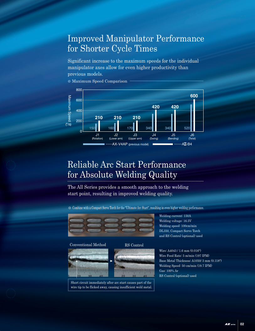
210
150
(Rotation)J2
160
210
(Lower arm)J3
170
210
(Upper arm)J4
340
420
(Swing)J5
340
420
(Bending)J6
(Twist)
520
600
(°/s)
Welding current: 150AWelding voltage: 16.5VWelding speed: 100cm/minDL350, Compact Servo Torch and RS Control (optional) used
Wire: A4043 / 1.6 mm (0.016")Wire Feed Rate: 5 m/min (197 IPM)Base Metal Thickness: A1050/ 3 mm (0.118")Welding Speed: 50 cm/min (19.7 IPM)Gas: 100% ArRS Control (optional) used
⦾ Combine with a Compact Servo Torch for the "Ultimate Arc Start", resulting in even higher welding performance.
Conventional Method RS Control
Short circuit immediately after arc start causes part of the wire tip to be flicked away, causing insufficient weld metal.
⦾ Maximum Speed Comparison
Improved Manipulator Performance for Shorter Cycle TimesSignificant increase to the maximum speeds for the individual manipulator axes allow for even higher productivity than previous models.
Reliable Arc Start Performance for Absolute Welding QualityThe All Series provides a smooth approach to the welding start point, resulting in improved welding quality.
Superior Operational Performance and Welding Quality
0201
0
200
400
600
800
Maxim
um S
peed
AII-B4AX-V4AP (previous model)
J1
210
150
(Rotation)J2
160
210
(Lower arm)J3
170
210
(Upper arm)J4
340
420
(Swing)J5
340
420
(Bending)J6
(Twist)
520
600
(°/s)
Welding current: 150AWelding voltage: 16.5VWelding speed: 100cm/minDL350, Compact Servo Torch and RS Control (optional) used
Wire: A4043 / 1.6 mm (0.016")Wire Feed Rate: 5 m/min (197 IPM)Base Metal Thickness: A1050/ 3 mm (0.118")Welding Speed: 50 cm/min (19.7 IPM)Gas: 100% ArRS Control (optional) used
⦾ Combine with a Compact Servo Torch for the "Ultimate Arc Start", resulting in even higher welding performance.
Conventional Method RS Control
Short circuit immediately after arc start causes part of the wire tip to be flicked away, causing insufficient weld metal.
⦾ Maximum Speed Comparison
Improved Manipulator Performance for Shorter Cycle TimesSignificant increase to the maximum speeds for the individual manipulator axes allow for even higher productivity than previous models.
Reliable Arc Start Performance for Absolute Welding QualityThe All Series provides a smooth approach to the welding start point, resulting in improved welding quality.
0403
Welding large workpieces
Long-Reach Arm Type
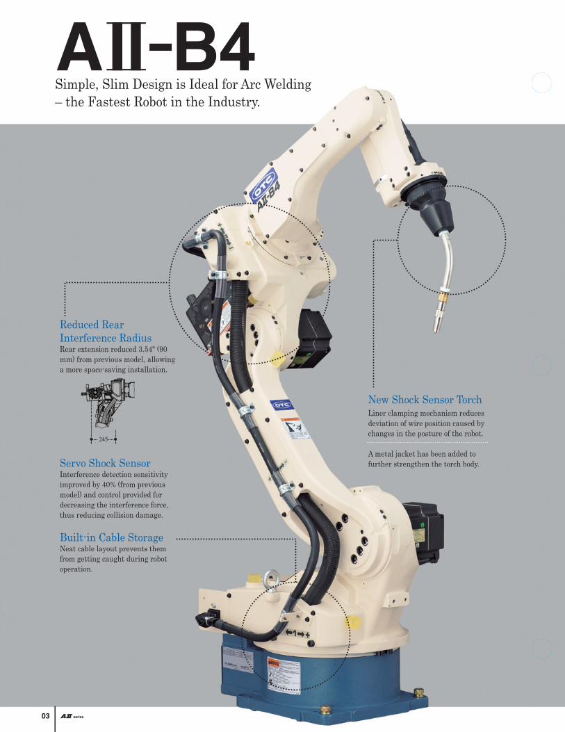
Simple, Slim Design is Ideal for Arc Welding– the Fastest Robot in the Industry.
Through-arm Cable Design Provides Incredible Welding Performance, Operability and Maintainability for the Ideal Arc Welding Solution.
AII-B4L
Circumference Welding(outer and inner)
Welding in Narrow Spaces
245
New Shock Sensor TorchLiner clamping mechanism reduces deviation of wire position caused by changes in the posture of the robot.
A metal jacket has been added to further strengthen the torch body.
Two Arm Lengths available:Standard and Long ReachFrom small to large workpieces, our robots can meet your application needs.
Reduced Rear Interference RadiusRear extension reduced 3.54" (90 mm) from previous model, allowing a more space-saving installation.
Servo Shock SensorInterference detection sensitivity improved by 40% (from previous model) and control provided for decreasing the interference force, thus reducing collision damage.
Built-in Cable StorageNeat cable layout prevents them from getting caught during robot operation.
Cantilever Structure Provides Ease of MaintenanceThe cantilever structure of the upper arm allows complete access to the coaxial cable for easy maintenance and service.
Built-in Coaxial Cable Provides Stable Wire Built-in power cable reduces wire bending, resulting in smooth, stable wire feeding and improved weld quality.
Easy Teaching with Built-in Power CableInterference of the coaxial cable is minimized even with complicated workpiece shapes or fixtures, allowing smoother approaches and teaching for natural welding positions.
Ideal for Offline TeachingSince coaxial cable is routed inside the arm, cable interference is no longer a factor to consider during offline teaching with a PC. This allows easier adoption of the offline program to the actual workpiece.

0403
Welding large workpieces
Long-Reach Arm Type
Simple, Slim Design is Ideal for Arc Welding– the Fastest Robot in the Industry.
Through-arm Cable Design Provides Incredible Welding Performance, Operability and Maintainability for the Ideal Arc Welding Solution.
AII-B4L
Circumference Welding(outer and inner)
Welding in Narrow Spaces
245
New Shock Sensor TorchLiner clamping mechanism reduces deviation of wire position caused by changes in the posture of the robot.
A metal jacket has been added to further strengthen the torch body.
Two Arm Lengths available:Standard and Long ReachFrom small to large workpieces, our robots can meet your application needs.
Reduced Rear Interference RadiusRear extension reduced 3.54" (90 mm) from previous model, allowing a more space-saving installation.
Servo Shock SensorInterference detection sensitivity improved by 40% (from previous model) and control provided for decreasing the interference force, thus reducing collision damage.
Built-in Cable StorageNeat cable layout prevents them from getting caught during robot operation.
Cantilever Structure Provides Ease of MaintenanceThe cantilever structure of the upper arm allows complete access to the coaxial cable for easy maintenance and service.
Built-in Coaxial Cable Provides Stable Wire Built-in power cable reduces wire bending, resulting in smooth, stable wire feeding and improved weld quality.
Easy Teaching with Built-in Power CableInterference of the coaxial cable is minimized even with complicated workpiece shapes or fixtures, allowing smoother approaches and teaching for natural welding positions.
Ideal for Offline TeachingSince coaxial cable is routed inside the arm, cable interference is no longer a factor to consider during offline teaching with a PC. This allows easier adoption of the offline program to the actual workpiece.

New Shock Sensor TorchLiner clamping mechanism reduces deviation of wire position caused by changes in the posture of the robot.
A metal jacket has been added to further strengthen the torch body.
Adaptable to Various Applications.Suitable for handling light articles as well as arc welding applications.
A Highly Versatile Manipulatorfor All Welding Applications.
AII-V20 AX-V16
Increased Range
For TIG Welding
Large Payload Capacity13.2 lbs. (6 kg) payload capacity supports all welding applications including CO2/MAG, MIG and TIG.
Ideal for Ceiling MountingThe working range at the back of the manipulator has been increased for easier ceiling mounting.
Two Arm Lengths available:Standard and Long ReachFrom small to large workpieces, our robots can meet your application needs.
0605
Advanced Operational PerformanceHighly accurate positional repeatability is ±0.003" (0.07 mm). Wrist allowable moment has been improved by 20% over the previous model – provides high operational performance even when welding thick plates that require weaving.
Improved MaintainabilityRobots can now be greased while the torch is mounted. Standardized motors between different robot models reduces the number of service parts.
Slim Arm WidthThe width of the upper arm has been reduced from 5.51" to 5.28" (5.51 mm to 134 mm) – easing interference in tight spaces.
Improved Dustproof and Waterproof Design Equivalent to IP54 (5/6 axes)The AII-V6 utilizes a completely sealed structure, preventing droplets in any direction from causing adverse effects.
Servo Shock SensorInterference detection sensitivity improved by 40% (from previous model) and control provided for easing the interference force, thus reducing collision damage.
Increased Payload CapacityPayload capacity has been increased to 44.1 lbs. (20 kg), providing support for a wider variety of handling applications.

0807
AX21
Characteristics affected by welding environment
Taught Current
Set Current
Welding characteristic data automatically adjusted by simple operation
Result of Adjustment
Taught Data
Differences accounted for due to welding environment
Line Control Panel
Standard PC
The AX21 controller can be used with a wide variety of applications, including arc welding, spot welding and material handling, addressing all kinds of needs in production processes.
PC-based management for compatibility with various applications
A deviation detection program can be run at regular intervals to see if there is any error. If deviation is detected, the calibration program is automatically run for correction.
Example of ladder diagram editing screen
Helps reduce system construction costs
Software PLC Function
For I/O interface with line control panel, field networks such as DeviceNet and CC-Link can be used on top of relay contacts, allowing wiring cost reduction by simplified wiring and flexible system construction according to the user's needs.
Simplified wiring by field network compatibility
Right: Motor speed and actual current of each axis displayed on the teach pendant. Robot Diagnostic Tool
AX21 features improved maintainability by modularization of parts and simplified cable wiring. Users can check preventive maintenance and abnormality diagnosis with the optional Robot Diagnostic Tool.
Simple and quick maintenance functions
Robot Diagnostic Tool
⦾ Torch Deviation is Automatically Detected and Calibrated
Automatic Calibration Function
Adjustments are made so that the actual welding current/voltage will be output in the conditions as taught by accounting for differences in the welding environment such as changes in wire extension.
Fully-equipped with Functions Ensuring Absolute Quality
Arc Data Monitor Function
Welding Characteristic Data Automatic Adjustment Function
Option
Option
Ethernet
Field Network
With the previous model, arc outage during welding caused the robot to pause.
Reduction of Pauses During Welding
Platform
Arc Welding
Spot Welding
Cutting
Sealing
Handling
Thermal Spray
⦾ Simple one-button tool correction
This process eliminates the need for adjustment with torch gauge, significantly reducing robot down time.
Two-point Tool Length Setting Function
Set the torch at the fixed point taught in advance.
Simply press the quick setting button on the teach pendant.
Tool correctionWire position deviated
during torch replacement
Torch bent by hitting
Improved cooling efficiency and dustproofing provides reliable use in severe environments, including production lines with high duty cycles and high-temperature and high-humidity areas.
⦾ Easier addition of external axes than previous model.
Controller with Higher Reliability and Maintainability
AX21 allows automatic restoration of robot operation under predefined conditions, such as the restart position and number of restarts.
Arc Start
Arc End
Cabinet features Improved Resistance to Heat and Dustproofingand Improved Reliability in Global Environments.
1116
865
450
1259
Previous model (AX-C) AX21
Compliant with international safety standards
AX21AX21 AX21
(UL, CE, etc.)
V
V
Quick fluctuations undetectable with the conventional sampling frequency
T
Sampling frequency significantly improved, allowing detection of quick fluctuations
Size and weight of drive unit reduced and single-touch connection of control cable improves maintainability
Up to 16 axes controllable simply by adding an extension case
This prevents weld failure due to deviation, thereby helping reduce
weld failure rates.
Productivity of the robot is significantly improved
Welding Voltage
Welding Voltage
Sampling Time
TSampling Time
Arc Outage
Spatter Control Rates
⦾Welding conditions monitored via teach pendantMonitor welding current, welding voltage, wire feed load, etc. on the teach pendant. Connecting a DL350 additionally shows spatter suppression rates.
⦾ Increased Sampling Frequency Provides Higher Detection AccuracyThe process is used to detect instantaneous arc outages, arc outages in short tack welding, etc. ⦾ Software PLC function for decrease of devices
Interface PLC with line control panel, which is provided by user, can be significantly simplified – reducing your system cost.

1009
Z+
Y+
X+
L,AS
L,AE
Advanced Interface
!
User-friendly Operation
Simple & speedy operation functions
Management FunctionsFurther Simplified Teaching
Visual teaching input assistance
OTC's proprietary Synchromotion option is available for a variety of applications.
Synchromotion
Touch Panel Teach Pendant
Touch Panel Function
Seam Coordinate System
Weaving start instruction teaching screen
Rich functions including :● Sort by Program ● Sort by Step
R
3-position Dead Man Switch
Multi-SynchromotionSynchromotion on multiple stations
Target Program
Step Number
Edit Details
Arc Start Failure Occurrences
User-Friendly Teach Pendant Provides Full Control for High Productivity and Optimal Welding Performance.
TPTeach Pendant
Program Number
Step Number
Option
Option
Jigless SynchromotionSynchromotion between material handling and welding robots
Twin SynchromotionSimultaneous synchromotion of two welding robots
There's no need for multiple-axis key operation necessary with the previous model, simplifying teaching operation
Multi-Window Display FunctionMulti-window display function allows display information of up to four windows.
High-resolution,large color display640 x 480 dot VGA TFT LCD display
Visual OperationIntuitive icon menu is easy to understand.
Reduced Number of OperationsFeatures like our Dedicated Keys, Seam Coordinate System, and Speed Collective Conversion reduce the overall number of key strokes required to program.
Function Keys for Simple OperationAssign frequently used instructions from simple icon instructions.
Improved Operability via Dedicated KeysTeaching time reduced by dedicated keys, including P, L, C, AS, WS, Input and Output.
⦾ Visualized teaching itemsTeaching items such as welding and weaving conditions are visualized for ultimate ease of setting.
⦾ Seam coordinate systemUse of seam coordinate system allows movement in the direction of seam or wire extension simply by single-axis operation of the teach pendant.
⦾ Weld Failure Management FunctionSearch and sort functions allow quick, accurate identification of causes of pauses due to weld failure for improved productivity.
⦾ Operate Tooling Switches via the Teach PendantIndicators and switches, previously located on the operation panel, can also be assigned to the teaching pendant.
⦾ Editing History DisplayTask programs and items of welding condition editing history can be sorted by date/time and program, allowing simple viewing of who edited what.
⦾ User Inspection FunctionNotifies operator of periodic robot inspections or part replacements via teach pendant message display or external output signal, which can be used for preventive maintenance of robot.

4- 18 mm 11.81”(300 mm)
R 10.91” (277 m
m)
5.28” (134 mm)
R 15.71”(399 mm)
R 55.2” (1402 mm
)
50°
230°
90°
155°
3.94”(100 mm)
48.9
” (12
42 m
m)
46.7
7” (1
188
mm
)
55.2” (1402 mm)
39.49”(1003 mm)
15.71” (399 mm)
42.6”(1082 mm)
6.3” (160 mm)
25.59”(650 mm)
A -V6 A -V6
170°
170°
170°
170°P-point Working Range
P-point Working Range
P-point Working Range
P-point Working Range
P-point2.27”
(57 mm)
2.26”(57.5 mm)
5.12”(130 mm)
R 15
.04”
(382
mm
)P-point
P-point Working Range P-point Working Range
P-point Working Range
170°
170°
R 79.06” (2008 mm)
5°
30°
115°
100° 155°
75°
45°
225°
55.95”(1421 mm)
71.7
7” (1
823
mm
)58
.98”
(175
2 m
m)
64.49” (1638 mm)
23.11”(587 mm)
79.06” (2008 mm)
40.95”(1040 mm)
7.28”(185 mm)
170°
170°
5.28”(134 mm)
R 78.98” (2006 mm)
R 23.54”(598 mm)
R 12
.48” (
317 m
m)
10°
P-point Working Range
55.43”(1408 mm)
71.6
9” (1
821
mm
)58
.86”
(174
9 m
m)
34.41” (1636 mm)
23.54”(598 mm)
78.98” (2006 mm)
50°
230°
41.34”(1050 mm)
100° 115°
35°
155°
75°
R 5
5.55
” (14
11 m
m)
R 13.07
” (33
2 mm)
49.2
5” (1
251
mm
)47
.09”
(119
6 m
m)
55.55” (1411 mm)
39.06”(992 mm)16.46”
(418 mm)
225°
45°
42.95”(1091 mm)
6.3”(160 mm)
25.2”(640 mm)
8.66”(220 mm)
P-point
P-point
P-point
P-point
P-point
P-point
Standard Long Reach Standard Long Reach
4- 18 mm
Manipulator Working Range *The figures below show working ranges of P-point with no torch mounted.
11.81”(300 mm)
R 23.5(597 mm)5.12”
(130 mm)
11.81”(300 mm)
R 10.91”
(277 mm)
11.81”(300 mm)
R 16.46”(418 mm)
16.93”(430 mm)
22.83”(580 mm)
7.87”(200 mm)
8.66”(220 mm)
20.67”(525 mm)
29.92”(760 mm)
8.66”(220 mm)
16.93”(430 mm)
22.83”(580 mm)
4.92”(125 mm)
20.67”(525 mm)
29.92”(760 mm)
5.91”(150 mm)
7.28”(185 mm)
3.94”(100 mm)
19.69”(500mm)
19.69”(500mm)
19.69”(500mm)
19.69”(500mm)
19.69”(500mm)
19.69”(500mm)
19.69”(500mm)
19.69”(500mm)
1211

4- 18 mm 11.81”(300 mm)
R 10.91” (277 m
m)
5.28” (134 mm)
R 15.71”(399 mm)
R 55.2” (1402 mm
)
50°
230°
90°
155°
3.94”(100 mm)
48.9
” (12
42 m
m)
46.7
7” (1
188
mm
)
55.2” (1402 mm)
39.49”(1003 mm)
15.71” (399 mm)
42.6”(1082 mm)
6.3” (160 mm)
25.59”(650 mm)
A -V6 A -V6
170°
170°
170°
170°P-point Working Range
P-point Working Range
P-point Working Range
P-point Working Range
P-point2.27”
(57 mm)
2.26”(57.5 mm)
5.12”(130 mm)
R 15
.04”
(382
mm
)
P-point
P-point Working Range P-point Working Range
P-point Working Range
170°
170°
R 79.06” (2008 mm)
5°
30°
115°
100° 155°
75°
45°
225°
55.95”(1421 mm)
71.7
7” (1
823
mm
)58
.98”
(175
2 m
m)
64.49” (1638 mm)
23.11”(587 mm)
79.06” (2008 mm)
40.95”(1040 mm)
7.28”(185 mm)
170°
170°
5.28”(134 mm)
R 78.98” (2006 mm)
R 23.54”(598 mm)
R 12
.48” (
317 m
m)
10°
P-point Working Range
55.43”(1408 mm)
71.6
9” (1
821
mm
)58
.86”
(174
9 m
m)
34.41” (1636 mm)
23.54”(598 mm)
78.98” (2006 mm)
50°
230°
41.34”(1050 mm)
100° 115°
35°
155°
75°
R 5
5.55
” (14
11 m
m)
R 13.07
” (33
2 mm)
49.2
5” (1
251
mm
)47
.09”
(119
6 m
m)
55.55” (1411 mm)
39.06”(992 mm)16.46”
(418 mm)
225°
45°
42.95”(1091 mm)
6.3”(160 mm)
25.2”(640 mm)
8.66”(220 mm)
P-point
P-point
P-point
P-point
P-point
P-point
Standard Long Reach Standard Long Reach
4- 18 mm
Manipulator Working Range *The figures below show working ranges of P-point with no torch mounted.
11.81”(300 mm)
R 23.5(597 mm)5.12”
(130 mm)
11.81”(300 mm)
R 10.91”
(277 mm)
11.81”(300 mm)
R 16.46”(418 mm)
16.93”(430 mm)
22.83”(580 mm)
7.87”(200 mm)
8.66”(220 mm)
20.67”(525 mm)
29.92”(760 mm)
8.66”(220 mm)
16.93”(430 mm)
22.83”(580 mm)
4.92”(125 mm)
20.67”(525 mm)
29.92”(760 mm)
5.91”(150 mm)
7.28”(185 mm)
3.94”(100 mm)
19.69”(500mm)
19.69”(500mm)
19.69”(500mm)
19.69”(500mm)
19.69”(500mm)
19.69”(500mm)
19.69”(500mm)
19.69”(500mm)
1211
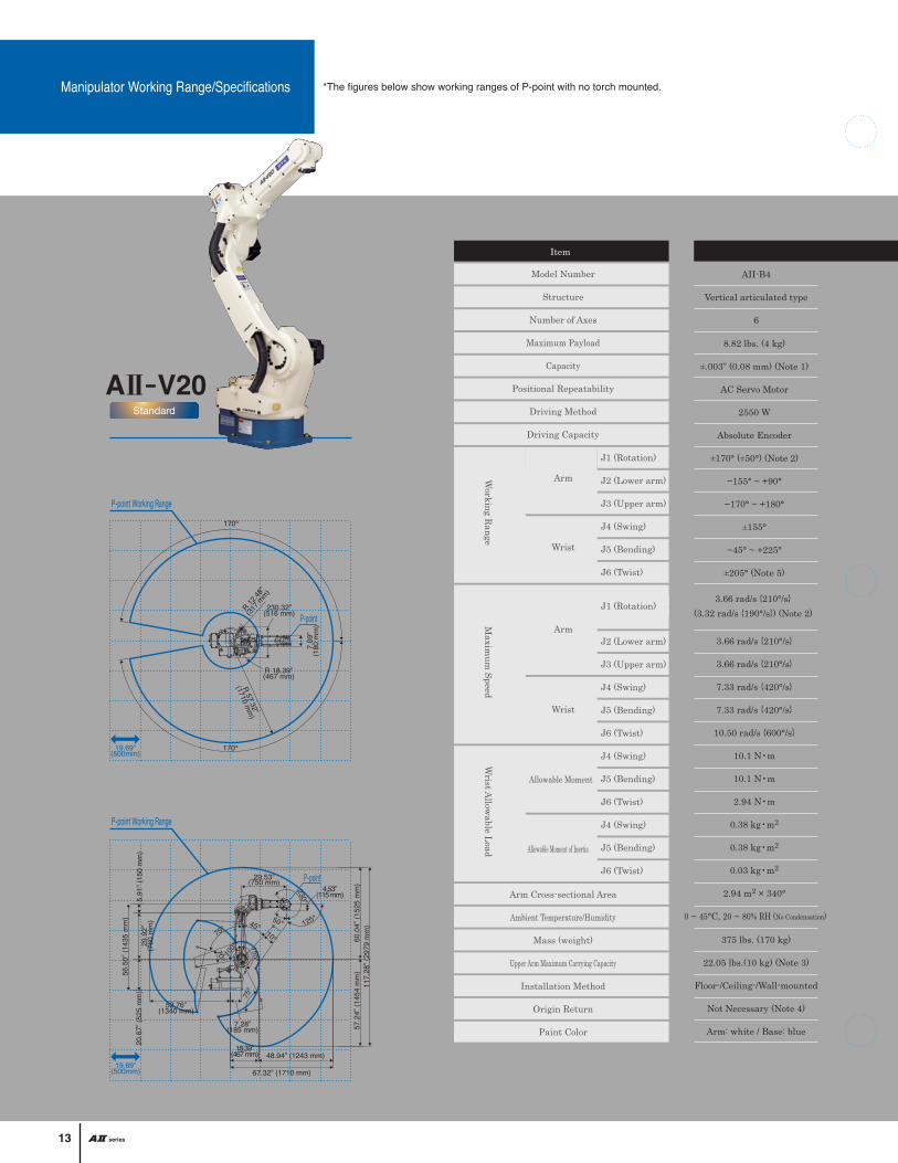
Manipulator Working Range/Specifications *The figures below show working ranges of P-point with no torch mounted.
Standard
A -V20
170°
170°
230.32”(516 mm)
R 57.32”
(1710 mm
)
R 18.39”(467 mm)
R 12.48
”
(317 m
m)
7.09
”(1
80 m
m)
P-point Working Range
P-point Working Range
50°75° 125°
230°
48.94” (1243 mm)
4.53”(115 mm)
29.53”(750 mm)
5.91
” (15
0 m
m)
29.9
2”(7
60 m
m)
20.6
7” (5
25 m
m)
60.0
4” (1
525
mm
)57
.24”
(145
4 m
m)
52.76”(1340 mm)
18.39”(467 mm)
67.32” (1710 mm)
7.28”(185 mm)
10°
117.
28” (
2979
mm
)
56.5
0” (1
435
mm
)
10°
45°
100° 155°
75°
1. Measured value obtained after sufficient repetition of automatic operation for stabilizing conditions of manipulator operation with upper arm maximum carrying capacity. 2. The value shown in ( ) indicates wall-mounted conditions. 3. When the output flange of the wrist axis is loaded with maximum payload capacity.4. Positional data is protected by battery-backed storage inside the manipulator. 5. Working range of J6 axis may be restricted by the position of J5 axis.6. Working range of J2 axis may be restricted when wall-mounted. 7. Working range of J3 axis is restricted to -170°to +205° for floor-mounted welding applications.*These specifications are subject to change without prior notice.
Note
Model Number
Structure
Number of Axes
Maximum Payload
Capacity
Positional Repeatability
Driving Method
Driving Capacity
Position Feedback
Arm Cross-sectional Area
Ambient Temperature/Humidity
Mass (weight)
Upper Arm Maximum Carrying Capacity
Installation Method
Origin Return
Paint Color
J1 (Rotation)
J2 (Lower arm)
J3 (Upper arm)
J4 (Swing)
J5 (Bending)
J6 (Twist)
J1 (Rotation)
J2 (Lower arm)
J3 (Upper arm)
J4 (Swing)
J5 (Bending)
J6 (Twist)
J4 (Swing)
J5 (Bending)
J6 (Twist)
J4 (Swing)
J5 (Bending)
J6 (Twist)
Arm
Wrist
Arm
Wrist
Allowable Moment
Allowable Moment of Inertia
Working R
angeM
aximum
SpeedW
rist Allow
able Load
8.82 lbs. (4 kg)
±.003” (0.08 mm) (Note 1)
AC Servo Motor
2550 W
Absolute Encoder
±170° (±50°) (Note 2)
−155° ~ +90°
−170° ~ +180°
±155°
−45° ~ +225°
±205° (Note 5)
3.66 rad/s {210°/s}
3.66 rad/s {210°/s}
7.33 rad/s {420°/s}
7.33 rad/s {420°/s}
10.50 rad/s {600°/s}
10.1 N•m
10.1 N•m
2.94 N•m
0.38 kg•m2
0.38 kg•m2
0.03 kg•m2
2.94 m2 × 340°
0 ~ 45°C, 20 ~ 80% RH (No Condensation)
3.66 rad/s {210°/s}(3.32 rad/s {190°/s}) (Note 2)
8.8 lbs. (4 kg)
±.003” (0.08 mm) (Note 1)
AC Servo Motor
4650 W
Absolute Encoder
±170° (±50°) (Note 2, 6)
−155° ~ +100°
−170° ~ +190°
±155°
−45° ~ +225°
±205° (Note 5)
3.49 rad/s {200°/s}
3.49 rad/s {200°/s}
7.33 rad/s {420°/s}
7.33 rad/s {420°/s}
10.5 rad/s {600°/s}
10.1 N•m
10.1 N•m
2.94 N•m
0.38 kg•m2
0.38 kg•m2
0.03 kg•m2
6.37 m2 × 340°
3.40 rad/s {195°/s}(3.05 rad/s {175°/s}) (Note 2)
13.2 lbs. (6 kg)
±.003” (0.08 mm) (Note 1)
AC Servo Motor
2600 W
Absolute Encoder
±170° (±50°) (Note 2)
−155° ~ +90°
−170° ~ +190°
±180°
−50° ~ +230°
±360°
3.66 rad/s {210°/s}
3.66 rad/s {210°/s}
7.33 rad/s {420°/s}
7.33 rad/s {420°/s}
10.82 rad/s {620°/s}
11.8 N•m
9.8 N•m
5.9 N•m
0.30 kg•m2
0.25 kg•m2
0.06 kg•m2
3.14 m2 × 340°
3.66 rad/s {210°/s}(3.32 rad/s {190°/s}) (Note 2)
13.2 lbs. (6 kg)
±.003” (0.08 mm) (Note 1)
AC Servo Motor
5000 W
Absolute Encoder
±170° (±50°) (Note 2, 6)
−155° ~ +100°
−170° ~ +260° (Note 7)
±180°
−50° ~ +230°
±360°
3.49 rad/s {200°/s}
3.49 rad/s {200°/s}
7.33 rad/s {420°/s}
7.33 rad/s {420°/s}
10.82 rad/s {620°/s}
11.8 N•m
9.8 N•m
5.9 N•m
0.30 kg•m2
0.25 kg•m2
0.06 kg•m2
7.57 m2 × 340°
3.40 rad/s {195°/s}(3.05 rad/s {175°/s}) (Note 2)
44.1 (20 kg)
±.003” (0.07 mm) (Note 1)
AC Servo Motor
5600 W
Absolute Encoder
±170° (±50°) (Note 2, 6)
−155° ~ +100°
−170° ~ +260° (Note 7)
±180°
−50° ~ +230°
±360°
3.33 rad/s {190°/s}
3.14 rad/s {180°/s}
6.98 rad/s {400°/s}
6.98 rad/s {400°/s}
10.5 rad/s {600°/s}
43.7 N•m
43.7 N•m
19.6 N•m
1.09 kg•m2
1.09 kg•m2
0.24 kg•m2
5.31 m2 × 340°
3.40 rad/s {195°/s}(3.05 rad/s {175°/s}) (Note 2)
SpecificationItem
AII-B4
Vertical articulated type
6
AII-B4L AII-V6 AII-V6L AII-V20
375 lbs. (170 kg)
22.05 lbs.(10 kg) (Note 3)
Floor-/Ceiling-/Wall-mounted
Not Necessary (Note 4)
Arm: white / Base: blue
617 lbs. (280 kg)
44.09 lbs. (20 kg) (Note 3)
353 lbs. (160 kg)
22.05 lbs.(10 kg) (Note 3)
617 lbs. (280 kg)
44.09 lbs. (20 kg) (Note 3)
628 lbs. (285 kg)
44.09 lbs. (20 kg) (Note 3)
19.69”(500mm)
P-point
P-point
1413
19.69”(500mm)

NoteThis product and the technologies (including software) used in the product are subject to Catch-All Controls. When exporting any of them, verify the users, applications, etc. according to the applicable laws and regulations and take appropriate procedures such as applications for export permission to the Minister of Economy, Trade and Industry if required.
CAT. NO. R0001-1
●The information contained in this catalog is current as of August 2008 and is subject to revision without notice.●This catalog was printed with environmentally-friendly soy oil ink.
Basic Configuration
CO2/MAG Welding Torches
Shock Sensor Torch Forced Pressurized Power Feeding Torch (TCC Torch)
Compact Servo Torch
Manipulator1
Controller2
Teach pendant3
Operation Box4
Control cable 1/25
Number and Part Name Model Specification
AII-V6(Model: NV61- N E F N )
AX21(Model: AX21- E V O ***)
A2TPDSNN- E C **
AXOP- 0 0 **
A2RB-10**
RZ3500
Model Rated current (MAG rating shown in parentheses)
Duty cycle (MAG rating shown in parentheses)
350A (350A) 80% (60%)R T 3 5 0 0R T 5 0 0 0RTW5000
Model Rated current (MAG rating shown in parentheses)
Duty cycle (MAG rating shown in parentheses)
350A (350A)500A (350A)500A (400A)
80% (60%)50% (70%)70% (60%)
MTXC-3541PSMTXCW-5041PS
Model Rated current (MAG rating shown in parentheses)
Duty cycle (MAG rating shown in parentheses)
350A (250A)500A (350A)
50% (50%)70% (50%)
Best selling CO2/MAG torch compatible with built-in shock sensor Improved welding quality
due to stabilized power fed wire.
AC servo motor provides stable wire feeding for high accuracy and high quality.
Shock Sensor Torch for V-type manipulator:RT3500
Compact Servo TorchMTXC-3541PS
Photo MTXC-3541PS mounted on pull feeder*The Compact Servo Torch requires the Assist Feeder.Photo: Shock sensor unit SSV mounted.Photo: Shock sensor unit SSV mounted.
Forced Pressurized Power Feeding Torch for V-type manipulator: RZ3500
CECU
::::
NJFN
::::
StandardJapaneseFloor-mountedStandard
Welding cable equipment optionOverseas (English)Ceiling mounted W: Wall-mountedUL-compliant
E
1
:
:
JVO
:::
JapaneseNV6, NB4No external axes
English C: CE certified U: UL certified W: CE-/UL-certified(type of connected manipulator)1: 1 external axis 2: 2 external axes (external axis in main cabinet)
J ::
Japanese0815
:E English U: UL certified 8m Model (standard)15m Model
**
O ::
Standard051015
:1 UL certified 5m Model (standard)10m Model15m Model
**
: 051015
5m Model (standard)10m Model15m Model
**
13
5
4
2
True digital welding machines designedmeet all of your robotic arc welding needs
InverterInverter
ADVANCED ARC WELDING ROBOTS
AII-B4 • B4L • V6 • V6L • V20AII Series
CAT. NO. R0001-1
OTC DAIHEN INC.(Service Center)5311 W. T. Harris Blvd., WestCharlotte, NC 28269
OTC DAIHEN INC.(Headquarters)1400 Blauser Dr.Tipp City, OH 45371Ph: 937-667-0800Fax: 937-667-0885
OTC DAIHEN INC.(Atlanta Branch)2964 Northeast Parkway NWAtlanta, GA 30360
OTC DAIHEN INC.(Detroit Branch)22241 Roethel Drive,Suite ANovi, MI 48375
OTC DAIHEN, Inc. reserves the right to change specifications without notice. © OTC DAIHEN, Inc. Printed in U.S.A.
Configuration