conf 401 manual
DESCRIPTION
hartTRANSCRIPT

©Springfield Research Corp. 1 CONF401manual - 1014
HART®
Fieldbus Profibus Intrinsic Safety Configuration Tools Semiconductors Training Custom Design
HART® Configurator Software
CONF401
Manual and Reference Guide
Visit Springfield Research at:
www.springres.us
©Springfield Research Corp. 2 CONF401manual - 1014
Table of Contents Installation 5
Getting Started 6
Opening the CONF401 HART® Configurator Software 6
Navigating through the CONF401 HART® Configurator 7
Creating a New Offline Device 8
Opening an Offline Device File 9
Opening a HPC301 Database File 10
Using the HPC Conduit Software 11
Polling Devices 12
Polling for a Single Device by Address 12
Polling for a Single Device by Tag 13
Polling for Multiple Devices 14
Utility Functions 15
Changing the Communication Port 15
Changing the Communication Port for Enhanced Settings 16
Using the Preferences Page 17
Setting the Auto Poll option 18
Changing the Look & Feel of the CONF401 19
Setting the Executable File Locations 21
Setting the Graphing Color Options 21
Learning About the CONF401 HART Configurator 23
Opening the HART Network Frame 23
HART Serial Monitor 24
HART Serial Monitor File Menu 24
Device Form Data 27
Creating a New Device Form 27
Opening a Device Form 27
©Springfield Research Corp. 3 CONF401manual - 1014
Table of Contents HART Network Frame 39
Device References 40
Adding Devices to the HART Network Frame 40
Offline Directory Tree Popup Menu 41
Offline Device Popup Menu 42
Downloading an Offline Device 43
Exporting Device Data to a HPC301 Database File 44
Printing Offline Device Data 45
Exporting Offline Device Data 47
Closing an Offline Device 48
Online Device Popup Menu 49
Opening an Online Device 50
Uploading an Online Device 50
Printing an Online Device 51
Exporting Online Device Data 52
Closing an Online Device 53
Device Frame 54
Device Frame Layout 54
Device Title 55
Device Panels 55
Field Labels 55
Editing Fields 56
Option Fields 57
Save/Send Button 57
Generic Device Frame 58
Information Panel 59
Device Info Panel 61
Monitor Panel 62
©Springfield Research Corp. 4 CONF401manual - 1014
Table of Contents
Specific Monitor Panel 63
Variable Codes Panel 64
Device Status Panel 65
Range Panel 66
Configuration Panel 69
Maintenance Panel 70
Self Test 70
Additional Status 71
Device Reset 72
Loop Test 72
Burst Mode 73
Trim Panel 74
Current Trim 74
Zero Trim 75
Multidrop Panel 76
Graphics Panel 77
Notes Panel 80
Shortcut Keys and Power User Commands 81
Supported HART® Commands 82
Troubleshooting 84

©Springfield Research Corp. 5 CONF401manual - 1014
Installation
Installing the CONF401 HART Configurator Software
1. Place your CONF401 HART Configurator CD into your CD-ROM drive. 2. From Windows Explorer, locate the jinstall.exe file on your CD drive. 3. Start the setup process by double clicking on this file. 4. Follow the on screen instructions.
If there are any complications, please refer to the README.txt file located on your CD.
©Springfield Research Corp. 6 CONF401manual - 1014
Getting Started Opening the CONF401 HART® Configurator Software From the Windows Start menu
1. Select Programs. 2. Select the CONF401 listing.
From your desktop
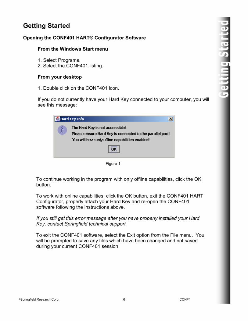
1. Double click on the CONF401 icon. If you do not currently have your Hard Key connected to your computer, you will see this message:
To continue working in the program with only offline capabilities, click the OK button. To work with online capabilities, click the OK button, exit the CONF401 HART Configurator, properly attach your Hard Key and re-open the CONF401 software following the instructions above. If you still get this error message after you have properly installed your Hard Key, contact Springfield technical support. To exit the CONF401 software, select the Exit option from the File menu. You will be prompted to save any files which have been changed and not saved during your current CONF401 session.
Figure 1
©Springfield Research Corp. 7 CONF401manual - 1014
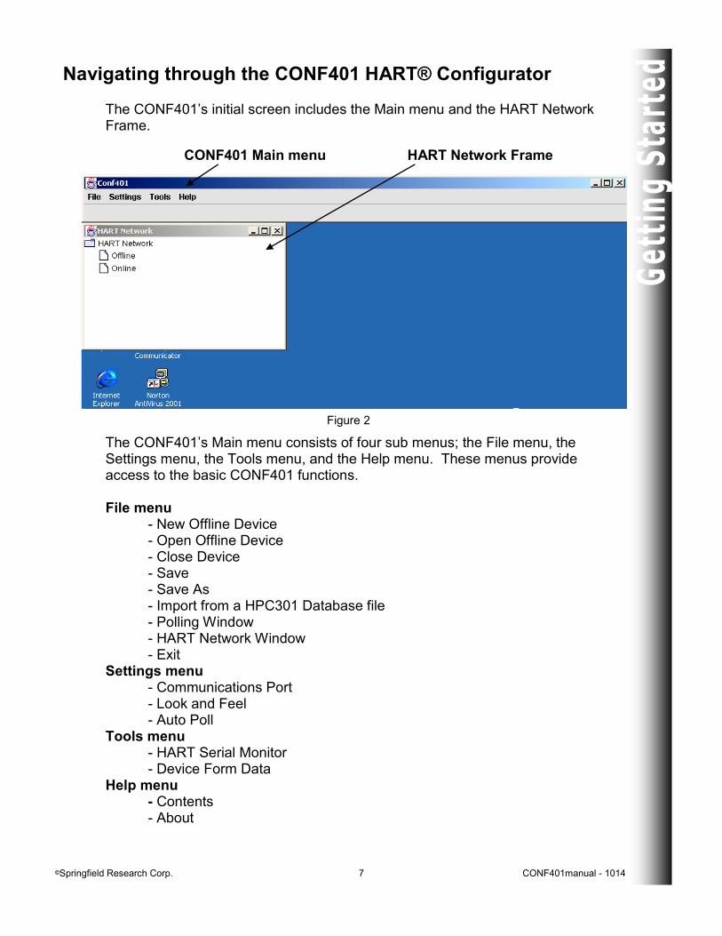
Navigating through the CONF401 HART® Configurator The CONF401’s initial screen includes the Main menu and the HART Network Frame.
The CONF401’s Main menu consists of four sub menus; the File menu, the Settings menu, the Tools menu, and the Help menu. These menus provide access to the basic CONF401 functions. File menu - New Offline Device - Open Offline Device - Close Device - Save - Save As - Import from a HPC301 Database file - Polling Window - HART Network Window - Exit Settings menu - Communications Port - Look and Feel - Auto Poll Tools menu - HART Serial Monitor - Device Form Data Help menu - Contents - About
Figure 2
CONF401 Main menu HART Network Frame
©Springfield Research Corp. 8 CONF401manual - 1014
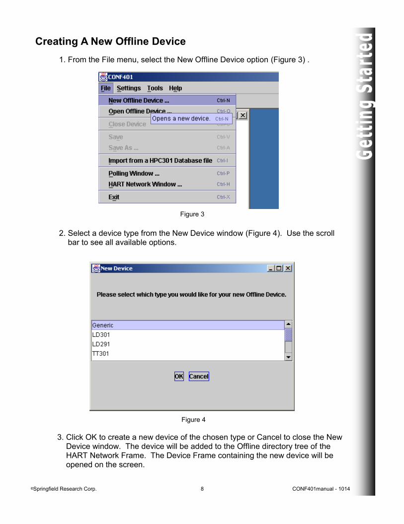
Creating A New Offline Device
1. From the File menu, select the New Offline Device option (Figure 3) . 2. Select a device type from the New Device window (Figure 4). Use the scroll
bar to see all available options.
3. Click OK to create a new device of the chosen type or Cancel to close the New Device window. The device will be added to the Offline directory tree of the HART Network Frame. The Device Frame containing the new device will be opened on the screen.
Figure 3
Figure 4
©Springfield Research Corp. 9 CONF401manual - 1014
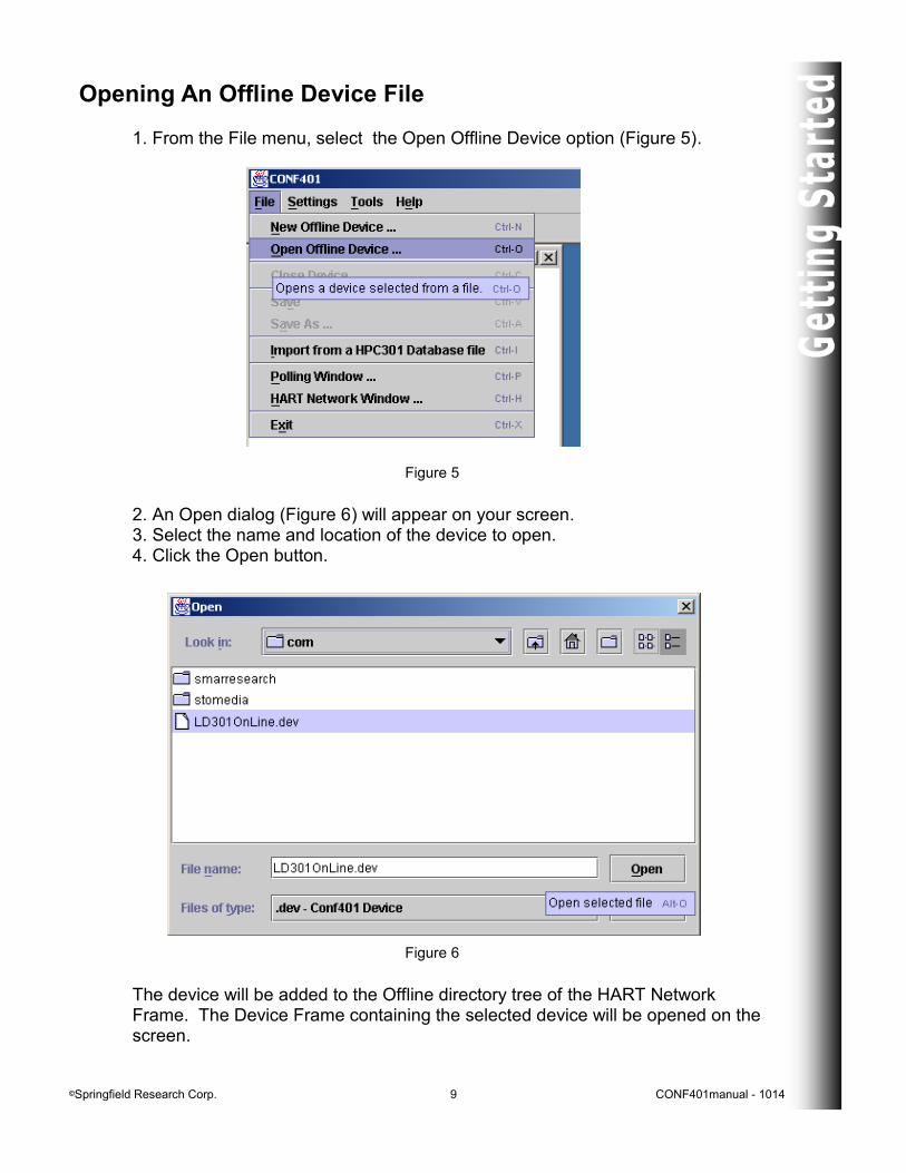
Opening An Offline Device File
1. From the File menu, select the Open Offline Device option (Figure 5).
Figure 6
2. An Open dialog (Figure 6) will appear on your screen. 3. Select the name and location of the device to open. 4. Click the Open button.
Figure 5
The device will be added to the Offline directory tree of the HART Network Frame. The Device Frame containing the selected device will be opened on the screen.
©Springfield Research Corp. 10 CONF401manual - 1014
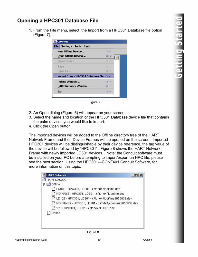
Opening a HPC301 Database File
1. From the File menu, select the Import from a HPC301 Database file option (Figure 7).
2. An Open dialog (Figure 6) will appear on your screen. 3. Select the name and location of the HPC301 Database device file that contains the palm devices you would like to import. 4. Click the Open button. The imported devices will be added to the Offline directory tree of the HART Network Frame and their Device Frames will be opened on the screen. Imported HPC301 devices will be distinguishable by their device reference, the tag value of the device will be followed by “HPC301”. Figure 8 shows the HART Network Frame with newly imported LD301 devices. Note: the Conduit software must be installed on your PC before attempting to import/export an HPC file, please see the next section, Using the HPC301—CONF401 Conduit Software, for more information on this topic.
Figure 7
Figure 8

©Springfield Research Corp. 11 CONF401manual - 1014
Using the HPC301—CONF401 Conduit Software
1. Install the HPC301-CONF401Conduit software on the PC that already has the Palm Desktop software and the CONF401 software installed. 2. Create some HPC301 records in your HPC301 application. (HPC301 version 3.15 or later, and CONF401 version 2.12 or later.) 3. Execute a HotSync. 4. On your PC, look for files with the extension .hpc, they will be located in your <palm folder>\<user name>\HPC301DB directory. You will find 5 files, HPCLD301.hpc, HPCGENERIC.hpc, HPCFY301.hpc, HPCDT301.hpc, and HPCTT301.hpc. These are the files that should be used when importing and exporting palm devices with the PC. 5. Once the files have been edited, execute a HotSync to update the Palm files.
©Springfield Research Corp. 12 CONF401manual - 1014
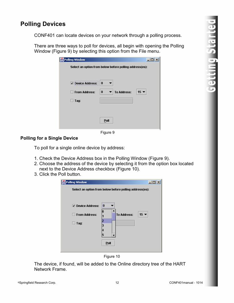
Polling Devices
CONF401 can locate devices on your network through a polling process. There are three ways to poll for devices, all begin with opening the Polling Window (Figure 9) by selecting this option from the File menu.
Polling for a Single Device
To poll for a single online device by address: 1. Check the Device Address box in the Polling Window (Figure 9). 2. Choose the address of the device by selecting it from the option box located next to the Device Address checkbox (Figure 10). 3. Click the Poll button. The device, if found, will be added to the Online directory tree of the HART Network Frame.
Figure 9
Figure 10
©Springfield Research Corp. 13 CONF401manual - 1014
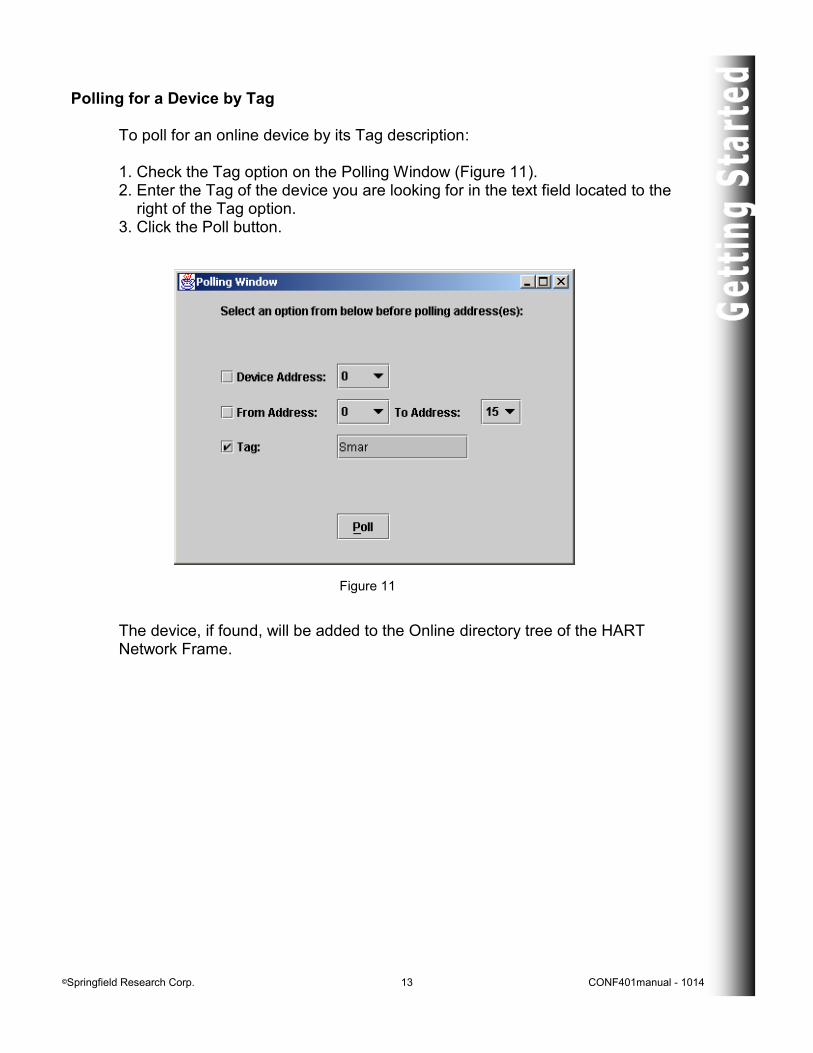
Polling for a Device by Tag To poll for an online device by its Tag description: 1. Check the Tag option on the Polling Window (Figure 11). 2. Enter the Tag of the device you are looking for in the text field located to the right of the Tag option. 3. Click the Poll button. The device, if found, will be added to the Online directory tree of the HART Network Frame.
Figure 11
©Springfield Research Corp. 14 CONF401manual - 1014
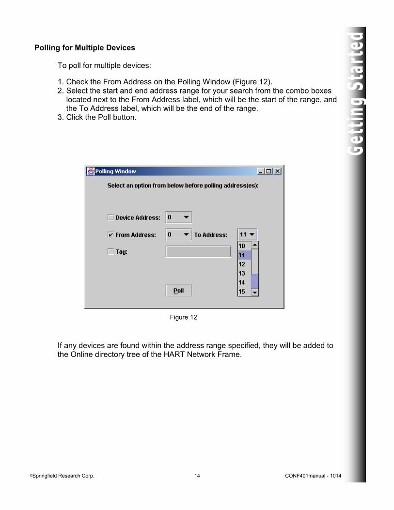
Polling for Multiple Devices To poll for multiple devices:
1. Check the From Address on the Polling Window (Figure 12). 2. Select the start and end address range for your search from the combo boxes located next to the From Address label, which will be the start of the range, and the To Address label, which will be the end of the range. 3. Click the Poll button.
Figure 12
If any devices are found within the address range specified, they will be added to the Online directory tree of the HART Network Frame.
©Springfield Research Corp. 15 CONF401manual - 1014
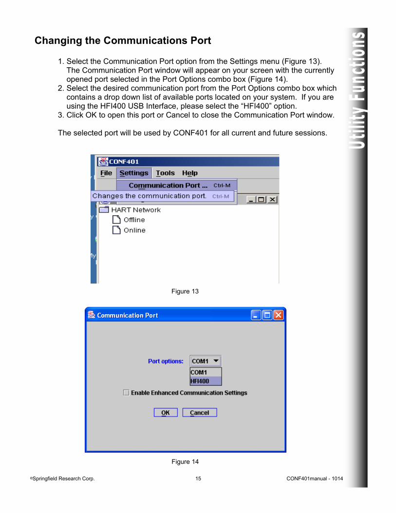
Changing the Communications Port 1. Select the Communication Port option from the Settings menu (Figure 13). The Communication Port window will appear on your screen with the currently opened port selected in the Port Options combo box (Figure 14). 2. Select the desired communication port from the Port Options combo box which contains a drop down list of available ports located on your system. If you are using the HFI400 USB Interface, please select the “HFI400” option. 3. Click OK to open this port or Cancel to close the Communication Port window. The selected port will be used by CONF401 for all current and future sessions.
Figure 14
Figure 13
©Springfield Research Corp. 16 CONF401manual - 1014
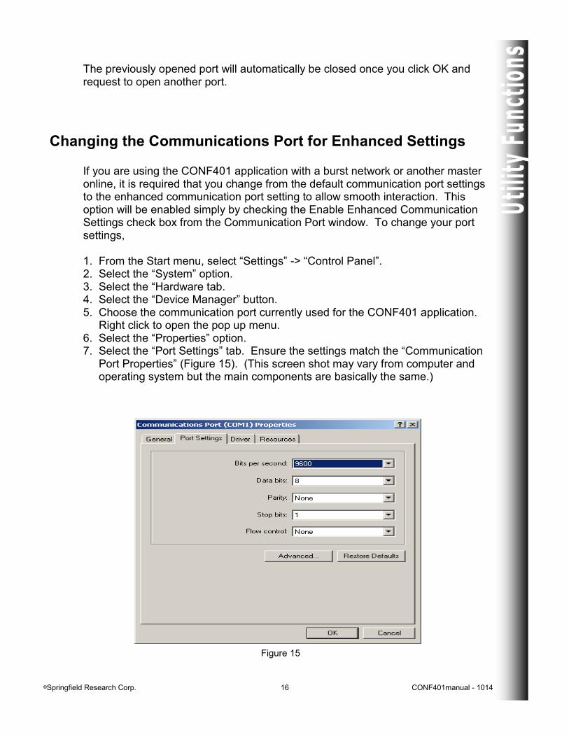
The previously opened port will automatically be closed once you click OK and request to open another port.
Changing the Communications Port for Enhanced Settings If you are using the CONF401 application with a burst network or another master online, it is required that you change from the default communication port settings to the enhanced communication port setting to allow smooth interaction. This option will be enabled simply by checking the Enable Enhanced Communication Settings check box from the Communication Port window. To change your port settings, 1. From the Start menu, select “Settings” -> “Control Panel”. 2. Select the “System” option. 3. Select the “Hardware tab. 4. Select the “Device Manager” button. 5. Choose the communication port currently used for the CONF401 application. Right click to open the pop up menu. 6. Select the “Properties” option. 7. Select the “Port Settings” tab. Ensure the settings match the “Communication Port Properties” (Figure 15). (This screen shot may vary from computer and operating system but the main components are basically the same.)
Figure 15
©Springfield Research Corp. 17 CONF401manual - 1014
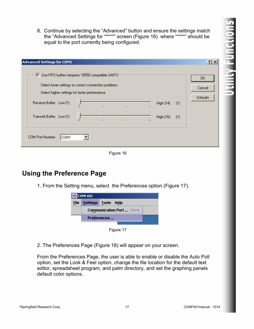
Figure 16
8. Continue by selecting the “Advanced” button and ensure the settings match the “Advanced Settings for *****” screen (Figure 16) where “****” should be equal to the port currently being configured.
Using the Preference Page
1. From the Setting menu, select the Preferences option (Figure 17).
Figure 17
2. The Preferences Page (Figure 18) will appear on your screen. From the Preferences Page, the user is able to enable or disable the Auto Poll option, set the Look & Feel option, change the file location for the default text editor, spreadsheet program, and palm directory, and set the graphing panels default color options.
©Springfield Research Corp. 18 CONF401manual - 1014
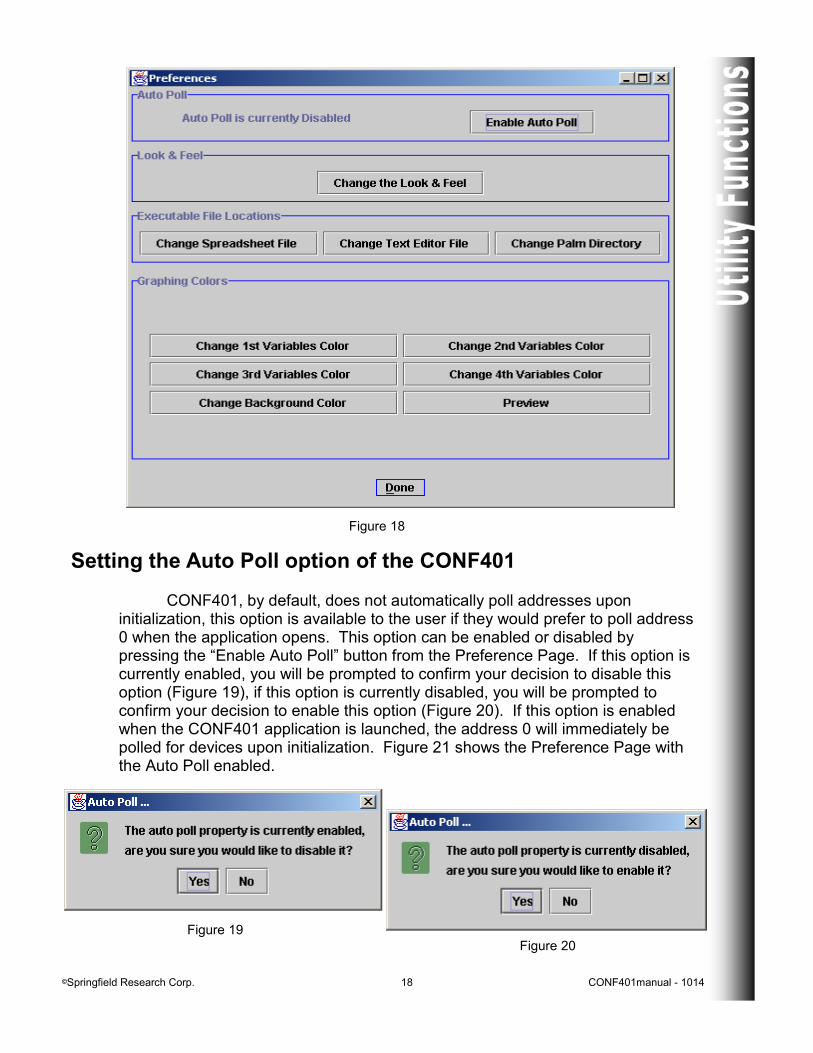
Figure 18
Setting the Auto Poll option of the CONF401 CONF401, by default, does not automatically poll addresses upon initialization, this option is available to the user if they would prefer to poll address 0 when the application opens. This option can be enabled or disabled by pressing the “Enable Auto Poll” button from the Preference Page. If this option is currently enabled, you will be prompted to confirm your decision to disable this option (Figure 19), if this option is currently disabled, you will be prompted to confirm your decision to enable this option (Figure 20). If this option is enabled when the CONF401 application is launched, the address 0 will immediately be polled for devices upon initialization. Figure 21 shows the Preference Page with the Auto Poll enabled.
Figure 19
Figure 20
©Springfield Research Corp. 19 CONF401manual - 1014
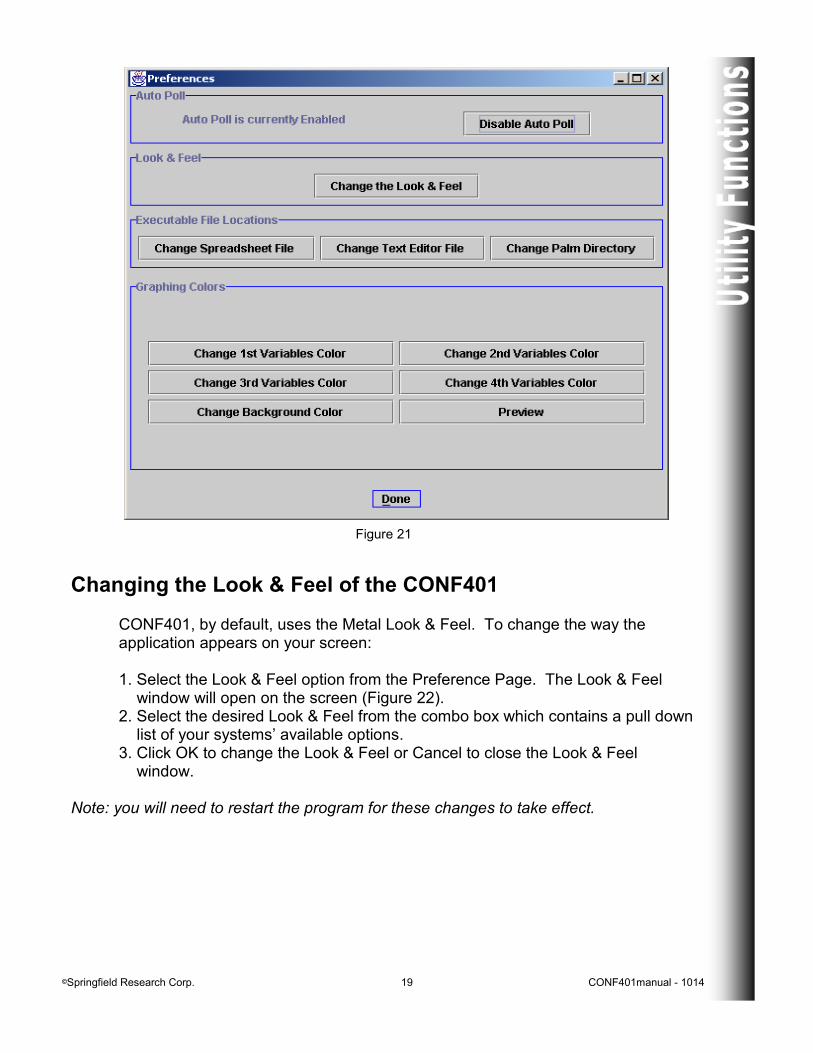
Figure 21
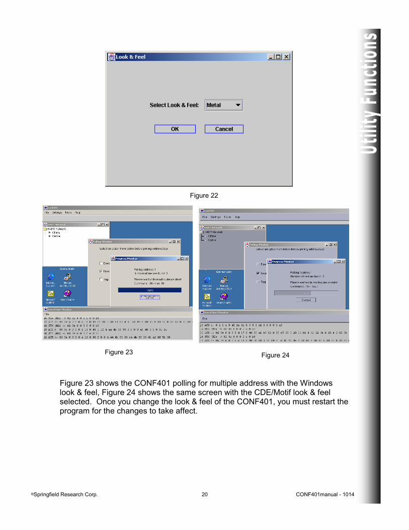
Changing the Look & Feel of the CONF401 CONF401, by default, uses the Metal Look & Feel. To change the way the application appears on your screen: 1. Select the Look & Feel option from the Preference Page. The Look & Feel window will open on the screen (Figure 22). 2. Select the desired Look & Feel from the combo box which contains a pull down list of your systems’ available options. 3. Click OK to change the Look & Feel or Cancel to close the Look & Feel window. Note: you will need to restart the program for these changes to take effect.
©Springfield Research Corp. 20 CONF401manual - 1014
Figure 22
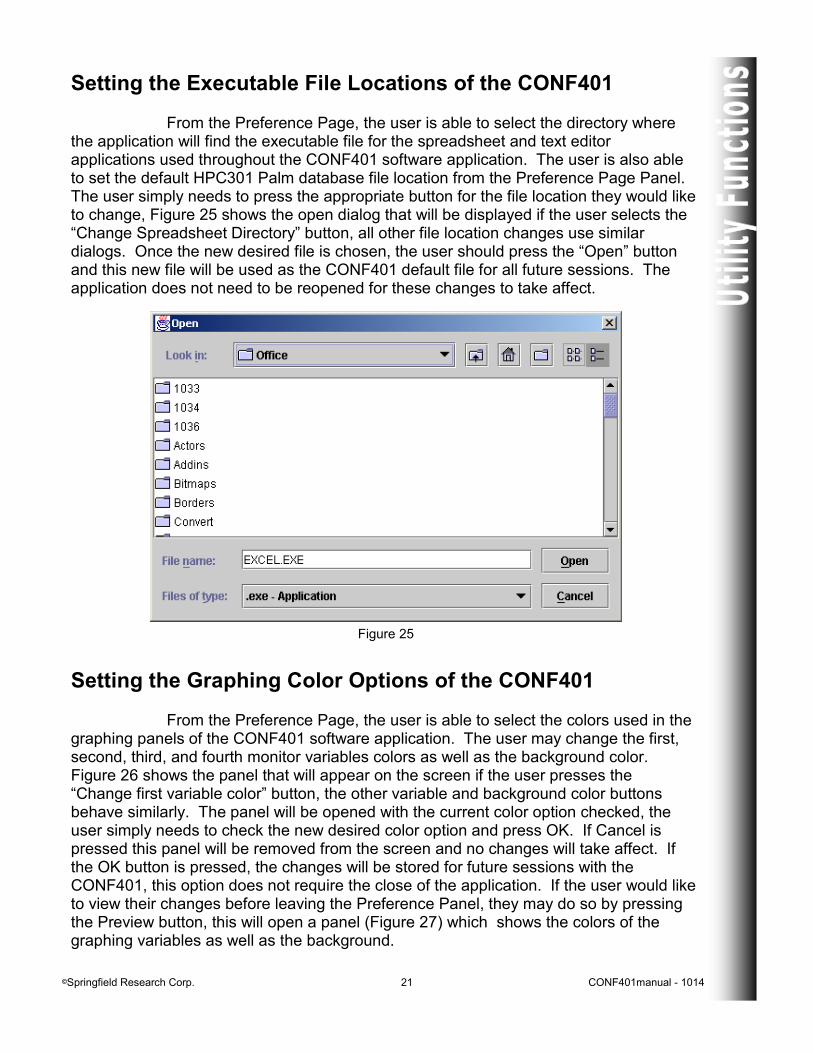
Figure 23 Figure 24
Figure 23 shows the CONF401 polling for multiple address with the Windows look & feel, Figure 24 shows the same screen with the CDE/Motif look & feel selected. Once you change the look & feel of the CONF401, you must restart the program for the changes to take affect.
©Springfield Research Corp. 21 CONF401manual - 1014
Setting the Executable File Locations of the CONF401 From the Preference Page, the user is able to select the directory where the application will find the executable file for the spreadsheet and text editor applications used throughout the CONF401 software application. The user is also able to set the default HPC301 Palm database file location from the Preference Page Panel. The user simply needs to press the appropriate button for the file location they would like to change, Figure 25 shows the open dialog that will be displayed if the user selects the “Change Spreadsheet Directory” button, all other file location changes use similar dialogs. Once the new desired file is chosen, the user should press the “Open” button and this new file will be used as the CONF401 default file for all future sessions. The application does not need to be reopened for these changes to take affect.
Figure 25
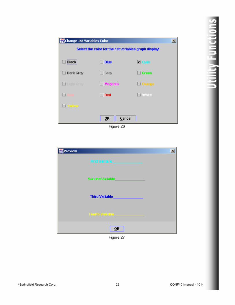
Setting the Graphing Color Options of the CONF401 From the Preference Page, the user is able to select the colors used in the graphing panels of the CONF401 software application. The user may change the first, second, third, and fourth monitor variables colors as well as the background color. Figure 26 shows the panel that will appear on the screen if the user presses the “Change first variable color” button, the other variable and background color buttons behave similarly. The panel will be opened with the current color option checked, the user simply needs to check the new desired color option and press OK. If Cancel is pressed this panel will be removed from the screen and no changes will take affect. If the OK button is pressed, the changes will be stored for future sessions with the CONF401, this option does not require the close of the application. If the user would like to view their changes before leaving the Preference Panel, they may do so by pressing the Preview button, this will open a panel (Figure 27) which shows the colors of the graphing variables as well as the background.
©Springfield Research Corp. 22 CONF401manual - 1014
Figure 26
Figure 27
©Springfield Research Corp. 23 CONF401manual - 1014
Learning About the CONF401 HART® Configurator
Information about the CONF401 HART Configurator, including copyright and version information, is available from the About window which can be opened by selecting the About option from the Help menu.
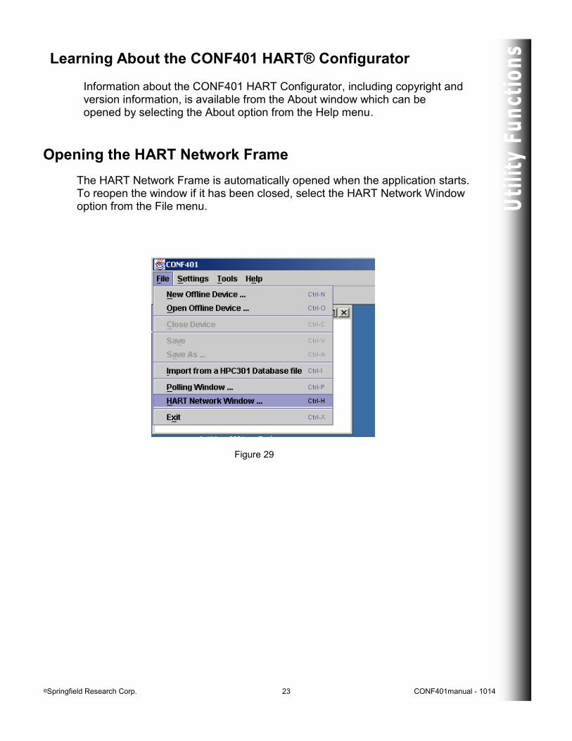
Opening the HART Network Frame
The HART Network Frame is automatically opened when the application starts. To reopen the window if it has been closed, select the HART Network Window option from the File menu.
Figure 29
©Springfield Research Corp. 24 CONF401manual - 1014
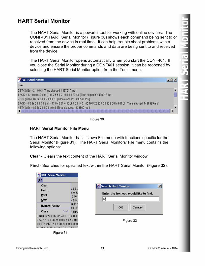
HART Serial Monitor The HART Serial Monitor is a powerful tool for working with online devices. The CONF401 HART Serial Monitor (Figure 30) shows each command being sent to or received from the device in real time. It can help trouble shoot problems with a device and ensure the proper commands and data are being sent to and received from the device. The HART Serial Monitor opens automatically when you start the CONF401. If you close the Serial Monitor during a CONF401 session, it can be reopened by selecting the HART Serial Monitor option from the Tools menu.
HART Serial Monitor File Menu The HART Serial Monitor has it’s own File menu with functions specific for the Serial Monitor (Figure 31). The HART Serial Monitors’ File menu contains the following options: Clear - Clears the text content of the HART Serial Monitor window. Find - Searches for specified text within the HART Serial Monitor (Figure 32).
Figure 30
Figure 31
Figure 32
©Springfield Research Corp. 25 CONF401manual - 1014
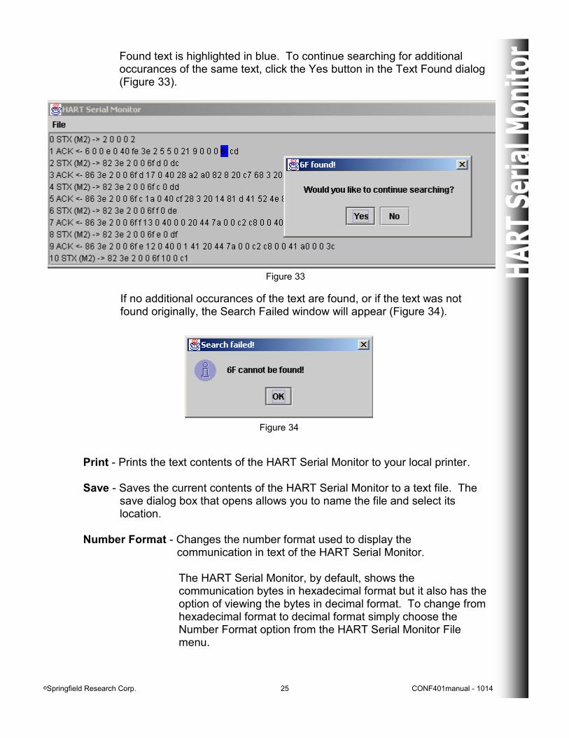
Found text is highlighted in blue. To continue searching for additional occurances of the same text, click the Yes button in the Text Found dialog (Figure 33).
Figure 33
If no additional occurances of the text are found, or if the text was not found originally, the Search Failed window will appear (Figure 34).
Figure 34
Print - Prints the text contents of the HART Serial Monitor to your local printer. Save - Saves the current contents of the HART Serial Monitor to a text file. The
save dialog box that opens allows you to name the file and select its location.
Number Format - Changes the number format used to display the
communication in text of the HART Serial Monitor. The HART Serial Monitor, by default, shows the communication bytes in hexadecimal format but it also has the option of viewing the bytes in decimal format. To change from hexadecimal format to decimal format simply choose the Number Format option from the HART Serial Monitor File menu.
©Springfield Research Corp. 26 CONF401manual - 1014
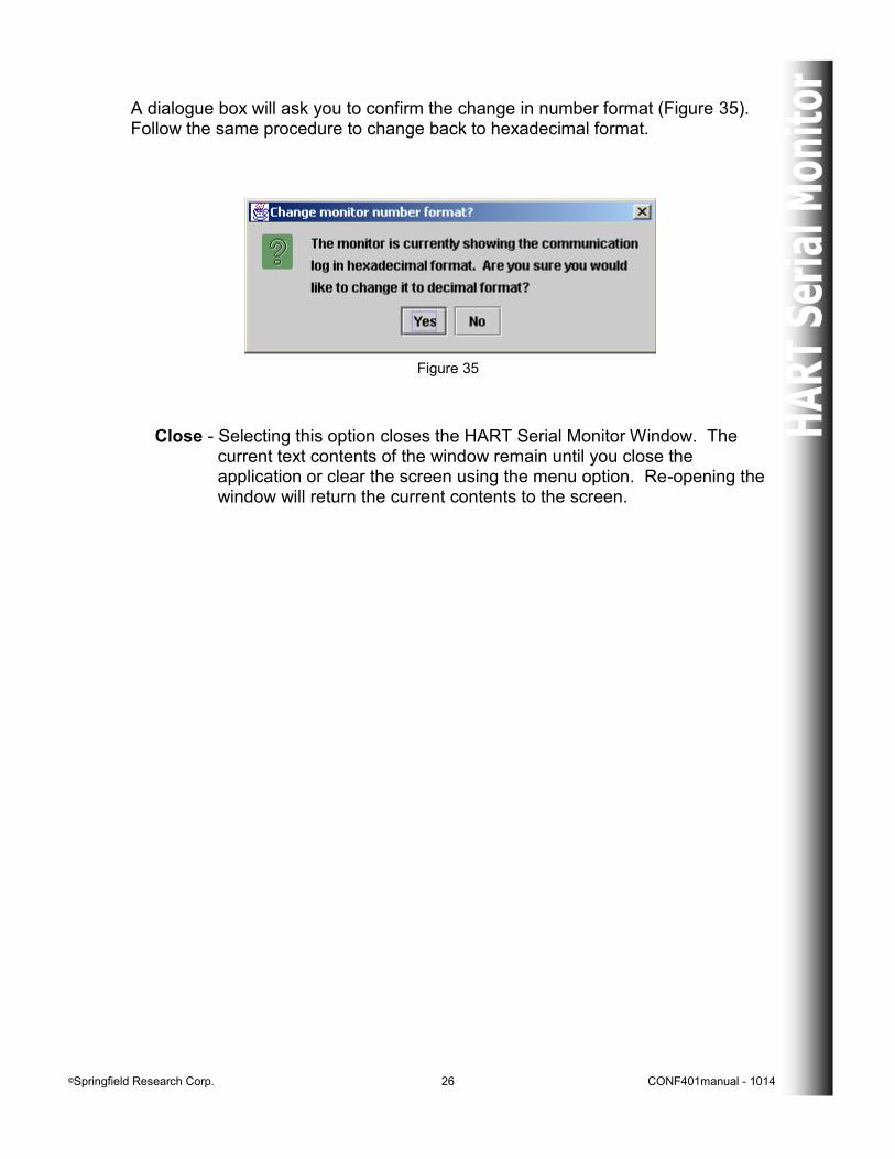
A dialogue box will ask you to confirm the change in number format (Figure 35). Follow the same procedure to change back to hexadecimal format.
Close - Selecting this option closes the HART Serial Monitor Window. The current text contents of the window remain until you close the
application or clear the screen using the menu option. Re-opening the window will return the current contents to the screen.
Figure 35
©Springfield Research Corp. 27 CONF401manual - 1014
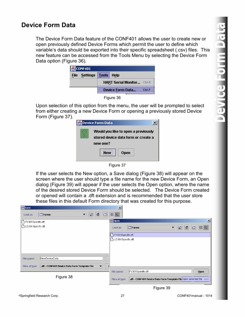
Device Form Data The Device Form Data feature of the CONF401 allows the user to create new or open previously defined Device Forms which permit the user to define which variable’s data should be exported into their specific spreadsheet (.csv) files. This new feature can be accessed from the Tools Menu by selecting the Device Form Data option (Figure 36).
Figure 36
Upon selection of this option from the menu, the user will be prompted to select from either creating a new Device Form or opening a previously stored Device Form (Figure 37).
Figure 37
If the user selects the New option, a Save dialog (Figure 38) will appear on the screen where the user should type a file name for the new Device Form, an Open dialog (Figure 39) will appear if the user selects the Open option, where the name of the desired stored Device Form should be selected. The Device Form created or opened will contain a .dft extension and is recommended that the user store these files in this default Form directory that was created for this purpose.
Figure 38
Figure 39
©Springfield Research Corp. 28 CONF401manual - 1014
Figure 40
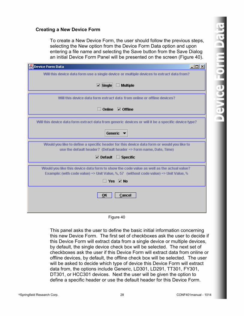
Creating a New Device Form To create a New Device Form, the user should follow the previous steps, selecting the New option from the Device Form Data option and upon entering a file name and selecting the Save button from the Save Dialog an initial Device Form Panel will be presented on the screen (Figure 40).
This panel asks the user to define the basic initial information concerning this new Device Form. The first set of checkboxes ask the user to decide if this Device Form will extract data from a single device or multiple devices, by default, the single device check box will be selected. The next set of checkboxes ask the user if this Device Form will extract data from online or offline devices, by default, the offline check box will be selected. The user will be asked to decide which type of device this Device Form will extract data from, the options include Generic, LD301, LD291, TT301, FY301, DT301, or HCC301 devices. Next the user will be given the option to define a specific header or use the default header for this Device Form.
©Springfield Research Corp. 29 CONF401manual - 1014
Figure 41
The default header is selected by default and will contain the form name, which is the file name by default but may be changed by the user, on the first line, the date on the second line, and the time on the third line. The header will always contain three lines, if the user selects a specific header, they may define what information goes on what line, or if all the information should be shown on the same line, but all Device Forms will contain three lines in their header. The time and the date information will be current to the time or date that the user creates the .csv file, not the .dft file, so these variables will correspond directly to the data that is extracted. Finally, the user must define whether this Device Form will show the code value of the selected variables next to the actual value or if only the actual value should be shown. By default, the Device Form does not show the code value but the user may choose to do so by selecting the Yes check box. Once these initial values are defined, the OK button should be selected in order to continue with the new Device Form definition. The Cancel button, if selected, will discontinue the new Device Form procedure and bring the user back to the main CONF401 screen.
Figure 42
©Springfield Research Corp. 30 CONF401manual - 1014
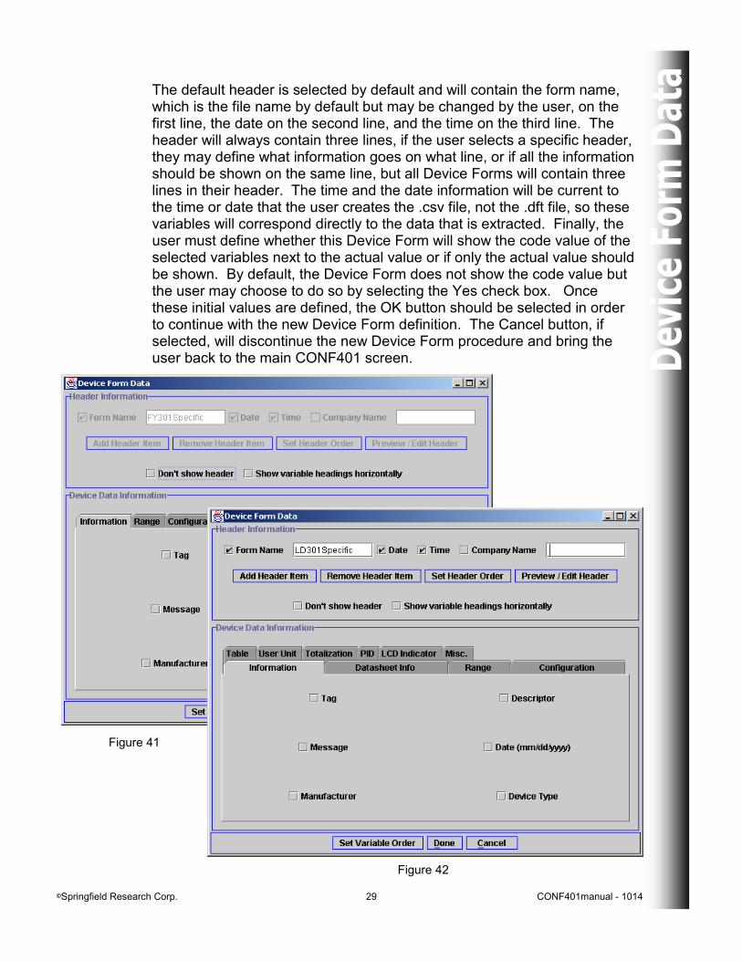
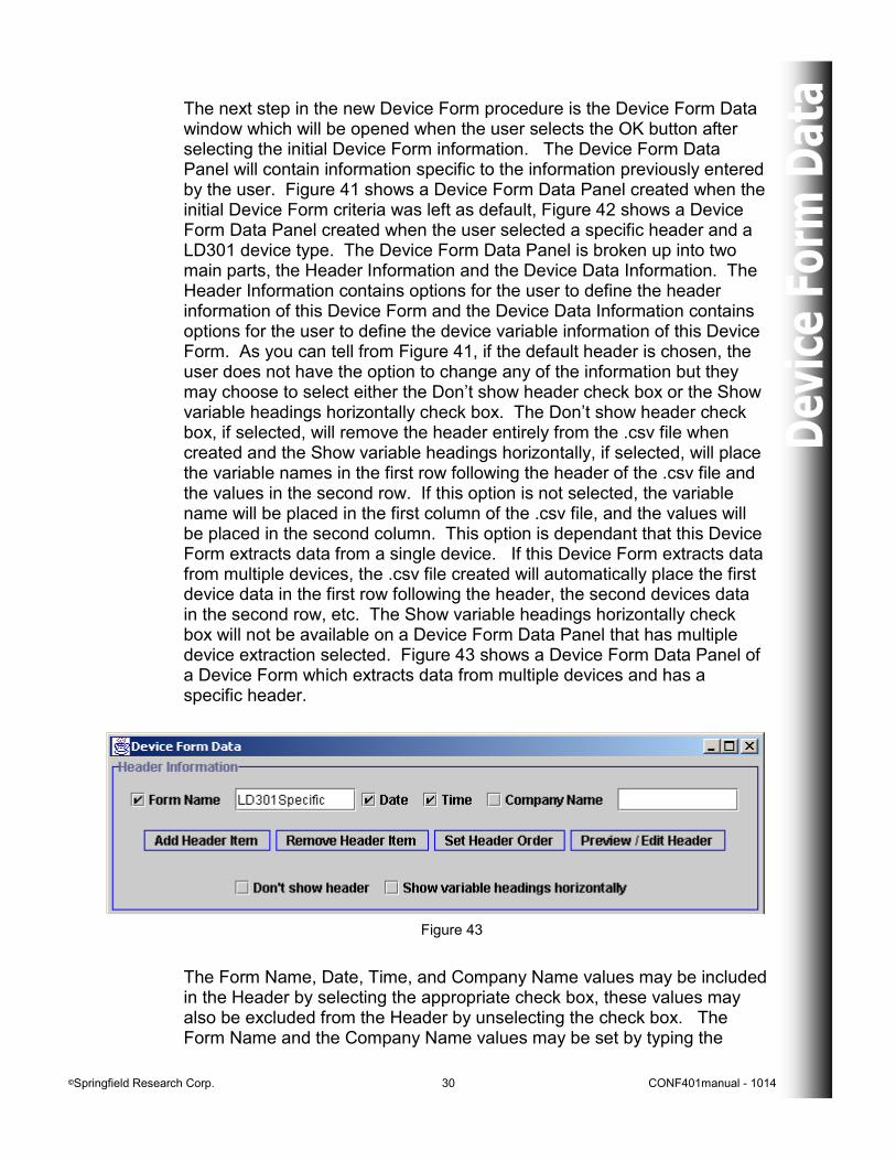
The next step in the new Device Form procedure is the Device Form Data window which will be opened when the user selects the OK button after selecting the initial Device Form information. The Device Form Data Panel will contain information specific to the information previously entered by the user. Figure 41 shows a Device Form Data Panel created when the initial Device Form criteria was left as default, Figure 42 shows a Device Form Data Panel created when the user selected a specific header and a LD301 device type. The Device Form Data Panel is broken up into two main parts, the Header Information and the Device Data Information. The Header Information contains options for the user to define the header information of this Device Form and the Device Data Information contains options for the user to define the device variable information of this Device Form. As you can tell from Figure 41, if the default header is chosen, the user does not have the option to change any of the information but they may choose to select either the Don’t show header check box or the Show variable headings horizontally check box. The Don’t show header check box, if selected, will remove the header entirely from the .csv file when created and the Show variable headings horizontally, if selected, will place the variable names in the first row following the header of the .csv file and the values in the second row. If this option is not selected, the variable name will be placed in the first column of the .csv file, and the values will be placed in the second column. This option is dependant that this Device Form extracts data from a single device. If this Device Form extracts data from multiple devices, the .csv file created will automatically place the first device data in the first row following the header, the second devices data in the second row, etc. The Show variable headings horizontally check box will not be available on a Device Form Data Panel that has multiple device extraction selected. Figure 43 shows a Device Form Data Panel of a Device Form which extracts data from multiple devices and has a specific header.
Figure 43
The Form Name, Date, Time, and Company Name values may be included in the Header by selecting the appropriate check box, these values may also be excluded from the Header by unselecting the check box. The Form Name and the Company Name values may be set by typing the
©Springfield Research Corp. 31 CONF401manual - 1014
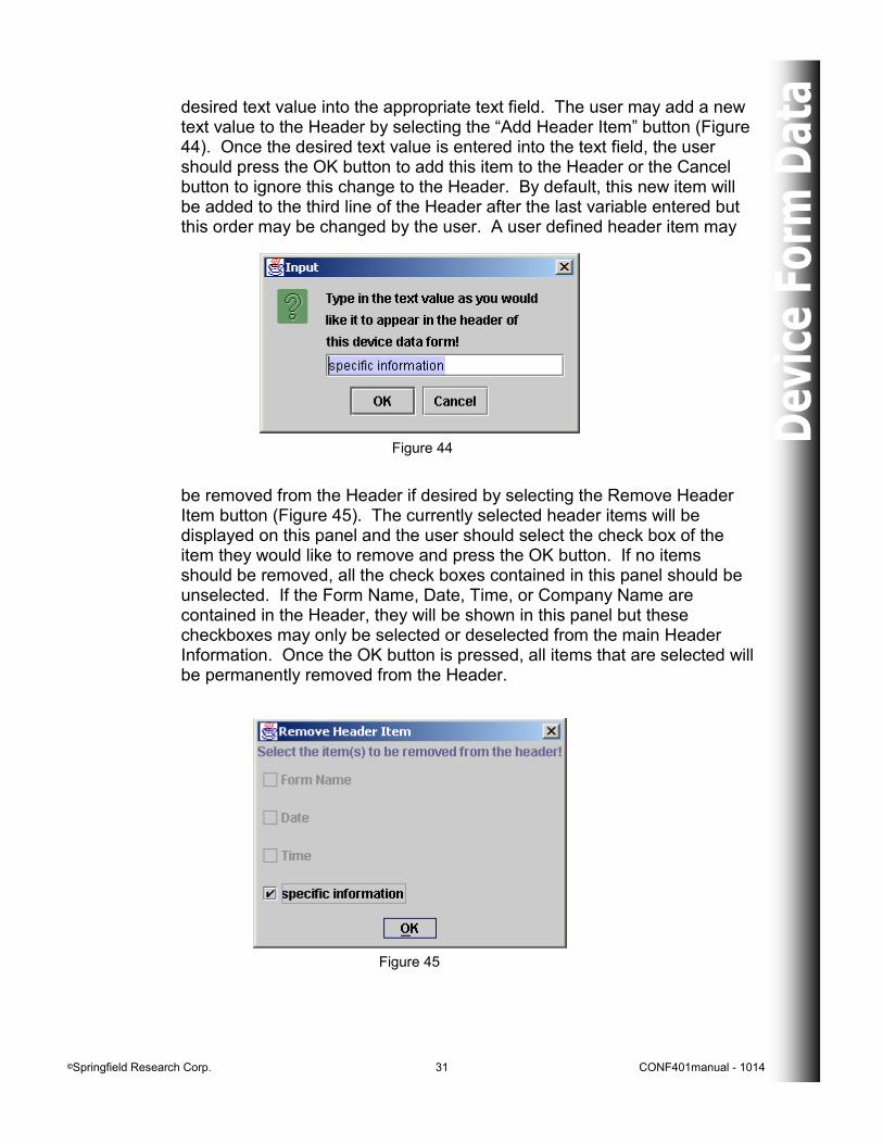
desired text value into the appropriate text field. The user may add a new text value to the Header by selecting the “Add Header Item” button (Figure 44). Once the desired text value is entered into the text field, the user should press the OK button to add this item to the Header or the Cancel button to ignore this change to the Header. By default, this new item will be added to the third line of the Header after the last variable entered but this order may be changed by the user. A user defined header item may
Figure 44
be removed from the Header if desired by selecting the Remove Header Item button (Figure 45). The currently selected header items will be displayed on this panel and the user should select the check box of the item they would like to remove and press the OK button. If no items should be removed, all the check boxes contained in this panel should be unselected. If the Form Name, Date, Time, or Company Name are contained in the Header, they will be shown in this panel but these checkboxes may only be selected or deselected from the main Header Information. Once the OK button is pressed, all items that are selected will be permanently removed from the Header.
Figure 45
©Springfield Research Corp. 32 CONF401manual - 1014
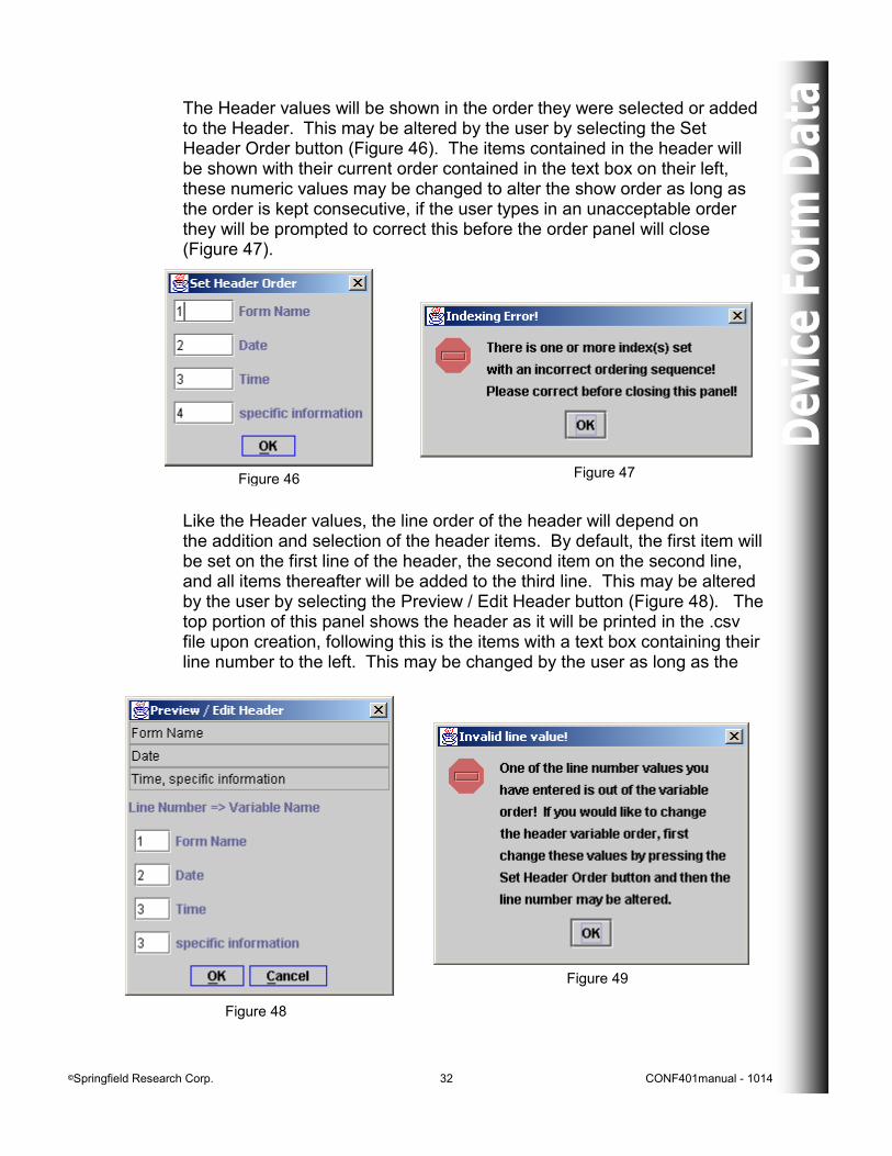
The Header values will be shown in the order they were selected or added to the Header. This may be altered by the user by selecting the Set Header Order button (Figure 46). The items contained in the header will be shown with their current order contained in the text box on their left, these numeric values may be changed to alter the show order as long as the order is kept consecutive, if the user types in an unacceptable order they will be prompted to correct this before the order panel will close (Figure 47).
Figure 46 Figure 47
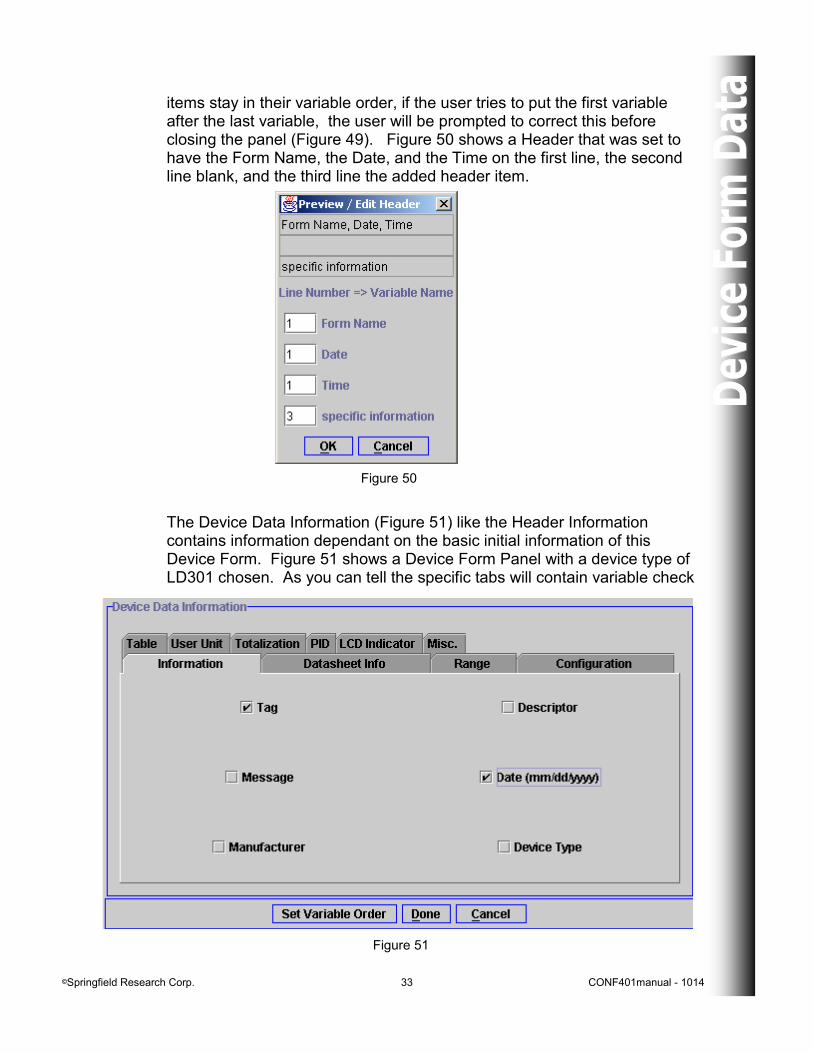
Like the Header values, the line order of the header will depend on the addition and selection of the header items. By default, the first item will be set on the first line of the header, the second item on the second line, and all items thereafter will be added to the third line. This may be altered by the user by selecting the Preview / Edit Header button (Figure 48). The top portion of this panel shows the header as it will be printed in the .csv file upon creation, following this is the items with a text box containing their line number to the left. This may be changed by the user as long as the
Figure 48
Figure 49
©Springfield Research Corp. 33 CONF401manual - 1014
Figure 50
items stay in their variable order, if the user tries to put the first variable after the last variable, the user will be prompted to correct this before closing the panel (Figure 49). Figure 50 shows a Header that was set to have the Form Name, the Date, and the Time on the first line, the second line blank, and the third line the added header item.
The Device Data Information (Figure 51) like the Header Information contains information dependant on the basic initial information of this Device Form. Figure 51 shows a Device Form Panel with a device type of LD301 chosen. As you can tell the specific tabs will contain variable check
Figure 51
©Springfield Research Corp. 34 CONF401manual - 1014
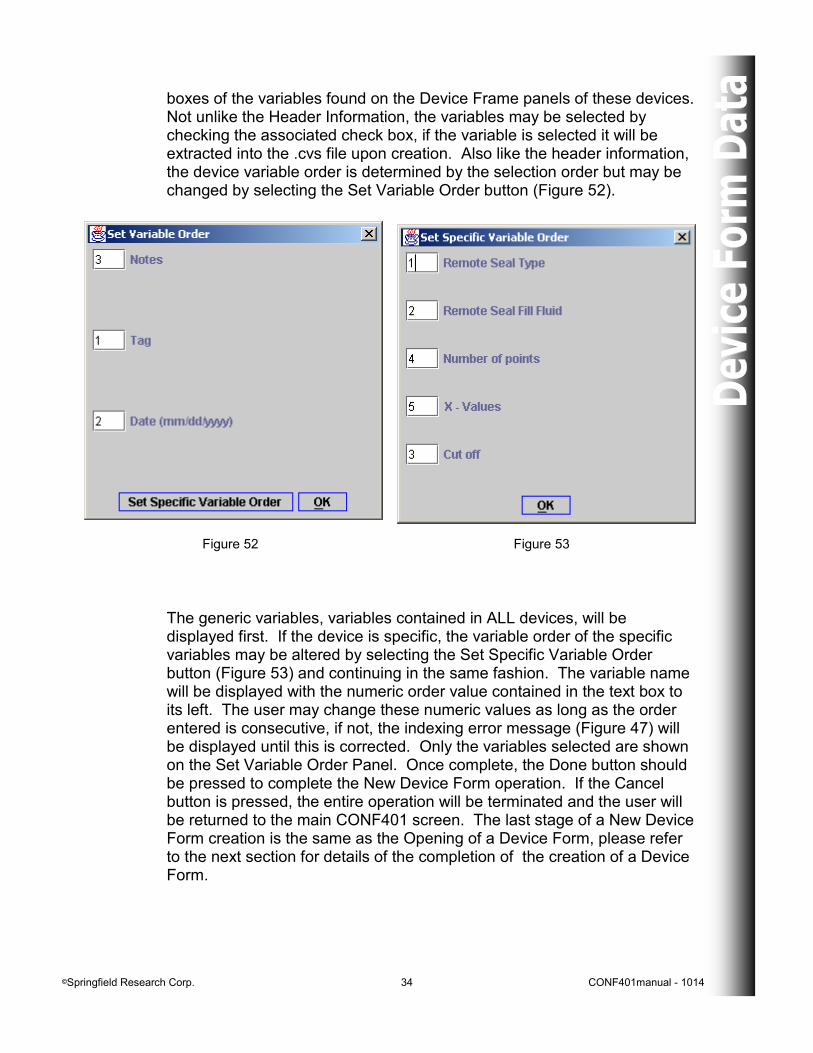
boxes of the variables found on the Device Frame panels of these devices. Not unlike the Header Information, the variables may be selected by checking the associated check box, if the variable is selected it will be extracted into the .cvs file upon creation. Also like the header information, the device variable order is determined by the selection order but may be changed by selecting the Set Variable Order button (Figure 52).
The generic variables, variables contained in ALL devices, will be displayed first. If the device is specific, the variable order of the specific variables may be altered by selecting the Set Specific Variable Order button (Figure 53) and continuing in the same fashion. The variable name will be displayed with the numeric order value contained in the text box to its left. The user may change these numeric values as long as the order entered is consecutive, if not, the indexing error message (Figure 47) will be displayed until this is corrected. Only the variables selected are shown on the Set Variable Order Panel. Once complete, the Done button should be pressed to complete the New Device Form operation. If the Cancel button is pressed, the entire operation will be terminated and the user will be returned to the main CONF401 screen. The last stage of a New Device Form creation is the same as the Opening of a Device Form, please refer to the next section for details of the completion of the creation of a Device Form.
Figure 52 Figure 53
©Springfield Research Corp. 35 CONF401manual - 1014
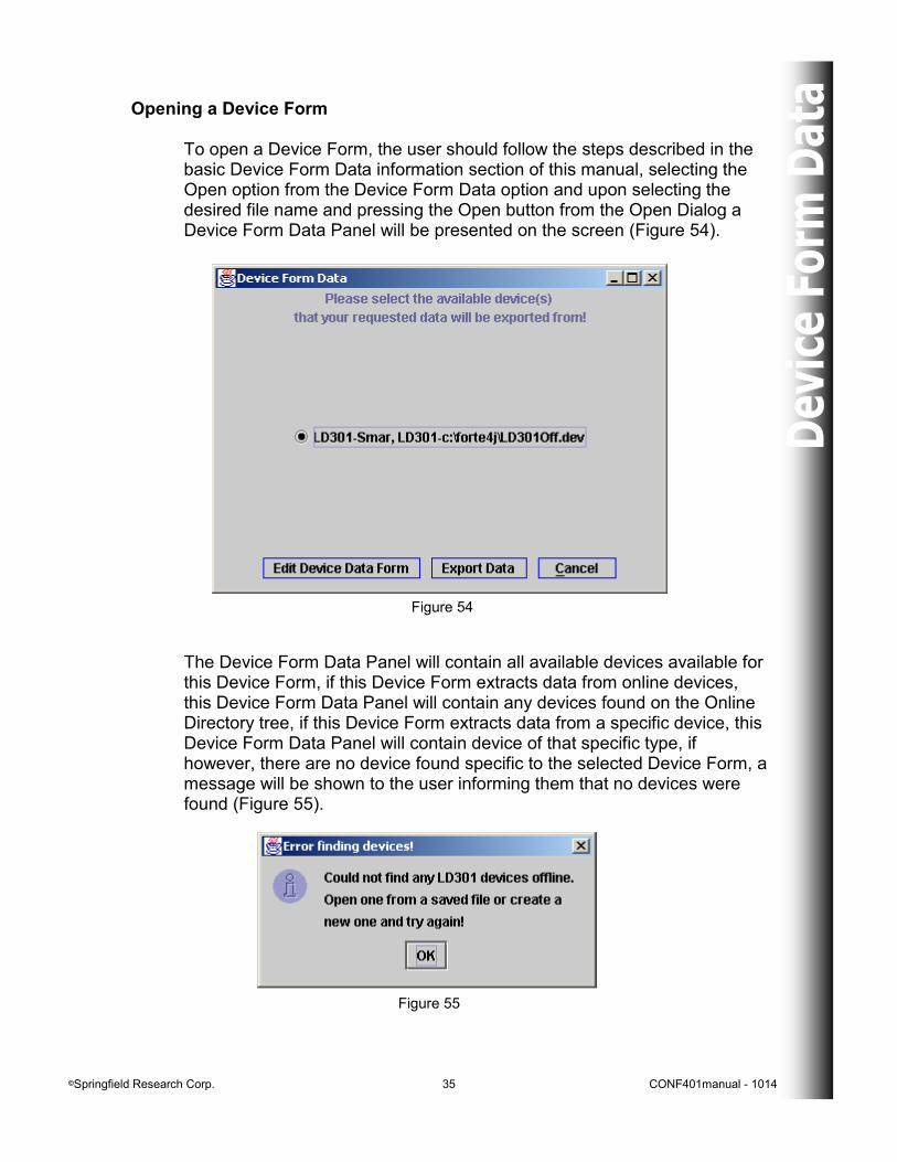
Opening a Device Form To open a Device Form, the user should follow the steps described in the basic Device Form Data information section of this manual, selecting the Open option from the Device Form Data option and upon selecting the desired file name and pressing the Open button from the Open Dialog a Device Form Data Panel will be presented on the screen (Figure 54).
Figure 54
The Device Form Data Panel will contain all available devices available for this Device Form, if this Device Form extracts data from online devices, this Device Form Data Panel will contain any devices found on the Online Directory tree, if this Device Form extracts data from a specific device, this Device Form Data Panel will contain device of that specific type, if however, there are no device found specific to the selected Device Form, a message will be shown to the user informing them that no devices were found (Figure 55).
Figure 55
©Springfield Research Corp. 36 CONF401manual - 1014
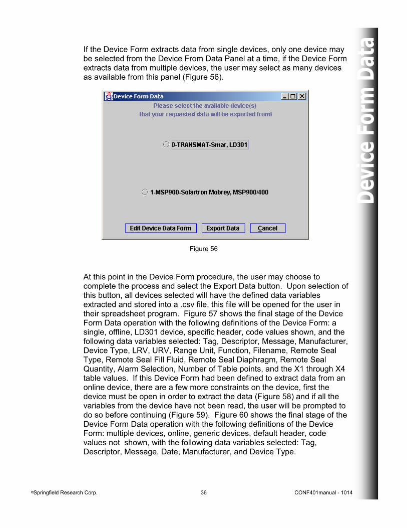
If the Device Form extracts data from single devices, only one device may be selected from the Device From Data Panel at a time, if the Device Form extracts data from multiple devices, the user may select as many devices as available from this panel (Figure 56).
Figure 56
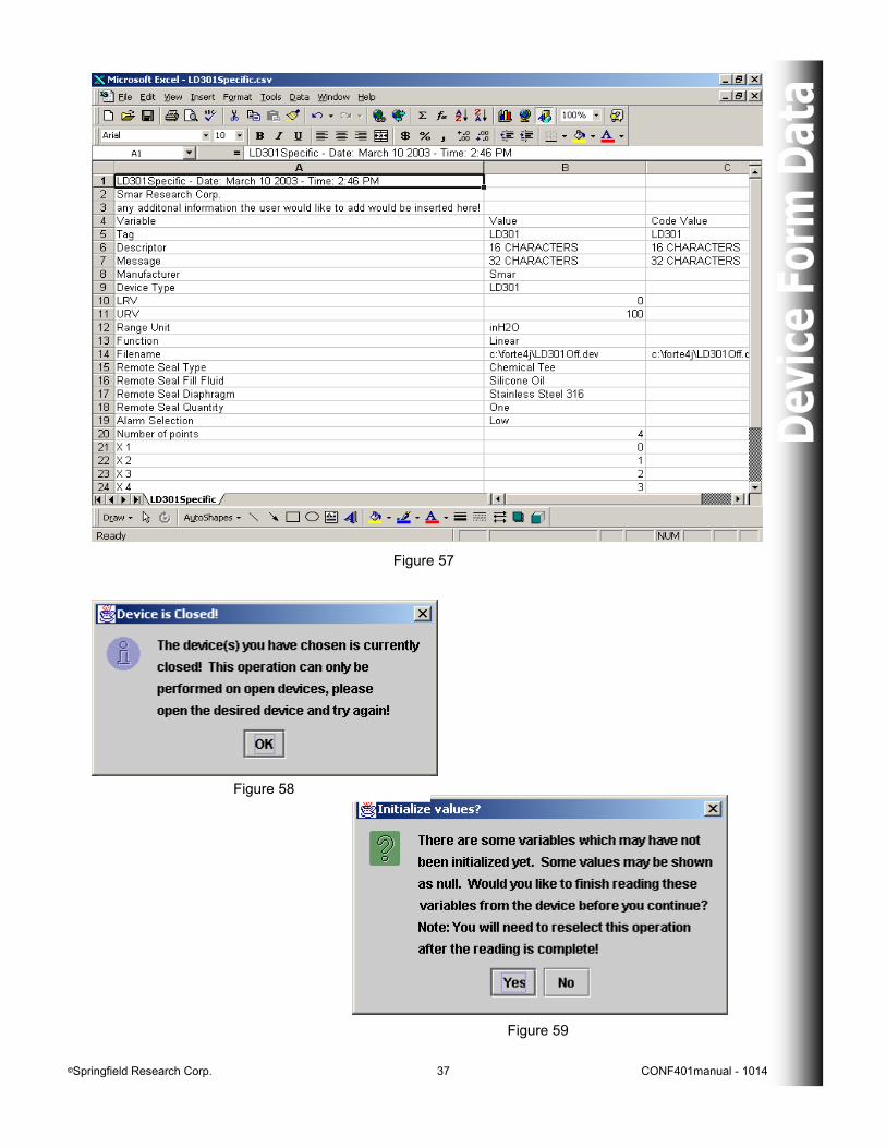
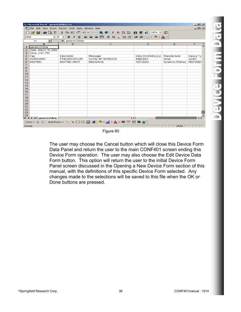
At this point in the Device Form procedure, the user may choose to complete the process and select the Export Data button. Upon selection of this button, all devices selected will have the defined data variables extracted and stored into a .csv file, this file will be opened for the user in their spreadsheet program. Figure 57 shows the final stage of the Device Form Data operation with the following definitions of the Device Form: a single, offline, LD301 device, specific header, code values shown, and the following data variables selected: Tag, Descriptor, Message, Manufacturer, Device Type, LRV, URV, Range Unit, Function, Filename, Remote Seal Type, Remote Seal Fill Fluid, Remote Seal Diaphragm, Remote Seal Quantity, Alarm Selection, Number of Table points, and the X1 through X4 table values. If this Device Form had been defined to extract data from an online device, there are a few more constraints on the device, first the device must be open in order to extract the data (Figure 58) and if all the variables from the device have not been read, the user will be prompted to do so before continuing (Figure 59). Figure 60 shows the final stage of the Device Form Data operation with the following definitions of the Device Form: multiple devices, online, generic devices, default header, code values not shown, with the following data variables selected: Tag, Descriptor, Message, Date, Manufacturer, and Device Type.
©Springfield Research Corp. 37 CONF401manual - 1014
Figure 57
Figure 58
Figure 59
©Springfield Research Corp. 38 CONF401manual - 1014
Figure 60
The user may choose the Cancel button which will close this Device Form Data Panel and return the user to the main CONF401 screen ending this Device Form operation. The user may also choose the Edit Device Data Form button. This option will return the user to the initial Device Form Panel screen discussed in the Opening a New Device Form section of this manual, with the definitions of this specific Device Form selected. Any changes made to the selections will be saved to this file when the OK or Done buttons are pressed.
©Springfield Research Corp. 39 CONF401manual - 1014
HART Network Frame
Figure 61
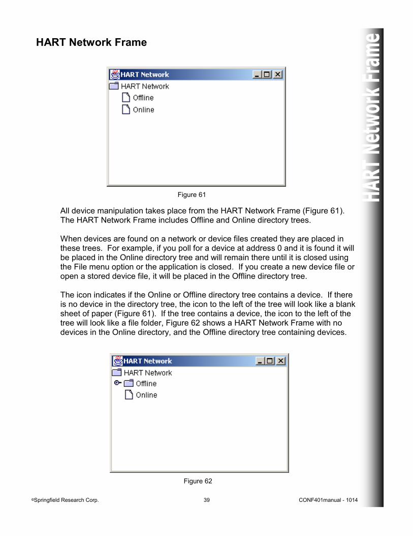
All device manipulation takes place from the HART Network Frame (Figure 61). The HART Network Frame includes Offline and Online directory trees. When devices are found on a network or device files created they are placed in these trees. For example, if you poll for a device at address 0 and it is found it will be placed in the Online directory tree and will remain there until it is closed using the File menu option or the application is closed. If you create a new device file or open a stored device file, it will be placed in the Offline directory tree. The icon indicates if the Online or Offline directory tree contains a device. If there is no device in the directory tree, the icon to the left of the tree will look like a blank sheet of paper (Figure 61). If the tree contains a device, the icon to the left of the tree will look like a file folder, Figure 62 shows a HART Network Frame with no devices in the Online directory, and the Offline directory tree containing devices.
Figure 62
©Springfield Research Corp. 40 CONF401manual - 1014
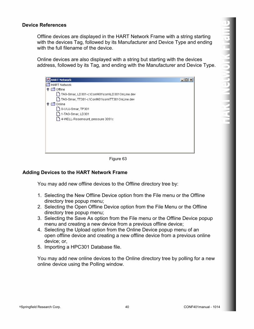
Device References Offline devices are displayed in the HART Network Frame with a string starting with the devices Tag, followed by its Manufacturer and Device Type and ending with the full filename of the device. Online devices are also displayed with a string but starting with the devices address, followed by its Tag, and ending with the Manufacturer and Device Type.
Figure 63
Adding Devices to the HART Network Frame You may add new offline devices to the Offline directory tree by: 1. Selecting the New Offline Device option from the File menu or the Offline directory tree popup menu; 2. Selecting the Open Offline Device option from the File Menu or the Offline directory tree popup menu; 3. Selecting the Save As option from the File menu or the Offline Device popup menu and creating a new device from a previous offline device; 4. Selecting the Upload option from the Online Device popup menu of an open offline device and creating a new offline device from a previous online device; or, 5. Importing a HPC301 Database file. You may add new online devices to the Online directory tree by polling for a new online device using the Polling window.
©Springfield Research Corp. 41 CONF401manual - 1014
Online Directory Tree Popup Menu
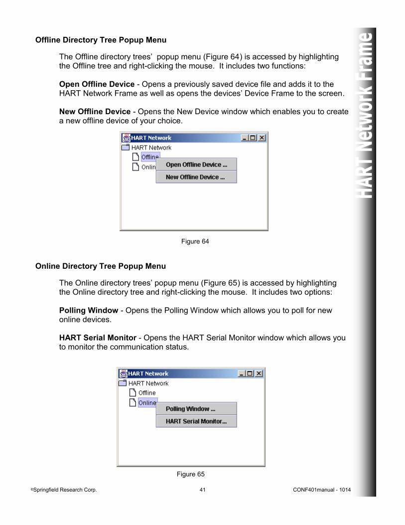
The Online directory trees’ popup menu (Figure 65) is accessed by highlighting the Online directory tree and right-clicking the mouse. It includes two options: Polling Window - Opens the Polling Window which allows you to poll for new online devices. HART Serial Monitor - Opens the HART Serial Monitor window which allows you to monitor the communication status.
Figure 65
Figure 64
Offline Directory Tree Popup Menu
The Offline directory trees’ popup menu (Figure 64) is accessed by highlighting the Offline tree and right-clicking the mouse. It includes two functions: Open Offline Device - Opens a previously saved device file and adds it to the HART Network Frame as well as opens the devices’ Device Frame to the screen. New Offline Device - Opens the New Device window which enables you to create a new offline device of your choice.
©Springfield Research Corp. 42 CONF401manual - 1014
Offline Device Popup Menu
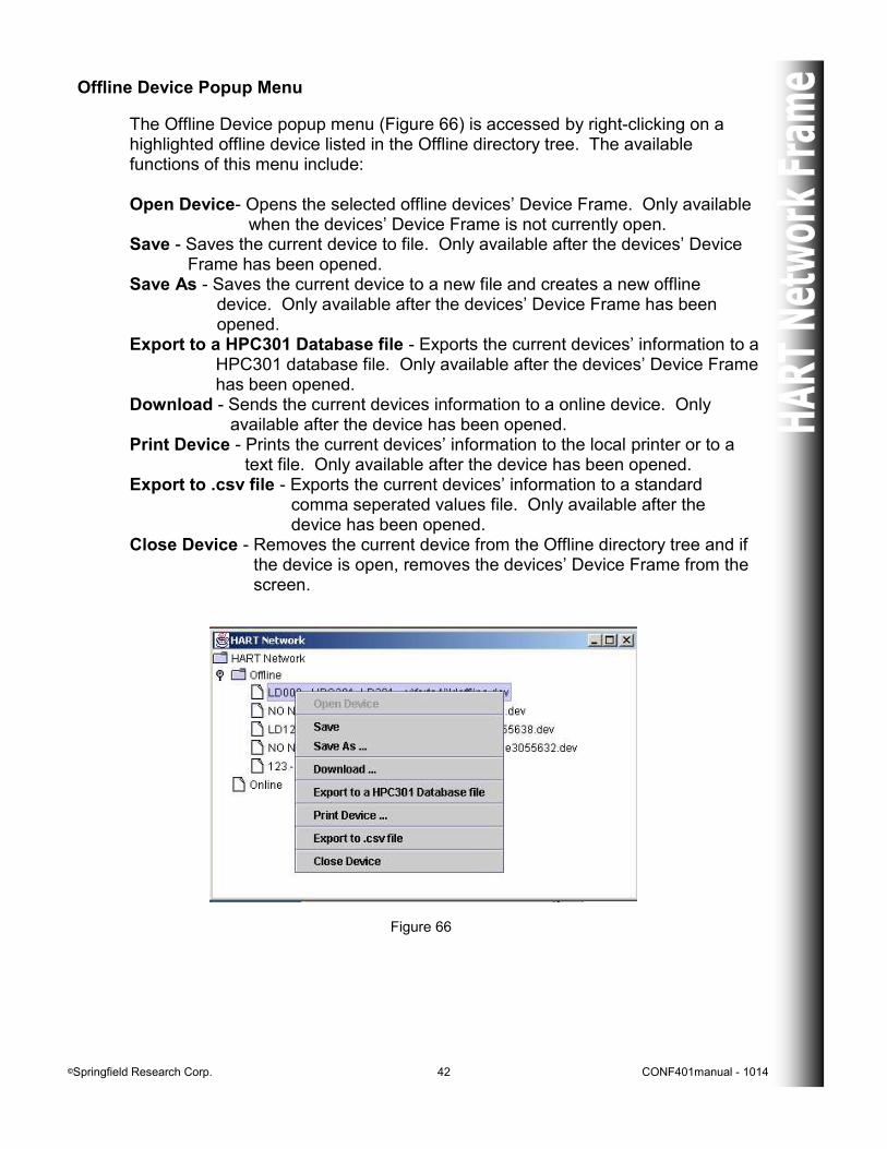
The Offline Device popup menu (Figure 66) is accessed by right-clicking on a highlighted offline device listed in the Offline directory tree. The available functions of this menu include: Open Device- Opens the selected offline devices’ Device Frame. Only available when the devices’ Device Frame is not currently open. Save - Saves the current device to file. Only available after the devices’ Device Frame has been opened. Save As - Saves the current device to a new file and creates a new offline device. Only available after the devices’ Device Frame has been opened. Export to a HPC301 Database file - Exports the current devices’ information to a HPC301 database file. Only available after the devices’ Device Frame has been opened. Download - Sends the current devices information to a online device. Only available after the device has been opened. Print Device - Prints the current devices’ information to the local printer or to a text file. Only available after the device has been opened. Export to .csv file - Exports the current devices’ information to a standard comma seperated values file. Only available after the device has been opened. Close Device - Removes the current device from the Offline directory tree and if the device is open, removes the devices’ Device Frame from the screen.
Figure 66
©Springfield Research Corp. 43 CONF401manual - 1014
Downloading an Offline Device
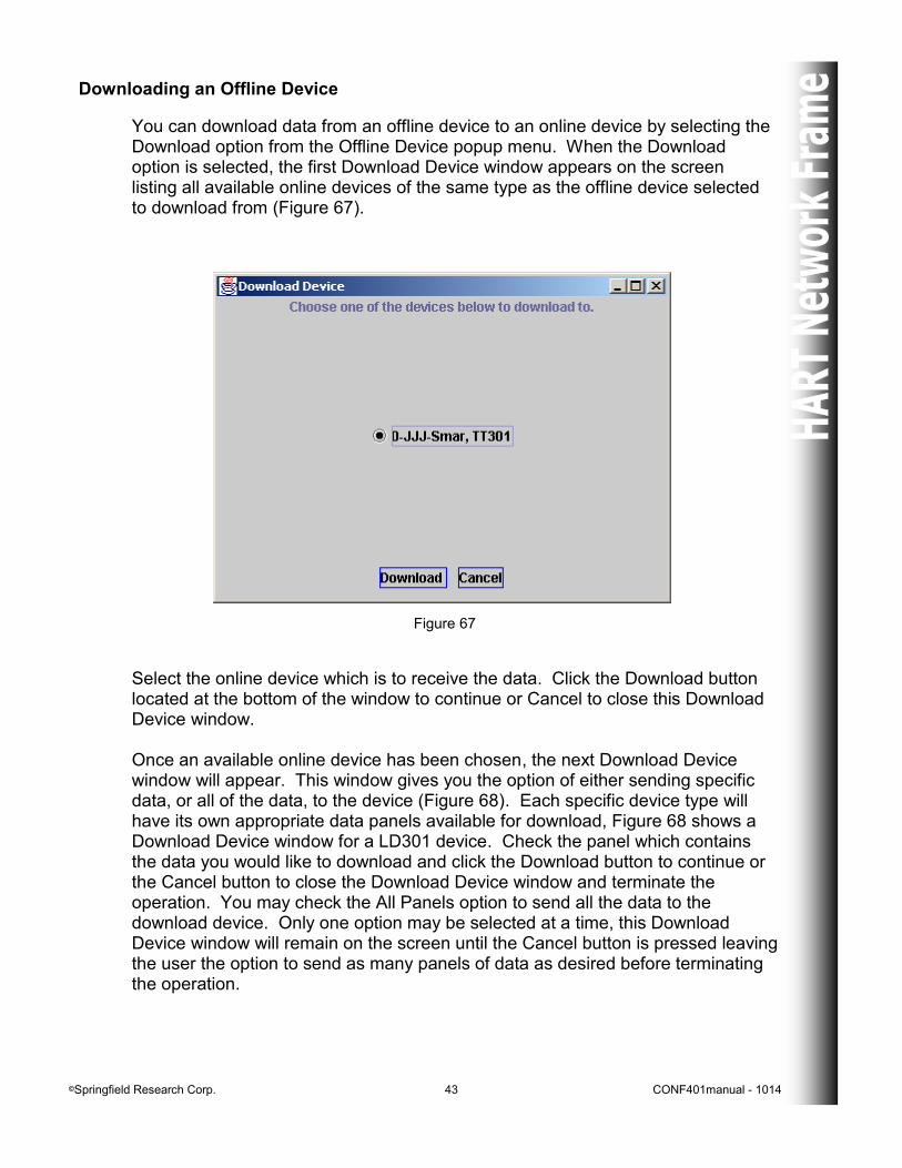
You can download data from an offline device to an online device by selecting the Download option from the Offline Device popup menu. When the Download option is selected, the first Download Device window appears on the screen listing all available online devices of the same type as the offline device selected to download from (Figure 67).
Figure 67
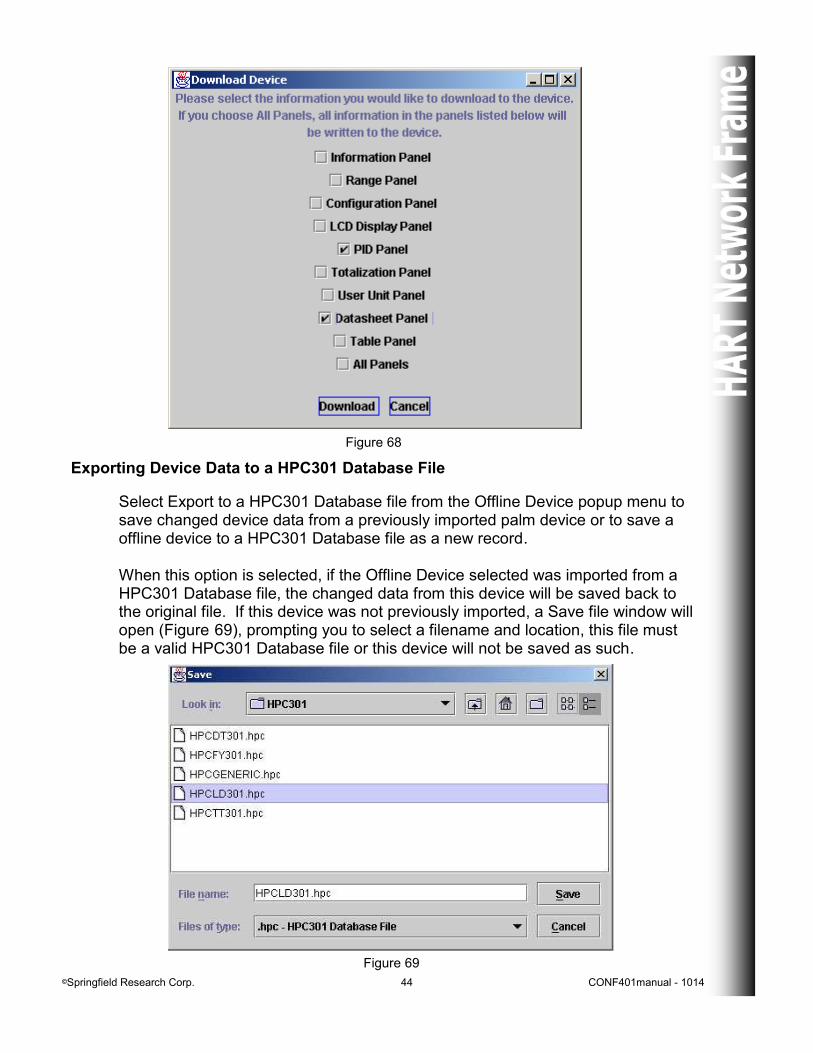
Select the online device which is to receive the data. Click the Download button located at the bottom of the window to continue or Cancel to close this Download Device window. Once an available online device has been chosen, the next Download Device window will appear. This window gives you the option of either sending specific data, or all of the data, to the device (Figure 68). Each specific device type will have its own appropriate data panels available for download, Figure 68 shows a Download Device window for a LD301 device. Check the panel which contains the data you would like to download and click the Download button to continue or the Cancel button to close the Download Device window and terminate the operation. You may check the All Panels option to send all the data to the download device. Only one option may be selected at a time, this Download Device window will remain on the screen until the Cancel button is pressed leaving the user the option to send as many panels of data as desired before terminating the operation.
©Springfield Research Corp. 44 CONF401manual - 1014
Figure 68
Exporting Device Data to a HPC301 Database File
Select Export to a HPC301 Database file from the Offline Device popup menu to save changed device data from a previously imported palm device or to save a offline device to a HPC301 Database file as a new record. When this option is selected, if the Offline Device selected was imported from a HPC301 Database file, the changed data from this device will be saved back to the original file. If this device was not previously imported, a Save file window will open (Figure 69), prompting you to select a filename and location, this file must be a valid HPC301 Database file or this device will not be saved as such.
Figure 69
©Springfield Research Corp. 45 CONF401manual - 1014
Figure 71
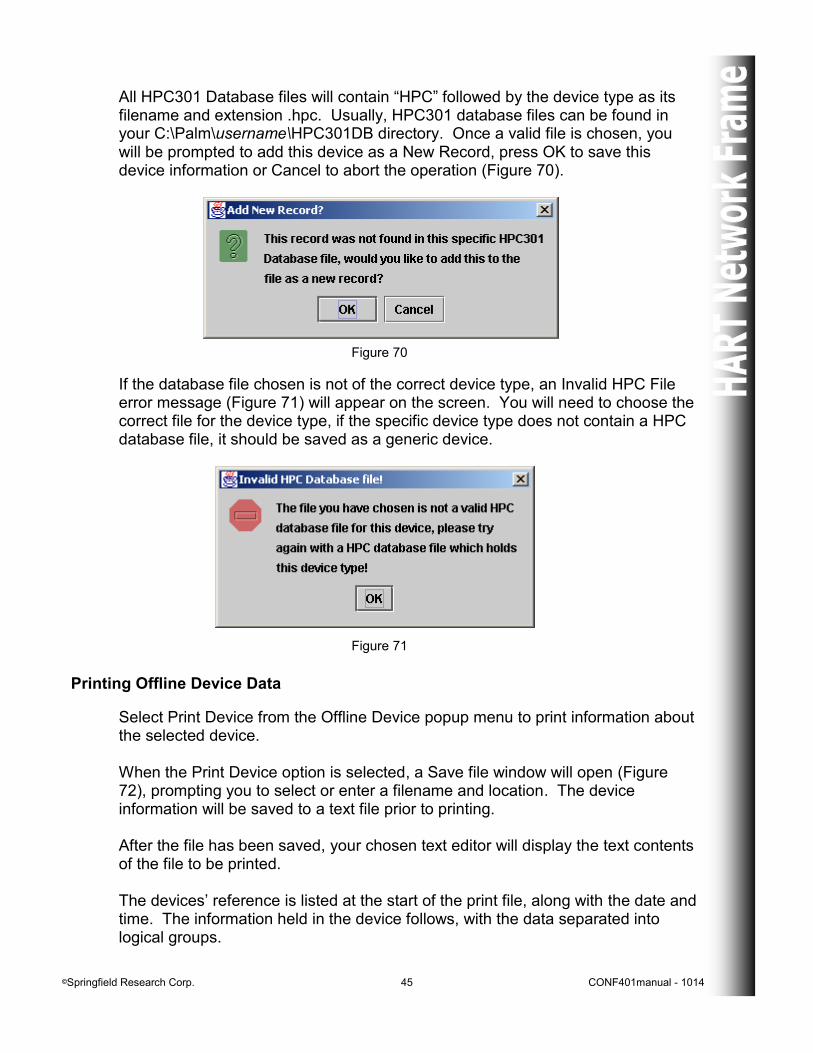
All HPC301 Database files will contain “HPC” followed by the device type as its filename and extension .hpc. Usually, HPC301 database files can be found in your C:\Palm\username\HPC301DB directory. Once a valid file is chosen, you will be prompted to add this device as a New Record, press OK to save this device information or Cancel to abort the operation (Figure 70).
If the database file chosen is not of the correct device type, an Invalid HPC File error message (Figure 71) will appear on the screen. You will need to choose the correct file for the device type, if the specific device type does not contain a HPC database file, it should be saved as a generic device.
Figure 70
Printing Offline Device Data
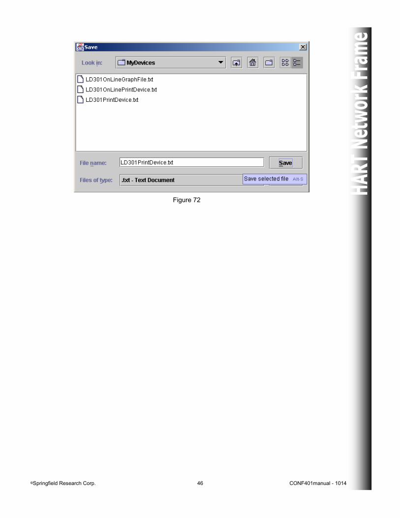
Select Print Device from the Offline Device popup menu to print information about the selected device. When the Print Device option is selected, a Save file window will open (Figure 72), prompting you to select or enter a filename and location. The device information will be saved to a text file prior to printing. After the file has been saved, your chosen text editor will display the text contents of the file to be printed. The devices’ reference is listed at the start of the print file, along with the date and time. The information held in the device follows, with the data separated into logical groups.
©Springfield Research Corp. 46 CONF401manual - 1014
Figure 72
©Springfield Research Corp. 47 CONF401manual - 1014
Exporting Offline Device Data
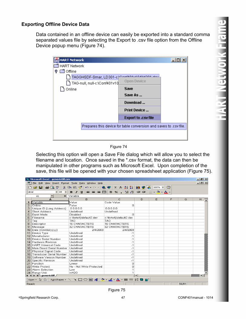
Data contained in an offline device can easily be exported into a standard comma separated values file by selecting the Export to .csv file option from the Offline Device popup menu (Figure 74).
Figure 74
Selecting this option will open a Save File dialog which will allow you to select the filename and location. Once saved in the *.csv format, the data can then be manipulated in other programs such as Microsoft Excel. Upon completion of the save, this file will be opened with your chosen spreadsheet application (Figure 75).
Figure 75

©Springfield Research Corp. 48 CONF401manual - 1014
Closing an Offline Device
An offline devices’ Device Frame can be closed and the device removed from the HART Network Offline directory tree by selecting the Close Device option from the Offline Device popup menu or directly from the CONF401 HART Configurators’ main File menu. If, after choosing the Close Device option, there were no changes made to the device since the last save, the devices’ Device Frame will be closed and the device removed from the Offline tree. If, on the other hand, changes were made to the device, the option of returning to the Device Frame and saving these changes will be given.
©Springfield Research Corp. 49 CONF401manual - 1014
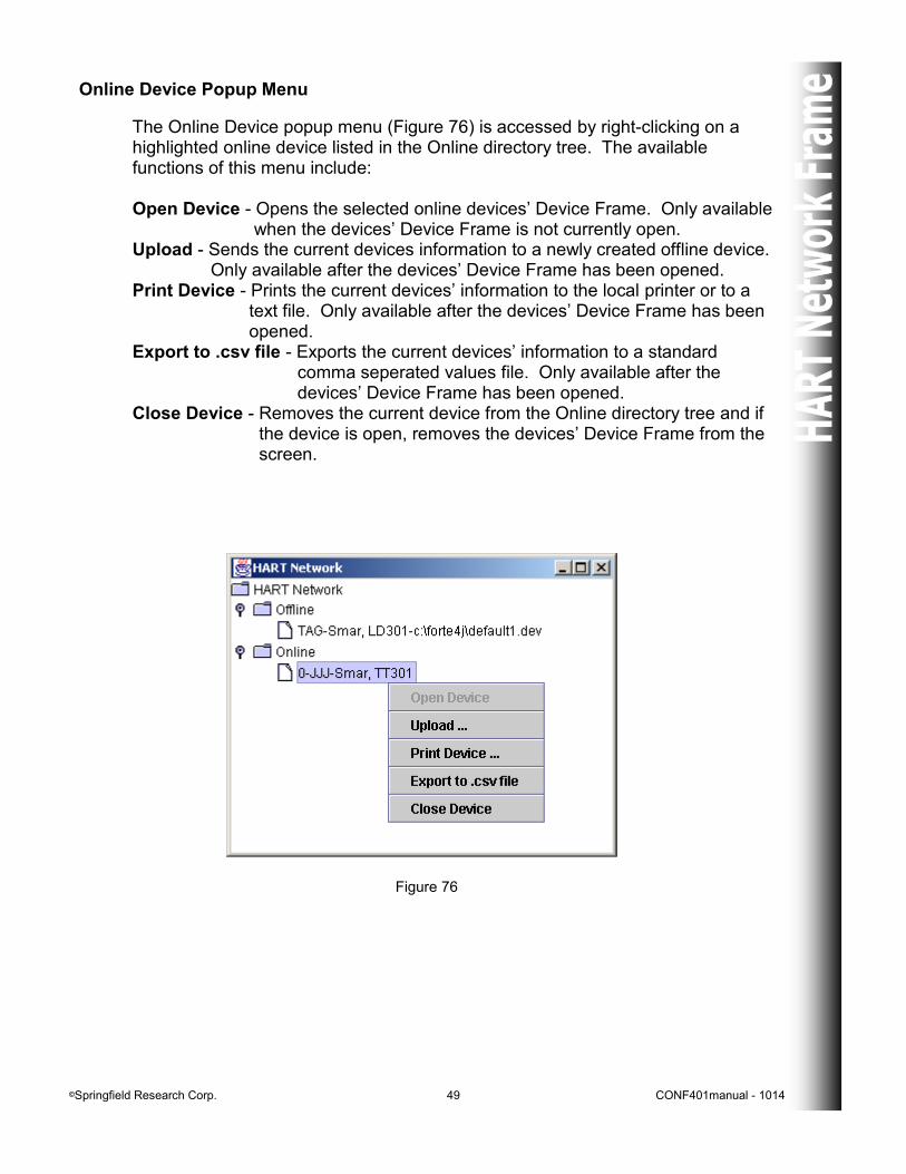
Online Device Popup Menu
The Online Device popup menu (Figure 76) is accessed by right-clicking on a highlighted online device listed in the Online directory tree. The available functions of this menu include: Open Device - Opens the selected online devices’ Device Frame. Only available when the devices’ Device Frame is not currently open. Upload - Sends the current devices information to a newly created offline device. Only available after the devices’ Device Frame has been opened. Print Device - Prints the current devices’ information to the local printer or to a text file. Only available after the devices’ Device Frame has been opened. Export to .csv file - Exports the current devices’ information to a standard comma seperated values file. Only available after the devices’ Device Frame has been opened. Close Device - Removes the current device from the Online directory tree and if the device is open, removes the devices’ Device Frame from the screen.
Figure 76
©Springfield Research Corp. 50 CONF401manual - 1014
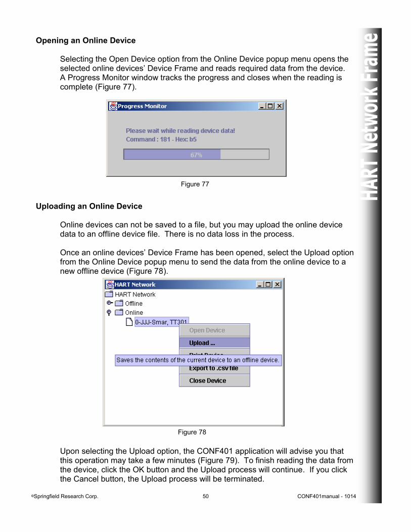
Opening an Online Device Selecting the Open Device option from the Online Device popup menu opens the selected online devices’ Device Frame and reads required data from the device. A Progress Monitor window tracks the progress and closes when the reading is complete (Figure 77).
Figure 77
Uploading an Online Device
Online devices can not be saved to a file, but you may upload the online device data to an offline device file. There is no data loss in the process. Once an online devices’ Device Frame has been opened, select the Upload option from the Online Device popup menu to send the data from the online device to a new offline device (Figure 78).
Figure 78
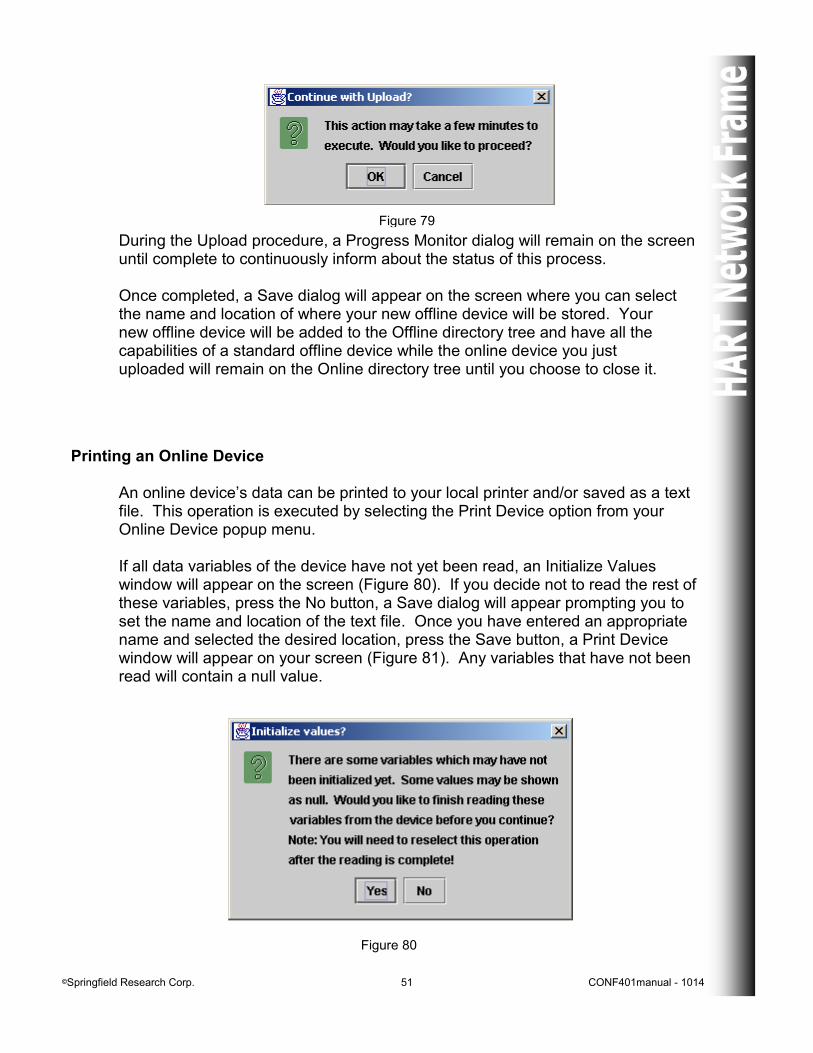
Upon selecting the Upload option, the CONF401 application will advise you that this operation may take a few minutes (Figure 79). To finish reading the data from the device, click the OK button and the Upload process will continue. If you click the Cancel button, the Upload process will be terminated.
©Springfield Research Corp. 51 CONF401manual - 1014
Figure 79
During the Upload procedure, a Progress Monitor dialog will remain on the screen until complete to continuously inform about the status of this process. Once completed, a Save dialog will appear on the screen where you can select the name and location of where your new offline device will be stored. Your new offline device will be added to the Offline directory tree and have all the capabilities of a standard offline device while the online device you just uploaded will remain on the Online directory tree until you choose to close it.
Printing an Online Device
An online device’s data can be printed to your local printer and/or saved as a text file. This operation is executed by selecting the Print Device option from your Online Device popup menu. If all data variables of the device have not yet been read, an Initialize Values window will appear on the screen (Figure 80). If you decide not to read the rest of these variables, press the No button, a Save dialog will appear prompting you to set the name and location of the text file. Once you have entered an appropriate name and selected the desired location, press the Save button, a Print Device window will appear on your screen (Figure 81). Any variables that have not been read will contain a null value.
Figure 80
©Springfield Research Corp. 52 CONF401manual - 1014
To read the variables that have not yet been initialized, click the Yes button on the Initialize Values window. A Progress Monitor will appear on your screen informing you of the communication status. Once all variables have been read from the device, the Progress Monitor will disappear and you will need to re-select the Print Device option from the Offline Device popup menu to complete the process. A Save dialog will appear on your screen and you will be prompted to supply a name and location for your text file. Once you have entered an appropriate name and selected the desired location, press the Save button, your chosen text editor will open with the information from your online device ready to print .
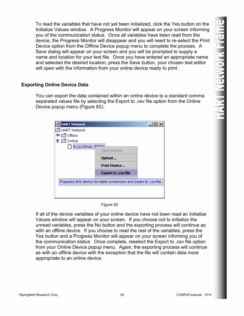
Exporting Online Device Data You can export the data contained within an online device to a standard comma separated values file by selecting the Export to .csv file option from the Online Device popup menu (Figure 82).
Figure 82
If all of the device variables of your online device have not been read an Initialize Values window will appear on your screen. If you choose not to initialize the unread variables, press the No button and the exporting process will continue as with an offline device. If you choose to read the rest of the variables, press the Yes button and a Progress Monitor will appear on your screen informing you of the communication status. Once complete, reselect the Export to .csv file option from your Online Device popup menu. Again, the exporting process will continue as with an offline device with the exception that the file will contain data more appropriate to an online device.
©Springfield Research Corp. 53 CONF401manual - 1014
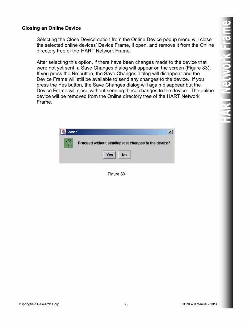
Closing an Online Device Selecting the Close Device option from the Online Device popup menu will close the selected online devices’ Device Frame, if open, and remove it from the Online directory tree of the HART Network Frame. After selecting this option, if there have been changes made to the device that were not yet sent, a Save Changes dialog will appear on the screen (Figure 83). If you press the No button, the Save Changes dialog will disappear and the Device Frame will still be available to send any changes to the device. If you press the Yes button, the Save Changes dialog will again disappear but the Device Frame will close without sending these changes to the device. The online device will be removed from the Online directory tree of the HART Network Frame.
Figure 83
©Springfield Research Corp. 54 CONF401manual - 1014
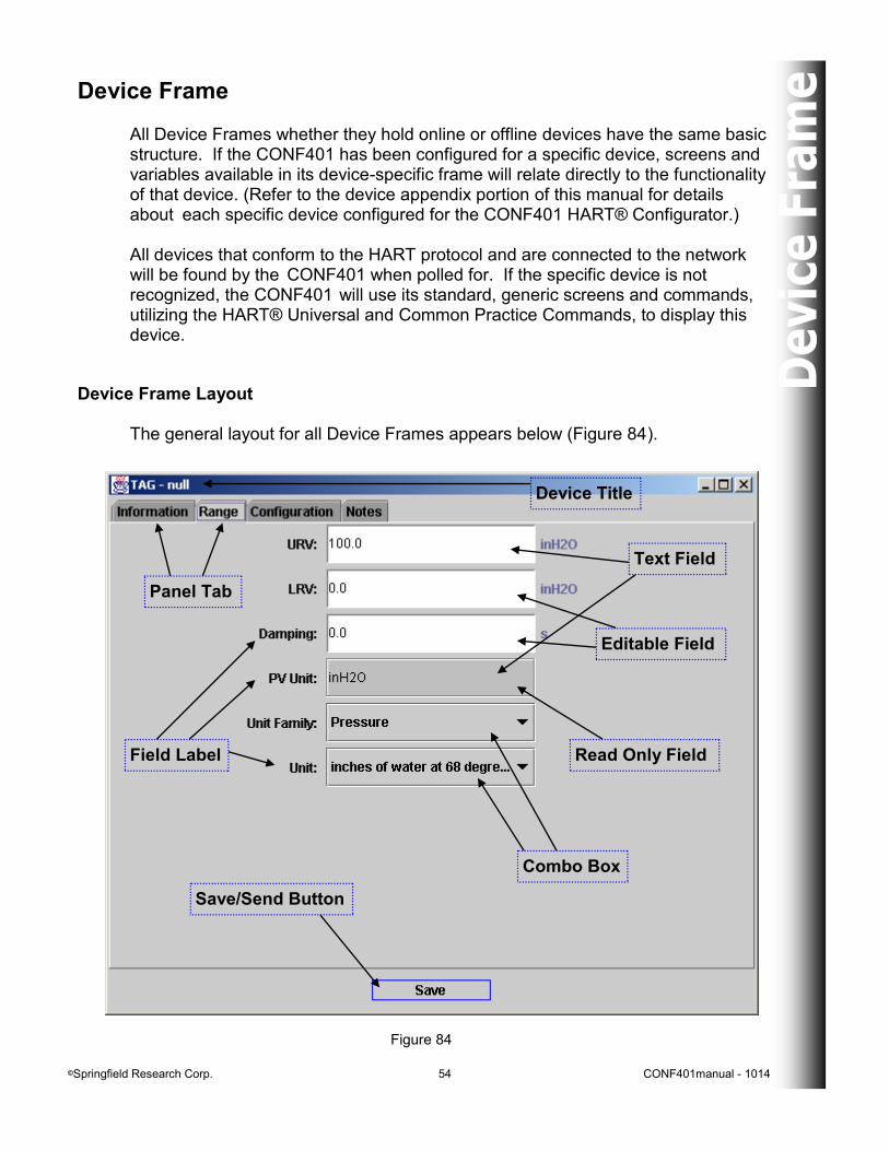
Device Frame All Device Frames whether they hold online or offline devices have the same basic structure. If the CONF401 has been configured for a specific device, screens and variables available in its device-specific frame will relate directly to the functionality of that device. (Refer to the device appendix portion of this manual for details about each specific device configured for the CONF401 HART® Configurator.) All devices that conform to the HART protocol and are connected to the network will be found by the CONF401 when polled for. If the specific device is not recognized, the CONF401 will use its standard, generic screens and commands, utilizing the HART® Universal and Common Practice Commands, to display this device.
Figure 84
Device Frame Layout The general layout for all Device Frames appears below (Figure 84).
Combo Box
Save/Send Button
Text Field
Editable Field
Read Only Field Field Label
Panel Tab
Device Title
©Springfield Research Corp. 55 CONF401manual - 1014
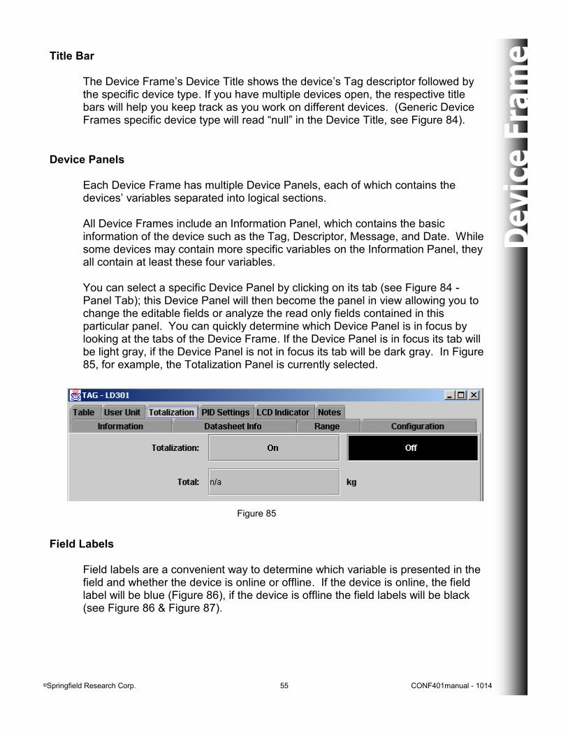
Device Panels Each Device Frame has multiple Device Panels, each of which contains the devices’ variables separated into logical sections. All Device Frames include an Information Panel, which contains the basic information of the device such as the Tag, Descriptor, Message, and Date. While some devices may contain more specific variables on the Information Panel, they all contain at least these four variables. You can select a specific Device Panel by clicking on its tab (see Figure 84 - Panel Tab); this Device Panel will then become the panel in view allowing you to change the editable fields or analyze the read only fields contained in this particular panel. You can quickly determine which Device Panel is in focus by looking at the tabs of the Device Frame. If the Device Panel is in focus its tab will be light gray, if the Device Panel is not in focus its tab will be dark gray. In Figure 85, for example, the Totalization Panel is currently selected.
Figure 85
Title Bar The Device Frame’s Device Title shows the device’s Tag descriptor followed by the specific device type. If you have multiple devices open, the respective title bars will help you keep track as you work on different devices. (Generic Device Frames specific device type will read “null” in the Device Title, see Figure 84).
Field Labels Field labels are a convenient way to determine which variable is presented in the field and whether the device is online or offline. If the device is online, the field label will be blue (Figure 86), if the device is offline the field labels will be black (see Figure 86 & Figure 87).
©Springfield Research Corp. 56 CONF401manual - 1014
Editing Fields Editable fields are fields of variables that the user may change (Figure 86), where as read only fields are not editable by the user (Figure 87). Editable fields will have a white background, while read only fields will have the same color background as the device panel (see Figure 84 - Editable Field/Read Only Field). Text fields (see Figure 84 - Text Field) can be edited by clicking your mouse inside the desired field and either selecting all of the text, or only the portion of text that is required to change, and typing in the new value.
Figure 86
Figure 87
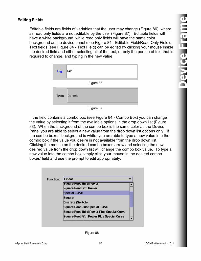
If the field contains a combo box (see Figure 84 - Combo Box) you can change the value by selecting it from the available options in the drop down list (Figure 88). When the background of the combo box is the same color as the Device Panel you are able to select a new value from the drop down list options only. If the combo boxes’ background is white, you are able to type a new value into the combo box if the value you desire is not available from the drop down list. Clicking the mouse on the desired combo boxes arrow and selecting the new desired value from the drop down list will change the combo box value. To type a new value into the combo box simply click your mouse in the desired combo boxes’ field and use the prompt to edit appropriately.
Figure 88
©Springfield Research Corp. 57 CONF401manual - 1014
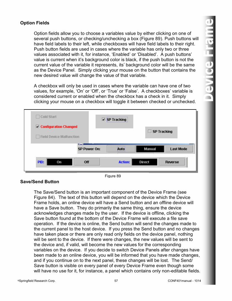
Option Fields Option fields allow you to choose a variables value by either clicking on one of several push buttons, or checking/unchecking a box (Figure 89). Push buttons will have field labels to their left, while checkboxes will have field labels to their right. Push button fields are used in cases where the variable has only two or three values associated with it, for instance, ‘Enabled’ or ‘Disabled’. A push buttons’ value is current when it’s background color is black, if the push button is not the current value of the variable it represents, its’ background color will be the same as the Device Panel. Simply clicking your mouse on the button that contains the new desired value will change the value of that variable. A checkbox will only be used in cases where the variable can have one of two values, for example, ‘On’ or ‘Off’, or ‘True’ or ‘False’. A checkboxes’ variable is considered current or enabled when the checkbox has a check in it. Simply clicking your mouse on a checkbox will toggle it between checked or unchecked.
Figure 89
Save/Send Button The Save/Send button is an important component of the Device Frame (see Figure 84). The text of this button will depend on the device which the Device Frame holds, an online device will have a Send button and an offline device will have a Save button. They do primarily the same thing, ensure the device acknowledges changes made by the user. If the device is offline, clicking the Save button found at the bottom of the Device Frame will execute a file save operation. If the device is online, the Send button will send the changes made to the current panel to the host device. If you press the Send button and no changes have taken place or there are only read only fields on the device panel, nothing will be sent to the device. If there were changes, the new values will be sent to the device and, if valid, will become the new values for the corresponding variables on the device. If you decide to switch Device Panels after changes have been made to an online device, you will be informed that you have made changes, and if you continue on to the next panel, these changes will be lost. The Send/ Save button is visible on every panel of every Device Frame even though some will have no use for it, for instance, a panel which contains only non-editable fields.
©Springfield Research Corp. 58 CONF401manual - 1014
Generic Device Frame Any device using the HART® Protocol will be found when polled for by the CONF401 HART Configurator. If the specific device is not recognized by the program, the new device will be treated as a HART, or generic, device. An Offline Generic Device Frame may be chosen to work with new devices that are not recognized by the CONF401 HART Configurator. Device Panels Device Panels that are contained within a Generic Device Frame include: - the Information Panel,
- the Device Info Panel (online only), - the Monitor Panel (online only), - the Specific Monitor Panel (online only), - the Device Status Panel (online only), - the Variable Codes Panel (online only), - the Range Panel, - the Configuration Panel, - the Maintenance Panel (online only), - the Trim Panel (online only), - the Graphics Panel (online only), - the Multidrop Panel (online only), and - the Notes Panel (offline only).
©Springfield Research Corp. 59 CONF401manual - 1014
Information Panel
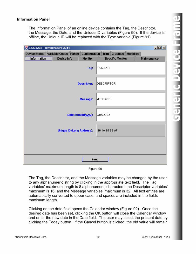
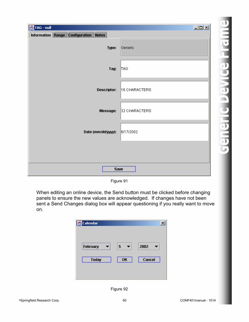
The Information Panel of an online device contains the Tag, the Descriptor, the Message, the Date, and the Unique ID variables (Figure 90). If the device is offline, the Unique ID will be replaced with the Type variable (Figure 91).
Figure 90
The Tag, the Descriptor, and the Message variables may be changed by the user to any alphanumeric string by clicking in the appropriate text field. The Tag variables’ maximum length is 8 alphanumeric characters, the Descriptor variables' maximum is 16, and the Message variables’ maximum is 32. All text entries are automatically converted to upper case, and spaces are included in the fields maximum length. Clicking on the date field opens the Calendar window (Figure 92). Once the desired date has been set, clicking the OK button will close the Calendar window and enter the new date in the Date field. The user may select the present date by clicking the Today button. If the Cancel button is clicked, the old value will remain.
©Springfield Research Corp. 60 CONF401manual - 1014
Figure 91
Figure 92
When editing an online device, the Send button must be clicked before changing panels to ensure the new values are acknowledged. If changes have not been sent a Send Changes dialog box will appear questioning if you really want to move on.
©Springfield Research Corp. 61 CONF401manual - 1014
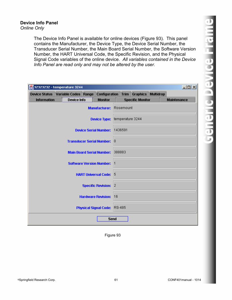
Device Info Panel Online Only
The Device Info Panel is available for online devices (Figure 93). This panel contains the Manufacturer, the Device Type, the Device Serial Number, the Transducer Serial Number, the Main Board Serial Number, the Software Version Number, the HART Universal Code, the Specific Revision, and the Physical Signal Code variables of the online device. All variables contained in the Device Info Panel are read only and may not be altered by the user.
Figure 93
©Springfield Research Corp. 62 CONF401manual - 1014
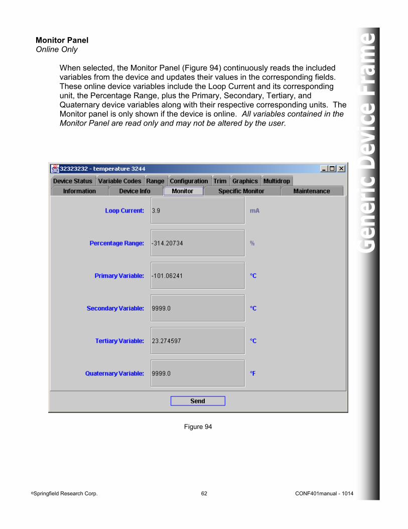
Monitor Panel Online Only When selected, the Monitor Panel (Figure 94) continuously reads the included variables from the device and updates their values in the corresponding fields. These online device variables include the Loop Current and its corresponding unit, the Percentage Range, plus the Primary, Secondary, Tertiary, and Quaternary device variables along with their respective corresponding units. The Monitor panel is only shown if the device is online. All variables contained in the Monitor Panel are read only and may not be altered by the user.
Figure 94
©Springfield Research Corp. 63 CONF401manual - 1014
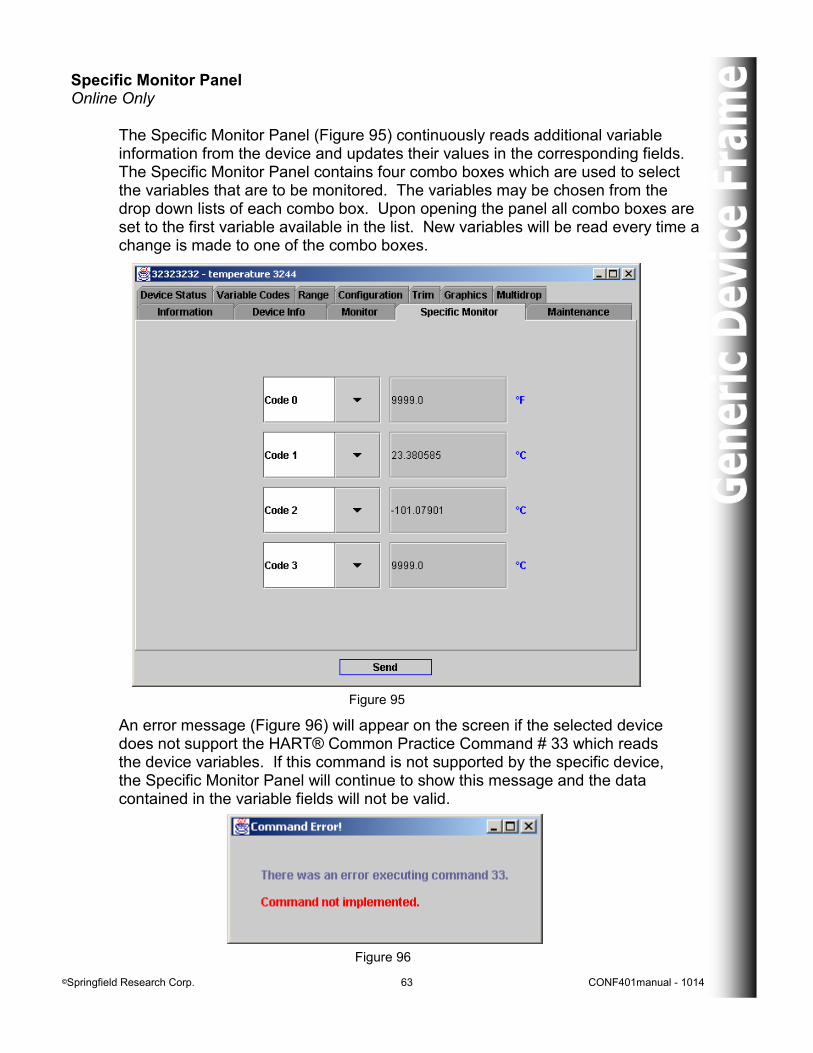
Specific Monitor Panel Online Only
The Specific Monitor Panel (Figure 95) continuously reads additional variable information from the device and updates their values in the corresponding fields. The Specific Monitor Panel contains four combo boxes which are used to select the variables that are to be monitored. The variables may be chosen from the drop down lists of each combo box. Upon opening the panel all combo boxes are set to the first variable available in the list. New variables will be read every time a change is made to one of the combo boxes.
Figure 95
An error message (Figure 96) will appear on the screen if the selected device does not support the HART® Common Practice Command # 33 which reads the device variables. If this command is not supported by the specific device, the Specific Monitor Panel will continue to show this message and the data contained in the variable fields will not be valid.
Figure 96
©Springfield Research Corp. 64 CONF401manual - 1014
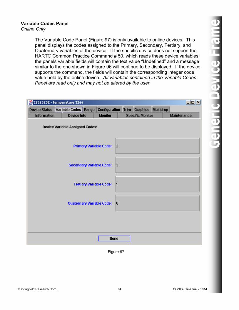
Variable Codes Panel Online Only
The Variable Code Panel (Figure 97) is only available to online devices. This panel displays the codes assigned to the Primary, Secondary, Tertiary, and Quaternary variables of the device. If the specific device does not support the HART® Common Practice Command # 50, which reads these device variables, the panels variable fields will contain the text value “Undefined” and a message similar to the one shown in Figure 96 will continue to be displayed. If the device supports the command, the fields will contain the corresponding integer code value held by the online device. All variables contained in the Variable Codes Panel are read only and may not be altered by the user.
Figure 97
©Springfield Research Corp. 65 CONF401manual - 1014
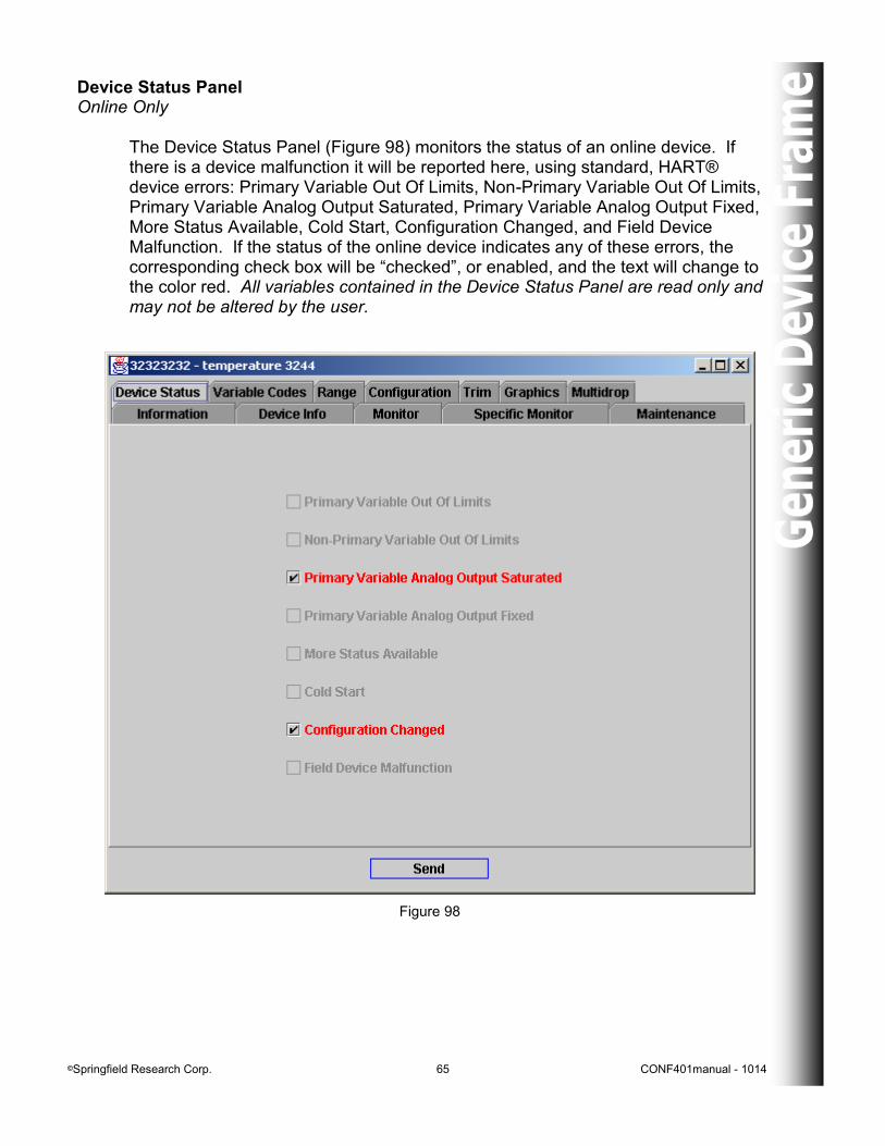
Device Status Panel Online Only The Device Status Panel (Figure 98) monitors the status of an online device. If there is a device malfunction it will be reported here, using standard, HART® device errors: Primary Variable Out Of Limits, Non-Primary Variable Out Of Limits, Primary Variable Analog Output Saturated, Primary Variable Analog Output Fixed, More Status Available, Cold Start, Configuration Changed, and Field Device Malfunction. If the status of the online device indicates any of these errors, the corresponding check box will be “checked”, or enabled, and the text will change to the color red. All variables contained in the Device Status Panel are read only and may not be altered by the user.
Figure 98
©Springfield Research Corp. 66 CONF401manual - 1014
Range Panel
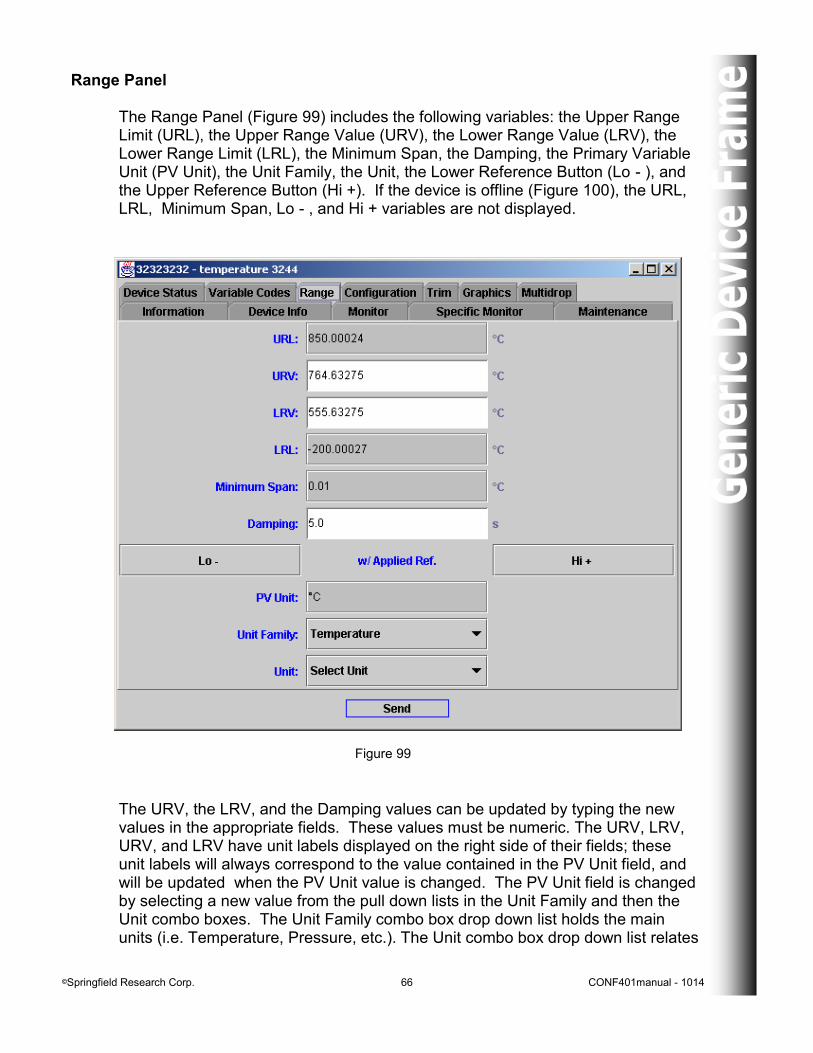
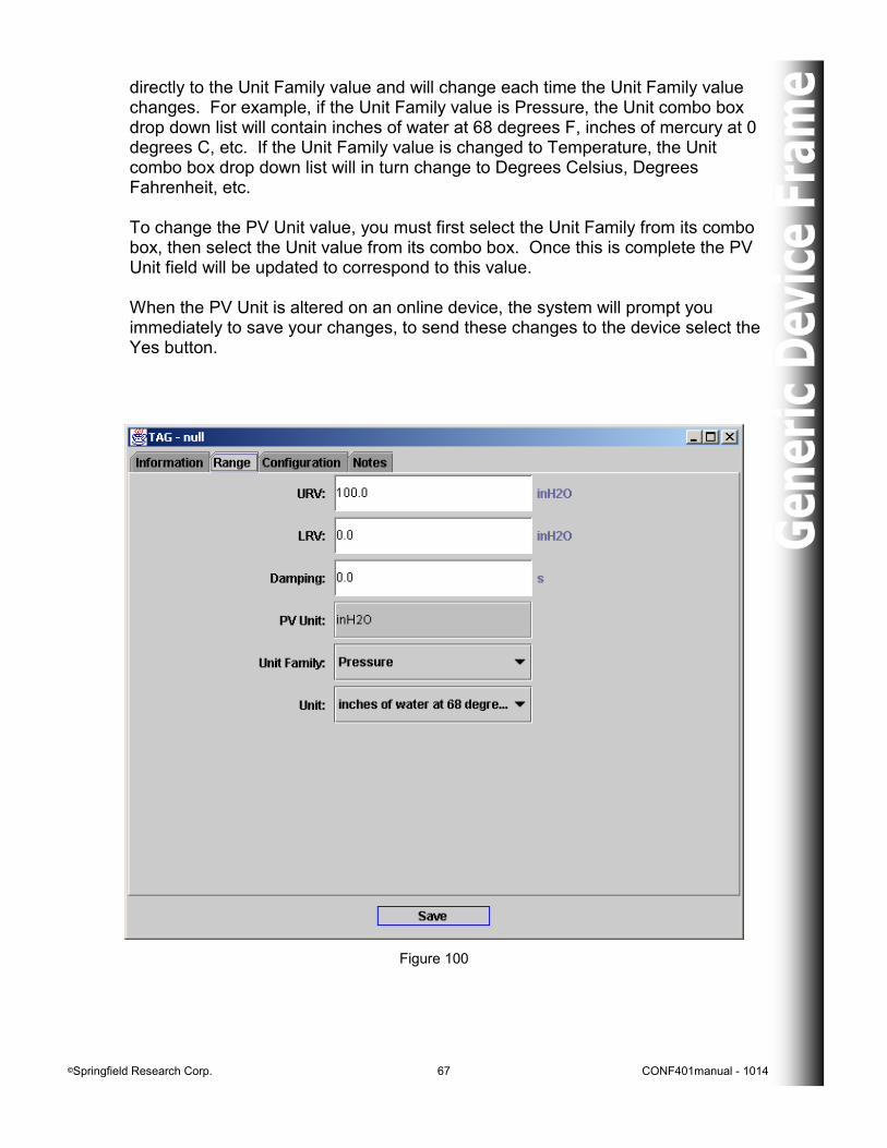
The Range Panel (Figure 99) includes the following variables: the Upper Range Limit (URL), the Upper Range Value (URV), the Lower Range Value (LRV), the Lower Range Limit (LRL), the Minimum Span, the Damping, the Primary Variable Unit (PV Unit), the Unit Family, the Unit, the Lower Reference Button (Lo - ), and the Upper Reference Button (Hi +). If the device is offline (Figure 100), the URL, LRL, Minimum Span, Lo - , and Hi + variables are not displayed.
Figure 99
The URV, the LRV, and the Damping values can be updated by typing the new values in the appropriate fields. These values must be numeric. The URV, LRV, URV, and LRV have unit labels displayed on the right side of their fields; these unit labels will always correspond to the value contained in the PV Unit field, and will be updated when the PV Unit value is changed. The PV Unit field is changed by selecting a new value from the pull down lists in the Unit Family and then the Unit combo boxes. The Unit Family combo box drop down list holds the main units (i.e. Temperature, Pressure, etc.). The Unit combo box drop down list relates
©Springfield Research Corp. 67 CONF401manual - 1014
directly to the Unit Family value and will change each time the Unit Family value changes. For example, if the Unit Family value is Pressure, the Unit combo box drop down list will contain inches of water at 68 degrees F, inches of mercury at 0 degrees C, etc. If the Unit Family value is changed to Temperature, the Unit combo box drop down list will in turn change to Degrees Celsius, Degrees Fahrenheit, etc. To change the PV Unit value, you must first select the Unit Family from its combo box, then select the Unit value from its combo box. Once this is complete the PV Unit field will be updated to correspond to this value. When the PV Unit is altered on an online device, the system will prompt you immediately to save your changes, to send these changes to the device select the Yes button.
Figure 100
©Springfield Research Corp. 68 CONF401manual - 1014
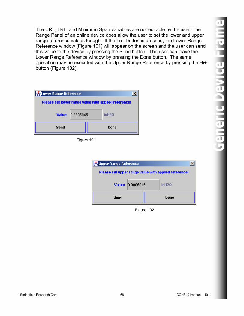
The URL, LRL, and Minimum Span variables are not editable by the user. The Range Panel of an online device does allow the user to set the lower and upper range reference values though. If the Lo - button is pressed, the Lower Range Reference window (Figure 101) will appear on the screen and the user can send this value to the device by pressing the Send button. The user can leave the Lower Range Reference window by pressing the Done button. The same operation may be executed with the Upper Range Reference by pressing the Hi+ button (Figure 102).
Figure 101
Figure 102
©Springfield Research Corp. 69 CONF401manual - 1014
Configuration Panel
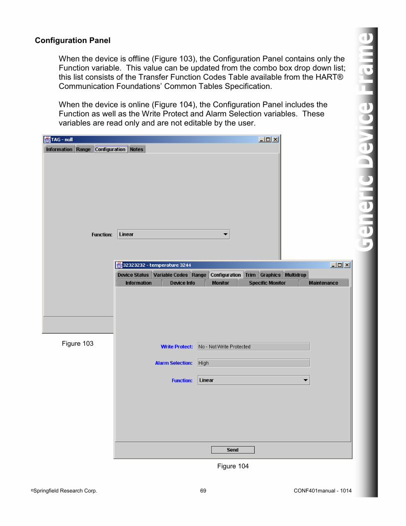
When the device is offline (Figure 103), the Configuration Panel contains only the Function variable. This value can be updated from the combo box drop down list; this list consists of the Transfer Function Codes Table available from the HART® Communication Foundations’ Common Tables Specification. When the device is online (Figure 104), the Configuration Panel includes the Function as well as the Write Protect and Alarm Selection variables. These variables are read only and are not editable by the user.
Figure 103
Figure 104
©Springfield Research Corp. 70 CONF401manual - 1014
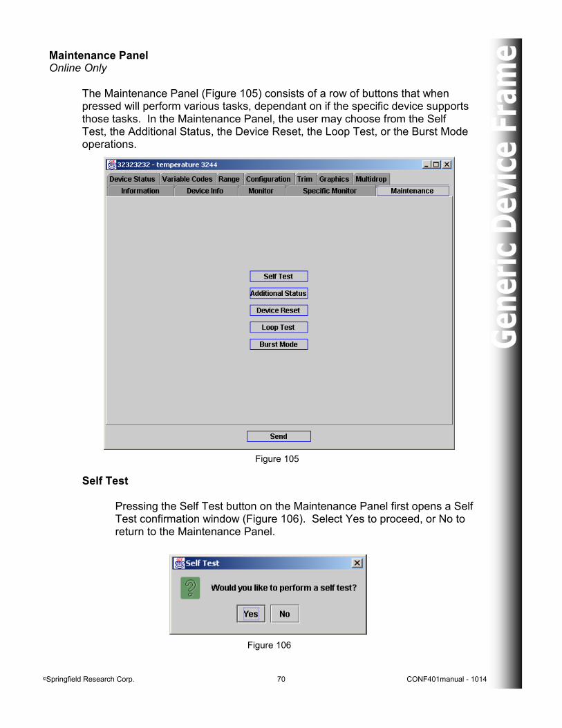
Maintenance Panel Online Only The Maintenance Panel (Figure 105) consists of a row of buttons that when pressed will perform various tasks, dependant on if the specific device supports those tasks. In the Maintenance Panel, the user may choose from the Self Test, the Additional Status, the Device Reset, the Loop Test, or the Burst Mode operations.
Figure 106
Self Test Pressing the Self Test button on the Maintenance Panel first opens a Self Test confirmation window (Figure 106). Select Yes to proceed, or No to return to the Maintenance Panel.
Figure 105
©Springfield Research Corp. 71 CONF401manual - 1014
Figure 107
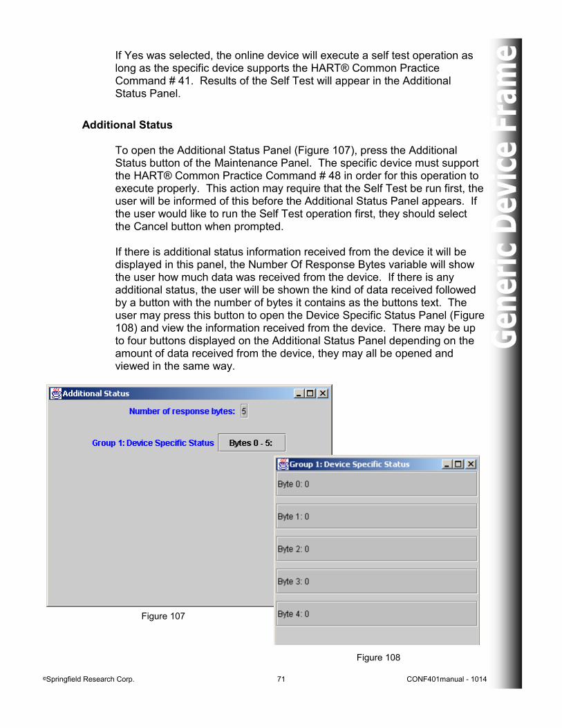
Additional Status To open the Additional Status Panel (Figure 107), press the Additional Status button of the Maintenance Panel. The specific device must support the HART® Common Practice Command # 48 in order for this operation to execute properly. This action may require that the Self Test be run first, the user will be informed of this before the Additional Status Panel appears. If the user would like to run the Self Test operation first, they should select the Cancel button when prompted. If there is additional status information received from the device it will be displayed in this panel, the Number Of Response Bytes variable will show the user how much data was received from the device. If there is any additional status, the user will be shown the kind of data received followed by a button with the number of bytes it contains as the buttons text. The user may press this button to open the Device Specific Status Panel (Figure 108) and view the information received from the device. There may be up to four buttons displayed on the Additional Status Panel depending on the amount of data received from the device, they may all be opened and viewed in the same way.
Figure 108
If Yes was selected, the online device will execute a self test operation as long as the specific device supports the HART® Common Practice Command # 41. Results of the Self Test will appear in the Additional Status Panel.
©Springfield Research Corp. 72 CONF401manual - 1014
Figure 109
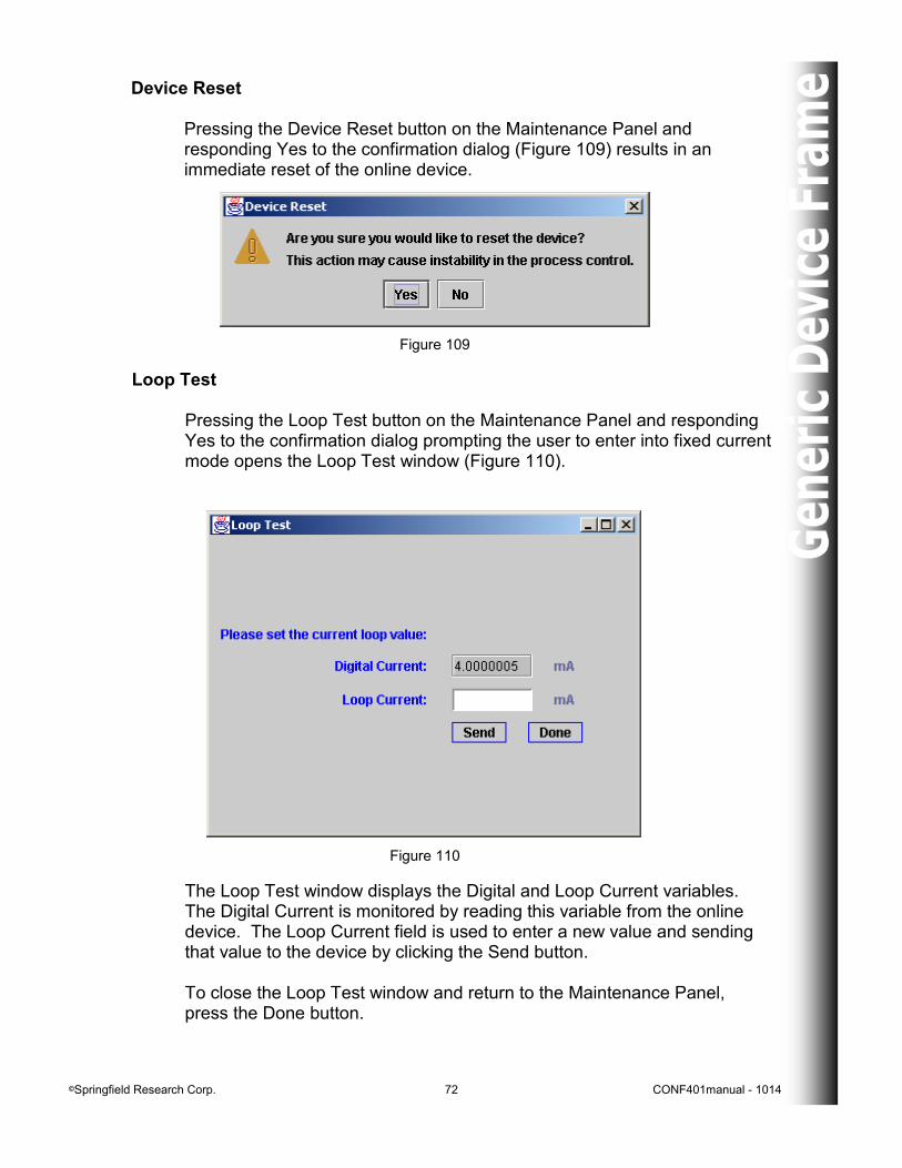
Device Reset Pressing the Device Reset button on the Maintenance Panel and responding Yes to the confirmation dialog (Figure 109) results in an immediate reset of the online device.
Loop Test Pressing the Loop Test button on the Maintenance Panel and responding Yes to the confirmation dialog prompting the user to enter into fixed current mode opens the Loop Test window (Figure 110).
Figure 110
The Loop Test window displays the Digital and Loop Current variables. The Digital Current is monitored by reading this variable from the online device. The Loop Current field is used to enter a new value and sending that value to the device by clicking the Send button. To close the Loop Test window and return to the Maintenance Panel,
press the Done button.
©Springfield Research Corp. 73 CONF401manual - 1014
Figure 111
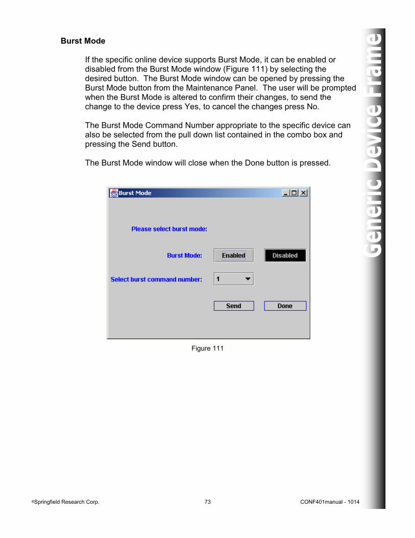
Burst Mode If the specific online device supports Burst Mode, it can be enabled or disabled from the Burst Mode window (Figure 111) by selecting the desired button. The Burst Mode window can be opened by pressing the Burst Mode button from the Maintenance Panel. The user will be prompted when the Burst Mode is altered to confirm their changes, to send the change to the device press Yes, to cancel the changes press No. The Burst Mode Command Number appropriate to the specific device can also be selected from the pull down list contained in the combo box and pressing the Send button. The Burst Mode window will close when the Done button is pressed.
©Springfield Research Corp. 74 CONF401manual - 1014
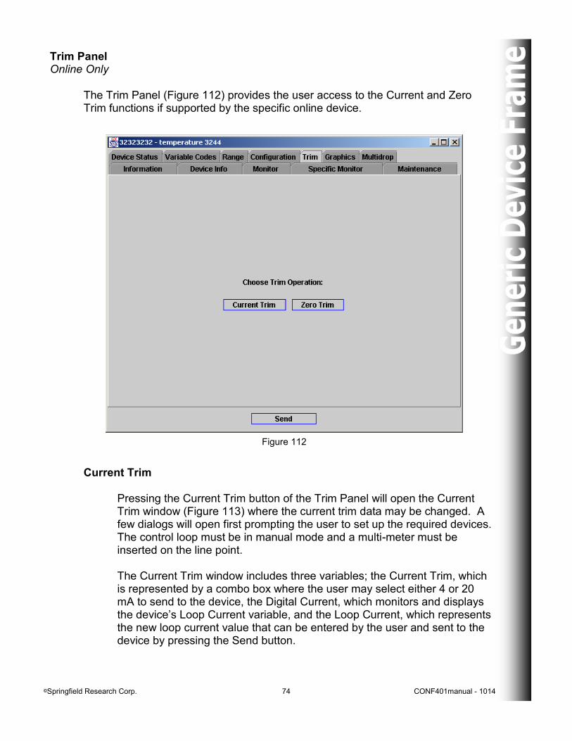
Trim Panel Online Only The Trim Panel (Figure 112) provides the user access to the Current and Zero Trim functions if supported by the specific online device.
Figure 112
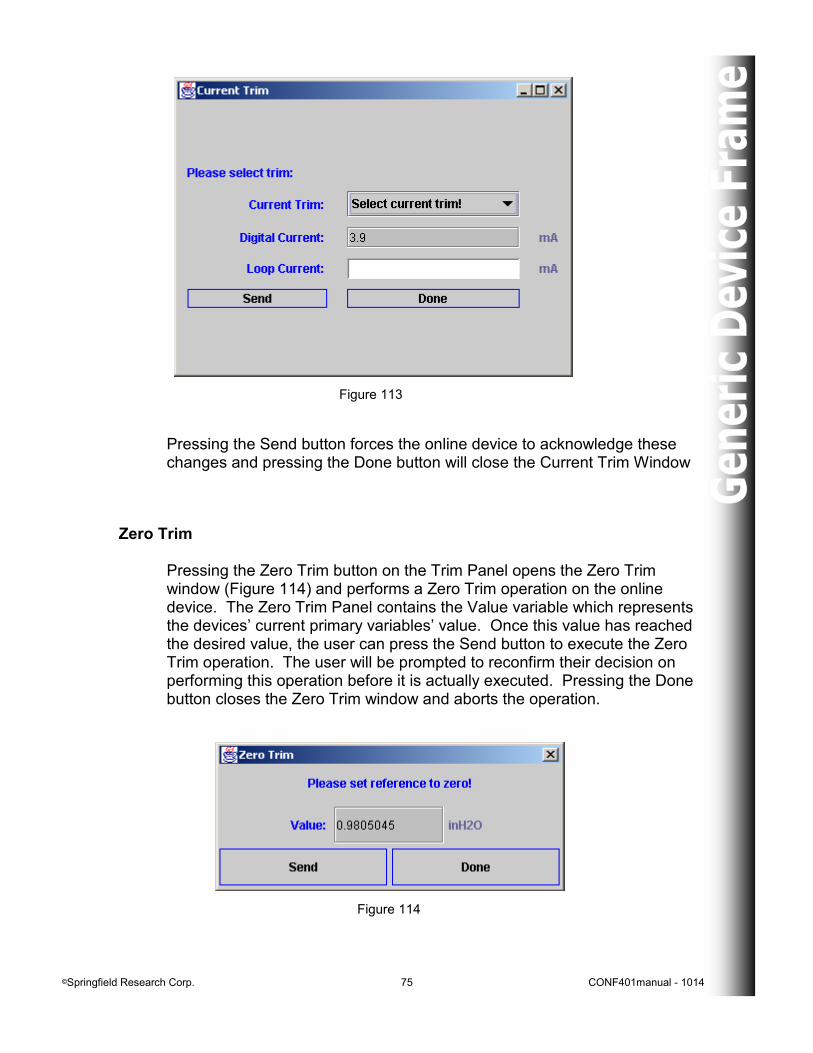
Current Trim Pressing the Current Trim button of the Trim Panel will open the Current Trim window (Figure 113) where the current trim data may be changed. A few dialogs will open first prompting the user to set up the required devices. The control loop must be in manual mode and a multi-meter must be inserted on the line point. The Current Trim window includes three variables; the Current Trim, which is represented by a combo box where the user may select either 4 or 20 mA to send to the device, the Digital Current, which monitors and displays the device’s Loop Current variable, and the Loop Current, which represents the new loop current value that can be entered by the user and sent to the device by pressing the Send button.
©Springfield Research Corp. 75 CONF401manual - 1014
Zero Trim Pressing the Zero Trim button on the Trim Panel opens the Zero Trim window (Figure 114) and performs a Zero Trim operation on the online device. The Zero Trim Panel contains the Value variable which represents the devices’ current primary variables’ value. Once this value has reached the desired value, the user can press the Send button to execute the Zero Trim operation. The user will be prompted to reconfirm their decision on performing this operation before it is actually executed. Pressing the Done button closes the Zero Trim window and aborts the operation.
Figure 114
Figure 113
Pressing the Send button forces the online device to acknowledge these changes and pressing the Done button will close the Current Trim Window
©Springfield Research Corp. 76 CONF401manual - 1014
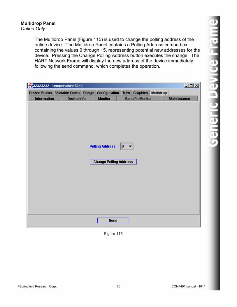
Multidrop Panel Online Only The Multidrop Panel (Figure 115) is used to change the polling address of the online device. The Multidrop Panel contains a Polling Address combo box containing the values 0 through 15, representing potential new addresses for the device. Pressing the Change Polling Address button executes the change. The HART Network Frame will display the new address of the device immediately following the send command, which completes the operation.
Figure 115
©Springfield Research Corp. 77 CONF401manual - 1014
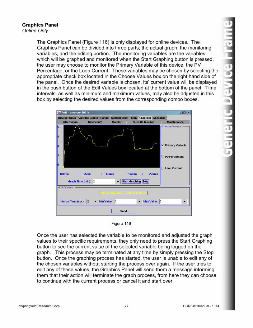
Graphics Panel Online Only The Graphics Panel (Figure 116) is only displayed for online devices. The Graphics Panel can be divided into three parts; the actual graph, the monitoring variables, and the editing portion. The monitoring variables are the variables which will be graphed and monitored when the Start Graphing button is pressed, the user may choose to monitor the Primary Variable of this device, the PV Percentage, or the Loop Current. These variables may be chosen by selecting the appropriate check box located in the Choose Values box on the right hand side of the panel. Once the desired variable is chosen, its’ current value will be displayed in the push button of the Edit Values box located at the bottom of the panel. Time intervals, as well as minimum and maximum values, may also be adjusted in this box by selecting the desired values from the corresponding combo boxes.
Figure 116
Once the user has selected the variable to be monitored and adjusted the graph values to their specific requirements, they only need to press the Start Graphing button to see the current value of the selected variable being logged on the graph. This process may be terminated at any time by simply pressing the Stop button. Once the graphing process has started, the user is unable to edit any of the chosen variables without starting the process over again. If the user tries to edit any of these values, the Graphics Panel will send them a message informing them that their action will terminate the graph process, from here they can choose to continue with the current process or cancel it and start over.
©Springfield Research Corp. 78 CONF401manual - 1014
Figure 117
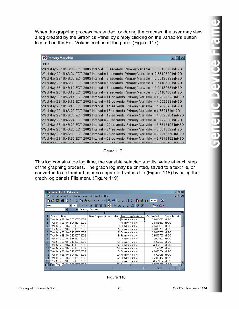
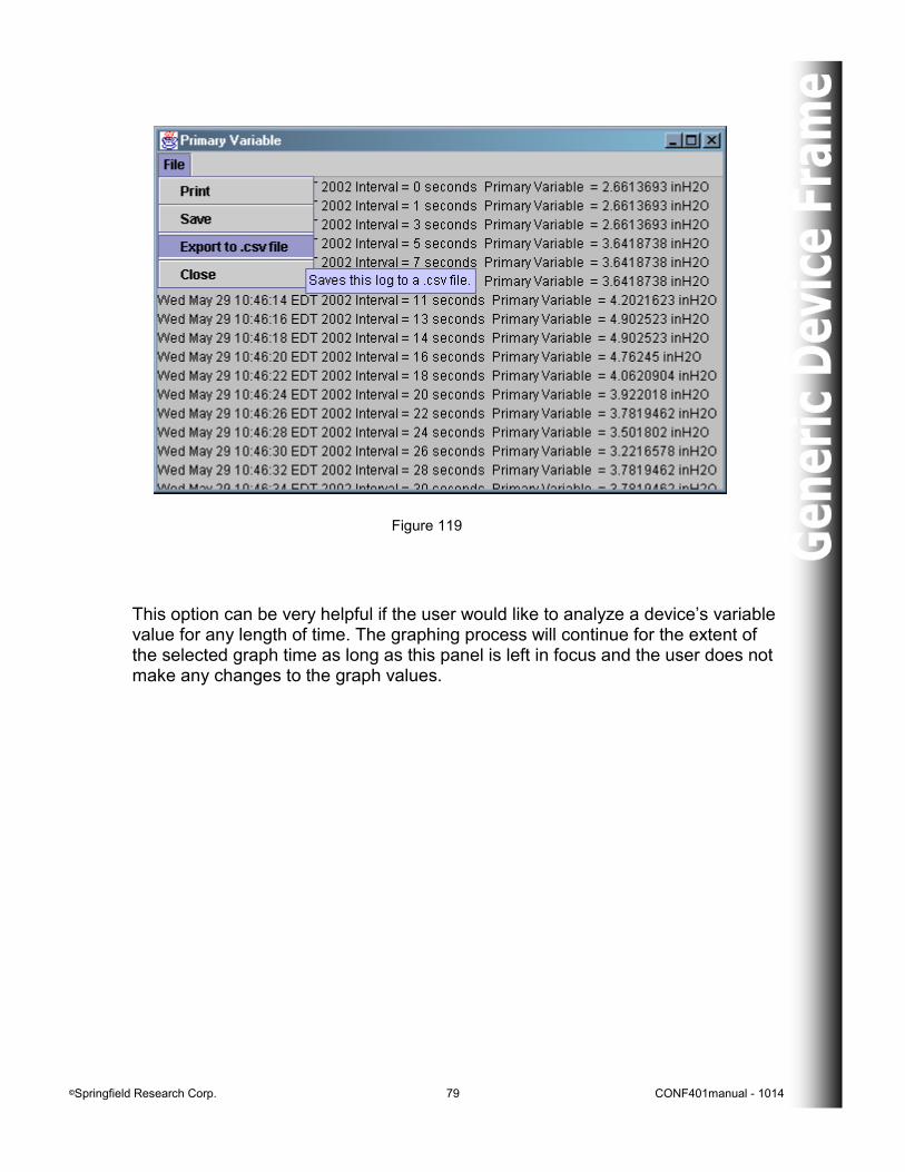
This log contains the log time, the variable selected and its’ value at each step of the graphing process. The graph log may be printed, saved to a text file, or converted to a standard comma separated values file (Figure 118) by using the graph log panels File menu (Figure 119).
When the graphing process has ended, or during the process, the user may view a log created by the Graphics Panel by simply clicking on the variable’s button located on the Edit Values section of the panel (Figure 117).
Figure 118
©Springfield Research Corp. 79 CONF401manual - 1014
Figure 119
This option can be very helpful if the user would like to analyze a device’s variable value for any length of time. The graphing process will continue for the extent of the selected graph time as long as this panel is left in focus and the user does not make any changes to the graph values.
©Springfield Research Corp. 80 CONF401manual - 1014
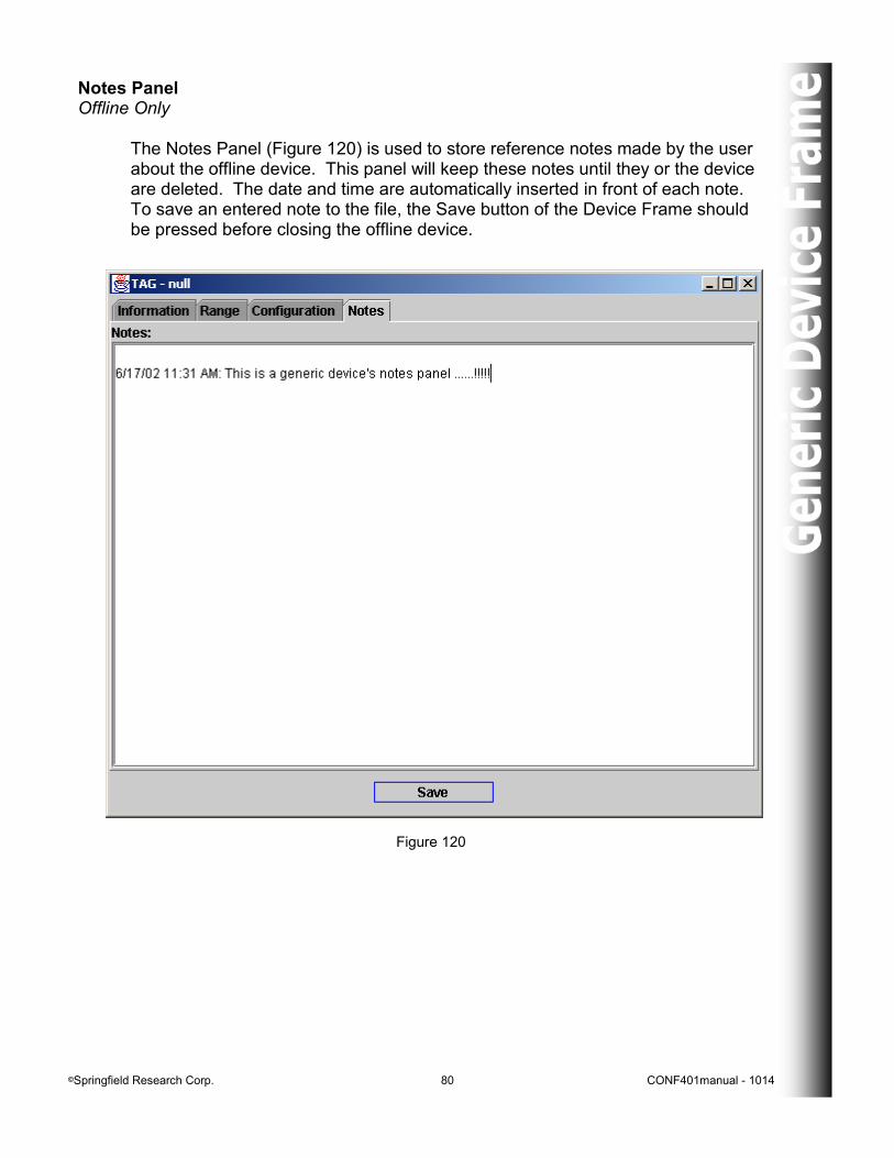
Notes Panel Offline Only The Notes Panel (Figure 120) is used to store reference notes made by the user about the offline device. This panel will keep these notes until they or the device are deleted. The date and time are automatically inserted in front of each note. To save an entered note to the file, the Save button of the Device Frame should be pressed before closing the offline device.
Figure 120
©Springfield Research Corp. 81 CONF401manual - 1014
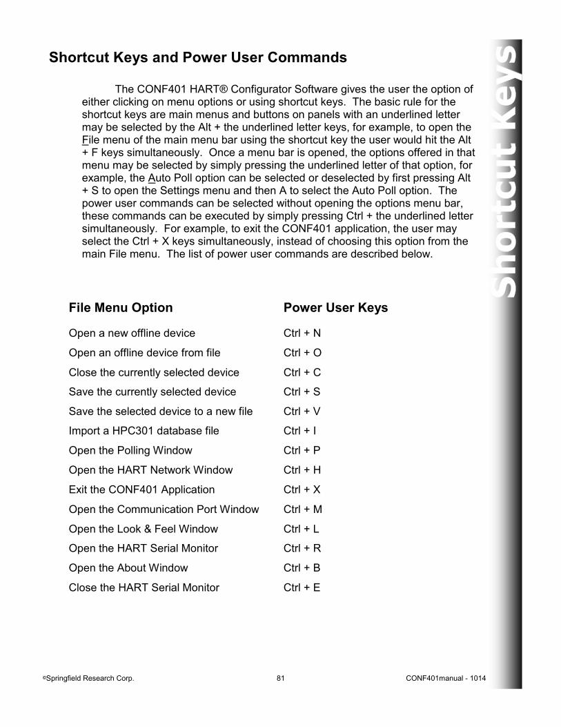
Shortcut Keys and Power User Commands The CONF401 HART® Configurator Software gives the user the option of either clicking on menu options or using shortcut keys. The basic rule for the shortcut keys are main menus and buttons on panels with an underlined letter may be selected by the Alt + the underlined letter keys, for example, to open the File menu of the main menu bar using the shortcut key the user would hit the Alt + F keys simultaneously. Once a menu bar is opened, the options offered in that menu may be selected by simply pressing the underlined letter of that option, for example, the Auto Poll option can be selected or deselected by first pressing Alt + S to open the Settings menu and then A to select the Auto Poll option. The power user commands can be selected without opening the options menu bar, these commands can be executed by simply pressing Ctrl + the underlined letter simultaneously. For example, to exit the CONF401 application, the user may select the Ctrl + X keys simultaneously, instead of choosing this option from the main File menu. The list of power user commands are described below.
File Menu Option Power User Keys
Open a new offline device Ctrl + N
Open an offline device from file Ctrl + O
Close the currently selected device Ctrl + C
Save the currently selected device Ctrl + S
Save the selected device to a new file Ctrl + V
Import a HPC301 database file Ctrl + I
Open the Polling Window Ctrl + P
Open the HART Network Window Ctrl + H
Exit the CONF401 Application Ctrl + X
Open the Communication Port Window Ctrl + M
Open the Look & Feel Window Ctrl + L
Open the HART Serial Monitor Ctrl + R
Open the About Window Ctrl + B
Close the HART Serial Monitor Ctrl + E
©Springfield Research Corp. 82 CONF401manual - 1014
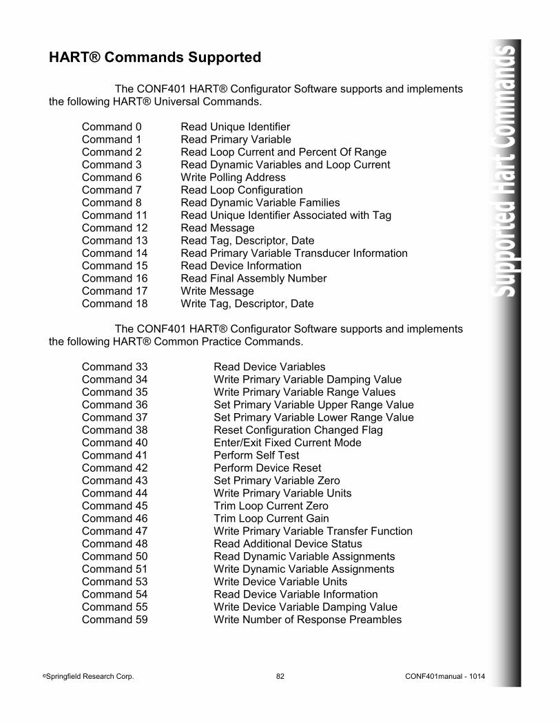
HART® Commands Supported The CONF401 HART® Configurator Software supports and implements the following HART® Universal Commands. Command 0 Read Unique Identifier Command 1 Read Primary Variable Command 2 Read Loop Current and Percent Of Range Command 3 Read Dynamic Variables and Loop Current Command 6 Write Polling Address Command 7 Read Loop Configuration Command 8 Read Dynamic Variable Families Command 11 Read Unique Identifier Associated with Tag Command 12 Read Message Command 13 Read Tag, Descriptor, Date Command 14 Read Primary Variable Transducer Information Command 15 Read Device Information Command 16 Read Final Assembly Number Command 17 Write Message Command 18 Write Tag, Descriptor, Date The CONF401 HART® Configurator Software supports and implements the following HART® Common Practice Commands. Command 33 Read Device Variables Command 34 Write Primary Variable Damping Value Command 35 Write Primary Variable Range Values Command 36 Set Primary Variable Upper Range Value Command 37 Set Primary Variable Lower Range Value Command 38 Reset Configuration Changed Flag Command 40 Enter/Exit Fixed Current Mode Command 41 Perform Self Test Command 42 Perform Device Reset Command 43 Set Primary Variable Zero Command 44 Write Primary Variable Units Command 45 Trim Loop Current Zero Command 46 Trim Loop Current Gain Command 47 Write Primary Variable Transfer Function Command 48 Read Additional Device Status Command 50 Read Dynamic Variable Assignments Command 51 Write Dynamic Variable Assignments Command 53 Write Device Variable Units Command 54 Read Device Variable Information Command 55 Write Device Variable Damping Value Command 59 Write Number of Response Preambles

©Springfield Research Corp. 83 CONF401manual - 1014
Command 107 Write Burst Device Variables Command 108 Write Burst Mode Command Number Command 109 Burst Mode Control
©Springfield Research Corp. 84 CONF401manual - 1014
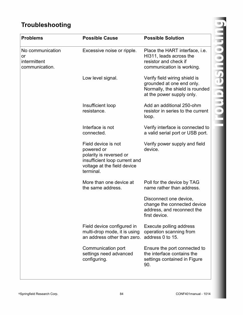
Problems Possible Cause Possible Solution
No communication or intermittent communication.
Excessive noise or ripple. Low level signal. Insufficient loop resistance. Interface is not connected. Field device is not powered or polarity is reversed or insufficient loop current and voltage at the field device terminal. More than one device at the same address. Field device configured in multi-drop mode, it is using an address other than zero. Communication port settings need advanced configuring.
Place the HART interface, i.e. HI311, leads across the resistor and check if communication is working. Verify field wiring shield is grounded at one end only. Normally, the shield is rounded at the power supply only. Add an additional 250-ohm resistor in series to the current loop. Verify interface is connected to a valid serial port or USB port. Verify power supply and field device. Poll for the device by TAG name rather than address. Disconnect one device, change the connected device address, and reconnect the first device. Execute polling address operation scanning from address 0 to 15. Ensure the port connected to the interface contains the settings contained in Figure 90.
Troubleshooting

©Springfield Research Corp. 85 CONF401manual - 1014
Springfield Research reserves the right to make changes to design and functionality of any product without notice. Springfield Research does not assume any liability arising out of the application or use of any product. Springfield Research and the Springfield Research
logo are registered trademarks of Springfield Research Corporation. The HART, Fieldbus, and Profibus Foundation logos are trademarks of their respective owners.
Springfield Research Corporation 3350 NW 22nd Terrace Suite 500 Pompano Beach, FL USA 33069
Tel: 954.657.8849 Fax: 954.657.8895 [email protected] www.springres.us