conext™ grid tie solar inverter - altestore.com · xantrex technology inc. reserves the right to...
TRANSCRIPT
Conext™ Grid Tie Solar InverterConext TX 2800 NAConext TX 3300 NAConext TX 3800 NAConext TX 5000 NA
Owner’s Manual
www.schneider-electric.com

Conext Grid Tie Solar Inverter
Owner’s Manual
www.schneider-electric.com
Copyright and Contact
TrademarksSchneider Electric, the Schneider Electric logo, Conext, Fast Sweep, Xantrex, and Xanbus are trademarks or registered trademarks of the Schneider Electric group of companies. Other trademarks, registered trademarks, and product names are the property of their respective owners and are used herein for identification purposes only.
Notice of CopyrightCopyright © July 2011 Xantrex Technology Inc. All rights reserved. No part of this document may be reproduced in any form or disclosed to third parties without the express written consent of:Xantrex Technology Inc.161–G South Vasco Road Livermore, California USA 94551Xantrex Technology Inc. reserves the right to revise this document and to periodically make changes to the content hereof without obligation or organization of such revisions or changes unless required to do so by prior arrangement.
Exclusion for DocumentationUNLESS SPECIFICALLY AGREED TO IN WRITING, XANTREX TECHNOLOGY INC. (“XANTREX”)
(A) MAKES NO WARRANTY AS TO THE ACCURACY, SUFFICIENCY OR SUITABILITY OF ANY TECHNICAL OR OTHER INFORMATION PROVIDED IN ITS MANUALS OR OTHER DOCUMENTATION;
(B) ASSUMES NO RESPONSIBILITY OR LIABILITY FOR LOSSES, DAMAGES, COSTS OR EXPENSES, WHETHER SPECIAL, DIRECT, INDIRECT, CONSEQUENTIAL OR INCIDENTAL, WHICH MIGHT ARISE OUT OF THE USE OF SUCH INFORMATION. THE USE OF ANY SUCH INFORMATION WILL BE ENTIRELY AT THE USER’S RISK; AND
(C) REMINDS YOU THAT IF THIS MANUAL IS IN ANY LANGUAGE OTHER THAN ENGLISH, ALTHOUGH STEPS HAVE BEEN TAKEN TO MAINTAIN THE ACCURACY OF THE TRANSLATION, THE ACCURACY CANNOT BE GUARANTEED. APPROVED XANTREX CONTENT IS CONTAINED WITH THE ENGLISH LANGUAGE VERSION WHICH IS POSTED AT WWW.SCHNEIDER-ELECTRIC.COM.
Date and RevisionJuly 2011 Revision A
Part Number975-0596-01-01
Product Part Numbers878–2801 Conext TX 2800 NA878–3301 Conext TX 3300 NA878–3801 Conext TX 3800 NA878–5001 Conext TX 5000 NA
Contact Information
www.schneider-electric.com
☎ ✉North America 1 650 351 8237
1 866 519 14701 925 245 1022 [email protected]
France +33 (0) 825 012 999 [email protected] +49 (0) 180 575 3 575 +49 (0) 2102 404 7101 [email protected]ña +34 902 101 813 +34 933 055 026 [email protected]'Italia +39 035 4151111 +39 035415 3200 [email protected]
For other country details please contact your local Schneider Electric Sales Representative or visit the Schneider Electric Web site at:http://www.schneider-electric.com/sites/corporate/en/support/operations/local-operations/local-operations.page

About This ManualThe purpose of this Owner’s Manual is to provide explanations and procedures for installing, operating, maintaining, and troubleshooting the Schneider Electric Conext Grid Tie Solar Inverter (Conext Inverter).
Scope
The manual provides safety guidelines as well as detailed planning and setup information. It provides procedures for installing, operating, and troubleshooting the Conext Inverter. It does not provide details about particular brands of photovoltaic (PV) panels. Consult individual PV manufacturers for that information.
Audience
Chapter 1 and Chapter 5 are intended for anyone who needs to operate the Conext Grid Tie Solar Inverter. Operators must be familiar with all the safety regulations pertaining to operating high-voltage equipment as dictated by local code. Operators must also have a complete understanding of this equipment’s features and functions. Do not use this product unless it has been installed by qualified personnel in accordance with the instructions in Chapter 2, “Installation”.
Chapter 2, Chapter 3, Chapter 4, and Chapter 6 are intended for qualified personnel who need to install the Conext Grid Tie Solar Inverter. Qualified personnel have training, knowledge, and experience in:
• Installing electrical equipment and PV power systems (up to 1000 V).
• Applying all applicable installation codes.
• Analyzing and reducing the hazards involved in performing electrical work.
• Selecting and using personal protective equipment.
Installation, commissioning, and maintenance of the Conext Inverter must be done only by qualified personnel.
975-0596-01-01 Revision A iii
About This Manual
Organization
This manual is organized into six chapters and an appendix.
Chapter 1 contains information about the features and functions of the Conext Grid Tie Solar Inverter.
Chapter 2 provides instructions for installing the Conext Grid Tie Solar Inverter. It contains information on determining a suitable location for installation, PV array requirements, and procedures for mounting the Conext Grid Tie Solar Inverter.
Chapter 3 provides information about DC and AC wiring as well as grounding the Conext Inverter and the PV array.
Chapter 4 provides instructions for starting the Conext Grid Tie Solar Inverter and performing a functional test.
Chapter 5 contains information about the LCD screens and the LED indicators.
Chapter 6 contains information on general maintenance of the Conext Grid Tie Solar Inverter. It also provides information about troubleshooting the Conext Inverter.
Appendix A contains specifications for the Conext Grid Tie Solar Inverter.
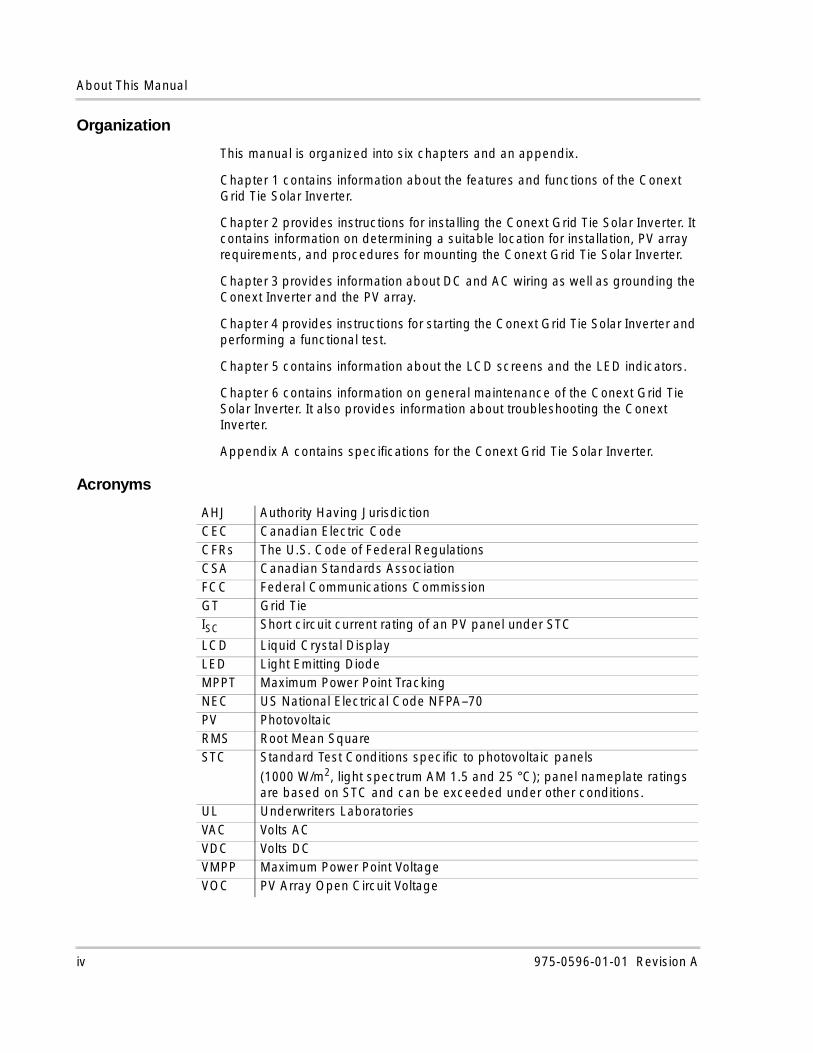
Acronyms
AHJ Authority Having JurisdictionCEC Canadian Electric CodeCFRs The U.S. Code of Federal RegulationsCSA Canadian Standards AssociationFCC Federal Communications CommissionGT Grid TieISC Short circuit current rating of an PV panel under STC
LCD Liquid Crystal DisplayLED Light Emitting DiodeMPPT Maximum Power Point TrackingNEC US National Electrical Code NFPA–70PV Photovoltaic RMS Root Mean SquareSTC Standard Test Conditions specific to photovoltaic panels
(1000 W/m2, light spectrum AM 1.5 and 25 °C); panel nameplate ratings are based on STC and can be exceeded under other conditions.
UL Underwriters LaboratoriesVAC Volts ACVDC Volts DCVMPP Maximum Power Point VoltageVOC PV Array Open Circuit Voltage
iv 975-0596-01-01 Revision A
About This Manual
Conventions Used
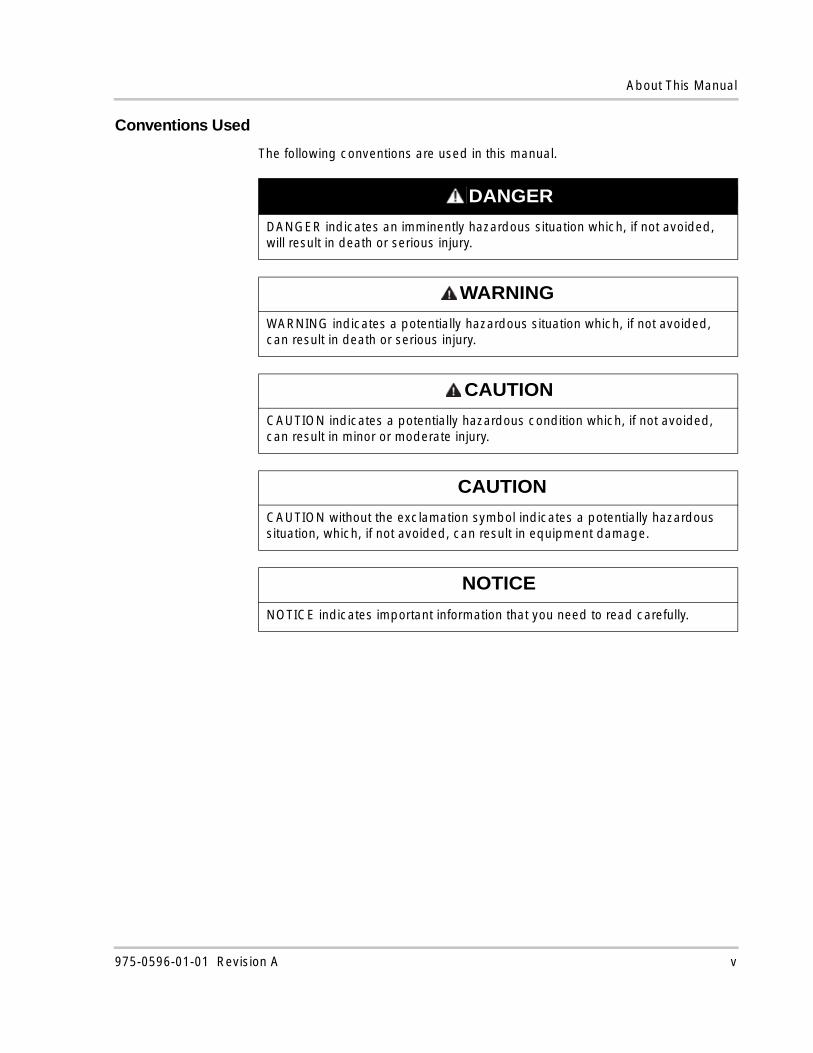
The following conventions are used in this manual.
DANGER
DANGER indicates an imminently hazardous situation which, if not avoided, will result in death or serious injury.
WARNING
WARNING indicates a potentially hazardous situation which, if not avoided, can result in death or serious injury.
CAUTION
CAUTION indicates a potentially hazardous condition which, if not avoided, can result in minor or moderate injury.
CAUTION
CAUTION without the exclamation symbol indicates a potentially hazardous situation, which, if not avoided, can result in equipment damage.
NOTICE
NOTICE indicates important information that you need to read carefully.
975-0596-01-01 Revision A v
About This Manual
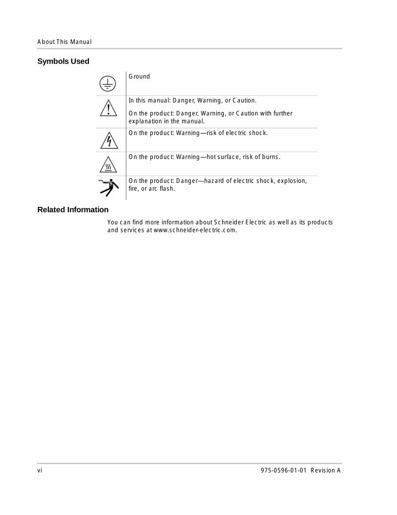
Symbols Used
Related Information
You can find more information about Schneider Electric as well as its products and services at www.schneider-electric.com.
Ground
In this manual: Danger, Warning, or Caution.
On the product: Danger, Warning, or Caution with further explanation in the manual.
On the product: Warning—risk of electric shock.
On the product: Warning—hot surface, risk of burns.
On the product: Danger—hazard of electric shock, explosion, fire, or arc flash.
vi 975-0596-01-01 Revision A
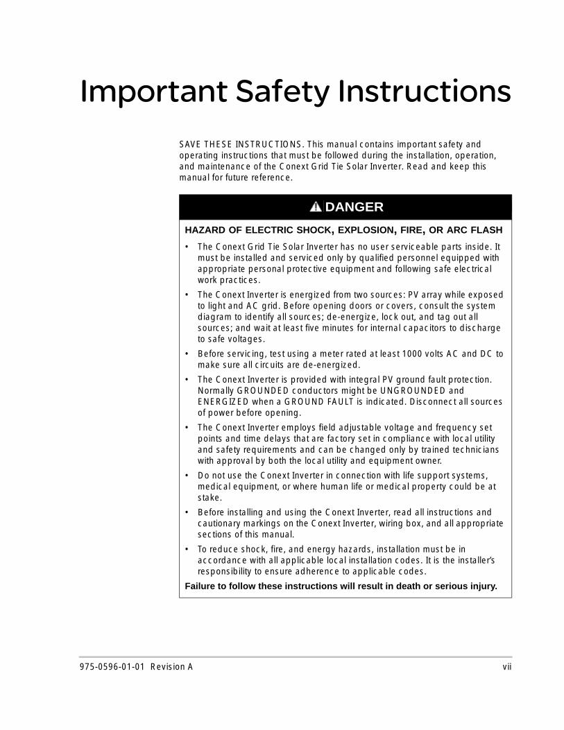
Important Safety InstructionsSAVE THESE INSTRUCTIONS. This manual contains important safety and operating instructions that must be followed during the installation, operation, and maintenance of the Conext Grid Tie Solar Inverter. Read and keep this manual for future reference.
DANGER
HAZARD OF ELECTRIC SHOCK, EXPLOSION, FIRE, OR ARC FLASH
• The Conext Grid Tie Solar Inverter has no user serviceable parts inside. It must be installed and serviced only by qualified personnel equipped with appropriate personal protective equipment and following safe electrical work practices.
• The Conext Inverter is energized from two sources: PV array while exposed to light and AC grid. Before opening doors or covers, consult the system diagram to identify all sources; de-energize, lock out, and tag out all sources; and wait at least five minutes for internal capacitors to discharge to safe voltages.
• Before servicing, test using a meter rated at least 1000 volts AC and DC to make sure all circuits are de-energized.
• The Conext Inverter is provided with integral PV ground fault protection. Normally GROUNDED conductors might be UNGROUNDED and ENERGIZED when a GROUND FAULT is indicated. Disconnect all sources of power before opening.
• The Conext Inverter employs field adjustable voltage and frequency set points and time delays that are factory set in compliance with local utility and safety requirements and can be changed only by trained technicians with approval by both the local utility and equipment owner.
• Do not use the Conext Inverter in connection with life support systems, medical equipment, or where human life or medical property could be at stake.
• Before installing and using the Conext Inverter, read all instructions and cautionary markings on the Conext Inverter, wiring box, and all appropriate sections of this manual.
• To reduce shock, fire, and energy hazards, installation must be in accordance with all applicable local installation codes. It is the installer’s responsibility to ensure adherence to applicable codes.
Failure to follow these instructions will result in death or serious injury.
975-0596-01-01 Revision A vii
Safety
DANGER
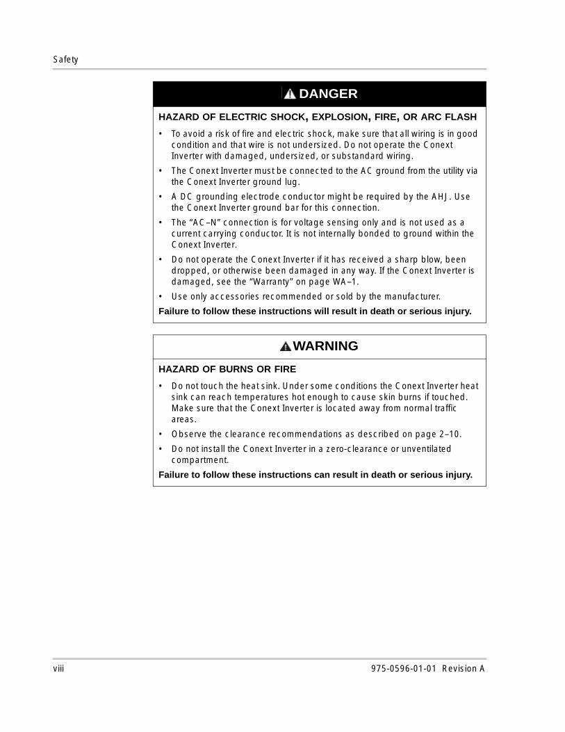
HAZARD OF ELECTRIC SHOCK, EXPLOSION, FIRE, OR ARC FLASH
• To avoid a risk of fire and electric shock, make sure that all wiring is in good condition and that wire is not undersized. Do not operate the Conext Inverter with damaged, undersized, or substandard wiring.
• The Conext Inverter must be connected to the AC ground from the utility via the Conext Inverter ground lug.
• A DC grounding electrode conductor might be required by the AHJ. Use the Conext Inverter ground bar for this connection.
• The “AC–N” connection is for voltage sensing only and is not used as a current carrying conductor. It is not internally bonded to ground within the Conext Inverter.
• Do not operate the Conext Inverter if it has received a sharp blow, been dropped, or otherwise been damaged in any way. If the Conext Inverter is damaged, see the “Warranty” on page WA–1.
• Use only accessories recommended or sold by the manufacturer.
Failure to follow these instructions will result in death or serious injury.
WARNING
HAZARD OF BURNS OR FIRE
• Do not touch the heat sink. Under some conditions the Conext Inverter heat sink can reach temperatures hot enough to cause skin burns if touched. Make sure that the Conext Inverter is located away from normal traffic areas.
• Observe the clearance recommendations as described on page 2–10.
• Do not install the Conext Inverter in a zero-clearance or unventilated compartment.
Failure to follow these instructions can result in death or serious injury.
viii 975-0596-01-01 Revision A
Safety
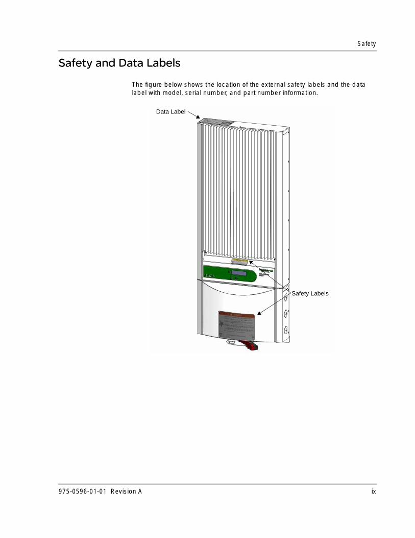
Safety and Data Labels
The figure below shows the location of the external safety labels and the data label with model, serial number, and part number information.
Safety Labels
Data Label
975-0596-01-01 Revision A ix
Safety
Safety Equipment
Authorized service personnel must be equipped with appropriate personal protective equipment including the following:
• Safety glasses
• Ear protection
• Composite-toed safety boots
• Safety hard hats
• Padlocks and tags
• Double-insulated tools
• Appropriate meter to verify that the circuits are de-energized (1000 volts AC and DC rated, minimum)
Check local safety regulations for other requirements.
FCC Information for the User
This equipment has been tested and found to comply with the limits for a Class B digital device, pursuant to part 15 of the FCC Rules. These limits are designed to provide reasonable protection against harmful interference in a residential installation. This equipment generates, uses, and can radiate radio frequency energy and—if not installed and used in accordance with the instructions—could cause harmful interference to radio communications. However, there is no guarantee that interference will not occur in a particular installation. If this equipment does cause harmful interference to radio or television reception, which can be determined by turning the equipment off and on, the user is encouraged to try to correct the interference by one or more of the following measures:
• Reorient or relocate the receiving antenna.
• Increase the separation between the equipment and the receiver.
• Connect the equipment to a different circuit from that to which the receiver is connected.
Consult the dealer or an experienced radio/TV technician for help.
x 975-0596-01-01 Revision A
Contents
Important Safety Instructions- - - - - - - - - - - - - - - - - - - - - - - - - - - - - - - - - - - - - viiSafety and Data Labels - - - - - - - - - - - - - - - - - - - - - - - - - - - - - - - - - - - - - - - - - - - - - - - - - - - - - -ixSafety Equipment - - - - - - - - - - - - - - - - - - - - - - - - - - - - - - - - - - - - - - - - - - - - - - - - - - - - - - - - - - xFCC Information for the User - - - - - - - - - - - - - - - - - - - - - - - - - - - - - - - - - - - - - - - - - - - - - - - - - - x
1 IntroductionAbout the Conext Grid Tie Solar Inverter- - - - - - - - - - - - - - - - - - - - - - - - - - - - - - - - - - - - - - - - - 1–2Standard Features - - - - - - - - - - - - - - - - - - - - - - - - - - - - - - - - - - - - - - - - - - - - - - - - - - - - - - - - 1–3Front Panel Features - - - - - - - - - - - - - - - - - - - - - - - - - - - - - - - - - - - - - - - - - - - - - - - - - - - - - - - 1–4Wiring/Disconnect Box - - - - - - - - - - - - - - - - - - - - - - - - - - - - - - - - - - - - - - - - - - - - - - - - - - - - - 1–4
2 InstallationInstallation Options - - - - - - - - - - - - - - - - - - - - - - - - - - - - - - - - - - - - - - - - - - - - - - - - - - - - - - - - 2–2Planning the Installation - - - - - - - - - - - - - - - - - - - - - - - - - - - - - - - - - - - - - - - - - - - - - - - - - - - - 2–2
Installation Codes - - - - - - - - - - - - - - - - - - - - - - - - - - - - - - - - - - - - - - - - - - - - - - - - - - - - - - 2–2Conext Grid Tie Solar Inverter Location - - - - - - - - - - - - - - - - - - - - - - - - - - - - - - - - - - - - - - - 2–2MPPT Requirements - - - - - - - - - - - - - - - - - - - - - - - - - - - - - - - - - - - - - - - - - - - - - - - - - - - - 2–4
Mounting the Conext Grid Tie Solar Inverter - - - - - - - - - - - - - - - - - - - - - - - - - - - - - - - - - - - - - - 2–5Dimensions and Knockout Locations - - - - - - - - - - - - - - - - - - - - - - - - - - - - - - - - - - - - - - - - 2–5Installing the Mounting Bracket - - - - - - - - - - - - - - - - - - - - - - - - - - - - - - - - - - - - - - - - - - - - 2–8Mounting the Conext Grid Tie Solar Inverter on the Bracket - - - - - - - - - - - - - - - - - - - - - - - 2–11
3 Wiring the Conext Grid Tie Solar InverterGrounding Requirements - - - - - - - - - - - - - - - - - - - - - - - - - - - - - - - - - - - - - - - - - - - - - - - - - - - 3–3
AC Grounding - - - - - - - - - - - - - - - - - - - - - - - - - - - - - - - - - - - - - - - - - - - - - - - - - - - - - - - - 3–3PV Grounding - - - - - - - - - - - - - - - - - - - - - - - - - - - - - - - - - - - - - - - - - - - - - - - - - - - - - - - - - 3–3Ground Fault Fuse - - - - - - - - - - - - - - - - - - - - - - - - - - - - - - - - - - - - - - - - - - - - - - - - - - - - - 3–5
Wiring Requirements- - - - - - - - - - - - - - - - - - - - - - - - - - - - - - - - - - - - - - - - - - - - - - - - - - - - - - - 3–5AC Circuit Breaker Requirements - - - - - - - - - - - - - - - - - - - - - - - - - - - - - - - - - - - - - - - - - - - 3–6DC/AC Disconnect Switch - - - - - - - - - - - - - - - - - - - - - - - - - - - - - - - - - - - - - - - - - - - - - - - - 3–6Combiner Fuses (Optional) - - - - - - - - - - - - - - - - - - - - - - - - - - - - - - - - - - - - - - - - - - - - - - - 3–6
Accessing the Wiring Terminals - - - - - - - - - - - - - - - - - - - - - - - - - - - - - - - - - - - - - - - - - - - - - - - 3–8Connecting the DC Wiring - - - - - - - - - - - - - - - - - - - - - - - - - - - - - - - - - - - - - - - - - - - - - - - - - - 3–11
Connecting the DC Wiring Using the Optional Fuse Holder - - - - - - - - - - - - - - - - - - - - - - - 3–13DC Wiring for Multiple Conext Grid Tie Solar Inverters - - - - - - - - - - - - - - - - - - - - - - - - - - - 3–15
Connecting the AC Wiring - - - - - - - - - - - - - - - - - - - - - - - - - - - - - - - - - - - - - - - - - - - - - - - - - - 3–17DC and AC Wiring for Multiple Conext Grid Tie Solar Inverters (Single-Phase System) - - - - - - - 3–18DC and AC Wiring for Multiple Conext Grid Tie Solar Inverters (Three-Phase System) - - - - - - - 3–19Communications Wiring for Multiple Conext Grid Tie Solar Inverters - - - - - - - - - - - - - - - - - - - - 3–20
Xanbus Network Technology - - - - - - - - - - - - - - - - - - - - - - - - - - - - - - - - - - - - - - - - - - - - - 3–21
975-0596-01-01 Revision A xi
Contents
Guidelines for Routing the Network Cables - - - - - - - - - - - - - - - - - - - - - - - - - - - - - - - - - - - 3–24Connecting Network Cable Between Multiple Conext Grid Tie Solar Inverters - - - - - - - - - - 3–25Verifying the Xanbus Network - - - - - - - - - - - - - - - - - - - - - - - - - - - - - - - - - - - - - - - - - - - - 3–26
Communications Wiring for Monitoring a Single Conext Grid Tie Solar Inverter - - - - - - - - - - - - 3–26Fast Sweep™ Shade Tolerant MPPT Algorithm - - - - - - - - - - - - - - - - - - - - - - - - - - - - - - - - - - 3–28
4 Starting the Conext Grid Tie Solar InverterStartup Procedure - - - - - - - - - - - - - - - - - - - - - - - - - - - - - - - - - - - - - - - - - - - - - - - - - - - - - - - - 4–2
Checking the PV Array DC Voltage - - - - - - - - - - - - - - - - - - - - - - - - - - - - - - - - - - - - - - - - - 4–2Checking the AC Utility Voltage - - - - - - - - - - - - - - - - - - - - - - - - - - - - - - - - - - - - - - - - - - - - 4–3Replacing the Wiring/Disconnect Box Cover - - - - - - - - - - - - - - - - - - - - - - - - - - - - - - - - - - - 4–3Starting the Conext Inverter - - - - - - - - - - - - - - - - - - - - - - - - - - - - - - - - - - - - - - - - - - - - - - - 4–4
Commissioning Multiple Conext Grid Tie Solar Inverters - - - - - - - - - - - - - - - - - - - - - - - - - - - - - 4–4Disconnect Test - - - - - - - - - - - - - - - - - - - - - - - - - - - - - - - - - - - - - - - - - - - - - - - - - - - - - - - - - - 4–6Locating the Firmware Version Number - - - - - - - - - - - - - - - - - - - - - - - - - - - - - - - - - - - - - - - - - 4–7
5 Monitoring the Conext Grid Tie Solar InverterMonitoring the Front Panel Display - - - - - - - - - - - - - - - - - - - - - - - - - - - - - - - - - - - - - - - - - - - - 5–2Front Panel Display Screens and What They Mean - - - - - - - - - - - - - - - - - - - - - - - - - - - - - - - - - 5–3
Startup Mode - - - - - - - - - - - - - - - - - - - - - - - - - - - - - - - - - - - - - - - - - - - - - - - - - - - - - - - - - 5–3Normal Operation Mode - - - - - - - - - - - - - - - - - - - - - - - - - - - - - - - - - - - - - - - - - - - - - - - - - 5–5Offline Mode - - - - - - - - - - - - - - - - - - - - - - - - - - - - - - - - - - - - - - - - - - - - - - - - - - - - - - - - - 5–7Fault Mode - - - - - - - - - - - - - - - - - - - - - - - - - - - - - - - - - - - - - - - - - - - - - - - - - - - - - - - - - - - 5–8Special Screens - - - - - - - - - - - - - - - - - - - - - - - - - - - - - - - - - - - - - - - - - - - - - - - - - - - - - - 5–10Custom Screens - - - - - - - - - - - - - - - - - - - - - - - - - - - - - - - - - - - - - - - - - - - - - - - - - - - - - - 5–11
Status Indicator Lights - - - - - - - - - - - - - - - - - - - - - - - - - - - - - - - - - - - - - - - - - - - - - - - - - - - - 5–12
6 Maintenance and TroubleshootingFactors Affecting Conext Grid Tie Solar Inverter Performance - - - - - - - - - - - - - - - - - - - - - - - - - 6–2
PV Array Factors - - - - - - - - - - - - - - - - - - - - - - - - - - - - - - - - - - - - - - - - - - - - - - - - - - - - - - 6–2Other Factors - - - - - - - - - - - - - - - - - - - - - - - - - - - - - - - - - - - - - - - - - - - - - - - - - - - - - - - - - 6–3
Performing General Maintenance - - - - - - - - - - - - - - - - - - - - - - - - - - - - - - - - - - - - - - - - - - - - - 6–4Replacing Parts - - - - - - - - - - - - - - - - - - - - - - - - - - - - - - - - - - - - - - - - - - - - - - - - - - - - - - - - - - 6–4
Replacing the Ground Fault Protection Fuse - - - - - - - - - - - - - - - - - - - - - - - - - - - - - - - - - - - 6–5Replacing the Conext Grid Tie Solar Inverter - - - - - - - - - - - - - - - - - - - - - - - - - - - - - - - - - - 6–7
Identifying Error/Fault Conditions and Solutions - - - - - - - - - - - - - - - - - - - - - - - - - - - - - - - - - - 6–11
A SpecificationsElectrical Specifications - - - - - - - - - - - - - - - - - - - - - - - - - - - - - - - - - - - - - - - - - - - - - - - - - - - - A–2
Conext TX 5000 NA - - - - - - - - - - - - - - - - - - - - - - - - - - - - - - - - - - - - - - - - - - - - - - - - - - - - A–2Conext TX 3800 NA - - - - - - - - - - - - - - - - - - - - - - - - - - - - - - - - - - - - - - - - - - - - - - - - - - - - A–4Conext TX 3300 NA - - - - - - - - - - - - - - - - - - - - - - - - - - - - - - - - - - - - - - - - - - - - - - - - - - - - A–7Conext TX 2800 NA - - - - - - - - - - - - - - - - - - - - - - - - - - - - - - - - - - - - - - - - - - - - - - - - - - - - A–9Adjustable Voltage, Frequency, and Reconnection Settings - - - - - - - - - - - - - - - - - - - - - - - A–12
xii 975-0596-01-01 Revision A
Contents
Output Power Versus Ambient Temperature - - - - - - - - - - - - - - - - - - - - - - - - - - - - - - - - - - - - - A–13Environmental Specifications - - - - - - - - - - - - - - - - - - - - - - - - - - - - - - - - - - - - - - - - - - - - - - - - A–13User Display - - - - - - - - - - - - - - - - - - - - - - - - - - - - - - - - - - - - - - - - - - - - - - - - - - - - - - - - - - - A–13User Display Accuracy - - - - - - - - - - - - - - - - - - - - - - - - - - - - - - - - - - - - - - - - - - - - - - - - - - - - A–14Mechanical Specifications- - - - - - - - - - - - - - - - - - - - - - - - - - - - - - - - - - - - - - - - - - - - - - - - - - A–14Regulatory Approvals - - - - - - - - - - - - - - - - - - - - - - - - - - - - - - - - - - - - - - - - - - - - - - - - - - - - - A–14
Warranty and Return Information- - - - - - - - - - - - - - - - - - - - - - - - - - - - - - - - - - - - - - - - - - - - - - - - WA–1
975-0596-01-01 Revision A xiii

xiv
1 Introduction
Chapter 1 contains information about the features and functions of the Conext Grid Tie Solar Inverter.
Introduction
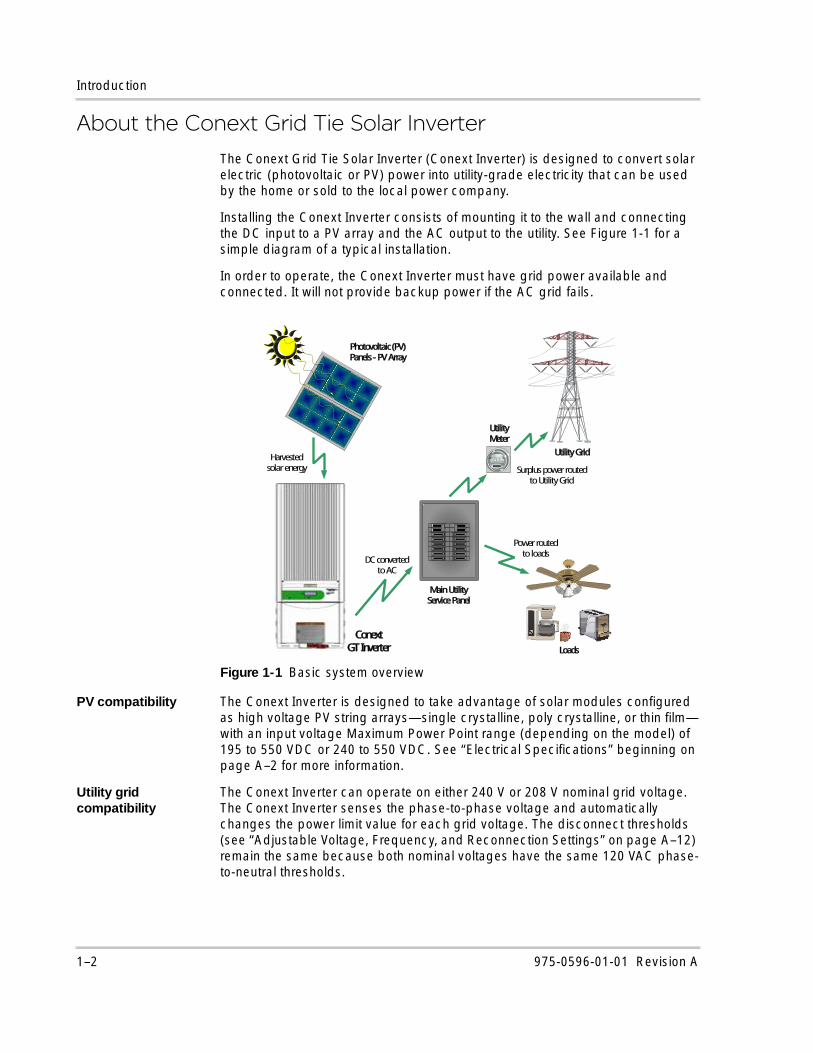
About the Conext Grid Tie Solar InverterThe Conext Grid Tie Solar Inverter (Conext Inverter) is designed to convert solar electric (photovoltaic or PV) power into utility-grade electricity that can be used by the home or sold to the local power company.
Installing the Conext Inverter consists of mounting it to the wall and connecting the DC input to a PV array and the AC output to the utility. See Figure 1-1 for a simple diagram of a typical installation.
In order to operate, the Conext Inverter must have grid power available and connected. It will not provide backup power if the AC grid fails.
PV compatibility The Conext Inverter is designed to take advantage of solar modules configured as high voltage PV string arrays—single crystalline, poly crystalline, or thin film—with an input voltage Maximum Power Point range (depending on the model) of 195 to 550 VDC or 240 to 550 VDC. See “Electrical Specifications” beginning on page A–2 for more information.
Utility grid compatibility
The Conext Inverter can operate on either 240 V or 208 V nominal grid voltage. The Conext Inverter senses the phase-to-phase voltage and automatically changes the power limit value for each grid voltage. The disconnect thresholds (see “Adjustable Voltage, Frequency, and Reconnection Settings” on page A–12) remain the same because both nominal voltages have the same 120 VAC phase-to-neutral thresholds.
Figure 1-1 Basic system overview
Utility Grid
Photovoltaic (PV) Panels -PV Array
ConextGT Inverter
Main Utility Service Panel
Loads
Utility Meter
Surplus power routed to Utility Grid
Harvested solar energy
DC converted to AC
Power routed to loads
1–2 975-0596-01-01 Revision A
Standard Features
Maximum Power Point Tracking (MPPT)
The Conext Inverter uses proprietary Maximum Power Point Tracking (MPPT) technology to harvest the maximum amount of energy from the solar array. MPPT learns your array’s specific characteristics, maximizing its output at all times.
High efficiency The high-frequency, solid-state design of the Conext Inverter is extremely efficient. See Appendix A, “Specifications” for the efficiency ratings of each model.
Expandable Multiple Conext Inverters can be networked together for increased net metering capacity or future system growth. All models have adjustable voltage and frequency disconnect settings and can be aggregated above 30 kW on a single point-of-common-coupling (PCC). See “Adjustable Voltage, Frequency, and Reconnection Settings” on page A–12.
Communications protocol
The Conext Inverter uses the Xanbus™ communications protocol, enabling it to communicate with multiple Conext Inverters connected within the system. For more information, see “Xanbus Network Technology” on page 3–21.
Standard FeaturesThe Conext Inverter has the following standard features:
• Sealed electronics section protecting power electronic components.
• Liquid Crystal Display (LCD) providing easy-to-read system status and daily cumulative energy production information.
• Two LED indicator lights providing unit status and ground fault indication.
• Wiring/disconnect box providing protection for all AC and DC connections and eliminating exposed “live” wiring if the electronics section of the Conext Inverter is removed.
975-0596-01-01 Revision A 1–3
Introduction
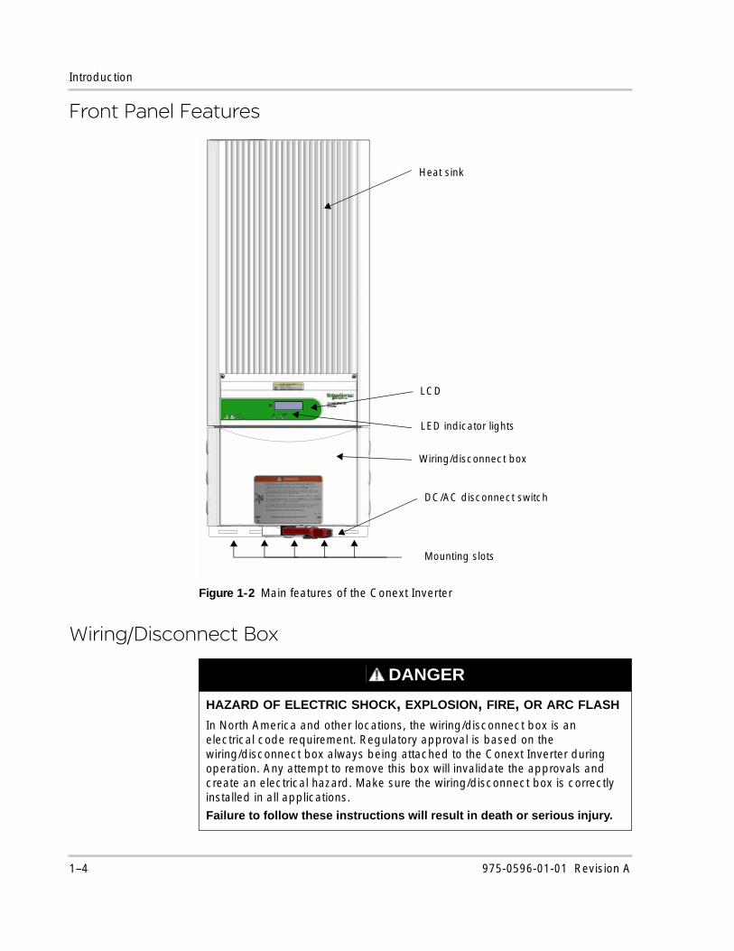
Front Panel Features
Wiring/Disconnect Box
Figure 1-2 Main features of the Conext Inverter
DANGER
HAZARD OF ELECTRIC SHOCK, EXPLOSION, FIRE, OR ARC FLASH
In North America and other locations, the wiring/disconnect box is an electrical code requirement. Regulatory approval is based on the wiring/disconnect box always being attached to the Conext Inverter during operation. Any attempt to remove this box will invalidate the approvals and create an electrical hazard. Make sure the wiring/disconnect box is correctly installed in all applications.
Failure to follow these instructions will result in death or serious injury.
LED indicator lights
DC/AC disconnect switch
Mounting slots
Heat sink
LCD
Wiring/disconnect box
1–4 975-0596-01-01 Revision A
Wiring/Disconnect Box
The wiring/disconnect box is standard on all North American models of the Conext Inverter. The wiring/disconnect box provides a location for making AC, DC, and ground connections. It also contains the DC/AC (PV array/utility) disconnect switch. When used in conjunction with the Conext Inverter, the DC/AC disconnect switch is suitable for disconnecting both AC and DC input voltages up to 600 V. The switch is lockable and meets the requirements of NEC Section 690 as a means of disconnect, subject to acceptance by your local AHJ.
The wiring/disconnect box has been designed to be physically mated to the electronics section of the Conext Inverter at the factory, but it remains in place as a non-serviceable item in the event that the Conext Inverter electronics section must be removed. The electronics section of the Conext Inverter and wiring/disconnect box together form a Type 3R enclosure to allow outdoor installation.
In jurisdictions where the local utility requires that the AC disconnect be capable of being locked in the open position by its service personnel, this disconnect switch can also serve as a lockable isolating device.
DANGER
HAZARD OF ELECTRIC SHOCK, EXPLOSION, FIRE, OR ARC FLASH
• The 600 volt DC/AC disconnect in the wiring/disconnect box meets NEC Article 690 requirements. It is a non-serviceable component and must remain in place. Separating the electronics section of the Conext Inverter and wiring/disconnect box or removing the wiring/disconnect box cover can expose energized conductors. PV input circuits in the wiring box ahead of the switch remain energized even when the switch is in the OFF position so hazardous voltage will still be present on the DC input (PV) terminals under the clear plastic insulation barrier inside the wiring/disconnect box.
• No user serviceable parts inside.
• To be installed and serviced only by qualified personnel equipped with appropriate personal protective equipment and following safe electrical work practices.
• Energized from two sources: PV array when exposed to light and AC grid. Before opening doors or covers, consult system diagram to identify all sources; de-energize, lock out, and tag out all sources; and wait at least five minutes for internal capacitors to discharge to safe voltages.
• Before servicing, test using a meter rated at least 1000 volts AC and DC to make sure all circuits are de-energized.
Failure to follow these instructions will result in death or serious injury.
975-0596-01-01 Revision A 1–5

1–6
2 Installation
Chapter 2 provides instructions for installing the Conext Grid Tie Solar Inverter. It contains information on determining a suitable location for installation, PV array requirements, and procedures for mounting the Conext Grid Tie Solar Inverter.
The topics in this chapter are organized as follows:• “Installation Options” on page 2–2• “Planning the Installation” on page 2–2• “Mounting the Conext Grid Tie Solar
Inverter” on page 2–5
DANGER
HAZARD OF ELECTRIC SHOCK, EXPLOSION, FIRE, OR ARC FLASH
The Conext Grid Tie Solar Inverter must be installed and serviced only by qualified personnel equipped with appropriate personal protective equipment and following safe electrical work practice and all applicable code requirements.
Failure to follow these instructions will result in death or serious injury.
Installation
Installation OptionsThe Conext Inverter can be installed as a single inverter for a single PV array of one to three PV strings. When two or more PV strings are connected, the existing wiring/disconnect box can serve as a fuse box, but fuse holders and fuses must be purchased and installed. See “Combiner Fuses (Optional)” on page 3–6 for details.
The Conext Inverter can also be installed in a multiple inverter system. If multiple Conext Inverters are used, each Conext Inverter must be wired to an independent PV array.
Enable communication between Conext Inverters by installing network cabling to the Conext Inverter’s RJ–45 ports. See “Connecting Network Cable Between Multiple Conext Grid Tie Solar Inverters” on page 3–25.
Planning the Installation
Make sure you have obtained all permits required by local authorities or utilities before beginning installation.
Installation Codes
Governing installation codes vary depending on the specific location and application of the installation. Some examples include the following:
• The U.S. National Electrical Code (NEC)
• The Canadian Electrical Code (CEC)
• The U.S. Code of Federal Regulations (CFRs)
• Canadian Standards Association (CSA)
It is the installer’s responsibility to make sure that all applicable installation requirements are met.
Conext Grid Tie Solar Inverter Location
CAUTIONb
HAZARD OF BURN
• In extreme conditions, the Conext Inverter heat sink can reach temperatures over 158 °F (70 °C) and can cause skin burns if accidentally touched.
• Make sure the Conext Inverter is located away from normal traffic areas.
Failure to follow these instructions can result in minor or moderate injury.
2–2 975-0596-01-01 Revision A
This chapter is for use by qualified personnel only.
Planning the Installation
Conext Inverter failure due to improper installation will void the Conext Inverter’s warranty. Consider the following when determining where to install the Conext Inverter:
Indoor/Outdoor • The Conext Inverter uses a Type 3R-rated enclosure (vertical mount only) that can be mounted indoors or outdoors. Type 3R enclosures are intended for outdoor use primarily to provide a degree of protection against falling rain and to be undamaged by the formation of ice on the enclosure.
• While the 3R-rated enclosure protects the Conext Inverter from moisture, outdoor installations should be located away from lawn sprinklers and other sources of spray.
• A sun shade is recommended for outdoor installations. In bright sun conditions, when the Conext Inverter is at or near full output with an ambient temperature above 104 °F (40 °C), shading the Conext Inverter will help increase its performance. A sun shade can also help protect the Conext Inverter from dust, debris, and birds. The sun shade should be made from an opaque (dark) material to provide shade for the heat sink. It should be large enough and positioned so that it shades the heat sink when the Conext Inverter is operating at full power (usually a four hour time period centered around noon). Make sure the shade is installed according to the minimum clearances specified on page 2–10.
Orientation • The Conext Inverter must be mounted vertically on a wall or pole.
• Do not mount the Conext Inverter horizontally.
• If mounting the Conext Inverter indoors on a south-facing wall, make sure the wall is insulated to reduce the amount of heat absorbed by the Conext Inverter. Unless walls are properly insulated, avoid mounting the Conext Inverter indoors on any wall that is directly exposed to the sun.
Temperature • Make sure the Conext Inverter is mounted in a location where the ambient temperature range is -13 to +149 °F (- 25 to + 65 °C).
• Above 104 °F (40 °C), the Conext Inverter might derate power output. See “Output power versus ambient temperature” on page A–13 and “Environmental Specifications” on page A–13.
• At extremely cold temperatures (outside of the specified operating range), the front panel LCD might not function normally. For example, the display could update very slowly or not update at all, it could be illegible, or it could go blank.
Distance • To minimize resistance and resulting power loss, make sure the wire lengths between the PV array and the Conext Inverter and between the Conext Inverter and the main utility service panel are kept to a minimum.
• Maximum distances will depend on the wire gauges used and PV array output voltages. To minimize system failures due to AC voltage faults, size the AC and DC wiring to have a maximum 1% to 1.5% voltage drop.
Debris free • Excessive debris (such as dust, leaves, and cobwebs) can accumulate on the Conext Inverter, interfering with wiring connections and ventilation. Do not install in a location where debris can accumulate (for example, under a tree).
975-0596-01-01 Revision A 2–3
This chapter is for use by qualified personnel only.
Installation
MPPT Requirements
MPPT operational window
The MPPT software maximizes the output energy of solar arrays as long as the operating voltage is within the MPPT operational window of the Conext Inverter. Make sure the open circuit voltage (VOC) of the PV array is within the MPPT operational window. See “Input voltage, Maximum Power Point range” in Appendix A, “Specifications” for the MPPT operational window of each Conext Inverter model.
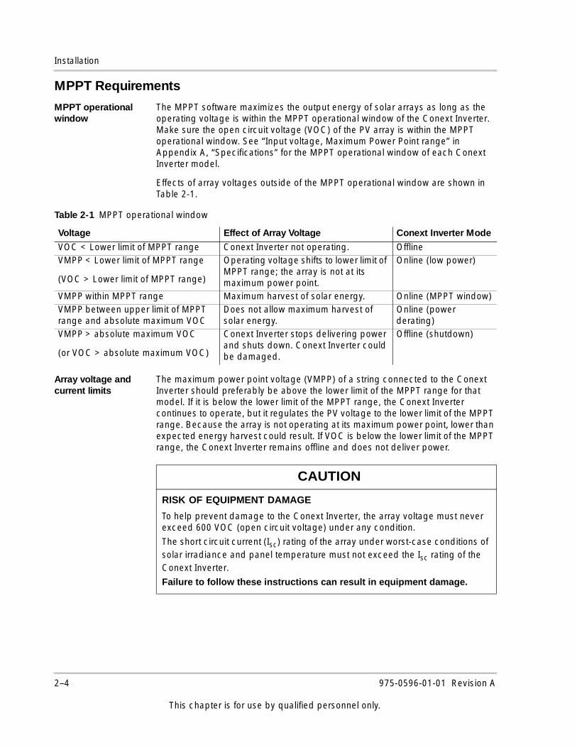
Effects of array voltages outside of the MPPT operational window are shown in Table 2-1.
Array voltage and current limits
The maximum power point voltage (VMPP) of a string connected to the Conext Inverter should preferably be above the lower limit of the MPPT range for that model. If it is below the lower limit of the MPPT range, the Conext Inverter continues to operate, but it regulates the PV voltage to the lower limit of the MPPT range. Because the array is not operating at its maximum power point, lower than expected energy harvest could result. If VOC is below the lower limit of the MPPT range, the Conext Inverter remains offline and does not deliver power.
Table 2-1 MPPT operational window
Voltage Effect of Array Voltage Conext Inverter Mode
VOC < Lower limit of MPPT range Conext Inverter not operating. OfflineVMPP < Lower limit of MPPT range
(VOC > Lower limit of MPPT range)
Operating voltage shifts to lower limit of MPPT range; the array is not at its maximum power point.
Online (low power)
VMPP within MPPT range Maximum harvest of solar energy. Online (MPPT window)VMPP between upper limit of MPPT range and absolute maximum VOC
Does not allow maximum harvest of solar energy.
Online (power derating)
VMPP > absolute maximum VOC
(or VOC > absolute maximum VOC)
Conext Inverter stops delivering power and shuts down. Conext Inverter could be damaged.
Offline (shutdown)
CAUTION
RISK OF EQUIPMENT DAMAGE
To help prevent damage to the Conext Inverter, the array voltage must never exceed 600 VOC (open circuit voltage) under any condition.
The short circuit current (Isc) rating of the array under worst-case conditions of solar irradiance and panel temperature must not exceed the Isc rating of the Conext Inverter.
Failure to follow these instructions can result in equipment damage.
2–4 975-0596-01-01 Revision A
This chapter is for use by qualified personnel only.
Mounting the Conext Grid Tie Solar Inverter
Guidelines for Matching PV Array Size to Conext Grid Tie Solar Inverter Input
• Consider the expected VOC of the string under all possible conditions. The panel manufacturer provides a VOC rating per panel, but it is usually rated at 77 °F (25 °C). Make sure that the VOC rating at the coldest ambient temperature does not exceed 600 VDC. Panel voltage increases in cold temperatures. The panel manufacturer should be able to provide a coefficient of voltage increase per degree.
• The NEC has required temperature/voltage deratings that must be used. These can be found in Article 690 of the NEC. You must determine the coldest temperatures expected on the site, and then size the array strings accordingly. To help prevent damage to the Conext Inverter, the array’s maximum DC voltage in the coldest expected temperature—with both manufacturer coefficient and NEC derating— must not exceed 600 VDC.
• Panel voltage decreases in high temperatures. This will affect the panels’ VMPP and VOC. The manufacturer’s coefficient must be used with the highest expected temperature to determine the minimum VMPP and VOC.
Mounting the Conext Grid Tie Solar Inverter
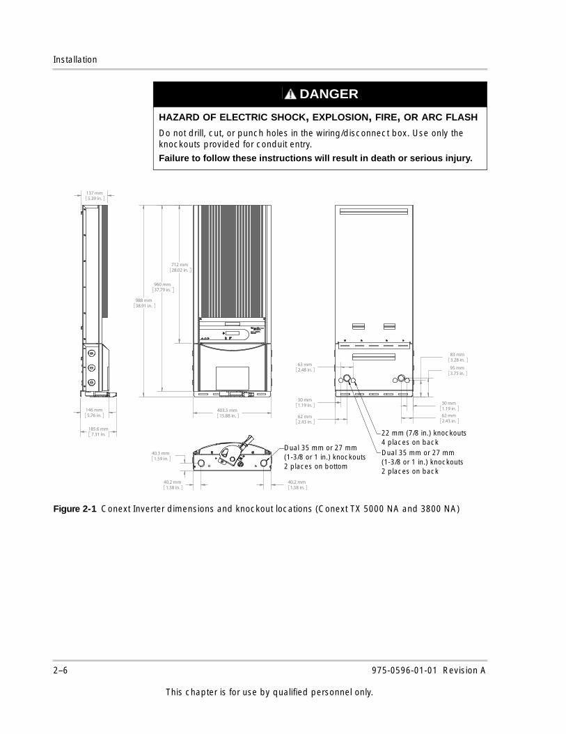
Dimensions and Knockout Locations
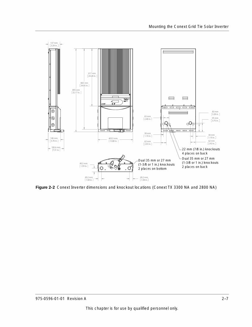
Dimensions and knockout locations for the Conext Inverter are shown in Figure 2-1 and Figure 2-2.
Dual knockouts are provided on the back and bottom of the Conext Inverter to accommodate wiring, and four knockouts are provided on the back of the wiring/disconnect box.
Six conduit holes on the sides of the wiring/disconnect box (three on each side) are filled with plastic plugs (thread size PG 21). These plugs can be removed to insert conduit nipples as required for multiple inverter systems; however, they must remain in place if not being populated with a conduit connection. Side conduit holes must be used to accommodate network communication cables connected between multiple Conext Inverter.
NOTICE
A PV array sizing tool is available at www.schneider-electric.com.
WARNING
HEAVY EQUIPMENT
The Conext Inverter weighs up to 84.0 lbs (38.1 kg). Use proper lifting techniques in accordance with local workplace safety rules, and always use assistance when moving or lifting.
Failure to follow these instructions can result in death or serious injury.
975-0596-01-01 Revision A 2–5
This chapter is for use by qualified personnel only.
Installation
DANGER
HAZARD OF ELECTRIC SHOCK, EXPLOSION, FIRE, OR ARC FLASH
Do not drill, cut, or punch holes in the wiring/disconnect box. Use only the knockouts provided for conduit entry.
Failure to follow these instructions will result in death or serious injury.
Figure 2-1 Conext Inverter dimensions and knockout locations (Conext TX 5000 NA and 3800 NA)
988 mm38.91 in.
403.5 mm15.88 in.
712 mm28.02 in.
960 mm37.79 in.
185.6 mm7.31 in.
146 mm5.76 in.
137 mm5.39 in.
40.2 mm1.58 in.
40.2 mm1.58 in.
40.3 mm1.59 in.
Dual 35mm or 27mm(1-3/8" or 1") knockouts2 places on bottom of BOS
62 mm2.43 in.
63 mm2.48 in.
62 mm2.43 in.
30 mm1.19 in.
83 mm3.28 in.
95 mm3.75 in.
30 mm1.19 in.
22mm (7/8") knockouts4 places on rear of BOS
Dual 35mm or 27mm(1-3/8" or 1") knockouts2 places on bottom of BOS
Dual 35 mm or 27 mm(1-3/8 or 1 in.) knockouts2 places on bottom
22 mm (7/8 in.) knockouts4 places on backDual 35 mm or 27 mm(1-3/8 or 1 in.) knockouts2 places on back
2–6 975-0596-01-01 Revision A
This chapter is for use by qualified personnel only.
Mounting the Conext Grid Tie Solar Inverter
Figure 2-2 Conext Inverter dimensions and knockout locations (Conext TX 3300 NA and 2800 NA)
893 mm35.17 in.
403.5 mm15.88 in.
617 mm24.28 in.
865 mm34.05 in.
185.6 mm7.31 in.
146 mm5.76 in.
137 mm5.39 in.
40.2 mm1.58 in.
40.2 mm1.58 in.
40.3 mm1.59 in.
Dual 35mm or 27mm(1-3/8" or 1") knockouts2 places on bottom of BOS
62 mm2.43 in.
63 mm2.48 in.
62 mm2.43 in.
30 mm1.19 in.
83 mm3.28 in.
95 mm3.75 in.
30 mm1.19 in.
22mm (7/8") knockouts4 places on rear of BOS
Dual 35mm or 27mm(1-3/8" or 1") knockouts2 places on bottom of BOS
Dual 35 mm or 27 mm(1-3/8 or 1 in.) knockouts2 places on bottom
22 mm (7/8 in.) knockouts4 places on back
Dual 35 mm or 27 mm(1-3/8 or 1 in.) knockouts2 places on back
975-0596-01-01 Revision A 2–7
This chapter is for use by qualified personnel only.
Installation
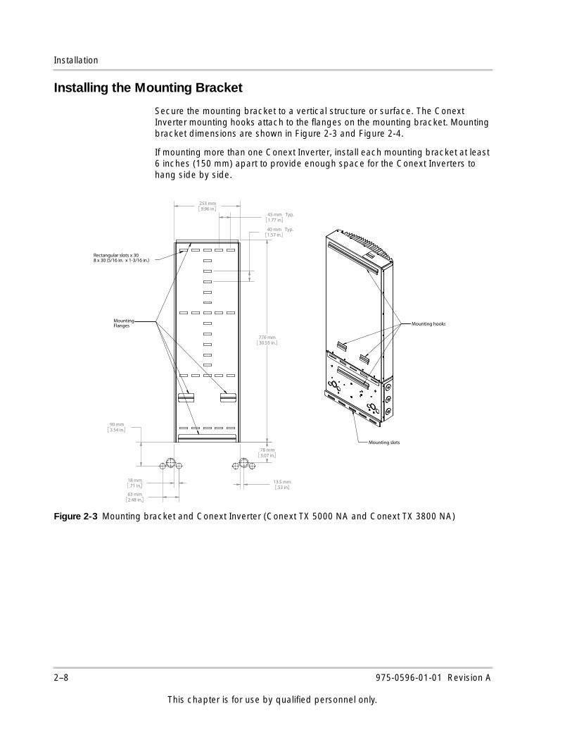
Installing the Mounting Bracket
Secure the mounting bracket to a vertical structure or surface. The Conext Inverter mounting hooks attach to the flanges on the mounting bracket. Mounting bracket dimensions are shown in Figure 2-3 and Figure 2-4.
If mounting more than one Conext Inverter, install each mounting bracket at least 6 inches (150 mm) apart to provide enough space for the Conext Inverters to hang side by side.
Figure 2-3 Mounting bracket and Conext Inverter (Conext TX 5000 NA and Conext TX 3800 NA)
Mounting hooks
Mounting slots
776 mm30.55 in.
253 mm9.96 in.
90 mm3.54 in.
18 mm.71 in.
78 mm3.07 in.
13.5 mm.53 in.
63 mm2.48 in.
40 mm Typ.1.57 in.
45 mm Typ.1.77 in.
MountingFlanges
Rectangular slots x 308 x 30 (5/16 in. x 1-3/16 in.)
2–8 975-0596-01-01 Revision A
This chapter is for use by qualified personnel only.
Mounting the Conext Grid Tie Solar Inverter
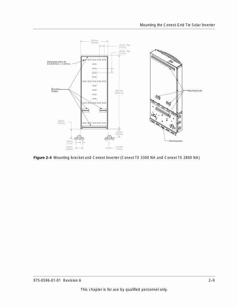
Figure 2-4 Mounting bracket and Conext Inverter (Conext TX 3300 NA and Conext TX 2800 NA)
Mounting slots
Mounting hooks681 mm26.81 in.
253 mm9.96 in.
90 mm3.54 in.
63 mm2.48 in.
18 mm.71 in.
78 mm3.07 in.
13.5 mm.53 in.
40 mm Typ.1.57 in.
45 mm Typ.1.77 in.
MountingFlanges
Rectangular slots x 308 x 30 (5/16 in. x 1-3/16 in.)
975-0596-01-01 Revision A 2–9
This chapter is for use by qualified personnel only.
Installation
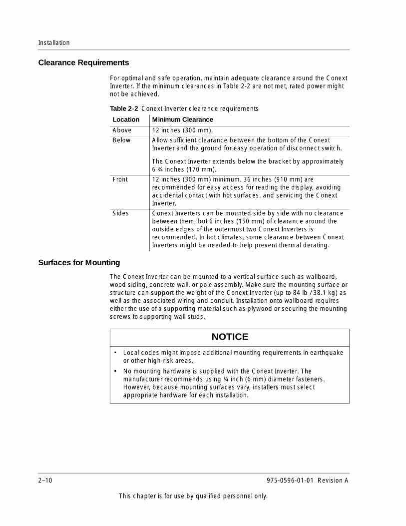
Clearance Requirements
For optimal and safe operation, maintain adequate clearance around the Conext Inverter. If the minimum clearances in Table 2-2 are not met, rated power might not be achieved.
Surfaces for Mounting
The Conext Inverter can be mounted to a vertical surface such as wallboard, wood siding, concrete wall, or pole assembly. Make sure the mounting surface or structure can support the weight of the Conext Inverter (up to 84 lb / 38.1 kg) as well as the associated wiring and conduit. Installation onto wallboard requires either the use of a supporting material such as plywood or securing the mounting screws to supporting wall studs.
Table 2-2 Conext Inverter clearance requirements
Location Minimum Clearance
Above 12 inches (300 mm).
Below Allow sufficient clearance between the bottom of the Conext Inverter and the ground for easy operation of disconnect switch.
The Conext Inverter extends below the bracket by approximately 6 ¾ inches (170 mm).
Front 12 inches (300 mm) minimum. 36 inches (910 mm) are recommended for easy access for reading the display, avoiding accidental contact with hot surfaces, and servicing the Conext Inverter.
Sides Conext Inverters can be mounted side by side with no clearance between them, but 6 inches (150 mm) of clearance around the outside edges of the outermost two Conext Inverters is recommended. In hot climates, some clearance between Conext Inverters might be needed to help prevent thermal derating.
NOTICE
• Local codes might impose additional mounting requirements in earthquake or other high-risk areas.
• No mounting hardware is supplied with the Conext Inverter. The manufacturer recommends using ¼ inch (6 mm) diameter fasteners. However, because mounting surfaces vary, installers must select appropriate hardware for each installation.
2–10 975-0596-01-01 Revision A
This chapter is for use by qualified personnel only.

Mounting the Conext Grid Tie Solar Inverter
Mounting the Conext Grid Tie Solar Inverter on the Bracket
Place the Conext Inverter’s mounting hooks over the flanges on the bracket. Make sure the Conext Inverter is seated properly, and then secure the bottom of the Conext Inverter with appropriate screws or anchors through the mounting slots.
Figure 2-5 Placing the Conext Inverter on the mounting bracket
Flange with mounting slots
975-0596-01-01 Revision A 2–11
This chapter is for use by qualified personnel only.

2–12
3 Wiring the Conext Grid Tie Solar Inverter
DANGER
HAZARD OF ELECTRIC SHOCK, EXPLOSION, FIRE, OR ARC FLASH
• The Conext Grid Tie Solar Inverter has no user serviceable parts inside. It must be installed and serviced only by qualified personnel equipped with appropriate personal protective equipment and following safe electrical work practices.
• The Conext Inverter is energized from two sources: PV array while exposed to light and AC grid. Before opening doors or covers, consult the system diagram to identify all sources; de-energize, lock out, and tag out all sources; and wait at least five minutes for internal capacitors to discharge to safe voltages.
• Before servicing, test using a meter rated at least 1000 volts AC and DC to ensure all circuits are de-energized.
• The Conext Inverter is provided with integral PV ground fault protection. Normally GROUNDED conductors might be UNGROUNDED and ENERGIZED when a GROUND FAULT is indicated. Disconnect all sources of power before opening.
• The Conext Inverter employs field adjustable voltage and frequency set points and time delays that are factory set in compliance with local utility and safety requirements and can be changed only by trained technicians with approval by both the local utility and equipment owner.
Failure to follow these instructions will result in death or serious injury.
Wiring the Conext Grid Tie Solar Inverter
Chapter 3 provides information about DC and AC wiring as well as grounding the Conext Inverter and the PV array.
This chapter does not provide sufficient information for anyone but qualified personnel (as defined under “Audience” on page iii) to install this product.
The topics in this chapter are organized as follows:• “Grounding Requirements” on page 3–3• “Wiring Requirements” on page 3–5• “Accessing the Wiring Terminals” on
page 3–8• “Connecting the DC Wiring” on
page 3–11• “Connecting the AC Wiring” on
page 3–17• “DC and AC Wiring for Multiple Conext
Grid Tie Solar Inverters (Single-Phase System)” on page 3–18
• “Communications Wiring for Multiple Conext Grid Tie Solar Inverters” on page 3–20
• “Communications Wiring for Monitoring a Single Conext Grid Tie Solar Inverter” on page 3–26
3–2 975-0596-01-01 Revision A
This chapter is for use by qualified personnel only.
Grounding Requirements
Grounding RequirementsThe Conext Inverter has the following grounding requirements.
AC Grounding
The Conext Inverter must be connected to the AC ground from the utility via the Conext Inverter ground lug (see Figure 3-1 on page 3–3).
PV Grounding
The PV array (frame) ground should be connected to the Conext Inverter ground bar (see Figure 3-1 on page 3–3). The size for the conductor is usually based on the size of the largest conductor in the DC system.
A DC grounding electrode conductor might be required by the AHJ. Use the Conext Inverter ground bar for this connection (see Figure 3-2 on page 3–4).
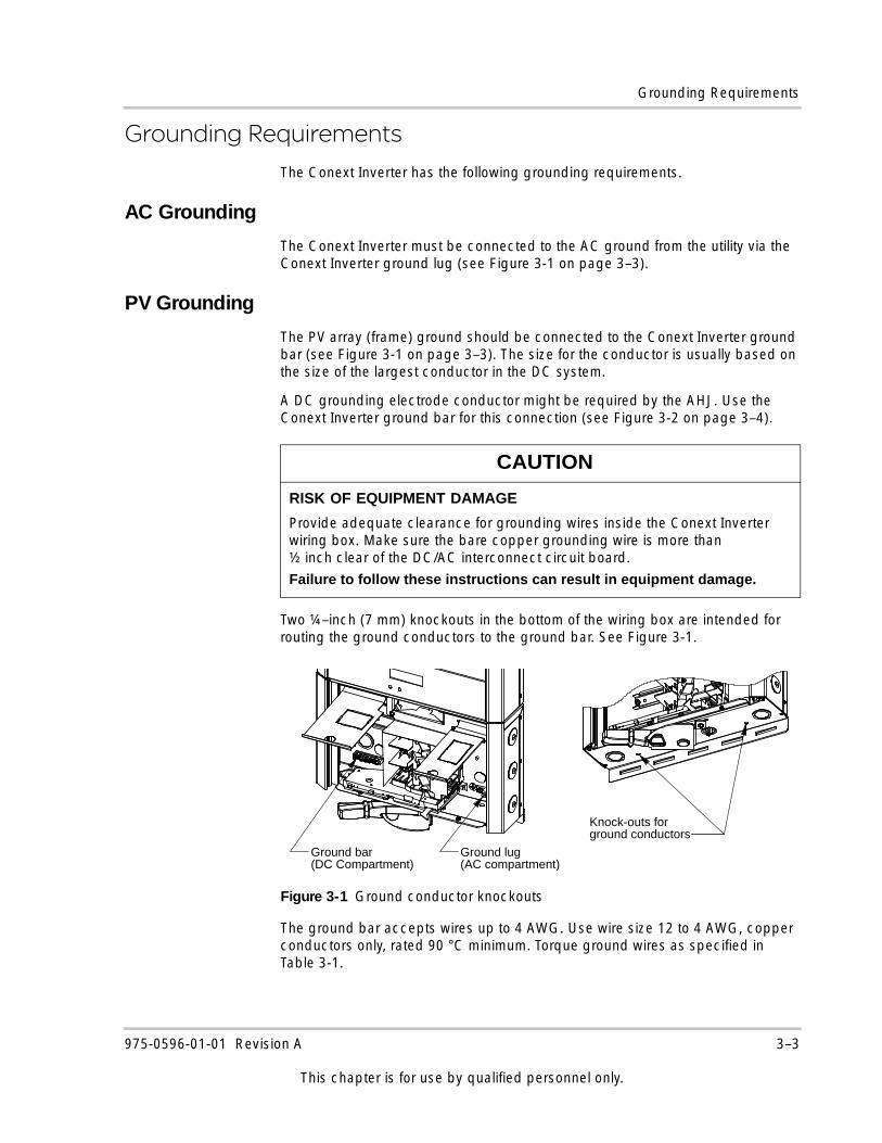
Two ¼–inch (7 mm) knockouts in the bottom of the wiring box are intended for routing the ground conductors to the ground bar. See Figure 3-1.
The ground bar accepts wires up to 4 AWG. Use wire size 12 to 4 AWG, copper conductors only, rated 90 °C minimum. Torque ground wires as specified in Table 3-1.
CAUTION
RISK OF EQUIPMENT DAMAGE
Provide adequate clearance for grounding wires inside the Conext Inverter wiring box. Make sure the bare copper grounding wire is more than ½ inch clear of the DC/AC interconnect circuit board.
Failure to follow these instructions can result in equipment damage.
Figure 3-1 Ground conductor knockouts
Knock-outs forground conductors
Ground bar(DC Compartment)
Ground lug(AC compartment)
975-0596-01-01 Revision A 3–3
This chapter is for use by qualified personnel only.
Wiring the Conext Grid Tie Solar Inverter
Table 3-1 Torque values for ground wiring
Wire Size Torque Value
AWG mm2 in-lb Nm
12–10 4.0–6.0 25–35 3.0–4.08 10 30–40 3.4–4.56–4 16–25 35–45 4.0–5.0
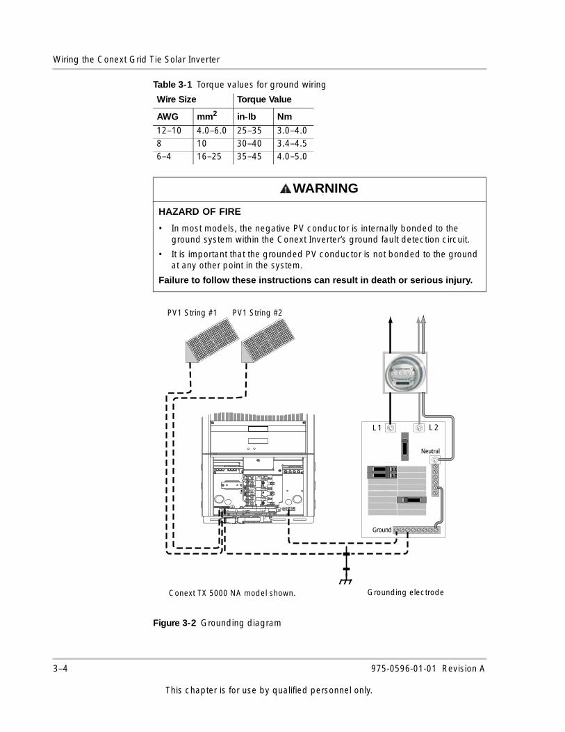
WARNINGw
HAZARD OF FIRE
• In most models, the negative PV conductor is internally bonded to the ground system within the Conext Inverter’s ground fault detection circuit.
• It is important that the grounded PV conductor is not bonded to the ground at any other point in the system.
Failure to follow these instructions can result in death or serious injury.
Figure 3-2 Grounding diagram
L 1 L 2
Neutral
L1L2
Ground
PV1 String #1 PV1 String #2
Grounding electrodeConext TX 5000 NA model shown.
3–4 975-0596-01-01 Revision A
This chapter is for use by qualified personnel only.
Wiring Requirements
Ground Fault Fuse
The Conext Inverter is equipped with a 600 V, 1 A ground fault protection fuse (replace with Littelfuse® KLKD 1 or equivalent).
Wiring Requirements
All AC and DC wiring must be copper conductors only, rated 90 °C minimum, and sized from 6 to 12 AWG according to the applicable electrical code. Strip all wires 0.48–0.51 inches (12–13 mm).
For safety and compliance with local electrical codes such as the NEC, run AC, DC, and communication wires in separate conduits.
NOTICE
A DC grounding electrode conductor might be required by the AHJ. Check local codes before installation.
DANGER
HAZARD OF ELECTRIC SHOCK, EXPLOSION, FIRE, OR ARC FLASH
The ground fault protection fuse must only be serviced by qualified service personnel, such as certified electricians or technicians. See “Replacing the Ground Fault Protection Fuse” on page 6–5.
Failure to follow these instructions will result in death or serious injury.
DANGER
HAZARD OF ELECTRIC SHOCK, EXPLOSION, FIRE, OR ARC FLASH
Check for existing electrical or plumbing prior to drilling holes in walls.
Failure to follow these instructions will result in death or serious injury.
WARNING
HAZARD OF FIRE
• Wiring must not be undersized. Wire sizes must be coordinated with the array maximum short circuit current or the AC breaker sizes used.
• Make sure wiring is in accordance with the NEC or applicable codes.
Failure to follow these instructions can result in death or serious injury.
975-0596-01-01 Revision A 3–5
This chapter is for use by qualified personnel only.
Wiring the Conext Grid Tie Solar Inverter
AC Circuit Breaker Requirements
The main utility service panel must dedicate a double pole breaker to operate each installed Conext Inverter. This breaker must be sized to handle the rated maximum output voltage and current of your Conext Inverter model (see “Electrical Specifications”, “Output” beginning on page A–2).
DC/AC Disconnect Switch
The wiring box includes a 600 V utility/PV disconnect switch that switches both AC and DC at the same time.
Depending on the installation, an external AC and/or DC disconnect might be required if the Conext Inverter is installed in a location not easily accessible to utility or fire personnel. Consult local authorities for additional information.
Combiner Fuses (Optional)
DANGER
HAZARD OF ELECTRIC SHOCK, EXPLOSION, FIRE, OR ARC FLASH
• Do not remove the wiring/disconnect box. The 600 V DC/AC disconnect in the wiring box meets NEC Article 690 requirements. It is a non-serviceable component and must remain in place. Removal can expose energized conductors.
• Use caution when working around sources of DC power. Although the DC/AC disconnect switch disconnects the Conext Inverter from DC power, hazardous voltages from paralleled PV strings will still be present upstream of the switch and inside the wiring box. Isolate or disconnect all sources of electricity, and always test for voltage before touching exposed wiring or devices. If the system does not provide a PV disconnect device, cover the PV array with opaque (dark) material.
Failure to follow these instructions will result in death or serious injury.
WARNING
HAZARD OF FIRE
If the array consists of more than two strings, fusing might be required to help prevent conductor overloads. Consult your local authority and electrical code for details.
Failure to follow these instructions can result in death or serious injury.
3–6 975-0596-01-01 Revision A
This chapter is for use by qualified personnel only.
Wiring Requirements
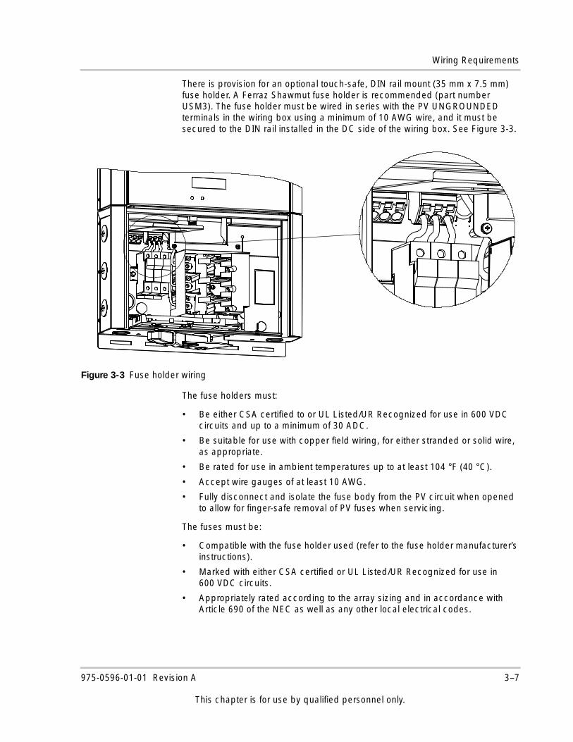
There is provision for an optional touch-safe, DIN rail mount (35 mm x 7.5 mm) fuse holder. A Ferraz Shawmut fuse holder is recommended (part number USM3). The fuse holder must be wired in series with the PV UNGROUNDED terminals in the wiring box using a minimum of 10 AWG wire, and it must be secured to the DIN rail installed in the DC side of the wiring box. See Figure 3-3.
The fuse holders must:
• Be either CSA certified to or UL Listed/UR Recognized for use in 600 VDC circuits and up to a minimum of 30 ADC.
• Be suitable for use with copper field wiring, for either stranded or solid wire, as appropriate.
• Be rated for use in ambient temperatures up to at least 104 °F (40 °C).
• Accept wire gauges of at least 10 AWG.
• Fully disconnect and isolate the fuse body from the PV circuit when opened to allow for finger-safe removal of PV fuses when servicing.
The fuses must be:
• Compatible with the fuse holder used (refer to the fuse holder manufacturer’s instructions).
• Marked with either CSA certified or UL Listed/UR Recognized for use in 600 VDC circuits.
• Appropriately rated according to the array sizing and in accordance with Article 690 of the NEC as well as any other local electrical codes.
Figure 3-3 Fuse holder wiring
975-0596-01-01 Revision A 3–7
This chapter is for use by qualified personnel only.
Wiring the Conext Grid Tie Solar Inverter
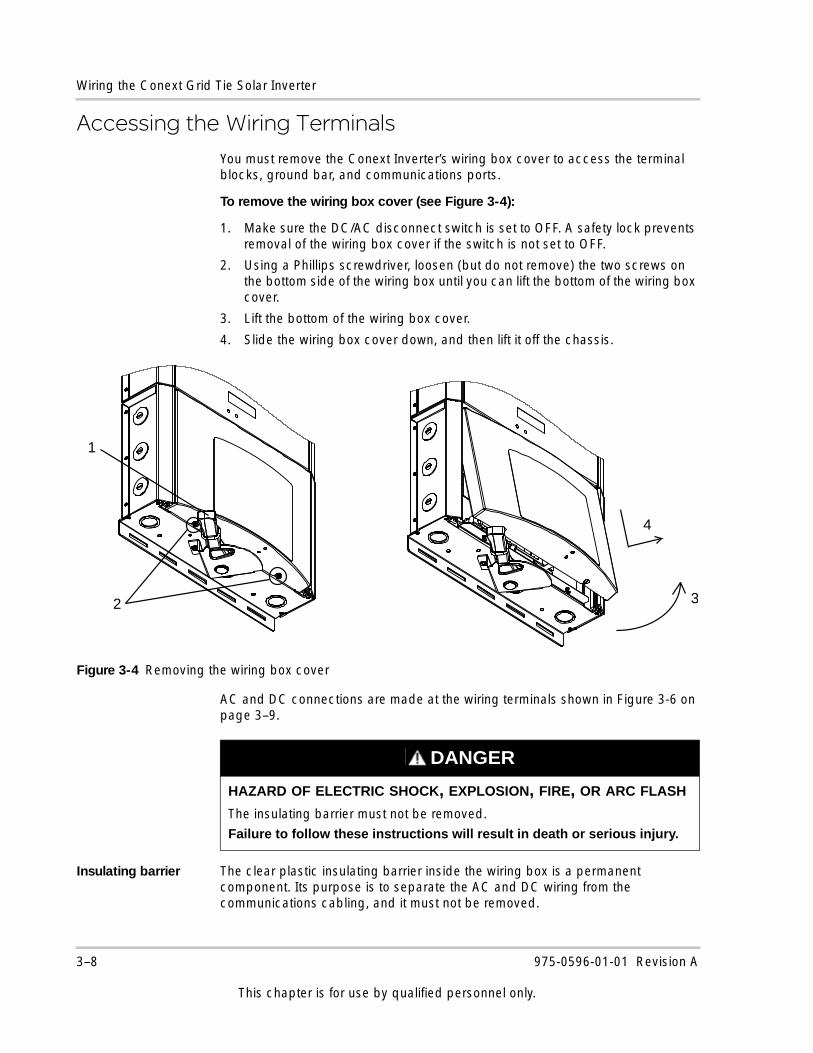
Accessing the Wiring TerminalsYou must remove the Conext Inverter’s wiring box cover to access the terminal blocks, ground bar, and communications ports.
To remove the wiring box cover (see Figure 3-4):
1. Make sure the DC/AC disconnect switch is set to OFF. A safety lock prevents removal of the wiring box cover if the switch is not set to OFF.
2. Using a Phillips screwdriver, loosen (but do not remove) the two screws on the bottom side of the wiring box until you can lift the bottom of the wiring box cover.
3. Lift the bottom of the wiring box cover.
4. Slide the wiring box cover down, and then lift it off the chassis.
AC and DC connections are made at the wiring terminals shown in Figure 3-6 on page 3–9.
Insulating barrier The clear plastic insulating barrier inside the wiring box is a permanent component. Its purpose is to separate the AC and DC wiring from the communications cabling, and it must not be removed.
Figure 3-4 Removing the wiring box cover
2 3
4
1
DANGER
HAZARD OF ELECTRIC SHOCK, EXPLOSION, FIRE, OR ARC FLASH
The insulating barrier must not be removed.
Failure to follow these instructions will result in death or serious injury.
3–8 975-0596-01-01 Revision A
This chapter is for use by qualified personnel only.
Accessing the Wiring Terminals
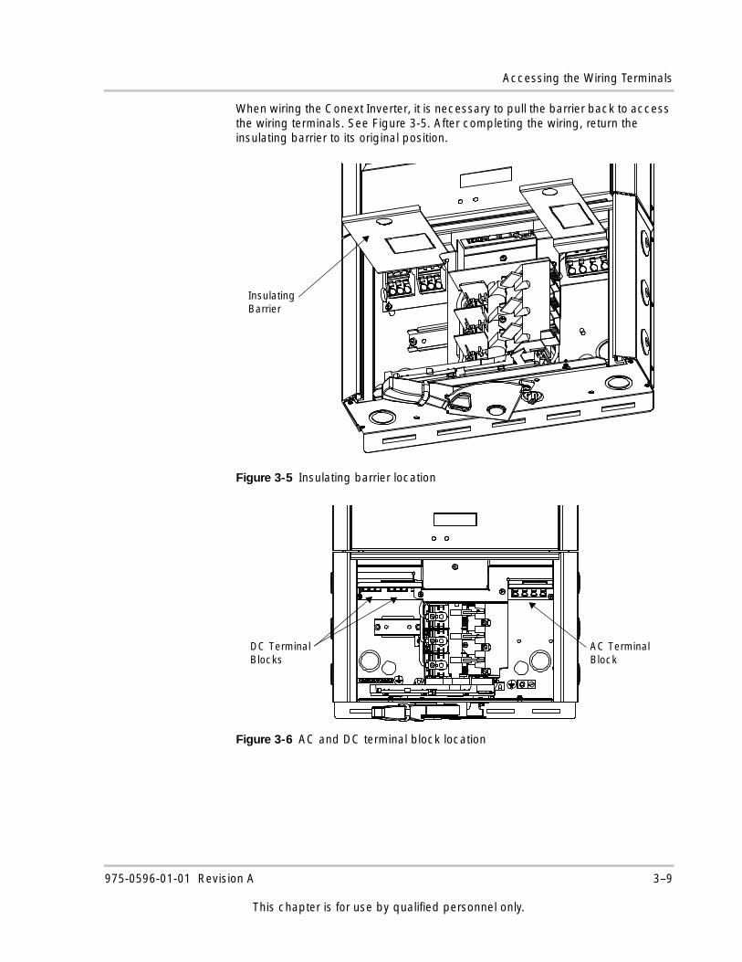
When wiring the Conext Inverter, it is necessary to pull the barrier back to access the wiring terminals. See Figure 3-5. After completing the wiring, return the insulating barrier to its original position.
Figure 3-5 Insulating barrier location
Figure 3-6 AC and DC terminal block location
Insulating Barrier
AC TerminalBlock
DC TerminalBlocks
975-0596-01-01 Revision A 3–9
This chapter is for use by qualified personnel only.
Wiring the Conext Grid Tie Solar Inverter
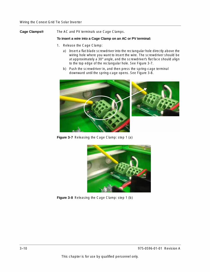
Cage Clamps® The AC and PV terminals use Cage Clamps.
To insert a wire into a Cage Clamp on an AC or PV terminal:
1. Release the Cage Clamp:
a) Insert a flat blade screwdriver into the rectangular hole directly above the wiring hole where you want to insert the wire. The screwdriver should be at approximately a 30° angle, and the screwdriver’s flat face should align to the top edge of the rectangular hole. See Figure 3-7.
b) Push the screwdriver in, and then press the spring-cage terminal downward until the spring-cage opens. See Figure 3-8.
Figure 3-7 Releasing the Cage Clamp: step 1 (a)
Figure 3-8 Releasing the Cage Clamp: step 1 (b)
3–10 975-0596-01-01 Revision A
This chapter is for use by qualified personnel only.
Connecting the DC Wiring
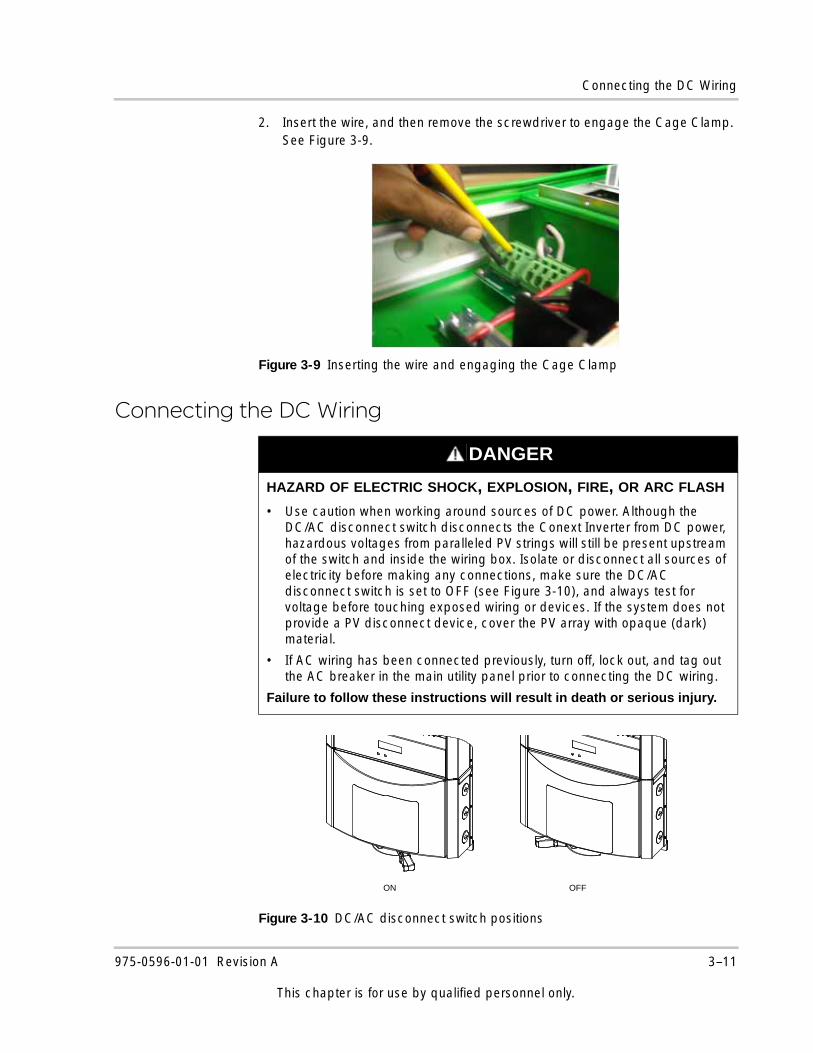
2. Insert the wire, and then remove the screwdriver to engage the Cage Clamp. See Figure 3-9.
Connecting the DC Wiring
Figure 3-9 Inserting the wire and engaging the Cage Clamp
DANGER
HAZARD OF ELECTRIC SHOCK, EXPLOSION, FIRE, OR ARC FLASH
• Use caution when working around sources of DC power. Although the DC/AC disconnect switch disconnects the Conext Inverter from DC power, hazardous voltages from paralleled PV strings will still be present upstream of the switch and inside the wiring box. Isolate or disconnect all sources of electricity before making any connections, make sure the DC/AC disconnect switch is set to OFF (see Figure 3-10), and always test for voltage before touching exposed wiring or devices. If the system does not provide a PV disconnect device, cover the PV array with opaque (dark) material.
• If AC wiring has been connected previously, turn off, lock out, and tag out the AC breaker in the main utility panel prior to connecting the DC wiring.
Failure to follow these instructions will result in death or serious injury.
Figure 3-10 DC/AC disconnect switch positions
ON OFF
975-0596-01-01 Revision A 3–11
This chapter is for use by qualified personnel only.
Wiring the Conext Grid Tie Solar Inverter
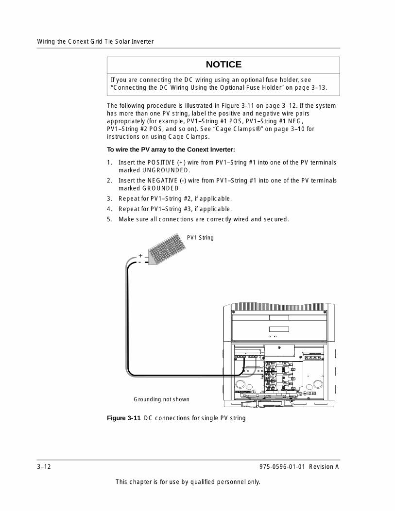
The following procedure is illustrated in Figure 3-11 on page 3–12. If the system has more than one PV string, label the positive and negative wire pairs appropriately (for example, PV1–String #1 POS, PV1–String #1 NEG, PV1–String #2 POS, and so on). See “Cage Clamps®” on page 3–10 for instructions on using Cage Clamps.
To wire the PV array to the Conext Inverter:
1. Insert the POSITIVE (+) wire from PV1–String #1 into one of the PV terminals marked UNGROUNDED.
2. Insert the NEGATIVE (-) wire from PV1–String #1 into one of the PV terminals marked GROUNDED.
3. Repeat for PV1–String #2, if applicable.
4. Repeat for PV1–String #3, if applicable.
5. Make sure all connections are correctly wired and secured.
NOTICE
If you are connecting the DC wiring using an optional fuse holder, see “Connecting the DC Wiring Using the Optional Fuse Holder” on page 3–13.
Figure 3-11 DC connections for single PV string
Grounding not shown
PV1 String
+-
3–12 975-0596-01-01 Revision A
This chapter is for use by qualified personnel only.
Connecting the DC Wiring
Connecting the DC Wiring Using the Optional Fuse Holder
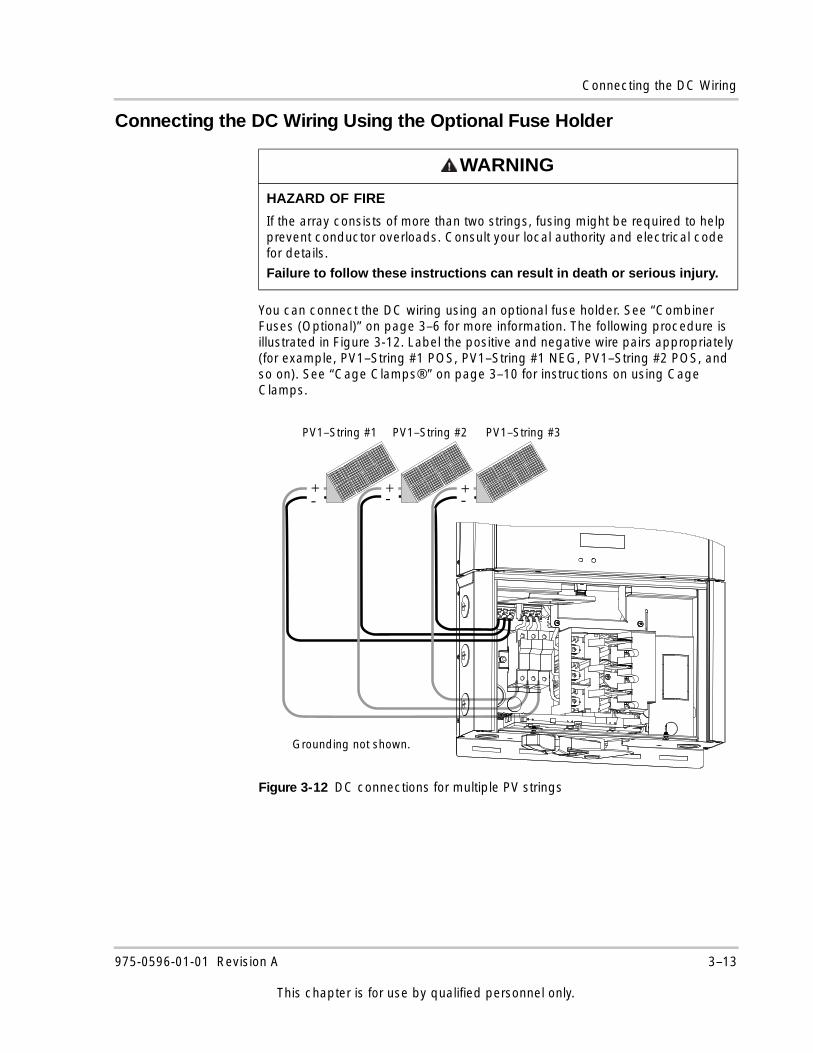
You can connect the DC wiring using an optional fuse holder. See “Combiner Fuses (Optional)” on page 3–6 for more information. The following procedure is illustrated in Figure 3-12. Label the positive and negative wire pairs appropriately (for example, PV1–String #1 POS, PV1–String #1 NEG, PV1–String #2 POS, and so on). See “Cage Clamps®” on page 3–10 for instructions on using Cage Clamps.
WARNING
HAZARD OF FIRE
If the array consists of more than two strings, fusing might be required to help prevent conductor overloads. Consult your local authority and electrical code for details.
Failure to follow these instructions can result in death or serious injury.
Figure 3-12 DC connections for multiple PV strings
PV1–String #1 PV1–String #2
Grounding not shown.
-+-+
PV1–String #3
-+
975-0596-01-01 Revision A 3–13
This chapter is for use by qualified personnel only.
Wiring the Conext Grid Tie Solar Inverter
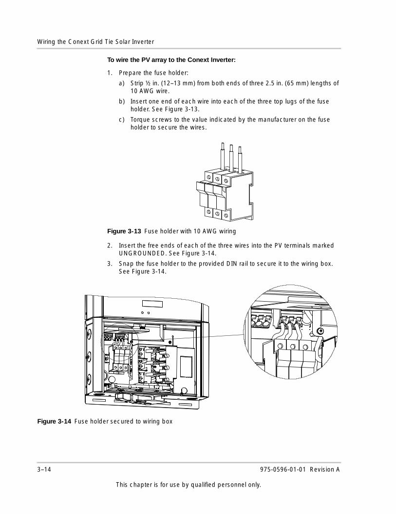
To wire the PV array to the Conext Inverter:
1. Prepare the fuse holder:
a) Strip ½ in. (12–13 mm) from both ends of three 2.5 in. (65 mm) lengths of 10 AWG wire.
b) Insert one end of each wire into each of the three top lugs of the fuse holder. See Figure 3-13.
c) Torque screws to the value indicated by the manufacturer on the fuse holder to secure the wires.
2. Insert the free ends of each of the three wires into the PV terminals marked UNGROUNDED. See Figure 3-14.
3. Snap the fuse holder to the provided DIN rail to secure it to the wiring box. See Figure 3-14.
Figure 3-13 Fuse holder with 10 AWG wiring
Figure 3-14 Fuse holder secured to wiring box
3–14 975-0596-01-01 Revision A
This chapter is for use by qualified personnel only.
Connecting the DC Wiring
4. Insert the POSITIVE (+) wire from PV1–String #1 into one of the fuse holders. Torque the screw to the value indicated by the manufacturer on the fuse holder to secure the wire.
5. Insert the NEGATIVE (-) wire from PV1–String #1 into one of the PV terminals marked GROUNDED.
6. Repeat for PV1–String #2, if applicable.
7. Repeat for PV1–String #3, if applicable.
8. Make sure all connections are correctly wired and secured. Torque wires in the fuse holder to the value indicated by the manufacturer.
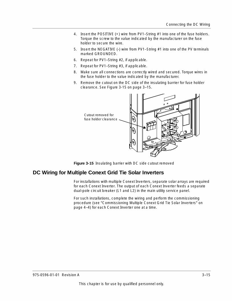
9. Remove the cutout on the DC side of the insulating barrier for fuse holder clearance. See Figure 3-15 on page 3–15.
DC Wiring for Multiple Conext Grid Tie Solar Inverters
For installations with multiple Conext Inverters, separate solar arrays are required for each Conext Inverter. The output of each Conext Inverter feeds a separate dual-pole circuit breaker (L1 and L2) in the main utility service panel.
For such installations, complete the wiring and perform the commissioning procedure (see “Commissioning Multiple Conext Grid Tie Solar Inverters” on page 4–4) for each Conext Inverter one at a time.
Figure 3-15 Insulating barrier with DC side cutout removed
Cutout removed for fuse holder clearance
975-0596-01-01 Revision A 3–15
This chapter is for use by qualified personnel only.
Wiring the Conext Grid Tie Solar Inverter
DANGER
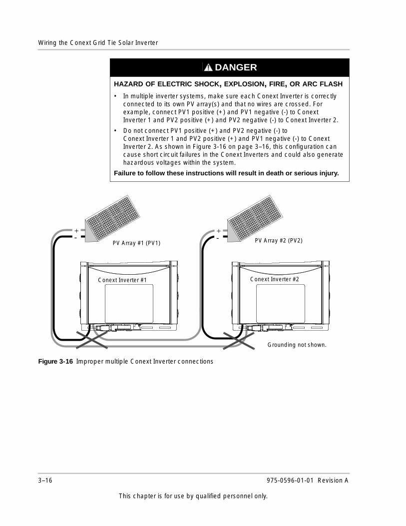
HAZARD OF ELECTRIC SHOCK, EXPLOSION, FIRE, OR ARC FLASH
• In multiple inverter systems, make sure each Conext Inverter is correctly connected to its own PV array(s) and that no wires are crossed. For example, connect PV1 positive (+) and PV1 negative (-) to Conext Inverter 1 and PV2 positive (+) and PV2 negative (-) to Conext Inverter 2.
• Do not connect PV1 positive (+) and PV2 negative (-) to Conext Inverter 1 and PV2 positive (+) and PV1 negative (-) to Conext Inverter 2. As shown in Figure 3-16 on page 3–16, this configuration can cause short circuit failures in the Conext Inverters and could also generate hazardous voltages within the system.
Failure to follow these instructions will result in death or serious injury.
Figure 3-16 Improper multiple Conext Inverter connections
- -+ +
PV Array #1 (PV1) PV Array #2 (PV2)
Conext Inverter #1 Conext Inverter #2
Grounding not shown.
3–16 975-0596-01-01 Revision A
This chapter is for use by qualified personnel only.
Connecting the AC Wiring
Connecting the AC Wiring
The Conext Inverter can be connected to a single bi-directional meter or to dual meters, where one meter indicates power used and the second meter indicates power sold (power supplied back to the utility). Consult the local utility to determine the proper components to install, and obtain any permits required prior to installation.
Make sure all connections are secured in the terminal block. See “Cage Clamps®” on page 3–10 for instructions on using Cage Clamps.
The AC wiring procedure is illustrated in Figure 3-17.
DANGER
HAZARD OF ELECTRIC SHOCK, EXPLOSION, FIRE, OR ARC FLASH
• Before wiring the Conext Inverter, make sure the main breaker in the primary utility breaker box is switched OFF, locked out, and tagged out. Switch this breaker on only after all wiring is completed as instructed in the procedures.
• If the DC wiring has been completed, make sure the DC/AC disconnect switch is in the OFF position and isolate or disconnect all sources of electricity. If the system does not provide a PV disconnect device, cover the PV array with opaque (dark) material.
Failure to follow these instructions will result in death or serious injury.
NOTICE
The neutral conductor must be attached to the Conext Inverter in all cases. The neutral conductor is used for phase-to-neutral voltage sensing only and is not a current-carrying conductor. This conductor is not bonded to ground in the Conext Inverter.
975-0596-01-01 Revision A 3–17
This chapter is for use by qualified personnel only.
Wiring the Conext Grid Tie Solar Inverter
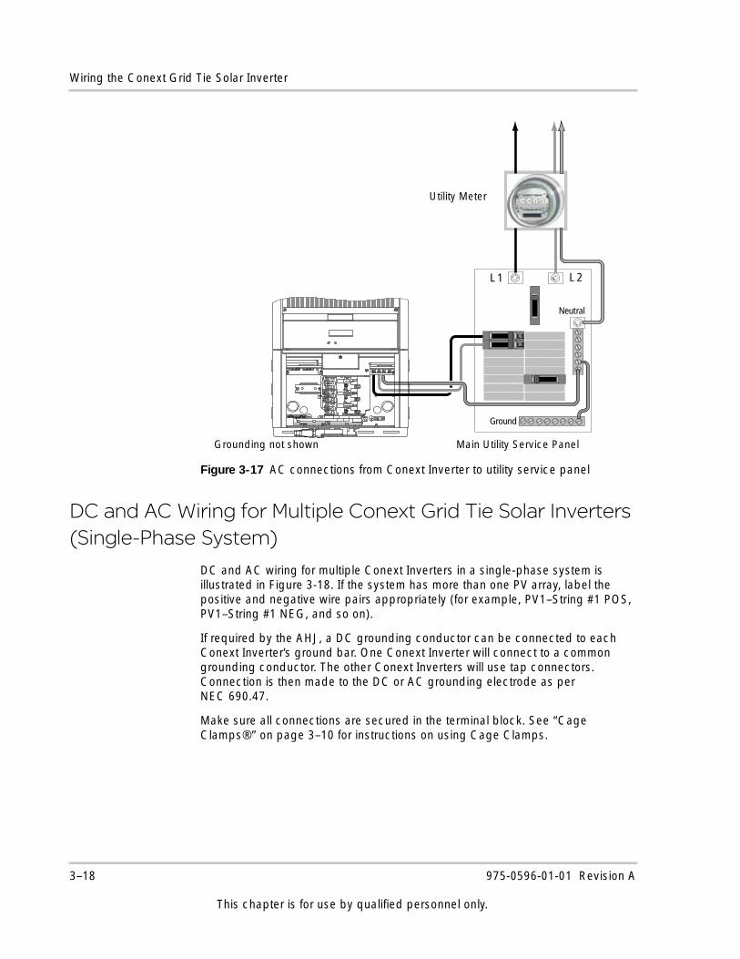
DC and AC Wiring for Multiple Conext Grid Tie Solar Inverters (Single-Phase System)
DC and AC wiring for multiple Conext Inverters in a single-phase system is illustrated in Figure 3-18. If the system has more than one PV array, label the positive and negative wire pairs appropriately (for example, PV1–String #1 POS, PV1–String #1 NEG, and so on).
If required by the AHJ, a DC grounding conductor can be connected to each Conext Inverter’s ground bar. One Conext Inverter will connect to a common grounding conductor. The other Conext Inverters will use tap connectors. Connection is then made to the DC or AC grounding electrode as per NEC 690.47.
Make sure all connections are secured in the terminal block. See “Cage Clamps®” on page 3–10 for instructions on using Cage Clamps.
Figure 3-17 AC connections from Conext Inverter to utility service panel
L 1 L 2
Neutral
Ground
L1L2
Grounding not shown
Utility Meter
Main Utility Service Panel
3–18 975-0596-01-01 Revision A
This chapter is for use by qualified personnel only.
DC and AC Wiring for Multiple Conext Grid Tie Solar Inverters (Three-Phase System)
DC and AC Wiring for Multiple Conext Grid Tie Solar Inverters (Three-Phase System)
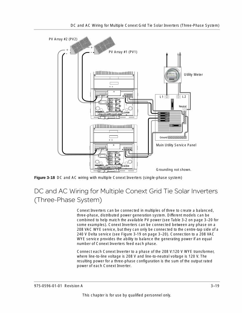
Conext Inverters can be connected in multiples of three to create a balanced, three-phase, distributed power generation system. Different models can be combined to help match the available PV power (see Table 3-2 on page 3–20 for some examples). Conext Inverters can be connected between any phase on a 208 VAC WYE service, but they can only be connected to the centre-tap side of a 240 V Delta service (see Figure 3-19 on page 3–20). Connection to a 208 VAC WYE service provides the ability to balance the generating power if an equal number of Conext Inverters feed each phase.
Connect each Conext Inverter to a phase of the 208 V:120 V WYE transformer, where line-to-line voltage is 208 V and line-to-neutral voltage is 120 V. The resulting power for a three-phase configuration is the sum of the output rated power of each Conext Inverter.
Figure 3-18 DC and AC wiring with multiple Conext Inverters (single-phase system)
L 1 L 2
Neutral
L1L2
L1L2
Ground
PV Array #2 (PV2)
PV Array #1 (PV1)
Grounding not shown.
Main Utility Service Panel
Utility Meter
-+
-+
975-0596-01-01 Revision A 3–19
This chapter is for use by qualified personnel only.
Wiring the Conext Grid Tie Solar Inverter
Communications Wiring for Multiple Conext Grid Tie Solar Inverters
Communications wiring between multiple Conext Inverters allows information about each Conext Inverter and its associated PV array to be communicated between all of the Conext Inverters in the system. Information about the entire system can be displayed on any Conext Inverter’s LCD in the system.
CAUTIONris
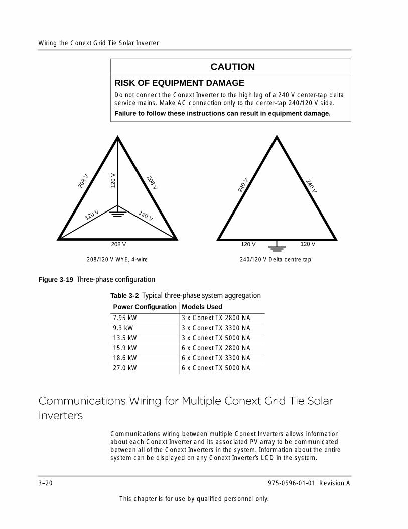
RISK OF EQUIPMENT DAMAGEDo not connect the Conext Inverter to the high leg of a 240 V center-tap delta service mains. Make AC connection only to the center-tap 240/120 V side.
Failure to follow these instructions can result in equipment damage.
Figure 3-19 Three-phase configuration
Table 3-2 Typical three-phase system aggregation
Power Configuration Models Used
7.95 kW 3 x Conext TX 2800 NA
9.3 kW 3 x Conext TX 3300 NA
13.5 kW 3 x Conext TX 5000 NA
15.9 kW 6 x Conext TX 2800 NA
18.6 kW 6 x Conext TX 3300 NA
27.0 kW 6 x Conext TX 5000 NA
120 V 120 V
240 V240
V
208
V 208 V
208 V
120 V 120 V
120
V
208/120 V WYE, 4-wire 240/120 V Delta centre tap
3–20 975-0596-01-01 Revision A
This chapter is for use by qualified personnel only.
Communications Wiring for Multiple Conext Grid Tie Solar Inverters
For example, in a two-inverter system, if Conext Inverter 1 is producing 1500 W and Conext Inverter 2 is producing 2000 W, both Conext Inverters display a total system power of 3500 W. The cumulative energy produced by both Conext Inverters that day is also displayed.
You can also view information for an individual Conext Inverter in a system. See “To view single inverter-specific screens in a multiple inverter system:” on page 5–6. Without communications wiring (network cables), each Conext Inverter in a system will only display information pertinent to itself.
Xanbus Network Technology
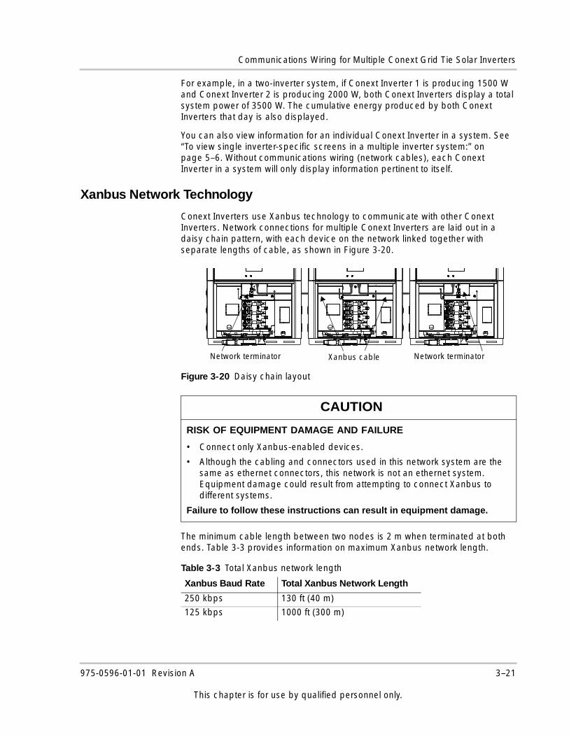
Conext Inverters use Xanbus technology to communicate with other Conext Inverters. Network connections for multiple Conext Inverters are laid out in a daisy chain pattern, with each device on the network linked together with separate lengths of cable, as shown in Figure 3-20.
The minimum cable length between two nodes is 2 m when terminated at both ends. Table 3-3 provides information on maximum Xanbus network length.
Figure 3-20 Daisy chain layout
CAUTION
RISK OF EQUIPMENT DAMAGE AND FAILURE
• Connect only Xanbus-enabled devices.
• Although the cabling and connectors used in this network system are the same as ethernet connectors, this network is not an ethernet system. Equipment damage could result from attempting to connect Xanbus to different systems.
Failure to follow these instructions can result in equipment damage.
Xanbus cableNetwork terminator Network terminator
Table 3-3 Total Xanbus network length
Xanbus Baud Rate Total Xanbus Network Length
250 kbps 130 ft (40 m)
125 kbps 1000 ft (300 m)
975-0596-01-01 Revision A 3–21
This chapter is for use by qualified personnel only.
Wiring the Conext Grid Tie Solar Inverter
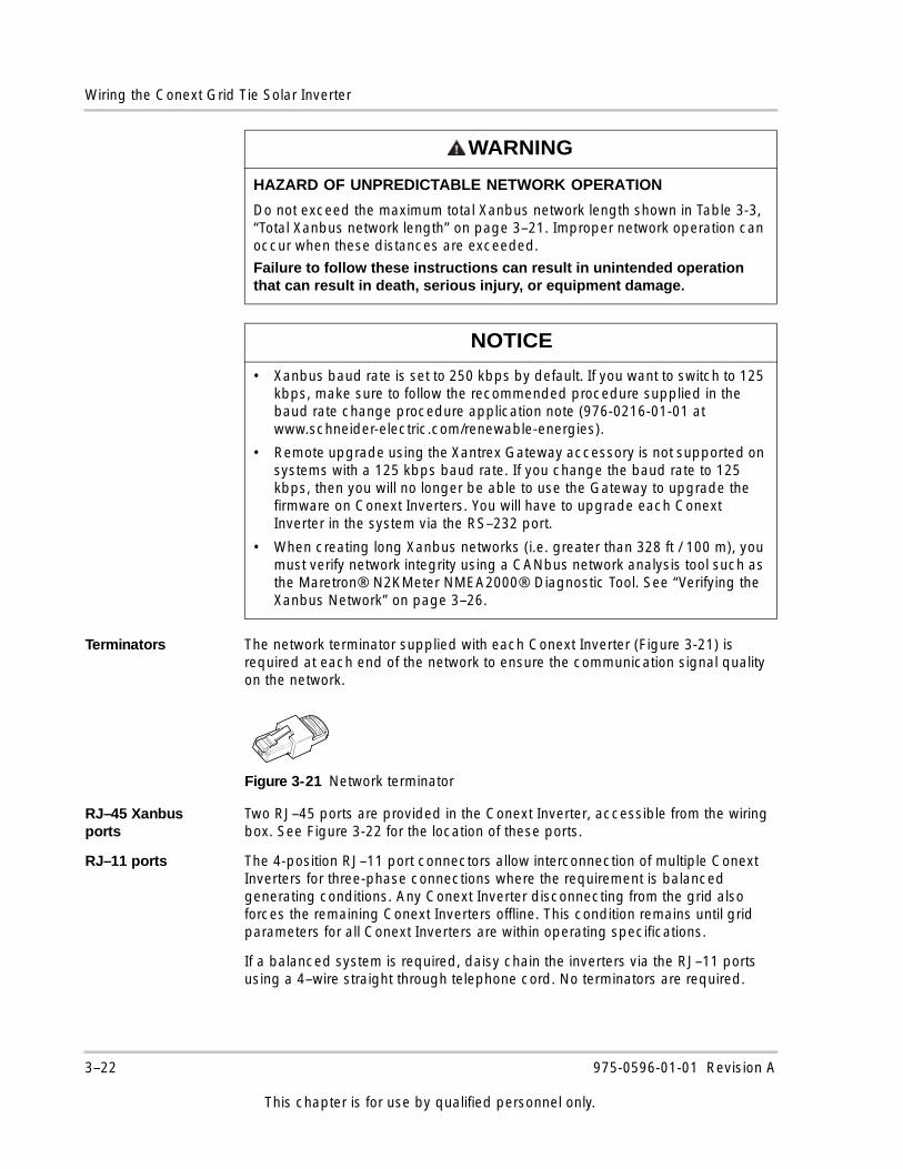
Terminators The network terminator supplied with each Conext Inverter (Figure 3-21) is required at each end of the network to ensure the communication signal quality on the network.
RJ–45 Xanbus ports
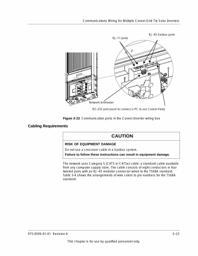
Two RJ–45 ports are provided in the Conext Inverter, accessible from the wiring box. See Figure 3-22 for the location of these ports.
RJ–11 ports The 4-position RJ–11 port connectors allow interconnection of multiple Conext Inverters for three-phase connections where the requirement is balanced generating conditions. Any Conext Inverter disconnecting from the grid also forces the remaining Conext Inverters offline. This condition remains until grid parameters for all Conext Inverters are within operating specifications.
If a balanced system is required, daisy chain the inverters via the RJ–11 ports using a 4–wire straight through telephone cord. No terminators are required.
WARNING
HAZARD OF UNPREDICTABLE NETWORK OPERATION
Do not exceed the maximum total Xanbus network length shown in Table 3-3, “Total Xanbus network length” on page 3–21. Improper network operation can occur when these distances are exceeded.
Failure to follow these instructions can result in unintended operation that can result in death, serious injury, or equipment damage.
NOTICE
• Xanbus baud rate is set to 250 kbps by default. If you want to switch to 125 kbps, make sure to follow the recommended procedure supplied in the baud rate change procedure application note (976-0216-01-01 at www.schneider-electric.com/renewable-energies).
• Remote upgrade using the Xantrex Gateway accessory is not supported on systems with a 125 kbps baud rate. If you change the baud rate to 125 kbps, then you will no longer be able to use the Gateway to upgrade the firmware on Conext Inverters. You will have to upgrade each Conext Inverter in the system via the RS–232 port.
• When creating long Xanbus networks (i.e. greater than 328 ft / 100 m), you must verify network integrity using a CANbus network analysis tool such as the Maretron® N2KMeter NMEA2000® Diagnostic Tool. See “Verifying the Xanbus Network” on page 3–26.
Figure 3-21 Network terminator
3–22 975-0596-01-01 Revision A
This chapter is for use by qualified personnel only.
Communications Wiring for Multiple Conext Grid Tie Solar Inverters
Cabling Requirements
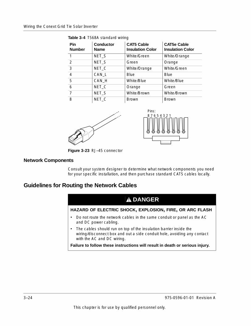
The network uses Category 5 (CAT5 or CAT5e) cable: a standard cable available from any computer supply store. The cable consists of eight conductors in four twisted pairs with an RJ–45 modular connector wired to the T568A standard. Table 3-4 shows the arrangements of wire colors to pin numbers for the T568A standard.
Figure 3-22 Communication ports in the Conext Inverter wiring box
CAUTION
RISK OF EQUIPMENT DAMAGE
Do not use a crossover cable in a Xanbus system.
Failure to follow these instructions can result in equipment damage.
Network terminator
RS–232 port (used to connect a PC to use Conext View)
RJ–11 portsRJ–45 Xanbus ports
975-0596-01-01 Revision A 3–23
This chapter is for use by qualified personnel only.
Wiring the Conext Grid Tie Solar Inverter
Network Components
Consult your system designer to determine what network components you need for your specific installation, and then purchase standard CAT5 cables locally.
Guidelines for Routing the Network Cables
Table 3-4 T568A standard wiring
Pin Number
Conductor Name
CAT5 Cable Insulation Color
CAT5e Cable Insulation Color
1 NET_S White/Green White/Orange
2 NET_S Green Orange
3 NET_C White/Orange White/Green
4 CAN_L Blue Blue
5 CAN_H White/Blue White/Blue
6 NET_C Orange Green
7 NET_S White/Brown White/Brown
8 NET_C Brown Brown
Figure 3-23 RJ–45 connector
Pins:8 7 6 5 4 3 2 1
DANGER
HAZARD OF ELECTRIC SHOCK, EXPLOSION, FIRE, OR ARC FLASH
• Do not route the network cables in the same conduit or panel as the AC and DC power cabling.
• The cables should run on top of the insulation barrier inside the wiring/disconnect box and out a side conduit hole, avoiding any contact with the AC and DC wiring.
Failure to follow these instructions will result in death or serious injury.
3–24 975-0596-01-01 Revision A
This chapter is for use by qualified personnel only.
Communications Wiring for Multiple Conext Grid Tie Solar Inverters
Connecting Network Cable Between Multiple Conext Grid Tie Solar Inverters
The following procedure (illustrated in Figure 3-20 on page 3–21) assumes only two Conext Inverters are connected. However, up to five Conext Inverters can be connected in this configuration.
To provide communication between multiple Conext Inverters:
1. Remove the wiring/disconnect box cover from each Conext Inverter. See “Accessing the Wiring Terminals” on page 3–8.
2. Connect the network cable to any RJ–45 port in Conext Inverter 1.
3. Route the cable along the top of the insulation barrier and through a side conduit hole to Conext Inverter 2.
4. Connect the network cable to any RJ–45 port in Conext Inverter 2.
5. For more than two Conext Inverters, continue connecting cable as described above.
6. Insert network terminators into the empty RJ–45 ports in the Conext Inverters at the beginning and end of the network. There should be no empty RJ–45 ports in any of the Conext Inverters.
WARNING
HAZARD OF UNPREDICTABLE DEVICE BEHAVIOR
Unpredictable device behavior might result from connecting one end of the network to the other to make a ring or loop.
Failure to follow these instructions can result in unintended operation that can result in death, serious injury, or equipment damage.
DANGER
HAZARD OF ELECTRIC SHOCK, EXPLOSION, FIRE, OR ARC FLASH
Before opening the Conext Inverter wiring/disconnect box, turn OFF the breaker switches connected to the Conext Inverter AC output, and turn the DC/AC disconnect switch to the OFF position. Hazardous voltage will still be present on the DC input (PV) terminals located under the clear plastic insulation barrier. Do not remove the insulation barrier during this procedure. To reduce the risk of shock, isolate or disconnect all sources of electricity. If the system does not provide a PV disconnect device, cover the PV array with opaque (dark) material.
Failure to follow these instructions will result in death or serious injury.
975-0596-01-01 Revision A 3–25
This chapter is for use by qualified personnel only.
Wiring the Conext Grid Tie Solar Inverter
Verifying the Xanbus Network
For long Xanbus networks (greater than 328 feet / 100 m), you must verify network integrity using a CANbus network analysis tool such as the Maretron N2KMeter NMEA 2000 Diagnostic Tool. To determine if the network is healthy, check to see if any bus errors are present on the network. The presence of bus errors, specifically more than one bus error per second, indicates that the network is not operating optimally.
If the CANbus analyzer indicates your network is not operating properly, check the following, and then re-test the network:
• Make sure the total Xanbus network length has not been exceeded. See Table 3-3, “Total Xanbus network length” on page 3–21.
• Make sure the network has only two terminators installed—one at each far end of the network.
• Make sure no long stub connections are coming from a Xanbus 3-port T connector (if any are used). Daisy chain network configuration is the optimal configuration.
• Make sure all cable sections are correct and not shorted anywhere.
Communications Wiring for Monitoring a Single Conext Grid Tie Solar Inverter
You can view Conext Inverter operational data on a personal computer using Conext View. Download it at www.schneider-electric.com. To use Conext View, connect your computer’s serial port to the Conext Inverter RS–232 port (see Figure 3-22 on page 3–23).
RS–232 cable requirements
To connect your computer to the Conext Inverter, you must use a serial DB9 “straight through” cable.
The RS–232 connector on the Conext Inverter is configured as follows:
• Pin 2: transmit
• Pin 3: receive
• Pin 5: ground
All other pins are unused.
3–26 975-0596-01-01 Revision A
This chapter is for use by qualified personnel only.
Communications Wiring for Monitoring a Single Conext Grid Tie Solar Inverter
To connect a single Conext Inverter to a personal computer:
1. Feed the male end of the serial cable through a top, side conduit hole on the Conext Inverter.
If the end of the serial cable is too large to fit through the conduit hole, you might need to use two DB9 to CAT 5 adaptors. Plug the DB9 end of the adapter into the Conext Inverter, and feed the CAT 5 end of the cable out the conduit hole. Use another adapter to convert the CAT 5 end of the cable back to DB9.
2. Plug the male end of the serial cable into the Conext Inverter’s RS–232 port.
3. Plug the female end of the serial cable into your computer’s serial port. A USB to DB9 converter (not supplied) could be required.
4. Replace the wiring/disconnect box cover.
5. Turn the DC/AC disconnect switch to the ON position and turn the main utility panel breaker switches ON.
When power is restored to the Conext Inverter, you can run Conext View on your computer to monitor the Conext Inverter’s operation.
For more information about Conext View, see the User’s Guide included with the Conext View software (Document Part Number 975-0611-01-01).
DANGER
HAZARD OF ELECTRIC SHOCK, EXPLOSION, FIRE, OR ARC FLASH
• Before opening the Conext Inverter wiring/disconnect box, turn OFF the breaker switches connected to the Conext Inverter AC output, and turn the DC/AC disconnect switch to the OFF position.
• Hazardous voltage will still be present on the DC input (PV) terminals located under the clear plastic insulation barrier. Do not remove the insulation barrier during this procedure.
• To reduce the risk of shock, isolate or disconnect all sources of electricity. If the system does not provide a PV disconnect device, cover the PV array with opaque (dark) material.
Failure to follow these instructions will result in death or serious injury.
NOTICE
In multiple installations, Conext View monitors only the Conext Inverters to which the computer is connected. However, if the Conext Inverters are connected with a Xanbus network cable, Conext View will display total system wattage and the accumulated daily energy produced by all Conext Inverters. Monitoring multiple Conext Inverters requires multiple DB9 cable connections (one per Conext Inverter) to your computer.
975-0596-01-01 Revision A 3–27
This chapter is for use by qualified personnel only.
Wiring the Conext Grid Tie Solar Inverter
Fast Sweep™ Shade Tolerant MPPT AlgorithmConext View contains the Fast Sweep MPPT algorithm that optimizes the Conext Inverter’s energy harvest under partially shaded conditions. Once Conext View is installed and communication with the inverters has been established, Fast Sweep can be enabled or disabled using Conext View. For instructions, see the Conext View User’s Guide (Document Part Number 975-0611-01-01) available with the software.
3–28 975-0596-01-01 Revision A
This chapter is for use by qualified personnel only.
4 Starting the Conext Grid Tie Solar Inverter
DANGER
HAZARD OF ELECTRIC SHOCK, EXPLOSION, FIRE, OR ARC FLASH
• The Conext Grid Tie Solar Inverter has no user serviceable parts inside. It must be installed and serviced only by qualified personnel equipped with appropriate personal protective equipment and following safe electrical work practices.
• The Conext Inverter is energized from two sources: PV array while exposed to light and AC grid. Before opening doors or covers, consult the system diagram to identify all sources; de-energize, lock out, and tag out all sources; and wait at least five minutes for internal capacitors to discharge to safe voltages.
• Before servicing, test using a meter rated at least 1000 volts AC and DC to make sure all circuits are de-energized.
• The Conext Inverter is provided with integral PV ground fault protection. Normally GROUNDED conductors might be UNGROUNDED and ENERGIZED when a GROUND FAULT is indicated. Disconnect all sources of power before opening.
• The Conext Inverter employs field adjustable voltage and frequency set points and time delays that are factory set in compliance with local utility and safety requirements and can be changed only by trained technicians with approval by both the local utility and equipment owner.
Failure to follow these instructions will result in death or serious injury.
Starting the Conext Grid Tie Solar Inverter
Chapter 4 provides instructions for starting the Conext Grid Tie Solar Inverter and performing a functional test.
The topics in this chapter are organized as follows:• “Startup Procedure” on page 4–2• “Commissioning Multiple Conext Grid
Tie Solar Inverters” on page 4–4• “Disconnect Test” on page 4–6• “Locating the Firmware Version
Number” on page 4–7
Startup Procedure
Starting the Conext Inverter includes several steps. You must:
1. Make sure the DC/AC disconnect switch is in the OFF position (see Figure 4-1).
2. Check the PV array DC voltage. Follow the procedure in “Checking the PV Array DC Voltage” on page 4–2.
3. Check the AC utility voltage. Follow the procedure in “Checking the AC Utility Voltage” on page 4–3.
4. Replace the cover on the wiring box. Follow the procedure in “Replacing the Wiring/Disconnect Box Cover” on page 4–3.
5. Start the Conext Inverter by switching the DC/AC disconnect switch ON (see Figure 4-1).
Checking the PV Array DC Voltage
To check the PV array DC voltage:
1. Uncover the PV arrays and expose them to full sunlight. The sunlight must be intense enough to produce the required output voltage.
2. Measure the PV array open circuit DC voltage across the DC positive (+) and negative (-) terminals of the string combiner. This voltage must be greater than 150 volts DC (to energize the electronics) and less than 600 volts DC (to help prevent damage to the Conext Inverter).
4–2 975-0596-01-01 Revision A
This chapter is for use by qualified personnel only.
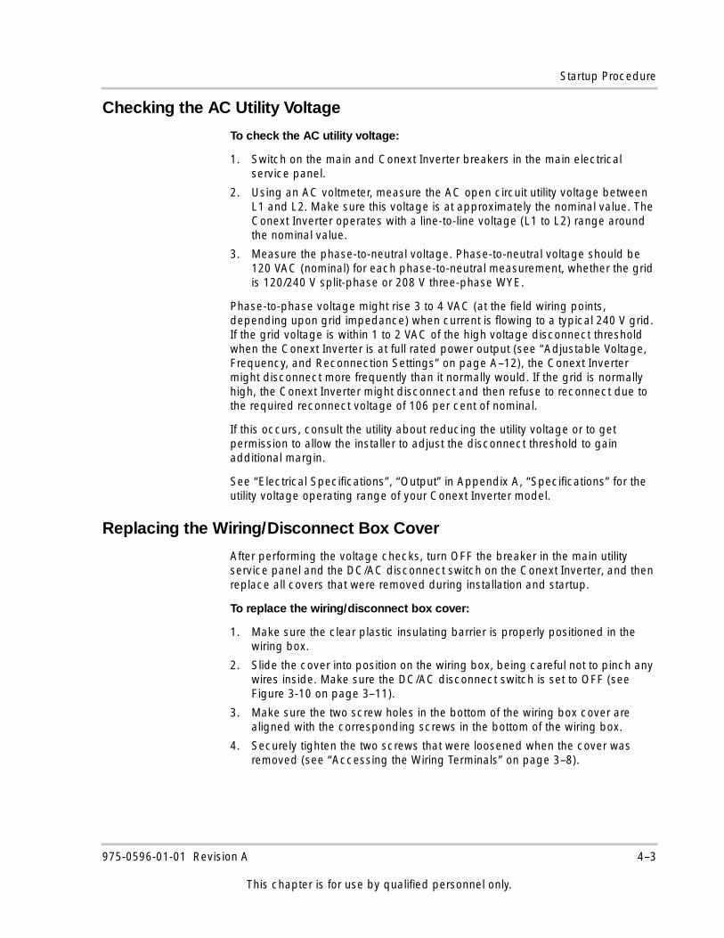
Startup Procedure
Checking the AC Utility Voltage
To check the AC utility voltage:
1. Switch on the main and Conext Inverter breakers in the main electrical service panel.
2. Using an AC voltmeter, measure the AC open circuit utility voltage between L1 and L2. Make sure this voltage is at approximately the nominal value. The Conext Inverter operates with a line-to-line voltage (L1 to L2) range around the nominal value.
3. Measure the phase-to-neutral voltage. Phase-to-neutral voltage should be 120 VAC (nominal) for each phase-to-neutral measurement, whether the grid is 120/240 V split-phase or 208 V three-phase WYE.
Phase-to-phase voltage might rise 3 to 4 VAC (at the field wiring points, depending upon grid impedance) when current is flowing to a typical 240 V grid. If the grid voltage is within 1 to 2 VAC of the high voltage disconnect threshold when the Conext Inverter is at full rated power output (see “Adjustable Voltage, Frequency, and Reconnection Settings” on page A–12), the Conext Inverter might disconnect more frequently than it normally would. If the grid is normally high, the Conext Inverter might disconnect and then refuse to reconnect due to the required reconnect voltage of 106 per cent of nominal.
If this occurs, consult the utility about reducing the utility voltage or to get permission to allow the installer to adjust the disconnect threshold to gain additional margin.
See “Electrical Specifications”, “Output” in Appendix A, “Specifications” for the utility voltage operating range of your Conext Inverter model.
Replacing the Wiring/Disconnect Box Cover
After performing the voltage checks, turn OFF the breaker in the main utility service panel and the DC/AC disconnect switch on the Conext Inverter, and then replace all covers that were removed during installation and startup.
To replace the wiring/disconnect box cover:
1. Make sure the clear plastic insulating barrier is properly positioned in the wiring box.
2. Slide the cover into position on the wiring box, being careful not to pinch any wires inside. Make sure the DC/AC disconnect switch is set to OFF (see Figure 3-10 on page 3–11).
3. Make sure the two screw holes in the bottom of the wiring box cover are aligned with the corresponding screws in the bottom of the wiring box.
4. Securely tighten the two screws that were loosened when the cover was removed (see “Accessing the Wiring Terminals” on page 3–8).
975-0596-01-01 Revision A 4–3
This chapter is for use by qualified personnel only.
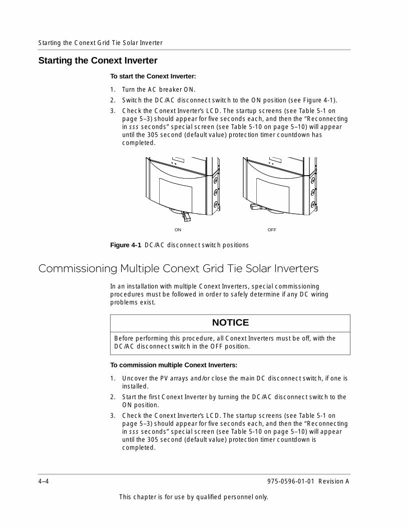
Starting the Conext Grid Tie Solar Inverter
Starting the Conext Inverter
To start the Conext Inverter:
1. Turn the AC breaker ON.
2. Switch the DC/AC disconnect switch to the ON position (see Figure 4-1).
3. Check the Conext Inverter’s LCD. The startup screens (see Table 5-1 on page 5–3) should appear for five seconds each, and then the “Reconnecting in sss seconds” special screen (see Table 5-10 on page 5–10) will appear until the 305 second (default value) protection timer countdown has completed.
Commissioning Multiple Conext Grid Tie Solar Inverters
In an installation with multiple Conext Inverters, special commissioning procedures must be followed in order to safely determine if any DC wiring problems exist.
To commission multiple Conext Inverters:
1. Uncover the PV arrays and/or close the main DC disconnect switch, if one is installed.
2. Start the first Conext Inverter by turning the DC/AC disconnect switch to the ON position.
3. Check the Conext Inverter’s LCD. The startup screens (see Table 5-1 on page 5–3) should appear for five seconds each, and then the “Reconnecting in sss seconds” special screen (see Table 5-10 on page 5–10) will appear until the 305 second (default value) protection timer countdown is completed.
Figure 4-1 DC/AC disconnect switch positions
ON OFF
NOTICE
Before performing this procedure, all Conext Inverters must be off, with the DC/AC disconnect switch in the OFF position.
4–4 975-0596-01-01 Revision A
This chapter is for use by qualified personnel only.
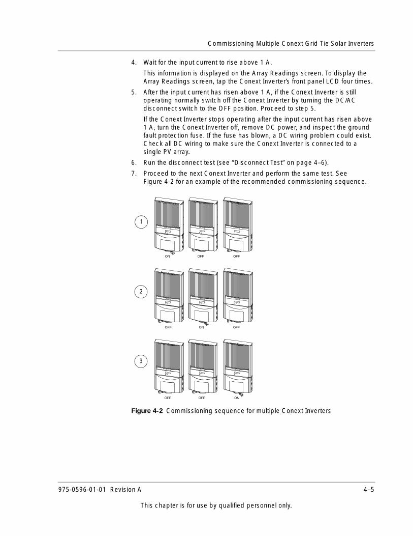
Commissioning Multiple Conext Grid Tie Solar Inverters
4. Wait for the input current to rise above 1 A.
This information is displayed on the Array Readings screen. To display the Array Readings screen, tap the Conext Inverter’s front panel LCD four times.
5. After the input current has risen above 1 A, if the Conext Inverter is still operating normally switch off the Conext Inverter by turning the DC/AC disconnect switch to the OFF position. Proceed to step 5.
If the Conext Inverter stops operating after the input current has risen above 1 A, turn the Conext Inverter off, remove DC power, and inspect the ground fault protection fuse. If the fuse has blown, a DC wiring problem could exist. Check all DC wiring to make sure the Conext Inverter is connected to a single PV array.
6. Run the disconnect test (see “Disconnect Test” on page 4–6).
7. Proceed to the next Conext Inverter and perform the same test. See Figure 4-2 for an example of the recommended commissioning sequence.
Figure 4-2 Commissioning sequence for multiple Conext Inverters
ON OFF OFF
OFF ON OFF
OFF OFF ON
1
2
3
975-0596-01-01 Revision A 4–5
This chapter is for use by qualified personnel only.
Starting the Conext Grid Tie Solar Inverter
Disconnect TestThe disconnect test is designed to verify correct operation of the Conext Inverter both on initial operation and periodically through its life as required by the local utility. This test makes sure the Conext Grid Tie Solar Inverter does not send electricity to the utility grid when the local utility has shut off the grid for repairs or when the utility wiring is damaged.
When operation of the Conext Inverter has been verified and the Conext Inverter is producing power, run the disconnect test as described in this procedure.
To run the disconnect test:
1. Switch off the AC breaker for the circuit connected to the Conext Inverter.
2. Have someone watch the front panel of the Conext Inverter to make sure the green light on the front of the Conext Inverter goes out within two seconds.
The green light goes out when the AC circuit is switched off, disconnecting the Conext Inverter from the AC grid. The front panel display will show an AC Fault display, indicating that the AC is out of the operating range.
3. Switch on the AC circuit for the Conext Inverter.
The Conext Inverter responds by starting its 305 second protection timer. Make sure the Conext Inverter does not produce power before the countdown is over. After completing the countdown, the green light turns on and the Conext Inverter begins delivering power. The display returns to showing the power being produced and the total kWh produced to date.
4. If you have another Conext Inverter to commission, switch off the AC circuit for the Conext Inverter you have just commissioned and tested by switching off the breaker on the main panel. You can then run the commissioning procedure and disconnect test on the next Conext Inverter.
NOTICE
The default voltage, frequency, and reconnect delay values are programmed into the Conext Inverter at the time of shipment from the factory. With the utility’s approval, these settings can be adjusted in the field using the GTConfigLite software tool. See “Adjustable Voltage, Frequency, and Reconnection Settings” on page A–12.
4–6 975-0596-01-01 Revision A
This chapter is for use by qualified personnel only.
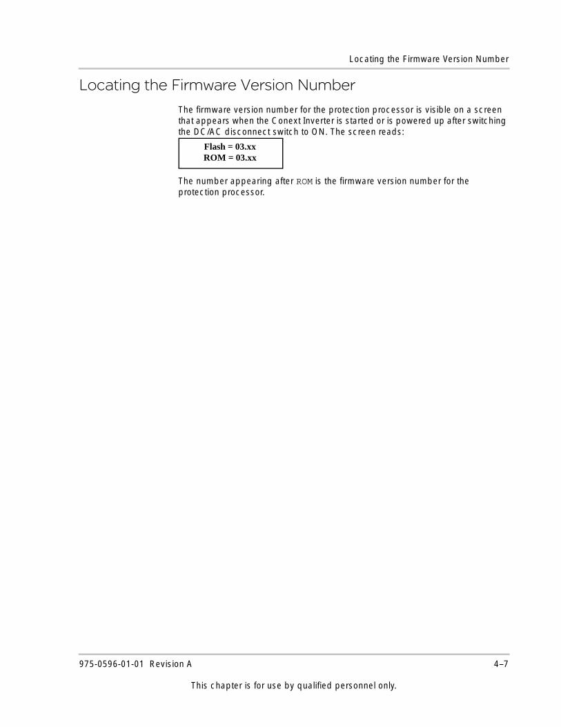
Locating the Firmware Version Number
Locating the Firmware Version NumberThe firmware version number for the protection processor is visible on a screen that appears when the Conext Inverter is started or is powered up after switching the DC/AC disconnect switch to ON. The screen reads:
The number appearing after ROM is the firmware version number for the protection processor.
Flash = 03.xxROM = 03.xx
975-0596-01-01 Revision A 4–7
This chapter is for use by qualified personnel only.

4–8
5 Monitoring the Conext Grid Tie Solar Inverter
Chapter 5 contains information about the LCD screens and the LED indicators.
The topics in this chapter are organized as follows:• “Monitoring the Front Panel Display” on
page 5–2• “Front Panel Display Screens and What
They Mean” on page 5–3• “Status Indicator Lights” on page 5–12
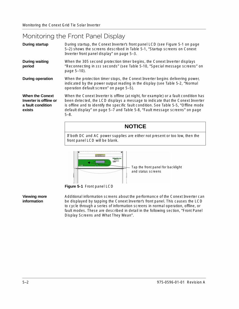
Monitoring the Conext Grid Tie Solar Inverter
Monitoring the Front Panel DisplayDuring startup During startup, the Conext Inverter’s front panel LCD (see Figure 5-1 on page
5–2) shows the screens described in Table 5-1, “Startup screens on Conext Inverter front panel display” on page 5–3.
During waiting period
When the 305 second protection timer begins, the Conext Inverter displays “Reconnecting in sss seconds” (see Table 5-10, “Special message screens” on page 5–10).
During operation When the protection timer stops, the Conext Inverter begins delivering power, indicated by the power output reading in the display (see Table 5-2, “Normal operation default screen” on page 5–5).
When the Conext Inverter is offline or a fault condition exists
When the Conext Inverter is offline (at night, for example) or a fault condition has been detected, the LCD displays a message to indicate that the Conext Inverter is offline and to identify the specific fault condition. See Table 5-5, “Offline mode default display” on page 5–7 and Table 5-8, “Fault message screens” on page 5–8.
Viewing more information
Additional information screens about the performance of the Conext Inverter can be displayed by tapping the Conext Inverter’s front panel. This causes the LCD to cycle through a series of information screens in normal operation, offline, or fault modes. These are described in detail in the following section, “Front Panel Display Screens and What They Mean”.
NOTICE
If both DC and AC power supplies are either not present or too low, then the front panel LCD will be blank.
Figure 5-1 Front panel LCD
Tap the front panel for backlight and status screens
5–2 975-0596-01-01 Revision A
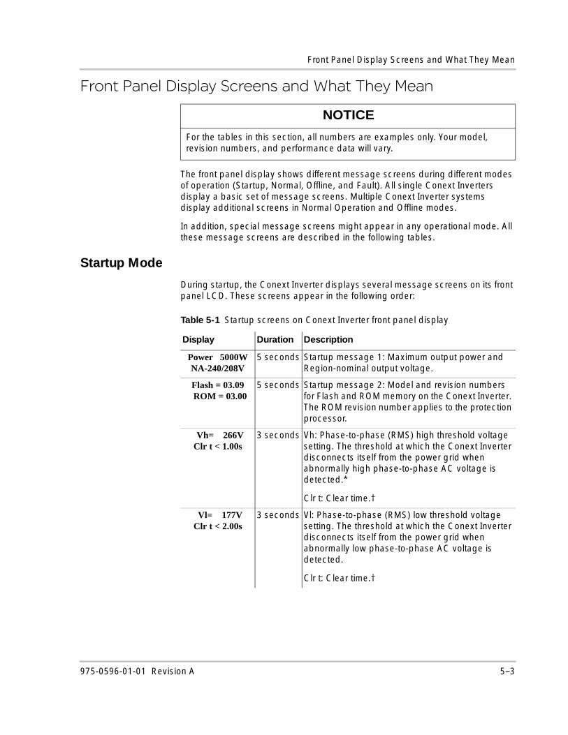
Front Panel Display Screens and What They Mean
Front Panel Display Screens and What They Mean
The front panel display shows different message screens during different modes of operation (Startup, Normal, Offline, and Fault). All single Conext Inverters display a basic set of message screens. Multiple Conext Inverter systems display additional screens in Normal Operation and Offline modes.
In addition, special message screens might appear in any operational mode. All these message screens are described in the following tables.
Startup Mode
During startup, the Conext Inverter displays several message screens on its front panel LCD. These screens appear in the following order:
NOTICE
For the tables in this section, all numbers are examples only. Your model, revision numbers, and performance data will vary.
Table 5-1 Startup screens on Conext Inverter front panel display
Display Duration Description
Power 5000WNA-240/208V
5 seconds Startup message 1: Maximum output power and Region-nominal output voltage.
Flash = 03.09..ROM = 03.00
5 seconds Startup message 2: Model and revision numbers for Flash and ROM memory on the Conext Inverter. The ROM revision number applies to the protection processor.
Vh= 266VClr t < 1.00s
3 seconds Vh: Phase-to-phase (RMS) high threshold voltage setting. The threshold at which the Conext Inverter disconnects itself from the power grid when abnormally high phase-to-phase AC voltage is detected.*
Clr t: Clear time.†
Vl= 177VClr t < 2.00s
3 seconds Vl: Phase-to-phase (RMS) low threshold voltage setting. The threshold at which the Conext Inverter disconnects itself from the power grid when abnormally low phase-to-phase AC voltage is detected.
Clr t: Clear time.†
975-0596-01-01 Revision A 5–3
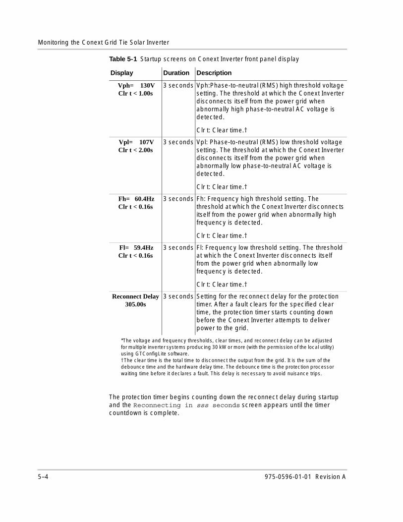
Monitoring the Conext Grid Tie Solar Inverter
The protection timer begins counting down the reconnect delay during startup and the Reconnecting in sss seconds screen appears until the timer countdown is complete.
Vph= 130VClr t < 1.00s
3 seconds Vph:Phase-to-neutral (RMS) high threshold voltage setting. The threshold at which the Conext Inverter disconnects itself from the power grid when abnormally high phase-to-neutral AC voltage is detected.
Clr t: Clear time.†
Vpl= 107VClr t < 2.00s
3 seconds Vpl: Phase-to-neutral (RMS) low threshold voltage setting. The threshold at which the Conext Inverter disconnects itself from the power grid when abnormally low phase-to-neutral AC voltage is detected.
Clr t: Clear time.†
Fh= 60.4HzClr t < 0.16s
3 seconds Fh: Frequency high threshold setting. The threshold at which the Conext Inverter disconnects itself from the power grid when abnormally high frequency is detected.
Clr t: Clear time.†
Fl= 59.4HzClr t < 0.16s
3 seconds Fl: Frequency low threshold setting. The threshold at which the Conext Inverter disconnects itself from the power grid when abnormally low frequency is detected.
Clr t: Clear time.†
Reconnect Delay305.00s
3 seconds Setting for the reconnect delay for the protection timer. After a fault clears for the specified clear time, the protection timer starts counting down before the Conext Inverter attempts to deliver power to the grid.
*The voltage and frequency thresholds, clear times, and reconnect delay can be adjusted for multiple inverter systems producing 30 kW or more (with the permission of the local utility) using GTConfigLite software.†The clear time is the total time to disconnect the output from the grid. It is the sum of the debounce time and the hardware delay time. The debounce time is the protection processor waiting time before it declares a fault. This delay is necessary to avoid nuisance trips.
Table 5-1 Startup screens on Conext Inverter front panel display
Display Duration Description
5–4 975-0596-01-01 Revision A
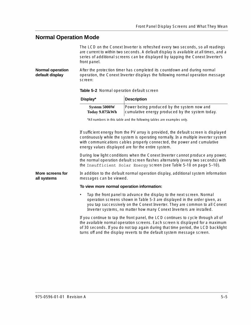
Front Panel Display Screens and What They Mean
Normal Operation Mode
The LCD on the Conext Inverter is refreshed every two seconds, so all readings are current to within two seconds. A default display is available at all times, and a series of additional screens can be displayed by tapping the Conext Inverter’s front panel.
Normal operation default display
After the protection timer has completed its countdown and during normal operation, the Conext Inverter displays the following normal operation message screen:
If sufficient energy from the PV array is provided, the default screen is displayed continuously while the system is operating normally. In a multiple inverter system with communications cables properly connected, the power and cumulative energy values displayed are for the entire system.
During low light conditions when the Conext Inverter cannot produce any power, the normal operation default screen flashes alternately (every two seconds) with the Insufficient Solar Energy screen (see Table 5-10 on page 5–10).
More screens for all systems
In addition to the default normal operation display, additional system information messages can be viewed.
To view more normal operation information:
• Tap the front panel to advance the display to the next screen. Normal operation screens shown in Table 5-3 are displayed in the order given, as you tap successively on the Conext Inverter. They are common to all Conext Inverter systems, no matter how many Conext Inverters are installed.
If you continue to tap the front panel, the LCD continues to cycle through all of the available normal operation screens. Each screen is displayed for a maximum of 30 seconds. If you do not tap again during that time period, the LCD backlight turns off and the display reverts to the default system message screen.
Table 5-2 Normal operation default screen
Display*
*All numbers in this table and the following tables are examples only.
Description
System 5000WToday 9.875kWh
Power being produced by the system now and cumulative energy produced by the system today.
975-0596-01-01 Revision A 5–5
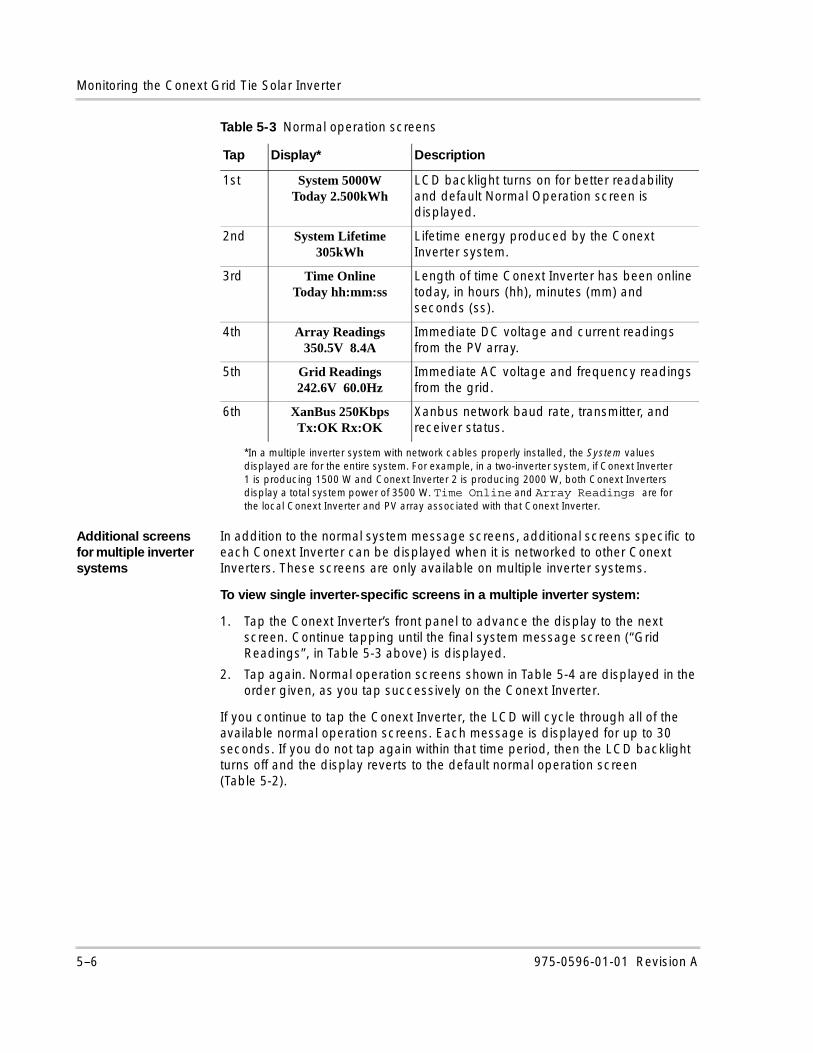
Monitoring the Conext Grid Tie Solar Inverter
Additional screens for multiple inverter systems
In addition to the normal system message screens, additional screens specific to each Conext Inverter can be displayed when it is networked to other Conext Inverters. These screens are only available on multiple inverter systems.
To view single inverter-specific screens in a multiple inverter system:
1. Tap the Conext Inverter’s front panel to advance the display to the next screen. Continue tapping until the final system message screen (“Grid Readings”, in Table 5-3 above) is displayed.
2. Tap again. Normal operation screens shown in Table 5-4 are displayed in the order given, as you tap successively on the Conext Inverter.
If you continue to tap the Conext Inverter, the LCD will cycle through all of the available normal operation screens. Each message is displayed for up to 30 seconds. If you do not tap again within that time period, then the LCD backlight turns off and the display reverts to the default normal operation screen (Table 5-2).
Table 5-3 Normal operation screens
Tap Display*
*In a multiple inverter system with network cables properly installed, the System values displayed are for the entire system. For example, in a two-inverter system, if Conext Inverter 1 is producing 1500 W and Conext Inverter 2 is producing 2000 W, both Conext Inverters display a total system power of 3500 W. Time Online and Array Readings are for the local Conext Inverter and PV array associated with that Conext Inverter.
Description
1st System 5000WToday 2.500kWh
LCD backlight turns on for better readability and default Normal Operation screen is displayed.
2nd System Lifetime305kWh
Lifetime energy produced by the Conext Inverter system.
3rd Time OnlineToday hh:mm:ss
Length of time Conext Inverter has been online today, in hours (hh), minutes (mm) and seconds (ss).
4th Array Readings350.5V 8.4A
Immediate DC voltage and current readings from the PV array.
5th Grid Readings242.6V 60.0Hz
Immediate AC voltage and frequency readings from the grid.
6th XanBus 250KbpsTx:OK Rx:OK
Xanbus network baud rate, transmitter, and receiver status.
5–6 975-0596-01-01 Revision A
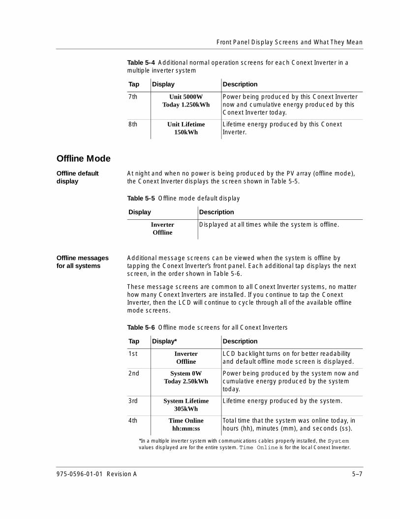
Front Panel Display Screens and What They Mean
Offline Mode
Offline default display
At night and when no power is being produced by the PV array (offline mode), the Conext Inverter displays the screen shown in Table 5-5.
Offline messages for all systems
Additional message screens can be viewed when the system is offline by tapping the Conext Inverter’s front panel. Each additional tap displays the next screen, in the order shown in Table 5-6.
These message screens are common to all Conext Inverter systems, no matter how many Conext Inverters are installed. If you continue to tap the Conext Inverter, then the LCD will continue to cycle through all of the available offline mode screens.
Table 5-4 Additional normal operation screens for each Conext Inverter in a multiple inverter system
Tap Display Description
7th Unit 5000WToday 1.250kWh
Power being produced by this Conext Inverter now and cumulative energy produced by this Conext Inverter today.
8th Unit Lifetime150kWh
Lifetime energy produced by this Conext Inverter.
Table 5-5 Offline mode default display
Display Description
InverterOffline
Displayed at all times while the system is offline.
Table 5-6 Offline mode screens for all Conext Inverters
Tap Display*
*In a multiple inverter system with communications cables properly installed, the System values displayed are for the entire system. Time Online is for the local Conext Inverter.
Description
1st InverterOffline
LCD backlight turns on for better readability and default offline mode screen is displayed.
2nd System 0WToday 2.50kWh
Power being produced by the system now and cumulative energy produced by the system today.
3rd System Lifetime305kWh
Lifetime energy produced by the system.
4th Time Onlinehh:mm:ss
Total time that the system was online today, in hours (hh), minutes (mm), and seconds (ss).
975-0596-01-01 Revision A 5–7
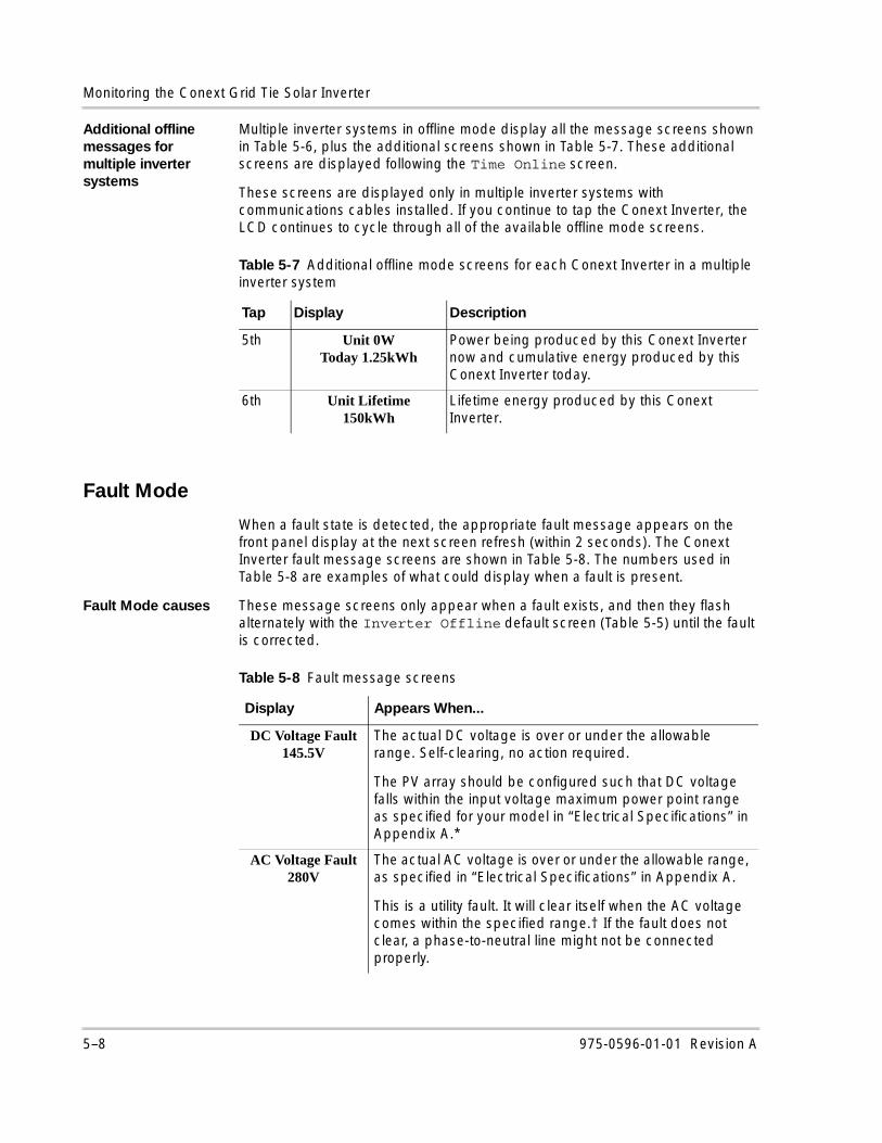
Monitoring the Conext Grid Tie Solar Inverter
Additional offline messages for multiple inverter systems
Multiple inverter systems in offline mode display all the message screens shown in Table 5-6, plus the additional screens shown in Table 5-7. These additional screens are displayed following the Time Online screen.
These screens are displayed only in multiple inverter systems with communications cables installed. If you continue to tap the Conext Inverter, the LCD continues to cycle through all of the available offline mode screens.
Fault Mode
When a fault state is detected, the appropriate fault message appears on the front panel display at the next screen refresh (within 2 seconds). The Conext Inverter fault message screens are shown in Table 5-8. The numbers used in Table 5-8 are examples of what could display when a fault is present.
Fault Mode causes These message screens only appear when a fault exists, and then they flash alternately with the Inverter Offline default screen (Table 5-5) until the fault is corrected.
Table 5-7 Additional offline mode screens for each Conext Inverter in a multiple inverter system
Tap Display Description
5th Unit 0WToday 1.25kWh
Power being produced by this Conext Inverter now and cumulative energy produced by this Conext Inverter today.
6th Unit Lifetime150kWh
Lifetime energy produced by this Conext Inverter.
Table 5-8 Fault message screens
Display Appears When...
DC Voltage Fault145.5V
The actual DC voltage is over or under the allowable range. Self-clearing, no action required.
The PV array should be configured such that DC voltage falls within the input voltage maximum power point range as specified for your model in “Electrical Specifications” in Appendix A.*
AC Voltage Fault280V
The actual AC voltage is over or under the allowable range, as specified in “Electrical Specifications” in Appendix A.
This is a utility fault. It will clear itself when the AC voltage comes within the specified range.† If the fault does not clear, a phase-to-neutral line might not be connected properly.
5–8 975-0596-01-01 Revision A
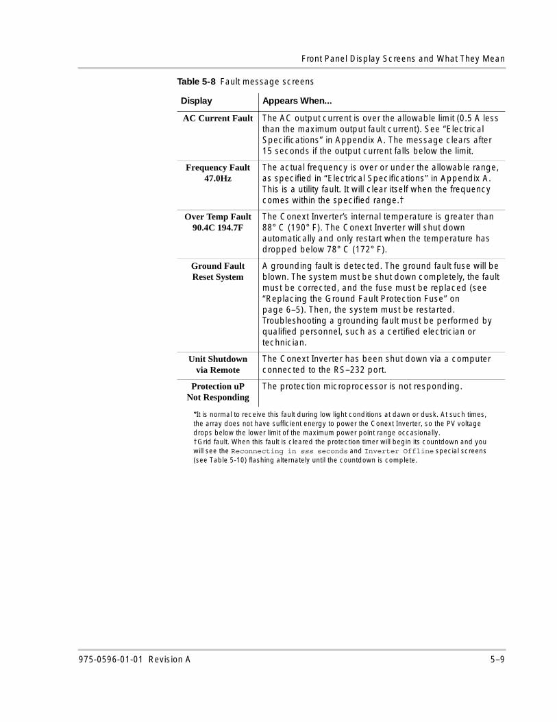
Front Panel Display Screens and What They Mean
AC Current Fault The AC output current is over the allowable limit (0.5 A less than the maximum output fault current). See “Electrical Specifications” in Appendix A. The message clears after 15 seconds if the output current falls below the limit.
Frequency Fault47.0Hz
The actual frequency is over or under the allowable range, as specified in “Electrical Specifications” in Appendix A. This is a utility fault. It will clear itself when the frequency comes within the specified range.†
Over Temp Fault90.4C 194.7F
The Conext Inverter’s internal temperature is greater than 88° C (190° F). The Conext Inverter will shut down automatically and only restart when the temperature has dropped below 78° C (172° F).
Ground FaultReset System
A grounding fault is detected. The ground fault fuse will be blown. The system must be shut down completely, the fault must be corrected, and the fuse must be replaced (see “Replacing the Ground Fault Protection Fuse” on page 6–5). Then, the system must be restarted. Troubleshooting a grounding fault must be performed by qualified personnel, such as a certified electrician or technician.
Unit Shutdownvia Remote
The Conext Inverter has been shut down via a computer connected to the RS–232 port.
Protection uPNot Responding
The protection microprocessor is not responding.
*It is normal to receive this fault during low light conditions at dawn or dusk. At such times, the array does not have sufficient energy to power the Conext Inverter, so the PV voltage drops below the lower limit of the maximum power point range occasionally.†Grid fault. When this fault is cleared the protection timer will begin its countdown and you will see the Reconnecting in sss seconds and Inverter Offline special screens (see Table 5-10) flashing alternately until the countdown is complete.
Table 5-8 Fault message screens
Display Appears When...
975-0596-01-01 Revision A 5–9
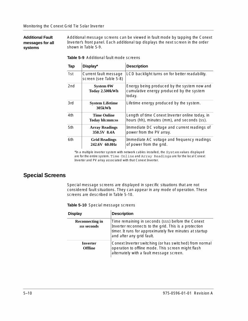
Monitoring the Conext Grid Tie Solar Inverter
Additional Fault messages for all systems
Additional message screens can be viewed in fault mode by tapping the Conext Inverter’s front panel. Each additional tap displays the next screen in the order shown in Table 5-9.
Special Screens
Special message screens are displayed in specific situations that are not considered fault situations. They can appear in any mode of operation. These screens are described in Table 5-10.
Table 5-9 Additional fault mode screens
Tap Display*
*In a multiple inverter system with network cables installed, the System values displayed are for the entire system. Time Online and Array Readings are for the local Conext Inverter and PV array associated with that Conext Inverter.
Description
1st Current fault message screen (see Table 5-8)
LCD backlight turns on for better readability.
2nd System 0WToday 2.500kWh
Energy being produced by the system now and cumulative energy produced by the system today.
3rd System Lifetime305kWh
Lifetime energy produced by the system.
4th Time OnlineToday hh:mm:ss
Length of time Conext Inverter online today, in hours (hh), minutes (mm), and seconds (ss).
5th Array Readings350.5V 8.4A
Immediate DC voltage and current readings of power from the PV array.
6th Grid Readings242.6V 60.0Hz
Immediate AC voltage and frequency readings of power from the grid.
Table 5-10 Special message screens
Display Description
Reconnecting insss seconds
Time remaining in seconds (sss) before the Conext Inverter reconnects to the grid. This is a protection timer. It runs for approximately five minutes at startup and after any grid fault.
InverterOffline
Conext Inverter switching (or has switched) from normal operation to offline mode. This screen might flash alternately with a fault message screen.
5–10 975-0596-01-01 Revision A
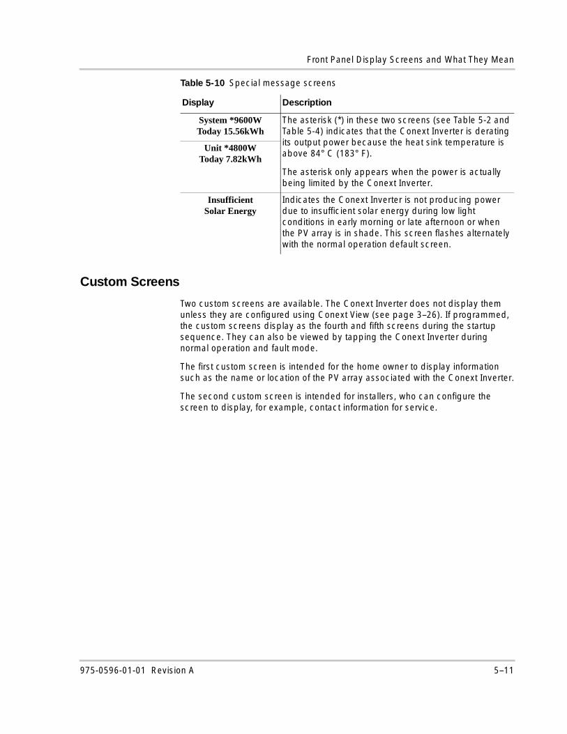
Front Panel Display Screens and What They Mean
Custom Screens
Two custom screens are available. The Conext Inverter does not display them unless they are configured using Conext View (see page 3–26). If programmed, the custom screens display as the fourth and fifth screens during the startup sequence. They can also be viewed by tapping the Conext Inverter during normal operation and fault mode.
The first custom screen is intended for the home owner to display information such as the name or location of the PV array associated with the Conext Inverter.
The second custom screen is intended for installers, who can configure the screen to display, for example, contact information for service.
System *9600WToday 15.56kWh
The asterisk (*) in these two screens (see Table 5-2 and Table 5-4) indicates that the Conext Inverter is derating its output power because the heat sink temperature is above 84° C (183° F).
The asterisk only appears when the power is actually being limited by the Conext Inverter.
Unit *4800WToday 7.82kWh
InsufficientSolar Energy
Indicates the Conext Inverter is not producing power due to insufficient solar energy during low light conditions in early morning or late afternoon or when the PV array is in shade. This screen flashes alternately with the normal operation default screen.
Table 5-10 Special message screens
Display Description
975-0596-01-01 Revision A 5–11
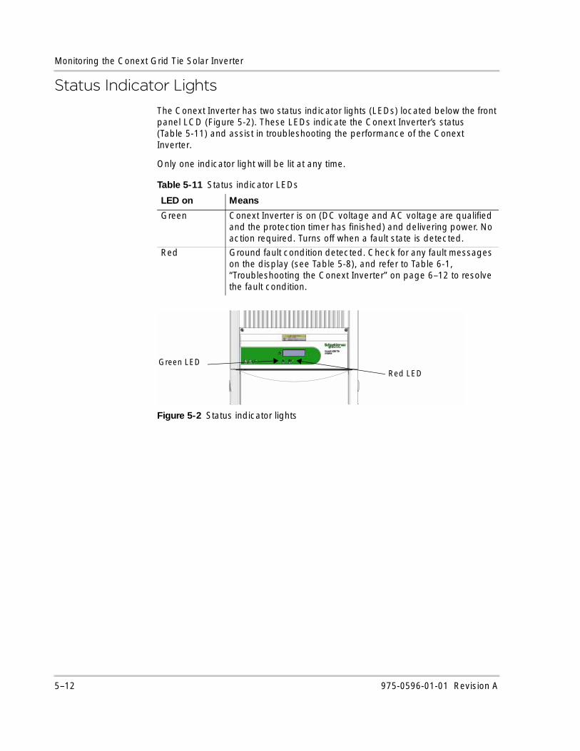
Monitoring the Conext Grid Tie Solar Inverter
Status Indicator LightsThe Conext Inverter has two status indicator lights (LEDs) located below the front panel LCD (Figure 5-2). These LEDs indicate the Conext Inverter’s status (Table 5-11) and assist in troubleshooting the performance of the Conext Inverter.
Only one indicator light will be lit at any time.
Table 5-11 Status indicator LEDs
LED on Means
Green Conext Inverter is on (DC voltage and AC voltage are qualified and the protection timer has finished) and delivering power. No action required. Turns off when a fault state is detected.
Red Ground fault condition detected. Check for any fault messages on the display (see Table 5-8), and refer to Table 6-1, “Troubleshooting the Conext Inverter” on page 6–12 to resolve the fault condition.
Figure 5-2 Status indicator lights
Green LEDRed LED
5–12 975-0596-01-01 Revision A
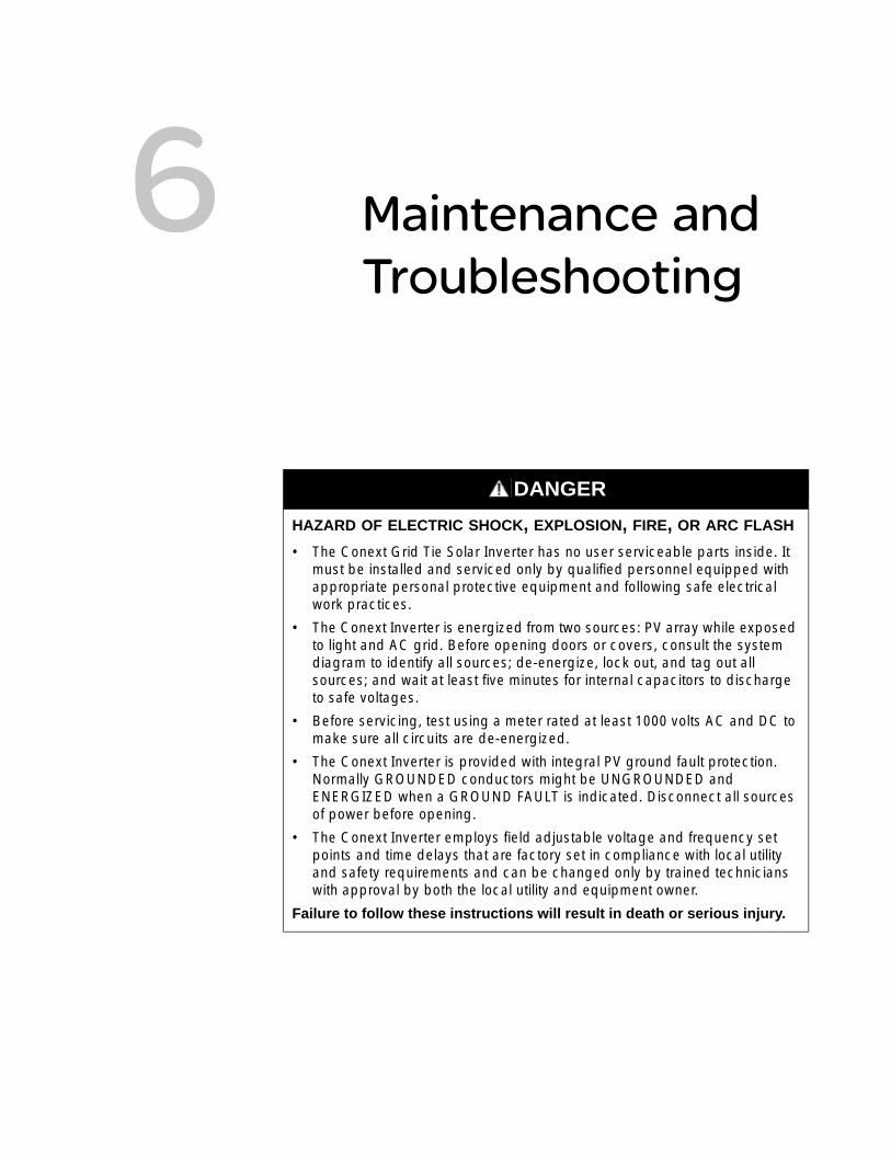
6 Maintenance and Troubleshooting
DANGER
HAZARD OF ELECTRIC SHOCK, EXPLOSION, FIRE, OR ARC FLASH
• The Conext Grid Tie Solar Inverter has no user serviceable parts inside. It must be installed and serviced only by qualified personnel equipped with appropriate personal protective equipment and following safe electrical work practices.
• The Conext Inverter is energized from two sources: PV array while exposed to light and AC grid. Before opening doors or covers, consult the system diagram to identify all sources; de-energize, lock out, and tag out all sources; and wait at least five minutes for internal capacitors to discharge to safe voltages.
• Before servicing, test using a meter rated at least 1000 volts AC and DC to make sure all circuits are de-energized.
• The Conext Inverter is provided with integral PV ground fault protection. Normally GROUNDED conductors might be UNGROUNDED and ENERGIZED when a GROUND FAULT is indicated. Disconnect all sources of power before opening.
• The Conext Inverter employs field adjustable voltage and frequency set points and time delays that are factory set in compliance with local utility and safety requirements and can be changed only by trained technicians with approval by both the local utility and equipment owner.
Failure to follow these instructions will result in death or serious injury.
Maintenance and Troubleshooting
Chapter 6 contains information on general maintenance of the Conext Grid Tie Solar Inverter. It also provides information about troubleshooting the Conext Inverter.
The topics in this chapter are organized as follows:• “Factors Affecting Conext Grid Tie Solar
Inverter Performance” on page 6–2• “Performing General Maintenance” on
page 6–4• “Replacing Parts” on page 6–4• “Identifying Error/Fault Conditions and
Solutions” on page 6–11.
Factors Affecting Conext Grid Tie Solar Inverter Performance
This section describes several factors that affect the amount of power a properly installed and operating Conext Inverter can produce.
PV Array Factors
PV array ratings PV arrays are rated under standardized conditions, such as specified illumination (1000 W/m2), spectrum of the light, and specified temperature (77 °F / 25 °C), which seldom reflect real-world installations. This is called the STC (Standard Test Condition) rating and is the figure that appears on the PV module nameplate label.
Expected performance
Due to several unavoidable environmental factors, you can expect your PV array to produce around 60% to 70% of its peak STC-rated output for a properly designed and installed PV system on a typical day.
Temperature and reduced output
PV array temperature affects the output of the entire system. As the temperature on the array surface rises, its energy output decreases. Roof-mounted arrays also collect the heat generated by the roof surface (or trapped under the array) and will produce less output than pole-mounted arrays, which allow greater air circulation behind the panels.
6–2 975-0596-01-01 Revision A
This chapter is for use by qualified personnel only.
Factors Affecting Conext Grid Tie Solar Inverter Performance
Angle of the sun The angle of the sun in relation to the PV array surface—the array orientation—can dramatically affect the PV array output. The array energy output will vary depending on the time of day and time of year as the sun’s angle in relation to the array changes. Incident sunlight decreases when the sun is near the horizons (such as in winter in North America) due to the greater atmospheric air mass that must be penetrated. This reduces both the light intensity that strikes the array’s surface and the spectrum of the light. In general, you can expect only four to six hours of direct sunlight per day.
Partial shade Shading of only a single module of the array will reduce the output of the entire system. Such shading can be caused by something as simple as the shadow of a utility wire or tree branch on part of the array’s surface. This condition acts like a weak battery in a flashlight, reducing the total output even though the other batteries are good. However, the output loss is not proportional to the shading.
The Conext Inverter is designed to maximize its energy production in all of the above situations using its MPPT algorithm. The shade tolerance algorithm can be enabled and disabled using Conext View. For instructions, see the Conext View User’s Guide (Document Part Number 975-0611-01-01) available with the software. For information on installing Conext View, see “Communications Wiring for Monitoring a Single Conext Grid Tie Solar Inverter” on page 3–26. For more information on shade-tolerant MPPT optimization, see the white paper, “Photovoltaic String Inverters and Shade-Tolerant Maximum Power Point Tracking: Toward Optimal Harvest Efficiency and Maximum ROI” for more information, available at http://www.se-renbu-docs.com/SEShadeTolerantWP.pdf.
Other Factors
Other factors that contribute to system losses are:
• Dust or dirt on the array
• Fog or smog
• Mismatched PV array modules, with slight inconsistencies in performance from one module to another
• Conext Inverter efficiency
• Wire losses
• Utility grid voltage
For additional information and technical notes concerning PV array performance, see www.schneider-electric.com.
NOTICE
The Conext Inverter will reduce its energy output to help protect its electronic circuits from overheating and to help protect from possible damage in high heat conditions. For maximum output in hot climates, mount the Conext Inverter in a shaded location with good air flow.
975-0596-01-01 Revision A 6–3
This chapter is for use by qualified personnel only.
Maintenance and Troubleshooting
Performing General Maintenance
Follow these simple routines to ensure many years of service and optimal performance of your solar energy system:
• Keep the heat sink clear of dust and debris.
• Clean the PV array during the cool part of the day whenever it is visibly dirty.
• Periodically inspect the system to make sure that all wiring and supports are securely in place.
• Maintain a log of system performance readings so that you can recognize when system performance becomes inconsistent.
Replacing Parts
DANGER
HAZARD OF ELECTRIC SHOCK, EXPLOSION, FIRE, OR ARC FLASH
• Use caution when working around sources of DC power. Although the DC/AC disconnect switch disconnects the Conext Inverter from DC power, hazardous voltages from paralleled PV strings will still be present upstream of the switch and inside the wiring box. Isolate or disconnect all sources of electricity before making any connections, make sure the DC/AC disconnect switch is set to OFF (see Figure 3-10 on page 3–11), and always test for voltage before touching exposed wiring or devices. If the system does not provide a PV disconnect device, cover the PV array with opaque (dark) material.
• Before attempting any maintenance or cleaning or working on any circuits connected to the Conext Inverter, consult the system diagram to identify all sources and then de-energize, lock out, and tag out all sources. Internal capacitors remain charged for five minutes after disconnecting all sources of power.
• Do not use a pressure washer to clean the Conext Inverter, and do not use other cleaning methods that could allow water to enter the Conext Inverter.
Failure to follow these instructions will result in death or serious injury.
DANGERshock
HAZARD OF ELECTRIC SHOCK, EXPLOSION, FIRE, OR ARC FLASH
The Conext Grid Tie Solar Inverter has no user serviceable parts inside. It must be installed and serviced only by qualified personnel equipped with appropriate personal protective equipment and following safe electrical work practices.
Failure to follow these instructions will result in death or serious injury.
6–4 975-0596-01-01 Revision A
This chapter is for use by qualified personnel only.
Replacing Parts
See “Warranty and Return Information” on page WA–1 for information on how to get service for your Conext Inverter.
Replacing the Ground Fault Protection Fuse
The ground fault protection fuse will blow when excessive leakage current occurs between the PV array and earth ground or when the system has been installed with deficient wiring. Before replacing the fuse, it is important to have qualified service personnel, such as a certified electrician or technician, determine the cause of the ground fault. The Conext Inverter also has an AC overcurrent protection fuse (see Figure 6-2 on page 6–7) that also must be replaced only by qualified service personnel.
To replace a ground fault protection fuse:
1. Isolate or disconnect all sources of electricity, turn the DC/AC disconnect switch OFF, and turn the AC breaker in the main utility service panel OFF. If the system does not provide a PV disconnect device, cover the PV array with opaque (dark) material.
2. Remove the wiring/disconnect box cover, as described on page 3–8.
DANGER
HAZARD OF ELECTRIC SHOCK, EXPLOSION, FIRE, OR ARC FLASH
• Conext Inverter fuses must be replaced only by qualified service personnel, such as a certified electrician or technician using appropriate personal protective equipment and following safe work procedures.
• After disconnecting both AC and DC power from the Conext Inverter, wait five minutes before attempting troubleshooting or maintenance on any circuits connected to the Conext Inverter to allow internal capacitors to discharge to a safe state.
• Isolate or disconnect all sources of electricity during this procedure. If the system does not provide a PV disconnect device, cover the PV array with opaque (dark) material. Otherwise, leakage current from the ungrounded conductor to ground at the array can cause the grounded lead to become a shock hazard even with the DC/AC disconnect switch turned OFF.
• Use insulated fuse pullers or fuse holders.
Failure to follow these instructions will result in death or serious injury.
WARNING
HAZARD OF FIRE
For continued protection against risk of fire, replace only with same type and rating of fuse. Use UL/CSA listed fuses only.
Failure to follow these instructions can result in death or serious injury.
975-0596-01-01 Revision A 6–5
This chapter is for use by qualified personnel only.
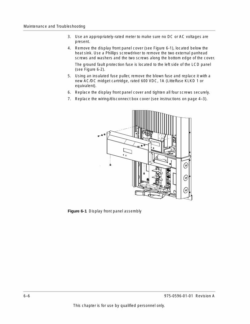
Maintenance and Troubleshooting
3. Use an appropriately-rated meter to make sure no DC or AC voltages are present.
4. Remove the display front panel cover (see Figure 6-1), located below the heat sink. Use a Phillips screwdriver to remove the two external panhead screws and washers and the two screws along the bottom edge of the cover.
The ground fault protection fuse is located to the left side of the LCD panel (see Figure 6-2).
5. Using an insulated fuse puller, remove the blown fuse and replace it with a new AC/DC midget cartridge, rated 600 VDC, 1A (Littelfuse KLKD 1 or equivalent).
6. Replace the display front panel cover and tighten all four screws securely.
7. Replace the wiring/disconnect box cover (see instructions on page 4–3).
Figure 6-1 Display front panel assembly
6–6 975-0596-01-01 Revision A
This chapter is for use by qualified personnel only.
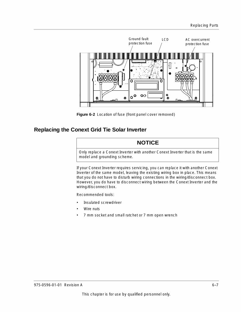
Replacing Parts
Replacing the Conext Grid Tie Solar Inverter
If your Conext Inverter requires servicing, you can replace it with another Conext Inverter of the same model, leaving the existing wiring box in place. This means that you do not have to disturb wiring connections in the wiring/disconnect box. However, you do have to disconnect wiring between the Conext Inverter and the wiring/disconnect box.
Recommended tools:
• Insulated screwdriver
• Wire nuts
• 7 mm socket and small ratchet or 7 mm open wrench
Figure 6-2 Location of fuse (front panel cover removed)
NOTICE
Only replace a Conext Inverter with another Conext Inverter that is the same model and grounding scheme.
AC overcurrent protection fuse
Ground fault protection fuse
LCD
975-0596-01-01 Revision A 6–7
This chapter is for use by qualified personnel only.
Maintenance and Troubleshooting
To remove the Conext Inverter from the wiring box:
1. Turn OFF the AC breaker in the main utility service panel and the DC/AC disconnect switch on the Conext Inverter. Isolate or disconnect all sources of electricity. If the system does not provide a PV disconnect device, cover the PV array with opaque (dark) material.
2. Remove the wiring/disconnect box cover, and then remove the display front panel cover (see Figure 3-4 on page 3–8 and Figure 6-1 on page 6–6).
3. Use an appropriately rated meter to check that no DC or AC voltages are present at the disconnect box input terminals and Conext Inverter terminal blocks.
4. Disconnect any network cables from the Conext Inverter.
5. Label the DC and AC wires connected to the Conext Inverter terminal blocks so they can be installed in the correct location on the replacement Conext Inverter.
6. Disconnect all DC and AC wires from the Conext Inverter terminal blocks, pull the wires into the wiring/disconnect box, and cap all disconnected AC and DC wire ends with wire nuts.
DANGER
HAZARD OF ELECTRIC SHOCK, EXPLOSION, FIRE, OR ARC FLASH
• Replacement of the Conext Inverter must be done only by qualified service personnel, such as a certified electrician or technician using appropriate personal protective equipment and following safe electrical work practices.
• The Conext Inverter is energized from two sources: PV array while exposed to light and AC grid. Before opening doors or covers, consult the system diagram to identify all sources; de-energize, lock out, and tag out all sources.
• After disconnecting both DC and AC power from the Conext Inverter, wait five minutes before attempting troubleshooting or maintenance on any circuit connected to the Conext Inverter. This will allow internal capacitors to discharge to a safe state.
• Turn OFF the AC breaker in the main utility service panel and the DC/AC disconnect switch on the Conext Inverter. Isolate or disconnect all sources of electricity. If the system does not provide a PV disconnect device, cover the PV array with opaque (dark) material. Otherwise, leakage current from the ungrounded conductor to ground at the array can cause the grounded lead to become a shock hazard even with the DC/AC disconnect switch turned OFF.
• The Conext Inverter should be removed from the wiring box only when a replacement Conext Inverter is immediately available. Do not leave the top of the wiring box exposed for extended periods of time.
Failure to follow these instructions will result in death or serious injury.
6–8 975-0596-01-01 Revision A
This chapter is for use by qualified personnel only.
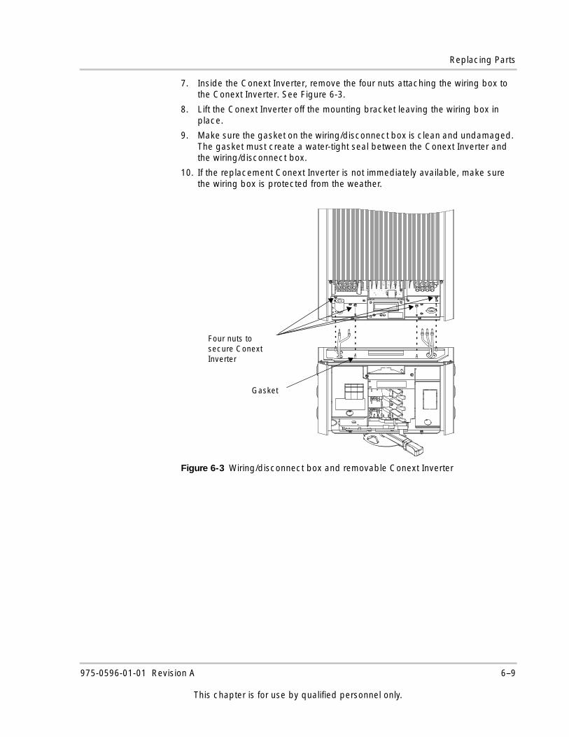
Replacing Parts
7. Inside the Conext Inverter, remove the four nuts attaching the wiring box to the Conext Inverter. See Figure 6-3.
8. Lift the Conext Inverter off the mounting bracket leaving the wiring box in place.
9. Make sure the gasket on the wiring/disconnect box is clean and undamaged. The gasket must create a water-tight seal between the Conext Inverter and the wiring/disconnect box.
10. If the replacement Conext Inverter is not immediately available, make sure the wiring box is protected from the weather.
Figure 6-3 Wiring/disconnect box and removable Conext Inverter
Four nuts to secure Conext Inverter
Gasket
975-0596-01-01 Revision A 6–9
This chapter is for use by qualified personnel only.
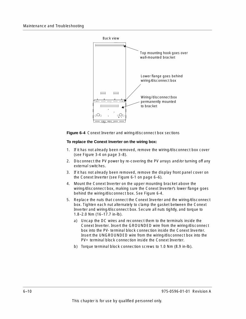
Maintenance and Troubleshooting
To replace the Conext Inverter on the wiring box:
1. If it has not already been removed, remove the wiring/disconnect box cover (see Figure 3-4 on page 3–8).
2. Disconnect the PV power by re-covering the PV arrays and/or turning off any external switches.
3. If it has not already been removed, remove the display front panel cover on the Conext Inverter (see Figure 6-1 on page 6–6).
4. Mount the Conext Inverter on the upper mounting bracket above the wiring/disconnect box, making sure the Conext Inverter’s lower flange goes behind the wiring/disconnect box. See Figure 6-4.
5. Replace the nuts that connect the Conext Inverter and the wiring/disconnect box. Tighten each nut alternately to clamp the gasket between the Conext Inverter and wiring/disconnect box. Secure all nuts tightly, and torque to 1.8–2.0 Nm (16–17.7 in-lb).
a) Uncap the DC wires and reconnect them to the terminals inside the Conext Inverter. Insert the GROUNDED wire from the wiring/disconnect box into the PV- terminal block connection inside the Conext Inverter. Insert the UNGROUNDED wire from the wiring/disconnect box into the PV+ terminal block connection inside the Conext Inverter.
b) Torque terminal block connection screws to 1.0 Nm (8.9 in-lb).
Figure 6-4 Conext Inverter and wiring/disconnect box sections
Wiring/ disconnect box permanently mounted to bracket
Lower flange goes behind wiring/disconnect box
Back view
Top mounting hook goes over wall-mounted bracket
6–10 975-0596-01-01 Revision A
This chapter is for use by qualified personnel only.
Identifying Error/Fault Conditions and Solutions
6. Uncap the AC wires and reconnect them to the terminals inside the Conext Inverter:
a) Insert the BLACK wire from the wiring/disconnect box into the L1 terminal block connection inside the Conext Inverter.
b) Insert the RED wire from the wiring/disconnect box into the L2 terminal block connection inside the Conext Inverter.
c) Insert the WHITE wire from the wiring/disconnect box into the Neutral terminal block connection inside the Conext Inverter.
d) Torque terminal block connection screws to 1.0 Nm (8.9 in-lb).
7. Re-connect any communications cables, and then make sure all connections are correctly wired and secured. Re-install the display front panel cover and wiring/disconnect box cover.
8. Follow the startup procedure as described on page 4–2.
Identifying Error/Fault Conditions and Solutions
Most error or fault conditions will be identified by fault message screens on the Conext Inverter’s front panel LCD. These are described in the “Fault Mode” section on page 5–8 of this manual. Most of these fault conditions are self-correcting and require no action to remedy. See “Front Panel Display Screens and What They Mean” on page 5–3 for more information.
DANGER
HAZARD OF ELECTRIC SHOCK, EXPLOSION, FIRE, OR ARC FLASH
Only qualified personnel equipped with appropriate personal protective equipment and following safe electrical practices should attempt to troubleshoot the Conext Inverter.
Failure to follow these instructions will result in death or serious injury.
975-0596-01-01 Revision A 6–11
This chapter is for use by qualified personnel only.
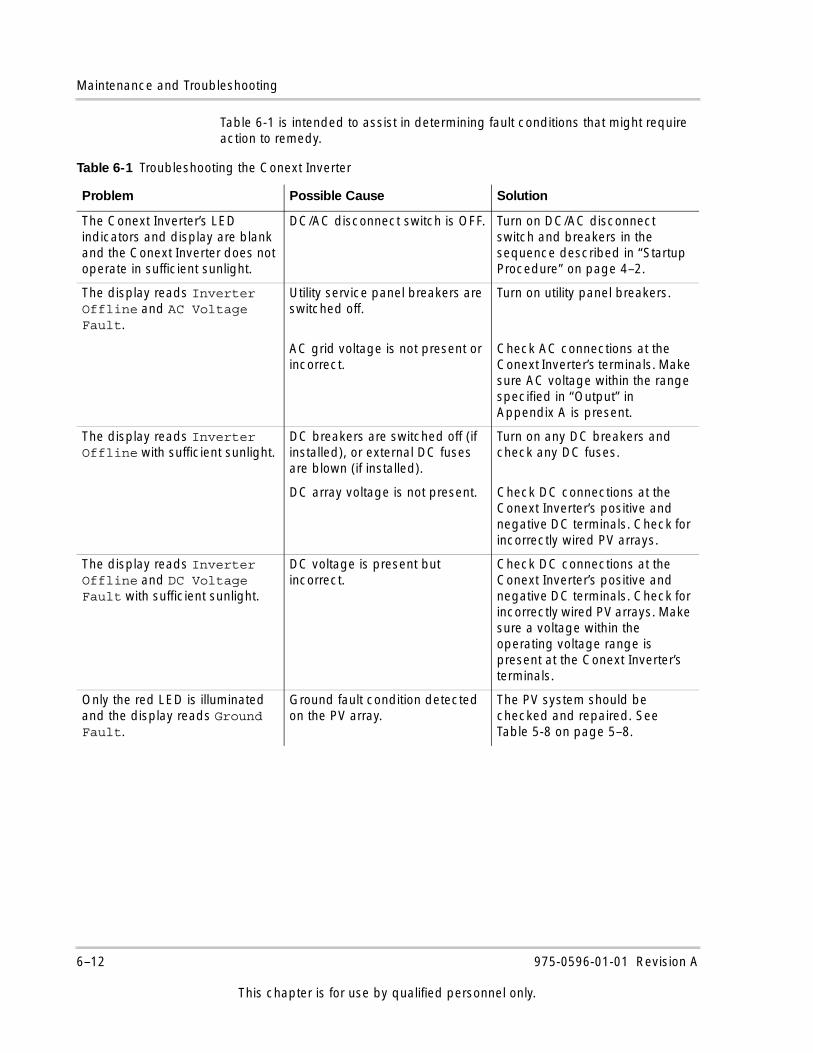
Maintenance and Troubleshooting
Table 6-1 is intended to assist in determining fault conditions that might require action to remedy.
Table 6-1 Troubleshooting the Conext Inverter
Problem Possible Cause Solution
The Conext Inverter’s LED indicators and display are blank and the Conext Inverter does not operate in sufficient sunlight.
DC/AC disconnect switch is OFF. Turn on DC/AC disconnect switch and breakers in the sequence described in “Startup Procedure” on page 4–2.
The display reads Inverter Offline and AC Voltage Fault.
Utility service panel breakers are switched off.
Turn on utility panel breakers.
AC grid voltage is not present or incorrect.
Check AC connections at the Conext Inverter’s terminals. Make sure AC voltage within the range specified in “Output” in Appendix A is present.
The display reads Inverter Offline with sufficient sunlight.
DC breakers are switched off (if installed), or external DC fuses are blown (if installed).
Turn on any DC breakers and check any DC fuses.
DC array voltage is not present. Check DC connections at the Conext Inverter’s positive and negative DC terminals. Check for incorrectly wired PV arrays.
The display reads Inverter Offline and DC Voltage Fault with sufficient sunlight.
DC voltage is present but incorrect.
Check DC connections at the Conext Inverter’s positive and negative DC terminals. Check for incorrectly wired PV arrays. Make sure a voltage within the operating voltage range is present at the Conext Inverter’s terminals.
Only the red LED is illuminated and the display reads Ground Fault.
Ground fault condition detected on the PV array.
The PV system should be checked and repaired. See Table 5-8 on page 5–8.
6–12 975-0596-01-01 Revision A
This chapter is for use by qualified personnel only.
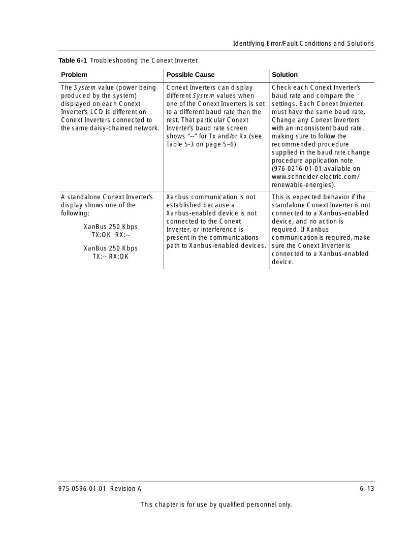
Identifying Error/Fault Conditions and Solutions
The System value (power being produced by the system) displayed on each Conext Inverter’s LCD is different on Conext Inverters connected to the same daisy-chained network.
Conext Inverters can display different System values when one of the Conext Inverters is set to a different baud rate than the rest. That particular Conext Inverter’s baud rate screen shows “--” for Tx and/or Rx (see Table 5-3 on page 5–6).
Check each Conext Inverter’s baud rate and compare the settings. Each Conext Inverter must have the same baud rate. Change any Conext Inverters with an inconsistent baud rate, making sure to follow the recommended procedure supplied in the baud rate change procedure application note (976-0216-01-01 available on www.schneider-electric.com/renewable-energies).
A standalone Conext Inverter’s display shows one of the following:
XanBus 250 KbpsTX:OK RX:--
XanBus 250 KbpsTX:-- RX:OK
Xanbus communication is not established because a Xanbus-enabled device is not connected to the Conext Inverter, or interference is present in the communications path to Xanbus-enabled devices.
This is expected behavior if the standalone Conext Inverter is not connected to a Xanbus-enabled device, and no action is required. If Xanbus communication is required, make sure the Conext Inverter is connected to a Xanbus-enabled device.
Table 6-1 Troubleshooting the Conext Inverter
Problem Possible Cause Solution
975-0596-01-01 Revision A 6–13
This chapter is for use by qualified personnel only.

6–14
A Specifications
Appendix A contains specifications for the Conext Grid Tie Solar Inverter.
The topics in this appendix are organized as follows:• “Electrical Specifications” on page A–2• “Output Power Versus Ambient
Temperature” on page A–13• “Environmental Specifications” on
page A–13• “User Display” on page A–13• “Mechanical Specifications” on
page A–14• “Regulatory Approvals” on page A–14
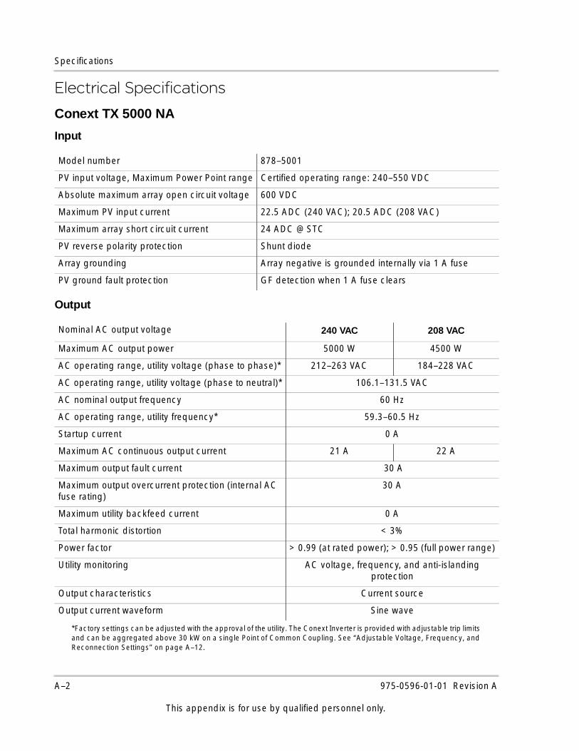
Specifications
Electrical Specifications
Conext TX 5000 NA
Input
Output
Model number 878–5001
PV input voltage, Maximum Power Point range Certified operating range: 240–550 VDC
Absolute maximum array open circuit voltage 600 VDC
Maximum PV input current 22.5 ADC (240 VAC); 20.5 ADC (208 VAC)
Maximum array short circuit current 24 ADC @ STC
PV reverse polarity protection Shunt diode
Array grounding Array negative is grounded internally via 1 A fuse
PV ground fault protection GF detection when 1 A fuse clears
Nominal AC output voltage 240 VAC 208 VAC
Maximum AC output power 5000 W 4500 W
AC operating range, utility voltage (phase to phase)*
*Factory settings can be adjusted with the approval of the utility. The Conext Inverter is provided with adjustable trip limits and can be aggregated above 30 kW on a single Point of Common Coupling. See “Adjustable Voltage, Frequency, and Reconnection Settings” on page A–12.
212–263 VAC 184–228 VAC
AC operating range, utility voltage (phase to neutral)* 106.1–131.5 VAC
AC nominal output frequency 60 Hz
AC operating range, utility frequency* 59.3–60.5 Hz
Startup current 0 A
Maximum AC continuous output current 21 A 22 A
Maximum output fault current 30 A
Maximum output overcurrent protection (internal AC fuse rating)
30 A
Maximum utility backfeed current 0 A
Total harmonic distortion < 3%
Power factor > 0.99 (at rated power); > 0.95 (full power range)
Utility monitoring AC voltage, frequency, and anti-islanding protection
Output characteristics Current source
Output current waveform Sine wave
A–2 975-0596-01-01 Revision A
This appendix is for use by qualified personnel only.
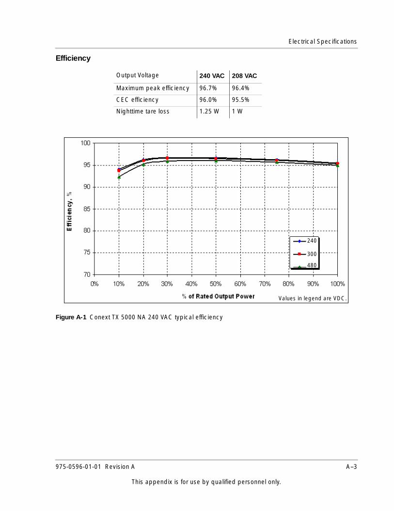
Electrical Specifications
Efficiency
Output Voltage 240 VAC 208 VAC
Maximum peak efficiency 96.7% 96.4%
CEC efficiency 96.0% 95.5%
Nighttime tare loss 1.25 W 1 W
Figure A-1 Conext TX 5000 NA 240 VAC typical efficiency
240
300
480
Values in legend are VDC.
975-0596-01-01 Revision A A–3
This appendix is for use by qualified personnel only.
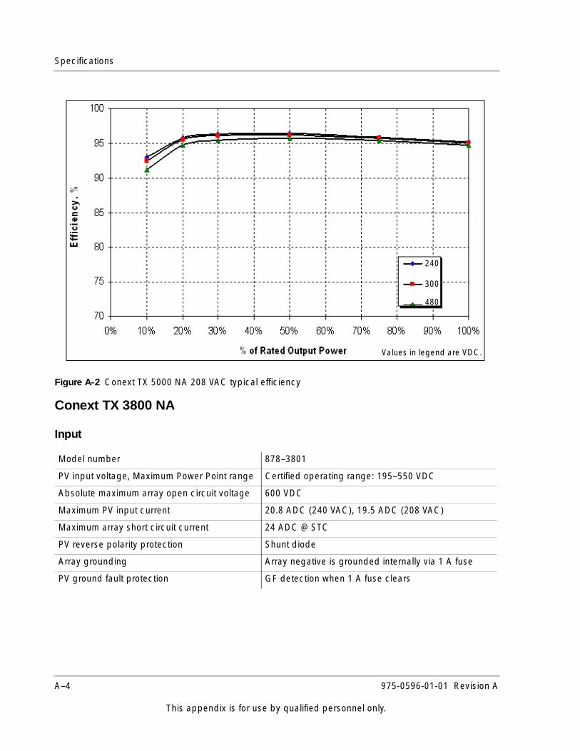
Specifications
Conext TX 3800 NA
Input
Figure A-2 Conext TX 5000 NA 208 VAC typical efficiency
Model number 878–3801
PV input voltage, Maximum Power Point range Certified operating range: 195–550 VDC
Absolute maximum array open circuit voltage 600 VDC
Maximum PV input current 20.8 ADC (240 VAC), 19.5 ADC (208 VAC)
Maximum array short circuit current 24 ADC @ STC
PV reverse polarity protection Shunt diode
Array grounding Array negative is grounded internally via 1 A fuse
PV ground fault protection GF detection when 1 A fuse clears
240
300
480
Values in legend are VDC.
A–4 975-0596-01-01 Revision A
This appendix is for use by qualified personnel only.
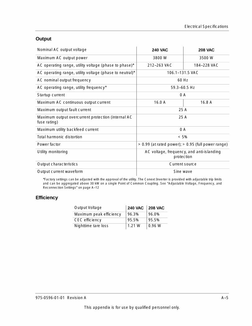
Electrical Specifications
Output
Efficiency
Nominal AC output voltage 240 VAC 208 VAC
Maximum AC output power 3800 W 3500 W
AC operating range, utility voltage (phase to phase)*
*Factory settings can be adjusted with the approval of the utility. The Conext Inverter is provided with adjustable trip limitsand can be aggregated above 30 kW on a single Point of Common Coupling. See “Adjustable Voltage, Frequency, andReconnection Settings” on page A–12
212–263 VAC 184–228 VAC
AC operating range, utility voltage (phase to neutral)* 106.1–131.5 VAC
AC nominal output frequency 60 Hz
AC operating range, utility frequency* 59.3–60.5 Hz
Startup current 0 A
Maximum AC continuous output current 16.0 A 16.8 A
Maximum output fault current 25 A
Maximum output overcurrent protection (internal AC fuse rating)
25 A
Maximum utility backfeed current 0 A
Total harmonic distortion < 5%
Power factor > 0.99 (at rated power); > 0.95 (full power range)
Utility monitoring AC voltage, frequency, and anti-islanding protection
Output characteristics Current source
Output current waveform Sine wave
Output Voltage 240 VAC 208 VAC
Maximum peak efficiency 96.3% 96.0%CEC efficiency 95.5% 95.5%Nighttime tare loss 1.21 W 0.96 W
975-0596-01-01 Revision A A–5
This appendix is for use by qualified personnel only.
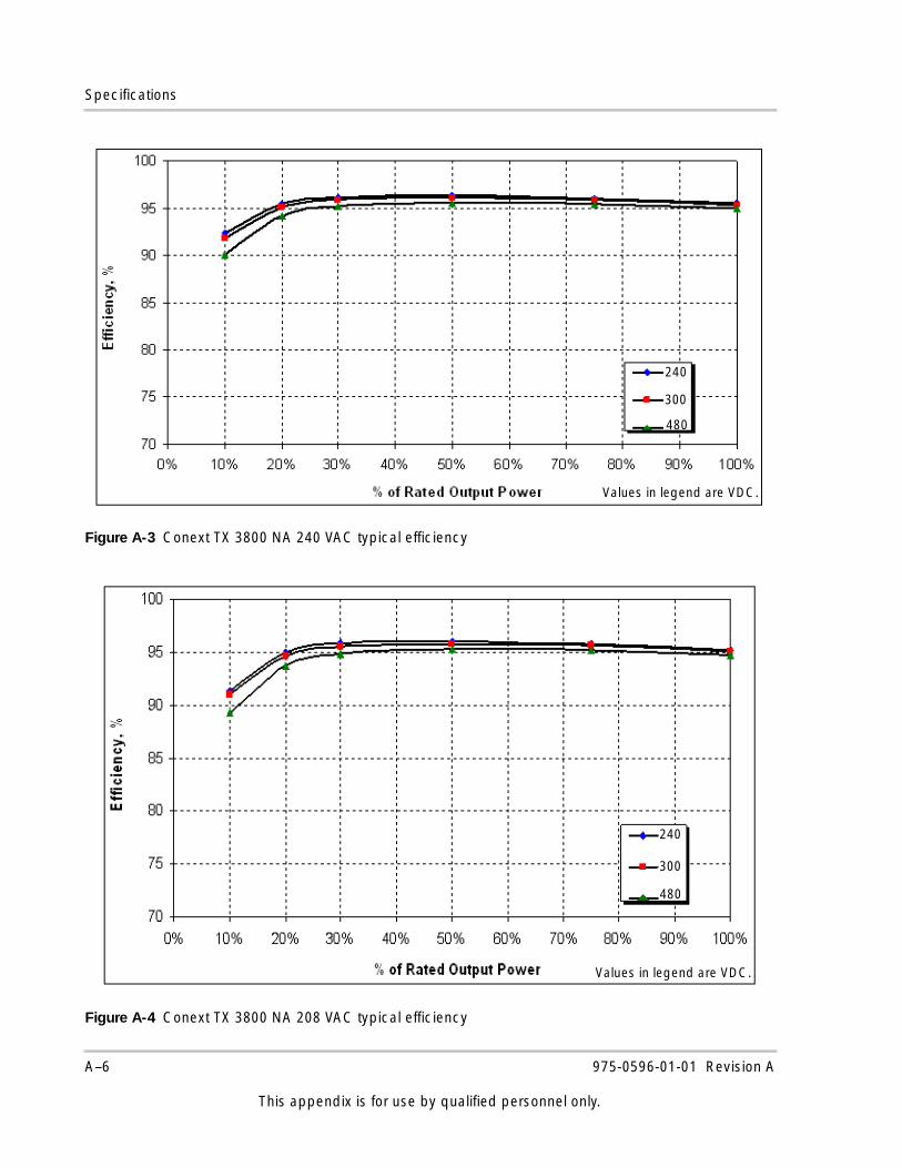
Specifications
Figure A-3 Conext TX 3800 NA 240 VAC typical efficiency
Figure A-4 Conext TX 3800 NA 208 VAC typical efficiency
240
300
480
Values in legend are VDC.
Values in legend are VDC.
240
300
480
A–6 975-0596-01-01 Revision A
This appendix is for use by qualified personnel only.
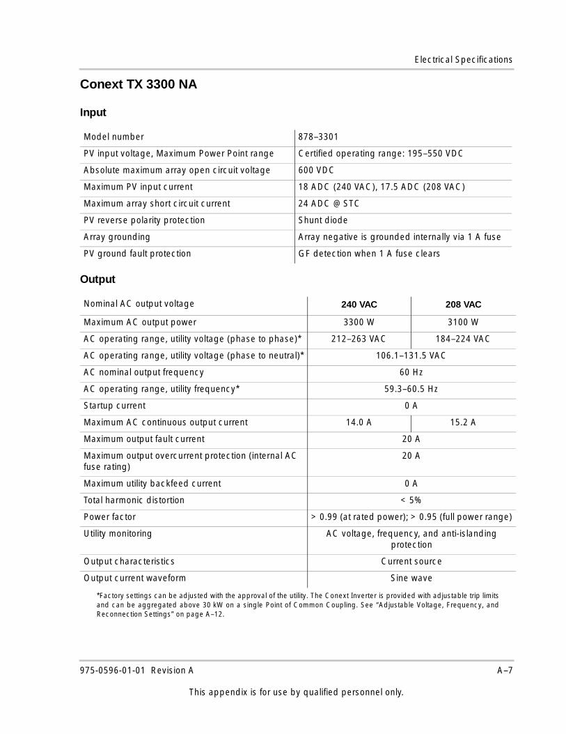
Electrical Specifications
Conext TX 3300 NA
Input
Output
Model number 878–3301
PV input voltage, Maximum Power Point range Certified operating range: 195–550 VDC
Absolute maximum array open circuit voltage 600 VDC
Maximum PV input current 18 ADC (240 VAC), 17.5 ADC (208 VAC)
Maximum array short circuit current 24 ADC @ STC
PV reverse polarity protection Shunt diode
Array grounding Array negative is grounded internally via 1 A fuse
PV ground fault protection GF detection when 1 A fuse clears
Nominal AC output voltage 240 VAC 208 VAC
Maximum AC output power 3300 W 3100 W
AC operating range, utility voltage (phase to phase)*
*Factory settings can be adjusted with the approval of the utility. The Conext Inverter is provided with adjustable trip limitsand can be aggregated above 30 kW on a single Point of Common Coupling. See “Adjustable Voltage, Frequency, andReconnection Settings” on page A–12.
212–263 VAC 184–224 VAC
AC operating range, utility voltage (phase to neutral)* 106.1–131.5 VAC
AC nominal output frequency 60 Hz
AC operating range, utility frequency* 59.3–60.5 Hz
Startup current 0 A
Maximum AC continuous output current 14.0 A 15.2 A
Maximum output fault current 20 A
Maximum output overcurrent protection (internal AC fuse rating)
20 A
Maximum utility backfeed current 0 A
Total harmonic distortion < 5%
Power factor > 0.99 (at rated power); > 0.95 (full power range)
Utility monitoring AC voltage, frequency, and anti-islanding protection
Output characteristics Current source
Output current waveform Sine wave
975-0596-01-01 Revision A A–7
This appendix is for use by qualified personnel only.
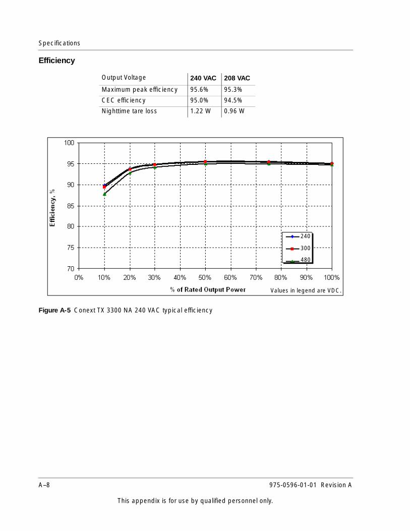
Specifications
Efficiency
Output Voltage 240 VAC 208 VAC
Maximum peak efficiency 95.6% 95.3%
CEC efficiency 95.0% 94.5%
Nighttime tare loss 1.22 W 0.96 W
Figure A-5 Conext TX 3300 NA 240 VAC typical efficiency
Values in legend are VDC.
240
300
480
A–8 975-0596-01-01 Revision A
This appendix is for use by qualified personnel only.
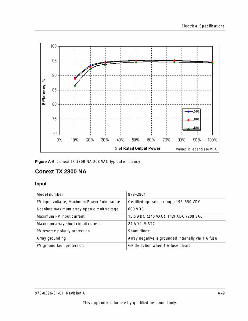
Electrical Specifications
Conext TX 2800 NA
Input
Figure A-6 Conext TX 3300 NA 208 VAC typical efficiency
Model number 878–2801
PV input voltage, Maximum Power Point range Certified operating range: 195–550 VDC
Absolute maximum array open circuit voltage 600 VDC
Maximum PV input current 15.5 ADC (240 VAC), 14.9 ADC (208 VAC)
Maximum array short circuit current 24 ADC @ STC
PV reverse polarity protection Shunt diode
Array grounding Array negative is grounded internally via 1 A fuse
PV ground fault protection GF detection when 1 A fuse clears
Values in legend are VDC.
240
300
480
975-0596-01-01 Revision A A–9
This appendix is for use by qualified personnel only.
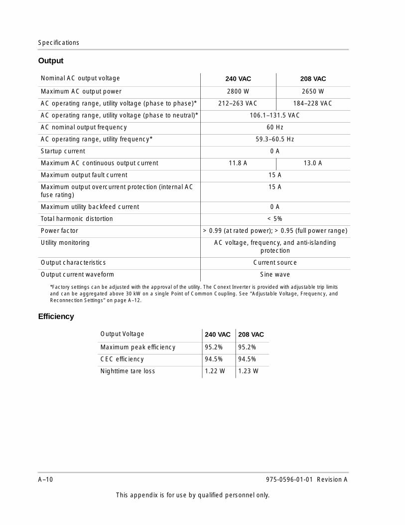
Specifications
Output
Efficiency
Nominal AC output voltage 240 VAC 208 VAC
Maximum AC output power 2800 W 2650 W
AC operating range, utility voltage (phase to phase)*
*Factory settings can be adjusted with the approval of the utility. The Conext Inverter is provided with adjustable trip limitsand can be aggregated above 30 kW on a single Point of Common Coupling. See “Adjustable Voltage, Frequency, andReconnection Settings” on page A–12.
212–263 VAC 184–228 VAC
AC operating range, utility voltage (phase to neutral)* 106.1–131.5 VAC
AC nominal output frequency 60 Hz
AC operating range, utility frequency* 59.3–60.5 Hz
Startup current 0 A
Maximum AC continuous output current 11.8 A 13.0 A
Maximum output fault current 15 A
Maximum output overcurrent protection (internal AC fuse rating)
15 A
Maximum utility backfeed current 0 A
Total harmonic distortion < 5%
Power factor > 0.99 (at rated power); > 0.95 (full power range)
Utility monitoring AC voltage, frequency, and anti-islanding protection
Output characteristics Current source
Output current waveform Sine wave
Output Voltage 240 VAC 208 VAC
Maximum peak efficiency 95.2% 95.2%
CEC efficiency 94.5% 94.5%
Nighttime tare loss 1.22 W 1.23 W
A–10 975-0596-01-01 Revision A
This appendix is for use by qualified personnel only.
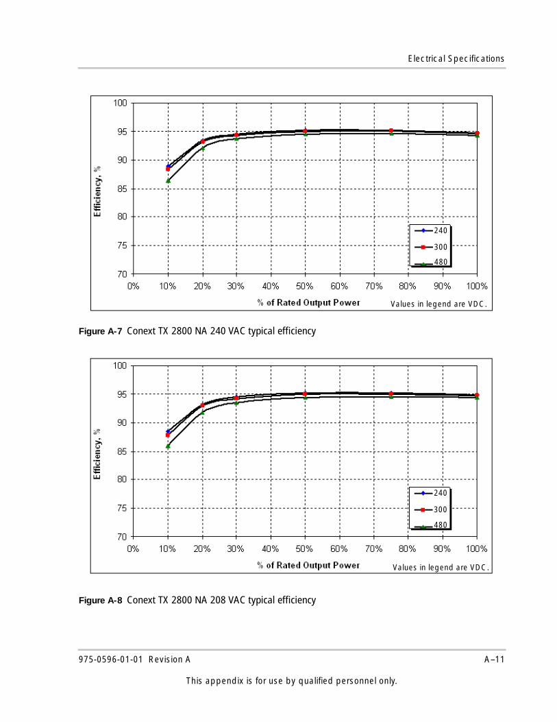
Electrical Specifications
Figure A-7 Conext TX 2800 NA 240 VAC typical efficiency
Figure A-8 Conext TX 2800 NA 208 VAC typical efficiency
Values in legend are VDC.
240
300
480
Values in legend are VDC.
240
300
480
975-0596-01-01 Revision A A–11
This appendix is for use by qualified personnel only.
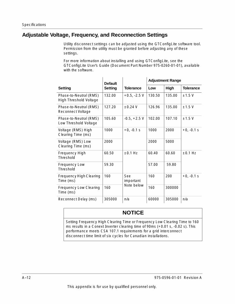
Specifications
Adjustable Voltage, Frequency, and Reconnection Settings
Utility disconnect settings can be adjusted using the GTConfigLite software tool. Permission from the utility must be granted before adjusting any of these settings.
For more information about installing and using GTConfigLite, see the GTConfigLite User’s Guide (Document Part Number 975-0260-01-01), available with the software.
SettingDefault Setting Tolerance
Adjustment Range
Low High Tolerance
Phase-to-Neutral (RMS) High Threshold Voltage
132.00 +0.5, -2.5 V 130.50 135.00 ±1.5 V
Phase-to-Neutral (RMS) Reconnect Voltage
127.20 ±0.24 V 126.96 135.00 ±1.5 V
Phase-to-Neutral (RMS) Low Threshold Voltage
105.60 -0.5, +2.5 V 102.00 107.10 ±1.5 V
Voltage (RMS) High Clearing Time (ms)
1000 +0, -0.1 s 1000 2000 +0, -0.1 s
Voltage (RMS) Low Clearing Time (ms)
2000 2000 5000
Frequency High Threshold
60.50 ±0.1 Hz 60.40 60.60 ±0.1 Hz
Frequency Low Threshold
59.30 57.00 59.80
Frequency High Clearing Time (ms)
160 See important Note below
160 200 +0, -0.1 s
Frequency Low Clearing Time (ms)
160 160 300000
Reconnect Delay (ms) 305000 n/a 60000 305000 n/a
NOTICE
Setting Frequency High Clearing Time or Frequency Low Clearing Time to 160 ms results in a Conext Inverter clearing time of 90ms (+0.01 s, -0.02 s). This performance meets CSA 107.1 requirements for a grid interconnect disconnect time limit of six cycles for Canadian installations.
A–12 975-0596-01-01 Revision A
This appendix is for use by qualified personnel only.
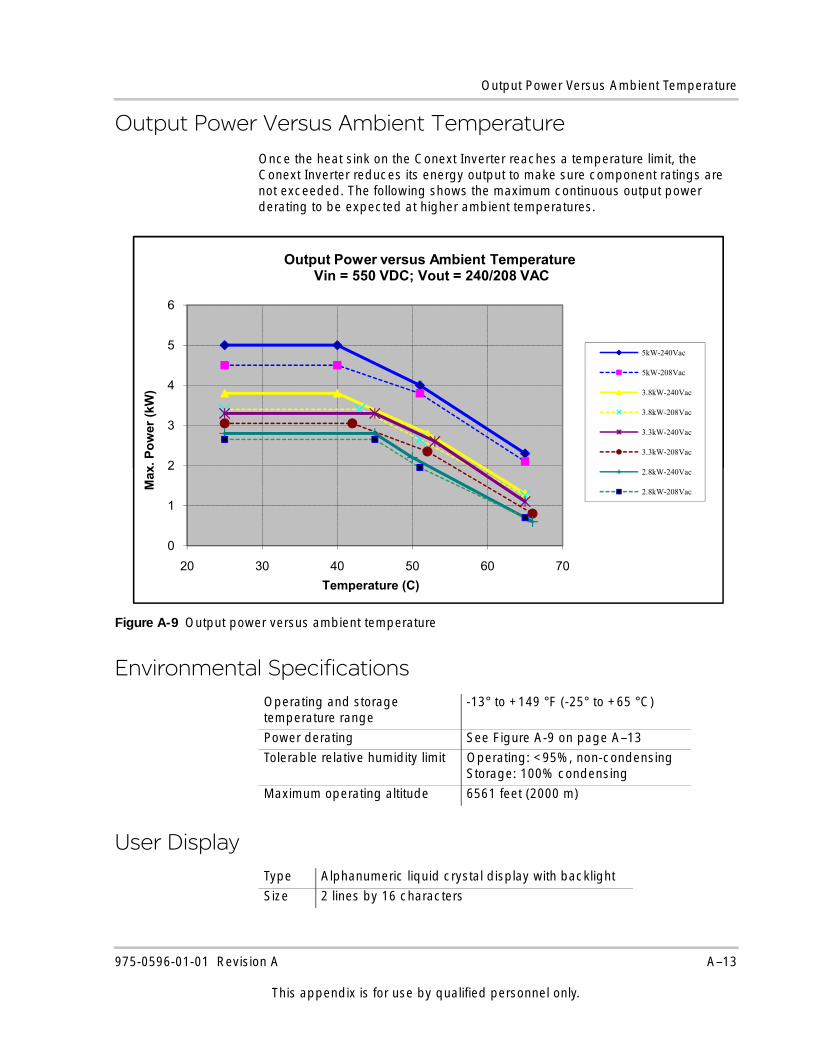
Output Power Versus Ambient Temperature
Output Power Versus Ambient TemperatureOnce the heat sink on the Conext Inverter reaches a temperature limit, the Conext Inverter reduces its energy output to make sure component ratings are not exceeded. The following shows the maximum continuous output power derating to be expected at higher ambient temperatures.
Environmental Specifications
User Display
Figure A-9 Output power versus ambient temperature
Operating and storage temperature range
-13° to +149 °F (-25° to +65 °C)
Power derating See Figure A-9 on page A–13
Tolerable relative humidity limit Operating: <95%, non-condensingStorage: 100% condensing
Maximum operating altitude 6561 feet (2000 m)
Type Alphanumeric liquid crystal display with backlight
Size 2 lines by 16 characters
2
3
4
5
6
x. P
ower
(kW
)
Output Power versus Ambient Temperature Vin = 550 VDC; Vout = 240/208 VAC
5kW-240Vac
5kW-208Vac
3.8kW-240Vac
3.8kW-208Vac
3.3kW-240Vac
3.3kW-208Vac
0
1
2
3
4
5
6
20 30 40 50 60 70
Max
. Pow
er (k
W)
Temperature (C)
Output Power versus Ambient Temperature Vin = 550 VDC; Vout = 240/208 VAC
5kW-240Vac
5kW-208Vac
3.8kW-240Vac
3.8kW-208Vac
3.3kW-240Vac
3.3kW-208Vac
2.8kW-240Vac
2.8kW-208Vac
975-0596-01-01 Revision A A–13
This appendix is for use by qualified personnel only.
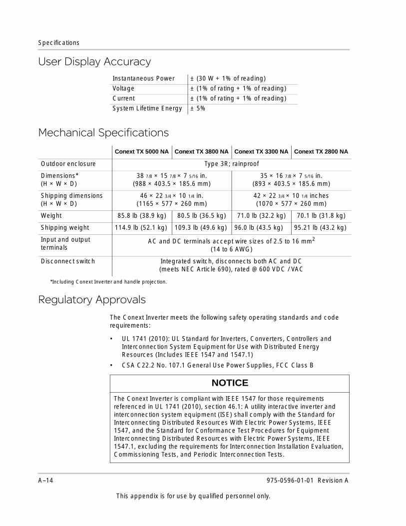
Specifications
User Display Accuracy
Mechanical Specifications
Regulatory Approvals
The Conext Inverter meets the following safety operating standards and code requirements:
• UL 1741 (2010): UL Standard for Inverters, Converters, Controllers and Interconnection System Equipment for Use with Distributed Energy Resources (Includes IEEE 1547 and 1547.1)
• CSA C22.2 No. 107.1 General Use Power Supplies, FCC Class B
Instantaneous Power ± (30 W + 1% of reading)
Voltage ± (1% of rating + 1% of reading)
Current ± (1% of rating + 1% of reading)
System Lifetime Energy ± 5%
Conext TX 5000 NA Conext TX 3800 NA Conext TX 3300 NA Conext TX 2800 NA
Outdoor enclosure Type 3R; rainproof
Dimensions* (H × W × D)
*Including Conext Inverter and handle projection.
38 7/8 × 15 7/8 × 7 5/16 in. (988 × 403.5 × 185.6 mm)
35 × 16 7/8 × 7 5/16 in.(893 × 403.5 × 185.6 mm)
Shipping dimensions(H × W × D)
46 × 22 3/4 × 10 1/4 in. (1165 × 577 × 260 mm)
42 × 22 3/4 × 10 1/4 inches (1070 × 577 × 260 mm)
Weight 85.8 lb (38.9 kg) 80.5 lb (36.5 kg) 71.0 lb (32.2 kg) 70.1 lb (31.8 kg)
Shipping weight 114.9 lb (52.1 kg) 109.3 lb (49.6 kg) 96.0 lb (43.5 kg) 95.21 lb (43.2 kg)
Input and output terminals
AC and DC terminals accept wire sizes of 2.5 to 16 mm2 (14 to 6 AWG)
Disconnect switch Integrated switch, disconnects both AC and DC (meets NEC Article 690), rated @ 600 VDC / VAC
NOTICE
The Conext Inverter is compliant with IEEE 1547 for those requirements referenced in UL 1741 (2010), section 46.1: A utility interactive inverter and interconnection system equipment (ISE) shall comply with the Standard for Interconnecting Distributed Resources With Electric Power Systems, IEEE 1547, and the Standard for Conformance Test Procedures for Equipment Interconnecting Distributed Resources with Electric Power Systems, IEEE 1547.1, excluding the requirements for Interconnection Installation Evaluation, Commissioning Tests, and Periodic Interconnection Tests.
A–14 975-0596-01-01 Revision A
This appendix is for use by qualified personnel only.
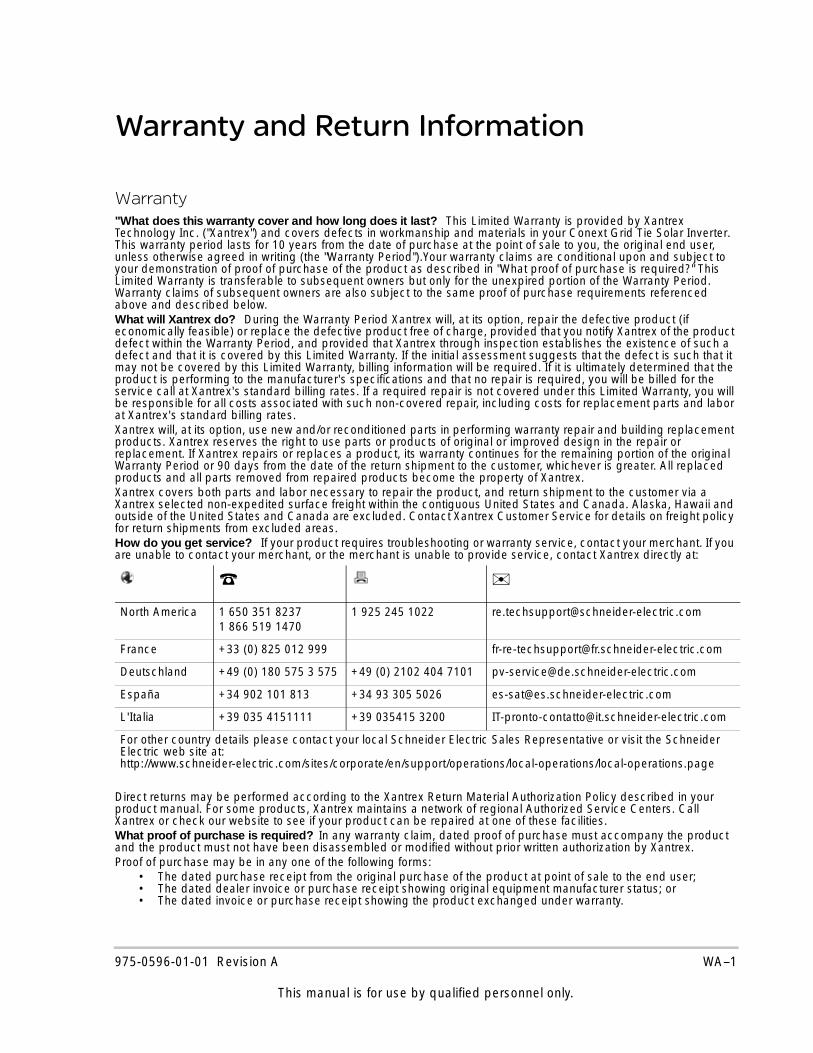
Warranty and Return Information
Warranty"What does this warranty cover and how long does it last? This Limited Warranty is provided by Xantrex Technology Inc. ("Xantrex") and covers defects in workmanship and materials in your Conext Grid Tie Solar Inverter. This warranty period lasts for 10 years from the date of purchase at the point of sale to you, the original end user, unless otherwise agreed in writing (the "Warranty Period").Your warranty claims are conditional upon and subject to your demonstration of proof of purchase of the product as described in "What proof of purchase is required?" This Limited Warranty is transferable to subsequent owners but only for the unexpired portion of the Warranty Period. Warranty claims of subsequent owners are also subject to the same proof of purchase requirements referenced above and described below.What will Xantrex do? During the Warranty Period Xantrex will, at its option, repair the defective product (if economically feasible) or replace the defective product free of charge, provided that you notify Xantrex of the product defect within the Warranty Period, and provided that Xantrex through inspection establishes the existence of such a defect and that it is covered by this Limited Warranty. If the initial assessment suggests that the defect is such that it may not be covered by this Limited Warranty, billing information will be required. If it is ultimately determined that the product is performing to the manufacturer's specifications and that no repair is required, you will be billed for the service call at Xantrex's standard billing rates. If a required repair is not covered under this Limited Warranty, you will be responsible for all costs associated with such non-covered repair, including costs for replacement parts and labor at Xantrex's standard billing rates.Xantrex will, at its option, use new and/or reconditioned parts in performing warranty repair and building replacement products. Xantrex reserves the right to use parts or products of original or improved design in the repair or replacement. If Xantrex repairs or replaces a product, its warranty continues for the remaining portion of the original Warranty Period or 90 days from the date of the return shipment to the customer, whichever is greater. All replaced products and all parts removed from repaired products become the property of Xantrex. Xantrex covers both parts and labor necessary to repair the product, and return shipment to the customer via a Xantrex selected non-expedited surface freight within the contiguous United States and Canada. Alaska, Hawaii and outside of the United States and Canada are excluded. Contact Xantrex Customer Service for details on freight policy for return shipments from excluded areas.How do you get service? If your product requires troubleshooting or warranty service, contact your merchant. If you are unable to contact your merchant, or the merchant is unable to provide service, contact Xantrex directly at:
Direct returns may be performed according to the Xantrex Return Material Authorization Policy described in your product manual. For some products, Xantrex maintains a network of regional Authorized Service Centers. Call Xantrex or check our website to see if your product can be repaired at one of these facilities.What proof of purchase is required? In any warranty claim, dated proof of purchase must accompany the product and the product must not have been disassembled or modified without prior written authorization by Xantrex. Proof of purchase may be in any one of the following forms:
• The dated purchase receipt from the original purchase of the product at point of sale to the end user;• The dated dealer invoice or purchase receipt showing original equipment manufacturer status; or• The dated invoice or purchase receipt showing the product exchanged under warranty.
☎ ✉North America 1 650 351 8237
1 866 519 14701 925 245 1022 [email protected]
France +33 (0) 825 012 999 [email protected]
Deutschland +49 (0) 180 575 3 575 +49 (0) 2102 404 7101 [email protected]
España +34 902 101 813 +34 93 305 5026 [email protected]
L'Italia +39 035 4151111 +39 035415 3200 [email protected]
For other country details please contact your local Schneider Electric Sales Representative or visit the Schneider Electric web site at:http://www.schneider-electric.com/sites/corporate/en/support/operations/local-operations/local-operations.page
975-0596-01-01 Revision A WA–1
This manual is for use by qualified personnel only.
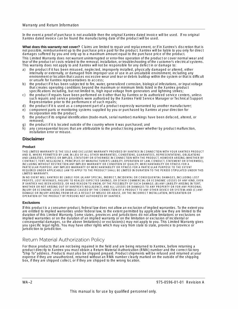
Warranty and Return Information
In the event a proof of purchase is not available then the original Xantrex dated invoice will be used. If no original Xantrex dated invoice can be found the manufacturing date of the product will be used.
What does this warranty not cover? Claims are limited to repair and replacement, or if in Xantrex's discretion that is not possible, reimbursement up to the purchase price paid for the product. Xantrex will be liable to you only for direct damages suffered by you and only up to a maximum amount equal to the purchase price of the product.This Limited Warranty does not warrant uninterrupted or error-free operation of the product or cover normal wear and tear of the product or costs related to the removal, installation, or troubleshooting of the customer's electrical systems. This warranty does not apply to and Xantrex will not be responsible for any defect in or damage to:a) the product if it has been misused, neglected, improperly installed, physically damaged or altered, either
internally or externally, or damaged from improper use or use in an unsuitable environment, including any environment or location that causes excessive wear and tear or debris buildup within the system or that is difficult or unsafe for Xantrex representatives to access;
b) the product if it has been subjected to fire, water, generalized corrosion, biological infestations, or input voltage that creates operating conditions beyond the maximum or minimum limits listed in the Xantrex product specifications including, but not limited to, high input voltage from generators and lightning strikes;
c) the product if repairs have been performed on it other than by Xantrex or its authorized service centers, unless such repairs and service providers were authorized by the Xantrex Field Service Manager or Technical Support Representative prior to the performance of such repairs;
d) the product if it is used as a component part of a product expressly warranted by another manufacturer;e) component parts or monitoring systems supplied by you or purchased by Xantrex at your direction for
incorporation into the product;f) the product if its original identification (trade-mark, serial number) markings have been defaced, altered, or
removed;g) the product if it is located outside of the country where it was purchased; andh) any consequential losses that are attributable to the product losing power whether by product malfunction,
installation error or misuse.
Disclaimer
ProductTHIS LIMITED WARRANTY IS THE SOLE AND EXCLUSIVE WARRANTY PROVIDED BY XANTREX IN CONNECTION WITH YOUR XANTREX PRODUCT AND IS, WHERE PERMITTED BY LAW, IN LIEU OF ALL OTHER WARRANTIES, CONDITIONS, GUARANTEES, REPRESENTATIONS, OBLIGATIONS AND LIABILITIES, EXPRESS OR IMPLIED, STATUTORY OR OTHERWISE IN CONNECTION WITH THE PRODUCT, HOWEVER ARISING (WHETHER BY CONTRACT, TORT, NEGLIGENCE, PRINCIPLES OF MANUFACTURER'S LIABILITY, OPERATION OF LAW, CONDUCT, STATEMENT OR OTHERWISE), INCLUDING WITHOUT RESTRICTION ANY IMPLIED WARRANTY OR CONDITION OF QUALITY, MERCHANTABILITY OR FITNESS FOR A PARTICULAR PURPOSE. ANY IMPLIED WARRANTY OF MERCHANTABILITY OR FITNESS FOR A PARTICULAR PURPOSE TO THE EXTENT REQUIRED UNDER APPLICABLE LAW TO APPLY TO THE PRODUCT SHALL BE LIMITED IN DURATION TO THE PERIOD STIPULATED UNDER THIS LIMITED WARRANTY.IN NO EVENT WILL XANTREX BE LIABLE FOR: (A) ANY SPECIAL, INDIRECT, INCIDENTAL OR CONSEQUENTIAL DAMAGES, INCLUDING LOST PROFITS, LOST REVENUES, FAILURE TO REALIZE EXPECTED SAVINGS, OR OTHER COMMERCIAL OR ECONOMIC LOSSES OF ANY KIND, EVEN IF XANTREX HAS BEEN ADVISED, OR HAD REASON TO KNOW, OF THE POSSIBILITY OF SUCH DAMAGE; (B) ANY LIABILITY ARISING IN TORT, WHETHER OR NOT ARISING OUT OF XANTREX'S NEGLIGENCE, AND ALL LOSSES OR DAMAGES TO ANY PROPERTY OR FOR ANY PERSONAL INJURY OR ECONOMIC LOSS OR DAMAGE CAUSED BY THE CONNECTION OF A PRODUCT TO ANY OTHER DEVICE OR SYSTEM; AND (C) ANY DAMAGE OR INJURY ARISING FROM OR AS A RESULT OF MISUSE OR ABUSE, OR THE INCORRECT INSTALLATION, INTEGRATION OR OPERATION OF THE PRODUCT BY PERSONS NOT AUTHORIZED BY XANTREX.
ExclusionsIf this product is a consumer product, federal law does not allow an exclusion of implied warranties. To the extent you are entitled to implied warranties under federal law, to the extent permitted by applicable law they are limited to the duration of this Limited Warranty. Some states, provinces and jurisdictions do not allow limitations or exclusions on implied warranties or on the duration of an implied warranty or on the limitation or exclusion of incidental or consequential damages, so the above limitation(s) or exclusion(s) may not apply to you. This Limited Warranty gives you specific legal rights. You may have other rights which may vary from state to state, province to province or jurisdiction to jurisdiction.
Return Material Authorization PolicyFor those products that are not being repaired in the field and are being returned to Xantrex, before returning a product directly to Xantrex you must obtain a Return Material Authorization (RMA) number and the correct factory "Ship To" address. Products must also be shipped prepaid. Product shipments will be refused and returned at your expense if they are unauthorized, returned without an RMA number clearly marked on the outside of the shipping box, if they are shipped collect, or if they are shipped to the wrong location.
WA–2 975-0596-01-01 Revision A
This manual is for use by qualified personnel only.
Warranty and Return Information
When you contact Xantrex to obtain service, please have your instruction manual ready for reference and be prepared to supply:
• The serial number of your product• Information about the installation and use of the unit• Information about the failure and/or reason for the return• A copy of your dated proof of purchase
Record these details in “Information About Your System”.
Return ProcedurePackage the unit safely, preferably using the original box and packing materials. Please ensure that your product is shipped fully insured in the original packaging or equivalent. This warranty will not apply where the product is damaged due to improper packaging.Include the following:
• The RMA number supplied by Xantrex Technology Inc. clearly marked on the outside of the box.• A return address where the unit can be shipped. Post office boxes are not acceptable.• A contact telephone number where you can be reached during work hours.• A brief description of the problem.
Ship the unit prepaid to the address provided by your Xantrex customer service representative.If you are returning a product from outside of the USA or Canada In addition to the above, you MUST include return freight funds and are fully responsible for all documents, duties, tariffs, and deposits. If you are returning a product to a Xantrex Authorized Service Center (ASC) A Xantrex return material authorization (RMA) number is not required. However, you must contact the ASC prior to returning the product or presenting the unit to verify any return procedures that may apply to that particular facility and that the ASC repairs this particular Xantrex product.
Out of Warranty ServiceIf the warranty period for your product has expired, if the unit was damaged by misuse or incorrect installation, if other conditions of the warranty have not been met, or if no dated proof of purchase is available, your unit may be serviced or replaced for a flat fee.To return your product for out of warranty service, contact Xantrex Customer Service for a Return Material Authorization (RMA) number and follow the other steps outlined in "Return Procedure". Payment options such as credit card or money order will be explained by the Customer Service Representative. In cases where the minimum flat fee does not apply, as with incomplete units or units with excessive damage, an additional fee will be charged. If applicable, you will be contacted by Customer Service once your unit has been received.
975-0596-01-01 Revision A WA–3
This manual is for use by qualified personnel only.
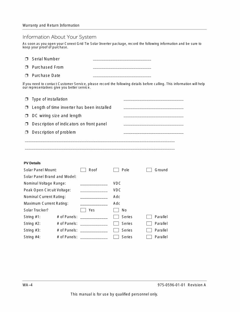
Warranty and Return Information
Information About Your SystemAs soon as you open your Conext Grid Tie Solar Inverter package, record the following information and be sure to keep your proof of purchase.
If you need to contact Customer Service, please record the following details before calling. This information will help our representatives give you better service.
❐ Serial Number _________________________________
❐ Purchased From _________________________________
❐ Purchase Date _________________________________
❐ Type of installation __________________________________
❐ Length of time inverter has been installed __________________________________
❐ DC wiring size and length __________________________________
❐ Description of indicators on front panel __________________________________
❐ Description of problem __________________________________
_____________________________________________________________________________________
_____________________________________________________________________________________
PV Details
Solar Panel Mount: Roof Pole Ground
Solar Panel Brand and Model:
Nominal Voltage Range: ______________ VDC
Peak Open Circuit Voltage: ______________ VDC
Nominal Current Rating: ______________ Adc
Maximum Current Rating: ______________ Adc
Solar Tracker? Yes No
String #1: # of Panels: ______________ Series Parallel
String #2: # of Panels: ______________ Series Parallel
String #3: # of Panels: ______________ Series Parallel
String #4: # of Panels: ______________ Series Parallel
WA–4 975-0596-01-01 Revision A
This manual is for use by qualified personnel only.
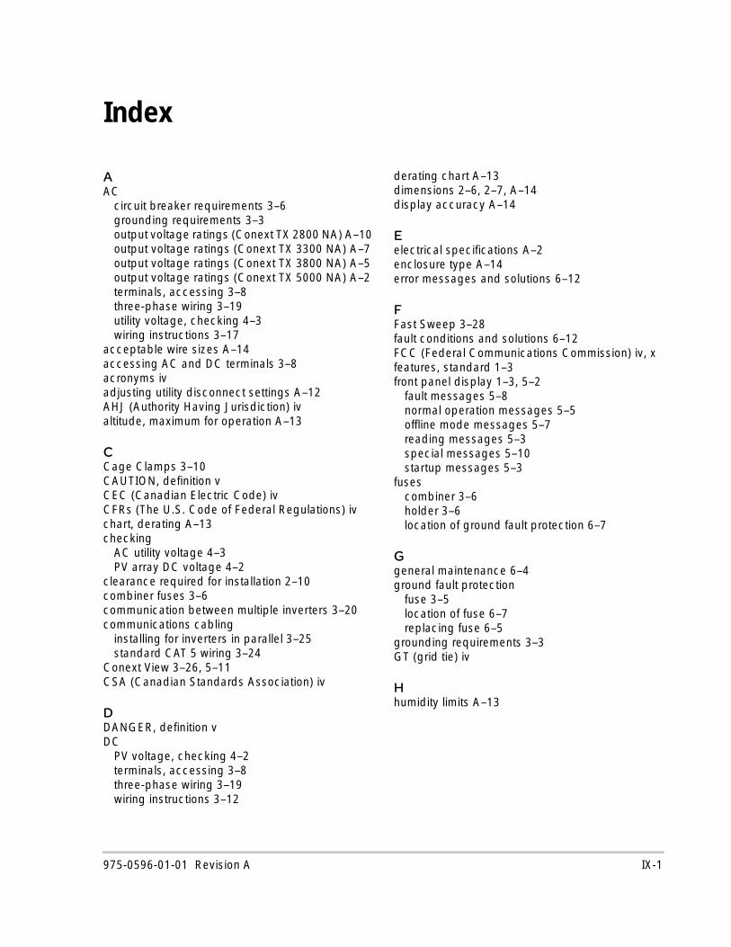
Index
AAC
circuit breaker requirements 3–6grounding requirements 3–3output voltage ratings (Conext TX 2800 NA) A–10output voltage ratings (Conext TX 3300 NA) A–7output voltage ratings (Conext TX 3800 NA) A–5output voltage ratings (Conext TX 5000 NA) A–2terminals, accessing 3–8three-phase wiring 3–19utility voltage, checking 4–3wiring instructions 3–17
acceptable wire sizes A–14accessing AC and DC terminals 3–8acronyms ivadjusting utility disconnect settings A–12AHJ (Authority Having Jurisdiction) ivaltitude, maximum for operation A–13
CCage Clamps 3–10CAUTION, definition vCEC (Canadian Electric Code) ivCFRs (The U.S. Code of Federal Regulations) ivchart, derating A–13checking
AC utility voltage 4–3PV array DC voltage 4–2
clearance required for installation 2–10combiner fuses 3–6communication between multiple inverters 3–20communications cabling
installing for inverters in parallel 3–25standard CAT 5 wiring 3–24
Conext View 3–26, 5–11CSA (Canadian Standards Association) iv
DDANGER, definition vDC
PV voltage, checking 4–2terminals, accessing 3–8three-phase wiring 3–19wiring instructions 3–12
derating chart A–13dimensions 2–6, 2–7, A–14display accuracy A–14
Eelectrical specifications A–2enclosure type A–14error messages and solutions 6–12
FFast Sweep 3–28fault conditions and solutions 6–12FCC (Federal Communications Commission) iv, xfeatures, standard 1–3front panel display 1–3, 5–2
fault messages 5–8normal operation messages 5–5offline mode messages 5–7reading messages 5–3special messages 5–10startup messages 5–3
fusescombiner 3–6holder 3–6location of ground fault protection 6–7
Ggeneral maintenance 6–4ground fault protection
fuse 3–5location of fuse 6–7replacing fuse 6–5
grounding requirements 3–3GT (grid tie) iv
Hhumidity limits A–13
975-0596-01-01 Revision A IX-1
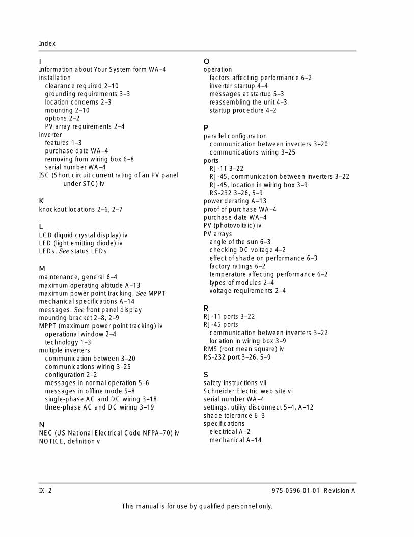
Index
IInformation about Your System form WA–4installation
clearance required 2–10grounding requirements 3–3location concerns 2–3mounting 2–10options 2–2PV array requirements 2–4
inverterfeatures 1–3purchase date WA–4removing from wiring box 6–8serial number WA–4
ISC (Short circuit current rating of an PV panel under STC) iv
Kknockout locations 2–6, 2–7
LLCD (liquid crystal display) ivLED (light emitting diode) ivLEDs. See status LEDs
Mmaintenance, general 6–4maximum operating altitude A–13maximum power point tracking. See MPPTmechanical specifications A–14messages. See front panel displaymounting bracket 2–8, 2–9MPPT (maximum power point tracking) iv
operational window 2–4technology 1–3
multiple inverterscommunication between 3–20communications wiring 3–25configuration 2–2messages in normal operation 5–6messages in offline mode 5–8single-phase AC and DC wiring 3–18three-phase AC and DC wiring 3–19
NNEC (US National Electrical Code NFPA–70) ivNOTICE, definition v
Ooperation
factors affecting performance 6–2inverter startup 4–4messages at startup 5–3reassembling the unit 4–3startup procedure 4–2
Pparallel configuration
communication between inverters 3–20communications wiring 3–25
portsRJ-11 3–22RJ-45, communication between inverters 3–22RJ-45, location in wiring box 3–9RS-232 3–26, 5–9
power derating A–13proof of purchase WA–4purchase date WA–4PV (photovoltaic) ivPV arrays
angle of the sun 6–3checking DC voltage 4–2effect of shade on performance 6–3factory ratings 6–2temperature affecting performance 6–2types of modules 2–4voltage requirements 2–4
RRJ-11 ports 3–22RJ-45 ports
communication between inverters 3–22location in wiring box 3–9
RMS (root mean square) ivRS-232 port 3–26, 5–9
Ssafety instructions viiSchneider Electric web site viserial number WA–4settings, utility disconnect 5–4, A–12shade tolerance 6–3specifications
electrical A–2mechanical A–14
IX–2 975-0596-01-01 Revision A
This manual is for use by qualified personnel only.
Index
standardfeatures 1–3test conditions iv, 6–2
startup procedurechecking PV array DC voltage 4–2checking utility AC voltage 4–3monitoring front panel display 5–2overview 4–2replacing wiring box cover 4–3starting the inverter 4–4
status LEDsdescription 5–12do not illuminate 6–12red LED is on 6–12
STC (standard test conditions) iv
Ttemperature
affecting PV array performance 6–2range for locating inverter 2–3
terminal blocks in wiring box 3–9terminators, network 3–22thermal derating chart A–13three-phase AC and DC wiring 3–19torque values for wires 3–3, 3–15troubleshooting 6–12
UUL (Underwriters Laboratories) ivutility disconnect settings 5–4, A–12
VVAC (volts AC) ivVDC (volts DC) ivVMPP (maximum power point voltage) ivVOC (PV array open circuit voltage) iv
WWARNING, definition vweight A–14wiring
acceptable wire sizes A–14PV array to Xantrex GT Inverter 3–12, 3–14torquing 3–3, 3–15using Cage Clamps 3–10
wiring boxdescription 1–5removing the cover 3–8removing the inverter from 6–8RJ-45 ports 3–9terminal block location 3–9
XXanbus technology 3–20
975-0596-01-01 Revision A IX–3
This manual is for use by qualified personnel only.

IX-4

975-0596-01-01 Revision A
Schneider Electric www.schneider-electric.com
☎ ✉North America 1 650 351 8237
1 866 519 14701 925 245 1022 [email protected]
France +33 (0) 825 012 999 [email protected]
Deutschland +49 (0) 180 575 3 575 +49 (0) 2102 404 7101 [email protected]
España +34 902 101 813 +34 933 055 026 [email protected]
L'Italia +39 035 4151111 +39 035415 3200 [email protected]
For other country details please contact your local Schneider Electric Sales Representative or visit the Schneider Electric Web site at:http://www.schneider-electric.com/sites/corporate/en/support/operations/local-operations/local-operations.page
Printed in India.