conesys europe hermetic connectors table of … 3 glass-to-metal sealing glossary conesys hermetic...
TRANSCRIPT
1www.conesys.com [email protected]
Conesys EuropeHermetic Connectors
Table of Contents
– –
Hermetic Connectors – General Characteristics . . . . . . . . . . . . . . . . . . . . . . . . . . . . . . . . . . . . . . . . . . . . . . . . . . . . . . . . . . . . . . . . . . . 2 – 4MIL-DTL-38999 Series I Based Connectors . . . . . . . . . . . . . . . . . . . . . . . . . . . . . . . . . . . . . . . . . . . . . . . . . . . . . . . . . . . . . . . . . . . . . . 5 – 14
MS27469 (AE169) Wall Mount Receptacle . . . . . . . . . . . . . . . . . . . . . . . . . . . . . . . . . . . . . . . . . . . . . . . . . . . . . . . . . . . . . . . . . . . . . . . 10 MS27470 (AE170) Jam Nut Receptacle . . . . . . . . . . . . . . . . . . . . . . . . . . . . . . . . . . . . . . . . . . . . . . . . . . . . . . . . . . . . . . . . . . . . . . . . . . . . . . 11MS27471 (AE171) Solder Mount Receptacle . . . . . . . . . . . . . . . . . . . . . . . . . . . . . . . . . . . . . . . . . . . . . . . . . . . . . . . . . . . . . . . . . . . . . . . . 12
MIL-DTL-38999 Series II Based Connectors . . . . . . . . . . . . . . . . . . . . . . . . . . . . . . . . . . . . . . . . . . . . . . . . . . . . . . . . . . . . . . . . . . . . 15 – 24MS27476 (AE276) Box Mount Receptacle . . . . . . . . . . . . . . . . . . . . . . . . . . . . . . . . . . . . . . . . . . . . . . . . . . . . . . . . . . . . . . . . . . . . . . . 20MS27477 (AE277) Jam Nut Receptacle . . . . . . . . . . . . . . . . . . . . . . . . . . . . . . . . . . . . . . . . . . . . . . . . . . . . . . . . . . . . . . . . . . . . . . . . . . . . . 21MS27478 (AE278) Solder Mount Receptacle . . . . . . . . . . . . . . . . . . . . . . . . . . . . . . . . . . . . . . . . . . . . . . . . . . . . . . . . . . . . . . . . . . . . . . . . 22
MIL-DTL-38999 Series III Based Connectors . . . . . . . . . . . . . . . . . . . . . . . . . . . . . . . . . . . . . . . . . . . . . . . . . . . . . . . . . . . . . . . . . . . 25 – 35D38999/21 (AE321) Wall Mount Receptacle . . . . . . . . . . . . . . . . . . . . . . . . . . . . . . . . . . . . . . . . . . . . . . . . . . . . . . . . . . . . . . . . . . . . . . 30D38999/23 (AE323) Jam Nut Receptacle . . . . . . . . . . . . . . . . . . . . . . . . . . . . . . . . . . . . . . . . . . . . . . . . . . . . . . . . . . . . . . . . . . . . . . . . . . . 31D38999/25 (AE325) Solder Mount Receptacle . . . . . . . . . . . . . . . . . . . . . . . . . . . . . . . . . . . . . . . . . . . . . . . . . . . . . . . . . . . . . . . . . . . . . . . . 32D38999/27 (AE327) Weld Mount Receptacle . . . . . . . . . . . . . . . . . . . . . . . . . . . . . . . . . . . . . . . . . . . . . . . . . . . . . . . . . . . . . . . . . . . . . . . . 33
MIL-DTL-38999 Series IV Based Connectors . . . . . . . . . . . . . . . . . . . . . . . . . . . . . . . . . . . . . . . . . . . . . . . . . . . . . . . . . . . . . . . . . . . . 36 – 46D38999/41 (AE341) Wall Mount Receptacle . . . . . . . . . . . . . . . . . . . . . . . . . . . . . . . . . . . . . . . . . . . . . . . . . . . . . . . . . . . . . . . . . . . . . . . . . 41D38999/43 (AE343) Jam Nut Receptacle . . . . . . . . . . . . . . . . . . . . . . . . . . . . . . . . . . . . . . . . . . . . . . . . . . . . . . . . . . . . . . . . . . . . . . 42 D38999/45 (AE345) Solder Mount Receptacle . . . . . . . . . . . . . . . . . . . . . . . . . . . . . . . . . . . . . . . . . . . . . . . . . . . . . . . . . . . . . . . . . . . . . . . 43D38999/48 (AE348) Weld Mount Receptacle . . . . . . . . . . . . . . . . . . . . . . . . . . . . . . . . . . . . . . . . . . . . . . . . . . . . . . . . . . . . . . . . . . . . . . . . 44
MIL-DTL-38999 Series I, II, III, and IV – Insert Arrangement and Contact Information . . . . . . . . . . . . . . . . . . . . . . . . . . . . . . 47 – 50EN2997 Based Connectors . . . . . . . . . . . . . . . . . . . . . . . . . . . . . . . . . . . . . . . . . . . . . . . . . . . . . . . . . . . . . . . . . . . . . . . . . . . . . . . . . . 51 – 64
EN2997 Y* 0 (8000 Y* 0) Wall Mount Receptacle . . . . . . . . . . . . . . . . . . . . . . . . . . . . . . . . . . . . . . . . . . . . . . . . . . . . . . . . . . . . . . . . . . 56 EN2997 Y* 7 (8000 Y* 7) Jam Nut Receptacle . . . . . . . . . . . . . . . . . . . . . . . . . . . . . . . . . . . . . . . . . . . . . . . . . . . . . . . . . . . . . . . . . . . . 57 EN2997 Y* 1 (8000 Y* 1) Solder Mount Receptacle . . . . . . . . . . . . . . . . . . . . . . . . . . . . . . . . . . . . . . . . . . . . . . . . . . . . . . . . . . . . . . . . . . . 58
MIL-DTL-83723 Series III Based Connectors . . . . . . . . . . . . . . . . . . . . . . . . . . . . . . . . . . . . . . . . . . . . . . . . . . . . . . . . . . . . . . . . . . . . 65 – 84M83723/79 (AE83379) Box Mount Receptacle, Solder Terminals, Bayonet Coupling . . . . . . . . . . . . . . . . . . . . . . . . . . . . . . . . . . . . 70M83723/80 (AE83380) Solder Mount Receptacle, Solder Terminals, Bayonet Coupling . . . . . . . . . . . . . . . . . . . . . . . . . . . . . . . . . 71M83723/81 (AE83381) Jam Nut Receptacle, Solder Terminals, Bayonet Coupling . . . . . . . . . . . . . . . . . . . . . . . . . . . . . . . . . . . . . . 72M83723/93 (AE83393) Solder Mount Receptacle, Pin Tail for PCB, Bayonet Coupling . . . . . . . . . . . . . . . . . . . . . . . . . . . . . . . . . . . 73M83723/94 (AE83394) Jam Nut Receptacle, Pin Tail for PCB, Bayonet Coupling . . . . . . . . . . . . . . . . . . . . . . . . . . . . . . . . . . . . . . . . 74M83723/88 (AE83388) Box Mount Receptacle, Solder Terminals, Threaded Coupling . . . . . . . . . . . . . . . . . . . . . . . . . . . . . . . . . . . 76M83723/89 (AE83389) Jam Nut Receptacle, Solder Terminals, Threaded Coupling . . . . . . . . . . . . . . . . . . . . . . . . . . . . . . . . . . . . . 77M83723/90 (AE83390) Solder Mount Receptacle, Solder Terminals, Threaded Coupling . . . . . . . . . . . . . . . . . . . . . . . . . . . . . . . . 78
MIL-DTL-26482 Series 2 and NAS1599 Based Connectors . . . . . . . . . . . . . . . . . . . . . . . . . . . . . . . . . . . . . . . . . . . . . . . . . . . . . . 85 – 102MS3440 (AE740) Wall Mount Receptacle – Narrow . . . . . . . . . . . . . . . . . . . . . . . . . . . . . . . . . . . . . . . . . . . . . . . . . . . . . . . . . . . . . . . . . . 89MS3443 (AE743) Solder Mount Receptacle . . . . . . . . . . . . . . . . . . . . . . . . . . . . . . . . . . . . . . . . . . . . . . . . . . . . . . . . . . . . . . . . . . . . . . . . . 90MS3449 (AE749) Jam Nut Receptacle . . . . . . . . . . . . . . . . . . . . . . . . . . . . . . . . . . . . . . . . . . . . . . . . . . . . . . . . . . . . . . . . . . . . . . . . . . . . . . 91AE7701 Solder Mount Receptacle . . . . . . . . . . . . . . . . . . . . . . . . . . . . . . . . . . . . . . . . . . . . . . . . . . . . . . . . . . . . . . . . . . . . . . . . . . . . . . . . . . 94AE7702 Square Flange Receptacle – Narrow . . . . . . . . . . . . . . . . . . . . . . . . . . . . . . . . . . . . . . . . . . . . . . . . . . . . . . . . . . . . . . . . . . . . . . . . 95AE7702L Square Flange Receptacle – Wide . . . . . . . . . . . . . . . . . . . . . . . . . . . . . . . . . . . . . . . . . . . . . . . . . . . . . . . . . . . . . . . . . . . . . . . . . 96AE7702S Square Flange Receptacle – Short . . . . . . . . . . . . . . . . . . . . . . . . . . . . . . . . . . . . . . . . . . . . . . . . . . . . . . . . . . . . . . . . . . . . . . . . 97A7707 Jam Nut Receptacle . . . . . . . . . . . . . . . . . . . . . . . . . . . . . . . . . . . . . . . . . . . . . . . . . . . . . . . . . . . . . . . . . . . . . . . . . . . . . . . . . . . . . . . . 98
MIL-DTL-5015 Based Connectors . . . . . . . . . . . . . . . . . . . . . . . . . . . . . . . . . . . . . . . . . . . . . . . . . . . . . . . . . . . . . . . . . . . . . . . . . . 103 – 116N/A (AE541) Solder Mount Receptacle – Less Flange . . . . . . . . . . . . . . . . . . . . . . . . . . . . . . . . . . . . . . . . . . . . . . . . . . . . . . . . . . . . 108MS3142 (AE542) Wall Mount Receptacle . . . . . . . . . . . . . . . . . . . . . . . . . . . . . . . . . . . . . . . . . . . . . . . . . . . . . . . . . . . . . . . . . . . . . . . . . . 109MS3143 (AE543) Solder Mount Receptacle . . . . . . . . . . . . . . . . . . . . . . . . . . . . . . . . . . . . . . . . . . . . . . . . . . . . . . . . . . . . . . . . . . . . . . . . . 110
MIL-DTL-26500 Based Connectors . . . . . . . . . . . . . . . . . . . . . . . . . . . . . . . . . . . . . . . . . . . . . . . . . . . . . . . . . . . . . . . . . . . . . . . . . . 117 – 130N/A (AE664*B) Wall Mount Receptacle – Bayonet Coupling . . . . . . . . . . . . . . . . . . . . . . . . . . . . . . . . . . . . . . . . . . . . . . . . . .122MS24265*B (AE665*B) Jam Nut Receptacle – Bayonet Coupling . . . . . . . . . . . . . . . . . . . . . . . . . . . . . . . . . . . . . . . . . . . . . . . . . . . . .123MS27034*B (AE634*B) Solder Mount Receptacle – Bayonet Coupling . . . . . . . . . . . . . . . . . . . . . . . . . . . . . . . . . . . . . . . . . . . . . . . . .124N/A (AE664*T) Wall Mount Receptacle – Threaded Coupling . . . . . . . . . . . . . . . . . . . . . . . . . . . . . . . . . . . . . . . . . . . . . . . . .125MS24265*T (AE665*T) Jam Nut Receptacle – Threaded Coupling . . . . . . . . . . . . . . . . . . . . . . . . . . . . . . . . . . . . . . . . . . . . . . . . . . . .126MS27034*T (AE634*T) Solder Mount Receptacle – Threaded Coupling . . . . . . . . . . . . . . . . . . . . . . . . . . . . . . . . . . . . . . . . . . . . . . .127
38999S
I38999
SII
38999S
IV38999
SIII
EN2997
83723S
III26482
S2
265005015
3www.conesys.com
Glass-to-Metal SealingGlossary
Conesys hermetic connectors are based upon glass-to-metalsealing technology, which offers reliability at an attractive cost.
This technology provides a high degree of performance inharsh environments that would typically cause resilient connectors to fail (from corrosion, high temperature, highpressure, etc.).
Hermetic technology is a good solution to reduce connectordimensions to a minimum. There are no rear parts, makingthe connectors completely flat (PCB applications).
Air LeakageAir leakage is the measure of gas ingress across a hermeticbarrier. Total air leakage is the sum of the gas which passesthrough the seal itself, through permeable shell materials, orvia cracks or gaps in the mounting area.
Hermeticity – Leak RateThis terminology describes the most important characteristicof a hermetic connector. The hermeticity or “leak rate” of ahermetic connector is measured by the helium leak test. Sinceall materials are ultimately permeable to helium gas ingressat some point, hermeticity ratings are used to define acceptable performance levels as required by individualapplications. The leak rate is measured in atm.cm3.s-1. Theacceptable leak rate depends on application. A leak rate of1.10-9 atm.cm3.s-1 is essentially zero. At this rate it wouldtake more than 1500 years for a connector to leak a tank of50 cm3 of helium. And helium is the smallest element present on earth. So imagine for air, water, fluid . . .
Pressure DifferentialPressure differential is the difference in pressure between theinside and outside of a sealed connector, the compartmentson either side of a wall or bulkhead, or the outside atmosphereand a sealed equipment housing. It is this pressure differentialthat leads to leakage across a sealed barrier and ultimately to contamination of sensitive electronic equipment.
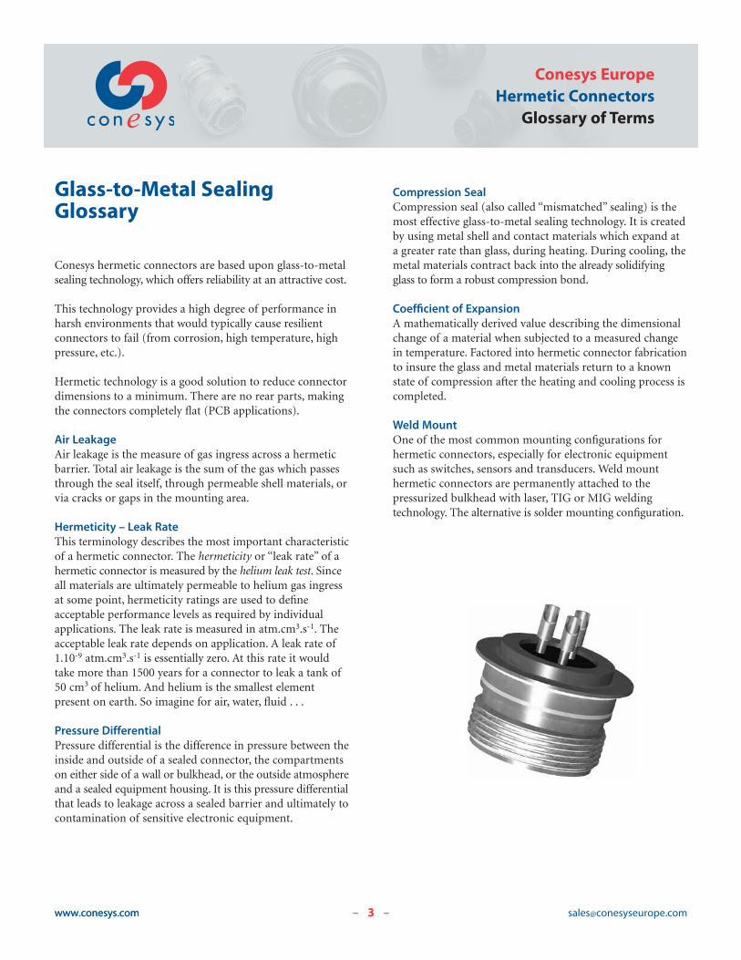
Compression SealCompression seal (also called “mismatched” sealing) is themost effective glass-to-metal sealing technology. It is createdby using metal shell and contact materials which expand ata greater rate than glass, during heating. During cooling, themetal materials contract back into the already solidifyingglass to form a robust compression bond.
Coefficient of ExpansionA mathematically derived value describing the dimensionalchange of a material when subjected to a measured changein temperature. Factored into hermetic connector fabricationto insure the glass and metal materials return to a knownstate of compression after the heating and cooling process iscompleted.
Weld MountOne of the most common mounting configurations for hermetic connectors, especially for electronic equipmentsuch as switches, sensors and transducers. Weld mount hermetic connectors are permanently attached to the pressurized bulkhead with laser, TIG or MIG welding technology. The alternative is solder mounting configuration.
3www.conesys.com [email protected]
Conesys EuropeHermetic Connectors
Glossary of Terms
– –
4www.conesys.com [email protected]– –
Conesys EuropeHermetic ConnectorsGeneral Characteristics
www.conesys.com
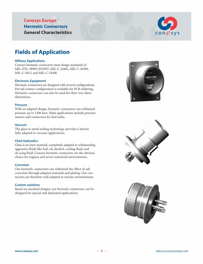
Fields of ApplicationMilitary ApplicationsConesys hermetic connectors meet design standards ofMIL-DTL-38999, EN2997, MIL-C-26482, MIL-C-26500,MIL-C-5015, and MIL-C-24308.
Electronic EquipmentHermetic connectors are designed with several configurations.Pin tail contact configuration is available for PCB soldering.Hermetic connectors can also be used for their very shortdimensions.
PressureWith an adapted design, hermetic connectors can withstandpressure up to 1500 bars. Main applications include pressuresensors and connectors for fuel tanks.
VacuumThe glass to metal sealing technology provides a barrierfully adapted to vacuum applications.
Fluid HydraulicsGlass is an inert material, completely adapted to withstandingaggressive fluids like fuel, oil, skydrol, cooling fluid, andde-icing fluid. Conesys hermetic connectors are the obviouschoice for engines and severe industrial environments.
CorrosionOur hermetic connectors can withstand the effect of saltcorrosion through adapted materials and plating. Our con-nectors are therefore well adapted to marine environments.
Custom solutionsBased on standard designs, our hermetic connectors can bedesigned for special and dedicated applications.
5www.conesys.com [email protected]
Conesys EuropeHermetic Connectors
AE1 Seriesper MIL-DTL-38999 Series I
– –
38999S
IM
IL-DTL-
6www.conesys.com [email protected]
AE1 SeriesHermetic Connectorsper MIL-DTL-38999 Series I
– –
MIL-D
TL-38999
SI
Features and Application
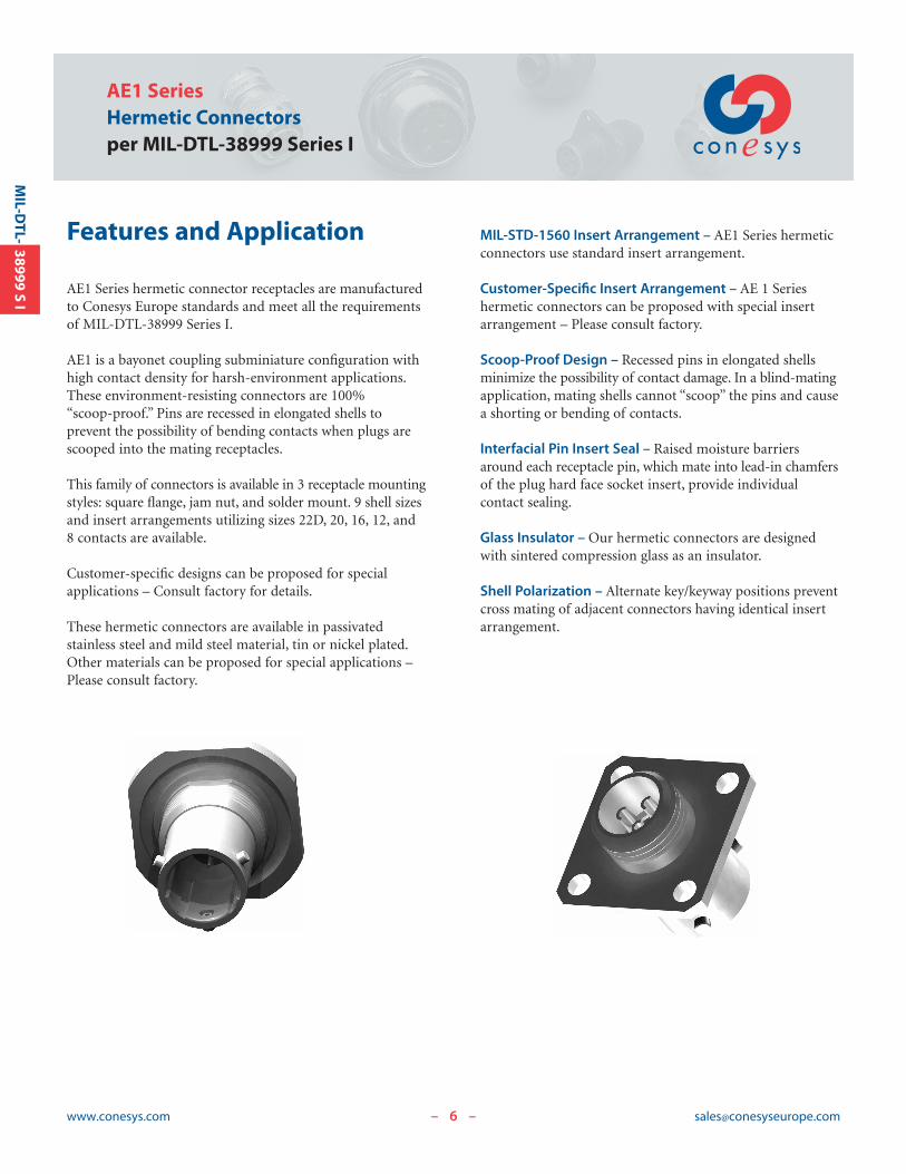
AE1 Series hermetic connector receptacles are manufacturedto Conesys Europe standards and meet all the requirementsof MIL-DTL-38999 Series I.
AE1 is a bayonet coupling subminiature configuration withhigh contact density for harsh-environment applications.These environment-resisting connectors are 100% “scoop-proof.” Pins are recessed in elongated shells to prevent the possibility of bending contacts when plugs arescooped into the mating receptacles.
This family of connectors is available in 3 receptacle mountingstyles: square flange, jam nut, and solder mount. 9 shell sizesand insert arrangements utilizing sizes 22D, 20, 16, 12, and 8 contacts are available.
Customer-specific designs can be proposed for special applications – Consult factory for details.
These hermetic connectors are available in passivated stainless steel and mild steel material, tin or nickel plated.Other materials can be proposed for special applications –Please consult factory.
MIL-STD-1560 Insert Arrangement – AE1 Series hermeticconnectors use standard insert arrangement.
Customer-Specific Insert Arrangement – AE 1 Series hermetic connectors can be proposed with special insertarrangement – Please consult factory.
Scoop-Proof Design – Recessed pins in elongated shellsminimize the possibility of contact damage. In a blind-matingapplication, mating shells cannot “scoop” the pins and causea shorting or bending of contacts.
Interfacial Pin Insert Seal – Raised moisture barriersaround each receptacle pin, which mate into lead-in chamfersof the plug hard face socket insert, provide individual contact sealing.
Glass Insulator – Our hermetic connectors are designedwith sintered compression glass as an insulator.
Shell Polarization – Alternate key/keyway positions preventcross mating of adjacent connectors having identical insertarrangement.
7www.conesys.com [email protected]
AE1 SeriesHermetic Connectors
per MIL-DTL-38999 Series I
– –
38999S
IM
IL-DTL-Performance Specifications
Operating Temperature RangeClasses E and N : -65°C to +200°C (-85°F to +392°F)
Class D : -65°C to +150°C (-85°F to +302°F)
Material and Finish Data (Class)Class E:
RECEPTACLE material: stainless steelfinish: passivated
CONTACTS material: ferrous alloyfinish: gold plated
Class N:RECEPTACLE material: stainless steel
finish: nickel platedCONTACTS material: ferrous alloy
finish: gold plated
Class D:RECEPTACLE material: mild steel
finish: tin platedCONTACTS material: ferrous alloy
finish: gold plated
Corrosion ResistanceClass E: 500 hours
Classes D and N: 48 hours
DurabilityMinimum of 500 mating cycles.
Leakage< 1.10-7 atm.cm3.s-1.
Shell-to-Shell ConductivityMaximum potential drop shall not exceed:
Class N: 1 millivoltClasses D and E: 50 millivolts
Insulation Resistance>5000 M| under 500 Vdc(25°C – 65% HR max.)
Withstanding VoltageAt sea level:
Service M: 1300 V RMSService I: 1800 V RMSService II: 2300 V RMS
At 21 000 m altitude:Service M: 800 V RMSService I: 1000 V RMSService II: 1000 V RMS
Maximum Current Rating per ContactSize 22D 3 AmpSize 20 5 AmpSize 16 10 AmpSize 12 17 AmpSize 8 40 Amp
AE1 SeriesHermetic Connectorsper MIL-DTL-38999 Series I
www.conesys.com [email protected]– –
MIL-D
TL-38999
SI
Military and Conesys Part Number Development
Mil. Prefix MS274 69Y 15 D 19 P A
Conesys Prefix AE1 69Y 15 D 19 P A -XXXShell Type (specification sheet number)
69Y = Wall mount receptacle
70Y = Jam nut receptacle
71Y = Solder mount receptacle
Shell SizeY 9, 11, 13, 15, 17, 19, 21, 23, and 25
Material and FinishD = Shell – mild steel, tin plated
= Terminals – ferrous alloy, gold plated
E = Shell – stainless steel, passivated
= Terminals – ferrous alloy, gold plated
N = Shell – stainless steel, nickel plated
= Terminals – ferrous alloy, gold plated
Insert ArrangementSee pages 47–50
Contact Style (pin only)P = Pin with solder cup
X = Pin with eyelet
C = Pin tail (for PCB)
Polarization (keying)N = Normal (omitted in part number)
A, B, C, or D for alternatives (B and C keyways are not available in SS 9)
Modification or Particularities (applies to Conesys part numbers only)XXX = Modification
Consult factory for details

9www.conesys.com [email protected]
AE1 SeriesHermetic Connectors
per MIL-DTL-38999 Series I
– –
38999S
IM
IL-DTL-
Terminal Configuration
Terminal Style PSolder cupAvailable in sizes 22, 20, 16, 12, and 8For other sizes, please consult factory.
Terminal Style XEyeletAvailable in sizes 22, 20, and 16For other sizes, please consult factory.
Terminal Style CPin tail for PCBAvailable in sizes 22, 20, and 16For other sizes or lengths, please consultfactory.
10www.conesys.com [email protected]
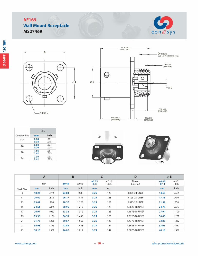
AE169Wall Mount ReceptacleMS27469
– –
MIL-D
TL-38999
SI
17.52/16.74[.690/.659]
2.36/1.57[.093/.062]
[ E
[ L
D THREAD6.35 [.250] MIN FULL THD.
27.76 MAX[1.092 MAX]
7.92 MAX[.312 MAX]
4.34/3.17[.171/.125]
B
[ A
4 x [ C
Contact Size
[ Lmm inch
22D 0.280.38
.011
.015
20 0.600.70
.024
.028
16 1.561.61
.061
.063
12 2.362.41
.093
.095
Shell Size
A B C D [ E
(TP) ±0.41 ±.016+0.25-0.13
+.010-.005
ThreadClass 2A
+0.03-0.13
+.001-.005
mm inch mm inch mm inch mm inch
9 18.26 .719 23.83 .938 3.25 .128 .6875-24 UNEF 14.53 .572
11 20.62 .812 26.19 1.031 3.25 .128 .8125-20 UNEF 17.78 .700
13 23.01 .906 28.57 1.125 3.25 .128 .9375-20 UNEF 21.59 .850
15 24.61 .969 30.96 1.219 3.25 .128 1.0625-18 UNEF 24.76 .975
17 26.97 1.062 33.32 1.312 3.25 .128 1.1875-18 UNEF 27.94 1.100
19 29.36 1.156 36.53 1.438 3.25 .128 1.3125-18 UNEF 30.66 1.207
21 31.75 1.250 39.67 1.562 3.25 .128 1.4375-18 UNEF 33.83 1.332
23 34.93 1.375 42.88 1.688 3.73 .147 1.5625-18 UNEF 37.01 1.457
25 38.10 1.500 46.02 1.812 3.73 .147 1.6875-18 UNEF 40.18 1.582
[ P
[ F[ E
G
23.24 ± 0.13[.915 ± .005]
PANEL THICKNESS3.18/1.57
[.125/.062]
4.44/3.17[.175/.125]
3.58 MAX[.141 MAX]
A THREAD
NUT PER MS 27514
DFLAT
C
[ B
11www.conesys.com [email protected]
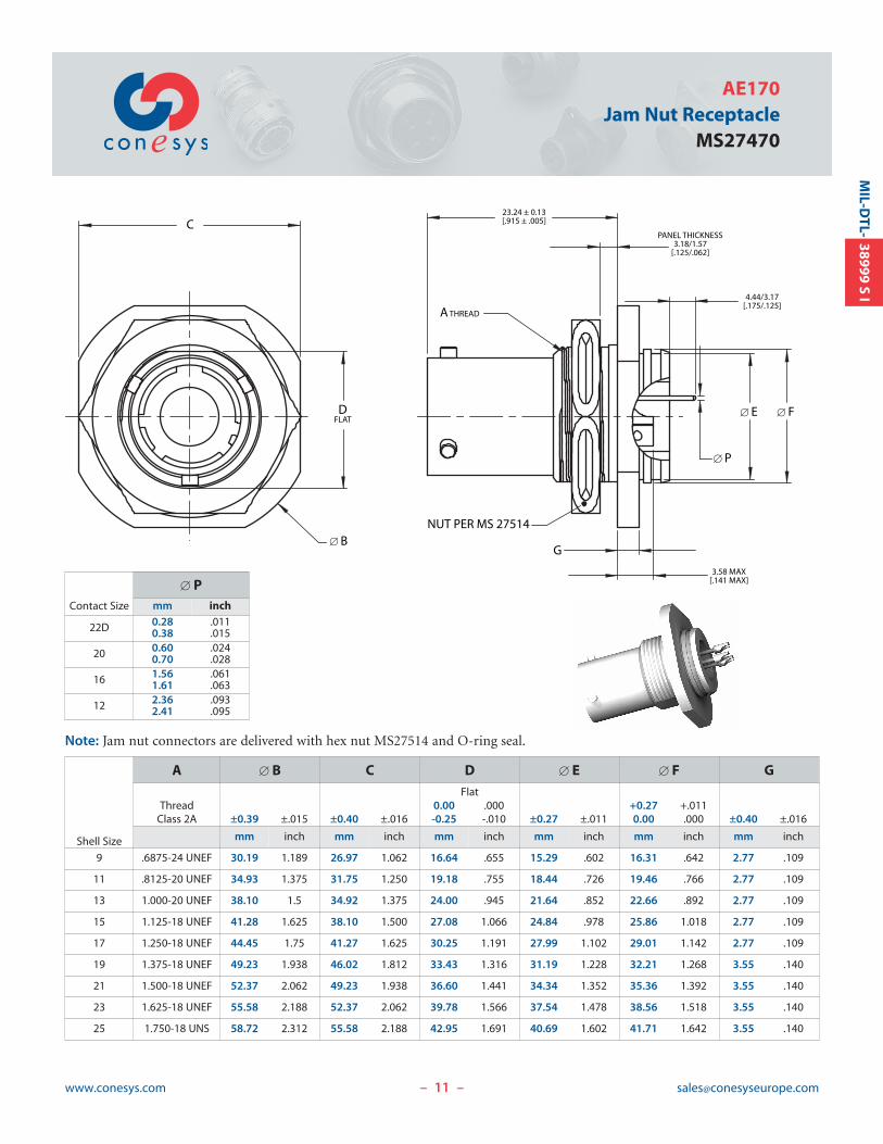
AE170Jam Nut Receptacle
MS27470
Note: Jam nut connectors are delivered with hex nut MS27514 and O-ring seal.
– –
38999S
IM
IL-DTL-
Contact Size
[ Pmm inch
22D 0.280.38
.011
.015
20 0.600.70
.024
.028
16 1.561.61
.061
.063
12 2.362.41
.093
.095
Shell Size
A [ B C D [ E [ F GFlat
Thread 0.00 .000 +0.27 +.011Class 2A ±0.39 ±.015 ±0.40 ±.016 -0.25 -.010 ±0.27 ±.011 0.00 .000 ±0.40 ±.016
mm inch mm inch mm inch mm inch mm inch mm inch
9 .6875-24 UNEF 30.19 1.189 26.97 1.062 16.64 .655 15.29 .602 16.31 .642 2.77 .109
11 .8125-20 UNEF 34.93 1.375 31.75 1.250 19.18 .755 18.44 .726 19.46 .766 2.77 .109
13 1.000-20 UNEF 38.10 1.5 34.92 1.375 24.00 .945 21.64 .852 22.66 .892 2.77 .109
15 1.125-18 UNEF 41.28 1.625 38.10 1.500 27.08 1.066 24.84 .978 25.86 1.018 2.77 .109
17 1.250-18 UNEF 44.45 1.75 41.27 1.625 30.25 1.191 27.99 1.102 29.01 1.142 2.77 .109
19 1.375-18 UNEF 49.23 1.938 46.02 1.812 33.43 1.316 31.19 1.228 32.21 1.268 3.55 .140
21 1.500-18 UNEF 52.37 2.062 49.23 1.938 36.60 1.441 34.34 1.352 35.36 1.392 3.55 .140
23 1.625-18 UNEF 55.58 2.188 52.37 2.062 39.78 1.566 37.54 1.478 38.56 1.518 3.55 .140
25 1.750-18 UNS 58.72 2.312 55.58 2.188 42.95 1.691 40.69 1.602 41.71 1.642 3.55 .140
12www.conesys.com [email protected]
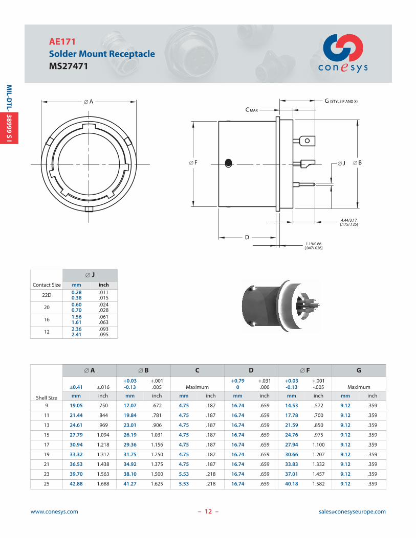
AE171Solder Mount ReceptacleMS27471
– –
MIL-D
TL-38999
SI
Contact Size
[ Jmm inch
22D 0.280.38
.011
.015
20 0.600.70
.024
.028
16 1.561.61
.061
.063
12 2.362.41
.093
.095
Shell Size
[ A [ B C D [ F G
+0.03 +.001 +0.79 +.031 +0.03 +.001±0.41 ±.016 -0.13 .005 Maximum 0 .000 -0.13 -.005 Maximum
mm inch mm inch mm inch mm inch mm inch mm inch
9 19.05 .750 17.07 .672 4.75 .187 16.74 .659 14.53 .572 9.12 .359
11 21.44 .844 19.84 .781 4.75 .187 16.74 .659 17.78 .700 9.12 .359
13 24.61 .969 23.01 .906 4.75 .187 16.74 .659 21.59 .850 9.12 .359
15 27.79 1.094 26.19 1.031 4.75 .187 16.74 .659 24.76 .975 9.12 .359
17 30.94 1.218 29.36 1.156 4.75 .187 16.74 .659 27.94 1.100 9.12 .359
19 33.32 1.312 31.75 1.250 4.75 .187 16.74 .659 30.66 1.207 9.12 .359
21 36.53 1.438 34.92 1.375 4.75 .187 16.74 .659 33.83 1.332 9.12 .359
23 39.70 1.563 38.10 1.500 5.53 .218 16.74 .659 37.01 1.457 9.12 .359
25 42.88 1.688 41.27 1.625 5.53 .218 16.74 .659 40.18 1.582 9.12 .359
[ B[ F
1.19/0.66[.047/.026]
D
C MAX
G (STYLE P AND X)
4.44/3.17[.175/.125]
[ J
[ A
13www.conesys.com [email protected]
AE1 SeriesHermetic Connectors
per MIL-DTL-38999 Series I
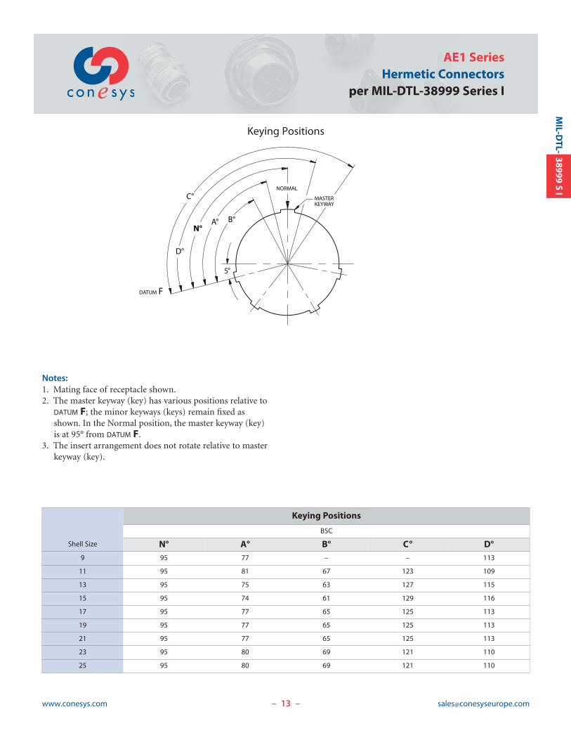
Keying Positions
– –
38999S
IM
IL-DTL-
DATUM F
D°
N°A°
C°
B°
MASTERKEYWAY
NORMAL
5°
Notes:1. Mating face of receptacle shown.2. The master keyway (key) has various positions relative to
DATUM F; the minor keyways (keys) remain fixed asshown. In the Normal position, the master keyway (key)is at 95° from DATUM F.
3. The insert arrangement does not rotate relative to masterkeyway (key).
Shell Size
Keying Positions
BSC
N° A° B° C° D°9 95 77 – – 113
11 95 81 67 123 109
13 95 75 63 127 115
15 95 74 61 129 116
17 95 77 65 125 113
19 95 77 65 125 113
21 95 77 65 125 113
23 95 80 69 121 110
25 95 80 69 121 110
14www.conesys.com [email protected]
AE1 SeriesHermetic Connectorsper MIL-DTL-38999 Series I
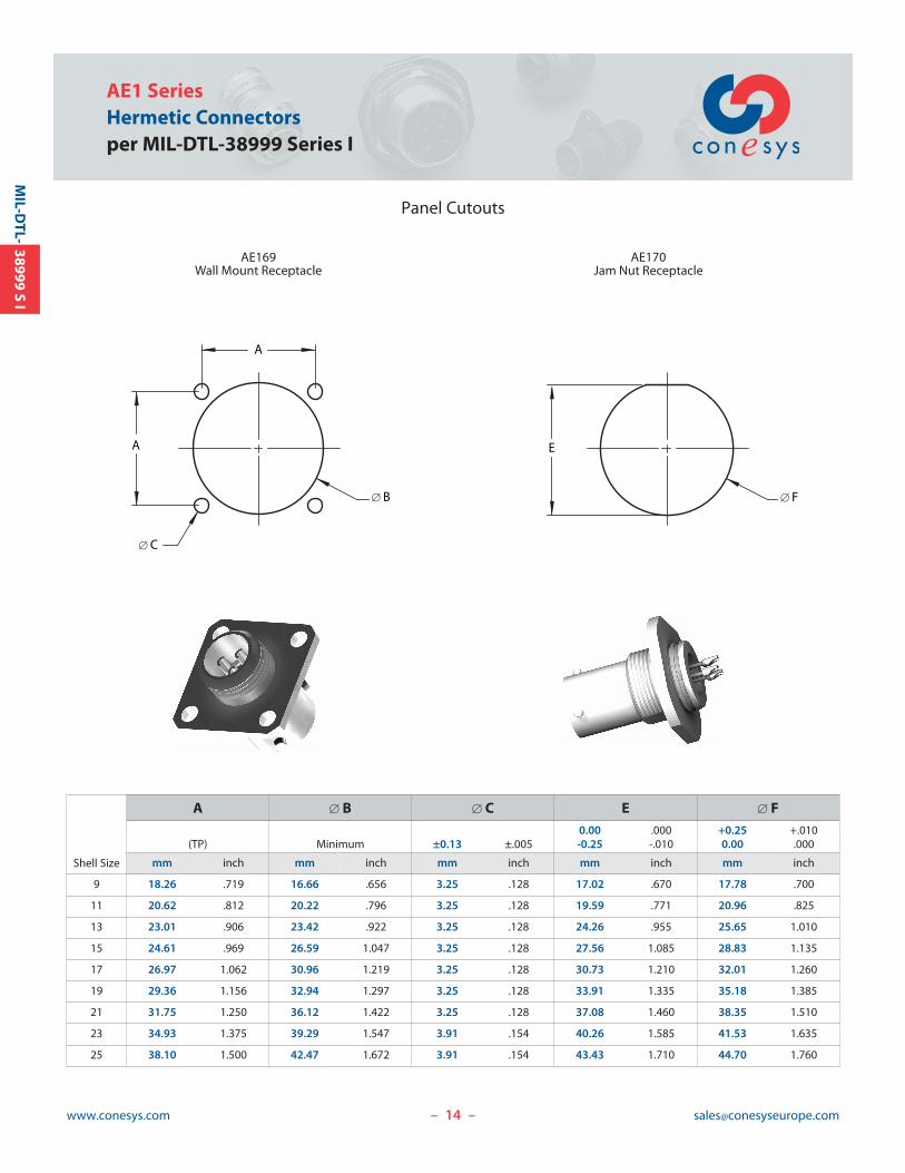
Panel Cutouts
– –
MIL-D
TL-38999
SI
A
[ B
A
[ C
AE169Wall Mount Receptacle
AE170Jam Nut Receptacle
[ F
E
Shell Size
A [ B [ C E [ F0.00 .000 +0.25 +.010
(TP) Minimum ±0.13 ±.005 -0.25 -.010 0.00 .000
mm inch mm inch mm inch mm inch mm inch
9 18.26 .719 16.66 .656 3.25 .128 17.02 .670 17.78 .700
11 20.62 .812 20.22 .796 3.25 .128 19.59 .771 20.96 .825
13 23.01 .906 23.42 .922 3.25 .128 24.26 .955 25.65 1.010
15 24.61 .969 26.59 1.047 3.25 .128 27.56 1.085 28.83 1.135
17 26.97 1.062 30.96 1.219 3.25 .128 30.73 1.210 32.01 1.260
19 29.36 1.156 32.94 1.297 3.25 .128 33.91 1.335 35.18 1.385
21 31.75 1.250 36.12 1.422 3.25 .128 37.08 1.460 38.35 1.510
23 34.93 1.375 39.29 1.547 3.91 .154 40.26 1.585 41.53 1.635
25 38.10 1.500 42.47 1.672 3.91 .154 43.43 1.710 44.70 1.760
15www.conesys.com [email protected]
Conesys EuropeHermetic Connectors
AE2 Seriesper MIL-DTL-38999 Series II
– –
38999S
IIM
IL-DTL-
16www.conesys.com [email protected]
AE2 SeriesHermetic Connectorsper MIL-DTL-38999 Series II
– –
38999S
IIM
IL-DTL-
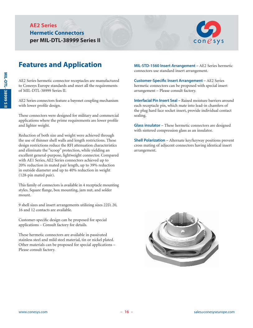
Features and Application
AE2 Series hermetic connector receptacles are manufacturedto Conesys Europe standards and meet all the requirementsof MIL-DTL-38999 Series II.
AE2 Series connectors feature a bayonet coupling mechanismwith lower profile design.
These connectors were designed for military and commercialapplications where the prime requirements are lower profileand lighter weight.
Reduction of both size and weight were achieved throughthe use of thinner shell walls and length restrictions. Thesedesign restrictions reduce the RFI attenuation characteristicsand eliminate the “scoop” protection, while yielding an excellent general-purpose, lightweight connector. Comparedwith AE1 Series, AE2 Series connectors achieved up to 20% reduction in mated pair length, up to 39% reduction in outside diameter and up to 40% reduction in weight (128-pin mated pair).
This family of connectors is available in 4 receptacle mountingstyles. Square flange, box mounting, jam nut, and soldermount.
9 shell sizes and insert arrangements utilizing sizes 22D, 20,16 and 12 contacts are available.
Customer-specific design can be proposed for special applications – Consult factory for details.
These hermetic connectors are available in passivated stainless steel and mild steel material, tin or nickel plated.Other materials can be proposed for special applications –Please consult factory.
MIL-STD-1560 Insert Arrangement – AE2 Series hermeticconnectors use standard insert arrangement.
Customer-Specific Insert Arrangement – AE2 Series hermetic connectors can be proposed with special insertarrangement – Please consult factory.
Interfacial Pin Insert Seal – Raised moisture barriers aroundeach receptacle pin, which mate into lead-in chamfers ofthe plug hard face socket insert, provide individual contactsealing.
Glass insulator – These hermetic connectors are designedwith sintered compression glass as an insulator.
Shell Polarization – Alternate key/keyway positions preventcross mating of adjacent connectors having identical insertarrangement.
17www.conesys.com [email protected]
AE2 SeriesHermetic Connectors
per MIL-DTL-38999 Series II
– –
38999S
IIM
IL-DTL-
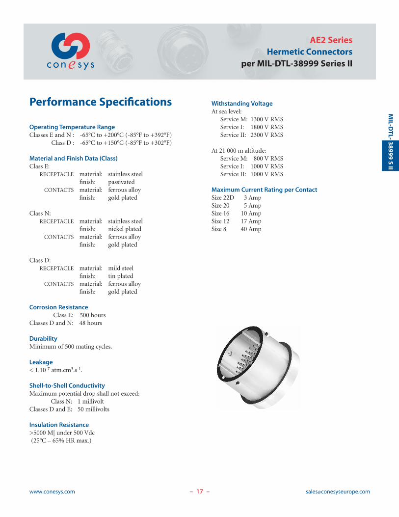
Performance Specifications
Operating Temperature RangeClasses E and N : -65°C to +200°C (-85°F to +392°F)
Class D : -65°C to +150°C (-85°F to +302°F)
Material and Finish Data (Class)Class E:
RECEPTACLE material: stainless steelfinish: passivated
CONTACTS material: ferrous alloyfinish: gold plated
Class N:RECEPTACLE material: stainless steel
finish: nickel platedCONTACTS material: ferrous alloy
finish: gold plated
Class D:RECEPTACLE material: mild steel
finish: tin platedCONTACTS material: ferrous alloy
finish: gold plated
Corrosion ResistanceClass E: 500 hours
Classes D and N: 48 hours
DurabilityMinimum of 500 mating cycles.
Leakage< 1.10-7 atm.cm3.s-1.
Shell-to-Shell ConductivityMaximum potential drop shall not exceed:
Class N: 1 millivoltClasses D and E: 50 millivolts
Insulation Resistance>5000 M| under 500 Vdc(25°C – 65% HR max.)
Withstanding VoltageAt sea level:
Service M: 1300 V RMSService I: 1800 V RMSService II: 2300 V RMS
At 21 000 m altitude:Service M: 800 V RMSService I: 1000 V RMSService II: 1000 V RMS
Maximum Current Rating per ContactSize 22D 3 AmpSize 20 5 AmpSize 16 10 AmpSize 12 17 AmpSize 8 40 Amp
AE2 SeriesHermetic Connectorsper MIL-DTL-38999 Series II
www.conesys.com [email protected]– –
38999S
IIM
IL-DTL-
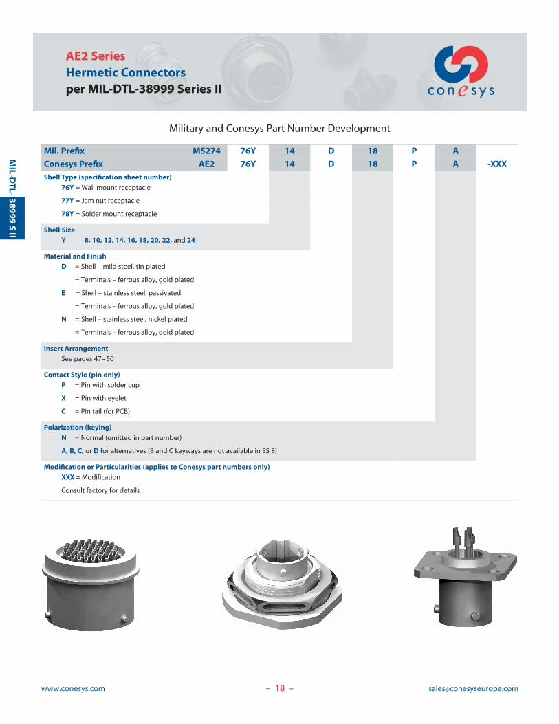
Military and Conesys Part Number Development
Mil. Prefix MS274 76Y 14 D 18 P A
Conesys Prefix AE2 76Y 14 D 18 P A -XXXShell Type (specification sheet number)
76Y = Wall mount receptacle
77Y = Jam nut receptacle
78Y = Solder mount receptacle
Shell SizeY 8, 10, 12, 14, 16, 18, 20, 22, and 24
Material and FinishD = Shell – mild steel, tin plated
= Terminals – ferrous alloy, gold plated
E = Shell – stainless steel, passivated
= Terminals – ferrous alloy, gold plated
N = Shell – stainless steel, nickel plated
= Terminals – ferrous alloy, gold plated
Insert ArrangementSee pages 47–50
Contact Style (pin only)P = Pin with solder cup
X = Pin with eyelet
C = Pin tail (for PCB)
Polarization (keying)N = Normal (omitted in part number)
A, B, C, or D for alternatives (B and C keyways are not available in SS 8)
Modification or Particularities (applies to Conesys part numbers only)XXX = Modification
Consult factory for details
19www.conesys.com [email protected]
AE2 SeriesHermetic Connectors
per MIL-DTL-38999 Series II
– –
38999S
IIM
IL-DTL-
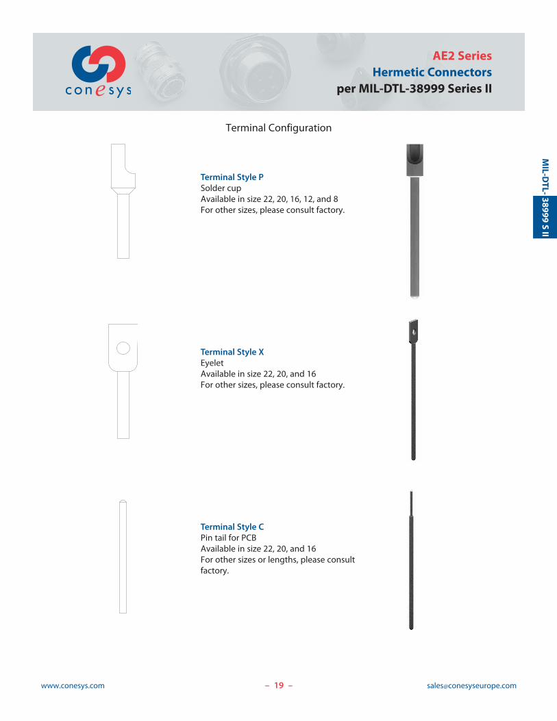
Terminal Configuration
Terminal Style PSolder cupAvailable in size 22, 20, 16, 12, and 8For other sizes, please consult factory.
Terminal Style XEyeletAvailable in size 22, 20, and 16For other sizes, please consult factory.
Terminal Style CPin tail for PCBAvailable in size 22, 20, and 16For other sizes or lengths, please consultfactory.
20www.conesys.com [email protected]
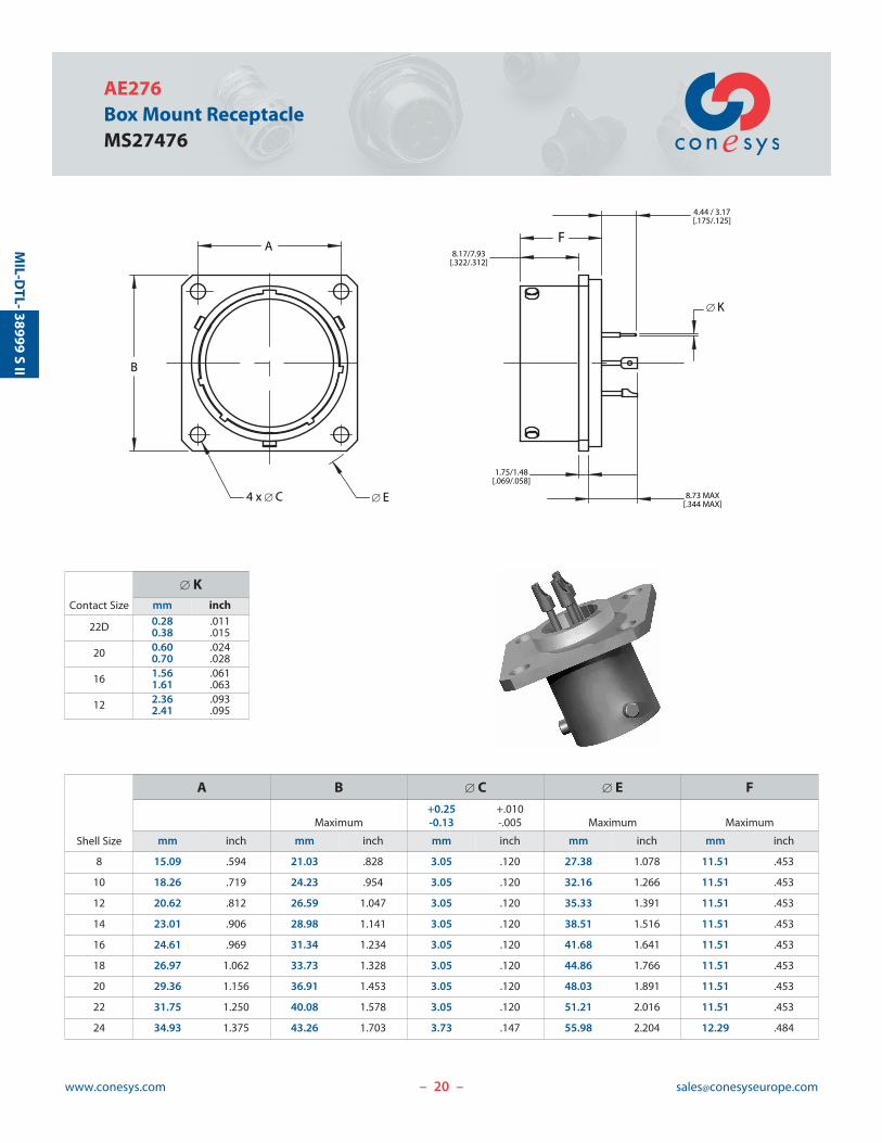
AE276Box Mount ReceptacleMS27476
– –
38999S
IIM
IL-DTL-
8.73 MAX[.344 MAX]
8.17/7.93[.322/.312]
4.44 / 3.17[.175/.125]
F
[ K
1.75/1.48[.069/.058]
B
4 x [ C [ E
A
Contact Size
[ Kmm inch
22D 0.280.38
.011
.015
20 0.600.70
.024
.028
16 1.561.61
.061
.063
12 2.362.41
.093
.095
Shell Size
A B [ C [ E F+0.25 +.010
Maximum -0.13 -.005 Maximum Maximum
mm inch mm inch mm inch mm inch mm inch
8 15.09 .594 21.03 .828 3.05 .120 27.38 1.078 11.51 .453
10 18.26 .719 24.23 .954 3.05 .120 32.16 1.266 11.51 .453
12 20.62 .812 26.59 1.047 3.05 .120 35.33 1.391 11.51 .453
14 23.01 .906 28.98 1.141 3.05 .120 38.51 1.516 11.51 .453
16 24.61 .969 31.34 1.234 3.05 .120 41.68 1.641 11.51 .453
18 26.97 1.062 33.73 1.328 3.05 .120 44.86 1.766 11.51 .453
20 29.36 1.156 36.91 1.453 3.05 .120 48.03 1.891 11.51 .453
22 31.75 1.250 40.08 1.578 3.05 .120 51.21 2.016 11.51 .453
24 34.93 1.375 43.26 1.703 3.73 .147 55.98 2.204 12.29 .484
2.66/2.14[.105/.084]
[ M
4.44/3.17[.175/.125]
E
F
ATHREAD
CFLAT
D
[ BHEX NUT PER MS27512
PANEL THICKNESS : 2.77/1.57 [.109/.062]
21www.conesys.com [email protected]
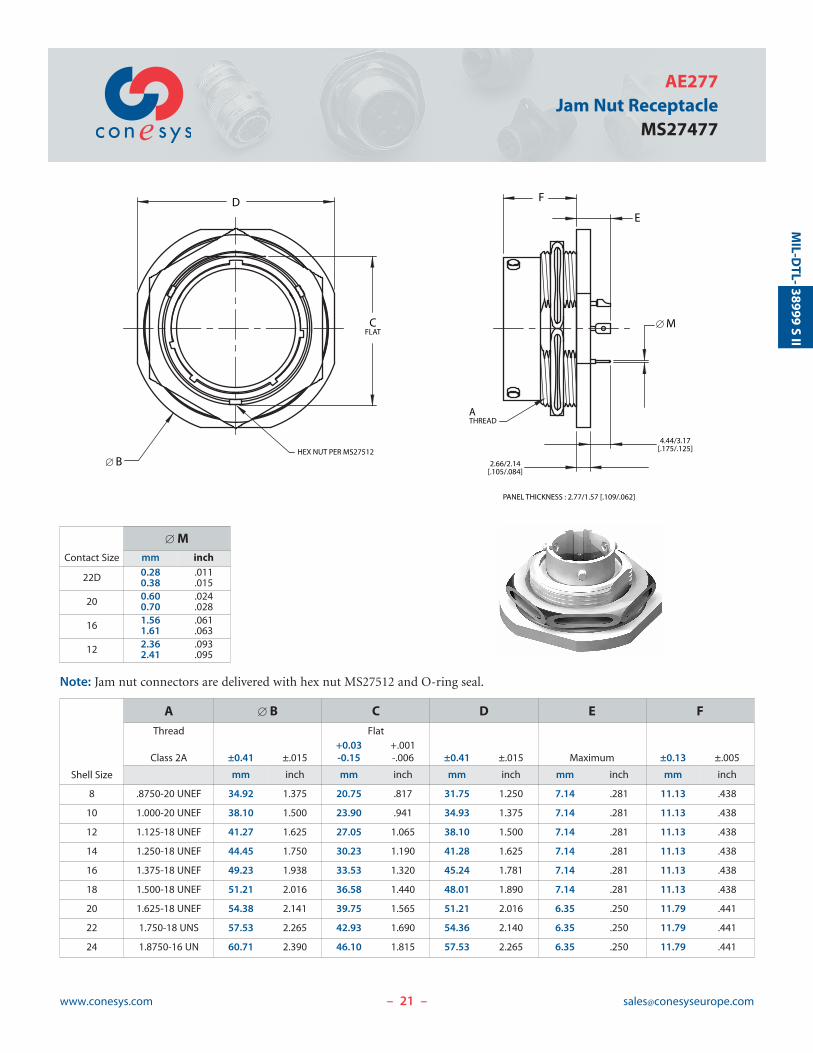
AE277Jam Nut Receptacle
MS27477
Note: Jam nut connectors are delivered with hex nut MS27512 and O-ring seal.
– –
38999S
IIM
IL-DTL-
Contact Size
[ Mmm inch
22D 0.280.38
.011
.015
20 0.600.70
.024
.028
16 1.561.61
.061
.063
12 2.362.41
.093
.095
Shell Size
A [ B C D E FThread Flat
+0.03 +.001Class 2A ±0.41 ±.015 -0.15 -.006 ±0.41 ±.015 Maximum ±0.13 ±.005
mm inch mm inch mm inch mm inch mm inch
8 .8750-20 UNEF 34.92 1.375 20.75 .817 31.75 1.250 7.14 .281 11.13 .438
10 1.000-20 UNEF 38.10 1.500 23.90 .941 34.93 1.375 7.14 .281 11.13 .438
12 1.125-18 UNEF 41.27 1.625 27.05 1.065 38.10 1.500 7.14 .281 11.13 .438
14 1.250-18 UNEF 44.45 1.750 30.23 1.190 41.28 1.625 7.14 .281 11.13 .438
16 1.375-18 UNEF 49.23 1.938 33.53 1.320 45.24 1.781 7.14 .281 11.13 .438
18 1.500-18 UNEF 51.21 2.016 36.58 1.440 48.01 1.890 7.14 .281 11.13 .438
20 1.625-18 UNEF 54.38 2.141 39.75 1.565 51.21 2.016 6.35 .250 11.79 .441
22 1.750-18 UNS 57.53 2.265 42.93 1.690 54.36 2.140 6.35 .250 11.79 .441
24 1.8750-16 UN 60.71 2.390 46.10 1.815 57.53 2.265 6.35 .250 11.79 .441
22www.conesys.com [email protected]
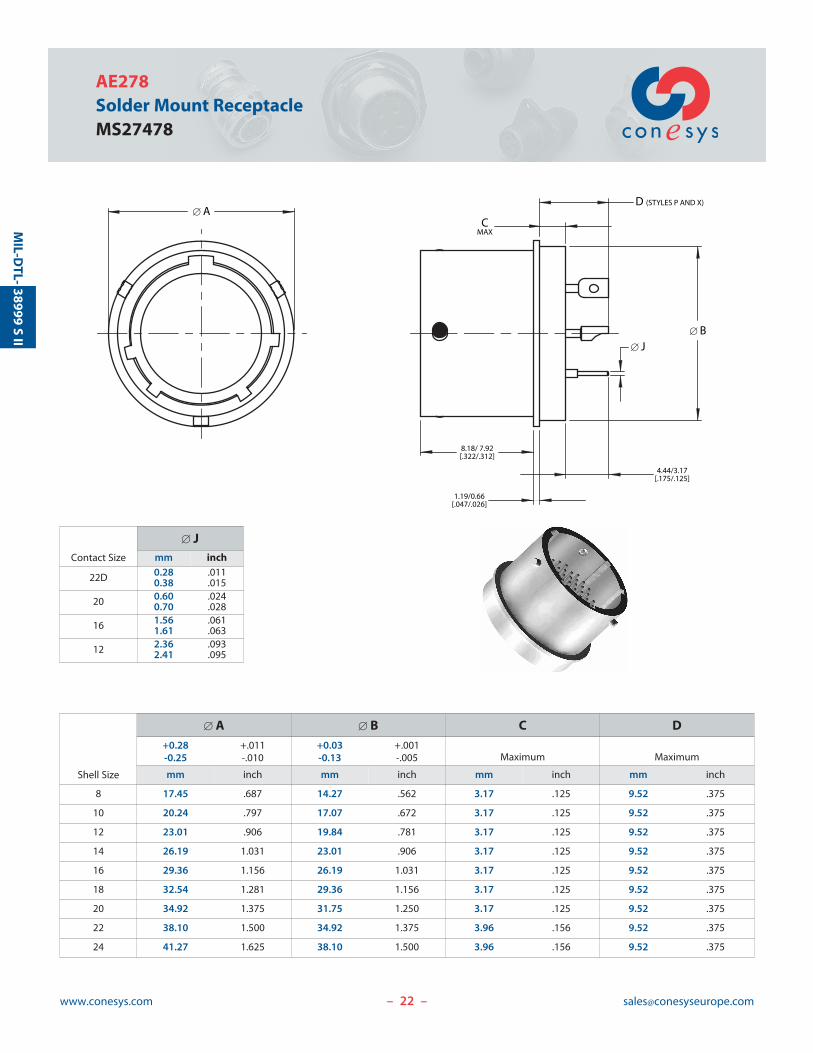
AE278Solder Mount ReceptacleMS27478
– –
38999S
IIM
IL-DTL-
Contact Size
[ Jmm inch
22D 0.280.38
.011
.015
20 0.600.70
.024
.028
16 1.561.61
.061
.063
12 2.362.41
.093
.095
[ B
8.18/ 7.92[.322/.312]
4.44/3.17[.175/.125]
1.19/0.66[.047/.026]
[ J
CMAX
D (STYLES P AND X) [ A
Shell Size
[ A [ B C D+0.28 +.011 +0.03 +.001
Maximum Maximum-0.25 -.010 -0.13 -.005
mm inch mm inch mm inch mm inch
8 17.45 .687 14.27 .562 3.17 .125 9.52 .375
10 20.24 .797 17.07 .672 3.17 .125 9.52 .375
12 23.01 .906 19.84 .781 3.17 .125 9.52 .375
14 26.19 1.031 23.01 .906 3.17 .125 9.52 .375
16 29.36 1.156 26.19 1.031 3.17 .125 9.52 .375
18 32.54 1.281 29.36 1.156 3.17 .125 9.52 .375
20 34.92 1.375 31.75 1.250 3.17 .125 9.52 .375
22 38.10 1.500 34.92 1.375 3.96 .156 9.52 .375
24 41.27 1.625 38.10 1.500 3.96 .156 9.52 .375

23www.conesys.com [email protected]
AE2 SeriesHermetic Connectors
per MIL-DTL-38999 Series II
Keying Positions
– –
38999S
IIM
IL-DTL-
DATUM F
D°
N°A°
C°
B°
MASTER NORMAL
KEYWAY
10°
Notes:1. Mating face of receptacle shown.2. The master keyway (key) has various positions relative to
DATUM F; the minor keyways (keys) remain fixed asshown. In the Normal position, the master keyway (key)is at 100° from DATUM F.
3. The insert arrangement does not rotate relative to masterkeyway (key).
ShellSize
Keying Positions
BSC
N° A° B° C° D°8 100 82 – – 118
10 100 86 72 128 114
12 100 80 68 132 120
14 100 79 66 134 121
16 100 82 70 130 118
18 100 82 70 130 118
20 100 82 70 130 118
22 100 85 74 126 115
24 100 85 74 126 115
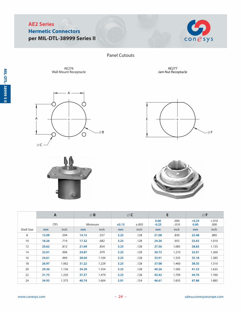
24www.conesys.com [email protected]
AE2 SeriesHermetic Connectorsper MIL-DTL-38999 Series II
Panel Cutouts
– –
38999S
IIM
IL-DTL-
A
[ B
A
[ C
AE276Wall Mount Receptacle
AE277Jam Nut Receptacle
[ F
E
Shell Size
A [ B [ C E [ F0.00 .000 +0.25 +.010
(TP) Minimum ±0.13 ±.005 -0.25 -.010 0.00 .000
mm inch mm inch mm inch mm inch mm inch
8 15.09 .594 14.15 .557 3.25 .128 21.08 .830 22.48 .885
10 18.26 .719 17.32 .682 3.25 .128 24.26 .955 25.65 1.010
12 20.62 .812 21.69 .854 3.25 .128 27.56 1.085 28.83 1.135
14 23.01 .906 24.87 .979 3.25 .128 30.73 1.210 32.01 1.260
16 24.61 .969 28.04 1.104 3.25 .128 33.91 1.335 35.18 1.385
18 26.97 1.062 31.22 1.229 3.25 .128 37.08 1.460 38.35 1.510
20 29.36 1.156 34.39 1.354 3.25 .128 40.26 1.585 41.53 1.635
22 31.75 1.250 37.57 1.479 3.25 .128 43.42 1.709 44.70 1.760
24 34.93 1.375 40.74 1.604 3.91 .154 46.61 1.835 47.88 1.885
25www.conesys.com [email protected]
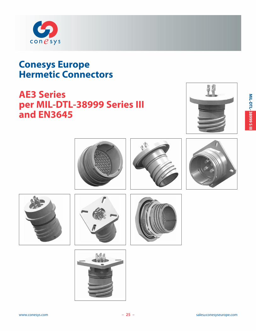
Conesys EuropeHermetic Connectors
AE3 Seriesper MIL-DTL-38999 Series IIIand EN3645
– –
MIL-D
TL-38999S
III
26www.conesys.com [email protected]
AE3 SeriesHermetic Connectorsper MIL-DTL-38999 Series III and EN3645
– –
MIL-D
TL-38999S
III
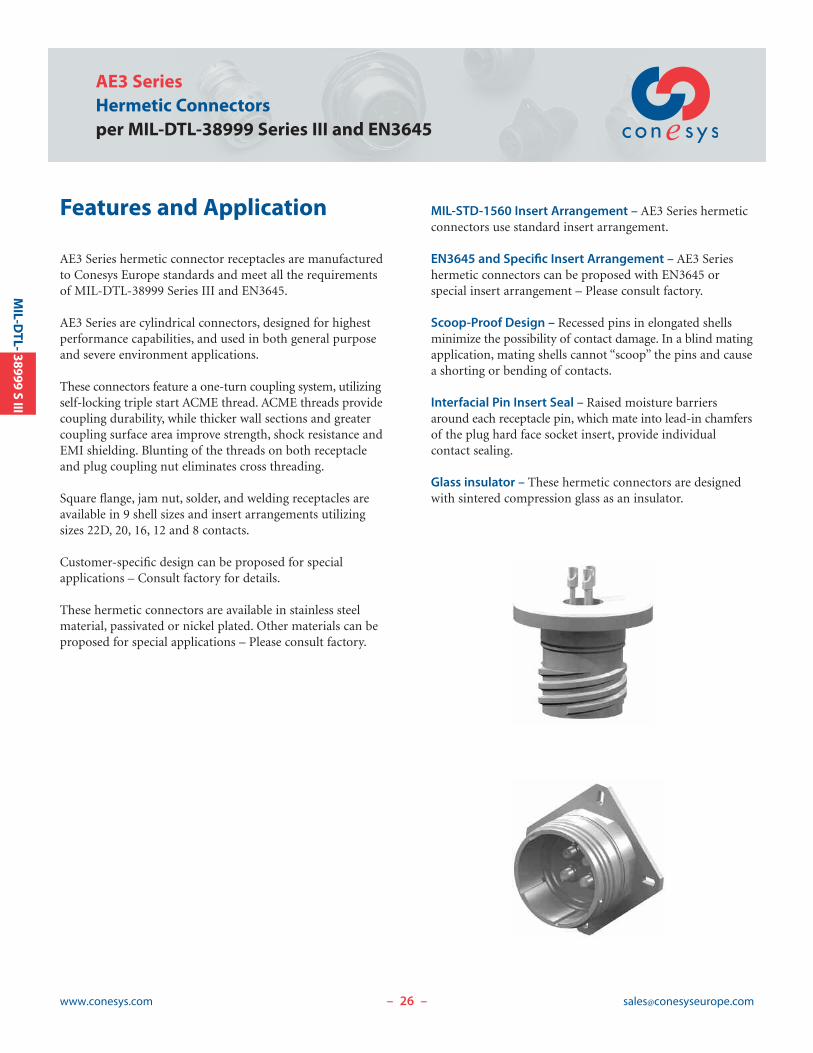
Features and Application
AE3 Series hermetic connector receptacles are manufacturedto Conesys Europe standards and meet all the requirementsof MIL-DTL-38999 Series III and EN3645.
AE3 Series are cylindrical connectors, designed for highestperformance capabilities, and used in both general purposeand severe environment applications.
These connectors feature a one-turn coupling system, utilizingself-locking triple start ACME thread. ACME threads providecoupling durability, while thicker wall sections and greatercoupling surface area improve strength, shock resistance andEMI shielding. Blunting of the threads on both receptacleand plug coupling nut eliminates cross threading.
Square flange, jam nut, solder, and welding receptacles areavailable in 9 shell sizes and insert arrangements utilizingsizes 22D, 20, 16, 12 and 8 contacts.
Customer-specific design can be proposed for special applications – Consult factory for details.
These hermetic connectors are available in stainless steelmaterial, passivated or nickel plated. Other materials can beproposed for special applications – Please consult factory.
MIL-STD-1560 Insert Arrangement – AE3 Series hermeticconnectors use standard insert arrangement.
EN3645 and Specific Insert Arrangement – AE3 Series hermetic connectors can be proposed with EN3645 or special insert arrangement – Please consult factory.
Scoop-Proof Design – Recessed pins in elongated shellsminimize the possibility of contact damage. In a blind matingapplication, mating shells cannot “scoop” the pins and causea shorting or bending of contacts.
Interfacial Pin Insert Seal – Raised moisture barriersaround each receptacle pin, which mate into lead-in chamfersof the plug hard face socket insert, provide individual contact sealing.
Glass insulator – These hermetic connectors are designedwith sintered compression glass as an insulator.

27www.conesys.com [email protected]
AE3 SeriesHermetic Connectors
per MIL-DTL-38999 Series III and EN3645
– –
MIL-D
TL-38999S
III
Performance Specifications
Operating Temperature RangeClasses Y and N : -65°C to +200°C (-85°F to +392°F)
Material and Finish Data (Class)Class Y:
RECEPTACLE material: stainless steelfinish: passivated
CONTACTS material: ferrous alloyfinish: gold plated
Class N:RECEPTACLE material: stainless steel
finish: nickel platedCONTACTS material: ferrous alloy
finish: gold plated
Corrosion ResistanceClass Y: 500 hours as per MIL-DTL-38999Class N: 48 hours as per MIL-DTL-38999
DurabilityMinimum of 500 mating cycles.
Leakage< 1.10-7 atm.cm3.s-1.
Shock and VibrationShock: Pulse of approximate half sine wave of 300 g ± 15%magnitude with duration of 3 ±1 milliseconds applied inthree axes. Vibration: as per MIL-DTL-38999.
Shell-to-Shell ConductivityMaximum potential drop shall not exceed:
Class N: 1 millivoltClasses Y: 50 millivolts
Insulation Resistance>5000 M| under 500 Vdc(25°C – 65% HR max.)
Withstanding VoltageAt sea level:
Service M: 1300 V RMSService I: 1800 V RMSService II: 2300 V RMS
At 21 000 m altitude:Service M: 800 V RMSService I: 1000 V RMSService II: 1000 V RMS
Maximum Current Rating per ContactSize 22D 3 AmpSize 20 5 AmpSize 16 10 AmpSize 12 17 AmpSize 8 40 Amp
AE3 SeriesHermetic Connectorsper MIL-DTL-38999 Series III and EN3645
www.conesys.com [email protected]– –
MIL-D
TL-38999S
III
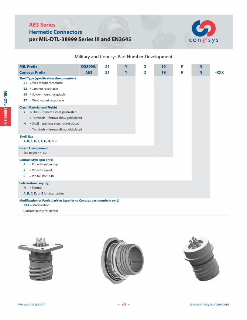
Military and Conesys Part Number Development
Mil. Prefix D38999/ 21 Y D 19 P N
Conesys Prefix AE3 21 Y D 19 P N -XXXShell Type (specification sheet number)
21 = Wall mount receptacle
23 = Jam nut receptacle
25 = Solder mount receptacle
27 = Weld mount receptacle
Class (Material and Finish)Y = Shell – stainless steel, passivated
= Terminals – ferrous alloy, gold plated
N = Shell – stainless steel, nickel plated
= Terminals – ferrous alloy, gold plated
Shell SizeA, B, C, D, E, F, G, H, or J
Insert ArrangementSee pages 47–50
Contact Style (pin only)P = Pin with solder cup
X = Pin with eyelet
C = Pin tail (for PCB)
Polarization (keying)N = Normal
A, B, C, D, or E for alternatives
Modification or Particularities (applies to Conesys part numbers only)XXX = Modification
Consult factory for details
29www.conesys.com [email protected]
AE3 SeriesHermetic Connectors
per MIL-DTL-38999 Series III and EN3645
– –
MIL-D
TL-38999S
III
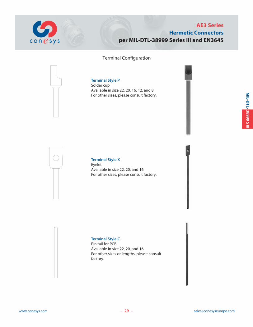
Terminal Configuration
Terminal Style PSolder cupAvailable in size 22, 20, 16, 12, and 8For other sizes, please consult factory.
Terminal Style XEyeletAvailable in size 22, 20, and 16For other sizes, please consult factory.
Terminal Style CPin tail for PCBAvailable in size 22, 20, and 16For other sizes or lengths, please consultfactory.
30www.conesys.com [email protected]
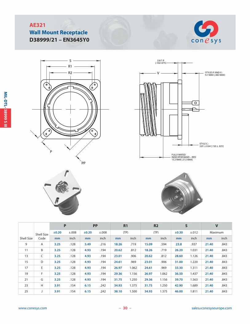
AE321Wall Mount ReceptacleD38999/21 – EN3645Y0
– –
MIL-D
TL-38999S
III
V
2.6/1.9[.102/.075]
STYLES P AND X :9.7 MAX [.382 MAX]
STYLE C :3.81 ± 0.64 [.150 ± .025]
FULLY MATEDINDICATOR BAND – RED13.2 MAX [.512 MAX]
PP
S
R1
R2
P
Shell SizeShell Size
Code
P PP R1 R2 S V
±0.20 ±.008 ±0.20 ±.008 (TP) (TP) ±0.30 ±.012 Maximum
mm inch mm inch mm inch mm inch mm inch mm inch
9 A 3.25 .128 5.49 .216 18.26 .719 15.09 .594 23.8 .937 21.40 .843
11 B 3.25 .128 4.93 .194 20.62 .812 18.26 .719 26.20 1.031 21.40 .843
13 C 3.25 .128 4.93 .194 23.01 .906 20.62 .812 28.60 1.126 21.40 .843
15 D 3.25 .128 4.93 .194 24.61 .969 23.01 .906 31.00 1.220 21.40 .843
17 E 3.25 .128 4.93 .194 26.97 1.062 24.61 .969 33.30 1.311 21.40 .843
19 F 3.25 .128 4.93 .194 29.36 1.156 26.97 1.062 36.50 1.437 21.40 .843
21 G 3.25 .128 4.93 .194 31.75 1.250 29.36 1.156 39.70 1.563 21.40 .843
23 H 3.91 .154 6.15 .242 34.93 1.375 31.75 1.250 42.90 1.689 21.40 .843
25 J 3.91 .154 6.15 .242 38.10 1.500 34.93 1.375 46.00 1.811 21.40 .843
Z
22.60 MAX[.890 MAX]
STYLE C3.81 ± 0.64 [.150 ± .025]
FULLY MATEDINDICATOR BAND – RED13.2 MAX [.512 MAX]
K(STYLES P AND X)
W
3.20/1.58[.125/.062]
GTHREAD
90° ± 5°
BFLATS
[ A
31www.conesys.com [email protected]
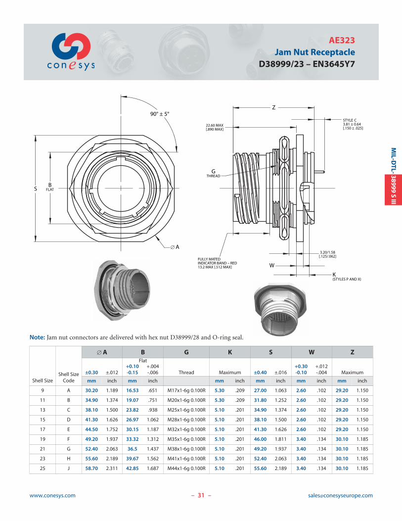
AE323Jam Nut Receptacle
D38999/23 – EN3645Y7
Note: Jam nut connectors are delivered with hex nut D38999/28 and O-ring seal.
– –
MIL-D
TL-38999S
III
Shell SizeShell Size
Code
[ A B G K S W ZFlat
+0.10 +.004 +0.30 +.012±0.30 ±.012 -0.15 -.006 Thread Maximum ±0.40 ±.016 -0.10 -.004 Maximum
mm inch mm inch mm inch mm inch mm inch mm inch
9 A 30.20 1.189 16.53 .651 M17x1-6g 0.100R 5.30 .209 27.00 1.063 2.60 .102 29.20 1.150
11 B 34.90 1.374 19.07 .751 M20x1-6g 0.100R 5.30 .209 31.80 1.252 2.60 .102 29.20 1.150
13 C 38.10 1.500 23.82 .938 M25x1-6g 0.100R 5.10 .201 34.90 1.374 2.60 .102 29.20 1.150
15 D 41.30 1.626 26.97 1.062 M28x1-6g 0.100R 5.10 .201 38.10 1.500 2.60 .102 29.20 1.150
17 E 44.50 1.752 30.15 1.187 M32x1-6g 0.100R 5.10 .201 41.30 1.626 2.60 .102 29.20 1.150
19 F 49.20 1.937 33.32 1.312 M35x1-6g 0.100R 5.10 .201 46.00 1.811 3.40 .134 30.10 1.185
21 G 52.40 2.063 36.5 1.437 M38x1-6g 0.100R 5.10 .201 49.20 1.937 3.40 .134 30.10 1.185
23 H 55.60 2.189 39.67 1.562 M41x1-6g 0.100R 5.10 .201 52.40 2.063 3.40 .134 30.10 1.185
25 J 58.70 2.311 42.85 1.687 M44x1-6g 0.100R 5.10 .201 55.60 2.189 3.40 .134 30.10 1.185
32www.conesys.com [email protected]
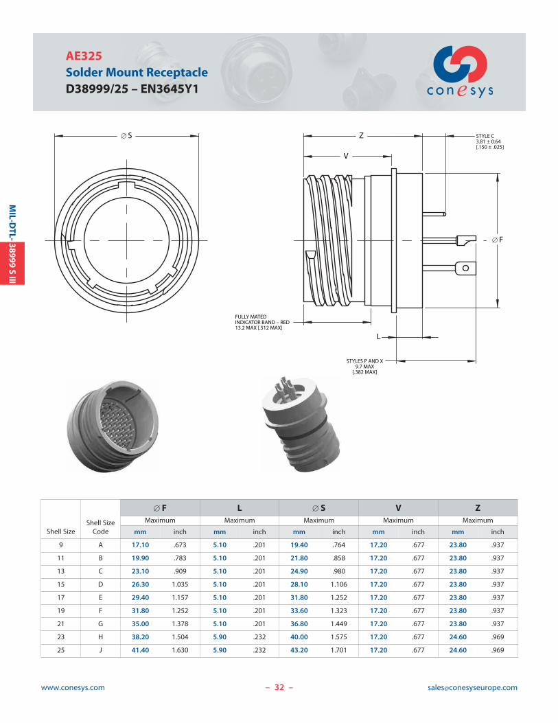
AE325Solder Mount ReceptacleD38999/25 – EN3645Y1
– –
MIL-D
TL-38999S
III
Z
V
FULLY MATEDINDICATOR BAND – RED13.2 MAX [.512 MAX]
[ F
L
STYLES P AND X9.7 MAX
[.382 MAX]
STYLE C3.81 ± 0.64[.150 ± .025]
[ S
Shell SizeShell Size
Code
[ F L [ S V ZMaximum Maximum Maximum Maximum Maximum
mm inch mm inch mm inch mm inch mm inch
9 A 17.10 .673 5.10 .201 19.40 .764 17.20 .677 23.80 .937
11 B 19.90 .783 5.10 .201 21.80 .858 17.20 .677 23.80 .937
13 C 23.10 .909 5.10 .201 24.90 .980 17.20 .677 23.80 .937
15 D 26.30 1.035 5.10 .201 28.10 1.106 17.20 .677 23.80 .937
17 E 29.40 1.157 5.10 .201 31.80 1.252 17.20 .677 23.80 .937
19 F 31.80 1.252 5.10 .201 33.60 1.323 17.20 .677 23.80 .937
21 G 35.00 1.378 5.10 .201 36.80 1.449 17.20 .677 23.80 .937
23 H 38.20 1.504 5.90 .232 40.00 1.575 17.20 .677 24.60 .969
25 J 41.40 1.630 5.90 .232 43.20 1.701 17.20 .677 24.60 .969
33www.conesys.com [email protected]
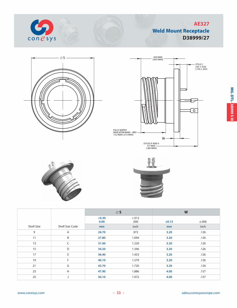
AE327Weld Mount Receptacle
D38999/27
– –
MIL-D
TL-38999S
III
FULLY MATEDINDICATOR BAND – RED13.2 MAX [.512 MAX]
STYLES P AND X9.7 MAX
[.382 MAX]
STYLE C3.81 ± 0.64[.150 ± .025]
20.8 MAX[.823 MAX]
W
[ S
Shell Size Shell Size Code
[ S W+0.30 +.0120.00 .000 ±0.15 ±.006
mm inch mm inch
9 A 24.70 .972 3.20 .126
11 B 27.80 1.094 3.20 .126
13 C 31.00 1.220 3.20 .126
15 D 34.20 1.346 3.20 .126
17 E 36.40 1.433 3.20 .126
19 F 40.10 1.579 3.20 .126
21 G 43.70 1.720 3.20 .126
23 H 47.90 1.886 4.00 .157
25 J 50.10 1.972 4.00 .157
34www.conesys.com [email protected]
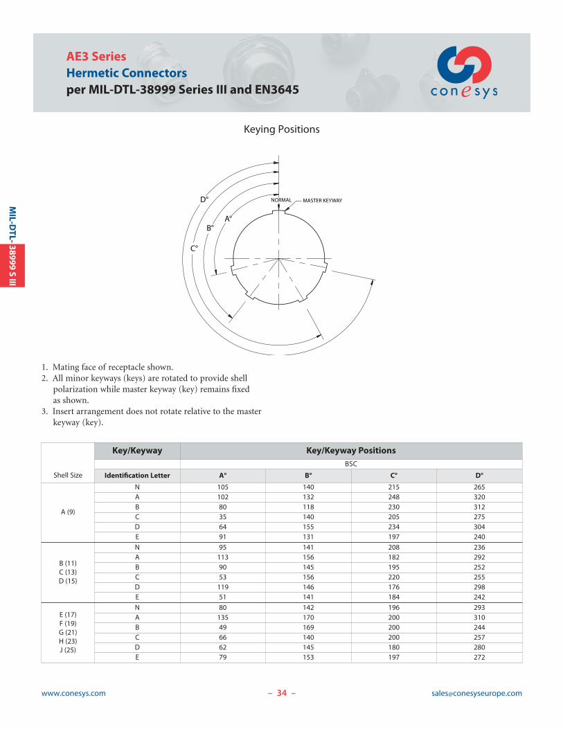
AE3 SeriesHermetic Connectorsper MIL-DTL-38999 Series III and EN3645
Keying Positions
– –
MIL-D
TL-38999S
III
C°
B°
D°
A°
MASTER KEYWAY NORMAL
1. Mating face of receptacle shown.2. All minor keyways (keys) are rotated to provide shell
polarization while master keyway (key) remains fixed as shown.
3. Insert arrangement does not rotate relative to the masterkeyway (key).
Shell Size
Key/Keyway Key/Keyway PositionsBSC
Identification Letter A° B° C° D°
A (9)
N 105 140 215 265A 102 132 248 320B 80 118 230 312C 35 140 205 275D 64 155 234 304E 91 131 197 240
B (11)C (13)D (15)
N 95 141 208 236A 113 156 182 292B 90 145 195 252C 53 156 220 255D 119 146 176 298E 51 141 184 242
E (17)F (19)G (21)H (23)J (25)
N 80 142 196 293A 135 170 200 310B 49 169 200 244C 66 140 200 257D 62 145 180 280E 79 153 197 272
35www.conesys.com [email protected]
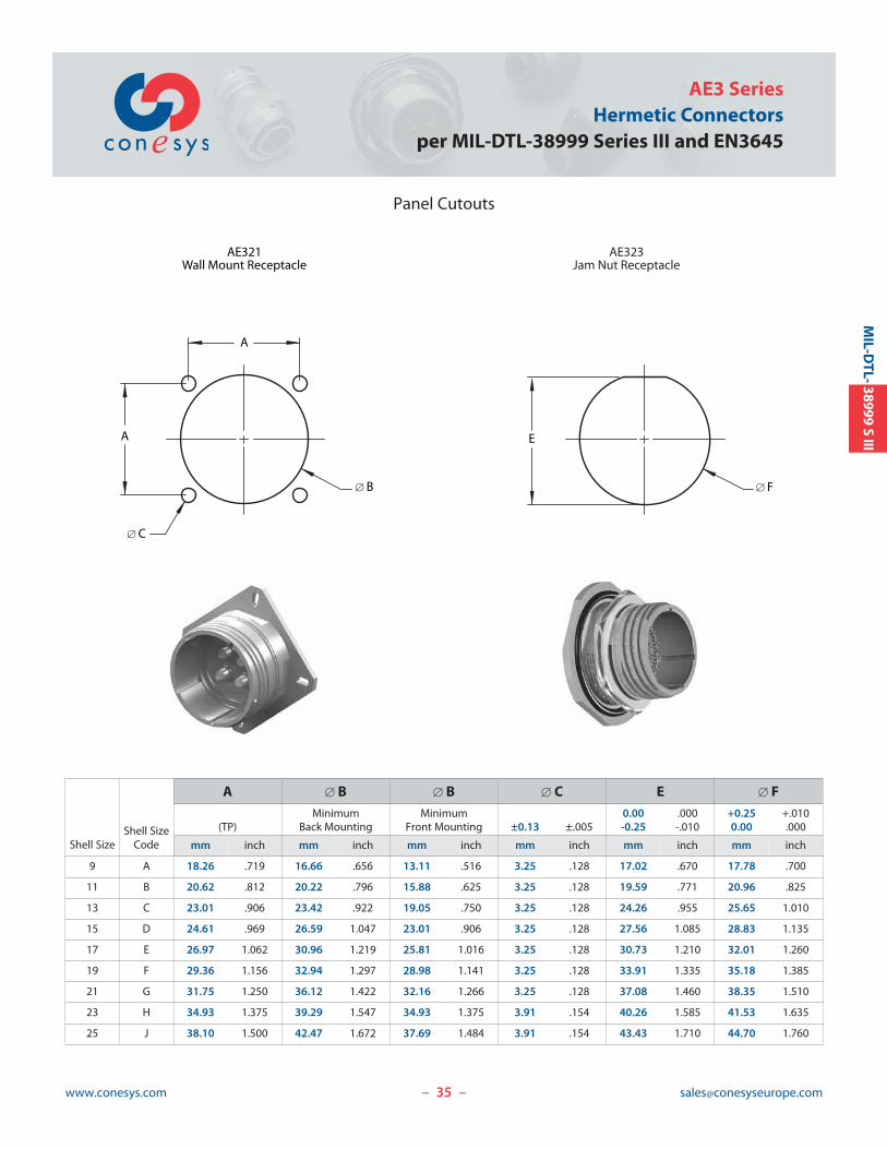
AE3 SeriesHermetic Connectors
per MIL-DTL-38999 Series III and EN3645
– –
MIL-D
TL-38999S
III
Panel Cutouts
A
[ B
A
[ C
AE321Wall Mount Receptacle
AE323Jam Nut Receptacle
[ F
E
Shell SizeShell Size
Code
A [ B [ B [ C E [ FMinimum Minimum 0.00 .000 +0.25 +.010
(TP) Back Mounting Front Mounting ±0.13 ±.005 -0.25 -.010 0.00 .000
mm inch mm inch mm inch mm inch mm inch mm inch
9 A 18.26 .719 16.66 .656 13.11 .516 3.25 .128 17.02 .670 17.78 .700
11 B 20.62 .812 20.22 .796 15.88 .625 3.25 .128 19.59 .771 20.96 .825
13 C 23.01 .906 23.42 .922 19.05 .750 3.25 .128 24.26 .955 25.65 1.010
15 D 24.61 .969 26.59 1.047 23.01 .906 3.25 .128 27.56 1.085 28.83 1.135
17 E 26.97 1.062 30.96 1.219 25.81 1.016 3.25 .128 30.73 1.210 32.01 1.260
19 F 29.36 1.156 32.94 1.297 28.98 1.141 3.25 .128 33.91 1.335 35.18 1.385
21 G 31.75 1.250 36.12 1.422 32.16 1.266 3.25 .128 37.08 1.460 38.35 1.510
23 H 34.93 1.375 39.29 1.547 34.93 1.375 3.91 .154 40.26 1.585 41.53 1.635
25 J 38.10 1.500 42.47 1.672 37.69 1.484 3.91 .154 43.43 1.710 44.70 1.760
36www.conesys.com [email protected]– –
MIL-D
TL-38999S
IV
Conesys EuropeHermetic Connectors
AE4 Seriesper MIL-DTL-38999 Series IV
37www.conesys.com [email protected]
AE4 SeriesHermetic Connectors
per MIL-DTL-38999 Series IV
– –37
Features and Application
AE4 Series hermetic connector receptacles are manufacturedto Conesys Europe standards and meet all the requirementsof MIL-DTL-38999 Series IV.
AE4 Series connectors are scoop-proof with breech coupling,designed to give a quick disconnect coupling mechanism toan already rugged connector.
AE4 Series hermetic receptacle connectors are intermateableand interchangeable with all other qualified MIL-C-38999Series IV connectors.
Square flange, jam nut, solder mount and weld mountreceptacles are available in 8 shell sizes and insert arrangements utilizing sizes 22D, 20, 16, 12, and 8 contacts.
Customer specific design can be proposed for special applications – Consult factory for details.
These hermetic connectors are available in stainless steelmaterial both passivated and nickel plated. Other materialscan be proposed for special applications – Please consultfactory.
MIL-STD-1560 Insert Arrangement – AE4 Series hermeticconnectors use standard insert arrangement.
Customer Specific Insert Arrangement – AE4 Series hermetic connectors can be proposed with special insertarrangement – Please consult factory.
Interfacial Pin Insert Seal – Raised moisture barriersaround each receptacle pin, which mate into lead-in chamfers of the plug hard face socket insert, provide individual contact sealing.
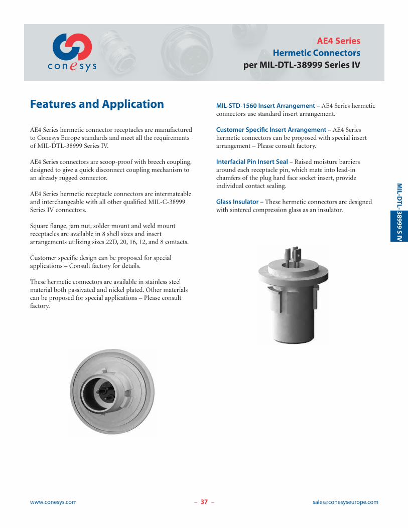
Glass Insulator – These hermetic connectors are designedwith sintered compression glass as an insulator.
MIL-D
TL- 38999S
IV
38www.conesys.com [email protected]
AE4 SeriesHermetic Connectorsper MIL-DTL-38999 Series IV
– –
MIL-D
TL-38999S
IV
Performance Specifications
Operating Temperature RangeClasses Y and N : -65°C to +200°C (-85°F to +392°F)
Material and Finish Data (Class)Class Y:
RECEPTACLE material: stainless steelfinish: passivated
CONTACTS material: ferrous alloyfinish: gold plated
Class N:RECEPTACLE material: stainless steel
finish: nickel platedCONTACTS material: ferrous alloy
finish: gold plated
Corrosion ResistanceClass Y: 500 hours as per MIL-DTL-38999Class N: 48 hours as per MIL-DTL-38999
DurabilityMinimum of 500 mating cycles.
Leakage< 1.10-7 atm.cm3.s-1.
Shock and VibrationShock: Pulse of approximate half sine wave of 300 g ± 15%magnitude with duration of 3 ±1 milliseconds applied inthree axes. Vibration: as per MIL-DTL-38999.
Shell-to-Shell ConductivityMaximum potential drop shall not exceed:
Class N: 1 millivoltClasses Y: 50 millivolts
Insulation Resistance>5000 M| under 500 Vdc(25°C – 65% HR max.)
Withstanding VoltageAt sea level:
Service M: 1300 V RMSService I: 1800 V RMSService II: 2300 V RMS
At 21 000 m altitude:Service M: 800 V RMSService I: 1000 V RMSService II: 1000 V RMS
Maximum Current Rating per ContactSize 22D 3 AmpSize 20 5 AmpSize 16 10 AmpSize 12 17 AmpSize 8 40 Amp
39www.conesys.com [email protected]
AE4 SeriesHermetic Connectors
per MIL-DTL-38999 Series IV
– –
Military and Conesys Part Number Development
Mil. Prefix D38999/ 41 Y D 19 P N
Conesys Prefix AE4 41 Y D 19 P N -XXXShell Type (specification sheet number)
41 = Wall mount receptacle
43 = Jam nut receptacle
45 = Solder mount receptacle
47 = Weld mount receptacle
Class (Material and Finish)Y = Shell – stainless steel, passivated
= Terminals – ferrous alloy, gold plated
N = Shell – stainless steel, nickel plated
= Terminals – ferrous alloy, gold plated
Shell SizeB, C, D, E, F, G, H, or J
Insert ArrangementSee pages 47–50
Contact Style (pin only)P = Pin with solder cup
X = Pin with eyelet
C = Pin tail (for PCB)
Polarization (keying)N = Normal
A, B, C, D, or E for alternatives
Modification or Particularities (applies to Conesys part numbers only)XXX = Modification
Consult factory for details
MIL-D
TL- 38999S
IV
40www.conesys.com [email protected]
AE4 SeriesHermetic Connectorsper MIL-DTL-38999 Series IV
– –
MIL-D
TL-38999S
IV
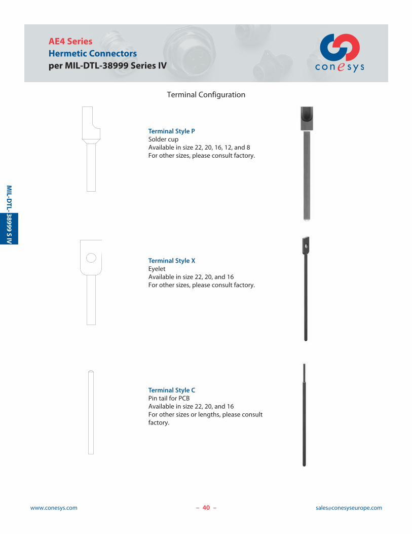
Terminal Configuration
Terminal Style PSolder cupAvailable in size 22, 20, 16, 12, and 8For other sizes, please consult factory.
Terminal Style XEyeletAvailable in size 22, 20, and 16For other sizes, please consult factory.
Terminal Style CPin tail for PCBAvailable in size 22, 20, and 16For other sizes or lengths, please consultfactory.
41www.conesys.com [email protected]
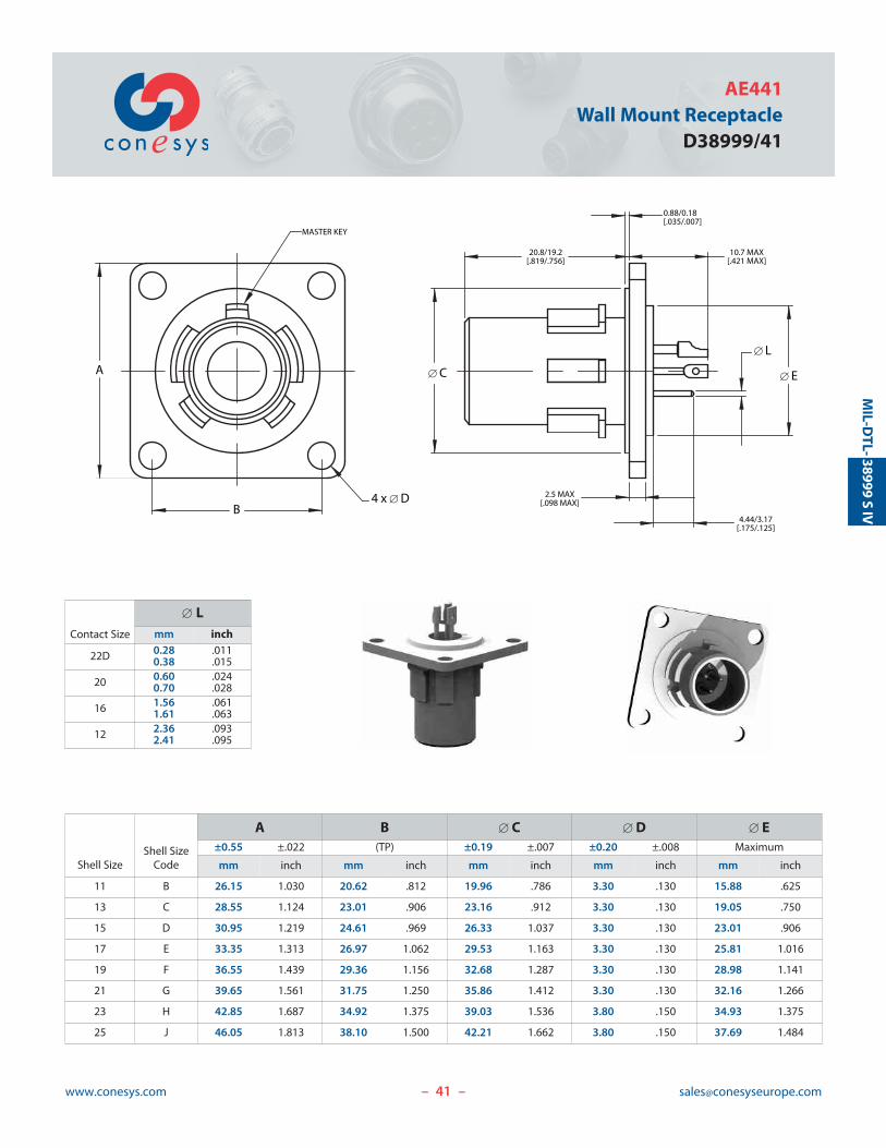
AE441Wall Mount Receptacle
D38999/41
– –
[ C
20.8/19.2[.819/.756]
2.5 MAX[.098 MAX]
4.44/3.17[.175/.125]
[ L
[ E
0.88/0.18[.035/.007]
10.7 MAX[.421 MAX]
B
A
4 x [ D
MASTER KEY
MIL-D
TL- 38999S
IV
Contact Size
[ Lmm inch
22D 0.280.38
.011
.015
20 0.600.70
.024
.028
16 1.561.61
.061
.063
12 2.362.41
.093
.095
Shell SizeShell Size
Code
A B [ C [ D [ E±0.55 ±.022 (TP) ±0.19 ±.007 ±0.20 ±.008 Maximum
mm inch mm inch mm inch mm inch mm inch
11 B 26.15 1.030 20.62 .812 19.96 .786 3.30 .130 15.88 .625
13 C 28.55 1.124 23.01 .906 23.16 .912 3.30 .130 19.05 .750
15 D 30.95 1.219 24.61 .969 26.33 1.037 3.30 .130 23.01 .906
17 E 33.35 1.313 26.97 1.062 29.53 1.163 3.30 .130 25.81 1.016
19 F 36.55 1.439 29.36 1.156 32.68 1.287 3.30 .130 28.98 1.141
21 G 39.65 1.561 31.75 1.250 35.86 1.412 3.30 .130 32.16 1.266
23 H 42.85 1.687 34.92 1.375 39.03 1.536 3.80 .150 34.93 1.375
25 J 46.05 1.813 38.10 1.500 42.21 1.662 3.80 .150 37.69 1.484
42www.conesys.com [email protected]
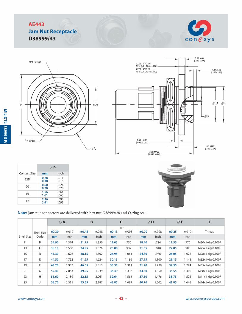
AE443Jam Nut ReceptacleD38999/43
– –
MIL-D
TL-38999S
IV
[ E[ D
[ P
4.44/3.17[.175/.125]
8.5 MAX[.335 MAX]
36.8 MAX[1.449 MAX]
2.35 ± 0.85[.092 ± .033]
5.89 MAX[.232 MAX]
SIZES 11 TO 17: 2.7 ± 0.3 [.106 ± .012]SIZES 19 TO 25: 3.5 ± 0.3 [.138 ± .012]
CFLATB
MASTER KEY
F THREAD
[ A
Note: Jam nut connectors are delivered with hex nut D38999/28 and O-ring seal.
Contact Size
[ Pmm inch
22D 0.280.38
.011
.015
20 0.600.70
.024
.028
16 1.561.61
.061
.063
12 2.362.41
.093
.095
Shell SizeShell Size
Code
[ A B C [ D [ E FFlat
±0.30 ±.012 ±0.45 ±.018 ±0.13 ±.005 ±0.20 ±.008 ±0.25 ±.010 Thread
mm inch mm inch mm inch mm inch mm inch
11 B 34.90 1.374 31.75 1.250 19.05 .750 18.40 .724 19.55 .770 M20x1-6g 0.100R
13 C 38.10 1.500 34.95 1.376 23.80 .937 21.55 .848 22.85 .900 M25x1-6g 0.100R
15 D 41.30 1.626 38.15 1.502 26.95 1.061 24.80 .976 26.05 1.026 M28x1-6g 0.100R
17 E 44.50 1.752 41.25 1.624 30.13 1.186 27.95 1.100 29.15 1.148 M32x1-6g 0.100R
19 F 49.20 1.937 46.05 1.813 33.31 1.311 31.20 1.228 32.35 1.274 M35x1-6g 0.100R
21 G 52.40 2.063 49.25 1.939 36.49 1.437 34.30 1.350 35.55 1.400 M38x1-6g 0.100R
23 H 55.60 2.189 52.35 2.061 39.64 1.561 37.50 1.476 38.75 1.526 M41x1-6g 0.100R
25 J 58.70 2.311 55.55 2.187 42.85 1.687 40.70 1.602 41.85 1.648 M44x1-6g 0.100R

43www.conesys.com [email protected]
AE445Solder Mount Receptacle
D38999/45
– –
[ D
20.8/19.2[.819/.756]
1.19/0.61[.047/.024]
0.88/0.18[.035/.007]
11.13 MAX[.438 MAX]
[ G
4.44/3.17[.175/.125]
4.57 MAX[.180 MAX]
[ A
[ B
MASTER KEY
MIL-D
TL- 38999S
IV
Contact Size
[ Gmm inch
22D 0.280.38
.011
.015
20 0.600.70
.024
.028
16 1.561.61
.061
.063
12 2.362.41
.093
.095
Shell Size Shell Size Code
[ A [ B [ DMaximum Maximum ±0.19 ±.007
mm inch mm inch mm inch
11 B 19.90 .783 21.90 .862 19.96 .786
13 C 23.10 .909 25.10 .988 23.16 .912
15 D 26.30 1.035 28.20 1.110 26.33 1.037
17 E 29.40 1.157 31.40 1.236 29.53 1.163
19 F 31.80 1.252 33.80 1.331 32.68 1.287
21 G 35.00 1.378 37.00 1.457 35.86 1.412
23 H 38.20 1.504 40.20 1.583 39.03 1.537
25 J 41.40 1.630 43.30 1.705 42.21 1.662
44www.conesys.com [email protected]
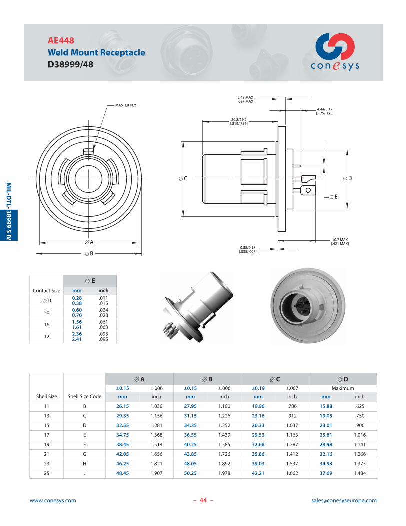
AE448Weld Mount ReceptacleD38999/48
– –
MIL-D
TL-38999S
IV
[ C [ D
[ E
4.44/3.17[.175/.125]
2.48 MAX[.097 MAX]
20.8/19.2[.819/.756]
0.88/0.18[.035/.007]
10.7 MAX[.421 MAX][ A
[ B
MASTER KEY
Contact Size
[ Emm inch
22D 0.280.38
.011
.015
20 0.600.70
.024
.028
16 1.561.61
.061
.063
12 2.362.41
.093
.095
Shell Size Shell Size Code
[ A [ B [ C [ D±0.15 ±.006 ±0.15 ±.006 ±0.19 ±.007 Maximum
mm inch mm inch mm inch mm inch
11 B 26.15 1.030 27.95 1.100 19.96 .786 15.88 .625
13 C 29.35 1.156 31.15 1.226 23.16 .912 19.05 .750
15 D 32.55 1.281 34.35 1.352 26.33 1.037 23.01 .906
17 E 34.75 1.368 36.55 1.439 29.53 1.163 25.81 1.016
19 F 38.45 1.514 40.25 1.585 32.68 1.287 28.98 1.141
21 G 42.05 1.656 43.85 1.726 35.86 1.412 32.16 1.266
23 H 46.25 1.821 48.05 1.892 39.03 1.537 34.93 1.375
25 J 48.45 1.907 50.25 1.978 42.21 1.662 37.69 1.484
45www.conesys.com [email protected]
AE4 SeriesHermetic Connectors
per MIL-DTL-38999 Series IV
Keying Positions
– –
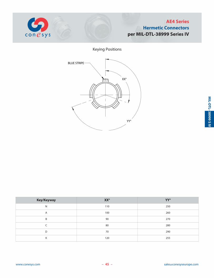
XX°
YY°
BLUE STRIPE
MIL-D
TL- 38999S
IV
Key/Keyway XX° YY°
N 110 250
A 100 260
B 90 270
C 80 280
D 70 290
K 120 255
46www.conesys.com [email protected]
AE4 SeriesHermetic Connectorsper MIL-DTL-38999 Series IV
– –
MIL-D
TL-38999S
IV
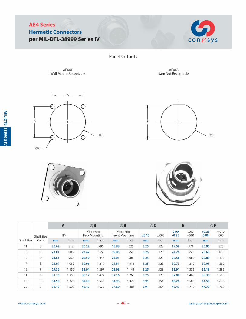
Panel Cutouts
A
[ B
A
[ C
AE441Wall Mount Receptacle
AE443Jam Nut Receptacle
[ F
E
Shell SizeShell Size
Code
A [ B [ B [ C E [ FMinimum Minimum 0.00 .000 +0.25 +.010
(TP) Back Mounting Front Mounting ±0.13 ±.005 -0.25 -.010 0.00 .000
mm inch mm inch mm inch mm inch mm inch mm inch
11 B 20.62 .812 20.22 .796 15.88 .625 3.25 .128 19.59 .771 20.96 .825
13 C 23.01 .906 23.42 .922 19.05 .750 3.25 .128 24.26 .955 25.65 1.010
15 D 24.61 .969 26.59 1.047 23.01 .906 3.25 .128 27.56 1.085 28.83 1.135
17 E 26.97 1.062 30.96 1.219 25.81 1.016 3.25 .128 30.73 1.210 32.01 1.260
19 F 29.36 1.156 32.94 1.297 28.98 1.141 3.25 .128 33.91 1.335 35.18 1.385
21 G 31.75 1.250 36.12 1.422 32.16 1.266 3.25 .128 37.08 1.460 38.35 1.510
23 H 34.93 1.375 39.29 1.547 34.93 1.375 3.91 .154 40.26 1.585 41.53 1.635
25 J 38.10 1.500 42.47 1.672 37.69 1.484 3.91 .154 43.43 1.710 44.70 1.760
47www.conesys.com [email protected]
AE1, AE2, AE3, and AE4 SeriesInsert Arrangement and Contact Information
per MIL-STD-1560
Insert Arrangement and Contact Information
– –
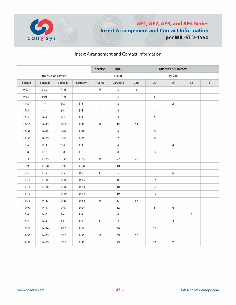
Insert Arrangement
Service Total Quantity of Contacts
No. of by Size
Series I Series II Series III Series IV Rating Contacts 22D 20 16 12 8
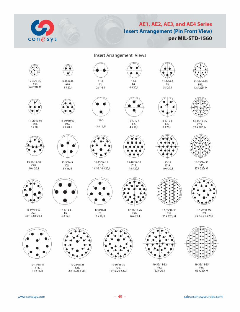
9-35 8-35 A-35 — M 6 6
9-98 8-98 A-98 — I 3 3
11-2 — B-2 B-2 I 2 2
11-4 — B-4 B-4 I 4 4
11-5 10-5 B-5 B-5 I 5 5
11-35 10-35 B-35 B-35 M 13 13
11-98 10-98 B-98 B-98 I 6 6
11-99 10-99 B-99 B-99 I 7 7
13-4 12-4 C-4 C-4 I 4 4
13-8 12-8 C-8 C-8 I 8 8
13-35 12-35 C-35 C-35 M 22 22
13-98 12-98 C-98 C-98 I 10 10
15-5 14-5 D-5 D-5 II 5 5
15-15 14-15 D-15 D-15 I 15 14 1
15-18 14-18 D-18 D-18 I 18 18
15-19 — D-19 D-19 I 19 19
15-35 14-35 D-35 D-35 M 37 37
15-97 14-97 D-97 D-97 I 12 8 4
17-6 16-6 E-6 E-6 I 6 6
17-8 16-8 E-8 E-8 II 8 8
17-26 16-26 E-26 E-26 I 26 26
17-35 16-35 E-35 E-35 M 55 55
17-99 16-99 E-99 E-99 I 23 21 2
48www.conesys.com [email protected]
AE1, AE2, AE3, and AE4 SeriesInsert Arrangement and Contact Information per MIL-STD-1560
Insert Arrangement and Contact Information
– –
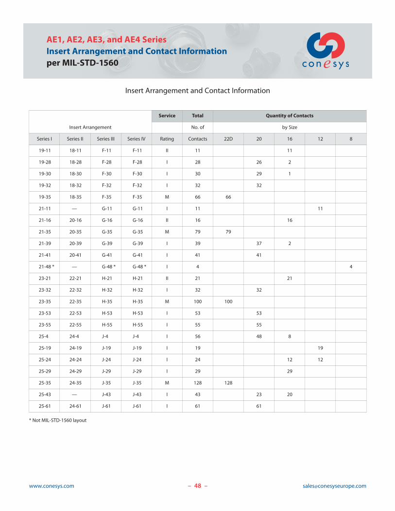
Insert Arrangement
Service Total Quantity of Contacts
No. of by Size
Series I Series II Series III Series IV Rating Contacts 22D 20 16 12 8
19-11 18-11 F-11 F-11 II 11 11
19-28 18-28 F-28 F-28 I 28 26 2
19-30 18-30 F-30 F-30 I 30 29 1
19-32 18-32 F-32 F-32 I 32 32
19-35 18-35 F-35 F-35 M 66 66
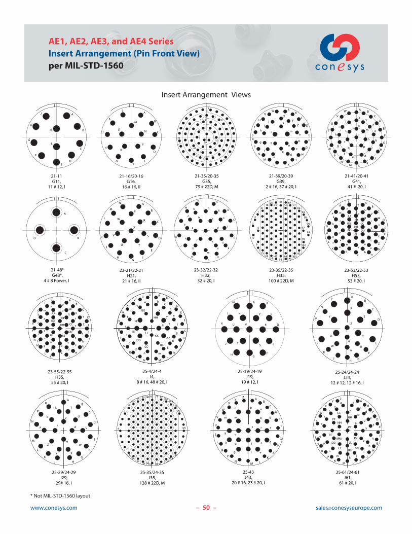
21-11 — G-11 G-11 I 11 11
21-16 20-16 G-16 G-16 II 16 16
21-35 20-35 G-35 G-35 M 79 79
21-39 20-39 G-39 G-39 I 39 37 2
21-41 20-41 G-41 G-41 I 41 41
21-48 * — G-48 * G-48 * I 4 4
23-21 22-21 H-21 H-21 II 21 21
23-32 22-32 H-32 H-32 I 32 32
23-35 22-35 H-35 H-35 M 100 100
23-53 22-53 H-53 H-53 I 53 53
23-55 22-55 H-55 H-55 I 55 55
25-4 24-4 J-4 J-4 I 56 48 8
25-19 24-19 J-19 J-19 I 19 19
25-24 24-24 J-24 J-24 I 24 12 12
25-29 24-29 J-29 J-29 I 29 29
25-35 24-35 J-35 J-35 M 128 128
25-43 — J-43 J-43 I 43 23 20
25-61 24-61 J-61 J-61 I 61 61
* Not MIL-STD-1560 layout
49www.conesys.com [email protected]
AE1, AE2, AE3, and AE4 SeriesInsert Arrangement (Pin Front View)
per MIL-STD-1560
Insert Arrangement Views
– –
1
23
4
56
9-35/8-35A35,
6 # 22D, M
A
B
C
9-98/8-98A98,
3 # 20, I
AB
11-2B2,
2 # 16, I
A
BC
D
11-4B4,
4 # 20, I
A
BC
D
E
11-5/10-5B5,
5 # 20, I
12
3
45
67
8
9
10 11
1213
11-35/10-35B35,
13 # 22D, M
A
B
CD
E F
11-98/10-98B98,
6 # 20, I
A
B
CD
E
FG
11-99/10-99B99,
7 # 20, I
A
B
C
12-3
3 # 16, II
A
B
C
D
13-4/12-4C4,
4 # 16, I
A
B
CD
E
F
G
H
13-8/12-8C8,
8 # 20, I
13-35/12-35C35,
22 # 22D, M
AB
C
D
E
F
G
H
JK
13-98/12-98C98,
10 # 20, I
A
B
CD
E
15-5/14-5D5,
5 # 16, II
A
B
C
D
E
F
G
H
J
K
L
MR N
15-15/14-15D15,
1 # 16, 14 # 20, I
A
B
C
D
EFG
H
J
K
L
M N
P
RS
T U
15-18/14-18D18,
18 # 20, I
A B
C
D
E
FG
H
J
K
L
M
N P
R
ST
U V
15-19D19,
19 # 20, I
15-35/14-35D35,
37 # 22D, M
A
B
C
D
EF
G
H
J
K
L
M
15-97/14-97D97,
4 # 16, 8 # 20, I
A
B
C
D
E
F
17-6/16-6E6,
6 # 12, I
A
B
C
DE
F
G
H
17-8/16-8E8,
8 # 16, II
AB
C
D
E
F
G
HJK
L
M
N
P
RS T
U
V
WX
Y
Z
a b
c
17-26/16-26E26,
26 # 20, I
17-35/16-35E35,
55 # 22D, M
P
1
3
4
9
10
16
17
24
25
31
32
39
40
46
47
52
53
55
1
15
22
21
14
21
1
31
17-99/16-99E99,
2 # 16, 21 # 20, I
19-11/18-11F11,
11 # 16, II
A
B
C
D
E
L
F
G
H
J
K
AB
C
D
E
FG
HJK
L
M
N
P
RS T
U
V
W
X
Y Z
19-28/18-28F28,
2 # 16, 26 # 20, I
A
B
C
D
E
F
G
JKL
M
N
P
R
S
T
U
V
W
X
Y
Z
a
b
c
d
e
19-30/18-30F30,
1 # 16, 29 # 20, I
A
B
C
D
E
F
GH
J
K
L
M
N
P
RS
T
U
V
W
X
Y
Z
a
b
c
d
e
fg
19-35/18-35F35,
66 #22D, M
1
3
4
9
10
16
17
24
25
33
34
42
43
50
51
57
58
63
64
66
19-32/18-32F32,
32 # 20, I
A
B
C
D
E
F
GJ
HKL
M
N
P
R
S
T
U
V
W
X
Y
Zab
c
d
e
f
g
h
j
50www.conesys.com [email protected]
AE1, AE2, AE3, and AE4 SeriesInsert Arrangement (Pin Front View)per MIL-STD-1560
Insert Arrangement Views
– –
21-11G11,
11 # 12, I
21-16/20-16G16,
16 # 16, II
A
B
C
DE
F
G
H
J
K
L
A
B
C
D
EF
G
H
J
K
L
M
N
P
R
S
21-41/20-41G41,
41 # 20, I
21-48*G48*,
4 # 8 Power, I
AB
C
D
E
F
G
H
J
KLM
N
P
R
S
T
U
V
W
XY
Z
a
b
c
def
g
h
i
j
km
t
n
pq
r
s
21-39/20-39G39,
2 # 16, 37 # 20, I
AB
C
D
E
F
G
H
J
KL
M
N
P
RS
T
U
VX
Y
Z
W
a
b
c
de
f
g
h
ij
k
m
n
p
q
r
A
B
C
D
23-21/22-21H21,
21 # 16, II
A
B
C
D
E
FG
H
J
K
L
M
N
P
R
S
TU
V
W
X
21-35/20-35G35,
79 # 22D, M
1
11
7121
31
41
51
61
79
23-53/22-53H53,
53 # 20, I
23-35/22-35H35,
100 # 22D, M
AB
C
D
E
F
G
HJ
K
L
M
N
P
RS
T
UV
W
X
Y
Z
a
bc
d
ef
g
h
k
mn
pq
r
s
tu
vw
x
y
z
AABB
CC
DDEE
FF
GGHH
1
2
3
5
6
8
715
16
24
25
34
35
45
46
55
4
56
66
67
76
77
85
86
93
94
95
96
97
98
99
100
23-32/22-32H32,
32 # 20, I
A
B
C
D
E
FG
H
J
K
L
M
N
PR
S
T
U
V
W
X
Y
Z
a
b
c
d
ef
g
h
i
25-4/24-4J4,
8 # 16, 48 # 20, I
e
AB
CD
E
F
G
H
J
KL
MN
X
YZ
a
bc
d
f
g
h
k
mnP
R
S
T
U
V
W
p
q
r
s
t
uv
w
x
y
z
AA
BBCC
DD
EE
FF
GG
HH
JJ
KKLL
23-55/22-55H55,
55 # 20, I
a
bc
de
fg
H
i
j
k
mn
pq
r
s
t
uv
wx
y
z
AB
C
D
E
F
G
HJK
L
M
N
P
R
S
TU
V
WX
Y
Z
AA
BB
CC
DDEEFF
GG
HH
25-19/24-19J19,
19 # 12, I
A B
C
D
E
FG
H
J
K
L
M
N P
R
ST
U V
25-24/24-24J24,
12 # 12, 12 # 16, I
a
AB
C
D
E
F
GHJ
K
L
M
N
P
R
S
T
UV
W
X
Y
Z
25-29/24-29J29,
29# 16, I
AB
C
D
E
F
G
HJ
K
L
M
N
P
R
S T
U
V
W
XY
Z
a
b c
d
e
f
25-35/24-35J35,
128 # 22D, M
1
4
7
8
14
15
24
25
35
36
47
48
58
59
70
71
81
8294
105
115
122
125
121114
10493
25-43J43,
20 # 16, 23 # 20, I
AB
C
D
E
F
G
H
J
KLM
N
P
R
S
T
U
V
W
XY
Z
a
b
c
d
efg
h
k
m
n p
r
stu
v
w
x
q
25-61/24-61J61,
61 # 20, I
A
B
C
D
E
F
G
H
JK
LMN
P
R
S
T
U
V
W
X
YZa b
c
d
e
f
g
h
jkm
n
P
r
s
t
uv
w
x
y
z
AABB
CC
DD
EE
FF
GG
HH
JJ
KKLL
MM
NN
PP
i
q
* Not MIL-STD-1560 layout
51www.conesys.com [email protected]
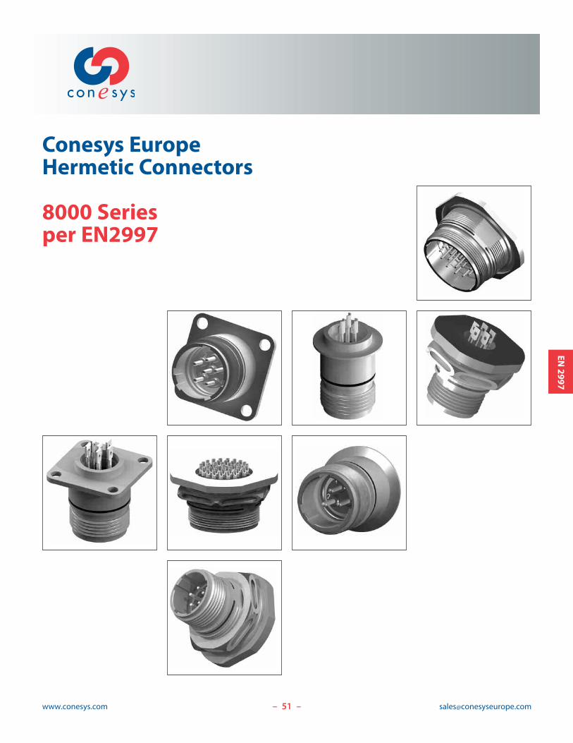
Conesys EuropeHermetic Connectors
8000 Seriesper EN2997
– –
EN2997
52www.conesys.com [email protected]
8000 SeriesHermetic Connectorsper EN2997
– –
EN2997
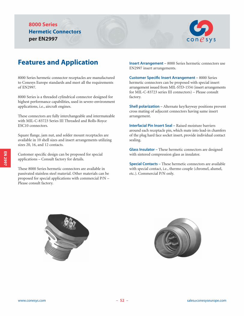
Features and Application
8000 Series hermetic connector receptacles are manufacturedto Conesys Europe standards and meet all the requirementsof EN2997.
8000 Series is a threaded cylindrical connector designed forhighest performance capabilities, used in severe-environmentapplications, i.e., aircraft engines.
These connectors are fully interchangeable and intermateablewith MIL-C-83723 Series III Threaded and Rolls-RoyceESC10 connectors.
Square flange, jam nut, and solder mount receptacles areavailable in 10 shell sizes and insert arrangements utilizingsizes 20, 16, and 12 contacts.
Customer specific design can be proposed for special applications – Consult factory for details.
These 8000 Series hermetic connectors are available in passivated stainless steel material. Other materials can beproposed for special applications with commercial P/N –Please consult factory.
Insert Arrangement – 8000 Series hermetic connectors useEN2997 insert arrangements.
Customer Specific Insert Arrangement – 8000 Series hermetic connectors can be proposed with special insertarrangement issued from MIL-STD-1554 (insert arrangementsfor MIL-C-83723 series III connectors) – Please consult factory.
Shell polarization – Alternate key/keyway positions preventcross mating of adjacent connectors having same insertarrangement.
Interfacial Pin Insert Seal – Raised moisture barriersaround each receptacle pin, which mate into lead-in chamfersof the plug hard face socket insert, provide individual contactsealing.
Glass Insulator – These hermetic connectors are designedwith sintered compression glass as insulator.
Special Contacts – These hermetic connectors are availablewith special contact, i.e., thermo couple (chromel, alumel,etc.). Commercial P/N only.
53www.conesys.com [email protected]
8000 SeriesHermetic Connectors
per EN2997
– –
EN2997
Performance Specifications
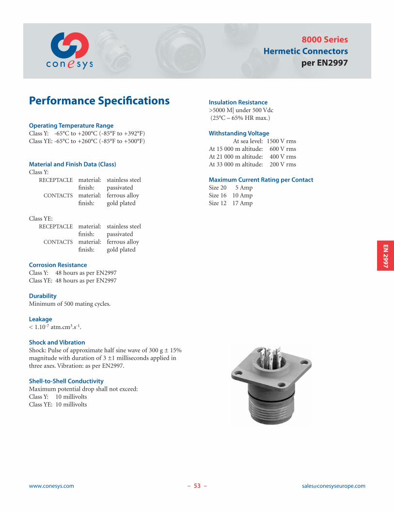
Operating Temperature RangeClass Y: -65°C to +200°C (-85°F to +392°F)Class YE: -65°C to +260°C (-85°F to +500°F)
Material and Finish Data (Class)Class Y:
RECEPTACLE material: stainless steelfinish: passivated
CONTACTS material: ferrous alloyfinish: gold plated
Class YE:RECEPTACLE material: stainless steel
finish: passivatedCONTACTS material: ferrous alloy
finish: gold plated
Corrosion ResistanceClass Y: 48 hours as per EN2997Class YE: 48 hours as per EN2997
DurabilityMinimum of 500 mating cycles.
Leakage< 1.10-7 atm.cm3.s-1.
Shock and VibrationShock: Pulse of approximate half sine wave of 300 g ± 15%magnitude with duration of 3 ±1 milliseconds applied inthree axes. Vibration: as per EN2997.
Shell-to-Shell ConductivityMaximum potential drop shall not exceed:Class Y: 10 millivoltsClass YE: 10 millivolts
Insulation Resistance>5000 M| under 500 Vdc(25°C – 65% HR max.)
Withstanding VoltageAt sea level: 1500 V rms
At 15 000 m altitude: 600 V rmsAt 21 000 m altitude: 400 V rmsAt 33 000 m altitude: 200 V rms
Maximum Current Rating per ContactSize 20 5 AmpSize 16 10 AmpSize 12 17 Amp

8000 SeriesHermetic Connectorsper EN2997
www.conesys.com [email protected]– –
EN2997
EN and Conesys Part Number Development
EN Prefix EN2997 Y 0 10 06 M N
Conesys Prefix 8000 Y 0 10 06 P N -XXXClass (Material and Finish)
Y = Shell – stainless steel, passivated (200 C°)
= Terminals – ferrous alloy, gold plated
YE = Shell – stainless steel, passivated (260 C°)
= Terminals – ferrous alloy, gold plated
Shell Type (specification sheet number)0 = Square flange receptacle
7 = Jam nut receptacle
1 = Solder mount receptacle
Shell Size8 thru 24 (Size 28 – Consult factory)
Insert ArrangementSee pages 62–64
Contact Style (pin only)M = Pin with solder cup – EN P/N only
P = Pin with solder cup – Conesys P/N only
X = Pin with eyelet – Conesys P/N only
C = Pin tail (for PCB) – Conesys P/N only
Polarization (keying)N = Normal
6, 7, 8, 9, or Y (Alternate keyed positions; Y is not available in SS 8)
Modification or Particularities (applies to Conesys part numbers only)XXX = Modification
Consult factory for details
EN2997
55www.conesys.com [email protected]
8000 SeriesHermetic Connectors
per EN2997
– –
EN2997
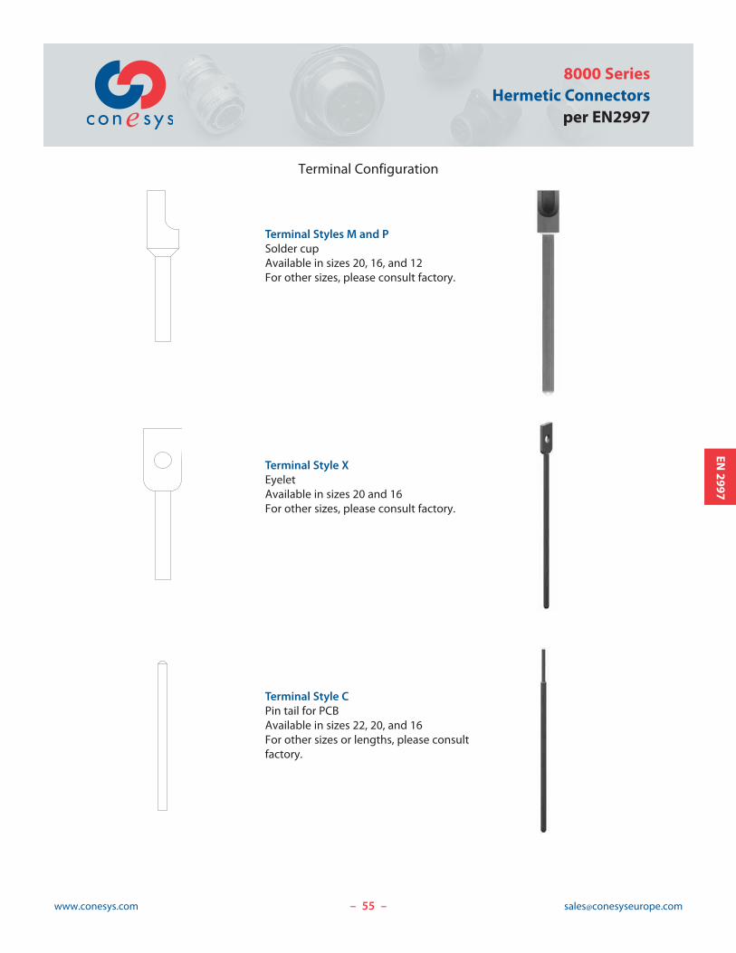
Terminal Configuration
Terminal Styles M and PSolder cupAvailable in sizes 20, 16, and 12For other sizes, please consult factory.
Terminal Style XEyeletAvailable in sizes 20 and 16For other sizes, please consult factory.
Terminal Style CPin tail for PCBAvailable in sizes 22, 20, and 16For other sizes or lengths, please consultfactory.
56www.conesys.com [email protected]
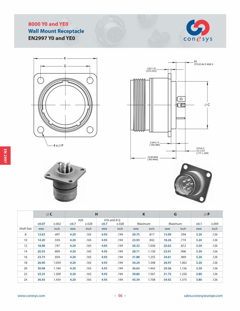
8000 Y0 and YE0Wall Mount ReceptacleEN2997 Y0 and YE0
– –
EN2997
22.96 MAX[.903 MAX]
[ C
STYLE C:4.5 ± 0.5[.177 ± .020]
HSTYLES M, P, AND X
2.64/2.13[.104/.084]
1.82/1.32[.072/.052]
K
G
4 x [ P
Shell Size
[ C H K G [ P#20 #16 and #12
±0.07 ±.002 ±0.7 ±.028 ±0.7 ±.028 Maximum Maximum ±0.1 ±.004
mm inch mm inch mm inch mm inch mm inch mm inch
8 12.63 .497 4.20 .165 4.93 .194 20.75 .817 15.09 .594 3.20 .126
10 14.20 .559 4.20 .165 4.93 .194 23.93 .942 18.26 .719 3.20 .126
12 18.98 .747 4.20 .165 4.93 .194 26.32 1.036 20.62 .812 3.20 .126
14 20.55 .809 4.20 .165 4.93 .194 28.71 1.130 23.01 .906 3.20 .126
16 23.73 .934 4.20 .165 4.93 .194 31.88 1.255 24.61 .969 3.20 .126
18 26.90 1.059 4.20 .165 4.93 .194 34.24 1.348 26.97 1.062 3.20 .126
20 30.08 1.184 4.20 .165 4.93 .194 36.63 1.442 29.36 1.156 3.20 .126
22 33.25 1.309 4.20 .165 4.93 .194 39.80 1.567 31.75 1.250 3.80 .126
24 36.43 1.434 4.20 .165 4.93 .194 43.39 1.708 34.92 1.375 3.80 .126
57www.conesys.com [email protected]
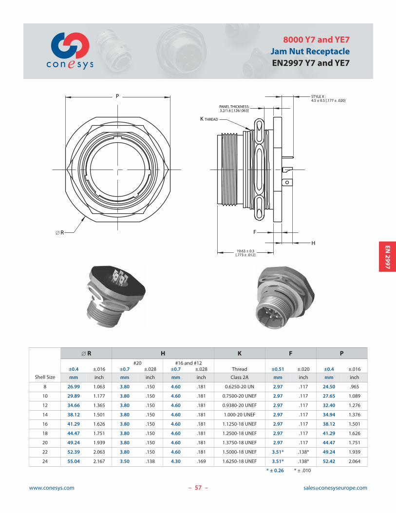
8000 Y7 and YE7Jam Nut ReceptacleEN2997 Y7 and YE7
– –
EN2997
F
19.63 ± 0.3[.773 ± .012]
STYLE X :4.5 ± 0.5 [.177 ± .020]
H
PANEL THICKNESS:3.2/1.6 [.126/.063]
K THREAD
P
[ R
Shell Size
[ R H K F P#20 #16 and #12
±0.4 ±.016 ±0.7 ±.028 ±0.7 ±.028 Thread ±0.51 ±.020 ±0.4 ±.016
mm inch mm inch mm inch Class 2A mm inch mm inch
8 26.99 1.063 3.80 .150 4.60 .181 0.6250-20 UN 2.97 .117 24.50 .965
10 29.89 1.177 3.80 .150 4.60 .181 0.7500-20 UNEF 2.97 .117 27.65 1.089
12 34.66 1.365 3.80 .150 4.60 .181 0.9380-20 UNEF 2.97 .117 32.40 1.276
14 38.12 1.501 3.80 .150 4.60 .181 1.000-20 UNEF 2.97 .117 34.94 1.376
16 41.29 1.626 3.80 .150 4.60 .181 1.1250-18 UNEF 2.97 .117 38.12 1.501
18 44.47 1.751 3.80 .150 4.60 .181 1.2500-18 UNEF 2.97 .117 41.29 1.626
20 49.24 1.939 3.80 .150 4.60 .181 1.3750-18 UNEF 2.97 .117 44.47 1.751
22 52.39 2.063 3.80 .150 4.60 .181 1.5000-18 UNEF 3.51* .138* 49.24 1.939
24 55.04 2.167 3.50 .138 4.30 .169 1.6250-18 UNEF 3.51* .138* 52.42 2.064
* ± 0.26 * ± .010
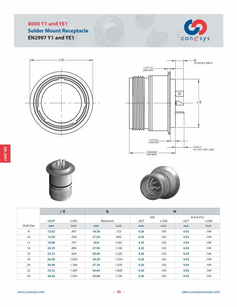
58www.conesys.com [email protected]
8000 Y1 and YE1Solder Mount ReceptacleEN2997 Y1 and YE1
– –
EN2997
[ E
22.96 MAX[.904 MAX]
STYLE C :4.3 ± 0.5 [.169 ± .020]
2.77/2.01[.109/.079]
1.57/1.19[.062/.047]
HSTYLES M, P, AND X
[ G
Shell Size
[ E G H#20 #16 & #12
±0.07 ±.002 Maximum ±0.7 ±.028 ±0.7 ±.028
mm inch mm inch mm inch mm inch
8 12.63 .497 18.36 .723 4.20 .165 4.93 .194
10 14.20 .559 21.59 .850 4.20 .165 4.93 .194
12 18.98 .747 26.8 1.055 4.20 .165 4.93 .194
14 20.55 .809 27.94 1.100 4.20 .165 4.93 .194
16 23.73 .934 30.99 1.220 4.20 .165 4.93 .194
18 26.90 1.059 34.39 1.354 4.20 .165 4.93 .194
20 30.08 1.184 37.34 1.470 4.20 .165 4.93 .194
22 33.25 1.309 40.64 1.600 4.20 .165 4.93 .194
24 36.43 1.434 43.68 1.720 4.20 .165 4.93 .194
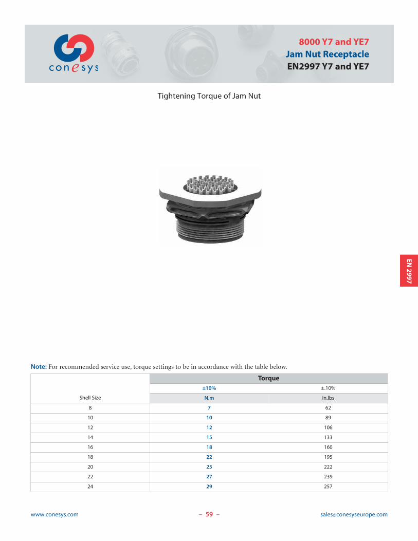
59www.conesys.com [email protected]
8000 Y7 and YE7Jam Nut ReceptacleEN2997 Y7 and YE7
– –
EN2997
Tightening Torque of Jam Nut
Note: For recommended service use, torque settings to be in accordance with the table below.
Shell Size
Torque±10% ±.10%
N.m in.lbs
8 7 62
10 10 89
12 12 106
14 15 133
16 18 160
18 22 195
20 25 222
22 27 239
24 29 257
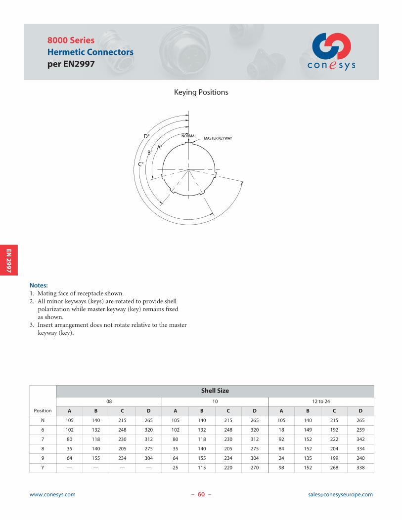
60www.conesys.com [email protected]
8000 SeriesHermetic Connectorsper EN2997
– –
EN2997
Keying Positions
C°
B°
D°
A°
MASTER KEYWAY NORMAL
Notes:1. Mating face of receptacle shown.2. All minor keyways (keys) are rotated to provide shell
polarization while master keyway (key) remains fixed as shown.
3. Insert arrangement does not rotate relative to the masterkeyway (key).
Position
Shell Size
08 10 12 to 24
A B C D A B C D A B C D
N 105 140 215 265 105 140 215 265 105 140 215 265
6 102 132 248 320 102 132 248 320 18 149 192 259
7 80 118 230 312 80 118 230 312 92 152 222 342
8 35 140 205 275 35 140 205 275 84 152 204 334
9 64 155 234 304 64 155 234 304 24 135 199 240
Y — — — — 25 115 220 270 98 152 268 338
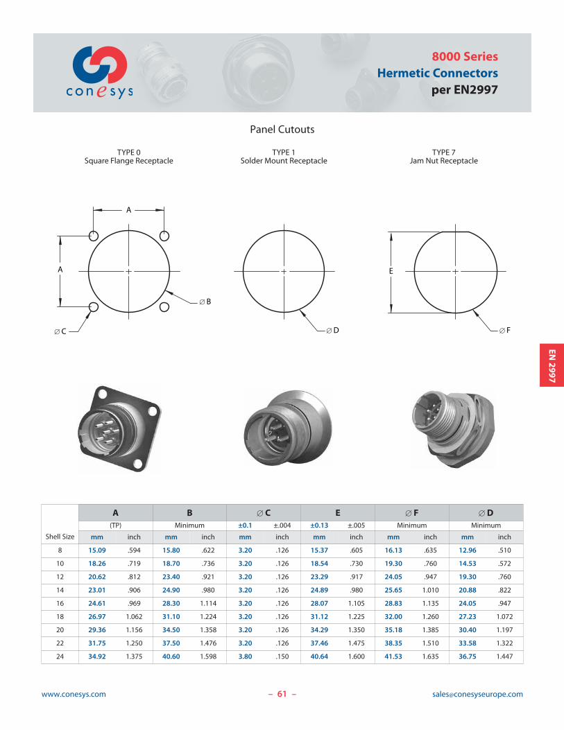
61www.conesys.com [email protected]
8000 SeriesHermetic Connectors
per EN2997
– –
EN2997
Panel Cutouts
Shell Size
A B [ C E [ F [ D(TP) Minimum ±0.1 ±.004 ±0.13 ±.005 Minimum Minimum
mm inch mm inch mm inch mm inch mm inch mm inch
8 15.09 .594 15.80 .622 3.20 .126 15.37 .605 16.13 .635 12.96 .510
10 18.26 .719 18.70 .736 3.20 .126 18.54 .730 19.30 .760 14.53 .572
12 20.62 .812 23.40 .921 3.20 .126 23.29 .917 24.05 .947 19.30 .760
14 23.01 .906 24.90 .980 3.20 .126 24.89 .980 25.65 1.010 20.88 .822
16 24.61 .969 28.30 1.114 3.20 .126 28.07 1.105 28.83 1.135 24.05 .947
18 26.97 1.062 31.10 1.224 3.20 .126 31.12 1.225 32.00 1.260 27.23 1.072
20 29.36 1.156 34.50 1.358 3.20 .126 34.29 1.350 35.18 1.385 30.40 1.197
22 31.75 1.250 37.50 1.476 3.20 .126 37.46 1.475 38.35 1.510 33.58 1.322
24 34.92 1.375 40.60 1.598 3.80 .150 40.64 1.600 41.53 1.635 36.75 1.447
A
[ B
A
[ C
TYPE 0Square Flange Receptacle
[ D [ F
TYPE 1Solder Mount Receptacle
TYPE 7Jam Nut Receptacle
E
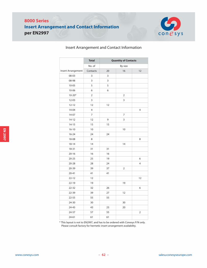
62www.conesys.com [email protected]– –
EN2997
8000 SeriesInsert Arrangement and Contact Informationper EN2997
Insert Arrangement and Contact Information
Insert Arrangement
Total Quantity of Contacts
No. of By size
Contacts 20 16 12
08-03 3 3
08-98 3 3
10-05 5 5
10-06 6 6
10-20* 2 2
12-03 3 3
12-12 12 12
14-04 4 4
14-07 7 7
14-12 12 9 3
14-15 15 15
16-10 10 10
16-24 24 24
18-08 8 8
18-14 14 14
18-31 31 31
20-16 16 16
20-25 25 19 6
20-28 28 24 4
20-39 39 37 2
20-41 41 41
22-12 12 12
22-19 19 19
22-32 32 26 6
22-39 39 27 12
22-55 55 55
24-30 30 30
24-43 43 23 20
24-57 57 55 2
24-61 61 61
* This layout is not to EN2997, and has to be ordered with Conesys P/N only. Please consult factory for hermetic insert arrangement availability.
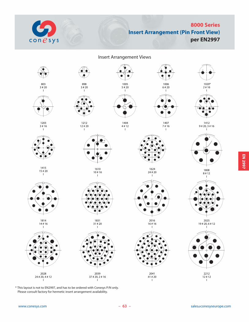
3
2
11
2
34
5
6
2 1
8033 # 20
I
8983 # 20
I
10055 # 20
I
10066 # 20
I
1020*2 # 16
I
12033 # 16
I
121212 # 20
I
14044 # 12
I
14077 # 16
I
14129 # 20, 3 # 16
I
181414 # 16
I
183131 # 20
I
201616 # 16
I
202519 # 20, 6 # 12
I
202824 # 20, 4 # 12
I
203937 # 20, 2 # 16
I
204141 # 20
I
221212 # 12
I
1
31
1
25
1
3 2
1
5
1
23
1
4
1
7
18088 # 12
I
1
8
1
12
1
12
141515 # 20
I
1
15
161010 # 16
I
1
10
1
14
1
12
1
39
162424 # 20
I
1
24
1
16
1
28
1
41
Insert Arrangement Views
63www.conesys.com [email protected]
8000 SeriesInsert Arrangement (Pin Front View)
per EN2997
– –
EN2997
* This layout is not to EN2997, and has to be ordered with Conesys P/N only. Please consult factory for hermetic insert arrangement availability.
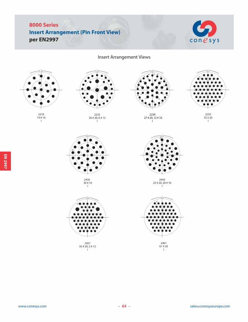
64www.conesys.com [email protected]– –
EN2997
8000 SeriesInsert Arrangement (Pin Front View)per EN2997
221919 # 16
I
223226 # 20, 6 # 12
I
244323 # 20, 20 # 16
I
243030 # 16
I
225555 # 20
I
245755 # 20, 2 # 12
I
246161 # 20
I
19
1 1
32
1
43
130
1
55
1
61
1
57
223927 # 20, 12 # 16
I
1
3
2
4
5
6
7
8
9
10
11
12
13
14
15
16
17
18
19 2021
22
23
24
25
26
27
282930
3132
33
34
35
36
37
3839
Insert Arrangement Views
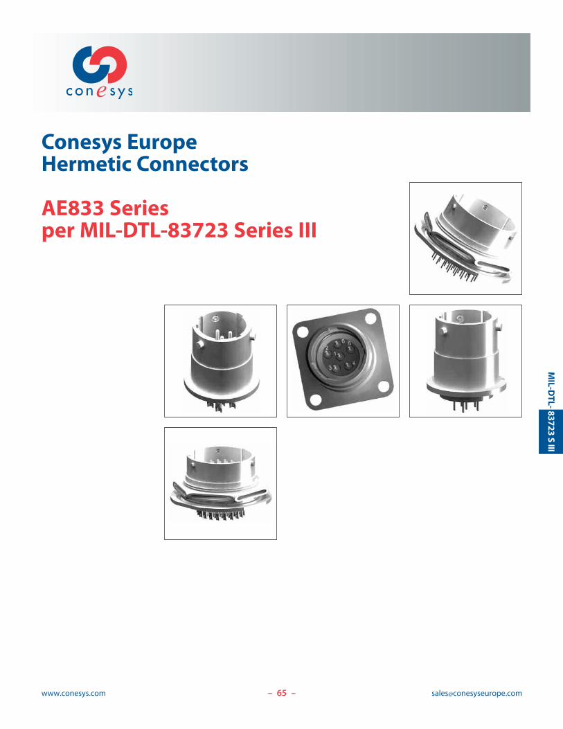
65www.conesys.com [email protected]
Conesys EuropeHermetic Connectors
AE833 Seriesper MIL-DTL-83723 Series III
– –
MIL-D
TL-83723
SIII
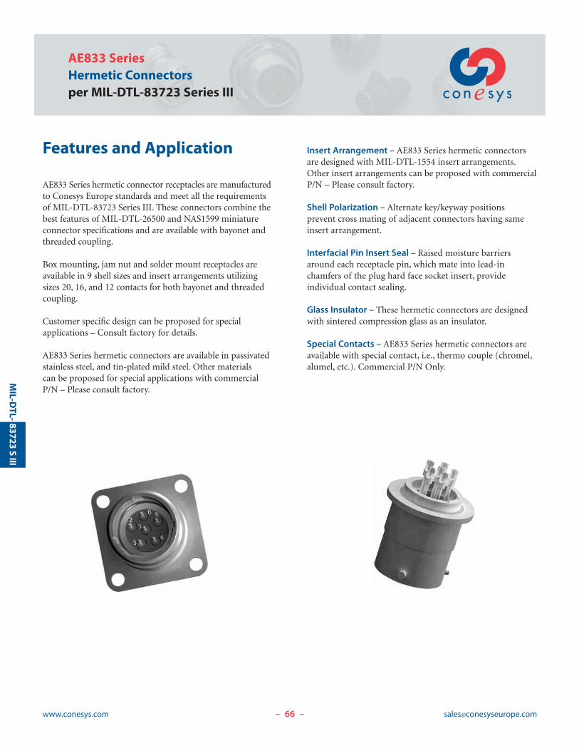
66www.conesys.com [email protected]
AE833 SeriesHermetic Connectorsper MIL-DTL-83723 Series III
– –
MIL-D
TL-83723
SIII
Features and Application
AE833 Series hermetic connector receptacles are manufacturedto Conesys Europe standards and meet all the requirementsof MIL-DTL-83723 Series III. These connectors combine thebest features of MIL-DTL-26500 and NAS1599 miniatureconnector specifications and are available with bayonet andthreaded coupling.
Box mounting, jam nut and solder mount receptacles areavailable in 9 shell sizes and insert arrangements utilizingsizes 20, 16, and 12 contacts for both bayonet and threadedcoupling.
Customer specific design can be proposed for special applications – Consult factory for details.
AE833 Series hermetic connectors are available in passivatedstainless steel, and tin-plated mild steel. Other materials can be proposed for special applications with commercialP/N – Please consult factory.
Insert Arrangement – AE833 Series hermetic connectorsare designed with MIL-DTL-1554 insert arrangements.Other insert arrangements can be proposed with commercialP/N – Please consult factory.
Shell Polarization – Alternate key/keyway positions prevent cross mating of adjacent connectors having sameinsert arrangement.
Interfacial Pin Insert Seal – Raised moisture barriersaround each receptacle pin, which mate into lead-in chamfers of the plug hard face socket insert, provide individual contact sealing.
Glass Insulator – These hermetic connectors are designedwith sintered compression glass as an insulator.
Special Contacts – AE833 Series hermetic connectors areavailable with special contact, i.e., thermo couple (chromel,alumel, etc.). Commercial P/N Only.
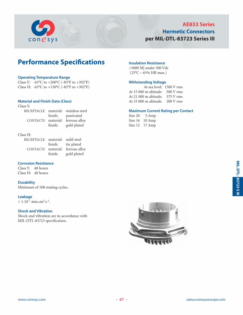
67www.conesys.com [email protected]
AE833 SeriesHermetic Connectors
per MIL-DTL-83723 Series III
– –
MIL-D
TL-83723
SIII
Performance Specifications
Operating Temperature RangeClass Y: -65°C to +200°C (-85°F to +392°F)Class H: -65°C to +150°C (-85°F to +302°F)
Material and Finish Data (Class)Class Y:
RECEPTACLE material: stainless steelfinish: passivated
CONTACTS material: ferrous alloyfinish: gold plated
Class H:RECEPTACLE material: mild steel
finish: tin platedCONTACTS material: ferrous alloy
finish: gold plated
Corrosion ResistanceClass Y: 48 hoursClass H: 48 hours
DurabilityMinimum of 500 mating cycles.
Leakage< 1.10-7 atm.cm3.s-1.
Shock and VibrationShock and vibration are in accordance with MIL-DTL-83723 specification.
Insulation Resistance>5000 M| under 500 Vdc(25°C – 65% HR max.)
Withstanding VoltageAt sea level: 1500 V rms
At 15 000 m altitude: 500 V rmsAt 21 000 m altitude: 375 V rmsAt 33 000 m altitude: 200 V rms
Maximum Current Rating per ContactSize 20 5 AmpSize 16 10 AmpSize 12 17 Amp
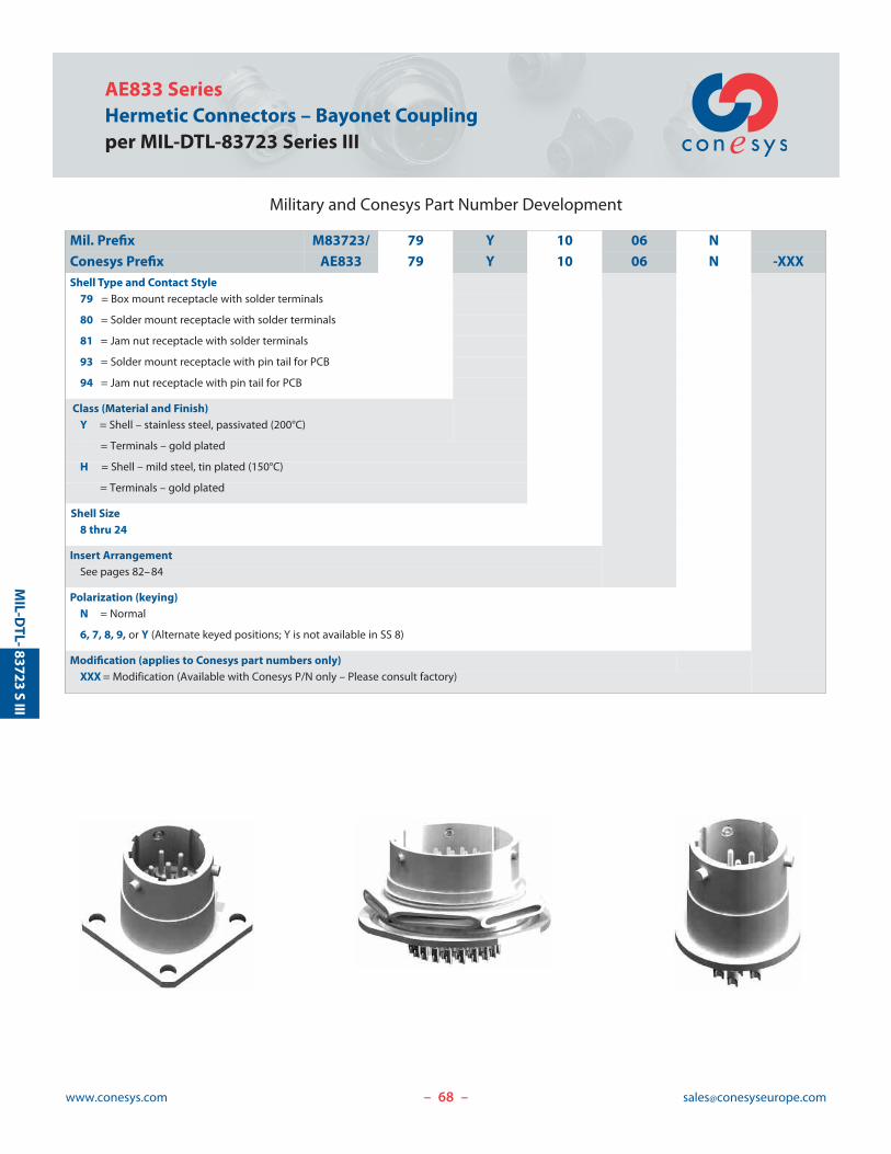
AE833 SeriesHermetic Connectors – Bayonet Couplingper MIL-DTL-83723 Series III
www.conesys.com [email protected]– –
MIL-D
TL-83723
SIII
Military and Conesys Part Number Development
Mil. Prefix M83723/ 79 Y 10 06 N
Conesys Prefix AE833 79 Y 10 06 N -XXXShell Type and Contact Style
79 = Box mount receptacle with solder terminals
80 = Solder mount receptacle with solder terminals
81 = Jam nut receptacle with solder terminals
93 = Solder mount receptacle with pin tail for PCB
94 = Jam nut receptacle with pin tail for PCB
Class (Material and Finish)Y = Shell – stainless steel, passivated (200°C)
= Terminals – gold plated
H = Shell – mild steel, tin plated (150°C)
= Terminals – gold plated
Shell Size8 thru 24
Insert ArrangementSee pages 82–84
Polarization (keying)N = Normal
6, 7, 8, 9, or Y (Alternate keyed positions; Y is not available in SS 8)
Modification (applies to Conesys part numbers only)XXX = Modification (Available with Conesys P/N only – Please consult factory)
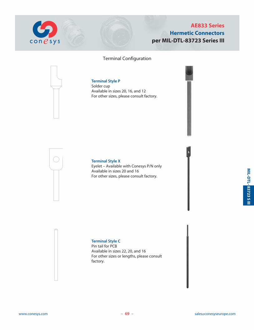
69www.conesys.com [email protected]
AE833 SeriesHermetic Connectors
per MIL-DTL-83723 Series III
– –
MIL-D
TL-83723
SIII
Terminal Configuration
Terminal Style PSolder cupAvailable in sizes 20, 16, and 12For other sizes, please consult factory.
Terminal Style XEyelet – Available with Conesys P/N onlyAvailable in sizes 20 and 16For other sizes, please consult factory.
Terminal Style CPin tail for PCBAvailable in sizes 22, 20, and 16For other sizes or lengths, please consultfactory.
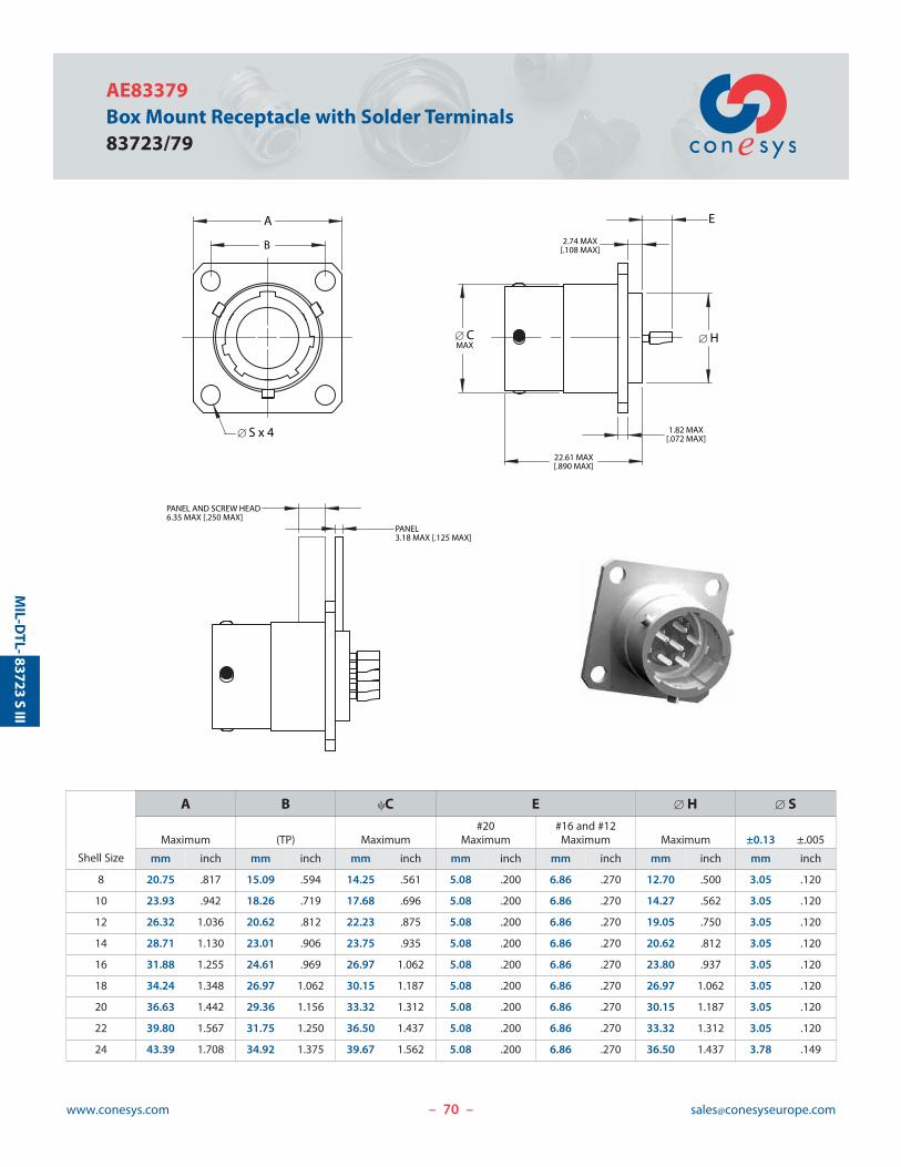
70www.conesys.com [email protected]
AE83379Box Mount Receptacle with Solder Terminals83723/79
MIL-D
TL-
PANEL3.18 MAX [.125 MAX]
A
B
[ S x 4
[ CMAX
22.61 MAX[.890 MAX]
1.82 MAX[.072 MAX]
2.74 MAX[.108 MAX]
E
[ H
PANEL AND SCREW HEAD6.35 MAX [.250 MAX]
– –
83723S
III
Shell Size
A B cC E [ H [ S#20 #16 and #12
Maximum (TP) Maximum Maximum Maximum Maximum ±0.13 ±.005
mm inch mm inch mm inch mm inch mm inch mm inch mm inch
8 20.75 .817 15.09 .594 14.25 .561 5.08 .200 6.86 .270 12.70 .500 3.05 .120
10 23.93 .942 18.26 .719 17.68 .696 5.08 .200 6.86 .270 14.27 .562 3.05 .120
12 26.32 1.036 20.62 .812 22.23 .875 5.08 .200 6.86 .270 19.05 .750 3.05 .120
14 28.71 1.130 23.01 .906 23.75 .935 5.08 .200 6.86 .270 20.62 .812 3.05 .120
16 31.88 1.255 24.61 .969 26.97 1.062 5.08 .200 6.86 .270 23.80 .937 3.05 .120
18 34.24 1.348 26.97 1.062 30.15 1.187 5.08 .200 6.86 .270 26.97 1.062 3.05 .120
20 36.63 1.442 29.36 1.156 33.32 1.312 5.08 .200 6.86 .270 30.15 1.187 3.05 .120
22 39.80 1.567 31.75 1.250 36.50 1.437 5.08 .200 6.86 .270 33.32 1.312 3.05 .120
24 43.39 1.708 34.92 1.375 39.67 1.562 5.08 .200 6.86 .270 36.50 1.437 3.78 .149
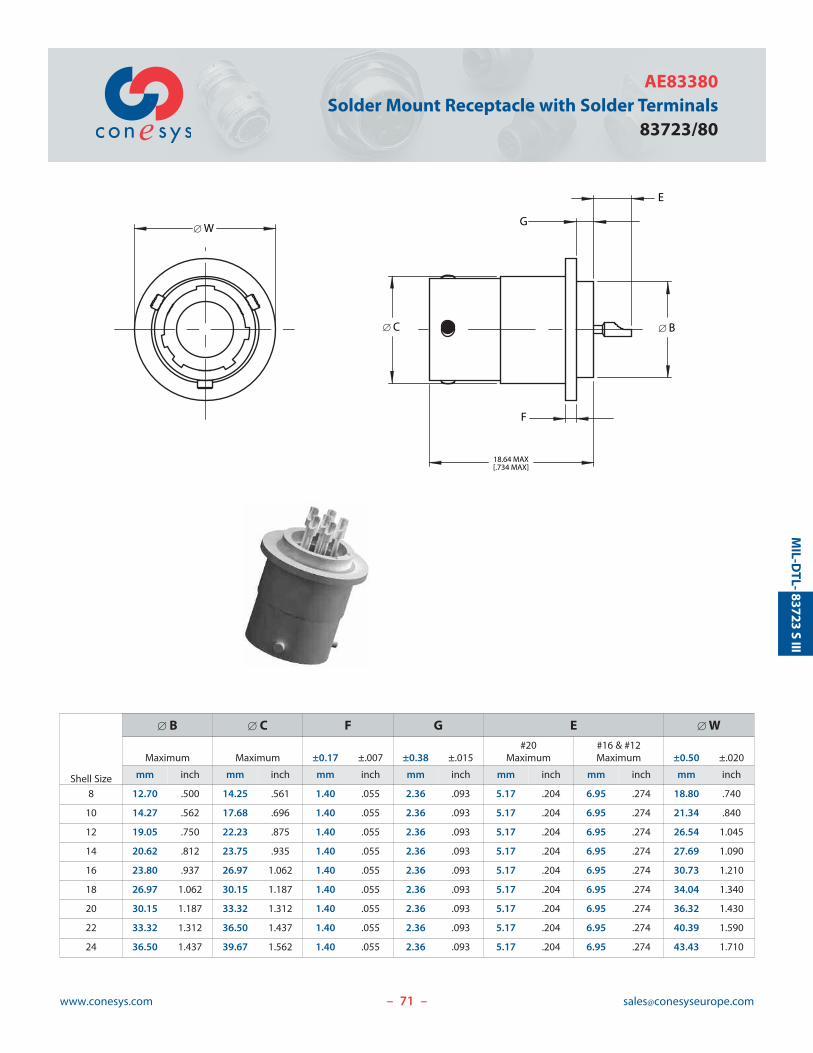
71www.conesys.com [email protected]
AE83380Solder Mount Receptacle with Solder Terminals
83723/80
– –
MIL-D
TL-83723
SIII
Shell Size
[ B [ C F G E [ W#20 #16 & #12
Maximum Maximum ±0.17 ±.007 ±0.38 ±.015 Maximum Maximum ±0.50 ±.020
mm inch mm inch mm inch mm inch mm inch mm inch mm inch
8 12.70 .500 14.25 .561 1.40 .055 2.36 .093 5.17 .204 6.95 .274 18.80 .740
10 14.27 .562 17.68 .696 1.40 .055 2.36 .093 5.17 .204 6.95 .274 21.34 .840
12 19.05 .750 22.23 .875 1.40 .055 2.36 .093 5.17 .204 6.95 .274 26.54 1.045
14 20.62 .812 23.75 .935 1.40 .055 2.36 .093 5.17 .204 6.95 .274 27.69 1.090
16 23.80 .937 26.97 1.062 1.40 .055 2.36 .093 5.17 .204 6.95 .274 30.73 1.210
18 26.97 1.062 30.15 1.187 1.40 .055 2.36 .093 5.17 .204 6.95 .274 34.04 1.340
20 30.15 1.187 33.32 1.312 1.40 .055 2.36 .093 5.17 .204 6.95 .274 36.32 1.430
22 33.32 1.312 36.50 1.437 1.40 .055 2.36 .093 5.17 .204 6.95 .274 40.39 1.590
24 36.50 1.437 39.67 1.562 1.40 .055 2.36 .093 5.17 .204 6.95 .274 43.43 1.710
18.64 MAX[.734 MAX]
G
E
[ B
F
[ W
[ C
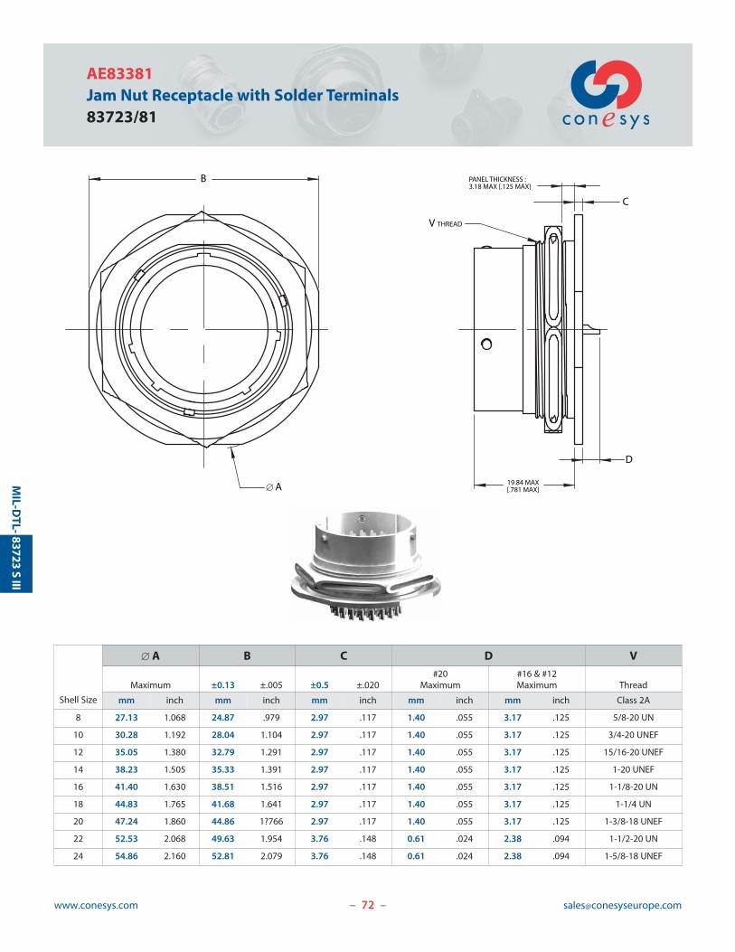
72www.conesys.com [email protected]
AE83381Jam Nut Receptacle with Solder Terminals83723/81
– –
MIL-D
TL-83723
SIII
19.84 MAX[.781 MAX]
D
C
PANEL THICKNESS : 3.18 MAX [.125 MAX]
V THREAD
B
[ A
Shell Size
[ A B C D V#20 #16 & #12
Maximum ±0.13 ±.005 ±0.5 ±.020 Maximum Maximum Thread
mm inch mm inch mm inch mm inch mm inch Class 2A
8 27.13 1.068 24.87 .979 2.97 .117 1.40 .055 3.17 .125 5/8-20 UN
10 30.28 1.192 28.04 1.104 2.97 .117 1.40 .055 3.17 .125 3/4-20 UNEF
12 35.05 1.380 32.79 1.291 2.97 .117 1.40 .055 3.17 .125 15/16-20 UNEF
14 38.23 1.505 35.33 1.391 2.97 .117 1.40 .055 3.17 .125 1-20 UNEF
16 41.40 1.630 38.51 1.516 2.97 .117 1.40 .055 3.17 .125 1-1/8-20 UN
18 44.83 1.765 41.68 1.641 2.97 .117 1.40 .055 3.17 .125 1-1/4 UN
20 47.24 1.860 44.86 1?766 2.97 .117 1.40 .055 3.17 .125 1-3/8-18 UNEF
22 52.53 2.068 49.63 1.954 3.76 .148 0.61 .024 2.38 .094 1-1/2-20 UN
24 54.86 2.160 52.81 2.079 3.76 .148 0.61 .024 2.38 .094 1-5/8-18 UNEF
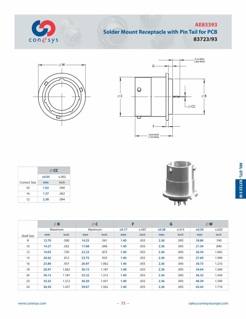
73www.conesys.com [email protected]
AE83393Solder Mount Receptacle with Pin Tail for PCB
83723/93
– –
MIL-D
TL-83723
SIII
[ W
18.64 MAX[.734 MAX]
F
[ C
G
9.14 MAX[.360 MAX]
[ B
[ CC
Shell Size
[ B [ C F G [ WMaximum Maximum ±0.17 ±.007 ±0.38 ±.015 ±0.50 ±.020
mm inch mm inch mm inch mm inch mm inch
8 12.70 .500 14.25 .561 1.40 .055 2.36 .093 18.80 .740
10 14.27 .562 17.68 .696 1.40 .055 2.36 .093 21.34 .840
12 19.05 .750 22.23 .875 1.40 .055 2.36 .093 26.54 1.045
14 20.62 .812 23.75 .935 1.40 .055 2.36 .093 27.69 1.090
16 23.80 .937 26.97 1.062 1.40 .055 2.36 .093 30.73 1.210
18 26.97 1.062 30.15 1.187 1.40 .055 2.36 .093 34.04 1.340
20 30.15 1.187 33.32 1.312 1.40 .055 2.36 .093 36.32 1.430
22 33.32 1.312 36.50 1.437 1.40 .055 2.36 .093 40.39 1.590
24 36.50 1.437 39.67 1.562 1.40 .055 2.36 .093 43.43 1.710
Contact Size
[ CC
±0.05 ±.002
mm inch
20 1.02 .040
16 1.57 .062
12 2.38 .094

74www.conesys.com [email protected]
AE83394Jam Nut Receptacle with Pin Tail for PCB per MIL-DTL-83723 Series III
– –
MIL-D
TL-83723
SIII
PANEL THICKNESS : 3.18 MAX [.125 MAX]
C
19.84 MAX[.781 MAX]
D
[ CC
[ A
B
V THREAD
Shell Size
[ A B C D VMaximum ±0.13 ±.005 ±0.5 ±.020 Maximum Thread
mm inch mm inch mm inch mm inch Class 2A
8 27.13 1.068 24.87 .979 2.97 .117 4.64 .183 5/8-20 UN
10 30.28 1.192 28.04 1.104 2.97 .117 4.64 .183 3/4-20 UNEF
12 35.05 1.380 32.79 1.291 2.97 .117 4.64 .183 15/16-20 UNEF
14 38.23 1.505 35.33 1.391 2.97 .117 4.64 .183 1-20 UNEF
16 41.40 1.630 38.51 1.516 2.97 .117 4.64 .183 1-1/8-20 UN
18 44.83 1.765 41.68 1.641 2.97 .117 4.64 .183 1-1/4 UN
20 47.24 1.860 44.86 1?766 2.97 .117 4.64 .183 1-3/8-18 UNEF
22 52.53 2.068 49.63 1.954 3.76 .148 3.85 .152 1-1/2-20 UN
24 54.86 2.160 52.81 2.079 3.76 .148 3.85 .152 1-5/8-18 UNEF
Contact Size
[ CC±0.05 ±.002
mm inch
20 0.84 .033
16 Consult factory
12 Consult factory
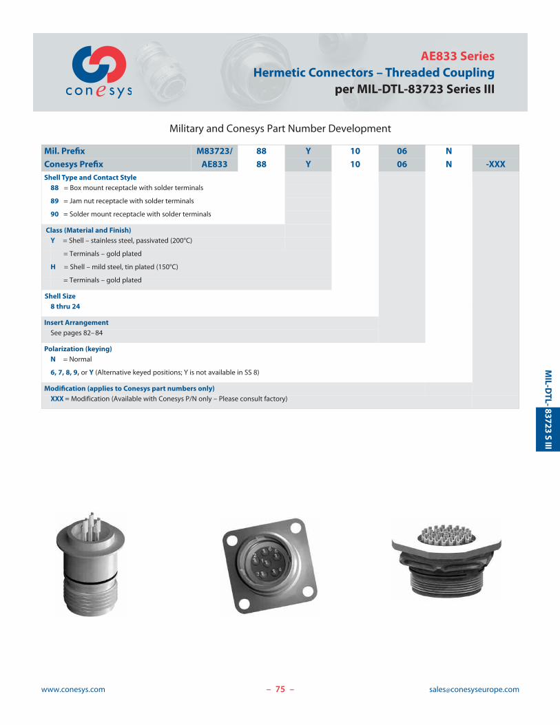
75www.conesys.com [email protected]
AE833 SeriesHermetic Connectors – Threaded Coupling
per MIL-DTL-83723 Series III
– –
MIL-D
TL-83723
SIII
Military and Conesys Part Number Development
Mil. Prefix M83723/ 88 Y 10 06 N
Conesys Prefix AE833 88 Y 10 06 N -XXXShell Type and Contact Style
88 = Box mount receptacle with solder terminals
89 = Jam nut receptacle with solder terminals
90 = Solder mount receptacle with solder terminals
Class (Material and Finish)Y = Shell – stainless steel, passivated (200°C)
= Terminals – gold plated
H = Shell – mild steel, tin plated (150°C)
= Terminals – gold plated
Shell Size8 thru 24
Insert ArrangementSee pages 82–84
Polarization (keying)N = Normal
6, 7, 8, 9, or Y (Alternative keyed positions; Y is not available in SS 8)
Modification (applies to Conesys part numbers only)XXX = Modification (Available with Conesys P/N only – Please consult factory)
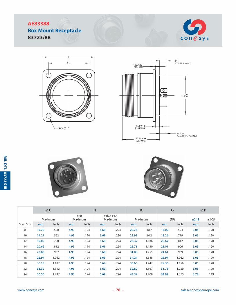
76www.conesys.com [email protected]
AE83388Box Mount Receptacle83723/88
MIL-D
TL-
22.96 MAX[.903 MAX]
[ C
STYLE C4.5 ±0.5 [.177 ± .020]
HSTYLES P AND X
2.64/2.13[.104/.084]
1.82/1.32[.072/.052]
K
G
4 x [ P
– –
83723S
III
Shell Size
[ C H K G [ P#20 #16 & #12
Maximum Maximum Maximum Maximum (TP) ±0.13 ±.005
mm inch mm inch mm inch mm inch mm inch mm inch
8 12.70 .500 4.93 .194 5.69 .224 20.75 .817 15.09 .594 3.05 .120
10 14.27 .562 4.93 .194 5.69 .224 23.93 .942 18.26 .719 3.05 .120
12 19.05 .750 4.93 .194 5.69 .224 26.32 1.036 20.62 .812 3.05 .120
14 20.62 .812 4.93 .194 5.69 .224 28.71 1.130 23.01 .906 3.05 .120
16 23.80 .937 4.93 .194 5.69 .224 31.88 1.255 24.61 .969 3.05 .120
18 26.97 1.062 4.93 .194 5.69 .224 34.24 1.348 26.97 1.062 3.05 .120
20 30.15 1.187 4.93 .194 5.69 .224 36.63 1.442 29.36 1.156 3.05 .120
22 33.32 1.312 4.93 .194 5.69 .224 39.80 1.567 31.75 1.250 3.05 .120
24 36.50 1.437 4.93 .194 5.69 .224 43.39 1.708 34.92 1.375 3.78 .149
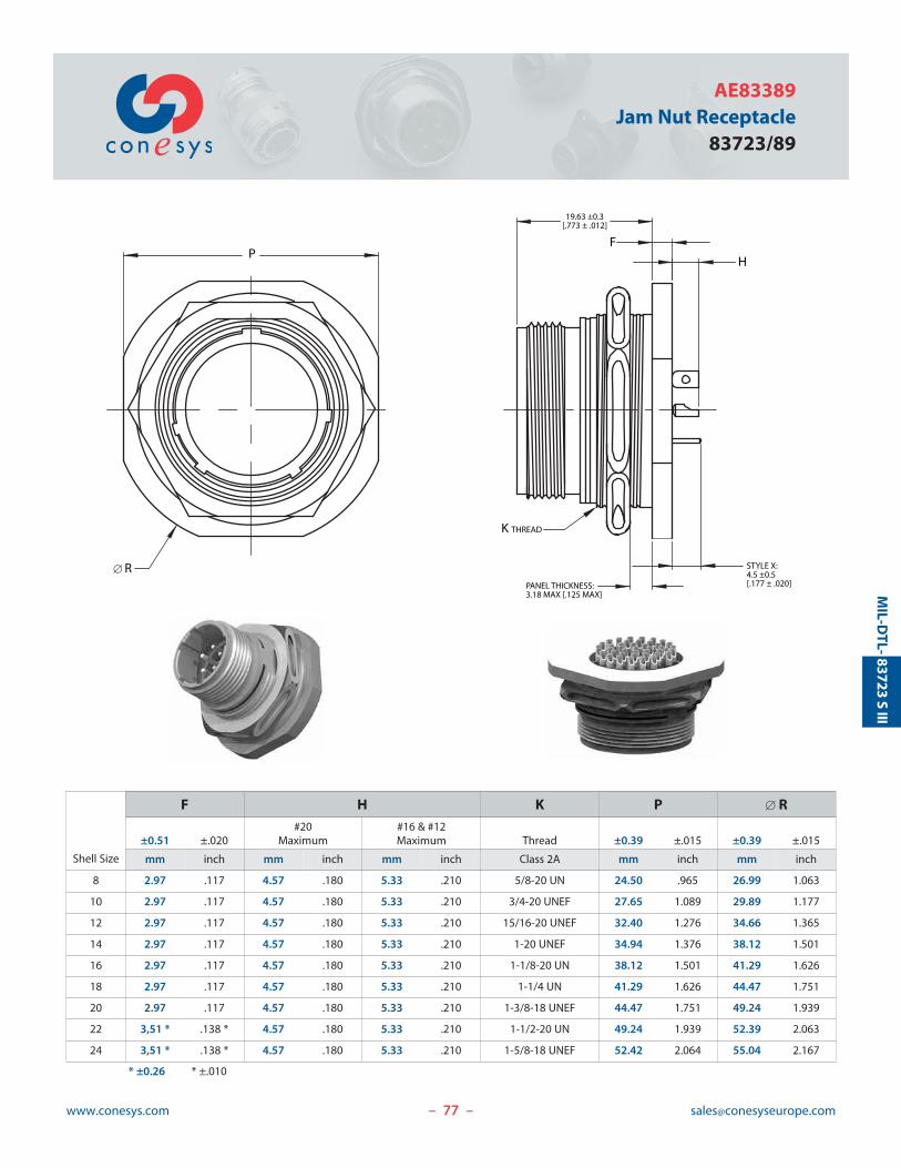
77www.conesys.com [email protected]
AE83389Jam Nut Receptacle
83723/89
– –
MIL-D
TL-83723
SIII
F
19.63 ±0.3[.773 ± .012]
STYLE X:4.5 ±0.5[.177 ± .020]
H
PANEL THICKNESS:3.18 MAX [.125 MAX]
K THREAD
P
[ R
Shell Size
F H K P [ R#20 #16 & #12
±0.51 ±.020 Maximum Maximum Thread ±0.39 ±.015 ±0.39 ±.015
mm inch mm inch mm inch Class 2A mm inch mm inch
8 2.97 .117 4.57 .180 5.33 .210 5/8-20 UN 24.50 .965 26.99 1.063
10 2.97 .117 4.57 .180 5.33 .210 3/4-20 UNEF 27.65 1.089 29.89 1.177
12 2.97 .117 4.57 .180 5.33 .210 15/16-20 UNEF 32.40 1.276 34.66 1.365
14 2.97 .117 4.57 .180 5.33 .210 1-20 UNEF 34.94 1.376 38.12 1.501
16 2.97 .117 4.57 .180 5.33 .210 1-1/8-20 UN 38.12 1.501 41.29 1.626
18 2.97 .117 4.57 .180 5.33 .210 1-1/4 UN 41.29 1.626 44.47 1.751
20 2.97 .117 4.57 .180 5.33 .210 1-3/8-18 UNEF 44.47 1.751 49.24 1.939
22 3,51 * .138 * 4.57 .180 5.33 .210 1-1/2-20 UN 49.24 1.939 52.39 2.063
24 3,51 * .138 * 4.57 .180 5.33 .210 1-5/8-18 UNEF 52.42 2.064 55.04 2.167
* ±0.26 * ±.010
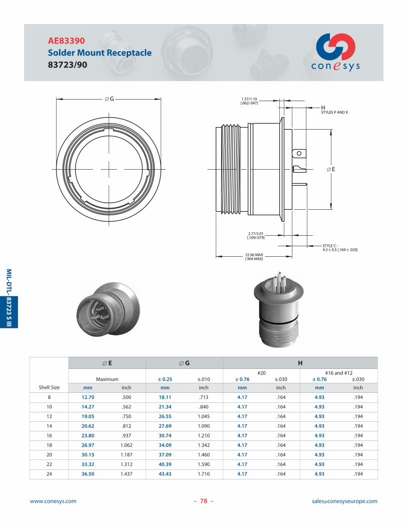
78www.conesys.com [email protected]
AE83390Solder Mount Receptacle83723/90
– –
MIL-D
TL-83723
SIII
[ E
22.96 MAX[.904 MAX]
STYLE C :4.3 ± 0.5 [.169 ± .020]
2.77/2.01[.109/.079]
1.57/1.19[.062/.047]
HSTYLES P AND X
[ G
Shell Size
[ E [ G H#20 #16 and #12
Maximum ± 0.25 ±.010 ± 0.76 ±.030 ± 0.76 ±.030
mm inch mm inch mm inch mm inch
8 12.70 .500 18.11 .713 4.17 .164 4.93 .194
10 14.27 .562 21.34 .840 4.17 .164 4.93 .194
12 19.05 .750 26.55 1.045 4.17 .164 4.93 .194
14 20.62 .812 27.69 1.090 4.17 .164 4.93 .194
16 23.80 .937 30.74 1.210 4.17 .164 4.93 .194
18 26.97 1.062 34.09 1.342 4.17 .164 4.93 .194
20 30.15 1.187 37.09 1.460 4.17 .164 4.93 .194
22 33.32 1.312 40.39 1.590 4.17 .164 4.93 .194
24 36.50 1.437 43.43 1.710 4.17 .164 4.93 .194
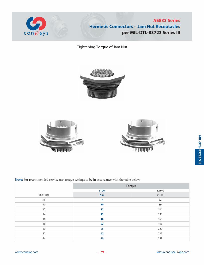
79www.conesys.com [email protected]
AE833 SeriesHermetic Connectors – Jam Nut Receptacles
per MIL-DTL-83723 Series III
– –
MIL-D
TL-83723
SIII
Tightening Torque of Jam Nut
Note: For recommended service use, torque settings to be in accordance with the table below.
Shell Size
Torque±10% ±.10%
N.m in.lbs
8 7 62
10 10 89
12 12 106
14 15 133
16 18 160
18 22 195
20 25 222
22 27 239
24 29 257
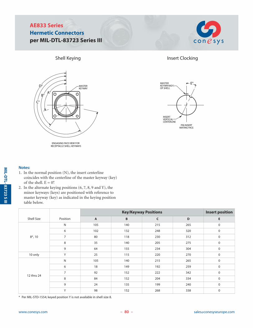
INSERTVERTICALCENTERLINE
PIN INSERTMATING FACE
ENGAGING FACE VIEW FOR RECEPTACLE SHELL KEYWAYS
MASTERKEYWAY(KEY)OF SHELL
E°
C°
B°
D°
A°
MASTERKEYWAY
83723S
IIIM
IL-DTL-
– –
AE833 SeriesHermetic Connectorsper MIL-DTL-83723 Series III
Shell Keying Insert Clocking
Notes:1. In the normal position (N), the insert centerline
coincides with the centerline of the master keyway (key)of the shell. E = 0°.
2. In the alternate keying positions (6, 7, 8, 9 and Y), theminor keyways (keys) are positioned with reference tomaster keyway (key) as indicated in the keying positiontable below.
Shell Size Position
Key/Keyway Positions Insert position
A B C D E
8*, 10
N 105 140 215 265 0
6 102 132 248 320 0
7 80 118 230 312 0
8 35 140 205 275 0
9 64 155 234 304 0
10 only Y 25 115 220 270 0
12 thru 24
N 105 140 215 265 0
6 18 149 192 259 0
7 92 152 222 342 0
8 84 152 204 334 0
9 24 135 199 240 0
Y 98 152 268 338 0
* Per MIL-STD-1554; keyed position Y is not available in shell size 8.
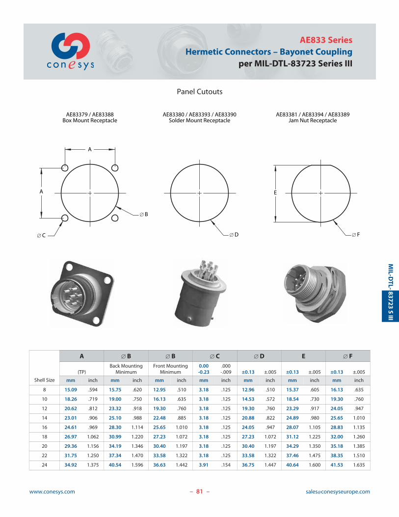
81www.conesys.com [email protected]
AE833 SeriesHermetic Connectors – Bayonet Coupling
per MIL-DTL-83723 Series III
Panel Cutouts
– –
MIL-D
TL-83723
SIII
A
[ B
A
[ C
AE83379 / AE83388Box Mount Receptacle
[ D [ F
AE83380 / AE83393 / AE83390Solder Mount Receptacle
AE83381 / AE83394 / AE83389Jam Nut Receptacle
E
Shell Size
A [ B [ B [ C [ D E [ FBack Mounting Front Mounting 0.00 .000
(TP) Minimum Minimum -0.23 -.009 ±0.13 ±.005 ±0.13 ±.005 ±0.13 ±.005
mm inch mm inch mm inch mm inch mm inch mm inch mm inch
8 15.09 .594 15.75 .620 12.95 .510 3.18 .125 12.96 .510 15.37 .605 16.13 .635
10 18.26 .719 19.00 .750 16.13 .635 3.18 .125 14.53 .572 18.54 .730 19.30 .760
12 20.62 .812 23.32 .918 19.30 .760 3.18 .125 19.30 .760 23.29 .917 24.05 .947
14 23.01 .906 25.10 .988 22.48 .885 3.18 .125 20.88 .822 24.89 .980 25.65 1.010
16 24.61 .969 28.30 1.114 25.65 1.010 3.18 .125 24.05 .947 28.07 1.105 28.83 1.135
18 26.97 1.062 30.99 1.220 27.23 1.072 3.18 .125 27.23 1.072 31.12 1.225 32.00 1.260
20 29.36 1.156 34.19 1.346 30.40 1.197 3.18 .125 30.40 1.197 34.29 1.350 35.18 1.385
22 31.75 1.250 37.34 1.470 33.58 1.322 3.18 .125 33.58 1.322 37.46 1.475 38.35 1.510
24 34.92 1.375 40.54 1.596 36.63 1.442 3.91 .154 36.75 1.447 40.64 1.600 41.53 1.635
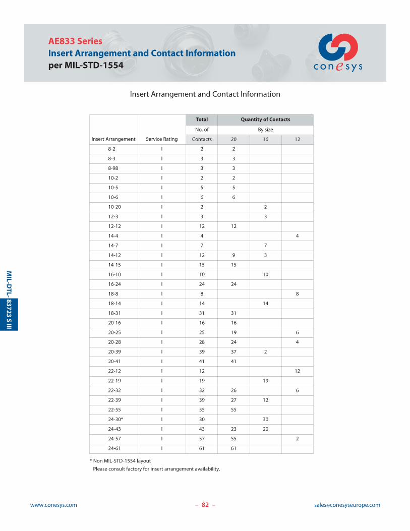
82www.conesys.com [email protected]
AE833 SeriesInsert Arrangement and Contact Informationper MIL-STD-1554
Insert Arrangement and Contact Information
– –
MIL-D
TL-83723
SIII
Insert Arrangement Service Rating
Total Quantity of Contacts
No. of By size
Contacts 20 16 12
8-2 I 2 2
8-3 I 3 3
8-98 I 3 3
10-2 I 2 2
10-5 I 5 5
10-6 I 6 6
10-20 I 2 2
12-3 I 3 3
12-12 I 12 12
14-4 I 4 4
14-7 I 7 7
14-12 I 12 9 3
14-15 I 15 15
16-10 I 10 10
16-24 I 24 24
18-8 I 8 8
18-14 I 14 14
18-31 I 31 31
20-16 I 16 16
20-25 I 25 19 6
20-28 I 28 24 4
20-39 I 39 37 2
20-41 I 41 41
22-12 I 12 12
22-19 I 19 19
22-32 I 32 26 6
22-39 I 39 27 12
22-55 I 55 55
24-30* I 30 30
24-43 I 43 23 20
24-57 I 57 55 2
24-61 I 61 61
* Non MIL-STD-1554 layout
Please consult factory for insert arrangement availability.
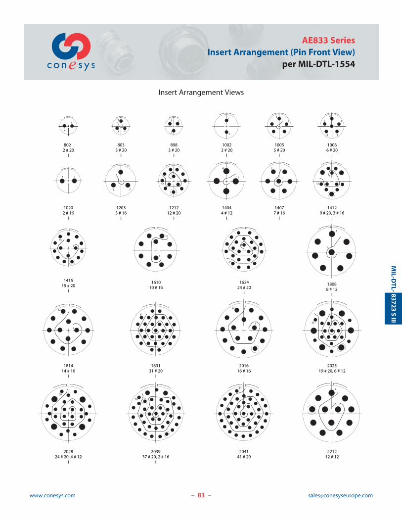
83www.conesys.com [email protected]
AE833 SeriesInsert Arrangement (Pin Front View)
per MIL-DTL-1554
Insert Arrangement Views
– –
MIL-D
TL-83723
SIII
2
13
2
11
2
12
34
5
6
2 1
8022 # 20
I
8033 # 20
I
8983 # 20
I
10022 # 20
I
10055 # 20
I
10066 # 20
I
10202 # 16
I
12033 # 16
I
121212 # 20
I
14044 # 12
I
14077 # 16
I
14129 # 20, 3 # 16
I
181414 # 16
I
183131 # 20
I
201616 # 16
I
202519 # 20, 6 # 12
I
202824 # 20, 4 # 12
I
203937 # 20, 2 # 16
I
204141 # 20
I
221212 # 12
I
1
31
1
25
1
3 2
1
5
1
23
1
4
1
7
18088 # 12
I
1
8
1
12
1
12
141515 # 20
I
1
15
161010 # 16
I
1
10
1
14
1
12
1
39
162424 # 20
I
1
24
1
16
1
28
1
41
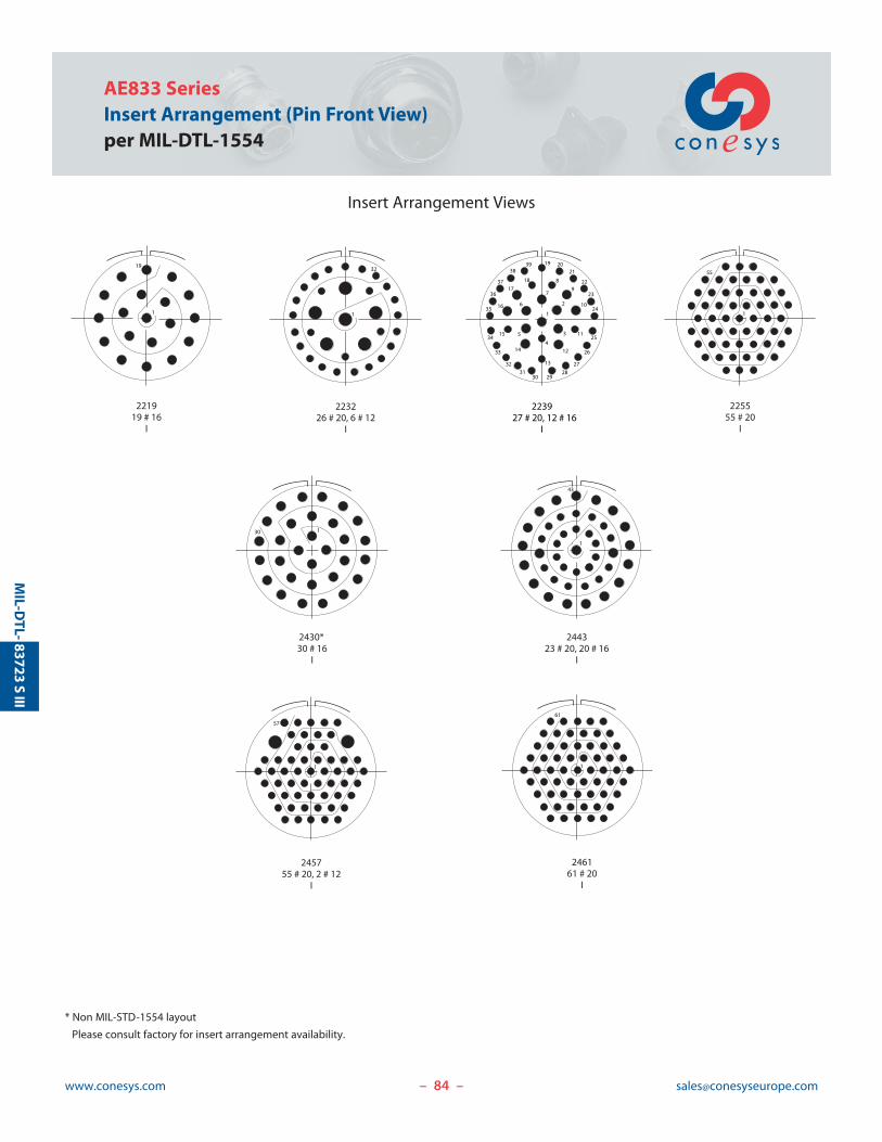
84www.conesys.com [email protected]
AE833 SeriesInsert Arrangement (Pin Front View)per MIL-DTL-1554
Insert Arrangement Views
– –
MIL-D
TL-83723
SIII
* Non MIL-STD-1554 layout
Please consult factory for insert arrangement availability.
221919 # 16
I
223226 # 20, 6 # 12
I
244323 # 20, 20 # 16
I
2430*30 # 16
I
225555 # 20
I
245755 # 20, 2 # 12
I
246161 # 20
I
19
1 1
32
1
43
130
1
55
1
61
1
57
223927 # 20, 12 # 16
I
1
3
2
4
5
6
7
8
9
10
11
12
13
14
15
16
17
18
19 2021
22
23
24
25
26
27
282930
3132
33
34
35
36
37
3839
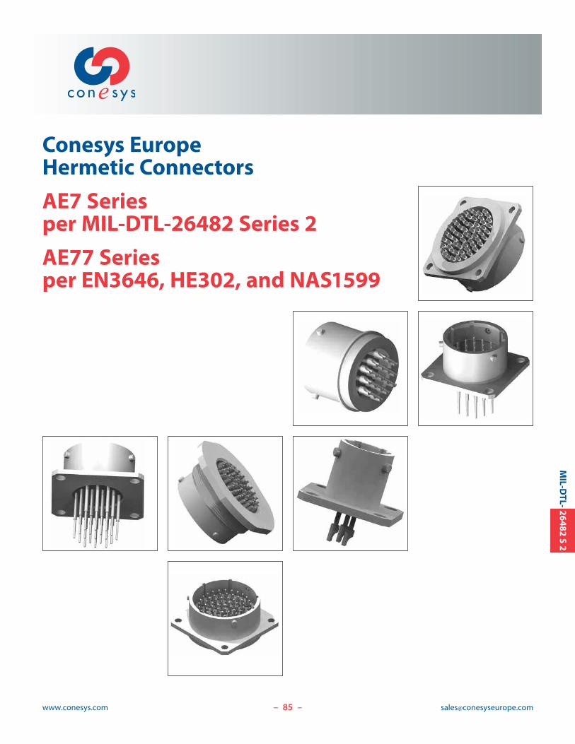
85www.conesys.com [email protected]
Conesys EuropeHermetic Connectors
AE7 Seriesper MIL-DTL-26482 Series 2
AE77 Seriesper EN3646, HE302, and NAS1599
– –
MIL-D
TL-26482
S2

86www.conesys.com [email protected]
AE7/AE77 SeriesHermetic Connectorsper MIL-DTL-26482, EN3646, HE302, and NAS1599
– –
MIL-D
TL-26482
S2
Features and Application
AE7 Series and AE77 Series hermetic connector receptaclesare manufactured to Conesys Europe standards. AE7 Seriesmeets all the requirements of MIL-DTL-26482. AE77 Serieshermetic connectors are based on HE302, EN3646, and NAS1599 specification. They are fully intermateable withAE7 series connectors.
AE7 and AE77 Series connectors are widely used on commercial, military and aerospace systems requiring general purpose, miniature cylindrical bayonet coupling connectors.
This family of hermetic connectors is available in 5 receptaclestyles. They include:• narrow flange, wall mounting• narrow short flange, wall mounting• wide flange, wall mounting• jam nut mounting• solder mounting
These hermetic connectors are available in passivated stainless steel material and tin or nickel plated mild steel.Other materials can be proposed for special applications –Please consult factory.
Insert Arrangement – AE7 and AE77 Series hermetic connectors use MIL-STD 1669 and EN3646 insert arrangements. Contacts are available in size 20, 16, and 12.
Insert Polarization – Alternate insert clocking positionsprevent cross mating of adjacent connectors having thesame insert arrangement.
Interfacial Pin Insert Seal – Raised moisture barriersaround each receptacle pin, which mate into lead-in chamfersof the plug hard face socket insert, provide individual contact sealing.
Glass Insulator – These hermetic connectors are designedwith sintered compression glass as an insulator.
Special Contacts – These hermetic connectors are availablewith special contact, i.e., thermo couple (chromel, alumel,etc.). Commercial P/N only.

87www.conesys.com [email protected]
AE7/AE77 SeriesHermetic Connectors
per MIL-DTL-26482, EN3646, HE302, and NAS1599
– –
MIL-D
TL-26482
S2
Performance Specifications
Operating Temperature RangeAE7 Series: -55°C to +200°C (-67°F to +392°F)AE77 Series:
Class H: -55°C to +200°C (-67°F to +392°F)Class Y: -55°C to +200°C (-67°F to +392°F)
Material and Finish Data (Class)Class H:
RECEPTACLE material: mild steelfinish: nickel plated
CONTACTS material: ferrous alloyfinish: gold plated
Class Y:RECEPTACLE material: stainless steel
finish: passivatedCONTACTS material: ferrous alloy
finish: gold plated
Corrosion ResistanceIn accordance with MIL-STD-1344 Method 1001 per MIL DTL 26482 (for standard plating).
DurabilityMinimum of 500 mating cycles.
Leakage< 1.10-7 atm.cm3.s-1.
Shock and VibrationIn accordance with MIL-STD-202, Method 204, Condition B.
Insulation Resistance>5000 M| under 500 Vdc(25°C – 65% HR max.)
Withstanding VoltageService Rating I:
At sea level: 1500 V rmsAt 15 000 m altitude: 600 V rmsAt 21 000 m altitude: 400 V rmsAt 33 000 m altitude: 200 V rms
Service Rating II:At sea level: 2300 V rms
At 15 000 m altitude: 750 V rmsAt 21 000 m altitude: 500 V rmsAt 33 000 m altitude: 200 V rms
Maximum Current Rating per ContactSize 20 5 AmpSize 16 10 AmpSize 12 17 Amp
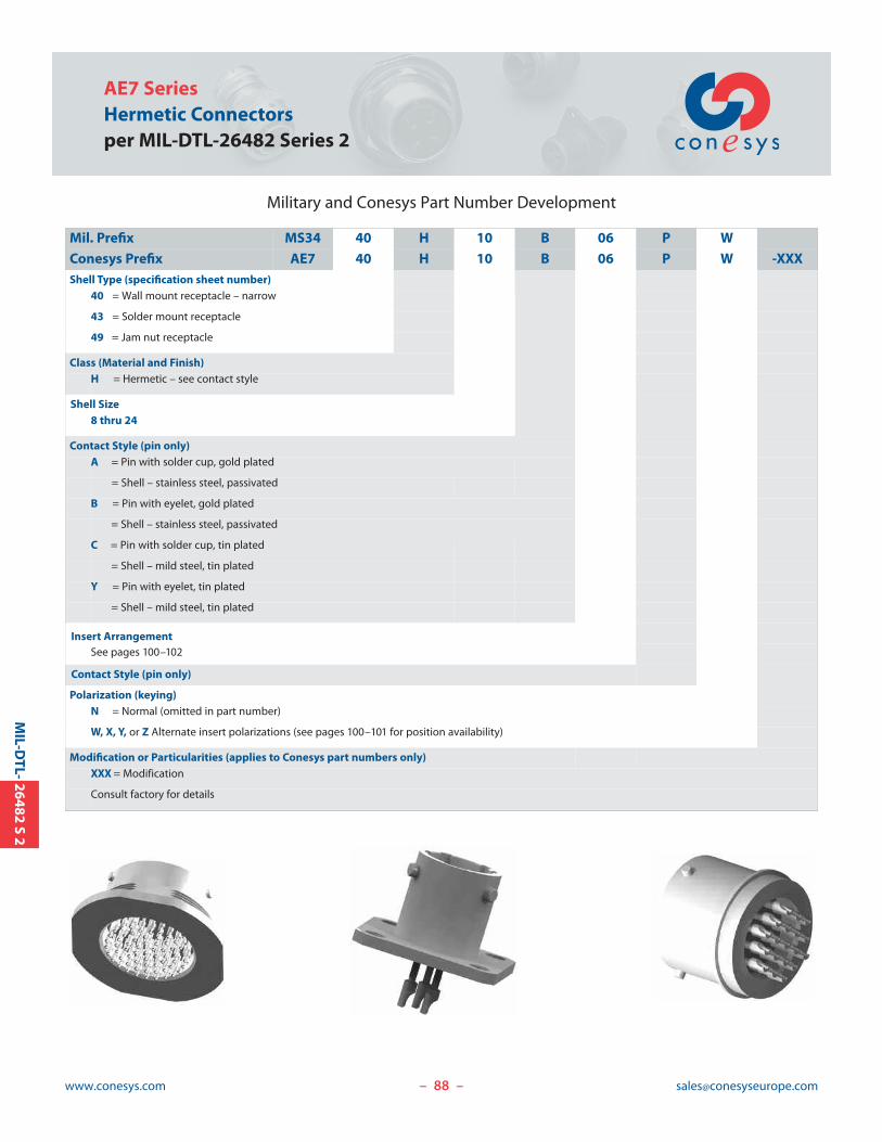
AE7 SeriesHermetic Connectorsper MIL-DTL-26482 Series 2
www.conesys.com [email protected]– –
MIL-D
TL-26482
S2
Military and Conesys Part Number Development
Mil. Prefix MS34 40 H 10 B 06 P W
Conesys Prefix AE7 40 H 10 B 06 P W -XXXShell Type (specification sheet number)
40 = Wall mount receptacle – narrow
43 = Solder mount receptacle
49 = Jam nut receptacle
Class (Material and Finish)H = Hermetic – see contact style
Shell Size8 thru 24
Contact Style (pin only)A = Pin with solder cup, gold plated
= Shell – stainless steel, passivated
B = Pin with eyelet, gold plated
= Shell – stainless steel, passivated
C = Pin with solder cup, tin plated
= Shell – mild steel, tin plated
Y = Pin with eyelet, tin plated
= Shell – mild steel, tin plated
Insert ArrangementSee pages 100–102
Contact Style (pin only)
Polarization (keying)N = Normal (omitted in part number)
W, X, Y, or Z Alternate insert polarizations (see pages 100–101 for position availability)
Modification or Particularities (applies to Conesys part numbers only)XXX = Modification
Consult factory for details
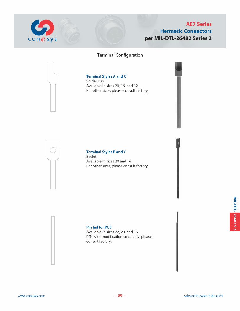
89www.conesys.com [email protected]
AE7 SeriesHermetic Connectors
per MIL-DTL-26482 Series 2
– –
MIL-D
TL-26482
S2
Terminal Configuration
Terminal Styles A and CSolder cupAvailable in sizes 20, 16, and 12For other sizes, please consult factory.
Terminal Styles B and YEyeletAvailable in sizes 20 and 16For other sizes, please consult factory.
Pin tail for PCBAvailable in sizes 22, 20, and 16P/N with modification code only; pleaseconsult factory.
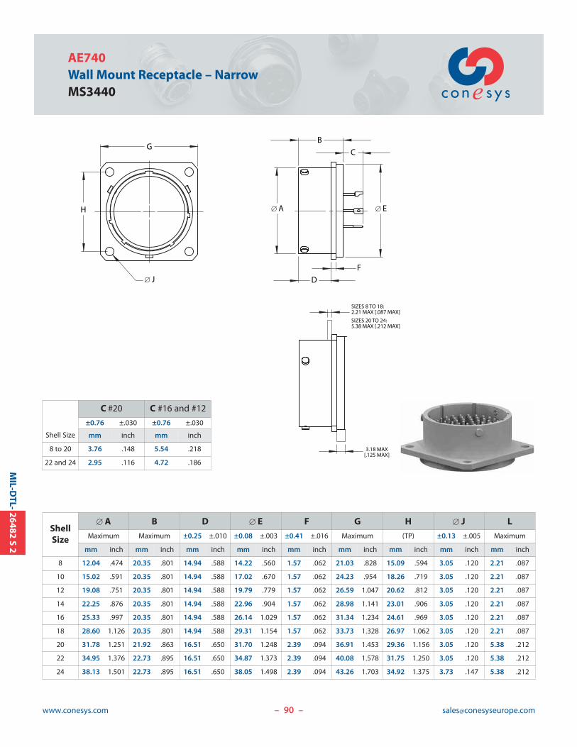
90www.conesys.com [email protected]– –
MIL-D
TL-26482
S2
AE740Wall Mount Receptacle – NarrowMS3440
[ A
F
[ E
C
D
GB
H
SIZES 8 TO 18: 2.21 MAX [.087 MAX]
SIZES 20 TO 24: 5.38 MAX [.212 MAX]
3.18 MAX[.125 MAX]
[ J
ShellSize
[ A B D [ E F G H [ J L
Maximum Maximum ±0.25 ±.010 ±0.08 ±.003 ±0.41 ±.016 Maximum (TP) ±0.13 ±.005 Maximum
mm inch mm inch mm inch mm inch mm inch mm inch mm inch mm inch mm inch
8 12.04 .474 20.35 .801 14.94 .588 14.22 .560 1.57 .062 21.03 .828 15.09 .594 3.05 .120 2.21 .087
10 15.02 .591 20.35 .801 14.94 .588 17.02 .670 1.57 .062 24.23 .954 18.26 .719 3.05 .120 2.21 .087
12 19.08 .751 20.35 .801 14.94 .588 19.79 .779 1.57 .062 26.59 1.047 20.62 .812 3.05 .120 2.21 .087
14 22.25 .876 20.35 .801 14.94 .588 22.96 .904 1.57 .062 28.98 1.141 23.01 .906 3.05 .120 2.21 .087
16 25.33 .997 20.35 .801 14.94 .588 26.14 1.029 1.57 .062 31.34 1.234 24.61 .969 3.05 .120 2.21 .087
18 28.60 1.126 20.35 .801 14.94 .588 29.31 1.154 1.57 .062 33.73 1.328 26.97 1.062 3.05 .120 2.21 .087
20 31.78 1.251 21.92 .863 16.51 .650 31.70 1.248 2.39 .094 36.91 1.453 29.36 1.156 3.05 .120 5.38 .212
22 34.95 1.376 22.73 .895 16.51 .650 34.87 1.373 2.39 .094 40.08 1.578 31.75 1.250 3.05 .120 5.38 .212
24 38.13 1.501 22.73 .895 16.51 .650 38.05 1.498 2.39 .094 43.26 1.703 34.92 1.375 3.73 .147 5.38 .212
Shell Size
C #20 C #16 and #12
±0.76 ±.030 ±0.76 ±.030
mm inch mm inch
8 to 20 3.76 .148 5.54 .218
22 and 24 2.95 .116 4.72 .186
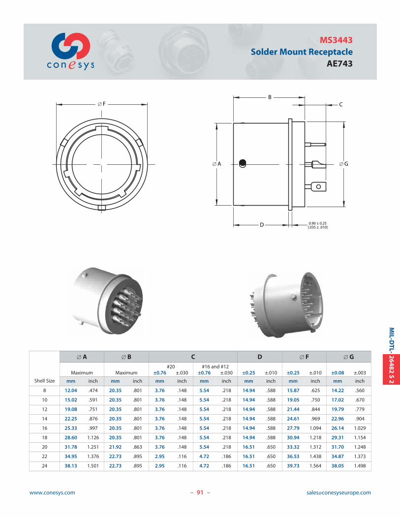
91www.conesys.com [email protected]
MS3443Solder Mount Receptacle
AE743
– –
MIL-D
TL-26482
S2
[ G[ A
CB
D 0.90 ± 0.25[.035 ± .010]
[ F
Shell Size
[ A [ B C D [ F [ G#20 #16 and #12
Maximum Maximum ±0.76 ±.030 ±0.76 ±.030 ±0.25 ±.010 ±0.25 ±.010 ±0.08 ±.003
mm inch mm inch mm inch mm inch mm inch mm inch mm inch
8 12.04 .474 20.35 .801 3.76 .148 5.54 .218 14.94 .588 15.87 .625 14.22 .560
10 15.02 .591 20.35 .801 3.76 .148 5.54 .218 14.94 .588 19.05 .750 17.02 .670
12 19.08 .751 20.35 .801 3.76 .148 5.54 .218 14.94 .588 21.44 .844 19.79 .779
14 22.25 .876 20.35 .801 3.76 .148 5.54 .218 14.94 .588 24.61 .969 22.96 .904
16 25.33 .997 20.35 .801 3.76 .148 5.54 .218 14.94 .588 27.79 1.094 26.14 1.029
18 28.60 1.126 20.35 .801 3.76 .148 5.54 .218 14.94 .588 30.94 1.218 29.31 1.154
20 31.78 1.251 21.92 .863 3.76 .148 5.54 .218 16.51 .650 33.32 1.312 31.70 1.248
22 34.95 1.376 22.73 .895 2.95 .116 4.72 .186 16.51 .650 36.53 1.438 34.87 1.373
24 38.13 1.501 22.73 .895 2.95 .116 4.72 .186 16.51 .650 39.73 1.564 38.05 1.498
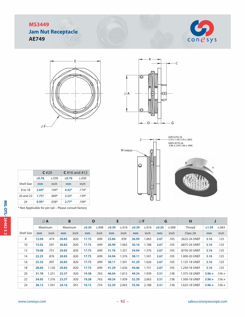
92www.conesys.com [email protected]– –
MIL-D
TL-26482
S2
MS3449Jam Nut ReceptacleAE749
C
D
J
[ A
G
BE
[ F
SIZES 8 TO 18: 3.16 ± 1.59 [.125 ± .063]
SIZES 20 TO 24: 3.96 ± 2.39 [.156 ± .094]
H THREAD
Shell Size
C #20 C #16 and #12±0.76 ±.030 ±0.76 ±.030
mm inch mm inch
8 to 18 2.64* .104* 4.42* .174*
20 and 22 1.75* .069* 3.53* .139*
24 0.95* .038* 2.77* .109*
* Not Applicable for pin tail – Please consult factory
Shell Size
[ A B D E [ F G H J
Maximum Maximum ±0.20 ±.008 ±0.39 ±.016 ±0.39 ±.016 ±0.20 ±.008 Thread ±1.59 ±.063
mm inch mm inch mm inch mm inch mm inch mm inch Class 2A mm inch
8 12.04 .474 20.83 .820 17.75 .699 23.84 .939 26.99 1.063 2.67 .105 .5625-24 UNEF 3.16 .125
10 15.02 .591 20.83 .820 17.75 .699 26.99 1.063 30.16 1.188 2.67 .105 .6875-24 UNEF 3.16 .125
12 19.08 .751 20.83 .820 17.75 .699 31.76 1.251 34.94 1.376 2.67 .105 .8750-20 UNEF 3.16 .125
14 22.25 .876 20.83 .820 17.75 .699 34.94 1.376 38.11 1.501 2.67 .105 1.000-20 UNEF 3.16 .125
16 25.33 .997 20.83 .820 17.75 .699 38.11 1.501 41.29 1.626 2.67 .105 1.125-18 UNEF 3.16 .125
18 28.60 1.126 20.83 .820 17.75 .699 41.29 1.626 44.46 1.751 2.67 .105 1.250-18 UNEF 3.16 .125
20 31.78 1.251 23.37 .920 19.38 .763 46.04 1.813 49.24 1.939 3.51 .138 1.375-18 UNEF 3.96 ≠ .156 ≠
22 34.95 1.376 23.37 .920 19.38 .763 49.24 1.939 52.39 2.063 3.51 .138 1.500-18 UNEF 3.96 ≠ .156 ≠
24 38.13 1.501 24.16 .951 19.15 .754 52.39 2.063 55.56 2.188 3.51 .138 1.625-18 UNEF 3.96 ≠ .156 ≠
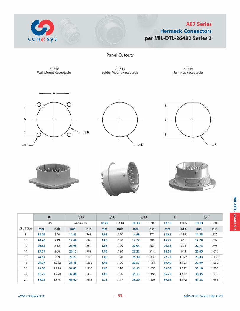
93www.conesys.com [email protected]
AE7 SeriesHermetic Connectors
per MIL-DTL-26482 Series 2
Panel Cutouts
– –
MIL-D
TL-26482
S2
A
[ B
A
[ C
AE740Wall Mount Receptacle
[ D [ F
AE743Solder Mount Receptacle
AE749Jam Nut Receptacle
E
Shell Size
A [ B [ C [ D E [ F
(TP) Minimum ±0.25 ±.010 ±0.13 ±.005 ±0.13 ±.005 ±0.13 ±.005
mm inch mm inch mm inch mm inch mm inch mm inch
8 15.09 .594 14.43 .568 3.05 .120 14.48 .570 13.61 .536 14.53 .572
10 18.26 .719 17.40 .685 3.05 .120 17.27 .680 16.79 .661 17.70 .697
12 20.62 .812 21.95 .864 3.05 .120 20.04 .789 20.93 .824 22.73 .895
14 23.01 .906 25.12 .989 3.05 .120 23.22 .914 24.08 .948 25.65 1.010
16 24.61 .969 28.27 1.113 3.05 .120 26.39 1.039 27.23 1.072 28.83 1.135
18 26.97 1.062 31.45 1.238 3.05 .120 29.57 1.164 30.40 1.197 32.00 1.260
20 29.36 1.156 34.62 1.363 3.05 .120 31.95 1.258 33.58 1.322 35.18 1.385
22 31.75 1.250 37.80 1.488 3.05 .120 35.13 1.383 36.75 1.447 38.35 1.510
24 34.92 1.375 41.02 1.615 3.73 .147 38.30 1.508 39.93 1.572 41.53 1.635
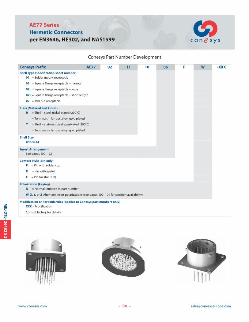
Conesys Part Number Development
Conesys Prefix AE77 02 H 10 06 P W -XXXShell Type (specification sheet number)
01 = Solder mount receptacle
02 = Square flange receptacle – narrow
02L = Square flange receptacle – wide
02S = Square flange receptacle – short length
07 = Jam nut receptacle
Class (Material and Finish)H = Shell – steel, nickel plated (200°C)
= Terminals – ferrous alloy, gold plated
Y = Shell – stainless steel, passivated (200°C)
= Terminals – ferrous alloy, gold plated
Shell Size8 thru 24
Insert ArrangementSee pages 100–102
Contact Style (pin only)P = Pin with solder cup
X = Pin with eyelet
C = Pin tail (for PCB)
Polarization (keying)N = Normal (omitted in part number)
W, X, Y, or Z Alternate insert polarizations (see pages 100–101 for position availability)
Modification or Particularities (applies to Conesys part numbers only)XXX = Modification
Consult factory for details
94www.conesys.com [email protected]
AE77 SeriesHermetic Connectorsper EN3646, HE302, and NAS1599
– –
MIL-D
TL-26482
S2
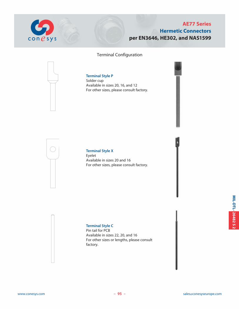
95www.conesys.com [email protected]
AE77 SeriesHermetic Connectors
per EN3646, HE302, and NAS1599
– –
MIL-D
TL-26482
S2
Terminal Configuration
Terminal Style PSolder cupAvailable in sizes 20, 16, and 12For other sizes, please consult factory.
Terminal Style XEyeletAvailable in sizes 20 and 16For other sizes, please consult factory.
Terminal Style CPin tail for PCBAvailable in sizes 22, 20, and 16For other sizes or lengths, please consultfactory.
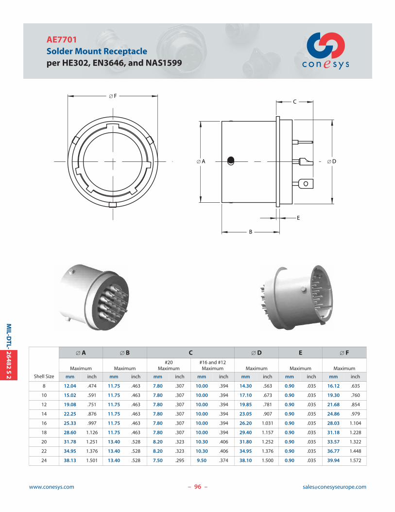
96www.conesys.com [email protected]
AE7701Solder Mount Receptacleper HE302, EN3646, and NAS1599
– –
MIL-D
TL-26482
S2
B
C
E
[ F
[ D[ A
Shell Size
[ A [ B C [ D E [ F#20 #16 and #12
Maximum Maximum Maximum Maximum Maximum Maximum Maximum
mm inch mm inch mm inch mm inch mm inch mm inch mm inch
8 12.04 .474 11.75 .463 7.80 .307 10.00 .394 14.30 .563 0.90 .035 16.12 .635
10 15.02 .591 11.75 .463 7.80 .307 10.00 .394 17.10 .673 0.90 .035 19.30 .760
12 19.08 .751 11.75 .463 7.80 .307 10.00 .394 19.85 .781 0.90 .035 21.68 .854
14 22.25 .876 11.75 .463 7.80 .307 10.00 .394 23.05 .907 0.90 .035 24.86 .979
16 25.33 .997 11.75 .463 7.80 .307 10.00 .394 26.20 1.031 0.90 .035 28.03 1.104
18 28.60 1.126 11.75 .463 7.80 .307 10.00 .394 29.40 1.157 0.90 .035 31.18 1.228
20 31.78 1.251 13.40 .528 8.20 .323 10.30 .406 31.80 1.252 0.90 .035 33.57 1.322
22 34.95 1.376 13.40 .528 8.20 .323 10.30 .406 34.95 1.376 0.90 .035 36.77 1.448
24 38.13 1.501 13.40 .528 7.50 .295 9.50 .374 38.10 1.500 0.90 .035 39.94 1.572
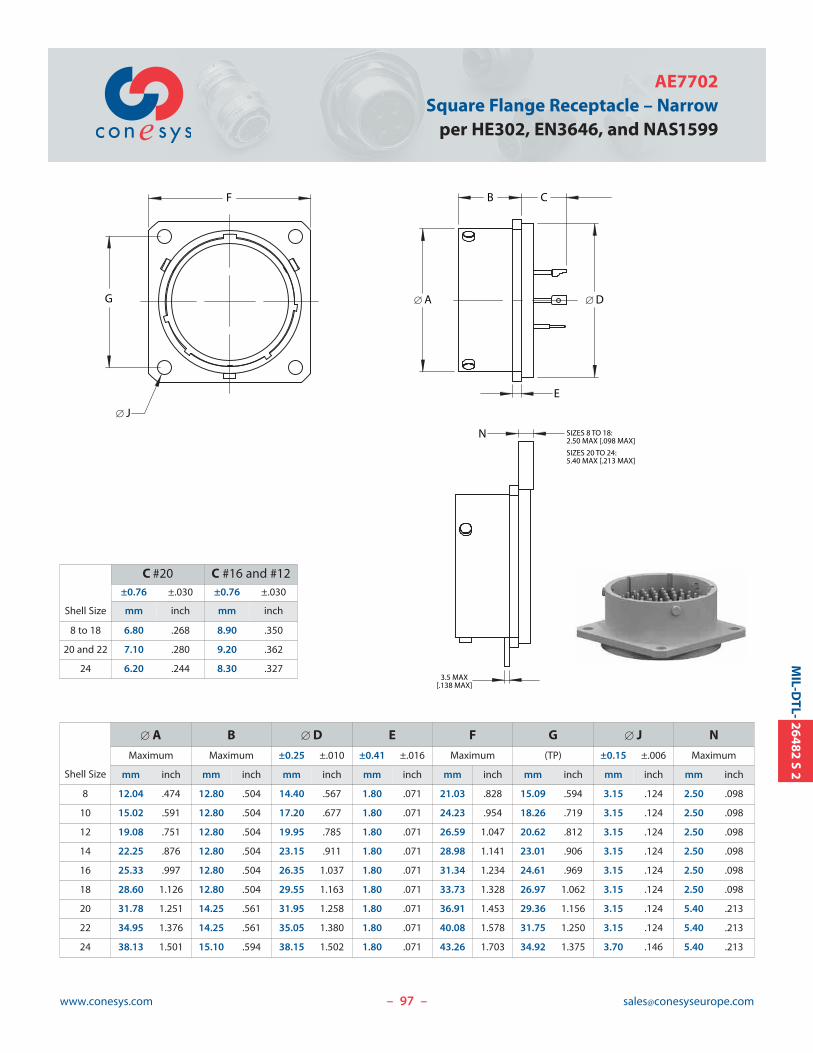
97www.conesys.com [email protected]
AE7702 Square Flange Receptacle – Narrow
per HE302, EN3646, and NAS1599
– –
MIL-D
TL-26482
S2
E
N
B C
[ D[ A
F
G
SIZES 8 TO 18: 2.50 MAX [.098 MAX]
SIZES 20 TO 24: 5.40 MAX [.213 MAX]
3.5 MAX[.138 MAX]
[ J
Shell Size
C #20 C #16 and #12±0.76 ±.030 ±0.76 ±.030
mm inch mm inch
8 to 18 6.80 .268 8.90 .350
20 and 22 7.10 .280 9.20 .362
24 6.20 .244 8.30 .327
Shell Size
[ A B [ D E F G [ J N
Maximum Maximum ±0.25 ±.010 ±0.41 ±.016 Maximum (TP) ±0.15 ±.006 Maximum
mm inch mm inch mm inch mm inch mm inch mm inch mm inch mm inch
8 12.04 .474 12.80 .504 14.40 .567 1.80 .071 21.03 .828 15.09 .594 3.15 .124 2.50 .098
10 15.02 .591 12.80 .504 17.20 .677 1.80 .071 24.23 .954 18.26 .719 3.15 .124 2.50 .098
12 19.08 .751 12.80 .504 19.95 .785 1.80 .071 26.59 1.047 20.62 .812 3.15 .124 2.50 .098
14 22.25 .876 12.80 .504 23.15 .911 1.80 .071 28.98 1.141 23.01 .906 3.15 .124 2.50 .098
16 25.33 .997 12.80 .504 26.35 1.037 1.80 .071 31.34 1.234 24.61 .969 3.15 .124 2.50 .098
18 28.60 1.126 12.80 .504 29.55 1.163 1.80 .071 33.73 1.328 26.97 1.062 3.15 .124 2.50 .098
20 31.78 1.251 14.25 .561 31.95 1.258 1.80 .071 36.91 1.453 29.36 1.156 3.15 .124 5.40 .213
22 34.95 1.376 14.25 .561 35.05 1.380 1.80 .071 40.08 1.578 31.75 1.250 3.15 .124 5.40 .213
24 38.13 1.501 15.10 .594 38.15 1.502 1.80 .071 43.26 1.703 34.92 1.375 3.70 .146 5.40 .213
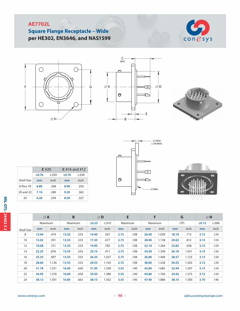
98www.conesys.com [email protected]
AE7702LSquare Flange Receptacle – Wideper HE302, EN3646, and NAS1599
– –
MIL-D
TL-26482
S2
CMAX
B
E
F G
3.5 MAX[.138 MAX]
O-RING
[ D
[ H
[ A
Shell Size
C #20 C #16 and #12±0.76 ±.030 ±0.76 ±.030
mm inch mm inch
8 thru 18 6.80 .268 8.90 .350
20 and 22 7.10 .280 9.20 .362
24 6.20 .244 8.30 .327
Shell Size
[ A B [ D E F G [ H
Maximum Maximum ±0.25 ±.010 Maximum Maximum (TP) ±0.15 ±.006
mm inch mm inch mm inch mm inch mm inch mm inch mm inch
8 12.04 .474 13.55 .533 14.40 .567 2.75 .108 26.40 1.039 18.10 .713 3.15 .124
10 15.02 .591 13.55 .533 17.20 .677 2.75 .108 28.90 1.138 20.62 .812 3.15 .124
12 19.08 .751 13.55 .533 19.95 .785 2.75 .108 32.10 1.264 23.82 .938 3.15 .124
14 22.25 .876 13.55 .533 23.15 .911 2.75 .108 34.50 1.358 26.18 1.031 3.15 .124
16 25.33 .997 13.55 .533 26.35 1.037 2.75 .108 36.80 1.449 28.57 1.125 3.15 .124
18 28.60 1.126 13.55 .533 29.55 1.163 2.75 .108 38.80 1.528 30.55 1.203 3.15 .124
20 31.78 1.251 16.00 .630 31.95 1.258 3.55 .140 42.80 1.685 32.94 1.297 3.15 .124
22 34.95 1.376 16.00 .630 35.05 1.380 3.55 .140 44.80 1.764 34.92 1.375 3.15 .124
24 38.13 1.501 16.85 .663 38.15 1.502 3.55 .140 47.90 1.886 38.10 1.500 3.70 .146
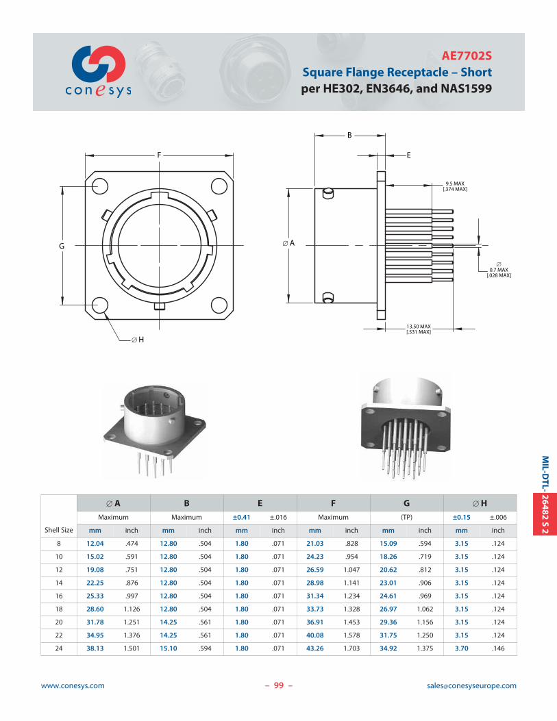
99www.conesys.com [email protected]
AE7702SSquare Flange Receptacle – Shortper HE302, EN3646, and NAS1599
– –
MIL-D
TL-26482
S2
13.50 MAX[.531 MAX]
[0.7 MAX
[.028 MAX]
9.5 MAX[.374 MAX]
B
EF
G
[ H
[ A
Shell Size
[ A B E F G [ H
Maximum Maximum ±0.41 ±.016 Maximum (TP) ±0.15 ±.006
mm inch mm inch mm inch mm inch mm inch mm inch
8 12.04 .474 12.80 .504 1.80 .071 21.03 .828 15.09 .594 3.15 .124
10 15.02 .591 12.80 .504 1.80 .071 24.23 .954 18.26 .719 3.15 .124
12 19.08 .751 12.80 .504 1.80 .071 26.59 1.047 20.62 .812 3.15 .124
14 22.25 .876 12.80 .504 1.80 .071 28.98 1.141 23.01 .906 3.15 .124
16 25.33 .997 12.80 .504 1.80 .071 31.34 1.234 24.61 .969 3.15 .124
18 28.60 1.126 12.80 .504 1.80 .071 33.73 1.328 26.97 1.062 3.15 .124
20 31.78 1.251 14.25 .561 1.80 .071 36.91 1.453 29.36 1.156 3.15 .124
22 34.95 1.376 14.25 .561 1.80 .071 40.08 1.578 31.75 1.250 3.15 .124
24 38.13 1.501 15.10 .594 1.80 .071 43.26 1.703 34.92 1.375 3.70 .146
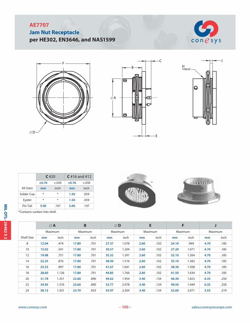
100www.conesys.com [email protected]
AE7707Jam Nut Receptacleper HE302, EN3646, and NAS1599
– –
MIL-D
TL-26482
S2
C
B
E
FJ
HTHREAD
[ A
[ D
All Sizes
C #20 C #16 and #12
±0.76 ±.030 ±0.76 ±.030
mm inch mm inch
Solder Cup * * 1.50 .059
Eyelet * * 1.50 .059
Pin Tail 5.00 .197 5.00 .197
*Contacts sunken into shell.
Shell Size
[ A B [ D E F J
Maximum Maximum Maximum Maximum Maximum Maximum
mm inch mm inch mm inch mm inch mm inch mm inch
8 12.04 .474 17.80 .701 27.37 1.078 2.60 .102 24.10 .949 4.70 .185
10 15.02 .591 17.80 .701 30.57 1.204 2.60 .102 27.20 1.071 4.70 .185
12 19.08 .751 17.80 .701 35.32 1.391 2.60 .102 32.10 1.264 4.70 .185
14 22.25 .876 17.80 .701 38.50 1.516 2.60 .102 35.10 1.382 4.70 .185
16 25.33 .997 17.80 .701 41.67 1.641 2.60 .102 38.30 1.508 4.70 .185
18 28.60 1.126 17.80 .701 44.85 1.766 2.60 .102 41.50 1.634 4.70 .185
20 31.78 1.251 22.60 .890 49.62 1.954 3.40 .134 46.30 1.823 6.35 .250
22 34.95 1.376 22.60 .890 52.77 2.078 3.40 .134 49.50 1.949 6.35 .250
24 38.13 1.501 23.70 .933 55.97 2.204 3.40 .134 52.60 2.071 5.55 .219
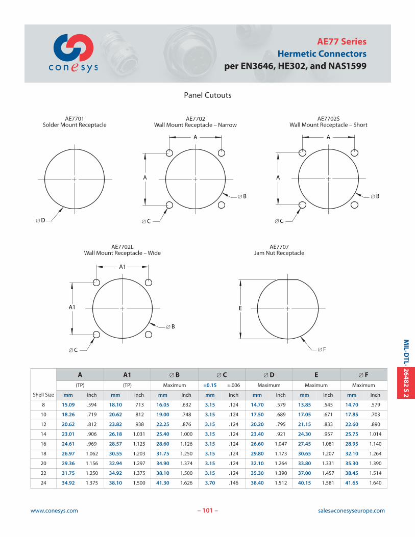
101www.conesys.com [email protected]
AE77 SeriesHermetic Connectors
per EN3646, HE302, and NAS1599
– –
MIL-D
TL-26482
S2
Panel Cutouts
A
[ B
A
[ C
AE7702Wall Mount Receptacle – Narrow
[ F
AE7707Jam Nut Receptacle
E
A
[ B
A
[ C
AE7702SWall Mount Receptacle – Short
A1
[ B
A1
[ C
AE7702LWall Mount Receptacle – Wide
[ D
AE7701Solder Mount Receptacle
Shell Size
A A1 [ B [ C [ D E [ F
(TP) (TP) Maximum ±0.15 ±.006 Maximum Maximum Maximum
mm inch mm inch mm inch mm inch mm inch mm inch mm inch
8 15.09 .594 18.10 .713 16.05 .632 3.15 .124 14.70 .579 13.85 .545 14.70 .579
10 18.26 .719 20.62 .812 19.00 .748 3.15 .124 17.50 .689 17.05 .671 17.85 .703
12 20.62 .812 23.82 .938 22.25 .876 3.15 .124 20.20 .795 21.15 .833 22.60 .890
14 23.01 .906 26.18 1.031 25.40 1.000 3.15 .124 23.40 .921 24.30 .957 25.75 1.014
16 24.61 .969 28.57 1.125 28.60 1.126 3.15 .124 26.60 1.047 27.45 1.081 28.95 1.140
18 26.97 1.062 30.55 1.203 31.75 1.250 3.15 .124 29.80 1.173 30.65 1.207 32.10 1.264
20 29.36 1.156 32.94 1.297 34.90 1.374 3.15 .124 32.10 1.264 33.80 1.331 35.30 1.390
22 31.75 1.250 34.92 1.375 38.10 1.500 3.15 .124 35.30 1.390 37.00 1.457 38.45 1.514
24 34.92 1.375 38.10 1.500 41.30 1.626 3.70 .146 38.40 1.512 40.15 1.581 41.65 1.640
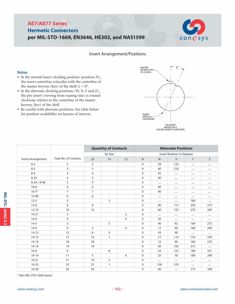
102www.conesys.com [email protected]
AE7/AE77 SeriesHermetic Connectorsper MIL-STD-1669, EN3646, HE302, and NAS1599
Insert Arrangement/Positions
– –
MIL-D
TL-26482
S2
Insert Arrangement Total No. of Contacts
Quantity of Contacts Alternate Positions
By Size Insert Rotation in Degrees
20 16 12 N W X Y Z
8-2 2 2 0 58 122 — —8-3 3 3 0 60 210 — —8-4 4 4 0 45 — — —8-33 3 3 0 90 — — —8-3A / 8-98 3 3 0 — — — —10-6 6 6 0 90 — — —10-7* 7 7 0 90 — — —10-98 6 6 0 — — — —12-3 3 3 0 — — 180 —12-8 8 8 0 90 112 203 273
12-10 10 10 0 60 155 270 295
14-2* 2 2 0 — — — —14-4 4 4 0 45 — — —14-5 5 5 0 40 92 184 273
14-9 9 5 4 0 15 90 180 240
14-12 12 8 4 0 43 90 — —14-15 15 14 1 0 17 110 155 234
14-18 18 18 0 15 90 180 270
14-19 19 19 0 30 165 315 —16-8 8 8 0 54 152 180 331
16-14 11 5 6 0 25 78 180 240
16-21 21 16 5 0 — — — —16-23 23 22 1 0 158 270 — —16-26 26 26 0 60 — 275 338
Notes:• In the normal insert clocking position (position N),
the insert centerline coincides with the centerline ofthe master keyway (key) of the shell: L = 0°.
• In the alternate clocking positions (W, X, Y and Z),the pin insert (viewing from mating side) is rotatedclockwise relative to the centerline of the master keyway (key) of the shell.
• Be careful with alternate positions. See table below for position availability on layouts of interest.
PIN INSERTMATING FACE
(SOCKET INSERT IS OPPOSITE)
INSERTVERTICALCENTERLINE
MASTERKEYWAY (KEY)OF A SHELL
L°
* Non MIL-STD-1669 layout
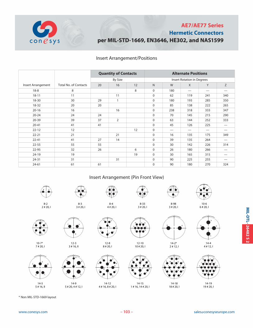
103www.conesys.com [email protected]
AE7/AE77 SeriesHermetic Connectors
per MIL-STD-1669, EN3646, HE302, and NAS1599
Insert Arrangement/Positions
Insert Arrangement (Pin Front View)
– –
MIL-D
TL-26482
S2
Insert Arrangement Total No. of Contacts
Quantity of Contacts Alternate Positions
By Size Insert Rotation in Degrees
20 16 12 N W X Y Z
18-8 8 8 0 180 — — —
18-11 11 11 0 62 119 241 340
18-30 30 29 1 0 180 193 285 350
18-32 20 20 0 85 138 222 265
20-16 16 16 0 238 318 333 347
20-24 24 24 0 70 145 215 290
20-39 39 37 2 0 63 144 252 333
20-41 41 41 0 45 126 225 —
22-12 12 12 0 — — — —
22-21 21 21 0 16 135 175 349
22-41 41 27 14 0 39 135 264 —
22-55 55 55 0 30 142 226 314
22-95 32 26 6 0 26 180 266 —
24-19 19 19 0 30 165 315 —
24-31 31 31 0 90 225 255 —
24-61 61 61 0 90 180 270 324
A
B
CABA
B C
D A
BC
A
B
C AB
CD
E
F
AB
G
CD
E
F A
B
C
A
H B
CD
E
F
G
A B
C
DEF
G
H
JK
A
B
C
D
AB
CD
E
A
B
C
D
E
F
G
H
J
A
B
C
DE
F
G
M
H
J
K
L
A
B
R C
D
EF
G
H
J
K
L
M
N
P
A
B
C
D
EFG
H
J
K
L
M N
P
RS
T U
A B
C
D
E
FGH
J
K
L
M
N P
R
ST
U V
8-33 # 20, I
8-22 # 20, I
8-44 # 20, I
8-333 # 20, I
8-983 # 20, I
10-66 # 20, I
10-7*7 # 20, I
12-33 # 16, II
12-88 # 20, I
12-1010 # 20, I
14-44 # 12, I
14-55 # 16, II
14-95 # 20, 4 # 12, I
14-124 # 16, 8 # 20, I
14-151 # 16, 14 # 20, I
14-1818 # 20, I
14-1919 # 20, I
AB
14-2*2 # 12, I
* Non MIL-STD-1669 layout

104www.conesys.com [email protected]
AE7/AE77 SeriesHermetic Connectorsper MIL-STD-1669, EN3646, HE302, and NAS1599
Insert Arrangement (Pin Front View)
– –
MIL-D
TL-26482
S2
A
B
C
D
EF
G
H
J
K
LM
N
P
R
ST
U
V
W X
Y
Z
a
20-2424 # 20, I
AB
C
D
E
F
G
H
JKL
M
N
P
R
S
T
UV
W
XY
Z
a
b
c
de
f
g
h
J
k
m
nP
r
i
q
20-392 # 16, 37 # 20, I
20-4141 # 20, I
A
B
C
D
E
FGH
J
K
L
M
N
P
R
S
TU
V
W
X
22-2121 # 16, II
A
B
C
D
EF
G
H
J
K
L
M
22-1212 # 12, I
a
b
c
d
ef
g
H
j
k
m
n
Pr
s
t
A
B
C
D
E
F
G
H
JK
LMN
R
S
T
U
V
W
XY
Z
P
i
q
22-4114 # 16, 27 # 20, I
AB
C
D
E
F
G
HJK
L
M
N
P
R
S
TU
V
WX
Y
Zl
a
b
c
d
ef
g
h
k
m
np
r
s
t
uv
wx
y
z
i
qAABB
CC
DDEE
FF
GG
HH
22-5555 # 20, I
A B
C
D
E
F
G
H
J
KLM
N
P
R
S
T
U
V
WX
Y Z
a
b
c
d
e
f
g
h
j
22-956 # 12, 26 # 20, I
A B
C
D
E
FGH
J
K
L
M
N P
R
ST
U V
24-1919 # 12, II
A
B
C
D
E
FG
H
J
K
L
M
N
P
R
S
T
U
V
W
X
Y
Z
a
b
cd
e
f
g
Q
24-3131 # 16, I
AB
C
D
E
F
G
H
J
KL
MNP
R
S
T
U
V
W
X
YZ
AABB
CC
DD
EE
FF
GGHH
JJ
LL
KKMM
NN
PP
a bc
d
e
f
g
h
jkmn
p
r
s
tu
vw
x
y
z
i
q
24-6161 # 20, I
AB
C
D
E
F
G
H
J
KL
MN
P
R
S
T
U
VW
XY
Z
a
b
c
de
f
g
h
j
km
n
p
r
si
q
t
A
B
C
DE
F
G
H
A
B
C
D
E
F
G
H
J
K
L
M
N P
A
B
C
D
E
FGH
J
K
L
M
NP
RS
T
UV
W
X
Y
Z
AB
C
D
E
F
GHJ
K
L
M
N
P
R
S T
U
V
WX
Y
Z
a b
c
A
B
C
DE
F
G
H
A
B
C
DE
G
H
J
K
L
F
AB
C
D
E
F
GHJ
K
L
M
N
P
RS
T
U
V
W
XY
Z
a
b
c
d
e
fg
AB
C
D
E
F
G
HJK
L
M
N
P
R
ST
UV
W
X
YZa
b
c
d
e
f
g
h
J
A
B
C
D
EF
G
H
J
K
L
M
N
PR
S
16-88 # 16, II
16-148 # 20, 6 # 12, I
16-231 # 16, 22 # 20, I
16-2626 # 20, I
18-88 # 12, I
18-1111 # 16, II
20-1616 # 16, II
18-3232 # 20, I
18-301 # 16, 29 # 20, I
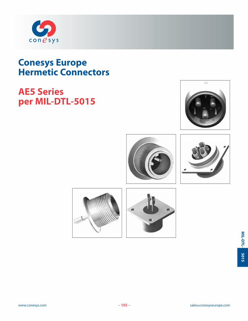
105www.conesys.com [email protected]
Conesys EuropeHermetic Connectors
AE5 Seriesper MIL-DTL-5015
– –
MIL-D
TL-5015
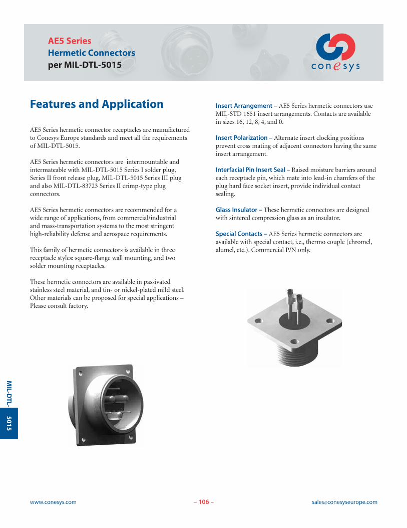
106www.conesys.com [email protected]
AE5 SeriesHermetic Connectorsper MIL-DTL-5015
– –
MIL-D
TL-5015
Features and Application
AE5 Series hermetic connector receptacles are manufacturedto Conesys Europe standards and meet all the requirementsof MIL-DTL-5015.
AE5 Series hermetic connectors are intermountable andintermateable with MIL-DTL-5015 Series I solder plug,Series II front release plug, MIL-DTL-5015 Series III plugand also MIL-DTL-83723 Series II crimp-type plug connectors.
AE5 Series hermetic connectors are recommended for a wide range of applications, from commercial/industrial and mass-transportation systems to the most stringent high-reliability defense and aerospace requirements.
This family of hermetic connectors is available in threereceptacle styles: square-flange wall mounting, and two solder mounting receptacles.
These hermetic connectors are available in passivated stainless steel material, and tin- or nickel-plated mild steel.Other materials can be proposed for special applications –Please consult factory.
Insert Arrangement – AE5 Series hermetic connectors useMIL-STD 1651 insert arrangements. Contacts are availablein sizes 16, 12, 8, 4, and 0.
Insert Polarization – Alternate insert clocking positions prevent cross mating of adjacent connectors having the sameinsert arrangement.
Interfacial Pin Insert Seal – Raised moisture barriers aroundeach receptacle pin, which mate into lead-in chamfers of theplug hard face socket insert, provide individual contact sealing.
Glass Insulator – These hermetic connectors are designedwith sintered compression glass as an insulator.
Special Contacts – AE5 Series hermetic connectors areavailable with special contact, i.e., thermo couple (chromel,alumel, etc.). Commercial P/N only.
107www.conesys.com [email protected]
AE5 SeriesHermetic Connectors
per MIL-DTL-5015
– –
MIL-D
TL-5015
Performance Specifications
Operating Temperature RangeClass HY: -55°C to +200°C (-67°F to +392°F)Class HT: -55°C to +175°C (-67°F to +347°F)Class H: -55°C to +125°C (-67°F to +257°F)
Material and Finish Data (Class)Class H:
RECEPTACLE material: ferrous alloyfinish: nickel plated
CONTACTS material: ferrous alloyfinish: gold plated
Class HT:RECEPTACLE material: ferrous alloy
finish: tin platedCONTACTS material: ferrous alloy
finish: gold plated
Class HY (Conesys P/N only):RECEPTACLE material: stainless steel
finish: passivatedCONTACTS material: ferrous alloy
finish: gold plated
Corrosion ResistanceClass H and HT: In accordance with MIL-DTL-5015.Class HY: 1000 hour salt spray.
DurabilityMinimum of 100 mating cycles.
Voltage Rating
Leakage< 1.10-7 atm.cm3.s-1.
Shock and VibrationIn accordance with MIL-DTL-5015 specification.
Insulation Resistance>5000 M| under 500 Vdc(25°C – 65% HR max.)
Maximum Current Rating per ContactSize 16 10 AmpSize 12 17 AmpSize 8 40 AmpSize 4 80 AmpSize 0 150 Amp
Altitude
Inst. A D E B C
V RMS V RMS V RMS V RMS V RMS V RMS
Sea Level 1000 2000 2800 3500 4500 7000
15 000 m 400 600 675 750 825 975
21 000 m 260 360 400 440 480 560
33 000 m 200 200 200 200 200 200
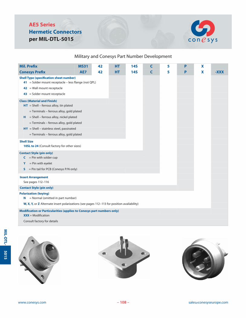
AE5 SeriesHermetic Connectorsper MIL-DTL-5015
www.conesys.com [email protected]– –
MIL-D
TL-5015
Military and Conesys Part Number Development
Mil. Prefix MS31 42 HT 14S C 5 P X
Conesys Prefix AE7 42 HT 14S C 5 P X -XXXShell Type (specification sheet number)
41 = Solder mount receptacle – less flange (not QPL)
42 = Wall mount receptacle
43 = Solder mount receptacle
Class (Material and Finish)HT = Shell – ferrous alloy, tin plated
= Terminals – ferrous alloy, gold plated
H = Shell – ferrous alloy, nickel plated
= Terminals – ferrous alloy, gold plated
HY = Shell – stainless steel, passivated
= Terminals – ferrous alloy, gold plated
Shell Size10SL to 24 (Consult factory for other sizes)
Contact Style (pin only)C = Pin with solder cup
Y = Pin with eyelet
S = Pin tail for PCB (Conesys P/N only)
Insert Arrangement
See pages 112–116
Contact Style (pin only)
Polarization (keying)N = Normal (omitted in part number)
W, X, Y, or Z Alternate insert polarizations (see pages 112–113 for position availability)
Modification or Particularities (applies to Conesys part numbers only)XXX = Modification
Consult factory for details
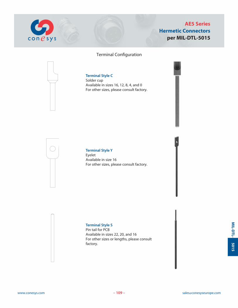
109www.conesys.com [email protected]
AE5 SeriesHermetic Connectors
per MIL-DTL-5015
– –
MIL-D
TL-5015
Terminal Configuration
Terminal Style CSolder cupAvailable in sizes 16, 12, 8, 4, and 0For other sizes, please consult factory.
Terminal Style YEyeletAvailable in size 16For other sizes, please consult factory.
Terminal Style SPin tail for PCBAvailable in sizes 22, 20, and 16For other sizes or lengths, please consultfactory.
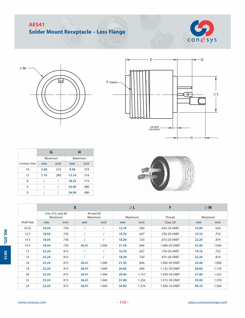
110www.conesys.com [email protected]
AE541Solder Mount Receptacle – Less Flange
– –
MIL-D
TL-5015
G
H
E
1.60 MAX[.063 MAX]
F THREAD
[ M
[ L
Contact Size
G H
Maximum Maximum
mm inch mm inch
16 5.56 .219 9.50 .374
12 7.10 .280 13.10 .516
8 / / 18.25 .719
4 / / 24.90 .980
0 / / 24.90 .980
Shell Size
E [ L F [ M#16, #12, and #8 #4 and #0
Maximum Maximum Maximum Thread Maximum
mm inch mm inch mm inch Class 2A mm inch
10 SL 18.54 .730 / / 12.70 .500 .625-24 UNEF 15.90 .626
12 S 18.54 .730 / / 16.70 .657 .750-20 UNEF 19.10 .752
14 S 18.54 .730 / / 18.30 .720 .875-20 UNEF 22.20 .874
16 S 18.54 .730 26.41 1.040 21.50 .846 1.000-20 UNEF 25.40 1.000
12 23.24 .915 / / 16.70 .657 .750-20 UNEF 19.10 .752
14 23.24 .915 / / 18.30 .720 .875-20 UNEF 22.20 .874
16 23.24 .915 26.41 1.040 21.50 .846 1.000-20 UNEF 25.40 1.000
18 23.24 .915 26.41 1.040 24.60 .969 1.125-18 UNEF 28.60 1.126
20 23.24 .915 26.41 1.040 29.40 1.157 1.250-18 UNEF 31.80 1.252
22 23.24 .915 26.41 1.040 31.90 1.256 1.375-18 UNEF 35.00 1.378
24 23.24 .915 26.41 1.040 34.90 1.374 1.500-18 UNEF 38.10 1.500
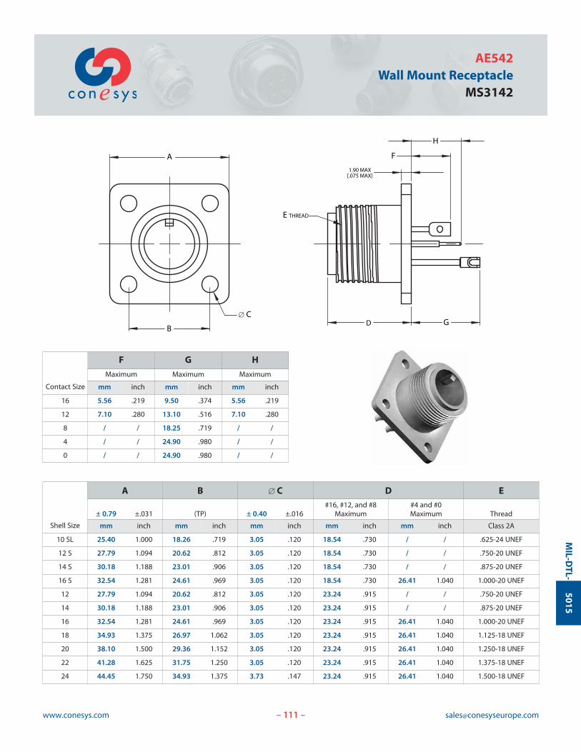
111www.conesys.com [email protected]
AE542Wall Mount Receptacle
MS3142
– –
MIL-D
TL-5015
D
F
H
G
1.90 MAX[.075 MAX]
E THREAD
A
B
[ C
Contact Size
F G H
Maximum Maximum Maximum
mm inch mm inch mm inch
16 5.56 .219 9.50 .374 5.56 .219
12 7.10 .280 13.10 .516 7.10 .280
8 / / 18.25 .719 / /
4 / / 24.90 .980 / /
0 / / 24.90 .980 / /
Shell Size
A B [ C D E#16, #12, and #8 #4 and #0
± 0.79 ±.031 (TP) ± 0.40 ±.016 Maximum Maximum Thread
mm inch mm inch mm inch mm inch mm inch Class 2A
10 SL 25.40 1.000 18.26 .719 3.05 .120 18.54 .730 / / .625-24 UNEF
12 S 27.79 1.094 20.62 .812 3.05 .120 18.54 .730 / / .750-20 UNEF
14 S 30.18 1.188 23.01 .906 3.05 .120 18.54 .730 / / .875-20 UNEF
16 S 32.54 1.281 24.61 .969 3.05 .120 18.54 .730 26.41 1.040 1.000-20 UNEF
12 27.79 1.094 20.62 .812 3.05 .120 23.24 .915 / / .750-20 UNEF
14 30.18 1.188 23.01 .906 3.05 .120 23.24 .915 / / .875-20 UNEF
16 32.54 1.281 24.61 .969 3.05 .120 23.24 .915 26.41 1.040 1.000-20 UNEF
18 34.93 1.375 26.97 1.062 3.05 .120 23.24 .915 26.41 1.040 1.125-18 UNEF
20 38.10 1.500 29.36 1.152 3.05 .120 23.24 .915 26.41 1.040 1.250-18 UNEF
22 41.28 1.625 31.75 1.250 3.05 .120 23.24 .915 26.41 1.040 1.375-18 UNEF
24 44.45 1.750 34.93 1.375 3.73 .147 23.24 .915 26.41 1.040 1.500-18 UNEF
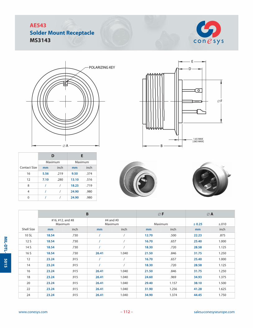
112www.conesys.com [email protected]
AE543Solder Mount ReceptacleMS3143
– –
MIL-D
TL-5015
POLARIZING KEY
E
1.65 MAX[.065 MAX]
D
B[ A
[ F
Contact Size
D E
Maximum Maximum
mm inch mm inch
16 5.56 .219 9.50 .374
12 7.10 .280 13.10 .516
8 / / 18.25 .719
4 / / 24.90 .980
0 / / 24.90 .980
Shell Size
B [ F [ A#16, #12, and #8 #4 and #0
Maximum Maximum Maximum ± 0.25 ±.010
mm inch mm inch mm inch mm inch
10 SL 18.54 .730 / / 12.70 .500 22.23 .875
12 S 18.54 .730 / / 16.70 .657 25.40 1.000
14 S 18.54 .730 / / 18.30 .720 28.58 1.125
16 S 18.54 .730 26.41 1.040 21.50 .846 31.75 1.250
12 23.24 .915 / / 16.70 .657 25.40 1.000
14 23.24 .915 / / 18.30 .720 28.58 1.125
16 23.24 .915 26.41 1.040 21.50 .846 31.75 1.250
18 23.24 .915 26.41 1.040 24.60 .969 34.93 1.375
20 23.24 .915 26.41 1.040 29.40 1.157 38.10 1.500
22 23.24 .915 26.41 1.040 31.90 1.256 41.28 1.625
24 23.24 .915 26.41 1.040 34.90 1.374 44.45 1.750
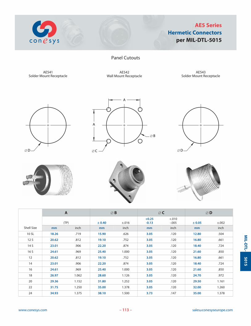
113www.conesys.com [email protected]
AE5 SeriesHermetic Connectors
per MIL-DTL-5015
– –
MIL-D
TL-5015
Panel Cutouts
A
[ B
A
[ C
AE542Wall Mount Receptacle
[ D
AE541Solder Mount Receptacle
[ D
AE543Solder Mount Receptacle
Shell Size
A [ B [ C [ D+0.25 +.010
(TP) ± 0.40 ±.016 -0.13 -.005 ± 0.05 ±.002
mm inch mm inch mm inch mm inch
10 SL 18.26 .719 15.90 .626 3.05 .120 12.80 .504
12 S 20.62 .812 19.10 .752 3.05 .120 16.80 .661
14 S 23.01 .906 22.20 .874 3.05 .120 18.40 .724
16 S 24.61 .969 25.40 1.000 3.05 .120 21.60 .850
12 20.62 .812 19.10 .752 3.05 .120 16.80 .661
14 23.01 .906 22.20 .874 3.05 .120 18.40 .724
16 24.61 .969 25.40 1.000 3.05 .120 21.60 .850
18 26.97 1.062 28.60 1.126 3.05 .120 24.70 .972
20 29.36 1.152 31.80 1.252 3.05 .120 29.50 1.161
22 31.75 1.250 35.00 1.378 3.05 .120 32.00 1.260
24 34.93 1.375 38.10 1.500 3.73 .147 35.00 1.378
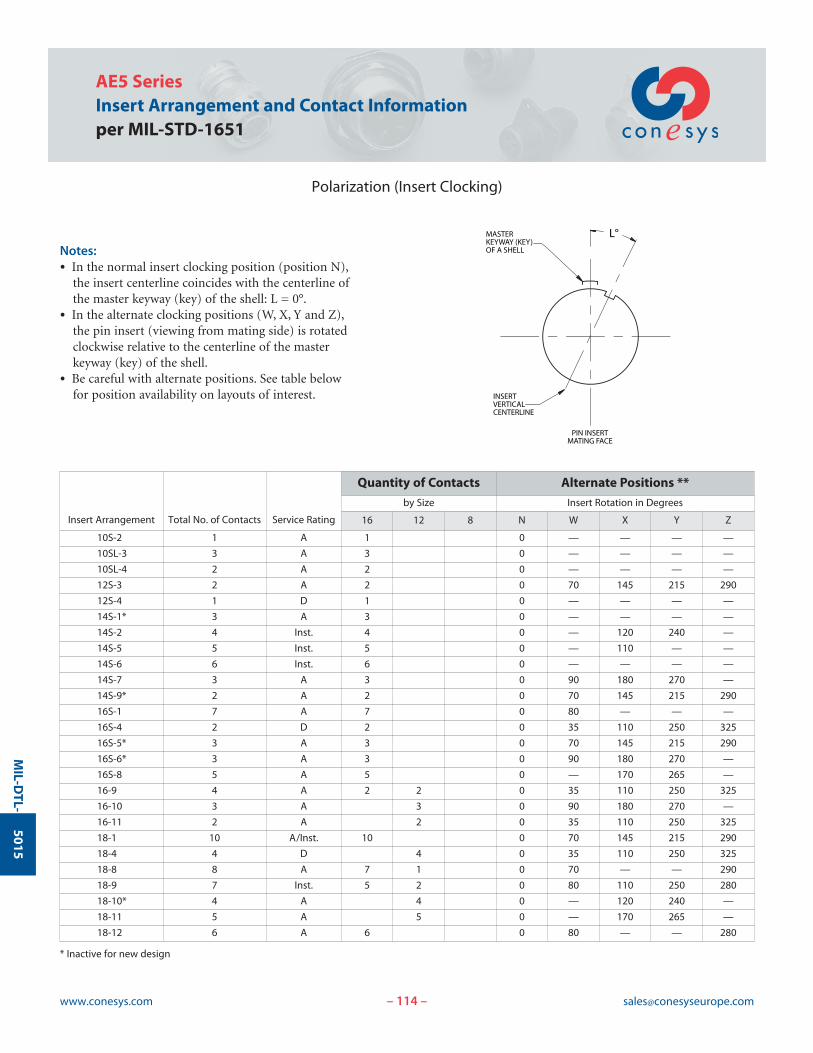
114www.conesys.com [email protected]
AE5 SeriesInsert Arrangement and Contact Informationper MIL-STD-1651
– –
MIL-D
TL-5015
Polarization (Insert Clocking)
Notes:• In the normal insert clocking position (position N),
the insert centerline coincides with the centerline ofthe master keyway (key) of the shell: L = 0°.
• In the alternate clocking positions (W, X, Y and Z),the pin insert (viewing from mating side) is rotatedclockwise relative to the centerline of the master keyway (key) of the shell.
• Be careful with alternate positions. See table below for position availability on layouts of interest.
PIN INSERTMATING FACE
INSERTVERTICALCENTERLINE
MASTERKEYWAY (KEY)OF A SHELL
L°
Insert Arrangement Total No. of Contacts Service Rating
Quantity of Contacts Alternate Positions **
by Size Insert Rotation in Degrees
16 12 8 N W X Y Z
10S-2 1 A 1 0 — — — —
10SL-3 3 A 3 0 — — — —
10SL-4 2 A 2 0 — — — —
12S-3 2 A 2 0 70 145 215 290
12S-4 1 D 1 0 — — — —
14S-1* 3 A 3 0 — — — —
14S-2 4 Inst. 4 0 — 120 240 —
14S-5 5 Inst. 5 0 — 110 — —
14S-6 6 Inst. 6 0 — — — —
14S-7 3 A 3 0 90 180 270 —
14S-9* 2 A 2 0 70 145 215 290
16S-1 7 A 7 0 80 — — —
16S-4 2 D 2 0 35 110 250 325
16S-5* 3 A 3 0 70 145 215 290
16S-6* 3 A 3 0 90 180 270 —
16S-8 5 A 5 0 — 170 265 —
16-9 4 A 2 2 0 35 110 250 325
16-10 3 A 3 0 90 180 270 —
16-11 2 A 2 0 35 110 250 325
18-1 10 A/Inst. 10 0 70 145 215 290
18-4 4 D 4 0 35 110 250 325
18-8 8 A 7 1 0 70 — — 290
18-9 7 Inst. 5 2 0 80 110 250 280
18-10* 4 A 4 0 — 120 240 —
18-11 5 A 5 0 — 170 265 —
18-12 6 A 6 0 80 — — 280
* Inactive for new design
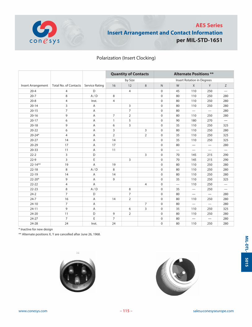
115www.conesys.com [email protected]
AE5 SeriesInsert Arrangement and Contact Information
per MIL-STD-1651
Polarization (Insert Clocking)
– –
MIL-D
TL-5015
Insert Arrangement Total No. of Contacts Service Rating
Quantity of Contacts Alternate Positions **
by Size Insert Rotation in Degrees
16 12 8 N W X Y Z
20-4 4 D 4 0 45 110 250 —
20-7 8 A / D 8 0 80 110 250 280
20-8 4 Inst. 4 0 80 110 250 280
20-14 3 A 3 0 80 110 250 280
20-15 7 A 7 0 80 — — 280
20-16 9 A 7 2 0 80 110 250 280
20-17 6 A 1 5 0 90 180 270 —
20-18 9 A 6 3 0 35 110 250 325
20-22 6 A 3 3 0 80 110 250 280
20-24* 4 A 2 2 0 35 110 250 325
20-27 14 A 14 0 35 110 250 325
20-29 17 A 17 0 80 — — 280
20-33 11 A 11 0 — — — —
22-2 3 D 3 0 70 145 215 290
22-9 3 E 3 0 70 145 215 290
22-14** 19 A 19 0 80 110 250 280
22-18 8 A / D 8 0 80 110 250 280
22-19 14 A 14 0 80 110 250 280
22-20* 9 A 9 0 35 110 250 325
22-22 4 A 4 0 — 110 250 —
22-23 8 A / D 8 0 35 — 250 —
24-2 7 D 7 0 80 — — 280
24-7 16 A 14 2 0 80 110 250 280
24-10 7 A 7 0 80 — — 280
24-11 9 A 6 3 0 35 110 250 325
24-20 11 D 9 2 0 80 110 250 280
24-27 7 E 7 0 80 — — 280
24-28 24 Inst. 24 0 80 110 250 280
* Inactive for new design
** Alternate positions X, Y are cancelled after June 26, 1968.
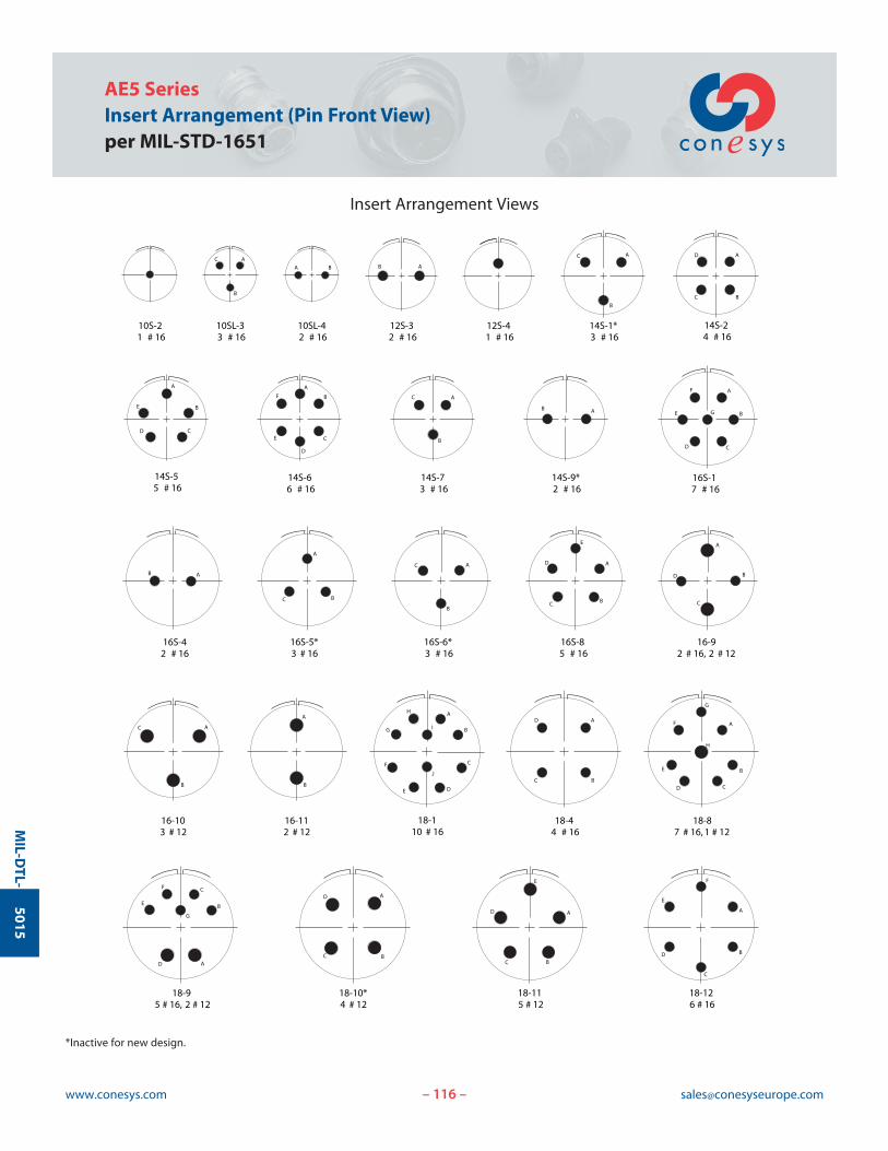
116www.conesys.com [email protected]
AE5 SeriesInsert Arrangement (Pin Front View)per MIL-STD-1651
Insert Arrangement Views
– –
MIL-D
TL-5015
A
BC
D
10S-21 # 16
A
B
C
10SL-33 # 16
A B
10SL-42 # 16
AB
12S-32 # 16
12S-41 # 16
A
B
C
14S-1*3 # 16
A
BC
D
14S-24 # 16
A
B
CD
E
14S-55 # 16
A
B
C
D
E
F
14S-66 # 16
A
B
C
14S-73 # 16
AB
14S-9*2 # 16
A
B
CD
E
F
G
16S-17 # 16
AB
16S-42 # 16
A
B
C
16S-6*3 # 16
A
BC
16S-5*3 # 16
A
BC
D
E
16S-85 # 16
A
B
C
D
16-92 # 16, 2 # 12
A
B
C
16-103 # 12
A
B
16-112 # 12
A
I
J
B
C
DE
G
H
F
18-110 # 16
A
BC
D
18-44 # 16
A
BC
D
E
18-115 # 12
A
B
C
D
E
F
18-126 # 16
A
B
CD
E
G
H
F
18-87 # 16, 1 # 12
A
B
C
D
E
G
F
18-95 # 16, 2 # 12
18-10*4 # 12
*Inactive for new design.
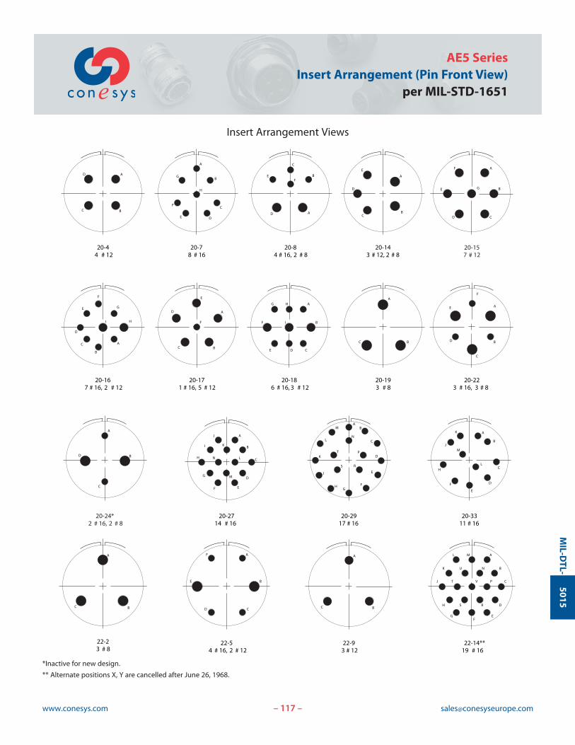
117www.conesys.com [email protected]
AE5 SeriesInsert Arrangement (Pin Front View)
per MIL-STD-1651
Insert Arrangement Views
– –
MIL-D
TL-5015
20-157 # 12
20-24*2 # 16, 2 # 8
A
B
C
D
EF
G
H
J
K
L
M
N
I
20-2714 # 16
AB
C
D
E
T
FG
H
J
K
L
M
N
P
RS
20-2917 # 16
A
B
C
D
E
F
H
J
K
L
M
20-3311 # 16
20-167 # 16, 2 # 12
20-171 # 16, 5 # 12
20-186 # 16, 3 # 12
20-223 # 16, 3 # 8
22-54 # 16, 2 # 12
A
B
C
D
E
F
G
HI
A
B
CD
E
F
G
A
BC
D
E
F
A
B
CDE
F
G H
I
A
B
C
D
E
F
20-193 # 8
A
BC
A
B
C
D
AF
BE
CD
22-23 # 8
A
BC
A
BC
22-93 # 12
A
B
C
D
EF
G
H
J
K
L M
N
P
RS
V
U
T
22-14**19 # 16
A
B
C
DE
G
H
F
A
BC
D
20-44 # 12
20-78 # 16
A
B
C
D
EF
20-84 # 16, 2 # 8
A
BC
D
E
20-143 # 12, 2 # 8
*Inactive for new design.
** Alternate positions X, Y are cancelled after June 26, 1968.
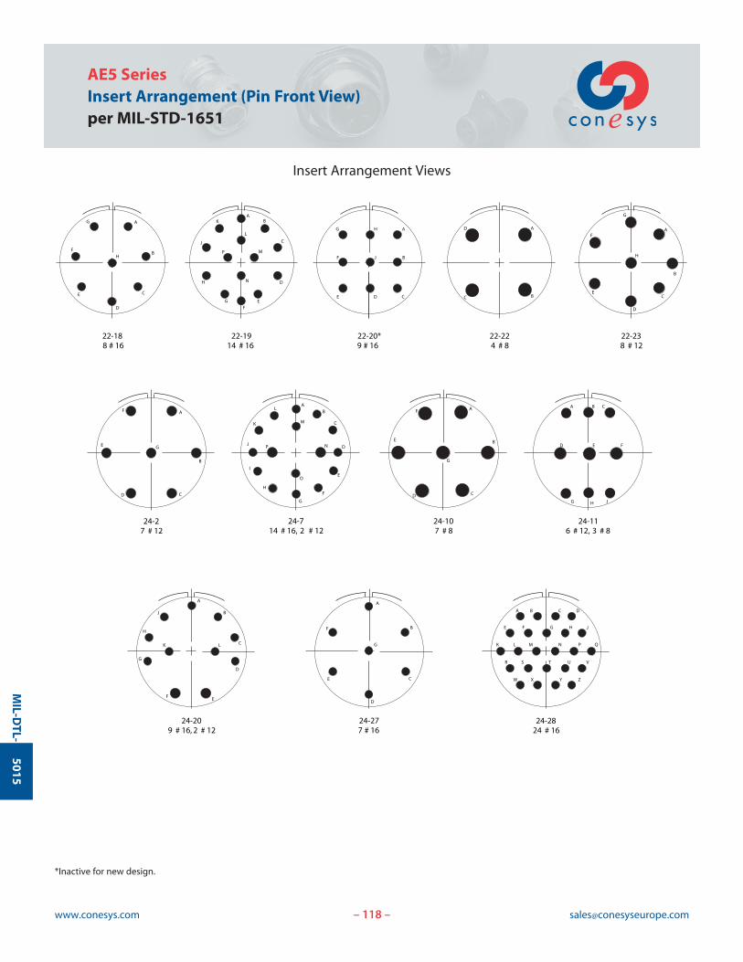
118www.conesys.com [email protected]
AE5 SeriesInsert Arrangement (Pin Front View)per MIL-STD-1651
Insert Arrangement Views
– –
MIL-D
TL-5015
A
B
CD
E
F
G
A
B
C
D
E
F
G
A B C D
JE F H
K L M N P Q
R S T U V
W X Y Z
G
24-714 # 16, 2 # 12
24-107 # 8
24-116 # 12, 3 # 8
24-209 # 16, 2 # 12
24-277 # 16
24-2824 # 16
A
B
CL
D
EF
H
G
J
K
A B C
D E F
H JG
AB
C
D
E
F
G
H
I
J
K
L
M
N
O
P
B
A
C
D
E
F
G
H
22-188 # 16
AB
C
D
EF
G
H
J
K
L
M
N
P
22-1914 # 16
A
B
CDE
F
G H
J
22-20*9 # 16
A
BC
D
22-224 # 8
A
B
C
D
E
F
G
H
22-238 # 12
A
B
CD
E
F
G
24-27 # 12
*Inactive for new design.
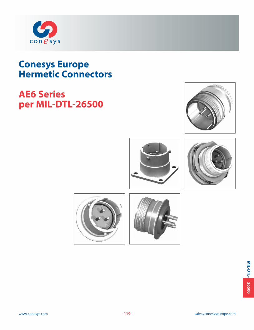
119www.conesys.com [email protected]
Conesys EuropeHermetic Connectors
AE6 Seriesper MIL-DTL-26500
– –
MIL-D
TL-26500
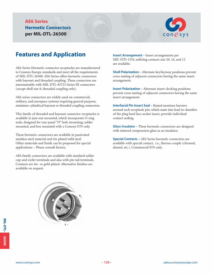
120www.conesys.com [email protected]
AE6 SeriesHermetic Connectorsper MIL-DTL-26500
– –
MIL-D
TL-26500
Features and Application
AE6 Series Hermetic connector receptacles are manufacturedto Conesys Europe standards and meet all the requirementsof MIL-DTL-26500. AE6 Series offers hermetic connectorswith bayonet and threaded coupling. These connectors areintermateable with MIL-DTL-83723 Series III connectors(except shell size 8, threaded coupling only).
AE6 series connectors are widely used on commercial,military, and aerospace systems requiring general purpose,miniature cylindrical bayonet or threaded coupling connectors.
This family of threaded and bayonet connector receptacles isavailable in jam-nut mounted, which incorporate O-ringseals, designed for rear panel “D” hole mounting; soldermounted, and box mounted with a Conesys P/N only.
These hermetic connectors are available in passivated stainless steel material and tin-plated mild steel.Other materials and finish can be proposed for special applications – Please consult factory.
AE6 family connectors are available with standard solder cup and eyelet terminals and also with pin tail terminals.Contacts are tin- or gold-plated. Alternative finishes are available on request.
Insert Arrangement – Insert arrangements per MIL-STD-1554, utilizing contacts size 20, 16, and 12 are available.
Shell Polarization – Alternate key/keyway positions preventcross mating of adjacent connectors having the same insertarrangement.
Insert Polarization – Alternate insert clocking positions prevent cross mating of adjacent connectors having the sameinsert arrangement.
Interfacial Pin Insert Seal – Raised moisture barriersaround each receptacle pin, which mate into lead-in chamfersof the plug hard face socket insert, provide individual contact sealing.
Glass Insulator – These hermetic connectors are designedwith sintered compression glass as an insulator.
Special Contacts – AE6 Series hermetic connectors are available with special contact, i.e., thermo couple (chromel,alumel, etc.). Commercial P/N only.
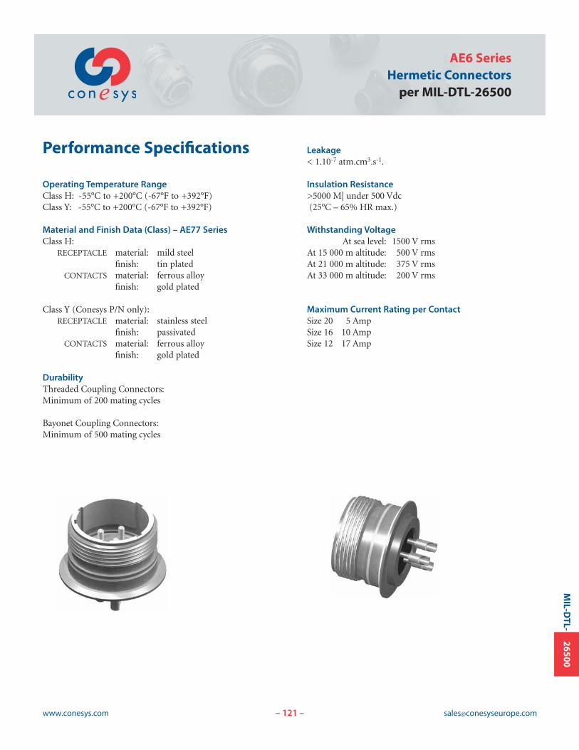
121www.conesys.com [email protected]
AE6 SeriesHermetic Connectors
per MIL-DTL-26500
– –
MIL-D
TL-26500
Performance Specifications
Operating Temperature RangeClass H: -55°C to +200°C (-67°F to +392°F)Class Y: -55°C to +200°C (-67°F to +392°F)
Material and Finish Data (Class) – AE77 SeriesClass H:
RECEPTACLE material: mild steelfinish: tin plated
CONTACTS material: ferrous alloyfinish: gold plated
Class Y (Conesys P/N only):RECEPTACLE material: stainless steel
finish: passivatedCONTACTS material: ferrous alloy
finish: gold plated
DurabilityThreaded Coupling Connectors:Minimum of 200 mating cycles
Bayonet Coupling Connectors:Minimum of 500 mating cycles
Leakage< 1.10-7 atm.cm3.s-1.
Insulation Resistance>5000 M| under 500 Vdc(25°C – 65% HR max.)
Withstanding VoltageAt sea level: 1500 V rms
At 15 000 m altitude: 500 V rmsAt 21 000 m altitude: 375 V rmsAt 33 000 m altitude: 200 V rms
Maximum Current Rating per ContactSize 20 5 AmpSize 16 10 AmpSize 12 17 Amp
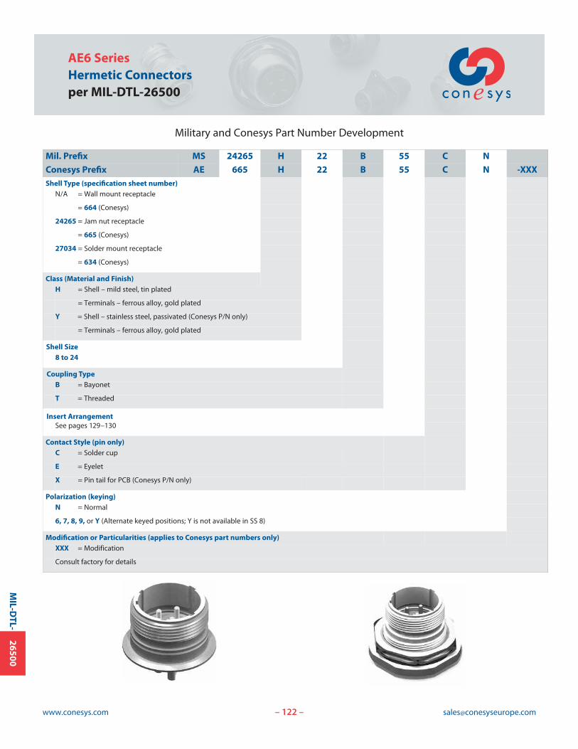
AE6 SeriesHermetic Connectorsper MIL-DTL-26500
www.conesys.com [email protected]– –
MIL-D
TL-26500
Military and Conesys Part Number Development
Mil. Prefix MS 24265 H 22 B 55 C N
Conesys Prefix AE 665 H 22 B 55 C N -XXXShell Type (specification sheet number)
N/A = Wall mount receptacle
= 664 (Conesys)
24265 = Jam nut receptacle
= 665 (Conesys)
27034 = Solder mount receptacle
= 634 (Conesys)
Class (Material and Finish)H = Shell – mild steel, tin plated
= Terminals – ferrous alloy, gold plated
Y = Shell – stainless steel, passivated (Conesys P/N only)
= Terminals – ferrous alloy, gold plated
Shell Size8 to 24
Coupling TypeB = Bayonet
T = Threaded
Insert ArrangementSee pages 129–130
Contact Style (pin only)C = Solder cup
E = Eyelet
X = Pin tail for PCB (Conesys P/N only)
Polarization (keying)N = Normal
6, 7, 8, 9, or Y (Alternate keyed positions; Y is not available in SS 8)
Modification or Particularities (applies to Conesys part numbers only)XXX = Modification
Consult factory for details
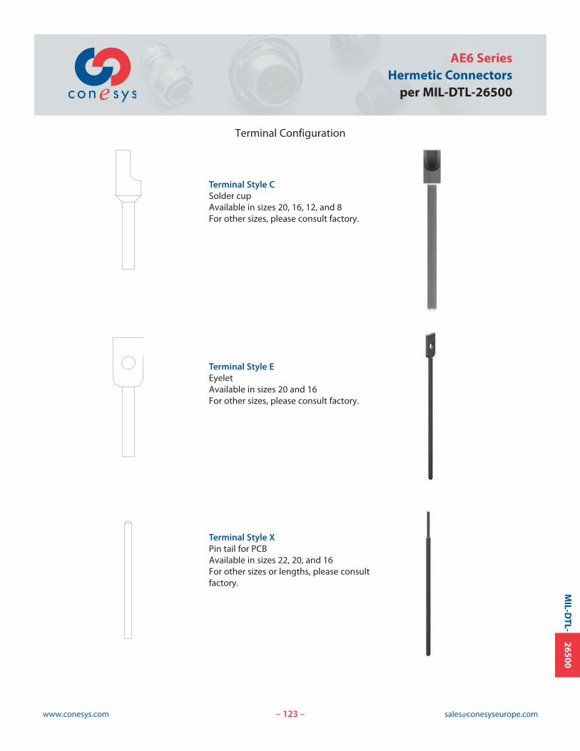
123www.conesys.com [email protected]
AE6 SeriesHermetic Connectors
per MIL-DTL-26500
– –
MIL-D
TL-26500
Terminal Configuration
Terminal Style CSolder cupAvailable in sizes 20, 16, 12, and 8For other sizes, please consult factory.
Terminal Style EEyeletAvailable in sizes 20 and 16For other sizes, please consult factory.
Terminal Style XPin tail for PCBAvailable in sizes 22, 20, and 16For other sizes or lengths, please consultfactory.
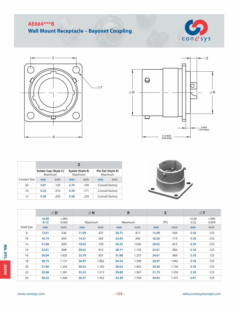
124www.conesys.com [email protected]
AE664***BWall Mount Receptacle – Bayonet Coupling
– –
MIL-D
TL-26500
21.8 MAX[.858 MAX]
2 MAX[.079 MAX]
ZS
R
[ T[ D [ N
Contact Size
Z
Solder Cup (Style C) Eyelet (Style E) Pin Tail (Style X)Maximum Maximum Maximum
mm inch mm inch mm inch
20 3.81 .150 2.76 .109 Consult factory
16 5.33 .510 4.34 .171 Consult factory
12 5.58 .220 5.58 .220 Consult factory
Shell Size
[ D [ N R S [ T+0.00 +.000 +0.00 +.000-0.12 -0.005 Maximum Maximum (TP) -0.22 -0.009
mm inch mm inch mm inch mm inch mm inch
8 13.61 .536 11.09 .437 20.75 .817 15.09 .594 3.18 .125
10 16.74 .659 14.27 .562 23.93 .942 18.26 .719 3.18 .125
12 21.06 .829 19.05 .750 26.32 1.036 20.62 .812 3.18 .125
14 22.81 .898 20.62 .812 28.71 1.130 23.01 .906 3.18 .125
16 26.04 1.025 23.79 .937 31.88 1.255 24.61 .969 3.18 .125
18 28.73 1.131 26.97 1.062 34.24 1.348 26.97 1.062 3.18 .125
20 31.90 1.256 30.02 1.182 36.63 1.442 29.36 1.156 3.18 .125
22 35.08 1.381 33.32 1.312 39.80 1.567 31.75 1.250 3.18 .125
24 38.25 1.506 36.37 1.432 43.39 1.708 34.92 1.375 3.91 .154

125www.conesys.com [email protected]
AE665***BJam Nut Receptacle – Bayonet Coupling
MS24265***B
– –
MIL-D
TL-26500
19.84/19.33[.781/.761]
Z
W
PANEL THICKNESS:1.57/3.55 [.062/.140]
V THREAD
F
M
[ D
Contact Size
Z
Solder Cup (Style C) Eyelet (Style E) Pin Tail (Style X)Maximum Maximum Maximum
mm inch mm inch mm inch
20 4.20 .165 4.20 .165 Consult factory
16 5.95 .234 5.95 .234 Consult factory
12 5.95 .234 5.95 .234 Consult factory
Shell Size
[ D F M V W+0.00 +.000 Flat-0.12 -0.005 ±0.07 ±.003 ±0.12 ±.005 Thread ±0.5 ±.020
mm inch mm inch mm inch Class 2A mm inch
8 13.61 .536 15.06 0.593 24.87 0.979 5/8-20 UN 2.97 .117
10 16.74 .659 18.24 0.718 28.04 1.104 3/4-20 UNEF 2.97 .117
12 21.06 .829 22.99 0.905 32.79 1.291 15/16-20 UNEF 2.97 .117
14 22.81 .898 24.59 0.968 35.33 1.391 1-20 UNEF 2.97 .117
16 26.04 1.025 27.76 1.093 38.51 1.516 1-1/8-20 UN 2.97 .117
18 28.73 1.131 30.91 1.217 41.68 1.641 1-1/4 UN 2.97 .117
20 31.90 1.256 34.09 1.342 44.86 1.766 1-3/8-18 UNEF 2.97 .117
22 35.08 1.381 37.26 1.467 49.63 1.954 1-1/2-20 UN 3.75 .148
24 38.25 1.506 40.44 1.592 52.81 2.079 1-5/8-18 UNEF 3.75 .148
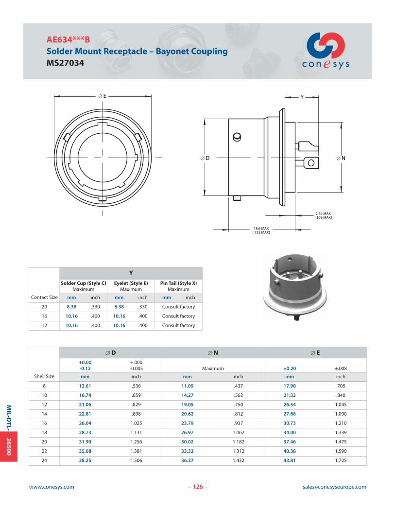
126www.conesys.com [email protected]
AE634***BSolder Mount Receptacle – Bayonet CouplingMS27034
– –
MIL-D
TL-26500
18.6 MAX[.732 MAX]
Y
2.76 MAX[.109 MAX]
[ E
[ D [ N
Contact Size
Y
Solder Cup (Style C) Eyelet (Style E) Pin Tail (Style X)Maximum Maximum Maximum
mm inch mm inch mm inch
20 8.38 .330 8.38 .330 Consult factory
16 10.16 .400 10.16 .400 Consult factory
12 10.16 .400 10.16 .400 Consult factory
Shell Size
[ D [ N [ E+0.00 +.000-0.12 -0.005 Maximum ±0.20 ±.008
mm inch mm inch mm inch
8 13.61 .536 11.09 .437 17.90 .705
10 16.74 .659 14.27 .562 21.33 .840
12 21.06 .829 19.05 .750 26.54 1.045
14 22.81 .898 20.62 .812 27.68 1.090
16 26.04 1.025 23.79 .937 30.73 1.210
18 28.73 1.131 26.97 1.062 34.00 1.339
20 31.90 1.256 30.02 1.182 37.46 1.475
22 35.08 1.381 33.32 1.312 40.38 1.590
24 38.25 1.506 36.37 1.432 43.81 1.725

127www.conesys.com [email protected]
AE664***TWall Mount Receptacle – Threaded Coupling
– –
MIL-D
TL-26500
21.8 MAX[.858 MAX]
2 MAX [.079 MAX]
Z
D THREAD
S
R [ T
[ N
Contact Size
Z
Solder Cup (Style C) Eyelet (Style E) Pin Tail (Style X)Maximum Maximum Maximum
mm inch mm inch mm inch
20 3.81 .150 2.76 .109 Consult factory
16 5.33 .510 4.34 .171 Consult factory
12 5.58 .220 5.58 .220 Consult factory
Shell Size
D [ N R S [ T+0.00 +.000
Thread Maximum Maximum (TP) -0.22 -0.009
Class 2A mm inch mm inch mm inch mm inch
8 9/16-24 UNEF 11.09 .437 20.75 .817 15.09 .594 3.18 .125
10 11/16-24 UNEF 14.27 .562 23.93 .942 18.26 .719 3.18 .125
12 7/8-20 UNEF 19.05 .750 26.32 1.036 20.62 .812 3.18 .125
14 15/16-20 UNEF 20.62 .812 28.71 1.130 23.01 .906 3.18 .125
16 1-1/16-18 UNEF 23.79 .937 31.88 1.255 24.61 .969 3.18 .125
18 1-3/16-18 UNEF 26.97 1.062 34.24 1.348 26.97 1.062 3.18 .125
20 1-5/16-18 UNEF 30.02 1.182 36.63 1.442 29.36 1.156 3.18 .125
22 1-7/16-18 UNEF 33.32 1.312 39.80 1.567 31.75 1.250 3.18 .125
24 1-9/16-18 UNEF 36.37 1.432 43.39 1.708 34.92 1.375 3.91 .154
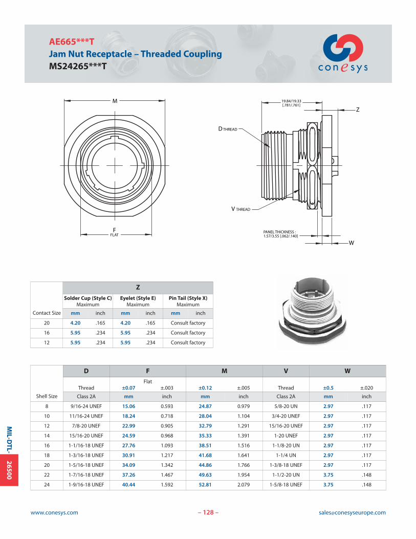
128www.conesys.com [email protected]
AE665***TJam Nut Receptacle – Threaded CouplingMS24265***T
– –
MIL-D
TL-26500
19.84/19.33[.781/.761]
Z
W
PANEL THICKNESS : 1.57/3.55 [.062/.140]
D THREAD
V THREAD
FFLAT
M
Contact Size
Z
Solder Cup (Style C) Eyelet (Style E) Pin Tail (Style X)Maximum Maximum Maximum
mm inch mm inch mm inch
20 4.20 .165 4.20 .165 Consult factory
16 5.95 .234 5.95 .234 Consult factory
12 5.95 .234 5.95 .234 Consult factory
Shell Size
D F M V W
FlatThread ±0.07 ±.003 ±0.12 ±.005 Thread ±0.5 ±.020
Class 2A mm inch mm inch Class 2A mm inch
8 9/16-24 UNEF 15.06 0.593 24.87 0.979 5/8-20 UN 2.97 .117
10 11/16-24 UNEF 18.24 0.718 28.04 1.104 3/4-20 UNEF 2.97 .117
12 7/8-20 UNEF 22.99 0.905 32.79 1.291 15/16-20 UNEF 2.97 .117
14 15/16-20 UNEF 24.59 0.968 35.33 1.391 1-20 UNEF 2.97 .117
16 1-1/16-18 UNEF 27.76 1.093 38.51 1.516 1-1/8-20 UN 2.97 .117
18 1-3/16-18 UNEF 30.91 1.217 41.68 1.641 1-1/4 UN 2.97 .117
20 1-5/16-18 UNEF 34.09 1.342 44.86 1.766 1-3/8-18 UNEF 2.97 .117
22 1-7/16-18 UNEF 37.26 1.467 49.63 1.954 1-1/2-20 UN 3.75 .148
24 1-9/16-18 UNEF 40.44 1.592 52.81 2.079 1-5/8-18 UNEF 3.75 .148
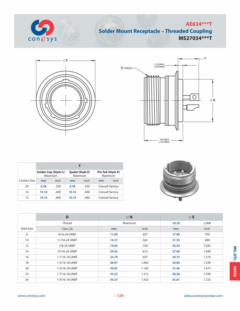
129www.conesys.com [email protected]
AE634***TSolder Mount Receptacle – Threaded Coupling
MS27034***T
– –
MIL-D
TL-26500
18.6 MAX[.732 MAX]
2.76 MAX[.109 MAX]
Y
D THREAD
[ E
[ N
Shell Size
D [ N [ E
Thread Maximum ±0.20 ±.008
Class 2A mm inch mm inch
8 9/16-24 UNEF 11.09 .437 17.90 .705
10 11/16-24 UNEF 14.27 .562 21.33 .840
12 7/8-20 UNEF 19.05 .750 26.54 1.045
14 15/16-20 UNEF 20.62 .812 27.68 1.090
16 1-1/16-18 UNEF 23.79 .937 30.73 1.210
18 1-3/16-18 UNEF 26.97 1.062 34.00 1.339
20 1-5/16-18 UNEF 30.02 1.182 37.46 1.475
22 1-7/16-18 UNEF 33.32 1.312 40.38 1.590
24 1-9/16-18 UNEF 36.37 1.432 43.81 1.725
Contact Size
Y
Solder Cup (Style C) Eyelet (Style E) Pin Tail (Style X)Maximum Maximum Maximum
mm inch mm inch mm inch
20 8.38 .330 8.38 .330 Consult factory
16 10.16 .400 10.16 .400 Consult factory
12 10.16 .400 10.16 .400 Consult factory
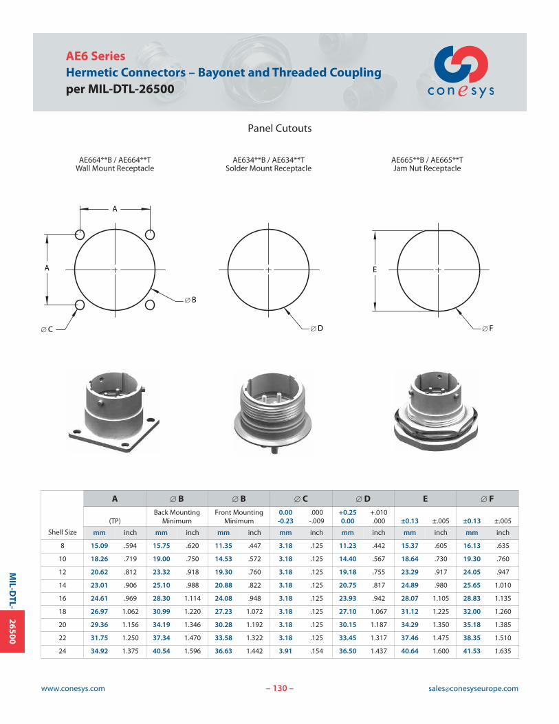
130www.conesys.com [email protected]
AE6 SeriesHermetic Connectors – Bayonet and Threaded Couplingper MIL-DTL-26500
Panel Cutouts
– –
MIL-D
TL-26500
A
[ B
A
[ C
AE664**B / AE664**TWall Mount Receptacle
[ D [ F
AE634**B / AE634**TSolder Mount Receptacle
AE665**B / AE665**TJam Nut Receptacle
E
Shell Size
A [ B [ B [ C [ D E [ FBack Mounting Front Mounting 0.00 .000 +0.25 +.010
(TP) Minimum Minimum -0.23 -.009 0.00 .000 ±0.13 ±.005 ±0.13 ±.005
mm inch mm inch mm inch mm inch mm inch mm inch mm inch
8 15.09 .594 15.75 .620 11.35 .447 3.18 .125 11.23 .442 15.37 .605 16.13 .635
10 18.26 .719 19.00 .750 14.53 .572 3.18 .125 14.40 .567 18.64 .730 19.30 .760
12 20.62 .812 23.32 .918 19.30 .760 3.18 .125 19.18 .755 23.29 .917 24.05 .947
14 23.01 .906 25.10 .988 20.88 .822 3.18 .125 20.75 .817 24.89 .980 25.65 1.010
16 24.61 .969 28.30 1.114 24.08 .948 3.18 .125 23.93 .942 28.07 1.105 28.83 1.135
18 26.97 1.062 30.99 1.220 27.23 1.072 3.18 .125 27.10 1.067 31.12 1.225 32.00 1.260
20 29.36 1.156 34.19 1.346 30.28 1.192 3.18 .125 30.15 1.187 34.29 1.350 35.18 1.385
22 31.75 1.250 37.34 1.470 33.58 1.322 3.18 .125 33.45 1.317 37.46 1.475 38.35 1.510
24 34.92 1.375 40.54 1.596 36.63 1.442 3.91 .154 36.50 1.437 40.64 1.600 41.53 1.635
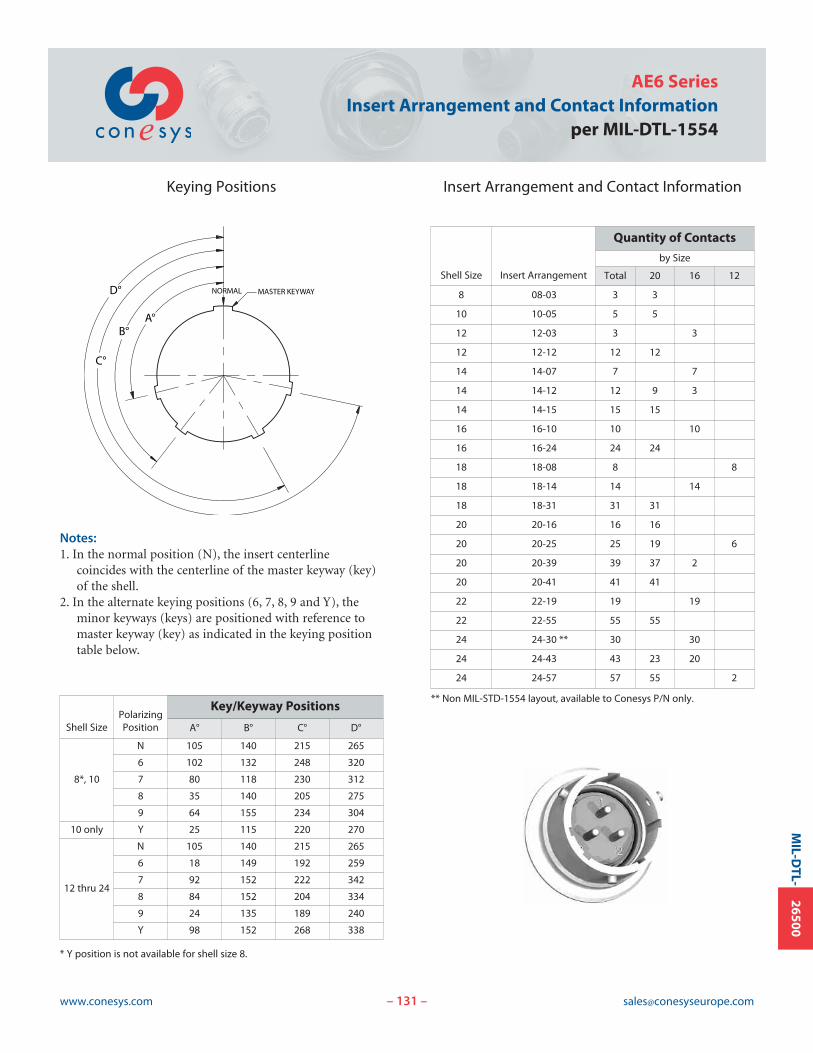
131www.conesys.com [email protected]
AE6 SeriesInsert Arrangement and Contact Information
per MIL-DTL-1554
Keying Positions Insert Arrangement and Contact Information
– –
MIL-D
TL-26500
C°
B°
D°
A°
MASTER KEYWAY NORMAL
Shell SizePolarizingPosition
Key/Keyway Positions
A° B° C° D°
8*, 10
N 105 140 215 265
6 102 132 248 320
7 80 118 230 312
8 35 140 205 275
9 64 155 234 304
10 only Y 25 115 220 270
12 thru 24
N 105 140 215 265
6 18 149 192 259
7 92 152 222 342
8 84 152 204 334
9 24 135 189 240
Y 98 152 268 338
Shell Size Insert Arrangement
Quantity of Contacts
by Size
Total 20 16 12
8 08-03 3 3
10 10-05 5 5
12 12-03 3 3
12 12-12 12 12
14 14-07 7 7
14 14-12 12 9 3
14 14-15 15 15
16 16-10 10 10
16 16-24 24 24
18 18-08 8 8
18 18-14 14 14
18 18-31 31 31
20 20-16 16 16
20 20-25 25 19 6
20 20-39 39 37 2
20 20-41 41 41
22 22-19 19 19
22 22-55 55 55
24 24-30 ** 30 30
24 24-43 43 23 20
24 24-57 57 55 2
Notes:1. In the normal position (N), the insert centerline
coincides with the centerline of the master keyway (key)of the shell.
2. In the alternate keying positions (6, 7, 8, 9 and Y), theminor keyways (keys) are positioned with reference tomaster keyway (key) as indicated in the keying positiontable below.
** Non MIL-STD-1554 layout, available to Conesys P/N only.
* Y position is not available for shell size 8.
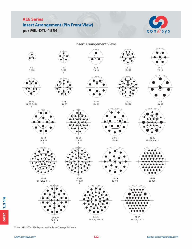
132www.conesys.com [email protected]
AE6 SeriesInsert Arrangement (Pin Front View)per MIL-DTL-1554
– –
MIL-D
TL-26500
** Non MIL-STD-1554 layout, available to Conesys P/N only.
8-33 # 20
I
1
3
10-55 # 20
I
1
5
12-33 # 16
I
1
23
14-77 # 16
I
1
7
18-88 # 12
I
1
8
12-1212 # 20
I
1
12
14-129 # 20, 3 # 16
I
1
12
14-1515 # 20
I
1
15
16-1010 # 16
I
1
10
20-3937 # 20, 2 # 16
I
1
39
16-2424 # 20
I
1
24
20-4141 # 20
I
1
41
22-1919 # 16
I
19
1
22-5555 # 20
I
1
55
24-4323 # 20, 20 # 16
I
1
43
24-5755 # 20, 2 # 12
I
1
57
130
24-30**30 # 16
I
18-1414 # 16
I
1
14
18-3131 # 20
I
1
31
20-1616 # 16
I
1
16
20-2519 # 20, 6 # 12
I
1
25
Insert Arrangement Views