conductive textiles 13webhost.bridgew.edu/ebrush/chem 489 pdf/journal c… · · 2018-01-2413.3.2...
TRANSCRIPT
13Conductive textiles
K. (Kelvin) Fu, R. Padbury, O. Toprakci, M. Dirican, X. Zhang
North Carolina State University, Raleigh, NC, United States13.1 Introduction
Conductive textiles are textile structures that can conduct electricity. Conductive tex-
tiles can be either made using conductive fibers or by depositing conductive layers
onto nonconductive textiles. Typical applications of conductive textiles include anti-
static textiles, electromagnetic (EM) shielding, and e-textiles for flexible electronics.
Conductive textiles can inhibit the static charge generated on fabric, to avoid uncom-
fortable feelings and electrical shocks. Conductive textiles can be used as shielding
materials to block EM radiation that is harmful to electronics and human. With the
development of flexible electronics, conductive textiles are becoming important
building blocks for the design of wearable electronics for a broad range of
applications.
In this chapter, we discuss the fundamental principles of conductive textiles with a
focus on three types of important applications including antistatic, EM shielding, and
e-textiles. We will then review the recent development of advanced coating technol-
ogy for conductive textiles.
13.2 Antistatic textiles
Static electricity is the buildup of electric charge on the surface of objects, which can
cause many problems for textile materials and fabrics in manufacturing and handling.
In dry textile process, fibers and fabrics will tend to generate electrostatic charges
from friction when they are moving at high speeds on different surfaces, such as con-
veyer belts, transport bands, and driving cords, causing fibers and yarns to repel each
other. Static electricity can also produce electrical shocks, and the “charging” can
cause the ignition of flammable substances. In general, two approaches are known
to prevent static electricity in textiles: one is to create a conducting surface and the
other is to produce a hydrophilic surface. Therefore, it is important to design antistatic
textiles to avoid the potential hazards caused by static electricity.
In this section, the objective is to present the mechanism of antistatic textiles and
common methods to achieve an antistatic function for durable and nondurable anti-
static textiles.
Engineering of High-Performance Textiles. http://dx.doi.org/10.1016/B978-0-08-101273-4.00017-2
© 2018 Elsevier Ltd. All rights reserved.
306 Engineering of High-Performance Textiles
13.2.1 Mechanism of antistatic textiles
Textile fibers including natural fibers and synthetic fibers are generally intrinsically
nonconductive. Static charges are often found in synthetic fibers, especially in a dry
environment. The static charges are generated by the motion of textile surfaces and
during this process, negative charges are generated and accumulated on one surface
and positive ones are on the other surface. The negatively charged textile material has
a stronger affinity for electrons that steal from the other textile material after the two
textile materials are separated. A triboelectric series can be used to predict which
material will become positive or negative and how strong the effect will be among
textile materials. Charging will occur if the contacting surfaces are separated. Param-
eters to determine charge formation include the conductivity of materials, the size
topography of the textile surfaces, the separation velocity, friction, and the humidity
of the environment.
For textile materials, synthetic fibers have more static problems compared with
natural fibers. Since most synthetic fibers, such as polyester, are hydrophobic, they
have low moisture regain and have a much higher electrical resistance on the surface,
which will accumulate large amount of charges on the surface and cause static charge.
In comparison, natural fibers, such as cotton, have high moisture regain and exhibit
higher conductivity on the surface that allows the accumulated charges to dissipate in
surroundings and has no static charge concern. It is generally accepted that improving
the hydrophilicity of textiles to increase the rate of static charge dissipation and apply-
ing conductive textiles to inhibit the charge generation are two effective ways to
achieve antistatic textiles.
13.2.2 Antistatic textiles with hydrophilic materials
Hydrophilic materials can help textiles to increase the rate of dissipation of static char-
ges in air. Most synthetic polymer fibers are hydrophobic and they tend to generate
high static charges on the surface; one simple way to reduce the static charge accu-
mulation is to incorporate hydrophilic fibers, such as cotton and viscose, to improve
the hydrophilicity of textile fabrics. The other approach is to apply hydrophilic treat-
ment in chemical and physical ways to absorb certain amounts of water on the textile
surface to obtain an antistatic effect.
13.2.3 Antistatic textiles with conductive materials
Conductive textiles can achieve an antistatic function by using conductive filaments
or a conductive coating to inhibit the static charge generated on fabric. Conductive
filaments can be produced by adding conducting additives, such as metals and car-
bons, into synesthetic fibers or co-weaving metal wires with synthetic fibers to
increase the conductivity of fabrics. Metals including Au, Ag, and Cu, and carbons
including carbon black (CB), carbon nanotubes (CNTs), and graphenes, can be used
as conducting additives for making conductive fibers or conductive coatings. Conduc-
tive coatings can be deposited onto textiles by printing, coating, and physical vapor

Conductive textiles 307
deposition (PVD) methods. Details of conductive textile coatings are discussed in a
later section of this chapter.
Although hydrophilicity and conductivity are two strategies to achieve antistatic
function, it should be noted that when we design antistatic textiles, both these two fac-
tors need to be considered to enhance maximally the antistatic effect of textiles.
13.3 EM shielding textiles
13.3.1 Mechanism of EM shielding
EM radiation refers to radiations in the form of gamma rays, X-rays, infrared light,
ultraviolet (UV) light, visible light, microwaves, and radio waves, in which electric
and magnetic fields vary simultaneously. EM radiation travels at the speed of light
in vacuum with different wavelengths or frequencies. EM radiation includes an elec-
tric and a magnetic field and they oscillate at right angles to each other. EM radiation
may cause malfunctioning of electronic equipment by creating some interference.
Furthermore, EM radiation with high energy, high frequency and low wavelength
can also cause health issues, so EM radiation should be shielded. EM shielding is
the process of restricting the diffusion of EM fields into a space. In this process, elec-
trically and/or magnetically conductive barriers are used. Shielding is a very common
method for protecting electrical equipment and human beings from radiating EM
fields. This barrier can be rigid [cement for construction (Chiou et al., 1989; Xiong
et al., 2011)] or flexible (i.e., textiles, gaskets). When an EM beam passes through
an object, the EM beam interacts with molecules of the object and this interaction
may take place as absorption, reflection, polarization, refraction, diffraction, or mul-
tiple reflections (MRs) through the object. When a barrier is exposed to an EM radi-
ation, some of the incident energy is lost due to the shielding effect. For the EM
shielding effect, absorption (A), reflection (R), and MR characteristics of the barrier
are critically important.
Reflection: When an electric field is applied to a sample of material, charges inside
the shield tend to move. If an impedance mismatch occurs between the incident wave
and the shield, the electric field cannot penetrate inside the shield and it is reflected.
Reflection loss of the shield is directly proportional to the relative conductivity of the
sample, and inversely proportional to the frequency and relative permeability of the
sample. It would not be affected by the thickness of the shield.
Multiple reflection: If the shield has a multilayer structure or a multiphase compo-
sition (i.e., composites and foams), then the incident EM wave gets reflected on the
surface as well as on the inside of the shield. In practice, if shielding effectiveness due
to absorption loss is higher than 10 dB,MR loss can be neglected (Roh et al., 2008). As
MR loss is high for thin shields, it is of significance for measuring thin samples at low
frequencies (especially in the kHz range).
Absorption: If an EMwave passes through the shield, its amplitude decreases expo-
nentially due to induced currents which later give rise to ohmic loss and material
heating. Materials with electric and/or magnetic dipoles can be used as EM absorbers

308 Engineering of High-Performance Textiles
(i.e., Fe3O4). Absorption loss is independent of the type of source field and mainly
depends on the physical characteristics of the shield (i.e., thickness, conductivity, per-
meability, etc.). For better absorption loss, a shield should possess high conductivity,
high permeability, and sufficient thickness; alongside these criteria, a good shielding
material should also possess low volume, low surface resistivity, high thickness, and
good mechanical strength. For composite shielding materials, shielding by absorption
depends on the distance between particles and/or the electrical resistivity of the com-
posites. In contrast, shielding by reflection depends on the conductivity and thickness
of the sample and the concentration of conductive filler.
Mathematically, electric shielding effectiveness (S1) and magnetic shielding
effectiveness (S2) can be defined as
Tab
201
Gra
Perc
shie
Shie
(dB
S1 ¼ 20 logEin
Eout
� �and S2 ¼ 20 log
Min
Mout
� �dBð Þ (13.1)
re “in” and “out” refer to incident and transmitted waves, respectively. E is the
wheelectrical field strength component (V m�1) andM is the magnetic field strength com-
ponent (H m�1). As shown in Eq. (13.2), shielding effectiveness can also be expressed
in terms of attenuation of power (W).
S¼ 10 logPin
Pout
� �dBð Þ (13.2)
lding effectiveness is sum of absorption loss (A), reflection loss (R) andMR losses
Shie(Geetha et al., 2009; Huang, 1995; Maity et al., 2013). This is defined in Eq. (13.3).
S1 ¼ S2 ¼ S¼A +R+MR dBð Þ (13.3)
uation of EM shielding effectiveness is shown in Table 13.1. According to this
Evalquantitative analysis, shielding material/structure should create at least a 30 dB power
loss ratio to receive an excellent-grade shielding effectiveness performance. The
target value of the EM shielding effectiveness needed for commercial applications
is around 20 dB.
le 13.1 Evaluation of EM shielding effectiveness (Ozen et al.,3)
de Excellent
Very
good Good Moderate Fair
entage of EM
lding (%)
99.9 99.9–99.0 99–90 90–80 80–70
lding effectiveness
)
>30 30–20 20–10 10–7 7–5
Conductive textiles 309
13.3.2 Measurement of EM shielding
To regulate the EM shielding effectiveness behavior of fabrics, many standards are
used by device manufacturers. Among them, MIL-STD-285 (1956), MIL-G-83528
(1992), IEEE-STD 299 (97) (1997), DIN-VG-95373-15 (2016), ASTM E1851
(2015), and ASTM D 4935-99 (1999) are well known. MIL-STD-285 is the first stan-
dard related to EM shielding. It is not so accurate and repeatable due to the presence of
discontinuities between the sample and the measuring enclosure, especially for small-
sized samples. The frequency range is also limited (up to 400 MHz). To overcome
these issues related with the standard, some modifications were made by
Perumalraj et al. (2010). The IEEE-STD 299 (97) standard is suitable for large enclo-
sures (especially, >2 m) and it has a wide range of working frequency (expandable
from 9 kHz–18 GHz to 50 Hz–100 GHz). DIN-VG-95373-15 is suitable for measur-
ing EM shielding behavior of small- to medium-sized enclosures between 30 and
200 MHz frequency ranges. ASTM D 4935-99 is a very commonly used standard
for EM shielding textiles. It has a large frequency range (between 30 MHz and
1.5 GHz). There are several parameters limiting the usage of higher frequencies such
as sample thickness (which should be lower than 1/100 of wavelength), requirement of
device calibration, and uniform sample-antenna distance (Badic and Marinescu,
2002). Different test methods were investigated by using these standards. These are
the open-field test, coaxial transmission line test, shielded box test, and shielded room
tests. The open-field test method requires a large open field (�30�30 m2) and there
should not be any metallic or conductive object between the sample and the receiving
antenna. The shielded box test is only suitable for materials in near-field conditions
and its measurement range is limited (i.e., up to 500 MHz). Furthermore, inadequate
contact between the sample and the shielded box may affect the repeatability and reli-
ability of results. The shielded room test is found to improve the reliability of the
shielded box test. It is possible to obtain repeatable results by using the shielded room
test, especially in externally disturbing conditions. Among these test methods, the
coaxial transmission line test is the most common one due to its suitability to measure
small-sized, flat, and thin conductive samples in an extended range of frequency
( Jagatheesan et al., 2015).
13.3.3 Materials used in EM shielding
The materials for shielding should have high electric conductivity and magnetic per-
meability. To this end, electrically conductive materials, conductive composite mate-
rials, ferromagnetic materials, or magnetic composite materials are used commonly in
EM shielding applications. Conductive fillers such as metals, alloys, and carbona-
ceous materials (carbon black—CB, graphite, etc.) are common components in con-
ductive composite materials. These materials can be used as a filler in the composite as
well as shielding structure by itself (Faraday cage). The addition of conductive filler
into the composite also increases its thermal conductivity. This reduces the chances of
thermal and chemical degradation during processing and improves its shelf life. Dif-
ferent materials used in EM shielding are listed as follows:

310 Engineering of High-Performance Textiles
l Ferrite (Fe3O4) and other magnetic materials (Rubacha and Zieba, 2007; Morari et al., 2011).l Nonferromagnetic materials (metals, alloys, etc.).l Carbonaceous materials (graphite, graphene, CNTs, carbon nanocoils (CNCs), etc.).l Conductive polymers.
Ferromagnetic materials, such as Fe, Ni, Co, Fe3O4, MnFe2O4, NiFe2O4, etc., can
show a spontaneous magnetization under an EM field. These materials have a high
level of magnetic permeability, which helps in storing/attenuating strong magnetic
fields than many other metals.
Metals are the primary candidates for EM shielding due to their high electrical con-
ductivity. They can be used as sheet, coated sheet, or wire [Cu, Ag, Au, Ni wires
(Rubacha and Zieba, 2006; Sonehara et al., 2009), Ni (Sonehara et al., 2008), or Zn
(Koprowska et al., 2008) coated-wires, etc.]. For high EM shielding effectiveness,
the reflectionmechanism is often adopted due to the presence of free electrons inmetal
structure. Metal coating can be applied on bulk materials, fibers, or particles, but coat-
ings tend to suffer from their poor wear or scratch resistance (Chung, 2001). Further-
more, metals have certain shortcomings such as heavy weight, narrow breaking
tolerance, oxidization in atmosphere and not being usable in corrosive media.
Shyr and Shie studied the effects of conductivity, magnetic loss, and complex per-
mittivity when using blended textiles of polyester fibers (polyethylene terephthalate,
PET) with stainless steel fibers (SSF) on EMwave shielding mechanisms at EMwave
frequencies ranging from 30 to 1500 MHz. Their results showed that the EM interfer-
ence shielding of the SSF/PET textiles show an absorption-dominant mechanism,
which is attributed to the dielectric loss and the magnetic loss at a lower frequency,
and to the magnetic loss at a higher frequency, respectively (Shyr and Shie, 2012).
Carbonaceous materials, such as CB, graphite, CNTs, CNCs, and graphite
nanosheets, exhibit high EM shielding effectiveness due to their thermally activated
carrier hopping associated with defect states. In practice, carbon-based plastic com-
posite materials can be used as shields. Carbonaceous materials used in those compos-
ites are graphite (Morari et al., 2011), carbon nanotubes (CNT) (Park et al., 2010;
Al-Saleh and Sundararaj, 2009), flexible and colloidal graphite (Chung, 2001), con-
tinuous carbon nanofiber (Luo and Chung, 1999), graphene (Wen et al., 2014), etc.
Ghosh and Chakrabarti (2000) produced a CB/vulcanized rubber composite with
�33 wt% CB loading. This composite showed �16 dB shielding effectiveness in
the range of 8–12 GHz. Instead of a conventional polymer, the use of a conducting
polymer as matrix for the composite improves shielding effectiveness by changing
the percolation threshold of the composite. Agnihotri et al. showed that an addition
of 0.5 wt% graphite nanoplates (GNPs) to PEDOT:PSS took the EM shielding effec-
tiveness to�30 dB. For higher amount of GNP loadings (25 wt%), the shielding
effectiveness value reached 70 dB at 0.8-mm thickness (Agnihotri et al., 2015). In
another study, 1.4-mm-thick carbon fiber composites (with very high carbon content)
showed higher than 70 dB shielding effectiveness at 8–12 GHz frequency range. The
shielding mechanism was dominated by reflection due to the larger number of con-
nected conduction paths in the sample (Rea et al., 2005).
Luo and Chung used a carbon-matrix composite with continuous carbon fibers to
improve shielding effectiveness in the frequency range from 0.3 MHz to 1.5 GHz.

Conductive textiles 311
A 2.4-mm-thick composite was found to be an excellent EM shielding material with
shielding effectiveness �124 dB, low surface impedance and high reflectivity (Luo
and Chung, 1999). Wang et al. compared EM shielding effectiveness of printed com-
posite films made of CB, graphite, and CNTs with different aspect ratios (�300). The
samples had 15 wt% of carbon fillers. CNTs with a higher aspect ratio showed better
shielding effectiveness even with the small thickness of 100 μm (Wang et al., 2009).
In another study, a 1-mm-thick MWCNT/PP composite film (7.5 vol% of MWCNT)
showed 36.4 dB EM shielding effectiveness at 12.4 GHz. With increasing thickness
and CNT content, the EM shielding effectiveness was improved. It was also observed
that absorption was the primary shielding mechanism (Al-Saleh and Sundararaj,
2009). Liang et al. achieved a 21 dB shielding efficiency from 15 wt% graphene
loaded-graphene/epoxy composites over a frequency range of 8.2–12.4 GHz (Liang
et al., 2009). To improve dipole polarization and the hopping conductivity of compos-
ites, reduced-graphene oxide (r-GO) was also used along with Fe3O4 and polystyrene
(PS). The EMI shielding effectiveness of the PS/r-GO/Fe3O4 composite was more
than 30 dB in the frequency range of 9.8–12 GHz with 2.24 vol% of graphene loading
(Chen et al., 2015). To observe high-temperature (200°C) performance, the r-GO/SiO2
composite was prepared with 20 wt% r-GO loading and�38 dB of EM shielding
effectiveness was obtained at a 8.2–12.4 GHz frequency range (Wen et al., 2014).
Intrinsically conductive polymers (ICPs): Metals are prone to corrosion, they are
costly, and they possess high density. On the other hand, ICPs are macromolecules
composed of conjugated double bonds. This sp2 hybridization with ionic doping
makes ICPs conductive. ICPs are lightweight materials and they show resistance to
corrosion. Unlike conventional polymers, ICPs are nontransparent toward EM radia-
tions and their electrical properties can be altered. These advantages of ICPs make
them attractive materials in EM shielding applications [aerospace (Naishadham,
1992), etc.]. Examples of ICPs are shown in Fig. 13.1.
Polypyrrole
Polyaniline
Polythiophene
S
S
SO3
NH
NH
NH
n
n
n n
n
n
n
n
ss
s
-
o
oo
ooo
**
Poly-p-PhenyleneVinylene
Polyphenylene
Polyphenylenesulfide
Polyacetylene
PEDOTPEDOT:PSS
Fig. 13.1 Common intrinsically conductive polymers.

312 Engineering of High-Performance Textiles
The major drawbacks of ICPs are their moderate mechanical properties and limited
processability. Naishadham found that multiple layers of conductive polyacetylene
(PAc) had better shielding effectiveness compared with single-layer PAc at the same
thickness (Naishadham, 1992). In another study, poly(3,4-ethylenedioxythiophene)
(PEDOT)/PET and polypyrrole (PPy)/PET composites were prepared by spray-
coating on a PET fabric. Kim et al. observed that a PPy/PET composite with 0.3
Ω*cm volume resistivity had 35 dB EM shielding effectiveness from 50 MHz to
1.5 GHz. It was also observed that PEDOT/PET samples with 3.5 Ω*cm volume
resistivity showed �14 dB shielding effectiveness at settings similar to PPy/PET
samples (Kim et al., 2003). Thermal oxidation behavior of PPy can be altered by using
different polymerization techniques. Kim et al. produced a dense structure of PPy
coating by electrochemical polymerization. Tight packing made PPy more defensive
to attack by oxygen, resulting in much better environmental stability (Kim et al., 2002;
Cetiner, 2014; Avloni et al., 2007). To improve the mechanical and shielding proper-
ties of polyaniline (PANI), PANI was coated on MWCNTs and this material was
proposed as a hybrid conductive filler in various thermoplastic matrices for making
structurally strong microwave shielding composites (Saini et al., 2009). In addition
to homopolymers of ICPs, copolymers of ICPs were also produced. For example,
Saini and Choudhary synthesized a highly conductive (12.8 S cm�1) copolymer of
aniline:2-isopropyl aniline (CP95Ip, 95:5) with high EM shielding effectiveness
values (�23.2 dB) (Saini and Choudhary, 2013; Table 13.2).
13.3.4 EM shielding designs in textiles
EM shielding textile materials can be found in the form of woven, knitted, or nonwo-
ven fabric. The major components of those fabrics are fibers and yarns. To achieve an
effective shielding behavior, these fibers or yarns should be electrically conductive.
Conductive yarns can be made by blending conductive fibers with conventional staple
fibers, twisting conductive/insulator filaments together, or conductive coating. Con-
ductive coating by using different techniques (metal plating, etc.), compounding with
conductive fillers, or just using ICPs as textile media are basic methods to create EM
shielding materials. For example, conductive metallic yarn (silver, copper, etc.) can be
wrapped with insulating textile materials to create hybrid yarns, which can be directly
integrated into woven or knitted structures (Erdumlu and Saricam, 2015; Rau et al.,
2011; Apreutesei et al., 2014).
Table 13.2 EM shielding effectiveness of different materials
Materials Frequency SE (dB) Ref.
MWCNT 15–1000 MHz 23 Wang et al. (2009)
Pani 12.4–18 GHz �27–39 Saini et al. (2009)
CP95Ip 12–18 GHz �23.2 Saini and Choudhary (2013)

Conductive textiles 313
The most common woven fabric designs include plain, twill, and satin patterns.
Hybrid yarns or metallic wires can be integrated into these designs as warp or weft
yarns. Roh et al. (2008) found that the EM shielding effectiveness of the fabric
decreased with the increase in fabric openness. Das et al. analyzed the effect of mate-
rial, yarn count, and number of layers of fabrics on the EM shielding effectiveness of
textile fabrics. According to their results, metal sheets (copper and brass) showed
much better performance than cellulose and PET sheets. With the increase in thick-
ness, yarn diameter, weight per unit area, and the number of fabric layers, EM
shielding effectiveness was also increased (Das et al., 2009). Perumalraj et al. mea-
sured the EM shield effectiveness of woven fabrics produced from copper-cotton
(core-sheath) blend yarn. In their study, the effect of yarn count, weft and warp den-
sity, cover factor, weave type, copper wire diameter, and number of fabric layers on
the shielding effectiveness of fabrics was analyzed in the frequency range of 20 MHz–18 GHz. With an increase in the number of conductive fabric layers, finer yarn count,
warp density, weft density, and cover factors, an increase in shielding effectiveness
was observed. With an increase in copper wire diameter, a decrease in shielding
effectiveness was observed (Perumalraj et al., 2009).
Another shield design by using hybrid yarns is knitted fabric structure (Zhu et al.,
2012; Ortlek et al., 2013). Knitted fabrics are chosen for wearable shields due to their
comfort properties. Various knitted fabric designs are schematically shown in
Fig. 13.2. Cheng et al. used uncommingled yarns made out of Cu wire/glass fiber/
polypropylene (PP) fibers to produce knitted fabrics for EM shielding. They measured
the effect of conductive filler content and stitch density on EM shielding effectiveness
in the range of 300 kHz–3 GHz. It was found that the shielding effectiveness was
increased with increasing conductive filler content and stich density (Cheng
et al., 2000).
Perumalraj and Dasaradan produced plain, rib, and interlock fabrics made from
Cu/cotton core-sheath yarns with 12.99, 13.13, and 15.22 tightness factors, respec-
tively. They also observed that EM shielding effectiveness increased with the increase
in tightness factor and stitch density of the fabric (Perumalraj and Dasaradan, 2009).
Apreutesei et al. (2015) studied the knitted structures with different designs used for
EM shielding. They found that half-cardigan showed the best performance in terms
of EM shielding effectiveness.
(A) (B) (C) (D)
Fig. 13.2 Schematic views of various knitted structures (A) plain, (B) 1/1 rib, (C) 1/2 rib, and
(D) interlock (Cheng et al., 2000).

314 Engineering of High-Performance Textiles
Conductive nonwoven fabrics can be directly made from fibers by melt blowing,
physical, or chemical bonding, etc. For conductive nonwoven fabric production,
conductive fibers can be used directly (Ozen et al., 2013; Ozen and Sancak, 2016).
Conductive coating of nonwovens is another approach to produce EM shielding
nonwoven designs. Conductive coating can be done by several methods such as
sputtering (Sonehara et al., 2008), plasma metallization (Koprowska et al., 2008),
screen printing (Wang et al., 2009), metal coating (Ozen et al., 2016), electroless metal
plating (Han et al., 2001), surface polymerization (Dhawan et al., 2002), and so on.
Ozen et al. prepared needle-punched nonwoven fabrics made from PET/SS,
PP/carbon, and Ag-coated PA fibers and measured the EM shielding performance
in the range of 15–3000 MHz. They investigated the effect of fabric thickness, con-
ductive fiber content, and needle-punch density on EM shielding effectiveness. In par-
allel with the previous research, it was observed that EM shielding effectiveness
values increased with the increase in fabric thickness, conductive filler content,
and needle-punch density (Ozen et al., 2013, 2016; Ozen and Sancak, 2016).
13.4 E-textiles
Electrically conductive fibers and yarns have attracted great interest because of
their distinguished features including reasonable electrical conductivity, flexibil-
ity, electrostatic discharge, and EM interference protection (Tao, 2005; Liu
et al., 2010). Conductive textile fibers and yarns are the primary component for
wearable smart textiles introduced particularly for different applications such as
sensors, EM interference shielding, electrostatic discharge, and data transfer in
clothing; hence, the demand for electrically conductive fibers and yarns is ever-
growing (Kim et al., 2004). The development of novel conductive fibers and yarns
also becomes crucial with technological improvement in wearable electronics such
as wearable displays, solar cells, actuators, data managing devices, and biomedical
sensors (Coyle et al., 2007; Maccioni et al., 2006; Post et al., 2000). Application
requirements play a critical role in selecting the conductivity of smart textile elec-
tronics. For some textile applications like lighting, considerable current is neces-
sary and low ohmic (high conductivity) fibers or yarns are preferred. On the other
hand, for certain sensing or heating applications lower conductivity would work
better; so they require fibers or yarns exhibiting lower electrical conductivity
(Cherenack and van Pieterson, 2012).
Textile electronics need flexible and mechanically stable conducting materials to
ensure electronic capabilities in clothing (R.F. Service, 2003; De Rossi, 2007).
Table 13.3 summarizes the most common fabrication methods to produce conductive
textiles at the fiber and yarn level. Metallic fibers and metallic fiber-based yarns have
been used traditionally as conducting material in wearable electronics. Although
metallic fibers and yarns have various advantages due to their high conductivity, avail-
ability, and relatively low production cost, some drawbacks of these materials, such as
poor flexibility and bendability, heavy weight, and proneness to oxidation under

Table 13.3 Overview of fabrication methods to produce conductivetextile fibers and yarns (Schwarz and Van Langenhove, 2013)
Fiber level Yarn level
During
fabrication
Spinning, wire drawing, melt spinning, wet
spinning
Spinning,
twisting
Posttreatments Coating, ink-jet printing Coating
Conductive textiles 315
ambient conditions, limit their convenience for wearable electronics (Le et al., 2013).
The conventional process to fabricate metal fibers is wire drawing, which is a mechan-
ical fabrication process. Different metal monofilaments including copper (Cu) and
silver-plated copper (Cu/Ag) filaments, brass (Ms) and silver-plated brass (Ms/Ag)
filaments, aluminum (Al) filaments, and copper-clad aluminum (CCA) filaments
are fabricated by the Swiss company Elektrisola Feindraht AG (Escholzmatt, Switzer-
land) (Stoppa and Chiolerio, 2014). These metal filaments are suitable for direct use in
weaving and knitting to produce electronic textiles or they can be blended with all
sorts of textile fibers to fabricate electrically conductive yarns for smart-textile
applications.
In the last two decades, nonmetallic conductive fibers and yarns are introduced for
wearable smart textile applications to ensure better textile properties such as flexibil-
ity, soft handling, drape, and washability. These nonmetallic electroconductive fibers
and yarns are generally fabricated by melt spinning or wet spinning from inherently
conductive polymers and their composites with conductive filler (CNTs, CB, metal
powder, etc.), or by coating textile fibers or yarns with electrically conducting mate-
rials such as conductive polymers, metal powder, CB, and CNTs (Pomfret et al., 1999;
Lu et al., 1996; Xue and Tao, 2005; Xue et al., 2007).
Melt spinning is considered one of the most versatile methods for fabricating
conductive polymeric textile fibers. To this end, high-conductivity blends of
PANI, PPy with polycaprolactone, polyolefins, PS, and poly (ethyleneterephtalate)
polymers are produced by dispersing conductive fillers in a thermoplastic polymer
and blending them by a mechanical mixing process (Hosier et al., 2001; Ikkala et al.,
1995; Yang et al., 1998). The efficiency of the melt-mixing process can be improved
by varying the melting temperature, mechanical mixing time, and mixing speed.
Another method for fabricating conductive fibers is wet spinning. Various wet
spinning techniques have been introduced for the fabrication of conductive fibers
of PANI and its derivatives. For instance, polyblend and block copolymers of
PANI and poly(p-phenylene-terephthalamide) were spun from homogeneous
solutions in concentrated sulfuric acid by Andreatta et al. (Andreatta et al., 1990).
In another study, Mattes et al. (1997) reported PANI fibers spun from highly con-
centrated emeraldine base solution using the wet spinning method. On the other
hand, wet spinning of inherently conductive PANI fibers in a one-step process
was achieved by Pomfret et al. (2000) from the solutions of PANI protonated with

316 Engineering of High-Performance Textiles
2-acrylamido-2-methyl-1-propanesulfonic acid in dichloroacetic acid. Drawbacks
for the wet-spinning production of conductive fibers are the use of large quantities
of coagulation liquids and the necessity to remove solvents after spinning (Bashir
et al., 2011).
Although conductive polymers can be produced in the fiber and yarn form, their
mechanical properties are not suitable for textile processing and applications.
A more economic and efficient method of making textile fibers and yarns electrically
conductive is coating conventional fibers or yarns with a layer of metals, CNTs, or
conducting polymers. By using this strategy, a large variety of conductive fibers or
yarns from natural and synthetic fibers with conductivity ranging from 1�10�6 to
1�104 S cm�1 can be produced (Dubas et al., 2006; Andrews and Weisenberger,
2004; Kang et al., 2010; Yamashita et al., 2013). For instance, Guo et al. (2009) fab-
ricated copper-plated polyester fibers successfully using the electroless deposition
method (Fig. 13.3). Coating conductive polymers on the surface of natural and syn-
thetic textile fibers or yarns is considered a versatile approach for the fabrication of
conductive fibers and yarns for smart textile applications. Most studies are focused on
coating traditional natural and synthetic fibers with PPy and PANI conducting poly-
mers by using in situ solution or vapor-phase polymerization (Bhat et al., 2004;
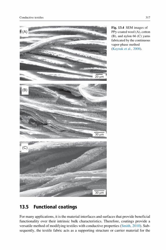
Dall’Acqua et al., 2004; Kaynak et al., 2008). Fig. 13.4 demonstrates the longitudinal
SEM images of wool, cotton, and nylon 66 yarns coated with PPy using the continuous
vapor polymerization method (Kaynak et al., 2008). Coating of PEDOT on the textile
fibers or yarns for making them electrically conductive was also reported (Knittel and
Schollmeyer, 2009). Another strategy to make the textile fibers conductive is coating
their surface with CNT to utilize its high conductivity feature (Liu et al., 2008). For
instance, Shim et al. (2008a) coated the surface of cotton yarns successfully with a
mixture of CNTs and polyelectrolyte by using the physical padding method to intro-
duce highly conductive yarns. On the other hand, direct sputtering or inking with
metal particles or metal film could be another strategy to make the textile fibers
and yarns conductive. However, this kind of coating generally results in flaking-off
of the metal layer or coating from the fiber surface; so durability of metal coatings
on the fiber surface remains a great challenge (Liu et al., 2010).
10 µm 500 nm
Fig. 13.3 SEM images of copper-plated polyester fibers at different magnifications (Guo
et al., 2009).
20 µm
30 µm
(B)
(A)
(C)
30 µm
Fig. 13.4 SEM images of
PPy-coated wool (A), cotton
(B), and nylon 66 (C) yarns
fabricated by the continuous
vapor-phase method
(Kaynak et al., 2008).
Conductive textiles 317
13.5 Functional coatings
For many applications, it is the material interfaces and surfaces that provide beneficial
functionality over their intrinsic bulk characteristics. Therefore, coatings provide a
versatile method of modifying textiles with conductive properties (Smith, 2010). Sub-
sequently, the textile fabric acts as a supporting structure or carrier material for the

318 Engineering of High-Performance Textiles
conductive finish (Sen, 2007). Conventional techniques such as dip coating or roll
coating are typically used to apply bulk coatings in the form of a saturation or lam-
ination that covers the entire “surface” of the textile. However, as will be presented
herein, the advent of nanotechnology in textile research, the development of novel
process techniques, and the advancement of inks and coating formulations affords
the opportunity to apply coatings to increasingly finer structures. Therefore, the def-
inition of a surface is highly dependent on which scale the coating can influence the
underlying carrier material.
The key to coating these ever finer levels of surface, such as yarns or single fila-
ments of a bulk textile fabric, is inherent in the line-of-sight (Wei, 2009). The coating
formulation is required to be able to overcome various blocking effects and penetrate
the layers of complex three-dimensional (3D) substrates (Hegemann et al., 2009). Fur-
thermore, the subsurface of the polymer that comprises the single filaments can also be
infiltrated and modified with inorganic properties resulting in hybrid finishes that are
neither purely organic nor inorganic ( Jena et al., 2012; Padbury and Jur, 2015). Con-
sequently, a diverse range of unique properties and coating morphologies can be uti-
lized to add extra functionality to textiles while maintaining their inherent properties
such as flexibility, strength, and breathability.
In this section, common methods of applying functional coatings to polymer sub-
strates are introduced including examples of advanced techniques and printing
methods. The field of functional coatings in polymer and textile manufacturing is
extremely broad. Therefore, the objective of Section 13.5 is to provide a qualitative
overview of various techniques from the perspectives of the authors. More detailed
and theoretical descriptions regarding coating techniques can be found elsewhere
in the literature and are referenced in Section 13.5 where applicable.
13.5.1 Percolation threshold
A typical coating formulation incorporates a binder or matrix material that adheres to
the fabric and provides durability with the addition of functional fillers for conductiv-
ity. Epoxies, polyacrylates, polyurethanes, and polyvinyl chlorides have been fre-
quently used as binder materials due to their additional properties such as
durability and mechanical strength (Tracton, 2005). However, the range of matrix
materials is greatly expanded by the abundance of raw materials such as polymer-
solvent combinations and thermoplastic polymers (Smith, 2010; Sen, 2007;
Tracton, 2005). Fillers of various materials such as nickel, silver, copper, and CB
in the form of powders, flakes, or filaments are incorporated into the matrix with
the objective of creating a conductive network (Nishikawa et al., 2010). In recent
years, more novel materials have been used such as graphene and CNTs resulting
in unprecedented conductivities (Bauhofer and Kovacs, 2009; Li et al., 2008; Shim
et al., 2008b).
Conductive networks in coatings are created by reaching a percolation threshold.
Mathematically, percolation theory describes the formation of long-range connectivity
in anotherwise randomarrangement (Sahimi, 1994).At lowconcentrations, conductive
fillers in a dielectric matrix are situated in random discrete locations. However, as the

Conductive textiles 319
concentration of conductive filler increases, contact occurs between adjacent particles
creating a conductive pathway. Therefore, the percolation threshold determines the
critical concentration of filler required to maximize the conductivity of the coating
as it transitions from the dielectric properties of the matrix to the conductive properties
of the filler (Sahimi, 1994). Accordingly, sharp changes in conductivity are observed at
concentrations close to the percolation threshold. Furthermore, percolation thresholds
are also influenced by particle geometry such as rods and platelets, which lead to lower
critical concentrations than spherical particles. This is due to the larger aspect ratios of
rods, flakes, and platelets that span the dielectric medium enhancing contact between
neighboring filler materials (Sandler et al., 2003). The development of low percolation
threshold coatings is particularly important as high loadings of filler can reduce the
mechanical properties of the coating and decrease the processability of the formulation
(Guo et al., 2015).
13.5.2 Liquid-coating methods
The most well-known method of applying functional formulations to a fabric is
through the use of liquid-coating techniques. Coatings applied from this highly ver-
satile technique can be introduced to the surface of a fabric using several methods that
have subtle variations in their process procedures. In direct coating, formulations can
be applied in liquid form from a chemical bath (Sen, 2007). In this process, the coating
solution is introduced to the fabric by a contact roller suspended partially in the chem-
ical bath (Sen, 2007). Meyer bar coating is an iteration of this technique and features a
bar located close to the roller to remove excess solution from the fabric (Sen, 2007).
Similarly, in a pad-dry-cure process, the fabric is passed through a series of rollers that
guide the material directly through the chemical bath to saturate the material with the
coating solution. Excess solution is removed by compressing the fabric through
another set of rollers, and finally the fabric is dried or cured (Sen, 2007).
The wet pickup weight and the resultant thickness and uniformity of the coating are
dependent on the concentration, surface tension, and substrate characteristics, which
influence the shape of the dynamic meniscus as the substrate is withdrawn from the
chemical bath. Furthermore, a number of forces act on the coating solution as it is
withdrawn, such as inertia and viscous drag which act to pull the solution up the sub-
strate, and cohesive forces that push the solution outwards due to intermolecular inter-
actions. In opposition, gravity draws the solution down while capillary action draws
the solution into the fabric, depending on the contact angle of the dynamic meniscus as
the fabric is withdrawn from the chemical bath (Smith, 2010). In general, higher con-
centrations leads to thicker coatings due to greater viscous drag and intermolecular
forces, which are magnified by the withdraw speed. However, at higher velocities
the coating thickness reaches a maximum due to larger shear forces and the act of
gravity forcing the solution back to the chemical bath (Fang et al., 2008).
While liquid-coating techniques provide a robust, standardized method of coating
textile fabrics, there are a number of considerations. Firstly, liquid-based techniques
often require large amounts of water or organic solvents that either needs to be

320 Engineering of High-Performance Textiles
disposed of or recovered, which increases the chemical footprint of the technique.
Moreover, liquid-coating processes are energy intensive due to the several steps
required to apply solutions followed by the use of large drying ovens to cure the coat-
ing or evaporate the residual solvent. However, alternative polymer chemistries that
require less energy intensive curing steps or utilize fewer chemicals are available. For
example, UV curable resins are widely available and UV lamps can replace energy
intensive drying ovens (Sen, 2007; Tracton, 2005). Furthermore, hot-melt coatings,
which are formed from a broad range of thermoplastic polymers, can be applied with-
out the need for solvents using transfer, lamination, or hot-melt extrusion processes
and cured via cooling (Sen, 2007; Tracton, 2005). Moreover, these formulations
can be compounded with functional fillers to impart conductive properties.
13.5.2.1 Alternative formulations
As mentioned above, the coating techniques described above are conducive to numer-
ous conventional coating materials, such as epoxides, polyacrylates, polyurethanes,
polyvinyl chlorides, and a wide variety of thermoplastic polymers. However, these
techniques also lend themselves to advanced coating formulations from a wide variety
of polymer-solvent combinations that address the need for better performance.
The layer-by-layer (Lbl) coating technique deposits polyelectrolytes with opposite
charges from solution to the surface of a material (Decher, 1997; Hammond, 2004).
Specifically, polyanionic and polycationic polymers are sequentially introduced to a
charged surface and fixed in place via electrostatic forces. The sequential control of
polyelectrolyte layers and solution concentration affords the opportunity to apply
nanoscale coatings to a broad range of substrates. The resulting coating can be used
to incorporate inorganic particles (Li et al., 2010), nanoparticles (Feldheim et al.,
1996), and nanofibers (Kim et al., 2011) that promote additional functionality in a tex-
tile fabric. Moreover, conventional liquid-coating techniques such as pad-dry-cure
can be used to apply Lbl coatings. Rubner et al. showed how p-type-doped electrically
conductive polymers and conjugated polyanions can be applied to a substrate using the
Lbl technique to promote conductive properties (Cheng et al., 1994; Ferreira et al.,
2016) Specifically, PPy, PANI, and poly(3-hexylthiophene) were combined resulting
in conductivities of 40 S cm�1 with as little as four deposited layers.
In a similar fashion, polymer grafts can be anchored to the surface of a textile sub-
strate, by chemical reaction with functional groups or methods such as atom transfer
radical polymerization, and used to modify the surface functionality of a bulk fabric.
Michielsen demonstrated a robust graft-site amplification method for functionalizing
fiber-forming polymers such as polyamides that is compatible with conventional
liquid-coating techniques (Michielsen, 1999). Using this method, fiber-forming poly-
mers with characteristically low concentrations of intrachain functional groups can be
modified with polymers that have a high concentration of functional groups, such as
polyacrylic acid. Specifically, functional moieties or particles can then be glued to the
graft to exploit desirable functional properties, such as electrical conductivity (Wang
et al., 2014; Wu et al., 2015). Furthermore, in situ polymerization techniques have
been utilized to enhance the conductive properties of textile fabrics. The work of
Conductive textiles 321
Bajgar et al. (2016) and Macasaquit and Binag (2010) demonstrates the in situ poly-
merization of conductive polymers, such as PPy and PANI to cotton and polyester
fabrics, respectively. The fabrics were coated with the monomers of the conductive
polymers by immersion and subsequently dried in air. Conductivities of the order
of 1–10 S cm�1 were achieved using these techniques which can be improved by
applying dopants such as iron (III) chloride.
Conductive and semiconductor coatings can also be applied to a textile fabric using
sol-gels. The sol-gel process is a wet chemical technique that forms a network gel of
hydrated inorganic colloid particles via hydrolysis and polycondensation reactions
(Hench and West, 1990). Initially, the solution has a low viscosity and is capable
of diffusing into porous substrates such as textiles via dip coating. Over time, the solu-
tion becomes more viscous as more molecules link together via crosslinking which
forms the gel component of the coating (Hench and West, 1990; Mahltig et al.,
2005). The gel is allowed to solidify within the substrate and the residual liquid is
removed via heat treatment resulting in a solid inorganic coating. Similarly, the hydro-
thermal technique can be used to process polymer fabrics through a chemical bath
containing metal alkoxides or metal salts mixed with water followed by a suitable heat
treatment (Cushing et al., 2004). Lee et al. (2005) utilized the hydrothermal technique
to grow semiconductor zinc oxide nanowires on PET substrates combined with
indium-tin-oxide (ITO) for field emission display applications.
13.5.3 Advanced coating methods
Despite the convenient and wide spread use of the coating techniques described in
Section 13.5.2, there are notable limitations. In the case of conventional liquid-coating
techniques and materials, wet pickup and resultant coatings tend to be bulky and thick.
Where minimal thickness is required, particularly at the nanoscale, it is possible to
achieve this requirement by varying solution concentrations or using advanced formu-
lations such as Lbl polyelectrolyte solutions and polymer grafts. However, these for-
mulations require multiple time-consuming steps to introduce the coatings to a
substrate surface. Furthermore, there is an increasing need for uniform coatings which
are difficult to control with conventional liquid-coatings and sol-gel precursors.
Therefore, the development of novel high-throughput coating techniques is of great
interest to the flexible electronics and electronic textiles industries.
13.5.3.1 Physical vapor deposition
PVD is a vacuum technique used to deposit a wide variety of metal, metal oxide, and
metal nitride thin films onto various substrates via sputtering or evaporation
(Sarakinos et al., 2010; Smentkowski, 2000). In general, collections of atoms are
vaporized and deposited onto a substrate as they condense and physisorb to the sub-
strate surface which, over time, forms a coalesced coating. During the sputtering pro-
cess plasmas such as ionized argon or oxygen, are used to bombard and liberate atoms
from the surface of a target which consists of the required coating material such as
gold or palladium (Sarakinos et al., 2010). Subsequently, the escaped atoms are

322 Engineering of High-Performance Textiles
accelerated through the vacuum chamber toward the substrate. Similarly, the evapo-
ration technique liberates atoms from the surface of a target; however, a subtle differ-
ence is that the target is either heated restively or with a high-energy beam, that is an
electron beam, so that atom clusters have enough energy to “boil” from the surface of
the target and accelerate through the vacuum chamber towards the substrate
(Smentkowski, 2000). High-purity coatings can be formed from PVD techniques;
however, it is a line-of-sight technique that produces nonuniform coatings on complex
substrates such as textile fabrics. Evaporation and sputter techniques can also result in
damage to the surface of the textile substrate through elevated temperatures or etching
from contact with plasmas.
13.5.3.2 Chemical vapor deposition
Chemical vapor deposition (CVD) is a thin-film deposition technique that utilizes
reactions between precursors and co-reactants with a substrate surface in the vapor
phase. Therefore, CVD is a vacuum technique operating below the vapor pressure
of the precursors to promote a viscous gas regime that delivers the precursors to
the substrate surface (Hampdensmith and Kodas, 1995; Murota et al., 2006). The reac-
tions that take place between the precursors either directly react with the substrate or
form a powder product that precipitates on the substrate surface. The former scenario
results in the formation of dense inorganic films while the latter case requires a cal-
cination step. Control of the deposition process is dependent on the process pressure,
temperature, and vapor transport conditions. Typical CVD processes require high
temperatures to dissociate the precursors and encourage the formation of a film. How-
ever, elevated temperatures are not favorable to a broad range of thermally sensitive
thermoplastic polymers. Therefore, plasma-assisted or photoinitiated techniques can
be used in place of thermal energy to promote the chemical reactions on polymeric
substrates (Matthews, 2003; Cote et al., 1999). In contrast to PVD, the CVD technique
has improved line-of-sight due to the mobility of vapor-phase precursors. However, it
is still a challenge to achieve uniform coatings on high aspect ratio substrates or com-
plex materials with long trenches and porous structures due to the short exposure
times. Therefore, alternative gas-phase technique are available such as atomic layer
deposition (ALD), that increase the precursor exposure time that promotes the
formation of inorganic coatings on highly complex 3D surfaces.
13.5.3.3 Atomic layer deposition
ALD is a technique used to deposit pinhole free, nanoscale coatings onto the surface of
a specific substrate with atomic scale precision (Fig. 13.5). This is achieved by ALD’s
unique attribute, a carefully chosen sequence of sequential self-limiting vapor-phase
reactions that involve complementary precursor gases and co-reactants to promote the
formation of a monolayer (Parsons et al., 2011). Multiple ALD cycles can produce
thin-film coatings on a broad range of natural and synthetic polymers due to the
low-temperature activation of many precursor chemistries (Puurunen, 2005). How-
ever, the coating morphology depends strongly on the polymer composition and
TMA
H2O
N2
Direction of flow
Substrate
Dose sequence:x(TMA/N2/H2O/N2)
N2 purgeVacuumpump
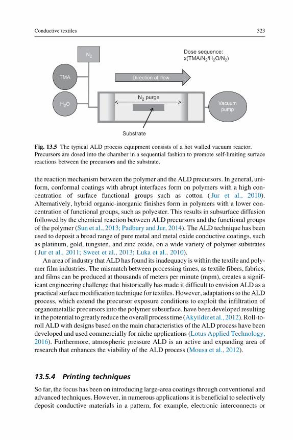
Fig. 13.5 The typical ALD process equipment consists of a hot walled vacuum reactor.
Precursors are dosed into the chamber in a sequential fashion to promote self-limiting surface
reactions between the precursors and the substrate.
Conductive textiles 323
the reaction mechanism between the polymer and the ALD precursors. In general, uni-
form, conformal coatings with abrupt interfaces form on polymers with a high con-
centration of surface functional groups such as cotton ( Jur et al., 2010).
Alternatively, hybrid organic-inorganic finishes form in polymers with a lower con-
centration of functional groups, such as polyester. This results in subsurface diffusion
followed by the chemical reaction between ALD precursors and the functional groups
of the polymer (Sun et al., 2013; Padbury and Jur, 2014). The ALD technique has been
used to deposit a broad range of pure metal and metal oxide conductive coatings, such
as platinum, gold, tungsten, and zinc oxide, on a wide variety of polymer substrates
( Jur et al., 2011; Sweet et al., 2013; Luka et al., 2010).
An area of industry that ALD has found its inadequacy is within the textile and poly-
mer film industries. The mismatch between processing times, as textile fibers, fabrics,
and films can be produced at thousands of meters per minute (mpm), creates a signif-
icant engineering challenge that historically has made it difficult to envision ALD as a
practical surface modification technique for textiles. However, adaptations to the ALD
process, which extend the precursor exposure conditions to exploit the infiltration of
organometallic precursors into the polymer subsurface, have been developed resulting
in thepotential togreatly reduce theoverall process time (Akyildiz et al., 2012).Roll-to-
roll ALDwith designs based on the main characteristics of the ALD process have been
developed and used commercially for niche applications (Lotus Applied Technology,
2016). Furthermore, atmospheric pressure ALD is an active and expanding area of
research that enhances the viability of the ALD process (Mousa et al., 2012).
13.5.4 Printing techniques
So far, the focus has been on introducing large-area coatings through conventional and
advanced techniques. However, in numerous applications it is beneficial to selectively
deposit conductive materials in a pattern, for example, electronic interconnects or

324 Engineering of High-Performance Textiles
antennas. The method of patterning substrates via photolithography and masks is well
known in the microelectronics industry. The technique requires numerous steps from
coating the substrate in a functional film and photoresist, exposing specific areas of the
substrate to radiation through a patterned mask, etching exposed areas, and finally
removing the resist layer leaving a patterned finish (Halbur et al., 2016). Lithography
is typically used as a batch process for specialized components such as semiconductor
printed circuit boards. However, continuous processes have been developed, as sum-
marized in Table 13.4, for the high throughput manufacturing of functional printed
electronic textiles or polymer films (Daniel, 2010). Typically, the printing processes
can be completed with no more than two steps from applying a conductive ink
followed by curing or fixing the pattern to a substrate. However, it is important to con-
sider that preprocess photolithographic or etching techniques are required to introduce
patterns to special rollers or screens, as will be discussed below.
Gravure printing provides the fastest throughput through the utilization of a series
of imprinted and impression rollers that transfer specialty inks to the surface of a sub-
strate. Specific patterns are etched directly into the imprinted roller, which is typically
made from copper-plated steel (Daniel, 2010). A special feature of the gravure process
is that the etching process, used to produce the pattern, creates cells in the imprint
roller that soak up the ink as it rotates. The depth of the cells determines the intensity
of the print with deeper cells creating more intense finishes. Subsequently, the ink is
transferred to the substrate through a combination of capillary forces through the sub-
strate and pressure from the impression roller.
Similarly, a further high-throughput process, flexographic printing, utilizes rollers
to transfer patterns to a substrate. However, a subtle difference to gravure printing is
that patterns are produced on plates made of rubber or photosensitive polymers that
are temporarily attached to imprint rollers. Furthermore, the flexographic process uti-
lizes transfer and metering rollers that pick up and store ink inside engraved cells,
respectively. Accordingly, the metering roller transfers a specific quantity of ink to
the imprint roller to control pattern intensity and thickness (Kipphan, 2001).
Table 13.4 Summary of printing techniques
Printing
method
Viscosity
(pas)
Layer
thickness
(μm)
Feature
resolution (μm)
Throughput
(m2 s21)
Gravure
printing
0.01–0.2 0.1–8 75 30–60
Screen
printing
0.5–50 0.015–100 20–100 2–3
Inkjet printing 0.001–0.04 0.05–20 20–50 0.01–0.5Flexographic
printing
0.05–0.5 0.04–2.5 80 3–30
Data from Daniel, J., 2010. Printed electronics: technologies, challenges, and applications. In: International Workshopon Flexible Printed Electronics, Palo Alto Research Center, PARC, Korea, September.
Conductive textiles 325
Screen printing has been enjoyed by children and adults alike to develop custom
upholstery and apparel. However, this versatile printing technique provides beneficial
properties to a wide range of substrates due to its compatibility with various coating
viscosities resulting in different coating thicknesses and resolutions (PNEAC, 2016).
The technique involves a stainless steel mesh molded over wooden or metallic screens
and a patterned stencil that is produced photochemically. A wiper is moved across the
mesh forcing ink through the open areas of the stencil and successively transferring the
pattern to the substrate. In automatic manufacturing processes, flatbed screen prints
are used in which fabric is fed on a conveyor. When the fabric is under the screen
the conveyor stops and the screen automatically closes over the fabric and ink is
applied through the mesh and stencil, which is transferred to the fabric (PNEAC,
2016). While flatbed screen printing possesses a low throughput, rotary screen-
printing techniques have been developed which offer higher throughput.
Printed patterns can be applied via inkjet printing with high resolution and varied
coating thicknesses on a broad range of substrates (Wong and Alberto, 2009; Yin
et al., 2010). Perhaps one of the most significant benefits of inkjet printing is that
no prefabrication steps, such as the development of engraved rollers and screens,
are required prior to the process. Ink drops can either be applied continuously or
via drop-on-demand techniques (Yin et al., 2010). In continuous inkjet printing, a con-
tinuous stream of ink is passed through a nozzle and charged. Droplets that become
charges are deflected by a suitable electric field, recovered, and recirculated.
Un-charged droplets are transported to the substrate and used to form a pattern or
image (Yin et al., 2010). In contrast, drop-on-demand inkjet printing takes advantage
of thermal or piezoelectric responses that project droplets onto the substrate by the
vaporization of the ink forming bubbles or deformation of the ink chamber, respec-
tively (Halbur et al., 2013). In contrast with other techniques summarized in
Table 13.4, inkjet printing is comparatively slow but offers the finest line widths
and feature resolutions.
13.5.5 Conclusions and considerations
In Section 13.5, a wide range of conventional and advanced coating techniques from
liquid-coating to vapor-phase techniques have been introduced. With respect to liquid
and direct coating, there are a broad range of materials available for coatings and lam-
inations from the extensive list of thermoplastics, thermosets, and polymer-solvent
combinations, many of which can be combined with conductive filler particles with
the objective of creating a percolation network (Tracton, 2005). Novel formulations
compatible with convention coating process techniques were also introduced provid-
ing the opportunity to incorporate conjugated conductive polymers, nanoparticles, and
inorganics to the surface of a textile which further expands the realm of capability in
electronic textiles. Control of process parameters such as metering, transferring, and
fixing along with coating characteristics for instance, concentration and rheology,
determines the thickness and uniformity of resultant coatings on a substrate. However,
there are further considerations that must be taken in to account by the operator.

326 Engineering of High-Performance Textiles
Explicitly, the chemical compatibility between the coating material and the
substrate determines the wettability and adhesion of the resultant coating, as intro-
duced in Section 13.5.2. Wettability and adhesion is highly dependent on the sur-
face tension of the two materials as well as the interfacial tension between the two
components (Smith, 2010). In general, a low-surface-tension substrate can result
in nonwetting behavior if the surface tension of the liquid is greater than the sur-
face tension of the substrate. In this case, the adhesive force of the substrate is
unable to overcome the cohesive forces of the coating solution. As a result, the
coating formulation acts to minimize its own surface energy by beading up rather
than uniformly spreading over the substrate. In the case of polymer coatings,
adhesion is also impacted by the diffusion of polymer chains into the substrate.
Polymer chains have greater mobility above the glass transition temperature;
therefore, in the case of hot-melt coating, higher temperature can lead to stronger
adhesion forces (Smith, 2010; Wei, 2009). However, diffusion and entanglement
of polymer chains is also dependent on chemical compatibility between the poly-
mers that make up the coating formulation and substrate. Low solubility param-
eters and repulsive forces between dissimilar polymers result in phase separation,
in the same way that oil separates from water, which can result in coating delam-
ination and reduced durability. To increase the adhesive force, high molecular
weight results in greater attractive interactions between neighboring polymer
chains, such as hydrogen bonds and van der Waals forces. Practically, textile fab-
rics are not perfectly smooth substrates; they inherently possess some surface
roughness that may influence wettability, adhesion, and the uniformity of a coat-
ing. Furthermore, textile fabrics are porous which can lead to capillary action or
wicking. For printing, capillary action can affect the resolution of line widths as
the solution is drawn into the fabric. On the other hand, for bulk coatings, pen-
etration into the fabric structure can enhance the mechanical properties of the sub-
strate up to a certain limit through mechanical locking (Smith, 2010).
While chemical compatibility and wettability may affect the uniformity and dura-
bility of coatings on a substrate, there are further considerations for printed patterns
made from polymer-solvent formulations. Firstly, incompatibility may result in non-
uniform line widths due to higher contact angles between the coating formulation and
substrate surface which impacts the minimum resolution possible. Furthermore, sol-
vents tend to evaporate quicker at the edges due to the microscopic crescent shape of
the liquid-gas interface of the coating. As the solvent evaporates, liquid moves out-
wards to replace the liquid that has evaporated. For inks and formulations that contain
a conductive particle component, coffee ring patterns can form where the flow of liq-
uid from the canter of the drop drags particles to the outside (Yin et al., 2010; Halbur
et al., 2013). The nonuniformity of the line widths and coffee ring pattern may result in
lower conductivities and potential short circuits.
Ultimately, the utilization of the coating and printing techniques outlined in this
section is a balance between cost (i.e., capital investment and throughput), coating
properties such as resolution (feature size) and thickness as well as the compatibility
between substrates and coating formulations.

Conductive textiles 327
References
A. D4935-99, 1999. Standard Test Method for Measuring the Electromagnetic Shielding
Effectiveness of Planar Materials.
A. E1851-15, 2015. Standard TestMethod for Electromagnetic Shielding Effectiveness of Dura-
ble Rigid Wall Relocatable Structures. ASTM International, West Conshohocken, PA.
Agnihotri, N., Chakrabarti, K., De, A., 2015. Highly efficient electromagnetic inter-
ference shielding using graphite nanoplatelet/poly(3,4-ethylenedioxythiophene)-poly
(styrenesulfonate) composites with enhanced thermal conductivity. RSC Adv. 5 (54),
43765–43771.Akyildiz, H.I., Padbury, R.P., Parsons, G.N., Jur, J.S., 2012. Temperature and exposure depen-
dence of hybrid organic-inorganic layer formation by sequential vapor infiltration into
polymer fibers. Langmuir 28 (44), 15697–15704.Al-Saleh, M.H., Sundararaj, U., 2009. Electromagnetic interference shielding mechanisms of
CNT/polymer composites. Carbon 47 (7), 1738–1746.Andreatta, A., Heeger, A.J., Smith, P., 1990. Electrically conductive poly blend fibers of poly-
aniline and poly(p-phenylene terephthalamide). Polym. Commun. 31, 275.
Andrews, R., Weisenberger, M., 2004. Carbon nanotube polymer composites. Curr. Opinion
Solid State Mater. Sci. 8, 31–37.Apreutesei, A.L., Curteza, A., David, V., Nica, I., Rau, M., Baltag, O., 2014. Investigation of the
textile structures with different design used in electromagnetic shielding. In: 2014 Inter-
national Conference and Exposition on Electrical and Power Engineering (EPE),
pp. 596–601.Apreutesei, A.L., Curteza, A., Baltag, O., 2015. Study of the knitted structures with different
designs used for electromagnetic shielding. In: 2015 9th International Symposium on
Advanced Topics in Electrical Engineering (ATEE), pp. 352–355.Avloni, J., Ouyang, M., Florio, L., Henn, A.R., Sparavigna, A., 2007. Shielding effectiveness
evaluation of metallized and polypyrrole-coated fabrics. J. Thermoplast. Compos. Mater.
20 (3), 241–254.Badic, W., Marinescu, M.J., 2002. The failure of coaxial TEM cells ASTM standards methods
in HF range. In: 2002 IEEE International Symposium on Electromagnetic Compatibility,
Vols 1 and 2, Symposium Record, pp. 29–34.Bajgar, V., Penhaker, M., Martinkova, L., Pavlovic, A., Bober, P., Trchova, M., Stejskal, J.,
2016. Cotton fabric coated with conducting polymers and its application in monitoring
of carnivorous plant response. Sensors 16 (4), 495.
Bashir, T., Skrifvars, M., Persson, N.K., 2011. Production of highly conductive textile viscose
yarns by chemical vapor deposition technique: a route to continuous process. Polym. Adv.
Technol. 22, 2214–2221.Bauhofer, W., Kovacs, J.Z., 2009. A review and analysis of electrical percolation in carbon
nanotube polymer composites. Compos. Sci. Technol. 69 (10), 1486–1498.Bhat, N., Seshadri, D., Radhakrishnan, S., 2004. Preparation, characterization, and performance
of conductive fabrics: cotton + PANi. Text. Res. J. 74, 155–166.Cetiner, S., 2014. Dielectric and morphological studies of nanostructured polypyrrole-coated
cotton fabrics. Text. Res. J. 84 (14), 1463–1475.Chen, Y., Wang, Y.L., Zhang, H.B., Li, X.F., Gui, C.X., Yu, Z.Z., 2015. Enhanced electromag-
netic interference shielding efficiency of polystyrene/graphene composites with magnetic
Fe3O4 nanoparticles. Carbon 82, 67–76.

328 Engineering of High-Performance Textiles
Cheng, J.H., Fou, A.F., Rubner, M.F., 1994. Molecular self-assembly of conducting polymers.
Thin Solid Films 244 (1–2), 985–989.Cheng, K.B., Ramakrishna, S., Lee, K.C., 2000. Electromagnetic shielding effectiveness of cop-
per/glass fiber knitted fabric reinforced polypropylene composites. J. Community Appl.
Soc. Psychol. 31 (10), 1039–1045.Cherenack, K., van Pieterson, L., 2012. Smart textiles: challenges and opportunities. J. Appl.
Phys. 112, 091301.
Chiou, J.M., Zheng, Q.J., Chung, D.D.L., 1989. Electromagnetic-interference shielding by
carbon-fiber reinforced cement. Composites 20 (4), 379–381.Chung, D.D.L., 2001. Electromagnetic interference shielding effectiveness of carbon materials.
Carbon 39 (2), 279–285.Cote, D.R., Nguyen, S.V., Stamper, A.K., Armbrust, D.S., Tobben, D., Conti, R.A., Lee, G.Y.,
1999. Plasma-assisted chemical vapor deposition of dielectric thin films for ULSI semi-
conductor circuits. J. Res. Dev. Educ. 43, 5.
Coyle, S., Wu, Y., Lau, K.-T., De Rossi, D., Wallace, G., Diamond, D., 2007. Smart nan-
otextiles: a review of materials and applications. MRS Bull. 32, 434–442.Cushing, B.L., Kolesnichenko, V.L., O’Connor, C.J., 2004. Recent advances in the liquid-phase
syntheses of inorganic nanoparticles. Chem. Rev. 104, 3893.
D.-V. 95373-15, 2016. Electromagnetic Compatibility (EMC)—Electromagnetic Compatibility
of Equipment—Part 15: Test Procedures for Coupling and Shielding. Deutsches Institut f€urNormung e. V., Germany.
Dall’Acqua, L., Tonin, C., Peila, R., Ferrero, F., Catellani, M., 2004. Performances and prop-
erties of intrinsic conductive cellulose–polypyrrole textiles. Synth. Met. 146, 213–221.Daniel, J., 2010. Printed electronics: technologies, challenges, and applications. In: Palo Alto
Research Center, PARC, International Workshop on Flexible Printed Electronics, Muju
Resort, Korea, September.
Das, A., Kothari, V.K., Kothari, A., Kumar, A., 2009. Effect of various parameters on electro-
magnetic shielding effectiveness of textile fabrics. Indian J. Fibre Text. Res. 34 (2),
144–148.De Rossi, D., 2007. Electronic textiles: a logical step. Nat. Mater. 6, 328–329.Decher, G., 1997. Fuzzy nanoassemblies: toward layered polymeric multicomposites. Science
277 (5330), 1232–1237.Dhawan, S.K., Singh, N., Venkatachalam, S., 2002. Shielding behaviour of conducting
polymer-coated fabrics in X-band W-band and radio frequency range. Synth. Met.
129 (3), 261–267.Dubas, S.T., Kumlangdudsana, P., Potiyaraj, P., 2006. Layer-by-layer deposition of antimicro-
bial silver nanoparticles on textile fibers. Colloids Surf. A Physicochem. Eng. Asp.
289, 105–109.Erdumlu, N., Saricam, C., 2015. Electromagnetic shielding effectiveness of woven fabrics con-
taining cotton/metal-wrapped hybrid yarns. J. Ind. Text 46 (4), 1084–1103.Fang, H.-W., et al., 2008. Dip coating assisted polylactic acid deposition on steel surface: film
thickness affected by drag force and gravity. Mater. Lett. 62 (21–22), 3739–3741.Feldheim, D.L., Grabar, K.C., Natan, M.J., Mallouk, T.E., 1996. Electron transfer in self assem-
bled inorganic polyelectrolyte/metal nanoparticle heterostructures. J. Am. Chem. Soc.
118, 7640–7641.Ferreira, M., Cheung, J.H., Rubner, M.F., 2016. Molecular self-assembly of conjugated poly-
ions: a new process for fabricating multilayer thin film heterostructures. Thin Solid Films
244 (1–2), 806–809.
Conductive textiles 329
Geetha, S., Kumar, K.K.S., Rao, C.R.K., Vijayan, M., Trivedi, D.C., 2009. EMI shielding:
methods and materials-a review. J. Appl. Polym. Sci. 112 (4), 2073–2086.Ghosh, P., Chakrabarti, A., 2000. Conducting carbon black filled EPDM vulcanizates: assess-
ment of dependence of physical and mechanical properties and conducting character on
variation of filler loading. Eur. Polym. J. 36 (5), 1043–1054.Guo, R., Jiang, S., Yuen, C.M., Ng, M., 2009. Surface characterisation of electroless copper
plated polyester fibres. Surf. Eng. 25, 101–105.Guo, C., et al., 2015. Preparation of the polypropylene/nickel coated glass fibers conductive
composites with a Low percolation threshold. Mater. Lett. 143, 124–127.Halbur, J.C., Padbury, R.P., Jur, J.S., 2013. Inducedwetting of polytetrafluoroethylene by atomic
layerdeposition for applicationof aqueous-basednanoparticle inks.Mater.Lett. 101, 25–28.Halbur, J.C., Padbury, R.P., Jur, J.S., 2016. Silver decorated polymer supported semiconductor
thin films by UV aided metalized laser printing. J. Vac. Sci. Technol. A 34 (3), 031402.
Hammond, P.T., 2004. Form and function in multilayer assembly: new applications at the nano-
scale. Adv. Mater. 16, 1271.
Hampdensmith, M.J., Kodas, T.T., 1995. Chemical-vapor-deposition of metals. 1. An overview
of CVD processes. Chem. Vap. Depos. 1, 8.
Han, E.G., Kim, E.A., Oh, K.W., 2001. Electromagnetic interference shielding effectiveness of
electroless Cu-plated PET fabrics. Synth. Met. 123 (3), 469–476.Hegemann, D., Amberg, M., Ritter, A., Heuberger, M., 2009. Recent developments in Ag meta-
llised textiles using plasma sputtering. Mater. Technol. 24 (1), 41–45.Hench, L.L., West, J.K., 1990. The sol-gel process. Chem. Rev. 90 (1), 33–72.Hosier, I., Vaughan, A., Patel, D., Sutton, S., Swingler, S., 2001. Morphology and electrical
conductivity in polyaniline/polyolefin blends. IEEE Trans. Dielectr. Electr. Insul.
8, 698–704.Huang, J.C., 1995. Emi shielding plastics—a review. Adv. Polym. Technol. 14 (2), 137–150.I.S. 299-1997, 1997. IEEE Standard Method for Measuring the Effectiveness of Electromag-
netic Shielding Enclosures. The Institute of Electrical and Electronics Engineers,
New York.
Ikkala, O., Laakso, J., V€akiparta, K., Virtanen, E., Ruohonen, H., J€arvinen, H., Taka, T.,
Passiniemi, P., €Osterholm, J.-E., Cao, Y., 1995. Counter-ion induced processibility of
polyaniline: conducting melt processible polymer blends. Synth. Met. 69, 97–100.Jagatheesan, K., Ramasamy, A., Das, A., Basu, A., 2015. Fabrics and their composites for elec-
tromagnetic shielding applications. Text. Prog. 47 (2), 87–161.Jena, K.K., Rout, T.K., Narayan, R., Raju, K., 2012. Novel organicinorganic hybrid coatings
prepared by the sol-gel process: corrosion and mechanical properties. Polym. Int.
61, 1101–1106.Jur, J.S., Spagnola, J.C., Lee, K., Gong, B., Peng, Q., Parsons, G.N., 2010. Temperature depen-
dent subsurface growth during atomic layer deposition on polypropylene and cellulose
fibers. Langmuir 26 (11), 8239–8244.Jur, J.S., Sweet III, W.J., Oldham, C.J., Parsons, G.N., 2011. Atomic layer deposition of conduc-
tive coatings on cotton, paper, and synthetic fibers: conductivity analysis and functional
chemical sensing using “all-fiber” capacitors. Adv. Funct. Mater. 21 (11), 1993–2002.Kang, T.J., Choi, A., Kim, D.-H., Jin, K., Seo, D.K., Jeong, D.H., Hong, S.-H., Park, Y.W.,
Kim, Y.H., 2010. Electromechanical properties of CNT-coated cotton yarn for electronic
textile applications. Smart Mater. Struct. 20, 015004.
Kaynak, A., Najar, S.S., Foitzik, R.C., 2008. Conducting nylon, cotton and wool yarns by con-
tinuous vapor polymerization of pyrrole. Synth. Met. 158, 1–5.
330 Engineering of High-Performance Textiles
Kim, M.S., Kim, H.K., Byun, S.W., Jeong, S.H., Hong, Y.K., Joo, J.S., Song, K.T., Kim, J.K.,
Lee, C.J., Lee, J.Y., 2002. PET fabric/polypyrrole composite with high electrical conduc-
tivity for EMI shielding. Synth. Met. 126 (2–3), 233–239.Kim, H.K., Kim, M.S., Song, K., Park, Y.H., Kim, S.H., Joo, J., Lee, J.Y., 2003. EMI shielding
intrinsically conducting polymer/PET textile composites. Synth. Met. 135 (1–3), 105–106.Kim, B., Koncar, V., Devaux, E., Dufour, C., Viallier, P., 2004. Electrical and morphological
properties of PP and PET conductive polymer fibers. Synth. Met. 146, 167–174.Kim, Y., Davis, R., Cain, A., Grunlan, J., 2011. Development of layer-by-layer assembled car-
bon nanofiber-filled coatings to reduce polyurethane foam flammability. Polymer 52 (13),
2847–2855.Kipphan, H., 2001. Handbook of Print Media: Technologies and Production Methods. Springer
Science & Business Media, Berlin, Heidelberg.
Knittel, D., Schollmeyer, E., 2009. Electrically high-conductive textiles. Synth. Met.
159, 1433–1437.Koprowska, J., Ziaja, J., Janukiewicz, J., 2008. Plasma metallization textiles as shields for elec-
tromagnetic fields. In: 2008 International Symposium on Electromagnetic Compatibility
(EMC Europe), pp. 759–762.Le, V.T., Kim, H., Ghosh, A., Kim, J., Chang, J., Vu, Q.A., Pham, D.T., Lee, J.-H., Kim, S.-W.,
Lee, Y.H., 2013. Coaxial fiber supercapacitor using all-carbon material electrodes. ACS
Nano 7, 5940–5947.Lee, C.Y., et al., 2005. Zno nanowires hydrothermally grown on PET polymer substrates and
their characteristics. J. Nanosci. Nanotechnol. 5 (7), 1088–1094.Li, D., M€uller, M.B., Gilje, S., Kaner, R.B., Wallace, G.G., 2008. Processable aqueous disper-
sions of graphene nanosheets. Nat. Nanotechnol. 3, 101–105.Li, Y., Schulz, J., Mannen, S., Delhom, C., Condon, B., Chang, S., Zammarano, M., Grunlan, J.,
2010. Flame retardant behavior of polyelectrolyte-clay thin film assemblies on cotton fab-
ric. ACS Nano 4 (6), 3325–3337.Liang, J.J., Wang, Y., Huang, Y., Ma, Y.F., Liu, Z.F., Cai, J.M., Zhang, C.D., Gao, H.J.,
Chen, Y.S., 2009. Electromagnetic interference shielding of graphene/epoxy composites.
Carbon 47 (3), 922–925.Liu, Y., Wang, X., Qi, K., Xin, J., 2008. Functionalization of cotton with carbon nanotubes.
J. Mater. Chem. 18, 3454–3460.Liu, X., Chang, H., Li, Y., Huck, W.T., Zheng, Z., 2010. Polyelectrolyte-bridged metal/cotton
hierarchical structures for highly durable conductive yarns. ACS Appl. Mater. Interfaces
2, 529–535.Lotus Applied Technology, 2016. Lotusat.com. N.p. (accessed 21 August 2016).
Lu, G., Li, X., Jiang, H., 1996. Electrical and shielding properties of ABS resin filled with
nickel-coated carbon fibers. Compos. Sci. Technol. 56, 193–200.Luka, G., et al., 2010. Transparent and conductive undoped zinc oxide thin films grown by
atomic layer deposition. Phys. Status Solidi 207, 1568–1571.Luo, X.C., Chung, D.D.L., 1999. Electromagnetic interference shielding using continuous carbon-
fiber carbon-matrix and polymer-matrix composites. Compos. Part B 30 (3), 227–231.Macasaquit, A.C., Binag, C.A., 2010. Preparation of conducting polyester textile by in situ poly-
merization of pyrrole. Philipp. J. Sci. 139 (2), 189–196.Maccioni, M., Orgiu, E., Cosseddu, P., Locci, S., Bonfiglio, A., 2006. Towards the textile tran-
sistor: assembly and characterization of an organic field effect transistor with a cylindrical
geometry. Appl. Phys. Lett. 89, 143515.

Conductive textiles 331
Mahltig, B., Haufe, H., Bottcher, H., 2005. Functionalisation of textiles by inorganic sol-gel
coatings. J. Mater. Chem. 15 (41), 4385–4398.Maity, S., Kunal, S., Debnath, P., Singha, M., 2013. Textiles in electromagnetic radiation pro-
tection. J. Saf. Eng. 2 (2), 11–19.Mattes, B., Wang, H., Yang, D., Zhua, Y., Blumenthala, W., Hundleya, M., 1997. Formation of
conductive polyaniline fibers derived from highly concentrated emeraldine base solutions.
Synth. Met. 84, 45–49.Matthews, A., 2003. Plasma-based physical vapor deposition surface engineering processes.
J. Vac. Sci. Technol. A 21, S224.
Michielsen, S., 1999. The effect of grafted polymeric lubricant molecular weight on the fric-
tional characteristics of nylon 6,6 fibers. J. Appl. Polym. Sci. 73 (1), 129–136.MIL-G-83528, 1992. GasketingMaterial, Conductive, Shielding Gasket, Electronic, Elastomer,
EMI/RFI General Specification for MIL-G-83528. Government Printing Office,
Washington, DC.
MIL-STD-285, 1956. Military Standard Attenuation Measurements for Enclosures, Electro-
magnetic Shielding, for Electronic Test Purposes Method of. Government Printing Office,
Washington, DC.
Morari, C., Balan, I., Pintea, J., Chitanu, E., Iordache, I., 2011. Electrical conductivity and elec-
tromagnetic shielding effectiveness of silicone rubber filled with ferrite and graphite pow-
ders. Prog. Electromagn. Res. 21, 93–104.Mousa, M.B.M., Oldham, C.J., Jur, J.S., Parsons, G.N., 2012. Effect of temperature and gas
velocity on growth per cycle during Al2O3 and ZnO atomic layer deposition at atmo-
spheric pressure. J. Vac. Sci. Technol. A 30 (1), 01A155.
Murota, J., Sakuraba, M., Tillack, B., 2006. Atomically controlled processing for group IV
semiconductors by chemical vapor deposition. Jpn. J. Appl. Phys. 45, 6767.
Naishadham, K., 1992. Shielding effectiveness of conductive polymers. IEEE Trans. Elec-
tromagn. Compat. 34 (1), 47–50.Nishikawa, H., Mikami, S., Miyake, K., Aoki, A., Takemoto, T., 2010. Effects of silver coating
covered with copper filler on electrical resistivity of electrically conductive adhesives.
Mater. Trans. 51 (10), 1785–1789.Ortlek, H.G., Alpyildiz, T., Kilic, G., 2013. Determination of electromagnetic shielding perfor-
mance of hybrid yarn knitted fabrics with anechoic chamber method. Text. Res. J. 83 (1),
90–99.Ozen, M.S., Sancak, E., 2016. Investigation of electromagnetic shielding effectiveness of nee-
dle punched nonwoven fabrics with staple polypropylene and carbon fibres. J. Text. Inst.
107 (2), 249–257.Ozen, M.S., Sancak, E., Beyit, A., Usta, I., Akalin, M., 2013. Investigation of electromagnetic
shielding properties of needle-punched nonwoven fabrics with stainless steel and polyester
fiber. Text. Res. J. 83 (8), 849–858.Ozen, M.S., Sancak, E., Soin, N., Shah, T.H., Siores, E., 2016. Investigation of electromagnetic
shielding effectiveness of needle punched nonwoven fabric produced from conductive sil-
ver coated staple polyamide fibre. J. Text. Inst. 107 (7), 912–922.Padbury, R.P., Jur, J.S., 2014. Temperature-dependent infiltration of polymers during sequen-
tial exposures to trimethylaluminum. Langmuir 30 (30), 9228–9238.Padbury, R., Jur, J., 2015. Systematic study of trimethyl aluminum infiltration in polyethylene
terephthalate and its effect on the mechanical properties of polyethylene terephthalate
fibers. J. Vac. Sci. Technol. A. 33, 01A112.

332 Engineering of High-Performance Textiles
Park, S.H., Theilmann, P.T., Asbeck, P.M., Bandaru, P.R., 2010. Enhanced electromagnetic
interference shielding through the use of functionalized carbon-nanotube-reactive polymer
composites. IEEE Trans. Nanotechnol. 9 (4), 464–469.Parsons, G.N., George, S.M., Knez, M., 2011. Progress and future directions for atomic layer
deposition and ALD-based chemistry. MRS Bull. 36 (11), 865–871.Perumalraj, R., Dasaradan, B.S., 2009. Electromagnetic shielding effectiveness of copper core
yarn knitted fabrics. Indian J. Fibre Text. Res. 34 (2), 149–154.Perumalraj, R., Dasaradan, B.S., Anbarasu, R., Arokiaraj, P., Harish, S.L., 2009. Electromag-
netic shielding effectiveness of copper core-woven fabrics. J. Text. Inst. 100 (6), 512–524.Perumalraj, R., Nalankilli, G., Balasaravanan, T.R., Roshanraja, K., Shyamsundar, G.,
Dasaradan, B.S., 2010. Electromagnetic shielding tester for conductive textile materials.
Indian J. Fibre Text. Res. 35 (4), 361–365.PNEAC, 2016. Printing Process Descriptions: Environment and Printing: The Printers’ National
Environmental Assistance Center: PNEAC: The Environmental Informationwebsite for
the Printing Industry. Pneac.org. N.p. (accesed 21 August 2016).
Pomfret, S., Adams, P., Comfort, N., Monkman, A., 1999. Advances in processing routes for
conductive polyaniline fibres. Synth. Met. 101, 724–725.Pomfret, S., Adams, P., Comfort, N., Monkman, A., 2000. Electrical and mechanical properties
of polyaniline fibres produced by a one-step wet spinning process. Polymer
41, 2265–2269.Post, E.R., Orth, M., Russo, P., Gershenfeld, N., 2000. E-broidery: design and fabrication of
textile-based computing. IBM Syst. J. 39, 840–860.Puurunen, R.L., 2005. Surface chemistry of atomic layer deposition: a case study for the
trimethylaluminum/water process. J. Appl. Phys. 97 (12), 121301.
R.F. Service, 2003. Electronic textiles charge ahead. Science 301, 909–911.Rau, M., Iftemie, A., Baltag, O., Costandache, D., 2011. The study of the electromagnetic
shielding properties of a textile material with amorphous microwire. Adv. Electr. Comput.
Eng. 11 (1), 17–22.Rea, S., Linton, D., Orr, E., McConnell, J., 2005. Electromagnetic shielding properties of carbon
fibre composites in avionic systems. Microw. Rev. 11 (1), 29–32.Roh, J.S., Chi, Y.S., Kang, T.J., Nam, S., 2008. Electromagnetic shielding effectiveness of
multifunctional metal composite fabrics. Text. Res. J. 78 (9), 825–835.Rubacha, M., Zieba, J., 2006. Magnetic textile elements. Fibres Text. East. Eur. 14 (5), 49–53.Rubacha, M., Zieba, J., 2007. Magnetic cellulose fibres and their application in textronics.
Fibres Text. East. Eur. 15 (5–6), 101–104.Sahimi, M., 1994. Applications of Percolation Theory. Taylor & Francis, London.
Saini, P., Choudhary, V., 2013. Structural details, electrical properties, and electromagnetic
interference shielding response of processable copolymers of aniline. J. Mater. Sci.
48 (2), 797–804.Saini, P., Choudhary, V., Singh, B.P., Mathur, R.B., Dhawan, S.K., 2009. Polyaniline-MWCNT
nanocomposites for microwave absorption and EMI shielding. Mater. Chem. Phys.
113 (2–3), 919–926.Sandler, J.K.W., et al., 2003. Ultra-low electrical percolation threshold in carbon-nanotube-
epoxy composites. Polymer 44 (19), 5893–5899.Sarakinos, K., Alami, J., Konstantinidis, S., 2010. High power pulsed magnetron sputtering: a
review on scientific and engineering state of the art. Surf. Coat. Technol. 204 (11),
1661–1684.Schwarz, A., Van Langenhove, L., 2013. Multidisciplinary Know-How for Smart-Textiles
Developers. Woodhead Publishing Ltd, Switzerland, pp. 29–69.

Conductive textiles 333
Sen, A.K., 2007. Coated Textiles: Principles and Applications. CRC Press, Boca Raton, FL.
Shim, B.S., Chen, W., Doty, C., Xu, C., Kotov, N.A., 2008a. Smart electronic yarns and wear-
able fabrics for human biomonitoring made by carbon nanotube coating with polyelectro-
lytes. Nano Lett. 8, 4151–4157.Shim, B.S., Chen, W., Doty, C., Xu, C., Kotov, N.A., 2008b. Smart electronic yarns and wear-
able fabrics for human biomonitoring made by carbon nanotube coating with polyelectro-
lytes. Nano Lett. 8 (12), 4151–4157.Shyr, T.W., Shie, J.W., 2012. Electromagnetic shielding mechanisms using soft magnetic stain-
less steel fiber enabled polyester textiles. J. Magn. Magn. Mater. 324 (23), 4127–4132.Smentkowski, V.S., 2000. Trends in sputtering. Prog. Surf. Sci. 64 (1–2), 58.Smith, W.C., 2010. Smart Textile, Coatings and Laminates. Woodhead Publishing Ltd,
Cambridge.
Sonehara, M., Sato, T., Takasaki, M., Konishi, H., Yamasawa, K., Miura, Y., 2008. Preparation
and characterization of nanofiber nonwoven textile for electromagnetic wave shielding.
IEEE Trans. Magn. 44 (11), 3107–3110.Sonehara, M., Noguchi, S., Kurashina, T., Sato, T., Yamasawa, K., Miura, Y., 2009. Develop-
ment of an electromagnetic wave shielding textile by electroless Ni-based alloy plating.
IEEE Trans. Magn. 45 (10), 4173–4175.Stoppa, M., Chiolerio, A., 2014. Wearable electronics and smart textiles: a critical review.
Sensors 14, 11957–11992.Sun, Y., Padbury, R.P., Akyildiz, H.I., Goertz, M.P., Palmer, J.A., Jur, J.S., 2013. Influence of
subsurface hybrid material growth on the mechanical properties of atomic layer deposited
thin films on polymers. Chem. Vap. Depos. 19 (4–6), 134–141.Sweet, W.J., Jur, J.S., Parsons, G.N., 2013. Bi-layer Al2O3/ZnO atomic layer deposition for
controllable conductive coatings on polypropylene nonwoven fiber mats. J. Appl. Phys.
113, 194303.
Tao, X., 2005. Wearable Electronics and Photonics. Woodhead Publishing Ltd, Cambridge.
Tracton, A.A., 2005. Coatings Technology Handbook. Taylor & Francis, Boca Raton, FL.
Wang, L.L., Tay, B.K., See, K.Y., Sun, Z., Tan, L.K., Lua, D., 2009. Electromagnetic interfer-
ence shielding effectiveness of carbon-basedmaterials prepared by screen printing. Carbon
47 (8), 1905–1910.Wang, X., et al., 2014. Aqueous and Air-compatible fabrication of high-performance conduc-
tive textiles. Chem. Asian. J. 9 (8), 2170–2177.Wei, Q. (Ed.), 2009. Surface Modification of Textiles. CRC Press, Boca Raton, FL.
Wen, B., Cao, M.S., Lu, M.M., Cao, W.Q., Shi, H.L., Liu, J., Wang, X.X., Jin, H.B., Fang, X.Y.,
Wang, W.Z., Yuan, J., 2014. Reduced graphene oxides: light-weight and high-efficiency
electromagnetic interference shielding at elevated temperatures. Adv. Mater. 26 (21),
3484–3489.Wong, W.S., Alberto, S. (Eds.), 2009. Flexible electronics: materials and applications-
Vol. 11. Springer Science & Business Media, New York.
Wu, B., et al., 2015. Electrical switchability and dry-wash durability of conductive textiles. Sci.
Rep. 5, 11255.
Xiong, G.X., Zhang, Z.B., Deng, M., Zhou, Y.F., 2011. Investigation of electromagnetic inter-
ference shielding effectiveness of cement-based composites filled with carbon materials.
Adv. Mater. Res. 168–170, 1021–1024.Xue, P., Tao, X., 2005. Morphological and electromechanical studies of fibers coated with elec-
trically conductive polymer. J. Appl. Polym. Sci. 98, 1844–1854.Xue, P., Park, K., Tao, X., Chen, W., Cheng, X., 2007. Electrically conductive yarns based on
PVA/carbon nanotubes. Compos. Struct. 78, 271–277.

334 Engineering of High-Performance Textiles
Yamashita, T., Takamatsu, S., Miyake, K., Itoh, T., 2013. Fabrication and evaluation of a con-
ductive polymer coated elastomer contact structure for woven electronic textile. Sensors
Actuators A Phys. 195, 213–218.Yang, J., Rannou, P., Planes, J., Pro�n, A., Nechtschein, M., 1998. Preparation of low density
polyethylene-based polyaniline conducting polymer composites with low percolation
threshold via extrusion. Synth. Met. 93, 169–173.Yin, Z.P., et al., 2010. Inkjet printing for flexible electronics: materials, processes and equip-
ments. Chin. Sci. Bull. 55 (30), 3383–3407.Zhu, X.Y., Li, X.J., Sun, B.K., 2012. Study on electromagnetic shielding efficacy of knitting
clothing. Prz. Elektrotechniczn. 88 (3B), 42–43.
Further reading
Followings are list of further readings to cover products and applications of conductive textiles.
Dias, T. (Ed.), 2015. Electronic Textiles, Smart Fabrics and Wearable Technology. Woodhead
Publishing, Waltham, MA.
Hu, L., Cui, Y., 2012. Energy and environmental nanotechnology in conductive paper and tex-
tiles. Energy Environ. Sci. 5 (4), 6423.
Tao, X. (Ed.), 2015. Handbook of Smart Textiles. Springer, Singapore.
Yetisen, A.K., Qu, H., Manbachi, A., Butt, H., Dokmeci, M.R., Hinestroza, J.P.,
Skorobogatiy, M., Khademhosseini, A., Yun, S.H., 2016. Nanotechnology in textiles.
ACS Nano 10 (3), 3042–3068.